US10979241B2 - Electronic furniture systems with integrated artificial intelligence - Google Patents
Electronic furniture systems with integrated artificial intelligenceDownload PDFInfo
- Publication number
- US10979241B2 US10979241B2US15/786,922US201715786922AUS10979241B2US 10979241 B2US10979241 B2US 10979241B2US 201715786922 AUS201715786922 AUS 201715786922AUS 10979241 B2US10979241 B2US 10979241B2
- Authority
- US
- United States
- Prior art keywords
- speaker
- furniture
- artificial intelligence
- transverse member
- base
- Prior art date
- Legal status (The legal status is an assumption and is not a legal conclusion. Google has not performed a legal analysis and makes no representation as to the accuracy of the status listed.)
- Active
Links
Images


Classifications
- H—ELECTRICITY
- H04—ELECTRIC COMMUNICATION TECHNIQUE
- H04L—TRANSMISSION OF DIGITAL INFORMATION, e.g. TELEGRAPHIC COMMUNICATION
- H04L12/00—Data switching networks
- H04L12/28—Data switching networks characterised by path configuration, e.g. LAN [Local Area Networks] or WAN [Wide Area Networks]
- H04L12/2803—Home automation networks
- H04L12/2816—Controlling appliance services of a home automation network by calling their functionalities
- H04L12/282—Controlling appliance services of a home automation network by calling their functionalities based on user interaction within the home
- A—HUMAN NECESSITIES
- A47—FURNITURE; DOMESTIC ARTICLES OR APPLIANCES; COFFEE MILLS; SPICE MILLS; SUCTION CLEANERS IN GENERAL
- A47C—CHAIRS; SOFAS; BEDS
- A47C7/00—Parts, details, or accessories of chairs or stools
- A47C7/62—Accessories for chairs
- A47C7/72—Adaptations for incorporating lamps, radio sets, bars, telephones, ventilation, heating or cooling arrangements or the like
- A47C7/723—Adaptations for incorporating lamps, radio sets, bars, telephones, ventilation, heating or cooling arrangements or the like with display screens
- A—HUMAN NECESSITIES
- A47—FURNITURE; DOMESTIC ARTICLES OR APPLIANCES; COFFEE MILLS; SPICE MILLS; SUCTION CLEANERS IN GENERAL
- A47C—CHAIRS; SOFAS; BEDS
- A47C1/00—Chairs adapted for special purposes
- A47C1/02—Reclining or easy chairs
- A47C1/022—Reclining or easy chairs having independently-adjustable supporting parts
- A47C1/024—Reclining or easy chairs having independently-adjustable supporting parts the parts, being the back-rest, or the back-rest and seat unit, having adjustable and lockable inclination
- A47C1/0242—Reclining or easy chairs having independently-adjustable supporting parts the parts, being the back-rest, or the back-rest and seat unit, having adjustable and lockable inclination by electric motors
- A—HUMAN NECESSITIES
- A47—FURNITURE; DOMESTIC ARTICLES OR APPLIANCES; COFFEE MILLS; SPICE MILLS; SUCTION CLEANERS IN GENERAL
- A47C—CHAIRS; SOFAS; BEDS
- A47C7/00—Parts, details, or accessories of chairs or stools
- A47C7/62—Accessories for chairs
- A47C7/72—Adaptations for incorporating lamps, radio sets, bars, telephones, ventilation, heating or cooling arrangements or the like
- A47C7/727—Adaptations for incorporating lamps, radio sets, bars, telephones, ventilation, heating or cooling arrangements or the like with speakers
- G—PHYSICS
- G06—COMPUTING OR CALCULATING; COUNTING
- G06F—ELECTRIC DIGITAL DATA PROCESSING
- G06F3/00—Input arrangements for transferring data to be processed into a form capable of being handled by the computer; Output arrangements for transferring data from processing unit to output unit, e.g. interface arrangements
- G06F3/16—Sound input; Sound output
- G06F3/167—Audio in a user interface, e.g. using voice commands for navigating, audio feedback
- H—ELECTRICITY
- H04—ELECTRIC COMMUNICATION TECHNIQUE
- H04L—TRANSMISSION OF DIGITAL INFORMATION, e.g. TELEGRAPHIC COMMUNICATION
- H04L12/00—Data switching networks
- H04L12/28—Data switching networks characterised by path configuration, e.g. LAN [Local Area Networks] or WAN [Wide Area Networks]
- H04L12/2803—Home automation networks
- H04L12/2823—Reporting information sensed by appliance or service execution status of appliance services in a home automation network
- H04L12/2827—Reporting to a device within the home network; wherein the reception of the information reported automatically triggers the execution of a home appliance functionality
- H04L12/2829—Reporting to a device within the home network; wherein the reception of the information reported automatically triggers the execution of a home appliance functionality involving user profiles according to which the execution of a home appliance functionality is automatically triggered
- H—ELECTRICITY
- H04—ELECTRIC COMMUNICATION TECHNIQUE
- H04R—LOUDSPEAKERS, MICROPHONES, GRAMOPHONE PICK-UPS OR LIKE ACOUSTIC ELECTROMECHANICAL TRANSDUCERS; DEAF-AID SETS; PUBLIC ADDRESS SYSTEMS
- H04R1/00—Details of transducers, loudspeakers or microphones
- H04R1/02—Casings; Cabinets ; Supports therefor; Mountings therein
- H04R1/025—Arrangements for fixing loudspeaker transducers, e.g. in a box, furniture
- H—ELECTRICITY
- H04—ELECTRIC COMMUNICATION TECHNIQUE
- H04R—LOUDSPEAKERS, MICROPHONES, GRAMOPHONE PICK-UPS OR LIKE ACOUSTIC ELECTROMECHANICAL TRANSDUCERS; DEAF-AID SETS; PUBLIC ADDRESS SYSTEMS
- H04R5/00—Stereophonic arrangements
- H04R5/02—Spatial or constructional arrangements of loudspeakers
- H04R5/023—Spatial or constructional arrangements of loudspeakers in a chair, pillow
- H—ELECTRICITY
- H04—ELECTRIC COMMUNICATION TECHNIQUE
- H04R—LOUDSPEAKERS, MICROPHONES, GRAMOPHONE PICK-UPS OR LIKE ACOUSTIC ELECTROMECHANICAL TRANSDUCERS; DEAF-AID SETS; PUBLIC ADDRESS SYSTEMS
- H04R2201/00—Details of transducers, loudspeakers or microphones covered by H04R1/00 but not provided for in any of its subgroups
- H04R2201/02—Details casings, cabinets or mounting therein for transducers covered by H04R1/02 but not provided for in any of its subgroups
- H04R2201/028—Structural combinations of loudspeakers with built-in power amplifiers, e.g. in the same acoustic enclosure
- H—ELECTRICITY
- H04—ELECTRIC COMMUNICATION TECHNIQUE
- H04R—LOUDSPEAKERS, MICROPHONES, GRAMOPHONE PICK-UPS OR LIKE ACOUSTIC ELECTROMECHANICAL TRANSDUCERS; DEAF-AID SETS; PUBLIC ADDRESS SYSTEMS
- H04R2420/00—Details of connection covered by H04R, not provided for in its groups
- H04R2420/07—Applications of wireless loudspeakers or wireless microphones
Definitions
- This Inventionis in the field of furniture with built-in electronic assembly (e.g., speaker) systems.
- built-in electronic assemblye.g., speaker
- Speaker systemsare widely used for home, business, social activities, entertainment and for practical, commercial, and household uses. Unfortunately, speaker systems take up a great deal of space in a home, office, or business environment, and even if small, they are often unsightly. Moreover, wiring and cabling associated with such systems is also unsightly and cumbersome.
- Furniturealso tends to take up a great deal of space in a home, office or business environment. When sitting on furniture, it is often desirable to listen to music, watch TV, or watch a movie in a home theater environment, or employ one or more electronic components. Improved furniture is needed with improved electronic assembly systems that can be used in association with modern furniture assemblies or devices.
- the present inventionrelates to space-saving furniture systems with associated electrical assembly systems, including integrated, embedded internal speaker systems, internal electrical power sources, electrical devices, and other electrical components associated with furniture that can be conveniently used by individuals while sitting on the furniture.
- the audio-enhanced furniture systemconveniently provides furniture for comfortably sitting, as well as integrated internal speakers for convenient, space saving high-fidelity listening, and a power source for providing electrical power to the speakers and other electrically powered objects, e.g., phones, computers, lighting systems, and recharging systems for recharging such devices as a user is comfortably sitting on the furniture.
- a power sourcefor providing electrical power to the speakers and other electrically powered objects, e.g., phones, computers, lighting systems, and recharging systems for recharging such devices as a user is comfortably sitting on the furniture.
- One electronic furniture system of the present inventioncomprises: (i) a furniture assembly comprising: (A) a base (e.g., a seat portion), (B) at least one transverse member (e.g., an armrest or backrest), and (C) a coupler for coupling the base to the transverse member; (ii) an electrical hub configured to selectively reside within the furniture assembly; and (iii) a speaker system mounted within one or more portions of the furniture assembly.
- the electrical hubacts as a source of electrical power for the speaker system and may be selectively positioned, for example, within a cavity in a transverse member of the furniture assembly.
- the speaker systemincludes one or more speakers mounted to a frame of the transverse member and one or more speakers mounted to a frame of the base member. Embedding the speakers within the base and transverse members saves vast amounts of space within a room while also hiding the speakers, using the same footprint of space for the combined furniture and speaker systems.
- a subwoofer speakercan be mounted within the base of a furniture assembly, while transverse members coupled to the base on opposing sides of the base acting as armrests include one or more speakers each (e.g., two speakers each) embedded therein.
- the combined base, transverse members, and associated internal speakersform a high-fidelity surround sound experience for a user. This enables a user to use furniture and speakers in the same footprint, saving valuable space for other objects in a room while simultaneously providing a high fidelity listening experience.
- the subwoofermay include an amplifier assembly comprising one or more amplifiers, an audio receiver and/or a controller for amplifying and controlling the outputs of the speakers in the transverse members and/or base.
- the electrical hubwhich provides electrical power to the speakers, comprises: (a) an electrical outlet assembly having a housing; (b) a securement panel linked to and offset from the electrical outlet assembly such that at least one outlet of the electrical outlet assembly is spaced away from the securement panel; and (c) an installation clip mounted to the electrical outlet assembly.
- the offset securement panel of the electrical hubforms a protective area within which to connect one more electrical cords (e.g. electrical cords of the speakers, amplifiers, audio receiver, controller or other objects, e.g., phones, etc.) to the outlet assembly.
- the installation clipcan be selectively moved to mount the electrical hub within a cavity of a transverse member of the furniture assembly.
- An example of a furniture system of the present inventioncomprises: (A) a base; (B) a transverse member; and (C) a speaker system comprising at least one speaker positioned within one of the base and the transverse member.
- a couplerselectively couples the base to the transverse member.
- the speaker systemcomprises one or more speakers mounted within at least one of: (i) the base; or (ii) the transverse member of the furniture assembly, the speaker system comprising at least one speaker mounted within the furniture assembly.
- Embedding the speakers in the modular or assemble-able furniture assemblyserves to hide the speakers and associated wiring and cabling from view, and provides high quality sound without using any additional space beyond that already occupied by the footprint of the furniture assembly.
- the electrical hubis configured to be coupled to at least one of: (i) the transverse member; or (ii) the base.
- the hubmay be selectively mounted within a cavity of the transverse member, for example.
- the hubmay be selectively mounted adjacent the coupler within the transverse member.
- Other componentsmay be connected to the hub in order to receive electrical power, such as cell phone, computers, lamps and/or an induction charger mounted within the furniture assembly for recharging other electrical devices, for example.
- the audio enhanced furniture system of the present inventionthus conveniently provides furniture for comfortably sitting, as well as speakers for convenient listening and a power source for providing electrical power to the speakers and other electrically powered objects, e.g., phones, computers, lighting systems, and recharging systems for recharging such devices.
- a power sourcefor providing electrical power to the speakers and other electrically powered objects, e.g., phones, computers, lighting systems, and recharging systems for recharging such devices.
- a major advantage of the present inventionis that the speaker systems and electronic assembly systems employed in the present invention are concealed from the view of the typical user and potential consumer, avoiding some of the unsightly and cluttered images of speakers and electronics that fill many of the spaces in modern homes and businesses.
- Furniture cavitiesprovided within the base member and the transverse member, may enhance the sound of the speakers mounted therein.
- the usermay experience a quality sound and musical experience using the base and transverse members of the present invention.
- the speakersare tuned in order to compensate for the sound being emitted through the fabric which covers the speakers embedded within the bases and/or transverse members.
- One major benefit of the present inventionis the concealment of the speakers within the bases and transverse members of the present invention. This enables significant space saving and aesthetics within a home, business, office or other location by using the space that speakers would normally take up for furniture.
- the sofa of the present inventionthus provides extensive space efficiencies.
- Speakerscan be concealed behind home decorative fabric. Such fabrics may not be acoustically transparent. Given frequencies emitted by the speakers are tuned in order to compensate for the fact that the emitted sound extends through the interface of the fabric, optimizing the sound as it extends through the fabric layer.
- the speaker system of the present inventioncan be used in a couch, in a chair, in sectional systems, and in sectional systems having a variety of different components, such as recliners, seats, foot rests and a vast variety of configurations.
- An embodimentcan include artificial intelligence (e.g., such as SIRI, ALEXA, or the like) positioned within the modular furniture.
- artificial intelligencee.g., such as SIRI, ALEXA, or the like
- such artificial intelligencecould be positioned within the hub, elsewhere within the transverse member, within the base member (e.g., within an amplifier or speaker enclosure of the base member), or within a transmitter apart from the furniture assembly, e.g., positioned at or near a TV.
- FIG. 1Ais a perspective view of a modular furniture assembly in the form of a surround sound chair of the present invention having audio speakers in the transverse members thereof to form a surround sound speaker system, the position and orientation of the speakers reflected in phantom lines in the transverse members.
- FIG. 1Bis a perspective view of the modular furniture assembly of FIG. 1A in the form of the chair, wherein the surround sound chair also has a subwoofer speaker in the base thereof, the subwoofer speaker shown in phantom lines in the base.
- FIG. 2shows an embodiment of the surround sound chair of FIGS. 1A-B with an adjacent lamp that is electrically coupled to the hub of the chair.
- FIG. 3is a chair having a surround sound speaker system as in FIGS. 1A-B , the cushions exploded therefrom and a cutaway view of the base shown.
- FIGS. 4A-4Billustrate a modular furniture assembly of the present invention.
- FIG. 5illustrate the modular furniture assembly of FIGS. 2A-2B in an exploded view with the addition of certain electronic assemblies which connect to an electrical hub configured to be mounted within the modular furniture assembly.
- FIG. 6is a perspective view of a transverse member of the present invention, including phantom views of certain electronic components internally mounted and connected to a hub of the present invention. An adjacent transverse member is also depicted.
- FIG. 7is a perspective view of a transverse member and a hub mounted within the transverse member, including a lamp electrically coupled to the hub.
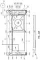
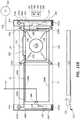
- FIGS. 8A-8Hdemonstrate the speaker-containing base of the chair of FIGS. 1A-1B of the present invention with the subwoofer speaker system mounted within the frame of the base.
- An outer and inner cover and feet members associated with components of the baseare depicted in FIG. 8F .
- FIGS. 9A-9Ddemonstrate the transverse member of FIGS. 1A through FIG. 3 of the present invention and the speaker system mounted within the frame of the transverse member.
- the electrical hub 100which is selectively mounted within the transverse member, is shown mounted within the transverse member.
- FIG. 10shows a cutaway view of an alternative speaker-containing transverse member, wherein the speaker is in a different location from the transverse member of FIGS. 9A-9D .
- FIGS. 11-12show alternate transverse members with alternate speaker locations.
- FIGS. 13A-Bare perspective views of a sofa similar to that of FIG. 1 a with audio speakers in the transverse members (armrests) thereof and subwoofer speakers in the bases thereof to form a surround sound speaker system, the speakers reflected in phantom lines.
- FIG. 14shows a sofa similar to that of FIGS. 13A-13B .
- the sofahas night light motion sensors.
- FIGS. 15A-15Cshow examples of wiring diagrams for the sofa of FIG. 14 .
- FIG. 15Dis another version of the wiring diagram of FIGS. 15A-15C with text descriptions for certain elements identified in the wiring diagram.
- FIG. 16is a perspective view of a controller or transmitter of the present invention.
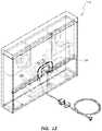
- FIG. 17is an example of a wall-mountable controller or transmitter of the present invention having a speaker (e.g., a center channel speaker).
- a speakere.g., a center channel speaker
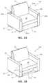
- FIG. 18schematically illustrates an easy-in, easy-out dockable speaker that may be selectively dockable into a portion of the furniture assembly.
- FIGS. 1 - 3Modular Furniture System w/Surround-Sound Speakers
- FIG. 1Ais a perspective view of a modular furniture assembly in the form of a chair of the present invention having audio speakers embedded in the transverse members thereof to form a surround sound speaker system, the speakers reflected in phantom lines in the transverse members.
- FIG. 1Bis a perspective view of the modular furniture assembly of FIG. 1A in the form of the chair, wherein the chair also has a subwoofer speaker in the base thereof, the subwoofer speaker shown in phantom lines in the base.
- the present inventionrelates to an audio-enhanced, modular furniture system 200 comprising a speaker-containing base member 12 a selectively coupled to speaker-containing transverse members 14 a and a non-speaker containing transverse member 14 .
- the speaker-containing base member 12 a and speaker-containing transverse members 14 a and transverse member 14are connected to each other as shown in FIGS. 1A and 1B .
- Audio-enhanced, modular furniture system 200advantageously includes one or more speakers positioned therein and as shown in FIGS. 1A-B , has a set of speakers in each armrest transverse member 14 a and a subwoofer 210 in base 12 a.
- furniture system 200comprises an integrated internal subwoofer 210 a and four integrated, internal non-subwoofer speakers 212 a - b , 214 a - b .
- the non-subwoofer speakers 212 a - b , 214 a - bas shown in FIG. 1A , include two front speakers 212 a - b and two surround, rear speakers 214 a - b which are oriented upwardly in the embodiment of FIG. 1A .
- the subwoofer 210 amay handle low frequency sounds (e.g., from about 20 Hz up to about 120 Hz, up to about 100 Hz, or up to about 80 Hz), while the front and rear speakers 212 a - b , 214 a - b may handle higher frequencies (e.g., from a cut-off frequency of the subwoofer up to about 20 kHz).
- Any of the speakersmay include cone drivers, dome drivers, ribbon drivers, horn drivers, any other driver configuration, or a combination of drivers.
- the footprint of system 200 having speakers 210 a - 214 b thereinhas the same mathematical specifications as the footprint of a modular furniture assembly not having speakers therein.
- the addition of speakers within system 200does not add any additional space requirements to a home or office.
- wiring and/or cabling typically associated with speakersis also hidden within the furniture assembly itself, presenting a very clean, aesthetically desirable appearance, while at the same time providing high quality stereo, surround, or other sound playback.
- the use of the speakers mounted within the furniture system 200efficiently uses furniture and provides a high-quality, high-fidelity listening experience to the user.
- the speakersare hidden within certain discrete portions of the transverse members 14 a and within the base 12 a , thereby enabling efficient use of space.
- speakers 212 a and 212 bare shown mounted in a front facing surface of transverse members 14 a .
- front-facing placement of speakers 212 a and 212 bworks in conjunction with a front wall, flat screen television or other surface which aids in reflection of the front directed sound from front-facing speakers 212 a and 212 b , the sound being reflected back to the user seated on furniture assembly 200 , the reflected sound potentially having the advantages of reflected sound, which may, in some embodiments, include improved sound quality.
- sound reflected back to the seated usermay mimic sound coming from front speakers actually positioned in front of the seated user.
- the subwoofer assembly within base 12 ais hidden inside the frame of base 12 a and is therefore underneath the seat cushion 18 .
- FIG. 2shows an embodiment of the surround sound chair of the furniture system 200 of FIGS. 1A-B with an adjacent lamp that is electrically coupled to an integral electrical hub mounted internally within the chair. Details of the internal electrical hub 100 will be discussed further with respect to FIGS. 5-7 .
- FIG. 3is a furniture system 200 in the form of a chair having a surround sound speaker system as in FIGS. 1A-B , the cushions exploded therefrom and a cutaway view of the base 12 a shown.
- FIG. 3shows an exploded view of the surround sound chair of the furniture system 200 of FIGS. 1A-B and FIG. 2 , showing use of: (1) selectively mounting couplers 15 which couple transverse members 14 , 14 a to base 12 a ; (2) integral electrical hubs 100 mounted internally within the furniture system 200 to provide a source of electrical power; as well as (3) details of base 12 a , including cushioning assemblies and integral, internal speaker assemblies of base 12 a.
- Audio-enhanced modular furniture system 200has bases 12 a and transverse members 14 a that are similar to base 12 and transverse member 13 of FIGS. 4A-B .
- Base 12 aconnects to transverse member 14 a and 14 in the same or similar manner to that of base 12 and transverse member 14 shown in FIGS. 4A-B , which will now be discussed.
- FIGS. 4 - 7Coupling and Electrical Power
- FIGS. 4A-4Bshows additional details relating to the use of couplers 15 and the coupling of a base 12 to a transverse member 14 .
- FIG. 5shows further details relating to couplers 15 , as well as details relating to electrical hub 100 , which acts as a source of electrical power for the speakers and other electrically powered devices, such as phones, computers, lamps, recharging systems, and other electrical devices that can be conveniently used by a user sitting on the modular furniture assembly depicted in FIG. 5 .
- FIG. 6shows the coupling of electrical hub 100 within a transverse member 14 , as well as the advantageous use of electrical hub 100 to power a speaker 170 and an induction charger 172 that can be used to wirelessly charge electrical devices, e.g., phones, etc., placed on or within a transverse member 14 , e.g., when transverse member 14 is being used as an armrest.
- FIG. 7shows the use of hub 100 to power a lamp.
- FIGS. 8A-8Hdemonstrate an embodiment of a speaker system coupled within base 12 a .
- FIGS. 9A-12demonstrate embodiments of speaker systems within transverse members 14 a.
- FIGS. 4A-7The coupling together of components of the modular furniture assembly of the present invention and the electrical power system within the modular furniture assembly will now be discussed with detailed reference to FIGS. 4A-7 .
- the principles of coupling using coupler 15 and the use of hub 100 to provide electrical powercan be employed in conjunction with speaker-containing bases 12 a and transverse members 14 a and/or in conjunction with non-speaker containing bases and transverse members.
- FIGS. 4 A- 4 BModular Furniture Configuration and Coupling
- FIGS. 4A-4Billustrate a modular furniture assembly 10 of the present invention.
- Modular furniture assembly 10 of FIGS. 4A-Billustrates the configuration of base 12 and transverse member 14 and the coupling of base 12 and transverse member 14 to each other.
- coupler 15selectively couples base 12 to transverse member 14 .
- Coupler 15can also be used to couple speaker-containing base 12 a to speaker-containing transverse member 14 .
- neither base 12 nor transverse member 14 of FIGS. 4A-4Bhave a speaker, electrical hub, or other electrical component therein
- base 12 and transverse member 14 of FIGS. 4A-4Beach may have one or more speakers, an electrical hub, or other electrical component therein.
- FIGS. 4A-4Bare shown in order to illustrate the use of coupler 15 to couple a non-speaker-containing base/transverse member combination or a speaker-containing base/transverse member combination.
- each of the modular furniture assemblies 10have a seat cushion 18 on base 12 thereon for sitting on by a user.
- foot couplers 34are shown for coupling the bottom portions of transverse members 14 and bases 12 to each other.
- the bases and transverse members of the present inventioncan include one or more covers (e.g., an inner cover and an outer cover).
- covershave various advantageous, such as that the outer covers are conveniently removable so that the user can remove the covers, wash them, and swap them with other covers as desired.
- the speakers used in the present inventionare frequency tuned so that there is a high quality sound emitted through the inner and/or the outer removable covers.
- FIG. 5Electrical Power Hub for Modular Furniture
- FIG. 5illustrates the modular furniture assembly of FIGS. 4A-4B in an exploded view with the addition of certain electronic assemblies which connect to an electrical hub configured to be mounted within the modular furniture assembly.
- Hub 100 of FIG. 5is used to provide electrical power to the speakers of furniture system 200 and other electrical components.
- Base 12 of furniture assembly 10is selectively coupled to first and second transverse members 14 of furniture assembly 10 , a second transverse member being shown in a partial view in FIG. 5 .
- Each transverse member 14has a cavity 26 in a middle, lower portion thereof.
- a U-shaped coupler 15selectively couples an upper portion of a base 12 to a middle, lower portion of a transverse member 14 .
- Foot couplers 34selectively couple respective feet of base 12 to respective feet of the transverse members 14 .
- Foot couplers 34have apertures therein that receive the feet of respective adjacent bases and transverse members, coupling them to each other.
- a foot couplersuch as coupler 34 can be placed under a foot of a base that is not adjacent a transverse member or other base, for aesthetic continuity and/or to provide a level surface of all four corners of the base.
- Furniture assembly 10is a modular furniture assembly that can be assembled as illustrated in FIG. 5 , for example.
- a U-shaped coupler 15selectively connects a portion of base 12 to a portion of a transverse member 14 by placing one plate of the U-shaped coupler 15 within an aperture 32 in the frame of base 12 and another plate of the U-shaped coupler 15 within an aperture 33 (see FIG. 7 ) in the frame of transverse member 14 that is in the cavity 26 of transverse member 14 , thereby selectively coupling base 12 to transverse member 14 .
- the second transverse member 14shown in partial view in FIG. 5 , and/or additional transverse members 14 , can be selectively coupled similarly or in exactly the same manner to base 12 .
- Base 12is used as a seat member and/or for receiving a cushion 18 to be used as a seat member while transverse member 14 can be used as a backrest and/or arm rest.
- transverse member 14can be used as a backrest and/or arm rest.
- Various combinations of bases, transverse members, and U-shaped couplers and foot couplerscan be used in varying numbers to create a variety of different furniture assemblies of the present invention, as discussed and illustrated in the patents and patent applications that are incorporated herein by reference.
- Electrical hub 100is also shown in an exploded view in FIG. 5 , electrical hub 100 being selectively mounted within the cavity 26 of transverse member 14 and a portion of an electrical hub 100 being selectively sandwiched between a portion of base 12 and a portion of transverse member 14 , thereby maintaining hub 100 in a convenient, stable position within furniture assembly 10 .
- Hub 100acts as a convenient power source for electrical devices 20 , 22 , and 24 .
- hub 100may also provide power for speakers and/or other audio components (e.g., an audio receiver).
- hub 100When cushion 18 of FIG. 4B is placed onto base 12 and adjacent transverse member 14 of FIG. 5 , hub 100 is not visible to the user, with the exception of the portion of the electrical cord 110 that extends from behind furniture assembly 10 and into the electrical wall outlet 19 .
- hub 100is not visible to the user, as shown in FIG. 2 .
- An electronic furniture assembly of FIG. 5thus comprises: (i) a furniture assembly 10 comprising: (A) a base 12 , (B) a transverse member 14 , and (C) a coupler 15 for coupling the base 12 to the transverse member 14 ; and (ii) an electrical hub 100 as shown in FIG. 5 configured to selectively reside within the furniture assembly 10 .
- electrical hub 100enables the resulting electronic furniture assembly of FIGS. 1A, 1B and 2 to conveniently receive and act as a source of electrical power for personal objects, such as all phones, computers and other accessories used while sitting on the furniture assembly 10 .
- Power available through hub 100may also be used to power speakers and other audio components embedded within the furniture assembly in a manner that during normal use (e.g., with cushion 18 is in place), the speakers, hub 100 , and even any wiring/cabling associated therewith is hidden from view.
- the electrical hub 100comprises one or more electrical outlets. Hub 100 is configured to be selectively integrated into furniture assembly 10 .
- One or more electrical hubs 100is configured to be selectively integrated into a variety of other furniture assemblies, having one or multiple transverse members 14 , such as the furniture assemblies disclosed in U.S. Pat. No. 8,783,778, entitled MOUNTING PLATFORM FOR MODULAR FURNITURE ASSEMBLY and (vii) Provisional Patent Application Ser. No. 62/257,623, filed on Nov. 19, 2015, entitled “Furniture with Electronic Assemblies,” each of which are incorporated herein by reference.
- the electrical hubs 100 described hereinare compatible to communicate with the transverse member cavities disclosed in the aforementioned patents and applications.
- hub 100in use in connection with modular furniture.
- hub 100is conveniently used in connection with various types of furniture, including: (i) fixed, non-configurable furniture; (ii) furniture that is assembled by a consumer (known as “assemble-able furniture); and furniture that can be configured into a variety of different configurations (known as “modular furniture”).
- Assemble-able furnitureincludes (i) modular furniture that can be configured into a variety of different configurations and (ii) furniture that can only be assembled into a single configuration.
- Hub 100is conveniently used in connection with various types of furniture, including (i) fixed-nonconfigurable, (ii) assembleable-modular and (iii) assembleable-non-modular furniture.
- FIG. 5illustrates a furniture assembly 10 that includes two transverse members 14 , and a base member 12
- the hub 100 or hubs 100may be used in other combinations of transverse members 14 and base members 12 , such as those disclosed in the aforementioned patents and applications, hub 100 being configured to be disposed partially within at least one of the transverse members 14 of such assemblies.
- cushion 18hides the hub 100 from view.
- a number of mobile, computing and/or other electronic devices 20 , 22 , 24are plugged in to the hub 100 that resides at least partially within the transverse member 14 behind the cushion 18 .
- FIG. 5illustrates a mobile phone 20 , a speaker 22 , and a laptop computer 24 electrically connected to the hub 100 .
- Other electrical devices that may be plugged into the hub 100may include, but are not limited to, table lamps, induction chargers, couch and/or chair lamps, reading and/or floor lamps, mobile computing devices, speakers, stereo systems, vacuums, heaters, fans, electric blankets, and the like for use by a user using furniture assembly 10 .
- FIG. 5also illustrates a hub electrical cord 110 plugged into a wall outlet 19 .
- the hub electrical cord 110provides electrical power to the hub 100 , which in turn provides electrical power to the one or more electronic devices 20 , 22 , 24 that are plugged or otherwise connected into the hub 100 .
- electronic devices 20 , 22 , 24are powered via the hub 100 in a visually pleasing and convenient way.
- the electrical outlets of hub 100 and connections of the electrical devices to the hub 100are typically not seen by the user when the user is seated on the couch or by others in the room when the cushion(s) is on the base 12 .
- the hub electrical cord 110thus provides power to multiple electronic devices 20 , 22 , 24 from a single a power source.
- a person sitting on or otherwise using the illustrated furniture assembly 10has access to his or her electronic devices 20 , 22 , 24 while they are being powered through the hub 100 without the need for multiple electrical cords or other power strips separate from the furniture assembly 10 .
- the electrical hub 100comprises: (a) an electrical outlet assembly 102 ; (b) a securement panel 104 wherein a rear face of the securement panel 104 is linked to the electrical outlet assembly 102 , such that at least one outlet of the electrical outlet assembly 102 is spaced away and offset from the securement panel 104 ; and (c) an installation clip 106 mounted to the electrical outlet assembly 102 , the installation clip 106 being moveable with respect to the electrical outlet assembly 102 , the installation clip 106 having an extended position and being capable of being moved to a compressed position when it is desired to move the hub into cavity 26 .
- Electrical outlet assembly 102includes electrical cord 110 and at least one electrical outlet in electrical communication with cord 110 .
- the free end of the installation clip 106is movable with respect to the assembly and is configured to be normally in the extended position absent any other force, and is selectively moved by a user from the extended position to the compressed position in order to mount the electrical hub 100 within the furniture assembly 10 .
- Clip 106is further configured to be selectively moved by a user from the extended position to the compressed position in order to remove the electrical hub 100 from the furniture assembly.
- Hub 100is configured to be selectively mounted within a furniture assembly 100 in order to provide a source of electrical power for one or more electrical devices 20 , 22 , 24 adjacent the furniture assembly, as illustrated in FIG. 5 .
- hub 100Additional information regarding hub 100 is disclosed in U.S. patent application Ser. No. 15/270,339, filed on Sep. 20, 2016, entitled “Electrical Hub for Furniture Assemblies,” which is incorporated herein by reference.
- FIGS. 6 - 7Electrical Components Coupled to Electrical Hub 100
- FIG. 6is a perspective view of a transverse member of the present invention, including phantom views of certain electronic components connected to a hub of the present invention. An optional adjacent transverse member is also depicted.
- FIG. 6illustrates a transverse member 14 of the present invention having an electrical hub 100 mounted therein, wherein a speaker 170 and an induction charger 172 are fed electrical power through the electrical hub, the speaker and induction charger being mounted within the transverse member.
- outlets of the electrical outlet assembly 102 or to the interior outlet 140 ′ shown in FIGS. 5-6can be electrically coupled to the outlets of the electrical outlet assembly 102 or to the interior outlet 140 ′ shown in FIGS. 5-6 , such as speakers, induction chargers (e.g., under the fabric of a transverse member serving as an arm rest), refrigerators, amplifiers for a surround sound system, and a vast number of other electrical devices that are convenient to have in a furniture assembly.
- outlet 140 ′has one, two, or more than two electrical outlets.
- one or more additional transverse members with a hub 100 , a speaker 170 , and a charger 172can also be provided in order to provide stereo and surround sound and in order to provide a conveniently wired electrical furniture assembly.
- induction charger 172mounted within a transverse member 14 , a user seated on a furniture assembly 10 can conveniently recharge an electrical device, such as a cellular phone, while seated on the modular furniture assembly.
- Wireless qi charginge.g., via induction charger 172 embedded within the transverse member or other devices is used to charge mobile devices, such as cellular phones, computers, lighting systems, lamps, or other electronic devices.
- the qi chargeralso known as an induction charger, may be hidden under furniture covers and/or embedded within the wooden frame of an embodiment of transverse member 14 .
- the induction chargeris mounted on an upper surface of one or more transverse members under a thin cover in order to provide easy access for mobile devices, such as cellular phones, etc.
- the induction chargercharges though layers of fabric when desired.
- the induction chargermay be placed in a variety of locations such as within the transverse member or the base.
- transverse member 14or in a base 12 , including ambience lights, heating systems, cooling systems and motion sensors, for example.
- Other embedded devicesthat may be employed in transverse member 14 or in a base 12 , including ambience lights, heating systems, cooling systems and motion sensors, for example.
- FIG. 7is a cutaway perspective view of a transverse member 14 and a hub 100 mounted within the transverse member 14 , including a lamp 150 electrically coupled to the hub 100 .
- the hub electrical cord 110extends from the hub 100 , through the transverse member 14 , out of a hole in the bottom portion of the frame of the transverse member 14 and below transverse member 14 , so that the hub electrical cord 110 can be plugged in to an external power source.
- the illustrated hub electrical cord 110is flexible and in some of the embodiments shown, e.g., in FIG. 7 is comprised of a plurality of extension cords.
- An electrical device such as lamp 150has a cord 160 thereof conveniently connected to floor resting cord outlet 140 a as shown in FIG. 7 .
- Electrical cord 110is thus advantageous because cord outlets such as floor resting cord outlet 140 a can power an electrical device such as lamp 150 and hide at least a portion of the corresponding electrical cord 160 from view, providing a more functional furniture assembly and a more pleasing aesthetic appearance.
- the cord elbow 120extending about electrical cord 110 is also illustrated.
- the cord elbow 120is a rigid or semi-rigid component (comprised, e.g., of a hard plastic) positioned about cord 110 in a bending, elbow shape along the length of the hub electrical cord 110 .
- the cord elbow 120is positioned about the hub electrical cord 110 so as to facilitate a convenient permanent bending of the hub electrical cord 110 while simultaneously protecting the bent portion of cord 110 .
- the cord elbow 120bends the hub electrical cord 110 at a position where the hub electrical cord 110 reaches the floor or other surface when extending between the electrical outlet assembly 102 and a power source, such as a wall outlet 19 .
- Elbows such as cord elbow 120provide a protected, smooth transition from a vertical orientation to a horizontal orientation, and may be comprised of a variety of different materials, such as a hard plastic, or a rubber, neoprene, silicone or other material that can be wrapped around and electrical cord and form a rigid or semi-rigid tubular member wrapped around the cord.
- Elbowssuch as cord elbow 120 extending about cord thus protect the electrical cord from breaking or fraying while bending, minimize the amount of electrical cord seen, and in some instances hides the electrical cord from view.
- one coupler plate 15 a of coupler 15is configured to fit within a corresponding aperture 32 of base 12 while another plate of coupler 15 fits within a corresponding aperture 33 of transverse member 14 to thereby selectively connect base 12 to member 14 .
- U-shaped coupler 15has a ribbon handle attached thereto for removing coupler 15 from respective apertures 32 , 33 and may have a hole in a top portion thereof, which assists in reducing the weight of the coupler 15 . In other embodiments, the hole and ribbon are not employed.
- FIG. 7further shows the convenience and utility of internal cord outlet 140 a or 140 ′ mounted within the body of transverse member 14 , which accepts the cord 160 of a lamp 150 , and/or the respective cords 170 a , 172 a ( FIG. 6 ) of one or more speakers 170 and one or more wireless electrical induction chargers 172 mounted within transverse member 14 .
- Induction charger 172can be mounted under the fabric within a transverse member 14 , for example for conveniently, wirelessly charging electronic devices wireless, e.g. a phone and/or computer placed by a user on a transverse member 14 .
- One or more tabs 120 a - bextend from the panel 104 of the hub 100 and are configured to reside between the transverse member 14 and the base member 12 when transverse member 14 and base member 12 are coupled together. In this way, the tabs 120 a - b are press fitted between the transverse member 14 and base member 12 so as to help secure the hub 100 at least partially within the cavity 26 in transverse member 14 .
- Coupler 15 and similar couplers and hub 100 and similar hubscan be employed to provide coupling and electrical power in conjunction with speaker-containing bases 12 a and transverse members 14 a and/or in conjunction with non-speaker containing bases and transverse members.
- FIGS. 8 A- 8 HBase 12 a with Speaker System
- FIGS. 8A-8Hdemonstrate an example of the base 12 a of the furniture system 200 in the form of the chair of FIGS. 1A - FIG. 3 of the present invention and the subwoofer speaker system mounted within the frame of the base 12 a.
- FIGS. 8A-8Hillustrate how subwoofer 210 a is mounted and positioned within base 12 a .
- base member 12 aincludes a frame assembly 216 into which subwoofer 210 a is mounted.
- Subwoofer 210 acan receive its audio signal wirelessly (e.g., from transmitter 224 , or from receiver/amplifier 217 ), or through a wired connection (e.g., from audio receiver 217 ).
- Power for a powered subwoofermay be provided from hub 100 . If the subwoofer is passive (e.g., no internal amplifier), the amplified signal may be provided from receiver/amplifier 217 .
- FIGS. 8A-Hillustrate how subwoofer 210 a is embedded into the frame assembly 216 of base 12 .
- Frame assembly 216 of base 12 ahas a cavity 226 within frame assembly 216 , within which subwoofer 210 a is positioned.
- Subwoofer speaker 210 ais comprised of a subwoofer speaker driver 211 a , including electronics and other structure typically associated with such a speaker driver, such as its magnet.
- Speaker driver 211 ais coupled to a speaker housing 228 on which driver 211 a is mounted.
- Speaker housing 228provides a given, desired internal volume associated with subwoofer speaker 210 a .
- housing 228is separately defined from the cavity 226 within frame assembly 216 .
- speaker housing 228enables speaker 210 a to be removed from the cavity 226 of base member 12 a so as to allow a user to remove subwoofer assembly 210 a from a given base member 12 a and install it into another base member 12 , for example, which may not have previously included a subwoofer speaker 210 a therein.
- Subwoofer assembly 210 ais thus entirely self-contained.
- Enclosure 228may be sealed or ported, as desired.
- Subwoofer speaker 210 afurther includes elongate attachment arms 230 a and 230 b mounted on opposing sides of speaker housing 228 . Arms 230 a and 230 b are attached to the enclosure 228 and couple enclosure 228 to frame assembly 216 of base 12 a.
- arms 230 a and 230 beach include an angled terminal extension 232 at each end thereof and a mounting hole 232 a associated therewith.
- the positioning and orientation of holes 232 aare configured to allow subwoofer speaker 210 a to be received within cavity 226 of frame assembly 216 in a manner that holes 232 a align with the holes for mounting feet 20 a of base member 12 a.
- Each of the arms 230 a - bare comprised of an L-shaped shaft body having an approximately 90 degree angled L-shaped cross section, each shaft body having terminating extensions 232 extending from the shaft body.
- the terminating extensions 232are angled to extend laterally outward from the shaft body as shown in FIG. 8H .
- the terminating extensions 232extend in the same plane as one of the legs of the L-shaped shaft body.
- the speaker systemcomprises one or more arms configured to couple one or more speakers to a frame of a portion of the furniture assembly, the one or more arms comprised of an L-shaped shaft body having an angled L-shaped cross section, the shaft body having terminating extensions extending from the shaft body, the terminating extensions being are angled to extend laterally outward from the shaft body, the terminating extensions extending in the same plane as one of the legs of the L-shaped shaft body.
- FIGS. 8A-8HThis relationship is further shown in FIGS. 8A-8H in which the positioning of feet 20 a is depicted.
- Feet 20 a of base member 12 aare shown as being configured to be mounted to the respective four corners of frame assembly 216 with arms 230 a and 230 b being sandwiched between the respective feet 20 a and a hole in frame assembly 216 into which feet 20 a are threadedly received, for example.
- FIG. 8Billustrates the positioning of upper and lower internally threaded hubs 233 that sandwich corner portions of frame assembly 216 .
- Feet 20 acan be selectively threaded into hubs 233 within the corner portions of frame assembly 216 .
- the subwoofer speaker 210 ais shown positioned within frame assembly 216 of base 12 in an orientation so that the driver 211 a of subwoofer speaker 210 a is oriented downwards, for example, in the same direction as feet 20 a (towards the floor).
- the cone of driver 211 a associated with subwoofer 210 ais shown as directing sound downward towards the floor or other support surface when assembled within base 12 a.
- driver 211 acan alternatively be flipped over so that the cone of driver 211 a associated with subwoofer speaker 210 a is oriented upwardly within base 12 a , in other words, toward the seated user.
- Each of these different configurationsprovides a different sound-enhanced experience for the user. For example, when driver 211 a is pointed downward towards the floor, sound is reflected off the floor, the reflected sound potentially having the advantages of reflected sound, which may, in some embodiments, include improving the sound quality.
- driver 211 aWhen driver 211 a is pointed upwardly toward the user sitting on the base 12 a , it may be possible for the user to feel and experience an increased amount of reverberation, improving the fourth dimensional experience for the user who can, in some embodiments, feel the sound of the speaker more intensely.
- the illustrated configurationprovides a high degree of protection for the driver 211 a of subwoofer speaker 210 a , while also providing excellent sound quality.
- frequencies of 120 Hz or less, or 80 Hz or lessare largely omni-directional, a user seated on couch 200 cannot readily tell from which direction such sounds are coming.
- Providing a full enclosure housing 228 for subwoofer speaker 210 ain addition to using an enclosure associated with frame assembly 216 of base 12 a , provides additional protection to the driver 211 a of subwoofer speaker 210 a.
- the top side of enclosure 228is spaced apart from the springs 263 coupled to the top of frame assembly 216 on which the cushion is positioned.
- the spacethus provided between the top of enclosure 228 and the springs 263 coupled to the top of frame assembly 216 , so that when a user sits on a cushion 18 positioned on the springs 263 coupled to the top of frame assembly 216 (or on fabric cover 266 or other cover over the springs 263 ), there is little risk of damage to driver 211 a of subwoofer speaker 210 a.
- such a space or clearance between the springs 263 and the housing 228may be at least about 2 inches to about 5 inches, for example.
- one or more internally threaded hubs 233are coupled to each of the corners of base frame 226 .
- corresponding upper and lower hubs 233are mounted within a corner such that each corner has an upper hub and a lower hub in an aperture thereof.
- Feet 20 aare threadedly coupled to corresponding corners by being threaded within corresponding upper and/or lower hubs 233 .
- foot couplers 234are shown. Foot couplers 234 are further shown in FIGS. 8F and 8H .
- the diameter of each of the holes of foot couplers 234are larger than the outer diameter of the feet 20 a , such that the rim and body portions of the foot couplers 234 contact the corners 232 of the arms 230 a - 230 b , such that weight of the arm's base frame 216 and an individual sitting on the base 12 a are received by the foot couplers 234 and not by the feet 20 .
- FIG. 8Fshows an example of an inner and outer cover 268 , 269 mounted on base frame 216 and having ends that extend slightly onto the underside of base frame 216 , as shown in FIG. 8F .
- Covers 268 , 269may be comprised of a variety of different fabrics. Additional covers or shielding members can be used to protect base frame 216 and/or speaker system 210 a , such as a metal or plastic mesh or caging material to cover driver 211 a on the bottom of frame assembly 216 .
- a removable outer cover 269is selectively, removably mounted on the undersurface of frame 216 and/or on inner cover 268 in order to protect inner cover 268 and frame 216 and in order to provide a selectively changeable aesthetic appearance.
- Covers 268 , 269may be secured over frame assembly 216 with attachment members, such as with one or more two-part attachment members, such as VELCRO, snaps, or with a variety of different attachment members. Staples or other attachment members may be used to connect inner cover 268 to frame 216 .
- serpentine springs 63 and/or Italian webbing 65are mounted on frame assembly 216 .
- Such resilient cushioning structuresprovide support to a cushion 18 placed over frame assembly 216 and may also help to ensure that even if a user were to step or jump on the top of frame assembly 216 or a cushion placed thereon, the springs and webbing 263 and 265 will not be pressed against enclosure housing 228 .
- housing 228Even in the unlikely event that a user were able to depress springs 263 and/or webbing 265 to a top surface of housing 228 , the rigid enclosure housing 228 will still protect subwoofer driver 211 a from any damage. Thus, the configuration of housing 228 and the space between housing 228 and springs 263 provides dual layers of protection for subwoofer driver 211 a.
- the foot couplers 34used to couple adjacent base members 12 a and/or transverse member 14 a to one another have apertures 35 that are large enough to surround feet 20 a without contacting feet 20 a , such that the upper surfaces of foot couplers 34 contact the surface of arms 230 a and 230 b on the respective corners of base 12 a , along with other surfaces of the corners, so that more of the force and strain associated with base members 12 a is carried by arm members 230 a and 230 b , and frame assembly 216 and foot couplers 34 , rather than all of the force being concentrated within foot members 20 .
- FIGS. 9 A- 12Transverse Member with Speakers
- FIGS. 9A-9Ddemonstrate an example of the transverse member 14 a of FIG. 1A through FIG. 3 of the present invention, with the speakers mounted within the frame of the transverse member 14 a .
- the electrical hub 100which is selectively mounted within the transverse member 14 a , is shown mounted within the transverse member 14 a .
- Depictions of inner and outer covers 241 , 243 of the transverse member 14 aare shown in FIGS. 9B-9C . Covers 241 , 243 are not depicted in FIGS. 9A and 9D .
- FIGS. 9A-9Dillustrate transverse member 14 a having two speakers embedded therein.
- FIGS. 9A-Dillustrates the mounting of front speaker 212 a on and within the frame 270 of transverse member 14 a and the rear, upwardly facing surround speaker 214 a mounted on and within the frame 270 of transverse member 14 a .
- FIG. 9Ashows how front speakers and rear speakers 212 a - b , 214 a - b of FIG. 1 may be mounted to the framing 270 within transverse member 14 a.
- FIG. 9Aan exemplary mounting configuration for mounting surround sound speakers 214 a and front speaker 212 a to frame 270 .
- speaker 212 ais screwed onto, bolted or otherwise secured to plywood, other wood, or other material of the frame 270 of the transverse member 14 a , as shown.
- the frame 270 of the transverse member 14 ais comprised of vertical and horizontally oriented members that define and create an internal speaker cavity within frame 270 .
- Frameis covered on one or more exterior surfaces thereof by a cushioning material 272 , e.g., a polyurethane foam material for providing cushioning to frame 270 .
- Holes 274 , 276are formed through the frame 270 and cushioning material 272 through which the sound of respective speakers 212 a , 214 a is emitted.
- a layer of polyurethane or other foamis typically present around the top, sides and front and back faces of frame 270 of transverse member 14 a .
- Holes 274 , 276extend through such foam and frame 270 through which respective speakers 212 a , 214 a adjacent the respective holes 274 , 276 emit sound.
- An inner fabric cover 241extends over the foam 272 and frame 270 of transverse member 14 and connects on the bottom of frame 270 , as illustrated in FIGS. 9B-9C .
- such fabricextends over the holes 274 , 276 , protecting the respective speakers 212 a , 214 a .
- An outer removable upholstery fabric cover 243is selectively placed over the inner cover 243 . The frequencies generated by the speakers are tuned such that the sound emitted from the speakers 212 a - b is tuned to compensate for the sound passing through the inner and outer covers 241 , 243 , which covers are typically not acoustically transparent materials.
- a fabric inner covermay be mounted within the holes of the polyurethane or other foam material and/or the plywood frame member, after which the speakers are secured to the frame member.
- the outer upholstery fabric coverthen extends over the transverse member, including the speakers 212 a , 214 a , hiding the speakers from view.
- Rear surround speaker 214 acan be mounted in the same or similar manner as speaker 212 a , or in a different manner.
- speaker 214 acan be secured to a plywood or other frame member of transverse member 14 a and mounted adjacent a hole in the frame member.
- a holeis also provided through the polyurethane or other foam around the top surface of transverse member 14 a through which surround speaker 214 a is mounted.
- Inner and outer fabric coverssimilarly extend over and/or about rear surround speaker 214 a.
- the transverse member frame 270is surrounded entirely by cushioning material 272 , except possibly on the bottom surface of frame 270 and possibly within the cavity 26 where the coupler 15 and hub 100 are mounted.
- the front speaker 212 a and rear surround speaker 214 a of FIGS. 9A-9Dare mounted within compartments within the frame 270 of transverse member 14 a and are coupled to the frame 270 , e.g., with screws or bolts. Holes 274 , 276 in the frame 270 and foam 272 correspond to the inner diameter of the respective speaker cone. As indicated, the interior cover 241 can either be covering the outer portion of the holes 274 to thereby cover the speakers, or can tucked into the holes created in the frame and foam that house the speakers.
- the speakers 212 a , 214 a of FIGS. 9A-9D of the speaker-containing transverse members 14 aare thus each positioned within the frame 270 thereof with the drivers of the speakers screwed or bolted to the frame 270 and with the inner diameter of the cones of the speakers 212 a , 214 a placed adjacent respective circular holes through the frame and adjacent foam.
- the holes in the outer foam coveringmay be covered by an inner cover 241 ( FIG. 9B ) which covers the transverse member frame and/or by an outer cover 243 (e.g., washable) that is selectively purchased by a user according to color, fabric, etc. and which selectively is placed over the inner cover 241 .
- the speakers 212 a - 214 aare tuned in order to emit sound in a high quality manner through the upholstery fabrics of the covers 241 , 243 . For example, frequencies that are preferentially absorbed by the fabric covers (altering the loudness of a given frequency as it passes through the fabric cover) may be boosted to compensate for loss as such frequency passes through the cover(s).
- Relatively higher frequenciesare typically more drastically attenuated by such fabric passage than relatively lower frequencies, such that the tuning may comprise preferentially boosting higher frequencies (as compared to little or no boosting of lower frequencies), in order to provide a “flat” frequency response across the frequency spectrum as heard on the other side of the fabric (i.e., at the listener's ears).
- the drivers of transverse members 14 amay optionally be covered by a metal or plastic mesh or caging material mounted within the holes within the cushioning material and/or frame, for additional protection beyond that provided by the fabric covers.
- the front-facing speaker 212 a of FIGS. 9A-9Dis shown positioned adjacent the front face 234 of transverse member 14 a .
- Front speaker 212 ais shown as being positioned near the top of the front face 234 .
- Upwardly facing rear surround speaker 214 ais shown as being embedded adjacent a top surface 236 of transverse member 14 a .
- Surround speaker 214 ais shown as being positioned within transverse member 14 near a rear end of upper surface 236 of member 14 a.
- the structure and positioning and tuning of speakers 212 a , 214 ais strategically useful to the sound and fidelity of the speakers as the speakers are covered by one or more covers 241 , 243 .
- Such placementis advantageous as it positions speaker 212 a , 214 a well above the floor on which the couch assembly 200 is placed, while also positioning rear surround speaker 214 a near to, and perhaps behind the ears of a user seated on couch 200 . Such positioning is also advantageous as it helps to protect speakers 212 a and 214 a from damage that might otherwise occur if the speakers were near the floor.
- positioning speakers 212 a , 214 a closer to the floor surfacemight result in a user inadvertently kicking the speaker, thereby damaging it.
- Positioning of surround speaker 214 a at or near a rear end of the upper surface 236 of transverse member 14is also advantageous as a user is less likely to spill a drink at this location or even position an arm or hand over the speaker, damaging the speaker and/or muffling sound generated thereby.
- the interior furniture cavities of the base and transverse members of the present inventionare utilized to potentially enhance the audio quality by resonance and positioning.
- the volume of the transverse member itselfmay be used as the speaker enclosure, creating the desired resonance.
- Speakersare tuned for speaker output through the fabric covers covering the frames of the speakers, which is highly useful.
- Removable, outer cover 243may selectively be mounted on transverse member frame 270 (and the at least partially surrounding foam 272 ) and/or on interior cover 241 through the use of a two part attachment assembly, such as VELCRO, or other two part attachment assembly.
- the inner and outer covers 241 , 243may be comprised of a variety of different upholstery fabrics, such fabrics comprising fibers, such as polyester fibers, or other fibers.
- the fabric of covers 241 , 243may be woven or non-woven.
- fabricsare not acoustically transparent, e.g., they affect sound waves at one or more frequencies from 20 Hz to 20 kHz by attenuating (or boosting) any such frequency more than 3 dB (i.e., ⁇ more than 3 dB).
- such upholstery fabricsare relatively heavy fabrics, which may typically attenuate particularly the higher sound frequencies at more than 3 dB.
- the sound generated at any such speaker hidden behind the upholstery fabricmay be tuned to increase the volume of the attenuated frequencies to compensate for the attenuation that occurs as the sound passes through the fabric. For example, if the fabric attenuates sounds at 2 kHz by 6 dB, the tuning may increase the volume of sounds at 2 kHz by 6 dB to compensate. There may typically be several frequencies which may be boosted to compensate for such fabric induced attenuation.
- Examples of the upholstery materials for the inner and/or outer cover 243include polyester, chenille, tweed, linen, velvet, leather, polyester linen, cotton, cotton blend, denim, twill, faux fur, leather, and the like, for example. Such materials can also be used for outer covers for base member 12 a , and all of which are examples of upholstery fabrics, although a variety of different fabrics may be employed.
- weights of upholstery fabricsthat can be used as interior covers and/or outer covers for the bases and/or transverse members of the present invention include, for example: fabrics having weights in a range of approximately 50 grams per square meter (GSM) to approximately 1500 grams per square meter (GSM), for example, such as approximately 100 GSM to approximately 1000 GSM, or such as approximately 190 GSM to approximately 800 GSM, although a variety of different interior and exterior fabrics may be employed.
- GSMgrams per square meter
- GSMgrams per square meter
- GSMgrams per square meter
- GSMgrams per square meter
- the speakers of the present inventionare adjusted and tuned in order to emit sound through such fabrics in a manner that attenuation due to such fabric is compensated for.
- the inner cover of base 12 a and/or the inner cover of transverse member 14 aare comprised of a thin cover comprising an approximately 90 percent polyester and approximately 10 percent cotton blend, for example.
- the upholstery fabric used in transverse member 14 ais in one embodiment not an acoustically transparent fabric, but rather is upholstery fabric configured to be employed in upholstery, chairs, couches and other furniture.
- the front speakers and the surround speakerscan be tuned to accommodate for the dynamic that the sound generated from such speakers is required to pass through the upholstery fabric.
- relatively higher frequenciese.g., 200 Hz or more, 400 Hz or more, 800 Hz or more, 2 kHz or more, 4 kHz or more, etc.
- the speakercan be tuned by boosting such higher frequencies before they pass through the fabric so that once the speaker sound passes through the fabric, it is approximately at a volume as it is intended to be heard and received by a listener (e.g., so that the overall tuned output is within ⁇ 3 dB of the un-attenuated “target” value).
- examples of the upholstery materials for the inner and/or outer cover 243include chenille, tweed, linen, velvets, leather, polyester linen, cotton, cotton blend, denim and others used in furniture upholstery, for example. Tuning of the frequencies of the speakers to provide the sound through such upholstery fabrics is a unique and novel aspect of the present invention.
- Such positioninghides speakers 212 a and 214 a within transverse member 14 so as to not be readily seen by a user or other person, but also allows a high quality sound from the speakers.
- Such hiding of the speakersis particularly advantageous in at least some embodiments. For example, many users dislike the appearance of speakers within a room in locations such as a bookshelf, or on stands located some distance from a couch, which is often typical.
- the present configurationsare advantageous in that they allow complete hiding of the speakers, sometimes even all of the speakers associated with a surround sound system.
- Each of speakers 212 a and/or 214 amay be mounted within transverse member 14 in any manner desired.
- theymay each include a dedicated housing enclosure similar to that described above, with respect to the subwoofer assembly.
- Such a housing enclosurecould be attached to the frame assembly within transverse member 14 a .
- the speaker driver associated with speakers 212 a and/or 214 acan simply be mounted to frame members internally disposed within transverse member 14 a , employing the cavity associated with transverse member 14 a for one or both of speakers 212 a and/or 214 a.
- a hole cover 245may be employed as a plug to cover electronics of the interior systems within the transverse member 14 a as shown in FIG. 9D .
- FIG. 9Cillustrates hole or opening 247 in a bottom face of transverse member 14 a , through which cord 110 passes.
- hole 247is shown covered by hole covering 245 .
- a relatively small slot 249may be provided through covering 245 , to permit cord 110 to extend therethrough.
- wiring 218 a , 218 bprovides power and/or signal to embedded speakers 212 a and/or 214 b as appropriate.
- Wire 218 aprovides at least part of an electrical connection between an amplifier 217 (see FIG. 15 ), which may be mounted in base 12 a on, near, or within housing 228 for example, and front speaker 212 a .
- amplifier 217see FIG. 15
- cable or wiring 218 a - bmay be provided in a plurality of sections to preserve the modular nature of furniture assembly 200 . For example, coupling between such wiring sections could be provided at or near the hub 100 disposed within transverse member 14 .
- a first section of such wiring or cablingmay extend from a base member 12 a and amplifier 217 to a location of the base member 12 a that is near or adjacent to the coupler 15 and/or hub 100 .
- This first section of wiring or cablingcould be terminated at this location with an appropriate RCA or other type coupling jack.
- the transverse member 14 amay similarly include another section of wiring 218 a which extends from speaker 212 a through transverse member 14 to another jack coupling at or near hub 100 .
- a similar multi-section wiring or cabling configurationcan similarly be provided between rear, surround speaker 214 a and a jack at or near the hub 100 and from the amplifier 217 to a location at or near the hub 100 , with a bridging coupling or wiring between wiring in base 12 a with wiring in the transverse member 14 a.
- such internal wiring spanning the base members and the transverse membersmay not necessarily be required.
- signalscould be transmitted to the speakers from receiver 217 (e.g., an audio or home theater receiver) and/or transmitter 224 through wireless transmission.
- the signalmay be transmitted wirelessly to speaker 212 a and/or speaker 214 a . In such embodiments, it may still be necessary to provide power to speaker 212 a and/or 214 a , e.g., through use of hub 100 Such wireless transmission of signals may eliminate the need for any wiring or electrical coupling for power or signals from base 12 a to transverse member 14 a , at least for speakers 212 a and 214 a.
- jumper connectionsare desired for power and/or signal transmission, such may be achieved through any suitable configuration.
- quick connect portse.g., RCA, banana plugs, or other
- a jumper cablefor example, from the transverse member 14 a to the base member 12 a.
- an induction charger 172(such as that in FIG. 6 ) is mounted on an upper surface of the frame 270 of the transverse member 14 a , embedded within the foam 272 on top of the frame 270 , for example, and located below the inner cover 241 (and possibly below a portion of foam) mounted on the frame 270 .
- Induction charger 172is electrically coupled to an interior outlet of the electrical hub 100 .
- Induction charger 172can be mounted in an upper middle portion 278 of transverse member frame 270 , for example, between the speakers 212 a - 214 a and above the electrical hub 100 .
- Charger 172may be in the same top surface 236 as surround speaker 214 a , positioned forwardly relative to speaker 214 a , e.g., behind speaker 212 a positioned in the front surface 234 of transverse member 14 a.
- FIGS. 10-12show alternate transverse members with speaker assemblies of the present invention.
- FIGS. 10, 11 and 12illustrate differently configured transverse members 14 b - 14 d in which the speakers embedded therein are differently positioned.
- FIG. 10shows a cutaway view of an alternative speaker-containing transverse member 14 b , wherein the speaker 280 is pointing horizontally and away from the hub 100 .
- Speaker 280is coupled to the frame 282 (e.g., wood, plywood, fiberboard) of transverse member 14 a , such that the speaker cone is adjacent a hole in the frame 282 and a corresponding hole in the foam cushioning material 284 adjacent the frame 282 .
- the frame 282e.g., wood, plywood, fiberboard
- An induction charger 172 shown in FIG. 10is mounted on an upper panel 286 of the frame 282 of the transverse member 14 b , embedded within (or, optionally, adjacent) the cushioning material 288 on top of the upper panel 286 of the frame 284 of transverse member 14 b , for example.
- FIGS. 11-12also show different speaker orientations for the transverse member speakers. It will thus be appreciated that numerous positioning possibilities are possible for positioning and orienting the speakers within transverse members 14 c - d.
- FIG. 11shows another alternative which may include perhaps only a single speaker 290 within transverse member 14 c which may be oriented and positioned in any desired orientation and position.
- Speaker 290is electrically coupled to an amplifier 291 within the frame of the transverse member 14 c .
- each speaker in each transverse memberhas its own associated amplifier mounted within the respective transverse member.
- a single amplifier 217 for each speaker of the speaker system(all transverse members and base(s) is mounted within or on the housing 228 within base 12 a .
- the signalis transmitted through wiring as shown in FIG. 11 to amplifier 291 (and eventually speaker 290 ), or alternatively the signal is transmitted wirelessly, and power for amplifier 291 can be provided from hub 100 through appropriate wiring.
- Amplifier 291sends an amplified signal to speaker 290 .
- An induction charger 172is mounted on the upper portion of the frame of transverse member 14 c in FIG. 11 .
- the speakers of FIG. 12may be wireless speakers so as to receive signals through wireless transmission as described herein from audio receiver 217 and/or transmitter 224 .
- Power for the speakers of FIG. 12may be provided through a connection with hub 100 .
- FIGS. 9A-12numerous speaker placement and a number of speaker options are possible.
- a stereo set upcould be provided in which only left and right speakers are provided or a system including left and right speakers and a subwoofer, for example, a 2.1 system.
- a single speaker for each channelfront left, front right, surround left, surround right
- more than one speakercan be provided for any given channel (e.g., for front left, front right, left surround, right surround, subwoofer, center, etc.).
- FIGS. 13 A- 14Modular Sofas with Speakers
- FIGS. 13A-13Bare perspective views of a modular furniture system 300 of the present invention using the disclosure herein to form a sofa with audio speakers in the transverse members 14 a (armrests) thereof and subwoofer speakers in the bases 12 a thereof to form a surround sound speaker furniture system 300 , the speakers reflected in phantom lines.
- Front speakers 212 a - b and rear, upwardly facing surround speakers 214 a - bare each mounted in a respective transverse members 14 a .
- surround speakers 214 a and 214 bare shown as being oriented upwards so that the sound directed therefrom may be directed towards the ceiling and reflected off the ceiling, the reflected sound potentially having the advantages of reflected sound, which may, in some embodiments, include improving the sound quality (e.g., creating a diffuse, surround sound).
- Each of transverse member speakers 212 a , 212 b , 214 a , 214 bare positioned underneath the upholstery fabric of the covers 241 , 243 ( FIGS. 9A-9C ) of the respective transverse member 14 a in which the speaker is positioned.
- Each of these speakersmay be tuned so that output from a given speaker accounts for transmission of the sound waves through the upholstery fabric associated with transverse member 14 a before reaching the user seated on sofa 300 .
- Positioning of speakers 212 a , 212 b , 214 a , and 214 bis also advantageous as the speakers are positioned in transverse members 14 a in a manner such that a user seated on sofa 300 typically will not obstruct sound emanating from any of these speakers.
- FIGS. 13A-13Bmay advantageously create a realistic surround sound environment in which sound from front speakers 212 a and 212 b is intentionally reflected off a front surface, such as a front wall, television or similar structure, disposed in front of a seated viewer. Sound from rear surround speakers 214 a and 214 b is similarly directed upwardly toward the ceiling so as to be reflected back down toward a seated viewer sitting on sofa 300 , the front and/or ceiling reflected sound potentially having the advantages of reflected sound, which may, in some embodiments, include improving the sound quality, creating a surround sound experience.
- a front surfacesuch as a front wall, television or similar structure
- the speakers embedded in base member 12 a and/or transverse member 14 acan be switched or swapped as a user wishes to reconfigure the modular furniture assembly of sofa 300 .
- a userwished to reconfigure sofa 300 so as to include more or less base members and/or more or less transverse members 14 a
- the usercan simply disassemble that part of sofa 300 and include additional base members 12 a and/or transverse members 14 a (or remove such), as desired.
- any of the furniture assemblies shown in any of the applications already incorporated by referencecan be modified to swap out any of the bases or transverse members with bases 12 a including a subwoofer, or transverse members 14 a including speakers, or any combination thereof.
- Such modularity of the furniture systemthus allows the user extreme flexibility in where the speakers are provided, hidden within the furniture assembly.
- the modularity of the subwoofer assembly in base 12 acan also allow a user to remove the assembly from one base, and install it in another base, if desired.
- the modularity of the systemallows a user to place base members 12 a and transverse members 14 a in any place desired.
- Some base members 12 and some transverse members 14may be provided which do not include any speakers positioned therein, allowing the user to use these component pieces in configuring any desired modular furniture assembly configuration they desire.
- sofa 300In order for an end user to set up sofa 300 (or system 200 or system 350 ), no tools are required because the speakers are already mounted within respective base members and transverse members, and wiring can be connected without the use of complicated tools. Therefore, the sofa 300 with its electronic assembly members is highly advantageous, efficient and useful.
- FIG. 14shows a furniture system 350 that is similar to sofa 300 of FIGS. 13A-13B .
- the sofa 350has night light motion sensors (i.e., lighting which is motion activated) mounted on the underside of the base 12 a and/or transverse members 14 a thereof.
- night light motion sensorsi.e., lighting which is motion activated
- FIG. 14thus illustrates another embodiment of a modular audio enhanced furniture system in the form of sofa 350 which includes motion activated night lights.
- LEDs or other lightsmay be embedded or otherwise provided on or within the bottoms surfaces of the frames of base members 12 a and/or transverse members 14 a so as to illuminate all or a portion of a perimeter of sofa 350 when desired by a user.
- such lightingmay be motion activated so as to illuminate when a user approaches the sofa within any given distance.
- Power for such lightsmay be provided through any of the hubs 100 associated with transverse members 14 a as described herein.
- Such a configurationmay provide a night light system which may illuminate an area around sofa 350 in an otherwise dark room, aiding a user in navigating through the room at night or otherwise.
- Such lightingmay also be desired in other environments where a user is using sofa 350 , for example, while watching a movie or other program on a television or other display in a dimly lit room.
- Modular furniture assembly 350is highly useful in a variety of different settings and includes electronic devices embedded in leisure seating such as in upholstery couches, modular seating, sectionals and the furniture known as Sectionals. While illustrated with audio components in the furniture assembly in addition to the motion activated night light system, it will be appreciated that a furniture system without audio components could include the motion activated night light system.
- FIG. 14illustrates an embodiment that might be considered as a 4.1 or 4.2 speaker system, including a front left, a front right, a left surround, and a right surround speaker with a subwoofer speaker 210 a embedded in at least one of the bases 12 a .
- a 4.1 systemresults.
- both basesare bases 12 a including subwoofer speakers 210 a
- a 4.2 systemcan result (e.g., particularly where the subwoofers produce independent sounds).
- the two subwoofer speakersmay produce the same, or different sounds (e.g., 1 or 2 channels).
- a virtual center speakercan be provided through sound signals sent to front speakers 212 a and 212 b (i.e., a virtual center channel can be mimicked by the stereo of speakers 212 a and 212 b ).
- a dedicated center channel speakercan be positioned under or above the television, behind a perforated screen, or incorporated into a television, or other display device.
- a center rear channelcan be similarly imitated using right and left surround speakers 214 a and 214 b , or mounted on a rear wall, as desired, to create 5.1 or 6.1 systems. 7.1 systems or other configurations (e.g., Dolby Atmos) could similarly be provided for.
- sofa 350includes speakers or other audio components embedded in leisure seating which includes upholstery couches, modular seating, etc.
- Sofa 350provides excellent stereo or surround quality sound and provides a high fidelity surround sound experience.
- the speakersare hidden from the view of the user and customers within the wooden framing portions of the base 12 a and/or transverse member 14 a and can be hidden under covers surrounding the wooden framing.
- FIG. 15shows an example of a wiring diagram to be used in conjunction with the furniture system 300 or 350 in the form of the sofa of FIGS. 13A-13B or FIG. 14 .
- a table identifying certain elements of the wiring diagram of FIG. 15is shown below.
- FIG. 15Reference Numbers and Components
- Hub power cord(e.g., 120 volt) 110 Power cord for amplifier/receiver 217 144a Power cord tether for electrical Hub 144b Floor lamp 150 Power cord for floor lamp, connected to hub 160 Qi induction charger 172 Subwoofer driver 211a Front right speaker 212a Front left speaker 212b Right surround speaker 214a Left surround speaker 214b Multi-channel amplifier and/or audio receiver 217 Front right speaker wire/cable 218a Front Left speaker wire/cable 218b Right surround speaker wire/cable 220a Left surround speaker wire/cable 220b TV or other display 222 Wireless transmitter (e.g., 5.1) 224 Power cord into wall 225 Subwoofer enclosure 228 Mounting brackets 230a-b Tethered Remote 250 Volume up function on remote 252 Mute function on remote 254 Volume down function on remote 256 Bass volume up function on remote 258 Bass mut
- FIG. 15illustrates an exemplary wiring diagram for a modular furniture assembly, including a surround sound system positioned therein, such as that shown in FIGS. 1A-1B, 13A-13B, and 14 .
- wiringmay be provided within the modular furniture assembly to provide signals and/or power to each of speakers 212 a , 212 b , 214 a and 214 b.
- amplifier 217is disposed within base member 12 a .
- Amplifier 217may be a multi-channel amplifier and/or an audio receiver including such an amplifier and is illustrated as being disposed within base member 12 a , for example, adjacent to subwoofer 210 a , e.g., mounted on or within housing 228 .
- wiring 218 a and 218 bmay provide audio signals from amplifier 217 to front right speaker 212 a and front left speaker 212 b .
- the signal sent through wiring 218 a and 218 bis already amplified as shown.
- a signalmay be sent from an audio receiver 217 to front right and front left speakers 212 a in an 212 b in an unamplified configuration where amplification occurs at the speaker 212 a or 212 b .
- Unamplified signalscan be sent through a wired or wireless connection, as desired.
- FIG. 15further shows wiring 220 a and 220 b extending from amplifier 217 to right surround speaker 214 a and wiring 220 b extending from amplifier 217 to left surround speaker 214 b .
- Power for amplifier 217is provided through electrical connections shown in FIG. 15 , for example.
- power from plug 110FIG. 5
- amplifier 217is in turn plugged into an outlet associated with hub 100 , providing power thereto.
- amplifier 217amplifies at least the subwoofer speaker. In another embodiment, amplifier 217 amplifies the subwoofer speaker and the other speakers, e.g., the transverse member speakers. In another embodiment, the subwoofer may include its own internal amplifier, and amplifier 217 may amplify the other speakers (e.g., speakers 212 a , 212 b , 214 a , 214 b ) in the furniture assembly. In yet another embodiment, amplifier 217 amplifies the subwoofer speaker and each of transverse member speakers has its own amplifier associated with that speaker.
- FIG. 15shows how additional components may also be powered by hub 100 and/or additional hubs that are present within any of transverse members 14 / 14 a .
- FIG. 15shows power being provided from a hub in the right transverse member 14 a to the qi (induction) charger 172 .
- FIG. 15further shows power from a second hub in left transverse member 14 a to another qi charger, as well as to a floor lamp 150 . Additional components can be plugged into or otherwise powered by either of such hubs.
- FIGS. 15-15Ashow a tethered remote 250 that may be used to provide control over volume ( 252 , 256 ), the ability to mute ( 254 ), the ability to adjust specific frequencies, for example, base up ( 258 ) or base down ( 262 ), or bass mute ( 260 ).
- one or more of base members 12may further include a recliner seat whereby power for such recliner could be provided by any of the shown hubs.
- FIG. 15further shows a television 222 or other display.
- a television 222 or other displayis positioned or mounted on a front wall in front of sofa 300 , 350 , allowing a user seated on the sofa to watch television while listening to surround sound provided through the speakers associated with sofa 300 or 350 .
- a transmitter 224is provided at the TV 222 , such as a wireless controller transmitting signals for audio through a wireless transmitter to the speaker system of sofa 300 or 350 .
- a wireless transmitter 224for example, shown associated with television 222 .
- a wireless transmitter 224is plugged into the wall at 225 so as to be powered therefrom.
- Signals from wireless transmitter 224are wirelessly transmitted to amplifier and/or audio receiver 217 in sofa 300 or 350 .
- Wireless transmission of such audio signals and/or control signalscan be through Blue-tooth, WiFi, IR, Wireless Speaker and Audio Technology (WISA) or other mechanisms.
- Receiver 217can be used to receive communication from wireless controller/transmitter 224 , or a smart phone or tablet app, or the like.
- a wired connectioncan be provided between a transmitter component 224 , and amplifier or audio receiver 217 , although wireless transmission as illustrated may be advantageous as no wire or cord is thus required between the location of transmitter 224 and amplifier or audio receiver 217 disposed within sofa 300 or 350 .
- the hubs 100provide power to the electronic furniture assembly system of sofa 300 or 350 , as well as all of the speakers, components and electronic devices associated with sofa 300 or 350 .
- the furniture system of the present inventionalso includes an audio receiver/sound bar and a bridge electrically coupled to the television in order to communicate sound to the speakers of the sofa 300 or 350 .
- the speakers mounted within the base and transverse memberin addition to providing invisibility from a user/customer, also provides an opportunity for high quality sound.
- the base and transverse membereach provide a large enclosure volume within which the speaker sound can resonate to provide high quality sound while using no additional footprint other than that of the sofa itself.
- base 12 amay further comprise support beams within subwoofer enclosure housing 228 , the support beams being reflected at reference numbers 270 in FIG. 15 .
- Support beamsare mounted between the upper and lower portions of the enclosure housing 228 so as to provide support within a cavity 226 to prevent any damage to speaker 210 a .
- a receiver or amplifier 217is mounted on or within the subwoofer housing 228 of base 12 a , which has power in and amplified signal outputs.
- FIG. 15Ais another example of the wiring diagram of FIG. 15 with text descriptions for certain elements identified it in the wiring diagram.
- FIG. 16Controllers for Controlling Speakers and Other Components
- FIG. 16is a perspective view of a controller 240 of the present invention. Any of various control mechanisms and components can be provided with the surround sound systems described herein.
- FIG. 16shows an exemplary control component 240 .
- Such a componentmay include one or more knobs, dials, or other controls that a user may use to control various aspects of the sound or other environment.
- a usermay control overall sound volume, sound volume of one or more of the speakers, frequency boosting (or attenuation) of one of more frequency bands associated with any of the speakers, or other controls that a user may desire to manipulate.
- a control component 240may transmit signals or instructions through an electrical wired connection or wirelessly from a location that is remote from sofa 300 or 350 , for example, adjacent television 222 or elsewhere.
- a usermay be able to pick up and move such a control component 240 anywhere desired. For example, they may pick it up and take it over to the couch where it may left, if desired, so as to allow control at that point.
- control of any of the desired parametersmay be provided through a cellular phone app (smart phone app) or other software application that can be provided in any desired interface.
- a cellular phone appsmart phone app
- the smartphone portable device, tablet, or other device accessible to the userwhich may wirelessly transmit control signals to the receiver 217 or other component, then implement any desired changes to parameters as instructed by a user.
- Receiver 217may be capable of receiving and/or transmitting through WiFi, Blue-tooth, or other wireless system, so as to communicate with such an app, to communicate with transmitter 222 , etc.
- the audio receiver and/or amplifier 217which may be positioned within the base member 212 a , may include some knobs and/or buttons for controlling any desired parameters thereon. For example, volume controls for each of the speakers could be provided thereon.
- Such controlsmay allow a user to manipulate levels of the different speakers within the surround sound speaker system. For example, where a user wants to calibrate speaker levels of a given surround sound speaker or a given front speaker, or a given subwoofer, controls for increasing or decreasing the sound volume associated with any given individual speaker may thus be provided, allowing a user to make such calibrations or changes.
- a usermay wish to boost or attenuate a right front speaker, a left front speaker, a right surround speaker, or a left surround speaker, as numerous furniture assembly possibilities are possible with the modular furniture assemblies.
- a usermay wish to boost or decrease volume output from one or more such speakers to even out or calibrate sound volumes from the pair of front, the pair of surround speakers, or across all speakers at a given seating location. Controls as described herein may allow the user to do such.
- the speakers and other electronic components of the present inventioncan be controlled through a variety of different control mechanisms, such as control mechanisms embedded within the sofa, e.g. within the base and/or transverse members or through a controller connected by an electrical cord to the base and/or transverse members or through a remote or wireless setting, such as through the use of a personal cellular phone (e.g., smart phone or tablet).
- the speakers and other electronicscan thus be controlled wirelessly, e.g. through Blue-tooth, WiFi, through internet connections or other wireless connection means.
- there is no delay through the WISAfor example, sound and video may be correlated to ensure no lip synch problems between produced sound and images (e.g., sound and/or video may be intentionally delayed to ensure proper synchronization).
- a central transmittersuch as controller 240 is employed, having a volume knob, wireless communication, ability to select and employ stereo, 4.1, 5.1 etc. with various input capabilities, including an auxiliary port in the jack.
- Remote control for the speakers or other audio components or electronic componentsmay be embedded within the furniture system 300 or 350 , e.g. within the transverse member 14 a or base 12 a .
- Examples of controlinclude wireless control and tethered control.
- Parameters that can be controlledinclude volume for the 2.0 system, 2.1 system, the 4.1 system, volume for the 5.1 system, etc., mute, volume level and intensity control.
- a software applicationis employed to control the electronic devices such as the speakers and other electronic components within sofa 300 or 350 or other devices in the present invention.
- the software applicationmay be designed to control within the speakers and other electronic components (e.g., television, lamps, etc.) the volume, power, mute, balance, bass/treble, or other features of the system.
- the software applicationcan also be used for the lights within the sofa, e.g. the tract lighting or LEDs or other lighting features, e.g., lighting power off and on, and can provide sound performance tracking, recliner settings, temperature settings, dimming/controlling lighting fixtures, television channels, and other user preferences.
- a software applicationmay be used to control the speakers and other electrical components.
- Such software applicationmay have a variety of different features and settings.
- the software applicationcontrols speaker volume, TV volume, powers the speakers, power for the TV, mute, balance, bass/treble, lights on/off, sound performance tracking, recliner settings, temperature, dimming/controlling of lamps and other lighting, TV channels, etc.
- FIG. 17Transmitter with Speaker
- FIG. 17shows another example of a transmitter 224 of the present invention, which includes a speaker, for example a center channel speaker, incorporated therein.
- Transmitter 224may serve similar functions as controller 240 of FIG. 16 and could be mounted below, or above or behind television or other display 222 .
- incorporating the center channel speaker 224 a into the same housing 224 b which houses the transmitter assembly of transmitter 224simplifies the overall speaker system.
- the center channelis in the same housing 224 b as the controller mechanism.
- transmitter 224including a built-in channel speaker
- transmitter 224can be configured to be wall mounted.
- itmay include mounting structure for such wall mounting.
- the furniture assemblycan be used as a bed having speakers and other electrical components embedded therein.
- base 12 acan be used as a bed having speakers integrally mounted therein.
- Base 12 acan be sized large enough to serve as a bed.
- base 12 acan be a stand-alone bed and/or can serve a box spring on which a cushion, such as cushion 18 can be mounted, the combination of base 12 a and cushion 18 serving as a bed, wherein the base 12 a and cushion 18 are configured to be large enough to serve as bed.
- a bed of the present invention having one or more speakers thereincan thus be comprised of base 12 a and/or base 12 a and cushion 18 .
- multiple speakerscan be placed within the bed.
- the present inventionthus relates to a variety of different types of furniture having electronic components such as speakers, rechargers, power systems and other electrical components embedded therein.
- An embodimentcan include artificial intelligence (e.g., such as SIRI, ALEXA, or the like) positioned within or configured for use with the modular furniture assembly.
- artificial intelligencee.g., such as SIRI, ALEXA, or the like
- FIGS. 15A-15Cillustrate three such possible placements.
- the AI module 292is shown integrated or positioned within one or more of hubs 100 .
- the AI module 292is shown integrated or positioned with amplifier 217 , or on or within enclosure 228 .
- the AI module 292can be included on or within the speaker system components included in base member 12 a .
- FIG. 15Cshows another possible alternative, with the AI module 292 positioned on or within the transmitter 224 at or near TV 222 .
- Such artificial intelligencecan be configured to accept and/or respond to voice or other commands provided by a user.
- Such AIcan be configured to control any function (e.g., volume levels, channels, pause, etc.) associated with the other systems that can be incorporated into the furniture system.
- such AIcan be configured to control various other components that may not necessarily be incorporated into the furniture system (e.g., implementing a voice command or other command to turn on or off the television, or the like).
- the furniture systemcan be configured for compatibility with Apple Home Kit or similar systems, to accommodate voice control and/or other AI control mechanisms.
- Such AIcan comprise a command center (e.g., positioned within or accessible from the furniture assembly) that allows control of home or other lighting, control of a television, radio, sound system, or other component.
- a command centere.g., positioned within or accessible from the furniture assembly
- Such AI command centercan be configured with a control panel built into the transverse member (e.g., positionable into the cavity of the transverse member), similar to the electrical hub as described herein.
- the AI command centercan be included within at least one of electrical hubs 100 .
- such an AI command centercould be independent of hub 100 , but provided in a manner so as to similarly be positionable within the same cavity of the transverse member into which hub 100 is received.
- such AImay provide for voice activated control of any component of the furniture assembly, or other components, that may not specifically be included with the furniture assembly, such as room lights, a TV, HVAC, window shades, or the like.
- Such AIcan be SIRI or Alexa enabled, e.g., so that a user could ask SIRI or ALEXA to turn on the sound, turn up the sound, turn down the sound, turn on the TV, turn off the TV, dim the lights, turn on the lights, close or open the window shades, or the like.
- Such AI of the furniture assemblycould include learned or preprogrammed settings, such as room temperature (automatically activating HVAC to heat or cool the room), volume levels, recliner position or other settings, and other configuration settings.
- the AImay provide the ability for a recliner or other component of the furniture assembly to configure itself (e.g., by voice command) based on past settings implemented by a user.
- Such learned settingscould be per each individual in the home.
- the AIcan recognize the particular individual through voice recognition, or other mechanism, and then apply the particular individual preferences for any given parameters capable of control through the AI.
- the AIcan be configured to provide timed or timer settings, e.g., such as providing for LED or other illumination at night (e.g., from sunset to sunrise), optionally based on live data provided to the AI.
- the AIcould illuminate a night light within the furniture assembly, or elsewhere within the room or home based on a timed setting, e.g., illuminating the night light at or within a given time of sunset (e.g., 30 minutes after sunset), until a given time relative to sunrise (e.g., 30 minutes before sunrise).
- Motion sensingcould also be incorporated into such a night light, as described elsewhere herein, in combination with the AI control of such night light or other functionality.
- FIG. 18illustrates how a transverse member 14 can include a dockable speaker receptacle 311 .
- transverse member 14 of FIG. 18includes a receptacle 311 into which speaker 312 can be selectively docked.
- Receptacle 311is shown as including contacts 313 a , for providing electrical power and contact to corresponding contacts 313 b on speaker 312 .
- Such electrical contactcould be provided through internal wiring, running back to hub 100 (see FIGS. 15A-15C ).
- a speaker grill or other cover 315can also be provided.
- Such a dockable speaker 312may be configured for positioning in the transverse member 14 , over any fabric cover of transverse member 14 .
- the speaker 312could be docked into receptacle 311 , and then a fabric cover associated with member 14 could be positioned over member 14 .
- Such a configurationmay be preferred where it is desired to hide the speakers.
- transverse member 14is shown as including one dockable speaker 312 , it will be appreciated that any of the speakers described herein (e.g., 212 a , 214 a , 212 b , 214 b , 210 , or the like) could be configured as a selectively dockable speaker. Such selective removability can allow a user to remove a speaker, e.g., where it is desired to upgrade a speaker, customize the speaker locations, or the like.
- speaker 312may not require any tools (e.g., not even a screwdriver, hammer, or the like).
- speaker 312can be configured to simply friction fit into place, or to provide a snap fit into receptacle 311 , providing electrical contact between contacts 313 a and 313 b.
Landscapes
- Engineering & Computer Science (AREA)
- Signal Processing (AREA)
- Physics & Mathematics (AREA)
- Automation & Control Theory (AREA)
- Acoustics & Sound (AREA)
- General Health & Medical Sciences (AREA)
- Health & Medical Sciences (AREA)
- Computer Networks & Wireless Communication (AREA)
- Theoretical Computer Science (AREA)
- Human Computer Interaction (AREA)
- Audiology, Speech & Language Pathology (AREA)
- Multimedia (AREA)
- General Engineering & Computer Science (AREA)
- General Physics & Mathematics (AREA)
- Dentistry (AREA)
- Chair Legs, Seat Parts, And Backrests (AREA)
Abstract
Description
| Reference | |
| Component | Number |
| Base with | 12a |
| Regular base or | 12 |
| Transverse member with front and surround | 14a |
| Regular | 14 |
| 100 | |
| Hub power cord (e.g., 120 volt) | 110 |
| Power cord for amplifier/ | 144a |
| Power cord tether for | |
| Floor lamp | |
| 150 | |
| Power cord for floor lamp, connected to | 160 |
| 172 | |
| 211a | |
| Front | 212a |
| Front left | 212b |
| 214a | |
| 214b | |
| Multi-channel amplifier and/or | 217 |
| Front right speaker wire/ | 218a |
| Front Left speaker wire/ | 218b |
| Right surround speaker wire/ | 220a |
| Left surround speaker wire/ | 220b |
| TV or | 222 |
| Wireless transmitter (e.g., 5.1) | 224 |
| Power cord into | 225 |
| 228 | |
| 230a-b | |
| Tethered | 250 |
| Volume up function on remote | 252 |
| Mute function on remote | 254 |
| Volume down function on remote | 256 |
| Bass volume up function on remote | 258 |
| Bass mute function on remote | 260 |
| Bass volume down function on remote | 262 |
| Low power LED night light from | 264 |
Claims (22)
Priority Applications (1)
| Application Number | Priority Date | Filing Date | Title |
|---|---|---|---|
| US15/786,922US10979241B2 (en) | 2015-11-19 | 2017-10-18 | Electronic furniture systems with integrated artificial intelligence |
Applications Claiming Priority (5)
| Application Number | Priority Date | Filing Date | Title |
|---|---|---|---|
| US201562257623P | 2015-11-19 | 2015-11-19 | |
| US15/270,339US10236643B2 (en) | 2015-11-19 | 2016-09-20 | Electrical hub for furniture assemblies |
| US201662417091P | 2016-11-03 | 2016-11-03 | |
| US15/348,068US10212519B2 (en) | 2015-11-19 | 2016-11-10 | Electronic furniture systems with integrated internal speakers |
| US15/786,922US10979241B2 (en) | 2015-11-19 | 2017-10-18 | Electronic furniture systems with integrated artificial intelligence |
Related Parent Applications (1)
| Application Number | Title | Priority Date | Filing Date |
|---|---|---|---|
| US15/348,068Continuation-In-PartUS10212519B2 (en) | 2015-11-19 | 2016-11-10 | Electronic furniture systems with integrated internal speakers |
Publications (2)
| Publication Number | Publication Date |
|---|---|
| US20180041354A1 US20180041354A1 (en) | 2018-02-08 |
| US10979241B2true US10979241B2 (en) | 2021-04-13 |
Family
ID=61069860
Family Applications (1)
| Application Number | Title | Priority Date | Filing Date |
|---|---|---|---|
| US15/786,922ActiveUS10979241B2 (en) | 2015-11-19 | 2017-10-18 | Electronic furniture systems with integrated artificial intelligence |
Country Status (1)
| Country | Link |
|---|---|
| US (1) | US10979241B2 (en) |
Cited By (8)
| Publication number | Priority date | Publication date | Assignee | Title |
|---|---|---|---|---|
| US11172301B2 (en) | 2015-11-19 | 2021-11-09 | The Lovesac Company | Electronic furniture systems with integrated internal speakers |
| US11178487B2 (en) | 2015-11-19 | 2021-11-16 | The Lovesac Company | Electronic furniture systems with integrated induction charger |
| US11178486B2 (en) | 2015-11-19 | 2021-11-16 | The Lovesac Company | Modular furniture speaker assembly with reconfigurable transverse members |
| US11357332B2 (en)* | 2020-08-11 | 2022-06-14 | Samuelson Group Inc. | Furniture with integrated acoustical system |
| US11647840B2 (en) | 2021-06-16 | 2023-05-16 | The Lovesac Company | Furniture console and methods of using the same |
| US11689856B2 (en) | 2015-11-19 | 2023-06-27 | The Lovesac Company | Electronic furniture systems with integrated induction charger |
| US11832039B2 (en) | 2021-04-12 | 2023-11-28 | The Lovesac Company | Tuning calibration technology for systems and methods for acoustically correcting sound loss through fabric |
| US12364338B2 (en) | 2019-02-15 | 2025-07-22 | The Lovesac Company | Modular furniture support systems |
Families Citing this family (23)
| Publication number | Priority date | Publication date | Assignee | Title |
|---|---|---|---|---|
| US20160174715A1 (en) | 2005-06-10 | 2016-06-23 | Sac Acquisition Llc | Modular furniture assembly with dual coupling mechanisms |
| USD1076494S1 (en) | 2005-06-10 | 2025-05-27 | The Lovesac Company | Modular furniture assembly with base and upright member |
| US10236643B2 (en) | 2015-11-19 | 2019-03-19 | The Lovesac Company | Electrical hub for furniture assemblies |
| US10143307B2 (en) | 2015-11-19 | 2018-12-04 | The Lovesac Company | Furniture system with recliner assembly |
| US11076700B2 (en) | 2017-01-30 | 2021-08-03 | Burrow, Inc. | Modular sofa construction and methods for assembly |
| US20190104842A1 (en)* | 2017-10-10 | 2019-04-11 | Zekeazoid Arts & Entertainment LLC | Modular furniture construction system |
| US10898002B1 (en)* | 2017-11-22 | 2021-01-26 | David W Sperry | Self-contained event cheering apparatus |
| US10631661B2 (en)* | 2018-01-12 | 2020-04-28 | Uniters S.P.A. | Voice control system for manipulating seating/reclining furniture |
| TW201944975A (en)* | 2018-04-26 | 2019-12-01 | 鄭仲盛 | Smart chair |
| DE202019100105U1 (en)* | 2019-01-10 | 2020-04-16 | Innotec Motion GmbH | Seating chassis |
| DE202019100110U1 (en)* | 2019-01-10 | 2020-04-16 | Innotec Motion GmbH | Seating chassis |
| US11659936B2 (en) | 2019-02-15 | 2023-05-30 | The Lovesac Company | Modular furniture support systems |
| US11191364B2 (en) | 2019-02-15 | 2021-12-07 | The Lovesac Company | Furniture storage base |
| CN109770600B (en)* | 2019-02-28 | 2021-12-21 | 浙江大圣实业有限公司 | Collapsible padauk leisure chaise longue |
| USD956817S1 (en) | 2020-01-31 | 2022-07-05 | Abbyson Living, Llc | Furniture controller |
| US11779116B2 (en)* | 2020-01-31 | 2023-10-10 | Abbyson Living Llc | Control panel for furniture and home entertainment system |
| WO2021155379A1 (en) | 2020-01-31 | 2021-08-05 | Abbyson Living Llc | Control panel for furniture and home entertainment system |
| CN111227549B (en)* | 2020-02-07 | 2024-02-23 | 广州视源电子科技股份有限公司 | Chair armrest and chair |
| US11317724B2 (en)* | 2020-03-02 | 2022-05-03 | Krueger International, Inc. | Lounge furniture with removable seat |
| US11457745B1 (en) | 2020-05-14 | 2022-10-04 | Burrow, Inc. | Modular seating apparatus and kit |
| US12070131B2 (en) | 2020-06-30 | 2024-08-27 | The Lovesac Company | Reconfigurable modular furniture assembly with overlapping geometry |
| USD1027526S1 (en) | 2021-05-13 | 2024-05-21 | Burrow, Inc. | Attachable support structure |
| US12396557B2 (en) | 2022-04-11 | 2025-08-26 | The Lovesac Company | Modular furniture and reclining assemblies |
Citations (156)
| Publication number | Priority date | Publication date | Assignee | Title |
|---|---|---|---|---|
| US988059A (en) | 1909-12-02 | 1911-03-28 | Edgar W Allen | Coin-controlled chair. |
| US2625983A (en)* | 1949-09-21 | 1953-01-20 | Slyter Louis Raymond | Combination rocking and swiveling chair |
| US2653648A (en)* | 1950-07-20 | 1953-09-29 | Marshall Richard Paul | Electric-hydraulic beauty chair |
| US3113633A (en)* | 1960-11-04 | 1963-12-10 | John F Eberhardt | Stereophonic sound system |
| JPS474753Y1 (en) | 1968-08-07 | 1972-02-19 | ||
| US3870297A (en)* | 1973-06-18 | 1975-03-11 | Del Mar Eng Lab | Exercise treadmill with inclination controlled chair mounted thereon |
| US3880152A (en) | 1973-07-16 | 1975-04-29 | Ryotaro Nohmura | Device for health promotion |
| US3893731A (en)* | 1973-10-09 | 1975-07-08 | Richard G Maggs | Adjustable couch with acoustical head rest |
| US4120017A (en) | 1976-11-05 | 1978-10-10 | Ppg Industries, Inc. | Detachable power supply for induction type electrostatic spray gun |
| US4124249A (en)* | 1977-10-25 | 1978-11-07 | Abbeloos Charles J | Sound transmitting system |
| JPS5687863A (en) | 1979-12-19 | 1981-07-16 | Mitsubishi Electric Corp | Signal measuring cord |
| US4321717A (en)* | 1980-07-11 | 1982-03-30 | Luis F. Segarra Boerman | Sofa bed |
| JPS5967079A (en) | 1982-10-07 | 1984-04-16 | Yorimasa Shinohara | Stamp allowing sealing both by pressing and pinching |
| JPS59107523A (en) | 1983-12-05 | 1984-06-21 | Nitto Electric Ind Co Ltd | Method for forming a protective film for semiconductor devices |
| US4507816A (en) | 1983-12-21 | 1985-04-02 | Smith Jr Gray H | Waterbed with sound wave system |
| US4734946A (en) | 1987-01-21 | 1988-04-05 | Saputo Richard A | Knock down foundation for a flotation bed |
| US4846525A (en)* | 1985-07-05 | 1989-07-11 | Manning Ted A | Spray system for sun tanning |
| US5106153A (en)* | 1990-11-05 | 1992-04-21 | Durling Walter E | Unit of furniture |
| JPH0679086A (en) | 1992-09-01 | 1994-03-22 | Hitachi Ltd | How to control the washing machine |
| US5362296A (en)* | 1994-04-05 | 1994-11-08 | Greenmaster Idustrial Corp. | Chair mounting exercising unit |
| US5367727A (en) | 1992-10-07 | 1994-11-29 | Valwhat Enterprises, Inc. | Flotation bed with enhanced postural support |
| US5368359A (en)* | 1988-08-31 | 1994-11-29 | Eakin; Byron C. | Acoustical chair with sound enhancing hood |
| US5544938A (en)* | 1993-08-20 | 1996-08-13 | La-Z-Boy Chair Company | Mounting apparatus for securing independent sections of a sectional sofa assembly |
| CN2236262Y (en) | 1995-11-20 | 1996-10-02 | 朱晓刚 | Sofa with stereo music displayer |
| GB2300329A (en) | 1995-04-12 | 1996-10-30 | Icetronic Limited | Chair incorporating loudspeakers |
| US5624156A (en)* | 1996-03-25 | 1997-04-29 | Leal; Horacio | Child safety seat with entertainment system |
| US5681179A (en)* | 1995-12-18 | 1997-10-28 | Lane; Alain Gerard | Modular extension cord system |
| US5683139A (en)* | 1994-01-13 | 1997-11-04 | Knoll, Inc. | Chair seat tilt adjustment and locking mechanism |
| JP3047023U (en) | 1997-09-10 | 1998-03-31 | 有限会社藤原製作所 | Wall-mounted outlet |
| US5735573A (en)* | 1996-08-20 | 1998-04-07 | Vredevoogd; Jon D. | Chair with power seat |
| US5790993A (en)* | 1997-09-08 | 1998-08-11 | Otis Bed Manufacturing Company, Inc. | Automatic futon frame |
| US5828766A (en)* | 1994-12-15 | 1998-10-27 | Anthony Gallo Acoustics, Inc. | Acoustic speaker system |
| US5895365A (en)* | 1997-12-11 | 1999-04-20 | Tomlinson; Terry | Massaging bedrest cushion |
| US5967820A (en)* | 1998-04-07 | 1999-10-19 | Ditto Sales, Inc. | Electrical system for use with ganged furniture |
| US5995634A (en)* | 1997-06-02 | 1999-11-30 | Zwolski; Scott A. | Speaker and lamp combination |
| US6000353A (en)* | 1997-06-02 | 1999-12-14 | De Leu; Douglas F. | Solar powered raft with guidance system |
| US6000758A (en)* | 1996-07-26 | 1999-12-14 | Pride Health Care, Inc. | Reclining lift chair |
| US6073723A (en)* | 1998-06-05 | 2000-06-13 | Gallo; Anthony | Acoustic damping material |
| US6092867A (en)* | 1998-04-23 | 2000-07-25 | Miller; Patrick | Gaming console |
| US20010020810A1 (en)* | 2000-01-18 | 2001-09-13 | Kennedy Joseph B. | Computer work station |
| JP2001285976A (en) | 2000-03-30 | 2001-10-12 | Sony Corp | Acoustic device |
| US6322146B1 (en)* | 2000-02-14 | 2001-11-27 | Fisher Dynamics Corporation | Linear recliner with plastic housing |
| US20020063454A1 (en) | 2000-08-29 | 2002-05-30 | Classic Slipcovers Inc. | Reversible slipcover |
| US20030025366A1 (en) | 2001-08-02 | 2003-02-06 | Armando Barreiro | Distributed weight massage power reclining chair |
| US20030102657A1 (en)* | 2001-12-05 | 2003-06-05 | Kuo Ming C. | Enclosed motorcycle |
| US20030139693A1 (en)* | 2002-01-22 | 2003-07-24 | Mary Swift | Dental massage chair |
| US20040026998A1 (en)* | 2002-07-24 | 2004-02-12 | Henriott Jay M. | Low voltage electrified furniture unit |
| US20040061943A1 (en)* | 2002-09-26 | 2004-04-01 | Bosch John P. | Vehicle accessory system |
| JP2004097273A (en) | 2002-09-05 | 2004-04-02 | Autech Japan Inc | Vertically moving device for electric wheelchair |
| US20040095000A1 (en) | 2002-11-14 | 2004-05-20 | Durling Walter E. | Apparatus and method for assembling components of knock-down furniture |
| US6814709B2 (en)* | 2000-06-16 | 2004-11-09 | Brookstone Purchasing, Inc. | Massaging bed rest cushion with light |
| US20050007067A1 (en) | 1999-06-21 | 2005-01-13 | Baarman David W. | Vehicle interface |
| US20050008147A1 (en)* | 2003-07-10 | 2005-01-13 | Tung-Hsun Lee | Two-purpose wireless hand-free earphone set for use in driving |
| US20050053252A1 (en)* | 2003-03-10 | 2005-03-10 | Cohen Daniel E. | Sound and vibration transmission pad and system |
| US20050096098A1 (en)* | 2002-04-25 | 2005-05-05 | Woods Michael R. | Wireless telephone system for electrically powered wheelchair |
| US20050185801A1 (en)* | 2004-02-24 | 2005-08-25 | Mccarty William A. | System and method for mounting of audio-visual components |
| US20050264044A1 (en)* | 2003-12-23 | 2005-12-01 | Steve Lee | Furniture piece |
| US20060036201A1 (en)* | 2003-03-10 | 2006-02-16 | Cohen Daniel E | Sound and vibration transmission pad and system |
| US7003832B2 (en) | 2004-06-30 | 2006-02-28 | Mary Bess Wilson | Changing pad cover |
| US20060076813A1 (en)* | 2004-10-13 | 2006-04-13 | Mohn Michael E | Heavy lift chair |
| US20060238087A1 (en)* | 2003-05-22 | 2006-10-26 | Aaron Holt | Computer Desk |
| US20060279124A1 (en)* | 2005-06-10 | 2006-12-14 | White Verdi Iii | Modular furniture assembly |
| US20070001494A1 (en) | 2005-06-29 | 2007-01-04 | Randy Hoover | Method and apparatus for simultaneously simulating an environment while participating in an activity |
| JP2007003994A (en) | 2005-06-27 | 2007-01-11 | Clarion Co Ltd | Sound system |
| US7172196B2 (en)* | 2002-12-10 | 2007-02-06 | Mitch Randall | Systems and methods for providing electric power to mobile and arbitrarily positioned devices |
| US20070164178A1 (en)* | 2006-01-17 | 2007-07-19 | Beilstein Christine D | Mounting receptacle with interchangeable hub |
| USD547087S1 (en) | 2006-04-11 | 2007-07-24 | Natuzzi S.P.A. | Sofa |
| US7312393B2 (en)* | 2004-01-30 | 2007-12-25 | Premier Manufacturing Group, Inc. | Electrical and communications receptacle for furniture |
| US20080012404A1 (en)* | 2005-01-14 | 2008-01-17 | Eckhart Dewert | Seating and/or reclining furniture, in particular a chair |
| US20080122241A1 (en)* | 2006-11-02 | 2008-05-29 | Kathleen Blackmore | Ambient lighting for vehicle interior floor console |
| US20080150329A1 (en)* | 2006-12-21 | 2008-06-26 | Greg Lawson | Recliner Lift Chair with Power Lift and Reclining Units |
| US7421608B2 (en)* | 2001-06-12 | 2008-09-02 | Sirona Dental Systems Gmbh | Method and system for operating a dental operating chair connected to a computer |
| US20080220646A1 (en)* | 2007-03-08 | 2008-09-11 | Dolan Northwest, Llc | Electrical outlet assembly |
| CN201135239Y (en) | 2008-01-14 | 2008-10-22 | 王海峰 | Concealed table board socket |
| US20080262657A1 (en)* | 2007-04-17 | 2008-10-23 | L&P Property Management Company | System and method for controlling adjustable furniture |
| US20090001775A1 (en)* | 2007-06-27 | 2009-01-01 | Laura Lisa Smith | Ampere modular tandem seating system |
| CN201178847Y (en) | 2008-01-25 | 2009-01-14 | 强新企业有限公司 | Sliding rocking chair with music playing device |
| US20090032660A1 (en)* | 2007-07-31 | 2009-02-05 | Belkin International, Inc. | Electronic Device or Power Strip with Active Clamping |
| US20090072782A1 (en)* | 2002-12-10 | 2009-03-19 | Mitch Randall | Versatile apparatus and method for electronic devices |
| US20090096255A1 (en)* | 2003-10-30 | 2009-04-16 | Robco Designs, Ltd. | Powered furniture |
| CN201282826Y (en) | 2008-09-04 | 2009-08-05 | 浙江圣奥家具制造有限公司 | Desk for greening combined with wire-distributing system |
| US20090212639A1 (en) | 2008-02-25 | 2009-08-27 | L & P Property Management Company | Inductively coupled consoles |
| US20090212737A1 (en)* | 2008-02-25 | 2009-08-27 | L & P Property Management Company | Inductively coupled shelving and storage containers |
| WO2009113319A1 (en)* | 2008-03-13 | 2009-09-17 | タカノ株式会社 | Chair with built-in speaker |
| CN201341645Y (en) | 2009-01-14 | 2009-11-11 | 重庆市南川区南双科技有限公司 | Sofa with sound box |
| US20100055928A1 (en) | 2008-07-24 | 2010-03-04 | Mitch Randall | Connector for providing power to a mobile electronic device |
| CN201452358U (en) | 2009-06-29 | 2010-05-12 | 华东师范大学附属杨行中学 | multifunctional sofa |
| CN201518894U (en) | 2009-09-15 | 2010-07-07 | 浙江理工大学 | desk |
| US20100178797A1 (en)* | 2007-06-11 | 2010-07-15 | Byrne Norman R | Latching power and data center |
| US20100290215A1 (en)* | 2009-05-12 | 2010-11-18 | Kimball International, Inc. | Furniture with wireless power |
| CN101909490A (en) | 2007-12-06 | 2010-12-08 | 身体之音技术股份有限公司 | Chair and system for transmitting sound and vibration |
| US7871280B2 (en)* | 2007-08-08 | 2011-01-18 | Kimball International, Inc. | Electrical system for office furniture |
| US20110012403A1 (en)* | 2009-07-17 | 2011-01-20 | Edward Earl Wilson | Seating furniture with media storage |
| US20110025915A1 (en) | 2008-02-06 | 2011-02-03 | Aharon Daban | Audio and Video Embedded Bedding |
| US20110110075A1 (en)* | 2009-11-06 | 2011-05-12 | Sharon Lynne Smith | Storage systems |
| US20110109211A1 (en)* | 2009-11-12 | 2011-05-12 | Bob Kirkeby | Furniture Product with Power Port Feature |
| US7982436B2 (en)* | 2002-12-10 | 2011-07-19 | Pure Energy Solutions, Inc. | Battery cover with contact-type power receiver for electrically powered device |
| US20110298340A1 (en)* | 2005-06-10 | 2011-12-08 | Sac Acquisition Llc | Mounting Platform For Modular Furniture Assembly |
| US8074581B2 (en)* | 2007-10-12 | 2011-12-13 | Steelcase Inc. | Conference table assembly |
| US20120051579A1 (en)* | 2003-03-10 | 2012-03-01 | Cohen Daniel E | Sound and Vibration Transmission Pad and System |
| CN202211357U (en) | 2011-09-06 | 2012-05-09 | 深圳市森源蒙玛家具有限公司 | Desk provided with accommodating box |
| WO2012093398A2 (en) | 2011-01-05 | 2012-07-12 | Powermat Technologies Ltd. | System and method for integrating inductive power functionality into furniture |
| US20120200129A1 (en)* | 2009-07-17 | 2012-08-09 | Wilson Jr Edward Earl | Seating furniture with built-in media dock |
| US20120286557A1 (en)* | 2010-12-29 | 2012-11-15 | Hoffman D Stephen | Reclining chair with tilting action to provide heart-rest position |
| CN202553058U (en) | 2012-05-14 | 2012-11-28 | 徐利峰 | Sound box sofa |
| US20120316884A1 (en)* | 2011-06-10 | 2012-12-13 | Curtis Instruments, Inc. | Wheelchair System Having Voice Activated Menu Navigation And Auditory Feedback |
| US20130002001A1 (en) | 2011-06-28 | 2013-01-03 | Weber Aircraft Llc | Retractable armrest |
| US20130066636A1 (en)* | 2011-09-13 | 2013-03-14 | Tara Chand Singhal | Apparatus and method for a wireless extension collar device for use with mobile and fixed end-user wireless devices |
| CN202817641U (en) | 2012-09-11 | 2013-03-20 | 创奇企业有限公司 | Junction box and its table |
| CN202907151U (en) | 2012-08-01 | 2013-04-24 | 肖敦金 | Bass speaker and sofa using same |
| DE102012211865A1 (en) | 2011-10-26 | 2013-05-02 | Sedus Stoll Ag | Media bar for use on tabletop of e.g. office table, has spring element clamping holding section against tabletop by spring force for fixing media bar at tabletop and adjusted to two different thicknesses for fixing media bar at tabletop |
| JP2013094405A (en) | 2011-10-31 | 2013-05-20 | Okamura Corp | Sofa unit |
| US20130137524A1 (en)* | 2011-06-15 | 2013-05-30 | Deana Scott | Seated Gaming Device and Workstation |
| CN202981088U (en) | 2012-11-12 | 2013-06-12 | 孙鸿斐 | Music sofa |
| US20130177198A1 (en) | 2012-01-09 | 2013-07-11 | Imation Corp. | Wireless Audio Player and Speaker System |
| US20130199421A1 (en)* | 2012-02-07 | 2013-08-08 | Kih-Utveckling Ab | Power distribution control of a furniture arrangement |
| US20130207478A1 (en)* | 2009-05-12 | 2013-08-15 | Kimball International, Inc. | Furniture with wireless power |
| US20130249257A1 (en)* | 2012-03-23 | 2013-09-26 | B/E Aerospace, Inc. | Passenger seat recline and tray table support mechanism |
| US20130333940A1 (en)* | 2012-06-15 | 2013-12-19 | David Joseph Stencil | Power module device, methods and assemblies using the device, and power module kit |
| US20140010387A1 (en)* | 2003-03-10 | 2014-01-09 | Daniel E. Cohen | Sound and Vibration Transmission Device |
| CN203563950U (en) | 2013-08-20 | 2014-04-30 | 顾家家居股份有限公司 | Sofa provided with USB interface and LED indicator light |
| CN203609079U (en) | 2013-12-10 | 2014-05-28 | 卞琪 | Automatic reminding sofa |
| US20140197666A1 (en)* | 2012-12-21 | 2014-07-17 | Logicdata Electronic & Software Entwicklungs Gmbh | Furniture control and piece of seating furniture |
| US20140285140A1 (en)* | 2013-03-19 | 2014-09-25 | Hanrim Postech Co., Ltd. | Wireless power transmission system, furniture having wireless charging function used therein, and wireless power transmssion apparatus used therein |
| JP2014230026A (en) | 2013-05-21 | 2014-12-08 | 株式会社デンソー | Mobile terminal adapter |
| US20140368476A1 (en)* | 2013-06-14 | 2014-12-18 | Hit Play Technologies Inc. | Furniture system with integrated display and low-voltage connectivity |
| US8920191B2 (en)* | 2012-01-10 | 2014-12-30 | Edison Nation, Llc | Clamp-on furniture electrical outlet |
| US20150061258A1 (en)* | 2013-08-28 | 2015-03-05 | Robert Flores | Wheelchair lighting system |
| US20150069965A1 (en)* | 2013-09-12 | 2015-03-12 | E I Du Pont De Nemours And Company | Embeddable wireless charger |
| US20150076881A1 (en)* | 2013-09-19 | 2015-03-19 | La-Z-Boy Incorporated | Furniture member power mechanism with selectable lift movement and zero gravity position |
| US20150076891A1 (en)* | 2013-09-19 | 2015-03-19 | La-Z-Boy Incorporated | Furniture member power mechanism with selectable lift movement and zero gravity position |
| JP2015126460A (en) | 2013-12-27 | 2015-07-06 | シャープ株式会社 | Source equipment |
| US9088117B2 (en)* | 2012-11-29 | 2015-07-21 | Dean Rosenblum | Power outlet extension systems and methods |
| US9095209B2 (en)* | 2013-12-19 | 2015-08-04 | Artifox Llc | Article of furniture with channel adapted to hold a device and interlocking construction |
| US20150230622A1 (en) | 2014-02-17 | 2015-08-20 | George Orbelian | Devices for prevention of bed bug infestations and elimination of existing bed bug infestations, and methods of preventing bed bug infestations and eliminating existing bed bug infestations. |
| US9119000B2 (en)* | 2007-04-25 | 2015-08-25 | Dennis A. Tracy | Modular speaker system |
| US20150255914A1 (en)* | 2014-01-20 | 2015-09-10 | Crestron Electronics, Inc. | Electric Power Receptacle |
| US20150300627A1 (en)* | 2014-04-18 | 2015-10-22 | Import Direct, Inc. | Furniture with LED Light Arrangement |
| US9185988B1 (en)* | 2013-09-18 | 2015-11-17 | Maximino Sanchez | Solar wireless beach chair |
| US20150334482A1 (en) | 2014-05-19 | 2015-11-19 | Ascion, Llc | Speaker system |
| US20160136529A1 (en)* | 2012-11-09 | 2016-05-19 | Whitewater West Industries Ltd. | Interactive amusement attraction system and method |
| US20160174715A1 (en)* | 2005-06-10 | 2016-06-23 | Sac Acquisition Llc | Modular furniture assembly with dual coupling mechanisms |
| US9529431B2 (en)* | 2012-09-06 | 2016-12-27 | Thales Avionics, Inc. | Directional sound systems including eye tracking capabilities and related methods |
| US20160379631A1 (en)* | 2015-06-26 | 2016-12-29 | Ford Global Technologies, Llc | System and methods for voice-controlled seat adjustment |
| US9585468B2 (en)* | 2014-06-09 | 2017-03-07 | Knoll, Inc. | Cord management system for furniture |
| US20170150264A1 (en)* | 2015-11-19 | 2017-05-25 | Sac Acquisition Llc | Electronic furniture systems with integrated internal speakers |
| US20170143122A1 (en)* | 2015-11-19 | 2017-05-25 | Sac Acquisition Llc | Furniture system with recliner assembly |
| US20170149181A1 (en)* | 2015-11-19 | 2017-05-25 | Sac Acquisition Llc | Electrical hub for furniture assemblies |
| US20170214197A1 (en)* | 2016-01-25 | 2017-07-27 | Harpreet Singh Suri | Portable furniture power outlet |
| US20170221340A1 (en) | 2016-01-29 | 2017-08-03 | Atlast Industries, L.L.C. | Bed sensor alarm clock system and device |
| US20170295941A1 (en)* | 2014-09-25 | 2017-10-19 | King Furniture Australia Pty Ltd. | An Article of Furniture |
| US20180000244A1 (en)* | 2015-11-19 | 2018-01-04 | The Lovesac Company | Furniture System Recliner Assembly with Sled Rails |
| US9984686B1 (en)* | 2015-03-17 | 2018-05-29 | Amazon Technologies, Inc. | Mapping device capabilities to a predefined set |
| US20180158192A1 (en) | 2015-08-10 | 2018-06-07 | Koninklijke Philips N.V. | Occupancy detection |
| US20200100030A1 (en) | 2015-11-19 | 2020-03-26 | The Lovesac Company | Modular furniture speaker assembly with reconfigurable transverse members |
| US20200221227A1 (en) | 2015-11-19 | 2020-07-09 | The Lovesac Company | Electronic furniture systems with integrated induction charger |
- 2017
- 2017-10-18USUS15/786,922patent/US10979241B2/enactiveActive
Patent Citations (197)
| Publication number | Priority date | Publication date | Assignee | Title |
|---|---|---|---|---|
| US988059A (en) | 1909-12-02 | 1911-03-28 | Edgar W Allen | Coin-controlled chair. |
| US2625983A (en)* | 1949-09-21 | 1953-01-20 | Slyter Louis Raymond | Combination rocking and swiveling chair |
| US2653648A (en)* | 1950-07-20 | 1953-09-29 | Marshall Richard Paul | Electric-hydraulic beauty chair |
| US3113633A (en)* | 1960-11-04 | 1963-12-10 | John F Eberhardt | Stereophonic sound system |
| JPS474753Y1 (en) | 1968-08-07 | 1972-02-19 | ||
| US3870297A (en)* | 1973-06-18 | 1975-03-11 | Del Mar Eng Lab | Exercise treadmill with inclination controlled chair mounted thereon |
| US3880152A (en) | 1973-07-16 | 1975-04-29 | Ryotaro Nohmura | Device for health promotion |
| US3893731A (en)* | 1973-10-09 | 1975-07-08 | Richard G Maggs | Adjustable couch with acoustical head rest |
| US4120017A (en) | 1976-11-05 | 1978-10-10 | Ppg Industries, Inc. | Detachable power supply for induction type electrostatic spray gun |
| US4124249A (en)* | 1977-10-25 | 1978-11-07 | Abbeloos Charles J | Sound transmitting system |
| JPS5687863A (en) | 1979-12-19 | 1981-07-16 | Mitsubishi Electric Corp | Signal measuring cord |
| US4321717A (en)* | 1980-07-11 | 1982-03-30 | Luis F. Segarra Boerman | Sofa bed |
| JPS5967079A (en) | 1982-10-07 | 1984-04-16 | Yorimasa Shinohara | Stamp allowing sealing both by pressing and pinching |
| JPS59107523A (en) | 1983-12-05 | 1984-06-21 | Nitto Electric Ind Co Ltd | Method for forming a protective film for semiconductor devices |
| US4507816A (en) | 1983-12-21 | 1985-04-02 | Smith Jr Gray H | Waterbed with sound wave system |
| US4846525A (en)* | 1985-07-05 | 1989-07-11 | Manning Ted A | Spray system for sun tanning |
| US4734946A (en) | 1987-01-21 | 1988-04-05 | Saputo Richard A | Knock down foundation for a flotation bed |
| US5368359A (en)* | 1988-08-31 | 1994-11-29 | Eakin; Byron C. | Acoustical chair with sound enhancing hood |
| US5106153A (en)* | 1990-11-05 | 1992-04-21 | Durling Walter E | Unit of furniture |
| JPH0679086A (en) | 1992-09-01 | 1994-03-22 | Hitachi Ltd | How to control the washing machine |
| US5367727A (en) | 1992-10-07 | 1994-11-29 | Valwhat Enterprises, Inc. | Flotation bed with enhanced postural support |
| US5544938A (en)* | 1993-08-20 | 1996-08-13 | La-Z-Boy Chair Company | Mounting apparatus for securing independent sections of a sectional sofa assembly |
| US5683139A (en)* | 1994-01-13 | 1997-11-04 | Knoll, Inc. | Chair seat tilt adjustment and locking mechanism |
| US5362296A (en)* | 1994-04-05 | 1994-11-08 | Greenmaster Idustrial Corp. | Chair mounting exercising unit |
| US5828766A (en)* | 1994-12-15 | 1998-10-27 | Anthony Gallo Acoustics, Inc. | Acoustic speaker system |
| GB2300329A (en) | 1995-04-12 | 1996-10-30 | Icetronic Limited | Chair incorporating loudspeakers |
| CN2236262Y (en) | 1995-11-20 | 1996-10-02 | 朱晓刚 | Sofa with stereo music displayer |
| US5681179A (en)* | 1995-12-18 | 1997-10-28 | Lane; Alain Gerard | Modular extension cord system |
| US5624156A (en)* | 1996-03-25 | 1997-04-29 | Leal; Horacio | Child safety seat with entertainment system |
| US6000758A (en)* | 1996-07-26 | 1999-12-14 | Pride Health Care, Inc. | Reclining lift chair |
| US5735573A (en)* | 1996-08-20 | 1998-04-07 | Vredevoogd; Jon D. | Chair with power seat |
| US6000353A (en)* | 1997-06-02 | 1999-12-14 | De Leu; Douglas F. | Solar powered raft with guidance system |
| US5995634A (en)* | 1997-06-02 | 1999-11-30 | Zwolski; Scott A. | Speaker and lamp combination |
| US5790993A (en)* | 1997-09-08 | 1998-08-11 | Otis Bed Manufacturing Company, Inc. | Automatic futon frame |
| JP3047023U (en) | 1997-09-10 | 1998-03-31 | 有限会社藤原製作所 | Wall-mounted outlet |
| US5895365A (en)* | 1997-12-11 | 1999-04-20 | Tomlinson; Terry | Massaging bedrest cushion |
| US5967820A (en)* | 1998-04-07 | 1999-10-19 | Ditto Sales, Inc. | Electrical system for use with ganged furniture |
| US6092867A (en)* | 1998-04-23 | 2000-07-25 | Miller; Patrick | Gaming console |
| US6073723A (en)* | 1998-06-05 | 2000-06-13 | Gallo; Anthony | Acoustic damping material |
| US20050007067A1 (en) | 1999-06-21 | 2005-01-13 | Baarman David W. | Vehicle interface |
| US20010020810A1 (en)* | 2000-01-18 | 2001-09-13 | Kennedy Joseph B. | Computer work station |
| US6322146B1 (en)* | 2000-02-14 | 2001-11-27 | Fisher Dynamics Corporation | Linear recliner with plastic housing |
| JP2001285976A (en) | 2000-03-30 | 2001-10-12 | Sony Corp | Acoustic device |
| US6814709B2 (en)* | 2000-06-16 | 2004-11-09 | Brookstone Purchasing, Inc. | Massaging bed rest cushion with light |
| US20020063454A1 (en) | 2000-08-29 | 2002-05-30 | Classic Slipcovers Inc. | Reversible slipcover |
| US7421608B2 (en)* | 2001-06-12 | 2008-09-02 | Sirona Dental Systems Gmbh | Method and system for operating a dental operating chair connected to a computer |
| US20030025366A1 (en) | 2001-08-02 | 2003-02-06 | Armando Barreiro | Distributed weight massage power reclining chair |
| US20030102657A1 (en)* | 2001-12-05 | 2003-06-05 | Kuo Ming C. | Enclosed motorcycle |
| US20030139693A1 (en)* | 2002-01-22 | 2003-07-24 | Mary Swift | Dental massage chair |
| US20050096098A1 (en)* | 2002-04-25 | 2005-05-05 | Woods Michael R. | Wireless telephone system for electrically powered wheelchair |
| US20040026998A1 (en)* | 2002-07-24 | 2004-02-12 | Henriott Jay M. | Low voltage electrified furniture unit |
| JP2004097273A (en) | 2002-09-05 | 2004-04-02 | Autech Japan Inc | Vertically moving device for electric wheelchair |
| US20040061943A1 (en)* | 2002-09-26 | 2004-04-01 | Bosch John P. | Vehicle accessory system |
| US20040095000A1 (en) | 2002-11-14 | 2004-05-20 | Durling Walter E. | Apparatus and method for assembling components of knock-down furniture |
| US7172196B2 (en)* | 2002-12-10 | 2007-02-06 | Mitch Randall | Systems and methods for providing electric power to mobile and arbitrarily positioned devices |
| US20090072782A1 (en)* | 2002-12-10 | 2009-03-19 | Mitch Randall | Versatile apparatus and method for electronic devices |
| US7982436B2 (en)* | 2002-12-10 | 2011-07-19 | Pure Energy Solutions, Inc. | Battery cover with contact-type power receiver for electrically powered device |
| US20060036201A1 (en)* | 2003-03-10 | 2006-02-16 | Cohen Daniel E | Sound and vibration transmission pad and system |
| US20120051579A1 (en)* | 2003-03-10 | 2012-03-01 | Cohen Daniel E | Sound and Vibration Transmission Pad and System |
| US20140010387A1 (en)* | 2003-03-10 | 2014-01-09 | Daniel E. Cohen | Sound and Vibration Transmission Device |
| US7918308B2 (en) | 2003-03-10 | 2011-04-05 | Cohen Daniel E | Sound and vibration transmission pad and system |
| US8668045B2 (en) | 2003-03-10 | 2014-03-11 | Daniel E. Cohen | Sound and vibration transmission pad and system |
| US20090250982A1 (en) | 2003-03-10 | 2009-10-08 | Cohen Daniel E | Sound and Vibration Transmission Pad and System |
| US7553288B2 (en) | 2003-03-10 | 2009-06-30 | Cohen Daniel E | Sound and vibration transmission pad and system |
| US20050053252A1 (en)* | 2003-03-10 | 2005-03-10 | Cohen Daniel E. | Sound and vibration transmission pad and system |
| US20060238087A1 (en)* | 2003-05-22 | 2006-10-26 | Aaron Holt | Computer Desk |
| US20050008147A1 (en)* | 2003-07-10 | 2005-01-13 | Tung-Hsun Lee | Two-purpose wireless hand-free earphone set for use in driving |
| US7699389B2 (en) | 2003-10-30 | 2010-04-20 | Roboco Design Ltd. | Powered furniture |
| US7735912B2 (en) | 2003-10-30 | 2010-06-15 | Robco Designs, Ltd. | Powered furniture |
| US7631937B2 (en) | 2003-10-30 | 2009-12-15 | Robco Designs Ltd. | Powered furniture |
| US7575279B2 (en) | 2003-10-30 | 2009-08-18 | Robco Designs Ltd. | Adjustable reclining chair |
| US20090096255A1 (en)* | 2003-10-30 | 2009-04-16 | Robco Designs, Ltd. | Powered furniture |
| US20050264044A1 (en)* | 2003-12-23 | 2005-12-01 | Steve Lee | Furniture piece |
| US7312393B2 (en)* | 2004-01-30 | 2007-12-25 | Premier Manufacturing Group, Inc. | Electrical and communications receptacle for furniture |
| US20050185801A1 (en)* | 2004-02-24 | 2005-08-25 | Mccarty William A. | System and method for mounting of audio-visual components |
| US7003832B2 (en) | 2004-06-30 | 2006-02-28 | Mary Bess Wilson | Changing pad cover |
| JP2008513138A (en) | 2004-09-16 | 2008-05-01 | ダニエル・イー・コーヘン | Sound and vibration transmission pads and devices |
| US7090297B2 (en) | 2004-10-13 | 2006-08-15 | La-Z-Boy Incorporated | Heavy lift chair |
| US20060076813A1 (en)* | 2004-10-13 | 2006-04-13 | Mohn Michael E | Heavy lift chair |
| US20080012404A1 (en)* | 2005-01-14 | 2008-01-17 | Eckhart Dewert | Seating and/or reclining furniture, in particular a chair |
| US20160174715A1 (en)* | 2005-06-10 | 2016-06-23 | Sac Acquisition Llc | Modular furniture assembly with dual coupling mechanisms |
| US7213885B2 (en)* | 2005-06-10 | 2007-05-08 | Sac Acquistion Llc | Modular furniture assembly |
| JP2008545504A (en) | 2005-06-10 | 2008-12-18 | エスエーシー アクイジション リミテッド ライアビリティ カンパニー | Modular furniture assembly |
| US8783778B2 (en) | 2005-06-10 | 2014-07-22 | Sac Acquistion Llc | Mounting platform for modular furniture assembly |
| WO2006135509A2 (en) | 2005-06-10 | 2006-12-21 | Sac Acquisition Llc. | Modular furniture assembly |
| US20110298340A1 (en)* | 2005-06-10 | 2011-12-08 | Sac Acquisition Llc | Mounting Platform For Modular Furniture Assembly |
| US20060279124A1 (en)* | 2005-06-10 | 2006-12-14 | White Verdi Iii | Modular furniture assembly |
| US7547073B2 (en) | 2005-06-10 | 2009-06-16 | Sac Aquisition Llc | Modular furniture assembly |
| US7963612B2 (en) | 2005-06-10 | 2011-06-21 | Sac Acquisition Llc | Modular furniture assembly |
| US9277826B2 (en) | 2005-06-10 | 2016-03-08 | Sac Acquisition Llc | Mounting platform for modular furniture assembly |
| US7419220B2 (en) | 2005-06-10 | 2008-09-02 | Sac Acquisition Llc | Modular furniture assembly |
| JP2007003994A (en) | 2005-06-27 | 2007-01-11 | Clarion Co Ltd | Sound system |
| US20070001494A1 (en) | 2005-06-29 | 2007-01-04 | Randy Hoover | Method and apparatus for simultaneously simulating an environment while participating in an activity |
| US20070164178A1 (en)* | 2006-01-17 | 2007-07-19 | Beilstein Christine D | Mounting receptacle with interchangeable hub |
| CN101005741A (en) | 2006-01-17 | 2007-07-25 | 桑福德有限合伙人公司 | Mounting receptacle with interchangeable hub |
| USD547087S1 (en) | 2006-04-11 | 2007-07-24 | Natuzzi S.P.A. | Sofa |
| US20080122241A1 (en)* | 2006-11-02 | 2008-05-29 | Kathleen Blackmore | Ambient lighting for vehicle interior floor console |
| US20080150329A1 (en)* | 2006-12-21 | 2008-06-26 | Greg Lawson | Recliner Lift Chair with Power Lift and Reclining Units |
| US7766421B2 (en) | 2006-12-21 | 2010-08-03 | L & P Property Management Company | Recliner lift chair with power lift and reclining units |
| US20080220646A1 (en)* | 2007-03-08 | 2008-09-11 | Dolan Northwest, Llc | Electrical outlet assembly |
| US20080262657A1 (en)* | 2007-04-17 | 2008-10-23 | L&P Property Management Company | System and method for controlling adjustable furniture |
| US9119000B2 (en)* | 2007-04-25 | 2015-08-25 | Dennis A. Tracy | Modular speaker system |
| US20100178797A1 (en)* | 2007-06-11 | 2010-07-15 | Byrne Norman R | Latching power and data center |
| US20090001775A1 (en)* | 2007-06-27 | 2009-01-01 | Laura Lisa Smith | Ampere modular tandem seating system |
| US20090032660A1 (en)* | 2007-07-31 | 2009-02-05 | Belkin International, Inc. | Electronic Device or Power Strip with Active Clamping |
| US7871280B2 (en)* | 2007-08-08 | 2011-01-18 | Kimball International, Inc. | Electrical system for office furniture |
| US8146229B2 (en) | 2007-08-08 | 2012-04-03 | Kimball International, Inc. | Electrical system for office furniture |
| US8074581B2 (en)* | 2007-10-12 | 2011-12-13 | Steelcase Inc. | Conference table assembly |
| CN101909490A (en) | 2007-12-06 | 2010-12-08 | 身体之音技术股份有限公司 | Chair and system for transmitting sound and vibration |
| US20100320819A1 (en)* | 2007-12-06 | 2010-12-23 | Daniel Cohen | Chair and System for Transmitting Sound and Vibration |
| CN201135239Y (en) | 2008-01-14 | 2008-10-22 | 王海峰 | Concealed table board socket |
| CN201178847Y (en) | 2008-01-25 | 2009-01-14 | 强新企业有限公司 | Sliding rocking chair with music playing device |
| US20110025915A1 (en) | 2008-02-06 | 2011-02-03 | Aharon Daban | Audio and Video Embedded Bedding |
| US20090212638A1 (en)* | 2008-02-25 | 2009-08-27 | L & P Property Management Company | Inductively coupled work surfaces |
| US8228026B2 (en) | 2008-02-25 | 2012-07-24 | L & P Property Management Company | Inductively coupled shelving and storage containers |
| US20090212639A1 (en) | 2008-02-25 | 2009-08-27 | L & P Property Management Company | Inductively coupled consoles |
| US20130234481A1 (en) | 2008-02-25 | 2013-09-12 | L & P Property Management Company | Inductively coupled consoles |
| US20090212737A1 (en)* | 2008-02-25 | 2009-08-27 | L & P Property Management Company | Inductively coupled shelving and storage containers |
| US8421407B2 (en) | 2008-02-25 | 2013-04-16 | L & P Property Management Company | Inductively coupled work surfaces |
| WO2009113319A1 (en)* | 2008-03-13 | 2009-09-17 | タカノ株式会社 | Chair with built-in speaker |
| US20100055928A1 (en) | 2008-07-24 | 2010-03-04 | Mitch Randall | Connector for providing power to a mobile electronic device |
| CN201282826Y (en) | 2008-09-04 | 2009-08-05 | 浙江圣奥家具制造有限公司 | Desk for greening combined with wire-distributing system |
| CN201341645Y (en) | 2009-01-14 | 2009-11-11 | 重庆市南川区南双科技有限公司 | Sofa with sound box |
| US20130207478A1 (en)* | 2009-05-12 | 2013-08-15 | Kimball International, Inc. | Furniture with wireless power |
| US20100290215A1 (en)* | 2009-05-12 | 2010-11-18 | Kimball International, Inc. | Furniture with wireless power |
| US20120026724A1 (en) | 2009-05-12 | 2012-02-02 | Kimball International, Inc. | Furniture with wireless power |
| US9124308B2 (en) | 2009-05-12 | 2015-09-01 | Kimball International, Inc. | Furniture with wireless power |
| US8061864B2 (en) | 2009-05-12 | 2011-11-22 | Kimball International, Inc. | Furniture with wireless power |
| CN201452358U (en) | 2009-06-29 | 2010-05-12 | 华东师范大学附属杨行中学 | multifunctional sofa |
| US20110012403A1 (en)* | 2009-07-17 | 2011-01-20 | Edward Earl Wilson | Seating furniture with media storage |
| US20120200129A1 (en)* | 2009-07-17 | 2012-08-09 | Wilson Jr Edward Earl | Seating furniture with built-in media dock |
| US8132856B2 (en) | 2009-07-17 | 2012-03-13 | Edward Earl Wilson | Seating furniture with media storage |
| CN201518894U (en) | 2009-09-15 | 2010-07-07 | 浙江理工大学 | desk |
| US20110110075A1 (en)* | 2009-11-06 | 2011-05-12 | Sharon Lynne Smith | Storage systems |
| US20110109211A1 (en)* | 2009-11-12 | 2011-05-12 | Bob Kirkeby | Furniture Product with Power Port Feature |
| US20120286557A1 (en)* | 2010-12-29 | 2012-11-15 | Hoffman D Stephen | Reclining chair with tilting action to provide heart-rest position |
| WO2012093398A2 (en) | 2011-01-05 | 2012-07-12 | Powermat Technologies Ltd. | System and method for integrating inductive power functionality into furniture |
| US20120316884A1 (en)* | 2011-06-10 | 2012-12-13 | Curtis Instruments, Inc. | Wheelchair System Having Voice Activated Menu Navigation And Auditory Feedback |
| US20130137524A1 (en)* | 2011-06-15 | 2013-05-30 | Deana Scott | Seated Gaming Device and Workstation |
| US20130002001A1 (en) | 2011-06-28 | 2013-01-03 | Weber Aircraft Llc | Retractable armrest |
| CN202211357U (en) | 2011-09-06 | 2012-05-09 | 深圳市森源蒙玛家具有限公司 | Desk provided with accommodating box |
| US20130066636A1 (en)* | 2011-09-13 | 2013-03-14 | Tara Chand Singhal | Apparatus and method for a wireless extension collar device for use with mobile and fixed end-user wireless devices |
| DE102012211865A1 (en) | 2011-10-26 | 2013-05-02 | Sedus Stoll Ag | Media bar for use on tabletop of e.g. office table, has spring element clamping holding section against tabletop by spring force for fixing media bar at tabletop and adjusted to two different thicknesses for fixing media bar at tabletop |
| JP2013094405A (en) | 2011-10-31 | 2013-05-20 | Okamura Corp | Sofa unit |
| US20130177198A1 (en) | 2012-01-09 | 2013-07-11 | Imation Corp. | Wireless Audio Player and Speaker System |
| US8920191B2 (en)* | 2012-01-10 | 2014-12-30 | Edison Nation, Llc | Clamp-on furniture electrical outlet |
| US20130199421A1 (en)* | 2012-02-07 | 2013-08-08 | Kih-Utveckling Ab | Power distribution control of a furniture arrangement |
| US8935985B2 (en) | 2012-02-07 | 2015-01-20 | Kih-Utveckling Ab | Power distribution control of a furniture arrangement |
| US20130249257A1 (en)* | 2012-03-23 | 2013-09-26 | B/E Aerospace, Inc. | Passenger seat recline and tray table support mechanism |
| CN202553058U (en) | 2012-05-14 | 2012-11-28 | 徐利峰 | Sound box sofa |
| US20130333940A1 (en)* | 2012-06-15 | 2013-12-19 | David Joseph Stencil | Power module device, methods and assemblies using the device, and power module kit |
| CN202907151U (en) | 2012-08-01 | 2013-04-24 | 肖敦金 | Bass speaker and sofa using same |
| US9529431B2 (en)* | 2012-09-06 | 2016-12-27 | Thales Avionics, Inc. | Directional sound systems including eye tracking capabilities and related methods |
| CN202817641U (en) | 2012-09-11 | 2013-03-20 | 创奇企业有限公司 | Junction box and its table |
| US20160136529A1 (en)* | 2012-11-09 | 2016-05-19 | Whitewater West Industries Ltd. | Interactive amusement attraction system and method |
| CN202981088U (en) | 2012-11-12 | 2013-06-12 | 孙鸿斐 | Music sofa |
| US9088117B2 (en)* | 2012-11-29 | 2015-07-21 | Dean Rosenblum | Power outlet extension systems and methods |
| US20140197666A1 (en)* | 2012-12-21 | 2014-07-17 | Logicdata Electronic & Software Entwicklungs Gmbh | Furniture control and piece of seating furniture |
| US20140285140A1 (en)* | 2013-03-19 | 2014-09-25 | Hanrim Postech Co., Ltd. | Wireless power transmission system, furniture having wireless charging function used therein, and wireless power transmssion apparatus used therein |
| JP2014230026A (en) | 2013-05-21 | 2014-12-08 | 株式会社デンソー | Mobile terminal adapter |
| US20140368476A1 (en)* | 2013-06-14 | 2014-12-18 | Hit Play Technologies Inc. | Furniture system with integrated display and low-voltage connectivity |
| CN203563950U (en) | 2013-08-20 | 2014-04-30 | 顾家家居股份有限公司 | Sofa provided with USB interface and LED indicator light |
| US20150061258A1 (en)* | 2013-08-28 | 2015-03-05 | Robert Flores | Wheelchair lighting system |
| US20150069965A1 (en)* | 2013-09-12 | 2015-03-12 | E I Du Pont De Nemours And Company | Embeddable wireless charger |
| US9185988B1 (en)* | 2013-09-18 | 2015-11-17 | Maximino Sanchez | Solar wireless beach chair |
| US9010851B2 (en) | 2013-09-19 | 2015-04-21 | La-Z-Boy Incorporated | Furniture member power mechanism with selectable lift movement and zero gravity position |
| US20150076891A1 (en)* | 2013-09-19 | 2015-03-19 | La-Z-Boy Incorporated | Furniture member power mechanism with selectable lift movement and zero gravity position |
| US20150076881A1 (en)* | 2013-09-19 | 2015-03-19 | La-Z-Boy Incorporated | Furniture member power mechanism with selectable lift movement and zero gravity position |
| CN203609079U (en) | 2013-12-10 | 2014-05-28 | 卞琪 | Automatic reminding sofa |
| US9095209B2 (en)* | 2013-12-19 | 2015-08-04 | Artifox Llc | Article of furniture with channel adapted to hold a device and interlocking construction |
| JP2015126460A (en) | 2013-12-27 | 2015-07-06 | シャープ株式会社 | Source equipment |
| US20150255914A1 (en)* | 2014-01-20 | 2015-09-10 | Crestron Electronics, Inc. | Electric Power Receptacle |
| US20150230622A1 (en) | 2014-02-17 | 2015-08-20 | George Orbelian | Devices for prevention of bed bug infestations and elimination of existing bed bug infestations, and methods of preventing bed bug infestations and eliminating existing bed bug infestations. |
| US20150300627A1 (en)* | 2014-04-18 | 2015-10-22 | Import Direct, Inc. | Furniture with LED Light Arrangement |
| US9788092B2 (en)* | 2014-05-19 | 2017-10-10 | Ascion, Llc | Speaker system |
| US20150334482A1 (en) | 2014-05-19 | 2015-11-19 | Ascion, Llc | Speaker system |
| US9585468B2 (en)* | 2014-06-09 | 2017-03-07 | Knoll, Inc. | Cord management system for furniture |
| US20170295941A1 (en)* | 2014-09-25 | 2017-10-19 | King Furniture Australia Pty Ltd. | An Article of Furniture |
| US9984686B1 (en)* | 2015-03-17 | 2018-05-29 | Amazon Technologies, Inc. | Mapping device capabilities to a predefined set |
| US20160379631A1 (en)* | 2015-06-26 | 2016-12-29 | Ford Global Technologies, Llc | System and methods for voice-controlled seat adjustment |
| US20180158192A1 (en) | 2015-08-10 | 2018-06-07 | Koninklijke Philips N.V. | Occupancy detection |
| US20170143122A1 (en)* | 2015-11-19 | 2017-05-25 | Sac Acquisition Llc | Furniture system with recliner assembly |
| US20170150264A1 (en)* | 2015-11-19 | 2017-05-25 | Sac Acquisition Llc | Electronic furniture systems with integrated internal speakers |
| US20200221227A1 (en) | 2015-11-19 | 2020-07-09 | The Lovesac Company | Electronic furniture systems with integrated induction charger |
| WO2017087266A1 (en) | 2015-11-19 | 2017-05-26 | Sac Acquisition Llc | Electronic furniture systems with integrated internal speakers |
| WO2017087268A1 (en) | 2015-11-19 | 2017-05-26 | Sac Acquisition, Llc | Electrical hub for furniture assemblies |
| US20180000244A1 (en)* | 2015-11-19 | 2018-01-04 | The Lovesac Company | Furniture System Recliner Assembly with Sled Rails |
| US20170149181A1 (en)* | 2015-11-19 | 2017-05-25 | Sac Acquisition Llc | Electrical hub for furniture assemblies |
| US20200100031A1 (en) | 2015-11-19 | 2020-03-26 | The Lovesac Company | Electronic furniture systems with speaker tuning |
| US10123621B2 (en) | 2015-11-19 | 2018-11-13 | The Lovesac Company | Furniture system recliner assembly with sled rails |
| US10143307B2 (en) | 2015-11-19 | 2018-12-04 | The Lovesac Company | Furniture system with recliner assembly |
| US10212519B2 (en) | 2015-11-19 | 2019-02-19 | The Lovesac Company | Electronic furniture systems with integrated internal speakers |
| US10236643B2 (en) | 2015-11-19 | 2019-03-19 | The Lovesac Company | Electrical hub for furniture assemblies |
| US20190222935A1 (en) | 2015-11-19 | 2019-07-18 | The Lovesac Company | Electronic furniture systems with integrated internal speakers |
| US20200100030A1 (en) | 2015-11-19 | 2020-03-26 | The Lovesac Company | Modular furniture speaker assembly with reconfigurable transverse members |
| US20170214197A1 (en)* | 2016-01-25 | 2017-07-27 | Harpreet Singh Suri | Portable furniture power outlet |
| US20170221340A1 (en) | 2016-01-29 | 2017-08-03 | Atlast Industries, L.L.C. | Bed sensor alarm clock system and device |
Non-Patent Citations (41)
| Title |
|---|
| "The Wireless Speaker and Audio (WISA®) Association," retrieved Nov. 7, 2016 at www.wisaassocation.org, 2 pages. |
| "WISA Wireless Speaker & Audio," retrieved on Nov. 7, 2016 at www.wisaassociation.org, 3 pages. |
| 2009113319 with English abstract and International Search Report (47 pages), WO, dated May 15, 2014, Sakuji et al. |
| 2014072975 and International Search Report (57 pages), WO, dated Nov. 28, 2012, Ozana et al. |
| 2017087224 (with International Search Report) 36 pages, WO, May 25, 2017, Nelson et al. |
| 9963786 (with International Search Report) 33 pages, WO, dated Dec. 9, 1999, Gallo. |
| Amendment and Response to Office Action for U.S. Appl. No. 16/273,773 dated May 11, 2020. |
| Bose Corporation, Wikipedia, http://en.wikipedia.org/wiki/Bose_Corporation, Apr. 25, 2012. |
| Curry, M. "Its Speakers Sound Good Even in Terrible Listening Environments, i.e. Your Apartment;" Core77; Article [online]. Sep. 29, 2015 [retrieved Jan. 30, 2017]. Retrieved from the Internet: <URL: http://www.core77.com/posts/41080/Sonos-Debuts-Software-That-Makes-Its-Speakers-Sound-Good-Even-in-Terrible-Listening-Environments-ie-Your-Apartment; p. 2, paragraph 2 to p. 4, paragraph 1. |
| Invitation to Pay Additional Fees and, Where Applicable, Protest Fee, from International Application No. PCT/US16/61491, dated Jan. 24, 2017. |
| Leviton, "2-Gang White Duplex Outlet/Quick Port Plate Recessed Device," retrieved Nov. 17, 2017 at homedepot.com, (2 pages). |
| Leviton, "Product Bulletin for Recessed Devices Cat. Nos. 689 and 690," Copyright 2008, published and available, on information and belief, at least as early as 2008 (2 pages). |
| Notice of Allowance dated Aug. 27, 2020 from U.S. Appl. No. 16/696,712, filed Nov. 26, 2019. |
| Notification of Transmittal of the International Search Report and the Written Opinion of the International Searching Authority, or the Declaration for PCT/2016/061508, dated Apr. 19, 2017 with Search History (12 pages). |
| Notification of Transmittal of the International Search Report and the Written Opinion of the International Searching Authority, or the Declaration for PCT/US2016/061491, dated Apr. 3, 2017 with Search History (25 pages). |
| Notification of Transmittal of the International Search Report and the Written Opinion of the International Searching Authority, or the Declaration from PCT/US16/61508, dated Apr. 19, 2017 (12 pages). |
| Notification of Transmittal of the International Search Report and the Written Opinion of the International Searching Authority, or the Declaration, from International Application No. PCT/US16/61085, dated Jan. 31, 2017, 11 pages. |
| Notification of Transmittal of the International Search Report and the Written Opinion of the International Searching Authority, or the Declaration, from PCT/US16/61491 dated Apr. 3, 2017 (25 pages). |
| Office Action dated Jun. 16, 2020 from U.S. Appl. No. 16/276,773, filed Feb. 12, 2019. |
| Office Action from U.S. Appl. No. 13/869,600, dated Dec. 15, 2015 (9 pages). |
| Office Action issued in U.S. Appl. No. 15/270,339 dated Aug. 6, 2018. |
| Restriction Requirement dated Aug. 2, 2017 from U.S. Appl. No. 15/348,068, filed Nov. 10, 2016. |
| The Wall Street Journal newspaper article entitled, "Wireless Charging Everywhere," dated Dec. 30, 2015. |
| U.S. Appl. No. 13/869,600, filed Sep. 14, 2016, Final Office Action. |
| U.S. Appl. No. 15/270,339, Feb. 27, 2019, Issue Notification. |
| U.S. Appl. No. 15/270,339, Jan. 24, 2019, Notice of Allowance. |
| U.S. Appl. No. 15/270,339, Jun. 22, 2017, Office Action. |
| U.S. Appl. No. 15/270,339, Mar. 12, 2018, Final Office Action. |
| U.S. Appl. No. 15/348,068, Apr. 2, 2018, Final Office Action. |
| U.S. Appl. No. 15/348,068, Dec. 12, 2018, Notice of Allowance. |
| U.S. Appl. No. 15/348,068, Jan. 30, 2019, Issue Notification. |
| U.S. Appl. No. 15/348,068, Nov. 1, 2017, Office Action. |
| U.S. Appl. No. 15/348,068, Oct. 2, 2018, Office Action. |
| U.S. Appl. No. 16/273,773, dated Feb. 12, 2020, Final Office Action. |
| U.S. Appl. No. 16/273,773, filed Jun. 16, 2020, Office Action. |
| U.S. Appl. No. 16/273,773, filed Oct. 13, 2020, Final Office Action. |
| U.S. Appl. No. 16/273,773, filed Oct. 25, 2019, Final Office Action. |
| U.S. Appl. No. 16/389,916, filed Jan. 28, 2021, Office Action. |
| U.S. Appl. No. 16/696,696, filed Jan. 14, 2021, Office Action. |
| U.S. Appl. No. 16/696,712, dated Dec. 30, 2020, Notice of Allowance. |
| U.S. Appl. No. 60/778,761, entitled Power Delivery Surface Power Supply Safety, dated Mar. 3, 2006 (59 pages). |
Cited By (11)
| Publication number | Priority date | Publication date | Assignee | Title |
|---|---|---|---|---|
| US11172301B2 (en) | 2015-11-19 | 2021-11-09 | The Lovesac Company | Electronic furniture systems with integrated internal speakers |
| US11178487B2 (en) | 2015-11-19 | 2021-11-16 | The Lovesac Company | Electronic furniture systems with integrated induction charger |
| US11178486B2 (en) | 2015-11-19 | 2021-11-16 | The Lovesac Company | Modular furniture speaker assembly with reconfigurable transverse members |
| US11689856B2 (en) | 2015-11-19 | 2023-06-27 | The Lovesac Company | Electronic furniture systems with integrated induction charger |
| US11805363B2 (en) | 2015-11-19 | 2023-10-31 | The Lovesac Company | Electronic furniture assembly with integrated internal speaker system including downward oriented speaker |
| US12052555B2 (en) | 2015-11-19 | 2024-07-30 | The Lovesac Company | Electronic furniture systems with integrated induction charger |
| US12364338B2 (en) | 2019-02-15 | 2025-07-22 | The Lovesac Company | Modular furniture support systems |
| US11357332B2 (en)* | 2020-08-11 | 2022-06-14 | Samuelson Group Inc. | Furniture with integrated acoustical system |
| US11832039B2 (en) | 2021-04-12 | 2023-11-28 | The Lovesac Company | Tuning calibration technology for systems and methods for acoustically correcting sound loss through fabric |
| US11647840B2 (en) | 2021-06-16 | 2023-05-16 | The Lovesac Company | Furniture console and methods of using the same |
| US11871853B2 (en) | 2021-06-16 | 2024-01-16 | The Lovesac Company | Furniture console and methods of using the same |
Also Published As
| Publication number | Publication date |
|---|---|
| US20180041354A1 (en) | 2018-02-08 |
Similar Documents
| Publication | Publication Date | Title |
|---|---|---|
| US11805363B2 (en) | Electronic furniture assembly with integrated internal speaker system including downward oriented speaker | |
| US10979241B2 (en) | Electronic furniture systems with integrated artificial intelligence | |
| US11178486B2 (en) | Modular furniture speaker assembly with reconfigurable transverse members | |
| US12052555B2 (en) | Electronic furniture systems with integrated induction charger | |
| US11178487B2 (en) | Electronic furniture systems with integrated induction charger | |
| US20230209262A1 (en) | Systems and methods for tuning based on furniture configuration | |
| EP4088365B1 (en) | Electronic furniture systems with integrated induction charger | |
| NZ782013B2 (en) | Electronic furniture systems with integrated internal speakers | |
| NZ742107B2 (en) | Electronic furniture systems with integrated internal speakers | |
| HK40068340A (en) | Electronic furniture systems with integrated induction charger |
Legal Events
| Date | Code | Title | Description |
|---|---|---|---|
| FEPP | Fee payment procedure | Free format text:ENTITY STATUS SET TO UNDISCOUNTED (ORIGINAL EVENT CODE: BIG.); ENTITY STATUS OF PATENT OWNER: LARGE ENTITY | |
| AS | Assignment | Owner name:WELLS FARGO BANK, NATIONAL ASSOCIATION, MASSACHUSETTS Free format text:SECURITY INTEREST;ASSIGNOR:THE LOVESAC COMPANY;REEL/FRAME:044851/0944 Effective date:20180202 Owner name:WELLS FARGO BANK, NATIONAL ASSOCIATION, MASSACHUSE Free format text:SECURITY INTEREST;ASSIGNOR:THE LOVESAC COMPANY;REEL/FRAME:044851/0944 Effective date:20180202 | |
| AS | Assignment | Owner name:THE LOVESAC COMPANY, CONNECTICUT Free format text:ASSIGNMENT OF ASSIGNORS INTEREST;ASSIGNORS:NELSON, SHAWN;UNDERWOOD, DAVID;KUCHLER, BRIAN;REEL/FRAME:044914/0924 Effective date:20180208 | |
| STPP | Information on status: patent application and granting procedure in general | Free format text:RESPONSE TO NON-FINAL OFFICE ACTION ENTERED AND FORWARDED TO EXAMINER | |
| STPP | Information on status: patent application and granting procedure in general | Free format text:FINAL REJECTION MAILED | |
| STPP | Information on status: patent application and granting procedure in general | Free format text:DOCKETED NEW CASE - READY FOR EXAMINATION | |
| STPP | Information on status: patent application and granting procedure in general | Free format text:NON FINAL ACTION MAILED | |
| STPP | Information on status: patent application and granting procedure in general | Free format text:RESPONSE TO NON-FINAL OFFICE ACTION ENTERED AND FORWARDED TO EXAMINER | |
| STPP | Information on status: patent application and granting procedure in general | Free format text:NOTICE OF ALLOWANCE MAILED -- APPLICATION RECEIVED IN OFFICE OF PUBLICATIONS | |
| STPP | Information on status: patent application and granting procedure in general | Free format text:DOCKETED NEW CASE - READY FOR EXAMINATION | |
| STPP | Information on status: patent application and granting procedure in general | Free format text:PUBLICATIONS -- ISSUE FEE PAYMENT VERIFIED | |
| STPP | Information on status: patent application and granting procedure in general | Free format text:DOCKETED NEW CASE - READY FOR EXAMINATION | |
| STPP | Information on status: patent application and granting procedure in general | Free format text:NOTICE OF ALLOWANCE MAILED -- APPLICATION RECEIVED IN OFFICE OF PUBLICATIONS | |
| STPP | Information on status: patent application and granting procedure in general | Free format text:DOCKETED NEW CASE - READY FOR EXAMINATION | |
| STPP | Information on status: patent application and granting procedure in general | Free format text:NOTICE OF ALLOWANCE MAILED -- APPLICATION RECEIVED IN OFFICE OF PUBLICATIONS | |
| STPP | Information on status: patent application and granting procedure in general | Free format text:PUBLICATIONS -- ISSUE FEE PAYMENT RECEIVED | |
| STPP | Information on status: patent application and granting procedure in general | Free format text:PUBLICATIONS -- ISSUE FEE PAYMENT VERIFIED | |
| STCF | Information on status: patent grant | Free format text:PATENTED CASE | |
| MAFP | Maintenance fee payment | Free format text:PAYMENT OF MAINTENANCE FEE, 4TH YEAR, LARGE ENTITY (ORIGINAL EVENT CODE: M1551); ENTITY STATUS OF PATENT OWNER: LARGE ENTITY Year of fee payment:4 |