US10979131B2 - Self-interference-cancelled full-duplex relays - Google Patents
Self-interference-cancelled full-duplex relaysDownload PDFInfo
- Publication number
- US10979131B2 US10979131B2US16/202,830US201816202830AUS10979131B2US 10979131 B2US10979131 B2US 10979131B2US 201816202830 AUS201816202830 AUS 201816202830AUS 10979131 B2US10979131 B2US 10979131B2
- Authority
- US
- United States
- Prior art keywords
- signal
- digital
- path
- analog
- self
- Prior art date
- Legal status (The legal status is an assumption and is not a legal conclusion. Google has not performed a legal analysis and makes no representation as to the accuracy of the status listed.)
- Active
Links
Images


Classifications
- H—ELECTRICITY
- H04—ELECTRIC COMMUNICATION TECHNIQUE
- H04B—TRANSMISSION
- H04B7/00—Radio transmission systems, i.e. using radiation field
- H04B7/14—Relay systems
- H04B7/15—Active relay systems
- H04B7/155—Ground-based stations
- H04B7/15564—Relay station antennae loop interference reduction
- H04B7/15585—Relay station antennae loop interference reduction by interference cancellation
- H—ELECTRICITY
- H04—ELECTRIC COMMUNICATION TECHNIQUE
- H04B—TRANSMISSION
- H04B7/00—Radio transmission systems, i.e. using radiation field
- H04B7/14—Relay systems
- H04B7/15—Active relay systems
- H04B7/155—Ground-based stations
- H04B7/15507—Relay station based processing for cell extension or control of coverage area
- H—ELECTRICITY
- H04—ELECTRIC COMMUNICATION TECHNIQUE
- H04B—TRANSMISSION
- H04B7/00—Radio transmission systems, i.e. using radiation field
- H04B7/02—Diversity systems; Multi-antenna system, i.e. transmission or reception using multiple antennas
- H04B7/04—Diversity systems; Multi-antenna system, i.e. transmission or reception using multiple antennas using two or more spaced independent antennas
- H04B7/0413—MIMO systems
Definitions
- This inventionrelates generally to the wireless communications field, and more specifically to new and useful full-duplex relays.
- FIG. 1is a diagram representation of a system of a preferred embodiment
- FIGS. 2A, 2B, and 2Care diagram representations of antenna couplings of a system of a preferred embodiment
- FIG. 3is a schematic representation of a receiver of a system of a preferred embodiment
- FIG. 4is a schematic representation of a transmitter of a system of a preferred embodiment
- FIG. 5is a diagram representation of a self-interference canceller of a system of a preferred embodiment
- FIG. 6is a diagram representation of a self-interference canceller of a system of a preferred embodiment
- FIGS. 7A and 7Bare diagram representations of a digital self-interference canceller of a system of a preferred embodiment
- FIG. 8is a diagram representation of a system of a preferred embodiment
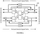
- FIG. 9is a diagram representation of a system of a preferred embodiment.
- FIGS. 10A, 10B and 10Care diagram representations of antenna couplings of a system of a preferred embodiment.
- FIG. 11is a diagram representation of a system of a preferred embodiment.
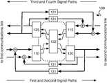
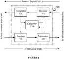
- a relay 100includes a first receiver 110 , a first transmitter 120 , a second receiver 115 , a second transmitter 125 , and a self-interference canceller 130 .
- the relay 100functions to repeat communication signals (and/or information contained in communication signals, herein referred to as “messages”) transmitted and received between two communications systems. In addition to repeating signals, the relay 100 preferably cancels self-interference between transmitted and received signals.
- the relay 100may additionally or alternatively scale (e.g. amplify, attenuate), shift, or otherwise modify signals received or transmitted by the relay 100 .
- the relay 100is preferably used to repeat communication signals traveling bi-directionally between two wireless communication systems (e.g. a cell-phone tower and a cell phone, or a Wi-FiTM access point and a computer, two wireless radios), but may additionally or alternatively be used to repeat communications signals between any other suitable wired or wireless communication systems.
- the relay 100is a one-way relay and includes only a first receiver 110 , a first transmitter 120 , and a self-interference canceller 130 .
- the relay 100is preferably implemented using both digital and analog circuitry.
- Digital circuitryis preferably implemented using a general-purpose processor, a digital signal processor, an application specific integrated circuit (ASIC), a field programmable gate array (FPGA) and/or any suitable processor(s) or circuit(s).
- Analog circuitryis preferably implemented using analog integrated circuits (ICs) but may additionally or alternatively be implemented using discrete components (e.g., capacitors, resistors, transistors), wires, transmission lines, waveguides, digital components, mixed-signal components, or any other suitable components.
- the relay 100preferably includes memory to store configuration data, but may additionally or alternatively be configured using externally stored configuration data or in any suitable manner.
- the relay 100is used as a cellular repeater.
- the relay 100is connected to a cell tower by a first communications link using a first transmit/receive antenna coupled to the relay 100 by a duplexer, and to a cell phone by a second communications link using a second transmit/receive antenna coupled to the relay 100 by a duplexer.
- the cell phone and cell towernatively communicate in an uplink frequency (from phone to tower) and a downlink frequency (from tower to phone).
- the relay 100receives and re-transmits communication on both the uplink frequency (phone to relay to tower) and the downlink frequency (tower to relay to phone).
- the self-interference canceller 130enables full-duplex operation for the first transmit/receive antenna and the second transmit receive/antenna. This is distinct from traditional relays, which must rely on techniques like time-division multiplexing or antenna isolation to avoid self-interference. More specifically, the self-interference canceller 130 may enable the relay 100 to receive downlink communications (from tower to relay), retransmit downlink communications (from relay to phone), receive uplink communications (from phone to relay), and retransmit uplink communications (from relay to tower) simultaneously, without requiring antennas to be isolated from one another, the use of additional frequencies, or the use of time multiplexing (because the self-interference canceller 130 reduces self-interference that may otherwise prohibit such operation). Thus, the relay 100 is able to provide network-relaying capability without excess cost, excess spectrum usage, or significantly decreased data capacity.
- the first receiver 110functions to receive analog receive signals transmitted by a first communications system over a first communications link (e.g., a wireless channel, a coaxial cable).
- the first receiver 110preferably converts analog receive signals into digital receive signals for processing before re-transmission by the first transmitter 120 , but may additionally or alternatively not convert analog receive signals (passing them through directly without conversion).
- the first receiver 110is preferably a radio-frequency (RF) receiver, but may additionally or alternatively be any suitable receiver.
- RFradio-frequency
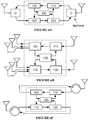
- the first receiver 110is preferably coupled to the first communications link by a duplexer-coupled RF antenna as shown in FIG. 2A , but may additionally or alternatively be coupled to the first communications link in any suitable manner. Some examples of alternative couplings include coupling via one or more dedicated receive antennas (as shown in FIG. 2B ). In another alternative coupling, the first receiver 110 may be coupled to the first communications link by a circulator-coupled RF antenna as shown in FIG. 2C .
- the first receiver 110preferably includes an analog-to-digital converter (ADC) in and a frequency downconverter 112 , as shown in FIG. 3 .
- the first receiver nomay additionally or alternatively include amplifiers, filters, signal processors and/or any other suitable components.
- the first receiver 110includes only analog processing circuitry (e.g., amplifiers, filters, attenuators, delayers). The first receiver may function to scale, shift, and/or otherwise modify the receive signal.
- the downconverter 112functions to downconvert the analog receive signal from RF (or any other suitable frequency) to a baseband analog receive signal, and the analog-to-digital converter (ADC) in functions to convert the baseband analog receive signal to a digital receive signal.
- ADCanalog-to-digital converter
- the ADC 111may be any suitable analog-to-digital converter; e.g., a direct-conversion ADC, a flash ADC, a successive-approximation ADC, a ramp-compare ADC, a Wilkinson ADC, an integrating ADC, a delta-encoded ADC, a time-interleaved ADC, or any other suitable type of ADC.
- a direct-conversion ADCe.g., a flash ADC, a successive-approximation ADC, a ramp-compare ADC, a Wilkinson ADC, an integrating ADC, a delta-encoded ADC, a time-interleaved ADC, or any other suitable type of ADC.
- the frequency downconverter 112functions to downconvert the carrier frequency of the analog receive signal to baseband, preparing it for conversion to a digital receive signal.
- the downconverter 112preferably accomplishes signal downconversion using heterodyning methods, but may additionally or alternatively use any suitable upconversion methods.
- the downconverter 112preferably includes a local oscillator (LO), a mixer, and a baseband filter.
- the local oscillatorfunctions to provide a frequency shift signal to the mixer; the mixer combines the frequency shift signal and the analog receive signal to create (usually two) frequency shifted signals, one of which is the baseband signal, and the baseband filter rejects signals other than the baseband analog receive signal.
- the local oscillatoris preferably a digital crystal variable-frequency oscillator (VFO) but may additionally or alternatively be an analog VFO or any other suitable type of oscillator.
- VFOdigital crystal variable-frequency oscillator
- the local oscillatorpreferably has a tunable oscillation frequency but may additionally or alternatively have a static oscillation frequency.
- the mixeris preferably an active mixer, but may additionally or alternatively be a passive mixer.
- the mixermay comprise discrete components, analog ICs, digital ICs, and/or any other suitable components.
- the mixerpreferably functions to combine two or more electrical input signals into one or more composite outputs, where each output includes some characteristics of at least two input signals.
- the baseband filteris preferably a lowpass filter with a tunable low-pass frequency. Additionally or alternatively, the baseband filter may be a lowpass filter with a set low-pass frequency, or any other suitable type of filter.
- the baseband filteris preferably a passive filter, but may additionally or alternatively be an active filter.
- the baseband filteris preferably implemented with analog circuit components, but may additionally or alternatively be digitally implemented.
- the second receiver 115functions to receive analog receive signals transmitted by a second communications system over a second communications link (e.g., a wireless channel, a coaxial cable).
- the second receiver 115preferably converts analog receive signals into digital receive signals for processing before re-transmission by the second transmitter 125 , but may additionally or alternatively not convert analog receive signals (passing them through directly without conversion).
- the second receiver 115preferably includes an analog-to-digital converter (ADC) 116 and a frequency downconverter 117 , as shown in FIG. 3 .
- ADCanalog-to-digital converter
- the second receiver 115is preferably substantially similar to the first receiver 110 , but may additionally or alternatively be any suitable receiver.
- the first transmitter 120functions to retransmit signals received by the first receiver 110 .
- the first transmitter 120preferably converts digital transmit signals into analog transmit signals, but may additionally or alternatively receive and retransmit analog transmit signals from the first receiver 110 , thus avoiding digital-to-analog conversion.
- the transmit signalsare preferably formed by processing receive signals (which may include analog-to-digital conversion or frequency shifting, for example) by the first receiver 110 , but the transmit signals may additionally or alternatively be any signal intended for transmission by the relay 100 .
- the first transmitter 120preferably transmits signals over a second communications link to a second communications system; these signals are preferably retransmitted signals from a first communication system sent to the relay 100 over a first communications link, but may additionally or alternatively be any suitable signals.
- the first transmitter 120is preferably a radio-frequency (RF) transmitter, but may additionally or alternatively be any suitable transmitter.
- RFradio-frequency
- the first transmitter 120is preferably coupled to the second communications link by a duplexer-coupled RF antenna as shown in FIG. 2A , but may additionally or alternatively be coupled to the second communications link in any suitable manner.
- Some examples of alternative couplingsinclude coupling via one or more dedicated transmit antennas (as shown in FIG. 2B ).
- the first transmitter 120may be coupled to the second communications link by a duplexer-coupled RF antenna as shown in FIG. 2C .
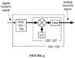
- the first transmitter 120preferably includes a digital-to-analog converter (DAC) 121 and a frequency upconverter 122 , as shown in FIG. 4 .
- the first transmitter 120may additionally or alternatively include amplifiers, filters, signal processors and/or any other suitable components.
- the first transmitter 120may function to scale, shift, and/or otherwise modify the transmit signal.
- the digital-to-analog converter (DAC) 121functions to convert the digital transmit signal to a baseband analog transmit signal
- the upconverter 122functions to upconvert the baseband analog transmit signal from baseband to RF (or any other intended transmission frequency).
- the DAC 121may be any suitable digital-to-analog converter; e.g., a pulse-width modulator, an oversampling DAC, a binary-weighted DAC, an R- 2 R ladder DAC, a cyclic DAC, a thermometer-coded DAC, or a hybrid DAC.
- a pulse-width modulatore.g., a pulse-width modulator, an oversampling DAC, a binary-weighted DAC, an R- 2 R ladder DAC, a cyclic DAC, a thermometer-coded DAC, or a hybrid DAC.
- the frequency upconverter 122functions to upconvert the carrier frequency of the baseband analog transmit signal to a radio frequency, preparing it for transmission over the communications link.
- the upconverter 122preferably accomplishes signal upconversion using heterodyning methods, but may additionally or alternatively use any suitable upconversion methods.
- the upconverter 122preferably includes a local oscillator (LO), a mixer, and an RF filter.
- the local oscillatorfunctions to provide a frequency shift signal to the mixer; the mixer combines the frequency shift signal and the baseband analog transmit signal to create (usually two) frequency shifted signals, one of which is the RF analog transmit signal, and the RF filter rejects signals other than the RF analog transmit signal.
- the local oscillatoris preferably a digital crystal variable-frequency oscillator (VFO) but may additionally or alternatively be an analog VFO or any other suitable type of oscillator.
- VFOdigital crystal variable-frequency oscillator
- the local oscillatorpreferably has a tunable oscillation frequency but may additionally or alternatively have a static oscillation frequency.
- the mixeris preferably an active mixer, but may additionally or alternatively be a passive mixer.
- the mixermay comprise discrete components, analog ICs, digital ICs, and/or any other suitable components.
- the mixerpreferably functions to combine two or more electrical input signals into one or more composite outputs, where each output includes some characteristics of at least two input signals.
- the RF filteris preferably a bandpass filter centered around a tunable radio frequency. Additionally or alternatively, the RF filter may be a bandpass filter centered around a set radio frequency, or any other suitable type of filter.
- the RF filteris preferably a passive filter, but may additionally or alternatively be an active filter.
- the RF filteris preferably implemented with analog circuit components, but may additionally or alternatively be digitally implemented.
- the second transmitter 125functions to retransmit signals received by the second receiver 115 .
- the second transmitter 125preferably converts digital transmit signals into analog transmit signals, but may additionally or alternatively receive and retransmit analog signals from the second receiver 115 , thus avoiding digital-to-analog conversion.
- the transmit signalsare preferably formed by processing receive signals (which may include analog-to-digital conversion or frequency shifting, for example) by the second receiver 115 , but the transmit signals may additionally or alternatively be any signal intended for transmission by the relay 100 .
- the second transmitter 125preferably transmits signals over a first communications link to a first communications system; these signals are preferably retransmitted signals from a second communication system sent to the relay 100 over a second communications link, but may additionally or alternatively be any suitable signals.
- the second transmitter 125preferably includes a digital-to-analog converter (DAC) 126 and a frequency upconverter 127 , as shown in FIG. 4 .
- the second transmitter 125is preferably substantially similar to the first transmitter 120 , but may additionally or alternatively be any suitable transmitter.
- the self-interference canceller 130functions to reduce self-interference in the relay 100 by canceling self-interference components present in receive signals of the relay 100 .
- the self-interference canceller 130preferably includes one or more analog self-interference cancellers 131 ; the self-interference canceller 130 may additionally or alternatively include a digital self-interference canceller 132 , as shown in FIG. 5 .
- Analog self-interference cancellers 131preferably reduce self-interference by sampling an analog transmit signal and generating an analog self-interference cancellation signal based on the input analog transmit signal.
- the analog self-interference cancellation signalis preferably combined with an analog receive signal before the analog receive signal is received by a receiver (e.g., 110 or 115 ), but may additionally or alternatively be combined with the receive signal at any suitable location or time.
- Analog self-interference cancellers 131preferably generate self-interference cancellation signals for a given analog receive signal from a corresponding direction analog transmit signal as shown in FIG. 5 (e.g., the self-interference cancellation signal combined with a re-transmitted uplink signal is preferably generated from the received uplink signal). Additionally or alternatively, analog self-interference cancellers 131 may generate self-interference cancellation signals for a given analog receive signal from any other analog transmit signal.
- self-interference in the downlink receiver occurring from the uplink transmittermay be negligible (or vice versa); however, in situations where the uplink and downlink frequencies are closer, self-interference may occur across channels (e.g., when uplink/downlink channels are in the same frequency band). In these situations it might be desirable to have hetero-channel as well as homo-channel self-interference cancellation, as shown in FIG. 6 .
- the analog self-interference canceller 131is preferably implemented as an analog circuit that transforms an analog transmit signal into an analog self-interference cancellation signal by combining a set of filtered, scaled, and/or delayed versions of the analog transmit signal, but may additionally or alternatively be implemented as any suitable circuit.
- the analog self-interference canceller 131may perform a transformation involving only a single version or copy of the analog transmit signal.
- the transformed signali.e. the analog self-interference cancellation signal
- the analog self-interference canceller 131is preferably adaptable to changing self-interference parameters in addition to changes in the analog transmit signal; for example, transmitter temperature, ambient temperature, antenna configuration, humidity, and transmitter power. Adaptation of the analog self-interference canceller 131 is preferably performed by a control circuit or other control mechanism included in the canceller 131 , but may additionally or alternatively be performed by any suitable controller.
- the analog self-interference canceller 131is preferably coupled to signal paths by short section directional transmission line couplers, but may additionally or alternatively be coupled by any power dividers, power combiners, directional couplers, or other types of signal splitters suitable for coupling signal paths of the relay 100 to the analog self-interference canceller 131 .
- the digital self-interference canceller 132functions to reduce self-interference in the relay 100 by canceling self-interference components present in digital receive signals.
- the digital self-interference canceller 132preferably performs both linear and non-linear digital self-interference cancellation, but alternatively may only perform one of the two.
- the digital self-interference canceller 132preferably reduces digital self-interference by sampling one or more digital transmit signals and generating one or more digital self-interference cancellation signals based on input sampled digital transmit signals (and a transform configuration). Digital self-interference cancellation signals may be combined with corresponding receive signals at any time or location.
- the digital self-interference canceller 132preferably removes self-interference signal components not removed by analog self-interference cancellers 131 .
- the digital self-interference canceller 132preferably samples digital transmit signals of the relay 100 (additionally or alternatively, the canceller 132 may sample analog transmit signals or any other suitable transmit signals) and transforms the digital transmit signals to digital self-interference cancellation signals based on one or more digital transform configurations.
- the digital transform configurationpreferably includes settings that dictate how the digital self-interference canceller 132 transforms a digital transmit signal to a digital self-interference cancellation signal (e.g. coefficients of a generalized memory polynomial used to transform the transmit signal to a self-interference signal).
- the digital self-interference canceller 132preferably generates self-interference cancellation signals for a given digital receive signal from a corresponding direction digital transmit signal as shown in FIG. 7A (e.g., the self-interference cancellation signal combined with a re-transmitted uplink signal is preferably generated from the received uplink signal). Additionally or alternatively, the digital self-interference canceller 132 may generate self-interference cancellation signals for a given digital receive signal from any other transmit signal or combination of transmit signals (including analog transmit signals converted using ADCs).
- self-interference in the downlink receiver occurring from the uplink transmittermay be negligible (or vice versa); however, in situations where the uplink and downlink frequencies are closer, self-interference may occur across channels. In these situations it might be desirable to have hetero-channel as well as homo-channel self-interference cancellation, as shown in FIG. 7B .
- Each self-interference cancellation signal generated by the digital self-interference canceller 132is preferably associated with a configuration transform (e.g., t 1 , t 2 , t 3 , and t 4 of FIGS. 7A and 7B ); additionally or alternatively, configuration transforms may be associated with digital self-interference cancellation signals in any suitable manner.
- a configuration transforme.g., t 1 , t 2 , t 3 , and t 4 of FIGS. 7A and 7B .
- the relay 100may form transmit signals by processing receive signals (e.g., by phase shifting, amplifying, attenuating, frequency shifting, etc.).
- processingmay be performed by relay bases 140 positioned between transmitters and receivers, as shown in FIG. 8 .
- a relay base 140may be a layer 1 (L1) relay, a layer 2 (L2) relay, a layer 3 (L3) relay, or any other suitable relay.
- Relay bases 140preferably function to prepare signals for retransmission; for example, a relay base 140 may reorganize information before retransmitting to increase transmission efficiency.
- a relay base 140may delay a signal before retransmission to time it with a particular transmission window.
- MIMOmultiple-in/multiple-out
- the example relay 100 as shown in FIG. 9represents a 2 ⁇ 2 MIMO system, but it is understood that the relay 100 may additionally or alternatively utilize any suitable number of transmit and receive signals.
- Each signal pathmay have separate antennas; alternatively, signal paths may share antennas via a duplexer or other coupler.
- each signal path of a 2 ⁇ 2 MIMO relayhas four antennas: a TX 1 antenna, a TX 2 antenna, an RX 1 antenna, and an RX 2 antenna, as shown in FIG. 10A .
- each signal path of a 2 ⁇ 2 MIMO systemhas two antennas: a TX 1 /RX 1 antenna (coupled to both TX 1 and RX 1 signal paths via a circulator) and a TX 2 /RX 2 antenna (coupled to both TX 2 and RX 2 signal paths via a circulator), as shown in FIG. 10B .
- each signal path of a 2 ⁇ 2 MIMO systemis again associated with four antennas, but the relay 100 has only four antennas total; a duplexer is used to couple each antenna to both a TX and an RX signal (where the TX and RX signals are from different signal paths), as shown in FIG. 10C .
- each transmitter 120 and 125are preferably implementations having multiple inputs and outputs.
- each transmitterpreferably includes a DAC and frequency upconverter for each transmit signal path; additionally or alternatively, transmit signal paths may share DACs and/or frequency upconverters.
- each transmittermay be any suitable MIMO transmitter; for example, transmitters may include MIMO signal splitting or processing circuitry (which may be used to process a single digital signal into multiple MIMO analog signals).
- the first and second receivers 110 and 115are preferably implementations having multiple inputs and outputs.
- each receiverpreferably includes an ADC and frequency downconverter for each receive signal path; additionally or alternatively, receive signal paths may share ADCs and/or frequency downconverters.
- receiversmay be any suitable MIMO receiver; for example, receivers may include MIMO signal splitting or processing circuitry (which may be used to process multiple MIMO analog signals into a single digital signal).
- the relay 100preferably includes analog self-interference cancellers 131 for each pair of receive/transmit signals, as shown in FIG. 9 .
- self-interferencemay occur across communications streams in addition to in them; for example, a TX 1 signal may cause interference in both of RX 1 and RX 2 signals.
- the relay 100may additionally or alternatively include analog self-interference cancellers 131 for self-interference cancellation across communications streams, as shown in FIG. 11 .
- Cross-stream cancellationmay additionally or alternatively be combined with cross-directional cancellation (which is as shown in FIG. 6 ).
- the digital self-interference canceller 132may perform digital self-interference cancellation on each MIMO digital receive signal, but may additionally or alternatively perform digital self-interference cancellation on a combined digital receive signal (resulting from the combination of MIMO digital receive signals). If the digital self-interference canceller 132 performs self-interference cancellation for multiple MIMO digital receive signals, cancellation may be performed for each TX/RX pairing, similarly to those described in the section on the analog self-interference canceller 131 .
Landscapes
- Engineering & Computer Science (AREA)
- Computer Networks & Wireless Communication (AREA)
- Signal Processing (AREA)
- Radio Relay Systems (AREA)
- Transceivers (AREA)
- Cable Transmission Systems, Equalization Of Radio And Reduction Of Echo (AREA)
Abstract
Description
Claims (19)
Priority Applications (1)
| Application Number | Priority Date | Filing Date | Title |
|---|---|---|---|
| US16/202,830US10979131B2 (en) | 2013-08-29 | 2018-11-28 | Self-interference-cancelled full-duplex relays |
Applications Claiming Priority (3)
| Application Number | Priority Date | Filing Date | Title |
|---|---|---|---|
| US201361871519P | 2013-08-29 | 2013-08-29 | |
| US14/473,653US10177836B2 (en) | 2013-08-29 | 2014-08-29 | Radio frequency self-interference-cancelled full-duplex relays |
| US16/202,830US10979131B2 (en) | 2013-08-29 | 2018-11-28 | Self-interference-cancelled full-duplex relays |
Related Parent Applications (1)
| Application Number | Title | Priority Date | Filing Date |
|---|---|---|---|
| US14/473,653ContinuationUS10177836B2 (en) | 2013-08-29 | 2014-08-29 | Radio frequency self-interference-cancelled full-duplex relays |
Publications (2)
| Publication Number | Publication Date |
|---|---|
| US20190097716A1 US20190097716A1 (en) | 2019-03-28 |
| US10979131B2true US10979131B2 (en) | 2021-04-13 |
Family
ID=52583149
Family Applications (2)
| Application Number | Title | Priority Date | Filing Date |
|---|---|---|---|
| US14/473,653ActiveUS10177836B2 (en) | 2013-08-29 | 2014-08-29 | Radio frequency self-interference-cancelled full-duplex relays |
| US16/202,830ActiveUS10979131B2 (en) | 2013-08-29 | 2018-11-28 | Self-interference-cancelled full-duplex relays |
Family Applications Before (1)
| Application Number | Title | Priority Date | Filing Date |
|---|---|---|---|
| US14/473,653ActiveUS10177836B2 (en) | 2013-08-29 | 2014-08-29 | Radio frequency self-interference-cancelled full-duplex relays |
Country Status (6)
| Country | Link |
|---|---|
| US (2) | US10177836B2 (en) |
| EP (1) | EP3039798A4 (en) |
| JP (1) | JP6183939B2 (en) |
| KR (1) | KR102200942B1 (en) |
| CN (1) | CN105493416A (en) |
| WO (1) | WO2015031830A1 (en) |
Cited By (1)
| Publication number | Priority date | Publication date | Assignee | Title |
|---|---|---|---|---|
| US12113603B2 (en) | 2013-08-29 | 2024-10-08 | Qualcomm Incorporated | Optically enhanced self-interference cancellation |
Families Citing this family (49)
| Publication number | Priority date | Publication date | Assignee | Title |
|---|---|---|---|---|
| US7876869B1 (en) | 2007-05-23 | 2011-01-25 | Hypers, Inc. | Wideband digital spectrometer |
| US9997830B2 (en) | 2012-05-13 | 2018-06-12 | Amir Keyvan Khandani | Antenna system and method for full duplex wireless transmission with channel phase-based encryption |
| WO2013173250A1 (en) | 2012-05-13 | 2013-11-21 | Invention Mine Llc | Full duplex wireless transmission with self-interference cancellation |
| US10177896B2 (en) | 2013-05-13 | 2019-01-08 | Amir Keyvan Khandani | Methods for training of full-duplex wireless systems |
| WO2015031830A1 (en) | 2013-08-29 | 2015-03-05 | Kumu Networks, Inc. | Full-duplex relays |
| US9236996B2 (en) | 2013-11-30 | 2016-01-12 | Amir Keyvan Khandani | Wireless full-duplex system and method using sideband test signals |
| US9413516B2 (en) | 2013-11-30 | 2016-08-09 | Amir Keyvan Khandani | Wireless full-duplex system and method with self-interference sampling |
| US9820311B2 (en) | 2014-01-30 | 2017-11-14 | Amir Keyvan Khandani | Adapter and associated method for full-duplex wireless communication |
| WO2015196398A1 (en)* | 2014-06-26 | 2015-12-30 | 华为技术有限公司 | Wireless communication method and system, and full-duplex wireless transceiver |
| CA2952837C (en) | 2014-08-15 | 2019-07-30 | SEAKR Engineering, Inc. | Integrated mixed-signal asic with adc, dac, and dsp |
| US10917163B2 (en) | 2014-08-15 | 2021-02-09 | SEAKR Engineering, Inc. | Integrated mixed-signal RF transceiver with ADC, DAC, and DSP and high-bandwidth coherent recombination |
| WO2016156949A1 (en)* | 2015-03-27 | 2016-10-06 | Andrew Wireless Systems Gmbh | Repeater system for use on a movable object |
| US10447505B2 (en)* | 2015-05-29 | 2019-10-15 | Lg Electronics Inc. | Method for performing self-interference cancellation in FDR environment and device for same |
| CN105262573B (en)* | 2015-09-08 | 2018-03-06 | 西安电子科技大学 | The space-time own coding method of full duplex bilateral relay network |
| WO2017106209A1 (en) | 2015-12-13 | 2017-06-22 | GenXComm, Inc. | Interference cancellation methods and apparatus |
| EP3239732B1 (en)* | 2016-04-29 | 2019-10-23 | IMEC vzw | Improvements relating to a multiple input multiple output radar system |
| US10333593B2 (en) | 2016-05-02 | 2019-06-25 | Amir Keyvan Khandani | Systems and methods of antenna design for full-duplex line of sight transmission |
| US10257746B2 (en)* | 2016-07-16 | 2019-04-09 | GenXComm, Inc. | Interference cancellation methods and apparatus |
| US10142137B2 (en) | 2017-03-02 | 2018-11-27 | Micron Technology, Inc. | Wireless devices and systems including examples of full duplex transmission |
| US10700766B2 (en) | 2017-04-19 | 2020-06-30 | Amir Keyvan Khandani | Noise cancelling amplify-and-forward (in-band) relay with self-interference cancellation |
| KR102608862B1 (en)* | 2017-04-24 | 2023-12-01 | 한국전자통신연구원 | Method and apparatus of wireless transmission and reception for a hybrid of sensing and communication |
| EP3627724A4 (en)* | 2017-06-26 | 2020-06-17 | Guangdong Oppo Mobile Telecommunications Corp., Ltd. | Wireless communication method and device |
| US10673518B2 (en)* | 2017-06-27 | 2020-06-02 | Wilson Electronics, Llc | Crossover isolation reduction in a signal booster |
| US11941516B2 (en) | 2017-08-31 | 2024-03-26 | Micron Technology, Inc. | Cooperative learning neural networks and systems |
| US10554375B2 (en) | 2017-09-11 | 2020-02-04 | Micron Technology, Inc. | Full duplex device-to-device cooperative communication |
| US11057204B2 (en) | 2017-10-04 | 2021-07-06 | Amir Keyvan Khandani | Methods for encrypted data communications |
| US11012144B2 (en) | 2018-01-16 | 2021-05-18 | Amir Keyvan Khandani | System and methods for in-band relaying |
| US11206050B2 (en) | 2018-02-06 | 2021-12-21 | Micron Technology, Inc. | Self interference noise cancellation to support multiple frequency bands |
| US10879995B2 (en) | 2018-04-10 | 2020-12-29 | Wilson Electronics, Llc | Feedback cancellation on multiband booster |
| KR102175362B1 (en)* | 2018-11-07 | 2020-11-06 | 주식회사 랜컴테크놀로지 | Apparatus and method for half duplex wireless repeaters |
| US11923952B2 (en) | 2018-12-10 | 2024-03-05 | Intel Corporation | Distributed relay |
| US11150409B2 (en) | 2018-12-27 | 2021-10-19 | GenXComm, Inc. | Saw assisted facet etch dicing |
| US10771166B1 (en)* | 2019-05-20 | 2020-09-08 | Telefonaktiebolaget Lm Ericsson (Publ) | Radio relay arrangement |
| US10727945B1 (en) | 2019-07-15 | 2020-07-28 | GenXComm, Inc. | Efficiently combining multiple taps of an optical filter |
| US10979097B2 (en) | 2019-09-05 | 2021-04-13 | Micron Technology, Inc. | Wireless devices and systems including examples of full duplex transmission using neural networks or recurrent neural networks |
| US11215755B2 (en) | 2019-09-19 | 2022-01-04 | GenXComm, Inc. | Low loss, polarization-independent, large bandwidth mode converter for edge coupling |
| US11539394B2 (en) | 2019-10-29 | 2022-12-27 | GenXComm, Inc. | Self-interference mitigation in in-band full-duplex communication systems |
| US11563481B2 (en) | 2019-11-13 | 2023-01-24 | Electronics And Telecommunications Research Institute | Method and apparatus for relay based on multiple beams in vehicle-to-everything communication system |
| EP3863191A1 (en) | 2020-02-04 | 2021-08-11 | Nokia Solutions and Networks Oy | Communication system |
| CN111585594B (en)* | 2020-03-27 | 2021-10-26 | 中国人民解放军海军工程大学 | Interference cancellation device and method based on cascade digital control method |
| US11258473B2 (en) | 2020-04-14 | 2022-02-22 | Micron Technology, Inc. | Self interference noise cancellation to support multiple frequency bands with neural networks or recurrent neural networks |
| CN111865844B (en)* | 2020-05-29 | 2023-06-06 | 北京百卓网络技术有限公司 | Channel estimation method and device for massive MIMO full-duplex relay system |
| CN114070420B (en)* | 2020-07-31 | 2023-04-07 | 华为技术有限公司 | Anti-interference electronic equipment and anti-interference method |
| US11796737B2 (en) | 2020-08-10 | 2023-10-24 | GenXComm, Inc. | Co-manufacturing of silicon-on-insulator waveguides and silicon nitride waveguides for hybrid photonic integrated circuits |
| US12001065B1 (en) | 2020-11-12 | 2024-06-04 | ORCA Computing Limited | Photonics package with tunable liquid crystal lens |
| US12057873B2 (en) | 2021-02-18 | 2024-08-06 | GenXComm, Inc. | Maximizing efficiency of communication systems with self-interference cancellation subsystems |
| EP4331120A1 (en) | 2021-04-29 | 2024-03-06 | Genxcomm, Inc. | Self-interference cancellation subsystems for mesh network nodes |
| CN113437992A (en)* | 2021-06-30 | 2021-09-24 | 展讯通信(上海)有限公司 | Radio frequency transceiver circuit |
| CA3234722A1 (en) | 2021-10-25 | 2023-05-04 | Farzad Mokhtari-Koushyar | Hybrid photonic integrated circuits for ultra-low phase noise signal generators |
Citations (178)
| Publication number | Priority date | Publication date | Assignee | Title |
|---|---|---|---|---|
| US3922617A (en) | 1974-11-18 | 1975-11-25 | Cutler Hammer Inc | Adaptive feed forward system |
| US4321624A (en) | 1978-10-30 | 1982-03-23 | Rca Corporation | AFT Circuit |
| US4952193A (en) | 1989-03-02 | 1990-08-28 | American Nucleonics Corporation | Interference cancelling system and method |
| US5212827A (en) | 1991-02-04 | 1993-05-18 | Motorola, Inc. | Zero intermediate frequency noise blanker |
| EP0755141A2 (en) | 1995-07-19 | 1997-01-22 | Sharp Kabushiki Kaisha | Adaptive decision feedback equalization for communication systems |
| US5691978A (en) | 1995-04-07 | 1997-11-25 | Signal Science, Inc. | Self-cancelling full-duplex RF communication system |
| US5734967A (en) | 1994-02-17 | 1998-03-31 | Motorola, Inc. | Method and apparatus for reducing self interference in a communication system |
| US5790658A (en) | 1996-10-28 | 1998-08-04 | Advanced Micro Devices, Inc. | High performance echo canceller for high speed modem |
| US5818385A (en) | 1994-06-10 | 1998-10-06 | Bartholomew; Darin E. | Antenna system and method |
| US5930301A (en) | 1996-06-25 | 1999-07-27 | Harris Corporation | Up-conversion mechanism employing side lobe-selective pre-distortion filter and frequency replica-selecting bandpass filter respectively installed upstream and downstream of digital-to-analog converter |
| US6215812B1 (en) | 1999-01-28 | 2001-04-10 | Bae Systems Canada Inc. | Interference canceller for the protection of direct-sequence spread-spectrum communications from high-power narrowband interference |
| US6240150B1 (en) | 1998-05-12 | 2001-05-29 | Nortel Networks Limited | Method and apparatus for filtering interference in a modem receiver |
| US6317583B1 (en) | 1997-07-25 | 2001-11-13 | Trw Inc. | Telecommunications satellite channelizer |
| US20020034191A1 (en) | 1998-02-12 | 2002-03-21 | Shattil Steve J. | Method and apparatus for transmitting and receiving signals having a carrier interferometry architecture |
| US20020064245A1 (en) | 2000-10-10 | 2002-05-30 | Mccorkle John W. | Ultra wide bandwidth noise cancellation mechanism and method |
| US6411250B1 (en) | 1997-09-01 | 2002-06-25 | Cambridge Consultants Limited | Electromagnetic sensor system |
| CN1373562A (en) | 2001-03-06 | 2002-10-09 | 松下电器产业株式会社 | Relay unit |
| US20020154717A1 (en)* | 2000-12-19 | 2002-10-24 | Telefonaktiebolaget Lm Ericsson (Publ) | Weighting factor setting method for subtractive interference canceller, interference canceller unit using said weighting factor and interference canceller |
| US20020172265A1 (en) | 2001-03-30 | 2002-11-21 | Kenney Thomas J. | Successive user data multipath interference cancellation |
| US20030031279A1 (en) | 2001-08-08 | 2003-02-13 | Viasat, Inc. | Method and apparatus for relayed communication using band-pass signals for self-interference cancellation |
| US6539204B1 (en) | 2000-09-29 | 2003-03-25 | Mobilian Corporation | Analog active cancellation of a wireless coupled transmit signal |
| US6567649B2 (en) | 2000-08-22 | 2003-05-20 | Novatel Wireless, Inc. | Method and apparatus for transmitter noise cancellation in an RF communications system |
| US20030099287A1 (en) | 2001-10-31 | 2003-05-29 | Bernard Arambepola | Method of and apparatus for detecting impulsive noise, method of operating a demodulator, demodulator and radio receiver |
| US20030104787A1 (en) | 2001-12-05 | 2003-06-05 | Viasat, Inc. | Multi-channel self-interference cancellation method and apparatus for relayed communication |
| US20030148748A1 (en) | 2002-02-01 | 2003-08-07 | Shah Peter Jivan | Distortion reduction in a wireless communication device |
| US6639551B2 (en) | 1999-08-11 | 2003-10-28 | China Academy Of Telecommunications Technology | Method of interference cancellation based on smart antenna |
| US6657950B1 (en) | 1999-02-19 | 2003-12-02 | Cisco Technology, Inc. | Optimal filtering and upconversion in OFDM systems |
| US20040106381A1 (en) | 2002-09-06 | 2004-06-03 | Engim Incorporated | Transmit signal cancellation in wireless receivers |
| US20040266378A1 (en) | 2001-08-10 | 2004-12-30 | Keisuke Fukamachi | Bypass filter, multi-band antenna switch circuit, and layered module composite part and communication device using them |
| US20050078743A1 (en) | 1999-08-10 | 2005-04-14 | Aki Shohara | Radio frequency control for communication systems |
| US20050129152A1 (en) | 2003-12-15 | 2005-06-16 | Hillstrom Timothy L. | Method and sytem for noise reduction in measurement receivers using automatic noise subtraction |
| US6915112B1 (en) | 2000-11-12 | 2005-07-05 | Intel Corporation | Active cancellation tuning to reduce a wireless coupled transmit signal |
| US20050159128A1 (en) | 2001-06-21 | 2005-07-21 | Collins Glenn D. | Adaptive canceller for frequency reuse systems |
| US20050250466A1 (en) | 2004-04-26 | 2005-11-10 | Hellosoft Inc. | Method and apparatus for improving MLSE in the presence of co-channel interferer for GSM/GPRS systems |
| US6965657B1 (en) | 1999-12-01 | 2005-11-15 | Velocity Communication, Inc. | Method and apparatus for interference cancellation in shared communication mediums |
| US20050254555A1 (en) | 2004-05-17 | 2005-11-17 | Teague Edward H | Interference control via selective blanking/attenuation of interfering transmissions |
| US20050282500A1 (en) | 2004-06-16 | 2005-12-22 | Wang Yi-Pin E | Benign interference suppression for received signal quality estimation |
| US20060029124A1 (en) | 2004-08-04 | 2006-02-09 | Telefonaktiebolaget Lm Ericsson (Publ) | Reduced complexity soft value generation for MIMO JD-GRAKE receivers |
| US20060030277A1 (en) | 2004-02-10 | 2006-02-09 | Cyr Russell J | Programmable radio transceiver |
| US20060058022A1 (en) | 2004-08-27 | 2006-03-16 | Mark Webster | Systems and methods for calibrating transmission of an antenna array |
| US20060083297A1 (en) | 2004-10-13 | 2006-04-20 | Analog Devices, Inc. | Filters for communication systems |
| US20060209754A1 (en) | 2005-03-16 | 2006-09-21 | Ji Tingfang | Channel structures for a quasi-orthogonal multiple-access communication system |
| US20060273853A1 (en) | 2005-06-03 | 2006-12-07 | Ntt Docomo, Inc. | Feed forward amplifier for multiple frequency bands |
| US20070018722A1 (en) | 2005-07-21 | 2007-01-25 | Alcatel | Adaptive digital pre-distortion system |
| US20070105509A1 (en) | 2005-11-09 | 2007-05-10 | Texas Instruments Inc. | RF transmission leakage mitigator, method of mitigating an RF transmission leakage and CDMA tranceiver employing the same |
| JP2007180597A (en) | 2004-09-01 | 2007-07-12 | Nokia Corp | Repeater and relay method |
| US20070207747A1 (en) | 2006-03-06 | 2007-09-06 | Paul Johnson | Single frequency duplex radio link |
| US20070249314A1 (en) | 2004-03-19 | 2007-10-25 | Sirit Technologies Inc. | Adjusting parameters associated with transmitter leakage |
| US20070274372A1 (en) | 2006-05-29 | 2007-11-29 | Tokyo Institute Of Technology | Radio communication apparatus and radio communication method |
| US20080037801A1 (en) | 2006-08-10 | 2008-02-14 | Cambridge Silicon Radio, Ltd. | Dual microphone noise reduction for headset application |
| US7336940B2 (en) | 2003-11-07 | 2008-02-26 | Andrew Corporation | Frequency conversion techniques using antiphase mixing |
| US20080089397A1 (en) | 2006-10-17 | 2008-04-17 | Interdigital Technology Corporation | Transceiver with hybrid adaptive self-interference canceller for removing transmitter generated noise to prevent modem jamming |
| US7362257B2 (en) | 2004-12-23 | 2008-04-22 | Radix Technology, Inc. | Wideband interference cancellation using DSP algorithms |
| US20080107046A1 (en) | 2006-11-06 | 2008-05-08 | Nokia Corporation | Analog signal path modeling for self-interference cancellation |
| US20080111754A1 (en) | 2006-11-13 | 2008-05-15 | The Boeing Company | Electronically scanned antenna with secondary phase shifters |
| US20080131133A1 (en) | 2006-05-17 | 2008-06-05 | Blunt Shannon D | Low sinr backscatter communications system and method |
| US20080144852A1 (en) | 2006-12-14 | 2008-06-19 | Ford Global Technologies, Llc | Multi-chamber noise control system |
| US20080192636A1 (en) | 2005-02-07 | 2008-08-14 | Briscoe Robert J | Policing Networks |
| US20080219339A1 (en) | 2007-03-09 | 2008-09-11 | Qualcomm Incorporated | Channel estimation using frequency smoothing |
| US20080219377A1 (en) | 2007-03-06 | 2008-09-11 | Sige Semiconductor Inc. | Transmitter crosstalk cancellation in multi-standard wireless transceivers |
| WO2008108528A1 (en) | 2007-03-06 | 2008-09-12 | Airpoint | Wireless repeater apparatus for canceling interference signal |
| US7426242B2 (en) | 2003-08-04 | 2008-09-16 | Viasat, Inc. | Orthogonal frequency digital multiplexing correlation canceller |
| US20090022089A1 (en) | 2007-07-16 | 2009-01-22 | Rudrapatna Ashok N | Architecture to support network-wide multiple-in-multiple-out wireless communication |
| US20090034437A1 (en) | 2007-07-31 | 2009-02-05 | Samsung Electronics Co., Ltd. | Apparatus and method for canceling interference in relay station in a communication system |
| EP1959625B1 (en) | 2007-02-14 | 2009-02-18 | NTT DoCoMo Inc. | Receiver apparatus for detecting narrowband interference in a multi-carrier receive signal |
| US20090047914A1 (en) | 2003-05-27 | 2009-02-19 | Interdigital Technology Corporation | Multi-mode radio with interference cancellation circuit |
| US7509100B2 (en) | 2001-04-11 | 2009-03-24 | Kyocera Wireless Corp. | Antenna interface unit |
| US20090115912A1 (en) | 2007-11-05 | 2009-05-07 | Mediatek Inc. | Television signal receiver capable of cancelling linear and non-linear distortion |
| US20090180404A1 (en) | 2008-01-14 | 2009-07-16 | Samsung Electronics Co., Ltd. | Apparatus and method for interference cancellation and synchronization maintenance over interference channel estimation in communication system based on full-duplex relay |
| US20090186582A1 (en) | 2008-01-22 | 2009-07-23 | Khurram Muhammad | System and method for transmission interference cancellation in full duplex transceiver |
| US20090221231A1 (en) | 2008-02-29 | 2009-09-03 | The Hong Kong University Of Science And Technology | Multi-user mimo relay protocol with self-interference cancellation |
| US20090303908A1 (en) | 2008-06-04 | 2009-12-10 | Budhaditya Deb | System and method for adjusting media access control parameters in a wireless network |
| US20090325509A1 (en) | 2008-06-27 | 2009-12-31 | Sven Mattisson | Methods and Apparatus for Reducing Own-Transmitter Interference in Low-IF and Zero-IF Receivers |
| US20100014614A1 (en) | 2006-07-28 | 2010-01-21 | Mstar Semiconductor, Inc. | Digital Radio Systems |
| US20100014600A1 (en) | 2008-07-18 | 2010-01-21 | Advanced Micro Devices, Inc. | Window position optimization for pilot-aided ofdm system |
| US20100022201A1 (en) | 2008-07-22 | 2010-01-28 | Patrick Vandenameele | Apparatus and method for reducing self-interference in a radio system |
| US20100031036A1 (en) | 2007-12-21 | 2010-02-04 | Harris Corporation | Secure wireless communications system and related method |
| US20100056166A1 (en) | 2006-11-07 | 2010-03-04 | Qualcomm Incorporated | Method and Apparatus for Reinforcement of Broadcast Transmissions in MBSFN Inactive Areas |
| US20100105320A1 (en) | 2008-10-23 | 2010-04-29 | Fujitsu Limited | Wireless relay device |
| US20100103900A1 (en) | 2006-12-08 | 2010-04-29 | Choong-Il Yeh | Beamforming method and device |
| US20100117693A1 (en) | 2008-11-07 | 2010-05-13 | Viasat, Inc. | Dual conversion transmitter with single local oscillator |
| US20100136900A1 (en) | 2008-12-02 | 2010-06-03 | Fujitsu Limited | Radio Relay Device and Method |
| US20100150033A1 (en) | 2008-12-16 | 2010-06-17 | General Electric Company | Software radio frequency canceller |
| US20100150070A1 (en) | 2008-12-16 | 2010-06-17 | Electronics And Telecommunication Research Institute | Sensor node having self localization function and self localization method thereof |
| US20100159858A1 (en) | 2008-12-19 | 2010-06-24 | Paul Wilkinson Dent | Strong Signal Tolerant OFDM Receiver and Receiving Methods |
| US20100215124A1 (en) | 2009-02-24 | 2010-08-26 | Samsung Electronics Co., Ltd. | Apparatus and operating method of digital rf receiver in a wireless communication system |
| US20100226448A1 (en) | 2009-03-05 | 2010-09-09 | Paul Wilkinson Dent | Channel extrapolation from one frequency and time to another |
| US20100232324A1 (en) | 2009-03-16 | 2010-09-16 | Microsoft Corporation | Full-Duplex Wireless Communications |
| EP2237434A1 (en) | 2009-04-02 | 2010-10-06 | Thales Nederland B.V. | An apparatus for emitting and receiving radio-frequency signals, comprising a circuit to cancel interferences |
| US20100279602A1 (en) | 2007-12-21 | 2010-11-04 | Telefonaktiebolaget Lm Ericsson (Publ) | Node and a Method for use in a Wireless Communications System |
| US20100295716A1 (en) | 2009-05-19 | 2010-11-25 | Kabushiki Kaisha Toshiba | Interference reduction device |
| EP2267946A2 (en) | 2009-06-23 | 2010-12-29 | Uniloc Usa, Inc. | System and method for traffic information delivery |
| US20110013684A1 (en) | 2009-07-14 | 2011-01-20 | Nokia Corporation | Channel estimates in a SIC receiver for a multi-transmitter array transmission scheme |
| US20110026509A1 (en) | 2008-04-25 | 2011-02-03 | Akio Tanaka | Wireless communication apparatus |
| US20110081880A1 (en) | 2009-10-01 | 2011-04-07 | Samsung Electronics Co. Ltd. | Wideband receiver for wireless communication system and method for controlling the same |
| US20110149714A1 (en) | 2009-12-21 | 2011-06-23 | Qualcomm Incorporated | Method and apparatus for adaptive non-linear self-jamming interference cancellation |
| US20110171922A1 (en) | 2010-01-08 | 2011-07-14 | Samsung Electro-Mechanics Company | Systems, methods, and apparatuses for reducing interference at the front-end of a communications receiving device |
| US20110195657A1 (en) | 2010-02-10 | 2011-08-11 | Kabushiki Kaisha Toshiba | Radio relay apparatus |
| US20110216813A1 (en) | 2008-11-14 | 2011-09-08 | Telefonaktiebolaget Lm Ericsson (Publ) | Method and Arrangement in a Communication System |
| US20110222631A1 (en) | 2010-03-11 | 2011-09-15 | Samsung Electronics Co., Ltd. | Apparatus for receiving signal and method of compensating phase mismatch thereof |
| US8027642B2 (en) | 2004-04-06 | 2011-09-27 | Qualcomm Incorporated | Transmission canceller for wireless local area network |
| US20110243202A1 (en) | 2010-04-01 | 2011-10-06 | Ismail Lakkis | Cancellation System for Millimeter-Wave Radar |
| US20110250858A1 (en) | 2010-04-08 | 2011-10-13 | Qualcomm Incorporated | Frequency selection and transition over white space |
| US20110254639A1 (en) | 2008-12-26 | 2011-10-20 | Taiyo Yuden Co., Ltd. | Duplexer and electronic device |
| US20110256857A1 (en) | 2010-04-20 | 2011-10-20 | Intersil Americas Inc. | Systems and Methods for Improving Antenna Isolation Using Signal Cancellation |
| US20110268232A1 (en) | 2010-05-03 | 2011-11-03 | Chester Park | Inter-carrier bandwidth control for mitigating iq imbalance |
| US8055235B1 (en) | 2008-05-02 | 2011-11-08 | Hypres, Inc. | System and method for digital interference cancellation |
| US8060803B2 (en) | 2006-05-16 | 2011-11-15 | Nokia Corporation | Method, apparatus and computer program product providing soft iterative recursive least squares (RLS) channel estimator |
| US20110311067A1 (en) | 2009-02-13 | 2011-12-22 | University Of Florida Research Foundation, Inc. | Digital sound leveling device and method to reduce the risk of noise induced hearing loss |
| US8086191B2 (en) | 2007-05-07 | 2011-12-27 | Ntt Docomo, Inc. | Leakage power reduction apparatus |
| US20110319044A1 (en) | 2010-06-28 | 2011-12-29 | Itt Manufacturing Enterprises, Inc. (A Subsidiary Of Itt Corporation) | Adaptive cancellation of multi-path interferences |
| US20120021153A1 (en) | 2010-07-21 | 2012-01-26 | Bhandari Yashpal J | Silicone Polyimide Compositions With Improved Flame Retardance |
| US20120063373A1 (en) | 2010-09-15 | 2012-03-15 | Interdigital Patent Holdings, Inc. | Method and apparatus for dynamic bandwidth provisioning in frequency division duplex systems |
| US20120063369A1 (en) | 2010-09-14 | 2012-03-15 | Qualcomm Incorporated | Method and apparatus for mitigating relay interference |
| US8155595B2 (en) | 2009-03-06 | 2012-04-10 | Ntt Docomo, Inc. | Method for iterative interference cancellation for co-channel multi-carrier and narrowband systems |
| US8175535B2 (en) | 2008-02-27 | 2012-05-08 | Telefonaktiebolaget Lm Ericsson (Publ) | Active cancellation of transmitter leakage in a wireless transceiver |
| US8179990B2 (en) | 2008-01-16 | 2012-05-15 | Mitsubishi Electric Research Laboratories, Inc. | Coding for large antenna arrays in MIMO networks |
| US20120140685A1 (en) | 2010-12-01 | 2012-06-07 | Infineon Technologies Ag | Simplified adaptive filter algorithm for the cancellation of tx-induced even order intermodulation products |
| US20120147790A1 (en) | 2010-12-13 | 2012-06-14 | Nec Laboratories America, Inc. | Method for a Canceling Self Interference Signal Using Active Noise Cancellation in RF Circuits and Transmission Lines for Full Duplex Simultaneous (In Time) and Overlapping (In Space) Wireless Transmission & Reception on the Same Frequency band |
| US8218697B2 (en) | 2005-11-15 | 2012-07-10 | Rambus Inc. | Iterative interference cancellation for MIMO-OFDM receivers |
| US20120201173A1 (en) | 2011-02-03 | 2012-08-09 | Mayank Jain | Single channel full duplex wireless communications |
| US20120224497A1 (en) | 2011-03-03 | 2012-09-06 | Telefonaktiebolaget L M Ericsson (Publ) | Signal Quality Measurement Based On Transmitter Status |
| CN102694562A (en) | 2011-05-17 | 2012-09-26 | 杭州畅鼎科技有限公司 | Method of adaptive interference cancellation by utilizing improved variable step size NLMS algorithm |
| US8331477B2 (en) | 2009-07-16 | 2012-12-11 | Industrial Technology Research Institute | Progressive parallel interference canceller and method and receiver thereof |
| US20130005284A1 (en) | 2010-03-23 | 2013-01-03 | Telefonaktiebolaget Lm Ericsson (Publ) | Circuit and Method for Interference Reduction |
| US8351533B2 (en) | 2009-04-16 | 2013-01-08 | Intel Corporation | Group resource allocation techniques for IEEE 802.16m |
| US20130044791A1 (en) | 2011-08-18 | 2013-02-21 | Qualcomm Incorporated | Joint linear and non-linear cancellation of transmit self-jamming interference |
| US8385871B2 (en) | 2008-12-01 | 2013-02-26 | Rockstar Consortium Us Lp | Frequency agile filter using a digital filter and bandstop filtering |
| US20130056270A1 (en) | 2010-05-11 | 2013-03-07 | John Michael Ward | Subsea noise mitigation systems and methods |
| US20130089009A1 (en)* | 2011-09-19 | 2013-04-11 | Li Erran Li | Method and apparatus for interference cancellation for antenna arrays |
| US8422540B1 (en) | 2012-06-21 | 2013-04-16 | CBF Networks, Inc. | Intelligent backhaul radio with zero division duplexing |
| WO2013056270A1 (en) | 2011-10-13 | 2013-04-18 | Physical Devices Llc | Methods, systems, and non-transitory computer readable media for wideband frequency and bandwidth tunable filtering |
| US20130102254A1 (en)* | 2010-05-27 | 2013-04-25 | Ubiquam Ltd. | Method and system of interference cancelation in collocated transceivers configurations |
| US20130114468A1 (en) | 2011-11-07 | 2013-05-09 | Dennis Hui | Dynamic space division duplex (sdd) wireless communications with multiple antennas using self-interference cancellation |
| US20130155913A1 (en) | 2011-12-14 | 2013-06-20 | Redline Communications Inc. | Single channel full duplex wireless communication |
| US20130166259A1 (en) | 2011-11-17 | 2013-06-27 | Analog Devices, Inc. | System linearization |
| WO2013095386A1 (en) | 2011-12-20 | 2013-06-27 | Intel Corporation | Techniques to simultaneously transmit and receive over the same radio-frequency carrier |
| US20130194984A1 (en) | 2012-01-16 | 2013-08-01 | Huawei Technologies Co., Ltd. | Method and apparatus for handling full-duplex interference |
| US20130215805A1 (en) | 2012-02-08 | 2013-08-22 | The Board Of Trustees Of The Leland Stanford Junior University | Systems and Methods for Full-Duplex Signal Shaping |
| US20130225101A1 (en) | 2012-02-27 | 2013-08-29 | Intel Mobile Communications GmbH | Second-order filter with notch for use in receivers to effectively suppress the transmitter blockers |
| US20130253917A1 (en) | 2010-12-09 | 2013-09-26 | Dolby International Ab | Psychoacoustic filter design for rational resamplers |
| US20130259343A1 (en) | 2012-03-28 | 2013-10-03 | Siemens Corporation | Alternating direction of multipliers method for parallel mri reconstruction |
| US20130294523A1 (en) | 2011-07-21 | 2013-11-07 | Luca Rossato | Signal processing and tiered signal encoding |
| US20130301487A1 (en) | 2012-05-13 | 2013-11-14 | Amir Keyvan Khandani | Full Duplex Wireless Transmission with Self-Interference Cancellation |
| US20130301488A1 (en)* | 2012-02-08 | 2013-11-14 | The Board Of Trustees Of The Leland Stanford Junior University | Systems and methods for cancelling interference using multiple attenuation delays |
| US20130308717A1 (en) | 2012-04-13 | 2013-11-21 | Alexander Maltsev | Millimeter-wave transceiver with coarse and fine beamforming with interference suppression and method |
| WO2013185106A1 (en) | 2012-06-08 | 2013-12-12 | The Board Of Trustees Of The Leland Stanford Junior University | Systems and methods for cancelling interference using multiple attenuation delays |
| US20140011461A1 (en) | 2012-07-03 | 2014-01-09 | Infineon Technologies Ag | System and Method for Attenuating a Signal in a Radio Frequency System |
| US20140016515A1 (en) | 2012-07-13 | 2014-01-16 | At&T Intellectual Property I, L.P. | System and method for full duplex cancellation |
| US20140126437A1 (en) | 2012-11-07 | 2014-05-08 | Qualcomm Incorporated | Methods and apparatus for communication mode selection based on content type |
| US8755756B1 (en) | 2009-04-29 | 2014-06-17 | Qualcomm Incorporated | Active cancellation of interference in a wireless communication system |
| US20140169236A1 (en) | 2012-12-13 | 2014-06-19 | Kumu Networks | Feed forward signal cancellation |
| US20140185533A1 (en) | 2012-12-28 | 2014-07-03 | David Haub | Method and apparatus for transmitter optimization based on allocated transmission band |
| US20140206300A1 (en) | 2010-02-26 | 2014-07-24 | Intersil Americas Inc. | Methods and systems for noise and interference cancellation |
| US20140219449A1 (en) | 2013-02-01 | 2014-08-07 | Steve J. Shattil | LPI/LPD Communication Systems |
| US20140219139A1 (en) | 2013-02-04 | 2014-08-07 | Kumu Networks | Signal cancellation using feedforward and feedback paths |
| US20140313946A1 (en) | 2013-04-17 | 2014-10-23 | Lsi Corporation | Non-Linear Interference Cancellation For Wireless Transceivers |
| US20140348032A1 (en) | 2012-02-09 | 2014-11-27 | The Regents Of The University Of California | Methods and systems for full duplex wireless communications |
| US20140348018A1 (en) | 2011-02-03 | 2014-11-27 | The Board Of Trustees Of The Leland Stanford Junior University | Self-interference cancellation |
| US8995410B2 (en) | 2012-05-25 | 2015-03-31 | University Of Southern California | Airsync: enabling distributed multiuser MIMO with full multiplexing gain |
| US20150139122A1 (en) | 2013-11-21 | 2015-05-21 | Qualcomm Incorporated | Shared non-linear interference cancellation module for multiple radios coexistence and methods for using the same |
| US9042838B2 (en) | 2010-08-25 | 2015-05-26 | Intel Corporation | Transmit leakage cancellation in a wide bandwidth distributed antenna system |
| US20150146765A1 (en) | 2013-11-27 | 2015-05-28 | Harris Corporation | Communications device with simultaneous transmit and receive and related methods |
| US20150156003A1 (en) | 2013-11-30 | 2015-06-04 | Amir Keyvan Khandani | Wireless Full-Duplex System and Method with Self-Interference Sampling |
| US20150156004A1 (en) | 2013-11-30 | 2015-06-04 | Amir Keyvan Khandani | Wireless Full-Duplex System and Method Using Sideband Test Signals |
| US9054795B2 (en) | 2013-08-14 | 2015-06-09 | Kumu Networks, Inc. | Systems and methods for phase noise mitigation |
| US20150171903A1 (en) | 2013-12-12 | 2015-06-18 | Kumu Networks, Inc. | Systems and methods for hybrid self-interference cancellation |
| US20150188646A1 (en) | 2013-08-09 | 2015-07-02 | Kumu Networks, Inc. | Systems and methods for self-interference canceller tuning |
| US20150215937A1 (en) | 2014-01-30 | 2015-07-30 | Amir Keyvan Khandani | Adapter and Associated Method for Full-Duplex Wireless Communication |
| US20150249444A1 (en) | 2012-09-28 | 2015-09-03 | Samsung Electronics Co., Ltd. | Apparatus and method of correcting output characteristics in a power combination apparatus |
| US9136883B1 (en) | 2014-08-20 | 2015-09-15 | Futurewei Technologies, Inc. | Analog compensation circuit and method |
| US20150270865A1 (en) | 2014-03-19 | 2015-09-24 | Trellisware Technologies, Inc. | Joint analog and digital interference cancellation in wireless systems |
| US9184902B2 (en) | 2012-04-25 | 2015-11-10 | Nec Laboratories America, Inc. | Interference cancellation for full-duplex communications |
| US20150341125A1 (en) | 2014-05-23 | 2015-11-26 | Kumu Networks, Inc. | Systems and methods for multi-rate digital self-interference cancellation |
| US9312895B1 (en) | 2008-08-07 | 2016-04-12 | Hypres, Inc. | Two stage radio frequency interference cancellation system and method |
| EP3039798A1 (en) | 2013-08-29 | 2016-07-06 | Kumu Networks, Inc. | Full-duplex relays |
| US20160218769A1 (en) | 2015-01-27 | 2016-07-28 | Electronics And Telecommunications Research Institute | Method and apparatus for canceling self-interference |
| US20180034550A1 (en) | 2016-07-29 | 2018-02-01 | PSquared Technologies LLC | Electro-mechanic-photonic delay line for analog signal processing |
Family Cites Families (2)
| Publication number | Priority date | Publication date | Assignee | Title |
|---|---|---|---|---|
| JP4914048B2 (en)* | 2005-10-07 | 2012-04-11 | 日本無線株式会社 | Relay broadcast device |
| JP4208088B2 (en)* | 2006-03-31 | 2009-01-14 | 国立大学法人東京工業大学 | Wireless communication apparatus and wireless communication method |
- 2014
- 2014-08-29WOPCT/US2014/053539patent/WO2015031830A1/enactiveApplication Filing
- 2014-08-29JPJP2016537913Apatent/JP6183939B2/enactiveActive
- 2014-08-29EPEP14839148.5Apatent/EP3039798A4/ennot_activeWithdrawn
- 2014-08-29KRKR1020167007587Apatent/KR102200942B1/enactiveActive
- 2014-08-29CNCN201480046415.0Apatent/CN105493416A/enactivePending
- 2014-08-29USUS14/473,653patent/US10177836B2/enactiveActive
- 2018
- 2018-11-28USUS16/202,830patent/US10979131B2/enactiveActive
Patent Citations (217)
| Publication number | Priority date | Publication date | Assignee | Title |
|---|---|---|---|---|
| US3922617A (en) | 1974-11-18 | 1975-11-25 | Cutler Hammer Inc | Adaptive feed forward system |
| US4321624A (en) | 1978-10-30 | 1982-03-23 | Rca Corporation | AFT Circuit |
| US4952193A (en) | 1989-03-02 | 1990-08-28 | American Nucleonics Corporation | Interference cancelling system and method |
| US5212827A (en) | 1991-02-04 | 1993-05-18 | Motorola, Inc. | Zero intermediate frequency noise blanker |
| US5734967A (en) | 1994-02-17 | 1998-03-31 | Motorola, Inc. | Method and apparatus for reducing self interference in a communication system |
| US5818385A (en) | 1994-06-10 | 1998-10-06 | Bartholomew; Darin E. | Antenna system and method |
| US5691978A (en) | 1995-04-07 | 1997-11-25 | Signal Science, Inc. | Self-cancelling full-duplex RF communication system |
| EP0755141A3 (en) | 1995-07-19 | 1998-10-21 | Sharp Kabushiki Kaisha | Adaptive decision feedback equalization for communication systems |
| EP0755141A2 (en) | 1995-07-19 | 1997-01-22 | Sharp Kabushiki Kaisha | Adaptive decision feedback equalization for communication systems |
| US5930301A (en) | 1996-06-25 | 1999-07-27 | Harris Corporation | Up-conversion mechanism employing side lobe-selective pre-distortion filter and frequency replica-selecting bandpass filter respectively installed upstream and downstream of digital-to-analog converter |
| US5790658A (en) | 1996-10-28 | 1998-08-04 | Advanced Micro Devices, Inc. | High performance echo canceller for high speed modem |
| US6317583B1 (en) | 1997-07-25 | 2001-11-13 | Trw Inc. | Telecommunications satellite channelizer |
| US6411250B1 (en) | 1997-09-01 | 2002-06-25 | Cambridge Consultants Limited | Electromagnetic sensor system |
| US20020034191A1 (en) | 1998-02-12 | 2002-03-21 | Shattil Steve J. | Method and apparatus for transmitting and receiving signals having a carrier interferometry architecture |
| US6240150B1 (en) | 1998-05-12 | 2001-05-29 | Nortel Networks Limited | Method and apparatus for filtering interference in a modem receiver |
| US6215812B1 (en) | 1999-01-28 | 2001-04-10 | Bae Systems Canada Inc. | Interference canceller for the protection of direct-sequence spread-spectrum communications from high-power narrowband interference |
| US6657950B1 (en) | 1999-02-19 | 2003-12-02 | Cisco Technology, Inc. | Optimal filtering and upconversion in OFDM systems |
| US20050078743A1 (en) | 1999-08-10 | 2005-04-14 | Aki Shohara | Radio frequency control for communication systems |
| RU2256985C2 (en) | 1999-08-11 | 2005-07-20 | Чайна Акэдеми Оф Телекоммьюникейшнс Текнолоджи | Noise suppression method depending on intelligent antenna |
| US6639551B2 (en) | 1999-08-11 | 2003-10-28 | China Academy Of Telecommunications Technology | Method of interference cancellation based on smart antenna |
| US6965657B1 (en) | 1999-12-01 | 2005-11-15 | Velocity Communication, Inc. | Method and apparatus for interference cancellation in shared communication mediums |
| US6567649B2 (en) | 2000-08-22 | 2003-05-20 | Novatel Wireless, Inc. | Method and apparatus for transmitter noise cancellation in an RF communications system |
| US6539204B1 (en) | 2000-09-29 | 2003-03-25 | Mobilian Corporation | Analog active cancellation of a wireless coupled transmit signal |
| US20020064245A1 (en) | 2000-10-10 | 2002-05-30 | Mccorkle John W. | Ultra wide bandwidth noise cancellation mechanism and method |
| US6915112B1 (en) | 2000-11-12 | 2005-07-05 | Intel Corporation | Active cancellation tuning to reduce a wireless coupled transmit signal |
| US20020154717A1 (en)* | 2000-12-19 | 2002-10-24 | Telefonaktiebolaget Lm Ericsson (Publ) | Weighting factor setting method for subtractive interference canceller, interference canceller unit using said weighting factor and interference canceller |
| CN1373562A (en) | 2001-03-06 | 2002-10-09 | 松下电器产业株式会社 | Relay unit |
| US20020172265A1 (en) | 2001-03-30 | 2002-11-21 | Kenney Thomas J. | Successive user data multipath interference cancellation |
| US7509100B2 (en) | 2001-04-11 | 2009-03-24 | Kyocera Wireless Corp. | Antenna interface unit |
| US20050159128A1 (en) | 2001-06-21 | 2005-07-21 | Collins Glenn D. | Adaptive canceller for frequency reuse systems |
| US20050190870A1 (en) | 2001-08-08 | 2005-09-01 | Viasat, Inc. | Relayed communication with versatile self-interference cancellation |
| US7349505B2 (en) | 2001-08-08 | 2008-03-25 | Viasat, Inc. | Relayed communication with versatile self-interference cancellation |
| US20030031279A1 (en) | 2001-08-08 | 2003-02-13 | Viasat, Inc. | Method and apparatus for relayed communication using band-pass signals for self-interference cancellation |
| US20040266378A1 (en) | 2001-08-10 | 2004-12-30 | Keisuke Fukamachi | Bypass filter, multi-band antenna switch circuit, and layered module composite part and communication device using them |
| US20030099287A1 (en) | 2001-10-31 | 2003-05-29 | Bernard Arambepola | Method of and apparatus for detecting impulsive noise, method of operating a demodulator, demodulator and radio receiver |
| US6725017B2 (en) | 2001-12-05 | 2004-04-20 | Viasat, Inc. | Multi-channel self-interference cancellation method and apparatus for relayed communication |
| US20030104787A1 (en) | 2001-12-05 | 2003-06-05 | Viasat, Inc. | Multi-channel self-interference cancellation method and apparatus for relayed communication |
| US20030148748A1 (en) | 2002-02-01 | 2003-08-07 | Shah Peter Jivan | Distortion reduction in a wireless communication device |
| US7139543B2 (en) | 2002-02-01 | 2006-11-21 | Qualcomm Incorporated | Distortion reduction in a wireless communication device |
| US20040106381A1 (en) | 2002-09-06 | 2004-06-03 | Engim Incorporated | Transmit signal cancellation in wireless receivers |
| US20090047914A1 (en) | 2003-05-27 | 2009-02-19 | Interdigital Technology Corporation | Multi-mode radio with interference cancellation circuit |
| US7426242B2 (en) | 2003-08-04 | 2008-09-16 | Viasat, Inc. | Orthogonal frequency digital multiplexing correlation canceller |
| US7336940B2 (en) | 2003-11-07 | 2008-02-26 | Andrew Corporation | Frequency conversion techniques using antiphase mixing |
| US20050129152A1 (en) | 2003-12-15 | 2005-06-16 | Hillstrom Timothy L. | Method and sytem for noise reduction in measurement receivers using automatic noise subtraction |
| US20060030277A1 (en) | 2004-02-10 | 2006-02-09 | Cyr Russell J | Programmable radio transceiver |
| US20070249314A1 (en) | 2004-03-19 | 2007-10-25 | Sirit Technologies Inc. | Adjusting parameters associated with transmitter leakage |
| US8027642B2 (en) | 2004-04-06 | 2011-09-27 | Qualcomm Incorporated | Transmission canceller for wireless local area network |
| US20050250466A1 (en) | 2004-04-26 | 2005-11-10 | Hellosoft Inc. | Method and apparatus for improving MLSE in the presence of co-channel interferer for GSM/GPRS systems |
| US20050254555A1 (en) | 2004-05-17 | 2005-11-17 | Teague Edward H | Interference control via selective blanking/attenuation of interfering transmissions |
| US20050282500A1 (en) | 2004-06-16 | 2005-12-22 | Wang Yi-Pin E | Benign interference suppression for received signal quality estimation |
| US20060029124A1 (en) | 2004-08-04 | 2006-02-09 | Telefonaktiebolaget Lm Ericsson (Publ) | Reduced complexity soft value generation for MIMO JD-GRAKE receivers |
| US7397843B2 (en) | 2004-08-04 | 2008-07-08 | Telefonaktiebolaget L L M Ericsson (Publ) | Reduced complexity soft value generation for multiple-input multiple-output (MIMO) joint detection generalized RAKE (JD-GRAKE) receivers |
| US20060058022A1 (en) | 2004-08-27 | 2006-03-16 | Mark Webster | Systems and methods for calibrating transmission of an antenna array |
| US20090116415A1 (en) | 2004-09-01 | 2009-05-07 | Tsuyoshi Kashima | Relay, and relaying method |
| JP2007180597A (en) | 2004-09-01 | 2007-07-12 | Nokia Corp | Repeater and relay method |
| US8417750B2 (en) | 2004-10-13 | 2013-04-09 | Mediatek Inc. | Filters for communication systems |
| US20060083297A1 (en) | 2004-10-13 | 2006-04-20 | Analog Devices, Inc. | Filters for communication systems |
| US7362257B2 (en) | 2004-12-23 | 2008-04-22 | Radix Technology, Inc. | Wideband interference cancellation using DSP algorithms |
| US20080192636A1 (en) | 2005-02-07 | 2008-08-14 | Briscoe Robert J | Policing Networks |
| US20060209754A1 (en) | 2005-03-16 | 2006-09-21 | Ji Tingfang | Channel structures for a quasi-orthogonal multiple-access communication system |
| US20060273853A1 (en) | 2005-06-03 | 2006-12-07 | Ntt Docomo, Inc. | Feed forward amplifier for multiple frequency bands |
| US20070018722A1 (en) | 2005-07-21 | 2007-01-25 | Alcatel | Adaptive digital pre-distortion system |
| US7706755B2 (en) | 2005-11-09 | 2010-04-27 | Texas Instruments Incorporated | Digital, down-converted RF residual leakage signal mitigating RF residual leakage |
| US20070105509A1 (en) | 2005-11-09 | 2007-05-10 | Texas Instruments Inc. | RF transmission leakage mitigator, method of mitigating an RF transmission leakage and CDMA tranceiver employing the same |
| US8218697B2 (en) | 2005-11-15 | 2012-07-10 | Rambus Inc. | Iterative interference cancellation for MIMO-OFDM receivers |
| US20070207747A1 (en) | 2006-03-06 | 2007-09-06 | Paul Johnson | Single frequency duplex radio link |
| US8060803B2 (en) | 2006-05-16 | 2011-11-15 | Nokia Corporation | Method, apparatus and computer program product providing soft iterative recursive least squares (RLS) channel estimator |
| US20080131133A1 (en) | 2006-05-17 | 2008-06-05 | Blunt Shannon D | Low sinr backscatter communications system and method |
| US7778611B2 (en) | 2006-05-29 | 2010-08-17 | Tokyo Institute Of Technology | Radio communication apparatus and radio communication method |
| US20070274372A1 (en) | 2006-05-29 | 2007-11-29 | Tokyo Institute Of Technology | Radio communication apparatus and radio communication method |
| US20100014614A1 (en) | 2006-07-28 | 2010-01-21 | Mstar Semiconductor, Inc. | Digital Radio Systems |
| US20080037801A1 (en) | 2006-08-10 | 2008-02-14 | Cambridge Silicon Radio, Ltd. | Dual microphone noise reduction for headset application |
| US20080089397A1 (en) | 2006-10-17 | 2008-04-17 | Interdigital Technology Corporation | Transceiver with hybrid adaptive self-interference canceller for removing transmitter generated noise to prevent modem jamming |
| US7869527B2 (en) | 2006-10-17 | 2011-01-11 | Interdigital Technology Corporation | Transceiver with hybrid adaptive self-interference canceller for removing transmitter generated noise to prevent modem jamming |
| US20080107046A1 (en) | 2006-11-06 | 2008-05-08 | Nokia Corporation | Analog signal path modeling for self-interference cancellation |
| US20100056166A1 (en) | 2006-11-07 | 2010-03-04 | Qualcomm Incorporated | Method and Apparatus for Reinforcement of Broadcast Transmissions in MBSFN Inactive Areas |
| US20080111754A1 (en) | 2006-11-13 | 2008-05-15 | The Boeing Company | Electronically scanned antenna with secondary phase shifters |
| US20100103900A1 (en) | 2006-12-08 | 2010-04-29 | Choong-Il Yeh | Beamforming method and device |
| US8005235B2 (en) | 2006-12-14 | 2011-08-23 | Ford Global Technologies, Llc | Multi-chamber noise control system |
| US20080144852A1 (en) | 2006-12-14 | 2008-06-19 | Ford Global Technologies, Llc | Multi-chamber noise control system |
| EP1959625B1 (en) | 2007-02-14 | 2009-02-18 | NTT DoCoMo Inc. | Receiver apparatus for detecting narrowband interference in a multi-carrier receive signal |
| WO2008108528A1 (en) | 2007-03-06 | 2008-09-12 | Airpoint | Wireless repeater apparatus for canceling interference signal |
| US20080219377A1 (en) | 2007-03-06 | 2008-09-11 | Sige Semiconductor Inc. | Transmitter crosstalk cancellation in multi-standard wireless transceivers |
| US8081695B2 (en) | 2007-03-09 | 2011-12-20 | Qualcomm, Incorporated | Channel estimation using frequency smoothing |
| US20080219339A1 (en) | 2007-03-09 | 2008-09-11 | Qualcomm Incorporated | Channel estimation using frequency smoothing |
| US8086191B2 (en) | 2007-05-07 | 2011-12-27 | Ntt Docomo, Inc. | Leakage power reduction apparatus |
| US20090022089A1 (en) | 2007-07-16 | 2009-01-22 | Rudrapatna Ashok N | Architecture to support network-wide multiple-in-multiple-out wireless communication |
| US20090034437A1 (en) | 2007-07-31 | 2009-02-05 | Samsung Electronics Co., Ltd. | Apparatus and method for canceling interference in relay station in a communication system |
| US8502924B2 (en) | 2007-11-05 | 2013-08-06 | Mediatek Inc. | Television signal receiver capable of cancelling linear and non-linear distortion |
| US20090115912A1 (en) | 2007-11-05 | 2009-05-07 | Mediatek Inc. | Television signal receiver capable of cancelling linear and non-linear distortion |
| US20100279602A1 (en) | 2007-12-21 | 2010-11-04 | Telefonaktiebolaget Lm Ericsson (Publ) | Node and a Method for use in a Wireless Communications System |
| US7987363B2 (en) | 2007-12-21 | 2011-07-26 | Harris Corporation | Secure wireless communications system and related method |
| US20100031036A1 (en) | 2007-12-21 | 2010-02-04 | Harris Corporation | Secure wireless communications system and related method |
| US20090180404A1 (en) | 2008-01-14 | 2009-07-16 | Samsung Electronics Co., Ltd. | Apparatus and method for interference cancellation and synchronization maintenance over interference channel estimation in communication system based on full-duplex relay |
| US8179990B2 (en) | 2008-01-16 | 2012-05-15 | Mitsubishi Electric Research Laboratories, Inc. | Coding for large antenna arrays in MIMO networks |
| US20090186582A1 (en) | 2008-01-22 | 2009-07-23 | Khurram Muhammad | System and method for transmission interference cancellation in full duplex transceiver |
| US8175535B2 (en) | 2008-02-27 | 2012-05-08 | Telefonaktiebolaget Lm Ericsson (Publ) | Active cancellation of transmitter leakage in a wireless transceiver |
| US8457549B2 (en) | 2008-02-29 | 2013-06-04 | Lingna Holdings Pte., Llc | Multi-user MIMO relay protocol with self-interference cancellation |
| US20090221231A1 (en) | 2008-02-29 | 2009-09-03 | The Hong Kong University Of Science And Technology | Multi-user mimo relay protocol with self-interference cancellation |
| US20110026509A1 (en) | 2008-04-25 | 2011-02-03 | Akio Tanaka | Wireless communication apparatus |
| US8055235B1 (en) | 2008-05-02 | 2011-11-08 | Hypres, Inc. | System and method for digital interference cancellation |
| US20090303908A1 (en) | 2008-06-04 | 2009-12-10 | Budhaditya Deb | System and method for adjusting media access control parameters in a wireless network |
| US20090325509A1 (en) | 2008-06-27 | 2009-12-31 | Sven Mattisson | Methods and Apparatus for Reducing Own-Transmitter Interference in Low-IF and Zero-IF Receivers |
| US20100014600A1 (en) | 2008-07-18 | 2010-01-21 | Advanced Micro Devices, Inc. | Window position optimization for pilot-aided ofdm system |
| US20100022201A1 (en) | 2008-07-22 | 2010-01-28 | Patrick Vandenameele | Apparatus and method for reducing self-interference in a radio system |
| US9312895B1 (en) | 2008-08-07 | 2016-04-12 | Hypres, Inc. | Two stage radio frequency interference cancellation system and method |
| JP2010103719A (en) | 2008-10-23 | 2010-05-06 | Fujitsu Ltd | Wireless relay device |
| US20100105320A1 (en) | 2008-10-23 | 2010-04-29 | Fujitsu Limited | Wireless relay device |
| US20100117693A1 (en) | 2008-11-07 | 2010-05-13 | Viasat, Inc. | Dual conversion transmitter with single local oscillator |
| US20110216813A1 (en) | 2008-11-14 | 2011-09-08 | Telefonaktiebolaget Lm Ericsson (Publ) | Method and Arrangement in a Communication System |
| US8385871B2 (en) | 2008-12-01 | 2013-02-26 | Rockstar Consortium Us Lp | Frequency agile filter using a digital filter and bandstop filtering |
| US20100136900A1 (en) | 2008-12-02 | 2010-06-03 | Fujitsu Limited | Radio Relay Device and Method |
| US20100150070A1 (en) | 2008-12-16 | 2010-06-17 | Electronics And Telecommunication Research Institute | Sensor node having self localization function and self localization method thereof |
| US8462697B2 (en) | 2008-12-16 | 2013-06-11 | Electronics And Telecommunications Research Institute | Sensor node having self localization function and self localization method thereof |
| US20100150033A1 (en) | 2008-12-16 | 2010-06-17 | General Electric Company | Software radio frequency canceller |
| US20100159858A1 (en) | 2008-12-19 | 2010-06-24 | Paul Wilkinson Dent | Strong Signal Tolerant OFDM Receiver and Receiving Methods |
| US8274342B2 (en) | 2008-12-26 | 2012-09-25 | Taiyo Yuden Co., Ltd. | Duplexer and electronic device |
| US20110254639A1 (en) | 2008-12-26 | 2011-10-20 | Taiyo Yuden Co., Ltd. | Duplexer and electronic device |
| US20110311067A1 (en) | 2009-02-13 | 2011-12-22 | University Of Florida Research Foundation, Inc. | Digital sound leveling device and method to reduce the risk of noise induced hearing loss |
| US20100215124A1 (en) | 2009-02-24 | 2010-08-26 | Samsung Electronics Co., Ltd. | Apparatus and operating method of digital rf receiver in a wireless communication system |
| US20100226416A1 (en) | 2009-03-05 | 2010-09-09 | Telefonaktiebolaget Lm Ericsson (Publ) | Compensating Pre-Filter for an OFDM Transmitter |
| US20100226448A1 (en) | 2009-03-05 | 2010-09-09 | Paul Wilkinson Dent | Channel extrapolation from one frequency and time to another |
| US8155595B2 (en) | 2009-03-06 | 2012-04-10 | Ntt Docomo, Inc. | Method for iterative interference cancellation for co-channel multi-carrier and narrowband systems |
| US20100232324A1 (en) | 2009-03-16 | 2010-09-16 | Microsoft Corporation | Full-Duplex Wireless Communications |
| EP2237434A1 (en) | 2009-04-02 | 2010-10-06 | Thales Nederland B.V. | An apparatus for emitting and receiving radio-frequency signals, comprising a circuit to cancel interferences |
| US8351533B2 (en) | 2009-04-16 | 2013-01-08 | Intel Corporation | Group resource allocation techniques for IEEE 802.16m |
| US8755756B1 (en) | 2009-04-29 | 2014-06-17 | Qualcomm Incorporated | Active cancellation of interference in a wireless communication system |
| US20100295716A1 (en) | 2009-05-19 | 2010-11-25 | Kabushiki Kaisha Toshiba | Interference reduction device |
| EP2267946A2 (en) | 2009-06-23 | 2010-12-29 | Uniloc Usa, Inc. | System and method for traffic information delivery |
| US20110013684A1 (en) | 2009-07-14 | 2011-01-20 | Nokia Corporation | Channel estimates in a SIC receiver for a multi-transmitter array transmission scheme |
| US8331477B2 (en) | 2009-07-16 | 2012-12-11 | Industrial Technology Research Institute | Progressive parallel interference canceller and method and receiver thereof |
| US20110081880A1 (en) | 2009-10-01 | 2011-04-07 | Samsung Electronics Co. Ltd. | Wideband receiver for wireless communication system and method for controlling the same |
| US20110149714A1 (en) | 2009-12-21 | 2011-06-23 | Qualcomm Incorporated | Method and apparatus for adaptive non-linear self-jamming interference cancellation |
| US8521090B2 (en) | 2010-01-08 | 2013-08-27 | Samsung Electro-Mechanics | Systems, methods, and apparatuses for reducing interference at the front-end of a communications receiving device |
| US20110171922A1 (en) | 2010-01-08 | 2011-07-14 | Samsung Electro-Mechanics Company | Systems, methods, and apparatuses for reducing interference at the front-end of a communications receiving device |
| US20110195657A1 (en) | 2010-02-10 | 2011-08-11 | Kabushiki Kaisha Toshiba | Radio relay apparatus |
| JP2011166529A (en) | 2010-02-10 | 2011-08-25 | Toshiba Corp | Radio relay apparatus |
| US20140206300A1 (en) | 2010-02-26 | 2014-07-24 | Intersil Americas Inc. | Methods and systems for noise and interference cancellation |
| US20110222631A1 (en) | 2010-03-11 | 2011-09-15 | Samsung Electronics Co., Ltd. | Apparatus for receiving signal and method of compensating phase mismatch thereof |
| US20130005284A1 (en) | 2010-03-23 | 2013-01-03 | Telefonaktiebolaget Lm Ericsson (Publ) | Circuit and Method for Interference Reduction |
| US20110243202A1 (en) | 2010-04-01 | 2011-10-06 | Ismail Lakkis | Cancellation System for Millimeter-Wave Radar |
| US20110250858A1 (en) | 2010-04-08 | 2011-10-13 | Qualcomm Incorporated | Frequency selection and transition over white space |
| US20110256857A1 (en) | 2010-04-20 | 2011-10-20 | Intersil Americas Inc. | Systems and Methods for Improving Antenna Isolation Using Signal Cancellation |
| US20110268232A1 (en) | 2010-05-03 | 2011-11-03 | Chester Park | Inter-carrier bandwidth control for mitigating iq imbalance |
| US20130056270A1 (en) | 2010-05-11 | 2013-03-07 | John Michael Ward | Subsea noise mitigation systems and methods |
| US20130102254A1 (en)* | 2010-05-27 | 2013-04-25 | Ubiquam Ltd. | Method and system of interference cancelation in collocated transceivers configurations |
| US20110319044A1 (en) | 2010-06-28 | 2011-12-29 | Itt Manufacturing Enterprises, Inc. (A Subsidiary Of Itt Corporation) | Adaptive cancellation of multi-path interferences |
| US20120021153A1 (en) | 2010-07-21 | 2012-01-26 | Bhandari Yashpal J | Silicone Polyimide Compositions With Improved Flame Retardance |
| US8349933B2 (en) | 2010-07-21 | 2013-01-08 | Sabic Innovative Plastics Ip B.V. | Silicone polyimide compositions with improved flame retardance |
| US9042838B2 (en) | 2010-08-25 | 2015-05-26 | Intel Corporation | Transmit leakage cancellation in a wide bandwidth distributed antenna system |
| US20150303984A1 (en) | 2010-08-25 | 2015-10-22 | Richard Neil Braithwaite | Transmit leakage cancellation in a wide bandwidth distributed antenna system |
| US20120063369A1 (en) | 2010-09-14 | 2012-03-15 | Qualcomm Incorporated | Method and apparatus for mitigating relay interference |
| US20120063373A1 (en) | 2010-09-15 | 2012-03-15 | Interdigital Patent Holdings, Inc. | Method and apparatus for dynamic bandwidth provisioning in frequency division duplex systems |
| US20120140685A1 (en) | 2010-12-01 | 2012-06-07 | Infineon Technologies Ag | Simplified adaptive filter algorithm for the cancellation of tx-induced even order intermodulation products |
| US20130253917A1 (en) | 2010-12-09 | 2013-09-26 | Dolby International Ab | Psychoacoustic filter design for rational resamplers |
| US20120154249A1 (en) | 2010-12-13 | 2012-06-21 | Nec Laboratories America, Inc. | Method for antenna cancellation for wireless communication |
| US20120147790A1 (en) | 2010-12-13 | 2012-06-14 | Nec Laboratories America, Inc. | Method for a Canceling Self Interference Signal Using Active Noise Cancellation in RF Circuits and Transmission Lines for Full Duplex Simultaneous (In Time) and Overlapping (In Space) Wireless Transmission & Reception on the Same Frequency band |
| US20120155335A1 (en) | 2010-12-13 | 2012-06-21 | Nec Laboratories America, Inc. | Method for a Canceling Self Interference Signal Using Active Noise Cancellation in the Air for Full Duplex Simultaneous (In Time) and Overlapping (In Space) Wireless Transmission & Reception on the Same Frequency band |
| US20120155336A1 (en) | 2010-12-13 | 2012-06-21 | Nec Laboratories America, Inc. | Method For A canceling Self Interference Signal Using Passive Noise Cancellation For Full-Duplex Simultaneous (in Time) and Overlapping (In Space) Wireless transmission and Reception On The Same Frequency Band |
| US20120201173A1 (en) | 2011-02-03 | 2012-08-09 | Mayank Jain | Single channel full duplex wireless communications |
| US20140348018A1 (en) | 2011-02-03 | 2014-11-27 | The Board Of Trustees Of The Leland Stanford Junior University | Self-interference cancellation |
| US20120201153A1 (en) | 2011-02-03 | 2012-08-09 | Dinesh Bharadia | Adaptive techniques for full duplex communications |
| US20120224497A1 (en) | 2011-03-03 | 2012-09-06 | Telefonaktiebolaget L M Ericsson (Publ) | Signal Quality Measurement Based On Transmitter Status |
| CN102694562A (en) | 2011-05-17 | 2012-09-26 | 杭州畅鼎科技有限公司 | Method of adaptive interference cancellation by utilizing improved variable step size NLMS algorithm |
| US20130294523A1 (en) | 2011-07-21 | 2013-11-07 | Luca Rossato | Signal processing and tiered signal encoding |
| US8711943B2 (en) | 2011-07-21 | 2014-04-29 | Luca Rossato | Signal processing and tiered signal encoding |
| US20130044791A1 (en) | 2011-08-18 | 2013-02-21 | Qualcomm Incorporated | Joint linear and non-linear cancellation of transmit self-jamming interference |
| US9124475B2 (en) | 2011-09-19 | 2015-09-01 | Alcatel Lucent | Method and apparatus for interference cancellation for antenna arrays |
| US20130089009A1 (en)* | 2011-09-19 | 2013-04-11 | Li Erran Li | Method and apparatus for interference cancellation for antenna arrays |
| WO2013056270A1 (en) | 2011-10-13 | 2013-04-18 | Physical Devices Llc | Methods, systems, and non-transitory computer readable media for wideband frequency and bandwidth tunable filtering |
| US9019849B2 (en) | 2011-11-07 | 2015-04-28 | Telefonaktiebolaget L M Ericsson (Publ) | Dynamic space division duplex (SDD) wireless communications with multiple antennas using self-interference cancellation |
| US20130114468A1 (en) | 2011-11-07 | 2013-05-09 | Dennis Hui | Dynamic space division duplex (sdd) wireless communications with multiple antennas using self-interference cancellation |
| US20130166259A1 (en) | 2011-11-17 | 2013-06-27 | Analog Devices, Inc. | System linearization |
| US20130155913A1 (en) | 2011-12-14 | 2013-06-20 | Redline Communications Inc. | Single channel full duplex wireless communication |
| US20140376416A1 (en)* | 2011-12-20 | 2014-12-25 | Yang-seok Choi | Techniques to simultaneously transmit and receive over the same radiofrequency carrier |
| WO2013095386A1 (en) | 2011-12-20 | 2013-06-27 | Intel Corporation | Techniques to simultaneously transmit and receive over the same radio-frequency carrier |
| US20130194984A1 (en) | 2012-01-16 | 2013-08-01 | Huawei Technologies Co., Ltd. | Method and apparatus for handling full-duplex interference |
| US20130215805A1 (en) | 2012-02-08 | 2013-08-22 | The Board Of Trustees Of The Leland Stanford Junior University | Systems and Methods for Full-Duplex Signal Shaping |
| US20130301488A1 (en)* | 2012-02-08 | 2013-11-14 | The Board Of Trustees Of The Leland Stanford Junior University | Systems and methods for cancelling interference using multiple attenuation delays |
| US20140348032A1 (en) | 2012-02-09 | 2014-11-27 | The Regents Of The University Of California | Methods and systems for full duplex wireless communications |
| US20130225101A1 (en) | 2012-02-27 | 2013-08-29 | Intel Mobile Communications GmbH | Second-order filter with notch for use in receivers to effectively suppress the transmitter blockers |
| US20130259343A1 (en) | 2012-03-28 | 2013-10-03 | Siemens Corporation | Alternating direction of multipliers method for parallel mri reconstruction |
| US20130308717A1 (en) | 2012-04-13 | 2013-11-21 | Alexander Maltsev | Millimeter-wave transceiver with coarse and fine beamforming with interference suppression and method |
| US9184902B2 (en) | 2012-04-25 | 2015-11-10 | Nec Laboratories America, Inc. | Interference cancellation for full-duplex communications |
| WO2013173250A1 (en) | 2012-05-13 | 2013-11-21 | Invention Mine Llc | Full duplex wireless transmission with self-interference cancellation |
| US20130301487A1 (en) | 2012-05-13 | 2013-11-14 | Amir Keyvan Khandani | Full Duplex Wireless Transmission with Self-Interference Cancellation |
| US8995410B2 (en) | 2012-05-25 | 2015-03-31 | University Of Southern California | Airsync: enabling distributed multiuser MIMO with full multiplexing gain |
| WO2013185106A1 (en) | 2012-06-08 | 2013-12-12 | The Board Of Trustees Of The Leland Stanford Junior University | Systems and methods for cancelling interference using multiple attenuation delays |
| US8422540B1 (en) | 2012-06-21 | 2013-04-16 | CBF Networks, Inc. | Intelligent backhaul radio with zero division duplexing |
| US20140011461A1 (en) | 2012-07-03 | 2014-01-09 | Infineon Technologies Ag | System and Method for Attenuating a Signal in a Radio Frequency System |
| US8842584B2 (en) | 2012-07-13 | 2014-09-23 | At&T Intellectual Property I, L.P. | System and method for full duplex cancellation |
| US20140016515A1 (en) | 2012-07-13 | 2014-01-16 | At&T Intellectual Property I, L.P. | System and method for full duplex cancellation |
| US20150249444A1 (en) | 2012-09-28 | 2015-09-03 | Samsung Electronics Co., Ltd. | Apparatus and method of correcting output characteristics in a power combination apparatus |
| US20140126437A1 (en) | 2012-11-07 | 2014-05-08 | Qualcomm Incorporated | Methods and apparatus for communication mode selection based on content type |
| US20140169236A1 (en) | 2012-12-13 | 2014-06-19 | Kumu Networks | Feed forward signal cancellation |
| WO2014093916A1 (en) | 2012-12-13 | 2014-06-19 | Kumu Networks | Feed forward signal cancellation |
| US20140185533A1 (en) | 2012-12-28 | 2014-07-03 | David Haub | Method and apparatus for transmitter optimization based on allocated transmission band |
| US20140219449A1 (en) | 2013-02-01 | 2014-08-07 | Steve J. Shattil | LPI/LPD Communication Systems |
| US20140219139A1 (en) | 2013-02-04 | 2014-08-07 | Kumu Networks | Signal cancellation using feedforward and feedback paths |
| US20140313946A1 (en) | 2013-04-17 | 2014-10-23 | Lsi Corporation | Non-Linear Interference Cancellation For Wireless Transceivers |
| US20150188646A1 (en) | 2013-08-09 | 2015-07-02 | Kumu Networks, Inc. | Systems and methods for self-interference canceller tuning |
| US9054795B2 (en) | 2013-08-14 | 2015-06-09 | Kumu Networks, Inc. | Systems and methods for phase noise mitigation |
| EP3039798A1 (en) | 2013-08-29 | 2016-07-06 | Kumu Networks, Inc. | Full-duplex relays |
| US20150139122A1 (en) | 2013-11-21 | 2015-05-21 | Qualcomm Incorporated | Shared non-linear interference cancellation module for multiple radios coexistence and methods for using the same |
| US9461698B2 (en) | 2013-11-27 | 2016-10-04 | Harris Corporation | Communications device with simultaneous transmit and receive and related methods |
| US20150146765A1 (en) | 2013-11-27 | 2015-05-28 | Harris Corporation | Communications device with simultaneous transmit and receive and related methods |
| US20150156004A1 (en) | 2013-11-30 | 2015-06-04 | Amir Keyvan Khandani | Wireless Full-Duplex System and Method Using Sideband Test Signals |
| US20150156003A1 (en) | 2013-11-30 | 2015-06-04 | Amir Keyvan Khandani | Wireless Full-Duplex System and Method with Self-Interference Sampling |
| US20150171903A1 (en) | 2013-12-12 | 2015-06-18 | Kumu Networks, Inc. | Systems and methods for hybrid self-interference cancellation |
| US9077421B1 (en) | 2013-12-12 | 2015-07-07 | Kumu Networks, Inc. | Systems and methods for hybrid self-interference cancellation |
| US20150215937A1 (en) | 2014-01-30 | 2015-07-30 | Amir Keyvan Khandani | Adapter and Associated Method for Full-Duplex Wireless Communication |
| US20150270865A1 (en) | 2014-03-19 | 2015-09-24 | Trellisware Technologies, Inc. | Joint analog and digital interference cancellation in wireless systems |
| US9231647B2 (en) | 2014-03-19 | 2016-01-05 | Trellisware Technologies, Inc. | Joint analog and digital interference cancellation in wireless systems |
| US20150341125A1 (en) | 2014-05-23 | 2015-11-26 | Kumu Networks, Inc. | Systems and methods for multi-rate digital self-interference cancellation |
| US9136883B1 (en) | 2014-08-20 | 2015-09-15 | Futurewei Technologies, Inc. | Analog compensation circuit and method |
| US20160218769A1 (en) | 2015-01-27 | 2016-07-28 | Electronics And Telecommunications Research Institute | Method and apparatus for canceling self-interference |
| US20180034550A1 (en) | 2016-07-29 | 2018-02-01 | PSquared Technologies LLC | Electro-mechanic-photonic delay line for analog signal processing |
Non-Patent Citations (4)
| Title |
|---|
| Bharadia et al., "Full Duplex Radios" SIGOMM, Aug. 12-16, 2013, Hong Kong, China, Copyright 2013 ACM 978-1-4503-2056-6/6/13/08, 12 pages. |
| European Office Action for application No. 14839148.5 dated Feb. 15, 2021. |
| Korean Office Action for Application No. 10-2016-7007587, dated Feb. 11, 2020. |
| McMichael et al., "Optimal Tuning of Analog Self-Interference Cancellers for Full-Duple Wireless Communication", Oct. 1-5, 2012, Fiftieth Annual Allerton Conference, Illinois, USA, pp. 246-251. |
Cited By (1)
| Publication number | Priority date | Publication date | Assignee | Title |
|---|---|---|---|---|
| US12113603B2 (en) | 2013-08-29 | 2024-10-08 | Qualcomm Incorporated | Optically enhanced self-interference cancellation |
Also Published As
| Publication number | Publication date |
|---|---|
| US20150063176A1 (en) | 2015-03-05 |
| EP3039798A1 (en) | 2016-07-06 |
| JP2016529837A (en) | 2016-09-23 |
| JP6183939B2 (en) | 2017-08-23 |
| EP3039798A4 (en) | 2017-05-03 |
| WO2015031830A1 (en) | 2015-03-05 |
| US20190097716A1 (en) | 2019-03-28 |
| KR20160078330A (en) | 2016-07-04 |
| KR102200942B1 (en) | 2021-01-11 |
| CN105493416A (en) | 2016-04-13 |
| US10177836B2 (en) | 2019-01-08 |
Similar Documents
| Publication | Publication Date | Title |
|---|---|---|
| US10979131B2 (en) | Self-interference-cancelled full-duplex relays | |
| US12113603B2 (en) | Optically enhanced self-interference cancellation | |
| US9755692B2 (en) | Systems and methods for phase noise mitigation | |
| US12334972B2 (en) | Mixed signal low noise interference cancellation | |
| US8909185B2 (en) | Frequency agile filter using a digital filter and bandstop filtering | |
| US20180048397A1 (en) | Wideband remote unit for distributed antenna system | |
| US10862528B2 (en) | Systems and methods for tunable out-of-band interference mitigation | |
| CN104067534A (en) | wireless communication network | |
| US9100082B2 (en) | Radio communication system and a repeater | |
| CN111527706A (en) | Simultaneous operation of Intelligent Transportation System (ITS) radio stations with shared antenna in the same frequency band | |
| US20140198831A1 (en) | Radio Frequency Signal Transceiving and Processing Method, Device, and Base Station System | |
| JP2008205564A (en) | Radio relay method, radio equipment and radio relay system |
Legal Events
| Date | Code | Title | Description |
|---|---|---|---|
| AS | Assignment | Owner name:KUMU NETWORKS, INC., CALIFORNIA Free format text:ASSIGNMENT OF ASSIGNORS INTEREST;ASSIGNORS:HONG, STEVEN;MEHLMAN, JEFFREY;BRAND, JOEL;AND OTHERS;SIGNING DATES FROM 20141002 TO 20141013;REEL/FRAME:047609/0280 | |
| FEPP | Fee payment procedure | Free format text:ENTITY STATUS SET TO UNDISCOUNTED (ORIGINAL EVENT CODE: BIG.); ENTITY STATUS OF PATENT OWNER: SMALL ENTITY | |
| FEPP | Fee payment procedure | Free format text:ENTITY STATUS SET TO SMALL (ORIGINAL EVENT CODE: SMAL); ENTITY STATUS OF PATENT OWNER: SMALL ENTITY | |
| STPP | Information on status: patent application and granting procedure in general | Free format text:DOCKETED NEW CASE - READY FOR EXAMINATION | |
| STPP | Information on status: patent application and granting procedure in general | Free format text:NON FINAL ACTION MAILED | |
| STPP | Information on status: patent application and granting procedure in general | Free format text:FINAL REJECTION MAILED | |
| STPP | Information on status: patent application and granting procedure in general | Free format text:ADVISORY ACTION MAILED | |
| STPP | Information on status: patent application and granting procedure in general | Free format text:NOTICE OF ALLOWANCE MAILED -- APPLICATION RECEIVED IN OFFICE OF PUBLICATIONS | |
| STPP | Information on status: patent application and granting procedure in general | Free format text:DOCKETED NEW CASE - READY FOR EXAMINATION | |
| STPP | Information on status: patent application and granting procedure in general | Free format text:NOTICE OF ALLOWANCE MAILED -- APPLICATION RECEIVED IN OFFICE OF PUBLICATIONS | |
| STPP | Information on status: patent application and granting procedure in general | Free format text:PUBLICATIONS -- ISSUE FEE PAYMENT RECEIVED | |
| STPP | Information on status: patent application and granting procedure in general | Free format text:PUBLICATIONS -- ISSUE FEE PAYMENT VERIFIED | |
| STCF | Information on status: patent grant | Free format text:PATENTED CASE | |
| AS | Assignment | Owner name:QUALCOMM INCORPORATED, CALIFORNIA Free format text:ASSIGNMENT OF ASSIGNORS INTEREST;ASSIGNOR:KUMU NETWORKS, INC.;REEL/FRAME:066090/0165 Effective date:20231219 | |
| AS | Assignment | Owner name:KUMU NETWORKS, INC., CALIFORNIA Free format text:ASSIGNMENT OF ASSIGNORS INTEREST;ASSIGNOR:MEHLMAN, JEFFREY;REEL/FRAME:066957/0267 Effective date:20120621 Owner name:KUMU NETWORKS, INC., CALIFORNIA Free format text:ASSIGNMENT OF ASSIGNORS INTEREST;ASSIGNOR:HONG, STEVEN;REEL/FRAME:066956/0854 Effective date:20120621 Owner name:KUMU NETWORKS, INC., CALIFORNIA Free format text:ASSIGNMENT OF ASSIGNORS INTEREST;ASSIGNOR:BRAND, JOEL;REEL/FRAME:066956/0806 Effective date:20130110 Owner name:KUMU NETWORKS, INC., CALIFORNIA Free format text:ASSIGNMENT OF ASSIGNORS INTEREST;ASSIGNOR:CHOI, JUNG IL;REEL/FRAME:066953/0646 Effective date:20111010 Owner name:KUMU NETWORKS, INC., CALIFORNIA Free format text:ASSIGNMENT OF ASSIGNORS INTEREST;ASSIGNOR:JAIN, MAYANK;REEL/FRAME:066953/0589 Effective date:20111010 | |
| FEPP | Fee payment procedure | Free format text:ENTITY STATUS SET TO UNDISCOUNTED (ORIGINAL EVENT CODE: BIG.); ENTITY STATUS OF PATENT OWNER: LARGE ENTITY | |
| MAFP | Maintenance fee payment | Free format text:PAYMENT OF MAINTENANCE FEE, 4TH YEAR, LARGE ENTITY (ORIGINAL EVENT CODE: M1551); ENTITY STATUS OF PATENT OWNER: LARGE ENTITY Year of fee payment:4 |