US10978882B2 - Constant-current charging circuit, energy storage power source and constant-current charging method - Google Patents
Constant-current charging circuit, energy storage power source and constant-current charging methodDownload PDFInfo
- Publication number
- US10978882B2 US10978882B2US15/880,468US201815880468AUS10978882B2US 10978882 B2US10978882 B2US 10978882B2US 201815880468 AUS201815880468 AUS 201815880468AUS 10978882 B2US10978882 B2US 10978882B2
- Authority
- US
- United States
- Prior art keywords
- resistor
- constant
- current charging
- circuit
- current
- Prior art date
- Legal status (The legal status is an assumption and is not a legal conclusion. Google has not performed a legal analysis and makes no representation as to the accuracy of the status listed.)
- Expired - Fee Related, expires
Links
Images

Classifications
- H—ELECTRICITY
- H02—GENERATION; CONVERSION OR DISTRIBUTION OF ELECTRIC POWER
- H02J—CIRCUIT ARRANGEMENTS OR SYSTEMS FOR SUPPLYING OR DISTRIBUTING ELECTRIC POWER; SYSTEMS FOR STORING ELECTRIC ENERGY
- H02J7/00—Circuit arrangements for charging or depolarising batteries or for supplying loads from batteries
- H02J7/007—Regulation of charging or discharging current or voltage
- H02J7/0071—Regulation of charging or discharging current or voltage with a programmable schedule
- H02J7/0072—
- H—ELECTRICITY
- H02—GENERATION; CONVERSION OR DISTRIBUTION OF ELECTRIC POWER
- H02M—APPARATUS FOR CONVERSION BETWEEN AC AND AC, BETWEEN AC AND DC, OR BETWEEN DC AND DC, AND FOR USE WITH MAINS OR SIMILAR POWER SUPPLY SYSTEMS; CONVERSION OF DC OR AC INPUT POWER INTO SURGE OUTPUT POWER; CONTROL OR REGULATION THEREOF
- H02M3/00—Conversion of DC power input into DC power output
- H02M3/02—Conversion of DC power input into DC power output without intermediate conversion into AC
- H02M3/04—Conversion of DC power input into DC power output without intermediate conversion into AC by static converters
- H02M3/06—Conversion of DC power input into DC power output without intermediate conversion into AC by static converters using resistors or capacitors, e.g. potential divider
- H—ELECTRICITY
- H02—GENERATION; CONVERSION OR DISTRIBUTION OF ELECTRIC POWER
- H02M—APPARATUS FOR CONVERSION BETWEEN AC AND AC, BETWEEN AC AND DC, OR BETWEEN DC AND DC, AND FOR USE WITH MAINS OR SIMILAR POWER SUPPLY SYSTEMS; CONVERSION OF DC OR AC INPUT POWER INTO SURGE OUTPUT POWER; CONTROL OR REGULATION THEREOF
- H02M3/00—Conversion of DC power input into DC power output
- H02M3/02—Conversion of DC power input into DC power output without intermediate conversion into AC
- H02M3/04—Conversion of DC power input into DC power output without intermediate conversion into AC by static converters
- H02M3/08—Conversion of DC power input into DC power output without intermediate conversion into AC by static converters using discharge tubes without control electrode or semiconductor devices without control electrode
- H—ELECTRICITY
- H02—GENERATION; CONVERSION OR DISTRIBUTION OF ELECTRIC POWER
- H02J—CIRCUIT ARRANGEMENTS OR SYSTEMS FOR SUPPLYING OR DISTRIBUTING ELECTRIC POWER; SYSTEMS FOR STORING ELECTRIC ENERGY
- H02J2207/00—Indexing scheme relating to details of circuit arrangements for charging or depolarising batteries or for supplying loads from batteries
- H02J2207/20—Charging or discharging characterised by the power electronics converter
Definitions
- the inventionrelates to a constant-current charging circuit, an energy storage power source and a constant-current charging method.
- Constant-current chargingis used for charging known lithium batteries.
- ASICsapplication specific integrated circuits
- For charging lithium batteriescurrently there are three methods which include using specific constant-current ICs, using constant-voltage ICs having operational amplifiers and using in series connected sampling resistors of voltage feedback and sampling resistors of current. The three methods have the following defects respectively.
- the circuit costis also high.
- an ordinary IC with operation amplifiersneeds 0.6 yuan and the cost will be increased to 1 yuan if other peripheral components are considered.
- the circuitis complex and the stability of a control loop of the circuit is poor.
- controllability of the methodis poor and output current may not be constant when a load changes in a large range.
- stabilityis poor and an output current will be changed with changes of an output voltage.
- the technical problem solved by the present inventionis to provide a constant-current charging circuit, an energy storage power source and a constant-current charging method, and the constant-current charging circuit is easy to be implemented, and has good flexibility, stability and low cost.
- a constant-current charging circuitcomprises a DC-DC converting circuit and a current-feedback circuit.
- a voltage output of said DC-DC converting circuitis a positive output of said constant-current charging circuit.
- a negative output of said DC-DC converting circuitis connected to a ground.
- Said DC-DC converting circuitis connected to positive and negative terminals for a direct current voltage power supply.
- a current-feedback circuitincludes first to third resistors and a reference voltage terminal. Said reference voltage terminal is connected to said ground via said first to third resistors being connected in series.
- a connection point between said third resistor and said second resistoris a negative output of said constant-current charging circuit.
- a connection point between said first resistor and said second resistoris connected with a feedback terminal of said DC-DC converting circuit.
- said constant-current charging circuitfurther comprises a voltage-feedback circuit which comprises a fourth resistor, a fifth resistor and a diode, said fourth resistor and said fifth resistor being connected in series between said positive output of said constant-current charging circuit and said ground, a connection point between said fourth resistor and said fifth resistor being connected with an anode of said diode, and a cathode of said diode being connected with said feedback terminal of said DC-DC converting circuit.
- a voltage-feedback circuitwhich comprises a fourth resistor, a fifth resistor and a diode, said fourth resistor and said fifth resistor being connected in series between said positive output of said constant-current charging circuit and said ground, a connection point between said fourth resistor and said fifth resistor being connected with an anode of said diode, and a cathode of said diode being connected with said feedback terminal of said DC-DC converting circuit.
- a first capacitoris connected between said positive output terminal and said negative terminal of said constant-current charging circuit.
- a second capacitoris connected between said positive terminal and said negative terminal.
- said DC-DC converting circuitadopts a ZTP7192 device.
- MP1495, MP1593, RT8296, MC34063, FP5138, etc.which can be bought in market, may adopted.
- Another aspect of the present inventionprovides an energy storage power source which includes an energy storage module and the above-described constant-current charging circuit for charging said energy storage module.
- said energy moduleis a lithium battery or a super capacitor.
- Another aspect of the present inventionprovides a constant-current charging method achieved by a DC-DC converting circuit and a current-feedback circuit, wherein said current-feedback circuit comprises a first resistor, a second resistor, a third resistor and a reference voltage terminal, wherein said method comprises:
- said methodfurther comprises a step of overvoltage protecting which is achieved by a voltage-feedback circuit and said DC-DC converting circuit.
- Said voltage-feedback circuitincludes a fourth resistor, a fifth resistor and a diode, said fourth resistor and said fifth resistor connected in series are connected between said positive output of said constant-current charging circuit and said ground, a connection point between said fourth resistor and said fifth resistor is connected with an anode of said diode, and a cathode of said diode is connected with said feedback terminal of said DC-DC converting circuit.
- a first capacitoris connected between said positive output and said negative output of said constant-current charging circuit.
- a second capacitor C 1is connected between said positive terminal and said negative terminal.
- a third capacitoris connected between said feedback terminal and said ground.
- a reference-voltage constant-current methodis used in the present invention, in which constant current is achieved by controlling a voltage feedback with a current-feedback loop which is formed by a dividing voltage of a reference power and a sampling resistor.
- the present inventionprovides a constant-current charging circuit, an energy storage power source and a constant-current charging method, which are a new solution for achieving constant-current charging.
- constant-currentis achieved by using a constant-voltage chip.
- the value of the output currentcan be flexibly set and the solution has good flexibility.
- application effects of the present inventionare better than traditional solutions using constant-current chips.
- Practiceshows that the charging circuit of the present invention has outstanding control effect and reduces the cost significantly.
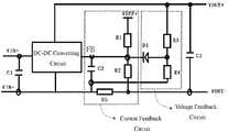
- FIG. 1is a principle diagram of a constant-current charging circuit according to an embodiment of the present invention.
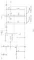
- FIG. 2is a circuit of a specific application of the constant-current charging circuit in FIG. 1 .
- FIG. 1is a principle diagram is of a constant-current charging circuit according to an embodiment of the present invention, of elements and labels shown in FIG. 1 are referred to as follows:
- VIN+is a positive terminal of an input power source
- VIN ⁇is a negative terminal of the input power source
- VOUT+is a positive output of an output power source
- VOUT ⁇is a negative output of the output power source
- VREF+is a positive terminal of a reference power source
- C 1is an input filter capacitor
- C 2is an output filter capacitor
- C 3is a current sampling feedback filter capacitor
- R 1 , R 2 , R 5 and R 3form a current sampling feedback circuit
- R 3 and R 4form a voltage sampling feedback circuit
- D 1is an isolating diode.
- a stable reference power sourceis used as a reference voltage and a divided voltage equal to a feedback terminal FB is obtained via resistors R 1 , R 2 and R 5 , thereby controlling a value of an output current by adjusting an inner PWM signal of a DC-DC converting circuit via the feedback terminal FB.
- a voltage across the sampling resistor R 5will rise when the output current increases. Since the voltage at the reference voltage terminal VRFE+ is a fixed value, the voltage at the feedback terminal FB also rises. Duty cycle of the PWM signal will decrease due to the rise of the voltage at the feedback terminal FB, therefore the output current will decrease. In such way, a complete feedback can be accomplished so as to achieve the purpose of stabilizing the output current.
- the output current Iois independent from the output voltage and input voltage.
- the output current Iois only in relation to VFB, R 1 , R 2 , and VREF which all have fixed values in a specific design (the voltage VFB is fixed in a steady state, and its steady-state value is 0.6 v for a constant-voltage chip fp7192), so K is certainly a fixed value. Therefore, the output current has excellent linearity and good controllability.
- the value of the output currentcan be calculated as follow if above parameters are assigned with the specific values set previously.
- the DC-DC converting circuitis a constant voltage driving IC, such as FP7192.
- the reference voltage constant-current method in this solutionhas the following characteristics: 1. It is convenient to control accuracy and stability by using a stable and fixed reference voltage; 2. It is simpler and more reliable by using a resistor divider feedback to replace current sampling; 3. It has wide application and can be used in any circuit which requires constant current; and 4. The cost reduces significantly, for example, the cost for the solution using a constant current IC and having an output of 12V/1 A is about 3 yuan while the cost for the solution provided by the present invention is within 1 yuan.
Landscapes
- Engineering & Computer Science (AREA)
- Power Engineering (AREA)
- Dc-Dc Converters (AREA)
- Continuous-Control Power Sources That Use Transistors (AREA)
Abstract
Description
VIo=Io*R5
VFB=VIo+((VREF+−VIo)*R2/(R1+R2))
Io=(VFB*(R1+R2)−R2*VREF+)/R1*R5
ifK=(VFB*(R1+R2)−R2*VREF+)/R1,then
Io=K/R5.
Claims (10)
Applications Claiming Priority (4)
| Application Number | Priority Date | Filing Date | Title |
|---|---|---|---|
| CN201710345961.XACN106953393A (en) | 2017-05-16 | 2017-05-16 | A kind of constant-current charging circuit, accumulation power supply and constant-current charge method |
| CN201720544010.0UCN206894279U (en) | 2017-05-16 | 2017-05-16 | A kind of constant-current charging circuit and accumulation power supply |
| CN201710345961.X | 2017-05-16 | ||
| CN201720544010.0 | 2017-05-16 |
Publications (2)
| Publication Number | Publication Date |
|---|---|
| US20180337543A1 US20180337543A1 (en) | 2018-11-22 |
| US10978882B2true US10978882B2 (en) | 2021-04-13 |
Family
ID=64272074
Family Applications (1)
| Application Number | Title | Priority Date | Filing Date |
|---|---|---|---|
| US15/880,468Expired - Fee RelatedUS10978882B2 (en) | 2017-05-16 | 2018-01-25 | Constant-current charging circuit, energy storage power source and constant-current charging method |
Country Status (1)
| Country | Link |
|---|---|
| US (1) | US10978882B2 (en) |
Families Citing this family (2)
| Publication number | Priority date | Publication date | Assignee | Title |
|---|---|---|---|---|
| WO2020111998A1 (en)* | 2018-11-27 | 2020-06-04 | Husqvarna Ab | Battery charger with a plurality of secondary transformer circuits |
| CN111384760A (en)* | 2020-04-24 | 2020-07-07 | 青岛鼎信通讯股份有限公司 | Constant-current constant-voltage charging circuit applied to products in power industry |
Citations (4)
| Publication number | Priority date | Publication date | Assignee | Title |
|---|---|---|---|---|
| US20070108943A1 (en)* | 2003-11-19 | 2007-05-17 | Shindengen Electric Manufacturing Co., Ltd. | Charger and dc-dc converter |
| US20110080103A1 (en)* | 2009-10-07 | 2011-04-07 | Daniel Reed | Method and apparatus for power driving |
| US20170271987A1 (en)* | 2014-08-27 | 2017-09-21 | Sg Micro Corp | Single inductor positive and negative voltage output device |
| US20180262042A1 (en)* | 2016-02-05 | 2018-09-13 | Guangdong Oppo Mobile Telecommunications Corp., Ltd. | Adapter and Method for Charging Control |
- 2018
- 2018-01-25USUS15/880,468patent/US10978882B2/ennot_activeExpired - Fee Related
Patent Citations (4)
| Publication number | Priority date | Publication date | Assignee | Title |
|---|---|---|---|---|
| US20070108943A1 (en)* | 2003-11-19 | 2007-05-17 | Shindengen Electric Manufacturing Co., Ltd. | Charger and dc-dc converter |
| US20110080103A1 (en)* | 2009-10-07 | 2011-04-07 | Daniel Reed | Method and apparatus for power driving |
| US20170271987A1 (en)* | 2014-08-27 | 2017-09-21 | Sg Micro Corp | Single inductor positive and negative voltage output device |
| US20180262042A1 (en)* | 2016-02-05 | 2018-09-13 | Guangdong Oppo Mobile Telecommunications Corp., Ltd. | Adapter and Method for Charging Control |
Also Published As
| Publication number | Publication date |
|---|---|
| US20180337543A1 (en) | 2018-11-22 |
Similar Documents
| Publication | Publication Date | Title |
|---|---|---|
| US10886752B2 (en) | Adjustable cable voltage compensation for battery chargers | |
| US7522432B2 (en) | Switching regulator and control circuit and method used therein | |
| US20050017701A1 (en) | Efficiency improved voltage converter | |
| CN105429460B (en) | DC-DC converter with line loss compensation | |
| CN107968566B (en) | Power supply conversion circuit | |
| CN103747561B (en) | Adjustment of load compensated switching power supply | |
| US7352161B2 (en) | Burst-mode switching voltage regulator with ESR compensation | |
| EP4134778A1 (en) | Voltage regulating apparatus, chip, power supply, and electronic device | |
| TW201348720A (en) | Simulation circuit of battery | |
| CN104617770A (en) | Switching power converter system and control method thereof | |
| CN105656307A (en) | Charge pump circuit and grid turn-on voltage generating circuit | |
| CN201781302U (en) | Integrated battery charger and circuit structure of direct current voltage stabilizing power supply | |
| CN113949267A (en) | Four-switch BUCKBOOST controller based on average current mode | |
| US10978882B2 (en) | Constant-current charging circuit, energy storage power source and constant-current charging method | |
| CN101304215A (en) | A kind of DC/DC circuit | |
| US8102168B1 (en) | PSRR regulator with UVLO | |
| CN110233572B (en) | Constant voltage source and constant voltage output method | |
| CN104506034A (en) | Continuous adjustable DC stabilized power supply circuit with 0V minimum output voltage based on three terminal regulator | |
| Kularatna | Modern component families and circuit block design | |
| CN108429455B (en) | Voltage conversion circuit and terminal equipment of power | |
| CN113157037B (en) | A low voltage drop linear regulator and power supply device | |
| CN207939403U (en) | Power supply unit and intelligent lock equipment | |
| CN205304604U (en) | DC -DC (direct current -direct current) converter with line loss compensation function | |
| CN101577500A (en) | Regulated power supply used for hydraulic servo controller | |
| CN210123940U (en) | Constant voltage source |
Legal Events
| Date | Code | Title | Description |
|---|---|---|---|
| AS | Assignment | Owner name:DONG GUAN JUXING POWER CO., LTD., CHINA Free format text:ASSIGNMENT OF ASSIGNORS INTEREST;ASSIGNORS:JI, YEXIN;LIAO, YUEFEI;REEL/FRAME:045152/0811 Effective date:20180119 | |
| FEPP | Fee payment procedure | Free format text:ENTITY STATUS SET TO UNDISCOUNTED (ORIGINAL EVENT CODE: BIG.); ENTITY STATUS OF PATENT OWNER: SMALL ENTITY | |
| FEPP | Fee payment procedure | Free format text:ENTITY STATUS SET TO SMALL (ORIGINAL EVENT CODE: SMAL); ENTITY STATUS OF PATENT OWNER: SMALL ENTITY | |
| STPP | Information on status: patent application and granting procedure in general | Free format text:DOCKETED NEW CASE - READY FOR EXAMINATION | |
| STPP | Information on status: patent application and granting procedure in general | Free format text:NOTICE OF ALLOWANCE MAILED -- APPLICATION RECEIVED IN OFFICE OF PUBLICATIONS | |
| STPP | Information on status: patent application and granting procedure in general | Free format text:PUBLICATIONS -- ISSUE FEE PAYMENT RECEIVED | |
| STPP | Information on status: patent application and granting procedure in general | Free format text:PUBLICATIONS -- ISSUE FEE PAYMENT VERIFIED | |
| STCF | Information on status: patent grant | Free format text:PATENTED CASE | |
| FEPP | Fee payment procedure | Free format text:MAINTENANCE FEE REMINDER MAILED (ORIGINAL EVENT CODE: REM.); ENTITY STATUS OF PATENT OWNER: SMALL ENTITY | |
| LAPS | Lapse for failure to pay maintenance fees | Free format text:PATENT EXPIRED FOR FAILURE TO PAY MAINTENANCE FEES (ORIGINAL EVENT CODE: EXP.); ENTITY STATUS OF PATENT OWNER: SMALL ENTITY | |
| STCH | Information on status: patent discontinuation | Free format text:PATENT EXPIRED DUE TO NONPAYMENT OF MAINTENANCE FEES UNDER 37 CFR 1.362 | |
| FP | Lapsed due to failure to pay maintenance fee | Effective date:20250413 |