US10978214B2 - Segmented reaction chamber for radioisotope production - Google Patents
Segmented reaction chamber for radioisotope productionDownload PDFInfo
- Publication number
- US10978214B2 US10978214B2US13/575,826US201113575826AUS10978214B2US 10978214 B2US10978214 B2US 10978214B2US 201113575826 AUS201113575826 AUS 201113575826AUS 10978214 B2US10978214 B2US 10978214B2
- Authority
- US
- United States
- Prior art keywords
- reactor
- target chamber
- target
- compartments
- isotope
- Prior art date
- Legal status (The legal status is an assumption and is not a legal conclusion. Google has not performed a legal analysis and makes no representation as to the accuracy of the status listed.)
- Active
Links
Images


Classifications
- G—PHYSICS
- G21—NUCLEAR PHYSICS; NUCLEAR ENGINEERING
- G21G—CONVERSION OF CHEMICAL ELEMENTS; RADIOACTIVE SOURCES
- G21G1/00—Arrangements for converting chemical elements by electromagnetic radiation, corpuscular radiation or particle bombardment, e.g. producing radioactive isotopes
- G21G1/04—Arrangements for converting chemical elements by electromagnetic radiation, corpuscular radiation or particle bombardment, e.g. producing radioactive isotopes outside nuclear reactors or particle accelerators
- G21G1/06—Arrangements for converting chemical elements by electromagnetic radiation, corpuscular radiation or particle bombardment, e.g. producing radioactive isotopes outside nuclear reactors or particle accelerators by neutron irradiation
- G21G1/08—Arrangements for converting chemical elements by electromagnetic radiation, corpuscular radiation or particle bombardment, e.g. producing radioactive isotopes outside nuclear reactors or particle accelerators by neutron irradiation accompanied by nuclear fission
- G—PHYSICS
- G21—NUCLEAR PHYSICS; NUCLEAR ENGINEERING
- G21B—FUSION REACTORS
- G21B1/00—Thermonuclear fusion reactors
- G21B1/01—Hybrid fission-fusion nuclear reactors
- Y—GENERAL TAGGING OF NEW TECHNOLOGICAL DEVELOPMENTS; GENERAL TAGGING OF CROSS-SECTIONAL TECHNOLOGIES SPANNING OVER SEVERAL SECTIONS OF THE IPC; TECHNICAL SUBJECTS COVERED BY FORMER USPC CROSS-REFERENCE ART COLLECTIONS [XRACs] AND DIGESTS
- Y02—TECHNOLOGIES OR APPLICATIONS FOR MITIGATION OR ADAPTATION AGAINST CLIMATE CHANGE
- Y02E—REDUCTION OF GREENHOUSE GAS [GHG] EMISSIONS, RELATED TO ENERGY GENERATION, TRANSMISSION OR DISTRIBUTION
- Y02E30/00—Energy generation of nuclear origin
- Y02E30/10—Nuclear fusion reactors
Definitions
- the inventionrelates to a device and method for producing isotopes. More particularly, the invention relates to a device and method for producing neutron generated medical isotopes with or without a sub-critical reactor and low enriched uranium (LEU).
- LEUlow enriched uranium
- Radioisotopesare commonly used by doctors in nuclear medicine. The most commonly used of these isotopes is Mo-99. Much of the supply of Mo-99 is developed from highly enriched uranium (HEU). The HEU employed is sufficiently enriched to make nuclear weapons. HEU is exported from the United States to facilitate the production of the needed Mo-99. It is desirable to produce the needed Mo-99 without the use of HEU.
- HEUhighly enriched uranium
- a reactoroperable to produce an isotope, the reactor comprising a region for containing a controlled nuclear fission reaction, the region segmented into a plurality of independent compartments, each of the compartments for containing a parent material in an aqueous solution that interacts with neutrons to produce the isotope via a fission reaction.
- the regionmay be segmented into n independent compartments, wherein n is an integer greater than or equal to 2.
- a reactoroperable to produce an isotope, the reactor comprising a fusion portion including a target path disposed within a target chamber that substantially encircles a space, the fusion portion operable to produce a neutron flux within the target chamber; and a fission portion for containing a controlled nuclear fission reaction, the fission portion segmented into a plurality of independent compartments and positioned within the space for containing a parent material in an aqueous solution that reacts with a portion of the neutron flux to produce the isotope during a fission reaction.
- a method of producing an isotopecomprising: positioning a parent material in an aqueous solution within a region for containing a controlled nuclear reaction, the region segmented into a plurality of independent compartments; reacting, in at least one of the compartments over a time period y, neutrons with the parent material to produce the isotope; and extracting the aqueous solution comprising the isotope from the compartment.
- FIG. 1is a first view of the generator with magnetic target chamber.
- FIG. 2is a second view of the generator with magnetic target chamber.
- FIG. 3is a first view of the generator with linear target chamber.
- FIG. 4is a first view of the ion source.
- FIG. 5is a sectional view of the ion source.
- FIG. 6is a first view of the accelerator.
- FIG. 7is a sectional view of the accelerator.
- FIG. 8is a first view of the differential pumping.
- FIG. 9is a sectional view of the differential pumping.
- FIG. 10is a first view of the gas filtration system.
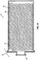
- FIG. 11is a first view of the magnetic target chamber.
- FIG. 12is a sectional view of the magnetic target chamber.
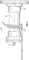
- FIG. 13is a first view of the linear target chamber.
- FIG. 14is a sectional view of the linear target chamber, showing an exemplary isotope generation system for 18 F and 13 N production.
- FIG. 15is a first view of the generator with linear target chamber and synchronized high speed pump.
- FIG. 16is a sectional view of the synchronized high speed pump in extraction state, allowing passage of an ion beam.
- FIG. 17is a sectional view of the synchronized high speed pump in suppression state, not allowing passage of an ion beam.
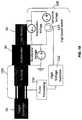
- FIG. 18is a schematic diagram of the generator with linear target chamber and synchronized high speed pump and one embodiment of controller.
- FIG. 19is a graph of stopping power (keV/ ⁇ m) versus ion energy (keV) for the stopping power of 3 He gas on 2 H ions at 10 torr gas pressure and 25° C.
- FIG. 20is a graph of stopping power (keV/ ⁇ m) versus ion energy (keV) for the stopping power of 3 He gas on 2 H ions at 10 torr gas pressure and 25° C.
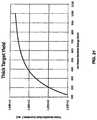
- FIG. 21is a graph of fusion reaction rate (reactions/second) versus ion beam incident energy (keV) for a 100 mA incident 2 H beam impacting a 3 He target at 10 torr.
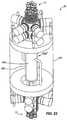
- FIG. 22is a perspective view of a hybrid reactor including a fusion portion and a fission portion suited to the production of medical isotopes;
- FIG. 23is a perspective view of another arrangement of a hybrid reactor including a fusion portion and a fission portion suited to the production of medical isotopes;
- FIG. 24is a side schematic view of the fission reactor illustrating the various layers of material
- FIG. 25is a top schematic view of the fission reactor of FIG. 24 illustrating the various layers of material
- FIG. 26is a side schematic view of another fission reactor illustrating the various layers of material
- FIG. 27is a top schematic view of the fission reactor of FIG. 26 illustrating the various layers of material
- FIG. 28is a side schematic view of another fission reactor illustrating the various layers of material and particularly suited to the formation of Mo-99 from Mo-98;
- FIG. 29is a top schematic view of the fission reactor of FIG. 28 illustrating the various layers of material.
- FIG. 30illustrates the decay of a particularly useful isotope, Mo-99 as created in a 5 day batch process.
- FIG. 31shows the amount of Mo-99 available during a 5 day batch process with a segmented reaction chamber in arbitrary units.
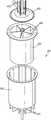
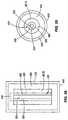
- FIG. 32is a perspective view of a segmented reaction chamber or activation cell.
- FIG. 33is an exploded view of a segmented reaction chamber or activation cell.
- FIG. 34is a side cross section view of a segmented reaction chamber or activation cell.
- FIG. 35is a top cross section view of a segmented reaction chamber or activation cell.
- any listed rangecan be easily recognized as sufficiently describing and enabling the same range being broken down into at least equal halves, thirds, quarters, fifths, tenths, etc.
- each range discussed hereincan be readily broken down into a lower third, middle third, and upper third, etc.
- all language such as “up to,” “at least,” “greater than,” “less than,” “more than” and the likeinclude the number recited and refer to ranges which can be subsequently broken down into subranges as discussed above.
- all ratios disclosed hereinalso include all subratios falling within the broader ratio. These are only examples of what is specifically intended.
- the phrases “ranging/ranges between” a first indicate number and a second indicate number and “ranging/ranges from” a first indicate number “to” a second indicate numberare used herein interchangeably.
- a segmented reaction chamberfor a reactor operable to produce an isotope.
- the reactormay comprise a region for containing a controlled nuclear fission reaction, the region segmented into a plurality of independent compartments.
- Each of the compartmentsmay contain a parent material in an aqueous solution.
- the parent materialmay interact with neutrons to produce an isotope via a fission reaction.
- the isotope producedmay comprise at least one of the isotopes including, but not limited to, Mo-99, I-131, I-125, Xe-133, Cs-137, Co-60, Y-90, Sr-90, and Sr-89.
- a reaction chamber 405comprises an activation cell 410 that may be segmented, forming a segmented activation cell 600 , as shown in FIGS. 32-35 . It is envisioned that the principles of a segmented approach for a subcritical reactor for isotope production is also applicable to any aqueous reactor system.
- the inventionprovides an aqueous reaction chamber (ARC), filled with an aqueous solution, such as one found in a critical or subcritical aqueous isotope production system.
- the activation cellmay be segmented into multiple pieces or a plurality of compartments by dividers 605 .
- the segmented activation cell 600may be divided or segmented into n independent compartments by dividers 605 .
- the independent compartments nmay be any integer from 2 to 10, from 3 to 8, or from 4 to 6.
- the compartmentsmay be assembled or positioned proximate to the target chamber in any suitable orientation.
- the compartmentsmay be radially symmetrically disposed about a central axis of the activation cell.
- the compartmentsmay be disposed linearly along a central axis, disposed concentrically about a central axis, or disposed radially asymmetrically about a central axis of the activation cell.
- the compartments of the activation cellmay independently contain a parent material for interacting with the protons or neutrons generated in the target chamber to produce an isotope.
- 1-3 solution extraction/fill lines 610may connect each chamber to an exterior reservoir (not shown) to transport parent material and isotope.
- a plurality of water cooling pipes 615may flow fluid to supply a cooling jacket 620 proximal to or surrounding the segmented activation cell 600 .
- a lid 625may cap the segmented activation cell 600 to retain the fluid materials within.
- a segmented activation cellmay allow for the extraction of isotopes at different periods of time. Separations in the reaction region may also be used to control instabilities that might develop in the solution.
- the parent material in at least one compartmentmay be reacted over a time period y with at least a portion of the neutrons or protons generated in the target chamber.
- the time period ymay be about the half life of the isotope produced. For example, the half life of Mo-99 is about 66 h. As such, the time period y may be about 60 h to about 70 h.
- the time period ymay be at least about at least about 12 h, at least about 18 h, 24 h, at least about 36 h, at least about 48 h, at least about 72 h, or at least about 96 h.
- the time period ymay be less than about 2 weeks, less than about 1.5 weeks, less than about 1 week, less than about 5 days, less than about 100 h, less than about 96 h, less than about 72 h, or less than about 48 h.
- the time period ymay be about 12 h to about 2 weeks, about 24 h to about 1 week, about 36 h to about 96 h, or about 48 h to about 80 h.
- ARCsmay utilize a single volume to contain the aqueous solution.
- the ARCmay be operated from periods of minutes to months to produce various isotopes.
- the fluidmay be drained and the isotope separated.
- optimal productionwill have occurred after a period of time equal to approximately one half-life of the material being created.
- FIG. 30illustrates the decay of a particularly useful isotope, Mo-99 as created in a 5 day batch process.
- the dashed linerepresents hypothetical demand (x-axis reads days, y axis reads supply units). In this system, it may take 5 days to produce 10 units of Mo-99. Once the isotope is extracted, irradiation may start on the next 5 day batch. This may result in a tremendous variation in the amount of material available. Due to requirements for high purity isotopes, the ARC may irradiate its solution to near saturation, so shorter batches may not be performed to distribute the production of isotopes over time.
- the ARCmay be cut into physically different sections within the same device. If a device has x regions in it, the entire system could be irradiated to saturation (which occurs at time y), and then one cell may have its isotopes extracted after a period of time proportional to the saturation time. Then, every period of time that passes equal to y/x, another cell may have its isotopes extracted. As soon as isotope extraction is performed on any given cell, the irradiation process on that cell may begin anew. As such, each cell may always be irradiated to nearly saturation before it is empty.
- FIG. 31shows the amount of Mo-99 available during a 5 day batch process with a segmented reaction chamber in arbitrary units.
- the dashed linerepresents hypothetical demand (x-axis reads days, y axis reads supply units).
- FIG. 30shown is the hypothetical ARC described may create an oversupply early in the 5 day period, and may not be able to meet demand later. As shown in FIG. 31 , the same ARC, segmented into 5 pieces, may continuously meet demand, which may result in less wasted product and eliminate the shortage previously experienced.
- a similar effectmay be created by producing multiple smaller units, but there may be significantly greater expense involved in doing so.
- the segmented designmay offer almost no additional cost, but may improve performance dramatically.
- the segmented aqueous systemmay serve to disrupt instabilities that may arise in critical or near critical aqueous systems. These instabilities may lead to control problems that may result in a failure to properly operate. Previous experiments with critical aqueous reactors resulted in instabilities that led to control problems as well as destructive behaviors that caused radiological spills. These instabilities were the result of the solution moving around in unpredictable ways, in some cases forming vortices in the solution.
- segmentationmay minimize the extent to which these instabilities can propagate, which may greatly increase the controllability of the reaction chamber.
- a segmented reaction chambermay be used with any suitable critical or subcritical fission reactor with an aqueous reaction chamber.
- a segmented reaction chambermay be used with a hybrid reactor described below.
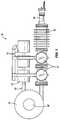
- FIG. 22illustrates an arrangement of a hybrid reactor 5 a that is well suited to the production of medical isotopes.
- the term “hybrid reactor” as used hereinis meant to describe a reactor that includes a fusion portion and a fission portion.
- the illustrated reactor 5 ais well suited to the production of Mo-99 from Mo-98 or from a solution of LEU.
- the hybrid reactor 5 aincludes a fusion portion 10 and a fission portion 8 that cooperate to produce the desired isotopes.
- ten distinct fusion portions 10are employed. Each fusion portion 10 is arranged as a magnetic fusion portion 10 and acts as a neutron source as will be discussed with regard to FIGS. 1 and 2 .
- FIGS. 1 and 2Of course other arrangements could use fewer fusion portions 10 , more fusion portions 10 , or other arrangements of fusion portions as desired.
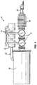
- FIG. 23illustrates another arrangement of a hybrid reactor 5 b that is well suited to the production of medical isotopes.
- linear fusion portions 11act as neutron sources as will be discussed with regard to FIGS. 3 and 4 .
- the linear fusion portions 11are arranged such that five fusion portions 11 are positioned at one end of the fission portion 8 and five fusion portions 11 are positioned on the opposite end of the fission portion 8 .
- Other arrangements that employ other quantities of fusion portions 11 , or other arrangements of fusion portionscould be employed if desired.
- each fusion portion 10 , 11provides a compact device that may function as a high energy proton source or a neutron source.
- the fusion portions 10 , 11utilize 2 H- 3 He (deuterium-helium 3) fusion reactions to generate protons, which may then be used to generate other isotopes.
- the fusion portions 10 , 11function as neutron sources by changing the base reactions to 2 H- 3 H, 2 H- 2 H, or 3 H- 3 H reactions.
- the fusion portions 10 , 11provide a novel high energy proton or neutron source (sometimes referred to herein generically as an ion source but also considered a particle source) that may be utilized for the production of medical isotopes.
- a novel high energy proton or neutron source(sometimes referred to herein generically as an ion source but also considered a particle source) that may be utilized for the production of medical isotopes.
- Each fusion portion 10 , 11uses a small amount of energy to create a fusion reaction, which then creates higher energy protons or neutrons that may be used for isotope production. Using a small amount of energy may allow the device to be more compact than previous conventional devices.
- Each fusion portion 10 , 11suitably generates protons that may be used to generate other isotopes including but not limited to 18 F, 11 C, 15 O, 13 N, 63 Zn, 124 I and many others.
- each fusion portionmay also be used to generate high fluxes of neutrons that may be used to generate isotopes including but not limited to I-131, Xe-133, In-111, I-125, Mo-99 (which decays to Tc-99m) and many others.
- each fusion portion 10 , 11provides a novel compact high energy proton or neutron source for uses such as medical isotope generation that has many of the advantages over the proton or neutron sources mentioned heretofore.
- each fusion portion 10 , 11provides an apparatus for generating protons or neutrons, which, in turn, are suitably used to generate a variety of radionuclides (or radioisotopes).
- each magnetic fusion portion 10includes a plasma ion source 20 , which may suitably include an RF-driven ion generator and/or antenna 24 , an accelerator 30 , which is suitably electrode-driven, and a target system including a target chamber 60 .
- the apparatusmay also include an isotope extraction system 90 .
- the RF-driven plasma ion source 20generates and collimates an ion beam directed along a predetermined pathway, wherein the ion source 20 includes an inlet for entry of a first fluid.
- the electrode-driven accelerator 30receives the ion beam and accelerates the ion beam to yield an accelerated ion beam.
- the target systemreceives the accelerated ion beam.
- the target systemcontains a nuclear particle-deriving, e.g. a proton-deriving or neutron-deriving, target material that is reactive with the accelerated beam and that, in turn, emits nuclear particles, i.e., protons or neutrons.
- the target systemmay have sidewalls that are transparent to the nuclear particles.
- An isotope extraction system 90is disposed proximate or inside the target system and contains an isotope-deriving material that is reactive to the nuclear particles to yield a radionuclide (or radioisotope).
- RF-driven ion generator or ion sourceis described herein, other systems and devices are also well-suited to generating the desired ions.
- other constructionscould employ a DC arc source in place of or in conjunction with the RF-driven ion generator or ion source.
- Still other constructionscould use hot cathode ion sources, cold cathode ion sources, laser ion sources, field emission sources, and/or field evaporation sources in place of or in conjunction with a DC arc source and or an RF-driven ion generator or ion source.
- the inventionshould not be limited to constructions that employ an RF-driven ion generator or ion source.
- the fusion portioncan be arranged in a magnetic configuration 10 and/or a linear configuration 11 .
- the six major sections or components of the deviceare connected as shown in FIG. 1 and FIG. 2 for the magnetic configuration 10 , and FIG. 3 for the linear configuration 11 .
- Each fusion portion, whether arranged in the magnetic arrangement or the linear arrangementincludes an ion source generally designated 20 , an accelerator 30 , a differential pumping system 40 , a target system which includes a target chamber 60 for the magnetic configuration 10 or a target chamber 70 for the linear configuration 11 , an ion confinement system generally designated 80 , and an isotope extraction system generally designated 90 .
- Each fusion portionmay additionally include a gas filtration system 50 .
- Each fusion portionmay also include a synchronized high speed pump 100 in place of or in addition to the differential pumping system 40 . Pump 100 is especially operative with the linear configuration of the target chamber.
- the ion source 20( FIG. 4 and FIG. 5 ) includes a vacuum chamber 25 , a radio-frequency (RF) antenna 24 , and an ion injector 26 having an ion injector first stage 23 and an ion injector final stage 35 ( FIG. 6 ).
- a magnet(not shown) may be included to allow the ion source to operate in a high density helicon mode to create higher density plasma 22 to yield more ion current.
- the field strength of this magnetsuitably ranges from about 50 G to about 6000 G, suitably about 100 G to about 5000 G.
- the magnetsmay be oriented so as to create an axial field (north-south orientation parallel to the path of the ion beam) or a cusp field (north-south orientation perpendicular to the path of the ion beam with the inner pole alternating between north and south for adjacent magnets).
- An axial fieldcan create a helicon mode (dense plasma), whereas a cusp field may generate a dense plasma but not a helicon inductive mode.
- a gas inlet 21is located on one end of the vacuum chamber 25 , and the first stage 23 of the ion injector 26 is on the other.
- Gas inlet 21provides one of the desired fuel types, which may include 1 H 2 , 2 H 2 , 3 H 2 , 3 H 2 , 3 He, and 11 B, or may comprise 1 H, 3 H, 3 He, and 11 B.
- the gas flow at inlet 21is suitably regulated by a mass flow controller (not shown), which may be user or automatically controlled.
- RF antenna 24is suitably wrapped around the outside of vacuum chamber 25 .
- RF antenna 24may be inside vacuum chamber 25 .
- RF antenna 24is proximate the vacuum chamber such that radio frequency radiation emitted by RF antenna 24 excites the contents (i.e., fuel gas) of vacuum chamber 25 , for example, forming a plasma.
- RF antenna 24includes a tube 27 of one or more turns.
- RF tube or wire 27may be made of a conductive and bendable material such as copper, aluminum, or stainless steel.
- Ion injector 26includes one or more shaped stages ( 23 , 35 ). Each stage of the ion injector includes an acceleration electrode 32 suitably made from conductive materials that may include metals and alloys to provide effective collimation of the ion beam.
- the electrodesare suitably made from a conductive metal with a low sputtering coefficient, e.g., tungsten.
- RF antenna 24is connected at one end to the output of an RF impedance matching circuit (not shown) and at the other end to ground. The RF impedance matching circuit may tune the antenna to match the impedance required by the generator and establish an RF resonance.
- RF antenna 24suitably generates a wide range of RF frequencies, including but not limited to 0 Hz to tens of kHz to tens of MHz to GHz and greater.
- RF antenna 24may be water-cooled by an external water cooler (not shown) so that it can tolerate high power dissipation with a minimal change in resistance.
- the matching circuit in a turn of RF antenna 24may be connected to an RF power generator (not shown).
- Ion source 20 , the matching circuit, and the RF power generatormay be floating (isolated from ground) at the highest accelerator potential or slightly higher, and this potential may be obtained by an electrical connection to a high voltage power supply.
- RF power generatormay be remotely adjustable, so that the beam intensity may be controlled by the user, or alternatively, by computer system.
- RF antenna 24 connected to vacuum chamber 25suitably positively ionizes the fuel, creating an ion beam.
- Alternative means for creating ionsare known by those of skill in the art and may include microwave discharge, electron-
- Accelerator 30( FIG. 6 and FIG. 7 ) suitably includes a vacuum chamber 36 , connected at one end to ion source 20 via an ion source mating flange 31 , and connected at the other end to differential pumping system 40 via a differential pumping mating flange 33 .
- the first stage of the acceleratoris also the final stage 35 of ion injector 26 .
- At least one circular acceleration electrode 32and suitably 3 to 50, more suitably 3 to 20, may be spaced along the axis of accelerator vacuum chamber 36 and penetrate accelerator vacuum chamber 36 , while allowing for a vacuum boundary to be maintained.
- Acceleration electrodes 32have holes through their centers (smaller than the bore of the accelerator chamber) and are suitably each centered on the longitudinal axis (from the ion source end to the differential pumping end) of the accelerator vacuum chamber for passage of the ion beam.
- the minimum diameter of the hole in acceleration electrode 32increases with the strength of the ion beam or with multiple ion beams and may range from about 1 mm to about 20 cm in diameter, and suitably from about 1 mm to about 6 cm in diameter.
- acceleration electrodes 32may be connected to anti-corona rings 34 that decrease the electric field and minimize corona discharges. These rings may be immersed in a dielectric oil or an insulating dielectric gas such as SF 6 .
- a differential pumping mating flange 33which facilitates connection to differential pumping section 40 , is at the exit of the accelerator.
- Each acceleration electrode 32 of accelerator 30can be supplied bias either from high voltage power supplies (not shown), or from a resistive divider network (not shown) as is known by those of skill in the art.
- the dividerfor most cases may be the most suitable configuration due to its simplicity.
- the ion source end of the acceleratormay be connected to the high voltage power supply, and the second to last accelerator electrode 32 may be connected to ground.
- the intermediate voltages of the accelerator electrodes 32may be set by the resistive divider.
- the final stage of the acceleratoris suitably biased negatively via the last acceleration electrode to prevent electrons from the target chamber from streaming back into accelerator 30 .
- a linac(for example, a RF quadrapole) may be used instead of an accelerator 30 as described above.
- a linacmay have reduced efficiency and be larger in size compared to accelerator 30 described above.
- the linacmay be connected to ion source 20 at a first end and connected to differential pumping system 40 at the other end.
- Linacsmay use RF instead of direct current and high voltage to obtain high particle energies, and they may be constructed as is known in the art.
- Differential pumping system 40( FIG. 8 and FIG. 9 ) includes pressure reducing barriers 42 that suitably separate differential pumping system 40 into at least one stage.
- Pressure reducing barriers 42each suitably include a thin solid plate or one or more long narrow tubes, typically 1 cm to 10 cm in diameter with a small hole in the center, suitably about 0.1 mm to about 10 cm in diameter, and more suitably about 1 mm to about 6 cm.
- Each stagecomprises a vacuum chamber 44 , associated pressure reducing barriers 42 , and vacuum pumps 17 , each with a vacuum pump exhaust 41 .
- Each vacuum chamber 44may have 1 or more, suitably 1 to 4, vacuum pumps 17 , depending on whether it is a 3, 4, 5, or 6 port vacuum chamber 44 .
- Two of the ports of the vacuum chamber 44are suitably oriented on the beamline and used for ion beam entrance and exit from differential pumping system 40 .
- the ports of each vacuum chamber 44may also be in the same location as pressure reducing barriers 42 .
- the remaining ports of each vacuum chamber 44are suitably connected by conflat flanges to vacuum pumps 17 or may be connected to various instrumentation or control devices.
- the exhaust from vacuum pumps 17is fed via vacuum pump exhaust 41 into an additional vacuum pump or compressor if necessary (not shown) and fed into gas filtration system 50 .
- this additional vacuum pumpmay be located in between gas filtration system 50 and target chamber 60 or 70 . If there is an additional compression stage, it may be between vacuum pumps 17 and filtration system 50 .
- Differential pumping sectionis connected at one end to the accelerator 30 via an accelerator mating flange 45 , and at the other at beam exit port 46 to target chamber ( 60 or 70 ) via a target chamber mating flange 43 .
- Differential pumping system 40may also include a turbulence generating apparatus (not shown) to disrupt laminar flow.
- a turbulence generating apparatusmay restrict the flow of fluid and may include surface bumps or other features or combinations thereof to disrupt laminar flow. Turbulent flow is typically slower than laminar flow and may therefore decrease the rate of fluid leakage from the target chamber into the differential pumping section.
- the pressure reducing barriers 42are replaced or enhanced by plasma windows.
- Plasma windowsinclude a small hole similar to those employed as pressure reducing barriers. However, a dense plasma is formed over the hole to inhibit the flow of gas through the small hole while still allowing the ion beam to pass. A magnetic or electric field is formed in or near the hole to hold the plasma in place.
- Gas filtration system 50is suitably connected at its vacuum pump isolation valves 51 to vacuum pump exhausts 41 of differential pumping system 40 or to additional compressors (not shown).
- Gas filtration system 50( FIG. 10 ) includes one or more pressure chambers or “traps” ( 13 , 15 ) over which vacuum pump exhaust 41 flows.
- the trapssuitably capture fluid impurities that may escape the target chamber or ion source, which, for example, may have leaked into the system from the atmosphere.
- the trapsmay be cooled to cryogenic temperatures with liquid nitrogen (LN traps, 15 ).
- LN traps, 15liquid nitrogen
- cold liquid traps 13 , 15suitably cause gas such as atmospheric contaminants to liquefy and remain in traps 13 , 15 .
- the gasAfter flowing over one or more LN traps 15 connected in series, the gas is suitably routed to a titanium getter trap 13 , which absorbs contaminant hydrogen gasses such as deuterium that may escape the target chamber or the ion source and may otherwise contaminate the target chamber.
- the outlet of getter trap 13is suitably connected to target chamber 60 or 70 via target chamber isolation valve 52 of gas filtration system 50 .
- Gas filtration system 50may be removed altogether from device 10 , if one wants to constantly flow gas into the system and exhaust it out vacuum pump exhaust 41 , to another vacuum pump exhaust (not shown), and to the outside of the system. Without gas filtration system 50 , operation of apparatus 10 would not be materially altered.
- Apparatus 10functioning as a neutron source, may not include getter trap 13 of gas filtration system 50 .
- Vacuum pump isolation valves 51 and target chamber isolation valves 52may facilitate gas filtration system 50 to be isolated from the rest of the device and connected to an external pump (not shown) via pump-out valve 53 when the traps become saturated with gas. As such, if vacuum pump isolation valves 51 and target chamber isolation valves 52 are closed, pump-out valves 53 can be opened to pump out impurities.
- Target chamber 60( FIG. 11 and FIG. 12 for magnetic system 10 ) or target chamber 70 ( FIG. 13 and FIG. 14 for the linear system 11 ) may be filled with the target gas to a pressure of about 0 to about 100 torr, about 100 mtorr to about 30 torr, suitably about 0.1 to about 10 torr, suitably about 100 mtorr to about 30 torr.
- the specific geometry of target chamber 60 or 70may vary depending on its primary application and may include many variations.
- the target chambermay suitably be a cylinder about 10 cm to about 5 m long, and about 5 mm to about 100 cm in diameter for the linear system 14 . When used in the hybrid reactor, the target chamber is arranged to provide an activation column in its center.
- target chamber 70may be about 0.1 m to about 2 m long, and about 30 to 50 cm in diameter for the linear system 14 .
- target chamber 60may resemble a thick pancake, about 10 cm to about 1 m tall and about 10 cm to about 10 m in diameter.
- the target chamber 60 for the magnetic system 12may be about 20 cm to about 50 cm tall and approximately 50 cm in diameter.
- a pair of either permanent magnets or electromagnetsmay be located on the faces of the pancake, outside of the vacuum walls or around the outer diameter of the target chamber (see FIG. 11 and FIG. 12 ).
- the magnetsare suitably made of materials including but not limited to copper and aluminum, or superconductors or NdFeB for electromagnets.
- the poles of the magnetsmay be oriented such that they create an axial magnetic field in the bulk volume of the target chamber.
- the magnetic fieldis suitably controlled with a magnetic circuit comprising high permeability magnetic materials such as 1010 steel, mu-metal, or other materials.
- the magnetsmay be oriented parallel to the flat faces of the pancake and polarized so that a magnetic field exists that is perpendicular to the direction of the beam from the accelerator 30 , that is, the magnets may be mounted to the top and bottom of the chamber to cause ion recirculation.
- These additional magnets creating the mirror fieldsmay be permanent magnets or electromagnets.
- One end of the target chamberis operatively connected to differential pumping system 40 via differential pumping mating flange 33 , and a gas recirculation port 62 allows for gas to re-enter the target chamber from gas filtration system 50 .
- the target chambermay also include feedthrough ports (not shown) to allow for various isotope generating apparatus to be connected.
- the magnetic fieldconfines the ions in the target chamber.
- the injected ionsare confined by the target gas.
- the target chambermay require shielding to protect the operator of the device from radiation, and the shielding may be provided by concrete walls suitably at least one foot thick.
- the devicemay be stored underground or in a bunker, distanced away from users, or water or other fluid may be used a shield, or combinations thereof.
- Both differential pumping system 40 and gas filtration system 50may feed into the target chamber 60 or 70 .
- Differential pumping system 40suitably provides the ion beam, while gas filtration system 50 supplies a stream of filtered gas to fill the target chamber.
- gas filtration system 50supplies a stream of filtered gas to fill the target chamber.
- a vacuum feedthrough(not shown) may be mounted to target chamber 60 or 70 to allow the isotope extraction system 90 to be connected to the outside.
- Isotope extraction system 90may be any number of configurations to provide parent compounds or materials and remove isotopes generated inside or proximate the target chamber.
- isotope generation system 63may include an activation tube 64 ( FIGS. 12 and 14 ) that is a tightly wound helix that fits just inside the cylindrical target chamber and having walls 65 .
- activation tube 64FIGS. 12 and 14
- itmay include a helix that covers the device along the circumference of the pancake and two spirals, one each on the top and bottom faces of the pancake, all connected in series.
- Walls 65 of activation tubes 64 used in these configurationsare sufficiently strong to withstand rupture, yet sufficiently thin so that protons of over 14 MeV (approximately 10 to 20 MeV) may pass through them while still keeping most of their energy.
- the walls of the tubingmay be about 0.01 mm to about 1 mm thick, and suitably about 0.1 mm thick.
- the walls of the tubingare suitably made of materials that will not generate neutrons.
- the thin-walled tubingmay be made from materials such as aluminum, carbon, copper, titanium, or stainless steel.
- Feedthroughsmay connect activation tube 64 to the outside of the system, where the daughter or product compound-rich fluid may go to a heat exchanger (not shown) for cooling and a chemical separator (not shown) where the daughter or product isotope compounds are separated from the mixture of parent compounds, daughter compounds, and impurities.
- a high speed pump 100is positioned in between accelerator 30 and target chamber 60 or 70 .
- High speed pump 100may replace the differential pumping system 40 and/or gas filtration system 50 .
- the high speed pumpsuitably includes one or more blades or rotors 102 and a timing signal 104 that is operatively connected to a controller 108 .
- the high speed pumpmay be synchronized with the ion beam flow from the accelerator section, such that the ion beam or beams are allowed to pass through at least one gap 106 in between or in blades 102 at times when gaps 106 are aligned with the ion beam.
- Timing signal 104may be created by having one or more markers along the pump shaft or on at least one of the blades.
- Timing signal 104may indicate the position of blades 102 or gap 106 and whether or not there is a gap aligned with the ion beam to allow passage of the ion beam from first stage 35 of accelerator 30 through high speed pump 100 to target chamber 60 or 70 .
- Timing signal 104may be used as a gate pulse switch on the ion beam extraction voltage to allow the ion beam to exit ion source 20 and accelerator 30 and enter high speed pump 100 .
- controller 108may comprise a pulse processing unit 110 , a high voltage isolation unit 112 , and a high speed switch 114 to control the voltage of accelerator 30 between suppression voltage (ion beam off; difference may be 5-10 kV) and extraction voltage (ion beam on; difference may be 20 kv).
- Timing signal 104suitably creates a logic pulse that is passed through delay or other logic or suitable means known in the art.
- Pulse processing unit 110may alter the turbine of the high speed pump to accommodate for delays, and high speed switch 114 may be a MOSFET switch or other suitable switch technology known in the art.
- High voltage isolation unit 112may be a fiber optic connection or other suitable connections known in the art.
- the timing signal 104may indicate the presence or absence of a gap 106 only once per rotation of a blade 102 , and the single pulse may signal a set of electronics via controller 108 to generate a set of n pulses per blade revolution, wherein n gaps are present in one blade rotation.
- timing signal 104may indicate the presence or absence of a gap 106 for each of m gaps during a blade rotation, and the m pulses may each signal a set of electronics via controller 108 to generate a pulse per blade revolution, wherein m gaps are present in one blade rotation.
- the logic pulsesmay be passed or coordinated via controller 108 to the first stage of accelerator section 35 (ion extractor), such that the logic pulse triggers the first stage of accelerator section 35 to change from a suppression state to an extraction state and visa versa.
- the first stage of accelerator 35may be biased to +295 kV when there is no gap 106 in high speed pump 100 , so that the positive ion beam will not flow from +295 kV to +300 kV, and the first stage of accelerator 35 may be biased to +310 kV when there is a gap 106 in high speed pump 100 , so that the ion beam travels through accelerator 30 and through gaps 106 in high speed pump 100 to target chamber 60 or 70 .
- the difference in voltage between the suppression and extraction statesmay be a relatively small change, such as about 1 kV to about 50 kV, suitably about 10 kV to about 20 kV. A small change in voltage may facilitate a quick change between suppression ( FIG.
- Timing signal 104 and controller 108may operate by any suitable means known in the art, including but not limited to semiconductors and fiber optics.
- the period of time that the ion beam is on and offmay depend on factors such as the rotational speed of blades 102 , the number of blades or gaps 106 , and the dimensions of the blades or gaps.
- the isotopes 18 F and 13 Nwhich are utilized in PET scans, may be generated from the nuclear reactions inside each fusion portion using an arrangement as illustrated in FIGS. 12 and 14 . These isotopes can be created from their parent isotopes, 18 O (for 18 F) and 16 O (for 13 N) by proton bombardment.
- the source of the parentmay be a fluid, such as water (H 2 18 O or H 2 16 O), that may flow through the isotope generation system via an external pumping system (not shown) and react with the high energy protons in the target chamber to create the desired daughter compound.
- waterFor the production of 18 F or 13 N, water (H 2 18 O or H 2 16 O, respectively) is flowed through isotope generation system 63 , and the high energy protons created from the aforementioned fusion reactions may penetrate tube 64 walls and impact the parent compound and cause (p, ⁇ ) reactions producing 18 F or 13 N.
- the isotope-rich watermay then be circulated through the heat exchanger (not shown) to cool the fluid and then into the chemical filter (not shown), such as an ion exchange resin, to separate the isotope from the fluid.
- the water mixturemay then recirculate into target chamber ( 60 or 70 ), while the isotopes are stored in a filter, syringe, or by other suitable means known in the art until enough has been produced for imaging or other procedures.
- isotope generation system 63may suitably be parallel loops or flat panel with ribs.
- a water jacketmay be attached to the vacuum chamber wall.
- the spiralcould be replaced by any number of thin walled geometries including thin windows, or could be replaced by a solid substance that contained a high oxygen concentration, and would be removed and processed after transmutation.
- Other isotopescan be generated by other means.
- the respective target chamber 60 or 70is suitably filled by first pre-flowing the target gas, such as 3 He, through the ion source 20 with the power off, allowing the gas to flow through the apparatus 10 and into the target chamber.
- a reactant gassuch as 2 H 2 enters the ion source 20 and is positively ionized by the RF field to form plasma 22 .
- plasma 22 inside vacuum chamber 25expands toward ion injector 26 , plasma 22 starts to be affected by the more negative potential in accelerator 30 . This causes the positively charged ions to accelerate toward target chamber 60 or 70 .
- Acceleration electrodes 32 of the stages ( 23 and 35 ) in ion source 20collimate the ion beam or beams, giving each a nearly uniform ion beam profile across the first stage of accelerator 30 .
- the first stage of accelerator 30may enable pulsing or on/off switching of the ion beam, as described above.
- the beampicks up additional energy at each stage, reaching energies of up to 5 MeV, up to 1 MeV, suitably up to 500 keV, suitably 50 keV to 5 MeV, suitably 50 keV to 500 keV, and suitably 0 to 10 Amps, suitably 10 to 100 mAmps, by the time it reaches the last stage of the accelerator 30 .
- This potentialis supplied by an external power source (not shown) capable of producing the desired voltage.
- Some neutral gas from ion source 20may also leak out into accelerator 30 , but the pressure in accelerator 30 will be kept to a minimum by differential pumping system 40 or synchronized high speed pump 100 to prevent excessive pressure and system breakdown.
- the beamcontinues at high velocity into differential pumping 40 where it passes through the relatively low pressure, short path length stages with minimal interaction. From here it continues into target chamber 60 or 70 , impacting the high density target gas that is suitably 0 to 100 torr, suitably 100 mtorr to 30 torr, suitably 5 to 20 torr, slowing down and creating nuclear reactions.
- the emitted nuclear particlesmay be about 0.3 MeV to about 30 MeV protons, suitably about 10 MeV to about 20 MeV protons, or about 0.1 MeV to about 30 MeV neutrons, suitably about 2 MeV to about 20 MeV neutrons.
- the ion beamcontinues in an approximately straight line and impacts the high density target gas to create nuclear reactions until it stops.
- the ion beamis bent into an approximately helical path, with the radius of the orbit (for deuterium ions, 2 H) given by the equation (2):
- r204 * E i B ( 2 )
- E ithe ion energy in eV
- Bthe magnetic field strength in gauss.
- the orbital radiusis about 20.6 cm and suitably fits inside a 25 cm radius chamber. While ion neutralization can occur, the rate at which re-ionization occurs is much faster, and the particle will spend the vast majority of its time as an ion.
- magnetic target chamber 60can also operate at lower pressure. Magnetic target chamber 60 , thus, may be the more suitable configuration.
- a magnetic target chambercan be smaller than a linear target chamber and still maintain a long path length, because the beam may recirculate many times within the same space. The fusion products may be more concentrated in the smaller chamber.
- a magnetic target chambermay operate at lower pressure than a linear chamber, easing the burden on the pumping system because the longer path length may give the same total number of collisions with a lower pressure gas as with a short path length and a higher pressure gas of the linac chamber.
- Vacuum pumps 17may remove this gas quickly, achieving a pressure reduction of approximately 10 to 100 times or greater. This “leaked” gas is then filtered and recycled via gas filtration system 50 and pumped back into the target chamber, providing more efficient operation.
- high speed pump 100may be oriented such that flow is in the direction back into the target chamber, preventing gas from flowing out of the target chamber.
- an isotope extraction system 90 as described hereinis inserted into target chamber 60 or 70 .
- This deviceallows the high energy protons to interact with the parent nuclide of the desired isotope.
- this targetmay be water-based ( 16 O for 13 N, and 18 O for 18 F) and will flow through thin-walled tubing. The wall thickness is thin enough that the 14.7 MeV protons generated from the fusion reactions will pass through them without losing substantial energy, allowing them to transmute the parent isotope to the desired daughter isotope.
- the 13 N or 18 F rich waterthen is filtered and cooled via external system.
- Other isotopessuch as 124 I (from 124 Te or others), 11 C (from 14 N or 11 B or others), 15 O (from 15 N or others), and 63 Zn, may also be generated.
- the isotope extraction system 90can be omitted.
- target chamber 60 or 70may be connected to another apparatus to provide high energy protons to these applications.
- the a fusion portionmay be used as an ion source for proton therapy, wherein a beam of protons is accelerated and used to irradiate cancer cells.
- the desired productis neutrons
- no hardwaresuch as isotope extraction system 90 is required, as the neutrons may penetrate the walls of the vacuum system with little attenuation.
- the fuel in the injectoris changed to either deuterium or tritium, with the target material changed to either tritium or deuterium, respectively.
- Neutron yieldsof up to about 10 15 neutrons/sec or more may be generated.
- getter trap 13may be removed.
- the parent isotope compoundmay be mounted around target chamber 60 or 70 , and the released neutrons may convert the parent isotope compound to the desired daughter isotope compound.
- an isotope extraction systemmay still or additionally be used inside or proximal to the target chamber.
- Moderators in neutronics termsmay be any material or materials that slow down neutrons. Suitable moderators may be made of materials with low atomic mass that are unlikely to absorb thermal neutrons. For example, to generate Mo-99 from a Mo-98 parent compound, a water moderator may be used. Mo-99 decays to Tc-99m, which may be used for medical imaging procedures. Other isotopes, such as I-131, Xe-133, In-111, and 1-125, may also be generated.
- the fusion portionmay include shielding such as concrete or a fluid such as water at least one foot thick to protect the operators from radiation. Alternatively, the neutron source may be stored underground to protect the operators from radiation. The manner of usage and operation of the invention in the neutron mode is the same as practiced in the above description.
- the fusion rate of the beam impacting a thick target gascan be calculated.
- the incremental fusion rate for the ion beam impacting a thick target gasis given by the equation (3):
- df(E)is the fusion rate (reactions/sec) in the differential energy interval dE
- n bis the target gas density (particles/m 3 )
- I ionis the ion current (A)
- eis the fundamental charge of 1.6022*10 ⁇ 19 coulombs/particle
- ⁇ (E)is the energy dependent cross section (m 2 )
- dlis the incremental path length at which the particle energy is E. Since the particle is slowing down once inside the target, the particle is only at energy E over an infinitesimal path length.
- equation (2)is integrated over the entire particle path length from where its energy is at its maximum of E i to where it stops as shown in equation (4):
- F(E i )is the total fusion rate for a beam of initial energy E i stopping in the gas target.
- the incremental path length dlis solved for in terms of energy. This relationship is determined by the stopping power of the gas, which is an experimentally measured function, and can be fit by various types of functions.
- E n+1E n ⁇ S ( E )* dl (5)
- E n+1is the energy in the next incremental step
- S(E)is the polynomial shown above that relates the particle energy to the stopping power
- dlis the size of an incremental step.
- Eis in keV and dl is in ⁇ m.
- This formulayields a way to determine the particle energy as it moves through the plasma, and this is important because it facilitates evaluation of the fusion cross section at each energy, and allows for the calculation of a fusion rate in any incremental step.
- the fusion rate in the numerical case for each stepis given by the equation (6):
- This fusion rateis known as the “thick-target yield”. To solve this, an initial energy was determined and a small step size dl chosen. The fusion rate in the interval dl at full energy was calculated. Then the energy for the next step was calculated, and the process repeated. This goes on until the particle stops in the gas.
- the fusion ratewas calculated to be approximately 2 ⁇ 10 13 fusions/second, generating the same number of high energy protons (equivalent to 3 ⁇ A protons). This level is sufficient for the production of medical isotopes, as is known by those of skill in the art.
- a plot showing the fusion rate for a 100 mA incident deuterium beam impacting a helium-3 target at 10 torris shown in FIG. 21 .
- the fusion portions as described hereinmay be used in a variety of different applications. According to one construction, the fusion portions are used as a proton source to transmutate materials including nuclear waste and fissile material. The fusion portions may also be used to embed materials with protons to enhance physical properties. For example, the fusion portion may be used for the coloration of gemstones. The fusion portions also provide a neutron source that may be used for neutron radiography. As a neutron source, the fusion portions may be used to detect nuclear weapons. For example, as a neutron source the fusion portions may be used to detect special nuclear materials, which are materials that can be used to create nuclear explosions, such as Pu, 233 U, and materials enriched with 233 U or 235 U.
- the fusion portionsmay be used to detect underground features including but not limited to tunnels, oil wells, and underground isotopic features by creating neutron pulses and measuring the reflection and/or refraction of neutrons from materials.
- the fusion portionsmay be used as a neutron source in neutron activation analysis (NAA), which may determine the elemental composition of materials.
- NAAneutron activation analysis
- the fusion portionsmay also be used to detect materials including but not limited to clandestine materials, explosives, drugs, and biological agents by determining the atomic composition of the material.
- the fusion portionsmay also be used as a driver for a sub-critical reactor.
- the fusion portions 10 , 11can be arranged in the magnetic configuration 10 to function as a neutron source.
- the system 10will be clean and empty, containing a vacuum of 10 ⁇ 9 torr or lower, and the high speed pumps 17 will be up to speed (two stages with each stage being a turbomolecular pump).
- Approximately 25-30 standard cubic centimeters of gas (deuterium for producing neutrons)will be flowed into the target chamber 60 to create the target gas.
- a valvewill be opened which allows a flow of 0.5 to 1 sccm (standard cubic centimeters per minute) of deuterium from the target chamber 60 into the ion source 20 .
- This gaswill re-circulate rapidly through the system, producing approximately the following pressures: in the ion source 20 the pressure will be a few mtorr; in the accelerator 30 the pressure will be around 20 ⁇ torr; over the pumping stage nearest the accelerator, the pressure will be ⁇ 20 ⁇ torr; over the pumping stage nearest the target chamber, the pressure will be approximately 50 mtorr; and in the target chamber 60 the pressure will be approximately 0.5 torr.
- the ion source 20using deuterium
- the RF power supplycoupled to the RF antenna 24 by the RF matching circuit
- the power levelwill be increased from zero to about 500 W creating a dense deuterium plasma with a density on the order of 10 11 particles/cm 3 .
- the ion extraction voltagewill be increased to provide the desired ion current (approximately 10 mA) and focusing.
- the accelerator voltagewill then be increased to 300 kV, causing the ion beam to accelerate through the flow restrictions and into the target chamber 60 .
- the target chamber 60will be filled with a magnetic field of approximately 5000 gauss (or 0.5 tesla), which causes the ion beam to re-circulate.
- the ion beamwill make approximately 10 revolutions before dropping to a negligibly low energy.
- the ion beamWhile re-circulating, the ion beam will create nuclear reactions with the target gas, producing 4 ⁇ 10 10 and up to 9 ⁇ 10 10 neutrons/sec for D. These neutrons will penetrate the target chamber 60 , and be detected with appropriate nuclear instrumentation.
- Neutral gas that leaks from the target chamber 60 into the differential pumping section 40will pass through the high speed pumps 17 , through a cold trap 13 , 15 , and back into the target chamber 60 .
- the cold traps 13 , 15will remove heavier gasses that in time can contaminate the system due to very small leaks.
- the fusion portions 11can also be arranged in the linear configuration to function as a neutron source.
- the systemwill be clean and empty, containing a vacuum of 10 ⁇ 9 torr or lower and the high speed pumps 17 will be up to speed (three stages, with the two nearest that accelerator being turbomolecular pumps and the third being a different pump such as a roots blower).
- Approximately 1000 standard cubic centimeters of deuterium gaswill be flowed into the target chamber 70 to create the target gas.
- a valvewill be opened which allows a flow of 0.5 to 1 sccm (standard cubic centimeters per minute) from the target chamber 70 into the ion source 20 .
- This gaswill re-circulate rapidly through the system, producing approximately the following pressures: in the ion source 20 the pressure will be a few mtorr; in the accelerator 30 the pressure will be around 20 ⁇ torr; over the pumping stage nearest the accelerator, the pressure will be ⁇ 20 ⁇ torr; over the center pumping stage the pressure will be approximately 50 mtorr; over the pumping stage nearest the target chamber 70 , the pressure will be approximately 500 mtorr; and in the target chamber 70 the pressure will be approximately 20 torr.
- the ion source 20(using deuterium) will be excited by enabling the RF power supply (coupled to the RF antenna 24 by the RF matching circuit) to about 10-30 MHz.
- the power levelwill be increased from zero to about 500 W creating a dense deuterium plasma with a density on the order of 10 11 particles/cm 3 .
- the ion extraction voltagewill be increased to provide the desired ion current (approximately 10 mA) and focusing.
- the accelerator voltagewill then be increased to 300 kV, causing the ion beam to accelerate through the flow restrictions and into the target chamber 70 .
- the target chamber 70will be a linear vacuum chamber in which the beam will travel approximately 1 meter before dropping to a negligibly low energy.
- the beamWhile passing through the target gas, the beam will create nuclear reactions, producing 4 ⁇ 10 10 and up to 9 ⁇ 10 10 neutrons/sec. These protons will penetrate the target chamber 70 , and be detected with appropriate nuclear instrumentation.
- Neutral gas that leaks from the target chamber 70 into the differential pumping section 40will pass through the high speed pumps 17 , through a cold trap 13 , 15 , and back into the target chamber 70 .
- the cold traps 13 , 15will remove heavier gasses that in time can contaminate the system due to very small leaks.
- the fusion portions 10are arranged in the magnetic configuration and are operable as proton sources.
- the systemwill be clean and empty, containing a vacuum of 10 ⁇ 9 torr or lower, and the high speed pumps 17 will be up to speed (two stages with each stage being a turbomolecular pump).
- Approximately 25-30 standard cubic centimeters of gasan approximate 50/50 mixture of deuterium and helium-3 to generate protons) will be flowed into the target chamber 60 to create the target gas.
- a valvewill be opened which allows a flow of 0.5 to 1 sccm (standard cubic centimeters per minute) of deuterium from the target chamber 60 into the ion source 20 .
- This gaswill re-circulate rapidly through the system, producing approximately the following pressures: in the ion source 20 the pressure will be a few mtorr; in the accelerator 30 the pressure will be around 20 ⁇ torr; over the pumping stage nearest the accelerator 30 , the pressure will be ⁇ 20 ⁇ torr; over the pumping stage nearest the target chamber 60 , the pressure will be approximately 50 mtorr; and in the target chamber 60 the pressure will be approximately 0.5 torr.
- the ion source 20using deuterium
- the RF power supplycoupled to the RF antenna 24 by the RF matching circuit
- the power levelwill be increased from zero to about 500 W creating a dense deuterium plasma with a density on the order of 10 11 particles/cm 3 .
- the ion extraction voltagewill be increased to provide the desired ion current (approximately 10 mA) and focusing.
- the accelerator voltagewill then be increased to 300 kV, causing the ion beam to accelerate through the flow restrictions and into the target chamber 60 .
- the target chamber 60will be filled with a magnetic field of approximately 5000 gauss (or 0.5 tesla), which causes the ion beam to re-circulate.
- the ion beamwill make approximately 10 revolutions before dropping to a negligibly low energy.
- the ion beamWhile re-circulating, the ion beam will create nuclear reactions with the target gas, producing 1 ⁇ 10 11 and up to about 5 ⁇ 10 11 protons/sec. These protons will penetrate the tubes of the isotope extraction system, and be detected with appropriate nuclear instrumentation.
- Neutral gas that leaks from the target chamber 60 into the differential pumping section 40will pass through the high speed pumps 17 , through a cold trap 13 , 15 , and back into the target chamber 60 .
- the cold traps 13 , 15will remove heavier gasses that in time can contaminate the system due to very small leaks.
- the fusion portions 11are arranged in the linear configuration and are operable as proton sources.
- the systemwill be clean and empty, containing a vacuum of 10 ⁇ 9 torr or lower and the high speed pumps 17 will be up to speed (three stages, with the two nearest that accelerator being turbomolecular pumps and the third being a different pump such as a roots blower).
- Approximately 1000 standard cubic centimeters of about 50/50 mixture of deuterium and helium-3 gaswill be flowed into the target chamber 70 to create the target gas.
- a valvewill be opened which allows a flow of 0.5 to 1 sccm (standard cubic centimeters per minute) from the target chamber 70 into the ion source 20 .
- This gaswill re-circulate rapidly through the system, producing approximately the following pressures: in the ion source 20 the pressure will be a few mtorr; in the accelerator 30 the pressure will be around 20 ⁇ torr; over the pumping stage nearest the accelerator 30 , the pressure will be ⁇ 20 ⁇ torr; over the center pumping stage the pressure will be approximately 50 mtorr; over the pumping stage nearest the target chamber 70 , the pressure will be approximately 500 mtorr; and in the target chamber 70 the pressure will be approximately 20 torr.
- the ion source 20(using deuterium) will be excited by enabling the RF power supply (coupled to the RF antenna 24 by the RF matching circuit) to about 10-30 MHz.
- the power levelwill be increased from zero to about 500 W creating a dense deuterium plasma with a density on the order of 10 11 particles/cm 3 .
- the ion extraction voltagewill be increased to provide the desired ion current (approximately 10 mA) and focusing.
- the accelerator voltagewill then be increased to 300 kV, causing the ion beam to accelerate through the flow restrictions and into the target chamber 70 .
- the target chamber 70will be a linear vacuum chamber in which the beam will travel approximately 1 meter before dropping to a negligibly low energy.
- the beamWhile passing through the target gas, the beam will create nuclear reactions, producing 1 ⁇ 10 11 and up to about 5 ⁇ 10 11 protons/sec. These neutrons will penetrate the walls of the tubes of the isotope extraction system, and be detected with appropriate nuclear instrumentation.
- Neutral gas that leaks from the target chamber 70 into the differential pumping section 40will pass through the high speed pumps 17 , through a cold trap 13 , 15 , and back into the target chamber 70 .
- the cold traps 13 , 15will remove heavier gasses that in time can contaminate the system due to very small leaks.
- the fusion portions 10 , 11are arranged in either the magnetic configuration or the linear configuration and are operated as neutron sources for isotope production.
- the systemwill be operated as discussed above with the magnetic target chamber or with the linear target chamber 70 .
- a solid sample, such as solid foil of parent material Mo-98will be placed proximal to the target chamber 60 , 70 .
- Neutrons created in the target chamber 60 , 70will penetrate the walls of the target chamber 60 , 70 and react with the Mo-98 parent material to create Mo-99, which may decay to meta-stable Tn-99m.
- the Mo-99will be detected using suitable instrumentation and technology known in the art.
- the fusion portions 10 , 11are arranged as proton sources for the production of isotopes.
- the fusion portion 10 , 11will be operated as described above with the magnetic target chamber 60 or with the linear target chamber 70 .
- the systemwill include an isotope extraction system inside the target chamber 60 , 70 .
- Parent materialsuch as water comprising H 2 16 O will be flowed through the isotope extraction system.
- the protons generated in the target chamberwill penetrate the walls of the isotope extraction system to react with the 16 O to produce 13 N.
- the 13 N product materialwill be extracted from the parent and other material using an ion exchange resin.
- the 13 Nwill be detected using suitable instrumentation and technology known in the art.
- each fusion portion 10 , 11provides, among other things, a compact high energy proton or neutron source.
- the foregoing descriptionis considered as illustrative only of the principles of the fusion portion 10 , 11 . Further, since numerous modifications and changes will readily occur to those skilled in the art, it is not desired to limit the fusion portion 10 , 11 to the exact construction and operation shown and described, and accordingly, all suitable modifications and equivalents may be resorted to as required or desired.
- the fission portions 400 a , 400 b of the hybrid reactor 5 a , 5 bare positioned adjacent the target chambers 60 , 70 of a plurality of fusion portions 10 , 11 .
- the fusion portions 10 , 11are arranged such that a reaction space 405 is defined within the target chambers 60 , 70 .
- the ion trajectories within the target chambers 60 , 70do not enter the reaction space 405 , and so materials to be irradiated can be placed within that volume.
- multiple fusion portions 10 , 11are stacked on top of one another, with as many as ten sources being beneficial. As illustrated in FIG.
- the hybrid reactor 5 aincludes the fission portion 400 a and fusion portions 10 in the magnetic arrangement to produce a plurality of stacked target chambers 60 that are pancake shaped but in which the ion beam flows along an annular path.
- the reaction space 405 within the annular pathcan be used for the placement of materials to be irradiated.
- FIG. 23illustrates a linear arrangement of the fusion portions 11 coupled to the fission portion 400 b to define the hybrid reactor 5 b .
- the ion beamsare directed along a plurality of substantially parallel, spaced-apart linear paths positioned within an annular target chamber 70 .
- the reaction space 405(sometimes referred to as reaction chamber) within the annular target chamber 70 is suitable for the placement of materials to be irradiated.
- the fission portions 400 a , 400 b described with regard to FIGS. 24-29could be employed with either the magnetic configuration or the linear configuration of the fusion portions 10 , 11 .
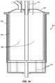
- the fission portion 400 a , 400 bincludes a substantially cylindrical activation column 410 (sometimes referred to as an activation cell) positioned within a tank 415 that contains a moderator/reflector material selected to reduce the radiation that escapes from the fission portion 400 a , 400 b during operation.
- An attenuatormay be positioned proximate the activation cell and selected to maintain the fission reaction at a subcritical level
- a reflectormay be positioned proximate the target chamber and selected to reflect neutrons toward the activation cell
- a moderatormay substantially surround the activation cell, the attenuator, and the reflector.
- the activation column 410is positioned within the target chamber 60 , 70 where the fusion reactions occur.
- the target chamber 60 , 70is about 1 m tall.
- a layer of beryllium 420may surround the target chamber 60 , 70 .
- the moderating materialis typically D 2 O or H 2 O.
- a gas regeneration system 425is positioned on top of the tank 415 .
- An aperture 430 in the center of the gas regeneration system 425extends into the activation column 410 where a sub-critical assembly 435 including a LEU mixture and/or other parent material may be located. In preferred constructions, the aperture 430 has about a 10 cm radius and is about 1 m long.
- Each fusion portion 10 , 11is arranged to emit high energy neutrons from the target chamber.
- the neutrons emitted by the fusion portions 10 , 11are emitted isotropically, and while at high energy those that enter the activation column 410 pass through it with little interaction.
- the target chamberis surrounded by 10-15 cm of beryllium 420 , which multiplies the fast neutron flux by approximately a factor of two. The neutrons then pass into the moderator where they slow to thermal energy and reflect back into the activation cell 410 .
- the neutron production rate from this configurationis about 10 15 n/s (the estimated source strength for a single fusion portion 10 , 11 operating at 500 kV and 100 mA is 10 14 n/s and there are ten of these devices in the illustrated construction).
- the total volumetric flux in the activation cell 410was calculated to be 2.35*1012 n/cm 2 /s with an uncertainty of 0.0094 and the thermal flux (less than 0.1 eV) was 1.34*10 12 n/cm 2 /s with an uncertainty of 0.0122. This neutron rate improves substantially with the presence of LEU as will be discussed.
- the fusion portion 10 , 11can be arranged in the magnetic arrangement or the linear arrangement.
- the real advantage of the magnetic arrangement of the fusion portions 10 , 11is that they allow for a long path length in a relatively low pressure gas.
- the target gasmust be cooled and must be maintained at a higher pressure.
- One example of such a configurationwould have several deuterium beam lines shooting axially into the target chamber 70 from above and below the device as illustrated in FIG. 23 . While the target chambers 70 may need to operate at up to 10 torr for this to be successful, it may be a simpler and more efficient approach for the fusion portion 10 , 11 .
- the primary simplification in the linear configurationis the elimination of the components needed to establish the magnetic field that guides the beam in the spiral or helical pattern.
- the lack of the components needed to create the fieldmakes the device cheaper and the magnets do not play a role in attenuating the neutron flux.
- a magnetic fieldis employed to collimate the ion beam produced by the linear arrangement of the fusion portions 11 , as will be discussed.
- the multiplication factor, k effis related to the multiplication by equation 1/(1 ⁇ k eff ). This multiplication effect can result in an increase of the total yield and specific activity of the end product by as much as a factor of 5-10.
- k effis a strong function of LEU density and moderator configuration.
- subcritical configurations of subcritical assemblies 435which consist of LEU (20% enriched) targets combined with H 2 O (or D 2 O) are possible. All of these configurations are inserted into the previously described reaction chamber space 405 .
- Some of the configurations consideredinclude LEU foils, an aqueous solution of a uranium salt dissolved in water, encapsulated UO 2 powder and others.
- the aqueous solutionsare highly desirable due to excellent moderation of the neutrons, but provide challenges from a criticality perspective.
- the criticality constant, k effshould be kept below 0.95.
- Further control featurescould easily be added to decrease k eff if a critical condition were obtained. These control features include, but are not limited to control rods, injectable poisons, or pressure relief valves that would dump the moderator and drop the criticality.
- Aqueous solutions of uraniumoffer tremendous benefits for downstream chemical processes. Furthermore, they are easy to cool, and provide an excellent combination of fuel and moderator. Initial studies were performed using a uranium nitrate solution-UO 2 (NO 3 ) 2 , but other solutions could be considered such as uranium sulfate or others.
- the salt concentration in the solutionis about 66 g of salt per 100 g H 2 O.
- the solutionis positioned within the activation cell 410 as illustrated in FIGS. 24 and 25 .
- the central most cylinder 500contains pure water and is surrounded by an aqueous mixture of uranium nitrate that is contained between the tube and a cylindrical wall 505 that cooperate to define a substantially annular space 510 .
- the target chamber 60 , 70is the next most outward layer and is also annular.
- the pure water, the aqueous mixture of uranium nitrate, and the target chamber 60 , 70are surrounded by the Be multiplier/reflector 420 .
- the outermost layer 520in this case is a large volume of D 2 O contained within the tank 415 .
- the D 2 Oacts as a moderator to reduce radiation leakage from the fission portion 400 a , 400 b .
- FIGS. 26-29illustrate similar structural components but contain different materials within some or all of the volumes as will be discussed with those particular figures.
- a common method to irradiate uraniumis to form it into either uranium dioxide pellets or encase a uranium dioxide powder in a container. These are inserted into a reactor and irradiated before removal and processing. While the UO 2 powders being used today utilize HEU, it is preferable to use LEU. In preferred constructions, a mixture of LEU and H 2 O that provides K eff ⁇ 0.95 is employed.
- FIGS. 26 and 27illustrate an activation column 410 that includes UO 2 in a homogeneous solution with D 2 O.
- the center cylinder 500 in this constructionis filled with H 2 O 525 , as is the outermost layer 530 (only a portion of which is illustrated).
- the first annular space 535contains a solution of 18% LEU (20% enriched) and 82% D 2 O.
- the second annular layer 540is substantially evacuated, consistent with the fusion portion target chambers 60 , 70 .
- the center cylinder 500 , the first annular space 535 , and the second annular space 540are surrounded by a layer of Be 420 , which serves as a multiplier and neutron reflector.
- Mo-99is extracted from uranium by chemical dissolution of LEU foils in a modified Cintichem process.
- thin foils containing uraniumare placed in a high flux region of a nuclear reactor, irradiated for some time and then removed.
- the foilsare dissolved in various solutions and processed through multiple chemical techniques.
- a fixed subcritical assembly 435 of LEUcan be used to increase the neutron flux (most likely UO 2 ), but can be isolated from the parent Mo-98.
- the subcritical assembly 435is still located inside of the fusion portion 10 , 11 , and the Mo-99 activation column would be located within the subcritical assembly 435 .
- Mo-98occupies a total of 20% of the activation column 410 (by volume).
- the centermost cylinder 500contains a homogeneous mixture of 20% Mo-98 and H 2 O.
- the first annular layer 555includes a subcritical assembly 435 and is comprised of an 18% LEU (20% enriched)/D 2 O mixture.
- the second annular layer 560is substantially evacuated, consistent with the fusion portion target chambers 60 , 70 .
- the center cylinder 500 , the first annular space 555 , and the second annular space 560are surrounded by the layer of Be 420 , which serves as a multiplier and neutron reflector.
- the outermost layer 570(only a portion of which is illustrated) contains water that reduces the amount of radiation that escapes from the fission portion 5 a , 5 b.
- the production rate and specific activity of Mo-99was determined by calculating 6% of the fission yield, with a fusion portion 10 , 11 operating at 10 15 n/s. K eff was calculated for various configurations as well. Table 1 summarizes the results of these calculations. In the case of production from Mo-98, an (n, ⁇ ) tally was used to determine the production rate of Mo-99. The following table illustrates the production rates for various target configurations in the hybrid reactor 5 a , 5 b .
- the subcritical assembly 435can be removed altogether. However, if the subcritical assembly 435 is removed, the specific activity of the end product will be quite a bit lower. Still, there are some indications that advanced generators might be able to make use of the low specific activity resulting from Mo-98 irradiation. The specific activity produced by the hybrid reactor 5 a , 5 b without subcritical multiplication is high enough for some of these technologies. Furthermore, the total demand for U.S. Mo-99 could still be met with several production facilities, which would allow for a fission free process.
- the subcritical assembly 435is omitted and Mo-98 is positioned within the activation column 410 .
- a more powerful ion beam produced by the linear arrangement of the fusion portion 11is employed. It is preferred to operate the ion beams at a power level approximately ten times that required in the aforementioned constructions.
- a magnetic fieldis established to collimate the beam and inhibit the undesirable dispersion of the beams. The field is arranged such that it is parallel to the beams and substantially surrounds the accelerator 30 and the pumping system 40 but does not necessarily extend into the target chamber 70 .
- This arrangementprovides the desired neutron flux without the multiplicative effect produced by the subcritical assembly 435 .
- One advantage of this arrangementis that no uranium is required to produce the desired isotopes.
- the inventionprovides, among other things, a segmented activation cell 600 for use in producing medical isotopes.
- the segmented activation cellmay be used, for example, with a hybrid reactor 5 a , 5 b .
- the constructions of the hybrid reactor 5 a , 5 b described above and illustrated in the figuresare presented by way of example only and are not intended as a limitation upon the concepts and principles of the invention.
Landscapes
- Physics & Mathematics (AREA)
- Engineering & Computer Science (AREA)
- Plasma & Fusion (AREA)
- General Engineering & Computer Science (AREA)
- High Energy & Nuclear Physics (AREA)
- Chemical & Material Sciences (AREA)
- Chemical Kinetics & Catalysis (AREA)
- General Chemical & Material Sciences (AREA)
- Particle Accelerators (AREA)
- Medicines That Contain Protein Lipid Enzymes And Other Medicines (AREA)
Abstract
Description
r=1.44√{square root over (E)}/B (1)
for deuterons, wherein r is in meters, E is the beam energy in eV, and B is the magnetic field strength in gauss. The magnets may be oriented parallel to the flat faces of the pancake and polarized so that a magnetic field exists that is perpendicular to the direction of the beam from the
where r is the orbital radius in cm, Eiis the ion energy in eV, and B is the magnetic field strength in gauss. For the case of a 500 keV deuterium beam and a magnetic field strength of 7 kG, the orbital radius is about 20.6 cm and suitably fits inside a 25 cm radius chamber. While ion neutralization can occur, the rate at which re-ionization occurs is much faster, and the particle will spend the vast majority of its time as an ion.
where df(E) is the fusion rate (reactions/sec) in the differential energy interval dE, nbis the target gas density (particles/m3), Iionis the ion current (A), e is the fundamental charge of 1.6022*10−19coulombs/particle, σ(E) is the energy dependent cross section (m2) and dl is the incremental path length at which the particle energy is E. Since the particle is slowing down once inside the target, the particle is only at energy E over an infinitesimal path length.
where F(Ei) is the total fusion rate for a beam of initial energy Eistopping in the gas target. To solve this equation, the incremental path length dl is solved for in terms of energy. This relationship is determined by the stopping power of the gas, which is an experimentally measured function, and can be fit by various types of functions. Since these fits and fits of the fusion cross section tend to be somewhat complicated, these integrals were solved numerically. Data for the stopping of deuterium in3He gas at 10 torr and 25° C. was obtained from the computer program Stopping and Range of Ions in Matter (SRIM; James Ziegler, www.srim.org) and is shown in
| TABLE 1 | |||
| Coefficient | |||
| 10 | −1.416621E−27 | ||
| 9 | 3.815365E−24 | ||
| 8 | −4.444877E−21 | ||
| 7 | 2.932194E−18 | ||
| 6 | −1.203915E−15 | ||
| 5 | 3.184518E−13 | ||
| 4 | −5.434029E−11 | ||
| 3 | 5.847578E−09 | ||
| 2 | −3.832260E−07 | ||
| 1 | 1.498854E−05 | ||
| 0 | −8.529514E−05 | ||
En+1=En−S(E)*dl (5)
where n is the current step (n=0 is the initial step, and Eois the initial particle energy), En+1is the energy in the next incremental step, S(E) is the polynomial shown above that relates the particle energy to the stopping power, and dl is the size of an incremental step. For the form of the incremental energy shown above, E is in keV and dl is in μm.
| Mo-99 yield/ | Total Mo-99 yield | ||
| g U (or Mo-98) | @ saturation (6 | ||
| Target Configuration | Keff | (Ci) | day kCi) |
| Aqueous UO2(NO3)2 | 0.947 | 1.51 | 2.93 |
| UO2powder | 0.945 | 2.92 | 22 |
| Natural Mo (w subcritical) | 0.943 | 0.68 | 2.69 |
| Mo-98 (w subcritical) | 0.943 | 2.83 | 11.1 |
| Natural Mo (w/o subcritical) | — | 0.085 | 0.44 |
| Mo-98 (w/o subcritical) | — | 0.35 | 1.8 |
Claims (18)
Priority Applications (1)
| Application Number | Priority Date | Filing Date | Title |
|---|---|---|---|
| US13/575,826US10978214B2 (en) | 2010-01-28 | 2011-01-28 | Segmented reaction chamber for radioisotope production |
Applications Claiming Priority (3)
| Application Number | Priority Date | Filing Date | Title |
|---|---|---|---|
| US29925810P | 2010-01-28 | 2010-01-28 | |
| PCT/US2011/023024WO2012003009A2 (en) | 2010-01-28 | 2011-01-28 | Segmented reaction chamber for radioisotope production |
| US13/575,826US10978214B2 (en) | 2010-01-28 | 2011-01-28 | Segmented reaction chamber for radioisotope production |
Related Parent Applications (1)
| Application Number | Title | Priority Date | Filing Date |
|---|---|---|---|
| PCT/US2011/023024A-371-Of-InternationalWO2012003009A2 (en) | 2010-01-28 | 2011-01-28 | Segmented reaction chamber for radioisotope production |
Related Child Applications (1)
| Application Number | Title | Priority Date | Filing Date |
|---|---|---|---|
| US17/228,419DivisionUS11894157B2 (en) | 2010-01-28 | 2021-04-12 | Segmented reaction chamber for radioisotope production |
Publications (2)
| Publication Number | Publication Date |
|---|---|
| US20120300890A1 US20120300890A1 (en) | 2012-11-29 |
| US10978214B2true US10978214B2 (en) | 2021-04-13 |
Family
ID=45402630
Family Applications (3)
| Application Number | Title | Priority Date | Filing Date |
|---|---|---|---|
| US13/575,826ActiveUS10978214B2 (en) | 2010-01-28 | 2011-01-28 | Segmented reaction chamber for radioisotope production |
| US17/228,419ActiveUS11894157B2 (en) | 2010-01-28 | 2021-04-12 | Segmented reaction chamber for radioisotope production |
| US18/513,306PendingUS20240145111A1 (en) | 2010-01-28 | 2023-11-17 | Segmented reaction chamber for radioisotope production |
Family Applications After (2)
| Application Number | Title | Priority Date | Filing Date |
|---|---|---|---|
| US17/228,419ActiveUS11894157B2 (en) | 2010-01-28 | 2021-04-12 | Segmented reaction chamber for radioisotope production |
| US18/513,306PendingUS20240145111A1 (en) | 2010-01-28 | 2023-11-17 | Segmented reaction chamber for radioisotope production |
Country Status (2)
| Country | Link |
|---|---|
| US (3) | US10978214B2 (en) |
| WO (1) | WO2012003009A2 (en) |
Cited By (1)
| Publication number | Priority date | Publication date | Assignee | Title |
|---|---|---|---|---|
| US20230411034A1 (en)* | 2022-06-15 | 2023-12-21 | Westinghouse Electric Company Llc | Use of sub-critical neutron multiplication driven by electronic neutron generators to produce radioisotopes |
Families Citing this family (14)
| Publication number | Priority date | Publication date | Assignee | Title |
|---|---|---|---|---|
| KR20160072846A (en) | 2008-05-02 | 2016-06-23 | 샤인 메디컬 테크놀로지스, 인크. | Device and method for producing medical isotopes |
| US10978214B2 (en) | 2010-01-28 | 2021-04-13 | SHINE Medical Technologies, LLC | Segmented reaction chamber for radioisotope production |
| US10734126B2 (en) | 2011-04-28 | 2020-08-04 | SHINE Medical Technologies, LLC | Methods of separating medical isotopes from uranium solutions |
| CN104321623B (en) | 2012-04-05 | 2018-11-30 | 阳光医疗技术公司 | Aqueous component and control method |
| US9875818B2 (en)* | 2012-10-11 | 2018-01-23 | Bwx Technologies, Inc. | Fail-safe reactivity compensation method for a nuclear reactor |
| US9997267B2 (en)* | 2013-02-13 | 2018-06-12 | Battelle Memorial Institute | Nuclear reactor target assemblies, nuclear reactor configurations, and methods for producing isotopes, modifying materials within target material, and/or characterizing material within a target material |
| US20160042826A1 (en)* | 2014-08-06 | 2016-02-11 | Research Triangle Institute | High efficiency neutron capture product production |
| CA3229072A1 (en) | 2017-01-18 | 2018-08-09 | Shine Technologies, Llc | High power ion beam generator systems and methods |
| US10362666B2 (en)* | 2017-05-25 | 2019-07-23 | Uchicago Argonne, Llc | Compac carbon ion LINAC |
| CA3096470A1 (en)* | 2018-04-11 | 2019-10-17 | Phoenix Llc | Neutron imaging systems and methods |
| KR102801596B1 (en) | 2018-06-06 | 2025-04-30 | 피닉스 뉴트론 이미징 엘엘씨 | Ion beam target assembly for neutron generation |
| US12400771B2 (en) | 2020-02-12 | 2025-08-26 | Chiyoda Technol Corporation | Scattering fast neutrons that have passed through an irradiated first sample to generate radioisotopes in both the first sample and a second sample |
| US11774375B1 (en) | 2022-04-15 | 2023-10-03 | Phoenix, Llc | Re-entrant cones for moderator chamber of a neutron imaging system |
| WO2024226629A1 (en)* | 2023-04-24 | 2024-10-31 | Shine Technologies, Llc | Radiation effects testing system with a beam accelerator |
Citations (164)
| Publication number | Priority date | Publication date | Assignee | Title |
|---|---|---|---|---|
| US2161985A (en) | 1934-03-12 | 1939-06-13 | Szilard Leo | Process of producing radio-active elements |
| US2837476A (en) | 1956-01-27 | 1958-06-03 | Harold M Busey | Steam stirred homogeneous nuclear reactor |
| US2853446A (en)* | 1956-08-06 | 1958-09-23 | William E Abbott | Fuel-breeder element for a nuclear reactor |
| US2907884A (en) | 1955-06-14 | 1959-10-06 | High Voltage Engineering Corp | Compact neutron source |
| GB829093A (en) | 1945-01-06 | 1960-02-24 | Atomic Energy Authority Uk | Recovery of uranium by precipitation as peroxide |
| US2992333A (en) | 1958-04-03 | 1961-07-11 | High Voltage Engineering Corp | Compact neutron source |
| US3030543A (en) | 1958-04-15 | 1962-04-17 | John S Luce | Method and apparatus for trapping ions in a magnetic field |
| US3079319A (en) | 1958-09-02 | 1963-02-26 | Westinghouse Electric Corp | Neutronic reactor fuel handling system |
| US3085966A (en)* | 1960-11-08 | 1963-04-16 | North American Aviation Inc | Liquid homogeneous fuel element and reactor therefor |
| US3218235A (en) | 1963-12-09 | 1965-11-16 | Arthur W Ehler | Method and apparatus for producing a magnetically confined hot dense plasma |
| US3258402A (en) | 1960-02-26 | 1966-06-28 | Itt | Electric discharge device for producing interactions between nuclei |
| US3276965A (en) | 1963-06-17 | 1966-10-04 | Internuclear Company | Single pass superheat reactor |
| US3386883A (en) | 1966-05-13 | 1968-06-04 | Itt | Method and apparatus for producing nuclear-fusion reactions |
| US3418206A (en) | 1963-04-29 | 1968-12-24 | Boeing Co | Particle accelerator |
| US3448314A (en) | 1965-03-11 | 1969-06-03 | Atomic Energy Authority Uk | Neutron generators |
| US3473056A (en) | 1967-08-09 | 1969-10-14 | Nat Electrostatics Corp | Power transmission system for high voltage accelerators |
| GB1187244A (en) | 1966-04-01 | 1970-04-08 | Babcock & Wilcox Co | Improvements in and relating to Nuclear Reactor Fuel Material |
| US3530497A (en) | 1968-04-24 | 1970-09-22 | Itt | Apparatus for generating fusion reactions |
| US3617908A (en) | 1969-02-24 | 1971-11-02 | Henry Greber | Charged particle accelerator with single or multimode operation |
| US3624240A (en) | 1970-03-24 | 1971-11-30 | Atomic Energy Commission | Feedback stabilization of a magnetically confined plasma |
| US3629588A (en) | 1968-12-21 | 1971-12-21 | Kernforschung Gmbh Ges Fuer | Neutron generator |
| US3634704A (en) | 1970-09-02 | 1972-01-11 | Atomic Energy Commission | Apparatus for the production of highly stripped ions |
| US3663858A (en) | 1969-11-06 | 1972-05-16 | Giuseppe Lisitano | Radio-frequency plasma generator |
| US3668066A (en) | 1970-02-18 | 1972-06-06 | Atomic Energy Commission | Dynamic stabilizer for plasma instabilities to improve plasma confinement and to increase plasma density |
| US3676672A (en) | 1969-02-03 | 1972-07-11 | Benjamin B Meckel | Large diameter ion beam apparatus with an apertured plate electrode to maintain uniform flux density across the beam |
| US3713967A (en) | 1971-06-18 | 1973-01-30 | Atomic Energy Commission | Energetic neutral particle injection system for controlled fusion reactor |
| US3718836A (en) | 1970-11-18 | 1973-02-27 | Itt | Multipactor ion generator |
| US3719893A (en) | 1971-12-23 | 1973-03-06 | Us Navy | System and method for accelerating charged particles utilizing pulsed hollow beam electrons |
| US3746859A (en) | 1970-04-22 | 1973-07-17 | Atomic Energy Commission | High intensity neutron source |
| US3794875A (en) | 1969-12-23 | 1974-02-26 | Nat Res Dev | Neutron generators |
| US3799883A (en) | 1971-06-30 | 1974-03-26 | Union Carbide Corp | Production of high purity fission product molybdenum-99 |
| US3925676A (en) | 1974-07-31 | 1975-12-09 | Ca Atomic Energy Ltd | Superconducting cyclotron neutron source for therapy |
| US3992625A (en) | 1973-12-27 | 1976-11-16 | Jersey Nuclear-Avco Isotopes, Inc. | Method and apparatus for extracting ions from a partially ionized plasma using a magnetic field gradient |
| US4008411A (en) | 1975-07-08 | 1977-02-15 | The United States Of America As Represented By The United States Energy Research And Development Administration | Production of 14 MeV neutrons by heavy ions |
| US4137012A (en) | 1976-11-03 | 1979-01-30 | S.A.E.S. Getters S.P.A. | Modular getter pumps |
| US4147590A (en)* | 1965-09-01 | 1979-04-03 | The United States Of America As Represented By The United States Department Of Energy | Nuclear propulsion apparatus with alternate reactor segments |
| US4202725A (en) | 1978-03-08 | 1980-05-13 | Jarnagin William S | Converging beam fusion system |
| US4311912A (en) | 1980-05-08 | 1982-01-19 | Mobil Oil Corporation | Neutron accelerator tube having improved target section |
| US4314879A (en) | 1979-03-22 | 1982-02-09 | The United States Of America As Represented By The United States Department Of Energy | Production of field-reversed mirror plasma with a coaxial plasma gun |
| US4370295A (en) | 1978-03-21 | 1983-01-25 | Fdx Associates, L.P. | Fusion-fission power generating device having fissile-fertile material within the region of the toroidal field coils generating means |
| US4431580A (en) | 1980-01-29 | 1984-02-14 | Alkem Gmbh | Method for purifying a nitric-acid U/Pu solution |
| JPS5968143A (en) | 1982-10-08 | 1984-04-18 | Fujitsu Ltd | Emitter tip for field ionization gas ion source |
| US4528003A (en) | 1982-07-09 | 1985-07-09 | Kernforschungszentrum Karlsruhe Gmbh | Apparatus for separating gaseous hydrogen isotopes |
| US4529571A (en) | 1982-10-27 | 1985-07-16 | The United States Of America As Represented By The United States Department Of Energy | Single-ring magnetic cusp low gas pressure ion source |
| JPS6160595B2 (en) | 1980-10-09 | 1986-12-22 | Nippon Telegraph & Telephone | |
| US4650630A (en) | 1982-02-11 | 1987-03-17 | Boyer John L | Process and apparatus for producing nuclear fusion energy |
| US4663110A (en) | 1982-03-12 | 1987-05-05 | Ga Technologies Inc. | Fusion blanket and method for producing directly fabricable fissile fuel |
| US4752432A (en) | 1986-06-18 | 1988-06-21 | Computer Technology And Imaging, Inc. | Device and process for the production of nitrogen-13 ammonium ion from carbon-13/fluid slurry target |
| US4793961A (en) | 1983-07-26 | 1988-12-27 | The United States Of America As Represented By The Department Of Energy | Method and source for producing a high concentration of positively charged molecular hydrogen or deuterium ions |
| US4800060A (en) | 1982-08-03 | 1989-01-24 | Yeda Research & Development Co., Ltd. | Window assembly for positron emitter |
| US4826646A (en) | 1985-10-29 | 1989-05-02 | Energy/Matter Conversion Corporation, Inc. | Method and apparatus for controlling charged particles |
| US4853173A (en) | 1985-11-27 | 1989-08-01 | Rolf Stenbacka | Method of producing fusion reactions and apparatus for a fusion reactor |
| US4976938A (en) | 1989-07-14 | 1990-12-11 | The United States Of America As Represented By The United States Department Of Energy | Hydrogen isotope separation utilizing bulk getters |
| US5037602A (en) | 1989-03-14 | 1991-08-06 | Science Applications International Corporation | Radioisotope production facility for use with positron emission tomography |
| JPH03190097A (en) | 1989-12-20 | 1991-08-20 | Hitachi Ltd | Neutron particle incident device |
| WO1991014268A1 (en) | 1990-03-07 | 1991-09-19 | Combustion Engineering, Inc. | Pressurized water reactor fuel |
| US5053184A (en) | 1988-04-26 | 1991-10-01 | U.S. Philips Corporation | Device for improving the service life and the reliability of a sealed high-flux neutron tube |
| US5126574A (en) | 1989-10-10 | 1992-06-30 | The United States Of America As Represented By The Secretary Of Commerce | Microtip-controlled nanostructure fabrication and multi-tipped field-emission tool for parallel-process nanostructure fabrication |
| US5152956A (en) | 1988-07-10 | 1992-10-06 | U.S. Philips Corporation | Neutron tube comprising an electrostatic ion source |
| EP0535235A1 (en) | 1991-04-17 | 1993-04-07 | Nkk Corporation | Method of synthesizing 13N-ammonia |
| US5215703A (en) | 1990-08-31 | 1993-06-01 | U.S. Philips Corporation | High-flux neutron generator tube |
| US5280505A (en) | 1991-05-03 | 1994-01-18 | Science Research Laboratory, Inc. | Method and apparatus for generating isotopes |
| USRE34575E (en) | 1986-04-30 | 1994-04-05 | Science Reseach Corporation | Electrostatic ion accelerator |
| EP0632680A1 (en) | 1993-06-30 | 1995-01-04 | Texas Instruments Incorporated | Antistatic protector and method |
| US5410574A (en) | 1992-12-28 | 1995-04-25 | Kabushiki Kaisha Toshiba | Internal component of fusion reactor |
| FR2711835A1 (en) | 1993-10-21 | 1995-05-05 | Framatome Sa | Fast-neutron nuclear reactor in which at least one moderator element is incorporated in assemblies of the reactor |
| US5443732A (en) | 1994-04-01 | 1995-08-22 | Westinghouse Electric Corporation | Boron isotope separation using continuous ion exchange chromatography |
| US5468355A (en) | 1993-06-04 | 1995-11-21 | Science Research Laboratory | Method for producing radioisotopes |
| US5482865A (en) | 1994-06-10 | 1996-01-09 | Associated Universities, Inc. | Apparatus and method for preparing oxygen-15 labeled water H2 [15 O] in an injectable form for use in positron emission tomography |
| US5508010A (en) | 1992-09-24 | 1996-04-16 | Forschungszenlrum Karlsruhe Gmbh | Method of separating fission molybdenum |
| CN1134197A (en) | 1993-10-29 | 1996-10-23 | 卡洛·鲁布比亚 | Energy amplifier driven by particle beam accelerator for 'clean' nuclear energy production |
| US5586153A (en) | 1995-08-14 | 1996-12-17 | Cti, Inc. | Process for producing radionuclides using porous carbon |
| US5596611A (en)* | 1992-12-08 | 1997-01-21 | The Babcock & Wilcox Company | Medical isotope production reactor |
| JPH09113693A (en) | 1995-10-13 | 1997-05-02 | N K K Plant Kensetsu Kk | Method for producing 15O-containing gas as radionuclide |
| US5729580A (en) | 1994-07-21 | 1998-03-17 | Millspaugh; Gregory L. | Hydrogen ion array acceleration generator and method |
| US5745537A (en) | 1993-09-29 | 1998-04-28 | U.S. Philips Corporation | Neutron tube with magnetic confinement of the electrons by permanent magnets and its method of manufacture |
| US5745536A (en) | 1996-06-05 | 1998-04-28 | Sandia Corporation | Secondary electron ion source neutron generator |
| US5812621A (en) | 1994-07-08 | 1998-09-22 | Hitachi, Ltd. | Reactor core for a light water cooled reactor, fuel assembly and control rod |
| US5854531A (en) | 1997-05-30 | 1998-12-29 | Science Applications International Corporation | Storage ring system and method for high-yield nuclear production |
| WO1998059347A1 (en) | 1997-06-19 | 1998-12-30 | European Organization For Nuclear Research | Neutron-driven element transmuter |
| US5870447A (en) | 1996-12-30 | 1999-02-09 | Brookhaven Science Associates | Method and apparatus for generating low energy nuclear particles |
| JPH1157043A (en) | 1997-08-21 | 1999-03-02 | Mitsubishi Heavy Ind Ltd | Neutron-irradiation apparatus for treatment and method therefor |
| US5898279A (en) | 1997-01-08 | 1999-04-27 | Kettering Medical Center | Cyclotron monitoring system and method |
| US5910971A (en) | 1998-02-23 | 1999-06-08 | Tci Incorporated | Method and apparatus for the production and extraction of molybdenum-99 |
| US5920601A (en) | 1996-10-25 | 1999-07-06 | Lockheed Martin Idaho Technologies Company | System and method for delivery of neutron beams for medical therapy |
| US5977554A (en) | 1998-03-23 | 1999-11-02 | The Penn State Research Foundation | Container for transporting antiprotons |
| US6011825A (en) | 1995-08-09 | 2000-01-04 | Washington University | Production of 64 Cu and other radionuclides using a charged-particle accelerator |
| US6141395A (en) | 1998-11-25 | 2000-10-31 | Japan National Oil Corporation | Sealed neutron tube |
| WO2001003142A2 (en) | 1999-04-23 | 2001-01-11 | Adna Corporation | Accelerator-driven energy generation from thorium |
| JP2001042098A (en) | 1999-03-15 | 2001-02-16 | Cymer Inc | Plasma focus high energy photon source |
| JP3145555B2 (en)* | 1994-02-28 | 2001-03-12 | 核燃料サイクル開発機構 | Radioactive waste annihilation treatment method using nuclear fusion |
| WO2001031678A1 (en) | 1999-10-27 | 2001-05-03 | Jmar Research, Inc. | Method and radiation generating system using microtargets |
| EP1134771A1 (en) | 2000-03-16 | 2001-09-19 | Hitachi Europe Limited | Apparatus for producing a flux of charge carriers |
| JP2001338800A (en) | 2000-05-30 | 2001-12-07 | Hitachi Ltd | Neutron generator |
| US6337055B1 (en) | 2000-01-21 | 2002-01-08 | Tci Incorporated | Inorganic sorbent for molybdenum-99 extraction from irradiated uranium solutions and its method of use |
| JP2002062388A (en) | 2000-08-21 | 2002-02-28 | Hitachi Ltd | Inertial electrostatic confinement fusion device and radioisotope manufacturing system |
| US6417634B1 (en) | 1998-09-29 | 2002-07-09 | Gems Pet Systems Ab | Device for RF control |
| JP2002214395A (en) | 2001-01-12 | 2002-07-31 | Hitachi Ltd | Isotope nuclide production equipment |
| EP1233425A1 (en)* | 2001-02-16 | 2002-08-21 | Framatome ANP GmbH | Nuclear reactor, in particular research or test reactor |
| US20020150193A1 (en) | 2001-03-16 | 2002-10-17 | Ka-Ngo Leung | Compact high flux neutron generator |
| WO2003019996A1 (en) | 2001-08-21 | 2003-03-06 | Neutron Systems Development Limited | Neutron generator apparatus |
| US6544606B1 (en) | 2000-01-11 | 2003-04-08 | Nac International | Systems and methods for storing fissile materials |
| US6567492B2 (en) | 2001-06-11 | 2003-05-20 | Eastern Isotopes, Inc. | Process and apparatus for production of F-18 fluoride |
| US6593686B1 (en) | 1999-03-30 | 2003-07-15 | Canon Kabushiki Kaisha | Electron gun and electron beam drawing apparatus using the same |
| US20030152186A1 (en) | 2002-01-28 | 2003-08-14 | Jurczyk Brian E. | Gas-target neutron generation and applications |
| US20030223528A1 (en) | 1995-06-16 | 2003-12-04 | George Miley | Electrostatic accelerated-recirculating-ion fusion neutron/proton source |
| US20040100214A1 (en) | 2002-05-13 | 2004-05-27 | Karl Erdman | Particle accelerator assembly with high power gas target |
| WO2004053892A2 (en) | 2002-12-10 | 2004-06-24 | Ion Beam Application S.A. | Device and method for producing radioisotopes |
| US6777699B1 (en) | 2002-03-25 | 2004-08-17 | George H. Miley | Methods, apparatus, and systems involving ion beam generation |
| US6835358B2 (en) | 2000-12-19 | 2004-12-28 | Delphi Technologies, Inc. | Non-thermal plasma reactor for lower power consumption |
| US6845137B2 (en) | 2000-02-23 | 2005-01-18 | Triumf | System and method for the production of 18F-Fluoride |
| US6850011B2 (en) | 2001-03-19 | 2005-02-01 | The Regents Of The University Of California | Controlled fusion in a field reversed configuration and direct energy conversion |
| US6870894B2 (en) | 2002-04-08 | 2005-03-22 | The Regents Of The University Of California | Compact neutron generator |
| US20050061994A1 (en) | 2000-11-28 | 2005-03-24 | Behrouz Amini | High power high yield target for production of all radioisotopes for positron emission tomography |
| US20050069076A1 (en) | 2001-12-21 | 2005-03-31 | Ion Beam Applications S.A. | Method and device for production of radio-isotopes from a target |
| US6891911B2 (en) | 2001-02-01 | 2005-05-10 | The Regents Of The University Of California | Formation of a field reversed configuration for magnetic and electrostatic confinement of plasma |
| JP2005127800A (en) | 2003-10-22 | 2005-05-19 | Toshiba Corp | Electron beam irradiation apparatus, irradiation method, and electron beam drawing apparatus |
| RU2004115750A (en) | 2001-10-30 | 2005-05-27 | Бритиш Нуклеа Фюэлс Плс (GB) | METHOD FOR CONTROLING THE STATE OF OXIDATION OF A METAL ION IN THE PROCESSING OF NUCLEAR FUEL |
| US6907097B2 (en) | 2001-03-16 | 2005-06-14 | The Regents Of The University Of California | Cylindrical neutron generator |
| US6925137B1 (en) | 1999-10-04 | 2005-08-02 | Leon Forman | Small neutron generator using a high current electron bombardment ion source and methods of treating tumors therewith |
| WO2006000104A1 (en) | 2004-06-29 | 2006-01-05 | Triumf, Operating As A Joint Venture By The Governors Of The University Of Alberta, The University Of British Columbia, Carleton University, Simon Fraser University, The University Of Toronto, And The | Forced convection target assembly |
| US20060017411A1 (en) | 2004-06-17 | 2006-01-26 | Accsys Technology, Inc. | Mobile/transportable PET radioisotope system with omnidirectional self-shielding |
| US20060023829A1 (en) | 2004-08-02 | 2006-02-02 | Battelle Memorial Institute | Medical radioisotopes and methods for producing the same |
| WO2006015864A1 (en) | 2004-08-12 | 2006-02-16 | John Sved | Proton generator apparatus for isotope production |
| US20060062342A1 (en) | 2004-09-17 | 2006-03-23 | Cyclotron Partners, L.P. | Method and apparatus for the production of radioisotopes |
| WO2007002455A2 (en) | 2005-06-23 | 2007-01-04 | The Regents Of The University Of California | Helicon plasma source with permanent magnets |
| US20070036261A1 (en)* | 2005-07-29 | 2007-02-15 | Korea Atomic Energy Research Institute | Plate-type nuclear fuels having regularly arranged coarse spherical particles of U-Mo- or U-Mo-X alloy and fabrication method thereof |
| CN1922695A (en) | 2004-02-20 | 2007-02-28 | 离子束应用股份有限公司 | Target device for producing a radioisotope |
| US7200198B2 (en) | 2002-05-21 | 2007-04-03 | Duke University | Recirculating target and method for producing radionuclide |
| WO2007040024A1 (en) | 2005-09-30 | 2007-04-12 | Hitachi, Ltd. | Apparatus for producing radioisotope and method of recycling target |
| US20070108922A1 (en) | 2005-11-11 | 2007-05-17 | Fondazione Per Adroterapia Oncologica - Tera | Proton accelerator complex for radio-isotopes and therapy |
| US7230201B1 (en) | 2000-02-25 | 2007-06-12 | Npl Associates | Apparatus and methods for controlling charged particles |
| US20070133734A1 (en)* | 2004-12-03 | 2007-06-14 | Fawcett Russell M | Rod assembly for nuclear reactors |
| US7235216B2 (en) | 2005-05-01 | 2007-06-26 | Iba Molecular North America, Inc. | Apparatus and method for producing radiopharmaceuticals |
| JP2007165250A (en) | 2005-12-16 | 2007-06-28 | Hitachi Ltd | Microwave ion source, linear accelerator system, accelerator system, medical accelerator system, high energy beam application device, neutron generator, ion beam process device, microwave plasma source and plasma process device |
| US20070160176A1 (en) | 2006-01-06 | 2007-07-12 | Ryoichi Wada | Isotope generator |
| US20070273308A1 (en) | 2005-12-22 | 2007-11-29 | Sven Fritzler | Method for producing radioactive isotopes for positron emission tomography |
| US20070297554A1 (en) | 2004-09-28 | 2007-12-27 | Efraim Lavie | Method And System For Production Of Radioisotopes, And Radioisotopes Produced Thereby |
| US7342988B2 (en) | 2002-02-06 | 2008-03-11 | The Regents Of The University Of California | Neutron tubes |
| JP2008102078A (en) | 2006-10-20 | 2008-05-01 | Japan Atomic Energy Agency | Method and device for manufacturing radioactive molybdenum and radioactive molybdenum manufactured by this method and this device |
| US7419604B1 (en) | 2004-12-29 | 2008-09-02 | University Of Kentucky Research Foundation | Use of boron compounds to precipitate uranium from water |
| US20080224106A1 (en) | 2006-09-08 | 2008-09-18 | Michael Ernest Johnson | Process for treating compositions containing uranium and plutonium |
| US20090129532A1 (en) | 2007-11-15 | 2009-05-21 | The State Of Or Acting By And Through The State System Of Higher Education On Behalf Of Or State U | Stable startup system for a nuclear reactor |
| WO2009100063A2 (en) | 2008-02-05 | 2009-08-13 | The Curators Of The University Of Missouri | Radioisotope production and treatment of solution of target material |
| US20090213977A1 (en)* | 2008-02-21 | 2009-08-27 | Ge-Hitachi Nuclear Energy Americas Llc | Apparatuses and methods for production of radioisotopes in nuclear reactor instrumentation tubes |
| US20090225923A1 (en)* | 2008-03-07 | 2009-09-10 | Neeley Gary W | Combinatorial heterogeneous-homogeneous reactor |
| WO2009135163A2 (en) | 2008-05-02 | 2009-11-05 | Phoenix Nuclear Labs Llc | Device and method for producing medical isotopes |
| US20090279658A1 (en)* | 2008-05-09 | 2009-11-12 | Ottawa Valley Research Associates Ltd. | Molten salt nuclear reactor |
| WO2009142669A2 (en) | 2007-12-28 | 2009-11-26 | Gregory Piefer | High energy proton or neutron source |
| US20090316850A1 (en) | 2003-06-19 | 2009-12-24 | Langenbrunner James R | Generating short-term criticality in a sub-critical reactor |
| US20100063344A1 (en) | 2008-09-11 | 2010-03-11 | Kotschenreuther Michael T | Fusion neutron source for fission applications |
| US20100193685A1 (en) | 2005-06-29 | 2010-08-05 | University Of Houston | Miniature Neutron Generator for Active Nuclear Materials Detection |
| US20110051876A1 (en)* | 2009-08-28 | 2011-03-03 | Searete Llc, A Limited Liability Corporation | Nuclear fission reactor, a vented nuclear fission fuel module, methods therefor and a vented nuclear fission fuel module system |
| US20110091000A1 (en) | 2008-02-27 | 2011-04-21 | Starfire Industries Llc | Method and system for in situ depositon and regeneration of high efficiency target materials for long life nuclear reaction devices |
| US7968838B2 (en) | 2007-10-16 | 2011-06-28 | Dent International Research, Inc. | Apparatus and process for generating a neutron beam |
| US7978804B2 (en) | 2007-12-10 | 2011-07-12 | Schlumberger Technology Corporation | Low power neutron generators |
| US20110176648A1 (en) | 2004-10-08 | 2011-07-21 | Rowland Mark S | Portable low energy neutron source for high sensitivity material characterization |
| US20110180698A1 (en) | 2009-01-21 | 2011-07-28 | Stephenson Kenneth E | Neutron generator |
| US20120300890A1 (en) | 2010-01-28 | 2012-11-29 | Shine Medical Technologies, Inc. | Segmented reaction chamber for radioisotope production |
| US20120300891A1 (en) | 2011-04-28 | 2012-11-29 | Shine Medical Technologies, Inc. | Methods of separating medical isotopes from uranium solutions |
| US8475747B1 (en) | 2008-06-13 | 2013-07-02 | U.S. Department Of Energy | Processing fissile material mixtures containing zirconium and/or carbon |
| WO2013187974A2 (en) | 2012-04-05 | 2013-12-19 | Shine Medical Technologies, Inc. | Aqueous assembly and control method |
| JP6160595B2 (en) | 2014-10-29 | 2017-07-12 | コニカミノルタ株式会社 | Image forming apparatus and control method |
| US20190105630A1 (en) | 2011-03-17 | 2019-04-11 | Perma-Fix Environmental Services, Inc. | Preparation of chitosan-based microporous composite material and its applications |
Family Cites Families (20)
| Publication number | Priority date | Publication date | Assignee | Title |
|---|---|---|---|---|
| US3117912A (en)* | 1954-06-17 | 1964-01-14 | Donald H Imhoff | Method of producing neutrons |
| US3860482A (en) | 1957-09-25 | 1975-01-14 | Atomic Energy Commission | Reactor reactivity control by coolant passage coating |
| GB869451A (en) | 1958-10-25 | 1961-05-31 | Asea Ab | Fuel composition for aqueous homogeneous nuclear reactors |
| US3255092A (en) | 1961-03-24 | 1966-06-07 | Gen Dynamics Corp | Control rods |
| US3748226A (en)* | 1972-05-18 | 1973-07-24 | Atomic Energy Commission | Pulsed high beta fusion reactor |
| US4370296A (en)* | 1978-03-21 | 1983-01-25 | Fdx Associates, L.P. | Toroidal fusion reactor having ohmic heating coil substantially adjacent toroidal fusion region |
| JPH06160595A (en) | 1992-11-16 | 1994-06-07 | Ishikawajima Harima Heavy Ind Co Ltd | Low speed positron generator |
| JPH075283A (en)* | 1993-06-07 | 1995-01-10 | Masaya Kuno | New nuclear energy generating method |
| JPH0743483A (en)* | 1993-07-30 | 1995-02-14 | Central Res Inst Of Electric Power Ind | Fusion-Fissile Hybrid Reactor |
| JP2000284096A (en)* | 1999-03-31 | 2000-10-13 | Hitachi Ltd | Production method for radioactive isotope and its production device |
| FR2792079B1 (en)* | 1999-04-08 | 2001-05-25 | Commissariat Energie Atomique | METHOD AND DEVICE FOR ANALYZING RADIOACTIVE OBJECTS |
| US20090323881A1 (en)* | 2003-02-25 | 2009-12-31 | Dauvergne Hector A | Reactor geometry and dry confinement for a nuclear reactor enabling the racquetball effect of neutron conservation dry confinement to be supported by the four-factor and six-factor formula |
| RU2352003C2 (en) | 2005-08-18 | 2009-04-10 | Лев Николаевич Максимов | Amorphised nuclear fuel |
| US20070133733A1 (en)* | 2005-12-07 | 2007-06-14 | Liviu Popa-Simil | Method for developing nuclear fuel and its application |
| US8971474B2 (en)* | 2006-11-28 | 2015-03-03 | Terrapower, Llc | Automated nuclear power reactor for long-term operation |
| US20090000268A1 (en)* | 2007-03-20 | 2009-01-01 | Yurash Greg J | Thermonuclear plasma reactor for rocket thrust and electrical generation |
| JP2008275572A (en)* | 2007-05-07 | 2008-11-13 | Motohiko Inai | Nuclear fusion and fission hybrid reactor |
| WO2009108331A2 (en)* | 2008-02-25 | 2009-09-03 | Forsley Lawrence Parker Gallow | A hybrid fusion fast fission reactor |
| US9047997B2 (en)* | 2009-11-12 | 2015-06-02 | Global Medical Isotope Systems Llc | Techniques for on-demand production of medical isotopes such as Mo-99/Tc-99m and radioactive iodine isotopes including I-131 |
| WO2015199770A2 (en)* | 2014-03-19 | 2015-12-30 | Phoenix Nuclear Labs Llc | Fast burst and steady-state intense neutron source |
- 2011
- 2011-01-28USUS13/575,826patent/US10978214B2/enactiveActive
- 2011-01-28WOPCT/US2011/023024patent/WO2012003009A2/enactiveApplication Filing
- 2021
- 2021-04-12USUS17/228,419patent/US11894157B2/enactiveActive
- 2023
- 2023-11-17USUS18/513,306patent/US20240145111A1/enactivePending
Patent Citations (177)
| Publication number | Priority date | Publication date | Assignee | Title |
|---|---|---|---|---|
| US2161985A (en) | 1934-03-12 | 1939-06-13 | Szilard Leo | Process of producing radio-active elements |
| GB829093A (en) | 1945-01-06 | 1960-02-24 | Atomic Energy Authority Uk | Recovery of uranium by precipitation as peroxide |
| US2907884A (en) | 1955-06-14 | 1959-10-06 | High Voltage Engineering Corp | Compact neutron source |
| US2837476A (en) | 1956-01-27 | 1958-06-03 | Harold M Busey | Steam stirred homogeneous nuclear reactor |
| US2853446A (en)* | 1956-08-06 | 1958-09-23 | William E Abbott | Fuel-breeder element for a nuclear reactor |
| US2992333A (en) | 1958-04-03 | 1961-07-11 | High Voltage Engineering Corp | Compact neutron source |
| US3030543A (en) | 1958-04-15 | 1962-04-17 | John S Luce | Method and apparatus for trapping ions in a magnetic field |
| US3079319A (en) | 1958-09-02 | 1963-02-26 | Westinghouse Electric Corp | Neutronic reactor fuel handling system |
| US3258402A (en) | 1960-02-26 | 1966-06-28 | Itt | Electric discharge device for producing interactions between nuclei |
| US3085966A (en)* | 1960-11-08 | 1963-04-16 | North American Aviation Inc | Liquid homogeneous fuel element and reactor therefor |
| US3418206A (en) | 1963-04-29 | 1968-12-24 | Boeing Co | Particle accelerator |
| US3276965A (en) | 1963-06-17 | 1966-10-04 | Internuclear Company | Single pass superheat reactor |
| US3218235A (en) | 1963-12-09 | 1965-11-16 | Arthur W Ehler | Method and apparatus for producing a magnetically confined hot dense plasma |
| US3448314A (en) | 1965-03-11 | 1969-06-03 | Atomic Energy Authority Uk | Neutron generators |
| US4147590A (en)* | 1965-09-01 | 1979-04-03 | The United States Of America As Represented By The United States Department Of Energy | Nuclear propulsion apparatus with alternate reactor segments |
| GB1187244A (en) | 1966-04-01 | 1970-04-08 | Babcock & Wilcox Co | Improvements in and relating to Nuclear Reactor Fuel Material |
| US3386883A (en) | 1966-05-13 | 1968-06-04 | Itt | Method and apparatus for producing nuclear-fusion reactions |
| US3473056A (en) | 1967-08-09 | 1969-10-14 | Nat Electrostatics Corp | Power transmission system for high voltage accelerators |
| US3530497A (en) | 1968-04-24 | 1970-09-22 | Itt | Apparatus for generating fusion reactions |
| US3629588A (en) | 1968-12-21 | 1971-12-21 | Kernforschung Gmbh Ges Fuer | Neutron generator |
| US3676672A (en) | 1969-02-03 | 1972-07-11 | Benjamin B Meckel | Large diameter ion beam apparatus with an apertured plate electrode to maintain uniform flux density across the beam |
| US3617908A (en) | 1969-02-24 | 1971-11-02 | Henry Greber | Charged particle accelerator with single or multimode operation |
| US3663858A (en) | 1969-11-06 | 1972-05-16 | Giuseppe Lisitano | Radio-frequency plasma generator |
| US3794875A (en) | 1969-12-23 | 1974-02-26 | Nat Res Dev | Neutron generators |
| US3668066A (en) | 1970-02-18 | 1972-06-06 | Atomic Energy Commission | Dynamic stabilizer for plasma instabilities to improve plasma confinement and to increase plasma density |
| US3624240A (en) | 1970-03-24 | 1971-11-30 | Atomic Energy Commission | Feedback stabilization of a magnetically confined plasma |
| US3746859A (en) | 1970-04-22 | 1973-07-17 | Atomic Energy Commission | High intensity neutron source |
| US3634704A (en) | 1970-09-02 | 1972-01-11 | Atomic Energy Commission | Apparatus for the production of highly stripped ions |
| US3718836A (en) | 1970-11-18 | 1973-02-27 | Itt | Multipactor ion generator |
| US3713967A (en) | 1971-06-18 | 1973-01-30 | Atomic Energy Commission | Energetic neutral particle injection system for controlled fusion reactor |
| US3799883A (en) | 1971-06-30 | 1974-03-26 | Union Carbide Corp | Production of high purity fission product molybdenum-99 |
| US3719893A (en) | 1971-12-23 | 1973-03-06 | Us Navy | System and method for accelerating charged particles utilizing pulsed hollow beam electrons |
| US3992625A (en) | 1973-12-27 | 1976-11-16 | Jersey Nuclear-Avco Isotopes, Inc. | Method and apparatus for extracting ions from a partially ionized plasma using a magnetic field gradient |
| US3925676A (en) | 1974-07-31 | 1975-12-09 | Ca Atomic Energy Ltd | Superconducting cyclotron neutron source for therapy |
| US4008411A (en) | 1975-07-08 | 1977-02-15 | The United States Of America As Represented By The United States Energy Research And Development Administration | Production of 14 MeV neutrons by heavy ions |
| US4137012A (en) | 1976-11-03 | 1979-01-30 | S.A.E.S. Getters S.P.A. | Modular getter pumps |
| US4202725A (en) | 1978-03-08 | 1980-05-13 | Jarnagin William S | Converging beam fusion system |
| US4370295A (en) | 1978-03-21 | 1983-01-25 | Fdx Associates, L.P. | Fusion-fission power generating device having fissile-fertile material within the region of the toroidal field coils generating means |
| US4314879A (en) | 1979-03-22 | 1982-02-09 | The United States Of America As Represented By The United States Department Of Energy | Production of field-reversed mirror plasma with a coaxial plasma gun |
| US4431580A (en) | 1980-01-29 | 1984-02-14 | Alkem Gmbh | Method for purifying a nitric-acid U/Pu solution |
| US4311912A (en) | 1980-05-08 | 1982-01-19 | Mobil Oil Corporation | Neutron accelerator tube having improved target section |
| JPS6160595B2 (en) | 1980-10-09 | 1986-12-22 | Nippon Telegraph & Telephone | |
| US4650630A (en) | 1982-02-11 | 1987-03-17 | Boyer John L | Process and apparatus for producing nuclear fusion energy |
| US4663110A (en) | 1982-03-12 | 1987-05-05 | Ga Technologies Inc. | Fusion blanket and method for producing directly fabricable fissile fuel |
| US4528003A (en) | 1982-07-09 | 1985-07-09 | Kernforschungszentrum Karlsruhe Gmbh | Apparatus for separating gaseous hydrogen isotopes |
| US4800060A (en) | 1982-08-03 | 1989-01-24 | Yeda Research & Development Co., Ltd. | Window assembly for positron emitter |
| JPS5968143A (en) | 1982-10-08 | 1984-04-18 | Fujitsu Ltd | Emitter tip for field ionization gas ion source |
| US4529571A (en) | 1982-10-27 | 1985-07-16 | The United States Of America As Represented By The United States Department Of Energy | Single-ring magnetic cusp low gas pressure ion source |
| US4793961A (en) | 1983-07-26 | 1988-12-27 | The United States Of America As Represented By The Department Of Energy | Method and source for producing a high concentration of positively charged molecular hydrogen or deuterium ions |
| US4826646A (en) | 1985-10-29 | 1989-05-02 | Energy/Matter Conversion Corporation, Inc. | Method and apparatus for controlling charged particles |
| US4853173A (en) | 1985-11-27 | 1989-08-01 | Rolf Stenbacka | Method of producing fusion reactions and apparatus for a fusion reactor |
| USRE34575E (en) | 1986-04-30 | 1994-04-05 | Science Reseach Corporation | Electrostatic ion accelerator |
| US4752432A (en) | 1986-06-18 | 1988-06-21 | Computer Technology And Imaging, Inc. | Device and process for the production of nitrogen-13 ammonium ion from carbon-13/fluid slurry target |
| US5053184A (en) | 1988-04-26 | 1991-10-01 | U.S. Philips Corporation | Device for improving the service life and the reliability of a sealed high-flux neutron tube |
| US5152956A (en) | 1988-07-10 | 1992-10-06 | U.S. Philips Corporation | Neutron tube comprising an electrostatic ion source |
| US5037602A (en) | 1989-03-14 | 1991-08-06 | Science Applications International Corporation | Radioisotope production facility for use with positron emission tomography |
| US4976938A (en) | 1989-07-14 | 1990-12-11 | The United States Of America As Represented By The United States Department Of Energy | Hydrogen isotope separation utilizing bulk getters |
| US5126574A (en) | 1989-10-10 | 1992-06-30 | The United States Of America As Represented By The Secretary Of Commerce | Microtip-controlled nanostructure fabrication and multi-tipped field-emission tool for parallel-process nanostructure fabrication |
| JPH03190097A (en) | 1989-12-20 | 1991-08-20 | Hitachi Ltd | Neutron particle incident device |
| WO1991014268A1 (en) | 1990-03-07 | 1991-09-19 | Combustion Engineering, Inc. | Pressurized water reactor fuel |
| US5215703A (en) | 1990-08-31 | 1993-06-01 | U.S. Philips Corporation | High-flux neutron generator tube |
| EP0535235A1 (en) | 1991-04-17 | 1993-04-07 | Nkk Corporation | Method of synthesizing 13N-ammonia |
| US5280505A (en) | 1991-05-03 | 1994-01-18 | Science Research Laboratory, Inc. | Method and apparatus for generating isotopes |
| US5508010A (en) | 1992-09-24 | 1996-04-16 | Forschungszenlrum Karlsruhe Gmbh | Method of separating fission molybdenum |
| US5596611A (en)* | 1992-12-08 | 1997-01-21 | The Babcock & Wilcox Company | Medical isotope production reactor |
| US5410574A (en) | 1992-12-28 | 1995-04-25 | Kabushiki Kaisha Toshiba | Internal component of fusion reactor |
| US5468355A (en) | 1993-06-04 | 1995-11-21 | Science Research Laboratory | Method for producing radioisotopes |
| EP0632680A1 (en) | 1993-06-30 | 1995-01-04 | Texas Instruments Incorporated | Antistatic protector and method |
| US5745537A (en) | 1993-09-29 | 1998-04-28 | U.S. Philips Corporation | Neutron tube with magnetic confinement of the electrons by permanent magnets and its method of manufacture |
| FR2711835A1 (en) | 1993-10-21 | 1995-05-05 | Framatome Sa | Fast-neutron nuclear reactor in which at least one moderator element is incorporated in assemblies of the reactor |
| CN1134197A (en) | 1993-10-29 | 1996-10-23 | 卡洛·鲁布比亚 | Energy amplifier driven by particle beam accelerator for 'clean' nuclear energy production |
| JP3145555B2 (en)* | 1994-02-28 | 2001-03-12 | 核燃料サイクル開発機構 | Radioactive waste annihilation treatment method using nuclear fusion |
| US5443732A (en) | 1994-04-01 | 1995-08-22 | Westinghouse Electric Corporation | Boron isotope separation using continuous ion exchange chromatography |
| US5482865A (en) | 1994-06-10 | 1996-01-09 | Associated Universities, Inc. | Apparatus and method for preparing oxygen-15 labeled water H2 [15 O] in an injectable form for use in positron emission tomography |
| US5940461A (en) | 1994-07-08 | 1999-08-17 | Hitachi, Ltd. | Reactor core for a light water cooled reactor, fuel assembly and control rod |
| US5812621A (en) | 1994-07-08 | 1998-09-22 | Hitachi, Ltd. | Reactor core for a light water cooled reactor, fuel assembly and control rod |
| US5729580A (en) | 1994-07-21 | 1998-03-17 | Millspaugh; Gregory L. | Hydrogen ion array acceleration generator and method |
| US20030223528A1 (en) | 1995-06-16 | 2003-12-04 | George Miley | Electrostatic accelerated-recirculating-ion fusion neutron/proton source |
| US6011825A (en) | 1995-08-09 | 2000-01-04 | Washington University | Production of 64 Cu and other radionuclides using a charged-particle accelerator |
| US5586153A (en) | 1995-08-14 | 1996-12-17 | Cti, Inc. | Process for producing radionuclides using porous carbon |
| JPH09113693A (en) | 1995-10-13 | 1997-05-02 | N K K Plant Kensetsu Kk | Method for producing 15O-containing gas as radionuclide |
| US5745536A (en) | 1996-06-05 | 1998-04-28 | Sandia Corporation | Secondary electron ion source neutron generator |
| US5920601A (en) | 1996-10-25 | 1999-07-06 | Lockheed Martin Idaho Technologies Company | System and method for delivery of neutron beams for medical therapy |
| US5870447A (en) | 1996-12-30 | 1999-02-09 | Brookhaven Science Associates | Method and apparatus for generating low energy nuclear particles |
| US5898279A (en) | 1997-01-08 | 1999-04-27 | Kettering Medical Center | Cyclotron monitoring system and method |
| US5854531A (en) | 1997-05-30 | 1998-12-29 | Science Applications International Corporation | Storage ring system and method for high-yield nuclear production |
| CA2294063A1 (en) | 1997-06-19 | 1998-12-30 | European Organization For Nuclear Research | Neutron-driven element transmuter |
| WO1998059347A1 (en) | 1997-06-19 | 1998-12-30 | European Organization For Nuclear Research | Neutron-driven element transmuter |
| US20050082469A1 (en) | 1997-06-19 | 2005-04-21 | European Organization For Nuclear Research | Neutron-driven element transmuter |
| JPH1157043A (en) | 1997-08-21 | 1999-03-02 | Mitsubishi Heavy Ind Ltd | Neutron-irradiation apparatus for treatment and method therefor |
| US5910971A (en) | 1998-02-23 | 1999-06-08 | Tci Incorporated | Method and apparatus for the production and extraction of molybdenum-99 |
| US5977554A (en) | 1998-03-23 | 1999-11-02 | The Penn State Research Foundation | Container for transporting antiprotons |
| US6417634B1 (en) | 1998-09-29 | 2002-07-09 | Gems Pet Systems Ab | Device for RF control |
| US6141395A (en) | 1998-11-25 | 2000-10-31 | Japan National Oil Corporation | Sealed neutron tube |
| JP2001042098A (en) | 1999-03-15 | 2001-02-16 | Cymer Inc | Plasma focus high energy photon source |
| US6593686B1 (en) | 1999-03-30 | 2003-07-15 | Canon Kabushiki Kaisha | Electron gun and electron beam drawing apparatus using the same |
| WO2001003142A2 (en) | 1999-04-23 | 2001-01-11 | Adna Corporation | Accelerator-driven energy generation from thorium |
| US6925137B1 (en) | 1999-10-04 | 2005-08-02 | Leon Forman | Small neutron generator using a high current electron bombardment ion source and methods of treating tumors therewith |
| WO2001031678A1 (en) | 1999-10-27 | 2001-05-03 | Jmar Research, Inc. | Method and radiation generating system using microtargets |
| US6544606B1 (en) | 2000-01-11 | 2003-04-08 | Nac International | Systems and methods for storing fissile materials |
| US6337055B1 (en) | 2000-01-21 | 2002-01-08 | Tci Incorporated | Inorganic sorbent for molybdenum-99 extraction from irradiated uranium solutions and its method of use |
| US20050129162A1 (en) | 2000-02-23 | 2005-06-16 | Ruth Thomas J. | System and method for the production of 18F-Fluoride |
| US6845137B2 (en) | 2000-02-23 | 2005-01-18 | Triumf | System and method for the production of 18F-Fluoride |
| US7230201B1 (en) | 2000-02-25 | 2007-06-12 | Npl Associates | Apparatus and methods for controlling charged particles |
| EP1134771A1 (en) | 2000-03-16 | 2001-09-19 | Hitachi Europe Limited | Apparatus for producing a flux of charge carriers |
| JP2001338800A (en) | 2000-05-30 | 2001-12-07 | Hitachi Ltd | Neutron generator |
| JP2002062388A (en) | 2000-08-21 | 2002-02-28 | Hitachi Ltd | Inertial electrostatic confinement fusion device and radioisotope manufacturing system |
| US20050061994A1 (en) | 2000-11-28 | 2005-03-24 | Behrouz Amini | High power high yield target for production of all radioisotopes for positron emission tomography |
| US6917044B2 (en) | 2000-11-28 | 2005-07-12 | Behrouz Amini | High power high yield target for production of all radioisotopes for positron emission tomography |
| US6835358B2 (en) | 2000-12-19 | 2004-12-28 | Delphi Technologies, Inc. | Non-thermal plasma reactor for lower power consumption |
| JP2002214395A (en) | 2001-01-12 | 2002-07-31 | Hitachi Ltd | Isotope nuclide production equipment |
| US6891911B2 (en) | 2001-02-01 | 2005-05-10 | The Regents Of The University Of California | Formation of a field reversed configuration for magnetic and electrostatic confinement of plasma |
| EP1233425A1 (en)* | 2001-02-16 | 2002-08-21 | Framatome ANP GmbH | Nuclear reactor, in particular research or test reactor |
| US20020150193A1 (en) | 2001-03-16 | 2002-10-17 | Ka-Ngo Leung | Compact high flux neutron generator |
| US7362842B2 (en) | 2001-03-16 | 2008-04-22 | Regents Of The University Of California | Cylindrical neutron generator |
| US6907097B2 (en) | 2001-03-16 | 2005-06-14 | The Regents Of The University Of California | Cylindrical neutron generator |
| US6850011B2 (en) | 2001-03-19 | 2005-02-01 | The Regents Of The University Of California | Controlled fusion in a field reversed configuration and direct energy conversion |
| US6567492B2 (en) | 2001-06-11 | 2003-05-20 | Eastern Isotopes, Inc. | Process and apparatus for production of F-18 fluoride |
| WO2003019996A1 (en) | 2001-08-21 | 2003-03-06 | Neutron Systems Development Limited | Neutron generator apparatus |
| RU2004115750A (en) | 2001-10-30 | 2005-05-27 | Бритиш Нуклеа Фюэлс Плс (GB) | METHOD FOR CONTROLING THE STATE OF OXIDATION OF A METAL ION IN THE PROCESSING OF NUCLEAR FUEL |
| US20050069076A1 (en) | 2001-12-21 | 2005-03-31 | Ion Beam Applications S.A. | Method and device for production of radio-isotopes from a target |
| US6922455B2 (en) | 2002-01-28 | 2005-07-26 | Starfire Industries Management, Inc. | Gas-target neutron generation and applications |
| US20030152186A1 (en) | 2002-01-28 | 2003-08-14 | Jurczyk Brian E. | Gas-target neutron generation and applications |
| US7342988B2 (en) | 2002-02-06 | 2008-03-11 | The Regents Of The University Of California | Neutron tubes |
| US6777699B1 (en) | 2002-03-25 | 2004-08-17 | George H. Miley | Methods, apparatus, and systems involving ion beam generation |
| US6870894B2 (en) | 2002-04-08 | 2005-03-22 | The Regents Of The University Of California | Compact neutron generator |
| US20040100214A1 (en) | 2002-05-13 | 2004-05-27 | Karl Erdman | Particle accelerator assembly with high power gas target |
| US7200198B2 (en) | 2002-05-21 | 2007-04-03 | Duke University | Recirculating target and method for producing radionuclide |
| WO2004053892A2 (en) | 2002-12-10 | 2004-06-24 | Ion Beam Application S.A. | Device and method for producing radioisotopes |
| US20060104401A1 (en) | 2002-12-10 | 2006-05-18 | Ion Beam Applications S.A. | Device and Device and method for producing raioisotopes |
| US20090316850A1 (en) | 2003-06-19 | 2009-12-24 | Langenbrunner James R | Generating short-term criticality in a sub-critical reactor |
| JP2005127800A (en) | 2003-10-22 | 2005-05-19 | Toshiba Corp | Electron beam irradiation apparatus, irradiation method, and electron beam drawing apparatus |
| CN1922695A (en) | 2004-02-20 | 2007-02-28 | 离子束应用股份有限公司 | Target device for producing a radioisotope |
| US20080023645A1 (en) | 2004-02-20 | 2008-01-31 | Ion Beam Applications, S.A. | Target Device for Producing a Radioisotope |
| US20060017411A1 (en) | 2004-06-17 | 2006-01-26 | Accsys Technology, Inc. | Mobile/transportable PET radioisotope system with omnidirectional self-shielding |
| WO2006000104A1 (en) | 2004-06-29 | 2006-01-05 | Triumf, Operating As A Joint Venture By The Governors Of The University Of Alberta, The University Of British Columbia, Carleton University, Simon Fraser University, The University Of Toronto, And The | Forced convection target assembly |
| US20060023829A1 (en) | 2004-08-02 | 2006-02-02 | Battelle Memorial Institute | Medical radioisotopes and methods for producing the same |
| WO2006015864A1 (en) | 2004-08-12 | 2006-02-16 | John Sved | Proton generator apparatus for isotope production |
| US20060062342A1 (en) | 2004-09-17 | 2006-03-23 | Cyclotron Partners, L.P. | Method and apparatus for the production of radioisotopes |
| US20070297554A1 (en) | 2004-09-28 | 2007-12-27 | Efraim Lavie | Method And System For Production Of Radioisotopes, And Radioisotopes Produced Thereby |
| US20110176648A1 (en) | 2004-10-08 | 2011-07-21 | Rowland Mark S | Portable low energy neutron source for high sensitivity material characterization |
| US20070133734A1 (en)* | 2004-12-03 | 2007-06-14 | Fawcett Russell M | Rod assembly for nuclear reactors |
| US7419604B1 (en) | 2004-12-29 | 2008-09-02 | University Of Kentucky Research Foundation | Use of boron compounds to precipitate uranium from water |
| US7235216B2 (en) | 2005-05-01 | 2007-06-26 | Iba Molecular North America, Inc. | Apparatus and method for producing radiopharmaceuticals |
| WO2007002455A2 (en) | 2005-06-23 | 2007-01-04 | The Regents Of The University Of California | Helicon plasma source with permanent magnets |
| US20100193685A1 (en) | 2005-06-29 | 2010-08-05 | University Of Houston | Miniature Neutron Generator for Active Nuclear Materials Detection |
| US20070036261A1 (en)* | 2005-07-29 | 2007-02-15 | Korea Atomic Energy Research Institute | Plate-type nuclear fuels having regularly arranged coarse spherical particles of U-Mo- or U-Mo-X alloy and fabrication method thereof |
| WO2007040024A1 (en) | 2005-09-30 | 2007-04-12 | Hitachi, Ltd. | Apparatus for producing radioisotope and method of recycling target |
| US20070108922A1 (en) | 2005-11-11 | 2007-05-17 | Fondazione Per Adroterapia Oncologica - Tera | Proton accelerator complex for radio-isotopes and therapy |
| JP2007165250A (en) | 2005-12-16 | 2007-06-28 | Hitachi Ltd | Microwave ion source, linear accelerator system, accelerator system, medical accelerator system, high energy beam application device, neutron generator, ion beam process device, microwave plasma source and plasma process device |
| US20070273308A1 (en) | 2005-12-22 | 2007-11-29 | Sven Fritzler | Method for producing radioactive isotopes for positron emission tomography |
| US20070160176A1 (en) | 2006-01-06 | 2007-07-12 | Ryoichi Wada | Isotope generator |
| US20080224106A1 (en) | 2006-09-08 | 2008-09-18 | Michael Ernest Johnson | Process for treating compositions containing uranium and plutonium |
| JP2008102078A (en) | 2006-10-20 | 2008-05-01 | Japan Atomic Energy Agency | Method and device for manufacturing radioactive molybdenum and radioactive molybdenum manufactured by this method and this device |
| US7968838B2 (en) | 2007-10-16 | 2011-06-28 | Dent International Research, Inc. | Apparatus and process for generating a neutron beam |
| US20090129532A1 (en) | 2007-11-15 | 2009-05-21 | The State Of Or Acting By And Through The State System Of Higher Education On Behalf Of Or State U | Stable startup system for a nuclear reactor |
| US7978804B2 (en) | 2007-12-10 | 2011-07-12 | Schlumberger Technology Corporation | Low power neutron generators |
| US20100284502A1 (en) | 2007-12-28 | 2010-11-11 | Gregory Piefer | High energy proton or neutron source |
| WO2009142669A2 (en) | 2007-12-28 | 2009-11-26 | Gregory Piefer | High energy proton or neutron source |
| WO2009100063A2 (en) | 2008-02-05 | 2009-08-13 | The Curators Of The University Of Missouri | Radioisotope production and treatment of solution of target material |
| US20090213977A1 (en)* | 2008-02-21 | 2009-08-27 | Ge-Hitachi Nuclear Energy Americas Llc | Apparatuses and methods for production of radioisotopes in nuclear reactor instrumentation tubes |
| US20110091000A1 (en) | 2008-02-27 | 2011-04-21 | Starfire Industries Llc | Method and system for in situ depositon and regeneration of high efficiency target materials for long life nuclear reaction devices |
| US20090225923A1 (en)* | 2008-03-07 | 2009-09-10 | Neeley Gary W | Combinatorial heterogeneous-homogeneous reactor |
| US8767905B2 (en) | 2008-03-07 | 2014-07-01 | Babcock & Wilcox Technical Services Group, Inc. | Combinatorial heterogeneous-homogeneous reactor |
| WO2009135163A2 (en) | 2008-05-02 | 2009-11-05 | Phoenix Nuclear Labs Llc | Device and method for producing medical isotopes |
| CN102084434A (en) | 2008-05-02 | 2011-06-01 | 阳光医疗技术公司 | Apparatus and method for producing medical isotopes |
| US20090279658A1 (en)* | 2008-05-09 | 2009-11-12 | Ottawa Valley Research Associates Ltd. | Molten salt nuclear reactor |
| US8475747B1 (en) | 2008-06-13 | 2013-07-02 | U.S. Department Of Energy | Processing fissile material mixtures containing zirconium and/or carbon |
| US20100063344A1 (en) | 2008-09-11 | 2010-03-11 | Kotschenreuther Michael T | Fusion neutron source for fission applications |
| US20110180698A1 (en) | 2009-01-21 | 2011-07-28 | Stephenson Kenneth E | Neutron generator |
| US20110051876A1 (en)* | 2009-08-28 | 2011-03-03 | Searete Llc, A Limited Liability Corporation | Nuclear fission reactor, a vented nuclear fission fuel module, methods therefor and a vented nuclear fission fuel module system |
| US20120300890A1 (en) | 2010-01-28 | 2012-11-29 | Shine Medical Technologies, Inc. | Segmented reaction chamber for radioisotope production |
| US20190105630A1 (en) | 2011-03-17 | 2019-04-11 | Perma-Fix Environmental Services, Inc. | Preparation of chitosan-based microporous composite material and its applications |
| US20120300891A1 (en) | 2011-04-28 | 2012-11-29 | Shine Medical Technologies, Inc. | Methods of separating medical isotopes from uranium solutions |
| WO2013187974A2 (en) | 2012-04-05 | 2013-12-19 | Shine Medical Technologies, Inc. | Aqueous assembly and control method |
| US20150092900A1 (en) | 2012-04-05 | 2015-04-02 | Shine Medical Technologies, Inc. | Aqueous assembly and control method |
| JP6160595B2 (en) | 2014-10-29 | 2017-07-12 | コニカミノルタ株式会社 | Image forming apparatus and control method |
Non-Patent Citations (150)
| Title |
|---|
| "Electron Beam Technology", 1 January 1982, WILEY-INTERSCIENCE, BERLIN, ISBN: 978-0-471-06056-7, article SIEGFRIED SCHILLER / ULLRICH HEISIG / SIEGFRIED PANZER: "Beam GENERATION", pages: 59, XP002545103 |
| "The Burr Amendment" "2005 Energy Act," Congressional Record, pp. S7237-S7244 (Jun. 23, 2005). |
| "The Schumer Amendment" "Comprehensive Report on H.R. 776" Congressional Record, p. H12103 (Oct. 5, 1992). |
| "U.S. Radioisotope Supply," American Nuclear Society Position Statement 30:(Jun. 2004). |
| Abraham, S., "Remarks by Energy Secretary Spencer Abraham on the Global Threat Reduction Initiative," Speech to the International Atomic Energy Agency, Vienna, Austria, (May 26, 2004). |
| Agostinelli, S., et al, "Geant4—A Simulation Toolkit," Nuclear Instruments and Methods in Physics Research A, 506:250-303 (2003). |
| Angelone, M. et al., "Conceptual Study of a Compact Accelerator-Driven Neutron Source for Radioisotope Production, Boron Neutron Capture Therapy and Fast Neutron Therapy," Nuc. Instr. & Methods in Physics Res. A:487:585-594 (2002). |
| Armstrong, D.D. et al., "Progress Report on Testing of a 100-kV, 125-mA Deuterium Injector," IEEE Transactions on Nuclear Science NS-26, No. 3 (1979). |
| Armstrong, D.D. et al., "Tests of the Intense Neutron Source Prototype" IEEE Transactions on Nuclear Science NS-26, No. 3 (1979). |
| Austen, I., "Reactor Shutdown Causing Medical Isotope Shortage," The New York Times, (Dec. 6, 2007). |
| Bakel, A.J. et al., "Thermoxid Sorbents for the Separation and Purification of 99Mo," 26th International Meeting on RERTR, Vienna, Austria, (Nov. 7-12, 2004). |
| Ball, R.M. et al., "Present Status of the Use of LEU in Aqueous Reactors to Produce Mo-99," 1998 International Meeting on Reduced Enrichment for Research and Test Reactors, Sao Paulo,(Oct. 18-23, 1998). |
| Barbry, F. "Criticality Accident Studies and Research Performed in the Valduc Criticality Laboratory, France," IAEA-TECDOC-1601: 39-48 (2008). |
| Barnett, C.F., "Atomic Data for Fusion, vol. 1: Collisions of H, H2, He and Li Atoms with Molecules," ORNL "Redbooks" 6086 (1990). |
| Barschall, H.H., "Intense Sources of Fast Neutrons," Ann. Rev. Nuclear Part. Sci. 28:207-237 (1978). |
| Biodex, Pulmonex II® Xenon System: http://www.biodex.com/radio/lungvent/lung_502feat.htm. Accessed: (Jun. 1, 2010). |
| Bosch, H., et al. "Improved Formulas for Fusion Cross-Sections and Thermal Reactivities," Nuclear Fusion 32:4: 611-631 (1992). |
| Bradley, E. et al., "Homogeneous Aqueous Solution Nuclear Reactors for the Production of Mo-99 and Other Short Lived Radioisotopes," IAEA-TECDOC-1601: 1-13 (2008). |
| Brown, R. W., "The Radiopharmaceutical Industry's Effort to Migrate Toward Mo-99 Production Utilizing LEU," The 2005 RERTR International Meeting, (Nov. 6-10, 2005). |
| Bunker, M.E. "Status Report on the Water Boiler Reactor," Los Alamos Technical Reports LA-2854 (Oct. 1963). |
| Bürck et al., "Sorption Behaviour of Molybdenum on Different Metal Oxide Ion Exchangers," Solvent Extraction and Ion Exchange 6.1, 1988, 167-182. Abstract available online: <https://www.tandfonline.com/doi/abs/10.1080/07366298808917930>. |
| Bussard, R.W. "Some Physics Considerations of Magnetic Inertial-Electrostatic Confinement: A New Concept for Spherical Converging-flow Fusion," Fusion Technology 19: 273 (1991). |
| Calamai, P., "Chalk River Crisis Sired by AECL," TheStar.com, (Jan. 19, 2008). |
| Canadian Patent Office Action for Application No. 2,723,224 dated Mar. 30, 2017 (4 pages). |
| Canadian Patent Office Action for Application No. 2,869,559 dated Jan. 22, 2020 (4 pages). |
| Canadian Patent Office Action for Application No. 2,869,559 dated Jan. 25, 2019 (4 pages). |
| Canadian Patent Office Action for Application No. 2,869,559 dated Nov. 6, 2020 (4 pages). |
| Canadian Patent Office Action for Application No. 2723224 dated Jun. 10, 2016. |
| Canadian Patent Office Action for Application No. 2723224 dated Jun. 5, 2015 (5 pages). |
| Cappiello, C. et al., "Lessons Learned from 64 Years of Experience with Aqueous Homogeneous Reactors," Los Alamos National Laboratory Report LA-UR-10-02947 (May 2010). |
| Celona, L. et al., "Status of the TRASCO Intense Proton Source and Emittance Measurements," Rev. of Sci. Instrum. 75:5: 1423 (2004). |
| Chakin, V.P., et al. "High dose neutron irradiation damage in beryllium as blanket material," Fusion Engineering and Design 58-59: 535-541 (Nov. 2001). |
| Chenevert, G.M. et al., "A Tritium Gas Target as an Intense Source of 14 MeV Neutrons," Nucl. Instr. and Methods 145: 149-155 (1977). |
| Cheng, Z. et al., "Preliminary Study of 99Mo Extraction Process from Uranly[sic]-Nitrate Fuel Solution of Medical Isotope Production Reactor," Homogeneous Aqueous Solution Nuclear reactors for the Production of Mo-99 and Other Short Lived Radioisotopes, IAEA-TECDOC-1601: 27-35 (2008). |
| Chinese Office Action for Application No. 200980123452.6 dated Feb. 11, 2014 (16 pages, English Translation included). |
| Chinese Office Action for Application No. 200980123452.6 dated Feb. 17, 2013 (12 pages—English Translation). |
| Chinese Patent Office Action for Application No. 200980123452.6 dated Apr. 22, 2015 (7 pages, English translation included). |
| Chinese Patent Office Action for Application No. 200980123452.6 dated Oct. 23, 2014 (14 pages, English translation included). |
| Chinese Patent Office Action for Application No. 201380018865.4 dated Feb. 2, 2016. |
| Chinese Patent Office Action for Application No. 201380018865.4 dated Nov. 28, 2016 (17 pages with English translation). |
| Chinese Patent Office Action for Application No. 2013800188654 dated Apr. 17, 2018 (7 pages, English translation included). |
| Chinese Patent Office Action for Application No. 2013800188654 dated Jul. 26, 2017 (16 pages, English translation included). |
| Chinese Patent Office Action for Application No. 201510976878.3 dated Mar. 3, 2017 (22 pages, English translation included). |
| Chinese Patent Office Action for Application No. 201510976878.3 dated Nov. 13, 2017 (10 pages). |
| Cipiti, B.B., "Fusion Transmutation of Waste: Design and Analysis of the In-Zinerator Concept," Sandia Report, SAND2006-6590, (Nov. 2006). |
| Cohilis, P., "Recent Advances in the Design of a Cyclotron-Driven, Intense, Subcritical Neutron Source," Proc. of the Fifth European Particle Physics Conference, EPAC'96, (Jun. 10-14, 1996). |
| Collins, K.E. et al., "Extraction of High Specific Activity Radionuclides from Reactor-Irradiated [alpha]-Phthalocyanine Targets," Radiochem. Radioanalyt. Lett. 41: 129-132 (1979). |
| Committee on Medical Isotope Production Without Highly Enriched Uranium, National Research Council of the National Academies. Medical Isotope Production Without Highly Enriched Uranium. The National Academies Press, Washington, DC (2009). http://www.nap.edu/catalog.php?record_id=12569 Accessed (Jun. 1, 2010). |
| Conner, C. et al., "Production of Mo-99 from LEU Targets Acid-side Processing," 2000 Meeting on Reduced Enrichment for Research and Test Reactors, Las Vegas, Nevada, (Oct. 1-6, 2000). |
| DeJesus, O.T. et al., "Preparation and Purification of 77Br-Labeled p-Bromospiroperidol Suitable for in vivo Dopamine Receptor Studies," J. Label. Comp. Radiopharm., 20: 745-756 (1983). |
| DeJesus, O.T. et al., "Production and Purification of Zr-89, a Potential PET Antibody Label," Appl. Radiat. Isotopes., Int.J. Radiat. Appl. Instr. Part A, 41:789-790 (1990). |
| Deluca, P.M., "Performance of a Gas Target Neutron Source for Radiotherapy," Phys. Med. Biol., 23:5: 876-887 (1978). |
| Demchenko, P.O., "A Neutron Source on a Basis of a Subcritical Assembly Driven by a Deuteron Linac," Problems of Atomic Science and Technology, 46:2:31-33 (2006). |
| Department of Defense. "Technology Readiness Assessment (TRA) Deskbook," (May 2005). |
| European Patent Office Action for Application No. 09739965.3 dated Nov. 26, 2015. |
| European Patent Office Action for Application No. 09739965.3 dated Sep. 19, 2012 (4 pages). |
| Evaluated Nuclear Data File (ENDF): http://www-nds.iaea.org/exfor/endf.htm. Database Version of May 31 (2010). Accessed (May 3, 2010). |
| Fraser, S., "Special Examination Report on Atomic Energy of Canada Limited—2007," OAG Special Examination Report on Atomic Energy of Canada Limited, (Jan. 29, 2008). |
| Galy, J. et al., "A Neutron Booster for Spallation Sources-Application to Accelerator driven Systems and Isotope Production," Nuc. Instr. & Methods in Physics Res., 485:3:739-752 (2002). |
| Ganjali, M.R. et al., "Novel Method for the Fast Separation and Purification of Molybdenum(VI) from Fission Products of Uranium with Aminofunctionalized Mesoporous Molecular Sieves (AMMS) Modified by Dicyclohexyl-18-Crown-6 and S-N Tetradentate Schiff's Base," Analytical Letters, 38:1813-1821 (2005). |
| Gobin, R. et al., "High Intensity ECR Ion Source (H+, D+, H− Developments at CEA/Saclay," Rev. of Sci. Instrum. 73:2: 922 (2002). |
| Gohar, Y., "Accelerator-driven Subcritical Facility: Conceptual Design Development," Nuclear Instruments and Methods in Physics Research A, 562:870-874 (2006). |
| Hamilton, T., "Reactor Shutdown Leaves Cancer Patients in Limbo," TheStar.com, (Dec. 5, 2007). |
| Hirsch, R. L. "Inertial-Electrostatic Confinement of Ionized Fusion Gases" J. App. Phys. 38:4522-4534 (1967). |
| IAEA, "Alternative Technologies for 99mTc Generators," IAEA-TECDOC-852, (Dec. 1995). |
| International Search Report and Written Opinion for Application No. PCT/US2013/031837 dated Dec. 6, 2013 (9 pages). |
| Japanese Office Action for Application No. 2011/507694 dated Jul. 24, 2014 (3 pages). |
| Japanese Office Action for Application No. 2011/507694 dated Jun. 4, 2013 (Translation and Original, 9 pages). |
| Japanese Patent Office Action for Application No. 2011-507694 dated Feb. 9, 2015 (3 pages—Statement of relevance included). |
| Japanese Patent Office Action for Application No. 2013-249823 dated Aug. 16, 2016 (3 pages with English translation). |
| Japanese Patent Office action for Application No. 2013-249823 dated Nov. 10, 2014 (2 pages—Statement of relevance included). |
| Japanese Patent Office Action for Application No. 2013-249823 dated Oct. 15, 2015 (6 pages) English translation only. |
| Kahn, L.H., "The Potential Dangers in Medical Isotope Production," The Bulletin Online, (Mar. 17, 2008). |
| Keele et al. "Solubility relations of uranyl fluoride-hydrofluoric acid-boric acid." Journal of Chemical and Engineering Data 17.3 (1972): 330-332. |
| King, LDP; Hammond, RP; Leary, JA; Bunker, ME; Wykoff, WR. "Gas Recombination System for a Homogeneous Reactor," Nucleonics 11:9:25-29 (Sep. 1953). |
| Kitten, S. et al., "Solution-reactor-produced Mo-99 using activated carbon to remore[sic] I-131," Los Alamos National Laboratory Report, LA-UR—98-522 (Jun. 1998). |
| Korean Patent Office Action for Application No. 10-2010-7027045 dated Feb. 15, 2016. |
| Korean Patent Office Action for Application No. 10-2010-7027045 dated Mar. 30, 2015 (10 pages—English translation included). |
| Korean Patent Office Action for Application No. 10-2014-7031068 dated Aug. 28, 2019 (10 pages, English translation included). |
| Korean Patent Office Action for Application No. 10-2016-7015856 dated Sep. 27, 2016 (11 pages with English translation). |
| Kulcinski, G. L., "Non-electric power, near term applications of fusion energy" 18th Symposium on Fusion Engineering, Albuquerque, NM, USA (1999) 5-8. |
| Kulcinski, G.L. "Near Term Commercial Opportunities from Long Range Fusion Research," 12th Annual Meeting on the Technology of Fusion Power, (Jun. 16-20, 1996). |
| Kulcinski, G.L., et al., "Alternate Applications of Fusion-Production of Radioisotopes" Fusion Science and Technology 44:559 (2003). |
| Kuperman, A.J., "Bomb-Grade Bazaar," Bulletin of the Atomic Scientists, 62:2:44-50 (Mar./Apr. 2006). |
| Kwan, J.D. et al., "A 2.45 GHz High Current Ion Source for Neutron Production," 17th International Workshop on ECR Ion Sources and Their Applications, Lanzhou, China, (Sep. 17-21 2006). |
| Lone, M.A., "Syrup Neutron Cross Sect. 10-40 JV1eV. Rep.:" BNL-NCS-50681, pp. 79-116 (1977). |
| Maclachlan, A. "NRG to Study Potential for Use of LEU for Mo-99," Nuclear Fuel, 32:26, (Dec. 17, 2007). |
| MDS-Nordion. "Mo-99 Fact Sheet: Molybdenum-99 Fission Radiochemical": http://www.nordion.com/documents/products/Mo-99_Bel.pdf (2009). Accessed (Jun. 1, 2010). |
| Meade, C. et al., "Considering the Effects of a Catastrophic Terrorist Attack," RAND Center for Terrorism Risk Management Policy Report, (2006). |
| Mirzadeh, S., "Production Capabilities in U.S. Nuclear Reactors for Medical Radioisotopes," ORNL report, ORNL/TM-12010, (Nov. 1992). |
| Mutalib, A., "Full Scale Demonstration of the Cintichem Process for the Production of Mo-99 Using a Low Enriched Target," ANL Report ANL/CMT/CP-97560, (Sep. 1999). |
| Newsline, "Shortage of Molybdenum-99 Due to Strike at NRU Reactor," The Journal of Nuclear Medicine, 38:8, (Aug. 1997). |
| Nickles, R.J. "Production of a Broad Range of Radionuclides with an 11 MeV Proton Cyclotron," J Label Comp Radiopharm 30:120 (1991). |
| Nortier, F.M. et al., "Investigation of the thermal performance of solid targets for radioisotope production," Nuel. Instr. and Meth. A 355:236 (1995). |
| Ogawa, K; et al., "Development of solution behavior observation system under criticality accident conditions in TRACY," Journal of Nuclear Science and Technology 37:12:1088-1097 (Dec. 2000). |
| Olhoett, G., "Applications and Frustrations in Using Ground Penetrating Radar," Aerospace and Electronics Systems Magazine, IEEE, 21:2:.12-20, (2002). |
| Osso, J.A., "Preparation of a Gel of Zirconium Molybdate for use in the Generators of 99Mo-99mTc Prepared with 99Mo Produced by the 98Mo(n,γ)99Mo Reaction," 1998 International Meeting on Reduced Enrichment for Research and Test Reactors, (Oct. 18-23, 1998). |
| PCT/US2008/088485 International Search Report and Written Opinion dated Dec. 18, 2009 (14 pages). |
| PCT/US2009/042587 International Preliminary Report on Patentability dated Nov. 11, 2010 (9 pages). |
| PCT/US2009/042587 International Search Report and Written Opinion dated Dec. 16, 2009 (9 pages). |
| PCT/US2011/23024 International Search Report and Written Opinion dated Dec. 6, 2011 (14 pages). |
| Piefer et al., "Mo-99 Production Using a Subcritical Assembly,"—Mo-99 2011—1st Annual Molybdenum-99 Topical Meeting, Dec. 2011 <https://mo99.ne.anl.gov/2011/pdfs/Mo99%202011%20Web%20Papers/S6-P3_Piefer-Paper.pdf> 7 pages. |
| Piefer, G. "Performance of a Low Pressure, Helicon Driven IEC Helium-3 Fusion Device," Ph.D. Thesis (Dec. 2006). |
| Radel et al., "Detection of Highly Enriched Uranium Using a Pulsed D-D Fusion Source," Fusion Science and Technology, vol. 52. No. 4, pp. 1087-1091 (2007). |
| Risler, R., "20 Years of Clinical Therapy Operation with the Fast Neutron Therapy System in Seattle," Proceedings of the Seventeenth International Conference on Cyclotrons and Their Applications, (Oct. 18-22, 2004). |
| Russian Patent Office Action for Application No. 2014144290 dated Oct. 31, 2016 (12 pages with English translation). |
| Russian Patent Office Decision to Grant a Patent for Invention dated for Application No. 2014144290 dated Jan. 26, 2018 (14 pages). |
| Russoto, R.L. et al., "Measurement of fuel ion temperatures in ICF implosions using current mode neutron time of flight detectors" Review of Scientific Instrumentation, 61:10:3125-3127 (1990). |
| Sabatier, J.M., "A Study on the Passive Detection of Clandestine Tunnels," 2008 IEEE Conference on Technologies for Homeland Security, pp. 353-358, (May 12-13, 2008). |
| Schiller et al., "Electron Beam Technology," Wiley-Interscience p. 59; Fig. F (XP002545103) (1982). |
| Schueller, M.J. et al., "Production and Extraction of 10CO2 From Proton Bombardment of Molten 10B2O3." Am Inst Physics Press (Oct. 2002). |
| Sherman, J. "High-Current Proton and Deuterium Extraction Systems," Procedings of the 2007 Particle Accelerator Conference, Albuquerque, NM: 1835 (2007). |
| Sherman, J.D. et al., "A 75-keV, 140-mA Proton Injector," Rev. of Scientific Instruments 73:2 917 (Feb. 2002). |
| Sherman, J.D. et al., "Proton Injector for cw-Mode Linear Accelerators," AIP Conf. Proc. 1099: 102 (2008). |
| Song, Z. et al., "Minipermanent Magnet High-Current Microwave Ion Source," Rev. of Sci. Instrum. 77 03A305 (2006). |
| Stacey, W.M, "Capabilities of a DT Tokamak Fusion Neutron Source for Driving a Spent Nuclear Fuel Transmutation Reactor," Nuclear Fusion, 41:2:135-154 (2001). |
| Stolarczyk, L.G., "Detection of Underground Tunnels with a Synchronized Electromagnetic Wave Gradiometer," AFRL-VS-HA-TR-2005-1066, ARFL Technical Report, (2005). |
| Taylor, T. et al., "An Advanced High-Current Low-Emittance dc Microwave Proton Source," Nucl. Instrum. and Methods in Phys. Res Part A 336:1 (1993). |
| Tkac, P. et al., "Speciation of molybdenum (IV) in aqueous and organic phases of selected extraction systems," Separation Science and Technology (2008) 43:2641-2675. |
| Underhill, DW. "The Adsorption of Argon, Krypton and Xenon on Activated Charcoal," Health Phs. 71:2:160-166 (1996). |
| United States Patent Office Action for U.S. Appl. No. 12/990,758 dated Jul. 21, 2016 (14 pages). |
| United States Patent Office Action for U.S. Appl. No. 12/990,758 dated Mar. 23, 2015 (17 pages). |
| United States Patent Office Action for U.S. Appl. No. 12/990,758 dated May 7, 2014 (14 pages). |
| United States Patent Office Action for U.S. Appl. No. 13/460,033 dated Apr. 17, 2015 (13 pages). |
| United States Patent Office Action for U.S. Appl. No. 13/460,033 dated Aug. 15, 2019 (37 pages). |
| United States Patent Office Action for U.S. Appl. No. 13/460,033 dated Feb. 1, 2017 (10 pages). |
| United States Patent Office Action for U.S. Appl. No. 13/460,033 dated Jan. 10, 2019 (21 pages). |
| United States Patent Office Action for U.S. Appl. No. 13/460,033 dated Jun. 26, 2018 (17 pages). |
| United States Patent Office Action for U.S. Appl. No. 13/460,033 dated Mar. 7, 2016 (12 pages). |
| United States Patent Office Action for U.S. Appl. No. 13/460,033 dated Nov. 16, 2017 (18 pages). |
| United States Patent Office Action for U.S. Appl. No. 14/390,658 dated Apr. 20, 2018 (14 pages). |
| United States Patent Office Action for U.S. Appl. No. 14/390,658 dated Apr. 6, 2020 (11 pages). |
| United States Patent Office Action for U.S. Appl. No. 14/390,658 dated Dec. 28, 2018 (14 pages). |
| United States Patent Office Action for U.S. Appl. No. 14/390,658 dated Dec. 7, 2020 (13 pages). |
| United States Patent Office Action for U.S. Appl. No. 14/390,658 dated Jul. 18, 2019 (11 pages). |
| United States Patent Office Action for U.S. Appl. No. 15/6.44,497 dated Sep. 21, 2020 (14 pages). |
| United States Patent Office Action for U.S. Appl. No. 15/644,497 dated Feb. 10, 2020 (16 pages). |
| United States Patent Office Action for U.S. Appl. No. 15/644,497 dated Jul. 16, 2019 (17 pages). |
| United States Patent Office Notice of Allowance for U.S. Appl. No. 12/990,758 dated Apr. 10, 2017 (8 pages). |
| United States Patent Office Notice of Allowance for U.S. Appl. No. 13/460,033 dated Mar. 24, 2020 (8 pages). |
| Vandegrift, G. "ANL (GFV) Perspective on Conversion of Mo-99 Production from High- to Low-Enriched Uranium," Presentation to the National Academies Committee on Medical Isotope Production without Highly Enriched Uranium, Washington D.C. (Apr. 10, 2007). |
| Vandegrift, G. F. et al., "RERTR Progress in Mo-99 Production from LEU," 6th International Topical Meeting Research Reactor Fuel Management (RRFM), Ghent, Belgium, Mar. 17-20, 2002. |
| Vandegrift, G.F. et al. "Production of Mo-99 from LEU Targets Base-side Processing," Meeting on Reduced Enrichment for Research and Test Reactors, Las Vegas, Nevada, (Oct. 1-6 2000). |
| Von Hippel, F.N. et al., "Feasibility of Eliminating the Use of Highly Enriched Uranium in the Production of Medical Radioisotopes," Science and Global Security, 14:151-162 (2006). |
| Vucina, J. L. "Elution Efficiency of Mo-99/Tc-99m Generators," Facta Universitatis—Series: Physics, Chemistry and Technology, 2:3:125-130 (2001). |
| Weidner, J.W. et al. "Production of 13N via Inertial Electrostatic Confinement Fusion," Fusion Science and Technology 44: 539 (2003). |
| William, B. et al., "Proliferation Dangers Associated with Nuclear Medicine: Getting Weapons-Grade Uranium Out of Radiopharmaceutical Production," Medicine, Conflict and Survival, 23:4:267-281 (Dec. 2007). |
| Yoshikawa, K., et al., "Research and development of landmine detection system by a compact fusion neutron source", 16th Topical Meeting on Fusion Energy, Madison, WI, USA, O-I-6.4 (2004) 1224-1228. |
| Zabetakis, M.G., "Flammability Characteristics of Combustible Gases and Vapors," Bulleltin 627, US Bureau of Mines (1965). |
| Ziegler, J. "Stopping and Range of Ions in Matter," www.srim.org (2008) Accessed (Jun. 1, 2010). |
Cited By (2)
| Publication number | Priority date | Publication date | Assignee | Title |
|---|---|---|---|---|
| US20230411034A1 (en)* | 2022-06-15 | 2023-12-21 | Westinghouse Electric Company Llc | Use of sub-critical neutron multiplication driven by electronic neutron generators to produce radioisotopes |
| TWI891013B (en)* | 2022-06-15 | 2025-07-21 | 美商西屋電器公司 | Use of sub-critical neutron multiplication driven by electronic neutron generators to produce radioisotopes |
Also Published As
| Publication number | Publication date |
|---|---|
| US20210304914A1 (en) | 2021-09-30 |
| US20240145111A1 (en) | 2024-05-02 |
| US11894157B2 (en) | 2024-02-06 |
| US20120300890A1 (en) | 2012-11-29 |
| WO2012003009A2 (en) | 2012-01-05 |
| WO2012003009A3 (en) | 2014-04-03 |
Similar Documents
| Publication | Publication Date | Title |
|---|---|---|
| US20240047091A1 (en) | Device and method for producing medical isotopes | |
| US11894157B2 (en) | Segmented reaction chamber for radioisotope production | |
| US8837662B2 (en) | High energy proton or neutron source | |
| US12444515B2 (en) | Device and method for producing medical isotopes | |
| HK1224802A1 (en) | Device and method for producing medical isotopes | |
| HK1224802B (en) | Device and method for producing medical isotopes | |
| HK1158811B (en) | Device and method for producing medical isotopes |
Legal Events
| Date | Code | Title | Description |
|---|---|---|---|
| AS | Assignment | Owner name:PHOENIX NUCLEAR LABS LLC, WISCONSIN Free format text:ASSIGNMENT OF ASSIGNORS INTEREST;ASSIGNOR:PIEFER, GREGORY;REEL/FRAME:028829/0145 Effective date:20101223 Owner name:SHINE MEDICAL TECHNOLOGIES, INC., WISCONSIN Free format text:ASSIGNMENT OF ASSIGNORS INTEREST;ASSIGNOR:PHOENIX NUCLEAR LABS LLC;REEL/FRAME:028829/0227 Effective date:20101223 | |
| AS | Assignment | Owner name:SHINE MEDICAL TECHNOLOGIES, INC., WISCONSIN Free format text:ASSIGNMENT OF ASSIGNORS INTEREST;ASSIGNOR:MACKIE, THOMAS ROCKWELL;REEL/FRAME:028932/0745 Effective date:20120831 | |
| AS | Assignment | Owner name:DEERFIELD MANAGEMENT COMPANY, L.P., NEW YORK Free format text:SECURITY INTEREST;ASSIGNOR:SHINE MEDICAL TECHNOLOGIES, INC.;REEL/FRAME:047555/0830 Effective date:20181120 | |
| STPP | Information on status: patent application and granting procedure in general | Free format text:NON FINAL ACTION MAILED | |
| STPP | Information on status: patent application and granting procedure in general | Free format text:RESPONSE TO NON-FINAL OFFICE ACTION ENTERED AND FORWARDED TO EXAMINER | |
| STPP | Information on status: patent application and granting procedure in general | Free format text:FINAL REJECTION MAILED | |
| STPP | Information on status: patent application and granting procedure in general | Free format text:DOCKETED NEW CASE - READY FOR EXAMINATION | |
| STPP | Information on status: patent application and granting procedure in general | Free format text:NOTICE OF ALLOWANCE MAILED -- APPLICATION RECEIVED IN OFFICE OF PUBLICATIONS | |
| STPP | Information on status: patent application and granting procedure in general | Free format text:AWAITING TC RESP., ISSUE FEE NOT PAID | |
| STPP | Information on status: patent application and granting procedure in general | Free format text:NOTICE OF ALLOWANCE MAILED -- APPLICATION RECEIVED IN OFFICE OF PUBLICATIONS | |
| AS | Assignment | Owner name:SHINE MEDICAL TECHNOLOGIES, LLC, WISCONSIN Free format text:CERTIFICATE OF CONVERSION AND CHANGE OF NAME;ASSIGNOR:SHINE MEDICAL TECHNOLOGIES, INC.;REEL/FRAME:054960/0567 Effective date:20190701 | |
| STPP | Information on status: patent application and granting procedure in general | Free format text:PUBLICATIONS -- ISSUE FEE PAYMENT RECEIVED | |
| STPP | Information on status: patent application and granting procedure in general | Free format text:PUBLICATIONS -- ISSUE FEE PAYMENT VERIFIED | |
| STCF | Information on status: patent grant | Free format text:PATENTED CASE | |
| AS | Assignment | Owner name:SHINE TECHNOLOGIES, LLC, WISCONSIN Free format text:CHANGE OF NAME;ASSIGNOR:SHINE MEDICAL TECHNOLOGIES, LLC;REEL/FRAME:057827/0843 Effective date:20210921 | |
| MAFP | Maintenance fee payment | Free format text:PAYMENT OF MAINTENANCE FEE, 4TH YR, SMALL ENTITY (ORIGINAL EVENT CODE: M2551); ENTITY STATUS OF PATENT OWNER: SMALL ENTITY Year of fee payment:4 |