US10976262B2 - Mobile and automated apparatus for the detection and classification of damages on the body of a vehicle - Google Patents
Mobile and automated apparatus for the detection and classification of damages on the body of a vehicleDownload PDFInfo
- Publication number
- US10976262B2 US10976262B2US16/468,417US201816468417AUS10976262B2US 10976262 B2US10976262 B2US 10976262B2US 201816468417 AUS201816468417 AUS 201816468417AUS 10976262 B2US10976262 B2US 10976262B2
- Authority
- US
- United States
- Prior art keywords
- vehicle
- damages
- distance
- damage
- images
- Prior art date
- Legal status (The legal status is an assumption and is not a legal conclusion. Google has not performed a legal analysis and makes no representation as to the accuracy of the status listed.)
- Active, expires
Links
- 238000001514detection methodMethods0.000titleclaimsabstractdescription33
- 238000012545processingMethods0.000claimsabstractdescription11
- 238000005259measurementMethods0.000claimsdescription21
- 238000000034methodMethods0.000claimsdescription20
- 230000002452interceptive effectEffects0.000claimsdescription5
- 238000001914filtrationMethods0.000claims1
- 238000000053physical methodMethods0.000claims1
- 239000004575stoneSubstances0.000abstractdescription4
- 230000007547defectEffects0.000description12
- 238000005516engineering processMethods0.000description7
- 238000004458analytical methodMethods0.000description6
- 238000004422calculation algorithmMethods0.000description4
- 230000004807localizationEffects0.000description4
- 238000010191image analysisMethods0.000description3
- 238000010586diagramMethods0.000description2
- 238000004519manufacturing processMethods0.000description2
- 238000003909pattern recognitionMethods0.000description2
- 230000008439repair processEffects0.000description2
- 230000035945sensitivityEffects0.000description2
- 230000037237body shapeEffects0.000description1
- 238000004364calculation methodMethods0.000description1
- 238000006243chemical reactionMethods0.000description1
- 230000010354integrationEffects0.000description1
- 239000003973paintSubstances0.000description1
- 238000012216screeningMethods0.000description1
- 230000011218segmentationEffects0.000description1
- 201000009032substance abuseDiseases0.000description1
- 230000001360synchronised effectEffects0.000description1
- 238000012549trainingMethods0.000description1
- 238000012800visualizationMethods0.000description1
Images


Classifications
- G—PHYSICS
- G01—MEASURING; TESTING
- G01N—INVESTIGATING OR ANALYSING MATERIALS BY DETERMINING THEIR CHEMICAL OR PHYSICAL PROPERTIES
- G01N21/00—Investigating or analysing materials by the use of optical means, i.e. using sub-millimetre waves, infrared, visible or ultraviolet light
- G01N21/84—Systems specially adapted for particular applications
- G01N21/88—Investigating the presence of flaws or contamination
- G01N21/8806—Specially adapted optical and illumination features
- G—PHYSICS
- G01—MEASURING; TESTING
- G01B—MEASURING LENGTH, THICKNESS OR SIMILAR LINEAR DIMENSIONS; MEASURING ANGLES; MEASURING AREAS; MEASURING IRREGULARITIES OF SURFACES OR CONTOURS
- G01B11/00—Measuring arrangements characterised by the use of optical techniques
- G01B11/24—Measuring arrangements characterised by the use of optical techniques for measuring contours or curvatures
- G01B11/25—Measuring arrangements characterised by the use of optical techniques for measuring contours or curvatures by projecting a pattern, e.g. one or more lines, moiré fringes on the object
- G01B11/2513—Measuring arrangements characterised by the use of optical techniques for measuring contours or curvatures by projecting a pattern, e.g. one or more lines, moiré fringes on the object with several lines being projected in more than one direction, e.g. grids, patterns
- G—PHYSICS
- G01—MEASURING; TESTING
- G01B—MEASURING LENGTH, THICKNESS OR SIMILAR LINEAR DIMENSIONS; MEASURING ANGLES; MEASURING AREAS; MEASURING IRREGULARITIES OF SURFACES OR CONTOURS
- G01B11/00—Measuring arrangements characterised by the use of optical techniques
- G01B11/24—Measuring arrangements characterised by the use of optical techniques for measuring contours or curvatures
- G01B11/25—Measuring arrangements characterised by the use of optical techniques for measuring contours or curvatures by projecting a pattern, e.g. one or more lines, moiré fringes on the object
- G01B11/2518—Projection by scanning of the object
- G01B11/2522—Projection by scanning of the object the position of the object changing and being recorded
- G—PHYSICS
- G01—MEASURING; TESTING
- G01B—MEASURING LENGTH, THICKNESS OR SIMILAR LINEAR DIMENSIONS; MEASURING ANGLES; MEASURING AREAS; MEASURING IRREGULARITIES OF SURFACES OR CONTOURS
- G01B11/00—Measuring arrangements characterised by the use of optical techniques
- G01B11/30—Measuring arrangements characterised by the use of optical techniques for measuring roughness or irregularity of surfaces
- G01B11/306—Measuring arrangements characterised by the use of optical techniques for measuring roughness or irregularity of surfaces for measuring evenness
- G—PHYSICS
- G01—MEASURING; TESTING
- G01N—INVESTIGATING OR ANALYSING MATERIALS BY DETERMINING THEIR CHEMICAL OR PHYSICAL PROPERTIES
- G01N21/00—Investigating or analysing materials by the use of optical means, i.e. using sub-millimetre waves, infrared, visible or ultraviolet light
- G01N21/84—Systems specially adapted for particular applications
- G01N21/88—Investigating the presence of flaws or contamination
- G01N21/8851—Scan or image signal processing specially adapted therefor, e.g. for scan signal adjustment, for detecting different kinds of defects, for compensating for structures, markings, edges
Definitions
- the present inventionrefers to a mobile and automated apparatus for the detection and classification of damages on the body of a vehicle, in particular of a vehicle such as a car, and specifically meaning by “damage” a dent or a depression on the vehicle body caused by pressure applied on such body by an external object, such as hail-stone or other.
- Hailstormswhich are unpredictable local and natural events, often cause damage to a vast number of motor vehicles.
- US20070146728A1discloses a system for detecting and determining damages on motor vehicles using reflective properties of observed objects.
- Such systemuses a special chamber with braces, which enables precise movement of light source, a deflection screen, a signal processing device.
- a complicated manipulation systemenables that each inspected surface can be brought into the reflection position with respect to the light source and to the screen. This enables detection of low contrast surface damages on all vehicle surfaces.
- the deflection screensince vehicles are stationary during screening, the position of damages can be determined with an appropriately calibrated system.
- the deflection screenonly scans a small surface area at a time, therefore the scanning time of each vehicle is long.
- the chamber-like systemis stationary and bound to a certain site, and is not transportable.
- DE102010015566B4discloses another chamber-like system for detecting and determining damages on motor vehicles.
- the systementails recording, with cameras, of a pattern generated on a lit surface.
- the system described in DE102010015566B4uses large light-emitting walls with a certain pattern and twelve cameras to cover all vehicle surfaces.
- the system in DE102010015566B4scans stationary vehicles, however, it can perform the scans significantly quicker than US20070146728A1 due to the possibility of simultaneously scanning more surfaces. Nevertheless, DE102010015566B4 describes a stationary chamber-like system which is not suitable for being transported in hail-affected areas.
- DE102007013883A1discloses a system using laser-scanning technology for detection of damages on motor vehicles.
- the systemis theoretically valid, since the laser technology enables detection of shallow and low contrast surface damages, such as hail damages.
- such systemis not used in practice because the use of laser technology on objects such as vehicles has two major problems. Firstly, laser-scanning technology generates a lot of spurious signals in the images, therefore the software has to distinguish between non-flat elements of the vehicle surface, actual surface damages and spurious signals created by the laser scanning itself. This fact makes the analysis software complicated and the detection of actual damages less reliable. Secondly, a single pass of a vehicle through the system means that each defect is scanned only once, which further reduces the reliability of damage detection. Such system is not suitable for practical use.
- AU2013101009A4discloses a system for the detection of damages on motor vehicles using video-cameras, lighting and special software, however, without any additional special technology, such as fringe reflection measurements. Therefore, the video-camera system, as described, does not enable automated detection of smaller and low contrast damages, such as hail damages.
- the video-camera systemacquires video of each vehicle, and the damage on each vehicle is visible in several consecutive images. Therefore, damage counting and position localization of damages is possible only with known damage correspondences on images.
- the system disclosed in AU2013101009incorporates no detection technologies, which makes accurate counting possible only manually on recorded videos.
- the present inventionautomates the most difficult and error-prone process, which is that of identifying, counting, localizing and classifying numerous damages, such as dents caused by hail, on a vehicle body.
- the system described in the AU2013101009is not suitable for automated motor vehicle hail damage detection.
- GB2308656Adiscloses a system for the automatic detection of defects on a vehicle body in a production chain.
- the defectsmay be any anomaly of the body surface, such as a deformation of the surface or a defect in the paint.
- the apparatusmust be pre-adjusted and optimized to detect and classify defects on a given body shape.
- the apparatus disclosed in GB2308656Ais not able to detect and classify damages on any car of any shape.
- GB2308656Ahas a plurality of image sensors, which are a high number of cameras, each trained and focused on a specific small portion of the vehicle body. Each camera detects the level of brightness inside said portion and compares it with the level of brightness expected. A variation in the level of brightness compared to the one expected can indicate a possible defect.
- the movement of the vehicle body under the apparatus and the alternation of bright and dark patterns (white and black stripes) projected on the vehicle bodyare used to separate noise from a true defect, by repetition of subsequent detections.
- the localization of the defectdepends from the synchronization with a constant and known speed and from the training of the camera (X and Y coordinates). Therefore, the key elements of the method and technologies of GB2308656A are: brightness detection and comparison of said brightness with an expected and pre-determined brightness, contained in a pre-defined “reference model” which is specific and unique for the shape of the vehicle body to be examined. This is further underlined by the fact that the whole apparatus must be “shaped substantially in conformity with the contour of the vehicle body”, and that each image sensor must be placed at a distance which “changes according to the shape of the vehicle body”.
- JPH09280845(A)discloses a system similar to GB2308656A.
- JPH09280845(A)discloses an apparatus wherein a defect detection means judges whether or not the defect candidates existing in each of the continuously extracted defect candidate images in each direction processed in time series conform to movements and prescribed fixed conditions.
- US2014/0201022A1discloses another system for the detection and classification of damages on motor vehicles.
- US2014/0201022A1contains a wide list of techniques with many possible applications, but does not disclose a usable product or apparatus.
- the aim of the present inventionis to provide a mobile and automated apparatus for the detection and classification of damages on bodies, and more specifically meaning by “damage” a dent or a depression on the vehicle body caused by pressure applied on such body by an external object (hail stone or other), which overcomes the problems of the prior art cited above.
- an important object of the inventionis that of providing an apparatus which easily transportable.
- a further object of the inventionis that of providing an apparatus which allows to execute the detection and classification of damages in a fast way without requiring the intervention of a human operator who has to visually and manually detect, count and classify said damages.
- a further object of the inventionis to provide an apparatus which allows to execute the detection and classification with a high degree of precision.
- a mobile and automated apparatus for detection and classification of damage on vehicle bodiescharacterized in that it comprises a support structure defining a passage area for a motor vehicle having a body; said support structure supporting lighting means adapted to project a grid pattern on the surface of said body; said support structure further supporting speed measurement means adapted to measure the speed of said vehicle in said passage area, distance measurement means to measure the distance of the vehicle body from the support structure, and image recording means to capture moving images of said pattern reflected by said surfaces; said apparatus further comprising an image processing unit that processes said pattern reflected by said surfaces and captured by said image recoding means, and simultaneously processes the signals from said speed and distance measurement means, in order to count and classify damages on said car body.
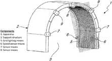
- FIG. 1is a perspective view schematically illustrating the automated and mobile apparatus for the detection and classification of damages on motor vehicles, according to the present invention
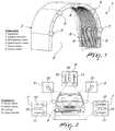
- FIG. 2is a front view schematically illustrating the position of all the sensor means of the apparatus in relation to the vehicle being scanned;
- FIG. 3is a side view schematically illustrating the typical working distance of the upper sensor system of the apparatus in relation to the front part of the vehicle;
- FIG. 4is a side view schematically illustrating the typical working distance of the upper sensor system of the apparatus in relation to another part of the vehicle;
- FIG. 5is a front view schematically illustrating the typical working distance of the side sensor system of the apparatus in relation to the vehicle;
- FIG. 6is an exploded view of the apparatus according to the invention.
- FIG. 7shows an example of image acquired by the upper sensor system of the present invention
- FIG. 8shows an example of pattern reflected by a damaged reflecting surface of the vehicle
- FIG. 9is a block diagram showing the process of the present invention.
- the automated and mobile apparatuscomprises a support structure 2 , shaped as an arch, which defines a passage area 3 , through which a vehicle 4 to be inspected is driven.
- the support structure 2supports grid lighting means 5 , adapted to light the passage area 3 and therefore all the surfaces of vehicle 4 to be inspected.
- the support structure 2further supports speed sensor means 6 , adapted to measure the speed of vehicle 4 , lateral sensor means 7 , upper sensor means 8 and diagonal sensor means 9 .
- Sensor means 7 , 8 and 9are adapted to measure the distance of the surfaces of vehicle 4 and to produce images of said surfaces.
- the lateral sensor means 7 and the upper sensor means 8each comprise a camera 10 , or other image capture device, and a distance-measuring device having a signal emitter 11 and a signal receiver 12 .
- the support structure 2is built in separate modules which can be assembled in a univocal way.
- the structure 2comprises two lateral modules 21 and 22 and an upper central module 23 .
- the apparatus 1allows to make an accurate detection of damages on the body of vehicle 4 , in particular counting said damages, positioning them on the vehicle, dimensionally classifying them, providing a report.
- the apparatusalso allows the recording and storage of the analyzed video images.
- the term damagespecifically means a dent or a depression on the vehicle body caused by pressure applied on such body by an external object, such as hail stone or others.
- the only task executed by the human operatoris that of driving the vehicle through the passage area 3 of the apparatus 1 .
- the apparatusmeasures the speed of the vehicle, the distance of the vehicle surfaces from the cameras 10 and records the video images of the surfaces of said vehicle.
- the speedis measured by the speed sensor means 6 , which comprise two or more presence sensors, spaced out from each other, and a timer.
- the passing vehiclefirstly interrupts the first presence sensor and subsequently the second presence sensor. Each sensor records the time of interruption. Knowing the physical distance between the sensors and the difference of the interruption time, the vehicle speed can be determined.
- the sensor means 7 , 8 and 9are able, thanks to the respective cameras 10 , to cover the whole surface of the vehicle along the shortest vehicle axis, i.e. the axis perpendicular to the driving direction.
- the lateral sensor means 7 and upper sensor means 8each further comprise a device for measuring the distance consisting in a signal emitter 11 and a signal receiver 12 .
- the exposition of all the sensor means 7 , 8 and 9may be adjusted in order to adapt the exposition to the vehicle color and in order to optimize the contrast of the pattern reflected by the vehicle surfaces.
- the image processing systemhas the information on the distance of the inspected surface from the camera.
- the vehicle surfaces which are further way from the sensor meanshave a lower resolution compared to the surfaces which are closer to the sensor means.
- FIG. 3shows an example of a greater distance 13 from the vehicle surface, in this case the bonnet, from the camera 10 of upper sensor means 8 .
- FIG. 4shows an example of a lesser distance 14 from the vehicle surface, in this case the roof, from the camera 10 of upper sensor means 8 .
- the distance measurements provided by the distance measurement devices 11 , 12are used by the processing system to accurately convert the damage dimensions from pixel units into physical units.
- the distance measurementcan be made with different techniques, such as TOF (Time of Flight) or the laser triangulation technique.
- TOFTime of Flight
- laser triangulation techniquethe laser triangulation technique
- FIG. 7shows an example of image 15 detected by the upper sensor system of the present apparatus.
- the grid 5consists of two portions: a thin grid portion 151 and a thick grid portion 152 .
- the thin grid portion 151allows to obtain a greater sensitivity to damages, however it can only be used for inspecting surfaces which are close to the cameras, where the working distance is short.
- the thick grid portion 152allows a lower sensitivity to damages, however it can also be used for surfaces further away from the cameras.
- the double grid 151 , 152allows to make the scan of different components of the vehicle (bonnet, roof) and allows to make the scan of vehicles of different heights.
- FIG. 8schematically shows the pattern reflected on the damaged surface of the vehicle.
- the patternis locally distorted around damages 16 . Such distortions in the reflected pattern are detected through the method of image analysis of the present invention.
- FIGS. 3 and 4illustrate the typical working distance of the upper sensor means 8 from the inspected vehicle surface. Such distance varies significantly for the different types of vehicles as well as for each single vehicle due to the fact that the roof and bonnet are at different distances from the sensor means.
- the upper sensor means 8must operate at great working distances 13 as well as at small working distances 14 .
- FIG. 5illustrates the typical working distance of the lateral sensor means 7 .
- the working distance of the lateral sensor means 7 from the vehicle surfaceis the same on both sides of the vehicle, i.e. the vehicle should be driven centrally within the passage area, however the lateral working distance, indicated with reference numbers 17 and 18 in FIG. 5 , varies in any case according to the different types of vehicles, due to the different widths of the vehicles.
- the measurements of the vehicle speed and of the distance from the inspected surface for each sensor meansare used to precisely calculate the vehicle movement between two subsequent video images in pixel units, which allows to keep track of the damages detected in the video, i.e. allows to find a correspondence of the damages in consecutive images.
- FIG. 6is an exploded view which shows the support structure 2 broken into its components: two lateral modules 21 and 22 and an upper central module 23 .
- a single operatorcan perform all the operations for assembly and disassembly of such components.
- the sensor meansare integrated into each module and the three modules can be assembled in a univocal way, without possibility of error.
- the sensor means 7 , 8 and 9are integrated into the modules 21 , 22 and 23 in a permanent way when manufacturing the modules.
- the apparatusOnce the apparatus is assembled, before its first use, all the sensor means are calibrated. Nevertheless, after the first calibration, the permanent integration of the sensors in the modules allows for an instantaneous use of the device even after the disassembly and later re-assembly of the modules, and no further calibration of the system is needed.
- FIG. 9is a block diagram which represents the method of analysis according to the present invention.
- Scanning of a vehicle 4is done by driving the vehicle through the passage area 3 of structure 2 .
- the apparatus 1measures the speed of the vehicle 4 , the distance of vehicle 4 from each of the sensor means 7 , 8 and 9 , and captures a video image of the vehicle surfaces using the deflectometry technique.
- the acquired imagesare transferred to an image processing unit to make the analysis of said images according to the method of the present invention.
- the method of analysis of the imagescomprises pattern recognition of inspected surfaces, pattern analysis, detection of possible damages, tracking of detected damages on video and classification of said damages.
- the detected damagesare tracked on video to distinguish real surface damages from possible detected damages and to allow the localization of the position of each detected damage on the vehicle.
- the methodalso comprises an interactive tool which allows the operator to interact with the apparatus and with the results.
- the methodalso comprises a system for providing a report and for the recording and storing the videos.
- the distance measurementsare synchronized with the video recording, allowing an accurate estimation of the distance of the inspected surface for each video image.
- the measurementsallow the conversion of digital pixel units into physical units.
- the pattern recognitionwhich can be carried out using several segmentation methods, determines the areas which must be analyzed for damages.
- the image analysisis thus carried out only for the relevant areas, and this greatly reduces the processing times and reduces the possibility of fake damage detections.
- the surface damagesare detectable as local distortions of the pattern reflected by the vehicle surface.
- the image analysis systemdetects the distortions and tags them as possible damages, and all possible damages are tracked on video.
- the tracking on video of consecutive imagesis done by software systems which identify the most appropriate correspondences, for instance they search for the closest image incorporating the calculation of the vehicle movement (in pixel) between two consecutive images.
- the vehicle moving speedin pixel, is obtained from the measurement of the vehicle speed and of the working distance of sensors 13 , 14 , 17 and 18 , i.e. the distance of the inspected surface from sensors 10 . No markers are needed on the vehicle according to the present method.
- Each possible damagemust be detected on several consecutive images to be recognized as a surface damage.
- the possible damages which are not recognized as surface damagesare considered fake surface damages and excluded from further analysis, counting and reporting.
- All detected damagesare converted by an image coordinates system into a global vehicle coordinates system in order to identify the position of each damage.
- the localization of the positionallows the counting of damages for each vehicle part and their visualization on the damage report.
- the system according to the present inventioncomprises an independent interactive tool which allows semi-automatic adding or removing of damages on the vehicle. If a damage is manually added or removed on a given image by an expert using the interactive tool, the damage is automatically added or removed in all corresponding video images, preceding and subsequent. The damage report and the counting of damages are correspondingly modified.
- the inventionachieves the aim and objects by providing a mobile and automated apparatus, for the detection and the classification of body damages which is able to make an accurate scan of a vehicle which makes a single pass through the said apparatus.
- the apparatusis adapted to all types of motor vehicles, such as cars and vans, and does not need the presence of markers on the body.
- the cameras 10are high-frequency and high-resolution cameras.
- All the cameras 10 and the distance measurement devices 11 , 12are able to make the measurements simultaneously.
- a further advantage of the present apparatusconsists in the fact that the vehicle can be driven through the passage area 3 at an arbitrary speed.
- the present inventionuses a low-number, typically 3 to 5, of high-definition cameras, each of which records moving images (videos) of the vehicle passing under the apparatus. Each camera generates a video which is analyzed by a proprietary shape recognition algorithm ( FIGS. 7 and 8 ) that detects the body deformation (dent or depression) based on the fact that the reflected lines recorded by the cameras are not straight but curving around the dent or depression.
- a proprietary shape recognition algorithmFIGS. 7 and 8
- the black and white stripesare essential to detect the damage, contrary to prior art systems such as in GB2308656A where they are used to confirm defect detections and eliminate false detections by repetition.
- the shape of the reflectionis essential in the present invention and not the level of brightness as in GB2308656A.
- the shapeafter processing by the proprietary algorithm, is used to determine the size and position of the dent or depression. Therefore, according to the present invention, any vehicle body of any shape can pass under the apparatus and the damages can be detected, and there is no need for a pre-determined “reference model” as in prior art systems, such as GB2308656A for example.
- the distance sensorsallow the proprietary shape recognition algorithm to work effectively.
- the system according to the present inventiondetects and classifies damages based on distorted shapes which are recognized by a proprietary algorithm, whereas prior art systems, such as GB2308656A, merely recognize brightness differences between the images received and the pre-determined reference model.
- a further feature of the present inventionis that the apparatus automatically detects and classifies the dents into any number of categories that can be defined by the operator while the prior art systems, such as US2014/0201022A1 for example, merely suggest to a classification of dents into three size categories: large-medium-small.
Landscapes
- Physics & Mathematics (AREA)
- General Physics & Mathematics (AREA)
- Engineering & Computer Science (AREA)
- Computer Vision & Pattern Recognition (AREA)
- Pathology (AREA)
- Health & Medical Sciences (AREA)
- Life Sciences & Earth Sciences (AREA)
- Chemical & Material Sciences (AREA)
- Analytical Chemistry (AREA)
- Biochemistry (AREA)
- General Health & Medical Sciences (AREA)
- Immunology (AREA)
- Signal Processing (AREA)
- Length Measuring Devices By Optical Means (AREA)
- Investigating Materials By The Use Of Optical Means Adapted For Particular Applications (AREA)
- Sorting Of Articles (AREA)
Abstract
Description
Claims (7)
Applications Claiming Priority (4)
| Application Number | Priority Date | Filing Date | Title |
|---|---|---|---|
| IT102017000002416 | 2017-01-11 | ||
| IT102017000002416AIT201700002416A1 (en) | 2017-01-11 | 2017-01-11 | AUTOMATED MOBILE EQUIPMENT FOR DETECTION AND CLASSIFICATION OF BODY DAMAGE |
| IT2017000002416 | 2017-01-11 | ||
| PCT/EP2018/000009WO2018130421A1 (en) | 2017-01-11 | 2018-01-08 | Mobile and automated apparatus for the detection and classification of damages on the body of a vehicle |
Publications (2)
| Publication Number | Publication Date |
|---|---|
| US20200011808A1 US20200011808A1 (en) | 2020-01-09 |
| US10976262B2true US10976262B2 (en) | 2021-04-13 |
Family
ID=58671824
Family Applications (1)
| Application Number | Title | Priority Date | Filing Date |
|---|---|---|---|
| US16/468,417Active2038-01-12US10976262B2 (en) | 2017-01-11 | 2018-01-08 | Mobile and automated apparatus for the detection and classification of damages on the body of a vehicle |
Country Status (7)
| Country | Link |
|---|---|
| US (1) | US10976262B2 (en) |
| EP (1) | EP3568668B1 (en) |
| AU (1) | AU2018208312B2 (en) |
| CA (1) | CA3041590C (en) |
| ES (1) | ES2910068T3 (en) |
| IT (1) | IT201700002416A1 (en) |
| WO (1) | WO2018130421A1 (en) |
Cited By (1)
| Publication number | Priority date | Publication date | Assignee | Title |
|---|---|---|---|---|
| US12437389B2 (en) | 2021-04-26 | 2025-10-07 | 2872475 Ontario Limited | Vehicle damage detection system and method |
Families Citing this family (22)
| Publication number | Priority date | Publication date | Assignee | Title |
|---|---|---|---|---|
| CN108921811B (en)* | 2018-04-03 | 2020-06-30 | 阿里巴巴集团控股有限公司 | Method and device for detecting item damage, item damage detector |
| DE102018118602B3 (en)* | 2018-07-31 | 2019-11-28 | Sarma Aryasomayajula | Method and device for detecting and analyzing surface defects of three-dimensional objects with a reflective surface, in particular motor vehicle bodies |
| BR112021006438A2 (en)* | 2018-10-03 | 2021-07-06 | Solera Holdings Inc | apparatus and method for combined visual intelligence |
| CN113383207A (en)* | 2018-10-04 | 2021-09-10 | 杜·普雷兹·伊萨克 | Optical surface encoder |
| IT201900014001A1 (en)* | 2019-08-05 | 2021-02-05 | Texa Spa | REGULATION APPARATUS FOR VEHICLE CALIBRATION DEVICES |
| EP3792619B1 (en)* | 2019-09-11 | 2023-11-01 | Proov Station | Assembly for detecting faults on a body of a motor vehicle |
| CN114450580A (en) | 2019-10-02 | 2022-05-06 | 柯尼卡美能达株式会社 | Workpiece surface defect detection device and detection method, workpiece surface inspection system, and program |
| GB2582397B (en) | 2019-10-04 | 2022-05-18 | Degould Ltd | Vehicle imaging station |
| LU101454B1 (en) | 2019-10-16 | 2021-04-27 | Virelux Inspection Systems Sarl | Method and system for determining a three-dimensional definition of an object by reflectometry |
| MX2022004871A (en)* | 2019-10-28 | 2022-05-13 | 3M Innovative Properties Company | AUTOMATED VEHICLE REPAIR SYSTEM. |
| DE102019129474A1 (en)* | 2019-10-31 | 2021-05-06 | Bayerische Motoren Werke Aktiengesellschaft | Method to support a visual inspection of components |
| NL2025856B1 (en)* | 2020-06-18 | 2022-02-17 | Singa Ip B V | Device and method for determining the three-dimensional geometry of an individual object |
| IT202000003802U1 (en) | 2020-06-30 | 2021-12-30 | Autoscan Gmbh | MOBILE AUTOMATED EQUIPMENT FOR THE DETECTION AND CLASSIFICATION OF DAMAGE ON THE BODYWORK, IN PARTICULAR OF A VEHICLE SUCH AS A CAR |
| RU2763307C2 (en)* | 2021-02-01 | 2021-12-28 | Виталий Сергеевич Новицкий | Method for detecting dents on vehicle body elements and device for implementing this method |
| JP2022127412A (en)* | 2021-02-19 | 2022-08-31 | トヨタ自動車株式会社 | Information processing system, information processing method and program |
| EP4298595A4 (en)* | 2021-02-25 | 2025-01-29 | Spinframe Technologies Ltd | SYSTEM AND METHOD FOR AUTOMATIC VEHICLE INSPECTION |
| US20250252546A1 (en)* | 2021-07-27 | 2025-08-07 | Konica Minolta, Inc. | Image capture condition adjustment device, image capture condition adjustment method, and program |
| CN114166128B (en)* | 2021-12-15 | 2023-08-11 | 北京微链道爱科技有限公司 | 3D camera detection device and detection method for rail transit equipment |
| CN115561242A (en)* | 2022-09-24 | 2023-01-03 | 广汽乘用车(杭州)有限公司 | Automatic positioning system and automatic positioning method for surface defects of automobile body |
| LU503215B1 (en)* | 2022-12-20 | 2024-06-20 | Virelux Inspection Systems Sarl | Dynamic single-period reflectometry scanner |
| GB2632421A (en)* | 2023-08-07 | 2025-02-12 | Degould Ltd | Vehicle imaging system |
| DE102024208623A1 (en) | 2023-09-12 | 2025-03-13 | Robert Bosch Gesellschaft mit beschränkter Haftung | Method and device for detecting damage to a vehicle body and server device |
Citations (31)
| Publication number | Priority date | Publication date | Assignee | Title |
|---|---|---|---|---|
| JPS5814027A (en)* | 1981-07-17 | 1983-01-26 | Japanese National Railways<Jnr> | Tester for operation of vehicle |
| JPH02300617A (en)* | 1989-05-16 | 1990-12-12 | Matsushita Electric Ind Co Ltd | Shape measuring device |
| JPH09280845A (en) | 1996-04-09 | 1997-10-31 | Nissan Motor Co Ltd | Surface defect inspection equipment |
| US5726705A (en)* | 1995-12-28 | 1998-03-10 | Nissan Motor Co., Ltd. | Surface defect inspection apparatus |
| JPH1096615A (en) | 1996-01-18 | 1998-04-14 | Nissan Motor Co Ltd | Painting defect inspection equipment |
| JP2003148953A (en)* | 2001-11-07 | 2003-05-21 | Nippon Telegr & Teleph Corp <Ntt> | Distance measuring method and device |
| US7164117B2 (en)* | 1992-05-05 | 2007-01-16 | Automotive Technologies International, Inc. | Vehicular restraint system control system and method using multiple optical imagers |
| US20070146728A1 (en) | 2003-04-03 | 2007-06-28 | Erwin Pristner | Method and device for detecting, determining and documenting damage, especially deformations in lacquered surfaces caused by sudden events |
| US20070253692A1 (en)* | 2006-04-28 | 2007-11-01 | Hiroshi Terada | Camera capable of displaying live view |
| DE102007013883A1 (en) | 2007-03-20 | 2008-10-30 | Beulenzentrum Jentgens Gmbh & Co. Kg | Damage i.e. hail damage, detecting and examining method for body of motor vehicle, involves detecting damages by scanning surface of motor vehicle while scanning devices i.e. laser scanners, are moved automatically relative to surface |
| US20110126617A1 (en)* | 2007-09-03 | 2011-06-02 | Koninklijke Philips Electronics N.V. | Laser sensor based system for status detection of tires |
| US20110196551A1 (en)* | 2010-01-20 | 2011-08-11 | Eurocopter Deutschland Gmbh | System and method for situation specific generation and assessment of risk profiles and start of suitable action for protection of vehicles |
| DE102010015566A1 (en) | 2010-04-19 | 2011-10-20 | Technische Universität Dortmund | Method for metric measurement of reflective surface, particularly for determining number of hail damages on vehicle surface, involves recording pattern generated at illuminated surface by using sensor surfaces of two cameras |
| US20120297337A1 (en)* | 2006-05-31 | 2012-11-22 | Manheim Investments, Inc. | Computer-based technology for aiding the repair of motor vehicles |
| AU2013101009A4 (en) | 2013-07-25 | 2013-08-29 | Cross, Michael MR | "DAVE" Digital Auto Visual Environment |
| US20140201022A1 (en)* | 2013-01-16 | 2014-07-17 | Andre Balzer | Vehicle damage processing and information system |
| US20150091718A1 (en)* | 2013-09-30 | 2015-04-02 | Hella Kgaa Hueck & Co. | Method for recognising and classifying damage incidents on motor vehicles and a device for the same |
| US20150212189A1 (en)* | 2014-01-30 | 2015-07-30 | Hella Kgaa Hueck & Co. | Device and method for detecting at least one structure-borne sound signal |
| CN105913410A (en)* | 2016-03-03 | 2016-08-31 | 华北电力大学(保定) | Long-distance moving object height measurement apparatus and method based on machine vision |
| CN106051573A (en)* | 2015-04-03 | 2016-10-26 | 株式会社小糸制作所 | Vehicle lamp |
| US20170010356A1 (en)* | 2015-07-10 | 2017-01-12 | Hexagon Technology Center Gmbh | 3d measuring machine |
| US9586138B2 (en)* | 2014-05-06 | 2017-03-07 | SZ DJI Technology Co., Ltd. | Apparatus, systems, and methods for detecting projectile hits on a surface |
| US20170106885A1 (en)* | 2015-09-03 | 2017-04-20 | Sameer Singh | Railroad track survey system |
| US20170169369A1 (en)* | 2015-12-15 | 2017-06-15 | International Business Machines Corporation | Image-based risk estimation |
| US9886771B1 (en)* | 2016-05-20 | 2018-02-06 | Ccc Information Services Inc. | Heat map of vehicle damage |
| US10007981B2 (en)* | 2016-07-09 | 2018-06-26 | Mountain Forge | Automated radial imaging and analysis system |
| CN109034266A (en)* | 2018-08-16 | 2018-12-18 | 新智数字科技有限公司 | A kind of target image detection method, apparatus and system |
| US10169856B1 (en)* | 2016-01-27 | 2019-01-01 | United Services Automobile Association (Usaa) | Laser-assisted image processing |
| US10255521B2 (en)* | 2016-12-12 | 2019-04-09 | Jack Cooper Logistics, LLC | System, method, and apparatus for detection of damages on surfaces |
| US10438293B2 (en)* | 2015-07-20 | 2019-10-08 | Audatex North America, Inc. | Vehicle estimating system that utilizes volumetric finite element analysis to provide a predictive estimate |
| US10576907B2 (en)* | 2014-05-13 | 2020-03-03 | Gse Technologies, Llc | Remote scanning and detection apparatus and method |
- 2017
- 2017-01-11ITIT102017000002416Apatent/IT201700002416A1/enunknown
- 2018
- 2018-01-08ESES18705829Tpatent/ES2910068T3/enactiveActive
- 2018-01-08EPEP18705829.2Apatent/EP3568668B1/enactiveActive
- 2018-01-08CACA3041590Apatent/CA3041590C/enactiveActive
- 2018-01-08WOPCT/EP2018/000009patent/WO2018130421A1/ennot_activeCeased
- 2018-01-08USUS16/468,417patent/US10976262B2/enactiveActive
- 2018-01-08AUAU2018208312Apatent/AU2018208312B2/enactiveActive
Patent Citations (31)
| Publication number | Priority date | Publication date | Assignee | Title |
|---|---|---|---|---|
| JPS5814027A (en)* | 1981-07-17 | 1983-01-26 | Japanese National Railways<Jnr> | Tester for operation of vehicle |
| JPH02300617A (en)* | 1989-05-16 | 1990-12-12 | Matsushita Electric Ind Co Ltd | Shape measuring device |
| US7164117B2 (en)* | 1992-05-05 | 2007-01-16 | Automotive Technologies International, Inc. | Vehicular restraint system control system and method using multiple optical imagers |
| US5726705A (en)* | 1995-12-28 | 1998-03-10 | Nissan Motor Co., Ltd. | Surface defect inspection apparatus |
| JPH1096615A (en) | 1996-01-18 | 1998-04-14 | Nissan Motor Co Ltd | Painting defect inspection equipment |
| JPH09280845A (en) | 1996-04-09 | 1997-10-31 | Nissan Motor Co Ltd | Surface defect inspection equipment |
| JP2003148953A (en)* | 2001-11-07 | 2003-05-21 | Nippon Telegr & Teleph Corp <Ntt> | Distance measuring method and device |
| US20070146728A1 (en) | 2003-04-03 | 2007-06-28 | Erwin Pristner | Method and device for detecting, determining and documenting damage, especially deformations in lacquered surfaces caused by sudden events |
| US20070253692A1 (en)* | 2006-04-28 | 2007-11-01 | Hiroshi Terada | Camera capable of displaying live view |
| US20120297337A1 (en)* | 2006-05-31 | 2012-11-22 | Manheim Investments, Inc. | Computer-based technology for aiding the repair of motor vehicles |
| DE102007013883A1 (en) | 2007-03-20 | 2008-10-30 | Beulenzentrum Jentgens Gmbh & Co. Kg | Damage i.e. hail damage, detecting and examining method for body of motor vehicle, involves detecting damages by scanning surface of motor vehicle while scanning devices i.e. laser scanners, are moved automatically relative to surface |
| US20110126617A1 (en)* | 2007-09-03 | 2011-06-02 | Koninklijke Philips Electronics N.V. | Laser sensor based system for status detection of tires |
| US20110196551A1 (en)* | 2010-01-20 | 2011-08-11 | Eurocopter Deutschland Gmbh | System and method for situation specific generation and assessment of risk profiles and start of suitable action for protection of vehicles |
| DE102010015566A1 (en) | 2010-04-19 | 2011-10-20 | Technische Universität Dortmund | Method for metric measurement of reflective surface, particularly for determining number of hail damages on vehicle surface, involves recording pattern generated at illuminated surface by using sensor surfaces of two cameras |
| US20140201022A1 (en)* | 2013-01-16 | 2014-07-17 | Andre Balzer | Vehicle damage processing and information system |
| AU2013101009A4 (en) | 2013-07-25 | 2013-08-29 | Cross, Michael MR | "DAVE" Digital Auto Visual Environment |
| US20150091718A1 (en)* | 2013-09-30 | 2015-04-02 | Hella Kgaa Hueck & Co. | Method for recognising and classifying damage incidents on motor vehicles and a device for the same |
| US20150212189A1 (en)* | 2014-01-30 | 2015-07-30 | Hella Kgaa Hueck & Co. | Device and method for detecting at least one structure-borne sound signal |
| US9586138B2 (en)* | 2014-05-06 | 2017-03-07 | SZ DJI Technology Co., Ltd. | Apparatus, systems, and methods for detecting projectile hits on a surface |
| US10576907B2 (en)* | 2014-05-13 | 2020-03-03 | Gse Technologies, Llc | Remote scanning and detection apparatus and method |
| CN106051573A (en)* | 2015-04-03 | 2016-10-26 | 株式会社小糸制作所 | Vehicle lamp |
| US20170010356A1 (en)* | 2015-07-10 | 2017-01-12 | Hexagon Technology Center Gmbh | 3d measuring machine |
| US10438293B2 (en)* | 2015-07-20 | 2019-10-08 | Audatex North America, Inc. | Vehicle estimating system that utilizes volumetric finite element analysis to provide a predictive estimate |
| US20170106885A1 (en)* | 2015-09-03 | 2017-04-20 | Sameer Singh | Railroad track survey system |
| US20170169369A1 (en)* | 2015-12-15 | 2017-06-15 | International Business Machines Corporation | Image-based risk estimation |
| US10169856B1 (en)* | 2016-01-27 | 2019-01-01 | United Services Automobile Association (Usaa) | Laser-assisted image processing |
| CN105913410A (en)* | 2016-03-03 | 2016-08-31 | 华北电力大学(保定) | Long-distance moving object height measurement apparatus and method based on machine vision |
| US9886771B1 (en)* | 2016-05-20 | 2018-02-06 | Ccc Information Services Inc. | Heat map of vehicle damage |
| US10007981B2 (en)* | 2016-07-09 | 2018-06-26 | Mountain Forge | Automated radial imaging and analysis system |
| US10255521B2 (en)* | 2016-12-12 | 2019-04-09 | Jack Cooper Logistics, LLC | System, method, and apparatus for detection of damages on surfaces |
| CN109034266A (en)* | 2018-08-16 | 2018-12-18 | 新智数字科技有限公司 | A kind of target image detection method, apparatus and system |
Cited By (1)
| Publication number | Priority date | Publication date | Assignee | Title |
|---|---|---|---|---|
| US12437389B2 (en) | 2021-04-26 | 2025-10-07 | 2872475 Ontario Limited | Vehicle damage detection system and method |
Also Published As
| Publication number | Publication date |
|---|---|
| US20200011808A1 (en) | 2020-01-09 |
| WO2018130421A1 (en) | 2018-07-19 |
| EP3568668A1 (en) | 2019-11-20 |
| IT201700002416A1 (en) | 2018-07-11 |
| ES2910068T3 (en) | 2022-05-11 |
| AU2018208312B2 (en) | 2021-04-01 |
| CA3041590C (en) | 2021-07-27 |
| CA3041590A1 (en) | 2018-07-19 |
| EP3568668B1 (en) | 2022-01-26 |
| AU2018208312A1 (en) | 2019-07-04 |
Similar Documents
| Publication | Publication Date | Title |
|---|---|---|
| US10976262B2 (en) | Mobile and automated apparatus for the detection and classification of damages on the body of a vehicle | |
| EP3388781B1 (en) | System and method for detecting defects in specular or semi-specular surfaces by means of photogrammetric projection | |
| KR101773791B1 (en) | Method and device for inspecting surfaces of an examined object | |
| US10760898B2 (en) | Optical device and method for inspecting tires | |
| US20130057678A1 (en) | Inspection system and method of defect detection on specular surfaces | |
| RU2764644C1 (en) | Method for detecting surface defects, device for detecting surface defects, method for producing steel materials, method for steel material quality control, steel materials production plant, method for generating models for determining surface defects and a model for determining surface defects | |
| JP2020008501A (en) | Surface defect detection apparatus and surface defect detection method | |
| WO2021064893A1 (en) | Workpiece surface defect detection device and detection method, workpiece surface inspection system, and program | |
| CN1839306B (en) | Macro defect detection using micro-inspection input | |
| JP2021056183A (en) | Apparatus and method for detecting surface defect of workpiece, surface inspection system for workpiece, and program | |
| CN118172046B (en) | Vehicle maintenance management method and system | |
| CN115375608A (en) | Detection method and device, detection equipment and storage medium | |
| JP2021060392A (en) | Device, method, and system for detecting surface defects of workpiece and program | |
| US12387312B2 (en) | Production-speed component inspection system and method | |
| JP2008160635A (en) | Camera state detection method | |
| JP2000321039A (en) | Paint defect inspection apparatus and method | |
| Akhtar et al. | A robotics inspection system for detecting defects on semi-specular painted automotive surfaces | |
| KR100950270B1 (en) | Mobile phone lens resolution automatic inspection device | |
| US11475553B1 (en) | Production-speed component inspection system and method | |
| US10241000B2 (en) | Method for checking the position of characteristic points in light distributions | |
| Safizadeh et al. | Automated detection of inner surface defects in pipes using image processing algorithms | |
| CN111183351A (en) | Image sensor surface defect detection method and detection system | |
| CN112102293B (en) | Rapid detection method for foreign matters in triangular holes of railway wagon | |
| JP2006226834A (en) | Surface inspection device, surface inspection method | |
| WO2020116075A1 (en) | Press-molded article necking determination method, press-molded article necking determination apparatus, and program |
Legal Events
| Date | Code | Title | Description |
|---|---|---|---|
| FEPP | Fee payment procedure | Free format text:ENTITY STATUS SET TO UNDISCOUNTED (ORIGINAL EVENT CODE: BIG.); ENTITY STATUS OF PATENT OWNER: SMALL ENTITY | |
| FEPP | Fee payment procedure | Free format text:ENTITY STATUS SET TO SMALL (ORIGINAL EVENT CODE: SMAL); ENTITY STATUS OF PATENT OWNER: SMALL ENTITY | |
| AS | Assignment | Owner name:AUTOSCAN GMBH, GERMANY Free format text:ASSIGNMENT OF ASSIGNORS INTEREST;ASSIGNOR:OZIM, MATEJ;REEL/FRAME:051078/0397 Effective date:20191021 | |
| STPP | Information on status: patent application and granting procedure in general | Free format text:RESPONSE TO NON-FINAL OFFICE ACTION ENTERED AND FORWARDED TO EXAMINER | |
| STPP | Information on status: patent application and granting procedure in general | Free format text:NOTICE OF ALLOWANCE MAILED -- APPLICATION RECEIVED IN OFFICE OF PUBLICATIONS | |
| STPP | Information on status: patent application and granting procedure in general | Free format text:NOTICE OF ALLOWANCE MAILED -- APPLICATION RECEIVED IN OFFICE OF PUBLICATIONS | |
| STPP | Information on status: patent application and granting procedure in general | Free format text:PUBLICATIONS -- ISSUE FEE PAYMENT RECEIVED | |
| STPP | Information on status: patent application and granting procedure in general | Free format text:PUBLICATIONS -- ISSUE FEE PAYMENT VERIFIED | |
| STCF | Information on status: patent grant | Free format text:PATENTED CASE | |
| MAFP | Maintenance fee payment | Free format text:PAYMENT OF MAINTENANCE FEE, 4TH YR, SMALL ENTITY (ORIGINAL EVENT CODE: M2551); ENTITY STATUS OF PATENT OWNER: SMALL ENTITY Year of fee payment:4 |