US10974121B2 - Swing quality measurement system - Google Patents
Swing quality measurement systemDownload PDFInfo
- Publication number
- US10974121B2 US10974121B2US16/835,247US202016835247AUS10974121B2US 10974121 B2US10974121 B2US 10974121B2US 202016835247 AUS202016835247 AUS 202016835247AUS 10974121 B2US10974121 B2US 10974121B2
- Authority
- US
- United States
- Prior art keywords
- swing
- bat
- plane
- axis
- impact
- Prior art date
- Legal status (The legal status is an assumption and is not a legal conclusion. Google has not performed a legal analysis and makes no representation as to the accuracy of the status listed.)
- Active
Links
Images


Classifications
- G—PHYSICS
- G06—COMPUTING OR CALCULATING; COUNTING
- G06Q—INFORMATION AND COMMUNICATION TECHNOLOGY [ICT] SPECIALLY ADAPTED FOR ADMINISTRATIVE, COMMERCIAL, FINANCIAL, MANAGERIAL OR SUPERVISORY PURPOSES; SYSTEMS OR METHODS SPECIALLY ADAPTED FOR ADMINISTRATIVE, COMMERCIAL, FINANCIAL, MANAGERIAL OR SUPERVISORY PURPOSES, NOT OTHERWISE PROVIDED FOR
- G06Q10/00—Administration; Management
- G06Q10/06—Resources, workflows, human or project management; Enterprise or organisation planning; Enterprise or organisation modelling
- G06Q10/063—Operations research, analysis or management
- G06Q10/0639—Performance analysis of employees; Performance analysis of enterprise or organisation operations
- A—HUMAN NECESSITIES
- A63—SPORTS; GAMES; AMUSEMENTS
- A63B—APPARATUS FOR PHYSICAL TRAINING, GYMNASTICS, SWIMMING, CLIMBING, OR FENCING; BALL GAMES; TRAINING EQUIPMENT
- A63B69/00—Training appliances or apparatus for special sports
- A63B69/36—Training appliances or apparatus for special sports for golf
- A63B69/3676—Training appliances or apparatus for special sports for golf for putting
- A63B69/3685—Putters or attachments on putters, e.g. for measuring, aligning
- A—HUMAN NECESSITIES
- A63—SPORTS; GAMES; AMUSEMENTS
- A63B—APPARATUS FOR PHYSICAL TRAINING, GYMNASTICS, SWIMMING, CLIMBING, OR FENCING; BALL GAMES; TRAINING EQUIPMENT
- A63B69/00—Training appliances or apparatus for special sports
- A63B69/36—Training appliances or apparatus for special sports for golf
- A63B69/3623—Training appliances or apparatus for special sports for golf for driving
- A63B69/3632—Clubs or attachments on clubs, e.g. for measuring, aligning
- A63B69/3635—Clubs or attachments on clubs, e.g. for measuring, aligning with sound-emitting source
- G—PHYSICS
- G01—MEASURING; TESTING
- G01C—MEASURING DISTANCES, LEVELS OR BEARINGS; SURVEYING; NAVIGATION; GYROSCOPIC INSTRUMENTS; PHOTOGRAMMETRY OR VIDEOGRAMMETRY
- G01C21/00—Navigation; Navigational instruments not provided for in groups G01C1/00 - G01C19/00
- G—PHYSICS
- G01—MEASURING; TESTING
- G01C—MEASURING DISTANCES, LEVELS OR BEARINGS; SURVEYING; NAVIGATION; GYROSCOPIC INSTRUMENTS; PHOTOGRAMMETRY OR VIDEOGRAMMETRY
- G01C21/00—Navigation; Navigational instruments not provided for in groups G01C1/00 - G01C19/00
- G01C21/10—Navigation; Navigational instruments not provided for in groups G01C1/00 - G01C19/00 by using measurements of speed or acceleration
- G01C21/12—Navigation; Navigational instruments not provided for in groups G01C1/00 - G01C19/00 by using measurements of speed or acceleration executed aboard the object being navigated; Dead reckoning
- G01C21/16—Navigation; Navigational instruments not provided for in groups G01C1/00 - G01C19/00 by using measurements of speed or acceleration executed aboard the object being navigated; Dead reckoning by integrating acceleration or speed, i.e. inertial navigation
- G06K9/00342—
- G06K9/00523—
- G06K9/00536—
- G—PHYSICS
- G06—COMPUTING OR CALCULATING; COUNTING
- G06T—IMAGE DATA PROCESSING OR GENERATION, IN GENERAL
- G06T7/00—Image analysis
- G06T7/20—Analysis of motion
- G—PHYSICS
- G06—COMPUTING OR CALCULATING; COUNTING
- G06V—IMAGE OR VIDEO RECOGNITION OR UNDERSTANDING
- G06V40/00—Recognition of biometric, human-related or animal-related patterns in image or video data
- G06V40/20—Movements or behaviour, e.g. gesture recognition
- G06V40/23—Recognition of whole body movements, e.g. for sport training
- A—HUMAN NECESSITIES
- A63—SPORTS; GAMES; AMUSEMENTS
- A63B—APPARATUS FOR PHYSICAL TRAINING, GYMNASTICS, SWIMMING, CLIMBING, OR FENCING; BALL GAMES; TRAINING EQUIPMENT
- A63B69/00—Training appliances or apparatus for special sports
- A63B69/0002—Training appliances or apparatus for special sports for baseball
- A63B2069/0004—Training appliances or apparatus for special sports for baseball specially adapted for particular training aspects
- A63B2069/0008—Training appliances or apparatus for special sports for baseball specially adapted for particular training aspects for batting
- A—HUMAN NECESSITIES
- A63—SPORTS; GAMES; AMUSEMENTS
- A63B—APPARATUS FOR PHYSICAL TRAINING, GYMNASTICS, SWIMMING, CLIMBING, OR FENCING; BALL GAMES; TRAINING EQUIPMENT
- A63B2220/00—Measuring of physical parameters relating to sporting activity
- A63B2220/18—Inclination, slope or curvature
- A—HUMAN NECESSITIES
- A63—SPORTS; GAMES; AMUSEMENTS
- A63B—APPARATUS FOR PHYSICAL TRAINING, GYMNASTICS, SWIMMING, CLIMBING, OR FENCING; BALL GAMES; TRAINING EQUIPMENT
- A63B2220/00—Measuring of physical parameters relating to sporting activity
- A63B2220/80—Special sensors, transducers or devices therefor
- A63B2220/83—Special sensors, transducers or devices therefor characterised by the position of the sensor
- A63B2220/833—Sensors arranged on the exercise apparatus or sports implement
- G—PHYSICS
- G01—MEASURING; TESTING
- G01P—MEASURING LINEAR OR ANGULAR SPEED, ACCELERATION, DECELERATION, OR SHOCK; INDICATING PRESENCE, ABSENCE, OR DIRECTION, OF MOVEMENT
- G01P15/00—Measuring acceleration; Measuring deceleration; Measuring shock, i.e. sudden change of acceleration
- G01P15/02—Measuring acceleration; Measuring deceleration; Measuring shock, i.e. sudden change of acceleration by making use of inertia forces using solid seismic masses
- G01P15/08—Measuring acceleration; Measuring deceleration; Measuring shock, i.e. sudden change of acceleration by making use of inertia forces using solid seismic masses with conversion into electric or magnetic values
- G01P15/0888—Measuring acceleration; Measuring deceleration; Measuring shock, i.e. sudden change of acceleration by making use of inertia forces using solid seismic masses with conversion into electric or magnetic values for indicating angular acceleration
- G—PHYSICS
- G06—COMPUTING OR CALCULATING; COUNTING
- G06F—ELECTRIC DIGITAL DATA PROCESSING
- G06F2218/00—Aspects of pattern recognition specially adapted for signal processing
- G06F2218/08—Feature extraction
- G—PHYSICS
- G06—COMPUTING OR CALCULATING; COUNTING
- G06F—ELECTRIC DIGITAL DATA PROCESSING
- G06F2218/00—Aspects of pattern recognition specially adapted for signal processing
- G06F2218/12—Classification; Matching
- G—PHYSICS
- G16—INFORMATION AND COMMUNICATION TECHNOLOGY [ICT] SPECIALLY ADAPTED FOR SPECIFIC APPLICATION FIELDS
- G16H—HEALTHCARE INFORMATICS, i.e. INFORMATION AND COMMUNICATION TECHNOLOGY [ICT] SPECIALLY ADAPTED FOR THE HANDLING OR PROCESSING OF MEDICAL OR HEALTHCARE DATA
- G16H20/00—ICT specially adapted for therapies or health-improving plans, e.g. for handling prescriptions, for steering therapy or for monitoring patient compliance
- G16H20/30—ICT specially adapted for therapies or health-improving plans, e.g. for handling prescriptions, for steering therapy or for monitoring patient compliance relating to physical therapies or activities, e.g. physiotherapy, acupressure or exercising
Definitions
- One or more embodiments setting forth the ideas described throughout this disclosurepertain to the field of motion capture sensors and analysis of motion capture data. More particularly, but not by way of limitation, one or more aspects of the invention enable a method for analysis of a baseball swing using data captured from a motion sensor on the bat.
- Methods for analyzing swings of a piece of equipmentsuch as a golf club, tennis racquet or baseball swings for example include video capture systems that record high speed video of a swing and that analyze the motion of the piece of equipment, club, racquet or bat, etc., and the player from the video. These systems are typically expensive and complex, and they are not portable.
- Another methodis to attach a motion sensor to the piece of equipment, e.g., a bat, etc., and to analyze motion data captured by the sensor during the swing.
- a significant challenge for these sensor based solutionsis interpretation of the sensor data.
- sensorstypically capture data in a local reference frame defined by the sensor geometry. This sensor reference frame moves and rotates constantly throughout a swing.
- the trajectory of specific point on the bat or other piece of equipment, for example the sweet spotis of particular importance since this is the optimum location on the bat for striking the ball.
- Embodiments of the inventionenable a method to analyze a swing of a piece of equipment, for example a baseball bat, tennis racquet, or golf club, etc., by transforming sensor data captured during the swing to a reference frame that reflects the physics and geometry of the swing itself.
- This reference frameis called a swing plane reference frame.
- Metrics defined with respect to the swing plane reference frameprovide a detailed characterization of a swing; these metrics can be compared across swings to analyze the factors that affect swing performance.
- examples directed at baseball bat swingsare detailed herein, however, the exemplary embodiments described herein may also be applied to any other piece of equipment that involves a swing, including but not limited to a golf club, tennis racquet, etc.
- One or more embodiments of the inventionmay obtain sensor data from a sensor coupled to a bat while the bat is swung to hit or otherwise contact a ball.
- the batmay be for example, without limitation, a baseball bat, a softball bat, or a cricket bat.
- the sensormay for example be an inertial motion sensor that includes any or all of a three axis accelerometer, a three axis gyroscope, and a three axis magnetometer.
- the sensormay be a compound sensor that incorporates multiple individual sensors of any types.
- a compound sensormay include multiple sensors at different locations on the bat; for example, without limitation, some sensors may be located on the knob of the bat, and other sensors may be located at the tip of the bat.
- Sensor datamay be collected throughout the swing, for example at a rate of 10 Hz, 100 Hz, 1000 Hz, or more.
- the sensor datamay be analyzed to determine the time of impact between the bat and a ball.
- accelerometer datai.e., or acceleration data
- a bat trajectorymay be calculated from the sensor data.
- the trajectorymay include motion data samples at multiple points in time throughout the swing; each motion data sample may describe one or more of the bat's position, orientation, velocity, angular velocity, acceleration, or angular acceleration at a point in time.
- Analysis of the bat trajectorymay include calculating an impact velocity vector for the velocity of the bat at the time of impact with the ball.
- a reference frame called the swing plane reference framemay be defined for the swing.
- the swing plane reference framemay be formed from three axes: a first axis may be the longitudinal axis of the bat; a second axis may be the impact velocity vector; and a third axis may be orthogonal to the swing plane spanned by the first (bat) axis and the second (impact velocity) axis.
- the angular velocity vector of the batwhich is the rotational axis that is perpendicular to the bat's instantaneous plane of rotation, may also be used to define or calculate one or more of the axes of the swing plane reference frame.
- the bat trajectorymay then be transformed to the swing plane reference frame for further analysis. This analysis may include creating one or more swing metrics from the transformed bat trajectory.
- Swing plane speed at any point in time during the swingmay be defined as an instantaneous rotational speed of the bat trajectory projected onto the swing plane.
- this swing plane speedmay be calculated by projecting angular velocity onto the normal vector of the swing plane.
- Swing durationmay then be calculated by defining the start of downswing as the latest time prior to impact when the swing plane speed has magnitude zero. Subtracting the start of downswing from the time of impact generates a duration metric called the time to contact, which measures how quickly the batter responds.
- the amount of bat motionmay be measured as the total angle traversed by the bat both in the swing plane (yielding a metric called total swing angle) and in a plane orthogonal to the swing plane (yielding a different metric called off plane angle).
- a measure of bat acceleration through the swingmay be defined by measuring the swing plane speed at the halfway point of a swing; the ratio of this halfway point swing plane speed to the peak swing plane speed through the swing is defined as the swing tempo metric.
- One or more embodimentsmay obtain a database of swings from multiple players. Analysis of the database may be used to generate one or more performance rating functions that rate swings on their relative performance. These performance rating functions may be applied to rate future swings, and to provide feedback to users on the performance and characteristics of their swings. Metrics and other data associated with swings in the database may be combined into feature vectors that may be used for classification and matching algorithms. For example, analysis of the database may be used to group swings into swing styles, where swings associated with the same swing style have similar feature vectors. Feature vector clustering and matching may be used to provide feedback to a user on the style of his or her swing, and to identify other users with similar swings. The feature vector may also include other data related to the swing event, such as for example incoming pitch trajectory or classification, outgoing ball trajectory, or game outcome (such as foul, fly-out, home run, etc.) in order to refine classification and analysis.
- game outcomesuch as foul, fly-out, home run, etc.
- one or more embodimentsmay extrapolate sensor data prior to or after the interval to estimate actual values during this interval. Extrapolation may for example use a Bézier curve.
- the curvemay be for example a cubic Bézier curve with four control points that are selected to match the values and the slopes of the sensor data curve at the endpoints of the interval.
- One or more embodimentsmay use a Kalman filter, or a similar state space estimator, to extrapolate sensor data into the time interval.
- a Kalman filtermay for example incorporate a kinematic model of the bat in order to predict motion parameters when sensor readings are not able to fully track the motion, for example because the motion is outside the sensor's measurement range.
- One or more embodiments of the inventionmay calculate a trajectory of the sweet spot or of a similar or other point on a bat or piece of equipment, and may derive metrics describing a swing from this trajectory.
- the sweet spot trajectorymay be calculated from sensor data, for example from a sensor coupled to the bat, which may for example include accelerometer or gyroscope data.
- Datamay be transformed to a reference frame that may for example be centered at the sweet spot at the time of impact.
- a reference framemay be defined for example, without limitation, with a z-axis pointing vertically upward, and an x-axis oriented so that the longitudinal axis of the bat is in the xz-plane at impact.
- the time of impactmay be calculated by searching the sensor data time series for event signatures that may for example have acceleration and angular velocity exceeding respective threshold values.
- a sweet spot as utilized hereinmay also indicate a range of location or shape of area on the piece of equipment where an impact occurs or is to occur, wherein the sweet spot meets a predefined threshold, or value, for maximum energy transfer, maximum ball speed or least vibration or any other metric related to efficiency or power for example, or using any other metric to define the location or range or area or area range on the piece of equipment.
- One or more embodimentsmay detect a virtual impact for an air swing, when a bat may not physically strike a ball. For example, one or more embodiments may detect an air swing by determining whether the swing is a valid air swing, and then detecting a point in the swing when angular velocity in the xy-plane is maximum. A valid air swing may for example require that peak xy angular velocity and peak z-axis acceleration exceed respective threshold values.
- One or more embodimentsmay calculate a start of downswing for a swing, and may calculate a time to contact metric as a difference between the time of impact and the start of downswing.
- One or more embodimentsmay calculate the trajectory of the position of the hands on the bat through the swing. This trajectory may be used for example to calculate a center of rotation for the swing.
- the center of rotationmay be calculated as a point equidistant from the hand position at three different points on the hand trajectory.
- An axis of rotationmay be calculated as an axis perpendicular to the plane through these three points.
- a body tilt anglemay be calculated as the angle between the axis of rotation and the vertical direction.
- One or more embodimentsmay calculate and use a two-lever model of the swing, which models the swing mechanics as a body lever extending from the center of rotation to the hand position, and a bat lever that extends from the hand position to the sweet spot.
- a body ratio metricmay be calculated based on the ratio of the rotation of the body lever through the swing to the rotation of the bat lever. The angle between the bat lever and the body lever changes through the swing as the batter cocks and then releases the wrist.
- a hinge anglemay be calculated through the swing based on the relative orientation between the bat lever and the body lever; for example, the hinge angle may be defined as the angle between the bat lever and the tangent to the body lever. The hinge angle at impact may be used as a swing metric.
- a commit eventmay be calculated to reflect when the batter releases the wrist during the swing.
- the time of commitmay be calculated as the time when the angular velocity of the hinge angle exceeds a threshold value.
- the hinge angle at the time of commitmay be used as a swing metric.
- the hinge release metricmay be calculated as the difference between the hinge angle at impact and the hinge angle at commit.
- One or more embodimentsmay determine a swing plane for the swing.
- the swing planemay be calculated based on the position, orientation, and velocity of the bat at the time of impact.
- the swing planemay be a plane through the sweet spot at impact, which is spanned by the bat's longitudinal axis at impact and by the velocity vector of the sweet spot at impact.
- the distance between the sweet spot and the swing planemay be calculated as an off-plane distance.
- An on-plane eventmay be calculated as the point in the swing when the off-plane distance is within a specified threshold and remains within this threshold until impact.
- An on-plane metricmay be calculated as the angular range of motion of the bat or of one or both of the body and bat levers between the on-plane event and the impact event.
- the bat forward velocity at any point in timemay be calculated as the velocity of the sweet spot projected onto a plane perpendicular to the longitudinal axis of the bat.
- Bat speed at impactmay be calculated as the forward bat speed at the time of impact.
- a peak bat speedmay be calculated as the maximum forward bat speed through the swing.
- Swing powermay be calculated as a product of the bat speed at impact, the mass of the bat, and the average acceleration of the sweet spot during the swing.
- a swing plane tilt angle metricmay be calculated as the angle between the bat's longitudinal axis at impact and the horizontal.
- An attack angle metricmay be calculated as the angle between the sweet spot velocity vector at impact and the horizontal.
- One or more embodiments of the inventionmay include utilizing sound or at least one Virtual Reality (VR), Augmented Reality (AR) or Mixed Reality (MR) display, glasses or goggles to provide bio-feedback to the user.
- a sound or visual displaymay be utilized to provide feedback to the user to indicate a correct position, or movement has been achieved. This enables a user to work on portions of a swing or an entire swing using different body positions, for example to simulate different feet positions in a sand trap for a golf swing for example and obtain feedback regarding the position and/or swing using sound or visual feedback.
- embodiments of the inventionenable a user to work on developing more power and improving skills in a bio-feedback environment and/or combine environment.
- Embodiments of the systemalso enable rehabilitation and general training of the body based on the data gathered by the system to suggest areas of the body to strength or stretch to improve the range of motion to avoid injury through use of correct biomechanics.
- One or more embodiments of the inventionmay include an inertial sensor on or in a bat, and a processor that analyzes data from the inertial sensor to generate one or more swing quality metrics.
- the processormay be attached to a memory that contains a bat geometry definition, which may for example define a hand position and a sweet spot position along the longitudinal axis of the bat.
- the processormay receive a time series of inertial sensor data, including acceleration data from a three-axis accelerometer and angular velocity data from a three-axis gyroscope. It may then calculate the trajectory of the hand position, the trajectory of the sweet spot, and the trajectory of the bat's longitudinal axis, and the time the bat impacts the ball.
- the processormay calculate the body tilt axis as the normal to the plane that passes through three distinct points of the hand trajectory. It may calculate the swing plane that is spanned by the velocity vector of the sweet spot at impact and the bat longitudinal axis at impact. It may calculate one or more swing quality metrics based on any or all of the data described above, including for example based on one or more of the time series of inertial sensor data, the time of impact, the trajectories of the hand position, sweet spot, and bat longitudinal axis, the body tilt axis, and the swing plane.
- the sweet spot position on the batmay correspond to any or all of an optimum location on the bat for striking the ball, a position on the bat that maximizes energy transfer or ball speed, and a position on the bat that minimizes vibration when hitting the ball.
- the longitudinal accelerationthe acceleration of the bat along its longitudinal axis—may be used to calculate a rotational acceleration metric.
- the start of centripetal accelerationmay be calculated as the time at or near a change in sign of the longitudinal acceleration, and an early rotation time may be calculated as a fixed offset after this start of centripetal acceleration.
- the fixed offsetmay be for example in the range of 10 to 50 milliseconds.
- a rotational acceleration metricmay be calculated as the difference between the longitudinal acceleration between the early rotation time and the start of centripetal acceleration.
- One or more embodimentsmay calculate a rotation-on-plane ratio at points in time during the swing, and use this ratio to calculate an on-plane efficiency metric.
- This ratiomay be based on angular velocity values transformed to a swing plane coordinate system with the z-axis along the bat longitudinal axis, the y-axis normal to the swing plane, and the x-axis orthogonal to the y and z axes.
- the rotation-on-plane ratiomay be calculated as the ratio of the magnitude of the y-axis angular velocity to the magnitude of the vector sum of the x and y axis angular velocities.
- the on-plane efficiencymay be calculated as the average of the rotation-on-plane ratio between the start of centripetal acceleration and the time of impact.
- One or more embodimentsmay calculate a body-bat angle at points in time during the swing, and use this angle to calculate one or more connection or disconnection metrics.
- the body-bat anglemay be calculated as the angle between the bat longitudinal axis and the body tilt axis.
- a connection-at-impact metricmay be calculated as the body-bat angle at the time of impact.
- a connection-early metricmay be calculated as the body-bat angle at the start of centripetal acceleration.
- a disconnection-at-impact metricmay be calculated as the absolute value of the difference between the connection-at-impact and 90 degrees.
- a disconnection-early metricmay be calculated as the absolute value of the difference between the connection-early and 90 degrees.
- An average-disconnection metricmay be calculated as the average of the disconnection-at-impact and the disconnection-early.
- FIG. 1shows an overview flowchart of an embodiment that processes sensor data in a swing plane reference frame to generate several swing metrics for the swing of a baseball bat.
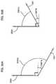
- FIG. 2shows a reference frame based on a swing plane defined by the bat orientation and by the velocity vector of the bat at the time of impact with the ball.
- FIG. 3illustrates transformation of a bat trajectory from a local sensor frame to the swing plane reference frame of FIG. 2 .
- FIG. 4illustrates various metrics derived from the swing plane reference frame, including a total swing angle in the swing plane, an off-plane swing angle, and a swing plane speed.
- FIG. 5illustrates derivation of a time to contact swing metric that measures how quickly the batter responds.
- FIG. 6illustrates derivation of a swing tempo metric based on swing plane speed, which indicates how quickly the swing plane speed increases through the swing.
- FIG. 7illustrates an embodiment that collects swing data from multiple users into a swing database, and that analyzes this database to generate methods of rating and classifying swings.
- FIG. 8illustrates an embodiment that analyzes swing tempo from multiple users to determine a target zone for peak performance.
- FIG. 9shows an embodiment that provides feedback to a user on his or her swing by comparing the swing tempo to the target zone described in FIG. 8 .
- FIG. 10illustrates an embodiment that classifies swings into swing styles based on a feature vector that combines multiple swing metrics; feedback to a user indicates the swing style as well as identifying other players with similar swings.
- FIG. 11shows a potential issue that may arise when a sensor has a limited range and the actual motion of the bat exceeds this measurement range during a time interval within the swing.
- FIG. 12illustrates an embodiment that addresses the limited range situation shown in FIG. 11 by extrapolating sensor data from before and after the time interval, in this example using a cubic Bézier curve.
- FIG. 13illustrates an embodiment that extrapolates sensor data using a Kalman filter to estimate values when the measurement range of the sensor is exceeded.
- FIG. 14illustrates an embodiment that tracks the trajectory of the sweet spot of a bat and that calculates swing metrics from this sweet spot trajectory.
- FIG. 15illustrates a reference frame used in one or more embodiments to measure bat motion and to calculate swing metrics; this reference frame has the origin at the sweet spot, a vertical z-axis, and the bat is in the xz-plane at impact.
- FIG. 16shows another view of the reference frame of FIG. 15 , and illustrates several swing metrics including the bat forward velocity at impact, the attack angle, and the swing plane tilt angle.
- FIG. 17shows a swing plane that is spanned by the bat's longitudinal axis and the velocity of the sweet spot at impact.
- FIG. 18shows the off-plane distance between the bat sweet spot and the swing plane during the swing, and it illustrates swing metrics that include the time when the bat is on-plane (within a specified threshold distance from the swing plane), and the on-plane metric that measures the angular range of motion while the bat is on-plane prior to impact.
- FIG. 19illustrates an embodiment of a center of rotation calculation, which determines a point equidistant from the hand position on the bat at multiple points on the swing.
- FIG. 20illustrates a two-lever model of a swing that is used to calculate swing metrics such as a hinge angle between a bat lever and a body lever.
- FIG. 21shows a calculation of a commit event that may represent, for example, when the wrist snaps to release the bat from a cocked orientation to complete a swing.
- FIG. 22shows an illustrative swing trajectory with several swing events annotated along the trajectory; it also illustrates a swing axis of rotation and a body tilt metric derived from this axis of rotation.
- FIG. 23shows an embodiment that provides bio-feedback to the user for setting posture or position or swing or any combination thereof via sound or AR/VR/MR visual displays, that enables working on postures, positions, swings and detecting proper or improper postures, positions, swings or portions thereof and to improve power and/or efficiency and to enable rehabilitation.
- FIG. 24shows an embodiment of the invention that calculates several swing quality metrics from acceleration and angular velocity data captured by an inertial sensor on a bat; illustrative swing quality metrics include rotational acceleration, on-plane efficiency, and body-bat connection.
- FIG. 24Ashows a variation of the embodiment of FIG. 24 that uses video cameras instead of inertial sensors to capture motion data.
- FIG. 25shows illustrative bat geometry data that may be used in one or more embodiments to calculate swing quality metrics.
- FIG. 26shows illustrative processing steps that may be used in one or more embodiments to calculate swing quality metrics; these steps may include integrating acceleration and angular velocity data, detecting impact, and calculating trajectories of bat orientation and of the positions of the hands and the sweet spot on the bat.
- FIG. 27expands on the flowchart of FIG. 26 to show additional data that may be calculated to determine swing quality metrics, including a swing plane and a body tilt axis.
- FIG. 28illustrates determination of a final phase of a swing that corresponds to centripetal (negative) acceleration along a bat's longitudinal axis.
- FIG. 29illustrates a method that may be used in one or more embodiments to determine the start of the centripetal acceleration phase.
- FIG. 30illustrates a method of calculating a rotational acceleration swing quality metric as a change in acceleration a short time after the beginning of the centripetal acceleration phase.
- FIG. 31shows illustrative rotational acceleration for three types of swings.
- FIG. 32shows a coordinate system defined using the swing plane, and angular velocities along the coordinate axes of this coordinate system.
- FIGS. 33A and 33Bshow illustrative calculations of an on-plane efficiency swing quality metric for two types of swings, one with a high value of on-plane efficiency and the other with a relative low value of on-plane efficiency.
- FIG. 34shows an illustrative definition of a body-bat connection metric using the bat direction and the body tilt axis.
- FIGS. 35A and 35Bshow illustrative calculations of a disconnection metric, which is the offset between the connection metric and 90 degrees.
- FIG. 36shows illustrative body-bat connection values at the start of centripetal acceleration and at impact.
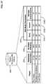
- FIG. 37shows illustrative values for three swing quality metrics—rotational acceleration, on-plane efficiency, and body-bat connection—for three players.
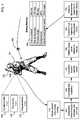
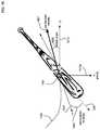
- FIG. 1shows an overview of an embodiment of the invention.
- User 101swings a baseball bat 102 to hit an incoming ball 103 .
- Datais collected throughout the swing from sensor 104 attached to the bat.
- Sensor 104may incorporate any type of sensor technology or technologies to measure any quantities, such as for example any aspects of the motion, position, or orientation of the bat.
- the sensormay be coupled with the proximal end of the bat, the distal end of the bat or anywhere in between.
- the sensor 104may comprise two or more sensors at different locations on the bat.
- sensor 104may contain any or all of a three axis accelerometer 105 , a three axis gyroscope 106 , and a three axis magnetometer 107 .
- sensor typesare illustrative; one or more embodiments may use sensor data from any type or types of sensors to track the swing of bat 102 .
- the sensor 104may not be physically attached to the bat; for example, the sensor may be stationary and it may observe the moving bat using technologies such as video, radar, LIDAR, or ultrasound.
- data from multiple types of sensorsmay be combined using sensor fusion.
- sensor data from an inertial sensor on a batmay be fused with radar data or other information from external devices to calculate a bat trajectory.
- Sensorsmay measure motion or other parameters on any number of axes. Sensors may measure these parameters at any desired frequency; higher measurement frequency may for example support more detailed analysis of the swing.
- sensor 104may collect data once per second, ten times per second, one hundred times per second, one thousand times per second, ten thousand times per second, or at frequencies above ten thousand times per second.
- bat 102is a baseball bat.
- One or more embodimentsmay obtain and analyze data for the swing of any type of bat or similar object, including for example, without limitation, a baseball bat, a softball bat, a cricket bat, and in one or more embodiments, a tennis racket, a table tennis racket, a badminton racket, a squash racket, a racquetball racket, a golf club, a polo mallet, a hockey stick, a field hockey stick, and a lacrosse stick or any other type of equipment that involves a swing.
- Data from sensor 104is obtained in step 110 .
- One or more embodimentsmay use any data transfer technology or technologies to obtain sensor data.
- datamay be transferred over a wireless network, over a wired network, or using a data storage medium that is moved from one system to another.
- Datamay be obtained in real time during a swing, obtained after a swing occurs, or obtained using a combination of real-time transfer and transfer after a swing event.
- Steps 120 through 170analyze data from sensor 104 to characterize the swing, resulting in swing metrics 180 . These steps may be performed in any order, or in parallel. These steps may be performed on any system or combination of systems. For example, without limitation, any or all of these steps may be performed on a computer, a mobile computer, a laptop computer, a notebook computer a desktop computer, a tablet computer, a mobile phone, a smart phone, a smart watch, a microprocessor, a server, or a network of any of these devices.
- the sensor 104may contain a processor or processors that perform some or all of the steps 110 through 170 .
- Step 120determines the time of impact between bat 102 and ball 103 .
- This stepmay for example detect a signature in the sensor data that indicates a collision.
- sensor 104includes an accelerometer such as accelerometer 105
- a rapid spike in accelerationmay be a signature of an impact.
- sensor 104includes a gyroscope such as gyroscope 106
- a rapid reduction in angular velocitymay be a signature of an impact.
- One or more embodimentsmay for example use sensors that directly measure impact, such as pressure sensors or contact switches.
- a swing endpointmay be defined even if the bat does not hit the ball, for example during practice swings, air swings, or strikes.
- This swing endpointmay be based for example, without limitation, on parameters such as the location of the bat relative to the plate or to an incoming ball, the aim angle of the bat, or the point in time when the bat achieves maximum velocity or maximum angular velocity.
- a calculated swing endpointmay be used instead of an actual impact time for any of the subsequent metric calculations described below.
- Step 130calculates a trajectory of the bat 102 from a starting point of the swing through the impact time determined in step 120 .
- the trajectorymay also extend beyond the impact or prior to the start of the swing.
- the bat trajectorymay be a time series of motion data samples, each of which represents the state of the bat at a point in time during the swing.
- each samplemay include data on any or all of the bat's position, orientation, velocity, angular velocity, acceleration, or angular acceleration.
- a samplemay include data for multiple locations on the bat.
- one or more embodimentsmay use inertial navigation algorithms known in the art to calculate the position and orientation of the bat over time from acceleration data (for example from accelerometer 105 ) and from angular velocity data (for example from gyroscope 106 ). Data from other sensors, such as for example magnetometer 107 , may for example provide redundant measurements to correct errors in inertial navigation algorithms.
- step 150a standardized reference frame is defined based on the swing itself. We refer to this reference frame as the swing plane reference frame.
- the bat trajectoryis transformed to this reference frame.
- step 170the transformed trajectory is used to analyze the swing, and to generate one or more swing metrics describing and characterizing the swing.
- Illustrative swing metrics 180describe for example the timing of the swing, the speed of the swing, and the angles traversed during the swing.
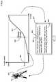
- FIG. 2illustrates definition and calculating of the swing plane reference frame.
- This reference frameis defined by the bat's orientation and motion at the time of impact between the bat 102 and the ball 103 .
- a swing plane 212is defined by two axes: a first axis 210 is the longitudinal axis of the bat (along the bat's long dimension); a second axis 211 is in the direction of the bat's velocity at the time of impact.
- the velocity vector at impactmay also be calculated as a tangent vector to the bat's instantaneous rotation round the angular velocity axis. This impact velocity vector 211 may be calculated or obtained from the bat trajectory.
- a specific point on the batsuch as for example the sweet spot, may be used to define the impact velocity vector.
- the swing plane 212is the plane spanned by the vectors 210 and 211 .
- a third orthogonal off-plane axis 213is selected as the normal vector to the plane 212 .
- the swing plane 212 defined by the axes 210 and 211provides a reference frame that can be calculated from data generated by bat sensor 104 .
- Other planes of rotation that may be relevant to the kinematics of the swinginclude for example the rotational plane 221 for the batter's shoulders, and the rotational plane 222 for the batter's hips.
- additional sensorsfor example sensors attached to the batter's shoulders and hips, may be used to calculate these body rotational planes in addition to the swing plane 212 .
- sensor 104has a local reference frame in which sensor data is measured.
- This local reference framein general may have a completely different orientation from the swing plane reference frame defined by axes 210 , 211 , and 213 .
- the sensor local reference framemay have axes 201 , 202 , and 210 ; in this example one axis of the sensor local reference frame is aligned with the bat longitudinal axis, but the other axes are in arbitrary directions due to the rotational symmetry of the bat around this axis.
- bat trajectory informationis transformed from the sensor local reference frame into the swing plane reference frame.
- FIG. 3illustrates this transformation.
- Bat trajectory 301includes motion data samples at various points in time, such as for example points 302 , 303 , and 304 . These samples may include any information on the state of the bat, such as position, orientation, or derivatives of these values like velocity and angular velocity.
- the bat trajectory 301is shown as a single curve in three dimensional space (for example as a curve of bat position over time); however, in one or more embodiments the bat trajectory may include any data with any number of dimensions.
- each sample pointhas coordinates such as coordinates 305 for point 304 .
- Transformation 310maps the sample points into the swing plane reference frame, for example using a rotation of the axes 201 , 202 , and 210 into axes 210 , 211 , and 213 .
- point 304 on the bat trajectory 301has coordinates 306 .
- FIG. 4shows illustrative metrics for angular change that are defined relative to the swing plane reference frame.
- Bat trajectory 401is a three dimensional curve in the three dimensional swing plane reference frame 410 defined by axes 210 , 211 , and 213 .
- Trajectory 401has starting point 420 , representing a start of the swing, and endpoint 421 , representing for example the time of impact between the bat and the ball.
- This curvemay be projected onto the two-dimensional swing plane 212 defined by axes 210 and 211 , and various metrics may be calculated from this projection.
- the 2D curve 402is the projection of the bat trajectory 401 onto plane 212 .
- This angle 403which we refer to as the total swing angle, is a swing metric that indicates the total amount of bat movement during the swing in the swing plane.
- the bat trajectory 401may be projected onto a plane 412 orthogonal to the swing plane, and the angle 407 subtended by the projected trajectory is a different swing metric that we refer to as the off-plane angle.
- the total swing angle metric and the off-plane angle metricprovide a useful characterization of how the batter is moving the bat through the swing.
- Projection of the trajectory 401 onto swing plane 212also provides a measure of the instantaneous angular velocity 406 of the trajectory at any point in time, such as at illustrative point 404 .
- This instantaneous angular velocity in the swing planewhich we refer to as the swing plane speed, is a more useful metric of the bat's motion than for example the total linear velocity of the bat, which includes an off-plane component of velocity that is not as relevant for the power of the swing.
- the swing plane speed 406may be calculated for example as the derivative of the instantaneous angle 405 between the point 404 on the projected trajectory 402 and the axis 210 .
- the swing plane speedmay be calculated by projecting the measured angular velocity onto the axis orthogonal to the swing plane 212 .
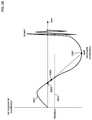
- FIG. 5shows an illustrative curve 501 of the swing plane speed 406 as a function of time.
- the curvetypically increases through the swing as the batter accelerates the bat.
- the swing plane speedreaches a maximum value 505 during the swing.
- the peak speed 505may occur at the time of impact 502 ; however, this is not necessarily the case for all swings.
- the impact swing plane speed 506is an important swing metric since it greatly affects the distance and power of the hit.
- the swing plane speed curvemay be used to define an unambiguous point in time for the start of the downswing of a swing: this start of downswing 503 may be defined as the last point in time when the swing plane speed is zero prior to the impact. This definition is based on an unambiguous physical event rather than an arbitrarily defined threshold crossing. This provides a clear advantage in terms of metric consistency and physical significance. If there is no zero crossing, as is the case in certain swing styles, we define the start of downswing where the slope and magnitude of the swing plane component meet certain threshold criteria.
- This fallback definitiondoes not provide the clear advantages of the zero crossing; however, because it is based on the swing plane component, it provides greater consistency than a definition based on vector magnitude, particularly across heterogeneous swing styles where much of the variability (e.g., bat waggle) occurs in the off-plane component.
- a total swing timewhich we refer to as the time to contact metric, may be defined as the difference 504 between the impact time 502 and the start of downswing time 503 .
- This time to contact metricis an important metric related to the batter's ability to read the pitch.
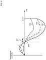
- FIG. 6illustrates a method to standardize this metric by measuring the fraction of the peak speed achieved at the halfway point of the swing.
- the swing plane speed curveis normalized so that swing plane speed is measured as a percentage 605 of the peak speed.
- the normalized swing speed curvestarts at zero at the start of downswing, and increases to 100% at the peak speed.
- a halfway point 602is defined for the swing, and the fraction 603 of the peak speed at this point is defined as the swing tempo metric 604 .
- the halfway pointmay be defined as halfway between the start of downswing and the time of impact.
- a more robust halfway pointmay be defined by selecting a swing onset time 601 as a time at which the swing plane speed reaches a specified small fraction of the peak speed, such as for example 10%, and by defining the halfway point as halfway between the swing onset time and the time of impact.
- This definition of the swing tempo metricis based on the insight from comparing statistical distributions, where the greatest variability in deviation from an ideal curve occurs at the half-way point between two fixed endpoints.
- the significance of this metriccomes from an understanding of the kinematic chain (hips, shoulders, arms, wrists) for transferring energy from the body to a baseball bat.
- a rotationally efficient swingwill derive a certain amount of energy from the hips and shoulders compared to the arms and wrists.
- We can infer how rotationally efficient a baseball swingis by the percentage of speed in the “body” half of the swing relative to the “arm” half.
- An ideal swing tempo rangeis learned from empirical data collected from elite-level batters.
- Deviation from the ideal tempo rangeis used to provide feedback and prescribe drills to the batter in order to improve performance.
- a low tempotypically indicates that the swing is dominated by arms (e.g., casting), while a high tempo indicates that a swing is dominated by body (at the expense of bat control).
- additional tempo metricsmay be defined at other points in a swing, in addition to the halfway point tempo metric described above.
- an early tempo metricmay be defined as the fraction of peak speed achieved at the 25% point of the swing
- a mid-tempo metricmay be defined as the fraction of peak speed achieved at the 50% point of the swing (as discussed above)
- a late tempo metricmay be defined as the fraction of peak speed achieved at the 75% point of the swing.
- the three tempo metricsmay isolate the effect of different segments of the kinematic chain of the swing; for example, the early tempo metric may characterize the rotation of hips and torso, the mid-tempo metric may characterize the rotation of the torso and arms, and the late tempo metric may characterize the rotation of the arms and bat. These percentages are illustrative; one or more embodiments may measure swing tempo at any point or points in a swing.
- swing data and swing metricsmay be collected from multiple users and organized in a swing database for further analysis.
- FIG. 7illustrates an embodiment that collects data into swing database 701 from multiple types of users, including for example, without limitation, experts 702 , professionals 703 , amateurs 704 , novices 705 , and instructors 706 .
- Data in the swing databasemay include for example, without limitation, sensor data 710 , bat trajectories in the swing plane frame 711 , and swing metrics 712 (such as for example the total swing angle, off-plane angle, time to contact, impact swing plane speed, and tempo metrics described above).
- Multiple metricsmay be combined into feature vectors 713 that may be used to classify, categorize, compare, or analyze swings.
- Data from the databasemay be used for various analysis procedures 720 , which may include for example any or all of modeling swings and batters, data mining the database for patterns or trends, and applying machine learning techniques to learn relationships, functions, or categories.
- Outputs of the analyses 720may include for example identification of best performances 721 that flag certain swings or groups of swings as illustrative of ideal or maximum performance; factors affecting performance 722 that identify swing characteristics that contribute to or detract from high performance; performance rating functions 723 that rate swings on how close they are to ideal performance levels; classifications of swing styles 724 that map swings into categories reflecting similar characteristics or similar performance; and matching of swings to similar players 725 that indicate which other swings or other players are most similar to a given swing or player.
- FIG. 8illustrates an example of the data analysis methods described with respect to FIG. 7 , using the swing tempo metric defined above.
- data analysis and data mining process 720compares swing plane speed curves across players to determine factors affecting performance 722 . This analysis indicates that best performance occurs when swing tempo is in a target zone 802 , for example in a range between 804 and 803 .
- This analysisuses normalized swing plane speed curves for the swings in database 701 , with the swing plane speed axis normalized to the percentage of peak speed 605 , and the time axis 801 normalized to a percentage of swing time between swing onset (0%) and impact 502 a (100%).
- the normalized swing plane speed at halfway point 602 a (50%)is the swing tempo metric for each swing.
- FIG. 9illustrates an example with batter 101 generating a swing plane speed curve 901 for a swing.
- the measured swing tempo 902 for this swingis compared to the target zone 802 in order to rate the swing's performance.
- Feedbackis then provided to batter 101 , for example on computer screen 903 .
- This feedbackprovides the swing tempo metric 902 , as well as a performance rating 904 that is based on comparing the swing to performance criteria derived from empirical analysis.
- the feedbackmay also include specific critiques such as 905 that diagnose the swing or suggest corrections or improvements.
- One or more embodimentsmay provide feedback to a batter or to other users (such as a coach or trainer) using any desired method or system.
- feedbackmay be displayed on any computer, laptop, notebook, tablet, mobile phone, smart watch, or wearable device.
- Feedbackmay be provided using a specific app, or transmitted via general messaging systems such as email or text messages.
- Feedbackmay be audio, visual, haptic, or any combination thereof.
- FIG. 10continues the example of FIG. 9 to illustrate additional analysis and feedback for a swing based on comparisons with swings in a swing database.
- a feature vector 1001is generated for a particular swing by batter 101 .
- this feature vectoris a combination of the swing tempo and the impact swing plane speed.
- One or more embodimentsmay generate feature vectors using any combinations of metrics or of any data derived from sensor data or bat trajectories. Swings from swing database 701 are compared on grid 1002 using this feature vector, and are analyzed (for example using cluster analysis techniques known in the art) to categorize swings into a set of swing styles. For example, the analysis may partition swings into three swing styles 1004 , 1005 , and 1006 .
- the feature vector 1001 corresponding to the swing by batter 101places the swing into swing style cluster 1006 .
- Feedback to the batterindicates this swing style 1020 .
- the batter's swingmay be matched against typical swings from other users to provide feedback 1021 that identifies other users with swings that resemble the batter's swing.
- FIG. 11shows an example of this situation where the sensor 104 on bat 102 includes accelerometer 105 with range 1101 , and gyroscope 106 with range 106 .
- the sensor 104 on bat 102includes accelerometer 105 with range 1101 , and gyroscope 106 with range 106 .
- the actual x-axis angular velocity 1103exceeds the upper limit 1104 of measurement range 1102 during time interval 1105 . Therefore, the measured sensor values 1106 cannot track the true values 1103 of the motion during this interval 1105 . Instead the measured value 1107 during this interval is saturated at the upper limit 1104 . This saturation may affect the accuracy of swing metrics.
- one or more embodiments of the inventionmay extrapolate sensor data from prior to or after the time interval 1105 when the sensor is saturated. Extrapolation may also be used when sensor data is unavailable for a period of time for any other reason, for example because of a limited sampling rate, a recalibration period, or a defective sensor. Extrapolation may be used for any sensor or sensors, or any axis of any sensor or sensors. Embodiments may use any method to extrapolate sensor data into any time interval.
- FIG. 12illustrates an embodiment that extrapolates sensor data from both endpoints of the time interval by constructing a Bézier curve 1200 for the values in the interval.
- the curve 1200is a cubic Bézier curve defined by the four control points 1201 , 1202 , 1203 , and 1204 .
- Control points 1201 and 1204match the values of the sensor measurements 1104 at the endpoints of interval 1105 .
- the internal control points 1202 and 1203are chosen to match the slopes of curve 1104 at these endpoints.
- the tangent value 1205 of the curve 1104 at point 1201is the slope of the line between control points 1201 and 1202
- the tangent value 1206 of the curve 1104 at point 1204is the slope of the line between control points 1203 and 1204 .
- Points 1202 and 1203may also be chosen to limit for example the maximum value of the curve 1200 in the interval.
- One or more embodimentsmay select control points for a Bézier curve in such a way as to satisfy the initial and/or final conditions (magnitude and slope) and also to satisfy additional constraints on the maximum absolute value and maximum extrapolation duration.
- four control pointsmay be used as shown for example in FIG. 12 : the initial and final points are placed where the curve crosses the saturation threshold, and two interior control points are along a line matching the slope of the curve at some distance, which is constrained by some maximum time duration and by a maximum absolute value.
- This approachprovides control of the shape of the extrapolation curve better than a cubic polynomial fit, which will match the same slope and value constraints but may exceed the other physical constraints.
- the unconstrained edgemay be represented by a single control point, resulting in a three-point Bézier curve. Again, the time and value for this single control point may be selected to achieve the desired shape of the extrapolated curve into the impact event. Because a Bézier curve is not parametric in time, it may be necessary to resample the extrapolated curve at the original sample times. This type of Bézier extrapolation may be applied to an individual saturated sensor axis (independent of the other components) or a composite value (e.g., the x-y resultant or total vector magnitude).
- the shape of the composite curvemay be easier to model or constrain than the underlying individual components for particular kinematic events, resulting in increased accuracy of the extrapolated result. If the underlying component values are needed, they can be obtained by solving for the unknown saturated component(s) from the extrapolated composite result and unsaturated component values (the result will be under-determined if more than one component is saturated).
- FIG. 13illustrates an example that uses this approach.
- Kalman filter 1301incorporates a kinematic model 1302 of the bat 102 .
- the system state 1303is estimated for each sample point, and this estimate is corrected based on measurements 1304 .
- the state 1303for example may include the position r(t) and the orientation Q(t) of the bat, and the measurements 1304 may include for example accelerometer values a x , a y , a z and gyroscope values ⁇ x , ⁇ y , ⁇ z .
- the filter 1301continues to predict state values 1303 . Therefore, the curve 1104 can be extrapolated to curve 1308 through interval 1105 ; for example, the orientation 1307 may be differentiated to estimate the x-axis angular velocity 1308 in this interval.
- one or more embodimentsmay use a recursive state space estimator (e.g., Kalman filter) with a kinematic model of the physical body or equipment being measured.
- the state-space propagation modelmay be used to impose appropriate physical constraints.
- the state space estimate and its uncertainty (covariance)may be updated using the non-saturated measurements from the various sensors.
- An estimate of the missing (saturated) parametermay then be derived from the state space estimate.
- the uncertainty in the estimated parametermay be derived from the model uncertainty.
- Either the state space propagation model or the measurement model (or both)may be non-linear, in which case a linearized (EKF) or sigma-point (UKF) filter may be used.
- EKFlinearized
- UPFsigma-point
- the uncertainty in the extrapolated time seriesmay be propagated to derived metrics.
- the gyroscopemay be saturated into impact, which affects the accuracy of the swing speed measurement. Using this approach, it is possible to estimate the actual swing speed and provide an uncertainty interval (error bars).
- a swing of a bat or similar equipmentmay be decomposed into key events and metrics that provide insight into overall swing quality. Some of these events and metrics may be related to or derived from the trajectory of a sweet spot of the bat.
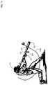
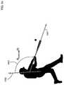
- FIG. 14shows an illustrative swing of bat 102 by batter 101 .
- the batis equipped with a sensor 104 , which may for example include a motion sensor with an accelerometer and a gyroscope.
- One or more embodimentsmay obtain sensor data from sensor or sensors 104 , and may use this sensor data to calculate the trajectory 1402 over time of sweet spot 1401 of the bat through all or a portion of the swing.
- the sweet spot location on a batmay be determined by any desired method.
- the sweet spot of the batproduces the maximum energy transfer to the ball, that it produces the maximum batted ball speed, or that it results in the least vibrational sensation (sting) in the player's hands. These results are not always produced by the same spot on a bat.
- the spotmay vary based on bat type (wood or aluminum), weight, shape, and other factors.
- an illustrative definition of a sweet spotmay be a location somewhere between four and eight inches from the tip of the bat, such as for example a single point on the centerline of the bat six inches from the tip.
- data from sensor 104may be integrated or otherwise analyzed to estimate the sensor velocity and position in an inertial (world) coordinate frame.
- the known position of the sweet spot relative to the sensormay then be used to calculate the sweet spot trajectory 1402 in this reference frame.
- the world reference framemay be defined as illustrated in FIG. 15 , which shows the bat at the point of impact with a ball (or at another point in time defined as a real or virtual time of impact).
- the origin of the reference frameis at the sweet spot of the bat 1401 at the moment of impact.
- Gravityis in the ⁇ z direction; hence the z axis 1513 points vertically upward.
- the world coordinate systemis not based on an absolute horizontal reference point such as home plate or absolute north.
- the world frameis rotated so that the bat longitudinal axis 1501 is in the xz plane pointing in the +x direction 1511 (for right handed batters) or ⁇ x direction (for left-handed batters).
- the forward velocity of the batis in the yz plane pointing in the +y direction 1512 . Because of this definition, the actual orientation of the world coordinate frame will vary from swing to swing.
- FIG. 16shows a close-up view of the reference frame illustrated in FIG. 15 , shown again at the point of impact of the swing.
- the reference frame originis the location 1401 of the sweet spot of the bat at impact.
- the ⁇ z axis 1513 ais in the direction of gravity, pointing vertically downward.
- Bat longitudinal axis 1501is in the plane defined by the x axis 1511 and the ⁇ z axis 1513 a .
- the y-axis 1512is perpendicular to the x-axis and to the z-axis.
- the batmay not be horizontally level at the time of impact; instead there may be a nonzero angle 1603 between the bat axis 1501 and the (horizontal) x-axis 1511 , which is referred to as the vertical bat angle.
- Vertical bat angleis defined as the vertical direction of the bat with respect to horizontal at impact. Vertical bat angle is negative below horizontal and positive above horizontal.
- the swing plane tilt angle 1603is the vertical bat angle at the moment of impact. The swing plane tilt angle is usually negative, meaning the bat is pointing toward the ground. A level bat would result in a swing plane tilt angle of 0°. Swing plane tilt angle is important for understanding adjustability and correlations to pitch types and locations. Pitch location will determine changes in the bat angle at impact.
- Adjusting the swing plane tilt angle to meet the pitchshould be done early in the swing in order to achieve maximum efficiency. Adjustment later in the swing drains energy from the speed of the bat.
- the swing plane tilt angleshould match the location of the pitch. Steeper angles are required for low, inside pitches, and shallower angles are required for high, outside pitches.
- the velocity of the bat at impactmay also in general not be horizontal; the attack angle 1602 is the angle of the bat's forward velocity at impact 1601 with respect to the horizontal y-axis 1512 .
- Attack angleis negative below horizontal and positive above horizontal. A positive value indicates swinging up, and a negative value indicates swinging down, where zero is perfectly level. Attack angle is important for two reasons: First, matching the bat path to the pitch path increases the likelihood of contact. Because the pitch is thrown from an elevated mound, it is typically on a downward angle as it crosses the plate. Therefore, a positive attack angle provides more opportunity to execute against a variety of pitches, which vary in height, speed, and angle. Second, a positive attack angle will usually maximize launch distance, increasing the scoring value of the at-bat.
- Other factorsinclude swing speed and style, pitch velocity and location, and game situation.
- the optimal attack angleis usually between +2° to +14° degrees.
- adaptationmay be required to put the ball in play.
- the ideal attack angleresults in the maximum distance for a given bat speed. For slow bat speeds, the ideal attack angle is around 21°, and it gets smaller with increasing speed.
- the bat forward velocity 1601is the projection of the velocity vector of the sweet spot onto the plane perpendicular to the bat longitudinal axis 1501 ; it ignores any speed in the direction of the bat axis 1501 .
- FIG. 17illustrates a definition of a swing plane from which various swing metrics may be derived.
- Swing plane 1701may for example be defined as a plane through the sweet spot 1401 which is spanned by the bat longitudinal axis 1501 at impact and by the bat forward velocity 1601 at impact. This swing plane is oriented so that it contains both the length of the bat and bat velocity at the moment of impact.
- the swing plane normal vectormay found by normalizing the cross product of the bat length and bat velocity vectors. The normal vector is centered at the sweet spot of the bat at the moment of impact, i.e., at (0, 0, 0).
- a swingmay be analyzed for example by decomposing the motion into swing plane versus off-plane components.
- Off-plane motionmay for example be characterized by the distance of the sweet spot of the bat from the swing plane at any moment in time.
- FIG. 18illustrates this distance of the sweet spot 1401 to the swing plane 1701 at several points in a swing prior to impact. For example, at the position of the bat shown in the figure, the off-plane distance is 1801 . As the swing progresses towards impact, the sweet spot approaches more closely to the swing plane 1701 . When the distance reaches a specified threshold 1802 , the swing is considered “on-plane” at that moment (provided that it remains at or below this distance from that moment until impact). For example, the threshold may be set to 3 inches.
- an on-plane metricmay be defined as the total angular range of motion (for example in degrees) of the swing where the sweet spot of the bat is within the threshold value (such as three inches) from the swing plane.
- the on-plane metricis the angle 1805 between the ray 1803 at the on-plane event and the ray 1804 at the impact event. This metric measures an aspect of the quality of the swing because the player typically wants the energy from the body and arms to increase forward bat speed rather than change its direction. Changing bat direction takes more energy as bat speed increases, so an efficient swing gets on plane early and stays on plane as it approaches impact.
- a batterwill read the pitch early and adjust the entire body to align the swing plane with the pitch location. This enables maximum bat speed for every pitch type.
- the systemmay report the percentage of total velocity that is generated while the bat in on plane. For example, if the velocity is 40% of the peak when the bat gets on plane, then the “on plane” metric is 60%.
- FIG. 19illustrates an embodiment that determines a center of rotation 1903 for a swing by determining the position of the hands at three points in the swing, at location 1902 a , 1902 b , and 1902 c .
- the center of rotationis selected for example as the point 1903 that is equidistant from these three points.
- One or more embodimentsmay use any point or points on hands trajectory 1901 to determine one or more centers of rotation for the swing.
- the center of rotationmay be calculated using the formula for the circumcenter of a triangle defined for example in en.wikipedia.org/wiki/Circumscribed_circle.
- Three points on hands trajectory 1901also define a plane, and therefore define an axis of rotation through the center of rotation 1903 that is perpendicular to that plane.
- the orientation of this axis of rotationmay also be used in one or more embodiments as a metric describing the swing.
- the three points that define the center of rotationlie in a plane that is typically tilted downward in front of the body.
- the axis of rotationmay be calculated for example using the cross product of any two of the radius vectors from the center of rotation calculation.
- a two-lever modelmay be used to describe and analyze a swing.
- an experienced batterrotates the core, arms, and bat as a single, connected unit. Then the batter commits by snapping the wrist, which moves the tip of the bat away from the body.
- the elbowmay also extend, depending on ball location. This optimal kinematic sequence results in maximum speed and control.
- the kinematic chainincludes core, shoulder, elbow, and wrist rotation. In some situations, it may not be feasible to measure all these movements directly using, for example, a single inertial sensor on the bat. Instead, one or more embodiments may use a simplified two-lever mechanical model to distinguish “body” rotation from “bat” rotation. The body contribution ends at the hands. It measures rotation around the body center of rotation, which is primarily core, shoulder, and some elbow extension. The bat component measures motion around the hand position, which is primarily due to elbow and wrist rotation. In a connected swing, the shoulder and elbow contributions are small, and the body component of our model closely approximates core body rotation.
- Total bat speedis a combination of body rotation and bat rotation.
- the body ratiomay be calculated the percentage of total rotation that is attributed to the body.
- An efficient swinguses both the body, arms, and wrists in the appropriate kinematic sequence.
- a swing that is mainly body rotation or mainly arm rotationis not as powerful as a swing that uses the entire kinematic chain.
- the bodyshould contribute about 40% to 50% of the total rotational speed. There may be some variation due to individual style, but a value that is consistently outside this range usually indicates a poor kinematic sequence.
- the hinge angle 2004is the angle between the bat lever 2002 and the tangent 2003 that is perpendicular to the body lever 2001 in the two-lever mechanical model. Hinge angle is negative when the tip of the bat is angled toward the body and positive when the tip is angled away from the body.
- One or more embodimentsmay incorporate a method of calculating a commit event.
- the commit eventalso known as wrist release, occurs when the hinge angle is “released”. In other words, the moment when the hinge angle starts to move in a positive direction away from the body. Commit is the transition point in the kinematic chain between body-only motion and the wrist snap contribution. A batter begins the swing with the bat angled towards the body. At commit, this hinge angle is released and the wrist is snapped forward to add speed to the bat and to contact the ball.
- FIG. 21illustrates a method of calculating a commit event that may be used in one or more embodiments.
- the hinge angular velocity 2102may be found by taking the first derivative of the hinge angle time series 2101 . Any desired method may be used to calculate or estimate a derivative; for example, one or more embodiments may use a centered, five-sample window to reduce sample noise.
- the commit event 2104may be defined as the instant when the hinge angular velocity 2102 exceeds a threshold value 2103 prior to impact. For example, a threshold value of 60 rpm (360 dps) is illustrated in FIG. 21 .
- One or more embodimentsmay define a sequence of events through a swing, and may derive one or more metrics from these events.
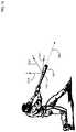
- FIG. 22shows an illustrative swing with events annotated at the point in the swing when they occur.
- Event 2201is the start of the downswing of the swing.
- Start of downswingindicates the start of significant motion of the downswing.
- An illustrative algorithm that may be used in one or more embodiments to calculate the start of downswingis as follows. Start of downswing is calculated by looking at the gyro xy resultant time series. Starting from the peak value, work backwards one sample at a time. For each sample, fit a straight line through the peak value and the sample of interest.
- the angular velocity curveis decomposed into two additive components, body lever and bat lever, and a metric is derived therefrom and optionally reported to the user and/or utilized for internal calculations.
- other metricsmay also be reported including measuring and comparing two parts (body and bat rotation) and utilizing peak speed ratios, amount of rotation ratios, peak angular velocity ratios, centripetal acceleration, i.e., how quickly a user starts accelerating a bat through body rotation to form metrics.
- Another metricmay be formed by dividing peak hand speed by peak bat speed or an average of the hand speed and bat speed from commit to impact to reduce variability in the measurement.
- any of these metrics or any other metrics defined hereinmay be provided to the user through sound, for example if over, equal to, or under a predetermined threshold, or via a visual display, or AR/VR/MR display (or through both audio and visual) to provide the user with biofeedback for use by the user to observe and/or alter position, posture, swing.
- Commit event 2014also known as wrist release, occurs when the hinge angle is released, as described with respect to FIG. 21 .
- the on-plane event 1803occurs when the sweet spot approaches to within a threshold (such as three inches, for example) of the swing plane, as described with respect to FIG. 18 .
- impact event 1804occurs when the bat hits the ball and when this impact is detected by the sensor or sensors.
- One or more embodimentsmay also detect a virtual impact event even when the bat does not hit a ball (for example, for an “air swing”), as described below.
- a simple impact detectionmay be performed by searching for a large discontinuity in accelerometer readings, corresponding to the shock of the impact.
- certain battersgenerate accelerometer noise greater than 4 g prior to true impact. This has been observed in internal testing and in pro-level swings. Analysis shows that this noise is almost always associated with high bat roll (z-axis angular velocity). Presumably, the bat is slipping in the grip, and the noise is caused by friction of the bat against the hands or gloves. Therefore, in one or more embodiments, the impact detection algorithm may use both the gyro and accelerometer to detect impact. The gyro search detects impact energy that is spread out over one or more subsequent samples.
- impactis the defined as the sample just before the first accelerometer discontinuity that exceeds the threshold.
- air swingsare supported by enabling an air swing version of the impact detection algorithm. If the system does not detect an impact event, the baseball swing processor determines whether the swing is a valid air swing.
- the air swing detection algorithmmay for example look for peaks in the gyro xy resultant and accelerometer z component. A swing may be classified as a valid air swing if for example: the gyro xy peak exceeds 500 dps; the accelerometer z component peak exceeds 4 g; and the two peaks occur within 100 ms.
- the time of the gyro xy peakmay be used as a proxy for the impact event in all subsequent calculations. Processing of air swings continues the same as for impact swings. All swings may be considered invalid if the air swing criteria are not met, even if there is a valid impact signature.
- a time to contact metricmay be calculated as the elapsed time between start of downswing and impact.
- the clockstarts when there is sufficient downswing motion and ends when the bat contacts the ball (or at a corresponding virtual impact event for an air swing).
- Time to contactmeasures the total time it takes to complete a swing.
- a major league fastballtakes about 400 milliseconds from pitcher to home plate. In that time, the batter must recognize the pitch, decide whether to commit, and execute the swing. The quicker the time to contact, the more time the batter has to recognize and commit to good pitches.
- the ideal time to contactdepends on age, strength, bat length and weight, experience level, and swing style. Our testing shows the typical time to contact for different age groups and skill levels: Little League: 230-400 milliseconds; Senior League: 185-325 milliseconds; High School: 140-260 milliseconds; College/Pro: 100-200 milliseconds.
- FIG. 22also illustrates metrics related to the orientation of the swing.
- axis of rotation 2204which is perpendicular to plane 2203 spanning points on the hand trajectory and is through center of rotation 1903 , forms a body tilt angle 2205 with the vertical axis.
- the center of rotationis a point at the center of the arc traced by the hands and is usually near the body's center of rotation.
- the axis of rotationis the axis that the body rotates around and is usually aligned with the spine.
- the body tilt angleis the angle between the axis of rotation and vertical.
- the body and batshould rotate around the same axis. A large difference between the swing plane tilt angle and the body tilt angle is an indication of a disconnected swing. In an efficient swing, the swing plane tilt angle and body tilt angle should be closely-aligned.
- FIG. 23shows an embodiment that provides bio-feedback to the user for setting posture or position or swing or any combination thereof via sound or AR/VR/MR visual displays, that enables working on postures, positions, swings and detecting proper or improper postures, positions, swings or portions thereof and to improve power and/or efficiency and to enable rehabilitation.
- One or more embodiments of the inventionmay include utilizing sound, e.g., via headphones 2302 , or at least one Virtual Reality (VR), Augmented Reality (AR) or Mixed Reality (MR) display, glasses or goggles 2301 to provide bio-feedback to the user.
- the audio and/or image components 2301 and/or 2302may be coupled with or formed into a helmet, such as a batter's helmet for example.
- MRis also referred to as “hybrid reality” and includes use of real and virtual data to produce novel environments and visual displays that include real and computed objects and interact, which also may include real-time display of data.
- a sound or visual displaymay be utilized to provide feedback to the user to indicate a correct position, or movement has been achieved.
- embodiments of the inventionenable a user to work on developing more power and improving skills in a bio-feedback environment and/or combine environment.
- Embodiments of the systemalso enable rehabilitation and general training of the body based on the data gathered by the system to suggest areas of the body to strength or stretch to improve the range of motion to avoid injury through use of correct biomechanics.
- One or more embodiments of the inventionmay include components that enable calculation of various swing quality metrics for a swing of a baseball bat, softball bat, or other equipment. Based on extensive analysis of swing data and swing biomechanics, the inventors have identified three swing quality metrics that appear to be valuable high-level summaries of how effectively a user swings a bat. One or more embodiments may extend or modify these three swing quality metrics in any desired manner.
- the three swing quality metrics described beloware rotational acceleration, on-plane efficiency, and body-bat connection. A system that calculates these metrics is illustrated in FIG. 24 .
- User 101swings a bat 102 to hit a ball.
- An inertial sensor 104is installed on bat 102 .
- the sensor 104may include for example a three-axis accelerometer and a three-axis gyroscope.
- Data 2401may be transferred from inertial sensor 104 to a processor 2400 , for example over a network connection.
- the processormay be for example a mobile device such as a smart phone or a laptop, or any other computer such as a desktop or server computer.
- the processormay be a network of multiple processors.
- the processor or a portion of the processormay be integrated into the inertial sensor 104 .
- Embodiments of the inventionmay not include all of the components shown in FIG. 24 .
- one or more embodimentsmay not include the inertial sensor 104 , but may instead receive data 2401 generated by another inertial sensor or similar device.
- One or more embodiments of the inventionmay not include processor 2400 , but may include software that executes on this processor to analyze data 2401 .
- Data 2401may include a time series of acceleration data captured by an accelerometer, and a time series of angular velocity data captured by a gyroscope.
- the accelerometer and gyroscopemay have three axes, and the time series may each have three sub-series for each of the three axes.
- Processor 2400may also access a bat geometry definition 2402 , which may for example describe physical characteristics of the bat 102 . Based on the acceleration and angular velocity time series 2401 , and the bat geometry 2402 , the processor or processors 2400 may execute one or more steps 2403 to calculate one or more swing quality metrics 2404 . These metrics may include any or all of rotational acceleration 2411 , on-plane efficiency 2412 , and body-bat connection 2413 .
- the swing quality metrics 2404may include other metrics in addition to these three metrics, or a subset of the metrics shown.
- Data and metrics from multiple battersmay be captured in a database 2421 , and analytics 2422 may be generated from this database. These analytics may for example be used to optimize batting orders, to improve individual players' swings, to assign exercise programs, to assist with recruiting, to match players to coaches, or to plan pitching strategies or adjustments.
- FIG. 24shows optional inertial sensor 104 a on one of the hands of batter 101 , for example in a batting glove; this sensor may capture data on motion of the hands. Sensors may be installed on any part or parts of the batter's body or on or in any equipment, such as on a belt, cap, or shoes. Data from these sensors may be fused with data from bat sensor 104 to analyze and characterize the swing.
- FIG. 24Ashows an embodiment of the invention that uses video camera data instead of inertial sensor data to track the motion of the bat.
- the sensors of FIG. 24 (inertial) and FIG. 24A (video)are illustrative; one or more embodiments may obtain bat motion data or motion data on other items such as the batter's hands using any type or types of sensors, including but not limited to inertial sensors and video camera sensors.
- Sensor data from any sensor or sensorsmay include or may be transformed to acceleration and angular velocity data 2401 , which in turn may be used to calculate swing quality metrics.
- three video cameras 2431 , 2432 , and 2433capture images of the swing of bat 102 by batter 101 .
- One or more embodimentsmay use any number of video cameras. A potential benefit of using multiple cameras it that the bat may be visible at any point in the swing from at least one camera. In this illustrative embodiment, no sensor or marker is placed on bat 102 (or on player 101 ). Although markers may facilitate motion tracking using video images, in some situations they may be awkward or time-consuming to use; therefore, one or more embodiments may use markerless motion tracking using analysis of video images only without markers.
- Video streams from cameras 2431 , 2432 , and 2433are combined into image sensor data 2435 , which consists of a time sequence of frames from each camera.
- These frames 2435are input into a step 2440 that generates the bat acceleration and angular velocity time series 2401 by analyzing the changes in the images over time.
- Techniques for tracking objects in video frames without markersare known in the art, as are techniques for generating data such as acceleration and angular velocity from the tracked object positions in frames. These techniques are used for example in markerless motion capture systems that recreate 3D motion from a series of 2D video streams, without attaching markers to the objects of interest.
- Image processing and recognition techniquesmay be used for example to identify the bat (or portions of the bat that are visible) in each frame, and stereo or multi-view triangulation may be used to recover 3D positions of the bat's points from the 2D projections of the bat in each frame.
- Step 2440 of calculating acceleration and angular velocity from the video frames 2435may be performed by processor or processors 2400 , or by any other system or systems.
- the cameras 2431 , 2432 , and 2433may perform all or part of this processing internally.
- Processor 2400may either obtain acceleration and angular velocity data 2401 directly from a sensor, or it may calculate this data from one or more sources of sensor data from one or more sensors of any type or types.
- Sensor data in this contextmay represent any data that represents or reflects motion of any object, including but not limited to inertial sensor data, video camera frames, or combinations thereof.
- One or more embodimentsmay combine data from inertial sensor 104 and cameras 2431 , 2432 , and 2433 (or other arrangements of one or more cameras) and may perform sensor fusion to calculate data 2401 .
- sensor measurements, metrics and calculations such as those illustrated in FIGS. 24 and 24Amay be applied to movements other than the swinging of a bat.
- calculation 2403 of quality metrics 2404 from inertial or video datamay be applied to movements such as a golf swing, a tennis racket swing, a hockey stick shot, a lacrosse stick shot, or to movements without stick-like equipment such as a basketball shot, a soccer shot, a volleyball hit, a jump, a spin of a figure skater, or a baseball pitch or throw.
- Any type of motionmay be analyzed with respect to a natural plane of rotation for that motion or an axis of rotation for the motion.
- the quality of the motionmay be summarized in one or more quality metrics, such as metrics that capture the acceleration of the motion, the connection between the body of the person performing the motion and any equipment or other body parts involved in the motion or between different body parts involved in the motion, and the efficiency of the motion with respect to the natural plane for the motion.
- quality metricssuch as metrics that capture the acceleration of the motion, the connection between the body of the person performing the motion and any equipment or other body parts involved in the motion or between different body parts involved in the motion, and the efficiency of the motion with respect to the natural plane for the motion.
- connection metrics for a spin of a figure skatermay measure how the skater extends his or her arms or legs during the spin, or how the arm and leg positions relate to each other or to the body orientation.
- Quality metricsmay be calculated from inertial sensor data or data from any other sensor on equipment or on the user's body, or they may be calculated from analysis of video captured during the motion.
- metrics and calculationsmay also measure the stress on one or more joints of the user during the motion; these stresses
- FIG. 25An illustrative bat geometry definition 2402 is shown in FIG. 25 .
- This bat geometryincludes the location of a hand position 2501 on the bat 102 , and a position of a sweet spot 2502 on the bat 102 . These positions may be located for example along the longitudinal axis 210 of the bat. Positions may be measured for example relative to a position 2500 of the inertial sensor 104 on the bat. In one or more embodiments the positions 2501 and 2502 may be set to any convenient locations; they may or may not match actual hand positions of a specific real batter or a physical sweet spot position of a bat. They may be set to average values or typical values, for example.
- the hand position 2501may be near the knob end of bat 102 , and the sweet spot position may be at or near a position that is an optimal spot on the bat for contacting a ball.
- An optimal position for contacting a ballmay correspond for example, without limitation, to a position that maximizes energy transfer, a position that maximizes ball speed, or a position that minimizes vibration when the bat hits the ball at this position along the longitudinal axis 210 .
- the bat geometry definition 2402 or any portions of this definitionmay be for example stored in memory on the inertial sensor 104 , or it may be stored in any memory accessible to the processor such RAM, ROM, or a hard disk containing a file or database.
- a simple bat geometry definition filemay contain for example only two numbers: the distance between points 2501 and 2500 , and the distance between points 2502 and 2500 .
- FIGS. 26 and 27show illustrative calculations that may be performed in one or more embodiments.
- the acceleration and angular velocity time series 2401 obtained from the inertial sensor or derived from camera image datamay be integrated in step 2610 to determine the position and orientation of the sensor over time.
- the bat geometry 2402may be used to calculate the position and orientation over time of the bat and of specific points on the bat.
- the processor of the systemmay calculate a trajectory of the longitudinal axis of the bat 2603 at points in time through the swing. It may calculate a trajectory 1901 of the hand position on the bat at points in time through the swing.
- FIG. 26shows an illustrative state of the bat at time 2604 in the swing, with bat longitudinal axis 210 k , hand position 2501 k , and sweet spot position 2502 k at this time.
- the systemmay determine specific events of interest in the swing and may locate points in time in the sensor data time series 2401 that correspond to these events. In particular the system may perform step 2611 to locate the impact of the bat with a ball or other object, to find impact time 502 .
- FIG. 27illustrates how the data calculated in the steps shown in FIG. 26 may be used in one or more embodiments to calculate swing quality metrics.
- the acceleration and angular velocity time series 2401 , the impact time 502 , the hand position trajectory 1901 , the sweet spot position trajectory 1601 , and the bat longitudinal axis trajectory 2603may be analyzed in calculations 2403 to generate metrics 2404 . Additional inputs to the calculations 2403 may include the swing plane 1701 , and the body tilt axis 2204 , which are described above with respect to FIG. 17 for the swing plane, and with respect to FIGS. 19 and 22 for the body tilt axis.
- FIGS. 28 through 36describe how the data shown in FIG. 27 may be used in one or more embodiments to calculate the illustrative swing quality metrics shown in 2404 : rotational acceleration, on-plane efficiency, and bat-body connection.
- one or more embodimentsmay separate a swing into a loading phase at the beginning of the swing, and a rotational phase when the batter completes the swing and accelerates to hit the ball.
- One method that may be used in one or more embodiments to define these two phasesis to use the acceleration along the bat's longitudinal axis. This approach is illustrated in FIG. 28 .
- the longitudinal axis 1501 of bat 102is oriented so that the positive direction from the knob of the handle towards the barrel.
- An accelerometer on the batmay measure acceleration in this longitudinal direction, either directly if an axis of the accelerometer is aligned with this longitudinal axis 1501 , or indirectly along multiple axes.
- FIG. 28shows a plot of acceleration 2801 along the axis 1501 . At time 2803 this acceleration changes sign, and it stays negative until impact 502 .
- the phase 2802 of centripetal (negative) accelerationmay be used to define the rotational phase of the swing.
- the point 2803 corresponding to the sign changemay be used to define the transition between the loading phase of the swing and the rotational phase of the swing.
- One or more embodimentsmay define a start of a centripetal acceleration phase in any desired manner, including but not limited to defining it as a zero crossing such as point 2803 in FIG. 28 .
- the start of centripetal acceleration eventmay be determined based on a model of the rotational patterns of a swing.
- FIG. 29illustrates a technique for defining the start of centripetal acceleration that may be used in one or more embodiments.
- a threshold 2904may be defined to locate points on longitudinal acceleration curve 2801 that are relatively small compared to the peak centripetal acceleration 2901 .
- the thresholdmay be set to 10% of the peak centripetal acceleration.
- a straight linemay be fit through the peak centripetal acceleration point 2901 and the sample.
- the time when this line crosses zero accelerationmay be used as an estimate of the start of centripetal acceleration. This is illustrated in FIG. 29 for sample 2902 ; the line through points 2901 and 2902 intersects the zero-acceleration axis at time 2903 . Point 2903 may therefore be used as an estimate of the start of centripetal acceleration.
- this processmay be repeated for different samples working back in time until the acceleration magnitude of the sample is less than a smaller threshold value, such as for example 1% of the peak centripetal acceleration, and the latest time of the intersection of the line through the sample may be used as the start of centripetal acceleration.
- This proceduremay generate a start of centripetal acceleration that is at or near the point in time when the centripetal acceleration changes sign.
- one or more embodimentsmay calculate a rotational acceleration swing quality metric by measuring the centripetal acceleration at a specific time offset after this event. This calculation is illustrated in FIG. 30 .
- a time interval 3001is fixed, and the point 3002 on centripetal acceleration curve 2801 is located at this time interval after the start of centripetal acceleration 2903 .
- the acceleration difference 3003 between the centripetal acceleration at 3002 and the centripetal acceleration at time 2903may be used as a rotational acceleration metric.
- the time interval 3001may be fixed so that comparisons of rotational acceleration across players measure how rapidly each player is able to accelerate the swing over a common period of time.
- This rotational acceleration metric 3003is a measure of how the hitter accelerates the bat into rotation. In one or more embodiments, it may be measured early in the rotational phase of the swing to capture information about the coordination and control patterns of the athlete; measuring early in the swing may make this metric less susceptible to swing differences based on pitch location.
- the time interval 3001may be selected, without limitation, in a range between 10 and 50 milliseconds, inclusive.
- Rotational accelerationis a useful metric to separate hitters between levels. Hitters with high rotational acceleration exhibit high-level movement patterns and proper sequencing of segments through the swing. This is due in large part because it is simply not possible to achieve high values of rotational acceleration without utilizing proper sequencing to accelerate the bat into rotation.
- a high magnitude of rotational accelerationis the result of proper timing and sequencing of bat load as aggressive body rotation pulls the bat down into rotation. The higher the magnitude, the more functionally proficient the player is in accelerating the bat into a rotational path in a more dynamically adjustable swing.
- quickly and efficiently generating energy that can be transferred through the kinetic chainis essential to be a successful hitter, given the incredibly dynamic and variable nature of the task.
- FIG. 31shows three illustrative swings 3101 , 3102 , and 3103 .
- Swing 3101is from a power hitter who achieves early torso rotation.
- Swing 3102is from a player who rotates the body less early in the swing, and therefore achieves less power.
- Swing 3103is from a player who primarily uses the arms and hands rather than the body, and therefore has very little hitting power.
- the major league baseball average for rotational accelerationis approximately 17 g's. Elite hitters are consistently in the mid 20 g's with some hitters reaching the 30 g's. Hitters with average rotational acceleration values are often “block rotators”, that initiate rotation with the hips and shoulders simultaneously. Hitters with low rotational acceleration are commonly hand-dominant hitters who pull the knob of the bat with their upper body to initiate the swing.
- FIG. 32shows swing plane 1701 and a coordinate system that may be defined with respect to the swing plane.
- This coordinate systemconsists of a z-axis 1501 along the longitudinal axis of the bat, a y-axis 3202 normal (perpendicular) to swing plane 1701 , and an x-axis 3203 orthogonal to the y and z axes.
- the labels x, y, and z for these axesare arbitrary; one or more embodiments may use any names or labels for any axes.
- On-plane efficiencymeasures how much of the rotation of the bat is around the y-axis 3202 . Rotation around other axes does not contribute to the velocity at impact, which lies in the swing plane 1701 . Therefore, a higher degree of on-plane efficiency reflects a more efficient swing.
- Angular velocity data from the inertial sensor on the batmay be transformed into the coordinate system of FIG. 32 .
- This transformationresults in three components of angular velocity: the y-axis angular velocity 3212 , which is the primary contributor to swing efficiency, the x-axis angular velocity 3213 , and the z-axis angular velocity 3211 .
- the z-axis angular velocity 3211is bat roll along the longitudinal axis of the bat, which is not a major factor in swing efficiency; however, a large amount of x-axis angular velocity 3213 may reflect an inefficient swing.
- a rotation-on-plane ratiomay be calculated at any point in time during the swing as the ratio of the magnitude of the y-axis angular velocity 3212 to the magnitude of the vector sum of x-axis angular velocity 3213 and y-axis angular velocity 3212 .
- This ratiois 100% for pure rotation around axis 3202 ; as more off-plane rotation occurs around axis 3203 , the ratio decreases. (Angular velocity 3211 around the z-axis is ignored in this analysis because it is typically a minor factor.)
- An on-plane efficiency metricmay be calculated as the value of this rotation-on-plane ratio at a point in time, or as an average over a period of time.
- the on-plane efficiency metricmay be calculated as an average of the rotation-on-plane ratio between the start of centripetal acceleration and impact.
- This methodis illustrated in FIGS. 33A and 33B , which show x-axis and y-axis angular velocity for two illustrative swings.
- Curves 3212 a and 3212 bshow y-axis angular velocity for the two swings; curves 3213 a and 3213 b show x-axis angular velocity for the two swings, and curves 3301 a and 3301 b show the magnitude of the vector sum of the x-axis and y-axis angular velocities for the two swings.
- Curves 3302 a and 3302 bshow the rotation-on-plane ratio 3310 over time for the two swings.
- the values of the rotation-on-plane ratiosare averaged across the time interval 2803 (start of centripetal acceleration) to 502 (impact), giving average values 3303 a and 3303 b for the two swings.
- the swing of FIG. 33Ahas a higher on-plane efficiency swing quality metric, since the y-axis angular velocity 3212 a is a relatively larger fraction of the total xy angular velocity 3301 a than the corresponding ratio for 3212 b and 3301 b.
- On-plane efficiencymeasures how early a swing gets on plane and how well it stays on plane as it approaches impact.
- the hitterwants to build as much forward bat speed on plane as possible, to maximize functional bat speed at impact.
- Swinging the bat on planeis one of the most important skills necessary to becoming a high-level hitter. It is also one of the most variable swing components when comparing hitters.
- An efficient swingis one in which the hitter gets the barrel on plane very early and deep in the swing path, which allows them to better optimize acceleration of the barrel through the zone. Deviations from the swing plane are the direct result of changes in arm and wrist kinematics relative to the body rotations.
- the hitterIn a connected swing, the hitter will read the pitch early and make adjustments through the core and the body instead of the arms and wrist in order to align the swing plane with the pitch location.
- a good functional swingwill have an average on-plane efficiency starting at 70% or higher.
- a typical dynamic range for on-plane efficiencyis 65%-85%. Moving the on-plane efficiency metric higher is desired and directly indicative of a more connected swing.
- FIG. 34illustrates a definition of body-bat connection that may be used in one or more embodiments.
- the body tilt axis 2204may be defined from three points on the trajectory of the hands, as discussed above with respect to FIGS. 19 and 22 .
- This axis 2204is calculated as a single axis for the entire swing.
- the bat longitudinal axis 1501moves through the swing; therefore, the angle 3401 between the body axis 2204 and the bat axis 1501 is a function of time. This angle 3401 may be used as the body-bat connection metric at that point in time, with an ideal value of 90°.
- a disconnection metricwhich is the complement of connection (the absolute value of the difference between the body-bat connection angle and 90°). Disconnection is illustrated in FIGS. 35A and 35B .
- the connection angle 3401 ais greater than 90°, and the disconnection angle 3501 a is angle 3401 less 90°.
- the connection angle 3401 bis below 90°, and the disconnection angle 3501 b is 90° less angle 3401 b .
- Use of disconnection instead of connectionmay be more useful when averaging or integrating connection angles over time, since use of absolute differences prevents a negative difference at one point in time from compensating for a positive difference at a different point in time.
- one or more embodimentsmay measure the body-bat connection (and/or disconnection) at the point of impact 502 and at the start of centripetal acceleration 2803 .
- the angle 3601 between the axis 2204 and the bat axis 1501 amay be referred to as the early connection or connection-early, and the angle 3602 between axis 2204 and bat axis 1501 b at impact may be referred to as the connection-at-impact.
- the connection-early and connection-at-impact valuesmay be averaged to generate an overall body-bat connection metric, or equivalently the disconnection-early and disconnection-at-impact values may be averaged to generate an average body-bat disconnection metric.
- Connectionis important measure of the athlete's ability to dynamically adjust for different pitch types and locations, as well as executing consistent mechanics swing to swing. Connection and the relationship between early connection and connection-at impact is also highly related to on-plane efficiency. In a good functional swing, the hitter adjusts to different pitch locations using their body tilt, keeping their connection values consistent. Hitters who adjust to different pitch locations by manipulating the barrel with their hands will have variable connection values across pitch locations. This introduces additional degrees of freedom at the wrist into the swing that are difficult to control and execute with consistency.
- connection-earlytypically in the range of 75°-130°.
- High connection-early valuestypically indicate a very steep vertical bat angle as the hitter begins to rotate.
- Hitters with connection-early values 110° and greaterwill either need to correct their connection quickly as they begin to rotate, or they will have poor on-plane efficiency values.
- Connection valuesideally will not change based on pitch location and will be consistently near 90° for all vertical bat angles.
- variable connectionis common for hitters who manipulate the barrel with their hands. The bat axis orientation will change based on pitch location and the hitter should adjust their body tilt to match that change.
- FIG. 37shows the three illustrative swing quality metrics for hypothetical swings by three players. These metrics may be stored for example in database 2421 .
- the rotational acceleration 3701 and on-plane efficiency 3702are calculated as described above.
- For bat-body connection 3703three values are shown: the early connection 3704 , the connection-at-impact 3705 , and the average disconnection 3706 .
Landscapes
- Engineering & Computer Science (AREA)
- Business, Economics & Management (AREA)
- Physics & Mathematics (AREA)
- Human Resources & Organizations (AREA)
- General Physics & Mathematics (AREA)
- Radar, Positioning & Navigation (AREA)
- Remote Sensing (AREA)
- Theoretical Computer Science (AREA)
- Entrepreneurship & Innovation (AREA)
- Development Economics (AREA)
- Educational Administration (AREA)
- Economics (AREA)
- Strategic Management (AREA)
- General Health & Medical Sciences (AREA)
- Health & Medical Sciences (AREA)
- Physical Education & Sports Medicine (AREA)
- Automation & Control Theory (AREA)
- Computer Vision & Pattern Recognition (AREA)
- Multimedia (AREA)
- Marketing (AREA)
- Operations Research (AREA)
- Quality & Reliability (AREA)
- Tourism & Hospitality (AREA)
- General Business, Economics & Management (AREA)
- Game Theory and Decision Science (AREA)
- Biophysics (AREA)
- Life Sciences & Earth Sciences (AREA)
- Psychiatry (AREA)
- Social Psychology (AREA)
- Human Computer Interaction (AREA)
- User Interface Of Digital Computer (AREA)
- Measurement Of The Respiration, Hearing Ability, Form, And Blood Characteristics Of Living Organisms (AREA)
Abstract
Description
Claims (20)
Priority Applications (6)
| Application Number | Priority Date | Filing Date | Title |
|---|---|---|---|
| US16/835,247US10974121B2 (en) | 2015-07-16 | 2020-03-30 | Swing quality measurement system |
| US17/228,635US11833406B2 (en) | 2015-07-16 | 2021-04-12 | Swing quality measurement system |
| US17/359,407US11577142B2 (en) | 2015-07-16 | 2021-06-25 | Swing analysis system that calculates a rotational profile |
| US17/498,841US11565163B2 (en) | 2015-07-16 | 2021-10-12 | Equipment fitting system that compares swing metrics |
| US18/068,101US12168168B2 (en) | 2015-07-16 | 2022-12-19 | Equipment fitting system that compares swing metrics |
| US18/984,580US20250114683A1 (en) | 2015-07-16 | 2024-12-17 | Multi-source equipment fitting system that compares swing metrics |
Applications Claiming Priority (10)
| Application Number | Priority Date | Filing Date | Title |
|---|---|---|---|
| US14/801,568US9396385B2 (en) | 2010-08-26 | 2015-07-16 | Integrated sensor and video motion analysis method |
| US15/087,776US9646199B2 (en) | 2010-08-26 | 2016-03-31 | Multi-sensor event analysis and tagging system |
| US15/214,339US9694267B1 (en) | 2016-07-19 | 2016-07-19 | Swing analysis method using a swing plane reference frame |
| US15/590,398US10109061B2 (en) | 2010-08-26 | 2017-05-09 | Multi-sensor even analysis and tagging system |
| US15/628,613US10124230B2 (en) | 2016-07-19 | 2017-06-20 | Swing analysis method using a sweet spot trajectory |
| US15/815,571US10121066B1 (en) | 2017-11-16 | 2017-11-16 | Method of determining joint stress from sensor data |
| US16/166,490US10607349B2 (en) | 2010-08-26 | 2018-10-22 | Multi-sensor event system |
| US16/181,955US10621425B2 (en) | 2017-11-16 | 2018-11-06 | Method of determining joint stress from sensor data |
| US16/189,889US10716989B2 (en) | 2016-07-19 | 2018-11-13 | Swing analysis method using a sweet spot trajectory |
| US16/835,247US10974121B2 (en) | 2015-07-16 | 2020-03-30 | Swing quality measurement system |
Related Parent Applications (3)
| Application Number | Title | Priority Date | Filing Date |
|---|---|---|---|
| US16/166,490Continuation-In-PartUS10607349B2 (en) | 2010-08-26 | 2018-10-22 | Multi-sensor event system |
| US16/181,955Continuation-In-PartUS10621425B2 (en) | 2015-07-16 | 2018-11-06 | Method of determining joint stress from sensor data |
| US16/189,889Continuation-In-PartUS10716989B2 (en) | 2015-07-16 | 2018-11-13 | Swing analysis method using a sweet spot trajectory |
Related Child Applications (5)
| Application Number | Title | Priority Date | Filing Date |
|---|---|---|---|
| US14/801,568ContinuationUS9396385B2 (en) | 2010-08-26 | 2015-07-16 | Integrated sensor and video motion analysis method |
| US15/087,776Continuation-In-PartUS9646199B2 (en) | 2010-08-26 | 2016-03-31 | Multi-sensor event analysis and tagging system |
| US15/214,339ContinuationUS9694267B1 (en) | 2015-07-16 | 2016-07-19 | Swing analysis method using a swing plane reference frame |
| US15/628,613Continuation-In-PartUS10124230B2 (en) | 2015-07-16 | 2017-06-20 | Swing analysis method using a sweet spot trajectory |
| US17/228,635ContinuationUS11833406B2 (en) | 2015-07-16 | 2021-04-12 | Swing quality measurement system |
Publications (2)
| Publication Number | Publication Date |
|---|---|
| US20200230482A1 US20200230482A1 (en) | 2020-07-23 |
| US10974121B2true US10974121B2 (en) | 2021-04-13 |
Family
ID=71610362
Family Applications (2)
| Application Number | Title | Priority Date | Filing Date |
|---|---|---|---|
| US16/835,247ActiveUS10974121B2 (en) | 2015-07-16 | 2020-03-30 | Swing quality measurement system |
| US17/228,635Active2035-10-17US11833406B2 (en) | 2015-07-16 | 2021-04-12 | Swing quality measurement system |
Family Applications After (1)
| Application Number | Title | Priority Date | Filing Date |
|---|---|---|---|
| US17/228,635Active2035-10-17US11833406B2 (en) | 2015-07-16 | 2021-04-12 | Swing quality measurement system |
Country Status (1)
| Country | Link |
|---|---|
| US (2) | US10974121B2 (en) |
Cited By (9)
| Publication number | Priority date | Publication date | Assignee | Title |
|---|---|---|---|---|
| US20210228963A1 (en)* | 2015-07-16 | 2021-07-29 | Blast Motion Inc. | Swing quality measurement system |
| US20210331057A1 (en)* | 2015-07-16 | 2021-10-28 | Blast Motion Inc. | Swing analysis system that calculates a rotational profile |
| US11163393B2 (en)* | 2016-09-27 | 2021-11-02 | Commissariat A L'energie Atomique Et Aux Energies Alternatives | Device for locating an impact against an interactive surface, corresponding facilities, method and computer program |
| US20220023730A1 (en)* | 2015-07-16 | 2022-01-27 | Blast Motion Inc. | Equipment fitting system that compares swing metrics |
| US11745077B1 (en)* | 2019-11-15 | 2023-09-05 | Toca Football, Inc. | System and method for a user adaptive training and gaming platform |
| US11972579B1 (en) | 2020-08-13 | 2024-04-30 | Toca Football, Inc. | System, method and apparatus for object tracking and human pose estimation |
| US11990160B2 (en) | 2015-07-16 | 2024-05-21 | Blast Motion Inc. | Disparate sensor event correlation system |
| US12159458B1 (en) | 2020-08-13 | 2024-12-03 | Toca Football, Inc. | Systems and methods for object tracking using a subsection of a sequence of images |
| US12194340B2 (en) | 2022-02-03 | 2025-01-14 | Tourbuilt, Llc | Systems and methods for measuring and analyzing the motion of a swing and matching the motion of a swing to optimized swing equipment |
Families Citing this family (9)
| Publication number | Priority date | Publication date | Assignee | Title |
|---|---|---|---|---|
| US20180361223A1 (en) | 2017-06-19 | 2018-12-20 | X Factor Technology, LLC | Swing alert system and method |
| JP7293793B2 (en)* | 2019-03-27 | 2023-06-20 | セイコーエプソン株式会社 | Swing analysis method and swing analysis device |
| US11721027B2 (en)* | 2020-06-09 | 2023-08-08 | Sony Group Corporation | Transforming sports implement motion sensor data to two-dimensional image for analysis |
| ES3032359T3 (en)* | 2020-07-31 | 2025-07-17 | Ledsreact | Sports training system and method |
| GB2599627A (en)* | 2020-09-18 | 2022-04-13 | Sony Group Corp | Method, apparatus and computer program product for generating a path of an object through a virtual environment |
| US12430021B1 (en)* | 2020-09-24 | 2025-09-30 | Apple Inc. | Rotation-based user interface |
| US12370427B2 (en)* | 2022-08-23 | 2025-07-29 | Blast Motion Inc. | Putting biofeedback system that analyzes motion data |
| CN117272693B (en)* | 2023-11-21 | 2024-03-01 | 上海友道智途科技有限公司 | Method for estimating articulation angle of commercial articulated vehicle in planned track |
| US12430791B1 (en)* | 2024-04-01 | 2025-09-30 | Htc Corporation | Hand tracking system and method |
Citations (11)
| Publication number | Priority date | Publication date | Assignee | Title |
|---|---|---|---|---|
| US4515365A (en)* | 1983-03-23 | 1985-05-07 | Mitsubishi Denki Kabushiki Kaisha | Device for measuring swing data of baseball bat |
| US5056783A (en)* | 1989-10-18 | 1991-10-15 | Batronics, Inc. | Sports implement swing analyzer |
| US6042492A (en)* | 1995-09-21 | 2000-03-28 | Baum; Charles S. | Sports analysis and testing system |
| US6292130B1 (en) | 1999-04-09 | 2001-09-18 | Sportvision, Inc. | System for determining the speed and/or timing of an object |
| US20060025229A1 (en)* | 2003-12-19 | 2006-02-02 | Satayan Mahajan | Motion tracking and analysis apparatus and method and system implementations thereof |
| US20140135139A1 (en)* | 2012-11-13 | 2014-05-15 | Keio University | Golf swing analysis device and golf swing analysis method |
| US20150258402A1 (en) | 2014-03-13 | 2015-09-17 | About 52 Feet Llc | Baseball batting trainer |
| US20170157484A1 (en) | 2012-01-13 | 2017-06-08 | InMotion Systems, LLC | Pitching simulator systems and methods |
| US9694267B1 (en)* | 2016-07-19 | 2017-07-04 | Blast Motion Inc. | Swing analysis method using a swing plane reference frame |
| US10124230B2 (en)* | 2016-07-19 | 2018-11-13 | Blast Motion Inc. | Swing analysis method using a sweet spot trajectory |
| US10456653B2 (en)* | 2015-07-16 | 2019-10-29 | Blast Motion Inc. | Swing quality measurement system |
Family Cites Families (346)
| Publication number | Priority date | Publication date | Assignee | Title |
|---|---|---|---|---|
| US1712537A (en) | 1924-12-01 | 1929-05-14 | Walter P White | Speed-indicating device for golf clubs |
| US3182508A (en) | 1962-05-22 | 1965-05-11 | Nat Castings Co | Golf drive metering apparatus |
| US3226704A (en) | 1963-07-22 | 1965-12-28 | Petrash Edward | Golf club accelerometer |
| US3270564A (en) | 1964-05-18 | 1966-09-06 | James W Evans | Athletic swing measurement system |
| US3788647A (en) | 1971-12-06 | 1974-01-29 | Athletic Swing Measurement | Swing measurement system |
| US3806131A (en) | 1972-03-29 | 1974-04-23 | Athletic Swing Measurement | Swing measurement and display system for athletic implements |
| US3792863A (en) | 1972-05-30 | 1974-02-19 | Athletic Swing Measurement | Swing measurement system and method employing simultaneous multi-swing display |
| US3776556A (en) | 1972-08-02 | 1973-12-04 | Laughlin C Mc | Golf club swing training device |
| US3945646A (en) | 1974-12-23 | 1976-03-23 | Athletic Swing Measurement, Inc. | Athletic swing measurement system and method |
| US4940236A (en) | 1985-07-26 | 1990-07-10 | Allen Dillis V | Computer golf club |
| US5184295A (en) | 1986-05-30 | 1993-02-02 | Mann Ralph V | System and method for teaching physical skills |
| US4759219A (en) | 1987-05-15 | 1988-07-26 | Swingspeed, Inc. | Swing parameter measurement system |
| US4898389A (en) | 1987-09-08 | 1990-02-06 | Plutt Daniel J | Impact indicating golf training device |
| US4902014A (en) | 1987-10-05 | 1990-02-20 | Bontomase Anthony J | Golf putter with sighting device |
| US4991850A (en) | 1988-02-01 | 1991-02-12 | Helm Instrument Co., Inc. | Golf swing evaluation system |
| US4910677A (en) | 1988-05-18 | 1990-03-20 | Joseph W. Remedio | Golf score recording system and network |
| US5111410A (en) | 1989-06-23 | 1992-05-05 | Kabushiki Kaisha Oh-Yoh Keisoku Kenkyusho | Motion analyzing/advising system |
| JPH03126477A (en) | 1989-10-11 | 1991-05-29 | Maruman Golf Corp | Swing analyzing device |
| US5086390A (en) | 1990-01-16 | 1992-02-04 | Matthews Gordon H | System for monitoring play of a golfer |
| US5127044A (en) | 1990-02-20 | 1992-06-30 | Golf Scoring Systems Unlimited, Inc. | Automatic golf scoring and scheduling system |
| US5259620A (en) | 1990-12-14 | 1993-11-09 | Joseph Marocco | Gold club training device |
| US5221088A (en) | 1991-01-22 | 1993-06-22 | Mcteigue Michael H | Sports training system and method |
| EP0586487B1 (en) | 1991-05-30 | 2004-10-13 | BAKER, Richard, John | Personalized instructional aid |
| US5249967A (en) | 1991-07-12 | 1993-10-05 | George P. O'Leary | Sports technique video training device |
| US5364093A (en) | 1991-12-10 | 1994-11-15 | Huston Charles D | Golf distance measuring system and method |
| US5333061A (en) | 1992-03-19 | 1994-07-26 | Midori Katayama | Method and apparatus for producing an instructional video analyzing a golf swing |
| US5283733A (en) | 1992-03-24 | 1994-02-01 | Colley Russell H | Computer on-line golf scoring device |
| JPH0796044B2 (en) | 1992-04-22 | 1995-10-18 | 光雄 浦 | Batting practice device |
| US5230512A (en) | 1992-05-08 | 1993-07-27 | Tattershall H David | Golf training device |
| US5688183A (en) | 1992-05-22 | 1997-11-18 | Sabatino; Joseph | Velocity monitoring system for golf clubs |
| US5298904A (en) | 1992-08-04 | 1994-03-29 | Olich Kirk J | Distance measuring system |
| US5441256A (en) | 1992-12-30 | 1995-08-15 | Hackman Lloyd E | Method of custom matching golf clubs |
| US5542676A (en) | 1993-02-11 | 1996-08-06 | Soundadvice For Sports, Inc. | Biosensor feedback device for sporting implements |
| KR950000521U (en) | 1993-06-02 | 1995-01-03 | Tennis racket | |
| US5610590A (en) | 1995-05-18 | 1997-03-11 | The United States Of America As Represented By The Secretary Of The Army | Motion sensor |
| US5615132A (en) | 1994-01-21 | 1997-03-25 | Crossbow Technology, Inc. | Method and apparatus for determining position and orientation of a moveable object using accelerometers |
| US5524081A (en) | 1994-05-02 | 1996-06-04 | Paul; Benjamin J. | Golf information and course mangement system |
| US5443260A (en) | 1994-05-23 | 1995-08-22 | Dynamic Sports Technology | Virtual reality baseball training and amusement system |
| US5826578A (en) | 1994-05-26 | 1998-10-27 | Curchod; Donald B. | Motion measurement apparatus |
| US5441269A (en) | 1994-08-22 | 1995-08-15 | Henwood; Richard | Putting stroke training device |
| US6359547B1 (en) | 1994-11-15 | 2002-03-19 | William D. Denison | Electronic access control device |
| US7386401B2 (en) | 1994-11-21 | 2008-06-10 | Phatrat Technology, Llc | Helmet that reports impact information, and associated methods |
| US8280682B2 (en) | 2000-12-15 | 2012-10-02 | Tvipr, Llc | Device for monitoring movement of shipped goods |
| US6539336B1 (en) | 1996-12-12 | 2003-03-25 | Phatrat Technologies, Inc. | Sport monitoring system for determining airtime, speed, power absorbed and other factors such as drop distance |
| US6266623B1 (en) | 1994-11-21 | 2001-07-24 | Phatrat Technology, Inc. | Sport monitoring apparatus for determining loft time, speed, power absorbed and other factors such as height |
| US5772522A (en) | 1994-11-23 | 1998-06-30 | United States Of Golf Association | Method of and system for analyzing a golf club swing |
| US5638300A (en) | 1994-12-05 | 1997-06-10 | Johnson; Lee E. | Golf swing analysis system |
| US5592401A (en) | 1995-02-28 | 1997-01-07 | Virtual Technologies, Inc. | Accurate, rapid, reliable position sensing using multiple sensing technologies |
| US5694340A (en) | 1995-04-05 | 1997-12-02 | Kim; Charles Hongchul | Method of training physical skills using a digital motion analyzer and an accelerometer |
| US5544888A (en) | 1995-08-04 | 1996-08-13 | Plane Sight, Inc. | Golf swing training device |
| US5868578A (en) | 1995-09-21 | 1999-02-09 | Baum; Charles S. | Sports analysis and testing system |
| JPH09215808A (en) | 1995-12-07 | 1997-08-19 | Hokuriku Electric Ind Co Ltd | Practice device for swing type exercise tool, and swing type exercise tool |
| US5707299A (en) | 1995-12-29 | 1998-01-13 | Mckenna; Roger D. | Level indicating golf putter |
| US5792001A (en) | 1996-07-16 | 1998-08-11 | Henwood; Richard | Putting stroke training device |
| US5904484A (en) | 1996-12-23 | 1999-05-18 | Burns; Dave | Interactive motion training device and method |
| US5998968A (en) | 1997-01-07 | 1999-12-07 | Ion Control Solutions, Llc | Method and apparatus for rapidly charging and reconditioning a battery |
| US5973596A (en) | 1997-03-26 | 1999-10-26 | John R. French | Golf club and bag security system |
| US6012995A (en) | 1997-04-21 | 2000-01-11 | Martin; Steven D. | Scorekeeping racket device with audio and visual display |
| US6030109A (en) | 1997-05-05 | 2000-02-29 | Lobsenz; Charles B. | Golf scoring system |
| US6044704A (en) | 1997-12-29 | 2000-04-04 | Sacher; David | Follow-through measuring device |
| US6073086A (en) | 1998-01-14 | 2000-06-06 | Silicon Pie, Inc. | Time of motion, speed, and trajectory height measuring device |
| US6293802B1 (en) | 1998-01-29 | 2001-09-25 | Astar, Inc. | Hybrid lesson format |
| US5941779A (en) | 1998-03-26 | 1999-08-24 | Zeiner-Gundersen; Dag H. | Golf club swing training device |
| US6669571B1 (en) | 1998-09-17 | 2003-12-30 | Acushnet Company | Method and apparatus for determining golf ball performance versus golf club configuration |
| US5993333A (en) | 1998-09-21 | 1999-11-30 | Heckaman; Thomas W. | Swing training method with game ball hitting implement |
| JP4612194B2 (en) | 1998-12-23 | 2011-01-12 | イメージ・ガイディッド・テクノロジーズ・インコーポレイテッド | Hybrid 3D probe tracked by multiple sensors |
| US6253159B1 (en) | 1998-12-31 | 2001-06-26 | Kimberly-Clark Worldwide, Inc. | Process control using multiple detections |
| US20040152058A1 (en) | 2002-06-11 | 2004-08-05 | Browne H. Lee | Video instructional system and method for teaching motor skills |
| US20010045904A1 (en) | 1999-01-29 | 2001-11-29 | Robert Curtis Silzer Jr. | Recreational facility management system |
| US6441745B1 (en) | 1999-03-22 | 2002-08-27 | Cassen L. Gates | Golf club swing path, speed and grip pressure monitor |
| US6224493B1 (en) | 1999-05-12 | 2001-05-01 | Callaway Golf Company | Instrumented golf club system and method of use |
| US7821503B2 (en) | 2003-04-09 | 2010-10-26 | Tegic Communications, Inc. | Touch screen and graphical user interface |
| US7004848B2 (en) | 1999-06-14 | 2006-02-28 | Konow Blaine L | Electronically traceable golf club incorporating a programmable transponder |
| US6248021B1 (en) | 1999-06-25 | 2001-06-19 | Zivota Ognjanovic | Visual impact detection golf teaching system |
| US6456938B1 (en) | 1999-07-23 | 2002-09-24 | Kent Deon Barnard | Personal dGPS golf course cartographer, navigator and internet web site with map exchange and tutor |
| JP2001037938A (en) | 1999-07-27 | 2001-02-13 | Asobous:Kk | Terminal device of golf play information and analyzing system |
| US7630986B1 (en) | 1999-10-27 | 2009-12-08 | Pinpoint, Incorporated | Secure data interchange |
| US6582328B2 (en) | 1999-11-10 | 2003-06-24 | Golflogix Inc. | System and method for collecting and managing data |
| US7037198B2 (en) | 1999-12-07 | 2006-05-02 | Nokia Corporation | Recording game information into a server |
| US6697820B1 (en) | 2000-01-14 | 2004-02-24 | Martin B. Tarlie | System for and method of golf performance recordation and analysis |
| US20020072815A1 (en) | 2000-01-21 | 2002-06-13 | Mcdonough William A. | Portable information system and method for golf play enhancement, analysis, and scorekeeping |
| US20010035880A1 (en) | 2000-03-06 | 2001-11-01 | Igor Musatov | Interactive touch screen map device |
| AU2001251634A1 (en) | 2000-04-17 | 2001-10-30 | Emtera Corporation | System and method for wireless purchases of goods and services |
| JP2001319154A (en) | 2000-05-09 | 2001-11-16 | Birukon Kk | Method for collecting/distributing business of gps golf course map data |
| US20020151994A1 (en) | 2000-06-16 | 2002-10-17 | Kent Sisco | Methods and apparatus for providing information on the game of golf |
| AU2001266956A1 (en) | 2000-06-16 | 2002-01-02 | Evaltec | Personnel golfing assistant |
| US7118498B2 (en) | 2000-06-16 | 2006-10-10 | Skyhawke Technologies, Llc | Personal golfing assistant and method and system for graphically displaying golf related information and for collection, processing and distribution of golf related data |
| JP2002024466A (en) | 2000-07-05 | 2002-01-25 | Fujitsu Ltd | Golf data managing system, data center, and golf data managing method |
| US6705942B1 (en) | 2000-07-19 | 2004-03-16 | Golf-Domain.Com Llc | Method and apparatus for managing golf related information obtained in part by using impulse radio technology |
| US6757572B1 (en) | 2000-07-24 | 2004-06-29 | Carl A. Forest | Computerized system and method for practicing and instructing in a sport and software for same |
| US6254492B1 (en) | 2000-08-02 | 2001-07-03 | Michael Taggett | Sports training system and sports video game |
| KR20020013367A (en) | 2000-08-09 | 2002-02-20 | 박기홍, 김석희 | Method for providing personal golf record information using internet |
| US6366205B1 (en) | 2000-08-25 | 2002-04-02 | Club Keeper International, Inc. | System for detecting missing golf clubs |
| US6746336B1 (en) | 2000-08-25 | 2004-06-08 | James R. Brant | Pool cue alignment and training apparatus |
| US6540620B1 (en) | 2000-09-14 | 2003-04-01 | Joseph Consiglio | Golf putter training device incorporating processor and counter mechanism |
| US6774932B1 (en) | 2000-09-26 | 2004-08-10 | Ewing Golf Associates, Llc | System for enhancing the televised broadcast of a golf game |
| US6802772B1 (en) | 2000-10-11 | 2004-10-12 | Walker Digital, Llc | Systems and methods wherein at least one set of possible input parameters to a physics simulation will produce a successful game result |
| US20020064764A1 (en) | 2000-11-29 | 2002-05-30 | Fishman Lewis R. | Multimedia analysis system and method of use therefor |
| CA2364919A1 (en) | 2000-12-14 | 2002-06-14 | Kevin Tuer | Proprioceptive golf club with analysis, correction and control capabilities |
| US7121962B2 (en) | 2000-12-19 | 2006-10-17 | Reeves G George | Golf round data system with cellular telephone and player help features |
| JP2002210055A (en) | 2001-01-17 | 2002-07-30 | Saibuaasu:Kk | Swing measurement system |
| US7185281B2 (en) | 2001-01-18 | 2007-02-27 | Square D Company | Remote metering display with motion sensor |
| US6567536B2 (en) | 2001-02-16 | 2003-05-20 | Golftec Enterprises Llc | Method and system for physical motion analysis |
| US6537076B2 (en) | 2001-02-16 | 2003-03-25 | Golftec Enterprises Llc | Method and system for presenting information for physical motion analysis |
| US20020173364A1 (en) | 2001-05-17 | 2002-11-21 | Bogie Boscha | Apparatus for measuring dynamic characteristics of golf game and method for asessment and analysis of hits and movements in golf |
| US20020177490A1 (en) | 2001-05-24 | 2002-11-28 | Yook-Kong Yong | Radio frequency identification system for identifying and locating golf balls in driving ranges and golf courses |
| US20030109322A1 (en) | 2001-06-11 | 2003-06-12 | Funk Conley Jack | Interactive method and apparatus for tracking and analyzing a golf swing in a limited space with swing position recognition and reinforcement |
| US20060247070A1 (en) | 2001-06-11 | 2006-11-02 | Recognition Insight, Llc | Swing position recognition and reinforcement |
| US20030191547A1 (en) | 2001-06-12 | 2003-10-09 | Morse Kevin C. | Golf game management system |
| US20020188359A1 (en) | 2001-06-12 | 2002-12-12 | Morse Kevin C. | Golf game management system |
| WO2003009680A1 (en) | 2001-07-24 | 2003-02-06 | The Regents Of The University Of Michigan | Electronic measurement of the motion of a moving body of sports equipment |
| US6923729B2 (en) | 2001-08-10 | 2005-08-02 | Mcginty Joseph R. | Golf club with impact display |
| WO2003022369A2 (en) | 2001-09-12 | 2003-03-20 | Pillar Vision Corporation | Trajectory detection and feedback system |
| US8409024B2 (en) | 2001-09-12 | 2013-04-02 | Pillar Vision, Inc. | Trajectory detection and feedback system for golf |
| US7174548B2 (en) | 2001-10-15 | 2007-02-06 | Intel Corporation | Managing firmware download |
| US6868338B1 (en) | 2001-11-19 | 2005-03-15 | Bbnt Solutions Llc | Method and apparatus for recording and synthesizing position data |
| US6668380B2 (en) | 2002-02-28 | 2003-12-30 | Koninklijke Philips Electronics N.V. | Selectively detachable and wearable electrode/sensors |
| KR100606996B1 (en) | 2002-04-30 | 2006-09-07 | (주)싸이런 | Golf swing motion analysis method and system |
| US7231063B2 (en) | 2002-08-09 | 2007-06-12 | Intersense, Inc. | Fiducial detection system |
| US20040033843A1 (en) | 2002-08-19 | 2004-02-19 | Miller John Clifford | Motion evaluation system for golf swing and sports training |
| US6972677B2 (en) | 2002-08-27 | 2005-12-06 | Coulthard John J | Monitoring system |
| US20040259651A1 (en) | 2002-09-27 | 2004-12-23 | Imego Ab | Sporting equipment provided with a motion detecting arrangement |
| JP2004121539A (en) | 2002-10-02 | 2004-04-22 | Seiko Epson Corp | Body motion detection device |
| US20050032582A1 (en) | 2002-12-19 | 2005-02-10 | Satayan Mahajan | Method and apparatus for determining orientation and position of a moveable object |
| JP2004207985A (en) | 2002-12-25 | 2004-07-22 | Fuji Photo Film Co Ltd | Digital camera |
| JP3801163B2 (en) | 2003-03-07 | 2006-07-26 | セイコーエプソン株式会社 | Body motion detection device, pitch meter, pedometer, wristwatch type information processing device, control method, and control program |
| US20040227676A1 (en) | 2003-05-16 | 2004-11-18 | Youn-Sung Kim | Antenna for cellular phone |
| US20040248676A1 (en) | 2003-06-04 | 2004-12-09 | Taylor James Z. | End cap and weight for sports equipment having a hollow shaft |
| US7283647B2 (en) | 2003-07-16 | 2007-10-16 | Mcnitt Michael J | Method and system for physical motion analysis and training of a golf club swing motion using image analysis techniques |
| US7544137B2 (en) | 2003-07-30 | 2009-06-09 | Richardson Todd E | Sports simulation system |
| US20060166738A1 (en) | 2003-09-08 | 2006-07-27 | Smartswing, Inc. | Method and system for golf swing analysis and training for putters |
| US20050054457A1 (en) | 2003-09-08 | 2005-03-10 | Smartswing, Inc. | Method and system for golf swing analysis and training |
| US7713148B2 (en) | 2003-11-12 | 2010-05-11 | Sweeney Holdings Llc | Topography linked golf aid |
| US7457439B1 (en) | 2003-12-11 | 2008-11-25 | Motion Reality, Inc. | System and method for motion capture |
| JP4343670B2 (en) | 2003-12-12 | 2009-10-14 | 株式会社日立国際電気 | Video storage system and video storage method |
| US6908404B1 (en) | 2003-12-22 | 2005-06-21 | Adam Gard | Caddy |
| US7097113B2 (en) | 2004-01-20 | 2006-08-29 | Norman Ivans | Irrigation unit including a power generator |
| US8886298B2 (en) | 2004-03-01 | 2014-11-11 | Microsoft Corporation | Recall device |
| JP4466133B2 (en) | 2004-03-09 | 2010-05-26 | 横浜ゴム株式会社 | Moving body measuring device |
| US7736242B2 (en) | 2004-03-23 | 2010-06-15 | Nike, Inc. | System for determining performance characteristics of a golf swing |
| US20050227775A1 (en) | 2004-03-26 | 2005-10-13 | Smartswing, Inc. | Method and system for calibrating sports implement inertial motion sensing signals |
| US20050261073A1 (en) | 2004-03-26 | 2005-11-24 | Smartswing, Inc. | Method and system for accurately measuring and modeling a sports instrument swinging motion |
| US7143639B2 (en) | 2004-06-07 | 2006-12-05 | Acushnet Company | Launch monitor |
| US7395696B2 (en) | 2004-06-07 | 2008-07-08 | Acushnet Company | Launch monitor |
| US8556267B2 (en) | 2004-06-07 | 2013-10-15 | Acushnet Company | Launch monitor |
| FI125048B (en) | 2004-06-16 | 2015-05-15 | Suunto Oy | Procedure in connection with a wrist computer and a wrist computer system |
| US7205894B1 (en) | 2004-06-22 | 2007-04-17 | Savage Paul A | Missing golf club reminder and wireless golf bag alarm system |
| US20050288119A1 (en) | 2004-06-28 | 2005-12-29 | Hongchuan Wang | Real-time measurements for establishing database of sporting apparatus motion and impact parameters |
| KR100786703B1 (en) | 2004-07-24 | 2007-12-21 | 삼성전자주식회사 | Device and method for measuring physical exercise using acceleration sensor |
| US20060084516A1 (en) | 2004-07-28 | 2006-04-20 | Smartswing, Inc. | Method and system for defining and using a reference swing for a sports training system |
| US7771263B2 (en) | 2004-09-09 | 2010-08-10 | Telford Golf Enterprises, LLC | Portable swing speed analyzer |
| US7160200B2 (en) | 2004-09-22 | 2007-01-09 | Yale University | Golf swing tempo measurement system |
| US7186185B2 (en) | 2004-09-24 | 2007-03-06 | Nagy Lajos I | Gold club with customizable alignment sighting and weighting device |
| US7106195B2 (en) | 2004-11-08 | 2006-09-12 | K Golf Bags, Inc. | Golf club reminder system for golf bags |
| KR100603601B1 (en) | 2004-11-08 | 2006-07-24 | 한국전자통신연구원 | Multi-view content generation device and method |
| EP1846115A4 (en) | 2005-01-26 | 2012-04-25 | Bentley Kinetics Inc | Method and system for athletic motion analysis and instruction |
| US7219033B2 (en) | 2005-02-15 | 2007-05-15 | Magneto Inertial Sensing Technology, Inc. | Single/multiple axes six degrees of freedom (6 DOF) inertial motion capture system with initial orientation determination capability |
| WO2006089417A1 (en) | 2005-02-23 | 2006-08-31 | Craig Summers | Automatic scene modeling for the 3d camera and 3d video |
| US20060189389A1 (en) | 2005-02-23 | 2006-08-24 | Dennis Hunter | System and method for allowing multiple participants to compete in an individual sport in real-time and non real-time |
| US8123624B2 (en) | 2005-03-03 | 2012-02-28 | Theodore Weissenburger Caldwell | Shot Monitoring Watch |
| US7492367B2 (en) | 2005-03-10 | 2009-02-17 | Motus Corporation | Apparatus, system and method for interpreting and reproducing physical motion |
| KR100649540B1 (en) | 2005-03-22 | 2006-11-27 | 임성규 | Safety indicator light bulb |
| US20060250745A1 (en) | 2005-05-05 | 2006-11-09 | Alan Butler | Programmable power controller |
| US20060270450A1 (en) | 2005-05-10 | 2006-11-30 | Garratt Reginald G | Voice activated distance measuring device |
| JP5028751B2 (en) | 2005-06-09 | 2012-09-19 | ソニー株式会社 | Action recognition device |
| US20060293112A1 (en) | 2005-06-27 | 2006-12-28 | Kyong Yi | Golf club head including level and alignment indicators |
| US7944454B2 (en) | 2005-09-07 | 2011-05-17 | Fuji Xerox Co., Ltd. | System and method for user monitoring interface of 3-D video streams from multiple cameras |
| US7293459B2 (en) | 2005-09-22 | 2007-11-13 | Avago Technologies General Ip (Singapore) Pte. Ltd. | Image-based sensing of acceleration |
| EP1946243A2 (en) | 2005-10-04 | 2008-07-23 | Intersense, Inc. | Tracking objects with markers |
| GB2430890A (en) | 2005-10-06 | 2007-04-11 | Peter Kimber | Swing performance analysis device |
| US20070099715A1 (en) | 2005-11-02 | 2007-05-03 | Jones Richard V | Location-based golf information systems and methods |
| WO2007064726A2 (en) | 2005-11-29 | 2007-06-07 | Pure Motion Inc. | Position determining apparatus and related method |
| US20070150138A1 (en) | 2005-12-08 | 2007-06-28 | James Plante | Memory management in event recording systems |
| US20070135225A1 (en) | 2005-12-12 | 2007-06-14 | Nieminen Heikki V | Sport movement analyzer and training device |
| US7978081B2 (en) | 2006-01-09 | 2011-07-12 | Applied Technology Holdings, Inc. | Apparatus, systems, and methods for communicating biometric and biomechanical information |
| US8055469B2 (en) | 2006-03-03 | 2011-11-08 | Garmin Switzerland Gmbh | Method and apparatus for determining the attachment position of a motion sensing apparatus |
| US7561989B2 (en) | 2006-04-04 | 2009-07-14 | Procise | Extracting performance metrics from images |
| WO2007130057A1 (en) | 2006-05-09 | 2007-11-15 | Microsoft Corporation | Smart communicating sports equipment |
| US7959521B2 (en) | 2006-06-21 | 2011-06-14 | Nusbaum Mark E | Electronically controlled golf swing analyzing/training mat system with ball striking-related feedback |
| WO2008007292A1 (en) | 2006-07-12 | 2008-01-17 | Philips Intellectual Property & Standards Gmbh | Health management device |
| US8688219B2 (en) | 2006-07-28 | 2014-04-01 | Medronic, Inc. | Dynamic sampling |
| US8430770B2 (en) | 2006-10-07 | 2013-04-30 | Brian M. Dugan | Systems and methods for measuring and/or analyzing swing information |
| US8337335B2 (en) | 2006-10-07 | 2012-12-25 | Dugan Brian M | Systems and methods for measuring and/or analyzing swing information |
| US20080090703A1 (en) | 2006-10-14 | 2008-04-17 | Outland Research, Llc | Automated Personal Exercise Regimen Tracking Apparatus |
| US20080108456A1 (en) | 2006-11-02 | 2008-05-08 | Bonito Anthony P | Golf scoring, marketing and reporting system and method of operation |
| GB0622451D0 (en) | 2006-11-10 | 2006-12-20 | Intelligent Earth Ltd | Object position and orientation detection device |
| CA2706695C (en) | 2006-12-04 | 2019-04-30 | Lynx System Developers, Inc. | Autonomous systems and methods for still and moving picture production |
| US20080211768A1 (en) | 2006-12-07 | 2008-09-04 | Randy Breen | Inertial Sensor Input Device |
| KR100788003B1 (en) | 2006-12-22 | 2007-12-21 | 주식회사 지오다이스 | Golf lesson device and server using unique plate turn and user authentication |
| US7843325B2 (en) | 2007-01-10 | 2010-11-30 | Halo Monitoring, Inc. | Wireless sensor network context data delivery system and method |
| US9486703B2 (en) | 2007-01-31 | 2016-11-08 | Broadcom Corporation | Mobile communication device with game application for use in conjunction with a remote mobile communication device and methods for use therewith |
| EP1970005B1 (en) | 2007-03-15 | 2012-10-03 | Xsens Holding B.V. | A system and a method for motion tracking using a calibration unit |
| US8718938B2 (en) | 2007-03-23 | 2014-05-06 | Qualcomm Incorporated | Multi-sensor data collection and/or processing |
| US20080280642A1 (en) | 2007-05-11 | 2008-11-13 | Sony Ericsson Mobile Communications Ab | Intelligent control of user interface according to movement |
| US8016420B2 (en) | 2007-05-17 | 2011-09-13 | Amo Development Llc. | System and method for illumination and fixation with ophthalmic diagnostic instruments |
| US8036826B2 (en) | 2007-05-18 | 2011-10-11 | Mnt Innovations Pty Ltd | Sports sensor |
| US20090017944A1 (en) | 2007-07-12 | 2009-01-15 | Chris Savarese | Apparatuses, methods and systems relating to automatic golf data collecting and recording |
| US20090029754A1 (en) | 2007-07-23 | 2009-01-29 | Cybersports, Inc | Tracking and Interactive Simulation of Real Sports Equipment |
| JP4835659B2 (en) | 2007-07-30 | 2011-12-14 | コワングウーン ユニバーシティー リサーチ インスティテュート フォー インダストリー コーオペレーション | 2D-3D combined display method and apparatus with integrated video background |
| WO2009020886A1 (en) | 2007-08-03 | 2009-02-12 | Pro Tee Systems, Inc. | Golf gaming systems and methods |
| US8360904B2 (en) | 2007-08-17 | 2013-01-29 | Adidas International Marketing Bv | Sports electronic training system with sport ball, and applications thereof |
| US8221290B2 (en) | 2007-08-17 | 2012-07-17 | Adidas International Marketing B.V. | Sports electronic training system with electronic gaming features, and applications thereof |
| US8122445B2 (en) | 2007-08-24 | 2012-02-21 | Mediatek Inc. | Processing system capable of downloading firmware code and being tested at same site during MP phase |
| KR20100061710A (en) | 2007-09-01 | 2010-06-08 | 리차드 재켈 | Apparatus and method for controlling the hitting accuracy in the case of a golf glub |
| US9675862B2 (en) | 2007-09-28 | 2017-06-13 | Karsten Manufacturing Corporation | Methods, apparatus, and systems to custom fit golf clubs |
| US8477027B2 (en) | 2007-10-24 | 2013-07-02 | Gerald E. Givens | Wireless sensor system |
| US9005047B2 (en) | 2007-10-25 | 2015-04-14 | Tag Golf, Llc | Apparatuses, methods and systems relating to semi-automatic golf data collecting and recording |
| FI20075775A0 (en) | 2007-10-31 | 2007-10-31 | A4Sp Technologies Ltd | Sports performance system |
| US8136133B2 (en) | 2007-11-13 | 2012-03-13 | Walker Digital, Llc | Methods and systems for broadcasting modified live media |
| US20090137333A1 (en) | 2007-11-28 | 2009-05-28 | Chih-Chien Lin | Golf putter assembly |
| US20090174676A1 (en) | 2008-01-04 | 2009-07-09 | Apple Inc. | Motion component dominance factors for motion locking of touch sensor data |
| US8979762B2 (en) | 2008-01-07 | 2015-03-17 | Well Being Digital Limited | Method of determining body parameters during exercise |
| US20090191846A1 (en) | 2008-01-25 | 2009-07-30 | Guangming Shi | Biometric smart card for mobile devices |
| US8696458B2 (en) | 2008-02-15 | 2014-04-15 | Thales Visionix, Inc. | Motion tracking system and method using camera and non-camera sensors |
| US9393478B2 (en) | 2008-02-20 | 2016-07-19 | Nike, Inc. | System and method for tracking one or more rounds of golf |
| US20110230986A1 (en) | 2008-02-20 | 2011-09-22 | Nike, Inc. | Systems and Methods for Storing and Analyzing Golf Data, Including Community and Individual Golf Data Collection and Storage at a Central Hub |
| US9661894B2 (en) | 2008-02-20 | 2017-05-30 | Nike, Inc. | Systems and methods for storing and analyzing golf data, including community and individual golf data collection and storage at a central hub |
| US9486669B2 (en) | 2008-02-20 | 2016-11-08 | Nike, Inc. | Systems and methods for storing and analyzing golf data, including community and individual golf data collection and storage at a central hub |
| US9623284B2 (en) | 2008-02-20 | 2017-04-18 | Karsten Manufacturing Corporation | Systems and methods for storing and analyzing golf data, including community and individual golf data collection and storage at a central hub |
| US8226495B2 (en) | 2008-03-17 | 2012-07-24 | Radar Corporation | Golf data recorder with integrated missing club reminder and theft prevention system |
| US8624738B2 (en) | 2008-03-17 | 2014-01-07 | Radar Corporation | Golf club apparatuses and methods |
| JP2009240677A (en) | 2008-03-31 | 2009-10-22 | Mizuno Corp | Swing analyzer |
| US9462844B2 (en) | 2008-06-13 | 2016-10-11 | Nike, Inc. | Footwear having sensor system |
| KR20100020131A (en) | 2008-08-12 | 2010-02-22 | 구의정 | Swing simulation system and the method and the program |
| US8589114B2 (en) | 2008-08-19 | 2013-11-19 | Angelo Gregory Papadourakis | Motion capture and analysis |
| US20100093458A1 (en) | 2008-10-09 | 2010-04-15 | Roger Davenport | Golf swing analysis apparatus and method |
| US7871333B1 (en) | 2010-05-11 | 2011-01-18 | Golf Impact Llc | Golf swing measurement and analysis system |
| US8888604B2 (en) | 2008-10-09 | 2014-11-18 | Golf Impact, Llc | Golf swing measurement and analysis system |
| US20100144456A1 (en) | 2008-10-10 | 2010-06-10 | Frank Ahern | Golf club and accessory system utilizable during actual game play to obtain, anaysis, and display information related to a player's swing and game performance |
| US8137208B2 (en) | 2008-10-10 | 2012-03-20 | Innoventions Partners, LLC | Automatic real-time game scoring device and golf club swing analyzer |
| US20100113174A1 (en) | 2008-10-10 | 2010-05-06 | Frank Ahern | Golf clubs providing for real-time collection, correlation, and analysis of data obtained during actural golf gaming |
| US20100105479A1 (en) | 2008-10-23 | 2010-04-29 | Microsoft Corporation | Determining orientation in an external reference frame |
| US8622795B2 (en) | 2008-12-04 | 2014-01-07 | Home Box Office, Inc. | System and method for gathering and analyzing objective motion data |
| US8172722B2 (en) | 2008-12-05 | 2012-05-08 | Nike, Inc. | Athletic performance monitoring systems and methods in a team sports environment |
| US8231506B2 (en) | 2008-12-05 | 2012-07-31 | Nike, Inc. | Athletic performance monitoring systems and methods in a team sports environment |
| US7731598B1 (en) | 2008-12-08 | 2010-06-08 | Seok Ki Kim | Golf club with slope indicator |
| KR20100074068A (en) | 2008-12-22 | 2010-07-01 | 채기웅 | Method and system of providing a golf club fitting service and selling golf goods |
| US8246050B2 (en) | 2009-01-13 | 2012-08-21 | International Business Machines Corporation | Intelligent system to indicate appropriate trajectories in cue sports |
| US8668595B2 (en) | 2011-04-28 | 2014-03-11 | Nike, Inc. | Golf clubs and golf club heads |
| US8117888B2 (en) | 2009-02-11 | 2012-02-21 | Perception Digital Limited | Method and apparatus of improving accuracy of accelerometer |
| JP4743292B2 (en) | 2009-02-16 | 2011-08-10 | 美津濃株式会社 | Swing analyzer and golf club shaft selection system |
| US20100309097A1 (en) | 2009-06-04 | 2010-12-09 | Roni Raviv | Head mounted 3d display |
| US20100323794A1 (en) | 2009-06-18 | 2010-12-23 | Yui-Zhang Su | Sensor based human motion detection gaming with false positive detection |
| JP2011000367A (en) | 2009-06-22 | 2011-01-06 | Yamaha Corp | Music reproduction control device |
| TW201102924A (en) | 2009-07-03 | 2011-01-16 | Inventec Appliances Corp | Embedded electronic device and method for updating firmware thereof |
| EP2280241A3 (en) | 2009-07-30 | 2017-08-23 | QinetiQ Limited | Vehicle control |
| CN101996021B (en) | 2009-08-12 | 2013-02-13 | 幻音科技(深圳)有限公司 | Handheld electronic equipment and method for controlling display contents thereby |
| US8257191B2 (en) | 2009-08-27 | 2012-09-04 | Nike, Inc. | Golf clubs and golf club heads having digital lie and/or other angle measuring equipment |
| US8139822B2 (en) | 2009-08-28 | 2012-03-20 | Allen Joseph Selner | Designation of a characteristic of a physical capability by motion analysis, systems and methods |
| US8292733B2 (en) | 2009-08-31 | 2012-10-23 | Disney Enterprises, Inc. | Entertainment system providing dynamically augmented game surfaces for interactive fun and learning |
| CA2772607A1 (en) | 2009-09-01 | 2011-03-10 | Prime Focus Vfx Services Ii Inc. | System and process for transforming two-dimensional images into three-dimensional images |
| US20110075341A1 (en) | 2009-09-28 | 2011-03-31 | Perception Digital Limited | Display Assembly |
| JP2011098190A (en) | 2009-10-06 | 2011-05-19 | Seiko Epson Corp | Speed detector and swing tool equipped with the same |
| EP2496322A4 (en) | 2009-11-06 | 2015-12-02 | Skyhawke Technologies Llc | GOLF PUNCHING SYSTEM |
| US8713094B2 (en) | 2009-11-21 | 2014-04-29 | Michael-Anthony W. Lisboa | Event-associating software application for accessing digital media |
| KR101079319B1 (en) | 2009-11-24 | 2011-11-04 | 강현철 | Apparatus measuring grip pressure and gradient of golf club |
| US8400548B2 (en) | 2010-01-05 | 2013-03-19 | Apple Inc. | Synchronized, interactive augmented reality displays for multifunction devices |
| US20110165998A1 (en) | 2010-01-07 | 2011-07-07 | Perception Digital Limited | Method For Monitoring Exercise, And Apparatus And System Thereof |
| CA2731025C (en) | 2010-02-05 | 2014-10-07 | Fletcher Lu | Mobile social fitness networked game |
| US9554111B2 (en) | 2010-03-08 | 2017-01-24 | Magisto Ltd. | System and method for semi-automatic video editing |
| US8140570B2 (en) | 2010-03-11 | 2012-03-20 | Apple Inc. | Automatic discovery of metadata |
| US20110238308A1 (en) | 2010-03-26 | 2011-09-29 | Isaac Thomas Miller | Pedal navigation using leo signals and body-mounted sensors |
| US7800480B1 (en) | 2010-05-12 | 2010-09-21 | Callaway Golf Company | Method and system for shot tracking |
| US7831212B1 (en) | 2010-05-18 | 2010-11-09 | Callaway Golf Company | Circuit for transmitting a RFID signal |
| US8527228B2 (en) | 2010-06-04 | 2013-09-03 | Apple Inc. | Calibration for three dimensional motion sensor |
| US8827717B2 (en) | 2010-07-02 | 2014-09-09 | The United States Of America As Represented By The Administrator Of The National Aeronautics And Space Administration | Physiologically modulating videogames or simulations which use motion-sensing input devices |
| JP2012026824A (en) | 2010-07-22 | 2012-02-09 | Seiko Epson Corp | Sensing device and electronic apparatus |
| US9396385B2 (en) | 2010-08-26 | 2016-07-19 | Blast Motion Inc. | Integrated sensor and video motion analysis method |
| US9247212B2 (en) | 2010-08-26 | 2016-01-26 | Blast Motion Inc. | Intelligent motion capture element |
| US9076041B2 (en) | 2010-08-26 | 2015-07-07 | Blast Motion Inc. | Motion event recognition and video synchronization system and method |
| US8903521B2 (en) | 2010-08-26 | 2014-12-02 | Blast Motion Inc. | Motion capture element |
| US9320957B2 (en) | 2010-08-26 | 2016-04-26 | Blast Motion Inc. | Wireless and visual hybrid motion capture system |
| US9028337B2 (en) | 2010-08-26 | 2015-05-12 | Blast Motion Inc. | Motion capture element mount |
| US8702516B2 (en) | 2010-08-26 | 2014-04-22 | Blast Motion Inc. | Motion event recognition system and method |
| US9622361B2 (en) | 2010-08-26 | 2017-04-11 | Blast Motion Inc. | Enclosure and mount for motion capture element |
| US9418705B2 (en) | 2010-08-26 | 2016-08-16 | Blast Motion Inc. | Sensor and media event detection system |
| US9604142B2 (en) | 2010-08-26 | 2017-03-28 | Blast Motion Inc. | Portable wireless mobile device motion capture data mining system and method |
| US8827824B2 (en) | 2010-08-26 | 2014-09-09 | Blast Motion, Inc. | Broadcasting system for broadcasting images with augmented motion data |
| US8696482B1 (en) | 2010-10-05 | 2014-04-15 | Swingbyte, Inc. | Three dimensional golf swing analyzer |
| US8723986B1 (en) | 2010-11-04 | 2014-05-13 | MCube Inc. | Methods and apparatus for initiating image capture on a hand-held device |
| JP6104169B2 (en) | 2010-11-08 | 2017-03-29 | クアルコム,インコーポレイテッド | Device and method for gyro sensor calibration |
| US9298886B2 (en) | 2010-11-10 | 2016-03-29 | Nike Inc. | Consumer useable testing kit |
| JP5948011B2 (en) | 2010-11-19 | 2016-07-06 | セイコーエプソン株式会社 | Motion analysis device |
| US20120142415A1 (en) | 2010-12-03 | 2012-06-07 | Lindsay L Jon | Video Show Combining Real Reality and Virtual Reality |
| US20120148216A1 (en) | 2010-12-14 | 2012-06-14 | Qualcomm Incorporated | Self-editing video recording |
| CN104524755B (en) | 2010-12-20 | 2017-07-18 | 精工爱普生株式会社 | Swing analyzing apparatus |
| KR101031432B1 (en) | 2010-12-31 | 2011-04-26 | (주) 골프존 | Virtual golf simulation apparatus and method for providing correction for distance reduction rate |
| JP5790914B2 (en) | 2011-01-11 | 2015-10-07 | セイコーエプソン株式会社 | Deformation amount calculation device and deformation amount calculation method |
| US9704393B2 (en) | 2011-01-11 | 2017-07-11 | Videonetics Technology Private Limited | Integrated intelligent server based system and method/systems adapted to facilitate fail-safe integration and/or optimized utilization of various sensory inputs |
| JP5704317B2 (en) | 2011-02-02 | 2015-04-22 | セイコーエプソン株式会社 | Swing analysis device, swing analysis system, program, and swing analysis method |
| US20130245966A1 (en) | 2011-02-17 | 2013-09-19 | Nike, Inc. | User experience |
| JP5764994B2 (en) | 2011-03-18 | 2015-08-19 | セイコーエプソン株式会社 | Sensor unit and swing analysis system |
| US9409073B2 (en) | 2011-04-28 | 2016-08-09 | Nike, Inc. | Golf clubs and golf club heads |
| CN102221369B (en) | 2011-04-29 | 2012-10-10 | 闫文闻 | Gesture recognizing method and device of ball game and gesture auxiliary device |
| CN102184549B (en) | 2011-04-29 | 2012-10-10 | 闫文闻 | Motion parameter determination method and device and motion auxiliary equipment |
| WO2012158955A2 (en) | 2011-05-19 | 2012-11-22 | NEWMAN, Harvey H. | Golf swing analyzer and analysis methods |
| CN102784473B (en) | 2011-05-20 | 2015-05-13 | 幻音科技(深圳)有限公司 | Posture analysis system and method |
| JP5761506B2 (en) | 2011-06-09 | 2015-08-12 | セイコーエプソン株式会社 | Swing analysis apparatus, swing analysis system, swing analysis method, swing analysis program, and recording medium |
| JP5761505B2 (en) | 2011-06-09 | 2015-08-12 | セイコーエプソン株式会社 | Swing analysis apparatus, swing analysis system, swing analysis method, swing analysis program, and recording medium |
| JP6120837B2 (en) | 2011-06-27 | 2017-04-26 | スウィング・プロファイル・リミテッド | How to analyze sports motion video |
| US8696450B2 (en) | 2011-07-27 | 2014-04-15 | The Board Of Trustees Of The Leland Stanford Junior University | Methods for analyzing and providing feedback for improved power generation in a golf swing |
| CH705403A1 (en) | 2011-08-26 | 2013-02-28 | Kitris Ag | Apparatus for detecting tennis game data. |
| US8314840B1 (en) | 2011-09-10 | 2012-11-20 | Conley Jack Funk | Motion analysis using smart model animations |
| US9345957B2 (en) | 2011-09-30 | 2016-05-24 | Microsoft Technology Licensing, Llc | Enhancing a sport using an augmented reality display |
| US10024743B2 (en) | 2011-10-27 | 2018-07-17 | Reebok International Limited | Body mounted monitoring system and method |
| JP5915148B2 (en) | 2011-12-16 | 2016-05-11 | セイコーエプソン株式会社 | Motion analysis method and motion analysis apparatus |
| US8913134B2 (en) | 2012-01-17 | 2014-12-16 | Blast Motion Inc. | Initializing an inertial sensor using soft constraints and penalty functions |
| JP6028335B2 (en) | 2012-01-24 | 2016-11-16 | セイコーエプソン株式会社 | Motion analysis system, motion analysis method, host terminal and sensor unit |
| US8944939B2 (en) | 2012-02-07 | 2015-02-03 | University of Pittsburgh—of the Commonwealth System of Higher Education | Inertial measurement of sports motion |
| JP5994306B2 (en) | 2012-03-15 | 2016-09-21 | ソニー株式会社 | Information processing apparatus, information processing system, and program |
| WO2013166456A2 (en) | 2012-05-04 | 2013-11-07 | Mocap Analytics, Inc. | Methods, systems and software programs for enhanced sports analytics and applications |
| JP5924109B2 (en) | 2012-05-11 | 2016-05-25 | セイコーエプソン株式会社 | Sensor unit, motion analysis device |
| JP5904019B2 (en) | 2012-06-05 | 2016-04-13 | セイコーエプソン株式会社 | Sensor unit, motion measurement system, and tennis racket |
| JP2015531900A (en) | 2012-06-07 | 2015-11-05 | ゾール メディカル コーポレイションZOLL Medical Corporation | System and method for video capture, user feedback, reporting, adaptive parameters, remote data access in vehicle safety monitoring |
| US8988341B2 (en) | 2012-06-08 | 2015-03-24 | Apple Inc. | Camera-assisted motion estimation for application control |
| US8929709B2 (en) | 2012-06-11 | 2015-01-06 | Alpinereplay, Inc. | Automatic digital curation and tagging of action videos |
| US9326704B2 (en) | 2012-06-22 | 2016-05-03 | Alpinereplay, Inc. | Method and apparatus for determining sportsman jumps using fuzzy logic |
| US9032794B2 (en) | 2012-08-09 | 2015-05-19 | The Regents Of The University Of Michigan | Pitcher training apparatus and method using a ball with an embedded inertial measurement unit |
| US9566021B2 (en) | 2012-09-12 | 2017-02-14 | Alpinereplay, Inc. | Systems and methods for synchronized display of athletic maneuvers |
| US10548514B2 (en) | 2013-03-07 | 2020-02-04 | Alpinereplay, Inc. | Systems and methods for identifying and characterizing athletic maneuvers |
| CN103706108B (en) | 2012-10-05 | 2017-09-26 | 精工爱普生株式会社 | golf swing analysis device and golf swing analysis method |
| US9415291B2 (en) | 2012-10-05 | 2016-08-16 | Seiko Epson Corporation | Golf swing analyzing apparatus and method of analyzing golf swing |
| JP6300195B2 (en) | 2012-10-05 | 2018-03-28 | セイコーエプソン株式会社 | Golf swing analysis apparatus and golf swing analysis method |
| US9060682B2 (en) | 2012-10-25 | 2015-06-23 | Alpinereplay, Inc. | Distributed systems and methods to measure and process sport motions |
| WO2014085744A1 (en) | 2012-11-29 | 2014-06-05 | Blast Motion, Inc. | Enclosure and mount for motion capture element |
| JP2014110832A (en) | 2012-12-05 | 2014-06-19 | Seiko Epson Corp | Motion analyzing system and motion analyzing method |
| WO2014092213A1 (en) | 2012-12-11 | 2014-06-19 | Du-Sung Technology Co.,Ltd. | System and operating method for real-time analysis of golf swing motion on golf club |
| US9311382B2 (en) | 2012-12-14 | 2016-04-12 | Apple Inc. | Method and apparatus for personal characterization data collection using sensors |
| US8998717B2 (en) | 2013-01-17 | 2015-04-07 | Ppg Technologies, Inc. | Device and method for reconstructing and analyzing motion of a rigid body |
| US8905856B2 (en) | 2013-01-17 | 2014-12-09 | Ppg Technologies, Inc. | Method and apparatus for determining a relative orientation of points on a rigid body |
| CN103076884B (en) | 2013-02-07 | 2015-03-25 | 泽普互动(天津)科技有限公司 | Data acquisition method and data acquisition device for motion recognition, and motion recognition system |
| JP2014151149A (en) | 2013-02-14 | 2014-08-25 | Seiko Epson Corp | Motion analysis apparatus and motion analysis method |
| US9500464B2 (en) | 2013-03-12 | 2016-11-22 | Adidas Ag | Methods of determining performance information for individuals and sports objects |
| JP5867432B2 (en) | 2013-03-22 | 2016-02-24 | ソニー株式会社 | Information processing apparatus, recording medium, and information processing system |
| US9792951B2 (en) | 2013-05-08 | 2017-10-17 | Vieu Labs, Inc. | Systems and methods for identifying potentially interesting events in extended recordings |
| JP5870969B2 (en) | 2013-06-21 | 2016-03-01 | セイコーエプソン株式会社 | Motion analysis apparatus and motion analysis program |
| JP6467766B2 (en) | 2013-06-21 | 2019-02-13 | セイコーエプソン株式会社 | Motion analysis method, motion analysis apparatus, and motion analysis program |
| KR20140148308A (en) | 2013-06-21 | 2014-12-31 | 세이코 엡슨 가부시키가이샤 | Motion analysis device |
| JP2015002912A (en) | 2013-06-21 | 2015-01-08 | セイコーエプソン株式会社 | Motion analysis apparatus and motion analysis program |
| JP2015013008A (en) | 2013-07-05 | 2015-01-22 | セイコーエプソン株式会社 | Movement detection device, movement detection program, and movement analysis system |
| JP6390076B2 (en) | 2013-07-05 | 2018-09-19 | セイコーエプソン株式会社 | Motion analysis apparatus, motion analysis program, and notification method |
| JP2015033425A (en) | 2013-08-08 | 2015-02-19 | セイコーエプソン株式会社 | Sensor unit and motion detection device |
| US20150124171A1 (en) | 2013-11-05 | 2015-05-07 | LiveStage°, Inc. | Multiple vantage point viewing platformand user interface |
| US9374477B2 (en) | 2014-03-05 | 2016-06-21 | Polar Electro Oy | Wrist computer wireless communication and event detection |
| US10974121B2 (en)* | 2015-07-16 | 2021-04-13 | Blast Motion Inc. | Swing quality measurement system |
| US10854104B2 (en) | 2015-08-28 | 2020-12-01 | Icuemotion Llc | System for movement skill analysis and skill augmentation and cueing |
- 2020
- 2020-03-30USUS16/835,247patent/US10974121B2/enactiveActive
- 2021
- 2021-04-12USUS17/228,635patent/US11833406B2/enactiveActive
Patent Citations (11)
| Publication number | Priority date | Publication date | Assignee | Title |
|---|---|---|---|---|
| US4515365A (en)* | 1983-03-23 | 1985-05-07 | Mitsubishi Denki Kabushiki Kaisha | Device for measuring swing data of baseball bat |
| US5056783A (en)* | 1989-10-18 | 1991-10-15 | Batronics, Inc. | Sports implement swing analyzer |
| US6042492A (en)* | 1995-09-21 | 2000-03-28 | Baum; Charles S. | Sports analysis and testing system |
| US6292130B1 (en) | 1999-04-09 | 2001-09-18 | Sportvision, Inc. | System for determining the speed and/or timing of an object |
| US20060025229A1 (en)* | 2003-12-19 | 2006-02-02 | Satayan Mahajan | Motion tracking and analysis apparatus and method and system implementations thereof |
| US20170157484A1 (en) | 2012-01-13 | 2017-06-08 | InMotion Systems, LLC | Pitching simulator systems and methods |
| US20140135139A1 (en)* | 2012-11-13 | 2014-05-15 | Keio University | Golf swing analysis device and golf swing analysis method |
| US20150258402A1 (en) | 2014-03-13 | 2015-09-17 | About 52 Feet Llc | Baseball batting trainer |
| US10456653B2 (en)* | 2015-07-16 | 2019-10-29 | Blast Motion Inc. | Swing quality measurement system |
| US9694267B1 (en)* | 2016-07-19 | 2017-07-04 | Blast Motion Inc. | Swing analysis method using a swing plane reference frame |
| US10124230B2 (en)* | 2016-07-19 | 2018-11-13 | Blast Motion Inc. | Swing analysis method using a sweet spot trajectory |
Cited By (14)
| Publication number | Priority date | Publication date | Assignee | Title |
|---|---|---|---|---|
| US11990160B2 (en) | 2015-07-16 | 2024-05-21 | Blast Motion Inc. | Disparate sensor event correlation system |
| US20210331057A1 (en)* | 2015-07-16 | 2021-10-28 | Blast Motion Inc. | Swing analysis system that calculates a rotational profile |
| US20220023730A1 (en)* | 2015-07-16 | 2022-01-27 | Blast Motion Inc. | Equipment fitting system that compares swing metrics |
| US11565163B2 (en)* | 2015-07-16 | 2023-01-31 | Blast Motion Inc. | Equipment fitting system that compares swing metrics |
| US11577142B2 (en)* | 2015-07-16 | 2023-02-14 | Blast Motion Inc. | Swing analysis system that calculates a rotational profile |
| US11833406B2 (en)* | 2015-07-16 | 2023-12-05 | Blast Motion Inc. | Swing quality measurement system |
| US20210228963A1 (en)* | 2015-07-16 | 2021-07-29 | Blast Motion Inc. | Swing quality measurement system |
| US11163393B2 (en)* | 2016-09-27 | 2021-11-02 | Commissariat A L'energie Atomique Et Aux Energies Alternatives | Device for locating an impact against an interactive surface, corresponding facilities, method and computer program |
| US12394072B1 (en) | 2019-11-15 | 2025-08-19 | Toca Football, Inc. | Generating a three-dimensional topography of a training environment |
| US11745077B1 (en)* | 2019-11-15 | 2023-09-05 | Toca Football, Inc. | System and method for a user adaptive training and gaming platform |
| US12159458B1 (en) | 2020-08-13 | 2024-12-03 | Toca Football, Inc. | Systems and methods for object tracking using a subsection of a sequence of images |
| US11972579B1 (en) | 2020-08-13 | 2024-04-30 | Toca Football, Inc. | System, method and apparatus for object tracking and human pose estimation |
| US12194340B2 (en) | 2022-02-03 | 2025-01-14 | Tourbuilt, Llc | Systems and methods for measuring and analyzing the motion of a swing and matching the motion of a swing to optimized swing equipment |
| US12434099B2 (en) | 2022-02-03 | 2025-10-07 | Tourbuilt, Llc | Systems and methods for measuring and analyzing the motion of a swing and matching the motion of a swing to optimized swing equipment |
Also Published As
| Publication number | Publication date |
|---|---|
| US20210228963A1 (en) | 2021-07-29 |
| US20200230482A1 (en) | 2020-07-23 |
| US11833406B2 (en) | 2023-12-05 |
Similar Documents
| Publication | Publication Date | Title |
|---|---|---|
| US11833406B2 (en) | Swing quality measurement system | |
| US10456653B2 (en) | Swing quality measurement system | |
| US10716989B2 (en) | Swing analysis method using a sweet spot trajectory | |
| US12168168B2 (en) | Equipment fitting system that compares swing metrics | |
| US10617926B2 (en) | Swing analysis method using a swing plane reference frame | |
| US9895590B2 (en) | Method and system to analyze sports motions using motion sensors of a mobile device | |
| KR101565739B1 (en) | Movement recognition method, device and movement auxiliary device for ball games | |
| JP2017035452A (en) | Method, system, and apparatus for analyzing sporting apparatus | |
| US10286282B2 (en) | Swing diagnosis method, recording medium, swing diagnosis apparatus, and swing diagnosis system | |
| CN104225899A (en) | Motion analysis method and motion analysis device | |
| US20170239520A1 (en) | Motion analysis apparatus, motion analysis system, motion analysis method, recording medium, and display method | |
| US11577142B2 (en) | Swing analysis system that calculates a rotational profile | |
| JP2016067410A (en) | Motion analysis apparatus, motion analysis system, motion analysis method, and program | |
| Srivastava et al. | Efficient characterization of tennis shots and game analysis using wearable sensors data | |
| CN108579080A (en) | The interaction realization method and system of entity racket and virtual ball under mixed reality environment | |
| JP7710288B2 (en) | Information processing device, information processing method, and program | |
| US20150335946A1 (en) | Tennis training system | |
| US20210153778A1 (en) | Smart apparel for monitoring athletics and associated systems and methods | |
| Bai et al. | Using a wearable device to assist the training of the throwing motion of baseball players | |
| Haq et al. | 3-D Motion Analysis Of The Upper Body Of Cricket Batsman At The Execution Pull Shot | |
| Liu et al. | A low-cost virtual coach for diagnosis and guidance in baseball/softball batting training | |
| CN111782643A (en) | A system and method for group training and evaluation of youth sports specific skills based on the Internet of Things and machine learning | |
| Whiteside et al. | Engineers, Part P: Journal of Sports |
Legal Events
| Date | Code | Title | Description |
|---|---|---|---|
| AS | Assignment | Owner name:BLAST MOTION INC., CALIFORNIA Free format text:ASSIGNMENT OF ASSIGNORS INTEREST;ASSIGNORS:THORNBRUE, JAMES;CHERVENY, PATRICK;BOSE, BHASKAR;AND OTHERS;SIGNING DATES FROM 20171004 TO 20171019;REEL/FRAME:052266/0120 | |
| FEPP | Fee payment procedure | Free format text:ENTITY STATUS SET TO UNDISCOUNTED (ORIGINAL EVENT CODE: BIG.); ENTITY STATUS OF PATENT OWNER: SMALL ENTITY | |
| FEPP | Fee payment procedure | Free format text:ENTITY STATUS SET TO SMALL (ORIGINAL EVENT CODE: SMAL); ENTITY STATUS OF PATENT OWNER: SMALL ENTITY | |
| STPP | Information on status: patent application and granting procedure in general | Free format text:NON FINAL ACTION MAILED | |
| STPP | Information on status: patent application and granting procedure in general | Free format text:RESPONSE TO NON-FINAL OFFICE ACTION ENTERED AND FORWARDED TO EXAMINER | |
| STPP | Information on status: patent application and granting procedure in general | Free format text:NOTICE OF ALLOWANCE MAILED -- APPLICATION RECEIVED IN OFFICE OF PUBLICATIONS | |
| STPP | Information on status: patent application and granting procedure in general | Free format text:NOTICE OF ALLOWANCE MAILED -- APPLICATION RECEIVED IN OFFICE OF PUBLICATIONS | |
| AS | Assignment | Owner name:NEWLIGHT CAPITAL LLC, INDIVIDUALLY AND FOR THE BENEFIT OF AND AS COLLATERAL AGENT FOR THE BENEFIT OF UMB BANK, NATIONAL ASSOCIATION, AS TRUSTEE, CALIFORNIA Free format text:SECURITY INTEREST;ASSIGNOR:BLAST MOTION INC.;REEL/FRAME:055207/0913 Effective date:20210122 | |
| STPP | Information on status: patent application and granting procedure in general | Free format text:PUBLICATIONS -- ISSUE FEE PAYMENT RECEIVED | |
| STPP | Information on status: patent application and granting procedure in general | Free format text:PUBLICATIONS -- ISSUE FEE PAYMENT VERIFIED | |
| STCF | Information on status: patent grant | Free format text:PATENTED CASE | |
| AS | Assignment | Owner name:NEWLIGHT CAPITAL LLC, CALIFORNIA Free format text:ASSIGNMENT OF ASSIGNORS INTEREST;ASSIGNOR:BLAST MOTION INC.,;REEL/FRAME:059208/0958 Effective date:20220215 | |
| AS | Assignment | Owner name:BLAST MOTION INC., CALIFORNIA Free format text:CHANGE OF ADDRESS;ASSIGNOR:BLAST MOTION INC.;REEL/FRAME:059366/0333 Effective date:20220314 | |
| AS | Assignment | Owner name:GALLAGHER IP SOLUTIONS LLC, NEW JERSEY Free format text:SECURITY INTEREST;ASSIGNOR:NEWLIGHT CAPITAL, LLC;REEL/FRAME:068328/0534 Effective date:20240731 | |
| MAFP | Maintenance fee payment | Free format text:PAYMENT OF MAINTENANCE FEE, 4TH YR, SMALL ENTITY (ORIGINAL EVENT CODE: M2551); ENTITY STATUS OF PATENT OWNER: SMALL ENTITY Year of fee payment:4 | |
| AS | Assignment | Owner name:BLAST MOTION INC., CALIFORNIA Free format text:ASSIGNMENT OF ASSIGNORS INTEREST;ASSIGNOR:BLAST MOTION INC.;REEL/FRAME:069217/0303 Effective date:20241004 | |
| AS | Assignment | Owner name:MFBM INVESTMENT HOLDINGS INC., CALIFORNIA Free format text:CHANGE OF NAME;ASSIGNOR:BLAST MOTION INC.;REEL/FRAME:069997/0961 Effective date:20241115 | |
| AS | Assignment | Owner name:BLAST MOTION INC., CALIFORNIA Free format text:RELEASE BY SECURED PARTY;ASSIGNOR:GALLAGHER IP SOLUTIONS LLC;REEL/FRAME:070441/0945 Effective date:20241007 |