US10973978B2 - Fluid flow regulation arrangements for drug delivery devices - Google Patents
Fluid flow regulation arrangements for drug delivery devicesDownload PDFInfo
- Publication number
- US10973978B2 US10973978B2US16/049,388US201816049388AUS10973978B2US 10973978 B2US10973978 B2US 10973978B2US 201816049388 AUS201816049388 AUS 201816049388AUS 10973978 B2US10973978 B2US 10973978B2
- Authority
- US
- United States
- Prior art keywords
- flow channel
- fluid
- liquid drug
- fluid flow
- flow
- Prior art date
- Legal status (The legal status is an assumption and is not a legal conclusion. Google has not performed a legal analysis and makes no representation as to the accuracy of the status listed.)
- Active, expires
Links
- 239000012530fluidSubstances0.000titleclaimsabstractdescription203
- 238000012377drug deliveryMethods0.000titledescription17
- 239000003814drugSubstances0.000claimsabstractdescription115
- 229940079593drugDrugs0.000claimsabstractdescription113
- 239000007788liquidSubstances0.000claimsabstractdescription81
- 230000001105regulatory effectEffects0.000claimsabstractdescription23
- 238000004891communicationMethods0.000claimsabstractdescription8
- 230000008859changeEffects0.000claimsdescription5
- 239000011521glassSubstances0.000claimsdescription5
- 230000008878couplingEffects0.000claimsdescription2
- 238000010168coupling processMethods0.000claimsdescription2
- 238000005859coupling reactionMethods0.000claimsdescription2
- 230000008520organizationEffects0.000claimsdescription2
- 238000000034methodMethods0.000description4
- 230000003247decreasing effectEffects0.000description3
- 230000008901benefitEffects0.000description2
- 239000000470constituentSubstances0.000description2
- 238000010586diagramMethods0.000description2
- NOESYZHRGYRDHS-UHFFFAOYSA-NinsulinChemical compoundN1C(=O)C(NC(=O)C(CCC(N)=O)NC(=O)C(CCC(O)=O)NC(=O)C(C(C)C)NC(=O)C(NC(=O)CN)C(C)CC)CSSCC(C(NC(CO)C(=O)NC(CC(C)C)C(=O)NC(CC=2C=CC(O)=CC=2)C(=O)NC(CCC(N)=O)C(=O)NC(CC(C)C)C(=O)NC(CCC(O)=O)C(=O)NC(CC(N)=O)C(=O)NC(CC=2C=CC(O)=CC=2)C(=O)NC(CSSCC(NC(=O)C(C(C)C)NC(=O)C(CC(C)C)NC(=O)C(CC=2C=CC(O)=CC=2)NC(=O)C(CC(C)C)NC(=O)C(C)NC(=O)C(CCC(O)=O)NC(=O)C(C(C)C)NC(=O)C(CC(C)C)NC(=O)C(CC=2NC=NC=2)NC(=O)C(CO)NC(=O)CNC2=O)C(=O)NCC(=O)NC(CCC(O)=O)C(=O)NC(CCCNC(N)=N)C(=O)NCC(=O)NC(CC=3C=CC=CC=3)C(=O)NC(CC=3C=CC=CC=3)C(=O)NC(CC=3C=CC(O)=CC=3)C(=O)NC(C(C)O)C(=O)N3C(CCC3)C(=O)NC(CCCCN)C(=O)NC(C)C(O)=O)C(=O)NC(CC(N)=O)C(O)=O)=O)NC(=O)C(C(C)CC)NC(=O)C(CO)NC(=O)C(C(C)O)NC(=O)C1CSSCC2NC(=O)C(CC(C)C)NC(=O)C(NC(=O)C(CCC(N)=O)NC(=O)C(CC(N)=O)NC(=O)C(NC(=O)C(N)CC=1C=CC=CC=1)C(C)C)CC1=CN=CN1NOESYZHRGYRDHS-UHFFFAOYSA-N0.000description2
- 238000012986modificationMethods0.000description2
- 230000004048modificationEffects0.000description2
- 229940124597therapeutic agentDrugs0.000description2
- 241000251730ChondrichthyesSpecies0.000description1
- 102000004877InsulinHuman genes0.000description1
- 108090001061InsulinProteins0.000description1
- 241000270295SerpentesSpecies0.000description1
- 238000007792additionMethods0.000description1
- 230000009286beneficial effectEffects0.000description1
- 230000006835compressionEffects0.000description1
- 238000007906compressionMethods0.000description1
- 229910003460diamondInorganic materials0.000description1
- 239000010432diamondSubstances0.000description1
- 238000002651drug therapyMethods0.000description1
- 229940125396insulinDrugs0.000description1
- 230000001788irregularEffects0.000description1
- 230000004044responseEffects0.000description1
- XLYOFNOQVPJJNP-UHFFFAOYSA-NwaterSubstancesOXLYOFNOQVPJJNP-UHFFFAOYSA-N0.000description1
Images


Classifications
- A—HUMAN NECESSITIES
- A61—MEDICAL OR VETERINARY SCIENCE; HYGIENE
- A61M—DEVICES FOR INTRODUCING MEDIA INTO, OR ONTO, THE BODY; DEVICES FOR TRANSDUCING BODY MEDIA OR FOR TAKING MEDIA FROM THE BODY; DEVICES FOR PRODUCING OR ENDING SLEEP OR STUPOR
- A61M5/00—Devices for bringing media into the body in a subcutaneous, intra-vascular or intramuscular way; Accessories therefor, e.g. filling or cleaning devices, arm-rests
- A61M5/14—Infusion devices, e.g. infusing by gravity; Blood infusion; Accessories therefor
- A61M5/168—Means for controlling media flow to the body or for metering media to the body, e.g. drip meters, counters ; Monitoring media flow to the body
- A61M5/16804—Flow controllers
- A—HUMAN NECESSITIES
- A61—MEDICAL OR VETERINARY SCIENCE; HYGIENE
- A61M—DEVICES FOR INTRODUCING MEDIA INTO, OR ONTO, THE BODY; DEVICES FOR TRANSDUCING BODY MEDIA OR FOR TAKING MEDIA FROM THE BODY; DEVICES FOR PRODUCING OR ENDING SLEEP OR STUPOR
- A61M5/00—Devices for bringing media into the body in a subcutaneous, intra-vascular or intramuscular way; Accessories therefor, e.g. filling or cleaning devices, arm-rests
- A61M5/14—Infusion devices, e.g. infusing by gravity; Blood infusion; Accessories therefor
- A61M5/168—Means for controlling media flow to the body or for metering media to the body, e.g. drip meters, counters ; Monitoring media flow to the body
- A61M5/16877—Adjusting flow; Devices for setting a flow rate
- A—HUMAN NECESSITIES
- A61—MEDICAL OR VETERINARY SCIENCE; HYGIENE
- A61M—DEVICES FOR INTRODUCING MEDIA INTO, OR ONTO, THE BODY; DEVICES FOR TRANSDUCING BODY MEDIA OR FOR TAKING MEDIA FROM THE BODY; DEVICES FOR PRODUCING OR ENDING SLEEP OR STUPOR
- A61M5/00—Devices for bringing media into the body in a subcutaneous, intra-vascular or intramuscular way; Accessories therefor, e.g. filling or cleaning devices, arm-rests
- A61M5/14—Infusion devices, e.g. infusing by gravity; Blood infusion; Accessories therefor
- A61M5/168—Means for controlling media flow to the body or for metering media to the body, e.g. drip meters, counters ; Monitoring media flow to the body
- A61M5/16804—Flow controllers
- A61M5/16813—Flow controllers by controlling the degree of opening of the flow line
- A—HUMAN NECESSITIES
- A61—MEDICAL OR VETERINARY SCIENCE; HYGIENE
- A61M—DEVICES FOR INTRODUCING MEDIA INTO, OR ONTO, THE BODY; DEVICES FOR TRANSDUCING BODY MEDIA OR FOR TAKING MEDIA FROM THE BODY; DEVICES FOR PRODUCING OR ENDING SLEEP OR STUPOR
- A61M5/00—Devices for bringing media into the body in a subcutaneous, intra-vascular or intramuscular way; Accessories therefor, e.g. filling or cleaning devices, arm-rests
- A61M5/14—Infusion devices, e.g. infusing by gravity; Blood infusion; Accessories therefor
- A61M5/168—Means for controlling media flow to the body or for metering media to the body, e.g. drip meters, counters ; Monitoring media flow to the body
- A61M5/16831—Monitoring, detecting, signalling or eliminating infusion flow anomalies
- A61M5/16854—Monitoring, detecting, signalling or eliminating infusion flow anomalies by monitoring line pressure
- A—HUMAN NECESSITIES
- A61—MEDICAL OR VETERINARY SCIENCE; HYGIENE
- A61M—DEVICES FOR INTRODUCING MEDIA INTO, OR ONTO, THE BODY; DEVICES FOR TRANSDUCING BODY MEDIA OR FOR TAKING MEDIA FROM THE BODY; DEVICES FOR PRODUCING OR ENDING SLEEP OR STUPOR
- A61M5/00—Devices for bringing media into the body in a subcutaneous, intra-vascular or intramuscular way; Accessories therefor, e.g. filling or cleaning devices, arm-rests
- A61M5/178—Syringes
- A61M5/28—Syringe ampoules or carpules, i.e. ampoules or carpules provided with a needle
- A61M5/281—Syringe ampoules or carpules, i.e. ampoules or carpules provided with a needle using emptying means to expel or eject media, e.g. pistons, deformation of the ampoule, or telescoping of the ampoule
- A—HUMAN NECESSITIES
- A61—MEDICAL OR VETERINARY SCIENCE; HYGIENE
- A61M—DEVICES FOR INTRODUCING MEDIA INTO, OR ONTO, THE BODY; DEVICES FOR TRANSDUCING BODY MEDIA OR FOR TAKING MEDIA FROM THE BODY; DEVICES FOR PRODUCING OR ENDING SLEEP OR STUPOR
- A61M5/00—Devices for bringing media into the body in a subcutaneous, intra-vascular or intramuscular way; Accessories therefor, e.g. filling or cleaning devices, arm-rests
- A61M5/178—Syringes
- A61M5/31—Details
- A61M5/315—Pistons; Piston-rods; Guiding, blocking or restricting the movement of the rod or piston; Appliances on the rod for facilitating dosing ; Dosing mechanisms
- A61M5/31533—Dosing mechanisms, i.e. setting a dose
- A61M5/31545—Setting modes for dosing
- A61M5/31548—Mechanically operated dose setting member
- A61M5/3155—Mechanically operated dose setting member by rotational movement of dose setting member, e.g. during setting or filling of a syringe
- A61M5/31553—Mechanically operated dose setting member by rotational movement of dose setting member, e.g. during setting or filling of a syringe without axial movement of dose setting member
- A—HUMAN NECESSITIES
- A61—MEDICAL OR VETERINARY SCIENCE; HYGIENE
- A61M—DEVICES FOR INTRODUCING MEDIA INTO, OR ONTO, THE BODY; DEVICES FOR TRANSDUCING BODY MEDIA OR FOR TAKING MEDIA FROM THE BODY; DEVICES FOR PRODUCING OR ENDING SLEEP OR STUPOR
- A61M5/00—Devices for bringing media into the body in a subcutaneous, intra-vascular or intramuscular way; Accessories therefor, e.g. filling or cleaning devices, arm-rests
- A61M5/178—Syringes
- A61M5/31—Details
- A61M5/32—Needles; Details of needles pertaining to their connection with syringe or hub; Accessories for bringing the needle into, or holding the needle on, the body; Devices for protection of needles
- A—HUMAN NECESSITIES
- A61—MEDICAL OR VETERINARY SCIENCE; HYGIENE
- A61M—DEVICES FOR INTRODUCING MEDIA INTO, OR ONTO, THE BODY; DEVICES FOR TRANSDUCING BODY MEDIA OR FOR TAKING MEDIA FROM THE BODY; DEVICES FOR PRODUCING OR ENDING SLEEP OR STUPOR
- A61M2205/00—General characteristics of the apparatus
- A61M2205/12—General characteristics of the apparatus with interchangeable cassettes forming partially or totally the fluid circuit
- A61M2205/123—General characteristics of the apparatus with interchangeable cassettes forming partially or totally the fluid circuit with incorporated reservoirs
- A—HUMAN NECESSITIES
- A61—MEDICAL OR VETERINARY SCIENCE; HYGIENE
- A61M—DEVICES FOR INTRODUCING MEDIA INTO, OR ONTO, THE BODY; DEVICES FOR TRANSDUCING BODY MEDIA OR FOR TAKING MEDIA FROM THE BODY; DEVICES FOR PRODUCING OR ENDING SLEEP OR STUPOR
- A61M2205/00—General characteristics of the apparatus
- A61M2205/33—Controlling, regulating or measuring
- A61M2205/3331—Pressure; Flow
- A61M2205/3334—Measuring or controlling the flow rate
- A—HUMAN NECESSITIES
- A61—MEDICAL OR VETERINARY SCIENCE; HYGIENE
- A61M—DEVICES FOR INTRODUCING MEDIA INTO, OR ONTO, THE BODY; DEVICES FOR TRANSDUCING BODY MEDIA OR FOR TAKING MEDIA FROM THE BODY; DEVICES FOR PRODUCING OR ENDING SLEEP OR STUPOR
- A61M2206/00—Characteristics of a physical parameter; associated device therefor
- A61M2206/10—Flow characteristics
- A61M2206/14—Static flow deviators in tubes disturbing laminar flow in tubes, e.g. archimedes screws
- A—HUMAN NECESSITIES
- A61—MEDICAL OR VETERINARY SCIENCE; HYGIENE
- A61M—DEVICES FOR INTRODUCING MEDIA INTO, OR ONTO, THE BODY; DEVICES FOR TRANSDUCING BODY MEDIA OR FOR TAKING MEDIA FROM THE BODY; DEVICES FOR PRODUCING OR ENDING SLEEP OR STUPOR
- A61M2206/00—Characteristics of a physical parameter; associated device therefor
- A61M2206/10—Flow characteristics
- A61M2206/20—Flow characteristics having means for promoting or enhancing the flow, actively or passively
Definitions
- the present applicationgenerally relates to medication delivery devices, and more particularly to systems and methods for regulating the flow of a liquid drug delivered by a drug delivery device.
- Many conventional drug delivery systemsare designed to be wearable and to deliver a drug slowly to the patient over time.
- Some conventional wearable drug delivery systemsuse spring arrangements to force a plunger to move within a liquid drug cartridge, expelling liquid drug from the cartridge into a needle that provides the drug to a patient.
- spring-powered devicesOne issue with such spring-powered devices is that the force applied to the plunger generally decays as the spring expands. This spring force decay can cause variations in the flow rate at which the liquid drug is expelled from the liquid drug container, resulting in uneven delivery of drug to the user.
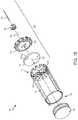
- FIG. 1Aillustrates an isometric view of a first exemplary drug delivery system.
- FIG. 1Billustrates an exploded view of the first exemplary drug system.
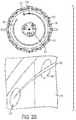
- FIG. 2Aillustrates an end view and a detail isometric view of an exemplary fluid flow regulator in a first operational state.
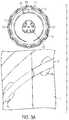
- FIG. 2Billustrates an end view and a detail isometric view of the exemplary fluid flow regulator in a second operational state.
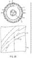
- FIG. 3Aillustrates an end view and a detail isometric view of the exemplary fluid flow regulator in a third operational state.
- FIG. 3Billustrates an end view and a detail isometric view of the exemplary fluid flow regulator in a fourth operational state.
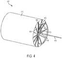
- FIG. 4illustrates a representational fluid flow diagram of the first exemplary drug delivery system.
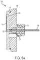
- FIG. 5Aillustrates a cross-sectional side view of the exemplary fluid flow regulator.
- FIG. 5Billustrates an end view of the exemplary fluid flow regulator.
- FIG. 6illustrates an exemplary flow profile and exemplary flow cross-sections provided by an exemplary fluid flow channel of the exemplary fluid flow regulator.
- FIG. 7illustrates exemplary flow profiles provided by an alternative exemplary fluid flow channel of the exemplary fluid flow regulator.
- FIG. 8Aillustrates a first flow scheme for exemplary fluid flow regulator.
- FIG. 8Billustrates a second flow scheme for exemplary fluid flow regulator.
- FIG. 8Cillustrates a third flow scheme for exemplary fluid flow regulator.
- FIG. 8Dillustrates a fourth flow scheme for exemplary fluid flow regulator.
- FIG. 8Eillustrates a fifth flow scheme for exemplary fluid flow regulator.
- FIG. 9illustrates an arrangement for equalizing the flow legs of the fluid flow regulating device depicted in FIGS. 8A-8E .
- FIG. 10Aillustrates an isometric view of a second exemplary drug delivery system.
- FIG. 10Billustrates a cross-sectional side view of the second exemplary drug delivery system
- FIG. 10Cillustrates an exploded view of the second exemplary drug delivery system.
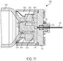
- FIG. 11illustrates a detailed view of an exemplary fluid flow regulator depicted in FIGS. 10A-10C .
- FIG. 12Aillustrates a first exemplary embodiment for adjusting an exemplary fluid flow regulator.
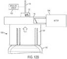
- FIG. 12Billustrates a second exemplary embodiment for adjusting an exemplary fluid flow regulator.
- FIG. 13shows a first exemplary surface profiling arrangement.
- FIG. 14shows a second exemplary surface profiling arrangement.
- FIG. 15shows a third exemplary surface profiling arrangement.
- FIG. 16shows a fourth exemplary surface profiling arrangement.
- This disclosurepresents various systems, components, and methods related to drug delivery devices. Each of the systems, components, and methods disclosed herein provides one or more advantages over conventional systems, components, and methods.
- Various embodimentsinclude a fluid flow regulator of a fluid delivery system that can adjust a flow rate of a liquid drug dispensed from a liquid drug container to a user.
- the fluid flow regulatorcan be coupled to an end of the liquid drug container.
- the fluid flow regulatorcan include a compliance plate and a flow channel selector plate having a fluid flow channel.
- the flow channel selector platecan be rotated relative to the compliance plate and the liquid drug container to expose a selected portion of the fluid flow channel to openings in the compliance plate that are in fluid communication with the liquid drug stored in the liquid drug container.
- the selected portion of the fluid flow channelcan correspond to a corresponding flow resistance of the liquid drug through the fluid flow channel, thereby regulating the flow of the liquid drug to the user.
- a fluid flow regulatormay be integrated into a custom drug container or attached to a standard primary container.
- the fluid flow regulatorcan use a tapered channel of varying length to change the outlet flow rate.
- flow calculationscan be developed using Poiseuille's Law:
- the disclosed fluid flow regulatorscan be used to regulate fluid exiting the drug delivery systems at finite and infinitely adjustable flow rates.
- laminar flowe.g., Reynold's number sub 4000 for water
- Disclosed arrangementscan be advantageous because in some drug therapies it is desirous to meter out the drug to a patient at a steady rate (e.g., for basal flow or delivery). Steady basal rates become difficult to achieve when using a mechanical, stored energy drive source, like a spring. Springs are inexpensive drive sources that provide repeatable performance and can withstand long shelf life, large temperature variation, and abuse in drop scenarios, while still performing properly thereafter.
- Springswill have a decaying force over extension (e.g., for a helical compression spring) spring constant or k. As force decays, drive pressure is reduced, and as a result the flow rate exiting the device is reduced. If outlet flow rate can be controlled, shorter and stiffer springs can be used to drive flow. Some of these springs may have a high k-value which means they lose drive force quickly and over a short stroke.
- the disclosed fluid regulatorscan accommodate the use of springs with relatively high k-value (and/or springs with any k-value including relatively low k-values).
- the disclosed fluid flow regulatorscan be adjusted, so as the spring force reduces (e.g., over the length of its stroke), the flow path restriction is reduced to keep the flow of drug consistent.
- the configuration of the fluid flow regulatoris fixed and not adjustable by a user.
- a plurality of discrete flow rate settingsare provided.
- available settingsare from a minimum value (e.g., off) to a maximum value (e.g., full flow).
- the configuration of the fluid flow regulatoris adjustable by a user or can be automatically adjusted to provide a desired or set flow rate.
- FIGS. 1A and 1Ba drug container system 100 (or liquid drug container system) is shown.
- FIG. 1Ashows the drug container system 100 in an assembled state.
- FIG. 1Bshows an exploded view of the drug container system 100 to illustrate the arrangement of the constituent components of the drug container system 100 .
- the drug container system 100can store or hold any liquid drug or any other fluid or therapeutic agent.
- the drug container system 100can include a drug container 102 (or liquid drug container), a plunger 104 , and a fluid flow regulator 106 .
- the drug container 102may be a generally cylindrical body and may receive the plunger 104 at a first end 108 , and may receive the fluid flow regulator 106 (and/or components thereof) at an opposite, second, end 110 .
- the drug container 102can be of any size in shape.
- the drug container 102can be a custom-molded container and/or can have a custom shape.
- the second end 110 of the drug container 102may include various features that interact with portions of the fluid flow regulator 106 , as will be described.
- the second end 110 of the drug container 102may have an inlet recess or manifold 112 and an outlet recess or manifold 114 (see also FIG. 4 and related discussion) that are configured to enable flow to be directed to specific locations within the fluid flow regulator 106 .
- the fluid flow regulator 106may include a compliance plate 116 , a flow channel selector plate 118 , a needle ball 120 , a needle ball retainer 122 , and a hard needle 124 .
- the compliance plate 116can be a flat elastomeric member or component that can seal the second end 110 of the drug container 102 from the flow channel selector plate 118 .
- the compliance plate 116can include first and second openings 126 and 128 . The first and second openings 126 and 128 may fluidly couple to the first and second recesses 112 and 114 , respectively (e.g., they may be in communication or fluid communication therewith, or coupled thereto).
- the arrangement of the first and second recesses 112 and 114 and the first and second openings 126 and 128can direct fluid stored in the drug container 102 to flow to a fluid flow channel 130 disposed within (e.g., positioned on the flow channel selector plate 118 and/or coupled or attached thereto).
- the compliance plate 116can also include a third opening 132 that can be coupled to the hard needle 124 (e.g., a central opening), described in more detail further herein.
- the first and second openings 126 and 128can be positioned a same distance from a center of the compliance plate 116 (e.g., a same radial distance from the third opening 132 ).
- the size, length, and/or configuration of the fluid flow channel 130can be adjusted to thereby adjust the flow resistance within the fluid flow channel 130 (and/or provided by the fluid flow channel 130 ).
- the position of the flow channel selector plate 118can be adjusted by rotating the flow channel selector plate 118 relative to a stationary compliance plate 116 (and liquid drug container 102 ). This adjustment, in turn, can be used to adjust the flow rate of a liquid drug travelling through the fluid flow channel 130 and, in turn, out to the user (e.g., through the needle 124 ).
- the liquid drug passing through the fluid flow channel 130can be provided to the user by coupling the hard needle 124 (or other fluid path or fluid path component) to the user.
- FIGS. 2A-2B and 3A-3Bshow end views of the fluid flow regulator 106 positioned within the drug container 102 (e.g., viewing in the compliance plate 116 from the needle 124 ) as well as corresponding detailed close up views of the first and second opening 126 and 128 in relation to the fluid flow channel 130 .
- FIG. 2Ashows the fluid flow regulator 106 in a minimum or a “0” position of the flow channel selector plate 118 .
- the “0” positionno part of the fluid flow channel 130 is coupled across the first and second openings 126 and 128 of the compliance plate 116 . As such, flow is shut off and no liquid drug is expelled (or can flow) from the drug container 102 .
- FIG. 2Bshows the fluid flow regulator 106 in a second selectable position or a “1” position of the flow channel selector plate 118 .
- a small cross-sectional portion of the fluid flow channel 130is coupled between the first and second openings 126 and 128 of the compliance plate 116 , enabling some (e.g., limited) flow of liquid drug from the drug container 102 .
- the detailed view of the compliance plate 116shows a portion of the fluid flow channel in dash to reveal the changing cross-sectional dimensions of the fluid flow channel coupled across the first and second opening s 126 and 128 as the selectable positions of the fluid flow selector plate 118 are changed.
- FIG. 3Ashows the fluid flow regulator 106 in another selectable position or the “6” position of the flow channel selector plate 118 .
- a larger cross-sectional portion of the fluid flow channel 130is coupled between the first and second openings 126 and 128 of the compliance plate 116 , enabling greater flow of liquid drug from the liquid drug container 102 as compared to position “1” depicted in FIG. 2B .
- FIG. 3Bshows the fluid flow regulator 106 in a maximum or “10” position of the flow channel selector plate 118 .
- the largest cross-sectional portion of the fluid flow channel 130is coupled between the first and second openings 126 and 128 of the compliance plate 116 , enabling greater flow of liquid drug from the liquid drug container 1 as compared to position “6” as depicted in FIG. 3A .
- the distance between the first and second openings 126 and 128 of the compliance plate 116stays constant, regardless of the position of the flow channel selector plate 118 (e.g., since the compliance plate 116 remains stationary).
- the position of the flow channel selector plate 118can determine the size of (e.g., the cross-sectional portion of) the fluid flow channel 130 positioned between the first and second openings 126 and 128 .
- Flow between the first and second openings 126 and 128can be increased as the size of the cross-sectional portion of the fluid flow channel 130 is increased (and correspondingly decreased as the size of the cross-sectional portion of the fluid flow channel 130 is decreased).
- flow through the fluid flow regulator 106is adjusted by changing the characteristics of the fluid flow channel 130 that is disposed across the first and second openings 126 and 128 .
- the adjusted flowcan then be coupled to the patient or user through, for example, the hard needle 124 .
- the fluid flow channel 130is a circular tapered channel.
- the fluid flow channel 130tapers from an initial height to a final height, with either the initial or final height being a maximum height or minimum height.
- the profile of the fluid flow channel 130can take on any shape or profile or tapering provided a final height is reached from a starting height. Accordingly, as the flow channel selector plate 118 is rotated, a different portion of the circular tapered channel forming the fluid flow channel 130 is exposed to the first and second openings 126 and 128 . Lower settings of the flow channel selector plate 118 correspond to the first and second openings 126 and 128 being exposed to smaller cross-sectional portions of the circular tapered channel.
- the fluid flow channel 130comprises a circular tapered channel molded into the flow channel selector plate 118 .
- the fluid flow channel 130can be coupled to the flow channel selector plate 118 in any manner.
- FIG. 4illustrates a fluid flow diagram 400 illustrating the flow path of a liquid drug from the liquid drug container 102 to the hard needle 124 .
- Flow portion 402represents the fluid as stored in the liquid drug container 102 .
- Flowexits the liquid drug container 102 through an opening in the second end 110 of the container 102 and is directed, via flow path 404 through an inlet manifold 112 (see FIG. 1 ) formed in the second end 110 of the container 102 .
- Flow path 406represents the flow of liquid through the first opening 126 in the compliance plate 116 .
- Flow path 408represents the flow of liquid from the first opening 126 though the fluid flow channel 130 of the flow channel selector plate 118 .
- Flow path 410represents the flow of liquid from the fluid flow channel 130 back through the second opening 128 in the compliance plate 116 .
- Flow path 412represents the flow of liquid from the second opening 128 through an outlet manifold 114 (see FIG. 1 ) formed in the second end 110 of the liquid drug container 102 .
- Flow path 414represents the flow of liquid from the outlet manifold 114 to a third opening 132 in the compliance plate 116 . From there, flow path 416 represents the flow of liquid from the third opening 132 out through the hard needle 124 (e.g., through a central opening of the flow channel selector plate).
- FIGS. 5A and 5BAspects of the fluid flow passages through the liquid drug container 102 (e.g., the inlet and outlet manifolds 112 and 114 ), and the compliance plate 116 (e.g., the second and third openings 128 and 132 ), as well as their connections to the needle 124 are illustrated in FIGS. 5A and 5B .
- FIG. 5Ashows a cross-sectional side view of the fluid flow regulator 106 . As shown in FIG.
- the second opening 128is coupled to the outlet manifold 114
- the outlet manifold 114is coupled to the third opening 132
- the third opening 132is coupled to the hard needle 124 , thereby completing a fluid path based on a selected regulated flow from the container 102 to the needle 102 .
- the needle ball 120 and the needle ball retainer 122can support the needle 124 .
- FIG. 5Bshows a rear view of the fluid flow regulator 106 (e.g., as viewed looking toward the needle ball retainer 122 from the needle 124 ). As shown, the manifolds 112 and 114 are shown providing part of the fluid path from the container 102 to the hard needle 124 .
- FIG. 6shows an isometric representation of the fluid flow channel 130 as a circular channel with a tapering cross-section.
- FIG. 6also shows an example flow profile 606 of the fluid flow channel 130 .
- the example flow profile 606 of the fluid flow channel 130can have a constantly tapering height “h” that has a largest or maximum height at a setting “11” and that has a smallest or minimum height at a setting “0”.
- the flow channel selector plate 118corresponds to the first and second openings 126 and 128 of the compliance plate 116 being exposed to smaller cross-sectional portions of the circular tapered channel of the fluid flow channel 130
- higher settings of the flow channel selector plate 118correspond to the first and second openings 126 and 128 being exposed to larger cross-sectional portions of the circular tapered channel of the fluid flow channel 130
- the flow profile 606has a height “h” that smoothly and linearly moves from a minimum height to a maximum height over the length of the fluid flow channel 130 .
- the change in the height “h”can be non-linear.
- FIG. 6further illustrates example cross-sectional shapes of the fluid flow channel 130 .
- a first cross-sectional shape 602can be a semi-circle or half-circle.
- a second cross-sectional shape 604can be a polygon (e.g., a square). It will be appreciated, however, that any of a variety of cross-sectional shapes (e.g., polygonal or other geometric and non-geometric shapes) can be used, as can cross-sectional shapes that change along the length of the fluid flow channel 130 (e.g., such that the fluid flow channel 130 includes two or more cross-sectional shapes or varies in any manner along the length of the fluid flow channel 130 ).
- the tapered channel(s) of the fluid flow channel 130may have gradual/helical tapers or distinct steps where high resolution low flow performance can be achieved within some set amount of degrees or radians, while the more “wide open” end can provide a bolus.
- FIG. 7illustrates an alternative embodiment 130 - 1 of the fluid flow channel 130 comprising a double channel that snakes around the face of the flow channel selector plate 116 .
- a double channelcan include an inner circular portion and an outer circular portion, each coupled to a different opening 126 and 128 (see FIGS. 8A-8E ).
- the fluid flow channel 130can include a linear double-tapered configuration such that fluid in the fluid flow channel 130 is forced through a loop that also tapers.
- a first open end of the double channelcan have a minimum height
- a second open end of the double channelcan also have the minimum height
- the heightcan increase to a maximum height and then back to the minimum height.
- FIG. 7also shows exemplary flow profiles.
- a flow profile 702can correspond to the embodiment of the fluid flow channel 130 - 1 shown in FIG. 7 having a linear double-tapered configuration (e.g., tapers from a maximum height from a halfway position of the channel down to a minimum height at the open ends of the channel).
- a flow profile 704is also shown in which the taper or change in the fluid flow channel 130 - 1 is stepped rather than linear.
- the stepscan be discontinuous changes in the height of the channel. The steps can be the same increases or changes or height or can vary and can be spaced evenly along the length of the channel or can vary.
- the fluid flow channel 130 - 1can be provided with any of a variety of profiles to achieve a desired flow response along any portion of a length of the fluid flow channel 130 including one or more different flow profiles.
- the double channeled fluid flow channel 130 - 1can have any cross-sectional shape along any portion of the fluid flow channel 130 - 1 .
- any fluid channel disclosed hereincan have any flow profile (e.g., linearly or non-linearly changing along the length of the channel) and any cross-sectional shape.
- FIGS. 8A through 8Eillustrate various selected flow paths through the “loop style” or double channel fluid flow channel 130 - 1 depicted in FIG. 7 .
- FIGS. 8A through 8Eshow the first and second openings 126 and 128 coupled to different portions of the fluid flow channel 130 - 1 .
- the first and second openings 126 and 128can be positioned along a same radial axis extending from a center of the compliance plate 116 —for example, such that the first opening 126 is positioned further from the center of the compliance plate than the second opening 128 .
- FIG. 8Ashows the first and second openings 126 and 128 coupled to a first portion of the fluid flow channel 130 - 1
- FIG. 8Bshows the first and second openings 126 and 128 coupled to a second portion of the fluid flow channel 130 - 1
- FIG. 8Cshows the first and second openings 126 and 128 coupled to a third portion of the fluid flow channel 130 - 1
- FIG. 8Dshows the first and second openings 126 and 128 coupled to a fourth portion of the fluid flow channel 130 - 1
- FIG. 8Eshows the first and second openings 126 and 128 coupled to a fifth portion of the fluid flow channel 130 - 1 .
- the first opening 126can be coupled to one of the two channels of the fluid flow channel 130 - 1 (e.g., one side of the fluid flow channel 130 - 1 ) and the second opening 128 can be coupled to the other of the two channels of the fluid flow channel 130 - 1 (e.g., the other side of the fluid flow channel 130 - 1 ).
- liquid drugis forced through the entire length of the flow loop of the fluid flow channel 130 - 1 between the first and second openings 126 and 128 in the compliance plate 116 (e.g., across all portions of both channels as indicated by the flow arrows).
- Thismay be associated with position “1” of the flow channel selector plate 118 as it represents the highest amount of fluid resistance available with the illustrated fluid flow channel 130 .
- the illustrated arrowscan show a flow of a liquid through the channel 130 - 1 .
- FIGS. 8C-8Eshow incrementally reduced lengths of the fluid flow channel 130 - 1 through which liquid drug will flow, which may correspond with respectively reduced flow resistance through the fluid flow channel 130 - 1 (since less distance is traversed by the liquid drug as increasingly reduced portions of each channel are traversed).
- FIG. 8Emay correspond with the highest level of the flow channel selector plate 118 —for example, representing maximum flow and lowest flow resistance.
- FIG. 9illustrates an arrangement for maintaining the lengths “equal” between the inner and the outer loops (or channels) 130 -A and 130 -B of the fluid flow channel 130 - 1 in order to obtain a linear output, for example when the fluid flow channel 130 is implemented in a “loop style” (e.g., as fluid flow channel 130 - 1 as shown in FIG. 7 ).
- an unconstrained section 902is positioned where the inner and outer loops 130 -A and 130 -B meet.
- the outer loop 130 -Bhas a radius R 1 that is greater than the radius R 2 of the inner loop 130 -A, the loops 130 -A and 130 -B will not be the same length.
- the positions of the inlet (at the first opening 126 in the compliance plate 116 ) and the outlet (at the second opening 128 in the compliance plate 116 )could be varied, or a deep channel (unconstrained section 902 ) could be positioned at the end of the longer outer loop 130 -B to “normalize” the lengths of the inner and outer loops 130 -A and 130 -B.
- FIGS. 10A through 10Cillustrate a drug container system 1000 (or liquid drug container system).
- FIG. 10Ashows a first view of the drug container system 1000 in an assembled state.
- FIG. 10Bshows a cross-sectional side view of the drug container.
- FIG. 10Cshows an exploded view of the drug container system 1000 to illustrate the arrangement of the constituent components of the drug container system 1000 .
- the drug container system 1000can store or hold any liquid drug or any other fluid or therapeutic agent.
- the drug container system 1000can include a drug container 1002 (or liquid drug container), a plunger 1004 , and a fluid flow regulator 1006 .
- the drug container 102may be an International Organization for Standardization (ISO) cartridge (e.g., made of glass). Accordingly, the drug container system 1000 illustrates a fluid flow regulator 1006 that can be coupled to a standard ISO glass cartridge 1002 .
- ISOInternational Organization for Standardization
- the features present in the second end 110 of the liquid drug container 102 of FIGS. 1A and 1Bcan be incorporated into a cartridge adapter 1008 .
- the cartridge adapter 1008may have features that enable it to snap onto a mouth portion or opening 1010 (e.g., a neck and crown) of the liquid drug container 1002 .
- these featurescan include flexible snaps 1012 that can flex outward when pressed against the mouth portion 1010 and then expand behind the mouth portion 1010 to lock the cartridge adapter 1008 in place.
- An annular seal 1014such as an O-ring may seal the cartridge adapter 1008 to the liquid drug container 1002 .
- the compliance plate 116 and the flow channel selector plate 118 of the drug container system 1000may have the same features and functionality as described in relation to the drug container system 100 .
- the needle ball 120 , needle ball retainer 122 , and the hard needle 124may also be the same as described in relation to the drug container system 100 .
- FIG. 11shows and inter-engagement between the liquid drug container 1002 and the fluid flow regulator 1006 depicted in FIGS. 10A-10C .
- the annular seal 1014may seal against an internal surface 1102 of the liquid drug container.
- the flexible snaps 1012are shown in a locked position, sitting behind the mouth portion 1010 of the liquid drug container 1002 .
- the compliance plate 116can be coupled to the cartridge adapter 1008 .
- the flow channel selector plate 118can be pressed against the compliance plate 116 and can also be positioned or disposed within the cartridge adapter 1008 .
- FIG. 12Ashows the fluid flow regulator 1006 incorporating a plurality of fixed, finite flow settings.
- the flow channel selector plate 118can include a flow setting 1202 (e.g., set by rotating the flow channel selector plate 118 ) and the cartridge adapter 1008 can include a flow setting indicator 1204 to specify what flow setting 1202 is selected or set.
- a finite number of portions of the flow channel selector plate 118(and therefore corresponding flow settings 1202 ) can be chosen or selected.
- a closed loop approachcan be applied in which a pressure sensor 1206 or plunger positioning sensor can sense flow rate or plunger position and can feed that information back to a flow regulation arrangement or component 1208 , which may include a motor or other arrangement for adjusting the flow channel selector plate 118 .
- the flow channel selector plate 118is infinitely adjustable, and is coupled to a motor 1208 .
- the motor 1208may be actuated to adjust the rotational position of the flow channel selector plate 118 to adjust the flow resistance through the fluid flow regulator 1006 .
- the motor 1208can be activated to adjust the position of the flow channel selector plate 118 to reduce flow resistance through the regulator to thereby re-establish flow to within the desired range.
- FIGS. 12A and 12Bcan be applied to the drug container system 100 as well.
- the pressure sensor 1206can be coupled to the needle 124 , for example, to detect a flow or flow pressure of the liquid drug through the needle 124 .
- FIGS. 13-16to control fluid delivery rates with varying drive sources which may exhibit decay or rapid changes in drive pressure, a turbulent flow regime (e.g., Reynold's number greater than 4000) may be exploited to disrupt flow sufficiently that for a given increase in pressure, little impact on outlet flow rate will be experienced.
- FIGS. 13-16illustrate various exemplary surface profiling arrangements that can be employed within the fluid flow channel 130 within any of the devices or systems described herein.
- one or more of these surface profiling arrangementscan be employed along the entire length of the fluid flow channel 130 or a portion thereof or according to any pattern (e.g., applied to distinct non-overlapping regions of the fluid flow channel 130 ).
- the surface profiling arrangementscan be applied over a limited length of the fluid flow channel 130 to generate turbulent flow over a limited length followed by an area that converts flow back to the laminar regime.
- the surface profiling arrangementsmay be molded or textured interior features of the fluid flow channel 130 (e.g., any of the exemplary fluid flow channels described herein).
- FIG. 13shows a first exemplary surface profiling arrangement. Specifically, FIG. 13 shows a plurality of diamond-shaped protrusions 1302 positioned on an interior surface 1304 of the fluid flow channel 130 .
- the protrusions 1306can be oriented so that the points of the diamond protrusions 1302 are aligned with a general flow of fluid between an inlet 1306 and an outlet 1308 of the fluid flow channel 130 .
- Flow indicators 1310shows the general flow of a fluid through the fluid flow channel 130 .
- the diamond-shaped protrusions 1302may be of varying heights with respect to the height “h” of the fluid flow channel 130 . Alternatively, the protrusions 1302 could have different orientations and/or could be of a consistent height.
- FIG. 14shows a second exemplary surface profiling arrangement. Specifically, FIG. 14 shows a plurality of circular protrusions 1402 positioned on the interior surface 1304 of the fluid flow channel 130 .
- Flow indicators 1404show the general flow of a fluid through the fluid flow channel 130 .
- the circular protrusions 1402may be of varying heights with respect to the height “h” of the fluid flow channel 130 .
- the protrusions 1402could have different orientations and/or could be a consistent height.
- the circular protrusions 1302may all have the same diameter or some may have different diameters.
- FIG. 15shows a third exemplary surface profiling arrangement. Specifically, FIG. 15 shows a plurality of perforated undulating walls 1502 positioned on the interior surface 1304 of the fluid flow channel 130 .
- the walls 1502can include a plurality of openings or cross-channels 1504 that allow flow 1506 of the liquid to pass through the walls 1502 as the fluid travels from the inlet 1306 to the outlet 1308 .
- the openings 1504can be regularly spaced along the length of the walls 1502 or can be spaced at irregular intervals and can be of the same size or of different sizes.
- the perforated undulating walls 1504span the height “h” of the fluid flow channel 130 but are not so limited.
- FIG. 16shows a “shark fin” perforated sheet 1602 arrangement including a plurality of U-shaped protrusions 1604 which can have different orientations with respect to the flow of fluid from the inlet 1306 to the outlet 1308 .
- the perforated sheets 1602can be locked in place with respect to the fluid flow channel 130 using pins 1606 .
- Various orientations of the protrusions 1604can be implemented so that flow in a delivery direction can be subject to high resistance (thus forming turbulent flow during drug delivery), while flow in the opposite direction (i.e., the filling direction) can be subject to relatively low resistance (thus achieving laminar flow during filling of the device).
- any of the fluid flow regulation arrangementscan be part of a wearable or on-body drug delivery device or pump, such as an OmniPod® (Insulet Corporation, Billerica, Mass., USA) device and/or any of the drug delivery devices described in U.S. Pat. Nos. 7,303,549; 7,144,384; 7,137,964; 6,960,192; 6,740,059; 6,699,218; 9,402,950; 7,771,412; 7,029,455; 6,740,05; and 6,656,159, each of which is incorporated herein by reference in its entirety.
- OmniPod®Insulet Corporation, Billerica, Mass., USA
Landscapes
- Health & Medical Sciences (AREA)
- Vascular Medicine (AREA)
- Engineering & Computer Science (AREA)
- Anesthesiology (AREA)
- Biomedical Technology (AREA)
- Heart & Thoracic Surgery (AREA)
- Hematology (AREA)
- Life Sciences & Earth Sciences (AREA)
- Animal Behavior & Ethology (AREA)
- General Health & Medical Sciences (AREA)
- Public Health (AREA)
- Veterinary Medicine (AREA)
- Physics & Mathematics (AREA)
- Fluid Mechanics (AREA)
- Infusion, Injection, And Reservoir Apparatuses (AREA)
Abstract
Description
Claims (18)
Priority Applications (1)
| Application Number | Priority Date | Filing Date | Title |
|---|---|---|---|
| US16/049,388US10973978B2 (en) | 2017-08-03 | 2018-07-30 | Fluid flow regulation arrangements for drug delivery devices |
Applications Claiming Priority (2)
| Application Number | Priority Date | Filing Date | Title |
|---|---|---|---|
| US201762540947P | 2017-08-03 | 2017-08-03 | |
| US16/049,388US10973978B2 (en) | 2017-08-03 | 2018-07-30 | Fluid flow regulation arrangements for drug delivery devices |
Publications (2)
| Publication Number | Publication Date |
|---|---|
| US20190038835A1 US20190038835A1 (en) | 2019-02-07 |
| US10973978B2true US10973978B2 (en) | 2021-04-13 |
Family
ID=65231402
Family Applications (1)
| Application Number | Title | Priority Date | Filing Date |
|---|---|---|---|
| US16/049,388Active2039-01-26US10973978B2 (en) | 2017-08-03 | 2018-07-30 | Fluid flow regulation arrangements for drug delivery devices |
Country Status (1)
| Country | Link |
|---|---|
| US (1) | US10973978B2 (en) |
Families Citing this family (1)
| Publication number | Priority date | Publication date | Assignee | Title |
|---|---|---|---|---|
| GB2584875B (en)* | 2019-06-18 | 2021-09-15 | Charles Devlin West Jonathan | Flow metering insert and/or device |
Citations (262)
| Publication number | Priority date | Publication date | Assignee | Title |
|---|---|---|---|---|
| US1441508A (en) | 1921-12-06 | 1923-01-09 | Jensen Anton Marius | Cylindrical slide valve |
| GB357139A (en) | 1929-06-14 | 1931-09-14 | Paul Von Vago | |
| US2198666A (en) | 1936-09-30 | 1940-04-30 | Lakeland Foundation | Syringe |
| GB810488A (en) | 1955-03-01 | 1959-03-18 | Eduard Woydt | Liquid pressure piston-engine or reciprocating pump |
| CA606281A (en) | 1960-10-04 | Dann Morris | Cartridge for metering syringe | |
| GB875034A (en) | 1957-07-01 | 1961-08-16 | Renault | Improvements in or relating to valves for fluids under pressure |
| US3176712A (en) | 1961-10-03 | 1965-04-06 | Ramsden Clement | Non-return valve |
| US3297260A (en) | 1964-09-21 | 1967-01-10 | Conrad R Barlow | Nozzle and valve assembly |
| US3464359A (en) | 1967-11-13 | 1969-09-02 | Medimeter Corp The | Apparatus for moving fluid from one system to a second system |
| GB1204836A (en) | 1968-05-20 | 1970-09-09 | Thermal Hydraulics Corp | Thermal actuator |
| FR2096275A5 (en) | 1970-06-13 | 1972-02-11 | Ismatec Sa | |
| US3885662A (en) | 1973-12-26 | 1975-05-27 | Ibm | Steerable follower selection mechanism |
| US3947692A (en) | 1974-08-05 | 1976-03-30 | Viron E. Payne, Inc. | Digital transducers |
| US3946732A (en) | 1973-08-08 | 1976-03-30 | Ampoules, Inc. | Two-chamber mixing syringe |
| US3993061A (en) | 1975-02-28 | 1976-11-23 | Ivac Corporation | Syringe pump drive system and disposable syringe cartridge |
| IL46017A (en) | 1974-11-07 | 1977-11-30 | Ampoules Inc | Two-chamber mixing syringe |
| US4108177A (en) | 1976-04-23 | 1978-08-22 | Michel Louis Paul Pistor | Automatic injector device |
| US4152098A (en) | 1977-01-03 | 1979-05-01 | Clark Ivan P | Micropump |
| GB2008806A (en) | 1977-11-03 | 1979-06-06 | Danfoss As | Controllable heating means for small masses |
| US4210173A (en) | 1976-12-06 | 1980-07-01 | American Hospital Supply Corporation | Syringe pumping system with valves |
| US4221219A (en) | 1978-07-31 | 1980-09-09 | Metal Bellows Corporation | Implantable infusion apparatus and method |
| FR2455269A1 (en) | 1978-01-17 | 1980-11-21 | Marceau Serge | Dynamic dosing of liquid food product - utilises compressed air operation of cylinders to move liquid dose to outlet |
| US4257324A (en) | 1978-10-30 | 1981-03-24 | Bell & Howell Company | Position monitoring methods and apparatus |
| US4268150A (en) | 1980-01-28 | 1981-05-19 | Laurence Chen | Disposable camera with simplified film advance and indicator |
| WO1981001658A1 (en) | 1979-12-13 | 1981-06-25 | M Loeb | Wearable insulin infusion system having a tubular reservoir and a positive displacement metering means |
| GB2077367A (en) | 1978-09-05 | 1981-12-16 | Mandroian Harold | Three valve precision pump apparatus with head pressure flow through protection |
| US4313439A (en) | 1980-03-24 | 1982-02-02 | Biotek, Inc. | Automated, spring-powered medicament infusion system |
| FR2507637A1 (en) | 1981-06-16 | 1982-12-17 | Libero Elettrotecnica | Thermo-electric drive for detergent reservoir of automatic dishwasher - has thermistor heating substance which expands and operates lever |
| US4371790A (en) | 1980-09-19 | 1983-02-01 | Rmr Systems, Inc. | Fluid measuring system |
| US4417889A (en) | 1980-12-31 | 1983-11-29 | Choi Soo Bong | Device for a portable automatic syringe |
| US4424720A (en) | 1980-12-15 | 1984-01-10 | Ivac Corporation | Mechanism for screw drive and syringe plunger engagement/disengagement |
| US4435173A (en) | 1982-03-05 | 1984-03-06 | Delta Medical Industries | Variable rate syringe pump for insulin delivery |
| US4498843A (en) | 1982-08-02 | 1985-02-12 | Schneider Philip H | Insulin infusion pump |
| US4507115A (en) | 1981-04-01 | 1985-03-26 | Olympus Optical Co., Ltd. | Medical capsule device |
| US4551134A (en) | 1982-08-06 | 1985-11-05 | Nuvatec, Inc. | Intravenous set |
| US4562751A (en) | 1984-01-06 | 1986-01-07 | Nason Clyde K | Solenoid drive apparatus for an external infusion pump |
| US4567549A (en) | 1985-02-21 | 1986-01-28 | Blazer International Corp. | Automatic takeup and overload protection device for shape memory metal actuator |
| US4585439A (en) | 1983-09-07 | 1986-04-29 | Disetronic Ag. | Portable infusion unit |
| US4601707A (en) | 1980-06-03 | 1986-07-22 | Albisser Anthony M | Insulin infusion device |
| WO1986006796A1 (en) | 1985-05-15 | 1986-11-20 | Henning Munk Ejlersen | A hose pump, in particular an insulin pump |
| US4634427A (en) | 1984-09-04 | 1987-01-06 | American Hospital Supply Company | Implantable demand medication delivery assembly |
| US4671429A (en) | 1983-11-15 | 1987-06-09 | Thomas J. Lipton, Inc. | Method and apparatus for volumetric dosing viscous products |
| US4678408A (en) | 1984-01-06 | 1987-07-07 | Pacesetter Infusion, Ltd. | Solenoid drive apparatus for an external infusion pump |
| US4684368A (en) | 1984-06-01 | 1987-08-04 | Parker Hannifin Corporation | Inverted pump |
| US4685903A (en) | 1984-01-06 | 1987-08-11 | Pacesetter Infusion, Ltd. | External infusion pump apparatus |
| US4755169A (en) | 1985-05-20 | 1988-07-05 | Survival Technology, Inc. | Automatic medicament ingredient mixing and injecting apparatus |
| US4766889A (en) | 1986-06-26 | 1988-08-30 | Medical Engineering Corporation | Infusion erectile system |
| US4808161A (en) | 1986-03-04 | 1989-02-28 | Kamen Dean L | Pressure-measurement flow control system |
| US4846797A (en) | 1985-05-14 | 1989-07-11 | Intelligent Medicine, Inc. | Syringe positioning device for enhancing fluid flow control |
| US4858619A (en) | 1987-06-29 | 1989-08-22 | Toth Marie A | Intracranial pressure monitoring system |
| US4898579A (en) | 1987-06-26 | 1990-02-06 | Pump Controller Corporation | Infusion pump |
| US4908017A (en) | 1985-05-14 | 1990-03-13 | Ivion Corporation | Failsafe apparatus and method for effecting syringe drive |
| US4944659A (en) | 1987-01-27 | 1990-07-31 | Kabivitrum Ab | Implantable piezoelectric pump system |
| US4969874A (en) | 1987-05-18 | 1990-11-13 | Disetronic Ag | Infusion device |
| US5007458A (en) | 1990-04-23 | 1991-04-16 | Parker Hannifin Corporation | Poppet diaphragm valve |
| US5020325A (en) | 1990-02-13 | 1991-06-04 | Procedes Vernet | Heat motor |
| EP0454331A1 (en) | 1990-04-16 | 1991-10-30 | Minimed Inc., doing business as Minimed Technologies | Infusionssystem für die Medikation |
| US5062841A (en) | 1988-08-12 | 1991-11-05 | The Regents Of The University Of California | Implantable, self-regulating mechanochemical insulin pump |
| US5147311A (en)* | 1987-09-09 | 1992-09-15 | Ewald Pickhard | Injection device for use with a deformable ampoule |
| US5178609A (en) | 1990-06-19 | 1993-01-12 | Kato Hatsujo Kaisha, Ltd. | Medical liquid injector for continuous transfusion |
| US5205819A (en) | 1989-05-11 | 1993-04-27 | Bespak Plc | Pump apparatus for biomedical use |
| US5213483A (en) | 1991-06-19 | 1993-05-25 | Strato Medical Corporation | Peristaltic infusion pump with removable cassette and mechanically keyed tube set |
| US5222362A (en) | 1989-01-10 | 1993-06-29 | Maus Daryl D | Heat-activated drug delivery system and thermal actuators therefor |
| DE4200595A1 (en) | 1992-01-13 | 1993-07-15 | Michail Efune | Assembly group for infusion set for insulin pump - involves steel needle inside plastics cannula with only limited axial movement and drawn back into cannula during infusion. |
| US5236416A (en) | 1991-05-23 | 1993-08-17 | Ivac Corporation | Syringe plunger position detection and alarm generation |
| US5261884A (en) | 1992-04-29 | 1993-11-16 | Becton, Dickinson And Company | Syringe pump control system |
| US5261882A (en) | 1993-04-26 | 1993-11-16 | Sealfon Andrew I | Negator spring-powered syringe |
| US5277338A (en) | 1990-12-21 | 1994-01-11 | Odin Developments Limited | Fluid metering apparatus |
| US5281202A (en) | 1991-09-03 | 1994-01-25 | Fresenius Ag | Device for draining a flexible fluid container |
| JPH0663133A (en) | 1992-06-18 | 1994-03-08 | Raifu Technol Kenkyusho | Portable automatic chemical injection device |
| WO1994015660A1 (en) | 1993-01-05 | 1994-07-21 | Berney Jean Claude | Powered-plunger infusion device |
| US5346476A (en) | 1992-04-29 | 1994-09-13 | Edward E. Elson | Fluid delivery system |
| JPH06296690A (en) | 1993-04-14 | 1994-10-25 | Nippon Medical Supply Corp | Syringe pump |
| US5364342A (en) | 1992-02-05 | 1994-11-15 | Nestle S.A. | Microsurgical cassette |
| US5388615A (en) | 1992-12-11 | 1995-02-14 | Busak & Luyken Gmbh & Co. | Sealing means and sealing valve for container openings |
| US5433710A (en) | 1993-03-16 | 1995-07-18 | Minimed, Inc. | Medication infusion pump with fluoropolymer valve seat |
| US5503628A (en) | 1995-03-15 | 1996-04-02 | Jettek, Inc. | Patient-fillable hypodermic jet injector |
| US5520661A (en) | 1994-07-25 | 1996-05-28 | Baxter International Inc. | Fluid flow regulator |
| US5533389A (en) | 1986-03-04 | 1996-07-09 | Deka Products Limited Partnership | Method and system for measuring volume and controlling flow |
| FR2731475A1 (en) | 1995-03-07 | 1996-09-13 | Thomson Dauphinoise | Thermal/mechanical device for mounting electric heating or cooling component on thermal actuator |
| JPH08238324A (en) | 1995-03-04 | 1996-09-17 | Nissho Corp | Means for mixed injection of plural medicinal liquids |
| US5582593A (en) | 1994-07-21 | 1996-12-10 | Hultman; Barry W. | Ambulatory medication delivery system |
| US5618269A (en) | 1995-05-04 | 1997-04-08 | Sarcos, Inc. | Pressure-driven attachable topical fluid delivery system |
| US5637095A (en) | 1995-01-13 | 1997-06-10 | Minimed Inc. | Medication infusion pump with flexible drive plunger |
| EP0789146A1 (en) | 1995-07-27 | 1997-08-13 | Seiko Epson Corporation | Microvalve and method of manufacturing the same, micropump using the microvalve and method of manufacturing the same, and apparatus using the micropump |
| US5665070A (en) | 1995-01-19 | 1997-09-09 | I-Flow Corporation | Infusion pump with magnetic bag compression |
| US5713875A (en) | 1994-07-29 | 1998-02-03 | Abbott Laboratories | System for administration of a liquid agent to a patient with a syringe pump |
| US5748827A (en) | 1996-10-23 | 1998-05-05 | University Of Washington | Two-stage kinematic mount |
| US5747350A (en) | 1993-04-02 | 1998-05-05 | Boehringer Mannheim Gmbh | System for dosing liquids |
| US5776103A (en) | 1995-10-11 | 1998-07-07 | Science Incorporated | Fluid delivery device with bolus injection site |
| US5779676A (en) | 1995-10-11 | 1998-07-14 | Science Incorporated | Fluid delivery device with bolus injection site |
| US5785688A (en) | 1996-05-07 | 1998-07-28 | Ceramatec, Inc. | Fluid delivery apparatus and method |
| US5797881A (en) | 1996-06-20 | 1998-08-25 | Gadot; Amir | Intravenous infusion apparatus |
| DE19723648C1 (en) | 1997-06-05 | 1998-08-27 | Disetronic Licensing Ag | Controlled infusion equipment with leak and reverse flow prevention used e.g. in insulin therapy |
| US5800397A (en) | 1995-04-20 | 1998-09-01 | Invasatec, Inc. | Angiographic system with automatic high/low pressure switching |
| US5807075A (en) | 1993-11-23 | 1998-09-15 | Sarcos, Inc. | Disposable ambulatory microprocessor controlled volumetric pump |
| EP0867196A2 (en) | 1997-03-26 | 1998-09-30 | Disetronic Licensing AG | Catheter system for transdermal passages |
| US5839467A (en) | 1993-10-04 | 1998-11-24 | Research International, Inc. | Micromachined fluid handling devices |
| WO1998055073A1 (en) | 1997-06-03 | 1998-12-10 | Kunshan Wang | A medical apparatus comprising an elastic valve-type stopper and a piercing needle |
| WO1998056293A1 (en) | 1997-06-09 | 1998-12-17 | Minimed Inc. | Insertion set for a transcutaneous sensor |
| WO1999010049A1 (en) | 1997-08-29 | 1999-03-04 | Cycle-Ops Products, Inc. | Exercise resistance device |
| WO1999010040A1 (en) | 1997-08-27 | 1999-03-04 | Science Incorporated | Fluid delivery device with temperature controlled energy source |
| US5891097A (en) | 1994-08-12 | 1999-04-06 | Japan Storage Battery Co., Ltd. | Electrochemical fluid delivery device |
| US5897530A (en) | 1997-12-24 | 1999-04-27 | Baxter International Inc. | Enclosed ambulatory pump |
| US5906597A (en) | 1998-06-09 | 1999-05-25 | I-Flow Corporation | Patient-controlled drug administration device |
| US5911716A (en) | 1992-01-24 | 1999-06-15 | I-Flow Corporation | Platen pump |
| US5919167A (en) | 1998-04-08 | 1999-07-06 | Ferring Pharmaceuticals | Disposable micropump |
| US5957890A (en) | 1997-06-09 | 1999-09-28 | Minimed Inc. | Constant flow medication infusion pump |
| US5971963A (en) | 1998-08-18 | 1999-10-26 | Choi; Soo Bong | Portable automatic syringe device and injection needle unit thereof |
| WO1999062576A1 (en) | 1998-06-04 | 1999-12-09 | Elan Corporation, Plc | Gas driven drug delivery device |
| US6019747A (en) | 1997-10-21 | 2000-02-01 | I-Flow Corporation | Spring-actuated infusion syringe |
| US6050457A (en) | 1995-12-06 | 2000-04-18 | The Procter & Gamble Company | High pressure manually-actuated spray pump |
| WO2000029047A1 (en) | 1998-11-18 | 2000-05-25 | Phiscience Gmbh, Entwicklung Von Sensoren | Portable device and method for the mobile supply of medicaments with wireless transmission of data for control or programming purposes |
| US6068615A (en) | 1994-07-22 | 2000-05-30 | Health Hero Network, Inc. | Inductance-based dose measurement in syringes |
| US6086615A (en) | 1995-09-12 | 2000-07-11 | Seattle Orthopedic Group, Inc. | Prosthetic pylon having a compressible medium to support a patient's weight |
| US6159188A (en) | 1998-01-14 | 2000-12-12 | Robert L. Rogers | Apparatus and method for delivery of micro and submicro quantities of materials |
| EP1065378A2 (en) | 1999-06-28 | 2001-01-03 | California Institute of Technology | Microfabricated elastomeric valve and pump systems |
| US6190359B1 (en) | 1996-04-30 | 2001-02-20 | Medtronic, Inc. | Method and apparatus for drug infusion |
| US6200293B1 (en) | 1997-08-27 | 2001-03-13 | Science Incorporated | Fluid delivery device with temperature controlled energy source |
| US20010016710A1 (en) | 1999-02-12 | 2001-08-23 | Minimed Inc. | Incremental motion pump mechanisms druven by shape memory alloy wire or the like |
| WO2001078812A1 (en) | 2000-04-13 | 2001-10-25 | Novo Nordisk A/S | A drug delivery device provided with a one-way mechanism |
| US20010056258A1 (en) | 2000-03-22 | 2001-12-27 | Evans Robert F. | Drug delivery and monitoring system |
| EP1177802A1 (en) | 2000-07-31 | 2002-02-06 | Becton Dickinson and Company | Wearable, self-contained drug infusion device |
| US6352522B1 (en)* | 1996-12-13 | 2002-03-05 | Boo Yoon Tech, Inc. | Disposable syringe assembly |
| US20020029018A1 (en) | 1996-03-30 | 2002-03-07 | Peter Jeffrey | Materials delivery device |
| WO2002020073A2 (en) | 2000-09-08 | 2002-03-14 | Insulet Corporation | Devices, systems and methods for patient infusion |
| US20020032374A1 (en) | 2000-02-10 | 2002-03-14 | Holker James D. | Analyte sensor and method of making the same |
| US20020037221A1 (en) | 2000-06-06 | 2002-03-28 | Mastrangelo Carlos H. | Thermally activated polymer device |
| US6363609B1 (en) | 2000-10-20 | 2002-04-02 | Short Block Technologies, Inc. | Method and apparatus for aligning crankshaft sections |
| WO2002026282A2 (en) | 2000-06-28 | 2002-04-04 | Science Incorporated | Fluid delivery device with light activated energy source |
| WO2002068823A1 (en) | 2000-11-06 | 2002-09-06 | Nanostream Inc. | Uni-directional flow microfluidic components |
| WO2002076535A1 (en) | 2001-03-27 | 2002-10-03 | Dca Design International Limited | Improvements in and relating to an injection device |
| CN1375338A (en) | 2002-03-22 | 2002-10-23 | 张�浩 | Heating infusion device |
| US6474219B2 (en) | 2000-03-24 | 2002-11-05 | Novo Nordisk A/S | Flexible piston rod |
| US20020173769A1 (en) | 2001-05-18 | 2002-11-21 | Gray Larry B. | Infusion set for a fluid pump |
| US20020173830A1 (en) | 2000-01-21 | 2002-11-21 | Starkweather Timothy J. | Method and apparatus for communicating between an ambulatory medical device and a control device via telemetry using randomized data |
| US6485461B1 (en) | 2000-04-04 | 2002-11-26 | Insulet, Inc. | Disposable infusion device |
| US6485462B1 (en) | 1997-08-27 | 2002-11-26 | Science Incorporated | Fluid delivery device with heat activated energy source |
| US6488652B1 (en) | 1998-02-02 | 2002-12-03 | Medtronic, Inc. | Safety valve assembly for implantable benefical agent infusion device |
| US6520936B1 (en) | 1999-06-08 | 2003-02-18 | Medtronic Minimed, Inc. | Method and apparatus for infusing liquids using a chemical reaction in an implanted infusion device |
| US20030040715A1 (en) | 2001-08-21 | 2003-02-27 | D'antonio Nicholas F. | Hypodermic jet injection kit |
| US6539286B1 (en) | 1998-01-26 | 2003-03-25 | Micron Technology, Inc. | Fluid level sensor |
| US6537249B2 (en) | 2000-12-18 | 2003-03-25 | Science, Incorporated | Multiple canopy |
| NL1019126C1 (en) | 2001-10-05 | 2003-04-08 | Fondse Valves B V | Dosing pump for e.g. measuring intercellular moisture, contains pump chamber with ejector and sliding part for sealing inlet and outlet ports |
| US6569115B1 (en) | 1997-08-28 | 2003-05-27 | Mdc Investment Holdings, Inc. | Pre-filled retractable needle injection device |
| US6595956B1 (en) | 1998-03-23 | 2003-07-22 | Joseph Gross | Drug delivery device |
| US20030163097A1 (en) | 2002-02-28 | 2003-08-28 | Fleury Michael T. | Huber needle with anti-rebound safety mechanism |
| US20030199825A1 (en) | 2002-04-23 | 2003-10-23 | Flaherty J. Christopher | Dispenser for patient infusion device |
| WO2003097133A1 (en) | 2002-05-17 | 2003-11-27 | Owen Mumford Limited | Injection device with automatically retractable needle |
| US6656158B2 (en) | 2002-04-23 | 2003-12-02 | Insulet Corporation | Dispenser for patient infusion device |
| US20040010207A1 (en) | 2002-07-15 | 2004-01-15 | Flaherty J. Christopher | Self-contained, automatic transcutaneous physiologic sensing system |
| US6699218B2 (en) | 2000-11-09 | 2004-03-02 | Insulet Corporation | Transcutaneous delivery means |
| EP1403519A1 (en) | 2002-09-27 | 2004-03-31 | Novo Nordisk A/S | Membrane pump with stretchable pump membrane |
| US20040064088A1 (en) | 2002-09-30 | 2004-04-01 | William Gorman | Dispenser components and methods for patient infusion device |
| US20040068224A1 (en) | 2002-10-02 | 2004-04-08 | Couvillon Lucien Alfred | Electroactive polymer actuated medication infusion pumps |
| US20040069044A1 (en) | 1999-04-29 | 2004-04-15 | Gilad Lavi | Device for measuring a volume of drug |
| US6723072B2 (en) | 2002-06-06 | 2004-04-20 | Insulet Corporation | Plunger assembly for patient infusion device |
| US20040092865A1 (en) | 2001-11-09 | 2004-05-13 | J. Christopher Flaherty | Transcutaneous delivery means |
| US20040094733A1 (en) | 2001-08-31 | 2004-05-20 | Hower Robert W. | Micro-fluidic system |
| US6749407B2 (en) | 2002-08-22 | 2004-06-15 | Motorola, Inc. | Method of installing valves in a micro-pump |
| WO2004056412A2 (en) | 2002-12-23 | 2004-07-08 | M2 Medical A/S | A disposable, wearable insulin dispensing device, a combination of such a device and a programming controller and a method of controlling the operation of such a device |
| US20040153032A1 (en) | 2002-04-23 | 2004-08-05 | Garribotto John T. | Dispenser for patient infusion device |
| JP2004247271A (en) | 2003-02-12 | 2004-09-02 | Bimetal Japan Kk | Voltage sensing switch |
| JP2004274719A (en) | 2003-02-18 | 2004-09-30 | Fujitsu Hitachi Plasma Display Ltd | Predriver circuit, capacitive load drive circuit, and plasma display |
| WO2004110526A1 (en) | 2003-06-17 | 2004-12-23 | Disetronic Licensing Ag | Modular infusion pump |
| US20050020980A1 (en) | 2003-06-09 | 2005-01-27 | Yoshio Inoue | Coupling system for an infusion pump |
| US6851260B2 (en) | 2001-01-17 | 2005-02-08 | M 2 Medical A/S | Shape memory alloy actuator |
| US6883778B1 (en) | 1996-11-18 | 2005-04-26 | Nypro Inc. | Apparatus for reducing fluid drawback through a medical valve |
| JP2005188355A (en) | 2003-12-25 | 2005-07-14 | Nikkiso Co Ltd | Diaphragm pump |
| US20050165363A1 (en) | 2002-03-18 | 2005-07-28 | Judson Jared A. | Medication dispensing apparatus with gear set for mechanical advantage |
| US20050203461A1 (en) | 2002-04-23 | 2005-09-15 | Insulet Corporation | Transcutaneous fluid delivery system |
| US20050238507A1 (en) | 2002-04-23 | 2005-10-27 | Insulet Corporation | Fluid delivery device |
| US20050277882A1 (en)* | 2004-05-26 | 2005-12-15 | Kriesel Marshall S | Infusion apparatus |
| US20060041229A1 (en) | 2002-07-16 | 2006-02-23 | Insulet Corporation | Flow restriction system and method for patient infusion device |
| US20060079765A1 (en) | 2004-10-13 | 2006-04-13 | Liebel-Flarsheim Company | Powerhead of a power injection system |
| JP2006159228A (en) | 2004-12-06 | 2006-06-22 | Mitsubishi Heavy Ind Ltd | Brazing method for heat exchanger and preheating apparatus for brazing |
| US20060155210A1 (en) | 2005-01-10 | 2006-07-13 | Ethicon Endo-Surgery, Inc. | Biopsy instrument with improved needle penetration |
| US20060173439A1 (en) | 2005-01-18 | 2006-08-03 | Thorne Gale H Jr | Syringe drive system |
| US20060178633A1 (en) | 2005-02-03 | 2006-08-10 | Insulet Corporation | Chassis for fluid delivery device |
| US7104275B2 (en)* | 2002-04-01 | 2006-09-12 | Emerson Electric Co. | Pinch valve |
| JP2006249130A (en) | 2005-03-08 | 2006-09-21 | Dainippon Ink & Chem Inc | Manufacturing method of oligomer containing fluorinated alkyl group |
| US7128727B2 (en) | 2002-09-30 | 2006-10-31 | Flaherty J Christopher | Components and methods for patient infusion device |
| US20060253085A1 (en) | 2005-05-06 | 2006-11-09 | Medtronic Minimed, Inc. | Dual insertion set |
| US20070005018A1 (en) | 2005-06-14 | 2007-01-04 | Tengiz Tekbuchava | Catheter for introduction of medications to the tissues of a heart or other organ |
| US7160272B1 (en) | 2002-05-31 | 2007-01-09 | Elcam Plastic | Y-site medical valve |
| US20070118405A1 (en) | 2003-04-18 | 2007-05-24 | Insulet Corporation | User Interface For Infusion Pump Remote Controller And Method Of Using The Same |
| WO2007066152A2 (en) | 2005-12-08 | 2007-06-14 | Owen Mumford Ltd | Substance delivery device |
| US20070282269A1 (en) | 2006-05-31 | 2007-12-06 | Seattle Medical Technologies | Cannula delivery apparatus and method for a disposable infusion device |
| US20080004515A1 (en) | 2006-06-30 | 2008-01-03 | Abbott Diabetes Care, Inc. | Integrated Analyte Sensor and Infusion Device and Methods Therefor |
| US20080051738A1 (en) | 2006-08-23 | 2008-02-28 | Medtronic Minimed, Inc. | Infusion medium delivery system, device and method with needle inserter and needle inserter device and method |
| US20080114304A1 (en) | 2006-11-13 | 2008-05-15 | Medical Components, Inc | Syringe for sequential expression of different liquids and method of using same |
| US20080172028A1 (en) | 2006-10-17 | 2008-07-17 | Blomquist Michael L | Insulin pump having selectable insulin absorption models |
| WO2008133702A1 (en) | 2007-04-30 | 2008-11-06 | Medtronic Minimed, Inc. | Needle inserting and fluid flow connection for infusion medium delivery system |
| US20080294040A1 (en) | 2007-01-10 | 2008-11-27 | Khader Mohiuddin | Volumetric pump |
| US20090024083A1 (en) | 2007-06-25 | 2009-01-22 | Kriesel Marshall S | Fluid dispenser with additive sub-system |
| US20090062767A1 (en) | 2007-08-29 | 2009-03-05 | Medtronic Minimed, Inc. | Combined sensor and infusion set using separated sites |
| WO2009039203A2 (en) | 2007-09-17 | 2009-03-26 | Satish Sundar | High precision infusion pump controller |
| GB2456681A (en) | 2006-10-26 | 2009-07-29 | Starbridge Systems Ltd | Therapeutic liquid pump with different valve actuation pressures |
| US20090198215A1 (en) | 2007-04-30 | 2009-08-06 | Medtronic Minimed, Inc. | Adhesive patch systems and methods |
| US20090278875A1 (en) | 2005-11-14 | 2009-11-12 | Mydata Automation Ab | Jetting Apparatus and Method of Improving the Performance of a Jetting Apparatus |
| WO2009141005A1 (en) | 2008-05-20 | 2009-11-26 | Tecpharma Licensing Ag | Device for administering an injectable product comprising a residual amount display |
| US20100036326A1 (en) | 2007-04-19 | 2010-02-11 | Rudolf Matusch | Disposable injector comprising at least one draw hook and a sliding wedge-type gear for unlocking a locking element |
| US20100152658A1 (en) | 2008-12-16 | 2010-06-17 | Medtronic Minimed, Inc. | Needle insertion systems and methods |
| US7771392B2 (en) | 2007-11-29 | 2010-08-10 | Roche Diagnostics Operations, Inc. | Lead screw delivery device using reusable shape memory actuator drive |
| US20100241066A1 (en) | 2006-05-29 | 2010-09-23 | Novo Nordisk A/S | Mechanism for Injection Device |
| WO2010139793A1 (en) | 2009-06-04 | 2010-12-09 | Novo Nordisk A/S | Mixing device with piston coupling arrangement |
| WO2011010198A2 (en) | 2009-07-23 | 2011-01-27 | Thierry Navarro | Fluid delivery system comprising a fluid pumping device and a drive system |
| US20110054399A1 (en) | 2009-09-02 | 2011-03-03 | Medtronic Minimed, Inc. | Insertion device systems and methods |
| US7914499B2 (en) | 2006-03-30 | 2011-03-29 | Valeritas, Inc. | Multi-cartridge fluid delivery device |
| US20110144586A1 (en) | 2009-07-30 | 2011-06-16 | Tandem Diabetes Care, Inc. | Infusion pump system with disposable cartridge having pressure venting and pressure feedback |
| WO2011075042A1 (en) | 2009-12-14 | 2011-06-23 | Shl Group Ab | Medicament delivery device |
| US20110230833A1 (en) | 2010-03-21 | 2011-09-22 | Mania Landman | Device and Method for Injecting Fluids or Gels |
| WO2011133823A1 (en) | 2010-04-21 | 2011-10-27 | Abbott Biotechnology Ltd. | Wearable automatic injection device for controlled delivery of therapeutic agents |
| EP2397181A1 (en) | 2010-06-18 | 2011-12-21 | F. Hoffmann-La Roche AG | Insertion device having a permanently locking rotating needle cover |
| US20120078161A1 (en) | 2004-03-08 | 2012-03-29 | Masterson Steven P | Apparatus for electrically mediated delivery of therapeutic agents |
| WO2012073032A1 (en) | 2010-12-02 | 2012-06-07 | Oval Medical Technologies Limited | A drive assembly for an autoinjector and a method of assembling an autoinjector |
| EP2468338A1 (en) | 2010-12-21 | 2012-06-27 | Sanofi-Aventis Deutschland GmbH | Auto-injector |
| US20130006213A1 (en) | 2009-11-03 | 2013-01-03 | Theo Arnitz | Device for substantially germ-free provision of a fluid medium |
| US20130017099A1 (en) | 2010-03-17 | 2013-01-17 | Sensile Pat Ag | Micropump |
| US8382703B1 (en) | 2011-10-18 | 2013-02-26 | King Saud University | Piezoelectric dual-syringe insulin pump |
| WO2013050535A2 (en) | 2011-10-07 | 2013-04-11 | Novo Nordisk A/S | System for determining position of element |
| US20130177455A1 (en) | 2011-12-21 | 2013-07-11 | DEKA Productions Limited Partnership | System, Method, and Apparatus for Infusing Fluid |
| US20130178803A1 (en) | 2008-12-12 | 2013-07-11 | Sanofi-Aventis Deutschland Gmbh | Resettable Drive Mechanism for a Medication Delivery Device and Medication Delivery Device |
| US8499913B2 (en) | 2011-05-20 | 2013-08-06 | The Boeing Company | Shape memory alloy actuator system and method |
| US20130245545A1 (en) | 2011-09-20 | 2013-09-19 | Medingo Ltd. | Drug Injection Devices, Systems and Methods |
| WO2013137893A1 (en) | 2012-03-15 | 2013-09-19 | Becton, Dickinson And Company | Multiple use disposable injection pen |
| US20130267932A1 (en) | 2010-11-03 | 2013-10-10 | Sanofi-Aventis Deutschland Gmbh | Needle Assembly for the Delivery of at Least Two Medicaments |
| US20140018730A1 (en) | 2011-03-31 | 2014-01-16 | Sanofi-Aventis Deutschland Gmbh | Dosing Mechanism |
| EP2703024A1 (en) | 2011-04-26 | 2014-03-05 | Taisei Kako Co., Ltd. | Elastic sealing body for prefilled syringe |
| US20140127048A1 (en) | 2012-03-30 | 2014-05-08 | Insulet Corporation | Fluid delivery device, transcutaneous access tool and fluid drive mechanism for use therewith |
| US20140148784A1 (en) | 2011-04-21 | 2014-05-29 | Abbvie Inc. | Wearable automatic injection device for controlled administration of therapeutic agents |
| US20140171901A1 (en) | 2012-12-13 | 2014-06-19 | Schott Ag | Device for retaining and storing liquid media and method of expelling the liquid media |
| WO2014149357A1 (en) | 2013-03-22 | 2014-09-25 | Amgen Inc. | Injector and method of assembly |
| US8939935B2 (en) | 2011-09-02 | 2015-01-27 | Unitract Syringe Pty Ltd | Drive mechanism for drug delivery pumps with integrated status indication |
| US20150041498A1 (en) | 2012-02-09 | 2015-02-12 | Arte Corporation | Device for accommodating a freeze-dried pharmaceutical product and method of manufacturing a sealed vessel accommodating a freeze-dried pharmaceutical product |
| US20150064036A1 (en) | 2012-03-19 | 2015-03-05 | B. Braun Melsungen Ag | Piston pump |
| WO2015032772A1 (en) | 2013-09-03 | 2015-03-12 | Sanofi | Mechanism for a drug delivery device and drug delivery device comprising the mechanism |
| US20150137017A1 (en)* | 2013-11-15 | 2015-05-21 | Ivenix, Inc. | Fluid flow regulator assembly |
| WO2015081337A2 (en) | 2013-12-01 | 2015-06-04 | Becton, Dickinson And Company | Medicament device |
| US20150202386A1 (en) | 2012-08-28 | 2015-07-23 | Osprey Medical, Inc. | Volume monitoring device utilizing hall sensor-based systems |
| WO2015117854A1 (en) | 2014-02-06 | 2015-08-13 | Novo Nordisk A/S | A cartridge and needle assembly in combination |
| US20150290389A1 (en) | 2012-12-10 | 2015-10-15 | Sanofi-Aventis Deutschland Gmbh | Medical pump and method of operating the same |
| US20150297825A1 (en) | 2014-04-18 | 2015-10-22 | Becton, Dickinson And Company | Split piston metering pump |
| WO2015167201A1 (en) | 2014-04-29 | 2015-11-05 | 최규동 | Length-reducing syringe driving device |
| US9192716B2 (en) | 2011-03-16 | 2015-11-24 | Sanofi-Aventis Deutschland Gmbh | Drive mechanism for a drug delivery device and drug delivery device |
| WO2015177082A1 (en) | 2014-05-19 | 2015-11-26 | Medicom Innovation Partner A/S | A medical cartridge comprising a one way valve |
| US20160008549A1 (en) | 2013-03-13 | 2016-01-14 | Sanofi-Aventis Deutschland Gmbh | Assembly for a drug delivery device comprising a feedback feature |
| US20160025544A1 (en) | 2006-02-09 | 2016-01-28 | Deka Products Limited Partnership | Device to Determine Volume of Fluid Dispensed |
| US20160082242A1 (en)* | 2013-05-31 | 2016-03-24 | 3M Innovative Properties Company | Microneedle injection and infusion apparatus and method of using same |
| US9539596B2 (en) | 2012-03-08 | 2017-01-10 | Musashi Engineering, Inc. | Liquid dispensing apparatus, coating apparatus for same, and liquid dispensing method |
| US20170021137A1 (en) | 2014-04-24 | 2017-01-26 | Becton, Dickinson And Company | Catheter insertion mechanism for a patch pump |
| US20170021096A1 (en) | 2014-04-24 | 2017-01-26 | Becton, Dickinson And Company | Cannula Insertion and Retraction Device for Infusion Device |
| JP6098988B2 (en) | 2012-09-28 | 2017-03-22 | 味の素株式会社 | Support-containing prepolymer sheet |
| US20170100541A1 (en)* | 2014-08-18 | 2017-04-13 | Windgap Medical, Llc | Portable Drug Mixing and Delivery Device and Associated Methods |
| US20170216516A1 (en) | 2016-01-28 | 2017-08-03 | Deka Products Limited Partnership | Apparatus for monitoring, regulating, or controlling fluid flow |
| US20170239415A1 (en) | 2014-09-10 | 2017-08-24 | Becton, Dickinson And Company | Activation system and method for on-body medical devices |
| WO2017148855A1 (en) | 2016-03-01 | 2017-09-08 | Novo Nordisk A/S | Switch arrangement for drug delivery device with data capture |
| GB2549750A (en) | 2016-04-27 | 2017-11-01 | Owen Mumford Ltd | Medicament delivery device |
| US20180021521A1 (en) | 2016-07-21 | 2018-01-25 | Amgen Inc | Drug delivery device with a rotatable drive mechanism |
| US20180313346A1 (en) | 2016-01-06 | 2018-11-01 | Vincentra B.V. | Shape memory actuator |
| US20190192782A1 (en) | 2016-05-30 | 2019-06-27 | Novo Nordisk A/S | Mounting feature for accessory device |
| US20190365993A1 (en) | 2017-01-31 | 2019-12-05 | Societe Industrielle De Sonceboz Sa | Drug delivery device |
- 2018
- 2018-07-30USUS16/049,388patent/US10973978B2/enactiveActive
Patent Citations (278)
| Publication number | Priority date | Publication date | Assignee | Title |
|---|---|---|---|---|
| CA606281A (en) | 1960-10-04 | Dann Morris | Cartridge for metering syringe | |
| US1441508A (en) | 1921-12-06 | 1923-01-09 | Jensen Anton Marius | Cylindrical slide valve |
| GB357139A (en) | 1929-06-14 | 1931-09-14 | Paul Von Vago | |
| US2198666A (en) | 1936-09-30 | 1940-04-30 | Lakeland Foundation | Syringe |
| GB810488A (en) | 1955-03-01 | 1959-03-18 | Eduard Woydt | Liquid pressure piston-engine or reciprocating pump |
| GB875034A (en) | 1957-07-01 | 1961-08-16 | Renault | Improvements in or relating to valves for fluids under pressure |
| US3176712A (en) | 1961-10-03 | 1965-04-06 | Ramsden Clement | Non-return valve |
| US3297260A (en) | 1964-09-21 | 1967-01-10 | Conrad R Barlow | Nozzle and valve assembly |
| US3464359A (en) | 1967-11-13 | 1969-09-02 | Medimeter Corp The | Apparatus for moving fluid from one system to a second system |
| GB1204836A (en) | 1968-05-20 | 1970-09-09 | Thermal Hydraulics Corp | Thermal actuator |
| FR2096275A5 (en) | 1970-06-13 | 1972-02-11 | Ismatec Sa | |
| US3946732A (en) | 1973-08-08 | 1976-03-30 | Ampoules, Inc. | Two-chamber mixing syringe |
| US3885662A (en) | 1973-12-26 | 1975-05-27 | Ibm | Steerable follower selection mechanism |
| US3947692A (en) | 1974-08-05 | 1976-03-30 | Viron E. Payne, Inc. | Digital transducers |
| IL46017A (en) | 1974-11-07 | 1977-11-30 | Ampoules Inc | Two-chamber mixing syringe |
| US3993061A (en) | 1975-02-28 | 1976-11-23 | Ivac Corporation | Syringe pump drive system and disposable syringe cartridge |
| US4108177A (en) | 1976-04-23 | 1978-08-22 | Michel Louis Paul Pistor | Automatic injector device |
| US4210173A (en) | 1976-12-06 | 1980-07-01 | American Hospital Supply Corporation | Syringe pumping system with valves |
| US4152098A (en) | 1977-01-03 | 1979-05-01 | Clark Ivan P | Micropump |
| GB2008806A (en) | 1977-11-03 | 1979-06-06 | Danfoss As | Controllable heating means for small masses |
| FR2455269A1 (en) | 1978-01-17 | 1980-11-21 | Marceau Serge | Dynamic dosing of liquid food product - utilises compressed air operation of cylinders to move liquid dose to outlet |
| US4221219A (en) | 1978-07-31 | 1980-09-09 | Metal Bellows Corporation | Implantable infusion apparatus and method |
| GB2077367A (en) | 1978-09-05 | 1981-12-16 | Mandroian Harold | Three valve precision pump apparatus with head pressure flow through protection |
| US4257324A (en) | 1978-10-30 | 1981-03-24 | Bell & Howell Company | Position monitoring methods and apparatus |
| WO1981001658A1 (en) | 1979-12-13 | 1981-06-25 | M Loeb | Wearable insulin infusion system having a tubular reservoir and a positive displacement metering means |
| US4268150A (en) | 1980-01-28 | 1981-05-19 | Laurence Chen | Disposable camera with simplified film advance and indicator |
| US4313439A (en) | 1980-03-24 | 1982-02-02 | Biotek, Inc. | Automated, spring-powered medicament infusion system |
| US4601707A (en) | 1980-06-03 | 1986-07-22 | Albisser Anthony M | Insulin infusion device |
| US4371790A (en) | 1980-09-19 | 1983-02-01 | Rmr Systems, Inc. | Fluid measuring system |
| US4424720A (en) | 1980-12-15 | 1984-01-10 | Ivac Corporation | Mechanism for screw drive and syringe plunger engagement/disengagement |
| US4417889A (en) | 1980-12-31 | 1983-11-29 | Choi Soo Bong | Device for a portable automatic syringe |
| US4507115A (en) | 1981-04-01 | 1985-03-26 | Olympus Optical Co., Ltd. | Medical capsule device |
| FR2507637A1 (en) | 1981-06-16 | 1982-12-17 | Libero Elettrotecnica | Thermo-electric drive for detergent reservoir of automatic dishwasher - has thermistor heating substance which expands and operates lever |
| US4435173A (en) | 1982-03-05 | 1984-03-06 | Delta Medical Industries | Variable rate syringe pump for insulin delivery |
| US4498843A (en) | 1982-08-02 | 1985-02-12 | Schneider Philip H | Insulin infusion pump |
| US4551134A (en) | 1982-08-06 | 1985-11-05 | Nuvatec, Inc. | Intravenous set |
| US4585439A (en) | 1983-09-07 | 1986-04-29 | Disetronic Ag. | Portable infusion unit |
| US4671429A (en) | 1983-11-15 | 1987-06-09 | Thomas J. Lipton, Inc. | Method and apparatus for volumetric dosing viscous products |
| US4678408A (en) | 1984-01-06 | 1987-07-07 | Pacesetter Infusion, Ltd. | Solenoid drive apparatus for an external infusion pump |
| US4685903A (en) | 1984-01-06 | 1987-08-11 | Pacesetter Infusion, Ltd. | External infusion pump apparatus |
| US4562751A (en) | 1984-01-06 | 1986-01-07 | Nason Clyde K | Solenoid drive apparatus for an external infusion pump |
| US4684368A (en) | 1984-06-01 | 1987-08-04 | Parker Hannifin Corporation | Inverted pump |
| US4634427A (en) | 1984-09-04 | 1987-01-06 | American Hospital Supply Company | Implantable demand medication delivery assembly |
| US4567549A (en) | 1985-02-21 | 1986-01-28 | Blazer International Corp. | Automatic takeup and overload protection device for shape memory metal actuator |
| US4846797A (en) | 1985-05-14 | 1989-07-11 | Intelligent Medicine, Inc. | Syringe positioning device for enhancing fluid flow control |
| US4908017A (en) | 1985-05-14 | 1990-03-13 | Ivion Corporation | Failsafe apparatus and method for effecting syringe drive |
| WO1986006796A1 (en) | 1985-05-15 | 1986-11-20 | Henning Munk Ejlersen | A hose pump, in particular an insulin pump |
| US4755169A (en) | 1985-05-20 | 1988-07-05 | Survival Technology, Inc. | Automatic medicament ingredient mixing and injecting apparatus |
| US4808161A (en) | 1986-03-04 | 1989-02-28 | Kamen Dean L | Pressure-measurement flow control system |
| US5533389A (en) | 1986-03-04 | 1996-07-09 | Deka Products Limited Partnership | Method and system for measuring volume and controlling flow |
| US4766889A (en) | 1986-06-26 | 1988-08-30 | Medical Engineering Corporation | Infusion erectile system |
| US4944659A (en) | 1987-01-27 | 1990-07-31 | Kabivitrum Ab | Implantable piezoelectric pump system |
| US4969874A (en) | 1987-05-18 | 1990-11-13 | Disetronic Ag | Infusion device |
| US4898579A (en) | 1987-06-26 | 1990-02-06 | Pump Controller Corporation | Infusion pump |
| US4858619A (en) | 1987-06-29 | 1989-08-22 | Toth Marie A | Intracranial pressure monitoring system |
| US5147311A (en)* | 1987-09-09 | 1992-09-15 | Ewald Pickhard | Injection device for use with a deformable ampoule |
| US5062841A (en) | 1988-08-12 | 1991-11-05 | The Regents Of The University Of California | Implantable, self-regulating mechanochemical insulin pump |
| US5222362A (en) | 1989-01-10 | 1993-06-29 | Maus Daryl D | Heat-activated drug delivery system and thermal actuators therefor |
| US5205819A (en) | 1989-05-11 | 1993-04-27 | Bespak Plc | Pump apparatus for biomedical use |
| US5020325A (en) | 1990-02-13 | 1991-06-04 | Procedes Vernet | Heat motor |
| EP0454331A1 (en) | 1990-04-16 | 1991-10-30 | Minimed Inc., doing business as Minimed Technologies | Infusionssystem für die Medikation |
| US5007458A (en) | 1990-04-23 | 1991-04-16 | Parker Hannifin Corporation | Poppet diaphragm valve |
| US5178609A (en) | 1990-06-19 | 1993-01-12 | Kato Hatsujo Kaisha, Ltd. | Medical liquid injector for continuous transfusion |
| US5277338A (en) | 1990-12-21 | 1994-01-11 | Odin Developments Limited | Fluid metering apparatus |
| US5236416A (en) | 1991-05-23 | 1993-08-17 | Ivac Corporation | Syringe plunger position detection and alarm generation |
| US5213483A (en) | 1991-06-19 | 1993-05-25 | Strato Medical Corporation | Peristaltic infusion pump with removable cassette and mechanically keyed tube set |
| US5281202A (en) | 1991-09-03 | 1994-01-25 | Fresenius Ag | Device for draining a flexible fluid container |
| DE4200595A1 (en) | 1992-01-13 | 1993-07-15 | Michail Efune | Assembly group for infusion set for insulin pump - involves steel needle inside plastics cannula with only limited axial movement and drawn back into cannula during infusion. |
| US5911716A (en) | 1992-01-24 | 1999-06-15 | I-Flow Corporation | Platen pump |
| US5364342A (en) | 1992-02-05 | 1994-11-15 | Nestle S.A. | Microsurgical cassette |
| US5346476A (en) | 1992-04-29 | 1994-09-13 | Edward E. Elson | Fluid delivery system |
| US5261884A (en) | 1992-04-29 | 1993-11-16 | Becton, Dickinson And Company | Syringe pump control system |
| JPH0663133A (en) | 1992-06-18 | 1994-03-08 | Raifu Technol Kenkyusho | Portable automatic chemical injection device |
| US5388615A (en) | 1992-12-11 | 1995-02-14 | Busak & Luyken Gmbh & Co. | Sealing means and sealing valve for container openings |
| WO1994015660A1 (en) | 1993-01-05 | 1994-07-21 | Berney Jean Claude | Powered-plunger infusion device |
| US5433710A (en) | 1993-03-16 | 1995-07-18 | Minimed, Inc. | Medication infusion pump with fluoropolymer valve seat |
| US5747350A (en) | 1993-04-02 | 1998-05-05 | Boehringer Mannheim Gmbh | System for dosing liquids |
| JPH06296690A (en) | 1993-04-14 | 1994-10-25 | Nippon Medical Supply Corp | Syringe pump |
| US5261882A (en) | 1993-04-26 | 1993-11-16 | Sealfon Andrew I | Negator spring-powered syringe |
| US5839467A (en) | 1993-10-04 | 1998-11-24 | Research International, Inc. | Micromachined fluid handling devices |
| US5807075A (en) | 1993-11-23 | 1998-09-15 | Sarcos, Inc. | Disposable ambulatory microprocessor controlled volumetric pump |
| US5582593A (en) | 1994-07-21 | 1996-12-10 | Hultman; Barry W. | Ambulatory medication delivery system |
| US6068615A (en) | 1994-07-22 | 2000-05-30 | Health Hero Network, Inc. | Inductance-based dose measurement in syringes |
| US5520661A (en) | 1994-07-25 | 1996-05-28 | Baxter International Inc. | Fluid flow regulator |
| US5713875A (en) | 1994-07-29 | 1998-02-03 | Abbott Laboratories | System for administration of a liquid agent to a patient with a syringe pump |
| US5891097A (en) | 1994-08-12 | 1999-04-06 | Japan Storage Battery Co., Ltd. | Electrochemical fluid delivery device |
| US5637095A (en) | 1995-01-13 | 1997-06-10 | Minimed Inc. | Medication infusion pump with flexible drive plunger |
| US5665070A (en) | 1995-01-19 | 1997-09-09 | I-Flow Corporation | Infusion pump with magnetic bag compression |
| JPH08238324A (en) | 1995-03-04 | 1996-09-17 | Nissho Corp | Means for mixed injection of plural medicinal liquids |
| FR2731475A1 (en) | 1995-03-07 | 1996-09-13 | Thomson Dauphinoise | Thermal/mechanical device for mounting electric heating or cooling component on thermal actuator |
| US5503628A (en) | 1995-03-15 | 1996-04-02 | Jettek, Inc. | Patient-fillable hypodermic jet injector |
| US5800397A (en) | 1995-04-20 | 1998-09-01 | Invasatec, Inc. | Angiographic system with automatic high/low pressure switching |
| US5618269A (en) | 1995-05-04 | 1997-04-08 | Sarcos, Inc. | Pressure-driven attachable topical fluid delivery system |
| EP0789146A1 (en) | 1995-07-27 | 1997-08-13 | Seiko Epson Corporation | Microvalve and method of manufacturing the same, micropump using the microvalve and method of manufacturing the same, and apparatus using the micropump |
| US6086615A (en) | 1995-09-12 | 2000-07-11 | Seattle Orthopedic Group, Inc. | Prosthetic pylon having a compressible medium to support a patient's weight |
| US5779676A (en) | 1995-10-11 | 1998-07-14 | Science Incorporated | Fluid delivery device with bolus injection site |
| US5776103A (en) | 1995-10-11 | 1998-07-07 | Science Incorporated | Fluid delivery device with bolus injection site |
| US6050457A (en) | 1995-12-06 | 2000-04-18 | The Procter & Gamble Company | High pressure manually-actuated spray pump |
| US20020029018A1 (en) | 1996-03-30 | 2002-03-07 | Peter Jeffrey | Materials delivery device |
| US6190359B1 (en) | 1996-04-30 | 2001-02-20 | Medtronic, Inc. | Method and apparatus for drug infusion |
| US5785688A (en) | 1996-05-07 | 1998-07-28 | Ceramatec, Inc. | Fluid delivery apparatus and method |
| US5797881A (en) | 1996-06-20 | 1998-08-25 | Gadot; Amir | Intravenous infusion apparatus |
| US5748827A (en) | 1996-10-23 | 1998-05-05 | University Of Washington | Two-stage kinematic mount |
| US6883778B1 (en) | 1996-11-18 | 2005-04-26 | Nypro Inc. | Apparatus for reducing fluid drawback through a medical valve |
| US6352522B1 (en)* | 1996-12-13 | 2002-03-05 | Boo Yoon Tech, Inc. | Disposable syringe assembly |
| EP0867196A2 (en) | 1997-03-26 | 1998-09-30 | Disetronic Licensing AG | Catheter system for transdermal passages |
| WO1998055073A1 (en) | 1997-06-03 | 1998-12-10 | Kunshan Wang | A medical apparatus comprising an elastic valve-type stopper and a piercing needle |
| DE19723648C1 (en) | 1997-06-05 | 1998-08-27 | Disetronic Licensing Ag | Controlled infusion equipment with leak and reverse flow prevention used e.g. in insulin therapy |
| WO1998056293A1 (en) | 1997-06-09 | 1998-12-17 | Minimed Inc. | Insertion set for a transcutaneous sensor |
| US5957890A (en) | 1997-06-09 | 1999-09-28 | Minimed Inc. | Constant flow medication infusion pump |
| WO1999010040A1 (en) | 1997-08-27 | 1999-03-04 | Science Incorporated | Fluid delivery device with temperature controlled energy source |
| US6200293B1 (en) | 1997-08-27 | 2001-03-13 | Science Incorporated | Fluid delivery device with temperature controlled energy source |
| US6527744B1 (en) | 1997-08-27 | 2003-03-04 | Science Incorporated | Fluid delivery device with light activated energy source |
| US5961492A (en) | 1997-08-27 | 1999-10-05 | Science Incorporated | Fluid delivery device with temperature controlled energy source |
| US6174300B1 (en) | 1997-08-27 | 2001-01-16 | Science Incorporated | Fluid delivery device with temperature controlled energy source |
| US6485462B1 (en) | 1997-08-27 | 2002-11-26 | Science Incorporated | Fluid delivery device with heat activated energy source |
| US6569115B1 (en) | 1997-08-28 | 2003-05-27 | Mdc Investment Holdings, Inc. | Pre-filled retractable needle injection device |
| WO1999010049A1 (en) | 1997-08-29 | 1999-03-04 | Cycle-Ops Products, Inc. | Exercise resistance device |
| US6019747A (en) | 1997-10-21 | 2000-02-01 | I-Flow Corporation | Spring-actuated infusion syringe |
| US5897530A (en) | 1997-12-24 | 1999-04-27 | Baxter International Inc. | Enclosed ambulatory pump |
| US6159188A (en) | 1998-01-14 | 2000-12-12 | Robert L. Rogers | Apparatus and method for delivery of micro and submicro quantities of materials |
| US6539286B1 (en) | 1998-01-26 | 2003-03-25 | Micron Technology, Inc. | Fluid level sensor |
| US6488652B1 (en) | 1998-02-02 | 2002-12-03 | Medtronic, Inc. | Safety valve assembly for implantable benefical agent infusion device |
| US6595956B1 (en) | 1998-03-23 | 2003-07-22 | Joseph Gross | Drug delivery device |
| US5919167A (en) | 1998-04-08 | 1999-07-06 | Ferring Pharmaceuticals | Disposable micropump |
| WO1999062576A1 (en) | 1998-06-04 | 1999-12-09 | Elan Corporation, Plc | Gas driven drug delivery device |
| US5906597A (en) | 1998-06-09 | 1999-05-25 | I-Flow Corporation | Patient-controlled drug administration device |
| US5971963A (en) | 1998-08-18 | 1999-10-26 | Choi; Soo Bong | Portable automatic syringe device and injection needle unit thereof |
| WO2000029047A1 (en) | 1998-11-18 | 2000-05-25 | Phiscience Gmbh, Entwicklung Von Sensoren | Portable device and method for the mobile supply of medicaments with wireless transmission of data for control or programming purposes |
| US20010016710A1 (en) | 1999-02-12 | 2001-08-23 | Minimed Inc. | Incremental motion pump mechanisms druven by shape memory alloy wire or the like |
| US6375638B2 (en) | 1999-02-12 | 2002-04-23 | Medtronic Minimed, Inc. | Incremental motion pump mechanisms powered by shape memory alloy wire or the like |
| US20040069044A1 (en) | 1999-04-29 | 2004-04-15 | Gilad Lavi | Device for measuring a volume of drug |
| US6520936B1 (en) | 1999-06-08 | 2003-02-18 | Medtronic Minimed, Inc. | Method and apparatus for infusing liquids using a chemical reaction in an implanted infusion device |
| EP1065378A2 (en) | 1999-06-28 | 2001-01-03 | California Institute of Technology | Microfabricated elastomeric valve and pump systems |
| US20020173830A1 (en) | 2000-01-21 | 2002-11-21 | Starkweather Timothy J. | Method and apparatus for communicating between an ambulatory medical device and a control device via telemetry using randomized data |
| US20020032374A1 (en) | 2000-02-10 | 2002-03-14 | Holker James D. | Analyte sensor and method of making the same |
| US20010056258A1 (en) | 2000-03-22 | 2001-12-27 | Evans Robert F. | Drug delivery and monitoring system |
| US6474219B2 (en) | 2000-03-24 | 2002-11-05 | Novo Nordisk A/S | Flexible piston rod |
| US6485461B1 (en) | 2000-04-04 | 2002-11-26 | Insulet, Inc. | Disposable infusion device |
| WO2001078812A1 (en) | 2000-04-13 | 2001-10-25 | Novo Nordisk A/S | A drug delivery device provided with a one-way mechanism |
| US20020037221A1 (en) | 2000-06-06 | 2002-03-28 | Mastrangelo Carlos H. | Thermally activated polymer device |
| WO2002026282A2 (en) | 2000-06-28 | 2002-04-04 | Science Incorporated | Fluid delivery device with light activated energy source |
| EP1177802A1 (en) | 2000-07-31 | 2002-02-06 | Becton Dickinson and Company | Wearable, self-contained drug infusion device |
| US20030097092A1 (en) | 2000-09-08 | 2003-05-22 | Flaherty J. Christopher | Devices, systems and methods for patient infusion |
| WO2002020073A2 (en) | 2000-09-08 | 2002-03-14 | Insulet Corporation | Devices, systems and methods for patient infusion |
| US6363609B1 (en) | 2000-10-20 | 2002-04-02 | Short Block Technologies, Inc. | Method and apparatus for aligning crankshaft sections |
| WO2002068823A1 (en) | 2000-11-06 | 2002-09-06 | Nanostream Inc. | Uni-directional flow microfluidic components |
| US6699218B2 (en) | 2000-11-09 | 2004-03-02 | Insulet Corporation | Transcutaneous delivery means |
| US6537249B2 (en) | 2000-12-18 | 2003-03-25 | Science, Incorporated | Multiple canopy |
| US6851260B2 (en) | 2001-01-17 | 2005-02-08 | M 2 Medical A/S | Shape memory alloy actuator |
| WO2002076535A1 (en) | 2001-03-27 | 2002-10-03 | Dca Design International Limited | Improvements in and relating to an injection device |
| US20020173769A1 (en) | 2001-05-18 | 2002-11-21 | Gray Larry B. | Infusion set for a fluid pump |
| US20030040715A1 (en) | 2001-08-21 | 2003-02-27 | D'antonio Nicholas F. | Hypodermic jet injection kit |
| US20040094733A1 (en) | 2001-08-31 | 2004-05-20 | Hower Robert W. | Micro-fluidic system |
| NL1019126C1 (en) | 2001-10-05 | 2003-04-08 | Fondse Valves B V | Dosing pump for e.g. measuring intercellular moisture, contains pump chamber with ejector and sliding part for sealing inlet and outlet ports |
| US20040092865A1 (en) | 2001-11-09 | 2004-05-13 | J. Christopher Flaherty | Transcutaneous delivery means |
| US20030163097A1 (en) | 2002-02-28 | 2003-08-28 | Fleury Michael T. | Huber needle with anti-rebound safety mechanism |
| US20050165363A1 (en) | 2002-03-18 | 2005-07-28 | Judson Jared A. | Medication dispensing apparatus with gear set for mechanical advantage |
| CN1375338A (en) | 2002-03-22 | 2002-10-23 | 张�浩 | Heating infusion device |
| US7104275B2 (en)* | 2002-04-01 | 2006-09-12 | Emerson Electric Co. | Pinch valve |
| US6656158B2 (en) | 2002-04-23 | 2003-12-02 | Insulet Corporation | Dispenser for patient infusion device |
| US20050238507A1 (en) | 2002-04-23 | 2005-10-27 | Insulet Corporation | Fluid delivery device |
| US20030199825A1 (en) | 2002-04-23 | 2003-10-23 | Flaherty J. Christopher | Dispenser for patient infusion device |
| US20050203461A1 (en) | 2002-04-23 | 2005-09-15 | Insulet Corporation | Transcutaneous fluid delivery system |
| US20040153032A1 (en) | 2002-04-23 | 2004-08-05 | Garribotto John T. | Dispenser for patient infusion device |
| WO2003097133A1 (en) | 2002-05-17 | 2003-11-27 | Owen Mumford Limited | Injection device with automatically retractable needle |
| US7160272B1 (en) | 2002-05-31 | 2007-01-09 | Elcam Plastic | Y-site medical valve |
| US6723072B2 (en) | 2002-06-06 | 2004-04-20 | Insulet Corporation | Plunger assembly for patient infusion device |
| US20040010207A1 (en) | 2002-07-15 | 2004-01-15 | Flaherty J. Christopher | Self-contained, automatic transcutaneous physiologic sensing system |
| US7018360B2 (en) | 2002-07-16 | 2006-03-28 | Insulet Corporation | Flow restriction system and method for patient infusion device |
| US20060041229A1 (en) | 2002-07-16 | 2006-02-23 | Insulet Corporation | Flow restriction system and method for patient infusion device |
| US6749407B2 (en) | 2002-08-22 | 2004-06-15 | Motorola, Inc. | Method of installing valves in a micro-pump |
| EP1403519A1 (en) | 2002-09-27 | 2004-03-31 | Novo Nordisk A/S | Membrane pump with stretchable pump membrane |
| US20060282290A1 (en) | 2002-09-30 | 2006-12-14 | Insulet Corporation | Components and Methods For Patient Infusion Device |
| US20040064088A1 (en) | 2002-09-30 | 2004-04-01 | William Gorman | Dispenser components and methods for patient infusion device |
| US7144384B2 (en) | 2002-09-30 | 2006-12-05 | Insulet Corporation | Dispenser components and methods for patient infusion device |
| US7128727B2 (en) | 2002-09-30 | 2006-10-31 | Flaherty J Christopher | Components and methods for patient infusion device |
| US20040068224A1 (en) | 2002-10-02 | 2004-04-08 | Couvillon Lucien Alfred | Electroactive polymer actuated medication infusion pumps |
| WO2004056412A2 (en) | 2002-12-23 | 2004-07-08 | M2 Medical A/S | A disposable, wearable insulin dispensing device, a combination of such a device and a programming controller and a method of controlling the operation of such a device |
| US20050273059A1 (en) | 2002-12-23 | 2005-12-08 | M 2 Medical A/S | Disposable, wearable insulin dispensing device, a combination of such a device and a programming controller and a method of controlling the operation of such a device |
| JP2004247271A (en) | 2003-02-12 | 2004-09-02 | Bimetal Japan Kk | Voltage sensing switch |
| JP2004274719A (en) | 2003-02-18 | 2004-09-30 | Fujitsu Hitachi Plasma Display Ltd | Predriver circuit, capacitive load drive circuit, and plasma display |
| US20070118405A1 (en) | 2003-04-18 | 2007-05-24 | Insulet Corporation | User Interface For Infusion Pump Remote Controller And Method Of Using The Same |
| US20050020980A1 (en) | 2003-06-09 | 2005-01-27 | Yoshio Inoue | Coupling system for an infusion pump |
| WO2004110526A1 (en) | 2003-06-17 | 2004-12-23 | Disetronic Licensing Ag | Modular infusion pump |
| JP2005188355A (en) | 2003-12-25 | 2005-07-14 | Nikkiso Co Ltd | Diaphragm pump |
| US20120078161A1 (en) | 2004-03-08 | 2012-03-29 | Masterson Steven P | Apparatus for electrically mediated delivery of therapeutic agents |
| US20050277882A1 (en)* | 2004-05-26 | 2005-12-15 | Kriesel Marshall S | Infusion apparatus |
| US20060079765A1 (en) | 2004-10-13 | 2006-04-13 | Liebel-Flarsheim Company | Powerhead of a power injection system |
| JP2006159228A (en) | 2004-12-06 | 2006-06-22 | Mitsubishi Heavy Ind Ltd | Brazing method for heat exchanger and preheating apparatus for brazing |
| US20060155210A1 (en) | 2005-01-10 | 2006-07-13 | Ethicon Endo-Surgery, Inc. | Biopsy instrument with improved needle penetration |
| US20060173439A1 (en) | 2005-01-18 | 2006-08-03 | Thorne Gale H Jr | Syringe drive system |
| US20060178633A1 (en) | 2005-02-03 | 2006-08-10 | Insulet Corporation | Chassis for fluid delivery device |
| JP2006249130A (en) | 2005-03-08 | 2006-09-21 | Dainippon Ink & Chem Inc | Manufacturing method of oligomer containing fluorinated alkyl group |
| US20060253085A1 (en) | 2005-05-06 | 2006-11-09 | Medtronic Minimed, Inc. | Dual insertion set |
| US20070005018A1 (en) | 2005-06-14 | 2007-01-04 | Tengiz Tekbuchava | Catheter for introduction of medications to the tissues of a heart or other organ |
| US20090278875A1 (en) | 2005-11-14 | 2009-11-12 | Mydata Automation Ab | Jetting Apparatus and Method of Improving the Performance of a Jetting Apparatus |
| WO2007066152A2 (en) | 2005-12-08 | 2007-06-14 | Owen Mumford Ltd | Substance delivery device |
| US20160025544A1 (en) | 2006-02-09 | 2016-01-28 | Deka Products Limited Partnership | Device to Determine Volume of Fluid Dispensed |
| US7914499B2 (en) | 2006-03-30 | 2011-03-29 | Valeritas, Inc. | Multi-cartridge fluid delivery device |
| US20100241066A1 (en) | 2006-05-29 | 2010-09-23 | Novo Nordisk A/S | Mechanism for Injection Device |
| US20070282269A1 (en) | 2006-05-31 | 2007-12-06 | Seattle Medical Technologies | Cannula delivery apparatus and method for a disposable infusion device |
| US20080004515A1 (en) | 2006-06-30 | 2008-01-03 | Abbott Diabetes Care, Inc. | Integrated Analyte Sensor and Infusion Device and Methods Therefor |
| US20080051738A1 (en) | 2006-08-23 | 2008-02-28 | Medtronic Minimed, Inc. | Infusion medium delivery system, device and method with needle inserter and needle inserter device and method |
| US20080172028A1 (en) | 2006-10-17 | 2008-07-17 | Blomquist Michael L | Insulin pump having selectable insulin absorption models |
| GB2456681A (en) | 2006-10-26 | 2009-07-29 | Starbridge Systems Ltd | Therapeutic liquid pump with different valve actuation pressures |
| US20080114304A1 (en) | 2006-11-13 | 2008-05-15 | Medical Components, Inc | Syringe for sequential expression of different liquids and method of using same |
| US20080294040A1 (en) | 2007-01-10 | 2008-11-27 | Khader Mohiuddin | Volumetric pump |
| US20100036326A1 (en) | 2007-04-19 | 2010-02-11 | Rudolf Matusch | Disposable injector comprising at least one draw hook and a sliding wedge-type gear for unlocking a locking element |
| US20090198215A1 (en) | 2007-04-30 | 2009-08-06 | Medtronic Minimed, Inc. | Adhesive patch systems and methods |
| WO2008133702A1 (en) | 2007-04-30 | 2008-11-06 | Medtronic Minimed, Inc. | Needle inserting and fluid flow connection for infusion medium delivery system |
| US20090024083A1 (en) | 2007-06-25 | 2009-01-22 | Kriesel Marshall S | Fluid dispenser with additive sub-system |
| US20090062767A1 (en) | 2007-08-29 | 2009-03-05 | Medtronic Minimed, Inc. | Combined sensor and infusion set using separated sites |
| WO2009039203A2 (en) | 2007-09-17 | 2009-03-26 | Satish Sundar | High precision infusion pump controller |
| US7771392B2 (en) | 2007-11-29 | 2010-08-10 | Roche Diagnostics Operations, Inc. | Lead screw delivery device using reusable shape memory actuator drive |
| WO2009141005A1 (en) | 2008-05-20 | 2009-11-26 | Tecpharma Licensing Ag | Device for administering an injectable product comprising a residual amount display |
| US20130178803A1 (en) | 2008-12-12 | 2013-07-11 | Sanofi-Aventis Deutschland Gmbh | Resettable Drive Mechanism for a Medication Delivery Device and Medication Delivery Device |
| US20100152658A1 (en) | 2008-12-16 | 2010-06-17 | Medtronic Minimed, Inc. | Needle insertion systems and methods |
| WO2010139793A1 (en) | 2009-06-04 | 2010-12-09 | Novo Nordisk A/S | Mixing device with piston coupling arrangement |
| WO2011010198A2 (en) | 2009-07-23 | 2011-01-27 | Thierry Navarro | Fluid delivery system comprising a fluid pumping device and a drive system |
| US20110144586A1 (en) | 2009-07-30 | 2011-06-16 | Tandem Diabetes Care, Inc. | Infusion pump system with disposable cartridge having pressure venting and pressure feedback |
| US20110054399A1 (en) | 2009-09-02 | 2011-03-03 | Medtronic Minimed, Inc. | Insertion device systems and methods |
| US20130006213A1 (en) | 2009-11-03 | 2013-01-03 | Theo Arnitz | Device for substantially germ-free provision of a fluid medium |
| WO2011075042A1 (en) | 2009-12-14 | 2011-06-23 | Shl Group Ab | Medicament delivery device |
| US20130017099A1 (en) | 2010-03-17 | 2013-01-17 | Sensile Pat Ag | Micropump |
| US20110230833A1 (en) | 2010-03-21 | 2011-09-22 | Mania Landman | Device and Method for Injecting Fluids or Gels |
| US9180244B2 (en) | 2010-04-21 | 2015-11-10 | Abbvie Biotechnology Ltd | Wearable automatic injection device for controlled delivery of therapeutic agents |
| WO2011133823A1 (en) | 2010-04-21 | 2011-10-27 | Abbott Biotechnology Ltd. | Wearable automatic injection device for controlled delivery of therapeutic agents |
| EP2397181A1 (en) | 2010-06-18 | 2011-12-21 | F. Hoffmann-La Roche AG | Insertion device having a permanently locking rotating needle cover |
| US20130267932A1 (en) | 2010-11-03 | 2013-10-10 | Sanofi-Aventis Deutschland Gmbh | Needle Assembly for the Delivery of at Least Two Medicaments |
| WO2012073032A1 (en) | 2010-12-02 | 2012-06-07 | Oval Medical Technologies Limited | A drive assembly for an autoinjector and a method of assembling an autoinjector |
| EP2468338A1 (en) | 2010-12-21 | 2012-06-27 | Sanofi-Aventis Deutschland GmbH | Auto-injector |
| US9192716B2 (en) | 2011-03-16 | 2015-11-24 | Sanofi-Aventis Deutschland Gmbh | Drive mechanism for a drug delivery device and drug delivery device |
| US20140018730A1 (en) | 2011-03-31 | 2014-01-16 | Sanofi-Aventis Deutschland Gmbh | Dosing Mechanism |
| US20140148784A1 (en) | 2011-04-21 | 2014-05-29 | Abbvie Inc. | Wearable automatic injection device for controlled administration of therapeutic agents |
| EP2703024A1 (en) | 2011-04-26 | 2014-03-05 | Taisei Kako Co., Ltd. | Elastic sealing body for prefilled syringe |
| US8499913B2 (en) | 2011-05-20 | 2013-08-06 | The Boeing Company | Shape memory alloy actuator system and method |
| US8939935B2 (en) | 2011-09-02 | 2015-01-27 | Unitract Syringe Pty Ltd | Drive mechanism for drug delivery pumps with integrated status indication |
| US20130245545A1 (en) | 2011-09-20 | 2013-09-19 | Medingo Ltd. | Drug Injection Devices, Systems and Methods |
| WO2013050535A2 (en) | 2011-10-07 | 2013-04-11 | Novo Nordisk A/S | System for determining position of element |
| US8382703B1 (en) | 2011-10-18 | 2013-02-26 | King Saud University | Piezoelectric dual-syringe insulin pump |
| US20130177455A1 (en) | 2011-12-21 | 2013-07-11 | DEKA Productions Limited Partnership | System, Method, and Apparatus for Infusing Fluid |
| US20150041498A1 (en) | 2012-02-09 | 2015-02-12 | Arte Corporation | Device for accommodating a freeze-dried pharmaceutical product and method of manufacturing a sealed vessel accommodating a freeze-dried pharmaceutical product |
| US9539596B2 (en) | 2012-03-08 | 2017-01-10 | Musashi Engineering, Inc. | Liquid dispensing apparatus, coating apparatus for same, and liquid dispensing method |
| WO2013137893A1 (en) | 2012-03-15 | 2013-09-19 | Becton, Dickinson And Company | Multiple use disposable injection pen |
| US20150064036A1 (en) | 2012-03-19 | 2015-03-05 | B. Braun Melsungen Ag | Piston pump |
| US9402950B2 (en) | 2012-03-30 | 2016-08-02 | Insulet Corporation | Fluid delivery device, transcutaneous access tool and fluid drive mechanism for use therewith |
| EP2830499A1 (en) | 2012-03-30 | 2015-02-04 | Insulet Corporation | Fluid delivery device with transcutaneous access tool, insertion mechansim and blood glucose monitoring for use therewith |
| US20140142508A1 (en) | 2012-03-30 | 2014-05-22 | Insulet Corporation | Fluid delivery device, transcutaneous access tool and insertion mechanism for use therewith |
| US20140127048A1 (en) | 2012-03-30 | 2014-05-08 | Insulet Corporation | Fluid delivery device, transcutaneous access tool and fluid drive mechanism for use therewith |
| US20140128839A1 (en) | 2012-03-30 | 2014-05-08 | Insulet Corporation | Fluid delivery device and transcutaneous access tool with blood glucose monitoring for use therewith |
| US20150202386A1 (en) | 2012-08-28 | 2015-07-23 | Osprey Medical, Inc. | Volume monitoring device utilizing hall sensor-based systems |
| JP6098988B2 (en) | 2012-09-28 | 2017-03-22 | 味の素株式会社 | Support-containing prepolymer sheet |
| US20150290389A1 (en) | 2012-12-10 | 2015-10-15 | Sanofi-Aventis Deutschland Gmbh | Medical pump and method of operating the same |
| US20140171901A1 (en) | 2012-12-13 | 2014-06-19 | Schott Ag | Device for retaining and storing liquid media and method of expelling the liquid media |
| US20160008549A1 (en) | 2013-03-13 | 2016-01-14 | Sanofi-Aventis Deutschland Gmbh | Assembly for a drug delivery device comprising a feedback feature |
| WO2014149357A1 (en) | 2013-03-22 | 2014-09-25 | Amgen Inc. | Injector and method of assembly |
| US20160082242A1 (en)* | 2013-05-31 | 2016-03-24 | 3M Innovative Properties Company | Microneedle injection and infusion apparatus and method of using same |
| WO2015032772A1 (en) | 2013-09-03 | 2015-03-12 | Sanofi | Mechanism for a drug delivery device and drug delivery device comprising the mechanism |
| US20160193423A1 (en) | 2013-09-03 | 2016-07-07 | Sanofi | Mechanism for a Drug Delivery Device and Drug Delivery Device Comprising the Mechanism |
| US20150137017A1 (en)* | 2013-11-15 | 2015-05-21 | Ivenix, Inc. | Fluid flow regulator assembly |
| WO2015081337A2 (en) | 2013-12-01 | 2015-06-04 | Becton, Dickinson And Company | Medicament device |
| WO2015117854A1 (en) | 2014-02-06 | 2015-08-13 | Novo Nordisk A/S | A cartridge and needle assembly in combination |
| US20150297825A1 (en) | 2014-04-18 | 2015-10-22 | Becton, Dickinson And Company | Split piston metering pump |
| US20170021137A1 (en) | 2014-04-24 | 2017-01-26 | Becton, Dickinson And Company | Catheter insertion mechanism for a patch pump |
| US20170021096A1 (en) | 2014-04-24 | 2017-01-26 | Becton, Dickinson And Company | Cannula Insertion and Retraction Device for Infusion Device |
| WO2015167201A1 (en) | 2014-04-29 | 2015-11-05 | 최규동 | Length-reducing syringe driving device |
| WO2015177082A1 (en) | 2014-05-19 | 2015-11-26 | Medicom Innovation Partner A/S | A medical cartridge comprising a one way valve |
| US20170100541A1 (en)* | 2014-08-18 | 2017-04-13 | Windgap Medical, Llc | Portable Drug Mixing and Delivery Device and Associated Methods |
| US20170239415A1 (en) | 2014-09-10 | 2017-08-24 | Becton, Dickinson And Company | Activation system and method for on-body medical devices |
| US20180313346A1 (en) | 2016-01-06 | 2018-11-01 | Vincentra B.V. | Shape memory actuator |
| US20170216516A1 (en) | 2016-01-28 | 2017-08-03 | Deka Products Limited Partnership | Apparatus for monitoring, regulating, or controlling fluid flow |
| WO2017148855A1 (en) | 2016-03-01 | 2017-09-08 | Novo Nordisk A/S | Switch arrangement for drug delivery device with data capture |
| WO2017187177A1 (en) | 2016-04-27 | 2017-11-02 | Owen Mumford Limited | Medicament delivery device |
| GB2549750A (en) | 2016-04-27 | 2017-11-01 | Owen Mumford Ltd | Medicament delivery device |
| US20190192782A1 (en) | 2016-05-30 | 2019-06-27 | Novo Nordisk A/S | Mounting feature for accessory device |
| US20180021521A1 (en) | 2016-07-21 | 2018-01-25 | Amgen Inc | Drug delivery device with a rotatable drive mechanism |
| US20190365993A1 (en) | 2017-01-31 | 2019-12-05 | Societe Industrielle De Sonceboz Sa | Drug delivery device |
Non-Patent Citations (29)
| Title |
|---|
| Author unknown, "The Animas R-1000 Insulin Pump-Animas Corporation intends to exit the insulin pump business and discontinue the manufacturing and sale of Animas® Vibe® and One Touch Ping® insulin pumps." [online], Dec. 1999 [retrieved on Jan. 8, 2019]. Retrieved from the Internet URL: http://www.animaspatientsupport.com/, 2 pages. |
| Author unknown, "The Animas R-1000 Insulin Pump—Animas Corporation intends to exit the insulin pump business and discontinue the manufacturing and sale of Animas® Vibe® and One Touch Ping® insulin pumps." [online], Dec. 1999 [retrieved on Jan. 8, 2019]. Retrieved from the Internet URL: http://www.animaspatientsupport.com/, 2 pages. |
| Author unknown, CeramTec "Discover the Electro Ceramic Products CeramTec acquired from Morgan Advanced Materials" [online], Mar. 1, 2001 [retrieved on Jan. 8, 2019. Retrieved from the Internet URL: http://www.morgantechnicalceramics.com/, 2 pages. |
| EPO Search Report dated Nov. 11, 2015, received in corresponding Application No. 13768938.6, 7 pgs. |
| European Search Report and Written Opinion for the European Patent Application No. EP19177571, dated Oct. 30, 2019, 8 pages. |
| European Search Report for the European Patent Application No. EP20174878, dated Sep. 29, 2020, 3 pages. |
| Galante, et al., "Design, Modeling, and Performance of a High Force Piezoelectric Inchworm Motor," Journal of Intelligent Material Systems and Structures, vol. 10, 962-972 (1999), 11 pages. |
| International Preliminary Report on Patentability for International application No. PCT/US2017/034811 dated Nov. 27, 2018 10 pages. |
| International Preliminary Report on Patentability for the International Patent Application No. PCT/US18/14351, dated Jul. 23, 2019, 6 pages. |
| International Preliminary Report on Patentability for the International Patent Application No. PCT/US2017/046508 dated Feb. 12, 2019 10 pp. |
| International Preliminary Report on Patentability for the International Patent Application No. PCT/US2017/046737, dated Feb. 19, 2019, 8 pages. |
| International Preliminary Report on Patentability for the International Patent Application No. PCT/US2017/046777, dated Feb. 19, 2019, 8 pages. |
| International Preliminary Report on Patentability for the International Patent Application No. PCT/US2017/055054, dated Apr. 9, 2019, 8 pages. |
| International Preliminary Report on Patentability for the International Patent Application No. PCT/US2018/045155, dated Feb. 13, 2020, 10 pages. |
| International Search Report and Written Opinion for Application No. PCT/US2019/059854, dated Aug. 26, 2020, 15 pages. |
| International Search Report and Written Opinion for International application No. PCT/GB2007/004073, dated Jan. 31, 2008. |
| International Search Report and Written Opinion for International Application No. PCT/US2017/034811, dated Oct. 18, 2017, 17 pages. |
| International Search Report and Written Opinion for International Application No. PCT/US2017/034814, dated Oct. 11, 2017, 18 pages. |
| International Search Report and Written Opinion for International Application No. PCT/US2017/046508, dated Jan. 17, 2018, 14 pages. |
| International Search Report and Written Opinion for International Application No. PCT/US2017/046737, dated Dec. 14, 2017, 11 pages. |
| International Search Report and Written Opinion for International Application No. PCT/US2017/046777, dated Dec. 13, 2017, 14 pages. |
| International Search Report and Written Opinion for International Application No. PCT/US2017/055054, dated Jan. 25, 2018, 13 pages. |
| International Search Report and Written Opinion for International Application No. PCT/US2018/014351, dated Jun. 4, 2018, 9 pages. |
| International Search Report and Written Opinion for International Application No. PCT/US2018/045155, dated Oct. 15, 2018, 15 pages. |
| International Search Report and Written Opinion for the International Patent Application No. PCT/US2019/035756, dated Jul. 31, 2019, 11 pages. |
| International Search Report and Written Opinion for the International Patent Application No. PCT/US2019/063615, dated May 3, 2020, 16 pages. |
| Lind, et al.,"Linear Motion Miniature Actuators." Paper presented at the 2nd Tampere International Conference on Machine Automation, Tampere, Finland (Sep. 1998), 2 pages. |
| PCT International Search Report and Written Opinion dated Aug. 6, 2013, received in corresponding PCT Application No. PCT/US13/34674,pp. 1-19. |
| Vaughan, M.E., "The Design, Fabrication, and Modeling of a Piezoelectric Linear Motor." Master's thesis, Virginia Polytechnic Institute and State University, VA. (2001), 93 pages. |
Also Published As
| Publication number | Publication date |
|---|---|
| US20190038835A1 (en) | 2019-02-07 |
Similar Documents
| Publication | Publication Date | Title |
|---|---|---|
| CN105517596B (en) | Regulator for drug infusion and drug infusion device including the regulator | |
| US6679865B2 (en) | Fluid flow meter for gravity fed intravenous fluid delivery systems | |
| KR101487754B1 (en) | Iv flow regulator | |
| US6569128B1 (en) | Catheter with adjustable flow restrictor | |
| US6254576B1 (en) | Pressure-responsive flow regulator and drug delivery devices employing the same | |
| US9662442B2 (en) | Linear flow regulating apparatus for intravenous infusion | |
| JP2005500602A (en) | Pressure regulator | |
| US20040019325A1 (en) | Syringe Pump | |
| JP2018512950A (en) | IV flow management system and method | |
| KR101901283B1 (en) | Flow regulator for infusion pump and method of manufacturing the same | |
| US10973978B2 (en) | Fluid flow regulation arrangements for drug delivery devices | |
| US20090306593A1 (en) | Mechanically operated liquid pump | |
| JP2009518140A (en) | Medical device flow restrictor | |
| EP3320931B1 (en) | Selector | |
| US20240245853A1 (en) | Infusion pump flow rate control | |
| US7074212B1 (en) | Flow regulator device and method of using | |
| CN110613870B (en) | infusion device | |
| US6910606B2 (en) | Piston operated fluid dispensing device capable of incrementally adjusting the volume being dispensed | |
| IL180877A (en) | Flow regulator particularly for medical purposes | |
| KR101638139B1 (en) | Cylinder Tube Type Linear Flow Regulating Apparatus for Intravenous Infusion | |
| KR20220037103A (en) | Medical flow regulator for medicial treatment |
Legal Events
| Date | Code | Title | Description |
|---|---|---|---|
| FEPP | Fee payment procedure | Free format text:ENTITY STATUS SET TO UNDISCOUNTED (ORIGINAL EVENT CODE: BIG.); ENTITY STATUS OF PATENT OWNER: LARGE ENTITY | |
| STPP | Information on status: patent application and granting procedure in general | Free format text:DOCKETED NEW CASE - READY FOR EXAMINATION | |
| AS | Assignment | Owner name:INSULET CORPORATION, MASSACHUSETTS Free format text:ASSIGNMENT OF ASSIGNORS INTEREST;ASSIGNORS:NAZZARO, DAVID;MCLAUGHLIN, IAN;ALLIS, DANIEL;AND OTHERS;SIGNING DATES FROM 20181002 TO 20181007;REEL/FRAME:047111/0831 | |
| STPP | Information on status: patent application and granting procedure in general | Free format text:NON FINAL ACTION MAILED | |
| STPP | Information on status: patent application and granting procedure in general | Free format text:RESPONSE TO NON-FINAL OFFICE ACTION ENTERED AND FORWARDED TO EXAMINER | |
| STPP | Information on status: patent application and granting procedure in general | Free format text:PUBLICATIONS -- ISSUE FEE PAYMENT RECEIVED | |
| STPP | Information on status: patent application and granting procedure in general | Free format text:PUBLICATIONS -- ISSUE FEE PAYMENT VERIFIED | |
| STCF | Information on status: patent grant | Free format text:PATENTED CASE | |
| AS | Assignment | Owner name:MORGAN STANLEY SENIOR FUNDING, INC., AS COLLATERAL AGENT, MARYLAND Free format text:SECURITY INTEREST;ASSIGNOR:INSULET CORPORATION;REEL/FRAME:056135/0974 Effective date:20210504 | |
| MAFP | Maintenance fee payment | Free format text:PAYMENT OF MAINTENANCE FEE, 4TH YEAR, LARGE ENTITY (ORIGINAL EVENT CODE: M1551); ENTITY STATUS OF PATENT OWNER: LARGE ENTITY Year of fee payment:4 |