US10973658B2 - Rotating implant and associated instrumentation - Google Patents
Rotating implant and associated instrumentationDownload PDFInfo
- Publication number
- US10973658B2 US10973658B2US16/195,516US201816195516AUS10973658B2US 10973658 B2US10973658 B2US 10973658B2US 201816195516 AUS201816195516 AUS 201816195516AUS 10973658 B2US10973658 B2US 10973658B2
- Authority
- US
- United States
- Prior art keywords
- implant
- post
- inserter
- hook
- tab
- Prior art date
- Legal status (The legal status is an assumption and is not a legal conclusion. Google has not performed a legal analysis and makes no representation as to the accuracy of the status listed.)
- Active, expires
Links
Images


Classifications
- A—HUMAN NECESSITIES
- A61—MEDICAL OR VETERINARY SCIENCE; HYGIENE
- A61F—FILTERS IMPLANTABLE INTO BLOOD VESSELS; PROSTHESES; DEVICES PROVIDING PATENCY TO, OR PREVENTING COLLAPSING OF, TUBULAR STRUCTURES OF THE BODY, e.g. STENTS; ORTHOPAEDIC, NURSING OR CONTRACEPTIVE DEVICES; FOMENTATION; TREATMENT OR PROTECTION OF EYES OR EARS; BANDAGES, DRESSINGS OR ABSORBENT PADS; FIRST-AID KITS
- A61F2/00—Filters implantable into blood vessels; Prostheses, i.e. artificial substitutes or replacements for parts of the body; Appliances for connecting them with the body; Devices providing patency to, or preventing collapsing of, tubular structures of the body, e.g. stents
- A61F2/02—Prostheses implantable into the body
- A61F2/30—Joints
- A61F2/46—Special tools for implanting artificial joints
- A61F2/4603—Special tools for implanting artificial joints for insertion or extraction of endoprosthetic joints or of accessories thereof
- A61F2/4611—Special tools for implanting artificial joints for insertion or extraction of endoprosthetic joints or of accessories thereof of spinal prostheses
- A—HUMAN NECESSITIES
- A61—MEDICAL OR VETERINARY SCIENCE; HYGIENE
- A61F—FILTERS IMPLANTABLE INTO BLOOD VESSELS; PROSTHESES; DEVICES PROVIDING PATENCY TO, OR PREVENTING COLLAPSING OF, TUBULAR STRUCTURES OF THE BODY, e.g. STENTS; ORTHOPAEDIC, NURSING OR CONTRACEPTIVE DEVICES; FOMENTATION; TREATMENT OR PROTECTION OF EYES OR EARS; BANDAGES, DRESSINGS OR ABSORBENT PADS; FIRST-AID KITS
- A61F2/00—Filters implantable into blood vessels; Prostheses, i.e. artificial substitutes or replacements for parts of the body; Appliances for connecting them with the body; Devices providing patency to, or preventing collapsing of, tubular structures of the body, e.g. stents
- A61F2/02—Prostheses implantable into the body
- A61F2/30—Joints
- A61F2/30767—Special external or bone-contacting surface, e.g. coating for improving bone ingrowth
- A61F2/30771—Special external or bone-contacting surface, e.g. coating for improving bone ingrowth applied in original prostheses, e.g. holes or grooves
- A—HUMAN NECESSITIES
- A61—MEDICAL OR VETERINARY SCIENCE; HYGIENE
- A61F—FILTERS IMPLANTABLE INTO BLOOD VESSELS; PROSTHESES; DEVICES PROVIDING PATENCY TO, OR PREVENTING COLLAPSING OF, TUBULAR STRUCTURES OF THE BODY, e.g. STENTS; ORTHOPAEDIC, NURSING OR CONTRACEPTIVE DEVICES; FOMENTATION; TREATMENT OR PROTECTION OF EYES OR EARS; BANDAGES, DRESSINGS OR ABSORBENT PADS; FIRST-AID KITS
- A61F2/00—Filters implantable into blood vessels; Prostheses, i.e. artificial substitutes or replacements for parts of the body; Appliances for connecting them with the body; Devices providing patency to, or preventing collapsing of, tubular structures of the body, e.g. stents
- A61F2/02—Prostheses implantable into the body
- A61F2/30—Joints
- A61F2/44—Joints for the spine, e.g. vertebrae, spinal discs
- A61F2/4455—Joints for the spine, e.g. vertebrae, spinal discs for the fusion of spinal bodies, e.g. intervertebral fusion of adjacent spinal bodies, e.g. fusion cages
- A61F2/4465—Joints for the spine, e.g. vertebrae, spinal discs for the fusion of spinal bodies, e.g. intervertebral fusion of adjacent spinal bodies, e.g. fusion cages having a circular or kidney shaped cross-section substantially perpendicular to the axis of the spine
- A—HUMAN NECESSITIES
- A61—MEDICAL OR VETERINARY SCIENCE; HYGIENE
- A61F—FILTERS IMPLANTABLE INTO BLOOD VESSELS; PROSTHESES; DEVICES PROVIDING PATENCY TO, OR PREVENTING COLLAPSING OF, TUBULAR STRUCTURES OF THE BODY, e.g. STENTS; ORTHOPAEDIC, NURSING OR CONTRACEPTIVE DEVICES; FOMENTATION; TREATMENT OR PROTECTION OF EYES OR EARS; BANDAGES, DRESSINGS OR ABSORBENT PADS; FIRST-AID KITS
- A61F2/00—Filters implantable into blood vessels; Prostheses, i.e. artificial substitutes or replacements for parts of the body; Appliances for connecting them with the body; Devices providing patency to, or preventing collapsing of, tubular structures of the body, e.g. stents
- A61F2/02—Prostheses implantable into the body
- A61F2/30—Joints
- A61F2/44—Joints for the spine, e.g. vertebrae, spinal discs
- A61F2/4455—Joints for the spine, e.g. vertebrae, spinal discs for the fusion of spinal bodies, e.g. intervertebral fusion of adjacent spinal bodies, e.g. fusion cages
- A61F2/447—Joints for the spine, e.g. vertebrae, spinal discs for the fusion of spinal bodies, e.g. intervertebral fusion of adjacent spinal bodies, e.g. fusion cages substantially parallelepipedal, e.g. having a rectangular or trapezoidal cross-section
- A—HUMAN NECESSITIES
- A61—MEDICAL OR VETERINARY SCIENCE; HYGIENE
- A61F—FILTERS IMPLANTABLE INTO BLOOD VESSELS; PROSTHESES; DEVICES PROVIDING PATENCY TO, OR PREVENTING COLLAPSING OF, TUBULAR STRUCTURES OF THE BODY, e.g. STENTS; ORTHOPAEDIC, NURSING OR CONTRACEPTIVE DEVICES; FOMENTATION; TREATMENT OR PROTECTION OF EYES OR EARS; BANDAGES, DRESSINGS OR ABSORBENT PADS; FIRST-AID KITS
- A61F2/00—Filters implantable into blood vessels; Prostheses, i.e. artificial substitutes or replacements for parts of the body; Appliances for connecting them with the body; Devices providing patency to, or preventing collapsing of, tubular structures of the body, e.g. stents
- A61F2/02—Prostheses implantable into the body
- A61F2/30—Joints
- A61F2/46—Special tools for implanting artificial joints
- A61F2/4603—Special tools for implanting artificial joints for insertion or extraction of endoprosthetic joints or of accessories thereof
- A—HUMAN NECESSITIES
- A61—MEDICAL OR VETERINARY SCIENCE; HYGIENE
- A61F—FILTERS IMPLANTABLE INTO BLOOD VESSELS; PROSTHESES; DEVICES PROVIDING PATENCY TO, OR PREVENTING COLLAPSING OF, TUBULAR STRUCTURES OF THE BODY, e.g. STENTS; ORTHOPAEDIC, NURSING OR CONTRACEPTIVE DEVICES; FOMENTATION; TREATMENT OR PROTECTION OF EYES OR EARS; BANDAGES, DRESSINGS OR ABSORBENT PADS; FIRST-AID KITS
- A61F2/00—Filters implantable into blood vessels; Prostheses, i.e. artificial substitutes or replacements for parts of the body; Appliances for connecting them with the body; Devices providing patency to, or preventing collapsing of, tubular structures of the body, e.g. stents
- A61F2/02—Prostheses implantable into the body
- A61F2/30—Joints
- A61F2/46—Special tools for implanting artificial joints
- A61F2/4637—Special tools for implanting artificial joints for connecting or disconnecting two parts of a prosthesis
- A—HUMAN NECESSITIES
- A61—MEDICAL OR VETERINARY SCIENCE; HYGIENE
- A61F—FILTERS IMPLANTABLE INTO BLOOD VESSELS; PROSTHESES; DEVICES PROVIDING PATENCY TO, OR PREVENTING COLLAPSING OF, TUBULAR STRUCTURES OF THE BODY, e.g. STENTS; ORTHOPAEDIC, NURSING OR CONTRACEPTIVE DEVICES; FOMENTATION; TREATMENT OR PROTECTION OF EYES OR EARS; BANDAGES, DRESSINGS OR ABSORBENT PADS; FIRST-AID KITS
- A61F2/00—Filters implantable into blood vessels; Prostheses, i.e. artificial substitutes or replacements for parts of the body; Appliances for connecting them with the body; Devices providing patency to, or preventing collapsing of, tubular structures of the body, e.g. stents
- A61F2/02—Prostheses implantable into the body
- A61F2/30—Joints
- A61F2002/30001—Additional features of subject-matter classified in A61F2/28, A61F2/30 and subgroups thereof
- A61F2002/30108—Shapes
- A61F2002/3011—Cross-sections or two-dimensional shapes
- A61F2002/30112—Rounded shapes, e.g. with rounded corners
- A61F2002/30133—Rounded shapes, e.g. with rounded corners kidney-shaped or bean-shaped
- A—HUMAN NECESSITIES
- A61—MEDICAL OR VETERINARY SCIENCE; HYGIENE
- A61F—FILTERS IMPLANTABLE INTO BLOOD VESSELS; PROSTHESES; DEVICES PROVIDING PATENCY TO, OR PREVENTING COLLAPSING OF, TUBULAR STRUCTURES OF THE BODY, e.g. STENTS; ORTHOPAEDIC, NURSING OR CONTRACEPTIVE DEVICES; FOMENTATION; TREATMENT OR PROTECTION OF EYES OR EARS; BANDAGES, DRESSINGS OR ABSORBENT PADS; FIRST-AID KITS
- A61F2/00—Filters implantable into blood vessels; Prostheses, i.e. artificial substitutes or replacements for parts of the body; Appliances for connecting them with the body; Devices providing patency to, or preventing collapsing of, tubular structures of the body, e.g. stents
- A61F2/02—Prostheses implantable into the body
- A61F2/30—Joints
- A61F2002/30001—Additional features of subject-matter classified in A61F2/28, A61F2/30 and subgroups thereof
- A61F2002/30316—The prosthesis having different structural features at different locations within the same prosthesis; Connections between prosthetic parts; Special structural features of bone or joint prostheses not otherwise provided for
- A61F2002/30329—Connections or couplings between prosthetic parts, e.g. between modular parts; Connecting elements
- A61F2002/30331—Connections or couplings between prosthetic parts, e.g. between modular parts; Connecting elements made by longitudinally pushing a protrusion into a complementarily-shaped recess, e.g. held by friction fit
- A61F2002/30362—Connections or couplings between prosthetic parts, e.g. between modular parts; Connecting elements made by longitudinally pushing a protrusion into a complementarily-shaped recess, e.g. held by friction fit with possibility of relative movement between the protrusion and the recess
- A61F2002/30364—Rotation about the common longitudinal axis
- A61F2002/30365—Rotation about the common longitudinal axis with additional means for limiting said rotation
- A—HUMAN NECESSITIES
- A61—MEDICAL OR VETERINARY SCIENCE; HYGIENE
- A61F—FILTERS IMPLANTABLE INTO BLOOD VESSELS; PROSTHESES; DEVICES PROVIDING PATENCY TO, OR PREVENTING COLLAPSING OF, TUBULAR STRUCTURES OF THE BODY, e.g. STENTS; ORTHOPAEDIC, NURSING OR CONTRACEPTIVE DEVICES; FOMENTATION; TREATMENT OR PROTECTION OF EYES OR EARS; BANDAGES, DRESSINGS OR ABSORBENT PADS; FIRST-AID KITS
- A61F2/00—Filters implantable into blood vessels; Prostheses, i.e. artificial substitutes or replacements for parts of the body; Appliances for connecting them with the body; Devices providing patency to, or preventing collapsing of, tubular structures of the body, e.g. stents
- A61F2/02—Prostheses implantable into the body
- A61F2/30—Joints
- A61F2002/30001—Additional features of subject-matter classified in A61F2/28, A61F2/30 and subgroups thereof
- A61F2002/30316—The prosthesis having different structural features at different locations within the same prosthesis; Connections between prosthetic parts; Special structural features of bone or joint prostheses not otherwise provided for
- A61F2002/30329—Connections or couplings between prosthetic parts, e.g. between modular parts; Connecting elements
- A61F2002/30426—Bayonet coupling
- A—HUMAN NECESSITIES
- A61—MEDICAL OR VETERINARY SCIENCE; HYGIENE
- A61F—FILTERS IMPLANTABLE INTO BLOOD VESSELS; PROSTHESES; DEVICES PROVIDING PATENCY TO, OR PREVENTING COLLAPSING OF, TUBULAR STRUCTURES OF THE BODY, e.g. STENTS; ORTHOPAEDIC, NURSING OR CONTRACEPTIVE DEVICES; FOMENTATION; TREATMENT OR PROTECTION OF EYES OR EARS; BANDAGES, DRESSINGS OR ABSORBENT PADS; FIRST-AID KITS
- A61F2/00—Filters implantable into blood vessels; Prostheses, i.e. artificial substitutes or replacements for parts of the body; Appliances for connecting them with the body; Devices providing patency to, or preventing collapsing of, tubular structures of the body, e.g. stents
- A61F2/02—Prostheses implantable into the body
- A61F2/30—Joints
- A61F2002/30001—Additional features of subject-matter classified in A61F2/28, A61F2/30 and subgroups thereof
- A61F2002/30316—The prosthesis having different structural features at different locations within the same prosthesis; Connections between prosthetic parts; Special structural features of bone or joint prostheses not otherwise provided for
- A61F2002/30329—Connections or couplings between prosthetic parts, e.g. between modular parts; Connecting elements
- A61F2002/30476—Connections or couplings between prosthetic parts, e.g. between modular parts; Connecting elements locked by an additional locking mechanism
- A—HUMAN NECESSITIES
- A61—MEDICAL OR VETERINARY SCIENCE; HYGIENE
- A61F—FILTERS IMPLANTABLE INTO BLOOD VESSELS; PROSTHESES; DEVICES PROVIDING PATENCY TO, OR PREVENTING COLLAPSING OF, TUBULAR STRUCTURES OF THE BODY, e.g. STENTS; ORTHOPAEDIC, NURSING OR CONTRACEPTIVE DEVICES; FOMENTATION; TREATMENT OR PROTECTION OF EYES OR EARS; BANDAGES, DRESSINGS OR ABSORBENT PADS; FIRST-AID KITS
- A61F2/00—Filters implantable into blood vessels; Prostheses, i.e. artificial substitutes or replacements for parts of the body; Appliances for connecting them with the body; Devices providing patency to, or preventing collapsing of, tubular structures of the body, e.g. stents
- A61F2/02—Prostheses implantable into the body
- A61F2/30—Joints
- A61F2002/30001—Additional features of subject-matter classified in A61F2/28, A61F2/30 and subgroups thereof
- A61F2002/30316—The prosthesis having different structural features at different locations within the same prosthesis; Connections between prosthetic parts; Special structural features of bone or joint prostheses not otherwise provided for
- A61F2002/30535—Special structural features of bone or joint prostheses not otherwise provided for
- A61F2002/30537—Special structural features of bone or joint prostheses not otherwise provided for adjustable
- A61F2002/30538—Special structural features of bone or joint prostheses not otherwise provided for adjustable for adjusting angular orientation
- A61F2002/3054—Special structural features of bone or joint prostheses not otherwise provided for adjustable for adjusting angular orientation about a connection axis or implantation axis for selecting any one of a plurality of radial orientations between two modular parts, e.g. Morse taper connections, at discrete positions, angular positions or continuous positions
- A—HUMAN NECESSITIES
- A61—MEDICAL OR VETERINARY SCIENCE; HYGIENE
- A61F—FILTERS IMPLANTABLE INTO BLOOD VESSELS; PROSTHESES; DEVICES PROVIDING PATENCY TO, OR PREVENTING COLLAPSING OF, TUBULAR STRUCTURES OF THE BODY, e.g. STENTS; ORTHOPAEDIC, NURSING OR CONTRACEPTIVE DEVICES; FOMENTATION; TREATMENT OR PROTECTION OF EYES OR EARS; BANDAGES, DRESSINGS OR ABSORBENT PADS; FIRST-AID KITS
- A61F2/00—Filters implantable into blood vessels; Prostheses, i.e. artificial substitutes or replacements for parts of the body; Appliances for connecting them with the body; Devices providing patency to, or preventing collapsing of, tubular structures of the body, e.g. stents
- A61F2/02—Prostheses implantable into the body
- A61F2/30—Joints
- A61F2002/30001—Additional features of subject-matter classified in A61F2/28, A61F2/30 and subgroups thereof
- A61F2002/30316—The prosthesis having different structural features at different locations within the same prosthesis; Connections between prosthetic parts; Special structural features of bone or joint prostheses not otherwise provided for
- A61F2002/30535—Special structural features of bone or joint prostheses not otherwise provided for
- A61F2002/30593—Special structural features of bone or joint prostheses not otherwise provided for hollow
- A—HUMAN NECESSITIES
- A61—MEDICAL OR VETERINARY SCIENCE; HYGIENE
- A61F—FILTERS IMPLANTABLE INTO BLOOD VESSELS; PROSTHESES; DEVICES PROVIDING PATENCY TO, OR PREVENTING COLLAPSING OF, TUBULAR STRUCTURES OF THE BODY, e.g. STENTS; ORTHOPAEDIC, NURSING OR CONTRACEPTIVE DEVICES; FOMENTATION; TREATMENT OR PROTECTION OF EYES OR EARS; BANDAGES, DRESSINGS OR ABSORBENT PADS; FIRST-AID KITS
- A61F2/00—Filters implantable into blood vessels; Prostheses, i.e. artificial substitutes or replacements for parts of the body; Appliances for connecting them with the body; Devices providing patency to, or preventing collapsing of, tubular structures of the body, e.g. stents
- A61F2/02—Prostheses implantable into the body
- A61F2/30—Joints
- A61F2/30767—Special external or bone-contacting surface, e.g. coating for improving bone ingrowth
- A61F2/30771—Special external or bone-contacting surface, e.g. coating for improving bone ingrowth applied in original prostheses, e.g. holes or grooves
- A61F2002/3082—Grooves
- A—HUMAN NECESSITIES
- A61—MEDICAL OR VETERINARY SCIENCE; HYGIENE
- A61F—FILTERS IMPLANTABLE INTO BLOOD VESSELS; PROSTHESES; DEVICES PROVIDING PATENCY TO, OR PREVENTING COLLAPSING OF, TUBULAR STRUCTURES OF THE BODY, e.g. STENTS; ORTHOPAEDIC, NURSING OR CONTRACEPTIVE DEVICES; FOMENTATION; TREATMENT OR PROTECTION OF EYES OR EARS; BANDAGES, DRESSINGS OR ABSORBENT PADS; FIRST-AID KITS
- A61F2/00—Filters implantable into blood vessels; Prostheses, i.e. artificial substitutes or replacements for parts of the body; Appliances for connecting them with the body; Devices providing patency to, or preventing collapsing of, tubular structures of the body, e.g. stents
- A61F2/02—Prostheses implantable into the body
- A61F2/30—Joints
- A61F2/30767—Special external or bone-contacting surface, e.g. coating for improving bone ingrowth
- A61F2/30771—Special external or bone-contacting surface, e.g. coating for improving bone ingrowth applied in original prostheses, e.g. holes or grooves
- A61F2002/30878—Special external or bone-contacting surface, e.g. coating for improving bone ingrowth applied in original prostheses, e.g. holes or grooves with non-sharp protrusions, for instance contacting the bone for anchoring, e.g. keels, pegs, pins, posts, shanks, stems, struts
- A61F2002/30879—Ribs
- A—HUMAN NECESSITIES
- A61—MEDICAL OR VETERINARY SCIENCE; HYGIENE
- A61F—FILTERS IMPLANTABLE INTO BLOOD VESSELS; PROSTHESES; DEVICES PROVIDING PATENCY TO, OR PREVENTING COLLAPSING OF, TUBULAR STRUCTURES OF THE BODY, e.g. STENTS; ORTHOPAEDIC, NURSING OR CONTRACEPTIVE DEVICES; FOMENTATION; TREATMENT OR PROTECTION OF EYES OR EARS; BANDAGES, DRESSINGS OR ABSORBENT PADS; FIRST-AID KITS
- A61F2/00—Filters implantable into blood vessels; Prostheses, i.e. artificial substitutes or replacements for parts of the body; Appliances for connecting them with the body; Devices providing patency to, or preventing collapsing of, tubular structures of the body, e.g. stents
- A61F2/02—Prostheses implantable into the body
- A61F2/30—Joints
- A61F2/30767—Special external or bone-contacting surface, e.g. coating for improving bone ingrowth
- A61F2002/3093—Special external or bone-contacting surface, e.g. coating for improving bone ingrowth for promoting ingrowth of bone tissue
- A—HUMAN NECESSITIES
- A61—MEDICAL OR VETERINARY SCIENCE; HYGIENE
- A61F—FILTERS IMPLANTABLE INTO BLOOD VESSELS; PROSTHESES; DEVICES PROVIDING PATENCY TO, OR PREVENTING COLLAPSING OF, TUBULAR STRUCTURES OF THE BODY, e.g. STENTS; ORTHOPAEDIC, NURSING OR CONTRACEPTIVE DEVICES; FOMENTATION; TREATMENT OR PROTECTION OF EYES OR EARS; BANDAGES, DRESSINGS OR ABSORBENT PADS; FIRST-AID KITS
- A61F2/00—Filters implantable into blood vessels; Prostheses, i.e. artificial substitutes or replacements for parts of the body; Appliances for connecting them with the body; Devices providing patency to, or preventing collapsing of, tubular structures of the body, e.g. stents
- A61F2/02—Prostheses implantable into the body
- A61F2/30—Joints
- A61F2/46—Special tools for implanting artificial joints
- A61F2/4603—Special tools for implanting artificial joints for insertion or extraction of endoprosthetic joints or of accessories thereof
- A61F2002/4615—Special tools for implanting artificial joints for insertion or extraction of endoprosthetic joints or of accessories thereof of spacers
- A—HUMAN NECESSITIES
- A61—MEDICAL OR VETERINARY SCIENCE; HYGIENE
- A61F—FILTERS IMPLANTABLE INTO BLOOD VESSELS; PROSTHESES; DEVICES PROVIDING PATENCY TO, OR PREVENTING COLLAPSING OF, TUBULAR STRUCTURES OF THE BODY, e.g. STENTS; ORTHOPAEDIC, NURSING OR CONTRACEPTIVE DEVICES; FOMENTATION; TREATMENT OR PROTECTION OF EYES OR EARS; BANDAGES, DRESSINGS OR ABSORBENT PADS; FIRST-AID KITS
- A61F2/00—Filters implantable into blood vessels; Prostheses, i.e. artificial substitutes or replacements for parts of the body; Appliances for connecting them with the body; Devices providing patency to, or preventing collapsing of, tubular structures of the body, e.g. stents
- A61F2/02—Prostheses implantable into the body
- A61F2/30—Joints
- A61F2/46—Special tools for implanting artificial joints
- A61F2/4603—Special tools for implanting artificial joints for insertion or extraction of endoprosthetic joints or of accessories thereof
- A61F2002/4622—Special tools for implanting artificial joints for insertion or extraction of endoprosthetic joints or of accessories thereof having the shape of a forceps or a clamp
- A—HUMAN NECESSITIES
- A61—MEDICAL OR VETERINARY SCIENCE; HYGIENE
- A61F—FILTERS IMPLANTABLE INTO BLOOD VESSELS; PROSTHESES; DEVICES PROVIDING PATENCY TO, OR PREVENTING COLLAPSING OF, TUBULAR STRUCTURES OF THE BODY, e.g. STENTS; ORTHOPAEDIC, NURSING OR CONTRACEPTIVE DEVICES; FOMENTATION; TREATMENT OR PROTECTION OF EYES OR EARS; BANDAGES, DRESSINGS OR ABSORBENT PADS; FIRST-AID KITS
- A61F2/00—Filters implantable into blood vessels; Prostheses, i.e. artificial substitutes or replacements for parts of the body; Appliances for connecting them with the body; Devices providing patency to, or preventing collapsing of, tubular structures of the body, e.g. stents
- A61F2/02—Prostheses implantable into the body
- A61F2/30—Joints
- A61F2/46—Special tools for implanting artificial joints
- A61F2/4603—Special tools for implanting artificial joints for insertion or extraction of endoprosthetic joints or of accessories thereof
- A61F2002/4625—Special tools for implanting artificial joints for insertion or extraction of endoprosthetic joints or of accessories thereof with relative movement between parts of the instrument during use
- A61F2002/4628—Special tools for implanting artificial joints for insertion or extraction of endoprosthetic joints or of accessories thereof with relative movement between parts of the instrument during use with linear motion along or rotating motion about an axis transverse to the instrument axis or to the implantation direction, e.g. clamping
- A—HUMAN NECESSITIES
- A61—MEDICAL OR VETERINARY SCIENCE; HYGIENE
- A61F—FILTERS IMPLANTABLE INTO BLOOD VESSELS; PROSTHESES; DEVICES PROVIDING PATENCY TO, OR PREVENTING COLLAPSING OF, TUBULAR STRUCTURES OF THE BODY, e.g. STENTS; ORTHOPAEDIC, NURSING OR CONTRACEPTIVE DEVICES; FOMENTATION; TREATMENT OR PROTECTION OF EYES OR EARS; BANDAGES, DRESSINGS OR ABSORBENT PADS; FIRST-AID KITS
- A61F2/00—Filters implantable into blood vessels; Prostheses, i.e. artificial substitutes or replacements for parts of the body; Appliances for connecting them with the body; Devices providing patency to, or preventing collapsing of, tubular structures of the body, e.g. stents
- A61F2/02—Prostheses implantable into the body
- A61F2/30—Joints
- A61F2/46—Special tools for implanting artificial joints
- A61F2002/4681—Special tools for implanting artificial joints by applying mechanical shocks, e.g. by hammering
Definitions
- the inventionrelates generally to interbody spinal implants and, in particular, to a system including an implant and an instrument used during surgical procedures to manipulate and place the implant in a spine.
- the spineis a column made of vertebrae and discs.
- the vertebraeprovide the support and structure of the spine while the spinal discs, located between the vertebrae, act as cushions or “shock absorbers.” These discs also contribute to the flexibility and motion of the spinal column. Over time, the discs may become diseased or infected, develop deformities such as tears and cracks, or simply lose structural integrity, for example bulge or flatten. These impaired discs can affect the anatomical functions of the vertebrae, due to the resultant lack of proper biomechanical support, and are often associated with chronic back pain.
- Spinal fusionhas become a recognized surgical procedure for mitigating back pain by restoring biomechanical and anatomical integrity to the spine.
- Spinal fusion techniquesinvolve the removal, or partial removal, of at least one intervertebral disc and preparation of the disc space for receiving an implant by shaping the exposed vertebral endplates. An implant is then inserted between the opposing endplates.
- a spinal implantmay be inserted during a spinal fixation procedure using an anterior, lateral, posterior, or transverse spinal approach.
- a discectomymay be performed to remove or partially remove a defective or damaged intervertebral disc. The discectomy may create a space for one or more spinal implants. The amount of removed disc material may correspond to the size and type of the spinal implant or spinal implants to be inserted.
- Anterior interbody fusion proceduresgenerally have reduced operative times, reduced blood loss, and do not interfere with the posterior anatomic structure of the lumbar spine. Anterior procedures also minimize scarring within the spinal canal while still achieving improved fusion rates, which is advantageous from a structural and biomechanical perspective. These generally preferred anterior procedures are particularly advantageous in providing improved access to the disc space, and thus correspondingly better endplate preparation.
- TLIFtransforaminal lateral interbody fusion
- the intervertebral implantincludes an insertion end, an opposing engagement end, and first and second opposed main surfaces configured to contact respective adjacent vertebral endplates.
- Each of the first and second main surfaceshas an anterior edge and a posterior edge, and extends between the insertion and engagement ends.
- Anterior and posterior wallsare formed between the first and second main surfaces and along the respective anterior and posterior edges and converge at the insertion and engagement ends.
- a slotis formed at the engagement end and extends continuously between and at least partially along the anterior and posterior walls.
- a postis positioned within the slot, spaced from at least one of the anterior and posterior walls and extending at least partially between the first and second main surfaces.
- the postincludes a plurality of exposed facets and is configured for engagement with a pivotable insertion instrument.
- U.S. Pat. No. 9,345,586 issued to Hunt et al.discloses a “Variable Angle Spinal Surgery Instrument.” Specifically, Hunt et al. teach an instrument for use in a procedure for inserting a spinal implant between human vertebrae.
- the instrumentincludes a shaft and an end member. The end member may rotate with respect to the shaft. An angle of the end member with respect to the shaft may be varied when the end member is in a disc space between the human vertebrae.
- the instrumentmay include a slide for securing the end member at selected angles relative to the shaft. The end member may be separable from the shaft when the end member is in a selected orientation with the shaft.
- An instrument kitmay include a shaft assembly and modular end members for various steps in a surgical procedure, such as disc space preparation, disc space evaluation, and spinal implant insertion.
- the unilateral transforaminal insertion of an interbody implant for lumbar spinal fusionpresents challenges to the surgeon tasked with the procedure due to the curved manipulation path that the implant must undergo once it enters the disc space.
- the procedurepresents a further challenge of coupling the implant to the inserter instrument while allowing the implant a limited amount of rotation or articulation to follow the desired path.
- These challengesalso present themselves to other angular unilateral approaches to the spine, in which the initial access corridor is linear yet, once the implant enters the disc space, the implant must be manipulated or articulated along a curved path.
- An implant system's corresponding surgical procedure, and the instruments used during such a procedure,should preserve as much vertebral endplate bone surface as possible by minimizing the amount of bone removed.
- This vertebral endplate bone surface, or subchondral boneis generally much stronger than the underlying cancellous bone.
- Preservation of the endplate bone stockensures biomechanical integrity of the endplates and minimizes the risk of implant subsidence.
- proper interbody implant designshould provide for optimal seating of the implant while utilizing the maximum amount of available supporting vertebral bone stock.
- the present inventionprovides a system for use during surgical procedures.
- the systemincludes an implant and an inserter.
- the implanthas a faceted post that rotates, ribs adapted to receive impact from an instrument to help position the implant, and stops.
- the inserterhas a sleeve, into and from which a hook retracts and extends and on which a tab is disposed, and a pair of catches.
- the hook and tabcombine to lock the post into position and to release the post so that the post can rotate.
- the engagements between the hook and the post and between the tab and the postpermit rotation of the implant in situ.
- the stops and catchesdefine an articulation range for the implant relative to a longitudinal axis of the inserter.
- a related method of using the systemis also provided.
- the methodfollows, or may include the steps of, identification of a spinal disc in need of repair or replacement, performance of at least a partial discectomy to create a disc space, and selection of the appropriate size of implant for the disc space.
- the methodincludes the following steps.
- the caretakercouples the implant to the inserter by manipulating the actuator of the inserter to extend the hook away from the sleeve and, using the handle of the inserter, manipulating the sleeve so that the hook engages the post of the implant, and manipulating the actuator to retract the hook into the sleeve until the post of the implant engages the tab of the inserter, with full engagement between the hook and the post and between the tab and the post locking the post into the hook and the tab, preventing rotation of the post.
- the caretakergrasps the handle of the inserter and inserts a tapered nose of the implant into the disc space created during the discectomy procedure until the tapered nose enters the disc space and begins to distract the adjacent vertebral bodies.
- the caretakeroptionally delivers impaction forces to one or both of a proximal end of the inserter and the ribs of the implant to urge the implant at least partially into the disc space.
- the caretakermanipulates the inserter and the implant sequentially to engage, release the tab from the post of, rotate, and re-engage the tab with the post of the implant to guide the implant along a path to a desired final position within the disc space.
- the caretakercan then release the implant from the inserter by manipulating the handle and the actuator so that neither the hook nor the tab engage the post.
- the inserteris removed from the disc space.
- FIG. 1shows a perspective view of an embodiment of the interbody spinal implant especially well adapted to be used in connection with an anterior lumbar interbody fusion (ALIF) surgical procedure;
- ALIFanterior lumbar interbody fusion
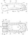
- FIG. 2shows a top view of the interbody spinal implant illustrated in FIG. 1 ;
- FIG. 3shows a perspective view from the front of another embodiment of the interbody spinal implant especially well adapted to be used in connection with a posterior lumbar interbody fusion (PLIF) surgical procedure;
- PLIFposterior lumbar interbody fusion
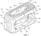
- FIG. 4shows a perspective view from the rear of the embodiment of the interbody spinal implant illustrated in FIG. 3 ;
- FIG. 5shows a perspective view of another embodiment of the interbody spinal implant especially well adapted to be used in connection with a transforaminal lumbar interbody fusion (TLIF) surgical procedure;
- TLIFtransforaminal lumbar interbody fusion
- FIG. 6Ashows a perspective view of another embodiment of the interbody spinal implant having a generally oval shape and being especially well adapted to be used in connection with a cervical spine surgical procedure;
- FIG. 6Bshows a perspective view of a cervical implant having a generally box shape
- FIG. 7shows a perspective view of another embodiment of the interbody spinal implant especially well adapted to be used in connection with a TLIF surgical procedure and having an inserter engagement portion according to the invention
- FIG. 8shows a top view of the interbody spinal implant illustrated in FIG. 7 ;
- FIG. 9shows a side view of the interbody spinal implant illustrated in FIGS. 7 and 8 ;
- FIG. 10shows an exemplary embodiment of the inserter that, together with the implant, form the components of the system according to the present invention
- FIGS. 11A, 11B, and 11Cillustrate sequentially the three, general steps by which the inserter shown in FIG. 10 engages the implant according to an embodiment of the present invention
- FIG. 12illustrates full, locking engagement between the post of the implant and the hook and the tab of the inserter according to an embodiment of the present invention
- FIGS. 13A, 13B, 13C, 13D, and 13Eillustrate sequentially the various steps in the method by which the caretaker typically manipulates the system shown in FIG. 10 when the application is a TLIF surgical procedure;
- FIG. 14illustrates the stops on the implant proximate one lateral side of the implant in contact with the first catch on the inserter when the implant is oriented with respect to the inserter at a specific angle relative to the longitudinal axis of the inserter;
- FIG. 15illustrates the stops on the implant proximate the opposing lateral side of the implant in contact with the second catch on the inserter when the implant is oriented with respect to the inserter at another specific angle relative to the longitudinal axis of the inserter.
- the inventionrelates to an implant and to an associated instrument used to manipulate and place the implant in a patient.
- the inventionalso relates to a system including both of the implant and the instrument as components.
- Certain embodiments of the inventionmay be especially suited for placement between adjacent human vertebral bodies.
- the implants of the inventionmay be used in procedures such as Anterior Lumbar Interbody Fusion (ALIF), Posterior Lumbar Interbody Fusion (PLIF), Transforaminal Lumbar Interbody Fusion (TLIF), and cervical fusion. Certain embodiments do not extend beyond the outer dimensions of the vertebral bodies.
- Interbody spinal implantsallow for improved seating over the apophyseal rim of the vertebral body. Still further, interbody spinal implants, as now taught, better utilize this vital surface area over which fusion may occur and may better bear the considerable biomechanical loads presented through the spinal column with minimal interference with other anatomical or neurological spinal structures. Even further, interbody spinal implants, according to certain aspects of the invention, allow for improved visualization of implant seating and fusion assessment. Interbody spinal implants, as now taught, may also facilitate osteointegration with the surrounding living bone.
- Anterior interbody spinal implants in accordance with certain aspects of the inventioncan be preferably made of a durable material such as stainless steel, stainless steel alloy, titanium, or titanium alloy, but can also be made of other durable materials such as, but not limited to, polymeric, ceramic, and composite materials.
- a durable materialsuch as stainless steel, stainless steel alloy, titanium, or titanium alloy
- other durable materialssuch as, but not limited to, polymeric, ceramic, and composite materials.
- certain embodiments of the inventionmay be comprised of a biocompatible, polymeric matrix reinforced with bioactive fillers, fibers, or both.
- Certain embodiments of the inventionmay be comprised of urethane dimethacrylate (DUDMA)/tri-ethylene glycol dimethacrylate (TEDGMA) blended resin and a plurality of fillers and fibers including bioactive fillers and E-glass fibers.
- Durable materialsmay also consist of any number of pure metals, metal alloys, or both.
- Titanium and its alloysare generally preferred for certain embodiments of the invention due to their acceptable, and desirable, strength and biocompatibility.
- certain embodiments of the present interbody spinal implantmay have improved structural integrity and may better resist fracture during implantation by impact. Interbody spinal implants, as now taught, may therefore be used as a distractor or trial implant during implantation.
- FIG. 1shows a perspective view of a first embodiment of the interbody spinal implant 1 especially well adapted for use in an ALIF procedure.
- the interbody spinal implant 1includes a body having a top surface 10 , a bottom surface 20 , opposing lateral sides 30 , and opposing anterior 40 and posterior 50 portions.
- One or both of the top surface 10 and the bottom surface 20has a roughened topography 80 .
- the roughened topography 80is distinct, however, from the teeth provided on the surfaces of some conventional devices.
- the implant 1may include an anti-expulsion edge 8 at the junction between the top surface 10 and the anterior portion 40 , at the junction between the bottom surface 20 and the anterior portion 40 , or, as illustrated in FIG. 1 , at both junctions.
- the anti-expulsion edge 8helps to maintain the implant 1 in place, inhibiting migration and reducing the risk of undesired pull-out.
- the interbody spinal implant 1is substantially hollow and has a generally oval-shaped transverse cross-sectional area with smooth, rounded, or both smooth and rounded lateral sides 30 and posterior-lateral corners.
- a substantially hollow implant 1includes an implant 1 having at least about 33% of the interior volume of the implant 1 vacant.
- the implant 1includes at least one vertical aperture 60 that extends the entire height of the implant body. As illustrated in the top view of FIG. 2 , the vertical aperture 60 may further define a transverse rim 100 having a greater posterior portion thickness 55 than an anterior portion thickness 45 .
- the opposing lateral sides 30 and the anterior portion 40have an anterior portion thickness 45 of about 5 mm, while the posterior portion 50 has a posterior portion thickness 55 of about 7 mm.
- the posterior portion thickness 55may allow for better stress sharing between the implant 1 and the adjacent vertebral endplates and helps to compensate for the weaker posterior endplate bone.
- the transverse rim 100has a generally large surface area and contacts the vertebral endplate. The transverse rim 100 may act to better distribute contact stresses upon the implant 1 , and hence minimize the risk of subsidence while maximizing contact with the apophyseal supportive bone.
- the transverse rim 100may have a substantially constant thickness (e.g., for the anterior portion thickness 45 to be substantially the same as the posterior portion thickness 55 ) or for the posterior portion 50 to have a posterior portion thickness 55 less than that of the opposing lateral sides 30 and the anterior portion 40 .
- the implant 1may also have a lordotic angle to facilitate alignment.
- the anterior portion 40is preferably generally greater in height than the posterior portion 50 . Therefore, the implant 1 may better compensate for the generally less supportive bone found in certain regions of the vertebral endplate.
- the implant 1may further include at least one transverse aperture 70 .
- the size and shape of the transverse aperture 70are carefully chosen (and predetermined) to achieve a preferable design tradeoff for the particular application envisioned for the implant 1 .
- predeterminedis meant determined beforehand, so that the predetermined characteristic must be determined, i.e., chosen or at least known, in advance of some event—in this case before the manufacture of the implant 1 .
- the transverse aperture 70should have minimal dimensions to maximize the strength and structural integrity of the implant 1 .
- the transverse aperture 70should have maximum dimensions to (a) improve the visibility of the implant 1 during surgical procedures to ensure proper implant placement and seating, and to improve post-operative assessment of implant fusion, and (b) to facilitate engagement between bone graft material and adjacent bone.
- the substantially hollow area defined by the implant 1may be filled with bone graft materials to facilitate the formation of a solid fusion column within the spine of a patient.
- the implant 1has an opening 90 in the anterior portion 40 .
- the opening 90has a number of functions. One function is to facilitate manipulation of the implant 1 by the caretaker.
- the caretakermay insert a surgical tool into the opening 90 and, through the engagement between the surgical tool and the opening 90 , manipulate the implant 1 .
- the opening 90may be threaded to enhance the engagement.
- a corresponding orifice 92may be provided in the posterior portion 50 .
- the opening 90 and orifice 92facilitate both insertion of graft material into the interior of the implant 1 and improve visualization of the implant 1 .
- FIG. 1shows a perspective view of one embodiment of the invention, the interbody spinal implant 1 , which is especially well adapted for use in an ALIF procedure.
- Other embodiments of the inventionare better suited for PLIF, TLIF, or cervical fusion procedures.
- FIGS. 3 and 4show perspective views of an embodiment of an interbody spinal implant 101 especially well adapted for use in a PLIF procedure.
- the interbody spinal implant 101includes a body having a top surface 110 , a bottom surface 120 , opposing lateral sides 130 , and opposing anterior 140 and posterior 150 portions.
- One or both of the top surface 110 and the bottom surface 120has a roughened topography 180 for gripping adjacent bone and inhibiting migration of the implant 101 .
- the interbody spinal implant 101are substantially hollow and have a generally rectangular shape with smooth, rounded, or both smooth and rounded lateral sides and anterior-lateral corners.
- the anterior portion 140may have a tapered nose 142 to facilitate insertion of the implant 101 .
- the implant 101has chamfers 106 at the corners of its posterior portion 150 . The chamfers 106 prevent the implant 101 from catching upon insertion, risking potential damage such as severed nerves, while still permitting the implant 101 to have an anti-expulsion edge 108 .
- the implant 101includes at least one vertical aperture 160 that extends the entire height of the implant body.
- the vertical aperture 160further defines a transverse rim 200 .
- the size and shape of the vertical aperture 160are carefully chosen to achieve a preferable design tradeoff for the particular application envisioned for the implant 101 .
- the vertical aperture 160seeks to maximize the surface area of the top surface 110 and the bottom surface 120 available proximate the anterior 140 and posterior 150 portions while maximizing both radiographic visualization and access to the bone graft material toward the center of the top 110 and bottom 120 surfaces.
- the size and shape of the vertical aperture 160are predetermined by the application in which the implant 101 will be used.
- the width of the implant 101 between the two lateral sides 130is approximately 9 mm.
- the shape of the vertical aperture 160approximates, in cross section, that of an American football.
- the center of the vertical aperture 160which defines the maximum width of the vertical aperture 160 , is about 5 mm.
- the thickness of the transverse rim 200 on either side of the vertical aperture 160 adjacent the center of the vertical aperture 160is about 2 mm.
- the vertical aperture 160tapers from its center to its ends along a longitudinal distance of about 7.75 mm (thus, the total length of the vertical aperture 160 is about 15.5 mm). This shape leaves intact much of the transverse rim 200 in the areas around the ends of the vertical aperture 160 . These areas may allow for better stress sharing between the implant 101 and the adjacent vertebral endplates. Thus, the transverse rim 200 has a generally large surface area and contacts the vertebral endplate.
- the implant 101has an opening 190 in the posterior portion 150 .
- the opening 190has a number of functions. One function is to facilitate manipulation of the implant 101 by the caretaker.
- the caretakermay insert a surgical tool into the opening 190 and, through the engagement between the surgical tool and the opening 190 , manipulate the implant 101 .
- the opening 190may be threaded to enhance the engagement.
- the implant 101may also have an Implant Holding Feature (IHF) 194 instead of or in addition to the opening 190 .
- IHFImplant Holding Feature
- the IHF 194is located proximate the opening 190 in the posterior portion 150 .
- the IHF 194is a U-shaped notch.
- the IHF 194has a number of functions, one of which is to facilitate manipulation of the implant 101 by the caretaker. Other functions of the opening 190 and the IHF 194 are to increase visibility of the implant 101 during surgical procedures and to enhance engagement between bone graft material and adjacent bone.
- the implant 101may further include at least one transverse aperture 170 .
- the size and shape of the transverse aperture 170are carefully chosen (and predetermined) to achieve a preferable design tradeoff for the particular application envisioned for the implant 101 .
- the transverse aperture 170should have minimal dimensions to maximize the strength and structural integrity of the implant 101 .
- the transverse aperture 170should have maximum dimensions to (a) improve the visibility of the implant 101 during surgical procedures to ensure proper implant placement and seating, and to improve post-operative assessment of implant fusion, and (b) to facilitate engagement between bone graft material and adjacent bone.
- the substantially hollow area defined by the implant 101may be filled with bone graft materials to facilitate the formation of a solid fusion column within the spine of a patient.
- the transverse aperture 170extends the entire transverse length of the implant body and nearly the entire height of the implant body. Thus, the size and shape of the transverse aperture 170 approach the maximum possible dimensions for the transverse aperture 170 .
- the section of the transverse aperture 170 proximate the IHF 194is substantially rectangular in shape; the other section of the transverse aperture 170 has the shape of a curved arch. Other shapes and dimensions are suitable for the transverse aperture 170 . In particular, all edges of the transverse aperture 170 may be rounded, smooth, or both.
- FIGS. 3 and 4The embodiment of the invention illustrated in FIGS. 3 and 4 is especially well suited for a PLIF surgical procedure.
- TLIF surgeryis done through the posterior (rear) part of the spine and is essentially like an extended PLIF procedure.
- the TLIF procedurewas developed in response to some of the technical problems encountered with a PLIF procedure.
- the main difference between the two spine fusion proceduresis that the TLIF approach to the disc space is expanded by removing one entire facet joint; a PLIF procedure is usually done on both sides by only taking a portion of each of the paired facet joints.
- the anterior approachin most cases still provides the best visualization, most surface area for healing, and the best reduction of any of the approaches to the disc space.
- These advantagesmust be weighed, however, against the increased morbidity (e.g., unwanted aftereffects and postoperative discomfort) of a second incision.
- Probably the biggest determinate in how the disc space is approachedis the comfort level that the spine surgeon has with an anterior approach for the spine fusion surgery. Not all spine surgeons are comfortable with operating around the great vessels (aorta and vena cava) or have access to a skilled vascular surgeon to help them with the approach. Therefore, choosing one of the posterior approaches for the spine fusion surgery is often a more practical solution.
- the embodiment of the invention illustrated in FIG. 5is especially well suited when the spine surgeon elects a TLIF procedure.
- Many of the features of the implant 101 a illustrated in FIG. 5are the same as those of the implant 101 illustrated in FIGS. 3 and 4 . Therefore, these features are given the same reference numbers, with the addition of the letter “a,” as those described with respect to the implant 101 .
- the interbody spinal implant 101 aincludes a body having a top surface 110 a , a bottom surface 120 a , opposing lateral sides 130 a , and opposing anterior 140 a and posterior 150 a portions.
- the anterior portion 140 amay have a tapered nose 142 a to facilitate insertion of the implant 101 a .
- One or both of the top surface 110 a and the bottom surface 120 ahas a roughened topography 180 a for gripping adjacent bone and inhibiting migration of the implant 101 a.
- the implant 101 and implant 101 ahave several differences, however, between the two embodiments (e.g., implant 101 and implant 101 a ).
- the implant 101 ahas a curved shape.
- the chamfers 106 and anti-expulsion edge 108 of the implant 101are replaced by curves or rounded edges for the implant 101 a .
- the TLIF procedureoften permits use of a larger implant 101 a which, in turn, may affect the size and shape of the predetermined vertical aperture 160 a.
- the substantially constant 9 mm width of the transverse rim 200 of the implant 101is replaced with a larger, curved transverse rim 200 a .
- the width of the transverse rim 200 ais 9 mm in the regions adjacent the anterior 140 a and posterior 150 a portions. That width gradually increases to 11 mm, however, near the center of the transverse rim 200 a .
- the additional real estate provided by the transverse rim 200 aallows the shape of the vertical aperture 160 a to change, in cross section, from approximating a football to approximating a boomerang.
- the center of the vertical aperture 160 awhich defines the maximum width of the vertical aperture 160 a , is increased (from 5 mm for the implant 101 ) to about 7 mm.
- the implant 101 amay also have a lordotic angle to facilitate alignment.
- the lateral side 130 a depicted at the top of the implant 101 ais preferably generally greater in height than the opposing lateral side 130 a . Therefore, the implant 101 a may better compensate for the generally less supportive bone found in certain regions of the vertebral endplate.
- the transverse aperture 170 aextends the entire transverse length of the implant body and nearly the entire height of the implant body.
- FIG. 5also highlights an alternative transverse aperture 170 a , where the transverse aperture 170 a is broken into two, separate sections by an intermediate wall 172 a .
- the dimensions of the transverse aperture 170 a shown in FIG. 5are much smaller than those for a single transverse aperture 170 a .
- the two sections of the alternative transverse aperture 170 aare each illustrated as substantially rectangular in shape and extending nearly the entire height of the implant body; other sizes and shapes are possible for one or both sections of the alternative transverse aperture 170 a.
- the intermediate wall 172 amay be made of the same material as the remainder of the implant 101 a (e.g., metal), or it may be made of another material (e.g., PEEK) to form a composite implant 101 a . It is also possible to extend the intermediate wall 172 a , whether made of metal, PEEK, ultra-high molecular weight polyethylene (UHMWPE), or another material, to eliminate entirely the transverse aperture 170 a . Given the reinforcement function of the intermediate wall 172 a , the length of the vertical aperture 160 a can be extended (as shown in FIG. 5 ) beyond the top surface 110 a and into the anterior portion 140 a of the implant 101 a.
- UHMWPEultra-high molecular weight polyethylene
- FIGS. 6A and 6Billustrate the interbody spinal implant 201 .
- the discsare usually not very large.
- the space available for the nervesis also not that great, however, which means that even a small cervical disc herniation may impinge on the nerve and cause significant pain.
- the implant 201is generally smaller in size than the other implant embodiments.
- the lower mechanical load requirements imposed by the cervical applicationtypically render a composite implant unnecessary. Therefore, the implant 201 is generally made entirely of metal (e.g., titanium) and devoid of other materials (e.g., PEEK).
- the implant 201includes a body having a top surface 210 , a bottom surface 220 , opposing lateral sides 230 , and opposing anterior 240 and posterior 250 portions.
- One or both of the top surface 210 and the bottom surface 220has a roughened topography 280 for gripping adjacent bone and inhibiting migration of the implant 201 .
- the implant 201is substantially hollow and has a generally oval shape with smooth, rounded, or both smooth and rounded edges.
- the implant 201includes at least one vertical aperture 260 that extends the entire height of the implant body.
- the vertical aperture 260further defines a transverse rim 300 .
- the size and shape of the vertical aperture 260are carefully chosen to achieve a preferable design tradeoff for the particular application envisioned for the implant 201 .
- the vertical aperture 260seeks to maximize the surface area of the top surface 210 and the bottom surface 220 , to allow for better stress sharing between the implant 201 and the adjacent vertebral endplates, while maximizing access to the bone graft material provided within the implant 201 .
- the size and shape of the vertical aperture 260are predetermined by the application.
- the implant 201has an opening 290 in the posterior portion 250 .
- the opening 290has a number of functions. One function is to facilitate manipulation of the implant 201 by the caretaker.
- the caretakermay insert a surgical tool into the opening 290 and, through the engagement between the surgical tool and the opening 290 , manipulate the implant 201 .
- the opening 290may be threaded to enhance the engagement.
- the implant 201may further include at least one transverse aperture 270 .
- the size and shape of the transverse aperture 270are carefully chosen (and predetermined) to achieve a preferable design tradeoff for the particular application envisioned for the implant 201 .
- the transverse aperture 270may extend the entire transverse length of the implant body and nearly the entire height of the implant body.
- the size and shape of the transverse aperture 270approach the maximum possible dimensions for the transverse aperture 270 .
- the implant 201may be provided with a solid rear wall 242 .
- the rear wall 242extends the entire width of the implant body and nearly the entire height of the implant body. Thus, the rear wall 242 essentially closes the anterior portion 240 of the implant 201 .
- the rear wall 242may offer one or more of several advantages, including reinforcement of the implant 201 and improved bone graft containment. In the cervical application, it may be important to prevent bone graft material from entering the spinal canal.
- the implant 201may have a generally box shape which gives the implant 201 increased cortical bone coverage.
- the implant 201 shown in FIG. 6Bhas a curved transverse rim 300 in the area of the anterior portion 240 .
- the shape of the posterior portion 250 of the implant 201is substantially flat, however, and the shape of the transverse rim 300 in the area of the posterior portion 250 is substantially square.
- the posterior portion 250provides a face that can receive impact from a tool, such as a surgical hammer, to force the implant 201 into position.
- the implant 201may also have a lordotic angle to facilitate alignment. As illustrated in FIGS. 6A and 6B , the anterior portion 240 is preferably generally greater in height than the posterior portion 250 . Therefore, the implant 201 may better compensate for the generally less supportive bone found in certain regions of the vertebral endplate. As an example, four degrees of lordosis may be built into the implant 201 to help restore balance to the spine.
- the implant 1 , 101 , 101 a , and 201are generally shaped (i.e., made wide) to maximize contact with the apophyseal rim of the vertebral endplates. They are designed to be impacted between the endplates, with fixation to the endplates created by an interference fit and annular tension.
- the implants 1 , 101 , 101 a , and 201are shaped and sized to spare the vertebral endplates and leave intact the hoop stress of the endplates.
- a wide range of sizesare possible to capture the apophyseal rim, along with a broad width of the peripheral rim, especially in the posterior region. It is expected that such designs will lead to reduced subsidence. As much as seven degrees of lordosis (or more) may be built into the implants 1 , 101 , 101 a , and 201 to help restore cervical balance.
- endplate-sparing spinal implant 1 , 101 , 101 a , and 201When endplate-sparing spinal implant 1 , 101 , 101 a , and 201 seats in the disc space against the apophyseal rim, it should still allow for deflection of the endplates like a diaphragm. This means that, regardless of the stiffness of the spinal implant 1 , 101 , 101 a , and 201 , the bone graft material inside the spinal implant 1 , 101 , 101 a , and 201 receives load, leading to healthy fusion. The vertical load in the human spine is transferred though the peripheral cortex of the vertebral bodies. By implanting an apophyseal-supporting inter-body implant 1 , 101 , 101 a , and 201 , the natural biomechanics may be better preserved than for conventional devices.
- the embodiment of the implant 501 illustrated in FIGS. 7is especially well suited for a TLIF surgical procedure.
- the primary distinction between the two TLIF implant embodimentsis that the implant holding feature 194 a of the implant 101 a has been replaced by an inserter engagement portion 551 located at the posterior portion 550 of the implant 501 . Otherwise, the implant 501 has substantially the same design as the implant 101 a.
- the interbody spinal implant 501includes a body having a top surface 510 , a bottom surface 520 , opposing lateral sides 530 , and opposing anterior 540 and posterior 550 portions.
- the implant 501includes at least one vertical aperture 560 that extends the entire height of the implant body and at least one transverse aperture 570 that extends the entire transverse length of the implant body and nearly the entire height of the implant body.
- the vertical aperture 560may further define a transverse rim 500 .
- the anterior portion 540may have a tapered nose 542 to facilitate insertion of the implant 501 .
- the implant 501may also have a lordotic angle to facilitate alignment.
- the lateral side 530 depicted at the top of the implant 501is preferably generally greater in height than the opposing lateral side 530 . Therefore, the implant 501 may better compensate for the generally less supportive bone found in certain regions of the vertebral endplate.
- One or more of the features illustrated and described above for the embodiments of the implant 1 , 101 , 101 a , and 201can be incorporated into the implant 501 .
- Such featuresinclude, without limitation, the edge 8 , 108 ; the roughened topography 80 , 180 , 180 a , and 280 ; and the rear wall 242 .
- the inserter engagement portion 551 depicted on the implant 501can be incorporated into any one of the other embodiments of the implant 1 , 101 , 101 a , and 201 .
- the inserter engagement portion 551has several components. As illustrated on the implant 501 , the inserter engagement portion 551 has a post 553 extending vertically between the top surface 510 and the bottom surface 520 of the implant 501 . The post 553 is located and recessed within a slot 563 created in the posterior portion 550 of the implant 501 . The slot 563 forms a step 567 in the body of the implant 501 at the posterior portion 550 .
- the post 553is free to rotate within the slot 563 about a vertical axis 565 and relative to the body of the implant 501 .
- a plurality of facets 555are formed in the surface of the post 553 , with the facets 555 separated by a series of partitions 557 .
- Each of the facets 555 and the partitions 557has a flat surface; the junctions between the facets 555 and partitions 557 are angled yielding a nut-like design.
- the facets 555 and partitions 557may give the surface of the post 553 a polygonal (and, preferably, an octagonal) shape.
- the inserter engagement portion 551has, as another component, a plurality of ribs 559 separated by a series of columns 561 on the posterior portion 550 of the implant 501 .
- the ribs 559 and the columns 561extend both from the top surface 510 to the top of the step 567 formed by the slot 563 and from the bottom surface 520 to the bottom of the step 567 formed by the slot 563 .
- Each of the ribs 559 and the columns 561has a flat surface; the junctions between the ribs 559 and columns 561 are angled yielding a nut-like design.
- the flat faces of the ribs 559are adapted to receive impact (force) from a hammer or other instrument typically used by a caretaker to help position the implant 501 between vertebrae.
- impactforce
- any number of ribs 559 and columns 561are possible, six ribs 559 separated by five columns 561 are suitable.
- the inserter engagement portion 551has, as yet another component, a number of stops 571 on the posterior portion 550 of the implant 501 .
- the stops 571prevent the caretaker from over-rotating the implant 501 about the vertical axis 565 and, therefore, function as a safety feature.
- Each of the stops 571has a flat surface. Although any number of stops 571 are possible, four stops 571 are suitable.
- an inserter 600is provided. As illustrated in FIG. 10 , the inserter 600 has a longitudinal axis 602 extending between a proximal end 604 and a distal end 606 .
- the terms “distal” and “distal end”are used to define the part or surface of a component which is facing the patient or positioned furthest from the user.
- the terms “proximal” and “proximal end”are used to define the part or surface of a component which is facing away from the patient or positioned closest to the user.
- the inserter 600includes an elongated outer sleeve 610 that surrounds an elongated inner hook 620 .
- the hook 620is configured to be translatable with respect to the sleeve 610 along the longitudinal axis 602 . More specifically, the hook 620 slides within the sleeve 610 . Thus, the hook 620 can both be extended from and be retracted into the sleeve 610 by actions of the user.
- the proximal end 604 of the sleeve 610includes a handle 612 and an actuator 614 .
- the caretakercan grasp the handle 612 comfortably and easily in the hand to hold and manipulate the inserter 600 and, ultimately, the implant 501 .
- the system 700has two components: the implant 501 and the inserter 600 .
- the caretakercan use the actuator 614 to translate the hook 620 with respect to the sleeve 610 .
- the distal end of the sleeve 610includes a tab 630 affixed to and extending outward from the sleeve 610 along the longitudinal axis 602 and parallel to the hook 620 .
- the tab 630is integral with the sleeve 610 .
- integralis meant a single piece or a single unitary part that is complete by itself without additional pieces, i.e., the part is of one monolithic piece formed as a unit with another part.
- the hook 620 and the tab 630are separated by a gap 625 (highlighted in FIGS. 11A and 11B ).
- FIGS. 11A, 11B, and 11Cillustrate the three, general steps by which the inserter 600 engages the implant 501 . More specifically, the hook 620 and tab 630 of the inserter 600 engage the post 553 of the inserter engagement portion 551 of the implant 501 .
- the caretakermanipulates the actuator 614 to extend the hook 620 away from the sleeve 610 and, using the handle 612 , manipulates the sleeve 610 so that the hook 620 moves in the direction of arrow A toward the post 553 of the implant 501 .
- the hook 620will enter the slot 563 , guided by the step 567 , and contact the facets 555 on the post 553 .
- the inner surface of the hook 620is shaped to correspond geometrically with the facets 555 so that, when the hook 620 fully engages the post 553 , the inner surface of the hook 620 contacts each of a plurality of the facets 555 on the post 553 . As illustrated in FIGS. 11B and 11C , the hook 620 typically contacts somewhat more than 50% of the facets 555 (although more or less contact may be suitable for a given application).
- the caretakermanipulates the actuator 614 to retract the hook 620 into the sleeve 610 in the direction of arrow B. Retraction continues until the post 553 of the implant 501 engages the tab 630 of the inserter 610 —as illustrated in FIG. 11C .
- the inner surface of the tab 630is shaped to correspond geometrically with at least one the facets 555 so that, when the tab 630 fully engages the post 553 , the inner surface of the tab 630 contacts fully at least one of the facets 555 on the post 553 .
- FIG. 11Cillustrates the hook 620 and tab 630 fully engaged with the post 553 .
- Arrow Chighlights the opposing contact or engagement points between (i) the hook 620 and the post 553 , and (ii) the tab 630 and the post 553 .
- Such full engagementlocks the post 553 into the geometry of the hook 620 and the corresponding geometry of the tab 630 , preventing rotation of the post 553 .
- FIG. 12illustrates full, locking engagement between the post 553 of the implant 501 and the hook 620 and the tab 630 of the inserter 600 .
- a comparison between the relative positions of the implant 501 and the inserter 600 illustrated in FIGS. 11C and 12advises, however, that the locked position can orient the two components of the system 700 (namely, the implant 501 and the inserter 600 ) in a variety of positions.
- the locked positionallows the caretaker to push robustly on the post 553 , perhaps using a separate instrument such as an impactor or hammer, and manipulate the implant 501 in situ (i.e., with the disk space).
- FIGS. 11A, 11B, and 11Calso illustrate a first catch 640 and a second catch 642 located on the sleeve 610 at the distal end 606 . More specifically, the first catch 640 is located proximate the hook 620 ; the second catch 642 is located proximate the tab 630 . Each of the first catch 640 and the second catch 642 can be formed by a linear taper angled away from the longitudinal axis 602 of the sleeve 610 .
- FIGS. 13A, 13B, 13C, 13D, and 13Eillustrate the various steps in the method by which the caretaker typically manipulates the inserter 600 and the implant 501 when the application is a TLIF surgical procedure.
- FIG. 13Aillustrates the starting position, in which the implant 501 is oriented with respect to the inserter 600 at about ⁇ 10° relative to the longitudinal axis 602 of the inserter 600 .
- the hook 620 and tab 630both engage the facets 555 on the post 553 of the implant 501 , thereby locking the implant 501 into a fixed position relative to the inserter 600 .
- the caretakercan impact the implant 501 , using a hammer or other suitable instrument, when the components of the system 700 are in the position shown in FIG. 13A .
- FIG. 13Billustrates the next step in the method, in which the caretaker, using the actuator 614 , advances the hook 620 (and, therefore, the implant 501 ) away from the sleeve 610 so that the tab 630 no longer engages the facets 555 on the post 553 of the implant 501 .
- Such disengagementfrees the post 553 to rotate. Note that, although the tab 630 engages and disengages the facets 555 on the post 553 of the implant 501 throughout the steps in the method, the hook 620 continuously engages the facets 555 on the post 553 of the implant 501 throughout the method steps.
- the caretakernext rotates the implant 501 by approximately 30-40° (and, more preferably, by about 33°) in the clockwise direction of arrow D, using the actuator 614 , and retracts the hook 620 (and, therefore, the implant 501 ) into the sleeve 610 so that the tab 630 again engages the facets 555 on the post 553 of the implant 501 . As illustrated in FIG. 13C , such engagement prevents further rotation of the post 553 and locks the implant 501 into a fixed position relative to the inserter 600 .
- the implant 501is now oriented with respect to the inserter 600 at about +20 to 30° (and, more preferably, by about +23°) relative to the longitudinal axis 602 of the inserter 600 .
- the caretakercan again impact the implant 501 , using a hammer or other suitable instrument, when the components of the system 700 are in the position shown in FIG. 13C .
- the caretakercan again advance the hook 620 (and, therefore, the implant 501 ) away from the sleeve 610 so that the tab 630 no longer engages the facets 555 on the post 553 of the implant 501 .
- Such disengagementfrees the post 553 to rotate.
- the caretakernext rotates the implant 501 by approximately 30-40° (and, more preferably, by about 33°) in the clockwise direction, using the actuator 614 , and retracts the hook 620 (and, therefore, the implant 501 ) into the sleeve 610 so that the tab 630 again engages the facets 555 on the post 553 of the implant 501 .
- Such engagementprevents further rotation of the post 553 and locks the implant 501 into a fixed position relative to the inserter 600 .
- the implant 501is now oriented with respect to the inserter 600 at about +50 to 60° (and, more preferably, by about +57°) relative to the longitudinal axis 602 of the inserter 600 .
- the caretakercan again impact the implant 501 , using a hammer or other suitable instrument, when the components of the system 700 are in the position shown in FIG. 13D .
- the caretakercan advance the hook 620 (and, therefore, the implant 501 ) away from the sleeve 610 so that the tab 630 no longer engages the facets 555 on the post 553 of the implant 501 .
- Such disengagementfrees the post 553 to rotate.
- the caretakernext rotates the implant 501 by approximately 30-40° (and, more preferably, by about 33°) in the clockwise direction, using the actuator 614 , and retracts the hook 620 (and, therefore, the implant 501 ) into the sleeve 610 so that the tab 630 again engages the facets 555 on the post 553 of the implant 501 .
- Such engagementprevents further rotation of the post 553 and locks the implant 501 into a fixed position relative to the inserter 600 .
- the implant 501is now oriented with respect to the inserter 600 at about +90° relative to the longitudinal axis 602 of the inserter 600 .
- the caretakercan again impact the implant 501 , using a hammer or other suitable instrument, when the components of the system 700 are in the position shown in FIG. 13E .
- the stops 571 on the implant 501 proximate one lateral side 530 of the implant 501contact the first catch 640 on the inserter 600 when the implant 501 is oriented with respect to the inserter 600 at about ⁇ 10° relative to the longitudinal axis 602 of the inserter 600 .
- the stops 571 and the first catch 640facilitates over-rotation of the implant 501 relative to the inserter 600 in the direction of arrow E and beyond about ⁇ 10°.
- such contactprovides a safety function.
- the stops 571 on the implant 501 proximate the opposing lateral side 530 of the implant 501contact the second catch 642 on the inserter 600 when the implant 501 is oriented with respect to the inserter 600 at about +90° relative to the longitudinal axis 602 of the inserter 600 .
- the stops 571 and the second catch 642facilitates over-rotation of the implant 501 relative to the inserter 600 in the direction of arrow F and beyond about +90°.
- such contactprovides a safety function.
- the stops 571 , the first catch 640 , and the second catch 642restrict rotation of the implant 501 relative to the inserter 600 within the range of about ⁇ 10° to about +90°.
- the articulation range(about ⁇ 10° to about +90° in the example) can be adjusted for a given application to other suitable ranges.
- the system 700 for inserting the implant 1 , 101 , 101 a , 201 , 501has two components: the implant 1 , 101 , 101 a , 201 , 501 and the inserter 600 .
- the implant 1 , 101 , 101 a , 201 , 501has a rigid, faceted post 553 , typically a polygon such as a hexagon, that rotates; ribs 559 on the inserter engagement portion 551 of the implant 1 , 101 , 101 a , 201 , 501 ; and stops 571 to prevent over-rotating the implant 1 , 101 , 101 a , 201 , 501 relative to the inserter 600 .
- the flat faces of the ribs 559are adapted to receive impact (force) from a hammer or other instrument typically used by a caretaker to help position the implant 501 between vertebrae.
- the inserter 600has a sleeve 610 into and from which a robust, single hook 620 retracts and extends, and on which a tab 630 is disposed.
- the inserter 600also has a pair of catches 640 , 642 .
- the static, rigid, manipulator tab 630helps the caretaker to manipulate the implant 1 , 101 , 101 a , 201 , 501 .
- the hook 620 and tab 630combine to lock the post 553 into position and to release the post 553 so that the post 553 can rotate.
- the engagements between the hook 620 and the post 553 and between the tab 630 and the post 553permit robust “turning” or rotation of the implant 1 , 101 , 101 a , 201 , 501 in situ.
- the stops 571 and catches 640 , 642define an articulation range (for example, about ⁇ 10° to about +90°) for the implant 1 , 101 , 101 a , 201 , 501 relative to a longitudinal axis 602 of the inserter 600 .
- a spinal disc in need of repair or replacementis identified.
- the caretakernext performs at least a partial discectomy, preferably using a unilateral transforaminal approach.
- the caretakerthen gauges the appropriate size of implant 501 to insert into the disc space (via measurement, a trial implant, or another technique known in the art) created by the discectomy.
- Bone graft material(not shown) is then optionally inserted into the internal cavity of the implant 501 defined by the vertical aperture 560 .
- the caretakercouples the implant 501 to the inserter 600 , for example, by performing the three, general steps by which the inserter 600 engages the implant 501 illustrated in FIGS. 11A, 11B, and 11C and described above. Although other orientations are possible, the caretaker will typically orient the implant 501 to the inserter 600 as shown in FIG. 13A when coupling the implant 501 to the inserter 600 .
- the caretakergrasps the handle 612 of the inserter 600 and inserts the tapered nose 542 of the implant 501 into the transforaminal window created during the discectomy procedure until the tapered nose 542 enters the disc space and begins to distract the adjacent vertebral bodies.
- the caretakercan deliver gentle hammer blows or other impaction forces to one or both of the proximal end 604 of the inserter 600 and the ribs 559 of the implant 501 to urge the implant 501 at least partially into the disc space. Toggling is prevented between the implant 501 and the inserter 600 during the delivery of impaction forces because the post 553 of the implant 501 is locked between the hook 620 and the tab 630 of the inserter 600 .
- the engagement between the stops 571 of the implant 501 and the first catch 640 of the inserter 600may also prevent toggling.
- the caretakermanipulates the inserter 600 and the implant 501 using the steps illustrated in FIGS. 13A, 13B, 13C, 13D, and 13E and described above. Typically, as described above, three steps of sequential engagement, release, rotation, and re-engagement between the inserter 600 and the implant 501 are applied. These steps allow the caretaker to guide the implant 501 along a path to a desired final position within the disc space.
- the post 553 and, hence, the implant 501rotates with respect to the inserter 600 within an articulation range defined by the stops 571 , the first catch 640 , and the second catch 642 . Such rotation promotes turning of the implant 501 and guides the implant 501 along the path of insertion of the implant 501 as the tapered nose 542 progresses into the disc space.
- the caretakermanipulates both the handle 612 and the actuator 614 of the inserter 600 until the optimum final positioning of the implant 501 is achieved with respect to the disc space.
- the insertion stepscan be facilitated while viewing the position of the implant 501 if either markers are provided on the implant 501 , which can be seen (for example) under fluoroscopic imaging, or X-rays are taken. Such markers, X-rays, or both can help the caretaker to determine the precise position of the implant 501 with respect to the disc space.
- the caretakerreleases the implant 501 from the inserter 600 by manipulating the handle 612 and the actuator 614 so that neither the hook 620 nor the tab 630 engage the post 553 .
- the compression forces between the vertebral endplates and the top surface 510 and the bottom surface 520 of the implant 501maintain the implant 501 in place as the caretaker removes the inserter 600 from the disc space and from the body of the patient.
- Imaging or X-rayscan ascertain for the caretaker that the implant 501 is located precisely and correctly in its final position.
- the vertical aperture 560 and transverse aperture 570can be viewed using lateral and/or frontal X-rays, for example, to confirm the appropriate position of the implant 501 within the disc space.
- the angle and position of the inserter 600 with respect to the disc spacecan be maintained substantially constant; the actions performed by the caretaker to articulate the implant 501 do not require movement of the inserter 600 .
- the spinal implant 501 and the associated inserter 600 , and the related method of using the system 700improve the ease with which the implant 501 may be manipulated during insertion or once within the disc space.
- the implant 501 , inserter 600 , and methodkeep the insertion width of the system 700 smaller and enable the caretaker to manipulate the implant 501 within the disc space, in situ, without passing multiple instruments by the exposed nerve roots.
- the system 700avoids the need for a large incision and subsequent trauma to the spine, as well as reduces the risk of damaging the nerve root with multiple passes of instrumentation.
Landscapes
- Health & Medical Sciences (AREA)
- Engineering & Computer Science (AREA)
- Biomedical Technology (AREA)
- Orthopedic Medicine & Surgery (AREA)
- Neurology (AREA)
- Transplantation (AREA)
- Heart & Thoracic Surgery (AREA)
- Oral & Maxillofacial Surgery (AREA)
- Cardiology (AREA)
- Vascular Medicine (AREA)
- Life Sciences & Earth Sciences (AREA)
- Animal Behavior & Ethology (AREA)
- General Health & Medical Sciences (AREA)
- Public Health (AREA)
- Veterinary Medicine (AREA)
- Physical Education & Sports Medicine (AREA)
- Prostheses (AREA)
Abstract
Description
Claims (20)
Priority Applications (1)
| Application Number | Priority Date | Filing Date | Title |
|---|---|---|---|
| US16/195,516US10973658B2 (en) | 2017-11-27 | 2018-11-19 | Rotating implant and associated instrumentation |
Applications Claiming Priority (2)
| Application Number | Priority Date | Filing Date | Title |
|---|---|---|---|
| US201762590800P | 2017-11-27 | 2017-11-27 | |
| US16/195,516US10973658B2 (en) | 2017-11-27 | 2018-11-19 | Rotating implant and associated instrumentation |
Publications (2)
| Publication Number | Publication Date |
|---|---|
| US20190192312A1 US20190192312A1 (en) | 2019-06-27 |
| US10973658B2true US10973658B2 (en) | 2021-04-13 |
Family
ID=64477070
Family Applications (1)
| Application Number | Title | Priority Date | Filing Date |
|---|---|---|---|
| US16/195,516Active2039-05-05US10973658B2 (en) | 2017-11-27 | 2018-11-19 | Rotating implant and associated instrumentation |
Country Status (2)
| Country | Link |
|---|---|
| US (1) | US10973658B2 (en) |
| EP (1) | EP3488826A1 (en) |
Families Citing this family (13)
| Publication number | Priority date | Publication date | Assignee | Title |
|---|---|---|---|---|
| WO2006058221A2 (en) | 2004-11-24 | 2006-06-01 | Abdou Samy M | Devices and methods for inter-vertebral orthopedic device placement |
| US8764806B2 (en) | 2009-12-07 | 2014-07-01 | Samy Abdou | Devices and methods for minimally invasive spinal stabilization and instrumentation |
| US8845728B1 (en) | 2011-09-23 | 2014-09-30 | Samy Abdou | Spinal fixation devices and methods of use |
| US20130226240A1 (en) | 2012-02-22 | 2013-08-29 | Samy Abdou | Spinous process fixation devices and methods of use |
| US9198767B2 (en) | 2012-08-28 | 2015-12-01 | Samy Abdou | Devices and methods for spinal stabilization and instrumentation |
| US9320617B2 (en) | 2012-10-22 | 2016-04-26 | Cogent Spine, LLC | Devices and methods for spinal stabilization and instrumentation |
| US10857003B1 (en) | 2015-10-14 | 2020-12-08 | Samy Abdou | Devices and methods for vertebral stabilization |
| US10973648B1 (en) | 2016-10-25 | 2021-04-13 | Samy Abdou | Devices and methods for vertebral bone realignment |
| US10744000B1 (en) | 2016-10-25 | 2020-08-18 | Samy Abdou | Devices and methods for vertebral bone realignment |
| US11179248B2 (en) | 2018-10-02 | 2021-11-23 | Samy Abdou | Devices and methods for spinal implantation |
| CN110840410B (en)* | 2019-12-05 | 2022-02-15 | 中国科学院深圳先进技术研究院 | Animal passive acrophobia behavior test device |
| CN113855201A (en)* | 2021-09-16 | 2021-12-31 | 天津正天医疗器械有限公司 | Endoscopic lumbar intervertebral implant and use method thereof |
| FR3129078A1 (en) | 2021-11-17 | 2023-05-19 | Safe | Set comprising an intersomatic cage and its positioning device |
Citations (135)
| Publication number | Priority date | Publication date | Assignee | Title |
|---|---|---|---|---|
| US661089A (en) | 1900-03-14 | 1900-11-06 | John Tanner | Adjustable window-screen. |
| US2821762A (en) | 1955-06-21 | 1958-02-04 | George W Foose | Clamps |
| US3286749A (en) | 1964-08-28 | 1966-11-22 | Howard K Learned | Fastener tool with fastener engaging means |
| US3995371A (en) | 1974-10-10 | 1976-12-07 | The Curators Of The University Of Missouri | Electroless plating method for treating teeth |
| US4060114A (en) | 1974-07-03 | 1977-11-29 | Ryuzo Matsushima | Tightening device for threaded screw part |
| US4163698A (en) | 1978-05-22 | 1979-08-07 | Olin Corporation | In situ reference electrode for diaphragm cells |
| US4865303A (en) | 1987-11-23 | 1989-09-12 | American Sterilizer Company | Operating table |
| US5158571A (en) | 1990-03-09 | 1992-10-27 | Picha George J | Tissue expander and method for expanding tissue |
| US5391422A (en) | 1991-02-18 | 1995-02-21 | Sumitomo Electric Industries, Ltd. | Diamond- or Diamond-like carbon-coated hard materials |
| US5443514A (en) | 1993-10-01 | 1995-08-22 | Acromed Corporation | Method for using spinal implants |
| WO2001028469A2 (en) | 1999-10-21 | 2001-04-26 | Sdgi Holdings, Inc. | Devices and techniques for a posterior lateral disc space approach |
| US20010001315A1 (en) | 1998-04-23 | 2001-05-17 | Bates James S. | Atraumatic medical retrieval device |
| US20010039464A1 (en) | 2000-03-15 | 2001-11-08 | Hackauf Klaus Dieter | Device and method for controlling the force exerted by the clamping jaws of lift trucks |
| WO2001095838A1 (en) | 2000-06-12 | 2001-12-20 | Ortho Development Corporation | Intervertebral spacer |
| US6436102B1 (en) | 2001-07-16 | 2002-08-20 | Third Millennium Engineering, Llc | Method of distracting vertebral bones |
| US6447546B1 (en) | 2000-08-11 | 2002-09-10 | Dale G. Bramlet | Apparatus and method for fusing opposing spinal vertebrae |
| US20020188294A1 (en) | 2001-04-06 | 2002-12-12 | Couture Gary M. | Vessel sealer and divider |
| US20030031984A1 (en) | 1999-08-26 | 2003-02-13 | Richard P. Rusin | Ceramic dental mill blanks |
| US6575975B2 (en) | 2000-04-19 | 2003-06-10 | Synthes (U.S.A.) | Bone fixation method |
| US20030189114A1 (en) | 2001-07-06 | 2003-10-09 | Diamicron, Inc. | Nozzles, and components thereof and methods for making the same |
| US6681662B2 (en) | 2002-03-01 | 2004-01-27 | Bondhus Corporation | Tool with fastener engaging member |
| US20040041131A1 (en) | 2002-09-04 | 2004-03-04 | Shin-Etsu Chemical Co., Ltd. | Electroconductive silicone pressure-sensitive adhesive composition |
| US20040098131A1 (en) | 1996-07-22 | 2004-05-20 | Sdgi Holdings, Inc. | Human spinal disc prosthesis |
| US20040117019A1 (en) | 2000-08-30 | 2004-06-17 | Trieu Hai H. | Method and apparatus for delivering an intervertebral disc implant |
| US20050101950A1 (en) | 1995-08-15 | 2005-05-12 | Rita Medical Systems, Inc. | Multiple antenna ablation apparatus and method |
| US20050131416A1 (en) | 2002-11-12 | 2005-06-16 | Jansen Keith E. | SERRATOME vertebral cortical endplate cutter |
| US20050251257A1 (en) | 2004-05-04 | 2005-11-10 | Mitchell Margaret E | Spinal implants with body and insert |
| US20050261768A1 (en) | 2004-05-21 | 2005-11-24 | Trieu Hai H | Interspinous spacer |
| US6974480B2 (en) | 2001-05-03 | 2005-12-13 | Synthes (Usa) | Intervertebral implant for transforaminal posterior lumbar interbody fusion procedure |
| US6981975B2 (en) | 2002-02-02 | 2006-01-03 | Sdgi Holdings, Inc. | Method for inserting a spinal fusion implant having deployable bone engaging projections |
| US20060004453A1 (en) | 2004-06-30 | 2006-01-05 | Depuy Spine, Inc. | Ceramic disc prosthesis |
| US20060041313A1 (en) | 2004-08-19 | 2006-02-23 | Sdgi Holdings, Inc. | Intervertebral disc system |
| US20060095136A1 (en) | 2004-11-03 | 2006-05-04 | Mcluen Design, Inc. | Bone fusion device |
| US20060116770A1 (en) | 2002-03-21 | 2006-06-01 | White John L | Vertebral body and disc space replacement devices |
| US7056321B2 (en) | 2000-08-01 | 2006-06-06 | Endius, Incorporated | Method of securing vertebrae |
| US20060121795A1 (en) | 2004-09-08 | 2006-06-08 | Nissan Motor Co., Ltd. | Rear vehicle structure |
| US20060122701A1 (en) | 2004-11-23 | 2006-06-08 | Kiester P D | Posterior lumbar interbody fusion expandable cage with lordosis and method of deploying the same |
| US7112224B2 (en) | 1997-08-26 | 2006-09-26 | Sdgi Holdings, Inc. | Spinal implant and cutting tool preparation accessory for mounting the implant |
| US20060265065A1 (en) | 2005-05-06 | 2006-11-23 | Bagga Charanpreet S | Anterior interbody spinal implant |
| US20060287652A1 (en) | 2005-06-21 | 2006-12-21 | Lessig Richard K | Adjustable fixation clamp and method |
| US20060293752A1 (en) | 2005-06-27 | 2006-12-28 | Missoum Moumene | Intervertebral disc prosthesis and associated methods |
| US20060293748A1 (en) | 2005-06-24 | 2006-12-28 | Spineworks, Llc | Prosthetic implant, and a method and tool for the insertion of same |
| US7179225B2 (en) | 2003-08-26 | 2007-02-20 | Shluzas Alan E | Access systems and methods for minimally invasive surgery |
| US20070062933A1 (en) | 2005-08-23 | 2007-03-22 | Boston Scientific Scimed, Inc. | Resonator with adjustable capacitor for medical device |
| USD539934S1 (en) | 2005-11-04 | 2007-04-03 | Spinal Elements, Inc. | Interbody fusion device |
| US20070093898A1 (en) | 2005-09-26 | 2007-04-26 | Schwab Frank J | Transforaminal hybrid implant |
| US20070089905A1 (en) | 2003-11-22 | 2007-04-26 | Lee Jung M | Cap with storage chamber for secondary material and the product with the same |
| USD541940S1 (en) | 2005-11-04 | 2007-05-01 | Spinal Elements, Inc. | Interbody fusion device |
| US20070118243A1 (en) | 2005-10-14 | 2007-05-24 | Vantus Technology Corporation | Personal fit medical implants and orthopedic surgical instruments and methods for making |
| US20070118220A1 (en) | 2000-03-14 | 2007-05-24 | Mingyan Liu | Vertebral implant for promoting arthrodesis of the spine |
| US20070118223A1 (en) | 2005-11-23 | 2007-05-24 | Warsaw Orthopedic Inc. | Posterior Articular Disc and Method for Implantation |
| US7226451B2 (en) | 2003-08-26 | 2007-06-05 | Shluzas Alan E | Minimally invasive access device and method |
| US20070173938A1 (en) | 2006-01-26 | 2007-07-26 | Spinal Generations, Llc | Interbody cage system |
| US20070191958A1 (en) | 2006-02-15 | 2007-08-16 | Abdou M S | Devices and Methods for Inter-Vertebral Orthopedic Device Placement |
| US20070213826A1 (en) | 2006-03-08 | 2007-09-13 | Seaspine, Inc. | Intervertebral spacer and insertion tool providing multiple angles of insertion |
| US20070225808A1 (en) | 2006-03-22 | 2007-09-27 | Warnick David R | Pivotable interbody spacer |
| US20070233248A1 (en) | 2005-09-26 | 2007-10-04 | Schwab Frank J | Anterior hybrid implant |
| US20070255414A1 (en) | 2006-05-01 | 2007-11-01 | Sdgi Holdings, Inc. | Intervertebral implants with one or more covers and methods of use |
| US20070260320A1 (en) | 2005-03-28 | 2007-11-08 | Peterman Marc M | Spinal system and method including lateral approach |
| US20070270956A1 (en) | 2006-04-13 | 2007-11-22 | Sdgi Holdings, Inc. | Vertebral fusion implants and methods of use |
| US20070269475A1 (en) | 2006-03-31 | 2007-11-22 | Gil Carlos E | Osteochondral plug graft trimming device and method |
| US20070270960A1 (en) | 2006-04-24 | 2007-11-22 | Sdgi Holdings, Inc. | Extendable anchor in a vertebral implant and methods of use |
| US20070270951A1 (en) | 2006-02-15 | 2007-11-22 | Reginald James Davis | Transforaminal intersomatic cage for an intervertebral fusion graft and an instrument for implanting the cage |
| US20070293949A1 (en) | 2004-10-08 | 2007-12-20 | Salerni Anthony A | Interior connecting interbody cage insertional tools, methods and devices |
| US20080071380A1 (en) | 2006-09-19 | 2008-03-20 | Thomas Sweeney | Systems and Methods for Percutaneous Placement of Interspinous Process Spacers |
| US20080077171A1 (en) | 2006-09-25 | 2008-03-27 | Spinal Elements, Inc. | Retractor |
| US20080119935A1 (en) | 2006-11-17 | 2008-05-22 | Luis Marquez Alvarez | Intersomatic cage, clamp for manipulating it and procedure for inserting the intersomatic cage between vertebrae |
| US20080154378A1 (en) | 2006-12-22 | 2008-06-26 | Warsaw Orthopedic, Inc. | Bone implant having engineered surfaces |
| US7410501B2 (en) | 2001-03-27 | 2008-08-12 | Warsaw Orthopedic, Inc. | Radially expanding interbody spinal fusion implants, instrumentation, and method of insertion |
| WO2008103843A1 (en) | 2007-02-22 | 2008-08-28 | Spinal Elements, Inc. | Vertebral facet joint drill and method of use |
| US20080249622A1 (en) | 2007-04-05 | 2008-10-09 | Gray Wayne P | Interbody implant |
| US20080269764A1 (en) | 2007-04-25 | 2008-10-30 | Spinal Elements, Inc. | Spinal implant distractor/inserter |
| US7445640B2 (en) | 1998-05-14 | 2008-11-04 | Hayes Medical, Inc. | Implant with composite coating |
| US20080275459A1 (en) | 2007-05-02 | 2008-11-06 | Charles Anthony Dickinson | Surgical instrument attachment mechanism |
| US20090005784A1 (en) | 2007-04-25 | 2009-01-01 | Spinal Elements, Inc. | Spinal implant distractor/inserter |
| US20090006225A1 (en) | 2007-06-29 | 2009-01-01 | Microsoft Corporation | Distribution channels and monetizing |
| US20090014243A1 (en) | 2007-07-13 | 2009-01-15 | Petrolink Usa, Llc | Breather-sampling-filler assembly for liquid reservoirs/systems |
| US20090024132A1 (en) | 2007-07-19 | 2009-01-22 | Spinal Elements, Inc. | Attachable instrument guide with detachable handle |
| US20090029458A1 (en) | 2001-06-07 | 2009-01-29 | Hiroshima University | Chicken leukemia inhibitory factor (LIF) and gene thereof |
| US20090054988A1 (en) | 2007-05-01 | 2009-02-26 | Harold Hess | Interspinous implants and methods for implanting same |
| US20090076614A1 (en) | 2007-09-17 | 2009-03-19 | Spinalmotion, Inc. | Intervertebral Prosthetic Disc with Shock Absorption Core |
| US20090076613A1 (en) | 2007-07-26 | 2009-03-19 | Lutz Biedermann | Intervertebral disc prosthesis |
| US20090082819A1 (en) | 2007-06-28 | 2009-03-26 | Spinal Elements, Inc. | Spinal stabilization device |
| US20090140544A1 (en) | 2005-01-17 | 2009-06-04 | Webasto Ag | Hatchback Assembly |
| US20090204152A1 (en) | 2004-02-06 | 2009-08-13 | Spinal Elements, Inc. | Vertebral facet joint prosthesis and method of fixation |
| USD599019S1 (en) | 2008-03-07 | 2009-08-25 | Nuvasive, Inc. | Spinal fusion implant |
| US20090259316A1 (en) | 2008-04-15 | 2009-10-15 | Ginn Richard S | Spacer Devices and Systems for the Treatment of Spinal Stenosis and Methods for Using the Same |
| US20090265007A1 (en) | 2007-11-12 | 2009-10-22 | Dennis Colleran | Vertebral interbody compression implant |
| US7645232B2 (en) | 2003-05-16 | 2010-01-12 | Zimmer Spine, Inc. | Access device for minimally invasive surgery |
| US7651496B2 (en) | 2004-07-23 | 2010-01-26 | Zimmer Spine, Inc. | Methods and apparatuses for percutaneous implant delivery |
| US20100023057A1 (en) | 2006-09-20 | 2010-01-28 | Woodwelding Ag | Device to be implanted in human or animal tissue and method for implanting and assembling the device |
| US7655012B2 (en) | 2003-10-02 | 2010-02-02 | Zimmer Spine, Inc. | Methods and apparatuses for minimally invasive replacement of intervertebral discs |
| US7658739B2 (en) | 2005-09-27 | 2010-02-09 | Zimmer Spine, Inc. | Methods and apparatuses for stabilizing the spine through an access device |
| US7662190B2 (en) | 2000-07-26 | 2010-02-16 | Straumann Holding Ag | Surface-modified implants |
| US20100057206A1 (en) | 2008-09-02 | 2010-03-04 | Duffield William E | Intervertebral fusion implant |
| US20100121385A1 (en) | 2008-11-10 | 2010-05-13 | Spinal Elements, Inc. | Rod reducer instrument for spinal surgery |
| US7744612B2 (en) | 2004-02-10 | 2010-06-29 | Spinal Elements, Inc. | System and method for protecting neurovascular structures |
| US20100168798A1 (en) | 2008-12-30 | 2010-07-01 | Clineff Theodore D | Bioactive composites of polymer and glass and method for making same |
| US7758620B2 (en) | 2002-09-24 | 2010-07-20 | Stryker Trauma Sa | Device for connecting a screw to a support plate |
| US20100191337A1 (en)* | 2006-03-08 | 2010-07-29 | Seaspine, Inc. | Interbody device for spinal applications |
| US20100274286A1 (en) | 2009-04-23 | 2010-10-28 | Spinal Elements, Inc. | Transverse connectors |
| US20100274358A1 (en) | 2009-02-25 | 2010-10-28 | Spinewelding Ag | Spine stabilization device, and method and kit for its implantation |
| US20110040301A1 (en) | 2007-02-22 | 2011-02-17 | Spinal Elements, Inc. | Vertebral facet joint drill and method of use |
| US8100955B2 (en) | 2005-03-17 | 2012-01-24 | Spinal Elements, Inc. | Orthopedic expansion fastener |
| US20120078371A1 (en) | 2010-09-23 | 2012-03-29 | Thomas Gamache | Fusion cage with in-line single piece fixation |
| US20120095561A1 (en) | 2010-10-13 | 2012-04-19 | Synthes Usa, Llc | Intervertebral implant |
| US8162994B2 (en) | 2007-10-22 | 2012-04-24 | Flexuspine, Inc. | Posterior stabilization system with isolated, dual dampener systems |
| US20120123548A1 (en) | 2010-03-16 | 2012-05-17 | Pinnacle Spine Group, Llc | Methods of delivering an implant to an intervertebral space |
| US20120143341A1 (en) | 2006-12-12 | 2012-06-07 | Arthrodisc, L.L.C. | Devices and methods for visual differentiation of intervertebral spaces |
| US20120232664A1 (en) | 2005-05-06 | 2012-09-13 | Titan Spine, Llc | Instruments and interbody spinal implants enhancing disc space distraction |
| US20120239151A1 (en) | 2005-05-06 | 2012-09-20 | Titan Spine, Llc | Method of using instruments and interbody spinal implants to enhance distraction |
| EP2517676A1 (en) | 2011-04-29 | 2012-10-31 | Medacta International S.A. | Intervertebral implant for the fusion between two vertebral bodies of a vertebral column and corresponding positioning instrument |
| US20120282454A1 (en) | 2011-05-03 | 2012-11-08 | Lockheed Martin Corporation | Direct bonding of heat conducting foam and substrates |
| US8347768B2 (en) | 2005-07-13 | 2013-01-08 | Stryker Trauma Gmbh | Screwdriver for an inner profile screw |
| US8353913B2 (en) | 2005-04-12 | 2013-01-15 | Moskowitz Ahmnon D | Bi-directional fixating transvertebral body screws and posterior cervical and lumbar interarticulating joint calibrated stapling devices for spinal fusion |
| US8399008B2 (en) | 2004-11-12 | 2013-03-19 | Purdue Research Foundation | System and method for attaching soft tissue to annodized metal implant |
| US8425602B2 (en) | 2007-02-09 | 2013-04-23 | Alphatec Spine, Inc. | Curvilinear spinal access method and device |
| US20130150968A1 (en) | 2009-12-31 | 2013-06-13 | Ldr Medical | Anchoring Device and System for an Intervertebral Implant, Intervertebral Implant and Implantation Instrument |
| US8523930B2 (en) | 2010-05-14 | 2013-09-03 | Neuraxis, Llc | Methods and devices for cooling spinal tissue |
| US20130245767A1 (en) | 2012-03-19 | 2013-09-19 | Amicus Design Group, Llc | Interbody vertebral prosthetic and orthopedic fusion device with self-deploying anchors |
| US20130268008A1 (en) | 2008-11-07 | 2013-10-10 | William P. McDonough | Zero-Profile Interbody Spacer and Coupled Plate Assembly |
| US20140039626A1 (en) | 2006-03-22 | 2014-02-06 | Beacon Biomedical, Llc | Pivotal lateral cage and method of insertion |
| US8702762B2 (en) | 2007-03-27 | 2014-04-22 | Depuy Spine, Inc. | Passive screw locking mechanism |
| US20140309691A1 (en) | 2011-10-05 | 2014-10-16 | Smith & Nephew Plc | Medical devices containing shape memory polymer compositions |
| US8894652B2 (en) | 2008-08-29 | 2014-11-25 | Globus Medical, Inc. | Devices and methods for treating bone |
| US8979749B2 (en) | 2007-04-17 | 2015-03-17 | K2M, Inc. | Minimally open interbody access retraction device and surgical method |
| EP2939639A1 (en) | 2009-11-05 | 2015-11-04 | Synthes GmbH | Self-pivoting spinal implant and associated instrumentation |
| US20160052162A1 (en) | 2013-03-29 | 2016-02-25 | Osseomatrix | Selective laser melting process |
| US9345586B2 (en) | 2003-08-01 | 2016-05-24 | Zimmer Spine, Inc. | Variable angle spinal surgery instrument |
| US9358133B2 (en)* | 2009-11-05 | 2016-06-07 | DePuy Synthes Products, Inc. | Self-pivoting spinal implant and associated instrumentation |
| US20170091657A1 (en) | 2015-09-26 | 2017-03-30 | Luis S. Kida | Technologies for platform-targeted machine learning |
| US20170177046A1 (en) | 2015-12-16 | 2017-06-22 | Intel Corporation | Controlling Telemetry Data Communication In A Processor |
| US20170172743A1 (en) | 2015-12-16 | 2017-06-22 | P Tech, Llc | Implant comprising nonbiologic portion and biologic portion |
| US20170290666A1 (en) | 2016-04-07 | 2017-10-12 | Kambiz Behzadi | Mechanical assembly including exterior surface preparation |
| US20170312084A1 (en) | 2016-04-27 | 2017-11-02 | AOD Holdings, LLC | Implant Device(s) Including Tapered Protrusions and Method(s) for Inserting the Same into Bone |
- 2018
- 2018-11-19USUS16/195,516patent/US10973658B2/enactiveActive
- 2018-11-26EPEP18208411.1Apatent/EP3488826A1/ennot_activeWithdrawn
Patent Citations (152)
| Publication number | Priority date | Publication date | Assignee | Title |
|---|---|---|---|---|
| US661089A (en) | 1900-03-14 | 1900-11-06 | John Tanner | Adjustable window-screen. |
| US2821762A (en) | 1955-06-21 | 1958-02-04 | George W Foose | Clamps |
| US3286749A (en) | 1964-08-28 | 1966-11-22 | Howard K Learned | Fastener tool with fastener engaging means |
| US4060114A (en) | 1974-07-03 | 1977-11-29 | Ryuzo Matsushima | Tightening device for threaded screw part |
| US3995371A (en) | 1974-10-10 | 1976-12-07 | The Curators Of The University Of Missouri | Electroless plating method for treating teeth |
| US4163698A (en) | 1978-05-22 | 1979-08-07 | Olin Corporation | In situ reference electrode for diaphragm cells |
| US4865303A (en) | 1987-11-23 | 1989-09-12 | American Sterilizer Company | Operating table |
| US5158571A (en) | 1990-03-09 | 1992-10-27 | Picha George J | Tissue expander and method for expanding tissue |
| US5391422A (en) | 1991-02-18 | 1995-02-21 | Sumitomo Electric Industries, Ltd. | Diamond- or Diamond-like carbon-coated hard materials |
| US5443514A (en) | 1993-10-01 | 1995-08-22 | Acromed Corporation | Method for using spinal implants |
| US20050101950A1 (en) | 1995-08-15 | 2005-05-12 | Rita Medical Systems, Inc. | Multiple antenna ablation apparatus and method |
| US20040098131A1 (en) | 1996-07-22 | 2004-05-20 | Sdgi Holdings, Inc. | Human spinal disc prosthesis |
| US7112224B2 (en) | 1997-08-26 | 2006-09-26 | Sdgi Holdings, Inc. | Spinal implant and cutting tool preparation accessory for mounting the implant |
| US20010001315A1 (en) | 1998-04-23 | 2001-05-17 | Bates James S. | Atraumatic medical retrieval device |
| US7445640B2 (en) | 1998-05-14 | 2008-11-04 | Hayes Medical, Inc. | Implant with composite coating |
| US20030031984A1 (en) | 1999-08-26 | 2003-02-13 | Richard P. Rusin | Ceramic dental mill blanks |
| WO2001028469A2 (en) | 1999-10-21 | 2001-04-26 | Sdgi Holdings, Inc. | Devices and techniques for a posterior lateral disc space approach |
| US20070118220A1 (en) | 2000-03-14 | 2007-05-24 | Mingyan Liu | Vertebral implant for promoting arthrodesis of the spine |
| US20010039464A1 (en) | 2000-03-15 | 2001-11-08 | Hackauf Klaus Dieter | Device and method for controlling the force exerted by the clamping jaws of lift trucks |
| US6575975B2 (en) | 2000-04-19 | 2003-06-10 | Synthes (U.S.A.) | Bone fixation method |
| WO2001095838A1 (en) | 2000-06-12 | 2001-12-20 | Ortho Development Corporation | Intervertebral spacer |
| US7662190B2 (en) | 2000-07-26 | 2010-02-16 | Straumann Holding Ag | Surface-modified implants |
| US7056321B2 (en) | 2000-08-01 | 2006-06-06 | Endius, Incorporated | Method of securing vertebrae |
| US7850695B2 (en) | 2000-08-01 | 2010-12-14 | Zimmer Spine, Inc. | Method of securing vertebrae |
| US8864785B2 (en) | 2000-08-01 | 2014-10-21 | Zimmer Spine, Inc. | Method for securing vertebrae |
| US6447546B1 (en) | 2000-08-11 | 2002-09-10 | Dale G. Bramlet | Apparatus and method for fusing opposing spinal vertebrae |
| US20040117019A1 (en) | 2000-08-30 | 2004-06-17 | Trieu Hai H. | Method and apparatus for delivering an intervertebral disc implant |
| US7410501B2 (en) | 2001-03-27 | 2008-08-12 | Warsaw Orthopedic, Inc. | Radially expanding interbody spinal fusion implants, instrumentation, and method of insertion |
| US20020188294A1 (en) | 2001-04-06 | 2002-12-12 | Couture Gary M. | Vessel sealer and divider |
| US6974480B2 (en) | 2001-05-03 | 2005-12-13 | Synthes (Usa) | Intervertebral implant for transforaminal posterior lumbar interbody fusion procedure |
| US20090029458A1 (en) | 2001-06-07 | 2009-01-29 | Hiroshima University | Chicken leukemia inhibitory factor (LIF) and gene thereof |
| US20030189114A1 (en) | 2001-07-06 | 2003-10-09 | Diamicron, Inc. | Nozzles, and components thereof and methods for making the same |
| US6436102B1 (en) | 2001-07-16 | 2002-08-20 | Third Millennium Engineering, Llc | Method of distracting vertebral bones |
| US6981975B2 (en) | 2002-02-02 | 2006-01-03 | Sdgi Holdings, Inc. | Method for inserting a spinal fusion implant having deployable bone engaging projections |
| US6681662B2 (en) | 2002-03-01 | 2004-01-27 | Bondhus Corporation | Tool with fastener engaging member |
| US7615078B2 (en) | 2002-03-21 | 2009-11-10 | Warsaw Orthopedic, Inc. | Vertebral body and disc space replacement devices |
| US20060116770A1 (en) | 2002-03-21 | 2006-06-01 | White John L | Vertebral body and disc space replacement devices |
| US20040041131A1 (en) | 2002-09-04 | 2004-03-04 | Shin-Etsu Chemical Co., Ltd. | Electroconductive silicone pressure-sensitive adhesive composition |
| US7758620B2 (en) | 2002-09-24 | 2010-07-20 | Stryker Trauma Sa | Device for connecting a screw to a support plate |
| US20050131416A1 (en) | 2002-11-12 | 2005-06-16 | Jansen Keith E. | SERRATOME vertebral cortical endplate cutter |
| US7645232B2 (en) | 2003-05-16 | 2010-01-12 | Zimmer Spine, Inc. | Access device for minimally invasive surgery |
| US8608651B2 (en) | 2003-05-16 | 2013-12-17 | Zimmer Spine, Inc. | Access device for minimally invasive surgery |
| US9345586B2 (en) | 2003-08-01 | 2016-05-24 | Zimmer Spine, Inc. | Variable angle spinal surgery instrument |
| US7179225B2 (en) | 2003-08-26 | 2007-02-20 | Shluzas Alan E | Access systems and methods for minimally invasive surgery |
| US7736305B2 (en) | 2003-08-26 | 2010-06-15 | Zimmer Spine, Inc. | Adjustable height access device for treating the spine of a patient |
| US7691120B2 (en) | 2003-08-26 | 2010-04-06 | Zimmer Spine, Inc. | Access systems and methods for minimally invasive surgery |
| US7976464B2 (en) | 2003-08-26 | 2011-07-12 | Zimmer Spine, Inc. | Access systems and methods for minimally invasive surgery |
| US7226451B2 (en) | 2003-08-26 | 2007-06-05 | Shluzas Alan E | Minimally invasive access device and method |
| US7655012B2 (en) | 2003-10-02 | 2010-02-02 | Zimmer Spine, Inc. | Methods and apparatuses for minimally invasive replacement of intervertebral discs |
| US20070089905A1 (en) | 2003-11-22 | 2007-04-26 | Lee Jung M | Cap with storage chamber for secondary material and the product with the same |
| US20090204152A1 (en) | 2004-02-06 | 2009-08-13 | Spinal Elements, Inc. | Vertebral facet joint prosthesis and method of fixation |
| US7998172B2 (en) | 2004-02-06 | 2011-08-16 | Spinal Elements, Inc. | Vertebral facet joint prosthesis and method of fixation |
| US7744612B2 (en) | 2004-02-10 | 2010-06-29 | Spinal Elements, Inc. | System and method for protecting neurovascular structures |
| US20050251257A1 (en) | 2004-05-04 | 2005-11-10 | Mitchell Margaret E | Spinal implants with body and insert |
| US20050261768A1 (en) | 2004-05-21 | 2005-11-24 | Trieu Hai H | Interspinous spacer |
| US20060004453A1 (en) | 2004-06-30 | 2006-01-05 | Depuy Spine, Inc. | Ceramic disc prosthesis |
| US7651496B2 (en) | 2004-07-23 | 2010-01-26 | Zimmer Spine, Inc. | Methods and apparatuses for percutaneous implant delivery |
| US20060041313A1 (en) | 2004-08-19 | 2006-02-23 | Sdgi Holdings, Inc. | Intervertebral disc system |
| US20060121795A1 (en) | 2004-09-08 | 2006-06-08 | Nissan Motor Co., Ltd. | Rear vehicle structure |
| US20070293949A1 (en) | 2004-10-08 | 2007-12-20 | Salerni Anthony A | Interior connecting interbody cage insertional tools, methods and devices |
| US20060095136A1 (en) | 2004-11-03 | 2006-05-04 | Mcluen Design, Inc. | Bone fusion device |
| US8399008B2 (en) | 2004-11-12 | 2013-03-19 | Purdue Research Foundation | System and method for attaching soft tissue to annodized metal implant |
| US20060122701A1 (en) | 2004-11-23 | 2006-06-08 | Kiester P D | Posterior lumbar interbody fusion expandable cage with lordosis and method of deploying the same |
| US20090140544A1 (en) | 2005-01-17 | 2009-06-04 | Webasto Ag | Hatchback Assembly |
| US8100955B2 (en) | 2005-03-17 | 2012-01-24 | Spinal Elements, Inc. | Orthopedic expansion fastener |
| US20120158056A1 (en) | 2005-03-17 | 2012-06-21 | Spinal Elements, Inc. | Orthopedic expansion fastener |
| US20070260320A1 (en) | 2005-03-28 | 2007-11-08 | Peterman Marc M | Spinal system and method including lateral approach |
| US8353913B2 (en) | 2005-04-12 | 2013-01-15 | Moskowitz Ahmnon D | Bi-directional fixating transvertebral body screws and posterior cervical and lumbar interarticulating joint calibrated stapling devices for spinal fusion |
| US20120239151A1 (en) | 2005-05-06 | 2012-09-20 | Titan Spine, Llc | Method of using instruments and interbody spinal implants to enhance distraction |
| US20120232664A1 (en) | 2005-05-06 | 2012-09-13 | Titan Spine, Llc | Instruments and interbody spinal implants enhancing disc space distraction |
| US20060265065A1 (en) | 2005-05-06 | 2006-11-23 | Bagga Charanpreet S | Anterior interbody spinal implant |
| US20060287652A1 (en) | 2005-06-21 | 2006-12-21 | Lessig Richard K | Adjustable fixation clamp and method |
| US20060293748A1 (en) | 2005-06-24 | 2006-12-28 | Spineworks, Llc | Prosthetic implant, and a method and tool for the insertion of same |
| US20060293752A1 (en) | 2005-06-27 | 2006-12-28 | Missoum Moumene | Intervertebral disc prosthesis and associated methods |
| US8770068B2 (en) | 2005-07-13 | 2014-07-08 | Stryker Trauma Gmbh | Screwdriver for an inner profile screw |
| US8347768B2 (en) | 2005-07-13 | 2013-01-08 | Stryker Trauma Gmbh | Screwdriver for an inner profile screw |
| US20070062933A1 (en) | 2005-08-23 | 2007-03-22 | Boston Scientific Scimed, Inc. | Resonator with adjustable capacitor for medical device |
| US20070093898A1 (en) | 2005-09-26 | 2007-04-26 | Schwab Frank J | Transforaminal hybrid implant |
| US20070233248A1 (en) | 2005-09-26 | 2007-10-04 | Schwab Frank J | Anterior hybrid implant |
| US7658739B2 (en) | 2005-09-27 | 2010-02-09 | Zimmer Spine, Inc. | Methods and apparatuses for stabilizing the spine through an access device |
| US20070118243A1 (en) | 2005-10-14 | 2007-05-24 | Vantus Technology Corporation | Personal fit medical implants and orthopedic surgical instruments and methods for making |
| USD539934S1 (en) | 2005-11-04 | 2007-04-03 | Spinal Elements, Inc. | Interbody fusion device |
| USD541940S1 (en) | 2005-11-04 | 2007-05-01 | Spinal Elements, Inc. | Interbody fusion device |
| USD566276S1 (en) | 2005-11-04 | 2008-04-08 | Spinal Elements, Inc. | Interbody fusion device |
| USD564095S1 (en) | 2005-11-04 | 2008-03-11 | Spinal Elements, Inc. | Interbody fusion device |
| US20070118223A1 (en) | 2005-11-23 | 2007-05-24 | Warsaw Orthopedic Inc. | Posterior Articular Disc and Method for Implantation |
| US20070173938A1 (en) | 2006-01-26 | 2007-07-26 | Spinal Generations, Llc | Interbody cage system |
| US20070191958A1 (en) | 2006-02-15 | 2007-08-16 | Abdou M S | Devices and Methods for Inter-Vertebral Orthopedic Device Placement |
| US20070270951A1 (en) | 2006-02-15 | 2007-11-22 | Reginald James Davis | Transforaminal intersomatic cage for an intervertebral fusion graft and an instrument for implanting the cage |
| US20070213826A1 (en) | 2006-03-08 | 2007-09-13 | Seaspine, Inc. | Intervertebral spacer and insertion tool providing multiple angles of insertion |
| US20100191337A1 (en)* | 2006-03-08 | 2010-07-29 | Seaspine, Inc. | Interbody device for spinal applications |
| US20140039626A1 (en) | 2006-03-22 | 2014-02-06 | Beacon Biomedical, Llc | Pivotal lateral cage and method of insertion |
| US20070225808A1 (en) | 2006-03-22 | 2007-09-27 | Warnick David R | Pivotable interbody spacer |
| US20070269475A1 (en) | 2006-03-31 | 2007-11-22 | Gil Carlos E | Osteochondral plug graft trimming device and method |
| US20070270956A1 (en) | 2006-04-13 | 2007-11-22 | Sdgi Holdings, Inc. | Vertebral fusion implants and methods of use |
| US20070270960A1 (en) | 2006-04-24 | 2007-11-22 | Sdgi Holdings, Inc. | Extendable anchor in a vertebral implant and methods of use |
| US20070255414A1 (en) | 2006-05-01 | 2007-11-01 | Sdgi Holdings, Inc. | Intervertebral implants with one or more covers and methods of use |
| US20080071380A1 (en) | 2006-09-19 | 2008-03-20 | Thomas Sweeney | Systems and Methods for Percutaneous Placement of Interspinous Process Spacers |
| US20100023057A1 (en) | 2006-09-20 | 2010-01-28 | Woodwelding Ag | Device to be implanted in human or animal tissue and method for implanting and assembling the device |
| US20080077171A1 (en) | 2006-09-25 | 2008-03-27 | Spinal Elements, Inc. | Retractor |
| US8142355B2 (en) | 2006-09-25 | 2012-03-27 | Spinal Elements, Inc. | Surgical tissue retractor |
| US20120149991A1 (en) | 2006-09-25 | 2012-06-14 | Spinal Elements, Inc. | Method of using a surgical tissue retractor |
| US20080119935A1 (en) | 2006-11-17 | 2008-05-22 | Luis Marquez Alvarez | Intersomatic cage, clamp for manipulating it and procedure for inserting the intersomatic cage between vertebrae |
| US20120143341A1 (en) | 2006-12-12 | 2012-06-07 | Arthrodisc, L.L.C. | Devices and methods for visual differentiation of intervertebral spaces |
| US20080154378A1 (en) | 2006-12-22 | 2008-06-26 | Warsaw Orthopedic, Inc. | Bone implant having engineered surfaces |
| US8425602B2 (en) | 2007-02-09 | 2013-04-23 | Alphatec Spine, Inc. | Curvilinear spinal access method and device |
| US20110040301A1 (en) | 2007-02-22 | 2011-02-17 | Spinal Elements, Inc. | Vertebral facet joint drill and method of use |
| WO2008103843A1 (en) | 2007-02-22 | 2008-08-28 | Spinal Elements, Inc. | Vertebral facet joint drill and method of use |
| US8702762B2 (en) | 2007-03-27 | 2014-04-22 | Depuy Spine, Inc. | Passive screw locking mechanism |
| US20080249622A1 (en) | 2007-04-05 | 2008-10-09 | Gray Wayne P | Interbody implant |
| US8979749B2 (en) | 2007-04-17 | 2015-03-17 | K2M, Inc. | Minimally open interbody access retraction device and surgical method |
| US8062304B2 (en) | 2007-04-25 | 2011-11-22 | Spinal Elements, Inc. | Spinal implant distractor/inserter |
| US20120123424A1 (en) | 2007-04-25 | 2012-05-17 | Spinal Elements, Inc. | Spinal implant distractor/inserter |
| US20090005784A1 (en) | 2007-04-25 | 2009-01-01 | Spinal Elements, Inc. | Spinal implant distractor/inserter |
| US20080269764A1 (en) | 2007-04-25 | 2008-10-30 | Spinal Elements, Inc. | Spinal implant distractor/inserter |
| US20090054988A1 (en) | 2007-05-01 | 2009-02-26 | Harold Hess | Interspinous implants and methods for implanting same |
| US20080275459A1 (en) | 2007-05-02 | 2008-11-06 | Charles Anthony Dickinson | Surgical instrument attachment mechanism |
| US20090082819A1 (en) | 2007-06-28 | 2009-03-26 | Spinal Elements, Inc. | Spinal stabilization device |
| US20090006225A1 (en) | 2007-06-29 | 2009-01-01 | Microsoft Corporation | Distribution channels and monetizing |
| US20090014243A1 (en) | 2007-07-13 | 2009-01-15 | Petrolink Usa, Llc | Breather-sampling-filler assembly for liquid reservoirs/systems |
| US20090024132A1 (en) | 2007-07-19 | 2009-01-22 | Spinal Elements, Inc. | Attachable instrument guide with detachable handle |
| US8172854B2 (en) | 2007-07-19 | 2012-05-08 | Spinal Elements, Inc. | Attachable instrument guide with detachable handle |
| US20090076613A1 (en) | 2007-07-26 | 2009-03-19 | Lutz Biedermann | Intervertebral disc prosthesis |
| US20090076614A1 (en) | 2007-09-17 | 2009-03-19 | Spinalmotion, Inc. | Intervertebral Prosthetic Disc with Shock Absorption Core |
| US8162994B2 (en) | 2007-10-22 | 2012-04-24 | Flexuspine, Inc. | Posterior stabilization system with isolated, dual dampener systems |
| US20090265007A1 (en) | 2007-11-12 | 2009-10-22 | Dennis Colleran | Vertebral interbody compression implant |
| USD599019S1 (en) | 2008-03-07 | 2009-08-25 | Nuvasive, Inc. | Spinal fusion implant |
| US20090259316A1 (en) | 2008-04-15 | 2009-10-15 | Ginn Richard S | Spacer Devices and Systems for the Treatment of Spinal Stenosis and Methods for Using the Same |
| US8894652B2 (en) | 2008-08-29 | 2014-11-25 | Globus Medical, Inc. | Devices and methods for treating bone |
| US20100057206A1 (en) | 2008-09-02 | 2010-03-04 | Duffield William E | Intervertebral fusion implant |
| US20130268008A1 (en) | 2008-11-07 | 2013-10-10 | William P. McDonough | Zero-Profile Interbody Spacer and Coupled Plate Assembly |
| US20100121385A1 (en) | 2008-11-10 | 2010-05-13 | Spinal Elements, Inc. | Rod reducer instrument for spinal surgery |
| US20100168798A1 (en) | 2008-12-30 | 2010-07-01 | Clineff Theodore D | Bioactive composites of polymer and glass and method for making same |
| US20100274358A1 (en) | 2009-02-25 | 2010-10-28 | Spinewelding Ag | Spine stabilization device, and method and kit for its implantation |
| US20100274286A1 (en) | 2009-04-23 | 2010-10-28 | Spinal Elements, Inc. | Transverse connectors |
| EP2939639A1 (en) | 2009-11-05 | 2015-11-04 | Synthes GmbH | Self-pivoting spinal implant and associated instrumentation |
| US9358133B2 (en)* | 2009-11-05 | 2016-06-07 | DePuy Synthes Products, Inc. | Self-pivoting spinal implant and associated instrumentation |
| US20130150968A1 (en) | 2009-12-31 | 2013-06-13 | Ldr Medical | Anchoring Device and System for an Intervertebral Implant, Intervertebral Implant and Implantation Instrument |
| US20120123548A1 (en) | 2010-03-16 | 2012-05-17 | Pinnacle Spine Group, Llc | Methods of delivering an implant to an intervertebral space |
| US8523930B2 (en) | 2010-05-14 | 2013-09-03 | Neuraxis, Llc | Methods and devices for cooling spinal tissue |
| US20120078371A1 (en) | 2010-09-23 | 2012-03-29 | Thomas Gamache | Fusion cage with in-line single piece fixation |
| US20120095561A1 (en) | 2010-10-13 | 2012-04-19 | Synthes Usa, Llc | Intervertebral implant |
| EP2517676A1 (en) | 2011-04-29 | 2012-10-31 | Medacta International S.A. | Intervertebral implant for the fusion between two vertebral bodies of a vertebral column and corresponding positioning instrument |
| US20120282454A1 (en) | 2011-05-03 | 2012-11-08 | Lockheed Martin Corporation | Direct bonding of heat conducting foam and substrates |
| US20140309691A1 (en) | 2011-10-05 | 2014-10-16 | Smith & Nephew Plc | Medical devices containing shape memory polymer compositions |
| US20130245767A1 (en) | 2012-03-19 | 2013-09-19 | Amicus Design Group, Llc | Interbody vertebral prosthetic and orthopedic fusion device with self-deploying anchors |
| US20160052162A1 (en) | 2013-03-29 | 2016-02-25 | Osseomatrix | Selective laser melting process |
| US20170091657A1 (en) | 2015-09-26 | 2017-03-30 | Luis S. Kida | Technologies for platform-targeted machine learning |
| US20170177046A1 (en) | 2015-12-16 | 2017-06-22 | Intel Corporation | Controlling Telemetry Data Communication In A Processor |
| US20170172743A1 (en) | 2015-12-16 | 2017-06-22 | P Tech, Llc | Implant comprising nonbiologic portion and biologic portion |
| US20170290666A1 (en) | 2016-04-07 | 2017-10-12 | Kambiz Behzadi | Mechanical assembly including exterior surface preparation |
| US20170312084A1 (en) | 2016-04-27 | 2017-11-02 | AOD Holdings, LLC | Implant Device(s) Including Tapered Protrusions and Method(s) for Inserting the Same into Bone |
Non-Patent Citations (3)
| Title |
|---|
| European Search Report dated Apr. 1, 2019 from the corresponding European application No. 18208411. |
| Petrini, et al. "Biomedical Applications of Shape Memory Alloys", J. Metallurgy, vol. 2011, (2011)Article ID 501483 pp. 1-15. |
| Shellabear, M., et al., "DMLS-Development History and State of the Art", LANE Conference, 2004, Erlangen Germany. |
Also Published As
| Publication number | Publication date |
|---|---|
| EP3488826A1 (en) | 2019-05-29 |
| US20190192312A1 (en) | 2019-06-27 |
Similar Documents
| Publication | Publication Date | Title |
|---|---|---|
| US10973658B2 (en) | Rotating implant and associated instrumentation | |
| US20210267765A1 (en) | Systems and methods for spinal fusion | |
| US8591590B2 (en) | Spinal implant having a transverse aperture | |
| US8545568B2 (en) | Method of using instruments and interbody spinal implants to enhance distraction | |
| US8435302B2 (en) | Instruments and interbody spinal implants enhancing disc space distraction | |
| US8551176B2 (en) | Spinal implant having a passage for enhancing contact between bone graft material and cortical endplate bone | |
| US8617248B2 (en) | Spinal implant having variable ratios of the integration surface area to the axial passage area | |
| US11911290B2 (en) | Modular adjustable corpectomy cage | |
| CA2882943A1 (en) | Spinal implant having a passage for enhancing contact between bone graft material and cortical endplate bone |
Legal Events
| Date | Code | Title | Description |
|---|---|---|---|
| FEPP | Fee payment procedure | Free format text:ENTITY STATUS SET TO UNDISCOUNTED (ORIGINAL EVENT CODE: BIG.); ENTITY STATUS OF PATENT OWNER: LARGE ENTITY | |
| FEPP | Fee payment procedure | Free format text:ENTITY STATUS SET TO SMALL (ORIGINAL EVENT CODE: SMAL); ENTITY STATUS OF PATENT OWNER: LARGE ENTITY | |
| AS | Assignment | Owner name:TITAN SPINE, LLC, WISCONSIN Free format text:ASSIGNMENT OF ASSIGNORS INTEREST;ASSIGNORS:ULLRICH, PETER F., JR.;ROGGOW, KENNETH;POLANCO, PABLO;REEL/FRAME:048934/0965 Effective date:20180110 Owner name:TITAN SPINE, INC., WISCONSIN Free format text:CHANGE OF NAME;ASSIGNOR:TITAN SPINE, LLC;REEL/FRAME:048952/0975 Effective date:20180430 | |
| FEPP | Fee payment procedure | Free format text:ENTITY STATUS SET TO UNDISCOUNTED (ORIGINAL EVENT CODE: BIG.); ENTITY STATUS OF PATENT OWNER: LARGE ENTITY | |
| STPP | Information on status: patent application and granting procedure in general | Free format text:NON FINAL ACTION MAILED | |
| STPP | Information on status: patent application and granting procedure in general | Free format text:RESPONSE TO NON-FINAL OFFICE ACTION ENTERED AND FORWARDED TO EXAMINER | |
| STPP | Information on status: patent application and granting procedure in general | Free format text:NOTICE OF ALLOWANCE MAILED -- APPLICATION RECEIVED IN OFFICE OF PUBLICATIONS | |
| STPP | Information on status: patent application and granting procedure in general | Free format text:PUBLICATIONS -- ISSUE FEE PAYMENT RECEIVED | |
| STPP | Information on status: patent application and granting procedure in general | Free format text:PUBLICATIONS -- ISSUE FEE PAYMENT VERIFIED | |
| STCF | Information on status: patent grant | Free format text:PATENTED CASE | |
| MAFP | Maintenance fee payment | Free format text:PAYMENT OF MAINTENANCE FEE, 4TH YEAR, LARGE ENTITY (ORIGINAL EVENT CODE: M1551); ENTITY STATUS OF PATENT OWNER: LARGE ENTITY Year of fee payment:4 |