US10973644B2 - Hydrogel implants with porous materials and methods - Google Patents
Hydrogel implants with porous materials and methodsDownload PDFInfo
- Publication number
- US10973644B2 US10973644B2US15/909,077US201815909077AUS10973644B2US 10973644 B2US10973644 B2US 10973644B2US 201815909077 AUS201815909077 AUS 201815909077AUS 10973644 B2US10973644 B2US 10973644B2
- Authority
- US
- United States
- Prior art keywords
- implant
- porous material
- hydrogel
- hole
- bone
- Prior art date
- Legal status (The legal status is an assumption and is not a legal conclusion. Google has not performed a legal analysis and makes no representation as to the accuracy of the status listed.)
- Active
Links
Images


Classifications
- A—HUMAN NECESSITIES
- A61—MEDICAL OR VETERINARY SCIENCE; HYGIENE
- A61F—FILTERS IMPLANTABLE INTO BLOOD VESSELS; PROSTHESES; DEVICES PROVIDING PATENCY TO, OR PREVENTING COLLAPSING OF, TUBULAR STRUCTURES OF THE BODY, e.g. STENTS; ORTHOPAEDIC, NURSING OR CONTRACEPTIVE DEVICES; FOMENTATION; TREATMENT OR PROTECTION OF EYES OR EARS; BANDAGES, DRESSINGS OR ABSORBENT PADS; FIRST-AID KITS
- A61F2/00—Filters implantable into blood vessels; Prostheses, i.e. artificial substitutes or replacements for parts of the body; Appliances for connecting them with the body; Devices providing patency to, or preventing collapsing of, tubular structures of the body, e.g. stents
- A61F2/02—Prostheses implantable into the body
- A61F2/30—Joints
- A61F2/30756—Cartilage endoprostheses
- A—HUMAN NECESSITIES
- A61—MEDICAL OR VETERINARY SCIENCE; HYGIENE
- A61F—FILTERS IMPLANTABLE INTO BLOOD VESSELS; PROSTHESES; DEVICES PROVIDING PATENCY TO, OR PREVENTING COLLAPSING OF, TUBULAR STRUCTURES OF THE BODY, e.g. STENTS; ORTHOPAEDIC, NURSING OR CONTRACEPTIVE DEVICES; FOMENTATION; TREATMENT OR PROTECTION OF EYES OR EARS; BANDAGES, DRESSINGS OR ABSORBENT PADS; FIRST-AID KITS
- A61F2/00—Filters implantable into blood vessels; Prostheses, i.e. artificial substitutes or replacements for parts of the body; Appliances for connecting them with the body; Devices providing patency to, or preventing collapsing of, tubular structures of the body, e.g. stents
- A61F2/02—Prostheses implantable into the body
- A61F2/30—Joints
- A61F2/38—Joints for elbows or knees
- A61F2/3872—Meniscus for implantation between the natural bone surfaces
- A—HUMAN NECESSITIES
- A61—MEDICAL OR VETERINARY SCIENCE; HYGIENE
- A61B—DIAGNOSIS; SURGERY; IDENTIFICATION
- A61B17/00—Surgical instruments, devices or methods
- A61B17/56—Surgical instruments or methods for treatment of bones or joints; Devices specially adapted therefor
- A61B17/58—Surgical instruments or methods for treatment of bones or joints; Devices specially adapted therefor for osteosynthesis, e.g. bone plates, screws or setting implements
- A61B17/68—Internal fixation devices, including fasteners and spinal fixators, even if a part thereof projects from the skin
- A61B17/84—Fasteners therefor or fasteners being internal fixation devices
- A61B17/86—Pins or screws or threaded wires; nuts therefor
- A—HUMAN NECESSITIES
- A61—MEDICAL OR VETERINARY SCIENCE; HYGIENE
- A61F—FILTERS IMPLANTABLE INTO BLOOD VESSELS; PROSTHESES; DEVICES PROVIDING PATENCY TO, OR PREVENTING COLLAPSING OF, TUBULAR STRUCTURES OF THE BODY, e.g. STENTS; ORTHOPAEDIC, NURSING OR CONTRACEPTIVE DEVICES; FOMENTATION; TREATMENT OR PROTECTION OF EYES OR EARS; BANDAGES, DRESSINGS OR ABSORBENT PADS; FIRST-AID KITS
- A61F2/00—Filters implantable into blood vessels; Prostheses, i.e. artificial substitutes or replacements for parts of the body; Appliances for connecting them with the body; Devices providing patency to, or preventing collapsing of, tubular structures of the body, e.g. stents
- A61F2/02—Prostheses implantable into the body
- A61F2/30—Joints
- A61F2/3094—Designing or manufacturing processes
- A61F2/30942—Designing or manufacturing processes for designing or making customized prostheses, e.g. using templates, CT or NMR scans, finite-element analysis or CAD-CAM techniques
- A—HUMAN NECESSITIES
- A61—MEDICAL OR VETERINARY SCIENCE; HYGIENE
- A61F—FILTERS IMPLANTABLE INTO BLOOD VESSELS; PROSTHESES; DEVICES PROVIDING PATENCY TO, OR PREVENTING COLLAPSING OF, TUBULAR STRUCTURES OF THE BODY, e.g. STENTS; ORTHOPAEDIC, NURSING OR CONTRACEPTIVE DEVICES; FOMENTATION; TREATMENT OR PROTECTION OF EYES OR EARS; BANDAGES, DRESSINGS OR ABSORBENT PADS; FIRST-AID KITS
- A61F2/00—Filters implantable into blood vessels; Prostheses, i.e. artificial substitutes or replacements for parts of the body; Appliances for connecting them with the body; Devices providing patency to, or preventing collapsing of, tubular structures of the body, e.g. stents
- A61F2/02—Prostheses implantable into the body
- A61F2/30—Joints
- A61F2/46—Special tools for implanting artificial joints
- A61F2/4603—Special tools for implanting artificial joints for insertion or extraction of endoprosthetic joints or of accessories thereof
- A61F2/4618—Special tools for implanting artificial joints for insertion or extraction of endoprosthetic joints or of accessories thereof of cartilage
- A—HUMAN NECESSITIES
- A61—MEDICAL OR VETERINARY SCIENCE; HYGIENE
- A61F—FILTERS IMPLANTABLE INTO BLOOD VESSELS; PROSTHESES; DEVICES PROVIDING PATENCY TO, OR PREVENTING COLLAPSING OF, TUBULAR STRUCTURES OF THE BODY, e.g. STENTS; ORTHOPAEDIC, NURSING OR CONTRACEPTIVE DEVICES; FOMENTATION; TREATMENT OR PROTECTION OF EYES OR EARS; BANDAGES, DRESSINGS OR ABSORBENT PADS; FIRST-AID KITS
- A61F2/00—Filters implantable into blood vessels; Prostheses, i.e. artificial substitutes or replacements for parts of the body; Appliances for connecting them with the body; Devices providing patency to, or preventing collapsing of, tubular structures of the body, e.g. stents
- A61F2/02—Prostheses implantable into the body
- A61F2/30—Joints
- A61F2002/30001—Additional features of subject-matter classified in A61F2/28, A61F2/30 and subgroups thereof
- A61F2002/30003—Material related properties of the prosthesis or of a coating on the prosthesis
- A61F2002/30004—Material related properties of the prosthesis or of a coating on the prosthesis the prosthesis being made from materials having different values of a given property at different locations within the same prosthesis
- A61F2002/30011—Material related properties of the prosthesis or of a coating on the prosthesis the prosthesis being made from materials having different values of a given property at different locations within the same prosthesis differing in porosity
- A—HUMAN NECESSITIES
- A61—MEDICAL OR VETERINARY SCIENCE; HYGIENE
- A61F—FILTERS IMPLANTABLE INTO BLOOD VESSELS; PROSTHESES; DEVICES PROVIDING PATENCY TO, OR PREVENTING COLLAPSING OF, TUBULAR STRUCTURES OF THE BODY, e.g. STENTS; ORTHOPAEDIC, NURSING OR CONTRACEPTIVE DEVICES; FOMENTATION; TREATMENT OR PROTECTION OF EYES OR EARS; BANDAGES, DRESSINGS OR ABSORBENT PADS; FIRST-AID KITS
- A61F2/00—Filters implantable into blood vessels; Prostheses, i.e. artificial substitutes or replacements for parts of the body; Appliances for connecting them with the body; Devices providing patency to, or preventing collapsing of, tubular structures of the body, e.g. stents
- A61F2/02—Prostheses implantable into the body
- A61F2/30—Joints
- A61F2002/30001—Additional features of subject-matter classified in A61F2/28, A61F2/30 and subgroups thereof
- A61F2002/30003—Material related properties of the prosthesis or of a coating on the prosthesis
- A61F2002/3006—Properties of materials and coating materials
- A61F2002/30075—Properties of materials and coating materials swellable, e.g. when wetted
- A—HUMAN NECESSITIES
- A61—MEDICAL OR VETERINARY SCIENCE; HYGIENE
- A61F—FILTERS IMPLANTABLE INTO BLOOD VESSELS; PROSTHESES; DEVICES PROVIDING PATENCY TO, OR PREVENTING COLLAPSING OF, TUBULAR STRUCTURES OF THE BODY, e.g. STENTS; ORTHOPAEDIC, NURSING OR CONTRACEPTIVE DEVICES; FOMENTATION; TREATMENT OR PROTECTION OF EYES OR EARS; BANDAGES, DRESSINGS OR ABSORBENT PADS; FIRST-AID KITS
- A61F2/00—Filters implantable into blood vessels; Prostheses, i.e. artificial substitutes or replacements for parts of the body; Appliances for connecting them with the body; Devices providing patency to, or preventing collapsing of, tubular structures of the body, e.g. stents
- A61F2/02—Prostheses implantable into the body
- A61F2/30—Joints
- A61F2002/30001—Additional features of subject-matter classified in A61F2/28, A61F2/30 and subgroups thereof
- A61F2002/30108—Shapes
- A61F2002/30199—Three-dimensional shapes
- A61F2002/30205—Three-dimensional shapes conical
- A61F2002/3021—Three-dimensional shapes conical frustoconical
- A—HUMAN NECESSITIES
- A61—MEDICAL OR VETERINARY SCIENCE; HYGIENE
- A61F—FILTERS IMPLANTABLE INTO BLOOD VESSELS; PROSTHESES; DEVICES PROVIDING PATENCY TO, OR PREVENTING COLLAPSING OF, TUBULAR STRUCTURES OF THE BODY, e.g. STENTS; ORTHOPAEDIC, NURSING OR CONTRACEPTIVE DEVICES; FOMENTATION; TREATMENT OR PROTECTION OF EYES OR EARS; BANDAGES, DRESSINGS OR ABSORBENT PADS; FIRST-AID KITS
- A61F2/00—Filters implantable into blood vessels; Prostheses, i.e. artificial substitutes or replacements for parts of the body; Appliances for connecting them with the body; Devices providing patency to, or preventing collapsing of, tubular structures of the body, e.g. stents
- A61F2/02—Prostheses implantable into the body
- A61F2/30—Joints
- A61F2002/30001—Additional features of subject-matter classified in A61F2/28, A61F2/30 and subgroups thereof
- A61F2002/30108—Shapes
- A61F2002/30199—Three-dimensional shapes
- A61F2002/30224—Three-dimensional shapes cylindrical
- A—HUMAN NECESSITIES
- A61—MEDICAL OR VETERINARY SCIENCE; HYGIENE
- A61F—FILTERS IMPLANTABLE INTO BLOOD VESSELS; PROSTHESES; DEVICES PROVIDING PATENCY TO, OR PREVENTING COLLAPSING OF, TUBULAR STRUCTURES OF THE BODY, e.g. STENTS; ORTHOPAEDIC, NURSING OR CONTRACEPTIVE DEVICES; FOMENTATION; TREATMENT OR PROTECTION OF EYES OR EARS; BANDAGES, DRESSINGS OR ABSORBENT PADS; FIRST-AID KITS
- A61F2/00—Filters implantable into blood vessels; Prostheses, i.e. artificial substitutes or replacements for parts of the body; Appliances for connecting them with the body; Devices providing patency to, or preventing collapsing of, tubular structures of the body, e.g. stents
- A61F2/02—Prostheses implantable into the body
- A61F2/30—Joints
- A61F2002/30001—Additional features of subject-matter classified in A61F2/28, A61F2/30 and subgroups thereof
- A61F2002/30108—Shapes
- A61F2002/30199—Three-dimensional shapes
- A61F2002/30273—Three-dimensional shapes pyramidal
- A—HUMAN NECESSITIES
- A61—MEDICAL OR VETERINARY SCIENCE; HYGIENE
- A61F—FILTERS IMPLANTABLE INTO BLOOD VESSELS; PROSTHESES; DEVICES PROVIDING PATENCY TO, OR PREVENTING COLLAPSING OF, TUBULAR STRUCTURES OF THE BODY, e.g. STENTS; ORTHOPAEDIC, NURSING OR CONTRACEPTIVE DEVICES; FOMENTATION; TREATMENT OR PROTECTION OF EYES OR EARS; BANDAGES, DRESSINGS OR ABSORBENT PADS; FIRST-AID KITS
- A61F2/00—Filters implantable into blood vessels; Prostheses, i.e. artificial substitutes or replacements for parts of the body; Appliances for connecting them with the body; Devices providing patency to, or preventing collapsing of, tubular structures of the body, e.g. stents
- A61F2/02—Prostheses implantable into the body
- A61F2/30—Joints
- A61F2002/30001—Additional features of subject-matter classified in A61F2/28, A61F2/30 and subgroups thereof
- A61F2002/30108—Shapes
- A61F2002/30199—Three-dimensional shapes
- A61F2002/30299—Three-dimensional shapes umbrella-shaped or mushroom-shaped
- A—HUMAN NECESSITIES
- A61—MEDICAL OR VETERINARY SCIENCE; HYGIENE
- A61F—FILTERS IMPLANTABLE INTO BLOOD VESSELS; PROSTHESES; DEVICES PROVIDING PATENCY TO, OR PREVENTING COLLAPSING OF, TUBULAR STRUCTURES OF THE BODY, e.g. STENTS; ORTHOPAEDIC, NURSING OR CONTRACEPTIVE DEVICES; FOMENTATION; TREATMENT OR PROTECTION OF EYES OR EARS; BANDAGES, DRESSINGS OR ABSORBENT PADS; FIRST-AID KITS
- A61F2/00—Filters implantable into blood vessels; Prostheses, i.e. artificial substitutes or replacements for parts of the body; Appliances for connecting them with the body; Devices providing patency to, or preventing collapsing of, tubular structures of the body, e.g. stents
- A61F2/02—Prostheses implantable into the body
- A61F2/30—Joints
- A61F2002/30001—Additional features of subject-matter classified in A61F2/28, A61F2/30 and subgroups thereof
- A61F2002/30316—The prosthesis having different structural features at different locations within the same prosthesis; Connections between prosthetic parts; Special structural features of bone or joint prostheses not otherwise provided for
- A61F2002/30317—The prosthesis having different structural features at different locations within the same prosthesis
- A61F2002/30327—The prosthesis having different structural features at different locations within the same prosthesis differing in diameter
- A—HUMAN NECESSITIES
- A61—MEDICAL OR VETERINARY SCIENCE; HYGIENE
- A61F—FILTERS IMPLANTABLE INTO BLOOD VESSELS; PROSTHESES; DEVICES PROVIDING PATENCY TO, OR PREVENTING COLLAPSING OF, TUBULAR STRUCTURES OF THE BODY, e.g. STENTS; ORTHOPAEDIC, NURSING OR CONTRACEPTIVE DEVICES; FOMENTATION; TREATMENT OR PROTECTION OF EYES OR EARS; BANDAGES, DRESSINGS OR ABSORBENT PADS; FIRST-AID KITS
- A61F2/00—Filters implantable into blood vessels; Prostheses, i.e. artificial substitutes or replacements for parts of the body; Appliances for connecting them with the body; Devices providing patency to, or preventing collapsing of, tubular structures of the body, e.g. stents
- A61F2/02—Prostheses implantable into the body
- A61F2/30—Joints
- A61F2002/30001—Additional features of subject-matter classified in A61F2/28, A61F2/30 and subgroups thereof
- A61F2002/30316—The prosthesis having different structural features at different locations within the same prosthesis; Connections between prosthetic parts; Special structural features of bone or joint prostheses not otherwise provided for
- A61F2002/30329—Connections or couplings between prosthetic parts, e.g. between modular parts; Connecting elements
- A61F2002/30331—Connections or couplings between prosthetic parts, e.g. between modular parts; Connecting elements made by longitudinally pushing a protrusion into a complementarily-shaped recess, e.g. held by friction fit
- A—HUMAN NECESSITIES
- A61—MEDICAL OR VETERINARY SCIENCE; HYGIENE
- A61F—FILTERS IMPLANTABLE INTO BLOOD VESSELS; PROSTHESES; DEVICES PROVIDING PATENCY TO, OR PREVENTING COLLAPSING OF, TUBULAR STRUCTURES OF THE BODY, e.g. STENTS; ORTHOPAEDIC, NURSING OR CONTRACEPTIVE DEVICES; FOMENTATION; TREATMENT OR PROTECTION OF EYES OR EARS; BANDAGES, DRESSINGS OR ABSORBENT PADS; FIRST-AID KITS
- A61F2/00—Filters implantable into blood vessels; Prostheses, i.e. artificial substitutes or replacements for parts of the body; Appliances for connecting them with the body; Devices providing patency to, or preventing collapsing of, tubular structures of the body, e.g. stents
- A61F2/02—Prostheses implantable into the body
- A61F2/30—Joints
- A61F2002/30001—Additional features of subject-matter classified in A61F2/28, A61F2/30 and subgroups thereof
- A61F2002/30316—The prosthesis having different structural features at different locations within the same prosthesis; Connections between prosthetic parts; Special structural features of bone or joint prostheses not otherwise provided for
- A61F2002/30329—Connections or couplings between prosthetic parts, e.g. between modular parts; Connecting elements
- A61F2002/30462—Connections or couplings between prosthetic parts, e.g. between modular parts; Connecting elements retained or tied with a rope, string, thread, wire or cable
- A—HUMAN NECESSITIES
- A61—MEDICAL OR VETERINARY SCIENCE; HYGIENE
- A61F—FILTERS IMPLANTABLE INTO BLOOD VESSELS; PROSTHESES; DEVICES PROVIDING PATENCY TO, OR PREVENTING COLLAPSING OF, TUBULAR STRUCTURES OF THE BODY, e.g. STENTS; ORTHOPAEDIC, NURSING OR CONTRACEPTIVE DEVICES; FOMENTATION; TREATMENT OR PROTECTION OF EYES OR EARS; BANDAGES, DRESSINGS OR ABSORBENT PADS; FIRST-AID KITS
- A61F2/00—Filters implantable into blood vessels; Prostheses, i.e. artificial substitutes or replacements for parts of the body; Appliances for connecting them with the body; Devices providing patency to, or preventing collapsing of, tubular structures of the body, e.g. stents
- A61F2/02—Prostheses implantable into the body
- A61F2/30—Joints
- A61F2002/30001—Additional features of subject-matter classified in A61F2/28, A61F2/30 and subgroups thereof
- A61F2002/30316—The prosthesis having different structural features at different locations within the same prosthesis; Connections between prosthetic parts; Special structural features of bone or joint prostheses not otherwise provided for
- A61F2002/30329—Connections or couplings between prosthetic parts, e.g. between modular parts; Connecting elements
- A61F2002/30476—Connections or couplings between prosthetic parts, e.g. between modular parts; Connecting elements locked by an additional locking mechanism
- A61F2002/305—Snap connection
- A—HUMAN NECESSITIES
- A61—MEDICAL OR VETERINARY SCIENCE; HYGIENE
- A61F—FILTERS IMPLANTABLE INTO BLOOD VESSELS; PROSTHESES; DEVICES PROVIDING PATENCY TO, OR PREVENTING COLLAPSING OF, TUBULAR STRUCTURES OF THE BODY, e.g. STENTS; ORTHOPAEDIC, NURSING OR CONTRACEPTIVE DEVICES; FOMENTATION; TREATMENT OR PROTECTION OF EYES OR EARS; BANDAGES, DRESSINGS OR ABSORBENT PADS; FIRST-AID KITS
- A61F2/00—Filters implantable into blood vessels; Prostheses, i.e. artificial substitutes or replacements for parts of the body; Appliances for connecting them with the body; Devices providing patency to, or preventing collapsing of, tubular structures of the body, e.g. stents
- A61F2/02—Prostheses implantable into the body
- A61F2/30—Joints
- A61F2002/30001—Additional features of subject-matter classified in A61F2/28, A61F2/30 and subgroups thereof
- A61F2002/30316—The prosthesis having different structural features at different locations within the same prosthesis; Connections between prosthetic parts; Special structural features of bone or joint prostheses not otherwise provided for
- A61F2002/30535—Special structural features of bone or joint prostheses not otherwise provided for
- A61F2002/30579—Special structural features of bone or joint prostheses not otherwise provided for with mechanically expandable devices, e.g. fixation devices
- A—HUMAN NECESSITIES
- A61—MEDICAL OR VETERINARY SCIENCE; HYGIENE
- A61F—FILTERS IMPLANTABLE INTO BLOOD VESSELS; PROSTHESES; DEVICES PROVIDING PATENCY TO, OR PREVENTING COLLAPSING OF, TUBULAR STRUCTURES OF THE BODY, e.g. STENTS; ORTHOPAEDIC, NURSING OR CONTRACEPTIVE DEVICES; FOMENTATION; TREATMENT OR PROTECTION OF EYES OR EARS; BANDAGES, DRESSINGS OR ABSORBENT PADS; FIRST-AID KITS
- A61F2/00—Filters implantable into blood vessels; Prostheses, i.e. artificial substitutes or replacements for parts of the body; Appliances for connecting them with the body; Devices providing patency to, or preventing collapsing of, tubular structures of the body, e.g. stents
- A61F2/02—Prostheses implantable into the body
- A61F2/30—Joints
- A61F2/30756—Cartilage endoprostheses
- A61F2002/30761—Support means for artificial cartilage, e.g. cartilage defect covering membranes
- A—HUMAN NECESSITIES
- A61—MEDICAL OR VETERINARY SCIENCE; HYGIENE
- A61F—FILTERS IMPLANTABLE INTO BLOOD VESSELS; PROSTHESES; DEVICES PROVIDING PATENCY TO, OR PREVENTING COLLAPSING OF, TUBULAR STRUCTURES OF THE BODY, e.g. STENTS; ORTHOPAEDIC, NURSING OR CONTRACEPTIVE DEVICES; FOMENTATION; TREATMENT OR PROTECTION OF EYES OR EARS; BANDAGES, DRESSINGS OR ABSORBENT PADS; FIRST-AID KITS
- A61F2/00—Filters implantable into blood vessels; Prostheses, i.e. artificial substitutes or replacements for parts of the body; Appliances for connecting them with the body; Devices providing patency to, or preventing collapsing of, tubular structures of the body, e.g. stents
- A61F2/02—Prostheses implantable into the body
- A61F2/30—Joints
- A61F2/30767—Special external or bone-contacting surface, e.g. coating for improving bone ingrowth
- A61F2/30771—Special external or bone-contacting surface, e.g. coating for improving bone ingrowth applied in original prostheses, e.g. holes or grooves
- A61F2002/30841—Sharp anchoring protrusions for impaction into the bone, e.g. sharp pins, spikes
- A—HUMAN NECESSITIES
- A61—MEDICAL OR VETERINARY SCIENCE; HYGIENE
- A61F—FILTERS IMPLANTABLE INTO BLOOD VESSELS; PROSTHESES; DEVICES PROVIDING PATENCY TO, OR PREVENTING COLLAPSING OF, TUBULAR STRUCTURES OF THE BODY, e.g. STENTS; ORTHOPAEDIC, NURSING OR CONTRACEPTIVE DEVICES; FOMENTATION; TREATMENT OR PROTECTION OF EYES OR EARS; BANDAGES, DRESSINGS OR ABSORBENT PADS; FIRST-AID KITS
- A61F2/00—Filters implantable into blood vessels; Prostheses, i.e. artificial substitutes or replacements for parts of the body; Appliances for connecting them with the body; Devices providing patency to, or preventing collapsing of, tubular structures of the body, e.g. stents
- A61F2/02—Prostheses implantable into the body
- A61F2/30—Joints
- A61F2/30767—Special external or bone-contacting surface, e.g. coating for improving bone ingrowth
- A61F2/30771—Special external or bone-contacting surface, e.g. coating for improving bone ingrowth applied in original prostheses, e.g. holes or grooves
- A61F2002/3085—Special external or bone-contacting surface, e.g. coating for improving bone ingrowth applied in original prostheses, e.g. holes or grooves with a threaded, e.g. self-tapping, bone-engaging surface, e.g. external surface
- A—HUMAN NECESSITIES
- A61—MEDICAL OR VETERINARY SCIENCE; HYGIENE
- A61F—FILTERS IMPLANTABLE INTO BLOOD VESSELS; PROSTHESES; DEVICES PROVIDING PATENCY TO, OR PREVENTING COLLAPSING OF, TUBULAR STRUCTURES OF THE BODY, e.g. STENTS; ORTHOPAEDIC, NURSING OR CONTRACEPTIVE DEVICES; FOMENTATION; TREATMENT OR PROTECTION OF EYES OR EARS; BANDAGES, DRESSINGS OR ABSORBENT PADS; FIRST-AID KITS
- A61F2/00—Filters implantable into blood vessels; Prostheses, i.e. artificial substitutes or replacements for parts of the body; Appliances for connecting them with the body; Devices providing patency to, or preventing collapsing of, tubular structures of the body, e.g. stents
- A61F2/02—Prostheses implantable into the body
- A61F2/30—Joints
- A61F2/30767—Special external or bone-contacting surface, e.g. coating for improving bone ingrowth
- A61F2002/3092—Special external or bone-contacting surface, e.g. coating for improving bone ingrowth having an open-celled or open-pored structure
- A—HUMAN NECESSITIES
- A61—MEDICAL OR VETERINARY SCIENCE; HYGIENE
- A61F—FILTERS IMPLANTABLE INTO BLOOD VESSELS; PROSTHESES; DEVICES PROVIDING PATENCY TO, OR PREVENTING COLLAPSING OF, TUBULAR STRUCTURES OF THE BODY, e.g. STENTS; ORTHOPAEDIC, NURSING OR CONTRACEPTIVE DEVICES; FOMENTATION; TREATMENT OR PROTECTION OF EYES OR EARS; BANDAGES, DRESSINGS OR ABSORBENT PADS; FIRST-AID KITS
- A61F2/00—Filters implantable into blood vessels; Prostheses, i.e. artificial substitutes or replacements for parts of the body; Appliances for connecting them with the body; Devices providing patency to, or preventing collapsing of, tubular structures of the body, e.g. stents
- A61F2/02—Prostheses implantable into the body
- A61F2/30—Joints
- A61F2/3094—Designing or manufacturing processes
- A61F2/30942—Designing or manufacturing processes for designing or making customized prostheses, e.g. using templates, CT or NMR scans, finite-element analysis or CAD-CAM techniques
- A61F2002/30957—Designing or manufacturing processes for designing or making customized prostheses, e.g. using templates, CT or NMR scans, finite-element analysis or CAD-CAM techniques using a positive or a negative model, e.g. moulds
- A—HUMAN NECESSITIES
- A61—MEDICAL OR VETERINARY SCIENCE; HYGIENE
- A61F—FILTERS IMPLANTABLE INTO BLOOD VESSELS; PROSTHESES; DEVICES PROVIDING PATENCY TO, OR PREVENTING COLLAPSING OF, TUBULAR STRUCTURES OF THE BODY, e.g. STENTS; ORTHOPAEDIC, NURSING OR CONTRACEPTIVE DEVICES; FOMENTATION; TREATMENT OR PROTECTION OF EYES OR EARS; BANDAGES, DRESSINGS OR ABSORBENT PADS; FIRST-AID KITS
- A61F2310/00—Prostheses classified in A61F2/28 or A61F2/30 - A61F2/44 being constructed from or coated with a particular material
- A61F2310/00005—The prosthesis being constructed from a particular material
- A61F2310/00011—Metals or alloys
- A61F2310/00017—Iron- or Fe-based alloys, e.g. stainless steel
- A—HUMAN NECESSITIES
- A61—MEDICAL OR VETERINARY SCIENCE; HYGIENE
- A61F—FILTERS IMPLANTABLE INTO BLOOD VESSELS; PROSTHESES; DEVICES PROVIDING PATENCY TO, OR PREVENTING COLLAPSING OF, TUBULAR STRUCTURES OF THE BODY, e.g. STENTS; ORTHOPAEDIC, NURSING OR CONTRACEPTIVE DEVICES; FOMENTATION; TREATMENT OR PROTECTION OF EYES OR EARS; BANDAGES, DRESSINGS OR ABSORBENT PADS; FIRST-AID KITS
- A61F2310/00—Prostheses classified in A61F2/28 or A61F2/30 - A61F2/44 being constructed from or coated with a particular material
- A61F2310/00005—The prosthesis being constructed from a particular material
- A61F2310/00011—Metals or alloys
- A61F2310/00023—Titanium or titanium-based alloys, e.g. Ti-Ni alloys
- A—HUMAN NECESSITIES
- A61—MEDICAL OR VETERINARY SCIENCE; HYGIENE
- A61F—FILTERS IMPLANTABLE INTO BLOOD VESSELS; PROSTHESES; DEVICES PROVIDING PATENCY TO, OR PREVENTING COLLAPSING OF, TUBULAR STRUCTURES OF THE BODY, e.g. STENTS; ORTHOPAEDIC, NURSING OR CONTRACEPTIVE DEVICES; FOMENTATION; TREATMENT OR PROTECTION OF EYES OR EARS; BANDAGES, DRESSINGS OR ABSORBENT PADS; FIRST-AID KITS
- A61F2310/00—Prostheses classified in A61F2/28 or A61F2/30 - A61F2/44 being constructed from or coated with a particular material
- A61F2310/00005—The prosthesis being constructed from a particular material
- A61F2310/00011—Metals or alloys
- A61F2310/00035—Other metals or alloys
- A61F2310/00047—Aluminium or Al-based alloys
- A—HUMAN NECESSITIES
- A61—MEDICAL OR VETERINARY SCIENCE; HYGIENE
- A61F—FILTERS IMPLANTABLE INTO BLOOD VESSELS; PROSTHESES; DEVICES PROVIDING PATENCY TO, OR PREVENTING COLLAPSING OF, TUBULAR STRUCTURES OF THE BODY, e.g. STENTS; ORTHOPAEDIC, NURSING OR CONTRACEPTIVE DEVICES; FOMENTATION; TREATMENT OR PROTECTION OF EYES OR EARS; BANDAGES, DRESSINGS OR ABSORBENT PADS; FIRST-AID KITS
- A61F2310/00—Prostheses classified in A61F2/28 or A61F2/30 - A61F2/44 being constructed from or coated with a particular material
- A61F2310/00005—The prosthesis being constructed from a particular material
- A61F2310/00011—Metals or alloys
- A61F2310/00035—Other metals or alloys
- A61F2310/00089—Zirconium or Zr-based alloys
- A—HUMAN NECESSITIES
- A61—MEDICAL OR VETERINARY SCIENCE; HYGIENE
- A61F—FILTERS IMPLANTABLE INTO BLOOD VESSELS; PROSTHESES; DEVICES PROVIDING PATENCY TO, OR PREVENTING COLLAPSING OF, TUBULAR STRUCTURES OF THE BODY, e.g. STENTS; ORTHOPAEDIC, NURSING OR CONTRACEPTIVE DEVICES; FOMENTATION; TREATMENT OR PROTECTION OF EYES OR EARS; BANDAGES, DRESSINGS OR ABSORBENT PADS; FIRST-AID KITS
- A61F2310/00—Prostheses classified in A61F2/28 or A61F2/30 - A61F2/44 being constructed from or coated with a particular material
- A61F2310/00005—The prosthesis being constructed from a particular material
- A61F2310/00179—Ceramics or ceramic-like structures
- A61F2310/00185—Ceramics or ceramic-like structures based on metal oxides
Definitions
- This disclosurerelates generally to implants, and, more specifically, to hydrogel joint implants and various tools, devices, systems, and methods related thereto.
- Implantscan be used to replace deteriorated or otherwise damaged cartilage within a joint.
- Such devicescan be used to treat osteoarthritis, rheumatoid arthritis, other inflammatory diseases, generalized joint pain, joints damaged in an accident, while damaged participating in athletics, joints damaged due to repetitive use, and/or other joint diseases.
- an implant configured for implantation in a jointcomprises, or alternatively consists essentially of, a first portion, a second portion, and a third portion.
- the first portioncomprises a hydrogel.
- the second portioncomprises a porous material (e.g., ceramic, metal, plastic) and the hydrogel in pores of the porous material.
- the third portioncomprises the porous material.
- the second portionis between the first portion and the second portion.
- the first portionis free or substantially free of the porous material.
- the third portionis free or substantially free of the hydrogel.
- the hydrogelmay comprise polyvinyl alcohol (PVA).
- the hydrogelmay comprise water.
- the hydrogelmay comprise saline.
- the porous materialmay comprise an oxide material.
- the porous materialmay comprise at least one of aluminum, alumina, zirconia, titanium, titania, stainless steel, PEEK, and steatite.
- the porous materialmay have a porosity between 45 ppi and 80 ppi. Pores of the porous material may have a dimension between 100 ⁇ m and 500 ⁇ m.
- the first portionmay comprise a contoured surface.
- the first portionmay comprise an annular flange.
- the third portionmay comprise threads.
- the implantmay be load bearing and non-biodegradable.
- the implantmay be configured to be placed in at least one of a toe, finger, ankle, knee, shoulder, hip, or other joint.
- a lateral dimension of the first portionmay be between 6 mm and 10 mm.
- a lateral dimension of the first portionmay be between 5% and 15% larger than a lateral dimension of the third portion.
- a ratio of a lateral dimension of the first portion to a lateral dimension of the third portionmay be between 1.05 and 1.3.
- a method of treatmentcomprises, or alternatively consists essentially of, aligning an implant deployment tool with a recess in a bone, the recess comprising an opening facing a joint, and deploying the implant out of the implant deployment tool, through the opening, and at least partially in the recess
- the implantAfter deployment, the implant may be 1 mm to 3 mm proud.
- the methodmay further comprise radially compressing the first portion of the implant in the implant deployment tool.
- the methodmay further comprise forming the recess. Forming the recess may comprise using a drill bit.
- Deploying the implantmay comprise urging the implant through an interior of the implant deployment tool using a plunger. Deploying the implant may be manual. Deploying the implant may be mechanically assisted. Deploying the implant may comprise screwing the implant into the recess.
- a method of manufacturing the implantcomprises, or alternatively consists essentially of, positioning hydrogel material in a well of a mold, positioning porous material in an upper portion of the well and protruding from the well, and freezing and thawing the hydrogel material at least once.
- Positioning the porous materialmay comprise anchoring the porous material.
- a method of manufacturing the implantcomprises, or alternatively consists essentially of, aligning a well of a second mold portion with a well of a first mold portion, the well of the first mold portion comprising a porous material, positioning hydrogel material in the well of the second mold portion and partially in the well of the first mold portion, and freezing and thawing the hydrogel material at least once.
- the methodmay further comprise positioning the porous material in the well of the first mold portion. Positioning the hydrogel material may be through a closable port, and further comprising closing the closable port.
- the methodmay comprising forming flash between the first mold portion and the second mold portion.
- the methodmay further comprise removing the flash.
- the porous materialmay comprise a disc shape.
- the first partcomprises an implant.
- the implantcomprises, or alternatively consists essentially of, a first portion comprising a hydrogel, a second portion comprising a porous material and the hydrogel in pores of the porous material, and a third portion comprising the porous material.
- the first portionis free of or lacks the porous material.
- the third portionis free of or lacks the hydrogel.
- the second partcomprises sidewalls, a bottom, a cavity at least partially defined by the sidewalls and the bottom, and an anchoring element.
- the cavityis configured to at least partially receive the implant.
- One of the porous material and the sidewalls of the second partcomprises a detent and the other of the porous material and the sidewalls of the second part comprises a groove configured to interact with the detent when the implant is at least partially in the cavity of the second part.
- the porous materialmay comprise a toroidal shape.
- the porous materialmay comprise a detent extending radially inward.
- the anchoring elementmay selected from the group consisting of a barb, and anchor, and a hole in the bottom of the second part and a screw configured to extend through the hole in the bottom of the second part.
- the anchormay comprise an insert, a finger extending radially outwardly and towards a top of the implant system, a wire threaded through holes in the bottom of the second part, and a knot configured to be tightened upon pulling of ends of the wire.
- the first partcomprises an implant comprising a first portion comprising a hydrogel, a second portion comprising a porous material and the hydrogel in pores of the porous material, and a third portion comprising the porous material.
- the first portionis free of or lacks the porous material.
- the third portionis free of or lacks the hydrogel.
- the second partcomprises sidewalls, a bottom, and a cavity at least partially defined by the sidewalls and the bottom. The cavity is configured to at least partially receive the implant.
- One of the porous material and the sidewalls of the second partmay comprise a detent and the other of the porous material and the sidewalls of the second part may comprise a groove configured to interact with the detent when the implant is at least partially in the cavity of the second part.
- the second partmay further comprise an anchoring element.
- the anchoring elementmay comprise a barb.
- the anchoring elementmay comprise an anchor comprising an insert, a finger extending radially outwardly and towards a top of the implant system, a wire threaded through holes in the bottom of the second part, and a knot configured to be tightened upon pulling of ends of the wire.
- the ends of the wiremay form a loop.
- the anchoring elementmay comprise a hole in the bottom of the second part and a screw configured to extend through the hole in the bottom of the second part.
- the anchoring elementmay comprise a hole in the sidewalls of the second part and a second screw configured to extend through the hole in the sidewalls of the second part.
- the first portionis free of or lacks the porous material.
- the third portionis free of or lacks the hydrogel.
- the third portionis configured to contact bone. Pores of the porous material are configured to allow bone infiltration.
- the first portionmay comprise a contoured surface.
- the contoured surfacemay be customized for a particular subject based on scan data.
- the scan datamay comprise at least one of computerized tomography, computerized axial tomography, positron emission tomography, and magnetic resonance imaging.
- the porous materialmay comprise at least one of aluminum, titanium, and stainless steel.
- the porous materialmay comprise titanium mesh.
- the porous materialmay comprise printed titanium.
- the porous materialmay comprise at least one of alumina, zirconia, titania, and steatite.
- the porous materialmay comprise PEEK.
- the porous materialmay have a porosity between 45 ppi and 80 ppi. Pores of the porous material may have a dimension between 100 ⁇ m and 500 ⁇ m.
- the first portionmay comprise a hemispherical shape.
- the first portionmay comprise a wedge shape.
- the first portionis free of or lacks the porous material.
- the third portionis free of or lacks the hydrogel.
- the second portionmay be between the first portion and the second portion.
- the hydrogelmay comprise polyvinyl alcohol (PVA).
- the hydrogelmay comprise water.
- the hydrogelmay comprise saline.
- the porous materialmay comprise an oxide ceramic.
- the porous materialmay comprise at least one of aluminum, titanium, and stainless steel.
- the porous materialmay comprise titanium mesh.
- the porous materialmay comprise printed titanium.
- the porous materialmay comprise PEEK.
- the porous materialmay comprise at least one of alumina, zirconia, titania, and steatite.
- the porous materialmay have a porosity between 45 ppi and 80 ppi. Pores of the porous material may have a dimension between 100 ⁇ m and 500 ⁇ m.
- the first portionmay comprise an annular flange.
- the third portionmay comprise threads.
- the first portionmay comprise a contoured surface.
- the contoured surfacemay be customized for a particular subject based on scan data.
- the scan datamay comprise at least one of computerized tomography, computerized axial tomography, positron emission tomography, and magnetic resonance imaging.
- the first portionmay comprise a hemispherical shape.
- the second portionmay comprise a hemispherical shape.
- the third portionmay comprise a cylindrical shape.
- the first portionmay comprise a wedge shape.
- the third portionmay comprise a wedge shape.
- the porous materialmay comprise a disc shape.
- the porous materialmay comprise a toroidal shape.
- the porous materialmay comprise a detent extending radially inward.
- the porous materialmay comprise an aperture through a sidewall of the porous material.
- the hydrogelmay at least partially extend through the aperture.
- the porous materialmay comprise a finger extending radially outwardly and towards a top of the implant system.
- the porous materialmay comprise a barb.
- the implantmay be load bearing.
- the implantmay be non-biodegradable.
- the implant systemmay be configured to be placed in at least one of a toe, finger, ankle, knee, shoulder, hip, or other joint.
- a lateral dimension of the first portionmay be between 6 mm and 10 mm.
- a lateral dimension of the first portionmay be between 5% and 15% larger than a lateral dimension of the third portion.
- a ratio of a lateral dimension of the first portion to a lateral dimension of the third portionmay be between 1.05 and 1.3.
- the implant systemmay further comprise a second part comprising sidewalls, a bottom, and a cavity at least partially defined by the sidewalls and the bottom.
- the cavitymay be configured to at least partially receive the implant.
- the porous materialmay comprise a groove extending radially inward and the second part may comprise a detent extending radially inward from the sidewalls of the second part.
- the detentmay be configured to interact with the groove when the implant is at least partially in the cavity of the second part.
- the porous materialmay comprise a detent extending radially outward and the second part may comprise a groove extending radially outward into the sidewalls of the second part.
- the detentmay be configured to interact with the groove when the implant is at least partially in the cavity of the second part.
- the second partfurther may comprise an anchoring element.
- the anchoring elementmay comprise a barb.
- the barbmay comprise a plurality of barbs.
- the plurality of barbsmay be vertically stacked.
- the anchoring elementmay comprise an anchor comprising an insert, a finger extending radially outwardly and towards a top of the implant system, a wire threaded through holes in the bottom of the second part, and a knot configured to be tightened upon pulling of ends of the wire.
- the ends of the wiremay form a loop.
- the anchoring elementmay comprise a hole in the bottom of the second part and a screw configured to extend through the hole in the bottom of the second part.
- the anchoring elementmay comprises a plurality of holes in the bottom of the second part and a plurality of screws configured to extend through the plurality of holes in the bottom of the second part.
- the anchoring elementmay comprise a hole in the sidewalls of the second part and a second screw configured to extend through the hole in the sidewalls of the second part.
- the anchoring elementmay comprise a plurality of holes in the sidewalls of the second part and a plurality of second screws configured to extend through the plurality of holes in the sidewalls of the second part.
- a method of treatmentcomprises, or alternatively consists essentially of, aligning an implant deployment tool with a recess in a bone and deploying the implant out of the implant deployment tool, through the opening, and at least partially in the recess.
- the recesscomprises an opening facing a joint.
- the implantAfter deployment, the implant may be 1 mm to 3 mm proud.
- the methodmay further comprise radially compressing the first portion of the implant in the implant deployment tool.
- the methodmay further comprise forming the recess. Forming the recess may comprise using a drill bit.
- Deploying the implantmay comprise urging the implant through an interior of the implant deployment tool using a plunger. Deploying the implant may be manual. Deploying the implant may be mechanically assisted. Deploying the implant may comprise screwing the implant into the recess.
- a method of manufacturing the implantcomprises positioning hydrogel material in a well of a mold, positioning porous material in an upper portion of the well and protruding from the well, and freezing and thawing the hydrogel material at least once.
- Positioning the porous materialmay comprise anchoring the porous material.
- a method of manufacturing the implantcomprises aligning a well of a second mold portion with a well of a first mold portion.
- the well of the first mold portioncomprises a porous material.
- the methodfurther comprises positioning hydrogel material in the well of the second mold portion and partially in the well of the first mold portion and freezing and thawing the hydrogel material at least once.
- the methodmay further comprising positioning the porous material in the well of the first mold portion.
- Positioning the hydrogel materialmay be through a closable port.
- the methodmay further comprise closing the closable port.
- the methodmay comprising forming flash between the first mold portion and the second mold portion.
- the methodmay further comprise removing the flash.
- the porous materialmay comprises a disc shape.
- the porous materialmay comprises a toroidal shape.
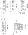
- FIG. 1Aschematically illustrates an example implant
- FIG. 1Bschematically illustrates an example implant
- FIG. 1Cschematically illustrates an example implant
- FIG. 2is a photo of an example implant
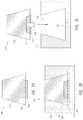
- FIGS. 3A and 3Bschematically illustrate an example method of positioning an example implant
- FIG. 3Cschematically illustrates an example method of positioning the example implant of FIG. 1B ;
- FIG. 4schematically illustrates an example method of manufacturing example implants
- FIGS. 5A-5Cschematically illustrate an example method of manufacturing example implants
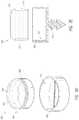
- FIG. 6schematically illustrates another example implant
- FIG. 7Aschematically illustrates an example implant
- FIG. 7Bschematically illustrates an example method of positioning an example implant
- FIG. 7Cschematically illustrates an example method of positioning an example implant
- FIG. 8Aschematically illustrates an example implant
- FIG. 8Bschematically illustrates an example method of positioning an example implant
- FIG. 8Cschematically illustrates an example method of positioning an example implant
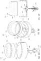
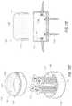
- FIG. 9Ais a side view of an example implant
- FIG. 9Bis a cross-sectional view of the implant of FIG. 9A ;
- FIGS. 9C and 9Dare top and side perspective exploded views of the implant of FIG. 9A ;
- FIG. 9Eis a cross-sectional view of an example implant
- FIG. 10Ais a side view of an example implant
- FIG. 10Bis a cross-sectional view of the implant of FIG. 10A ;
- FIGS. 10C-10Eare top and side perspective exploded views of the implant of FIG. 10A ;
- FIG. 10Fis a cross-sectional view of an example implant
- FIG. 11Ais a side view of an example implant
- FIG. 11Bis a cross-sectional view of the implant of FIG. 11A ;
- FIG. 11Cis a top and side perspective view of the implant of FIG. 11A ;
- FIG. 11Dis a top and side perspective exploded view of the implant of FIG. 11A ;
- FIG. 11Eis a cross-sectional view of an example implant
- FIG. 12Ais a side cross-sectional view of an example implant
- FIG. 12Bis a side cross-sectional view of an example implant
- FIG. 12Cis a side cross-sectional view of an example implant
- FIG. 12Dis a side cross-sectional view of example implants
- FIG. 13Ais a top and side perspective view of an example implant.
- FIG. 13Bis plan view of an example device for manufacturing example implants.
- a cartilage implantas well as various tools, systems, and methods related thereto.
- a number of these devices and associated treatment methodsare particularly well suited to replace deteriorated or otherwise damaged cartilage within a joint.
- Such implantsare configured to remain within the patient's joint on a long-term basis (e.g., for most or all of the life of the patient or subject), and as such, are configured, in some embodiments, to replace native cartilage.
- an implantis configured to be substantially non-biodegradable and/or non-erodable.
- an implantis configured to remain within the patient's joint or other portion of the anatomy for a minimum of 10 to 100 years (e.g., about 10 years, about 20 years, about 25 years, about 30 years, about 35 years, about 40 years, about 45 years, about 50 years, about 55 years, about 60 years, about 65 years, about 70 years, about 75 years, about 80 years, about 85 years, about 90 years, about 95 years, about 100 years, duration ranges between the foregoing values, etc.) without losing structural and/or physical properties and/or without losing ability to function as a cartilage replacement component or device.
- an implantis configured to remain within the anatomy for greater than 100 years without losing structural and/or physical properties and/or without losing ability to function as a cartilage replacement component.
- Certain implants described hereincan be used to treat osteoarthritis, rheumatoid arthritis, other inflammatory diseases, generalized joint pain, joints damaged in an accident, joints damaged while participating in athletics, joints damaged due to repetitive use, and/or other joint diseases.
- the various devices, systems, methods, and other features of the embodiments disclosed hereinmay be utilized or applied to other types of apparatuses, systems, procedures, and/or methods, including arrangements that have non-medical benefits or applications.
- Certain embodiments described hereinmay be advantageous because they include one, several, or all of the following benefits: (i) improved osseointegration compared to implants having a hydrogel surface; (ii) improved coupling of disparate implant materials; (iii) improved cavity wall apposition compared to substantially cylindrical implants; (iv) reduced implant height; (v) reduced depth of a bone cavity configured to receive an implant; (vi) improved structural stability; and/or (vii) increased manufacturing flexibility.
- FIG. 1Aschematically illustrates an example implant 100 .
- the implant 100comprises, or alternatively consists essentially of, a first portion 102 , a second portion 104 , and a third portion 106 .
- the first portion 102 and the second portion 104 of the implant 100as well as other implants disclosed herein (as is the case for each implant feature unless described otherwise), comprises, or alternatively consists essentially of, a hydrogel (e.g., a hydrogel or other formulation comprising polyvinyl alcohol (PVA) hydrogel).
- PVApolyvinyl alcohol
- the third portion 106comprises, or alternatively consists essentially of, a porous material (e.g., a material or section comprising porous ceramic material (e.g., oxide-ceramic), metal (e.g., titanium (e.g., titanium mesh, printed titanium), stainless steel (e.g., stainless steel wool)), plastic (e.g., polyaryl ether ketone (PAEK) (e.g., polyether ether ketone (PEEK))), other biocompatible materials, combinations thereof, and the like).
- a porous materiale.g., a material or section comprising porous ceramic material (e.g., oxide-ceramic), metal (e.g., titanium (e.g., titanium mesh, printed titanium), stainless steel (e.g., stainless steel wool)), plastic (e.g., polyaryl ether ketone (PAEK) (e.g., polyether ether ketone (PEEK))), other biocompatible materials, combinations thereof, and the
- the first portion 102 and the second portion 104 of the implant 100can comprise one or more other materials, either in addition to or in lieu of PVA, such as, for example, other hydrogels, other polymeric materials, additives, and/or the like.
- the second portion 104comprises porous material.
- the PVA content of a hydrogelis about 40% by weight.
- the PVA content of hydrogel in an implant 100can be less than or more than about 40% by weight (e.g., about 10%, about 15%, about 20%, about 25%, about 30%, about 32%, about 34%, about 36%, about 37%, about 38%, about 39%, about 41%, about 42%, about 43%, about 44%, about 46%, about 48%, about 50%, about 55%, about 60%, about 65%, about 70%, less than about 10%, more than about 70%, ranges between such values, etc.), as desired or required.
- 40% by weighte.g., about 10%, about 15%, about 20%, about 25%, about 30%, about 32%, about 34%, about 36%, about 37%, about 38%, about 39%, about 41%, about 42%, about 43%, about 44%, about 46%, about 48%, about 50%, about 55%, about 60%, about 65%, about 70%, less than about 10%, more than about 70%, ranges between such values, etc.
- the hydrogel of the implant 100can comprise water, saline, other liquids, combinations thereof, and/or the like.
- salinemay be preferred over water, because, under certain circumstances, saline can help maintain osmotic balance with surrounding anatomical tissues following implantation.
- the exact composition of hydrogel in an implant 100e.g., PVA or other hydrogel materials, water, saline or other liquids, other additives, etc.
- any hydrogel portion of the implants disclosed hereinconsist essentially of saline and PVA.
- such hydrogel portions of the implantsdo not comprise any additional additives (e.g., growth factors, surface or other coatings, etc.).
- the hydrogel portions of any of the implant configurations disclosed hereincomprises a consistent concentration (e.g., no concentration gradients), density and/or other chemical and/or physical properties throughout.
- the implant 100is configured for drug delivery and/or is seeded with growth factors and/or cells.
- the implant 100comprises one or more of the following: chondrocytes, growth factors, bone morphogenetic proteins, collagen, hyaluronic acid, nucleic acids, and stem cells.
- chondrocytesgrowth factors
- bone morphogenetic proteinsgrowth factors
- collagenhyaluronic acid
- nucleic acidsnucleic acids
- stem cellsstem cells.
- Such factors and/or any other materials included in the implant 100 and selectively delivered to an implant sitecan help facilitate and/or promote the long-term fixation of the implant 100 at the joint or other target area of the anatomy.
- the hydrogelcomprises PVA and/or any other polymeric material.
- the content of PVA in the hydrogelis between about 35% and about 45% by weight (e.g., about 35%, about 36%, about 37%, about 38%, about 39%, about 40%, about 41%, about 42%, about 43%, about 44%, about 45%, ranges between such values, etc.).
- the content of PVA in the hydrogelis greater than about 45% by weight (e.g., about 45%, about 50%, about 55%, about 60%, about 65%, about 70%, greater than about 70%, ranges between such values, etc.) or less than about 35% by weight (e.g., about 5%, about 10%, about 15%, about 20%, about 25%, about 30%, about 35%, ranges between such values, less than about 5%, etc.).
- the content of PVA or other component in the hydrogelis about 40% by weight.
- the implant 100is load bearing and generally non-biodegradable (e.g., non-bioerodable). In some embodiments, the implant 100 is configured for placement in at least one of a toe, finger, ankle, knee, shoulder, hip, or any other joint. In some embodiments, a transition between the upper surface and the sidewalls is generally curved or otherwise smooth.
- the first portion 102 of the implantmay have a lateral dimension (e.g., diameter) between about 6 mm and about 10 mm (e.g., about 6 mm, about 7 mm, about 8 mm, about 9 mm, about 10 mm, ranges between such values, etc.), as measured in an uncompressed state.
- Lateral dimensions smaller than about 6 mm (e.g., between about 2 mm and about 6 mm) and larger than about 10 mm (e.g., between about 10 mm and about 14 mm)are also possible for use in subjects with small or large bones, respectively, and/or for use in joints with small or large bones, respectively.
- the third portion 106 of the implantcan comprise a porous material, such as, for example, a porous ceramic (e.g., oxide-ceramic), metal (e.g., titanium (e.g., titanium mesh, printed titanium), stainless steel (e.g., stainless steel wool)), plastic (e.g., polyaryl ether ketone (PAEK) (e.g., polyether ether ketone (PEEK))), other biocompatible materials, combinations thereof, and the like).
- the third portion 106may be free or substantially free from the hydrogel of the first portion 102 .
- the third portion 106is substantially rigid or non-deformable.
- the third portion 106is at least partially deformable.
- the pores and/or other openings of the third portion 106may promote osseointegration of the implant 100 in a bone.
- an implantcomprising one or more porous materials (e.g., porous ceramic, metal, plastic, etc.) may have a reduced height because the porous ceramic and/or other porous material may provide structural stability and/or because the porous ceramic or other porous material may provide better osseointegration such that less contact with bone provides at least as much osseointegration.
- the third portion 106is illustrated in FIG. 1A as a disc, although other shapes of the third portion 106 are also possible. In some embodiments, the third portion 106 may be toroidal, wedge-shaped, etc., for example as described in further detail herein. In some embodiments, the third portion 106 is substantially rigid, semi-rigid, and/or non-deformable. In some embodiments, the second portion 104 comprises the hydrogel of the first portion 102 within pores of the porous material of the third portion 106 . According to some embodiments, the diameter or other lateral dimension of the second portion 104 and/or third portion 106 is smaller than the diameter or other lateral dimension of the first portion 102 of the implant.
- the implant 100can be radially compressed (e.g., during delivery into a target anatomical site of a subject), especially in embodiments where the first portion 102 is more readily radially compressible than the second portion 104 and/or the third portion 106 (e.g., because of the material(s) included in each portion).
- the diameter or other lateral dimension of the second portion 104 and/or third portion 106is between about 70% and about 95% (e.g., about 70%, about 75%, about 80%, about 85%, about 90%, about 95%, ranges between the foregoing percentages, etc.) of the diameter or other lateral dimension of the first portion 102 .
- the second portion 104 and the third portion 106may comprise an oxide ceramic, for example oxide ceramics from CeramTec of Laurens, S.C., as provided in Tables 1 and 2, although other materials and combinations of materials are also possible (e.g., non-oxide ceramics, non-ceramics).
- oxide ceramicsfrom CeramTec of Laurens, S.C., as provided in Tables 1 and 2, although other materials and combinations of materials are also possible (e.g., non-oxide ceramics, non-ceramics).
- the second portion 104 and the third portion 106may comprise a metal, for example titanium mesh, printed titanium, stainless steel, etc.
- the second portion 104 and the third portion 106may comprise a plastic, for example PAEK, PEEK, etc.
- the porous materialcan have a porosity between about 45 pores per inch (ppi) and about 80 ppi (e.g., about 45 ppi, about 50 ppi, about 55 ppi, about 60 ppi, about 65 ppi, about 70 ppi, about 75 ppi, about 80 ppi, ranges between such values, etc.).
- ppipores per inch
- 80 ppie.g., about 45 ppi, about 50 ppi, about 55 ppi, about 60 ppi, about 65 ppi, about 70 ppi, about 75 ppi, about 80 ppi, ranges between such values, etc.
- the pores of the porous materialmay have a diameter or other dimension between about 100 micrometers (microns; ⁇ m) and about 500 ⁇ m (e.g., about 100 ⁇ m, about 150 ⁇ m, about 200 ⁇ m, about 250 ⁇ m, about 300 ⁇ m, about 350 ⁇ m, about 400 ⁇ m, about 450 ⁇ m, about 500 ⁇ m, ranges between such values, etc.), as desired or required.
- ⁇ mmicrometers
- 500 ⁇ me.g., about 100 ⁇ m, about 150 ⁇ m, about 200 ⁇ m, about 250 ⁇ m, about 300 ⁇ m, about 350 ⁇ m, about 400 ⁇ m, about 450 ⁇ m, about 500 ⁇ m, ranges between such values, etc.
- pores of the porous material in the second portion 104are different than pores of the porous material in the third portion 106 .
- the pores of the porous material in the second portion 104may be configured to allow hydrogel infiltration while the pores of the porous material in the third portion 106 may be configured to allow osseointegration.
- the porous material in the second portion 104is different than the porous material in the third portion 106 .
- the porous material in the second portion 104may comprise a first material having a property and the porous material in the third portion 106 may comprise a second material having a property different than the property of the first material.
- the propertymay comprise, for example, the material itself (e.g., whether ceramic, metal, plastic, etc.), porosity, pore size, dimensions, deformability, etc.
- Overlap of hydrogel material of the first portion 102 and porous material of the third portion 106 in the second portion 104may securely anchor the first portion 102 to the third portion 106 , for example compared to an implant in which a surface of a hydrogel material is adhered to a surface of another material.
- a ratio of a height of the second portion 104 to a height of the third portion 106is between about 1:5 and about 5:1 (e.g., about 1:5, about 1:4, about 1:3, about 1:2, about 1:1, about 2:1, about 3:1, about 4:1, about 5:1, ranges between such values, etc.).
- a ratio of a height of the second portion 104 to a height of the ceramic materialis between about 1:5 and about 1:1.1 (e.g., about 1:5, about 1:4, about 1:3, about 1:2, about 1:1.5, about 1:1.4, about 1:1.3, about 1:1.2, about 1:1.1, ranges between such values, etc.).
- a ratio of a height of the third portion 106 to a height of the ceramic materialis between about 1:5 and about 1:1.1 (e.g., about 1:5, about 1:4, about 1:3, about 1:2, about 1:1.5, about 1:1.4, about 1:1.3, about 1:1.2, about 1:1.1, ranges between such values, etc.).
- an implant comprising porous materialmay have a reduced height.
- porous materiale.g., porous ceramic, metal, plastic, etc.
- such hybrid implantscan have a height that is reduced by between about 5% and about 30% (e.g., about 5%, about 10%, about 15%, about 20%, about 25%, about 30%, ranges between the foregoing percentages, etc.).
- the third portion 106 of the implant 100may provide improved or enhanced structural stability to the implant 100 . Such improved or enhanced structural stability may be beneficial for use with large bones, although use with small bones is also possible.
- an upper surface of the first portion 102may be contoured to abut particular anatomy (e.g., planar (e.g., flat), non-planar (e.g., curved, concave, convex, undulating, fluted)).
- the implant 100can include a generally circular or oval cross-sectional shape.
- the implant 100is generally shaped like a cylinder or a mushroom.
- the overall shape of any of the implants disclosed hereincan vary depending on the specific application or use.
- the shape of at least part of a portion 102 , 104 , 106can be generally polygonal (e.g., rectangular, round, hexagonal), irregular, and/or the like.
- a molding processfor example as described herein with respect to FIG. 4 and/or with respect to FIGS. 5A-5C , may be used to form particular shape of an implant 100 .
- means for treating a jointcomprises, or alternatively consists essentially of, means for providing a lubricious surface (e.g., the first portion 102 ) and means for promoting osseointegration (e.g., the third portion 106 ).
- FIG. 1Bschematically illustrates an example implant 150 .
- the implant 150comprises, or alternatively consists essentially of, a first portion 152 , a second portion, and a third portion 156 .
- the first portion 152 and the second portion of the implant 150comprises, or alternatively consists essentially of, a hydrogel (e.g., a hydrogel or other formulation comprising PVA hydrogel).
- the second portionis not illustrated due to the opacity of the hydrogel material of the first portion 152 .
- the third portion 156comprises, or alternatively consists essentially of, a porous material (e.g., a material or section comprising porous ceramic material (e.g., oxide-ceramic), metal (e.g., titanium (e.g., titanium mesh, printed titanium), stainless steel (e.g., stainless steel wool)), plastic (e.g., polyaryl ether ketone (PAEK) (e.g., polyether ether ketone (PEEK))), other biocompatible materials, combinations thereof, and the like).
- the first portion 152or the hydrogel material, comprises a contoured upper surface 162 .
- the upper surface 162may be rounded at the edges and then flat (e.g., as illustrated in FIG. 1B ), contoured to correspond to an opposing surface, etc.
- the hydrogel material of the implant 150also includes a taper 164 towards the porous material of the third portion 156 . Other shapes, surface contours, and combinations thereof are also possible.
- FIG. 1Cschematically illustrates an example implant 180 .
- the implant 180comprises, or alternatively consists essentially of, a first portion 182 , a second portion 184 , and a third portion 186 .
- the third portion 186comprises threads 188 , which can allow the implant to be screwed into bone and/or a hole in bone.
- the implant 180may take the shape of a screw.
- the threads 188may comprise a same material as the third portion 186 (e.g., porous material) or a different material than the third portion 186 (e.g., a non-porous ceramic, metal, plastic, etc.).
- Aspects of orthopedic screws, dental implants, etc.such as coatings, surface features, etc.
- the second portion 184may comprise threads. Threads in the second portion 184 may help, for example, to anchor the hydrogel material to the porous material and/or inhibit relative longitudinal movement therebetween. Threads of the second portion 184 may be the same or different than the threads 188 of the third portion 186 .
- FIG. 2illustrates one embodiment of an implant 200 comprising a hydrogel section and a porous material section. Similar to the implant 100 discussed above, the illustrated implant 200 comprises a first hydrogel portion 202 , a second overlap portion 204 , and a third porous material portion 206 . In the depicted arrangement, the third portion 206 is substantially free from the hydrogel of the first portion 202 , as highlighted by the dotted line 208 between the second portion 204 and the third portion 206 . More or less overlap in the second portion 204 is also possible, for example by using less hydrogel material and/or less porous material, by adjusting height of the implant 200 , etc.
- a ratio of a height of the second portion 204 (e.g., measured at an average of the hydrogel level) to a height of the implant 200is between about 5% and about 40% (e.g., about 5%, about 10%, about 15%, about 20%, about 25%, about 30%, about 35%, about 40%, ranges between such values, etc.). In some embodiments, a ratio of a height of the second portion 204 to a height of the first portion 202 is between about 15% and about 75% (e.g., about 15%, about 25%, about 35%, about 45%, about 55%, about 65%, about 75%, ranges between such values, etc.).
- a ratio of a height of the second portion 204 to a height of the third portion 206is between about 10% and about 90% (e.g., about 10%, about 20%, about 30%, about 40%, about 50%, about 60%, about 70%, about 80%, about 90%, ranges between such values, etc.).
- FIGS. 3A and 3Bschematically illustrate an example method of positioning an example implant 300 .
- the implant 300comprises a first hydrogel portion 302 , a second overlap portion 304 , and a third porous material portion 306 .
- the bone portion 308 in which the implant 300 will be positionedhas been drilled to form a hole or aperture or recess or cavity or crater or pit or pocket 310 .
- the lateral dimension (e.g., diameter) of the hole 310is less than the lateral dimension (e.g., diameter) of the third portion 306 , which is rigid.
- a lateral dimension and/or cross-sectional area of the hole 310is about 5% to about 15% (e.g., about 5%, about 6%, about 7%, about 8%, about 9%, about 10%, about 11%, about 12%, about 13%, about 14%, about 15%, ranges between such values, etc.) wider or otherwise larger than the lateral dimension and/or cross-sectional area of the third portion 306 .
- the lateral dimension (e.g., diameter) of the hole 310may be smaller than the lateral dimension (e.g., diameter) of the first portion 302 , which may flex radially inwardly.
- a lateral dimension and/or cross-sectional area of the hole 310is about 5% to about 15% (e.g., about 5%, about 6%, about 7%, about 8%, about 9%, about 10%, about 11%, about 12%, about 13%, about 14%, about 15%, ranges between such values, etc.) narrower or otherwise smaller than the lateral dimension and/or cross-sectional area of the first portion 302 .
- the hole 310may be coated or otherwise treated prior to positioning of the implant 300 .
- the implant 300may be inwardly radially compressed in order to insert the implant 300 in the hole 310 .
- a delivery system or introducer 312 and/or other delivery toolscan be used to facilitate positioning of the implant 300 .
- Radially inward compressive forcesmay facilitate delivery of an implant 300 that is at least partially radially oversized relative to the hole 310 , as discussed further herein.
- the degree to which the implant 300 can be compressedmay depend on one or more factors, properties, characteristics and/or other considerations of the first portion 302 , such as, for example, implant size, water content, ingredients and other components, strength, elasticity, surrounding temperature, method of manufacturing, and/or the like.
- the second portion 304 and the third portion 306may also have some degree of compressibility. Radial compression of an implant 300 can affect the overall height, the shape and/or contours of outer surfaces (e.g., top or articulating surface, base or bottom surface, sides, etc.), and/or one or more other properties or characteristics of the implant 300 .
- radial compression of an implant 300causes the height of the implant 300 to increase (e.g., relative to the height of the implant 300 when not radially compressed). Consequently, careful consideration may be given to the design of the implant 300 based on, among other things, the expected level of radial compression that may occur once the implant 300 has been properly secured in the hole 310 , prior to implantation. Otherwise, in some embodiments, upon implantation, an implant 300 may not properly align with adjacent cartilage or other tissue surfaces in a joint or other anatomical location.
- the implant 300is loaded into a delivery system 312 ; only the distal end of the delivery system 312 is illustrated in FIG. 3A .
- the delivery system 312can comprise an outer body 314 and a plunger or pusher member 316 .
- the outer body 314may be cylindrical or may taper radially inwardly towards the distal end of the delivery system 312 .
- the plunger 316abuts the first portion 302 of the implant 300 .
- the delivery system 312can be aligned with the hole 310 , and then a user such as a surgeon can depress the plunger 316 .
- the plunger 316is translatable along the longitudinal axis of the delivery system 312 to push the implant 300 out of the distal end of the delivery system 312 into the hole 310 . Depression of the plunger 316 and/or deployment of the implant 300 may be manual, mechanically assisted, combinations thereof, and the like.
- FIG. 3Billustrates the implant 300 in the bone portion 308 .
- the hole 310preferably has a depth that is greater than or equal to the height of the second portion 304 and the third portion 306 such that the part of the implant 300 prolapsing from the bone portion 308 , the load-bearing surface, comprises hydrogel and is free or substantially free of the relatively more rigid porous material.
- an upper surface of the implant 300is about 1 millimeter (mm) to about 3 mm above an upper surface of the bone portion 308 (e.g., the bone of the bone portion, remaining cartilage, etc.), also termed “proud,” designated in FIG. 3B by the measurement p, which can provide a desired contour of the damaged joint surface.
- such a raised or otherwise protruding configurationcan assist in creating a smoother transition between the exposed surface of the implant 300 and adjacent native surfaces.
- the first portion 302may have a larger lateral dimension (e.g., diameter) than the third portion 306 to create a “mushroom” shape, as illustrated in FIG. 3B , as well as in FIGS. 1A-2 and other examples herein.
- a ratio of a lateral dimension (e.g., diameter) and/or cross-sectional area of the first portion 302 or a portion thereof to a lateral dimension (e.g., diameter) and/or cross-sectional area of the third portion 306 or a portion thereofis between about 1 and about 1.3 (e.g., greater than or equal to about 1.05, about 1.06, about 1.07, about 1.08, about 1.09, about 1.1, about 1.11, about 1.12, about 1.13, about 1.14, about 1.15, about 1.16, about 1.17, about 1.18, about 1.19, about 1.2, about 1.21, about 1.22, about 1.23, about 1.24, about 1.25, about 1.26, about 1.
- the ratiois between about 1 and 1.05 (e.g., greater than or equal to about 1.01, about 1.02, about 1.03, about 1.04, about 1.05, ranges between such values, etc.), or greater than about 1.3 (e.g., greater than or equal to about 1.3, about 1.35, about 1.4, about 1.45, about 1.5, about 1.55, about 1.6, etc.), as desired or required.
- the smaller third portion 306can slide into the hole 310 of the bone portion 308 , although preferably making contact with the sidewalls or perimeter of the hole 310 , and the larger first portion 302 can be wedged into the hole 310 of the bone portion 308 due to its flexibility.
- the implant 300may be held in the delivery system 312 by radial compression of the implant 300 .
- the substantially rigid porous material of the second portion 304 and the third portion 306might not be susceptible to radial compression.
- the larger first portion 302can be radially compressed or wedged into the outer body 314 due to its flexibility while the smaller third portion 306 may slide within the outer body 314 .
- FIG. 3Cschematically illustrates an example method of positioning the example implant 150 of FIG. 1B .
- the implant 150in a bone portion 358 , for example by the method of FIGS. 3A and 3B or another method.
- the third portion 156makes contact with the perimeter of the hole in the bone portion 358 .
- the hydrogel material of the second portion and usually the first portion 152is radially compressed in the hole in the bone portion 358 .
- FIG. 3Cillustrates a radially compressed segment 366 and an uncompressed segment 368 .
- the uncompressed segment 368is over the surface of the bone portion 358 .
- the segment of the first portion 302 that is proudmay be radially larger than the segment of the first portion 302 that is in the hole 310 in the bone portion 308 .
- FIG. 4schematically illustrates an example method of manufacturing example implants 400 .
- a mold 408comprises a plurality of wells or cavities or recesses or holes 410 . Bottoms of the wells 410 may be contoured, for example for a specific anatomy location in which an implant 400 will be placed, and/or other factors or considerations.
- an implant 400can be configured to generally or specifically match the slopes, contours, and/or other features of the existing cartilaginous and/or bone tissue (e.g., planar (e.g., flat), non-planar (e.g., curved, concave, convex, undulating, fluted)), a recess or hole or cavity created in the bone, and/or the like.
- planare.g., flat
- non-planare.g., curved, concave, convex, undulating, fluted
- the mold 408further comprises a plurality of anchors 412 configured to inhibit or prevent third portions 406 from sinking into first portions 402 during the manufacturing process.
- the anchors 412may comprise wire, clamps, releasable adhesive, combinations thereof, and the like.
- Hydrogel material of the first portion 402fills pores of the porous material of the third portion 406 in the second portion 404 .
- the upper surface of the hydrogelmay be generally planar, although other shapes are also possible.
- a mold configured to make one implant 400 at a timeis also possible.
- FIGS. 5A-5Cschematically illustrate an example method of manufacturing example implants 500 .
- a first mold portion 508comprises a plurality of wells or cavities or recesses or holes 510 .
- the first mold portion 508may be the same or different than the mold 408 .
- the implants 400are made “upside down” in that the bottom surfaces of the implants 500 in the mold 508 will not be the upper load bearing surfaces of the implants 500 in use.
- Porous material 505for example in the shape of discs, grommets, etc., are inserted into the wells 510 .
- porous material 505are substantially rigid, they will not conform to any contours at bottoms of the wells 510 .
- the fit of the porous ceramic 505 in the mold 508is preferably tight enough that hydrogel material subsequently inserted into the wells 510 is inhibited or prevented from flowing to bottoms of the wells 510 .
- a second mold portion 512comprises a plurality of wells 514 configured to be aligned with the plurality of wells 510 of the first mold portion 508 .
- Bottoms of the wells 514(or tops of the wells 514 in the orientation of FIG. 5B ) may be contoured, for example for a specific anatomical location in which an implant 500 will be placed, and/or other factors or considerations.
- an implant 500can be configured to generally or specifically match the slopes, contours, and/or other features of the existing cartilaginous and/or bone tissue (e.g., planar (e.g., flat), non-planar (e.g., curved, concave, convex, undulating, fluted)), a recess or hole or cavity created in the bone, and/or the like.
- planare.g., flat
- non-planare.g., curved, concave, convex, undulating, fluted
- the upper surfaces of the implants 500will be the upper load bearing surfaces of the implants 500 in use.
- the second mold portion 512is aligned with the first mold portion 508 .
- Hydrogel materialcan then be inserted into the wells 510 , 512 , for example through closable port or holes or apertures 516 .
- the hydrogel materialfills some but preferably not all of the pores of the porous material 505 .
- Porous material 505 free or substantially free of hydrogel materialform the third portions 506
- porous material 505 having pores at least partially filled or filled by hydrogel materialform the second portions 504
- hydrogel material free or substantially free of porous material 505form the first portions 502 .
- the first mold portion 508 and the second mold portion 512meet at intersection 518 . Similar to blow molding processes, any spacing between the mold portions 508 , 512 may result in flashing.
- the molds 508 , 512may be configured to reduce or minimize flashing, for example by being precisely corresponding, tightly joined, etc.
- the molds 508 , 512may be configured to not reduce flashing, for example by using a flash removal process or by allowing the implants 500 to have flashing.
- One or more of the mold portions described with respect to FIGS. 4 and 5A-5C , and modifications thereof,may be tailored to, or designed or customized for, a specific subject's anatomy.
- a surface of a bone and/or an opposing bonemay be scanned (e.g., via computerized tomography (CT), computerized axial tomography (CAT), positron emission tomography (PET), magnetic resonance imaging (MRI), combinations thereof, etc.), which can be used to make a mold (e.g., via 3D printing, CAD-CAM milling, etc.) to match specific anatomical features of a specific patient or subject.
- CTcomputerized tomography
- CATcomputerized axial tomography
- PETpositron emission tomography
- MRImagnetic resonance imaging
- the bottom of the well 410may be customized such that hydrogel of the first portion 402 takes a certain shape.
- the bottom of the well 514may be customized such that hydrogel of the first portion 402 takes a certain shape.
- Other parts of the moldsmay also be modified (e.g., sides of the wells 410 , 514 , wells 510 , etc.).
- a custom implantcan be advantageous, for example, when the anatomy has been damaged or otherwise includes unique characteristics.
- a scanmay reveal that a plurality of implants may be used for treatment. For example, compared to one implant, a plurality of implants may be better able to treat a large defect, be better provide a load bearing surface to key points, and/or provide better access to a physician.
- the scancan be used to select locations and/or sizes for a plurality of implants. For example, taking a knee joint as an example, a user may select in a scan a portion of a lateral condyle for a first implant and a portion of a medial condyle for a second implant.
- the implantwould provide an advantage if the portion is a little more anterior, a little more posterior, a little more medial, a little more lateral, etc., the implant can be customized to that particular location using the scan, which may result in, for example, different load bearing surface features, different dimensions, different protrusion amounts, combinations thereof, and the like.
- any of the implant embodiments disclosed herein, or equivalents thereof,can be manufactured using freeze/thaw cycling and/or any other appropriate production method.
- a hydrogel formulationcomprising water, saline, PVA (and/or other hydrogel materials), other polymeric materials, other additives and/or the like can be cooled, heated, and/or otherwise treated as part of a freeze/thaw manufacturing process.
- a hydrogel solutioncomprising saline and about 40% PVA by weight is heated to approximately 121° C. under elevated pressure conditions (e.g., to effect dissolution of the polymer).
- elevated pressure conditionse.g., to effect dissolution of the polymer
- such a solutioncan be autoclaved to facilitate complete or substantially complete dissolution of the PVA in the saline, water, and/or other liquid.
- the temperature and/or pressure of the solutioncan be lowered to permit entrapped air and/or other gases to escape.
- the solutionis generally maintained at a temperature of approximately 95° C. and atmospheric pressure for a predetermined time period.
- the solutioncan then be transferred (e.g., pumped, poured, etc.) into a mold or mold portions (e.g., as described with respect to FIGS. 4 and 5C ) where, once set, form at least part of the shape of the implant.
- the molded implantcan be removed either after initial formation or after undergoing additional treatment (e.g., freeze/thaw cycling, other heat and/or pressure treatment, etc.).
- the molded implantmay optionally be cut, altered, or otherwise processed after molding.
- flashingmay be excised and discarded as part of a subsequent reshaping step.
- accommodation of any changes in size (e.g., expansion, contraction, etc.) that may occur or are likely to occur to the implantcan be considered during manufacturing by properly sizing and otherwise designing the mold or mold portions.
- the amount of contraction or expansion of the implantcan be based on one or more factors or conditions, such as, for example, the number of freeze/thaw cycles, the temperature and/or pressure ranges associated with the remaining steps, and/or the like.
- an implantcan be formed, at least in part, using an injection molding process and/or any other molding or casting procedure.
- injection or transfer molding techniquesonce the hydrogel or other implant solution has been prepared, it can be loaded into an injection cylinder or other container of a molding press. The solution can then be forcibly transferred into a closed mold assembly using a pneumatic or hydraulic ram or any other electromechanical device, system, or method.
- the hydrogel and/or other solution or implant componentis injected into a corresponding closed mold assembly through a standard runner and gate system. Injection molding of implants can provide one or more benefits relative to open mold assemblies.
- an implant formed as part of an injection molding techniquemay be or may essentially be in a final shape immediately after the injection molding step has been completed such that the manufacturing process may be free or may be substantially free of steps such as post-mold cutting, reshaping, resizing, and/or processing.
- the implantcan be subsequently subjected to one or more freeze/thaw cycles, as desired or required.
- the implantwhile in a cavity of a mold, is cooled using a total of four freeze/thaw cycles in which the temperature is sequentially varied between about ⁇ 20° C. and about 20° C.
- the number of freeze/thaw cycles, the temperature fluctuation, and/or other detailscan be different than disclosed herein, in accordance with a specific production protocol and/or implant design.
- the implantcan be at least partially removed (e.g., including fully removed) from the mold and placed in one or more saline and/or other fluid (e.g., other liquid) baths where the implant can be subjected to additional cooling and/or other treatment procedures (e.g., to further stabilize the physical properties of the implant).
- additional cooling and/or other treatment procedurese.g., to further stabilize the physical properties of the implant.
- the implantundergoes an additional eight freeze/thaw cycles while in saline.
- follow-up cooling procedurescan be either different (e.g., more or fewer freeze/thaw cycles, different type of bath, etc.) or altogether eliminated from the production process, as desired or required.
- the implantscan be inspected for any manufacturing flaws or other defects. At least some of the implants can be subjected to selective testing for physical and other characteristics, in accordance with the original design goals and/or target parameters.
- the implantmay be cut or otherwise processed to remove any excess portions (e.g., flash).
- one or more completed implantis packaged in hermetically sealed plastic trays or other containers comprising foil or other types of lids or covering members. A volume of saline and/or other liquid can be included within such trays or other containers to provide hydration of the implant(s) during storage and/or any other steps preceding use.
- the implant tray or other containeris terminally sterilized using e-beam exposure between about 25 kilogray (kGy) and about 40 kGy.
- FIG. 6schematically illustrates another example implant 600 .
- the implant 600comprises a first hydrogel portion 602 , a second overlap portion 604 , and a third porous portion (e.g., comprising porous material) 606 .
- the implant 600comprises an outer contour or rim or flange 608 .
- the use of a two-part moldmay result in flashing where the mold portions 508 , 512 meet at intersection 518 .
- the outer contour 608may comprise unremoved flashing.
- the outer contour 608may increase apposition of the first portion 602 in a hole, which can help to anchor the implant 600 in the hole.
- FIG. 7Aschematically illustrates an example implant 700 .
- the implant 700comprises a first hydrogel portion 702 , a second overlap portion 704 , and a third porous portion (e.g., comprising porous material) 706 .
- the implant 700comprises outer sidewalls having an angle to the longitudinal axis of the implant 700 .
- the implant 700comprises a frustoconical shape.
- the implant 700comprises a pyramid shape.
- the porous material in the second portion 704 and the third portion 706comprises a disc shape, for example as described with respect to the implant 100 .
- the porous material in the second portion 704 and the third portion 706comprises a frustoconical or pyramid shape, for example as shown in FIG. 7A .
- the shape of the porous material and the shape of the hydrogelmay be the same (e.g., as illustrated in FIG. 7A ) or different (e.g., comprising a disc-shaped porous material).
- Implant dimensions, shapes, angles, tooling used to make non-cylindrical bone apertures, tooling to deploy non-cylindrical implants, potential advantages, etc.may be the same as or similar to (e.g., including appropriate modification to include porous material as understood from the present application) the hydrogel implants comprising wedge shapes are described in U.S. Pat. No. 9,155,543, which is hereby incorporated by reference in its entirety for all purposes.
- the porous materialmay be selected based on bone infiltration characteristics and/or dimensions of the third portion 706 .
- the height and/or shape of the second portion 704may be at least partially based on a porosity of the porous material. For example, if the porous material is more porous, then hydrogel infiltration into the porous material will be greater, so less porous material may be used. Conversely, if the porous material is less porous, then hydrogel infiltration into the porous material will be less, so more porous material may be used.
- FIG. 7Bschematically illustrates an example method of positioning an example implant 700 . More specifically, FIG. 7B illustrates the implant 700 in a bone portion 708 .
- the bone portion 708 in which the implant 700 will be positionedhas been drilled to form a hole or aperture or recess or cavity or crater or pit or pocket 710 .
- the hole 710comprises a shape corresponding to the shape of the implant 700 .
- the hole 710may be frustoconical, pyramidal, etc.
- a cylindrical pilot holemay be formed in the bone segment, then a secondary tool may be used to shape the hole 710 such that the hole 710 can take a wide variety of shapes.
- the lateral dimension (e.g., diameter) of the top of the hole 710is greater than the lateral dimension (e.g., diameter) of the bottom of the third portion 706 , which is rigid.
- a lateral dimension and/or cross-sectional area of the top of the hole 710is about 5% to about 15% (e.g., about 5%, about 6%, about 7%, about 8%, about 9%, about 10%, about 11%, about 12%, about 13%, about 14%, about 15%, ranges between such values, etc.) wider or otherwise larger than the lateral dimension and/or cross-sectional area of the bottom of the third portion 706 .
- the lateral dimension (e.g., diameter) of the hole 710may be smaller than the lateral dimension (e.g., diameter) of the bottom of the first portion 702 , which may flex radially inwardly.
- a lateral dimension and/or cross-sectional area of the top of the hole 710is about 5% to about 15% (e.g., about 5%, about 6%, about 7%, about 8%, about 9%, about 10%, about 11%, about 12%, about 13%, about 14%, about 15%, ranges between such values, etc.) narrower or otherwise smaller than the lateral dimension and/or cross-sectional area of the bottom of the first portion 702 .
- the hole 710may be coated or otherwise treated prior to positioning of the implant 700 .
- the hole 710preferably has a depth that is greater than or equal to the height of the second portion 704 and the third portion 706 such that the part of the implant 700 prolapsing from the bone portion 708 , the load-bearing surface, comprises hydrogel and is free or substantially free of the relatively more rigid porous material.
- an upper surface of the implant 700is about 1 millimeter (mm) to about 7 mm above an upper surface of the bone portion 708 (e.g., the bone of the bone portion, remaining cartilage, etc.), which can provide a desired contour of the damaged joint surface.
- such a raised or otherwise protruding configurationcan assist in creating a smoother transition between the exposed surface of the implant 700 and adjacent native surfaces.
- the implant 700may be inwardly radially compressed in order to insert the implant 700 in the hole 710 .
- a delivery system or introducer and/or other delivery toolscan be used to facilitate positioning of the implant 700 .
- Radially inward compressive forcesmay facilitate delivery of the implant 700 that is at radially oversized relative to the top of the hole 710 .
- the degree to which the implant 700 can be compressedmay depend on one or more factors, properties, characteristics and/or other considerations of the first portion 702 , such as, for example, implant size, water content, ingredients and other components, strength, elasticity, surrounding temperature, method of manufacturing, and/or the like. Although described herein as generally rigid, the second portion 704 and the third portion 706 may also have some degree of compressibility. Radial compression of an implant 700 can affect the overall height, the shape and/or contours of outer surfaces (e.g., top or articulating surface, base or bottom surface, sides, etc.), and/or one or more other properties or characteristics of the implant 700 .
- outer surfacese.g., top or articulating surface, base or bottom surface, sides, etc.
- radial compression of an implant 700causes the height of the implant 700 to increase (e.g., relative to the height of the implant 700 when not radially compressed). Consequently, careful consideration may be given to the design of the implant 700 based on, among other things, the expected level of radial compression that may occur once the implant 700 has been properly secured in the hole 710 , prior to implantation. Otherwise, in some embodiments, upon implantation, an implant 700 may not properly align with adjacent cartilage or other tissue surfaces in a joint or other anatomical location.
- Interaction between the sidewalls of the hole 710 and the edges of the implant 700can create a downward force, which can create a more secure implantation (e.g., resisting dislodge forces). Interaction between the sidewalls of the hole 710 and the edges of the implant 700 can create a downward force, which can help the third portion 706 make contact with the bottom of the hole 710 , which can improve bone infiltration into the third portion 706 .
- the third portion and the holemay have non-uniform lateral cross-sections.
- the bottom of the third portionmay have an ellipse shape having a length greater than a width
- the top of the holemay have an oval shape having a length greater than a width.
- the implantmay be positioned such that the length and width of the third portion are aligned with the length and width of the hole.
- the generally rigid third portionmay fit through the hole when aligned, but the generally rigid third portion may not fit through the hole when the implant is rotated. For example, after rotation, the length of the third portion may not be able to fit through a width of the hole.
- the length of an ellipse compared to a circle in a third portion for an otherwise same implantmay increase the area of contact between the bottom of the third portion and the bottom of the hole by about 10% to about 50% (e.g., about 10%, about 20%, about 30%, about 40%, about 50%, ranges between such values, etc.).
- the implantmay be rotated until sides of the third portion make contact with the hole. Contact between sides of the third portion and sides of the hole may provide increased area for bone infiltration and/or increase downward force.
- FIG. 7Cschematically illustrates an example method of positioning an example implant 720 .
- the implant 720comprises a first hydrogel portion 722 , a second overlap portion 724 , and a third porous portion (e.g., comprising porous material) 726 .
- the implant 700further comprises an anchor 728 .
- the anchor 728is illustrated as comprising barbs, but implants comprising other types of anchors compatible with the implant 720 and other implants (e.g., the implants 100 , 150 , 180 , 200 , 300 , 600 , 700 , and modifications thereof) are described in further detail herein.
- the porous materialmay comprise a grommet shape including an eyelet.
- the eyeletmay be in a center of the porous material or elsewhere, including superficial eyelets in lateral sides of the porous material.
- the anchormay extend through the eyelet.
- the porous materialmay comprise a plurality of eyelets, which may be used for a plurality of anchors and/or for securing a single anchor.
- the anchor 728When the implant 720 is inserted into a hole 740 in a bone segment 732 that comprises a secondary hole 742 , the anchor 728 can fit into the secondary hole 742 .
- the anchor 728can flex inwardly during insertion and then is resistant to retraction.
- the anchor 728can maintain a downward force on the third portion 726 against the bottom of the hole 740 .
- the forcemay be advantageous at least until bone infiltration, which may be complete enough to anchor the implant without the anchor 728 in about six to eight weeks.
- the secondary hole 742can be formed while forming a pilot hole (e.g., using a dual diameter drill bit).
- the secondary hole 742can be formed before or after forming a pilot hole (e.g., using a different drill bit), before or after forming a shape such as a wedge. In some embodiments in which a guide pin is used for procedures like drill bit alignment, the secondary hole 742 may be a result of removal of the guide pin.
- FIG. 8Aschematically illustrates an example implant 800 .
- the implant 800comprises a first hydrogel portion 802 , a second overlap portion 804 , and a third porous portion (e.g., comprising porous material) 806 .
- the porous materialcomprises a titanium mesh and/or stainless steel wool comprising a bundle of intertwined filaments.
- the implant 800comprises a mushroom shape in which the first portion 802 and the second portion 804 are generally hemispherical or dome shaped and the third portion 806 is generally cylindrical.
- the shape of the porous material in the second portion 802 and the shape of the hydrogelmay be the same (e.g., as illustrated in FIG.
- the shape of the first portion 802corresponds to a load bearing surface, for example a condyle.
- FIG. 8Bschematically illustrates an example method of positioning an example implant 800 . More specifically, FIG. 8B illustrates the implant 800 in a bone portion 808 .
- the bone portion 808 in which the implant 800 will be positionedhas been drilled to form a hole or aperture or recess or cavity or crater or pit or pocket 810 .
- the hole 810comprises a shape corresponding to the shape of the implant 800 .
- the hole 810may comprise a generally cylindrical lower portion and a wedge shape or spherical segment shape upper portion. As described in further detail in U.S. Pat. No.
- a cylindrical pilot holemay be formed in the bone segment, then a secondary tool may be used to shape the hole 810 such that the hole 810 can take a wide variety of shapes.
- the lateral dimension (e.g., diameter) of the top of the hole 810is greater than the lateral dimension (e.g., diameter) of the bottom of the second portion 804 , which is relatively rigid.
- a lateral dimension and/or cross-sectional area of the top of the hole 810is about 5% to about 15% (e.g., about 5%, about 6%, about 7%, about 8%, about 9%, about 10%, about 11%, about 12%, about 13%, about 14%, about 15%, ranges between such values, etc.) wider or otherwise larger than the lateral dimension and/or cross-sectional area of the bottom of the second portion 804 .
- the lateral dimension (e.g., diameter) of the hole 810may be smaller than the lateral dimension (e.g., diameter) of the bottom of the first portion 802 , which may flex radially inwardly.
- a lateral dimension and/or cross-sectional area of the top of the hole 810is about 5% to about 15% (e.g., about 5%, about 6%, about 7%, about 8%, about 9%, about 10%, about 11%, about 12%, about 13%, about 14%, about 15%, ranges between such values, etc.) narrower or otherwise smaller than the lateral dimension and/or cross-sectional area of the bottom of the first portion 802 .
- the lateral dimension (e.g., diameter) of the lower segment of the hole 810is about the same (e.g., about ⁇ 5%, about ⁇ 10%, about ⁇ 15%, about ⁇ 20%, about ⁇ 25%) as the lateral dimension (e.g., diameter) of the third portion 806 , which is generally rigid but may be flexible or compressible enough to squeeze radially inwardly.
- a lateral dimension (e.g., diameter) of the third portion 806may increase.
- the hole 810may be coated or otherwise treated prior to positioning of the implant 800 .
- the hole 810preferably has a depth that is greater than or equal to the height of the second portion 804 and the third portion 806 such that the part of the implant 800 prolapsing from the bone portion 808 , the load-bearing surface, comprises hydrogel and is free or substantially free of the relatively more rigid porous material.
- an upper surface of the implant 800is about 1 millimeter (mm) to about 7 mm above an upper surface of the bone portion 808 (e.g., the bone of the bone portion, remaining cartilage, etc.), which can provide a desired contour of the damaged joint surface.
- such a raised or otherwise protruding configurationcan assist in creating a smoother transition between the exposed surface of the implant 800 and adjacent native surfaces.
- the implant 800may be inwardly radially compressed in order to insert the implant 800 in the hole 810 .
- a delivery system or introducer and/or other delivery toolscan be used to facilitate positioning of the implant 800 .
- Radially inward compressive forcesmay facilitate delivery of the implant 800 that is at radially oversized relative to the top of the hole 810 .
- the degree to which the implant 800 can be compressedmay depend on one or more factors, properties, characteristics and/or other considerations of the first portion 802 , such as, for example, implant size, water content, ingredients and other components, strength, elasticity, surrounding temperature, method of manufacturing, and/or the like. Although described herein as generally rigid, the second portion 804 and the third portion 806 may also have some degree of compressibility. Radial compression of an implant 800 can affect the overall height, the shape and/or contours of outer surfaces (e.g., top or articulating surface, base or bottom surface, sides, etc.), and/or one or more other properties or characteristics of the implant 800 .
- outer surfacese.g., top or articulating surface, base or bottom surface, sides, etc.
- radial compression of an implant 800causes the height of the implant 800 to increase (e.g., relative to the height of the implant 800 when not radially compressed). Consequently, careful consideration may be given to the design of the implant 800 based on, among other things, the expected level of radial compression that may occur once the implant 800 has been properly secured in the hole 810 , prior to implantation. Otherwise, in some embodiments, upon implantation, an implant 800 may not properly align with adjacent cartilage or other tissue surfaces in a joint or other anatomical location.
- Interaction between the sidewalls of the hole 810 and the edges of the implant 810can create a downward force, which can create a more secure implantation (e.g., resisting dislodge forces). Interaction between the sidewalls of the hole 810 and the edges of the implant 800 can create a downward force, which can help the third portion 806 make contact with the bottom of the hole 810 , which can improve bone infiltration into the third portion 806 .
- the sides of the third portion 806may appose the sidewalls of the lower segment of the hole 810 and contact the bottom of the hole 810 , which can provide a large area for bone infiltration.
- FIG. 8Cschematically illustrates an example method of positioning an example implant 800 .
- the hole 820 in the bone segment 818is generally cylindrical throughout.
- the bottom of the first portion 802can appose sidewalls of the hole 818 .
- the hole 820may be easier and/or faster to form than the hole 810 such that the hole 820 may be desired even if sidewall apposition by the third portion 806 is reduced or eliminated and Interaction between the sidewalls of the hole 810 and the edges of the implant 810 do not create a downward force.
- a holecomprises a lower cylindrical portion having a first lateral dimension (e.g., diameter) sized to correspond to a lateral dimension (e.g., diameter) of the third portion 806 and an upper cylindrical portion having a second lateral dimension (e.g., diameter) larger than the first lateral dimension, which may be easier to form than the hole 810 and still provide sidewall apposition by the third portion 806 .
- first lateral dimensione.g., diameter
- second lateral dimensione.g., diameter
- FIG. 9Ais a side view of an example implant 900 .
- FIG. 9Bis a cross-sectional view of the implant 900 of FIG. 9A .
- FIGS. 9C and 9Dare top and side perspective exploded views of the implant 900 of FIG. 9A .
- the implant 900comprises, in a first part 901 , hydrogel 902 and porous material 904 .
- the hydrogel 902may infiltrate pores of the porous material 904 .
- the porous material 904is generally annular.
- the porous material 904could be a solid disc (e.g., like the porous material of the implant 100 ).
- the implant 900also comprises a second part 908 .
- the second part 908comprises an annular rim, a bottom, and a barb 910 .
- the rim and the bottomat least partially define a cavity configured to receive the first part 901 .
- the barb 910is monolithic (formed from a single piece of material) with the remainder of the second part 908 .
- the barb 910is formed separately from the remainder of the second part 908 and coupled to the remainder of the second part 908 .
- the second part 908may comprise a rigid material such as metal, ceramic, plastic, etc.
- the second part 908may be formed, for example, by metal casting, injection molding, milling, printing, combinations thereof, etc.
- the barb 908may be inwardly compressible when longitudinally advanced, for example into a hole in a bone site, but configured to catch when longitudinally retracted, for example from a hole in a bone site.
- the second part 908may comprise a porous material (e.g., to allow bone infiltration) and/or non-porous material (e.g., the second part 908 being anchored by the barb 908 ).
- the second part 908may be inserted at an implant site (e.g., a hole in a bone site) and the first part 901 may be inserted into the second part 908 , and thus also into the implant site.
- the porous material 904comprises an annular groove 905 and the second part 908 comprises a detent 912 .
- the porous material 904 and/or the detent 912can flex until the detent 912 interacts with the groove 905 , at which point the first part 901 is inhibited from being dislodged from the second portion 908 .
- the groove 905may be partially or fully annular.
- the second part 908comprises a plurality of detents 912 (e.g., two detents, three detents, four detents, five detents, six detents, ranges therebetween, or more than six detents).
- the circumferential spacing between detents 912may be the same (e.g., spaced by about 360° divided by the number of detents) or may vary between pairs of detents 912 .
- FIG. 9Eis a cross-sectional view of an example implant 920 .
- the implant 920shares some features with the implant 900 , for example comprising hydrogel 922 , porous material 924 , and a second part 928 .
- the second part 928comprises a barb 930 comprising two radially outward protrusions, which may provide better dislodge resistance than a single barb.
- the porous material 904comprises a groove 905 and the second part 908 comprises a detent 912
- the porous material 924comprises a detent 925
- the second part 928comprises a groove 932 .
- the groove 925may be partially or fully annular.
- the porous material 924comprises a plurality of detents 925 (e.g., two detents, three detents, four detents, five detents, six detents, ranges therebetween, or more than six detents).
- the circumferential spacing between detents 925may be the same (e.g., spaced by about 360° divided by the number of detents) or may vary between pairs of detents 925 .
- FIG. 10Ais a side view of an example implant 1000 .
- FIG. 10Bis a cross-sectional view of the implant 1000 of FIG. 10A .
- FIGS. 10C-10Eare top and side perspective exploded views of the implant 1000 of FIG. 10A .
- the implant 1000comprises, in a first part 1001 , hydrogel 1002 and porous material 1004 .
- the hydrogel 1002may infiltrate pores of the porous material 1004 .
- the porous material 1004is generally annular.
- the porous material 1004could be a solid disc (e.g., like the porous material of the implant 100 ).
- the implant 1000also comprises a second part 1008 .
- the second part 1008comprises an annular rim, a bottom, and an anchor 1010 .
- the rim and the bottomat least partially define a cavity configured to receive the first part 1001 .
- the second part 1008may comprise a rigid material such as metal, ceramic, plastic, etc.
- the second part 1008may be formed, for example, by metal casting, injection molding, milling, printing, combinations thereof, etc.
- the second part 1008may comprise a porous material (e.g., to allow bone infiltration) and/or non-porous material (e.g., the second part 1008 being anchored by the barb 1008 ).
- the anchor 1010comprises an insert 1022 and radially outwardly extending fingers 1024 .
- the anchor 1010may be coupled to the second part 1008 by a wire 1026 extending through holes 1009 and forming a knot 1028 .
- the anchor 1010may be pushed into a hole (e.g., a hole in a bone site).
- the fingers 1024may flex radially inwardly during advancement into the hole and flex radially outward to inhibit dislodgement from the hole. Ends of the wire 1026 may optionally form a loop. When ends of the wire 1026 are pulled, the knot 1028 tightens to draw the second part 1008 and the anchor 1010 closer together.
- the anchor 1010is inhibited from retracting, so the tightening pushes the second part 1008 into the hole.
- the anchor 1010shares features with the anchors described in U.S. Patent Pub. No. 2015/0351815, which is incorporated herein by reference in its entirety for all purposes.
- the second part 1008may be inserted at an implant site (e.g., a hole in a bone site) and tightened, and the first part 1001 may be inserted into the second part 1008 , and thus also into the implant site.
- the porous material 1004comprises an annular groove 1005 and the second part 1008 comprises a detent 1012 .
- the porous material 1004 and/or the detent 1012can flex until the detent 1012 interacts with the groove 1005 , at which point the first part 1001 is inhibited from being dislodged from the second portion 1008 .
- the groove 1005may be partially or fully annular.
- the second part 1008comprises a plurality of detents 1012 (e.g., two detents, three detents, four detents, five detents, six detents, ranges therebetween, or more than six detents).
- the circumferential spacing between detents 1012may be the same (e.g., spaced by about 360° divided by the number of detents) or may vary between pairs of detents 1012 .
- FIG. 10Fis a cross-sectional view of an example implant 1040 .
- the implant 1040shares some features with the implant 1000 , for example comprising hydrogel 1042 , porous material 1044 , and a second part 1048 .
- the second part 1048comprises an anchor 1050 including a loop 1060 proximal to a knot 1058 .
- the porous material 1004comprises a groove 1005
- the second part 1008comprises a detent 1012
- the porous material 1044comprises a detent 1045
- the second part 1048comprises a groove 1052 .
- the groove 1052may be partially or fully annular.
- the porous material 1044comprises a plurality of detents 1045 (e.g., two detents, three detents, four detents, five detents, six detents, ranges therebetween, or more than six detents).
- the circumferential spacing between detents 1045may be the same (e.g., spaced by about 360° divided by the number of detents) or may vary between pairs of detents 1045 .
- FIG. 11Ais a side view of an example implant 1100 .
- FIG. 11Bis a cross-sectional view of the implant 1100 of FIG. 11A .
- FIG. 11Cis a top and side perspective view of the implant 1100 of FIG. 11A .
- FIG. 11Dis a top and side perspective exploded view of the implant 1100 of FIG. 11A .
- the implant 1100comprises, in a first part 1101 , hydrogel 1102 and porous material 1104 .
- the hydrogel 1102may infiltrate pores of the porous material 1104 .
- the porous material 1104is generally annular.
- the porous material 1104could be a solid disc (e.g., like the porous material of the implant 100 ).
- the implant 1100also comprises a second part 1108 .
- the second part 1108comprises an annular rim and a bottom. The rim and the bottom at least partially define a cavity configured to receive the first part 1101 .
- the second part 1108may comprise a rigid material such as metal, ceramic, plastic, etc.
- the second part 1108may be formed, for example, by metal casting, injection molding, milling, printing, combinations thereof, etc.
- the second part 1108may comprise a porous material (e.g., to allow bone infiltration) and/or non-porous material (e.g., the second part 1108 being anchored by the barb 1108 ).
- the bottom of the second part 1108comprises a plurality of holes 1109 configured to receive screws 1110 .
- the bottom of the second part 1108comprises one hole 1109 , two holes 1109 , three holes 1109 , four holes 1109 (e.g., as shown in FIG. 11D ), five holes 1109 , six holes 1109 , ranges therebetween, or more than six holes.
- the second part 1108may be inserted at an implant site (e.g., a hole in a bone site).
- One or more screws 1010may be inserted through holes 1109 to tighten the second part 1108 against the hole.
- the first part 1101may be inserted into the second part 1108 , and thus also into the implant site.
- the porous material 1104comprises an annular groove 1105 and the second part 1108 comprises a detent 1112 .
- the porous material 1104 and/or the detent 1112can flex until the detent 1112 interacts with the groove 1105 , at which point the first part 1101 is inhibited from being dislodged from the second portion 1108 .
- the groove 1105may be partially or fully annular.
- the second part 1108comprises a plurality of detents 1112 (e.g., two detents, three detents, four detents, five detents, six detents, ranges therebetween, or more than six detents).
- the circumferential spacing between detents 1112may be the same (e.g., spaced by about 360° divided by the number of detents) or may vary between pairs of detents 1112 .
- FIG. 11Eis a cross-sectional view of an example implant 1120 .
- the implant 1120shares some features with the implant 1100 , for example comprising hydrogel 1122 , porous material 1124 , and a second part 1128 .
- the second part 1128comprises a bottom including holes configured to receive screws 1110 therethrough.
- the second part 1128also comprises holes in the sidewalls configured to receive screws 1140 therethrough. Inserting the screws 1140 in the sidewalls of the second part can provide more options for fixation of the second part 1128 at an implant site and/or better fixation than a second part comprising only bottom holes.
- the porous material 1124comprises a detent 1125 and the second part 1128 comprises a groove 1132 .
- the groove 1132may be partially or fully annular.
- the porous material 1124comprises a plurality of detents 1125 (e.g., two detents, three detents, four detents, five detents, six detents, ranges therebetween, or more than six detents).
- the circumferential spacing between detents 1125may be the same (e.g., spaced by about 360° divided by the number of detents) or may vary between pairs of detents 1115 .
- FIG. 12Ais a side cross-sectional view of an example implant 1200 .
- the implant 1200comprises hydrogel 1202 and porous material 1204 .
- the hydrogel 1202may infiltrate pores of the porous material 1204 .
- the porous material 1204is generally annular.
- the porous material 1204could be a solid disc (e.g., like the porous material of the implant 100 ).
- the porous material 1204comprises a detent 1206 configured to interact with or “bite” the hydrogel 1202 .
- the detent 1206may be partially or fully annular.
- the porous material 1204comprises a plurality of detents 1206 , for example at a variety of positions along the inner walls of the porous material 1204 .
- the porous material 1204may comprise a non-porous material, for example because the bite of the detent 1206 provides sufficient interaction with the hydrogel 1202 to inhibit dislodgement of the hydrogel 1202 .
- the porous material 1204further comprises a barb 1208 .
- the barb 1208may be inwardly compressible (e.g., due to being thin and/or porous) when longitudinally advanced, for example into a hole in a bone site, but configured to catch when longitudinally retracted, for example from a hole in a bone site.
- the barb 1208may be partially or completely annular.
- the porous material 1204may comprise barbs 1208 at different longitudinal positions.
- the porous material 1204may be 3D printed, machined, etc.
- the height of the porous material 1204may be at least partially based on the intended use of the implant 1200 . For example, if the intended use is a small joint (e.g., in a hand or foot), a larger profile and a less proud hydrogel 1202 generally reduces the chances of dislocation.
- FIG. 12Bis a side cross-sectional view of an example implant 1210 .
- the implant 1210comprises hydrogel 1212 and porous material 1214 comprising a barb 1218 .
- the porous material 1214comprises a groove into which the hydrogel 1212 can radially outwardly extend to form a detent 1216 or a flange if fully annular.
- the interaction between the detent 1216 and the porous material 1214provides sufficient bite that the porous material 1214 may comprise a non-porous material.
- the detent 1216may be trimmed.
- FIG. 12Cis a side cross-sectional view of an example implant 1220 .
- the implant 1220comprises hydrogel 1222 and porous material 1224 comprising a detent 1226 .
- the porous material 1224lacks or is free of a barb, but the porous material 1224 may interact with sidewalls of a hole at an implant site to allow bone infiltration.
- the implant 1220may comprise a hydrogel detent like the implant 1210 . Any of the implants 1200 , 1210 , 1220 may comprise porous material detents, hydrogel detents, or combinations thereof.
- FIG. 12Dis a side cross-sectional view of example implants 1230 , 1240 .
- the implant 1230comprises hydrogel 1232 and porous material 1234 .
- the hydrogel 1232infiltrates the pores of the porous material 1234 .
- the porous material 1234comprises a detent 1236 configured to engage a groove, for example in a second part and/or in a bone hole at an implant site.
- the porous material 1234has a height h 1 .
- the hydrogel 1232is proud over the porous material 1234 .
- the implant 1240comprises hydrogel 1242 and porous material 1244 .
- the hydrogel 1242infiltrates the pores of the porous material 1244 .
- the porous material 1244comprises a detent 1246 configured to engage a groove, for example in a second part and/or in a bone hole at an implant site.
- the porous material 1244has a height h 2 less than the height h 1 .
- the hydrogel 1242is proud over the porous material 1244 .
- the implant 1240may provide more hydrogel 1242 to appose sidewalls of a second part and/or a bone hole at an implant site. If the bone stock and/or density is limited, the height of the porous material may be increased, which can provide column strength in the implant. If bone stock and/or density is favorable, the height of the porous material may be reduced, which can allow more hydrogel apposition of sidewalls.
- the implantmay advantageously be visible under x-ray.
- an overall heightcan be reduced versus and implant, for example, consisting essentially of hydrogel (e.g., lacking porous material and/or a fixation device), which generally uses interaction between a long bone hole and a large height to provide anti-dislodging force.
- an anchored implantcan have a height that is less than a height of an equivalent but unanchored implant by about 10% to about 60% (e.g., about 10%, about 20%, about 30%, about 40%, about 50%, about 60%, ranges between such values, etc.).
- a hydrogel implanthas a diameter of 10 mm and a height of 10 mm
- an implant as described hereinmay have a diameter of 10 mm and a height of 5 mm such that the height is 50% less.
- FIG. 13Ais a top and side perspective view of an example implant 1300 .
- the implant 1300comprises hydrogel 1302 and porous material 1304 .
- the hydrogel 1302infiltrates pores of the porous material 1304 .
- the porous material 1304comprises radially outward and upward extending fingers 1306 . Similar to the anchor 1010 of the implant 1000 described herein, the fingers 1306 may flex radially inwardly during advancement of the implant 1300 into a bone hole at an implant site and flex radially outward to inhibit dislodgement from the hole.
- the fingers 1306 and general structure of the device 1300share features with the anchors described in U.S. Patent Pub. No. 2015/0351815.
- the hydrogel 1302may extend radially outward towards the fingers 1306 .
- FIG. 13Bis plan view of an example device 1310 for manufacturing example implants such as the implant 1300 .
- the device 1310comprises a hydrogel mold.
- the device 1310comprises a plurality of radially outwardly extending arms 1312 configured to accommodate hydrogel that can infiltrate cutouts forming the fingers 1306 .
- a porous material 1304comprising a plurality of fingers 1306 can be placed into the device 1310 .
- the device 1310may be filled with hydrogel 1302 , which can infiltrate pores of the porous material 1304 to form the implant 1300 .
- any methods disclosed hereinthe acts or operations can be performed in any suitable sequence and are not necessarily limited to any particular disclosed sequence and not be performed in the order recited.
- Various operationscan be described as multiple discrete operations in turn, in a manner that can be helpful in understanding certain embodiments; however, the order of description should not be construed to imply that these operations are order dependent.
- any structures described hereincan be embodied as integrated components or as separate components. For purposes of comparing various embodiments, certain aspects and advantages of these embodiments are described. Not necessarily all such aspects or advantages are achieved by any particular embodiment. Thus, for example, embodiments can be carried out in a manner that achieves or optimizes one advantage or group of advantages without necessarily achieving other advantages or groups of advantages.
- the methods disclosed hereininclude certain actions taken by a practitioner; however, they can also include any third-party instruction of those actions, either expressly or by implication.
- actions such as “deploying an implant”include “instructing deployment of an implant.”
- the ranges disclosed hereinalso encompass any and all overlap, sub-ranges, and combinations thereof.
- Language such as “up to,” “at least,” “greater than,” “less than,” “between,” and the likeincludes the number recited. Numbers preceded by a term such as “about” or “approximately” include the recited numbers and should be interpreted based on the circumstances (e.g., as accurate as reasonably possible under the circumstances, for example ⁇ 5%, ⁇ 10%, ⁇ 15%, etc.).
Landscapes
- Health & Medical Sciences (AREA)
- Orthopedic Medicine & Surgery (AREA)
- Heart & Thoracic Surgery (AREA)
- Vascular Medicine (AREA)
- Oral & Maxillofacial Surgery (AREA)
- Transplantation (AREA)
- Engineering & Computer Science (AREA)
- Biomedical Technology (AREA)
- Veterinary Medicine (AREA)
- Cardiology (AREA)
- Life Sciences & Earth Sciences (AREA)
- Animal Behavior & Ethology (AREA)
- General Health & Medical Sciences (AREA)
- Public Health (AREA)
- Rheumatology (AREA)
- Physical Education & Sports Medicine (AREA)
- Prostheses (AREA)
Abstract
Description
| TABLE 1 | ||||||
| Alumina | Alumina | Alumina | Alumina | Alumina | ||
| Property | Units | (92%) | (94%) | (96%) | (99.5%) I | (99.5%) II |
| Density | g/cm3 | 3.65 | 3.6 | 3.7 | 3.9 | 3.9 |
| Hardness | HV 0.5 | 1300 | 1200 | 1350 | 1700 | 1700 |
| Flexural | MPa | 240 | 290 | 296 | 310 | 310 |
| Strength | (k PSI) | (34.8) | (42) | (43) | (45) | (45) |
| Fracture | MPaxm1/2 | 5 | 3 | 4 | 4 | 4 |
| Toughness | ||||||
| Young's | GPa | 300 | 289 | 303 | 372 | 376 |
| Modulus | (×106PSI) | (44) | (42) | (44) | (54) | (54) |
| Shear | GPa | 120 | 121 | 127 | 152 | 152 |
| Modulus | (×106PSI) | (17) | (17.5) | (18.5) | (22) | (22) |
| Polsson | 0.24 | 0.21 | 0.21 | 0.21 | 0.21 | |
| Thermal | ×10−6/° C. | 7.0 | 6.6 | 6.5 | 6.8 | 6.7 |
| Expansion | ||||||
| (300 ° C.) | ||||||
| Thermal | ×10−6/° C. | 7.3 | 7.6 | 7.6 | 7.9 | 7.8 |
| Expansion | ||||||
| (700 ° C.) | ||||||
| Thermal | ×10−6/° C. | 7.5 | 8.2 | 8.1 | 8.3 | 8.2 |
| Expansion | ||||||
| (1,000 ° C.) | ||||||
| Thermal | W/mK | 21.0 | 21.0 | 24.0 | 30.0 | 30.0 |
| Conductivity | ||||||
| at 25 ° C. | ||||||
| Volume | ohm × cm | >1014 | >1014 | >1014 | >1014 | >1014 |
| Resistivity | ||||||
| Specific | J/gK | 0.96 | 0.8 | 1.1 | 0.8 | 0.8 |
| Heat | ||||||
| Dielectric | V/mil | — | 200 | 210 | 230 | 220 |
| Strength | ||||||
| Dielectric | — | — | 9.0 | 9.3 | 9.8 | 9.8 |
| Constant at | ||||||
| 1 MHz | ||||||
| Dissipation | — | 9.0 × 10⁻⁴ | 3.0 × 10⁻⁴ | 3.0 × 10⁻⁴ | 1.0 × 10⁻⁴ | 1.0 × 10⁻⁴ |
| Factor at 1 | ||||||
| MHz | ||||||
| Loss Factor | — | — | 3.0 × 10⁻³ | 3.0 × 10⁻³ | 1.0 × 10⁻³ | 1.0 × 10⁻³ |
| at 1 MHz | ||||||
| TABLE 2 | ||||||
| Toughened | ||||||
| Property | Units | Alumina | Zirconia | Titania | Steatite I | Steatite II |
| Density | g/cm3 | 4.0 | 6.0 | 4.0 | 2.7 | 2.8 |
| Hardness | HV 0.5 | 1600 | 1150 | 800 | 450 | 420 |
| Flexural | MPa | 448 | 752 | 138 | 131 | 145 |
| Strength | (k PSI) | (65) | (109) | (20) | (19) | (21) |
| Fracture | MPaxm1/2 | 4 | 10 | 3 | — | — |
| Toughness | ||||||
| Young's | GPa | — | 186 | 227 | 108 | 112 |
| Modulus | (×106PSI) | (27) | (33) | (16) | (16) | |
| Shear | GPa | — | 80 | 90 | 43 | 45 |
| Modulus | (×106PSI) | — | (11.6) | (13.0) | (6.3) | (6.5) |
| Polsson | 0.33 | 0.27 | 0.23 | 0.25 | ||
| Thermal | ×10−6/° C. | 7.9 | — | 8.3 | 8.2 | 6.9 |
| Expansion | ||||||
| (300 ° C.) | ||||||
| Thermal | ×10−6/° C. | 8.5 | 10.0 | 9.0 | 8.9 | 7.8 |
| Expansion | ||||||
| (700 ° C.) | ||||||
| Thermal | ×10−6/° C. | 9.6 | 11.0 | 9.0 | 9.4 | 8.0 |
| Expansion | ||||||
| (1,000 ° C.) | ||||||
| Thermal | W/mK | 25.0 | 2.7 | 11.9 | 5.5 | 5.9 |
| Conductivity | ||||||
| at 25 ° C. | ||||||
| Volume | ohm × cm | 9.0 × 10¹³ | — | >1012 | >1014 | >1014 |
| Resistivity | ||||||
| Specific | J/gK | 0.96 | 0.4 | 0.7 | 1.1 | 1.1 |
| Heat | ||||||
| Dielectric | V/mil | — | — | 100 | 210 | 230 |
| Strength | ||||||
| Dielectric | — | — | 28 | 85 | 5.8 | 6.1 |
| Constant at | ||||||
| 1 MHz | ||||||
| Dissipation | — | 9.0 × 10⁻⁴ | — | 5.0 × 10⁻⁴ | 1.9 × 10⁻³ | 8.0 × 10⁻⁴ |
| Factor at 1 | ||||||
| MHz | ||||||
| Loss Factor | — | — | — | — | 1.1 × 10⁻² | 5.0 × 10⁻³ |
| at 1 MHz | ||||||
Claims (9)
Priority Applications (4)
| Application Number | Priority Date | Filing Date | Title |
|---|---|---|---|
| US15/909,077US10973644B2 (en) | 2015-03-31 | 2018-03-01 | Hydrogel implants with porous materials and methods |
| US17/076,115US20210045885A1 (en) | 2015-03-31 | 2020-10-21 | Hydrogel implants with porous materials and methods |
| US17/197,595US11717411B2 (en) | 2015-03-31 | 2021-03-10 | Hydrogel implants with porous materials and methods |
| US18/338,452US20230338152A1 (en) | 2015-03-31 | 2023-06-21 | Hydrogel implants with porous materials and methods |
Applications Claiming Priority (3)
| Application Number | Priority Date | Filing Date | Title |
|---|---|---|---|
| US201562141059P | 2015-03-31 | 2015-03-31 | |
| US15/085,840US9907663B2 (en) | 2015-03-31 | 2016-03-30 | Hydrogel implants with porous materials and methods |
| US15/909,077US10973644B2 (en) | 2015-03-31 | 2018-03-01 | Hydrogel implants with porous materials and methods |
Related Parent Applications (1)
| Application Number | Title | Priority Date | Filing Date |
|---|---|---|---|
| US15/085,840ContinuationUS9907663B2 (en) | 2015-03-31 | 2016-03-30 | Hydrogel implants with porous materials and methods |
Related Child Applications (2)
| Application Number | Title | Priority Date | Filing Date |
|---|---|---|---|
| US17/076,115ContinuationUS20210045885A1 (en) | 2015-03-31 | 2020-10-21 | Hydrogel implants with porous materials and methods |
| US17/197,595ContinuationUS11717411B2 (en) | 2015-03-31 | 2021-03-10 | Hydrogel implants with porous materials and methods |
Publications (2)
| Publication Number | Publication Date |
|---|---|
| US20180185159A1 US20180185159A1 (en) | 2018-07-05 |
| US10973644B2true US10973644B2 (en) | 2021-04-13 |
Family
ID=57005264
Family Applications (5)
| Application Number | Title | Priority Date | Filing Date |
|---|---|---|---|
| US15/085,840ActiveUS9907663B2 (en) | 2015-03-31 | 2016-03-30 | Hydrogel implants with porous materials and methods |
| US15/909,077ActiveUS10973644B2 (en) | 2015-03-31 | 2018-03-01 | Hydrogel implants with porous materials and methods |
| US17/076,115AbandonedUS20210045885A1 (en) | 2015-03-31 | 2020-10-21 | Hydrogel implants with porous materials and methods |
| US17/197,595Active2036-11-11US11717411B2 (en) | 2015-03-31 | 2021-03-10 | Hydrogel implants with porous materials and methods |
| US18/338,452PendingUS20230338152A1 (en) | 2015-03-31 | 2023-06-21 | Hydrogel implants with porous materials and methods |
Family Applications Before (1)
| Application Number | Title | Priority Date | Filing Date |
|---|---|---|---|
| US15/085,840ActiveUS9907663B2 (en) | 2015-03-31 | 2016-03-30 | Hydrogel implants with porous materials and methods |
Family Applications After (3)
| Application Number | Title | Priority Date | Filing Date |
|---|---|---|---|
| US17/076,115AbandonedUS20210045885A1 (en) | 2015-03-31 | 2020-10-21 | Hydrogel implants with porous materials and methods |
| US17/197,595Active2036-11-11US11717411B2 (en) | 2015-03-31 | 2021-03-10 | Hydrogel implants with porous materials and methods |
| US18/338,452PendingUS20230338152A1 (en) | 2015-03-31 | 2023-06-21 | Hydrogel implants with porous materials and methods |
Country Status (5)
| Country | Link |
|---|---|
| US (5) | US9907663B2 (en) |
| EP (2) | EP3277219B1 (en) |
| AU (3) | AU2016243659B2 (en) |
| CA (1) | CA2981061A1 (en) |
| WO (1) | WO2016161025A1 (en) |
Families Citing this family (19)
| Publication number | Priority date | Publication date | Assignee | Title |
|---|---|---|---|---|
| CA2837303C (en) | 2011-05-26 | 2019-08-20 | Cartiva, Inc. | Tapered joint implant and related tools |
| US9737294B2 (en) | 2013-01-28 | 2017-08-22 | Cartiva, Inc. | Method and system for orthopedic repair |
| US9907663B2 (en) | 2015-03-31 | 2018-03-06 | Cartiva, Inc. | Hydrogel implants with porous materials and methods |
| US10758374B2 (en) | 2015-03-31 | 2020-09-01 | Cartiva, Inc. | Carpometacarpal (CMC) implants and methods |
| EP3282961A4 (en) | 2015-04-14 | 2018-12-05 | Cartiva, Inc. | Tooling for creating tapered opening in tissue and related methods |
| US20180289493A1 (en)* | 2015-10-05 | 2018-10-11 | Formae, Inc. | Medical implant and anchoring system for a medical implant |
| AU2018261753B2 (en) | 2017-05-01 | 2023-05-25 | New York Society For The Relief Of The Ruptured And Crippled, Maintaining The Hospital For Special Surgery | A method of and a mold for the manufacture, making and/or production of a multi-component implant, device, construct or material |
| CA3086956A1 (en) | 2018-01-02 | 2019-07-11 | Cartiheal (2009) Ltd. | Implantation tool and protocol for optimized solid substrates promoting cell and tissue growth |
| US11076964B2 (en) | 2018-08-29 | 2021-08-03 | Zimmer, Inc. | Metarsophalangeal joint replacement device and methods |
| WO2021113797A1 (en)* | 2019-12-06 | 2021-06-10 | Formae, Inc. | Medical implant and anchoring system for a medical implant |
| US11633879B2 (en) | 2020-01-21 | 2023-04-25 | United States Government As Represented By The Department Of Veterans Affairs | Anatomic tissue-engineered osteochondral implant and method for fabrication thereof |
| AU2021300370A1 (en) | 2020-07-01 | 2023-02-09 | Duke University | Nanofiber reinforcement of attached hydrogels |
| CN112245069B (en)* | 2020-11-20 | 2022-06-14 | 北京爱康宜诚医疗器材有限公司 | cartilage prosthesis |
| EP4262631A4 (en)* | 2020-12-16 | 2024-11-06 | Formae Inc. | FIXATION ASSEMBLY FOR FIXING A MEDICAL IMPLANT IN A PATIENT |
| JP2024506178A (en)* | 2021-02-05 | 2024-02-09 | オーバーチュア・リサーフェシング・インコーポレイテッド | Articular surface replacement implant system and method for osteochondral defects |
| US20240238094A1 (en)* | 2021-05-04 | 2024-07-18 | Duke University | Hydrogel-coated orthopedic implants |
| US11701452B2 (en) | 2021-10-12 | 2023-07-18 | Duke University | Synthetic hydrogel composite |
| WO2023215841A2 (en) | 2022-05-04 | 2023-11-09 | Duke University | Synthetic hydrogel composite |
| WO2025054444A1 (en)* | 2023-09-07 | 2025-03-13 | Board Of Regents, The University Of Texas System | Porous polyether-ether-ketone (peek) scaffolds and methods of making and use thereof |
Citations (409)
| Publication number | Priority date | Publication date | Assignee | Title |
|---|---|---|---|---|
| US3276996A (en) | 1963-07-15 | 1966-10-04 | Lazare Leon | Separating water from saline solutions |
| US3663470A (en) | 1969-06-05 | 1972-05-16 | Kanegafuchi Spinning Co Ltd | Method of producing polyvinyl acetal porous articles and the shaped porous articles made therefrom |
| US3673612A (en) | 1970-08-28 | 1972-07-04 | Massachusetts Inst Technology | Non-thrombogenic materials and methods for their preparation |
| US3849238A (en) | 1972-04-07 | 1974-11-19 | S Ronel | Artificial skin |
| US3859421A (en) | 1969-12-05 | 1975-01-07 | Edward E Hucke | Methods of producing carbonaceous bodies and the products thereof |
| US4083906A (en) | 1974-03-07 | 1978-04-11 | Hoechst Aktiengesellschaft | Process for the manufacture of open-pore shaped articles of polyvinyl alcohol-acetal sponge |
| US4158684A (en) | 1975-08-21 | 1979-06-19 | The United States Of America As Represented By The Secretary Of The Navy | Method of making ceramic prosthetic implant suitable for a knee joint |
| US4205400A (en) | 1978-12-04 | 1980-06-03 | Zimmer Usa, Inc. | Metallo-polymeric prosthesis with cavitied interconnection |
| GB2056882A (en) | 1979-06-29 | 1981-03-25 | Union Carbide Corp | Prosthetic devices |
| US4472542A (en) | 1982-08-13 | 1984-09-18 | Nippon Oil Co., Ltd. | Freeze-dried polyvinyl alcohol gel |
| US4517295A (en) | 1983-02-18 | 1985-05-14 | Diagnostic, Inc. | Hyaluronic acid from bacterial culture |
| US4524064A (en) | 1982-05-26 | 1985-06-18 | Nippon Oil Company, Limited | Wound-covering materials |
| US4609337A (en) | 1983-12-06 | 1986-09-02 | Ceskoslovenska Akademie Ved | Apparatus for inserting molds filled with a monomer mixture into rotating polymerization columns |
| US4663358A (en) | 1985-05-01 | 1987-05-05 | Biomaterials Universe, Inc. | Porous and transparent poly(vinyl alcohol) gel and method of manufacturing the same |
| US4664857A (en) | 1981-02-05 | 1987-05-12 | Nippon Oil Company, Limited | Process for preparing a hydrogel |
| EP0222407A2 (en) | 1985-11-14 | 1987-05-20 | Nippon Oil Co. Ltd. | Denture base |
| EP0222404A1 (en) | 1985-11-15 | 1987-05-20 | Kollmorgen Technologies Corporation | Gallium arsenide crystals and process for growing same |
| US4693939A (en) | 1983-06-03 | 1987-09-15 | Minnesota Mining And Manufacturing Company | Article coated with copolymer of poly(vinyl alcohol) |
| US4731081A (en) | 1984-09-11 | 1988-03-15 | Mentor Corporation | Rupture-resistant prosthesis with creasable shell and method of forming same |
| US4734097A (en) | 1981-09-25 | 1988-03-29 | Nippon Oil Company, Ltd. | Medical material of polyvinyl alcohol and process of making |
| US4738255A (en) | 1986-04-07 | 1988-04-19 | Biotron Labs, Inc. | Suture anchor system |
| US4753761A (en) | 1986-11-10 | 1988-06-28 | Agency Of Industrial Science & Technology | Method for production of expansible macromolecular material and porous macromolecular membrane |
| US4759766A (en) | 1984-09-04 | 1988-07-26 | Humboldt-Universitaet Zu Berlin | Intervertebral disc endoprosthesis |
| US4772284A (en) | 1986-03-27 | 1988-09-20 | Collagenix Corporation | Breast prosthesis with improved biocompatibility and method of making the same |
| US4784990A (en) | 1985-01-18 | 1988-11-15 | Bio-Technology General Corporation | High molecular weight sodium hyaluronate |
| US4787905A (en) | 1987-07-24 | 1988-11-29 | Nearly Me | Gel for breast prosthesis |
| US4808353A (en) | 1982-09-24 | 1989-02-28 | Nippon Oil Co., Ltd. | Process for preparing an artificial biological membrane |
| US4828493A (en) | 1986-11-13 | 1989-05-09 | Nippon Oil Co., Ltd. | Denture base |
| US4851168A (en) | 1988-12-28 | 1989-07-25 | Dow Corning Corporation | Novel polyvinyl alcohol compositions and products prepared therefrom |
| EP0346129A1 (en) | 1988-06-10 | 1989-12-13 | University Of Medicine And Dentistry Of New Jersey | Functional and biocompatible intervertebral disc spacer |
| US4911720A (en) | 1983-03-10 | 1990-03-27 | Collier John P | Particular surface replacement prosthesis |
| US4916170A (en) | 1985-12-27 | 1990-04-10 | Nippon Oil Co., Ltd. | Process for making skin marker |
| WO1990007545A2 (en) | 1988-12-30 | 1990-07-12 | Anderson David M | Stabilized microporous materials and hydrogel materials |
| JPH02184580A (en) | 1989-01-10 | 1990-07-19 | Seiko Epson Corp | Cellular artificial dental root |
| US4946461A (en) | 1986-01-17 | 1990-08-07 | Fischer William B | Tool for removing the ball of the femur |
| WO1990010018A1 (en) | 1989-02-23 | 1990-09-07 | Creative Biomolecules, Inc. | Bone collagen matrix for implants |
| US4988761A (en) | 1988-09-22 | 1991-01-29 | Dow Corning K.K. | Process for producing a low water content PVA hydrogel |
| US4995882A (en) | 1989-08-28 | 1991-02-26 | Washington University | Radiolucent breast implant |
| US5047055A (en) | 1990-12-21 | 1991-09-10 | Pfizer Hospital Products Group, Inc. | Hydrogel intervertebral disc nucleus |
| US5080674A (en) | 1988-09-08 | 1992-01-14 | Zimmer, Inc. | Attachment mechanism for securing an additional portion to an implant |
| JPH0453843A (en) | 1990-06-21 | 1992-02-21 | Agency Of Ind Science & Technol | Production of porous high-molecular material for use in artificial muscle |
| US5095037A (en) | 1989-12-21 | 1992-03-10 | Nissho Corporation | Combined anti-inflammatory agent |
| US5106876A (en) | 1988-09-22 | 1992-04-21 | Terumo Kabushiki Kaisha | Water-insoluble hydrogel and method for production thereof by using radiation, freezing and thawing |
| US5106743A (en) | 1981-01-26 | 1992-04-21 | Trustees Of Boston University | Hydrogels capable of supporting cell growth |
| US5108436A (en) | 1988-09-29 | 1992-04-28 | Collagen Corporation | Implant fixation |
| US5108428A (en) | 1988-03-02 | 1992-04-28 | Minnesota Mining And Manufacturing Company | Corneal implants and manufacture and use thereof |
| US5118667A (en) | 1991-05-03 | 1992-06-02 | Celtrix Pharmaceuticals, Inc. | Bone growth factors and inhibitors of bone resorption for promoting bone formation |
| US5141973A (en) | 1988-12-27 | 1992-08-25 | Nippon Oil Co., Ltd. | Method of preparing polyvinyl alcohol gel |
| EP0505634A1 (en) | 1991-03-29 | 1992-09-30 | Kyocera Corporation | A prosthesis |
| US5171322A (en) | 1990-02-13 | 1992-12-15 | Kenny Charles H | Stabilized meniscus prosthesis |
| US5192326A (en) | 1990-12-21 | 1993-03-09 | Pfizer Hospital Products Group, Inc. | Hydrogel bead intervertebral disc nucleus |
| US5206023A (en) | 1991-01-31 | 1993-04-27 | Robert F. Shaw | Method and compositions for the treatment and repair of defects or lesions in cartilage |
| US5219360A (en) | 1991-05-10 | 1993-06-15 | Fortis Research Corporation | Mammary prosthesis fill and method of making same |
| US5234456A (en) | 1990-02-08 | 1993-08-10 | Pfizer Hospital Products Group, Inc. | Hydrophilic stent |
| WO1993016664A1 (en) | 1992-02-28 | 1993-09-02 | Limbs & Things Limited | Artificial spinal disc |
| US5244799A (en) | 1987-05-20 | 1993-09-14 | Anderson David M | Preparation of a polymeric hydrogel containing micropores and macropores for use as a cell culture substrate |
| EP0410010B1 (en) | 1989-07-22 | 1993-10-27 | Johannes Friedrich Prof. Dr. Osborn | Osteotropic implant material |
| US5258042A (en) | 1991-12-16 | 1993-11-02 | Henry Ford Health System | Intravascular hydrogel implant |
| US5258043A (en) | 1987-07-20 | 1993-11-02 | Regen Corporation | Method for making a prosthetic intervertebral disc |
| US5258023A (en) | 1992-02-12 | 1993-11-02 | Reger Medical Development, Inc. | Prosthetic heart valve |
| US5260066A (en) | 1992-01-16 | 1993-11-09 | Srchem Incorporated | Cryogel bandage containing therapeutic agent |
| WO1994001483A1 (en) | 1992-07-02 | 1994-01-20 | Collagen Corporation | Biocompatible polymer conjugates |
| US5287857A (en) | 1992-06-22 | 1994-02-22 | David Mann | Apparatus and method for obtaining an arterial biopsy |
| US5290494A (en) | 1990-03-05 | 1994-03-01 | Board Of Regents, The University Of Texas System | Process of making a resorbable implantation device |
| US5314477A (en) | 1990-03-07 | 1994-05-24 | J.B.S. Limited Company | Prosthesis for intervertebral discs and instruments for implanting it |
| US5326364A (en) | 1992-12-16 | 1994-07-05 | Wright Medical Technology, Inc. | Trapezial implant |
| US5336767A (en) | 1985-07-08 | 1994-08-09 | Fidia, S.P.A. | Total or partial esters of hyaluronic acid |
| US5336551A (en) | 1992-12-14 | 1994-08-09 | Mizu Systems, Inc. | Reinforced polyvinyl alcohol hydrogels containing uniformly dispersed crystalline fibrils and method for preparing same |
| US5343877A (en) | 1992-09-09 | 1994-09-06 | University Of Iowa Research Foundation | Orthopedic implant and method |
| US5344459A (en) | 1991-12-03 | 1994-09-06 | Swartz Stephen J | Arthroscopically implantable prosthesis |
| US5346935A (en) | 1991-05-28 | 1994-09-13 | Takeda Chemical Industries, Ltd. | Hydrogel |
| US5399591A (en) | 1993-09-17 | 1995-03-21 | Nalco Chemical Company | Superabsorbent polymer having improved absorption rate and absorption under pressure |
| US5401269A (en) | 1992-03-13 | 1995-03-28 | Waldemar Link Gmbh & Co. | Intervertebral disc endoprosthesis |
| US5410016A (en) | 1990-10-15 | 1995-04-25 | Board Of Regents, The University Of Texas System | Photopolymerizable biodegradable hydrogels as tissue contacting materials and controlled-release carriers |
| US5409904A (en) | 1984-11-13 | 1995-04-25 | Alcon Laboratories, Inc. | Hyaluronic acid compositions and methods |
| US5442053A (en) | 1982-09-28 | 1995-08-15 | Fidia, S.P.A. | Salts and mixtures of hyaluronic acid with pharmaceutically active substances, pharmaceutical compositions containing the same and methods for administration of such compositions |
| WO1995025183A1 (en) | 1994-03-17 | 1995-09-21 | Teledyne Industries, Incorporated | Composite article, alloy and method |
| JPH07247365A (en) | 1994-03-14 | 1995-09-26 | Kuraray Co Ltd | Polymeric granular hydrogel and method for producing the same |
| US5458645A (en) | 1992-04-03 | 1995-10-17 | Bertin; Kim C. | Method for resecting the knee using a resection guide and provisional prosthetic component |
| US5486197A (en) | 1994-03-24 | 1996-01-23 | Ethicon, Inc. | Two-piece suture anchor with barbs |
| US5489310A (en) | 1994-06-27 | 1996-02-06 | Mikhail; W. E. Michael | Universal glenoid shoulder prosthesis and method for implanting |
| US5490962A (en) | 1993-10-18 | 1996-02-13 | Massachusetts Institute Of Technology | Preparation of medical devices by solid free-form fabrication methods |
| US5492697A (en) | 1990-03-05 | 1996-02-20 | Board Of Regents, Univ. Of Texas System | Biodegradable implant for fracture nonunions |
| US5494940A (en) | 1991-12-20 | 1996-02-27 | Alliedsignal Inc. | Low density materials having high surface areas and articles formed therefrom |
| US5502082A (en) | 1991-12-20 | 1996-03-26 | Alliedsignal Inc. | Low density materials having good compression strength and articles formed therefrom |
| US5512475A (en) | 1986-04-18 | 1996-04-30 | Advanced Tissue Sciences, Inc. | Three-dimensional skin cell and tissue culture system |
| US5522898A (en) | 1993-09-16 | 1996-06-04 | Howmedica Inc. | Dehydration of hydrogels |
| US5534028A (en) | 1993-04-20 | 1996-07-09 | Howmedica, Inc. | Hydrogel intervertebral disc nucleus with diminished lateral bulging |
| US5545229A (en) | 1988-08-18 | 1996-08-13 | University Of Medicine And Dentistry Of Nj | Functional and biocompatible intervertebral disc spacer containing elastomeric material of varying hardness |
| US5556431A (en) | 1992-03-13 | 1996-09-17 | B+E,Uml U+Ee Ttner-Janz; Karin | Intervertebral disc endoprosthesis |
| US5556429A (en) | 1994-05-06 | 1996-09-17 | Advanced Bio Surfaces, Inc. | Joint resurfacing system |
| US5578217A (en) | 1994-11-30 | 1996-11-26 | Alliedsignal Inc. | Use a solvent impregnated crosslinked matrix for metal recovery |
| US5601562A (en) | 1995-02-14 | 1997-02-11 | Arthrex, Inc. | Forked insertion tool and metnod of arthroscopic surgery using the same |
| WO1997006101A1 (en) | 1995-08-03 | 1997-02-20 | The Secretary Of State For Defence | Biomaterial |
| US5626861A (en) | 1994-04-01 | 1997-05-06 | Massachusetts Institute Of Technology | Polymeric-hydroxyapatite bone composite |
| US5645592A (en) | 1992-05-20 | 1997-07-08 | M.u.r.s.t. Italian Ministry for Universities and Scientific and Technological Research | Use of hydrogels to fix bone replacements |
| US5656450A (en) | 1994-05-27 | 1997-08-12 | Board Of Regents, The University Of Texas System | Activation of latent transforming growth factor β by matrix vesicles |
| US5658329A (en) | 1995-02-14 | 1997-08-19 | Mentor Corporation | Filling material for soft tissue implant prostheses and implants made therewith |
| US5674295A (en) | 1994-10-17 | 1997-10-07 | Raymedica, Inc. | Prosthetic spinal disc nucleus |
| US5674296A (en) | 1994-11-14 | 1997-10-07 | Spinal Dynamics Corporation | Human spinal disc prosthesis |
| US5674241A (en) | 1995-02-22 | 1997-10-07 | Menlo Care, Inc. | Covered expanding mesh stent |
| US5688459A (en) | 1994-08-30 | 1997-11-18 | Chin Rehabilitation Research Center | Process for preparing high water-containing elastomer medical catheter |
| WO1997046178A1 (en) | 1996-06-07 | 1997-12-11 | Interpore International | Improved porous biomaterials and methods for their manufacture |
| US5700289A (en) | 1995-10-20 | 1997-12-23 | North Shore University Hospital Research Corporation | Tissue-engineered bone repair using cultured periosteal cells |
| US5705780A (en) | 1995-06-02 | 1998-01-06 | Howmedica Inc. | Dehydration of hydrogels |
| WO1998002146A2 (en) | 1996-07-16 | 1998-01-22 | Medlogic Global Corporation | Chemo-mechanical expansion delivery system |
| US5716416A (en) | 1996-09-10 | 1998-02-10 | Lin; Chih-I | Artificial intervertebral disk and method for implanting the same |
| US5750585A (en) | 1995-04-04 | 1998-05-12 | Purdue Research Foundation | Super absorbent hydrogel foams |
| EP0845480A1 (en) | 1996-11-28 | 1998-06-03 | Kuraray Co., Ltd. | Polyvinyl alcohol hydrogel and process for producing the same |
| US5769899A (en) | 1994-08-12 | 1998-06-23 | Matrix Biotechnologies, Inc. | Cartilage repair unit |
| US5769897A (en) | 1991-12-13 | 1998-06-23 | Haerle; Anton | Synthetic bone |
| US5789464A (en) | 1993-08-06 | 1998-08-04 | Ciba Vision Corporation | Photocrosslinked polymers |
| US5824093A (en) | 1994-10-17 | 1998-10-20 | Raymedica, Inc. | Prosthetic spinal disc nucleus |
| US5824094A (en) | 1997-10-17 | 1998-10-20 | Acromed Corporation | Spinal disc |
| WO1998050017A1 (en) | 1997-05-05 | 1998-11-12 | Georgia Tech Research Corporation | Poly(vinyl alcohol) cryogel |
| US5844016A (en) | 1995-03-23 | 1998-12-01 | Focal, Inc. | Redox and photoinitiator priming for improved adherence of gels to substrates |
| US5847046A (en) | 1997-03-12 | 1998-12-08 | United States Surgical Corporation | Biodegradable bone cement |
| US5855610A (en) | 1995-05-19 | 1999-01-05 | Children's Medical Center Corporation | Engineering of strong, pliable tissues |
| US5863297A (en) | 1995-10-11 | 1999-01-26 | Osteobiologics, Inc. | Moldable, hand-shapable biodegradable implant material |
| US5863551A (en) | 1996-10-16 | 1999-01-26 | Organogel Canada Ltee | Implantable polymer hydrogel for therapeutic uses |
| JPH1135732A (en) | 1997-07-18 | 1999-02-09 | Unitika Chem Co Ltd | Production of polyvinyl alcohol sponge |
| US5876452A (en) | 1992-02-14 | 1999-03-02 | Board Of Regents, University Of Texas System | Biodegradable implant |
| US5876741A (en) | 1995-03-30 | 1999-03-02 | Medlogic Global Corporation | Chemo-mechanical expansion delivery system |
| US5880216A (en) | 1995-12-22 | 1999-03-09 | Kuraray Co., Ltd. | Polyvinyl alcohol and gel containing the same |
| US5882351A (en) | 1995-09-29 | 1999-03-16 | Biomedical Enterprises, Inc. | Fasteners having coordinated self-seeking conforming members and uses thereof |
| US5900245A (en) | 1996-03-22 | 1999-05-04 | Focal, Inc. | Compliant tissue sealants |
| WO1999025391A2 (en) | 1997-11-14 | 1999-05-27 | Bonetec Corporation | Biodegradable polymer scaffold |
| US5916585A (en) | 1996-06-03 | 1999-06-29 | Gore Enterprise Holdings, Inc. | Materials and method for the immobilization of bioactive species onto biodegradable polymers |
| WO1999034845A1 (en) | 1997-12-31 | 1999-07-15 | Biorthex Inc. | Porous nickel-titanium alloy article |
| US5925626A (en) | 1983-10-10 | 1999-07-20 | Fidia S.P.A. | Hyaluronic acid fractions having pharmaceutical activity, and pharmaceutical compositions containing the same |
| US5928239A (en) | 1998-03-16 | 1999-07-27 | University Of Washington | Percutaneous surgical cavitation device and method |
| US5935129A (en) | 1997-03-07 | 1999-08-10 | Innovasive Devices, Inc. | Methods and apparatus for anchoring objects to bone |
| US5944754A (en) | 1995-11-09 | 1999-08-31 | University Of Massachusetts | Tissue re-surfacing with hydrogel-cell compositions |
| US5947844A (en) | 1996-09-26 | 1999-09-07 | Bridgestone Sports Co., Ltd. | Golf ball and mold therefor |
| US5948829A (en) | 1997-11-25 | 1999-09-07 | Kimberly-Clark Worldwide, Inc. | Process for preparing an absorbent foam |
| US5957787A (en) | 1998-07-01 | 1999-09-28 | Woohak Leispia Inc. | Golf ball having annular dimples |
| US5976186A (en) | 1994-09-08 | 1999-11-02 | Stryker Technologies Corporation | Hydrogel intervertebral disc nucleus |
| US6001352A (en) | 1997-03-31 | 1999-12-14 | Osteobiologics, Inc. | Resurfacing cartilage defects with chondrocytes proliferated without differentiation using platelet-derived growth factor |
| US6027744A (en) | 1998-04-24 | 2000-02-22 | University Of Massachusetts Medical Center | Guided development and support of hydrogel-cell compositions |
| US6060534A (en) | 1996-07-11 | 2000-05-09 | Scimed Life Systems, Inc. | Medical devices comprising ionically and non-ionically crosslinked polymer hydrogels having improved mechanical properties |
| WO2000030998A1 (en) | 1998-11-20 | 2000-06-02 | Board Of Trustees Operating Michigan State University | Porous ceramic composites |
| US6093205A (en) | 1997-06-25 | 2000-07-25 | Bridport-Gundry Plc C/O Pearsalls Implants | Surgical implant |
| WO2000042991A1 (en) | 1999-01-26 | 2000-07-27 | Partisyn, Inc. | Inorganic shaped bodies and methods for their production and use |
| US6103255A (en) | 1999-04-16 | 2000-08-15 | Rutgers, The State University | Porous polymer scaffolds for tissue engineering |
| US6102954A (en) | 1992-05-18 | 2000-08-15 | Astra Aktiebolag | Joint prosthesis and apparatus for preparing the bone prior to fitting of the prosthesis |
| US6132465A (en) | 1998-06-04 | 2000-10-17 | Raymedica, Inc. | Tapered prosthetic spinal disc nucleus |
| WO2000062829A1 (en) | 1999-04-16 | 2000-10-26 | Rutgers, The State University | Porous polymer scaffolds for tissue engineering |
| WO2000066191A1 (en) | 1999-05-04 | 2000-11-09 | Porex Surgical, Inc. | Porous polyvinyl alcohol freeze-thaw hydrogel |
| US6171610B1 (en) | 1998-04-24 | 2001-01-09 | University Of Massachusetts | Guided development and support of hydrogel-cell compositions |
| WO2001002033A1 (en) | 1999-06-30 | 2001-01-11 | Ethicon, Inc. | Process for manufacturing biomedical foams |
| US6187329B1 (en) | 1997-12-23 | 2001-02-13 | Board Of Regents Of The University Of Texas System | Variable permeability bone implants, methods for their preparation and use |
| US6206927B1 (en) | 1999-04-02 | 2001-03-27 | Barry M. Fell | Surgically implantable knee prothesis |
| WO2001022902A2 (en) | 1999-09-30 | 2001-04-05 | Stoy Vladimir A | Spinal nucleus implant |
| US6224630B1 (en) | 1998-05-29 | 2001-05-01 | Advanced Bio Surfaces, Inc. | Implantable tissue repair device |
| US6245026B1 (en) | 1996-07-29 | 2001-06-12 | Farallon Medsystems, Inc. | Thermography catheter |
| US6255359B1 (en) | 1997-12-23 | 2001-07-03 | Board Of Regents Of The University Of Texas System | Permeable compositions and methods for their preparation |
| US6271278B1 (en) | 1997-05-13 | 2001-08-07 | Purdue Research Foundation | Hydrogel composites and superporous hydrogel composites having fast swelling, high mechanical strength, and superabsorbent properties |
| WO2001059160A1 (en) | 2000-02-10 | 2001-08-16 | The Board Of Trustees Of The Leland Stanford Junior University | Detection of polymorphisms by denaturing high-performance liquid chromatography |
| US20010016741A1 (en) | 2000-02-04 | 2001-08-23 | Burkus J. Kenneth | Methods and instrumentation for vertebral interbody fusion |
| WO2001064030A1 (en) | 2000-03-02 | 2001-09-07 | Csir | Implantation |
| WO2001070436A1 (en) | 2000-03-20 | 2001-09-27 | Societe Victhom Corporation | Porous intermetallic alloy |
| US20010039455A1 (en) | 2000-03-14 | 2001-11-08 | Timothy Simon | Cartilage repair plug |
| US20010046488A1 (en) | 1999-06-29 | 2001-11-29 | Herman H. Vandenburgh | Compositions and methods for delivery of an organized tissue to an organism |
| WO2001091822A1 (en) | 2000-05-31 | 2001-12-06 | Mnemoscience Gmbh | Shape memory thermoplastics and polymer networks for tissue engineering |
| US6340369B1 (en) | 1999-08-13 | 2002-01-22 | Bret A. Ferree | Treating degenerative disc disease with harvested disc cells and analogues of the extracellular matrix |
| US6341952B2 (en) | 1997-03-20 | 2002-01-29 | Therics, Inc. | Fabrication of tissue products with additives by casting or molding using a mold formed by solid free-form methods |
| US6344058B1 (en) | 1999-08-13 | 2002-02-05 | Bret A. Ferree | Treating degenerative disc disease through transplantation of allograft disc and vertebral endplates |
| WO2002009647A2 (en) | 2000-07-28 | 2002-02-07 | Emory University | Biological component comprising artificial membrane |
| US20020026244A1 (en) | 2000-08-30 | 2002-02-28 | Trieu Hai H. | Intervertebral disc nucleus implants and methods |
| US20020031500A1 (en) | 2000-01-27 | 2002-03-14 | Maclaughlin David T. | Delivery of therapeutic biologicals from implantable tissue matrices |
| US6358251B1 (en) | 2000-03-21 | 2002-03-19 | University Of Washington | Method and apparatus for forming a cavity in soft tissue or bone |
| US6371984B1 (en) | 1999-09-13 | 2002-04-16 | Keraplast Technologies, Ltd. | Implantable prosthetic or tissue expanding device |
| WO2002030480A1 (en) | 2000-10-11 | 2002-04-18 | Hans-Knöll-Institut für Naturstoff-Forschung e.V. | Biocompatible composite material for medical applications |
| US6402784B1 (en) | 1997-07-10 | 2002-06-11 | Aberdeen Orthopaedic Developments Limited | Intervertebral disc nucleus prosthesis |
| US6402785B1 (en) | 1999-06-04 | 2002-06-11 | Sdgi Holdings, Inc. | Artificial disc implant |
| US20020072116A1 (en) | 2000-10-12 | 2002-06-13 | Bhatia Sangeeta N. | Nanoporous silicon bioreactor |
| US6419704B1 (en) | 1999-10-08 | 2002-07-16 | Bret Ferree | Artificial intervertebral disc replacement methods and apparatus |
| US6428576B1 (en) | 1999-04-16 | 2002-08-06 | Endospine, Ltd. | System for repairing inter-vertebral discs |
| WO2002064182A2 (en) | 2001-02-14 | 2002-08-22 | Genzyme Corporation | Biocompatible fleece for hemostasis and tissue engineering |
| US6451059B1 (en) | 1999-11-12 | 2002-09-17 | Ethicon, Inc. | Viscous suspension spinning process for producing resorbable ceramic fibers and scaffolds |
| US6472210B1 (en) | 1997-11-14 | 2002-10-29 | Bonetec Corporation | Polymer scaffold having microporous polymer struts defining interconnected macropores |
| US6482234B1 (en) | 2000-04-26 | 2002-11-19 | Pearl Technology Holdings, Llc | Prosthetic spinal disc |
| US20020173855A1 (en) | 2001-02-05 | 2002-11-21 | Mansmann Kevin A. | Cartilage repair implant with soft bearing surface and flexible anchoring device |
| US20020183845A1 (en) | 2000-11-30 | 2002-12-05 | Mansmann Kevin A. | Multi-perforated non-planar device for anchoring cartilage implants and high-gradient interfaces |
| US20020183848A1 (en) | 1999-04-05 | 2002-12-05 | Raymedica, Inc. | Prosthetic spinal disc nucleus having a shape change characteristic |
| US20030008396A1 (en) | 1999-03-17 | 2003-01-09 | Ku David N. | Poly(vinyl alcohol) hydrogel |
| US20030021823A1 (en) | 2001-06-27 | 2003-01-30 | Rudiger Landers | Coated polymer material, its use and process for its production |
| DE20218703U1 (en) | 2002-11-26 | 2003-02-13 | Aesculap AG & Co. KG, 78532 Tuttlingen | Foamed material for use in medical instruments or implants comprises a high-melting plastic chemically foamed by a metal (especially titanium or zirconium) hydride |
| EP1287796A1 (en) | 2001-09-04 | 2003-03-05 | Biorthex Inc. | Intervertebral fusion device |
| US6531523B1 (en) | 2000-10-10 | 2003-03-11 | Renal Tech International, Llc | Method of making biocompatible polymeric adsorbing material for purification of physiological fluids of organism |
| US6534084B1 (en) | 1999-06-30 | 2003-03-18 | Ethicon, Inc. | Porous tissue scaffoldings for the repair or regeneration of tissue |
| US20030059463A1 (en) | 1999-12-07 | 2003-03-27 | Mika Lahtinen | Medical device |
| WO2003030787A1 (en) | 2001-10-05 | 2003-04-17 | Therics, Inc. | System and method for rapidly customizing design, manufacture and/or selection of biomedical devices |
| US20030082808A1 (en) | 1998-11-13 | 2003-05-01 | Limin Guan | Composite biodegradable polymer scaffold |
| US6558421B1 (en) | 2000-09-19 | 2003-05-06 | Barry M. Fell | Surgically implantable knee prosthesis |
| US6607558B2 (en) | 2001-07-03 | 2003-08-19 | Axiomed Spine Corporation | Artificial disc |
| US6610094B2 (en) | 1995-11-08 | 2003-08-26 | Sulzer Orthopaedie Ag | Intervertebral prosthesis |
| EP1344538A1 (en) | 2002-03-14 | 2003-09-17 | Degradable Solutions AG | Porous biodegradable implant material and method for its fabrication |
| US20030175656A1 (en) | 2000-09-05 | 2003-09-18 | Erella Livne | Hydrogel incorporated with bone growth promoting agents for dental and oral surgery |
| US20030176922A1 (en) | 2002-03-13 | 2003-09-18 | Cross Medical Products, Inc. | Keeled prosthetic nucleus |
| US6629997B2 (en) | 2000-03-27 | 2003-10-07 | Kevin A. Mansmann | Meniscus-type implant with hydrogel surface reinforced by three-dimensional mesh |
| US20030199984A1 (en) | 2000-08-30 | 2003-10-23 | Trieu Hai H. | Intervertebral disc nucleus implants and methods |
| US6645248B2 (en) | 2001-08-24 | 2003-11-11 | Sulzer Orthopedics Ltd. | Artificial intervertebral disc |
| WO2003092760A1 (en) | 2002-04-29 | 2003-11-13 | Biomet Deutschland Gmbh | Structured composites as a matrix (scaffold) for the tissue engineering of bones |
| US20030220695A1 (en) | 2000-09-26 | 2003-11-27 | Sevrain Lionel C. | Inter-vertebral disc prosthesis for lumbar rachis through posterior surgery thereof |
| US20030233150A1 (en) | 2002-03-29 | 2003-12-18 | George Bourne | Tissue treatment |
| US6667049B2 (en) | 1999-06-14 | 2003-12-23 | Ethicon, Inc. | Relic process for producing bioresorbable ceramic tissue scaffolds |
| US20030236573A1 (en) | 2002-06-13 | 2003-12-25 | Evans Douglas G. | Devices and methods for treating defects in the tissue of a living being |
| US20040010048A1 (en) | 2002-07-06 | 2004-01-15 | Evans Douglas G. | Resorbable structure for treating and healing of tissue defects |
| US6679917B2 (en) | 2000-05-01 | 2004-01-20 | Arthrosurface, Incorporated | System and method for joint resurface repair |
| US6686437B2 (en) | 2001-10-23 | 2004-02-03 | M.M.A. Tech Ltd. | Medical implants made of wear-resistant, high-performance polyimides, process of making same and medical use of same |
| US20040024465A1 (en) | 1999-08-18 | 2004-02-05 | Gregory Lambrecht | Devices and method for augmenting a vertebral disc |
| US20040044412A1 (en) | 1999-08-18 | 2004-03-04 | Gregory Lambrecht | Devices and method for augmenting a vertebral disc |
| US6707558B2 (en) | 2000-08-02 | 2004-03-16 | Kvh Industries, Inc. | Decreasing the effects of linear birefringence in a fiber-optic sensor by use of Berry's topological phase |
| US6710126B1 (en) | 1999-11-15 | 2004-03-23 | Bio Cure, Inc. | Degradable poly(vinyl alcohol) hydrogels |
| US20040059415A1 (en) | 2000-06-09 | 2004-03-25 | Reinhold Schmieding | Method of ACL reconstruction using allograft bone cross pin implant |
| US20040059425A1 (en) | 2002-09-20 | 2004-03-25 | Reinhold Schmieding | Method and instrumentation for osteochondral repair using preformed implants |
| US20040064195A1 (en) | 2002-07-15 | 2004-04-01 | Hugh Herr | Variable-mechanical-impedance artificial legs |
| US20040073312A1 (en) | 2002-01-09 | 2004-04-15 | Lukas Eisermann | Intervertebral prosthetic joint |
| US6733533B1 (en) | 2002-11-19 | 2004-05-11 | Zimmer Technology, Inc. | Artificial spinal disc |
| US20040092653A1 (en) | 2002-08-02 | 2004-05-13 | Cambridge Polymer Group, Inc. | Systems and methods for controlling and forming polymer gels |
| US20040117022A1 (en) | 2002-12-13 | 2004-06-17 | Theirry Marnay | Intervertebral implant, insertion tool and method of inserting same |
| WO2004060554A1 (en) | 2002-12-30 | 2004-07-22 | Polymerics Gmbh | Adsorbing material for blood and plasma cleaning method and for albumin purification |
| US20040143333A1 (en) | 2002-11-26 | 2004-07-22 | Bain Allison C. | Prosthetic spinal disc nucleus with elevated swelling rate |
| US20040143327A1 (en) | 2003-01-17 | 2004-07-22 | Ku David N. | Solid implant |
| US20040147016A1 (en) | 2002-09-30 | 2004-07-29 | Rowley Jonathan A. | Programmable scaffold and methods for making and using the same |
| US6773713B2 (en) | 2001-02-23 | 2004-08-10 | University Of Massachusetts | Injection molding of living tissues |
| US6783721B2 (en) | 2001-10-30 | 2004-08-31 | Howmedica Osteonics Corp. | Method of making an ion treated hydrogel |
| US6783546B2 (en) | 1999-09-13 | 2004-08-31 | Keraplast Technologies, Ltd. | Implantable prosthetic or tissue expanding device |
| US20040172135A1 (en) | 2002-10-29 | 2004-09-02 | St. Francis Medical Technologies, Inc. | Artificial vertebral disk replacement implant with crossbar spacer and method |
| US6800298B1 (en) | 2000-05-11 | 2004-10-05 | Clemson University | Biological lubricant composition and method of applying lubricant composition |
| US20040220296A1 (en) | 2003-04-30 | 2004-11-04 | Lowman Anthony M. | Thermogelling polymer blends for biomaterial applications |
| US20040220669A1 (en) | 2001-06-27 | 2004-11-04 | Armin Studer | Intervertebral disk prosthesis |
| US20040220670A1 (en) | 2003-02-12 | 2004-11-04 | Sdgi Holdings, Inc. | Articular disc prosthesis and method for treating spondylolisthesis |
| WO2004101013A1 (en) | 2003-05-15 | 2004-11-25 | Orthogem Limited | Biomaterial |
| US6827743B2 (en) | 2001-02-28 | 2004-12-07 | Sdgi Holdings, Inc. | Woven orthopedic implants |
| US20040249465A1 (en) | 2003-06-06 | 2004-12-09 | Ferree Bret A. | Methods and apparatus for total disc replacements with oblique keels |
| US6840960B2 (en) | 2002-09-27 | 2005-01-11 | Stephen K. Bubb | Porous implant system and treatment method |
| US6855743B1 (en) | 2001-10-29 | 2005-02-15 | Nanosystems Research, Inc. | Reinforced, laminated, impregnated, and composite-like materials as crosslinked polyvinyl alcohol hydrogel structures |
| US20050037052A1 (en) | 2003-08-13 | 2005-02-17 | Medtronic Vascular, Inc. | Stent coating with gradient porosity |
| US20050049706A1 (en) | 2001-05-01 | 2005-03-03 | Amedica Corporation, A Delaware Corporation | Radiolucent spinal fusion cage |
| US20050055094A1 (en) | 2002-11-05 | 2005-03-10 | Kuslich Stephen D. | Semi-biological intervertebral disc replacement system |
| US20050055099A1 (en) | 2003-09-09 | 2005-03-10 | Ku David N. | Flexible spinal disc |
| US6875386B1 (en) | 1999-11-17 | 2005-04-05 | Isense Corp. | Neovascularization promoting membrane for bioimplants |
| US6875232B2 (en) | 1998-12-23 | 2005-04-05 | Anamed, Inc. | Corneal implant and method of manufacture |
| US20050074877A1 (en) | 2003-07-28 | 2005-04-07 | Mao Jeremy Jian | Biological engineering of articular structures containing both cartilage and bone |
| US6878384B2 (en) | 2001-03-13 | 2005-04-12 | Microvention, Inc. | Hydrogels that undergo volumetric expansion in response to changes in their environment and their methods of manufacture and use |
| US20050079200A1 (en) | 2003-05-16 | 2005-04-14 | Jorg Rathenow | Biocompatibly coated medical implants |
| US20050090901A1 (en) | 2001-12-05 | 2005-04-28 | Armin Studer | Intervertebral disk prosthesis or nucleus replacement prosthesis |
| US20050096744A1 (en) | 2003-11-05 | 2005-05-05 | Sdgi Holdings, Inc. | Compressible corpectomy device |
| US6893463B2 (en) | 1999-05-10 | 2005-05-17 | Barry M. Fell | Surgically implantable knee prosthesis having two-piece keyed components |
| US20050137677A1 (en) | 2003-12-17 | 2005-06-23 | Rush Scott L. | Endovascular graft with differentiable porosity along its length |
| US20050137707A1 (en) | 2003-12-18 | 2005-06-23 | Malek Michel H. | Systems and methods for agent delivery |
| US20050143826A1 (en) | 2003-12-11 | 2005-06-30 | St. Francis Medical Technologies, Inc. | Disk repair structures with anchors |
| US20050149196A1 (en) | 2004-01-07 | 2005-07-07 | St. Francis Medical Technologies, Inc. | Artificial spinal disk replacement device with rotation limiter and lateral approach implantation method |
| US20050154462A1 (en) | 2003-12-02 | 2005-07-14 | St. Francis Medical Technologies, Inc. | Laterally insertable artificial vertebral disk replacement implant with translating pivot point |
| US20050154463A1 (en) | 2000-08-30 | 2005-07-14 | Trieu Hal H. | Spinal nucleus replacement implants and methods |
| US6923811B1 (en) | 1999-05-10 | 2005-08-02 | Spray Venture Partners | Systems and methods for spinal fixation |
| US20050171608A1 (en) | 2004-01-09 | 2005-08-04 | Sdgi Holdings, Inc. | Centrally articulating spinal device and method |
| US20050177238A1 (en) | 2001-05-01 | 2005-08-11 | Khandkar Ashok C. | Radiolucent bone graft |
| WO2005077013A2 (en) | 2004-02-06 | 2005-08-25 | Georgia Tech Research Corporation | Surface directed cellular attachment |
| WO2005077304A1 (en) | 2004-02-06 | 2005-08-25 | Georgia Tech Research Corporation | Load bearing biocompatible device |
| US20050216087A1 (en) | 2004-01-05 | 2005-09-29 | St. Francis Medical Technologies, Inc. | Disk repair structures for positioning disk repair material |
| EP1584338A2 (en) | 2004-04-07 | 2005-10-12 | Millenium Biologix Inc. | Silicon substituted oxyapatite |
| US20050228500A1 (en) | 2003-08-01 | 2005-10-13 | Spinal Kinetics, Inc. | Prosthetic intervertebral disc and methods for using same |
| WO2005097006A2 (en) | 2004-03-31 | 2005-10-20 | Sdgi Holdings, Inc. | Shape memory alloy disc replacement device |
| US6960617B2 (en) | 2002-04-22 | 2005-11-01 | Purdue Research Foundation | Hydrogels having enhanced elasticity and mechanical strength properties |
| US20050261682A1 (en) | 2002-04-13 | 2005-11-24 | Ferree Bret A | Vertebral shock absorbers |
| US20050273176A1 (en) | 2001-05-01 | 2005-12-08 | Amedica Corporation | Hip prosthesis with monoblock ceramic acetabular cup |
| US20050278025A1 (en) | 2004-06-10 | 2005-12-15 | Salumedica Llc | Meniscus prosthesis |
| US20050277921A1 (en) | 2004-05-28 | 2005-12-15 | Sdgi Holdings, Inc. | Prosthetic joint and nucleus supplement |
| US20050287187A1 (en) | 2003-10-02 | 2005-12-29 | Mansmann Kevin A | Hydrogel implants for replacing hyaline cartilage, with charged surfaces and improved anchoring |
| US6982298B2 (en) | 2003-01-10 | 2006-01-03 | The Cleveland Clinic Foundation | Hydroxyphenyl cross-linked macromolecular network and applications thereof |
| US20060002890A1 (en) | 2004-07-05 | 2006-01-05 | Ulrich Hersel | Hydrogel formulations |
| US6993406B1 (en) | 2003-04-24 | 2006-01-31 | Sandia Corporation | Method for making a bio-compatible scaffold |
| WO2006018531A2 (en) | 2004-07-27 | 2006-02-23 | Institut National Des Sciences Appliquees | Porous bioglass and preparation method thereof |
| US7008635B1 (en) | 1999-09-10 | 2006-03-07 | Genzyme Corporation | Hydrogels for orthopedic repair |
| US20060052875A1 (en) | 2001-05-01 | 2006-03-09 | Amedica Corporation | Knee prosthesis with ceramic tibial component |
| US20060052878A1 (en) | 2004-08-18 | 2006-03-09 | Reinhold Schmieding | Modular joint replacement implant with hydrogel surface |
| US20060052874A1 (en) | 2004-09-09 | 2006-03-09 | Johnson Wesley M | Prostheses for spine discs having fusion capability |
| US7012034B2 (en) | 1999-08-26 | 2006-03-14 | Curasan Ag | Resorbable bone replacement and bone formation material |
| WO2006030054A1 (en) | 2004-08-12 | 2006-03-23 | Universitat Politècnica De Catalunya | Injectable, self-setting calcium phosphate foam |
| US20060064172A1 (en) | 2000-08-30 | 2006-03-23 | Trieu Hai H | Composite intervertebral disc implants and methods for forming the same |
| US20060064173A1 (en) | 2004-09-08 | 2006-03-23 | Arthrex, Inc. | Modular system for replacement of radial head |
| WO2006034365A2 (en) | 2004-09-21 | 2006-03-30 | Massachusetts Institute Of Technology | Gradient scaffolding and methods of producing the same |
| US7029479B2 (en) | 2000-05-01 | 2006-04-18 | Arthrosurface, Inc. | System and method for joint resurface repair |
| JP2006101893A (en) | 2004-09-30 | 2006-04-20 | Olympus Corp | Living body tissue prosthesis and its production method |
| US20060083728A1 (en) | 2003-08-20 | 2006-04-20 | Akihiko Kusanagi | Acellular matrix implant for treatment of cartilage lesions, injuries and defects |
| US20060100304A1 (en) | 2004-05-21 | 2006-05-11 | Synthes Inc. | Replacement or supplementation of a nucleus pulposus using a hydrogel |
| US7052515B2 (en) | 2001-12-07 | 2006-05-30 | Simonson Rush E | Vertebral implant with dampening matrix adapted for posterior insertion |
| WO2006060416A2 (en) | 2004-11-30 | 2006-06-08 | Osteobiologics, Inc. | Implants and delivery system for treating defects in articulating surfaces |
| US7060097B2 (en) | 2003-03-31 | 2006-06-13 | Depuy Spine, Inc. | Method and apparatus for implant stability |
| US20060136064A1 (en) | 2003-06-02 | 2006-06-22 | Sherman Michael C | Intervertebral disc implants and methods for manufacturing and using the same |
| US20060136065A1 (en) | 2004-12-16 | 2006-06-22 | Replication Medical Inc. | Radially compressed dehydrated spinal nucleus implants |
| US7066960B1 (en) | 2002-06-28 | 2006-06-27 | Dickman Curtis A | Intervertebral disk replacement |
| US7066958B2 (en) | 2002-05-10 | 2006-06-27 | Ferree Bret A | Prosthetic components with partially contained compressible resilient members |
| US7083649B2 (en) | 2002-10-29 | 2006-08-01 | St. Francis Medical Technologies, Inc. | Artificial vertebral disk replacement implant with translating pivot point |
| US7091191B2 (en) | 2003-12-19 | 2006-08-15 | Ethicon, Inc. | Modified hyaluronic acid for use in musculoskeletal tissue repair |
| US20060200250A1 (en) | 2005-03-04 | 2006-09-07 | Ku David N | Biocompatible implant device |
| US20060206209A1 (en) | 2003-10-23 | 2006-09-14 | Cragg Andrew H | Prosthetic nucleus apparatus and methods |
| US20060224244A1 (en) | 2005-03-31 | 2006-10-05 | Zimmer Technology, Inc. | Hydrogel implant |
| US20060235541A1 (en) | 2005-04-15 | 2006-10-19 | Zimmer Technology, Inc. | Bearing implant |
| US20060241777A1 (en) | 2004-11-30 | 2006-10-26 | Partin Jason I | Resorbable medical implants and methods |
| US20060257560A1 (en) | 2004-12-30 | 2006-11-16 | Affymetrix, Inc. | Polymer surfaces for insitu synthesis of polymer arrays |
| US20060259144A1 (en) | 2004-01-27 | 2006-11-16 | Warsaw Orthopedic Inc. | Hybrid intervertebral disc system |
| US20060282165A1 (en) | 2004-03-19 | 2006-12-14 | Perumala Corporation | Intervertebral disc implant |
| US20060282166A1 (en) | 2005-06-09 | 2006-12-14 | Sdgi Holdings, Inc. | Compliant porous coating |
| US20060287730A1 (en) | 2005-06-15 | 2006-12-21 | Jerome Segal | Mechanical apparatus and method for artificial disc replacement |
| US20060293751A1 (en) | 2001-06-29 | 2006-12-28 | Lotz Jeffrey C | Biodegradable/bioactive nucleus pulposus implant and method for treating degenerated intervertebral discs |
| US20060293561A1 (en) | 2005-06-24 | 2006-12-28 | Abay Eustaquio O Ii | System and methods for intervertebral disc surgery |
| US20070010889A1 (en) | 2005-07-06 | 2007-01-11 | Sdgi Holdings, Inc. | Foldable nucleus replacement device |
| US20070032873A1 (en) | 2005-08-02 | 2007-02-08 | Perumala Corporation | Total artificial intervertebral disc |
| US20070038301A1 (en) | 2005-08-10 | 2007-02-15 | Zimmer Spine, Inc. | Devices and methods for disc nucleus replacement |
| US7186419B2 (en) | 2000-08-25 | 2007-03-06 | Contura Sa | Polyacrylamide hydrogel for arthritis |
| US20070067036A1 (en) | 2005-09-20 | 2007-03-22 | Zimmer Spine, Inc. | Hydrogel total disc prosthesis |
| US20070073402A1 (en) | 2005-08-26 | 2007-03-29 | Edward Vresilovic | Hydrogel balloon prosthesis for nucleus pulposus |
| US7201774B2 (en) | 1999-10-08 | 2007-04-10 | Ferree Bret A | Artificial intervertebral disc replacements incorporating reinforced wall sections |
| US7201776B2 (en) | 1999-10-08 | 2007-04-10 | Ferree Bret A | Artificial intervertebral disc replacements with endplates |
| US20070093906A1 (en) | 2005-10-26 | 2007-04-26 | Zimmer Spine, Inc. | Nucleus implant and method |
| US7214245B1 (en) | 1999-10-29 | 2007-05-08 | Drexel University | Associating hydrogels for nucleus pulposus replacement in intervertebral discs |
| US20070106387A1 (en) | 1999-10-29 | 2007-05-10 | Michele Marcolongo | Associating hydrogels for nucleus pulposus replacement in intervertebral discs |
| US20070118218A1 (en) | 2005-11-22 | 2007-05-24 | Hooper David M | Facet joint implant and procedure |
| US20070116678A1 (en) | 2005-11-23 | 2007-05-24 | Hsing-Wen Sung | Medical device with living cell sheet |
| US20070118225A1 (en) | 2005-11-18 | 2007-05-24 | Zimmer Spine, Inc. | Artificial spinal discs and methods |
| US20070134333A1 (en) | 2005-12-07 | 2007-06-14 | Zimmer, Inc. | Methods of bonding or modifying hydrogels using irradiation |
| US20070135922A1 (en) | 2005-04-25 | 2007-06-14 | Trieu Hai H | Selectively Expandable Composite Structures for Spinal Arthroplasty |
| US20070142326A1 (en) | 2004-09-30 | 2007-06-21 | Youe-Kong Shue | Treatment of a condition in a mammal with administration of aminosugar and uses thereof |
| US7235592B2 (en) | 2004-10-12 | 2007-06-26 | Zimmer Gmbh | PVA hydrogel |
| US20070162135A1 (en) | 2005-06-15 | 2007-07-12 | Jerome Segal | Mechanical apparatus and method for artificial disc replacement |
| US20070168039A1 (en) | 2006-01-13 | 2007-07-19 | Sdgi Holdings, Inc. | Materials, devices and methods for treating multiple spinal regions including vertebral body and endplate regions |
| US20070173951A1 (en) | 2003-07-15 | 2007-07-26 | Stichting Voor De Technische Wetenschappen | Tissue substitute material |
| US20070179622A1 (en) | 2006-01-25 | 2007-08-02 | Salumedica, Llc | Methods of producing pva hydrogel implants and related devices |
| US20070179621A1 (en) | 2006-01-25 | 2007-08-02 | Spinemedica Corporation | Spinal disc implants with flexible keels and methods of fabricating implants |
| US20070179606A1 (en) | 2003-07-15 | 2007-08-02 | Huyghe Jacques M R | Prosthesis made of a fibre-reinforced hydrogel, method of manufacturing the prosthesis and use thereof. |
| US20070179620A1 (en) | 2005-11-22 | 2007-08-02 | Seaton James P Jr | Method and composition for repair and reconstruction of intervertebral discs and other reconstructive surgery |
| US20070179614A1 (en) | 2006-01-30 | 2007-08-02 | Sdgi Holdings, Inc. | Intervertebral prosthetic disc and method of installing same |
| US20070179615A1 (en) | 2006-01-31 | 2007-08-02 | Sdgi Holdings, Inc. | Intervertebral prosthetic disc |
| US20070179618A1 (en) | 2006-01-31 | 2007-08-02 | Sdgi Holdings, Inc. | Intervertebral prosthetic disc |
| US20070179617A1 (en) | 2006-01-25 | 2007-08-02 | Spinemedica Corporation | Prosthetic wide range motion facets and methods of fabricating same |
| US7258692B2 (en) | 2000-03-07 | 2007-08-21 | Zimmer, Inc. | Method and apparatus for reducing femoral fractures |
| US20070196454A1 (en) | 2006-01-11 | 2007-08-23 | Hyperbranch Medical Technology, Inc. | Crosslinked gels comprising polyalkyleneimines, and their uses as medical devices |
| US20070202074A1 (en) | 2003-01-15 | 2007-08-30 | Shalaby Shalaby W | Polymeric precursors of non-absorbable, in situ-forming hydrogels and applications thereof |
| US20070203580A1 (en) | 2006-02-24 | 2007-08-30 | Paonan Biotech Co., Ltd. | Intervertebral filling |
| US20070203095A1 (en) | 2005-12-14 | 2007-08-30 | Anika Therapeutics, Inc. | Treatment of arthritis and other musculoskeletal disorders with crosslinked hyaluronic acid |
| US20070208426A1 (en) | 2006-03-03 | 2007-09-06 | Sdgi Holdings, Inc. | Spinal implant with improved surface properties for delivery |
| US20070213718A1 (en) | 2006-02-14 | 2007-09-13 | Sdgi Holdings, Inc. | Treatment of the vertebral column |
| US20070213824A1 (en) | 2006-02-14 | 2007-09-13 | Sdgi Holdings, Inc. | Treatment of the vertebral column |
| US20070213825A1 (en) | 2006-02-13 | 2007-09-13 | Lanx, Llc | Method and apparatus for intervertebral disc support and repair |
| US20070224238A1 (en) | 2006-03-23 | 2007-09-27 | Mansmann Kevin A | Implants for replacing hyaline cartilage, with hydrogel reinforced by three-dimensional fiber arrays |
| US20070225823A1 (en) | 2006-03-24 | 2007-09-27 | Zimmer, Inc. | Methods of preparing hydrogel coatings |
| US20070233259A1 (en) | 2001-01-17 | 2007-10-04 | Muhanna Nabil L | Intervertebral disc prosthesis and methods of implantation |
| US20070227547A1 (en) | 2006-02-14 | 2007-10-04 | Sdgi Holdings, Inc. | Treatment of the vertebral column |
| US20070233135A1 (en) | 2006-03-28 | 2007-10-04 | Gil Carlos E | Osteochondral repair assembly including retracting spacer, kit and method |
| US7282165B2 (en) | 2004-04-27 | 2007-10-16 | Howmedica Osteonics Corp. | Wear resistant hydrogel for bearing applications |
| US7291169B2 (en) | 2005-04-15 | 2007-11-06 | Zimmer Technology, Inc. | Cartilage implant |
| US20070265626A1 (en) | 2006-05-09 | 2007-11-15 | Steven Seme | Systems and methods for stabilizing a functional spinal unit |
| US20070270970A1 (en) | 2006-03-14 | 2007-11-22 | Sdgi Holdings, Inc. | Spinal implants with improved wear resistance |
| US20070270876A1 (en) | 2006-04-07 | 2007-11-22 | Yi-Chen Kuo | Vertebra bone cement introduction system |
| US20070270971A1 (en) | 2006-03-14 | 2007-11-22 | Sdgi Holdings, Inc. | Intervertebral prosthetic disc with improved wear resistance |
| US20070276392A1 (en) | 2007-01-09 | 2007-11-29 | Disc-O-Tech Medical Technologies Ltd | Soft Tissue to Bone Fixation |
| US7316919B2 (en) | 2003-02-19 | 2008-01-08 | Nysa Membrane Technologies | Composite materials comprising supported porous gels |
| US20080015697A1 (en) | 2005-06-03 | 2008-01-17 | Nuvasive, Inc. | Prosthetic spinal disc and related methods |
| US20080021563A1 (en) | 2006-06-23 | 2008-01-24 | Surmodics, Inc. | Hydrogel-based joint repair system and method |
| US20080031962A1 (en) | 2004-10-08 | 2008-02-07 | Boyan Barbara D | Microencapsulation of Cells in Hydrogels Using Electrostatic Potentials |
| US20080045949A1 (en) | 2005-06-17 | 2008-02-21 | Hunt Margaret M | Method of treating degenerative spinal disorders |
| US20080057128A1 (en) | 2003-07-18 | 2008-03-06 | Omeros Corporation | Biodegradable triblock copolymers, synthesis methods therefore, and hydrogels and biomaterials made there from |
| US20080077244A1 (en) | 2006-09-26 | 2008-03-27 | Robinson Janine C | Prosthetic intervertebral discs having cast end plates and methods for making and using them |
| US20080077242A1 (en) | 2006-09-27 | 2008-03-27 | Reo Michael L | Prosthetic intervertebral discs having compressible core elements bounded by fiber-containing membranes |
| US20080075657A1 (en) | 2006-04-18 | 2008-03-27 | Abrahams John M | Biopolymer system for tissue sealing |
| US7357798B2 (en) | 1996-07-16 | 2008-04-15 | Arthrocare Corporation | Systems and methods for electrosurgical prevention of disc herniations |
| US20080097606A1 (en) | 2006-10-19 | 2008-04-24 | Cragg Andrew H | Knee joint prosthesis and hyaluronate compositions for treatment of osteoarthritis |
| US20080114367A1 (en) | 2006-11-10 | 2008-05-15 | Syberspine Limited | Method and relaxable distracters for in-situ formation of intervertebral disc prosthesis |
| US7377942B2 (en) | 2003-08-06 | 2008-05-27 | Warsaw Orthopedic, Inc. | Posterior elements motion restoring device |
| US20080125870A1 (en) | 2006-11-06 | 2008-05-29 | Carmichael Ralph W | Nerve regeneration device |
| US20080131425A1 (en) | 2006-09-19 | 2008-06-05 | Georgia Tech Research Corporation | Biomolecular coating for implants |
| US20080145404A1 (en) | 2003-10-22 | 2008-06-19 | Encelle, Inc. | Methods and compositions for regenerating connective tissue |
| US20080154372A1 (en) | 2006-12-21 | 2008-06-26 | Peckham Steven M | Osteochondral implant using a growth factor concentration gradient for repair of bone and cartilage tissue |
| US20080166329A1 (en) | 2005-10-24 | 2008-07-10 | Hsing-Wen Sung | Medical device and methods for living cell injection |
| US20080221505A1 (en) | 2007-03-07 | 2008-09-11 | Andres Betts | Expandable Blade Device for Stabilizing Compression Fractures |
| US20080269908A1 (en) | 2007-04-27 | 2008-10-30 | Piper Medical, Inc. | Carpometacarpal (cmc) joint arthoplasty implants and related jigs, medical kits and methods |
| US20090043398A1 (en) | 2007-08-09 | 2009-02-12 | Zimmer, Inc. | Method of producing gradient articles by centrifugation molding or casting |
| US20090138015A1 (en) | 2007-11-19 | 2009-05-28 | Magellan Spine Technologies, Inc. | Spinal implants and methods |
| US20090177205A1 (en) | 2008-01-09 | 2009-07-09 | Providence Medical Technology, Inc. | Methods and apparatus for accessing and treating the facet joint |
| US20090182421A1 (en) | 2007-07-17 | 2009-07-16 | Tom Silvestrini | Ocular implant with hydrogel expansion capabilities |
| US7731988B2 (en) | 2007-08-03 | 2010-06-08 | Zimmer, Inc. | Multi-polymer hydrogels |
| US20100161073A1 (en) | 2008-07-28 | 2010-06-24 | Zimmer, Inc. | Mosaicplasty constructs |
| US20100198258A1 (en) | 2009-01-30 | 2010-08-05 | Kfx Medical Corporation | System and method for attaching soft tissue to bone |
| US7828853B2 (en) | 2004-11-22 | 2010-11-09 | Arthrosurface, Inc. | Articular surface implant and delivery system |
| US20100324694A1 (en) | 2009-06-19 | 2010-12-23 | Michel Hassler | Trapeziometacarpal joint implant and associated methods |
| US20100324693A1 (en) | 2009-06-23 | 2010-12-23 | Hardenbrook Frederick H | Carpometacarpal joint spacer |
| US20110040332A1 (en) | 2009-08-11 | 2011-02-17 | Interventional Spine, Inc. | Spinous process spacer and implantation procedure |
| US20110208305A1 (en) | 2008-08-05 | 2011-08-25 | University Of Miami | Composite bone grafts, particulate bone-calcium sulfate constructs, and methods of treating joint injuries |
| US20110270400A1 (en) | 2008-05-27 | 2011-11-03 | Drexel University | Phase transitioning hydrogels |
| US20110318704A1 (en) | 2010-06-24 | 2011-12-29 | Gernot Teichmann | Endosseus implant for use in a jaw cavity and template for making the cavity |
| US20120022568A1 (en) | 2010-03-03 | 2012-01-26 | Orthovita, Inc. | Instrument for Use in Bone and Method of Use |
| US20120053642A1 (en) | 2010-08-31 | 2012-03-01 | Lozier Antony J | Osteochondral graft delivery device and uses thereof |
| US20120203346A1 (en) | 2009-10-20 | 2012-08-09 | Tpl Technology Patents Licenses, Kilian Kraus | Implant, method and tool for kyphoplasty |
| WO2012162552A1 (en) | 2011-05-26 | 2012-11-29 | Cartiva, Inc. | Tapered joint implant and related tools |
| US8334044B2 (en) | 2007-02-06 | 2012-12-18 | The Board Of Trustees Of The Leland Stanford Junior University | Hydrogel-metal assembly |
| US8475503B2 (en) | 2007-01-19 | 2013-07-02 | Mimedx Group, Inc. | Methods for forming implants with selectively exposed mesh for fixation and related implants |
| US20130211451A1 (en) | 2012-02-09 | 2013-08-15 | Anulex Technologies, Inc. | Bone anchor and related instrumentation and methods |
| US8709045B1 (en) | 2009-03-27 | 2014-04-29 | A. Clint Folsom | Joint fusing system |
| US20140324169A1 (en)* | 2013-04-26 | 2014-10-30 | New York Society For The Ruptured And Crippled Maintaining The Hospital For Special Surgery | Multi-component non-biodegradable implant, a method of making and a method of implantation |
| US20150351815A1 (en) | 2013-01-28 | 2015-12-10 | Cartiva, Inc. | Systems and methods for orthopedic repair |
| US20160287407A1 (en) | 2015-03-31 | 2016-10-06 | Cartiva, Inc. | Carpometacarpal (cmc) implants and methods |
| US20160302930A1 (en) | 2012-05-24 | 2016-10-20 | Cartiva, Inc. | Tooling for creating tapered opening in tissue and related methods |
| US9737294B2 (en) | 2013-01-28 | 2017-08-22 | Cartiva, Inc. | Method and system for orthopedic repair |
| US20170304039A1 (en) | 2016-04-20 | 2017-10-26 | Emory University | Soft Tissue Implant Systems, Kits, Implants, Devices and Associated Methods |
| US9907663B2 (en) | 2015-03-31 | 2018-03-06 | Cartiva, Inc. | Hydrogel implants with porous materials and methods |
Family Cites Families (5)
| Publication number | Priority date | Publication date | Assignee | Title |
|---|---|---|---|---|
| US5601557A (en)* | 1982-05-20 | 1997-02-11 | Hayhurst; John O. | Anchoring and manipulating tissue |
| US6334044B1 (en) | 2000-10-20 | 2001-12-25 | Toshiba Tec Kabushiki Kaisha | Image forming apparatus |
| US20090017096A1 (en)* | 2005-08-15 | 2009-01-15 | Anthony Lowman | Porous non-biodegradable hydrogel admixed with a chemoattractant for tissue replacement |
| BRPI0615262A2 (en)* | 2005-09-06 | 2011-05-17 | Fin Ceramica Faenza Spa | articular prosthesis pin, articular prosthesis comprising said pin, tibial component and knee joint prosthesis comprising said tibial component |
| US20110257753A1 (en)* | 2009-04-02 | 2011-10-20 | Synvasive Technology, Inc. | Implant having a convex surface surrounding a concave articular surface |
- 2016
- 2016-03-30USUS15/085,840patent/US9907663B2/enactiveActive
- 2016-03-30AUAU2016243659Apatent/AU2016243659B2/ennot_activeCeased
- 2016-03-30EPEP16774133.9Apatent/EP3277219B1/ennot_activeNot-in-force
- 2016-03-30WOPCT/US2016/025080patent/WO2016161025A1/ennot_activeCeased
- 2016-03-30EPEP20187933.5Apatent/EP3753531A1/ennot_activeWithdrawn
- 2016-03-30CACA2981061Apatent/CA2981061A1/ennot_activeAbandoned
- 2018
- 2018-03-01USUS15/909,077patent/US10973644B2/enactiveActive
- 2020
- 2020-07-22AUAU2020207814Apatent/AU2020207814B2/ennot_activeCeased
- 2020-10-21USUS17/076,115patent/US20210045885A1/ennot_activeAbandoned
- 2021
- 2021-03-10USUS17/197,595patent/US11717411B2/enactiveActive
- 2021-06-29AUAU2021204444Apatent/AU2021204444B2/ennot_activeCeased
- 2023
- 2023-06-21USUS18/338,452patent/US20230338152A1/enactivePending
Patent Citations (506)
| Publication number | Priority date | Publication date | Assignee | Title |
|---|---|---|---|---|
| US3276996A (en) | 1963-07-15 | 1966-10-04 | Lazare Leon | Separating water from saline solutions |
| US3663470A (en) | 1969-06-05 | 1972-05-16 | Kanegafuchi Spinning Co Ltd | Method of producing polyvinyl acetal porous articles and the shaped porous articles made therefrom |
| US3859421A (en) | 1969-12-05 | 1975-01-07 | Edward E Hucke | Methods of producing carbonaceous bodies and the products thereof |
| US3673612A (en) | 1970-08-28 | 1972-07-04 | Massachusetts Inst Technology | Non-thrombogenic materials and methods for their preparation |
| US3849238A (en) | 1972-04-07 | 1974-11-19 | S Ronel | Artificial skin |
| US4083906A (en) | 1974-03-07 | 1978-04-11 | Hoechst Aktiengesellschaft | Process for the manufacture of open-pore shaped articles of polyvinyl alcohol-acetal sponge |
| US4158684A (en) | 1975-08-21 | 1979-06-19 | The United States Of America As Represented By The Secretary Of The Navy | Method of making ceramic prosthetic implant suitable for a knee joint |
| US4205400A (en) | 1978-12-04 | 1980-06-03 | Zimmer Usa, Inc. | Metallo-polymeric prosthesis with cavitied interconnection |
| GB2128501A (en) | 1979-06-29 | 1984-05-02 | Union Carbide Corp | Prosthetic devices |
| US4351069A (en) | 1979-06-29 | 1982-09-28 | Union Carbide Corporation | Prosthetic devices having sintered thermoplastic coatings with a porosity gradient |
| GB2056882A (en) | 1979-06-29 | 1981-03-25 | Union Carbide Corp | Prosthetic devices |
| US5106743A (en) | 1981-01-26 | 1992-04-21 | Trustees Of Boston University | Hydrogels capable of supporting cell growth |
| US4664857A (en) | 1981-02-05 | 1987-05-12 | Nippon Oil Company, Limited | Process for preparing a hydrogel |
| US4734097A (en) | 1981-09-25 | 1988-03-29 | Nippon Oil Company, Ltd. | Medical material of polyvinyl alcohol and process of making |
| US4524064A (en) | 1982-05-26 | 1985-06-18 | Nippon Oil Company, Limited | Wound-covering materials |
| US4472542A (en) | 1982-08-13 | 1984-09-18 | Nippon Oil Co., Ltd. | Freeze-dried polyvinyl alcohol gel |
| US4808353A (en) | 1982-09-24 | 1989-02-28 | Nippon Oil Co., Ltd. | Process for preparing an artificial biological membrane |
| US5442053A (en) | 1982-09-28 | 1995-08-15 | Fidia, S.P.A. | Salts and mixtures of hyaluronic acid with pharmaceutically active substances, pharmaceutical compositions containing the same and methods for administration of such compositions |
| US4517295A (en) | 1983-02-18 | 1985-05-14 | Diagnostic, Inc. | Hyaluronic acid from bacterial culture |
| US4911720A (en) | 1983-03-10 | 1990-03-27 | Collier John P | Particular surface replacement prosthesis |
| US4693939A (en) | 1983-06-03 | 1987-09-15 | Minnesota Mining And Manufacturing Company | Article coated with copolymer of poly(vinyl alcohol) |
| US5925626A (en) | 1983-10-10 | 1999-07-20 | Fidia S.P.A. | Hyaluronic acid fractions having pharmaceutical activity, and pharmaceutical compositions containing the same |
| US4609337A (en) | 1983-12-06 | 1986-09-02 | Ceskoslovenska Akademie Ved | Apparatus for inserting molds filled with a monomer mixture into rotating polymerization columns |
| US4759766A (en) | 1984-09-04 | 1988-07-26 | Humboldt-Universitaet Zu Berlin | Intervertebral disc endoprosthesis |
| US4731081A (en) | 1984-09-11 | 1988-03-15 | Mentor Corporation | Rupture-resistant prosthesis with creasable shell and method of forming same |
| US5409904A (en) | 1984-11-13 | 1995-04-25 | Alcon Laboratories, Inc. | Hyaluronic acid compositions and methods |
| US4784990A (en) | 1985-01-18 | 1988-11-15 | Bio-Technology General Corporation | High molecular weight sodium hyaluronate |
| US4663358A (en) | 1985-05-01 | 1987-05-05 | Biomaterials Universe, Inc. | Porous and transparent poly(vinyl alcohol) gel and method of manufacturing the same |
| US5336767A (en) | 1985-07-08 | 1994-08-09 | Fidia, S.P.A. | Total or partial esters of hyaluronic acid |
| EP0222407A2 (en) | 1985-11-14 | 1987-05-20 | Nippon Oil Co. Ltd. | Denture base |
| EP0222404A1 (en) | 1985-11-15 | 1987-05-20 | Kollmorgen Technologies Corporation | Gallium arsenide crystals and process for growing same |
| US4916170A (en) | 1985-12-27 | 1990-04-10 | Nippon Oil Co., Ltd. | Process for making skin marker |
| US4946461A (en) | 1986-01-17 | 1990-08-07 | Fischer William B | Tool for removing the ball of the femur |
| US4772284A (en) | 1986-03-27 | 1988-09-20 | Collagenix Corporation | Breast prosthesis with improved biocompatibility and method of making the same |
| US4738255A (en) | 1986-04-07 | 1988-04-19 | Biotron Labs, Inc. | Suture anchor system |
| US5512475A (en) | 1986-04-18 | 1996-04-30 | Advanced Tissue Sciences, Inc. | Three-dimensional skin cell and tissue culture system |
| US4753761A (en) | 1986-11-10 | 1988-06-28 | Agency Of Industrial Science & Technology | Method for production of expansible macromolecular material and porous macromolecular membrane |
| US4828493A (en) | 1986-11-13 | 1989-05-09 | Nippon Oil Co., Ltd. | Denture base |
| US5244799A (en) | 1987-05-20 | 1993-09-14 | Anderson David M | Preparation of a polymeric hydrogel containing micropores and macropores for use as a cell culture substrate |
| US5258043A (en) | 1987-07-20 | 1993-11-02 | Regen Corporation | Method for making a prosthetic intervertebral disc |
| US4787905A (en) | 1987-07-24 | 1988-11-29 | Nearly Me | Gel for breast prosthesis |
| US5108428A (en) | 1988-03-02 | 1992-04-28 | Minnesota Mining And Manufacturing Company | Corneal implants and manufacture and use thereof |
| EP0346129A1 (en) | 1988-06-10 | 1989-12-13 | University Of Medicine And Dentistry Of New Jersey | Functional and biocompatible intervertebral disc spacer |
| US5545229A (en) | 1988-08-18 | 1996-08-13 | University Of Medicine And Dentistry Of Nj | Functional and biocompatible intervertebral disc spacer containing elastomeric material of varying hardness |
| US5080674A (en) | 1988-09-08 | 1992-01-14 | Zimmer, Inc. | Attachment mechanism for securing an additional portion to an implant |
| US4988761A (en) | 1988-09-22 | 1991-01-29 | Dow Corning K.K. | Process for producing a low water content PVA hydrogel |
| US5106876A (en) | 1988-09-22 | 1992-04-21 | Terumo Kabushiki Kaisha | Water-insoluble hydrogel and method for production thereof by using radiation, freezing and thawing |
| US5108436A (en) | 1988-09-29 | 1992-04-28 | Collagen Corporation | Implant fixation |
| US5141973A (en) | 1988-12-27 | 1992-08-25 | Nippon Oil Co., Ltd. | Method of preparing polyvinyl alcohol gel |
| US4851168A (en) | 1988-12-28 | 1989-07-25 | Dow Corning Corporation | Novel polyvinyl alcohol compositions and products prepared therefrom |
| WO1990007575A1 (en) | 1988-12-30 | 1990-07-12 | Anderson David M | Stabilized microporous materials and hydrogel materials |
| WO1990007545A2 (en) | 1988-12-30 | 1990-07-12 | Anderson David M | Stabilized microporous materials and hydrogel materials |
| JPH02184580A (en) | 1989-01-10 | 1990-07-19 | Seiko Epson Corp | Cellular artificial dental root |
| EP0411105B1 (en) | 1989-02-23 | 1995-06-21 | Stryker Corporation | Bone collagen matrix for implants |
| US5171574A (en) | 1989-02-23 | 1992-12-15 | Stryker Corporation | Bone collagen matrix for implants |
| WO1990010018A1 (en) | 1989-02-23 | 1990-09-07 | Creative Biomolecules, Inc. | Bone collagen matrix for implants |
| EP0410010B1 (en) | 1989-07-22 | 1993-10-27 | Johannes Friedrich Prof. Dr. Osborn | Osteotropic implant material |
| US4995882A (en) | 1989-08-28 | 1991-02-26 | Washington University | Radiolucent breast implant |
| US5095037B1 (en) | 1989-12-21 | 1995-12-19 | Nissho Kk | Combined anti-inflammatory agent |
| US5095037A (en) | 1989-12-21 | 1992-03-10 | Nissho Corporation | Combined anti-inflammatory agent |
| US5234456A (en) | 1990-02-08 | 1993-08-10 | Pfizer Hospital Products Group, Inc. | Hydrophilic stent |
| US5171322A (en) | 1990-02-13 | 1992-12-15 | Kenny Charles H | Stabilized meniscus prosthesis |
| US5492697A (en) | 1990-03-05 | 1996-02-20 | Board Of Regents, Univ. Of Texas System | Biodegradable implant for fracture nonunions |
| US5290494A (en) | 1990-03-05 | 1994-03-01 | Board Of Regents, The University Of Texas System | Process of making a resorbable implantation device |
| US5397572A (en) | 1990-03-05 | 1995-03-14 | Board Of Regents, The University Of Texas System | Resorbable materials based on independently gelling polymers of a single enantiomeric lactide |
| US5314477A (en) | 1990-03-07 | 1994-05-24 | J.B.S. Limited Company | Prosthesis for intervertebral discs and instruments for implanting it |
| JPH0453843A (en) | 1990-06-21 | 1992-02-21 | Agency Of Ind Science & Technol | Production of porous high-molecular material for use in artificial muscle |
| US5410016A (en) | 1990-10-15 | 1995-04-25 | Board Of Regents, The University Of Texas System | Photopolymerizable biodegradable hydrogels as tissue contacting materials and controlled-release carriers |
| US5047055A (en) | 1990-12-21 | 1991-09-10 | Pfizer Hospital Products Group, Inc. | Hydrogel intervertebral disc nucleus |
| US5192326A (en) | 1990-12-21 | 1993-03-09 | Pfizer Hospital Products Group, Inc. | Hydrogel bead intervertebral disc nucleus |
| US5206023A (en) | 1991-01-31 | 1993-04-27 | Robert F. Shaw | Method and compositions for the treatment and repair of defects or lesions in cartilage |
| US5314478A (en) | 1991-03-29 | 1994-05-24 | Kyocera Corporation | Artificial bone connection prosthesis |
| US5458643A (en) | 1991-03-29 | 1995-10-17 | Kyocera Corporation | Artificial intervertebral disc |
| EP0505634A1 (en) | 1991-03-29 | 1992-09-30 | Kyocera Corporation | A prosthesis |
| US5118667A (en) | 1991-05-03 | 1992-06-02 | Celtrix Pharmaceuticals, Inc. | Bone growth factors and inhibitors of bone resorption for promoting bone formation |
| US5219360A (en) | 1991-05-10 | 1993-06-15 | Fortis Research Corporation | Mammary prosthesis fill and method of making same |
| US5346935A (en) | 1991-05-28 | 1994-09-13 | Takeda Chemical Industries, Ltd. | Hydrogel |
| US5344459A (en) | 1991-12-03 | 1994-09-06 | Swartz Stephen J | Arthroscopically implantable prosthesis |
| US5769897A (en) | 1991-12-13 | 1998-06-23 | Haerle; Anton | Synthetic bone |
| US5258042A (en) | 1991-12-16 | 1993-11-02 | Henry Ford Health System | Intravascular hydrogel implant |
| US5494940A (en) | 1991-12-20 | 1996-02-27 | Alliedsignal Inc. | Low density materials having high surface areas and articles formed therefrom |
| US5541234A (en) | 1991-12-20 | 1996-07-30 | Alliedsignal Inc. | Process for making low density hydrogel materials having high surface areas |
| US5502082A (en) | 1991-12-20 | 1996-03-26 | Alliedsignal Inc. | Low density materials having good compression strength and articles formed therefrom |
| US5288503A (en) | 1992-01-16 | 1994-02-22 | Srchem Incorporated | Cryogel oral pharmaceutical composition containing therapeutic agent |
| US5260066A (en) | 1992-01-16 | 1993-11-09 | Srchem Incorporated | Cryogel bandage containing therapeutic agent |
| US5258023A (en) | 1992-02-12 | 1993-11-02 | Reger Medical Development, Inc. | Prosthetic heart valve |
| US5876452A (en) | 1992-02-14 | 1999-03-02 | Board Of Regents, University Of Texas System | Biodegradable implant |
| WO1993016664A1 (en) | 1992-02-28 | 1993-09-02 | Limbs & Things Limited | Artificial spinal disc |
| US5556431A (en) | 1992-03-13 | 1996-09-17 | B+E,Uml U+Ee Ttner-Janz; Karin | Intervertebral disc endoprosthesis |
| US5401269A (en) | 1992-03-13 | 1995-03-28 | Waldemar Link Gmbh & Co. | Intervertebral disc endoprosthesis |
| US5458645A (en) | 1992-04-03 | 1995-10-17 | Bertin; Kim C. | Method for resecting the knee using a resection guide and provisional prosthetic component |
| US6102954A (en) | 1992-05-18 | 2000-08-15 | Astra Aktiebolag | Joint prosthesis and apparatus for preparing the bone prior to fitting of the prosthesis |
| US5645592A (en) | 1992-05-20 | 1997-07-08 | M.u.r.s.t. Italian Ministry for Universities and Scientific and Technological Research | Use of hydrogels to fix bone replacements |
| US5287857A (en) | 1992-06-22 | 1994-02-22 | David Mann | Apparatus and method for obtaining an arterial biopsy |
| WO1994001483A1 (en) | 1992-07-02 | 1994-01-20 | Collagen Corporation | Biocompatible polymer conjugates |
| US5343877A (en) | 1992-09-09 | 1994-09-06 | University Of Iowa Research Foundation | Orthopedic implant and method |
| US5336551A (en) | 1992-12-14 | 1994-08-09 | Mizu Systems, Inc. | Reinforced polyvinyl alcohol hydrogels containing uniformly dispersed crystalline fibrils and method for preparing same |
| US5326364A (en) | 1992-12-16 | 1994-07-05 | Wright Medical Technology, Inc. | Trapezial implant |
| US5534028A (en) | 1993-04-20 | 1996-07-09 | Howmedica, Inc. | Hydrogel intervertebral disc nucleus with diminished lateral bulging |
| EP0919209A1 (en) | 1993-04-20 | 1999-06-02 | Howmedica Inc. | Hydrogel intervertabral disc nucleus with diminished lateral bulging |
| US5789464A (en) | 1993-08-06 | 1998-08-04 | Ciba Vision Corporation | Photocrosslinked polymers |
| US5522898A (en) | 1993-09-16 | 1996-06-04 | Howmedica Inc. | Dehydration of hydrogels |
| US5399591A (en) | 1993-09-17 | 1995-03-21 | Nalco Chemical Company | Superabsorbent polymer having improved absorption rate and absorption under pressure |
| US5490962A (en) | 1993-10-18 | 1996-02-13 | Massachusetts Institute Of Technology | Preparation of medical devices by solid free-form fabrication methods |
| JPH07247365A (en) | 1994-03-14 | 1995-09-26 | Kuraray Co Ltd | Polymeric granular hydrogel and method for producing the same |
| WO1995025183A1 (en) | 1994-03-17 | 1995-09-21 | Teledyne Industries, Incorporated | Composite article, alloy and method |
| US5486197A (en) | 1994-03-24 | 1996-01-23 | Ethicon, Inc. | Two-piece suture anchor with barbs |
| US5626861A (en) | 1994-04-01 | 1997-05-06 | Massachusetts Institute Of Technology | Polymeric-hydroxyapatite bone composite |
| US5766618A (en) | 1994-04-01 | 1998-06-16 | Massachusetts Institute Of Technology | Polymeric-hydroxyapatite bone composite |
| US5795353A (en) | 1994-05-06 | 1998-08-18 | Advanced Bio Surfaces, Inc. | Joint resurfacing system |
| US5556429A (en) | 1994-05-06 | 1996-09-17 | Advanced Bio Surfaces, Inc. | Joint resurfacing system |
| US5656450A (en) | 1994-05-27 | 1997-08-12 | Board Of Regents, The University Of Texas System | Activation of latent transforming growth factor β by matrix vesicles |
| US5489310A (en) | 1994-06-27 | 1996-02-06 | Mikhail; W. E. Michael | Universal glenoid shoulder prosthesis and method for implanting |
| US5769899A (en) | 1994-08-12 | 1998-06-23 | Matrix Biotechnologies, Inc. | Cartilage repair unit |
| US5688459A (en) | 1994-08-30 | 1997-11-18 | Chin Rehabilitation Research Center | Process for preparing high water-containing elastomer medical catheter |
| US5976186A (en) | 1994-09-08 | 1999-11-02 | Stryker Technologies Corporation | Hydrogel intervertebral disc nucleus |
| US6280475B1 (en) | 1994-09-08 | 2001-08-28 | Stryker Technologies Corporation | Hydrogel intervertebral disc nucleus implantation method |
| US5824093A (en) | 1994-10-17 | 1998-10-20 | Raymedica, Inc. | Prosthetic spinal disc nucleus |
| US5674295A (en) | 1994-10-17 | 1997-10-07 | Raymedica, Inc. | Prosthetic spinal disc nucleus |
| US6156067A (en) | 1994-11-14 | 2000-12-05 | Spinal Dynamics Corporation | Human spinal disc prosthesis |
| US5674296A (en) | 1994-11-14 | 1997-10-07 | Spinal Dynamics Corporation | Human spinal disc prosthesis |
| US5578217A (en) | 1994-11-30 | 1996-11-26 | Alliedsignal Inc. | Use a solvent impregnated crosslinked matrix for metal recovery |
| US6376573B1 (en) | 1994-12-21 | 2002-04-23 | Interpore International | Porous biomaterials and methods for their manufacture |
| US5601562A (en) | 1995-02-14 | 1997-02-11 | Arthrex, Inc. | Forked insertion tool and metnod of arthroscopic surgery using the same |
| US5658329A (en) | 1995-02-14 | 1997-08-19 | Mentor Corporation | Filling material for soft tissue implant prostheses and implants made therewith |
| US5674241A (en) | 1995-02-22 | 1997-10-07 | Menlo Care, Inc. | Covered expanding mesh stent |
| US5844016A (en) | 1995-03-23 | 1998-12-01 | Focal, Inc. | Redox and photoinitiator priming for improved adherence of gels to substrates |
| US5876741A (en) | 1995-03-30 | 1999-03-02 | Medlogic Global Corporation | Chemo-mechanical expansion delivery system |
| US5750585A (en) | 1995-04-04 | 1998-05-12 | Purdue Research Foundation | Super absorbent hydrogel foams |
| US5855610A (en) | 1995-05-19 | 1999-01-05 | Children's Medical Center Corporation | Engineering of strong, pliable tissues |
| US5705780A (en) | 1995-06-02 | 1998-01-06 | Howmedica Inc. | Dehydration of hydrogels |
| WO1997006101A1 (en) | 1995-08-03 | 1997-02-20 | The Secretary Of State For Defence | Biomaterial |
| US20040052867A1 (en) | 1995-08-03 | 2004-03-18 | Psimedica Limited | Biomaterial |
| US20020034646A1 (en) | 1995-08-03 | 2002-03-21 | Qinetiq Limited. | Biomaterial |
| US5882351A (en) | 1995-09-29 | 1999-03-16 | Biomedical Enterprises, Inc. | Fasteners having coordinated self-seeking conforming members and uses thereof |
| US5863297A (en) | 1995-10-11 | 1999-01-26 | Osteobiologics, Inc. | Moldable, hand-shapable biodegradable implant material |
| US5700289A (en) | 1995-10-20 | 1997-12-23 | North Shore University Hospital Research Corporation | Tissue-engineered bone repair using cultured periosteal cells |
| US6610094B2 (en) | 1995-11-08 | 2003-08-26 | Sulzer Orthopaedie Ag | Intervertebral prosthesis |
| US5944754A (en) | 1995-11-09 | 1999-08-31 | University Of Massachusetts | Tissue re-surfacing with hydrogel-cell compositions |
| US5880216A (en) | 1995-12-22 | 1999-03-09 | Kuraray Co., Ltd. | Polyvinyl alcohol and gel containing the same |
| US5900245A (en) | 1996-03-22 | 1999-05-04 | Focal, Inc. | Compliant tissue sealants |
| US5916585A (en) | 1996-06-03 | 1999-06-29 | Gore Enterprise Holdings, Inc. | Materials and method for the immobilization of bioactive species onto biodegradable polymers |
| WO1997046178A1 (en) | 1996-06-07 | 1997-12-11 | Interpore International | Improved porous biomaterials and methods for their manufacture |
| US6060534A (en) | 1996-07-11 | 2000-05-09 | Scimed Life Systems, Inc. | Medical devices comprising ionically and non-ionically crosslinked polymer hydrogels having improved mechanical properties |
| US7357798B2 (en) | 1996-07-16 | 2008-04-15 | Arthrocare Corporation | Systems and methods for electrosurgical prevention of disc herniations |
| WO1998002146A2 (en) | 1996-07-16 | 1998-01-22 | Medlogic Global Corporation | Chemo-mechanical expansion delivery system |
| US6245026B1 (en) | 1996-07-29 | 2001-06-12 | Farallon Medsystems, Inc. | Thermography catheter |
| US5716416A (en) | 1996-09-10 | 1998-02-10 | Lin; Chih-I | Artificial intervertebral disk and method for implanting the same |
| US5947844A (en) | 1996-09-26 | 1999-09-07 | Bridgestone Sports Co., Ltd. | Golf ball and mold therefor |
| US5863551A (en) | 1996-10-16 | 1999-01-26 | Organogel Canada Ltee | Implantable polymer hydrogel for therapeutic uses |
| EP0845480A1 (en) | 1996-11-28 | 1998-06-03 | Kuraray Co., Ltd. | Polyvinyl alcohol hydrogel and process for producing the same |
| US5935129A (en) | 1997-03-07 | 1999-08-10 | Innovasive Devices, Inc. | Methods and apparatus for anchoring objects to bone |
| US5847046A (en) | 1997-03-12 | 1998-12-08 | United States Surgical Corporation | Biodegradable bone cement |
| US6341952B2 (en) | 1997-03-20 | 2002-01-29 | Therics, Inc. | Fabrication of tissue products with additives by casting or molding using a mold formed by solid free-form methods |
| US6001352A (en) | 1997-03-31 | 1999-12-14 | Osteobiologics, Inc. | Resurfacing cartilage defects with chondrocytes proliferated without differentiation using platelet-derived growth factor |
| US5981826A (en) | 1997-05-05 | 1999-11-09 | Georgia Tech Research Corporation | Poly(vinyl alcohol) cryogel |
| US20010029399A1 (en) | 1997-05-05 | 2001-10-11 | Ku David N. | Poly (vinyl alcohol) hydrogel |
| US20070299540A1 (en) | 1997-05-05 | 2007-12-27 | Salumedica Llc | Methods of making medical implants of poly (vinyl alcohol) hydrogel |
| WO1998050017A1 (en) | 1997-05-05 | 1998-11-12 | Georgia Tech Research Corporation | Poly(vinyl alcohol) cryogel |
| US6231605B1 (en) | 1997-05-05 | 2001-05-15 | Restore Therapeutics | Poly(vinyl alcohol) hydrogel |
| US20010038831A1 (en) | 1997-05-13 | 2001-11-08 | Kiham Park | Super-absorbent hydrogel foams |
| US6271278B1 (en) | 1997-05-13 | 2001-08-07 | Purdue Research Foundation | Hydrogel composites and superporous hydrogel composites having fast swelling, high mechanical strength, and superabsorbent properties |
| US6093205A (en) | 1997-06-25 | 2000-07-25 | Bridport-Gundry Plc C/O Pearsalls Implants | Surgical implant |
| US6402784B1 (en) | 1997-07-10 | 2002-06-11 | Aberdeen Orthopaedic Developments Limited | Intervertebral disc nucleus prosthesis |
| JPH1135732A (en) | 1997-07-18 | 1999-02-09 | Unitika Chem Co Ltd | Production of polyvinyl alcohol sponge |
| US5824094A (en) | 1997-10-17 | 1998-10-20 | Acromed Corporation | Spinal disc |
| US20030008395A1 (en) | 1997-11-14 | 2003-01-09 | Holy Chantal E. | Process for growing tissue in a biocompatible macroporous polymer scaffold and products therefrom |
| EP1030697B1 (en) | 1997-11-14 | 2003-08-27 | Bonetec Corporation | Biodegradable polymer scaffold |
| WO1999025391A2 (en) | 1997-11-14 | 1999-05-27 | Bonetec Corporation | Biodegradable polymer scaffold |
| US6379962B1 (en) | 1997-11-14 | 2002-04-30 | Bonetec Corporation | Polymer scaffold having microporous polymer struts defining interconnected macropores |
| US6472210B1 (en) | 1997-11-14 | 2002-10-29 | Bonetec Corporation | Polymer scaffold having microporous polymer struts defining interconnected macropores |
| US6875442B2 (en) | 1997-11-14 | 2005-04-05 | Bonetec Corporation | Process for growing tissue in a biocompatible macroporous polymer scaffold and products therefrom |
| US5948829A (en) | 1997-11-25 | 1999-09-07 | Kimberly-Clark Worldwide, Inc. | Process for preparing an absorbent foam |
| US6187329B1 (en) | 1997-12-23 | 2001-02-13 | Board Of Regents Of The University Of Texas System | Variable permeability bone implants, methods for their preparation and use |
| US6255359B1 (en) | 1997-12-23 | 2001-07-03 | Board Of Regents Of The University Of Texas System | Permeable compositions and methods for their preparation |
| WO1999034845A1 (en) | 1997-12-31 | 1999-07-15 | Biorthex Inc. | Porous nickel-titanium alloy article |
| US5928239A (en) | 1998-03-16 | 1999-07-27 | University Of Washington | Percutaneous surgical cavitation device and method |
| US6027744A (en) | 1998-04-24 | 2000-02-22 | University Of Massachusetts Medical Center | Guided development and support of hydrogel-cell compositions |
| US6171610B1 (en) | 1998-04-24 | 2001-01-09 | University Of Massachusetts | Guided development and support of hydrogel-cell compositions |
| US6224630B1 (en) | 1998-05-29 | 2001-05-01 | Advanced Bio Surfaces, Inc. | Implantable tissue repair device |
| US6132465A (en) | 1998-06-04 | 2000-10-17 | Raymedica, Inc. | Tapered prosthetic spinal disc nucleus |
| US5957787A (en) | 1998-07-01 | 1999-09-28 | Woohak Leispia Inc. | Golf ball having annular dimples |
| US7022522B2 (en) | 1998-11-13 | 2006-04-04 | Limin Guan | Macroporous polymer scaffold containing calcium phosphate particles |
| US20030082808A1 (en) | 1998-11-13 | 2003-05-01 | Limin Guan | Composite biodegradable polymer scaffold |
| WO2000030998A1 (en) | 1998-11-20 | 2000-06-02 | Board Of Trustees Operating Michigan State University | Porous ceramic composites |
| US6875232B2 (en) | 1998-12-23 | 2005-04-05 | Anamed, Inc. | Corneal implant and method of manufacture |
| US6383519B1 (en) | 1999-01-26 | 2002-05-07 | Vita Special Purpose Corporation | Inorganic shaped bodies and methods for their production and use |
| US20020140137A1 (en) | 1999-01-26 | 2002-10-03 | Vita Special Purpose Corporation | Inorganic shaped bodies and methods for their production and use |
| WO2000042991A1 (en) | 1999-01-26 | 2000-07-27 | Partisyn, Inc. | Inorganic shaped bodies and methods for their production and use |
| US20050106255A1 (en) | 1999-03-17 | 2005-05-19 | Ku David N. | Poly(vinyl alcohol) hydrogel |
| US20030008396A1 (en) | 1999-03-17 | 2003-01-09 | Ku David N. | Poly(vinyl alcohol) hydrogel |
| US20040143329A1 (en) | 1999-03-17 | 2004-07-22 | Ku David N. | Poly(vinyl alcohol) hydrogel |
| US20050071003A1 (en) | 1999-03-17 | 2005-03-31 | Ku David N. | Poly(vinyl alcohol) hydrogel |
| US6206927B1 (en) | 1999-04-02 | 2001-03-27 | Barry M. Fell | Surgically implantable knee prothesis |
| US6602291B1 (en) | 1999-04-05 | 2003-08-05 | Raymedica, Inc. | Prosthetic spinal disc nucleus having a shape change characteristic |
| US20020183848A1 (en) | 1999-04-05 | 2002-12-05 | Raymedica, Inc. | Prosthetic spinal disc nucleus having a shape change characteristic |
| US6428576B1 (en) | 1999-04-16 | 2002-08-06 | Endospine, Ltd. | System for repairing inter-vertebral discs |
| WO2000062829A1 (en) | 1999-04-16 | 2000-10-26 | Rutgers, The State University | Porous polymer scaffolds for tissue engineering |
| US6103255A (en) | 1999-04-16 | 2000-08-15 | Rutgers, The State University | Porous polymer scaffolds for tissue engineering |
| US6337198B1 (en) | 1999-04-16 | 2002-01-08 | Rutgers, The State University | Porous polymer scaffolds for tissue engineering |
| WO2000066191A1 (en) | 1999-05-04 | 2000-11-09 | Porex Surgical, Inc. | Porous polyvinyl alcohol freeze-thaw hydrogel |
| US6268405B1 (en) | 1999-05-04 | 2001-07-31 | Porex Surgical, Inc. | Hydrogels and methods of making and using same |
| US6893463B2 (en) | 1999-05-10 | 2005-05-17 | Barry M. Fell | Surgically implantable knee prosthesis having two-piece keyed components |
| US6923811B1 (en) | 1999-05-10 | 2005-08-02 | Spray Venture Partners | Systems and methods for spinal fixation |
| US6402785B1 (en) | 1999-06-04 | 2002-06-11 | Sdgi Holdings, Inc. | Artificial disc implant |
| US6881228B2 (en) | 1999-06-04 | 2005-04-19 | Sdgi Holdings, Inc. | Artificial disc implant |
| US6667049B2 (en) | 1999-06-14 | 2003-12-23 | Ethicon, Inc. | Relic process for producing bioresorbable ceramic tissue scaffolds |
| US20050260178A1 (en) | 1999-06-29 | 2005-11-24 | Cell Based Delivery | Delivery of an organized tissue to an organism |
| US20010046488A1 (en) | 1999-06-29 | 2001-11-29 | Herman H. Vandenburgh | Compositions and methods for delivery of an organized tissue to an organism |
| US6355699B1 (en) | 1999-06-30 | 2002-03-12 | Ethicon, Inc. | Process for manufacturing biomedical foams |
| WO2001002033A1 (en) | 1999-06-30 | 2001-01-11 | Ethicon, Inc. | Process for manufacturing biomedical foams |
| US6534084B1 (en) | 1999-06-30 | 2003-03-18 | Ethicon, Inc. | Porous tissue scaffoldings for the repair or regeneration of tissue |
| US6340369B1 (en) | 1999-08-13 | 2002-01-22 | Bret A. Ferree | Treating degenerative disc disease with harvested disc cells and analogues of the extracellular matrix |
| US6344058B1 (en) | 1999-08-13 | 2002-02-05 | Bret A. Ferree | Treating degenerative disc disease through transplantation of allograft disc and vertebral endplates |
| US20040024465A1 (en) | 1999-08-18 | 2004-02-05 | Gregory Lambrecht | Devices and method for augmenting a vertebral disc |
| US20040044412A1 (en) | 1999-08-18 | 2004-03-04 | Gregory Lambrecht | Devices and method for augmenting a vertebral disc |
| US7012034B2 (en) | 1999-08-26 | 2006-03-14 | Curasan Ag | Resorbable bone replacement and bone formation material |
| US7008635B1 (en) | 1999-09-10 | 2006-03-07 | Genzyme Corporation | Hydrogels for orthopedic repair |
| US6849092B2 (en) | 1999-09-13 | 2005-02-01 | Keraplast Technologies, Ltd. | Implantable prosthetic or tissue expanding device |
| US6783546B2 (en) | 1999-09-13 | 2004-08-31 | Keraplast Technologies, Ltd. | Implantable prosthetic or tissue expanding device |
| US6371984B1 (en) | 1999-09-13 | 2002-04-16 | Keraplast Technologies, Ltd. | Implantable prosthetic or tissue expanding device |
| US20050169963A1 (en) | 1999-09-13 | 2005-08-04 | Southwest Ressearch Institute | Implantable prosthetic or tissue expanding device |
| US6264695B1 (en) | 1999-09-30 | 2001-07-24 | Replication Medical, Inc. | Spinal nucleus implant |
| US6726721B2 (en) | 1999-09-30 | 2004-04-27 | Replication Medical Inc. | Hydrogel-based prosthetic device for replaceing at least a part of the nucleus of a spinal disc |
| WO2001022902A2 (en) | 1999-09-30 | 2001-04-05 | Stoy Vladimir A | Spinal nucleus implant |
| US6419704B1 (en) | 1999-10-08 | 2002-07-16 | Bret Ferree | Artificial intervertebral disc replacement methods and apparatus |
| US7201776B2 (en) | 1999-10-08 | 2007-04-10 | Ferree Bret A | Artificial intervertebral disc replacements with endplates |
| US7201774B2 (en) | 1999-10-08 | 2007-04-10 | Ferree Bret A | Artificial intervertebral disc replacements incorporating reinforced wall sections |
| US7214245B1 (en) | 1999-10-29 | 2007-05-08 | Drexel University | Associating hydrogels for nucleus pulposus replacement in intervertebral discs |
| US20070106387A1 (en) | 1999-10-29 | 2007-05-10 | Michele Marcolongo | Associating hydrogels for nucleus pulposus replacement in intervertebral discs |
| US6451059B1 (en) | 1999-11-12 | 2002-09-17 | Ethicon, Inc. | Viscous suspension spinning process for producing resorbable ceramic fibers and scaffolds |
| US6710126B1 (en) | 1999-11-15 | 2004-03-23 | Bio Cure, Inc. | Degradable poly(vinyl alcohol) hydrogels |
| US6875386B1 (en) | 1999-11-17 | 2005-04-05 | Isense Corp. | Neovascularization promoting membrane for bioimplants |
| US20030059463A1 (en) | 1999-12-07 | 2003-03-27 | Mika Lahtinen | Medical device |
| US20020031500A1 (en) | 2000-01-27 | 2002-03-14 | Maclaughlin David T. | Delivery of therapeutic biologicals from implantable tissue matrices |
| US20010016741A1 (en) | 2000-02-04 | 2001-08-23 | Burkus J. Kenneth | Methods and instrumentation for vertebral interbody fusion |
| WO2001059160A1 (en) | 2000-02-10 | 2001-08-16 | The Board Of Trustees Of The Leland Stanford Junior University | Detection of polymorphisms by denaturing high-performance liquid chromatography |
| WO2001064030A1 (en) | 2000-03-02 | 2001-09-07 | Csir | Implantation |
| US7258692B2 (en) | 2000-03-07 | 2007-08-21 | Zimmer, Inc. | Method and apparatus for reducing femoral fractures |
| US20010039455A1 (en) | 2000-03-14 | 2001-11-08 | Timothy Simon | Cartilage repair plug |
| WO2001070436A1 (en) | 2000-03-20 | 2001-09-27 | Societe Victhom Corporation | Porous intermetallic alloy |
| US6358251B1 (en) | 2000-03-21 | 2002-03-19 | University Of Washington | Method and apparatus for forming a cavity in soft tissue or bone |
| US6629997B2 (en) | 2000-03-27 | 2003-10-07 | Kevin A. Mansmann | Meniscus-type implant with hydrogel surface reinforced by three-dimensional mesh |
| US6482234B1 (en) | 2000-04-26 | 2002-11-19 | Pearl Technology Holdings, Llc | Prosthetic spinal disc |
| US6533818B1 (en) | 2000-04-26 | 2003-03-18 | Pearl Technology Holdings, Llc | Artificial spinal disc |
| US6679917B2 (en) | 2000-05-01 | 2004-01-20 | Arthrosurface, Incorporated | System and method for joint resurface repair |
| US7029479B2 (en) | 2000-05-01 | 2006-04-18 | Arthrosurface, Inc. | System and method for joint resurface repair |
| US6800298B1 (en) | 2000-05-11 | 2004-10-05 | Clemson University | Biological lubricant composition and method of applying lubricant composition |
| WO2001091822A1 (en) | 2000-05-31 | 2001-12-06 | Mnemoscience Gmbh | Shape memory thermoplastics and polymer networks for tissue engineering |
| US20040059415A1 (en) | 2000-06-09 | 2004-03-25 | Reinhold Schmieding | Method of ACL reconstruction using allograft bone cross pin implant |
| US20040063200A1 (en) | 2000-07-28 | 2004-04-01 | Elliot Chaikof | Biological component comprising artificial membrane |
| WO2002009647A2 (en) | 2000-07-28 | 2002-02-07 | Emory University | Biological component comprising artificial membrane |
| US6707558B2 (en) | 2000-08-02 | 2004-03-16 | Kvh Industries, Inc. | Decreasing the effects of linear birefringence in a fiber-optic sensor by use of Berry's topological phase |
| US7186419B2 (en) | 2000-08-25 | 2007-03-06 | Contura Sa | Polyacrylamide hydrogel for arthritis |
| US20050154463A1 (en) | 2000-08-30 | 2005-07-14 | Trieu Hal H. | Spinal nucleus replacement implants and methods |
| US20030199984A1 (en) | 2000-08-30 | 2003-10-23 | Trieu Hai H. | Intervertebral disc nucleus implants and methods |
| US20020026244A1 (en) | 2000-08-30 | 2002-02-28 | Trieu Hai H. | Intervertebral disc nucleus implants and methods |
| US20060064172A1 (en) | 2000-08-30 | 2006-03-23 | Trieu Hai H | Composite intervertebral disc implants and methods for forming the same |
| US6893466B2 (en) | 2000-08-30 | 2005-05-17 | Sdgi Holdings, Inc. | Intervertebral disc nucleus implants and methods |
| US20030175656A1 (en) | 2000-09-05 | 2003-09-18 | Erella Livne | Hydrogel incorporated with bone growth promoting agents for dental and oral surgery |
| US6558421B1 (en) | 2000-09-19 | 2003-05-06 | Barry M. Fell | Surgically implantable knee prosthesis |
| US20030220695A1 (en) | 2000-09-26 | 2003-11-27 | Sevrain Lionel C. | Inter-vertebral disc prosthesis for lumbar rachis through posterior surgery thereof |
| US6531523B1 (en) | 2000-10-10 | 2003-03-11 | Renal Tech International, Llc | Method of making biocompatible polymeric adsorbing material for purification of physiological fluids of organism |
| WO2002030480A1 (en) | 2000-10-11 | 2002-04-18 | Hans-Knöll-Institut für Naturstoff-Forschung e.V. | Biocompatible composite material for medical applications |
| US6734000B2 (en) | 2000-10-12 | 2004-05-11 | Regents Of The University Of California | Nanoporous silicon support containing macropores for use as a bioreactor |
| US20020072116A1 (en) | 2000-10-12 | 2002-06-13 | Bhatia Sangeeta N. | Nanoporous silicon bioreactor |
| US20040171143A1 (en) | 2000-10-12 | 2004-09-02 | Chin Vicki I. | Nanoporous silicon bioreactor |
| US20020183845A1 (en) | 2000-11-30 | 2002-12-05 | Mansmann Kevin A. | Multi-perforated non-planar device for anchoring cartilage implants and high-gradient interfaces |
| US20070233259A1 (en) | 2001-01-17 | 2007-10-04 | Muhanna Nabil L | Intervertebral disc prosthesis and methods of implantation |
| US20020173855A1 (en) | 2001-02-05 | 2002-11-21 | Mansmann Kevin A. | Cartilage repair implant with soft bearing surface and flexible anchoring device |
| WO2002064182A3 (en) | 2001-02-14 | 2003-01-09 | Genzyme Corp | Biocompatible fleece for hemostasis and tissue engineering |
| US20020187182A1 (en) | 2001-02-14 | 2002-12-12 | Genzyme Corporation | Biocompatible fleece for hemostasis and tissue engineering |
| WO2002064182A2 (en) | 2001-02-14 | 2002-08-22 | Genzyme Corporation | Biocompatible fleece for hemostasis and tissue engineering |
| US6773713B2 (en) | 2001-02-23 | 2004-08-10 | University Of Massachusetts | Injection molding of living tissues |
| US6827743B2 (en) | 2001-02-28 | 2004-12-07 | Sdgi Holdings, Inc. | Woven orthopedic implants |
| US20050043733A1 (en) | 2001-02-28 | 2005-02-24 | Lukas Eisermann | Woven orthopedic implants |
| US6878384B2 (en) | 2001-03-13 | 2005-04-12 | Microvention, Inc. | Hydrogels that undergo volumetric expansion in response to changes in their environment and their methods of manufacture and use |
| US20050273176A1 (en) | 2001-05-01 | 2005-12-08 | Amedica Corporation | Hip prosthesis with monoblock ceramic acetabular cup |
| US20050177238A1 (en) | 2001-05-01 | 2005-08-11 | Khandkar Ashok C. | Radiolucent bone graft |
| US20050049706A1 (en) | 2001-05-01 | 2005-03-03 | Amedica Corporation, A Delaware Corporation | Radiolucent spinal fusion cage |
| US20060052875A1 (en) | 2001-05-01 | 2006-03-09 | Amedica Corporation | Knee prosthesis with ceramic tibial component |
| US20030021823A1 (en) | 2001-06-27 | 2003-01-30 | Rudiger Landers | Coated polymer material, its use and process for its production |
| US20040220669A1 (en) | 2001-06-27 | 2004-11-04 | Armin Studer | Intervertebral disk prosthesis |
| US7156877B2 (en) | 2001-06-29 | 2007-01-02 | The Regents Of The University Of California | Biodegradable/bioactive nucleus pulposus implant and method for treating degenerated intervertebral discs |
| US20060293751A1 (en) | 2001-06-29 | 2006-12-28 | Lotz Jeffrey C | Biodegradable/bioactive nucleus pulposus implant and method for treating degenerated intervertebral discs |
| US6607558B2 (en) | 2001-07-03 | 2003-08-19 | Axiomed Spine Corporation | Artificial disc |
| US6645248B2 (en) | 2001-08-24 | 2003-11-11 | Sulzer Orthopedics Ltd. | Artificial intervertebral disc |
| EP1287796A1 (en) | 2001-09-04 | 2003-03-05 | Biorthex Inc. | Intervertebral fusion device |
| US20030055505A1 (en) | 2001-09-04 | 2003-03-20 | Benoit Sicotte | Intervertebral fusion device |
| WO2003030787A1 (en) | 2001-10-05 | 2003-04-17 | Therics, Inc. | System and method for rapidly customizing design, manufacture and/or selection of biomedical devices |
| US6686437B2 (en) | 2001-10-23 | 2004-02-03 | M.M.A. Tech Ltd. | Medical implants made of wear-resistant, high-performance polyimides, process of making same and medical use of same |
| US6855743B1 (en) | 2001-10-29 | 2005-02-15 | Nanosystems Research, Inc. | Reinforced, laminated, impregnated, and composite-like materials as crosslinked polyvinyl alcohol hydrogel structures |
| US7332117B2 (en) | 2001-10-30 | 2008-02-19 | Howmedica Osteonics Corp. | Ion treated hydrogel |
| US6783721B2 (en) | 2001-10-30 | 2004-08-31 | Howmedica Osteonics Corp. | Method of making an ion treated hydrogel |
| US20050090901A1 (en) | 2001-12-05 | 2005-04-28 | Armin Studer | Intervertebral disk prosthesis or nucleus replacement prosthesis |
| US7052515B2 (en) | 2001-12-07 | 2006-05-30 | Simonson Rush E | Vertebral implant with dampening matrix adapted for posterior insertion |
| US20040073312A1 (en) | 2002-01-09 | 2004-04-15 | Lukas Eisermann | Intervertebral prosthetic joint |
| US6740118B2 (en) | 2002-01-09 | 2004-05-25 | Sdgi Holdings, Inc. | Intervertebral prosthetic joint |
| US20030176922A1 (en) | 2002-03-13 | 2003-09-18 | Cross Medical Products, Inc. | Keeled prosthetic nucleus |
| US6802863B2 (en) | 2002-03-13 | 2004-10-12 | Cross Medical Products, Inc. | Keeled prosthetic nucleus |
| US20050209704A1 (en) | 2002-03-14 | 2005-09-22 | Maspero Fabrizio A | Porous biocompatible implant material and method for its fabrication |
| EP1344538A1 (en) | 2002-03-14 | 2003-09-17 | Degradable Solutions AG | Porous biodegradable implant material and method for its fabrication |
| EP1482996B1 (en) | 2002-03-14 | 2005-11-09 | Degradable Solutions AG | Porous biocompatible implant material and method for its fabrication |
| US20030233150A1 (en) | 2002-03-29 | 2003-12-18 | George Bourne | Tissue treatment |
| US20050261682A1 (en) | 2002-04-13 | 2005-11-24 | Ferree Bret A | Vertebral shock absorbers |
| US6960617B2 (en) | 2002-04-22 | 2005-11-01 | Purdue Research Foundation | Hydrogels having enhanced elasticity and mechanical strength properties |
| US20050233454A1 (en) | 2002-04-29 | 2005-10-20 | Berthold Nies | Structured composites as a matrix (scaffold) for the tissue engineering of bones |
| WO2003092760A1 (en) | 2002-04-29 | 2003-11-13 | Biomet Deutschland Gmbh | Structured composites as a matrix (scaffold) for the tissue engineering of bones |
| US7066958B2 (en) | 2002-05-10 | 2006-06-27 | Ferree Bret A | Prosthetic components with partially contained compressible resilient members |
| US20030236573A1 (en) | 2002-06-13 | 2003-12-25 | Evans Douglas G. | Devices and methods for treating defects in the tissue of a living being |
| US20040034434A1 (en) | 2002-06-13 | 2004-02-19 | Evans Douglas G. | Devices and methods for treating defects in the tissue of a living being |
| US7066960B1 (en) | 2002-06-28 | 2006-06-27 | Dickman Curtis A | Intervertebral disk replacement |
| US20040010048A1 (en) | 2002-07-06 | 2004-01-15 | Evans Douglas G. | Resorbable structure for treating and healing of tissue defects |
| US20040064195A1 (en) | 2002-07-15 | 2004-04-01 | Hugh Herr | Variable-mechanical-impedance artificial legs |
| US7745532B2 (en) | 2002-08-02 | 2010-06-29 | Cambridge Polymer Group, Inc. | Systems and methods for controlling and forming polymer gels |
| US20040092653A1 (en) | 2002-08-02 | 2004-05-13 | Cambridge Polymer Group, Inc. | Systems and methods for controlling and forming polymer gels |
| US20070167541A1 (en) | 2002-08-02 | 2007-07-19 | Cambridge Polymer Group | Systems and methods for controlling and forming polymer gels |
| US20040059425A1 (en) | 2002-09-20 | 2004-03-25 | Reinhold Schmieding | Method and instrumentation for osteochondral repair using preformed implants |
| US7264634B2 (en) | 2002-09-20 | 2007-09-04 | Arthrex, Inc. | Method and instrumentation for osteochondral repair using preformed implants |
| US6840960B2 (en) | 2002-09-27 | 2005-01-11 | Stephen K. Bubb | Porous implant system and treatment method |
| US20040147016A1 (en) | 2002-09-30 | 2004-07-29 | Rowley Jonathan A. | Programmable scaffold and methods for making and using the same |
| US7083649B2 (en) | 2002-10-29 | 2006-08-01 | St. Francis Medical Technologies, Inc. | Artificial vertebral disk replacement implant with translating pivot point |
| US20040172135A1 (en) | 2002-10-29 | 2004-09-02 | St. Francis Medical Technologies, Inc. | Artificial vertebral disk replacement implant with crossbar spacer and method |
| US20050055094A1 (en) | 2002-11-05 | 2005-03-10 | Kuslich Stephen D. | Semi-biological intervertebral disc replacement system |
| US6733533B1 (en) | 2002-11-19 | 2004-05-11 | Zimmer Technology, Inc. | Artificial spinal disc |
| US20040143333A1 (en) | 2002-11-26 | 2004-07-22 | Bain Allison C. | Prosthetic spinal disc nucleus with elevated swelling rate |
| DE20218703U1 (en) | 2002-11-26 | 2003-02-13 | Aesculap AG & Co. KG, 78532 Tuttlingen | Foamed material for use in medical instruments or implants comprises a high-melting plastic chemically foamed by a metal (especially titanium or zirconium) hydride |
| US20040117022A1 (en) | 2002-12-13 | 2004-06-17 | Theirry Marnay | Intervertebral implant, insertion tool and method of inserting same |
| US20060058413A1 (en) | 2002-12-30 | 2006-03-16 | Aniela Leistner | Adsorbing material for blood and plasma cleaning method and for albumin purification |
| WO2004060554A1 (en) | 2002-12-30 | 2004-07-22 | Polymerics Gmbh | Adsorbing material for blood and plasma cleaning method and for albumin purification |
| US6982298B2 (en) | 2003-01-10 | 2006-01-03 | The Cleveland Clinic Foundation | Hydroxyphenyl cross-linked macromolecular network and applications thereof |
| US20070202074A1 (en) | 2003-01-15 | 2007-08-30 | Shalaby Shalaby W | Polymeric precursors of non-absorbable, in situ-forming hydrogels and applications thereof |
| US20060229721A1 (en) | 2003-01-17 | 2006-10-12 | Ku David N | Solid implant |
| US20040143327A1 (en) | 2003-01-17 | 2004-07-22 | Ku David N. | Solid implant |
| US20050043802A1 (en) | 2003-02-12 | 2005-02-24 | Sdgi Holdings, Inc. | Articular disc prosthesis for lateral insertion |
| US20040220670A1 (en) | 2003-02-12 | 2004-11-04 | Sdgi Holdings, Inc. | Articular disc prosthesis and method for treating spondylolisthesis |
| US7316919B2 (en) | 2003-02-19 | 2008-01-08 | Nysa Membrane Technologies | Composite materials comprising supported porous gels |
| US7060097B2 (en) | 2003-03-31 | 2006-06-13 | Depuy Spine, Inc. | Method and apparatus for implant stability |
| US6993406B1 (en) | 2003-04-24 | 2006-01-31 | Sandia Corporation | Method for making a bio-compatible scaffold |
| US20040220296A1 (en) | 2003-04-30 | 2004-11-04 | Lowman Anthony M. | Thermogelling polymer blends for biomaterial applications |
| US20060122706A1 (en) | 2003-05-15 | 2006-06-08 | Lo Wei J | Synthetic bone graft biomaterial |
| WO2004101013A1 (en) | 2003-05-15 | 2004-11-25 | Orthogem Limited | Biomaterial |
| US20050079200A1 (en) | 2003-05-16 | 2005-04-14 | Jorg Rathenow | Biocompatibly coated medical implants |
| US20060136064A1 (en) | 2003-06-02 | 2006-06-22 | Sherman Michael C | Intervertebral disc implants and methods for manufacturing and using the same |
| US20040249465A1 (en) | 2003-06-06 | 2004-12-09 | Ferree Bret A. | Methods and apparatus for total disc replacements with oblique keels |
| US7048766B2 (en) | 2003-06-06 | 2006-05-23 | Ferree Bret A | Methods and apparatus for total disc replacements with oblique keels |
| US20070173951A1 (en) | 2003-07-15 | 2007-07-26 | Stichting Voor De Technische Wetenschappen | Tissue substitute material |
| US20070179606A1 (en) | 2003-07-15 | 2007-08-02 | Huyghe Jacques M R | Prosthesis made of a fibre-reinforced hydrogel, method of manufacturing the prosthesis and use thereof. |
| US20080057128A1 (en) | 2003-07-18 | 2008-03-06 | Omeros Corporation | Biodegradable triblock copolymers, synthesis methods therefore, and hydrogels and biomaterials made there from |
| US20050074877A1 (en) | 2003-07-28 | 2005-04-07 | Mao Jeremy Jian | Biological engineering of articular structures containing both cartilage and bone |
| US20080103599A1 (en) | 2003-08-01 | 2008-05-01 | Spinal Kinetics, Inc. | Prosthetic Intervertebral Discs Having Substantially Rigid End Plates and Fibers Between Those End Plates |
| US20050228500A1 (en) | 2003-08-01 | 2005-10-13 | Spinal Kinetics, Inc. | Prosthetic intervertebral disc and methods for using same |
| US7377942B2 (en) | 2003-08-06 | 2008-05-27 | Warsaw Orthopedic, Inc. | Posterior elements motion restoring device |
| US20050037052A1 (en) | 2003-08-13 | 2005-02-17 | Medtronic Vascular, Inc. | Stent coating with gradient porosity |
| US20060083728A1 (en) | 2003-08-20 | 2006-04-20 | Akihiko Kusanagi | Acellular matrix implant for treatment of cartilage lesions, injuries and defects |
| US7217294B2 (en) | 2003-08-20 | 2007-05-15 | Histogenics Corp. | Acellular matrix implants for treatment of articular cartilage, bone or osteochondral defects and injuries and method for use thereof |
| US20070014867A1 (en) | 2003-08-20 | 2007-01-18 | Histogenics Corp | Acellular matrix implants for treatment of articular cartilage, bone or osteochondral defects and injuries and a method for use thereof |
| US20050055099A1 (en) | 2003-09-09 | 2005-03-10 | Ku David N. | Flexible spinal disc |
| US20070164464A1 (en) | 2003-09-09 | 2007-07-19 | Spinemedica Corporation | Flexible spinal disc |
| US20050287187A1 (en) | 2003-10-02 | 2005-12-29 | Mansmann Kevin A | Hydrogel implants for replacing hyaline cartilage, with charged surfaces and improved anchoring |
| US20080145404A1 (en) | 2003-10-22 | 2008-06-19 | Encelle, Inc. | Methods and compositions for regenerating connective tissue |
| US20080004707A1 (en) | 2003-10-23 | 2008-01-03 | Cragg Andrew H | Prosthetic nucleus apparatus and method |
| US20060206209A1 (en) | 2003-10-23 | 2006-09-14 | Cragg Andrew H | Prosthetic nucleus apparatus and methods |
| US20050096744A1 (en) | 2003-11-05 | 2005-05-05 | Sdgi Holdings, Inc. | Compressible corpectomy device |
| US20050154462A1 (en) | 2003-12-02 | 2005-07-14 | St. Francis Medical Technologies, Inc. | Laterally insertable artificial vertebral disk replacement implant with translating pivot point |
| US20050143826A1 (en) | 2003-12-11 | 2005-06-30 | St. Francis Medical Technologies, Inc. | Disk repair structures with anchors |
| US20050137677A1 (en) | 2003-12-17 | 2005-06-23 | Rush Scott L. | Endovascular graft with differentiable porosity along its length |
| JP2005199054A (en) | 2003-12-17 | 2005-07-28 | Cordis Corp | Endovascular graft with discriminably differentiable porosity along its length |
| US20050137707A1 (en) | 2003-12-18 | 2005-06-23 | Malek Michel H. | Systems and methods for agent delivery |
| US7091191B2 (en) | 2003-12-19 | 2006-08-15 | Ethicon, Inc. | Modified hyaluronic acid for use in musculoskeletal tissue repair |
| US20050216087A1 (en) | 2004-01-05 | 2005-09-29 | St. Francis Medical Technologies, Inc. | Disk repair structures for positioning disk repair material |
| US20050149196A1 (en) | 2004-01-07 | 2005-07-07 | St. Francis Medical Technologies, Inc. | Artificial spinal disk replacement device with rotation limiter and lateral approach implantation method |
| US20050171608A1 (en) | 2004-01-09 | 2005-08-04 | Sdgi Holdings, Inc. | Centrally articulating spinal device and method |
| US20060259144A1 (en) | 2004-01-27 | 2006-11-16 | Warsaw Orthopedic Inc. | Hybrid intervertebral disc system |
| US7250060B2 (en) | 2004-01-27 | 2007-07-31 | Sdgi Holdings, Inc. | Hybrid intervertebral disc system |
| US20060178748A1 (en) | 2004-02-05 | 2006-08-10 | Dinger Fred B Iii | Implants and delivery system for treating defects in articulating surfaces |
| US7682540B2 (en) | 2004-02-06 | 2010-03-23 | Georgia Tech Research Corporation | Method of making hydrogel implants |
| US8142808B2 (en) | 2004-02-06 | 2012-03-27 | Georgia Tech Research Corporation | Method of treating joints with hydrogel implants |
| WO2005077304A1 (en) | 2004-02-06 | 2005-08-25 | Georgia Tech Research Corporation | Load bearing biocompatible device |
| US8002830B2 (en) | 2004-02-06 | 2011-08-23 | Georgia Tech Research Corporation | Surface directed cellular attachment |
| US8895073B2 (en) | 2004-02-06 | 2014-11-25 | Georgia Tech Research Corporation | Hydrogel implant with superficial pores |
| WO2005077013A2 (en) | 2004-02-06 | 2005-08-25 | Georgia Tech Research Corporation | Surface directed cellular attachment |
| US7910124B2 (en) | 2004-02-06 | 2011-03-22 | Georgia Tech Research Corporation | Load bearing biocompatible device |
| US8486436B2 (en) | 2004-02-06 | 2013-07-16 | Georgia Tech Research Corporation | Articular joint implant |
| US8318192B2 (en) | 2004-02-06 | 2012-11-27 | Georgia Tech Research Corporation | Method of making load bearing hydrogel implants |
| US20060282165A1 (en) | 2004-03-19 | 2006-12-14 | Perumala Corporation | Intervertebral disc implant |
| WO2005097006A2 (en) | 2004-03-31 | 2005-10-20 | Sdgi Holdings, Inc. | Shape memory alloy disc replacement device |
| EP1584338A2 (en) | 2004-04-07 | 2005-10-12 | Millenium Biologix Inc. | Silicon substituted oxyapatite |
| US20050244449A1 (en) | 2004-04-07 | 2005-11-03 | Michael Sayer | Silicon substituted oxyapatite |
| US7282165B2 (en) | 2004-04-27 | 2007-10-16 | Howmedica Osteonics Corp. | Wear resistant hydrogel for bearing applications |
| US20060100304A1 (en) | 2004-05-21 | 2006-05-11 | Synthes Inc. | Replacement or supplementation of a nucleus pulposus using a hydrogel |
| US20050277921A1 (en) | 2004-05-28 | 2005-12-15 | Sdgi Holdings, Inc. | Prosthetic joint and nucleus supplement |
| US20050278025A1 (en) | 2004-06-10 | 2005-12-15 | Salumedica Llc | Meniscus prosthesis |
| US20060002890A1 (en) | 2004-07-05 | 2006-01-05 | Ulrich Hersel | Hydrogel formulations |
| WO2006018531A2 (en) | 2004-07-27 | 2006-02-23 | Institut National Des Sciences Appliquees | Porous bioglass and preparation method thereof |
| WO2006019634A1 (en) | 2004-08-12 | 2006-02-23 | Medtronic Vascular, Inc. | Stent coating with gradient porosity |
| WO2006030054A1 (en) | 2004-08-12 | 2006-03-23 | Universitat Politècnica De Catalunya | Injectable, self-setting calcium phosphate foam |
| US20060052878A1 (en) | 2004-08-18 | 2006-03-09 | Reinhold Schmieding | Modular joint replacement implant with hydrogel surface |
| US20060064173A1 (en) | 2004-09-08 | 2006-03-23 | Arthrex, Inc. | Modular system for replacement of radial head |
| US20060052874A1 (en) | 2004-09-09 | 2006-03-09 | Johnson Wesley M | Prostheses for spine discs having fusion capability |
| US20060121609A1 (en) | 2004-09-21 | 2006-06-08 | Yannas Ioannis V | Gradient scaffolding and methods of producing the same |
| WO2006034365A2 (en) | 2004-09-21 | 2006-03-30 | Massachusetts Institute Of Technology | Gradient scaffolding and methods of producing the same |
| US20070142326A1 (en) | 2004-09-30 | 2007-06-21 | Youe-Kong Shue | Treatment of a condition in a mammal with administration of aminosugar and uses thereof |
| JP2006101893A (en) | 2004-09-30 | 2006-04-20 | Olympus Corp | Living body tissue prosthesis and its production method |
| US20080031962A1 (en) | 2004-10-08 | 2008-02-07 | Boyan Barbara D | Microencapsulation of Cells in Hydrogels Using Electrostatic Potentials |
| US7235592B2 (en) | 2004-10-12 | 2007-06-26 | Zimmer Gmbh | PVA hydrogel |
| US7985781B2 (en) | 2004-10-12 | 2011-07-26 | Zimmer Gmbh | PVA hydrogel |
| US7828853B2 (en) | 2004-11-22 | 2010-11-09 | Arthrosurface, Inc. | Articular surface implant and delivery system |
| WO2006060416A2 (en) | 2004-11-30 | 2006-06-08 | Osteobiologics, Inc. | Implants and delivery system for treating defects in articulating surfaces |
| US20060241777A1 (en) | 2004-11-30 | 2006-10-26 | Partin Jason I | Resorbable medical implants and methods |
| US20060136065A1 (en) | 2004-12-16 | 2006-06-22 | Replication Medical Inc. | Radially compressed dehydrated spinal nucleus implants |
| US20060257560A1 (en) | 2004-12-30 | 2006-11-16 | Affymetrix, Inc. | Polymer surfaces for insitu synthesis of polymer arrays |
| US20060200250A1 (en) | 2005-03-04 | 2006-09-07 | Ku David N | Biocompatible implant device |
| US20060224244A1 (en) | 2005-03-31 | 2006-10-05 | Zimmer Technology, Inc. | Hydrogel implant |
| US20080051889A1 (en) | 2005-04-15 | 2008-02-28 | Zimmer, Inc. | Cartilage implant |
| US20060235541A1 (en) | 2005-04-15 | 2006-10-19 | Zimmer Technology, Inc. | Bearing implant |
| US7291169B2 (en) | 2005-04-15 | 2007-11-06 | Zimmer Technology, Inc. | Cartilage implant |
| US20070135922A1 (en) | 2005-04-25 | 2007-06-14 | Trieu Hai H | Selectively Expandable Composite Structures for Spinal Arthroplasty |
| US20080015697A1 (en) | 2005-06-03 | 2008-01-17 | Nuvasive, Inc. | Prosthetic spinal disc and related methods |
| US20060282166A1 (en) | 2005-06-09 | 2006-12-14 | Sdgi Holdings, Inc. | Compliant porous coating |
| US20060287730A1 (en) | 2005-06-15 | 2006-12-21 | Jerome Segal | Mechanical apparatus and method for artificial disc replacement |
| US20070162135A1 (en) | 2005-06-15 | 2007-07-12 | Jerome Segal | Mechanical apparatus and method for artificial disc replacement |
| US20080045949A1 (en) | 2005-06-17 | 2008-02-21 | Hunt Margaret M | Method of treating degenerative spinal disorders |
| US20060293561A1 (en) | 2005-06-24 | 2006-12-28 | Abay Eustaquio O Ii | System and methods for intervertebral disc surgery |
| US20070010889A1 (en) | 2005-07-06 | 2007-01-11 | Sdgi Holdings, Inc. | Foldable nucleus replacement device |
| US20070032873A1 (en) | 2005-08-02 | 2007-02-08 | Perumala Corporation | Total artificial intervertebral disc |
| US20070043441A1 (en) | 2005-08-02 | 2007-02-22 | Perumala Corporation | Total artificial disc |
| US20070038301A1 (en) | 2005-08-10 | 2007-02-15 | Zimmer Spine, Inc. | Devices and methods for disc nucleus replacement |
| US20070073402A1 (en) | 2005-08-26 | 2007-03-29 | Edward Vresilovic | Hydrogel balloon prosthesis for nucleus pulposus |
| US20070067036A1 (en) | 2005-09-20 | 2007-03-22 | Zimmer Spine, Inc. | Hydrogel total disc prosthesis |
| US20080166329A1 (en) | 2005-10-24 | 2008-07-10 | Hsing-Wen Sung | Medical device and methods for living cell injection |
| US20070093906A1 (en) | 2005-10-26 | 2007-04-26 | Zimmer Spine, Inc. | Nucleus implant and method |
| US20070118225A1 (en) | 2005-11-18 | 2007-05-24 | Zimmer Spine, Inc. | Artificial spinal discs and methods |
| US20070118218A1 (en) | 2005-11-22 | 2007-05-24 | Hooper David M | Facet joint implant and procedure |
| US20070179620A1 (en) | 2005-11-22 | 2007-08-02 | Seaton James P Jr | Method and composition for repair and reconstruction of intervertebral discs and other reconstructive surgery |
| US20070116678A1 (en) | 2005-11-23 | 2007-05-24 | Hsing-Wen Sung | Medical device with living cell sheet |
| US20070134333A1 (en) | 2005-12-07 | 2007-06-14 | Zimmer, Inc. | Methods of bonding or modifying hydrogels using irradiation |
| US20070203095A1 (en) | 2005-12-14 | 2007-08-30 | Anika Therapeutics, Inc. | Treatment of arthritis and other musculoskeletal disorders with crosslinked hyaluronic acid |
| US20070196454A1 (en) | 2006-01-11 | 2007-08-23 | Hyperbranch Medical Technology, Inc. | Crosslinked gels comprising polyalkyleneimines, and their uses as medical devices |
| US20070168039A1 (en) | 2006-01-13 | 2007-07-19 | Sdgi Holdings, Inc. | Materials, devices and methods for treating multiple spinal regions including vertebral body and endplate regions |
| US20070179622A1 (en) | 2006-01-25 | 2007-08-02 | Salumedica, Llc | Methods of producing pva hydrogel implants and related devices |
| US20070179617A1 (en) | 2006-01-25 | 2007-08-02 | Spinemedica Corporation | Prosthetic wide range motion facets and methods of fabricating same |
| US20070179621A1 (en) | 2006-01-25 | 2007-08-02 | Spinemedica Corporation | Spinal disc implants with flexible keels and methods of fabricating implants |
| US20070179614A1 (en) | 2006-01-30 | 2007-08-02 | Sdgi Holdings, Inc. | Intervertebral prosthetic disc and method of installing same |
| US20070179615A1 (en) | 2006-01-31 | 2007-08-02 | Sdgi Holdings, Inc. | Intervertebral prosthetic disc |
| US20070179618A1 (en) | 2006-01-31 | 2007-08-02 | Sdgi Holdings, Inc. | Intervertebral prosthetic disc |
| US20070213825A1 (en) | 2006-02-13 | 2007-09-13 | Lanx, Llc | Method and apparatus for intervertebral disc support and repair |
| US20070213823A1 (en) | 2006-02-14 | 2007-09-13 | Sdgi Holdings, Inc. | Treatment of the vertebral column |
| US20070227547A1 (en) | 2006-02-14 | 2007-10-04 | Sdgi Holdings, Inc. | Treatment of the vertebral column |
| US20070213822A1 (en) | 2006-02-14 | 2007-09-13 | Sdgi Holdings, Inc. | Treatment of the vertebral column |
| US20070213824A1 (en) | 2006-02-14 | 2007-09-13 | Sdgi Holdings, Inc. | Treatment of the vertebral column |
| US20070213718A1 (en) | 2006-02-14 | 2007-09-13 | Sdgi Holdings, Inc. | Treatment of the vertebral column |
| US20070203580A1 (en) | 2006-02-24 | 2007-08-30 | Paonan Biotech Co., Ltd. | Intervertebral filling |
| US20070208426A1 (en) | 2006-03-03 | 2007-09-06 | Sdgi Holdings, Inc. | Spinal implant with improved surface properties for delivery |
| US20070270971A1 (en) | 2006-03-14 | 2007-11-22 | Sdgi Holdings, Inc. | Intervertebral prosthetic disc with improved wear resistance |
| US20070270970A1 (en) | 2006-03-14 | 2007-11-22 | Sdgi Holdings, Inc. | Spinal implants with improved wear resistance |
| US20070224238A1 (en) | 2006-03-23 | 2007-09-27 | Mansmann Kevin A | Implants for replacing hyaline cartilage, with hydrogel reinforced by three-dimensional fiber arrays |
| US20070225823A1 (en) | 2006-03-24 | 2007-09-27 | Zimmer, Inc. | Methods of preparing hydrogel coatings |
| US20070233135A1 (en) | 2006-03-28 | 2007-10-04 | Gil Carlos E | Osteochondral repair assembly including retracting spacer, kit and method |
| US20070270876A1 (en) | 2006-04-07 | 2007-11-22 | Yi-Chen Kuo | Vertebra bone cement introduction system |
| US20080075657A1 (en) | 2006-04-18 | 2008-03-27 | Abrahams John M | Biopolymer system for tissue sealing |
| US20070265626A1 (en) | 2006-05-09 | 2007-11-15 | Steven Seme | Systems and methods for stabilizing a functional spinal unit |
| US20080021563A1 (en) | 2006-06-23 | 2008-01-24 | Surmodics, Inc. | Hydrogel-based joint repair system and method |
| US20080131425A1 (en) | 2006-09-19 | 2008-06-05 | Georgia Tech Research Corporation | Biomolecular coating for implants |
| US20080077244A1 (en) | 2006-09-26 | 2008-03-27 | Robinson Janine C | Prosthetic intervertebral discs having cast end plates and methods for making and using them |
| US20080077242A1 (en) | 2006-09-27 | 2008-03-27 | Reo Michael L | Prosthetic intervertebral discs having compressible core elements bounded by fiber-containing membranes |
| US20080097606A1 (en) | 2006-10-19 | 2008-04-24 | Cragg Andrew H | Knee joint prosthesis and hyaluronate compositions for treatment of osteoarthritis |
| US20080125870A1 (en) | 2006-11-06 | 2008-05-29 | Carmichael Ralph W | Nerve regeneration device |
| US20080114367A1 (en) | 2006-11-10 | 2008-05-15 | Syberspine Limited | Method and relaxable distracters for in-situ formation of intervertebral disc prosthesis |
| US20080154372A1 (en) | 2006-12-21 | 2008-06-26 | Peckham Steven M | Osteochondral implant using a growth factor concentration gradient for repair of bone and cartilage tissue |
| US20070276392A1 (en) | 2007-01-09 | 2007-11-29 | Disc-O-Tech Medical Technologies Ltd | Soft Tissue to Bone Fixation |
| US8475503B2 (en) | 2007-01-19 | 2013-07-02 | Mimedx Group, Inc. | Methods for forming implants with selectively exposed mesh for fixation and related implants |
| US8334044B2 (en) | 2007-02-06 | 2012-12-18 | The Board Of Trustees Of The Leland Stanford Junior University | Hydrogel-metal assembly |
| US20080221505A1 (en) | 2007-03-07 | 2008-09-11 | Andres Betts | Expandable Blade Device for Stabilizing Compression Fractures |
| US20080269908A1 (en) | 2007-04-27 | 2008-10-30 | Piper Medical, Inc. | Carpometacarpal (cmc) joint arthoplasty implants and related jigs, medical kits and methods |
| US20090182421A1 (en) | 2007-07-17 | 2009-07-16 | Tom Silvestrini | Ocular implant with hydrogel expansion capabilities |
| US7731988B2 (en) | 2007-08-03 | 2010-06-08 | Zimmer, Inc. | Multi-polymer hydrogels |
| US20090043398A1 (en) | 2007-08-09 | 2009-02-12 | Zimmer, Inc. | Method of producing gradient articles by centrifugation molding or casting |
| WO2009052208A2 (en) | 2007-10-15 | 2009-04-23 | Cragg Andrew H | Knee joint prosthesis and hyaluronate compositions and systems useful for osteoarthritis |
| US20090138015A1 (en) | 2007-11-19 | 2009-05-28 | Magellan Spine Technologies, Inc. | Spinal implants and methods |
| US20090177205A1 (en) | 2008-01-09 | 2009-07-09 | Providence Medical Technology, Inc. | Methods and apparatus for accessing and treating the facet joint |
| US20110270400A1 (en) | 2008-05-27 | 2011-11-03 | Drexel University | Phase transitioning hydrogels |
| US20100161073A1 (en) | 2008-07-28 | 2010-06-24 | Zimmer, Inc. | Mosaicplasty constructs |
| US20110208305A1 (en) | 2008-08-05 | 2011-08-25 | University Of Miami | Composite bone grafts, particulate bone-calcium sulfate constructs, and methods of treating joint injuries |
| US20100198258A1 (en) | 2009-01-30 | 2010-08-05 | Kfx Medical Corporation | System and method for attaching soft tissue to bone |
| US8709045B1 (en) | 2009-03-27 | 2014-04-29 | A. Clint Folsom | Joint fusing system |
| US20100324694A1 (en) | 2009-06-19 | 2010-12-23 | Michel Hassler | Trapeziometacarpal joint implant and associated methods |
| US20100324693A1 (en) | 2009-06-23 | 2010-12-23 | Hardenbrook Frederick H | Carpometacarpal joint spacer |
| US20110040332A1 (en) | 2009-08-11 | 2011-02-17 | Interventional Spine, Inc. | Spinous process spacer and implantation procedure |
| US20120203346A1 (en) | 2009-10-20 | 2012-08-09 | Tpl Technology Patents Licenses, Kilian Kraus | Implant, method and tool for kyphoplasty |
| US20120022568A1 (en) | 2010-03-03 | 2012-01-26 | Orthovita, Inc. | Instrument for Use in Bone and Method of Use |
| US20110318704A1 (en) | 2010-06-24 | 2011-12-29 | Gernot Teichmann | Endosseus implant for use in a jaw cavity and template for making the cavity |
| US20120053642A1 (en) | 2010-08-31 | 2012-03-01 | Lozier Antony J | Osteochondral graft delivery device and uses thereof |
| WO2012162552A1 (en) | 2011-05-26 | 2012-11-29 | Cartiva, Inc. | Tapered joint implant and related tools |
| US9155543B2 (en) | 2011-05-26 | 2015-10-13 | Cartiva, Inc. | Tapered joint implant and related tools |
| US9526632B2 (en) | 2011-05-26 | 2016-12-27 | Cartiva, Inc. | Methods of repairing a joint using a wedge-shaped implant |
| US20170165074A1 (en) | 2011-05-26 | 2017-06-15 | Cartiva, Inc. | Devices and methods for creating wedge-shaped recesses |
| US20130211451A1 (en) | 2012-02-09 | 2013-08-15 | Anulex Technologies, Inc. | Bone anchor and related instrumentation and methods |
| US20160302930A1 (en) | 2012-05-24 | 2016-10-20 | Cartiva, Inc. | Tooling for creating tapered opening in tissue and related methods |
| US20150351815A1 (en) | 2013-01-28 | 2015-12-10 | Cartiva, Inc. | Systems and methods for orthopedic repair |
| US9737294B2 (en) | 2013-01-28 | 2017-08-22 | Cartiva, Inc. | Method and system for orthopedic repair |
| US20140324169A1 (en)* | 2013-04-26 | 2014-10-30 | New York Society For The Ruptured And Crippled Maintaining The Hospital For Special Surgery | Multi-component non-biodegradable implant, a method of making and a method of implantation |
| US9545310B2 (en) | 2013-04-26 | 2017-01-17 | New York Society For The Ruptured And Crippled Maintaining The Hospital For Special Surgery | Multi-component non-biodegradable implant, a method of making and a method of implantation |
| US20160287407A1 (en) | 2015-03-31 | 2016-10-06 | Cartiva, Inc. | Carpometacarpal (cmc) implants and methods |
| US9907663B2 (en) | 2015-03-31 | 2018-03-06 | Cartiva, Inc. | Hydrogel implants with porous materials and methods |
| US20170304039A1 (en) | 2016-04-20 | 2017-10-26 | Emory University | Soft Tissue Implant Systems, Kits, Implants, Devices and Associated Methods |
Non-Patent Citations (54)
Also Published As
| Publication number | Publication date |
|---|---|
| US20180185159A1 (en) | 2018-07-05 |
| US20230338152A1 (en) | 2023-10-26 |
| AU2016243659A1 (en) | 2017-10-19 |
| AU2016243659B2 (en) | 2020-04-23 |
| AU2021204444B2 (en) | 2022-10-06 |
| AU2020207814B2 (en) | 2021-05-27 |
| CA2981061A1 (en) | 2016-10-06 |
| US20210220142A1 (en) | 2021-07-22 |
| EP3277219A1 (en) | 2018-02-07 |
| EP3277219B1 (en) | 2020-07-29 |
| US20210045885A1 (en) | 2021-02-18 |
| EP3753531A1 (en) | 2020-12-23 |
| US9907663B2 (en) | 2018-03-06 |
| EP3277219A4 (en) | 2019-03-06 |
| AU2021204444A1 (en) | 2021-07-29 |
| US20160287392A1 (en) | 2016-10-06 |
| US11717411B2 (en) | 2023-08-08 |
| AU2020207814A1 (en) | 2020-08-06 |
| WO2016161025A1 (en) | 2016-10-06 |
Similar Documents
| Publication | Publication Date | Title |
|---|---|---|
| US11717411B2 (en) | Hydrogel implants with porous materials and methods | |
| US11839552B2 (en) | Carpometacarpal (CMC) implants and methods | |
| CN102883687B (en) | Prosthesis | |
| JP6336393B6 (en) | Hard tissue implant | |
| US20240423803A1 (en) | Intra-operatively fitted antibiotic spacer system | |
| RU2759655C1 (en) | Method for manufacturing hip joint spacer at non-operable acetabulum and acetabulum component of hip joint spacer | |
| CN110314018A (en) | A kind of Multi-function femur handle prosthese | |
| WO2013064832A1 (en) | Prosthesis |
Legal Events
| Date | Code | Title | Description |
|---|---|---|---|
| AS | Assignment | Owner name:CARTIVA, INC., GEORGIA Free format text:ASSIGNMENT OF ASSIGNORS INTEREST;ASSIGNORS:PATRICK, TIMOTHY J.;RAMEY, CARRIBETH B.;TUDOR, LETITIA;AND OTHERS;SIGNING DATES FROM 20160331 TO 20160425;REEL/FRAME:045079/0487 | |
| FEPP | Fee payment procedure | Free format text:ENTITY STATUS SET TO UNDISCOUNTED (ORIGINAL EVENT CODE: BIG.); ENTITY STATUS OF PATENT OWNER: LARGE ENTITY | |
| FEPP | Fee payment procedure | Free format text:ENTITY STATUS SET TO SMALL (ORIGINAL EVENT CODE: SMAL); ENTITY STATUS OF PATENT OWNER: LARGE ENTITY | |
| AS | Assignment | Owner name:MIDCAP FUNDING IV TRUST, MARYLAND Free format text:INTELLECTUAL PROPERTY SECURITY AGREEMENT;ASSIGNOR:CARTIVA, INC.;REEL/FRAME:047308/0912 Effective date:20181016 | |
| STPP | Information on status: patent application and granting procedure in general | Free format text:RESPONSE TO NON-FINAL OFFICE ACTION ENTERED AND FORWARDED TO EXAMINER | |
| STPP | Information on status: patent application and granting procedure in general | Free format text:NON FINAL ACTION MAILED | |
| STPP | Information on status: patent application and granting procedure in general | Free format text:RESPONSE TO NON-FINAL OFFICE ACTION ENTERED AND FORWARDED TO EXAMINER | |
| STPP | Information on status: patent application and granting procedure in general | Free format text:FINAL REJECTION MAILED | |
| STPP | Information on status: patent application and granting procedure in general | Free format text:DOCKETED NEW CASE - READY FOR EXAMINATION | |
| STPP | Information on status: patent application and granting procedure in general | Free format text:NON FINAL ACTION MAILED | |
| FEPP | Fee payment procedure | Free format text:ENTITY STATUS SET TO UNDISCOUNTED (ORIGINAL EVENT CODE: BIG.); ENTITY STATUS OF PATENT OWNER: LARGE ENTITY | |
| STPP | Information on status: patent application and granting procedure in general | Free format text:RESPONSE TO NON-FINAL OFFICE ACTION ENTERED AND FORWARDED TO EXAMINER | |
| STPP | Information on status: patent application and granting procedure in general | Free format text:NOTICE OF ALLOWANCE MAILED -- APPLICATION RECEIVED IN OFFICE OF PUBLICATIONS | |
| AS | Assignment | Owner name:CARTIVA, INC., GEORGIA Free format text:RELEASE BY SECURED PARTY;ASSIGNOR:MIDCAP FUNDING IV TRUST;REEL/FRAME:054417/0200 Effective date:20201112 | |
| STPP | Information on status: patent application and granting procedure in general | Free format text:PUBLICATIONS -- ISSUE FEE PAYMENT RECEIVED | |
| STPP | Information on status: patent application and granting procedure in general | Free format text:PUBLICATIONS -- ISSUE FEE PAYMENT VERIFIED | |
| STCF | Information on status: patent grant | Free format text:PATENTED CASE | |
| MAFP | Maintenance fee payment | Free format text:PAYMENT OF MAINTENANCE FEE, 4TH YEAR, LARGE ENTITY (ORIGINAL EVENT CODE: M1551); ENTITY STATUS OF PATENT OWNER: LARGE ENTITY Year of fee payment:4 | |
| AS | Assignment | Owner name:STRYKER CORPORATION, MICHIGAN Free format text:NUNC PRO TUNC ASSIGNMENT;ASSIGNOR:CARTIVA, INC.;REEL/FRAME:069335/0614 Effective date:20241021 |