US10973545B2 - Powered drivers, intraosseous devices and methods to access bone marrow - Google Patents
Powered drivers, intraosseous devices and methods to access bone marrowDownload PDFInfo
- Publication number
- US10973545B2 US10973545B2US17/029,326US202017029326AUS10973545B2US 10973545 B2US10973545 B2US 10973545B2US 202017029326 AUS202017029326 AUS 202017029326AUS 10973545 B2US10973545 B2US 10973545B2
- Authority
- US
- United States
- Prior art keywords
- penetrator
- connector
- operable
- battery
- bone marrow
- Prior art date
- Legal status (The legal status is an assumption and is not a legal conclusion. Google has not performed a legal analysis and makes no representation as to the accuracy of the status listed.)
- Expired - Fee Related
Links
Images


Classifications
- A—HUMAN NECESSITIES
- A61—MEDICAL OR VETERINARY SCIENCE; HYGIENE
- A61B—DIAGNOSIS; SURGERY; IDENTIFICATION
- A61B10/00—Instruments for taking body samples for diagnostic purposes; Other methods or instruments for diagnosis, e.g. for vaccination diagnosis, sex determination or ovulation-period determination; Throat striking implements
- A61B10/02—Instruments for taking cell samples or for biopsy
- A61B10/0233—Pointed or sharp biopsy instruments
- A61B10/025—Pointed or sharp biopsy instruments for taking bone, bone marrow or cartilage samples
- A—HUMAN NECESSITIES
- A61—MEDICAL OR VETERINARY SCIENCE; HYGIENE
- A61B—DIAGNOSIS; SURGERY; IDENTIFICATION
- A61B17/00—Surgical instruments, devices or methods
- A61B17/16—Instruments for performing osteoclasis; Drills or chisels for bones; Trepans
- A61B17/1613—Component parts
- A61B17/1615—Drill bits, i.e. rotating tools extending from a handpiece to contact the worked material
- A—HUMAN NECESSITIES
- A61—MEDICAL OR VETERINARY SCIENCE; HYGIENE
- A61B—DIAGNOSIS; SURGERY; IDENTIFICATION
- A61B17/00—Surgical instruments, devices or methods
- A61B17/16—Instruments for performing osteoclasis; Drills or chisels for bones; Trepans
- A61B17/1613—Component parts
- A61B17/1622—Drill handpieces
- A61B17/1624—Drive mechanisms therefor
- A—HUMAN NECESSITIES
- A61—MEDICAL OR VETERINARY SCIENCE; HYGIENE
- A61B—DIAGNOSIS; SURGERY; IDENTIFICATION
- A61B17/00—Surgical instruments, devices or methods
- A61B17/16—Instruments for performing osteoclasis; Drills or chisels for bones; Trepans
- A61B17/1613—Component parts
- A61B17/1628—Motors; Power supplies
- A—HUMAN NECESSITIES
- A61—MEDICAL OR VETERINARY SCIENCE; HYGIENE
- A61B—DIAGNOSIS; SURGERY; IDENTIFICATION
- A61B17/00—Surgical instruments, devices or methods
- A61B17/32—Surgical cutting instruments
- A61B17/320016—Endoscopic cutting instruments, e.g. arthroscopes, resectoscopes
- A61B17/32002—Endoscopic cutting instruments, e.g. arthroscopes, resectoscopes with continuously rotating, oscillating or reciprocating cutting instruments
- A—HUMAN NECESSITIES
- A61—MEDICAL OR VETERINARY SCIENCE; HYGIENE
- A61B—DIAGNOSIS; SURGERY; IDENTIFICATION
- A61B17/00—Surgical instruments, devices or methods
- A61B17/34—Trocars; Puncturing needles
- A61B17/3472—Trocars; Puncturing needles for bones, e.g. intraosseus injections
- A—HUMAN NECESSITIES
- A61—MEDICAL OR VETERINARY SCIENCE; HYGIENE
- A61B—DIAGNOSIS; SURGERY; IDENTIFICATION
- A61B17/00—Surgical instruments, devices or methods
- A61B17/34—Trocars; Puncturing needles
- A61B17/3474—Insufflating needles, e.g. Veress needles
- A—HUMAN NECESSITIES
- A61—MEDICAL OR VETERINARY SCIENCE; HYGIENE
- A61B—DIAGNOSIS; SURGERY; IDENTIFICATION
- A61B17/00—Surgical instruments, devices or methods
- A61B17/34—Trocars; Puncturing needles
- A61B17/3476—Powered trocars, e.g. electrosurgical cutting, lasers, powered knives
- A—HUMAN NECESSITIES
- A61—MEDICAL OR VETERINARY SCIENCE; HYGIENE
- A61B—DIAGNOSIS; SURGERY; IDENTIFICATION
- A61B90/00—Instruments, implements or accessories specially adapted for surgery or diagnosis and not covered by any of the groups A61B1/00 - A61B50/00, e.g. for luxation treatment or for protecting wound edges
- A61B90/30—Devices for illuminating a surgical field, the devices having an interrelation with other surgical devices or with a surgical procedure
- A—HUMAN NECESSITIES
- A61—MEDICAL OR VETERINARY SCIENCE; HYGIENE
- A61B—DIAGNOSIS; SURGERY; IDENTIFICATION
- A61B17/00—Surgical instruments, devices or methods
- A61B17/16—Instruments for performing osteoclasis; Drills or chisels for bones; Trepans
- A61B17/1637—Hollow drills or saws producing a curved cut, e.g. cylindrical
- A—HUMAN NECESSITIES
- A61—MEDICAL OR VETERINARY SCIENCE; HYGIENE
- A61B—DIAGNOSIS; SURGERY; IDENTIFICATION
- A61B17/00—Surgical instruments, devices or methods
- A61B17/32—Surgical cutting instruments
- A61B17/3205—Excision instruments
- A61B17/32053—Punch like cutting instruments, e.g. using a cylindrical or oval knife
- A—HUMAN NECESSITIES
- A61—MEDICAL OR VETERINARY SCIENCE; HYGIENE
- A61B—DIAGNOSIS; SURGERY; IDENTIFICATION
- A61B10/00—Instruments for taking body samples for diagnostic purposes; Other methods or instruments for diagnosis, e.g. for vaccination diagnosis, sex determination or ovulation-period determination; Throat striking implements
- A61B10/02—Instruments for taking cell samples or for biopsy
- A61B10/0233—Pointed or sharp biopsy instruments
- A61B10/025—Pointed or sharp biopsy instruments for taking bone, bone marrow or cartilage samples
- A61B2010/0258—Marrow samples
- A—HUMAN NECESSITIES
- A61—MEDICAL OR VETERINARY SCIENCE; HYGIENE
- A61B—DIAGNOSIS; SURGERY; IDENTIFICATION
- A61B17/00—Surgical instruments, devices or methods
- A61B2017/00367—Details of actuation of instruments, e.g. relations between pushing buttons, or the like, and activation of the tool, working tip, or the like
- A61B2017/00398—Details of actuation of instruments, e.g. relations between pushing buttons, or the like, and activation of the tool, working tip, or the like using powered actuators, e.g. stepper motors, solenoids
- A—HUMAN NECESSITIES
- A61—MEDICAL OR VETERINARY SCIENCE; HYGIENE
- A61B—DIAGNOSIS; SURGERY; IDENTIFICATION
- A61B17/00—Surgical instruments, devices or methods
- A61B2017/0046—Surgical instruments, devices or methods with a releasable handle; with handle and operating part separable
- A—HUMAN NECESSITIES
- A61—MEDICAL OR VETERINARY SCIENCE; HYGIENE
- A61B—DIAGNOSIS; SURGERY; IDENTIFICATION
- A61B17/00—Surgical instruments, devices or methods
- A61B2017/00681—Aspects not otherwise provided for
- A61B2017/00734—Aspects not otherwise provided for battery operated
- A—HUMAN NECESSITIES
- A61—MEDICAL OR VETERINARY SCIENCE; HYGIENE
- A61B—DIAGNOSIS; SURGERY; IDENTIFICATION
- A61B90/00—Instruments, implements or accessories specially adapted for surgery or diagnosis and not covered by any of the groups A61B1/00 - A61B50/00, e.g. for luxation treatment or for protecting wound edges
- A61B90/03—Automatic limiting or abutting means, e.g. for safety
- A61B2090/033—Abutting means, stops, e.g. abutting on tissue or skin
- A61B2090/036—Abutting means, stops, e.g. abutting on tissue or skin abutting on tissue or skin
- A—HUMAN NECESSITIES
- A61—MEDICAL OR VETERINARY SCIENCE; HYGIENE
- A61B—DIAGNOSIS; SURGERY; IDENTIFICATION
- A61B90/00—Instruments, implements or accessories specially adapted for surgery or diagnosis and not covered by any of the groups A61B1/00 - A61B50/00, e.g. for luxation treatment or for protecting wound edges
- A61B90/08—Accessories or related features not otherwise provided for
- A61B2090/0813—Accessories designed for easy sterilising, i.e. re-usable
- A—HUMAN NECESSITIES
- A61—MEDICAL OR VETERINARY SCIENCE; HYGIENE
- A61B—DIAGNOSIS; SURGERY; IDENTIFICATION
- A61B50/00—Containers, covers, furniture or holders specially adapted for surgical or diagnostic appliances or instruments, e.g. sterile covers
- A61B50/30—Containers specially adapted for packaging, protecting, dispensing, collecting or disposing of surgical or diagnostic appliances or instruments
- A61B50/31—Carrying cases or bags, e.g. doctors' bags
- A—HUMAN NECESSITIES
- A61—MEDICAL OR VETERINARY SCIENCE; HYGIENE
- A61B—DIAGNOSIS; SURGERY; IDENTIFICATION
- A61B90/00—Instruments, implements or accessories specially adapted for surgery or diagnosis and not covered by any of the groups A61B1/00 - A61B50/00, e.g. for luxation treatment or for protecting wound edges
- A61B90/10—Instruments, implements or accessories specially adapted for surgery or diagnosis and not covered by any of the groups A61B1/00 - A61B50/00, e.g. for luxation treatment or for protecting wound edges for stereotaxic surgery, e.g. frame-based stereotaxis
- A61B90/11—Instruments, implements or accessories specially adapted for surgery or diagnosis and not covered by any of the groups A61B1/00 - A61B50/00, e.g. for luxation treatment or for protecting wound edges for stereotaxic surgery, e.g. frame-based stereotaxis with guides for needles or instruments, e.g. arcuate slides or ball joints
- A—HUMAN NECESSITIES
- A61—MEDICAL OR VETERINARY SCIENCE; HYGIENE
- A61M—DEVICES FOR INTRODUCING MEDIA INTO, OR ONTO, THE BODY; DEVICES FOR TRANSDUCING BODY MEDIA OR FOR TAKING MEDIA FROM THE BODY; DEVICES FOR PRODUCING OR ENDING SLEEP OR STUPOR
- A61M5/00—Devices for bringing media into the body in a subcutaneous, intra-vascular or intramuscular way; Accessories therefor, e.g. filling or cleaning devices, arm-rests
- A61M5/14—Infusion devices, e.g. infusing by gravity; Blood infusion; Accessories therefor
- A61M5/158—Needles for infusions; Accessories therefor, e.g. for inserting infusion needles, or for holding them on the body
- A61M2005/1581—Right-angle needle-type devices
- A—HUMAN NECESSITIES
- A61—MEDICAL OR VETERINARY SCIENCE; HYGIENE
- A61M—DEVICES FOR INTRODUCING MEDIA INTO, OR ONTO, THE BODY; DEVICES FOR TRANSDUCING BODY MEDIA OR FOR TAKING MEDIA FROM THE BODY; DEVICES FOR PRODUCING OR ENDING SLEEP OR STUPOR
- A61M5/00—Devices for bringing media into the body in a subcutaneous, intra-vascular or intramuscular way; Accessories therefor, e.g. filling or cleaning devices, arm-rests
- A61M5/14—Infusion devices, e.g. infusing by gravity; Blood infusion; Accessories therefor
- A61M5/158—Needles for infusions; Accessories therefor, e.g. for inserting infusion needles, or for holding them on the body
- A61M2005/1585—Needle inserters
- A—HUMAN NECESSITIES
- A61—MEDICAL OR VETERINARY SCIENCE; HYGIENE
- A61M—DEVICES FOR INTRODUCING MEDIA INTO, OR ONTO, THE BODY; DEVICES FOR TRANSDUCING BODY MEDIA OR FOR TAKING MEDIA FROM THE BODY; DEVICES FOR PRODUCING OR ENDING SLEEP OR STUPOR
- A61M2205/00—General characteristics of the apparatus
- A61M2205/58—Means for facilitating use, e.g. by people with impaired vision
- A61M2205/587—Lighting arrangements
- A—HUMAN NECESSITIES
- A61—MEDICAL OR VETERINARY SCIENCE; HYGIENE
- A61M—DEVICES FOR INTRODUCING MEDIA INTO, OR ONTO, THE BODY; DEVICES FOR TRANSDUCING BODY MEDIA OR FOR TAKING MEDIA FROM THE BODY; DEVICES FOR PRODUCING OR ENDING SLEEP OR STUPOR
- A61M2210/00—Anatomical parts of the body
- A61M2210/02—Bones
- A—HUMAN NECESSITIES
- A61—MEDICAL OR VETERINARY SCIENCE; HYGIENE
- A61M—DEVICES FOR INTRODUCING MEDIA INTO, OR ONTO, THE BODY; DEVICES FOR TRANSDUCING BODY MEDIA OR FOR TAKING MEDIA FROM THE BODY; DEVICES FOR PRODUCING OR ENDING SLEEP OR STUPOR
- A61M39/00—Tubes, tube connectors, tube couplings, valves, access sites or the like, specially adapted for medical use
- A61M39/02—Access sites
- A61M39/0247—Semi-permanent or permanent transcutaneous or percutaneous access sites to the inside of the body
- A—HUMAN NECESSITIES
- A61—MEDICAL OR VETERINARY SCIENCE; HYGIENE
- A61M—DEVICES FOR INTRODUCING MEDIA INTO, OR ONTO, THE BODY; DEVICES FOR TRANSDUCING BODY MEDIA OR FOR TAKING MEDIA FROM THE BODY; DEVICES FOR PRODUCING OR ENDING SLEEP OR STUPOR
- A61M5/00—Devices for bringing media into the body in a subcutaneous, intra-vascular or intramuscular way; Accessories therefor, e.g. filling or cleaning devices, arm-rests
- A61M5/14—Infusion devices, e.g. infusing by gravity; Blood infusion; Accessories therefor
- A61M5/158—Needles for infusions; Accessories therefor, e.g. for inserting infusion needles, or for holding them on the body
Definitions
- the present disclosureis related in general to medical devices operable to access bone marrow, and more specifically to an apparatus and method for penetrating a bone and associated bone marrow with a powered driver, inserting an intraosseous device into the bone and associated bone marrow, and providing access to the bone, bone marrow, and other portions of a patient's vascular system.
- vascular accessmay be a critical problem in approximately five (5%) percent to ten (10%) percent of patients treated in either prehospital or hospital settings.
- approximately six million patients annuallymay experience problems with traditional intravenous (IV) access.
- An essential element for treating all such emergenciesis the rapid establishment of an intravenous line in order to administer drugs and fluids directly into the circulatory system. Whether in the ambulance by paramedics, or in the emergency room by emergency specialists, the goal is the same—to start an IV in order to administer life-saving drugs and fluids.
- the ability to successfully treat such critical emergenciesis dependent on the skill and luck of the operator in accomplishing vascular access.
- An accepted alternative route to give IV medications and fluidsis through bone marrow by providing intraosseous (IO) access.
- Drugs and other fluidsmay enter a patient's vascular system just as rapidly via the intraosseous route as when given intravenously.
- Bone and associated bone marrowmay be considered a large non-collapsible vein.
- the intraosseous routehas been used for alternative emergency access in pediatric patients, whose bones are soft enough to permit manual insertion of intraosseous needles.
- Powered drivers associated with intraosseous devicestypically include a housing with various types of motors and/or gear assemblies disposed therein.
- a rotatable shaftmay be disposed within the housing and connected with a gear assembly.
- Various types of fittings, connections, connectors and/or connector receptaclesmay be provided at one end of the rotatable shaft extending from the housing to releasably engage an intraosseous device with the powered driver.
- Intraosseous spaceprovides a direct conduit to a patent's vascular system and systemic circulation. Therefore, intraosseous access is generally an effective route to administer a wide variety of drugs, other medications and fluids equivalent to IV access. Rapid intraosseous access offers great promise for almost any serious emergency that requires vascular access to administer life saving drugs, other medications and/or fluids when traditional IV access is difficult or impossible.
- Bone marrowtypically includes blood, blood forming cells, and connective tissue disposed in an intraosseous space or cavity surrounded by compact bone.
- Long bonessuch as the tibia typically have an elongated central cavity filled with yellow bone marrow and adipose or connective tissue.
- Such cavitiesmay also be referred to as a “medullary cavity,” “bone marrow cavity” and/or “intraosseous space.”
- anterior compact boneor “anterior bone cortex.”
- posterior compact boneor “posterior bone cortex.”
- the upper tibia proximate a patient's knee or the humeral head proximate a patient's shouldermay be used as insertion sites for an intraosseous device to establish access with the patient's vascular system. Sternal access may also be used as an insertion site.
- Availability of multiple intraosseous insertion sites and associated target areas in adjacent bone marrowhave proven to be especially important in applications such as emergency treatment of battlefield casualties or other mass casualty situations.
- Teachings of the present disclosuremay be used at a wide variety of insertion sites and target areas. Teachings of the present disclosure are not limited to power drivers and/or intraosseous devices which may be inserted at the proximal tibia, distal tibia, humerus, or sternum.
- Intraosseous accessmay be used as a “bridge” for temporary fluid and/or drug therapy during emergency conditions until conventional IV sites can be found and used.
- Conventional IV sitesoften become available because fluids and/or medication provided via intraosseous access may stabilize a patient and expand veins and other portions of a patient's vascular system.
- Intraosseous devices and associated procedures incorporating teachings of the present disclosuremay become standard care for administering medications and fluids in situations when IV access is difficult or not possible.
- Intraosseous accessmay be used as a “routine” procedure with chronic conditions which substantially reduce or eliminate availability of conventional IV sites.
- chronic conditionsmay include, but are not limited to, dialysis patients, patients in intensive care units and epilepsy patients.
- Intraosseous devices and associated apparatus incorporating teachings of the present disclosuremay be quickly and safely used to provide intraosseous access to a patient's vascular system in difficult cases such as status epilepticus to give medical personnel an opportunity to administer crucial medications and/or fluids. Further examples of such acute and chronic conditions are listed near the end of this written description.
- apparatus and methodsare provided for gaining rapid access to a patient's bone marrow and vascular system.
- an apparatus for penetrating a bone marrowincludes a housing and a penetrator assembly.
- the penetrator assemblyis operable to penetrate the bone marrow, having a removable inner trocar and an outer penetrator.
- a connector operable to releasably attach the penetrator assembly to a drill shaftis included.
- the drill shaftis operable to connect the penetrator assembly to a gear assembly.
- the gear assemblyis operable to engage and rotate the drill shaft.
- a motoroperable to engage the gear assembly and drive the penetrator into the bone marrow by rotation of the drill shaft and a power supply and associated circuitry operable to power the motor are also included.
- the power supplymay comprise at least one rechargeable battery.
- an apparatus for penetrating a bone marrowin another embodiment, includes a housing and a penetrator assembly, operable to penetrate the bone marrow.
- a connectoroperable to releasably attach the penetrator assembly to a drill shaft, the drill shaft operable to connect the penetrator assembly to a reduction gear assembly is included.
- a reduction gear assemblyoperable to engage and rotate the drill shaft and a motor operable to engage the reduction gear assembly and drive the penetrator into the bone marrow by rotation of the drill shaft are also included.
- a power supply and associated circuitry operable to power the motorare also provided.
- the power supplymay comprise at least one rechargeable battery.
- a penetrator assemblyoperable to provide access to a bone marrow comprising an outer penetrator and a removable inner trocar operable to penetrate the bone marrow is provided.
- a connectoroperable to releasably attach the penetrator assembly to a power drill is also included.
- a penetrator assemblyoperable to provide access to a bone marrow comprising an outer penetrator and a removable inner trocar operable to penetrate the bone marrow.
- the inner trocarincludes a handle, the handle including a grasping means that allows a user to grasp and manipulate the device.
- the outer penetratorincludes a handle, the handle including a grasping means, and also includes a flange operable to engage an insertion site proximate the bone marrow.
- a connectoroperable to releasably attach the penetrator assembly to a power drill is also provided.
- the inner trocaris operable to releasably engage the connector.
- a method of accessing a bone marrowincludes inserting a penetrator assembly into the bone marrow by means of a powered apparatus, detaching the powered apparatus from the penetrator, removing an inner trocar from an outer penetrator of the assembly and attaching a right angle connector to the outer penetrator.
- a method of accessing a bone marrowincludes inserting a penetrator assembly into the bone marrow by means of a powered apparatus, detaching the powered apparatus from the penetrator, removing an inner trocar from an outer penetrator of the assembly and attaching an adapter suitable to convey medications or fluids to the bone marrow.
- a method of manufacturing an apparatus operable to penetrate a bone marrowincludes manufacturing a housing having a connector operable to releasably attach a penetrator assembly to a drill shaft, a drill gear assembly, a gear assembly operable to engage and rotate the drill shaft, a motor operable to engage the gear assembly and drive a penetrator assembly into the bone marrow and a power supply and associated circuitry operable to power the motor and manufacturing a penetrator assembly operable to releasably attach to the connector.
- the power supplymay comprise at least one rechargeable battery.
- a kit for use in penetrating a bone marrow in an extremityincludes a carrying case, an apparatus for penetrating the bone marrow including a housing and penetrator assemblies operable to penetrate the bone marrow, a removable inner trocar and an outer penetrator forming portions of at least one of the penetrator assemblies, at least one connector operable to releasably attach the penetrator assemblies to a drill shaft, a gear assembly operable to engage and rotate the drill shaft, a motor operable to engage the reduction gear assembly and drive at least one of the penetrator assemblies into the bone marrow and a power supply and associated circuitry to power the motor and a strap operable to immobilize the outer penetrator to a site in an extremity.
- the power supplymay comprise at least one rechargeable battery.
- One embodimentmay include a powered driver operable to insert an intraosseous device into a patient's bone marrow at a selected target site.
- the powered drivermay include a variable speed mechanism such as a low voltage potentiometer or any other electrical device satisfactory to allow varying the speed of an associated motor.
- the apparatusmay include a housing, a drive shaft, a motor, a power supply and associated electrical circuit, and a light.
- the drive shaftmay extend from an opening in the housing and may be operable to releasably engage the intraosseous device.
- the motormay be disposed within the housing and rotatably engaged with the drive shaft.
- the power supply and associated electrical circuitmay be operable to power the motor.
- the lightmay extend from the housing and be connected to the power supply and the light may be operable to illuminate an insertion site for the intraosseous device.
- the powered drivermay include a housing, a drive shaft extending from the housing, a motor, a power supply, electrical circuits, and a switch connected to the electrical circuits.
- the drive shaftmay be operable to releasably engage the intraosseous device.
- the motormay be disposed within the housing and rotatably engaged with the drive shaft.
- the power supply and associated electrical circuitmay be operable to power the motor.
- the switchmay be operable to activate the motor to rotate the drive shaft.
- the apparatusmay include a powered driver, a drive shaft, a motor, a power supply and electrical circuits, a switch, and a suction pump.
- the powered drivermay have a housing with one end of the drive shaft extending therefrom. The one end of the drive shaft may be operable to releasably engage the intraosseous device.
- the motormay be disposed within the housing and rotatably engaged with the drive shaft.
- the power supply and electrical circuitsmay be operable to power the motor.
- the switchmay be operable to activate the motor to rotate the drill shaft.
- the suction pumpmay have a connector operable to be releasably engaged with the one end of the drive shaft whereby the powered driver may operate the pump.
- kitsfor some embodiments such kits may include intravenous access devices and intraosseous access devices. Such kits may be used in both emergency situations or more routine procedures associated with treating chronic conditions.
- the present disclosuremay provide apparatus and methods to establish vascular access during treatment of a patient at a wide variety of locations and facilities including, but not limited to, accident sites, emergency rooms, battlefields, emergency medical services (EMS) facilities, oncology treatment centers, chromic disease treatment facilities and veterinary applications.
- EMSemergency medical services
- Technical benefits of some embodimentsmay include providing portable kits with devices and components for rapid penetration of bone and bone marrow to provide access to a patient's vascular system.
- Technical benefits of some embodimentsmay include devices and components for rapid penetration of bone and associated bone marrow. Such devices and components may be placed in a kit for use in accessing a patient's vascular system.
- Technical benefits of some embodimentsmay include obtaining fast, inexpensive access to a patient's vascular system with minimal risk.
- Apparatus and methods incorporating teachings of the present disclosuremay be used to provide IO and IV access so that drugs and/or fluids can be injected into associated bone marrow.
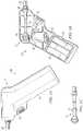
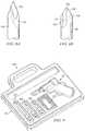
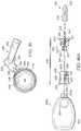
- FIG. 1Ais a schematic drawing showing an isometric view of one embodiment of the present disclosure.
- FIG. 1Bis a schematic drawing showing an isometric view of one embodiment of the present disclosure.
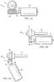
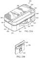
- FIG. 2Ais a schematic drawing showing an isometric view of one embodiment of the present disclosure.
- FIG. 2Bis a schematic drawing showing an isometric view of one embodiment of the present disclosure.
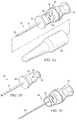
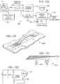
- FIGS. 3A-Cillustrate a side and cross-sectional view of one embodiment of the present disclosure.
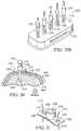
- FIGS. 4A-Cillustrate various alternate embodiments of a reduction gear mechanism that may be included in an embodiment of the present disclosure.
- FIGS. 5A-Cillustrate one embodiment of a penetrator assembly of the present disclosure.
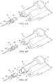
- FIGS. 6A-Cillustrate various alternate embodiments of a penetrator assembly connector of the present disclosure.
- FIG. 7Aillustrates one embodiment of a penetrator assembly of the present disclosure.
- FIG. 7Billustrates a cross-sectional view of one embodiment of a penetrator assembly of the present disclosure.
- FIG. 7Cillustrates one embodiment of an inner trocar in cross section of the present disclosure.
- FIG. 7Dillustrates one embodiment of an outer penetrator in cross section of the present disclosure.
- FIGS. 7E-Gillustrate examples of release mechanisms of the present disclosure.
- FIG. 8Aillustrates one embodiment of a tip of a penetrator assembly of the present disclosure.
- FIG. 8Billustrates one embodiment of a tip of a penetrator assembly of the present disclosure.
- FIG. 9illustrates one embodiment of a kit to access the bone marrow of the present disclosure.
- FIG. 10illustrates one embodiment of a connector to attach to an outer penetrator of the present disclosure.
- FIG. 11Ais a schematic drawing in section showing one embodiment of a rechargeable powered driver incorporating teachings of the present disclosure.
- FIG. 11Bis a schematic drawing showing an isometric view of the rechargeable powered driver of FIG. 11A ;
- FIG. 12Ais a schematic drawing showing one example of an electrical power circuit incorporating teachings of the present disclosure.
- FIG. 12Bis a schematic drawing showing an example of one component of a variable speed controller satisfactory for use with a powered driver in accordance with teachings of the present disclosure.
- FIG. 12Cis an isometric drawing showing an example of another component of a variable speed controller which may be used with a powered driver in accordance with teachings of the present disclosure.
- FIG. 12Dis a schematic drawing showing an example of an electrical power circuit having an enable switch or safety switch incorporating teachings of the present disclosure.
- FIG. 13Ais a schematic drawing showing a powered driver disposed in a charging cradle incorporating teachings of the present disclosure.
- FIG. 13Bis a schematic drawing showing an isometric view of a powered driver having a battery charge indicator incorporating teachings of the present disclosure.
- FIG. 13Cis a schematic drawing with portions broken away showing another example of a charge indicator for a powered driver incorporating teachings of the present disclosure.
- FIG. 13Dis a schematic drawing with portions broken away showing still another example of a power supply status indicator for a powered driver incorporating teachings of the present disclosure.
- FIG. 14Ais a schematic drawing showing an isometric view of a powered driver having a light in accordance with teachings of the present disclosure.
- FIG. 14Bis a schematic drawing showing an isometric view of another example of a light disposed on a powered driver in accordance with teachings of the present disclosure.
- FIG. 14Cis a schematic drawing showing another example of a rechargeable powered driver incorporating teachings of the present disclosure.
- FIG. 15Ais a schematic drawing showing an isometric view of a powered driver having a safety switch incorporating teachings of the present disclosure.
- FIG. 15Bis a schematic drawing showing an isometric view of another powered driver having an enable switch incorporating teachings of the present disclosure.
- FIG. 15Cis a schematic drawing showing an isometric view of still another powered driver having a safety switch incorporating teachings of the present disclosure.
- FIG. 16Ais a schematic drawing in section with portions broken away showing one example of a protective covering for a trigger assembly or switch assembly of a powered driver incorporating teachings of the present disclosure.
- FIG. 16Bis a schematic drawing showing another example of a protective cover for a trigger assembly or switch assembly of a powered driver incorporating teachings of the present disclosure.
- FIG. 16Cis an isometric drawing showing a cross-section of a powered driver incorporating teachings of the present disclosure.
- FIG. 17Ais a schematic drawing showing a wall mounted cradle for a powered driver incorporating teachings of the present disclosure.
- FIG. 17Bis a schematic drawing showing another isometric view of a cradle and powered driver of FIG. 17B .
- FIG. 18Ais a schematic drawing showing one example of an intraosseous needle set which may be inserted into a patient's vascular system using a powered driver.
- FIG. 18Bis a schematic drawing showing an isometric view with portions broken away of a connector receptacle which may be releasably engaged with a powered driver incorporating teachings of the present disclosure.
- FIG. 19Ais a schematic drawing showing an isometric view of one embodiment of a hub which may be installed by a powered driver in accordance with teachings of the present disclosure.
- FIG. 19Bis a schematic drawing showing an isometric view of one embodiment of a connector which may be installed by a powered driver in accordance with teachings of the present disclosure.
- FIG. 20is a schematic drawing showing an isometric view with portions broken away of a pump which may be operated by a powered driver in accordance with teachings of the present disclosure.
- FIG. 21illustrates a powered driver including a battery indicator according to another aspect of the present disclosure.
- FIG. 22illustrates a powered driver including a rechargeable battery according to another aspect of the present disclosure.
- FIG. 23Ais a schematic drawing showing an isometric view of one example of a kit which may be used to obtain access to a patient's vascular system in a first, closed position.
- FIG. 23Bis a schematic, drawing with portions broken away showing one example of a breakable seal which may be used to indicate status of the kit of FIG. 23A .
- FIG. 24Ais a schematic drawing showing an isometric view of the kit in FIG. 23A in an open position along with examples of intraosseous and intravenous devices and components disposed therein.
- FIG. 24Bis a schematic drawing showing one side of a divider or panel which may be disposed in the kit of FIG. 24A along with examples of intraosseous and intravenous devices and components attached thereto.
- FIG. 25is a schematic drawing showing an isometric view of one example of a securing device which may be installed in a kit to releasably hold a drive in accordance with teachings of the present disclosure.
- FIG. 26is a schematic drawing showing one example of a powered driver and penetrator assembly which may be included in a kit in accordance with teachings of the present disclosure.
- FIG. 27is a schematic drawing showing an isometric view of one example of a powered driver and securing device releasably engaged with each other in accordance with teachings of the present disclosure.
- FIG. 28is a schematic drawing showing an isometric view of one example of a kit in a second, open position with a powered driver installed in a securing device operable to recharge a battery carried within the powered driver in accordance with teachings of the present disclosure.
- FIG. 29Ais a schematic drawing showing another example of a kit in a first, closed position incorporating teachings of the present disclosure.
- FIG. 29Bis a schematic drawing showing an isometric view of the kit of FIG. 29A in a second, open position.
- FIG. 30is a schematic drawing in section showing an intraosseous device inserted into bone marrow of a patient after using various devices and components carried in a kit in accordance with the teachings of the present disclosure.
- FIG. 31is a schematic drawing in elevation with portions broken away showing one example of a strap and supporting structure which may be carried in a kit and used to position an intraosseous device at a selected insertion site.
- FIG. 32is a schematic drawing showing a plan view with portions broken away of another example of a strap and supporting structure which may be carried in a kit and used to position an intraosseous device at a selected insertion site.
- FIG. 33is a schematic drawing in section and in elevation showing an intraosseous device inserted into bone marrow of a patient along with another example of a strap and supporting structure which may be carried in a kit in accordance, with teachings of the present disclosure.
- FIG. 34is a schematic drawing in section showing an intraosseous device inserted into bone marrow of a patient along with another example of a strap and supporting structure which may be carried in a kit in accordance with teachings of the present disclosure.
- FIG. 35is a schematic drawing in section showing an intraosseous device inserted into bone marrow of a patient along with another example of a strap and supporting structure which may be carried in a kit in accordance with teachings of the present disclosure.
- FIG. 36is a schematic drawing in section showing another example of a strap and supporting structure which may be satisfactorily used to position an intraosseous device at a selected insertion site.
- FIG. 37is a schematic drawing in section with portions broken away of the strap and supporting structure of FIG. 36 .
- FIG. 38is a schematic drawing showing an isometric view with portions broken away of the strap and supporting structure of FIGS. 36 and 37 releasably attached to the leg of a patient proximate the tibia.
- FIG. 39is a schematic drawing showing another example of a powered driver which may be carried in a kit incorporating teachings of the present disclosure along with a strap and supporting structure for an associated intraosseous device.
- FIG. 40Ais a schematic drawing showing an exploded view of a manual driver and associated intraosseous device which may be carried in a kit in accordance with teachings of the present disclosure.
- FIG. 40Bis a schematic drawing showing an isometric view of a container with one example of an intraosseous device disposed therein.
- FIG. 41is a schematic drawing showing another example of a manual driver which may be carried in a kit in accordance with teachings of the present disclosure.
- FIGS. 1A-41wherein like numbers refer to same and like parts.
- Apparatus and methods incorporating teachings of the present disclosuremay be used to provide intraosseous access to a patient's vascular system in the sternum, the proximal humerus (the shoulder area), the proximal tibia (below the knee) and the distal tibia (above the inside of the ankle).
- the distal tibiamay provide easier vascular access to morbidly obese patients.
- the distal tibiais usually a thinner area of the body. Using the distal tibia as an insertion site may allow emergency medical service personnel to pump medications and fluids into the body of obese patients when regular conventional IV access is difficult.
- EMS personnelmay often not be able to start IVs in obese patients because their size may obscure many of the veins used for conventional IV access.
- Adipose tissue (fat) around normal IO access sitesmay be so thick that EMS personnel can't reach adjacent the bone with standard IO needles. Therefore, the distal tibia may provide an IO access site for the overweight population.
- One aspect of the present disclosuremay include providing a powered driver and respective IO needle sets for safe and controlled vascular access to provide medication and fluids to bone marrow, to remove biopsies of bone and/or bone marrow and to aspirate bone marrow.
- Apparatus and methods incorporating teachings of the present disclosuremay be used with patients of all ages and weights.
- one IO needle setmay be appropriate for patients within the weight range of 3 kilograms to 39 kilograms.
- a second IO needle setmay be satisfactory for use with patients weighing 40 kilograms or more.
- teeth formed on one end of a cannula or cathetermay be bent radially outward to reduce the amount of time and the amount of force required to penetrate bone and associated bone marrow using the cannula or catheter.
- a powered driver and aspiration needle set formed in accordance with teachings of the present disclosuremay provide access to a patient's bone marrow using the same amount of torque.
- the length of time for penetrating a relatively hard bonemay be increased as compared with the length of time required to penetrate a relatively softer bone.
- the circuitmay limit current supplied to the motor to protect associated batteries and to protect the motor for high current flow.
- High current flowmay correspond with high torque which indicates improper use or operation of the powered driver.
- High torquemay also indicate that the powered driver is not driving into bone.
- Current flow through the motormay be directly related to torque produced by the drive shaft.
- the circuitmay indicate when current flow through the motor is typical for penetrating the hard outer layer of a bone (compact bone issue) with an IO device.
- the circuitmay also indicate when current flow through the motor decreases in response to the IO device penetrating associated bone marrow.
- the powered drivermay include a trigger assembly operable to activate a low speed switch, a high speed switch and/or turn an associated motor off.
- the powered drivermay include a drive shaft having one end with a generally hexagonal cross section operable to be releasably engaged with intraosseous devices including, but not limited to, biopsy needles and bone marrow aspiration needles.
- the powered drivermay include a gear assembly rotatably attached to a motor.
- the gear assemblymay have a speed reducing ratio between 60:1 and 80:1.
- the gear assemblymay reduce speed of rotation of an attached motor at a ratio of approximately 66:1 or 77:1.
- Apparatus and methods incorporating teachings of the present disclosuremay include using a first IO needle set having a fifteen (15) gage cannula with a length of approximately fifteen (15) millimeters to establish vascular access for patients weighing between approximately three (3) kilograms and thirty nine (39) kilograms.
- a second IO needle set having a fifteen (15) gage cannula with an approximate length of twenty-five (25) millimetersmay be used to establish vascular access for patients weighing forty (40) kilograms and greater.
- intraosseous needles and needle sets incorporating teachings of the present disclosuremay be formed from 304-stainless steel. Standard Luer lock catheter connections may be provided on each IO needle. IO needles and needle sets incorporating teachings of the present disclosure may be easily removed from an insertion site without the use of special tooling or equipment. The reduced size and weight of drivers and IO devices incorporating teachings of the present disclosure accommodate use in emergency crash carts and emergency medical vehicles.
- driveras used in this application may include any type of powered driver or manual driver satisfactory for inserting an intraosseous (IO) device including, but not limited to, a penetrator assembly, catheter, IO needle, IO needle set, biopsy needle or aspiration needle into a selected portion of a patient's vascular system.
- IOintraosseous
- Various techniquesmay be satisfactorily used to releasably engage or attach an IO device and/or penetrator assembly with a driver incorporating teachings of the present disclosure.
- a wide variety of connectors and associated connector receptacles, fittings and/or other types of connections with various dimensions and configurationsmay be satisfactorily used to releasably engage an IO device with a driver.
- a battery powered driver incorporating teachings of the present disclosuremay be used to insert an intraosseous device into a selected target area in ten seconds or less.
- intraosseous (IO) devicemay be used in this application to include any hollow needle, hollow drive bit, penetrator assembly, bone penetrator, catheter, cannula, trocar, inner penetrator, outer penetrator, IO needle or IO needle set operable to provide access to an intraosseous space or interior portions of a bone.
- an IO needle or IO needle setmay include a connector with a trocar or stylet extending from a first end of the connector.
- a second end of the connectormay be operable to be releasably engaged with a powered driver incorporating teachings of the present disclosure.
- An IO needle or IO needle setmay also include a hub with a hollow cannula or catheter extending from a first end of the hub.
- a second end of the hubmay include an opening sized to allow inserting the trocar through the opening and the hollow cannula.
- the second end of the hubmay also be operable to be releasably engaged with the first end of the connector.
- the second end of the connectormay be releasably engaged with a powered driver.
- a wide variety of connectors and hubsmay be used with an IO device incorporating teaching of the present disclosure. The present disclosure is not limited to connector 1180 or hub 1200 as shown in FIGS. 18A and 18B .
- kits having a driver to insert an intraosseous (IO) device into bone marrow of a patient at a selected insertion sitemay be described with respect to a kit having a driver to insert an intraosseous (IO) device into bone marrow of a patient at a selected insertion site.
- IOintraosseous
- a kit with devices and components incorporating teachings of the present disclosuremay be satisfactorily used to access various portions of a patient's vascular system.
- the present disclosureis not limited to IO devices and procedures.
- kitsmay be used in this application to describe a wide variety of bags, containers, carrying cases and other portable enclosures which may be used to carry and store intraosseous devices and/or intravenous devices along with related components and accessories. Such kits and their contents along with applicable procedures may be used to provide access to a patient's vascular system in accordance with teachings of the present disclosure.
- FIGS. 1A and 1BVarious examples of an apparatus operable to access the bone marrow in accordance with the present invention are shown generally in FIGS. 1A and 1B at 10 .
- Apparatus 10 as shown in FIGS. 1A and 1Bgenerally includes housing 12 and penetrator assembly 14 .
- Housing 12includes handle 16 that is sized and contoured to fit the hand of an operator.
- Handle 16may include on/off switch 22 and safety 24 .
- Penetrator assembly 14includes outer penetrator 18 , inner trocar (not expressly shown) and penetrator assembly connector 20 .
- FIGS. 2A and 2Billustrate an alternate embodiment of the present invention.
- Apparatus 10 agenerally includes housing 12 and penetrator assembly 14 a .
- Housing 12includes handle 16 that is sized and contoured to fit the hand of an operator.
- Handle 16may include an on/off switch 22 .
- Penetrator assembly 14 aincludes outer penetrator 18 , inner trocar (not expressly shown) and penetrator assembly connector 20 .
- Penetrator assembly 14 amay include penetrator shield 26 .
- An outer penetratormay include either a trocar, a needle, a cannula, a hollow tube, a drill bit or a hollow drill bit.
- FIGS. 3A and 3Billustrate yet another embodiment of the present invention.
- Apparatus 10 bgenerally includes housing 12 and a penetrator assembly (not expressly shown).
- Housing 12includes handle 16 and on/off switch 22 .
- Penetrator assemblymay include penetrator (not expressly shown) and a connector, for example a pentagonal connector 20 as shown in FIG. 3A .
- housing 12encloses motor 30 , power supply 32 , for example four or more AA batteries, motor connecting wires 34 between power supply 32 and motor 30 and switch connecting wires 36 between on/off switch 22 and power supply 32 .
- the power supply to the apparatusmay be any suitable number of AA batteries or any other type of battery, a source of direct current, a source of alternating current or a source of air or gas power.
- the motormay be reciprocating or rotational.
- Thruster bearing 45for example a washer, may be located adjacent to housing 12 where drill shaft 40 exits housing 12 . Thruster bearing 45 prevents the thrust or penetration force of drilling from being placed on gear assembly 38 as penetrator is drilled into bone.
- FIG. 3Cshows one embodiment of the invention where drill shaft 40 may be separated into two interdigitating pieces at 42 in order to allow the two ends of drill shaft 40 to slide in and out as bone is penetrated to avoid applying excessive force to a gear assembly.
- gear assembly 38is coupled to motor 30 .
- Gear assembly 38may be a reduction gear assembly such as that shown in FIG. 3B that functions to reduce the revolutions per minute (RPMs) between the motor and drill shaft 40 and to increase drill shaft torque.
- RPMsrevolutions per minute
- gear assemblymay or not be of the reduction type.
- a reduction gear assemblyfor example a worm gear assembly is shown in more detail in FIG. 4A and may include first connector 43 that connects shaft 44 of motor 30 to worm gear 46 . Worm gear 46 may engage spur gear 47 .
- Reduction gear assembly 38may be used to decrease the RPMs between the motor and penetrator assembly to provide an optimum RPM at the point of insertion of penetrator assembly into bone. Reduction gear assembly 38 may also be used to increase the torque of drill shaft and drilling power.
- FIG. 4Billustrates one embodiment of reduction gear assembly 38 wherein a first spur gear 47 engages a second spur gear 49 .
- FIG. 4Cillustrates an alternate embodiment of reduction gear assembly 38 wherein spur gear 47 is offset from mitered gear 48 that may be preferable in some embodiments of the present invention.
- Other gearsmay be used in a reduction gear assembly, for example a planetary gear (not expressly shown) that may be used alone or in combination with a worm gear or a spur gear.
- gear assemblymay be any suitable gear arrangement and is not limited to a reduction gear assembly.
- FIGS. 5A-5Cillustrate one embodiment of a penetrator assembly 55 operable to penetrate a bone marrow, having a removable inner trocar 50 and an outer penetrator 52 .
- a penetrator shield 26that may be used to shield penetrator assembly 55 from inadvertent engagement and also serves to preserve needle sterility.
- outer penetrator 52may be a type of needle or cannula.
- FIG. 5Billustrates outer penetrator 52 may include a male connecting piece 56 operable to engage a complementary female connecting piece 54 of inner trocar 50 . Adjacent to male connecting piece 56 is connecting piece locking mechanism 58 that locks into position on female connecting piece 54 .
- outer penetratormay include a female connecting piece suitable to engage a complementary male connecting piece of an inner trocar.
- Luer lock attachment 57is coupled to male connecting piece 56 for connection to an intravenous tubing or syringe after the outer penetrator is positioned in the bone marrow.
- Male connecting piece 56 and female connecting piece 54may also be of the luer-lock type.
- Inner trocar 50includes stylet 53 that keeps outer penetrator 52 from getting plugged with debris created during drilling. Stylet 53 acts in combination with cannula portion 51 of outer penetrator.
- Outer penetrator 52may include flange 60 that abuts or interfaces the skin of an insertion site and may be used to stabilize a penetrator assembly at the time of insertion.
- Penetrator assembly 55may include various types of connectors, such as connector 62 that may be used to connect penetrator assembly 55 to a powered drill. Connector 62 may be pentagonal as shown in FIGS. 5A and 5C
- the inventionmay include a specialized connector between the penetrator assembly and a powered drill.
- the connectorperforms at least two functions, a connecting function and a releasing function.
- the connecting functionmay be performed by various mechanisms such as a pentagonal male-female fitting or various lock-and-key mechanisms such as one that may include a combination or series of grooves and ridges or bars that match and interlock on a connector.
- the releasing functionmay be performed by an O-ring connection, a magnetic connector, a chuck release mechanism, or a ball and detent mechanism with and without a spring.
- the releasing functionmay occur by means of a trigger mechanism whereby a trigger comes in contact with a holding mechanism and releases a penetrator or needle.
- a connecting mechanismmay also include a trigger or retractable shield rod that slides up and contacts a holding mechanism or clamp that breaks away and releases a penetrator or needle after contact (not expressly shown).
- FIGS. 6A-Cillustrate alternate embodiments of connectors operable to releasably attach penetrator assembly 55 to powered drill apparatus 10 .
- FIG. 6Aillustrates penetrator assembly connector 62 wherein connector 62 is formed to fit into a connector receptacle 64 and releasably lock into place.
- connector 62 and connector receptacle 64are pentagonal shaped. Advantages of this embodiment may be the ease of attachment and removal of penetrator assembly 55 from powered drill apparatus 10 .
- Penetrator assembly connector 62may be formed from metal or plastic.
- FIG. 6Billustrates an alternate embodiment of penetrator assembly connector wherein a female pentagonal receptacle 65 is operable to engage pentagonal connecting piece 66 attached to powered drill apparatus 10 .
- FIG. 6Cillustrates a further embodiment of a penetrator assembly connector wherein penetrator assembly connector 68 is a proprietary design having a pattern of ridges or bars 73 that engage a matching pattern of slots 71 on a connecting receptacle 72 .
- Example penetrator assembly connectorsmay include any type of lock and key design or a pentagonal design. Penetrator assembly connectors of any type may be held in place by either a magnet, an O-ring connector or a ball and detent mechanism with or without a spring (not expressly shown).
- the penetrator assemblymay include an outer penetrator such as a cannula, needle or hollow drill bit which may be of various sizes. Needles may be small (for pediatric patients), medium (for adults) and large (for over-sized adults). Penetrator, cannulas or needles may be provided in various configurations depending on the clinical purpose for needle insertion. For example, there may be one configuration for administering drugs and fluids and an alternate configuration for sampling bone marrow or for other diagnostic purposes although one needle configuration may be suitable for both purposes. Needle configuration may vary depending on the site chosen for insertion of a needle.
- an outer penetratorsuch as a cannula, needle or hollow drill bit which may be of various sizes. Needles may be small (for pediatric patients), medium (for adults) and large (for over-sized adults). Penetrator, cannulas or needles may be provided in various configurations depending on the clinical purpose for needle insertion. For example, there may be one configuration for administering drugs and fluids and an alternate configuration for sampling bone marrow
- FIGS. 7A-7Dillustrate one embodiment of a penetrator assembly 80 that includes a removable inner trocar 82 and an outer penetrator 84 .
- FIG. 7Billustrates a cross-sectional view of one embodiment of a penetrator assembly having a removable inner trocar 82 and an outer penetrator 84 .
- Outer penetrator 84includes flange 86 and flange groove 88 .
- Flange 86may be used to stabilize penetrator assembly 80 against the skin of an insertion site.
- Flange groove 88is operable to engage plastic penetrator cover 94 .
- the surface of outer penetratormay include a series of discs formed along a longitudinal axis, a series of ridges or some other grasping means.
- Outer penetrator 84includes a penetrator cannula 96 that is hollow when stylet 100 is removed.
- inner trocar 82includes handle 98 that may have a surface such as a series of discs formed along a longitudinal axis of the trocar, or a series of ridges or some other grasping means. Handle 98 allows an operator to easily grasp and manipulate inner trocar 82 and disengage it from outer penetrator 84 .
- Inner trocar 82also includes stylet 100 . Stylet 100 exits an end of penetrator cannula 96 when inner trocar 82 is inserted into outer penetrator 84 Stylet 100 includes a cutting tip and is operable to penetrate bone marrow.
- inner trocar 82may include metal disc 95 to allow a magnetic connection between penetrator assembly and powered drill. Receptacle 97 may also engage a penetrator assembly male-type connector piece operable to connect penetrating assembly to a powered drill, or any other suitable connector.
- FIGS. 7E-7Gillustrate example release mechanisms that may be coupled to a connector and included in penetrator assembly 80 .
- FIG. 7Eillustrates one embodiment of a magnetic release mechanism where magnetic disc 70 is included in inner trocar 82 .
- magnetic disc 70is at the base of open area or receptacle 97 .
- a magnetic disccould be included with a pentagonal connector or a lock and key connector or any other suitable connector.
- FIG. 7Fillustrates another embodiment of a release mechanism where O-ring 72 is included in trocar 98 as part of a connector.
- O-ring 72is in the wall of receptacle 97 .
- O-ring 72is able to engage a lock and key connector, a pentagonal connector or any other suitable connector.
- FIG. 7Gillustrates yet another embodiment of a release mechanism using ball and detent mechanism 74 .
- ball and detent mechanism 74is in the wall of receptacle 97 .
- Ball and detent mechanism 74is able to engage a lock and key connector, a pentagonal connector or any other suitable connector.
- FIG. 8Aillustrates an embodiment of an outer penetrator needle 110 and inner stylet 112 .
- Cutting tip 114 of outer penetrator needle 110 and tip of inner stylet 112are operable to penetrate bone marrow.
- the outer penetrator needle and the inner styletare ground together as one unit in the manufacturing process to ensure that the two pieces are an exact fit and act as a single drilling unit.
- FIG. 8Billustrates another embodiment of an outer penetrator needle 96 and an inner stylet 100 .
- Cutting tip 102 of inner stylet 100is operable to penetrate bone marrow.
- Inner styletmay also include a longitudinal groove 104 that runs along the side of stylet 100 that allows bone chips and tissue to exit an insertion site as a penetrator assembly is drilled deeper into bone.
- Outer penetrator or needle 96includes cutting tip 106 that facilitates insertion of outer penetrator or needle 96 and minimizes damage to outer penetrator or needle 96 as penetrator assembly 55 is inserted into bone marrow.
- the outer penetrator needle and the inner styletare ground together as one unit in the manufacturing process to ensure that the two pieces are an exact fit and act as a single drilling unit.
- FIG. 9illustrates one embodiment of kit 120 to penetrate bone marrow.
- Kit 120includes apparatus 10 for penetrating bone marrow, alternative sizes of penetrator assemblies 122 , and strap 124 suitable to immobilize an outer penetrator on an extremity during insertion of penetrator assembly 122 .
- Carrying case 125is also included.
- FIG. 10illustrates an example of a connector that may be used to connect the outer penetrator of a penetrator assembly to tubing 130 , for example an intravenous tubing for providing intravenous fluids or medications to a person.
- Outer penetrator 84is inserted into the bone marrow of an extremity.
- Right angle connector 132is then used to connect intravenous tubing 130 to outer penetrator 84 .
- Right angle connectorhas the advantage of allowing tubing to be connected to an outer penetrator or needle at an angle that will not kink or pinch off the lumen of the tubing.
- connectors or adaptersmay also be used to connect an outer penetrator to an intravenous tubing, another kind of tubing or to a syringe for use in providing medication or fluids to a person or for use in withdrawing a sample of blood from the bone marrow.
- a method for providing access to the bone marrowincludes using a powered drill, capable of reciprocal or rotational motion, to insert a penetrator assembly that includes an outer penetrator and an inner trocar into a bone marrow cavity.
- the powered drillis then released from the penetrator assembly and the inner trocar is grasped and removed from the outer penetrator.
- a connector present on the end of the outer penetratorfor example a luer lock connector, is then available for attachment to either an adapter, such as a right angle connector or directly to an intravenous tubing or syringe.
- powered drivers 1030 and 1030 a - 1030 fmay also be described with respect to powered drivers 1030 and 1030 a - 1030 f .
- Various features of the present disclosuremay also be described with respect to intraosseous devices such as shown in FIGS. 18A and 18B .
- the present disclosureis not limited to use with intraosseous device 1160 or powered drivers 1030 and 1030 a - 1030 f.
- Powered driver 1030 as shown in FIGS. 11A, 11B and 13Amay be satisfactorily used to insert an intraosseous device at a desired insertion site adjacent to a bone and associated bone marrow (not expressly shown).
- powered driver 1030may include one or more features of the present disclosure including, but not limited to, a light operable to illuminate an insertion site, charging contacts and associated charging circuitry, a power supply status indicator, trigger guard, variable speed controller, safety switch and/or timing circuit. At least one or more of the preceding features and/or additional features of the present disclosure may also be shown with respect to powered drivers 1030 - 1030 f and/or 1330 a - 1330 k.
- a power sourcesuch as rechargeable battery pack 1034 may be disposed within handle 1036 .
- Battery pack 1034may have various configurations and may include multiple batteries disposed within sealed packaging material.
- a non-rechargeable battery packmay also be disposed within handle 1036 .
- Handle 1036may be generally described as an elongated, hollow container sized to receive battery pack or power supply 1034 .
- Cap 1038may be disposed on one end of handle 1036 .
- Cap 1038may be removed to allow inserting and removing battery pack 1034 therefrom.
- Handle 1036may also include finger grips 1064 having generally ergonomic configurations.
- cap 1038may include a pair of charging contacts 1040 a and 1040 b .
- a portion of each contact 1040 a and 1040 bmay extend from cap 1038 for engagement with an appropriate charging receptacle. See FIG. 13A .
- cap 1038 and adjacent portions of handle 1036may have heavy duty screw on or thread connections (not expressly shown).
- cap 1038may be formed from relatively strong, heavy duty polymeric material.
- Motor 1044 and gear assembly 1046may also be disposed within portions of housing 1032 adjacent to handle 1036 .
- motor 1044 and gear assembly 1046may be generally aligned with each other.
- Motor 1044may be connected with one end of gear assembly 1046 .
- Drive shaft 1052may be engaged with and extend from another end of gear assembly 1046 opposite from motor 1044 .
- both motor 1044 and gear assembly 1046may have generally cylindrical configurations. Exterior portion 1045 of motor 1044 may correspond with the largest nominal outside diameter associated with motor 1044 . Exterior portion 1047 of gear assembly 1046 may correspond with the largest nominal outside diameter associated with gear assembly 1046 . For embodiments of the present disclosure represented by powered drivers 1030 - 1030 e and 1330 a - 1330 k , exterior portion 1047 of gear assembly 1046 may represent a nominal outside diameter portion larger than any other outside diameter portion associated with motor 1044 . In other embodiments of the present disclosure represented by powered driver 1330 i , exterior portion 1047 of gear assembly 1046 may be smaller than outside diameter portions associated with impact device 1044 a.
- housing 1032may have generally similar cylindrical configurations corresponding with exterior portions of motor 1044 and gear assembly 1046 .
- segment 1032 a of housing 1032may have a generally cylindrical, hollow configuration with an inside diameter compatible with exterior portion 1045 of motor 1044 .
- Housing segment 1032 bmay have a generally cylindrical, hollow configuration with an inside diameter compatible with exterior portion 1047 of gear assembly 1046 . Since portions of gear assembly 1046 have an outside diameter that is larger than the outside diameter of motor 1044 , housing segment 1032 b may have a larger outside diameter than the outside diameter of housing segment 1032 a.
- Motors and gear assemblies satisfactory for use with a powered driver incorporating teachings of the present disclosuremay be obtained from various vendors. Such motor and gear assemblies are typically ordered as “sets” with one end of each motor securely attached to an adjacent end of an associated gear assembly.
- the gear assembliesmay sometimes be referred to as “reduction gears” or “planetary gears”.
- a drive shaft having desired dimensions and configurationmay extend from the gear assembly opposite from the motor.
- the drive shaftmay be provided as part of each motor and gear assembly set.
- the dimensions and/or configuration of an associated housingmay be modified in accordance with teachings of the present disclosure to accommodate various types of motors, gear assemblies and/or drive shafts.
- powered drivers used with aspiration needles and/or biopsy needlesmay include gear assemblies with larger dimensions required to accommodate larger speed reduction ratios, for example between 60:1 and 80:1, resulting in slower drive shaft RPM.
- Powered drivers used to provide intraosseous access during emergency medical proceduresmay operate at a higher speed and may include gear assemblies having a smaller speed reduction ratio, for example between 10:1 and 30:1, resulting in higher drive shaft RPM.
- the difference in size for gear assembliesmay result in increasing the inside diameter of an associated housing by approximately two to three millimeters to accommodate larger gear assemblies associated with powered drivers used to insert biopsy needles and/or aspiration needles.
- Distal end or first end 1048 of housing 1032may include opening 1050 with portions of drive shaft 1052 extending therefrom.
- the portion of drive shaft 1052 extending from housing 1032may have a generally pentagonal shaped cross section with tapered surfaces 1054 disposed thereon. Tapered surfaces 1054 may be disposed at an angle of approximately three (3°) degrees with respect to a longitudinal axis or rotational axis (not expressly shown) associated with drive shaft 1052 .
- Relatively small magnet 1056disposed on the extreme end of drive shaft 1052 opposite from housing 1032 . Fittings and/or connectors with various dimensions and/or configurations other than drive shaft 1052 and/or magnet 1056 may also be satisfactorily used with a powered driver incorporating teachings of the present disclosure.
- Intraosseous devices having corresponding tapered openings or connector receptaclesmay be releasably engaged with portions of drive shaft 1052 extending from housing 1032 .
- portions of drive shaft 1052 extending from distal end 1048may be releasably engaged with tapered opening 1186 in connector 1180 as shown in FIGS. 18A and 18B or tapered opening 1156 in connector receptacle 1152 as shown in FIGS. 19 and 20 .
- powered driver 1030may also include light 1060 disposed adjacent to trigger assembly 1062 .
- Electrical circuits and associated wiring contactsmay also be disposed within housing 1032 to supply electrical power to light 1060 .
- Trigger assembly 1062may be used to activate electrical circuits to provide electricity from rechargeable battery 1034 to motor 1044 and/or light 1060 .
- a block diagram showing one example of such electrical circuitsis shown in FIG. 12A .
- FIG. 12AA block diagram showing one example of electrical circuits and other components which may be satisfactory used with a powered driver incorporating teachings of the present disclosure is shown in FIG. 12A .
- Electrical system 1400may include various components such as power supply or battery pack 1034 , charging contacts 1040 a and 1040 b , motor 1044 , light 1060 and/or enable switch 1062 .
- Electrical system 1400may include a wide variety of electrical circuits and electrical components including, but not limited to, power supply status indicator 1070 and electrical charging circuit 1410 , voltage regulator 1430 and variable speed controller 1460 .
- power supply or battery pack 1034may include one or more rechargeable batteries.
- Battery pack 1034may supply fourteen (14) to eighteen (18) volts of direct current (DC) power.
- DCdirect current
- chargeable and non-rechargeable batteriesmay be satisfactorily used with powered drivers incorporating teachings of the present disclosure.
- power supply status indicator 1070A wide variety of electrical circuits and/or electronic indicators may be used with power supply status indicator 1070 . Additional information concerning such electrical circuits and displays may be described with respect to various power supply status indicators as shown in FIGS. 13B, 13C and 13D .
- FIGS. 12B and 12CA wide variety of charging circuits, voltage regulators and variable speed controllers may be satisfactorily used with a powered driver incorporating teachings of the present disclosure.
- FIGS. 12B and 12CVarious examples of such charging circuits, voltage regulators and/or variable speed controllers are shown in FIGS. 12B and 12C .
- Various types of commercial available charging circuits, voltage regulators and/or variable speed controllersmay be satisfactorily used with a powered driver incorporating teachings of the present disclosure.
- Various examples of commercially available microcontrollersmay be satisfactory for use with variable speed controller 1460 .
- Variable resistor 1600 a as shown in FIG. 12B and variable resistor 1600 b as shown in FIG. 12Crepresents examples of mechanical devices having slidable contacts which may be used to vary current supplied to motor 1044 .
- a trigger assembly incorporating teachings of the present disclosuremay be satisfactory used to move one or more of the electrical contacts 1602 a or 1602 b.
- Switch 1062may be provided to prevent inadvertent or undesired activation of motor 1044 . Switch 1062 may prevent discharge of battery 1034 when an associated powered device is carried in a backpack and/or mobile storage container.
- An associated button 1072 amay be disposed on exterior portions of a housing to activate the variable speed controller 1460 . Button 1072 a may be located at various positions on the exterior of a housing associated with a powered driver incorporating teachings of the present disclosure as shown in FIGS. 15A-15C .
- a wide variety of indicatorsincluding, but not limited to, light emitting diodes (LED), liquid crystal displays (LCD) and small more conventional light bulbs may be satisfactorily used with a powered driver according to teachings of the present disclosure.
- FIG. 13Ashows one example of a cradle which may be used to recharge a powered driver in accordance with teachings of the present disclosure.
- Cradles and/or holders incorporating teachings of the present disclosuremay be fabricated from a wide variety of thermoplastic and/or polymeric materials including, but not limited to, polycarbonates. Such materials may be filled with glass fibers or any other fibers satisfactory for use in forming a cradle or holder operable to hold and/or recharge a powered driver in accordance with teachings of the present disclosure. Nylon filled with glass may be used for some applications.
- Materials used to form cradle 1280may be relatively low cost but durable. Such materials may be relatively stiff to secure a powered driver therein and may also flex without breaking to allow inserting and removing a powered driver at least five hundred (500) times.
- Cradle 1280may have a length and width selected to be compatible with exterior portions of housing 1032 and corresponding dimensions of powered driver 1030 .
- first end 1281 and second end 1282may have generally rounded configurations.
- a notch(not expressly shown) may also be formed in first end 1281 to accommodate portions of drive shaft 1052 .
- Various types of holders, clamps or quick release mechanismsmay be included as part of cradle 1280 .
- cradle 1280may include a pair of arms 1284 projecting from respective edges of cradle 1280 . Only one arm 1284 is shown in FIG. 13A .
- Arms 1284may be relatively strong with sufficient flexibility to allow inserting and removing portions of powered driver 1030 from engagement with cradle 1280 .
- the height of arms 1284 relative to adjacent longitudinal edges of cradle 1280may be based at least in part on the corresponding dimensions of handle 1036 and other portions of housing 1032 .
- the spacing or gap formed between arms 1284may be selected to accommodate the width of handle 1036 .
- Respective rib 1286may be formed on the end of each arm 1284 .
- the configuration of ribs 1286may be selected to be compatible with a snug but releasable snap fit with adjacent portions of handle 1036 .
- walls or partitions 1290may be formed adjacent to respective arms 1294 . Only one wall 1290 is shown in FIG. 13A . Partitions or walls 1290 may be spaced from each other a sufficient distance to accommodate associated portions of housing 1032 and may be sized to prevent accidental activation of trigger assembly 1062 .
- End 1282 of cradle 1280may be modified to include electrical contact (not expressly shown) operable to engage recharging contacts 1040 a and 1040 b .
- Electric power cable 1292may also extend from end 1282 .
- Electrical power cable 1292may be inserted into an appropriate electrical outlet for use in recharging powered driver 1030 .
- a plurality of lights 1296 , 1298 and 1300may be provided on exterior portions of cradle 1300 to indicate the status of rechargeable battery 1034 . For example light 1296 may indicate red when rechargeable battery 1034 is discharged below a desired level. Light 1298 may be flashing yellow to indicate that rechargeable battery 1034 is being recharged and/or discharged. Light 1300 may be steady green to indicate when rechargeable battery 1034 has been fully recharged. Lights 1296 , 1298 and 1300 may also alternately blink or have a steady state condition.
- Powered drive 1030 a as shown in FIG. 13Bmay include an indicator operable to indicate the status of a power supply disposed within handle 1036 .
- status indicator 1070 amay be disposed at proximal end or second end 1049 a of powered driver 1030 a .
- a digital display indicating the number of insertions available from a power supply disposed within housing 1032 amay be provided by indicator 1070 at proximal end 1049 a of housing 1032 a .
- the power supplymay be any type of battery or other suitable source of power.
- FIG. 13CAn embodiment of the present disclosure is shown in FIG. 13C which includes status indicator 1070 b disposed on second end or proximal end 1049 b of powered driver 1030 b .
- Status indicator 1070 bmay include digital indication 1072 showing the number of insertions remaining in an associated power source.
- variable indicator scale 1074may be provided to show the status of an associated power source between fully charged and recharge required.
- variable indicator scale 1074may include a voltmeter, an amp meter, and/or any other component operable to measure the status of an associated power supply.
- variable indicator scale 1074may be calibrated to display a percentage of full charge and/or a number of insertions remaining.
- lights 1296 , 1298 and 1300may be disposed on proximal end or second end 1049 c of powered driver 1030 c .
- Lights 1296 , 1298 and 1300may function as previously describe with respect to cradle 1280 .
- FIGS. 17A and 17Bshow another embodiment of the present disclosure including powered driver 1330 j disposed within cradle 1280 a .
- Cradle 1280 amay include arms 1284 a as described in relation to FIG. 13 b .
- Arms 1284 amay be relatively strong with sufficient flexibility to allow inserting and removing portions of powered driver 1330 j from engagement with cradle 1280 a .
- the height of arms 1284 a relative to adjacent longitudinal edges of cradle 1280 amay be based at least in part on the corresponding dimensions of handle 1336 and other portions of housing 1332 .
- the spacing or gap formed between arms 1284may be selected to accommodate the width of handle 1336 .
- Powered drivers 1030 d and 1030 e as shown in FIGS. 14A and 14Bshow alternative locations for a light disposed on a powered driver in accordance with teachings of the present disclosure.
- Powered driver 1030 dmay include substantially the same features as powered driver 1030 except light 1060 d may be disposed on housing segment 1032 b opposite from trigger assembly 1062 .
- light 1060 emay be disposed on distal end or first end 1048 e of powered driver 1030 e .
- Light 1060 emay extend approximately three hundred sixty degrees (360°) around the perimeter of associated drive shaft 1054 .
- FIG. 14CA further embodiment of a rechargeable powered driver incorporating teachings of the present disclosure is shown in FIG. 14C .
- cap 1038 fmay be disposed on one end of handle 1036 .
- Cap 1038may include opening 1040 sized to receive charging connection 1130 attached to power cable 1132 .
- a wide variety of recharging connectorsmay be used to provide power to cable 1132 .
- FIGS. 16A and 16Bshow examples of a protective covering 1063 for trigger assembly 1062 or switch assembly 1062 of powered driver incorporating teachings of the present disclosure.
- Housing 1032may be sealed to prevent blood, other bodily fluids, and/or other contaminants from reaching interior portions of housing 1032 and components disposed therein (e.g., battery 1034 , motor 1044 , and/or gear assembly 1046 ).
- FIGS. 16A and 16Bshow protective covering 1063 a and 1063 b configured to seal with housing 1032 .
- Protective covering 1063 a and 1063 bmay be formed with an elastomeric material chosen for resistance to wear, electrical current, impermeability, and/or any other characteristic sought as long as it allows operation of switch assembly 1062 by the user.
- FIG. 16Cshows powered driver 1330 i incorporating an impact device 1044 a associated with gearbox 1046 and power sensor circuit 1600 c .
- Impact device 1044 amay be configured to operate in a similar manner to an impact wrench by storing energy in a rotating mass then delivering it suddenly to gearbox 1046 . In some embodiments, impact device 1044 a will require less total power from power supply 1034 .
- Power sensor circuit 1600 cmay detect current changes between impact device 1044 a and power supply 1034 . In some applications, current changes between impact device 1044 a and power supply 1034 may indicate bone penetration is complete. Power sensor circuit 1600 c may be operable to automatically reduce or cut power from power supply 1034 to impact device 1044 a once the associated intraosseous device has penetrated the cortex of the bone.
- An intraosseous devicemay include an outer penetrator such as a cannula, needle or hollow drive bit which may be of various sizes. Needles may be small (for pediatric patients), medium (for adults) and large (for over-sized adults). Penetrator, cannulas or needles may be provided in various configurations depending on the clinical purpose for needle insertion. For example, there may be one configuration for administering drugs and fluids and an alternate configuration for sampling bone marrow or for other diagnostic purposes although one needle configuration may be suitable for both purposes. Needle configuration may vary depending on the site chosen for insertion of a needle.
- trocars, spindles and/or shaftsmay be disposed within a catheter or cannula during insertion at a selected insertion site. Such trocars, spindles and shafts may also be characterized as inner penetrators.
- a catheter, cannula, hollow needle or hollow drive bitmay sometimes be characterized as an outer penetrator.
- a layer or coating (not expressly shown) of an anticoagulant such as, but not limited to, heparinmay be placed on interior and/or exterior portions of a catheter or cannula to prevent thrombotic occlusion of the catheter or cannula.
- Anticoagulantsmay reduce platelet adhesion to interior surfaces of the catheter or cannula and may reduce clotting time of blood flowing into and through the catheter or cannula. Placing a layer of an anticoagulant on exterior portions of a catheter or cannula adjacent to an associated tip and/or side ports may be helpful to prevent clotting.
- Penetrator assembly 1160 as shown in FIGS. 18A and 18Bmay include connector 1180 , and associated hub 1200 , outer penetrator 1210 and inner penetrator 1220 .
- Penetrator assembly 1160may include an outer penetrator such as a cannula, hollow tube or hollow drive bit and an inner penetrator such as a stylet or trocar.
- outer penetrator or cannula 1210may be described as a generally elongated tube sized to receive inner penetrator or stylet 1220 therein.
- inner penetrator 1220may be disposed within longitudinal passageway 1184 extending through outer penetrator 1210 .
- the outside diameter of inner penetrator 1220 and the inside diameter of longitudinal passageway 1184may be selected such that inner penetrator 1220 may be slidably disposed within outer penetrator 1210 .
- Metallic disc 1170may be disposed within opening 1186 for use in releasably attaching connector 1180 with magnet 1056 disposed on the end of drive shaft 1052 .
- End 1223 of inner penetrator 1220is preferably spaced from metallic disc 1170 with insulating or electrically nonconductive material disposed therebetween.
- Tip 1211 of outer penetrator 1210 and/or tip 1222 of inner penetrator 1220may be operable to penetrate bone and associated bone marrow.
- the configuration of tips 1211 and/or 1222may be selected to penetrate a bone or other body cavities with minimal trauma.
- First end or tip 1222 of inner penetrator 1220may be trapezoid shaped and may include one or more cutting surfaces.
- outer penetrator 1210 and inner penetrator 1220may be ground together as one unit during an associated manufacturing process. Providing a matching fit allows respective tips 1211 and 1222 to act as a single driving unit which facilitates insertion and minimizes damage as portions of penetrator assembly 1160 are inserted into a bone and associated bone marrow.
- Outer penetrator 1210 and/or inner penetrator 1220may be formed from stainless steel, titanium or other materials of suitable strength and durability to penetrate bone.
- Hub 1200may be used to stabilize penetrator assembly 1160 during insertion of an associated penetrator into a patient's skin, soft tissue and adjacent bone at a selected insertion site.
- First end 1201 of hub 1200may be operable for releasable engagement or attachment with associated connector 1180 .
- Second end 1202 of hub 1200may have a size and configuration compatible with an associated insertion site for outer penetrator 1210 .
- the combination of hub 1200 with outer penetrator 1210may sometimes be referred to as a “penetrator set” or intraosseous needle.
- Connector 1180 and attached inner penetrator 1220may be releasably engaged with each other by Luer type fittings, threaded connections or other suitable fittings formed on first end 1201 of hub 1200 .
- Outer penetrator 1210extends from second end 1202 of hub 1200 .
- connector 1180may be described as a generally cylindrical tube defined in part by first end 1181 and second end 1182 .
- the exterior of connector 1180may include an enlarged tapered portion adjacent to end 1181 .
- a plurality of longitudinal ridges 1190may be formed on the exterior of connector 1180 to allow an operator to grasp associated penetrator assembly 1160 during attachment with a drive shaft. See FIG. 18B . Longitudinal ridges 1190 also allow connector 1180 to be grasped for disengagement from hub 1200 when outer penetrator 1210 has been inserted into a bone and associated bone marrow.
- Second end 1182 of connector 1180may include opening 1185 sized to receive first end 1201 of hub 1200 therein. Threads 1188 may be formed in opening 1185 adjacent to second end 1182 of connector 1180 . Threaded fitting 1188 may be used in releasably attaching connector 1180 with threaded fitting 1208 adjacent to first end 1201 of hub 1200 .
- First end 1201 of hub 1200may include a threaded connector 1208 or other suitable fittings formed on the exterior thereof.
- First end 1201may have a generally cylindrical pin type configuration compatible with releasably engaging second end or box end 1182 of connector 1180 .
- end 1202 of hub 1200may have the general configuration of a flange.
- Angular slot or groove 1204 sized to receive one end of protective cover or needle cap 1234may be formed in end 1202 .
- Slot or groove 1204may be used to releasable engage a needle cover (not expressly shown) with penetrator assembly 1160 .
- a penetrator assemblymay include only a single, hollow penetrator.
- a penetrator assemblymay include an outer penetrator such as a cannula, hollow needle or hollow drive bit and an inner penetrator such as a stylet, trocar or other removable device disposed within the outer penetrator.
- Penetrator 1210is one example of a single, hollow penetrator.
- the size of a penetratormay vary depending upon the intended application for the associated penetrator assembly. Penetrators may be relatively small for pediatric patients, medium size for adults and large for oversize adults. By way of example, a penetrator may range in length from five (5) mm to thirty (30) mm. The diameter of a penetrator may range from eighteen (18) gauge to ten (10) gauge. The length and diameter of the penetrator used in a particular application may depend on the size of a bone to which the apparatus may be applied. Penetrators may be provided in a wide variety of configurations depending upon intended clinical purposes for insertion of the associated penetrator. For example, there may be one configuration for administering drugs and/or fluids to a patient's bone marrow and an alternative configuration for sampling bone marrow and/or blood from a patient. Other configurations may be appropriate for bone and/or tissue biopsy.
- connector 1180may be described as having a generally cylindrical configuration defined in part by first end 1181 and second end 1182 . See FIG. 18B . Exterior portions of connector 1180 may include an enlarged tapered portion adjacent to end 1181 . A plurality of longitudinal ridges 1190 may be formed on the exterior of connector 1180 to allow an operator to grasp associated penetrator assembly 1160 during attachment with a drive shaft. Longitudinal ridges 1190 also allow connector 1180 to be grasped for disengagement from hub 1200 when outer penetrator 1210 has been inserted into a bone and associated bone marrow.
- First end 1181 of connector of 1180may include opening 1186 sized to receive portions drive shaft 1052 therein.
- a plurality of webs 1136may extend radially outward from connector receptacle 1186 . Webs 1136 cooperate with each other to form a plurality of openings 1138 adjacent to first end 1181 . Opening 1186 and openings 1138 cooperate with each other to form portions of a connector receptacle operable to receive respective portions of connector 1030 therein.
- FIGS. 19A and 19Bshow isometric views of embodiments of connector 1180 a and hub 1200 a.
- Pump assembly 1130 as shown in FIG. 20represents an example of an accessory tool which may be operated by a powered driver incorporating teachings of the present disclosure.
- Pump assembly 1130may include housing 1134 with connector receptacle 1152 extending therefrom.
- Various components of pump assembly 1130(not expressly shown) may be disposed within housing 1134 and rotatably attached with connector receptacle 1152 .
- Inlet tubing 1131may be provided to communicate fluids with interior portions of pump housing 1134 .
- Outlet tubing 1132may be provided to direct fluids exiting from pump assembly 1130 .
- Such fluidsmay be various types of liquids associated with medical procedures. Such fluids may include small particulate matter.
- Pump assembly 1130may sometimes function as a vacuum or suction pump for such procedures.
- First end 1154 of connector receptacle 1152may include opening 1156 similar to opening 1186 as described with respect to connector 1180 .
- End 1252 extending from power driver 1230 amay be disposed within opening 1156 to rotate connector receptacle 1152 and attached components of pump assembly 1130 a .
- powered driver 1230 amay be used to pump fluids from inlet 1131 through pump assembly 1130 a and outwardly from outlet 1132 .
- One embodiment of the devicecalls for it being disposable.
- Another embodimentis designed for the body (driver) to be reusable and the needle to be disposable. This is made possible by providing a chuck that mates with a proprietary shaft attached to the needle's Luer lock.
- the needlesmust maintain sterility during storage and mounting of the needle while the driver does not have to be sterile.
- the driverwill be rugged in design and the battery (or other power source) will be rechargeable or the battery will be easy to replace with off-the-shelf batteries.
- FIG. 21shows the configuration of a driver without a needle inserted.
- a housing 2014 and a trigger 2015are shown.
- a battery indicator 2040is also shown.
- FIG. 22shows the motor 2011 , gearbox 2017 , gear 2018 , and battery 2010 of the reusable driver. It also shows the chuck 2037 , which is designed to accept the keyed needle or “unit dose” ampule. It is important in the reusable design to have a rechargeable battery or the ability to easily change off-the-shelf batteries i.e. a 9-volt battery. It may also incorporate a battery level indicator or other battery reserve indicator (not expressly shown).
- kitsmay include apparatus operable to access a patient's bone marrow using a driver, an intraosseous needle and one or more connectors to communicate fluids with the patient's bone marrow.
- kitsmay also include apparatus which allows monitoring a patient.
- Kits incorporating teachings of the present disclosuremay be rigid, semi-rigid or soft-sided. Such kits may provide a convenient way to carry various components and devices operable to achieve vascular access in an organized and systematic fashion. Such kits may present EMS first responders and other medical personnel with a well organized collection of components and devices to achieve vascular access by placement of peripheral intravenous (IV) catheters and/or intraosseous (IO) catheters.
- IVperipheral intravenous
- IOintraosseous
- a kit incorporating teachings of the present disclosuremay be combination an IV kit, an IO kit and/or a unit dose kit in one convenient bag. Examples of various types of devices and components which may be carried in a kit in accordance with teachings of the present disclosure are shown in FIGS. 29A-41 .
- Securing devices incorporating teachings of the present disclosuremay be provided in kits to allow easy removal and replacement of associated drivers.
- Such securing devicesmay include a wide variety of cradles and other types of holder's with relatively rugged snap-in features to prevent undesired release of a driver from an associated securing device.
- Securing devicesmay be formed from plastic and/or glass composite materials to provide durability for repeated replacement and use of an associated driver.
- Such securing devicesmay releasably hold an associated driver in place within a kit so that the driver does not interfere with other devices and components disposed in the kit.
- a securing devicemay be positioned in a kit to clearly present an associated driver to a user during consideration of alternate vascular access routes.
- Securing devicesmay make it easy for a user to extract an associated driver from a kit using only one hand.
- Other componentssuch as penetrator assemblies and IO needles may be conveniently located in the kit to further minimize time and manipulations required for a user to attach an IO needle and insert the IO needle at a desired site in a patient.
- Such securing devicesmay also provide an easy site to return the driver to the kit after use.
- the associated drivermay snap into place to securely protect the driver against accidental deployment until required for use in presiding another IO access.
- Kits incorporating teachings of the present disclosuremay be used in locations where ruggedness and durability are of paramount importance. Such kits may be washable, water proof, temperature resistant, and/or crush proof. Such kits may have a wide variety of different shapes and colors. Kits incorporating teachings of the present disclosure may be any size as required to contain selected IO devices and IV devices which may be used to obtain vascular access. In some embodiment kits may be approximately ten inches in length by six to eight inches in width.
- kits incorporating teachings of the present disclosuremay be designed for use in military applications. Such kit may be as compact as feasible with components disposed in one or more compartments as necessary for an efficient use of space. Such kits may also include a manual intraosseous driver and related intraosseous components to access a patient's vascular system. Such kits may include intraosseous catheters, intravenous catheters, containers with sterile normal saline, tourniquets and IO/IV securing devices. Various components may be configured for particular branches of the military, e.g., Army, Navy, Air Force, Coast Guard and Special Forces.
- kitswith one or more dividers having components and devices arranged in order on page one and page two corresponding with steps of a procedure such as treating a patient with an emergency condition or treating a patient for a chronic condition.
- the pages in a kitmay be arranged to accommodate a wide variety of procedures. For example, if a kit will be used in an oncology related application or for treatment of other chronic conditions, the “pages” in the kit may be arranged based on the steps required to provide access to a patient's vascular system and to carry out a planned treatment.
- FIGS. 30 and 33-39various types of straps may be used. See FIGS. 30 and 33-39 .
- various types of medical grade tape and adhesive materialsmay be used.
- Velcro stripsmay be used (see FIGS. 37 and 38 ).
- kit 3020See FIGS. 23A, 23B, 24A
- kit 3020 aSee FIG. 28
- kit 3120See FIGS. 29A and 29B
- the present disclosureis not limited to kits with designs, features and/or contents as shown in FIGS. 23A-41 .
- kits 3020 , 3020 a and/or 3120may be semi-rigid or soft, sided. Kits 3020 , 3020 a and 3120 may be formed from a wide variety of materials including, but not limited to, nylon, corduroy type materials, various types of polymeric and plastic materials. For some applications kits 3020 , 3020 a and/or 3120 may be formed from relatively soft materials such as canvas, polyesters and similar materials. For other applications kits incorporating teachings of the present disclosure may be relatively rigid and formed from materials such as lightweight aluminum alloys and similar hard materials.
- kits 3020 and 3020 amay be formed using compression molded techniques.
- kits 3020 and 3020 amay be formed with a foam liner having desired configuration and dimensions with an outer layer of sewn fabric.
- foam linersmay be designed to protect the contents carried in the resulting kit from being damaged or crushed.
- Other alternative low-cost, and reliable manufacturing techniquesmay be satisfactorily used to form kits in accordance with teachings of the present disclosure.
- kits 3020 or 3020 amay be generally described as a two part molded case formed at least in part by compression molding ethylene vinyl acetate (EVA) foam.
- EVAmay be generally described as a polymeric material with some of the characteristics of elastomeric materials and some characteristics of thermal plastic materials.
- kits incorporating teachings of the present disclosuremay be formed from a wide variety of polymeric materials, elastomeric materials and/or thermoplastic materials.
- Kits 3020 and/or 3020 amay have a nominal wall thickness of approximately 0.19 inches. Exterior surfaces of kits 3020 and/or 3020 a may be covered by a durable layer of heavy linear polyester or other suitable material. Interior portions of kits 3020 and/or 3020 a may be formed in part by relatively smooth layers of urethane or relatively smooth layers of polyvinyl chloride (PVC). Such materials allow interior portions of kits 3020 and/or 3020 a to be more easily cleaned, particularly after use during an emergency at a field location.
- PVCpolyvinyl chloride
- Kits 3020 and/or 3020 amay have two segments or enclosures 3022 and 3024 with generally hollow, rectangular configurations and compatible dimensions. As a result first segment 3022 and second segment 3024 may be releasably engaged with each other to form an enclosure having desired dimensions and configurations to efficiently carry IO and IV devices and components associated with kits 3020 and 3020 a . For some applications, first segment 3022 and second segment 3024 may have approximately the same dimensions and configurations such that each segment 3022 and 3024 may form approximately one-half of the resulting kit. For applications such as shown in FIGS. 23A-24A and 28 , first segment 3022 may have a greater height or depth as compared with second segment 3024 . Interior portions of first segment 3022 may be sized to contain intravenous fluid bags, intravenous tubing and extension tubing, various types of connectors, syringes and Lidocaine or other anesthetizing agents.
- first segment 3022may be described as having generally rectangular bottom layer or base 3030 with respective pairs of walls 3034 and 3036 extending therefrom.
- Base 3030may also include first surface or interior surface 3031 (See FIGS. 24A and 28 ) and a second, exterior surface (not expressly shown).
- One wall 3034 a of kit 3020 amay be modified as compared to corresponding wall 3034 of kit 3020 .
- Wall 3034 awill be discussed later in more detail.
- Generally rounded corners 3038may be formed between adjacent walls 3034 and 3036 .
- Second segment 3024may be defined in part by top layer or cover 3040 .
- top layer 3040may also be referred to as a lid.
- Top layer 3040may include first surface or interior surface 3041 (See FIGS. 24A and 28 ) and second surface or exterior surface 3042 (See FIG. 23A ).
- Respective pairs of walls 3044 and 3046may extend from top layer 3040 .
- Respective rounded corners 48may be formed between adjacent walls 3044 and 3046 .
- a pair of zippers 3028 and 3029may be used to releasably engage second segment 3024 with first segment 3022 when associated kits 3020 or 3020 a is in their respective first, closed position. (See FIG. 23A ).
- a single zippermay be satisfactorily used.
- a fluid seal(not expressly shown) may be formed when the perimeter of first enclosure 3022 is engaged with the perimeter of second enclosure 3024 when kits 3020 and/or 3020 a are in their first, closed position.
- First segment 3022 and second segment 3024may be hinged with each other along one side of respective kits 3020 and 3020 a .
- Fabric type hinge 3058 or other suitable low cost, reliable hinge mechanismmay be used to allow movement of second segment 3024 relative to first segment 3022 to open and close the associated kit 3020 or 3020 a .
- Handle 3026may be attached with exterior portion of kits 3020 and 3020 a opposite from the hinge 3058 located on interiors of kits 3020 and 3020 a .
- Handle 3026may be formed from lightweight, durable web type material or any other suitable material.
- Zippers 3028 and 3029may be moved around the three edges of contact between first enclosure 3022 and second enclosure 3024 to engage and disengage adjacent portions of enclosures 3022 and 3024 .
- Zippers 3028 and 3029 and associated zipper mechanismsmay be formed from durable, rustproof material and extend along three edges of contact between first enclosure 3022 and second enclosure 3024 .
- kits 3020 and/or 3020 aAfter kits 3020 and/or 3020 a have been used at a field location or at a medical facility, the used kit may be returned to a central location for cleaning and replacement of any missing components or devices.
- breakable seal 3023See FIG. 23B ) may be engaged with zippers 3028 and 3029 to indicate that the associated kit 3020 or 3020 a has been cleaned, inspected, any missing components or devices replaced and is now ready to be used to provide access to a patient's vascular system.
- kits 3020 and 3020 aone edge of each divider 3050 may be engaged with associated hinge 3058 to allow rotating movement of each divider 3050 relative to hinge 3058 when associated kit 3020 or 3020 a is in its first, open position.
- Dividers 3050may be formed from polyvinyl chloride (PVC) or other suitable materials. Each divider 3050 may have a generally rectangular configuration with dimensions compatible with nesting each divider within segments 3022 and 3024 when associated kit 3020 or 3020 a is in its first, closed position. For some applications dividers 3050 may be about 0.050 to 0.060 inches thick. The width and other characteristics of hinge 3058 may also be selected to accommodate nesting of each divider 3050 within segments 3022 and 3024 when associated kit 3020 or 3020 a is in its first closed position.
- PVCpolyvinyl chloride
- Each divider 3050may also include first surface 3051 and a second surface 3052 .
- Surfaces 3051 and 3052may sometimes be referred to as “pages.”
- first surface 3051 or page 1 and second surface 3052 or page 2may include a plurality of holders such as elastic straps or bands 3054 and pockets 3056 . Velcro type straps, holders and elastic bands may also be used.
- “page one” or first surface 3051 of divider 3050may present EMS personnel with devices, components and instructions used to select and clean a site for vascular access.
- Such components and devicesmay include containers 3062 with cleaning fluids, alcohol wipes or other prep materials, flashlight 3064 and a tourniquet (not expressly shown).
- Written instructions for selecting an insertion site and/or locating a veinmay be provided in pockets 3056 on page one.
- “Page Two” or second surface 3052 of divider 3050may include devices and components that allow EMS personnel to access a patient's vascular system via a peripheral vein or an intraosseous route. Such components may include intravenous catheters, intraosseous needles and other components that may be used to access a patient's vascular system. As shown in FIG. 24B , one or more containers 3230 with respective IO devices disposed therein may be releasably engaged with second surface 3052 or page two of divider 3050 . One or more IV devices such as IV needle sets 3136 may also be releasably engaged with second surface 3052 . Each IV needle set 3136 may include a syringe, IV needle and cover for the IV needle.
- interior surface 3041 of cover 3040may also function as page three with additional devices, components and instructions attached thereto.
- interior surface 3041 or page threemay include devices and components used to secure and intraosseous device and/or an IV device at the insertion site and to further prepare the patient for movement to an EMS treatment facility.
- Components and devicessuch as tape, dressing materials, an arm-board or splint and other components operable to secure a catheter or an intraosseous line may be provided on page three.
- Various types of straps and supporting structures for IO devicesmay be releasably attached to page three or interior surface 3041 . See some examples in FIGS. 30-39 .
- Outside pocket 3060 formed from mesh type materialmay be attached to exterior surface 3042 of cover 3040 .
- Outside pocket 3060may hold printed reference materials such as quick reference cards.
- elastic cords(not expressly shown) may also be provided on exterior portion of kits 3020 and 3020 a to hold such materials.
- Velcro or elastic strips or loops or any other fastening devicemay be used to position components on dividers 3050 .
- IO and IV devices and related componentsmay be configured in some other arrangement or organizing mechanism such as compartments or smaller containers carried in a kit.
- a device for accessing an intraosseous spacesuch as a powered driver (See FIG. 26 ) or a manual driver (See FIGS. 40A and 41 ) may be carried in first segment 3022 .
- a securing devicesuch as shown in FIGS. 24A, 25, 27 and 28 may be disposed within first segment 3022 to releasably hold a driver.
- a powered driver and/or manual drivermay be placed in a collapsible bag or pouch and placed within first segment 3022 or other portions of kit 3020 and/or 3020 a .
- a powered driver and/or manual drivermay be carried in a bag or pouch attached to exterior portions (not expressly shown) of kit 3020 and/or 3020 a.
- Powered driver 3200may include housing 3202 with various types of motors and/or gear assemblies disposed therein (not expressly shown).
- a rotatable shaft(not expressly shown) may be disposed within housing 3202 and connected with a gear assembly.
- Various types of fittings and/or connectorsmay be disposed proximate one end of the rotatable shaft extending from end 3204 of housing 3202 .
- a pin type fitting or connectorsuch as drive shaft 3216 may be used.
- a matching box type fitting or connector receptaclemay be provided on an intraosseous device such that power driver 3200 may be releasably engaged with the intraosseous device.
- drive shaft 3236may have a pentagonal shaped cross section with tapered surfaces formed on the exterior thereof. Fittings and/or connections with various dimensions and configurations may be satisfactorily used to releasably engage an intraosseous device with a powered driver.
- Container 3230 as shown in FIGS. 24B and 40Bmay include lid 3232 along with associated tab 3234 .
- Tab 3234may be configured to be flipped open with one or more digits of an operator's hand.
- an operatormay releasably engage a driver with an IO device disposed in container 3230 .
- drive shaft 3216 of powered driver 3200may be releasably engaged with box type connector or receptacle 3258 of penetrator assembly 3240 . See FIGS. 26 and 40A .
- Flexible strap 3236may be used to retain lid 3232 with container 3230 after lid 3232 has been opened.
- Handle 3206may include a battery (not expressly shown) or other power source. Handle 3205 may also include trigger assembly 3208 for use in activating powered driver 3200 . Examples of powered drivers are shown in U.S. patent application Ser. No. 10/449,503, filed May 30, 2003, entitled “Apparatus and Method to Provide Emergency Access To Bone Marrow,” now U.S. Pat. No. 7,670,328; U.S. patent application Ser. No. 10/449,476, filed May 30, 2003, entitled “Apparatus and Method to Access Bone Marrow,” now U.S. Pat. No. 7,699,850; and U.S. patent application Ser. No. 11/042,912, filed Jan. 25, 2005, entitled “Manual Intraosseous Device,” now U.S. Pat. No. 8,641,715.
- intraosseous devicesVarious types may be carried in a kit incorporating teachings of the present disclosure. See for example FIG. 24B .
- Intraosseous devices 3160 and 3160 awhich are shown in FIGS. 30, 33, 34 and 35 may be carried in a kit along with powered driver 3200 and inserted into a patient's bone marrow in accordance with teachings of the present disclosure.
- a securing device designed to accommodate one or more specific types of driversmay be disposed within first segment 3022 .
- more generic types of holders or cradlesmay be placed within first segment 3022 .
- securing device or cradle 3080may be designed to accommodate powered drivers such as powered driver 3200 .
- Cradles and holders incorporating teachings of the present disclosuremay be fabricated from a wide variety of thermoplastic and/or polymeric materials filled with glass fibers.
- Length 3082 and width 3084 of cradle 3080may be selected to be compatible with interior dimensions of first enclosure 3022 and similar dimensions associated with a driver that will be releasably engaged with cradle 3080 .
- first end 3086 and second end 3088may have generally rounded configurations.
- Notch 3090may be formed in first end 3086 to accommodate drive shaft 3216 extending from end 3204 of power driver 3200 .
- First longitudinal edge 3091 and second longitudinal edge 3092may be spaced from each other and extend generally parallel with each other between first end 3086 and second end 3088 .
- ends 3086 , 3088 and longitudinal edges 3091 , 3092may fit flush with interior surface 3031 of bottom layer 3030 . Maintaining close contact between interior surface 3031 and adjacent portions of cradle 3080 may substantially reduce or minimize problems associated with cleaning an associated kit after use, particularly after used during an emergency at a field location.
- a pair of arms 3094 and 3096may project from respective longitudinal edges 3091 and 3092 .
- Arms 3094 and 3096may be relatively strong with sufficient flexibility to allow inserting and removing portions driver 3200 from engagement with cradle 3080 .
- the height of arms 3094 and 3096 relative to longitudinal edges 3091 and 3092may be based at least in part on the height or depth of first enclosure 3022 and corresponding dimensions of driver 3200 .
- Support surface 3098may be disposed between arms 3094 and 3096 in an elevated position relative to longitudinal edges 3091 and 3092 . The location of support surface 3098 may be selected to accommodate corresponding dimensions of driver 3200 and particularly handle 3206 .
- first arm 3094 and second arm 3096may be selected to accommodate the width of handle 3206 of driver 3200 .
- Respective ribs 3100may be formed approximate the end of each arm 3094 and 3096 opposite from longitudinal edges 3091 and 3092 . Ribs 3100 preferably extend inwardly relative to associated arm 3094 and 3096 .
- the dimensions of arms 3094 and 3096 , the gap formed therebetween, and associated ribs 3100may be selected to be compatible with forming a snug but releasable snap type fit with adjacent portions of handle 3206 of driver 3200 .
- first wall 3104 and second wall 3106may be disposed between first end 3086 and supporting surface 3098 such as shown in FIG. 25 .
- the spacing between first wall 3104 and second wall 3106may be selected to correspond with corresponding dimensions of handle 3206 of driver 3200 and particularly dimensions associated with trigger assembly 3208 .
- Walls 3104 and 3106may cooperate with each other to provide a “trigger guard” to prevent accidental activation of driver 3200 when kit 3020 and/or 3020 a are in their first, closed position.
- One or more holes 3108may be formed in cradle 3080 approximate first end 3086 and second end 3088 . Holes 3108 may be sized to receive various types of fasteners such as rivets and/or screws (not expressly shown). Such fasteners may be used to secure cradle 3080 at a desired location within first enclosure 3022 .
- cradle 3080Materials used to form cradle 3080 may be relatively low cost but must also have sufficient durability for repeated insertion and removal of an associated driver.
- arms 3094 and 3096may be designed to allow insertion and removal of an associated driver at least five hundred times. Arms 3094 and 3096 may also have sufficient stiffness and strength to allow associated driver 3200 to snap into place. The stiffness of arms 3094 and 3096 may be selected such that driver 3200 will not be inadvertently released from cradle 3080 if kit 3020 or 3020 a should be dropped or otherwise mishandled.
- second end 3088 (not expressly shown) of cradle 3080 amay be modified to include electrical contacts used to charge a battery or other power source disposed in handle 3206 of driver 3200 .
- Electrical connector assembly 3070may be disposed on exterior portions of wall 3034 a to accommodate inserting charging cable 3072 extending from an appropriate charger (not expressly shown).
- Lights 3074 and 3076may be provided as part of electrical connector assembly 3070 to indicate the status of a battery or other power source disposed in handle 3206 after each use of powered driver 3200 and to indicate the status of recharging powered driver 3200 .
- indicator lightsmay be used.
- light 3074may be yellow to indicate that a battery (not expressly shown) in power driver 3200 needs to be recharged.
- Light 3076may be green to indicate that the charging is not required or that charging of associated powered driver 3200 has been satisfactorily completed.
- kit 3020 awill preferably be in its first, open position during charging of powered driver 3200 .
- Unit dose ampulesare widely used by paramedics to give a predetermined amount of medication for a particular indication. A limited number of drugs may satisfactorily fill such needs.
- Kit 3120 as shown in FIGS. 29A and 29Brepresents one example of a kit containing unit doses in accordance with teachings of the present disclosure.
- kit 3120may be carried separate from previously discussed kits 3020 and 3020 a .
- kit 3120may be disposed within kits 3020 and/or 3020 a .
- Kit 3120is shown in FIG. 29B in its second, open position with cover 3140 removed to provide access to ampules 3123 - 3127 containing respective unit doses of medication.
- Kit 3120may include base portion 3130 and cover 3140 .
- Zipper 3122 or other types of closuresmay be satisfactorily used to releasably engage cover 3140 with base portion 3130 .
- a pair of zippers and a breakable sealsuch as shown in FIG. 23B may be used with kit 3120 .
- Kit 3120is shown in FIG. 29A in its first, closed position with cover 3140 releasably engaged with base portion 3130 .
- kit 3120may be described as having a generally rectangular configuration with rounded corners.
- Cover 3140may be generally described as a hollow enclosure defined in part by top layer 142 with four (4) walls extending therefrom. Walls 3143 and 3144 are shown in FIG. 29A . Interior portions of cover 3140 are preferably open to accommodate storage of ampules 3123 - 3127 .
- Base 3130may be formed from a relatively thick layer of material satisfactory for use.
- a plurality of holesmay be formed in interior surface 3032 of base 3130 satisfactory to accommodate releasably storing each ampule 3123 - 3127 in a respective hole.
- the exterior configurations of base 3130may also be defined in part by walls and rounded corners which are preferably compatible with the walls and rounded corners associated with cover 3140 .
- Base portion 3130 as shown in FIG. 29Bmay function as a rack releasably holding a plurality of single use (unit dose) ampules which may meet many (if not most) of an emergency medical service provider's immediate needs.
- ampule 3123may contain epinephrine for cardiac arrest and life threatening allergies.
- Ampule 3124may contain atropine for cardiac arrest and chemical exposures.
- Ampule 3125may contain diazepam for seizures and emergency sedation.
- Ampule 3126may contain amiodarone for cardiac arrhythmias.
- Ampule 3127may contain narcan for drug overdose.
- kit 3120may contain medications in an easy to carry and maintain rack or stand such as base 3130 .
- Kit 3120may include zip lock cover 3140 which is easy to remove in an emergency.
- the ability to satisfactorily insert an IO device such as an IO needle at a desired insertion sitemay be problematic when a patient is moving or has the potential to move. Inserting an IO device in the wrong place may expose a patient to potential harm. Patient movement may be of special concern for patients suffering from status epilepticus or violent patients (drug overdoses or mental status changes) that need to be controlled for their safety and treatment. Epileptic patients may shake violently for prolonged periods which makes starting a conventional IV nearly impossible. Likewise, it may be difficult to accurately place an IO device at a desired insertion site in these patients.
- target areas for successful IO placementsuch as a patient's tibia and humerus are often larger than target areas for placement of an IV device
- problems with inserting an IO device at a desired insertion sitemay be minimized by using stabilization devices and supporting structures incorporating teachings of the present disclosure.
- Such devices and supporting structuresmay be easy to apply, even in difficult field environments.
- FIGS. 30, 33, 34, 35, 36 and 39show various examples of an intraosseous device inserted into a patient's bone marrow to provide vascular access in accordance with teachings of the present disclosure.
- Bone 3152 and associated bone marrow 3154shown in FIGS. 30, 33, 34, 35, 36 and 39 , may be representative of the tibia in a patient's leg.
- the upper tibia proximate a patient's kneemay often be used as an insertion site for IO access to a patient's vascular system.
- a humerusmay also be used as an insertion site for IO access to a patient's vascular system.
- FIG. 30shows one example of an intraosseous device which may have been inserted into a patient's bone marrow using a kit containing various devices and components in accordance with teachings of the present disclosure.
- intraosseous device 3160may be generally described as intraosseous (IO) needle 3160 having a hollow, longitudinal bore extending therethrough (not expressly shown).
- IO devices 3160may be releasably attached to page 2 of kits 3020 and/or 3020 a.
- First end or tip 3161 of IO needle 3160may be designed to drill or cut through bone 3152 and penetrate associated bone marrow 3154 .
- Tip 3161may be open to allow communication of fluids with bone marrow 3154 .
- one or more side ports 3164may be formed in IO needle 3160 to allow communication of fluids therethrough.
- Second end 3162 of IO needle 3160may have various types of connections including, but not limited to, a conventional Luer lock connection (not expressly shown) associated with supplying IV fluids and medications to a patient.
- Strap 3170 and supporting structure 3180such as shown in FIGS. 30 and 31 may be carried in a kit in accordance with teachings of the present disclosure.
- Strap 3170may be formed from various types of elastomeric and/or nonelastomeric materials compatible with contacting skin 3156 and other soft tissue covering a patient's bone at a selected insertion sight.
- the dimensions and configuration of strap 3170may be selected to form satisfactory engagement with adjacent portions of leg 3150 , an arm, or other desired sites for providing IO access to a patient's vascular system.
- Strap 3170may include first end 3171 and second end 3172 sized to be inserted through holes 3181 and 3182 of supporting structure 3180 . Strap 3170 and supporting structure 3180 cooperate with each other to prevent accidental removal or withdrawal of IO needle 3160 from an insertion site. Strap 3170 and supporting structure 3180 also cooperate with each other to prevent excessive movement or rocking of IO needle 3160 relative to the insertion site.
- Supporting structure 3180may include relatively short, hollow cylinder 3184 with a pair of flanges or wings 3186 extending therefrom. Holes 3181 and 3182 may respectively be formed in each wing or flange 3186 . Wings 3186 may be formed from relatively flexible material which will conform with adjacent portions of a patient's skin, soft tissue and bone. Hollow cylinder 3184 may be formed from relatively rigid material to prevent undesired movement of associated 3010 needle 3160 . Interior dimensions of hollow cylinder 3184 may correspond approximately with the exterior dimensions of IO needle 3160 to provide a relatively snug fit therebetween.
- supporting structure 3180 amay include wings or tabs 3186 a which have been modified to include respective projections 3181 a and 3182 a extending there from.
- Strap 3170 amay be modified as compared with strap 3170 by attaching respective buckles 3174 with first end 3171 a and second end 3172 a .
- Each buckle 3174may include respective hole 3176 sized to receive associated projection 3181 a and 3182 a formed on tabs 3186 a.
- Supporting structure 3180 amay be placed at an IO insertion site. Buckle 3174 a at first end 3171 a of strap 3170 a may be releasably engaged with corresponding projection 3181 a . Strap 3170 a may then be extended around patient's leg or other bone to allow engaging buckle 3174 a at second end 3172 a with associated projection 3182 a . For such applications, strap 3170 a may be formed from elastomeric material.
- supporting structure 3180may be placed at an insertion site prior to installing IO device 3160 .
- IO device 3160may then be inserted through the longitudinal bore of supporting structure 3180 .
- an IO device with exterior dimensions and exterior configuration of the IO devicemay be compatible with interior dimensions 3188 of supporting structure 3180 may first be installed at a desired insertion site.
- Supporting structure 3180may then be fitted over the installed IO device (not expressly shown) by placing the IO device through the longitudinal bore of supporting structure 3180 .
- Strap 3170 amay then be engaged with respective projections 3181 and 3182 .
- FIG. 33shows IO needle 3160 inserted into bone marrow 3154 .
- Supporting structure 3180 bmay be used to stabilize IO needle 3160 and limit excessive movement relative to bone 3152 .
- Supporting structure 3180 bmay be generally described as having a domed shape configuration. The dimensions of supporting structure 3180 b may be selected to be compatible with a desired insertion site.
- a longitudinal bore or a longitudinal opening(not expressly shown) may extend through supporting structure 3180 b .
- the longitudinal boremay have dimensions compatible with exterior dimensions of IO needle 3160 .
- Supporting structure 3180 bmay be formed from various types of semi-rigid silicone based materials and/or materials satisfactory for providing required support.
- a pair of holesmay be provided in supporting structure 3180 b to accommodate the use of strap 3170 .
- other strapssuch as shown in FIGS. 32, 36 and 37 and/or adhesive materials (not expressly shown) may be satisfactory used to position supporting structure 3180 at a desired insertion site.
- FIG. 34shows IO 3160 inserted into bone 3152 and associated bone marrow 3154 .
- Strap 3170may be placed around bone 3152 and attached to supporting structure 3180 as previously described.
- Sensor 3178may be attached to strap 3170 for use in measuring various parameters associated with providing fluids and/or medications through IO device 3160 to bone marrow 3154 .
- Such parametersmay include, but are not limited to, pressure and/or changes in the size of a patient's leg, temperature and/or pulse rate.
- sensor 3178detects a preset value for one or more of these parameters, an alarm may be sounded.
- sensor 3178may be coupled with monitor 3190 and/or a general purpose computer (not expressly shown).
- the general purpose computermay include one or more programs operable to stop infusion of fluids and/or medication through associated IO device 3160 in the event one or more parameters exceeds preset limits.
- FIG. 35shows IO device 3160 a inserted into bone 3152 and associated bone marrow 3154 .
- IO device 3160 amay be equipped with pressure transducer 3192 proximate tip 3161 to measure intraosseous pressure.
- a similar needle(not expressly shown) may be placed in a leg muscle to measure intra-compartment pressure.
- Seal assembly 3195may be used to isolate transducer wire 3196 so that infusions of fluids may proceed while, at the same time, measuring intravenous pressure at tip 3161 .
- Measurements from sensor 3192may be analyzed by a computer (not expressly shown) to manage changes in a patient's condition by initiating pre-set increases in infusion pressure, controlling the rate of infusion or stopping infusion all together and alarming the patient and/or medical personnel if pressure limits are exceeded.
- FIGS. 36, 37 and 38show one example of a supporting structure or guide which may be disposed at a desired insertion site such as the upper tibia proximate a patient's knee.
- Supporting structure or guide 3180 cmay be generally described as having a dome shaped configuration with cavity or recess 3194 formed therein and sized to receive an intraosseous device.
- recess 3194may be sized to accommodate an intraosseous device such as penetrator assembly 3240 . See for example FIG. 39 .
- Supporting structure or guide 3180 cmay be formed from various polymeric and/or thermoplastic materials having desired rigidity and strength to direct insertion of an intraosseous device at a de sired insertion site.
- Supporting structure 3180 cmay also be formed from various types of elastomeric and/or nonelastomeric materials satisfactory for use in forming a guide or supporting structure to direct insertion of an intraosseous device at a desired insertion site.
- strap 3170 cmay include one or more strips of hook and loop type material 3198 (sometimes referred to as Velcro® strips) disposed proximate first end 3171 c and second end 3172 c of strap 3170 c .
- the configuration, size and dimensions of Velcro® strips 3198may be modified to allow strap 3170 c to releasably attach supporting structure 3180 c with a leg or other portions of a patient's body having various dimensions.
- supporting structure 3180 cmay include target 3199 disposed within recess 3194 for use by an operator to more precisely direct insertion of an associated IO device at a desired insertion site.
- FIG. 39shows powered driver 3200 being used to insert penetrator assembly 3240 at an insertion site identified by guide or supporting structure 3180 c .
- Powered driver 3200may be further stabilized with various types of straps and/or medical grade tape (not expressly shown) prior to inserting penetrator assembly 3240 .
- FIGS. 40A and 41show examples of manual drivers which may be carried in a kit in accordance with teachings of the present disclosure.
- a kitmay contain only a powered driver or only a manual driver.
- a kit incorporating teachings of the present disclosuremay include both a powered driver and a manual driver. Examples of manual drivers are shown in U.S. patent application Ser. No. 10/449,503, filed May 30, 2003, entitled “Apparatus and Method to Provide Emergency Access To Bone Marrow,” now U.S. Pat. No. 7,670,328; and U.S. patent application Ser. No. 11/042,912, filed Jan. 25, 2005, entitled “Manual Intraosseous Device,” now U.S. Pat. No. 8,641,715.
- Manual driver 3200 amay include handle 3212 with drive shaft 216 extending therefrom. Manual driver 3200 a may also include an optional ratchet mechanism (not expressly shown). Handle 3212 may be formed in a variety of shapes, such as with finger grips 3214 . Handle 3212 may be formed from materials satisfactory for multiple uses or may be formed from materials satisfactory for one time or disposable use. Handle 3212 may have an ergonomically designed shape suitable for grasping with a hand and/or fingers during manual insertion of an IO device into bone and associated bone marrow.
- FIG. 40Ashows an exploded view of manual driver 3200 a and penetrator assembly 3240 .
- Penetrator assembly 3240may include an outer penetrator such as a cannula, hollow tube or hollow drill bit and an inner penetrator such as a stylet or trocar.
- outer penetratorsmay be used to form a portion of penetrator assembly 3240 .
- stylets and/or trocarsmay be disposed within an outer penetrator.
- penetrator assembly 3240may include connector 3250 with inner penetrator or trocar 3260 extending therefrom and hub 3270 with outer penetrator or cannula 3280 extending therefrom.
- Connector 3250 and hub 3270may be releasably engaged with each other using Luer type fittings, threaded connections or other suitable fittings formed on second end 3252 of connector 3250 and first end 3271 of hub 3270 .
- Outer penetrator 3280may extend from second end 3272 of hub 3270 .
- outer penetrator or cannula 3280may be described as a generally elongated tube sized to receive inner penetrator or stylet 3260 therein. Portions of inner penetrator 3260 may be disposed within a longitudinal passageway 3276 extending through outer penetrator 3280 . The outside diameter of inner penetrator 3260 and the inside diameter of longitudinal passageway 3276 may be selected so that inner penetrator 3260 may be slidably disposed within outer penetrator 3280 .
- Outer penetrator 3280may be formed from stainless steel, titanium or other materials of suitable strength and durability to penetrate bone and magnetic characteristics to allow releasable engagement with disc 3254 .
- Tip 3281 of outer penetrator 3280 and/or tip 3261 of inner penetrator 3260may be operable to penetrate bone and associated bone marrow.
- the configuration of tips 3261 and/or 3281may be selected to penetrate a bone or other body cavities with minimal trauma.
- First end or tip 3261 of inner penetrator 3260may be trapezoid shaped and may include one or more cutting surfaces.
- outer penetrator 3280 and inner penetrator 3260may be ground together as one unit during an associated manufacturing process.
- Inner penetrator 3260may also include a longitudinal groove (not expressly shown) that runs along the side of inner penetrator 3260 to allow bone chips and/or tissues to exit an insertion site as penetrator assembly 3240 is drilled deeper into an associated bone.
- Hub 3270may be used to stabilize penetrator assembly 3240 during insertion of outer penetrator 3280 into a patient's skin, soft tissue and adjacent bone at a selected insertion site.
- First end 3271 of hub 3270may be operable for releasable engagement or attachment with associated connector 3250 .
- Second end 3272 of hub 3270may have a size and configuration compatible with an associated insertion site.
- the combination of hub 3270 with outer penetrator 3280may sometimes be referred to as a penetrator set or an intraosseous needle.
- connector 3250may be described as a generally cylindrical tube defined in part by first end 3251 and second end 3252 .
- the exterior of connector 3250may include an enlarged tapered portion adjacent to end 3251 .
- a plurality of longitudinal ridges 3256may be formed on the exterior of connector 3250 to allow an operator to grasp associated penetrator assembly 3240 during attachment with drive shaft 3216 . Longitudinal ridges 3256 also allow connector 3250 to be grasped for disengagement from hub 3270 after outer penetrator 3280 has been inserted into a bone and associated bone marrow.
- Disc 3254may be disposed within receptacle or opening 3256 for use in releasably attaching connector 3250 with drive shaft 3216 .
- disc 3254may be a magnet.
- drive shaft 3216may be formed from various types of metallic materials with magnetic characteristics compatible with releasable engagement of drive shaft 3216 with the magnetic disc 3254 disposed in penetrator assembly 3240 .
- a magnet(not expressly shown) may be formed on the end of drive shaft 3216 .
- disc 3254may be formed from various types of metallic material with characteristics compatible with releasably engaging penetrator assembly 3240 with the magnet formed on the end of drive shaft 3216 .
- First end 3271may have a generally cylindrical pin type configuration compatible with releasably engaging hub 3270 with second end or box end 3252 of connector 3250 .
- Second end 3252 of connector 3250may include opening 3258 sized to receive first end 3271 of hub 3270 therein.
- Threads 3259may be formed in opening 3258 adjacent to second end 3252 of connector 3250 .
- Threads 3273may be formed proximate end 3271 of hub 3270 . Threads 3259 and 3273 may be used to releasably attach connector 3250 with first end 3271 of hub 3270 .
- end 3272 of hub 3270may have the general configuration of flange.
- Angular slot or groove 3274 sized to receive one end of protective cover or needle cap 3290may be formed in end 3272 .
- Slot or groove 3274may be used to releasable engage cover 3290 with penetrator assembly 3240 .
- cover 3290may be described as a generally hollow tube having rounded end 3292 .
- Cover 3290may be disposed within associated slot 3274 to protect portions of outer penetrator 3280 and inner penetrator 3260 prior to attachment with a driver.
- Cover 3290may include a plurality of longitudinal ridges 3294 formed on the exterior thereof. Longitudinal ridges 3294 cooperate with each other to allow installing and removing cover or needle cap 3290 without contaminating portions of an associated penetrator.
- Cover 3290may be formed from various plastics and/or metals.
- FIG. 40Bshows container 3230 with penetrator assembly 3240 disposed therein.
- One of the benefits of the present disclosureincludes providing a kit which allows an operator to remove a driver from a holder contained within the kit using one hand. The other hand of the operator may remove container 3230 from page two of divider 3050 and open lid 3232 of container 3230 using one hand.
- Drive shaft 3216may be releasably engaged with receptacle 3258 in end 3251 of connector 3250 .
- FIG. 41shows another example of a manual driver which may be used to insert an IO device into bone marrow in accordance with teachings of the present disclosure.
- Manual driver 3200 bmay include pistol grip type handle 3212 b with drive shaft 3216 extending therefrom.
- Manual driver 3200 bmay also include an optional ratchet mechanism (not expressly shown).
- Manual driver 3200 bmay be releasably engaged with penetrator assembly 3240 or any other IO device incorporating teachings of the present disclosure.
- Examples of acute and chronic conditionswhich may be treated using powered drivers, intraosseous devices, kits, and procedures incorporating teachings of the present disclosure include, but are not limited to, the following:
- Arrhythmiaanti-arrhythmics, electrolyte balance, life support
- Burns(fluid replacement, antibiotics, morphine for pain control);
- Cardiac arrest(epinephrine, atropine, amiodarone, calcium, xylocaine, magnesium);
- Congestive heart failurelife support, diuretics, morphine, nitroglycerin
- Diabetic Ketoacidosislife support, electrolyte control, fluid replacement
- Dialysis(emergency port for life support, antibiotics, blood, electrolytes);
- Drug overdosenaloxone, life support, electrolyte correction
- Emphysemalife support, beta adrenergics, steroids
- Hemophiliacslife support, blood, fibrin products, analgesics
- Osteomyelitis(antibiotics directly into the site of infection, analgesics);
- Renal Failureboth acute and chronic kidney failure, inability to purify blood
- Seizuresanti-seizure medications, life support, fluid balance
- Sickle cell crisisfluid, morphine for pain, blood, antibiotics
- Trauma(emergency port for life support fluids, antibiotics, blood, electrolytes).
- Kits incorporating teachings of the present disclosuremay be used to administer medications and treats before permanent damage to a patient occurs.
- Kits with IO devices incorporating teachings of the present disclosuremay provide a simple and straightforward solution for extremely difficult clinical problems.
- ICUsIntensive Care Units
- Intravenous access with a large bore needle/cathetermust be established to administer anticonvulsant medications. These include a benzodiazepine followed by phenytoin and/or phenobarbitol for immediate seizure control and prevention of further seizures. There are no satisfactory oral, rectal, or intramuscular medications that will control status epilepticus.
- caregiversare at great risk of puncturing themselves with a needle when attempting to establish venous access in a patient during a seizure.
- a needleWhen attempting to establish venous access in a patient during a seizure.
- doctors, nurses, and paramedicswork in mortal fear of contracting AIDS and hepatitis through an inadvertent puncture with a contaminated needle.
- Dialysis patientswho often come to the emergency room in life threatening situations such as pulmonary edema (water on the lungs) or high potassium leading to cardiac arrest. These patients typically have troublesome or non-existent veins. The IO access may give these patients hope for a better quality of live and decrease their mortality.
- Drug overdose victimsoften comatose, generally require immediate IV access to give antidotes and life saving medications such as Narcan. These patients usually have difficult venous access due to long term abuse of their veins. IO access may give these patients an alternate route for delivery of medications and fluids while improving the safety of the healthcare workers.
Landscapes
- Health & Medical Sciences (AREA)
- Life Sciences & Earth Sciences (AREA)
- Surgery (AREA)
- Animal Behavior & Ethology (AREA)
- Public Health (AREA)
- Veterinary Medicine (AREA)
- General Health & Medical Sciences (AREA)
- Engineering & Computer Science (AREA)
- Biomedical Technology (AREA)
- Heart & Thoracic Surgery (AREA)
- Molecular Biology (AREA)
- Medical Informatics (AREA)
- Nuclear Medicine, Radiotherapy & Molecular Imaging (AREA)
- Orthopedic Medicine & Surgery (AREA)
- Pathology (AREA)
- Oral & Maxillofacial Surgery (AREA)
- Dentistry (AREA)
- Hematology (AREA)
- Immunology (AREA)
- Rheumatology (AREA)
- Vascular Medicine (AREA)
- Anesthesiology (AREA)
- Surgical Instruments (AREA)
- Infusion, Injection, And Reservoir Apparatuses (AREA)
Abstract
Description
Claims (17)
Priority Applications (3)
| Application Number | Priority Date | Filing Date | Title |
|---|---|---|---|
| US17/029,326US10973545B2 (en) | 2002-05-31 | 2020-09-23 | Powered drivers, intraosseous devices and methods to access bone marrow |
| US17/228,468US11103282B1 (en) | 2002-05-31 | 2021-04-12 | Powered drivers, intraosseous devices and methods to access bone marrow |
| US17/460,541US11291472B2 (en) | 2002-05-31 | 2021-08-30 | Powered drivers, intraosseous devices and methods to access bone marrow |
Applications Claiming Priority (14)
| Application Number | Priority Date | Filing Date | Title |
|---|---|---|---|
| US38475602P | 2002-05-31 | 2002-05-31 | |
| US10/449,503US7670328B2 (en) | 2002-05-31 | 2003-05-30 | Apparatus and method to provide emergency access to bone marrow |
| US10/449,476US7699850B2 (en) | 2002-05-31 | 2003-05-30 | Apparatus and method to access bone marrow |
| US67524605P | 2005-04-27 | 2005-04-27 | |
| US11/253,467US8876826B2 (en) | 2002-05-31 | 2005-10-19 | Apparatus and method to access bone marrow |
| US11/253,959US8506568B2 (en) | 2002-05-31 | 2005-10-19 | Apparatus and method to access bone marrow |
| US11/380,340US9072543B2 (en) | 2002-05-31 | 2006-04-26 | Vascular access kits and methods |
| US91012207P | 2007-04-04 | 2007-04-04 | |
| US12/061,944US9451968B2 (en) | 2002-05-31 | 2008-04-03 | Powered drivers, intraosseous devices and methods to access bone marrow |
| US14/791,654US9872703B2 (en) | 2002-05-31 | 2015-07-06 | Vascular access kits and methods |
| US15/272,647US10512474B2 (en) | 2002-05-31 | 2016-09-22 | Powered drivers, intraosseous devices and methods to access bone marrow |
| US15/854,406US10806491B2 (en) | 2002-05-31 | 2017-12-26 | Vascular access kits and methods |
| US16/725,939US11337728B2 (en) | 2002-05-31 | 2019-12-23 | Powered drivers, intraosseous devices and methods to access bone marrow |
| US17/029,326US10973545B2 (en) | 2002-05-31 | 2020-09-23 | Powered drivers, intraosseous devices and methods to access bone marrow |
Related Parent Applications (3)
| Application Number | Title | Priority Date | Filing Date |
|---|---|---|---|
| US15/854,406Continuation-In-PartUS10806491B2 (en) | 2002-05-31 | 2017-12-26 | Vascular access kits and methods |
| US15/854,406ContinuationUS10806491B2 (en) | 2002-05-31 | 2017-12-26 | Vascular access kits and methods |
| US16/725,939Continuation-In-PartUS11337728B2 (en) | 2002-05-31 | 2019-12-23 | Powered drivers, intraosseous devices and methods to access bone marrow |
Related Child Applications (2)
| Application Number | Title | Priority Date | Filing Date |
|---|---|---|---|
| US11/253,467Continuation-In-PartUS8876826B2 (en) | 2002-05-31 | 2005-10-19 | Apparatus and method to access bone marrow |
| US17/228,468ContinuationUS11103282B1 (en) | 2002-05-31 | 2021-04-12 | Powered drivers, intraosseous devices and methods to access bone marrow |
Publications (2)
| Publication Number | Publication Date |
|---|---|
| US20210045753A1 US20210045753A1 (en) | 2021-02-18 |
| US10973545B2true US10973545B2 (en) | 2021-04-13 |
Family
ID=74568235
Family Applications (3)
| Application Number | Title | Priority Date | Filing Date |
|---|---|---|---|
| US17/029,326Expired - Fee RelatedUS10973545B2 (en) | 2002-05-31 | 2020-09-23 | Powered drivers, intraosseous devices and methods to access bone marrow |
| US17/228,468Expired - Fee RelatedUS11103282B1 (en) | 2002-05-31 | 2021-04-12 | Powered drivers, intraosseous devices and methods to access bone marrow |
| US17/460,541Expired - LifetimeUS11291472B2 (en) | 2002-05-31 | 2021-08-30 | Powered drivers, intraosseous devices and methods to access bone marrow |
Family Applications After (2)
| Application Number | Title | Priority Date | Filing Date |
|---|---|---|---|
| US17/228,468Expired - Fee RelatedUS11103282B1 (en) | 2002-05-31 | 2021-04-12 | Powered drivers, intraosseous devices and methods to access bone marrow |
| US17/460,541Expired - LifetimeUS11291472B2 (en) | 2002-05-31 | 2021-08-30 | Powered drivers, intraosseous devices and methods to access bone marrow |
Country Status (1)
| Country | Link |
|---|---|
| US (3) | US10973545B2 (en) |
Cited By (8)
| Publication number | Priority date | Publication date | Assignee | Title |
|---|---|---|---|---|
| US20220071659A1 (en)* | 2020-09-09 | 2022-03-10 | Bard Access Systems, Inc. | Aspiration Apparatus for Intraosseous Access System |
| US20230116952A1 (en)* | 2021-10-18 | 2023-04-20 | Lowe's Companies, Inc. | Ergonomic manual driver |
| US11998237B2 (en) | 2020-06-03 | 2024-06-04 | Bard Access Systems, Inc. | Intraosseous device including a sensing obturator |
| US12178471B2 (en) | 2019-09-27 | 2024-12-31 | Bard Access Systems, Inc. | Autovance feature of an intraosseous device |
| US12193710B2 (en) | 2020-04-21 | 2025-01-14 | Bard Access Systems, Inc. | Reusable push-activated intraosseous access device |
| US12226124B2 (en) | 2019-09-27 | 2025-02-18 | Bard Access Systems, Inc. | Constant-torque intraosseous access devices and methods thereof |
| US12274469B2 (en) | 2020-08-25 | 2025-04-15 | Bard Access Systems, Inc. | Angled intraosseous access system |
| US12390229B2 (en) | 2021-02-08 | 2025-08-19 | Bard Access Systems, Inc. | Intraosseous modular power |
Families Citing this family (9)
| Publication number | Priority date | Publication date | Assignee | Title |
|---|---|---|---|---|
| US11337728B2 (en) | 2002-05-31 | 2022-05-24 | Teleflex Life Sciences Limited | Powered drivers, intraosseous devices and methods to access bone marrow |
| US10973545B2 (en) | 2002-05-31 | 2021-04-13 | Teleflex Life Sciences Limited | Powered drivers, intraosseous devices and methods to access bone marrow |
| US8641715B2 (en) | 2002-05-31 | 2014-02-04 | Vidacare Corporation | Manual intraosseous device |
| US8668698B2 (en) | 2002-05-31 | 2014-03-11 | Vidacare Corporation | Assembly for coupling powered driver with intraosseous device |
| EP2039298B1 (en) | 2002-05-31 | 2017-10-25 | Vidacare LLC | Apparatus to access bone marrow |
| US9504477B2 (en) | 2003-05-30 | 2016-11-29 | Vidacare LLC | Powered driver |
| US8944069B2 (en) | 2006-09-12 | 2015-02-03 | Vidacare Corporation | Assemblies for coupling intraosseous (IO) devices to powered drivers |
| USD968627S1 (en)* | 2020-08-07 | 2022-11-01 | Recensmedical, Inc. | Medical cooling device |
| USD968626S1 (en)* | 2020-08-07 | 2022-11-01 | Recensmedical, Inc. | Medical cooling device |
Citations (447)
| Publication number | Priority date | Publication date | Assignee | Title |
|---|---|---|---|---|
| US1539637A (en) | 1923-06-04 | 1925-05-26 | Finn J Bronner | Dental instrument |
| US2219605A (en)* | 1938-06-06 | 1940-10-29 | Turkel Henry | Device for performing a biopsy |
| US2317648A (en) | 1941-07-08 | 1943-04-27 | Ivar E Siqveland | Process and apparatus for producing intraosseous anesthesia |
| US2419045A (en) | 1947-01-04 | 1947-04-15 | Charles C Whittaker | Spring-driven rotatable surgical cutter with hand pressure speed control |
| US2426535A (en)* | 1944-10-21 | 1947-08-26 | Turkel Henry | Infusion and biopsy needle |
| GB629824A (en) | 1945-12-20 | 1949-09-29 | Henry Turkel | Infusion and biopsy needle |
| US2525588A (en)* | 1946-12-12 | 1950-10-10 | Leroy F Cameron | Illuminated electric drill and the like |
| US2773501A (en) | 1955-01-26 | 1956-12-11 | Harold S Young | Drill element for effecting intraosseous fluid injections and the like |
| US2817648A (en) | 1954-12-24 | 1957-12-24 | Hercules Powder Co Ltd | Process for inhibiting polymerization in free-radical reactions |
| US2860635A (en) | 1957-03-20 | 1958-11-18 | Edgar H Wilburn | Sterilizable and sterilized hypodermic syringe assemblies |
| US3022596A (en) | 1960-05-11 | 1962-02-27 | Colbert H Cannon | Safety device for trigger guard |
| US3104448A (en) | 1961-09-21 | 1963-09-24 | Morrow | Mortician's body cavity injector |
| US3120845A (en) | 1961-02-20 | 1964-02-11 | David B Horner | Self-powered surgical drill |
| US3173417A (en) | 1961-06-15 | 1965-03-16 | David B Horner | Self-powered sterilizable surgical drill |
| US3175554A (en) | 1963-03-26 | 1965-03-30 | Becton Dickinson Co | Split biopsy needle |
| US3507276A (en) | 1968-08-28 | 1970-04-21 | Murray B Burgess | Jet injector |
| US3529580A (en) | 1968-10-23 | 1970-09-22 | Foster Wheeler Corp | Start-up system |
| US3543966A (en) | 1968-10-16 | 1970-12-01 | Mattel Inc | Mixing and dispensing device |
| US3697223A (en) | 1970-07-14 | 1972-10-10 | Medipak Corp Ltd | Container for surgical instruments and appliances |
| US3734207A (en) | 1971-12-27 | 1973-05-22 | M Fishbein | Battery powered orthopedic cutting tool |
| US3750667A (en) | 1972-01-31 | 1973-08-07 | N Pshenichny | Device for intraosseous injection of liquid substances |
| US3802555A (en) | 1969-06-03 | 1974-04-09 | Abbott Lab | Surgical instrument package and handling procedure |
| US3815605A (en) | 1971-05-19 | 1974-06-11 | Philips Corp | Device and holder therefor for inserting a hollow coupling member into bone marrow |
| US3835860A (en) | 1973-06-21 | 1974-09-17 | H Garretson | Surgical bone punch |
| US3893455A (en) | 1971-07-16 | 1975-07-08 | Aubrey D Mcnally | Male retaining device |
| US3893445A (en)* | 1974-01-09 | 1975-07-08 | Becton Dickinson Co | Bone marrow biopsy instrument |
| US3935909A (en) | 1973-08-28 | 1976-02-03 | Mabuchi Motor Co. Ltd. | Electric hand tool |
| US3981398A (en) | 1974-09-13 | 1976-09-21 | Hendrik Lukas Pienaar | Aid in the management of clinical emergencies in medical and dental practices and other circumstances |
| US3991765A (en) | 1975-04-09 | 1976-11-16 | Howard Cohen | Cricothyrotomy apparatus |
| US3999110A (en) | 1975-02-06 | 1976-12-21 | The Black And Decker Manufacturing Company | Battery pack and latch |
| US4021920A (en) | 1973-06-18 | 1977-05-10 | Horst Kirschner | Drilling or milling apparatus for the working of live bone, particularly for dentistry |
| US4046254A (en) | 1973-09-19 | 1977-09-06 | Kramer Steven G | Surgical trays |
| US4099518A (en) | 1976-05-10 | 1978-07-11 | Baylis Shelby M | Biopsy apparatus |
| US4124026A (en) | 1976-05-14 | 1978-11-07 | Deutsche Gardner-Denver Gmbh | Procedure and apparatus for screwing implants into bones |
| US4142517A (en) | 1976-07-23 | 1979-03-06 | Contreras Guerrero De Stavropo | Apparatus for extracting bone marrow specimens |
| US4170993A (en) | 1978-03-13 | 1979-10-16 | Marcial Alvarez | Sliding I.V. needle carrier assembly |
| US4185619A (en) | 1975-12-01 | 1980-01-29 | Atomic Products Corporation | Retractable shield for syringes |
| US4194505A (en) | 1978-09-15 | 1980-03-25 | Vac-O-Cast, Inc. | Containerized hypodermic module |
| FR2457105A1 (en) | 1979-05-22 | 1980-12-19 | Villette Alain | Penetrating compact materials with injection syringe - rotary needle, used esp. for anaesthesia in dentistry |
| US4258722A (en) | 1978-12-15 | 1981-03-31 | Ferris Manufacturing Corp. | Disposable biopsy needle, particularly for bone marrow samplings |
| US4262676A (en) | 1979-08-24 | 1981-04-21 | Khosrow Jamshidi | Biopsy needle having integral stylet locking device |
| US4266555A (en) | 1979-11-09 | 1981-05-12 | Khosrow Jamshidi | Biopsy needle with stylet and cannula orientation |
| US4306570A (en) | 1980-08-20 | 1981-12-22 | Matthews Larry S | Counter rotating biopsy needle |
| US4333459A (en) | 1980-03-12 | 1982-06-08 | Michael Becker | Intramuscular injection device suitable for insulin injections |
| US4359052A (en) | 1976-01-26 | 1982-11-16 | Concept Inc. | Removable tip cautery |
| US4381777A (en) | 1980-01-14 | 1983-05-03 | Micro-Mega S.A. | Syringe with oscillating needle |
| FR2516386A1 (en) | 1981-11-16 | 1983-05-20 | Walther Roger | Medical partic. dental anaesthetic syringe for penetrating bone etc. - has power driven rotary needle which revolves during insertion |
| US4399723A (en) | 1979-07-11 | 1983-08-23 | Gilles Marleau | Compact combination tool set |
| US4420085A (en) | 1982-01-15 | 1983-12-13 | The Kendall Company | Stand up organizer |
| US4441563A (en) | 1981-11-02 | 1984-04-10 | Black & Decker Inc. | Tool collet and control means |
| GB2130890A (en) | 1982-11-30 | 1984-06-13 | Downs Surgical Plc | Aspiration needle |
| JPS59119808A (en) | 1982-12-27 | 1984-07-11 | Toshiba Corp | vehicle transformer |
| US4469109A (en) | 1981-12-24 | 1984-09-04 | Creative Research And Manufacturing Inc. | Bone marrow aspiration needle |
| US4484577A (en) | 1981-07-23 | 1984-11-27 | Key Pharmaceuticals, Inc. | Drug delivery method and inhalation device therefor |
| US4487209A (en) | 1981-03-16 | 1984-12-11 | Creative Research And Manufacturing Inc. | Biopsy needle |
| US4543966A (en) | 1981-06-10 | 1985-10-01 | Downs Surgical Plc | Biopsy needle |
| US4553539A (en) | 1983-09-30 | 1985-11-19 | Surgikos, Inc. | Bilateral fenestrated drape |
| JPS6132663A (en) | 1984-07-25 | 1986-02-15 | Matsushita Electric Ind Co Ltd | Picture signal processing device |
| US4578064A (en) | 1983-12-21 | 1986-03-25 | Survival Technology Inc. | Plural dosage automatic injector with improved safety |
| US4605011A (en) | 1983-03-23 | 1986-08-12 | Naeslund Jan Ingemar | Cell sampling apparatus |
| US4620539A (en) | 1983-07-11 | 1986-11-04 | Andrews E Trent | Pistol grip, bone drill |
| US4630616A (en) | 1984-06-15 | 1986-12-23 | Berkley And Company, Inc. | Bone marrow needle |
| US4646731A (en) | 1985-05-20 | 1987-03-03 | Brower Arthur B | Self adhesive suture and bandage |
| US4654492A (en) | 1984-04-12 | 1987-03-31 | Bbc Aktiengesellschaft Brown, Boverie & Cie | Switch drive |
| US4655226A (en) | 1983-12-16 | 1987-04-07 | Southland Instruments, Inc. | Disposable biopsy needle unit |
| US4659329A (en) | 1984-07-27 | 1987-04-21 | The Kendall Company | Liquid drainage system |
| US4692073A (en) | 1985-02-25 | 1987-09-08 | Martindell J Richard | Handle adapter and chuck apparatus for power bits |
| US4702261A (en) | 1985-07-03 | 1987-10-27 | Sherwood Medical Company | Biopsy device and method |
| US4711636A (en) | 1985-11-08 | 1987-12-08 | Bierman Steven F | Catheterization system |
| US4713061A (en) | 1986-07-14 | 1987-12-15 | Survival Technology, Inc. | Cartridge with universal plastic hub |
| US4716901A (en) | 1984-09-27 | 1988-01-05 | Pratt Burnerd International Limited | Surgical appliance for forming an opening through the skin |
| US4720881A (en) | 1986-09-08 | 1988-01-26 | Meyers William K | Anesthesia accessories |
| US4723945A (en) | 1984-05-03 | 1988-02-09 | Bunder Glas Gmbh | Hypodermic syringe |
| US4736850A (en) | 1986-10-17 | 1988-04-12 | W. L. Gore & Associates, Inc. | Endothelial cell harvesting kit |
| US4758225A (en) | 1985-11-08 | 1988-07-19 | Pharmacia Limited | Devices for sampling, drainage or infusion of liquids from or to the human or animal body |
| US4762118A (en) | 1987-07-28 | 1988-08-09 | Welch Allyn, Inc. | Self-adjusting steering mechanism for borescope, endoscope, or guide tube |
| US4772261A (en) | 1987-01-29 | 1988-09-20 | Board Of Regents, The University Of Texas System | Intramedullary catheter |
| US4787893A (en) | 1985-05-09 | 1988-11-29 | Alain Villette | Instrument for injecting biocompatible products through bone tissue |
| US4793363A (en) | 1986-09-11 | 1988-12-27 | Sherwood Medical Company | Biopsy needle |
| US4810248A (en) | 1986-02-03 | 1989-03-07 | Masters Edwin J | Syringe with safety sheath and safety needle cap |
| US4838282A (en) | 1987-02-26 | 1989-06-13 | Manan Manufacturing Co., Inc. | Bone biopsy needle assembly |
| US4844259A (en) | 1987-12-22 | 1989-07-04 | Osteotech, Inc. | Medical and surgical procedure pack |
| US4867158A (en) | 1987-07-20 | 1989-09-19 | Sugg Winfred L | Hand held battery powered bone awl |
| US4919146A (en) | 1988-10-25 | 1990-04-24 | Medrad, Inc. | Biopsy device |
| US4921013A (en) | 1989-08-21 | 1990-05-01 | Aeroquip Corporation | Coupling adapter |
| US4922602A (en) | 1981-03-16 | 1990-05-08 | Creative Research And Manufacturing, Inc. | Method of manufacturing a biopsy needle |
| US4935010A (en) | 1986-11-20 | 1990-06-19 | Pharmacia Limited | Devices for sampling, drainage or infusion of liquids from or to the human or animal body |
| US4940459A (en) | 1988-10-12 | 1990-07-10 | Mallinckrodt, Inc. | Inflation device for balloon catheter |
| US4944677A (en) | 1987-06-29 | 1990-07-31 | Raymond Joseph Alexandre | Intraosseus dental anesthesia apparatus and method |
| US4969870A (en) | 1989-06-07 | 1990-11-13 | The Regents Of The University Of California | Method and apparatus for intraosseous infusions |
| US4986279A (en) | 1989-03-01 | 1991-01-22 | National-Standard Company | Localization needle assembly with reinforced needle assembly |
| US5002546A (en) | 1987-04-13 | 1991-03-26 | Romano Jack W | Curved bore drilling apparatus |
| US5025797A (en) | 1989-03-29 | 1991-06-25 | Baran Gregory W | Automated biopsy instrument |
| US5036860A (en) | 1989-11-24 | 1991-08-06 | Medical Device Technologies, Inc. | Disposable soft tissue biopsy apparatus |
| US5057085A (en) | 1989-11-24 | 1991-10-15 | Medical Device Technologies, Inc. | Stabilized aspiration biopsy needle assembly |
| US5064426A (en) | 1987-12-11 | 1991-11-12 | Huebsch Donald L | Apparatus for removal of bone cement |
| US5074311A (en) | 1989-12-06 | 1991-12-24 | Hasson Harrith M | Biopsy device |
| US5116324A (en) | 1991-07-15 | 1992-05-26 | Brierley Carol L | Protector for IV site |
| WO1992008410A1 (en) | 1990-11-14 | 1992-05-29 | Kedem, Hadar | Hard tissue biopsy instrument |
| US5120312A (en) | 1990-04-20 | 1992-06-09 | Regents Of The University Of Minnesota | Method and apparatus for catheterization |
| US5122114A (en) | 1991-02-01 | 1992-06-16 | Board Of Regents, University Of Texas System | Method of using intramedullary catheter |
| US5133359A (en) | 1990-11-14 | 1992-07-28 | Du-Kedem Technologies Ltd. | Hard tissue biopsy instrument with rotary drive |
| US5137518A (en) | 1990-11-02 | 1992-08-11 | Becton, Dickinson And Company | Instantaneous vein entry indicator for intravenous needle |
| US5139500A (en) | 1989-05-08 | 1992-08-18 | Schwartz Nathan H | Bone attachment system |
| US5145369A (en) | 1990-04-23 | 1992-09-08 | L. Paul Lustig | Dental tool driving apparatus having rotating and roto-reciprocating motions |
| USRE34056E (en) | 1989-07-31 | 1992-09-08 | C.R. Bard, Inc. | Tissue sampling device |
| US5172701A (en) | 1990-02-28 | 1992-12-22 | Medical Device Technologies, Inc. | Single use automated soft tissue aspiration biopsy device |
| US5172702A (en) | 1989-11-24 | 1992-12-22 | Medical Device Technologies, Inc. | Disposable spring-loaded soft tissue biopsy apparatus |
| US5176643A (en) | 1991-04-29 | 1993-01-05 | George C. Kramer | System and method for rapid vascular drug delivery |
| US5176415A (en) | 1990-08-16 | 1993-01-05 | Choksi Pradip V | Taper fitting with protective skirt |
| US5187422A (en) | 1991-07-31 | 1993-02-16 | Stryker Corporation | Charger for batteries of different type |
| US5195985A (en) | 1990-05-25 | 1993-03-23 | Hall John E | Syringe having a retractable needle |
| US5203056A (en) | 1991-06-07 | 1993-04-20 | Joka Kathetertechnik Gmbh | Hose clamp for medical application |
| WO1993007819A2 (en) | 1991-10-25 | 1993-04-29 | Elias Elias G | Automated biopsy device |
| US5207303A (en) | 1991-07-15 | 1993-05-04 | Oswalt Brenda K | Medical emergency carrying case |
| US5207697A (en)* | 1991-06-27 | 1993-05-04 | Stryker Corporation | Battery powered surgical handpiece |
| US5217478A (en) | 1987-02-18 | 1993-06-08 | Linvatec Corporation | Arthroscopic surgical instrument drive system |
| US5244619A (en) | 1991-05-03 | 1993-09-14 | Burnham Warren R | Method of making catheter with irregular inner and/or outer surfaces to reduce travelling friction |
| US5249583A (en) | 1991-02-01 | 1993-10-05 | Vance Products Incorporated | Electronic biopsy instrument with wiperless position sensors |
| US5257632A (en) | 1992-09-09 | 1993-11-02 | Symbiosis Corporation | Coaxial bone marrow biopsy coring and aspirating needle assembly and method of use thereof |
| US5261877A (en) | 1991-07-22 | 1993-11-16 | Dow Corning Wright | Method of performing a thrombectomy procedure |
| US5269785A (en) | 1990-06-28 | 1993-12-14 | Bonutti Peter M | Apparatus and method for tissue removal |
| US5271414A (en) | 1992-09-30 | 1993-12-21 | Becton, Dickinson And Company | Biopsy cannula having non-cylindrical interior |
| US5279306A (en) | 1981-03-16 | 1994-01-18 | Creative Research And Manufacturing | Biopsy needle |
| US5300070A (en) | 1992-03-17 | 1994-04-05 | Conmed Corporation | Electrosurgical trocar assembly with bi-polar electrode |
| US5312364A (en) | 1993-08-06 | 1994-05-17 | Pyng | Intraosseous infusion device |
| US5312351A (en) | 1993-01-29 | 1994-05-17 | Gerrone Carmen J | Combined pneumo-needle and trocar apparatus |
| US5312408A (en) | 1992-10-21 | 1994-05-17 | Brown Byron L | Apparatus and method of cutting and suctioning the medullary canal of long bones prior to insertion of an endoprosthesis |
| US5315737A (en) | 1992-06-29 | 1994-05-31 | Serge Ouimet | Worm drive clamp with band guide channels |
| US5332398A (en) | 1992-02-01 | 1994-07-26 | Board Of Regents, The University Of Texas System | Intramedullary catheter |
| US5334169A (en) | 1992-05-11 | 1994-08-02 | American Interventional Technologies, Inc. | Reinforced catheter with thin monolithic walls |
| US5333790A (en) | 1992-04-20 | 1994-08-02 | Christopher Gilman O | Quick disconnect nozzle apparatus |
| US5339831A (en) | 1992-01-30 | 1994-08-23 | Baxter International Inc. | Pouch within a pouch design |
| US5341816A (en) | 1989-11-06 | 1994-08-30 | Allen William C | Biopsy device |
| US5341823A (en) | 1993-03-26 | 1994-08-30 | Abbott Laboratories | Method for loading a T-shaped tension device into a slotted needle |
| US5356006A (en) | 1992-12-16 | 1994-10-18 | Ethicon, Inc. | Sterile package for surgical devices |
| US5357974A (en) | 1993-03-04 | 1994-10-25 | Thomas F. Robinson | Bone marrow biopsy instrument |
| US5361853A (en) | 1991-11-29 | 1994-11-08 | Ryobi Limited | Power tool |
| US5372583A (en) | 1992-11-25 | 1994-12-13 | Cardiopulmonary Specialities, Inc. | Bone marrow infuser and method of use |
| US5383859A (en) | 1992-02-06 | 1995-01-24 | Sewell, Jr.; Frank | Rotatable laparoscopic puncturing instrument |
| US5385553A (en) | 1991-07-18 | 1995-01-31 | Applied Medical Resources Corporation | Trocar with floating septum seal |
| US5389553A (en) | 1993-06-30 | 1995-02-14 | National Semiconductor Corporation | Methods for fabrication of transistors |
| US5400798A (en) | 1989-03-29 | 1995-03-28 | Baran; Gregory W. | Automated biopsy instrument |
| US5405362A (en) | 1991-04-29 | 1995-04-11 | The Board Of Regents For The University Of Texas System | Interactive external defibrillation and drug injection system |
| US5405348A (en) | 1993-02-12 | 1995-04-11 | Anspach, Jr.; William E. | Surgical cutting instrument |
| US5423824A (en) | 1992-03-23 | 1995-06-13 | Radi Medical Systems Ab | Method of accessing hard tissue |
| US5431655A (en) | 1988-10-24 | 1995-07-11 | Cook Incorporated | Intraosseous needle |
| US5451210A (en) | 1991-04-29 | 1995-09-19 | Lifequest Medical, Inc. | System and method for rapid vascular drug delivery |
| US5497787A (en) | 1994-08-05 | 1996-03-12 | Nemesdy; Gabor | Limb monitoring method and associated apparatus |
| US5514097A (en) | 1994-02-14 | 1996-05-07 | Genentech, Inc. | Self administered injection pen apparatus and method |
| USD369858S (en) | 1994-06-14 | 1996-05-14 | Medical Device Technologies, Inc. | Combined biopsy stylet and biopsy cannula |
| US5526821A (en) | 1993-06-03 | 1996-06-18 | Medical Biopsy, Inc. | Biopsy needle with sample retaining means |
| CA2138842A1 (en) | 1994-12-22 | 1996-06-23 | David E. Gibbs | Catheterized intra-osseus delivery system |
| US5529580A (en) | 1987-10-30 | 1996-06-25 | Olympus Optical Co., Ltd. | Surgical resecting tool |
| US5549565A (en) | 1993-07-13 | 1996-08-27 | Symbiosis Corporation | Reusable surgical trocar with disposable valve assembly |
| US5554154A (en) | 1995-03-03 | 1996-09-10 | Rosenberg; Norman | Intra-osseous needle drill |
| US5556399A (en) | 1995-02-14 | 1996-09-17 | Huebner; Randall J. | Bone-harvesting drill apparatus and method for its use |
| WO1996031164A1 (en) | 1995-04-07 | 1996-10-10 | Gibbs David E | Targeted catheter drug administration |
| US5571133A (en) | 1995-06-01 | 1996-11-05 | Yoon; Inbae | Penetrating instrument with sequential indication of entry into anatomical cavities |
| US5586847A (en) | 1995-06-06 | 1996-12-24 | Mattern, Jr.; Charles J. | Power tool adapter |
| US5591188A (en) | 1994-04-12 | 1997-01-07 | Wais-Med Lmt, A Subsidiary Company Of Teic Technion Enterpreneurial Incubator Ltd. | Surgical instrument for impact insertion of an intraosseous trocar-needle |
| US5595186A (en) | 1992-04-06 | 1997-01-21 | Alan I. Rubinstein | Bone marrow biopsy needle |
| US5601559A (en) | 1988-10-24 | 1997-02-11 | Cook Incorporated | Intraosseous needle |
| US5632747A (en) | 1995-03-15 | 1997-05-27 | Osteotech, Inc. | Bone dowel cutter |
| US5651419A (en) | 1992-02-19 | 1997-07-29 | Holzer; Peter | Powered hand tool |
| US5672155A (en) | 1996-06-14 | 1997-09-30 | Riley; Robert Q. | Fluid transfer apparatus |
| WO1998006337A1 (en) | 1996-08-15 | 1998-02-19 | Cyberdent, Inc. | Intraosseous drug delivery device and method |
| US5724873A (en) | 1996-07-12 | 1998-03-10 | Hillinger; George | Composite magnetic-field screwdriver |
| US5733262A (en) | 1996-04-18 | 1998-03-31 | Paul; Kamaljit S. | Blood vessel cannulation device |
| US5752923A (en) | 1996-06-24 | 1998-05-19 | Medical Device Technologies, Inc. | Biopsy instrument with handle and needle set |
| US5766221A (en) | 1991-12-03 | 1998-06-16 | Boston Scientific Technology, Inc. | Bone anchor implantation device |
| US5769086A (en) | 1995-12-06 | 1998-06-23 | Biopsys Medical, Inc. | Control system and method for automated biopsy device |
| US5801454A (en) | 1994-12-02 | 1998-09-01 | Leininger; Jon J. | Air tool |
| US5800389A (en) | 1996-02-09 | 1998-09-01 | Emx, Inc. | Biopsy device |
| US5807275A (en) | 1995-07-19 | 1998-09-15 | Medical Biopsy, Inc. | Biopsy needle |
| US5807277A (en) | 1995-12-15 | 1998-09-15 | Swaim; William R. | Biopsy hand tool for capturing tissue sample |
| US5809653A (en) | 1994-09-09 | 1998-09-22 | Ryobi North America, Inc. | Attachment system for battery powered tool |
| US5817052A (en) | 1995-12-26 | 1998-10-06 | Pyng Medical Corp. | Apparatus for intraosseous infusion or aspiration |
| US5823970A (en) | 1996-03-22 | 1998-10-20 | Medical Device Technologies, Inc. | Biopsy needle set |
| WO1998052638A2 (en) | 1997-05-16 | 1998-11-26 | Pyng Medical Corp. | Method and apparatus for the intraosseous introduction of a device such as an infusion tube |
| USD403405S (en) | 1996-06-24 | 1998-12-29 | Medical Device Technologies, Inc. | Biopsy needle set |
| US5858005A (en) | 1997-08-27 | 1999-01-12 | Science Incorporated | Subcutaneous infusion set with dynamic needle |
| US5865711A (en) | 1997-11-12 | 1999-02-02 | Chen; Ping | Exercise bicycle |
| US5868750A (en) | 1997-11-03 | 1999-02-09 | Spectrum Surgical Instruments, Inc. | Orthopedic pin insertion tool |
| US5868711A (en) | 1991-04-29 | 1999-02-09 | Board Of Regents, The University Of Texas System | Implantable intraosseous device for rapid vascular access |
| US5873510A (en) | 1996-05-10 | 1999-02-23 | Hitachi Koki Co., Ltd. | Repetitive striking type pneumatically operated nail gun |
| US5873499A (en) | 1996-08-14 | 1999-02-23 | Scientific Resources, Inc. | Pressure breakaway dispensing gun |
| US5885226A (en) | 1991-12-13 | 1999-03-23 | International Medical Technologies Corporation | Bone marrow biopsy needle with cutting and/or retaining device at distal end |
| US5891085A (en) | 1995-01-09 | 1999-04-06 | Medi-Ject Corporation | Nozzle assembly with lost motion connection for medical injector assembly |
| WO1999018866A1 (en) | 1997-10-14 | 1999-04-22 | Parallax Medical, Inc. | Precision instruments for use in vertebroplasty |
| US5906797A (en) | 1996-10-15 | 1999-05-25 | Kanto Denka Kogyo Co., Ltd. | Treatment of NF3 -containing gases |
| CN2320209Y (en) | 1997-12-03 | 1999-05-26 | 山东省滨州地区人民医院 | Simple marrow puncture needle |
| US5911708A (en) | 1994-11-07 | 1999-06-15 | Teirstein; Paul S. | Method and apparatus for uninterrupted delivery of radiographic dye |
| US5911701A (en) | 1998-01-29 | 1999-06-15 | Sdgi Holidings, Inc. | Surgical cutting instrument |
| US5916229A (en) | 1996-02-07 | 1999-06-29 | Evans; Donald | Rotating needle biopsy device and method |
| US5919172A (en) | 1996-07-17 | 1999-07-06 | Becton, Dickinson And Company | Hypodermic needle having a differential surface finish |
| US5921987A (en) | 1996-09-13 | 1999-07-13 | Depuy Orthopaedic Technology, Inc. | Articular cartilage transplant instrument set |
| US5924864A (en) | 1997-04-18 | 1999-07-20 | Kaltenbach & Voigt Gmbh | Handpiece for medical purposes, in particular for a medical or dental treatment device, preferably for a cutting treatment of a dental root canal |
| US5926989A (en) | 1997-10-16 | 1999-07-27 | Oliver, Sr.; Frank | Trigger finger stop assembly |
| US5927976A (en) | 1996-05-10 | 1999-07-27 | Cyberdent, Inc. | Medication injection device and method |
| US5928241A (en) | 1995-06-14 | 1999-07-27 | Sodem Diffusion S.A. | Quick connection method and device, and surgical instrument for driving interchangeable rotary tools |
| US5938636A (en) | 1997-06-20 | 1999-08-17 | The Bd Of Regents Of The University Of California | Autoinfuser for resuscitation and method of infusion fluid injection |
| US5941851A (en) | 1996-07-12 | 1999-08-24 | C.R. Bard, Inc. | Pulsed lavage handpiece with improved handle |
| US5941706A (en) | 1997-10-20 | 1999-08-24 | Ura; Robert S. | Variable depth medical drill and method of making the same |
| US5951026A (en) | 1997-12-12 | 1999-09-14 | Black & Decker Inc. | Removable chuck |
| WO1999052444A1 (en) | 1998-04-09 | 1999-10-21 | Mti Precision Products, Inc. | Disposable anesthesia delivery system |
| US5980545A (en) | 1996-05-13 | 1999-11-09 | United States Surgical Corporation | Coring device and method |
| US5984020A (en) | 1995-08-17 | 1999-11-16 | Milwaukee Electric Tool Corporation | Power toll including inertia responsive element |
| US5993454A (en) | 1998-09-29 | 1999-11-30 | Stryker Corporation | Drill attachment for a surgical drill |
| US5993417A (en) | 1998-01-06 | 1999-11-30 | Yerfino; Daniel Alberto | Disposable syringe with an automatically retractable hypodermic needle |
| US6007496A (en) | 1996-12-30 | 1999-12-28 | Brannon; James K. | Syringe assembly for harvesting bone |
| US6018094A (en) | 1995-02-06 | 2000-01-25 | Biomedical Enterprises, Inc. | Implant and insert assembly for bone and uses thereof |
| US6017348A (en) | 1995-03-07 | 2000-01-25 | Innovasive Devices, Inc. | Apparatus and methods for articular cartilage defect repair |
| US6018230A (en) | 1998-06-15 | 2000-01-25 | Casey; John P. | Apparatus and method for interrupting charging of self-charging electronic device |
| US6022324A (en) | 1998-01-02 | 2000-02-08 | Skinner; Bruce A. J. | Biopsy instrument |
| US6025683A (en) | 1998-12-23 | 2000-02-15 | Stryker Corporation | Motor control circuit for regulating a D.C. motor |
| US6027458A (en) | 1996-12-23 | 2000-02-22 | Janssens; Jacques Phillibert | Device for taking a tissue sample |
| WO2000009024A1 (en) | 1998-08-14 | 2000-02-24 | Kyphon Inc. | Systems and methods for placing materials into bone |
| US6033369A (en) | 1998-09-23 | 2000-03-07 | Goldenberg; Alec | Disposable handle and needle assembly |
| US6033408A (en)* | 1996-07-30 | 2000-03-07 | Midas Rex, L.P. | Resecting tool for magnetic field environment |
| US6042585A (en) | 1997-05-01 | 2000-03-28 | Linvatec Corporation | Surgical wire driver with one-handed gripping attachment |
| US6049725A (en) | 1997-10-15 | 2000-04-11 | Motorola, Inc. | Charging cradle |
| US6059806A (en)* | 1996-02-26 | 2000-05-09 | Aesculap A.G. & Co. K.G. | Drill for surgical purposes |
| US6063037A (en) | 1998-08-21 | 2000-05-16 | Manan Medical Products, Inc. | Bone marrow biopsy needle |
| US6066938A (en) | 1998-03-18 | 2000-05-23 | Makita Corporation | Charging system including a charger and an electric power tool operating on an internal battery unit |
| US6071284A (en) | 1995-10-30 | 2000-06-06 | Biomedical Enterprises, Inc. | Materials collection system and uses thereof |
| US6080115A (en) | 1999-02-24 | 2000-06-27 | Rubinstein; Alan I. | Bone marrow biopsy needle |
| US6083176A (en) | 1998-08-11 | 2000-07-04 | Medical Device Technologies, Inc. | Automated biopsy needle handle |
| US6086543A (en) | 1998-06-24 | 2000-07-11 | Rubicor Medical, Inc. | Fine needle and core biopsy devices and methods |
| US6086544A (en) | 1999-03-31 | 2000-07-11 | Ethicon Endo-Surgery, Inc. | Control apparatus for an automated surgical biopsy device |
| US6092355A (en) | 1994-07-22 | 2000-07-25 | Mtd Products Inc. | Control system |
| US6096042A (en) | 1996-01-04 | 2000-08-01 | Herbert; Timothy James | Driver |
| US6102915A (en) | 1996-02-13 | 2000-08-15 | Advanced Technical Fabrication | Hip prosthesis positioning instrument |
| US6106484A (en) | 1998-05-12 | 2000-08-22 | Medical Device Technologies, Inc. | Reusable automated biopsy needle handle |
| US6110174A (en) | 1992-06-12 | 2000-08-29 | Larry S. Nichter | Method of fixating bone by driving a wire through oscillation |
| US6110128A (en) | 1998-12-11 | 2000-08-29 | Andelin; John B. | Bone marrow biopsy needle and method for using the same |
| US6110129A (en) | 1998-07-13 | 2000-08-29 | Medical Device Technologies, Inc. | Biopsy needle and surgical instrument |
| US6120462A (en) | 1999-03-31 | 2000-09-19 | Ethicon Endo-Surgery, Inc. | Control method for an automated surgical biopsy device |
| WO2000056220A1 (en) | 1999-03-19 | 2000-09-28 | Paul Cervi | Biopsy needle |
| CA2366676A1 (en) | 1999-03-23 | 2000-09-28 | Fna Concepts, Llc. | Biopsy needle instrument |
| US6126670A (en) | 1998-12-16 | 2000-10-03 | Medtronic, Inc. | Cordless surgical handpiece with disposable battery; and method |
| US6135769A (en) | 1998-11-20 | 2000-10-24 | Kwan; Danny Pak-Nam | Intraosseous injection system |
| US6152918A (en) | 1996-04-05 | 2000-11-28 | Eclipse Surgical Technologies, Inc. | Laser device with auto-piercing tip for myocardial revascularization procedures |
| US6159163A (en) | 1998-05-07 | 2000-12-12 | Cedars-Sinai Medical Center | System for attenuating pain during bone marrow aspiration and method |
| US6162203A (en) | 1999-01-11 | 2000-12-19 | Haaga; John R. | Cargo delivery needle |
| US6183442B1 (en) | 1998-03-02 | 2001-02-06 | Board Of Regents Of The University Of Texas System | Tissue penetrating device and methods for using same |
| US6187768B1 (en) | 1999-06-01 | 2001-02-13 | Becton, Dickinson And Company | Kit for flushing medical devices and method of preparation |
| US6210376B1 (en) | 1999-04-08 | 2001-04-03 | New York University | Cannulated delivery pin |
| US6217561B1 (en) | 1995-06-06 | 2001-04-17 | David Gibbs | Medication injection device and method |
| US6221029B1 (en) | 1999-05-13 | 2001-04-24 | Stryker Corporation | Universal biopsy system |
| US6238355B1 (en) | 1998-02-16 | 2001-05-29 | Daum Gmbh | Tumortherapy device and method |
| US6248110B1 (en) | 1994-01-26 | 2001-06-19 | Kyphon, Inc. | Systems and methods for treating fractured or diseased bone using expandable bodies |
| US20010005778A1 (en) | 1999-12-22 | 2001-06-28 | Asahi Kogaku Kogyo Kabushiki Kaisha | Endoscopic tissue collecting instrument |
| US6257351B1 (en) | 1999-06-29 | 2001-07-10 | Microaire Surgical Instruments, Inc. | Powered surgical instrument having locking systems and a clutch mechanism |
| US6267763B1 (en) | 1999-03-31 | 2001-07-31 | Surgical Dynamics, Inc. | Method and apparatus for spinal implant insertion |
| US6273715B1 (en) | 1999-06-09 | 2001-08-14 | X-Tip Technologies, Llc | Disposable anesthesia delivery system with shortened outer sleeve and inner hollow drill |
| US6273862B1 (en) | 1998-10-23 | 2001-08-14 | Ethicon Endo-Surgery, Inc | Surgical device for the collection of soft tissue |
| US20010014439A1 (en) | 1999-06-09 | 2001-08-16 | X-Tip Technologies, L.L.C. | Disposable anesthesia delivery system with shortened outer sleeve and inner hollow drill |
| US6283970B1 (en) | 1997-03-20 | 2001-09-04 | Philipp Lubinus | Cutting tool for cleaning out the femur medullary space and artificial hip to be inserted into this space |
| US6283925B1 (en) | 1998-05-12 | 2001-09-04 | Medical Device Technologies, Inc. | Biopsy needle handle |
| US6287114B1 (en) | 1999-06-09 | 2001-09-11 | X-Tip Technologies, Llc | Disposable anesthesia delivery system with shortened outer sleeve and inner solid drill |
| US6302852B1 (en) | 2000-04-25 | 2001-10-16 | Manan Medical Products, Inc. | Bone marrow biopsy device |
| WO2001078590A1 (en) | 2000-04-18 | 2001-10-25 | Allegiance Corporation | Bone marrow aspiration needle |
| US6309358B1 (en) | 1998-03-05 | 2001-10-30 | Terumo Kabushiki Kaisha | Tube unit system including an adapter interposed between a connector and a connecting part |
| US6312394B1 (en) | 2000-04-25 | 2001-11-06 | Manan Medical Products, Inc. | Bone marrow biopsy device |
| US20010047183A1 (en) | 2000-04-05 | 2001-11-29 | Salvatore Privitera | Surgical device for the collection of soft tissue |
| US6328744B1 (en) | 1999-06-04 | 2001-12-11 | American Medical Systems, Inc. | Bone suturing device |
| US6358252B1 (en) | 1997-07-01 | 2002-03-19 | Ira L. Shapira | Apparatus for extracting bone marrow |
| US20020050364A1 (en) | 2000-03-16 | 2002-05-02 | Hitoshi Suzuki | Power tools |
| US6382212B1 (en) | 2000-01-18 | 2002-05-07 | Medtronic, Inc. | Fenestrated surgical drape with in situ features |
| US20020055713A1 (en) | 1995-06-06 | 2002-05-09 | David Gibbs | Device for targeted, catherized delivery of medications |
| WO2002041792A1 (en) | 2000-11-23 | 2002-05-30 | Michel Kurc | Drilling device comprising a bone recuperating trephine |
| WO2002041791A1 (en) | 2000-11-27 | 2002-05-30 | Scimed Life Systems, Inc. | Full thickness resection device control handle |
| US20020091039A1 (en) | 1999-06-14 | 2002-07-11 | Reinbold Kirk A. | Method and apparatus for isometric exercise |
| US6419490B1 (en) | 2001-01-30 | 2002-07-16 | Arthur Kitchings Weathers, Jr. | Grooved intraosseous dental drill bit |
| US6425888B1 (en) | 1994-08-30 | 2002-07-30 | R. P. Scherer Corporation | Ocular treatment device |
| US6428487B1 (en) | 1999-12-17 | 2002-08-06 | Ethicon Endo-Surgery, Inc. | Surgical biopsy system with remote control for selecting an operational mode |
| US20020120212A1 (en) | 1994-03-24 | 2002-08-29 | Ritchart Mark A. | Methods and devices for automated biopsy and collection of soft tissue |
| DE10057931A1 (en) | 2000-11-22 | 2002-08-29 | Peter Lell | Surgical instrument uses gas pressure produced by combustion of an explosive substance to drive a needle, in particular, in the form of a trocar into a human or animal body |
| US6443910B1 (en) | 2000-04-18 | 2002-09-03 | Allegiance Corporation | Bone marrow biopsy needle |
| US20020133148A1 (en) | 2001-01-11 | 2002-09-19 | Daniel Steven A. | Bone-treatment instrument and method |
| US20020138021A1 (en) | 2001-03-23 | 2002-09-26 | Devonrex, Inc. | Micro-invasive tissue removal device |
| US6458117B1 (en) | 2000-01-19 | 2002-10-01 | Kevin Daniel Pollins, Sr. | Intraosseous infusion assembly and method for intraosseous infusion |
| US20020143269A1 (en) | 2001-03-30 | 2002-10-03 | Neuenfeldt Eric Matthew | Method and device to reduce needle insertion force |
| US20020151821A1 (en) | 2000-07-24 | 2002-10-17 | Pietro Castellacci | Needle of the biopsy type or for taking other samples from human or animal organs |
| US20020151902A1 (en) | 2001-03-21 | 2002-10-17 | Medtronic, Inc. | Surgical instrument with rotary cutting member and quick release coupling arrangement |
| US20020158102A1 (en) | 2001-04-30 | 2002-10-31 | Patton James Andrew | Portable pneumatic tool powered by an onboard compressor |
| US6488636B2 (en) | 1997-09-19 | 2002-12-03 | United States Surgical Corporation | Biopsy apparatus |
| WO2002096497A1 (en) | 2001-05-29 | 2002-12-05 | David George Noble | Intraosseous method and apparatus |
| US6494590B1 (en) | 1999-07-30 | 2002-12-17 | Makita Corporation | Power tools having lighting devices |
| US20030028146A1 (en) | 2001-08-02 | 2003-02-06 | Teodulo Aves | Epidural catheter needle |
| US20030032939A1 (en) | 1995-06-06 | 2003-02-13 | David Gibbs | Device for targeted, catherized delivery of medications |
| US20030036747A1 (en) | 2001-08-16 | 2003-02-20 | Ie John M. Mc | Temperature indicator and insulator for powered surgical instruments |
| US6523698B1 (en) | 1993-07-12 | 2003-02-25 | Baxter International, Inc. | Bone marrow kit |
| CA2454600A1 (en) | 2001-08-09 | 2003-02-27 | Japan Immunoresearch Laboratories Co., Ltd. | Bone marrow harvesting set and bone marrow harvesting needle |
| US6527736B1 (en) | 2000-10-23 | 2003-03-04 | Grieshaber & Co. Ag Schaffhausen | Device for use in ophthalmologic procedures |
| US20030050574A1 (en) | 2000-04-18 | 2003-03-13 | John Krueger | Bone biopsy instrument having improved sample retention |
| US6540694B1 (en) | 2000-10-16 | 2003-04-01 | Sanarus Medical, Inc. | Device for biopsy tumors |
| US6547511B1 (en) | 2000-10-30 | 2003-04-15 | Owens Corning Fiberglas Technology, Inc. | Process of loading rolls of roofing material onto a pallet |
| US6550786B2 (en) | 1997-12-12 | 2003-04-22 | Black & Decker Inc. | Removable chuck |
| US20030078586A1 (en) | 1997-07-01 | 2003-04-24 | Shapira Ira L. | Method and apparatus for extracting bone marrow |
| US6555212B2 (en) | 1997-10-06 | 2003-04-29 | Pirelli Coordinamento Pneumatici S.P.A. | Reinforcing fabric for an article made from elastomeric material and corresponding article comprising this fabric |
| US6554779B2 (en) | 1998-02-20 | 2003-04-29 | United States Surgical Corporation | Biopsy instrument driver apparatus |
| US6575919B1 (en) | 1999-10-19 | 2003-06-10 | Kyphon Inc. | Hand-held instruments that access interior body regions |
| US6582399B1 (en) | 1998-04-27 | 2003-06-24 | Computer Controlled Syringe Inc. | Syringe with detachable syringe barrel |
| US6585622B1 (en) | 1999-12-03 | 2003-07-01 | Nike, Inc. | Interactive use an athletic performance monitoring and reward method, system, and computer program product |
| US20030125639A1 (en) | 2002-01-02 | 2003-07-03 | Fisher John S. | Biopsy needle having rotating core for shearing tissue |
| US6595362B2 (en) | 2000-05-12 | 2003-07-22 | Lindon Products Inc. | Cases for medication delivery devices |
| US6595979B1 (en) | 2001-07-10 | 2003-07-22 | Myocardial Therapeutics, Inc. | Methods for sterile aspiration/reinjection of bodily fluid |
| US6595911B2 (en) | 2001-04-03 | 2003-07-22 | Lovuolo Michael | Method and device for anchor implantation and support of bodily structures |
| US20030153842A1 (en) | 2000-07-29 | 2003-08-14 | Lamoureux Gary A. | Bone marrow extraction tool |
| US6616632B2 (en) | 2000-06-09 | 2003-09-09 | Inviro Medical Device Ltd. | Cannula for use with a medical syringe |
| US6620111B2 (en) | 2001-04-20 | 2003-09-16 | Ethicon Endo-Surgery, Inc. | Surgical biopsy device having automatic rotation of the probe for taking multiple samples |
| US6626173B2 (en) | 2001-01-08 | 2003-09-30 | Iep Pharmaceutical Devices Inc. | Dry powder inhaler |
| US6626887B1 (en) | 1999-06-08 | 2003-09-30 | Intravantage, Inc. | Hard tissue drug delivery device and method |
| US20030195524A1 (en) | 2002-04-12 | 2003-10-16 | Gil Barner | Body tissue aspiration cannula |
| US20030195436A1 (en) | 2000-10-16 | 2003-10-16 | Sanarus Medical Incorporated | Device for biopsy of tumors |
| US20030199879A1 (en) | 2002-04-22 | 2003-10-23 | Spranza Joseph John | Hardware for cutting bone cores |
| US20030199787A1 (en) | 2002-04-23 | 2003-10-23 | Jeffrey Schwindt | Pneumatic circuit |
| US6638235B2 (en) | 2000-11-06 | 2003-10-28 | Suros Surgical Systems, Inc. | Biopsy apparatus |
| US20030216667A1 (en) | 2000-09-11 | 2003-11-20 | Frank Viola | Biopsy system |
| US6656133B2 (en) | 2000-10-13 | 2003-12-02 | Ethicon Endo-Surgery, Inc. | Transmission assembly for a surgical biopsy device |
| US20030225364A1 (en) | 2002-06-04 | 2003-12-04 | Stanford, Office Of Technology Licensing | Device and method for rapid aspiration and collection of body tissue from within an enclosed body space |
| US20030225344A1 (en) | 2002-05-31 | 2003-12-04 | Vidacare Corporation | Apparatus and method to access the bone marrow for oncology and stem cell applications |
| US20040019297A1 (en) | 2002-03-20 | 2004-01-29 | Angel Luis F. | Biopsy needle |
| US6690308B2 (en) | 2001-03-09 | 2004-02-10 | Victor Company Of Japan, Ltd. | Computer program for implementing a modulation method and a demodulation method therefor |
| US6702761B1 (en) | 2000-03-06 | 2004-03-09 | Fonar Corporation | Vibration assisted needle device |
| US6702760B2 (en) | 2000-11-06 | 2004-03-09 | Bioengineering Consultants | Biopsy and coagulant device |
| US20040049205A1 (en) | 2002-09-09 | 2004-03-11 | Endo Via Medical, Inc. | Surgical instrument coupling mechanism |
| US20040049128A1 (en) | 2000-11-06 | 2004-03-11 | Miller Michael E. | Biopsy apparatus |
| US6706016B2 (en) | 2000-11-24 | 2004-03-16 | Ckm Diagnostics, Inc. | Nerve stimulator output control needle with depth determination capability and method of use |
| US20040064136A1 (en) | 2002-09-30 | 2004-04-01 | Paula Papineau | Novel device for advancing a functional element through tissue |
| US6716215B1 (en) | 1999-10-29 | 2004-04-06 | Image-Guided Neurologics | Cranial drill with sterile barrier |
| US6716216B1 (en) | 1998-08-14 | 2004-04-06 | Kyphon Inc. | Systems and methods for treating vertebral bodies |
| US6716192B1 (en) | 1997-09-30 | 2004-04-06 | Charles F. Schroeder | Medical needle having a visibly marked tip |
| US20040073139A1 (en) | 2002-10-11 | 2004-04-15 | Hirsch Joshua A. | Cannula for extracting and implanting material |
| US6730044B2 (en) | 2000-10-13 | 2004-05-04 | Ethicon Endo-Surgery, Inc. | Firing mechanism for use in a surgical biopsy device |
| US6730043B2 (en) | 2000-04-18 | 2004-05-04 | Allegiance Corporation | Bone marrow biopsy needle |
| US20040092946A1 (en) | 2001-02-20 | 2004-05-13 | Bagga Charanpreet S. | System and kit for delivery of restorative materials |
| US6749576B2 (en) | 1996-01-26 | 2004-06-15 | Allegiance Corporation | Biopsy device with adjustable sampling |
| US6752816B2 (en) | 1996-08-15 | 2004-06-22 | Stryker Corporation | Powered surgical handpiece with removable control switch |
| US20040127814A1 (en) | 2002-12-12 | 2004-07-01 | Carlos Negroni | Biopsy assembly |
| US6761726B1 (en) | 1998-05-15 | 2004-07-13 | Pyng Medical Corp. | Method and apparatus for the intraosseous introduction of a device such as an infusion tube |
| US20040153003A1 (en) | 2002-12-11 | 2004-08-05 | Chris Cicenas | Biopsy device with sample tube |
| US20040158172A1 (en) | 2003-02-11 | 2004-08-12 | Promex/ Us Biopsy, Llc | Single-handed biopsy system |
| US6796957B2 (en) | 2001-07-10 | 2004-09-28 | Myocardial Therapeutics, Inc. | Sterile aspiration/reinjection systems |
| US20040191897A1 (en) | 2003-03-31 | 2004-09-30 | The Cleveland Clinic Foundation | Apparatus and method for harvesting bone marrow |
| US20040210198A1 (en) | 2003-04-18 | 2004-10-21 | Life-Shield Products, Inc. | Safety retractable type syringe |
| US20040220497A1 (en) | 2000-03-02 | 2004-11-04 | Findlay Judith M. | Patch for locating a target zone for penetration |
| CN2664675Y (en) | 2003-11-21 | 2004-12-22 | 中国人民解放军第三军医大学野战外科研究所 | Incorporated breast bone transfusion device |
| US6849051B2 (en) | 2001-08-03 | 2005-02-01 | Stemsource Llc | Devices and methods for extraction of bone marrow |
| US20050027210A1 (en) | 2000-11-06 | 2005-02-03 | Miller Michael E. | Biopsy apparatus |
| US20050033275A1 (en) | 2002-02-19 | 2005-02-10 | Aesculap Ag & Co. Kg | Surgical appliance |
| US6855148B2 (en) | 1999-10-20 | 2005-02-15 | Sdgi Holdings, Inc. | Methods and instrumentation for distraction of a disc space |
| US20050040060A1 (en) | 2001-09-07 | 2005-02-24 | Andersen Birthe Vestbo | Package for an ostomy applicance |
| US6860860B2 (en) | 2000-11-27 | 2005-03-01 | Tyco Healthcare Group, Lp | Tissue sampling and removal apparatus and method |
| US6875219B2 (en) | 2003-02-14 | 2005-04-05 | Yves P. Arramon | Bone access system |
| US20050085838A1 (en) | 2003-02-25 | 2005-04-21 | Bennie Thompson | Method of operating a biopsy device |
| US6887209B2 (en) | 2002-01-25 | 2005-05-03 | Advanced Medical Optics | Pulsed vacuum and/or flow method and apparatus for tissue removal |
| US6890308B2 (en) | 2003-06-03 | 2005-05-10 | Abul Bashar Mohammed Anwarul Islam | Bone marrow biopsy needle |
| US20050101880A1 (en) | 2002-12-11 | 2005-05-12 | Chris Cicenas | Biopsy device with piston advance |
| US6896141B2 (en) | 2002-02-28 | 2005-05-24 | Kimberly-Clark Worldwide, Inc. | Surgical kit with multiple planar recess surfaces |
| US20050113716A1 (en) | 2003-04-24 | 2005-05-26 | Mueller Richard L.Jr. | Biopsy device having endoscope |
| US20050119660A1 (en) | 2002-02-11 | 2005-06-02 | Maurice Bourlion | Device for monitoring penetration into anatomical members |
| US20050116673A1 (en) | 2003-04-18 | 2005-06-02 | Rensselaer Polytechnic Institute | Methods and systems for controlling the operation of a tool |
| US20050124915A1 (en) | 2003-07-30 | 2005-06-09 | Eggers Philip E. | Electrical apparatus and system with improved tissue capture component |
| US20050131345A1 (en) | 2002-05-31 | 2005-06-16 | Larry Miller | Apparatus and method for accessing the bone marrow of the sternum |
| US20050148940A1 (en) | 2002-05-31 | 2005-07-07 | Larry Miller | Apparatus and method for accessing the bone marrow |
| US20050165328A1 (en) | 2002-03-19 | 2005-07-28 | Norbert Heske | Biopsy device and biopsy needle module that can be inserted into the biopsy device |
| US20050165404A1 (en) | 2002-05-31 | 2005-07-28 | Miller Larry J. | Manual interosseous device |
| US20050165403A1 (en) | 2004-01-26 | 2005-07-28 | Miller Larry J. | Impact-driven intraosseous needle |
| WO2005072625A2 (en) | 2004-01-26 | 2005-08-11 | Vidacare Corporation | Manual interosseous device |
| US6930461B2 (en) | 2000-07-13 | 2005-08-16 | Dr. Johnannes Heidenhain Gmbh | Device and method for controlling a machine tool |
| US20050182394A1 (en) | 2004-02-12 | 2005-08-18 | Spero Richard K. | Rotational core biopsy device with liquid cryogen adhesion probe |
| US20050200087A1 (en) | 2004-03-15 | 2005-09-15 | Vasudeva Kailash C. | Rotary tool with quick connect means and attachments thereto |
| US20050203439A1 (en) | 2002-03-19 | 2005-09-15 | Norbert Heske | Vacuum biopsy device |
| US20050215921A1 (en) | 2003-09-30 | 2005-09-29 | John Hibner | Biopsy instrument with internal specimen collection mechanism |
| US20050228309A1 (en) | 2002-12-31 | 2005-10-13 | Fisher John S | Sealant Plug Delivery Methods |
| US20050236940A1 (en) | 2004-04-22 | 2005-10-27 | Rockoff Mark A | Medical procedure cart and method of customizing the same |
| WO2005110259A1 (en) | 2004-05-19 | 2005-11-24 | Sintea Biotech S.P.A. | Intravertebral widening device, injection device, and kit and method for kyphoplasty |
| US20050261693A1 (en) | 2002-05-31 | 2005-11-24 | Miller Larry J | Apparatus and method to inject fluids into bone marrow and other target sites |
| US6969373B2 (en) | 2001-04-13 | 2005-11-29 | Tricardia, Llc | Syringe system |
| WO2005112800A2 (en) | 2004-05-17 | 2005-12-01 | Tiax Llc | Intraosseous infusion device |
| US20060011506A1 (en) | 2004-07-14 | 2006-01-19 | Scimed Life Systems, Inc. | Packaging for a kit, and related methods of use |
| US7001342B2 (en) | 2001-10-30 | 2006-02-21 | Movdice Holding, Inc. | Biopsy/access tool with integrated biopsy device and access cannula and use thereof |
| US7008394B2 (en) | 2000-03-29 | 2006-03-07 | Bioaccess, Inc. | System and method for processing bone marrow |
| US7008381B2 (en) | 2001-02-16 | 2006-03-07 | Jacques Phillibert Janssens | Device for taking a tissue sample |
| US7018343B2 (en) | 2002-04-05 | 2006-03-28 | Allegiance Corporation | Biopsy needle and biopsy device containing the same |
| US20060074345A1 (en) | 2004-09-29 | 2006-04-06 | Hibner John A | Biopsy apparatus and method |
| US7025732B2 (en) | 2003-02-25 | 2006-04-11 | Ethicon Endo-Surgery, Inc. | Biopsy device with variable speed cutter advance |
| US20060079774A1 (en) | 2004-10-08 | 2006-04-13 | Wendell Anderson | Microwave biopsy probe |
| US20060089565A1 (en) | 2004-10-21 | 2006-04-27 | Inter-V Manan | Forward-fired automatic tissue sampling apparatus with safety lock |
| US20060115066A1 (en) | 2004-11-22 | 2006-06-01 | Levien Royce A | Transfer back |
| US20060122535A1 (en) | 2004-12-08 | 2006-06-08 | Wolfgang Daum | Method and device to obtain percutaneous tissue samples |
| US20060129082A1 (en) | 2002-08-13 | 2006-06-15 | Jacek Rozga | Selective plasma exchange therapy |
| US7063703B2 (en) | 1998-01-27 | 2006-06-20 | Kyphon Inc. | Slip-fit handle for hand-held instruments that access interior body regions |
| US7063672B2 (en) | 2003-01-31 | 2006-06-20 | Inter-V Manan | Integrated biopsy needle assembly |
| US20060144548A1 (en) | 2004-12-30 | 2006-07-06 | Beckman Andrew T | Method of manufacturing a needle assembly for use with a biopsy device |
| US20060149163A1 (en) | 2004-12-29 | 2006-07-06 | Hibner John A | Core sampling biopsy device with short coupled MRI-compatible driver |
| US20060151188A1 (en) | 2005-01-07 | 2006-07-13 | Bodine Thomas J | Impact wrench anvil and method of forming an impact wrench anvil |
| US20060184063A1 (en) | 2005-02-15 | 2006-08-17 | Miller Michael E | Single motor handheld biopsy device |
| US20060189940A1 (en) | 2005-02-24 | 2006-08-24 | Kirsch Andrew J | Implant positioning system and method |
| US20060206132A1 (en) | 2005-03-11 | 2006-09-14 | Baylis Medical Company Inc. | Method for removing material from a patient's body |
| US7137985B2 (en) | 2003-09-24 | 2006-11-21 | N Spine, Inc. | Marking and guidance method and system for flexible fixation of a spine |
| US20070016100A1 (en) | 2002-05-31 | 2007-01-18 | Miller Larry J | Apparatus and Methods to Harvest Bone and Bone Marrow |
| US20070049945A1 (en) | 2002-05-31 | 2007-03-01 | Miller Larry J | Apparatus and methods to install, support and/or monitor performance of intraosseous devices |
| US7186257B2 (en) | 2003-06-09 | 2007-03-06 | Jun Hyun Kim | Auxiliary apparatus for inserting a pin into a broken bone |
| US7207949B2 (en) | 2003-09-25 | 2007-04-24 | Nuvasive, Inc. | Surgical access system and related methods |
| US7229401B2 (en) | 2001-11-23 | 2007-06-12 | Nucletron B. V. | Self controlled image guided device and method for inserting a needle in an animal body for effecting radiation therapy in said body |
| US20070149920A1 (en) | 2005-12-28 | 2007-06-28 | Smiths Medical Md, Inc. | Portal access device with removable sharps protection |
| US20070213735A1 (en) | 2004-10-15 | 2007-09-13 | Vahid Saadat | Powered tissue modification devices and methods |
| US7278972B2 (en) | 2002-01-24 | 2007-10-09 | Worldwide Medical Technologies, Llc | Combined bone marrow aspiration and core biopsy device |
| US20070270775A1 (en) | 2004-11-12 | 2007-11-22 | Miller Larry J | Intraosseous Device And Methods For Accessing Bone Marrow In The Sternum And Other Target Areas |
| US20080015623A1 (en) | 2005-02-03 | 2008-01-17 | Frank Deck | Electromechanical pricking aid for taking liquid samples |
| US7331462B2 (en) | 2004-10-26 | 2008-02-19 | Alcon, Inc. | Kit management system |
| US20080045861A1 (en) | 2002-05-31 | 2008-02-21 | Miller Larry J | Medical Procedures Trays And Related Methods |
| US20080045860A1 (en) | 2002-05-31 | 2008-02-21 | Miller Larry J | Biopsy Devices and Related Methods |
| US20080045965A1 (en) | 2002-05-31 | 2008-02-21 | Miller Larry J | Apparatus and Methods for Biopsy and Aspiration of Bone Marrow |
| US20080045857A1 (en) | 2002-05-31 | 2008-02-21 | Miller Larry J | Bone Marrow Aspiration Devices and Related Methods |
| WO2008033874A2 (en) | 2006-09-12 | 2008-03-20 | Vidacare Corporation | Bone marrow aspiration devices and related methods |
| US20080087448A1 (en) | 2006-10-13 | 2008-04-17 | Snap-On Incorporated | Anvil for a power tool |
| US20080140014A1 (en) | 2006-10-30 | 2008-06-12 | Miller Larry J | Apparatus And Methods To Communicate Fluids And/Or Support Intraosseous Devices |
| WO2008081438A1 (en) | 2006-12-31 | 2008-07-10 | Gil Shetrit | Vascular access system and method |
| US20080177200A1 (en) | 2007-01-23 | 2008-07-24 | Jimro Co., Ltd. | Bone marrow harvesting drill |
| US20080215056A1 (en) | 2002-05-31 | 2008-09-04 | Miller Larry J | Powered Drivers, Intraosseous Devices And Methods To Access Bone Marrow |
| US20080221580A1 (en) | 2003-05-30 | 2008-09-11 | Miller Larry J | Powered Driver |
| US20090069716A1 (en) | 2004-06-03 | 2009-03-12 | Dominique Freeman | Method and apparatus for a fluid sampling device |
| US7513722B2 (en) | 2003-12-30 | 2009-04-07 | Greenberg Surgical Technologies, Llc | Collet collar stop for a drill bit |
| US20090093677A1 (en) | 2007-10-05 | 2009-04-09 | Tyco Healthcare Group Lp | Visual obturator |
| US7565935B1 (en) | 2006-03-06 | 2009-07-28 | Phillips Robert E | Powered tap driver with rotary control structure |
| US20090194446A1 (en) | 2006-09-12 | 2009-08-06 | Miller Larry J | Vertebral Access System and Methods |
| US7615043B2 (en) | 2003-08-20 | 2009-11-10 | Boston Scientific Scimed, Inc. | Medical device incorporating a polymer blend |
| US20100204611A1 (en) | 2009-02-06 | 2010-08-12 | Roberto Zambelli | Bone biopsy device |
| US20110046507A1 (en) | 2003-03-25 | 2011-02-24 | Herndon Terry O | Drill device and method for forming microconduits |
| US7988643B2 (en) | 2005-02-03 | 2011-08-02 | Lts Lohmann Therapie-Systeme Ag | Biopsy needle for the histological examination of body tissue |
| US20110186456A1 (en) | 2008-07-10 | 2011-08-04 | Depuy International Ltd | Container and system of containers of surgical instruments for knee surgery |
| WO2011123703A1 (en) | 2010-03-31 | 2011-10-06 | Smart Medical Devices, Inc. | Depth controllable and measurable medical driver devices |
| US20110306841A1 (en) | 2009-02-25 | 2011-12-15 | Lozman Philip R | Surgical Retention Port and Method of Use |
| US20120165832A1 (en) | 2007-03-19 | 2012-06-28 | Oostman Jr Clifford A | Biological Unit Removal Tools with Concentric Tubes |
| US8217561B2 (en) | 2007-09-17 | 2012-07-10 | Ngk Spark Plug Co., Ltd. | Spark plug having laminated ground electrode |
| US8690791B2 (en) | 2002-05-31 | 2014-04-08 | Vidacare Corporation | Apparatus and method to access the bone marrow |
| US20140262408A1 (en) | 2013-03-15 | 2014-09-18 | Vidacare Corporation | Drivers and Drive System |
| US9072543B2 (en) | 2002-05-31 | 2015-07-07 | Vidacare LLC | Vascular access kits and methods |
| US20160081732A1 (en)* | 2006-04-07 | 2016-03-24 | Gamal Baroud | Integrated cement delivery system for bone augmentation procedures and methods |
| US9662160B2 (en) | 2008-04-17 | 2017-05-30 | Warsaw Othropedic, Inc. | Surgical tool |
| US9826984B2 (en) | 2013-09-04 | 2017-11-28 | Mcginley Engineered Solutions, Llc | Drill with depth measurement system |
| US20180056095A1 (en) | 2016-08-25 | 2018-03-01 | Ethicon Llc | Ultrasonic transducer to waveguide acoustic coupling, connections, and configurations |
Family Cites Families (269)
| Publication number | Priority date | Publication date | Assignee | Title |
|---|---|---|---|---|
| USRE24056E (en) | 1955-08-30 | Johansen | ||
| US1272104A (en) | 1914-11-25 | 1918-07-09 | Richard H Riethmueller | Hypodermic needle. |
| US1686482A (en) | 1927-05-25 | 1928-10-02 | Randolph T Windle | Trigger lock for firearms |
| US1954620A (en) | 1932-04-25 | 1934-04-10 | Edwin L Connell | Clutch |
| US2080202A (en) | 1935-05-27 | 1937-05-11 | Wilkie M Drake | Trigger protector |
| US2130845A (en) | 1936-12-19 | 1938-09-20 | Siemens Ag | Electrode arrangement |
| US2138842A (en) | 1937-03-27 | 1938-12-06 | Mitchell N Drew | Pole setting device |
| US2318648A (en) | 1939-01-30 | 1943-05-11 | H A Douglas Mfg Co | Connector |
| FR853349A (en) | 1939-04-22 | 1940-03-15 | Improvements to devices for removing pieces of tissue from human or animal organs | |
| US2261958A (en) | 1940-12-03 | 1941-11-11 | Lucien S Burri | Article of jewelry |
| US2525839A (en) | 1946-01-31 | 1950-10-17 | Birtman Electric Co | Variable-speed electric drill |
| CH269534A (en) | 1948-01-02 | 1950-07-15 | Sig Schweiz Industrieges | Firearm with trigger and safety device for the same. |
| US2660635A (en) | 1948-12-08 | 1953-11-24 | Ite Circuit Breaker Ltd | Air operated circuit breaker |
| US2714026A (en) | 1954-08-03 | 1955-07-26 | R C S Eugineering Corp | Rotating tool connector |
| US2766907A (en) | 1955-03-15 | 1956-10-16 | Robbins Instr Corp | Pressure infusion apparatus |
| US2876369A (en) | 1955-04-28 | 1959-03-03 | Dormeyer Corp | Portable power drill |
| US3413498A (en) | 1965-08-09 | 1968-11-26 | Rockwell Mfg Co | Electrically powered hand tool |
| US3269046A (en) | 1965-08-11 | 1966-08-30 | Central Specialties Company | Trigger shield for firearms |
| US3519858A (en) | 1967-03-13 | 1970-07-07 | Stanley Works | Portable electrical tool having permanent magnet field |
| US3598108A (en) | 1969-02-28 | 1971-08-10 | Khosrow Jamshidi | Biopsy technique and biopsy device |
| US3536943A (en) | 1969-10-31 | 1970-10-27 | Rockwell Mfg Co | Electrically powered hand tool |
| US3664163A (en) | 1970-02-24 | 1972-05-23 | Master Lock Co | Protective anchoring assemblage |
| US3671699A (en) | 1970-11-19 | 1972-06-20 | Lucerne Products Inc | Power tool control |
| US4040462A (en) | 1971-03-08 | 1977-08-09 | William P. Green | Fasteners having threads formed of essentially helical coil structures |
| US3843143A (en) | 1971-04-23 | 1974-10-22 | T Laxson | Chuck adapter |
| US3713417A (en) | 1971-07-26 | 1973-01-30 | M Shugart | Air operated ultrasonic transducer |
| US3844291A (en) | 1973-04-26 | 1974-10-29 | G Moen | Grip device |
| US3850158A (en) | 1973-07-09 | 1974-11-26 | E Elias | Bone biopsy instrument and method |
| US3976066A (en) | 1975-04-28 | 1976-08-24 | Mccartney James S | Skin protective device |
| US4189266A (en) | 1975-08-01 | 1980-02-19 | George Koslow | Rotary drill bit for hand-held power drills |
| CA1060744A (en) | 1975-09-05 | 1979-08-21 | Vernon H. Troutner | Wire inserter and sterile wire pack |
| JPS6043134B2 (en) | 1977-08-25 | 1985-09-26 | 信紘 佐藤 | Device for measuring reflection characteristics of biological organs and tissues |
| US4269192A (en) | 1977-12-02 | 1981-05-26 | Olympus Optical Co., Ltd. | Stabbing apparatus for diagnosis of living body |
| US4154026A (en) | 1978-03-15 | 1979-05-15 | Palthe John W | Abrading tool |
| US4200111A (en) | 1978-09-21 | 1980-04-29 | Harris Arthur M | Specimen removal instrument |
| US4299230A (en) | 1979-05-09 | 1981-11-10 | Olympus Optical Co., Ltd. | Stabbing apparatus for diagnosis of living body |
| US4356826A (en) | 1979-05-09 | 1982-11-02 | Olympus Optical Co., Ltd. | Stabbing apparatus for diagnosis of living body |
| US4378053A (en) | 1979-11-30 | 1983-03-29 | Black & Decker Inc. | Tool holder |
| DE3163728D1 (en) | 1980-04-08 | 1984-06-28 | Greater Glasgow Health Board | Dispensing device |
| US4393872A (en) | 1980-05-27 | 1983-07-19 | Eder Instrument Co., Inc. | Aspirating surgical forceps |
| GB2079831B (en) | 1980-07-14 | 1984-07-11 | Hayes Derek | Improvements in gripping or locating devices |
| US4330093A (en) | 1980-08-08 | 1982-05-18 | Western Electric Company, Inc. | Thumb-controlled hand-held tool |
| US4373518A (en) | 1980-09-26 | 1983-02-15 | Zimmer, Inc. | Method of drilling living bone |
| US4504267A (en) | 1980-11-28 | 1985-03-12 | Parmelee William H | Apparatus for intravenous injection of liquids |
| US4316463A (en) | 1981-01-26 | 1982-02-23 | Vac-O-Cast, Inc. | Corrosive protected hypodermic module |
| US4334529A (en) | 1981-04-14 | 1982-06-15 | Caroline G. Wirth | Wirth's sterile, disposable surgical drape |
| US4595322A (en) | 1981-08-10 | 1986-06-17 | Burke Clement | Spade drill bit |
| US4461305A (en) | 1981-09-04 | 1984-07-24 | Cibley Leonard J | Automated biopsy device |
| JPS5982011U (en) | 1982-11-25 | 1984-06-02 | 株式会社吉田製作所 | Drive control device for dental treatment instruments |
| US4645492A (en) | 1983-10-11 | 1987-02-24 | Medical Engineering Corporation | Catheter anchoring device |
| US4522302A (en) | 1984-03-05 | 1985-06-11 | Sterling Drug Inc. | Pre-sterilized medical procedure kit packages |
| US4753345A (en) | 1984-06-14 | 1988-06-28 | American Home Products Corporation | Hypodermic syringe tray |
| JPS6130476U (en) | 1984-07-27 | 1986-02-24 | 株式会社 新飯田製作所 | double chainstitch sewing machine |
| US4670008A (en) | 1985-07-01 | 1987-06-02 | Albertini Beat | High flux threaded needle |
| US4838877A (en) | 1985-08-06 | 1989-06-13 | Massau Bruce A | Polymeric hypodermic device |
| US4801293A (en) | 1985-10-09 | 1989-01-31 | Anthony Jackson | Apparatus and method for detecting probe penetration of human epidural space and injecting a therapeutic substance thereinto |
| US4623335A (en) | 1985-10-09 | 1986-11-18 | Anthony Jackson | Apparatus and methods for detecting probe penetration of human internal target tissue having predetermined internal pressure |
| DE3539912A1 (en) | 1985-11-11 | 1987-05-14 | Hilti Ag | TOOL HOLDER FOR DRILLING AND CHISEL TOOLS |
| US4728876A (en) | 1986-02-19 | 1988-03-01 | Minnesota Mining And Manufacturing Company | Orthopedic drive assembly |
| US4654030A (en) | 1986-02-24 | 1987-03-31 | Endotherapeutics | Trocar |
| US4696308A (en) | 1986-04-09 | 1987-09-29 | The Cleveland Clinic Foundation | Core sampling apparatus |
| JPS6327805A (en) | 1986-07-21 | 1988-02-05 | Sumitomo Electric Ind Ltd | Optical fiber connection member and connection method using the same |
| ES2007667A6 (en) | 1987-07-28 | 1989-07-01 | Espejo Martinez Antonio | A device for locating the epidural space. |
| DE8712926U1 (en) | 1987-09-25 | 1987-11-05 | B. Braun Melsungen Ag, 3508 Melsungen | protective cap |
| US4874181A (en) | 1988-05-31 | 1989-10-17 | Hsu Shing Wang | Coupling member for securing a drilling head to the rotatable rod of a pneumatic tool body |
| US5204670A (en) | 1988-08-29 | 1993-04-20 | B. I. Incorporated | Adaptable electric monitoring and identification system |
| US5172700A (en) | 1989-01-31 | 1992-12-22 | C. R. Bard, Inc. | Disposable biopsy forceps |
| JPH0395616A (en) | 1989-09-08 | 1991-04-22 | Toshiba Corp | Keyboard connection control system |
| US5012605A (en) | 1989-10-23 | 1991-05-07 | Nishioka Jim Z | Trigger cover |
| US4976269A (en) | 1989-10-26 | 1990-12-11 | Creative Research & Manufacturing | Tissue needle |
| US5040542A (en) | 1990-03-05 | 1991-08-20 | Norman Gray | Bone biopsy needle |
| US5685820A (en) | 1990-11-06 | 1997-11-11 | Partomed Medizintechnik Gmbh | Instrument for the penetration of body tissue |
| DE4035146A1 (en) | 1990-11-06 | 1992-05-07 | Riek Siegfried | INSTRUMENT FOR PENETRATING BODY TISSUE |
| US5148813A (en) | 1990-11-20 | 1992-09-22 | Bucalo Brian D | Biopsy instrument with tissue specimen retaining and retrieval device |
| GB9100147D0 (en) | 1991-01-04 | 1991-02-20 | Smiths Industries Plc | Tracheal tube assemblies and liners |
| US5261891A (en) | 1991-01-15 | 1993-11-16 | Ethicon, Inc. | Trocar |
| US5104382A (en) | 1991-01-15 | 1992-04-14 | Ethicon, Inc. | Trocar |
| US5354287A (en) | 1991-01-16 | 1994-10-11 | Senetek Plc | Injector for delivering fluid to internal target tissue |
| US5984919A (en) | 1991-02-13 | 1999-11-16 | Applied Medical Resources Corporation | Surgical trocar |
| WO1992014514A1 (en) | 1991-02-13 | 1992-09-03 | Applied Medical Resources, Inc. | Surgical trocar |
| US5599347A (en) | 1991-02-13 | 1997-02-04 | Applied Medical Resources Corporation | Surgical trocar with cutoff circuit |
| US5075994A (en) | 1991-03-19 | 1991-12-31 | Nishioka Jim Z | Trigger cover |
| US5271744A (en) | 1991-04-29 | 1993-12-21 | George C. Kramer | System and method for rapid vascular drug delivery |
| US5137500A (en) | 1991-05-22 | 1992-08-11 | The Chamberlain Group, Inc. | Sprocket conversion kit for garage door opener |
| USD338270S (en) | 1991-08-07 | 1993-08-10 | Ethicon, Inc. | Adjustable trocar stabilizing collar |
| US5183054A (en) | 1991-09-09 | 1993-02-02 | Sherwood Medical Company | Actuated biopsy cutting needle with removable stylet |
| US5312361A (en) | 1991-09-13 | 1994-05-17 | Zadini Filiberto P | Automatic cannulation device |
| US5210376A (en) | 1991-10-25 | 1993-05-11 | Imperial Underground Sprinkler Co. | Sealed electrical connection device and method |
| US5320110A (en) | 1991-10-29 | 1994-06-14 | Wang Ko P | Pleural biopsy syringe-needles |
| US5159163A (en) | 1991-11-27 | 1992-10-27 | Otis Elevator Company | Elevator management system time based security |
| US6358239B1 (en) | 1992-01-24 | 2002-03-19 | I-Flow Corporation | Platen pump |
| US5209721A (en) | 1992-01-31 | 1993-05-11 | Wilk Peter J | Laparoscopic surgical device and related method |
| US5432459A (en) | 1992-03-17 | 1995-07-11 | Conmed Corporation | Leakage capacitance compensating current sensor for current supplied to medical device loads with unconnected reference conductor |
| US5436566A (en) | 1992-03-17 | 1995-07-25 | Conmed Corporation | Leakage capacitance compensating current sensor for current supplied to medical device loads |
| US5156399A (en) | 1992-03-18 | 1992-10-20 | Robert Gauer | Golf glove-supported golf swing aid |
| US5499997A (en) | 1992-04-10 | 1996-03-19 | Sharpe Endosurgical Corporation | Endoscopic tenaculum surgical instrument |
| US5318589A (en) | 1992-04-15 | 1994-06-07 | Microsurge, Inc. | Surgical instrument for endoscopic surgery |
| US5334204A (en) | 1992-08-03 | 1994-08-02 | Ace Medical Company | Fixation screw |
| US5527290A (en) | 1992-08-10 | 1996-06-18 | Zadini; Filiberto | Semi-automatic cannulation device or manually triggered self-propelled catheter cannulation device |
| IL107038A (en) | 1992-10-05 | 1997-04-15 | Senetek Plc | Medicament injectors and methods for injection using same |
| US5318543A (en) | 1992-10-08 | 1994-06-07 | Abbott Laboratories | Laparoscopic jejunostomy instrumentation kit |
| JPH06132663A (en) | 1992-10-21 | 1994-05-13 | Murata Mfg Co Ltd | Manufacture of multilayer interconnection board |
| US5313733A (en) | 1992-10-28 | 1994-05-24 | Meade Ronald A | Quick release safety device for firearms |
| US5357979A (en) | 1992-12-01 | 1994-10-25 | Intelliwire, Inc. | Flexible elongate device having a distal extremity with current controlled adjustable stiffness and adjustable bend location and method |
| US5331972A (en) | 1992-12-03 | 1994-07-26 | Baxter International Inc. | Bone marrow biopsy, aspiration and transplant needles |
| US5257972A (en) | 1992-12-04 | 1993-11-02 | Simon Gurmarnik | Device for and method of length determination of epidural anesthesia catheter |
| US5330480A (en) | 1993-03-03 | 1994-07-19 | Codman & Shurtleff, Inc. | Surgical drill |
| US5366445A (en) | 1993-03-30 | 1994-11-22 | Habley Medical Technology Corp. | Trocar with rotating safety shield |
| US5449370A (en) | 1993-05-12 | 1995-09-12 | Ethicon, Inc. | Blunt tipped ultrasonic trocar |
| US5454791A (en) | 1993-09-07 | 1995-10-03 | United States Surgical Corporation | Trocar with tissue penetration pressure indicator |
| US5423796A (en) | 1993-10-08 | 1995-06-13 | United States Surgical Corporation | Trocar with electrical tissue penetration indicator |
| US5421821A (en) | 1993-11-12 | 1995-06-06 | Marlow Surgical Technologies, Inc. | Verres needle system and method |
| US5407243A (en) | 1993-12-10 | 1995-04-18 | Riemann; Mathew W. | Tick removing device |
| GB9405002D0 (en) | 1994-03-15 | 1994-04-27 | Univ Manitoba | Apparatus and method of use for pulsatile blood flow with return of in vivo variability of the pulse waveform |
| US5526822A (en) | 1994-03-24 | 1996-06-18 | Biopsys Medical, Inc. | Method and apparatus for automated biopsy and collection of soft tissue |
| US5476102A (en) | 1994-06-29 | 1995-12-19 | Baxter International Inc. | Biopsy needle assembly and guide |
| US5505737A (en) | 1994-07-01 | 1996-04-09 | Midas Rex Pneumatic Tools, Inc. | Quick release coupling for a dissecting tool |
| US6270087B1 (en) | 1994-07-27 | 2001-08-07 | Mednext, Inc. | Tool shaft coupler |
| US5437119A (en) | 1994-08-16 | 1995-08-01 | Weinraub Enterprises, Inc. | Gun trigger blocking structure |
| US5526820A (en) | 1994-09-19 | 1996-06-18 | Myelotec, Inc. | Catheter with integral pressure sensor |
| US5533843A (en) | 1994-09-19 | 1996-07-09 | Chung; Lee H.-C. | Electric hand drill set |
| US5591119A (en) | 1994-12-07 | 1997-01-07 | Adair; Edwin L. | Sterile surgical coupler and drape |
| US6080092A (en) | 1994-10-06 | 2000-06-27 | Xomed Surgical Products, Inc. | Industrial cleaning sponge |
| US6321855B1 (en) | 1994-12-29 | 2001-11-27 | George Edward Barnes | Anti-vibration adaptor |
| DE19527193A1 (en) | 1995-07-26 | 1997-01-30 | Hilti Ag | Screwdriver |
| US5738177A (en) | 1995-07-28 | 1998-04-14 | Black & Decker Inc. | Production assembly tool |
| US5687802A (en) | 1995-09-21 | 1997-11-18 | Chicago Pneumatic Tool Company | Power hand tool with rotatable handle |
| US5712543A (en) | 1995-10-31 | 1998-01-27 | Smith & Nephew Endoscopy Inc. | Magnetic switching element for controlling a surgical device |
| US5624214A (en) | 1995-12-15 | 1997-04-29 | Carroll; Stuart | Adjustable drill bit extension |
| IL116685A (en) | 1996-01-05 | 2000-07-16 | Vascular Technologies Ltd | Blood vessel entry indicator |
| US5713149A (en) | 1996-01-11 | 1998-02-03 | Trigger Block, Inc. | Electronic trigger lock |
| IE80772B1 (en) | 1996-06-10 | 1999-02-10 | Elan Corp Plc | Delivery needle |
| US5762498A (en) | 1996-06-18 | 1998-06-09 | Gonzalez; Arnaldo | Dental drill bit |
| AU735969B2 (en) | 1996-07-16 | 2001-07-19 | Fire-Trol Holdings, Llc | Proportioning valve and control means therefor |
| JP3667477B2 (en) | 1996-12-09 | 2005-07-06 | 滲透工業株式会社 | Gas carburizing furnace parts and jigs |
| US5947989A (en) | 1996-12-12 | 1999-09-07 | United States Surgical Corporation | Method and apparatus for transmyocardial revascularization |
| IT1290628B1 (en) | 1997-01-03 | 1998-12-10 | Gallini Srl | DEVICE FOR THE EXECUTION OF BIOPSIES |
| JP3577921B2 (en) | 1997-01-13 | 2004-10-20 | 株式会社村田製作所 | Dielectric filter and dielectric duplexer |
| US5873580A (en) | 1997-01-17 | 1999-02-23 | Commando Products, Inc. | Tool holder with interchangeable collet/chuck system |
| CN2294028Y (en) | 1997-03-25 | 1998-10-14 | 顾利华 | Removabe chargeable drill for bone |
| US5893851A (en) | 1997-04-18 | 1999-04-13 | Midas Rex Pneumatic Tools, Inc. | Multiple chuck resecting tool |
| EP0893185B1 (en) | 1997-05-29 | 2003-08-20 | Black & Decker Inc. | Twist drill |
| US6171276B1 (en) | 1997-08-06 | 2001-01-09 | Pharmacia & Upjohn Ab | Automated delivery device and method for its operation |
| US5960575A (en) | 1997-09-22 | 1999-10-05 | Chiovitt; Joseph R. | Trigger guard lock for a firearm |
| US6076152A (en) | 1997-12-17 | 2000-06-13 | Src Computers, Inc. | Multiprocessor computer architecture incorporating a plurality of memory algorithm processors in the memory subsystem |
| USD404458S (en) | 1998-01-13 | 1999-01-19 | Pruitt Bobby E | Trigger guard |
| US5921562A (en) | 1998-01-27 | 1999-07-13 | Robison; Troy | Magnetic chuck assembly |
| US6098042A (en) | 1998-01-30 | 2000-08-01 | International Business Machines Corporation | Homograph filter for speech synthesis system |
| US5989257A (en) | 1998-03-11 | 1999-11-23 | Midas Rex L.P. | Redundant safety lock mechanism |
| US7572263B2 (en) | 1998-04-01 | 2009-08-11 | Arthrocare Corporation | High pressure applicator |
| US5954671A (en) | 1998-04-20 | 1999-09-21 | O'neill; Michael J. | Bone harvesting method and apparatus |
| US6102887A (en) | 1998-08-11 | 2000-08-15 | Biocardia, Inc. | Catheter drug delivery system and method for use |
| US6872187B1 (en) | 1998-09-01 | 2005-03-29 | Izex Technologies, Inc. | Orthoses for joint rehabilitation |
| US6015391A (en) | 1998-10-06 | 2000-01-18 | Medsol, Corp. | Biopsy needle structure |
| US6309258B1 (en) | 1998-10-23 | 2001-10-30 | Cooper Industries, Inc. | Single pole cable connector |
| JP2000171671A (en) | 1998-12-09 | 2000-06-23 | Matsushita Electric Ind Co Ltd | Optical communication module and mounting method thereof |
| US7189206B2 (en) | 2003-02-24 | 2007-03-13 | Senorx, Inc. | Biopsy device with inner cutter |
| DE29901723U1 (en) | 1999-02-02 | 2000-06-29 | Synthes AG Chur, Chur, Graubünden | Device for extracting bone chips |
| US6549511B1 (en) | 1999-02-24 | 2003-04-15 | Hewlett Packard Development Company, L.P. | Optical disk medium having features for radial tilt detection and apparatus for measuring radial tilt |
| US6154995A (en) | 1999-04-07 | 2000-12-05 | Lenoir; Richard C. | Trigger cover for firearm |
| US6242009B1 (en) | 1999-04-20 | 2001-06-05 | Kareem I. Batarseh | Microbicidal formulations and methods to control microorganisms |
| US6575745B2 (en) | 2000-12-05 | 2003-06-10 | Tulsa Dental Products Inc. | Titanium alloy intraosseous anesthesia delivery device |
| US6272007B1 (en) | 1999-06-28 | 2001-08-07 | Sun Microsystems, Inc. | Computer system cooling configuration |
| US6349496B1 (en) | 1999-08-31 | 2002-02-26 | George Joseph Neely | Safety locking device for a firearm |
| US6302409B1 (en) | 1999-09-10 | 2001-10-16 | Gunter Emil Gutsche | Elements for a magnetic tool holder system |
| US6308540B1 (en) | 1999-10-22 | 2001-10-30 | Li-Chiue Lee | Cable-type fastening device for pistol trigger lock |
| DE19954373B4 (en) | 1999-11-11 | 2011-01-27 | Helvoet Pharma Belgium N.V. | Protective cap for a cannula |
| US6446734B1 (en) | 1999-11-11 | 2002-09-10 | Black & Decker Inc. | Motor/handle housing and gear case mounting for portable power tool |
| US6770070B1 (en) | 2000-03-17 | 2004-08-03 | Rita Medical Systems, Inc. | Lung treatment apparatus and method |
| US6416484B1 (en) | 2000-03-24 | 2002-07-09 | Promex, Inc. | Biopsy extractor |
| US6425388B1 (en) | 2000-05-22 | 2002-07-30 | The Garland Group | Pizza oven deck |
| DE20009786U1 (en) | 2000-05-31 | 2000-10-19 | Taufig, Ahmmed Ziah, Dr., 51109 Köln | Liposuction device |
| US6537242B1 (en) | 2000-06-06 | 2003-03-25 | Becton, Dickinson And Company | Method and apparatus for enhancing penetration of a member for the intradermal sampling or administration of a substance |
| WO2001094732A1 (en) | 2000-06-09 | 2001-12-13 | Vkr Holding A/S | A window operator |
| US6450973B1 (en) | 2000-06-16 | 2002-09-17 | Kieran P. J. Murphy | Biopsy gun |
| US6462448B1 (en) | 2000-07-05 | 2002-10-08 | Black & Decker Inc. | Flux ring for an electric motor |
| JP2002019122A (en) | 2000-07-10 | 2002-01-23 | Canon Inc | Substrate for inkjet recording head, inkjet recording head, and method of manufacturing the head |
| IT1316915B1 (en) | 2000-07-20 | 2003-05-13 | Hs Hospital Service Spa | TRANSCUTANEOUS BIOPSY DEVICE FOR RIGID TISSUES. |
| US6641395B2 (en) | 2000-08-02 | 2003-11-04 | Nobel Biocare Ab | Endosseous implant drill |
| DE10051591A1 (en) | 2000-10-18 | 2002-05-02 | Festo Ag & Co | Bus Repeater |
| AU2002225251A1 (en) | 2000-11-01 | 2002-05-15 | David Mann | A kit for obtaining an endoarterial biopsy sample |
| DE10057831A1 (en) | 2000-11-21 | 2002-05-23 | Knf Flodos Ag Sursee | Membrane pump |
| IT1316978B1 (en) | 2000-12-28 | 2003-05-13 | Hs Hospital Service Spa | DEVICE FOR TRANSCUTANEOUS BIOPSY OF RIGID TISSUES, IN PARTICULAR OSTEOMIDOLLAR TISSUE. |
| DE10100027B4 (en) | 2001-01-03 | 2005-07-14 | Schweiger, Bernd | Change holder for hollow drill |
| US6511440B2 (en) | 2001-01-22 | 2003-01-28 | Long Hsiung Chen | Safety vacuum syringe for blood sampling conformed to ergonomics |
| US6431289B1 (en) | 2001-01-23 | 2002-08-13 | Black & Decker Inc. | Multi-speed power tool transmission |
| US6451023B1 (en) | 2001-01-25 | 2002-09-17 | Linvatec Corporation | Guide bushing for coring reamer, storage package for reamer assembly, and method of use |
| WO2002071790A2 (en) | 2001-03-07 | 2002-09-12 | Meriton Networks Inc. | Generic optical routing information base support |
| US7001391B2 (en) | 2001-03-21 | 2006-02-21 | Medtronic, Inc. | Surgical instrument with rotary cutting member and quick release coupling arrangement |
| CN100544780C (en) | 2001-07-27 | 2009-09-30 | 贝克顿迪肯森公司 | Rule connector assembly |
| EP1452586B1 (en) | 2001-10-30 | 2012-05-30 | Nc Medical Research Inc. | Method of inducing differentiation of mesodermal stem cells into nervous system cells |
| US6726649B2 (en) | 2001-12-28 | 2004-04-27 | Becton, Dickinson And Company | Medical needle assemblies |
| DE10303235B4 (en) | 2002-01-29 | 2011-03-31 | Makita Corp., Anjo | Torque-transmitting mechanisms and power tools with such torque-transmitting mechanisms |
| US8277411B2 (en) | 2002-01-31 | 2012-10-02 | Boston Scientific Scimed, Inc. | Needle device |
| US20030149436A1 (en) | 2002-02-04 | 2003-08-07 | Mcdowell Charles L. | Fixation and compression fastener assembly for bone fractures |
| US7169127B2 (en) | 2002-02-21 | 2007-01-30 | Boston Scientific Scimed, Inc. | Pressure apron direct injection catheter |
| US6917183B2 (en) | 2002-05-01 | 2005-07-12 | Linvatec Corporation | Battery pack for sterile transfer battery container |
| US10973545B2 (en) | 2002-05-31 | 2021-04-13 | Teleflex Life Sciences Limited | Powered drivers, intraosseous devices and methods to access bone marrow |
| US10973532B2 (en) | 2002-05-31 | 2021-04-13 | Teleflex Life Sciences Limited | Powered drivers, intraosseous devices and methods to access bone marrow |
| US7081123B2 (en) | 2002-06-18 | 2006-07-25 | Musculoskeletal Transplant Foundation | Bone marrow aspiration instrument |
| US6916292B2 (en) | 2002-07-12 | 2005-07-12 | Depuy Spine, Inc. | Bone marrow aspirator |
| WO2004024005A1 (en) | 2002-09-11 | 2004-03-25 | Nuvasive, Inc. | Systems and methods for removing body tissue |
| US6709392B1 (en) | 2002-10-10 | 2004-03-23 | Koninklijke Philips Electronics N.V. | Imaging ultrasound transducer temperature control system and method using feedback |
| US20040127818A1 (en) | 2002-12-27 | 2004-07-01 | Roe Steven N. | Precision depth control lancing tip |
| DE10303964A1 (en) | 2003-01-31 | 2004-08-19 | Wolfgang Prof. Dr. Oettinger | Medical drilling device and medical drilling method |
| US7285112B2 (en) | 2003-04-08 | 2007-10-23 | Surgiquest, Incorporated | Gas flow trocar arrangement |
| US7854724B2 (en) | 2003-04-08 | 2010-12-21 | Surgiquest, Inc. | Trocar assembly with pneumatic sealing |
| US7338473B2 (en) | 2003-04-08 | 2008-03-04 | Surgiquest, Incorporated | Pneumoseal trocar arrangement |
| US7182752B2 (en) | 2003-04-08 | 2007-02-27 | Surgiquest, Incorporated | Continuous gas flow trocar assembly |
| US6960164B2 (en) | 2003-08-01 | 2005-11-01 | Neosurg Technologies, Inc. | Obturator tip for a trocar |
| US9408592B2 (en) | 2003-12-23 | 2016-08-09 | Senorx, Inc. | Biopsy device with aperture orientation and improved tip |
| US7934333B1 (en) | 2004-05-21 | 2011-05-03 | Michael Tuz | Pistol concealment device |
| WO2006003785A1 (en) | 2004-06-30 | 2006-01-12 | Matsushita Electric Industrial Co., Ltd. | Capacitor deterioration judgment method |
| DE102004051913A1 (en) | 2004-08-09 | 2006-02-23 | Robert Bosch Gmbh | Cordless Screwdriver |
| US20060043685A1 (en) | 2004-08-25 | 2006-03-02 | Burton Kozak | Universal bit and tool holder for a linear-to-rotational motion converting device |
| SE0402394D0 (en) | 2004-10-04 | 2004-10-04 | Vibratech Ab | Medical arrangement |
| US7828773B2 (en) | 2005-07-11 | 2010-11-09 | Covidien Ag | Safety reset key and needle assembly |
| US20060111724A1 (en) | 2004-11-24 | 2006-05-25 | Yeung Research | Bone harvesting drill bit for oral surgery |
| ES2314748T3 (en) | 2004-12-08 | 2009-03-16 | Laurane Medical | TROCAR PERFORADOR. |
| US20060173480A1 (en) | 2005-01-31 | 2006-08-03 | Yi Zhang | Safety penetrating method and apparatus into body cavities, organs, or potential spaces |
| DE102005000015A1 (en) | 2005-02-25 | 2006-08-31 | Hilti Ag | tool holder |
| US20060237205A1 (en) | 2005-04-21 | 2006-10-26 | Eastway Fair Company Limited | Mode selector mechanism for an impact driver |
| DE102005000097A1 (en) | 2005-07-28 | 2007-02-01 | Hilti Ag | Impact tool holder |
| DE102005000168A1 (en) | 2005-11-25 | 2007-05-31 | Hilti Ag | tool holder |
| US20070209957A1 (en) | 2006-03-09 | 2007-09-13 | Sdgi Holdings, Inc. | Packaging system for medical devices |
| US20080072719A1 (en) | 2006-09-27 | 2008-03-27 | Burton Kozak | Non-ferrous bit for use with a magnetic chuck |
| WO2008045316A2 (en) | 2006-10-06 | 2008-04-17 | Surgiquest, Incorporated | Visualization trocar |
| EP2101662B1 (en) | 2006-12-18 | 2018-07-11 | SurgiQuest, Incorporated | System for surgical insufflation and gas recirculation |
| EP2097028B1 (en) | 2006-12-18 | 2013-09-11 | Greatbatch Medical SA | Calibrated mechanical orthopedic driver with wear-compensated torque-limiting mechanism |
| US8920388B2 (en) | 2007-02-07 | 2014-12-30 | Massachusetts Institute Of Technology | Methods and devices for sensing tissues and tissue compartments |
| BRPI0809127B8 (en) | 2007-03-19 | 2021-06-22 | Univ Virginia Patent Foundation | devices and methods for accessing one or more locations and detecting pressure at one or more locations |
| US9468396B2 (en) | 2007-03-19 | 2016-10-18 | University Of Virginia Patent Foundation | Systems and methods for determining location of an access needle in a subject |
| US20080262383A1 (en) | 2007-04-17 | 2008-10-23 | Needletech Products, Inc. | Needle assembly with separable handle |
| CN101720243A (en) | 2007-05-17 | 2010-06-02 | 维达保健公司 | Monitor patients and with the method and apparatus of treat with intraosseous fluids |
| JP2008302434A (en) | 2007-06-05 | 2008-12-18 | Hitachi Koki Co Ltd | Electric tool |
| US7798331B2 (en) | 2007-08-20 | 2010-09-21 | Suros Surgical Systems, Inc. | Tissue collection tray |
| US20090131832A1 (en) | 2007-11-20 | 2009-05-21 | Innovamedica S.A.P.I. De C.V. | Electronic Syringe with Safety System for Spinal Injection |
| AR070764A1 (en) | 2007-12-07 | 2010-05-05 | Pyng Medical Corp | APPLIANCES AND METHODS TO ENTER OSEOS PORTALS |
| US8814935B2 (en) | 2008-03-31 | 2014-08-26 | The Lonnie and Shannon Paulos Trust | Interference screw driver assembly and method of use |
| FR2931451B1 (en) | 2008-05-22 | 2010-12-17 | Fmc Technologies Sa | CONTROL DEVICE FOR SYSTEM FOR LOADING AND / OR UNLOADING FLUIDS |
| US8109183B2 (en) | 2008-06-06 | 2012-02-07 | Black & Decker Inc. | Impact resistant tool bit and tool bit holder |
| MX2008011713A (en) | 2008-09-12 | 2010-03-12 | Hector De Jesus Velez Rivera | Epidural space locating device. |
| US8974569B2 (en) | 2008-10-10 | 2015-03-10 | Paul A. Matula | Multi-flow filtration system |
| CN102264451B (en) | 2008-10-10 | 2014-12-24 | 瑟吉奎斯特公司 | Multi-flow Filtration System |
| JP5733831B2 (en) | 2008-10-10 | 2015-06-10 | サージクェスト,インコーポレーテッド | System and method for improved gas recirculation in a surgical trocar with a gas sealing mechanism |
| US8814807B2 (en) | 2009-08-19 | 2014-08-26 | Mirador Biomedical | Spinal canal access and probe positioning, devices and methods |
| WO2011022073A1 (en) | 2009-08-19 | 2011-02-24 | Mirador Biomedical | Systems, methods, and devices for facilitating access to target anatomical sites or environments |
| US10463838B2 (en) | 2009-08-19 | 2019-11-05 | Medline Industries, Inc | Vascular access methods and devices |
| WO2011035103A2 (en) | 2009-09-18 | 2011-03-24 | Depuy Products, Inc. | Disposable orthopaedic surgery kit and components |
| WO2011070593A1 (en) | 2009-12-11 | 2011-06-16 | Secretary, Department Of Biotechnology | Device for vascular access |
| CN102753782B (en) | 2010-01-07 | 2015-09-30 | 布莱克和戴克公司 | There is the electric screw driver rotating input control |
| US20150173818A1 (en) | 2010-01-20 | 2015-06-25 | Gamal Baroud | Minimally invasive method and applications for injectible materials |
| US9301690B2 (en) | 2010-04-22 | 2016-04-05 | University Of Houston System | Device, system, and method for a stress sensing medical needle |
| WO2012044410A2 (en) | 2010-09-20 | 2012-04-05 | Surgiquest, Inc. | Multi-flow filtration system |
| FR2972176B1 (en) | 2011-03-04 | 2014-03-07 | Messier Bugatti | HYDRAULIC BRAKING ARCHITECTURES FOR AIRCRAFT FOR BRAKING AT LEAST ONE WHEEL OF THE AIRCRAFT. |
| KR20120134169A (en) | 2011-06-01 | 2012-12-12 | 삼성전자주식회사 | Voltage-temperature sensor and system including the same |
| GB2492091B (en) | 2011-06-21 | 2018-04-04 | Seatriever International Holdings Ltd | An illumination device for a balloon |
| US8720097B2 (en) | 2011-09-11 | 2014-05-13 | Jay S Derman | Trigger lock |
| US8584853B2 (en) | 2012-02-16 | 2013-11-19 | Biomedical Enterprises, Inc. | Method and apparatus for an orthopedic fixation system |
| EP2830495A1 (en) | 2012-03-30 | 2015-02-04 | Koninklijke Philips N.V. | Medical needle |
| GB2517363B (en) | 2012-06-05 | 2016-02-24 | Mayank Goyal | Systems and methods for enhancing preparation and completion of surgical and medical procedures |
| US9901398B2 (en) | 2012-06-29 | 2018-02-27 | Covidien Lp | Microwave antenna probes |
| EP2934302B9 (en) | 2012-12-22 | 2020-03-11 | Omeq Medical Ltd. | Positioning and tissue sensing devices |
| US20140311302A1 (en) | 2013-04-17 | 2014-10-23 | Vessel Industrial Co., Ltd. | Attachment for rotating tool |
| JP6132663B2 (en) | 2013-06-03 | 2017-05-24 | レンゴー株式会社 | Corrugated cardboard box |
| CN106572845B (en) | 2014-02-07 | 2020-04-21 | 泰利福医疗工具有限公司 | Auxiliary devices and associated kits and methods for removing biological samples from intraosseous devices |
| CN106470801B (en) | 2014-02-17 | 2019-07-12 | 维达保健公司 | Powered drives actuated by force on a drive shaft and related kits, components and methods |
| EP3168005A1 (en) | 2015-08-03 | 2017-05-17 | Chervon (HK) Limited | Torque output tool and torque output assembly |
| TWM522105U (en) | 2016-03-15 | 2016-05-21 | wei-jie Zhuang | Torque socket with torque adjustability |
- 2020
- 2020-09-23USUS17/029,326patent/US10973545B2/ennot_activeExpired - Fee Related
- 2021
- 2021-04-12USUS17/228,468patent/US11103282B1/ennot_activeExpired - Fee Related
- 2021-08-30USUS17/460,541patent/US11291472B2/ennot_activeExpired - Lifetime
Patent Citations (544)
| Publication number | Priority date | Publication date | Assignee | Title |
|---|---|---|---|---|
| US1539637A (en) | 1923-06-04 | 1925-05-26 | Finn J Bronner | Dental instrument |
| US2219605A (en)* | 1938-06-06 | 1940-10-29 | Turkel Henry | Device for performing a biopsy |
| US2317648A (en) | 1941-07-08 | 1943-04-27 | Ivar E Siqveland | Process and apparatus for producing intraosseous anesthesia |
| US2426535A (en)* | 1944-10-21 | 1947-08-26 | Turkel Henry | Infusion and biopsy needle |
| GB629824A (en) | 1945-12-20 | 1949-09-29 | Henry Turkel | Infusion and biopsy needle |
| US2525588A (en)* | 1946-12-12 | 1950-10-10 | Leroy F Cameron | Illuminated electric drill and the like |
| US2419045A (en) | 1947-01-04 | 1947-04-15 | Charles C Whittaker | Spring-driven rotatable surgical cutter with hand pressure speed control |
| US2817648A (en) | 1954-12-24 | 1957-12-24 | Hercules Powder Co Ltd | Process for inhibiting polymerization in free-radical reactions |
| US2773501A (en) | 1955-01-26 | 1956-12-11 | Harold S Young | Drill element for effecting intraosseous fluid injections and the like |
| US2860635A (en) | 1957-03-20 | 1958-11-18 | Edgar H Wilburn | Sterilizable and sterilized hypodermic syringe assemblies |
| US3022596A (en) | 1960-05-11 | 1962-02-27 | Colbert H Cannon | Safety device for trigger guard |
| US3120845A (en) | 1961-02-20 | 1964-02-11 | David B Horner | Self-powered surgical drill |
| US3173417A (en) | 1961-06-15 | 1965-03-16 | David B Horner | Self-powered sterilizable surgical drill |
| US3104448A (en) | 1961-09-21 | 1963-09-24 | Morrow | Mortician's body cavity injector |
| US3175554A (en) | 1963-03-26 | 1965-03-30 | Becton Dickinson Co | Split biopsy needle |
| US3507276A (en) | 1968-08-28 | 1970-04-21 | Murray B Burgess | Jet injector |
| US3543966A (en) | 1968-10-16 | 1970-12-01 | Mattel Inc | Mixing and dispensing device |
| US3529580A (en) | 1968-10-23 | 1970-09-22 | Foster Wheeler Corp | Start-up system |
| US3802555A (en) | 1969-06-03 | 1974-04-09 | Abbott Lab | Surgical instrument package and handling procedure |
| US3697223A (en) | 1970-07-14 | 1972-10-10 | Medipak Corp Ltd | Container for surgical instruments and appliances |
| US3815605A (en) | 1971-05-19 | 1974-06-11 | Philips Corp | Device and holder therefor for inserting a hollow coupling member into bone marrow |
| US3893455A (en) | 1971-07-16 | 1975-07-08 | Aubrey D Mcnally | Male retaining device |
| US3734207A (en) | 1971-12-27 | 1973-05-22 | M Fishbein | Battery powered orthopedic cutting tool |
| US3750667A (en) | 1972-01-31 | 1973-08-07 | N Pshenichny | Device for intraosseous injection of liquid substances |
| US4021920A (en) | 1973-06-18 | 1977-05-10 | Horst Kirschner | Drilling or milling apparatus for the working of live bone, particularly for dentistry |
| US3835860A (en) | 1973-06-21 | 1974-09-17 | H Garretson | Surgical bone punch |
| US3935909A (en) | 1973-08-28 | 1976-02-03 | Mabuchi Motor Co. Ltd. | Electric hand tool |
| US4046254A (en) | 1973-09-19 | 1977-09-06 | Kramer Steven G | Surgical trays |
| US3893445A (en)* | 1974-01-09 | 1975-07-08 | Becton Dickinson Co | Bone marrow biopsy instrument |
| US3981398A (en) | 1974-09-13 | 1976-09-21 | Hendrik Lukas Pienaar | Aid in the management of clinical emergencies in medical and dental practices and other circumstances |
| US3999110A (en) | 1975-02-06 | 1976-12-21 | The Black And Decker Manufacturing Company | Battery pack and latch |
| US3991765A (en) | 1975-04-09 | 1976-11-16 | Howard Cohen | Cricothyrotomy apparatus |
| US4185619A (en) | 1975-12-01 | 1980-01-29 | Atomic Products Corporation | Retractable shield for syringes |
| US4359052A (en) | 1976-01-26 | 1982-11-16 | Concept Inc. | Removable tip cautery |
| US4099518A (en) | 1976-05-10 | 1978-07-11 | Baylis Shelby M | Biopsy apparatus |
| US4124026A (en) | 1976-05-14 | 1978-11-07 | Deutsche Gardner-Denver Gmbh | Procedure and apparatus for screwing implants into bones |
| US4142517A (en) | 1976-07-23 | 1979-03-06 | Contreras Guerrero De Stavropo | Apparatus for extracting bone marrow specimens |
| US4170993A (en) | 1978-03-13 | 1979-10-16 | Marcial Alvarez | Sliding I.V. needle carrier assembly |
| US4194505A (en) | 1978-09-15 | 1980-03-25 | Vac-O-Cast, Inc. | Containerized hypodermic module |
| US4258722A (en) | 1978-12-15 | 1981-03-31 | Ferris Manufacturing Corp. | Disposable biopsy needle, particularly for bone marrow samplings |
| FR2457105A1 (en) | 1979-05-22 | 1980-12-19 | Villette Alain | Penetrating compact materials with injection syringe - rotary needle, used esp. for anaesthesia in dentistry |
| US4399723A (en) | 1979-07-11 | 1983-08-23 | Gilles Marleau | Compact combination tool set |
| US4262676A (en) | 1979-08-24 | 1981-04-21 | Khosrow Jamshidi | Biopsy needle having integral stylet locking device |
| US4266555A (en) | 1979-11-09 | 1981-05-12 | Khosrow Jamshidi | Biopsy needle with stylet and cannula orientation |
| US4381777A (en) | 1980-01-14 | 1983-05-03 | Micro-Mega S.A. | Syringe with oscillating needle |
| US4333459A (en) | 1980-03-12 | 1982-06-08 | Michael Becker | Intramuscular injection device suitable for insulin injections |
| US4306570A (en) | 1980-08-20 | 1981-12-22 | Matthews Larry S | Counter rotating biopsy needle |
| US5279306A (en) | 1981-03-16 | 1994-01-18 | Creative Research And Manufacturing | Biopsy needle |
| US5279306B1 (en) | 1981-03-16 | 1998-06-02 | Creative Res & Mfg | Biopsy needle |
| US4922602A (en) | 1981-03-16 | 1990-05-08 | Creative Research And Manufacturing, Inc. | Method of manufacturing a biopsy needle |
| US4487209A (en) | 1981-03-16 | 1984-12-11 | Creative Research And Manufacturing Inc. | Biopsy needle |
| US4543966A (en) | 1981-06-10 | 1985-10-01 | Downs Surgical Plc | Biopsy needle |
| US4484577A (en) | 1981-07-23 | 1984-11-27 | Key Pharmaceuticals, Inc. | Drug delivery method and inhalation device therefor |
| US4441563A (en) | 1981-11-02 | 1984-04-10 | Black & Decker Inc. | Tool collet and control means |
| FR2516386A1 (en) | 1981-11-16 | 1983-05-20 | Walther Roger | Medical partic. dental anaesthetic syringe for penetrating bone etc. - has power driven rotary needle which revolves during insertion |
| US4469109A (en) | 1981-12-24 | 1984-09-04 | Creative Research And Manufacturing Inc. | Bone marrow aspiration needle |
| US4420085A (en) | 1982-01-15 | 1983-12-13 | The Kendall Company | Stand up organizer |
| GB2130890A (en) | 1982-11-30 | 1984-06-13 | Downs Surgical Plc | Aspiration needle |
| JPS59119808A (en) | 1982-12-27 | 1984-07-11 | Toshiba Corp | vehicle transformer |
| US4605011A (en) | 1983-03-23 | 1986-08-12 | Naeslund Jan Ingemar | Cell sampling apparatus |
| US4620539A (en) | 1983-07-11 | 1986-11-04 | Andrews E Trent | Pistol grip, bone drill |
| US4553539A (en) | 1983-09-30 | 1985-11-19 | Surgikos, Inc. | Bilateral fenestrated drape |
| US4655226A (en) | 1983-12-16 | 1987-04-07 | Southland Instruments, Inc. | Disposable biopsy needle unit |
| US4578064A (en) | 1983-12-21 | 1986-03-25 | Survival Technology Inc. | Plural dosage automatic injector with improved safety |
| US4654492A (en) | 1984-04-12 | 1987-03-31 | Bbc Aktiengesellschaft Brown, Boverie & Cie | Switch drive |
| US4723945A (en) | 1984-05-03 | 1988-02-09 | Bunder Glas Gmbh | Hypodermic syringe |
| US4630616A (en) | 1984-06-15 | 1986-12-23 | Berkley And Company, Inc. | Bone marrow needle |
| JPS6132663A (en) | 1984-07-25 | 1986-02-15 | Matsushita Electric Ind Co Ltd | Picture signal processing device |
| US4659329A (en) | 1984-07-27 | 1987-04-21 | The Kendall Company | Liquid drainage system |
| US4716901A (en) | 1984-09-27 | 1988-01-05 | Pratt Burnerd International Limited | Surgical appliance for forming an opening through the skin |
| US4692073A (en) | 1985-02-25 | 1987-09-08 | Martindell J Richard | Handle adapter and chuck apparatus for power bits |
| US4787893A (en) | 1985-05-09 | 1988-11-29 | Alain Villette | Instrument for injecting biocompatible products through bone tissue |
| US4646731A (en) | 1985-05-20 | 1987-03-03 | Brower Arthur B | Self adhesive suture and bandage |
| US4702261A (en) | 1985-07-03 | 1987-10-27 | Sherwood Medical Company | Biopsy device and method |
| US4711636A (en) | 1985-11-08 | 1987-12-08 | Bierman Steven F | Catheterization system |
| US4758225A (en) | 1985-11-08 | 1988-07-19 | Pharmacia Limited | Devices for sampling, drainage or infusion of liquids from or to the human or animal body |
| US4810248A (en) | 1986-02-03 | 1989-03-07 | Masters Edwin J | Syringe with safety sheath and safety needle cap |
| US4713061A (en) | 1986-07-14 | 1987-12-15 | Survival Technology, Inc. | Cartridge with universal plastic hub |
| US4720881A (en) | 1986-09-08 | 1988-01-26 | Meyers William K | Anesthesia accessories |
| US4793363A (en) | 1986-09-11 | 1988-12-27 | Sherwood Medical Company | Biopsy needle |
| US4736850A (en) | 1986-10-17 | 1988-04-12 | W. L. Gore & Associates, Inc. | Endothelial cell harvesting kit |
| US4935010A (en) | 1986-11-20 | 1990-06-19 | Pharmacia Limited | Devices for sampling, drainage or infusion of liquids from or to the human or animal body |
| US4772261A (en) | 1987-01-29 | 1988-09-20 | Board Of Regents, The University Of Texas System | Intramedullary catheter |
| US5217478A (en) | 1987-02-18 | 1993-06-08 | Linvatec Corporation | Arthroscopic surgical instrument drive system |
| US4838282A (en) | 1987-02-26 | 1989-06-13 | Manan Manufacturing Co., Inc. | Bone biopsy needle assembly |
| US5002546A (en) | 1987-04-13 | 1991-03-26 | Romano Jack W | Curved bore drilling apparatus |
| US4944677A (en) | 1987-06-29 | 1990-07-31 | Raymond Joseph Alexandre | Intraosseus dental anesthesia apparatus and method |
| US4867158A (en) | 1987-07-20 | 1989-09-19 | Sugg Winfred L | Hand held battery powered bone awl |
| US4762118A (en) | 1987-07-28 | 1988-08-09 | Welch Allyn, Inc. | Self-adjusting steering mechanism for borescope, endoscope, or guide tube |
| US5529580A (en) | 1987-10-30 | 1996-06-25 | Olympus Optical Co., Ltd. | Surgical resecting tool |
| US5064426A (en) | 1987-12-11 | 1991-11-12 | Huebsch Donald L | Apparatus for removal of bone cement |
| US4844259A (en) | 1987-12-22 | 1989-07-04 | Osteotech, Inc. | Medical and surgical procedure pack |
| US4940459A (en) | 1988-10-12 | 1990-07-10 | Mallinckrodt, Inc. | Inflation device for balloon catheter |
| US5601559A (en) | 1988-10-24 | 1997-02-11 | Cook Incorporated | Intraosseous needle |
| US5484442A (en) | 1988-10-24 | 1996-01-16 | Cook Incorporated | Intraosseous needle |
| US5431655A (en) | 1988-10-24 | 1995-07-11 | Cook Incorporated | Intraosseous needle |
| US4919146A (en) | 1988-10-25 | 1990-04-24 | Medrad, Inc. | Biopsy device |
| US4986279A (en) | 1989-03-01 | 1991-01-22 | National-Standard Company | Localization needle assembly with reinforced needle assembly |
| US5025797A (en) | 1989-03-29 | 1991-06-25 | Baran Gregory W | Automated biopsy instrument |
| US5400798A (en) | 1989-03-29 | 1995-03-28 | Baran; Gregory W. | Automated biopsy instrument |
| US5139500A (en) | 1989-05-08 | 1992-08-18 | Schwartz Nathan H | Bone attachment system |
| US4969870A (en) | 1989-06-07 | 1990-11-13 | The Regents Of The University Of California | Method and apparatus for intraosseous infusions |
| USRE34056E (en) | 1989-07-31 | 1992-09-08 | C.R. Bard, Inc. | Tissue sampling device |
| US4921013A (en) | 1989-08-21 | 1990-05-01 | Aeroquip Corporation | Coupling adapter |
| US5341816A (en) | 1989-11-06 | 1994-08-30 | Allen William C | Biopsy device |
| US5172702A (en) | 1989-11-24 | 1992-12-22 | Medical Device Technologies, Inc. | Disposable spring-loaded soft tissue biopsy apparatus |
| US5057085A (en) | 1989-11-24 | 1991-10-15 | Medical Device Technologies, Inc. | Stabilized aspiration biopsy needle assembly |
| US5036860A (en) | 1989-11-24 | 1991-08-06 | Medical Device Technologies, Inc. | Disposable soft tissue biopsy apparatus |
| US5074311A (en) | 1989-12-06 | 1991-12-24 | Hasson Harrith M | Biopsy device |
| US5348022A (en) | 1990-02-28 | 1994-09-20 | Medical Device Technologies, Inc. | Single use automated soft tissue aspiration biopsy device |
| US5713368A (en) | 1990-02-28 | 1998-02-03 | Medical Device Technologies, Inc. | Single use automated soft tissue aspiration biopsy device |
| US5172701A (en) | 1990-02-28 | 1992-12-22 | Medical Device Technologies, Inc. | Single use automated soft tissue aspiration biopsy device |
| US5120312A (en) | 1990-04-20 | 1992-06-09 | Regents Of The University Of Minnesota | Method and apparatus for catheterization |
| US5145369A (en) | 1990-04-23 | 1992-09-08 | L. Paul Lustig | Dental tool driving apparatus having rotating and roto-reciprocating motions |
| US5195985A (en) | 1990-05-25 | 1993-03-23 | Hall John E | Syringe having a retractable needle |
| US5269785A (en) | 1990-06-28 | 1993-12-14 | Bonutti Peter M | Apparatus and method for tissue removal |
| US5176415A (en) | 1990-08-16 | 1993-01-05 | Choksi Pradip V | Taper fitting with protective skirt |
| US5137518A (en) | 1990-11-02 | 1992-08-11 | Becton, Dickinson And Company | Instantaneous vein entry indicator for intravenous needle |
| WO1992008410A1 (en) | 1990-11-14 | 1992-05-29 | Kedem, Hadar | Hard tissue biopsy instrument |
| US5133359A (en) | 1990-11-14 | 1992-07-28 | Du-Kedem Technologies Ltd. | Hard tissue biopsy instrument with rotary drive |
| US5122114A (en) | 1991-02-01 | 1992-06-16 | Board Of Regents, University Of Texas System | Method of using intramedullary catheter |
| US5249583A (en) | 1991-02-01 | 1993-10-05 | Vance Products Incorporated | Electronic biopsy instrument with wiperless position sensors |
| US5960797A (en) | 1991-04-29 | 1999-10-05 | Board Of Regents, The University Of Texas System | Implantable intraosseous device for rapid vascular access |
| US5405362A (en) | 1991-04-29 | 1995-04-11 | The Board Of Regents For The University Of Texas System | Interactive external defibrillation and drug injection system |
| US5176643A (en) | 1991-04-29 | 1993-01-05 | George C. Kramer | System and method for rapid vascular drug delivery |
| US5451210A (en) | 1991-04-29 | 1995-09-19 | Lifequest Medical, Inc. | System and method for rapid vascular drug delivery |
| US5868711A (en) | 1991-04-29 | 1999-02-09 | Board Of Regents, The University Of Texas System | Implantable intraosseous device for rapid vascular access |
| US5244619A (en) | 1991-05-03 | 1993-09-14 | Burnham Warren R | Method of making catheter with irregular inner and/or outer surfaces to reduce travelling friction |
| US5203056A (en) | 1991-06-07 | 1993-04-20 | Joka Kathetertechnik Gmbh | Hose clamp for medical application |
| US5207697A (en)* | 1991-06-27 | 1993-05-04 | Stryker Corporation | Battery powered surgical handpiece |
| US5116324A (en) | 1991-07-15 | 1992-05-26 | Brierley Carol L | Protector for IV site |
| US5207303A (en) | 1991-07-15 | 1993-05-04 | Oswalt Brenda K | Medical emergency carrying case |
| US5385553A (en) | 1991-07-18 | 1995-01-31 | Applied Medical Resources Corporation | Trocar with floating septum seal |
| US5261877A (en) | 1991-07-22 | 1993-11-16 | Dow Corning Wright | Method of performing a thrombectomy procedure |
| US5187422A (en) | 1991-07-31 | 1993-02-16 | Stryker Corporation | Charger for batteries of different type |
| WO1993007819A2 (en) | 1991-10-25 | 1993-04-29 | Elias Elias G | Automated biopsy device |
| US5324300A (en) | 1991-10-25 | 1994-06-28 | Elias Elias G | Device for the controlled excision of tissue from a living body |
| US5361853A (en) | 1991-11-29 | 1994-11-08 | Ryobi Limited | Power tool |
| US5766221A (en) | 1991-12-03 | 1998-06-16 | Boston Scientific Technology, Inc. | Bone anchor implantation device |
| US5885226A (en) | 1991-12-13 | 1999-03-23 | International Medical Technologies Corporation | Bone marrow biopsy needle with cutting and/or retaining device at distal end |
| US5339831A (en) | 1992-01-30 | 1994-08-23 | Baxter International Inc. | Pouch within a pouch design |
| US6228088B1 (en) | 1992-02-01 | 2001-05-08 | Board Of Regents, The University Of Texas System | Combination drill bit and intrametullary catheter and method of using same |
| US5332398A (en) | 1992-02-01 | 1994-07-26 | Board Of Regents, The University Of Texas System | Intramedullary catheter |
| US5383859A (en) | 1992-02-06 | 1995-01-24 | Sewell, Jr.; Frank | Rotatable laparoscopic puncturing instrument |
| US5651419A (en) | 1992-02-19 | 1997-07-29 | Holzer; Peter | Powered hand tool |
| US5300070A (en) | 1992-03-17 | 1994-04-05 | Conmed Corporation | Electrosurgical trocar assembly with bi-polar electrode |
| US5810826A (en) | 1992-03-23 | 1998-09-22 | Radi Medical Systems Ab | Puncture instrument |
| US5423824A (en) | 1992-03-23 | 1995-06-13 | Radi Medical Systems Ab | Method of accessing hard tissue |
| US5595186A (en) | 1992-04-06 | 1997-01-21 | Alan I. Rubinstein | Bone marrow biopsy needle |
| US5333790A (en) | 1992-04-20 | 1994-08-02 | Christopher Gilman O | Quick disconnect nozzle apparatus |
| US5334169A (en) | 1992-05-11 | 1994-08-02 | American Interventional Technologies, Inc. | Reinforced catheter with thin monolithic walls |
| US5558737A (en) | 1992-05-11 | 1996-09-24 | American Interventional Technologies, Inc. | Method of welding a tip to a catheter |
| US6110174A (en) | 1992-06-12 | 2000-08-29 | Larry S. Nichter | Method of fixating bone by driving a wire through oscillation |
| US5315737A (en) | 1992-06-29 | 1994-05-31 | Serge Ouimet | Worm drive clamp with band guide channels |
| US5257632A (en) | 1992-09-09 | 1993-11-02 | Symbiosis Corporation | Coaxial bone marrow biopsy coring and aspirating needle assembly and method of use thereof |
| US5385151A (en) | 1992-09-09 | 1995-01-31 | Symbiosis Corporation | Coaxial bone marrow biopsy needle assembly |
| US5368046A (en) | 1992-09-09 | 1994-11-29 | Symbiosis Corporation | Bone marrow needle assembly |
| US5271414A (en) | 1992-09-30 | 1993-12-21 | Becton, Dickinson And Company | Biopsy cannula having non-cylindrical interior |
| US5312408A (en) | 1992-10-21 | 1994-05-17 | Brown Byron L | Apparatus and method of cutting and suctioning the medullary canal of long bones prior to insertion of an endoprosthesis |
| US5372583A (en) | 1992-11-25 | 1994-12-13 | Cardiopulmonary Specialities, Inc. | Bone marrow infuser and method of use |
| US5356006A (en) | 1992-12-16 | 1994-10-18 | Ethicon, Inc. | Sterile package for surgical devices |
| US5312351A (en) | 1993-01-29 | 1994-05-17 | Gerrone Carmen J | Combined pneumo-needle and trocar apparatus |
| US5405348A (en) | 1993-02-12 | 1995-04-11 | Anspach, Jr.; William E. | Surgical cutting instrument |
| US5357974A (en) | 1993-03-04 | 1994-10-25 | Thomas F. Robinson | Bone marrow biopsy instrument |
| US5341823A (en) | 1993-03-26 | 1994-08-30 | Abbott Laboratories | Method for loading a T-shaped tension device into a slotted needle |
| US5526821A (en) | 1993-06-03 | 1996-06-18 | Medical Biopsy, Inc. | Biopsy needle with sample retaining means |
| US5389553A (en) | 1993-06-30 | 1995-02-14 | National Semiconductor Corporation | Methods for fabrication of transistors |
| US6523698B1 (en) | 1993-07-12 | 2003-02-25 | Baxter International, Inc. | Bone marrow kit |
| US5549565A (en) | 1993-07-13 | 1996-08-27 | Symbiosis Corporation | Reusable surgical trocar with disposable valve assembly |
| US5312364A (en) | 1993-08-06 | 1994-05-17 | Pyng | Intraosseous infusion device |
| US6248110B1 (en) | 1994-01-26 | 2001-06-19 | Kyphon, Inc. | Systems and methods for treating fractured or diseased bone using expandable bodies |
| US5514097A (en) | 1994-02-14 | 1996-05-07 | Genentech, Inc. | Self administered injection pen apparatus and method |
| US20060167377A1 (en) | 1994-03-24 | 2006-07-27 | Ritchart Mark A | Methods and devices for automated biopsy and collection of soft tissue |
| US20020120212A1 (en) | 1994-03-24 | 2002-08-29 | Ritchart Mark A. | Methods and devices for automated biopsy and collection of soft tissue |
| US20040019299A1 (en) | 1994-03-24 | 2004-01-29 | Ritchart Mark A. | Methods and devices for automated biopsy and collection of soft tissue |
| US5591188A (en) | 1994-04-12 | 1997-01-07 | Wais-Med Lmt, A Subsidiary Company Of Teic Technion Enterpreneurial Incubator Ltd. | Surgical instrument for impact insertion of an intraosseous trocar-needle |
| USD369858S (en) | 1994-06-14 | 1996-05-14 | Medical Device Technologies, Inc. | Combined biopsy stylet and biopsy cannula |
| US6092355A (en) | 1994-07-22 | 2000-07-25 | Mtd Products Inc. | Control system |
| US5497787A (en) | 1994-08-05 | 1996-03-12 | Nemesdy; Gabor | Limb monitoring method and associated apparatus |
| US6425888B1 (en) | 1994-08-30 | 2002-07-30 | R. P. Scherer Corporation | Ocular treatment device |
| US5809653A (en) | 1994-09-09 | 1998-09-22 | Ryobi North America, Inc. | Attachment system for battery powered tool |
| US5911708A (en) | 1994-11-07 | 1999-06-15 | Teirstein; Paul S. | Method and apparatus for uninterrupted delivery of radiographic dye |
| US5801454A (en) | 1994-12-02 | 1998-09-01 | Leininger; Jon J. | Air tool |
| CA2138842A1 (en) | 1994-12-22 | 1996-06-23 | David E. Gibbs | Catheterized intra-osseus delivery system |
| US5891085A (en) | 1995-01-09 | 1999-04-06 | Medi-Ject Corporation | Nozzle assembly with lost motion connection for medical injector assembly |
| US6018094A (en) | 1995-02-06 | 2000-01-25 | Biomedical Enterprises, Inc. | Implant and insert assembly for bone and uses thereof |
| US5556399A (en) | 1995-02-14 | 1996-09-17 | Huebner; Randall J. | Bone-harvesting drill apparatus and method for its use |
| US5554154A (en) | 1995-03-03 | 1996-09-10 | Rosenberg; Norman | Intra-osseous needle drill |
| US6017348A (en) | 1995-03-07 | 2000-01-25 | Innovasive Devices, Inc. | Apparatus and methods for articular cartilage defect repair |
| US5632747A (en) | 1995-03-15 | 1997-05-27 | Osteotech, Inc. | Bone dowel cutter |
| US5928238A (en) | 1995-03-15 | 1999-07-27 | Osteotech, Inc. | Bone dowel cutter |
| WO1996031164A1 (en) | 1995-04-07 | 1996-10-10 | Gibbs David E | Targeted catheter drug administration |
| US5762639A (en) | 1995-04-07 | 1998-06-09 | Gibbs; David E. | Device for targeted, catherized delivery of medications |
| US5571133A (en) | 1995-06-01 | 1996-11-05 | Yoon; Inbae | Penetrating instrument with sequential indication of entry into anatomical cavities |
| US6905486B2 (en) | 1995-06-06 | 2005-06-14 | David Gibbs | Device for targeted, catheterized delivery of medications |
| US20020055713A1 (en) | 1995-06-06 | 2002-05-09 | David Gibbs | Device for targeted, catherized delivery of medications |
| US20030032939A1 (en) | 1995-06-06 | 2003-02-13 | David Gibbs | Device for targeted, catherized delivery of medications |
| US6468248B2 (en) | 1995-06-06 | 2002-10-22 | David Gibbs | Device for targeted, catherized delivery of medications |
| US6217561B1 (en) | 1995-06-06 | 2001-04-17 | David Gibbs | Medication injection device and method |
| US5586847A (en) | 1995-06-06 | 1996-12-24 | Mattern, Jr.; Charles J. | Power tool adapter |
| US5928241A (en) | 1995-06-14 | 1999-07-27 | Sodem Diffusion S.A. | Quick connection method and device, and surgical instrument for driving interchangeable rotary tools |
| US5807275A (en) | 1995-07-19 | 1998-09-15 | Medical Biopsy, Inc. | Biopsy needle |
| US5984020A (en) | 1995-08-17 | 1999-11-16 | Milwaukee Electric Tool Corporation | Power toll including inertia responsive element |
| US6071284A (en) | 1995-10-30 | 2000-06-06 | Biomedical Enterprises, Inc. | Materials collection system and uses thereof |
| US6325806B1 (en) | 1995-10-30 | 2001-12-04 | Biomedical Enterprises, Inc. | Materials collection system and uses thereof |
| US5769086A (en) | 1995-12-06 | 1998-06-23 | Biopsys Medical, Inc. | Control system and method for automated biopsy device |
| US5807277A (en) | 1995-12-15 | 1998-09-15 | Swaim; William R. | Biopsy hand tool for capturing tissue sample |
| US5817052A (en) | 1995-12-26 | 1998-10-06 | Pyng Medical Corp. | Apparatus for intraosseous infusion or aspiration |
| US6096042A (en) | 1996-01-04 | 2000-08-01 | Herbert; Timothy James | Driver |
| US6749576B2 (en) | 1996-01-26 | 2004-06-15 | Allegiance Corporation | Biopsy device with adjustable sampling |
| US5916229A (en) | 1996-02-07 | 1999-06-29 | Evans; Donald | Rotating needle biopsy device and method |
| US6228049B1 (en) | 1996-02-09 | 2001-05-08 | Promex, Inc. | Surgical and pharmaceutical site access guide and methods |
| US5800389A (en) | 1996-02-09 | 1998-09-01 | Emx, Inc. | Biopsy device |
| US6102915A (en) | 1996-02-13 | 2000-08-15 | Advanced Technical Fabrication | Hip prosthesis positioning instrument |
| US6059806A (en)* | 1996-02-26 | 2000-05-09 | Aesculap A.G. & Co. K.G. | Drill for surgical purposes |
| US5823970A (en) | 1996-03-22 | 1998-10-20 | Medical Device Technologies, Inc. | Biopsy needle set |
| US6152918A (en) | 1996-04-05 | 2000-11-28 | Eclipse Surgical Technologies, Inc. | Laser device with auto-piercing tip for myocardial revascularization procedures |
| US5733262A (en) | 1996-04-18 | 1998-03-31 | Paul; Kamaljit S. | Blood vessel cannulation device |
| US5927976A (en) | 1996-05-10 | 1999-07-27 | Cyberdent, Inc. | Medication injection device and method |
| US5873510A (en) | 1996-05-10 | 1999-02-23 | Hitachi Koki Co., Ltd. | Repetitive striking type pneumatically operated nail gun |
| US5980545A (en) | 1996-05-13 | 1999-11-09 | United States Surgical Corporation | Coring device and method |
| US5672155A (en) | 1996-06-14 | 1997-09-30 | Riley; Robert Q. | Fluid transfer apparatus |
| US5752923A (en) | 1996-06-24 | 1998-05-19 | Medical Device Technologies, Inc. | Biopsy instrument with handle and needle set |
| USD403405S (en) | 1996-06-24 | 1998-12-29 | Medical Device Technologies, Inc. | Biopsy needle set |
| US5724873A (en) | 1996-07-12 | 1998-03-10 | Hillinger; George | Composite magnetic-field screwdriver |
| US5941851A (en) | 1996-07-12 | 1999-08-24 | C.R. Bard, Inc. | Pulsed lavage handpiece with improved handle |
| US5919172A (en) | 1996-07-17 | 1999-07-06 | Becton, Dickinson And Company | Hypodermic needle having a differential surface finish |
| US6033408A (en)* | 1996-07-30 | 2000-03-07 | Midas Rex, L.P. | Resecting tool for magnetic field environment |
| US5873499A (en) | 1996-08-14 | 1999-02-23 | Scientific Resources, Inc. | Pressure breakaway dispensing gun |
| JP2001505076A (en) | 1996-08-15 | 2001-04-17 | サイバーデント・インク | Intraosseous drug delivery device and method |
| WO1998006337A1 (en) | 1996-08-15 | 1998-02-19 | Cyberdent, Inc. | Intraosseous drug delivery device and method |
| US6752816B2 (en) | 1996-08-15 | 2004-06-22 | Stryker Corporation | Powered surgical handpiece with removable control switch |
| US5779708A (en) | 1996-08-15 | 1998-07-14 | Cyberdent, Inc. | Intraosseous drug delivery device and method |
| US5921987A (en) | 1996-09-13 | 1999-07-13 | Depuy Orthopaedic Technology, Inc. | Articular cartilage transplant instrument set |
| US5906797A (en) | 1996-10-15 | 1999-05-25 | Kanto Denka Kogyo Co., Ltd. | Treatment of NF3 -containing gases |
| US6027458A (en) | 1996-12-23 | 2000-02-22 | Janssens; Jacques Phillibert | Device for taking a tissue sample |
| US6007496A (en) | 1996-12-30 | 1999-12-28 | Brannon; James K. | Syringe assembly for harvesting bone |
| US6283970B1 (en) | 1997-03-20 | 2001-09-04 | Philipp Lubinus | Cutting tool for cleaning out the femur medullary space and artificial hip to be inserted into this space |
| US5924864A (en) | 1997-04-18 | 1999-07-20 | Kaltenbach & Voigt Gmbh | Handpiece for medical purposes, in particular for a medical or dental treatment device, preferably for a cutting treatment of a dental root canal |
| US6042585A (en) | 1997-05-01 | 2000-03-28 | Linvatec Corporation | Surgical wire driver with one-handed gripping attachment |
| WO1998052638A2 (en) | 1997-05-16 | 1998-11-26 | Pyng Medical Corp. | Method and apparatus for the intraosseous introduction of a device such as an infusion tube |
| US5938636A (en) | 1997-06-20 | 1999-08-17 | The Bd Of Regents Of The University Of California | Autoinfuser for resuscitation and method of infusion fluid injection |
| US20030078586A1 (en) | 1997-07-01 | 2003-04-24 | Shapira Ira L. | Method and apparatus for extracting bone marrow |
| US6358252B1 (en) | 1997-07-01 | 2002-03-19 | Ira L. Shapira | Apparatus for extracting bone marrow |
| US6846314B2 (en) | 1997-07-01 | 2005-01-25 | Ira L. Shapira | Method and apparatus for extracting bone marrow |
| US5858005A (en) | 1997-08-27 | 1999-01-12 | Science Incorporated | Subcutaneous infusion set with dynamic needle |
| US6488636B2 (en) | 1997-09-19 | 2002-12-03 | United States Surgical Corporation | Biopsy apparatus |
| US6716192B1 (en) | 1997-09-30 | 2004-04-06 | Charles F. Schroeder | Medical needle having a visibly marked tip |
| US6555212B2 (en) | 1997-10-06 | 2003-04-29 | Pirelli Coordinamento Pneumatici S.P.A. | Reinforcing fabric for an article made from elastomeric material and corresponding article comprising this fabric |
| WO1999018866A1 (en) | 1997-10-14 | 1999-04-22 | Parallax Medical, Inc. | Precision instruments for use in vertebroplasty |
| US6033411A (en) | 1997-10-14 | 2000-03-07 | Parallax Medical Inc. | Precision depth guided instruments for use in vertebroplasty |
| US6049725A (en) | 1997-10-15 | 2000-04-11 | Motorola, Inc. | Charging cradle |
| US5926989A (en) | 1997-10-16 | 1999-07-27 | Oliver, Sr.; Frank | Trigger finger stop assembly |
| US5941706A (en) | 1997-10-20 | 1999-08-24 | Ura; Robert S. | Variable depth medical drill and method of making the same |
| US5868750A (en) | 1997-11-03 | 1999-02-09 | Spectrum Surgical Instruments, Inc. | Orthopedic pin insertion tool |
| US5865711A (en) | 1997-11-12 | 1999-02-02 | Chen; Ping | Exercise bicycle |
| CN2320209Y (en) | 1997-12-03 | 1999-05-26 | 山东省滨州地区人民医院 | Simple marrow puncture needle |
| US5951026A (en) | 1997-12-12 | 1999-09-14 | Black & Decker Inc. | Removable chuck |
| US6550786B2 (en) | 1997-12-12 | 2003-04-22 | Black & Decker Inc. | Removable chuck |
| US6022324A (en) | 1998-01-02 | 2000-02-08 | Skinner; Bruce A. J. | Biopsy instrument |
| US6315737B1 (en) | 1998-01-02 | 2001-11-13 | Biopsy Needle Limited Partnership | Biopsy needle for a biopsy instrument |
| US5993417A (en) | 1998-01-06 | 1999-11-30 | Yerfino; Daniel Alberto | Disposable syringe with an automatically retractable hypodermic needle |
| US7063703B2 (en) | 1998-01-27 | 2006-06-20 | Kyphon Inc. | Slip-fit handle for hand-held instruments that access interior body regions |
| US5911701A (en) | 1998-01-29 | 1999-06-15 | Sdgi Holidings, Inc. | Surgical cutting instrument |
| US6238355B1 (en) | 1998-02-16 | 2001-05-29 | Daum Gmbh | Tumortherapy device and method |
| US6554779B2 (en) | 1998-02-20 | 2003-04-29 | United States Surgical Corporation | Biopsy instrument driver apparatus |
| US7226450B2 (en) | 1998-03-02 | 2007-06-05 | The Board Of Regents Of The University Of Texas Systems | Tissue penetrating device and methods for using same |
| US6183442B1 (en) | 1998-03-02 | 2001-02-06 | Board Of Regents Of The University Of Texas System | Tissue penetrating device and methods for using same |
| US6527778B2 (en) | 1998-03-02 | 2003-03-04 | The Board Of Regents Of The University Of Texas System | Tissue penetrating device and methods for using same |
| US20010053888A1 (en) | 1998-03-02 | 2001-12-20 | Athanasiou Kyriacos A. | Tissue penetrating device and methods for using same |
| US20030114858A1 (en) | 1998-03-02 | 2003-06-19 | Athanasiou Kyriacos A. | Tissue penetrating device and methods for using same |
| US6309358B1 (en) | 1998-03-05 | 2001-10-30 | Terumo Kabushiki Kaisha | Tube unit system including an adapter interposed between a connector and a connecting part |
| US6066938A (en) | 1998-03-18 | 2000-05-23 | Makita Corporation | Charging system including a charger and an electric power tool operating on an internal battery unit |
| US6247928B1 (en) | 1998-04-09 | 2001-06-19 | Moshe Meller | Disposable anesthesia delivery system |
| WO1999052444A1 (en) | 1998-04-09 | 1999-10-21 | Mti Precision Products, Inc. | Disposable anesthesia delivery system |
| US6582399B1 (en) | 1998-04-27 | 2003-06-24 | Computer Controlled Syringe Inc. | Syringe with detachable syringe barrel |
| US6159163A (en) | 1998-05-07 | 2000-12-12 | Cedars-Sinai Medical Center | System for attenuating pain during bone marrow aspiration and method |
| US6283925B1 (en) | 1998-05-12 | 2001-09-04 | Medical Device Technologies, Inc. | Biopsy needle handle |
| US6106484A (en) | 1998-05-12 | 2000-08-22 | Medical Device Technologies, Inc. | Reusable automated biopsy needle handle |
| US6761726B1 (en) | 1998-05-15 | 2004-07-13 | Pyng Medical Corp. | Method and apparatus for the intraosseous introduction of a device such as an infusion tube |
| US6018230A (en) | 1998-06-15 | 2000-01-25 | Casey; John P. | Apparatus and method for interrupting charging of self-charging electronic device |
| US6086543A (en) | 1998-06-24 | 2000-07-11 | Rubicor Medical, Inc. | Fine needle and core biopsy devices and methods |
| EP1447050A2 (en) | 1998-06-24 | 2004-08-18 | Rubicor Medical, Inc. | Fine needle and core biopsy devices and methods |
| US6328701B1 (en) | 1998-07-13 | 2001-12-11 | Medical Device Technologies, Inc. | Biopsy needle and surgical instrument |
| US6110129A (en) | 1998-07-13 | 2000-08-29 | Medical Device Technologies, Inc. | Biopsy needle and surgical instrument |
| US6083176A (en) | 1998-08-11 | 2000-07-04 | Medical Device Technologies, Inc. | Automated biopsy needle handle |
| US6716216B1 (en) | 1998-08-14 | 2004-04-06 | Kyphon Inc. | Systems and methods for treating vertebral bodies |
| WO2000009024A1 (en) | 1998-08-14 | 2000-02-24 | Kyphon Inc. | Systems and methods for placing materials into bone |
| US6613054B2 (en) | 1998-08-14 | 2003-09-02 | Kyphon Inc. | Systems and methods for placing materials into bone |
| US6063037A (en) | 1998-08-21 | 2000-05-16 | Manan Medical Products, Inc. | Bone marrow biopsy needle |
| US6033369A (en) | 1998-09-23 | 2000-03-07 | Goldenberg; Alec | Disposable handle and needle assembly |
| US5993454A (en) | 1998-09-29 | 1999-11-30 | Stryker Corporation | Drill attachment for a surgical drill |
| US20040034280A1 (en) | 1998-10-23 | 2004-02-19 | Salvatore Privitera | Surgical device for the collection of soft tissue |
| US6273862B1 (en) | 1998-10-23 | 2001-08-14 | Ethicon Endo-Surgery, Inc | Surgical device for the collection of soft tissue |
| US6135769A (en) | 1998-11-20 | 2000-10-24 | Kwan; Danny Pak-Nam | Intraosseous injection system |
| US6110128A (en) | 1998-12-11 | 2000-08-29 | Andelin; John B. | Bone marrow biopsy needle and method for using the same |
| US6126670A (en) | 1998-12-16 | 2000-10-03 | Medtronic, Inc. | Cordless surgical handpiece with disposable battery; and method |
| US6025683A (en) | 1998-12-23 | 2000-02-15 | Stryker Corporation | Motor control circuit for regulating a D.C. motor |
| US6162203A (en) | 1999-01-11 | 2000-12-19 | Haaga; John R. | Cargo delivery needle |
| US6080115A (en) | 1999-02-24 | 2000-06-27 | Rubinstein; Alan I. | Bone marrow biopsy needle |
| WO2000056220A1 (en) | 1999-03-19 | 2000-09-28 | Paul Cervi | Biopsy needle |
| US20020042581A1 (en) | 1999-03-19 | 2002-04-11 | Cervi Paul Laurence | Biopsy needle |
| US6875183B2 (en) | 1999-03-19 | 2005-04-05 | Paul Laurence Cervi | Biopsy needle |
| US6689072B2 (en) | 1999-03-23 | 2004-02-10 | Leopold S. Kaplan | Biopsy needle instrument |
| CA2366676A1 (en) | 1999-03-23 | 2000-09-28 | Fna Concepts, Llc. | Biopsy needle instrument |
| US20040162505A1 (en) | 1999-03-23 | 2004-08-19 | Kaplan Leopold S. | Biopsy needle instrument |
| US6402701B1 (en) | 1999-03-23 | 2002-06-11 | Fna Concepts, Llc | Biopsy needle instrument |
| US6120462A (en) | 1999-03-31 | 2000-09-19 | Ethicon Endo-Surgery, Inc. | Control method for an automated surgical biopsy device |
| US6086544A (en) | 1999-03-31 | 2000-07-11 | Ethicon Endo-Surgery, Inc. | Control apparatus for an automated surgical biopsy device |
| US6267763B1 (en) | 1999-03-31 | 2001-07-31 | Surgical Dynamics, Inc. | Method and apparatus for spinal implant insertion |
| US6210376B1 (en) | 1999-04-08 | 2001-04-03 | New York University | Cannulated delivery pin |
| US6221029B1 (en) | 1999-05-13 | 2001-04-24 | Stryker Corporation | Universal biopsy system |
| US6187768B1 (en) | 1999-06-01 | 2001-02-13 | Becton, Dickinson And Company | Kit for flushing medical devices and method of preparation |
| US6328744B1 (en) | 1999-06-04 | 2001-12-11 | American Medical Systems, Inc. | Bone suturing device |
| US6626887B1 (en) | 1999-06-08 | 2003-09-30 | Intravantage, Inc. | Hard tissue drug delivery device and method |
| US6273715B1 (en) | 1999-06-09 | 2001-08-14 | X-Tip Technologies, Llc | Disposable anesthesia delivery system with shortened outer sleeve and inner hollow drill |
| US20010014439A1 (en) | 1999-06-09 | 2001-08-16 | X-Tip Technologies, L.L.C. | Disposable anesthesia delivery system with shortened outer sleeve and inner hollow drill |
| US6287114B1 (en) | 1999-06-09 | 2001-09-11 | X-Tip Technologies, Llc | Disposable anesthesia delivery system with shortened outer sleeve and inner solid drill |
| US6547561B2 (en) | 1999-06-09 | 2003-04-15 | Tulsa Dental Products Inc. | Disposable anesthesia delivery system with shortened outer sleeve and inner hollow drill |
| US20020091039A1 (en) | 1999-06-14 | 2002-07-11 | Reinbold Kirk A. | Method and apparatus for isometric exercise |
| US6257351B1 (en) | 1999-06-29 | 2001-07-10 | Microaire Surgical Instruments, Inc. | Powered surgical instrument having locking systems and a clutch mechanism |
| US6494590B1 (en) | 1999-07-30 | 2002-12-17 | Makita Corporation | Power tools having lighting devices |
| US20030191414A1 (en) | 1999-10-19 | 2003-10-09 | Kyphon Inc. | Hand-held instruments that access interior body regions |
| US6575919B1 (en) | 1999-10-19 | 2003-06-10 | Kyphon Inc. | Hand-held instruments that access interior body regions |
| US6855148B2 (en) | 1999-10-20 | 2005-02-15 | Sdgi Holdings, Inc. | Methods and instrumentation for distraction of a disc space |
| US6716215B1 (en) | 1999-10-29 | 2004-04-06 | Image-Guided Neurologics | Cranial drill with sterile barrier |
| US6585622B1 (en) | 1999-12-03 | 2003-07-01 | Nike, Inc. | Interactive use an athletic performance monitoring and reward method, system, and computer program product |
| US6752768B2 (en) | 1999-12-17 | 2004-06-22 | Ethicon Endo-Surgery | Surgical biopsy system with remote control for selecting an operational mode |
| US6428487B1 (en) | 1999-12-17 | 2002-08-06 | Ethicon Endo-Surgery, Inc. | Surgical biopsy system with remote control for selecting an operational mode |
| US20040210161A1 (en) | 1999-12-17 | 2004-10-21 | Burdorff Mark A. | Surgical biopsy system with remote control for selecting an operational mode |
| US20010005778A1 (en) | 1999-12-22 | 2001-06-28 | Asahi Kogaku Kogyo Kabushiki Kaisha | Endoscopic tissue collecting instrument |
| US6572563B2 (en) | 1999-12-22 | 2003-06-03 | Pentax Corporation | Endoscopic tissue collecting instrument |
| US6382212B1 (en) | 2000-01-18 | 2002-05-07 | Medtronic, Inc. | Fenestrated surgical drape with in situ features |
| US6458117B1 (en) | 2000-01-19 | 2002-10-01 | Kevin Daniel Pollins, Sr. | Intraosseous infusion assembly and method for intraosseous infusion |
| US20040220497A1 (en) | 2000-03-02 | 2004-11-04 | Findlay Judith M. | Patch for locating a target zone for penetration |
| US7008383B1 (en) | 2000-03-06 | 2006-03-07 | Fonar Corporation | Method of conducting a needle biopsy procedure |
| US6702761B1 (en) | 2000-03-06 | 2004-03-09 | Fonar Corporation | Vibration assisted needle device |
| US20020050364A1 (en) | 2000-03-16 | 2002-05-02 | Hitoshi Suzuki | Power tools |
| US7008394B2 (en) | 2000-03-29 | 2006-03-07 | Bioaccess, Inc. | System and method for processing bone marrow |
| US20010047183A1 (en) | 2000-04-05 | 2001-11-29 | Salvatore Privitera | Surgical device for the collection of soft tissue |
| WO2001078590A1 (en) | 2000-04-18 | 2001-10-25 | Allegiance Corporation | Bone marrow aspiration needle |
| US6443910B1 (en) | 2000-04-18 | 2002-09-03 | Allegiance Corporation | Bone marrow biopsy needle |
| US6478751B1 (en) | 2000-04-18 | 2002-11-12 | Allegiance Corporation | Bone marrow aspiration needle |
| US20030050574A1 (en) | 2000-04-18 | 2003-03-13 | John Krueger | Bone biopsy instrument having improved sample retention |
| US6730043B2 (en) | 2000-04-18 | 2004-05-04 | Allegiance Corporation | Bone marrow biopsy needle |
| US6312394B1 (en) | 2000-04-25 | 2001-11-06 | Manan Medical Products, Inc. | Bone marrow biopsy device |
| US6302852B1 (en) | 2000-04-25 | 2001-10-16 | Manan Medical Products, Inc. | Bone marrow biopsy device |
| US6595362B2 (en) | 2000-05-12 | 2003-07-22 | Lindon Products Inc. | Cases for medication delivery devices |
| US6616632B2 (en) | 2000-06-09 | 2003-09-09 | Inviro Medical Device Ltd. | Cannula for use with a medical syringe |
| US6930461B2 (en) | 2000-07-13 | 2005-08-16 | Dr. Johnannes Heidenhain Gmbh | Device and method for controlling a machine tool |
| US20020151821A1 (en) | 2000-07-24 | 2002-10-17 | Pietro Castellacci | Needle of the biopsy type or for taking other samples from human or animal organs |
| US20030153842A1 (en) | 2000-07-29 | 2003-08-14 | Lamoureux Gary A. | Bone marrow extraction tool |
| US20030216667A1 (en) | 2000-09-11 | 2003-11-20 | Frank Viola | Biopsy system |
| US6730044B2 (en) | 2000-10-13 | 2004-05-04 | Ethicon Endo-Surgery, Inc. | Firing mechanism for use in a surgical biopsy device |
| US20040158173A1 (en) | 2000-10-13 | 2004-08-12 | Voegele James W. | Transmission assembly for a surgical biopsy device |
| US6656133B2 (en) | 2000-10-13 | 2003-12-02 | Ethicon Endo-Surgery, Inc. | Transmission assembly for a surgical biopsy device |
| US20030195436A1 (en) | 2000-10-16 | 2003-10-16 | Sanarus Medical Incorporated | Device for biopsy of tumors |
| US6540694B1 (en) | 2000-10-16 | 2003-04-01 | Sanarus Medical, Inc. | Device for biopsy tumors |
| US6527736B1 (en) | 2000-10-23 | 2003-03-04 | Grieshaber & Co. Ag Schaffhausen | Device for use in ophthalmologic procedures |
| US6547511B1 (en) | 2000-10-30 | 2003-04-15 | Owens Corning Fiberglas Technology, Inc. | Process of loading rolls of roofing material onto a pallet |
| US6702760B2 (en) | 2000-11-06 | 2004-03-09 | Bioengineering Consultants | Biopsy and coagulant device |
| US6638235B2 (en) | 2000-11-06 | 2003-10-28 | Suros Surgical Systems, Inc. | Biopsy apparatus |
| US20050027210A1 (en) | 2000-11-06 | 2005-02-03 | Miller Michael E. | Biopsy apparatus |
| US20040049128A1 (en) | 2000-11-06 | 2004-03-11 | Miller Michael E. | Biopsy apparatus |
| US6758824B1 (en) | 2000-11-06 | 2004-07-06 | Suros Surgical Systems, Inc. | Biopsy apparatus |
| DE10057931A1 (en) | 2000-11-22 | 2002-08-29 | Peter Lell | Surgical instrument uses gas pressure produced by combustion of an explosive substance to drive a needle, in particular, in the form of a trocar into a human or animal body |
| US6942669B2 (en) | 2000-11-23 | 2005-09-13 | Michel Kurc | Drilling device comprising a bone recuperating trephine |
| WO2002041792A1 (en) | 2000-11-23 | 2002-05-30 | Michel Kurc | Drilling device comprising a bone recuperating trephine |
| US6706016B2 (en) | 2000-11-24 | 2004-03-16 | Ckm Diagnostics, Inc. | Nerve stimulator output control needle with depth determination capability and method of use |
| US6860860B2 (en) | 2000-11-27 | 2005-03-01 | Tyco Healthcare Group, Lp | Tissue sampling and removal apparatus and method |
| WO2002041791A1 (en) | 2000-11-27 | 2002-05-30 | Scimed Life Systems, Inc. | Full thickness resection device control handle |
| US6626173B2 (en) | 2001-01-08 | 2003-09-30 | Iep Pharmaceutical Devices Inc. | Dry powder inhaler |
| US20020133148A1 (en) | 2001-01-11 | 2002-09-19 | Daniel Steven A. | Bone-treatment instrument and method |
| US6419490B1 (en) | 2001-01-30 | 2002-07-16 | Arthur Kitchings Weathers, Jr. | Grooved intraosseous dental drill bit |
| US7008381B2 (en) | 2001-02-16 | 2006-03-07 | Jacques Phillibert Janssens | Device for taking a tissue sample |
| US20040092946A1 (en) | 2001-02-20 | 2004-05-13 | Bagga Charanpreet S. | System and kit for delivery of restorative materials |
| US6690308B2 (en) | 2001-03-09 | 2004-02-10 | Victor Company Of Japan, Ltd. | Computer program for implementing a modulation method and a demodulation method therefor |
| US20020151902A1 (en) | 2001-03-21 | 2002-10-17 | Medtronic, Inc. | Surgical instrument with rotary cutting member and quick release coupling arrangement |
| US20020138021A1 (en) | 2001-03-23 | 2002-09-26 | Devonrex, Inc. | Micro-invasive tissue removal device |
| US20050209530A1 (en) | 2001-03-23 | 2005-09-22 | Stryker Puerto Rico Limited | Micro-invasive tissue removal device |
| US20020143269A1 (en) | 2001-03-30 | 2002-10-03 | Neuenfeldt Eric Matthew | Method and device to reduce needle insertion force |
| US6626848B2 (en) | 2001-03-30 | 2003-09-30 | Eric M. Neuenfeldt | Method and device to reduce needle insertion force |
| US6595911B2 (en) | 2001-04-03 | 2003-07-22 | Lovuolo Michael | Method and device for anchor implantation and support of bodily structures |
| US6969373B2 (en) | 2001-04-13 | 2005-11-29 | Tricardia, Llc | Syringe system |
| US6620111B2 (en) | 2001-04-20 | 2003-09-16 | Ethicon Endo-Surgery, Inc. | Surgical biopsy device having automatic rotation of the probe for taking multiple samples |
| US20020158102A1 (en) | 2001-04-30 | 2002-10-31 | Patton James Andrew | Portable pneumatic tool powered by an onboard compressor |
| WO2002096497A1 (en) | 2001-05-29 | 2002-12-05 | David George Noble | Intraosseous method and apparatus |
| US6595979B1 (en) | 2001-07-10 | 2003-07-22 | Myocardial Therapeutics, Inc. | Methods for sterile aspiration/reinjection of bodily fluid |
| US6796957B2 (en) | 2001-07-10 | 2004-09-28 | Myocardial Therapeutics, Inc. | Sterile aspiration/reinjection systems |
| US20030028146A1 (en) | 2001-08-02 | 2003-02-06 | Teodulo Aves | Epidural catheter needle |
| US6849051B2 (en) | 2001-08-03 | 2005-02-01 | Stemsource Llc | Devices and methods for extraction of bone marrow |
| US20040215102A1 (en) | 2001-08-09 | 2004-10-28 | Susumu Ikehara | Marrow fluid sampling set and marrow needle |
| CA2454600A1 (en) | 2001-08-09 | 2003-02-27 | Japan Immunoresearch Laboratories Co., Ltd. | Bone marrow harvesting set and bone marrow harvesting needle |
| WO2003015637A1 (en) | 2001-08-09 | 2003-02-27 | Japan Immunoresearch Laboratories Co., Ltd. | Marrow fluid sampling set and marrow needle |
| US20030036747A1 (en) | 2001-08-16 | 2003-02-20 | Ie John M. Mc | Temperature indicator and insulator for powered surgical instruments |
| US20050040060A1 (en) | 2001-09-07 | 2005-02-24 | Andersen Birthe Vestbo | Package for an ostomy applicance |
| US7331930B2 (en) | 2001-10-30 | 2008-02-19 | Movdicé Holding, Inc. | Biopsy/access tool |
| US7001342B2 (en) | 2001-10-30 | 2006-02-21 | Movdice Holding, Inc. | Biopsy/access tool with integrated biopsy device and access cannula and use thereof |
| US7229401B2 (en) | 2001-11-23 | 2007-06-12 | Nucletron B. V. | Self controlled image guided device and method for inserting a needle in an animal body for effecting radiation therapy in said body |
| US20030125639A1 (en) | 2002-01-02 | 2003-07-03 | Fisher John S. | Biopsy needle having rotating core for shearing tissue |
| US7278972B2 (en) | 2002-01-24 | 2007-10-09 | Worldwide Medical Technologies, Llc | Combined bone marrow aspiration and core biopsy device |
| US6887209B2 (en) | 2002-01-25 | 2005-05-03 | Advanced Medical Optics | Pulsed vacuum and/or flow method and apparatus for tissue removal |
| US20050119660A1 (en) | 2002-02-11 | 2005-06-02 | Maurice Bourlion | Device for monitoring penetration into anatomical members |
| US20050033275A1 (en) | 2002-02-19 | 2005-02-10 | Aesculap Ag & Co. Kg | Surgical appliance |
| US6896141B2 (en) | 2002-02-28 | 2005-05-24 | Kimberly-Clark Worldwide, Inc. | Surgical kit with multiple planar recess surfaces |
| US20050203439A1 (en) | 2002-03-19 | 2005-09-15 | Norbert Heske | Vacuum biopsy device |
| US20050165328A1 (en) | 2002-03-19 | 2005-07-28 | Norbert Heske | Biopsy device and biopsy needle module that can be inserted into the biopsy device |
| US20040019297A1 (en) | 2002-03-20 | 2004-01-29 | Angel Luis F. | Biopsy needle |
| US7018343B2 (en) | 2002-04-05 | 2006-03-28 | Allegiance Corporation | Biopsy needle and biopsy device containing the same |
| US20030195524A1 (en) | 2002-04-12 | 2003-10-16 | Gil Barner | Body tissue aspiration cannula |
| US6884245B2 (en) | 2002-04-22 | 2005-04-26 | Spranza, Iii Joseph John | Hardware for cutting bone cores |
| US20030199879A1 (en) | 2002-04-22 | 2003-10-23 | Spranza Joseph John | Hardware for cutting bone cores |
| US20050075581A1 (en) | 2002-04-23 | 2005-04-07 | Jeffrey Schwindt | Pneumatic circuit |
| US20030199787A1 (en) | 2002-04-23 | 2003-10-23 | Jeffrey Schwindt | Pneumatic circuit |
| US7951089B2 (en) | 2002-05-31 | 2011-05-31 | Vidacare Corporation | Apparatus and methods to harvest bone and bone marrow |
| US9072543B2 (en) | 2002-05-31 | 2015-07-07 | Vidacare LLC | Vascular access kits and methods |
| US20050131345A1 (en) | 2002-05-31 | 2005-06-16 | Larry Miller | Apparatus and method for accessing the bone marrow of the sternum |
| US20050148940A1 (en) | 2002-05-31 | 2005-07-07 | Larry Miller | Apparatus and method for accessing the bone marrow |
| US20080045860A1 (en) | 2002-05-31 | 2008-02-21 | Miller Larry J | Biopsy Devices and Related Methods |
| US20050165404A1 (en) | 2002-05-31 | 2005-07-28 | Miller Larry J. | Manual interosseous device |
| US10512474B2 (en) | 2002-05-31 | 2019-12-24 | Teleflex Medical Devices S.À R.L. | Powered drivers, intraosseous devices and methods to access bone marrow |
| US20050171504A1 (en) | 2002-05-31 | 2005-08-04 | Vidacare Corporation | Apparatus and method to provide emergency access to bone marrow |
| US10245010B2 (en) | 2002-05-31 | 2019-04-02 | Teleflex Medical Devices S.A.R.L | Assembly for coupling powered driver with intraosseous device |
| US10806491B2 (en) | 2002-05-31 | 2020-10-20 | Teleflex Life Sciences Limited | Vascular access kits and methods |
| US20080045861A1 (en) | 2002-05-31 | 2008-02-21 | Miller Larry J | Medical Procedures Trays And Related Methods |
| US20080045857A1 (en) | 2002-05-31 | 2008-02-21 | Miller Larry J | Bone Marrow Aspiration Devices and Related Methods |
| US9872703B2 (en) | 2002-05-31 | 2018-01-23 | Teleflex Medical Devices S.Àr.L. | Vascular access kits and methods |
| US7850620B2 (en) | 2002-05-31 | 2010-12-14 | Vidacare Corporation | Biopsy devices and related methods |
| US20080015467A1 (en) | 2002-05-31 | 2008-01-17 | Miller Larry J | Apparatus and Method to Access the Bone Marrow for Oncology and Stem Cell Applications |
| US20080015468A1 (en) | 2002-05-31 | 2008-01-17 | Miller Larry J | Apparatus and method to access the bone marrow for oncology and stem cell applications |
| US20110082387A1 (en) | 2002-05-31 | 2011-04-07 | Miller Larry J | Biopsy Devices and Related Methods |
| US7811260B2 (en) | 2002-05-31 | 2010-10-12 | Vidacare Corporation | Apparatus and method to inject fluids into bone marrow and other target sites |
| US9451968B2 (en) | 2002-05-31 | 2016-09-27 | Vidacare LLC | Powered drivers, intraosseous devices and methods to access bone marrow |
| US20050261693A1 (en) | 2002-05-31 | 2005-11-24 | Miller Larry J | Apparatus and method to inject fluids into bone marrow and other target sites |
| US8480632B2 (en) | 2002-05-31 | 2013-07-09 | Vidacare Corporation | Cartridge apparatus for injecting fluids into bone |
| US9439667B2 (en) | 2002-05-31 | 2016-09-13 | Vidacare LLC | Apparatus and methods to install, support and/or monitor performance of intraosseous devices |
| US9078637B2 (en) | 2002-05-31 | 2015-07-14 | Vidacare LLC | Apparatus and methods to harvest bone and bone marrow |
| US20080045965A1 (en) | 2002-05-31 | 2008-02-21 | Miller Larry J | Apparatus and Methods for Biopsy and Aspiration of Bone Marrow |
| US20060036212A1 (en) | 2002-05-31 | 2006-02-16 | Miller Larry J | Apparatus and method to access bone marrow |
| US8038664B2 (en) | 2002-05-31 | 2011-10-18 | Vidacare Corporation | Apparatus and method to inject fluids into bone marrow and other target sites |
| US7699850B2 (en) | 2002-05-31 | 2010-04-20 | Vidacare Corporation | Apparatus and method to access bone marrow |
| US20070049945A1 (en) | 2002-05-31 | 2007-03-01 | Miller Larry J | Apparatus and methods to install, support and/or monitor performance of intraosseous devices |
| US20080215056A1 (en) | 2002-05-31 | 2008-09-04 | Miller Larry J | Powered Drivers, Intraosseous Devices And Methods To Access Bone Marrow |
| US20060052790A1 (en) | 2002-05-31 | 2006-03-09 | Vidacare Corporation | Apparatus and method to access bone marrow |
| US7670328B2 (en) | 2002-05-31 | 2010-03-02 | Vidacare Corporation | Apparatus and method to provide emergency access to bone marrow |
| US8876826B2 (en) | 2002-05-31 | 2014-11-04 | Vidacare Corporation | Apparatus and method to access bone marrow |
| US20070016100A1 (en) | 2002-05-31 | 2007-01-18 | Miller Larry J | Apparatus and Methods to Harvest Bone and Bone Marrow |
| US8715287B2 (en) | 2002-05-31 | 2014-05-06 | Vidacare Corporation | Apparatus and method to provide emergency access to bone marrow |
| US8690791B2 (en) | 2002-05-31 | 2014-04-08 | Vidacare Corporation | Apparatus and method to access the bone marrow |
| US8684978B2 (en) | 2002-05-31 | 2014-04-01 | Vidacare Corporation | Apparatus and method to inject fluids into bone marrow and other target sites |
| US8668698B2 (en) | 2002-05-31 | 2014-03-11 | Vidacare Corporation | Assembly for coupling powered driver with intraosseous device |
| US8142365B2 (en) | 2002-05-31 | 2012-03-27 | Vidacare Corporation | Apparatus and method for accessing the bone marrow of the sternum |
| US20030225411A1 (en) | 2002-05-31 | 2003-12-04 | Vidacare Corporation | Apparatus and method to access bone marrow |
| US8308693B2 (en) | 2002-05-31 | 2012-11-13 | Vidacare Corporation | Bone penetrating needle with angled ports |
| US8656929B2 (en) | 2002-05-31 | 2014-02-25 | Vidacare Corporation | Medical procedures trays and related methods |
| US8641715B2 (en) | 2002-05-31 | 2014-02-04 | Vidacare Corporation | Manual intraosseous device |
| US8506568B2 (en) | 2002-05-31 | 2013-08-13 | Vidacare Corporation | Apparatus and method to access bone marrow |
| US20030225344A1 (en) | 2002-05-31 | 2003-12-04 | Vidacare Corporation | Apparatus and method to access the bone marrow for oncology and stem cell applications |
| US20060167379A1 (en) | 2002-05-31 | 2006-07-27 | Miller Larry J | Apparatus and method to access the bone marrow for oncology and stem cell applications |
| US20060167378A1 (en) | 2002-05-31 | 2006-07-27 | Miller Larry J | Apparatus and method to access the bone marrow for oncology and stem cell applications |
| US20030225364A1 (en) | 2002-06-04 | 2003-12-04 | Stanford, Office Of Technology Licensing | Device and method for rapid aspiration and collection of body tissue from within an enclosed body space |
| US20060129082A1 (en) | 2002-08-13 | 2006-06-15 | Jacek Rozga | Selective plasma exchange therapy |
| US20040049205A1 (en) | 2002-09-09 | 2004-03-11 | Endo Via Medical, Inc. | Surgical instrument coupling mechanism |
| US20040064136A1 (en) | 2002-09-30 | 2004-04-01 | Paula Papineau | Novel device for advancing a functional element through tissue |
| US20040073139A1 (en) | 2002-10-11 | 2004-04-15 | Hirsch Joshua A. | Cannula for extracting and implanting material |
| US20050101880A1 (en) | 2002-12-11 | 2005-05-12 | Chris Cicenas | Biopsy device with piston advance |
| US20040153003A1 (en) | 2002-12-11 | 2004-08-05 | Chris Cicenas | Biopsy device with sample tube |
| US20040127814A1 (en) | 2002-12-12 | 2004-07-01 | Carlos Negroni | Biopsy assembly |
| US20050228309A1 (en) | 2002-12-31 | 2005-10-13 | Fisher John S | Sealant Plug Delivery Methods |
| US7063672B2 (en) | 2003-01-31 | 2006-06-20 | Inter-V Manan | Integrated biopsy needle assembly |
| US20040158172A1 (en) | 2003-02-11 | 2004-08-12 | Promex/ Us Biopsy, Llc | Single-handed biopsy system |
| US6875219B2 (en) | 2003-02-14 | 2005-04-05 | Yves P. Arramon | Bone access system |
| US20050085838A1 (en) | 2003-02-25 | 2005-04-21 | Bennie Thompson | Method of operating a biopsy device |
| US7025732B2 (en) | 2003-02-25 | 2006-04-11 | Ethicon Endo-Surgery, Inc. | Biopsy device with variable speed cutter advance |
| US20110046507A1 (en) | 2003-03-25 | 2011-02-24 | Herndon Terry O | Drill device and method for forming microconduits |
| US20040191897A1 (en) | 2003-03-31 | 2004-09-30 | The Cleveland Clinic Foundation | Apparatus and method for harvesting bone marrow |
| US20050116673A1 (en) | 2003-04-18 | 2005-06-02 | Rensselaer Polytechnic Institute | Methods and systems for controlling the operation of a tool |
| US20040210198A1 (en) | 2003-04-18 | 2004-10-21 | Life-Shield Products, Inc. | Safety retractable type syringe |
| US20050113716A1 (en) | 2003-04-24 | 2005-05-26 | Mueller Richard L.Jr. | Biopsy device having endoscope |
| US10052111B2 (en) | 2003-05-30 | 2018-08-21 | Teleflex Medical Devices S.À R.L. | Powered driver |
| US9504477B2 (en) | 2003-05-30 | 2016-11-29 | Vidacare LLC | Powered driver |
| US20080221580A1 (en) | 2003-05-30 | 2008-09-11 | Miller Larry J | Powered Driver |
| US6890308B2 (en) | 2003-06-03 | 2005-05-10 | Abul Bashar Mohammed Anwarul Islam | Bone marrow biopsy needle |
| US7186257B2 (en) | 2003-06-09 | 2007-03-06 | Jun Hyun Kim | Auxiliary apparatus for inserting a pin into a broken bone |
| US20050124915A1 (en) | 2003-07-30 | 2005-06-09 | Eggers Philip E. | Electrical apparatus and system with improved tissue capture component |
| US7615043B2 (en) | 2003-08-20 | 2009-11-10 | Boston Scientific Scimed, Inc. | Medical device incorporating a polymer blend |
| US7137985B2 (en) | 2003-09-24 | 2006-11-21 | N Spine, Inc. | Marking and guidance method and system for flexible fixation of a spine |
| US7207949B2 (en) | 2003-09-25 | 2007-04-24 | Nuvasive, Inc. | Surgical access system and related methods |
| US20050215921A1 (en) | 2003-09-30 | 2005-09-29 | John Hibner | Biopsy instrument with internal specimen collection mechanism |
| CN2664675Y (en) | 2003-11-21 | 2004-12-22 | 中国人民解放军第三军医大学野战外科研究所 | Incorporated breast bone transfusion device |
| US7513722B2 (en) | 2003-12-30 | 2009-04-07 | Greenberg Surgical Technologies, Llc | Collet collar stop for a drill bit |
| US7815642B2 (en) | 2004-01-26 | 2010-10-19 | Vidacare Corporation | Impact-driven intraosseous needle |
| US8870872B2 (en) | 2004-01-26 | 2014-10-28 | Vidacare Corporation | Impact-driven intraosseous needle |
| US20050165403A1 (en) | 2004-01-26 | 2005-07-28 | Miller Larry J. | Impact-driven intraosseous needle |
| WO2005072625A2 (en) | 2004-01-26 | 2005-08-11 | Vidacare Corporation | Manual interosseous device |
| US20050182394A1 (en) | 2004-02-12 | 2005-08-18 | Spero Richard K. | Rotational core biopsy device with liquid cryogen adhesion probe |
| US20050200087A1 (en) | 2004-03-15 | 2005-09-15 | Vasudeva Kailash C. | Rotary tool with quick connect means and attachments thereto |
| US20050236940A1 (en) | 2004-04-22 | 2005-10-27 | Rockoff Mark A | Medical procedure cart and method of customizing the same |
| WO2005112800A2 (en) | 2004-05-17 | 2005-12-01 | Tiax Llc | Intraosseous infusion device |
| US20060015066A1 (en) | 2004-05-17 | 2006-01-19 | Turieo Melanie J | Intraosseous infusion device |
| WO2005110259A1 (en) | 2004-05-19 | 2005-11-24 | Sintea Biotech S.P.A. | Intravertebral widening device, injection device, and kit and method for kyphoplasty |
| US20090069716A1 (en) | 2004-06-03 | 2009-03-12 | Dominique Freeman | Method and apparatus for a fluid sampling device |
| US20060011506A1 (en) | 2004-07-14 | 2006-01-19 | Scimed Life Systems, Inc. | Packaging for a kit, and related methods of use |
| US20060074345A1 (en) | 2004-09-29 | 2006-04-06 | Hibner John A | Biopsy apparatus and method |
| US20060079774A1 (en) | 2004-10-08 | 2006-04-13 | Wendell Anderson | Microwave biopsy probe |
| US20070213735A1 (en) | 2004-10-15 | 2007-09-13 | Vahid Saadat | Powered tissue modification devices and methods |
| US20060089565A1 (en) | 2004-10-21 | 2006-04-27 | Inter-V Manan | Forward-fired automatic tissue sampling apparatus with safety lock |
| US7331462B2 (en) | 2004-10-26 | 2008-02-19 | Alcon, Inc. | Kit management system |
| US8998848B2 (en) | 2004-11-12 | 2015-04-07 | Vidacare LLC | Intraosseous device and methods for accessing bone marrow in the sternum and other target areas |
| US20070270775A1 (en) | 2004-11-12 | 2007-11-22 | Miller Larry J | Intraosseous Device And Methods For Accessing Bone Marrow In The Sternum And Other Target Areas |
| US8419683B2 (en) | 2004-11-12 | 2013-04-16 | Vidacare Corporation | Intraosseous device and methods for accessing bone marrow in the sternum and other target areas |
| US20060115066A1 (en) | 2004-11-22 | 2006-06-01 | Levien Royce A | Transfer back |
| US20060122535A1 (en) | 2004-12-08 | 2006-06-08 | Wolfgang Daum | Method and device to obtain percutaneous tissue samples |
| US20060149163A1 (en) | 2004-12-29 | 2006-07-06 | Hibner John A | Core sampling biopsy device with short coupled MRI-compatible driver |
| US20060144548A1 (en) | 2004-12-30 | 2006-07-06 | Beckman Andrew T | Method of manufacturing a needle assembly for use with a biopsy device |
| US20060151188A1 (en) | 2005-01-07 | 2006-07-13 | Bodine Thomas J | Impact wrench anvil and method of forming an impact wrench anvil |
| US7988643B2 (en) | 2005-02-03 | 2011-08-02 | Lts Lohmann Therapie-Systeme Ag | Biopsy needle for the histological examination of body tissue |
| US20080015623A1 (en) | 2005-02-03 | 2008-01-17 | Frank Deck | Electromechanical pricking aid for taking liquid samples |
| US20060184063A1 (en) | 2005-02-15 | 2006-08-17 | Miller Michael E | Single motor handheld biopsy device |
| US20060189940A1 (en) | 2005-02-24 | 2006-08-24 | Kirsch Andrew J | Implant positioning system and method |
| US20060206132A1 (en) | 2005-03-11 | 2006-09-14 | Baylis Medical Company Inc. | Method for removing material from a patient's body |
| US20070149920A1 (en) | 2005-12-28 | 2007-06-28 | Smiths Medical Md, Inc. | Portal access device with removable sharps protection |
| US7565935B1 (en) | 2006-03-06 | 2009-07-28 | Phillips Robert E | Powered tap driver with rotary control structure |
| US20160081732A1 (en)* | 2006-04-07 | 2016-03-24 | Gamal Baroud | Integrated cement delivery system for bone augmentation procedures and methods |
| US20090194446A1 (en) | 2006-09-12 | 2009-08-06 | Miller Larry J | Vertebral Access System and Methods |
| US8944069B2 (en) | 2006-09-12 | 2015-02-03 | Vidacare Corporation | Assemblies for coupling intraosseous (IO) devices to powered drivers |
| WO2008033874A2 (en) | 2006-09-12 | 2008-03-20 | Vidacare Corporation | Bone marrow aspiration devices and related methods |
| US20080087448A1 (en) | 2006-10-13 | 2008-04-17 | Snap-On Incorporated | Anvil for a power tool |
| US8974410B2 (en) | 2006-10-30 | 2015-03-10 | Vidacare LLC | Apparatus and methods to communicate fluids and/or support intraosseous devices |
| US20080140014A1 (en) | 2006-10-30 | 2008-06-12 | Miller Larry J | Apparatus And Methods To Communicate Fluids And/Or Support Intraosseous Devices |
| US10258783B2 (en) | 2006-10-30 | 2019-04-16 | Teleflex Medical Devices S.À R.L. | Apparatus and methods to communicate fluids and/or support intraosseous devices |
| WO2008081438A1 (en) | 2006-12-31 | 2008-07-10 | Gil Shetrit | Vascular access system and method |
| US20080177200A1 (en) | 2007-01-23 | 2008-07-24 | Jimro Co., Ltd. | Bone marrow harvesting drill |
| US20120165832A1 (en) | 2007-03-19 | 2012-06-28 | Oostman Jr Clifford A | Biological Unit Removal Tools with Concentric Tubes |
| US8217561B2 (en) | 2007-09-17 | 2012-07-10 | Ngk Spark Plug Co., Ltd. | Spark plug having laminated ground electrode |
| US20090093677A1 (en) | 2007-10-05 | 2009-04-09 | Tyco Healthcare Group Lp | Visual obturator |
| US9662160B2 (en) | 2008-04-17 | 2017-05-30 | Warsaw Othropedic, Inc. | Surgical tool |
| US20110186456A1 (en) | 2008-07-10 | 2011-08-04 | Depuy International Ltd | Container and system of containers of surgical instruments for knee surgery |
| US20100204611A1 (en) | 2009-02-06 | 2010-08-12 | Roberto Zambelli | Bone biopsy device |
| US20110306841A1 (en) | 2009-02-25 | 2011-12-15 | Lozman Philip R | Surgical Retention Port and Method of Use |
| WO2011123703A1 (en) | 2010-03-31 | 2011-10-06 | Smart Medical Devices, Inc. | Depth controllable and measurable medical driver devices |
| US20140262408A1 (en) | 2013-03-15 | 2014-09-18 | Vidacare Corporation | Drivers and Drive System |
| US9826984B2 (en) | 2013-09-04 | 2017-11-28 | Mcginley Engineered Solutions, Llc | Drill with depth measurement system |
| US20180056095A1 (en) | 2016-08-25 | 2018-03-01 | Ethicon Llc | Ultrasonic transducer to waveguide acoustic coupling, connections, and configurations |
Non-Patent Citations (146)
| Title |
|---|
| "Proven reliability for quality bone marrow samples", Special Procedures, Cardinal Health, 6 pages, 2003. |
| Astrom, K. Gunnar O., "CT-guided Transstemal Core Biopsy of Anterior Mediastinal Masses," Radiology 1996; 199:564-567, May 1996. |
| Astrom, K.G., "Automatic Biopsy Instruments Used Through a Coaxial Bone Biopsy System with an Eccentric Drill Tip," Acta Radiologica, 1995; 36:237-242, May 1995. |
| Australian Exam Report on Patent Application No. 2003240970, 2 pages, dated Oct. 15, 2007. |
| BioAccess.com, Single Use Small Bone Power Tool—How It Works, 1 pg, printed Jun. 9, 2008. |
| Buckley et al., "CT-guided bone biopsy: initial experience with commercially available hand held Black and Decker kill," European Journal of Radiology 61:176-180. 2007. |
| Chinese Office Action with English translation; Application No. 2007800011983; p. 13, dated Apr. 27, 2010. |
| Chinese Office Action with English translation; Application No. 200880000182.5; 12 pages, dated Sep. 10, 2010. |
| Chinese Office Action with English translation; Application No. 200910006631.3; 12 pages, dated Mar. 11, 2010. |
| Chinese Office Action, Application No. 2005800003261, (with English translation), (9 pgs.), dated Jan. 16, 2009. |
| Chinese Office Action, Application No. 200780000590.6, (with English translation), 13 pages, dated Aug. 21, 2009. |
| Communication Pursuant to Article 94(3) EPC, Application No. 05 712 091.7-1265, 4 pages, dated Apr. 8, 2008. |
| Communication relating to the results of the partial International Search Report for PCT/US2005/002484, 6 pages, dated May 19, 2005. |
| Cummins, Richard O., et al., "ACLS-Principles and Practice", ACLS—The Reference Textbook, American Heart Association, pp. 214-218, 2003. |
| European Extended Search Report, Application No. EP08021732.6, 7 pages, dated Nov. 13, 2009. |
| European Extended Search Report, Application No. EP10153350.3, 5 pages, dated Mar. 11, 2010. |
| European Office Action and Search Report, Application No. 09150973.7, 8 pages, dated Oct. 23, 2009. |
| European Office Action Communication, Application No. 08158699.2-1265/1967142, 10 pages, dated Nov. 4, 2008. |
| European Office Action dated Dec. 22, 2011 and Response sent Jun. 29, 2012 , EP Application No. 09150973.7. |
| European Office Action dated Jan. 19, 2011 and Response sent Jul. 21, 2011 , EP Application No. 09150973.7. |
| European Office Action EP03731475.4, 4 pages, dated Oct. 11, 2007. |
| European Office Action; Application No. 09 155 111.0-2310; 3 pages, dated Nov. 25, 2009. |
| European Patent Office, Communication from Examining Division for European Patent Application No. 08799753.2, dated Apr. 10, 2014. |
| European Patent Office, Communication from Examining Division for European Patent Application No. 08799753.2, dated May 18, 2015. |
| European Patent Office, Communication from Examining Division for European Patent Application No. 08799753.2, dated Sep. 29, 2014. |
| European Patent Office, European Search Report for European Patent Application No. 08799753.2, dated May 23, 2013. |
| European Search Report 08158699.2-1265, 4 pages, dated Aug. 2008. |
| European Search Report issued in European Patent Application No. 17198059.2 dated Jan. 29, 2018. |
| F.A.S.T. 1 Intraosseous Infusion System with Depth-Control Mechanism Brochure, 6 pages, 2000. |
| Final Office Action, U.S. Appl. No. 11/064,156, 12 pages, dated Jun. 19, 2009. |
| Final Office Action, U.S. Appl. No. 11/427,501, (10 pgs.), dated Oct. 21, 2009. |
| Final Office Action, U.S. Appl. No. 11/781,568, 19 pages, dated Jun. 17, 2009. |
| Final Office Action, U.S. Appl. No. 11/781,597, 14 pages, dated Nov. 17, 2009. |
| Final Office Action, U.S. Appl. No. 11/853,685, 21 pages, dated Jun. 24, 2009. |
| Gunal et al., Compartment Syndrome After Intraosseous Infusion: an Experimental Study in Dogs, Journal of Pediatric Surgery, vol. 31, No. 11, pp. 1491-1493, Nov. 1996. |
| Hakan et al., CT-guided Bone Biopsy Performed by Means of Coaxial Biopsy System with an Eccentric Drill, Radiology, pp. 549-552, Aug. 1993. |
| International PCT Search Report and Written Opinion PCT/US2004/037753, 16 pages, dated Jul. 8, 2005. |
| International PCT Search Report and Written Opinion PCT/US2005/002484, 15 pages, dated Jul. 22, 2005. |
| International PCT Search Report PCT/US03/17167, 8 pages, dated Sep. 16, 2003. |
| International PCT Search Report PCT/US03/17203, 8 pages, dated Sep. 16, 2003. |
| International PCT Search Report PCT/US2004/037753, 6 pages, dated Apr. 19, 2005. |
| International Preliminary Report on Patentability for international application PCT/US20071072202. dated Jan. 15, 2009. |
| International Preliminary Report on Patentability PCT/US2005/002484, 9 pages, dated Aug. 3, 2006. |
| International Preliminary Report on Patentability, PCT/US/2007/072209, 10 pages, dated May 14, 2009. |
| International Preliminary Report on Patentability, PCT/US/2007/078203, 13 pages, dated Mar. 26, 2009. |
| International Preliminary Report on Patentability, PCT/US/2007/078204, 11 pages, dated Apr. 2, 2009. |
| International Preliminary Report on Patentability, PCT/US/2007/078205, 10 pages, dated Mar. 26, 2009. |
| International Preliminary Report on Patentability, PCT/US/2007/078207, 10 pages, dated Mar. 26, 2009. |
| International Preliminary Report on Patentability, PCT/US08152943, 7 pages, dated Oct. 15, 2009. |
| International Preliminary Report on Patentability, PCT/US2007/072202, 10 pages, dated Jan. 15, 2009. |
| International Preliminary Report on Patentability, PCT/US2007/072217, 11 pages, dated Feb. 12, 2009. |
| International Preliminary Report, PCT/US2005/002484, 9 pages, dated Aug. 3, 2006. |
| International Search Report and Written Opinion for International Application No. PCT/US2006/025201 (18 pages), dated Jan. 29, 2007. |
| International Search Report and Written Opinion, PCT/US08/50346, 12 pages, dated May 22, 2008. |
| International Search Report and Written Opinion, PCT/US08/52943, 8 pages, dated Sep. 26, 2008. |
| International Search Report and Written Opinion, PCT/US2007/072202, 17 pages, dated Mar. 25, 2008. |
| International Search Report and Written Opinion, PCT/US2007/078203, 15 pages, dated May 13, 2008. |
| International Search Report and Written Opinion, PCT/US2007/078204, 14 pages, dated May 15, 2008. |
| International Search Report and Written Opinion, PCT/US2007/078205, 13 pages, dated Apr. 7, 2008. |
| International Search Report and Written Opinion, PCT/US2007/078207, 13 pages, dated Apr. 7, 2008. |
| International Search Report, PCT/US2006/025201, 12 pages, dated Feb. 7, 2008. |
| International Search Report, PCT/US2007/072209, 18 pages, dated Apr. 25, 2008. |
| International Search Report, PCT/US2007/072209, 9 pages, dated Mar. 12, 2007. |
| International Search Report, PCT/US2007/072217, 20 pages, dated Mar. 31, 2008. |
| International Search Report, PCT/US2007/072217, 9 pages, dated Mar. 12, 2007. |
| Interview Summary dated Jul. 13, 2009 and Response to Interview Summary and Amendment filed Aug. 12, 2009, U.S. Appl. No. 11/190,331, 17 pages. |
| Japanese Office Action with English Translation; Application No. 2004-508,670; PCT/US03/17203; p. 7, dated Jan. 20, 2011. |
| Japanese Office Action, Application No. 2004-508,669, (with English summary), (9 pgs), dated Aug. 3, 2009. |
| Japanese Office Action, Application No. 2004-508,670, (with English summary), (13 pgs), dated Apr. 21, 2009. |
| Liakat A. Parapia, Trepanning or trephines: a history of bone marrow biopsy, British Journal of Haematoloay, pp. 14-19, 2007. |
| Michael Trotty, "Technology (A Special Report)—The Wall Street Journal 2008 Technology Innovation Awards—This years winners include: an IV alternative, a better way to make solar panels, a cheap, fuel efficient car and a better way to see in the dark", The Wall Street Journal, Factiva, 5 pages, 2008. |
| Non-Final Office Action dated Apr. 1, 2009 and Response to Office Action filed Jul. 1, 2009, U.S. Appl. No. 10/449,503, 19 pages. |
| Non-Final Office Action dated Mar. 23, 2009 and Response to Office Action filed Jun. 22, 2009, U.S. Appl. No. 11/190,331, 61 pages. |
| Non-Final Office Action dated May 13, 2009 and Response to Office Action filed Jul. 1, 2009, U.S. Appl. No. 11/427,501, 23 pages. |
| Non-Final Office Action for U.S. Appl. No. 11/427,501, 14 pages, dated Aug. 7, 2008. |
| Non-Final Office Action, U.S. Appl. No. 10/449,476, 6 pages, dated May 29, 2009. |
| Non-Final Office Action, U.S. Appl. No. 10/449,476, 8 pages, dated Oct. 29, 2008. |
| Non-Final Office Action, U.S. Appl. No. 10/987,051, 9 pages, dated Nov. 10, 2009. |
| Non-Final Office Action, U.S. Appl. No. 11/042,912, 8 pages, dated Jul. 23, 2009. |
| Non-Final Office Action, U.S. Appl. No. 12/259,745,11 pages, dated Jul. 17, 2009. |
| Notice of Allowance dated Jul. 11, 2012 in U.S. Appl. No. 12/554,708. |
| Notice of Allowance dated Jul. 20, 2012 in U.S. Appl. No. 12/554,664. |
| Notice of Allowance dated Jun. 22, 2012 in U.S. Appl. No. 11/042,912. |
| Notice of Allowance dated Mar. 14, 2013 in U.S. Appl. No. 11/253,959. |
| Notice of Allowance dated Mar. 14, 2013 in U.S. Appl. No. 11/853,701. |
| Notice of Allowance dated Mar. 27, 2013 in U.S. Appl. No. 11/042,912. |
| Notice of Allowance dated Mar. 27, 2013 in U.S. Appl. No. 11/853,678. |
| Notice of Allowance dated Mar. 29, 2013 in U.S. Appl. No. 11/253,467. |
| Notice of Allowance dated Mar. 4, 2014 in U.S. Appl. No. 11/253,467. |
| Notice of Allowance dated Mar. 6, 2013 in U.S. Appl. No. 12/718,606. |
| Notice of Allowance dated Oct. 11, 2012 in U.S. Appl. No. 12/718,606. |
| Notice of Allowance dated Oct. 5, 2012 in U.S. Appl. No. 11/042,912. |
| Notice of Allowance in U.S. Appl. No. 11/042,912, dated Sep. 24, 2013. |
| Notice of Allowance in U.S. Appl. No. 11/619,390 dated Jul. 3, 2014. |
| Notice of Allowance in U.S. Appl. No. 11/620,927 dated Jun. 3, 2014. |
| Notice of Allowance in U.S. Appl. No. 11/853,678 dated Jul. 11, 2013. |
| Notice of Allowance in U.S. Appl. No. 11/853,678, dated Nov. 8, 2013. |
| Notice of Allowance in U.S. Appl. No. 12/331,979, dated Dec. 23, 2013. |
| Notice of Allowance in U.S. Appl. No. 12/407,651 dated Jun. 11, 2014. |
| Notice of Allowance in U.S. Appl. No. 12/427,310, dated Nov. 29, 2013. |
| Notice of Allowance in U.S. Appl. No. 12/899,696 dated Jul. 18, 2013. |
| Notice of Allowance in U.S. Appl. No. 12/899,696, dated Nov. 12, 2013. |
| Notice of Allowance issued in U.S. Appl. No. 11/042,912, dated Mar. 27, 2013. |
| Notice of Allowance issued in U.S. Appl. No. 11/042,912, dated Oct. 5, 2012. |
| Notice of Allowance issued in U.S. Appl. No. 11/253,467, dated Mar. 29, 2013. |
| Notice of Allowance issued in U.S. Appl. No. 11/253,959, dated Mar. 14, 2013. |
| Notice of Allowance issued in U.S. Appl. No. 11/253,959, dated May 20, 2013. |
| Notice of Allowance issued in U.S. Appl. No. 11/853,678, dated Mar. 27, 2013. |
| Notice of Allowance issued in U.S. Appl. No. 11/853,701, dated Mar. 14, 2013. |
| Notice of Allowance issued in U.S. Appl. No. 12/427,310, dated Jun. 5, 2013. |
| Notice of Allowance issued in U.S. Appl. No. 12/718,606, dated Mar. 6, 2013. |
| Notice of Allowance issued in U.S. Appl. No. 12/718,606, dated Oct. 11. 2012. |
| Notification of the First Chinese Office Action, Application No. 200580003261.8, 3 pages, dated Mar. 21, 2008. |
| Office Action (and Search Report) for European application 09150973.7. dated Oct. 23, 2009. |
| Office Action for Chinese application 200880000182.5 (English translation). dated Jun. 27, 2013. |
| Office Action for Chinese application 201210169456.0 with English translation. dated Aug. 28, 2013. |
| Office Action for European application 08021732.6. dated Oct. 2, 2013. |
| Office Action for Japanese application 2004-508,670 (English summary). dated Apr. 21, 2009. |
| Office Action for U.S. Appl. No. 11/042,912, dated Mar. 19, 2010. |
| Office Action for U.S. Appl. No. 11/253,467, dated Apr. 28, 2011. |
| Office Action for U.S. Appl. No. 11/253,467, dated Jul. 22, 2010. |
| Office Action for U.S. Appl. No. 11/253,959, dated Mar. 30, 2011. |
| Office Action for U.S. Appl. No. 12/905,659, dated Mar. 21, 2011. |
| Office Action for U.S. Appl. No. 12/905,659, dated May 13, 2011. |
| Office Action issued in Chinese Application No. 200910006631.3, dated Mar. 22, 2011. |
| Office Communication in European Application No. 08021732.6, dated Jun. 20, 2013. |
| Office Communication issued in Chinese Patent Application No. 200910138130.0, dated Oct. 10, 2011. |
| Office Communication issued in European Patent Application No. 09150973.7, dated Dec. 22, 2011. |
| Official Action for European Application No. 03756317.8 (4 pages), dated Dec. 28, 2006. |
| PCT Invitation to Pay Additional Fees, PCT/US2007/072209, 9 pages, dated Dec. 3, 2007. |
| PCT Preliminary Report on Patentability, PCT/US/2008/050346, (8 pgs.), dated Jul. 23, 2009. |
| Pediatric Emergency, Intraosseous Infusion for Administration of Fluids and Drugs, www.cookgroup.com, 1 pg., 2000. |
| Pediatrics, "2005 American Heart Association Guidelines for Cardiopulmonary Resuscitation and Emergency cardiovascular Care of Pediatric and Neonatal Patients: Pediatric Advanced Life Support," www.pediatrics.org, Official Journal of the American Academy of Pediatrics (26 pages), Feb. 21, 2007. |
| R.S. Riley et al.; "A Pathologists Perspective on Bone Marrow Aspiration and Biopsy: I. Performing a Bone Marrow Examination"; Journal of Clinical Laboratory Analysis, vol. 18; pp. 70-90, 2004. |
| Request for Continued Examination and Amendment, U.S. Appl. No. 11/064,156, 22 pages, dated Nov. 19, 2009. |
| Request for Continued Examination and Amendment, U.S. Appl. No. 11/781,568, (9 pgs.), dated Sep. 17, 2009. |
| Response to May 29, 2009 Office Action filed Aug. 12, 2009, U.S. Appl. No. 10/449,476, 14 pages. |
| Response to Non-Final Office Action, U.S. Appl. No. 11/042,912, (11 pgs.), dated Oct. 23, 2009. |
| Riley et al., "A Pathologists Perspective on Bone Marrow Aspiration Biopsy: I Performing a Bone Marrow Examination," Journal of Clinical Laboratory Analysis 18, pp. 70-90, 2004. |
| State Intellectual Property Office of the Peoples Republic of China, First Office Action issued for Chinese Patent Application No. 200880000182.5, dated Sep. 10, 2010. |
| State Intellectual Property Office of the PeopleS Republic of China, Reexamination Decision Issued for Chinese Patent Application No. 200880000182.5, dated Nov. 20, 2013. |
| State Intellectual Property Office of the PeopleS Republic of China, Rejection Decision issued for Chinese Patent Application No. 200880000182.5, dated Jun. 27, 2013. |
| State Intellectual Property Office of the Peoples Republic of China, Second Office Action issued for Chinese Patent Application No. 200880000182.5, dated Mar. 12, 2012. |
| State Intellectual Property Office of the PeopleS Republic of China, Third Office Action issued for Chinese Patent Application No. 200880000182.5, dated Dec. 13, 2012. |
| Taiwan Office Action , Application No. 94102179 (with English translation); 12 pages, dated May 13, 2010. |
| Vidacare Corporation Comments to Intraosseous Vascular Access Position Paper, Infusion Nurses Society, 6 pages, May 4, 2009. |
Cited By (11)
| Publication number | Priority date | Publication date | Assignee | Title |
|---|---|---|---|---|
| US12178471B2 (en) | 2019-09-27 | 2024-12-31 | Bard Access Systems, Inc. | Autovance feature of an intraosseous device |
| US12226124B2 (en) | 2019-09-27 | 2025-02-18 | Bard Access Systems, Inc. | Constant-torque intraosseous access devices and methods thereof |
| US12193710B2 (en) | 2020-04-21 | 2025-01-14 | Bard Access Systems, Inc. | Reusable push-activated intraosseous access device |
| US11998237B2 (en) | 2020-06-03 | 2024-06-04 | Bard Access Systems, Inc. | Intraosseous device including a sensing obturator |
| US12274469B2 (en) | 2020-08-25 | 2025-04-15 | Bard Access Systems, Inc. | Angled intraosseous access system |
| US20220071659A1 (en)* | 2020-09-09 | 2022-03-10 | Bard Access Systems, Inc. | Aspiration Apparatus for Intraosseous Access System |
| US12402911B2 (en)* | 2020-09-09 | 2025-09-02 | Bard Access Systems, Inc. | Aspiration apparatus for intraosseous access system |
| US12390229B2 (en) | 2021-02-08 | 2025-08-19 | Bard Access Systems, Inc. | Intraosseous modular power |
| US20230116952A1 (en)* | 2021-10-18 | 2023-04-20 | Lowe's Companies, Inc. | Ergonomic manual driver |
| US12157219B2 (en)* | 2021-10-18 | 2024-12-03 | Lowe's Companies, Inc. | Ergonomic manual driver |
| US20250091193A1 (en)* | 2021-10-18 | 2025-03-20 | Lowe's Companies, Inc. | Ergonomic manual driver |
Also Published As
| Publication number | Publication date |
|---|---|
| US20210386455A1 (en) | 2021-12-16 |
| US11291472B2 (en) | 2022-04-05 |
| US11103282B1 (en) | 2021-08-31 |
| US20210045753A1 (en) | 2021-02-18 |
Similar Documents
| Publication | Publication Date | Title |
|---|---|---|
| US11291472B2 (en) | Powered drivers, intraosseous devices and methods to access bone marrow | |
| US10973532B2 (en) | Powered drivers, intraosseous devices and methods to access bone marrow | |
| US10806491B2 (en) | Vascular access kits and methods | |
| US10512474B2 (en) | Powered drivers, intraosseous devices and methods to access bone marrow | |
| US11771439B2 (en) | Powered driver | |
| US11337728B2 (en) | Powered drivers, intraosseous devices and methods to access bone marrow | |
| EP2131751B1 (en) | Powered driver | |
| EP2144662B1 (en) | Apparatus for monitoring patients and for treatment with intraosseous fluids and defibrillation | |
| US8992535B2 (en) | Apparatus and method to provide emergency access to bone marrow | |
| US11678909B2 (en) | Powered intraosseous driver with protective member, and related kits, components, and methods |
Legal Events
| Date | Code | Title | Description |
|---|---|---|---|
| FEPP | Fee payment procedure | Free format text:ENTITY STATUS SET TO UNDISCOUNTED (ORIGINAL EVENT CODE: BIG.); ENTITY STATUS OF PATENT OWNER: LARGE ENTITY | |
| AS | Assignment | Owner name:TELEFLEX LIFE SCIENCES LIMITED, MALTA Free format text:ASSIGNMENT OF ASSIGNORS INTEREST;ASSIGNOR:MILLER, LARRY J.;REEL/FRAME:055116/0716 Effective date:20210202 | |
| AS | Assignment | Owner name:TELEFLEX LIFE SCIENCE LIMITED, MALTA Free format text:ASSIGNMENT OF ASSIGNORS INTEREST;ASSIGNOR:TITKEMEYER, ROBERT W.;REEL/FRAME:055156/0568 Effective date:20210203 | |
| AS | Assignment | Owner name:TELEFLEX LIFE SCIENCES LIMITED, MALTA Free format text:ASSIGNMENT OF ASSIGNORS INTEREST;ASSIGNOR:SCHWIMMER, CHARLES M.;REEL/FRAME:055218/0288 Effective date:20210209 | |
| AS | Assignment | Owner name:TELEFLEX LIFE SCIENCES LIMITED, MALTA Free format text:ASSIGNMENT OF ASSIGNORS INTEREST;ASSIGNOR:BOLLETER, DAVID S.;REEL/FRAME:055417/0231 Effective date:20210225 | |
| STPP | Information on status: patent application and granting procedure in general | Free format text:AWAITING TC RESP., ISSUE FEE NOT PAID | |
| AS | Assignment | Owner name:VIDACARE CORPORATION, TEXAS Free format text:ASSIGNMENT OF ASSIGNORS INTEREST;ASSIGNOR:MILLER, LARRY J;REEL/FRAME:055484/0099 Effective date:20030529 Owner name:VIDACARE CORPORATION, TEXAS Free format text:ASSIGNMENT OF ASSIGNORS INTEREST;ASSIGNORS:MILLER, LARRY J;BOLLETER, DAVID S;TITKEMEYER, ROBERT W;REEL/FRAME:055485/0031 Effective date:20080514 Owner name:VIDACARE CORPORATION, TEXAS Free format text:ASSIGNMENT OF ASSIGNORS INTEREST;ASSIGNOR:MILLER, LARRY J;REEL/FRAME:055484/0599 Effective date:20030528 Owner name:VIDACARE CORPORATION, TEXAS Free format text:ASSIGNMENT OF ASSIGNORS INTEREST;ASSIGNORS:MILLER, LARRY J;BOLLETER, DAVID S;TITKEMEYER, ROBERT W;AND OTHERS;SIGNING DATES FROM 20060424 TO 20060426;REEL/FRAME:055484/0709 Owner name:VIDACARE CORPORATION, TEXAS Free format text:ASSIGNMENT OF ASSIGNORS INTEREST;ASSIGNOR:MILLER, LARRY J;REEL/FRAME:055485/0317 Effective date:20071107 Owner name:VIDACARE CORPORATION, TEXAS Free format text:ASSIGNMENT OF ASSIGNORS INTEREST;ASSIGNORS:MILLER, LARRY J;BOLLETER, DAVID S;TITKEMEYER, ROBERT W;REEL/FRAME:055485/0340 Effective date:20080514 Owner name:VIDACARE CORPORATION, TEXAS Free format text:ASSIGNMENT OF ASSIGNORS INTEREST;ASSIGNORS:MILLER, LARRY J;BOLLETER, DAVID S;TITKEMEYER, ROBERT W;AND OTHERS;REEL/FRAME:055485/0270 Effective date:20060426 | |
| AS | Assignment | Owner name:TELEFLEX MEDICAL DEVICES S.A R.L., LUXEMBOURG Free format text:ASSIGNMENT OF ASSIGNORS INTEREST;ASSIGNOR:VIDACARE LLC;REEL/FRAME:055493/0154 Effective date:20170213 Owner name:VIDACARE LLC, PENNSYLVANIA Free format text:CHANGE OF NAME;ASSIGNOR:VIDACARE CORPORATION;REEL/FRAME:055549/0104 Effective date:20140327 Owner name:TELEFLEX LIFE SCIENCES LIMITED, MALTA Free format text:ASSIGNMENT OF ASSIGNORS INTEREST;ASSIGNOR:TELEFLEX MEDICAL DEVICES S.A R.L.;REEL/FRAME:055549/0878 Effective date:20191230 | |
| STPP | Information on status: patent application and granting procedure in general | Free format text:NOTICE OF ALLOWANCE MAILED -- APPLICATION RECEIVED IN OFFICE OF PUBLICATIONS | |
| AS | Assignment | Owner name:TELEFLEX LIFE SCIENCES LIMITED, MALTA Free format text:ASSIGNMENT OF ASSIGNORS INTEREST;ASSIGNOR:SCHWIMMER, CHARLES M.;REEL/FRAME:055539/0072 Effective date:20210309 | |
| STPP | Information on status: patent application and granting procedure in general | Free format text:PUBLICATIONS -- ISSUE FEE PAYMENT RECEIVED | |
| STPP | Information on status: patent application and granting procedure in general | Free format text:PUBLICATIONS -- ISSUE FEE PAYMENT VERIFIED | |
| STCF | Information on status: patent grant | Free format text:PATENTED CASE | |
| AS | Assignment | Owner name:TELEFLEX LIFE SCIENCES II LLC, DELAWARE Free format text:ASSIGNMENT OF ASSIGNORS INTEREST;ASSIGNOR:TELEFLEX LIFE SCIENCES LIMITED;REEL/FRAME:066616/0701 Effective date:20231211 Owner name:TELEFLEX TECHNOLOGIES LLC, DELAWARE Free format text:MERGER;ASSIGNOR:TELEFLEX LIFE SCIENCES II LLC;REEL/FRAME:066621/0946 Effective date:20231218 Owner name:TELEFLEX LIFE SCIENCES II LLC, DELAWARE Free format text:CHANGE OF NAME;ASSIGNOR:TELEFLEX TECHNOLOGIES LLC;REEL/FRAME:066621/0882 Effective date:20231219 | |
| AS | Assignment | Owner name:JPMORGAN CHASE BANK, N.A., AS ADMINISTRATIVE AGENT, ILLINOIS Free format text:SECURITY INTEREST;ASSIGNOR:TELEFLEX LIFE SCIENCES II LLC;REEL/FRAME:066723/0376 Effective date:20240301 | |
| FEPP | Fee payment procedure | Free format text:MAINTENANCE FEE REMINDER MAILED (ORIGINAL EVENT CODE: REM.); ENTITY STATUS OF PATENT OWNER: LARGE ENTITY | |
| LAPS | Lapse for failure to pay maintenance fees | Free format text:PATENT EXPIRED FOR FAILURE TO PAY MAINTENANCE FEES (ORIGINAL EVENT CODE: EXP.); ENTITY STATUS OF PATENT OWNER: LARGE ENTITY | |
| STCH | Information on status: patent discontinuation | Free format text:PATENT EXPIRED DUE TO NONPAYMENT OF MAINTENANCE FEES UNDER 37 CFR 1.362 | |
| FP | Lapsed due to failure to pay maintenance fee | Effective date:20250413 |