US10973124B2 - Connector assembly having an adapter to connect two circuit boards - Google Patents
Connector assembly having an adapter to connect two circuit boardsDownload PDFInfo
- Publication number
- US10973124B2 US10973124B2US15/802,847US201715802847AUS10973124B2US 10973124 B2US10973124 B2US 10973124B2US 201715802847 AUS201715802847 AUS 201715802847AUS 10973124 B2US10973124 B2US 10973124B2
- Authority
- US
- United States
- Prior art keywords
- conductor
- terminal
- outer conductor
- center
- connector assembly
- Prior art date
- Legal status (The legal status is an assumption and is not a legal conclusion. Google has not performed a legal analysis and makes no representation as to the accuracy of the status listed.)
- Active
Links
Images


Classifications
- H—ELECTRICITY
- H05—ELECTRIC TECHNIQUES NOT OTHERWISE PROVIDED FOR
- H05K—PRINTED CIRCUITS; CASINGS OR CONSTRUCTIONAL DETAILS OF ELECTRIC APPARATUS; MANUFACTURE OF ASSEMBLAGES OF ELECTRICAL COMPONENTS
- H05K1/00—Printed circuits
- H05K1/02—Details
- H05K1/14—Structural association of two or more printed circuits
- H05K1/148—Arrangements of two or more hingeably connected rigid printed circuit boards, i.e. connected by flexible means
- H—ELECTRICITY
- H01—ELECTRIC ELEMENTS
- H01R—ELECTRICALLY-CONDUCTIVE CONNECTIONS; STRUCTURAL ASSOCIATIONS OF A PLURALITY OF MUTUALLY-INSULATED ELECTRICAL CONNECTING ELEMENTS; COUPLING DEVICES; CURRENT COLLECTORS
- H01R31/00—Coupling parts supported only by co-operation with counterpart
- H01R31/06—Intermediate parts for linking two coupling parts, e.g. adapter
- H—ELECTRICITY
- H01—ELECTRIC ELEMENTS
- H01R—ELECTRICALLY-CONDUCTIVE CONNECTIONS; STRUCTURAL ASSOCIATIONS OF A PLURALITY OF MUTUALLY-INSULATED ELECTRICAL CONNECTING ELEMENTS; COUPLING DEVICES; CURRENT COLLECTORS
- H01R13/00—Details of coupling devices of the kinds covered by groups H01R12/70 or H01R24/00 - H01R33/00
- H01R13/02—Contact members
- H01R13/10—Sockets for co-operation with pins or blades
- H01R13/11—Resilient sockets
- H—ELECTRICITY
- H01—ELECTRIC ELEMENTS
- H01R—ELECTRICALLY-CONDUCTIVE CONNECTIONS; STRUCTURAL ASSOCIATIONS OF A PLURALITY OF MUTUALLY-INSULATED ELECTRICAL CONNECTING ELEMENTS; COUPLING DEVICES; CURRENT COLLECTORS
- H01R12/00—Structural associations of a plurality of mutually-insulated electrical connecting elements, specially adapted for printed circuits, e.g. printed circuit boards [PCB], flat or ribbon cables, or like generally planar structures, e.g. terminal strips, terminal blocks; Coupling devices specially adapted for printed circuits, flat or ribbon cables, or like generally planar structures; Terminals specially adapted for contact with, or insertion into, printed circuits, flat or ribbon cables, or like generally planar structures
- H01R12/50—Fixed connections
- H01R12/51—Fixed connections for rigid printed circuits or like structures
- H01R12/52—Fixed connections for rigid printed circuits or like structures connecting to other rigid printed circuits or like structures
- H—ELECTRICITY
- H01—ELECTRIC ELEMENTS
- H01R—ELECTRICALLY-CONDUCTIVE CONNECTIONS; STRUCTURAL ASSOCIATIONS OF A PLURALITY OF MUTUALLY-INSULATED ELECTRICAL CONNECTING ELEMENTS; COUPLING DEVICES; CURRENT COLLECTORS
- H01R12/00—Structural associations of a plurality of mutually-insulated electrical connecting elements, specially adapted for printed circuits, e.g. printed circuit boards [PCB], flat or ribbon cables, or like generally planar structures, e.g. terminal strips, terminal blocks; Coupling devices specially adapted for printed circuits, flat or ribbon cables, or like generally planar structures; Terminals specially adapted for contact with, or insertion into, printed circuits, flat or ribbon cables, or like generally planar structures
- H01R12/70—Coupling devices
- H01R12/71—Coupling devices for rigid printing circuits or like structures
- H01R12/72—Coupling devices for rigid printing circuits or like structures coupling with the edge of the rigid printed circuits or like structures
- H01R12/73—Coupling devices for rigid printing circuits or like structures coupling with the edge of the rigid printed circuits or like structures connecting to other rigid printed circuits or like structures
- H—ELECTRICITY
- H01—ELECTRIC ELEMENTS
- H01R—ELECTRICALLY-CONDUCTIVE CONNECTIONS; STRUCTURAL ASSOCIATIONS OF A PLURALITY OF MUTUALLY-INSULATED ELECTRICAL CONNECTING ELEMENTS; COUPLING DEVICES; CURRENT COLLECTORS
- H01R13/00—Details of coupling devices of the kinds covered by groups H01R12/70 or H01R24/00 - H01R33/00
- H01R13/02—Contact members
- H01R13/20—Pins, blades, or sockets shaped, or provided with separate member, to retain co-operating parts together
- H—ELECTRICITY
- H01—ELECTRIC ELEMENTS
- H01R—ELECTRICALLY-CONDUCTIVE CONNECTIONS; STRUCTURAL ASSOCIATIONS OF A PLURALITY OF MUTUALLY-INSULATED ELECTRICAL CONNECTING ELEMENTS; COUPLING DEVICES; CURRENT COLLECTORS
- H01R13/00—Details of coupling devices of the kinds covered by groups H01R12/70 or H01R24/00 - H01R33/00
- H01R13/46—Bases; Cases
- H01R13/502—Bases; Cases composed of different pieces
- H—ELECTRICITY
- H01—ELECTRIC ELEMENTS
- H01R—ELECTRICALLY-CONDUCTIVE CONNECTIONS; STRUCTURAL ASSOCIATIONS OF A PLURALITY OF MUTUALLY-INSULATED ELECTRICAL CONNECTING ELEMENTS; COUPLING DEVICES; CURRENT COLLECTORS
- H01R13/00—Details of coupling devices of the kinds covered by groups H01R12/70 or H01R24/00 - H01R33/00
- H01R13/46—Bases; Cases
- H01R13/514—Bases; Cases composed as a modular blocks or assembly, i.e. composed of co-operating parts provided with contact members or holding contact members between them
- H—ELECTRICITY
- H01—ELECTRIC ELEMENTS
- H01R—ELECTRICALLY-CONDUCTIVE CONNECTIONS; STRUCTURAL ASSOCIATIONS OF A PLURALITY OF MUTUALLY-INSULATED ELECTRICAL CONNECTING ELEMENTS; COUPLING DEVICES; CURRENT COLLECTORS
- H01R13/00—Details of coupling devices of the kinds covered by groups H01R12/70 or H01R24/00 - H01R33/00
- H01R13/62—Means for facilitating engagement or disengagement of coupling parts or for holding them in engagement
- H01R13/627—Snap or like fastening
- H01R13/6277—Snap or like fastening comprising annular latching means, e.g. ring snapping in an annular groove
- H—ELECTRICITY
- H01—ELECTRIC ELEMENTS
- H01R—ELECTRICALLY-CONDUCTIVE CONNECTIONS; STRUCTURAL ASSOCIATIONS OF A PLURALITY OF MUTUALLY-INSULATED ELECTRICAL CONNECTING ELEMENTS; COUPLING DEVICES; CURRENT COLLECTORS
- H01R13/00—Details of coupling devices of the kinds covered by groups H01R12/70 or H01R24/00 - H01R33/00
- H01R13/66—Structural association with built-in electrical component
- H01R13/665—Structural association with built-in electrical component with built-in electronic circuit
- H01R13/6658—Structural association with built-in electrical component with built-in electronic circuit on printed circuit board
- H—ELECTRICITY
- H01—ELECTRIC ELEMENTS
- H01R—ELECTRICALLY-CONDUCTIVE CONNECTIONS; STRUCTURAL ASSOCIATIONS OF A PLURALITY OF MUTUALLY-INSULATED ELECTRICAL CONNECTING ELEMENTS; COUPLING DEVICES; CURRENT COLLECTORS
- H01R24/00—Two-part coupling devices, or either of their cooperating parts, characterised by their overall structure
- H01R24/38—Two-part coupling devices, or either of their cooperating parts, characterised by their overall structure having concentrically or coaxially arranged contacts
- H01R24/40—Two-part coupling devices, or either of their cooperating parts, characterised by their overall structure having concentrically or coaxially arranged contacts specially adapted for high frequency
- H01R24/56—Two-part coupling devices, or either of their cooperating parts, characterised by their overall structure having concentrically or coaxially arranged contacts specially adapted for high frequency specially adapted to a specific shape of cables, e.g. corrugated cables, twisted pair cables, cables with two screens or hollow cables
- H01R24/564—Corrugated cables
- H—ELECTRICITY
- H01—ELECTRIC ELEMENTS
- H01R—ELECTRICALLY-CONDUCTIVE CONNECTIONS; STRUCTURAL ASSOCIATIONS OF A PLURALITY OF MUTUALLY-INSULATED ELECTRICAL CONNECTING ELEMENTS; COUPLING DEVICES; CURRENT COLLECTORS
- H01R12/00—Structural associations of a plurality of mutually-insulated electrical connecting elements, specially adapted for printed circuits, e.g. printed circuit boards [PCB], flat or ribbon cables, or like generally planar structures, e.g. terminal strips, terminal blocks; Coupling devices specially adapted for printed circuits, flat or ribbon cables, or like generally planar structures; Terminals specially adapted for contact with, or insertion into, printed circuits, flat or ribbon cables, or like generally planar structures
- H01R12/50—Fixed connections
- H01R12/59—Fixed connections for flexible printed circuits, flat or ribbon cables or like structures
- H01R12/62—Fixed connections for flexible printed circuits, flat or ribbon cables or like structures connecting to rigid printed circuits or like structures
- H—ELECTRICITY
- H01—ELECTRIC ELEMENTS
- H01R—ELECTRICALLY-CONDUCTIVE CONNECTIONS; STRUCTURAL ASSOCIATIONS OF A PLURALITY OF MUTUALLY-INSULATED ELECTRICAL CONNECTING ELEMENTS; COUPLING DEVICES; CURRENT COLLECTORS
- H01R13/00—Details of coupling devices of the kinds covered by groups H01R12/70 or H01R24/00 - H01R33/00
- H01R13/62—Means for facilitating engagement or disengagement of coupling parts or for holding them in engagement
- H01R13/639—Additional means for holding or locking coupling parts together, after engagement, e.g. separate keylock, retainer strap
- H—ELECTRICITY
- H01—ELECTRIC ELEMENTS
- H01R—ELECTRICALLY-CONDUCTIVE CONNECTIONS; STRUCTURAL ASSOCIATIONS OF A PLURALITY OF MUTUALLY-INSULATED ELECTRICAL CONNECTING ELEMENTS; COUPLING DEVICES; CURRENT COLLECTORS
- H01R2103/00—Two poles
- H—ELECTRICITY
- H01—ELECTRIC ELEMENTS
- H01R—ELECTRICALLY-CONDUCTIVE CONNECTIONS; STRUCTURAL ASSOCIATIONS OF A PLURALITY OF MUTUALLY-INSULATED ELECTRICAL CONNECTING ELEMENTS; COUPLING DEVICES; CURRENT COLLECTORS
- H01R24/00—Two-part coupling devices, or either of their cooperating parts, characterised by their overall structure
- H01R24/38—Two-part coupling devices, or either of their cooperating parts, characterised by their overall structure having concentrically or coaxially arranged contacts
- H01R24/40—Two-part coupling devices, or either of their cooperating parts, characterised by their overall structure having concentrically or coaxially arranged contacts specially adapted for high frequency
- H01R24/50—Two-part coupling devices, or either of their cooperating parts, characterised by their overall structure having concentrically or coaxially arranged contacts specially adapted for high frequency mounted on a PCB [Printed Circuit Board]
- H—ELECTRICITY
- H01—ELECTRIC ELEMENTS
- H01R—ELECTRICALLY-CONDUCTIVE CONNECTIONS; STRUCTURAL ASSOCIATIONS OF A PLURALITY OF MUTUALLY-INSULATED ELECTRICAL CONNECTING ELEMENTS; COUPLING DEVICES; CURRENT COLLECTORS
- H01R24/00—Two-part coupling devices, or either of their cooperating parts, characterised by their overall structure
- H01R24/38—Two-part coupling devices, or either of their cooperating parts, characterised by their overall structure having concentrically or coaxially arranged contacts
- H01R24/40—Two-part coupling devices, or either of their cooperating parts, characterised by their overall structure having concentrically or coaxially arranged contacts specially adapted for high frequency
- H01R24/54—Intermediate parts, e.g. adapters, splitters or elbows
- H01R24/542—Adapters
- H—ELECTRICITY
- H01—ELECTRIC ELEMENTS
- H01R—ELECTRICALLY-CONDUCTIVE CONNECTIONS; STRUCTURAL ASSOCIATIONS OF A PLURALITY OF MUTUALLY-INSULATED ELECTRICAL CONNECTING ELEMENTS; COUPLING DEVICES; CURRENT COLLECTORS
- H01R33/00—Coupling devices specially adapted for supporting apparatus and having one part acting as a holder providing support and electrical connection via a counterpart which is structurally associated with the apparatus, e.g. lamp holders; Separate parts thereof
- H01R33/88—Coupling devices specially adapted for supporting apparatus and having one part acting as a holder providing support and electrical connection via a counterpart which is structurally associated with the apparatus, e.g. lamp holders; Separate parts thereof adapted for simultaneous co-operation with two or more identical counterparts
- H—ELECTRICITY
- H01—ELECTRIC ELEMENTS
- H01R—ELECTRICALLY-CONDUCTIVE CONNECTIONS; STRUCTURAL ASSOCIATIONS OF A PLURALITY OF MUTUALLY-INSULATED ELECTRICAL CONNECTING ELEMENTS; COUPLING DEVICES; CURRENT COLLECTORS
- H01R33/00—Coupling devices specially adapted for supporting apparatus and having one part acting as a holder providing support and electrical connection via a counterpart which is structurally associated with the apparatus, e.g. lamp holders; Separate parts thereof
- H01R33/94—Holders formed as intermediate parts for linking a counter-part to a coupling part
- H—ELECTRICITY
- H01—ELECTRIC ELEMENTS
- H01R—ELECTRICALLY-CONDUCTIVE CONNECTIONS; STRUCTURAL ASSOCIATIONS OF A PLURALITY OF MUTUALLY-INSULATED ELECTRICAL CONNECTING ELEMENTS; COUPLING DEVICES; CURRENT COLLECTORS
- H01R9/00—Structural associations of a plurality of mutually-insulated electrical connecting elements, e.g. terminal strips or terminal blocks; Terminals or binding posts mounted upon a base or in a case; Bases therefor
- H01R9/03—Connectors arranged to contact a plurality of the conductors of a multiconductor cable, e.g. tapping connections
- H01R9/05—Connectors arranged to contact a plurality of the conductors of a multiconductor cable, e.g. tapping connections for coaxial cables
Definitions
- the present inventionrelates to an electrical connector assembly and, more particularly, to a connector assembly having an adapter to connect two circuit boards.
- an electrical connector assembly for connecting a PCB (Print Circuit Board) to another PCBtypically comprises two receptacles and one adapter.
- Each receptaclegenerally comprises a cylindrical outer terminal, a column center terminal, an insulation body, and an insulation housing.
- the center terminalis disposed in the outer terminal and the insulation body is disposed between the center terminal and the outer terminal to support the center terminal and electrically isolate the center terminal from the outer terminal.
- the outer terminalis accommodated and positioned in the insulation housing.
- the adaptergenerally comprises a cylindrical outer conductor, a column center conductor, and an insulator.
- the center conductoris disposed in the outer conductor and the insulator is disposed between the center conductor and the outer conductor to support the center conductor and electrically isolate the center conductor from the outer conductor.
- Both ends of the adapterare adapted to be mated with the two receptacles, respectively.
- a first end of the adapteris locked and engaged with a first receptacle and an opposite second end of the adapter is slidably engaged with the second receptacle.
- a first solutionthe cylindrical outer conductor of the adapter is assembled with the outer terminal of the first receptacle in an interference-fit.
- a contact area between the cylindrical outer conductor of the adapter and the outer terminal of the receptacleis too large, even if there is a multi-point contact in an axial direction of the connector assembly, which reduces the mutual adjustment performance.
- the insulation body of the adapteris assembled with the insulator of the first receptacle in an interference-fit.
- engagement strength between the insulator and the insulation bodydoes not provide sufficient mechanical retention, which causes the one end of the adapter to be easily separated from the receptacle.
- An adapter according to the invention for mating with a receptaclecomprises a cylindrical outer conductor, a columnar center conductor disposed in the outer conductor, and an insulator disposed between the outer conductor and the center conductor.
- the outer conductorhas a recess in an inner wall at a first end of the outer conductor.
- the insulatorelectrically isolates the outer conductor from the center conductor.
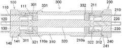
- FIG. 1is a longitudinal sectional view of a connector assembly according to an embodiment of the invention
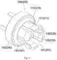
- FIG. 2is a perspective view of an adapter of the connector assembly of FIG. 1 ;
- FIG. 3is an enlarged longitudinal sectional view of the connector assembly of FIG. 1 ;
- FIG. 4is a perspective view of a first receptacle or a second receptacle of the connector assembly of FIG. 1 ;
- FIG. 5is a perspective view of a first insulator or a second insulator of the adapter of FIG. 2 ;
- FIG. 6is an enlarged longitudinal sectional view of a connector assembly according to another embodiment of the invention.
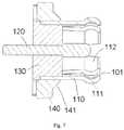
- FIG. 7is a sectional view of a first receptacle of the connector assembly of FIG. 6 ;
- FIG. 8is a sectional view of an end of an adapter of the connector assembly of FIG. 6 ;
- FIG. 9is a perspective view of an insulator of the adapter of FIG. 8 .
- FIGS. 1-5A connector assembly according to the invention is shown in FIGS. 1-5 .
- the connector assemblycomprises an adapter 300 , a first receptacle 100 attached to a first end of the adapter 300 , and a second receptacle 200 attached to an opposite second end of the adapter 300 .
- the adapter 300is shown in FIGS. 1 and 2 and comprises a cylindrical outer conductor 310 , a columnar center conductor 320 disposed in the outer conductor 310 , and an insulator 331 , 332 disposed between the outer conductor 310 and the center conductor 320 to electrically isolate the outer conductor 310 from the center conductor 320 .
- the insulator 331 , 332 of the adapter 300comprises a first insulator 331 mounted on a first end 321 of the center conductor 320 and a second insulator 332 mounted on an opposite second end 322 of the center conductor 320 . Both ends 321 , 322 of the center conductor 320 are supported and held on the insulator 331 , 332 ; the first end 321 of the center conductor 320 is held on the first insulator 331 and the second end 322 of the center conductor 320 is held on the second insulator 322 .
- the first insulator 331 and second insulator 332are identical, as shown in FIG. 5 .
- the first insulator 331 and the second insulator 332each have a columnar shape and an axial positioning passageway 3301 extending through the insulator 331 , 332 . Both ends 321 , 322 of the center conductor 320 are fit into the axial positioning passageways 3301 of the first insulator 331 and the second insulator 332 , respectively.
- the first receptacle 100comprises a cylindrical first outer terminal 110 , a columnar first center terminal 120 disposed in the first outer terminal 110 , and a first insulation body 130 disposed between the first outer terminal 110 and the first center terminal 120 to electrically isolate the first outer terminal 110 from the first center terminal 120 .
- the first outer terminal 110has a first annular protrusion 111 on an outer wall of one end thereof.
- the first outer terminal 110has at least one first axial slit 101 in a first end thereof.
- the at least one first axial slit 101divides the first end of the first outer terminal 110 into a plurality of petals so that the first end of the first outer terminal 110 is formed as a resilient finger with a plurality of petal structures.
- the first receptacle 100further comprises a first insulation housing 140 in which the first outer terminal 110 , the first center terminal 120 and the first insulation body 130 are held.
- the first receptacle 100is adapted to be locked onto a first end of the adapter 300 .
- the outer conductor 310 of the adapter 300has a recess 301 in an inner wall at the first end.
- the first annular protrusion 111 on the outer terminal 110 of the first receptacle 100is adapted to be elastically snap-fit into the recess 301 to lock the first receptacle 100 onto the first end of the adapter 300 .
- the first annular protrusion 111is brought into electrical contact with the inner wall of the outer conductor 310 of the adapter 300 .
- the first end of the first outer terminal 110has an end surface 110 a abutting against the insulators 331 , 332 to prevent the end surface 110 a from electrically contacting the inner wall of the outer conductor 310 .
- the outer conductor 310 of the adapter 300 and the first outer terminal 110 of the first receptacle 100are in electrical contact with each other only through the first annular protrusion 111 .
- the first insulation housing 140is disposed at the first end of the outer conductor 310 and spaced apart therefrom by a predetermined gap.
- the gapallows the outer conductor 310 to deflect with respect to an axial direction of the connector assembly by a predetermined angle.
- the predetermined angleis greater than 0 degrees and less than 15 degrees, greater than 0 degrees and less than 10 degrees, or greater than 0 degrees and less than 5 degrees.
- the outer conductor 310has a conical inner end surface 311 tapered inwardly at the first end thereof and the first insulation housing 140 has a conical outer end surface 141 tapered toward the outer conductor 310 .
- the conical inner end surface 311faces the conical outer end surface 141 and is spaced apart therefrom by the predetermined gap.
- the conical inner end surface 311 of the outer conductor 310abuts the conical outer end surface 141 of the first insulation housing 140 to prevent the first end of the outer conductor 310 from being in electrical contact with the first outer terminal 110 . As described above, this ensures that the outer conductor 310 and the first outer terminal 110 are brought into electrical contact with each other only through the first annular protrusion 111 .
- the first end of the first center terminal 120is inserted into the first end 321 of the center conductor 320 and into electrical contact therewith by sliding.
- the center conductor 320as shown in FIG. 2 , has at least one axial slit 320 a in the first end 321 .
- the at least one axial slit 320 adivides the first end 321 of the center conductor 320 into a plurality of petals so that the first end 321 is a resilient finger with the plurality of petal structures.
- the second receptacle 200is identical to the first receptacle 100 .
- the second receptacle 200comprises a cylindrical second outer terminal 210 , a columnar second center terminal 220 disposed in the second outer terminal 210 , and a second insulation body 230 disposed between the second outer terminal 210 and the second center terminal 220 to electrically isolate the second outer terminal 210 from the second center terminal 220 .
- the second outer terminal 210has a second annular protrusion 211 on an outer wall of a first end thereof.
- the second outer terminal 210has at least one second axial slit 201 in the first end.
- the at least one second axial slit 201divides the first end of the second outer terminal 210 into a plurality of petals so that the first end of the second outer terminal 210 is formed as a resilient finger with a plurality of petal structures.
- a free end of each petalis formed as an arc protrusion protruding outwardly, and a plurality of arc protrusions of the plurality of petals form the second annular protrusion 211 .
- the second receptacle 200further comprises a second insulation housing 240 in which the second outer terminal 210 , the second center terminal 220 and the second insulation body 230 are held.
- the second annular protrusion 211is brought into electrical contact with the inner wall of the outer conductor 310 of the adapter 300 through sliding, as shown in FIG. 1 .
- the first end of the second outer terminal 210has an end surface 210 a abutted against the insulator 322 of the adapter 300 to prevent the end surface 210 a of the first end of the second outer terminal 210 from being in electrical contact with the inner wall of the outer conductor 310 .
- the outer conductor 310 of the adapter 300 and the second outer terminal 210 of the second receptacle 200are in electrical contact with each other only through the second annular protrusion 211 .
- the second insulation housing 240is disposed at the second end of the outer conductor 310 and is spaced apart therefrom by a predetermined gap to allow the outer conductor 310 to be deflectable with respect to the axial direction of the connector assembly by a predetermined angle.
- the predetermined angleis greater than 0 degrees and less than 15 degrees, greater than 0 degrees and less than 10 degrees, or greater than 0 degrees and less than 5 degrees.
- the outer conductor 310has a conical inner end surface 312 tapered inwardly at the second end and the second insulation housing 240 has a conical outer end surface 241 tapered toward the outer conductor 310 .
- the conical inner end surface 312faces the conical outer end surface 241 and is spaced apart therefrom by the predetermined gap.
- the conical inner end surface 312 of the outer conductor 310abuts the conical outer end surface 241 of the second insulation housing 240 to prevent the second end of the outer conductor 310 from being in electrical contact with the second outer terminal 210 .
- thisensures that the outer conductor 310 of the adapter 300 and the second outer terminal 210 of the second receptacle 200 are brought into electrical contact with each other only through the second annular protrusion 211 .
- the second end 321 of the center conductor 320has a cylindrical shape and the first end of the second center terminal 220 is inserted into the second end 322 of the center conductor 320 and into electrical contact therewith through sliding.
- the center conductor 320has at least one axial slit 320 a in the second end 322 .
- the at least one axial slit 320 adivides the second end 322 of the center conductor 320 into a plurality of petals so that the second end 322 of the center conductor 320 is a resilient finger with the plurality of petal structures.
- the first outer terminal 110 and the second outer terminal 210 shown in FIG. 4are each formed by a stamping process.
- the first insulation body 130 , the second insulation body 230 , the first insulation housing 140 , and the second insulation housing 240are each formed by an injection molding process.
- the connector assemblyis a radio frequency (RF) coaxial connector assembly.
- the RF coaxial connectoris adapted to connect two circuit boards so that a RF signal may be transmitted from one circuit board to the other circuit board via the RF coaxial connector assembly.
- FIGS. 6-9A connector assembly according to another embodiment of the invention is shown in FIGS. 6-9 .
- Like reference numbersindicate like elements and only the differences with respect to the embodiment of the connector assembly shown in FIGS. 1-5 will be described in detail herein.
- the insulator 331 of the adapter 300comprises a columnar main body 3310 , a cylindrical extending portion 3311 extending from the columnar main body 3310 , and an annular protrusion 3312 formed on a free end of the cylindrical extending portion 3311 .
- the first outer terminal 110has an annular recess 112 , as shown in FIGS. 6 and 7 , protruding outwardly in an inner wall of the first end.
- the annular protrusion 3312is adapted to be elastically snap-fit into the annular recess 112 to lock the first receptacle 100 onto the first end of the adapter 300 .
- the insulator 331is formed of a plastic material.
- the first annular protrusion 111 on the first end of the first outer terminal 110is opposite to the annular recess 112 in a radial direction of the first outer terminal 110 .
- the annular protrusion 111 and the annular recess 112may be formed at the same position of the first end of the first outer conductor 100 through stamping.
Landscapes
- Engineering & Computer Science (AREA)
- Microelectronics & Electronic Packaging (AREA)
- Coupling Device And Connection With Printed Circuit (AREA)
Abstract
Description
Claims (21)
Applications Claiming Priority (3)
| Application Number | Priority Date | Filing Date | Title |
|---|---|---|---|
| CN201610971286.7ACN108023250B (en) | 2016-11-03 | 2016-11-03 | Adapter, socket and connector combinations |
| CN201610971286 | 2016-11-03 | ||
| CN201610971286.7 | 2016-11-03 |
Publications (2)
| Publication Number | Publication Date |
|---|---|
| US20180124921A1 US20180124921A1 (en) | 2018-05-03 |
| US10973124B2true US10973124B2 (en) | 2021-04-06 |
Family
ID=60244991
Family Applications (1)
| Application Number | Title | Priority Date | Filing Date |
|---|---|---|---|
| US15/802,847ActiveUS10973124B2 (en) | 2016-11-03 | 2017-11-03 | Connector assembly having an adapter to connect two circuit boards |
Country Status (3)
| Country | Link |
|---|---|
| US (1) | US10973124B2 (en) |
| EP (1) | EP3319183A3 (en) |
| CN (1) | CN108023250B (en) |
Cited By (2)
| Publication number | Priority date | Publication date | Assignee | Title |
|---|---|---|---|---|
| US12191601B2 (en)* | 2021-12-07 | 2025-01-07 | Japan Aviation Electronics Industry, Ltd. | Floating connector and floating connector assembly |
| USD1056853S1 (en)* | 2021-11-01 | 2025-01-07 | Gigalane Co., Ltd. | Rf connector |
Families Citing this family (16)
| Publication number | Priority date | Publication date | Assignee | Title |
|---|---|---|---|---|
| US11054472B2 (en)* | 2017-08-23 | 2021-07-06 | Avo Multi-Amp Corporation | Relay test paddle |
| CN110943328B (en)* | 2018-09-21 | 2020-12-22 | 上海雷迪埃电子有限公司 | Radio frequency connector |
| CN109274918A (en)* | 2018-11-15 | 2019-01-25 | 江苏八达电子有限公司 | A CATV connector |
| CN111370901B (en)* | 2018-12-26 | 2022-11-15 | 泰科电子(上海)有限公司 | Connector and socket |
| CN110752462B (en)* | 2019-10-09 | 2025-06-17 | 中航光电科技股份有限公司 | A coaxial connector and its outer conductor |
| CN210326256U (en)* | 2019-10-14 | 2020-04-14 | 罗森伯格亚太电子有限公司 | Board-to-board radio frequency coaxial connector |
| CN112787121A (en) | 2019-11-11 | 2021-05-11 | 康普技术有限责任公司 | Coaxial connector and board-to-board connector assembly |
| EP3869634B1 (en)* | 2020-02-20 | 2023-01-18 | Rohde & Schwarz GmbH & Co. KG | Coaxial connector |
| US11588285B2 (en)* | 2020-06-19 | 2023-02-21 | Te Connectivity Solutions Gmbh | Coaxial connector system with adaptor |
| CN112600035A (en)* | 2020-12-03 | 2021-04-02 | 歌尔科技有限公司 | Connector, control panel and electronic equipment |
| CN214706539U (en)* | 2021-05-18 | 2021-11-12 | 康普技术有限责任公司 | Peripheral device-to-external device connectors for wireless communication devices |
| US12261400B2 (en)* | 2021-10-29 | 2025-03-25 | Rosenberger Hochfrequenztechnik Gmbh & Co. Kg | Electrical plug connector and electrical plug connection |
| EP4552189A1 (en)* | 2022-07-08 | 2025-05-14 | Samtec, Inc. | Electrical interposer |
| JP2024169007A (en)* | 2023-05-25 | 2024-12-05 | 株式会社オートネットワーク技術研究所 | Shielded Connectors |
| JP2024169009A (en)* | 2023-05-25 | 2024-12-05 | 株式会社オートネットワーク技術研究所 | Shielded Connectors |
| WO2025143270A1 (en)* | 2023-12-29 | 2025-07-03 | キーコム株式会社 | Connector, connector assembly, and transmission line connection system |
Citations (7)
| Publication number | Priority date | Publication date | Assignee | Title |
|---|---|---|---|---|
| US4925403A (en)* | 1988-10-11 | 1990-05-15 | Gilbert Engineering Company, Inc. | Coaxial transmission medium connector |
| US5074809A (en)* | 1989-01-20 | 1991-12-24 | Alliance Technique Industrielle | Ultraminiature high-frequency connection interface |
| US6227868B1 (en)* | 2000-05-05 | 2001-05-08 | Antoine Wlodarski | Coaxial cable connector |
| US6663397B1 (en)* | 2002-09-25 | 2003-12-16 | Hon Hai Precision Ind. Co., Ltd. | Electrical connector |
| US20070275584A1 (en)* | 2006-05-23 | 2007-11-29 | Micro-Coax, Inc. | Cable interconnect |
| US7500873B1 (en)* | 2008-05-16 | 2009-03-10 | Corning Gilbert Inc. | Snap-on coaxial cable connector |
| US20110237123A1 (en)* | 2010-03-29 | 2011-09-29 | Donald Andrew Burris | Digital, Small Signal and RF Microwave Coaxial Subminiature Push-on Differential Pair System |
Family Cites Families (10)
| Publication number | Priority date | Publication date | Assignee | Title |
|---|---|---|---|---|
| US4632487A (en)* | 1986-01-13 | 1986-12-30 | Brunswick Corporation | Electrical lead retainer with compression seal |
| US6224421B1 (en)* | 2000-02-29 | 2001-05-01 | Palco Connector, Inc. | Multi-part connector |
| CN201247879Y (en)* | 2008-08-27 | 2009-05-27 | 宁波市吉品信息科技有限公司 | Plate-to-plate concentration mounting type RF coaxial connector |
| US8597050B2 (en)* | 2009-12-21 | 2013-12-03 | Corning Gilbert Inc. | Digital, small signal and RF microwave coaxial subminiature push-on differential pair system |
| BR112012018469A2 (en)* | 2010-01-25 | 2016-04-12 | Huber+Suhner Ag | circuit board coaxial connector |
| CN101964463A (en)* | 2010-11-10 | 2011-02-02 | 上海航天科工电器研究院有限公司 | Radio frequency connector |
| CN202067955U (en)* | 2011-03-16 | 2011-12-07 | 泰科电子(上海)有限公司 | Coaxial connector combination and plate-to-plate coaxial connector combination |
| CN204257981U (en)* | 2014-11-12 | 2015-04-08 | 西安富士达科技股份有限公司 | A kind of radio frequency connector |
| DE202015007010U1 (en)* | 2015-10-07 | 2015-10-22 | Rosenberger Hochfrequenztechnik Gmbh & Co. Kg | Interconnects |
| CN206412597U (en)* | 2016-11-03 | 2017-08-15 | 泰科电子(上海)有限公司 | adapter, socket and connector combination |
- 2016
- 2016-11-03CNCN201610971286.7Apatent/CN108023250B/enactiveActive
- 2017
- 2017-11-03USUS15/802,847patent/US10973124B2/enactiveActive
- 2017-11-03EPEP17199920.4Apatent/EP3319183A3/ennot_activeWithdrawn
Patent Citations (7)
| Publication number | Priority date | Publication date | Assignee | Title |
|---|---|---|---|---|
| US4925403A (en)* | 1988-10-11 | 1990-05-15 | Gilbert Engineering Company, Inc. | Coaxial transmission medium connector |
| US5074809A (en)* | 1989-01-20 | 1991-12-24 | Alliance Technique Industrielle | Ultraminiature high-frequency connection interface |
| US6227868B1 (en)* | 2000-05-05 | 2001-05-08 | Antoine Wlodarski | Coaxial cable connector |
| US6663397B1 (en)* | 2002-09-25 | 2003-12-16 | Hon Hai Precision Ind. Co., Ltd. | Electrical connector |
| US20070275584A1 (en)* | 2006-05-23 | 2007-11-29 | Micro-Coax, Inc. | Cable interconnect |
| US7500873B1 (en)* | 2008-05-16 | 2009-03-10 | Corning Gilbert Inc. | Snap-on coaxial cable connector |
| US20110237123A1 (en)* | 2010-03-29 | 2011-09-29 | Donald Andrew Burris | Digital, Small Signal and RF Microwave Coaxial Subminiature Push-on Differential Pair System |
Cited By (2)
| Publication number | Priority date | Publication date | Assignee | Title |
|---|---|---|---|---|
| USD1056853S1 (en)* | 2021-11-01 | 2025-01-07 | Gigalane Co., Ltd. | Rf connector |
| US12191601B2 (en)* | 2021-12-07 | 2025-01-07 | Japan Aviation Electronics Industry, Ltd. | Floating connector and floating connector assembly |
Also Published As
| Publication number | Publication date |
|---|---|
| CN108023250A (en) | 2018-05-11 |
| EP3319183A3 (en) | 2018-07-25 |
| CN108023250B (en) | 2023-12-15 |
| US20180124921A1 (en) | 2018-05-03 |
| EP3319183A2 (en) | 2018-05-09 |
Similar Documents
| Publication | Publication Date | Title |
|---|---|---|
| US10973124B2 (en) | Connector assembly having an adapter to connect two circuit boards | |
| US10931051B2 (en) | Connector and receptacle | |
| US9236694B2 (en) | Coaxial, plug and socket connectors with precision centering means | |
| EP3547459B1 (en) | Board mating connector in which signal contact unit and ground contact unit are interlocked | |
| EP3696922B1 (en) | Coaxial connector | |
| US9484688B2 (en) | Printed circuit board coaxial connector | |
| US7112078B2 (en) | Gimbling electronic connector | |
| EP3547460B1 (en) | Board mating connector | |
| US10553977B2 (en) | Electrical plug connector | |
| US20160164233A1 (en) | Float adapter for electrical connector and method for making the same | |
| US12184024B2 (en) | Coaxial electrical connector adapter and electrical connector test system | |
| US11437760B2 (en) | Floating coaxial connector with a stabilizing ring at the mating end | |
| US20150093935A1 (en) | Insulation body of a plug-in connector | |
| CN206412597U (en) | adapter, socket and connector combination | |
| US20230238752A1 (en) | Coaxial connector with an improved locking structure | |
| US12126125B2 (en) | Low passive intermodulation connector system | |
| EP3783745A1 (en) | Quick lock rf connector | |
| CN103972690B (en) | A kind of cluster connector | |
| US20240297465A1 (en) | Outer conductor contact for a connector and connector | |
| CN107528151B (en) | Connector plug | |
| WO2024056442A1 (en) | Electrical connector assembly | |
| HK1104876B (en) | Coaxial plug connector with quick-acting closure |
Legal Events
| Date | Code | Title | Description |
|---|---|---|---|
| FEPP | Fee payment procedure | Free format text:ENTITY STATUS SET TO UNDISCOUNTED (ORIGINAL EVENT CODE: BIG.); ENTITY STATUS OF PATENT OWNER: LARGE ENTITY | |
| AS | Assignment | Owner name:TYCO ELECTRONICS (SHANGHAI) CO. LTD., CHINA Free format text:ASSIGNMENT OF ASSIGNORS INTEREST;ASSIGNORS:SONG, ZHIGANG;NI, LIN;CHEN, JLAHUI;AND OTHERS;REEL/FRAME:044985/0162 Effective date:20180122 | |
| STPP | Information on status: patent application and granting procedure in general | Free format text:RESPONSE TO NON-FINAL OFFICE ACTION ENTERED AND FORWARDED TO EXAMINER | |
| STPP | Information on status: patent application and granting procedure in general | Free format text:FINAL REJECTION MAILED | |
| STPP | Information on status: patent application and granting procedure in general | Free format text:ADVISORY ACTION MAILED | |
| STPP | Information on status: patent application and granting procedure in general | Free format text:NON FINAL ACTION MAILED | |
| STPP | Information on status: patent application and granting procedure in general | Free format text:RESPONSE TO NON-FINAL OFFICE ACTION ENTERED AND FORWARDED TO EXAMINER | |
| STPP | Information on status: patent application and granting procedure in general | Free format text:FINAL REJECTION MAILED | |
| STPP | Information on status: patent application and granting procedure in general | Free format text:RESPONSE AFTER FINAL ACTION FORWARDED TO EXAMINER | |
| STPP | Information on status: patent application and granting procedure in general | Free format text:NON FINAL ACTION MAILED | |
| STPP | Information on status: patent application and granting procedure in general | Free format text:PUBLICATIONS -- ISSUE FEE PAYMENT RECEIVED | |
| STPP | Information on status: patent application and granting procedure in general | Free format text:PUBLICATIONS -- ISSUE FEE PAYMENT VERIFIED | |
| STCF | Information on status: patent grant | Free format text:PATENTED CASE | |
| MAFP | Maintenance fee payment | Free format text:PAYMENT OF MAINTENANCE FEE, 4TH YEAR, LARGE ENTITY (ORIGINAL EVENT CODE: M1551); ENTITY STATUS OF PATENT OWNER: LARGE ENTITY Year of fee payment:4 |