US10971794B2 - Antenna mounting bracket assembly - Google Patents
Antenna mounting bracket assemblyDownload PDFInfo
- Publication number
- US10971794B2 US10971794B2US16/048,998US201816048998AUS10971794B2US 10971794 B2US10971794 B2US 10971794B2US 201816048998 AUS201816048998 AUS 201816048998AUS 10971794 B2US10971794 B2US 10971794B2
- Authority
- US
- United States
- Prior art keywords
- antenna
- mounting bracket
- hooks
- panel
- antenna assembly
- Prior art date
- Legal status (The legal status is an assumption and is not a legal conclusion. Google has not performed a legal analysis and makes no representation as to the accuracy of the status listed.)
- Expired - Fee Related, expires
Links
Images


Classifications
- H—ELECTRICITY
- H01—ELECTRIC ELEMENTS
- H01Q—ANTENNAS, i.e. RADIO AERIALS
- H01Q1/00—Details of, or arrangements associated with, antennas
- H01Q1/12—Supports; Mounting means
- H01Q1/1242—Rigid masts specially adapted for supporting an aerial
- H—ELECTRICITY
- H01—ELECTRIC ELEMENTS
- H01Q—ANTENNAS, i.e. RADIO AERIALS
- H01Q1/00—Details of, or arrangements associated with, antennas
- H01Q1/12—Supports; Mounting means
- H01Q1/1207—Supports; Mounting means for fastening a rigid aerial element
- H01Q1/1228—Supports; Mounting means for fastening a rigid aerial element on a boom
- H—ELECTRICITY
- H01—ELECTRIC ELEMENTS
- H01Q—ANTENNAS, i.e. RADIO AERIALS
- H01Q21/00—Antenna arrays or systems
- H01Q21/0006—Particular feeding systems
- H01Q21/0025—Modular arrays
- H—ELECTRICITY
- H01—ELECTRIC ELEMENTS
- H01Q—ANTENNAS, i.e. RADIO AERIALS
- H01Q1/00—Details of, or arrangements associated with, antennas
- H01Q1/12—Supports; Mounting means
- H01Q1/22—Supports; Mounting means by structural association with other equipment or articles
- H01Q1/24—Supports; Mounting means by structural association with other equipment or articles with receiving set
- H01Q1/241—Supports; Mounting means by structural association with other equipment or articles with receiving set used in mobile communications, e.g. GSM
- H01Q1/246—Supports; Mounting means by structural association with other equipment or articles with receiving set used in mobile communications, e.g. GSM specially adapted for base stations
- H—ELECTRICITY
- H01—ELECTRIC ELEMENTS
- H01Q—ANTENNAS, i.e. RADIO AERIALS
- H01Q1/00—Details of, or arrangements associated with, antennas
- H01Q1/42—Housings not intimately mechanically associated with radiating elements, e.g. radome
Definitions
- the present inventionis directed to an assembly to mount an antenna to a mounting structure.
- Antennas for wireless communicationsare typically mounted on an antenna tower or other elevated mounting structure, for example a street pole.
- a majority of these antennasare secured to the mounting structure through use of a bolted mechanical connection.
- the limited space between the antennas and the mounting structuremakes installation and maintenance at times difficult for a technician. Having an additional way to further secure the antennas to the mounting structure may also be beneficial from a safety perspective.
- inventions of the inventionare directed to an, antenna assembly.
- the antenna assemblycomprises: an antenna; a first mounting bracket mounted to the antenna comprising a first panel and a first plurality of hooks, wherein the first plurality of hooks is configured to secure the first mounting bracket to a mounting structure; and a second mounting bracket mounted, to the antenna comprising a second panel and a second plurality of hooks, wherein the second plurality of hooks is configured to secure the second mounting bracket to the mounting structure.
- the first mounting bracket and the second mounting bracketare configured to secure the antenna to the mounting structure.
- embodiments of the inventionare directed to an antenna assembly comprising: an antenna; a mounting structure; a first mounting bracket mounted to the antenna comprising a first panel and a first plurality of hooks; and a second mounting bracket mounted to the antenna comprising a second panel and a second plurality of hooks.
- the first and second pluralities of hooksare inserted into pre-formed holes in the mounting structure.
- an antenna assemblycomprising: three antennas; a mounting structure; a first mounting bracket mounted to each antenna, wherein each first mounting bracket comprises a first panel and a first plurality of hooks; and a second mounting bracket mounted to each antenna, wherein each second mounting bracket comprises a second panel and a second plurality of hooks.
- the antennasare secured to the mounting structure when the first and second pluralities of hooks of each respective antenna are inserted into pre-formed holes in the mounting structure.
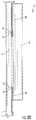
- FIG. 1is a side view of an antenna assembly according to embodiments of the present invention.
- FIG. 2is a perspective view of the upper mounting bracket of the antenna assembly of FIG. 1 ,
- FIG. 3is a perspective view of the lower mounting bracket of the antenna assembly of FIG. 1 .
- FIG. 4is a side view of the upper mounting bracket of the antenna assembly of FIG. 1 .
- FIG. 5is a side view of the lower mounting bracket of the antenna assembly or FIG. 1 .
- FIG. 6is a top view of upper mounting bracket of the antenna assembly of FIG. 1 .
- FIG. 7is a top view of the lower mounting bracket of the antenna assembly of FIG. 1 .
- FIGS. 8A-Dis a side view of an antenna assembly secured to a mounting bracket according, to embodiments of the present invention.
- FIG. 9is a perspective view showing three antennas using an antenna assembly according to embodiments of the present invention.
- FIG. 10is a perspective view of the antenna assembly of FIG. 9 with cables attached thereto.
- FIG. 11is a top perspective view of the antenna assembly of FIG. 9 showing attachment of the upper mounting brackets to a pole via a cap.
- FIG. 12is an enlarged partial perspective view of the antenna assembly of FIG. 9 showing attachment of the lower brackets to a pole via a band clamp.
- FIGS. 1-12an antenna assembly 10 for mounting an antenna 12 is illustrated in FIGS. 1-12 .
- the antenna assembly 10is described herein in connection with antennas attached to a street pole. This particular application is described for exemplary purposes only.
- the antenna assembly 10may be used to secure other types of antennas to different types of structures.
- the antenna assembly 10comprises a first upper mounting bracket 20 and second lower mounting bracket 30 ( FIG. 1 ).
- the upper and lower mounting brackets 20 , 30are mounted to an antenna 12 and are configured to secure the antenna 12 to a mounting structure 14 , such as a street pole or the like.
- the upper mounting bracket 20comprises a panel 24 and two hooks 22 ( FIG. 2 ).
- the hooks 22are configured to secure the upper mounting bracket 20 to the mounting structure 14 ( FIG. 1 ).
- the lower mounting bracket 30also comprises a panel 34 and two hooks 32 ( FIG. 3 ).
- the hooks 32are configured to secure the lower mounting bracket to the mounting structure 14 ( FIG. 1 ).
- the present inventionis not limited to the number of hooks 22 , 32 that may be, used. Any number of hooks 22 , 32 may be used to secure the antenna 12 to a mounting structure 14 .
- the panels 24 , 34may comprise holes 28 , 38 .
- the holes 28 , 38reduce the overall weight of the upper and lower mounting brackets 20 , 30 . Reducing the overall weight has many advantages including, but not limited to, ease of use and cost savings.
- These holes 28 , 38can take the form of a variety of different shapes (e.g., holes, slots) and sizes, so long as the structural integrity of the brackets 20 , 30 is not affected.
- brackets 20 , 30are shown as separate brackets; however, the brackets 20 , 30 may form a monolithic structure.
- the hooks 22 , 32are configured to be inserted into pre-formed holes 16 in the mounting structure 14 ( FIGS. 4 and 5 ). Once the hooks 22 , 32 are inserted into the pre-formed holes 16 , the antenna 12 becomes secured to the mounting structure 14 ( FIGS. 8A-D ).
- the hooks 22 , 32can take the form of a variety of different shapes and sizes and are not limited to the shapes and sizes as illustrated in FIGS. 2 and 3 .
- the shape and size of the hooks 22 , 32may be dependent on the shape and size of the pre-formed holes 16 or vice versa. Alternatively, other latching mechanisms may be used.
- each of the hooks 22may be configured at an angle (A) greater than 90 degrees with respect to the panel 24 of the upper mounting bracket 20 ( FIG. 6 ).
- the angle (A)may match the curvature of the mounting structure 14 which allows the hooks 22 to more easily latch onto the mounting structure 14 when inserted into the pre-formed holes 16 , thus, improving the mounting of the antenna 12 to the mounting structure 14 .
- each of the hooks 22may be perpendicular to the panel 24 (i.e., 90 degrees).
- the hooks 32may be configured at an angle (A) greater than 90 degrees with respect to the panel 34 of the lower mounting bracket 30 ( FIG. 7 ). Similar to the hooks 22 , the angle (A) may match the curvature of the mounting structure 14 which allows the hooks 32 to more easily latch onto the mounting structure 14 when inserted into the pre-formed holes 16 improving the mounting of the antenna 12 to the mounting structure 14 . In some embodiments, each of the hooks 32 may be perpendicular to the panel 34 (i.e., 90 degrees).
- the upper mounting bracket 20further comprises a flange 26 that is perpendicular to the panel 24 ( FIG. 2 ).
- the flange 26is configured to further secure the upper mounting, bracket 20 to the mounting structure 14 in the manner discussed below ( FIGS. 8A-C ).
- the lower mounting bracket 30further comprises an extension 36 that is parallel to the panel 34 ( FIG. 3 ).
- the extension 36is configured to further secure the lower mounting bracket 30 to the mounting structure 14 in the manner discussed below.
- Each antenna 12can be mounted on the mounting structure 14 to form a complete antenna system 200 with full coverage ( FIG. 9 ).
- each antenna 12is secured to the mounting structure 14 by inserting the hooks 22 , 32 into the pre-formed holes 16 in the mounting structure 14 .
- holes 16can be created in the field to accommodate the mounting brackets 20 , 30 of the present invention.
- each antenna 12further comprises a flange 26 that is perpendicular to the panel 24 .
- Each flange 26may be secured by a cap 50 or other securing device mounted on the top portion of the mounting structure 14 ( FIGS. 8A-C and 11 ). This configuration helps further secure each respective antenna 12 to the mounting structure 14 .
- each antenna 12further comprises an extension 36 that is parallel to the panel 34 .
- Each extension 36may be secured to the mounting structure 14 via a band clamp 60 ( FIG. 12 ) or other securing device. This configuration helps further secure each respective antenna 12 to the mounting structure 14 .
- the dimensions of the upper and lower mounting brackets 20 , 30can vary based on the size of the antenna 12 and mounting structure 14 to which the antenna 12 is being mounted.
- the upper mounting bracket 20may be about 720 millimeters by about 125 millimeters.
- the lower mounting bracket 30may be about 410 millimeters (including extension 26 ) by about 125 millimeters.
- the hooks 22 , 32may extend about 28 millimeters from the panels 24 , 34 .
- brackets 20 , 30comprising two hooks 22 , 32
- the hooks 22 , 32may be about 70 millimeters apart from each other.
- the spacing of the hooks 22 , 32can vary based on the dimensions (e.g., diameter) of the mounting structure 14 .
- the typical diameter of the mounting structure 14may be about 127 millimeters.
- each of the three antennas 12when each of the three antennas 12 is secured to the mounting structure 14 , the side edge of each antenna may be immediately adjacent to a side edge of an adjacent antenna 12 ( FIGS. 10 and 11 ). In some embodiments, between the side edges of each antenna 12 is a small gap (G).
- the gap (G)may be between about 0 millimeters and about 20 millimeters.
- the gap (G)can vary based on the type of antenna 12 being used. Because of the limited space between the antennas 12 , use of the upper and lower mounting brackets 20 , 30 may significantly facilitate mounting of the antennas 12 .
- the antenna assemblies of the present inventioncan be formed from a variety of materials that can withstand a wide range of environmental conditions, but the mounting brackets must be comprised from a material that is able to at least support the weight of the antenna(s).
- the antenna assembliesmay be formed from galvanized steel, stainless steel, or the like.
Landscapes
- Support Of Aerials (AREA)
Abstract
Description
Claims (18)
Priority Applications (1)
| Application Number | Priority Date | Filing Date | Title |
|---|---|---|---|
| US16/048,998US10971794B2 (en) | 2017-08-15 | 2018-07-30 | Antenna mounting bracket assembly |
Applications Claiming Priority (2)
| Application Number | Priority Date | Filing Date | Title |
|---|---|---|---|
| US201762545537P | 2017-08-15 | 2017-08-15 | |
| US16/048,998US10971794B2 (en) | 2017-08-15 | 2018-07-30 | Antenna mounting bracket assembly |
Publications (2)
| Publication Number | Publication Date |
|---|---|
| US20190058239A1 US20190058239A1 (en) | 2019-02-21 |
| US10971794B2true US10971794B2 (en) | 2021-04-06 |
Family
ID=65361444
Family Applications (1)
| Application Number | Title | Priority Date | Filing Date |
|---|---|---|---|
| US16/048,998Expired - Fee RelatedUS10971794B2 (en) | 2017-08-15 | 2018-07-30 | Antenna mounting bracket assembly |
Country Status (3)
| Country | Link |
|---|---|
| US (1) | US10971794B2 (en) |
| GB (1) | GB2579977B8 (en) |
| WO (1) | WO2019036175A1 (en) |
Cited By (2)
| Publication number | Priority date | Publication date | Assignee | Title |
|---|---|---|---|---|
| US11316267B2 (en)* | 2018-12-05 | 2022-04-26 | Commscope Technologies Llc | Devices and methods for mitigating external passive intermodulation sources in base station antennas |
| US20220264757A1 (en)* | 2021-02-12 | 2022-08-18 | Gary Barbosa | Modular electrical equipment storage assembly |
Families Citing this family (6)
| Publication number | Priority date | Publication date | Assignee | Title |
|---|---|---|---|---|
| US10897070B2 (en)* | 2018-08-01 | 2021-01-19 | Wilson Electronics, Llc | Connect RV mount |
| CN111799541B (en)* | 2019-04-08 | 2025-08-05 | 户外无线网络有限公司 | Antenna mounting device |
| US11626655B2 (en)* | 2020-10-06 | 2023-04-11 | Dish Wireless L.L.C. | Apparatus for mounting a transceiver radio unit to a component of a cellular communication system |
| US11837772B2 (en) | 2021-03-25 | 2023-12-05 | Commscope Technologies Llc | Modules for cellular base stations and bracket assemblies for mounting same |
| US12056565B2 (en)* | 2022-01-14 | 2024-08-06 | Zebra Technologies Corporation | Structural isolation of RFID antenna |
| CN116845528A (en)* | 2022-03-23 | 2023-10-03 | 康普技术有限责任公司 | Mounting device for base station antenna and base station antenna system |
Citations (36)
| Publication number | Priority date | Publication date | Assignee | Title |
|---|---|---|---|---|
| US4287519A (en)* | 1980-04-04 | 1981-09-01 | The United States Of America As Represented By The Secretary Of The Navy | Multi-mode Luneberg lens antenna |
| US5641141A (en)* | 1994-10-06 | 1997-06-24 | At&T Wireless Services, Inc. | Antenna mounting system |
| US5787673A (en)* | 1992-09-14 | 1998-08-04 | Pirod, Inc. | Antenna support with multi-direction adjustability |
| US6002374A (en)* | 1998-04-20 | 1999-12-14 | Melvin Nicholas | Disk antenna |
| US6045103A (en)* | 1998-07-17 | 2000-04-04 | Lucent Technologies, Inc. | Multiple axis bracket with keyed mount |
| US6111553A (en)* | 1997-10-07 | 2000-08-29 | Steenbuck; Wendel F. | Adjustable antenna bracket |
| US6126128A (en)* | 1998-11-20 | 2000-10-03 | Lucent Technologies Inc. | Adjustable mounting bracket |
| US6232928B1 (en)* | 2000-02-03 | 2001-05-15 | Ems Technologies, Inc. | Antenna mounting bracket assembly |
| US6273377B1 (en)* | 1998-05-29 | 2001-08-14 | Lucent Technologies Inc. | Device for fixing antenna |
| US6361007B1 (en)* | 2000-01-14 | 2002-03-26 | Xircom Wireless, Inc. | Mounting bracket for PCS and other antennas |
| US20040108963A1 (en)* | 2002-08-20 | 2004-06-10 | Aerosat Corporation | Communication system with broadband antenna |
| US6768474B2 (en)* | 2002-12-20 | 2004-07-27 | Spx Corporation | Antenna mounting assembly and method |
| US6766992B1 (en)* | 2003-04-24 | 2004-07-27 | The United States Of America As Represented By The Secretary Of The Navy | Mounting bracket for attachment to flat or cylindrical surfaces |
| US7027006B2 (en)* | 2003-09-24 | 2006-04-11 | Echostar Technologies Corporation | Apparatus and method for mounting a satellite dish to a pole |
| US7106273B1 (en) | 1998-12-21 | 2006-09-12 | Samsung Electronics Co., Ltd. | Antenna mounting apparatus |
| US20070001919A1 (en)* | 2004-12-01 | 2007-01-04 | Carroll Niallo D | Antenna assembly |
| US7161554B2 (en)* | 2003-10-30 | 2007-01-09 | Cushcraft Corporation | System and method for securing an antenna |
| US20070273598A1 (en)* | 2004-02-06 | 2007-11-29 | Masatoshi Kuroda | Luneberg Lens Antenna Device |
| US20090315804A1 (en)* | 2008-06-20 | 2009-12-24 | Dish Network L.L.C. | Structures and methods for mounting an antenna |
| KR20100034351A (en) | 2008-09-23 | 2010-04-01 | 알트론 주식회사 | Fixing apparatus |
| KR20110065959A (en) | 2009-12-10 | 2011-06-16 | 홍광희 | Eco-Friendly Antenna |
| US8011628B1 (en)* | 2007-10-09 | 2011-09-06 | Dennis P. Suddeth | Remote reading meter bracket |
| US20120211627A1 (en)* | 2011-02-23 | 2012-08-23 | Ming-Chan Lee | Clamp structure |
| US20150091777A1 (en)* | 2012-06-22 | 2015-04-02 | Andrew Llc | Antenna Radome With Removeably Connected Electronics Module |
| US20150144758A1 (en)* | 2012-05-18 | 2015-05-28 | Fasmetrics S.A. | Apparatus and method for accurate and precise positioning of cellular antennas |
| US9123987B2 (en)* | 2012-07-31 | 2015-09-01 | Dish Network L.L.C. | Antenna mounting systems and methods |
| US9196177B2 (en)* | 2011-06-29 | 2015-11-24 | Wild August Llc | Display for multiple types of door handles |
| US9303811B1 (en) | 2014-02-11 | 2016-04-05 | Cisco Technology, Inc. | Configurable mounting bracket for mounting rail installations |
| US20160261030A1 (en)* | 2013-11-18 | 2016-09-08 | Kmw Inc. | Antenna device of base station |
| US20160352042A1 (en)* | 2015-05-27 | 2016-12-01 | Amphenol Corporation | Integrated antenna unit with blind mate interconnect |
| US20160365618A1 (en)* | 2014-02-24 | 2016-12-15 | Kmw Inc. | Multi-band antenna apparatus |
| US20170062944A1 (en)* | 2015-08-27 | 2017-03-02 | Commscope Technologies Llc | Lensed antennas for use in cellular and other communications systems |
| US20180026327A1 (en)* | 2016-07-25 | 2018-01-25 | Commscope Technologies Llc | Integrated cell site sector |
| US9882260B2 (en)* | 2012-06-15 | 2018-01-30 | Kathrein-Werke Kg | Retainer system for a mobile-telephony antenna and a mobile-telephony component |
| US10044091B2 (en)* | 2015-05-14 | 2018-08-07 | Micro Wireless Solutions, Corp. | Antenna equipment mount |
| US10439272B1 (en)* | 2015-11-23 | 2019-10-08 | Ethertronics, Inc. | Beam steering system configured for multi-client network |
Family Cites Families (4)
| Publication number | Priority date | Publication date | Assignee | Title |
|---|---|---|---|---|
| FR2818810A1 (en)* | 2000-12-22 | 2002-06-28 | Coprebat | Adjustable antenna mount has separate orthogonal settings can be set from ground |
| KR100373686B1 (en)* | 2001-01-31 | 2003-02-25 | 삼성전자주식회사 | A portable computer having external antenna |
| FR2889624B1 (en)* | 2005-08-08 | 2009-10-30 | Luigi Pillosio | MAT ENCLICABLE RADIO COMMUNICATION ANTENNA SUPPORT |
| CN103647135B (en)* | 2013-12-24 | 2017-03-01 | 威海北洋电气集团股份有限公司 | Bookshelf antenna fixing device and the bookshelf based on RFID technology of identification |
- 2018
- 2018-07-27GBGB2003693.5Apatent/GB2579977B8/enactiveActive
- 2018-07-27WOPCT/US2018/044011patent/WO2019036175A1/ennot_activeCeased
- 2018-07-30USUS16/048,998patent/US10971794B2/ennot_activeExpired - Fee Related
Patent Citations (39)
| Publication number | Priority date | Publication date | Assignee | Title |
|---|---|---|---|---|
| US4287519A (en)* | 1980-04-04 | 1981-09-01 | The United States Of America As Represented By The Secretary Of The Navy | Multi-mode Luneberg lens antenna |
| US5787673A (en)* | 1992-09-14 | 1998-08-04 | Pirod, Inc. | Antenna support with multi-direction adjustability |
| US5641141A (en)* | 1994-10-06 | 1997-06-24 | At&T Wireless Services, Inc. | Antenna mounting system |
| US6111553A (en)* | 1997-10-07 | 2000-08-29 | Steenbuck; Wendel F. | Adjustable antenna bracket |
| US6002374A (en)* | 1998-04-20 | 1999-12-14 | Melvin Nicholas | Disk antenna |
| US6273377B1 (en)* | 1998-05-29 | 2001-08-14 | Lucent Technologies Inc. | Device for fixing antenna |
| US6045103A (en)* | 1998-07-17 | 2000-04-04 | Lucent Technologies, Inc. | Multiple axis bracket with keyed mount |
| US6126128A (en)* | 1998-11-20 | 2000-10-03 | Lucent Technologies Inc. | Adjustable mounting bracket |
| US7106273B1 (en) | 1998-12-21 | 2006-09-12 | Samsung Electronics Co., Ltd. | Antenna mounting apparatus |
| US6361007B1 (en)* | 2000-01-14 | 2002-03-26 | Xircom Wireless, Inc. | Mounting bracket for PCS and other antennas |
| US6232928B1 (en)* | 2000-02-03 | 2001-05-15 | Ems Technologies, Inc. | Antenna mounting bracket assembly |
| US20040108963A1 (en)* | 2002-08-20 | 2004-06-10 | Aerosat Corporation | Communication system with broadband antenna |
| US6768474B2 (en)* | 2002-12-20 | 2004-07-27 | Spx Corporation | Antenna mounting assembly and method |
| US6766992B1 (en)* | 2003-04-24 | 2004-07-27 | The United States Of America As Represented By The Secretary Of The Navy | Mounting bracket for attachment to flat or cylindrical surfaces |
| US7027006B2 (en)* | 2003-09-24 | 2006-04-11 | Echostar Technologies Corporation | Apparatus and method for mounting a satellite dish to a pole |
| US7161554B2 (en)* | 2003-10-30 | 2007-01-09 | Cushcraft Corporation | System and method for securing an antenna |
| US20070273598A1 (en)* | 2004-02-06 | 2007-11-29 | Masatoshi Kuroda | Luneberg Lens Antenna Device |
| US20070001919A1 (en)* | 2004-12-01 | 2007-01-04 | Carroll Niallo D | Antenna assembly |
| US8011628B1 (en)* | 2007-10-09 | 2011-09-06 | Dennis P. Suddeth | Remote reading meter bracket |
| US20090315804A1 (en)* | 2008-06-20 | 2009-12-24 | Dish Network L.L.C. | Structures and methods for mounting an antenna |
| KR20100034351A (en) | 2008-09-23 | 2010-04-01 | 알트론 주식회사 | Fixing apparatus |
| KR20110065959A (en) | 2009-12-10 | 2011-06-16 | 홍광희 | Eco-Friendly Antenna |
| US20120211627A1 (en)* | 2011-02-23 | 2012-08-23 | Ming-Chan Lee | Clamp structure |
| US9196177B2 (en)* | 2011-06-29 | 2015-11-24 | Wild August Llc | Display for multiple types of door handles |
| US9893410B2 (en)* | 2012-05-18 | 2018-02-13 | Fasmetrics S.A. | Apparatus and method for accurate and precise positioning of cellular antennas |
| US20150144758A1 (en)* | 2012-05-18 | 2015-05-28 | Fasmetrics S.A. | Apparatus and method for accurate and precise positioning of cellular antennas |
| US9882260B2 (en)* | 2012-06-15 | 2018-01-30 | Kathrein-Werke Kg | Retainer system for a mobile-telephony antenna and a mobile-telephony component |
| US9325061B2 (en) | 2012-06-22 | 2016-04-26 | Commscope Technologies Llc | Antenna radome with removeably connected electronics module |
| US20150091777A1 (en)* | 2012-06-22 | 2015-04-02 | Andrew Llc | Antenna Radome With Removeably Connected Electronics Module |
| US9123987B2 (en)* | 2012-07-31 | 2015-09-01 | Dish Network L.L.C. | Antenna mounting systems and methods |
| US20160261030A1 (en)* | 2013-11-18 | 2016-09-08 | Kmw Inc. | Antenna device of base station |
| US9303811B1 (en) | 2014-02-11 | 2016-04-05 | Cisco Technology, Inc. | Configurable mounting bracket for mounting rail installations |
| US20160365618A1 (en)* | 2014-02-24 | 2016-12-15 | Kmw Inc. | Multi-band antenna apparatus |
| US10044091B2 (en)* | 2015-05-14 | 2018-08-07 | Micro Wireless Solutions, Corp. | Antenna equipment mount |
| US20160352042A1 (en)* | 2015-05-27 | 2016-12-01 | Amphenol Corporation | Integrated antenna unit with blind mate interconnect |
| US20170062944A1 (en)* | 2015-08-27 | 2017-03-02 | Commscope Technologies Llc | Lensed antennas for use in cellular and other communications systems |
| US10439272B1 (en)* | 2015-11-23 | 2019-10-08 | Ethertronics, Inc. | Beam steering system configured for multi-client network |
| US20180026327A1 (en)* | 2016-07-25 | 2018-01-25 | Commscope Technologies Llc | Integrated cell site sector |
| US10218046B2 (en)* | 2016-07-25 | 2019-02-26 | Commscope Technologies Llc | Integrated cell site sector |
Non-Patent Citations (2)
| Title |
|---|
| International Preliminary Report on Patentability corresponding to International Application No. PCT/US2018/044011 dated Feb. 27, 2020. |
| Notification of Transmittal of the International Search Report and the Written Opinion of the International Searching Authority, or the Declaration corresponding to International Application No. PCT/US2018/044011 dated Nov. 12, 2018. |
Cited By (3)
| Publication number | Priority date | Publication date | Assignee | Title |
|---|---|---|---|---|
| US11316267B2 (en)* | 2018-12-05 | 2022-04-26 | Commscope Technologies Llc | Devices and methods for mitigating external passive intermodulation sources in base station antennas |
| US20220264757A1 (en)* | 2021-02-12 | 2022-08-18 | Gary Barbosa | Modular electrical equipment storage assembly |
| US12289850B2 (en)* | 2021-02-12 | 2025-04-29 | Gary Barbosa | Modular electrical equipment storage assembly |
Also Published As
| Publication number | Publication date |
|---|---|
| WO2019036175A1 (en) | 2019-02-21 |
| GB2579977B (en) | 2022-07-20 |
| GB2579977B8 (en) | 2023-07-19 |
| US20190058239A1 (en) | 2019-02-21 |
| GB2579977A8 (en) | 2023-07-19 |
| GB202003693D0 (en) | 2020-04-29 |
| GB2579977A (en) | 2020-07-08 |
Similar Documents
| Publication | Publication Date | Title |
|---|---|---|
| US10971794B2 (en) | Antenna mounting bracket assembly | |
| EP3427558B1 (en) | Universal rru mounting assembly | |
| US11159006B2 (en) | Brackets for mounting antenna cables | |
| US5320312A (en) | Cable cluster mount | |
| US9882260B2 (en) | Retainer system for a mobile-telephony antenna and a mobile-telephony component | |
| EP2797487B1 (en) | Antenna assembly mounting system | |
| US11362410B2 (en) | Mounting configuration for small cell antenna assembly | |
| US11936095B2 (en) | Telecommunications antenna mounts and associated transition covers | |
| US11837772B2 (en) | Modules for cellular base stations and bracket assemblies for mounting same | |
| US8561218B1 (en) | Toilet flange stabilizer | |
| US9916783B2 (en) | Banner support assembly | |
| US20120299796A1 (en) | Module for Carrying Antennas of a Telecommunication System and Antenna Mast Arrangement | |
| US20240283125A1 (en) | Universal mount for remote radio units and related assemblies | |
| US20200399923A1 (en) | Pole mounting apparatus and method of using same | |
| US9768489B2 (en) | Joining device for fastening a radome onto an antenna reflector | |
| JP2013126304A (en) | Lightning arrester and lightning protection power transmission line system | |
| KR20220069751A (en) | Wind pressure absorption type camouflage apparatus for the camouflage of the antenna for the base station | |
| CN105977606A (en) | Combined-type antenna installation hoop set based on suspension rod | |
| EP2403058B1 (en) | Fixing adapter for a directional antenna | |
| CN119866597A (en) | Vertical photovoltaic system and method of installing same | |
| JPH09162636A (en) | Flat type radio wave reflector with multiple sheet radomes | |
| JP3072807U (en) | Television radio transmission tower | |
| KR20180086914A (en) | Bracket for lighting arrester installation |
Legal Events
| Date | Code | Title | Description |
|---|---|---|---|
| FEPP | Fee payment procedure | Free format text:ENTITY STATUS SET TO UNDISCOUNTED (ORIGINAL EVENT CODE: BIG.); ENTITY STATUS OF PATENT OWNER: LARGE ENTITY | |
| AS | Assignment | Owner name:COMMSCOPE DESIGN & INTEGRATION UK LIMITED, SCOTLAN Free format text:ASSIGNMENT OF ASSIGNORS INTEREST;ASSIGNOR:SMITH, BARNABY C.;REEL/FRAME:047853/0091 Effective date:20181211 Owner name:COMMSCOPE DESIGN & INTEGRATION UK LIMITED, SCOTLAND Free format text:ASSIGNMENT OF ASSIGNORS INTEREST;ASSIGNOR:SMITH, BARNABY C.;REEL/FRAME:047853/0091 Effective date:20181211 | |
| STPP | Information on status: patent application and granting procedure in general | Free format text:DOCKETED NEW CASE - READY FOR EXAMINATION | |
| STPP | Information on status: patent application and granting procedure in general | Free format text:NON FINAL ACTION MAILED | |
| STPP | Information on status: patent application and granting procedure in general | Free format text:NOTICE OF ALLOWANCE MAILED -- APPLICATION RECEIVED IN OFFICE OF PUBLICATIONS | |
| STPP | Information on status: patent application and granting procedure in general | Free format text:NOTICE OF ALLOWANCE MAILED -- APPLICATION RECEIVED IN OFFICE OF PUBLICATIONS | |
| STPP | Information on status: patent application and granting procedure in general | Free format text:PUBLICATIONS -- ISSUE FEE PAYMENT VERIFIED | |
| STCF | Information on status: patent grant | Free format text:PATENTED CASE | |
| CC | Certificate of correction | ||
| AS | Assignment | Owner name:COMMSCOPE DESIGN & INTEGRATION UK LIMITED, SCOTLAND Free format text:ASSIGNMENT OF ASSIGNORS INTEREST;ASSIGNOR:SMAILES, RICHARD JOHN;REEL/FRAME:061716/0768 Effective date:20221110 | |
| FEPP | Fee payment procedure | Free format text:MAINTENANCE FEE REMINDER MAILED (ORIGINAL EVENT CODE: REM.); ENTITY STATUS OF PATENT OWNER: LARGE ENTITY | |
| LAPS | Lapse for failure to pay maintenance fees | Free format text:PATENT EXPIRED FOR FAILURE TO PAY MAINTENANCE FEES (ORIGINAL EVENT CODE: EXP.); ENTITY STATUS OF PATENT OWNER: LARGE ENTITY | |
| STCH | Information on status: patent discontinuation | Free format text:PATENT EXPIRED DUE TO NONPAYMENT OF MAINTENANCE FEES UNDER 37 CFR 1.362 | |
| FP | Lapsed due to failure to pay maintenance fee | Effective date:20250406 |