US10970614B2 - Single-use pressure transducer disposable interface - Google Patents
Single-use pressure transducer disposable interfaceDownload PDFInfo
- Publication number
- US10970614B2 US10970614B2US16/014,534US201816014534AUS10970614B2US 10970614 B2US10970614 B2US 10970614B2US 201816014534 AUS201816014534 AUS 201816014534AUS 10970614 B2US10970614 B2US 10970614B2
- Authority
- US
- United States
- Prior art keywords
- adapter
- coupling
- diaphragm
- sensor transducer
- coupled
- Prior art date
- Legal status (The legal status is an assumption and is not a legal conclusion. Google has not performed a legal analysis and makes no representation as to the accuracy of the status listed.)
- Active, expires
Links
Images


Classifications
- G—PHYSICS
- G06—COMPUTING OR CALCULATING; COUNTING
- G06K—GRAPHICAL DATA READING; PRESENTATION OF DATA; RECORD CARRIERS; HANDLING RECORD CARRIERS
- G06K19/00—Record carriers for use with machines and with at least a part designed to carry digital markings
- G06K19/06—Record carriers for use with machines and with at least a part designed to carry digital markings characterised by the kind of the digital marking, e.g. shape, nature, code
- G06K19/067—Record carriers with conductive marks, printed circuits or semiconductor circuit elements, e.g. credit or identity cards also with resonating or responding marks without active components
- G06K19/07—Record carriers with conductive marks, printed circuits or semiconductor circuit elements, e.g. credit or identity cards also with resonating or responding marks without active components with integrated circuit chips
- G06K19/077—Constructional details, e.g. mounting of circuits in the carrier
- G06K19/07749—Constructional details, e.g. mounting of circuits in the carrier the record carrier being capable of non-contact communication, e.g. constructional details of the antenna of a non-contact smart card
- G06K19/07773—Antenna details
- C—CHEMISTRY; METALLURGY
- C12—BIOCHEMISTRY; BEER; SPIRITS; WINE; VINEGAR; MICROBIOLOGY; ENZYMOLOGY; MUTATION OR GENETIC ENGINEERING
- C12M—APPARATUS FOR ENZYMOLOGY OR MICROBIOLOGY; APPARATUS FOR CULTURING MICROORGANISMS FOR PRODUCING BIOMASS, FOR GROWING CELLS OR FOR OBTAINING FERMENTATION OR METABOLIC PRODUCTS, i.e. BIOREACTORS OR FERMENTERS
- C12M23/00—Constructional details, e.g. recesses, hinges
- C12M23/26—Constructional details, e.g. recesses, hinges flexible
- C—CHEMISTRY; METALLURGY
- C12—BIOCHEMISTRY; BEER; SPIRITS; WINE; VINEGAR; MICROBIOLOGY; ENZYMOLOGY; MUTATION OR GENETIC ENGINEERING
- C12M—APPARATUS FOR ENZYMOLOGY OR MICROBIOLOGY; APPARATUS FOR CULTURING MICROORGANISMS FOR PRODUCING BIOMASS, FOR GROWING CELLS OR FOR OBTAINING FERMENTATION OR METABOLIC PRODUCTS, i.e. BIOREACTORS OR FERMENTERS
- C12M23/00—Constructional details, e.g. recesses, hinges
- C12M23/28—Constructional details, e.g. recesses, hinges disposable or single use
- C—CHEMISTRY; METALLURGY
- C12—BIOCHEMISTRY; BEER; SPIRITS; WINE; VINEGAR; MICROBIOLOGY; ENZYMOLOGY; MUTATION OR GENETIC ENGINEERING
- C12M—APPARATUS FOR ENZYMOLOGY OR MICROBIOLOGY; APPARATUS FOR CULTURING MICROORGANISMS FOR PRODUCING BIOMASS, FOR GROWING CELLS OR FOR OBTAINING FERMENTATION OR METABOLIC PRODUCTS, i.e. BIOREACTORS OR FERMENTERS
- C12M23/00—Constructional details, e.g. recesses, hinges
- C12M23/48—Holding appliances; Racks; Supports
- C—CHEMISTRY; METALLURGY
- C12—BIOCHEMISTRY; BEER; SPIRITS; WINE; VINEGAR; MICROBIOLOGY; ENZYMOLOGY; MUTATION OR GENETIC ENGINEERING
- C12M—APPARATUS FOR ENZYMOLOGY OR MICROBIOLOGY; APPARATUS FOR CULTURING MICROORGANISMS FOR PRODUCING BIOMASS, FOR GROWING CELLS OR FOR OBTAINING FERMENTATION OR METABOLIC PRODUCTS, i.e. BIOREACTORS OR FERMENTERS
- C12M29/00—Means for introduction, extraction or recirculation of materials, e.g. pumps
- C—CHEMISTRY; METALLURGY
- C12—BIOCHEMISTRY; BEER; SPIRITS; WINE; VINEGAR; MICROBIOLOGY; ENZYMOLOGY; MUTATION OR GENETIC ENGINEERING
- C12M—APPARATUS FOR ENZYMOLOGY OR MICROBIOLOGY; APPARATUS FOR CULTURING MICROORGANISMS FOR PRODUCING BIOMASS, FOR GROWING CELLS OR FOR OBTAINING FERMENTATION OR METABOLIC PRODUCTS, i.e. BIOREACTORS OR FERMENTERS
- C12M41/00—Means for regulation, monitoring, measurement or control, e.g. flow regulation
- C12M41/40—Means for regulation, monitoring, measurement or control, e.g. flow regulation of pressure
- G—PHYSICS
- G01—MEASURING; TESTING
- G01L—MEASURING FORCE, STRESS, TORQUE, WORK, MECHANICAL POWER, MECHANICAL EFFICIENCY, OR FLUID PRESSURE
- G01L19/00—Details of, or accessories for, apparatus for measuring steady or quasi-steady pressure of a fluent medium insofar as such details or accessories are not special to particular types of pressure gauges
- G01L19/0007—Fluidic connecting means
- G01L19/003—Fluidic connecting means using a detachable interface or adapter between the process medium and the pressure gauge
- G—PHYSICS
- G01—MEASURING; TESTING
- G01L—MEASURING FORCE, STRESS, TORQUE, WORK, MECHANICAL POWER, MECHANICAL EFFICIENCY, OR FLUID PRESSURE
- G01L19/00—Details of, or accessories for, apparatus for measuring steady or quasi-steady pressure of a fluent medium insofar as such details or accessories are not special to particular types of pressure gauges
- G01L19/08—Means for indicating or recording, e.g. for remote indication
- G01L19/086—Means for indicating or recording, e.g. for remote indication for remote indication
- G—PHYSICS
- G01—MEASURING; TESTING
- G01L—MEASURING FORCE, STRESS, TORQUE, WORK, MECHANICAL POWER, MECHANICAL EFFICIENCY, OR FLUID PRESSURE
- G01L9/00—Measuring steady of quasi-steady pressure of fluid or fluent solid material by electric or magnetic pressure-sensitive elements; Transmitting or indicating the displacement of mechanical pressure-sensitive elements, used to measure the steady or quasi-steady pressure of a fluid or fluent solid material, by electric or magnetic means
- G01L9/0041—Transmitting or indicating the displacement of flexible diaphragms
- G—PHYSICS
- G06—COMPUTING OR CALCULATING; COUNTING
- G06K—GRAPHICAL DATA READING; PRESENTATION OF DATA; RECORD CARRIERS; HANDLING RECORD CARRIERS
- G06K17/00—Methods or arrangements for effecting co-operative working between equipments covered by two or more of main groups G06K1/00 - G06K15/00, e.g. automatic card files incorporating conveying and reading operations
- G06K17/0022—Methods or arrangements for effecting co-operative working between equipments covered by two or more of main groups G06K1/00 - G06K15/00, e.g. automatic card files incorporating conveying and reading operations arrangements or provisions for transferring data to distant stations, e.g. from a sensing device
- G—PHYSICS
- G06—COMPUTING OR CALCULATING; COUNTING
- G06K—GRAPHICAL DATA READING; PRESENTATION OF DATA; RECORD CARRIERS; HANDLING RECORD CARRIERS
- G06K7/00—Methods or arrangements for sensing record carriers, e.g. for reading patterns
- G06K7/10—Methods or arrangements for sensing record carriers, e.g. for reading patterns by electromagnetic radiation, e.g. optical sensing; by corpuscular radiation
- G06K7/10009—Methods or arrangements for sensing record carriers, e.g. for reading patterns by electromagnetic radiation, e.g. optical sensing; by corpuscular radiation sensing by radiation using wavelengths larger than 0.1 mm, e.g. radio-waves or microwaves
- G06K7/10366—Methods or arrangements for sensing record carriers, e.g. for reading patterns by electromagnetic radiation, e.g. optical sensing; by corpuscular radiation sensing by radiation using wavelengths larger than 0.1 mm, e.g. radio-waves or microwaves the interrogation device being adapted for miscellaneous applications
- G—PHYSICS
- G06—COMPUTING OR CALCULATING; COUNTING
- G06K—GRAPHICAL DATA READING; PRESENTATION OF DATA; RECORD CARRIERS; HANDLING RECORD CARRIERS
- G06K19/00—Record carriers for use with machines and with at least a part designed to carry digital markings
- G06K19/06—Record carriers for use with machines and with at least a part designed to carry digital markings characterised by the kind of the digital marking, e.g. shape, nature, code
- G06K19/067—Record carriers with conductive marks, printed circuits or semiconductor circuit elements, e.g. credit or identity cards also with resonating or responding marks without active components
- G06K19/07—Record carriers with conductive marks, printed circuits or semiconductor circuit elements, e.g. credit or identity cards also with resonating or responding marks without active components with integrated circuit chips
- G06K19/0716—Record carriers with conductive marks, printed circuits or semiconductor circuit elements, e.g. credit or identity cards also with resonating or responding marks without active components with integrated circuit chips at least one of the integrated circuit chips comprising a sensor or an interface to a sensor
- G06K19/0717—Record carriers with conductive marks, printed circuits or semiconductor circuit elements, e.g. credit or identity cards also with resonating or responding marks without active components with integrated circuit chips at least one of the integrated circuit chips comprising a sensor or an interface to a sensor the sensor being capable of sensing environmental conditions such as temperature history or pressure
Definitions
- Single-use containerssuch as bioreactors, are useful for generating and supporting biological reactions for any number of purposes.
- Biological reactionscan be susceptible to changes in temperature and/or pressure.
- the reactionitself may change various parameters within the bioreactor, such as the pressure. Accordingly, it may be important to monitor pressure or other variables of the biological reaction.
- the life sciences industryis moving from large, capital-intensive facilities made of stainless steel with large clean-in-place (CIP) infrastructure to smaller facilities that use polymeric bags or containers functioning as bioreactors.
- CIPclean-in-place
- the bioreactor bagis used once and then discarded.
- This single-use bioreactor techniquesignificantly reduces the capital cost of the plant. For example, in existing facilities that use stainless steel CIP infrastructure, up to 90% of the cost of operating the facility may be due to the clean-in-place infrastructure, including very high end instrumentation designed to withstand a steam cleaning cycle.
- the CIP portion of the capitalcan be eliminated and the facility can be more flexible and much smaller, which, in turn, allows the production of the smaller batches that are needed for more targeted drug therapies and other smaller-scale applications.
- a single-use adapter for coupling a single-use container to a reusable sensor transducerincludes an attachment region.
- the single-use adapterincludes a deflectable diaphragm sealingly coupling to the attachment region and configured to contact a media sample.
- the single-use adapteralso includes a radio-frequency identification (RFID) tag coupled to the single-use adapter and configured to store and transmit data.
- RFIDradio-frequency identification
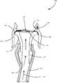
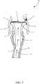
- FIG. 1is a diagrammatic view of a single-use container, such as a bioreactor, and an adapter in accordance with an embodiment of the present invention.
- FIG. 2is a block diagram of a measuring instrument, such as a sensor transducer, in more detail.
- FIG. 3is a diagrammatic view of an adapter with an attachment region and a diaphragm coupled to a fluidic coupling mechanism in accordance with an embodiment of the present invention.
- FIG. 4is a diagrammatic view of an adapter and a sensor transducer in accordance with an embodiment of the present invention.
- FIG. 5is a diagrammatic view of an adapter assembly in accordance with an embodiment of the present invention.
- FIG. 6is a diagrammatic view of a radio frequency identification (RFID) tag within an adapter in accordance with an embodiment of the present invention.
- RFIDradio frequency identification
- FIG. 7is a diagrammatic view of a pressure retention feature of a single-use adapter in accordance with an embodiment of the present invention.
- FIG. 8is a flow diagram showing one example of receiving information from a RFID tag in accordance with an embodiment of the present invention.
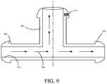
- FIG. 9is a diagrammatic view of an adapter with an attachment region and a diaphragm in accordance with an embodiment of the present invention.
- an adapterthat provides an interface between a sensor transducer and a media sample from a single-use container.
- the adapterallows the sensor transducer to monitor a parameter of the media sample, via a diaphragm of the adapter, while maintaining the media integrity within the single-use container.
- the adaptermaintains the media integrity with or without the sensor transducer connected to the adapter.
- the adapteralso protects the sensor transducer from adverse effects stemming from direct contact with the media (such as corrosion), while also protecting the single use container from any external contamination.
- embodiments of the present inventioninclude a single-use adapter with a simplified and improved mechanical interface that allows for a confirmation of sensor installation and material traceability.
- thisincludes a single-use adapter with an RFID tag storing material traceability information, lot information, or any suitable configuration information.
- the RFID tag within the adaptermay be a passive tag with an open antenna circuit, with an antenna coil and a switch, that is configured to be closed upon physically coupling a sensor transducer to the adapter.
- the antenna circuitupon physically coupling a sensor transducer to the adapter, the antenna circuit is closed, via conductive contacts on the adapter, and can receive radio frequency (RF) energy from an RF reader.
- RFradio frequency
- the RF tagUpon receiving the RF energy, the RF tag can subsequently supply the information within the RFID tag to the RF reader. Based on the received information resulting from the closed antenna circuit, the sensor transducer can generate an indication of a successful coupling between the single-use adapter and the sensor transducer. While a RFID tag is mentioned, it is expressly contemplated that the RFID tag may be active or passive, and, in certain embodiments, may be an NFC tag as well.
- an improved mechanical interfaceincludes at least one coupling, or snap-in, mechanism that allows either the adapter or the sensor transducer to click-lock into place and be subsequently removed via a tear-away feature or finger squeeze lever.
- the adaptermay include a retention feature configured to enable the adapter to withstand a greater internal pressure prior to being coupled to a sensor transducer. This may allow the diameter and, thus, cost of the adapter to be reduced while still meeting pressure handling requirements. This may include manufacturing the adapter using various polymers or plastics that can be sterilized as a single piece. However, these are simply examples of a number of improved mechanical features within the context of the present invention.
- FIG. 1is a diagrammatic view of a single-use container, such as a bioreactor, and an adapter in accordance with an embodiment of the present invention.
- Bioreaction system 100includes a bioreactor 102 , configured to carry out a biological reaction, coupled to adapters 104 , 109 via fluidic coupling mechanisms 106 , 107 respectively.
- fluidic coupling mechanisms 106 , 107illustratively includes a tube, a variety of other mechanisms may be used as well, such as a connection port.
- Bioreactor 102illustratively includes an outer support container 108 with a wall that is relatively solid such that it forms a shell for a single-use bioreaction bag 110 disposed therein.
- Support container 108is generally matched to the dimensions and functionality of single-use bioreaction bag 110 to support a biological sample 112 configured to undergo a reaction within bioreaction bag 110 .
- support container 108is typically a reusable item
- single-use bioreaction bag 110is generally a polymeric bag that is disposed of after a biological reaction occurs within sample 112 .
- adapters 104 , 109are configured to serve as an interface between biological sample 112 , within bioreactor 102 , and measurement instruments, such as sensor transducers, configured to measure a parameter of the media sample. This involves simultaneously coupling adapters 104 , 109 to fluidic coupling mechanisms 106 , 107 , illustratively shown as tubes, and the measurement instruments such that the measurement instruments can monitor a parameter of biological sample 112 without directly contacting biological sample 112 and/or fluidic coupling mechanisms 106 , 107 . This will be discussed further in the context of FIGS. 3-9 .
- fluidic coupling mechanisms 106 , 107can include a hose, tube or any other mechanism that allows the measurement instruments to monitor a parameter, such as pressure, of biological sample 112 upon being coupled to adapters 104 , 109 .
- adapter 109can be a downstream connector that allows a measurement instrument to measure a parameter of the media sample as the media sample moves downstream for further processing. This may include harvesting, filtration, etc.
- FIG. 2is a block diagram of a measurement instrument, such as a sensor transducer, in more detail.
- Measurement instrument 220can measure a wide variety of different parameters of a biological sample which can include temperature, pressure, dissolved oxygen, pH, etc. Additionally, measurement instrument 220 can include characterization and/or calibration information to compensate for variations in temperature and/or other environmental variables. Measurement instrument 220 can also perform diagnostics relative to itself and/or a biological sample to provide additional information outside of simply the measured parameter.
- Measurement instrument 220includes process communication circuitry 202 , a power module 208 , a controller 212 with memory 214 , an optional radio-frequency identification (RFID) reader 216 , measurement circuitry 218 and sensor(s) 222 .
- process communication circuitry 202is configured to be coupled to a process communication loop or segment via a plurality of conductors 204 , 206 .
- measurement instrument 220can convey information to one or more additional devices via the process communication loop or segment in accordance with the Highway Addressable Remote Transducer (HART®) protocol or the FOUNDATIONTM Fieldbus protocol.
- HART®Highway Addressable Remote Transducer
- FOUNDATIONTM Fieldbus protocolthe Highway Addressable Remote Transducer
- process communication circuitrycan communicate wirelessly using any suitable wireless communication protocols, such as IEC 62591.
- Power module 208is coupled to conductors 204 , 206 and, in some embodiments, is configured to receive energization power from conductors 204 , 206 such that suitable power can be provided to various components within measurement instrument 220 . This is generally indicated by arrow 210 labeled “To All.”
- controller 212is coupled to process communication circuitry 202 , measurement circuitry 218 and optional RFID reader 216 such that information received from measurement circuitry 218 and/or RFID reader 216 can be communicated over a process communication loop or in accordance with a wireless communication protocol. Additionally, controller 212 may include, or be coupled to, suitable memory 214 which can store program data as well as process data. Memory 214 may include volatile and/or non-volatile memory. In one embodiment, controller 212 is a microprocessor with suitable memory 214 such that controller 212 is able to programmatically execute a series of program steps in order to serve its function as a measurement instrument 220 .
- Measurement circuitry 218is coupled to one or more sensors 222 , such as a pressure sensor, to sense a sample parameter within the bioreactor.
- Measurement circuitry 218includes, in some embodiments, one or more analog-to-digital converters, linearization and/or amplification circuitry, and provides an indication of one or more sensed analog values to controller 212 in the form of a digital signal.
- Controller 212receives the digital signal from measurement circuitry 218 and programmatically calculates one or more process variables that may be made available over a process communication loop or segment.
- Sensor(s) 222may be disposed within measurement instrument 220 , such as a pressure sensor disposed within a sensor transducer, or may be disposed external to measurement instrument 220 and coupled thereto via suitable wiring. Sensor(s) 222 are configured to generate an analog signal, indicative of a media parameter, and provide the signal to measurement circuitry 218 .
- RFID reader 216may be coupled to controller 212 and enables controller 212 to communicate in accordance with known RFID techniques.
- RFID reader 216is, in some embodiments, configured to power a passive RFID tag or device that is disposed within an adapter as will be discussed in FIGS. 3-6 . Briefly, however, upon powering an RFID tag within an adapter, controller 212 can receive traceability and lot information, or any other configuration information stored within the RFID tag regarding a media sample within a single-use container. Additionally, in embodiments where the RFID antenna circuit is closed upon physically coupling the adapter to the sensor transducer, RFID communication will provide confirmation of such successful coupling.
- RFID reader 216is illustratively shown within measurement instrument 220 , it is also contemplated that RFID reader 216 may be external to measurement instrument 220 and used to power the RFID tag within the adapter.
- FIG. 3is a diagrammatic view of adapter 300 with an attachment region 312 and a diaphragm 316 coupled to a fluidic coupling mechanism 106 in accordance with an embodiment of the present invention.
- adapter 300is configured to serve as an interface between a received media sample from a single-use container and a measurement instrument configured to measure a parameter of the received media sample. In operation, this involves simultaneously coupling adapter 300 to both fluidic coupling mechanism 106 , illustratively shown as a tube, and a measurement instrument, such as measurement instrument 220 .
- Adapter 300illustratively includes an attachment region 312 with passageway 320 , barbs 310 , deflectable diaphragm 316 , RFID tag 306 with contacts 304 , pressure retention feature 302 (shown in greater detail in FIG. 7 ), and coupling mechanisms 308 coupled to attachment region 312 via an ultrasonic or thermal weld 314 .
- attachment region 312 of adapter 300couples to fluidic coupling mechanism 106 , via barbs 310 , and receives a media sample from a single-use container generally in the direction of arrows 318 .
- a received media samplethen travels through passageway 320 of attachment region 312 and comes into contact with an interior of deflectable diaphragm 316 .
- a measurement instrumente.g. measurement instrument 220 shown in FIG. 2
- a parametersuch as pressure
- a measurement instrumentsuch as a sensor transducer
- a parameter of the media samplesuch as pressure
- a relatively high precision measurement instrumentcan obtain a high-quality process fluid measurement and provide an indication thereof to monitoring and/or control equipment without contacting the media directly.
- a process sensor and transmittercan be reused after being coupled to adapter 300 , enabling the measuring instrument to be a relatively complex and feature-rich device that is able to carry out a number of functions such as linearization, digital communication, alarm detection and annunciation, etc.
- Deflectable diaphragm 316can be formed of any suitable material that is suited for exposure to the media and is able to allow a measurement instrument coupled on an opposite side thereof to transduce meaningful information relative to the media. This may include one uniform material or a plurality of different materials. For example, an interior of diaphragm 316 may be formed of a different material compared to an exterior of diaphragm 316 .
- Example materialscan include silicone rubber, polytetrafluoroethylene (PTFE), Ultra-Low, Very-Low, Low, Medium, High, and Very-High Durometer Urethane, Nylon, Polyethylene Terephthalate (PET), and Pebax®.
- adapter 300may include pressure retention feature 302 that allows for an increased pressure retention capability compared to what diaphragm 316 can withstand alone.
- retention feature 302can be a “tear-away” support cap that is manufactured proximate diaphragm 316 and allows for an increased pressure retention capability, up to 5 pounds per square inch (psi) in one example, prior to coupling diaphragm 316 to the measurement instrument.
- pressure retention feature 302can be removed (i.e. torn away) just prior to coupling diaphragm 316 to the measurement instrument. This will be discussed further in FIG. 7 .
- Adapter 300couples to a measurement instrument using coupling features 308 .
- Coupling features 308are snap-in features that allow the measurement instrument to click-lock into place on adapter 300 , and, subsequently, allow the measurement instrument to be released from adapter 300 by a finger squeeze lever.
- an insertion forcemay be applied to the measurement instrument until a flange of the measurement instrument is received by coupling features 308 . Once received, the measurement instrument is securely fastened proximate diaphragm 316 . To release the measurement instrument, a pressure may be applied to coupling features 308 allowing the measurement instrument to be removed from adapter 300 . This is but one example and is illustratively shown in FIG. 5 . Additionally, while it is shown in FIGS. 3 and 5 that coupling features 308 are coupled to adapter 300 , it is also contemplated that coupling features 308 may be coupled to measurement instrument as illustratively shown in FIG. 4 .
- coupling features 308can be coupled to attachment region 312 via ultrasonic welds 314 or any other suitable manufacturing techniques.
- ultrasonic weld 314allows for a secure attachment between the pieces through an application of high-frequency ultrasonic acoustic vibrations while the collective pieces are under pressure. This allows for a relatively less expensive design and manufacture for adapter 300 .
- RFID tag 306is a passive RFID tag that includes an RFID chip with any or all information pertaining to material traceability and/or lot information, and an antenna circuit with an antenna coil and switch configured to supply power received from a RFID reader, e.g. RFID reader 216 within measurement instrument 220 , to the RFID chip.
- a RFID readere.g. RFID reader 216 within measurement instrument 220
- the RFID chip within tag 306is able to provide the information to the RFID reader, such as reader 216 (shown in FIG. 2 ). The information may then be transmitted over a process communication loop and/or stored by the measurement instrument.
- a controller of the measurement instrumentcan generate and provide an indication of a correct coupling between adapter 300 and the measurement instrument.
- the antenna circuit of RFID tag 306may be an open circuit, with exposed contacts 304 , that is configured to be closed upon physically coupling the measurement instrument to adapter 300 .
- the antenna circuitremains open and cannot supply power to the RFID chip. As a result, no information can be received from RFID tag 306 .
- the antenna circuitis closed and can receive power from a RFID reader. Power can then be supplied from the antenna circuit to the RFID chip such that information can be provided to the RFID reader. Once received, the controller of measurement instrument can generate an indication of a successful coupling between adapter 300 and the measurement instrument based on the successfully received information from the RFID chip.
- RFID tag 306is illustratively shown coupled to coupling features 308 , it is contemplated that RFID tag 306 may be coupled to other features of adapter 300 . Furthermore, it is contemplated that RFID tag 306 can be sterilized along with adapter 300 , or alternatively, as part of an assembly with adapter 300 coupled to fluidic coupling mechanism 106 . This can include exposure to gamma radiation in one example. In one embodiment, tag 306 is a commercially available RFID tag sold under the trade designation GammaTag® available from Verigenics, of Southhampton, Pa.
- FIG. 4is a diagrammatic view of an adapter and a sensor transducer in accordance with an embodiment of the present invention.
- adapter 400includes many of the same features as shown in FIG. 3 .
- coupling features 408are coupled to measurement instrument 402 rather than adapter 400 .
- Coupling features 408may be the same or different than coupling features 308 shown in FIG. 3 .
- adapter 400includes a receiving portion 404 that is configured to couple to coupling features 408 on measurement instrument 402 .
- measurement instrument 402is securely fastened to adapter 400 and can measure a parameter of a media sample via a characteristic change in diaphragm 316 .
- receiving portion 404may be fixed to attachment region 312 via ultrasonic or thermal welds 406 .
- FIG. 5is a diagrammatic view of an adapter assembly in accordance with an embodiment of the present invention.
- Adapter assemblyincludes adapter 500 securely coupled to measurement instrument 402 .
- adapter 500is securely fastened to measurement instrument 402 via a coupling between coupling features 308 and a flange of measurement instrument 402 .
- tapered portions 508 of coupling features 308can physically couple to the flange thereby securing measurement instrument 402 to adapter 500 .
- adapter 500includes RFID tag 306 with a RFID chip 506 and an open antenna circuit 504 with exposed contacts 304 .
- Exposed contacts 304may be made of a conductive plastic. While exposed contacts 304 are illustratively exposed on a single coupling feature, in other embodiments, exposed contacts 304 may be located at various locations within adapter 500 .
- antenna circuit 504is configured to be closed and can direct power received from an RFID reader, within measurement instrument 402 , to RFID chip 506 .
- RFID chip 506may then supply any information within RFID chip 506 to measurement instrument 402 .
- a confirmation signalmay be generated by measurement instrument 402 indicative of a successful coupling between adapter 500 and measurement instrument 402 based on closed antenna circuit 504 .
- FIG. 6is a diagrammatic view of a radio frequency identification (RFID) tag within an adapter in accordance with an embodiment of the present invention.
- RFID tag 600includes RFID chip 602 and an open antenna circuit 610 .
- Antenna circuit 610includes an antenna coil 604 connected to a switch 606 with contacts 608 .
- RFID chip 602includes any or all traceability data, lot information and/or configuration information, and, upon receiving energy from antenna coil 604 , supplied from a RFID reader, communicates the information to the RFID reader.
- switch 606is connected to antenna coil 604 and is configured to remain open until the adapter is physically coupled to a sensor transducer.
- switch 606Upon physically coupling the sensor transducer to the adapter, switch 606 is closed enabling antenna coil 604 to provide energy to RFID chip 602 .
- RFID chip 602can supply the information to the RFID reader while indicating a successful physical coupling between the adapter and the sensor transducer.
- a confirmation signalis generated and provided over a process communication loop indicative of the physical coupling.
- FIG. 7is a diagrammatic view of a pressure retention feature of a single-use adapter in accordance with an embodiment of the present invention.
- Pressure retention feature 302is configured to securely couple to adapter 300 , proximate diaphragm 316 , during manufacture to allow the adapter to withstand a greater internal pressure than could be borne by diaphragm 316 alone.
- retention feature 302can be removed such that a diaphragm of the adapter is exposed for contact with the measurement instrument.
- Pressure retention feature 302includes a cap 704 , a connecting member 706 and a circular member 706 .
- cap 704can rest on a diaphragm and allow adapter to have a greater internal pressure retaining capability.
- a pulling forcemay be applied to circular member 706 which, in turn, decouples cap 704 from the diaphragm. Once removed, retention feature 302 may be discarded and the adapter coupled to a measurement instrument.
- FIG. 8is a flow diagram showing one example of receiving information from an RFID tag in accordance with an embodiment of the present invention.
- Method 800may be useful for obtaining information regarding material traceability and lot information, among a variety of other configuration information for single-use applications.
- Method 800begins at block 802 where electromagnetic energy is generated for a RFID tag within an adapter.
- electromagnetic energyis generated by an RFID reader within a measurement instrument, such as a sensor transducer, configured to couple to the adapter as indicated by block 804 .
- a RFID readermay be placed in a variety of other devices as well as indicated by block 806 .
- data pertaining to material traceability and lot informationis received from a RFID tag within an adapter.
- datamay be received based on a physical coupling between the adapter and a measurement instrument such that an antenna circuit within the RFID tag is closed, allowing the RFID tag to receive the generated electromagnetic energy from the RFID reader.
- other ways of closing an antenna circuit within a RFID tagare contemplated as well as indicated by block 812 .
- information received from an RFID tagare provided to a process controller. This can include lot information, material traceability information and a wide variety of other configuration information as well. Additionally, an indication of a secure coupling between an adapter and measurement instrument can be generated and provided to a process controller based on the closed antenna circuit. This is indicated by block 816 . However, a variety of other data can be provided as well, as indicated by block 820 .
- a single-use adapteris provided with a simplified and improved mechanical interface that allows for confirmation of sensor installation and material traceability. Additionally, the single-use adapter maintains a media integrity while allowing a sensor transducer to monitor a parameter of a media sample within a single-use container.
- FIG. 9is a diagrammatic view of an adapter with an attachment region and a diaphragm in accordance with an embodiment of the present invention.
- Adapter 900illustratively includes an attachment region 908 , with barbs 904 and an RFID tag 910 , coupled to a diaphragm 902 .
- adapter 900can receive a flow of media, generally in the direction 906 , through passageway 914 .
- the flow of mediais configured to move from a bioreactor to another system for downstream processing, that, in one example, can include filtration, harvesting, etc.
- a measurement instrument coupled to diaphragm 902can measure a parameter of the flow of media. This can include temperature, pressure, pH, etc. Additionally, by physically coupling the measurement instrument to diaphragm 902 , the measurement instrument can close an open antenna circuit of RFID tag 910 via exposed contacts 912 . In one example, this can indicate a successful coupling between adapter 900 and the measurement instrument.
Landscapes
- Engineering & Computer Science (AREA)
- Health & Medical Sciences (AREA)
- Chemical & Material Sciences (AREA)
- Zoology (AREA)
- Life Sciences & Earth Sciences (AREA)
- Organic Chemistry (AREA)
- Wood Science & Technology (AREA)
- Bioinformatics & Cheminformatics (AREA)
- Physics & Mathematics (AREA)
- General Physics & Mathematics (AREA)
- General Health & Medical Sciences (AREA)
- General Engineering & Computer Science (AREA)
- Biomedical Technology (AREA)
- Genetics & Genomics (AREA)
- Biochemistry (AREA)
- Sustainable Development (AREA)
- Microbiology (AREA)
- Biotechnology (AREA)
- Clinical Laboratory Science (AREA)
- Theoretical Computer Science (AREA)
- Toxicology (AREA)
- Artificial Intelligence (AREA)
- Computer Vision & Pattern Recognition (AREA)
- Microelectronics & Electronic Packaging (AREA)
- Electromagnetism (AREA)
- Computer Networks & Wireless Communication (AREA)
- Computer Hardware Design (AREA)
- Analytical Chemistry (AREA)
- Measuring Fluid Pressure (AREA)
- Apparatus Associated With Microorganisms And Enzymes (AREA)
- Measuring And Recording Apparatus For Diagnosis (AREA)
Abstract
Description
Claims (13)
Priority Applications (6)
| Application Number | Priority Date | Filing Date | Title |
|---|---|---|---|
| US16/014,534US10970614B2 (en) | 2018-06-21 | 2018-06-21 | Single-use pressure transducer disposable interface |
| CN201811206669.0ACN110631760B (en) | 2018-06-21 | 2018-10-16 | Disposable disposable interface for pressure transducer |
| CN201821678764.6UCN209541975U (en) | 2018-06-21 | 2018-10-16 | Disposable adapter, disposable sensing component and disposable container component |
| PCT/US2019/037687WO2019246065A1 (en) | 2018-06-21 | 2019-06-18 | Single-use pressure transducer disposable interface |
| JP2020570715AJP7061696B2 (en) | 2018-06-21 | 2019-06-18 | Disposable interface for disposable pressure transducers |
| EP19822455.2AEP3810748B1 (en) | 2018-06-21 | 2019-06-18 | Single-use pressure transducer disposable interface |
Applications Claiming Priority (1)
| Application Number | Priority Date | Filing Date | Title |
|---|---|---|---|
| US16/014,534US10970614B2 (en) | 2018-06-21 | 2018-06-21 | Single-use pressure transducer disposable interface |
Publications (2)
| Publication Number | Publication Date |
|---|---|
| US20190392280A1 US20190392280A1 (en) | 2019-12-26 |
| US10970614B2true US10970614B2 (en) | 2021-04-06 |
Family
ID=68247068
Family Applications (1)
| Application Number | Title | Priority Date | Filing Date |
|---|---|---|---|
| US16/014,534Active2038-11-30US10970614B2 (en) | 2018-06-21 | 2018-06-21 | Single-use pressure transducer disposable interface |
Country Status (5)
| Country | Link |
|---|---|
| US (1) | US10970614B2 (en) |
| EP (1) | EP3810748B1 (en) |
| JP (1) | JP7061696B2 (en) |
| CN (2) | CN209541975U (en) |
| WO (1) | WO2019246065A1 (en) |
Families Citing this family (5)
| Publication number | Priority date | Publication date | Assignee | Title |
|---|---|---|---|---|
| US10970614B2 (en)* | 2018-06-21 | 2021-04-06 | Rosemount Inc. | Single-use pressure transducer disposable interface |
| US10944472B2 (en)* | 2019-07-08 | 2021-03-09 | Net2Edge Limited | System for reporting optical link failures using intelligent small form-factor pluggable optical time domain reflectometer |
| US11506556B2 (en) | 2020-09-30 | 2022-11-22 | Rosenmount Inc. | Single-use plastic pressure sensor |
| JP7556842B2 (en)* | 2021-11-26 | 2024-09-26 | トーステ株式会社 | Mounting structure for detachably mounting a general-purpose sensor to a sanitary circulation section, and a sanitary circulation section equipped with the mounting structure for the general-purpose sensor |
| DE102023133478A1 (en)* | 2023-11-30 | 2025-06-05 | Endress+Hauser SE+Co. KG | Device for attaching a pressure sensor to a container |
Citations (25)
| Publication number | Priority date | Publication date | Assignee | Title |
|---|---|---|---|---|
| US20040027912A1 (en) | 2002-04-12 | 2004-02-12 | Hynetics Llc | Mixing tank assembly |
| US20050205658A1 (en)* | 2004-03-16 | 2005-09-22 | Newage Industries, Inc. | Process equipment tracking system |
| US7151455B2 (en)* | 2004-04-30 | 2006-12-19 | Kimberly-Clark Worldwide, Inc. | Activating a data tag by load or orientation or user control |
| US20080024310A1 (en)* | 2004-03-16 | 2008-01-31 | Newage Industries, Inc. | Tracking system for gamma radiation sterilized bags and disposable items |
| US20090247989A1 (en)* | 2008-03-26 | 2009-10-01 | Aaron Burke | System and method for interfacing sensors to a sterile flow stream |
| US20090273447A1 (en)* | 2007-05-08 | 2009-11-05 | Finesse Solutions, Llc. | Bioprocess data management |
| US7784353B1 (en)* | 2009-07-08 | 2010-08-31 | Feldmeier Robert H | Sanitary diaphragm pressure gauge adapter |
| US20110041619A1 (en)* | 2009-03-13 | 2011-02-24 | Millipore Corporation | Device For Determining A Physical Value Of A Liquid Flowing In A Pipe |
| US20110264069A1 (en) | 2010-04-27 | 2011-10-27 | Walter John Bochenko | Medication and identification information transfer apparatus |
| US8138922B2 (en)* | 2004-04-30 | 2012-03-20 | Binforma Group Limited Liability Company | Deactivating a data tag for user privacy or tamper-evident packaging |
| US20120222468A1 (en) | 2011-03-04 | 2012-09-06 | Becton, Dickinson And Company | Attachment device for identifying constituents within a fluid |
| US20120240686A1 (en) | 2011-03-25 | 2012-09-27 | Blomberg Max D | Pressure measuring port with thermoplastic elastomeric interface |
| US8318111B2 (en)* | 2006-09-20 | 2012-11-27 | Binforma Group Limited Liability Company | Packaging closures integrated with disposable RFID devices |
| US20130018356A1 (en)* | 2011-07-13 | 2013-01-17 | Crisi Medical Systems, Inc. | Characterizing medication container preparation, use, and disposal within a clinical workflow |
| US8653940B2 (en)* | 2008-03-27 | 2014-02-18 | Ge Healthcare Bio-Sciences Corp. | Method for preventing an unauthorized use of disposable bioprocess components |
| US8963684B2 (en)* | 2008-03-27 | 2015-02-24 | Ge Healthcare Bio-Sciences Corp | Gamma sterilizable RFID system that prevents unauthorized operation of associated disposable bioprocess components |
| US20150061282A1 (en)* | 2012-03-27 | 2015-03-05 | Ge Healthcare Bio-Sciences Ab | Aseptic connector |
| US20150137992A1 (en)* | 2013-11-21 | 2015-05-21 | Ge Healthcare Bio-Sciences Ab | Systems and methods for status indication in a single-use biomedical and bioprocess system |
| US20150323486A1 (en)* | 2013-03-15 | 2015-11-12 | Parker-Hannifin Corporation | Single-use sensors in bioreactors, biotech purification and bioprocessing |
| US20150359954A1 (en)* | 2014-02-26 | 2015-12-17 | Medtronic, Inc. | Authentication system utilized in a sorbent-based dialysis system for therapy optimization |
| US20160017269A1 (en)* | 2013-03-04 | 2016-01-21 | Gymetrics Sa | Bioreactor and sensing system therefor |
| US20160148027A1 (en)* | 2014-11-25 | 2016-05-26 | DePuy Synthes Products, Inc. | Medical Device Identification System |
| US20160245714A1 (en)* | 2013-10-30 | 2016-08-25 | Alphinity, Llc | Fluid monitoring device with disposable inner liner with sensor integration |
| US20170068832A1 (en)* | 2015-09-03 | 2017-03-09 | Wolff Industries, Inc. | Tag carriers and assemblies for rfid tags |
| US20180049947A1 (en)* | 2014-12-19 | 2018-02-22 | Fresenius Kabi Deutschland Gmbh | Connector system comprising at least two withdrawal ports |
Family Cites Families (10)
| Publication number | Priority date | Publication date | Assignee | Title |
|---|---|---|---|---|
| US7388505B2 (en)* | 2005-01-05 | 2008-06-17 | Wesley Jack White | Storage container smart collar |
| US20090204250A1 (en) | 2008-02-08 | 2009-08-13 | General Electric Company | System and method for integrating rfid sensors in manufacturing system comprising single use components |
| JP5977521B2 (en) | 2009-01-29 | 2016-08-24 | ジーイー・ヘルスケア・バイオサイエンス・バイオプロセス・コーポレイション | System and method for operating an RFID device with a single-use connector |
| WO2014007122A1 (en)* | 2012-07-02 | 2014-01-09 | 日立金属株式会社 | Magnetic circuit |
| FR3007816B1 (en)* | 2013-06-28 | 2016-02-05 | Sartorius Stedim Biotech | ASEXUE FLUID CONNECTOR WITH COLLAR AND PROTECTION. |
| US9620305B2 (en) | 2013-07-31 | 2017-04-11 | Briggs & Stratton Corporation | Meter socket adapter with integrated automatic transfer switch |
| US10359415B2 (en) | 2014-05-02 | 2019-07-23 | Rosemount Inc. | Single-use bioreactor sensor architecture |
| US9562819B2 (en) | 2015-06-30 | 2017-02-07 | Rosemount Inc | Polymeric remote seal system for single-use containers |
| US10836990B2 (en) | 2016-12-23 | 2020-11-17 | Cyberoptics Corporation | Sensor interface for single-use containers |
| US10970614B2 (en)* | 2018-06-21 | 2021-04-06 | Rosemount Inc. | Single-use pressure transducer disposable interface |
- 2018
- 2018-06-21USUS16/014,534patent/US10970614B2/enactiveActive
- 2018-10-16CNCN201821678764.6Upatent/CN209541975U/ennot_activeExpired - Fee Related
- 2018-10-16CNCN201811206669.0Apatent/CN110631760B/enactiveActive
- 2019
- 2019-06-18WOPCT/US2019/037687patent/WO2019246065A1/ennot_activeCeased
- 2019-06-18EPEP19822455.2Apatent/EP3810748B1/enactiveActive
- 2019-06-18JPJP2020570715Apatent/JP7061696B2/enactiveActive
Patent Citations (48)
| Publication number | Priority date | Publication date | Assignee | Title |
|---|---|---|---|---|
| US20040027912A1 (en) | 2002-04-12 | 2004-02-12 | Hynetics Llc | Mixing tank assembly |
| US20050205658A1 (en)* | 2004-03-16 | 2005-09-22 | Newage Industries, Inc. | Process equipment tracking system |
| US7259675B2 (en)* | 2004-03-16 | 2007-08-21 | Newage Industries, Inc. | Process equipment tracking system |
| US20070200703A1 (en)* | 2004-03-16 | 2007-08-30 | Newage Industries, Inc. | Process equipment tracking system |
| US20080024310A1 (en)* | 2004-03-16 | 2008-01-31 | Newage Industries, Inc. | Tracking system for gamma radiation sterilized bags and disposable items |
| US8519846B2 (en)* | 2004-03-16 | 2013-08-27 | Newage Industries, Inc. | Tracking system for gamma radiation sterilized bags and disposable items |
| US8138922B2 (en)* | 2004-04-30 | 2012-03-20 | Binforma Group Limited Liability Company | Deactivating a data tag for user privacy or tamper-evident packaging |
| US7151455B2 (en)* | 2004-04-30 | 2006-12-19 | Kimberly-Clark Worldwide, Inc. | Activating a data tag by load or orientation or user control |
| US8318111B2 (en)* | 2006-09-20 | 2012-11-27 | Binforma Group Limited Liability Company | Packaging closures integrated with disposable RFID devices |
| US20150306267A1 (en)* | 2007-05-08 | 2015-10-29 | Finesse Solutions, Inc. | Bioprocess data management |
| US9782506B2 (en)* | 2007-05-08 | 2017-10-10 | Finesse Solutions, Inc. | Bioprocess data management |
| US9050379B2 (en)* | 2007-05-08 | 2015-06-09 | Finesse Solutions, Inc. | Bioprocess data management |
| US20090273447A1 (en)* | 2007-05-08 | 2009-11-05 | Finesse Solutions, Llc. | Bioprocess data management |
| US20090247989A1 (en)* | 2008-03-26 | 2009-10-01 | Aaron Burke | System and method for interfacing sensors to a sterile flow stream |
| US8640560B2 (en) | 2008-03-26 | 2014-02-04 | Emd Millipore Corporation | System and method for interfacing sensors to a sterile flow stream |
| US8653940B2 (en)* | 2008-03-27 | 2014-02-18 | Ge Healthcare Bio-Sciences Corp. | Method for preventing an unauthorized use of disposable bioprocess components |
| US8963684B2 (en)* | 2008-03-27 | 2015-02-24 | Ge Healthcare Bio-Sciences Corp | Gamma sterilizable RFID system that prevents unauthorized operation of associated disposable bioprocess components |
| US20110041619A1 (en)* | 2009-03-13 | 2011-02-24 | Millipore Corporation | Device For Determining A Physical Value Of A Liquid Flowing In A Pipe |
| US8297128B2 (en)* | 2009-03-13 | 2012-10-30 | Emd Millipore Corporation | Device for determining a physical value of a liquid flowing in a pipe |
| US8485044B2 (en)* | 2009-03-13 | 2013-07-16 | Emd Millipore Corporation | Device for determining a physical value of a liquid flowing in a pipe |
| US7784353B1 (en)* | 2009-07-08 | 2010-08-31 | Feldmeier Robert H | Sanitary diaphragm pressure gauge adapter |
| US20110264069A1 (en) | 2010-04-27 | 2011-10-27 | Walter John Bochenko | Medication and identification information transfer apparatus |
| US8702674B2 (en)* | 2010-04-27 | 2014-04-22 | Crisi Medical Systems, Inc. | Medication and identification information transfer apparatus |
| US20120222468A1 (en) | 2011-03-04 | 2012-09-06 | Becton, Dickinson And Company | Attachment device for identifying constituents within a fluid |
| US9067014B2 (en)* | 2011-03-04 | 2015-06-30 | Becton, Dickinson And Company | Attachment device for identifying constituents within a fluid |
| US20120240686A1 (en) | 2011-03-25 | 2012-09-27 | Blomberg Max D | Pressure measuring port with thermoplastic elastomeric interface |
| US20130018356A1 (en)* | 2011-07-13 | 2013-01-17 | Crisi Medical Systems, Inc. | Characterizing medication container preparation, use, and disposal within a clinical workflow |
| US20150061282A1 (en)* | 2012-03-27 | 2015-03-05 | Ge Healthcare Bio-Sciences Ab | Aseptic connector |
| US20170281921A1 (en)* | 2012-03-27 | 2017-10-05 | Ge Healthcare Bio-Sciences Ab | Aseptic connector |
| US20160017269A1 (en)* | 2013-03-04 | 2016-01-21 | Gymetrics Sa | Bioreactor and sensing system therefor |
| US20150323486A1 (en)* | 2013-03-15 | 2015-11-12 | Parker-Hannifin Corporation | Single-use sensors in bioreactors, biotech purification and bioprocessing |
| US10267701B2 (en)* | 2013-10-30 | 2019-04-23 | Alphinity, Llc | Fluid monitoring device with disposable inner liner with sensor integration |
| US20170322100A1 (en)* | 2013-10-30 | 2017-11-09 | Alphinity, Llc | Fluid monitoring device with disposable inner liner with sensor integration |
| US20160245714A1 (en)* | 2013-10-30 | 2016-08-25 | Alphinity, Llc | Fluid monitoring device with disposable inner liner with sensor integration |
| US9746391B2 (en)* | 2013-10-30 | 2017-08-29 | Alphinity, Llc | Fluid monitoring device with disposable inner liner with sensor integration |
| US20150137992A1 (en)* | 2013-11-21 | 2015-05-21 | Ge Healthcare Bio-Sciences Ab | Systems and methods for status indication in a single-use biomedical and bioprocess system |
| US20170124845A1 (en)* | 2013-11-21 | 2017-05-04 | Ge Healthcare Bio-Sciences Ab | Systems and methods for status indication in a single-use biomedical and bioprocess system |
| US10089850B2 (en)* | 2013-11-21 | 2018-10-02 | Ge Healthcare Bio-Sciences Ab | Systems and methods for status indication in a single-use biomedical and bioprocess system |
| US20190043333A1 (en)* | 2013-11-21 | 2019-02-07 | Ge Healthcare Bio-Sciences Ab | Systems and methods for status indication in a single-use biomedical and bioprocess system |
| US10522025B2 (en)* | 2013-11-21 | 2019-12-31 | Ge Healthcare Bio-Sciences Ab | Systems and methods for status indication in a single-use biomedical and bioprocess system |
| US9764076B2 (en)* | 2014-02-26 | 2017-09-19 | Medtronic, Inc. | Authentication system utilized in a sorbent-based dialysis system for therapy optimization |
| US20150359954A1 (en)* | 2014-02-26 | 2015-12-17 | Medtronic, Inc. | Authentication system utilized in a sorbent-based dialysis system for therapy optimization |
| US20160148027A1 (en)* | 2014-11-25 | 2016-05-26 | DePuy Synthes Products, Inc. | Medical Device Identification System |
| US20180049947A1 (en)* | 2014-12-19 | 2018-02-22 | Fresenius Kabi Deutschland Gmbh | Connector system comprising at least two withdrawal ports |
| US20170068832A1 (en)* | 2015-09-03 | 2017-03-09 | Wolff Industries, Inc. | Tag carriers and assemblies for rfid tags |
| US9996718B2 (en)* | 2015-09-03 | 2018-06-12 | Wolff Industries, Inc. | Tag carriers and assemblies for RFID tags |
| US20180253575A1 (en)* | 2015-09-03 | 2018-09-06 | Wolff Industries, Inc. | Tag carriers and assemblies for rfid tags |
| US10262170B2 (en)* | 2015-09-03 | 2019-04-16 | Wolff Industries, Inc. | Tag carriers and assemblies for RFID tags |
Non-Patent Citations (2)
| Title |
|---|
| First Chinese Office Action dated Oct. 12, 2020 for Chinese patent appticafion No. 201811206669.0, 21 pages including English translation. |
| International Search Report and Written Opinion for International Patent Application No. PCT/US2019/037667, dated Oct. 18, 2019, date of filing: Jun. 18, 2019, 11 pages. |
Also Published As
| Publication number | Publication date |
|---|---|
| WO2019246065A1 (en) | 2019-12-26 |
| CN110631760B (en) | 2022-06-14 |
| JP7061696B2 (en) | 2022-04-28 |
| US20190392280A1 (en) | 2019-12-26 |
| CN110631760A (en) | 2019-12-31 |
| CN209541975U (en) | 2019-10-25 |
| JP2021527815A (en) | 2021-10-14 |
| EP3810748B1 (en) | 2023-08-23 |
| EP3810748A1 (en) | 2021-04-28 |
| EP3810748A4 (en) | 2022-04-06 |
Similar Documents
| Publication | Publication Date | Title |
|---|---|---|
| US10970614B2 (en) | Single-use pressure transducer disposable interface | |
| US10836990B2 (en) | Sensor interface for single-use containers | |
| US10359415B2 (en) | Single-use bioreactor sensor architecture | |
| EP3317392B1 (en) | Polymeric remote seal system for single-use containers | |
| AU2018214815B2 (en) | Improved pressure transducer | |
| EP3685136B1 (en) | Compact sensor connector for single-use fluid measurement |
Legal Events
| Date | Code | Title | Description |
|---|---|---|---|
| FEPP | Fee payment procedure | Free format text:ENTITY STATUS SET TO UNDISCOUNTED (ORIGINAL EVENT CODE: BIG.); ENTITY STATUS OF PATENT OWNER: LARGE ENTITY | |
| AS | Assignment | Owner name:ROSEMOUNT INC., MINNESOTA Free format text:ASSIGNMENT OF ASSIGNORS INTEREST;ASSIGNORS:FADELL, PAUL R.;STOKES, NATHAN;SIGNING DATES FROM 20180705 TO 20180725;REEL/FRAME:046643/0144 | |
| AS | Assignment | Owner name:ROSEMOUNT INC., MINNESOTA Free format text:ASSIGNMENT OF ASSIGNORS INTEREST;ASSIGNOR:FADELL, PAUL R.;REEL/FRAME:047280/0246 Effective date:20180725 | |
| AS | Assignment | Owner name:ROSEMOUNT INC., MINNESOTA Free format text:CORRECTIVE ASSIGNMENT TO CORRECT THE INVENTOR DATA BY ADDING AN INVENTOR PREVIOUSLY RECORDED AT REEL: 047280 FRAME: 0246. ASSIGNOR(S) HEREBY CONFIRMS THE ASSIGNMENT;ASSIGNORS:FADELL, PAUL R.;STOKES, NATHAN;SIGNING DATES FROM 20180705 TO 20180725;REEL/FRAME:047901/0102 | |
| STPP | Information on status: patent application and granting procedure in general | Free format text:NON FINAL ACTION MAILED | |
| STPP | Information on status: patent application and granting procedure in general | Free format text:RESPONSE TO NON-FINAL OFFICE ACTION ENTERED AND FORWARDED TO EXAMINER | |
| STPP | Information on status: patent application and granting procedure in general | Free format text:NOTICE OF ALLOWANCE MAILED -- APPLICATION RECEIVED IN OFFICE OF PUBLICATIONS | |
| STPP | Information on status: patent application and granting procedure in general | Free format text:PUBLICATIONS -- ISSUE FEE PAYMENT VERIFIED | |
| STPP | Information on status: patent application and granting procedure in general | Free format text:AWAITING TC RESP, ISSUE FEE PAYMENT VERIFIED | |
| STPP | Information on status: patent application and granting procedure in general | Free format text:PUBLICATIONS -- ISSUE FEE PAYMENT VERIFIED | |
| STCF | Information on status: patent grant | Free format text:PATENTED CASE | |
| CC | Certificate of correction | ||
| MAFP | Maintenance fee payment | Free format text:PAYMENT OF MAINTENANCE FEE, 4TH YEAR, LARGE ENTITY (ORIGINAL EVENT CODE: M1551); ENTITY STATUS OF PATENT OWNER: LARGE ENTITY Year of fee payment:4 |