US10969785B2 - Automated vehicle operation to compensate for sensor field-of-view limitations - Google Patents
Automated vehicle operation to compensate for sensor field-of-view limitationsDownload PDFInfo
- Publication number
- US10969785B2 US10969785B2US15/658,065US201715658065AUS10969785B2US 10969785 B2US10969785 B2US 10969785B2US 201715658065 AUS201715658065 AUS 201715658065AUS 10969785 B2US10969785 B2US 10969785B2
- Authority
- US
- United States
- Prior art keywords
- vehicle
- host
- road
- intersecting
- view
- Prior art date
- Legal status (The legal status is an assumption and is not a legal conclusion. Google has not performed a legal analysis and makes no representation as to the accuracy of the status listed.)
- Active
Links
- 238000004891communicationMethods0.000claimsabstractdescription10
- 238000013459approachMethods0.000claimsabstractdescription5
- 238000000034methodMethods0.000claimsdescription7
- 238000001514detection methodMethods0.000claimsdescription4
- 230000035945sensitivityEffects0.000claimsdescription4
- 230000000007visual effectEffects0.000description1
Images


Classifications
- G—PHYSICS
- G01—MEASURING; TESTING
- G01S—RADIO DIRECTION-FINDING; RADIO NAVIGATION; DETERMINING DISTANCE OR VELOCITY BY USE OF RADIO WAVES; LOCATING OR PRESENCE-DETECTING BY USE OF THE REFLECTION OR RERADIATION OF RADIO WAVES; ANALOGOUS ARRANGEMENTS USING OTHER WAVES
- G01S17/00—Systems using the reflection or reradiation of electromagnetic waves other than radio waves, e.g. lidar systems
- G01S17/88—Lidar systems specially adapted for specific applications
- G—PHYSICS
- G05—CONTROLLING; REGULATING
- G05D—SYSTEMS FOR CONTROLLING OR REGULATING NON-ELECTRIC VARIABLES
- G05D1/00—Control of position, course, altitude or attitude of land, water, air or space vehicles, e.g. using automatic pilots
- G05D1/0094—Control of position, course, altitude or attitude of land, water, air or space vehicles, e.g. using automatic pilots involving pointing a payload, e.g. camera, weapon, sensor, towards a fixed or moving target
- B—PERFORMING OPERATIONS; TRANSPORTING
- B62—LAND VEHICLES FOR TRAVELLING OTHERWISE THAN ON RAILS
- B62D—MOTOR VEHICLES; TRAILERS
- B62D15/00—Steering not otherwise provided for
- B62D15/02—Steering position indicators ; Steering position determination; Steering aids
- B62D15/025—Active steering aids, e.g. helping the driver by actively influencing the steering system after environment evaluation
- G—PHYSICS
- G01—MEASURING; TESTING
- G01S—RADIO DIRECTION-FINDING; RADIO NAVIGATION; DETERMINING DISTANCE OR VELOCITY BY USE OF RADIO WAVES; LOCATING OR PRESENCE-DETECTING BY USE OF THE REFLECTION OR RERADIATION OF RADIO WAVES; ANALOGOUS ARRANGEMENTS USING OTHER WAVES
- G01S13/00—Systems using the reflection or reradiation of radio waves, e.g. radar systems; Analogous systems using reflection or reradiation of waves whose nature or wavelength is irrelevant or unspecified
- G01S13/02—Systems using reflection of radio waves, e.g. primary radar systems; Analogous systems
- G01S13/06—Systems determining position data of a target
- G01S13/42—Simultaneous measurement of distance and other co-ordinates
- G—PHYSICS
- G01—MEASURING; TESTING
- G01S—RADIO DIRECTION-FINDING; RADIO NAVIGATION; DETERMINING DISTANCE OR VELOCITY BY USE OF RADIO WAVES; LOCATING OR PRESENCE-DETECTING BY USE OF THE REFLECTION OR RERADIATION OF RADIO WAVES; ANALOGOUS ARRANGEMENTS USING OTHER WAVES
- G01S13/00—Systems using the reflection or reradiation of radio waves, e.g. radar systems; Analogous systems using reflection or reradiation of waves whose nature or wavelength is irrelevant or unspecified
- G01S13/86—Combinations of radar systems with non-radar systems, e.g. sonar, direction finder
- G01S13/867—Combination of radar systems with cameras
- G—PHYSICS
- G01—MEASURING; TESTING
- G01S—RADIO DIRECTION-FINDING; RADIO NAVIGATION; DETERMINING DISTANCE OR VELOCITY BY USE OF RADIO WAVES; LOCATING OR PRESENCE-DETECTING BY USE OF THE REFLECTION OR RERADIATION OF RADIO WAVES; ANALOGOUS ARRANGEMENTS USING OTHER WAVES
- G01S13/00—Systems using the reflection or reradiation of radio waves, e.g. radar systems; Analogous systems using reflection or reradiation of waves whose nature or wavelength is irrelevant or unspecified
- G01S13/88—Radar or analogous systems specially adapted for specific applications
- G01S13/93—Radar or analogous systems specially adapted for specific applications for anti-collision purposes
- G01S13/931—Radar or analogous systems specially adapted for specific applications for anti-collision purposes of land vehicles
- G—PHYSICS
- G01—MEASURING; TESTING
- G01S—RADIO DIRECTION-FINDING; RADIO NAVIGATION; DETERMINING DISTANCE OR VELOCITY BY USE OF RADIO WAVES; LOCATING OR PRESENCE-DETECTING BY USE OF THE REFLECTION OR RERADIATION OF RADIO WAVES; ANALOGOUS ARRANGEMENTS USING OTHER WAVES
- G01S17/00—Systems using the reflection or reradiation of electromagnetic waves other than radio waves, e.g. lidar systems
- G01S17/02—Systems using the reflection of electromagnetic waves other than radio waves
- G01S17/06—Systems determining position data of a target
- G01S17/42—Simultaneous measurement of distance and other co-ordinates
- G—PHYSICS
- G01—MEASURING; TESTING
- G01S—RADIO DIRECTION-FINDING; RADIO NAVIGATION; DETERMINING DISTANCE OR VELOCITY BY USE OF RADIO WAVES; LOCATING OR PRESENCE-DETECTING BY USE OF THE REFLECTION OR RERADIATION OF RADIO WAVES; ANALOGOUS ARRANGEMENTS USING OTHER WAVES
- G01S17/00—Systems using the reflection or reradiation of electromagnetic waves other than radio waves, e.g. lidar systems
- G01S17/88—Lidar systems specially adapted for specific applications
- G01S17/93—Lidar systems specially adapted for specific applications for anti-collision purposes
- G01S17/931—Lidar systems specially adapted for specific applications for anti-collision purposes of land vehicles
- G—PHYSICS
- G01—MEASURING; TESTING
- G01S—RADIO DIRECTION-FINDING; RADIO NAVIGATION; DETERMINING DISTANCE OR VELOCITY BY USE OF RADIO WAVES; LOCATING OR PRESENCE-DETECTING BY USE OF THE REFLECTION OR RERADIATION OF RADIO WAVES; ANALOGOUS ARRANGEMENTS USING OTHER WAVES
- G01S7/00—Details of systems according to groups G01S13/00, G01S15/00, G01S17/00
- G01S7/48—Details of systems according to groups G01S13/00, G01S15/00, G01S17/00 of systems according to group G01S17/00
- G01S7/481—Constructional features, e.g. arrangements of optical elements
- G—PHYSICS
- G05—CONTROLLING; REGULATING
- G05D—SYSTEMS FOR CONTROLLING OR REGULATING NON-ELECTRIC VARIABLES
- G05D1/00—Control of position, course, altitude or attitude of land, water, air or space vehicles, e.g. using automatic pilots
- G05D1/02—Control of position or course in two dimensions
- G05D1/021—Control of position or course in two dimensions specially adapted to land vehicles
- G05D1/0231—Control of position or course in two dimensions specially adapted to land vehicles using optical position detecting means
- G05D1/0238—Control of position or course in two dimensions specially adapted to land vehicles using optical position detecting means using obstacle or wall sensors
- G05D1/024—Control of position or course in two dimensions specially adapted to land vehicles using optical position detecting means using obstacle or wall sensors in combination with a laser
- G—PHYSICS
- G05—CONTROLLING; REGULATING
- G05D—SYSTEMS FOR CONTROLLING OR REGULATING NON-ELECTRIC VARIABLES
- G05D1/00—Control of position, course, altitude or attitude of land, water, air or space vehicles, e.g. using automatic pilots
- G05D1/02—Control of position or course in two dimensions
- G05D1/021—Control of position or course in two dimensions specially adapted to land vehicles
- G05D1/0231—Control of position or course in two dimensions specially adapted to land vehicles using optical position detecting means
- G05D1/0246—Control of position or course in two dimensions specially adapted to land vehicles using optical position detecting means using a video camera in combination with image processing means
- G—PHYSICS
- G05—CONTROLLING; REGULATING
- G05D—SYSTEMS FOR CONTROLLING OR REGULATING NON-ELECTRIC VARIABLES
- G05D1/00—Control of position, course, altitude or attitude of land, water, air or space vehicles, e.g. using automatic pilots
- G05D1/02—Control of position or course in two dimensions
- G05D1/021—Control of position or course in two dimensions specially adapted to land vehicles
- G05D1/0257—Control of position or course in two dimensions specially adapted to land vehicles using a radar
- G—PHYSICS
- G05—CONTROLLING; REGULATING
- G05D—SYSTEMS FOR CONTROLLING OR REGULATING NON-ELECTRIC VARIABLES
- G05D1/00—Control of position, course, altitude or attitude of land, water, air or space vehicles, e.g. using automatic pilots
- G05D1/02—Control of position or course in two dimensions
- G05D1/021—Control of position or course in two dimensions specially adapted to land vehicles
- G05D1/0268—Control of position or course in two dimensions specially adapted to land vehicles using internal positioning means
- G05D1/0274—Control of position or course in two dimensions specially adapted to land vehicles using internal positioning means using mapping information stored in a memory device
- G—PHYSICS
- G01—MEASURING; TESTING
- G01S—RADIO DIRECTION-FINDING; RADIO NAVIGATION; DETERMINING DISTANCE OR VELOCITY BY USE OF RADIO WAVES; LOCATING OR PRESENCE-DETECTING BY USE OF THE REFLECTION OR RERADIATION OF RADIO WAVES; ANALOGOUS ARRANGEMENTS USING OTHER WAVES
- G01S13/00—Systems using the reflection or reradiation of radio waves, e.g. radar systems; Analogous systems using reflection or reradiation of waves whose nature or wavelength is irrelevant or unspecified
- G01S13/88—Radar or analogous systems specially adapted for specific applications
- G01S13/93—Radar or analogous systems specially adapted for specific applications for anti-collision purposes
- G01S13/931—Radar or analogous systems specially adapted for specific applications for anti-collision purposes of land vehicles
- G01S2013/9323—Alternative operation using light waves
- G05D2201/0213—
Definitions
- object-detectorse.g. camera, radar, or lidar
- object-detectorsare not omnidirectional, but have a preferred direction of use and are fixedly attached to a host-vehicle.
- the range and/or sensitivity of object detectionmay be better in some directions based on the mounting orientation of the object detector with respect to the automated vehicle.
- a side-view radarmay be better able to detect objects located at +/ ⁇ 90° of angle relative to the forward-direction of travel of the host-vehicle, when compared to other-directions, e.g. +/ ⁇ 45° of angle relative to the forward-direction of travel of the host-vehicle.
- the systemincludes an intersecting-road-indicator that indicates an intersecting-road connected to an intersection approached by the host-vehicle.
- the controlleris in communication with the intersecting-road-indicator.
- the controllerdesignates an intersecting-road as the detected-object, and steers the host-vehicle to align the preferred-portion of the object-detector with the intersecting-road when the host-vehicle approaches the intersection.
- FIG. 1is operating system for an automated vehicle in accordance with one embodiment
- FIG. 1illustrates a non-limiting example of an operating system 10 , hereafter referred to as the system 10 , which is suitable for use on an automated vehicle, e.g. host-vehicle 12 .
- the system 10overcomes the aforementioned problem of detecting objects when the host-vehicle 12 is equipped with limited field-of-view sensors, e.g. an object-detector 20 such as a radar 20 A, a lidar 20 B, a camera 20 C, or any combination thereof.
- the aforementioned problemis generally due to the object-detector 20 being fixedly attached to the host-vehicle 12 . That is, no means is provided to change the base direction or boresight of the field-of-view 18 of the object-detector 20 with respect to a forward-direction 22 ( FIG. 2 ) of travel of the host-vehicle 12 .
- the system 10may merely assist the human-operator in certain circumstances to steer the host-vehicle 12 to better aim the object-detector 20 at the object 24 .
- the object-detector 20is generally configured to detect objects such as, but not limited to, an other vehicle 26 , an intersection 28 being approached by the host-vehicle 12 and/or an intersecting-road 30 that intersects with a travel-road 32 ( FIG. 2 ) presently traveled by or proximate to the host-vehicle 12 .
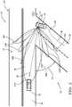
- FIG. 2illustrates a non-limiting example of a traffic-scenario 34 that the host-vehicle 12 , equipped with the system 10 described herein, may encounter.
- the host-vehicle 12is illustrated as having followed a travel-path 36 along the travel-road as the host-vehicle 12 approached the intersection 28 .
- the reason for the swerve-maneuver 48 in the travel-path 36 just prior to reaching the intersection 28will be described later.
- the field-of-view 18is the area between arrow 18 A and arrow 18 B, and is generally centered about a boresight 38 of the object-detector 20 .
- the field-of-view 18 of the object-detector 20is characterized by or defines a preferred-portion 40 of the field-of-view 18 that in this example is an area defined or bounded between arrow 40 A and arrow 40 B.
- the preferred-portion 40is an area that is narrower than, and entirely within, the extents of the field-of-view 18 .
- the preferred-portion 40is a subset of the field-of-view 18 .
- the preferred-portion 40is characterized as preferred for using the object-detector 20 to identify, track, monitor, classify, or otherwise detect an instance of the object 24 , which could be, but is not limited to, the intersection 28 , the intersecting-road 30 , and/or the other-vehicle 26 .
- the preferred-portion 40may be selected based on some performance characteristic such as, but not limited to, sensitivity, resolution, and/or detection range being better within the preferred-portion 40 when compared to the area within the field-of-view 18 but outside of the preferred-portion 40 .
- the system 10includes a controller 42 in communication with the object-detector 20 .
- the controller 42may include a processor (not specifically shown) such as a microprocessor or other control circuitry such as analog and/or digital control circuitry including an application specific integrated circuit (ASIC) for processing data as should be evident to those in the art.
- the controller 42may include memory (not specifically shown), including non-volatile memory, such as electrically erasable programmable read-only memory (EEPROM) for storing one or more routines, thresholds, and captured data.
- EEPROMelectrically erasable programmable read-only memory
- the controller 42is configured or adapted to steer the host-vehicle 12 to align the preferred-portion 40 with a detected-object 46 , e.g. a particular instance of the object 24 such as the intersection 28 , the intersecting-road 30 , and/or the other-vehicle 26 .
- a detected-object 46e.g. a particular instance of the object 24 such as the intersection 28 , the intersecting-road 30 , and/or the other-vehicle 26 .
- the travel-road 32 and the intersecting-road 30intersect at an angle other than the typical right-angle of many or most intersections.
- the preferred-portion 40 of the object-detector 20may not be well aimed toward where an approaching-vehicle (e.g.
- the steering of the host-vehicle 12 to align the preferred-portion 40 with the detected-object 46may include a swerve-maneuver 48 to better situate the orientation of the host-vehicle 12 at the intersection 28 to align the preferred-portion 40 of the object-detector 20 with the detected-object 46 .
- the object-detector 20may consist only of, or may include along with other devices, the camera 20 C.
- the camera 20 Cmay be operable to a wide-view-mode 50 A (which may include operating at a relatively high-resolution) that views all or the entirety of the field-of-view 18 , and a telescope-mode 50 B (which may include operating at a relatively low-resolution due to viewing a specified or limited region of interest) that views only the preferred-portion 40 of the field-of-view 18 .
- the controller 42may operate the camera 20 C in the wide-view-mode 50 A until the object 24 is detected (which then becomes or is designated by the system 10 as the detected-object 46 ), and then steer the host-vehicle 12 (if/when possible) so the object 24 (i.e. the detected-object 46 ) is within the preferred-portion 40 before switching to the telescope-mode 50 B.
- the controller 42steers the host-vehicle 12 to align the preferred-portion 40 of the camera 20 C with the intersecting-road 30 , then the camera 20 C may be operated to the telescope-mode 50 B so that an instance of the other-vehicle 26 (if an instance is present) can be more readily detected/classified/tracked by the camera 20 C.
- the object-detector 20may consist only of, or may include along with other devices, the radar 20 A.
- the field-of-view 18 of the radar 20 Amay be characterized by a sensitivity-pattern 54 that defines side-lobes 54 B and a main-lobe 54 A.
- the detected-object 46may be the other-vehicle 26 approaching the host-vehicle 12 by traveling on the intersecting-road 30 that intersects the travel-road 32 of the host-vehicle 12 at the intersection 28 . Accordingly, the controller 42 may steer the host-vehicle 12 to align the main-lobe 54 A of the radar 20 A with the other-vehicle 26 .
- the radar 20 Amay be operable to a low-frame-rate/wide-mode and high-frame-rate/narrow-mode similar to the how the camera 20 C is operable to the wide-view-mode 50 A and the telescope-mode 50 B.
- the same sensor (the radar 20 A or the camera 20 C) that is used to initially detect the detected-object 46is also redirected by steering the host-vehicle 12 so the detected-object 46 is with the preferred-portion 40 .
- the system 10may include, in addition to the object-detector 20 , an intersecting-road-indicator 56 that indicates the presence of the intersecting-road 30 connected to the intersection 28 that is being approached by the host-vehicle 12 .
- the intersecting-road-indicator 56may be a radar, a lidar, a camera, a digital-map 58 , or any combination thereof.
- FIG. 1may be interpreted to suggest that the object-detector 20 and the intersection-road-indicator 56 each have, for example, a dedicated instance of a camera, this is not a requirement. That is, the camera 20 C shown as part of the object-detector 20 and the camera (no reference number) shown as part of the intersecting-road-indicator 56 may be the same camera that is shared by the object-detector 22 and the intersecting-road-indicator 56 .
- controller 42is also in communication with the intersecting-road-indicator 56 .
- the controller 42may designate the intersecting-road 30 as the detected-object 46 , and steer the host-vehicle 12 to align the preferred-portion 40 of the object-detector 20 with the intersecting-road 30 when the host-vehicle 12 approaches the intersection 28 .
- the intersecting-road-indicator 56may be is a digital-map 58 such as those used on known navigation devices to plan a route to a destination for the host-vehicle 12 to travel.
- the system 10may include a location-detector 60 such as a global-positioning-system (GPS) receiver that provides GPS-coordinates and/or a heading (direction of travel on a compass) of the host-vehicle 12 .
- GPSglobal-positioning-system
- the digital-map 58may indicate an intersection-location 62 of the intersection 28 and/or information regarding the intersection-angle 52 of the travel-road 32 with the intersecting-road 30 .
- the information from the digital-map 58may be used to determine how to steer the host-vehicle 12 at the intersection 28 so the preferred-portion 40 of the object-detector 20 is better aligned with the intersecting-road 30 so the other-vehicle 26 (if present) can be more readily or reliably detected.
- the object-detector 20may be the lidar 20 B, and the controller 42 steers the host-vehicle 12 to align the field-of-view of the lidar with the intersecting-road 30 .
- the lidarmay be operable to a slow/wide mode where a slower frame is used but all of the field-of-view 18 of the lidar is scanned, and operable to a fast/narrow-mode where the preferred-portion 40 of the field-of-view is scanned, but an increased frame-rate is possible.
- the intersecting-road-indicator 56may be the camera (optionally the camera 20 C), and the object-detector 20 may be the radar 20 A.
- the field-of-view 18 of the radar 20 Amay be characterized by the sensitivity-pattern 54 that defines the side-lobes 54 B and the main-lobe 54 A.
- the controllermay then steer the host-vehicle 12 to align the main-lobe 54 A of the radar 20 A with the intersecting-road 30 based on the detection of the intersecting-road 30 and/or the intersection 28 by the camera. For example, information from the camera may be used to determine the intersection-angle 52 , and the controller 42 may determine the shape of the swerve-maneuver 48 necessary to align the preferred-portion 40 with a detected-object 46 .
- an operating system(the system 10 ), a controller 42 for the system 10 , and a method of operating the system 10 is provided.
- the system 10steers the host-vehicle 12 so that a sensor that is being used as the object-detector 20 is better aligned with an instance of the detected-object 46 , where the instance may be, for example, the other-vehicle 26 , the intersection 28 , or the intersecting-road 30 .
Landscapes
- Engineering & Computer Science (AREA)
- Radar, Positioning & Navigation (AREA)
- Remote Sensing (AREA)
- Physics & Mathematics (AREA)
- General Physics & Mathematics (AREA)
- Computer Networks & Wireless Communication (AREA)
- Electromagnetism (AREA)
- Automation & Control Theory (AREA)
- Aviation & Aerospace Engineering (AREA)
- Mechanical Engineering (AREA)
- Transportation (AREA)
- Combustion & Propulsion (AREA)
- Chemical & Material Sciences (AREA)
- Computer Vision & Pattern Recognition (AREA)
- Multimedia (AREA)
- Optics & Photonics (AREA)
- Traffic Control Systems (AREA)
- Radar Systems Or Details Thereof (AREA)
Abstract
Description
Claims (19)
Priority Applications (4)
| Application Number | Priority Date | Filing Date | Title |
|---|---|---|---|
| US15/658,065US10969785B2 (en) | 2017-07-24 | 2017-07-24 | Automated vehicle operation to compensate for sensor field-of-view limitations |
| EP18184892.0AEP3435118B1 (en) | 2017-07-24 | 2018-07-23 | Automated vehicle operation to compensate for sensor field-of-view limitations |
| CN201810818492.3ACN109298429A (en) | 2017-07-24 | 2018-07-24 | Automated vehicle operation to compensate for sensor field-of-view limitations |
| US17/222,900US20210223775A1 (en) | 2017-07-24 | 2021-04-05 | Automated vehicle operation to compensate for sensor field-of-view limitations |
Applications Claiming Priority (1)
| Application Number | Priority Date | Filing Date | Title |
|---|---|---|---|
| US15/658,065US10969785B2 (en) | 2017-07-24 | 2017-07-24 | Automated vehicle operation to compensate for sensor field-of-view limitations |
Related Child Applications (1)
| Application Number | Title | Priority Date | Filing Date |
|---|---|---|---|
| US17/222,900ContinuationUS20210223775A1 (en) | 2017-07-24 | 2021-04-05 | Automated vehicle operation to compensate for sensor field-of-view limitations |
Publications (2)
| Publication Number | Publication Date |
|---|---|
| US20190025833A1 US20190025833A1 (en) | 2019-01-24 |
| US10969785B2true US10969785B2 (en) | 2021-04-06 |
Family
ID=63035886
Family Applications (2)
| Application Number | Title | Priority Date | Filing Date |
|---|---|---|---|
| US15/658,065ActiveUS10969785B2 (en) | 2017-07-24 | 2017-07-24 | Automated vehicle operation to compensate for sensor field-of-view limitations |
| US17/222,900AbandonedUS20210223775A1 (en) | 2017-07-24 | 2021-04-05 | Automated vehicle operation to compensate for sensor field-of-view limitations |
Family Applications After (1)
| Application Number | Title | Priority Date | Filing Date |
|---|---|---|---|
| US17/222,900AbandonedUS20210223775A1 (en) | 2017-07-24 | 2021-04-05 | Automated vehicle operation to compensate for sensor field-of-view limitations |
Country Status (3)
| Country | Link |
|---|---|
| US (2) | US10969785B2 (en) |
| EP (1) | EP3435118B1 (en) |
| CN (1) | CN109298429A (en) |
Cited By (1)
| Publication number | Priority date | Publication date | Assignee | Title |
|---|---|---|---|---|
| US20220108554A1 (en)* | 2020-10-05 | 2022-04-07 | Comotomo Corporation | Vision based light detection and ranging system using multi-fields of view |
Families Citing this family (3)
| Publication number | Priority date | Publication date | Assignee | Title |
|---|---|---|---|---|
| JP6680170B2 (en)* | 2016-09-30 | 2020-04-15 | 株式会社デンソー | Driving support device and driving support method |
| EP3707526A2 (en)* | 2017-11-06 | 2020-09-16 | Echodyne Corp | Intelligent sensor and intelligent feedback-based dynamic control of a parameter of a field of regard to which the sensor is directed |
| DE102024200297A1 (en)* | 2024-01-12 | 2025-07-17 | Volkswagen Aktiengesellschaft | Method for detecting an environmental area of a vehicle's surroundings relevant for a driving maneuver of a vehicle, as well as method for carrying out a corresponding driving maneuver, sensor system and vehicle |
Citations (20)
| Publication number | Priority date | Publication date | Assignee | Title |
|---|---|---|---|---|
| US5926114A (en)* | 1998-05-18 | 1999-07-20 | Toyota Jidosha Kabushiki Kaisha | Intersection warning system |
| US20080300733A1 (en)* | 2006-02-15 | 2008-12-04 | Bayerische Motoren Werke Aktiengesellschaft | Method of aligning a swivelable vehicle sensor |
| US20110025529A1 (en)* | 2008-03-31 | 2011-02-03 | Toyota Jidosha Kabushiki Kaisha | Intersection visibility determination device, vehicle with intersection visibility determination device, and method for determining intersection visibility |
| US20150002329A1 (en)* | 2013-06-27 | 2015-01-01 | GM Global Technology Operations LLC | Multiple transmission methods for improving the operation of automotive radar systems |
| US9357208B2 (en)* | 2011-04-25 | 2016-05-31 | Magna Electronics Inc. | Method and system for dynamically calibrating vehicular cameras |
| DE102015016057A1 (en) | 2015-12-11 | 2016-06-23 | Daimler Ag | Sensor arrangement and vehicle |
| US9460613B1 (en)* | 2016-05-09 | 2016-10-04 | Iteris, Inc. | Pedestrian counting and detection at a traffic intersection based on object movement within a field of view |
| WO2017023427A1 (en) | 2015-07-31 | 2017-02-09 | Delphi Technologies, Inc. | Variable object detection field-of-focus for automated vehicle control |
| US20170050671A1 (en)* | 2014-04-10 | 2017-02-23 | Magna Electronics Inc. | Vehicle control system with adaptive wheel angle correction |
| US20170108863A1 (en)* | 2015-10-14 | 2017-04-20 | Magna Electronics Inc. | Driver assistance system with sensor offset correction |
| US9719801B1 (en)* | 2013-07-23 | 2017-08-01 | Waymo Llc | Methods and systems for calibrating sensors using road map data |
| US20180050664A1 (en)* | 2016-08-18 | 2018-02-22 | Toyota Motor Engineering & Manufacturing North America, Inc. | Operational mode change based on vehicle occupancy for an autonomous vehicle |
| US20180059236A1 (en)* | 2016-08-24 | 2018-03-01 | Magna Electronics Inc. | Vehicle sensor with integrated radar and image sensors |
| US20180074493A1 (en)* | 2016-09-13 | 2018-03-15 | Toyota Motor Engineering & Manufacturing North America, Inc. | Method and device for producing vehicle operational data based on deep learning techniques |
| US20180101737A1 (en)* | 2016-10-11 | 2018-04-12 | Mando Corporation | Driving assistant apparatus using front monitoring apparatus and driving assistant method using front monitoring apparatus |
| US20180203124A1 (en)* | 2017-01-17 | 2018-07-19 | Delphi Technologies, Inc. | Object detection system |
| US20180253099A1 (en)* | 2014-03-04 | 2018-09-06 | Cybernet Systems Corporation | All weather autonomously driven vehicles |
| US20180261095A1 (en)* | 2017-03-08 | 2018-09-13 | GM Global Technology Operations LLC | Method and apparatus of networked scene rendering and augmentation in vehicular environments in autonomous driving systems |
| US20180373260A1 (en)* | 2017-06-27 | 2018-12-27 | GM Global Technology Operations LLC | Method and apparatus for object surface estimation using reflections delay spread |
| US20190025849A1 (en)* | 2016-01-08 | 2019-01-24 | 4G Space Genius Inc. | Robot for automated image acquisition |
Family Cites Families (11)
| Publication number | Priority date | Publication date | Assignee | Title |
|---|---|---|---|---|
| JP2004336666A (en)* | 2003-05-12 | 2004-11-25 | Calsonic Kansei Corp | Vertical angle-of-visibility switching apparatus for video processing system |
| KR20040101743A (en)* | 2003-05-26 | 2004-12-03 | 삼성전자주식회사 | Apparatus and method for decoding of ldpc in a communication system |
| US8218007B2 (en)* | 2007-09-23 | 2012-07-10 | Volkswagen Ag | Camera system for a vehicle and method for controlling a camera system |
| WO2012068064A1 (en)* | 2010-11-15 | 2012-05-24 | Image Sensing Systems, Inc. | Hybrid traffic sensor system and associated method |
| JP2013161440A (en)* | 2012-02-08 | 2013-08-19 | Toyota Motor Corp | Vehicle surroundings monitoring device |
| EP3019824B1 (en)* | 2013-07-09 | 2018-01-10 | Xenomatix NV | Surround sensing system |
| US9746550B2 (en)* | 2014-10-08 | 2017-08-29 | Ford Global Technologies, Llc | Detecting low-speed close-range vehicle cut-in |
| US20170057545A1 (en)* | 2015-08-26 | 2017-03-02 | Delphi Technologies, Inc. | Gps data correction for automated vehicle |
| US11228700B2 (en)* | 2015-10-07 | 2022-01-18 | Magna Electronics Inc. | Vehicle vision system camera with adaptive field of view |
| CN105578058A (en)* | 2016-02-03 | 2016-05-11 | 北京光年无限科技有限公司 | Shooting control method and device for intelligent robot and robot |
| US10078334B2 (en)* | 2016-12-07 | 2018-09-18 | Delphi Technologies, Inc. | Vision sensing compensation |
- 2017
- 2017-07-24USUS15/658,065patent/US10969785B2/enactiveActive
- 2018
- 2018-07-23EPEP18184892.0Apatent/EP3435118B1/enactiveActive
- 2018-07-24CNCN201810818492.3Apatent/CN109298429A/enactivePending
- 2021
- 2021-04-05USUS17/222,900patent/US20210223775A1/ennot_activeAbandoned
Patent Citations (20)
| Publication number | Priority date | Publication date | Assignee | Title |
|---|---|---|---|---|
| US5926114A (en)* | 1998-05-18 | 1999-07-20 | Toyota Jidosha Kabushiki Kaisha | Intersection warning system |
| US20080300733A1 (en)* | 2006-02-15 | 2008-12-04 | Bayerische Motoren Werke Aktiengesellschaft | Method of aligning a swivelable vehicle sensor |
| US20110025529A1 (en)* | 2008-03-31 | 2011-02-03 | Toyota Jidosha Kabushiki Kaisha | Intersection visibility determination device, vehicle with intersection visibility determination device, and method for determining intersection visibility |
| US9357208B2 (en)* | 2011-04-25 | 2016-05-31 | Magna Electronics Inc. | Method and system for dynamically calibrating vehicular cameras |
| US20150002329A1 (en)* | 2013-06-27 | 2015-01-01 | GM Global Technology Operations LLC | Multiple transmission methods for improving the operation of automotive radar systems |
| US9719801B1 (en)* | 2013-07-23 | 2017-08-01 | Waymo Llc | Methods and systems for calibrating sensors using road map data |
| US20180253099A1 (en)* | 2014-03-04 | 2018-09-06 | Cybernet Systems Corporation | All weather autonomously driven vehicles |
| US20170050671A1 (en)* | 2014-04-10 | 2017-02-23 | Magna Electronics Inc. | Vehicle control system with adaptive wheel angle correction |
| WO2017023427A1 (en) | 2015-07-31 | 2017-02-09 | Delphi Technologies, Inc. | Variable object detection field-of-focus for automated vehicle control |
| US20170108863A1 (en)* | 2015-10-14 | 2017-04-20 | Magna Electronics Inc. | Driver assistance system with sensor offset correction |
| DE102015016057A1 (en) | 2015-12-11 | 2016-06-23 | Daimler Ag | Sensor arrangement and vehicle |
| US20190025849A1 (en)* | 2016-01-08 | 2019-01-24 | 4G Space Genius Inc. | Robot for automated image acquisition |
| US9460613B1 (en)* | 2016-05-09 | 2016-10-04 | Iteris, Inc. | Pedestrian counting and detection at a traffic intersection based on object movement within a field of view |
| US20180050664A1 (en)* | 2016-08-18 | 2018-02-22 | Toyota Motor Engineering & Manufacturing North America, Inc. | Operational mode change based on vehicle occupancy for an autonomous vehicle |
| US20180059236A1 (en)* | 2016-08-24 | 2018-03-01 | Magna Electronics Inc. | Vehicle sensor with integrated radar and image sensors |
| US20180074493A1 (en)* | 2016-09-13 | 2018-03-15 | Toyota Motor Engineering & Manufacturing North America, Inc. | Method and device for producing vehicle operational data based on deep learning techniques |
| US20180101737A1 (en)* | 2016-10-11 | 2018-04-12 | Mando Corporation | Driving assistant apparatus using front monitoring apparatus and driving assistant method using front monitoring apparatus |
| US20180203124A1 (en)* | 2017-01-17 | 2018-07-19 | Delphi Technologies, Inc. | Object detection system |
| US20180261095A1 (en)* | 2017-03-08 | 2018-09-13 | GM Global Technology Operations LLC | Method and apparatus of networked scene rendering and augmentation in vehicular environments in autonomous driving systems |
| US20180373260A1 (en)* | 2017-06-27 | 2018-12-27 | GM Global Technology Operations LLC | Method and apparatus for object surface estimation using reflections delay spread |
Non-Patent Citations (3)
| Title |
|---|
| European Extended Search Report in European Application No. 18184892.0, dated Dec. 20, 2018, 9 pages. |
| Florentine et al., "Pedestrian notification methods in autonomous vehicles for multi-class mobility-on-demand service." Proceedings of the Fourth International Conference on Human Agent Interaction, Oct. 4, 2016, pp. 387-392. |
| Pendleton et al., "Autonomous golf cars for public trial of mobility-on-demand service." Intelligent Robots and Systems (IROS), 2015 IEEE/RSJ International Conference on Sep. 28, 2018, pp. 1164-1171. |
Cited By (2)
| Publication number | Priority date | Publication date | Assignee | Title |
|---|---|---|---|---|
| US20220108554A1 (en)* | 2020-10-05 | 2022-04-07 | Comotomo Corporation | Vision based light detection and ranging system using multi-fields of view |
| US11790671B2 (en)* | 2020-10-05 | 2023-10-17 | Crazing Lab, Inc. | Vision based light detection and ranging system using multi-fields of view |
Also Published As
| Publication number | Publication date |
|---|---|
| EP3435118B1 (en) | 2024-05-01 |
| EP3435118A1 (en) | 2019-01-30 |
| US20210223775A1 (en) | 2021-07-22 |
| US20190025833A1 (en) | 2019-01-24 |
| CN109298429A (en) | 2019-02-01 |
Similar Documents
| Publication | Publication Date | Title |
|---|---|---|
| US20210223775A1 (en) | Automated vehicle operation to compensate for sensor field-of-view limitations | |
| US10571913B2 (en) | Operation-security system for an automated vehicle | |
| EP3608635A1 (en) | Positioning system | |
| US9898008B2 (en) | Scenario aware perception system for an automated vehicle | |
| US10836388B2 (en) | Vehicle control method and apparatus | |
| US9835719B2 (en) | Systems and methods for adaptive sensor angle positioning in vehicles | |
| US10471961B2 (en) | Cruise control device and cruise control method for vehicles | |
| US10025311B2 (en) | Automated vehicle sensor control system | |
| US7275431B2 (en) | Vehicle mounted system for detecting objects | |
| CN108627854B (en) | Automated vehicle GPS accuracy improvement using V2V communication | |
| US10078334B2 (en) | Vision sensing compensation | |
| US20080052000A1 (en) | Method for determining the global position | |
| US11488476B2 (en) | Detection system and method | |
| US20190061753A1 (en) | Vehicle control apparatus | |
| US10466706B2 (en) | Automated guidance system | |
| US10209717B2 (en) | Autonomous guidance system | |
| US10222803B2 (en) | Determining objects of interest for active cruise control | |
| US11099264B2 (en) | Variable range and frame-rate radar operation for automated vehicle | |
| US11142196B2 (en) | Lane detection method and system for a vehicle | |
| US20170248958A1 (en) | Adjacent lane verification for an automated vehicle | |
| US10848718B2 (en) | Vehicle sensor configuration based on map data | |
| EP3333027B1 (en) | Automatic braking system | |
| EP3640121A1 (en) | Vehicle lane-bias system and method | |
| GB2370706A (en) | Determining the position of a vehicle | |
| US11519735B2 (en) | Vehicle navigation system and method |
Legal Events
| Date | Code | Title | Description |
|---|---|---|---|
| AS | Assignment | Owner name:DELPHI TECHNOLOGIES, INC., MICHIGAN Free format text:ASSIGNMENT OF ASSIGNORS INTEREST;ASSIGNORS:KIM, JUNSUNG;XU, WENDA;WEI, JUNQING;REEL/FRAME:043082/0477 Effective date:20170719 | |
| AS | Assignment | Owner name:APTIV TECHNOLOGIES LIMITED, BARBADOS Free format text:ASSIGNMENT OF ASSIGNORS INTEREST;ASSIGNOR:DELPHI TECHNOLOGIES INC.;REEL/FRAME:047153/0902 Effective date:20180101 | |
| STPP | Information on status: patent application and granting procedure in general | Free format text:NON FINAL ACTION MAILED | |
| STPP | Information on status: patent application and granting procedure in general | Free format text:RESPONSE TO NON-FINAL OFFICE ACTION ENTERED AND FORWARDED TO EXAMINER | |
| STPP | Information on status: patent application and granting procedure in general | Free format text:FINAL REJECTION MAILED | |
| AS | Assignment | Owner name:MOTIONAL AD LLC, MASSACHUSETTS Free format text:ASSIGNMENT OF ASSIGNORS INTEREST;ASSIGNOR:APTIV TECHNOLOGIES LIMITED;REEL/FRAME:053863/0399 Effective date:20200917 | |
| STPP | Information on status: patent application and granting procedure in general | Free format text:NOTICE OF ALLOWANCE MAILED -- APPLICATION RECEIVED IN OFFICE OF PUBLICATIONS | |
| STPP | Information on status: patent application and granting procedure in general | Free format text:PUBLICATIONS -- ISSUE FEE PAYMENT RECEIVED | |
| STPP | Information on status: patent application and granting procedure in general | Free format text:PUBLICATIONS -- ISSUE FEE PAYMENT VERIFIED | |
| STCF | Information on status: patent grant | Free format text:PATENTED CASE | |
| MAFP | Maintenance fee payment | Free format text:PAYMENT OF MAINTENANCE FEE, 4TH YEAR, LARGE ENTITY (ORIGINAL EVENT CODE: M1551); ENTITY STATUS OF PATENT OWNER: LARGE ENTITY Year of fee payment:4 |