US10969475B2 - Method and system for encoding and decoding LiDAR - Google Patents
Method and system for encoding and decoding LiDARDownload PDFInfo
- Publication number
- US10969475B2 US10969475B2US15/863,695US201815863695AUS10969475B2US 10969475 B2US10969475 B2US 10969475B2US 201815863695 AUS201815863695 AUS 201815863695AUS 10969475 B2US10969475 B2US 10969475B2
- Authority
- US
- United States
- Prior art keywords
- pulse
- light
- scattered light
- lidar
- scanning system
- Prior art date
- Legal status (The legal status is an assumption and is not a legal conclusion. Google has not performed a legal analysis and makes no representation as to the accuracy of the status listed.)
- Active, expires
Links
Images


Classifications
- G—PHYSICS
- G01—MEASURING; TESTING
- G01S—RADIO DIRECTION-FINDING; RADIO NAVIGATION; DETERMINING DISTANCE OR VELOCITY BY USE OF RADIO WAVES; LOCATING OR PRESENCE-DETECTING BY USE OF THE REFLECTION OR RERADIATION OF RADIO WAVES; ANALOGOUS ARRANGEMENTS USING OTHER WAVES
- G01S7/00—Details of systems according to groups G01S13/00, G01S15/00, G01S17/00
- G01S7/48—Details of systems according to groups G01S13/00, G01S15/00, G01S17/00 of systems according to group G01S17/00
- G01S7/483—Details of pulse systems
- G01S7/486—Receivers
- G01S7/4865—Time delay measurement, e.g. time-of-flight measurement, time of arrival measurement or determining the exact position of a peak
- G—PHYSICS
- G01—MEASURING; TESTING
- G01S—RADIO DIRECTION-FINDING; RADIO NAVIGATION; DETERMINING DISTANCE OR VELOCITY BY USE OF RADIO WAVES; LOCATING OR PRESENCE-DETECTING BY USE OF THE REFLECTION OR RERADIATION OF RADIO WAVES; ANALOGOUS ARRANGEMENTS USING OTHER WAVES
- G01S17/00—Systems using the reflection or reradiation of electromagnetic waves other than radio waves, e.g. lidar systems
- G01S17/02—Systems using the reflection of electromagnetic waves other than radio waves
- G01S17/06—Systems determining position data of a target
- G01S17/08—Systems determining position data of a target for measuring distance only
- G01S17/10—Systems determining position data of a target for measuring distance only using transmission of interrupted, pulse-modulated waves
- G—PHYSICS
- G01—MEASURING; TESTING
- G01S—RADIO DIRECTION-FINDING; RADIO NAVIGATION; DETERMINING DISTANCE OR VELOCITY BY USE OF RADIO WAVES; LOCATING OR PRESENCE-DETECTING BY USE OF THE REFLECTION OR RERADIATION OF RADIO WAVES; ANALOGOUS ARRANGEMENTS USING OTHER WAVES
- G01S7/00—Details of systems according to groups G01S13/00, G01S15/00, G01S17/00
- G01S7/48—Details of systems according to groups G01S13/00, G01S15/00, G01S17/00 of systems according to group G01S17/00
- G01S7/483—Details of pulse systems
- G01S7/484—Transmitters
- G—PHYSICS
- G01—MEASURING; TESTING
- G01S—RADIO DIRECTION-FINDING; RADIO NAVIGATION; DETERMINING DISTANCE OR VELOCITY BY USE OF RADIO WAVES; LOCATING OR PRESENCE-DETECTING BY USE OF THE REFLECTION OR RERADIATION OF RADIO WAVES; ANALOGOUS ARRANGEMENTS USING OTHER WAVES
- G01S7/00—Details of systems according to groups G01S13/00, G01S15/00, G01S17/00
- G01S7/48—Details of systems according to groups G01S13/00, G01S15/00, G01S17/00 of systems according to group G01S17/00
- G01S7/483—Details of pulse systems
- G01S7/486—Receivers
- G01S7/487—Extracting wanted echo signals, e.g. pulse detection
- G01S7/4876—Extracting wanted echo signals, e.g. pulse detection by removing unwanted signals
Definitions
- the present disclosuregenerally relates to a light detection and ranging (LiDAR) and, more specifically, to a technique for encoding and decoding a LiDAR system.
- LiDARlight detection and ranging
- LiDAR systemcan be used to measure the distance between an object and the system. Specifically, the system can transmit a signal (e.g., using a light source), record a returned signal (e.g., using light detectors), and determine the distance by calculating the delay between the returned signal and the transmitted signal.
- a signale.g., using a light source
- a returned signale.g., using light detectors
- a light detection and ranging (LiDAR) scanning systemcomprising: a light source, wherein the light source is configured to transmit a pulse of light to illuminate a surface of an object; a modulator operable to encode the pulse of light in response to a signal from a sequence generator; a light detector configured to detect scattered light from the surface of the object of the light pulse; a correlator electrically coupled to the light detector, wherein the correlator is configured to correlate the scattered light with the sequence code and output a peak value associated with a time that the pulse of light is received, and a microprocessor electrically coupled to the light source and the correlator, wherein the microprocessor is configured to: determine whether an amplitude of the peak value exceeds a threshold value, in accordance with a determination that the amplitude of the peak exceeds the threshold value: determine a time difference between a time that pulse of light was transmitted and the time that the pulse of light is received, and calculate a distance to the surface of the object
- a method for light detection and ranging (LiDAR) scanning detectioncomprising: encoding a pulse of light from a light source with a sequence code; transmitting the pulse of light to illuminate a surface of an object; detecting, at a detector, scattered light from the illuminated surface of the object; correlating the detected scattered light with the sequence code that outputs a peak value associated with a time that the pulse of light is received determining whether an amplitude of the peak value exceeds a threshold value; in accordance with a determination that the amplitude of the peak exceeds the threshold value: determining a time difference between a time that pulse of light was transmitted and the time the pulse of light is received; and calculating a distance to the surface of the object based on the time difference.
- LiDARlight detection and ranging
- a computer-implemented methodcomprises: in a light detection and ranging (LiDAR) system having a light source and a light detector: transmitting, using the light source, a first pulse group signal having a first number of pulse signals and a second pulse group signal having a second number of pulse signals, wherein the first number is different from the second number; receiving, using the light detector, a returned pulse group signal having a third number of pulse signals; determining, based on the third number of pulse signals, whether the returned pulse group signal corresponds to the first pulse group signal or the second pulse group signal; in accordance with a determination that the returned pulse group signal corresponds to the first pulse group signal, determining a first distance based on the returned pulse group signal and the transmitted first pulse group signal; and in accordance with a determination that the returned pulse group signal corresponds to the second pulse group signal, determining a second distance based on the returned pulse group signal and the transmitted second pulse group signal.
- LiDARlight detection and ranging
- a light detection and ranging (LiDAR) scanning systemcomprises a light source, wherein the light source is configured to transmit a first pulse group signal having a first number of pulse signals and a second pulse group signal having a second number of pulse signals, wherein the first number is different from the second number; a light detector configured to detect a returned pulse group signal having a third number of pulse signals; a microprocessor electrically coupled to the light source and the light detector, wherein the microprocessor is configured to determine, based on the third number of pulse signals, whether the returned pulse group signal corresponds to the first pulse group signal or the second pulse group signal; in accordance with a determination that the returned pulse group signal corresponds to the first pulse group signal, determine a first distance based on the returned pulse group signal and the transmitted first pulse group signal; and in accordance with a determination that the returned pulse group signal corresponds to the second pulse group signal, determine a second distance based on the returned pulse group signal and the transmitted second pulse group signal.
- LiDARlight detection and ranging
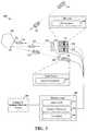
- FIG. 1illustrates a plurality of LiDAR systems attached to a vehicle.
- FIG. 2illustrates an exemplary LiDAR system for distinguishing delayed pulses of light.
- FIG. 3illustrates an exemplary LiDAR system for distinguishing pulses of light from different light sources.
- FIG. 4Aillustrates four encoded sequences for encoded LiDAR systems in overlapping regions.
- FIG. 4Billustrates correlation for distinguishing an encoded sequence between other sequences.
- FIG. 5Aillustrates an encoded signal of scattered light with noise and varied attenuation.
- FIG. 5Billustrates correlation for the encoded signal of scattered light with noise and varied attenuation.
- FIG. 6illustrates an exemplary process for encoding and decoding a LiDAR system.
- FIG. 7Aillustrates an exemplary LiDAR system for correlating returned scattered lights with transmitted pulse signals, according to some embodiments of the disclosure.
- FIG. 7Billustrates an exemplary set of pulse signals transmitted by a LiDAR system, according to some embodiments of the disclosure.
- a LiDAR systemilluminates an object with a pulse of light and detects the scattered light that corresponds to the pulse of light. Associating a pulse of light with scattered light that does not correspond to the pulse of light may cause the LiDAR system to interpret the presence of an object, even though there is no physical object there. For example, scattered light from another pulse transmitted by the same LiDAR system or by a second LiDAR system in proximity to the LiDAR system can mistakenly be paired with the original pulse light, which can be incorrectly interpreted as an object.
- Current techniquestypically post-process samples to correct for “false” objects by comparing adjacent samples of a capture frame, which is at best an approximation. As such, the challenge is to improve on pairing a pulse of light with the corresponding scattered light from the light pulse.
- first pulse signalcould be termed a second pulse signal
- first pulse signalcould be termed a first pulse signal
- second pulse signalcould be termed a first pulse signal
- the first pulse signal and the second pulse signalsare both pulse signals, but they may not be the same pulse signal.
- ifis, optionally, construed to mean “when” or “upon” or “in response to determining” or “in response to detecting,” depending on the context.
- phrase “if it is determined” or “if [a stated condition or event] is detected”is, optionally, construed to mean “upon determining” or “in response to determining” or “upon detecting [the stated condition or event]” or “in response to detecting [the stated condition or event],” depending on the context.
- FIG. 1illustrates a plurality of LiDAR systems 102 A- 102 F attached to a vehicle 100 .
- the vehicle 100has a first LiDAR system 102 A directed to scan the front region 104 A of the vehicle 100 , a second LiDAR system 102 B directed to scan the rear region 104 B of the vehicle 100 , a third LiDAR system 102 C directed to scan passenger side region 104 C of the vehicle 100 , a fourth LiDAR system 102 B directed to scan the driver side region 104 D of the vehicle 100 , a fifth LiDAR system 102 E directed to scan the front passenger side corner region 104 E of the vehicle 100 , and a sixth LiDAR system 102 F directed to scan the front driver side corner region 104 F of the vehicle 100 .
- the fifth LiDAR system 102 E of the vehicle 100covers a “blind spot” (e.g., an area not scanned by a LiDAR system) corresponding to the non-scanned area between the front region 104 A and the passenger side region 104 C.
- the fifth LiDAR system 102 Ehas a front passenger side corner region 104 E that overlaps with the front region 104 A at a first overlapping region 106 AE and a front passenger side corner region 104 E that overlaps with the passenger side region 104 C at a second overlapping region 106 EC.
- the sixth LiDAR system 102 F of the vehicle 100covers a “blind spot” (e.g., an area not scanned by a LiDAR system) corresponding to the non-scanned area between the front region 104 A and the driver side region 104 D.
- the sixth LiDAR system 102 Fhas a front driver side corner region 104 F that overlaps with the front region 104 A at a third overlapping region 106 AF and a front driver side corner region 104 F that overlaps with the driver side region 104 D at a fourth overlapping region 106 FD.
- the overlapping regionscan provide additional resolution since each overlapping region can range objects within each respective overlapping region from more than one LiDAR system.
- the first LiDAR system 102 Acan range a surface of an object situated in the first overlapping region 106 AE and the fifth LiDAR system 102 E can range an adjacent surface of an object situated in the first overlapping region 106 AE.
- the first overlapping region 106 AEcan be over-scanned where two LiDAR systems can range objects in the same area at the same time.
- Over-scanning overlapping regionscan also cause interference between one or more LiDAR systems.
- the first LiDAR system 102 Acan range a surface of an object situated in the first overlapping region 106 AE at substantially the same time and in substantially the same location that the fifth LiDAR system 102 E ranges a surface of an object situated in the first overlapping region 106 AE.
- a pulse of scattered light from the first LiDAR system 102 Acan mistakenly be detected at the fifth LiDAR system 102 E.
- a pulse of scattered light from the fifth LiDAR system 102 Ecan mistakenly be detected at the first LiDAR system 102 A.
- a pulse of scattered light from the first LiDAR system 102 Acan interfere with a pulse of scattered light from the fifth LiDAR system 102 E. That is, the first LiDAR system 102 A can detect both the pulses of scattered light and it can be difficult to distinguish which is the pulse of scattered light that corresponds to the pulse of light transmitted from the first LiDAR system 102 A.
- One approach to distinguish which pulse of scattered light corresponds to the transmitted pulse of light when multiple pulses of scattered light are detectedis to implement a “first to arrive” distinction, which associates the first detected scattered light to a transmitted pulse of light. The reasoning in this approach is that the first pulse of light to arrive travels the shortest distance, which corresponds to the correct transmitted pulse of light.
- pulses of scattered light from adjacent LiDAR systemscan interfere with this approach.
- a pulse of scattered light from the fifth LiDAR system 102 Ecan arrive at the first LiDAR system 102 A prior to a pulse of scattered light transmitted from the first LiDAR system 102 A.
- selecting the “first to arrive”e.g., in this instance, a pulse of scattered light from the fifth LiDAR system 102 E
- Another approach to distinguish which pulse of scattered light corresponds to the transmitted pulse of light when multiple pulses of scattered light are detectedis to implement a “most intense” distinction, which associates the brightest detected pulse of scattered light to a transmitted pulse of light.
- the reasoning in this approachis that the alignment of the light source and the detector collects a more intense pulse of light than a second light source that is randomly aligned with the detector.
- the most intense (e.g., brightest) pulse of light to arrivecorresponds to the transmitted pulse of light.
- the pulse of scattered light originating from the fifth LiDAR system 102 Ecan arrive at the first LiDAR system 102 A after and with a higher intensity than a pulse of scattered light originating from the first LiDAR system 102 A.
- selecting the “most intense”e.g., in this instance, a pulse of scattered light from the fifth LiDAR system 102 E
- each LiDAR system depicted in FIG. 1includes a modulator operable to encode the transmitted pulse of light in response to a signal from a sequence generator. That is, each transmitted pulse of light is modulated according to a sequence code, which is represented in FIG. 1 as the pattern for each scanning region (e.g., regions 104 A- 104 F).
- the sequence codeis a pseudorandom bit sequence (PRBS) code.
- the PRBS codecan have 2 5 ⁇ 1 bits corresponding to a PRBS-5 code, PRBS code can have 2 31 ⁇ 1 bits corresponding to a PRBS-31 code, etc. It should be appreciated that the PRBS code can be larger than 2 5 ⁇ 1. For instance, the PRBS code can have 2 6 ⁇ 1 bits corresponding to a PRBS-6 code, the PRBS code can have 2 7 ⁇ 1 bits corresponding to a PRBS-7 code, the PRBS code can have 2 8 ⁇ 1 bits corresponding to a PRBS-8 code, the PRBS code can have 2 9 ⁇ 1 bits corresponding to a PRBS-9 code, etc. It should also be appreciated that the PRBS code can be smaller than 2 5 ⁇ 1. For instance, the PRBS code can have 2 4 ⁇ 1 bits corresponding to a PRBS-4 code, the PRBS code can have 2 3 ⁇ 1 bits corresponding to a PRBS-3 code, etc.
- each LiDAR systemencodes the transmitted pulse of light, which facilitates distinguishing the pulse of scattered light that corresponds to the transmitted pulse of light when multiple pulses of scattered light are detected.
- the pulse of scattered light originating from the fifth LiDAR system 102 Ecan arrive at the first LiDAR system 102 A prior to pulse of scattered light transmitted from the first LiDAR system 102 A.
- the pulse of scattered light originating from the pulse of scattered light originating from the first LiDAR system 102 A and the fifth LiDAR system 102 Eare correlated with the sequence code of the first LiDAR system 102 A.
- the first LiDAR system 102 Acorrectly identifies the pulse of scattered light arriving later (e.g., the pulse of scattered light originating from the first LiDAR system 102 A).
- a pulse of scattered light originating from the fifth LiDAR system 102 Ecan arrive at the first LiDAR system 102 A after with a higher intensity than a pulse of scattered light originating from the first LiDAR system 102 A.
- the pulse of scattered light originating from the first LiDAR system 102 A and the pulse of scattered light originating from the fifth LiDAR system 102 Eare correlated with the sequence code of the first LiDAR system 102 A.
- the first LiDAR system 102 Acorrectly identifies the pulse of scattered light with the lower intensity (e.g., the pulse of scattered light originating from the first LiDAR system 102 A).
- FIG. 2illustrates an exemplary LiDAR system 200 for distinguishing delayed pulses of light.
- the LiDAR system 200includes a light source 210 , a light detector 230 , and an electrical processing and computing device (such as a microcontroller) 240 .
- the light source 210is configured to transmit a pulse of light 214 that illuminates a first surface 252 of an object 250 .
- the light source 210is a laser diode.
- the light source 210can be incandescent light, fluorescent light, and the like.
- the light source 210can have one or more wavelengths that in the visible spectrum, one or more wavelengths in the infrared spectrum, or one or more wavelengths in the ultra violet spectrum.
- the light source 210has an internal modulator 212 that is operable to encode the pulse of light 214 in response to a signal from a sequence generator 244 .
- the internal modulator 212is configured to modulate an injection current to the laser diode light source 210 in accordance with on-off keying.
- the modulatorcan be external the light source.
- the modulatorcan be an opto-electrical modulator 220 situated in the optical path of the light source 210 and the object 250 , as depicted as an option in FIG. 2 .
- the opto-electrical modulator 220can be a Mach-Zehnder modulator.
- the light detector 230is in the optical path of the pulse of scattered light 216 .
- the light detector 230is configured to detect a pulse of scattered light 216 diffused or scattered from the first surface 252 of the object 250 originating from the light pulse 214 .
- the light detector 230can include a photo sensor 232 , an aperture mask 234 , and converging lens 236 .
- the converging lens 236is configured to direct a pulse scattered light toward a focal region at the photo sensor 232 .
- the converging lens 236can be made from any transparent material such as high index glass, plastic, and the like.
- the lens 236directs pulses of scattered light 216 over a large area, which increases the amount of pulses of scattered light 216 collected at the photo sensor 232 .
- the mask 234is configured to filter pulses of scattered light 216 near the photo sensor 232 that are obliquely angled with respect to the optical path of a direct pulse of scattered light 216 , so that only light that is substantially parallel to the path of a direct pulse of scattered light 216 can reach the photo sensor 232 .
- light from the pulse of light 214can disperse from a first surface 252 and “echo” off a second surface 254 and be directed along an optical path that is substantially parallel to the path of a direct pulse of scattered light 216 .
- the extra distance that such pulse of echo-scattered light 218 takesdelays the pulse of echo-scattered light 218 from the more direct path of the pulse of scattered light 216 .
- echo-scattered light 218lag a direct pulse of scattered light 216 .
- the photo sensor 232can be a photodiode, an avalanche photodiode, a photo-multiplier tube, and the like.
- the photo sensor 232includes a reflective mirror facing the opposite surface of the light incident surface, which reflects light back to the absorption region of the photo sensor 232 .
- the LiDAR system 200detects both the pulse of scattered light 216 and the echo-scattered light 218 and the LiDAR system 200 associates both the pulse of scattered light 216 and the echo-scattered light 218 as valid pulses transmitted by the LiDAR system 200 .
- the LiDAR system 200associates both the pulses of scattered light 216 and the echo-scattered light 218 as valid pulses transmitted by the LiDAR system 200 based on the sequence code encoded in the pulses in accordance with the methods described herein.
- the LiDAR system 200attributes the “first to arrive” as the pulse of scattered light 214 and the remaining as pulses of echo-scattered light 218 as echo-scattered light 218 lag a direct pulse of scattered light 216 .
- the light detector 230includes an analog to digital (A/D) converter 238 .
- the A/D converter 238can be an integrated circuit that is configured to convert the analog electrical response from the detector (e.g., photo sensor 232 ) to absorbed scattered light 216 to a digital electrical signal.
- having the A/D converter 238 substantially at the photo sensor 232can reduces losses (e.g., line loss), which can increase the signal integrity.
- the example depicted in FIG. 2includes an electrical processing and computing device (such as a microprocessor) 240 that is electrically coupled to a computer-readable medium/memory 248 , the light source 210 , the light detector 230 , photo sensor 232 , the optional optical modulator 224 , and the optional opto-electrical modulator 220 .
- the microprocessor 240 in the LiDAR system 200can execute software.
- Softwareshall be construed broadly to mean instructions, instruction sets, code, code segments, program code, programs, subprograms, software components, applications, software applications, software packages, routines, subroutines, objects, executables, threads of execution, procedures, functions, etc., whether referred to as software, firmware, middleware, microcode, hardware description language, or otherwise
- the microprocessor 240includes a time/clock 242 , a sequence generator 244 , and a correlator 246 . As depicted in FIG. 2 , the microprocessor 240 is electrically coupled to the light source 210 and the correlator 246 . As such, the light source 210 can trigger the timer/clock 242 to mark the time for a pulse of light 214 is transmitted. Likewise the correlator 246 can mark the time for pulse of light detected. In some examples, the timer/clock module 242 is configured to mark each pulse of light 214 that is transmitted or received with a timestamp. The timestamp is an encoded date and time.
- time timestampsinclude “month-day-year@hour:min:sec,” “month-day-year@hour:min:sec,” “year-dd-month@hour:min:sec,” “1234567890 (Unix time),” etc.
- the timer/clock module 308can further pair a pulse of light 214 with a scattered pulse of light 216 and determine the time difference.
- the time/clock 242is a module embedded within the microprocessor 240 .
- the sequence generator 244is configured to generate a sequence code.
- the sequence generator 244is electrically coupled to the correlator 246 , the light source 210 (e.g., internal modulator 212 ), and optionally to the opto-electrical modulator 220 .
- the sequence generator 244is a module embedded within the microprocessor 240 .
- the sequence codeis a pseudorandom bit sequence (PRBS) code.
- the correlator 246is electrically coupled to the light detector 230 .
- the correlator 246is configured to correlate a pulse of scattered light 216 with a sequence code, which measures the similarity between the pulse of scattered light 216 and the sequence code. For a high similarity, the correlator 246 outputs a peak value where the pulse of scattered light 216 and the sequence code align. The position of the peak value is associated with a time that the pulse of scattered light 216 is received.
- the correlator 246accesses the digital electrical signal from the A/D converter 238 , which corresponds to the electrical representation of the scattered light 216 . As depicted in FIG. 2 , the A/D converter 238 is electrically coupled to the light detector 230 .
- the LiDAR system 200can include an optical modulator 224 , which correlates a pulse of scattered light 216 in the optical domain.
- the optical modulator 224is situated in the optical path of the scattered light 216 .
- the pulse of scattered light 216is optically correlated with the sequence code.
- the optical modulator 224is configured to implement four-wave-mixing.
- the microprocessor 240is further configure to determine whether an amplitude of the peak value from the correlation between the scattered light 216 and the sequence code exceeds a threshold value.
- the threshold valueis at least one standard deviation above an average of the output from the correlator 246 .
- the microprocessor 240is further configure to determine a time difference between a time that pulse of light 214 was transmitted and the time that the pulse of scattered light 216 was received. Based on this time difference the microprocessor 240 is configured to calculate a distance to the surface (e.g., distance to first surface 252 ) of the object 250 .
- the microprocessor 240is further configured to determine a reflectivity of the surface (e.g., first surface 252 ) of the object 250 based on the amplitude of the peak value.
- the computer-readable medium/memory 248is electrically coupled to microprocessor and provides storage for the time markers, the sequence code, timestamps, distance determinations, etc.
- FIG. 3illustrates an exemplary LiDAR system 200 ′ for distinguishing pulses of light from different light sources.
- the LiDAR system 200 ′can be the LiDAR system 200 of FIG. 2 that receives a different pulse of scattered light 316 from second light source 310 instead of receiving a pulse of echo-scattered light 218 .
- the LiDAR system 200 ′depicts a different pulse of light 314 from a second light source 310 that illuminates a third surface 352 of an object 250 , which is in proximity to the first surface 252 .
- Some light from the different pulse of light 314can disperse from a third surface 352 and be directed along an optical path that is substantially parallel to the path of a direct pulse of scattered light 216 and be detected by the light detector 230 .
- the correlator 246correlates the different pulse of scattered light 318 originating from the light source 310 and the code sequence and also correlates the pulse of scattered 218 originating from the light source 210 and the code sequence.
- the correlation resultsindicate that the correlation is higher for the pulse of scattered 218 compared to the correlation for the different pulse of scattered light 318 .
- the LiDAR system 200 ′correctly associated the different pulse of light 314 with the pulse of scattered 218 .
- FIG. 3illustrates distinguishing scattered lights originated from different light sources (i.e., light sources 210 and 310 ), it should be appreciated that the method of encoding pulse signals described herein can be used to distinguish among scattered lights originated from the same source.
- a LiDAR systemcan encode multiple transmitted pulse signals with different sequence codes (e.g., PRBS codes) respectively.
- PRBS codese.g., PRBS codes
- the LiDAR systemcan perform decoding to correlate the scattered light to a particular transmitted pulse signal that has the same encoding information.
- the scattered lights from multiple transmitted pulse signalsreach the light detector in an order different from the order their corresponding pulse signals were transmitted from the LiDAR system, the system can still uniquely identify each scattered light pulse.
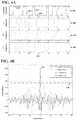
- FIG. 4Aillustrates four encoded sequences for encoded LiDAR systems.
- the encoded sequence 402has a logic level “1” 410 and a logic level “0” 416 that transitions at a rising edge 412 or a falling edge 414 .
- there is no noise on the each sequence codese.g., encoded sequence 402 , 1 st sequence 404 , 2 nd sequence 406 , 3 rd sequence 408 , etc.
- the encoded sequence 402is a PRBS-5 code corresponding to 31 bits (e.g., 2 5 ⁇ 1).
- FIG. 4Billustrates correlation for distinguishing an encoded sequence 402 between other sequences (e.g., 1 st sequence 404 , 2 nd sequence 406 , 3 rd sequence 408 , etc.).
- the correlator 246correlates the sequence code (e.g., encoded sequence 402 ) with the encoded sequence 402 , with 1 st sequence 404 , with 2 nd sequence 406 , and with 3 rd sequence 408 .
- the sequence codee.g., encoded sequence 402
- the correlation between the sequence code (e.g., encoded sequence 402 ) and the encoded sequence 402yields a peak value 418 that is much higher than the correlation peaks from the other sequences (e.g., 1 st sequence 404 , 2 nd sequence 406 , and 3 rd sequence 408 ).
- the encoded sequence 402is the sequence code for the first LiDAR system 102 A ( FIG. 1 ) and the 1 st sequence 404 is the sequence code for the fifth LiDAR system 102 E ( FIG. 1 )
- the first LiDAR system 102 Acan correctly distinguish a pulse of scattered light from the first LiDAR system 102 A over the fifth LiDAR system 102 E within the first overlapping region 106 AE.
- the 2 nd sequence 406can be the sequence code for the second LiDAR system 102 B ( FIG. 1 )
- the 3 rd sequence 408can be the sequence code for the third LiDAR system 102 C ( FIG. 1 )
- other sequence codescan be generated for the fourth LiDAR system 102 D ( FIG. 1 ) and the sixth LiDAR system 102 F ( FIG. 1 ).
- FIG. 4Balso depicts a threshold values 420 .
- the microprocessor 240determines a threshold value 420 base on the statistics of the correlation output. For example, in some instances the threshold value 420 is at least one standard deviation above an average of the output from the correlator 246 .
- FIG. 5Aillustrates an encoded signal of scattered light 216 with noise 530 and varied attenuation (e.g., 0 dB attenuation 502 A, 20 dB attenuation 502 B, 20 dB attenuation 502 C).
- a pulse of light 214is encoded with the encoded sequence 402 .
- the pulse of light 214is encoded with a logic level “1” 410 and a logic level “0” 416 that transitions at a rising edge 412 or a falling edge 414 .
- the pulse of light 214 for 0 dB attenuation 502 Ais similar to the encoded sequence 402 of FIG.
- the noise 530 in the pulse of light 214can be thermal noise (e.g., from transistors during modulation), light noise (e.g., background radiation), etc.
- the pulse of light 214 at 20 dB attenuation 502 Bappears to be slightly visible over the noise term (e.g., noise 530 )
- the pulse of light 214 at 30 dB attenuation 502 Cappears to be almost indistinguishable to the naked eye over the noise term (e.g., noise 530 ).
- FIG. 5Billustrates correlation for the encoded signal of scattered light 216 with noise 530 and varied attenuation (e.g., 0 dB attenuation 502 A, 20 dB attenuation 502 B, 20 dB attenuation 502 C).
- correlator 246correlates the pulse of light 214 at 0 dB attenuation 502 A, 20 dB attenuation 502 B, and 30 dB attenuation 502 C of FIG. 5A with the encoded sequence 402 ( FIG. 4 ). As depicted in FIG.
- each of the correlation at 0 dB attenuation 504 A, the correlation at 20 dB attenuation 504 B, and the correlation at 30 dB attenuation 504 Chave a peak value 418 A, a peak value 418 B, and a peak value 418 C, respectively.
- the correlation at 0 dB attenuation 504 Ais substantially similar to the correlation for encoded sequence 402 in FIG. 4B
- the correlation at 20 dB attenuation 504 Bhas a peak value 418 B looks similar but is roughly an order of magnitude smaller (e.g. 10 times smaller) than the peak value 418 A of the correlation at 0 dB attenuation 504 A.
- the correlation at 30 dB attenuation 504 Chas a peak value 418 C that is roughly three times smaller than the peak value 418 B of the correlation at 20 dB attenuation 504 B.
- the microprocessor 240can be configured to determine a reflectivity of the surface (e.g., first surface 252 ) of the object 250 based on the amplitude of the peak value 418 .
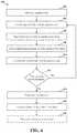
- FIG. 6illustrates an exemplary process 600 for encoding and decoding a LiDAR system (e.g., LiDAR system 200 , LiDAR system 200 ′, etc.).
- Process 600can be performed by a system disposed or included in a vehicle.
- the systemcan be the LiDAR system 200 or 200 ′ ( FIGS. 2 and 3 ).
- process 600generates a sequence code.
- the sequence generator 244( FIGS. 2 and 3 ) can be module embedded within the microprocessor 240 .
- the sequence codeis a pseudorandom bit sequence (PRBS) code.
- PRBS codecan have 2 5 ⁇ 1 bits corresponding to a PRBS-5 code.
- the sequence generator 244provides the sequence code to the light source 210 (e.g., internal modulator 212 ) and the correlator 246 .
- PRBSpseudorandom bit sequence
- the process 600encodes a pulse of light from a light source with a sequence code.
- the light source 210is a diode laser with an internal modulator 212 that is operable to encode the pulse of light 214 in response to a signal from a sequence generator 244 .
- encoding a pulse of light 214comprises modulating an injection current to the laser diode light source 210 in accordance with on/off keying.
- the internal modulator 212can be configured to modulate an injection current to the laser diode light source 210 in accordance with on-off keying.
- the modulatoris an external modulator such as the opto-electrical modulator 220 situated in the optical path of the light source 210 and the object 250 .
- the opto-electrical modulator 220can be a Mach-Zehnder modulator.
- encoding a pulse of light 214is modulating the pulse of light 214 via a Mach-Zehnder modulator situated in the optical path of the light source 210 .
- encoding a pulse of light 214includes modulating the pulse of light 214 in optical domain via an electro-optical modulator.
- the process 600transmits the pulse of light to illuminate a surface of an object. That is, the light source 210 ( FIGS. 2 and 3 ) can transmit a pulse of light 214 that illuminates a first surface 252 of an object 250 . As a result, some light from the light pulse 214 can disperse from a first surface 252 and be directed along an optical path that is substantially parallel to the path of a direct scattered light 216 .
- the process 600detects, at a detector (e.g., detector 230 ), scattered light from the illuminated surface of the object. That is, the detector 230 can detect the pulse of scattered light 216 that was dispersed from the first surface 252 and directed to the light detector 230 .
- the light detector 230can include a photo sensor 232 , an aperture mask 234 , and converging lens 236 to assist in gathering more pulses of scattered light (e.g., pulse of scattered light 238 ).
- the converging lens 236gathers and directs pulses of scattered light (e.g., pulse of scattered light 238 ) toward a focal region at the photo sensor 232 .
- the pulses of scattered lightinclude an encoded pulse of scattered light 238 originating from the light pulse 214 , echo-scattered light 218 originating from the dispersed light pulse 214 echoing off one or more surfaces, and different pulse of light scattered 318 originating from a different pulse of light 314 .
- the photo sensor 232is a photodiode such as an avalanche photodiode.
- the detectoris a photomultiplier tube.
- detecting scattered lightincludes converting the detected pulse of scattered light 238 to a digital electrical signal.
- the process 600correlates the detected pulse of scattered light with the sequence code that outputs a peak value associated with a time that the pulse of light is received.
- the correlator 246receives the sequence code from the signal generator 244 and the converted digital electrical signal from the A/D converter 238 of the detector 230 .
- the correlator 246then correlates the converted digital electrical signal with the sequence code.
- the correlationyields a peak value 418 (e.g., peak 418 FIG. 4B ) situated at time index 0 , which facilities synchronizing with time/clock 242 to determine the difference in time.
- the process 600determines whether an amplitude of the at least one peak value exceeds a threshold value.
- the microprocessor 240can be configure to determine whether an amplitude of the peak value 418 from the correlation between the scattered light 216 and the sequence code exceeds a threshold value 418 .
- the microprocessorwould determine that the peak 118 depicted in FIG. 4B exceeds the threshold value 420 , whereas the peaks of the remaining correlations do not exceed the threshold value 420 .
- the threshold valueis at least one standard deviation above an average of the output from the correlator.
- the microprocessor 240can average and the standard deviation of the output of the correlator 246 and then set the threshold value to at the average plus the standard deviation. In some examples, the microprocessor makes the determination after the output of the correlator from one transceiving cycle is recorded.
- the process 600determines a time difference between a time that pulse of light was transmitted and the time the pulse of light is received.
- the time/clock 242can pair a pulse of light 214 with a scattered pulse of light 216 and determine the time difference.
- the time/clock 242uses time markers (e.g., timestamps).
- firing the pulse of light 214can trigger a time marker and the correlation at time index zero can trigger a time marker.
- the process 600calculates a distance to the surface of the object based on the time difference.
- the microprocessor 240can multiple the time difference by the speed of light divided by 2 to yield the distance to an object 250 . For instance, with a time difference of 0.8 microseconds the microprocessor 240 would calculate the distance to an object 250 to be around 120 meters away (e.g., 0.8e-6*2.9979e8/2).
- the calculator module 310can store the values to computer-readable medium/memory 248 .
- the process 600determines a reflectivity of the surface of the object based on the amplitude of the peak. For example, a pulse of light 214 illuminates a surface (e.g., first surface 252 ) of an object 250 , in which the light disperses and some of the scattered light 218 is directed to the detector 230 . For highly reflective surfaces a large portion (e.g., percentage) of scattered light 218 is directed to the detector 230 , whereas for low reflective surface a large portion (e.g., percentage) of scattered light 218 is directed to the detector 230 .
- a pulse of light 214illuminates a surface (e.g., first surface 252 ) of an object 250 , in which the light disperses and some of the scattered light 218 is directed to the detector 230 .
- a large portion (e.g., percentage) of scattered light 218is directed to the detector 230
- a large portion (e.g., percentage) of scattered light 218is directed to the detector
- FIG. 7Aillustrates an exemplary LiDAR system for correlating returned scattered lights with transmitted pulse signals, according to some embodiments of the disclosure.
- a LiDAR system 700includes a transmitter 702 and a receiver 704 .
- the transmitter 702transmits, using a light source, a first pulse group signal 706 and a second pulse group signal 708 at two different times.
- a pulse group signalcan include a group of one or more pulses that are spaced apart by relatively small time intervals. Thus, a pulse group signal can have one or more peaks.
- the first pulse group signal 706includes a single pulse and thus one peak, while the second pulse group signal 708 includes two pulses and thus two peaks.
- the pulse signal of the first pulse group signal 706 and the pulse signals of the second pulse group signal 708are associated with a same wavelength.
- the pulse group signals 706 and 708differ in other characteristics, such as pulse width, pulse shape, and/or the pulse repetition period within a pulse group.
- the first pulse group signal 706 and the second pulse group signal 708are separated by a time interval.
- the time intervalis set large enough such that the two group signals do not overlap with each other.
- the time interval between the transmission of pulse group signals 706 and 708is larger than the time interval between the two pulses within the pulse group signal 708 . This improves the likelihood that the scattered lights from the pulse group signals 706 and 708 are recognized as two distinct group signals.
- the receiver 704receives, using the light detector, a first returned pulse group signal 712 and a second returned pulse group signal 714 .
- the systemmakes a determination as to which transmitted pulse group signal it corresponds to. For example, the system identifies two pulses (or peaks) within the second returned pulse group signal 714 and thus determines that the second returned pulse group signal 714 corresponds to the second pulse group signal 708 . Accordingly, the system determines a distance based on the time when the pulse group signal 708 is transmitted and the time when the pulse group signal 714 is received.
- the systemidentifies one pulse (or peak) within the first returned pulse group signal 712 and thus determines that the first returned pulse group signal 712 corresponds to the first pulse group signal 706 . Accordingly, the system determines a distance based on the time when the pulse group signal 706 is transmitted and the time when the pulse group signal 712 is received.
- the LiDAR system 700can correlate returned pulse group signals 712 and 714 to the respective transmitted signals regardless of the order in which the returned pulse group signals 712 and 714 are received. For example, if the first pulse group signal 706 is scattered by a relatively faraway object while the second pulse group signal 708 is scattered by a relatively nearby object, the returned pulse group signal 714 (corresponding to the second pulse group signal 708 ) may be received before the returned pulse group signal 712 . Nevertheless, the system can still correctly correlate the returned pulse group signal 714 with the later transmitted pulse group signal 708 based on the number of peaks identified in the returned pulse group signal 714 .
- the above-described method of distinguishing scattered light originated from the same sourceimproves the resolution of the LiDAR system.
- the systemmay need to ensure that the scattered lights arrive in the same order, for example, by transmitting a signal and then waiting for the maximum time it takes for a light pulse to travel round trip to the farthest distance the LiDAR is designed for before transmitting the next signal.
- the systemdoes not need to wait for the maximum time of flight between transmitting two consecutive signals.
- the time between transmitting the first pulse group signal 706 and transmitting the second pulse group signal 708can be less than the round trip time of flight for a light pulse to reach the farthest of the objects per the design specification of the system.
- the systemis able to transmit pulse signals at a higher frequency, thus yielding higher resolution in the field of view without reducing the range of detection.
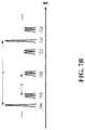
- FIG. 7Billustrates an exemplary set of pulse signals transmitted by a LiDAR system, according to some embodiments of the disclosure.
- the set of pulse signalsincludes a first plurality of pulse group signals including the pulse group signals 706 and 724 , as well as a second plurality of pulse group signals including the pulse group signals 708 , 720 , 722 , and 726 .
- the first plurality of pulse group signalsare for detecting relatively faraway objects, while the second plurality of pulse group signals are for detecting relative nearby objects.
- the first plurality of pulse group signalse.g., 706 , 724
- the second plurality of pulse group signalse.g., 708 , 720 , 722 , 726 .
- the higher amplitude of signals 706 and 724allows those signals to be used to range objects farther away.
- the signals 706 and 724 of the first pluralityare separated by a time interval t 1 .
- the time interval t 1may be the maximum time it takes for a light pulse to travel round trip to the farthest distance the LiDAR system is designed for; as such, the system can distinguish among the signals of the first plurality using the “first to arrive” approach.
- the signals 708 and 720 of the second pluralityare separated by a time interval t 2 . The system can distinguish between the scattered lights corresponding to signals of the first plurality and the scattered lights corresponding to signals of the second plurality based on the respective number of peaks in each scattered light, in accordance with the method described above.
- each pulse group signal of the first pluralityis separated from the neighboring pulse group signal by the same time interval t 1 and each pulse group signal of the second plurality is separated from the neighboring pulse group signal by the same time interval t 2 .
- the ratio between t 1 and t 2is configured such that none of the first plurality of pulse group signals overlaps with any of the second plurality of pulse group signals.
- FIG. 7Billustrates distinguishing scattered lights originated from the same source
- a first LiDAR systemcan be configured to transmit the first plurality of pulse group signals including 706 and 724 while a second LiDAR system can be configured to transmit the second plurality of pulse group signals including 708 , 720 , 722 , and 726 .
- the first LiDAR systemcan identify the number of pulses (and/or peaks) within the scattered light and determine whether the scattered light originates from the first or the second LiDAR system.
- a light detection and ranging (LiDAR) scanning systemcomprising:
- the light sourceis configured to transmit a pulse of light to illuminate a surface of an object
- a modulatoroperable to encode the pulse of light with a sequence code in response to a signal from a sequence generator
- a light detectorconfigured to detect a pulse of scattered light from the surface of the object originating from the light pulse
- correlatorelectrically coupled to the light detector, wherein the correlator is configured to correlate the pulse of scattered light with the sequence code and output a peak value associated with a time that the pulse of scattered light is received, and
- microprocessorelectrically coupled to the light source and the correlator, wherein the microprocessor is configured to:
- each pulse group signal of the first pluralityis separated from a neighboring pulse group signal of the first plurality by a first time interval;
- each pulse group signal of the second pluralityis separated from a neighboring pulse group signal of the second plurality by a second time interval, and wherein the first time interval is different from the second time interval.
- a light detection and ranging (LiDAR) scanning systemcomprising:
- the light sourceis configured to transmit a first pulse group signal having a first number of pulse signals and a second pulse group signal having a second number of pulse signals, wherein the first number is different from the second number;
- a light detectorconfigured to detect a returned pulse group signal having a third number of pulse signals
- microprocessorelectrically coupled to the light source and the light detector, wherein the microprocessor is configured to determine, based on the third number of pulse signals, whether the returned pulse group signal corresponds to the first pulse group signal or the second pulse group signal;
- Combinations such as “at least one of A, B, or C,” “one or more of A, B, or C,” “at least one of A, B, and C,” “one or more of A, B, and C,” and “A, B, C, or any combination thereof”include any combination of A, B, and/or C, and may include multiples of A, multiples of B, or multiples of C.
- combinations such as “at least one of A, B, or C,” “one or more of A, B, or C,” “at least one of A, B, and C,” “one or more of A, B, and C,” and “A, B, C, or any combination thereof”may be A only, B only, C only, A and B, A and C, B and C, or A and B and C, where any such combinations may contain one or more member or members of A, B, or C.
Landscapes
- Engineering & Computer Science (AREA)
- Physics & Mathematics (AREA)
- Computer Networks & Wireless Communication (AREA)
- General Physics & Mathematics (AREA)
- Radar, Positioning & Navigation (AREA)
- Remote Sensing (AREA)
- Electromagnetism (AREA)
- Optical Radar Systems And Details Thereof (AREA)
- Optical Communication System (AREA)
- Measurement Of Optical Distance (AREA)
Abstract
Description
- determine whether an amplitude of the peak value exceeds a threshold value;
- in accordance with a determination that the amplitude of the peak exceeds the threshold value:
- determine a time difference between a time that pulse of light was transmitted and the time that the pulse of light is received; and
- calculate a distance to the surface of the object based on the time difference.
2. The LiDAR scanning system ofitem 1, wherein the light source is a laser diode light source.
3. The LiDAR scanning system of item 2, wherein the modulator is configured to modulate an injection current to the laser diode in accordance with on-off keying.
4. The LiDAR scanning system of any of items 1-3, wherein modulator is an opto-electrical modulator situated in the optical path of the pulse of light.
5. The LiDAR scanning system of any of items 1-4, wherein modulator is a Mach-Zehnder modulator situated in the optical path of the pulse of light.
6. The LiDAR scanning system of any of items 1-5, wherein the detector is a photodiode.
7. The LiDAR scanning system of any of items 1-6, wherein the detector is a photomultiplier tube.
8. The LiDAR scanning system of any of items 1-7, wherein the detector further comprises an analog to digital converter configured to convert the detected pulse of scattered light to an electrical digital signal.
9. The LiDAR scanning system of any of items 1-8, wherein the correlator is a module embedded within the microprocessor.
10. The LiDAR scanning system of any of items 1-9, wherein the correlator is an optical modulator configured to implement four-wave-mixing.
11. The LiDAR scanning system of any of items 1-10, wherein the sequence generator is a module embedded within the microprocessor.
12. The LiDAR scanning system of any of items 1-11, wherein the sequence code is a pseudorandom bit sequence code.
13. The LiDAR scanning system of item 12, wherein the pseudorandom bit sequence code is PRBS-5.
14. The LiDAR scanning system of any of items 1-13, wherein the threshold value is at least one standard deviation above an average of the output from the correlator.
15. The LiDAR scanning system of any of items 1-14, wherein in accordance with a determination that the amplitude of the peak exceeds the threshold value, the microprocessor is further configured to determine a reflectivity of the surface of the object based on the amplitude of the peak value.
16. A method for light detection and ranging (LiDAR) scanning detection, the method comprising:
- determining a time difference between a time that pulse of light was transmitted and the time the pulse of scattered light is received; and
- calculating a distance to the surface of the object based on the time difference.
17. The method of item 16, wherein in accordance with a determination that the amplitude of the peak exceeds the threshold value further comprises determining a reflectivity of the surface of the object based on the amplitude of the peak.
18. The method of any of items 16-17, wherein the light source is a laser diode.
19. The method of item 18, wherein encoding a pulse of light comprises modulating an injection current to the laser diode in accordance with on/off keying.
20. The method of any of items 16-19, wherein encoding a pulse of light comprises modulating the pulse of light in optical domain via an electro-optical modulator situated in the optical path of the pulse of light.
21. The method of any of items 16-20, wherein encoding a pulse of light comprises modulating the pulse of light via a Mach-Zehnder modulator situated in the optical path of the pulse of light.
22. The method of any of items 16-21, wherein the detector is a photodiode.
23. The method of any of items 16-22, wherein the detector is a photomultiplier tube.
24. The method of any of items 16-23, wherein detecting the pulse of scattered light comprises converting the detected pulse of scattered light to an electrical digital signal.
25. The method of any of items 16-24, wherein the sequence code is a pseudorandom bit sequence code.
26. The method ofitem 25, wherein the pseudorandom bit sequence code is PRBS-5.
27. The method of any of items 16-26, wherein the threshold value is at least one standard deviation above an average of the output from the correlator.
28. The method of any of items 16-27, wherein in accordance with a determination that the amplitude of the peak value exceeds the threshold value, determining a reflectivity of the surface of the object based on the amplitude of the peak value.
29. A computer-implemented method, comprising: in a light detection and ranging (LiDAR) system having a light source and a light detector:
- in accordance with a determination that the returned pulse group signal corresponds to the first pulse group signal, determining a first distance based on the returned pulse group signal and the transmitted first pulse group signal; and
- in accordance with a determination that the returned pulse group signal corresponds to the second pulse group signal, determining a second distance based on the returned pulse group signal and the transmitted second pulse group signal.
30. The method of item 29, wherein the first number is one.
31. The method of any of items 29-30, wherein the pulse signals of the first pulse group signal and the pulse signals of the second pulse group signal are associated with a same wavelength.
32. The method of any of items 29-31, wherein the time between transmitting the first pulse group signal and transmitting the second pulse group signal is less than the round trip time of flight for a light pulse to reach the farthest of the objects per the design specification of the system.
33. The method of any of items 29-32, further comprising:
- in accordance with a determination that the returned pulse group signal corresponds to the first pulse group signal, determine a first distance based on the returned pulse group signal and the transmitted first pulse group signal; and
- in accordance with a determination that the returned pulse group signal corresponds to the second pulse group signal, determine a second distance based on the returned pulse group signal and the transmitted second pulse group signal.
Claims (17)
Priority Applications (2)
| Application Number | Priority Date | Filing Date | Title |
|---|---|---|---|
| US15/863,695US10969475B2 (en) | 2017-01-05 | 2018-01-05 | Method and system for encoding and decoding LiDAR |
| US17/210,173US11947047B2 (en) | 2017-01-05 | 2021-03-23 | Method and system for encoding and decoding LiDAR |
Applications Claiming Priority (2)
| Application Number | Priority Date | Filing Date | Title |
|---|---|---|---|
| US201762442758P | 2017-01-05 | 2017-01-05 | |
| US15/863,695US10969475B2 (en) | 2017-01-05 | 2018-01-05 | Method and system for encoding and decoding LiDAR |
Related Child Applications (1)
| Application Number | Title | Priority Date | Filing Date |
|---|---|---|---|
| US17/210,173ContinuationUS11947047B2 (en) | 2017-01-05 | 2021-03-23 | Method and system for encoding and decoding LiDAR |
Publications (2)
| Publication Number | Publication Date |
|---|---|
| US20180188358A1 US20180188358A1 (en) | 2018-07-05 |
| US10969475B2true US10969475B2 (en) | 2021-04-06 |
Family
ID=62711583
Family Applications (2)
| Application Number | Title | Priority Date | Filing Date |
|---|---|---|---|
| US15/863,695Active2038-09-26US10969475B2 (en) | 2017-01-05 | 2018-01-05 | Method and system for encoding and decoding LiDAR |
| US17/210,173Active2038-06-30US11947047B2 (en) | 2017-01-05 | 2021-03-23 | Method and system for encoding and decoding LiDAR |
Family Applications After (1)
| Application Number | Title | Priority Date | Filing Date |
|---|---|---|---|
| US17/210,173Active2038-06-30US11947047B2 (en) | 2017-01-05 | 2021-03-23 | Method and system for encoding and decoding LiDAR |
Country Status (6)
| Country | Link |
|---|---|
| US (2) | US10969475B2 (en) |
| EP (1) | EP3566070B1 (en) |
| JP (2) | JP7177065B2 (en) |
| KR (1) | KR102569841B1 (en) |
| CN (1) | CN110573900A (en) |
| WO (1) | WO2018129408A1 (en) |
Cited By (51)
| Publication number | Priority date | Publication date | Assignee | Title |
|---|---|---|---|---|
| US11054508B2 (en) | 2017-01-05 | 2021-07-06 | Innovusion Ireland Limited | High resolution LiDAR using high frequency pulse firing |
| US11289873B2 (en) | 2018-04-09 | 2022-03-29 | Innovusion Ireland Limited | LiDAR systems and methods for exercising precise control of a fiber laser |
| US11300683B2 (en) | 2016-12-30 | 2022-04-12 | Innovusion Ireland Limited | Multiwavelength LiDAR design |
| US11391823B2 (en) | 2018-02-21 | 2022-07-19 | Innovusion, Inc. | LiDAR detection systems and methods with high repetition rate to observe far objects |
| US11422267B1 (en) | 2021-02-18 | 2022-08-23 | Innovusion, Inc. | Dual shaft axial flux motor for optical scanners |
| US11467288B2 (en)* | 2018-10-24 | 2022-10-11 | Red Leader Technologies, Inc. | Lidar system and method of operation |
| US20220342073A1 (en)* | 2018-10-24 | 2022-10-27 | Red Leader Technologies, Inc. | Lidar system and method of operation |
| US11493601B2 (en) | 2017-12-22 | 2022-11-08 | Innovusion, Inc. | High density LIDAR scanning |
| US11555895B2 (en) | 2021-04-20 | 2023-01-17 | Innovusion, Inc. | Dynamic compensation to polygon and motor tolerance using galvo control profile |
| US11567182B2 (en) | 2018-03-09 | 2023-01-31 | Innovusion, Inc. | LiDAR safety systems and methods |
| US11579300B1 (en) | 2018-08-21 | 2023-02-14 | Innovusion, Inc. | Dual lens receive path for LiDAR system |
| US11579258B1 (en) | 2018-08-30 | 2023-02-14 | Innovusion, Inc. | Solid state pulse steering in lidar systems |
| US11604279B2 (en) | 2017-01-05 | 2023-03-14 | Innovusion, Inc. | MEMS beam steering and fisheye receiving lens for LiDAR system |
| US11609336B1 (en) | 2018-08-21 | 2023-03-21 | Innovusion, Inc. | Refraction compensation for use in LiDAR systems |
| US11614521B2 (en) | 2021-04-21 | 2023-03-28 | Innovusion, Inc. | LiDAR scanner with pivot prism and mirror |
| US11614526B1 (en) | 2018-08-24 | 2023-03-28 | Innovusion, Inc. | Virtual windows for LIDAR safety systems and methods |
| US11624806B2 (en) | 2021-05-12 | 2023-04-11 | Innovusion, Inc. | Systems and apparatuses for mitigating LiDAR noise, vibration, and harshness |
| US11644543B2 (en) | 2018-11-14 | 2023-05-09 | Innovusion, Inc. | LiDAR systems and methods that use a multi-facet mirror |
| US11662439B2 (en) | 2021-04-22 | 2023-05-30 | Innovusion, Inc. | Compact LiDAR design with high resolution and ultra-wide field of view |
| US11662440B2 (en) | 2021-05-21 | 2023-05-30 | Innovusion, Inc. | Movement profiles for smart scanning using galvonometer mirror inside LiDAR scanner |
| US11675053B2 (en) | 2018-06-15 | 2023-06-13 | Innovusion, Inc. | LiDAR systems and methods for focusing on ranges of interest |
| US11675050B2 (en) | 2018-01-09 | 2023-06-13 | Innovusion, Inc. | LiDAR detection systems and methods |
| US11675055B2 (en) | 2019-01-10 | 2023-06-13 | Innovusion, Inc. | LiDAR systems and methods with beam steering and wide angle signal detection |
| US11686827B2 (en)* | 2018-06-27 | 2023-06-27 | Hesai Technology Co., Ltd. | Adaptive coding for Lidar systems |
| US11762095B2 (en) | 2022-02-01 | 2023-09-19 | Red Leader Technologies, Inc. | Lidar system and method of operation |
| US11762065B2 (en) | 2019-02-11 | 2023-09-19 | Innovusion, Inc. | Multiple beam generation from a single source beam for use with a lidar system |
| US11768294B2 (en) | 2021-07-09 | 2023-09-26 | Innovusion, Inc. | Compact lidar systems for vehicle contour fitting |
| US11782132B2 (en) | 2016-12-31 | 2023-10-10 | Innovusion, Inc. | 2D scanning high precision LiDAR using combination of rotating concave mirror and beam steering devices |
| US11789132B2 (en) | 2018-04-09 | 2023-10-17 | Innovusion, Inc. | Compensation circuitry for lidar receiver systems and method of use thereof |
| US11789128B2 (en) | 2021-03-01 | 2023-10-17 | Innovusion, Inc. | Fiber-based transmitter and receiver channels of light detection and ranging systems |
| US11796645B1 (en) | 2018-08-24 | 2023-10-24 | Innovusion, Inc. | Systems and methods for tuning filters for use in lidar systems |
| US11808888B2 (en) | 2018-02-23 | 2023-11-07 | Innovusion, Inc. | Multi-wavelength pulse steering in LiDAR systems |
| US11860316B1 (en) | 2018-08-21 | 2024-01-02 | Innovusion, Inc. | Systems and method for debris and water obfuscation compensation for use in LiDAR systems |
| US11871130B2 (en) | 2022-03-25 | 2024-01-09 | Innovusion, Inc. | Compact perception device |
| US11927696B2 (en) | 2018-02-21 | 2024-03-12 | Innovusion, Inc. | LiDAR systems with fiber optic coupling |
| US11933967B2 (en) | 2019-08-22 | 2024-03-19 | Red Creamery, LLC | Distally actuated scanning mirror |
| US11947047B2 (en) | 2017-01-05 | 2024-04-02 | Seyond, Inc. | Method and system for encoding and decoding LiDAR |
| US11953603B2 (en) | 2020-10-13 | 2024-04-09 | Red Leader Technologies, Inc. | Lidar system and method of operation |
| US11965980B2 (en) | 2018-01-09 | 2024-04-23 | Innovusion, Inc. | Lidar detection systems and methods that use multi-plane mirrors |
| US11977185B1 (en) | 2019-04-04 | 2024-05-07 | Seyond, Inc. | Variable angle polygon for use with a LiDAR system |
| US11988773B2 (en) | 2018-02-23 | 2024-05-21 | Innovusion, Inc. | 2-dimensional steering system for lidar systems |
| US12038534B2 (en) | 2021-11-24 | 2024-07-16 | Innovusion (suzhou) Co., Ltd. | Motor for on-vehicle lidar, on-vehicle lidar, and vehicle |
| US12061289B2 (en) | 2021-02-16 | 2024-08-13 | Innovusion, Inc. | Attaching a glass mirror to a rotating metal motor frame |
| US12072447B2 (en) | 2021-04-22 | 2024-08-27 | Seyond, Inc. | Compact LiDAR design with high resolution and ultra-wide field of view |
| US12123950B2 (en) | 2016-02-15 | 2024-10-22 | Red Creamery, LLC | Hybrid LADAR with co-planar scanning and imaging field-of-view |
| US12169254B2 (en) | 2018-06-27 | 2024-12-17 | Hesai Technology Co., Ltd. | Adaptive coding for lidar systems |
| US12204033B2 (en) | 2022-03-25 | 2025-01-21 | Seyond, Inc. | Multimodal detection with integrated sensors |
| US12298399B2 (en) | 2018-02-22 | 2025-05-13 | Seyond, Inc. | Receive path for LiDAR system |
| US12313788B1 (en) | 2018-10-09 | 2025-05-27 | Seyond, Inc. | Ultrashort pulses in LiDAR systems |
| US12399278B1 (en) | 2016-02-15 | 2025-08-26 | Red Creamery Llc | Hybrid LIDAR with optically enhanced scanned laser |
| US12399279B1 (en) | 2016-02-15 | 2025-08-26 | Red Creamery Llc | Enhanced hybrid LIDAR with high-speed scanning |
Families Citing this family (25)
| Publication number | Priority date | Publication date | Assignee | Title |
|---|---|---|---|---|
| US10594920B2 (en)* | 2016-06-15 | 2020-03-17 | Stmicroelectronics, Inc. | Glass detection with time of flight sensor |
| CN111542765B (en) | 2017-10-19 | 2024-08-02 | 图达通智能美国有限公司 | LIDAR with large dynamic range |
| US11754713B2 (en)* | 2017-12-15 | 2023-09-12 | Nec Corporation | Range finding apparatus and control method |
| US20190049583A1 (en)* | 2017-12-27 | 2019-02-14 | Intel Corporation | Encoding lidar signals to avoid interference |
| US12085673B2 (en) | 2018-02-23 | 2024-09-10 | Seyond, Inc. | Distributed LiDAR systems |
| FR3079619B1 (en)* | 2018-04-03 | 2020-09-25 | Arianegroup Sas | METHOD AND SYSTEM FOR EMISSION AND RECEPTION OF LASER PULSES |
| EP3614175B1 (en)* | 2018-08-23 | 2022-06-22 | Ibeo Automotive Systems GmbH | Method and device for optically measuring distances |
| CN110799853B (en)* | 2018-10-26 | 2024-04-30 | 深圳市大疆创新科技有限公司 | Environmental perception system and mobile platform |
| GB2578788B (en)* | 2018-11-09 | 2022-10-05 | Toshiba Kk | An investigation system and method |
| CN210212200U (en)* | 2019-01-03 | 2020-03-31 | 华域视觉科技(上海)有限公司 | Three-dimensional detection lighting system and car |
| KR102664396B1 (en) | 2019-01-15 | 2024-05-08 | 삼성전자주식회사 | LiDAR device and operating method of the same |
| US11402477B2 (en)* | 2019-03-01 | 2022-08-02 | Beijing Voyager Technology Co., Ltd | System and methods for ranging operations using modulated signals |
| EP3918369A4 (en)* | 2019-03-05 | 2023-01-25 | Waymo Llc | SYSTEMS AND METHODS FOR REAL-TIME CALIBRATION OF LIDAR RANGE |
| CN110208814B (en)* | 2019-05-17 | 2022-07-08 | 深圳市速腾聚创科技有限公司 | Laser radar and anti-interference method thereof |
| US10613203B1 (en)* | 2019-07-01 | 2020-04-07 | Velodyne Lidar, Inc. | Interference mitigation for light detection and ranging |
| US11153010B2 (en) | 2019-07-02 | 2021-10-19 | Waymo Llc | Lidar based communication |
| CN113640820A (en)* | 2020-04-24 | 2021-11-12 | 广东博智林机器人有限公司 | Distance measuring method and device, electronic equipment and storage medium |
| US11029395B1 (en)* | 2020-06-30 | 2021-06-08 | Aurora Innovation, Inc. | Systems and methods for pulsed-wave LIDAR |
| KR102527463B1 (en) | 2021-06-23 | 2023-05-03 | 람다이노비전 주식회사 | LiDAR USING PSEUDO-RANDOM BINARY SEQUENCE |
| JP7677006B2 (en)* | 2021-07-09 | 2025-05-15 | 株式会社デンソー | Distance measuring device and distance measuring method |
| JP2023010253A (en)* | 2021-07-09 | 2023-01-20 | 株式会社デンソー | Ranging device and ranging method |
| CN113740873B (en)* | 2021-08-31 | 2024-05-28 | 自然资源部第二海洋研究所 | A fast simulation method for ocean lidar based on Gaussian convolution |
| WO2024137696A1 (en)* | 2022-12-22 | 2024-06-27 | Arizona Board Of Regents On Behalf Of The University Of Arizona | Method and system for optical transmission and crosstalk reduction in lidar using polarized light |
| CN118731957A (en)* | 2023-03-29 | 2024-10-01 | 上海禾赛科技有限公司 | Laser radar and its detection method |
| CN118826887A (en)* | 2024-07-04 | 2024-10-22 | 中国人民解放军海军工程大学 | A space laser communication system based on pulse light modulation and demodulation |
Citations (66)
| Publication number | Priority date | Publication date | Assignee | Title |
|---|---|---|---|---|
| GB2000411A (en) | 1977-06-15 | 1979-01-04 | Impulsphysik Gmbh | Ceilometric method and apparatus |
| US5006721A (en) | 1990-03-23 | 1991-04-09 | Perceptron, Inc. | Lidar scanning system |
| US5157451A (en) | 1991-04-01 | 1992-10-20 | John Taboada | Laser imaging and ranging system using two cameras |
| US5442358A (en) | 1991-08-16 | 1995-08-15 | Kaman Aerospace Corporation | Imaging lidar transmitter downlink for command guidance of underwater vehicle |
| US5657077A (en) | 1993-02-18 | 1997-08-12 | Deangelis; Douglas J. | Event recording system with digital line camera |
| US5926259A (en) | 1995-05-04 | 1999-07-20 | Bushnell Corporation | Laser range finder with target quality display |
| US6163378A (en)* | 1999-06-14 | 2000-12-19 | Khoury; Jehad | Spectroscopic time integrative correlation for rapid medical diagnostic and universal image analysis |
| US20020136251A1 (en) | 2001-01-25 | 2002-09-26 | Science And Technology Corporation | Automatic gain control system for use with multiple wavelength signal detector |
| US6650404B1 (en) | 2002-05-28 | 2003-11-18 | Analog Modules, Inc. | Laser rangefinder receiver |
| US20040135992A1 (en)* | 2002-11-26 | 2004-07-15 | Munro James F. | Apparatus for high accuracy distance and velocity measurement and methods thereof |
| US20050033497A1 (en) | 2003-08-06 | 2005-02-10 | Stopczynski Lawrence Gerard | Method of controlling an external object sensor for an automotive vehicle |
| US20060071846A1 (en) | 2003-05-30 | 2006-04-06 | Yakayuki Yanagisawa | Coherent laser radar |
| US20060132752A1 (en) | 2004-12-16 | 2006-06-22 | Kane David M | Micromechanical and related lidar apparatus and method, and fast light-routing components |
| US20070091948A1 (en) | 2005-07-29 | 2007-04-26 | Aculight Corporation | Multi-stage optical amplifier having photonic-crystal waveguides for generation of high-power pulsed radiation and associated method |
| US20080174762A1 (en) | 2006-08-29 | 2008-07-24 | Jony Jiang Liu | Micro-mirror optical tracking and ranging system |
| US20090010644A1 (en)* | 2002-02-01 | 2009-01-08 | Cubic Corporation | Integrated optical communication and range finding system and applications thereof |
| US20090051926A1 (en) | 2007-04-13 | 2009-02-26 | United States Of America As Represented By The Administrator Of The National Aeronautics And Spac | Multiple frequency optical mixer and demultiplexer and apparatus for remote sensing |
| US20090059201A1 (en) | 2007-08-28 | 2009-03-05 | Science Applications International Corporation | Full-Field Light Detection and Ranging Imaging System |
| US20090147239A1 (en) | 2005-09-02 | 2009-06-11 | Neptec | Apparatus and method for tracking an object |
| US20090262760A1 (en) | 2005-01-20 | 2009-10-22 | Vladimir Krupkin | Laser Obstacle Ranging and Display |
| US20100006760A1 (en) | 2004-04-13 | 2010-01-14 | Science & Engineering Services, Inc. | Ultraviolet lidar for detection of biological warfare agents |
| US20100020306A1 (en) | 2006-07-13 | 2010-01-28 | Velodyne Acoustics, Inc. | High definition lidar system |
| US20100027602A1 (en)* | 2008-07-31 | 2010-02-04 | United States Of America As Represented By The Administrator Of The National Aeronautics And Spac | Time delay and distance measurement |
| US20100045965A1 (en) | 2008-08-19 | 2010-02-25 | Rosemount Aerospace Inc. | Lidar system using a pseudo-random pulse sequence |
| US20100128109A1 (en) | 2008-11-25 | 2010-05-27 | Banks Paul S | Systems And Methods Of High Resolution Three-Dimensional Imaging |
| US20100271614A1 (en)* | 2006-01-27 | 2010-10-28 | Vijay Albuquerque | LIDAR system utilizing SOI-based opto-electronic components |
| US20120038903A1 (en) | 2010-08-16 | 2012-02-16 | Ball Aerospace & Technologies Corp. | Electronically steered flash lidar |
| US20120124113A1 (en) | 2010-11-05 | 2012-05-17 | University of Maribor | LIGHT DETECTION AND RANGING (LiDAR)DATA COMPRESSION AND DECOMPRESSION METHODS AND APPARATUS |
| US20120221142A1 (en) | 2011-02-24 | 2012-08-30 | Mss, Inc. | Sequential Scanning Of Multiple Wavelengths |
| US20130107016A1 (en) | 2010-05-17 | 2013-05-02 | Iee International Electronics & Engineering S.A. | Scanning 3d imager |
| US20130293946A1 (en) | 2012-05-01 | 2013-11-07 | Imra America, Inc. | Optical frequency ruler |
| US20130293867A1 (en) | 2009-09-23 | 2013-11-07 | Pixart Imaging Inc. | Distance-measuring device of measuring distance according to variation of imaging location and calibrating method thereof |
| US20140078514A1 (en) | 2010-10-22 | 2014-03-20 | Neptec Design Group Ltd. | Wide angle bistatic scanning optical ranging sensor |
| US20140350836A1 (en) | 2013-05-24 | 2014-11-27 | Advance Scientific Concepts, Inc. | Automotive auxiliary ladar sensor |
| US20140347650A1 (en) | 2011-12-23 | 2014-11-27 | Leica Geosystems Ag | Distance-measuring device alignment |
| US20150078123A1 (en) | 2013-09-16 | 2015-03-19 | Appareo Systems, Llc | Synthetic underwater visualization system |
| US20150084805A1 (en) | 2012-03-19 | 2015-03-26 | Qinetiq Limited | Detection Techniques |
| US20150116692A1 (en) | 2012-04-30 | 2015-04-30 | Michigan Aerospace Corporation | System and method for scan range gating |
| US20150139259A1 (en) | 2013-11-21 | 2015-05-21 | Christie Digital Systems Canada Inc. | Method, system and apparatus for automatically determining operating conditions of a periodically poled lithium niobate crystal in a laser system |
| EP2889642A1 (en) | 2013-12-16 | 2015-07-01 | Riegl Laser Measurement Systems GmbH | Method for distance measurement |
| US9086273B1 (en) | 2013-03-08 | 2015-07-21 | Google Inc. | Microrod compression of laser beam in combination with transmit lens |
| US20150355327A1 (en) | 2012-11-21 | 2015-12-10 | Nikon Metrology Nv | Scan mirrors for laser radar |
| US20160003946A1 (en) | 2014-07-03 | 2016-01-07 | Advanced Scientific Concepts, Inc. | Ladar sensor for a dense environment |
| US20160047900A1 (en) | 2014-08-15 | 2016-02-18 | US LADAR, Inc. | Method and System for Scanning Ladar Transmission with Pulse Modulation |
| US20160061655A1 (en) | 2014-09-03 | 2016-03-03 | Panasonic Intellectual Property Management Co., Ltd. | Measurement system |
| US20160061935A1 (en) | 2014-08-28 | 2016-03-03 | Google Inc. | Methods and Systems for Vehicle Radar Coordination and Interference Reduction |
| US20160100521A1 (en) | 2014-10-10 | 2016-04-14 | Irobot Corporation | Autonomous Robot Localization |
| US20160117048A1 (en) | 2014-09-26 | 2016-04-28 | Cypress Semiconductor Corporation | Background Light Detection for Optical Navigation Systems |
| US20160245902A1 (en) | 2015-02-25 | 2016-08-25 | Abbie T. Watnik | Real-time processing and adaptable illumination lidar camera using a spatial light modulator |
| US20160291134A1 (en) | 2015-04-06 | 2016-10-06 | Google Inc. | Long Range Steerable LIDAR System |
| US20160313445A1 (en)* | 2012-03-16 | 2016-10-27 | Advanced Scientific Concepts, Inc. | Personal ladar sensor |
| US20160327646A1 (en) | 2015-05-07 | 2016-11-10 | GM Global Technology Operations LLC | Pseudo random sequences in array lidar systems |
| US20170153319A1 (en) | 2015-11-30 | 2017-06-01 | Luminar Technologies, Inc. | Lidar system with distributed laser and multiple sensor heads |
| US9869754B1 (en) | 2017-03-22 | 2018-01-16 | Luminar Technologies, Inc. | Scan patterns for lidar systems |
| US20180158471A1 (en) | 2016-12-02 | 2018-06-07 | Breakaway Records, L.L.C. | Record Stabilizer for Multiple Vinyl Sizes |
| US20180188355A1 (en) | 2016-12-31 | 2018-07-05 | Innovusion Ireland Limited | 2D SCANNING HIGH PRECISION LiDAR USING COMBINATION OF ROTATING CONCAVE MIRROR AND BEAM STEERING DEVICES |
| US20180188371A1 (en) | 2016-12-30 | 2018-07-05 | Innovusion Ireland Limited | Multiwavelength lidar design |
| US20180188358A1 (en) | 2017-01-05 | 2018-07-05 | Innovusion Ireland Limited | METHOD AND SYSTEM FOR ENCODING AND DECODING LiDAR |
| US20180188357A1 (en) | 2017-01-05 | 2018-07-05 | Innovusion Ireland Limited | HIGH RESOLUTION LiDAR USING HIGH FREQUENCY PULSE FIRING |
| WO2018129410A1 (en) | 2017-01-05 | 2018-07-12 | Innovusion Ireland Limited | Mems beam steering and fisheye receiving lens for lidar system |
| WO2018175990A1 (en) | 2017-03-23 | 2018-09-27 | Innovusion Ireland Limited | High resolution lidar using multi-stage multi-phase signal modulation, integration, sampling, and analysis |
| US20190120942A1 (en) | 2017-10-19 | 2019-04-25 | Innovusion Ireland Limited | Lidar with large dynamic range |
| US20190257924A1 (en) | 2018-02-22 | 2019-08-22 | Innovusion Ireland Limited | Receive path for lidar system |
| US20190265337A1 (en) | 2018-02-23 | 2019-08-29 | Innovusion Ireland Limited | Multi-wavelength pulse steering in lidar systems |
| US20190265339A1 (en) | 2018-02-23 | 2019-08-29 | Innovusion Ireland Limited | Distributed lidar systems |
| WO2019165294A1 (en) | 2018-02-23 | 2019-08-29 | Innovusion Ireland Limited | 2-dimensional steering system for lidar systems |
Family Cites Families (155)
| Publication number | Priority date | Publication date | Assignee | Title |
|---|---|---|---|---|
| JPS5245479B2 (en) | 1972-02-19 | 1977-11-16 | ||
| US3897150A (en) | 1972-04-03 | 1975-07-29 | Hughes Aircraft Co | Scanned laser imaging and ranging system |
| US4464048A (en) | 1981-03-25 | 1984-08-07 | Barr & Stroud Limited | Laser rangefinders |
| JPH04255280A (en) | 1991-02-07 | 1992-09-10 | Nippon Steel Corp | Semiconductor laser excitation solid-state laser device |
| GB2266620B (en) | 1992-04-27 | 1996-08-28 | Univ Southampton | Optical power limited amplifier |
| US5838239A (en) | 1992-10-20 | 1998-11-17 | Robotic Vision Systems, Inc. | System for detecting ice or snow on surface which specularly reflects light |
| US5546188A (en) | 1992-11-23 | 1996-08-13 | Schwartz Electro-Optics, Inc. | Intelligent vehicle highway system sensor and method |
| US5319434A (en) | 1992-12-30 | 1994-06-07 | Litton Systems, Inc. | Laser rangefinder apparatus with fiber optic interface |
| US5793491A (en) | 1992-12-30 | 1998-08-11 | Schwartz Electro-Optics, Inc. | Intelligent vehicle highway system multi-lane sensor and method |
| US7209221B2 (en) | 1994-05-23 | 2007-04-24 | Automotive Technologies International, Inc. | Method for obtaining and displaying information about objects in a vehicular blind spot |
| US5691808A (en) | 1995-07-31 | 1997-11-25 | Hughes Electronics | Laser range finder receiver |
| US5936756A (en) | 1996-01-10 | 1999-08-10 | Ricoh Company Ltd. | Compact scanning optical system |
| JP3446466B2 (en) | 1996-04-04 | 2003-09-16 | 株式会社デンソー | Reflection measuring device for inter-vehicle distance control device and inter-vehicle distance control device using the same |
| JP3849324B2 (en) | 1998-11-02 | 2006-11-22 | 株式会社デンソー | Distance measuring device |
| JP2000147124A (en) | 1998-11-12 | 2000-05-26 | Denso Corp | On-vehicle radar device |
| EP1085346B1 (en)* | 1999-09-19 | 2002-03-20 | Deutsches Zentrum für Luft- und Raumfahrt e.V. | Method for determining the distance of objects, atmospheric particles and the like using Lidar- or Laserradar signals |
| WO2002033817A1 (en)* | 2000-10-16 | 2002-04-25 | Rudolf Schwarte | Method and device for detecting and processing signal waves |
| US6847477B2 (en) | 2001-02-28 | 2005-01-25 | Kilolamdia Ip Limited | Optical system for converting light beam into plurality of beams having different wavelengths |
| JP3939541B2 (en)* | 2001-12-04 | 2007-07-04 | 日本電信電話株式会社 | Optical clock phase locked loop circuit |
| DE10244641A1 (en) | 2002-09-25 | 2004-04-08 | Ibeo Automobile Sensor Gmbh | Optoelectronic position monitoring system for road vehicle has two pulsed lasers, sensor and mechanical scanner with mirror at 45 degrees on shaft with calibration disk driven by electric motor |
| DE10331467A1 (en) | 2003-07-11 | 2005-02-10 | Sick Ag | Device for optically scanning objects, in particular markings |
| DE102004009496A1 (en) | 2004-02-27 | 2005-09-15 | Sick Ag | Method and device for optically scanning objects |
| JP2005291787A (en) | 2004-03-31 | 2005-10-20 | Denso Corp | Distance detection device |
| US7505196B2 (en) | 2004-03-31 | 2009-03-17 | Imra America, Inc. | Method and apparatus for controlling and protecting pulsed high power fiber amplifier systems |
| US7649616B2 (en) | 2004-07-08 | 2010-01-19 | Lockheed Martin Corporation | Fiber laser ladar |
| IL165212A (en) | 2004-11-15 | 2012-05-31 | Elbit Systems Electro Optics Elop Ltd | Device for scanning light |
| US7345743B1 (en)* | 2005-03-21 | 2008-03-18 | Advanced Optical Systems | Wide angle laser range and bearing finder |
| US8270440B2 (en) | 2005-04-07 | 2012-09-18 | Panasonic Corporation | Laser light source and optical device |
| JP2006308482A (en) | 2005-04-28 | 2006-11-09 | Sanyo Electric Co Ltd | Detector |
| JP4444159B2 (en) | 2005-05-17 | 2010-03-31 | 日本信号株式会社 | Optical communication device |
| JP4694304B2 (en) | 2005-08-15 | 2011-06-08 | 株式会社トプコン | Surveying equipment |
| JP2007144667A (en) | 2005-11-24 | 2007-06-14 | Fuji Xerox Co Ltd | Image forming apparatus and formed image correcting method |
| US7724423B2 (en) | 2006-03-16 | 2010-05-25 | Alcatel-Lucent Usa Inc. | Optical fiber laser having improved efficiency |
| JP4897430B2 (en)* | 2006-10-27 | 2012-03-14 | 三井造船株式会社 | Image information acquisition device |
| EP2078212A4 (en) | 2006-10-30 | 2010-12-29 | Autonosys Inc | Scanning system for lidar |
| WO2008101120A1 (en) | 2007-02-14 | 2008-08-21 | Finisar Corporation | Collimated ball lenses for optical triplexers |
| US7880865B2 (en) | 2007-02-28 | 2011-02-01 | Denso Wave Incorporated | Laser radar apparatus for three-dimensional detection of objects |
| JP2009156666A (en)* | 2007-12-26 | 2009-07-16 | Panasonic Corp | Ultrasonic measurement method and ultrasonic measurement apparatus |
| DE102008031681A1 (en) | 2008-07-04 | 2010-01-14 | Eads Deutschland Gmbh | LIDAR method for measuring velocities and LIDAR device with timed detection |
| US7869112B2 (en) | 2008-07-25 | 2011-01-11 | Prysm, Inc. | Beam scanning based on two-dimensional polygon scanner for display and other applications |
| JP2010035385A (en) | 2008-07-31 | 2010-02-12 | Kyocera Mita Corp | Motor drive controller |
| EP2154769B1 (en) | 2008-08-11 | 2014-02-26 | Siemens Aktiengesellschaft | Device for supplying power to a system |
| US8125622B2 (en) | 2009-07-28 | 2012-02-28 | Applied Concepts, Inc. | Lidar measurement device with target tracking and method for use of same |
| EP2395368B1 (en) | 2010-06-11 | 2012-02-08 | Sick AG | Distance-measuring laser scanner for detecting objects in a surveillance range |
| DE102010030603A1 (en) | 2010-06-28 | 2011-12-29 | Fraunhofer-Gesellschaft zur Förderung der angewandten Forschung e.V. | A method for generating a distance measurement signal and method and system for ranging between a transmitter and a receiver |
| KR101162177B1 (en) | 2010-08-05 | 2012-07-04 | (주)이오시스템 | Device for compensating gain of avalanche photo diode in optic measuring device |
| WO2012098911A1 (en) | 2011-01-20 | 2012-07-26 | 日本電信電話株式会社 | Optical amplifier device |
| WO2012117542A1 (en) | 2011-03-02 | 2012-09-07 | トヨタ自動車株式会社 | Laser radar device |
| KR101301453B1 (en) | 2011-12-15 | 2013-09-03 | 여우순엽 | The apparatus and method of monitoring with terrestrial lidar and reflectless totalstation |
| US20130241761A1 (en) | 2012-03-16 | 2013-09-19 | Nikon Corporation | Beam steering for laser radar and other uses |
| US9835490B2 (en) | 2012-05-10 | 2017-12-05 | Voxtel, Inc. | Discriminating photo counts and dark counts in an avalanche photodiode |
| CN102928832A (en)* | 2012-11-30 | 2013-02-13 | 中国科学院上海光学精密机械研究所 | Remote laser distance measuring system based on high-speed pseudo-random code modulation and photon counting |
| EP2746808B1 (en) | 2012-12-18 | 2015-02-25 | Sick Ag | Opto-electronic sensor for detecting objects |
| DE102013100696B3 (en) | 2013-01-24 | 2013-11-07 | Sick Ag | Optoelectronic sensor e.g. laser scanner for detecting objects in monitored area, has diode array that determines threshold for intensity of reflected light, such that photocurrent is flowed only through insensitive receiving path |
| CN103116164B (en)* | 2013-01-25 | 2014-11-12 | 哈尔滨工业大学 | Heterodyne pulse compression type multifunctional laser radar and controlling method thereof |
| DE102013215117A1 (en) | 2013-08-01 | 2015-02-05 | Robert Bosch Gmbh | Object determination by means of radar sensor |
| KR102136401B1 (en) | 2013-10-21 | 2020-07-21 | 한국전자통신연구원 | Multi-wave image lidar sensor apparatus and signal processing method thereof |
| AU2014352833B2 (en) | 2013-11-22 | 2019-12-05 | Aurora Operations, Inc. | LiDAR scanner calibration |
| CN103616696B (en)* | 2013-11-27 | 2015-10-21 | 中国电子科技集团公司第三十八研究所 | A kind of method of laser imaging radar device and range finding thereof |
| KR101480651B1 (en) | 2013-12-09 | 2015-01-09 | 현대자동차주식회사 | Method for Object Processing and Vehicle supporting the same |
| JP2016115740A (en) | 2014-12-12 | 2016-06-23 | オムロン株式会社 | Light amplifier device and laser processing device |
| KR20160075231A (en) | 2014-12-19 | 2016-06-29 | 한화테크윈 주식회사 | Lidar system |
| WO2016123320A1 (en) | 2015-01-29 | 2016-08-04 | Massachusetts Institute Of Technology | Systems and methods for light amplification |
| JP6353398B2 (en) | 2015-04-28 | 2018-07-04 | 日本電信電話株式会社 | Optical modulation circuit |
| JP2017003347A (en) | 2015-06-08 | 2017-01-05 | 日本信号株式会社 | Object detection device and object detection method |
| KR101699273B1 (en) | 2015-06-30 | 2017-01-24 | 한국표준과학연구원 | Apparatus for real-time non-contact non-destructive thickness measurement using terahertz wave |
| CN204885804U (en) | 2015-07-21 | 2015-12-16 | 北京杏林睿光科技有限公司 | A narrow linewidth beam combining module and a multi-wavelength Raman laser with the module |
| CN204758260U (en) | 2015-07-21 | 2015-11-11 | 北京杏林睿光科技有限公司 | Semiconductor laser structure of multitube core characteristic monitoring |
| US9992477B2 (en) | 2015-09-24 | 2018-06-05 | Ouster, Inc. | Optical system for collecting distance information within a field |
| EP3396413A4 (en) | 2015-12-21 | 2019-08-21 | Koito Manufacturing Co., Ltd. | Image acquisition device for vehicles, control device, vehicle provided with image acquisition device for vehicles and control device, and image acquisition method for vehicles |
| JP2017138301A (en) | 2016-01-28 | 2017-08-10 | 株式会社デンソー | Laser radar equipment |
| US10627490B2 (en) | 2016-01-31 | 2020-04-21 | Velodyne Lidar, Inc. | Multiple pulse, LIDAR based 3-D imaging |
| US10042159B2 (en) | 2016-02-18 | 2018-08-07 | Aeye, Inc. | Ladar transmitter with optical field splitter/inverter |
| US10782393B2 (en) | 2016-02-18 | 2020-09-22 | Aeye, Inc. | Ladar receiver range measurement using distinct optical path for reference light |
| US20170242104A1 (en) | 2016-02-18 | 2017-08-24 | Aeye, Inc. | Ladar Transmitter with Induced Phase Drift for Improved Gaze on Scan Area Portions |
| CN105891841A (en)* | 2016-04-25 | 2016-08-24 | 武汉科技大学 | Vehicle laser radar distance and velocity measurement method |
| WO2017200896A2 (en) | 2016-05-18 | 2017-11-23 | James O'keeffe | A dynamically steered lidar adapted to vehicle shape |
| WO2017210418A1 (en) | 2016-06-01 | 2017-12-07 | Velodyne Lidar, Inc. | Multiple pixel scanning lidar |
| CN105911559A (en)* | 2016-06-02 | 2016-08-31 | 中国科学院光电研究院 | Laser radar system based on visible light-near infrared-short wave infrared bands |
| CN105954732B (en)* | 2016-06-14 | 2018-09-07 | 深圳大学 | A kind of the sediment reflectivity extracting method and system of laser radar depth measurement data |
| US20170365105A1 (en) | 2016-06-17 | 2017-12-21 | Ford Global Technologies, Llc | Method and apparatus for inter-vehicular safety awareness and alert |
| CN106199562B (en)* | 2016-07-06 | 2018-12-25 | 山东省科学院海洋仪器仪表研究所 | Sea error calibration method based on airborne laser radar measurement sea-floor relief |
| US9940761B2 (en) | 2016-08-02 | 2018-04-10 | International Business Machines Corporation | Self-driving vehicle sensor fault remediation |
| US10137903B2 (en) | 2016-08-16 | 2018-11-27 | Uber Technologies, Inc. | Autonomous vehicle diagnostic system |
| CN106597471B (en) | 2016-11-08 | 2019-05-24 | 上海禾赛光电科技有限公司 | Vehicle and method with transparent barriers object automatic detection function |
| US10942272B2 (en) | 2016-12-13 | 2021-03-09 | Waymo Llc | Power modulation for a rotary light detection and ranging (LIDAR) device |
| DE102017101501B3 (en) | 2017-01-26 | 2018-01-04 | Sick Ag | An optoelectronic sensor and method for determining the distance of an object in a surveillance area |
| US9810786B1 (en) | 2017-03-16 | 2017-11-07 | Luminar Technologies, Inc. | Optical parametric oscillator for lidar system |
| KR101946870B1 (en) | 2017-03-22 | 2019-02-11 | (주)위키옵틱스 | LIDAR light-emitting system improved pattern rotation |
| US10061019B1 (en) | 2017-03-28 | 2018-08-28 | Luminar Technologies, Inc. | Diffractive optical element in a lidar system to correct for backscan |
| US10007001B1 (en) | 2017-03-28 | 2018-06-26 | Luminar Technologies, Inc. | Active short-wave infrared four-dimensional camera |
| US10641874B2 (en) | 2017-03-29 | 2020-05-05 | Luminar Technologies, Inc. | Sizing the field of view of a detector to improve operation of a lidar system |
| US10191155B2 (en) | 2017-03-29 | 2019-01-29 | Luminar Technologies, Inc. | Optical resolution in front of a vehicle |
| US9989629B1 (en) | 2017-03-30 | 2018-06-05 | Luminar Technologies, Inc. | Cross-talk mitigation using wavelength switching |
| US10684360B2 (en) | 2017-03-30 | 2020-06-16 | Luminar Technologies, Inc. | Protecting detector in a lidar system using off-axis illumination |
| US11022688B2 (en) | 2017-03-31 | 2021-06-01 | Luminar, Llc | Multi-eye lidar system |
| US20180284246A1 (en) | 2017-03-31 | 2018-10-04 | Luminar Technologies, Inc. | Using Acoustic Signals to Modify Operation of a Lidar System |
| EP3593166B1 (en) | 2017-03-31 | 2024-04-17 | Velodyne Lidar USA, Inc. | Integrated lidar illumination power control |
| DE202018006300U1 (en) | 2017-04-19 | 2019-12-19 | Beijing Surestar Technology Co., Ltd | Laser scanning device, laser radar set and scanning method of the laser radar set |
| DE202018006696U1 (en) | 2017-05-15 | 2022-04-01 | Ouster, Inc. | Optical image transmitter with brightness improvement |
| CN108132472A (en) | 2017-12-08 | 2018-06-08 | 上海禾赛光电科技有限公司 | Laser radar system |
| CN207457508U (en) | 2017-08-08 | 2018-06-05 | 上海禾赛光电科技有限公司 | Laser radar system based on two-dimensional scanning mirrors |
| CN207557465U (en) | 2017-08-08 | 2018-06-29 | 上海禾赛光电科技有限公司 | Laser radar system based on tilting mirror |
| US11002857B2 (en) | 2017-09-15 | 2021-05-11 | Aeye, Inc. | Ladar system with intelligent selection of shot list frames based on field of view data |
| US11415676B2 (en) | 2017-10-09 | 2022-08-16 | Luminar, Llc | Interlaced scan patterns for lidar system |
| DE102017124535A1 (en) | 2017-10-20 | 2019-04-25 | Sick Ag | Transceiver module for an optoelectronic sensor and method for detecting objects |
| CN109725320B (en) | 2017-10-27 | 2020-12-29 | 上海禾赛光电科技有限公司 | Laser radar |
| DE102017127420A1 (en) | 2017-11-21 | 2019-05-23 | Sick Ag | Polygon scanner and method for capturing objects in a surveillance area |
| US10324185B2 (en) | 2017-11-22 | 2019-06-18 | Luminar Technologies, Inc. | Reducing audio noise in a lidar scanner with a polygon mirror |
| US10451716B2 (en) | 2017-11-22 | 2019-10-22 | Luminar Technologies, Inc. | Monitoring rotation of a mirror in a lidar system |
| CN208421228U (en) | 2018-06-29 | 2019-01-22 | 上海禾赛光电科技有限公司 | laser radar system |
| CN108089201B (en) | 2017-12-08 | 2020-04-24 | 上海禾赛光电科技有限公司 | Obstacle information acquisition method, laser pulse emission method and device |
| US11675050B2 (en) | 2018-01-09 | 2023-06-13 | Innovusion, Inc. | LiDAR detection systems and methods |
| DE102018203534A1 (en) | 2018-03-08 | 2019-09-12 | Ibeo Automotive Systems GmbH | Receiver arrangement for receiving light pulses, LiDAR module and method for receiving light pulses |
| US10429495B1 (en) | 2018-04-03 | 2019-10-01 | Hesai Photonics Technology Co., Ltd. | Lidar system and method |
| CN108445468B (en) | 2018-04-03 | 2019-11-05 | 上海禾赛光电科技有限公司 | A kind of distribution type laser radar |
| US10578720B2 (en) | 2018-04-05 | 2020-03-03 | Luminar Technologies, Inc. | Lidar system with a polygon mirror and a noise-reducing feature |
| US11029406B2 (en) | 2018-04-06 | 2021-06-08 | Luminar, Llc | Lidar system with AlInAsSb avalanche photodiode |
| WO2019237581A1 (en) | 2018-06-13 | 2019-12-19 | Hesai Photonics Technology Co., Ltd. | Lidar systems and methods |
| CN109116331B (en) | 2018-06-27 | 2020-04-24 | 上海禾赛光电科技有限公司 | Coding laser transceiver, distance measuring device and laser radar system |
| US10466342B1 (en) | 2018-09-30 | 2019-11-05 | Hesai Photonics Technology Co., Ltd. | Adaptive coding for lidar systems |
| CN109116366B (en) | 2018-06-27 | 2020-05-19 | 上海禾赛光电科技有限公司 | Multi-beam laser radar with non-uniform pulse energy |
| CN109116367B (en) | 2018-06-27 | 2020-05-19 | 上海禾赛光电科技有限公司 | Laser radar |
| CN208314210U (en) | 2018-06-29 | 2019-01-01 | 上海禾赛光电科技有限公司 | laser radar system |
| CN208705506U (en) | 2018-08-28 | 2019-04-05 | 上海禾赛光电科技有限公司 | A kind of lens group for laser radar |
| CN109188397B (en) | 2018-08-29 | 2020-11-24 | 上海禾赛科技股份有限公司 | Laser transmitter-receiver and laser radar |
| CN209280923U (en) | 2018-10-16 | 2019-08-20 | 上海禾赛光电科技有限公司 | It is a kind of for the receiving terminal circuit of laser radar, reception device and laser radar |
| CN112327275B (en) | 2019-01-07 | 2022-08-02 | 上海禾赛科技有限公司 | Laser radar |
| CN109814082B (en) | 2019-01-21 | 2021-10-22 | 上海禾赛科技有限公司 | Light receiving module and laser radar system |
| CN109917348B (en) | 2019-01-25 | 2020-11-03 | 上海禾赛科技股份有限公司 | Laser radar system |
| CN109917408B (en) | 2019-03-28 | 2020-04-24 | 上海禾赛光电科技有限公司 | Echo processing method and distance measuring method of laser radar and laser radar |
| EP3888203B1 (en) | 2019-04-02 | 2023-11-29 | Hesai Technology Co., Ltd. | Laser system for lidar |
| CN109950784B (en) | 2019-04-10 | 2021-05-28 | 上海禾赛科技股份有限公司 | Laser and laser radar |
| CN110031822B (en) | 2019-04-22 | 2020-05-22 | 上海禾赛光电科技有限公司 | Noise identification method and lidar system that can be used in lidar |
| CN110988846B (en) | 2019-04-22 | 2023-07-18 | 威力登激光雷达美国有限公司 | Noise point identification method for laser radar and laser radar system |
| US11486986B2 (en) | 2019-06-21 | 2022-11-01 | Aeva, Inc. | LIDAR system with solid state spectral scanning |
| CN110492856B (en) | 2019-08-12 | 2020-11-13 | 上海禾赛光电科技有限公司 | Transimpedance amplification unit circuit feedback circuit, photoelectric detection circuit and laser radar system |
| CN110492349B (en) | 2019-08-20 | 2021-03-19 | 上海禾赛科技股份有限公司 | Driving circuit, driving method and laser system |
| CN112578396B (en) | 2019-09-30 | 2022-04-19 | 上海禾赛科技有限公司 | Method and device for coordinate transformation between radars and computer-readable storage medium |
| CN110784220B (en) | 2019-11-07 | 2021-02-02 | 上海禾赛光电科技有限公司 | Dynamic threshold timing circuit, laser radar and method for acquiring time information |
| CN110736975B (en) | 2019-11-07 | 2020-11-27 | 上海禾赛光电科技有限公司 | Receiver module and lidar including it |
| CN110780283B (en) | 2019-11-22 | 2021-01-26 | 上海禾赛光电科技有限公司 | Receiving system, laser radar comprising same and echo receiving method |
| CN110780284B (en) | 2019-11-22 | 2020-12-29 | 上海禾赛光电科技有限公司 | Receiving system, laser radar including the same, and method of echo reception processing |
| CN211655309U (en) | 2019-12-23 | 2020-10-09 | 上海禾赛光电科技有限公司 | Laser and laser radar including the same |
| CN213182011U (en) | 2020-04-26 | 2021-05-11 | 上海禾赛光电科技有限公司 | Laser radar's transmitting unit, receiving element and laser radar |
| CN212623082U (en) | 2020-04-29 | 2021-02-26 | 上海禾赛光电科技有限公司 | Scanning device for laser radar and laser radar |
| EP4150378A1 (en) | 2020-05-13 | 2023-03-22 | Luminar, LLC | Lidar system with high-resolution scan pattern |
| CN213750313U (en) | 2020-11-27 | 2021-07-20 | 上海禾赛科技有限公司 | Optical window and laser radar |
| CN214151038U (en) | 2020-12-11 | 2021-09-07 | 上海禾赛科技有限公司 | Laser radar |
| CN214795206U (en) | 2021-04-07 | 2021-11-19 | 上海禾赛科技股份有限公司 | Laser radar |
| CN214795200U (en) | 2021-04-30 | 2021-11-19 | 上海禾赛科技有限公司 | Window for laser radar and laser radar |
| CN215641806U (en) | 2021-04-30 | 2022-01-25 | 上海禾赛科技有限公司 | Laser radar |
| CN214895784U (en) | 2021-04-30 | 2021-11-26 | 上海禾赛科技有限公司 | Optical detection device and running vehicle |
| CN214895810U (en) | 2021-04-30 | 2021-11-26 | 上海禾赛科技有限公司 | Light splitting device and laser radar |
| CN215932142U (en) | 2021-09-15 | 2022-03-01 | 上海禾赛科技有限公司 | Laser radar |
- 2018
- 2018-01-05USUS15/863,695patent/US10969475B2/enactiveActive
- 2018-01-05EPEP18736738.8Apatent/EP3566070B1/enactiveActive
- 2018-01-05JPJP2019536968Apatent/JP7177065B2/enactiveActive
- 2018-01-05KRKR1020197022584Apatent/KR102569841B1/enactiveActive
- 2018-01-05CNCN201880015869.XApatent/CN110573900A/enactivePending
- 2018-01-05WOPCT/US2018/012703patent/WO2018129408A1/ennot_activeCeased
- 2021
- 2021-03-23USUS17/210,173patent/US11947047B2/enactiveActive
- 2022
- 2022-11-09JPJP2022179213Apatent/JP7599466B2/enactiveActive
Patent Citations (119)
| Publication number | Priority date | Publication date | Assignee | Title |
|---|---|---|---|---|
| GB2000411A (en) | 1977-06-15 | 1979-01-04 | Impulsphysik Gmbh | Ceilometric method and apparatus |
| US5006721A (en) | 1990-03-23 | 1991-04-09 | Perceptron, Inc. | Lidar scanning system |
| US5157451A (en) | 1991-04-01 | 1992-10-20 | John Taboada | Laser imaging and ranging system using two cameras |
| US5442358A (en) | 1991-08-16 | 1995-08-15 | Kaman Aerospace Corporation | Imaging lidar transmitter downlink for command guidance of underwater vehicle |
| US5657077A (en) | 1993-02-18 | 1997-08-12 | Deangelis; Douglas J. | Event recording system with digital line camera |
| US5926259A (en) | 1995-05-04 | 1999-07-20 | Bushnell Corporation | Laser range finder with target quality display |
| US6163378A (en)* | 1999-06-14 | 2000-12-19 | Khoury; Jehad | Spectroscopic time integrative correlation for rapid medical diagnostic and universal image analysis |
| US20020136251A1 (en) | 2001-01-25 | 2002-09-26 | Science And Technology Corporation | Automatic gain control system for use with multiple wavelength signal detector |
| US6594000B2 (en) | 2001-01-25 | 2003-07-15 | Science And Technology Corporation | Automatic gain control system for use with multiple wavelength signal detector |
| US7489865B2 (en) | 2002-02-01 | 2009-02-10 | Cubic Corporation | Integrated optical communication and range finding system and applications thereof |
| US20090010644A1 (en)* | 2002-02-01 | 2009-01-08 | Cubic Corporation | Integrated optical communication and range finding system and applications thereof |
| US6650404B1 (en) | 2002-05-28 | 2003-11-18 | Analog Modules, Inc. | Laser rangefinder receiver |
| US20040135992A1 (en)* | 2002-11-26 | 2004-07-15 | Munro James F. | Apparatus for high accuracy distance and velocity measurement and methods thereof |
| US7202941B2 (en) | 2002-11-26 | 2007-04-10 | Munro James F | Apparatus for high accuracy distance and velocity measurement and methods thereof |
| US20060071846A1 (en) | 2003-05-30 | 2006-04-06 | Yakayuki Yanagisawa | Coherent laser radar |
| US6950733B2 (en) | 2003-08-06 | 2005-09-27 | Ford Global Technologies, Llc | Method of controlling an external object sensor for an automotive vehicle |
| US20050033497A1 (en) | 2003-08-06 | 2005-02-10 | Stopczynski Lawrence Gerard | Method of controlling an external object sensor for an automotive vehicle |
| US20100006760A1 (en) | 2004-04-13 | 2010-01-14 | Science & Engineering Services, Inc. | Ultraviolet lidar for detection of biological warfare agents |
| US20060132752A1 (en) | 2004-12-16 | 2006-06-22 | Kane David M | Micromechanical and related lidar apparatus and method, and fast light-routing components |
| US7440084B2 (en) | 2004-12-16 | 2008-10-21 | Arete' Associates | Micromechanical and related lidar apparatus and method, and fast light-routing components |
| US7847235B2 (en) | 2005-01-20 | 2010-12-07 | Elbit Systems Electro-Optics Elop Ltd. | Laser obstacle ranging and display |
| US20090262760A1 (en) | 2005-01-20 | 2009-10-22 | Vladimir Krupkin | Laser Obstacle Ranging and Display |
| US7835068B1 (en) | 2005-07-29 | 2010-11-16 | Lockheed Martin Corporation | Photonic-crystal-rod optical amplifier with sealed-hole endcap and associated method |
| US7440175B2 (en) | 2005-07-29 | 2008-10-21 | Aculight Corporation | Multi-stage optical amplifier having photonic-crystal waveguides for generation of high-power pulsed radiation and associated method |
| US20070091948A1 (en) | 2005-07-29 | 2007-04-26 | Aculight Corporation | Multi-stage optical amplifier having photonic-crystal waveguides for generation of high-power pulsed radiation and associated method |
| US20090147239A1 (en) | 2005-09-02 | 2009-06-11 | Neptec | Apparatus and method for tracking an object |
| US20100271614A1 (en)* | 2006-01-27 | 2010-10-28 | Vijay Albuquerque | LIDAR system utilizing SOI-based opto-electronic components |
| US7936448B2 (en) | 2006-01-27 | 2011-05-03 | Lightwire Inc. | LIDAR system utilizing SOI-based opto-electronic components |
| US7969558B2 (en) | 2006-07-13 | 2011-06-28 | Velodyne Acoustics Inc. | High definition lidar system |
| US20100020306A1 (en) | 2006-07-13 | 2010-01-28 | Velodyne Acoustics, Inc. | High definition lidar system |
| US20080174762A1 (en) | 2006-08-29 | 2008-07-24 | Jony Jiang Liu | Micro-mirror optical tracking and ranging system |
| US7576837B2 (en) | 2006-08-29 | 2009-08-18 | The United States Of America As Represented By The Secretary Of The Army | Micro-mirror optical tracking and ranging system |
| US7830527B2 (en) | 2007-04-13 | 2010-11-09 | The United States Of America As Represented By The Administrator Of The National Aeronautics And Space Administration | Multiple frequency optical mixer and demultiplexer and apparatus for remote sensing |
| US20090051926A1 (en) | 2007-04-13 | 2009-02-26 | United States Of America As Represented By The Administrator Of The National Aeronautics And Spac | Multiple frequency optical mixer and demultiplexer and apparatus for remote sensing |
| US20090059201A1 (en) | 2007-08-28 | 2009-03-05 | Science Applications International Corporation | Full-Field Light Detection and Ranging Imaging System |
| US20100027602A1 (en)* | 2008-07-31 | 2010-02-04 | United States Of America As Represented By The Administrator Of The National Aeronautics And Spac | Time delay and distance measurement |
| US7982861B2 (en) | 2008-07-31 | 2011-07-19 | The United States Of America As Represented By The Administrator Of The National Aeronautics And Space Administration | Time delay and distance measurement |
| US20100045965A1 (en) | 2008-08-19 | 2010-02-25 | Rosemount Aerospace Inc. | Lidar system using a pseudo-random pulse sequence |
| US8072582B2 (en) | 2008-08-19 | 2011-12-06 | Rosemount Aerospace Inc. | Lidar system using a pseudo-random pulse sequence |
| US20100128109A1 (en) | 2008-11-25 | 2010-05-27 | Banks Paul S | Systems And Methods Of High Resolution Three-Dimensional Imaging |
| US8471895B2 (en) | 2008-11-25 | 2013-06-25 | Paul S. Banks | Systems and methods of high resolution three-dimensional imaging |
| US8749764B2 (en) | 2009-09-23 | 2014-06-10 | Pixart Imaging Inc. | Distance-measuring device of measuring distance according to variation of imaging location and calibrating method thereof |
| US20130293867A1 (en) | 2009-09-23 | 2013-11-07 | Pixart Imaging Inc. | Distance-measuring device of measuring distance according to variation of imaging location and calibrating method thereof |
| US9621876B2 (en) | 2010-05-17 | 2017-04-11 | Iee International Electronics & Engineering S.A. | Scanning 3D imager |
| US20130107016A1 (en) | 2010-05-17 | 2013-05-02 | Iee International Electronics & Engineering S.A. | Scanning 3d imager |
| US8736818B2 (en) | 2010-08-16 | 2014-05-27 | Ball Aerospace & Technologies Corp. | Electronically steered flash LIDAR |
| US20120038903A1 (en) | 2010-08-16 | 2012-02-16 | Ball Aerospace & Technologies Corp. | Electronically steered flash lidar |
| US20140078514A1 (en) | 2010-10-22 | 2014-03-20 | Neptec Design Group Ltd. | Wide angle bistatic scanning optical ranging sensor |
| US9255790B2 (en) | 2010-10-22 | 2016-02-09 | Neptec Design Group Ltd. | Wide angle bistatic scanning optical ranging sensor |
| US20120124113A1 (en) | 2010-11-05 | 2012-05-17 | University of Maribor | LIGHT DETECTION AND RANGING (LiDAR)DATA COMPRESSION AND DECOMPRESSION METHODS AND APPARATUS |
| US9300321B2 (en) | 2010-11-05 | 2016-03-29 | University of Maribor | Light detection and ranging (LiDAR)data compression and decompression methods and apparatus |
| US20120221142A1 (en) | 2011-02-24 | 2012-08-30 | Mss, Inc. | Sequential Scanning Of Multiple Wavelengths |
| US8812149B2 (en) | 2011-02-24 | 2014-08-19 | Mss, Inc. | Sequential scanning of multiple wavelengths |
| US20140347650A1 (en) | 2011-12-23 | 2014-11-27 | Leica Geosystems Ag | Distance-measuring device alignment |
| US9194701B2 (en) | 2011-12-23 | 2015-11-24 | Leica Geosystems Ag | Distance-measuring device alignment |
| US9915726B2 (en) | 2012-03-16 | 2018-03-13 | Continental Advanced Lidar Solutions Us, Llc | Personal LADAR sensor |
| US20160313445A1 (en)* | 2012-03-16 | 2016-10-27 | Advanced Scientific Concepts, Inc. | Personal ladar sensor |
| US20150084805A1 (en) | 2012-03-19 | 2015-03-26 | Qinetiq Limited | Detection Techniques |
| US20150116692A1 (en) | 2012-04-30 | 2015-04-30 | Michigan Aerospace Corporation | System and method for scan range gating |
| US9696426B2 (en) | 2012-04-30 | 2017-07-04 | Michigan Aerospace Corporation | System and method for scan range gating |
| US20130293946A1 (en) | 2012-05-01 | 2013-11-07 | Imra America, Inc. | Optical frequency ruler |
| US9354485B2 (en) | 2012-05-01 | 2016-05-31 | Imra America, Inc. | Optical frequency ruler |
| US20150355327A1 (en) | 2012-11-21 | 2015-12-10 | Nikon Metrology Nv | Scan mirrors for laser radar |
| US9638799B2 (en) | 2012-11-21 | 2017-05-02 | Nikon Corporation | Scan mirrors for laser radar |
| US9086273B1 (en) | 2013-03-08 | 2015-07-21 | Google Inc. | Microrod compression of laser beam in combination with transmit lens |
| US20140350836A1 (en) | 2013-05-24 | 2014-11-27 | Advance Scientific Concepts, Inc. | Automotive auxiliary ladar sensor |
| US9702966B2 (en) | 2013-09-16 | 2017-07-11 | Appareo Systems, Llc | Synthetic underwater visualization system |
| US20150078123A1 (en) | 2013-09-16 | 2015-03-19 | Appareo Systems, Llc | Synthetic underwater visualization system |
| US9048616B1 (en) | 2013-11-21 | 2015-06-02 | Christie Digital Systems Usa, Inc. | Method, system and apparatus for automatically determining operating conditions of a periodically poled lithium niobate crystal in a laser system |
| US20150139259A1 (en) | 2013-11-21 | 2015-05-21 | Christie Digital Systems Canada Inc. | Method, system and apparatus for automatically determining operating conditions of a periodically poled lithium niobate crystal in a laser system |
| EP2889642A1 (en) | 2013-12-16 | 2015-07-01 | Riegl Laser Measurement Systems GmbH | Method for distance measurement |
| US20160003946A1 (en) | 2014-07-03 | 2016-01-07 | Advanced Scientific Concepts, Inc. | Ladar sensor for a dense environment |
| US9575184B2 (en) | 2014-07-03 | 2017-02-21 | Continental Advanced Lidar Solutions Us, Inc. | LADAR sensor for a dense environment |
| US20160047900A1 (en) | 2014-08-15 | 2016-02-18 | US LADAR, Inc. | Method and System for Scanning Ladar Transmission with Pulse Modulation |
| US10073166B2 (en) | 2014-08-15 | 2018-09-11 | Aeye, Inc. | Method and system for ladar transmission with spinning polygon mirror for dynamic scan patterns |
| US9885778B2 (en) | 2014-08-15 | 2018-02-06 | Aeye, Inc. | Method and system for scanning ladar transmission with pulse modulation |
| US20160047896A1 (en) | 2014-08-15 | 2016-02-18 | US LADAR, Inc. | Method and System for Ladar Transmission with Spinning Polygon Mirror for Dynamic Scan Patterns |
| US20160061935A1 (en) | 2014-08-28 | 2016-03-03 | Google Inc. | Methods and Systems for Vehicle Radar Coordination and Interference Reduction |
| US20160061655A1 (en) | 2014-09-03 | 2016-03-03 | Panasonic Intellectual Property Management Co., Ltd. | Measurement system |
| US9605998B2 (en) | 2014-09-03 | 2017-03-28 | Panasonic Intellectual Property Management Co., Ltd. | Measurement system |
| US9927915B2 (en) | 2014-09-26 | 2018-03-27 | Cypress Semiconductor Corporation | Optical navigation systems and methods for background light detection and avoiding false detection and auto-movement |
| US20160117048A1 (en) | 2014-09-26 | 2016-04-28 | Cypress Semiconductor Corporation | Background Light Detection for Optical Navigation Systems |
| US9510505B2 (en) | 2014-10-10 | 2016-12-06 | Irobot Corporation | Autonomous robot localization |
| US20160100521A1 (en) | 2014-10-10 | 2016-04-14 | Irobot Corporation | Autonomous Robot Localization |
| US10557923B2 (en) | 2015-02-25 | 2020-02-11 | The Government Of The United States Of America, As Represented By The Secretary Of The Navy | Real-time processing and adaptable illumination lidar camera using a spatial light modulator |
| US20160245902A1 (en) | 2015-02-25 | 2016-08-25 | Abbie T. Watnik | Real-time processing and adaptable illumination lidar camera using a spatial light modulator |
| US9880263B2 (en) | 2015-04-06 | 2018-01-30 | Waymo Llc | Long range steerable LIDAR system |
| US20160291134A1 (en) | 2015-04-06 | 2016-10-06 | Google Inc. | Long Range Steerable LIDAR System |
| US20160327646A1 (en) | 2015-05-07 | 2016-11-10 | GM Global Technology Operations LLC | Pseudo random sequences in array lidar systems |
| US10215847B2 (en) | 2015-05-07 | 2019-02-26 | GM Global Technology Operations LLC | Pseudo random sequences in array lidar systems |
| US9823353B2 (en) | 2015-11-30 | 2017-11-21 | Luminar Technologies, Inc. | Lidar system |
| US10591600B2 (en) | 2015-11-30 | 2020-03-17 | Luminar Technologies, Inc. | Lidar system with distributed laser and multiple sensor heads |
| US20170153319A1 (en) | 2015-11-30 | 2017-06-01 | Luminar Technologies, Inc. | Lidar system with distributed laser and multiple sensor heads |
| US20170299721A1 (en) | 2015-11-30 | 2017-10-19 | Luminar Technologies, Inc. | Lidar system |
| US20180158471A1 (en) | 2016-12-02 | 2018-06-07 | Breakaway Records, L.L.C. | Record Stabilizer for Multiple Vinyl Sizes |
| US10157630B2 (en) | 2016-12-02 | 2018-12-18 | Breakaway Records, L.L.C. | Record stabilizer for multiple vinyl sizes |
| US20180188371A1 (en) | 2016-12-30 | 2018-07-05 | Innovusion Ireland Limited | Multiwavelength lidar design |
| WO2018182812A2 (en) | 2016-12-30 | 2018-10-04 | Innovusion Ireland Limited | Multiwavelength lidar design |
| US20180188355A1 (en) | 2016-12-31 | 2018-07-05 | Innovusion Ireland Limited | 2D SCANNING HIGH PRECISION LiDAR USING COMBINATION OF ROTATING CONCAVE MIRROR AND BEAM STEERING DEVICES |
| US20180188358A1 (en) | 2017-01-05 | 2018-07-05 | Innovusion Ireland Limited | METHOD AND SYSTEM FOR ENCODING AND DECODING LiDAR |
| WO2018129409A1 (en) | 2017-01-05 | 2018-07-12 | Innovusion Ireland Limited | High resolution lidar using high frequency pulse firing |
| WO2018129410A1 (en) | 2017-01-05 | 2018-07-12 | Innovusion Ireland Limited | Mems beam steering and fisheye receiving lens for lidar system |
| US20190025428A1 (en) | 2017-01-05 | 2019-01-24 | Innovusion Ireland Limited | MEMS BEAM STEERING AND FISHEYE RECEIVING LENS FOR LiDAR SYSTEM |
| US20180188357A1 (en) | 2017-01-05 | 2018-07-05 | Innovusion Ireland Limited | HIGH RESOLUTION LiDAR USING HIGH FREQUENCY PULSE FIRING |
| WO2018129408A1 (en) | 2017-01-05 | 2018-07-12 | Innovusion Ireland Limited | Method and system for encoding and decoding lidar |
| US9869754B1 (en) | 2017-03-22 | 2018-01-16 | Luminar Technologies, Inc. | Scan patterns for lidar systems |
| WO2018175990A1 (en) | 2017-03-23 | 2018-09-27 | Innovusion Ireland Limited | High resolution lidar using multi-stage multi-phase signal modulation, integration, sampling, and analysis |
| US20180275274A1 (en) | 2017-03-23 | 2018-09-27 | Innovusion Ireland Limited | High resolution lidar using multi-stage multi-phase signal modulation, integration, sampling, and analysis |
| US20190120942A1 (en) | 2017-10-19 | 2019-04-25 | Innovusion Ireland Limited | Lidar with large dynamic range |
| WO2019079642A1 (en) | 2017-10-19 | 2019-04-25 | Innovusion Ireland Limited | Lidar with large dynamic range |
| WO2019165289A1 (en) | 2018-02-22 | 2019-08-29 | Innovusion Ireland Limited | Receive path for lidar system |
| US20190257924A1 (en) | 2018-02-22 | 2019-08-22 | Innovusion Ireland Limited | Receive path for lidar system |
| US20190265339A1 (en) | 2018-02-23 | 2019-08-29 | Innovusion Ireland Limited | Distributed lidar systems |
| WO2019165294A1 (en) | 2018-02-23 | 2019-08-29 | Innovusion Ireland Limited | 2-dimensional steering system for lidar systems |
| US20190265334A1 (en) | 2018-02-23 | 2019-08-29 | Innovusion Ireland Limited | Distributed lidar systems |
| US20190265336A1 (en) | 2018-02-23 | 2019-08-29 | Innovusion Ireland Limited | 2-dimensional steering system for lidar systems |
| WO2019165095A1 (en) | 2018-02-23 | 2019-08-29 | Innovusion Ireland Limited | Distributed lidar systems |
| WO2020013890A2 (en) | 2018-02-23 | 2020-01-16 | Innovusion Ireland Limited | Multi-wavelength pulse steering in lidar systems |
| US20190265337A1 (en) | 2018-02-23 | 2019-08-29 | Innovusion Ireland Limited | Multi-wavelength pulse steering in lidar systems |
Non-Patent Citations (34)
| Title |
|---|
| Chen, X, et al. (Feb. 2010). "Polarization Coupling of Light and Optoelectronics Devices Based on Periodically Poled Lithium Niobate," Shanghai Jiao Tong University, China, Frontiers in Guided Wave Optics and Optoelectronics, 24 pages. |
| EP2889642 Description translation, created Oct. 3, 2020 from application dated Nov. 11, 2014, 27 pp. (Year: 2020). |
| European Search Report, dated Jul. 17, 2020, for EP Application No. 18776977.3, twelve pages. |
| Extended European Search Report, dated Jul. 10, 2020, for EP Application No. 18736738.8, nine pages. |
| Extended European Search Report, dated Jul. 22, 2020, for EP Application No. 18736685.1, ten pages. |
| Final Office Action dated Oct. 8, 2020, for U.S. Appl. No. 15/857,563, filed Dec. 28, 2017, thirteen pages. |
| Gluckman, J. (May 13, 2016). "Design of the processing chain for a high-altitude, airborne, single-photon lidar mapping instrument," Proceedings of SPIE; [Proceedings of SPIE ISSN 0277-786X vol. 10524], SPIE, US, vol. 9832, pp. 983203-983203. |
| Goldstein, R. (Apr. 1986) "Electro-Optic Devices in Review, The Linear Electro-Optic (Pockels) Effect Forms the Basis for a Family of Active Devices," Laser & Applications, FastPulse Technology, Inc., six pages. |
| Gunzung, Kim, et al. (Mar. 2, 2016). "A hybrid 3D LIDAR imager based on pixel-by-pixel scanning and DS-OCDMA," Proceedings of SPIE; [Proceedings of SPIE ISSN 0277-786X vol. 10524], SPIE, US, vol. 9751, pp. 975119-1-975119-8. |
| International Preliminary Report on Patentability and Written Opinion of the International Searching Authority, dated Sep. 18, 2018, for PCT Application No. PCT/US2018/12116, filed Jan. 2, 2018, 11 pages. |
| International Preliminary Report on Patentability dated Apr. 30, 2020, for PCT Application No. PCT/US2018/056577, eight pages. |
| International Preliminary Report on Patentability, and Written Opinion dated Jul. 9, 2019, for PCT Application No. PCT/US2018/012703, filed Jan. 5, 2018, 10 pages. |
| International Preliminary Report on Patentability, dated Jul. 9, 2019, for PCT Application No. PCT/US2018/012704, filed Jan. 5, 2018, 7 pages. |
| International Preliminary Report on Patentability, dated Jul. 9, 2019, for PCT Application No. PCT/US2018/012705, filed Jan. 5, 2018, 7 pages. |
| International Search Report and Written Opinion, dated Jan. 17, 2020, for PCT Application No. PCT/US19/19276, 14 pages. |
| International Search Report and Written Opinion, dated Jan. 3, 2019, for PCT Application No. PCT/US2018/056577, nine pages. |
| International Search Report and Written Opinion, dated Jul. 9, 2019, for PCT Application No. PCT/US2019/18987, 17 pages. |
| International Search Report and Written Opinion, dated May 3, 2019, for PCT Application No. PCT/US2019/19272, 16 pages. |
| International Search Report and Written Opinion, dated May 6, 2019, for PCT Application No. PCT/US2019/19264, 15 pages. |
| International Search Report, dated Jun. 7, 2018, for PCT Application No. PCT/US2018/24185, filed Mar. 23, 2018, 2 pages. |
| International Search Report, dated Mar. 19, 2018, for PCT Application No. PCT/US2018/012705, filed Jan. 5, 2018, 2 pages. |
| International Search Report, dated Mar. 20, 2018, for PCT Application No. PCT/US2018/012703, filed Jan. 5, 2018, 2 pages. |
| International Search Report, dated Mar. 23, 2018, for PCT Application No. PCT/US2018/012704, filed Jan. 5, 2018, 2 pages. |
| International Search Report, dated Sep. 18, 2018, for PCT Application No. PCT/US2018/12116, filed Jan. 2, 2018, 2 pages. |
| Non-Final Office Action dated Apr. 1, 2020, for U.S. Appl. No. 15/857,566, filed Dec. 28, 2017, twenty one pages. |
| Non-Final Office Action dated Apr. 30, 2020, for U.S. Appl. No. 15/860,598, filed Jan. 2, 2018, thirteen pages. |
| Non-Final Office Action dated Dec. 16, 2020, for U.S. Appl. No. 15/857,566, filed Dec. 28, 2017, eight pages. |
| Non-Final Office Action dated Feb. 18, 2021, for U.S. Appl. No. 15/860,598, filed Jan. 2, 2018, thirteen pages. |
| Non-Final Office Action dated Jun. 2, 2020, for U.S. Appl. No. 15/934,807, filed Mar. 23, 2018, thirteen pages. |
| Non-Final Office Action dated Mar. 26, 2020, for U.S. Appl. No. 15/857,563, filed Dec. 28, 2017, twenty three pages. |
| Written Opinion of the International Searching Authority, dated Jun. 7, 2018, for PCT Application No. PCT/US2018/24185, filed Mar. 23, 2018, 5 pages. |
| Written Opinion of the International Searching Authority, dated Mar. 19, 2018, for PCT Application No. PCT/US2018/012705, filed Jan. 5, 2018, 6 pages. |
| Written Opinion of the International Searching Authority, dated Mar. 20, 2018, for PCT Application No. PCT/US2018/012703, filed Jan. 5, 2018, 9 pages. |
| Written Opinion of the International Searching Authority, dated Mar. 23, 2018, for PCT Application No. PCT/US2018/012704, filed Jan. 5, 2018, 6 pages. |
Cited By (79)
| Publication number | Priority date | Publication date | Assignee | Title |
|---|---|---|---|---|
| US12399278B1 (en) | 2016-02-15 | 2025-08-26 | Red Creamery Llc | Hybrid LIDAR with optically enhanced scanned laser |
| US12123950B2 (en) | 2016-02-15 | 2024-10-22 | Red Creamery, LLC | Hybrid LADAR with co-planar scanning and imaging field-of-view |
| US12399279B1 (en) | 2016-02-15 | 2025-08-26 | Red Creamery Llc | Enhanced hybrid LIDAR with high-speed scanning |
| US11953601B2 (en) | 2016-12-30 | 2024-04-09 | Seyond, Inc. | Multiwavelength lidar design |
| US11300683B2 (en) | 2016-12-30 | 2022-04-12 | Innovusion Ireland Limited | Multiwavelength LiDAR design |
| US12276755B2 (en) | 2016-12-31 | 2025-04-15 | Seyond, Inc. | 2D scanning high precision LiDAR using combination of rotating concave mirror and beam steering devices |
| US11782131B2 (en) | 2016-12-31 | 2023-10-10 | Innovusion, Inc. | 2D scanning high precision LiDAR using combination of rotating concave mirror and beam steering devices |
| US11782132B2 (en) | 2016-12-31 | 2023-10-10 | Innovusion, Inc. | 2D scanning high precision LiDAR using combination of rotating concave mirror and beam steering devices |
| US11899134B2 (en) | 2016-12-31 | 2024-02-13 | Innovusion, Inc. | 2D scanning high precision lidar using combination of rotating concave mirror and beam steering devices |
| US11977183B2 (en) | 2016-12-31 | 2024-05-07 | Seyond, Inc. | 2D scanning high precision LiDAR using combination of rotating concave mirror and beam steering devices |
| US12248095B2 (en) | 2016-12-31 | 2025-03-11 | Seyond, Inc. | 2D scanning high precision LiDAR using combination of rotating concave mirror and beam steering devices |
| US12241999B2 (en) | 2016-12-31 | 2025-03-04 | Seyond, Inc. | 2D scanning high precision LiDAR using combination of rotating concave mirror and beam steering devices |
| US11947047B2 (en) | 2017-01-05 | 2024-04-02 | Seyond, Inc. | Method and system for encoding and decoding LiDAR |
| US11054508B2 (en) | 2017-01-05 | 2021-07-06 | Innovusion Ireland Limited | High resolution LiDAR using high frequency pulse firing |
| US11604279B2 (en) | 2017-01-05 | 2023-03-14 | Innovusion, Inc. | MEMS beam steering and fisheye receiving lens for LiDAR system |
| US12050288B2 (en) | 2017-01-05 | 2024-07-30 | Seyond, Inc. | High resolution LiDAR using high frequency pulse firing |
| US11493601B2 (en) | 2017-12-22 | 2022-11-08 | Innovusion, Inc. | High density LIDAR scanning |
| US12189058B2 (en) | 2017-12-22 | 2025-01-07 | Seyond, Inc. | High resolution LiDAR using high frequency pulse firing |
| US11965980B2 (en) | 2018-01-09 | 2024-04-23 | Innovusion, Inc. | Lidar detection systems and methods that use multi-plane mirrors |
| US11977184B2 (en) | 2018-01-09 | 2024-05-07 | Seyond, Inc. | LiDAR detection systems and methods that use multi-plane mirrors |
| US12078755B2 (en) | 2018-01-09 | 2024-09-03 | Seyond, Inc. | LiDAR detection systems and methods that use multi-plane mirrors |
| US11675050B2 (en) | 2018-01-09 | 2023-06-13 | Innovusion, Inc. | LiDAR detection systems and methods |
| US11927696B2 (en) | 2018-02-21 | 2024-03-12 | Innovusion, Inc. | LiDAR systems with fiber optic coupling |
| US11391823B2 (en) | 2018-02-21 | 2022-07-19 | Innovusion, Inc. | LiDAR detection systems and methods with high repetition rate to observe far objects |
| US11782138B2 (en) | 2018-02-21 | 2023-10-10 | Innovusion, Inc. | LiDAR detection systems and methods with high repetition rate to observe far objects |
| US12298399B2 (en) | 2018-02-22 | 2025-05-13 | Seyond, Inc. | Receive path for LiDAR system |
| US11808888B2 (en) | 2018-02-23 | 2023-11-07 | Innovusion, Inc. | Multi-wavelength pulse steering in LiDAR systems |
| US11988773B2 (en) | 2018-02-23 | 2024-05-21 | Innovusion, Inc. | 2-dimensional steering system for lidar systems |
| US11567182B2 (en) | 2018-03-09 | 2023-01-31 | Innovusion, Inc. | LiDAR safety systems and methods |
| US12032100B2 (en) | 2018-03-09 | 2024-07-09 | Seyond, Inc. | Lidar safety systems and methods |
| US11289873B2 (en) | 2018-04-09 | 2022-03-29 | Innovusion Ireland Limited | LiDAR systems and methods for exercising precise control of a fiber laser |
| US11569632B2 (en) | 2018-04-09 | 2023-01-31 | Innovusion, Inc. | Lidar systems and methods for exercising precise control of a fiber laser |
| US11789132B2 (en) | 2018-04-09 | 2023-10-17 | Innovusion, Inc. | Compensation circuitry for lidar receiver systems and method of use thereof |
| US12276759B2 (en) | 2018-06-15 | 2025-04-15 | Seyond, Inc. | LiDAR systems and methods for focusing on ranges of interest |
| US11675053B2 (en) | 2018-06-15 | 2023-06-13 | Innovusion, Inc. | LiDAR systems and methods for focusing on ranges of interest |
| US11860313B2 (en) | 2018-06-15 | 2024-01-02 | Innovusion, Inc. | LiDAR systems and methods for focusing on ranges of interest |
| US12169254B2 (en) | 2018-06-27 | 2024-12-17 | Hesai Technology Co., Ltd. | Adaptive coding for lidar systems |
| US11686827B2 (en)* | 2018-06-27 | 2023-06-27 | Hesai Technology Co., Ltd. | Adaptive coding for Lidar systems |
| US11579300B1 (en) | 2018-08-21 | 2023-02-14 | Innovusion, Inc. | Dual lens receive path for LiDAR system |
| US12050269B2 (en) | 2018-08-21 | 2024-07-30 | Seyond, Inc. | Dual lens receive path for LiDAR system |
| US11609336B1 (en) | 2018-08-21 | 2023-03-21 | Innovusion, Inc. | Refraction compensation for use in LiDAR systems |
| US11860316B1 (en) | 2018-08-21 | 2024-01-02 | Innovusion, Inc. | Systems and method for debris and water obfuscation compensation for use in LiDAR systems |
| US11796645B1 (en) | 2018-08-24 | 2023-10-24 | Innovusion, Inc. | Systems and methods for tuning filters for use in lidar systems |
| US11614526B1 (en) | 2018-08-24 | 2023-03-28 | Innovusion, Inc. | Virtual windows for LIDAR safety systems and methods |
| US11940570B2 (en) | 2018-08-24 | 2024-03-26 | Seyond, Inc. | Virtual windows for LiDAR safety systems and methods |
| US11914076B2 (en) | 2018-08-30 | 2024-02-27 | Innovusion, Inc. | Solid state pulse steering in LiDAR systems |
| US11579258B1 (en) | 2018-08-30 | 2023-02-14 | Innovusion, Inc. | Solid state pulse steering in lidar systems |
| US12313788B1 (en) | 2018-10-09 | 2025-05-27 | Seyond, Inc. | Ultrashort pulses in LiDAR systems |
| US11960007B2 (en) | 2018-10-24 | 2024-04-16 | Red Leader Technologies, Inc. | Lidar system and method of operation |
| US12000930B2 (en)* | 2018-10-24 | 2024-06-04 | Red Leader Technologies, Inc. | Lidar system and method of operation |
| US20230341553A1 (en)* | 2018-10-24 | 2023-10-26 | Red Leader Technologies, Inc. | Lidar system and method of operation |
| US20220342073A1 (en)* | 2018-10-24 | 2022-10-27 | Red Leader Technologies, Inc. | Lidar system and method of operation |
| US11579301B2 (en) | 2018-10-24 | 2023-02-14 | Red Leader Technologies, Inc. | Lidar system and method of operation |
| US11467288B2 (en)* | 2018-10-24 | 2022-10-11 | Red Leader Technologies, Inc. | Lidar system and method of operation |
| US11726211B2 (en)* | 2018-10-24 | 2023-08-15 | Red Leader Technologies, Inc. | Lidar system and method of operation |
| US11644543B2 (en) | 2018-11-14 | 2023-05-09 | Innovusion, Inc. | LiDAR systems and methods that use a multi-facet mirror |
| US11686824B2 (en) | 2018-11-14 | 2023-06-27 | Innovusion, Inc. | LiDAR systems that use a multi-facet mirror |
| US11675055B2 (en) | 2019-01-10 | 2023-06-13 | Innovusion, Inc. | LiDAR systems and methods with beam steering and wide angle signal detection |
| US12158545B2 (en) | 2019-01-10 | 2024-12-03 | Seyond, Inc. | Lidar systems and methods with beam steering and wide angle signal detection |
| US11762065B2 (en) | 2019-02-11 | 2023-09-19 | Innovusion, Inc. | Multiple beam generation from a single source beam for use with a lidar system |
| US11977185B1 (en) | 2019-04-04 | 2024-05-07 | Seyond, Inc. | Variable angle polygon for use with a LiDAR system |
| US11933967B2 (en) | 2019-08-22 | 2024-03-19 | Red Creamery, LLC | Distally actuated scanning mirror |
| US11953603B2 (en) | 2020-10-13 | 2024-04-09 | Red Leader Technologies, Inc. | Lidar system and method of operation |
| US12061289B2 (en) | 2021-02-16 | 2024-08-13 | Innovusion, Inc. | Attaching a glass mirror to a rotating metal motor frame |
| US11567213B2 (en) | 2021-02-18 | 2023-01-31 | Innovusion, Inc. | Dual shaft axial flux motor for optical scanners |
| US11422267B1 (en) | 2021-02-18 | 2022-08-23 | Innovusion, Inc. | Dual shaft axial flux motor for optical scanners |
| US11789128B2 (en) | 2021-03-01 | 2023-10-17 | Innovusion, Inc. | Fiber-based transmitter and receiver channels of light detection and ranging systems |
| US11555895B2 (en) | 2021-04-20 | 2023-01-17 | Innovusion, Inc. | Dynamic compensation to polygon and motor tolerance using galvo control profile |
| US12146988B2 (en) | 2021-04-20 | 2024-11-19 | Innovusion, Inc. | Dynamic compensation to polygon and motor tolerance using galvo control profile |
| US11614521B2 (en) | 2021-04-21 | 2023-03-28 | Innovusion, Inc. | LiDAR scanner with pivot prism and mirror |
| US11662439B2 (en) | 2021-04-22 | 2023-05-30 | Innovusion, Inc. | Compact LiDAR design with high resolution and ultra-wide field of view |
| US12072447B2 (en) | 2021-04-22 | 2024-08-27 | Seyond, Inc. | Compact LiDAR design with high resolution and ultra-wide field of view |
| US11624806B2 (en) | 2021-05-12 | 2023-04-11 | Innovusion, Inc. | Systems and apparatuses for mitigating LiDAR noise, vibration, and harshness |
| US11662440B2 (en) | 2021-05-21 | 2023-05-30 | Innovusion, Inc. | Movement profiles for smart scanning using galvonometer mirror inside LiDAR scanner |
| US11768294B2 (en) | 2021-07-09 | 2023-09-26 | Innovusion, Inc. | Compact lidar systems for vehicle contour fitting |
| US12038534B2 (en) | 2021-11-24 | 2024-07-16 | Innovusion (suzhou) Co., Ltd. | Motor for on-vehicle lidar, on-vehicle lidar, and vehicle |
| US11762095B2 (en) | 2022-02-01 | 2023-09-19 | Red Leader Technologies, Inc. | Lidar system and method of operation |
| US12204033B2 (en) | 2022-03-25 | 2025-01-21 | Seyond, Inc. | Multimodal detection with integrated sensors |
| US11871130B2 (en) | 2022-03-25 | 2024-01-09 | Innovusion, Inc. | Compact perception device |
Also Published As
| Publication number | Publication date |
|---|---|
| EP3566070A1 (en) | 2019-11-13 |
| US20210231784A1 (en) | 2021-07-29 |
| JP7599466B2 (en) | 2024-12-13 |
| CN110573900A (en) | 2019-12-13 |
| EP3566070B1 (en) | 2024-07-24 |
| JP2023011903A (en) | 2023-01-24 |
| WO2018129408A1 (en) | 2018-07-12 |
| US11947047B2 (en) | 2024-04-02 |
| EP3566070A4 (en) | 2020-08-12 |
| KR20190099321A (en) | 2019-08-26 |
| US20180188358A1 (en) | 2018-07-05 |
| JP7177065B2 (en) | 2022-11-22 |
| JP2020505585A (en) | 2020-02-20 |
| KR102569841B1 (en) | 2023-08-24 |
Similar Documents
| Publication | Publication Date | Title |
|---|---|---|
| US11947047B2 (en) | Method and system for encoding and decoding LiDAR | |
| EP3457177B1 (en) | Distance measurement apparatus | |
| US20210325515A1 (en) | Transmit signal design for an optical distance measurement system | |
| US20180081041A1 (en) | LiDAR with irregular pulse sequence | |
| US6657704B2 (en) | Distance measurement apparatus | |
| KR101266687B1 (en) | How to measure the propagation time of light | |
| KR100462418B1 (en) | Sensor for detecting clocks and wet areas | |
| US20040118624A1 (en) | CMOS camera with integral laser ranging and velocity measurement | |
| US11579262B2 (en) | Operating method and control unit for a LIDAR system, LIDAR system, and working device | |
| CN107290755B (en) | Method for obtaining target distance and target intensity based on 4D imaging photon counting laser radar system | |
| CN107907885A (en) | A kind of Underwater Target Detection device based on single-photon counting method | |
| CN114488173A (en) | A time-of-flight-based distance detection method and system | |
| JPH06242240A (en) | Distance measuring device | |
| US20210325514A1 (en) | Time of flight apparatus and method | |
| US11567202B2 (en) | SPAD-based LIDAR system | |
| US20130341486A1 (en) | Apparatus for obtaining 3d information using photodetector array | |
| US12267107B2 (en) | Face detection and optical wireless communication module | |
| KR20210072671A (en) | Lidar module | |
| JP2006010696A (en) | Optical signal time-of-flight measurement method and apparatus | |
| US12313788B1 (en) | Ultrashort pulses in LiDAR systems | |
| KR20240168646A (en) | Apparatus for controlling lidar and method thereof | |
| WO2024035861A1 (en) | Glare-resistant lidar | |
| RU2549210C2 (en) | Method of detecting object at short distances and device therefor | |
| JP2011237059A (en) | Space communication device |
Legal Events
| Date | Code | Title | Description |
|---|---|---|---|
| FEPP | Fee payment procedure | Free format text:ENTITY STATUS SET TO UNDISCOUNTED (ORIGINAL EVENT CODE: BIG.); ENTITY STATUS OF PATENT OWNER: SMALL ENTITY | |
| FEPP | Fee payment procedure | Free format text:ENTITY STATUS SET TO SMALL (ORIGINAL EVENT CODE: SMAL); ENTITY STATUS OF PATENT OWNER: SMALL ENTITY | |
| AS | Assignment | Owner name:INNOVUSION IRELAND LIMITED, CALIFORNIA Free format text:ASSIGNMENT OF ASSIGNORS INTEREST;ASSIGNORS:LI, YIMIN;BAO, JUNWEI;ZHANG, RUI;REEL/FRAME:044978/0588 Effective date:20180216 | |
| STPP | Information on status: patent application and granting procedure in general | Free format text:DOCKETED NEW CASE - READY FOR EXAMINATION | |
| STPP | Information on status: patent application and granting procedure in general | Free format text:NON FINAL ACTION MAILED | |
| STPP | Information on status: patent application and granting procedure in general | Free format text:PUBLICATIONS -- ISSUE FEE PAYMENT RECEIVED | |
| STPP | Information on status: patent application and granting procedure in general | Free format text:PUBLICATIONS -- ISSUE FEE PAYMENT VERIFIED | |
| STCF | Information on status: patent grant | Free format text:PATENTED CASE | |
| CC | Certificate of correction | ||
| AS | Assignment | Owner name:INNOVUSION, INC., CALIFORNIA Free format text:ASSIGNMENT OF ASSIGNORS INTEREST;ASSIGNOR:INNOVUSION IRELAND LIMITED;REEL/FRAME:060202/0550 Effective date:20220331 | |
| AS | Assignment | Owner name:SEYOND, INC., CALIFORNIA Free format text:CHANGE OF NAME;ASSIGNOR:INNOVUSION, INC.;REEL/FRAME:066660/0957 Effective date:20231031 | |
| MAFP | Maintenance fee payment | Free format text:PAYMENT OF MAINTENANCE FEE, 4TH YR, SMALL ENTITY (ORIGINAL EVENT CODE: M2551); ENTITY STATUS OF PATENT OWNER: SMALL ENTITY Year of fee payment:4 | |
| FEPP | Fee payment procedure | Free format text:ENTITY STATUS SET TO UNDISCOUNTED (ORIGINAL EVENT CODE: BIG.); ENTITY STATUS OF PATENT OWNER: LARGE ENTITY | |
| MAFP | Maintenance fee payment | Free format text:PAYMENT OF MAINTENANCE FEE UNDER 1.28(C) (ORIGINAL EVENT CODE: M1559); ENTITY STATUS OF PATENT OWNER: LARGE ENTITY |