US10968669B2 - System and method for inductive power transfer to door - Google Patents
System and method for inductive power transfer to doorDownload PDFInfo
- Publication number
- US10968669B2 US10968669B2US15/690,743US201715690743AUS10968669B2US 10968669 B2US10968669 B2US 10968669B2US 201715690743 AUS201715690743 AUS 201715690743AUS 10968669 B2US10968669 B2US 10968669B2
- Authority
- US
- United States
- Prior art keywords
- door
- power
- lock assembly
- frame
- magnetic lock
- Prior art date
- Legal status (The legal status is an assumption and is not a legal conclusion. Google has not performed a legal analysis and makes no representation as to the accuracy of the status listed.)
- Active, expires
Links
- 230000001939inductive effectEffects0.000titleclaimsabstractdescription49
- 238000000034methodMethods0.000titleclaimsabstractdescription20
- 238000012546transferMethods0.000titleclaimsdescription9
- 230000005291magnetic effectEffects0.000claimsabstractdescription104
- 238000004146energy storageMethods0.000claimsabstractdescription23
- 238000004891communicationMethods0.000claimsdescription30
- 230000003750conditioning effectEffects0.000claimsdescription12
- 230000005294ferromagnetic effectEffects0.000claimsdescription11
- 230000003213activating effectEffects0.000claims1
- 230000005540biological transmissionEffects0.000description8
- 238000012795verificationMethods0.000description5
- 238000013459approachMethods0.000description2
- 230000002457bidirectional effectEffects0.000description2
- 238000010586diagramMethods0.000description2
- 238000009429electrical wiringMethods0.000description2
- 238000012423maintenanceMethods0.000description2
- 230000003190augmentative effectEffects0.000description1
- 239000003990capacitorSubstances0.000description1
- 238000006243chemical reactionMethods0.000description1
- 238000010276constructionMethods0.000description1
- 230000006698inductionEffects0.000description1
- 238000009434installationMethods0.000description1
Images


Classifications
- E—FIXED CONSTRUCTIONS
- E05—LOCKS; KEYS; WINDOW OR DOOR FITTINGS; SAFES
- E05C—BOLTS OR FASTENING DEVICES FOR WINGS, SPECIALLY FOR DOORS OR WINDOWS
- E05C19/00—Other devices specially designed for securing wings, e.g. with suction cups
- E05C19/16—Devices holding the wing by magnetic or electromagnetic attraction
- E05C19/166—Devices holding the wing by magnetic or electromagnetic attraction electromagnetic
- E—FIXED CONSTRUCTIONS
- E05—LOCKS; KEYS; WINDOW OR DOOR FITTINGS; SAFES
- E05B—LOCKS; ACCESSORIES THEREFOR; HANDCUFFS
- E05B47/00—Operating or controlling locks or other fastening devices by electric or magnetic means
- E05B47/0001—Operating or controlling locks or other fastening devices by electric or magnetic means with electric actuators; Constructional features thereof
- E05B47/0002—Operating or controlling locks or other fastening devices by electric or magnetic means with electric actuators; Constructional features thereof with electromagnets
- E—FIXED CONSTRUCTIONS
- E05—LOCKS; KEYS; WINDOW OR DOOR FITTINGS; SAFES
- E05B—LOCKS; ACCESSORIES THEREFOR; HANDCUFFS
- E05B47/00—Operating or controlling locks or other fastening devices by electric or magnetic means
- E05B2047/0048—Circuits, feeding, monitoring
- E05B2047/0057—Feeding
- E05B2047/0058—Feeding by batteries
- E—FIXED CONSTRUCTIONS
- E05—LOCKS; KEYS; WINDOW OR DOOR FITTINGS; SAFES
- E05B—LOCKS; ACCESSORIES THEREFOR; HANDCUFFS
- E05B47/00—Operating or controlling locks or other fastening devices by electric or magnetic means
- E05B2047/0048—Circuits, feeding, monitoring
- E05B2047/0057—Feeding
- E05B2047/0059—Feeding by transfer between frame and wing
- E05B2047/0061—Feeding by transfer between frame and wing using induction
- E—FIXED CONSTRUCTIONS
- E05—LOCKS; KEYS; WINDOW OR DOOR FITTINGS; SAFES
- E05B—LOCKS; ACCESSORIES THEREFOR; HANDCUFFS
- E05B47/00—Operating or controlling locks or other fastening devices by electric or magnetic means
- E05B2047/0048—Circuits, feeding, monitoring
- E05B2047/0067—Monitoring
- E05B2047/0068—Door closed
- E—FIXED CONSTRUCTIONS
- E05—LOCKS; KEYS; WINDOW OR DOOR FITTINGS; SAFES
- E05B—LOCKS; ACCESSORIES THEREFOR; HANDCUFFS
- E05B47/00—Operating or controlling locks or other fastening devices by electric or magnetic means
- E05B2047/0082—Induction for charging or current transformation
- E—FIXED CONSTRUCTIONS
- E05—LOCKS; KEYS; WINDOW OR DOOR FITTINGS; SAFES
- E05B—LOCKS; ACCESSORIES THEREFOR; HANDCUFFS
- E05B47/00—Operating or controlling locks or other fastening devices by electric or magnetic means
- E05B2047/0094—Mechanical aspects of remotely controlled locks
Definitions
- Security systemsare often installed within and around buildings such as commercial, residential, or governmental buildings. Examples of these buildings include offices, hospitals, warehouses, schools or universities, shopping malls, government offices, and casinos.
- the security systemstypically include components such as system controllers, access control systems, access control readers, video surveillance cameras, network video recorders (NVRs), and door control modules, to list a few examples.
- NVRsnetwork video recorders
- Access control systems in buildingsare principally concerned with physical security and the selective access to, restriction of, and/or notification of access to a place or other resource.
- the main components of the access control systemswere access control readers and possibly door control modules and possibly door locking systems.
- the access control readerswere often installed to enable presentation of credentials to obtain access to restricted areas, such as buildings or areas of the buildings.
- the readerswere installed near access points, such as doors or hallways or elevators.
- individualswould interact with the access control readers by swiping keycards or bringing contactless smart cards within range (approximately 2-3 inches or 5 centimeters) of the reader.
- the access control readerswould read the credential information of the keycards and validate the information possibly by reference to a verification system that confirmed the credentials and determined if the individuals were authorized to access the restricted areas. If the individuals were authorized, then the door control modules might be signaled to operate the door locking system to unlock doors, for example.
- the access control readersare most often mounted to a wall next to a door frame of the door, and input power is usually provided to each of the readers via electrical cabling within the walls near each door.
- the door locking systemscan take a number of forms. Some systems include mechanical release latches on the doorframe that are directly controlled by the door control module. In other examples, the door locking systems are battery-powered and included as part of the door knob assembly. These systems are common in hotels. Magnetic lock systems are still another example.
- the magnetic lock systemstypically include a number of components and are often controlled by the door control module.
- An electromagnettypically is mounted to the door frame of the door and an armature, a ferromagnetic plate, is mounted to the door. Electrical energy supplied to the electromagnet creates a magnetic field that attracts the ferromagnetic plate with enough force to keep the door closed.
- the verification systemsends a signal to the door control module for the door, which in turn deenergizes the electromagnet, thus allowing the door to be opened.
- the typical approach to providing power to electronic systems on the dooris to include a battery on the door, such as in the door knob assembly.
- a battery on the doorsuch as in the door knob assembly.
- Such systemshave advantages in terms of low cost but are expensive in terms of maintenance since the batteries must be periodically replaced.
- such systemswill not be fail-safe since if the batteries are depleted of charge, then the door will remain locked. This limits the places in which they can be deployed.
- Another potential solution to providing power to electronic systems on the dooris to run electrical wiring to the door itself.
- the wiringis located near one of the door's hinges, near the top of the door. This approach can be used to avoid the necessity of having a battery on the door.
- the disadvantageis the expense of installation.
- the electrical wiringmust be run through the doorframe and through the door. Moreover, these systems suffer from maintenance issues since the repeated opening and closing of the door will cause the wiring to fatigue over time.
- the present inventionsolves the problem of providing power to electronic systems on the door.
- the magnetic lock systemis augmented with an inductive power transfer system.
- powercan be transmitted to the moving door without the need for new electrical wired connections.
- This transferred powercan be used to recharge power energy storage elements on the door such as rechargeable batteries or capacitors. It can also be used to power other electronic systems on the door.
- the inventionfeatures a system for a door.
- the systemincludes a frame magnetic lock assembly mounted to a door frame and a door magnetic lock assembly mounted to a door for receiving inductively transferred power from the frame magnetic lock assembly.
- the frame magnetic lock assemblyincludes an inductive power transmitter that transfers the power.
- the door magnetic lock assemblypreferably includes an inductive power receiver that receives the inductively transferred power from the frame magnetic lock assembly. Additionally, the magnetic lock system includes a door electronics subsystem mounted to the door. The door electronics subsystem includes a power management system that provides power to the door from the inductively transferred power, a power bus that distributes power to the door, and a door controller that is powered by the power bus.
- the magnetic lock systemcan also include a WiFi transceiver that provides data communication for the door controller and is powered via the power bus.
- the power management systemincludes an energy storage element and a power conditioning circuit.
- the power conditioning circuitconverts an AC power signal transduced from the inductively transferred power into a door DC power signal and charges the energy storage an energy storage element on the door with the door DC power signal.
- the door magnetic lock assemblycan also include a door position sensor that indicates an open and/or closed state of the door.
- the frame magnetic lock assemblycan further include a frame communications antenna, connected to a frame communications transceiver, and the door magnetic lock assembly further comprises a door communications antenna, connected to a frame communications transceiver, for enabling communications between the door and the door frame.
- the frame communications transceiver and the door communications transceiverare near field communications (NFC) transceivers.
- the inventionfeatures an access control system that includes a door control module, a frame magnetic lock assembly mounted to a door frame, and a door magnetic lock assembly mounted to a door for receiving inductively transferred power from the frame lock assembly.
- the inventionfeatures a method for providing power to a door.
- the methodincludes a door magnetic lock assembly mounted to a door receiving inductively transferred power from a frame magnetic lock assembly mounted to a door frame.
- the methodalso includes providing power to the door from the inductively transferred power.
- providing power to the door from the inductively transferred poweris accomplished by converting an AC power signal transduced from the inductively transferred power into a door DC power signal, and charging an energy storage element on the door with the door DC power signal.
- the methodadditionally includes providing power to the door from the energy storage element when the door is open.
- the methodalso includes providing power to the door from the energy storage element occurs in response to a door control module at the door frame unlocking the door, the door control module unlocking the door by deactivating a DC power unit that supplies power to the frame magnetic lock assembly.
- the methodalso includes providing power to the door from the energy storage element when the inductively transferred power at the door is absent, and resuming providing power to the door from the inductively transferred power when the inductively transferred power at the door is restored.
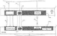
- FIG. 1is a schematic diagram of an exemplary access control system including the inventive magnetic lock system mounted to a door and door frame of the door, where the magnetic lock system includes a door magnetic lock assembly mounted to the door and a frame magnetic lock assembly mounted to the door frame;
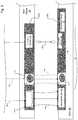
- FIG. 2Ashows detail for an embodiment of the frame magnetic lock assembly of the magnetic lock system in FIG. 1 and also shows components on a door frame side that interface with the frame magnetic lock assembly;
- FIG. 2Bshows detail for another embodiment of the frame magnetic lock assembly
- FIG. 3shows more detail for the magnetic lock system, including interfacing and signals between the door magnetic lock assembly and the frame magnetic lock assembly;
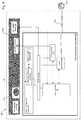
- FIG. 4shows more detail for components on the door side of the magnetic lock system.
- the term “and/or”includes any and all combinations of one or more of the associated listed items. Further, the singular forms and the articles “a”, “an” and “the” are intended to include the plural forms as well, unless expressly stated otherwise. It will be further understood that the terms: includes, comprises, including and/or comprising, when used in this specification, specify the presence of stated features, integers, steps, operations, elements, and/or components, but do not preclude the presence or addition of one or more other features, integers, steps, operations, elements, components, and/or groups thereof. Further, it will be understood that when an element, including component or subsystem, is referred to and/or shown as being connected or coupled to another element, it can be directly connected or coupled to the other element or intervening elements may be present.
- FIG. 1is a schematic diagram of an exemplary access control system 100 to which the invention is directed.
- the access control system 100is installed at a premises such as a building 90 .
- Major components of the access control system 100include a magnetic lock system 20 mounted between a door frame 32 and a door 30 , a door control module 80 , an access reader 50 , a WiFi access point 27 , and a central control system 42 .
- the central control system 42in one example, functions as a verification system for verifying user credentials 77 of users.
- the door 30is attached to the door frame 32 by hinges 63 that enable opening and closing of the door 30 .
- the door 30also includes a door electronics subsystem 60 and a handle/door plate 24 .
- the magnetic lock system 20 and the door electronics subsystem 60form a door system 200 .
- the access reader 50is mounted to a wall 45 next to the door frame 32 of the door 30 , and input power is usually provided to the access reader 50 via electrical cabling within the wall 45 .
- the access reader 50can also receive a signal from a request to exit device 28 mounted to the wall 45 .
- the request to exit device 28can be a simple button pressed by the user that sends the signal to the door control module 80 , or a Passive Infra-Red (PIR) sensor that detects the presence of the user and sends the signal in response.
- PIRPassive Infra-Red
- the door control module 80 , the access reader 50 , and the request to exit device 28are examples of equipment mounted near the door frame 32 of the access control system 100 that typically receive input power via electrical cabling within the wall 45 .
- the magnetic lock system 20includes a frame magnetic lock assembly 20 a mounted to the door frame 32 and a door magnetic lock assembly 20 b mounted to the door 30 .
- the frame magnetic lock assembly 20 areceives power from the door control module 80 , in one embodiment, and the door control module 80 communicates with the central control system 42 and the WiFi access point 27 over a local network 13 .
- a database 15 connected to the local network 13stores the user credentials 77 of users.
- the database 15is directly connected to the central control system 42 rather than via the local network 13 .
- the direct connection of the database 15 to the central control system 42provides heightened data security for the user credentials of the users 77 and other information stored within the database 15 .
- Users at the door 30typically present access cards including their user credentials 77 to the access reader 50 to obtain access to the building 90 .
- the access reader 50sends the user credentials 77 directly to the central control system 42 or to the door control module 80 , which in turn forwards the user credentials 77 to the central control system 42 for verification.
- the central control system 42Upon verification of the user credentials 77 , the central control system 42 sends a signal for unlocking the door 30 to the door controller module 80 .
- the door controller module 80sends a signal to the frame magnetic lock assembly 20 a to unlock the door 30 .
- the door control module 80can provide power to and control the locking and unlocking of multiple doors 30 within the building 90 .
- FIG. 2Ashows detail for an embodiment of a door system 200 according to the invention.
- the systemincludes the frame magnetic lock assembly 20 a - 1 of the magnetic lock system 20 in FIG. 1 and also shows components on the door frame side of the magnetic lock system 20 that interface with the frame magnetic lock assembly.
- the frame magnetic lock assembly 20 a - 1includes a lock coil 14 , an inductive power transmission module 34 , an inductive power transmitter 33 , and a frame Near Field Communications (NFC) antenna, or frame NFC antenna 54 a .
- the door control module 80includes a controller 21 , a DC power unit 36 , and an NFC transceiver 23 a .
- the DC power unit 36 and the NFC transceiver 23 aare under control of the controller 21 .
- the NFC transceiver 23 ais connected to the frame NFC antenna 54 a.
- NFC communicationsare not supported.
- the door control module 80does not include the NFC transceiver 23 a and the frame magnetic lock assembly 20 a - 1 does not include the frame NFC antenna 54 a.
- the controller 21controls the locking and unlocking of the door 30 , in one example, by sending a control signal 99 to activate or deactivate the DC power unit 36 .
- the DC power unit 36provides a dc power signal 22 to power the lock coil 14 , i.e., electromagnet, and the inductive power transmission module 34 .
- the dc power signal 22is either 12 or 24 VDC.
- the controller 21sends a control signal 99 to activate the DC power unit 36 , thus enabling the dc power signal 22 .
- the inductive power transmission module 34which is installed on the door frame 32 , then provides an alternating current (ac) inductive power transfer signal 18 to an inductive power transmitter 33 .
- the controller 21sends a control signal 99 that deactivates the DC power unit 36 , thus disabling the dc power signal 22 .
- the inductive power transfer signal 18can also be disabled. In this situation, the door is often open thus preventing inductive power transfer.
- a userpresents his/her user credentials 77 at the access reader 50 to obtain access to the building 90 , through a normally closed and locked door 30 .
- the door control module 80sends the user credentials 77 over the network 13 to the central control system 42 .
- the central control system 42compares the received user credentials 77 to those of valid users in the database 15 to validate the users. If the user is a valid user, the controller 21 sends a control signal 99 to deactivate the DC power unit 36 , thus disabling the dc power signal 22 to unlock the door 30 .
- FIG. 2Bshows detail for another embodiment of a frame magnetic lock assembly 20 a - 2 , which is similar to and operates in a similar manner as the frame magnetic lock assembly 20 a - 1 in FIG. 2A .
- the inductive power transmission module 34is included within the door control module 80 rather than being located in the frame magnetic lock assembly 20 a , as in FIG. 2A .
- the door control module 80 and frame magnetic lock assembly 20 a - 2otherwise operate in a similar manner as the door control module 80 and frame magnetic lock assembly 20 a - 1 in FIG. 2A .
- the controller 21 of the frame magnetic lock assembly 20 a - 2locks the door 30 by sending a control signal 99 that instructs the DC power unit 36 to enable its dc power signal 22 , which powers both the lock coil 14 and the inductive power transmission module 34 .
- the controller 21sends a control signal 99 that instructs the DC power unit 36 to disable its dc power signal 22 .
- the frame magnetic lock assembly 20 a - 2includes fewer components than in the frame magnetic lock assembly 20 a - 1 in FIG. 2A and therefore can be more easily manufactured, which lowers cost. As with the frame magnetic lock assembly 20 a - 2 in FIG. 2A , the frame magnetic lock assembly 20 a - 2 has an alternative embodiment that does not support NFC communications.
- FIG. 3shows more detail for the magnetic lock 20 of the door system 200 , including interfacing and signals between its frame magnetic lock assembly 20 a and door magnetic lock assembly 20 b.
- the door magnetic lock assembly 20 bincludes a ferromagnetic plate 38 , an inductive power receiver 43 , a door NFC antenna 54 b , and a door position sensor 26 .
- the door 30is normally closed and locked.
- the dc power signal 22energizes the lock coil 14 , which in turn applies a magnetic field 44 that attracts the ferromagnetic plate 38 .
- the door frame 32provides inductively transferred power 16 to the door 30 .
- the ac inductive power input signal 18energizes the inductive power transmitter 33 , which in turn creates inductively transferred power 16 in the form of a magnetic field that radiates toward the inductive power receiver 43 .
- the inductive power receiver 43receives and transduces the magnetic signal into a door ac power signal 18 ′ at the door.
- an NFC communications link 48is also established between the door frame 32 and the door 30 .
- the NFC communications link 48is established between the frame NFC antenna 54 a of the frame magnetic lock assembly 20 a and the door NFC antenna 54 b of the door magnetic lock assembly 20 b.
- the door magnetic lock assembly 20 balso no longer receives inductively transferred power 16 from the frame magnetic lock assembly 20 a when the door control module 80 unlocks the door 30 . Because the inductive power transmission module 34 has no source of power, the inductive power transmission module 34 cannot create the ac inductive power input signal 18 that, in turn, energizes the inductive power transmitter 33 of the frame magnetic lock assembly 20 a . As a result, the inductive power transmitter 33 no longer provides the inductively transferred power 16 to the inductive power receiver 43 at the door 30 when the door 30 is open. Inductive power transfer is also prevented when the door is opened because of the resulting gap between the transmitter 33 and the receiver 43 .
- FIG. 4shows more detail for components on the door side of the door system 200 .
- the door 30includes a door electronics subsystem 60 that is typically either mounted upon or integrated within the door 30 .
- the door electronics subsystem 60includes a power management system 74 , a power bus 75 , a door controller 84 , an NFC transceiver 23 b , and a WiFi transceiver 88 .
- the power management system 74includes a power conditioning circuit 72 and an energy storage element 66 .
- NFC communicationsare not supported.
- the door control module 80does not include the NFC transceiver 23 a and the frame magnetic lock assembly 20 a - 1 does not include the frame NFC antenna 54 a.
- the power conditioning circuit 72receives the door ac power input signal 18 ′ from the inductive power receiver 43 and converts the door ac power input signal 18 ′ to a door dc power signal 22 ′.
- the power conditioning circuitprovides ripple reduction of the door ac power input signal and rectifies the door ac power input signal 18 ′ into the door dc power signal 22 ′.
- the door dc power signal 22 ′provides power to the door electronics subsystem 60 and other various components at the door 30 via the power bus 75 .
- the power bus 75distributes the door dc power signal 22 ′ to the door position sensor 26 , the door controller 84 , which is typically a microcontroller, the WiFi transceiver 88 , and the NFC transceiver 23 b .
- the power conditioning circuit 72also charges the energy storage element 66 with the door dc power signal 22 ′.
- the energy storage element 66is a rechargeable energy source such as a supercapacitor or a rechargeable battery.
- the inductively transferred power 16is not available at the door 30 when the door is opened by a user and/or unlocked by the door control module 80 at the door frame 32 , in examples.
- the inductive power receiver 43is no longer located near the inductive power transmitter 44 .
- the magnetic field of the inductively transferred power 16cannot energize the inductive power receiver 43 .
- the door control module 80sends a control signal 99 to deactivate the DC power unit 36 .
- the inductive power transmitter 33 of the frame magnetic lock assembly 20 ais not powered and therefore cannot create and provide the inductively transferred power 16 to the door 30 .
- the power management system 74can provide power to the door 30 via the stored door DC power signal 22 ′ from the energy storage element 66 .
- the power conditioning circuit 72 of the power management system 74provides the stored door DC power signal 22 ′ to the power bus 75 , which in turn powers the door electronics subsystem 60 and possibly other components at the door 30 . In this way, the power management system 74 can ride-through a disconnection of the inductively transferred power 16 .
- the power management system 74also alternates between powering the door 30 via the inductively transferred power 16 and via the stored door DC power signal 22 ′ from the energy storage element 66 , based on the availability of the inductively transferred power 16 at the door 30 .
- the power management system 74powers the door 30 via the stored door dc power signal 22 ′.
- the power management system 74can then switch back to providing power to the door 30 from the inductively transferred power 16 when the inductively transferred power 16 at the door 30 is restored.
- the power management system 74determines whether the inductively transferred power 16 is available at the door 30 via the power conditioning circuit 72 . Because the inductive power receiver 43 creates the door ac power input signal 18 ′ from the inductively transferred power 16 , the power conditioning circuit 72 can inferentially determine the availability of the inductively transferred power 16 based upon the presence or absence of the door ac power input signal 18 ′, in one example. In another example, the power conditioning circuit 72 can inferentially determine the availability of the inductively transferred power 16 based upon the quality of the door ac power input signal 18 ′.
- the power management circuit 72can conclude that the inductively transferred power 16 is effectively unavailable at the door 30 .
- the power conditioning circuit 72uses some of the input power to recharge the energy storage element 66 so that it is fully charged for the next time the door 30 is opened.
- the remaining power from the door ac input signal 18 ′is used to provide power on the power bus 75 and to the other components of the door electronics subsystem 60 .
- the door controller 84receives an indication that the door 30 is open and/or closed from the door position sensor 26 and controls the NFC transceiver 23 b and the WiFi transceiver 88 .
- the WiFi transceiver 88establishes a WiFi link 89 to the WiFi access point 27 , which in turn communicates with the door control module 80 via the local network 13 . This enables bidirectional WiFi communications between the door frame 32 and the door 30 .
- the NFC transceiver 23 bis connected to the door NFC antenna 54 b , which also enables bidirectional NFC communications between the door frame 32 and the door 30 .
Landscapes
- Physics & Mathematics (AREA)
- Electromagnetism (AREA)
- Engineering & Computer Science (AREA)
- Mechanical Engineering (AREA)
- Lock And Its Accessories (AREA)
Abstract
Description
Claims (20)
Priority Applications (1)
| Application Number | Priority Date | Filing Date | Title |
|---|---|---|---|
| US15/690,743US10968669B2 (en) | 2017-08-30 | 2017-08-30 | System and method for inductive power transfer to door |
Applications Claiming Priority (1)
| Application Number | Priority Date | Filing Date | Title |
|---|---|---|---|
| US15/690,743US10968669B2 (en) | 2017-08-30 | 2017-08-30 | System and method for inductive power transfer to door |
Publications (2)
| Publication Number | Publication Date |
|---|---|
| US20190063128A1 US20190063128A1 (en) | 2019-02-28 |
| US10968669B2true US10968669B2 (en) | 2021-04-06 |
Family
ID=65436535
Family Applications (1)
| Application Number | Title | Priority Date | Filing Date |
|---|---|---|---|
| US15/690,743Active2038-11-20US10968669B2 (en) | 2017-08-30 | 2017-08-30 | System and method for inductive power transfer to door |
Country Status (1)
| Country | Link |
|---|---|
| US (1) | US10968669B2 (en) |
Families Citing this family (6)
| Publication number | Priority date | Publication date | Assignee | Title |
|---|---|---|---|---|
| DE102017219403A1 (en)* | 2017-10-27 | 2019-05-02 | Thyssenkrupp Ag | Synchronization of door movements in an elevator system |
| CA3098711C (en)* | 2018-03-23 | 2024-06-11 | Schlage Lock Company Llc | Power and communication arrangements for an access control system |
| CA3115844C (en)* | 2019-02-25 | 2022-04-12 | 1Valet Corp. | Inductively powered door locks and retrofit kits for battery powered door locks |
| EP3754137A1 (en)* | 2019-06-19 | 2020-12-23 | Assa Abloy AB | Bolt identity |
| WO2022197966A1 (en)* | 2021-03-17 | 2022-09-22 | Carefusion 303, Inc. | Locking cap assembly |
| JP2024537010A (en)* | 2021-09-23 | 2024-10-10 | マゾナイト コーポレーション | DOOR ASSEMBLY HAVING A RECHARGEABLE BATTERY, METHOD AND SYSTEM FOR CHARGING THE BATTERY - Patent application |
Citations (57)
| Publication number | Priority date | Publication date | Assignee | Title |
|---|---|---|---|---|
| US4682801A (en)* | 1984-08-31 | 1987-07-28 | Securitron-Magnalock Corp. | Electromagnet access control circuit |
| US5195341A (en)* | 1991-01-08 | 1993-03-23 | Chubb Lips Nederland Bv | Electronic cylinder lock with inductively coupled key |
| US6259352B1 (en) | 1998-03-02 | 2001-07-10 | Leon Yulkowski | Door lock system |
| US6282407B1 (en) | 1998-04-16 | 2001-08-28 | Motorola, Inc. | Active electrostatic transceiver and communicating system |
| US6720861B1 (en) | 1999-03-12 | 2004-04-13 | Best Access Systems | Wireless security control system |
| US20050116480A1 (en)* | 2003-03-21 | 2005-06-02 | Deng Sheng B. | Door lock and operation mechanism |
| US20060114099A1 (en)* | 2003-03-21 | 2006-06-01 | Deng Sheng B | Door lock and operation mechanism |
| US20070124427A1 (en) | 1997-11-03 | 2007-05-31 | Light Elliott D | System and method for obtaining equipment status data over a network |
| US20070146115A1 (en)* | 2005-01-27 | 2007-06-28 | Roosli Philipp A | Power management lock system and method |
| US20070198850A1 (en) | 2004-10-21 | 2007-08-23 | Honeywell International, Inc. | Biometric verification and duress detection system and method |
| US20070204663A1 (en) | 2004-03-16 | 2007-09-06 | Irevo, Inc. | Easy-To-Retrofit, Electronically Controlled Door Lock System |
| US20080017726A1 (en) | 2006-07-19 | 2008-01-24 | Somfy Sas | Method of operating a self-powered home automation sensor device for detecting the existence of and/or for measuring the intensity of a physical phenomenon |
| US20080209965A1 (en) | 2005-07-21 | 2008-09-04 | Koninklijke Philips Electronics, N.V. | Software-Controlled Mechanical Lock for Portable Electronic Devices |
| US20080218330A1 (en) | 2007-03-09 | 2008-09-11 | Phillip Herzog Biles | Kit and system for providing security access to a door using power over ethernet with data persistence and fire alarm control panel integration |
| US20080222963A1 (en) | 2005-04-01 | 2008-09-18 | Sios Concepts B.V. | Door Comprising an Identification Unit and an Electrical Lock and Door Body For Use In Such a Door |
| US20090302995A1 (en) | 2006-05-02 | 2009-12-10 | Jang-Ho Park | Multi digital door |
| US20100097225A1 (en) | 2008-10-17 | 2010-04-22 | Robert Bosch Gmbh | Automation and security system |
| US20100290542A1 (en)* | 2009-05-15 | 2010-11-18 | Joshua Todd Peabody | System for Providing Power and Data Transmission Between a Door and a Frame |
| US20120267962A1 (en)* | 2009-05-15 | 2012-10-25 | Hanchett Jr Leland J | System for Providing Power and Data Transmission Between a Door and a Frame |
| US20130167190A1 (en) | 2011-12-22 | 2013-06-27 | Next Level Security Systems, Inc. | Mobile communication device surveillance system |
| US20130260676A1 (en)* | 2012-03-30 | 2013-10-03 | Integrated Device Technology, Inc. | Apparatus, system, and method for back-channel communication in an inductive wireless power transfer system |
| US20130342342A1 (en) | 2012-06-20 | 2013-12-26 | Hunter Capital Management Group, LLC | Intelligent safety device testing and operation |
| US20140159388A1 (en) | 2012-12-07 | 2014-06-12 | Li-Shih Liao | Electromagnetic doorlock with shock detection and power saving device |
| US8772978B2 (en)* | 2010-06-24 | 2014-07-08 | Murata Manufacturing Co., Ltd. | Power transmitting apparatus, power receiving apparatus, and wireless power transmission system |
| US20140265359A1 (en) | 2013-03-15 | 2014-09-18 | August Home, Inc. | Intelligent Door Lock System |
| US20140282048A1 (en) | 2013-03-15 | 2014-09-18 | Adt Us Holdings, Inc. | Security system access profiles |
| US20140274033A1 (en) | 2013-03-15 | 2014-09-18 | Research In Motion Limited | Method and Apparatus Pertaining to use of Bluetooth and Bluetooth Low Energy |
| US20140292096A1 (en) | 2013-04-02 | 2014-10-02 | Canon Kabushiki Kaisha | Power transmission apparatus, power reception apparatus, wireless power feeding system, and control method thereof |
| US20140340032A1 (en)* | 2013-05-16 | 2014-11-20 | Microchip Technology Incorporated | Wireless Door Lock Power Transfer System Having Communications Capabilities |
| US20150116082A1 (en) | 2013-10-28 | 2015-04-30 | Smartlabs, Inc. | Systems and methods to control locking and unlocking of doors using powerline and radio frequency communications |
| US20150211270A1 (en) | 2014-01-24 | 2015-07-30 | Cdvi Digit | Anti-remanent device for an electromagnetic door lock |
| US20150243195A1 (en) | 2014-02-27 | 2015-08-27 | Ray Escobedo | Door messaging system |
| US20150249548A1 (en) | 2014-02-28 | 2015-09-03 | Tyco Fire & Security Gmbh | Establishing Links Between Sub-Nets |
| US20150348220A1 (en) | 2014-05-28 | 2015-12-03 | Sensormatic Electronics, LLC | Method and system for managing evacuations using positioning systems |
| US20160047144A1 (en) | 2013-04-05 | 2016-02-18 | Rutherford Controls Int'l Inc. | Low power magnetic lock assembly |
| US20160077575A1 (en) | 2014-09-17 | 2016-03-17 | Advanced Micro Devices, Inc. | Interface to expose interrupt times to hardware |
| US20160087687A1 (en)* | 2008-09-27 | 2016-03-24 | Witricity Corporation | Communication in a wireless power transmission system |
| US20160275781A1 (en) | 2015-03-18 | 2016-09-22 | Google Inc. | Systems and methods of privacy within a security system |
| US20160307683A1 (en)* | 2015-04-14 | 2016-10-20 | Hanchett Entry Systems, Inc. | Constant-current controller for an inductive load |
| US20160343181A1 (en) | 2014-03-12 | 2016-11-24 | August Home Inc. | Wireless access control system and methods for intelligent door lock system |
| US20170091998A1 (en) | 2015-09-24 | 2017-03-30 | Tyco Fire & Security Gmbh | Fire/Security Service System with Augmented Reality |
| US20170186254A1 (en) | 2015-12-28 | 2017-06-29 | Unikey Technologies Inc. | Wireless access control system including closed door position and interior area remote access wireless communications device based lock switching and related methods |
| US20170228603A1 (en) | 2013-03-15 | 2017-08-10 | August Home, Inc. | Door lock system with wide view camera |
| US20170238401A1 (en) | 2014-01-25 | 2017-08-17 | Innosys, Inc. | Solid State Lighting Systems |
| US20170243455A1 (en) | 2013-03-15 | 2017-08-24 | August Home, Inc. | Door lock system with one or more virtual fences |
| US20170263065A1 (en) | 2013-03-15 | 2017-09-14 | August Home Inc. | Intelligent door lock system with notification to user regarding battery status |
| US20170284129A1 (en) | 2014-09-02 | 2017-10-05 | Rudolf King | Door and home security system and method |
| US20170332055A1 (en) | 2014-11-26 | 2017-11-16 | STRATTEC Advanced Logic | Door lock and door security system |
| US9845623B1 (en) | 2016-06-17 | 2017-12-19 | Toyota Motor Engineering & Manufacturing North America, Inc. | Touch control of vehicle door locks |
| US20170373723A1 (en)* | 2014-12-23 | 2017-12-28 | Rollock Oy | Door lock and arrangement for transferring power to door lock |
| US20180058099A1 (en) | 2015-03-23 | 2018-03-01 | Kaba Gmbh | Window or door lock |
| US20180076664A1 (en) | 2016-09-14 | 2018-03-15 | U.S.A. As Represented By The Administrator Of The National Aeronautics And Space Administration | Inductive power transfer for aerospace flight systems |
| US20180075961A1 (en) | 2016-09-09 | 2018-03-15 | Hanchett Entry Systems, Inc. | Degauss circuit for use in an electronically actuated door lock |
| US9984523B1 (en)* | 2017-03-17 | 2018-05-29 | I-Ting Shen | Control system for lock devices |
| US20180213191A1 (en) | 2017-01-26 | 2018-07-26 | I-Ting Shen | Door Access System |
| US10158831B1 (en) | 2017-06-15 | 2018-12-18 | MVI Systems, LLC | Entranceway or foyer-based, communication apparatus and system |
| US20190186181A1 (en) | 2017-12-17 | 2019-06-20 | Glen A. Robertson | Energy efficient and power versatile electro-permanent magnet system for use in a door holder unit |
- 2017
- 2017-08-30USUS15/690,743patent/US10968669B2/enactiveActive
Patent Citations (57)
| Publication number | Priority date | Publication date | Assignee | Title |
|---|---|---|---|---|
| US4682801A (en)* | 1984-08-31 | 1987-07-28 | Securitron-Magnalock Corp. | Electromagnet access control circuit |
| US5195341A (en)* | 1991-01-08 | 1993-03-23 | Chubb Lips Nederland Bv | Electronic cylinder lock with inductively coupled key |
| US20070124427A1 (en) | 1997-11-03 | 2007-05-31 | Light Elliott D | System and method for obtaining equipment status data over a network |
| US6259352B1 (en) | 1998-03-02 | 2001-07-10 | Leon Yulkowski | Door lock system |
| US6282407B1 (en) | 1998-04-16 | 2001-08-28 | Motorola, Inc. | Active electrostatic transceiver and communicating system |
| US6720861B1 (en) | 1999-03-12 | 2004-04-13 | Best Access Systems | Wireless security control system |
| US20050116480A1 (en)* | 2003-03-21 | 2005-06-02 | Deng Sheng B. | Door lock and operation mechanism |
| US20060114099A1 (en)* | 2003-03-21 | 2006-06-01 | Deng Sheng B | Door lock and operation mechanism |
| US20070204663A1 (en) | 2004-03-16 | 2007-09-06 | Irevo, Inc. | Easy-To-Retrofit, Electronically Controlled Door Lock System |
| US20070198850A1 (en) | 2004-10-21 | 2007-08-23 | Honeywell International, Inc. | Biometric verification and duress detection system and method |
| US20070146115A1 (en)* | 2005-01-27 | 2007-06-28 | Roosli Philipp A | Power management lock system and method |
| US20080222963A1 (en) | 2005-04-01 | 2008-09-18 | Sios Concepts B.V. | Door Comprising an Identification Unit and an Electrical Lock and Door Body For Use In Such a Door |
| US20080209965A1 (en) | 2005-07-21 | 2008-09-04 | Koninklijke Philips Electronics, N.V. | Software-Controlled Mechanical Lock for Portable Electronic Devices |
| US20090302995A1 (en) | 2006-05-02 | 2009-12-10 | Jang-Ho Park | Multi digital door |
| US20080017726A1 (en) | 2006-07-19 | 2008-01-24 | Somfy Sas | Method of operating a self-powered home automation sensor device for detecting the existence of and/or for measuring the intensity of a physical phenomenon |
| US20080218330A1 (en) | 2007-03-09 | 2008-09-11 | Phillip Herzog Biles | Kit and system for providing security access to a door using power over ethernet with data persistence and fire alarm control panel integration |
| US20160087687A1 (en)* | 2008-09-27 | 2016-03-24 | Witricity Corporation | Communication in a wireless power transmission system |
| US20100097225A1 (en) | 2008-10-17 | 2010-04-22 | Robert Bosch Gmbh | Automation and security system |
| US20100290542A1 (en)* | 2009-05-15 | 2010-11-18 | Joshua Todd Peabody | System for Providing Power and Data Transmission Between a Door and a Frame |
| US20120267962A1 (en)* | 2009-05-15 | 2012-10-25 | Hanchett Jr Leland J | System for Providing Power and Data Transmission Between a Door and a Frame |
| US8772978B2 (en)* | 2010-06-24 | 2014-07-08 | Murata Manufacturing Co., Ltd. | Power transmitting apparatus, power receiving apparatus, and wireless power transmission system |
| US20130167190A1 (en) | 2011-12-22 | 2013-06-27 | Next Level Security Systems, Inc. | Mobile communication device surveillance system |
| US20130260676A1 (en)* | 2012-03-30 | 2013-10-03 | Integrated Device Technology, Inc. | Apparatus, system, and method for back-channel communication in an inductive wireless power transfer system |
| US20130342342A1 (en) | 2012-06-20 | 2013-12-26 | Hunter Capital Management Group, LLC | Intelligent safety device testing and operation |
| US20140159388A1 (en) | 2012-12-07 | 2014-06-12 | Li-Shih Liao | Electromagnetic doorlock with shock detection and power saving device |
| US20140265359A1 (en) | 2013-03-15 | 2014-09-18 | August Home, Inc. | Intelligent Door Lock System |
| US20140274033A1 (en) | 2013-03-15 | 2014-09-18 | Research In Motion Limited | Method and Apparatus Pertaining to use of Bluetooth and Bluetooth Low Energy |
| US20140282048A1 (en) | 2013-03-15 | 2014-09-18 | Adt Us Holdings, Inc. | Security system access profiles |
| US20170263065A1 (en) | 2013-03-15 | 2017-09-14 | August Home Inc. | Intelligent door lock system with notification to user regarding battery status |
| US20170243455A1 (en) | 2013-03-15 | 2017-08-24 | August Home, Inc. | Door lock system with one or more virtual fences |
| US20170228603A1 (en) | 2013-03-15 | 2017-08-10 | August Home, Inc. | Door lock system with wide view camera |
| US20140292096A1 (en) | 2013-04-02 | 2014-10-02 | Canon Kabushiki Kaisha | Power transmission apparatus, power reception apparatus, wireless power feeding system, and control method thereof |
| US20160047144A1 (en) | 2013-04-05 | 2016-02-18 | Rutherford Controls Int'l Inc. | Low power magnetic lock assembly |
| US20140340032A1 (en)* | 2013-05-16 | 2014-11-20 | Microchip Technology Incorporated | Wireless Door Lock Power Transfer System Having Communications Capabilities |
| US20150116082A1 (en) | 2013-10-28 | 2015-04-30 | Smartlabs, Inc. | Systems and methods to control locking and unlocking of doors using powerline and radio frequency communications |
| US20150211270A1 (en) | 2014-01-24 | 2015-07-30 | Cdvi Digit | Anti-remanent device for an electromagnetic door lock |
| US20170238401A1 (en) | 2014-01-25 | 2017-08-17 | Innosys, Inc. | Solid State Lighting Systems |
| US20150243195A1 (en) | 2014-02-27 | 2015-08-27 | Ray Escobedo | Door messaging system |
| US20150249548A1 (en) | 2014-02-28 | 2015-09-03 | Tyco Fire & Security Gmbh | Establishing Links Between Sub-Nets |
| US20160343181A1 (en) | 2014-03-12 | 2016-11-24 | August Home Inc. | Wireless access control system and methods for intelligent door lock system |
| US20150348220A1 (en) | 2014-05-28 | 2015-12-03 | Sensormatic Electronics, LLC | Method and system for managing evacuations using positioning systems |
| US20170284129A1 (en) | 2014-09-02 | 2017-10-05 | Rudolf King | Door and home security system and method |
| US20160077575A1 (en) | 2014-09-17 | 2016-03-17 | Advanced Micro Devices, Inc. | Interface to expose interrupt times to hardware |
| US20170332055A1 (en) | 2014-11-26 | 2017-11-16 | STRATTEC Advanced Logic | Door lock and door security system |
| US20170373723A1 (en)* | 2014-12-23 | 2017-12-28 | Rollock Oy | Door lock and arrangement for transferring power to door lock |
| US20160275781A1 (en) | 2015-03-18 | 2016-09-22 | Google Inc. | Systems and methods of privacy within a security system |
| US20180058099A1 (en) | 2015-03-23 | 2018-03-01 | Kaba Gmbh | Window or door lock |
| US20160307683A1 (en)* | 2015-04-14 | 2016-10-20 | Hanchett Entry Systems, Inc. | Constant-current controller for an inductive load |
| US20170091998A1 (en) | 2015-09-24 | 2017-03-30 | Tyco Fire & Security Gmbh | Fire/Security Service System with Augmented Reality |
| US20170186254A1 (en) | 2015-12-28 | 2017-06-29 | Unikey Technologies Inc. | Wireless access control system including closed door position and interior area remote access wireless communications device based lock switching and related methods |
| US9845623B1 (en) | 2016-06-17 | 2017-12-19 | Toyota Motor Engineering & Manufacturing North America, Inc. | Touch control of vehicle door locks |
| US20180075961A1 (en) | 2016-09-09 | 2018-03-15 | Hanchett Entry Systems, Inc. | Degauss circuit for use in an electronically actuated door lock |
| US20180076664A1 (en) | 2016-09-14 | 2018-03-15 | U.S.A. As Represented By The Administrator Of The National Aeronautics And Space Administration | Inductive power transfer for aerospace flight systems |
| US20180213191A1 (en) | 2017-01-26 | 2018-07-26 | I-Ting Shen | Door Access System |
| US9984523B1 (en)* | 2017-03-17 | 2018-05-29 | I-Ting Shen | Control system for lock devices |
| US10158831B1 (en) | 2017-06-15 | 2018-12-18 | MVI Systems, LLC | Entranceway or foyer-based, communication apparatus and system |
| US20190186181A1 (en) | 2017-12-17 | 2019-06-20 | Glen A. Robertson | Energy efficient and power versatile electro-permanent magnet system for use in a door holder unit |
Also Published As
| Publication number | Publication date |
|---|---|
| US20190063128A1 (en) | 2019-02-28 |
Similar Documents
| Publication | Publication Date | Title |
|---|---|---|
| US10968669B2 (en) | System and method for inductive power transfer to door | |
| US9673868B2 (en) | Wireless door lock power transfer system having communications capabilities | |
| US7967197B2 (en) | Integrated online door via electronic door handle | |
| US11386730B2 (en) | Smart lock systems and methods | |
| US10937262B2 (en) | Door system with power management system and method of operation thereof | |
| US20140020295A1 (en) | Architectural closure powering device | |
| US8354914B2 (en) | Reduced power electronic lock system | |
| US9342936B2 (en) | Smart lock systems and methods | |
| US20180114389A1 (en) | Wireless charging systems and methods for the battery of an electronic door locking system | |
| US10204467B2 (en) | Smart lock systems and methods | |
| US20150101369A1 (en) | Smart lock systems and methods | |
| US10943415B2 (en) | System and method for providing communication over inductive power transfer to door | |
| KR20230033743A (en) | IoT Door-lock System Having High Operating Stability | |
| EP3987133B1 (en) | Bolt identity | |
| US20240071156A1 (en) | Smart lock systems and methods | |
| JP5441223B2 (en) | Door lock system | |
| US11942804B2 (en) | Wireless charging locking device | |
| US10332370B2 (en) | System and method for energy saving on access control products | |
| KR20150128330A (en) | System and method for controlling digital door lock | |
| WO2024175333A1 (en) | Access control method and system based on access decision point(s) and access enforcement point(s) |
Legal Events
| Date | Code | Title | Description |
|---|---|---|---|
| FEPP | Fee payment procedure | Free format text:ENTITY STATUS SET TO UNDISCOUNTED (ORIGINAL EVENT CODE: BIG.); ENTITY STATUS OF PATENT OWNER: LARGE ENTITY | |
| AS | Assignment | Owner name:SENSORMATIC ELECTRONICS, LLC, FLORIDA Free format text:ASSIGNMENT OF ASSIGNORS INTEREST;ASSIGNORS:MCLEOD, MURDO JAMIE SCOTT;MARTIN, WALTER A.;REEL/FRAME:043466/0468 Effective date:20170831 | |
| STPP | Information on status: patent application and granting procedure in general | Free format text:DOCKETED NEW CASE - READY FOR EXAMINATION | |
| STPP | Information on status: patent application and granting procedure in general | Free format text:NON FINAL ACTION MAILED | |
| STPP | Information on status: patent application and granting procedure in general | Free format text:RESPONSE TO NON-FINAL OFFICE ACTION ENTERED AND FORWARDED TO EXAMINER | |
| STPP | Information on status: patent application and granting procedure in general | Free format text:FINAL REJECTION MAILED | |
| STCV | Information on status: appeal procedure | Free format text:NOTICE OF APPEAL FILED | |
| STPP | Information on status: patent application and granting procedure in general | Free format text:DOCKETED NEW CASE - READY FOR EXAMINATION | |
| STPP | Information on status: patent application and granting procedure in general | Free format text:NOTICE OF ALLOWANCE MAILED -- APPLICATION RECEIVED IN OFFICE OF PUBLICATIONS | |
| STPP | Information on status: patent application and granting procedure in general | Free format text:PUBLICATIONS -- ISSUE FEE PAYMENT RECEIVED | |
| STPP | Information on status: patent application and granting procedure in general | Free format text:PUBLICATIONS -- ISSUE FEE PAYMENT VERIFIED | |
| STCF | Information on status: patent grant | Free format text:PATENTED CASE | |
| AS | Assignment | Owner name:JOHNSON CONTROLS TYCO IP HOLDINGS LLP, WISCONSIN Free format text:ASSIGNMENT OF ASSIGNORS INTEREST;ASSIGNOR:JOHNSON CONTROLS INC;REEL/FRAME:058600/0126 Effective date:20210617 Owner name:JOHNSON CONTROLS INC, WISCONSIN Free format text:ASSIGNMENT OF ASSIGNORS INTEREST;ASSIGNOR:JOHNSON CONTROLS US HOLDINGS LLC;REEL/FRAME:058600/0080 Effective date:20210617 Owner name:JOHNSON CONTROLS US HOLDINGS LLC, WISCONSIN Free format text:ASSIGNMENT OF ASSIGNORS INTEREST;ASSIGNOR:SENSORMATIC ELECTRONICS LLC;REEL/FRAME:058600/0001 Effective date:20210617 | |
| AS | Assignment | Owner name:JOHNSON CONTROLS US HOLDINGS LLC, WISCONSIN Free format text:NUNC PRO TUNC ASSIGNMENT;ASSIGNOR:SENSORMATIC ELECTRONICS, LLC;REEL/FRAME:058957/0138 Effective date:20210806 Owner name:JOHNSON CONTROLS TYCO IP HOLDINGS LLP, WISCONSIN Free format text:NUNC PRO TUNC ASSIGNMENT;ASSIGNOR:JOHNSON CONTROLS, INC.;REEL/FRAME:058955/0472 Effective date:20210806 Owner name:JOHNSON CONTROLS, INC., WISCONSIN Free format text:NUNC PRO TUNC ASSIGNMENT;ASSIGNOR:JOHNSON CONTROLS US HOLDINGS LLC;REEL/FRAME:058955/0394 Effective date:20210806 | |
| AS | Assignment | Owner name:TYCO FIRE & SECURITY GMBH, SWITZERLAND Free format text:ASSIGNMENT OF ASSIGNORS INTEREST;ASSIGNOR:JOHNSON CONTROLS TYCO IP HOLDINGS LLP;REEL/FRAME:068494/0384 Effective date:20240201 | |
| MAFP | Maintenance fee payment | Free format text:PAYMENT OF MAINTENANCE FEE, 4TH YEAR, LARGE ENTITY (ORIGINAL EVENT CODE: M1551); ENTITY STATUS OF PATENT OWNER: LARGE ENTITY Year of fee payment:4 |