US10967970B2 - Durable modular unmanned aerial vehicle - Google Patents
Durable modular unmanned aerial vehicleDownload PDFInfo
- Publication number
- US10967970B2 US10967970B2US15/424,667US201715424667AUS10967970B2US 10967970 B2US10967970 B2US 10967970B2US 201715424667 AUS201715424667 AUS 201715424667AUS 10967970 B2US10967970 B2US 10967970B2
- Authority
- US
- United States
- Prior art keywords
- motor
- spokes
- hub
- pod
- mount
- Prior art date
- Legal status (The legal status is an assumption and is not a legal conclusion. Google has not performed a legal analysis and makes no representation as to the accuracy of the status listed.)
- Active, expires
Links
Images


Classifications
- B—PERFORMING OPERATIONS; TRANSPORTING
- B64—AIRCRAFT; AVIATION; COSMONAUTICS
- B64C—AEROPLANES; HELICOPTERS
- B64C39/00—Aircraft not otherwise provided for
- B64C39/02—Aircraft not otherwise provided for characterised by special use
- B64C39/024—Aircraft not otherwise provided for characterised by special use of the remote controlled vehicle type, i.e. RPV
- B—PERFORMING OPERATIONS; TRANSPORTING
- B64—AIRCRAFT; AVIATION; COSMONAUTICS
- B64U—UNMANNED AERIAL VEHICLES [UAV]; EQUIPMENT THEREFOR
- B64U20/00—Constructional aspects of UAVs
- B64U20/80—Arrangement of on-board electronics, e.g. avionics systems or wiring
- B64U20/87—Mounting of imaging devices, e.g. mounting of gimbals
- B—PERFORMING OPERATIONS; TRANSPORTING
- B64—AIRCRAFT; AVIATION; COSMONAUTICS
- B64C—AEROPLANES; HELICOPTERS
- B64C27/00—Rotorcraft; Rotors peculiar thereto
- B64C27/20—Rotorcraft characterised by having shrouded rotors, e.g. flying platforms
- B64D27/26—
- B—PERFORMING OPERATIONS; TRANSPORTING
- B64—AIRCRAFT; AVIATION; COSMONAUTICS
- B64U—UNMANNED AERIAL VEHICLES [UAV]; EQUIPMENT THEREFOR
- B64U30/00—Means for producing lift; Empennages; Arrangements thereof
- B64U30/20—Rotors; Rotor supports
- B64U30/29—Constructional aspects of rotors or rotor supports; Arrangements thereof
- B64U30/293—Foldable or collapsible rotors or rotor supports
- B64C2201/027—
- B64C2201/042—
- B64C2201/108—
- B—PERFORMING OPERATIONS; TRANSPORTING
- B64—AIRCRAFT; AVIATION; COSMONAUTICS
- B64U—UNMANNED AERIAL VEHICLES [UAV]; EQUIPMENT THEREFOR
- B64U10/00—Type of UAV
- B64U10/10—Rotorcrafts
- B64U10/13—Flying platforms
- B64U10/14—Flying platforms with four distinct rotor axes, e.g. quadcopters
- B—PERFORMING OPERATIONS; TRANSPORTING
- B64—AIRCRAFT; AVIATION; COSMONAUTICS
- B64U—UNMANNED AERIAL VEHICLES [UAV]; EQUIPMENT THEREFOR
- B64U30/00—Means for producing lift; Empennages; Arrangements thereof
- B64U30/20—Rotors; Rotor supports
- B64U30/29—Constructional aspects of rotors or rotor supports; Arrangements thereof
- B64U30/299—Rotor guards
- B—PERFORMING OPERATIONS; TRANSPORTING
- B64—AIRCRAFT; AVIATION; COSMONAUTICS
- B64U—UNMANNED AERIAL VEHICLES [UAV]; EQUIPMENT THEREFOR
- B64U50/00—Propulsion; Power supply
- B64U50/10—Propulsion
- B64U50/19—Propulsion using electrically powered motors
Definitions
- Embodiments disclosed hereinrelate generally to aerial vehicles, and more particularly to structural improvements for multi-rotor unmanned aerial vehicles (UAVs) that provide for enhanced performance and more convenient portability
- UAVsunmanned aerial vehicles
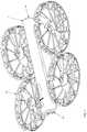
- FIG. 1shows a quadcopter with modular components.
- FIG. 2shows a quadcopter with the modular components moved away from the fuselage.
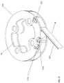
- FIG. 3is a view of the bottom side of the fuselage.
- FIG. 4is an exploded view of a pod pair.
- FIG. 5shows a section through a pod pair.
- FIG. 6shows an exploded view of a hub assembly.
- FIG. 7is an exploded view of the vibration isolation sub-assembly.
- FIG. 8shows a magnet with a step feature.
- FIG. 9is a magnified view of a portion of the motor hub assembly.
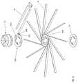
- FIG. 10is a top view of the rotor set.
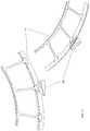
- FIG. 11is an enlarged detail view of the rotor set hinge.
- FIG. 13shows the a rotor set in the process of folding.
- FIG. 14shows two views of a fully folded rotor set and a detail view of nested spring pins.
- FIG. 15shows the gimbal attached to the video processing circuit sub-system.
- FIG. 16shows the gimbal detached from the video processing circuit sub-system.
- FIG. 18is an exploded view of the gimbal.
- FIG. 19is an angled view of the gimbal attachment location on the fuselage.
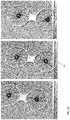
- FIG. 20is a series of frames from a high-speed video of a pod pair dropped onto a hard surface.
- Small UAVsare increasingly used for aerial reconnaissance, typically recording video and still images for later viewing, or viewing in real-time.
- a typical UAVis powered by either a single gas-powered engine or several electric powered motors with the required thrust for lift being generated by at least one, but usually three or more spinning propellers.
- Each propellerincludes one or more radially disposed blades extending from a central hub. The hub of each propeller is mechanically connected, either directly or indirectly through a transmission, to the drive shaft of the engine or each motor used.
- a UAVresembles a radio controlled model helicopter, except that a helicopter's conventional tail rotor is not required with a UAV since the multi-propeller design effectively cancels out any propeller-generated rotational thrust that must otherwise be controlled using a tail-rotor in single-propeller designs.
- a motor hub assemblyincluding a motor supported by a motor mount, an outer protective structure circumscribing and spaced apart from the motor mount, and a plurality of spokes extending radially outward from the mount and extending at least between the mount and the protective structure, the plurality of spokes being substantially more resistant to flexure out of a plane normal to a rotational axis of the motor than to flexure parallel to the plane normal to the rotational axis of the motor.
- the plurality of spokescan have a rectangular cross-section within a plane normal to a line between the motor mount and the protective structure along which the spokes extend.
- the assemblycan include at least one propeller blade coupled to the motor and configured to rotate within a plane normal to the rotational axis of the motor.
- the plurality of spokescan have a cross-sectional shape which tapers to a narrower width on the side of the spokes proximate the at least one propeller blade.
- the motor mountcan include a compliant material.
- the the plurality of spokescan extend along lines which do not intersect the rotational axis of the motor.
- the motor mountcan include a central hub, the central hub including a plurality of inwardly extending slots configured to receive radially inward ends of the plurality of spokes, an upper plate overlying at least a portion of the radially inward ends of the plurality of spokes received within the plurality of inwardly extending slots, and a lower plate underlying at least a portion of the radially inward ends of the plurality of spokes received within the plurality of inwardly extending slots.
- the central hubcan include a deformable material and can be compressed between the upper plate and the lower plate to frictionally retain the radially inward ends of the plurality of spokes.
- the upper platecan include a circuit board configured to carry power to the motor.
- the protective structurecan be concentric with the motor mount.
- the protective structurecan be concentric with an axis of rotation of the motor.
- the plurality of spokescan include a carbon fiber material.
- the plurality of spokescan include a pultruded carbon fiber material.
- the plurality of spokescan inhibit displacement of the motor along an axis of rotation of the motor to a greater degree than displacement of the motor within a plane normal to the axis of rotation of the motor.
- the the plurality of spokescan further inhibit rotation of the motor mount out of the plane normal to the axis of rotation of the motor.
- a motor hub assemblyincluding a compliant motor mount, a plurality of carbon fiber spokes fastened to the motor mount and constrained compressively substantially in plane by a top rigid hub plate and a bottom rigid hub plate, and a protective outer ring, each of the plurality of fiber spokes fastened to the outer ring.
- the top hub platecan include a rigid circuit board configured to carry power to a motor.
- a thrust pod assemblyincluding a protective structure, the protective structure including an upper portion including an inner hoop, an outer hoop, and a plurality of protective ribs connecting the inner hoop to the outer hoop, a bottom part including an outer hoop, and a cylindrical rim fastened to the outer hoop of the top part and the outer hoop of the bottom part, a compliant motor mount, and a plurality of carbon fiber spokes, each spoke fastened at one end to the outer hoop of the bottom part of the protective structure, the plurality of spokes constrained compressively substantially in plane by a top rigid hub plate and a bottom rigid hub plate.
- the term “flying mode”is used to refer to a mode in which the quadcopter is airborne, and may be under the control of a flight control subsystem.
- the term “static mode”is used to refer to a mode in which the quadcopter is assembled with all modules attached and can be ready to fly. The propellers may or may not be spinning.
- the term “portable mode”is used to refer to a mode in which the quadcopter modules are disassembled for transport and storage.
- FIG. 1 and FIG. 2show a quadcopter 1 with modular components including a rotor set 12 , a battery 21 , and a camera gimbal 24 .
- Quadcopter 1 fuselage 8encloses an electronics sub-system that includes a power conversion circuit, motor controllers, a flight control sub-system, a gimbal control sub-system, and various sensors including an IMU, a sonar sensor, a GPS receiver, and a Wifi transceiver.
- the electronics sub-systemis not described in detail as they are not the subject of the invention.
- FIG. 3a view of the bottom side of fuselage 8 , shows magnetic, power, and electrical signal interface features for rotor set 12 and battery 21 module.
- a plurality of pod motor contacts 96 A and 96 Bare gold plated pads integral to a motherboard 34 and functionally connected to the four DC motors 36 A, 36 B, 36 C, and 36 D included in rotor set 12 .
- Corresponding to motor contacts 96 A and 96 Bare two pairs of a cylindrical pod attach magnet 100 A and 100 B, and 100 C and 110 D, fastened into and flush with the bottom surface of fuselage 8 .
- Two battery power contacts 104 A and 104 Bare soldered onto motherboard 34 and functionally connect to battery +V and GND respectively when battery 21 is attached.
- Two each of a cylindrical battery attach magnet 112 A and 112 Bare mounted in and flush with the bottom surface of fuselage 8 .
- Two each of a prismatic battery attach magnet 116 A and 116 Bare mounted in and flush with the bottom surface of fuselage 8 .
- Magnets 100 A, 100 B, 100 C, and 100 D, 112 A and B, and 116 A and 116 Bare comprised of nickel-plated neodymium and in some embodiments are fastened into fuselage 8 with cyanoacrylate adhesive.
- magnet 118is mechanically captured in fuselage 8 by an annular step feature 120 on a magnet 118 in combination with a rib feature 124 added to fuselage 8 .
- FIG. 2rotor set 12 is comprised of pod pair 16 A and 16 B, which are identical.
- FIG. 3an exploded assembly view, shows that pod pair 16 A includes a pod top 8 and a pod bottom 20 both manufactured of injection-molded polycarbonate plastic.
- Pod top 8 and pod bottom 20both include a center enclosure portion and a circular hoop portion on either side.
- Pod bottom 20includes a plurality of spoke bosses 37 which are a molded in U-shaped channel.
- Each of spokes 48are inserted into a spoke boss 37 .
- spokes 48are fastened to spoke bosses 37 with flexible epoxy adhesive.
- a carbon fiber rim 46 A and 46 Bis fastened to both pod top 8 circular hoop portion and pod bottom 20 circular hoop portion.
- FIG. 5an enlarged section view of pod pair 16 A, pod top 8 circular hoop portion includes a pod top inverted U-shaped channel 22 and pod bottom 20 includes a pod bottom U-shaped channel 23 sized to accept carbon fiber rim 46 A.
- a plurality of protective ribsconnect the outer hoop 8 A of pod top 8 to the inner hoop 8 B (see FIG. 4 ).
- rim 46 A and 46 Bare fastened to pod top 8 and pod top bottom with flexible epoxy adhesive.
- Rim 46 A and 46 Bare fabricated by routing a flat shape out of carbon fiber sheet which is then bent into a circular shape.
- FIG. 4shows that rim 46 A includes a plurality of spoke slots 18 for accepting spokes 48 when assembled in pod pair 16 A and 16 B, providing the benefit of mechanically coupling the lightweight and stiff composite components.
- pod bottom 20is injection-molded around rim 46 A and 46 B and spokes 48 . Then pod top 8 is fastened to the partial assembly.
- pod bottom 20is first injection-molded, then spokes 48 and rim 46 A and 46 B are inserted into pod bottom 20 circular portions and pod bottom 20 is re-heated to form a bond around spokes 48 and rim 46 A and 46 B.
- the center enclosure portions of pod top 8 and pod bottom 20are fastened together by adhering battery side label 25 to battery side label VHB 26 , which is in turn adhered to the battery side surfaces of pod top 8 and pod bottom 20 .
- battery side label VHB 26is adhered to fuselage side label VHB 30 , which is in turn adhered to the fuselage side surfaces of pod top 8 and pod bottom 20 .
- Fuselage side label 29 and battery side label 25are comprised of 0.010 inch thick polycarbonate sheet die cut to shape.
- Fuselage side label VHB 30 and battery side label VHB 26are comprised of 5906 0.15 mm thick VHB tape due cut to shape.
- a top label 4is a die cut polycarbonate 0.010 inch thick sheet die cut to shape and is adhered to the top surface of pod top 8 by a die cut VHB top label VHB 6 part also comprised of 5906 VHB tape.
- 5906 tapeis manufactured by 3M Company of St. Paul, Minn.
- FIG. 3shows that the top, front, and rear surfaces of center enclosure portion of pod top 8 and pod bottom 20 include large openings.
- Top label 4 , fuselage side label 29 , and battery side label 25all function as thin, lightweight enclosure walls providing for a substantially sealed enclosure. Additionally the fastening means provided by fuselage side label VHB 30 , battery side label VHB 26 , and top label VHB 6 dynamically strains but does not release thereby absorbing impact if quadcopter 1 crashes.
- quadcopter 1can be used to record high definition images and video while flying. All aerial vehicles are susceptible to various internal and external dynamic loads that cause the vehicle to change its position and/or orientation.
- the purpose of 2-axis gimbal 24is to dynamically respond to the motions of quadcopter 1 to maintain a substantially steady view of the imaged subject.
- One source of internal loadsare vibrations produced by DC motors 36 and the propellers 78 A and B, and propellers 82 A and B.
- FIG. 4shows a motor vibration isolation sub-assembly 28 that functions to isolate motor 36 A, B, C, and D, and propeller 78 A and B, and 82 A and B vibrations from gimbal 24 mounted on fuselage 8 .
- FIG. 7shows that vibration isolation sub-assembly 28 is comprised of a connector plate 60 , a magnet 56 A and 56 B, a vibration isolation flexure sub-assembly 40 , the stainless steel dowel pins 64 and 64 B, an 8-pin spring-loaded connector 68 , a connector PCB 72 , and a pin header 76 .
- Each of pod magnet 56 A and 56 Bare fastened into cavities in connector plate 60 with cyanoacrylate glue.
- Connector plate 60 cavitiesare sized so that the top surface of magnet 56 A and 56 B are flush with the adjacent top surface of connector plate 60 .
- magnet fasteningis accomplished as shown in FIG. 8 incorporating magnet 118 with annular step feature 120 in combination with a step feature 124 added to connector plate 60 .
- Connector plate 60is positioned in vibration isolation sub-assembly 28 A and 28 B such that connector plate 60 partially protrudes from the top surface of pod top 8 , but never comes in contact with pod top 8 when quadcopter 1 is in flying mode.
- Pod top 8 and pod bottom 20are also fixedly attached. Therefore when quadcopter 1 is in flying mode, motor 36 A and 36 B are coupled to pod bottom 20 and pod top 8 which vibrates substantially at the same frequency and energy as motors 36 A and 36 B.
- Connector plate 60is mechanically attached to pod bottom 20 by a vibration isolation wire sub-assembly 40 A and 40 B, each of which is comprised of a wire 84 with a crimp 88 A and 88 B fixedly attached at each end.
- Crimp 88 Ais fixedly captured in connector plate 60 and crimp 88 B is fixedly captured in an isolation wire mount 80 .
- Isolation wire mount 80is fixedly attached to pod bottom 20 .
- FIG. 7also shows that a motor rigid flex 92 A and 92 B includes a flexible portion that is located inside the enclosure created by pod top 8 and pod bottom 20 , and is soldered to a pin header 76 which in turn is soldered to a connector PCB 72 , providing an electrical circuit for powering motors 36 A and 36 B.
- the flexible portion of rigid flex circuit 92 A and 92 Bis substantially thin and is designed with extra length to form a service loop. Therefore the flexible portion of rigid flex circuit 92 A and 92 B exerts minimal load on connector plate 60 .
- Connector plate 60is substantially rigidly attached to fuselage 8 by the magnetic force of magnet couples comprising pod attach magnets 100 A, B, C, and D and, and pod magnets 56 A and 56 B. Therefore when quadcopter 1 is in flying mode fuselage 8 vibrates substantially less than pod top 8 due to the free length and flexibility of wire 84 .
- pod magnet 56 A and 56 Bare mounted in connector plate with reversed polarities.
- Pod attach magnets 100 A, B, C, and Dare mounted with corresponding opposite polarities so that rotor set 12 is firmly magnetically attached to fuselage 8 .
- battery attach magnets 112 A and 112 Bare configured with reverse polarity, as are battery attach magnets 116 A and 116 B.
- Battery magnets 140 A, 140 B, 144 A, and 144 Bare mounted with corresponding opposite polarities so that battery 21 is firmly magnetically attached to fuselage 8 . Configuring magnet pairs in close vicinity as described constitutes a closed magnetic field that reduces the interference of the stray magnetic fields on a magnetometer 150 included in the rear section of fuselage 8 while increasing the magnetic field strength.
- FIG. 6shows that hub assembly 32 is comprised of a flexible motor hub 44 A co-molded around a portion of a plurality of pultruded carbon fiber spokes 48 .
- spokes 48are fastened to motor hub 44 with a toughened instant adhesive.
- Motor hub 44 Ais sandwiched between the rigid portion of motor rigid-flex circuit 92 A and a carbon fiber hub plate 52 .
- DC motor 36is fastened to hub assembly 32 by four screws (not shown) inserted from the bottom through hub plate 52 .
- motor hub 44 Ais molded out of a thermos-plastic elastomer with a durometer of SHORE 80 A.
- motor hub 44 Ais molded out of polycarbonate plastic.
- spokes 48are arranged tangentially, providing for a longer spoke 48 length and increased motor hub 44 A to spoke 48 bond surface area and increased portion of spoke 48 that is clamped by the rigid portion of motor rigid-flex circuit 92 A and hub plate 52 , thereby increasing the stiffness of hub assembly 32 .
- carbon fiber pultruded spokes 48have a rectangular cross section.
- carbon fiber pultruded spokes 136have a teardrop cross section shape oriented with the wider cross section dimension near the propellers. This streamlined cross sectional shape has a substantially lower drag coefficient, thereby increasing the efficiency of the propellers.
- spokes Xhave an oval cross-section which substantially reduces the drag induced by a cross-wind.
- the pod pair planemay be defined as the plane where the motor rotational axis is normal, for example in FIG. 10 the pod pair plane is parallel to the drawing sheet.
- the embodiment of hub assembly 32 that includes elastomeric motor hub 44 Aresults in pod pair 16 A that is substantially rigid in torsion and bending in the pod pair plane, but is compliant when impacted from directions parallel or close to parallel to the pod pair plane.
- FIG. 20shows a series of frames from a high-video of a pod pair dropped from 10 feet onto a hard surface. The video images show that spokes 48 , pod top 8 hoop feature, pod bottom hoop feature 20 , and rim 46 B deflect to absorb and return the impact energy, causing pod pair 16 A to bounce with no damage.
- FIG. 9is a magnified view of a portion of hub assembly 32 with only spoke 48 that is laminated to motor flex circuit 92 A shown.
- Three each of a spring contact 132 A, B, and Care soldered to pod motor contacts 96 A, B, and C.
- Motor 36includes corresponding electrical contacts that align with spring contacts 132 A, B, and C when motor 36 is assembled to hub assembly 32 .
- spring contacts 132 A, B, and Care part number 1447360-8 manufactured by TE Connectivity, Inc. of Berwyn, Pa.
- rotor set 12includes a hinge flexure 12 A and 12 B that connect pod pair 16 A and 16 B.
- hinge flexure 12 A and 12 Bis die cut 0.0325 inch thick graphene reinforced nitrile rubber sheet.
- FIG. 12includes a drawing (not to scale) of the flattened die cut shape of hinge flexure 12 A that shows an oval hole at each end. Detail A in FIG. 12 shows hinge flexure 12 B mounted to pod pair 16 A in the flexed state when rotor set 12 is in the open and mounted configuration (rotor set 16 B is not shown).
- FIG. 11shows two views of a hinge flange 38 A and 38 B to which hinge flexure 12 A is mounted.
- Hinge flange 38 Ais a feature integral to pod top 8 and includes a stem and an enlarged flange feature.
- Hinge flexure 12 Adie cut oval holes are smaller in size than hinge flange 38 A flange feature.
- One end of hinge flexure 12 Ais stretched over hinge flange 38 A and is retained by hinge flange 38 A enlarged flange feature.
- hinge flexure 12 Ais stretched over hinge flange 38 B on pod top 8 in pod pair 16 B.
- hinge flexures 12 A and 12 Bare in a stretched tension state thereby constraining pod pair 16 A and 16 B together.
- pod bottom 20includes the hinge magnet bosses 41 A and 41 B, into which are placed the hinge magnets 32 A and 32 B with opposite polarity.
- hinge magnets 32 A and 32 Bare fastened with cyanoacrylate adhesive.
- hinge magnet 32 A and 32 Bopposite polarity magnetic fields accurately and firmly align and reversibly fasten rotor set 12 .
- Applying a firm rotational force along rotor set 12 virtual hinge axis(denoted by the dashed line in FIG. 10 ) will break the magnetic bond and allow pod pair 16 A and 16 B to rotate to the closed position, shown in FIG. 14 .
- FIG. 14shows two views of rotor set 12 in the closed position.
- spring-loaded connector 68is located off-center in connector plate 60 by one-quarter of the spring pin pitch.
- the pitch of the spring pins in spring-loaded connector 68is 2.54 mm, therefore the offset is 0.635 mm.
- rotor set 12is comprised of two identical pod pairs 16 A and 16 B, where 16 B is rotated so that hinge magnets 32 A and 32 B are apositioned when rotor set 12 is open, the combined offsets of each of spring-loaded loaded connector 68 results in a relative offset of one-half of the spring pin pitch.
- FIG. 14 DETAIL Btherefore shows that spring-loaded pins nest beside each other when rotor set 12 is in the closed position.
- pod connector magnet 56 A and 56 B in each of pod pair 16 A and 16 Bare apositioned and close together so that there is a magnetic attraction force acting to keep rotor set 12 in the closed position.
- FIG. 16shows the components associated with a modular replaceable camera gimbal 24 .
- Gimbal 24includes two axes of rotation for the purpose of camera aiming and stabilization.
- a gimbal mount 180is fixedly attached to a roll stage 53 (shown in FIG. 18 ).
- gimbal mount 180is a comprised of injection-molded polycarbonate plastic.
- a camera rigid-flexible circuit assembly 49is configured with service loop lengths to allow for rotational motion of roll stage 53 and pitch stage 56 .
- FIG. 16 and FIG. 18show that camera flex circuit 49 extends into and is fastened to a cavity in gimbal mount 180 .
- a circuit board rigid portion 196 of camera flex circuit 49provides support for a gimbal connector 188 shown also in FIG. 18 .
- gimbal connector 188is a surface mount board-to-board connector, part number DF40C-30DP, manufactured by Hirose Electric, U.S.A., Inc., of Lombard, Ill.
- FIG. 16shows that an image processing rigid-flexible circuit board assembly 44 includes a flexible portion 160 with a rigid circuit board portion 192 .
- Image processing circuit board assembly 44is located inside fuselage 8 , which is illustrated in FIG. 20 , and includes the video encoding processor 152 and an SDRAM integrated circuit 156 .
- Other electrical components required for the function of image processing assembly 44are not shown as they would be well known to one skilled in the art of image processing electronics design.
- Rigid circuit board 192supports a soldered surface mount connector 184 that electrically and mechanically mates with gimbal connector 188 when gimbal 24 is installed in fuselage 8 .
- connector 184is a surface mount board-to-board connector, part number DF40C(2.0)-30DS-0.4V, also manufactured by Hirose Electric, U.S.A., Inc., of Lombard, Ill.
- Rigid circuit board portion 192is fixedly attached to a gimbal screw plate 176 .
- FIG. 19is a front angled view of fuselage 8 with several parts removed.
- Gimbal screw plate 176is fastened to the inside surface of a vertical gimbal attach wall 200 such that the two screw boss portions of gimbal screw plate 176 extend through two holes in gimbal attach wall 200 .
- gimbal screw plateis manufactured out of stainless steel and the screw boss portions are threaded for M2 screws.
- FIG. 18shows in a rear view of gimbal 24 that gimbal mount 180 includes two concave bosses that fit closely over gimbal screw plate 176 protruding screw bosses.
- FIG. 18an exploded view of gimbal 24 , shows that camera flex circuit 49 includes an image sensor 164 that is functionally electrically connected to image processing circuit assembly 44 when gimbal 24 is attached to fuselage 8 .
- image sensor 164is part number IMX377, manufactured by Sony Corporation of Tokyo, Japan.
- the IMX377 image sensoris capable of capturing 4K (4000 ⁇ 3000 pixels).
- Connector 184is held rigidly to gimbal screw plate 176 , which is in turn rigidly attached to gimbal attach wall 200 .
- Connector 188 in gimbal 24is soldered to rigid circuit board 196 which is compliantly constrained against the rear walls of gimbal mount 180 by a gimbal rubber 168 part.
- gimbal rubber 168is comprised of a thermos-plastic elastomer with a durometer of SHORE A 60. This provides a compliant fit between connector 184 and connector 188 when gimbal 24 is screwed tightly to fuselage 8 .
- Couplemay indicate either an indirect connection or a direct connection.
- first componentmay be either indirectly connected to the second component or directly connected to the second component.
- pluralitydenotes two or more. For example, a plurality of components indicates two or more components.
Landscapes
- Engineering & Computer Science (AREA)
- Aviation & Aerospace Engineering (AREA)
- Mechanical Engineering (AREA)
- Microelectronics & Electronic Packaging (AREA)
- Remote Sensing (AREA)
- Connection Of Motors, Electrical Generators, Mechanical Devices, And The Like (AREA)
- Telephone Set Structure (AREA)
Abstract
Description
Claims (16)
Priority Applications (1)
| Application Number | Priority Date | Filing Date | Title |
|---|---|---|---|
| US15/424,667US10967970B2 (en) | 2016-02-05 | 2017-02-03 | Durable modular unmanned aerial vehicle |
Applications Claiming Priority (2)
| Application Number | Priority Date | Filing Date | Title |
|---|---|---|---|
| US201662292164P | 2016-02-05 | 2016-02-05 | |
| US15/424,667US10967970B2 (en) | 2016-02-05 | 2017-02-03 | Durable modular unmanned aerial vehicle |
Publications (2)
| Publication Number | Publication Date |
|---|---|
| US20170225783A1 US20170225783A1 (en) | 2017-08-10 |
| US10967970B2true US10967970B2 (en) | 2021-04-06 |
Family
ID=58016875
Family Applications (1)
| Application Number | Title | Priority Date | Filing Date |
|---|---|---|---|
| US15/424,667Active2038-04-01US10967970B2 (en) | 2016-02-05 | 2017-02-03 | Durable modular unmanned aerial vehicle |
Country Status (2)
| Country | Link |
|---|---|
| US (1) | US10967970B2 (en) |
| WO (1) | WO2017136776A1 (en) |
Cited By (7)
| Publication number | Priority date | Publication date | Assignee | Title |
|---|---|---|---|---|
| US20200207469A1 (en)* | 2017-05-19 | 2020-07-02 | The Texas A&M University System | Multi-modal vehicle |
| US20210053677A1 (en)* | 2019-08-19 | 2021-02-25 | Shaun Passley | Charging/re-charging drone assembly system and apparatus |
| US11820508B2 (en)* | 2021-11-22 | 2023-11-21 | Autoflight (Kunshan) Co., Ltd. | Combined vertical takeoff and landing UAV |
| US20240190278A1 (en)* | 2019-06-26 | 2024-06-13 | Robotic Research Opco, Llc | Self-powered drone tether |
| US12246865B2 (en)* | 2022-09-01 | 2025-03-11 | Toyota Jidosha Kabushiki Kaisha | Takeoff and landing assist apparatus |
| US20250153872A1 (en)* | 2021-07-05 | 2025-05-15 | Argosdyne Co., Ltd. | Drone station |
| US12391414B2 (en)* | 2022-03-09 | 2025-08-19 | SZ DJI Technology Co., Ltd. | Unmanned aerial vehicle base station and unmanned aerial vehicle system |
Families Citing this family (39)
| Publication number | Priority date | Publication date | Assignee | Title |
|---|---|---|---|---|
| US9384668B2 (en) | 2012-05-09 | 2016-07-05 | Singularity University | Transportation using network of unmanned aerial vehicles |
| US9836053B2 (en) | 2015-01-04 | 2017-12-05 | Zero Zero Robotics Inc. | System and method for automated aerial system operation |
| US10719080B2 (en) | 2015-01-04 | 2020-07-21 | Hangzhou Zero Zero Technology Co., Ltd. | Aerial system and detachable housing |
| US10220954B2 (en) | 2015-01-04 | 2019-03-05 | Zero Zero Robotics Inc | Aerial system thermal control system and method |
| CN204998752U (en)* | 2015-01-04 | 2016-01-27 | 北京零零无限科技有限公司 | Folding unmanned aerial vehicle |
| US10358214B2 (en) | 2015-01-04 | 2019-07-23 | Hangzhou Zero Zro Technology Co., Ltd. | Aerial vehicle and method of operation |
| US10126745B2 (en) | 2015-01-04 | 2018-11-13 | Hangzhou Zero Zero Technology Co., Ltd. | System and method for automated aerial system operation |
| EP3374263A4 (en)* | 2015-11-10 | 2019-05-08 | Matternet, Inc. | METHODS AND TRANSPORT SYSTEMS USING PILOT-FREE AIR VEHICLES |
| US10435144B2 (en) | 2016-04-24 | 2019-10-08 | Hangzhou Zero Zero Technology Co., Ltd. | Aerial system propulsion assembly and method of use |
| USD847019S1 (en)* | 2016-10-18 | 2019-04-30 | Samsung Electronics Co., Ltd. | Drone |
| USD847020S1 (en)* | 2016-10-18 | 2019-04-30 | Samsung Electronics Co., Ltd. | Drone |
| USD847017S1 (en)* | 2016-10-18 | 2019-04-30 | Samsung Electronics Co., Ltd. | Drone |
| USD846439S1 (en)* | 2016-10-18 | 2019-04-23 | Samsung Electronics Co., Ltd. | Drone |
| USD846444S1 (en)* | 2016-10-18 | 2019-04-23 | Samsung Electronics Co., Ltd. | Drone |
| USD846442S1 (en)* | 2016-10-18 | 2019-04-23 | Samsung Electronics Co., Ltd. | Drone |
| USD846441S1 (en)* | 2016-10-18 | 2019-04-23 | Samsung Electronics Co., Ltd. | Drone |
| USD846437S1 (en)* | 2016-10-18 | 2019-04-23 | Samsung Electronics Co., Ltd. | Drone |
| USD847021S1 (en)* | 2016-10-18 | 2019-04-30 | Samsung Electroncis Co., Ltd. | Drone |
| USD846440S1 (en)* | 2016-10-18 | 2019-04-23 | Samsung Electronics Co., Ltd. | Drone |
| USD846438S1 (en)* | 2016-10-18 | 2019-04-23 | Samsung Electronics Co., Ltd. | Drone |
| USD847018S1 (en)* | 2016-10-18 | 2019-04-30 | Samsung Electronics Co., Ltd. | Drone |
| USD846443S1 (en)* | 2016-10-18 | 2019-04-23 | Samsung Electronics Co., Ltd. | Drone |
| US20180022453A1 (en)* | 2016-12-31 | 2018-01-25 | Haoxiang Electric Energy (Kunshan) Co., Ltd. | Flying machine and flying unit |
| US10067513B2 (en) | 2017-01-23 | 2018-09-04 | Hangzhou Zero Zero Technology Co., Ltd | Multi-camera system and method of use |
| DE102017010620B4 (en)* | 2017-11-13 | 2019-07-04 | Majd Jbeili | helicopter |
| USD906170S1 (en)* | 2018-02-13 | 2020-12-29 | Skydio, Inc. | Unmanned aerial vehicle |
| SG11202009468WA (en)* | 2018-03-26 | 2020-10-29 | Univ Singapore Technology & Design | Aerial vehicles, methods of imaging a tunnel and methods of imaging a shaft |
| CN208412168U (en)* | 2018-06-26 | 2019-01-22 | 深圳市大疆创新科技有限公司 | Unmanned plane and its fuselage, holder camera |
| CN112533825B (en)* | 2018-08-24 | 2024-08-02 | 杭州零零科技有限公司 | Detachable protection structure for unmanned aerial system |
| RU2685107C1 (en)* | 2018-09-12 | 2019-04-16 | Михаил Юрьевич Шаховцев | Multi-copter |
| USD925399S1 (en)* | 2019-04-17 | 2021-07-20 | Shenzhen Aee Aviation Technology Co., Ltd. | Pocket drone |
| EP4592189A3 (en)* | 2019-10-09 | 2025-09-03 | Kitty Hawk Corporation | Hybrid power systems for different modes of flight |
| USD944117S1 (en)* | 2020-03-16 | 2022-02-22 | Zero Zero Robotics Inc. | Unmanned aerial vehicle |
| USD943457S1 (en)* | 2020-03-16 | 2022-02-15 | Zero Zero Robotics Inc. | Unmanned aerial vehicle |
| USD938860S1 (en)* | 2020-05-22 | 2021-12-21 | Liying Bao | Unmanned aerial vehicle |
| CN111661329B (en)* | 2020-06-12 | 2022-04-01 | 杭州海康机器人技术有限公司 | Method and device for eliminating magnetic field interference, unmanned aerial vehicle and storage medium |
| JP1672470S (en)* | 2020-06-26 | 2020-11-16 | ||
| USD985425S1 (en)* | 2020-07-24 | 2023-05-09 | Sang Hyun Lee | Drone |
| US12145753B2 (en)* | 2022-08-09 | 2024-11-19 | Pete Bitar | Compact and lightweight drone delivery device called an ArcSpear electric jet drone system having an electric ducted air propulsion system and being relatively difficult to track in flight |
Citations (54)
| Publication number | Priority date | Publication date | Assignee | Title |
|---|---|---|---|---|
| US1349035A (en)* | 1919-03-29 | 1920-08-10 | Frederick T Alder | Vehicle wheel and spoke |
| US1375267A (en)* | 1920-06-09 | 1921-04-19 | Weil Louis Sanford | Wire-spoke wheel |
| US3128062A (en)* | 1961-07-19 | 1964-04-07 | Brocard Jean Marie Rene | Aircraft |
| US4046339A (en)* | 1976-05-05 | 1977-09-06 | Stancliffe Floyd S | Landing gear for an aircraft including expansible wheels |
| US4529253A (en)* | 1983-06-10 | 1985-07-16 | Ho Wei K | Bicycle wheel, hub and spoke assembly |
| US5303546A (en)* | 1992-07-23 | 1994-04-19 | Monti Farrell | Oscillating piston engine for driving a ducted fan |
| US5810453A (en)* | 1994-08-09 | 1998-09-22 | O'brien; Colin | Bicycle wheels having hub tightened spoke system |
| WO2000040464A2 (en) | 1998-12-11 | 2000-07-13 | Moller International, Inc. | Stabilizing control apparatus for robotic or remotely controlled flying platform |
| WO2001096179A1 (en) | 2000-06-10 | 2001-12-20 | Bae Systems Plc | Ring-wing aircraft |
| US20020149257A1 (en)* | 2001-04-14 | 2002-10-17 | Miansian James K. | Spoke and hub assembly |
| US20030230928A1 (en)* | 2002-06-17 | 2003-12-18 | Schroepfer David J. | Spoked wheel apparatus |
| US20070152497A1 (en)* | 2006-01-04 | 2007-07-05 | Yen-Jiun Lin | Wheel frame |
| US20080191544A1 (en)* | 1998-12-14 | 2008-08-14 | Raphael Schlanger | Vehicle wheel spoke connection |
| US7429997B2 (en)* | 2000-11-29 | 2008-09-30 | Micoy Corporation | System and method for spherical stereoscopic photographing |
| US20100120273A1 (en)* | 2008-11-13 | 2010-05-13 | Honeywell International Inc. | Structural ring interconnect printed circuit board assembly for a ducted fan unmanned aerial vehicle |
| US20110024553A1 (en)* | 2009-07-29 | 2011-02-03 | Hanley (China) Limited | Bottom Blade Type Vehicle |
| US8328130B2 (en)* | 2008-12-08 | 2012-12-11 | Honeywell International Inc. | Vertical take off and landing unmanned aerial vehicle airframe structure |
| US8430709B1 (en)* | 2012-07-30 | 2013-04-30 | Silverlit Limited | Detachable propeller for flying toys |
| US20130162008A1 (en)* | 2011-12-23 | 2013-06-27 | Mu-Rong Li | Wheel rim structure |
| US20140131507A1 (en)* | 2012-11-14 | 2014-05-15 | Arash Kalantari | Hybrid aerial and terrestrial vehicle |
| US8821123B2 (en)* | 2010-03-08 | 2014-09-02 | The Penn State Research Foundation | Double-ducted fan |
| US20140319266A1 (en)* | 2011-03-29 | 2014-10-30 | Institut Superieur De L'aeronautique Et De L'espace | Remotely controlled micro/nanoscale aerial vehicle comprising a system for traveling on the ground, vertical takeoff, and landing |
| US20140343752A1 (en)* | 2011-08-19 | 2014-11-20 | Aerovironment Inc. | Deep stall aircraft landing |
| US8903568B1 (en)* | 2013-07-31 | 2014-12-02 | SZ DJI Technology Co., Ltd | Remote control method and terminal |
| US9004393B2 (en)* | 2010-10-24 | 2015-04-14 | University Of Kansas | Supersonic hovering air vehicle |
| US9174732B2 (en)* | 2013-12-30 | 2015-11-03 | Google Inc. | Methods and systems for transitioning an aerial vehicle between crosswind flight and hover flight |
| US20150323930A1 (en)* | 2014-05-12 | 2015-11-12 | Unmanned Innovation, Inc. | Unmanned aerial vehicle authorization and geofence envelope determination |
| US9266609B1 (en)* | 2014-10-20 | 2016-02-23 | Insitu, Inc | Dual mode flight vehicle |
| US9305317B2 (en)* | 2013-10-24 | 2016-04-05 | Tourmaline Labs, Inc. | Systems and methods for collecting and transmitting telematics data from a mobile device |
| US20160200437A1 (en)* | 2015-01-12 | 2016-07-14 | Mark Andrew Ryan | Tethered Flight Control System for Small Unmanned Aircraft |
| US20160229530A1 (en)* | 2014-11-24 | 2016-08-11 | Amazon Technologies, Inc. | Unmanned aerial vehicle protective frame configuration |
| US20160228764A9 (en)* | 2012-10-05 | 2016-08-11 | Qfo Labs, Inc. | Wireless communication system for game play with multiple remote control flying craft |
| US20160236774A1 (en)* | 2015-02-13 | 2016-08-18 | Airbus Defence and Space GmbH | Aircraft capable of vertical takeoff |
| US20160236789A1 (en)* | 2015-02-12 | 2016-08-18 | Airbus Defence and Space GmbH | Ultralight aircraft |
| US9481204B1 (en)* | 2014-04-21 | 2016-11-01 | Kornelius Wiebe | Wheel rim |
| US20160318615A1 (en)* | 2015-04-28 | 2016-11-03 | SkyFallX, LLC | Autonomous safety and recovery system for unmanned aerial vehicles |
| US20160339981A1 (en)* | 2014-03-12 | 2016-11-24 | Bert Vermeulen | System and method for packing a human-powerable wheeled vehicle |
| US20160340049A1 (en)* | 2015-05-18 | 2016-11-24 | The Boeing Company | Flight termination for air vehicles |
| US20160355257A1 (en)* | 2015-06-05 | 2016-12-08 | Dana R. CHAPPELL | Unmanned aerial rescue system |
| US9540105B2 (en)* | 2013-03-04 | 2017-01-10 | Michael Beaugavin Markov | Aerial material distribution apparatus |
| US9567076B2 (en)* | 2014-01-24 | 2017-02-14 | Shenzhen AEE Technology Co., Ltd | Unmanned aerial vehicle and fuselage thereof and method for manufacturing the fuselage |
| US9567081B1 (en)* | 2015-06-26 | 2017-02-14 | Amazon Technologies, Inc. | Maneuvering a package following in-flight release from an unmanned aerial vehicle (UAV) |
| US20170050726A1 (en)* | 2015-08-17 | 2017-02-23 | Fujitsu Limited | Flying machine frame structural body, flying machine, flying machine usage method |
| US9616998B2 (en)* | 2010-08-26 | 2017-04-11 | Geotech Environmental Equipment, Inc. | Unmanned aerial vehicle/unmanned aircraft system |
| US9630710B2 (en)* | 2014-10-29 | 2017-04-25 | Qualcomm Incorporated | Unmanned aerial vehicle |
| US9688400B2 (en)* | 2014-10-29 | 2017-06-27 | Qualcomm Incorporated | Unmanned aerial vehicle |
| US9760072B2 (en)* | 2014-07-03 | 2017-09-12 | David R. Hall | Secure remote operation and actuation of unmanned aerial vehicles |
| US9815552B1 (en)* | 2015-09-21 | 2017-11-14 | Amazon Technologies, Inc. | Unmanned aerial vehicle with center mounted fuselage and closed wing |
| US9836053B2 (en)* | 2015-01-04 | 2017-12-05 | Zero Zero Robotics Inc. | System and method for automated aerial system operation |
| US9840339B1 (en)* | 2016-04-26 | 2017-12-12 | Amazon Technologies, Inc. | Sensors embedded within aerial vehicle control surfaces |
| US9842505B2 (en)* | 2014-04-17 | 2017-12-12 | SZ DJI Technology Co., Ltd | Flight control for flight-restricted regions |
| US9927682B2 (en)* | 2015-03-31 | 2018-03-27 | Vantage Robotics, Llc | Miniature stabilized unmanned aerial vehicle gimbal |
| US9938009B2 (en)* | 2013-08-15 | 2018-04-10 | Traxxas Lp | Rotorcraft with integrated light pipe support members |
| US20180275654A1 (en)* | 2015-09-03 | 2018-09-27 | Commonwealth Scientific And Industrial Research Or Ganisation | Unmanned Aerial Vehicle Control Techniques |
- 2017
- 2017-02-03WOPCT/US2017/016585patent/WO2017136776A1/ennot_activeCeased
- 2017-02-03USUS15/424,667patent/US10967970B2/enactiveActive
Patent Citations (58)
| Publication number | Priority date | Publication date | Assignee | Title |
|---|---|---|---|---|
| US1349035A (en)* | 1919-03-29 | 1920-08-10 | Frederick T Alder | Vehicle wheel and spoke |
| US1375267A (en)* | 1920-06-09 | 1921-04-19 | Weil Louis Sanford | Wire-spoke wheel |
| US3128062A (en)* | 1961-07-19 | 1964-04-07 | Brocard Jean Marie Rene | Aircraft |
| US4046339A (en)* | 1976-05-05 | 1977-09-06 | Stancliffe Floyd S | Landing gear for an aircraft including expansible wheels |
| US4529253A (en)* | 1983-06-10 | 1985-07-16 | Ho Wei K | Bicycle wheel, hub and spoke assembly |
| US5303546A (en)* | 1992-07-23 | 1994-04-19 | Monti Farrell | Oscillating piston engine for driving a ducted fan |
| US5810453A (en)* | 1994-08-09 | 1998-09-22 | O'brien; Colin | Bicycle wheels having hub tightened spoke system |
| WO2000040464A2 (en) | 1998-12-11 | 2000-07-13 | Moller International, Inc. | Stabilizing control apparatus for robotic or remotely controlled flying platform |
| US6450445B1 (en)* | 1998-12-11 | 2002-09-17 | Moller International, Inc. | Stabilizing control apparatus for robtic or remotely controlled flying platform |
| US20080191544A1 (en)* | 1998-12-14 | 2008-08-14 | Raphael Schlanger | Vehicle wheel spoke connection |
| WO2001096179A1 (en) | 2000-06-10 | 2001-12-20 | Bae Systems Plc | Ring-wing aircraft |
| US7429997B2 (en)* | 2000-11-29 | 2008-09-30 | Micoy Corporation | System and method for spherical stereoscopic photographing |
| US20020149257A1 (en)* | 2001-04-14 | 2002-10-17 | Miansian James K. | Spoke and hub assembly |
| US20030230928A1 (en)* | 2002-06-17 | 2003-12-18 | Schroepfer David J. | Spoked wheel apparatus |
| US20070152497A1 (en)* | 2006-01-04 | 2007-07-05 | Yen-Jiun Lin | Wheel frame |
| EP2187714A2 (en) | 2008-11-13 | 2010-05-19 | Honeywell International Inc. | Structural ring interconnect printed circuit board assembly for a ducted fan unmanned aerial vehicle |
| US20100120273A1 (en)* | 2008-11-13 | 2010-05-13 | Honeywell International Inc. | Structural ring interconnect printed circuit board assembly for a ducted fan unmanned aerial vehicle |
| US8328130B2 (en)* | 2008-12-08 | 2012-12-11 | Honeywell International Inc. | Vertical take off and landing unmanned aerial vehicle airframe structure |
| US20110024553A1 (en)* | 2009-07-29 | 2011-02-03 | Hanley (China) Limited | Bottom Blade Type Vehicle |
| US8821123B2 (en)* | 2010-03-08 | 2014-09-02 | The Penn State Research Foundation | Double-ducted fan |
| US9616998B2 (en)* | 2010-08-26 | 2017-04-11 | Geotech Environmental Equipment, Inc. | Unmanned aerial vehicle/unmanned aircraft system |
| US9004393B2 (en)* | 2010-10-24 | 2015-04-14 | University Of Kansas | Supersonic hovering air vehicle |
| US20140319266A1 (en)* | 2011-03-29 | 2014-10-30 | Institut Superieur De L'aeronautique Et De L'espace | Remotely controlled micro/nanoscale aerial vehicle comprising a system for traveling on the ground, vertical takeoff, and landing |
| US20140343752A1 (en)* | 2011-08-19 | 2014-11-20 | Aerovironment Inc. | Deep stall aircraft landing |
| US20130162008A1 (en)* | 2011-12-23 | 2013-06-27 | Mu-Rong Li | Wheel rim structure |
| US8430709B1 (en)* | 2012-07-30 | 2013-04-30 | Silverlit Limited | Detachable propeller for flying toys |
| US20160228764A9 (en)* | 2012-10-05 | 2016-08-11 | Qfo Labs, Inc. | Wireless communication system for game play with multiple remote control flying craft |
| US20140131507A1 (en)* | 2012-11-14 | 2014-05-15 | Arash Kalantari | Hybrid aerial and terrestrial vehicle |
| US9540105B2 (en)* | 2013-03-04 | 2017-01-10 | Michael Beaugavin Markov | Aerial material distribution apparatus |
| US8903568B1 (en)* | 2013-07-31 | 2014-12-02 | SZ DJI Technology Co., Ltd | Remote control method and terminal |
| US9938009B2 (en)* | 2013-08-15 | 2018-04-10 | Traxxas Lp | Rotorcraft with integrated light pipe support members |
| US9305317B2 (en)* | 2013-10-24 | 2016-04-05 | Tourmaline Labs, Inc. | Systems and methods for collecting and transmitting telematics data from a mobile device |
| US9174732B2 (en)* | 2013-12-30 | 2015-11-03 | Google Inc. | Methods and systems for transitioning an aerial vehicle between crosswind flight and hover flight |
| US9567076B2 (en)* | 2014-01-24 | 2017-02-14 | Shenzhen AEE Technology Co., Ltd | Unmanned aerial vehicle and fuselage thereof and method for manufacturing the fuselage |
| US20160339981A1 (en)* | 2014-03-12 | 2016-11-24 | Bert Vermeulen | System and method for packing a human-powerable wheeled vehicle |
| US9842505B2 (en)* | 2014-04-17 | 2017-12-12 | SZ DJI Technology Co., Ltd | Flight control for flight-restricted regions |
| US9481204B1 (en)* | 2014-04-21 | 2016-11-01 | Kornelius Wiebe | Wheel rim |
| US20150323930A1 (en)* | 2014-05-12 | 2015-11-12 | Unmanned Innovation, Inc. | Unmanned aerial vehicle authorization and geofence envelope determination |
| US20170154535A1 (en)* | 2014-05-12 | 2017-06-01 | Unmanned Innovation, Inc. | Unmanned aerial vehicle authorization and geofence envelope determination |
| US9760072B2 (en)* | 2014-07-03 | 2017-09-12 | David R. Hall | Secure remote operation and actuation of unmanned aerial vehicles |
| US9266609B1 (en)* | 2014-10-20 | 2016-02-23 | Insitu, Inc | Dual mode flight vehicle |
| US9630710B2 (en)* | 2014-10-29 | 2017-04-25 | Qualcomm Incorporated | Unmanned aerial vehicle |
| US9688400B2 (en)* | 2014-10-29 | 2017-06-27 | Qualcomm Incorporated | Unmanned aerial vehicle |
| US20160229530A1 (en)* | 2014-11-24 | 2016-08-11 | Amazon Technologies, Inc. | Unmanned aerial vehicle protective frame configuration |
| US9836053B2 (en)* | 2015-01-04 | 2017-12-05 | Zero Zero Robotics Inc. | System and method for automated aerial system operation |
| US20160200437A1 (en)* | 2015-01-12 | 2016-07-14 | Mark Andrew Ryan | Tethered Flight Control System for Small Unmanned Aircraft |
| US20160236789A1 (en)* | 2015-02-12 | 2016-08-18 | Airbus Defence and Space GmbH | Ultralight aircraft |
| US20160236774A1 (en)* | 2015-02-13 | 2016-08-18 | Airbus Defence and Space GmbH | Aircraft capable of vertical takeoff |
| US9927682B2 (en)* | 2015-03-31 | 2018-03-27 | Vantage Robotics, Llc | Miniature stabilized unmanned aerial vehicle gimbal |
| US20160318615A1 (en)* | 2015-04-28 | 2016-11-03 | SkyFallX, LLC | Autonomous safety and recovery system for unmanned aerial vehicles |
| US20160340049A1 (en)* | 2015-05-18 | 2016-11-24 | The Boeing Company | Flight termination for air vehicles |
| US20160355257A1 (en)* | 2015-06-05 | 2016-12-08 | Dana R. CHAPPELL | Unmanned aerial rescue system |
| US9896182B1 (en)* | 2015-06-26 | 2018-02-20 | Amazon Technologies, Inc. | Systems and methods for maneuvering a package following in-flight release from an unmanned aerial vehicle (UAV) |
| US9567081B1 (en)* | 2015-06-26 | 2017-02-14 | Amazon Technologies, Inc. | Maneuvering a package following in-flight release from an unmanned aerial vehicle (UAV) |
| US20170050726A1 (en)* | 2015-08-17 | 2017-02-23 | Fujitsu Limited | Flying machine frame structural body, flying machine, flying machine usage method |
| US20180275654A1 (en)* | 2015-09-03 | 2018-09-27 | Commonwealth Scientific And Industrial Research Or Ganisation | Unmanned Aerial Vehicle Control Techniques |
| US9815552B1 (en)* | 2015-09-21 | 2017-11-14 | Amazon Technologies, Inc. | Unmanned aerial vehicle with center mounted fuselage and closed wing |
| US9840339B1 (en)* | 2016-04-26 | 2017-12-12 | Amazon Technologies, Inc. | Sensors embedded within aerial vehicle control surfaces |
Non-Patent Citations (1)
| Title |
|---|
| International Search Report and Written Opinion dated May 8, 2017 for Application No. PCT/US2017/016585. |
Cited By (10)
| Publication number | Priority date | Publication date | Assignee | Title |
|---|---|---|---|---|
| US20200207469A1 (en)* | 2017-05-19 | 2020-07-02 | The Texas A&M University System | Multi-modal vehicle |
| US11673663B2 (en)* | 2017-05-19 | 2023-06-13 | The Texas A&M University System | Multi-modal vehicle |
| US20240190278A1 (en)* | 2019-06-26 | 2024-06-13 | Robotic Research Opco, Llc | Self-powered drone tether |
| US20210053677A1 (en)* | 2019-08-19 | 2021-02-25 | Shaun Passley | Charging/re-charging drone assembly system and apparatus |
| US11597515B2 (en)* | 2019-08-19 | 2023-03-07 | Epazz, Inc. | Charging/re-charging drone assembly system and apparatus |
| US20250153872A1 (en)* | 2021-07-05 | 2025-05-15 | Argosdyne Co., Ltd. | Drone station |
| US12420961B2 (en)* | 2021-07-05 | 2025-09-23 | Argosdyne Co., Ltd. | Drone station |
| US11820508B2 (en)* | 2021-11-22 | 2023-11-21 | Autoflight (Kunshan) Co., Ltd. | Combined vertical takeoff and landing UAV |
| US12391414B2 (en)* | 2022-03-09 | 2025-08-19 | SZ DJI Technology Co., Ltd. | Unmanned aerial vehicle base station and unmanned aerial vehicle system |
| US12246865B2 (en)* | 2022-09-01 | 2025-03-11 | Toyota Jidosha Kabushiki Kaisha | Takeoff and landing assist apparatus |
Also Published As
| Publication number | Publication date |
|---|---|
| US20170225783A1 (en) | 2017-08-10 |
| WO2017136776A1 (en) | 2017-08-10 |
Similar Documents
| Publication | Publication Date | Title |
|---|---|---|
| US10967970B2 (en) | Durable modular unmanned aerial vehicle | |
| US9988145B2 (en) | Supporting assembly and unmanned aerial vehicle using the same | |
| US20180262664A1 (en) | Motor, gimbal and aircraft | |
| CN110282132B (en) | Unmanned vehicles and many meshes imaging system | |
| US20190382133A1 (en) | Unmanned aerial vehicle | |
| CN107310740B (en) | Cloud platform camera and unmanned aerial vehicle | |
| CN207876021U (en) | Holder, picture shooting assembly and unmanned vehicle | |
| EP3409592B1 (en) | Shock-absorbing structure, pan-tilt assembly using same, and unmanned aerial vehicle | |
| US10179647B1 (en) | Unmanned aerial vehicle | |
| CN112437741B (en) | Universal joint device and flying equipment | |
| CN107975556B (en) | Damping element, damping device, camera module and unmanned vehicles | |
| US10843816B2 (en) | Photographic assembly and unmanned aerial vehicle having same | |
| WO2022199340A1 (en) | Alignment target and four-wheel alignment system | |
| US20200283118A1 (en) | Unmanned aerial vehicle | |
| CN107148383B (en) | The rack and unmanned vehicle of unmanned vehicle | |
| EP3412579A1 (en) | Photographing assembly and unmanned aerial vehicle having same | |
| CN106985997A (en) | A kind of miniature quadrotor of vibration isolation | |
| US20220363372A1 (en) | Uav foot stand and uav | |
| WO2019144673A1 (en) | Lens assembly and mobile terminal | |
| CN214608062U (en) | Arm and unmanned aerial vehicle | |
| KR102490560B1 (en) | 3-axis rotating apparatus mounted on a flying object | |
| EP3446974A1 (en) | Unmanned aerial vehicle | |
| CN112074456B (en) | Gimbals, camera components, unmanned aerial vehicles, shock absorbers and mounting brackets | |
| CN113359293A (en) | Apparatus for attaching an accessory to a first-view headset | |
| CN216783853U (en) | Unmanned aerial vehicle subassembly and unmanned aerial vehicle |
Legal Events
| Date | Code | Title | Description |
|---|---|---|---|
| AS | Assignment | Owner name:VANTAGE ROBOTICS, LLC, CALIFORNIA Free format text:ASSIGNMENT OF ASSIGNORS INTEREST;ASSIGNORS:FISHER, TOBIN;VAN NIEKERK, JOHANNES BECKER;JANIK, CRAIG;SIGNING DATES FROM 20170206 TO 20170207;REEL/FRAME:044823/0574 | |
| STPP | Information on status: patent application and granting procedure in general | Free format text:NON FINAL ACTION MAILED | |
| STPP | Information on status: patent application and granting procedure in general | Free format text:RESPONSE TO NON-FINAL OFFICE ACTION ENTERED AND FORWARDED TO EXAMINER | |
| STPP | Information on status: patent application and granting procedure in general | Free format text:FINAL REJECTION MAILED | |
| STCV | Information on status: appeal procedure | Free format text:NOTICE OF APPEAL FILED | |
| STPP | Information on status: patent application and granting procedure in general | Free format text:NOTICE OF ALLOWANCE MAILED -- APPLICATION RECEIVED IN OFFICE OF PUBLICATIONS | |
| STPP | Information on status: patent application and granting procedure in general | Free format text:PUBLICATIONS -- ISSUE FEE PAYMENT VERIFIED | |
| STCB | Information on status: application discontinuation | Free format text:ABANDONMENT FOR FAILURE TO CORRECT DRAWINGS/OATH/NONPUB REQUEST | |
| STPP | Information on status: patent application and granting procedure in general | Free format text:AWAITING TC RESP, ISSUE FEE PAYMENT VERIFIED | |
| STPP | Information on status: patent application and granting procedure in general | Free format text:PUBLICATIONS -- ISSUE FEE PAYMENT VERIFIED | |
| STCF | Information on status: patent grant | Free format text:PATENTED CASE | |
| FEPP | Fee payment procedure | Free format text:MAINTENANCE FEE REMINDER MAILED (ORIGINAL EVENT CODE: REM.); ENTITY STATUS OF PATENT OWNER: SMALL ENTITY | |
| FEPP | Fee payment procedure | Free format text:SURCHARGE FOR LATE PAYMENT, SMALL ENTITY (ORIGINAL EVENT CODE: M2554); ENTITY STATUS OF PATENT OWNER: SMALL ENTITY | |
| MAFP | Maintenance fee payment | Free format text:PAYMENT OF MAINTENANCE FEE, 4TH YR, SMALL ENTITY (ORIGINAL EVENT CODE: M2551); ENTITY STATUS OF PATENT OWNER: SMALL ENTITY Year of fee payment:4 |