US10967521B2 - Robot and robot system - Google Patents
Robot and robot systemDownload PDFInfo
- Publication number
- US10967521B2 US10967521B2US15/743,723US201615743723AUS10967521B2US 10967521 B2US10967521 B2US 10967521B2US 201615743723 AUS201615743723 AUS 201615743723AUS 10967521 B2US10967521 B2US 10967521B2
- Authority
- US
- United States
- Prior art keywords
- robot
- watching
- hand
- cartilage conduction
- ear
- Prior art date
- Legal status (The legal status is an assumption and is not a legal conclusion. Google has not performed a legal analysis and makes no representation as to the accuracy of the status listed.)
- Active, expires
Links
Images


Classifications
- B—PERFORMING OPERATIONS; TRANSPORTING
- B25—HAND TOOLS; PORTABLE POWER-DRIVEN TOOLS; MANIPULATORS
- B25J—MANIPULATORS; CHAMBERS PROVIDED WITH MANIPULATION DEVICES
- B25J11/00—Manipulators not otherwise provided for
- B25J11/008—Manipulators for service tasks
- B25J11/009—Nursing, e.g. carrying sick persons, pushing wheelchairs, distributing drugs
- B—PERFORMING OPERATIONS; TRANSPORTING
- B25—HAND TOOLS; PORTABLE POWER-DRIVEN TOOLS; MANIPULATORS
- B25J—MANIPULATORS; CHAMBERS PROVIDED WITH MANIPULATION DEVICES
- B25J11/00—Manipulators not otherwise provided for
- B25J11/0005—Manipulators having means for high-level communication with users, e.g. speech generator, face recognition means
- B—PERFORMING OPERATIONS; TRANSPORTING
- B25—HAND TOOLS; PORTABLE POWER-DRIVEN TOOLS; MANIPULATORS
- B25J—MANIPULATORS; CHAMBERS PROVIDED WITH MANIPULATION DEVICES
- B25J15/00—Gripping heads and other end effectors
- B25J15/0009—Gripping heads and other end effectors comprising multi-articulated fingers, e.g. resembling a human hand
- B—PERFORMING OPERATIONS; TRANSPORTING
- B25—HAND TOOLS; PORTABLE POWER-DRIVEN TOOLS; MANIPULATORS
- B25J—MANIPULATORS; CHAMBERS PROVIDED WITH MANIPULATION DEVICES
- B25J9/00—Programme-controlled manipulators
- B25J9/0009—Constructional details, e.g. manipulator supports, bases
- B—PERFORMING OPERATIONS; TRANSPORTING
- B25—HAND TOOLS; PORTABLE POWER-DRIVEN TOOLS; MANIPULATORS
- B25J—MANIPULATORS; CHAMBERS PROVIDED WITH MANIPULATION DEVICES
- B25J9/00—Programme-controlled manipulators
- B25J9/10—Programme-controlled manipulators characterised by positioning means for manipulator elements
- B25J9/1005—Programme-controlled manipulators characterised by positioning means for manipulator elements comprising adjusting means
- B25J9/101—Programme-controlled manipulators characterised by positioning means for manipulator elements comprising adjusting means using limit-switches, -stops
- H—ELECTRICITY
- H04—ELECTRIC COMMUNICATION TECHNIQUE
- H04R—LOUDSPEAKERS, MICROPHONES, GRAMOPHONE PICK-UPS OR LIKE ACOUSTIC ELECTROMECHANICAL TRANSDUCERS; DEAF-AID SETS; PUBLIC ADDRESS SYSTEMS
- H04R1/00—Details of transducers, loudspeakers or microphones
- H—ELECTRICITY
- H04—ELECTRIC COMMUNICATION TECHNIQUE
- H04R—LOUDSPEAKERS, MICROPHONES, GRAMOPHONE PICK-UPS OR LIKE ACOUSTIC ELECTROMECHANICAL TRANSDUCERS; DEAF-AID SETS; PUBLIC ADDRESS SYSTEMS
- H04R1/00—Details of transducers, loudspeakers or microphones
- H04R1/10—Earpieces; Attachments therefor ; Earphones; Monophonic headphones
- H04R1/1016—Earpieces of the intra-aural type
- H—ELECTRICITY
- H04—ELECTRIC COMMUNICATION TECHNIQUE
- H04R—LOUDSPEAKERS, MICROPHONES, GRAMOPHONE PICK-UPS OR LIKE ACOUSTIC ELECTROMECHANICAL TRANSDUCERS; DEAF-AID SETS; PUBLIC ADDRESS SYSTEMS
- H04R25/00—Deaf-aid sets, i.e. electro-acoustic or electro-mechanical hearing aids; Electric tinnitus maskers providing an auditory perception
- H04R25/40—Arrangements for obtaining a desired directivity characteristic
- H04R25/407—Circuits for combining signals of a plurality of transducers
- H—ELECTRICITY
- H04—ELECTRIC COMMUNICATION TECHNIQUE
- H04R—LOUDSPEAKERS, MICROPHONES, GRAMOPHONE PICK-UPS OR LIKE ACOUSTIC ELECTROMECHANICAL TRANSDUCERS; DEAF-AID SETS; PUBLIC ADDRESS SYSTEMS
- H04R5/00—Stereophonic arrangements
- H04R5/027—Spatial or constructional arrangements of microphones, e.g. in dummy heads
- H—ELECTRICITY
- H04—ELECTRIC COMMUNICATION TECHNIQUE
- H04R—LOUDSPEAKERS, MICROPHONES, GRAMOPHONE PICK-UPS OR LIKE ACOUSTIC ELECTROMECHANICAL TRANSDUCERS; DEAF-AID SETS; PUBLIC ADDRESS SYSTEMS
- H04R1/00—Details of transducers, loudspeakers or microphones
- H04R1/10—Earpieces; Attachments therefor ; Earphones; Monophonic headphones
- H04R1/1041—Mechanical or electronic switches, or control elements
- H—ELECTRICITY
- H04—ELECTRIC COMMUNICATION TECHNIQUE
- H04R—LOUDSPEAKERS, MICROPHONES, GRAMOPHONE PICK-UPS OR LIKE ACOUSTIC ELECTROMECHANICAL TRANSDUCERS; DEAF-AID SETS; PUBLIC ADDRESS SYSTEMS
- H04R1/00—Details of transducers, loudspeakers or microphones
- H04R1/10—Earpieces; Attachments therefor ; Earphones; Monophonic headphones
- H04R1/1058—Manufacture or assembly
- H04R1/1075—Mountings of transducers in earphones or headphones
- H—ELECTRICITY
- H04—ELECTRIC COMMUNICATION TECHNIQUE
- H04R—LOUDSPEAKERS, MICROPHONES, GRAMOPHONE PICK-UPS OR LIKE ACOUSTIC ELECTROMECHANICAL TRANSDUCERS; DEAF-AID SETS; PUBLIC ADDRESS SYSTEMS
- H04R17/00—Piezoelectric transducers; Electrostrictive transducers
- H—ELECTRICITY
- H04—ELECTRIC COMMUNICATION TECHNIQUE
- H04R—LOUDSPEAKERS, MICROPHONES, GRAMOPHONE PICK-UPS OR LIKE ACOUSTIC ELECTROMECHANICAL TRANSDUCERS; DEAF-AID SETS; PUBLIC ADDRESS SYSTEMS
- H04R2460/00—Details of hearing devices, i.e. of ear- or headphones covered by H04R1/10 or H04R5/033 but not provided for in any of their subgroups, or of hearing aids covered by H04R25/00 but not provided for in any of its subgroups
- H04R2460/09—Non-occlusive ear tips, i.e. leaving the ear canal open, for both custom and non-custom tips
- H—ELECTRICITY
- H04—ELECTRIC COMMUNICATION TECHNIQUE
- H04R—LOUDSPEAKERS, MICROPHONES, GRAMOPHONE PICK-UPS OR LIKE ACOUSTIC ELECTROMECHANICAL TRANSDUCERS; DEAF-AID SETS; PUBLIC ADDRESS SYSTEMS
- H04R2460/00—Details of hearing devices, i.e. of ear- or headphones covered by H04R1/10 or H04R5/033 but not provided for in any of their subgroups, or of hearing aids covered by H04R25/00 but not provided for in any of its subgroups
- H04R2460/11—Aspects relating to vents, e.g. shape, orientation, acoustic properties in ear tips of hearing devices to prevent occlusion
- H—ELECTRICITY
- H04—ELECTRIC COMMUNICATION TECHNIQUE
- H04R—LOUDSPEAKERS, MICROPHONES, GRAMOPHONE PICK-UPS OR LIKE ACOUSTIC ELECTROMECHANICAL TRANSDUCERS; DEAF-AID SETS; PUBLIC ADDRESS SYSTEMS
- H04R2460/00—Details of hearing devices, i.e. of ear- or headphones covered by H04R1/10 or H04R5/033 but not provided for in any of their subgroups, or of hearing aids covered by H04R25/00 but not provided for in any of its subgroups
- H04R2460/13—Hearing devices using bone conduction transducers
- H—ELECTRICITY
- H04—ELECTRIC COMMUNICATION TECHNIQUE
- H04R—LOUDSPEAKERS, MICROPHONES, GRAMOPHONE PICK-UPS OR LIKE ACOUSTIC ELECTROMECHANICAL TRANSDUCERS; DEAF-AID SETS; PUBLIC ADDRESS SYSTEMS
- H04R2499/00—Aspects covered by H04R or H04S not otherwise provided for in their subgroups
- H04R2499/10—General applications
- H04R2499/11—Transducers incorporated or for use in hand-held devices, e.g. mobile phones, PDA's, camera's
- H—ELECTRICITY
- H04—ELECTRIC COMMUNICATION TECHNIQUE
- H04R—LOUDSPEAKERS, MICROPHONES, GRAMOPHONE PICK-UPS OR LIKE ACOUSTIC ELECTROMECHANICAL TRANSDUCERS; DEAF-AID SETS; PUBLIC ADDRESS SYSTEMS
- H04R5/00—Stereophonic arrangements
- H04R5/04—Circuit arrangements, e.g. for selective connection of amplifier inputs/outputs to loudspeakers, for loudspeaker detection, or for adaptation of settings to personal preferences or hearing impairments
- H—ELECTRICITY
- H04—ELECTRIC COMMUNICATION TECHNIQUE
- H04R—LOUDSPEAKERS, MICROPHONES, GRAMOPHONE PICK-UPS OR LIKE ACOUSTIC ELECTROMECHANICAL TRANSDUCERS; DEAF-AID SETS; PUBLIC ADDRESS SYSTEMS
- H04R7/00—Diaphragms for electromechanical transducers; Cones
- H04R7/02—Diaphragms for electromechanical transducers; Cones characterised by the construction
- H04R7/04—Plane diaphragms
- H04R7/045—Plane diaphragms using the distributed mode principle, i.e. whereby the acoustic radiation is emanated from uniformly distributed free bending wave vibration induced in a stiff panel and not from pistonic motion
Definitions
- the present inventionrelates to a robot and a robot system.
- Patent Document 1 listed belowproposes a humanoid robot that talks in a recorded voice of a particular individual and that can simultaneously move its members based on previously registered habits of that individual to express affection and the like.
- Patent Document 2 listed belowproposes receiving data of detection both from a human detection sensor installed in a home of a person as a target to be watched and from an acceleration sensor that the resident wears, to make judgments on activities and conditions of the resident and events occurring in the home.
- Patent Document 3 listed belowproposes a mastication movement detection device in which the number of mastication movements is counted based on a detected waveform received from a detector that is placed in an external auditory canal and detects an amount of deformation of the external auditory canal.
- cartilage conductionwhich has been discovered as a third conduction route in addition to the long-known air conduction and bone conduction
- Patent Document 4 listed belowdescribes that vibration generated by a vibration source contacting an ear cartilage around the entrance part of an external auditory canal causes air-conducted sound to be generated from a cartilage surface inside the external auditory canal, and the generated air-conducted sound then proceeds through the inside of the external auditory canal to reach an tympanic membrane.
- Patent Document 1Japanese Patent Application Publication No. 2010-94799
- Patent Document 2Japanese Patent Application Publication No. 2014-89494
- Patent Document 3Japanese Patent Application Publication No. 2011-10791
- Patent Document 4Japanese Patent Application Publication No. 2013-81047
- an object of the present inventionis to provide a robot, and a robot system that utilizes a robot, that is capable of appropriate communication with humans.
- a robotincluding: a hand; and a cartilage conduction vibration source which is provided in the hand and which conducts vibration to the ear cartilage of a human.
- a cartilage conduction vibration sourcewhich is provided in the hand and which conducts vibration to the ear cartilage of a human.
- the robotincludes two hands, and the cartilage conduction vibration source is provided in each of the two hands.
- the cartilage conduction vibration sourceis provided in each of the two hands.
- the robotincludes a finger in the hand, and the cartilage conduction vibration source is provided in the finger.
- the cartilage conduction vibration sourceis provided in the finger.
- there is provided a joint mechanismwhich guides the entire hand to achieve contact with the ear cartilage and which adjusts the finger to guide it to the tragus. Thus, adjustment for appropriate cartilage conduction is possible.
- the robotincludes a control unit which, when the two hands make contact with the ear cartilages of two ears respectively for cartilage conduction, controls the two hands so as not to restrain the movement of the face while maintaining the positions of the two hands relative to each other.
- cartilage conductionwithout a sense of restraint is possible.
- the robotincludes an eye which is movable in exterior appearance, and the eye is moved in coordination such that the line of sight of the eye points between the two hands.
- the robotincludes a mouth mechanism which is movable in exterior appearance, and the mouth mechanism moves in coordination with the voice conducted by the vibration of the cartilage conduction vibration source.
- the mouth mechanismmoves in coordination with the voice conducted by the vibration of the cartilage conduction vibration source.
- the robotincludes a limiter which, when the hand makes contact with the ear cartilage to conduct the vibration of the cartilage conduction vibration source to the ear cartilage, adjusts the pressure of the contact.
- the robotincludes a communicating means for asking for consent when the hand is brought into contact with the ear cartilage to conduct the vibration of the cartilage conduction vibration source to the ear cartilage.
- the robotincludes a control unit which, when the hand is brought into contact with the ear cartilage to conduct the vibration of the cartilage conduction vibration source to the ear cartilage, confirms safety beforehand.
- the robotincludes an abnormality detecting means, and, when the hand is brought into contact with the ear cartilage to conduct the vibration of the cartilage conduction vibration source to the ear cartilage, if the abnormality detecting means detects an abnormality, the hand is inhibited from making contact with the ear cartilage.
- the robotincludes a joint mechanism which holds an arm of the robot so as not to resist the external force which guides the hand to the ear cartilage.
- the cartilage conduction vibration sourceconducts vibration to one ear of the human, and, and the robot includes a following means for making the hand follow the movement of the head of the human.
- the hand of the robothas: a first finger in which the cartilage conduction vibration source is provided; and a second finger which supports the weight of the head of the human.
- a robotincluding: a hand; and a heater which heats the hand to human body temperature.
- a robot systemincluding: a robot which has, provided in a finger, a cartilage conduction vibration source for conducting vibration to the ear cartilage of a human and which is shared among a large number of humans; and accessories which are to be worn by the large number of humans respectively, each of the accessories covering at least part of the ear cartilage.
- the vibration of the cartilage conduction vibration sourceis conducted to the ear cartilage of one of the large number of humans indirectly via the corresponding one of the accessories.
- the accessoriesare each, for example, one of an ear warmer, a headband, an ear cuff, and an ear-worn article of character merchandise.
- the accessorieseach include an information holding unit that holds information for identifying its wearer, and the robot includes a reading means for reading the information.
- FIG. 1is a diagram illustrating a system configuration of a first embodiment of the present invention (first embodiment);
- FIG. 2is a block diagram illustrating a detailed configuration of the first embodiment described in FIG. 1 ;
- FIG. 3is a sectional view of an ear for describing cartilage conduction
- FIG. 4is a graph illustrating an example of measured data which shows an effect of the cartilage conduction
- FIG. 5is a flowchart illustrating a function of an ear-mounted unit in the first embodiment
- FIG. 6is a flowchart illustrating a function of a mobile phone in the first embodiment
- FIG. 7is a flowchart illustrating a function of an in-home monitoring unit in the first embodiment
- FIG. 8is a diagram illustrating a system configuration of a second embodiment of the present invention (second embodiment).
- FIG. 9is a diagram illustrating a system configuration of a third embodiment of the present invention (third embodiment).
- FIG. 10is a block diagram of a robot of the third embodiment in FIG. 9 ;
- FIG. 11is a flow chart showing functions of a control unit 240 in a robot of the third embodiment
- FIG. 12is a flow chart showing details of step S 140 in FIG. 11 ;
- FIG. 13is a diagram illustrating a system configuration of a fourth embodiment of the present invention (fourth embodiment).
- FIG. 14is a block diagram of the fourth embodiment
- FIG. 15is a flow chart showing part of functions of a control unit in the fourth embodiment.
- FIG. 16is a diagram illustrating a system configuration of a fifth embodiment of the present invention (fifth embodiment).
- FIG. 17is a block diagram of the fifth embodiment
- FIG. 18is a flow chart showing functions of a control unit in the fifth embodiment.
- FIG. 19is a flow chart showing details of step S 258 in FIG. 18 ;
- FIGS. 20A to 20Dcomprise side views showing contact via accessories in the fifth embodiment
- FIG. 21is a system block diagram of an entire bank in the fifth embodiment.
- FIG. 22is a flow chart showing functions of a bank control unit in FIG. 21 ;
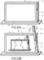
- FIGS. 23A and 23Bcomprise perspective views related to a sixth embodiment of the present invention.
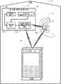
- FIG. 1is a diagram illustrating a system configuration of a first embodiment according to an aspect of the present invention.
- a watching systemthat performs watching inside a home 2 includes an ear-mounted unit 6 (indicated by a short-dashed line for distinction from a structure of an ear), which contacts a cartilage around a hole of an ear 4 of a watching-target person by being sandwiched between an antihelix and a tragus to fit in a cavum conchae, an in-home monitoring unit 8 , and a mobile phone 10 of the watching-target person.
- the in-home monitoring unit 8 and the mobile phone 10exchange information with the ear-mounted unit 6 via short-range communication.
- the mobile phone 10exchanges information with the ear-mounted unit 6 and the in-house monitor unit 8 via short-range communication.
- the ear-mounted unit 6functions as a headset for the mobile phone 10 by performing the short-range communication with the mobile phone 10 , and allows a phone call to be made with the mobile phone 10 kept in a clothes pocket.
- the ear-mounted unit 6also independently functions as a hearing aid. These functions as a headset and as a hearing aid are both achieved by making use of cartilage conduction, which will be described later.
- the ear-mounted unit 6further includes a mastication sensor to detect movement of the tragus, etc., or deformation of the external auditory canal, caused by masticatory movement.
- the ear-mounted unit 6is ring-shaped with a hole 6 a, so that the entrance of the external auditory canal is open even when the ear-mounted unit 6 is fitted in the external auditory canal. This makes it possible to hear external sound via the hole 6 a, and contributes to a comfortable wear of the ear-mounted unit 6 without a feeling of blockage in the external auditory canal. Further, by closing the hole 6 a with a finger or covering it with a palm as necessary as will be described later, it is possible to obtain an occlusion effect in the cartilage conduction to hear a larger sound.
- the in-home monitor unit 8has a short-range communication unit 12 for short-range communication with the ear-mounted unit 6 and the mobile phone 10 , and a digital communication unit 14 which performs always-on-connection Internet communication with an external device.
- a control unit 16controls the entire in-home monitoring unit 8 , which includes the short-range communication unit 12 and the digital communication unit 14 .
- a storage unit 18stores therein a program necessary for the control performed by the control unit 16 , and also temporarily stores therein various pieces of data related to the control, etc.
- the in-home monitoring unit 8receives a result of detection of masticatory movement from the ear-mounted unit 6 via the short-range communication. If no masticatory movement expected in daily life has been detected, the in-home monitor unit 8 judges that there is a possibility of an abnormality, and notifies a watching-service provider to that effect via the digital communication unit 14 . Further, the in-home monitoring unit 8 receives information regarding presence/absence of voice of the watching-target person detected by the headset function of the ear-mounted unit 6 .
- the in-home monitoring unit 8judges that there is a possibility of an abnormality, and notifies a watching-service provider to that effect via the digital communication unit 14 .
- the mobile phone 10receives a result of detection of masticatory movement from the ear-mounted unit 6 via short-range communication. If no masticatory movement expected in daily life has been detected, the mobile phone 10 judges that there is a possibility of an abnormality, and makes an automatic phone call to a mobile phone of a member of family of the watching-target person or the like who lives remotely and has been registered in advance, and when an answer to the phone call is received, the mobile phone 10 notifies him/her to that effect in a form of an automatic voice message. Further, the mobile phone 10 receives information regarding presence/absence of voice of the watching-target person detected by the headset function of the ear-mounted unit 6 .
- the mobile phone 10judges that there is a possibility of an abnormality, and makes an automatic phone call to the mobile phone of the member of family of the watching-target person or the like who lives remotely and has been registered in advance, and when an answer to the phone call is received, the mobile phone 10 issues a notification to that effect.
- the mobile phone 10makes an automatic phone call to the mobile phone of the member of family of the watching-target person or the like who lives remotely, and when an answer to the phone call is received, the mobile phone 10 notifies him/her to the effect that there is no abnormality occurring as an automatic voice message. Further, based on detection of a normal voice of the watching-target person, too, the mobile phone 10 makes an automatic phone call to the member of family of the watching-target person or the like who lives remotely as necessary, and when an answer to the phone call is received, the mobile phone 10 notifies him/her to the effect that there is no abnormality occurring in the form of an automatic voice message.
- the mobile phone 10makes an automatic phone call even when the watching-target person does not intend to, and thus contents of such conversations are to be undesirably heard by the member of family of the watching-target person or the like who lives remotely.
- FIG. 2is a block diagram illustrating a detailed configuration of the first embodiment of the present invention illustrated in FIG. 1 .
- the in-home monitoring unit 8which is configured as illustrated in FIG. 1 , includes a power supply unit 20 which supplies power to the entire in-home monitoring unit 8 .
- the power supply unit 20receives power from a household power supply in the home 2 .
- the mobile phone 10includes a mobile phone function unit 22 to perform phone communication by means of an antenna 24 via a wireless telephone network.
- a short-range communication unit 26communicates with the short-range communication units 36 and 12 of the ear-mounted unit 6 and the in-home monitoring unit 8 , respectively.
- a GPS unit 28detects a location of the watching-target person wearing the ear-mounted unit 6 when he/she is out, and communicates with the mobile phone of the member of family of the watching-target person or the like who lives remotely or with the watching-service provider, who have been described above, to thereby provide them with information of the location of the watching-target person.
- a control unit 30performs entire control of the entire mobile phone 10 , which includes the mobile phone function unit 22 , the short-range communication unit 26 , and the GPS unit 28 .
- a storage unit 32stores therein a program necessary for the control performed by the control unit 30 , and also, temporarily stores therein various pieces of data related to the control, etc.
- a power supply unit 34includes a rechargeable storage battery, and supplies power to the entire mobile phone 10 .
- FIG. 2for simplicity, such ones of the components of the mobile phone 10 as are typically included in mobile phones, such as a large-sized touch-panel liquid crystal display unit, a microphone, a speaker, a proximity sensor, and an inner camera, are not illustrated.
- the ear-mounted unit 6includes the short-range communication unit 36 , which performs short-range communication with the short-range communication unit 26 of the mobile phone 10 and the short-range communication unit 12 of the in-home monitoring unit 8 .
- a mastication sensor 38detects movement of the tragus, etc., or deformation of the external auditory canal of the watching-target person, caused by masticatory movement of the watching-target person, and thereby detects presence/absence of mastication of the watching-target person.
- the mastication sensor 38includes, for example, a strain gage, a piezoelectric element, or the like.
- a control unit 40When a masticatory movement is detected, a control unit 40 notifies the mobile phone 10 to that effect through the short-range communication unit 36 and the short-range communication unit 26 . If no masticatory movement expected in daily life is detected, the control unit 40 judges that there is a possibility of an abnormality, and, by means of the short-range communication unit 36 , notifies the mobile phone 10 and the in-home monitoring unit 8 to that effect through the short-range communication unit 26 and the short-range communication unit 36 , respectively.
- the ear-mounted unit 6includes a cartilage conduction vibration source 42 (which is, for example, a piezoelectric bimorph element), which vibrates in accordance with a voice signal of a call partner received from the mobile phone 10 via short-range communication, and this vibration is transmitted to an ear cartilage in contact with the ear-mounted unit 6 , and this makes it possible to hear the voice of the phone call partner by cartilage conduction, which will be described later.
- a bone conduction microphone 44catches bone-conducted own voice of the watching-target person and transmits a voice signal of the own voice to the mobile phone 10 via short-range communication, and this enables conversations to be conducted. In this manner, the ear-mounted unit 6 functions as a headset for the mobile phone 10 .
- An air conduction sound microphone 46catches an air-conducted voice of an outside conversation partner located close to the watching-target person to obtain a voice signal of the conversation partner, which makes the cartilage conduction vibration source 42 vibrate.
- the ear-mounted unit 6also independently functions as a hearing aid.
- the control unit 40controls the ear-mounted unit 6 also with respect to the head-set and hearing-aid functions.
- the bone conduction microphone 44also functions as a voice sensor for watching whether or not the watching-target person utters voice expected in daily life.
- a power supply unit 48which includes a rechargeable storage battery, supplies power to the entire ear-mounted unit 6 .
- Cartilage conductionis a phenomenon discovered by the present inventors, and denotes the phenomenon in which vibration conducted to the cartilage around an entrance part of the external auditory canal, such as that in the tragus, makes the surface of an external-auditory-canal cartilaginous part vibrate, producing air-conducted sound inside the external auditory canal.
- the air-conducted sound produced inside the external auditory canaltravels on deeper into the external auditory canal and reaches the tympanic membrane.
- the greater part of the sound heard by cartilage conductionis the sound heard via the tympanic membrane.
- the sound heard via the tympanic membraneis not ordinary air-conducted sound, i.e., sound that has entered the external auditory canal from outside, but air-conducted sound that is produced inside the external auditory canal.
- FIG. 3is a sectional view of an ear for illustrating the phenomenon of cartilage conduction mentioned just above, and illustrates a relationship between the structure of an ear 4 and the ear-mounted unit 6 used in the present invention.
- Arrows 52indicate transmission routes of vibration of the ear-mounted unit 6 which is made to vibrate by the cartilage conduction vibration source 42 .
- Vibration generated from the ear-mounted unit 6is, as indicated by the arrows 52 , first conducted from a contact part to a cartilage 54 around the entrance part of the external auditory canal.
- the vibration of the cartilage 54generates, from its surface (the external-auditory-canal cartilaginous part), air-conducted sound inside the external auditory canal.
- the air-conducted soundtravels on deeper into the external auditory canal and reaches a tympanic membrane 50 via an external auditory canal osseous part 56 .
- air-conducted conducted sound from outsideenters the external auditory canal via the hole 6 a of the ear-mounted unit 6 , and reaches the tympanic membrane 50 . This contributes to comfortable wear of the ear-mounted unit 6 without a feeling of blockage in the external auditory canal.
- FIG. 4is a graph illustrating an example of measured data showing an effect of cartilage conduction.
- the graph of FIG. 4illustrates, in relation to frequency, sound pressure within the external auditory canal at a position 1 cm inside from the entrance part of the external auditory canal when, without contact with a helix, a surface of an outer wall of a vibration body that is caused to vibrate by a cartilage conduction vibration source is brought into contact with at least part of ear cartilage around the entrance part of the external auditory canal.
- a vertical axisindicates sound pressure (in dBSPL)
- a horizontal axisindicates frequency on a logarithmic scale (in Hz).
- the graphuses a solid line to illustrate the sound pressure during a non-contact state (in a state where only air-conducted sound generated from the surface of the outer wall of the vibration body can be heard), a short dashed line to illustrate the sound pressure under a contact pressure of 10 grams, a single-dotted chain line to illustrate the sound pressure under a contact pressure of 250 grams, and a double-dotted chain line to illustrate the sound pressure under a contact pressure of 500 grams.
- the sound pressureincreases as the contact pressure is increased from the non-contact state to the 10-gram contact pressure, and further increases as the contact pressure is increased to 250 grams, and then, the sound pressure increases even more as the contact pressure is further increased to 500 grams.
- the ear-mounted unit 6does not have a structure for generating air-conducted sound (such as a vibration plate included in typical earphones), it is possible to obtain sufficient sound pressure by transmitting vibration of the cartilage conduction vibration source 42 to the ear cartilage by bringing the cartilage conduction vibration source 42 into contact with the ear cartilage.
- the ear-mounted unit 6can be formed in a ring shape having the hole 6 a, for example, and this makes it possible to hear outside sound through the hole 6 a even when the ear-mounted unit 6 is mounted to an ear, and this contributes to comfortable wear of the ear-mounted unit 6 without a feeling of blockage in the external auditory canal.
- the measurement results of which are illustrated in FIG. 4was all conducted under a constant output of the cartilage conduction vibration source.
- the surface of the outer wall of the vibration bodycontacting at least part of the ear cartilage around the entrance part of the external auditory canal without contacting the helix, the surface of the outer wall of the vibration body was brought into contact with at least part of the ear cartilage from outside of the tragus.
- the closed state of the external auditory canalwas brought about by pressing the tragus from outside so strong as to bend the tragus as described above.
- the occlusion effect as described abovecan be achieved by closing the hole 6 a and increasing the contact pressure of the ear-mounted unit 6 against the cartilage by pushing the ear-mounted unit 6 with a finger placed over the hole 6 a.
- the occlusion effectcan be achieved by covering the entire ear 4 with a palm.
- the measurement graph of FIG. 4is merely an example; upon further scrutiny, there are individual differences. Also, for simplification and standardization of the phenomenon, the values illustrated in the measurement graph of FIG. 4 were obtained through measurement performed in a state where the surface of the outer wall of the vibration body was in contact only with a small surface area of the outside of the tragus.
- increase in sound pressure caused by the contact with the cartilagealso depends on the area of the contact, and in a case where the surface of the outer wall is in contact with the ear cartilage around the entrance part of the external auditory canal without contacting the helix, the increase in sound pressure is further elevated when the surface of the outer wall of the vibration body is in contact with a portion of the cartilage wider than around the entrance part of the external auditory canal.
- the values illustrated in the measurement graph of FIG. 4have generality in illustrating the configuration making use of cartilage conduction, and can be reproduced by many and unspecified subjects. Further, the measurement graph of FIG. 4 was drawn by plotting the values obtained by the measurement conducted with the tragus being pressed from the outside in closing the entrance part of the external auditory canal to thereby increase the contact pressure and fold the tragus over, but similar results can be obtained also in a case where the outer wall of the vibration body is pressed into the entrance part of the external auditory canal to close the external auditory canal.
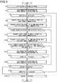
- FIG. 5is a flowchart illustrating a function of the control unit 40 of the ear-mounted unit 6 in the watching system of the first embodiment.
- the flowstarts when the ear-mounted unit 6 connected to an unillustrated charger for charging is disconnected from the charger.
- Step S 2it is checked whether or not pairing for short-range communication with the mobile phone 10 has been set, and when no pairing is found to have been set, pairing is automatically set.
- Step S 4the air conduction microphone 46 and the bone conduction microphone 44 are turned on.
- the ear-mounted unit 6starts to function as a hearing aid, and also the bone conduction microphone 44 is brought into a standby state in which it stands by for detection of voice of the watching-target person.
- the mastication sensor 38is constantly in an ON state from the start to an end of the flow and in a standby state in which it stands by for detection of mastication.
- Step S 6it is checked whether or not the mastication sensor 38 has detected a masticatory movement.
- Step S 8a detection signal is transmitted to the mobile phone 10 via short-range communication, and then the process proceeds to Step S 12 .
- Step S 12the process proceeds directly to Step S 12 .
- Step S 12it is checked whether or not the bone conduction microphone 44 has detected voice of the watching-target person.
- voice of the watching-target personis found to have been detected, the process proceeds to Step S 14 , and a detected voice signal is transmitted to the mobile phone 10 via the short-range communication, and meanwhile, in Step S 16 , the detected voice signal is transmitted to the in-home monitoring unit 8 via the short-range communication.
- Step S 12 to Step S 16the steps from Step S 12 to Step S 16 are illustrated in a simplified manner, in these steps, actually, for a predetermined period of time (10 seconds, for example) after voice starts to be detected by the bone conduction microphone 44 , the voice signal continues to be transmitted from the bone conduction microphone 44 simultaneously to the mobile phone 10 and the in-home monitoring unit 8 .
- Step S 20the process proceeds to Step S 20 .
- Step S 20it is checked whether the watching-target person has operated the mobile phone 10 to make a phone call and the other party has answered the phone call, or whether there has been an external incoming call received by the mobile phone 10 and the watching-target person has operated the mobile phone 10 to answer the incoming call. If whichever of the above is found to have occurred, the process proceeds to Step S 22 , where the air conduction microphone 46 is turned off and the bone conduction microphone 44 is maintained in an on state, and then the process proceeds to Step S 24 . Thereby, the ear-mounted unit 6 starts to function as a headset for the mobile phone 10 , and prevents ambient noise from being picked up by the air conduction microphone 46 to disturb the phone call.
- Step S 24it is checked whether the phone call started in Step S 20 has been ended by hanging-up of the phone. Then, when it is detected that the phone call has been ended, the process proceeds to Step S 26 , where the air conduction microphone 46 is turned on and the bone conduction microphone 44 is maintained in an on state, and the process proceeds to Step S 28 . Thereby, the ear-mounted unit 6 starts to function as a hearing aid again, and the bone conduction microphone 44 is maintained in the standby state in which it stands by for detection of voice of the watching-target person. On the other hand, when it is found that the phone call has not been ended yet in Step S 24 , the Step S 24 is repeated until end of the phone call is detected. Further, in a case where, in Step S 20 , neither making a phone call and answering the phone call nor receiving a phone call and answering the phone call is detected, the process proceeds directly to Step S 28 .
- Step S 28it is checked whether the storage battery of the power supply unit 48 has been exhausted.
- the processproceeds to Step S 30 , where it is checked whether the ear-mounted unit 6 has been connected to the charger, which is not illustrated, to be charged. This step is provided to deal with a case of removing the ear-mounted unit 6 from the year 4 to be charged even though the storage battery has not been exhausted.
- Step S 32ending processing is performed to end the flow. This is significant in that this helps prevent the ear-mounted unit 6 from being maintained in an operation state by mistake when it is removed from the ear 4 and thus its watching function is disabled.
- Step S 30when no connection for charging is detected in Step S 30 , the process returns to Step S 6 to repeat the steps from Step S 6 to Step S 30 until the storage battery becomes exhausted or connection is achieved for charging, and the ear-mounted unit 6 maintains, as necessary, its hearing-aid function, watching function, and headset function for the mobile phone 10 .
- Step S 28in a case where it is detected in Step S 28 that the storage battery has been exhausted, too, the process proceeds to Step S 32 , where the ending processing is performed to end the flow.
- FIG. 6is a flowchart illustrating a function of the control unit 30 of the mobile phone 10 in the first embodiment. Note that FIG. 6 illustrates the flow by extracting operations of functions related to watching, and thus in the mobile phone 10 , the control unit 30 has operations that are not described in the flow of FIG. 6 , such as operations related to a normal mobile phone function of the mobile phone 10 .
- a hardware configuration itself of the mobile phone 10is one that is typically adopted in mobile phones, and the functions extracted in FIG. 6 are installed in the ear-mounted unit 6 as accessory software.
- Step S 42a normal mobile phone mode is set.
- Step S 44a check is performed for a state of pairing for the short-range communication with the ear-mounted unit 6 .
- the pairingis found to have been achieved, watching can be performed by the mobile phone 10 in cooperation with the ear-mounted unit 6 , and thus the process proceeds to Step S 46 .
- Step S 46it is checked whether or not a new mastication detection signal has been received from the ear-mounted unit 6 , and when it is found that there has been reception of a new mastication detection signal, the process proceeds to Step S 48 , where an e-mail notifying that the watching-target person is safe is automatically transmitted to a mobile phone of the member of family of the watching-target person or the like who lives remotely and has been registered in advance.
- Step S 48instead of sending an e-mail, an automatic phone call is made to the mobile phone of the member of family of the watching-target person or the like who lives remotely and has been registered in advance, and on reception of a response from the mobile phone, an automatic voice message is transmitted to notify him/her that the watching-target person is safe. It is also possible to set such that both an e-mail and a phone call are to be sent and made.
- detecting masticationwhich basically takes place three times a day and thus can be regarded as not too often, each time a mastication detection signal is detected, the member of family of the watching-target person or the like who lives remotely is notified that the watching-target person is safe and thereby reassured.
- Step S 48it is possible to set in advance such that Step S 48 will be omitted.
- Step S 50reception history of mastication detection signals stored in the storage unit 32 is updated, together with time and date information, based on the reception of the new mastication detection signal, and a GPS signal at that time point is also stored in the storage unit 32 , and then the process proceeds to Step S 52 .
- Step S 52reception history of mastication detection signals stored in the storage unit 32 is updated, together with time and date information, based on the reception of the new mastication detection signal, and a GPS signal at that time point is also stored in the storage unit 32 .
- Step S 52reception history of mastication detection signals stored in the storage unit 32 is updated, together with time and date information, based on the reception of the new mastication detection signal, and a GPS signal at that time point is also stored in the storage unit 32 .
- Step S 52based on the reception history stored in the storage unit 32 , it is checked whether or not there has been reception of a new mastication detection signal within a predetermined period of time after the reception of the preceding mastication detection signal.
- the processproceeds to Step S 54 , where an automatic phone call is made to the mobile phone of the member of family of the watching-target person or the like who lives remotely and has been registered in advance, and on reception of a response to the phone call, an automatic voice message is transmitted to the effect that there is a possibility of an abnormality, and the process proceeds to Step S 56 .
- Step S 54another automatic voice message is transmitted to notify a current location of the watching-target person based on GPS information obtained then.
- Step S 52when it is confirmed from the reception history that there has been reception of a new mastication detection signal, the process proceeds to Step S 56 .
- Step S 56it is checked whether or not there has been reception of a voice signal picked up by the bone conduction microphone 44 of the ear-mounted unit 6 .
- the processproceeds to Step S 58 , where it is checked whether or not the received voice is a scream or begging for help (urgency) based on recognized contents of the voice signal (such as words included in the voice signal), intensity of the voice signal, a tone pattern, etc.
- Step S 60When there is a high possibility that the voice is a scream or begging for help (when it is judged that it is a highly urgent situation), the process proceeds to Step S 60 , where an automatic phone call is made to the mobile phone of the member of family of the watching-target person or the like who lives remotely and has been registered in advance, and on reception of a response to the phone call, the received voice itself is transmitted to the mobile phone, and then the process proceeds to Step S 62 .
- Step S 58it is judged that the received voice is not a scream or begging for help but merely voice of an ordinary conversation (of low urgency)
- the processproceeds directly to Step S 62 .
- Step S 62it is checked whether or not the received voice signal has been received in a time zone (for example, a time zone when the watching-target usually goes shopping, a time zone when the watching-target person usually chants a sutra) previously set based on a regular life pattern.
- a time zonefor example, a time zone when the watching-target usually goes shopping, a time zone when the watching-target person usually chants a sutra
- the processproceeds to Step S 64 , where an e-mail is automatically transmitted to the mobile phone of the member of family of the watching-target person or the like who lives remotely and has been registered in advance to notify him/her that the watching-target person is safe, and the process proceeds to Step S 66 .
- Step S 62when the received voice signal is found not to have been received in the previously set time zone, the process proceeds directly to Step S 66 .
- a setting same as in Step S 48is also possible, that is, instead of or together with an e-mail, an automatic phone call may be made and automatic voice message may be transmitted.
- Steps S 62 and S 64it is possible to set in advance such that Steps S 62 and S 64 will be omitted.
- the message to be transmitted in Step S 64is not the voice signal actually picked up by the bone conduction microphone 44 , but a message notifying merely the fact that there has been reception of a voice signal.
- Step S 60contents of conversation of the watching-target person are not heard and thus privacy of the watching-target person is preserved.
- Step S 66reception history of voice signals stored in the storage unit 32 is updated, together with time and date information, based on the reception of the new voice signal, and a GPS signal at that time point is also stored in the storage unit 32 , and then the process proceeds to Step S 68 .
- Step S 68reception history of voice signals stored in the storage unit 32 is updated, together with time and date information, based on the reception of the new voice signal, and a GPS signal at that time point is also stored in the storage unit 32 , and then the process proceeds to Step S 68 .
- Step S 68reception history of voice signals stored in the storage unit 32 is updated, together with time and date information, based on the reception of the new voice signal, and a GPS signal at that time point is also stored in the storage unit 32 , and then the process proceeds to Step S 68 .
- Step S 68based on the reception history stored in the storage unit 32 , it is checked whether or not there has been reception of a new voice signal within a predetermined period of time after the reception of the preceding voice signal.
- the processproceeds to Step S 70 , where an automatic phone call is made to the mobile phone of the member of family of the watching-target person or the like who lives remotely and has been registered in advance, and on reception of a response to the phone call, an automatic voice message is transmitted to the effect that there is a possibility of an abnormality, and then the process proceeds to Step S 72 .
- Step S 70too, another automatic voice message is transmitted to notify a current location of the watching-target person based on GPS information obtained then.
- Step S 68when it is confirmed in Step S 68 that there has been reception of a new voice signal within the predetermined period of time, the process proceeds directly to Step S 72 .
- Step S 72the steps for watching are not performed, and the mobile phone 10 functions as an ordinary mobile phone.
- Step S 72it is checked whether or not the storage battery of the power supply unit 34 has been exhausted.
- the processreturns to Step S 44 , and then, the steps from Step S 44 to Step S 72 are repeated until exhaustion of the storage battery is detected, such that the mobile phone 10 deals with various situations in watching.
- the processproceeds to Step S 74 , where ending processing is performed to end the flow.
- FIG. 7is a flowchart illustrating a function of the control unit 16 of the in-home monitoring unit 16 in the first embodiment.
- the flowstarts when the in-home monitoring unit 8 is placed and connected to the household power supply or the power supply of the in-home monitoring unit 8 is turned on. Then, in Step S 82 , always-on connection to the Internet is automatically set for communication with the watching service provider, and an automatic test is performed to check cooperation, such as the short-range communication, with the ear-mounted unit 6 , and the process proceeds to Step S 84 .
- Step S 84it is checked whether or not the state of the short-range communication with the ear-mounted unit 6 has been shifted from an enabled state to a disabled state. This is equivalent to checking whether or not the watching-target person has gone out into a range where the short-range communication is not available.
- Step S 86it is checked whether or not the state of the short-range communication with the ear-mounted unit 6 has shifted from the disabled state to the enabled state. This is equivalent to checking whether or not the watching-target person has come back into the short-range communication range.
- Step S 88an e-mail is automatically transmitted to the mobile phone of the member of family of the watching-target person or the like who lives remotely and has been registered in advance to notify him/her that the watching-target person has come home.
- Step S 90automatic short-range communication is performed with the mobile phone 10 , and processing is performed to confirm that the state of short-range communication has been shifted back into the state of system configuration as illustrated in FIG. 2 .
- This processingis performed because it can be presumed that when the watching-target person is out, the mobile phone 10 is carried by him/her into a range where the short-range communication is not available.
- Step S 90if by any chance it cannot be confirmed that the short-range communication is possible with the mobile phone 10 , notification to that effect is issued to the watching service provider and to the mobile phone of the member of family of the watching-target person or the like who lives remotely.
- Step S 90further, a cross check of the history of reception from the ear-mounted unit 6 and information exchange are performed between the storage unit 18 of the in-home monitoring unit 8 and the storage unit 32 of the mobile phone 10 to match the information in the storage unit 18 and the information in the storage unit 32 with each other.
- Thisis applicable mainly to a case where the watching-target person is out and the in-home monitoring unit 8 cannot receive signals from ear-mounted unit 6 , during which information cannot be received from the in-home monitoring unit 8 and thus information is received from the mobile phone 10 instead.
- the function of matching information in the two storage units by the cross check as described aboveis also useful as a measure to deal with a case where the storage battery of the mobile phone 10 has been exhausted when the mobile phone 10 is in the home 2 and thus information is not received from the ear-mounted unit 6 until the storage battery is recharged.
- Step S 90the process proceeds to Step S 92 , where it is checked whether or not there has been reception of a new mastication detection signal from the ear-mounted unit 6 .
- Step S 94reception history of mastication detection signals stored in the storage unit 18 is updated, together with time and date information, based on the reception of the new mastication detection signal, and the process proceeds to Step S 96 .
- Step S 96reception history of mastication detection signals stored in the storage unit 18 is updated, together with time and date information, based on the reception of the new mastication detection signal.
- Step S 96based on the reception history stored in the storage unit 18 , it is checked whether or not there has been reception of a new mastication detection signal within a predetermined period of time after the reception of the preceding mastication detection signal.
- Step S 98an automatic notification is issued to the watching service provider, with whom a contract has been made in advance, to the effect that there is a possibility of an abnormality, and then the process proceeds to Step S 100 .
- Step S 96from the reception history of mastication detection signals, that there has been reception of a new mastication detection signal within the predetermined period of time, it is judged that there is no abnormality occurring, and the process proceeds directly to Step S 100 .
- Step S 100it is checked whether or not there has been reception of a voice signal picked up by the bone conduction microphone 44 of the ear-mounted unit 6 .
- the processproceeds to Step S 102 , where it is checked whether or not the received voice is a scream, a cry for help, or the like, based on identification of voice in the contents (words and the like included therein) of the voice signal, intensity pattern, tone, and the like of the voice signal, etc.
- Step S 104the received voice itself is transferred to the watching-service provider, and the process proceeds to Step S 106 .
- Step S 102it is judged that the received voice is neither a scream nor a cry for help, but voice of an ordinary conversation, the process proceeds directly to Step S 106 .
- Step S 106reception history of voice signals stored in the storage unit 18 is updated, together with time and data information, based on the reception of the new voice signal, and the process proceeds to Step S 108 .
- Step S 108reception history of voice signals stored in the storage unit 18 is updated, together with time and data information, based on the reception of the new voice signal, and the process proceeds to Step S 108 .
- the processproceeds directly to Step S 108 .
- Step S 108based on the reception history of voice signals stored in the storage unit 18 , it is checked whether or not there has been reception of a new voice signal within a predetermined period of time after the reception of the preceding voice signal.
- Step S 110an automatic notification is issued to the watching service provider to the effect that there is a possibility of an abnormality, and then the process proceeds to Step S 112 .
- Step S 112the process proceeds directly to Step S 112 .
- Step S 84when it is detected in Step S 84 that the state of the short-range communication with the ear-mounted unit 6 has been shifted from an enabled state to a disabled state, the process proceeds to Step S 114 , where an e-mail is automatically transmitted to the mobile phone of the member of family of the watching-target person or the like who lives remotely and has been registered in advance to notify him/her that the watching-target person has gone out, and then the step proceeds to Step S 112 .
- the mobile phone 10 that the watching-target person carriesis charged with execution of the watching function, and the in-home monitoring unit 8 does not executes the watching function.
- Step S 112it is checked whether or not power of the in-home monitoring unit 8 has been turned off. Turning off of the power of the in-home monitoring unit 8 includes power-supply disconnection caused by power failure or the like. When it is found that there has been no turning off of the power, the process returns to Step S 84 , and then the steps of from Step S 84 to Step S 114 are repeated as long as the power is not turned off, and the in-home monitoring unit 8 deals with various situations in watching. On the other hand, when turning off of the power is detected in Step S 112 , the process proceeds to Step S 116 , where ending processing is performed to end the flow.
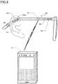
- FIG. 8is a diagram illustrating a system configuration of a second embodiment according to an aspect of the present invention.
- a watching system for watching inside a homeincludes an eyeglass type ear-mounted unit 106 .
- the other featuresare the same as the first embodiment illustrated in FIGS. 1 and 2 , and thus the common features are denoted by the same reference numerals and overlapping descriptions thereof will not be repeated.
- a home 2 and an in-home monitoring unit 8are not illustrated, but configurations thereof are common to those of the first embodiment described in FIGS. 1 and 2 .
- a cartilage conduction vibration source, a bone conduction microphone, and a mastication sensorcan each be formed with a piezoelectric element, and thus, one piezoelectric element can serve as a cartilage conduction vibration source, a bone conduction microphone, and a mastication sensor.
- a piezoelectric bimorph element 142which serves as a cartilage conduction vibration source, a bone conduction microphone, and a mastication sensor are formed in such part of a temple of eyeglasses as is laid on a cartilage in a base of an ear 4 when the eyeglasses are worn.
- vibration of the piezoelectric bimorph element 142is conducted to the cartilage at the base of the ear 4 to cause cartilage conduction. Further, voice by bone conduction is picked up by the piezoelectric bimorph element 142 . Further, movement caused by mastication in part close to the base of the ear 4 is also detected by the piezoelectric bimorph element 142 .
- extraction and separation of signals fed to and outputted from the piezoelectric bimorph element 142are achieved by means of signal processing performed by a control unit 140 .
- an air conduction microphone 46which is originally provided for the purpose of picking up voice of a conversation partner for the function of hearing aid, is used to pick up voice of a watching-target person himself or herself by air conduction, and the picked up voice is used as information for the extraction and separation of signals fed to and outputted from the piezoelectric bimorph element 142 .
- the entrance of an external auditory canalis left open, and thus it is possible to hear external sound and to achieve comfortable wear of an ear-mounted unit 106 without a feeling of blockage in the external auditory canal. Further, by closing the entrance of the external auditory canal with a finger or completely covering the ear 4 with a palm, it is possible to obtain the occlusion effect in cartilage conduction, to thereby hear a larger sound.
- one piezoelectric bimorph elementmay be used for the functions of the cartilage conduction vibration source, the bone conduction microphone, and the mastication sensor as in the second embodiment.
- the cartilage conduction vibration source, the bone conduction microphone, and the mastication sensormay be formed as optimum separate elements to be optimally disposed at scattered positions.
- a bone conduction microphoneis adopted to pick up voice of a watching-target person, but an air-conducted sound microphone may be used for this purpose (for example, the air conduction microphone 46 serving for this purpose, too).
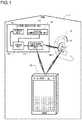
- FIG. 9is a system configuration diagram of a third embodiment according to one aspect of the present invention.
- the third embodimentis configured as a robot that can communicate with a human by cartilage conduction; as in the first embodiment, it constitutes a watching system for watching inside a home and is capable of humanly communication with a watching-target person.
- the third embodiment in FIG. 9is similar to the first embodiment except that the ear-mounted unit 6 in the first embodiment in FIG. 1 is replaced with a robot 206 in the third embodiment. Accordingly, illustration will be omitted except for the robot 206 and the watching-target person 201 , and no description of common features will be repeated unless necessary.
- the robot 206exchanges information with the in-home monitoring unit 8 shown in FIG. 1 and the mobile phone 10 of the watching-target person 201 via short-range communication.
- the robot 206has, at the left and right ears 205 of a head part 203 , a pair of stereo external air-conducted sound microphones to collect the voice of the watching-target person 201 , and has, at left and right eyes 207 of the head part 203 , a pair of 3D cameras to take an image of the watching-target person 201 .
- the air-conducted sound microphones and the 3D camerasfunction respectively as sensors for watching the watching-target person 201 , and the detected results are transmitted to the in-home monitoring unit 8 and the mobile phone 10 shown in FIG. 1 .
- an air-conducted sound speakeris provided, so that speech can be uttered to the watching-target person 201 .
- the mouth mechanism 209 of the robot 206moves in coordination with the speech.
- the air-conducted sound microphones and the 3D cameras provided in the head part 203 of the robot 206function also as an external talking unit of the mobile phone 10 .
- a cartilage conduction vibration sourcecomprising a piezoelectric bimorph or the like is arranged so that the finger tip of the middle finger 213 vibrates efficiently.
- the vibration of the cartilage conduction vibration sourceis conducted to the entire right hand 211 , and thus cartilage conduction is possible from any part of the right hand 211 .
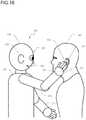
- FIG. 9shows a state where the finger tip of the middle finger 213 makes contact with the tragus 232 of the left ear of the watching-target person 201 and thereby optimum cartilage conduction is achieved. Though not illustrated in FIG.
- a similar cartilage conduction vibration sourceis arranged also in a middle finger of a left hand of the robot 206 , and makes contact with the tragus of the right ear of the watching-target person 201 .
- cartilage conductionis possible stereophonically as in the ordinary hearing of air-conducted sound with both ears.
- the mouth mechanism 209 of the robot 206moves in coordination with the voice conducted by cartilage conduction.
- the robot 206gently holds the face of the watching-target person 201 in both hands and utters speech in a comforting atmosphere.
- the watching-target person 201can hear the voice of the robot 206 in a comforted psychological condition.
- the right and left arms 215 and 217 of the robot 206are provided with applied pressure limiters so that the pressure with which the robot 206 holds the face of the watching-target person 201 in both hands is not excessive.
- the joints of the right and left arms 215 and 217 of the robot 206are controlled relative to a trunk 219 of the robot 206 so that the left and right hands follow, with no resistance, the free movement of the face of the watching-target person 201 .
- the two hands of the robot 206are heated to human body temperature before starting the movement of holding the face of the watching-target person 201 .
- the left and right eyes 207 of the robot 206are movable in exterior appearance so as not to inadvertently avoid the line of sight of the watching-target person 201 but follows it naturally without giving an intimidating impression.
- Utterance of speech by cartilage conduction as described aboveis useful in cases such as where the watching-target person 201 has impaired hearing for advanced age or the like and where the ambient noise is loud, and helps avoid a situation like one that requires the air-conducted sound speaker to yell out loudly.
- a bone conduction microphoneis provided to collect the voice of the watching-target person 201 in cases such as where the ambient sound level is high, so as to collect bone-conducted sound from the cheek bone or the like.
- cartilage conduction vibration sourcescomprising piezoelectric bimorph elements may be used to double as bone conduction microphones.
- FIG. 10is a block diagram of the robot 206 of the third embodiment of the present invention shown in FIG. 9 .
- Such parts as appear also in FIG. 9are identified by the same reference numerals, and no overlapping description will be repeated unless necessary.
- communication with the in-home monitoring unit 8 and the mobile phone 10 shown in FIG. 1 in the third embodimentis similar to that in the first embodiment, and accordingly, in FIG. 10 , only a short-range communication unit 236 is illustrated and no description will be repeated.
- the robot 206has, at the left and right ears 205 (see FIG. 10 ).
- the head part 203has, at the left and right eyes 207 , a 3D camera (a pair of cameras) 238 , and takes an image of the watching-target person 201 .
- the direction of the head part 203 and the following of the line of sight of the left and right eyes 207are controlled through the recognition of the face and the eyes of the watching-target person 201 based on an analysis of the image of the 3D camera 238 .
- an air-conducted sound speaker 223is provided, and this makes utterance of speech to the watching-target person 201 possible as described above.
- the mouth mechanism 209moves in coordination with the utterance of speech by the robot 206 from the air-conducted sound speaker 223 .
- a cartilage conduction vibration source 242 acomprising a piezoelectric bimorph element or the like is arranged so that the finger tip of the middle finger 213 a vibrates efficiently.
- the vibration of the cartilage conduction vibration source 242 ais conducted to the entire right hand 211 , and thus cartilage conduction is possible with any part of the right hand 211 in contact with the ear cartilage.
- the mouth mechanism 209 of the robot 206moves in coordination with the voice delivered by the vibration of the cartilage conduction vibration source 242 a.
- the middle finger 213 ais further provided with a tactile sensor 231 a comprising a pressure-sensitive sensor or the like, and this will be described later.
- a bone conduction microphone 244 ais provided, which collects bone-conducted sound from the cheek bone or the like.
- the cartilage conduction vibration source 242 acomprising a piezoelectric bimorph element may be used to double as a bone conduction microphone.
- a tactile sensor similar to the tactile sensor 231 a in the middle finger 213 ais provided also in the thumb 221 a, and this too will be described later.
- the right hand 211is further provided with a heater 225 a, which is switched on before the start of the movement of holding the face of the watching-target person 201 to heat the entire right hand 211 to human body temperature.
- the right arm 215is provided with a right joint mechanism 227 a, which performs, among others, a movement for holding the face of the watching-target person 201 from the right side (the left side as seen from the watching-target person 201 ) and uttering speech.
- the right joint mechanism 227 ais illustrated only at the should joint, it is assumed to represents all the joints of the right hand 211 and the right arm 215 , including the elbow joint, the wrist joint, and the finger joints.
- the right joint mechanism 227 ais coordinated with a left joint mechanism 227 b so that, when the staging in which the face of the watching-target person 201 is held in both hands gently and speech is uttered, once an adequate pressure between the left and right hands is determined, while the relative distance between the left and right hands are maintained, the mechanisms are so controlled as to follow, with no resistance, the free movement of the face of the watching-target person 201 .
- the configuration of the left arm 217 and the left hand 229 in FIG. 10is similar to the configuration of the right arm 215 and the right hand 211 ; accordingly, the constituent elements suffixed with “a”, like the middle finger 213 a, at the right side are illustrated as corresponding elements suffixed with “b”, like the middle finger 213 b, at the left side, and no overlapping description will be repeated.
- the cartilage conduction vibration sources 242 a and 242 ballow stereophonic hearing on the principle of cartilage conduction via the ear drums.
- the bone conduction microphones 244 a and 244 bcollect the same vibration of the skull because of the nature of bone conduction; thus, they are provided at the left and right sides not to constitute stereo microphones but to mutually complement the contact state. Accordingly, as will be described later, in a case where the optimal cartilage conduction contact position is secured sufficiently by fine-tuning the contact position of the thumb at one side, the bone conduction microphone in the thumb at the other side may be omitted.
- the right and left joint mechanisms 227 a and 227 bextend the right and left hands 211 and 229 toward the face of the watching-target person 201 as recognized through the analysis of the image by the 3D camera 238 .
- the right and left joint mechanisms 227 a and 227 bare each provided with a load detection sensor, and detect whether or not any load is acting other than a movement in a free state that may result from collision with an arm, hand, finger, or the like. If any such load is acting, those sensors identify at what part of a joint and with what intensity it is acting.
- the applied pressure limitersoperate to limit the pressure with which the face of the watching-target person 201 is held. Then, while the outputs from the tactile sensors 231 a and 231 b provided at the finger tips of the left and right middle fingers 213 a and 231 b and the image by the 3D camera 238 are monitored, the positions of the right and left hands 211 and 229 and the curves of the left and right middle fingers 213 a and 231 b are fine-tuned.
- the left and right middle fingers 213 a and 231 bare brought into contact with the tragi of the watching-target person 201 (the state illustrated in FIG. 9 is achieved).
- the left and right thumbs 221 a and 221 bwhile the outputs of the tactile sensors (unillustrated) provided at their finger tips and the image by the 3D camera 238 are monitored, the curves of the left and right thumbs 221 a and 221 b are fine-tuned so as to make contact with the cheek bones of the watching-target person 201 .
- the right and left joint mechanisms 227 a and 227 bperform control such that the left and right hands move translatorily while keeping the relative distance between them so as to follow, with no resistance, the free movement of the face of the watching-target person 201 .
- This followingis performed relative to the state where the right and left arms 215 and 217 , in a free state, are raised and kept at rest against their weights, and thus the load of the right and left arms 215 and 217 does not act on the face.
- the right and left joint mechanisms 227 a and 227 bdetect a load in a upward, downward, leftward, or rightward direction based on the movement of the face, in response, while the relative distance between the left and right hands are maintained, the right and left joint mechanisms 227 a and 227 b are driven subordinately.
- the watching-target person 201despite his face being held in both hands of the robot 206 , can move the face without restraint while maintaining the cartilage conduction state.
- the functions described aboveare achieved by a control unit 240 based on programs stored in a storage unit 218 .
- the control unit 240includes a dedicated image processing function unit that is connected to the 3D camera 238 .
- the control unit 240further includes a dedicated piezoelectric bimorph driving function unit that is connected to the cartilage conduction vibration sources 242 a and 242 b, and a dedicated sound processing function unit that is connected to the piezoelectric bimorph driving function unit, the air-conducted sound speaker 223 , and the bone conduction microphones 244 a and 244 b.
- the storage unit 218temporarily stores various kinds of data for the functioning of the control unit 240 .
- a power supply unit 248 including a rechargeable batterysupplies different constituent elements of the robot 206 with voltages that they respectively need.
- the control unit 240 , the storage unit 218 , the power supply unit 248 , and the short-range communication unit 236 mentioned abovecan be built in the trunk 219 of the robot 206 .
- FIG. 11is a flow chart showing the functions of the control unit 240 in the robot 206 of the third embodiment shown in FIG. 10 .
- the flowstarts when the supply of electric power from the power supply unit 248 is started by a main power switch of the robot 206 .
- step S 122it is checked whether or not pairing for short-range communication with the in-home monitoring unit 8 and the mobile phone 10 (see FIG. 1 ) of the watching-target person 201 is set, and when no paring is set, paring is set automatically.
- step S 124processing for starting an ordinary watching function is performed.
- the ordinary watching functionis basically based on the watching function in the first or second embodiment described with reference to FIGS. 1 to 8 ; in the case of the third embodiment, the stereo external air-conducted sound microphones 246 and the 3D camera 238 function as watching sensors.
- step S 126it is checked whether or not there is an abnormality, and if there is no abnormality, an advance is made to step S 128 , where it is checked whether or not now is a timing for regular reporting. If now is not a timing for regular reporting, an advance is made to step S 130 . On the other hand, if, in step S 128 , it is confirmed that now is a timing for regular reporting, an advance is made to step S 132 , where normality reporting processing is performed, and then an advance is made to step S 130 .
- the normality reporting processinghere is similar to that in the first or second embodiment.
- step S 130it is judged whether or not to start conversation with the watching-target person 201 .
- the watching-target person 201meets the robot 206 after a while, as when the watching-target person 201 has come home from a day-care facility or the robot 206 has come back from repair, or when the watching-target person 201 moves toward the robot 206 , or when the watching-target person 201 talks to the robot 206 , or when the robot 206 , having observed the watching-target person 201 , chooses to spontaneously talk to him, or the like can be a case where a determination that “conversation should be started” is made.
- step S 130If, in step S 130 , a determination to start conversation is made, an advance is made to step S 134 , where, first, the stereo external air-conducted sound microphones 246 and the air-conducted sound speaker 223 are turned on in preparation for conversation by ordinary air-conducted sound.
- step S 136it is checked whether or not the watching-target person 201 is a registered person with whom to conduct conversation by cartilage conduction. Such registration can be performed beforehand in a case where the watching-target person 201 has impaired hearing due to advanced age or the like or by preference of the watching-target person 201 himself.
- step S 136If, in step S 136 , it cannot be confirmed that the watching-target person 201 is a registered person for cartilage conduction, an advance is made to step S 138 , where it is checked whether or not the ambient air-conducted sound level is equal to or higher than a predetermined level.
- the ambient air-conducted sound levelIn a watching environment, ordinary noise is unlikely to be present; however, in a case where a large number of people are chatting at different places in a room, the ambient air-conducted sound level may be equal to or higher than a predetermined level, making personal conversation between the robot 206 and the watching-target person 201 by air-conducted sound difficult.
- step S 138If, in step S 138 , it is judged that the ambient air-conducted sound level is equal to or higher than the predetermined level, an advance is made to step S 140 . On the other hand, if, in step S 136 , it is judged that the watching-target person 201 is a registered person with whom to conduct conversation by cartilage conduction, an advance is made directly to step S 140 .
- step S 140processing for bringing both hands of the robot 206 into contact with both ears of the watching-target person 201 for cartilage conduction is performed. This will be described in detail later.
- step S 142an advance is made to step S 142 , where it is confirmed whether or not the middle fingers 213 a and 213 b of both hands of the robot 206 are in contact with the tragi of both ears of the watching-target person 201 and whether or not the thumbs 221 a and 221 b of both hands are in contact with both cheek bones of the watching-target person 201 .
- step S 144an advance is made to step S 144 , where the stereo external air-conducted sound microphones 246 and the air-conducted sound speaker 223 are turned off, and the bone conduction microphones 244 a and 244 b and the cartilage conduction vibration sources 242 a and 242 b are all turned on; then an advance is made to step S 146 .
- conversation by air-conducted soundis switched to conversation by cartilage conduction and the bone conduction microphones.
- step S 142cartilage conduction is possible if only any part of the hands and fingers of the robot 206 is in contact with any part of the cartilage of the ears of the watching-target person 201 .
- step S 140while the stereo external air-conducted sound microphones 246 and the air-conducted sound speaker 223 are kept on, the bone conduction microphones 244 a and 244 b and the cartilage conduction vibration sources 242 a and 242 b are all turned on.
- step S 140By contrast, if no contact between the hands of the robot 206 and the watching-target person 201 takes place in the both-hand contact processing in step S 140 , no processing for extending both hands of the robot 206 toward the watching-target person 201 is performed, nor are the bone conduction microphones 244 a and 244 b and the cartilage conduction vibration sources 242 a and 242 b turned on; thus, conversation with the stereo external air-conducted sound microphones 246 and the air-conducted sound speaker 223 is continued.
- the both-hand contact processing in step S 140will be described in detail later.
- step S 138If, in step S 138 , it is not judged that the ambient air-conducted sound level is equal to or higher than the predetermined level, an advance is made directly to step S 146 . In this case, no processing for extending both hands of the robot 206 toward the watching-target person 201 is performed, but conversation with the stereo external air-conducted sound microphones 246 and the air-conducted sound speaker 223 is continued.
- step S 146it is checked whether or not there is an abnormality. This is to cope with an unexpected situation that may arise during the conversation started with no abnormality in step S 126 .
- cartilage conduction by the hands of the robot 206may already be underway, and thus the robot 206 comes to have increased sensor functions for watching.
- the bone conduction microphones 244 a and 244 b and the tactile sensors 231 a and 231 bcontribute to abnormality detection, in case, for example, the watching-target person 201 falls, an abnormal load acts on the load detection sensors in the right and left joint mechanisms 227 a and 227 b via the hands holding the face; this, together with the image by the 3D camera 238 , makes exact abnormality detection possible.
- step S 148If, in step S 146 , no abnormality is detected, an advance is made to step S 148 , where it is checked whether or not conversation has ended. This check is done comprehensively based on a check of whether or not both sides have remained silent for a predetermined period or longer, an analysis of the contents of conversation, a check for presence of key words suggesting the end of conversation, and the like. If it is not judged that conversation has ended, a return is made to step S 136 and thereafter, until it is judged that conversation has ended, steps S 136 through S 148 are repeated. Owing to this repetition, even while no cartilage conduction is being performed yet, when, in step S 138 , the ambient sound level becomes equal to or higher than the predetermined level, transition to cartilage conduction is possible.
- Transition from communication by air-conducted sound to communication by cartilage conductionis one-directional. That is, during the just-mentioned repetition, even when, in step S 138 , the ambient sound level becomes low, no function is available whereby once-started communication by cartilage conduction is switched back to communication by air-conducted sound. Accordingly, in the middle of a session of conversation, no frequent switching occurs between cartilage conduction communication and air-conducted sound communication. However, in case of an abnormality, leaving the hands of the robot 206 holding the face of the watching-target person 201 is dangerous, and this is dealt with by step S 146 in the above-mentioned repetition. This will be described in detail later.
- step S 150If, in step S 148 , it is judged that conversation has ended, an advance is made to step S 150 , where it is checked whether or not a cartilage conduction state is in effect. If a cartilage conduction state is in effect, an advance is made to step S 152 , where both hands of the robot 206 are retracted to release the face of the watching-target person 201 , and an advance is made to step S 154 . On the other hand, if, in step S 150 , a cartilage conduction state is not detected, it means that conversation is proceeding by ordinary air-conducted sound, and the watching-target person 201 is not restrained; thus an advance is made directly to step S 154 .
- step S 126If, in step S 126 , an abnormal state is detected, an advance is made to step S 156 , where abnormality handling processing is performed, and an advance is made to step S 150 .
- the abnormality handling processinghere basically is notifying processing similar to that in the first or second embodiment; however, since the third embodiment is configured as a robot 206 , in accordance with the condition of the watching-target person 201 as grasped by the robot 206 , if possible and if the degree of urgency exceeds the risk, a previously programmed emergency treatment is performed.
- step S 146an abnormality is detected during conversation, an advance is made to step S 156 , where abnormality handling processing is performed, and an advance is made to step S 150 .
- step S 146an abnormality is detected, then even if it is not judged that conversation has ended, the repetition loop from steps S 136 through S 148 is exited, and an advance is made, through the abnormality handling processing in step S 156 , to step S 150 .
- step S 150it is confirmed that a cartilage conduction state has been in effect, an advance is made to step S 152 , where both hands of the robot 206 are retracted to release the face of the watching-target person 201 .
- step S 154it is checked whether or not, as a result of the main power switch of the robot 206 being turned off or as a result of the rechargeable battery in the power supply unit 248 being depleted, the supply of electric power to the robot 206 has stopped. If it is not confirmed that the supply of electric power has stopped, a return is made to step S 126 . If, in step S 130 , it is not detected that conversation has started, a return is made directly to step S 126 . Thereafter, until, in step S 154 , it is confirmed that the supply of electric power has stopped, steps S 126 to S 154 are repeated to cope with various changes in the condition of the robot 206 .
- step S 154if, in step S 154 , it is confirmed that the supply of electric power has stopped, an advance is made to step S 158 , where predetermined ending processing is performed, and then the flow ends.
- the ending processinghere includes, as a fail-safe measure, a function whereby, in case both hands of the robot 206 remain in contact with the face of the watching-target person, they are retracted.
- FIG. 12is a flow chart showing the details of the both-hand contact processing in step S 140 in FIG. 11 .
- step S 162it is checked whether or not step S 140 has already been performed so that the hands are already in contact with the watching-target person 201 . If it is detected that contact has already been made, the flow ends immediately; this means that nothing is performed in step S 140 .
- Thisis a result equivalent to that reached when, in the flow in FIG. 11 , as a result of, in step S 138 , it being detected that the ambient sound level is higher than the predetermined level, nothing is performed in steps S 140 through S 144 and thus, virtually, step S 146 is reached directed.
- step S 140contact by the hands with the watching-target person 201 is achieved in some way, it is thereafter possible to avoid, in the middle of conversation, step S 140 being repeated to change the state and to persistently repeat the same processing.
- step S 162contact by the hands of the robot 206 is confirmed, an advance is made to step S 164 , where rapid heating of the hands to human body temperature by the heaters 225 a and 225 b is started, and an advance is made to step S 166 .
- step S 166consent-to-contact communication processing is performed.
- physical contactin this case, with the robot 206 as a partner
- step S 166does not act unilaterally but, respecting the intention of the watching-target person 201 , ask for consent to contact in step S 166 in FIG. 12 .
- the communication performed in step S 166 at that timeis not limited to a direct inquiry by speech only such as “may I touch your face?” but may instead be, for example, a gesture involving, as if about to give a hug, first spreading the arms and then shifting, in such a way as not to surprise the target, into a movement of gently holding the face. Such a movement may be accompanied with suggestive words such as “shall we chat in peace?” to attempt comprehensive communication. While such an approach is being made, the target's behavior is observed with the 3D camera 238 and the stereo external air-conducted sound microphones 246 , and an advance is made to step S 168 .
- step S 168it is checked whether or not there is an indication of intention of the watching-target person 201 with a refusing phrase, or with a refusing movement such as turning his head away, from the watching-target person 201 , and if it is judged that there is no indication of intention to refuse contact, an advance is made to step S 170 .
- step S 170it is checked whether or not the watching-target person 201 uses a wheelchair. This is because, with a wheelchair user, the position of the face is comparatively stable, and applying a contact pressure with the hands of the robot 206 is unlikely to lead to a danger such as a fall.
- step S 170If, in step S 170 , it is not confirmed that the watching-target person 201 is a wheelchair user, an advance is made to seat-taking guidance processing in step S 172 .
- This processinginvolves checking whether or not there is a chair and where it is located, making an announcement to recommend the watching-target person 201 to take a seat and guiding him to a chair, confirming whether or not he has taken the seat, etc.
- step S 174a final check is done to see whether or not bringing the hands into contact with the face of the watching-target person 201 is dangerous.
- This checkshould best be done by confirming whether or not the watching-target person 201 has taken a seat, but, even when he is standing, may instead be done by confirming, through the seat-taking guidance processing, that the watching-target person 201 shows no weakness in the legs and thus applying a certain pressure to his face is unlikely to lead to a risk of a fall.
- step S 174safety is confirmed
- step S 176line-of-sight alignment is started whereby the direction in which both hands are extended toward the face is aligned with the direction of the line of sight
- step S 178an advance is made to step S 178 .
- step S 78both-hand adjustment processing is performed whereby, to hold the face in both hands, based on information from the 3D camera 238 , the right and left joint mechanisms 227 a and 227 b are driven, and an advance is made to step S 180 .
- step S 180it is checked whether or not the load resulting from both hands making contact with the face is detected by the load detection sensors in the right and left joint mechanisms 227 a and 227 b.
- step S 178If no load is detected, a return is made to step S 178 , so that, until both hands make contact with the face, steps S 178 and S 180 are repeated.
- step S 180a load is detected, an advance is made to step S 182 , where the applied pressure limiters are turned on to start to limit the pressure with which the face of the watching-target person 201 is held such that it is not excessive.
- step S 184where the bone conduction microphones 244 a and 244 b and the cartilage conduction vibration sources 242 a and 242 b are turned on, and then an advance is made to step S 186 .
- the air-conducted sound speaker 223 and the bone conduction microphones 244 a and 244 b in an on stateare used together.
- step S 186in a similar manner as when speech is uttered from the air-conducted sound speaker 223 alone, synchronization is continued so that the mouth mechanism 209 moves in coordination with the voice by the vibration of the cartilage conduction vibration sources 242 a and 242 b.
- the synchronization in step S 186is continued even after, in step S 144 in FIG. 12 , the air-conducted sound speaker 223 is turned off
- step S 188hand interval holding/joint slackening processing is started. This is processing whereby the right and left joint mechanisms 227 a and 227 b are controlled so as to follow, so to speak, in a slackened state such that, as mentioned earlier, both hand move translatorily while keeping the relative distance between them such that they follow, with no resistance, free movement of the face of the watching-target person 201 . This processing is continued even after the flow exits step S 188 .
- step S 190processing is started whereby, while the curves of the left and right middle fingers 213 a and 231 b are fine-tuned, the finger tips are brought into contact with the tragi of the watching-target person 201 and, while the curves of the left and right thumbs 221 a and 221 b are fine-tuned, they are brought into contact with the cheek bones of the watching-target person 201 .
- step S 192it is checked whether or not, as a result of the just-mentioned processing, the left and right middle fingers 213 a and 231 b are in contact with the tragi and the left and right thumbs 221 a and 221 b are in contact with the cheek bones, and if contact is not confirmed, an advance is made to step S 194 .
- step S 194it is checked whether or not a predetermined time has elapsed since step S 190 was started, and if the predetermined time has not elapsed, a return is made to step S 190 . Thereafter, steps S 190 through S 194 are repeated.
- step S 192contact with the tragi and the cheek bones is confirmed, the flow ends, and a jump is made to step S 142 in FIG. 11 .
- step S 194it is confirmed that the predetermined time has elapsed, the flow ends, and a jump is made to step S 142 in FIG. 11 .
- step S 144 in FIG. 11is skipped, and while the stereo external air-conducted sound microphones 246 and the air-conducted sound speaker 223 in an on state is kept being used together, a jump is made to step S 146 .
- step S 168it is judged that there is even a slight indication of intention to refuse contact, an advance is made to step S 196 , where the heating of the hands to human body temperature by the heaters 225 a and 225 b is stopped, and the flow ends.
- step S 174safety is not confirmed, an advance is made to step S 196 , where the heating of the hands to human body temperature by the heaters 225 a and 225 b is stopped, and the flow ends. In either case, no cartilage conduction by contact between the hands of the robot 206 and the watching-target person 201 is performed, and communication by air-conducted sound is continued.
- bone conduction microphonesare provided in thumbs and cartilage conduction vibration sources are provided in middle fingers.
- cartilage conduction vibration sourcemay be provided in forefingers.
- a plurality of cartilage conduction vibration sourcesmay be provided respectively in a plurality of fingers of one hand.
- the heatersmay be kept on all the time to keep the hands of the robot at human body temperature so that, even when the robot touches the watching-target person for other purposes, it does not feel cold.
- step S 140only if, in step S 136 , a registered person for cartilage conduction is confirmed or if, in step S 138 , the ambient sound level becomes high, the both-hand contact processing in step S 140 is started.
- an interruptmay be issued based on a free indication of intention from the watching-target person 201 (for example, when an utterance of the watching-target person 201 wishing contact is confirmed by the stereo external air-conducted sound microphones 246 , or when a movement of the watching-target person 201 wishing cartilage conduction is confirmed by the 3D camera 238 , or when the watching-target person 201 himself takes a hand of the robot 206 and puts it to his ear) so that an advance is then made to step S 140 in FIG. 11 .
- the hands of the robotare provided with tactile sensors for confirming contact of the finger tips with the tragi of the watching-target person.
- tactile sensorsmay be replaced with optical proximity sensors, or tactile sensors and optical proximity sensors may be used together.
- FIG. 13is a system configuration diagram of a fourth embodiment according to one aspect of the present invention.
- the fourth embodimentis configured as a robot that can communicate with a human by cartilage conduction; as in the first embodiment, it constitutes a watching system for watching inside a home and, like the robot 206 of the second embodiment, is capable of humanly communication with a watching-target person 201 .
- the fourth embodiment in FIG. 13has much in common with the third embodiment, and accordingly, similar parts are identified by the same reference numerals, and no overlapping description will be repeated unless necessary.
- the fourth embodiment shown in FIG. 13differs from the third embodiment shown in FIG. 3 in the structure and control of the hands of the robot 306 .
- the robot 306 of the fourth embodimentcan hold and raise a watching-target person 201 lying on a bed 350 and communicate with him by cartilage conduction.
- the robot 306 of the fourth embodimentcan communicate also with a watching-target person 201 who can go about by himself
- the functions of the robot 306 related to communication with a lying watching-target person 201will be described in detail.
- the robot 306holds and raises the watching-target person 201 a little with both hands so that he will face the face of the robot 306 . This permits friendlier communication than if the robot 306 standing beside a bed 350 looks down at the watching-target person 201 with no physical contact.
- the middle fingers 313 , the ring fingers 351 , and the little fingers 352 put behind the back of the head and the neck of the watching-target person 201chiefly support the weight of the upper body of the watching-target person 201 .
- the thumbs 321 provided with cartilage conduction vibration sourcesmake contact with the tragi 232 of the watching-target person 201 , and conduct voice from the robot 306 by cartilage conduction.
- the forefingers 354 provided with bone conduction microphonesmake contact with the mastoid bones of the watching-target person 201 , and collect the voice of the watching-target person 201 by bone conduction.
- FIG. 14is a block diagram of the robot 306 of the fourth embodiment of the present invention shown in FIG. 13 .
- Such parts as appear also in FIG. 13are identified by the same reference numerals, and no overlapping description will be repeated unless necessary.
- the fourth embodimenthas much in common with the third embodiment, and thus the configuration of the right hand 211 , which differs from that in the third embodiment, is illustrated in relation to a control unit 340 .
- FIG. 10which is a block diagram of the third embodiment, and the corresponding description are to be referred to, and their illustration is omitted or simplified in FIG. 14 . Even such parts as are illustrated in FIG. 14 , if they appear also in FIG. 10 , are identified by the same reference numerals, and no overlapping description will be repeated.
- the middle finger 313 of the right hand 211 of the robot 306is provided with a first cartilage conduction vibration source 242 a and a first tactile sensor 231 a.
- the thumb 321 of the right hand 211 of the robot 306is provided with a first bone conduction microphone 244 a, and this collects bone-conducted sound from the cheek bone or the like.
- the configuration thus faris the same as that of the cartilage conduction vibration source 242 a, the tactile sensor 231 a, and the bone conduction microphone 244 a shown in FIG. 10 , and these are used, as in the third embodiment, to communicate with a watching-target person 201 who can go about by himself
- the thumb 321is provided with a second cartilage conduction vibration source 342 a, and this makes contact with the tragus 232 of the watching-target person 201 to conduct voice from the robot 306 by cartilage conduction.
- the thumb 321is also provided with a second tactile sensor 331 a which monitors the state of contact with the tragus 232 of the watching-target person 201 to achieve and maintain satisfactory cartilage conduction.
- the forefinger 354is provided with a second bone conduction microphone 344 a, and this makes contact with the mastoid bode of the watching-target person 201 to collect the voice of the watching-target person 201 by bone conduction.
- the second cartilage conduction vibration source 342 a, the second tactile sensor 331 a, and the second bone conduction microphone 344 a just mentionedare switched with the first cartilage conduction vibration source 242 a, the first tactile sensor 231 a, and the first bone conduction microphone 244 a mentioned previously so that either set functions at the time.
- a hold-and-raise finger adjustment mechanism 355is provided, and this supports those fingers such that, put behind the back of the head and the neck, they can support the weight of the upper body of the watching-target person 201 .
- the right joint mechanism 227 asupports the right hand 211 and the right arm 215 so as to support the weight of the upper body of the watching-target person 201 .
- the right joint mechanism 227controls such that, while the position in the vertical direction is maintained, movement is possible in the horizontal direction so as to follow, with no resistance, free movement of the head of the watching-target person 201 . Also in the up-down direction, if the head of the watching-target person 201 exhibits a larger than predetermined movement, it is followed, with no resistance, to comfortably support the weight of the upper body of the watching-target person 201 .
- a watching-target person 201 lying on a bed 350can be held and raised naturally and communication can be conducted by cartilage conduction in a friendlier, comfortable state.
- FIG. 15is a flow chart showing part of the functions of the control unit 340 in the robot 306 of the fourth embodiment shown in FIG. 14 .
- the fourth embodimenthas much in common with the third embodiment, and thus for a flow chart showing the functions of the entire control unit 340 , the one in FIG. 11 directed to the third embodiment is to be referred to.
- the flow chart in FIG. 15will be described as showing the details of the both-hand contact processing in step S 140 in the flow chart in FIG. 11 .
- step S 152in the both-hand retraction processing in step S 152 , before the face of the watching-target person 201 is released, processing is performed whereby the head of the watching-target person 201 is put back on the bed 350 slowly. Also similar to the third embodiment is that, when the both-hand retraction processing in step S 152 ends, the heating of the hands by the heaters 225 a is stopped.
- step S 202it is checked whether or not step S 140 has already been performed so that the hands of the robot 306 are already in contact with the watching-target person 201 . If it is detected that contact has already been made, it is judged that cartilage conduction has already been achieved, and the flow ends immediately. In this case nothing is performed in step S 140 .
- step S 202contact by the hands of the robot 306 is not confirmed, an advance is made to step S 204 , where rapid heating of the hands to human body temperature by the heaters 225 a and 225 b is started, and an advance is made to step S 206 .
- step S 206consent-to-contact communication processing is performed whereby, while the intention of the watching-target person 201 is respected, consent to contact for head-raising is prompted.
- the communicationis similar to that in the third embodiment.
- the 3D camera 238 and the stereo external air-conducted sound microphones 246while a response from the other side is waited, his behavior is observed, and an advance is made to step S 208 .
- step S 208it is checked whether or not there is an indication of intention of the watching-target person 201 with a refusing phrase or a refusing movement from the watching-target person 201 , and if it can be judged that there is no indication of intention to refuse contact, an advance is made to step S 210 .
- step S 210it is checked whether or not the watching-target person 201 is a lying person.
- step S 210If, in step S 210 , it is confirmed that the watching-target person 201 is a lying person, the first cartilage conduction vibration source 242 a, the first tactile sensor 231 a, and the first bone conduction microphone 244 a are brought into a disabled state, and the second cartilage conduction vibration source 342 a, the second tactile sensor 331 a, and the second bone conduction microphone 344 a are brought into an enabled state.
- switching to a state where cartilage conduction is performed by the thumb 321is complete, and an advance is made to step S 214 .
- step S 214line-of-sight alignment is performed whereby the direction in which both hands are extended toward the face is aligned with the direction of the line of sight, and an advance is made to step S 216 .
- step S 216based on information from the 3D camera 238 , the right and left joint mechanisms 227 a and 227 b and the hold-and-raise finger adjustment mechanism 355 are driven, then processing is performed whereby the middle to little fingers 313 to 352 of the robot 306 are put behind the back of the head and the neck of the watching-target person 201 to hold and raise him, and an advance is made to step S 218 .
- step S 218processing is performed whereby, in a held and raised state, the curves of the thumb 321 and the forefinger 354 are fine-tuned according to information from the second tactile sensor 331 a (as necessary, the first tactile sensor 231 a is used together; the same applies in similar cases below) and the 3D camera 238 so that those fingers are brought into contact with the tragus and the mastoid bone respectively, and an advance is made to step S 220 .
- step S 220based on information from the second tactile sensor 331 a and the 3D camera 238 , it is checked whether or not the above-mentioned contact has been achieved.
- step S 218If no contact is confirmed, a return is made to step S 218 , so that, until contact is confirmed, steps S 218 and S 220 are repeated.
- step S 220contact is confirmed, an advance is made to step S 222 , where the applied pressure limiters are turned on to start to limit the pressure with which the face of the watching-target person 201 is held on the thumbs 321 and the forefingers 354 of both hands such that it is not excessive.
- step S 224an advance is made to step S 224 , where the second bone conduction microphone 344 a and the second cartilage conduction vibration source 342 a are turned on, and an advance is made to step S 226 .
- step S 226synchronization is performed such that the mouth mechanism 209 moves in coordination with the voice by the vibration of the second cartilage conduction vibration source 342 a, and an advance is made to step S 228 .
- step S 228processing is performed whereby joints are slackened so that, while the distance between the thumbs of both hands and the distance between the forefingers of both hands are maintained, both hands can move translatorily in the horizontal direction.
- thisis processing for performing control such that, without the fingers of the robot 306 restraining the watching-target person 201 , both hands follow, in a slackened state, free movement of the head. This processing is continued even after the flow exits the step S 228 .
- step S 230When the processing in step S 228 is started, an advance is made to step S 230 , where, based on information from the second tactile sensor 331 a and the 3D camera 238 , it is checked once again whether or not the thumb 321 and the forefinger 354 are in contact with the tragus and the mastoid bone respectively. If, in step S 230 , contact is confirmed once again, the flow ends. As a result, the flow jumps to step S 142 in FIG. 11 . On the other hand, if, in step S 230 , no contact is confirmed any longer, an advance is made to step S 232 .
- step S 232it is checked whether or not a predetermined time has elapsed since step S 218 was started, and if the predetermined time has not elapsed, a return is made to step S 218 . Thereafter, steps S 218 through S 232 are repeated. During this repetition, if, in step S 230 , contact of the fingers with the tragus and the mastoid bone is confirmed or if, in step S 232 , the lapse of the predetermined time is confirmed, the flow ends, and a jump is made to step S 142 in FIG. 11 . In a case where the target is a lying person, the processing in step S 142 is to be read as “contact with tragus/mastoid bone confirmed?”.
- step S 208if, in step S 208 , it is judged that the watching-target person 201 shows even a slight indication of intention to refuse contact, an advance is made to step S 234 , where the heating of the hands to human body temperature by the heater 225 a is stopped, and the flow ends. In this case, no cartilage conduction by contact of the hands of the robot 306 with the watching-target person 201 is performed, and communication by air-conducted sound is continued.
- step S 210If, in step S 210 , it is not confirmed that the watching-target person 201 is a lying person, an advance is made to step S 236 , where the second cartilage conduction vibration source 342 a, the second tactile sensor 331 a, and the second bone conduction microphone 344 a are brought into a disabled state, and the first cartilage conduction vibration source 242 a, the first tactile sensor 231 a, and the first bone conduction microphone 244 a are brought into an enabled state.
- the self-sustained person processing in step S 238is the same as steps S 170 through S 196 in FIG. 12 .
- FIG. 16is a system configuration diagram of a fifth embodiment according to one aspect of the present invention.
- the fifth embodimentis configured as a robot 406 that can communicate with a human by cartilage conduction.
- the robot 406is configured as a customer handling system in a bank. It makes smooth communication with particular customers possible in a noisy environment in a bank visited by many customers, and provides a system that is useful also from the perspective of privacy protection.
- the fifth embodiment in FIG. 16has much in common with the third embodiment; accordingly, similar parts are identified by the same reference numerals, and no overlapping description will be repeated unless necessary.
- the fifth embodiment shown in FIG. 16differs from the third embodiment shown in FIG. 9 in that the robot 406 can maintain satisfactory cartilage conduction even when it, by using one hand, makes contact with an ear of a customer, in that hygiene-related problems that may result from serial contact with many customers are coped with, and in that customers can be handled adroitly.
- the robot 406by using only the right hand 211 , makes contact with the left ear of a customer 401 .
- the middle finger 413makes contact with the tragus 232
- the thumb 421makes contact with the cheek bone.
- the fingeris provided with an acceleration sensor.
- an IC tag readeris provided in a finger.
- FIG. 17is a block diagram of the robot 406 of the fifth embodiment of the present invention shown in FIG. 16 .
- Such parts as appear also in FIG. 16are identified by the same reference numerals, and no overlapping description will be repeated unless necessary.
- the fifth embodimenthas much in common with the third embodiment, and thus, as with the fourth embodiment, the configuration of the right hand 211 , 93 in the third embodiment, is illustrated in relation to a control unit 440 .
- FIG. 10which is a block diagram of the third embodiment, and the corresponding description are to be referred to, and their illustration is omitted or simplified in FIG. 17 . Even such parts as are illustrated in FIG. 17 , if common to FIG. 10 , are identified by the same reference numerals, and no overlapping description will be repeated.
- the middle finger 413 of the right hand 211 of the robot 406is provided with, in addition to a cartilage conduction vibration source 442 a and a tactile sensor 431 a, an acceleration sensor 456 .
- the acceleration sensor 456detects the acceleration of the middle finger 413 which is dragged by the movement of the head due to contact friction.
- the control unit 440determines the movement of the head. Based on the determination, the right joint mechanism 227 is driven so that the movement of the right hand 211 follows the movement of the head. In this way, even when the head of the customer 401 moves, the contact of the middle finger 413 with the tragus and the contact of the thumb 421 with the cheek bone are maintained.
- the ring finger 451is provided with an IC tag reader 457 .
- FIG. 18is a flow chart showing the functions of the control unit 440 in the robot 406 of the fifth embodiment in FIG. 17 .
- the flowstarts when the supply of electric power is started by a main power switch of the robot 406 .
- step S 242it is checked whether or not pairing for short-range communication with a bank management section is set, and when no paring is set, paring is set automatically.
- step S 247processing for starting an ordinary customer handling function is performed.
- the ordinary customer handling functionis a function whereby, in a bank, the robot 406 handles a customer 401 by conducting conversation with the customer 401 by ordinary air-conducted sound.
- step S 248it is judged whether or not the situation is one in which to start conversation with the customer 401 . If, in step S 248 , it is judged that conversation should be started, an advance is made to step S 250 , where, first, the stereo external air-conducted sound microphones 246 and the air-conducted sound speaker 223 (see FIG. 10 ) are turned on in preparation for conversation by ordinary air-conducted sound. Next, in step S 252 , it is checked whether or not the customer 401 is a registered person (described later) with whom to conduct conversation by cartilage conduction.
- step S 254it is checked whether or not the ambient air-conducted sound level is equal to or higher than a predetermined level.
- the purpose of this stepis to recognize a case where, as when the bank is crowded with customers, the ambient air-conducted sound level is equal to or higher than the predetermined level and personal conversation between the robot 406 and a given customer 401 is difficult. If, in step S 254 , the ambient air-conducted sound level is equal to or higher than the predetermined level, an advance is made to step S 256 .
- step S 256it is checked whether or not the customer 401 consents to the robot 406 making contact with his ear for cartilage conduction. If consent is confirmed, an advance is made to step S 258 . On the other hand, if, in step S 252 , the customer 401 is judged to be a registered person, an advance is made directly to step S 258 .
- step S 258processing for bringing one hand of the robot 406 into contact with one ear of the customer 401 for cartilage conduction and then maintaining the contact is started.
- step S 260an advance is made to step S 260 , where it is checked whether or not the middle finger 413 of the robot 406 is in contact with the tragus of the customer 401 and the thumb 421 is in contact with the cheek bone of the customer 401 .
- step S 262an advance is made to step S 262 , where the stereo external air-conducted sound microphones 246 and the air-conducted sound speaker 223 (see FIG.
- step S 264conversation by air-conducted sound is switched to conversation by cartilage conduction and the bone conduction microphone 244 a.
- step S 264it is checked whether or not the customer 401 is a registered person (described later) with whom to conduct conversation by cartilage conduction, and if it is confirmed that he is a registered person, an advance is made to step S 266 , where IC tag management processing is performed, and an advance is made to step S 268 . What is performed in the IC tag management processing in step S 266 will be described later.
- step S 264it cannot be confirmed that the customer 401 is a registered person, an advance is made to step S 270 , where regular menu processing for a state (the state in FIG. 16 ) where a hand of the robot 406 makes direct contact with the customer 401 is performed, and an advance is made to step S 268 .
- step S 260If, in step S 260 , no contact with the tragus or the cheek bone as mentioned above is confirmed, an advance is made directly to step S 268 . Also if, in step S 254 , it is not judged that the ambient air-conducted sound level is equal to or higher than the predetermined level or if, in step S 256 , no consent of the customer 401 to the robot 406 making contact with his ear for cartilage conduction is confirmed, an advance is made to step S 268 .
- step S 268it is checked whether or not conversation-based handling of the customer 401 by the robot 406 has ended. This check is done, as in the third embodiment, comprehensively based on a check of whether or not both sides have remained silent for a predetermined period or longer, an analysis of the contents of conversation, a check for presence of key words suggesting the end of conversation, and the like. If, in step S 268 , it is not judged that conversation has ended, a return is made to step S 252 , and thereafter, until it is judged that conversation-based customer handling has ended, steps S 252 through S 268 are repeated. Owing to this repetition, even while no cartilage conduction is being performed yet, when, for example, in step S 254 , the ambient sound level becomes equal to or higher than the predetermined level, transition to cartilage conduction is possible.
- step S 268it is judged that conversation-based customer handling has ended, an advance is made to step S 272 , where it is checked whether or not a cartilage conduction state is in effect. If a cartilage conduction state is in effect, an advance is made to step S 274 , where the one hand of the robot 406 is retracted, and an advance is made to step S 276 .
- step S 272it is confirmed that a cartilage conduction state is not in effect, an advance is made directly to step S 276 .
- step S 276it is checked whether or not, as a result of the main power switch of the robot 406 being turned off or as a result of the rechargeable battery in the power supply unit 248 (see Fig. mobile phone 10 ) being depleted, the supply of electric power to the robot 206 has stopped. If it is not confirmed that the supply of electric power has stopped, a return is made to step S 248 . Thereafter, until, in step S 276 , it is confirmed that the supply of electric power has stopped, steps S 248 through S 276 are repeated to cope with various changes in the condition of the robot 406 .
- step S 276if, in step S 276 , it is confirmed that the supply of electric power has stopped, the flow reaches step S 278 , where predetermined ending processing is performed, and then the flow ends.
- the ending processinghere includes, as a fail-safe measure, a function whereby, in case one hand of the robot 406 remains extended toward the face of the customer 401 , it is retracted. When it is retracted, in a similar manner as described in connection with step S 274 , safety measures are taken so that, for example, the hand of the customer 401 will not be pushed aside.
- FIG. 19is a flow chart showing the detains of the single-hand contact/maintaining processing in the step S 258 in FIG. 18 .
- step S 282it is checked whether or not a hand of the robot 406 is already in contact with the customer 401 . If it is not detected that contact has already been made, an advance is made to step S 284 , where rapid heating of the hand to human body temperature by the heater 225 a is started, and an advance is made to step S 286 .
- step S 286contact guiding communication processing is performed. Guidance is given chiefly by air-conducted sound, but may be given visually by a display provided at the chest of the robot 406 .
- the guidancebasically comprises an explanation of cartilage conduction-based combination itself, but may include communication for introducing specific methods of contact and prompting a choice from them, the methods including one in which the customer 401 takes in his own hand a hand of the robot 406 and puts it to his ear and one in which the robot 406 extends a hand toward the face of the customer 401 and attempts contact.
- communicationfor introducing specific methods of contact and prompting a choice from them, the methods including one in which the customer 401 takes in his own hand a hand of the robot 406 and puts it to his ear and one in which the robot 406 extends a hand toward the face of the customer 401 and attempts contact.
- step S 288it is checked whether or not the customer 401 has chosen a method in which the customer 401 takes in his own hand a hand of the robot 406 and puts it to his ear. This check is done based on not only a choice response from the customer 401 but also detection of the customer 401 having abruptly started an action of taking a hand of the robot 406 and putting it to his ear.
- step S 288If, in step S 288 , it is judged that the customer 401 has not chosen contact started by hand-taking, an advance is made to step S 290 , where line-of-sight alignment is started whereby the direction in which the robot 406 extends one hand toward the face of the customer 401 is aligned with the direction of the line of sight of the robot 406 , and an advance is made to step S 292 .
- step S 292single-hand adjustment processing is performed whereby the right joint mechanism 227 a (or the left joint mechanism 227 b ) is driven based on information from the 3D camera 238 so that one hand is extended automatically to bring a finger into contact with an ear of the customer 401 , and an advance is made to step S 294 .
- step S 294it is checked whether or not a load resulting from one hand making contact with the face is detected by the load detection sensor in the right joint mechanism 227 a. If no load is detected, a return is made to step S 292 , and then, until one hand makes contact with the face, steps S 292 and S 294 are repeated.
- step S 294If, in step S 294 , a load is detected, the applied pressure limiter is turned on to start to limit the pressure with which the hand of the robot 406 pushes the face of the customer 401 from one side such that it is not excessive, and an advance is made to step S 296 .
- the applied pressure limiterprevents an accident such as one in which the robot 406 pushes down the customer 401 sideways.
- step S 288it is judged that the customer 401 has chosen a method in which the customer 401 takes in his own hand a hand of the robot 406 and puts it to his ear, an advance is made to joint slackening processing in step S 298 , where the hand of the robot 406 is left just to follow, without resistance, the movement of the hand of the customer 401 .
- this slackening processingto prevent the load of the weight of the hand of the robot 406 from acting on the hand of the customer 401 , the arm of the robot 406 is balanced in a gravity-free state the up-down direction and is supported on the trunk 219 (see FIG.
- step S 298it is confirmed that, by the hand of the customer 401 himself, one hand of the robot 406 has been brought into contact with the face, an advance is made to step S 296 .
- step S 296the bone conduction microphone 244 a and the cartilage conduction vibration source 442 a are turned on, and an advance is made to step S 300 .
- the air-conducted sound speaker 223see FIG. 10
- the bone conduction microphone 244 a in an on stateare used together.
- step S 300as in a case where speech is uttered only from the air-conducted sound speaker 223 , synchronization is continued so that the mouth mechanism 209 (see FIG. 10 ) moves in coordination with the voice by the vibration of the cartilage conduction vibration source 442 a.
- the synchronization in step S 300is continued even after the air-conducted sound speaker 223 is turned off in step S 262 in FIG. 18 .
- step S 302finger adjustment processing is started. Started here is processing whereby, while the curve of the middle finger 413 is fine-tuned, the fingertip is brought into contact with the tragus of the customer 401 and, while the curve of the thumb 421 is fine-tuned, it is brought into contact with the cheek bone of the customer 401 .
- step S 304it is checked whether or not, as a result of the just-mentioned processing, the middle finger 413 is in contact with the tragus and the thumb 421 is in contact with the cheek bone, and if contact is confirmed, an advance is made to step S 306 , where the normal contact state is registered as a pressure of the tactile sensor 431 a and an image of the 3D camera 238 ( FIG. 10 ). Then, an advance is made to step S 308 , where monitoring of changes in the outputs of the acceleration sensor 456 and the tactile sensor 431 a is started. In step S 310 , monitoring of a face recognition position by the 3D camera 238 is started.
- step S 312it is checked whether or not there is a change in the outputs of the acceleration sensor 456 and the tactile sensor 431 a or a change in the face recognition position by the 3D camera 238 . If there is any change, an advance is made to step S 314 , where following processing is performed whereby the hand of the robot 406 is made to follow the detected movement of the head, and the flow ends.
- the control unit 440comprehensively determines the movement of the head, and makes the hand of the robot 406 follow in such a direction as to compensate for the movement, so that thereby, even when the head of the customer 401 moves, the contact of the middle finger 413 with the tragus and the contact of the thumb 421 with the cheek bone are maintained.
- step S 312If, in step S 312 , none of a change in the outputs of the acceleration sensor 456 and the tactile sensor 431 a and a change in the face recognition position by the 3D camera 238 is detected, the head is considered to be at rest, and thus the flow ends immediately.
- step S 304if, in step S 304 , no contact between the middle finger 413 and the tragus or between the thumb 421 and the cheek bone is confirmed, an advance is made to step S 316 , where it is checked whether or not a predetermined time has elapsed since step S 302 was started. If the predetermined time has not elapsed, a return is made to step S 302 , and then, until, in step S 304 , contact is detected or, in step S 316 , the lapse of the predetermined time is detected, the loop of steps S 302 , S 304 , and S 316 is repeated. If, in step S 316 , the lapse of the predetermined time is detected, the flow ends immediately. When, via any of these steps, the flow in FIG. 19 ends, a jump is made to step S 260 in FIG. 18 .
- FIGS. 20A to 20Dcomprise side views showing how, in the fifth embodiment described with reference to FIGS. 16 to 19 , the middle finger 413 of the robot 406 makes contact with the tragus 232 of the customer 401 via an accessory.
- the overall systemis the same as in FIG. 16 , and all parts except contact parts are omitted from illustration.
- an ear warmer 461is worn on both ears.
- the tragus 232hides beneath the ear warmer 461
- the middle finger 413 of the robot 406is in indirect contact with the tragus 232 of the customer 401 via the ear warmer 461 .
- FIG. 20Bas an example of an accessory, a headband 462 462 is worn around the head.
- the tragus 232hides beneath the headband 462 , and the middle finger 413 of the robot 406 is in indirect contact with the tragus 232 of the customer 401 via the headband 462 .
- FIG. 20Cas an example of an accessory, an ear cuff 463 is worn on the tragus.
- the middle finger 413 of the robot 406is in indirect contact with the tragus of the customer 401 from over the ear cuff 463 .
- FIG. 20Das an example of an accessory, an article of character merchandise 464 for kids is worn on the ear.
- the tragushides beneath the article of character merchandise 464 for kids, and the middle finger 413 of the robot 406 is in indirect contact with the tragus of the customer 401 via the article of character merchandise 464 for kids.
- These accessoriesare distributed to customers 401 visiting a bank as presents in exchange for registering their individual information and consultation subjects.
- the accessoriesare provided with an IC tag, to which a customer ID is written in by the bank management section.
- the hand (for example, the ring finger 451 ) of the robot 406is, as shown in FIG. 17 , provided with an IC tag reader 457 , so that, when the hand of the robot 406 comes close to the accessory, the ID of the customer 401 is read out.
- the accessories shown in FIG. 20have a significance also as a measure for good hygiene.
- a bankis visited by an unspecified number of customers, and the hand of the robot 406 touches the ears of a large number of customers. From the perspective of hygiene, some customers may be unwilling to be touched by the hand of the robot 406 which has touched no one knows whom.
- the accessories shown in FIG. 20by covering the ear, prevent the hand of the robot 406 from directly touching the skin of a customer, and thereby meet the needs of such customers.
- Wearing an accessoryhas the advantage of permitting a customer 401 to be identified by the IC tag, and it is possible to handle different customers adroitly according to their consultation subjects registered beforehand. Thus, customers can enjoy being presented with accessories as well as good hygiene and appropriate customer handling, and this further heighten the incentive to visit a bank for contact with the robot 406 .
- FIG. 21is a system block diagram of the entire bank in the fifth embodiment, and illustrates the parts related to the functions of the IC tag in an extracted fashion. Such parts as appear also in FIGS. 17 and 20 are identified by the same reference numerals, and no overlapping description will be repeated unless necessary.
- the bank management section 472handles a customer before the customer makes contact with the robot 406 .
- a reception data input unit 476a keyboard operated by a receptionist, or a bank card reader
- the customeris identified, and information on his consultation subject is entered.
- a bank control unit 478stores the thus entered information in a customer database 480 , then writes in, with an IC tag reader 482 , the customer ID to an accessory 461 (an ear warmer 461 is illustrated as a representative), and distributes the accessory 461 as a present to the received customer.
- FIG. 20makes contact with the robot 406 , the IC tag reader 457 provided in the ring finger 451 reads out the customer ID written in to an IC tag 470 provided in the accessory 461 , and transmits identification information of the customer 401 currently in contact from a short-range communication unit 236 to a short-range communication unit 474 of the bank management section 472 .
- the bank management section 472reads out information on the consultation subject of the corresponding customer 401 stored in the customer database 480 , and replies from the short-range communication unit 474 to the short-range communication unit 236 of the robot 406 .
- the robot 406can communicate with a particular customer 401 according to a consultation subject registered beforehand.
- Communicationis conducted by the vibration of the cartilage conduction vibration source 442 a provided in the middle finger 413 of the robot 406 being conducted to the tragus 232 indirectly via the accessory 461 , and by the speech of the customer 401 being picked up by the bone conduction microphone 244 a.
- FIG. 22is a flow chart showing the functions of the bank control unit 478 in FIG.
- step S 320The flow starts when the bank starts business on a given day, and in step S 320 , it is checked whether or not customer handling related to customer registration is requested. If there is a request, an advance is made to step S 322 , where it is checked whether or not the request is for new registration of a customer. If the request is for registration of a new customer, then, in step S 324 , mutual agreement processing as to privacy protection is performed, and an advance is made to step S 326 . In step S 326 , a customer ID is issued.
- step S 328it is checked whether or not entry of customer information is complete, and if it is complete, then, in step S 330 , it is checked whether or not entry of the customer's subject information is complete. If this too is complete, an advance is made to step S 332 , where, for each ID issued, the customer information and the subject information are stored in the customer database 480 , and an advance is made to step S 334 .
- step S 334it is checked whether or not writing-in of the ID to an IC tag in the accessory to be distributed to the registered customer is complete, and when it is confirmed to be complete, an advance is made to step S 336 . At this time, the accessory is distributed to the customer. On the other hand, if, in step S 322 , no new registration is being request, it is judged that registration is complete and that an accessory has been distributed, and an advance is made directly to step S 336 .
- step S 336it is checked whether or not the robot 406 has read out, with the IC tag reader 457 , the customer ID of the customer 401 currently in contact and has transmitted it. If it has been transmitted, an advance is made to S 338 , where the customer information corresponding to the received customer ID is read out from the customer database 480 . Then an advance is made to step S 340 , where the subject information corresponding to the received customer ID is read out from the customer database 480 . Then, in step S 342 , the thus read-out data is transmitted to the robot 406 .
- step S 344it is checked whether or not a conversation record based on cartilage conduction has been received from the robot 406 . If there is a received conversation record, an advance is made to S 346 , where, for each ID, it is analyzed and organized as conversation information and is written in to the customer database 480 ; then an advance is made to step S 348 . If, in step S 344 , no reception is conformed, an advance is made directly to S 348 . In step S 348 , it is checked whether or not handling of the customer 401 by the robot 406 has ended, and if it has not ended, a return is made to S 344 , so that, until the end of customer handling, steps S 344 through S 348 are repeated. When, in step S 348 , the end of customer handling is detected, the flow ends.
- step S 336it is not confirmed that the robot 406 has read out a customer ID and has transmitted it, the flow ends immediately. If, in step S 320 , no request for customer handling related to customer registration is confirmed, an advance is made to step S 350 , where regular customer handling processing not involving processing by an IC tag 470 is performed, and the flow ends.
- FIGS. 23A and 23Bare perspective views related to a sixth embodiment according to one aspect of the present invention, and it is configured, like the fifth embodiment, as a customer handling system in a bank.
- the fifth embodimentis a system employing a humanoid robot
- the sixth embodimentis configured as a system including a display which a customer faces and a telescopic cartilage conduction talking unit which is provided at a side of the display and which a customer can take in his hand and put to his ear.
- FIG. 23Ais a front view of a stationary customer handling apparatus 701 .
- the stationary customer handling apparatus 701is provided with a large-screen display unit 705 which doubles as a touch panel.
- the stationary customer handling apparatus 701is provided with, at its right side, a telescopic cartilage conduction talking unit 781 which is coupled to it via a free joint 703 .
- the telescopic cartilage conduction talking unit 781has, at the top end, a cartilage conduction unit 724 , and is provided with, in a middle part, a microphone 723 .
- FIG. 23Abasically shows a state where the telescopic cartilage conduction talking unit 781 is not in use and is stored at the right side of the stationary customer handling apparatus 701 .
- FIG. 23Bshows a state where the telescopic cartilage conduction talking unit 781 of the stationary customer handling apparatus 701 is in use.
- a customercan, with his hand, pull out the cartilage conduction unit 724 upward by sliding a sliding part 781 c in the direction of the arrow 781 a, and can incline the cartilage conduction unit 724 forward.
- the telescopic cartilage conduction talking unit 781is coupled to the stationary customer handling apparatus 701 via the free joint 703 , it can be inclined not only forward but in any direction.
- a customercan, while keeping a posture in which he views bank information displayed on the large-screen display unit 705 , pull out the cartilage conduction unit 724 and put it to his ear with his hand to hear bank information conveyed by voice even in a noisy environment in a bank.
- the customer's own voicecan be collected by the microphone 723 which, in a state as just mentioned, is located close to the mouth.
- the cartilage conduction unit 724is so balanced that it does not fall under its own weight or put a load on the customer, and is supported in a slack state so as not to resist the movement of the customer's hand.
- how to pull out the cartilage conduction unit 724is displayed on the large-screen display unit 705 so that a first-time customer can communicate with the bank properly by cartilage conduction.
- an IC tagis taken.
- a means for holding informationis not limited to an IC tag, but may instead be a bar code or a two-dimensional bar code.
- a configuration where a customer ID is held directly in a means for holding informationis not meant as any limitation.
- an accessory ID by which an accessory can be identifiedmay be held there, in which case, by holding information associating each accessory with the customer to which it was distributed in a database, it is possible, by reading out the accessory ID, to identify the wearer indirectly.
- the single-hand contact/maintaining processing described with reference to FIG. 19 in connection with the fifth embodimentis effective also in a case where vibration is conducted to the tragus or the like indirectly via an accessory as shown in FIG. 20 .
- a watching systemincluding a watching detection device and a watching notification device.
- the watching detection devicehas a cartilage conduction vibration source and a watching detection sensor, and is mountable to an ear with an entrance of an external auditory canal open.
- the watching notification devicereceives watching information from the watching detection sensor by performing short-range communication with the watching detection device. This contributes to comfortable wear of the watching detection device.
- the watching detection devicehas an air conduction microphone, and functions as a hearing aid by vibrating the cartilage conduction vibration source in accordance with a voice signal picked up by the air conduction microphone. This makes it possible to perform watch by using a hearing aid which is used daily.
- the watching detection devicemakes the cartilage conduction vibration source vibrate in accordance with a voice signal received from the watching notification device via short-range communication. This makes it possible to perform watch by using a device, such as a mobile phone, through which it is possible to hear a voice signal received from another device.
- the watching detection sensoris a masticatory movement sensor.
- the watching detection sensoris a voice sensor.
- the voice sensoris a bone conduction microphone or an air-conducted sound microphone.
- the watching notification deviceissues a notification when it has been impossible to receive a detection signal for a predetermined period of time.
- a watching systemincluding a watching detection device, and a plurality of watching notification devices which each receive watching information from the watching detection device via short-range communication with the watching detection device.
- the plurality of watching notification devicesexchange with each other the watching information received. This makes it possible to deal with a missing part in the watching information received by one watching notification device by sharing the watching information received by the other watching notification devices, and thus to prevent confusion from occurring among the plurality of watching notification devices.
- a watching systemincluding a watching detection device, and a plurality of watching notification devices which each receive watching information from the watching detection device via short-range communication with the watching detection device.
- the plurality of watching notification devicesissue different notifications based on the watching information. This makes it possible to perform watch in a manner suitable to each of the plurality of watching notification devices, which are different from each other in properties.
- the plurality of watching notification devicesinclude a mobile phone and a notification device placed in a home.
- a watching systemincluding a watching detection device having a voice sensor, and a watching notification device that receives watching information from the watching detection sensor via short-range communication with the watching detection device.
- the watching notification deviceissues a notification of whether a voice signal picked up by the voice sensor is present, without issuing any notification of the contents of the voice signal. This helps protect privacy of a watching-target person.
- the watching notification devicemakes a judgment on urgency of the voice signal picked up by the voice sensor, and when the urgency is high, the contents of the voice signal is exceptionally notified. This makes it possible to obtain a specific notification in raw voice in a case where a scream or a cry for help has been received.
- a watching detection deviceincluding a cartilage conduction vibration source and a watching detection sensor, and the watching detection device is mountable to an ear with an entrance of an external auditory canal open. This contributes to comfortable wear of the watching detection device.
- the watching detection devicehas an air conduction microphone, and functions as a hearing aid by vibrating the cartilage conduction vibration source in accordance with a voice signal picked up by the air conduction microphone.
- the watching detection devicevibrates the cartilage conduction vibration source in accordance with a voice signal received from the watching notification device via short-range communication, to thereby function as a device, such as a mobile phone, through which it is possible to hear a voice signal received from another device.
- the watching detection sensoris a masticatory movement sensor.
- the masticatory movement sensorcan serve also as the cartilage conduction vibration source.
- the watching detection sensoris a voice sensor. More specifically, the voice sensor is a bone conduction microphone. Still more specifically, the bone conduction microphone can serve also as the cartilage conduction vibration source.
- the watching detection sensorincludes an air-conducted sound microphone for a hearing aid, and the air-conducted sound microphone is turned off when the bone conduction microphone is used.
- the voice sensoris an air-conducted sound microphone.
- a watching notification devicehaving an acquisition unit that acquires watching information from a voice sensor and a notification unit that issues a notification of whether a voice signal acquired by the acquisition unit is present, without issuing any notification of contents of the voice signal. This helps protect privacy of a watching-target person.
- the notification unitmakes a judgment on urgency of the voice signal picked up by the voice sensor, and the contents of the voice signal is notified exceptionally when the urgency is high.
- a robotincluding: a hand; and a cartilage conduction vibration source which is provided in the hand.
- a cartilage conduction vibration sourcewhich is provided in the hand.
- the robotincludes two hands, and the cartilage conduction vibration source is provided in each of the two hands.
- the cartilage conduction vibration sourceis provided in each of the two hands.
- the robotincludes a finger in the hand, and the cartilage conduction vibration source is provided in the finger.
- the cartilage conduction vibration sourceis provided in the finger.
- a joint mechanismwhich guides the entire hand to achieve contact with the ear cartilage and which adjusts the finger to guide it to the tragus.
- adjustment for appropriate cartilage conductionis possible.
- the robotincludes a control unit which, when the two hands make contact with the ear cartilages of two ears respectively for cartilage conduction, controls the two hands so as not to restrain the movement of the face while maintaining the positions of the two hands relative to each other.
- cartilage conductionwithout a sense of restraint is possible.
- the robotincludes an eye which is movable in exterior appearance, and the eye is moved in coordination such that the line of sight of the eye points between the two hands.
- the eyeis moved in coordination such that the line of sight of the eye points between the two hands.
- the robotincludes a mouth mechanism which is movable in exterior appearance, and the mouth mechanism moves in coordination with the voice conducted by the vibration of the cartilage conduction vibration source.
- the mouth mechanismmoves in coordination with the voice conducted by the vibration of the cartilage conduction vibration source.
- the robotincludes a limiter which, when the hand makes contact with the ear cartilage to conduct the vibration of the cartilage conduction vibration source to the ear cartilage, adjusts the pressure of the contact.
- a limiterwhich, when the hand makes contact with the ear cartilage to conduct the vibration of the cartilage conduction vibration source to the ear cartilage, adjusts the pressure of the contact.
- the robotincludes a communicating means for asking for consent when the hand is brought into contact with the ear cartilage to conduct the vibration of the cartilage conduction vibration source to the ear cartilage.
- a communicating means for asking for consentwhen the hand is brought into contact with the ear cartilage to conduct the vibration of the cartilage conduction vibration source to the ear cartilage.
- the robotincludes a control unit which, when the hand is brought into contact with the ear cartilage to conduct the vibration of the cartilage conduction vibration source to the ear cartilage, confirms safety beforehand.
- a control unitwhich, when the hand is brought into contact with the ear cartilage to conduct the vibration of the cartilage conduction vibration source to the ear cartilage, confirms safety beforehand.
- the robotincludes an abnormality detecting means, and, when the hand is brought into contact with the ear cartilage to conduct the vibration of the cartilage conduction vibration source to the ear cartilage, if the abnormality detecting means detects an abnormality, the hand is inhibited from making contact with the ear cartilage.
- an abnormality detecting meansdetects an abnormality, the hand is inhibited from making contact with the ear cartilage.
- a robotincluding: a hand; and a heater which heats the hand to human body temperature.
- a handincluding: a hand; and a heater which heats the hand to human body temperature.
- a cartilage conduction hearing systemincluding: a cartilage conduction unit which conducts vibration to the ear cartilage of a human; and an accessory which is worn by the human and which covers at least part of the ear cartilage.
- the vibration of the cartilage conduction unitis conducted to the ear cartilage indirectly via the accessory.
- the accessoryis configured as one of an ear warmer, a headband, an ear cuff, and an ear-worn article of character merchandise.
- the cartilage conduction hearing system of this embodimentis configured as a customer handling system in a bank.
- the cartilage conduction unit used by no one knows whomit is possible to make suitable use of the benefits of the hearing system according to the present invention which provides the benefits of cartilage conduction hygienically.
- the accessoryincludes an information holding unit that holds information for identifying an wearer thereof, and there is provided a reading means for reading the information in a state where the cartilage conduction unit can conduct the vibration of the cartilage conduction unit to the ear cartilage via the accessory.
- the informationis information on the wearer.
- the informationis information for identifying the accessory, and there is provided a related information holding means for holding information on the relationship between the wearer and the accessory.
- the cartilage conduction unitis provided in a finger of the robot.
- the effect of contact with the ear cartilageis enhanced, and cartilage conduction can be used effectively.
- the robotincludes a joint mechanism which, when the human guides the finger of the robot to the ear cartilage, holds an arm of the robot so as not to resist it.
- the cartilage conduction unitcan be guided to the ear cartilage reliably, and smooth cooperation for cartilage conduction is possible between the human and the robot.
- the cartilage conduction unitconducts vibration to one ear of the human, and there is provided a following means for making the finger of the robot follow the movement of the head of the human.
- the conduction of the vibrationcan be prevented from being broken by the movement of the head of the human.
- a cartilage conduction hearing systemincluding: a cartilage conduction unit which conducts vibration to the ear cartilage of a human; and a support unit which movably supports the cartilage conduction unit.
- the support unitsupports the cartilage conduction unit so as not to resist it.
- the cartilage conduction unitcan be guided to the ear cartilage reliably without giving a sense of discomfort to the user.
- the cartilage conduction unitis provided in a finger of the robot.
- the cartilage conduction hearing system of this embodimentincludes a display screen, and the cartilage conduction unit is supported on the display screen by the support unit.
- a cartilage conduction hearing systemincluding: a cartilage conduction unit which is provided in a finger of a robot to conduct vibration to the ear cartilage of a human; and a following means which is provided in the robot to make the finger of the robot follow the movement of the head of the human when the cartilage conduction unit conducts vibration to one ear of the human.
- a cartilage conduction hearing systemincluding: a cartilage conduction unit provided in a first finger of a robot to conduct vibration to the ear cartilage of a human.
- the head of the humanis supported by a second finger of the robot.
- a lying personcan be raised naturally to conduct communication.
- the first finger of each of a left and a right hand of the robotto conduct vibration to the ear cartilages of the left and right ears, respectively, of the human, and the head of the human is supported by the second fingers of the left and right hands of the robot.
- the first fingeris a thumb
- the second fingeris a middle finger.
- a robotsuitable for use in various cartilage conduction hearing systems as described above.
- the present inventionis applicable to a robot that can communicate with a human, and to a customer handling system in a bank or the like.
Landscapes
- Engineering & Computer Science (AREA)
- Robotics (AREA)
- Mechanical Engineering (AREA)
- Physics & Mathematics (AREA)
- Acoustics & Sound (AREA)
- Signal Processing (AREA)
- Health & Medical Sciences (AREA)
- General Health & Medical Sciences (AREA)
- Audiology, Speech & Language Pathology (AREA)
- Human Computer Interaction (AREA)
- Neurosurgery (AREA)
- Otolaryngology (AREA)
- Nursing (AREA)
- Telephone Function (AREA)
- Telephone Set Structure (AREA)
Abstract
Description
Claims (13)
Applications Claiming Priority (6)
| Application Number | Priority Date | Filing Date | Title |
|---|---|---|---|
| JP2015-141168 | 2015-07-15 | ||
| JP2015141168AJP6667172B2 (en) | 2015-07-15 | 2015-07-15 | robot |
| JPJP2016-138187 | 2016-07-13 | ||
| JP2016-138187 | 2016-07-13 | ||
| JP2016138187AJP6783451B2 (en) | 2016-07-13 | 2016-07-13 | Listening system and robots used in listening system |
| PCT/JP2016/070848WO2017010547A1 (en) | 2015-07-15 | 2016-07-14 | Robot and robot system |
Publications (2)
| Publication Number | Publication Date |
|---|---|
| US20190381672A1 US20190381672A1 (en) | 2019-12-19 |
| US10967521B2true US10967521B2 (en) | 2021-04-06 |
Family
ID=57757284
Family Applications (1)
| Application Number | Title | Priority Date | Filing Date |
|---|---|---|---|
| US15/743,723Active2037-07-01US10967521B2 (en) | 2015-07-15 | 2016-07-14 | Robot and robot system |
Country Status (6)
| Country | Link |
|---|---|
| US (1) | US10967521B2 (en) |
| EP (1) | EP3323567B1 (en) |
| KR (1) | KR102056550B1 (en) |
| CN (1) | CN107848125B (en) |
| TW (1) | TWI631983B (en) |
| WO (1) | WO2017010547A1 (en) |
Families Citing this family (4)
| Publication number | Priority date | Publication date | Assignee | Title |
|---|---|---|---|---|
| JP6794918B2 (en)* | 2017-04-28 | 2020-12-02 | トヨタ自動車株式会社 | Image transmission program and image transmission device |
| US11950039B2 (en)* | 2019-02-13 | 2024-04-02 | Yukka Magic Llc | Ringed-shaped biometric earpiece |
| CN111062048B (en)* | 2019-12-31 | 2022-10-04 | 深圳市工匠社科技有限公司 | Secure transmission method and related device |
| JP1753085S (en)* | 2022-10-11 | 2023-09-14 | Image for icon |
Citations (625)
| Publication number | Priority date | Publication date | Assignee | Title |
|---|---|---|---|---|
| US2045404A (en) | 1933-05-24 | 1936-06-23 | Sonotone Corp | Piezoelectric vibrator device |
| JPS518161B1 (en) | 1970-05-07 | 1976-03-15 | ||
| JPS5194220A (en) | 1975-02-15 | 1976-08-18 | Denkishingo shindohenkansochi | |
| JPS5236894A (en) | 1975-09-16 | 1977-03-22 | Hidetaka Takeda | Ear plug |
| JPS5246695B2 (en) | 1973-06-15 | 1977-11-26 | ||
| JPS5588497A (en) | 1978-12-25 | 1980-07-04 | Matsushita Electric Ind Co Ltd | Ear receiver |
| JPS5617780U (en) | 1979-07-16 | 1981-02-16 | ||
| JPS5689086A (en) | 1979-12-20 | 1981-07-20 | Seiko Epson Corp | Display device for digital watch |
| JPS5690018A (en) | 1979-12-21 | 1981-07-21 | Ihara Chem Ind Co Ltd | Preparation of organic bromide |
| US4351166A (en) | 1980-11-10 | 1982-09-28 | Juliette Belin | Ring |
| JPS57162611A (en) | 1981-03-31 | 1982-10-06 | Kurita Water Ind Ltd | Flocculation reacting tank |
| JPS57169312U (en) | 1981-04-18 | 1982-10-25 | ||
| JPS58182398A (en) | 1982-04-19 | 1983-10-25 | Takeshi Yoshii | Magnetic bone conduction and eardrum oscillation microphone in common use of transmission and reception |
| JPS60116800U (en) | 1984-01-17 | 1985-08-07 | イ−スタンエレクトリツク株式会社 | hearing aid |
| JPS62208680A (en) | 1986-03-07 | 1987-09-12 | Murata Mfg Co Ltd | Laminar bymorph |
| JPS63142981A (en) | 1986-11-28 | 1988-06-15 | テクトロニックス・インコーポレイテッド | Video camera equipment |
| JPS63115728U (en) | 1987-01-22 | 1988-07-26 | ||
| JPS63140753U (en) | 1987-03-06 | 1988-09-16 | ||
| JPH0212099A (en) | 1988-04-05 | 1990-01-17 | Framatome Et Cogema <Fragema> | Method of determining and calculating output return capacity for pressurized water type nuclear reactor |
| JPH0262199A (en) | 1988-08-02 | 1990-03-02 | B Shriver Simeon | Bone-conductive sound catching device and method |
| JPH02182098A (en) | 1989-01-07 | 1990-07-16 | Hiroshi Osada | Headphone for stereophonic |
| JPH02248121A (en) | 1989-03-20 | 1990-10-03 | Sony Corp | Wireless headphone system |
| JPH0329424A (en) | 1989-06-27 | 1991-02-07 | Oki Electric Ind Co Ltd | Echo canceller circuit for hand-free telephone call |
| JPH03117995A (en) | 1989-09-29 | 1991-05-20 | Mitsubishi Electric Corp | Color signal contour correction device |
| JPH0490298A (en) | 1990-08-02 | 1992-03-24 | Matsushita Electric Ind Co Ltd | Hearing aid |
| US5125032A (en) | 1988-12-02 | 1992-06-23 | Erwin Meister | Talk/listen headset |
| JPH04303815A (en) | 1991-03-30 | 1992-10-27 | I Utsudo:Kk | Temple of psectacles body |
| JPH0541297A (en) | 1991-07-31 | 1993-02-19 | Ishikawajima Harima Heavy Ind Co Ltd | Vacuum exhaust device for SOR device |
| JPH0573073A (en) | 1991-09-18 | 1993-03-26 | Nissan Motor Co Ltd | Active type noise controller |
| JPH05183618A (en) | 1991-12-27 | 1993-07-23 | Sony Corp | Telephone set |
| JPH05207579A (en) | 1991-06-03 | 1993-08-13 | Pioneer Electron Corp | Ear speaker |
| JPH05292167A (en) | 1992-04-13 | 1993-11-05 | Sony Corp | Telephone set |
| USRE34525E (en) | 1987-06-24 | 1994-02-01 | Lazzaroni; John J. | Motorcycle helmet microphone mount and plug mount |
| JPH0630494A (en) | 1992-07-06 | 1994-02-04 | Atsuden Kk | Directional microphone device |
| US5295193A (en) | 1992-01-22 | 1994-03-15 | Hiroshi Ono | Device for picking up bone-conducted sound in external auditory meatus and communication device using the same |
| US5323468A (en) | 1992-06-30 | 1994-06-21 | Bottesch H Werner | Bone-conductive stereo headphones |
| JP3003950U (en) | 1994-05-09 | 1994-11-01 | 株式会社京浜特殊印刷 | Amplifier for learning foreign language |
| JP3009206U (en) | 1994-09-19 | 1995-04-04 | リオン電子株式会社 | Piezoelectric drive type transport device |
| JPH07107146A (en) | 1993-10-05 | 1995-04-21 | Mitsubishi Electric Corp | Cordless telephone device using bone conduction earphone microphone |
| JPH07131268A (en) | 1993-10-29 | 1995-05-19 | Casio Comput Co Ltd | Telephone |
| CN2198618Y (en) | 1994-05-19 | 1995-05-24 | 刘瓒澄 | Stereo TV glass |
| JPH0739150U (en) | 1993-12-14 | 1995-07-14 | アツデン株式会社 | Mobile phone |
| JPH07210176A (en) | 1994-01-18 | 1995-08-11 | Fujitsu Ten Ltd | Noise controller |
| CN1110857A (en) | 1993-07-27 | 1995-10-25 | 拉兹罗·霍拉克斯基 | Image display device |
| JPH0833026A (en) | 1994-07-15 | 1996-02-02 | Nitsuko Corp | Battery support for radio equipment |
| JPH0879338A (en) | 1994-08-30 | 1996-03-22 | Sanyo Electric Co Ltd | Portable telephone set |
| JPH0890986A (en) | 1994-09-28 | 1996-04-09 | Pilot Corp:The | Writing utensil |
| JPH08102780A (en) | 1994-09-30 | 1996-04-16 | Nippon Telegr & Teleph Corp <Ntt> | Hearing aid for telephone |
| JPH08111703A (en) | 1994-10-07 | 1996-04-30 | Matsushita Electric Ind Co Ltd | Mobile radio telephone |
| WO1996027253A1 (en) | 1995-03-02 | 1996-09-06 | Tdk Corporation | Incoming-call vibrator |
| JPH08237185A (en) | 1995-02-27 | 1996-09-13 | Fujitsu Ltd | Mobile communication terminal |
| JPH08256080A (en) | 1995-03-16 | 1996-10-01 | Sharp Corp | Portable information equipment |
| JPH0923256A (en) | 1995-07-07 | 1997-01-21 | Oki Electric Ind Co Ltd | Structure for telephone set |
| CN1141856A (en) | 1995-08-02 | 1997-02-05 | 楚树湘 | Photoelectric sculpturing method |
| KR970008927A (en) | 1995-07-14 | 1997-02-24 | 구자홍 | Carrier Frequency Error Correction Circuit of Satellite Broadcasting System |
| US5687244A (en) | 1996-03-28 | 1997-11-11 | Stanton Magnetics, Inc. | Bone conduction speaker and mounting system |
| US5686882A (en) | 1996-02-20 | 1997-11-11 | Giani; Sandra M. | Silent alarm band |
| WO1998005148A1 (en) | 1996-07-29 | 1998-02-05 | Nihon Velbon Seiki Kogyo Kabushiki Kaisha | Wristwatchlike telephone set |
| JPH1042021A (en) | 1996-07-25 | 1998-02-13 | Nec Corp | Telephone set |
| JPH10136480A (en) | 1996-10-28 | 1998-05-22 | Masao Endo | Method and device for recognizing sound for person having difficulty in hearing |
| JP3050147U (en) | 1997-12-24 | 1998-06-30 | 嘉正 平田 | Simplified mobile phone for the hearing impaired |
| KR19980022845A (en) | 1996-09-24 | 1998-07-06 | 김광호 | System and method for saving power when writing to nonvolatile memory |
| JPH10200608A (en) | 1997-01-10 | 1998-07-31 | Shuichi Osawa | Portable telephone set |
| JPH10227U (en) | 1997-12-04 | 1998-09-29 | 日本電気株式会社 | Battery storage structure |
| JPH11112672A (en) | 1997-09-30 | 1999-04-23 | Mitsubishi Electric Corp | Multipoint communication device |
| JPH11163980A (en) | 1997-12-01 | 1999-06-18 | Daisan Kikaku Kk | Incoming call sensor accessory for portable telephone |
| US5956682A (en) | 1991-06-06 | 1999-09-21 | Lj Laboratories, Llc | Picture frame with associated audio messages and position sensitive or speech recognition device |
| JPH11298595A (en) | 1998-04-10 | 1999-10-29 | Mitsubishi Electric Corp | Communication device |
| US5986813A (en) | 1996-08-23 | 1999-11-16 | Olympus Optical Co., Ltd. | Head mounted type display apparatus capable of generating or detecting vibrations |
| JP3064055U (en) | 1999-02-08 | 1999-12-14 | 照美 森屋 | Thin mobile phone with an appropriate distance between earpiece and mouthpiece |
| JPH11352138A (en) | 1998-06-04 | 1999-12-24 | Seiko Instruments Inc | Magnetic force microscope |
| JP2000013294A (en) | 1998-06-24 | 2000-01-14 | Nippon Telegr & Teleph Corp <Ntt> | Wireless handset |
| JP2000031858A (en) | 1998-07-08 | 2000-01-28 | Shicoh Eng Co Ltd | Portable radio communication equipment |
| JP2000049935A (en) | 1998-03-18 | 2000-02-18 | Nippon Telegr & Teleph Corp <Ntt> | Wearable communication device |
| JP3066305U (en) | 1999-08-02 | 2000-02-18 | 博次 高野 | Hearing aid |
| JP3070222U (en) | 2000-01-11 | 2000-07-28 | 勲 伊藤 | Bone conduction receiver |
| JP2000217015A (en) | 1998-11-19 | 2000-08-04 | Nikon Corp | Camera with communication function |
| JP2000295696A (en) | 1999-04-01 | 2000-10-20 | Nippon Telegr & Teleph Corp <Ntt> | headphone |
| JP2000324217A (en) | 1999-05-07 | 2000-11-24 | Ntt Docomo Inc | Sound information transmission device in portable device and portable device |
| JP2000322186A (en) | 1998-03-18 | 2000-11-24 | Nippon Telegr & Teleph Corp <Ntt> | Wearable command input device |
| CN1276142A (en) | 1997-08-19 | 2000-12-06 | 韩国电子通信研究院 | Telephone with receiver arousing bone-conduction and air-conduction hearing |
| JP2000339793A (en) | 1999-05-28 | 2000-12-08 | Sony Corp | Reproducing device |
| JP2001125742A (en) | 1999-10-29 | 2001-05-11 | International Intelligent Information:Kk | Penphone PDA |
| JP2001169016A (en) | 1999-12-13 | 2001-06-22 | Seiko Instruments Inc | Device and method for processing information and computer readable recording medium with program making computer perform the method recorded thereon |
| JP2001177809A (en) | 1999-12-21 | 2001-06-29 | Nec Corp | Video telephone system |
| JP3193583B2 (en) | 1994-04-12 | 2001-07-30 | 株式会社ブリヂストン | Method for molding unvulcanized tire of flat pneumatic radial tire |
| CN1311942A (en) | 1999-06-03 | 2001-09-05 | 株式会社坦姆科日本 | Mobile communication device with bone conduction speaker |
| JP2001268211A (en) | 2000-03-21 | 2001-09-28 | Xanavi Informatics Corp | Hands-free device for telephone |
| US20010026626A1 (en) | 2000-01-07 | 2001-10-04 | Lewis Athanas | Mechanical-to-acoustical transformer and multi-media flat film speaker |
| JP2001287183A (en) | 2000-01-31 | 2001-10-16 | Matsushita Electric Works Ltd | Automatic conveyance robot |
| WO2001087007A1 (en) | 2000-05-09 | 2001-11-15 | Temco Japan Co., Ltd. | Receiver comprising bone-conduction loudspeaker |
| JP2001333161A (en) | 2000-05-18 | 2001-11-30 | Nec Corp | Portable terminal |
| JP2001339504A (en) | 2000-05-26 | 2001-12-07 | Sharp Corp | Wireless communication equipment |
| JP2001352395A (en) | 2000-06-07 | 2001-12-21 | Sony Corp | Mobile terminal |
| US20020003604A1 (en) | 2000-07-05 | 2002-01-10 | Nikon Eyewear Co., Ltd. | Spectacle frame |
| JP2002016720A (en) | 2000-06-29 | 2002-01-18 | Matsushita Electric Ind Co Ltd | Information communication equipment |
| US20020012441A1 (en) | 2000-07-27 | 2002-01-31 | International Business Machines Corporation | Body set type speaker unit |
| JP2002036158A (en) | 2000-07-27 | 2002-02-05 | Yamaha Motor Co Ltd | Electronic appliance having autonomous function |
| JP2002041411A (en) | 2000-07-28 | 2002-02-08 | Nippon Telegr & Teleph Corp <Ntt> | Text-to-speech robot, control method thereof, and recording medium storing text-to-speech robot control program |
| JP2002051111A (en) | 2000-07-31 | 2002-02-15 | Kenwood Corp | Communication terminal |
| WO2002021881A1 (en) | 2000-09-04 | 2002-03-14 | Applied Electronics Laboratories, Inc. | Display window having voice input/output function |
| JP2002084575A (en) | 2000-06-21 | 2002-03-22 | Seiko Epson Corp | Wearable wireless communication device, mobile phone device, control method thereof, control method of wireless communication system, control program, and recording medium |
| JP2002111822A (en) | 2000-10-02 | 2002-04-12 | Ntt Docomo Inc | Actuator support device and body-mounted type transmitter / receiver equipped with the actuator support device |
| US6380923B1 (en) | 1993-08-31 | 2002-04-30 | Nippon Telegraph And Telephone Corporation | Full-time wearable information managing device and method for the same |
| JP2002149312A (en) | 2000-08-08 | 2002-05-24 | Ntt Docomo Inc | Portable electronic device, electronic device, vibration generator, notification method by vibration, and notification control method |
| JP2002164986A (en) | 2000-11-24 | 2002-06-07 | Temuko Japan:Kk | Portable telephone attachment for hearing-impaired people |
| JP2002171321A (en) | 2000-11-30 | 2002-06-14 | Toshiba Corp | Mobile wireless terminal |
| JP2002223475A (en) | 2001-01-25 | 2002-08-09 | Nec Telecom Syst Ltd | Mobile communication terminal, wrist watch and call reception system, and call reception method |
| US20020114214A1 (en) | 2001-01-26 | 2002-08-22 | Hansen Kaj Borge | Electroacoustic transducer |
| US20020115478A1 (en) | 2000-06-21 | 2002-08-22 | Teruhiko Fujisawa | Mobile telephone and radio communication device cooperatively processing incoming call |
| JP2002238262A (en) | 2001-02-09 | 2002-08-23 | Taiheiyo Cement Corp | Piezo-electric transformer inverter |
| JP2002262377A (en) | 2001-02-28 | 2002-09-13 | Taiyo Yuden Co Ltd | Bone conduction pickup element and its unit |
| US6456721B1 (en) | 1998-05-11 | 2002-09-24 | Temco Japan Co., Ltd. | Headset with bone conduction speaker and microphone |
| US6463157B1 (en) | 1998-10-06 | 2002-10-08 | Analytical Engineering, Inc. | Bone conduction speaker and microphone |
| US20020183014A1 (en) | 2001-05-31 | 2002-12-05 | Temco Japan Co., Ltd. | Transceiver |
| JP2002368839A (en) | 2001-06-06 | 2002-12-20 | Matsushita Electric Ind Co Ltd | Telephone and method of correcting audio signal frequency of the telephone |
| JP3090729U (en) | 2002-06-13 | 2002-12-26 | 蕃夫 鈴木 | Pen-type separate handset for writing |
| JP2003032343A (en) | 2001-07-17 | 2003-01-31 | Mitsubishi Electric Corp | Mobile phone |
| JP2003032768A (en) | 2001-07-19 | 2003-01-31 | Matsushita Electric Ind Co Ltd | headphone |
| JP2003037885A (en) | 2002-07-01 | 2003-02-07 | Hitachi Maxell Ltd | Ear-mounted sound information transmitter |
| JP2003037651A (en) | 2001-07-25 | 2003-02-07 | Nec Saitama Ltd | Automatic volume control for telephone set |
| US20030064758A1 (en) | 2001-09-28 | 2003-04-03 | Nec Corporation | Foldable portable information terminal |
| JP2003101625A (en) | 2001-07-05 | 2003-04-04 | Mieko Tsuyusaki | Portable telephone set, and telephone set |
| JP2003102094A (en) | 2001-09-19 | 2003-04-04 | Kenwood Corp | Piezoelectric speaker system |
| JP2003103220A (en) | 2001-09-28 | 2003-04-08 | Nec Tokin Corp | Living body conductive actuator |
| JP2003111175A (en) | 2001-10-01 | 2003-04-11 | Yukio Masuda | Speech transmission and receiving system |
| JP2003125473A (en) | 2001-10-10 | 2003-04-25 | Nec Tokin Corp | Housing case vibration piezoelectric actuator and portable electronic apparatus |
| US20030083112A1 (en) | 2001-10-30 | 2003-05-01 | Mikio Fukuda | Transceiver adapted for mounting upon a strap of facepiece or headgear |
| JP2003143253A (en) | 2001-11-02 | 2003-05-16 | Nec Viewtechnology Ltd | Interactive terminal, its speech control method, and its program |
| JP2003145048A (en) | 2001-11-16 | 2003-05-20 | Nec Tokin Corp | Bone conduction vibrating actuator and portable electronic apparatus |
| US20030108209A1 (en) | 2001-12-11 | 2003-06-12 | Mcintosh Jason Darrell | Communication device with active equalization and method therefor |
| JP2003169115A (en) | 2001-11-29 | 2003-06-13 | Kyocera Corp | Foldable mobile phone |
| JP2003173375A (en) | 2001-09-28 | 2003-06-20 | Toshiba Corp | Life management terminal device, life management method and life management system |
| US20030118197A1 (en) | 2001-12-25 | 2003-06-26 | Kabushiki Kaisha Toshiba | Communication system using short range radio communication headset |
| US20030119566A1 (en) | 2001-12-26 | 2003-06-26 | E-Lead Electronic Co., Ltd. | Hand-free device equipped with expansion function modules |
| JP2003179988A (en) | 2001-06-28 | 2003-06-27 | Matsushita Electric Ind Co Ltd | Speaker system, portable terminal device, and electronic device |
| WO2003055183A1 (en) | 2001-12-20 | 2003-07-03 | Matsushita Electric Industrial Co., Ltd. | Wireless headset and communication system |
| JP2003211087A (en) | 2002-01-22 | 2003-07-29 | Nec Tokin Corp | Vibration actuator and display device |
| JP2003218989A (en) | 2002-01-24 | 2003-07-31 | Fdk Corp | Incoming device |
| US6603863B1 (en) | 1998-12-25 | 2003-08-05 | Matsushita Electric Industrial Co., Ltd. | Headphone apparatus for providing dynamic sound with vibrations and method therefor |
| US20030174856A1 (en) | 2002-01-25 | 2003-09-18 | Leif Johannsen | Flexible diaphragm with integrated coil |
| CN2575916Y (en) | 2002-12-13 | 2003-09-24 | 深圳市天霆实业发展有限公司 | Digital distributing frame for communication |
| JP2003274470A (en) | 2002-03-19 | 2003-09-26 | Denso Corp | Bone conduction voice vibration detecting element, manufacturing method of bone conduction voice vibration detecting element, and voice recognition system |
| JP2003274376A (en) | 2002-03-14 | 2003-09-26 | Sanyo Electric Co Ltd | Mobile communication apparatus |
| JP2003300015A (en) | 2002-04-05 | 2003-10-21 | Nec Tokin Corp | Method for driving vibration actuator, and portable device |
| JP2003304308A (en) | 2001-10-31 | 2003-10-24 | Matsushita Electric Ind Co Ltd | Mobile terminal device |
| JP2003319022A (en) | 2002-04-26 | 2003-11-07 | Sanyo Electric Co Ltd | Portable telephone device |
| JP2003348208A (en) | 2002-05-29 | 2003-12-05 | Temuko Japan:Kk | Portable telephone set provided with bone-conduction speaker |
| JP2004064457A (en) | 2002-07-30 | 2004-02-26 | Toru Kato | Bone conduction speaker device and communication system |
| JP2004094389A (en) | 2002-08-29 | 2004-03-25 | Sony Corp | I/o device and electronic device having i/o device |
| JP2004128915A (en) | 2002-10-03 | 2004-04-22 | Nippon Telegr & Teleph Corp <Ntt> | Wearable communication device |
| WO2004034734A1 (en) | 2002-10-08 | 2004-04-22 | Nec Corporation | Array device and portable terminal |
| US20040087346A1 (en) | 2002-07-25 | 2004-05-06 | Leif Johannsen | Mobile handset and assembly having multi-loudspeaker system |
| US20040086149A1 (en) | 2002-07-25 | 2004-05-06 | Leif Johannsen | One-magnet rectangular transducer |
| US20040105566A1 (en) | 2000-07-27 | 2004-06-03 | International Business Machines Corporation | Body set type speaker unit |
| JP2004158961A (en) | 2002-11-05 | 2004-06-03 | Nippon Telegr & Teleph Corp <Ntt> | Headphone equipment |
| JP2004157873A (en) | 2002-11-07 | 2004-06-03 | Sony Ericsson Mobilecommunications Japan Inc | Mobile terminal system |
| JP2004166174A (en) | 2002-09-20 | 2004-06-10 | Junichi Suzuki | External auditory meatus insertion type bone conduction receiver, and external auditory meatus insertion type bone conduction hearing aid |
| JP2004173264A (en) | 2002-11-08 | 2004-06-17 | Semiconductor Energy Lab Co Ltd | Display device |
| JP2004173018A (en) | 2002-11-20 | 2004-06-17 | Toshiba Life Engineering Kk | Communication system for helmet |
| US6754359B1 (en) | 2000-09-01 | 2004-06-22 | Nacre As | Ear terminal with microphone for voice pickup |
| JP2004187031A (en) | 2002-12-04 | 2004-07-02 | Temuko Japan:Kk | Mobile phone using bone conduction speaker |
| US20040132509A1 (en) | 2003-03-07 | 2004-07-08 | Cardo Systems Inc. | Wireless communication headset with exchangeable attachments |
| US20040131211A1 (en) | 2002-11-08 | 2004-07-08 | Semiconductor Energy Laboratory Co., Ltd. | Display appliance |
| JP2004190699A (en) | 2002-12-06 | 2004-07-08 | Sony Corp | Clip and clip clamping method |
| US20040137963A1 (en) | 2001-07-05 | 2004-07-15 | David Barras | Irst-worm electronic instrument with antenna |
| JP2004208220A (en) | 2002-12-26 | 2004-07-22 | Tdk Corp | Earphone and sound transmission apparatus |
| JP2004205839A (en) | 2002-12-25 | 2004-07-22 | Fuji Iryoki:Kk | Hearing aid |
| JP2004233316A (en) | 2003-02-03 | 2004-08-19 | Matsushita Electric Ind Co Ltd | Clock with wireless communication function |
| JP2004252626A (en) | 2003-02-19 | 2004-09-09 | Tokyo Shinyu:Kk | Message transmission method to information terminal device |
| JP2004266321A (en) | 2003-01-22 | 2004-09-24 | Hitachi Maxell Ltd | Ear-mounted communication device |
| JP2004274438A (en) | 2003-03-10 | 2004-09-30 | Vodafone Kk | Mobile phone |
| US20040207542A1 (en) | 2003-04-16 | 2004-10-21 | Massachusetts Institute Of Technology | Methods and apparatus for vibrotactile communication |
| TW200423682A (en) | 2003-03-20 | 2004-11-01 | Tdk Corp | Vibration device and mobile phone using the device |
| JP2004357198A (en) | 2003-05-30 | 2004-12-16 | Sharp Corp | earphone |
| US20040259513A1 (en) | 2003-06-23 | 2004-12-23 | Lg Electronics Inc. | Apparatus and method for automatically controlling speaker volume for a mobile terminal |
| JP2005020234A (en) | 2003-06-25 | 2005-01-20 | Nec Commun Syst Ltd | Mobile phone |
| US20050046790A1 (en) | 2002-07-26 | 2005-03-03 | James Jannard | Speaker mounts for eyeglass with MP3 player |
| JP2005072643A (en) | 2003-08-22 | 2005-03-17 | Pioneer Electronic Corp | Earphone |
| JP2005074257A (en) | 2003-08-28 | 2005-03-24 | One Plus:Kk | Sanitary seal |
| US20050088530A1 (en) | 1998-11-19 | 2005-04-28 | Nikon Corporation | Camera capable of communicating with other communication device |
| JP2005142835A (en) | 2003-11-06 | 2005-06-02 | Sanyo Electric Co Ltd | Foldable portable terminal |
| JP2005142729A (en) | 2003-11-05 | 2005-06-02 | Casio Comput Co Ltd | Wristwatch type communication device |
| JP2005151292A (en) | 2003-11-18 | 2005-06-09 | Tdk Corp | Bone conduction speaker and glasses employing the same |
| CN1627864A (en) | 2003-12-12 | 2005-06-15 | Nec东金株式会社 | Acoustic vibration generating element |
| JP2005159969A (en) | 2003-11-28 | 2005-06-16 | Sanyo Electric Co Ltd | Mobile communication terminal |
| US6912287B1 (en)* | 1998-03-18 | 2005-06-28 | Nippon Telegraph And Telephone Corporation | Wearable communication device |
| JP2005184267A (en) | 2003-12-17 | 2005-07-07 | Matsushita Electric Ind Co Ltd | Mobile terminal device |
| KR200389666Y1 (en) | 2005-04-29 | 2005-07-18 | 박세준 | Bicycle having a charger |
| WO2005067339A1 (en) | 2003-12-26 | 2005-07-21 | Temco Japan Co., Ltd. | Acoustic apparatus using bone-conduction speaker |
| US20050160270A1 (en) | 2002-05-06 | 2005-07-21 | David Goldberg | Localized audio networks and associated digital accessories |
| WO2005069586A1 (en) | 2004-01-16 | 2005-07-28 | Temco Japan Co., Ltd. | Portable telephone using bone conduction device |
| JP2005223717A (en) | 2004-02-06 | 2005-08-18 | Sharp Corp | Audio amplifier |
| JP2005229324A (en) | 2004-02-13 | 2005-08-25 | Hiroshi Fukamizu | Bone conduction speaker |
| US20050184875A1 (en) | 2004-02-19 | 2005-08-25 | Massachusetts Institute Of Technology | Methods and apparatus for connecting an intimate group by exchanging awareness cues and text, voice instant messages, and two-way voice communications |
| US20050185813A1 (en) | 2004-02-24 | 2005-08-25 | Microsoft Corporation | Method and apparatus for multi-sensory speech enhancement on a mobile device |
| JP2005237026A (en) | 2005-03-18 | 2005-09-02 | Matsushita Electric Ind Co Ltd | Video phone equipment |
| WO2005086522A1 (en) | 2004-03-05 | 2005-09-15 | Temco Japan Co., Ltd. | Bone conduction device |
| WO2005091670A1 (en) | 2004-03-19 | 2005-09-29 | Temco Japan Co., Ltd. | Bone conduction device unit, and portable telephone and headset using the same |
| CN1679371A (en) | 2002-08-30 | 2005-10-05 | 中岛淑贵 | Microphones and Communication Interface Systems |
| WO2005096599A1 (en) | 2004-03-31 | 2005-10-13 | Temco Japan Co., Ltd. | Talking device using bone conduction speaker |
| WO2005096664A1 (en) | 2004-03-31 | 2005-10-13 | Temco Japan Co., Ltd. | Hybrid speaker and hybrid speaker unit |
| US20050237685A1 (en) | 2004-04-22 | 2005-10-27 | Sharp Kabushiki Kaisha | Thin film circuit substrate, piezoelectric speaker device, display device, and sound-generating display device |
| JP2005328125A (en) | 2004-05-12 | 2005-11-24 | Nec Tokin Corp | Earphone |
| US20050260969A1 (en) | 2004-05-24 | 2005-11-24 | Kabushiki Kaisha Toyota Jidoshokki | Portable radio receiver and automatic power generator |
| JP2005341543A (en) | 2005-04-04 | 2005-12-08 | Noriyuki Sugimoto | Portable telephone set with power saving type automatic video recording function |
| JP2005348193A (en) | 2004-06-04 | 2005-12-15 | Nec Tokin Corp | Receiver |
| US20050275714A1 (en) | 2004-06-09 | 2005-12-15 | Murata Manufacturing Co., Ltd. | Eyeglass interface device and security system |
| US20050276164A1 (en) | 2004-06-12 | 2005-12-15 | Scott Amron | Watch adapted to rotate a displayed image so as to appear in a substantially constant upright orientation |
| US20050286734A1 (en) | 2004-06-25 | 2005-12-29 | Wisepoint Tech. Co., Ltd. | Nasal bone conduction wireless communication transmitting device |
| JP2006005625A (en) | 2004-06-17 | 2006-01-05 | Nec Tokin Corp | Acoustic vibration generating device |
| JP2006007342A (en) | 2004-06-23 | 2006-01-12 | Mitsubishi Heavy Ind Ltd | Robot control program updating method and system |
| JP2006007919A (en) | 2004-06-24 | 2006-01-12 | Mazda Motor Corp | Operating unit for vehicle |
| JP2006011591A (en) | 2004-06-23 | 2006-01-12 | Denso Corp | Individual authentication system |
| CN1723733A (en) | 2003-09-02 | 2006-01-18 | 东芝生活工程股份有限公司 | Bone-conduction speaker device |
| WO2006006313A1 (en) | 2004-07-08 | 2006-01-19 | Matsushita Electric Industrial Co., Ltd. | Mobile terminal device |
| JP2006019812A (en) | 2004-06-30 | 2006-01-19 | Panasonic Mobile Communications Co Ltd | Mobile phone and method for molding casing of mobile phone |
| TW200605621A (en) | 2004-07-28 | 2006-02-01 | Dbtel Inc | Caller identification device and method thereof |
| JP2006050056A (en) | 2004-08-02 | 2006-02-16 | Matsushita Electric Ind Co Ltd | Foldable portable radio |
| JP2006051300A (en) | 2004-08-09 | 2006-02-23 | Tadao Sato | Method for observing biological blood flow |
| WO2006021133A1 (en) | 2004-08-27 | 2006-03-02 | Victorion Technology Co., Ltd. | The nasal bone conduction wireless communication transmission equipment |
| JP2006066972A (en) | 2004-08-24 | 2006-03-09 | Nec Tokin Corp | Speaker device |
| JP2006067049A (en) | 2004-08-25 | 2006-03-09 | Nec Tokin Corp | Composite speaker |
| WO2006028045A1 (en) | 2004-09-07 | 2006-03-16 | Temco Japan Co., Ltd. | Spectacle type communication device |
| JP2006074671A (en) | 2004-09-06 | 2006-03-16 | Taiyo Yuden Co Ltd | Headset |
| JP2006086581A (en) | 2004-09-14 | 2006-03-30 | Nec Tokin Corp | Wireless communication function attached headset, wireless communication system, and computer program |
| JP2006094158A (en) | 2004-09-24 | 2006-04-06 | Nec Access Technica Ltd | Drive circuit, and portable device having the same |
| US20060079291A1 (en) | 2004-10-12 | 2006-04-13 | Microsoft Corporation | Method and apparatus for multi-sensory speech enhancement on a mobile device |
| JP2006109326A (en) | 2004-10-08 | 2006-04-20 | Nec Corp | Security system for portable terminal and security method therefor |
| JP2006115060A (en) | 2004-10-13 | 2006-04-27 | Makitekku:Kk | Ear insertion type earphone |
| US20060089522A1 (en) | 2002-10-09 | 2006-04-27 | Rastatter Michael P | Methods and devices for treating non-stuttering pathologies using frequency altered feedback |
| US20060094464A1 (en) | 2004-11-01 | 2006-05-04 | Nec Corporation | Portable terminal apparatus with TV function and TV antenna with function as input pen |
| US20060093161A1 (en) | 2004-10-15 | 2006-05-04 | Falcon Stephen R | Method and apparatus for proximity sensing in a portable electronic device |
| JP2006129117A (en) | 2004-10-29 | 2006-05-18 | Hosiden Corp | Display part structure for electronic equipment and electronic equipment with the same |
| US20060121960A1 (en) | 2004-12-08 | 2006-06-08 | Nec Corporation | Headset, portable communication system, and headset calling method |
| JP2006148295A (en) | 2004-11-17 | 2006-06-08 | Nec Tokin Corp | Bone conduction speaker and bone conduction receiver |
| JP2006155734A (en) | 2004-11-29 | 2006-06-15 | Kyocera Corp | Portable device, portable device set, and disk drive device protection method |
| JP2006157226A (en) | 2004-11-26 | 2006-06-15 | Hosiden Corp | Flat panel speaker |
| JP2006157318A (en) | 2004-11-29 | 2006-06-15 | Nec Tokin Corp | Bone conduction speaker unit |
| CN1791283A (en) | 2004-12-16 | 2006-06-21 | 智点科技股份有限公司 | Nasal bone conduction hearing aids |
| JP2006165702A (en) | 2004-12-02 | 2006-06-22 | Taiyo Yuden Co Ltd | Piezoelectric sounder and electronic apparatus |
| JP2006166300A (en) | 2004-12-10 | 2006-06-22 | Ricoh Co Ltd | Mobile terminal, communication system, audio silencing method, program, and recording medium in mobile terminal |
| US20060140439A1 (en) | 2004-12-27 | 2006-06-29 | Takahiro Nakagawa | Gasket member, diaphragm, flat panel speaker, method of mounting same flat panel speaker, and method of assembling electronic device |
| JP2006186691A (en) | 2004-12-27 | 2006-07-13 | Nec Saitama Ltd | Dust-proof structure and dust-proof method in electronic equipment, and electronic equipment |
| WO2006075440A1 (en) | 2005-01-11 | 2006-07-20 | Nec Corporation | Piezoelectric actuator and electronic device |
| US20060158064A1 (en) | 2004-12-02 | 2006-07-20 | Kazuo Asakawa | Piezoelectric sounding body and electronic device |
| US20060159297A1 (en) | 2004-12-17 | 2006-07-20 | Nokia Corporation | Ear canal signal converting method, ear canal transducer and headset |
| CN2800681Y (en) | 2005-05-16 | 2006-07-26 | 郁令友 | Watch type blue tooth earphone structure |
| JP2006197267A (en) | 2005-01-13 | 2006-07-27 | Toshiba Corp | Bone conduction speaker built-in pillow |
| JP2006197404A (en) | 2005-01-14 | 2006-07-27 | Nec Corp | Mobile telephone |
| JP2006211317A (en) | 2005-01-28 | 2006-08-10 | Nec Tokin Corp | Bone conduction speaker |
| JP2006217088A (en) | 2005-02-01 | 2006-08-17 | Sharp Corp | Auditory transmission system |
| JP2006217321A (en) | 2005-02-04 | 2006-08-17 | Matsushita Electric Ind Co Ltd | Headset and communication system |
| JP2006229647A (en) | 2005-02-18 | 2006-08-31 | Nec Tokin Corp | Acoustic vibrator for bone conduction |
| JP2006226506A (en) | 2005-02-21 | 2006-08-31 | Sharp Corp | Portable information terminal |
| JP2006238072A (en) | 2005-02-25 | 2006-09-07 | Nec Tokin Corp | Acoustic vibration generating piezoelectric bimorph element |
| EP1705875A2 (en) | 2005-03-24 | 2006-09-27 | Samsung Electronics Co., Ltd. | Mobile terminal having multi-directional camera |
| EP1705075A1 (en) | 2005-03-21 | 2006-09-27 | Delphi Technologies, Inc. | Steering wheel assembly |
| CN1843019A (en) | 2004-01-16 | 2006-10-04 | 株式会社坦姆科日本 | Portable telephone using bone conduction device |
| US20060227984A1 (en) | 2005-04-08 | 2006-10-12 | Microsoft Corporation | Electret-based accelerometer |
| JP2006283541A (en) | 2005-04-03 | 2006-10-19 | Kaiji Suzuki | Backing member body of sticking finishing material and finishing construction method using backing member body of its sticking finishing material |
| JP2006295786A (en) | 2005-04-14 | 2006-10-26 | Matsushita Electric Ind Co Ltd | Data transmission / reception system, data transmission method, and wireless communication terminal device |
| JP2006303618A (en) | 2005-04-15 | 2006-11-02 | Hosiden Corp | Speaker driving system |
| US20060262951A1 (en) | 2005-05-23 | 2006-11-23 | Samsung Electronics Co., Ltd. | Apparatus for generating magnetic field for the hearing impaired in portable communication terminal |
| KR20060121606A (en) | 2005-05-24 | 2006-11-29 | 엘지전자 주식회사 | Speaker device of mobile communication terminal |
| JP2006333058A (en) | 2005-05-26 | 2006-12-07 | Takao Kanbe | Bone conduction mobile phone |
| JP2006339914A (en) | 2005-05-31 | 2006-12-14 | Sharp Corp | Electronics |
| JP2006345025A (en) | 2005-06-07 | 2006-12-21 | Matsushita Electric Ind Co Ltd | Telephone device and voice processing method thereof |
| JP2006345471A (en) | 2005-05-09 | 2006-12-21 | Hosiden Corp | Piezoelectric actuator and flat panel speaker using thereof |
| US20070003098A1 (en) | 2005-06-03 | 2007-01-04 | Rasmus Martenson | Headset |
| JP2007006369A (en) | 2005-06-27 | 2007-01-11 | Pioneer Electronic Corp | Remote controller and viewing system including the same |
| JP2007003702A (en) | 2005-06-22 | 2007-01-11 | Ntt Docomo Inc | Noise removal apparatus, communication terminal, and noise removal method |
| US20070014423A1 (en) | 2005-07-18 | 2007-01-18 | Lotus Technology, Inc. | Behind-the-ear auditory device |
| JP2007010518A (en) | 2005-06-30 | 2007-01-18 | Canon Inc | Target substance detection method and detection apparatus using cantilever sensor |
| US20070019452A1 (en) | 2005-07-11 | 2007-01-25 | Hitachi, Ltd. | Electronic apparatus and sensor network system |
| JP2007019957A (en) | 2005-07-08 | 2007-01-25 | Nec Tokin Corp | Headphone |
| JP2007019898A (en) | 2005-07-08 | 2007-01-25 | Toshiba Corp | Mobile phone |
| JP2007028469A (en) | 2005-07-21 | 2007-02-01 | Nec Tokin Corp | Acoustic vibration generating element, manufacturing method thereof, and acoustic vibration generating apparatus |
| US20070025574A1 (en) | 2003-09-10 | 2007-02-01 | New Transducers Limited | Audio apparatus |
| JP2007051007A (en) | 2000-06-12 | 2007-03-01 | United Parcel Service Of America Inc | System, method, and apparatus for real-time tracking of package |
| JP2007051395A (en) | 2005-08-18 | 2007-03-01 | Nippon Mmi Technology Kk | Communication system for helmet |
| US20070053530A1 (en) | 2003-09-02 | 2007-03-08 | Toshiba Ha Products Co., Ltd | Bone-conduction speaker device |
| US20070057601A1 (en) | 2005-09-09 | 2007-03-15 | Nec Tokin Corporation | Piezoelectric device for generating acoustic signal |
| JP2007072015A (en) | 2005-09-05 | 2007-03-22 | Eyetec Co Ltd | Ear bend for spectacle frame |
| JP2007081276A (en) | 2005-09-16 | 2007-03-29 | Ariose Electronics Co Ltd | Piezoelectric ceramic composite and piezoelectric actuator, piezoelectric wrapper, or piezoelectric buzzer composed thereof |
| WO2007034739A1 (en) | 2005-09-20 | 2007-03-29 | Temco Japan Co., Ltd. | Bone conduction speaker holder and bone conduction speaker unit using this |
| US20070081679A1 (en) | 2005-10-07 | 2007-04-12 | Sony Corporation | Portable audio drive unit |
| JP2007096386A (en) | 2005-09-27 | 2007-04-12 | Akita Denshi Systems:Kk | Speaker |
| JP2007104548A (en) | 2005-10-07 | 2007-04-19 | Nec Tokin Corp | Ear receiving device |
| JP2007103989A (en) | 2005-09-30 | 2007-04-19 | Nec Tokin Corp | Receiver |
| WO2007046269A1 (en) | 2005-10-17 | 2007-04-26 | Pioneer Corporation | Information presenting apparatus, information presenting method, information presenting program, and computer readable recording medium |
| US20070117594A1 (en) | 2005-11-22 | 2007-05-24 | Motorola, Inc. | Method and system for selective deactivation of a main display |
| JP2007129740A (en) | 2006-12-11 | 2007-05-24 | Hitachi Ltd | Portable information terminal device and extended function unit |
| JP2007133698A (en) | 2005-11-10 | 2007-05-31 | Sony Ericsson Mobilecommunications Japan Inc | Portable terminal |
| JP2007142920A (en) | 2005-11-21 | 2007-06-07 | Hosiden Corp | Flat panel speaker and electronic device using the same |
| US7231235B2 (en) | 2002-04-03 | 2007-06-12 | Ttpcom Limited | Wireless communication terminals |
| CN1984505A (en) | 2005-12-16 | 2007-06-20 | 株式会社坦姆科日本 | Bone conduction receiver |
| JP2007165938A (en) | 2005-11-18 | 2007-06-28 | Nec Tokin Corp | Earphone device |
| JP2007180827A (en) | 2005-12-27 | 2007-07-12 | Citizen Electronics Co Ltd | Panel-type speaker |
| JP2007189578A (en) | 2006-01-16 | 2007-07-26 | Nec Tokin Corp | Receiving device and portable telephone |
| US7257372B2 (en) | 2003-09-30 | 2007-08-14 | Sony Ericsson Mobile Communications Ab | Bluetooth enabled hearing aid |
| CN101022678A (en) | 2006-02-13 | 2007-08-22 | 致胜科技股份有限公司 | Osteoacusis multi-sound channel device |
| JP2007214883A (en) | 2006-02-09 | 2007-08-23 | Nec Tokin Corp | Receiving device |
| JP2007228508A (en) | 2006-02-27 | 2007-09-06 | Nec Tokin Corp | Receiver |
| WO2007099707A1 (en) | 2006-02-28 | 2007-09-07 | Temco Japan Co., Ltd. | Glasses type sound/communication device |
| JP2007268028A (en) | 2006-03-31 | 2007-10-18 | Advanced Telecommunication Research Institute International | Magnetic resonance imaging device |
| JP2007281916A (en) | 2006-04-07 | 2007-10-25 | Nittetsu Elex Co Ltd | Earphone microphone |
| JP2007275819A (en) | 2006-04-10 | 2007-10-25 | Nec Tokin Corp | Piezoelectric vibration unit and piezoelectric speaker |
| US20070263893A1 (en) | 2006-05-10 | 2007-11-15 | Lg Electronics Inc. | Mobile terminal having acoustic transducer and control method thereof |
| JP2007306465A (en) | 2006-05-15 | 2007-11-22 | Shinichi Sakamoto | Termination notifying method of portable cell phone |
| US20070269777A1 (en) | 2006-03-31 | 2007-11-22 | Vadim Fux | Handheld electronic device including indication of a selected data source, and associated method |
| JP2007307124A (en) | 2006-05-18 | 2007-11-29 | Azden Corp | Speech communication device used in mri system |
| US20070297637A1 (en) | 2004-07-30 | 2007-12-27 | Matsushita Electric Industrial Co., Ltd. | Loudspeaker System, Mobile Terminal Device, an Electronic Device |
| JP2007330560A (en) | 2006-06-15 | 2007-12-27 | Twinbird Corp | Waterproof case |
| JP2007336418A (en) | 2006-06-19 | 2007-12-27 | Nec Tokin Corp | Bone conduction speaker |
| JP2008000709A (en) | 2006-06-23 | 2008-01-10 | Mitsubishi Rayon Co Ltd | Method for producing heteropolyacid catalyst for methacrylic acid production |
| KR20080006514A (en) | 2007-12-15 | 2008-01-16 | 구연영 | Earphones with rubber shocks |
| JP2008006558A (en) | 2006-06-30 | 2008-01-17 | Shinano Kenshi Co Ltd | Power assist device |
| WO2008007666A1 (en) | 2006-07-10 | 2008-01-17 | Nec Tokin Corporation | Bone conduction receiver |
| JP2008017327A (en) | 2006-07-07 | 2008-01-24 | Mitsubishi Electric Corp | Mobile phone |
| KR20080009602A (en) | 2006-07-24 | 2008-01-29 | 엘지전자 주식회사 | Bone conduction audio transceiver and method |
| JP2008042324A (en) | 2006-08-02 | 2008-02-21 | Toyota Motor Corp | Vibration generator and speaker device |
| JP2008046844A (en) | 2006-08-15 | 2008-02-28 | Ntt Docomo Inc | Mobile terminal device and operation support method thereof |
| US20080054862A1 (en) | 2006-08-30 | 2008-03-06 | Fujitsu Limited | Electronic device |
| CN201035260Y (en) | 2007-04-02 | 2008-03-12 | 严世熙 | Glasses with integrated bone conduction technology |
| WO2008029515A1 (en) | 2006-09-07 | 2008-03-13 | Temco Japan Co., Ltd. | Bone conduction speaker |
| JP2008085417A (en) | 2006-09-26 | 2008-04-10 | Yamaha Corp | Speaker sound enhancing apparatus |
| JP2008092164A (en) | 2006-09-29 | 2008-04-17 | Sharp Corp | Mobile device |
| JP2008092313A (en) | 2006-10-03 | 2008-04-17 | Kyocera Corp | Bone conduction audio output device |
| US20080092278A1 (en) | 2005-06-17 | 2008-04-24 | Artisent, Inc. | Hinged Attachment of Headgear to a Helmet |
| US20080106449A1 (en) | 2006-11-08 | 2008-05-08 | Nec Electronics Corporation | Semiconductor device and audio processor chip |
| US20080107300A1 (en) | 2004-11-30 | 2008-05-08 | Xiping Chen | Headset Acoustic Device and Sound Channel Reproducing Method |
| KR20080040962A (en) | 2006-11-06 | 2008-05-09 | 주식회사 바이오사운드랩 | Wireless headset detachable from glasses |
| JP2008121796A (en) | 2006-11-13 | 2008-05-29 | Jtekt Corp | Hydraulically actuated clutch device and driving force transmission device using the clutch device as a clutch mechanism |
| US20080123893A1 (en) | 2006-11-27 | 2008-05-29 | Inter Brands Co. | Eyeglass frame assembly |
| US20080129703A1 (en) | 2006-12-05 | 2008-06-05 | Funai Electric Co., Ltd. | Portable terminal device and control method thereof |
| JP2008135991A (en) | 2006-11-28 | 2008-06-12 | Kyocera Corp | Mobile phone and audio output control method |
| US20080139254A1 (en) | 2003-12-23 | 2008-06-12 | Isaac Levy | Wireless telephone headset built into eyeglasses |
| US20080137883A1 (en) | 2005-03-01 | 2008-06-12 | Daisuke Araki | Audio Output Device, Its Alarm Output Control Method, and Its Control Program |
| US20080140868A1 (en) | 2006-12-12 | 2008-06-12 | Nicholas Kalayjian | Methods and systems for automatic configuration of peripherals |
| JP2008141589A (en) | 2006-12-04 | 2008-06-19 | Namiki Precision Jewel Co Ltd | Mobile phone with bone conduction speaker |
| US20080143512A1 (en) | 2006-12-14 | 2008-06-19 | Yoshihiro Wakisaka | Wireless communication system and wireless terminal apparatus for sensor network |
| JP2008148086A (en) | 2006-12-12 | 2008-06-26 | Wecom Kenkyusho:Kk | Cartilage conduction speaker |
| JP2008149427A (en) | 2006-12-19 | 2008-07-03 | Mitsubishi Heavy Ind Ltd | Method of acquiring information necessary for service of moving object by robot, and the object movement service system by the robot |
| US20080170725A1 (en) | 2007-01-16 | 2008-07-17 | Sony Corporation | Sound outputting apparatus, sound outputting method, sound outputting system and sound output processing program |
| JP2008177705A (en) | 2007-01-16 | 2008-07-31 | Ntt Docomo Inc | Sound output device |
| JP3144392U (en) | 2008-06-16 | 2008-08-28 | 真幸電機株式会社 | Bone conduction device attached to headphones |
| US20080205679A1 (en) | 2005-07-18 | 2008-08-28 | Darbut Alexander L | In-Ear Auditory Device and Methods of Using Same |
| CN101267463A (en) | 2007-03-16 | 2008-09-17 | Lg电子株式会社 | Portable terminal |
| JP2008227123A (en) | 2007-03-13 | 2008-09-25 | Seiko Epson Corp | Method and apparatus for manufacturing piezoelectric vibrator |
| JP2008227806A (en) | 2007-03-12 | 2008-09-25 | Yamaha Corp | Bone conduction speaker system |
| CN101277331A (en) | 2007-03-27 | 2008-10-01 | 索尼株式会社 | Sound reproducing device and sound reproduction method |
| JP2008229531A (en) | 2007-03-22 | 2008-10-02 | Citizen Electronics Co Ltd | Driving method of magnetic driving type plane vibrator |
| US20080239061A1 (en) | 2007-03-30 | 2008-10-02 | Cok Ronald S | First portable communication device |
| US7437122B2 (en) | 2004-09-02 | 2008-10-14 | Lg Electronics Inc. | Apparatus and method for turning wireless TV on/off |
| US7442164B2 (en) | 2003-07-23 | 2008-10-28 | Med-El Elektro-Medizinische Gerate Gesellschaft M.B.H. | Totally implantable hearing prosthesis |
| JP2008263383A (en) | 2007-04-11 | 2008-10-30 | Sony Ericsson Mobilecommunications Japan Inc | Apparatus and method for canceling generated sound |
| US20080267433A1 (en) | 2005-01-31 | 2008-10-30 | Tooru Katou | Bone-Conduction Loudspeaker Set, Electronic Equipment, Electronic Translation System, Auditory Support System, Navigation Apparatus, and Cellular Phone |
| US20080297373A1 (en) | 2007-05-30 | 2008-12-04 | Hitachi, Ltd. | Sensor node |
| CN101321196A (en) | 2007-06-04 | 2008-12-10 | 邓维波 | Connection type wireless earphone |
| US20080319250A1 (en) | 2005-02-21 | 2008-12-25 | Entific Medical Systems Ab | Vibrator |
| JP2009010593A (en) | 2007-06-27 | 2009-01-15 | Yamaha Corp | Portable communication terminal |
| CN101355823A (en) | 2008-09-18 | 2009-01-28 | 陈奚平 | Insert earphone using bone conduction loudspeaker |
| US20090028356A1 (en) | 2007-07-23 | 2009-01-29 | Asius Technologies, Llc | Diaphonic acoustic transduction coupler and ear bud |
| JP2009022261A (en) | 2007-07-23 | 2009-02-05 | Masanori Okihiro | Globefish freezing tightening |
| JP2009044510A (en) | 2007-08-09 | 2009-02-26 | Ntt Docomo Inc | Mobile device, server, and video playback method in mobile device |
| US20090069045A1 (en) | 2007-09-12 | 2009-03-12 | Ta-Peng Cheng | Wrist-watch mobile phone |
| CN101390440A (en) | 2006-02-27 | 2009-03-18 | 松下电器产业株式会社 | Wearable terminal, mobile imaging sound collecting device, and device, method, and program for implementing them |
| CN201216023Y (en) | 2008-07-18 | 2009-04-01 | 航宇救生装备有限公司 | Bone conduction type earphone |
| KR20090033564A (en) | 2007-10-01 | 2009-04-06 | (주)디오컴 | Multichannel headset |
| JP2009077260A (en) | 2007-09-21 | 2009-04-09 | Pioneer Electronic Corp | Information processing apparatus, information processing method and the like |
| JP2009088942A (en) | 2007-09-28 | 2009-04-23 | Cosmo Gear Kk | Earphone apparatus |
| JP2009094986A (en) | 2007-10-12 | 2009-04-30 | Nec Tokin Corp | Telephone receiver |
| JP2009111820A (en) | 2007-10-31 | 2009-05-21 | Nippon Mmi Technology Kk | Bone conduction earphone |
| JP2009118396A (en) | 2007-11-09 | 2009-05-28 | Nec Tokin Corp | Transceiver apparatus |
| JP2009117953A (en) | 2007-11-02 | 2009-05-28 | Casio Hitachi Mobile Communications Co Ltd | Vibrator structure of case, and portable electronic device |
| US20090158423A1 (en) | 2007-12-14 | 2009-06-18 | Symbol Technologies, Inc. | Locking mobile device cradle |
| US20090156186A1 (en) | 2007-12-12 | 2009-06-18 | Lyle Ruthie D | Method and system for managing contacts in a mobile communications device |
| JP2009147680A (en) | 2007-12-14 | 2009-07-02 | Yamatatsugumi:Kk | Mobile phone |
| JP2009159577A (en) | 2007-12-25 | 2009-07-16 | Haruo Matsuda | Solid sonic speaker system |
| JP2009159402A (en) | 2007-12-27 | 2009-07-16 | Cosmo Gear Kk | PTT remote control device and hands-free call system |
| US20090185699A1 (en) | 2006-05-17 | 2009-07-23 | Sung-Ho Kim | Bone conduction headset |
| JP2009171249A (en) | 2008-01-16 | 2009-07-30 | Sony Corp | Sound collection device, recording device, and recording method |
| JP2009166213A (en) | 2008-01-18 | 2009-07-30 | Toyota Motor Corp | Robot and robot control method |
| KR20090082879A (en) | 2009-07-13 | 2009-07-31 | 허은 | Bicycle direction indicator |
| WO2009105115A2 (en) | 2008-02-22 | 2009-08-27 | T-Mobile Usa, Inc. | Data exchange initiated by tapping devices |
| WO2009104437A1 (en) | 2008-02-22 | 2009-08-27 | 日本電気株式会社 | Biometric authentication device, biometric authentication method and biometric authentication program |
| US20090226020A1 (en) | 2008-03-04 | 2009-09-10 | Sonitus Medical, Inc. | Dental bone conduction hearing appliance |
| JP2009207056A (en) | 2008-02-29 | 2009-09-10 | Nec Tokin Corp | Vibration generating apparatus |
| US20090226011A1 (en) | 2008-03-04 | 2009-09-10 | Sonitus Medical, Inc. | Dental bone conduction hearing appliance |
| US20090245556A1 (en) | 2008-03-31 | 2009-10-01 | Cochlear Limited | Hearing device having one or more in-the-canal vibrating extensions |
| JP2009232443A (en) | 2008-02-29 | 2009-10-08 | Nec Tokin Corp | Receiver |
| JP2009246954A (en) | 2008-02-22 | 2009-10-22 | Nec Tokin Corp | Earphone device |
| JP2009260883A (en) | 2008-04-21 | 2009-11-05 | Three S Denki Seisakusho:Kk | Earphone for person with hearing loss |
| WO2009133873A1 (en) | 2008-04-30 | 2009-11-05 | Sato Kenji | Acoustic device |
| US7616771B2 (en) | 2001-04-27 | 2009-11-10 | Virginia Commonwealth University | Acoustic coupler for skin contact hearing enhancement devices |
| JP2009267616A (en) | 2008-04-23 | 2009-11-12 | Asahi Kasei Electronics Co Ltd | Acoustic transducer, and method of manufacturing the same |
| WO2009136498A1 (en) | 2008-05-08 | 2009-11-12 | 株式会社テムコジャパン | Vibration-proof supporting method and vibration-proof supporting structure for microphones |
| KR20090120951A (en) | 2008-05-21 | 2009-11-25 | 지디텍 주식회사 | Speaker device |
| JP2009542038A (en) | 2006-03-22 | 2009-11-26 | ディヴィッド・ウェイスマン | Method and system for bone conduction sound propagation |
| US20090288489A1 (en) | 2006-09-14 | 2009-11-26 | Umedical Co., Ltd. | Pure tone audiometer with automated masking |
| WO2009141912A1 (en) | 2008-05-23 | 2009-11-26 | 日本エムエムアイテクノロジー株式会社 | Earphone apparatus |
| CN101594161A (en) | 2008-05-29 | 2009-12-02 | 株式会社威克姆研究所 | Bone conduction voice collector |
| US20090323976A1 (en) | 2008-06-27 | 2009-12-31 | Sony Corporation | Noise reduction audio reproducing device and noise reduction audio reproducing method |
| JP2010010945A (en) | 2008-06-25 | 2010-01-14 | Cosmo Gear Kk | Bone conduction microphone-speaker communication apparatus |
| WO2010005045A1 (en) | 2008-07-09 | 2010-01-14 | Hiroshige Hatsunori | Thin microphone and helmet with microphone |
| US20100056227A1 (en) | 2008-08-27 | 2010-03-04 | Fujitsu Limited | Noise suppressing device, mobile phone, noise suppressing method, and recording medium |
| US20100061582A1 (en) | 2008-09-11 | 2010-03-11 | Yamaha Corporation | Earphone device, sound tube forming a part of earphone device and sound generating apparatus |
| US20100061584A1 (en) | 2008-09-05 | 2010-03-11 | Gloria Lin | Compact Housing for Portable Electronic Device with Internal Speaker |
| KR20100034906A (en) | 2008-09-25 | 2010-04-02 | 김형호 | Head set which has a noise interception means |
| JP2010087810A (en) | 2008-09-30 | 2010-04-15 | Wecom Kenkyusho:Kk | Ear canal type bone conduction receiver |
| KR20100041386A (en) | 2008-10-14 | 2010-04-22 | 엘지이노텍 주식회사 | Wireless headset |
| US20100098269A1 (en) | 2008-10-16 | 2010-04-22 | Sonitus Medical, Inc. | Systems and methods to provide communication, positioning and monitoring of user status |
| JP2010094799A (en) | 2008-10-17 | 2010-04-30 | Littleisland Inc | Humanoid robot |
| WO2010050154A1 (en) | 2008-10-27 | 2010-05-06 | 日本電気株式会社 | Information processing device |
| JP2010109795A (en) | 2008-10-31 | 2010-05-13 | Tetsuo Watanabe | Multifunctional vibration-generating apparatus |
| TW201018982A (en) | 2008-11-04 | 2010-05-16 | Neovictory Technology Co Ltd | Sphenoid temporal bone conduction communication and/or hearing aid device |
| JP2010124287A (en) | 2008-11-20 | 2010-06-03 | Sharp Corp | Cellular phone |
| WO2010060323A1 (en) | 2008-11-28 | 2010-06-03 | 新兴盛科技股份有限公司 | Spheno-temporal bone conduction communication and/or hearing aid equipment |
| US20100150368A1 (en) | 2008-12-12 | 2010-06-17 | Cisco Technology, Inc. | Apparatus, System, and Method for Audio Communications |
| JP2010147727A (en) | 2008-12-17 | 2010-07-01 | Scalar Corp | Mounting instrument for head-mounted display, head-mounted display, and endoscopic surgery system |
| US20100172519A1 (en) | 2009-01-05 | 2010-07-08 | Kabushiki Kaisha Audio-Technica | Bone-conduction microphone built-in headset |
| US20100178957A1 (en) | 2009-01-13 | 2010-07-15 | Chao Chen | Mobile device having an impact resistant input |
| US20100178597A1 (en) | 2004-03-09 | 2010-07-15 | Hiroyuki Ishida | Mask fabrication supporting method, mask blank providing method, and mask blank dealing system |
| US20100184487A1 (en) | 2009-01-16 | 2010-07-22 | Oki Electric Industry Co., Ltd. | Sound signal adjustment apparatus and method, and telephone |
| JP2010528547A (en) | 2007-05-31 | 2010-08-19 | ニュー トランスデューサーズ リミテッド | Audio equipment |
| US7783034B2 (en) | 2007-08-27 | 2010-08-24 | Jb Scientific, Llc | Communication privacy mask |
| US20100216526A1 (en) | 2009-02-23 | 2010-08-26 | Apple Inc. | Audio Jack with Included Microphone |
| US20100222639A1 (en) | 2006-07-27 | 2010-09-02 | Cochlear Limited | Hearing device having a non-occluding in the canal vibrating component |
| US20100238108A1 (en) | 2009-03-19 | 2010-09-23 | Junichi Rekimoto | Light-tactility conversion system, and method for providing tactile feedback |
| JP2010207963A (en) | 2009-03-10 | 2010-09-24 | Nippon Telegr & Teleph Corp <Ntt> | Attached device of robot hand |
| US20100246878A1 (en) | 2007-11-22 | 2010-09-30 | Creative Technology Ltd | Ear bud earphone with variable noise isolation, a cushion for an ear bud earphone and a corresponding method |
| US20100245585A1 (en) | 2009-02-27 | 2010-09-30 | Fisher Ronald Eugene | Headset-Based Telecommunications Platform |
| WO2010116510A1 (en) | 2009-04-09 | 2010-10-14 | 日本エムエムアイテクノロジー株式会社 | Microphone device, and headset device |
| JP2010232755A (en) | 2009-03-26 | 2010-10-14 | Kddi Corp | Hands-free communication device, directivity adjustment method, directivity adjustment program |
| US7822215B2 (en) | 2005-07-07 | 2010-10-26 | Face International Corp | Bone-conduction hearing-aid transducer having improved frequency response |
| JP2010245854A (en) | 2009-04-07 | 2010-10-28 | Hitachi Omron Terminal Solutions Corp | Information processing apparatus, portable terminal, and function control program |
| JP2010258701A (en) | 2009-04-23 | 2010-11-11 | Ntt Docomo Inc | Communication terminal and volume level adjustment method |
| JP2010268336A (en) | 2009-05-18 | 2010-11-25 | Panasonic Corp | Information terminal with touch panel |
| US20100311462A1 (en) | 2009-06-03 | 2010-12-09 | Fujitsu Limited | Portable radio communication device and control method thereof |
| US20100310086A1 (en) | 2007-12-21 | 2010-12-09 | Anthony James Magrath | Noise cancellation system with lower rate emulation |
| WO2010140087A1 (en) | 2009-06-02 | 2010-12-09 | Koninklijke Philips Electronics N.V. | Earphone arrangement and method of operation therefor |
| US20100320961A1 (en) | 2009-06-22 | 2010-12-23 | Sennheiser Electronic Gmbh & Co. Kg | Transport and/or storage container for rechargeable wireless earphones |
| US20100322127A1 (en) | 2009-06-18 | 2010-12-23 | Kabushiki Kaisha Toshiba | Communication apparatus |
| US20100329485A1 (en) | 2008-03-17 | 2010-12-30 | Temco Japan Co., Ltd. | Bone conduction speaker and hearing device using the same |
| JP2011008503A (en) | 2009-06-25 | 2011-01-13 | Denso Wave Inc | Security terminal equipment |
| WO2011007679A1 (en) | 2009-07-13 | 2011-01-20 | シャープ株式会社 | Mobile telephone, mobile telephone control method and programme |
| JP2011010791A (en) | 2009-07-01 | 2011-01-20 | Infoscience Corp | Device for recognizing mastication condition |
| JP2011015193A (en) | 2009-07-02 | 2011-01-20 | Funai Electric Co Ltd | Voice output device |
| KR20110006838A (en) | 2009-07-15 | 2011-01-21 | (주)본웨이브 | Bone conduction vibrator |
| JP2011017969A (en) | 2009-07-10 | 2011-01-27 | Shimadzu Corp | Display device |
| US20110034219A1 (en) | 2009-08-05 | 2011-02-10 | Filson J Benjamin | Electronic devices with clips |
| US7890147B2 (en) | 2007-01-31 | 2011-02-15 | Fujitsu Toshiba Mobile Communications Limited | Portable terminal device |
| JP2011035560A (en) | 2009-07-30 | 2011-02-17 | Fujitsu Toshiba Mobile Communications Ltd | Loudspeaker |
| WO2011023672A1 (en) | 2009-08-25 | 2011-03-03 | Store Electronic Systems | High efficiency regulated charge pump |
| JP2011048697A (en) | 2009-08-27 | 2011-03-10 | Kyocera Corp | Electronic apparatus |
| US20110059769A1 (en) | 2009-09-04 | 2011-03-10 | Brunolli Michael J | Remote phone manager |
| JP2011053744A (en) | 2009-08-31 | 2011-03-17 | Nissha Printing Co Ltd | Mount structure for touch panel also used as speaker |
| JP2011059376A (en) | 2009-09-10 | 2011-03-24 | Pioneer Electronic Corp | Headphone with noise reduction device |
| JP2011512745A (en) | 2008-02-11 | 2011-04-21 | ボーン・トーン・コミュニケイションズ・リミテッド | Acoustic system and method for providing sound |
| JP2011087142A (en) | 2009-10-15 | 2011-04-28 | Prefectural Univ Of Hiroshima | Stick type bone conduction hearing aid |
| CN201845183U (en) | 2010-09-03 | 2011-05-25 | 康佳集团股份有限公司 | Wireless wrist watch matched with mobile phone for use |
| CN102075633A (en) | 2011-02-11 | 2011-05-25 | 华为终端有限公司 | Information prompt method and mobile terminal |
| JP2011114454A (en) | 2009-11-25 | 2011-06-09 | Victor Co Of Japan Ltd | Headphone |
| US20110143769A1 (en) | 2009-12-16 | 2011-06-16 | Microsoft Corporation | Dual display mobile communication device |
| US20110159855A1 (en) | 2009-12-31 | 2011-06-30 | C-Media Electronics Inc. | Method for providing background sound to communication device and system applying the method |
| JP2011130334A (en) | 2009-12-21 | 2011-06-30 | Akiko Nakatani | Bone conduction speaker and bone conduction headphone device |
| US20110158425A1 (en) | 2009-12-25 | 2011-06-30 | Fujitsu Limited | Microphone directivity control apparatus |
| JP2011139462A (en) | 2009-12-29 | 2011-07-14 | Gn Resound As | Beam-forming in hearing aid |
| US20110170718A1 (en) | 2008-09-04 | 2011-07-14 | Temco Japan Co., Ltd. | Ear-muff type headset for two-way communication |
| US20110169622A1 (en) | 2009-07-16 | 2011-07-14 | Patent Navigation Inc. | Enhanced communication through vibration |
| US20110180542A1 (en) | 2010-01-22 | 2011-07-28 | Ryan Drollinger | Methods for reducing fluid loss in fluid-bearing systems |
| US20110237306A1 (en) | 2010-03-25 | 2011-09-29 | Toshihiro Kamii | Mobile display device |
| WO2011121740A1 (en) | 2010-03-30 | 2011-10-06 | 富士通株式会社 | Telephone set, and sound adjustment method of telephone set |
| US20110254616A1 (en) | 2010-04-14 | 2011-10-20 | Oki Semiconductor Co., Ltd. | Boosting circuit of charge pump type and boosting method |
| JP2011212167A (en) | 2010-03-31 | 2011-10-27 | Japan Health Science Foundation | Transducer for inputting biological information, biological information transmitter, biological information monitoring device and biological information monitoring system |
| US20110263200A1 (en) | 2010-04-26 | 2011-10-27 | Sony Ericsson Mobile Communications Ab | Vibrating motor disposed external to electronic device |
| US20110267551A1 (en) | 2010-04-30 | 2011-11-03 | Kabushiki Kaisha Toshiba | Television apparatus, electronic device, and slide support mechanism |
| KR20110121012A (en) | 2010-04-30 | 2011-11-07 | 이동원 | Hearing loss prevention headset |
| US20110281617A1 (en) | 2010-05-14 | 2011-11-17 | Lg Electronics Inc. | Mobile terminal |
| JP2011233971A (en) | 2010-04-23 | 2011-11-17 | Kyocera Corp | Portable terminal device |
| US20110293133A1 (en) | 2010-05-25 | 2011-12-01 | Yan xu-dong | Speaker |
| US20110293105A1 (en) | 2008-11-10 | 2011-12-01 | Heiman Arie | Earpiece and a method for playing a stereo and a mono signal |
| WO2011153165A2 (en) | 2010-06-04 | 2011-12-08 | Apple Inc. | Active noise cancellation decisions in a portable audio device |
| WO2011159349A1 (en) | 2010-06-14 | 2011-12-22 | Audiotoniq, Inc. | Hearing aid system |
| US20110316289A1 (en) | 2010-05-24 | 2011-12-29 | Gregory Trimarche | Bicycle with a flywheel accessory for generating electrical power |
| US20120008793A1 (en) | 2010-07-07 | 2012-01-12 | Audiotoniq, Inc. | Hearing Damage Limiting Headphones |
| US20120010735A1 (en) | 2010-07-09 | 2012-01-12 | Eyal Gilboa | Earpiece attaching system and method |
| US20120020503A1 (en) | 2009-01-22 | 2012-01-26 | Mitsuru Endo | Hearing aid system |
| US20120028679A1 (en) | 2010-07-28 | 2012-02-02 | Kenichi Ozasa | Mobile electronic device |
| JP2012028852A (en) | 2010-07-20 | 2012-02-09 | Wecom Kenkyusho:Kk | Ear hole type bone conduction receiver usable as earphone for able-bodied person |
| KR20120015209A (en) | 2010-08-11 | 2012-02-21 | 나상일 | Helmet type audio output device using vibration unit |
| JP2012070245A (en) | 2010-09-24 | 2012-04-05 | Nishi Nihon Kosoku Doro Maintenance Kansai Kk | Headphone for helmet and helmet having headphone |
| US20120082329A1 (en) | 2010-09-30 | 2012-04-05 | Audiotoniq, Inc. | Hearing aid with automatic mode change capabilities |
| US20120105192A1 (en) | 2009-07-09 | 2012-05-03 | Nec Corporation | Event notification device, event notification method, program, and recording medium |
| US20120130660A1 (en) | 2010-11-23 | 2012-05-24 | Audiotoniq, Inc. | Battery Life Monitor System and Method |
| US20120133213A1 (en) | 2010-11-24 | 2012-05-31 | Georgia-Pacific Consumer Products Lp | Apparatus and method for wirelessly powered dispensing |
| US8194875B2 (en) | 2002-09-11 | 2012-06-05 | Innotech Pty Ltd | Communication apparatus and helmet |
| JP2012109663A (en) | 2010-11-15 | 2012-06-07 | Sharp Corp | Bone conduction transmitting/receiving apparatus |
| US20120140917A1 (en) | 2010-06-04 | 2012-06-07 | Apple Inc. | Active noise cancellation decisions using a degraded reference |
| US20120162143A1 (en) | 2009-08-31 | 2012-06-28 | Yoshihiro Kai | Mount structure of touch panel with vibration function |
| WO2012090947A1 (en) | 2010-12-27 | 2012-07-05 | ローム株式会社 | Transmitter/receiver unit and receiver unit |
| WO2012097314A1 (en) | 2011-01-13 | 2012-07-19 | Qualcomm Incorporated | Variable beamforming with a mobile platform |
| US20120183163A1 (en) | 2011-01-14 | 2012-07-19 | Audiotoniq, Inc. | Portable Electronic Device and Computer-Readable Medium for Remote Hearing Aid Profile Storage |
| JP2012138770A (en) | 2010-12-27 | 2012-07-19 | Yuji Hosoi | Portable phone and piezoelectric element controller |
| JP2012142679A (en) | 2010-12-28 | 2012-07-26 | Sanyo Electric Co Ltd | Video telephone apparatus |
| US8238967B1 (en) | 2007-07-03 | 2012-08-07 | Kyocera Corporation | Controlling a wireless device with a wireless headset |
| JP2012150266A (en) | 2011-01-19 | 2012-08-09 | Toppan Printing Co Ltd | Anticounterfeit label |
| JP2012156781A (en) | 2011-01-26 | 2012-08-16 | Nec Casio Mobile Communications Ltd | Portable communication terminal |
| WO2012114917A1 (en) | 2011-02-25 | 2012-08-30 | ローム株式会社 | Talk system and finger ring for talk system |
| WO2012114772A1 (en) | 2011-02-24 | 2012-08-30 | 京セラ株式会社 | Electronic device |
| US20120219161A1 (en) | 2011-02-28 | 2012-08-30 | Tadashi Amada | Playback apparatus, audio data correction apparatus and playback method |
| US20120221329A1 (en) | 2009-10-27 | 2012-08-30 | Phonak Ag | Speech enhancement method and system |
| JP2012169817A (en) | 2011-02-14 | 2012-09-06 | Yuji Hosoi | Mobile phone, mobile phone system, and handset unit |
| CN102670206A (en) | 2011-03-18 | 2012-09-19 | 索尼公司 | Mastication detection device and mastication detection method |
| US20120244917A1 (en) | 2010-12-27 | 2012-09-27 | Rohm Co., Ltd. | Mobile telephone |
| US20120253236A1 (en) | 2011-04-04 | 2012-10-04 | Snow Buddy L | Methods and apparatuses for delivering external therapeutic stimulation to animals and humans |
| US20120283746A1 (en) | 2011-05-02 | 2012-11-08 | Hstar Technologies | Mobile Medical Robotic System |
| US20120300956A1 (en) | 2011-05-27 | 2012-11-29 | Kyocera Corporation | Sound outputting device |
| JP2012244515A (en) | 2011-05-23 | 2012-12-10 | Jvc Kenwood Corp | Ear-hook hanger, earphone, and manufacturing method of the earphone |
| JP5108161B1 (en) | 2012-05-07 | 2012-12-26 | 勝男 人見 | Safety confirmation system for singles |
| US20120330654A1 (en) | 2008-11-21 | 2012-12-27 | International Business Machines Corporation | Identifying and generating audio cohorts based on audio data input |
| JP2012257072A (en) | 2011-06-09 | 2012-12-27 | Kddi Corp | Portable terminal device |
| CN202652216U (en) | 2012-06-27 | 2013-01-02 | 中国移动通信集团公司 | short range wireless communication device |
| JP2013005212A (en) | 2011-06-16 | 2013-01-07 | Kddi Corp | Portable terminal device |
| EP2544430A2 (en) | 2011-07-08 | 2013-01-09 | Pi-Fen Lin | Wireless headset with touch pen |
| US20130051585A1 (en) | 2011-08-30 | 2013-02-28 | Nokia Corporation | Apparatus and Method for Audio Delivery With Different Sound Conduction Transducers |
| JP2013055492A (en) | 2011-09-02 | 2013-03-21 | Yuji Hosoi | Mobile phone |
| TWI391880B (en) | 2008-12-05 | 2013-04-01 | Univ Chang Gung | Wearable motion sensing device and method thereof |
| JP2013061176A (en) | 2011-09-12 | 2013-04-04 | Seiko Epson Corp | Wrist wearing type electronic equipment and control method therefor |
| WO2013047609A1 (en) | 2011-09-30 | 2013-04-04 | 京セラ株式会社 | Portable electronic apparatus |
| JP2013078116A (en) | 2011-09-13 | 2013-04-25 | Kddi Corp | Voice transmission device |
| US8433080B2 (en) | 2007-08-22 | 2013-04-30 | Sonitus Medical, Inc. | Bone conduction hearing device with open-ear microphone |
| TWM452360U (en) | 2012-11-02 | 2013-05-01 | Univ Southern Taiwan Sci & Tec | Hearing disorder people feel watch |
| JP2013081047A (en) | 2011-10-03 | 2013-05-02 | Yuji Hosoi | Mobile phone |
| US20130111346A1 (en) | 2011-10-31 | 2013-05-02 | Apple Inc. | Dual function scroll wheel input |
| US20130120311A1 (en) | 2011-11-11 | 2013-05-16 | Canon Kabushiki Kaisha | Display control apparatus and display control method |
| US20130129121A1 (en) | 2010-07-15 | 2013-05-23 | Yamaha Corporation | Electrostatic loudspeaker and method of producing electrostatic loudspeaker |
| US20130133424A1 (en)* | 2011-06-10 | 2013-05-30 | Aliphcom | System-based motion detection |
| US20130136279A1 (en) | 2010-08-09 | 2013-05-30 | Jeremy A Brown | Personal Listening Device |
| JP2013115638A (en) | 2011-11-29 | 2013-06-10 | Sanyo Electric Co Ltd | Television telephone device |
| JP2013115800A (en) | 2011-12-01 | 2013-06-10 | Goldendance Co Ltd | Ear-hooked hearing aid |
| CN203039851U (en) | 2012-11-08 | 2013-07-03 | 长春芬达电子有限公司 | Bone conduction hearing aid earphone |
| JP2013130402A (en) | 2011-12-20 | 2013-07-04 | Nec Infrontia Corp | Erroneous detection prevention method of proximity sensor, erroneous detection prevention device, erroneous detection prevention program and terminal with erroneous detection prevention device |
| JP2013128896A (en) | 2011-12-22 | 2013-07-04 | Kddi Corp | Vibration device |
| US20130177188A1 (en) | 2012-01-06 | 2013-07-11 | Audiotoniq, Inc. | System and method for remote hearing aid adjustment and hearing testing by a hearing health professional |
| JP5246695B2 (en) | 2008-10-03 | 2013-07-24 | リオン株式会社 | Hearing aid |
| US20130191114A1 (en) | 2012-01-17 | 2013-07-25 | Sin El Gim | System and method for providing universal communication |
| TW201332333A (en) | 2012-01-20 | 2013-08-01 | Rohm Co Ltd | mobile phone |
| JP2013162167A (en) | 2012-02-01 | 2013-08-19 | Sharp Corp | Input/output device, input/output method, and input/output program |
| WO2013121631A1 (en) | 2012-02-15 | 2013-08-22 | Necカシオモバイルコミュニケーションズ株式会社 | Mobile phone |
| US8526646B2 (en) | 2004-05-10 | 2013-09-03 | Peter V. Boesen | Communication device |
| CN103281953A (en) | 2011-01-06 | 2013-09-04 | 皇家飞利浦电子股份有限公司 | Patient monitoring system and method for monitoring the physiological status of a patient |
| CN203181220U (en) | 2013-04-25 | 2013-09-04 | 中国人民解放军总医院 | Combination-glasses-type single-channel or double-channel piezoelectric ceramics bone conduction hearing aid |
| US20130242262A1 (en) | 2005-10-07 | 2013-09-19 | Percept Technologies Inc. | Enhanced optical and perceptual digital eyewear |
| US20130242809A1 (en) | 2011-12-16 | 2013-09-19 | Hitachi Media Electronics Co., Ltd. | Mobile communication terminal module and mobile communication terminal |
| JP2013198072A (en) | 2012-03-22 | 2013-09-30 | Yuji Hosoi | Cellular phone |
| JP2013201560A (en) | 2012-03-23 | 2013-10-03 | Sharp Corp | Mobile phone device, control method, control system, control program, and processor |
| TW201342313A (en) | 2012-04-10 | 2013-10-16 | Nat Univ Tsing Hua | Voice recognition nursing method and system thereof |
| US20130281152A1 (en) | 2012-04-23 | 2013-10-24 | Kyocera Corporation | Mobile terminal device, storage medium and sound output control method |
| JP2013232860A (en) | 2012-05-02 | 2013-11-14 | Rion Co Ltd | Earphone and hearing device using the same |
| US20130324193A1 (en) | 2010-12-27 | 2013-12-05 | Rohm Co., Ltd. | Mobile telephone |
| JP2013255091A (en) | 2012-06-07 | 2013-12-19 | Kyocera Corp | Acoustic transmission device |
| JP2013255212A (en) | 2011-09-13 | 2013-12-19 | Kddi Corp | Telephone call device |
| JP2014003488A (en) | 2012-06-19 | 2014-01-09 | Kyocera Corp | Acoustic transmission device |
| KR101358881B1 (en) | 2012-09-21 | 2014-02-06 | 주식회사 라비오텍 | Bone conduction pillow with sleep function and sleep guide function |
| US20140086417A1 (en) | 2012-09-25 | 2014-03-27 | Gn Resound A/S | Hearing aid for providing phone signals |
| JP2014089494A (en) | 2012-10-29 | 2014-05-15 | System Craft Inc | Resident watching device, resident watching program, and resident watching method |
| JP2014116755A (en) | 2012-12-07 | 2014-06-26 | Yuji Hosoi | Stereo earphone, and method of using earphone |
| JP2014116972A (en) | 2012-03-29 | 2014-06-26 | Kyocera Corp | Electronic apparatus, panel unit, and unit for electronic apparatus |
| US20140201889A1 (en) | 2013-01-18 | 2014-07-24 | Bell Sports, Inc. | System and method for custom forming a protective helmet for a customer's head |
| US20140205131A1 (en) | 2013-01-22 | 2014-07-24 | Apple Inc. | Multi-driver earbud |
| CN103999480A (en) | 2012-04-26 | 2014-08-20 | 京瓷株式会社 | electronic device |
| US20140233356A1 (en) | 2011-01-19 | 2014-08-21 | Ram Pattikonda | Mobile Communication Watch Utilizing Projected Directional Sound |
| JP2014165692A (en) | 2013-02-26 | 2014-09-08 | Kddi Corp | Speech output device |
| WO2014156534A1 (en) | 2013-03-28 | 2014-10-02 | ビッグローブ株式会社 | Information-processing device, wearing-mode detection method |
| JP3193583U (en) | 2013-09-04 | 2014-10-09 | 鴻文 洪 | Earplugs without tinnitus |
| US20140305714A1 (en) | 2013-04-16 | 2014-10-16 | Ming-Chang Huang | Apparatus for powering a movable carrier |
| JP2014216861A (en) | 2013-04-25 | 2014-11-17 | 京セラ株式会社 | Acoustic regeneration device and sound collection type acoustic regeneration device |
| JP2014229991A (en) | 2013-05-20 | 2014-12-08 | 裕司 細井 | Earphone |
| JP2014232905A (en) | 2013-05-28 | 2014-12-11 | リオン株式会社 | Earphone and hearing device using the same |
| US20150023527A1 (en) | 2012-05-16 | 2015-01-22 | Kyocera Corporation | Electronic apparatus |
| US20150022438A1 (en) | 2013-07-18 | 2015-01-22 | Gyuseog Hong | Watch type mobile terminal and method of controlling the same |
| US20150043748A1 (en) | 2012-05-02 | 2015-02-12 | Kyocera Corporation | Electronic device, control method, and control program |
| US20150043758A1 (en) | 2012-05-01 | 2015-02-12 | Kyocera Corporation | Electronic device, control method, and control program |
| US20150054779A1 (en) | 2012-03-29 | 2015-02-26 | Kyocera Corporation | Electronic apparatus and panel unit |
| WO2015033677A1 (en) | 2013-09-03 | 2015-03-12 | 株式会社テムコジャパン | Bone conduction speaker unit |
| JP2015053640A (en) | 2013-09-09 | 2015-03-19 | 株式会社ファインウェル | Stereo earphone |
| JP2015061285A (en) | 2013-09-20 | 2015-03-30 | 株式会社ファインウェル | Call transmission/reception device and call transmission/reception method |
| TW201513629A (en) | 2013-08-23 | 2015-04-01 | 羅姆股份有限公司 | Portable telephone |
| US20150110318A1 (en) | 2012-05-29 | 2015-04-23 | Kyocera Corporation | Electronic device |
| US20150110322A1 (en) | 2013-10-23 | 2015-04-23 | Marcus ANDERSSON | Contralateral sound capture with respect to stimulation energy source |
| JP2015082818A (en) | 2013-10-24 | 2015-04-27 | 株式会社ファインウェル | Transmitter / receiver |
| JP2015084801A (en) | 2013-10-28 | 2015-05-07 | 俊道 妻木 | Motion assisting device |
| WO2015064340A1 (en) | 2013-10-29 | 2015-05-07 | ゴールデンダンス株式会社 | Sound vibration generation element |
| JP2015089016A (en) | 2013-10-31 | 2015-05-07 | 株式会社ファインウェル | Transmitter / receiver, name tag, and contactless IC card |
| US20150131816A1 (en) | 2012-05-14 | 2015-05-14 | Kyocera Corporation | Electronic device |
| US20150141088A1 (en) | 2010-12-27 | 2015-05-21 | Rohm Co., Ltd. | Mobile telephone |
| US20150156295A1 (en) | 2012-07-30 | 2015-06-04 | Kyocera Corporation | Electronic apparatus |
| US20150181338A1 (en)* | 2012-06-29 | 2015-06-25 | Rohm Co., Ltd. | Stereo Earphone |
| JP2015139132A (en) | 2014-01-23 | 2015-07-30 | 株式会社ファインウェル | Notification device |
| US9107466B2 (en) | 2009-08-31 | 2015-08-18 | Rawlings Sporting Goods Company, Inc. | Batting helmet having localized impact protection |
| WO2015122879A1 (en) | 2014-02-11 | 2015-08-20 | Bodhi Technology Ventures Llc | Detecting the limb wearing a wearable electronic device |
| JP3200747U (en) | 2015-06-19 | 2015-11-05 | 株式会社システック | Disaster prevention helmet |
| US20150320135A1 (en) | 2014-05-08 | 2015-11-12 | Bell Sports, Inc. | Expanded field of view for full-face motorcycle helmet |
| WO2015187092A1 (en)* | 2014-06-02 | 2015-12-10 | Yizhong Zhang | A mobile automatic massage apparatus |
| JP2015222908A (en) | 2014-05-23 | 2015-12-10 | 株式会社ファインウェル | Portable phone, method of using portable phone and explanation medium for usage method |
| US20160018892A1 (en)* | 2014-07-21 | 2016-01-21 | Xiaochi Gu | Hand motion-capturing device with force feedback system |
| US20160062392A1 (en) | 2014-08-28 | 2016-03-03 | Pebble Technology Corp | Connection by securing device with integrated circuitry layer |
| US20160058091A1 (en) | 2014-08-28 | 2016-03-03 | Sony Corporation | Mounting device and imaging device |
| US9351090B2 (en) | 2012-10-02 | 2016-05-24 | Sony Corporation | Method of checking earphone wearing state |
| US20160150328A1 (en) | 2013-06-26 | 2016-05-26 | Kyocera Corporation | Measurement device and measurement system |
| US9367087B1 (en) | 2015-03-03 | 2016-06-14 | Pebble Technology Corp. | Securing device for connecting to a display device |
| US20160261299A1 (en) | 2013-10-24 | 2016-09-08 | Rohm Co., Ltd. | Wristband-type handset and wristband-type alerting device |
| US20160337760A1 (en) | 2014-01-30 | 2016-11-17 | Kyocera Corporation | Piezoelectric element, and piezoelectric vibrating apparatus, portable terminal, sound generator, sound generating apparatus, and electronic device comprising the piezoelectric element |
| US20170013338A1 (en)* | 2015-07-07 | 2017-01-12 | Origami Group Limited | Wrist and finger communication device |
| US9552707B1 (en) | 2015-01-12 | 2017-01-24 | Shantanu Bala | Wearable device that indicates the passage of time as a tactile sensation moving across the surface of a person's skin |
| US9565285B2 (en) | 2014-02-20 | 2017-02-07 | Apple Inc. | Cellular network communications wireless headset and mobile device |
| WO2017099938A1 (en) | 2015-12-10 | 2017-06-15 | Intel Corporation | System for sound capture and generation via nasal vibration |
| US20170230754A1 (en) | 2014-02-11 | 2017-08-10 | Apple Inc. | Detecting an Installation Position of a Wearable Electronic Device |
| US20170295269A1 (en) | 2014-12-18 | 2017-10-12 | Rohm Co., Ltd. | Cartilage conduction hearing device using an electromagnetic vibration unit, and electromagnetic vibration unit |
| US9949670B2 (en) | 2012-07-31 | 2018-04-24 | Kyocera Corportion | Ear model, head model, and measuring apparatus and measuring method employing same |
| US20180259915A1 (en) | 2015-09-16 | 2018-09-13 | Rohm Co., Ltd. | Wrist watch with hearing function |
| US20190028580A1 (en) | 2016-01-19 | 2019-01-24 | Rohm Co., Ltd. | Pen-type handset |
| US20200050269A1 (en)* | 2014-07-21 | 2020-02-13 | Dexta Robotics | Hand exoskeleton force feedback system |
Family Cites Families (2)
| Publication number | Priority date | Publication date | Assignee | Title |
|---|---|---|---|---|
| JP3511088B2 (en)* | 2000-04-10 | 2004-03-29 | 独立行政法人航空宇宙技術研究所 | Pressure distribution sensor for multi-joint care robot control |
| CN102161202B (en)* | 2010-12-31 | 2012-11-14 | 中国科学院深圳先进技术研究院 | Full-view monitoring robot system and monitoring robot |
- 2016
- 2016-07-14EPEP16824527.2Apatent/EP3323567B1/enactiveActive
- 2016-07-14USUS15/743,723patent/US10967521B2/enactiveActive
- 2016-07-14CNCN201680041763.8Apatent/CN107848125B/enactiveActive
- 2016-07-14KRKR1020187000808Apatent/KR102056550B1/enactiveActive
- 2016-07-14WOPCT/JP2016/070848patent/WO2017010547A1/ennot_activeCeased
- 2016-07-15TWTW105122452Apatent/TWI631983B/enactive
Patent Citations (837)
| Publication number | Priority date | Publication date | Assignee | Title |
|---|---|---|---|---|
| US2045404A (en) | 1933-05-24 | 1936-06-23 | Sonotone Corp | Piezoelectric vibrator device |
| JPS518161B1 (en) | 1970-05-07 | 1976-03-15 | ||
| JPS5246695B2 (en) | 1973-06-15 | 1977-11-26 | ||
| JPS5194220A (en) | 1975-02-15 | 1976-08-18 | Denkishingo shindohenkansochi | |
| JPS5236894A (en) | 1975-09-16 | 1977-03-22 | Hidetaka Takeda | Ear plug |
| JPS5588497A (en) | 1978-12-25 | 1980-07-04 | Matsushita Electric Ind Co Ltd | Ear receiver |
| JPS5617780U (en) | 1979-07-16 | 1981-02-16 | ||
| JPS5689086A (en) | 1979-12-20 | 1981-07-20 | Seiko Epson Corp | Display device for digital watch |
| JPS5690018A (en) | 1979-12-21 | 1981-07-21 | Ihara Chem Ind Co Ltd | Preparation of organic bromide |
| US4351166A (en) | 1980-11-10 | 1982-09-28 | Juliette Belin | Ring |
| JPS57162611A (en) | 1981-03-31 | 1982-10-06 | Kurita Water Ind Ltd | Flocculation reacting tank |
| JPS57169312U (en) | 1981-04-18 | 1982-10-25 | ||
| JPS58182398A (en) | 1982-04-19 | 1983-10-25 | Takeshi Yoshii | Magnetic bone conduction and eardrum oscillation microphone in common use of transmission and reception |
| JPS60116800U (en) | 1984-01-17 | 1985-08-07 | イ−スタンエレクトリツク株式会社 | hearing aid |
| JPS62208680A (en) | 1986-03-07 | 1987-09-12 | Murata Mfg Co Ltd | Laminar bymorph |
| JPS63142981A (en) | 1986-11-28 | 1988-06-15 | テクトロニックス・インコーポレイテッド | Video camera equipment |
| JPS63115728U (en) | 1987-01-22 | 1988-07-26 | ||
| JPS63140753U (en) | 1987-03-06 | 1988-09-16 | ||
| USRE34525E (en) | 1987-06-24 | 1994-02-01 | Lazzaroni; John J. | Motorcycle helmet microphone mount and plug mount |
| JPH0212099A (en) | 1988-04-05 | 1990-01-17 | Framatome Et Cogema <Fragema> | Method of determining and calculating output return capacity for pressurized water type nuclear reactor |
| JPH0262199A (en) | 1988-08-02 | 1990-03-02 | B Shriver Simeon | Bone-conductive sound catching device and method |
| US5125032A (en) | 1988-12-02 | 1992-06-23 | Erwin Meister | Talk/listen headset |
| JPH02182098A (en) | 1989-01-07 | 1990-07-16 | Hiroshi Osada | Headphone for stereophonic |
| JPH02248121A (en) | 1989-03-20 | 1990-10-03 | Sony Corp | Wireless headphone system |
| JPH0329424A (en) | 1989-06-27 | 1991-02-07 | Oki Electric Ind Co Ltd | Echo canceller circuit for hand-free telephone call |
| JPH03117995A (en) | 1989-09-29 | 1991-05-20 | Mitsubishi Electric Corp | Color signal contour correction device |
| JPH0490298A (en) | 1990-08-02 | 1992-03-24 | Matsushita Electric Ind Co Ltd | Hearing aid |
| JPH04303815A (en) | 1991-03-30 | 1992-10-27 | I Utsudo:Kk | Temple of psectacles body |
| JPH05207579A (en) | 1991-06-03 | 1993-08-13 | Pioneer Electron Corp | Ear speaker |
| US5396563A (en) | 1991-06-03 | 1995-03-07 | Pioneer Electronic Corporation | Earphone |
| US5956682A (en) | 1991-06-06 | 1999-09-21 | Lj Laboratories, Llc | Picture frame with associated audio messages and position sensitive or speech recognition device |
| JPH0541297A (en) | 1991-07-31 | 1993-02-19 | Ishikawajima Harima Heavy Ind Co Ltd | Vacuum exhaust device for SOR device |
| JPH0573073A (en) | 1991-09-18 | 1993-03-26 | Nissan Motor Co Ltd | Active type noise controller |
| JPH05183618A (en) | 1991-12-27 | 1993-07-23 | Sony Corp | Telephone set |
| US5295193A (en) | 1992-01-22 | 1994-03-15 | Hiroshi Ono | Device for picking up bone-conducted sound in external auditory meatus and communication device using the same |
| JPH05292167A (en) | 1992-04-13 | 1993-11-05 | Sony Corp | Telephone set |
| US5323468A (en) | 1992-06-30 | 1994-06-21 | Bottesch H Werner | Bone-conductive stereo headphones |
| JPH0630494A (en) | 1992-07-06 | 1994-02-04 | Atsuden Kk | Directional microphone device |
| CN1110857A (en) | 1993-07-27 | 1995-10-25 | 拉兹罗·霍拉克斯基 | Image display device |
| US5682173A (en) | 1993-07-27 | 1997-10-28 | Holakovszky; Laszlo | Image Display device |
| US6380923B1 (en) | 1993-08-31 | 2002-04-30 | Nippon Telegraph And Telephone Corporation | Full-time wearable information managing device and method for the same |
| JPH07107146A (en) | 1993-10-05 | 1995-04-21 | Mitsubishi Electric Corp | Cordless telephone device using bone conduction earphone microphone |
| JPH07131268A (en) | 1993-10-29 | 1995-05-19 | Casio Comput Co Ltd | Telephone |
| JPH0739150U (en) | 1993-12-14 | 1995-07-14 | アツデン株式会社 | Mobile phone |
| JPH07210176A (en) | 1994-01-18 | 1995-08-11 | Fujitsu Ten Ltd | Noise controller |
| JP3193583B2 (en) | 1994-04-12 | 2001-07-30 | 株式会社ブリヂストン | Method for molding unvulcanized tire of flat pneumatic radial tire |
| JP3003950U (en) | 1994-05-09 | 1994-11-01 | 株式会社京浜特殊印刷 | Amplifier for learning foreign language |
| CN2198618Y (en) | 1994-05-19 | 1995-05-24 | 刘瓒澄 | Stereo TV glass |
| JPH0833026A (en) | 1994-07-15 | 1996-02-02 | Nitsuko Corp | Battery support for radio equipment |
| JPH0879338A (en) | 1994-08-30 | 1996-03-22 | Sanyo Electric Co Ltd | Portable telephone set |
| JP3009206U (en) | 1994-09-19 | 1995-04-04 | リオン電子株式会社 | Piezoelectric drive type transport device |
| JPH0890986A (en) | 1994-09-28 | 1996-04-09 | Pilot Corp:The | Writing utensil |
| JPH08102780A (en) | 1994-09-30 | 1996-04-16 | Nippon Telegr & Teleph Corp <Ntt> | Hearing aid for telephone |
| JPH08111703A (en) | 1994-10-07 | 1996-04-30 | Matsushita Electric Ind Co Ltd | Mobile radio telephone |
| JPH08237185A (en) | 1995-02-27 | 1996-09-13 | Fujitsu Ltd | Mobile communication terminal |
| WO1996027253A1 (en) | 1995-03-02 | 1996-09-06 | Tdk Corporation | Incoming-call vibrator |
| JPH08256080A (en) | 1995-03-16 | 1996-10-01 | Sharp Corp | Portable information equipment |
| JPH0923256A (en) | 1995-07-07 | 1997-01-21 | Oki Electric Ind Co Ltd | Structure for telephone set |
| KR970008927A (en) | 1995-07-14 | 1997-02-24 | 구자홍 | Carrier Frequency Error Correction Circuit of Satellite Broadcasting System |
| CN1141856A (en) | 1995-08-02 | 1997-02-05 | 楚树湘 | Photoelectric sculpturing method |
| US5686882A (en) | 1996-02-20 | 1997-11-11 | Giani; Sandra M. | Silent alarm band |
| US5687244A (en) | 1996-03-28 | 1997-11-11 | Stanton Magnetics, Inc. | Bone conduction speaker and mounting system |
| JPH1042021A (en) | 1996-07-25 | 1998-02-13 | Nec Corp | Telephone set |
| WO1998005148A1 (en) | 1996-07-29 | 1998-02-05 | Nihon Velbon Seiki Kogyo Kabushiki Kaisha | Wristwatchlike telephone set |
| US5986813A (en) | 1996-08-23 | 1999-11-16 | Olympus Optical Co., Ltd. | Head mounted type display apparatus capable of generating or detecting vibrations |
| KR19980022845A (en) | 1996-09-24 | 1998-07-06 | 김광호 | System and method for saving power when writing to nonvolatile memory |
| JPH10136480A (en) | 1996-10-28 | 1998-05-22 | Masao Endo | Method and device for recognizing sound for person having difficulty in hearing |
| JPH10200608A (en) | 1997-01-10 | 1998-07-31 | Shuichi Osawa | Portable telephone set |
| US6483917B1 (en) | 1997-08-19 | 2002-11-19 | Electronics And Telecommunications Research Insitute | Telephone with a receiver arousing bone-conduction and air-conduction hearing |
| CN1276142A (en) | 1997-08-19 | 2000-12-06 | 韩国电子通信研究院 | Telephone with receiver arousing bone-conduction and air-conduction hearing |
| JPH11112672A (en) | 1997-09-30 | 1999-04-23 | Mitsubishi Electric Corp | Multipoint communication device |
| JPH11163980A (en) | 1997-12-01 | 1999-06-18 | Daisan Kikaku Kk | Incoming call sensor accessory for portable telephone |
| JPH10227U (en) | 1997-12-04 | 1998-09-29 | 日本電気株式会社 | Battery storage structure |
| JP3050147U (en) | 1997-12-24 | 1998-06-30 | 嘉正 平田 | Simplified mobile phone for the hearing impaired |
| US6912287B1 (en)* | 1998-03-18 | 2005-06-28 | Nippon Telegraph And Telephone Corporation | Wearable communication device |
| JP2000049935A (en) | 1998-03-18 | 2000-02-18 | Nippon Telegr & Teleph Corp <Ntt> | Wearable communication device |
| JP2000322186A (en) | 1998-03-18 | 2000-11-24 | Nippon Telegr & Teleph Corp <Ntt> | Wearable command input device |
| US20050207599A1 (en) | 1998-03-18 | 2005-09-22 | Masaaki Fukumoto | Wearable communication device |
| JPH11298595A (en) | 1998-04-10 | 1999-10-29 | Mitsubishi Electric Corp | Communication device |
| US6456721B1 (en) | 1998-05-11 | 2002-09-24 | Temco Japan Co., Ltd. | Headset with bone conduction speaker and microphone |
| JPH11352138A (en) | 1998-06-04 | 1999-12-24 | Seiko Instruments Inc | Magnetic force microscope |
| JP2000013294A (en) | 1998-06-24 | 2000-01-14 | Nippon Telegr & Teleph Corp <Ntt> | Wireless handset |
| US6028556A (en) | 1998-07-08 | 2000-02-22 | Shicoh Engineering Company, Ltd. | Portable radio communication apparatus |
| JP2000031858A (en) | 1998-07-08 | 2000-01-28 | Shicoh Eng Co Ltd | Portable radio communication equipment |
| US6463157B1 (en) | 1998-10-06 | 2002-10-08 | Analytical Engineering, Inc. | Bone conduction speaker and microphone |
| US20130169829A1 (en) | 1998-11-19 | 2013-07-04 | Nikon Corporation | Camera capable of communicating with other communication device |
| US20080227490A1 (en) | 1998-11-19 | 2008-09-18 | Nikon Corporation | Camera capable of communicating with other communication device |
| US20150172588A1 (en) | 1998-11-19 | 2015-06-18 | Nikon Corporation | Camera capable of communicating with other communication device |
| JP2000217015A (en) | 1998-11-19 | 2000-08-04 | Nikon Corp | Camera with communication function |
| US6950126B1 (en) | 1998-11-19 | 2005-09-27 | Nikon Corporation | Camera capable of communicating with other communication device |
| US20050088530A1 (en) | 1998-11-19 | 2005-04-28 | Nikon Corporation | Camera capable of communicating with other communication device |
| US6603863B1 (en) | 1998-12-25 | 2003-08-05 | Matsushita Electric Industrial Co., Ltd. | Headphone apparatus for providing dynamic sound with vibrations and method therefor |
| JP3064055U (en) | 1999-02-08 | 1999-12-14 | 照美 森屋 | Thin mobile phone with an appropriate distance between earpiece and mouthpiece |
| JP2000295696A (en) | 1999-04-01 | 2000-10-20 | Nippon Telegr & Teleph Corp <Ntt> | headphone |
| JP2000324217A (en) | 1999-05-07 | 2000-11-24 | Ntt Docomo Inc | Sound information transmission device in portable device and portable device |
| JP2000339793A (en) | 1999-05-28 | 2000-12-08 | Sony Corp | Reproducing device |
| US6957049B1 (en) | 1999-06-03 | 2005-10-18 | Temco Japan Co., Ltd. | Mobile communication unit with bone conduction speaker |
| CN1311942A (en) | 1999-06-03 | 2001-09-05 | 株式会社坦姆科日本 | Mobile communication device with bone conduction speaker |
| JP3066305U (en) | 1999-08-02 | 2000-02-18 | 博次 高野 | Hearing aid |
| JP2001125742A (en) | 1999-10-29 | 2001-05-11 | International Intelligent Information:Kk | Penphone PDA |
| US6825830B1 (en) | 1999-12-13 | 2004-11-30 | Seiko Instruments Inc. | Information processing system, information processing method, and computer-readable recording medium for executing information processing method on a computer |
| JP2001169016A (en) | 1999-12-13 | 2001-06-22 | Seiko Instruments Inc | Device and method for processing information and computer readable recording medium with program making computer perform the method recorded thereon |
| JP2001177809A (en) | 1999-12-21 | 2001-06-29 | Nec Corp | Video telephone system |
| US20010011951A1 (en) | 1999-12-21 | 2001-08-09 | Yusuke Kimata | Picture-phone device providing means for guiding operator's line of sight to specific direction therein |
| US20040189151A1 (en) | 2000-01-07 | 2004-09-30 | Lewis Athanas | Mechanical-to-acoustical transformer and multi-media flat film speaker |
| US20010026626A1 (en) | 2000-01-07 | 2001-10-04 | Lewis Athanas | Mechanical-to-acoustical transformer and multi-media flat film speaker |
| JP2007195239A (en) | 2000-01-07 | 2007-08-02 | Unison Products Inc | Mechanical-acoustic transducer and multimedia flat film speaker |
| JP3070222U (en) | 2000-01-11 | 2000-07-28 | 勲 伊藤 | Bone conduction receiver |
| JP2001287183A (en) | 2000-01-31 | 2001-10-16 | Matsushita Electric Works Ltd | Automatic conveyance robot |
| JP2001268211A (en) | 2000-03-21 | 2001-09-28 | Xanavi Informatics Corp | Hands-free device for telephone |
| WO2001087007A1 (en) | 2000-05-09 | 2001-11-15 | Temco Japan Co., Ltd. | Receiver comprising bone-conduction loudspeaker |
| JP2001320790A (en) | 2000-05-09 | 2001-11-16 | Temuko Japan:Kk | Telephone receiver using bone conduction speaker |
| JP2001333161A (en) | 2000-05-18 | 2001-11-30 | Nec Corp | Portable terminal |
| US20020001381A1 (en) | 2000-05-18 | 2002-01-03 | Nec Corporation | Portable terminal |
| JP2001339504A (en) | 2000-05-26 | 2001-12-07 | Sharp Corp | Wireless communication equipment |
| JP2001352395A (en) | 2000-06-07 | 2001-12-21 | Sony Corp | Mobile terminal |
| JP2007051007A (en) | 2000-06-12 | 2007-03-01 | United Parcel Service Of America Inc | System, method, and apparatus for real-time tracking of package |
| JP2002084575A (en) | 2000-06-21 | 2002-03-22 | Seiko Epson Corp | Wearable wireless communication device, mobile phone device, control method thereof, control method of wireless communication system, control program, and recording medium |
| US20020115478A1 (en) | 2000-06-21 | 2002-08-22 | Teruhiko Fujisawa | Mobile telephone and radio communication device cooperatively processing incoming call |
| JP2002016720A (en) | 2000-06-29 | 2002-01-18 | Matsushita Electric Ind Co Ltd | Information communication equipment |
| US20020003604A1 (en) | 2000-07-05 | 2002-01-10 | Nikon Eyewear Co., Ltd. | Spectacle frame |
| JP2002023115A (en) | 2000-07-05 | 2002-01-23 | Nikon Corp | Glasses frame |
| US20020012441A1 (en) | 2000-07-27 | 2002-01-31 | International Business Machines Corporation | Body set type speaker unit |
| JP2002036158A (en) | 2000-07-27 | 2002-02-05 | Yamaha Motor Co Ltd | Electronic appliance having autonomous function |
| US20040105566A1 (en) | 2000-07-27 | 2004-06-03 | International Business Machines Corporation | Body set type speaker unit |
| US20020068995A1 (en) | 2000-07-27 | 2002-06-06 | Makoto Yoshida | Electronic equipment with an autonomous function |
| JP2002041411A (en) | 2000-07-28 | 2002-02-08 | Nippon Telegr & Teleph Corp <Ntt> | Text-to-speech robot, control method thereof, and recording medium storing text-to-speech robot control program |
| JP2002051111A (en) | 2000-07-31 | 2002-02-15 | Kenwood Corp | Communication terminal |
| JP2002149312A (en) | 2000-08-08 | 2002-05-24 | Ntt Docomo Inc | Portable electronic device, electronic device, vibration generator, notification method by vibration, and notification control method |
| US20020149561A1 (en) | 2000-08-08 | 2002-10-17 | Masaaki Fukumoto | Electronic apparatus vibration generator, vibratory informing method and method for controlling information |
| US6754359B1 (en) | 2000-09-01 | 2004-06-22 | Nacre As | Ear terminal with microphone for voice pickup |
| WO2002021881A1 (en) | 2000-09-04 | 2002-03-14 | Applied Electronics Laboratories, Inc. | Display window having voice input/output function |
| JP2002111822A (en) | 2000-10-02 | 2002-04-12 | Ntt Docomo Inc | Actuator support device and body-mounted type transmitter / receiver equipped with the actuator support device |
| JP2002164986A (en) | 2000-11-24 | 2002-06-07 | Temuko Japan:Kk | Portable telephone attachment for hearing-impaired people |
| US20040013279A1 (en) | 2000-11-24 | 2004-01-22 | Takeshi Takeda | Portable telephone attachment for person hard of hearing |
| JP2002171321A (en) | 2000-11-30 | 2002-06-14 | Toshiba Corp | Mobile wireless terminal |
| JP2002223475A (en) | 2001-01-25 | 2002-08-09 | Nec Telecom Syst Ltd | Mobile communication terminal, wrist watch and call reception system, and call reception method |
| US20060215873A1 (en) | 2001-01-26 | 2006-09-28 | Hansen Kaj B | Electroacoustic transducer |
| US20020114214A1 (en) | 2001-01-26 | 2002-08-22 | Hansen Kaj Borge | Electroacoustic transducer |
| US20050031152A1 (en) | 2001-01-26 | 2005-02-10 | Sonionkirk A/S | Coil for an electroacoustic transducer |
| JP2002238262A (en) | 2001-02-09 | 2002-08-23 | Taiheiyo Cement Corp | Piezo-electric transformer inverter |
| JP2002262377A (en) | 2001-02-28 | 2002-09-13 | Taiyo Yuden Co Ltd | Bone conduction pickup element and its unit |
| US7616771B2 (en) | 2001-04-27 | 2009-11-10 | Virginia Commonwealth University | Acoustic coupler for skin contact hearing enhancement devices |
| JP2002359889A (en) | 2001-05-31 | 2002-12-13 | Temuko Japan:Kk | Handset device |
| US20020183014A1 (en) | 2001-05-31 | 2002-12-05 | Temco Japan Co., Ltd. | Transceiver |
| JP2002368839A (en) | 2001-06-06 | 2002-12-20 | Matsushita Electric Ind Co Ltd | Telephone and method of correcting audio signal frequency of the telephone |
| JP2003179988A (en) | 2001-06-28 | 2003-06-27 | Matsushita Electric Ind Co Ltd | Speaker system, portable terminal device, and electronic device |
| JP2003101625A (en) | 2001-07-05 | 2003-04-04 | Mieko Tsuyusaki | Portable telephone set, and telephone set |
| US20040137963A1 (en) | 2001-07-05 | 2004-07-15 | David Barras | Irst-worm electronic instrument with antenna |
| JP2003032343A (en) | 2001-07-17 | 2003-01-31 | Mitsubishi Electric Corp | Mobile phone |
| JP2003032768A (en) | 2001-07-19 | 2003-01-31 | Matsushita Electric Ind Co Ltd | headphone |
| JP2003037651A (en) | 2001-07-25 | 2003-02-07 | Nec Saitama Ltd | Automatic volume control for telephone set |
| JP2003102094A (en) | 2001-09-19 | 2003-04-04 | Kenwood Corp | Piezoelectric speaker system |
| US20030064758A1 (en) | 2001-09-28 | 2003-04-03 | Nec Corporation | Foldable portable information terminal |
| US20090093283A1 (en) | 2001-09-28 | 2009-04-09 | Nec Corporation | Foldable portable information terminal |
| JP2003173375A (en) | 2001-09-28 | 2003-06-20 | Toshiba Corp | Life management terminal device, life management method and life management system |
| CN1411253A (en) | 2001-09-28 | 2003-04-16 | 日本电气株式会社 | Foldable portable information terminal |
| JP2003103220A (en) | 2001-09-28 | 2003-04-08 | Nec Tokin Corp | Living body conductive actuator |
| US20110028190A1 (en) | 2001-09-28 | 2011-02-03 | Nec Corporation | Foldable portable information terminal |
| JP2003111175A (en) | 2001-10-01 | 2003-04-11 | Yukio Masuda | Speech transmission and receiving system |
| JP2003125473A (en) | 2001-10-10 | 2003-04-25 | Nec Tokin Corp | Housing case vibration piezoelectric actuator and portable electronic apparatus |
| US20030083112A1 (en) | 2001-10-30 | 2003-05-01 | Mikio Fukuda | Transceiver adapted for mounting upon a strap of facepiece or headgear |
| US20040048633A1 (en) | 2001-10-31 | 2004-03-11 | Noriyoshi Sato | Portable terminal device |
| JP2003304308A (en) | 2001-10-31 | 2003-10-24 | Matsushita Electric Ind Co Ltd | Mobile terminal device |
| JP2003143253A (en) | 2001-11-02 | 2003-05-16 | Nec Viewtechnology Ltd | Interactive terminal, its speech control method, and its program |
| JP2003145048A (en) | 2001-11-16 | 2003-05-20 | Nec Tokin Corp | Bone conduction vibrating actuator and portable electronic apparatus |
| JP2003169115A (en) | 2001-11-29 | 2003-06-13 | Kyocera Corp | Foldable mobile phone |
| JP2005512440A (en) | 2001-12-11 | 2005-04-28 | モトローラ・インコーポレイテッド | Communication device having active equalization circuit and method thereof |
| US20030108209A1 (en) | 2001-12-11 | 2003-06-12 | Mcintosh Jason Darrell | Communication device with active equalization and method therefor |
| WO2003055183A1 (en) | 2001-12-20 | 2003-07-03 | Matsushita Electric Industrial Co., Ltd. | Wireless headset and communication system |
| JP2003188985A (en) | 2001-12-20 | 2003-07-04 | Matsushita Electric Ind Co Ltd | Wireless headset, helmet using the same, internet telephone system, vehicle hands-free system, communication system, credit processing system, and cash service system |
| US20080247562A1 (en) | 2001-12-25 | 2008-10-09 | Kabushiki Kaisha Toshiba | Communication system using short range radio communication headset |
| US20030118197A1 (en) | 2001-12-25 | 2003-06-26 | Kabushiki Kaisha Toshiba | Communication system using short range radio communication headset |
| US20050232436A1 (en) | 2001-12-25 | 2005-10-20 | Kabushiki Kaisha Toshiba | Communication system using short range radio communication headset |
| US20070015467A1 (en) | 2001-12-25 | 2007-01-18 | Kabushiki Kaisha Toshiba | Communication system using short range radio communication headset |
| JP2003198719A (en) | 2001-12-25 | 2003-07-11 | Toshiba Corp | Headset for short-range wireless communication, communication system using the same, and sound processing method in short-range wireless communication |
| US20030119566A1 (en) | 2001-12-26 | 2003-06-26 | E-Lead Electronic Co., Ltd. | Hand-free device equipped with expansion function modules |
| JP2003211087A (en) | 2002-01-22 | 2003-07-29 | Nec Tokin Corp | Vibration actuator and display device |
| JP2003218989A (en) | 2002-01-24 | 2003-07-31 | Fdk Corp | Incoming device |
| US20030174856A1 (en) | 2002-01-25 | 2003-09-18 | Leif Johannsen | Flexible diaphragm with integrated coil |
| JP2003274376A (en) | 2002-03-14 | 2003-09-26 | Sanyo Electric Co Ltd | Mobile communication apparatus |
| JP2003274470A (en) | 2002-03-19 | 2003-09-26 | Denso Corp | Bone conduction voice vibration detecting element, manufacturing method of bone conduction voice vibration detecting element, and voice recognition system |
| US7231235B2 (en) | 2002-04-03 | 2007-06-12 | Ttpcom Limited | Wireless communication terminals |
| JP2003300015A (en) | 2002-04-05 | 2003-10-21 | Nec Tokin Corp | Method for driving vibration actuator, and portable device |
| JP2003319022A (en) | 2002-04-26 | 2003-11-07 | Sanyo Electric Co Ltd | Portable telephone device |
| US20050160270A1 (en) | 2002-05-06 | 2005-07-21 | David Goldberg | Localized audio networks and associated digital accessories |
| JP2003348208A (en) | 2002-05-29 | 2003-12-05 | Temuko Japan:Kk | Portable telephone set provided with bone-conduction speaker |
| US20050176459A1 (en) | 2002-05-29 | 2005-08-11 | Temco Japan Co. Ltd. | Portable telephone with bone conduction speaker |
| JP3090729U (en) | 2002-06-13 | 2002-12-26 | 蕃夫 鈴木 | Pen-type separate handset for writing |
| JP2003037885A (en) | 2002-07-01 | 2003-02-07 | Hitachi Maxell Ltd | Ear-mounted sound information transmitter |
| US20040086149A1 (en) | 2002-07-25 | 2004-05-06 | Leif Johannsen | One-magnet rectangular transducer |
| CN1672114A (en) | 2002-07-25 | 2005-09-21 | 桑尼昂霍森斯公司 | Mobile handset and assembly having multi-loudspeaker system |
| US20040087346A1 (en) | 2002-07-25 | 2004-05-06 | Leif Johannsen | Mobile handset and assembly having multi-loudspeaker system |
| JP2005534269A (en) | 2002-07-26 | 2005-11-10 | オークレイ・インコーポレイテッド | Wireless interactive headset |
| US20050046790A1 (en) | 2002-07-26 | 2005-03-03 | James Jannard | Speaker mounts for eyeglass with MP3 player |
| JP2004064457A (en) | 2002-07-30 | 2004-02-26 | Toru Kato | Bone conduction speaker device and communication system |
| US20070080951A1 (en) | 2002-08-29 | 2007-04-12 | Sony Corporation | Input device and electronic device using the input device |
| JP2004094389A (en) | 2002-08-29 | 2004-03-25 | Sony Corp | I/o device and electronic device having i/o device |
| CN1679371A (en) | 2002-08-30 | 2005-10-05 | 中岛淑贵 | Microphones and Communication Interface Systems |
| US20050244020A1 (en)* | 2002-08-30 | 2005-11-03 | Asahi Kasei Kabushiki Kaisha | Microphone and communication interface system |
| US8194875B2 (en) | 2002-09-11 | 2012-06-05 | Innotech Pty Ltd | Communication apparatus and helmet |
| JP2004166174A (en) | 2002-09-20 | 2004-06-10 | Junichi Suzuki | External auditory meatus insertion type bone conduction receiver, and external auditory meatus insertion type bone conduction hearing aid |
| JP2004128915A (en) | 2002-10-03 | 2004-04-22 | Nippon Telegr & Teleph Corp <Ntt> | Wearable communication device |
| US20050213432A1 (en) | 2002-10-08 | 2005-09-29 | Osamu Hoshuyama | Array device and mobile terminal |
| WO2004034734A1 (en) | 2002-10-08 | 2004-04-22 | Nec Corporation | Array device and portable terminal |
| JP2012196455A (en) | 2002-10-09 | 2012-10-18 | East Carolina Univ | Method and device for treating non-stuttering pathology using frequency altered feedback |
| US20110028777A1 (en) | 2002-10-09 | 2011-02-03 | Rastatter Michael P | Frequency altered feedback for treating non-stuttering pathologies |
| US20060089522A1 (en) | 2002-10-09 | 2006-04-27 | Rastatter Michael P | Methods and devices for treating non-stuttering pathologies using frequency altered feedback |
| US20120301859A1 (en) | 2002-10-09 | 2012-11-29 | Rastatter Michael P | Frequency altered feedback for treating non-stuttering pathologies |
| JP2004158961A (en) | 2002-11-05 | 2004-06-03 | Nippon Telegr & Teleph Corp <Ntt> | Headphone equipment |
| JP2004157873A (en) | 2002-11-07 | 2004-06-03 | Sony Ericsson Mobilecommunications Japan Inc | Mobile terminal system |
| JP2004173264A (en) | 2002-11-08 | 2004-06-17 | Semiconductor Energy Lab Co Ltd | Display device |
| US20040131211A1 (en) | 2002-11-08 | 2004-07-08 | Semiconductor Energy Laboratory Co., Ltd. | Display appliance |
| JP2004173018A (en) | 2002-11-20 | 2004-06-17 | Toshiba Life Engineering Kk | Communication system for helmet |
| JP2004187031A (en) | 2002-12-04 | 2004-07-02 | Temuko Japan:Kk | Mobile phone using bone conduction speaker |
| JP2004190699A (en) | 2002-12-06 | 2004-07-08 | Sony Corp | Clip and clip clamping method |
| CN2575916Y (en) | 2002-12-13 | 2003-09-24 | 深圳市天霆实业发展有限公司 | Digital distributing frame for communication |
| JP2004205839A (en) | 2002-12-25 | 2004-07-22 | Fuji Iryoki:Kk | Hearing aid |
| JP2004208220A (en) | 2002-12-26 | 2004-07-22 | Tdk Corp | Earphone and sound transmission apparatus |
| US20060120546A1 (en) | 2003-01-22 | 2006-06-08 | Nec Tokin Corporation | Ear fixed type conversation device |
| JP2004266321A (en) | 2003-01-22 | 2004-09-24 | Hitachi Maxell Ltd | Ear-mounted communication device |
| JP2004233316A (en) | 2003-02-03 | 2004-08-19 | Matsushita Electric Ind Co Ltd | Clock with wireless communication function |
| JP2004252626A (en) | 2003-02-19 | 2004-09-09 | Tokyo Shinyu:Kk | Message transmission method to information terminal device |
| US20040132509A1 (en) | 2003-03-07 | 2004-07-08 | Cardo Systems Inc. | Wireless communication headset with exchangeable attachments |
| JP2004274438A (en) | 2003-03-10 | 2004-09-30 | Vodafone Kk | Mobile phone |
| US20060113932A1 (en) | 2003-03-20 | 2006-06-01 | Teruo Mori | Vibrator unit and portable telephone employing it |
| TW200423682A (en) | 2003-03-20 | 2004-11-01 | Tdk Corp | Vibration device and mobile phone using the device |
| US20040207542A1 (en) | 2003-04-16 | 2004-10-21 | Massachusetts Institute Of Technology | Methods and apparatus for vibrotactile communication |
| JP2004357198A (en) | 2003-05-30 | 2004-12-16 | Sharp Corp | earphone |
| JP2005020730A (en) | 2003-06-23 | 2005-01-20 | Lg Electronics Inc | Apparatus and method for automatically adjusting reception volume of portable terminal |
| US20040259513A1 (en) | 2003-06-23 | 2004-12-23 | Lg Electronics Inc. | Apparatus and method for automatically controlling speaker volume for a mobile terminal |
| JP2005020234A (en) | 2003-06-25 | 2005-01-20 | Nec Commun Syst Ltd | Mobile phone |
| US7442164B2 (en) | 2003-07-23 | 2008-10-28 | Med-El Elektro-Medizinische Gerate Gesellschaft M.B.H. | Totally implantable hearing prosthesis |
| JP2005072643A (en) | 2003-08-22 | 2005-03-17 | Pioneer Electronic Corp | Earphone |
| JP2005074257A (en) | 2003-08-28 | 2005-03-24 | One Plus:Kk | Sanitary seal |
| CN1723733A (en) | 2003-09-02 | 2006-01-18 | 东芝生活工程股份有限公司 | Bone-conduction speaker device |
| US20070053530A1 (en) | 2003-09-02 | 2007-03-08 | Toshiba Ha Products Co., Ltd | Bone-conduction speaker device |
| JP2007505540A (en) | 2003-09-10 | 2007-03-08 | ニュー トランスデューサーズ リミテッド | Audio equipment |
| US20070025574A1 (en) | 2003-09-10 | 2007-02-01 | New Transducers Limited | Audio apparatus |
| US7257372B2 (en) | 2003-09-30 | 2007-08-14 | Sony Ericsson Mobile Communications Ab | Bluetooth enabled hearing aid |
| JP2005142729A (en) | 2003-11-05 | 2005-06-02 | Casio Comput Co Ltd | Wristwatch type communication device |
| JP2005142835A (en) | 2003-11-06 | 2005-06-02 | Sanyo Electric Co Ltd | Foldable portable terminal |
| JP2005151292A (en) | 2003-11-18 | 2005-06-09 | Tdk Corp | Bone conduction speaker and glasses employing the same |
| JP2005159969A (en) | 2003-11-28 | 2005-06-16 | Sanyo Electric Co Ltd | Mobile communication terminal |
| US20080107290A1 (en) | 2003-12-12 | 2008-05-08 | Nec Tokin Corporation | Acoustic vibration generating element |
| CN1627864A (en) | 2003-12-12 | 2005-06-15 | Nec东金株式会社 | Acoustic vibration generating element |
| US20050129257A1 (en) | 2003-12-12 | 2005-06-16 | Nec Tokin Corporation | Acoustic vibration generating element |
| JP2005184267A (en) | 2003-12-17 | 2005-07-07 | Matsushita Electric Ind Co Ltd | Mobile terminal device |
| US20080139254A1 (en) | 2003-12-23 | 2008-06-12 | Isaac Levy | Wireless telephone headset built into eyeglasses |
| US20070098200A1 (en) | 2003-12-26 | 2007-05-03 | Ryuichi Takei | Acoustic apparatus using bone-conduction speaker |
| WO2005067339A1 (en) | 2003-12-26 | 2005-07-21 | Temco Japan Co., Ltd. | Acoustic apparatus using bone-conduction speaker |
| EP1705874A1 (en) | 2004-01-16 | 2006-09-27 | Temco Japan Co., Ltd. | Portable telephone using bone conduction device |
| US20060286998A1 (en) | 2004-01-16 | 2006-12-21 | Mikio Fukuda | Portable telephone using bone conduction device |
| TW200539664A (en) | 2004-01-16 | 2005-12-01 | Temco Japan | Portable telephone using bone conduction device |
| CN1843019A (en) | 2004-01-16 | 2006-10-04 | 株式会社坦姆科日本 | Portable telephone using bone conduction device |
| WO2005069586A1 (en) | 2004-01-16 | 2005-07-28 | Temco Japan Co., Ltd. | Portable telephone using bone conduction device |
| JP2005223717A (en) | 2004-02-06 | 2005-08-18 | Sharp Corp | Audio amplifier |
| JP2005229324A (en) | 2004-02-13 | 2005-08-25 | Hiroshi Fukamizu | Bone conduction speaker |
| US20050184875A1 (en) | 2004-02-19 | 2005-08-25 | Massachusetts Institute Of Technology | Methods and apparatus for connecting an intimate group by exchanging awareness cues and text, voice instant messages, and two-way voice communications |
| JP2005244968A (en) | 2004-02-24 | 2005-09-08 | Microsoft Corp | Method and apparatus for multi-sensor speech improvement on mobile devices |
| US20050185813A1 (en) | 2004-02-24 | 2005-08-25 | Microsoft Corporation | Method and apparatus for multi-sensory speech enhancement on a mobile device |
| KR20050086378A (en) | 2004-02-24 | 2005-08-30 | 마이크로소프트 코포레이션 | Method and apparatus for multi-sensory speech enhancement on a mobile device |
| WO2005086522A1 (en) | 2004-03-05 | 2005-09-15 | Temco Japan Co., Ltd. | Bone conduction device |
| US20070160238A1 (en) | 2004-03-05 | 2007-07-12 | Temco Japan Co., Ltd. | Bone conduction device |
| US20100178597A1 (en) | 2004-03-09 | 2010-07-15 | Hiroyuki Ishida | Mask fabrication supporting method, mask blank providing method, and mask blank dealing system |
| WO2005091670A1 (en) | 2004-03-19 | 2005-09-29 | Temco Japan Co., Ltd. | Bone conduction device unit, and portable telephone and headset using the same |
| TW200536415A (en) | 2004-03-19 | 2005-11-01 | Temco Japan | Bone conduction device unit, and portable telephone and headset using the same |
| JP4307488B2 (en) | 2004-03-19 | 2009-08-05 | 株式会社テムコジャパン | Bone conduction device unit and mobile phone and headset using the same |
| WO2005096599A1 (en) | 2004-03-31 | 2005-10-13 | Temco Japan Co., Ltd. | Talking device using bone conduction speaker |
| US20070160253A1 (en) | 2004-03-31 | 2007-07-12 | Ryuichi Takei | Talking device using bone conduction speaker |
| WO2005096664A1 (en) | 2004-03-31 | 2005-10-13 | Temco Japan Co., Ltd. | Hybrid speaker and hybrid speaker unit |
| US20050237685A1 (en) | 2004-04-22 | 2005-10-27 | Sharp Kabushiki Kaisha | Thin film circuit substrate, piezoelectric speaker device, display device, and sound-generating display device |
| JP2005311125A (en) | 2004-04-22 | 2005-11-04 | Sharp Corp | Thin film circuit board, piezoelectric speaker device and display device including the same, and sound source built-in display device. |
| US8526646B2 (en) | 2004-05-10 | 2013-09-03 | Peter V. Boesen | Communication device |
| JP2005328125A (en) | 2004-05-12 | 2005-11-24 | Nec Tokin Corp | Earphone |
| US20050260969A1 (en) | 2004-05-24 | 2005-11-24 | Kabushiki Kaisha Toyota Jidoshokki | Portable radio receiver and automatic power generator |
| JP2005340927A (en) | 2004-05-24 | 2005-12-08 | Toyota Industries Corp | Mobile radio receiver with self power generating function |
| JP2005348193A (en) | 2004-06-04 | 2005-12-15 | Nec Tokin Corp | Receiver |
| JP2005352024A (en) | 2004-06-09 | 2005-12-22 | Murata Mfg Co Ltd | Glasses type interface device and security system |
| US20050275714A1 (en) | 2004-06-09 | 2005-12-15 | Murata Manufacturing Co., Ltd. | Eyeglass interface device and security system |
| US20050276164A1 (en) | 2004-06-12 | 2005-12-15 | Scott Amron | Watch adapted to rotate a displayed image so as to appear in a substantially constant upright orientation |
| JP2006005625A (en) | 2004-06-17 | 2006-01-05 | Nec Tokin Corp | Acoustic vibration generating device |
| JP2006011591A (en) | 2004-06-23 | 2006-01-12 | Denso Corp | Individual authentication system |
| JP2006007342A (en) | 2004-06-23 | 2006-01-12 | Mitsubishi Heavy Ind Ltd | Robot control program updating method and system |
| JP2006007919A (en) | 2004-06-24 | 2006-01-12 | Mazda Motor Corp | Operating unit for vehicle |
| US20050286734A1 (en) | 2004-06-25 | 2005-12-29 | Wisepoint Tech. Co., Ltd. | Nasal bone conduction wireless communication transmitting device |
| US7555136B2 (en) | 2004-06-25 | 2009-06-30 | Victorion Technology Co., Ltd. | Nasal bone conduction wireless communication transmitting device |
| JP2006019812A (en) | 2004-06-30 | 2006-01-19 | Panasonic Mobile Communications Co Ltd | Mobile phone and method for molding casing of mobile phone |
| WO2006006313A1 (en) | 2004-07-08 | 2006-01-19 | Matsushita Electric Industrial Co., Ltd. | Mobile terminal device |
| US20070249395A1 (en) | 2004-07-08 | 2007-10-25 | Satoshi Kondo | Mobile Terminal Device |
| TW200605621A (en) | 2004-07-28 | 2006-02-01 | Dbtel Inc | Caller identification device and method thereof |
| US20070297637A1 (en) | 2004-07-30 | 2007-12-27 | Matsushita Electric Industrial Co., Ltd. | Loudspeaker System, Mobile Terminal Device, an Electronic Device |
| JP2006050056A (en) | 2004-08-02 | 2006-02-16 | Matsushita Electric Ind Co Ltd | Foldable portable radio |
| JP2006051300A (en) | 2004-08-09 | 2006-02-23 | Tadao Sato | Method for observing biological blood flow |
| JP2006066972A (en) | 2004-08-24 | 2006-03-09 | Nec Tokin Corp | Speaker device |
| JP2006067049A (en) | 2004-08-25 | 2006-03-09 | Nec Tokin Corp | Composite speaker |
| WO2006021133A1 (en) | 2004-08-27 | 2006-03-02 | Victorion Technology Co., Ltd. | The nasal bone conduction wireless communication transmission equipment |
| JP2008511217A (en) | 2004-08-27 | 2008-04-10 | ビクトリオン テクノロジー カンパニー リミテッド | Nasal bone conduction wireless communication transmission device |
| EP1783919A1 (en) | 2004-08-27 | 2007-05-09 | Victorion Technology Co., Ltd. | The nasal bone conduction wireless communication transmission equipment |
| US7437122B2 (en) | 2004-09-02 | 2008-10-14 | Lg Electronics Inc. | Apparatus and method for turning wireless TV on/off |
| JP2006074671A (en) | 2004-09-06 | 2006-03-16 | Taiyo Yuden Co Ltd | Headset |
| US20080008344A1 (en) | 2004-09-07 | 2008-01-10 | Tetsuo Wakabayashi | Spectacle Type Communication Device |
| WO2006028045A1 (en) | 2004-09-07 | 2006-03-16 | Temco Japan Co., Ltd. | Spectacle type communication device |
| JP2006086581A (en) | 2004-09-14 | 2006-03-30 | Nec Tokin Corp | Wireless communication function attached headset, wireless communication system, and computer program |
| JP2006094158A (en) | 2004-09-24 | 2006-04-06 | Nec Access Technica Ltd | Drive circuit, and portable device having the same |
| JP2006109326A (en) | 2004-10-08 | 2006-04-20 | Nec Corp | Security system for portable terminal and security method therefor |
| US20070036370A1 (en) | 2004-10-12 | 2007-02-15 | Microsoft Corporation | Method and apparatus for multi-sensory speech enhancement on a mobile device |
| US20060079291A1 (en) | 2004-10-12 | 2006-04-13 | Microsoft Corporation | Method and apparatus for multi-sensory speech enhancement on a mobile device |
| JP2006115476A (en) | 2004-10-12 | 2006-04-27 | Microsoft Corp | Method and apparatus for multisensory speech enhancement on mobile device |
| JP2006115060A (en) | 2004-10-13 | 2006-04-27 | Makitekku:Kk | Ear insertion type earphone |
| US20060093161A1 (en) | 2004-10-15 | 2006-05-04 | Falcon Stephen R | Method and apparatus for proximity sensing in a portable electronic device |
| JP2006129117A (en) | 2004-10-29 | 2006-05-18 | Hosiden Corp | Display part structure for electronic equipment and electronic equipment with the same |
| JP2006129404A (en) | 2004-11-01 | 2006-05-18 | Nec Corp | Portable terminal device with tv function, and tv antenna used as input pen in common |
| US20060094464A1 (en) | 2004-11-01 | 2006-05-04 | Nec Corporation | Portable terminal apparatus with TV function and TV antenna with function as input pen |
| US20090184884A1 (en) | 2004-11-01 | 2009-07-23 | Nec Corporation | Portable terminal apparatus with tv function and tv antenna with function as input pen |
| JP4541111B2 (en) | 2004-11-17 | 2010-09-08 | Necトーキン株式会社 | Method of using bone conduction speaker and method of using bone conduction receiver |
| JP2006148295A (en) | 2004-11-17 | 2006-06-08 | Nec Tokin Corp | Bone conduction speaker and bone conduction receiver |
| JP2006157226A (en) | 2004-11-26 | 2006-06-15 | Hosiden Corp | Flat panel speaker |
| JP2006157318A (en) | 2004-11-29 | 2006-06-15 | Nec Tokin Corp | Bone conduction speaker unit |
| JP2006155734A (en) | 2004-11-29 | 2006-06-15 | Kyocera Corp | Portable device, portable device set, and disk drive device protection method |
| US20080107300A1 (en) | 2004-11-30 | 2008-05-08 | Xiping Chen | Headset Acoustic Device and Sound Channel Reproducing Method |
| JP2006165702A (en) | 2004-12-02 | 2006-06-22 | Taiyo Yuden Co Ltd | Piezoelectric sounder and electronic apparatus |
| US20060158064A1 (en) | 2004-12-02 | 2006-07-20 | Kazuo Asakawa | Piezoelectric sounding body and electronic device |
| JP2006166128A (en) | 2004-12-08 | 2006-06-22 | Nec Corp | Headset, portable communication system and headset conversation method |
| US20060121960A1 (en) | 2004-12-08 | 2006-06-08 | Nec Corporation | Headset, portable communication system, and headset calling method |
| CN101360140A (en) | 2004-12-08 | 2009-02-04 | 日本电气株式会社 | Wireless headset, portable communication system, and method for placing a call from a headset |
| JP2006166300A (en) | 2004-12-10 | 2006-06-22 | Ricoh Co Ltd | Mobile terminal, communication system, audio silencing method, program, and recording medium in mobile terminal |
| CN1791283A (en) | 2004-12-16 | 2006-06-21 | 智点科技股份有限公司 | Nasal bone conduction hearing aids |
| US20060159297A1 (en) | 2004-12-17 | 2006-07-20 | Nokia Corporation | Ear canal signal converting method, ear canal transducer and headset |
| US20060140439A1 (en) | 2004-12-27 | 2006-06-29 | Takahiro Nakagawa | Gasket member, diaphragm, flat panel speaker, method of mounting same flat panel speaker, and method of assembling electronic device |
| US20060171107A1 (en) | 2004-12-27 | 2006-08-03 | Atsushi Yamamoto | Dustproof structure and dust entry preventing method and electronic device having same dustproof structure |
| JP2006186691A (en) | 2004-12-27 | 2006-07-13 | Nec Saitama Ltd | Dust-proof structure and dust-proof method in electronic equipment, and electronic equipment |
| WO2006075440A1 (en) | 2005-01-11 | 2006-07-20 | Nec Corporation | Piezoelectric actuator and electronic device |
| JP2006197267A (en) | 2005-01-13 | 2006-07-27 | Toshiba Corp | Bone conduction speaker built-in pillow |
| JP2006197404A (en) | 2005-01-14 | 2006-07-27 | Nec Corp | Mobile telephone |
| JP2006211317A (en) | 2005-01-28 | 2006-08-10 | Nec Tokin Corp | Bone conduction speaker |
| US20080267433A1 (en) | 2005-01-31 | 2008-10-30 | Tooru Katou | Bone-Conduction Loudspeaker Set, Electronic Equipment, Electronic Translation System, Auditory Support System, Navigation Apparatus, and Cellular Phone |
| JP2006217088A (en) | 2005-02-01 | 2006-08-17 | Sharp Corp | Auditory transmission system |
| JP2006217321A (en) | 2005-02-04 | 2006-08-17 | Matsushita Electric Ind Co Ltd | Headset and communication system |
| JP2006229647A (en) | 2005-02-18 | 2006-08-31 | Nec Tokin Corp | Acoustic vibrator for bone conduction |
| US20080319250A1 (en) | 2005-02-21 | 2008-12-25 | Entific Medical Systems Ab | Vibrator |
| JP2006226506A (en) | 2005-02-21 | 2006-08-31 | Sharp Corp | Portable information terminal |
| JP2006238072A (en) | 2005-02-25 | 2006-09-07 | Nec Tokin Corp | Acoustic vibration generating piezoelectric bimorph element |
| US20080137883A1 (en) | 2005-03-01 | 2008-06-12 | Daisuke Araki | Audio Output Device, Its Alarm Output Control Method, and Its Control Program |
| JP2005237026A (en) | 2005-03-18 | 2005-09-02 | Matsushita Electric Ind Co Ltd | Video phone equipment |
| EP1705075A1 (en) | 2005-03-21 | 2006-09-27 | Delphi Technologies, Inc. | Steering wheel assembly |
| US20060216022A1 (en) | 2005-03-24 | 2006-09-28 | Samsung Electronics Co., Ltd. | Mobile terminal having multi-directional camera lens modules |
| EP1705875A2 (en) | 2005-03-24 | 2006-09-27 | Samsung Electronics Co., Ltd. | Mobile terminal having multi-directional camera |
| JP2006283541A (en) | 2005-04-03 | 2006-10-19 | Kaiji Suzuki | Backing member body of sticking finishing material and finishing construction method using backing member body of its sticking finishing material |
| JP2005341543A (en) | 2005-04-04 | 2005-12-08 | Noriyuki Sugimoto | Portable telephone set with power saving type automatic video recording function |
| US20060227984A1 (en) | 2005-04-08 | 2006-10-12 | Microsoft Corporation | Electret-based accelerometer |
| JP2006295786A (en) | 2005-04-14 | 2006-10-26 | Matsushita Electric Ind Co Ltd | Data transmission / reception system, data transmission method, and wireless communication terminal device |
| JP2006303618A (en) | 2005-04-15 | 2006-11-02 | Hosiden Corp | Speaker driving system |
| KR200389666Y1 (en) | 2005-04-29 | 2005-07-18 | 박세준 | Bicycle having a charger |
| JP2006345471A (en) | 2005-05-09 | 2006-12-21 | Hosiden Corp | Piezoelectric actuator and flat panel speaker using thereof |
| CN2800681Y (en) | 2005-05-16 | 2006-07-26 | 郁令友 | Watch type blue tooth earphone structure |
| US20060262951A1 (en) | 2005-05-23 | 2006-11-23 | Samsung Electronics Co., Ltd. | Apparatus for generating magnetic field for the hearing impaired in portable communication terminal |
| KR20060121606A (en) | 2005-05-24 | 2006-11-29 | 엘지전자 주식회사 | Speaker device of mobile communication terminal |
| JP2006333058A (en) | 2005-05-26 | 2006-12-07 | Takao Kanbe | Bone conduction mobile phone |
| JP2006339914A (en) | 2005-05-31 | 2006-12-14 | Sharp Corp | Electronics |
| US20070003098A1 (en) | 2005-06-03 | 2007-01-04 | Rasmus Martenson | Headset |
| JP2006345025A (en) | 2005-06-07 | 2006-12-21 | Matsushita Electric Ind Co Ltd | Telephone device and voice processing method thereof |
| US20080092278A1 (en) | 2005-06-17 | 2008-04-24 | Artisent, Inc. | Hinged Attachment of Headgear to a Helmet |
| JP2007003702A (en) | 2005-06-22 | 2007-01-11 | Ntt Docomo Inc | Noise removal apparatus, communication terminal, and noise removal method |
| JP2007006369A (en) | 2005-06-27 | 2007-01-11 | Pioneer Electronic Corp | Remote controller and viewing system including the same |
| JP2007010518A (en) | 2005-06-30 | 2007-01-18 | Canon Inc | Target substance detection method and detection apparatus using cantilever sensor |
| US7822215B2 (en) | 2005-07-07 | 2010-10-26 | Face International Corp | Bone-conduction hearing-aid transducer having improved frequency response |
| JP2007019957A (en) | 2005-07-08 | 2007-01-25 | Nec Tokin Corp | Headphone |
| JP2007019898A (en) | 2005-07-08 | 2007-01-25 | Toshiba Corp | Mobile phone |
| US20070019452A1 (en) | 2005-07-11 | 2007-01-25 | Hitachi, Ltd. | Electronic apparatus and sensor network system |
| JP2007020051A (en) | 2005-07-11 | 2007-01-25 | Hitachi Ltd | Electronic equipment and sensor network system |
| US20080205679A1 (en) | 2005-07-18 | 2008-08-28 | Darbut Alexander L | In-Ear Auditory Device and Methods of Using Same |
| US20070014423A1 (en) | 2005-07-18 | 2007-01-18 | Lotus Technology, Inc. | Behind-the-ear auditory device |
| JP2007028469A (en) | 2005-07-21 | 2007-02-01 | Nec Tokin Corp | Acoustic vibration generating element, manufacturing method thereof, and acoustic vibration generating apparatus |
| JP2007051395A (en) | 2005-08-18 | 2007-03-01 | Nippon Mmi Technology Kk | Communication system for helmet |
| JP2007072015A (en) | 2005-09-05 | 2007-03-22 | Eyetec Co Ltd | Ear bend for spectacle frame |
| US20070057601A1 (en) | 2005-09-09 | 2007-03-15 | Nec Tokin Corporation | Piezoelectric device for generating acoustic signal |
| JP2007074663A (en) | 2005-09-09 | 2007-03-22 | Nec Tokin Corp | Piezoelectric device for generating acoustic signals |
| JP2007081276A (en) | 2005-09-16 | 2007-03-29 | Ariose Electronics Co Ltd | Piezoelectric ceramic composite and piezoelectric actuator, piezoelectric wrapper, or piezoelectric buzzer composed thereof |
| WO2007034739A1 (en) | 2005-09-20 | 2007-03-29 | Temco Japan Co., Ltd. | Bone conduction speaker holder and bone conduction speaker unit using this |
| JP2007096386A (en) | 2005-09-27 | 2007-04-12 | Akita Denshi Systems:Kk | Speaker |
| JP2007103989A (en) | 2005-09-30 | 2007-04-19 | Nec Tokin Corp | Receiver |
| US20070081679A1 (en) | 2005-10-07 | 2007-04-12 | Sony Corporation | Portable audio drive unit |
| US20130242262A1 (en) | 2005-10-07 | 2013-09-19 | Percept Technologies Inc. | Enhanced optical and perceptual digital eyewear |
| JP2007104548A (en) | 2005-10-07 | 2007-04-19 | Nec Tokin Corp | Ear receiving device |
| JP2007104603A (en) | 2005-10-07 | 2007-04-19 | Sony Corp | Portable sound driver |
| WO2007046269A1 (en) | 2005-10-17 | 2007-04-26 | Pioneer Corporation | Information presenting apparatus, information presenting method, information presenting program, and computer readable recording medium |
| JP2007133698A (en) | 2005-11-10 | 2007-05-31 | Sony Ericsson Mobilecommunications Japan Inc | Portable terminal |
| JP2007165938A (en) | 2005-11-18 | 2007-06-28 | Nec Tokin Corp | Earphone device |
| JP2007142920A (en) | 2005-11-21 | 2007-06-07 | Hosiden Corp | Flat panel speaker and electronic device using the same |
| US20070117594A1 (en) | 2005-11-22 | 2007-05-24 | Motorola, Inc. | Method and system for selective deactivation of a main display |
| CN1984505A (en) | 2005-12-16 | 2007-06-20 | 株式会社坦姆科日本 | Bone conduction receiver |
| JP2007180827A (en) | 2005-12-27 | 2007-07-12 | Citizen Electronics Co Ltd | Panel-type speaker |
| JP2007189578A (en) | 2006-01-16 | 2007-07-26 | Nec Tokin Corp | Receiving device and portable telephone |
| JP2007214883A (en) | 2006-02-09 | 2007-08-23 | Nec Tokin Corp | Receiving device |
| CN101022678A (en) | 2006-02-13 | 2007-08-22 | 致胜科技股份有限公司 | Osteoacusis multi-sound channel device |
| JP2007228508A (en) | 2006-02-27 | 2007-09-06 | Nec Tokin Corp | Receiver |
| US20090129620A1 (en) | 2006-02-27 | 2009-05-21 | Junichi Tagawa | Wearable terminal, mobile imaging sound collecting device, and device, method, and program for implementing them |
| CN101390440A (en) | 2006-02-27 | 2009-03-18 | 松下电器产业株式会社 | Wearable terminal, mobile imaging sound collecting device, and device, method, and program for implementing them |
| US20090002626A1 (en) | 2006-02-28 | 2009-01-01 | Temco Japan Co., Ltd. | Glasses Type Sound/Communication Device |
| WO2007099707A1 (en) | 2006-02-28 | 2007-09-07 | Temco Japan Co., Ltd. | Glasses type sound/communication device |
| CN101390438A (en) | 2006-02-28 | 2009-03-18 | 株式会社坦姆科日本 | Glasses type sound/communication device |
| US20090304210A1 (en) | 2006-03-22 | 2009-12-10 | Bone Tone Communications Ltd. | Method and System for Bone Conduction Sound Propagation |
| US20130142348A1 (en) | 2006-03-22 | 2013-06-06 | David Weisman | Method and System for Bone Conduction Sound Propagation |
| JP2009542038A (en) | 2006-03-22 | 2009-11-26 | ディヴィッド・ウェイスマン | Method and system for bone conduction sound propagation |
| JP2007268028A (en) | 2006-03-31 | 2007-10-18 | Advanced Telecommunication Research Institute International | Magnetic resonance imaging device |
| US20070269777A1 (en) | 2006-03-31 | 2007-11-22 | Vadim Fux | Handheld electronic device including indication of a selected data source, and associated method |
| JP2007281916A (en) | 2006-04-07 | 2007-10-25 | Nittetsu Elex Co Ltd | Earphone microphone |
| JP2007275819A (en) | 2006-04-10 | 2007-10-25 | Nec Tokin Corp | Piezoelectric vibration unit and piezoelectric speaker |
| KR20070109323A (en) | 2006-05-10 | 2007-11-15 | 엘지전자 주식회사 | Portable terminal with acoustic transducer and control method thereof |
| US20070263893A1 (en) | 2006-05-10 | 2007-11-15 | Lg Electronics Inc. | Mobile terminal having acoustic transducer and control method thereof |
| JP2007306465A (en) | 2006-05-15 | 2007-11-22 | Shinichi Sakamoto | Termination notifying method of portable cell phone |
| US20090185699A1 (en) | 2006-05-17 | 2009-07-23 | Sung-Ho Kim | Bone conduction headset |
| JP2007307124A (en) | 2006-05-18 | 2007-11-29 | Azden Corp | Speech communication device used in mri system |
| JP2007330560A (en) | 2006-06-15 | 2007-12-27 | Twinbird Corp | Waterproof case |
| JP2007336418A (en) | 2006-06-19 | 2007-12-27 | Nec Tokin Corp | Bone conduction speaker |
| JP2008000709A (en) | 2006-06-23 | 2008-01-10 | Mitsubishi Rayon Co Ltd | Method for producing heteropolyacid catalyst for methacrylic acid production |
| JP2008006558A (en) | 2006-06-30 | 2008-01-17 | Shinano Kenshi Co Ltd | Power assist device |
| JP2008017327A (en) | 2006-07-07 | 2008-01-24 | Mitsubishi Electric Corp | Mobile phone |
| JP2008017398A (en) | 2006-07-10 | 2008-01-24 | Nec Tokin Corp | Bone conduction receiver |
| WO2008007666A1 (en) | 2006-07-10 | 2008-01-17 | Nec Tokin Corporation | Bone conduction receiver |
| KR20080009602A (en) | 2006-07-24 | 2008-01-29 | 엘지전자 주식회사 | Bone conduction audio transceiver and method |
| US20100222639A1 (en) | 2006-07-27 | 2010-09-02 | Cochlear Limited | Hearing device having a non-occluding in the canal vibrating component |
| JP2008042324A (en) | 2006-08-02 | 2008-02-21 | Toyota Motor Corp | Vibration generator and speaker device |
| JP2008046844A (en) | 2006-08-15 | 2008-02-28 | Ntt Docomo Inc | Mobile terminal device and operation support method thereof |
| US20080054862A1 (en) | 2006-08-30 | 2008-03-06 | Fujitsu Limited | Electronic device |
| WO2008029515A1 (en) | 2006-09-07 | 2008-03-13 | Temco Japan Co., Ltd. | Bone conduction speaker |
| US20090290730A1 (en) | 2006-09-07 | 2009-11-26 | Temco Japan Co., Ltd. | Bone conduction speaker |
| CN101513081A (en) | 2006-09-07 | 2009-08-19 | 株式会社坦姆科日本 | Bone conduction speaker |
| US20090288489A1 (en) | 2006-09-14 | 2009-11-26 | Umedical Co., Ltd. | Pure tone audiometer with automated masking |
| JP2008085417A (en) | 2006-09-26 | 2008-04-10 | Yamaha Corp | Speaker sound enhancing apparatus |
| JP2008092164A (en) | 2006-09-29 | 2008-04-17 | Sharp Corp | Mobile device |
| JP2008092313A (en) | 2006-10-03 | 2008-04-17 | Kyocera Corp | Bone conduction audio output device |
| KR20080040962A (en) | 2006-11-06 | 2008-05-09 | 주식회사 바이오사운드랩 | Wireless headset detachable from glasses |
| US20080106449A1 (en) | 2006-11-08 | 2008-05-08 | Nec Electronics Corporation | Semiconductor device and audio processor chip |
| JP2008121796A (en) | 2006-11-13 | 2008-05-29 | Jtekt Corp | Hydraulically actuated clutch device and driving force transmission device using the clutch device as a clutch mechanism |
| US20080123893A1 (en) | 2006-11-27 | 2008-05-29 | Inter Brands Co. | Eyeglass frame assembly |
| JP2008135991A (en) | 2006-11-28 | 2008-06-12 | Kyocera Corp | Mobile phone and audio output control method |
| JP2008141589A (en) | 2006-12-04 | 2008-06-19 | Namiki Precision Jewel Co Ltd | Mobile phone with bone conduction speaker |
| JP2008141687A (en) | 2006-12-05 | 2008-06-19 | Funai Electric Co Ltd | Portable terminal equipment |
| US20080129703A1 (en) | 2006-12-05 | 2008-06-05 | Funai Electric Co., Ltd. | Portable terminal device and control method thereof |
| JP2007129740A (en) | 2006-12-11 | 2007-05-24 | Hitachi Ltd | Portable information terminal device and extended function unit |
| JP2008148086A (en) | 2006-12-12 | 2008-06-26 | Wecom Kenkyusho:Kk | Cartilage conduction speaker |
| US20080140868A1 (en) | 2006-12-12 | 2008-06-12 | Nicholas Kalayjian | Methods and systems for automatic configuration of peripherals |
| US20080143512A1 (en) | 2006-12-14 | 2008-06-19 | Yoshihiro Wakisaka | Wireless communication system and wireless terminal apparatus for sensor network |
| JP2008153783A (en) | 2006-12-14 | 2008-07-03 | Hitachi Ltd | Wireless communication system and wireless terminal device |
| JP2008149427A (en) | 2006-12-19 | 2008-07-03 | Mitsubishi Heavy Ind Ltd | Method of acquiring information necessary for service of moving object by robot, and the object movement service system by the robot |
| US20080170725A1 (en) | 2007-01-16 | 2008-07-17 | Sony Corporation | Sound outputting apparatus, sound outputting method, sound outputting system and sound output processing program |
| JP2008177629A (en) | 2007-01-16 | 2008-07-31 | Sony Corp | Sound outputting apparatus, sound outputting method, sound outputting system and sound output processing program |
| JP2008177705A (en) | 2007-01-16 | 2008-07-31 | Ntt Docomo Inc | Sound output device |
| US7890147B2 (en) | 2007-01-31 | 2011-02-15 | Fujitsu Toshiba Mobile Communications Limited | Portable terminal device |
| JP2008227806A (en) | 2007-03-12 | 2008-09-25 | Yamaha Corp | Bone conduction speaker system |
| JP2008227123A (en) | 2007-03-13 | 2008-09-25 | Seiko Epson Corp | Method and apparatus for manufacturing piezoelectric vibrator |
| CN101267463A (en) | 2007-03-16 | 2008-09-17 | Lg电子株式会社 | Portable terminal |
| US20080227501A1 (en) | 2007-03-16 | 2008-09-18 | Won Seok Joo | Portable terminal |
| EP1970792A2 (en) | 2007-03-16 | 2008-09-17 | LG Electronics Inc. | Portable terminal |
| JP2008229531A (en) | 2007-03-22 | 2008-10-02 | Citizen Electronics Co Ltd | Driving method of magnetic driving type plane vibrator |
| CN101277331A (en) | 2007-03-27 | 2008-10-01 | 索尼株式会社 | Sound reproducing device and sound reproduction method |
| US20080240465A1 (en) | 2007-03-27 | 2008-10-02 | Sony Corporation | Sound reproducing device and sound reproduction method |
| US20080239061A1 (en) | 2007-03-30 | 2008-10-02 | Cok Ronald S | First portable communication device |
| JP2010524295A (en) | 2007-03-30 | 2010-07-15 | イーストマン コダック カンパニー | First portable communication device |
| CN201035260Y (en) | 2007-04-02 | 2008-03-12 | 严世熙 | Glasses with integrated bone conduction technology |
| JP2008263383A (en) | 2007-04-11 | 2008-10-30 | Sony Ericsson Mobilecommunications Japan Inc | Apparatus and method for canceling generated sound |
| US20120139750A1 (en) | 2007-05-30 | 2012-06-07 | Hitachi, Ltd. | Sensor node |
| JP2008301071A (en) | 2007-05-30 | 2008-12-11 | Hitachi Ltd | Sensor node |
| US20080297373A1 (en) | 2007-05-30 | 2008-12-04 | Hitachi, Ltd. | Sensor node |
| US20120237075A1 (en) | 2007-05-31 | 2012-09-20 | New Transducers Limited | Audio apparatus |
| JP2010528547A (en) | 2007-05-31 | 2010-08-19 | ニュー トランスデューサーズ リミテッド | Audio equipment |
| CN101321196A (en) | 2007-06-04 | 2008-12-10 | 邓维波 | Connection type wireless earphone |
| JP2009010593A (en) | 2007-06-27 | 2009-01-15 | Yamaha Corp | Portable communication terminal |
| US8238967B1 (en) | 2007-07-03 | 2012-08-07 | Kyocera Corporation | Controlling a wireless device with a wireless headset |
| JP2009022261A (en) | 2007-07-23 | 2009-02-05 | Masanori Okihiro | Globefish freezing tightening |
| US20090028356A1 (en) | 2007-07-23 | 2009-01-29 | Asius Technologies, Llc | Diaphonic acoustic transduction coupler and ear bud |
| JP2009044510A (en) | 2007-08-09 | 2009-02-26 | Ntt Docomo Inc | Mobile device, server, and video playback method in mobile device |
| US8433080B2 (en) | 2007-08-22 | 2013-04-30 | Sonitus Medical, Inc. | Bone conduction hearing device with open-ear microphone |
| US7783034B2 (en) | 2007-08-27 | 2010-08-24 | Jb Scientific, Llc | Communication privacy mask |
| TWI353164B (en) | 2007-09-12 | 2011-11-21 | ||
| US20090069045A1 (en) | 2007-09-12 | 2009-03-12 | Ta-Peng Cheng | Wrist-watch mobile phone |
| JP2009077260A (en) | 2007-09-21 | 2009-04-09 | Pioneer Electronic Corp | Information processing apparatus, information processing method and the like |
| JP2009088942A (en) | 2007-09-28 | 2009-04-23 | Cosmo Gear Kk | Earphone apparatus |
| KR20090033564A (en) | 2007-10-01 | 2009-04-06 | (주)디오컴 | Multichannel headset |
| JP2009094986A (en) | 2007-10-12 | 2009-04-30 | Nec Tokin Corp | Telephone receiver |
| JP2009111820A (en) | 2007-10-31 | 2009-05-21 | Nippon Mmi Technology Kk | Bone conduction earphone |
| JP2009117953A (en) | 2007-11-02 | 2009-05-28 | Casio Hitachi Mobile Communications Co Ltd | Vibrator structure of case, and portable electronic device |
| JP2009118396A (en) | 2007-11-09 | 2009-05-28 | Nec Tokin Corp | Transceiver apparatus |
| US20100246878A1 (en) | 2007-11-22 | 2010-09-30 | Creative Technology Ltd | Ear bud earphone with variable noise isolation, a cushion for an ear bud earphone and a corresponding method |
| CN101874410A (en) | 2007-11-22 | 2010-10-27 | 创新科技有限公司 | An ear bud earphone with variable noise isolation, a cushion for an ear bud earphone and a corresponding method |
| US20090156186A1 (en) | 2007-12-12 | 2009-06-18 | Lyle Ruthie D | Method and system for managing contacts in a mobile communications device |
| US20090158423A1 (en) | 2007-12-14 | 2009-06-18 | Symbol Technologies, Inc. | Locking mobile device cradle |
| JP2009147680A (en) | 2007-12-14 | 2009-07-02 | Yamatatsugumi:Kk | Mobile phone |
| CN101897198A (en) | 2007-12-15 | 2010-11-24 | 具然永 | Earphone via drumhead |
| US20100254562A1 (en) | 2007-12-15 | 2010-10-07 | Koo Youn Young | Earphone via drumhead |
| KR20080006514A (en) | 2007-12-15 | 2008-01-16 | 구연영 | Earphones with rubber shocks |
| US20100310086A1 (en) | 2007-12-21 | 2010-12-09 | Anthony James Magrath | Noise cancellation system with lower rate emulation |
| US20150078569A1 (en) | 2007-12-21 | 2015-03-19 | Wolfson Microelectronics Ltd. | Noise cancellation system with lower rate emulation |
| JP2009159577A (en) | 2007-12-25 | 2009-07-16 | Haruo Matsuda | Solid sonic speaker system |
| JP2009159402A (en) | 2007-12-27 | 2009-07-16 | Cosmo Gear Kk | PTT remote control device and hands-free call system |
| JP2009171249A (en) | 2008-01-16 | 2009-07-30 | Sony Corp | Sound collection device, recording device, and recording method |
| JP2009166213A (en) | 2008-01-18 | 2009-07-30 | Toyota Motor Corp | Robot and robot control method |
| JP2011512745A (en) | 2008-02-11 | 2011-04-21 | ボーン・トーン・コミュニケイションズ・リミテッド | Acoustic system and method for providing sound |
| US20110301729A1 (en) | 2008-02-11 | 2011-12-08 | Bone Tone Communications Ltd. | Sound system and a method for providing sound |
| US20100328033A1 (en) | 2008-02-22 | 2010-12-30 | Nec Corporation | Biometric authentication device, biometric authentication method, and storage medium |
| US20110319016A1 (en) | 2008-02-22 | 2011-12-29 | T-Mobile Usa, Inc. | Data exchange initiated by tapping devices |
| WO2009105115A2 (en) | 2008-02-22 | 2009-08-27 | T-Mobile Usa, Inc. | Data exchange initiated by tapping devices |
| WO2009104437A1 (en) | 2008-02-22 | 2009-08-27 | 日本電気株式会社 | Biometric authentication device, biometric authentication method and biometric authentication program |
| JP2009246954A (en) | 2008-02-22 | 2009-10-22 | Nec Tokin Corp | Earphone device |
| US20140120834A1 (en) | 2008-02-22 | 2014-05-01 | T-Mobile Usa, Inc. | Data exchange initiated by tapping devices |
| US20150180547A1 (en) | 2008-02-22 | 2015-06-25 | T-Mobile Usa, Inc. | Data exchange initiated by tapping devices |
| JP2009207056A (en) | 2008-02-29 | 2009-09-10 | Nec Tokin Corp | Vibration generating apparatus |
| JP2009232443A (en) | 2008-02-29 | 2009-10-08 | Nec Tokin Corp | Receiver |
| US20090226020A1 (en) | 2008-03-04 | 2009-09-10 | Sonitus Medical, Inc. | Dental bone conduction hearing appliance |
| US20130236043A1 (en) | 2008-03-04 | 2013-09-12 | Sonitus Medical, Inc. | Dental bone conduction hearing appliance |
| US20110280416A1 (en) | 2008-03-04 | 2011-11-17 | Sonitus Medical, Inc. | Dental bone conduction hearing appliance |
| US20090226017A1 (en) | 2008-03-04 | 2009-09-10 | Sonitus Medical, Inc. | Dental bone conduction hearing appliance |
| US20090226011A1 (en) | 2008-03-04 | 2009-09-10 | Sonitus Medical, Inc. | Dental bone conduction hearing appliance |
| US20100329485A1 (en) | 2008-03-17 | 2010-12-30 | Temco Japan Co., Ltd. | Bone conduction speaker and hearing device using the same |
| CN101978704A (en) | 2008-03-17 | 2011-02-16 | 株式会社坦姆科日本 | Bone conduction speaker and hearing device using the same |
| US8532322B2 (en) | 2008-03-31 | 2013-09-10 | Cochlear Limited | Bone conduction device for a single sided deaf recipient |
| US20090245557A1 (en) | 2008-03-31 | 2009-10-01 | Cochlear Limited | Piercing conducted bone conduction device |
| US20090245556A1 (en) | 2008-03-31 | 2009-10-01 | Cochlear Limited | Hearing device having one or more in-the-canal vibrating extensions |
| JP2009260883A (en) | 2008-04-21 | 2009-11-05 | Three S Denki Seisakusho:Kk | Earphone for person with hearing loss |
| JP2009267616A (en) | 2008-04-23 | 2009-11-12 | Asahi Kasei Electronics Co Ltd | Acoustic transducer, and method of manufacturing the same |
| WO2009133873A1 (en) | 2008-04-30 | 2009-11-05 | Sato Kenji | Acoustic device |
| WO2009136498A1 (en) | 2008-05-08 | 2009-11-12 | 株式会社テムコジャパン | Vibration-proof supporting method and vibration-proof supporting structure for microphones |
| KR20090120951A (en) | 2008-05-21 | 2009-11-25 | 지디텍 주식회사 | Speaker device |
| WO2009141912A1 (en) | 2008-05-23 | 2009-11-26 | 日本エムエムアイテクノロジー株式会社 | Earphone apparatus |
| CN101594161A (en) | 2008-05-29 | 2009-12-02 | 株式会社威克姆研究所 | Bone conduction voice collector |
| JP3144392U (en) | 2008-06-16 | 2008-08-28 | 真幸電機株式会社 | Bone conduction device attached to headphones |
| JP2010010945A (en) | 2008-06-25 | 2010-01-14 | Cosmo Gear Kk | Bone conduction microphone-speaker communication apparatus |
| JP2010011117A (en) | 2008-06-27 | 2010-01-14 | Sony Corp | Noise reduction audio reproducing device and method |
| US20090323976A1 (en) | 2008-06-27 | 2009-12-31 | Sony Corporation | Noise reduction audio reproducing device and noise reduction audio reproducing method |
| US20160086594A1 (en) | 2008-06-27 | 2016-03-24 | Sony Corporation | Noise reduction audio reproducing device and noise reduction audio reproducing methods |
| WO2010005045A1 (en) | 2008-07-09 | 2010-01-14 | Hiroshige Hatsunori | Thin microphone and helmet with microphone |
| CN201216023Y (en) | 2008-07-18 | 2009-04-01 | 航宇救生装备有限公司 | Bone conduction type earphone |
| JP2010054731A (en) | 2008-08-27 | 2010-03-11 | Fujitsu Ltd | Noise suppressing device, mobile phone, noise suppressing method and computer program |
| US20100056227A1 (en) | 2008-08-27 | 2010-03-04 | Fujitsu Limited | Noise suppressing device, mobile phone, noise suppressing method, and recording medium |
| US20110170718A1 (en) | 2008-09-04 | 2011-07-14 | Temco Japan Co., Ltd. | Ear-muff type headset for two-way communication |
| US20130308799A1 (en) | 2008-09-05 | 2013-11-21 | Apple Inc. | Compact housing for portable electronic device with internal speaker |
| US20120298441A1 (en) | 2008-09-05 | 2012-11-29 | Gloria Lin | Compact housing for portable electronic device with internal speaker |
| US20100061584A1 (en) | 2008-09-05 | 2010-03-11 | Gloria Lin | Compact Housing for Portable Electronic Device with Internal Speaker |
| US20100061582A1 (en) | 2008-09-11 | 2010-03-11 | Yamaha Corporation | Earphone device, sound tube forming a part of earphone device and sound generating apparatus |
| JP2010068299A (en) | 2008-09-11 | 2010-03-25 | Yamaha Corp | Earphone |
| CN101355823A (en) | 2008-09-18 | 2009-01-28 | 陈奚平 | Insert earphone using bone conduction loudspeaker |
| KR20100034906A (en) | 2008-09-25 | 2010-04-02 | 김형호 | Head set which has a noise interception means |
| JP2010087810A (en) | 2008-09-30 | 2010-04-15 | Wecom Kenkyusho:Kk | Ear canal type bone conduction receiver |
| JP5246695B2 (en) | 2008-10-03 | 2013-07-24 | リオン株式会社 | Hearing aid |
| KR20100041386A (en) | 2008-10-14 | 2010-04-22 | 엘지이노텍 주식회사 | Wireless headset |
| US20100098269A1 (en) | 2008-10-16 | 2010-04-22 | Sonitus Medical, Inc. | Systems and methods to provide communication, positioning and monitoring of user status |
| JP2010094799A (en) | 2008-10-17 | 2010-04-30 | Littleisland Inc | Humanoid robot |
| US20110201301A1 (en) | 2008-10-27 | 2011-08-18 | Takashi Okada | Information processing apparatus |
| WO2010050154A1 (en) | 2008-10-27 | 2010-05-06 | 日本電気株式会社 | Information processing device |
| JP2010109795A (en) | 2008-10-31 | 2010-05-13 | Tetsuo Watanabe | Multifunctional vibration-generating apparatus |
| TW201018982A (en) | 2008-11-04 | 2010-05-16 | Neovictory Technology Co Ltd | Sphenoid temporal bone conduction communication and/or hearing aid device |
| US20110293105A1 (en) | 2008-11-10 | 2011-12-01 | Heiman Arie | Earpiece and a method for playing a stereo and a mono signal |
| JP2012508499A (en) | 2008-11-10 | 2012-04-05 | ボーン トーン コミュニケイションズ リミテッド | Handset and method for reproducing stereo and monaural signals |
| JP2010124287A (en) | 2008-11-20 | 2010-06-03 | Sharp Corp | Cellular phone |
| US20120330654A1 (en) | 2008-11-21 | 2012-12-27 | International Business Machines Corporation | Identifying and generating audio cohorts based on audio data input |
| WO2010060323A1 (en) | 2008-11-28 | 2010-06-03 | 新兴盛科技股份有限公司 | Spheno-temporal bone conduction communication and/or hearing aid equipment |
| TWI391880B (en) | 2008-12-05 | 2013-04-01 | Univ Chang Gung | Wearable motion sensing device and method thereof |
| US20100150368A1 (en) | 2008-12-12 | 2010-06-17 | Cisco Technology, Inc. | Apparatus, System, and Method for Audio Communications |
| JP2010147727A (en) | 2008-12-17 | 2010-07-01 | Scalar Corp | Mounting instrument for head-mounted display, head-mounted display, and endoscopic surgery system |
| US20100172519A1 (en) | 2009-01-05 | 2010-07-08 | Kabushiki Kaisha Audio-Technica | Bone-conduction microphone built-in headset |
| CN101795143A (en) | 2009-01-05 | 2010-08-04 | 欧力天工股份有限公司 | Bone-conduction microphone built-in headset |
| US20100178957A1 (en) | 2009-01-13 | 2010-07-15 | Chao Chen | Mobile device having an impact resistant input |
| JP2010166406A (en) | 2009-01-16 | 2010-07-29 | Oki Electric Ind Co Ltd | Sound signal adjusting device, program and method, and telephone device |
| US20100184487A1 (en) | 2009-01-16 | 2010-07-22 | Oki Electric Industry Co., Ltd. | Sound signal adjustment apparatus and method, and telephone |
| JP2012515574A (en) | 2009-01-20 | 2012-07-12 | ソニタス メディカル, インコーポレイテッド | Dental bone conduction hearing device |
| JP2013236396A (en) | 2009-01-22 | 2013-11-21 | Panasonic Corp | Hearing aid |
| US20120020503A1 (en) | 2009-01-22 | 2012-01-26 | Mitsuru Endo | Hearing aid system |
| US20100216526A1 (en) | 2009-02-23 | 2010-08-26 | Apple Inc. | Audio Jack with Included Microphone |
| US20130039508A1 (en) | 2009-02-23 | 2013-02-14 | Apple Inc. | Audio jack with included microphone |
| US20100245585A1 (en) | 2009-02-27 | 2010-09-30 | Fisher Ronald Eugene | Headset-Based Telecommunications Platform |
| JP2010207963A (en) | 2009-03-10 | 2010-09-24 | Nippon Telegr & Teleph Corp <Ntt> | Attached device of robot hand |
| US20100238108A1 (en) | 2009-03-19 | 2010-09-23 | Junichi Rekimoto | Light-tactility conversion system, and method for providing tactile feedback |
| JP2010232755A (en) | 2009-03-26 | 2010-10-14 | Kddi Corp | Hands-free communication device, directivity adjustment method, directivity adjustment program |
| JP2010245854A (en) | 2009-04-07 | 2010-10-28 | Hitachi Omron Terminal Solutions Corp | Information processing apparatus, portable terminal, and function control program |
| WO2010116510A1 (en) | 2009-04-09 | 2010-10-14 | 日本エムエムアイテクノロジー株式会社 | Microphone device, and headset device |
| JP2010258701A (en) | 2009-04-23 | 2010-11-11 | Ntt Docomo Inc | Communication terminal and volume level adjustment method |
| JP2010268336A (en) | 2009-05-18 | 2010-11-25 | Panasonic Corp | Information terminal with touch panel |
| US20120082335A1 (en) | 2009-06-02 | 2012-04-05 | Koninklijke Philips Electronics N.V. | Earphone arrangement and method of operation therefor |
| WO2010140087A1 (en) | 2009-06-02 | 2010-12-09 | Koninklijke Philips Electronics N.V. | Earphone arrangement and method of operation therefor |
| US20100311462A1 (en) | 2009-06-03 | 2010-12-09 | Fujitsu Limited | Portable radio communication device and control method thereof |
| JP2010283541A (en) | 2009-06-03 | 2010-12-16 | Fujitsu Ltd | Portable wireless communication device and control method thereof |
| US20100322127A1 (en) | 2009-06-18 | 2010-12-23 | Kabushiki Kaisha Toshiba | Communication apparatus |
| JP2011004195A (en) | 2009-06-18 | 2011-01-06 | Toshiba Corp | Mobile communication device |
| US20100320961A1 (en) | 2009-06-22 | 2010-12-23 | Sennheiser Electronic Gmbh & Co. Kg | Transport and/or storage container for rechargeable wireless earphones |
| JP2011008503A (en) | 2009-06-25 | 2011-01-13 | Denso Wave Inc | Security terminal equipment |
| JP2011010791A (en) | 2009-07-01 | 2011-01-20 | Infoscience Corp | Device for recognizing mastication condition |
| JP2011015193A (en) | 2009-07-02 | 2011-01-20 | Funai Electric Co Ltd | Voice output device |
| US20120105192A1 (en) | 2009-07-09 | 2012-05-03 | Nec Corporation | Event notification device, event notification method, program, and recording medium |
| JP2011017969A (en) | 2009-07-10 | 2011-01-27 | Shimadzu Corp | Display device |
| WO2011007679A1 (en) | 2009-07-13 | 2011-01-20 | シャープ株式会社 | Mobile telephone, mobile telephone control method and programme |
| US20110143819A1 (en) | 2009-07-13 | 2011-06-16 | Juri Sugiyama | Mobile phone, method for controlling same, and program |
| KR20090082879A (en) | 2009-07-13 | 2009-07-31 | 허은 | Bicycle direction indicator |
| KR20110006838A (en) | 2009-07-15 | 2011-01-21 | (주)본웨이브 | Bone conduction vibrator |
| US20110169622A1 (en) | 2009-07-16 | 2011-07-14 | Patent Navigation Inc. | Enhanced communication through vibration |
| JP2011035560A (en) | 2009-07-30 | 2011-02-17 | Fujitsu Toshiba Mobile Communications Ltd | Loudspeaker |
| US20110034219A1 (en) | 2009-08-05 | 2011-02-10 | Filson J Benjamin | Electronic devices with clips |
| US20120249223A1 (en) | 2009-08-25 | 2012-10-04 | Charles Francis Neugebauer | High efficiency regulated charge pump |
| WO2011023672A1 (en) | 2009-08-25 | 2011-03-03 | Store Electronic Systems | High efficiency regulated charge pump |
| JP2011048697A (en) | 2009-08-27 | 2011-03-10 | Kyocera Corp | Electronic apparatus |
| JP2011053744A (en) | 2009-08-31 | 2011-03-17 | Nissha Printing Co Ltd | Mount structure for touch panel also used as speaker |
| US9107466B2 (en) | 2009-08-31 | 2015-08-18 | Rawlings Sporting Goods Company, Inc. | Batting helmet having localized impact protection |
| US20120162143A1 (en) | 2009-08-31 | 2012-06-28 | Yoshihiro Kai | Mount structure of touch panel with vibration function |
| US20110059769A1 (en) | 2009-09-04 | 2011-03-10 | Brunolli Michael J | Remote phone manager |
| US20170213452A1 (en) | 2009-09-04 | 2017-07-27 | Prunolo, Inc. | Remote phone manager |
| TW201119339A (en) | 2009-09-04 | 2011-06-01 | Prunolo Inc | Remote phone manager |
| JP2011059376A (en) | 2009-09-10 | 2011-03-24 | Pioneer Electronic Corp | Headphone with noise reduction device |
| JP2011087142A (en) | 2009-10-15 | 2011-04-28 | Prefectural Univ Of Hiroshima | Stick type bone conduction hearing aid |
| US20120221329A1 (en) | 2009-10-27 | 2012-08-30 | Phonak Ag | Speech enhancement method and system |
| JP2011114454A (en) | 2009-11-25 | 2011-06-09 | Victor Co Of Japan Ltd | Headphone |
| JP2013514737A (en) | 2009-12-16 | 2013-04-25 | マイクロソフト コーポレーション | Dual display mobile communication device |
| US20110143769A1 (en) | 2009-12-16 | 2011-06-16 | Microsoft Corporation | Dual display mobile communication device |
| JP2011130334A (en) | 2009-12-21 | 2011-06-30 | Akiko Nakatani | Bone conduction speaker and bone conduction headphone device |
| US20110158425A1 (en) | 2009-12-25 | 2011-06-30 | Fujitsu Limited | Microphone directivity control apparatus |
| JP2011135489A (en) | 2009-12-25 | 2011-07-07 | Fujitsu Ltd | Microphone directivity control apparatus |
| JP2011139462A (en) | 2009-12-29 | 2011-07-14 | Gn Resound As | Beam-forming in hearing aid |
| US20130336507A1 (en) | 2009-12-29 | 2013-12-19 | Gn Resound A/S | Beamforming in hearing aids |
| US20120008807A1 (en) | 2009-12-29 | 2012-01-12 | Gran Karl-Fredrik Johan | Beamforming in hearing aids |
| US20110159855A1 (en) | 2009-12-31 | 2011-06-30 | C-Media Electronics Inc. | Method for providing background sound to communication device and system applying the method |
| JP2011139439A (en) | 2009-12-31 | 2011-07-14 | C-Media Electronics Inc | Method for providing background sound effect to communication device and communication system applying the method |
| US20110180542A1 (en) | 2010-01-22 | 2011-07-28 | Ryan Drollinger | Methods for reducing fluid loss in fluid-bearing systems |
| WO2011090944A2 (en) | 2010-01-22 | 2011-07-28 | Ryan Drollinger | Methods for reducing fluid loss in fluid-bearing systems |
| US20110237306A1 (en) | 2010-03-25 | 2011-09-29 | Toshihiro Kamii | Mobile display device |
| JP2011223556A (en) | 2010-03-25 | 2011-11-04 | Kyocera Corp | Portable terminal device |
| WO2011121740A1 (en) | 2010-03-30 | 2011-10-06 | 富士通株式会社 | Telephone set, and sound adjustment method of telephone set |
| US20130259221A1 (en) | 2010-03-30 | 2013-10-03 | Fujitsu Limited | Telephone and voice adjustment method for telephone |
| JP2011212167A (en) | 2010-03-31 | 2011-10-27 | Japan Health Science Foundation | Transducer for inputting biological information, biological information transmitter, biological information monitoring device and biological information monitoring system |
| US20150070083A1 (en) | 2010-04-14 | 2015-03-12 | Lapis Semiconductor Co., Ltd. | Boosting circuit of charge pump type and boosting method |
| JP2011223824A (en) | 2010-04-14 | 2011-11-04 | Oki Semiconductor Co Ltd | Charge pump type boosting circuit and boosting method |
| US20130169352A1 (en) | 2010-04-14 | 2013-07-04 | Lapis Semiconductor Co., Ltd. | Boosting circuit of charge pump type and boosting method |
| US20110254616A1 (en) | 2010-04-14 | 2011-10-20 | Oki Semiconductor Co., Ltd. | Boosting circuit of charge pump type and boosting method |
| JP2011233971A (en) | 2010-04-23 | 2011-11-17 | Kyocera Corp | Portable terminal device |
| US20110263200A1 (en) | 2010-04-26 | 2011-10-27 | Sony Ericsson Mobile Communications Ab | Vibrating motor disposed external to electronic device |
| EP2388981A1 (en) | 2010-04-26 | 2011-11-23 | Sony Ericsson Mobile Communications AB | Vibrating motor disposed external to electronic device |
| JP2011234323A (en) | 2010-04-30 | 2011-11-17 | Toshiba Corp | Television device, electronic device, and swinging and supporting mechanism |
| US20110267551A1 (en) | 2010-04-30 | 2011-11-03 | Kabushiki Kaisha Toshiba | Television apparatus, electronic device, and slide support mechanism |
| KR20110121012A (en) | 2010-04-30 | 2011-11-07 | 이동원 | Hearing loss prevention headset |
| US20130100596A1 (en) | 2010-04-30 | 2013-04-25 | Kabushiki Kaisha Toshiba | Television apparatus, electronic device, and slide support mechanism |
| US20110281617A1 (en) | 2010-05-14 | 2011-11-17 | Lg Electronics Inc. | Mobile terminal |
| US20110316289A1 (en) | 2010-05-24 | 2011-12-29 | Gregory Trimarche | Bicycle with a flywheel accessory for generating electrical power |
| US20110293133A1 (en) | 2010-05-25 | 2011-12-01 | Yan xu-dong | Speaker |
| US20120140917A1 (en) | 2010-06-04 | 2012-06-07 | Apple Inc. | Active noise cancellation decisions using a degraded reference |
| US20110299695A1 (en) | 2010-06-04 | 2011-12-08 | Apple Inc. | Active noise cancellation decisions in a portable audio device |
| WO2011153165A2 (en) | 2010-06-04 | 2011-12-08 | Apple Inc. | Active noise cancellation decisions in a portable audio device |
| US20130252675A1 (en) | 2010-06-04 | 2013-09-26 | Apple Inc. | Active noise cancellation decisions in a portable audio device |
| WO2011159349A1 (en) | 2010-06-14 | 2011-12-22 | Audiotoniq, Inc. | Hearing aid system |
| US20150256946A1 (en) | 2010-06-14 | 2015-09-10 | Audiotoniq, Inc. | Hearing aid and hearing aid dual use dongle |
| US20140003641A1 (en) | 2010-06-14 | 2014-01-02 | Audiotoniq, Inc. | Hearing aid and hearing aid dual use dongle |
| US20160007109A1 (en) | 2010-07-07 | 2016-01-07 | Iii Holdings 4, Llc | Hearing damage limiting headphones |
| US20120008793A1 (en) | 2010-07-07 | 2012-01-12 | Audiotoniq, Inc. | Hearing Damage Limiting Headphones |
| US20120010735A1 (en) | 2010-07-09 | 2012-01-12 | Eyal Gilboa | Earpiece attaching system and method |
| US20130129121A1 (en) | 2010-07-15 | 2013-05-23 | Yamaha Corporation | Electrostatic loudspeaker and method of producing electrostatic loudspeaker |
| JP2012028852A (en) | 2010-07-20 | 2012-02-09 | Wecom Kenkyusho:Kk | Ear hole type bone conduction receiver usable as earphone for able-bodied person |
| JP2012034064A (en) | 2010-07-28 | 2012-02-16 | Kyocera Corp | Portable electronic apparatus |
| US20120028679A1 (en) | 2010-07-28 | 2012-02-02 | Kenichi Ozasa | Mobile electronic device |
| US20130136279A1 (en) | 2010-08-09 | 2013-05-30 | Jeremy A Brown | Personal Listening Device |
| KR20120015209A (en) | 2010-08-11 | 2012-02-21 | 나상일 | Helmet type audio output device using vibration unit |
| CN201845183U (en) | 2010-09-03 | 2011-05-25 | 康佳集团股份有限公司 | Wireless wrist watch matched with mobile phone for use |
| US20130180033A1 (en) | 2010-09-24 | 2013-07-18 | Goldendance Co., Ltd. | Headset for helmet and helmet comprising headset |
| JP2012070245A (en) | 2010-09-24 | 2012-04-05 | Nishi Nihon Kosoku Doro Maintenance Kansai Kk | Headphone for helmet and helmet having headphone |
| US20120082329A1 (en) | 2010-09-30 | 2012-04-05 | Audiotoniq, Inc. | Hearing aid with automatic mode change capabilities |
| US20130301860A1 (en) | 2010-09-30 | 2013-11-14 | Audiotoniq, Inc. | Hearing aid with automatic mode change capabilities |
| JP2012109663A (en) | 2010-11-15 | 2012-06-07 | Sharp Corp | Bone conduction transmitting/receiving apparatus |
| US20120130660A1 (en) | 2010-11-23 | 2012-05-24 | Audiotoniq, Inc. | Battery Life Monitor System and Method |
| US20120133213A1 (en) | 2010-11-24 | 2012-05-31 | Georgia-Pacific Consumer Products Lp | Apparatus and method for wirelessly powered dispensing |
| US20120244917A1 (en) | 2010-12-27 | 2012-09-27 | Rohm Co., Ltd. | Mobile telephone |
| US20160286296A1 (en) | 2010-12-27 | 2016-09-29 | Rohm Co., Ltd. | Incoming/outgoing-talk unit and incoming-talk unit |
| US8886263B2 (en) | 2010-12-27 | 2014-11-11 | Rohm Co., Ltd. | Incoming/outgoing-talk unit and incoming-talk unit |
| CN103053147A (en) | 2010-12-27 | 2013-04-17 | 罗姆股份有限公司 | Incoming/Outgoing talk unit and Incoming talk unit |
| US20120289162A1 (en) | 2010-12-27 | 2012-11-15 | Rohm Co., Ltd. | Incoming/outgoing-talk unit and incoming-talk unit |
| CN102959930A (en) | 2010-12-27 | 2013-03-06 | 罗姆股份有限公司 | Mobile telephone |
| US8918149B2 (en) | 2010-12-27 | 2014-12-23 | Rohm Co., Ltd. | Mobile telephone |
| US20150065057A1 (en) | 2010-12-27 | 2015-03-05 | Hiroshi Hosoi | Incoming/outgoing-talk unit and incoming-talk unit |
| US20180199127A1 (en) | 2010-12-27 | 2018-07-12 | Rohm Co., Ltd. | Incoming/outgoing-talk unit and incoming-talk unit |
| KR20160003340A (en) | 2010-12-27 | 2016-01-08 | 로무 가부시키가이샤 | Transmitter/receiver unit and receiver unit |
| US8521239B2 (en) | 2010-12-27 | 2013-08-27 | Rohm Co., Ltd. | Mobile telephone |
| TW201233119A (en) | 2010-12-27 | 2012-08-01 | Rohm Co Ltd | Transmitter/receiver unit and receiver unit |
| WO2012090947A1 (en) | 2010-12-27 | 2012-07-05 | ローム株式会社 | Transmitter/receiver unit and receiver unit |
| US9313306B2 (en) | 2010-12-27 | 2016-04-12 | Rohm Co., Ltd. | Mobile telephone cartilage conduction unit for making contact with the ear cartilage |
| US20160205233A1 (en) | 2010-12-27 | 2016-07-14 | Rohm Co., Ltd. | Mobile Telephone |
| US20150141088A1 (en) | 2010-12-27 | 2015-05-21 | Rohm Co., Ltd. | Mobile telephone |
| JP2012138770A (en) | 2010-12-27 | 2012-07-19 | Yuji Hosoi | Portable phone and piezoelectric element controller |
| US20130324193A1 (en) | 2010-12-27 | 2013-12-05 | Rohm Co., Ltd. | Mobile telephone |
| JP2012142679A (en) | 2010-12-28 | 2012-07-26 | Sanyo Electric Co Ltd | Video telephone apparatus |
| CN103281953A (en) | 2011-01-06 | 2013-09-04 | 皇家飞利浦电子股份有限公司 | Patient monitoring system and method for monitoring the physiological status of a patient |
| US20130293373A1 (en) | 2011-01-06 | 2013-11-07 | Koninklijke Philips Electronics N.V. | Patient monitoring system and method for monitoring the physiological status of a patient |
| WO2012097314A1 (en) | 2011-01-13 | 2012-07-19 | Qualcomm Incorporated | Variable beamforming with a mobile platform |
| US20120182429A1 (en) | 2011-01-13 | 2012-07-19 | Qualcomm Incorporated | Variable beamforming with a mobile platform |
| US20130316691A1 (en) | 2011-01-13 | 2013-11-28 | Qualcomm Incorporated | Variable beamforming with a mobile platform |
| US20120183163A1 (en) | 2011-01-14 | 2012-07-19 | Audiotoniq, Inc. | Portable Electronic Device and Computer-Readable Medium for Remote Hearing Aid Profile Storage |
| US20140233356A1 (en) | 2011-01-19 | 2014-08-21 | Ram Pattikonda | Mobile Communication Watch Utilizing Projected Directional Sound |
| JP2012150266A (en) | 2011-01-19 | 2012-08-09 | Toppan Printing Co Ltd | Anticounterfeit label |
| JP2012156781A (en) | 2011-01-26 | 2012-08-16 | Nec Casio Mobile Communications Ltd | Portable communication terminal |
| CN102075633A (en) | 2011-02-11 | 2011-05-25 | 华为终端有限公司 | Information prompt method and mobile terminal |
| JP2012169817A (en) | 2011-02-14 | 2012-09-06 | Yuji Hosoi | Mobile phone, mobile phone system, and handset unit |
| WO2012114772A1 (en) | 2011-02-24 | 2012-08-30 | 京セラ株式会社 | Electronic device |
| US20130335210A1 (en) | 2011-02-24 | 2013-12-19 | Kyocera Corporation | Electronic device |
| JP2012178695A (en) | 2011-02-25 | 2012-09-13 | Yuji Hosoi | Conversation system, ring for conversation system, ring for mobile phone, ring type mobile phone, and voice listening method |
| US9020170B2 (en) | 2011-02-25 | 2015-04-28 | Rohm Co., Ltd. | Hearing system and finger ring for the hearing system |
| US20150208153A1 (en) | 2011-02-25 | 2015-07-23 | Rohm Co., Ltd. | Hearing system and finger ring for the hearing system |
| WO2012114917A1 (en) | 2011-02-25 | 2012-08-30 | ローム株式会社 | Talk system and finger ring for talk system |
| US20170026727A1 (en) | 2011-02-25 | 2017-01-26 | Rohm Co., Ltd. | Hearing system and finger ring for the hearing system |
| US20120219161A1 (en) | 2011-02-28 | 2012-08-30 | Tadashi Amada | Playback apparatus, audio data correction apparatus and playback method |
| US20120238908A1 (en) | 2011-03-18 | 2012-09-20 | Osako keiichi | Mastication detection device and mastication detection method |
| CN102670206A (en) | 2011-03-18 | 2012-09-19 | 索尼公司 | Mastication detection device and mastication detection method |
| US20120253236A1 (en) | 2011-04-04 | 2012-10-04 | Snow Buddy L | Methods and apparatuses for delivering external therapeutic stimulation to animals and humans |
| US20120283746A1 (en) | 2011-05-02 | 2012-11-08 | Hstar Technologies | Mobile Medical Robotic System |
| JP2012244515A (en) | 2011-05-23 | 2012-12-10 | Jvc Kenwood Corp | Ear-hook hanger, earphone, and manufacturing method of the earphone |
| US20150131838A1 (en) | 2011-05-27 | 2015-05-14 | Kyocera Corporation | Sound outputting device |
| JP2012249097A (en) | 2011-05-27 | 2012-12-13 | Kyocera Corp | Speech output device |
| US20120300956A1 (en) | 2011-05-27 | 2012-11-29 | Kyocera Corporation | Sound outputting device |
| JP2012257072A (en) | 2011-06-09 | 2012-12-27 | Kddi Corp | Portable terminal device |
| US20130133424A1 (en)* | 2011-06-10 | 2013-05-30 | Aliphcom | System-based motion detection |
| JP2013005212A (en) | 2011-06-16 | 2013-01-07 | Kddi Corp | Portable terminal device |
| EP2544430A2 (en) | 2011-07-08 | 2013-01-09 | Pi-Fen Lin | Wireless headset with touch pen |
| US20130051585A1 (en) | 2011-08-30 | 2013-02-28 | Nokia Corporation | Apparatus and Method for Audio Delivery With Different Sound Conduction Transducers |
| US9020168B2 (en) | 2011-08-30 | 2015-04-28 | Nokia Corporation | Apparatus and method for audio delivery with different sound conduction transducers |
| JP2013055492A (en) | 2011-09-02 | 2013-03-21 | Yuji Hosoi | Mobile phone |
| JP2013061176A (en) | 2011-09-12 | 2013-04-04 | Seiko Epson Corp | Wrist wearing type electronic equipment and control method therefor |
| CN103891308A (en) | 2011-09-13 | 2014-06-25 | Kddi株式会社 | Communication device |
| JP2013255212A (en) | 2011-09-13 | 2013-12-19 | Kddi Corp | Telephone call device |
| US20140342783A1 (en) | 2011-09-13 | 2014-11-20 | Kddi Corporation | Communication device |
| JP2013078116A (en) | 2011-09-13 | 2013-04-25 | Kddi Corp | Voice transmission device |
| US20150256656A1 (en) | 2011-09-30 | 2015-09-10 | Kyocera Corporation | Mobile electronic device |
| JP5676003B2 (en) | 2011-09-30 | 2015-02-25 | 京セラ株式会社 | Portable electronic devices |
| WO2013047609A1 (en) | 2011-09-30 | 2013-04-04 | 京セラ株式会社 | Portable electronic apparatus |
| JP2013081047A (en) | 2011-10-03 | 2013-05-02 | Yuji Hosoi | Mobile phone |
| US20130111346A1 (en) | 2011-10-31 | 2013-05-02 | Apple Inc. | Dual function scroll wheel input |
| US20130120311A1 (en) | 2011-11-11 | 2013-05-16 | Canon Kabushiki Kaisha | Display control apparatus and display control method |
| JP2013105272A (en) | 2011-11-11 | 2013-05-30 | Canon Inc | Display control device and method, program, and storage medium |
| JP2013115638A (en) | 2011-11-29 | 2013-06-10 | Sanyo Electric Co Ltd | Television telephone device |
| US20140313280A1 (en) | 2011-11-29 | 2014-10-23 | Sanyo Electric Co., Ltd. | Video-phone device |
| JP2013115800A (en) | 2011-12-01 | 2013-06-10 | Goldendance Co Ltd | Ear-hooked hearing aid |
| US20130242809A1 (en) | 2011-12-16 | 2013-09-19 | Hitachi Media Electronics Co., Ltd. | Mobile communication terminal module and mobile communication terminal |
| JP2013130402A (en) | 2011-12-20 | 2013-07-04 | Nec Infrontia Corp | Erroneous detection prevention method of proximity sensor, erroneous detection prevention device, erroneous detection prevention program and terminal with erroneous detection prevention device |
| JP2013128896A (en) | 2011-12-22 | 2013-07-04 | Kddi Corp | Vibration device |
| US20130177188A1 (en) | 2012-01-06 | 2013-07-11 | Audiotoniq, Inc. | System and method for remote hearing aid adjustment and hearing testing by a hearing health professional |
| US20130191114A1 (en) | 2012-01-17 | 2013-07-25 | Sin El Gim | System and method for providing universal communication |
| US20140378191A1 (en) | 2012-01-20 | 2014-12-25 | Hiroshi Hosoi | Mobile telephone |
| US20170006144A1 (en) | 2012-01-20 | 2017-01-05 | Rohm Co., Ltd. | Mobile Telephone |
| US20180352061A1 (en) | 2012-01-20 | 2018-12-06 | Rohm Co., Ltd. | Mobile Telephone |
| US10079925B2 (en) | 2012-01-20 | 2018-09-18 | Rohm Co., Ltd. | Mobile telephone |
| US20170353797A1 (en) | 2012-01-20 | 2017-12-07 | Rohm Co., Ltd. | Stereo Earphone |
| TW201332333A (en) | 2012-01-20 | 2013-08-01 | Rohm Co Ltd | mobile phone |
| JP2013162167A (en) | 2012-02-01 | 2013-08-19 | Sharp Corp | Input/output device, input/output method, and input/output program |
| WO2013121631A1 (en) | 2012-02-15 | 2013-08-22 | Necカシオモバイルコミュニケーションズ株式会社 | Mobile phone |
| JP2013198072A (en) | 2012-03-22 | 2013-09-30 | Yuji Hosoi | Cellular phone |
| JP2013201560A (en) | 2012-03-23 | 2013-10-03 | Sharp Corp | Mobile phone device, control method, control system, control program, and processor |
| US20150054779A1 (en) | 2012-03-29 | 2015-02-26 | Kyocera Corporation | Electronic apparatus and panel unit |
| US20150086047A1 (en) | 2012-03-29 | 2015-03-26 | Kyocera Corporation | Electronic apparatus, panel unit, and unit for electronic apparatus |
| JP2014116972A (en) | 2012-03-29 | 2014-06-26 | Kyocera Corp | Electronic apparatus, panel unit, and unit for electronic apparatus |
| TW201342313A (en) | 2012-04-10 | 2013-10-16 | Nat Univ Tsing Hua | Voice recognition nursing method and system thereof |
| US20130281152A1 (en) | 2012-04-23 | 2013-10-24 | Kyocera Corporation | Mobile terminal device, storage medium and sound output control method |
| US20160073202A1 (en) | 2012-04-26 | 2016-03-10 | Kyocera Corporation | Electronic device |
| US20140355792A1 (en) | 2012-04-26 | 2014-12-04 | Kyocera Corporation | Electronic device |
| CN103999480A (en) | 2012-04-26 | 2014-08-20 | 京瓷株式会社 | electronic device |
| US20150043758A1 (en) | 2012-05-01 | 2015-02-12 | Kyocera Corporation | Electronic device, control method, and control program |
| US20150043748A1 (en) | 2012-05-02 | 2015-02-12 | Kyocera Corporation | Electronic device, control method, and control program |
| JP2013232860A (en) | 2012-05-02 | 2013-11-14 | Rion Co Ltd | Earphone and hearing device using the same |
| JP5108161B1 (en) | 2012-05-07 | 2012-12-26 | 勝男 人見 | Safety confirmation system for singles |
| JP2013235316A (en) | 2012-05-07 | 2013-11-21 | Katsuo Hitomi | Safety confirmation system for solitary person |
| WO2013168628A1 (en) | 2012-05-07 | 2013-11-14 | ルックマン株式会社 | Well-being checking system for people living alone |
| US20150131816A1 (en) | 2012-05-14 | 2015-05-14 | Kyocera Corporation | Electronic device |
| US20150023527A1 (en) | 2012-05-16 | 2015-01-22 | Kyocera Corporation | Electronic apparatus |
| US20150110318A1 (en) | 2012-05-29 | 2015-04-23 | Kyocera Corporation | Electronic device |
| JP2013255091A (en) | 2012-06-07 | 2013-12-19 | Kyocera Corp | Acoustic transmission device |
| JP2014003488A (en) | 2012-06-19 | 2014-01-09 | Kyocera Corp | Acoustic transmission device |
| CN202652216U (en) | 2012-06-27 | 2013-01-02 | 中国移动通信集团公司 | short range wireless communication device |
| US20150181338A1 (en)* | 2012-06-29 | 2015-06-25 | Rohm Co., Ltd. | Stereo Earphone |
| US20200068308A1 (en) | 2012-06-29 | 2020-02-27 | Finewell Co., Ltd. | Stereo Earphone |
| US20180262839A1 (en) | 2012-06-29 | 2018-09-13 | Rohm Co., Ltd. | Stereo Earphone |
| US20150156295A1 (en) | 2012-07-30 | 2015-06-04 | Kyocera Corporation | Electronic apparatus |
| US9949670B2 (en) | 2012-07-31 | 2018-04-24 | Kyocera Corportion | Ear model, head model, and measuring apparatus and measuring method employing same |
| KR101358881B1 (en) | 2012-09-21 | 2014-02-06 | 주식회사 라비오텍 | Bone conduction pillow with sleep function and sleep guide function |
| US20140086417A1 (en) | 2012-09-25 | 2014-03-27 | Gn Resound A/S | Hearing aid for providing phone signals |
| JP2014068346A (en) | 2012-09-25 | 2014-04-17 | Gn Resound As | Hearing aid for providing telephone signal |
| US9351090B2 (en) | 2012-10-02 | 2016-05-24 | Sony Corporation | Method of checking earphone wearing state |
| JP2014089494A (en) | 2012-10-29 | 2014-05-15 | System Craft Inc | Resident watching device, resident watching program, and resident watching method |
| TWM452360U (en) | 2012-11-02 | 2013-05-01 | Univ Southern Taiwan Sci & Tec | Hearing disorder people feel watch |
| CN203039851U (en) | 2012-11-08 | 2013-07-03 | 长春芬达电子有限公司 | Bone conduction hearing aid earphone |
| JP2014116755A (en) | 2012-12-07 | 2014-06-26 | Yuji Hosoi | Stereo earphone, and method of using earphone |
| US20140201889A1 (en) | 2013-01-18 | 2014-07-24 | Bell Sports, Inc. | System and method for custom forming a protective helmet for a customer's head |
| US20140205131A1 (en) | 2013-01-22 | 2014-07-24 | Apple Inc. | Multi-driver earbud |
| JP2014165692A (en) | 2013-02-26 | 2014-09-08 | Kddi Corp | Speech output device |
| JP2014190965A (en) | 2013-03-28 | 2014-10-06 | Biglobe Inc | Information processor, mounting state detection method and program |
| WO2014156534A1 (en) | 2013-03-28 | 2014-10-02 | ビッグローブ株式会社 | Information-processing device, wearing-mode detection method |
| US20140305714A1 (en) | 2013-04-16 | 2014-10-16 | Ming-Chang Huang | Apparatus for powering a movable carrier |
| JP2014216861A (en) | 2013-04-25 | 2014-11-17 | 京セラ株式会社 | Acoustic regeneration device and sound collection type acoustic regeneration device |
| CN203181220U (en) | 2013-04-25 | 2013-09-04 | 中国人民解放军总医院 | Combination-glasses-type single-channel or double-channel piezoelectric ceramics bone conduction hearing aid |
| US20160100262A1 (en) | 2013-04-25 | 2016-04-07 | Kyocera Corporation | Acoustic reproduction device and sound-collecting acoustic reproduction device |
| JP2014229991A (en) | 2013-05-20 | 2014-12-08 | 裕司 細井 | Earphone |
| JP2014232905A (en) | 2013-05-28 | 2014-12-11 | リオン株式会社 | Earphone and hearing device using the same |
| US20160150328A1 (en) | 2013-06-26 | 2016-05-26 | Kyocera Corporation | Measurement device and measurement system |
| KR20150010087A (en) | 2013-07-18 | 2015-01-28 | 엘지전자 주식회사 | Watch type mobile terminal |
| US20150022438A1 (en) | 2013-07-18 | 2015-01-22 | Gyuseog Hong | Watch type mobile terminal and method of controlling the same |
| US20160248894A1 (en) | 2013-08-23 | 2016-08-25 | Rohm Co., Ltd. | Mobile telephone |
| US20180124222A1 (en) | 2013-08-23 | 2018-05-03 | Rohm Co., Ltd. | Mobile telephone |
| TW201513629A (en) | 2013-08-23 | 2015-04-01 | 羅姆股份有限公司 | Portable telephone |
| US20180332152A1 (en) | 2013-08-23 | 2018-11-15 | Rohm Co., Ltd. | Mobile telephone |
| WO2015033677A1 (en) | 2013-09-03 | 2015-03-12 | 株式会社テムコジャパン | Bone conduction speaker unit |
| US20150289052A1 (en) | 2013-09-03 | 2015-10-08 | Temco Japan Co., Ltd. | Bone conduction speaker unit |
| JP3193583U (en) | 2013-09-04 | 2014-10-09 | 鴻文 洪 | Earplugs without tinnitus |
| JP2015053640A (en) | 2013-09-09 | 2015-03-19 | 株式会社ファインウェル | Stereo earphone |
| JP2015061285A (en) | 2013-09-20 | 2015-03-30 | 株式会社ファインウェル | Call transmission/reception device and call transmission/reception method |
| US20150110322A1 (en) | 2013-10-23 | 2015-04-23 | Marcus ANDERSSON | Contralateral sound capture with respect to stimulation energy source |
| US20160261299A1 (en) | 2013-10-24 | 2016-09-08 | Rohm Co., Ltd. | Wristband-type handset and wristband-type alerting device |
| JP2015082818A (en) | 2013-10-24 | 2015-04-27 | 株式会社ファインウェル | Transmitter / receiver |
| US20170302320A1 (en) | 2013-10-24 | 2017-10-19 | Rohm Co., Ltd. | Wristband-type handset and wristband-type alerting device |
| JP2015084801A (en) | 2013-10-28 | 2015-05-07 | 俊道 妻木 | Motion assisting device |
| WO2015064340A1 (en) | 2013-10-29 | 2015-05-07 | ゴールデンダンス株式会社 | Sound vibration generation element |
| JP2015089016A (en) | 2013-10-31 | 2015-05-07 | 株式会社ファインウェル | Transmitter / receiver, name tag, and contactless IC card |
| JP2015139132A (en) | 2014-01-23 | 2015-07-30 | 株式会社ファインウェル | Notification device |
| US20160337760A1 (en) | 2014-01-30 | 2016-11-17 | Kyocera Corporation | Piezoelectric element, and piezoelectric vibrating apparatus, portable terminal, sound generator, sound generating apparatus, and electronic device comprising the piezoelectric element |
| WO2015122879A1 (en) | 2014-02-11 | 2015-08-20 | Bodhi Technology Ventures Llc | Detecting the limb wearing a wearable electronic device |
| US20160349803A1 (en) | 2014-02-11 | 2016-12-01 | Apple Inc. | Detecting the Limb Wearing a Wearable Electronic Device |
| US20170230754A1 (en) | 2014-02-11 | 2017-08-10 | Apple Inc. | Detecting an Installation Position of a Wearable Electronic Device |
| US9565285B2 (en) | 2014-02-20 | 2017-02-07 | Apple Inc. | Cellular network communications wireless headset and mobile device |
| US20150320135A1 (en) | 2014-05-08 | 2015-11-12 | Bell Sports, Inc. | Expanded field of view for full-face motorcycle helmet |
| JP2015222908A (en) | 2014-05-23 | 2015-12-10 | 株式会社ファインウェル | Portable phone, method of using portable phone and explanation medium for usage method |
| WO2015187092A1 (en)* | 2014-06-02 | 2015-12-10 | Yizhong Zhang | A mobile automatic massage apparatus |
| US20200050269A1 (en)* | 2014-07-21 | 2020-02-13 | Dexta Robotics | Hand exoskeleton force feedback system |
| US20160018892A1 (en)* | 2014-07-21 | 2016-01-21 | Xiaochi Gu | Hand motion-capturing device with force feedback system |
| US9471102B2 (en) | 2014-08-28 | 2016-10-18 | Pebble Technology, Corp. | Connection by securing device with integrated circuitry layer |
| US20160062392A1 (en) | 2014-08-28 | 2016-03-03 | Pebble Technology Corp | Connection by securing device with integrated circuitry layer |
| US20160058091A1 (en) | 2014-08-28 | 2016-03-03 | Sony Corporation | Mounting device and imaging device |
| US20170295269A1 (en) | 2014-12-18 | 2017-10-12 | Rohm Co., Ltd. | Cartilage conduction hearing device using an electromagnetic vibration unit, and electromagnetic vibration unit |
| US10356231B2 (en) | 2014-12-18 | 2019-07-16 | Finewell Co., Ltd. | Cartilage conduction hearing device using an electromagnetic vibration unit, and electromagnetic vibration unit |
| US9552707B1 (en) | 2015-01-12 | 2017-01-24 | Shantanu Bala | Wearable device that indicates the passage of time as a tactile sensation moving across the surface of a person's skin |
| US10016161B2 (en) | 2015-03-03 | 2018-07-10 | Fitbit, Inc. | Securing device for connecting to a display device |
| US9367087B1 (en) | 2015-03-03 | 2016-06-14 | Pebble Technology Corp. | Securing device for connecting to a display device |
| JP3200747U (en) | 2015-06-19 | 2015-11-05 | 株式会社システック | Disaster prevention helmet |
| US20170013338A1 (en)* | 2015-07-07 | 2017-01-12 | Origami Group Limited | Wrist and finger communication device |
| US20180259915A1 (en) | 2015-09-16 | 2018-09-13 | Rohm Co., Ltd. | Wrist watch with hearing function |
| KR102017755B1 (en) | 2015-09-16 | 2019-09-04 | 파인웰 씨오., 엘티디 | Wristwatch with sign language |
| WO2017099938A1 (en) | 2015-12-10 | 2017-06-15 | Intel Corporation | System for sound capture and generation via nasal vibration |
| US20190028580A1 (en) | 2016-01-19 | 2019-01-24 | Rohm Co., Ltd. | Pen-type handset |
Non-Patent Citations (111)
| Title |
|---|
| China Intellectual Property Office, Office Action for China Appln. No. 201510131342.1, dated Nov. 4, 2019, with English Translation. |
| Chinese Office Action in Chinese Application No. 201510148247.2, dated May 3, 2017, 39 pages (English Translation). |
| CN Office Action in Chinese Application No. 201680041763.8, dated Apr. 3, 2020, 18 pages (with English translation). |
| European Extended Search Report for EP Application No. 18179998.2_dated Oct. 26, 2018. |
| European Patent Office, EESR for EP Application No. 16824527.2 dated Feb. 28, 2019. |
| European Patent Office, EESR for European Patent Application No. 15834516 dated Mar. 12, 2018. |
| European Patent Office, official communication in Application No. EP 11 85 3718 (dated May 14, 2014). |
| European Patent Office, Partial Search Report for EP 11 85 3443 dated Oct. 27, 2016. |
| European Patent Office, Summons to attend oral proceedings for EP Appln. No. 11853443.7, dated Oct. 10, 2019. |
| European Patent Office. EESR for EP Application No. 16846372.7 dated Feb. 19, 2019. |
| Extended European Search Report for PCTJP2013067781 dated Feb. 19, 2016. |
| Extended European Search Report in European patent application No. 12866397.8 dated Jul. 20, 2015. |
| Final Office Action for JP Patent Application No. 2012-120173 dated Feb. 7, 2017 with English translation. |
| Fukumoto, M. and Sugimum, T., Fulltime-wear Interface Technology , NTT Technical Review, 8(1):77-81, (2003) (with English Translation). |
| International Search Report and Written Opinion in PCT Application No. PCT/JP2019/037808, dated Nov. 12, 2019, 10 pages. |
| International Search Report for International Application No. PCT/JP2016/070848, dated Sep. 9, 2016, 5 pages. |
| International Search Report for International Application No. PCT/JP2017/000787, dated Mar. 28, 2017, 1 page. |
| International Search Report for International Patent Application PCT/JP2011/080099 (dated Apr. 3, 2012). |
| Isaka et al., "Development of Bone Conduction Speaker by Using Piezoelectric Vibration," The Japan Society of Mechanical Engineers (No. 04-5) Dynamics and Design Conference 2004 CD-Rom Compilation (Sep. 27-30, 2004; Tokyo) (and English translation). |
| Japan Patent Office, International Search Report for PCT/JP2014/077792 dated Dec. 16, 2014 (with English translation). |
| Japan Patent Office, International Search Report for PCT/JP2015/071490 dated Nov. 2, 2015 with English translation. |
| Japan Patent Office, International Search Report for PCT/JP2016/070848 dated Sep. 6, 2016, with English translation. |
| Japan Patent Office, International Search Report for PCT/JP2016/076494 dated Nov. 29, 2016, with English translation. |
| Japan Patent Office, International Search Report for PCT/JP2017/000787 dated Mar. 28, 2017 (with English translation). |
| Japan Patent Office, JP Application No. 2015-082557 dated Mar. 19, 2019 (with English translation). |
| Japan Patent Office, Office Action dated Oct. 23, 2018 for Japanese application No. 2015-012282 (with English translation). |
| Japan Patent Office, Office Action for Japanese Patent Application No. 2013-106416 dated Jan. 9, 2018 with English translation. |
| Japan Patent Office, Office Action for Japanese Patent Application No. 2016-202733 dated Mar. 13, 2018 with English translation. |
| Japan Patent Office, Office Action for JP 2015-082557 dated Jul. 30, 2019 with English Translation. |
| Japan Patent Office, Office Action for JP 2015-141168, dated Jun. 4, 2019 with English Translation. |
| Japan Patent Office, Office Action for JP 2015-204396, dated Jul. 16, 2019 with English Translation. |
| Japan Patent Office, Office Action for JP 2015-238764 dated Aug. 20, 2019 with English Translation. |
| Japan Patent Office, Office Action for JP Application No. 2014-256091 dated Oct. 30, 2018 with English translation. |
| Japanese Office Action in Japanese Application No. 2012-150941, dated May 9, 2017, English Translation. |
| Japanese Office Action in Japanese Application No. 2012-197484, dated Jun. 13, 2017, English Translation. |
| Japanese Office Action in Japanese Application No. 2013-028997, dated Mar. 21, 2017, 8 pages (English Translation). |
| Japanese Office Action in Japanese Application No. 2013-106416, dated May 30, 2017, English Translation. |
| Japanese Office Action in Japanese Application No. 2013-126623, dated Jun. 13, 2017, English Translation. |
| Japanese Office Action in Japanese Application No. 2015-217421, dated Feb. 28, 2017, 6 pages (English Translation). |
| Japanese Office Action in Japanese Application No. 2016-051347, dated Feb. 14, 2017, 6 pages (English Translation). |
| Japanese Office Action in Japanese Application No. 2016-087027, dated Mar. 28, 2017, 9 pages (English Translation). |
| Japanese Office Action in Japanese Application No. 2016-097777, dated Mar. 21, 2017, 8 pages (English Translation). |
| Japanese Office Action in Japanese Application No. 2016-114221, dated Jun. 13, 2017, English Translation. |
| Japanese Patent Office, International Search Report for International Patent Application PCT/JP2012/053231 (dated Mar. 13, 2012). |
| Japanese Patent Office, International Search Report for International Patent Application PCT/JP2012/066376 (dated Oct. 30, 2012). |
| Japanese Patent Office, International Search Report for PCT/JP2013/067781 dated Oct. 1, 2013 (with English translation). |
| Japanese Patent Office, International Search Report for PCT/JP2014/071607 dated Nov. 11, 2014 (with English translation). |
| Japanese Patent Office, official communication in Japanese Patent Application No. 2012-054308 dated Jun. 7, 2016 (and machine translation). |
| Japanese Patent Office, official communication in Japanese Patent Application No. 2012-120173 dated Jul. 26, 2016 (and machine translation). |
| Japanese Patent Office, official communication in Japanese Patent Application No. 2012-147753 dated Aug. 23, 2016 (and machine translation). |
| Japanese Patent Office, official communication in Japanese Patent Application No. 2015-048052 dated Aug. 2, 2016 (and machine translation). |
| Japanese Patent Office, official communication in Japanese Patent Application No. 2015-056466 dated Jul. 12, 2016 (and machine translation). |
| Japanese Patent Office, official communication in Japanese Patent Application No. 2015-217421 dated Jul. 19, 2016 (and machine translation). |
| Japanese Patent Office, official communication in Japanese Patent Application No. 2015-217427 dated Jul. 19, 2016 (and machine translation). |
| Japanese Patent Office, official communication in Japanese Patent Application No. 2015-231478 dated Aug. 30, 2016 (and machine translation). |
| Japanese Patent Office; Office Action mailed in counterpart Japanese patent Application No. 2017-004233 dated Nov. 21, 2017 (with English-language translation). |
| Korea Intellectual Property Office, Office Action for Korean Application No. 10-2019-7025296, dated Sep. 20, 2019, with English Translation. |
| Korea Intellectual Property Office, Office Action for Korean Appln No. 10-2018-7020853, dated Sep. 16, 2019, with English Translation. |
| Korea Intellectual Property Office, Office Action for Korean Appln No. 10-2019-7011539, dated Dec. 25, 2019, 10 pages (with English translation). |
| Korean Intellectual Property Office, Office Action for counterpart KR Application No. 10-2017-7016517 dated Oct. 31, 2018 with English translation. |
| Korean Intellectual Property Office, Office Action for Korean Application No. 10-2018-7006763 dated Jan. 30, 2019 with English Translation. |
| Korean Intellectual Property Office, Office Action for Korean Application No. 10-2018-7014722 dated Dec. 26, 2018 with English Translation. |
| Korean Intellectual Property Office, Office Action for Korean Application No. 10-2018-7034989 dated Mar. 4, 2019 with English Translation. |
| Korean Intellectual Property Office, Office Action for KR 10-2019-7011539 dated Jun. 20, 2019 with English Translation. |
| Korean Office Action in Korean Application No. 10-2015-7005518, dated Mar. 20, 2017, 12 pages (English Translation). |
| News Release, "New Offer of Smartphone Using Cartilage Conduction", Rohm Semiconductor, Kyoto, Japan, Apr. 23, 2012 (with English translation). |
| Office Action for Japanese Application No. 2017-004233 dated Nov. 21, 2017 with English Translation. |
| Office Action for Japanese Patent Application No. 2013-173595 dated Oct. 10, 2017 (with English translation). |
| Office Action for Japanese Patent Application No. 2013-186424 dated Sep. 26, 2017_with English translation. |
| Office Action for Japanese Patent Application No. 2013-195756 dated Sep. 26, 2017_with English translation. |
| Office Action for Japanese Patent Application No. 2013-221303 dated Dec. 26, 2017 with English Translation. |
| Office Action for Japanese Patent Application No. 2013-221303 dated Oct. 17, 2017 with English Translation. |
| Office Action for Japanese Patent Application No. 2013-237963 dated Dec. 26, 2017 with English Translation. |
| Office Action for Japanese Patent Application No. 2013-237963 dated Nov. 7, 2017 with English Translation. |
| Office Action for Japanese Patent Application No. 2014-010271 dated Nov. 28, 2017 with English Translation. |
| Office Action for Japanese Patent Application No. 2016-185559 dated Jul. 25, 2017 with English translation. |
| Office Action for Japanese Patent Application No. 2016-195560 dated Aug. 22, 2017 with English translation. |
| Office Action for Japanese Patent Application No. 2016-197219 dated Aug. 22, 2017_ with English translation. |
| Office Action for Japanese Patent Application No. 2016-197225 dated Aug. 22, 2017 with English translation. |
| Office Action for Japanese Patent Application No. 2016-236604 dated Nov. 21, 2017 with English Translation. |
| Office Action for Japanese Patent Application No. 2017-000580 dated Dec. 19, 2017 with English Translation. |
| Office Action for JP Patent Application No. 2012-054308 dated Feb. 7, 2017 with English Translation. |
| Office Action for JP Patent Application No. 2012-229176 dated Dec. 27, 2016 with English Translation. |
| Office Action for JP Patent Application No. 2012-243480 dated Dec. 20, 2016 with English Translation. |
| Office Action for JP Patent Application No. 2012-252203 dated Dec. 20, 2016 with English Translation. |
| Office Action for JP Patent Application No. 2012-268649 dated Jan. 31, 2017 with English Translation. |
| Office Action for JP Patent Application No. 2016-013411 dated Nov. 22, 2016 with English Translation. |
| Office Action for Korean Application No. 10-2016-7004740 dated Dec. 19, 2017 with English Translation. |
| Office Action for KR Patent Application No. 10-2016-7004740 dated Nov. 28, 2016 with English Translation. |
| Office Action in Chinese Application No. 201810260704, dated Jul. 1, 2020, 12 pages (with English translation). |
| Office Action in Chinese Appln. No. 201810640135.2, dated Jan. 21, 2020, 14 pages (with English translation). |
| Office Action in Japanese Appln. No. 2016-120820, dated Jan. 21, 2020, 6 pages (with English translation). |
| Office Action in Japanese Appln. No. 2016-202836, dated Mar. 24, 2020, 8 pages (with English translation). |
| Office Action in Taiwanese Application No. 10920697260, dated Jul. 23, 2020, 4 pages. |
| Office Action mailed for Japanese Patent Application No. 2013-227279 dated Oct. 17, 2017 with English translation. |
| Office Action mailed for KR Patent Application No. 10-2017-7019074 dated Oct. 13, 2017 with English Translation. |
| Rion Co. Ltd., "New-generation Vibration Level Meter Model VM-51," Acoustical Society of Japan, 1990 with Partial English Translation. |
| Sasaki C, Crusoe Supplementary Class note Which Condensed the Function Called For, ASCII, 12 pages (2001) (Partial English Translation). |
| Search Report in European Application No. 20166767.2, dated Jun. 29, 2020, 12 pages. |
| Shimomura et al., "Vibration and Acoustic Characteristics of Cartilage Transducer," Acoustical Society of Japan, 2010 with Partial English Translation. |
| SIPO of People's Republic of China, official communication for Chinese Patent Application No. 201180031904.5 dated Jul. 20, 2016 (and machine translation). |
| SIPO Patent Office, Chinese Patent Application No. 2014800584218 dated Jan. 3, 2018, with English translation. |
| SIPO, Office Action dated Aug. 8, 2018 for Chinese application No. 201580044713.0 (with English translation). |
| SIPO, Office Action for Chinese Application No. 201610520280.8 dated Jan. 3, 2019 with English Translation. |
| Smartphone Black Berry Bold 9700, Operation guide (2010). |
| Taiwanese Patent Office, search report in application 100148983 (2 pages) (dated Jan. 17, 2013). |
| TW Office Action in Taiwanese Application No. 10920470180, dated May 20, 2020, 6 pages. |
| U.S. Patent and Trademark Office, Office Action in U.S. Appl. No. 13/489,971 (dated Oct. 24, 2012). |
| U.S. Patent and Trademark Office, Office Action in U.S. Appl. No. 13/556,367 (dated Oct. 19, 2012). |
| U.S. Patent and Trademark Office, Office Action in U.S. Appl. No. 15/049,403 dated Nov. 23, 2016. |
| U.S. Patent and Trademark Office, Office Action in U.S. Appl. No. 15/174,746 dated Nov. 25, 2016. |
Also Published As
| Publication number | Publication date |
|---|---|
| EP3323567A4 (en) | 2019-04-03 |
| KR102056550B1 (en) | 2019-12-16 |
| CN107848125A (en) | 2018-03-27 |
| HK1255537A1 (en) | 2019-08-23 |
| EP3323567A1 (en) | 2018-05-23 |
| WO2017010547A1 (en) | 2017-01-19 |
| KR20180017128A (en) | 2018-02-20 |
| EP3323567B1 (en) | 2020-02-12 |
| CN107848125B (en) | 2021-04-27 |
| TWI631983B (en) | 2018-08-11 |
| US20190381672A1 (en) | 2019-12-19 |
| TW201707759A (en) | 2017-03-01 |
Similar Documents
| Publication | Publication Date | Title |
|---|---|---|
| US10380864B2 (en) | Watching system, watching detection device, and watching notification device | |
| JP6158317B2 (en) | Glasses adapter | |
| US10967521B2 (en) | Robot and robot system | |
| US20130343585A1 (en) | Multisensor hearing assist device for health | |
| JP2013013540A (en) | Auricle-installed apparatus | |
| JP2016505889A (en) | Communication glasses with safety function zone | |
| WO2017205558A1 (en) | In-ear utility device having dual microphones | |
| JP6229970B2 (en) | Information sharing earphone system | |
| WO2018096337A1 (en) | System and method of user mobility monitoring | |
| CN204706899U (en) | A kind of wearable electronic and charging device thereof | |
| JP7448922B2 (en) | conversation aid | |
| JP6667172B2 (en) | robot | |
| JP6982906B2 (en) | Listening system and robot used for listening system | |
| CN210469734U (en) | Behind-the-ear hearing aid | |
| HK1255537B (en) | Robot and robot system | |
| JP6783451B2 (en) | Listening system and robots used in listening system | |
| KR101899044B1 (en) | Earphone for glasses detachmnet | |
| CN117597065B (en) | Fall detection method, device, earphone and storage medium | |
| CN111295895B (en) | Body-worn device, multi-purpose device and method | |
| HK1234569A1 (en) | Watching system, watching detection device, and watching notification device |
Legal Events
| Date | Code | Title | Description |
|---|---|---|---|
| FEPP | Fee payment procedure | Free format text:ENTITY STATUS SET TO UNDISCOUNTED (ORIGINAL EVENT CODE: BIG.); ENTITY STATUS OF PATENT OWNER: SMALL ENTITY | |
| AS | Assignment | Owner name:FINEWELL CO., LTD., JAPAN Free format text:ASSIGNMENT OF ASSIGNORS INTEREST;ASSIGNORS:HOSOI, HIROSHI;HOSOI, YOJI;TANAKA, MASAHIDE;SIGNING DATES FROM 20171130 TO 20171207;REEL/FRAME:044690/0339 Owner name:ROHM CO., LTD., JAPAN Free format text:ASSIGNMENT OF ASSIGNORS INTEREST;ASSIGNORS:HOSOI, HIROSHI;HOSOI, YOJI;TANAKA, MASAHIDE;SIGNING DATES FROM 20171130 TO 20171207;REEL/FRAME:044690/0339 | |
| AS | Assignment | Owner name:FINEWELL CO., LTD., JAPAN Free format text:ASSIGNMENT OF ASSIGNORS INTEREST;ASSIGNOR:ROHM CO., LTD.;REEL/FRAME:047343/0367 Effective date:20180927 | |
| STPP | Information on status: patent application and granting procedure in general | Free format text:NON FINAL ACTION MAILED | |
| STPP | Information on status: patent application and granting procedure in general | Free format text:RESPONSE TO NON-FINAL OFFICE ACTION ENTERED AND FORWARDED TO EXAMINER | |
| STPP | Information on status: patent application and granting procedure in general | Free format text:PUBLICATIONS -- ISSUE FEE PAYMENT RECEIVED | |
| STPP | Information on status: patent application and granting procedure in general | Free format text:PUBLICATIONS -- ISSUE FEE PAYMENT VERIFIED | |
| STCF | Information on status: patent grant | Free format text:PATENTED CASE | |
| FEPP | Fee payment procedure | Free format text:ENTITY STATUS SET TO SMALL (ORIGINAL EVENT CODE: SMAL); ENTITY STATUS OF PATENT OWNER: SMALL ENTITY | |
| MAFP | Maintenance fee payment | Free format text:PAYMENT OF MAINTENANCE FEE, 4TH YR, SMALL ENTITY (ORIGINAL EVENT CODE: M2551); ENTITY STATUS OF PATENT OWNER: SMALL ENTITY Year of fee payment:4 |