US10966773B2 - Correction guide for femoral neck - Google Patents
Correction guide for femoral neckDownload PDFInfo
- Publication number
- US10966773B2 US10966773B2US15/664,664US201715664664AUS10966773B2US 10966773 B2US10966773 B2US 10966773B2US 201715664664 AUS201715664664 AUS 201715664664AUS 10966773 B2US10966773 B2US 10966773B2
- Authority
- US
- United States
- Prior art keywords
- guide wire
- axis
- distal end
- channel
- proximal end
- Prior art date
- Legal status (The legal status is an assumption and is not a legal conclusion. Google has not performed a legal analysis and makes no representation as to the accuracy of the status listed.)
- Active, expires
Links
- 238000012937correctionMethods0.000titleclaimsabstractdescription75
- 210000002436femur neckAnatomy0.000titleclaimsdescription18
- 238000003780insertionMethods0.000claimsdescription20
- 230000037431insertionEffects0.000claimsdescription20
- 210000000689upper legAnatomy0.000claimsdescription6
- 210000000988bone and boneAnatomy0.000abstractdescription24
- 238000000034methodMethods0.000description5
- 239000007943implantSubstances0.000description4
- 208000010392Bone FracturesDiseases0.000description2
- 208000020089femoral neck fractureDiseases0.000description2
- 210000002758humerusAnatomy0.000description2
- 238000012986modificationMethods0.000description2
- 230000004048modificationEffects0.000description2
- 206010017076FractureDiseases0.000description1
- 210000003484anatomyAnatomy0.000description1
- 238000004891communicationMethods0.000description1
- 238000003384imaging methodMethods0.000description1
- 239000003550markerSubstances0.000description1
- 238000001356surgical procedureMethods0.000description1
- 210000001519tissueAnatomy0.000description1
Images


Classifications
- A—HUMAN NECESSITIES
- A61—MEDICAL OR VETERINARY SCIENCE; HYGIENE
- A61B—DIAGNOSIS; SURGERY; IDENTIFICATION
- A61B17/00—Surgical instruments, devices or methods
- A61B17/56—Surgical instruments or methods for treatment of bones or joints; Devices specially adapted therefor
- A61B17/58—Surgical instruments or methods for treatment of bones or joints; Devices specially adapted therefor for osteosynthesis, e.g. bone plates, screws or setting implements
- A61B17/88—Osteosynthesis instruments; Methods or means for implanting or extracting internal or external fixation devices
- A61B17/8897—Guide wires or guide pins
- A—HUMAN NECESSITIES
- A61—MEDICAL OR VETERINARY SCIENCE; HYGIENE
- A61B—DIAGNOSIS; SURGERY; IDENTIFICATION
- A61B17/00—Surgical instruments, devices or methods
- A61B17/16—Instruments for performing osteoclasis; Drills or chisels for bones; Trepans
- A61B17/17—Guides or aligning means for drills, mills, pins or wires
- A61B17/1721—Guides or aligning means for drills, mills, pins or wires for applying pins along or parallel to the axis of the femoral neck
- A—HUMAN NECESSITIES
- A61—MEDICAL OR VETERINARY SCIENCE; HYGIENE
- A61B—DIAGNOSIS; SURGERY; IDENTIFICATION
- A61B17/00—Surgical instruments, devices or methods
- A61B17/16—Instruments for performing osteoclasis; Drills or chisels for bones; Trepans
- A61B17/17—Guides or aligning means for drills, mills, pins or wires
- A61B17/1739—Guides or aligning means for drills, mills, pins or wires specially adapted for particular parts of the body
- A61B17/1742—Guides or aligning means for drills, mills, pins or wires specially adapted for particular parts of the body for the hip
- A—HUMAN NECESSITIES
- A61—MEDICAL OR VETERINARY SCIENCE; HYGIENE
- A61B—DIAGNOSIS; SURGERY; IDENTIFICATION
- A61B17/00—Surgical instruments, devices or methods
- A61B17/56—Surgical instruments or methods for treatment of bones or joints; Devices specially adapted therefor
- A61B17/58—Surgical instruments or methods for treatment of bones or joints; Devices specially adapted therefor for osteosynthesis, e.g. bone plates, screws or setting implements
- A61B17/68—Internal fixation devices, including fasteners and spinal fixators, even if a part thereof projects from the skin
- A61B17/74—Devices for the head or neck or trochanter of the femur
- A61B17/742—Devices for the head or neck or trochanter of the femur having one or more longitudinal elements oriented along or parallel to the axis of the neck
- A—HUMAN NECESSITIES
- A61—MEDICAL OR VETERINARY SCIENCE; HYGIENE
- A61B—DIAGNOSIS; SURGERY; IDENTIFICATION
- A61B17/00—Surgical instruments, devices or methods
- A61B17/56—Surgical instruments or methods for treatment of bones or joints; Devices specially adapted therefor
- A61B17/58—Surgical instruments or methods for treatment of bones or joints; Devices specially adapted therefor for osteosynthesis, e.g. bone plates, screws or setting implements
- A61B17/68—Internal fixation devices, including fasteners and spinal fixators, even if a part thereof projects from the skin
- A61B17/84—Fasteners therefor or fasteners being internal fixation devices
- A61B17/842—Flexible wires, bands or straps
- A—HUMAN NECESSITIES
- A61—MEDICAL OR VETERINARY SCIENCE; HYGIENE
- A61B—DIAGNOSIS; SURGERY; IDENTIFICATION
- A61B17/00—Surgical instruments, devices or methods
- A61B2017/0042—Surgical instruments, devices or methods with special provisions for gripping
Definitions
- Femoral neck fracturesmay be fixed with implants inserted along an axis of the femoral neck so that the implant extends into the femoral head.
- the femoral implantmay be guided along a guide wire inserted along the axis of the femoral neck.
- accurate placement of the guide wireis crucial for optimal fixation of the fracture.
- the present inventionrelates to a device for correcting a placement of a guide wire in a bone, comprising a body extending from a proximal end to a distal end, a central channel extending through the body from the proximal end to the distal end along a central axis, the central channel sized and shaped to receive a guide wire slidably therein, and a first correction channel extending through the body from the proximal end to the distal end, the first correction channel sized and shaped to receive a guide wire therein at an angle relative to the central axis of the central axis of the central channel.
- the present inventionalso relates to a system for correcting a placement of a guide wire in a bone, comprising a device including a body extending from a proximal end to a distal end, the body tapering from the proximal end to the distal end and including a central channel and a first correction channel extending therethrough from the proximal end to the distal end, a handle portion extending from the proximal end of the body at an angle relative to a longitudinal axis thereof, a first guide wire sized and shaped to be inserted through the central channel, and a second guide wire sized and shaped to be inserted through the first correction channel at an angle relative to a central axis of the central channel.
- the present inventionalso relates to a method for correcting a guide wire placement in a bone, comprising inserting a first guide wire through into a bone, imaging the bone to determine a desired corrected placement of the first guide wire, sliding a device along the first guide wire until a distal end thereof abuts a surface of the bone, the device slid along the first guide wire so that the first guide wire is received within a central channel of the device along a central axis thereof, and inserting a second guide wire through a correction channel of the device, the correction channel permitting insertion of the second guide wire therein along an axis corresponding to the desired corrected placement of the first guide wire, the axis of insertion of the second guide wire being one of angled and parallel to the central axis.
- FIG. 1shows a perspective view of a system according to an exemplary embodiment of the present disclosure, in which first and second guide wires are inserted into a bone at an angle relative to one another;
- FIG. 2shows another perspective view of the system of FIG. 1 , in which first and second guide wires are inserted into a bone parallel to one another;
- FIG. 3shows a perspective view of a device of the system of FIG. 1 ;
- FIG. 4shows a lateral side view of the device of the system of FIG. 1 ;
- FIG. 5shows a longitudinal side view of the device of the system of FIG. 1 ;
- FIG. 6shows another longitudinal side view of the device of the system of FIG. 1 ;
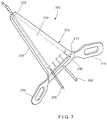
- FIG. 7shows a perspective view of a system according to another exemplary embodiment of the present disclosure.
- FIG. 8shows a perspective view of a system according to a further exemplary embodiment of the system shown in FIG. 7 ;
- FIG. 9shows a perspective view of a device according to an alternate embodiment of the system shown in FIG. 8 .
- the present embodimentsmay be understood with reference to the following description and the appended drawings, wherein like elements are referred to with the same reference numerals.
- the present embodimentsrelate to the treatment of bone fractures and, in particular, relates to the treatment of femoral neck fractures.
- Exemplary embodimentsdescribe a device for correcting an axis along which a guide wire is inserted into a femoral neck.
- guide wiresshould generally be inserted along a central axis of the femoral neck and into the femoral head. In many cases, however, surgeons insert the guide wire into the femoral head without the use of a guiding device, so that an initial placement of the guide wire may require correction.
- the exemplary embodimentsdescribe the device as being used for guide wires inserted through the femoral neck, it will be understood by those of skill in the art that the device may be used to correct placement of guide wires inserted in any of a variety of bones.
- the exemplary devicemay also be used to correct guide wires placed in the distal femur, proximal humerus, distal humerus and for guide wire placement during foot surgeries.
- proximal and distalas used herein, are intended to refer to a direction toward (proximal) and away from (distal) a user (e.g., surgeon) of the device.
- a system 100 for correcting a position of a guide wirecomprises a correction device 102 for correcting the placement of a first guide wire 104 in a bone (e.g., femoral neck) by inserting a second guide wire 106 either at an angle or parallel the first guide wire 104 .
- the device 102comprises a body 108 including a central channel 110 for receiving the first guide wire 104 and a first correction channel 112 extending therethrough at an angle relative to the central channel 110 .
- the body 108may additionally include a second correction channel 114 extending therethrough at an angle relative to the central channel 110 and along a side of the body 102 substantially opposing the first correction channel 112 .
- Each of the first and second correction channels 112 , 114is sized and shaped to receive the second guide wire 106 so that, when the first guide wire 104 is received in the central channel 110 , the user may insert the second guide wire 106 through one of the first and second correction channels 112 , 114 depending on which correction channel aligns with the axis along which it is desired to insert the second guide wire 106 .
- a third correction channel 116extends through the body 108 substantially parallel to the first correction channel 110 for use when the user has determined that the second guide wire 116 should extend parallel to the first guide wire 104 but offset laterally from the first guide wire 104 .
- the device 102additionally includes a handle portion 118 extending from the body 108 to facilitate gripping of the device 102 .
- the device 102may be slid along the first guide wire 104 while the first guide wire 104 is received within the central channel 110 .
- the second guide wire 106is then inserted through one of the first, second and third channels 112 , 114 , 116 and into the bone. If the second guide wire 106 is in the desired corrected position (e.g., along a central axis of the femoral neck), the first guide wire 104 and the device 102 may be removed, leaving the second guide wire 106 .
- the body 108 of the device 102extends from a proximal end 120 to a distal end 122 .
- the central channel 110extends through the body 108 from the proximal end 120 to the distal end 122 along a central axis C.
- the first correction channel 112extends through the body 108 from the proximal end 120 to the distal end 122 along a first axis A, which extends at an angle relative to the central axis C.
- the first axis A and the central axis Cintersect at a point distal of the distal end 122 .
- the second correction channel 114extends through the body 108 from the proximal end 120 to the distal end 122 along a side of the body 108 substantially opposing the first correction channel 112 .
- the second correction channel 114extends through the body 108 along an axis B, which extends at an angle relative to the central axis C so that the axes B and C intersect at a point distal of the distal end 122 .
- the body 108may be marked to show the angulation of each of the first, second and third correction channels 112 , 114 , 116 relative to the central axis C.
- each of the first and second axes A and Bare angled at an angle of 5° relative to the central axis C.
- the angle of the axes A and B relative to the central axis Cmay vary depending on a desired level of correction of the guide wire.
- the axes A and Bmay be angled relative to the central axis C by an angle up to 20°.
- the first axis A and the second axis Bmay have angulations that are different from one another.
- the third correction channel 116also extends through the body 108 from the proximal end 120 to the distal end 122 along a third axis D.
- the third axis Dextends substantially parallel relative to the central axis C.
- the third axis Dmay be distanced from the central axis C at a distance ranging, for example, between 4.0 mm and 6.0 mm. In one particular embodiment, the third axis D may be distanced from the central axis C by a distance of 5.0 mm. It will be understood by those of skill in the art, however, that the distance of the axis D from the central axis C may vary, as desired. For example, the axis D may be distanced from the central axis C by a distance of up to 15 mm.
- Each of the central channel 110 and the first, second and third corrections channels 112 , 114 , 116is sized and shaped to receive a guide wire therein.
- the channels 110 - 116are sized and shaped to receive guide wires having a diameter ranging from 2.5 mm to 3.0 mm.
- the channels 110 - 116are sized to receive guide wires having a 2.8 mm diameter.
- the device 102may be slid along an initially inserted first guide wire 104 with the first guide wire 104 received within the central channel 110 .
- the second guide wire 106may then be inserted into one of the first, second and third correction channels 112 , 114 , 116 to correct an initial placement of the first guide wire 104 .
- the first and second correction channels 112 , 114extend along opposing sides of the body 108 so that, if an angulation of the second guide wire 106 relative to the first guide wire 104 is desired, the user may determine a direction in which it is desired to angulate the second guide wire 106 with respect to the first guide wire 104 .
- a size and shape of the body 108may be defined via the central channel 110 and the first, second and third correction channels 112 , 114 , 116 , tapering from the proximal end 120 to the distal end 122 .
- a length of the body 108may be selected so that the device 102 may be inserted through tissue and into a living body so that the distal end 122 may contact the bone while the handle portion 118 , which is connected to the proximal end 120 , extends outside of the body.
- a length of the channels 110 - 116should be long enough to provide precision during insertion of the guide wires along the axes A-D.
- a length of the body 108may range from between 100 and 200 mm.
- the body 108 of the correction device 102may have a length of approximately 142 mm.
- the handle portion 118optionally includes first and second winged handles 124 , 126 , respectively, each extending laterally from the proximal end 120 of the body 108 at an angle relative to a longitudinal axis of the device 102 .
- the first and second winged handles 124 , 126extend from substantially opposing sides of the body 108 .
- the first winged handle 124extends from the side of the body 108 including the first correction channel 112 and the second winged handle 126 extends from the side of the body 108 including the second correction channel 114 .
- An angle of the first and second winged handles 124 , 126 relative to the longitudinal axis of the device 102is selected to facilitate ease of gripping of at least one of the first and second handles 124 , 126 .
- the userwill have at least one handle to grip while inserting the second guide wire 106 through one of the first, second and third correction channels 112 , 114 , 116 .
- the first guide wire 104is inserted along an axis of the femoral neck and into the femoral head.
- the first guide wire 104may be inserted into the femoral head using an angled guide, which permits insertion of the first guide wire 104 at a predetermined angle relative to a longitudinal axis of the femur.
- the usermay take an image scan (e.g., x-ray) of the proximal portion of the femur to determine whether a correction is required. In most cases, it is desirable for the guide wire to be inserted along a central axis of the femoral neck.
- the usermay determine that correction is required. Based on the image scan, the user may also determine a desired corrected path of the guide wire. For example, the user may determine whether the guide wire should be angulated in an anterior or posterior direction relative to the initially placed first guide wire 104 , or whether it is desired for the guide wire to extend parallel to the initially placed first guide wire 104 but offset laterally therefrom.
- the device 102is slid along the first guide wire 104 with the first guide wire 104 received within the central channel 110 until the distal end 122 contacts the bone.
- the usermay rotate the device 102 about the first guide wire 104 until an entry point of the second guide wire 106 (e.g., a distal opening of a selected one of the first, second and third correction channels 112 , 114 , 116 through which the second guide wire 106 will be inserted) is in alignment with the desired corrected path.
- the userthen grips one of the first and second handles 124 , 126 to hold the device 102 against the bone, in the desired orientation, while inserting the second guide wire 106 through the selected one of the first, second and third correction channels 112 , 114 , 116 , respectively.
- the userdetermines which of the first, second and third correction channels 112 , 114 , 116 to use based on the determined desired corrected path.
- the second guide wire 106is inserted into the bone via the selected correction channel and the new entry point along the desired corrected path, in alignment with one of the first, second and third axes A, B, D.
- the first guide wire 104 and the device 102may be removed from the patient body.
- Another image scan of the proximal femurmay be taken to confirm that the second guide wire is in the desired position within the bone.
- the above-described processmay be repeated by sliding the device 102 over the second guide wire 106 so that the second guide wire 106 is received within the central channel 110 .
- a third guide wiremay be inserted through one of the first, second and third correction channels 112 , 114 , 116 along a desired corrected path.
- the desired corrected pathmay have a greater angulation relative to the first guide wire 104 and/or is at a greater distance than is permitted via the device 102 .
- the axes A and Bmay extend at a 5° angle relative to the axis C, while the desired path is 10° relative to the first guide wire 104 .
- the above-described processmay be repeated using additional guide wires until a path of insertion of a guide wire substantially corresponds to the desired corrected path.
- the exemplary embodimentdescribes and shows three correction channels 112 - 116 , it will be understood by those of skill in the art that the device 102 may include additional channels to provide additional angulation and/or distance options. Additional channels, however, may increase a size of the body 108 of the device 102 .
- a system 200may be substantially similar to the system 100 , comprising a device 202 for correcting an initial placement of a first guide wire 204 by permitting insertion of a second guide wire 206 at an angle relative to and/or at a distance from the first guide wire 204 .
- the device 202may be substantially similar to the device 102 .
- the device 202includes a slotted correction channel 212 which permits insertion of a guide wire therethrough along an axis angled relative to an axis C of a central channel 210 of the device 202 , within a permitted range of angulations.
- the device 202includes a body 208 extending from a proximal end 220 to a distal end 222 , a handle portion 218 extending from the proximal end 220 the body 208 .
- the device 202includes the central channel 210 extending through the body 208 from the proximal end 220 to the distal end 222 for receiving the first guide wire 204 .
- the slotted correction channel 212also extends through the body 208 from the proximal end 220 to the distal end 222 .
- the slotted correction channel 212tapers from the proximal end 220 toward the distal end 222 so that a proximal opening 213 thereof is slotted (i.e., elongated) to permit insertion of the second guide wire 206 therethrough, within a permitted range of angulations.
- the slotted correction channel 212may permit insertion of the second guide wire 206 therethrough at an angle ranging from between ⁇ 10° to 10° relative to the central axis C. It will be understood by those of skill in the art, however, that this permitted range of angulation may vary, as desired.
- the body 208may be marked with the permitted range of angulations so that a user may insert the second guide wire 206 through the slotted correction channel 212 in alignment with a marking showing the desired angulation of the second guide wire 206 .
- the second guide wire 206may be inserted into the bone at an angle relative to the first guide wire 204 (which is received within the central channel 210 ) or parallel to the first guide wire 204 .
- the second guide wire 206may be inserted through the slotted channel 212 in alignment with a 0° marker shown on the body 208 .
- a device according to the present disclosuremay include more than one slotted channel providing a predetermined range of angulations of a guide wire inserted therethrough. It will also be understood by those of skill in the art that a device according to the present disclosure may also include a combination of at least one slotted channel, as described above with respect to the device 202 , and at least one of the correction channels described above with respect to the device 102 .
- the system 200may be used in a manner substantially similar to the device 100 .
- the device 202may be slid over an initially placed first guide wire 204 such that the first guide wire 204 is received within the central channel 210 .
- the usermay determine a desired corrected path for the second guide wire 206 .
- the second guide wire 206may be inserted through the slotted channel 212 and into the bone along in alignment with a marking corresponding to the desired corrected path.
- a system 300may be substantially similar to the system 200 described above, comprising a device 302 for correcting an initial placement of a first guide wire 304 by permitting insertion of a second guide wire 306 at an angle relative to and/or at a distance from the first guide wire 304 .
- the device 302includes a central channel 310 and a slotted channel 312 extending longitudinally through a body 308 of the device 302 from a proximal end 320 of the body 308 to a distal end 322 of the body 308 .
- the slotted channel 312is substantially similar to the slotted channel 212 , permitting insertion therethrough of the second guide wire 306 at a desired angle within a permitted range of angulations relative to a central axis C of the central channel 310 , in which the first guide wire 304 is received.
- the device 302further includes a slider 330 movably received within the slotted channel 312 .
- the slider 330includes an opening extending longitudinally therethrough. The opening is sized and shaped to receive a guide wire therethrough. The slider 330 may be moved laterally within the slotted channel 312 so that the slider 330 may be positioned in alignment with a desired angle (corresponding to a desired correction path) within the permitted range of angulations.
- the slider 330may provide a greater precision for the insertion of the second guide wire 306 along the desired correction path.
- the slider 330may be slidably housed within a correspondingly sized and shaped groove 334 extending laterally through the body 308 in communication with the slotted channel 312 .
- the groove 334houses the slider 330 such that a portion thereof is accessible to the user so that the user may slide the slider 330 laterally relative to the body 308 into alignment with, for example, a marking showing the desired angle within the permitted range of angulations.
- the slider 330may include features preventing the slider 330 from moving during insertion of the second guide wire 306 .
- the slider 330may be friction fit within the groove 334 and/or include an engaging feature which permit the slider 330 to be clicked or snapped into a desired one of a plurality of correspondingly sized and shaped engaging features of the groove 334 .
- the correspondingly sized and shaped engaging features of the groove 334may permit the slide 330 to be fixed at the desired position relative to the body 308 .
- a device 302 ′may include a longitudinally extending slider 330 ′ received within a slotted channel 312 ′ and pivotally coupled to a distal end 322 ′ of a body 308 ′ of the device 302 ′.
- the slider 330 ′includes an alignment channel 332 ′ extending longitudinally therethrough, the alignment channel 332 ′ sized and shaped to receive a guide wire therein.
- the slider 330 ′may be pivoted into alignment with a marking showing a desired angulation (corresponding to a desired correction path) within a permitted range of angulations relative to a central axis C of a central channel 310 ′ of the device 302 ′ to provide greater precision of insertion along the desired correction path.
- the devices 302 , 302 ′may be used in a manner substantially similarly to the devices 102 , 202 described above.
- the device 302(or 302 ′) may be slid along an initially placed first guide wire 304 .
- the slider 330is moved into alignment with a desired correction path of the guide wire so that the second guide wire 306 may be guided through the opening 332 thereof and into the bone.
Landscapes
- Health & Medical Sciences (AREA)
- Surgery (AREA)
- Life Sciences & Earth Sciences (AREA)
- Orthopedic Medicine & Surgery (AREA)
- Biomedical Technology (AREA)
- Public Health (AREA)
- Veterinary Medicine (AREA)
- Engineering & Computer Science (AREA)
- Nuclear Medicine, Radiotherapy & Molecular Imaging (AREA)
- Heart & Thoracic Surgery (AREA)
- Medical Informatics (AREA)
- Molecular Biology (AREA)
- Animal Behavior & Ethology (AREA)
- General Health & Medical Sciences (AREA)
- Dentistry (AREA)
- Oral & Maxillofacial Surgery (AREA)
- Neurology (AREA)
- Surgical Instruments (AREA)
Abstract
Description
Claims (18)
Priority Applications (10)
| Application Number | Priority Date | Filing Date | Title |
|---|---|---|---|
| US15/664,664US10966773B2 (en) | 2017-07-31 | 2017-07-31 | Correction guide for femoral neck |
| BR112020001903-8ABR112020001903B1 (en) | 2017-07-31 | 2018-07-26 | DEVICE AND SYSTEM FOR CORRECT PLACEMENT OF A GUIDE WIRE IN A FEMORAL NECK |
| CN201880050204.2ACN111031940B (en) | 2017-07-31 | 2018-07-26 | Correction guide for femoral neck |
| PCT/US2018/043885WO2019027802A2 (en) | 2017-07-31 | 2018-07-26 | Correction guide for femoral neck |
| EP18758999.9AEP3661432A2 (en) | 2017-07-31 | 2018-07-26 | Correction guide for femoral neck |
| AU2018311824AAU2018311824B2 (en) | 2017-07-31 | 2018-07-26 | Correction guide for femoral neck |
| CA3070787ACA3070787A1 (en) | 2017-07-31 | 2018-07-26 | Correction guide for femoral neck |
| JP2020505136AJP2020529243A (en) | 2017-07-31 | 2018-07-26 | Compensation guide for the femoral neck |
| US17/249,898US11980406B2 (en) | 2017-07-31 | 2021-03-17 | Correction guide for femoral neck |
| JP2022177215AJP7451651B2 (en) | 2017-07-31 | 2022-11-04 | Correction guide for the femoral neck |
Applications Claiming Priority (1)
| Application Number | Priority Date | Filing Date | Title |
|---|---|---|---|
| US15/664,664US10966773B2 (en) | 2017-07-31 | 2017-07-31 | Correction guide for femoral neck |
Related Child Applications (1)
| Application Number | Title | Priority Date | Filing Date |
|---|---|---|---|
| US17/249,898ContinuationUS11980406B2 (en) | 2017-07-31 | 2021-03-17 | Correction guide for femoral neck |
Publications (2)
| Publication Number | Publication Date |
|---|---|
| US20190029743A1 US20190029743A1 (en) | 2019-01-31 |
| US10966773B2true US10966773B2 (en) | 2021-04-06 |
Family
ID=63312455
Family Applications (2)
| Application Number | Title | Priority Date | Filing Date |
|---|---|---|---|
| US15/664,664Active2037-08-10US10966773B2 (en) | 2017-07-31 | 2017-07-31 | Correction guide for femoral neck |
| US17/249,898Active2038-11-29US11980406B2 (en) | 2017-07-31 | 2021-03-17 | Correction guide for femoral neck |
Family Applications After (1)
| Application Number | Title | Priority Date | Filing Date |
|---|---|---|---|
| US17/249,898Active2038-11-29US11980406B2 (en) | 2017-07-31 | 2021-03-17 | Correction guide for femoral neck |
Country Status (7)
| Country | Link |
|---|---|
| US (2) | US10966773B2 (en) |
| EP (1) | EP3661432A2 (en) |
| JP (2) | JP2020529243A (en) |
| CN (1) | CN111031940B (en) |
| AU (1) | AU2018311824B2 (en) |
| CA (1) | CA3070787A1 (en) |
| WO (1) | WO2019027802A2 (en) |
Families Citing this family (5)
| Publication number | Priority date | Publication date | Assignee | Title |
|---|---|---|---|---|
| ES2656974T3 (en)* | 2012-01-19 | 2018-03-01 | Stryker European Holdings I, Llc | Cuff for suprarrotulian surgery |
| US10966773B2 (en)* | 2017-07-31 | 2021-04-06 | DePuy Synthes Products, Inc. | Correction guide for femoral neck |
| KR102357527B1 (en)* | 2020-03-03 | 2022-02-03 | 가톨릭대학교 산학협력단 | femoral headless nephrotectomy apparatus |
| US11382675B2 (en)* | 2020-04-01 | 2022-07-12 | EKTA-Sofia Ltd. | Surgical method for biplane screw fixation of femoral neck fractures (calcar buttressed screw fixation) |
| WO2025106471A1 (en)* | 2023-11-14 | 2025-05-22 | The General Hospital Corporation | Angle bisector surgical tool |
Citations (72)
| Publication number | Priority date | Publication date | Assignee | Title |
|---|---|---|---|---|
| US2301500A (en)* | 1940-05-31 | 1942-11-10 | Anderson Roger | Wire guiding device |
| US2531734A (en)* | 1945-07-27 | 1950-11-28 | Heywood H Hopkins | Hip nail aiming device |
| US4037592A (en)* | 1976-05-04 | 1977-07-26 | Kronner Richard F | Guide pin locating tool and method |
| US4335715A (en)* | 1980-06-20 | 1982-06-22 | Kirkley William H | Osteotomy guide |
| US4421112A (en)* | 1982-05-20 | 1983-12-20 | Minnesota Mining And Manufacturing Company | Tibial osteotomy guide assembly and method |
| US4465065A (en)* | 1983-01-07 | 1984-08-14 | Yechiel Gotfried | Surgical device for connection of fractured bones |
| US5053039A (en)* | 1989-09-14 | 1991-10-01 | Intermedics Orthopedics | Upper tibial osteotomy system |
| US5078719A (en)* | 1990-01-08 | 1992-01-07 | Schreiber Saul N | Osteotomy device and method therefor |
| US5207753A (en)* | 1991-02-18 | 1993-05-04 | Kannivelu Badrinath | Bone fracture repair apparatus and method |
| US5246444A (en)* | 1990-01-08 | 1993-09-21 | Schreiber Saul N | Osteotomy device and method |
| US5254119A (en)* | 1991-08-23 | 1993-10-19 | Schreiber Saul N | Osteotomy device and method therefor |
| US5306278A (en)* | 1992-09-11 | 1994-04-26 | Ace Medical Company | Corticotomy drill guide |
| US5324295A (en)* | 1992-04-24 | 1994-06-28 | Shapiro Michael R | Drill guide for surgical pins |
| US5417694A (en)* | 1993-11-08 | 1995-05-23 | Smith & Nephew Richards Inc. | Distal femoral cutting guide apparatus with anterior or posterior referencing for use in knee joint replacement surgery |
| US5449360A (en)* | 1991-08-23 | 1995-09-12 | Schreiber; Saul N. | Osteotomy device and method |
| US5766221A (en)* | 1991-12-03 | 1998-06-16 | Boston Scientific Technology, Inc. | Bone anchor implantation device |
| USRE36020E (en)* | 1992-06-08 | 1998-12-29 | Orthopedic Systems, Inc. | Method and apparatus for tying suture to bone |
| US6007535A (en)* | 1996-01-03 | 1999-12-28 | John M. Rayhack | Multi-plane bone distraction system |
| US6342056B1 (en)* | 2000-02-04 | 2002-01-29 | Jean-Marc Mac-Thiong | Surgical drill guide and method for using the same |
| US20030004513A1 (en)* | 2001-06-27 | 2003-01-02 | Guzman Pamela C. | Method and apparatus for use in the performance of endoscopic minimally invasive orthopaedic plating procedures |
| US20030018340A1 (en)* | 2001-06-29 | 2003-01-23 | Branch Thomas P. | Method and apparatus for installing cannula |
| US20030216742A1 (en)* | 2002-02-13 | 2003-11-20 | Merrick Wetzler | Surgical drill guide |
| US20030220651A1 (en)* | 2002-03-15 | 2003-11-27 | Stryker Trauma Gmbh | Targeting device for locking nails |
| JP2004016463A (en) | 2002-06-17 | 2004-01-22 | Nippon Yunitekku:Kk | Insertion guiding implement for guide pin for bonesetting implants |
| US20040082959A1 (en)* | 2002-10-25 | 2004-04-29 | Hayes Kiele S. | Instrumentation guide for orthopedic surgery |
| US20060052795A1 (en)* | 2003-09-03 | 2006-03-09 | White Ralph R | Extracapsular surgical procedure and surgical referencing instrument therefor |
| US20060058810A1 (en)* | 2004-09-13 | 2006-03-16 | Finsbury (Development) Limited | Tool |
| US20060064087A1 (en)* | 2004-09-03 | 2006-03-23 | Ather Mirza | External fixation device for fractures |
| US20060200160A1 (en)* | 2005-02-18 | 2006-09-07 | Ebi, L.P. | Internal fixation assemblies and associated instruments |
| US20060271059A1 (en)* | 2005-05-16 | 2006-11-30 | Arthrocare Corporation | Convergent tunnel guide apparatus and method |
| US20070005067A1 (en)* | 2005-06-21 | 2007-01-04 | Brian Dross | Arthoscopic method and apparatus for tissue attachment to bone |
| US20080015603A1 (en)* | 2006-06-30 | 2008-01-17 | Howmedica Osteonics Corp. | High tibial osteotomy system |
| US20080086136A1 (en)* | 2006-08-30 | 2008-04-10 | Bednar Drew A | Percutaneous hip system |
| US20080114370A1 (en)* | 2006-06-09 | 2008-05-15 | Biomet Manufacturing Corp. | Patient-Specific Alignment Guide For Multiple Incisions |
| US20090088768A1 (en)* | 2007-09-27 | 2009-04-02 | Depuy Products, Inc. | Apparatus for measuring an angle of a guide wire relative to a bone |
| US20090149707A1 (en)* | 2001-09-19 | 2009-06-11 | Brannon James K | Endoscopic bone debridement portal |
| US20090318924A1 (en)* | 2008-06-19 | 2009-12-24 | Helenbolt Kenneth T | Amz tibial tuberosity transfer system |
| US20100036431A1 (en)* | 2007-05-04 | 2010-02-11 | Haidukewych George J | Bone end (Epiphysis) fracture fixation device and method of use |
| US20110054550A1 (en)* | 2009-08-26 | 2011-03-03 | Metzinger Anthony J | Method for implanting a hip fracture nail system |
| US20110213432A1 (en)* | 2009-06-26 | 2011-09-01 | Wyatt Drake Geist | Guidewire And Method For Surgical Procedures |
| US20120123415A1 (en)* | 2010-11-17 | 2012-05-17 | Vienney Cecile | Devices, Methods and Systems for Remedying or Preventing Fractures |
| US8277458B2 (en)* | 2009-01-23 | 2012-10-02 | Biomet Sports Medicine, Llc | Apparatus and method for arthroscopic transhumeral rotator cuff repair |
| US20120253353A1 (en)* | 2011-03-28 | 2012-10-04 | Amendia Inc. | Pedicle drill guide for spinal surgery |
| US8317862B2 (en)* | 2008-10-10 | 2012-11-27 | Marcus Troger | Method for replacing a ligament in a knee |
| US8388624B2 (en)* | 2003-02-24 | 2013-03-05 | Arthrosurface Incorporated | Trochlear resurfacing system and method |
| US20130110120A1 (en)* | 2010-01-20 | 2013-05-02 | Gamal Baroud | Orthopedic device and method |
| US8491595B2 (en)* | 2006-10-30 | 2013-07-23 | Depuy Mitek, Llc | Methods and devices for ligament repair |
| US20140081281A1 (en)* | 2012-09-14 | 2014-03-20 | DePuy Synthes Products, LLC | Multihole Drill Sleeve with Protection Sleeve |
| US8777957B2 (en)* | 2005-11-23 | 2014-07-15 | Trinity Orthopedics, Llc | Percutaneous transpedicular access, fusion, discectomy, and stabilization system and method |
| US20140277450A1 (en)* | 2013-03-14 | 2014-09-18 | Mark J. Warburton | Apparatus and methods for aol and drl reconstruction of cmc joints |
| US20150066041A1 (en) | 2011-03-31 | 2015-03-05 | The Catholic University Of Korea Industry-Academic Cooperation Foundation | Pin guide for operating on avascular necrosis of the femoral head |
| US20150066039A1 (en)* | 2012-04-05 | 2015-03-05 | Nlt Spine Ltd. | Conic retraction |
| US20150157379A1 (en)* | 2013-12-05 | 2015-06-11 | Acumed, Llc | Guide for Surgical Wires, Method, System, and Device |
| US20150182267A1 (en)* | 2014-01-02 | 2015-07-02 | DePuy Synthes Products, LLC | Method and Device for Attaching a Bone Plate |
| US9149286B1 (en)* | 2010-11-12 | 2015-10-06 | Flexmedex, LLC | Guidance tool and method for use |
| EP2929845A1 (en) | 2014-03-25 | 2015-10-14 | Synvasive Technology, Inc. | Hip resurfacing drill guide device |
| US20160074049A1 (en)* | 2014-09-12 | 2016-03-17 | Innovision, Inc. | Bone drill guides and methods of use thereof |
| US20160089162A1 (en)* | 2014-09-30 | 2016-03-31 | Medos International Sàrl | Universal Surgical Guide Systems and Methods |
| US20160270800A1 (en)* | 2015-02-04 | 2016-09-22 | Mark Sanders | Osteotomy guide and method of using the same |
| US20160310191A1 (en)* | 2015-04-21 | 2016-10-27 | Acumed Llc | Articulating Syndesmosis Targeting Guide Device and Method |
| US20160338696A1 (en)* | 2015-05-18 | 2016-11-24 | Soprane | Surgical needle holder |
| US20160367270A1 (en)* | 2015-06-16 | 2016-12-22 | Arthrex, Inc. | Targeting guide assembly |
| US20170042532A1 (en)* | 2015-08-12 | 2017-02-16 | Technical Manufacturing West, Llc | Suture cutter |
| US9855063B2 (en)* | 2013-02-28 | 2018-01-02 | Jonathan Feibel | Systems, methods, and apparatuses for reaming bone elements |
| US9883874B1 (en)* | 2013-03-08 | 2018-02-06 | Vg Innovations, Llc | Tool and method for implanting fusion device into sacroiliac joint |
| US20180235603A1 (en)* | 2017-02-17 | 2018-08-23 | Suture Ease, Inc. | Access and suture apparatus, system, and method of closing tissue |
| US10098646B2 (en)* | 2014-09-30 | 2018-10-16 | Medos International Sàrl | Surgical guide for use in ligament repair procedures |
| US20180296244A1 (en)* | 2017-04-18 | 2018-10-18 | Texas Scottish Rite Hospital For Children | Device and Method for Treating Osteonecrosis |
| US20180344330A1 (en)* | 2017-06-05 | 2018-12-06 | Conmed Corporation | Multi-Barrel Drill Guide |
| US10154868B2 (en)* | 2015-07-17 | 2018-12-18 | Kator, Llc | Transosseous method |
| US10159502B2 (en)* | 2016-09-05 | 2018-12-25 | E-Da Healthcare Group | Arthroscopic positioning instrument |
| US20190029743A1 (en)* | 2017-07-31 | 2019-01-31 | DePuy Synthes Products, Inc. | Correction guide for femoral neck |
Family Cites Families (5)
| Publication number | Priority date | Publication date | Assignee | Title |
|---|---|---|---|---|
| US4333715A (en) | 1978-09-11 | 1982-06-08 | Brooks Philip A | Moving picture apparatus |
| US4383527A (en)* | 1981-02-20 | 1983-05-17 | Howmedica, Inc. | Device for guiding the insertion of surgical wires into bone tissue |
| US4421122A (en) | 1981-05-15 | 1983-12-20 | The Children's Medical Center Corporation | Brain electrical activity mapping |
| WO2005016155A1 (en)* | 2003-08-13 | 2005-02-24 | Synthes Gmbh | Curved positioning and insertion instrument for inserting a guide wire into the femur |
| AU2012225496B2 (en) | 2011-03-07 | 2016-09-22 | Conventus Orthopaedics, Inc. | Apparatus and methods for bone repair preparation |
- 2017
- 2017-07-31USUS15/664,664patent/US10966773B2/enactiveActive
- 2018
- 2018-07-26CNCN201880050204.2Apatent/CN111031940B/enactiveActive
- 2018-07-26JPJP2020505136Apatent/JP2020529243A/enactivePending
- 2018-07-26WOPCT/US2018/043885patent/WO2019027802A2/ennot_activeCeased
- 2018-07-26AUAU2018311824Apatent/AU2018311824B2/enactiveActive
- 2018-07-26EPEP18758999.9Apatent/EP3661432A2/enactivePending
- 2018-07-26CACA3070787Apatent/CA3070787A1/enactivePending
- 2021
- 2021-03-17USUS17/249,898patent/US11980406B2/enactiveActive
- 2022
- 2022-11-04JPJP2022177215Apatent/JP7451651B2/enactiveActive
Patent Citations (74)
| Publication number | Priority date | Publication date | Assignee | Title |
|---|---|---|---|---|
| US2301500A (en)* | 1940-05-31 | 1942-11-10 | Anderson Roger | Wire guiding device |
| US2531734A (en)* | 1945-07-27 | 1950-11-28 | Heywood H Hopkins | Hip nail aiming device |
| US4037592A (en)* | 1976-05-04 | 1977-07-26 | Kronner Richard F | Guide pin locating tool and method |
| US4335715A (en)* | 1980-06-20 | 1982-06-22 | Kirkley William H | Osteotomy guide |
| US4421112A (en)* | 1982-05-20 | 1983-12-20 | Minnesota Mining And Manufacturing Company | Tibial osteotomy guide assembly and method |
| US4465065A (en)* | 1983-01-07 | 1984-08-14 | Yechiel Gotfried | Surgical device for connection of fractured bones |
| US5053039A (en)* | 1989-09-14 | 1991-10-01 | Intermedics Orthopedics | Upper tibial osteotomy system |
| US5246444A (en)* | 1990-01-08 | 1993-09-21 | Schreiber Saul N | Osteotomy device and method |
| US5078719A (en)* | 1990-01-08 | 1992-01-07 | Schreiber Saul N | Osteotomy device and method therefor |
| US5207753A (en)* | 1991-02-18 | 1993-05-04 | Kannivelu Badrinath | Bone fracture repair apparatus and method |
| US5254119A (en)* | 1991-08-23 | 1993-10-19 | Schreiber Saul N | Osteotomy device and method therefor |
| US5449360A (en)* | 1991-08-23 | 1995-09-12 | Schreiber; Saul N. | Osteotomy device and method |
| US5766221A (en)* | 1991-12-03 | 1998-06-16 | Boston Scientific Technology, Inc. | Bone anchor implantation device |
| US5324295A (en)* | 1992-04-24 | 1994-06-28 | Shapiro Michael R | Drill guide for surgical pins |
| USRE36020E (en)* | 1992-06-08 | 1998-12-29 | Orthopedic Systems, Inc. | Method and apparatus for tying suture to bone |
| US5306278A (en)* | 1992-09-11 | 1994-04-26 | Ace Medical Company | Corticotomy drill guide |
| US5417694A (en)* | 1993-11-08 | 1995-05-23 | Smith & Nephew Richards Inc. | Distal femoral cutting guide apparatus with anterior or posterior referencing for use in knee joint replacement surgery |
| US6007535A (en)* | 1996-01-03 | 1999-12-28 | John M. Rayhack | Multi-plane bone distraction system |
| US6342056B1 (en)* | 2000-02-04 | 2002-01-29 | Jean-Marc Mac-Thiong | Surgical drill guide and method for using the same |
| US20030004513A1 (en)* | 2001-06-27 | 2003-01-02 | Guzman Pamela C. | Method and apparatus for use in the performance of endoscopic minimally invasive orthopaedic plating procedures |
| US20030018340A1 (en)* | 2001-06-29 | 2003-01-23 | Branch Thomas P. | Method and apparatus for installing cannula |
| US20090149707A1 (en)* | 2001-09-19 | 2009-06-11 | Brannon James K | Endoscopic bone debridement portal |
| US20030216742A1 (en)* | 2002-02-13 | 2003-11-20 | Merrick Wetzler | Surgical drill guide |
| US20030220651A1 (en)* | 2002-03-15 | 2003-11-27 | Stryker Trauma Gmbh | Targeting device for locking nails |
| JP2004016463A (en) | 2002-06-17 | 2004-01-22 | Nippon Yunitekku:Kk | Insertion guiding implement for guide pin for bonesetting implants |
| US20040082959A1 (en)* | 2002-10-25 | 2004-04-29 | Hayes Kiele S. | Instrumentation guide for orthopedic surgery |
| US8388624B2 (en)* | 2003-02-24 | 2013-03-05 | Arthrosurface Incorporated | Trochlear resurfacing system and method |
| US20060052795A1 (en)* | 2003-09-03 | 2006-03-09 | White Ralph R | Extracapsular surgical procedure and surgical referencing instrument therefor |
| US20060064087A1 (en)* | 2004-09-03 | 2006-03-23 | Ather Mirza | External fixation device for fractures |
| US20060058810A1 (en)* | 2004-09-13 | 2006-03-16 | Finsbury (Development) Limited | Tool |
| US20060200160A1 (en)* | 2005-02-18 | 2006-09-07 | Ebi, L.P. | Internal fixation assemblies and associated instruments |
| US20060271059A1 (en)* | 2005-05-16 | 2006-11-30 | Arthrocare Corporation | Convergent tunnel guide apparatus and method |
| US20070005067A1 (en)* | 2005-06-21 | 2007-01-04 | Brian Dross | Arthoscopic method and apparatus for tissue attachment to bone |
| US8777957B2 (en)* | 2005-11-23 | 2014-07-15 | Trinity Orthopedics, Llc | Percutaneous transpedicular access, fusion, discectomy, and stabilization system and method |
| US20080114370A1 (en)* | 2006-06-09 | 2008-05-15 | Biomet Manufacturing Corp. | Patient-Specific Alignment Guide For Multiple Incisions |
| US20080015603A1 (en)* | 2006-06-30 | 2008-01-17 | Howmedica Osteonics Corp. | High tibial osteotomy system |
| US20080086136A1 (en)* | 2006-08-30 | 2008-04-10 | Bednar Drew A | Percutaneous hip system |
| US8491595B2 (en)* | 2006-10-30 | 2013-07-23 | Depuy Mitek, Llc | Methods and devices for ligament repair |
| US20100036431A1 (en)* | 2007-05-04 | 2010-02-11 | Haidukewych George J | Bone end (Epiphysis) fracture fixation device and method of use |
| US20090088768A1 (en)* | 2007-09-27 | 2009-04-02 | Depuy Products, Inc. | Apparatus for measuring an angle of a guide wire relative to a bone |
| US20090318924A1 (en)* | 2008-06-19 | 2009-12-24 | Helenbolt Kenneth T | Amz tibial tuberosity transfer system |
| US8317862B2 (en)* | 2008-10-10 | 2012-11-27 | Marcus Troger | Method for replacing a ligament in a knee |
| US8277458B2 (en)* | 2009-01-23 | 2012-10-02 | Biomet Sports Medicine, Llc | Apparatus and method for arthroscopic transhumeral rotator cuff repair |
| US20110213432A1 (en)* | 2009-06-26 | 2011-09-01 | Wyatt Drake Geist | Guidewire And Method For Surgical Procedures |
| US20110054550A1 (en)* | 2009-08-26 | 2011-03-03 | Metzinger Anthony J | Method for implanting a hip fracture nail system |
| US20130110120A1 (en)* | 2010-01-20 | 2013-05-02 | Gamal Baroud | Orthopedic device and method |
| US9149286B1 (en)* | 2010-11-12 | 2015-10-06 | Flexmedex, LLC | Guidance tool and method for use |
| US20120123415A1 (en)* | 2010-11-17 | 2012-05-17 | Vienney Cecile | Devices, Methods and Systems for Remedying or Preventing Fractures |
| US9119645B2 (en)* | 2011-03-28 | 2015-09-01 | Amendia, Inc. | Pedicle drill guide for spinal surgery |
| US20120253353A1 (en)* | 2011-03-28 | 2012-10-04 | Amendia Inc. | Pedicle drill guide for spinal surgery |
| US9707001B2 (en)* | 2011-03-31 | 2017-07-18 | The Catholic University Industry—Academic Cooperation Foundation | Pin guide for operating on avascular necrosis of the femoral head |
| US20150066041A1 (en) | 2011-03-31 | 2015-03-05 | The Catholic University Of Korea Industry-Academic Cooperation Foundation | Pin guide for operating on avascular necrosis of the femoral head |
| US20150066039A1 (en)* | 2012-04-05 | 2015-03-05 | Nlt Spine Ltd. | Conic retraction |
| US20140081281A1 (en)* | 2012-09-14 | 2014-03-20 | DePuy Synthes Products, LLC | Multihole Drill Sleeve with Protection Sleeve |
| US9855063B2 (en)* | 2013-02-28 | 2018-01-02 | Jonathan Feibel | Systems, methods, and apparatuses for reaming bone elements |
| US9883874B1 (en)* | 2013-03-08 | 2018-02-06 | Vg Innovations, Llc | Tool and method for implanting fusion device into sacroiliac joint |
| US20140277450A1 (en)* | 2013-03-14 | 2014-09-18 | Mark J. Warburton | Apparatus and methods for aol and drl reconstruction of cmc joints |
| US20150157379A1 (en)* | 2013-12-05 | 2015-06-11 | Acumed, Llc | Guide for Surgical Wires, Method, System, and Device |
| US20150182267A1 (en)* | 2014-01-02 | 2015-07-02 | DePuy Synthes Products, LLC | Method and Device for Attaching a Bone Plate |
| EP2929845A1 (en) | 2014-03-25 | 2015-10-14 | Synvasive Technology, Inc. | Hip resurfacing drill guide device |
| US20160074049A1 (en)* | 2014-09-12 | 2016-03-17 | Innovision, Inc. | Bone drill guides and methods of use thereof |
| US20160089162A1 (en)* | 2014-09-30 | 2016-03-31 | Medos International Sàrl | Universal Surgical Guide Systems and Methods |
| US10098646B2 (en)* | 2014-09-30 | 2018-10-16 | Medos International Sàrl | Surgical guide for use in ligament repair procedures |
| US20160270800A1 (en)* | 2015-02-04 | 2016-09-22 | Mark Sanders | Osteotomy guide and method of using the same |
| US20160310191A1 (en)* | 2015-04-21 | 2016-10-27 | Acumed Llc | Articulating Syndesmosis Targeting Guide Device and Method |
| US20160338696A1 (en)* | 2015-05-18 | 2016-11-24 | Soprane | Surgical needle holder |
| US20160367270A1 (en)* | 2015-06-16 | 2016-12-22 | Arthrex, Inc. | Targeting guide assembly |
| US10154868B2 (en)* | 2015-07-17 | 2018-12-18 | Kator, Llc | Transosseous method |
| US20170042532A1 (en)* | 2015-08-12 | 2017-02-16 | Technical Manufacturing West, Llc | Suture cutter |
| US10159502B2 (en)* | 2016-09-05 | 2018-12-25 | E-Da Healthcare Group | Arthroscopic positioning instrument |
| US20180235603A1 (en)* | 2017-02-17 | 2018-08-23 | Suture Ease, Inc. | Access and suture apparatus, system, and method of closing tissue |
| US20180296244A1 (en)* | 2017-04-18 | 2018-10-18 | Texas Scottish Rite Hospital For Children | Device and Method for Treating Osteonecrosis |
| US20180344330A1 (en)* | 2017-06-05 | 2018-12-06 | Conmed Corporation | Multi-Barrel Drill Guide |
| US20190029743A1 (en)* | 2017-07-31 | 2019-01-31 | DePuy Synthes Products, Inc. | Correction guide for femoral neck |
Also Published As
| Publication number | Publication date |
|---|---|
| BR112020001903A2 (en) | 2020-08-04 |
| CN111031940A (en) | 2020-04-17 |
| JP2020529243A (en) | 2020-10-08 |
| WO2019027802A3 (en) | 2019-02-28 |
| US11980406B2 (en) | 2024-05-14 |
| US20210204992A1 (en) | 2021-07-08 |
| EP3661432A2 (en) | 2020-06-10 |
| JP7451651B2 (en) | 2024-03-18 |
| CA3070787A1 (en) | 2019-02-07 |
| AU2018311824B2 (en) | 2024-08-08 |
| JP2023011859A (en) | 2023-01-24 |
| US20190029743A1 (en) | 2019-01-31 |
| CN111031940B (en) | 2023-11-03 |
| AU2018311824A1 (en) | 2020-02-06 |
| WO2019027802A2 (en) | 2019-02-07 |
Similar Documents
| Publication | Publication Date | Title |
|---|---|---|
| US11980406B2 (en) | Correction guide for femoral neck | |
| US12295634B2 (en) | Bone fixation system, assembly, implants, devices, alignment guides, and methods of use | |
| US11779358B2 (en) | Targeting instruments, systems and methods of use | |
| US10349990B2 (en) | Method and device for attaching a bone plate | |
| US20230139017A1 (en) | Lateral mass fixation system | |
| US11779360B2 (en) | Chevron osteotomy tools and methods | |
| CN102596060B (en) | Improved hip fracture nail system | |
| US9204976B2 (en) | Spinal surgery apparatus and method | |
| US20090138095A1 (en) | Method for treating a cartilage defect, surgical instrumentation and surgical navigation system | |
| US20250248719A1 (en) | Reusable surgical guide for osteosynthesis surgery in particular of the hallux valgus | |
| US20130041374A1 (en) | Radius intramedullar locking nail | |
| US9549771B1 (en) | Fingerstall-cannulated guide for fast and accurate guide wire positioning | |
| BR112020001903B1 (en) | DEVICE AND SYSTEM FOR CORRECT PLACEMENT OF A GUIDE WIRE IN A FEMORAL NECK | |
| US10646695B1 (en) | Percutaneous methods, systems, and devices for positioning a guide wire in a bone | |
| Taglang | The operative technique for the latest generation gamma nail (the Gamma3) | |
| CN114366273A (en) | Pedicle of vertebral arch mouth gag for spinal surgery |
Legal Events
| Date | Code | Title | Description |
|---|---|---|---|
| AS | Assignment | Owner name:DEPUY SYNTHES PRODUCTS, INC., MASSACHUSETTS Free format text:ASSIGNMENT OF ASSIGNORS INTEREST;ASSIGNOR:SYNTHES GMBH;REEL/FRAME:043924/0666 Effective date:20171023 Owner name:SYNTHES GMBH, SWITZERLAND Free format text:ASSIGNMENT OF ASSIGNORS INTEREST;ASSIGNORS:AEBI, THIS;MUELLER, DAVID;OSWALD, MARTIN;AND OTHERS;SIGNING DATES FROM 20170919 TO 20171002;REEL/FRAME:043924/0575 | |
| AS | Assignment | Owner name:DEPUY SYNTHES PRODUCTS, INC., MASSACHUSETTS Free format text:CORRECTIVE ASSIGNMENT TO CORRECT THE INCORRECT ASSIGNMENT MISSING NOTARY STAMP PREVIOUSLY RECORDED AT REEL: 043924 FRAME: 0666. ASSIGNOR(S) HEREBY CONFIRMS THE ASSIGNMENT;ASSIGNOR:SYNTHES GMBH;REEL/FRAME:044748/0202 Effective date:20171023 | |
| STPP | Information on status: patent application and granting procedure in general | Free format text:RESPONSE TO NON-FINAL OFFICE ACTION ENTERED AND FORWARDED TO EXAMINER | |
| STPP | Information on status: patent application and granting procedure in general | Free format text:NON FINAL ACTION MAILED | |
| STPP | Information on status: patent application and granting procedure in general | Free format text:RESPONSE TO NON-FINAL OFFICE ACTION ENTERED AND FORWARDED TO EXAMINER | |
| STPP | Information on status: patent application and granting procedure in general | Free format text:FINAL REJECTION MAILED | |
| STPP | Information on status: patent application and granting procedure in general | Free format text:RESPONSE AFTER FINAL ACTION FORWARDED TO EXAMINER | |
| STPP | Information on status: patent application and granting procedure in general | Free format text:ADVISORY ACTION MAILED | |
| STPP | Information on status: patent application and granting procedure in general | Free format text:DOCKETED NEW CASE - READY FOR EXAMINATION | |
| STPP | Information on status: patent application and granting procedure in general | Free format text:NON FINAL ACTION MAILED | |
| STPP | Information on status: patent application and granting procedure in general | Free format text:FINAL REJECTION MAILED | |
| STPP | Information on status: patent application and granting procedure in general | Free format text:RESPONSE AFTER FINAL ACTION FORWARDED TO EXAMINER | |
| STPP | Information on status: patent application and granting procedure in general | Free format text:PUBLICATIONS -- ISSUE FEE PAYMENT RECEIVED | |
| STPP | Information on status: patent application and granting procedure in general | Free format text:PUBLICATIONS -- ISSUE FEE PAYMENT VERIFIED | |
| STCF | Information on status: patent grant | Free format text:PATENTED CASE | |
| MAFP | Maintenance fee payment | Free format text:PAYMENT OF MAINTENANCE FEE, 4TH YEAR, LARGE ENTITY (ORIGINAL EVENT CODE: M1551); ENTITY STATUS OF PATENT OWNER: LARGE ENTITY Year of fee payment:4 |