US10966751B2 - Thoracoscopic irrigation cannula - Google Patents
Thoracoscopic irrigation cannulaDownload PDFInfo
- Publication number
- US10966751B2 US10966751B2US16/253,838US201916253838AUS10966751B2US 10966751 B2US10966751 B2US 10966751B2US 201916253838 AUS201916253838 AUS 201916253838AUS 10966751 B2US10966751 B2US 10966751B2
- Authority
- US
- United States
- Prior art keywords
- cannula
- obturator
- leg
- thoracoscopic
- bowl
- Prior art date
- Legal status (The legal status is an assumption and is not a legal conclusion. Google has not performed a legal analysis and makes no representation as to the accuracy of the status listed.)
- Active, expires
Links
Images


Classifications
- A—HUMAN NECESSITIES
- A61—MEDICAL OR VETERINARY SCIENCE; HYGIENE
- A61B—DIAGNOSIS; SURGERY; IDENTIFICATION
- A61B17/00—Surgical instruments, devices or methods
- A61B17/34—Trocars; Puncturing needles
- A61B17/3417—Details of tips or shafts, e.g. grooves, expandable, bendable; Multiple coaxial sliding cannulas, e.g. for dilating
- A61B17/3421—Cannulas
- A—HUMAN NECESSITIES
- A61—MEDICAL OR VETERINARY SCIENCE; HYGIENE
- A61B—DIAGNOSIS; SURGERY; IDENTIFICATION
- A61B17/00—Surgical instruments, devices or methods
- A61B17/02—Surgical instruments, devices or methods for holding wounds open, e.g. retractors; Tractors
- A61B17/0293—Surgical instruments, devices or methods for holding wounds open, e.g. retractors; Tractors with ring member to support retractor elements
- A—HUMAN NECESSITIES
- A61—MEDICAL OR VETERINARY SCIENCE; HYGIENE
- A61B—DIAGNOSIS; SURGERY; IDENTIFICATION
- A61B17/00—Surgical instruments, devices or methods
- A61B17/02—Surgical instruments, devices or methods for holding wounds open, e.g. retractors; Tractors
- A61B2017/0237—Surgical instruments, devices or methods for holding wounds open, e.g. retractors; Tractors for heart surgery
- A—HUMAN NECESSITIES
- A61—MEDICAL OR VETERINARY SCIENCE; HYGIENE
- A61B—DIAGNOSIS; SURGERY; IDENTIFICATION
- A61B17/00—Surgical instruments, devices or methods
- A61B17/34—Trocars; Puncturing needles
- A61B17/3417—Details of tips or shafts, e.g. grooves, expandable, bendable; Multiple coaxial sliding cannulas, e.g. for dilating
- A61B17/3421—Cannulas
- A61B17/3423—Access ports, e.g. toroid shape introducers for instruments or hands
- A61B2017/3425—Access ports, e.g. toroid shape introducers for instruments or hands for internal organs, e.g. heart ports
- A—HUMAN NECESSITIES
- A61—MEDICAL OR VETERINARY SCIENCE; HYGIENE
- A61B—DIAGNOSIS; SURGERY; IDENTIFICATION
- A61B17/00—Surgical instruments, devices or methods
- A61B17/34—Trocars; Puncturing needles
- A61B17/3417—Details of tips or shafts, e.g. grooves, expandable, bendable; Multiple coaxial sliding cannulas, e.g. for dilating
- A61B17/3421—Cannulas
- A61B17/3423—Access ports, e.g. toroid shape introducers for instruments or hands
- A61B2017/3427—Access ports, e.g. toroid shape introducers for instruments or hands for intercostal space
Definitions
- the inventionis directed toward an irrigation cannula for use during thoracoscopic surgery, and particularly to a cannula for providing irrigation solution to the chest cavity during surgery.
- a primary objective of the present inventionis the provision of a thoracoscopic irrigation cannula for manually irrigating the chest cavity during chest surgery.
- Another objective of the present inventionis the provision of a thoracoscopic irrigation cannula which can rapidly deliver large volumes of solution to the pleural cavity through thoracoscopic surgical incisions between the ribs with minimal slippage.
- a further objective of the present inventionis the provision of a thoracoscopic irrigation cannula that is simple and safe to use, and easy to manufacture. For example, the need to provide a power source is eliminated.
- the thoracoscopic irrigation cannula of the present inventionincludes a bowl with a small diameter leg, and a drain opening at the juncture of the bowl and upper end of the leg.
- An obturatorhas an upper handle and a lower tip that is manually inserted through the leg to facilitate insertion of the leg through the incision in the chest wall.
- the thoracoscopic irrigation cannulacan be made from a variety of materials, including metals and polymers. Also, the cannula can be disposable or reusable.
- the size of the bowlcan also vary, for example, a smaller bowl for surgery on a child and a larger bowl for surgery on an adult.
- the shape of the bowlcan also vary.
- the cannulais operated manually, without electrical power, batteries, or other complex structure.
- FIG. 1is a perspective view of one embodiment of a thoracoscopic irrigation cannula of the present invention.
- FIG. 2is a side elevation view of the thoracoscopic irrigation cannula shown in FIG. 1 .
- FIG. 3is a side elevation of the thoracoscopic irrigation cannula with the obturator removed from the bowl.
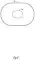
- FIG. 4is an end elevation view of the bowl and obturator.
- FIG. 5is a sectional view showing the obturator in a first position engaging the drain opening of the bowl.
- FIG. 6is a top plan view of the bowl and obturator.
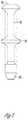
- FIG. 7is a side elevation view of the obturator shown in FIG. 3 .
- FIG. 8is a sectional view along line 8 - 8 of FIG. 5 .
- FIG. 9is a view showing the cannula being inserted through an incision in the chest wall and into the chest cavity.
- FIG. 10is a view showing the cannula in use for supplying a liquid into the chest cavity.
- the thoracoscopic irrigation cannula of the present inventionis generally designated by the reference numeral 10 in the drawings.
- the thoracoscopic irrigation cannulaincludes a bowl 12 and a hollow leg 14 connected to the bowl 12 .
- the bowl 12 and leg 14have an integral construction.
- the bowl 12includes a drain opening 16 which allows liquid in the bowl to drain through the leg 14 .
- An obturator 18is removably insertable into the leg 14 so as to facilitate insertion of the leg 14 though the chest incision into the chest cavity.
- the obturator 18has an upper end 20 forming a handle which may extend above the bowl 12 and a lower end 22 which extends beyond the open end of the leg 14 .
- the lower end 22 of the obturator 18has a smooth, curved surface to facilitate passage of the leg 14 through the tissues around the incision.
- the thoracoscopic irrigation leg 14 , and obturator 18have a round or oval cross section, as shown in FIG. 8 .
- the shapewill depend upon the physical restrictions around the location of the incision. As shown in FIGS. 5 and 8 , the outside diameter of the obturator 18 may vary but is smaller than the inside diameter of the leg 14 , so that the tip of the obturator passes through the leg 14 easily.
- the bowl 12 and leg 14are formed as a one-piece integral unit.
- the bowl 12 and leg 14can be made of various materials, including metal and plastic, and sterilized before use.
- the cannula 10may be designed for one-time disposable use, or for re-use after sterilization.
- the leg 14has a length for one-time disposable use, or for re-use after sterilization.
- the leg 14has a length sufficient to extend through the incision in the chest wall and into the pleural space the chest cavity.
- the obturator 18is manually moveable between a first position fully inserted into the bowl 12 and through the leg 14 , such that an enlarged diameter plug portion 24 stops at the drain opening 16 , so as to limit how far the lower end of obturator 22 extends beyond the end of the leg tip 14 to assure smooth introduction through the incision.
- the handle 20can be held by the operator to facilitate guidance of the cannula into the chest cavity. There is smooth transition between the lower end of obturator 22 and end of the cannula in the inserted position, to decrease resistance during passage through the tissues of the incision.
- the operatorholds the handle 20 of the obturator 18 and manually pulls the obturator upwardly or outwardly from the bowl 12 . Then the solution can be poured into the bowl 12 for drainage through the leg 14 into the chest cavity, as shown in FIG. 10 .
Landscapes
- Health & Medical Sciences (AREA)
- Surgery (AREA)
- Life Sciences & Earth Sciences (AREA)
- Biomedical Technology (AREA)
- Nuclear Medicine, Radiotherapy & Molecular Imaging (AREA)
- Engineering & Computer Science (AREA)
- Heart & Thoracic Surgery (AREA)
- Medical Informatics (AREA)
- Molecular Biology (AREA)
- Animal Behavior & Ethology (AREA)
- General Health & Medical Sciences (AREA)
- Public Health (AREA)
- Veterinary Medicine (AREA)
- Pathology (AREA)
- Surgical Instruments (AREA)
Abstract
Description
Claims (20)
Priority Applications (1)
| Application Number | Priority Date | Filing Date | Title |
|---|---|---|---|
| US16/253,838US10966751B2 (en) | 2018-01-22 | 2019-01-22 | Thoracoscopic irrigation cannula |
Applications Claiming Priority (2)
| Application Number | Priority Date | Filing Date | Title |
|---|---|---|---|
| US201862620175P | 2018-01-22 | 2018-01-22 | |
| US16/253,838US10966751B2 (en) | 2018-01-22 | 2019-01-22 | Thoracoscopic irrigation cannula |
Publications (2)
| Publication Number | Publication Date |
|---|---|
| US20190223902A1 US20190223902A1 (en) | 2019-07-25 |
| US10966751B2true US10966751B2 (en) | 2021-04-06 |
Family
ID=67299624
Family Applications (1)
| Application Number | Title | Priority Date | Filing Date |
|---|---|---|---|
| US16/253,838Active2039-04-13US10966751B2 (en) | 2018-01-22 | 2019-01-22 | Thoracoscopic irrigation cannula |
Country Status (1)
| Country | Link |
|---|---|
| US (1) | US10966751B2 (en) |
Citations (12)
| Publication number | Priority date | Publication date | Assignee | Title |
|---|---|---|---|---|
| US2568566A (en)* | 1946-05-06 | 1951-09-18 | Sokolik Edward | Surgical therapeutic appliance |
| US2863444A (en) | 1956-08-21 | 1958-12-09 | Winsten Joseph | Liver retractor for cholecystectomies |
| US5514076A (en) | 1994-01-27 | 1996-05-07 | Flexmedics Corporation | Surgical retractor |
| US6416465B2 (en) | 2000-04-14 | 2002-07-09 | Salvador A. Brau | Surgical retractor and related surgical approach to access the anterior lumbar region |
| USD511383S1 (en) | 2004-02-18 | 2005-11-08 | Accurate Surgical & Scientific Instruments Corporation | Breast retractor |
| US20090281483A1 (en)* | 2006-11-06 | 2009-11-12 | Aadvark Medical, Llc | Irrigation and aspiration devices and methods |
| US20130118639A1 (en)* | 2008-05-20 | 2013-05-16 | Grinon Industries | Fluid transfer assembly and methods of fluid transfer |
| US20140121592A1 (en)* | 2012-10-30 | 2014-05-01 | Keith Rubin | Irrigation assembly |
| US20150057678A1 (en)* | 2013-08-21 | 2015-02-26 | Crh Medical Corporation | Elastic band ligation device with integrated obturator and method for treatment of hemorrhoids |
| USD724207S1 (en) | 2010-09-21 | 2015-03-10 | Cardioprecision Limited | Surgical retractor |
| US20160130793A1 (en)* | 2014-11-12 | 2016-05-12 | Charles Siegerdt | Bathtub drain stopper assembly and screen |
| US20180162717A1 (en)* | 2014-04-02 | 2018-06-14 | Kuvee, Inc. | Container for preserving liquid contents |
- 2019
- 2019-01-22USUS16/253,838patent/US10966751B2/enactiveActive
Patent Citations (12)
| Publication number | Priority date | Publication date | Assignee | Title |
|---|---|---|---|---|
| US2568566A (en)* | 1946-05-06 | 1951-09-18 | Sokolik Edward | Surgical therapeutic appliance |
| US2863444A (en) | 1956-08-21 | 1958-12-09 | Winsten Joseph | Liver retractor for cholecystectomies |
| US5514076A (en) | 1994-01-27 | 1996-05-07 | Flexmedics Corporation | Surgical retractor |
| US6416465B2 (en) | 2000-04-14 | 2002-07-09 | Salvador A. Brau | Surgical retractor and related surgical approach to access the anterior lumbar region |
| USD511383S1 (en) | 2004-02-18 | 2005-11-08 | Accurate Surgical & Scientific Instruments Corporation | Breast retractor |
| US20090281483A1 (en)* | 2006-11-06 | 2009-11-12 | Aadvark Medical, Llc | Irrigation and aspiration devices and methods |
| US20130118639A1 (en)* | 2008-05-20 | 2013-05-16 | Grinon Industries | Fluid transfer assembly and methods of fluid transfer |
| USD724207S1 (en) | 2010-09-21 | 2015-03-10 | Cardioprecision Limited | Surgical retractor |
| US20140121592A1 (en)* | 2012-10-30 | 2014-05-01 | Keith Rubin | Irrigation assembly |
| US20150057678A1 (en)* | 2013-08-21 | 2015-02-26 | Crh Medical Corporation | Elastic band ligation device with integrated obturator and method for treatment of hemorrhoids |
| US20180162717A1 (en)* | 2014-04-02 | 2018-06-14 | Kuvee, Inc. | Container for preserving liquid contents |
| US20160130793A1 (en)* | 2014-11-12 | 2016-05-12 | Charles Siegerdt | Bathtub drain stopper assembly and screen |
Non-Patent Citations (2)
| Title |
|---|
| Orringer, Mark B., "Transhiatal Esophagectomy without Thoracotomy", Operative Techniques in Thoracic and Cardiovascular Surgery, vol. 10, Issue 1, pp. 63-83, 2005. |
| Schneiter, Didier, et al. "Accelerated Treatment of Postpneumonectomy Empyema: A Binational Long-Term Study." The Journal of Thoracic and Cardiovascular Surgery, vol. 136, No. 1, Jul. 4, 2008, pp. 179-185., doi:10.1016/j.jtcvs.2008.01.036. (Year: 2008).* |
Also Published As
| Publication number | Publication date |
|---|---|
| US20190223902A1 (en) | 2019-07-25 |
Similar Documents
| Publication | Publication Date | Title |
|---|---|---|
| JP6543349B2 (en) | Capsule drainage set | |
| WO2014125434A1 (en) | Tool for the induction of the pneumoperitoneum and assembly comprising the tool | |
| JP5189090B2 (en) | Needle cover with site preparation tip | |
| CN104644242A (en) | Negative pressure suction device | |
| KR101519211B1 (en) | A drilling guide tube for guided flapless implant surgery | |
| US10966751B2 (en) | Thoracoscopic irrigation cannula | |
| TWI554295B (en) | Overtube and irrigation kit | |
| KR200483494Y1 (en) | Needling device for medical treatment | |
| US11026715B2 (en) | Chest cavity suction medical apparatus and method | |
| CN103007370A (en) | Medical double-cavity irrigation pipe | |
| CN104287812B (en) | Airbag indicating and locating pneumoperitoneum needle | |
| EP2868335B1 (en) | Device to drain an abscess | |
| CN111744067A (en) | A peritoneal dialysis tube puncture device | |
| MX2021009589A (en) | Catheter placing instrument. | |
| CN204815044U (en) | Pneumothorax drainage puncture ware | |
| CN205964683U (en) | Washout type drainage tube | |
| CN205698027U (en) | Thoracentesis kit | |
| CN204484239U (en) | Negative pressure suction device | |
| US20120109110A1 (en) | Suction catheter with retractable blade | |
| CN210750797U (en) | A drainage tube insertion tool | |
| EP4157386A1 (en) | Ergonomic surgical device for the removal of residues of the viscous and/or semi-solid type | |
| KR200411226Y1 (en) | Chest tube inserter | |
| JP2016195678A (en) | Puncture needle for subcutaneous tunnel | |
| CN204208169U (en) | Flushable drain age-tube device | |
| CN204319360U (en) | Drainage system |
Legal Events
| Date | Code | Title | Description |
|---|---|---|---|
| FEPP | Fee payment procedure | Free format text:ENTITY STATUS SET TO UNDISCOUNTED (ORIGINAL EVENT CODE: BIG.); ENTITY STATUS OF PATENT OWNER: SMALL ENTITY | |
| AS | Assignment | Owner name:UNIVERSITY OF IOWA RESEARCH FOUNDATION, IOWA Free format text:ASSIGNMENT OF ASSIGNORS INTEREST;ASSIGNOR:ARSHAVA, EVGENY;REEL/FRAME:048110/0689 Effective date:20180206 | |
| FEPP | Fee payment procedure | Free format text:ENTITY STATUS SET TO SMALL (ORIGINAL EVENT CODE: SMAL); ENTITY STATUS OF PATENT OWNER: SMALL ENTITY | |
| STPP | Information on status: patent application and granting procedure in general | Free format text:NON FINAL ACTION MAILED | |
| STPP | Information on status: patent application and granting procedure in general | Free format text:RESPONSE TO NON-FINAL OFFICE ACTION ENTERED AND FORWARDED TO EXAMINER | |
| STPP | Information on status: patent application and granting procedure in general | Free format text:NOTICE OF ALLOWANCE MAILED -- APPLICATION RECEIVED IN OFFICE OF PUBLICATIONS | |
| STPP | Information on status: patent application and granting procedure in general | Free format text:PUBLICATIONS -- ISSUE FEE PAYMENT RECEIVED | |
| STPP | Information on status: patent application and granting procedure in general | Free format text:PUBLICATIONS -- ISSUE FEE PAYMENT VERIFIED | |
| STCF | Information on status: patent grant | Free format text:PATENTED CASE | |
| MAFP | Maintenance fee payment | Free format text:PAYMENT OF MAINTENANCE FEE, 4TH YR, SMALL ENTITY (ORIGINAL EVENT CODE: M2551); ENTITY STATUS OF PATENT OWNER: SMALL ENTITY Year of fee payment:4 |