US10966737B2 - Device and method for generating forward directed shock waves - Google Patents
Device and method for generating forward directed shock wavesDownload PDFInfo
- Publication number
- US10966737B2 US10966737B2US15/989,016US201815989016AUS10966737B2US 10966737 B2US10966737 B2US 10966737B2US 201815989016 AUS201815989016 AUS 201815989016AUS 10966737 B2US10966737 B2US 10966737B2
- Authority
- US
- United States
- Prior art keywords
- conductive
- distal end
- inner member
- outer covering
- wires
- Prior art date
- Legal status (The legal status is an assumption and is not a legal conclusion. Google has not performed a legal analysis and makes no representation as to the accuracy of the status listed.)
- Active, expires
Links
Images


Classifications
- A—HUMAN NECESSITIES
- A61—MEDICAL OR VETERINARY SCIENCE; HYGIENE
- A61B—DIAGNOSIS; SURGERY; IDENTIFICATION
- A61B17/00—Surgical instruments, devices or methods
- A61B17/22—Implements for squeezing-off ulcers or the like on inner organs of the body; Implements for scraping-out cavities of body organs, e.g. bones; for invasive removal or destruction of calculus using mechanical vibrations; for removing obstructions in blood vessels, not otherwise provided for
- A61B17/22004—Implements for squeezing-off ulcers or the like on inner organs of the body; Implements for scraping-out cavities of body organs, e.g. bones; for invasive removal or destruction of calculus using mechanical vibrations; for removing obstructions in blood vessels, not otherwise provided for using mechanical vibrations, e.g. ultrasonic shock waves
- A61B17/22012—Implements for squeezing-off ulcers or the like on inner organs of the body; Implements for scraping-out cavities of body organs, e.g. bones; for invasive removal or destruction of calculus using mechanical vibrations; for removing obstructions in blood vessels, not otherwise provided for using mechanical vibrations, e.g. ultrasonic shock waves in direct contact with, or very close to, the obstruction or concrement
- A61B17/22022—Implements for squeezing-off ulcers or the like on inner organs of the body; Implements for scraping-out cavities of body organs, e.g. bones; for invasive removal or destruction of calculus using mechanical vibrations; for removing obstructions in blood vessels, not otherwise provided for using mechanical vibrations, e.g. ultrasonic shock waves in direct contact with, or very close to, the obstruction or concrement using electric discharge
- A—HUMAN NECESSITIES
- A61—MEDICAL OR VETERINARY SCIENCE; HYGIENE
- A61B—DIAGNOSIS; SURGERY; IDENTIFICATION
- A61B17/00—Surgical instruments, devices or methods
- A61B17/22—Implements for squeezing-off ulcers or the like on inner organs of the body; Implements for scraping-out cavities of body organs, e.g. bones; for invasive removal or destruction of calculus using mechanical vibrations; for removing obstructions in blood vessels, not otherwise provided for
- A61B17/22004—Implements for squeezing-off ulcers or the like on inner organs of the body; Implements for scraping-out cavities of body organs, e.g. bones; for invasive removal or destruction of calculus using mechanical vibrations; for removing obstructions in blood vessels, not otherwise provided for using mechanical vibrations, e.g. ultrasonic shock waves
- A61B17/22012—Implements for squeezing-off ulcers or the like on inner organs of the body; Implements for scraping-out cavities of body organs, e.g. bones; for invasive removal or destruction of calculus using mechanical vibrations; for removing obstructions in blood vessels, not otherwise provided for using mechanical vibrations, e.g. ultrasonic shock waves in direct contact with, or very close to, the obstruction or concrement
- A61B17/2202—Implements for squeezing-off ulcers or the like on inner organs of the body; Implements for scraping-out cavities of body organs, e.g. bones; for invasive removal or destruction of calculus using mechanical vibrations; for removing obstructions in blood vessels, not otherwise provided for using mechanical vibrations, e.g. ultrasonic shock waves in direct contact with, or very close to, the obstruction or concrement the ultrasound transducer being inside patient's body at the distal end of the catheter
- A—HUMAN NECESSITIES
- A61—MEDICAL OR VETERINARY SCIENCE; HYGIENE
- A61M—DEVICES FOR INTRODUCING MEDIA INTO, OR ONTO, THE BODY; DEVICES FOR TRANSDUCING BODY MEDIA OR FOR TAKING MEDIA FROM THE BODY; DEVICES FOR PRODUCING OR ENDING SLEEP OR STUPOR
- A61M25/00—Catheters; Hollow probes
- A61M25/10—Balloon catheters
- A61M25/1018—Balloon inflating or inflation-control devices
- A61M25/10181—Means for forcing inflation fluid into the balloon
- A—HUMAN NECESSITIES
- A61—MEDICAL OR VETERINARY SCIENCE; HYGIENE
- A61M—DEVICES FOR INTRODUCING MEDIA INTO, OR ONTO, THE BODY; DEVICES FOR TRANSDUCING BODY MEDIA OR FOR TAKING MEDIA FROM THE BODY; DEVICES FOR PRODUCING OR ENDING SLEEP OR STUPOR
- A61M25/00—Catheters; Hollow probes
- A61M25/10—Balloon catheters
- A61M25/1018—Balloon inflating or inflation-control devices
- A61M25/10184—Means for controlling or monitoring inflation or deflation
- A61M25/10185—Valves
- A61M25/10186—One-way valves
- A—HUMAN NECESSITIES
- A61—MEDICAL OR VETERINARY SCIENCE; HYGIENE
- A61M—DEVICES FOR INTRODUCING MEDIA INTO, OR ONTO, THE BODY; DEVICES FOR TRANSDUCING BODY MEDIA OR FOR TAKING MEDIA FROM THE BODY; DEVICES FOR PRODUCING OR ENDING SLEEP OR STUPOR
- A61M25/00—Catheters; Hollow probes
- A61M25/10—Balloon catheters
- A61M25/104—Balloon catheters used for angioplasty
- A—HUMAN NECESSITIES
- A61—MEDICAL OR VETERINARY SCIENCE; HYGIENE
- A61M—DEVICES FOR INTRODUCING MEDIA INTO, OR ONTO, THE BODY; DEVICES FOR TRANSDUCING BODY MEDIA OR FOR TAKING MEDIA FROM THE BODY; DEVICES FOR PRODUCING OR ENDING SLEEP OR STUPOR
- A61M5/00—Devices for bringing media into the body in a subcutaneous, intra-vascular or intramuscular way; Accessories therefor, e.g. filling or cleaning devices, arm-rests
- A61M5/007—Devices for bringing media into the body in a subcutaneous, intra-vascular or intramuscular way; Accessories therefor, e.g. filling or cleaning devices, arm-rests for contrast media
- A—HUMAN NECESSITIES
- A61—MEDICAL OR VETERINARY SCIENCE; HYGIENE
- A61B—DIAGNOSIS; SURGERY; IDENTIFICATION
- A61B17/00—Surgical instruments, devices or methods
- A61B17/22—Implements for squeezing-off ulcers or the like on inner organs of the body; Implements for scraping-out cavities of body organs, e.g. bones; for invasive removal or destruction of calculus using mechanical vibrations; for removing obstructions in blood vessels, not otherwise provided for
- A61B2017/22001—Angioplasty, e.g. PCTA
- A—HUMAN NECESSITIES
- A61—MEDICAL OR VETERINARY SCIENCE; HYGIENE
- A61B—DIAGNOSIS; SURGERY; IDENTIFICATION
- A61B17/00—Surgical instruments, devices or methods
- A61B17/22—Implements for squeezing-off ulcers or the like on inner organs of the body; Implements for scraping-out cavities of body organs, e.g. bones; for invasive removal or destruction of calculus using mechanical vibrations; for removing obstructions in blood vessels, not otherwise provided for
- A61B17/22004—Implements for squeezing-off ulcers or the like on inner organs of the body; Implements for scraping-out cavities of body organs, e.g. bones; for invasive removal or destruction of calculus using mechanical vibrations; for removing obstructions in blood vessels, not otherwise provided for using mechanical vibrations, e.g. ultrasonic shock waves
- A61B17/22012—Implements for squeezing-off ulcers or the like on inner organs of the body; Implements for scraping-out cavities of body organs, e.g. bones; for invasive removal or destruction of calculus using mechanical vibrations; for removing obstructions in blood vessels, not otherwise provided for using mechanical vibrations, e.g. ultrasonic shock waves in direct contact with, or very close to, the obstruction or concrement
- A61B2017/22025—Implements for squeezing-off ulcers or the like on inner organs of the body; Implements for scraping-out cavities of body organs, e.g. bones; for invasive removal or destruction of calculus using mechanical vibrations; for removing obstructions in blood vessels, not otherwise provided for using mechanical vibrations, e.g. ultrasonic shock waves in direct contact with, or very close to, the obstruction or concrement applying a shock wave
- A—HUMAN NECESSITIES
- A61—MEDICAL OR VETERINARY SCIENCE; HYGIENE
- A61B—DIAGNOSIS; SURGERY; IDENTIFICATION
- A61B17/00—Surgical instruments, devices or methods
- A61B17/22—Implements for squeezing-off ulcers or the like on inner organs of the body; Implements for scraping-out cavities of body organs, e.g. bones; for invasive removal or destruction of calculus using mechanical vibrations; for removing obstructions in blood vessels, not otherwise provided for
- A61B17/22004—Implements for squeezing-off ulcers or the like on inner organs of the body; Implements for scraping-out cavities of body organs, e.g. bones; for invasive removal or destruction of calculus using mechanical vibrations; for removing obstructions in blood vessels, not otherwise provided for using mechanical vibrations, e.g. ultrasonic shock waves
- A61B2017/22027—Features of transducers
- A61B2017/22028—Features of transducers arrays, e.g. phased arrays
- A—HUMAN NECESSITIES
- A61—MEDICAL OR VETERINARY SCIENCE; HYGIENE
- A61B—DIAGNOSIS; SURGERY; IDENTIFICATION
- A61B17/00—Surgical instruments, devices or methods
- A61B17/22—Implements for squeezing-off ulcers or the like on inner organs of the body; Implements for scraping-out cavities of body organs, e.g. bones; for invasive removal or destruction of calculus using mechanical vibrations; for removing obstructions in blood vessels, not otherwise provided for
- A61B2017/22038—Implements for squeezing-off ulcers or the like on inner organs of the body; Implements for scraping-out cavities of body organs, e.g. bones; for invasive removal or destruction of calculus using mechanical vibrations; for removing obstructions in blood vessels, not otherwise provided for with a guide wire
- A—HUMAN NECESSITIES
- A61—MEDICAL OR VETERINARY SCIENCE; HYGIENE
- A61B—DIAGNOSIS; SURGERY; IDENTIFICATION
- A61B17/00—Surgical instruments, devices or methods
- A61B17/22—Implements for squeezing-off ulcers or the like on inner organs of the body; Implements for scraping-out cavities of body organs, e.g. bones; for invasive removal or destruction of calculus using mechanical vibrations; for removing obstructions in blood vessels, not otherwise provided for
- A61B2017/22051—Implements for squeezing-off ulcers or the like on inner organs of the body; Implements for scraping-out cavities of body organs, e.g. bones; for invasive removal or destruction of calculus using mechanical vibrations; for removing obstructions in blood vessels, not otherwise provided for with an inflatable part, e.g. balloon, for positioning, blocking, or immobilisation
- A61B2017/22062—Implements for squeezing-off ulcers or the like on inner organs of the body; Implements for scraping-out cavities of body organs, e.g. bones; for invasive removal or destruction of calculus using mechanical vibrations; for removing obstructions in blood vessels, not otherwise provided for with an inflatable part, e.g. balloon, for positioning, blocking, or immobilisation to be filled with liquid
- A—HUMAN NECESSITIES
- A61—MEDICAL OR VETERINARY SCIENCE; HYGIENE
- A61M—DEVICES FOR INTRODUCING MEDIA INTO, OR ONTO, THE BODY; DEVICES FOR TRANSDUCING BODY MEDIA OR FOR TAKING MEDIA FROM THE BODY; DEVICES FOR PRODUCING OR ENDING SLEEP OR STUPOR
- A61M25/00—Catheters; Hollow probes
- A61M25/10—Balloon catheters
- A61M2025/1043—Balloon catheters with special features or adapted for special applications
- A61M2025/1079—Balloon catheters with special features or adapted for special applications having radio-opaque markers in the region of the balloon
- A—HUMAN NECESSITIES
- A61—MEDICAL OR VETERINARY SCIENCE; HYGIENE
- A61M—DEVICES FOR INTRODUCING MEDIA INTO, OR ONTO, THE BODY; DEVICES FOR TRANSDUCING BODY MEDIA OR FOR TAKING MEDIA FROM THE BODY; DEVICES FOR PRODUCING OR ENDING SLEEP OR STUPOR
- A61M2210/00—Anatomical parts of the body
- A61M2210/10—Trunk
- A61M2210/1078—Urinary tract
- A61M2210/1082—Kidney
- A—HUMAN NECESSITIES
- A61—MEDICAL OR VETERINARY SCIENCE; HYGIENE
- A61M—DEVICES FOR INTRODUCING MEDIA INTO, OR ONTO, THE BODY; DEVICES FOR TRANSDUCING BODY MEDIA OR FOR TAKING MEDIA FROM THE BODY; DEVICES FOR PRODUCING OR ENDING SLEEP OR STUPOR
- A61M2210/00—Anatomical parts of the body
- A61M2210/12—Blood circulatory system
Definitions
- the present disclosurerelates generally to the generation of shock waves, and, more specifically, to the generation of shock waves within vascular or urinary structures.
- the subject inventionrelates to treating calcified lesions in blood vessels, or obstructions in other vessels, such as kidney stones in ureters.
- One common approach to addressing this issueis balloon angioplasty.
- a catheter, carrying a balloonis advanced into the vasculature along a guide wire until the balloon is aligned with the occlusion.
- the balloonis then pressurized in a manner to reduce or break the occlusion.
- angioplasty balloonscan have a specific maximum diameter to which they will expand. Generally, the opening in the vessel under a concentric lesion will typically be much smaller.
- the balloonwill be confined to the size of the opening in the calcified lesion (before it is broken open). As the pressure builds, a tremendous amount of energy is stored in the balloon until the calcified lesion breaks or cracks. That energy is then released and results in the rapid expansion of the balloon to its maximum dimension and may stress and injure the vessel walls.
- Embodiments described thereininclude a catheter having balloon, such as an angioplasty balloon, at the distal end thereof arranged to be inflated with a fluid. Disposed within the balloon is a shock wave generator that may take the form of, for example, a pair of electrodes, which are coupled to a high voltage source at the proximal end of the catheter through a connector.
- balloonsuch as an angioplasty balloon
- shock wave generatorthat may take the form of, for example, a pair of electrodes, which are coupled to a high voltage source at the proximal end of the catheter through a connector.
- shock waveWhen the balloon is placed adjacent a calcified region of a vein or artery and a high voltage pulse is applied across the electrodes, a shock wave is formed that propagates through the fluid and impinges upon the wall of the balloon and the calcified region. Repeated pulses break up the calcium without damaging surrounding soft tissue.
- a similar techniquecan be used to treat kidney stones in the ureter.
- the shock waves generated by such systemstypically propagate in all directions from the electrodes.
- the subject inventionrelates to yet another alternative approach for generating forward directed shock waves that can be integrated with an angioplasty balloon. This approach can also be used in conjunction with other types of shock wave electrodes.
- shock wave devices and methods for the treatment of plaques or obstructions in vesselsmay include blood vessels in a patient's vascular system or ureters in the patient's urinary system.
- a shock wave deviceincludes an outer covering and an inner member forming a guide wire lumen.
- the outer covering and inner memberare connected at a distal end of the device, and a volume between the outer covering and the inner member is fillable with a conductive fluid.
- a first conductive wire and a second conductive wireextend along the length of the device within the volume between the outer covering and the inner member and end proximate to the distal end of the device. The lengths of the first and second wires are insulated and the ends of the first and second wires are uninsulated.
- a conductive emitter bandcircumscribes the ends of the first and second wires and forms a first spark gap between the end of the first wire and the emitter band and a second spark gap between the end of the second wire and the emitter band.
- the devicefurther includes an insulting sheath circumscribing the inner member in a region proximate to the ends of the first and second wires.
- the outer coveringcomprises an angioplasty balloon.
- the emitter bandis a cylindrical tube that extends closer to the distal end of the device than the first and second wires.
- the devicefurther includes a fluid pump connected to a proximal end of the device configured to provide conductive fluid to the volume between the outer covering and the inner member, and a fluid return line having an inlet proximate to the distal end of the device and configured to remove the conductive fluid from the volume between the outer covering and the inner member.
- the fluid pump and fluid return linemay be configured to circulate the conductive fluid under pressure within the volume between the outer covering and the inner member.
- the devicefurther includes a pressure relief valve at an outlet of the fluid return line.
- the devicefurther includes a third conductive wire and a fourth conductive wire extending along the length of the device within the volume between the outer covering and the inner member and ending proximate to the distal end of the device.
- the lengths of the third and fourth wiresmay be insulated and the ends of the third and fourth wires may be uninsulated.
- the conductive emitter bandmay circumscribe the ends of the third and fourth wires and form a third spark gap between the end of the third wire and the emitter band and a fourth spark gap between the end of the fourth wire and the emitter band.
- the conductive fluidcomprises saline or a combination of saline and a contrasting agent.
- the devicefurther includes one or more secondary emitter bands disposed at a medial location of the device and configured to initiate at least a third shock wave from the medial location.
- One example of a methodincludes introducing a shock wave device into a vessel, advancing the shock wave device within the vessel such that a distal end of the shock wave device faces a first treatment region, and applying a high voltage pulse across first and second wires to initiate first and second shock waves from first and second spark gaps formed between the first and second wires and an emitter band.
- the positioning of the first and second wires and the emitter bandresults in the first and second shock waves propagating in a substantially forward direction.
- the methodfurther includes, after the applying step, advancing the shock wave device further within the vessel such that an angioplasty balloon is aligned with the first treatment region or second treatment region, and inflating the angioplasty balloon. In some examples, the method further includes, after the applying step, advancing the shock wave device further within the vessel such that one or more secondary emitter bands at a medial location of the device are aligned with the first treatment region or a second treatment region, and initiating third shock waves from the secondary emitter bands.
- the vesselis a blood vessel of a patient's vascular system or a ureter of the patient's urinary system.
- first treatment regionincludes a chronic total occlusion (CTO), circumferential calcium, or a kidney stone.
- CTOchronic total occlusion
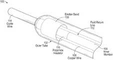
- FIG. 1depicts a cutaway perspective view of an example shock wave device for generating forward directed shock waves, in accordance with some embodiments.
- FIG. 2depicts a side sectional view of an example shock wave device for generating forward directed shock waves, in accordance with some embodiments.
- FIG. 3depicts a front sectional view of an example shock wave device for generating forward directed shock waves, in accordance with some embodiments.
- FIG. 4depicts an extended side sectional view of an example shock wave device for generating forward directed shock waves, in accordance with some embodiments.
- FIG. 5depicts a side view of an extended length of an example shock wave device, in accordance with some embodiments.
- FIG. 6is a flowchart representation of an exemplary method for generating forward directed shock waves.
- a shock wave deviceincludes an outer covering and an inner member forming a guide wire lumen.
- the outer covering and inner memberare connected at a distal end of the device.
- a first conductive wire and a second conductive wireextend along the length of the device within the volume between the outer covering and the inner member, and end proximate to the distal end of the device.
- a conductive emitter bandcircumscribes the ends of the first and second wires to form a first spark gap between the end of the first wire and the emitter band and a second spark gap between the end of the second wire and the emitter band.
- first and second shock wavescan be initiated from the first and second spark gaps.
- the voltagemay range from 100 to 10,000 volts for various pulse durations.
- This high voltagemay generate a gas bubble at the end surface of a wire and cause a plasma arc of electric current to traverse the bubble to the emitter band and create a rapidly expanding and collapsing bubble, which in turn creates a mechanical shock wave at the distal end of the device.
- the positioning of the emitter band in relation to the end of the wiremay result in the shock wave propagating out in a substantially forward direction toward the distal end of the device.
- the shock wavesmay be mechanically conducted through the conductive fluid and through the outer covering in the substantially forward direction to apply mechanical force or pressure to impinge on an occlusion or calcium facing the distal end of the device.
- the size, rate of expansion and collapse of the bubble(and therefore, the magnitude, duration, and distribution of the mechanical force) may vary based on the magnitude and duration of the voltage pulse, as well as the distance between the end of the wire and the emitter band.
- the emitter bandmay be made of materials that can withstand high voltage levels and intense mechanical forces (e.g., about 1000-2000 psi or 68-136 ATM in a few microseconds) that are generated during use.
- the emitter bandmay be made of stainless steel, tungsten, nickel, iron, steel, and the like.
- FIG. 1depicts a cutaway perspective view of an example shock wave device 100 for generating forward directed shock waves, in accordance with some embodiments.
- the device 100includes an outer covering 102 (e.g., a flexible outer tube) and an inner member 104 that forms a lumen for a guide wire 114 .
- the outer covering 102 and inner member 104are connected at a distal end of the device 100 , where the guide wire 114 may exit the device 100 .
- the interior volume of the device 100 between the outer covering 102 and inner member 104may be filled with a conductive fluid (e.g., saline and/or imaging contrast agent).
- Two insulated conductive wires 106(e.g., insulated copper wires) extend along the length of the device 100 within the interior volume.
- the second wire 106extends along an opposing side of the inner member 104 , as shown in FIGS. 2-3 .
- the two wires 106end near the distal end of the device 100 where the guide wire exits the lumen formed by the inner member 104 .
- the ends of the two wires 106include uninsulated portions (not shown). For example, the flat circular surfaces at the ends of the two wires may be uninsulated.
- An emitter band 108is positioned within the interior volume around the ends of the two wires 106 .
- the emitter band 108may be a conductive cylinder with a diameter larger than the total diameter of the inner member 104 and the two wires 106 combined, such that the emitter band circumscribes the ends of the two wires 106 without contacting the wires, as shown in FIG. 2 .
- An insulating sheath 110e.g., a polyimide insulator
- shock wavesare initiated at the distal end of the shock wave device 100 , which then propagate through the conductive fluid and the wall of the outer covering 102 to impinge on an occlusion or calcification.
- the device 100may include a second pair of wires (not shown) offset from wires 106 by 90 degrees.
- the second pair of wiresmay be positioned at 90 and 270 degrees.
- the second pair of wiresalso end near the distal end of the device 100 and include uninsulated portions at their ends.
- the emitter band 108circumscribes the ends of the second pair of wires as well.
- a separate high voltage pulsemay be applied across the second pair of wires to generate a second pair of arcs with the emitter band 108 .
- a second set of shock wavesare initiated from the distal end of the device 100 .
- the first pair of wires 106 and the second pair of wiresmay be activated alternately, which may improve the effectiveness of the device 100 by further spreading the shock waves.
- a fluid return line 112 with an inlet near the distal end of the device 100draws in the conductive fluid from the interior volume, while a fluid pump (not shown) pumps in additional conductive fluid via a fluid inlet (shown in FIG. 5 ) at a proximal end of the device 100 .
- the fluid return line 112 and fluid pumpcirculate the conductive fluid under pressure within the interior volume. Circulation of the conductive fluid may prevent bubbles created by the device 100 from becoming trapped within the distal tip of the device 100 due to the limited space within the tip. Furthermore, circulation of the conductive fluid may aid in cooling the device 100 and treatment site.
- FIG. 2depicts a side sectional view of an example shock wave device 100 for generating forward directed shock waves, in accordance with some embodiments.
- the two conductive wires 106e.g., polyimide-insulated copper wires
- Each of the wires 106include uninsulated wire ends 202 .
- the insulating sheath 110e.g., polyimide tubing
- the emitter band 108is positioned with a forward edge closer to the distal end of the device 100 than the wire ends 202 , such that two spark gaps are formed between each of the wire ends 202 and the emitter band 108 .
- the positioning of the wire ends 202 , insulating sheath 110 , and emitter band 108makes it so that when a high voltage pulse is applied across the two wires 106 , an electrical current will arc from the uninsulated end of one wire to the emitter band 108 , and then arc again from the emitter band 108 to the uninsulated end of the other wire.
- shock wavesare initiated at the distal end of the shock wave device 100 , which then propagate through the conductive fluid and the wall of the outer covering 102 to impinge on an occlusion or calcification.
- the positioning of the emitter band 108 closer to the distal end of the device than the wire ends 202helps to encourage the shock waves to propagate in a substantially forward direction (e.g., longitudinally out of the distal end of the device 100 ).
- Shock wavesmay be generated repeatedly, as may be desirable by the practitioner to treat a region of vasculature.
- FIG. 3depicts a front sectional view of an example shock wave device 100 for generating forward directed shock waves, in accordance with some embodiments.
- the emitter band 108circumscribes the two conductive wires 106 (e.g., insulated copper wires) and the fluid return line 112 .
- the fluid return line 112includes an inlet that draws in conductive fluid from the interior volume of the device to allow the conductive fluid to be circulated within the distal end of the device 100 .
- FIG. 4depicts an extended side sectional view of an example shock wave device 100 for generating forward directed shock waves, in accordance with some embodiments.
- the outer covering of the device 100includes an angioplasty balloon 402 .
- the balloon 402may be inflated by pumping additional fluid into the interior volume of the device.
- the balloon 402may be inflated before or after applying shock waves to a treatment region.
- the device 100is advanced further into a patient's vascular, and the balloon 402 is inflated in the region of the occlusion to further treat the region.
- the shock wave device 100may include secondary emitter bands 404 located in a medial location of the device 100 .
- the device 100 shown in FIG. 4includes two secondary emitter bands 404 , but various numbers of secondary bands 404 may be used.
- the device 100may include a single secondary emitter band 404 .
- the device 100may include five or more secondary emitter bands 404 .
- the secondary emitter bands 404may generate shock waves using a variety of techniques.
- the secondary emitter bands 404may generate shock waves using low-profile or coplanar electrodes, such as those described in U.S. Pat. No. 8,888,788 and U.S. application Ser. No.
- the shock wavesmay radiate in a substantially radial direction from the medial location of the secondary emitter bands 404 .
- the secondary emitter bands 404may initiate shock waves independently of the emitter band 108 at the distal end of the device 100 .
- the device 100is advanced further into a patient's vascular until the medial location of a secondary emitter band 404 is aligned with the region of the occlusion. Then additional shock waves may be initiated from the secondary emitter band 404 to further treat the region.
- additional conductive wiresmay be provided between the high voltage source and the second emitter bands 404 .
- forward directed shock waves from the emitter band 108may be utilized in various sequences and combinations to treat plaques or obstructions in vessels.
- the vesselsmay include blood vessels in a patient's vascular system or ureters in the patient's urinary system.
- FIG. 5depicts a side view of an extended length of an example shock wave device 100 , in accordance with some embodiments.
- the shock wave device 100may be in communication with a fluid source and fluid pump (not shown) that introduces conductive fluid into an interior volume of the device 100 via a fluid inlet 502 .
- the fluid pumpmay fill the interior volume with fluid to a certain pressure.
- the conductive fluidmay be circulated within the interior volume of the device 100 by drawing fluid into the fluid return line shown in FIGS. 1 and 3 , and then dispelling it through a waste outlet 504 .
- the waste outlet 504may include a pressure relief valve to maintain the fluid pressure within the interior volume of the device while the conductive fluid is circulated.
- Circulation of the conductive fluidmay prevent bubbles created by the device 100 from becoming trapped within the distal tip of the device 100 due to the limited space within the tip. Trapped bubbles may block subsequent shock waves from propagating from the device 100 , thus it is beneficial to prevent their build-up.
- the waste outlet 504may be connected to the fluid source so that the fluid pump recirculates the waste fluid.
- FIG. 6is a flowchart representation of an exemplary method for generating forward directed shock waves.
- a shock wave deviceis introduced into a vessel ( 602 ).
- the vesselmay include blood vessels in a patient's vascular system or ureters in the patient's urinary system.
- the shock wave devicemay be the device 100 described in reference to FIGS. 1-5 .
- the shock wave deviceis advanced within the vessel such that a distal end of the device faces a first treatment region ( 604 ).
- the first treatment regionmay include a chronic total occlusion (CTO), circumferential calcium, a kidney stone, or other obstructions or concretions.
- CTOchronic total occlusion
- a high voltage pulseis applied across first and second wires to initiate first and second shock waves from first and second spark gaps formed between the first and second wires and an emitter band ( 606 ). Due to the positioning of the first and second wires and the emitter band, the first and second shock waves propagate in a substantially forward direction out of the shock wave device to impinge on the occlusion or calcium in the first treatment area.
- the shock wave devicemay then be advanced further within the vessel such that an angioplasty balloon is aligned with the first treatment region or with a second treatment region ( 608 ). The angioplasty balloon may then be inflated in the first or second treatment regions ( 610 ).
- the shock wave devicemay be advanced further within the vessel such that a secondary emitter band at a medial location of the device is aligned with the first treatment region or with a second treatment region ( 612 ). Third shock waves may then be initiated from the secondary emitter band to apply additional shock wave treatment to the first or second treatment areas ( 614 ). Steps 604 - 614 may be carried out in various sequences or combinations, and repeated as necessary, when appropriate to treat the patient.
Landscapes
- Health & Medical Sciences (AREA)
- Life Sciences & Earth Sciences (AREA)
- Engineering & Computer Science (AREA)
- Heart & Thoracic Surgery (AREA)
- Surgery (AREA)
- Animal Behavior & Ethology (AREA)
- Veterinary Medicine (AREA)
- Public Health (AREA)
- Biomedical Technology (AREA)
- General Health & Medical Sciences (AREA)
- Vascular Medicine (AREA)
- Nuclear Medicine, Radiotherapy & Molecular Imaging (AREA)
- Molecular Biology (AREA)
- Medical Informatics (AREA)
- Orthopedic Medicine & Surgery (AREA)
- Mechanical Engineering (AREA)
- Anesthesiology (AREA)
- Hematology (AREA)
- Child & Adolescent Psychology (AREA)
- Biophysics (AREA)
- Pulmonology (AREA)
- Surgical Instruments (AREA)
Abstract
Description
Claims (17)
Priority Applications (5)
| Application Number | Priority Date | Filing Date | Title |
|---|---|---|---|
| US15/989,016US10966737B2 (en) | 2017-06-19 | 2018-05-24 | Device and method for generating forward directed shock waves |
| US17/185,276US11602363B2 (en) | 2017-06-19 | 2021-02-25 | Device and method for generating forward directed shock waves |
| US18/106,900US11950793B2 (en) | 2017-06-19 | 2023-02-07 | Device and method for generating forward directed shock waves |
| US18/582,579US12232754B2 (en) | 2017-06-19 | 2024-02-20 | Device and method for generating forward directed shock waves |
| US19/023,002US20250152191A1 (en) | 2017-06-19 | 2025-01-15 | Device and method for generating forward directed shock waves |
Applications Claiming Priority (2)
| Application Number | Priority Date | Filing Date | Title |
|---|---|---|---|
| US201762521994P | 2017-06-19 | 2017-06-19 | |
| US15/989,016US10966737B2 (en) | 2017-06-19 | 2018-05-24 | Device and method for generating forward directed shock waves |
Related Child Applications (1)
| Application Number | Title | Priority Date | Filing Date |
|---|---|---|---|
| US17/185,276ContinuationUS11602363B2 (en) | 2017-06-19 | 2021-02-25 | Device and method for generating forward directed shock waves |
Publications (2)
| Publication Number | Publication Date |
|---|---|
| US20180360482A1 US20180360482A1 (en) | 2018-12-20 |
| US10966737B2true US10966737B2 (en) | 2021-04-06 |
Family
ID=62599765
Family Applications (5)
| Application Number | Title | Priority Date | Filing Date |
|---|---|---|---|
| US15/989,016Active2038-10-23US10966737B2 (en) | 2017-06-19 | 2018-05-24 | Device and method for generating forward directed shock waves |
| US17/185,276Active2038-10-14US11602363B2 (en) | 2017-06-19 | 2021-02-25 | Device and method for generating forward directed shock waves |
| US18/106,900ActiveUS11950793B2 (en) | 2017-06-19 | 2023-02-07 | Device and method for generating forward directed shock waves |
| US18/582,579ActiveUS12232754B2 (en) | 2017-06-19 | 2024-02-20 | Device and method for generating forward directed shock waves |
| US19/023,002PendingUS20250152191A1 (en) | 2017-06-19 | 2025-01-15 | Device and method for generating forward directed shock waves |
Family Applications After (4)
| Application Number | Title | Priority Date | Filing Date |
|---|---|---|---|
| US17/185,276Active2038-10-14US11602363B2 (en) | 2017-06-19 | 2021-02-25 | Device and method for generating forward directed shock waves |
| US18/106,900ActiveUS11950793B2 (en) | 2017-06-19 | 2023-02-07 | Device and method for generating forward directed shock waves |
| US18/582,579ActiveUS12232754B2 (en) | 2017-06-19 | 2024-02-20 | Device and method for generating forward directed shock waves |
| US19/023,002PendingUS20250152191A1 (en) | 2017-06-19 | 2025-01-15 | Device and method for generating forward directed shock waves |
Country Status (6)
| Country | Link |
|---|---|
| US (5) | US10966737B2 (en) |
| EP (2) | EP3641672B1 (en) |
| JP (2) | JP7142035B2 (en) |
| CN (2) | CN116531055A (en) |
| ES (2) | ES2960728T3 (en) |
| WO (1) | WO2018236551A1 (en) |
Cited By (42)
| Publication number | Priority date | Publication date | Assignee | Title |
|---|---|---|---|---|
| US20200129231A1 (en)* | 2018-10-25 | 2020-04-30 | Medtronic Vascular, Inc. | Cavitation guidewire |
| US11484327B2 (en) | 2021-02-26 | 2022-11-01 | Fastwave Medical Inc. | Intravascular lithotripsy |
| US11517713B2 (en) | 2019-06-26 | 2022-12-06 | Boston Scientific Scimed, Inc. | Light guide protection structures for plasma system to disrupt vascular lesions |
| US11583339B2 (en) | 2019-10-31 | 2023-02-21 | Bolt Medical, Inc. | Asymmetrical balloon for intravascular lithotripsy device and method |
| US11602363B2 (en) | 2017-06-19 | 2023-03-14 | Shockwave Medical, Inc. | Device and method for generating forward directed shock waves |
| WO2023059967A1 (en) | 2021-10-05 | 2023-04-13 | Shockwave Medical, Inc. | Lesion crossing shock wave catheter |
| US11648057B2 (en) | 2021-05-10 | 2023-05-16 | Bolt Medical, Inc. | Optical analyzer assembly with safety shutdown system for intravascular lithotripsy device |
| US11660427B2 (en) | 2019-06-24 | 2023-05-30 | Boston Scientific Scimed, Inc. | Superheating system for inertial impulse generation to disrupt vascular lesions |
| US11672585B2 (en) | 2021-01-12 | 2023-06-13 | Bolt Medical, Inc. | Balloon assembly for valvuloplasty catheter system |
| US11672599B2 (en) | 2020-03-09 | 2023-06-13 | Bolt Medical, Inc. | Acoustic performance monitoring system and method within intravascular lithotripsy device |
| US11707323B2 (en) | 2020-04-03 | 2023-07-25 | Bolt Medical, Inc. | Electrical analyzer assembly for intravascular lithotripsy device |
| US11707289B2 (en) | 2018-10-25 | 2023-07-25 | Medtronic Vascular, Inc. | Cavitation catheter |
| US11717139B2 (en) | 2019-06-19 | 2023-08-08 | Bolt Medical, Inc. | Plasma creation via nonaqueous optical breakdown of laser pulse energy for breakup of vascular calcium |
| US11779363B2 (en) | 2021-10-19 | 2023-10-10 | Shockwave Medical, Inc. | Intravascular lithotripsy catheter with interfering shock waves |
| US11806075B2 (en) | 2021-06-07 | 2023-11-07 | Bolt Medical, Inc. | Active alignment system and method for laser optical coupling |
| US11819229B2 (en) | 2019-06-19 | 2023-11-21 | Boston Scientific Scimed, Inc. | Balloon surface photoacoustic pressure wave generation to disrupt vascular lesions |
| US11839391B2 (en) | 2021-12-14 | 2023-12-12 | Bolt Medical, Inc. | Optical emitter housing assembly for intravascular lithotripsy device |
| US11903642B2 (en) | 2020-03-18 | 2024-02-20 | Bolt Medical, Inc. | Optical analyzer assembly and method for intravascular lithotripsy device |
| US11911056B2 (en) | 2021-02-26 | 2024-02-27 | Fastwave Medical Inc. | Intravascular lithotripsy |
| US11918285B2 (en) | 2022-06-01 | 2024-03-05 | Fast Wave Medical Inc. | Intravascular lithotripsy |
| US11944331B2 (en) | 2021-02-26 | 2024-04-02 | Fastwave Medical Inc. | Intravascular lithotripsy |
| US12016610B2 (en) | 2020-12-11 | 2024-06-25 | Bolt Medical, Inc. | Catheter system for valvuloplasty procedure |
| US12035932B1 (en) | 2023-04-21 | 2024-07-16 | Shockwave Medical, Inc. | Intravascular lithotripsy catheter with slotted emitter bands |
| US12089861B2 (en) | 2021-08-05 | 2024-09-17 | Nextern Innovation, Llc | Intravascular lithotripsy system and device |
| US12102384B2 (en) | 2019-11-13 | 2024-10-01 | Bolt Medical, Inc. | Dynamic intravascular lithotripsy device with movable energy guide |
| DE112022005708T5 (en) | 2021-11-30 | 2024-11-14 | Shockwave Medical, Inc. | ELECTRODE DESIGN FOR DIRECTED LITHOTRIPSY CATHETER |
| US12178458B1 (en) | 2024-05-16 | 2024-12-31 | Shockwave Medical, Inc. | Guidewireless shock wave catheters |
| US12193738B2 (en) | 2022-06-01 | 2025-01-14 | Fastwave Medical Inc. | Intravascular lithotripsy |
| US12207870B2 (en) | 2020-06-15 | 2025-01-28 | Boston Scientific Scimed, Inc. | Spectroscopic tissue identification for balloon intravascular lithotripsy guidance |
| US12220141B2 (en) | 2023-06-29 | 2025-02-11 | Shockwave Medical, Inc. | Catheter system with independently controllable bubble and arc generation |
| US12232755B2 (en) | 2020-12-11 | 2025-02-25 | Shockwave Medical, Inc. | Lesion crossing shock wave catheter |
| US12256989B2 (en) | 2022-09-29 | 2025-03-25 | Calyxo, Inc. | Tool guiding device for kidney stone treatment apparatus |
| US12274497B2 (en) | 2019-12-18 | 2025-04-15 | Bolt Medical, Inc. | Multiplexer for laser-driven intravascular lithotripsy device |
| US12274460B2 (en) | 2019-09-24 | 2025-04-15 | Shockwave Medical, Inc. | Lesion crossing shock wave catheter |
| US12274485B2 (en) | 2021-01-12 | 2025-04-15 | Bolt Medical, Inc. | Balloon assembly for valvuloplasty catheter system |
| US12295654B2 (en) | 2020-06-03 | 2025-05-13 | Boston Scientific Scimed, Inc. | System and method for maintaining balloon integrity within intravascular lithotripsy device with plasma generator |
| US12329396B2 (en) | 2022-03-02 | 2025-06-17 | Calyxo, Inc. | Kidney stone treatment system |
| US12396742B1 (en) | 2024-02-08 | 2025-08-26 | IV-X Medical, LLC | Intravascular lithotripsy system |
| US12402946B2 (en) | 2019-06-19 | 2025-09-02 | Boston Scientific Scimed, Inc. | Breakdown of laser pulse energy for breakup of vascular calcium |
| US12402899B2 (en) | 2023-11-30 | 2025-09-02 | Shockwave Medical, Inc. | Systems, devices, and methods for generating shock waves in a forward direction |
| US12426904B2 (en) | 2023-11-17 | 2025-09-30 | Shockwave Medical, Inc. | Intravascular lithotripsy catheter with oscillating impactor |
| US12433620B2 (en) | 2024-02-23 | 2025-10-07 | Shockwave Medical, Inc. | Locus emitter shock wave catheter devices with increased longevity and higher sonic output |
Families Citing this family (28)
| Publication number | Priority date | Publication date | Assignee | Title |
|---|---|---|---|---|
| EP3648678A4 (en) | 2017-07-06 | 2021-03-24 | Raghuveer Basude | TISSUE GRIPPING DEVICES AND RELATED PROCEDURES |
| US10709462B2 (en) | 2017-11-17 | 2020-07-14 | Shockwave Medical, Inc. | Low profile electrodes for a shock wave catheter |
| US11103262B2 (en) | 2018-03-14 | 2021-08-31 | Boston Scientific Scimed, Inc. | Balloon-based intravascular ultrasound system for treatment of vascular lesions |
| EP3809988B1 (en) | 2018-06-21 | 2023-06-07 | Shockwave Medical, Inc. | System for treating occlusions in body lumens |
| WO2020086361A1 (en) | 2018-10-24 | 2020-04-30 | Boston Scientific Scimed, Inc. | Photoacoustic pressure wave generation for intravascular calcification disruption |
| CN111067591A (en)* | 2019-06-14 | 2020-04-28 | 谱创医疗科技(上海)有限公司 | Shock wave generation system for traversing a lesion site |
| EP4512350A3 (en)* | 2019-09-24 | 2025-05-07 | Shockwave Medical, Inc. | Low profile electrodes for a shock wave catheter |
| WO2021061523A1 (en) | 2019-09-24 | 2021-04-01 | Shockwave Medical, Inc. | System for treating thrombus in body lumens |
| US20210267685A1 (en)* | 2020-02-27 | 2021-09-02 | Bolt Medical, Inc. | Fluid recirculation system for intravascular lithotripsy device |
| CN111790046B (en)* | 2020-07-31 | 2024-09-27 | 深圳市赛禾医疗技术有限公司 | A pressure wave balloon catheter |
| US11992232B2 (en)* | 2020-10-27 | 2024-05-28 | Shockwave Medical, Inc. | System for treating thrombus in body lumens |
| US20220168003A1 (en)* | 2020-12-01 | 2022-06-02 | Olympus America Inc. | Dilation and stone retrieval catheter |
| MX2023006886A (en) | 2020-12-11 | 2023-07-18 | Shockwave Medical Inc | Lesion crossing shock wave catheter. |
| CN112869825A (en)* | 2021-01-06 | 2021-06-01 | 苏州中荟医疗科技有限公司 | Electrode device for generating seismic waves and using method |
| CN113288420B (en)* | 2021-05-24 | 2022-08-16 | 哈尔滨医科大学 | Sacculus system and vascular calcification treatment device |
| CN113367768B (en)* | 2021-06-11 | 2023-03-21 | 南京欣科医疗器械有限公司 | Shock wave sacculus pipe with integrated electric field generating mechanism |
| US11896248B2 (en) | 2021-08-05 | 2024-02-13 | Nextern Innovation, Llc | Systems, devices and methods for generating subsonic pressure waves in intravascular lithotripsy |
| US11957369B2 (en) | 2021-08-05 | 2024-04-16 | Nextern Innovation, Llc | Intravascular lithotripsy systems and methods |
| US11801066B2 (en) | 2021-08-05 | 2023-10-31 | Nextern Innovation, Llc | Systems, devices and methods for selection of arc location within a lithoplasty balloon spark gap |
| US11877761B2 (en) | 2021-08-05 | 2024-01-23 | Nextern Innovation, Llc | Systems, devices and methods for monitoring voltage and current and controlling voltage of voltage pulse generators |
| CN115192122A (en)* | 2022-07-13 | 2022-10-18 | 上海佳沐垚医疗科技有限公司 | Shockwave Balloon Catheter Device |
| US20240099773A1 (en)* | 2022-09-28 | 2024-03-28 | Acotec Technologies Limited | Lithotripsy balloon catheter |
| CN115778485B (en)* | 2022-12-02 | 2023-11-07 | 鑫易舟(上海)医疗器械有限公司 | Shock wave generating device, shock wave generating system and method |
| CN116173386B (en)* | 2023-03-21 | 2024-08-23 | 深圳市赛禾医疗技术有限公司 | Shock wave balloon catheter |
| WO2024220780A1 (en)* | 2023-04-21 | 2024-10-24 | Cardiovascular Systems, Inc. | Intravascular lithotripsy devices and systems including sizing measurement |
| US20250160862A1 (en)* | 2023-11-16 | 2025-05-22 | Shockwave Medical, Inc. | Low-profile shock wave catheters |
| WO2025106089A1 (en)* | 2023-11-17 | 2025-05-22 | Shockwave Medical, Inc. | Intravascular lithotripsy catheter with oscillating impactor |
| US20250176987A1 (en)* | 2023-11-30 | 2025-06-05 | Shockwave Medical, Inc. | Systems, devices, and methods for treatment of target material in a body lumen with shock waves |
Citations (163)
| Publication number | Priority date | Publication date | Assignee | Title |
|---|---|---|---|---|
| US3413976A (en) | 1963-07-29 | 1968-12-03 | G Elektrotekhnichesky Zd Vef | Arrangement for removal of concretions from urinary tract |
| US3785382A (en) | 1971-05-14 | 1974-01-15 | Wolf Gmbh Richard | Device for destroying stones in the bladder, in the ureter, in the kidneys and the like |
| US3902499A (en) | 1974-01-02 | 1975-09-02 | Hoffman Saul | Stone disintegrator |
| US4027674A (en) | 1975-06-06 | 1977-06-07 | Tessler Arthur N | Method and device for removing concretions within human ducts |
| US4030505A (en) | 1975-11-28 | 1977-06-21 | Calculus Instruments Ltd. | Method and device for disintegrating stones in human ducts |
| DE3038445A1 (en) | 1980-10-11 | 1982-05-27 | Dornier Gmbh, 7990 Friedrichshafen | Pressure wave generator for diagnosis and therapy - has spark gap in inflatable balloon at end of catheter |
| JPS6029828B2 (en) | 1978-11-20 | 1985-07-12 | 株式会社ウオルブロ−・フア−イ−スト | Rotary throttle valve type carburetor |
| JPS60191353U (en) | 1984-05-25 | 1985-12-18 | 日立工機株式会社 | Ink ribbon feeding control device |
| US4662126A (en) | 1986-05-23 | 1987-05-05 | Fike Corporation | Vibration resistant explosion control vent |
| US4671254A (en) | 1985-03-01 | 1987-06-09 | Memorial Hospital For Cancer And Allied Diseases | Non-surgical method for suppression of tumor growth |
| JPS6299210U (en) | 1985-12-12 | 1987-06-24 | ||
| US4685458A (en) | 1984-03-01 | 1987-08-11 | Vaser, Inc. | Angioplasty catheter and method for use thereof |
| JPS62275446A (en) | 1986-05-21 | 1987-11-30 | オリンパス光学工業株式会社 | Discharge stone crushing apparatus |
| US4809682A (en) | 1985-12-12 | 1989-03-07 | Dornier Medizintechnik Gmbh | Underwater electrodes for contactless lithotripsy |
| US4813934A (en) | 1987-08-07 | 1989-03-21 | Target Therapeutics | Valved catheter device and method |
| US4878495A (en) | 1987-05-15 | 1989-11-07 | Joseph Grayzel | Valvuloplasty device with satellite expansion means |
| US4900303A (en) | 1978-03-10 | 1990-02-13 | Lemelson Jerome H | Dispensing catheter and method |
| US4994032A (en) | 1987-12-01 | 1991-02-19 | Terumo Kabushiki Kaisha | Balloon catheter |
| JPH0363059A (en) | 1989-04-26 | 1991-03-19 | Advanced Cardiovascular Syst Inc | Blood flow measurement using self-irrigation catheter for blood vessel formation and its device |
| US5009232A (en) | 1988-08-17 | 1991-04-23 | Siemens Aktiengesellschaft | Extracorporeal lithotripsy apparatus using high intensity shock waves for calculus disintegration and low intensity shock waves for imaging |
| EP0442199A2 (en) | 1990-02-12 | 1991-08-21 | BS & B SAFETY SYSTEMS, INC. | Low pressure non-fragmenting rupture disks |
| US5057103A (en) | 1990-05-01 | 1991-10-15 | Davis Emsley A | Compressive intramedullary nail |
| US5057106A (en) | 1986-02-27 | 1991-10-15 | Kasevich Associates, Inc. | Microwave balloon angioplasty |
| US5061240A (en) | 1990-04-02 | 1991-10-29 | George Cherian | Balloon tip catheter for venous valve ablation |
| US5078717A (en) | 1989-04-13 | 1992-01-07 | Everest Medical Corporation | Ablation catheter with selectively deployable electrodes |
| WO1992003975A1 (en) | 1990-09-04 | 1992-03-19 | Cannon Robert L Iii | Catheter and apparatus for the treatment, inter alia, of pulmonary embolisms |
| US5103804A (en) | 1990-07-03 | 1992-04-14 | Boston Scientific Corporation | Expandable tip hemostatic probes and the like |
| US5152767A (en) | 1990-11-23 | 1992-10-06 | Northgate Technologies, Inc. | Invasive lithotripter with focused shockwave |
| US5152768A (en) | 1991-02-26 | 1992-10-06 | Bhatta Krishna M | Electrohydraulic lithotripsy |
| US5154722A (en) | 1988-05-05 | 1992-10-13 | Circon Corporation | Electrohydraulic probe having a controlled discharge path |
| US5176675A (en) | 1985-04-24 | 1993-01-05 | The General Hospital Corporation | Use of lasers to break down objects for removal from within the body |
| US5195508A (en) | 1990-05-18 | 1993-03-23 | Dornier Medizintechnik Gmbh | Spark gap unit for lithotripsy |
| US5231976A (en) | 1989-03-21 | 1993-08-03 | Hans Wiksell | Apparatus for triggering shock waves |
| US5245988A (en) | 1989-11-15 | 1993-09-21 | Dormer Gmbh | Preparing a circuit for the production of shockwaves |
| US5246447A (en) | 1989-02-22 | 1993-09-21 | Physical Sciences, Inc. | Impact lithotripsy |
| US5254121A (en) | 1992-05-22 | 1993-10-19 | Meditron Devices, Inc. | Method and device for removing concretions within human ducts |
| EP0571306A1 (en) | 1992-05-22 | 1993-11-24 | LASER MEDICAL TECHNOLOGY, Inc. | Apparatus and method for removal of deposits from the walls of body passages |
| US5281231A (en) | 1989-02-22 | 1994-01-25 | Physical Sciences, Inc. | Impact lithotrypsy |
| US5295958A (en) | 1991-04-04 | 1994-03-22 | Shturman Cardiology Systems, Inc. | Method and apparatus for in vivo heart valve decalcification |
| JPH06125915A (en) | 1992-10-21 | 1994-05-10 | Inter Noba Kk | Catheter type medical instrument |
| US5321715A (en) | 1993-05-04 | 1994-06-14 | Coherent, Inc. | Laser pulse format for penetrating an absorbing fluid |
| US5324255A (en) | 1991-01-11 | 1994-06-28 | Baxter International Inc. | Angioplasty and ablative devices having onboard ultrasound components and devices and methods for utilizing ultrasound to treat or prevent vasopasm |
| US5336234A (en) | 1992-04-17 | 1994-08-09 | Interventional Technologies, Inc. | Method and apparatus for dilatation of a stenotic vessel |
| US5362309A (en) | 1992-09-14 | 1994-11-08 | Coraje, Inc. | Apparatus and method for enhanced intravascular phonophoresis including dissolution of intravascular blockage and concomitant inhibition of restenosis |
| EP0623360A1 (en) | 1993-02-05 | 1994-11-09 | The Joe W. And Dorothy Dorsett Brown Foundation | Ultrasonic angioplasty balloon catheter |
| US5364393A (en) | 1990-07-02 | 1994-11-15 | Heart Technology, Inc. | Tissue dissipative recanalization catheter |
| US5368591A (en) | 1988-10-28 | 1994-11-29 | Prutech Research And Development Partnership Ii | Heated balloon catheters |
| US5395335A (en) | 1991-05-24 | 1995-03-07 | Jang; G. David | Universal mode vascular catheter system |
| US5417208A (en) | 1993-10-12 | 1995-05-23 | Arrow International Investment Corp. | Electrode-carrying catheter and method of making same |
| US5425735A (en) | 1989-02-22 | 1995-06-20 | Psi Medical Products, Inc. | Shielded tip catheter for lithotripsy |
| US5431173A (en)* | 1991-05-29 | 1995-07-11 | Origin Medsystems, Inc. | Method and apparatus for body structure manipulation and dissection |
| US5472406A (en) | 1991-10-03 | 1995-12-05 | The General Hospital Corporation | Apparatus and method for vasodilation |
| WO1996024297A1 (en) | 1995-02-09 | 1996-08-15 | C.R. Bard, Inc. | Angioplasty catheter used to expand and/or open up blood vessels |
| US5582578A (en) | 1995-08-01 | 1996-12-10 | Duke University | Method for the comminution of concretions |
| US5603731A (en) | 1994-11-21 | 1997-02-18 | Whitney; Douglass G. | Method and apparatus for thwarting thrombosis |
| JPH1099444A (en) | 1996-09-27 | 1998-04-21 | Advanced Cardeovascular Syst Inc | Vibratory stent to open calcified lesion part |
| JPH10314177A (en) | 1997-04-26 | 1998-12-02 | Convergenza Ag | Device with treating catheter |
| US5846218A (en) | 1996-09-05 | 1998-12-08 | Pharmasonics, Inc. | Balloon catheters having ultrasonically driven interface surfaces and methods for their use |
| WO1999002096A1 (en) | 1997-07-08 | 1999-01-21 | The Regents Of The University Of California | Circumferential ablation device assembly and method |
| US5931805A (en) | 1997-06-02 | 1999-08-03 | Pharmasonics, Inc. | Catheters comprising bending transducers and methods for their use |
| US6080119A (en) | 1997-05-02 | 2000-06-27 | Hmt Holding Ag | Process and device for generating shock waves for medical uses |
| US6113560A (en) | 1994-09-21 | 2000-09-05 | Hmt High Medical Techologies | Method and device for generating shock waves for medical therapy, particularly for electro-hydraulic lithotripsy |
| US6186963B1 (en) | 1997-05-02 | 2001-02-13 | Hmt Holding Ag | Device for generating acoustic shock waves, especially for medical applications |
| US6210408B1 (en) | 1999-02-24 | 2001-04-03 | Scimed Life Systems, Inc. | Guide wire system for RF recanalization of vascular blockages |
| US6217531B1 (en) | 1997-10-24 | 2001-04-17 | Its Medical Technologies & Services Gmbh | Adjustable electrode and related method |
| US6267747B1 (en) | 1998-05-11 | 2001-07-31 | Cardeon Corporation | Aortic catheter with porous aortic root balloon and methods for inducing cardioplegic arrest |
| US6277138B1 (en) | 1999-08-17 | 2001-08-21 | Scion Cardio-Vascular, Inc. | Filter for embolic material mounted on expandable frame |
| US20010044596A1 (en) | 2000-05-10 | 2001-11-22 | Ali Jaafar | Apparatus and method for treatment of vascular restenosis by electroporation |
| US6352535B1 (en) | 1997-09-25 | 2002-03-05 | Nanoptics, Inc. | Method and a device for electro microsurgery in a physiological liquid environment |
| US6367203B1 (en) | 2000-09-11 | 2002-04-09 | Oklahoma Safety Equipment Co., Inc. | Rupture panel |
| US6371971B1 (en) | 1999-11-15 | 2002-04-16 | Scimed Life Systems, Inc. | Guidewire filter and methods of use |
| US20020045890A1 (en) | 1996-04-24 | 2002-04-18 | The Regents Of The University O F California | Opto-acoustic thrombolysis |
| US6398792B1 (en) | 1999-06-21 | 2002-06-04 | O'connor Lawrence | Angioplasty catheter with transducer using balloon for focusing of ultrasonic energy and method for use |
| US6406486B1 (en) | 1991-10-03 | 2002-06-18 | The General Hospital Corporation | Apparatus and method for vasodilation |
| JP2002538932A (en) | 1999-03-19 | 2002-11-19 | アトリオニクス・インコーポレーテツド | Perimeter linear reformer assembly for providing a modifying perimeter linear band along an inflatable member and method of use and manufacture thereof |
| US20030004434A1 (en) | 2001-06-29 | 2003-01-02 | Francesco Greco | Catheter system having disposable balloon |
| US6514203B2 (en) | 2001-02-12 | 2003-02-04 | Sonata Technologies Ltd. | Method for ultrasonic coronary thrombolysis |
| US6524251B2 (en) | 1999-10-05 | 2003-02-25 | Omnisonics Medical Technologies, Inc. | Ultrasonic device for tissue ablation and sheath for use therewith |
| US20030060813A1 (en)* | 2001-09-22 | 2003-03-27 | Loeb Marvin P. | Devices and methods for safely shrinking tissues surrounding a duct, hollow organ or body cavity |
| US6589253B1 (en) | 1999-12-30 | 2003-07-08 | Advanced Cardiovascular Systems, Inc. | Ultrasonic angioplasty transmission wire |
| US6607003B1 (en) | 2001-04-23 | 2003-08-19 | Oklahoma Safety Equipment Co, | Gasket-lined rupture panel |
| US20030176873A1 (en) | 2002-03-12 | 2003-09-18 | Lithotech Medical Ltd. | Method for intracorporeal lithotripsy fragmentation and apparatus for its implementation |
| US6638246B1 (en) | 2000-11-28 | 2003-10-28 | Scimed Life Systems, Inc. | Medical device for delivery of a biologically active material to a lumen |
| US6652547B2 (en) | 1999-10-05 | 2003-11-25 | Omnisonics Medical Technologies, Inc. | Apparatus and method of removing occlusions using ultrasonic medical device operating in a transverse mode |
| US20030229370A1 (en) | 2002-06-11 | 2003-12-11 | Miller Paul James | Catheter balloon with ultrasonic microscalpel blades |
| JP2004081374A (en) | 2002-08-26 | 2004-03-18 | Dairin Kk | Instrument for removing sediment in tubular organ |
| US6736784B1 (en) | 1999-06-24 | 2004-05-18 | Ferton Holding S.A. | Medical instrument for treating biological tissue and method for transmitting pressure waves |
| US20040097963A1 (en) | 2002-11-19 | 2004-05-20 | Seddon J. Michael | Method and apparatus for disintegrating urinary tract stones |
| US20040097996A1 (en) | 1999-10-05 | 2004-05-20 | Omnisonics Medical Technologies, Inc. | Apparatus and method of removing occlusions using an ultrasonic medical device operating in a transverse mode |
| US6740081B2 (en) | 2002-01-25 | 2004-05-25 | Applied Medical Resources Corporation | Electrosurgery with improved control apparatus and method |
| US6755821B1 (en) | 1998-12-08 | 2004-06-29 | Cardiocavitational Systems, Inc. | System and method for stimulation and/or enhancement of myocardial angiogenesis |
| WO2004069072A2 (en) | 2003-02-03 | 2004-08-19 | Cardiofocus, Inc. | Coaxial catheter instruments for ablation with radiant energy |
| US20040162508A1 (en) | 2003-02-19 | 2004-08-19 | Walter Uebelacker | Shock wave therapy method and device |
| US20040254570A1 (en) | 2003-06-13 | 2004-12-16 | Andreas Hadjicostis | Endoscopic medical treatment involving acoustic ablation |
| JP2004357792A (en) | 2003-06-02 | 2004-12-24 | Keio Gijuku | Apparatus for preventing and treating vascular restenosis by sound pressure wave induced by high intensity pulsed light irradiation |
| US20050015953A1 (en) | 2003-07-21 | 2005-01-27 | Yaron Keidar | Method for making a spiral array ultrasound transducer |
| US20050021013A1 (en) | 1997-10-21 | 2005-01-27 | Endo Vasix, Inc. | Photoacoustic removal of occlusions from blood vessels |
| US20050059965A1 (en) | 2003-09-15 | 2005-03-17 | Scimed Life Systems, Inc. | Catheter balloons |
| US20050075662A1 (en) | 2003-07-18 | 2005-04-07 | Wesley Pedersen | Valvuloplasty catheter |
| JP2005095410A (en) | 2003-09-25 | 2005-04-14 | Keisei Ika Kogyo Kk | Catheter for thrombus removal |
| US20050090888A1 (en) | 2003-10-28 | 2005-04-28 | Hines Richard A. | Pleated stent assembly |
| US20050113722A1 (en) | 2003-03-14 | 2005-05-26 | Sws Shock Wave Systems Ag | Apparatus and process for optimized electro-hydraulic pressure pulse generation |
| US20050113822A1 (en) | 2002-07-23 | 2005-05-26 | Fuimaono Kristine B. | Ablation catheter having stabilizing array |
| US20050171527A1 (en) | 2003-12-31 | 2005-08-04 | Sumita Bhola | Circumferential ablation device assembly with an expandable member |
| US20050228372A1 (en) | 2000-08-01 | 2005-10-13 | Sciogen, Inc. | Voltage threshold ablation apparatus |
| WO2005099594A1 (en) | 2004-04-08 | 2005-10-27 | Boston Scientific Limited | Cutting balloon catheter and method for blade mounting |
| US20050245866A1 (en) | 1996-05-20 | 2005-11-03 | Medtronic Vascular, Inc. | Exchange method for emboli containment |
| US20050251131A1 (en) | 1997-05-09 | 2005-11-10 | Lesh Michael D | Circumferential ablation device assembly |
| US20060004286A1 (en) | 2004-04-21 | 2006-01-05 | Acclarent, Inc. | Methods and devices for performing procedures within the ear, nose, throat and paranasal sinuses |
| WO2006006169A2 (en) | 2004-07-14 | 2006-01-19 | By-Pass, Inc. | Material delivery system |
| US6989009B2 (en) | 2002-04-19 | 2006-01-24 | Scimed Life Systems, Inc. | Cryo balloon |
| US20060074484A1 (en) | 2004-10-02 | 2006-04-06 | Huber Christoph H | Methods and devices for repair or replacement of heart valves or adjacent tissue without the need for full cardiopulmonary support |
| US20060184076A1 (en) | 2004-12-01 | 2006-08-17 | Gill Robert P | Ultrasonic device and method for treating stones within the body |
| WO2006127158A2 (en) | 2005-05-23 | 2006-11-30 | Qi Yu | An intravascular ultrasound catheter device and method for ablating atheroma |
| US20070016112A1 (en) | 2005-06-09 | 2007-01-18 | Reiner Schultheiss | Shock Wave Treatment Device and Method of Use |
| US20070088380A1 (en) | 2005-10-14 | 2007-04-19 | Endocross Ltd. | Balloon catheter system for treating vascular occlusions |
| WO2007088546A2 (en) | 2006-02-02 | 2007-08-09 | Releaf Medical Ltd. | Shock-wave generating device, such as for the treatment of calcific aortic stenosis |
| CN101043914A (en) | 2004-07-14 | 2007-09-26 | 旁路公司 | Material delivery system |
| US20070239082A1 (en) | 2006-01-27 | 2007-10-11 | General Patent, Llc | Shock Wave Treatment Device |
| US20070239253A1 (en) | 2006-04-06 | 2007-10-11 | Jagger Karl A | Oscillation assisted drug elution apparatus and method |
| US20070244423A1 (en) | 2002-05-29 | 2007-10-18 | Jona Zumeris | Acoustic add-on device for biofilm prevention in urinary catheter |
| US20070255270A1 (en) | 2006-04-27 | 2007-11-01 | Medtronic Vascular, Inc. | Intraluminal guidance system using bioelectric impedance |
| US20070282301A1 (en) | 2004-02-26 | 2007-12-06 | Segalescu Victor A | Dilatation Balloon Catheter Including External Means For Endoluminal Therapy And For Drug Activation |
| US20070299481A1 (en) | 2006-06-21 | 2007-12-27 | Intrapace, Inc. | Endoscopic device delivery system |
| WO2007149905A2 (en) | 2006-06-20 | 2007-12-27 | Aortx, Inc. | Prosthetic valve implant site preparation techniques |
| US20080097251A1 (en) | 2006-06-15 | 2008-04-24 | Eilaz Babaev | Method and apparatus for treating vascular obstructions |
| US20080188913A1 (en) | 2006-10-18 | 2008-08-07 | Minnow Medical, Inc. | Inducing desirable temperature effects on body tissue |
| US20090041833A1 (en) | 2005-04-18 | 2009-02-12 | Bracco Research S.A. | Composition comprising gas-filled microcapsules for ultrasound mediated delivery |
| US7505812B1 (en) | 1993-05-10 | 2009-03-17 | Arthrocare Corporation | Electrosurgical system for treating restenosis of body lumens |
| US20090247945A1 (en) | 2006-10-13 | 2009-10-01 | Endocross | Balloons and balloon catheter systems for treating vascular occlusions |
| WO2009121017A1 (en) | 2008-03-27 | 2009-10-01 | The Regents Of The University Of California | Balloon catheter for reducing restenosis via irreversible electroporation |
| WO2009126544A1 (en) | 2008-04-08 | 2009-10-15 | Arizona Board Of Regents, A Body Corporate Of The State Of Arizona Acting For And On Behalf Of Arizona State University | Assemblies and methods for reducing warp and bow of a flexible substrate during semiconductor processing |
| US20090312768A1 (en) | 2008-06-13 | 2009-12-17 | Aspen Medtech, Inc. | Shockwave balloon catheter system |
| US20100016862A1 (en) | 2008-07-16 | 2010-01-21 | Daniel Hawkins | Method of providing embolic protection and shockwave angioplasty therapy to a vessel |
| WO2010014515A2 (en) | 2008-07-27 | 2010-02-04 | Klein, David | Fracturing calcifications in heart valves |
| US20100036294A1 (en) | 2008-05-07 | 2010-02-11 | Robert Mantell | Radially-Firing Electrohydraulic Lithotripsy Probe |
| US20100094209A1 (en) | 2008-10-10 | 2010-04-15 | Intervalve, Inc. | Valvuloplasty Catheter And Methods |
| US20100114065A1 (en)* | 2008-11-04 | 2010-05-06 | Daniel Hawkins | Drug delivery shockwave balloon catheter system |
| US20100114020A1 (en) | 2008-11-05 | 2010-05-06 | Daniel Hawkins | Shockwave valvuloplasty catheter system |
| US20100121322A1 (en) | 2002-09-24 | 2010-05-13 | Endoscopic Technologies, Inc. (Estech) | Electrophysiology electrode having multiple power connections and electrophysiology devices including the same |
| US20100274189A1 (en)* | 2009-04-22 | 2010-10-28 | Pressure Products Medical Supplies Inc. | Balloon catheter and method of manufacture of the same |
| EP2253884A1 (en) | 2008-03-14 | 2010-11-24 | Yantai Longyuan Power Technology Co. Ltd. | A method of reducing nitrogen oxides of a pulverized coal boiler using inner combustion type burners |
| US7873404B1 (en) | 2008-05-29 | 2011-01-18 | Seth Caplan | Method for performing angioplasty and angiography with a single catheter |
| US20110034832A1 (en) | 2009-07-08 | 2011-02-10 | Iulian Cioanta | Usage of Extracorporeal and Intracorporeal Pressure Shock Waves in Medicine |
| CN102057422A (en) | 2008-04-14 | 2011-05-11 | 阿夫纳·斯佩科特 | Automatic adjustable voltage for pressure stabilization of shock wave medical therapy equipment |
| US20110208185A1 (en) | 2010-02-24 | 2011-08-25 | Valery Diamant | Method and system for assisting a wire guide to cross occluded ducts |
| WO2011143468A2 (en) | 2010-05-12 | 2011-11-17 | Shifamed, Llc | Low profile electrode assembly |
| WO2012025833A2 (en) | 2010-08-27 | 2012-03-01 | Socpra- Sciences Et Génie, S.E.C. | Mechanical wave generator and method thereof |
| US20120095461A1 (en) | 2010-04-09 | 2012-04-19 | Minnow Medical, Inc. | Power generating and control apparatus for the treatment of tissue |
| US20120221013A1 (en) | 2008-06-13 | 2012-08-30 | Daniel Hawkins | Non-cavitation shockwave balloon catheter system |
| CN102765785A (en) | 2012-07-16 | 2012-11-07 | 广州埔玛电气有限公司 | Device and method for sterilizing and disinfecting wastewater by pulsed liquid-phase discharge plasma |
| US20130030431A1 (en) | 2008-06-13 | 2013-01-31 | Adams John M | Shock wave balloon catheter system with off center shock wave generator |
| US8574247B2 (en) | 2011-11-08 | 2013-11-05 | Shockwave Medical, Inc. | Shock wave valvuloplasty device with moveable shock wave generator |
| US20140005576A1 (en) | 2012-06-27 | 2014-01-02 | Shockwave Medical, Inc. | Shock wave balloon catheter with multiple shock wave sources |
| US20140039513A1 (en) | 2012-08-06 | 2014-02-06 | Shockwave Medical, Inc. | Low profile electrodes for an angioplasty shock wave catheter |
| US20140052145A1 (en) | 2012-08-17 | 2014-02-20 | Shockwave Medical, Inc. | Shock wave catheter system with arc preconditioning |
| US20140074111A1 (en) | 2012-09-13 | 2014-03-13 | Shockwave Medical, Inc. | Shockwave catheter system with energy control |
| CN203564304U (en) | 2013-07-08 | 2014-04-30 | 刘京山 | Shock-wave guide tube of in-vivo electro-hydraulic lithotripsy electrode |
| US20140288570A1 (en) | 2012-09-13 | 2014-09-25 | Shockwave Medical, Inc. | Shockwave catheter system with energy control |
| US20150320432A1 (en) | 2014-05-08 | 2015-11-12 | Shockwave Medical, Inc. | Shock wave guide wire |
| US9198825B2 (en) | 2012-06-22 | 2015-12-01 | Sanuwave, Inc. | Increase electrode life in devices used for extracorporeal shockwave therapy (ESWT) |
| WO2016109739A1 (en) | 2014-12-30 | 2016-07-07 | The Spectranetics Corporation | Electrically-induced pressure wave emitting catheter sheath |
| US20170135709A1 (en) | 2015-11-18 | 2017-05-18 | Shockwave Medical, Inc. | Shock wave electrodes |
Family Cites Families (101)
| Publication number | Priority date | Publication date | Assignee | Title |
|---|---|---|---|---|
| US2916647A (en) | 1959-03-18 | 1959-12-08 | Roscoe H George | Spark gap impulse generator |
| BE654594A (en) | 1963-10-28 | 1965-04-20 | ||
| US3412288A (en) | 1965-01-25 | 1968-11-19 | Gen Motors Corp | Arc suppression circuit for inductive loads |
| US3583766A (en) | 1969-05-22 | 1971-06-08 | Louis R Padberg Jr | Apparatus for facilitating the extraction of minerals from the ocean floor |
| CH574734A5 (en) | 1973-10-12 | 1976-04-30 | Dornier System Gmbh | |
| DE2635635C3 (en)* | 1976-08-07 | 1979-05-31 | Dornier System Gmbh, 7990 Friedrichshafen | Spark gap for generating shock waves for the contact-free destruction of calculus in the bodies of living beings |
| US4445509A (en) | 1982-02-04 | 1984-05-01 | Auth David C | Method and apparatus for removal of enclosed abnormal deposits |
| JPS61135648A (en)* | 1984-12-05 | 1986-06-23 | オリンパス光学工業株式会社 | Discharge stone crushing probe |
| EP0196353A3 (en) | 1985-04-04 | 1987-02-04 | DORNIER SYSTEM GmbH | Device for the avoidance or reduction of pain in extracorporal lithotripsy |
| CA1293663C (en) | 1986-01-06 | 1991-12-31 | David Christopher Auth | Transluminal microdissection device |
| US4741405A (en) | 1987-01-06 | 1988-05-03 | Tetra Corporation | Focused shock spark discharge drill using multiple electrodes |
| US4890603A (en) | 1987-11-09 | 1990-01-02 | Filler William S | Extracorporeal shock wave lithotripsy employing non-focused, spherical-sector shock waves |
| US4909252A (en) | 1988-05-26 | 1990-03-20 | The Regents Of The Univ. Of California | Perfusion balloon catheter |
| AU4945490A (en) | 1989-01-06 | 1990-08-01 | Angioplasty Systems Inc. | Electrosurgical catheter for resolving atherosclerotic plaque |
| US6146358A (en) | 1989-03-14 | 2000-11-14 | Cordis Corporation | Method and apparatus for delivery of therapeutic agent |
| US5709676A (en) | 1990-02-14 | 1998-01-20 | Alt; Eckhard | Synergistic treatment of stenosed blood vessels using shock waves and dissolving medication |
| US6524274B1 (en) | 1990-12-28 | 2003-02-25 | Scimed Life Systems, Inc. | Triggered release hydrogel drug delivery system |
| US5102402A (en) | 1991-01-04 | 1992-04-07 | Medtronic, Inc. | Releasable coatings on balloon catheters |
| US5893840A (en) | 1991-01-04 | 1999-04-13 | Medtronic, Inc. | Releasable microcapsules on balloon catheters |
| US5116227A (en) | 1991-03-01 | 1992-05-26 | Endo Technic Corporation | Process for cleaning and enlarging passages |
| US5304134A (en) | 1992-01-17 | 1994-04-19 | Danforth Biomedical, Inc. | Lubricious yet bondable catheter channel sleeve for over-the-wire catheters |
| CA2104414A1 (en) | 1993-08-19 | 1995-02-20 | Krishna M. Bhatta | Electrohydraulic lithotripsy |
| IL109669A (en) | 1994-05-17 | 1997-09-30 | Hadasit Med Res Service | System and method for coronary angioplasty |
| US5584843A (en) | 1994-12-20 | 1996-12-17 | Boston Scientific Corporation | Shaped wire multi-burr rotational ablation device |
| US6090104A (en) | 1995-06-07 | 2000-07-18 | Cordis Webster, Inc. | Catheter with a spirally wound flat ribbon electrode |
| CN1204242A (en) | 1995-10-13 | 1999-01-06 | 血管转换公司 | Methods and devices for bypassing and/or other transvascular procedures for arterial blockages |
| EP1013142A4 (en) | 1996-08-05 | 2002-06-05 | Tetra Corp | Electrohydraulic pressure wave projectors |
| US6024718A (en) | 1996-09-04 | 2000-02-15 | The Regents Of The University Of California | Intraluminal directed ultrasound delivery device |
| WO1999000060A1 (en) | 1997-06-26 | 1999-01-07 | Advanced Coronary Intervention | Electrosurgical catheter for resolving obstructions by radio frequency ablation |
| US6132444A (en) | 1997-08-14 | 2000-10-17 | Shturman Cardiology Systems, Inc. | Eccentric drive shaft for atherectomy device and method for manufacture |
| US6494890B1 (en) | 1997-08-14 | 2002-12-17 | Shturman Cardiology Systems, Inc. | Eccentric rotational atherectomy device |
| US6056722A (en) | 1997-09-18 | 2000-05-02 | Iowa-India Investments Company Limited Of Douglas | Delivery mechanism for balloons, drugs, stents and other physical/mechanical agents and methods of use |
| US6206283B1 (en) | 1998-12-23 | 2001-03-27 | At&T Corp. | Method and apparatus for transferring money via a telephone call |
| US6440124B1 (en) | 1998-07-22 | 2002-08-27 | Endovasix, Inc. | Flexible flow apparatus and method for the disruption of occlusions |
| US20040249401A1 (en) | 1999-10-05 | 2004-12-09 | Omnisonics Medical Technologies, Inc. | Apparatus and method for an ultrasonic medical device with a non-compliant balloon |
| US6364894B1 (en) | 2000-06-12 | 2002-04-02 | Cordis Corporation | Method of making an angioplasty balloon catheter |
| US6413256B1 (en) | 2000-08-01 | 2002-07-02 | Csaba Truckai | Voltage threshold ablation method and apparatus |
| US20020082553A1 (en) | 2000-12-22 | 2002-06-27 | Advanced Cardiovascular Systems, Inc. | Balloon designs for angioplasty |
| DE10100974B4 (en) | 2001-01-11 | 2004-07-08 | Hmt High Medical Technologies Ag | Device for generating shock waves |
| US7837676B2 (en) | 2003-02-20 | 2010-11-23 | Recor Medical, Inc. | Cardiac ablation devices |
| KR101193709B1 (en) | 2004-04-19 | 2012-10-23 | 프로리듬, 인크. | Ablation devices with sensor structures |
| US7959608B2 (en) | 2004-04-27 | 2011-06-14 | The Spectranetics Corporation | Thrombectomy and soft debris removal device |
| US7389148B1 (en) | 2004-05-05 | 2008-06-17 | Pacesetter, Inc. | Electrode design for defibrillation and/or sensing capabilities |
| US8750983B2 (en) | 2004-09-20 | 2014-06-10 | P Tech, Llc | Therapeutic system |
| US20060069424A1 (en) | 2004-09-27 | 2006-03-30 | Xtent, Inc. | Self-constrained segmented stents and methods for their deployment |
| US7309324B2 (en) | 2004-10-15 | 2007-12-18 | Futuremed Interventional, Inc. | Non-compliant medical balloon having an integral woven fabric layer |
| US7595615B2 (en) | 2005-04-05 | 2009-09-29 | Texas Instruments Incorporated | Systems and methods for providing over-current protection in a switching power supply |
| US7853332B2 (en) | 2005-04-29 | 2010-12-14 | Medtronic, Inc. | Lead electrode for use in an MRI-safe implantable medical device |
| GB2426456B (en) | 2005-05-26 | 2010-10-27 | Leonid Shturman | Rotational device with eccentric abrasive element and method of use |
| EP2759276A1 (en) | 2005-06-20 | 2014-07-30 | Medtronic Ablation Frontiers LLC | Ablation catheter |
| US20090299447A1 (en) | 2005-07-01 | 2009-12-03 | Marc Jensen | Deployable epicardial electrode and sensor array |
| US8696656B2 (en) | 2005-11-18 | 2014-04-15 | Medtronic Cryocath Lp | System and method for monitoring bioimpedance and respiration |
| JP5032500B2 (en) | 2006-01-03 | 2012-09-26 | アルコン,インコーポレイティド | System for dissociation and removal of proteinaceous tissue |
| US7651492B2 (en) | 2006-04-24 | 2010-01-26 | Covidien Ag | Arc based adaptive control system for an electrosurgical unit |
| DE202006014285U1 (en) | 2006-09-13 | 2006-12-28 | Walz Elektronik Gmbh | Probe for generating an electro-hydraulic pressure wave for shattering concrete bodies has coil electrode wound around rod electrode at the end of a sheath |
| US10220187B2 (en) | 2010-06-16 | 2019-03-05 | St. Jude Medical, Llc | Ablation catheter having flexible tip with multiple flexible electrode segments |
| AU2008291763A1 (en)* | 2007-05-23 | 2009-03-05 | Oscillon Ltd. | Apparatus and method for guided chronic total occlusion penetration |
| IL188067A (en) | 2007-12-12 | 2011-12-29 | Lithotech Medical Ltd | Device for fragmenting and removing concretions from body ducts and cavities |
| US8466605B2 (en) | 2008-03-13 | 2013-06-18 | Ultrashape Ltd. | Patterned ultrasonic transducers |
| US20090234282A1 (en) | 2008-03-17 | 2009-09-17 | Medtronic Vascular, Inc. | Outer Catheter Shaft to Balloon Joint |
| US8177801B2 (en) | 2008-04-18 | 2012-05-15 | Cardiovascular Systems, Inc. | Method and apparatus for increasing rotational amplitude of abrasive element on high-speed rotational atherectomy device |
| US10702293B2 (en) | 2008-06-13 | 2020-07-07 | Shockwave Medical, Inc. | Two-stage method for treating calcified lesions within the wall of a blood vessel |
| US8734437B2 (en) | 2008-07-23 | 2014-05-27 | Boston Scientific Scimed, Inc. | Catheter having electrically conductive pathways |
| US8021330B2 (en) | 2008-11-14 | 2011-09-20 | Medtronic Vascular, Inc. | Balloon catheter for crossing a chronic total occlusion |
| WO2010080886A1 (en) | 2009-01-09 | 2010-07-15 | Recor Medical, Inc. | Methods and apparatus for treatment of mitral valve in insufficiency |
| EP2506781B1 (en) | 2009-12-05 | 2018-03-21 | Pi-R-Squared Ltd. | Device for fracturing calcifications in heart valves |
| US9005198B2 (en) | 2010-01-29 | 2015-04-14 | Ethicon Endo-Surgery, Inc. | Surgical instrument comprising an electrode |
| US9192790B2 (en) | 2010-04-14 | 2015-11-24 | Boston Scientific Scimed, Inc. | Focused ultrasonic renal denervation |
| US20130123694A1 (en) | 2010-09-17 | 2013-05-16 | Angiometrix Corporation | Diagnostic kit and method for measuring balloon dimension in vivo |
| US20120116289A1 (en) | 2010-11-09 | 2012-05-10 | Daniel Hawkins | Shockwave valvuloplasty device with guidewire and debris basket |
| US9204922B2 (en) | 2010-12-01 | 2015-12-08 | Enable Urology, Llc | Method and apparatus for remodeling/profiling a tissue lumen, particularly in the urethral lumen in the prostate gland |
| US11246653B2 (en) | 2010-12-07 | 2022-02-15 | Boaz Avitall | Catheter systems for cardiac arrhythmia ablation |
| US8979840B2 (en) | 2010-12-17 | 2015-03-17 | St. Jude Medical, Atrial Fibrillation Division, Inc. | Irrigant distribution system for flexible electrodes |
| US20120203255A1 (en) | 2011-02-04 | 2012-08-09 | Daniel Hawkins | High pressure balloon shockwave catheter and method |
| US8873900B2 (en) | 2011-04-21 | 2014-10-28 | Medtronic Vascular, Inc. | Balloon catheter with integrated optical sensor for determining balloon diameter |
| US11458290B2 (en) | 2011-05-11 | 2022-10-04 | Ekos Corporation | Ultrasound system |
| US20130041355A1 (en) | 2011-08-11 | 2013-02-14 | Tammo Heeren | Reducing Damage From A Dielectric Breakdown in Surgical Applications |
| BR112014009634A2 (en) | 2011-10-19 | 2017-05-09 | Mercator Medsystems Inc | preparation and therapeutic agent |
| US8574248B2 (en) | 2011-12-12 | 2013-11-05 | Kassab Kughn Endovascular Devices | Catheter system with balloon-mounted plaque-modifying elements |
| WO2013169807A1 (en)* | 2012-05-07 | 2013-11-14 | Djt, Llc. | Non-cavitation shockwave balloon catheter system |
| US20140350401A1 (en) | 2012-06-30 | 2014-11-27 | Yegor D. Sinelnikov | Carotid body ablation via directed energy |
| CA2881184C (en)* | 2012-08-06 | 2019-06-04 | Shockwave Medical, Inc. | Shockwave catheter |
| US9237984B2 (en) | 2012-08-10 | 2016-01-19 | Shockwave Medical, Inc. | Shockwave nerve therapy system and method |
| WO2014159276A1 (en)* | 2013-03-14 | 2014-10-02 | Recor Medical, Inc. | Ultrasound-based neuromodulation system |
| US9867629B2 (en) | 2013-07-31 | 2018-01-16 | Shockwave Medical, Inc. | Angioplasty balloon |
| CN106573130B (en) | 2014-09-04 | 2020-01-24 | 泰尔茂株式会社 | Catheter tube |
| EP3400886B1 (en) | 2014-09-10 | 2019-11-27 | Teleflex Innovations S.à.r.l. | Perfusion catheters |
| US20160135828A1 (en) | 2014-11-14 | 2016-05-19 | Shockwave Medical, Inc. | Shock wave valvuloplasty device and methods |
| US10258354B2 (en) | 2014-12-22 | 2019-04-16 | Cognition Medical Corp | Post-conditioning suction catheter apparatus and methods |
| DE102015008949A1 (en)* | 2015-07-10 | 2017-01-12 | Andreas Möbius | Device for generating shockwaves |
| US10226265B2 (en) | 2016-04-25 | 2019-03-12 | Shockwave Medical, Inc. | Shock wave device with polarity switching |
| CN109890300B (en) | 2016-08-12 | 2023-02-28 | 艾鲁森特医疗股份有限公司 | Surgical device guidance and monitoring devices, systems, and methods |
| AU2017339980B2 (en) | 2016-10-06 | 2022-08-18 | Shockwave Medical, Inc. | Aortic leaflet repair using shock wave applicators |
| US10966737B2 (en) | 2017-06-19 | 2021-04-06 | Shockwave Medical, Inc. | Device and method for generating forward directed shock waves |
| NL2019807B1 (en) | 2017-10-26 | 2019-05-06 | Boston Scient Scimed Inc | Shockwave generating device |
| US11071557B2 (en) | 2017-10-19 | 2021-07-27 | Medtronic Vascular, Inc. | Catheter for creating pulse wave within vasculature |
| US10709462B2 (en) | 2017-11-17 | 2020-07-14 | Shockwave Medical, Inc. | Low profile electrodes for a shock wave catheter |
| CN111067591A (en) | 2019-06-14 | 2020-04-28 | 谱创医疗科技(上海)有限公司 | Shock wave generation system for traversing a lesion site |
| EP4512350A3 (en) | 2019-09-24 | 2025-05-07 | Shockwave Medical, Inc. | Low profile electrodes for a shock wave catheter |
| WO2021061451A1 (en) | 2019-09-24 | 2021-04-01 | Shockwave Medical, Inc. | Lesion crossing shock wave catheter |
| US12232755B2 (en) | 2020-12-11 | 2025-02-25 | Shockwave Medical, Inc. | Lesion crossing shock wave catheter |
- 2018
- 2018-05-24USUS15/989,016patent/US10966737B2/enactiveActive
- 2018-05-29JPJP2019569918Apatent/JP7142035B2/enactiveActive
- 2018-05-29EPEP18731325.9Apatent/EP3641672B1/enactiveActive
- 2018-05-29CNCN202310535579.0Apatent/CN116531055A/enactivePending
- 2018-05-29ESES21191690Tpatent/ES2960728T3/enactiveActive
- 2018-05-29WOPCT/US2018/034855patent/WO2018236551A1/ennot_activeCeased
- 2018-05-29EPEP21191690.3Apatent/EP3960099B1/enactiveActive
- 2018-05-29ESES18731325Tpatent/ES2896873T3/enactiveActive
- 2018-05-29CNCN201880040835.6Apatent/CN110785137B/enactiveActive
- 2021
- 2021-02-25USUS17/185,276patent/US11602363B2/enactiveActive
- 2022
- 2022-04-22JPJP2022070706Apatent/JP7364735B2/enactiveActive
- 2023
- 2023-02-07USUS18/106,900patent/US11950793B2/enactiveActive
- 2024
- 2024-02-20USUS18/582,579patent/US12232754B2/enactiveActive
- 2025
- 2025-01-15USUS19/023,002patent/US20250152191A1/enactivePending
Patent Citations (234)
| Publication number | Priority date | Publication date | Assignee | Title |
|---|---|---|---|---|
| US3413976A (en) | 1963-07-29 | 1968-12-03 | G Elektrotekhnichesky Zd Vef | Arrangement for removal of concretions from urinary tract |
| US3785382A (en) | 1971-05-14 | 1974-01-15 | Wolf Gmbh Richard | Device for destroying stones in the bladder, in the ureter, in the kidneys and the like |
| US3902499A (en) | 1974-01-02 | 1975-09-02 | Hoffman Saul | Stone disintegrator |
| US4027674A (en) | 1975-06-06 | 1977-06-07 | Tessler Arthur N | Method and device for removing concretions within human ducts |
| US4030505A (en) | 1975-11-28 | 1977-06-21 | Calculus Instruments Ltd. | Method and device for disintegrating stones in human ducts |
| US4900303A (en) | 1978-03-10 | 1990-02-13 | Lemelson Jerome H | Dispensing catheter and method |
| JPS6029828B2 (en) | 1978-11-20 | 1985-07-12 | 株式会社ウオルブロ−・フア−イ−スト | Rotary throttle valve type carburetor |
| DE3038445A1 (en) | 1980-10-11 | 1982-05-27 | Dornier Gmbh, 7990 Friedrichshafen | Pressure wave generator for diagnosis and therapy - has spark gap in inflatable balloon at end of catheter |
| US4685458A (en) | 1984-03-01 | 1987-08-11 | Vaser, Inc. | Angioplasty catheter and method for use thereof |
| JPS60191353U (en) | 1984-05-25 | 1985-12-18 | 日立工機株式会社 | Ink ribbon feeding control device |
| US4671254A (en) | 1985-03-01 | 1987-06-09 | Memorial Hospital For Cancer And Allied Diseases | Non-surgical method for suppression of tumor growth |
| US5176675A (en) | 1985-04-24 | 1993-01-05 | The General Hospital Corporation | Use of lasers to break down objects for removal from within the body |
| JPS6299210U (en) | 1985-12-12 | 1987-06-24 | ||
| US4809682A (en) | 1985-12-12 | 1989-03-07 | Dornier Medizintechnik Gmbh | Underwater electrodes for contactless lithotripsy |
| US5057106A (en) | 1986-02-27 | 1991-10-15 | Kasevich Associates, Inc. | Microwave balloon angioplasty |
| JPS62275446A (en) | 1986-05-21 | 1987-11-30 | オリンパス光学工業株式会社 | Discharge stone crushing apparatus |
| US4662126A (en) | 1986-05-23 | 1987-05-05 | Fike Corporation | Vibration resistant explosion control vent |
| US4878495A (en) | 1987-05-15 | 1989-11-07 | Joseph Grayzel | Valvuloplasty device with satellite expansion means |
| US4813934A (en) | 1987-08-07 | 1989-03-21 | Target Therapeutics | Valved catheter device and method |
| US4813934B1 (en) | 1987-08-07 | 1992-05-12 | Target Therapeutics Inc | |
| US4994032A (en) | 1987-12-01 | 1991-02-19 | Terumo Kabushiki Kaisha | Balloon catheter |
| US5154722A (en) | 1988-05-05 | 1992-10-13 | Circon Corporation | Electrohydraulic probe having a controlled discharge path |
| US5009232A (en) | 1988-08-17 | 1991-04-23 | Siemens Aktiengesellschaft | Extracorporeal lithotripsy apparatus using high intensity shock waves for calculus disintegration and low intensity shock waves for imaging |
| US5368591A (en) | 1988-10-28 | 1994-11-29 | Prutech Research And Development Partnership Ii | Heated balloon catheters |
| US5425735A (en) | 1989-02-22 | 1995-06-20 | Psi Medical Products, Inc. | Shielded tip catheter for lithotripsy |
| US5281231A (en) | 1989-02-22 | 1994-01-25 | Physical Sciences, Inc. | Impact lithotrypsy |
| US5246447A (en) | 1989-02-22 | 1993-09-21 | Physical Sciences, Inc. | Impact lithotripsy |
| US5231976A (en) | 1989-03-21 | 1993-08-03 | Hans Wiksell | Apparatus for triggering shock waves |
| US5078717A (en) | 1989-04-13 | 1992-01-07 | Everest Medical Corporation | Ablation catheter with selectively deployable electrodes |
| US5046503A (en) | 1989-04-26 | 1991-09-10 | Advanced Cardiovascular Systems, Inc. | Angioplasty autoperfusion catheter flow measurement method and apparatus |
| JPH0363059A (en) | 1989-04-26 | 1991-03-19 | Advanced Cardiovascular Syst Inc | Blood flow measurement using self-irrigation catheter for blood vessel formation and its device |
| US5245988A (en) | 1989-11-15 | 1993-09-21 | Dormer Gmbh | Preparing a circuit for the production of shockwaves |
| EP0442199A2 (en) | 1990-02-12 | 1991-08-21 | BS & B SAFETY SYSTEMS, INC. | Low pressure non-fragmenting rupture disks |
| US5061240A (en) | 1990-04-02 | 1991-10-29 | George Cherian | Balloon tip catheter for venous valve ablation |
| US5057103A (en) | 1990-05-01 | 1991-10-15 | Davis Emsley A | Compressive intramedullary nail |
| US5195508A (en) | 1990-05-18 | 1993-03-23 | Dornier Medizintechnik Gmbh | Spark gap unit for lithotripsy |
| US5364393A (en) | 1990-07-02 | 1994-11-15 | Heart Technology, Inc. | Tissue dissipative recanalization catheter |
| US5103804A (en) | 1990-07-03 | 1992-04-14 | Boston Scientific Corporation | Expandable tip hemostatic probes and the like |
| WO1992003975A1 (en) | 1990-09-04 | 1992-03-19 | Cannon Robert L Iii | Catheter and apparatus for the treatment, inter alia, of pulmonary embolisms |
| US5152767A (en) | 1990-11-23 | 1992-10-06 | Northgate Technologies, Inc. | Invasive lithotripter with focused shockwave |
| US5324255A (en) | 1991-01-11 | 1994-06-28 | Baxter International Inc. | Angioplasty and ablative devices having onboard ultrasound components and devices and methods for utilizing ultrasound to treat or prevent vasopasm |
| US5152768A (en) | 1991-02-26 | 1992-10-06 | Bhatta Krishna M | Electrohydraulic lithotripsy |
| US5295958A (en) | 1991-04-04 | 1994-03-22 | Shturman Cardiology Systems, Inc. | Method and apparatus for in vivo heart valve decalcification |
| US5395335A (en) | 1991-05-24 | 1995-03-07 | Jang; G. David | Universal mode vascular catheter system |
| US5431173A (en)* | 1991-05-29 | 1995-07-11 | Origin Medsystems, Inc. | Method and apparatus for body structure manipulation and dissection |
| US6406486B1 (en) | 1991-10-03 | 2002-06-18 | The General Hospital Corporation | Apparatus and method for vasodilation |
| US6033371A (en) | 1991-10-03 | 2000-03-07 | The General Hospital Corporation | Apparatus and method for vasodilation |
| US5662590A (en) | 1991-10-03 | 1997-09-02 | The General Hospital Corporation | Apparatus and method for vasodilation |
| US5472406A (en) | 1991-10-03 | 1995-12-05 | The General Hospital Corporation | Apparatus and method for vasodilation |
| US5336234A (en) | 1992-04-17 | 1994-08-09 | Interventional Technologies, Inc. | Method and apparatus for dilatation of a stenotic vessel |
| JPH0889511A (en) | 1992-05-22 | 1996-04-09 | Laser Medical Technol Inc | Method and device to remove deposit from lumen |
| EP0571306A1 (en) | 1992-05-22 | 1993-11-24 | LASER MEDICAL TECHNOLOGY, Inc. | Apparatus and method for removal of deposits from the walls of body passages |
| US5254121A (en) | 1992-05-22 | 1993-10-19 | Meditron Devices, Inc. | Method and device for removing concretions within human ducts |
| US5362309A (en) | 1992-09-14 | 1994-11-08 | Coraje, Inc. | Apparatus and method for enhanced intravascular phonophoresis including dissolution of intravascular blockage and concomitant inhibition of restenosis |
| JPH06125915A (en) | 1992-10-21 | 1994-05-10 | Inter Noba Kk | Catheter type medical instrument |
| US5609606A (en) | 1993-02-05 | 1997-03-11 | Joe W. & Dorothy Dorsett Brown Foundation | Ultrasonic angioplasty balloon catheter |
| JPH0747135A (en) | 1993-02-05 | 1995-02-21 | Joe W & Dorothy Dorsett Brown Found:The | Ultrasonic angioplasty balloon catheter |
| EP0623360A1 (en) | 1993-02-05 | 1994-11-09 | The Joe W. And Dorothy Dorsett Brown Foundation | Ultrasonic angioplasty balloon catheter |
| US5321715A (en) | 1993-05-04 | 1994-06-14 | Coherent, Inc. | Laser pulse format for penetrating an absorbing fluid |
| US7505812B1 (en) | 1993-05-10 | 2009-03-17 | Arthrocare Corporation | Electrosurgical system for treating restenosis of body lumens |
| US5417208A (en) | 1993-10-12 | 1995-05-23 | Arrow International Investment Corp. | Electrode-carrying catheter and method of making same |
| US6113560A (en) | 1994-09-21 | 2000-09-05 | Hmt High Medical Techologies | Method and device for generating shock waves for medical therapy, particularly for electro-hydraulic lithotripsy |
| US5603731A (en) | 1994-11-21 | 1997-02-18 | Whitney; Douglass G. | Method and apparatus for thwarting thrombosis |
| WO1996024297A1 (en) | 1995-02-09 | 1996-08-15 | C.R. Bard, Inc. | Angioplasty catheter used to expand and/or open up blood vessels |
| JPH10513379A (en) | 1995-02-09 | 1998-12-22 | シー.アール.バード インコーポレイテッド | Angioplasty catheter for dilating and / or opening blood vessels |
| US6007530A (en) | 1995-02-09 | 1999-12-28 | C.R. Bard, Inc. | Angioplasty catheter for expanding and/or opening up blood vessels |
| US5582578A (en) | 1995-08-01 | 1996-12-10 | Duke University | Method for the comminution of concretions |
| US20020045890A1 (en) | 1996-04-24 | 2002-04-18 | The Regents Of The University O F California | Opto-acoustic thrombolysis |
| US20050245866A1 (en) | 1996-05-20 | 2005-11-03 | Medtronic Vascular, Inc. | Exchange method for emboli containment |
| US6287272B1 (en) | 1996-09-05 | 2001-09-11 | Pharmasonics, Inc. | Balloon catheters having ultrasonically driven interface surfaces and methods for their use |
| US5846218A (en) | 1996-09-05 | 1998-12-08 | Pharmasonics, Inc. | Balloon catheters having ultrasonically driven interface surfaces and methods for their use |
| US20020177889A1 (en) | 1996-09-05 | 2002-11-28 | Pharmasonics, Inc. | Ballon catheters having ultraonically driven interface surfaces and methods for their use |
| US6083232A (en) | 1996-09-27 | 2000-07-04 | Advanced Cardivascular Systems, Inc. | Vibrating stent for opening calcified lesions |
| JPH1099444A (en) | 1996-09-27 | 1998-04-21 | Advanced Cardeovascular Syst Inc | Vibratory stent to open calcified lesion part |
| US6689089B1 (en) | 1997-04-26 | 2004-02-10 | Convergenza Ag | Therapeutic catheter having sensor for monitoring distal environment |
| JPH10314177A (en) | 1997-04-26 | 1998-12-02 | Convergenza Ag | Device with treating catheter |
| US20070129667A1 (en) | 1997-04-26 | 2007-06-07 | Convergenza Ag | Device with a therapeutic catheter |
| US6186963B1 (en) | 1997-05-02 | 2001-02-13 | Hmt Holding Ag | Device for generating acoustic shock waves, especially for medical applications |
| US6080119A (en) | 1997-05-02 | 2000-06-27 | Hmt Holding Ag | Process and device for generating shock waves for medical uses |
| US20050251131A1 (en) | 1997-05-09 | 2005-11-10 | Lesh Michael D | Circumferential ablation device assembly |
| US5931805A (en) | 1997-06-02 | 1999-08-03 | Pharmasonics, Inc. | Catheters comprising bending transducers and methods for their use |
| WO1999002096A1 (en) | 1997-07-08 | 1999-01-21 | The Regents Of The University Of California | Circumferential ablation device assembly and method |
| CN1269708A (en) | 1997-07-08 | 2000-10-11 | 加利福尼亚大学董事会 | Circumferential ablation device assembly and method |
| US6352535B1 (en) | 1997-09-25 | 2002-03-05 | Nanoptics, Inc. | Method and a device for electro microsurgery in a physiological liquid environment |
| US20050021013A1 (en) | 1997-10-21 | 2005-01-27 | Endo Vasix, Inc. | Photoacoustic removal of occlusions from blood vessels |
| US6217531B1 (en) | 1997-10-24 | 2001-04-17 | Its Medical Technologies & Services Gmbh | Adjustable electrode and related method |
| US6267747B1 (en) | 1998-05-11 | 2001-07-31 | Cardeon Corporation | Aortic catheter with porous aortic root balloon and methods for inducing cardioplegic arrest |
| US6755821B1 (en) | 1998-12-08 | 2004-06-29 | Cardiocavitational Systems, Inc. | System and method for stimulation and/or enhancement of myocardial angiogenesis |
| US6210408B1 (en) | 1999-02-24 | 2001-04-03 | Scimed Life Systems, Inc. | Guide wire system for RF recanalization of vascular blockages |
| JP2002538932A (en) | 1999-03-19 | 2002-11-19 | アトリオニクス・インコーポレーテツド | Perimeter linear reformer assembly for providing a modifying perimeter linear band along an inflatable member and method of use and manufacture thereof |
| US7241295B2 (en) | 1999-03-19 | 2007-07-10 | Astrionix | Circumferential ablation device assembly and methods of use and manufacture providing an ablative circumferential band along an expandable member |
| US6398792B1 (en) | 1999-06-21 | 2002-06-04 | O'connor Lawrence | Angioplasty catheter with transducer using balloon for focusing of ultrasonic energy and method for use |
| US6736784B1 (en) | 1999-06-24 | 2004-05-18 | Ferton Holding S.A. | Medical instrument for treating biological tissue and method for transmitting pressure waves |
| US6277138B1 (en) | 1999-08-17 | 2001-08-21 | Scion Cardio-Vascular, Inc. | Filter for embolic material mounted on expandable frame |
| US20040097996A1 (en) | 1999-10-05 | 2004-05-20 | Omnisonics Medical Technologies, Inc. | Apparatus and method of removing occlusions using an ultrasonic medical device operating in a transverse mode |
| US6652547B2 (en) | 1999-10-05 | 2003-11-25 | Omnisonics Medical Technologies, Inc. | Apparatus and method of removing occlusions using ultrasonic medical device operating in a transverse mode |
| US6524251B2 (en) | 1999-10-05 | 2003-02-25 | Omnisonics Medical Technologies, Inc. | Ultrasonic device for tissue ablation and sheath for use therewith |
| US6371971B1 (en) | 1999-11-15 | 2002-04-16 | Scimed Life Systems, Inc. | Guidewire filter and methods of use |
| US6589253B1 (en) | 1999-12-30 | 2003-07-08 | Advanced Cardiovascular Systems, Inc. | Ultrasonic angioplasty transmission wire |
| US20010044596A1 (en) | 2000-05-10 | 2001-11-22 | Ali Jaafar | Apparatus and method for treatment of vascular restenosis by electroporation |
| US20100305565A1 (en) | 2000-08-01 | 2010-12-02 | Arqos Surgical, Inc. | Voltage threshold ablation apparatus |
| US20050228372A1 (en) | 2000-08-01 | 2005-10-13 | Sciogen, Inc. | Voltage threshold ablation apparatus |
| US6367203B1 (en) | 2000-09-11 | 2002-04-09 | Oklahoma Safety Equipment Co., Inc. | Rupture panel |
| US7569032B2 (en) | 2000-11-28 | 2009-08-04 | Boston Scientific Scimed, Inc. | Medical device for delivery of a biologically active material to a lumen |
| US20040044308A1 (en) | 2000-11-28 | 2004-03-04 | Scimed Life Systems, Inc. | Medical device for delivery of a biologically active material to a lumen |
| US6638246B1 (en) | 2000-11-28 | 2003-10-28 | Scimed Life Systems, Inc. | Medical device for delivery of a biologically active material to a lumen |
| US6514203B2 (en) | 2001-02-12 | 2003-02-04 | Sonata Technologies Ltd. | Method for ultrasonic coronary thrombolysis |
| US6607003B1 (en) | 2001-04-23 | 2003-08-19 | Oklahoma Safety Equipment Co, | Gasket-lined rupture panel |
| US20030004434A1 (en) | 2001-06-29 | 2003-01-02 | Francesco Greco | Catheter system having disposable balloon |
| US20030060813A1 (en)* | 2001-09-22 | 2003-03-27 | Loeb Marvin P. | Devices and methods for safely shrinking tissues surrounding a duct, hollow organ or body cavity |
| JP2005515825A (en) | 2002-01-25 | 2005-06-02 | アプライド メディカル リソーシーズ コーポレイション | Electrosurgical instrument using improved control device and method of handling the same |
| US6740081B2 (en) | 2002-01-25 | 2004-05-25 | Applied Medical Resources Corporation | Electrosurgery with improved control apparatus and method |
| US20030176873A1 (en) | 2002-03-12 | 2003-09-18 | Lithotech Medical Ltd. | Method for intracorporeal lithotripsy fragmentation and apparatus for its implementation |
| US6989009B2 (en) | 2002-04-19 | 2006-01-24 | Scimed Life Systems, Inc. | Cryo balloon |
| US20070244423A1 (en) | 2002-05-29 | 2007-10-18 | Jona Zumeris | Acoustic add-on device for biofilm prevention in urinary catheter |
| US20030229370A1 (en) | 2002-06-11 | 2003-12-11 | Miller Paul James | Catheter balloon with ultrasonic microscalpel blades |
| US20050113822A1 (en) | 2002-07-23 | 2005-05-26 | Fuimaono Kristine B. | Ablation catheter having stabilizing array |
| JP2004081374A (en) | 2002-08-26 | 2004-03-18 | Dairin Kk | Instrument for removing sediment in tubular organ |
| US20100121322A1 (en) | 2002-09-24 | 2010-05-13 | Endoscopic Technologies, Inc. (Estech) | Electrophysiology electrode having multiple power connections and electrophysiology devices including the same |
| US20040097963A1 (en) | 2002-11-19 | 2004-05-20 | Seddon J. Michael | Method and apparatus for disintegrating urinary tract stones |
| JP2006516465A (en) | 2003-02-03 | 2006-07-06 | カーディオフォーカス・インコーポレイテッド | Coaxial catheter device for ablation with radiant energy |
| WO2004069072A2 (en) | 2003-02-03 | 2004-08-19 | Cardiofocus, Inc. | Coaxial catheter instruments for ablation with radiant energy |
| US20040162508A1 (en) | 2003-02-19 | 2004-08-19 | Walter Uebelacker | Shock wave therapy method and device |
| US20050113722A1 (en) | 2003-03-14 | 2005-05-26 | Sws Shock Wave Systems Ag | Apparatus and process for optimized electro-hydraulic pressure pulse generation |
| JP2004357792A (en) | 2003-06-02 | 2004-12-24 | Keio Gijuku | Apparatus for preventing and treating vascular restenosis by sound pressure wave induced by high intensity pulsed light irradiation |
| US20040254570A1 (en) | 2003-06-13 | 2004-12-16 | Andreas Hadjicostis | Endoscopic medical treatment involving acoustic ablation |
| US20050075662A1 (en) | 2003-07-18 | 2005-04-07 | Wesley Pedersen | Valvuloplasty catheter |
| US20050015953A1 (en) | 2003-07-21 | 2005-01-27 | Yaron Keidar | Method for making a spiral array ultrasound transducer |
| US20050059965A1 (en) | 2003-09-15 | 2005-03-17 | Scimed Life Systems, Inc. | Catheter balloons |
| JP2005095410A (en) | 2003-09-25 | 2005-04-14 | Keisei Ika Kogyo Kk | Catheter for thrombus removal |
| US20050090888A1 (en) | 2003-10-28 | 2005-04-28 | Hines Richard A. | Pleated stent assembly |
| US20050171527A1 (en) | 2003-12-31 | 2005-08-04 | Sumita Bhola | Circumferential ablation device assembly with an expandable member |
| US20070282301A1 (en) | 2004-02-26 | 2007-12-06 | Segalescu Victor A | Dilatation Balloon Catheter Including External Means For Endoluminal Therapy And For Drug Activation |
| WO2005099594A1 (en) | 2004-04-08 | 2005-10-27 | Boston Scientific Limited | Cutting balloon catheter and method for blade mounting |
| JP2007532182A (en) | 2004-04-08 | 2007-11-15 | ボストン サイエンティフィック リミテッド | Cutting balloon catheter and blade mounting method |
| US20060004286A1 (en) | 2004-04-21 | 2006-01-05 | Acclarent, Inc. | Methods and devices for performing procedures within the ear, nose, throat and paranasal sinuses |
| US20060190022A1 (en) | 2004-07-14 | 2006-08-24 | By-Pass, Inc. | Material delivery system |
| JP2008506447A (en) | 2004-07-14 | 2008-03-06 | バイ−パス, インコーポレイテッド | Material delivery system |
| CN101043914A (en) | 2004-07-14 | 2007-09-26 | 旁路公司 | Material delivery system |
| WO2006006169A2 (en) | 2004-07-14 | 2006-01-19 | By-Pass, Inc. | Material delivery system |
| US20060074484A1 (en) | 2004-10-02 | 2006-04-06 | Huber Christoph H | Methods and devices for repair or replacement of heart valves or adjacent tissue without the need for full cardiopulmonary support |
| US20060184076A1 (en) | 2004-12-01 | 2006-08-17 | Gill Robert P | Ultrasonic device and method for treating stones within the body |
| US20090041833A1 (en) | 2005-04-18 | 2009-02-12 | Bracco Research S.A. | Composition comprising gas-filled microcapsules for ultrasound mediated delivery |
| WO2006127158A2 (en) | 2005-05-23 | 2006-11-30 | Qi Yu | An intravascular ultrasound catheter device and method for ablating atheroma |
| US8162859B2 (en) | 2005-06-09 | 2012-04-24 | General Patent , LLC | Shock wave treatment device and method of use |
| US20070016112A1 (en) | 2005-06-09 | 2007-01-18 | Reiner Schultheiss | Shock Wave Treatment Device and Method of Use |
| US20090254114A1 (en) | 2005-10-14 | 2009-10-08 | Eran Hirszowicz | Balloon catheter system for treating vascular occlusions |
| US20070088380A1 (en) | 2005-10-14 | 2007-04-19 | Endocross Ltd. | Balloon catheter system for treating vascular occlusions |
| US20070239082A1 (en) | 2006-01-27 | 2007-10-11 | General Patent, Llc | Shock Wave Treatment Device |
| WO2007088546A2 (en) | 2006-02-02 | 2007-08-09 | Releaf Medical Ltd. | Shock-wave generating device, such as for the treatment of calcific aortic stenosis |
| US20070239253A1 (en) | 2006-04-06 | 2007-10-11 | Jagger Karl A | Oscillation assisted drug elution apparatus and method |
| US20070255270A1 (en) | 2006-04-27 | 2007-11-01 | Medtronic Vascular, Inc. | Intraluminal guidance system using bioelectric impedance |
| US20080097251A1 (en) | 2006-06-15 | 2008-04-24 | Eilaz Babaev | Method and apparatus for treating vascular obstructions |
| WO2007149905A2 (en) | 2006-06-20 | 2007-12-27 | Aortx, Inc. | Prosthetic valve implant site preparation techniques |
| US20070299481A1 (en) | 2006-06-21 | 2007-12-27 | Intrapace, Inc. | Endoscopic device delivery system |
| US20090247945A1 (en) | 2006-10-13 | 2009-10-01 | Endocross | Balloons and balloon catheter systems for treating vascular occlusions |
| US20080188913A1 (en) | 2006-10-18 | 2008-08-07 | Minnow Medical, Inc. | Inducing desirable temperature effects on body tissue |
| JP2011513694A (en) | 2008-03-14 | 2011-04-28 | 煙台竜源電力技術股▲ふん▼有限公司 | Method for reducing nitrogen oxides in pulverized coal boilers using an internal combustion burner |
| EP2253884A1 (en) | 2008-03-14 | 2010-11-24 | Yantai Longyuan Power Technology Co. Ltd. | A method of reducing nitrogen oxides of a pulverized coal boiler using inner combustion type burners |
| WO2009121017A1 (en) | 2008-03-27 | 2009-10-01 | The Regents Of The University Of California | Balloon catheter for reducing restenosis via irreversible electroporation |
| JP2011520248A (en) | 2008-04-08 | 2011-07-14 | アリゾナ ボード オブ リージェンツ ア ボディー コーポレート アクティング オン ビハーフ オブ アリゾナ ステイト ユニバーシティ | Assembly and method for reducing warp and bow of a flexible substrate during semiconductor processing |
| WO2009126544A1 (en) | 2008-04-08 | 2009-10-15 | Arizona Board Of Regents, A Body Corporate Of The State Of Arizona Acting For And On Behalf Of Arizona State University | Assemblies and methods for reducing warp and bow of a flexible substrate during semiconductor processing |
| CN102057422A (en) | 2008-04-14 | 2011-05-11 | 阿夫纳·斯佩科特 | Automatic adjustable voltage for pressure stabilization of shock wave medical therapy equipment |
| US20100036294A1 (en) | 2008-05-07 | 2010-02-11 | Robert Mantell | Radially-Firing Electrohydraulic Lithotripsy Probe |
| US20120071889A1 (en) | 2008-05-07 | 2012-03-22 | Northgate Technologies Inc. | Radially-firing electrohydraulic lithotripsy probe |
| US7873404B1 (en) | 2008-05-29 | 2011-01-18 | Seth Caplan | Method for performing angioplasty and angiography with a single catheter |
| US20110166570A1 (en) | 2008-06-13 | 2011-07-07 | Daniel Hawkins | Shockwave balloon catheter system |
| US20130030447A1 (en) | 2008-06-13 | 2013-01-31 | Adams John M | Shockwave balloon catheter system |
| US8956374B2 (en) | 2008-06-13 | 2015-02-17 | Shockwave Medical, Inc. | Shockwave balloon catheter system |
| WO2009152352A2 (en) | 2008-06-13 | 2009-12-17 | Aspen Medtech, Inc. | Shockwave balloon catheter system |
| US8956371B2 (en) | 2008-06-13 | 2015-02-17 | Shockwave Medical, Inc. | Shockwave balloon catheter system |
| US20150238208A1 (en) | 2008-06-13 | 2015-08-27 | Shockwave Medical, Inc. | Shockwave balloon catheter system |
| US9011462B2 (en) | 2008-06-13 | 2015-04-21 | Shockwave Medical, Inc. | Shockwave balloon catheter system |
| US20090312768A1 (en) | 2008-06-13 | 2009-12-17 | Aspen Medtech, Inc. | Shockwave balloon catheter system |
| US20120221013A1 (en) | 2008-06-13 | 2012-08-30 | Daniel Hawkins | Non-cavitation shockwave balloon catheter system |
| US20130030431A1 (en) | 2008-06-13 | 2013-01-31 | Adams John M | Shock wave balloon catheter system with off center shock wave generator |
| JP2011524203A (en) | 2008-06-13 | 2011-09-01 | ダニエル ホーキンス、 | Shock wave balloon catheter device |
| US20100016862A1 (en) | 2008-07-16 | 2010-01-21 | Daniel Hawkins | Method of providing embolic protection and shockwave angioplasty therapy to a vessel |
| WO2010014515A2 (en) | 2008-07-27 | 2010-02-04 | Klein, David | Fracturing calcifications in heart valves |
| US20110118634A1 (en) | 2008-07-27 | 2011-05-19 | Erez Golan | Fracturing calcifications in heart valves |
| JP2011528963A (en) | 2008-07-27 | 2011-12-01 | ゴラン、エレズ | Fracture of calcified part in heart valve |
| WO2010014515A3 (en) | 2008-07-27 | 2010-08-12 | Klein, David | Fracturing calcifications in heart valves |
| JP2012505050A (en) | 2008-10-10 | 2012-03-01 | インターバルブ, インコーポレイテッド | Valvuloplasty catheter and method |
| US7951111B2 (en) | 2008-10-10 | 2011-05-31 | Intervalve, Inc. | Valvuloplasty catheter and methods |
| US20100094209A1 (en) | 2008-10-10 | 2010-04-15 | Intervalve, Inc. | Valvuloplasty Catheter And Methods |
| US20100114065A1 (en)* | 2008-11-04 | 2010-05-06 | Daniel Hawkins | Drug delivery shockwave balloon catheter system |
| EP2362798B1 (en) | 2008-11-05 | 2014-04-09 | Djt, Llc. | Shockwave valvuloplasty catheter system |
| US20100114020A1 (en) | 2008-11-05 | 2010-05-06 | Daniel Hawkins | Shockwave valvuloplasty catheter system |
| JP2012508042A (en) | 2008-11-05 | 2012-04-05 | ダニエル ホーキンス、 | Shock wave valve forming catheter system |
| WO2010054048A2 (en) | 2008-11-05 | 2010-05-14 | Daniel Hawkins | Shockwave valvuloplasty catheter system |
| CN102271748A (en) | 2008-11-05 | 2011-12-07 | 丹尼尔·霍金斯 | Shockwave Valvuloplasty Catheter System |
| US20110295227A1 (en) | 2008-11-05 | 2011-12-01 | Daniel Hawkins | Shockwave valvuloplasty catheter system |
| AU2009313507B2 (en) | 2008-11-05 | 2014-11-27 | Djt, Llc | Shockwave valvuloplasty catheter system |
| US9044619B2 (en) | 2008-11-05 | 2015-06-02 | Shockwave Medical, Inc. | Shockwave valvuloplasty catheter system |
| US9044618B2 (en) | 2008-11-05 | 2015-06-02 | Shockwave Medical, Inc. | Shockwave valvuloplasty catheter system |
| US20150238209A1 (en) | 2008-11-05 | 2015-08-27 | Shockwave Medical, Inc. | Shockwave valvuloplasty catheter system |
| US9421025B2 (en) | 2008-11-05 | 2016-08-23 | Shockwave Medical, Inc. | Shockwave valvuloplasty catheter system |
| US20160324534A1 (en) | 2008-11-05 | 2016-11-10 | Shockwave Medical, Inc. | Shockwave valvuloplasty catheter system |
| JP6081510B2 (en) | 2008-11-05 | 2017-02-15 | ショックウェーブ メディカル, インコーポレイテッド | Shock wave valve forming catheter system |
| WO2010054048A3 (en) | 2008-11-05 | 2010-09-02 | Daniel Hawkins | Shockwave valvuloplasty catheter system |
| JP6029828B2 (en) | 2008-11-05 | 2016-11-24 | ショックウェーブ メディカル, インコーポレイテッド | Shock wave valve forming catheter system |
| US20100274189A1 (en)* | 2009-04-22 | 2010-10-28 | Pressure Products Medical Supplies Inc. | Balloon catheter and method of manufacture of the same |
| US20110034832A1 (en) | 2009-07-08 | 2011-02-10 | Iulian Cioanta | Usage of Extracorporeal and Intracorporeal Pressure Shock Waves in Medicine |
| US8556813B2 (en) | 2009-07-08 | 2013-10-15 | Sanuwave, Inc. | Extracorporeal pressure shock wave device |
| US20110208185A1 (en) | 2010-02-24 | 2011-08-25 | Valery Diamant | Method and system for assisting a wire guide to cross occluded ducts |
| US20120095461A1 (en) | 2010-04-09 | 2012-04-19 | Minnow Medical, Inc. | Power generating and control apparatus for the treatment of tissue |
| WO2011143468A2 (en) | 2010-05-12 | 2011-11-17 | Shifamed, Llc | Low profile electrode assembly |
| WO2012025833A2 (en) | 2010-08-27 | 2012-03-01 | Socpra- Sciences Et Génie, S.E.C. | Mechanical wave generator and method thereof |
| US20160151081A1 (en) | 2011-11-08 | 2016-06-02 | Shockwave Medical, Inc. | Shock wave valvuloplasty device with moveable shock wave generator |
| US8574247B2 (en) | 2011-11-08 | 2013-11-05 | Shockwave Medical, Inc. | Shock wave valvuloplasty device with moveable shock wave generator |
| US9198825B2 (en) | 2012-06-22 | 2015-12-01 | Sanuwave, Inc. | Increase electrode life in devices used for extracorporeal shockwave therapy (ESWT) |
| US20140243820A1 (en) | 2012-06-27 | 2014-08-28 | Shockwave Medical, Inc. | Shock wave balloon catheter with multiple shock wave sources |
| US20140005576A1 (en) | 2012-06-27 | 2014-01-02 | Shockwave Medical, Inc. | Shock wave balloon catheter with multiple shock wave sources |
| US9011463B2 (en) | 2012-06-27 | 2015-04-21 | Shockwave Medical, Inc. | Shock wave balloon catheter with multiple shock wave sources |
| CN102765785A (en) | 2012-07-16 | 2012-11-07 | 广州埔玛电气有限公司 | Device and method for sterilizing and disinfecting wastewater by pulsed liquid-phase discharge plasma |
| US20140052147A1 (en) | 2012-08-06 | 2014-02-20 | Shockwave Medical, Inc. | Low profile electrodes for an angioplasty shock wave catheter |
| US8747416B2 (en) | 2012-08-06 | 2014-06-10 | Shockwave Medical, Inc. | Low profile electrodes for an angioplasty shock wave catheter |
| US20150073430A1 (en) | 2012-08-06 | 2015-03-12 | Shockwave Medical, Inc. | Low profile electrodes for an angioplasty shock wave catheter |
| US8888788B2 (en) | 2012-08-06 | 2014-11-18 | Shockwave Medical, Inc. | Low profile electrodes for an angioplasty shock wave catheter |
| US20140039513A1 (en) | 2012-08-06 | 2014-02-06 | Shockwave Medical, Inc. | Low profile electrodes for an angioplasty shock wave catheter |
| US20140052145A1 (en) | 2012-08-17 | 2014-02-20 | Shockwave Medical, Inc. | Shock wave catheter system with arc preconditioning |
| US9333000B2 (en) | 2012-09-13 | 2016-05-10 | Shockwave Medical, Inc. | Shockwave catheter system with energy control |
| US8728091B2 (en) | 2012-09-13 | 2014-05-20 | Shockwave Medical, Inc. | Shockwave catheter system with energy control |
| US9005216B2 (en) | 2012-09-13 | 2015-04-14 | Shockwave Medical, Inc. | Shockwave catheter system with energy control |
| US20160183957A1 (en) | 2012-09-13 | 2016-06-30 | Shockwave Medical, Inc. | Shockwave catheter system with energy control |
| US20140074113A1 (en) | 2012-09-13 | 2014-03-13 | Shockwave Medical, Inc. | Shockwave catheter system with energy control |
| US20140074111A1 (en) | 2012-09-13 | 2014-03-13 | Shockwave Medical, Inc. | Shockwave catheter system with energy control |
| US20140243847A1 (en) | 2012-09-13 | 2014-08-28 | Shockwave Medical, Inc. | Shockwave catheter system with energy control |
| US20140288570A1 (en) | 2012-09-13 | 2014-09-25 | Shockwave Medical, Inc. | Shockwave catheter system with energy control |
| CN203564304U (en) | 2013-07-08 | 2014-04-30 | 刘京山 | Shock-wave guide tube of in-vivo electro-hydraulic lithotripsy electrode |
| US20150320432A1 (en) | 2014-05-08 | 2015-11-12 | Shockwave Medical, Inc. | Shock wave guide wire |
| US20170311965A1 (en) | 2014-05-08 | 2017-11-02 | Shockwave Medical, Inc. | Shock wave guide wire |
| WO2016109739A1 (en) | 2014-12-30 | 2016-07-07 | The Spectranetics Corporation | Electrically-induced pressure wave emitting catheter sheath |
| US20170135709A1 (en) | 2015-11-18 | 2017-05-18 | Shockwave Medical, Inc. | Shock wave electrodes |
Non-Patent Citations (149)
| Title |
|---|
| Advisory Action received for U.S. Appl. No. 12/482,995, dated Jun. 2, 2014, 3 pages. |
| Advisory Action received for U.S. Appl. No. 12/482,995, dated Sep. 29, 2011, 2 pages. |
| Advisory Action received for U.S. Appl. No. 12/581,295, dated Jul. 3, 2014, 3 pages. |
| Advisory Action received for U.S. Appl. No. 13/049,199, dated Jun. 7, 2012, 3 pages. |
| Advisory Action received for U.S. Appl. No. 13/267,383, dated Jan. 6, 2014, 4 pages. |
| Advisory Action received for U.S. Appl. No. 13/615,107, dated Nov. 6, 2015, 3 pages. |
| Decision of Appeals Notice received for Japanese Patent Application No. 2011-534914, mailed on Oct. 17, 2016, 2 pages (Official Copy Only) (See Communication under 37 CFR § 1.98(a) (3)). |
| Decision to Grant received for European Patent Application No. 09825393.3, dated Mar. 13, 2014, 2 pages. |
| Decision to Grant received for European Patent Application No. 13756766.5, dated May 27, 2016, 2 pages. |
| Decision to Grant received for Japanese Patent Application No. 2011-513694, dated Oct. 7, 2014, 3 pages (Official Copy Only) (See Communication under 37 CFR § 1.98(a) (3)). |
| Extended European Search Report (includes Supplementary European Search Report and Search Opinion) received for European Patent Application No. 09763640.1, dated Oct. 10, 2013, 5 pages. |
| Extended European Search Report and Search Opinion received for European Patent Application No. 09825393.3, dated Feb. 28, 2013, 6 pages. |
| Extended European Search Report received for European Patent Application No. 13827971.6, dated Apr. 12, 2016, 8 pages. |
| Final Office Action received for U.S. Appl. No. 12/482,995, dated Feb. 20, 2014, 11 pages. |
| Final Office Action received for U.S. Appl. No. 12/482,995, dated Jul. 22, 2011, 14 pages. |
| Final Office Action received for U.S. Appl. No. 12/501,619, dated Feb. 21, 2012, 12 pages. |
| Final Office Action received for U.S. Appl. No. 12/581,295, dated Jun. 5, 2014, 14 pages. |
| Final Office Action received for U.S. Appl. No. 12/611,997, dated Dec. 11, 2012, 9 pages. |
| Final Office Action received for U.S. Appl. No. 12/611,997, dated Nov. 10, 2011, 15 pages. |
| Final Office Action received for U.S. Appl. No. 12/611,997, dated Oct. 24, 2013, 10 pages. |
| Final Office Action received for U.S. Appl. No. 13/049,199 dated Aug. 11, 2014, 8 pages. |
| Final Office Action received for U.S. Appl. No. 13/049,199, dated Apr. 4, 2012, 10 pages. |
| Final Office Action received for U.S. Appl. No. 13/207,381, dated Nov. 2, 2012, 7 pages. |
| Final Office Action received for U.S. Appl. No. 13/207,381, dated Nov. 7, 2013, 7 pages. |
| Final Office Action received for U.S. Appl. No. 13/267,383, dated May 28, 2015, 12 pages. |
| Final Office Action received for U.S. Appl. No. 13/267,383, dated Oct. 25, 2013, 8 pages. |
| Final Office Action received for U.S. Appl. No. 13/534,658, dated Aug. 23, 2016, 11 pages. |
| Final Office Action received for U.S. Appl. No. 13/615,107 dated Sep. 1, 2015, 9 pages. |
| Final Office Action received for U.S. Appl. No. 13/646,570, dated Dec. 23, 2014, 10 pages. |
| Final Office Action received for U.S. Appl. No. 14/229,735, dated Aug. 27, 2015, 7 pages. |
| Final Office Action received for U.S. Appl. No. 14/271,342 dated Feb. 27, 2015, 7 pages. |
| Final Office Action received for U.S. Appl. No. 14/273,063, dated Dec. 28, 2016, 11 pages. |
| Final Office Action received for U.S. Appl. No. 14/660,539, dated Aug. 3, 2017, 11 pages. |
| Intention to Grant received for European Patent Application No. 13756766.5, dated Jan. 8, 2016, 5 pages. |
| International Preliminary Report on Patentability received for PCT Patent Application No. PCT/US2009/047070, dated Dec. 23, 2010, 7 pages. |
| International Preliminary Report on Patentability received for PCT Patent Application No. PCT/US2009/063354, dated May 19, 2011, 6 pages. |
| International Preliminary Report on Patentability received for PCT Patent Application No. PCT/US2011/047070, dated Feb. 21, 2013, 7 pages. |
| International Preliminary Report on Patentability received for PCT Patent Application No. PCT/US2012/023172, dated Aug. 15, 2013, 6 pages. |
| International Preliminary Report on Patentability received for PCT Patent Application No. PCT/US2013/031805, dated Feb. 19, 2015, 11 pages. |
| International Preliminary Report on Patentability received for PCT Patent Application No. PCT/US2013/039987, dated Nov. 20, 2014, 11 pages. |
| International Preliminary Report on Patentability received for PCT Patent Application No. PCT/US2013/048277, dated Jan. 8, 2015, 9 pages. |
| International Preliminary Report on Patentability received for PCT Patent Application No. PCT/US2013/055431, dated Feb. 26, 2015, 7 pages. |
| International Preliminary Report on Patentability received for PCT Patent Application No. PCT/US2013/059533, dated Mar. 26, 2015, 10 pages. |
| International Preliminary Report on Patentability received for PCT Patent Application No. PCT/US2015/029088, dated Nov. 17, 2016, 8 pages. |
| International Search Report and Written Opinion Received for PCT Application No. PCT/US2018/034855, dated Aug. 23, 2018, 13 pages. |
| International Search Report and Written Opinion received for PCT Patent Application No. PCT/US2013/031805, dated May 20, 2013, 13 pages. |
| International Search Report and Written Opinion received for PCT Patent Application No. PCT/US2013/039987, dated Sep. 23, 2013, 15 pages. |
| International Search Report and Written Opinion received for PCT Patent Application No. PCT/US2013/048277, dated Oct. 2, 2013, 14 pages. |
| International Search Report and Written Opinion received for PCT Patent Application No. PCT/US2013/055431, dated Nov. 12, 2013, 9 pages. |
| International Search Report and Written Opinion received for PCT Patent Application No. PCT/US2013/059533, dated Nov. 7, 2013, 14 pages. |
| International Search Report and Written Opinion received for PCT Patent Application No. PCT/US2015/029088, dated Jul. 16, 2015, 13 pages. |
| International Search Report received for PCT Patent Application No. PCT/US2009/047070, dated Jan. 19, 2010, 4 pages. |
| International Search Report received for PCT Patent Application No. PCT/US2009/063354, dated Jun. 11, 2010, 3 pages. |
| International Search Report received for PCT Patent Application No. PCT/US2012/023172, dated Sep. 28, 2012, 3 pages. |
| International Written Opinion received for PCT Patent Application No. PCT/US2009/063354, dated Jun. 11, 2010, 4 pages. |
| International Written Opinion received for PCT Patent Application No. PCT/US2011/047070, dated May 1, 2012, 5 pages. |
| Non-Final Office Action received for U.S. Appl. No. 12/482,995, dated Aug. 13, 2014, 10 pages. |
| Non-Final Office Action received for U.S. Appl. No. 12/482,995, dated Feb. 11, 2011, 27 pages. |
| Non-Final Office Action received for U.S. Appl. No. 12/482,995, dated Jul. 12, 2013, 11 pages. |
| Non-Final Office Action received for U.S. Appl. No. 12/501,619, dated Jan. 28, 2014, 10 pages. |
| Non-Final Office Action received for U.S. Appl. No. 12/501,619, dated Nov. 3, 2011, 10 pages. |
| Non-Final Office Action received for U.S. Appl. No. 12/581,295, dated Jan. 15, 2015, 14 pages. |
| Non-Final Office Action received for U.S. Appl. No. 12/581,295, dated Mar. 10, 2014, 11 pages. |
| Non-Final Office Action received for U.S. Appl. No. 12/611,997, dated Apr. 8, 2013, 9 pages. |
| Non-Final Office Action received for U.S. Appl. No. 12/611,997, dated Aug. 24, 2012, 11 pages. |
| Non-Final Office Action received for U.S. Appl. No. 12/611,997, dated Feb. 13, 2014, 9 pages. |
| Non-Final Office Action received for U.S. Appl. No. 12/611,997, dated Jun. 21, 2011, 13 pages. |
| Non-Final Office Action received for U.S. Appl. No. 12/611,997, dated Nov. 26, 2014, 8 pages. |
| Non-Final Office Action received for U.S. Appl. No. 13/049,199, dated Dec. 12, 2011, 10 pages. |
| Non-Final Office Action received for U.S. Appl. No. 13/049,199, dated Feb. 4, 2014, 8 pages. |
| Non-Final Office Action received for U.S. Appl. No. 13/207,381, dated Feb. 22, 2013, 7 pages. |
| Non-Final Office Action received for U.S. Appl. No. 13/207,381, dated Feb. 25, 2014, 8 pages. |
| Non-Final Office Action received for U.S. Appl. No. 13/207,381, dated Jun. 12, 2012, 6 pages. |
| Non-Final Office Action received for U.S. Appl. No. 13/207,381, dated Nov. 25, 2014, 5 pages. |
| Non-Final Office Action received for U.S. Appl. No. 13/267,383, dated Feb. 25, 2015, 9 pages. |
| Non-Final Office Action received for U.S. Appl. No. 13/465,264, dated Dec. 23, 2014, 13 pages. |
| Non-Final Office Action received for U.S. Appl. No. 13/465,264, dated Oct. 29, 2014, 13 pages. |
| Non-Final Office Action received for U.S. Appl. No. 13/534,658, dated Mar. 11, 2016, 12 pages. |
| Non-Final Office Action received for U.S. Appl. No. 13/615,107, dated Apr. 24, 2015, 9 pages. |
| Non-Final Office Action received for U.S. Appl. No. 13/646,570, dated Oct. 29, 2014, 10 pages. |
| Non-Final Office Action received for U.S. Appl. No. 13/646,583, dated Oct. 31, 2014, 8 pages. |
| Non-Final Office Action received for U.S. Appl. No. 14/061,554, dated Mar. 12, 2014, 14 pages. |
| Non-Final Office Action received for U.S. Appl. No. 14/079,463, dated Mar. 4, 2014, 9 pages. |
| Non-Final Office Action received for U.S. Appl. No. 14/218,858, dated Mar. 30, 2016, 13 pages. |
| Non-Final Office Action received for U.S. Appl. No. 14/271,276, dated Aug. 4, 2014, 7 pages. |
| Non-Final Office Action received for U.S. Appl. No. 14/271,342, dated Sep. 2, 2014, 6 pages. |
| Non-Final Office Action received for U.S. Appl. No. 14/273,063, dated Jun. 3, 2016, 9 pages. |
| Non-Final Office Action received for U.S. Appl. No. 14/515,130, dated Jan. 14, 2016, 16 pages. |
| Non-Final Office Action received for U.S. Appl. No. 14/660,539, dated Mar. 6, 2017, 14 pages. |
| Non-Final Office Action received for U.S. Appl. No. 14/660,539, dated Nov. 24, 2017, 10 pages. |
| Non-Final Office Action received for U.S. Appl. No. 14/693,155, dated Jan. 15, 2016, 6 pages. |
| Notice of Acceptance received for Australian Patent Application No. 2009257368, dated Aug. 28, 2014, 2 pages. |
| Notice of Acceptance received for Australian Patent Application No. 2009313507, dated Nov. 17, 2014, 2 pages. |
| Notice of Allowance received for Canadian Patent Application No. 2,727,429, dated May 26, 2015, 1 page. |
| Notice of Allowance received for Canadian Patent Application No. 2,779,600, dated Jul. 7, 2017, 1 page. |
| Notice of Allowance received for Japanese Patent Application No. 2015-036444, dated Jan. 13, 2017, 3 pages (Official Copy Only) (See Communication under 37 CFR § 1.98(a) (3)). |
| Notice of Allowance received for U.S. Appl. No. 12/482,995, dated Dec. 24, 2014, 6 pages. |
| Notice of Allowance received for U.S. Appl. No. 12/581,295, dated Jul. 10, 2015, 15 pages. |
| Notice of Allowance received for U.S. Appl. No. 12/581,295, dated Jul. 29, 2015, 7 pages. |
| Notice of Allowance received for U.S. Appl. No. 12/611,997, dated Apr. 15, 2015, 7 pages. |
| Notice of Allowance received for U.S. Appl. No. 13/049,199, dated Dec. 15, 2014, 7 pages. |
| Notice of Allowance received for U.S. Appl. No. 13/049,199, dated Jan. 13, 2015, 4 pages. |
| Notice of Allowance received for U.S. Appl. No. 13/207,381, dated Apr. 14, 2015, 7 pages. |
| Notice of Allowance received for U.S. Appl. No. 13/465,264, dated May 8, 2015, 7 pages. |
| Notice of Allowance received for U.S. Appl. No. 13/615,107, dated Dec. 31, 2015, 10 pages. |
| Notice of Allowance received for U.S. Appl. No. 13/646,570, dated Mar. 11, 2015, 7 pages. |
| Notice of Allowance received for U.S. Appl. No. 13/777,807, dated May 19, 2015, 13 pages. |
| Notice of Allowance received for U.S. Appl. No. 13/831,543, dated Oct. 8, 2014, 14 pages. |
| Notice of Allowance received for U.S. Appl. No. 13/957,276, dated Aug. 28, 2015, 9 pages. |
| Notice of Allowance received for U.S. Appl. No. 14/061,554, dated Apr. 25, 2014, 8 pages. |
| Notice of Allowance received for U.S. Appl. No. 14/079,463, dated Apr. 1, 2014, 5 pages. |
| Notice of Allowance received for U.S. Appl. No. 14/218,858, dated Aug. 26, 2016, 8 pages. |
| Notice of Allowance received for U.S. Appl. No. 14/271,276, dated Feb. 25, 2015, 8 pages. |
| Notice of Allowance received for U.S. Appl. No. 14/271,342, dated Mar. 13, 2015, 5 pages. |
| Notice of Allowance received for U.S. Appl. No. 14/273,063, dated Apr. 12, 2017, 7 pages. |
| Notice of Allowance received for U.S. Appl. No. 14/515,130, dated May 2, 2016, 8 pages. |
| Notice of Allowance received for U.S. Appl. No. 14/515,130, dated May 25, 2016, 3 pages. |
| Notice of Allowance received for U.S. Appl. No. 14/660,539, dated Apr. 6, 2018, 7 pages. |
| Notice of Allowance received for U.S. Appl. No. 14/693,155, dated Apr. 26, 2016, 9 pages. |
| Office Action received for Australian Patent Application No. 2009257368, dated Apr. 28, 2014, 4 pages. |
| Office Action received for Australian Patent Application No. 2009257368, dated Jul. 31, 2013, 4 pages. |
| Office Action received for Australian Patent Application No. 2009313507, dated Nov. 13, 2013, 3 pages. |
| Office Action received for Canadian Patent Application No. 2,727,429, dated Apr. 14, 2015, 4 pages. |
| Office Action received for Canadian Patent Application No. 2,779,600, dated Jan. 4, 2016, 6 pages. |
| Office Action received for Canadian Patent Application No. 2,779,600, dated Oct. 19, 2016, 3 pages. |
| Office Action received for Chinese Patent Application No. 200980153687.X, dated Dec. 26, 2012, 11 pages (Official Copy Only) (See Communication under 37 CFR § 1.98(a) (3)). |
| Office Action received for Chinese Patent Application No. 200980153687.X, dated Jul. 11, 2013, 11 pages (Official Copy Only) (See Communication under 37 CFR § 1.98(a) (3)). |
| Office Action received for Chinese Patent Application No. 201380033808.3, dated Jul. 5, 2016, 9 pages (3 pages of English Translation and 6 pages of Official Copy). |
| Office Action received for Chinese Patent Application No. 201380041656.1, dated Jul. 5, 2016, 9 pages (4 pages of English Translation and 5 pages of Official Copy). |
| Office Action received for Chinese Patent Application No. 201380042887.4, dated Aug. 8, 2016, 9 pages (4 pages of English Translation and 5 pages of Official copy). |
| Office Action received for European Patent Application No. 09763640.1, dated Dec. 2, 2016, 4 pages. |
| Office Action received for Japanese Patent Application No. 2011-513694, dated Aug. 27, 2013, 6 pages (3 pages of English Translation and 3 pages of Official Copy). |
| Office Action Received for Japanese Patent Application No. 2011-513694, dated Jun. 10, 2014, 4 pages (2 pages of English Translation and 2 pages of Official Copy). |
| Office Action Received for Japanese Patent Application No. 2011-534914, dated Jan. 13, 2015, 9 pages (7 pages of English Translation and 2 pages of Official Copy). |
| Office Action Received for Japanese Patent Application No. 2011-534914, dated Jul. 15, 2014, 3 pages (1 page of English Translation and 2 pages of Official Copy). |
| Office Action received for Japanese Patent Application No. 2011-534914, dated May 10, 2016, 10 pages (6 pages of English Translation and 4 pages of Official Copy). |
| Office Action received for Japanese Patent Application No. 2011-534914, dated Oct. 1, 2013, 5 pages (2 pages of English Translation and 3 pages of Official Copy). |
| Office Action received for Japanese Patent Application No. 2014-158517, dated Feb. 15, 2017, 8 pages (5 pages of English Translation and 3 pages of Official Copy). |
| Office Action Received for Japanese Patent Application No. 2014-158517, dated Jun. 22, 2017, 14 pages (Official Copy Only) (See Communication under 37 CFR § 1.98(a) (3)). |
| Office Action received for Japanese Patent Application No. 2014-158517, dated May 19, 2015, 5 pages (2 pages of English Translation and 3 pages of Official Copy). |
| Office Action received for Japanese Patent Application No. 2015-036444, dated Feb. 23, 2016, 3 pages (English Translation Only). |
| Office Action received for Japanese Patent Application No. 2015-036444, dated Sep. 14, 2016, 5 pages (3 pages of English Translation and 2 pages of Official Copy). |
| Office Action received for Japanese Patent Application No. 2016-094326, dated Dec. 2, 2016, 4 pages (2 pages of English Translation and 2 pages Official Copy). |
| Office Action received for Japanese Patent Application No. 2016-094326, dated Jul. 6, 2017, 2 pages (Official Copy Only) (See Communication under 37 CFR § 1.98(a) (3)). |
| Office Action received for Japanese Patent Application No. 2016-143049, dated Apr. 24, 2017, 5 pages (3 pages of English Translation and 2 pages of Official Copy). |
| Rosenschein et al., "Shock-Wave Thrombus Ablation, a New Method for Noninvasive Mechanical Thrombolysis", The American Journal of Cardiology, vol. 70, Nov. 15, 1992, pp. 1358-1361. |
| Written Opinion received for PCT Patent Application No. PCT/US2009/047070, dated Jan. 19, 2010, 5 pages. |
| Written Opinion received for PCT Patent Application No. PCT/US2012/023172, dated Sep. 28, 2012, 4 pages. |
| Zhong et al., "Transient Oscillation of Cavitation Bubbles Near Stone Surface During Electrohydraulic Lithotripsy", Journal of Endourology, vol. 11, No. 1, Feb. 1997, pp. 55-61. |
Cited By (59)
| Publication number | Priority date | Publication date | Assignee | Title |
|---|---|---|---|---|
| US12232754B2 (en) | 2017-06-19 | 2025-02-25 | Shockwave Medical, Inc. | Device and method for generating forward directed shock waves |
| US11950793B2 (en) | 2017-06-19 | 2024-04-09 | Shockwave Medical, Inc. | Device and method for generating forward directed shock waves |
| US11602363B2 (en) | 2017-06-19 | 2023-03-14 | Shockwave Medical, Inc. | Device and method for generating forward directed shock waves |
| US11707289B2 (en) | 2018-10-25 | 2023-07-25 | Medtronic Vascular, Inc. | Cavitation catheter |
| US11826092B2 (en)* | 2018-10-25 | 2023-11-28 | Medtronic Vascular, Inc. | Cavitation guidewire |
| US20200129231A1 (en)* | 2018-10-25 | 2020-04-30 | Medtronic Vascular, Inc. | Cavitation guidewire |
| US11819229B2 (en) | 2019-06-19 | 2023-11-21 | Boston Scientific Scimed, Inc. | Balloon surface photoacoustic pressure wave generation to disrupt vascular lesions |
| US12402946B2 (en) | 2019-06-19 | 2025-09-02 | Boston Scientific Scimed, Inc. | Breakdown of laser pulse energy for breakup of vascular calcium |
| US11717139B2 (en) | 2019-06-19 | 2023-08-08 | Bolt Medical, Inc. | Plasma creation via nonaqueous optical breakdown of laser pulse energy for breakup of vascular calcium |
| US11660427B2 (en) | 2019-06-24 | 2023-05-30 | Boston Scientific Scimed, Inc. | Superheating system for inertial impulse generation to disrupt vascular lesions |
| US12280223B2 (en) | 2019-06-26 | 2025-04-22 | Boston Scientific Scimed, Inc. | Focusing element for plasma system to disrupt vascular lesions |
| US11517713B2 (en) | 2019-06-26 | 2022-12-06 | Boston Scientific Scimed, Inc. | Light guide protection structures for plasma system to disrupt vascular lesions |
| US11911574B2 (en) | 2019-06-26 | 2024-02-27 | Boston Scientific Scimed, Inc. | Fortified balloon inflation fluid for plasma system to disrupt vascular lesions |
| US12311124B2 (en) | 2019-06-26 | 2025-05-27 | Boston Scientific Scimed, Inc. | Fortified balloon inflation fluid for plasma system to disrupt vascular lesions |
| US12186499B2 (en) | 2019-06-26 | 2025-01-07 | Boston Scientific Scimed, Inc. | Light guide protection structures for plasma system to disrupt vascular lesions |
| US12274460B2 (en) | 2019-09-24 | 2025-04-15 | Shockwave Medical, Inc. | Lesion crossing shock wave catheter |
| US11583339B2 (en) | 2019-10-31 | 2023-02-21 | Bolt Medical, Inc. | Asymmetrical balloon for intravascular lithotripsy device and method |
| US12102384B2 (en) | 2019-11-13 | 2024-10-01 | Bolt Medical, Inc. | Dynamic intravascular lithotripsy device with movable energy guide |
| US12274497B2 (en) | 2019-12-18 | 2025-04-15 | Bolt Medical, Inc. | Multiplexer for laser-driven intravascular lithotripsy device |
| US11672599B2 (en) | 2020-03-09 | 2023-06-13 | Bolt Medical, Inc. | Acoustic performance monitoring system and method within intravascular lithotripsy device |
| US11903642B2 (en) | 2020-03-18 | 2024-02-20 | Bolt Medical, Inc. | Optical analyzer assembly and method for intravascular lithotripsy device |
| US11707323B2 (en) | 2020-04-03 | 2023-07-25 | Bolt Medical, Inc. | Electrical analyzer assembly for intravascular lithotripsy device |
| US12295654B2 (en) | 2020-06-03 | 2025-05-13 | Boston Scientific Scimed, Inc. | System and method for maintaining balloon integrity within intravascular lithotripsy device with plasma generator |
| US12207870B2 (en) | 2020-06-15 | 2025-01-28 | Boston Scientific Scimed, Inc. | Spectroscopic tissue identification for balloon intravascular lithotripsy guidance |
| US12232755B2 (en) | 2020-12-11 | 2025-02-25 | Shockwave Medical, Inc. | Lesion crossing shock wave catheter |
| US12016610B2 (en) | 2020-12-11 | 2024-06-25 | Bolt Medical, Inc. | Catheter system for valvuloplasty procedure |
| US11672585B2 (en) | 2021-01-12 | 2023-06-13 | Bolt Medical, Inc. | Balloon assembly for valvuloplasty catheter system |
| US12274485B2 (en) | 2021-01-12 | 2025-04-15 | Bolt Medical, Inc. | Balloon assembly for valvuloplasty catheter system |
| US11911056B2 (en) | 2021-02-26 | 2024-02-27 | Fastwave Medical Inc. | Intravascular lithotripsy |
| US11484327B2 (en) | 2021-02-26 | 2022-11-01 | Fastwave Medical Inc. | Intravascular lithotripsy |
| US11944331B2 (en) | 2021-02-26 | 2024-04-02 | Fastwave Medical Inc. | Intravascular lithotripsy |
| US12376869B2 (en) | 2021-02-26 | 2025-08-05 | Fastwave Medical Inc. | Intravascular lithotripsy |
| US11633200B2 (en) | 2021-02-26 | 2023-04-25 | Fastwave Medical Inc. | Intravascular lithotripsy |
| US12156668B2 (en) | 2021-02-26 | 2024-12-03 | Fastwave Medical Inc. | Intravascular lithotripsy |
| US11648057B2 (en) | 2021-05-10 | 2023-05-16 | Bolt Medical, Inc. | Optical analyzer assembly with safety shutdown system for intravascular lithotripsy device |
| US11806075B2 (en) | 2021-06-07 | 2023-11-07 | Bolt Medical, Inc. | Active alignment system and method for laser optical coupling |
| US12089861B2 (en) | 2021-08-05 | 2024-09-17 | Nextern Innovation, Llc | Intravascular lithotripsy system and device |
| US12023098B2 (en) | 2021-10-05 | 2024-07-02 | Shockwave Medical, Inc. | Lesion crossing shock wave catheter |
| WO2023059967A1 (en) | 2021-10-05 | 2023-04-13 | Shockwave Medical, Inc. | Lesion crossing shock wave catheter |
| DE112022004783T5 (en) | 2021-10-05 | 2024-09-05 | Shockwave Medical, Inc. | LESION CROSSING SHOCK WAVE CATHETER |
| US12011185B2 (en) | 2021-10-19 | 2024-06-18 | Shockwave Medical, Inc. | Intravascular lithotripsy catheter with interfering shock waves |
| DE112022005004T5 (en) | 2021-10-19 | 2024-08-01 | Shockwave Medical, Inc. | INTRAVASCULAR LITHOTRIPSY CATHETER WITH INTERFERING SHOCK WAVES |
| US11779363B2 (en) | 2021-10-19 | 2023-10-10 | Shockwave Medical, Inc. | Intravascular lithotripsy catheter with interfering shock waves |
| DE112022005708T5 (en) | 2021-11-30 | 2024-11-14 | Shockwave Medical, Inc. | ELECTRODE DESIGN FOR DIRECTED LITHOTRIPSY CATHETER |
| US12232753B2 (en) | 2021-12-14 | 2025-02-25 | Bolt Medical, Inc. | Optical emitter housing assembly for intravascular lithotripsy device |
| US11839391B2 (en) | 2021-12-14 | 2023-12-12 | Bolt Medical, Inc. | Optical emitter housing assembly for intravascular lithotripsy device |
| US12329396B2 (en) | 2022-03-02 | 2025-06-17 | Calyxo, Inc. | Kidney stone treatment system |
| US12329399B2 (en) | 2022-03-02 | 2025-06-17 | Calyxo, Inc. | Kidney stone treatment system |
| US12193738B2 (en) | 2022-06-01 | 2025-01-14 | Fastwave Medical Inc. | Intravascular lithotripsy |
| US11918285B2 (en) | 2022-06-01 | 2024-03-05 | Fast Wave Medical Inc. | Intravascular lithotripsy |
| US12256989B2 (en) | 2022-09-29 | 2025-03-25 | Calyxo, Inc. | Tool guiding device for kidney stone treatment apparatus |
| US12035932B1 (en) | 2023-04-21 | 2024-07-16 | Shockwave Medical, Inc. | Intravascular lithotripsy catheter with slotted emitter bands |
| US12220141B2 (en) | 2023-06-29 | 2025-02-11 | Shockwave Medical, Inc. | Catheter system with independently controllable bubble and arc generation |
| US12426904B2 (en) | 2023-11-17 | 2025-09-30 | Shockwave Medical, Inc. | Intravascular lithotripsy catheter with oscillating impactor |
| US12402899B2 (en) | 2023-11-30 | 2025-09-02 | Shockwave Medical, Inc. | Systems, devices, and methods for generating shock waves in a forward direction |
| US12396742B1 (en) | 2024-02-08 | 2025-08-26 | IV-X Medical, LLC | Intravascular lithotripsy system |
| US12402901B2 (en) | 2024-02-08 | 2025-09-02 | IV-X Medical, LLC | Intravascular lithotripsy catheter |
| US12433620B2 (en) | 2024-02-23 | 2025-10-07 | Shockwave Medical, Inc. | Locus emitter shock wave catheter devices with increased longevity and higher sonic output |
| US12178458B1 (en) | 2024-05-16 | 2024-12-31 | Shockwave Medical, Inc. | Guidewireless shock wave catheters |
Also Published As
| Publication number | Publication date |
|---|---|
| CN110785137B (en) | 2023-05-30 |
| US20180360482A1 (en) | 2018-12-20 |
| US20250152191A1 (en) | 2025-05-15 |
| ES2960728T3 (en) | 2024-03-06 |
| JP7364735B2 (en) | 2023-10-18 |
| US12232754B2 (en) | 2025-02-25 |
| EP3641672B1 (en) | 2021-09-22 |
| US11950793B2 (en) | 2024-04-09 |
| US20210177445A1 (en) | 2021-06-17 |
| EP3641672A1 (en) | 2020-04-29 |
| JP2020524032A (en) | 2020-08-13 |
| WO2018236551A1 (en) | 2018-12-27 |
| EP3960099B1 (en) | 2023-08-30 |
| US20230190316A1 (en) | 2023-06-22 |
| US20240188975A1 (en) | 2024-06-13 |
| JP2022106828A (en) | 2022-07-20 |
| EP3960099A1 (en) | 2022-03-02 |
| US11602363B2 (en) | 2023-03-14 |
| CN110785137A (en) | 2020-02-11 |
| EP3960099C0 (en) | 2023-08-30 |
| JP7142035B2 (en) | 2022-09-26 |
| CN116531055A (en) | 2023-08-04 |
| ES2896873T3 (en) | 2022-02-28 |
Similar Documents
| Publication | Publication Date | Title |
|---|---|---|
| US12232754B2 (en) | Device and method for generating forward directed shock waves | |
| US12274460B2 (en) | Lesion crossing shock wave catheter | |
| AU2019290401B2 (en) | System for treating occlusions in body lumens | |
| US12023098B2 (en) | Lesion crossing shock wave catheter | |
| EP4512350A2 (en) | Low profile electrodes for a shock wave catheter | |
| US20130030431A1 (en) | Shock wave balloon catheter system with off center shock wave generator | |
| US20240099773A1 (en) | Lithotripsy balloon catheter | |
| US20240350154A1 (en) | Intravascular lithotripsy catheter with slotted emitter bands | |
| US12402899B2 (en) | Systems, devices, and methods for generating shock waves in a forward direction | |
| CN117379134A (en) | Lithotripter device |
Legal Events
| Date | Code | Title | Description |
|---|---|---|---|
| FEPP | Fee payment procedure | Free format text:ENTITY STATUS SET TO UNDISCOUNTED (ORIGINAL EVENT CODE: BIG.); ENTITY STATUS OF PATENT OWNER: LARGE ENTITY | |
| FEPP | Fee payment procedure | Free format text:ENTITY STATUS SET TO SMALL (ORIGINAL EVENT CODE: SMAL); ENTITY STATUS OF PATENT OWNER: LARGE ENTITY | |
| AS | Assignment | Owner name:SHOCKWAVE MEDICAL, INC., CALIFORNIA Free format text:ASSIGNMENT OF ASSIGNORS INTEREST;ASSIGNOR:NGUYEN, HOA D.;REEL/FRAME:047354/0044 Effective date:20180626 | |
| STPP | Information on status: patent application and granting procedure in general | Free format text:DOCKETED NEW CASE - READY FOR EXAMINATION | |
| STPP | Information on status: patent application and granting procedure in general | Free format text:NON FINAL ACTION MAILED | |
| STPP | Information on status: patent application and granting procedure in general | Free format text:RESPONSE TO NON-FINAL OFFICE ACTION ENTERED AND FORWARDED TO EXAMINER | |
| STPP | Information on status: patent application and granting procedure in general | Free format text:RESPONSE TO NON-FINAL OFFICE ACTION ENTERED AND FORWARDED TO EXAMINER | |
| FEPP | Fee payment procedure | Free format text:ENTITY STATUS SET TO UNDISCOUNTED (ORIGINAL EVENT CODE: BIG.); ENTITY STATUS OF PATENT OWNER: LARGE ENTITY | |
| STPP | Information on status: patent application and granting procedure in general | Free format text:PUBLICATIONS -- ISSUE FEE PAYMENT VERIFIED | |
| STCF | Information on status: patent grant | Free format text:PATENTED CASE | |
| AS | Assignment | Owner name:WELLS FARGO BANK, NATIONAL ASSOCIATION, NORTH CAROLINA Free format text:SECURITY AGREEMENT;ASSIGNOR:SHOCKWAVE MEDICAL, INC.;REEL/FRAME:061728/0132 Effective date:20221019 | |
| AS | Assignment | Owner name:SHOCKWAVE MEDICAL, INC., CALIFORNIA Free format text:TERMINATION OF PATENT SECURITY AGREEMENT;ASSIGNOR:WELLS FARGO BANK, NATIONAL ASSOCIATION, AS ADMINISTRATIVE AGENT;REEL/FRAME:067605/0799 Effective date:20240531 | |
| MAFP | Maintenance fee payment | Free format text:PAYMENT OF MAINTENANCE FEE, 4TH YEAR, LARGE ENTITY (ORIGINAL EVENT CODE: M1551); ENTITY STATUS OF PATENT OWNER: LARGE ENTITY Year of fee payment:4 |