US10966584B2 - Low profile surface cleaning head - Google Patents
Low profile surface cleaning headDownload PDFInfo
- Publication number
- US10966584B2 US10966584B2US15/750,653US201615750653AUS10966584B2US 10966584 B2US10966584 B2US 10966584B2US 201615750653 AUS201615750653 AUS 201615750653AUS 10966584 B2US10966584 B2US 10966584B2
- Authority
- US
- United States
- Prior art keywords
- surface cleaning
- cleaning apparatus
- cleaning head
- cyclone assembly
- suction motor
- Prior art date
- Legal status (The legal status is an assumption and is not a legal conclusion. Google has not performed a legal analysis and makes no representation as to the accuracy of the status listed.)
- Active, expires
Links
- 238000004140cleaningMethods0.000titleclaimsabstractdescription127
- JTJMJGYZQZDUJJ-UHFFFAOYSA-NphencyclidineChemical classC1CCCCN1C1(C=2C=CC=CC=2)CCCCC1JTJMJGYZQZDUJJ-UHFFFAOYSA-N0.000claimsabstractdescription32
- 230000009977dual effectEffects0.000claimsdescription19
- 239000012530fluidSubstances0.000claimsdescription9
- 238000011144upstream manufacturingMethods0.000claimsdescription2
- 239000000428dustSubstances0.000description31
- 230000008901benefitEffects0.000description2
- 230000008878couplingEffects0.000description2
- 238000010168coupling processMethods0.000description2
- 238000005859coupling reactionMethods0.000description2
- 238000005422blastingMethods0.000description1
- 238000012986modificationMethods0.000description1
- 230000004048modificationEffects0.000description1
- 239000002245particleSubstances0.000description1
- 238000006467substitution reactionMethods0.000description1
Images


Classifications
- A—HUMAN NECESSITIES
- A47—FURNITURE; DOMESTIC ARTICLES OR APPLIANCES; COFFEE MILLS; SPICE MILLS; SUCTION CLEANERS IN GENERAL
- A47L—DOMESTIC WASHING OR CLEANING; SUCTION CLEANERS IN GENERAL
- A47L9/00—Details or accessories of suction cleaners, e.g. mechanical means for controlling the suction or for effecting pulsating action; Storing devices specially adapted to suction cleaners or parts thereof; Carrying-vehicles specially adapted for suction cleaners
- A47L9/10—Filters; Dust separators; Dust removal; Automatic exchange of filters
- A47L9/16—Arrangement or disposition of cyclones or other devices with centrifugal action
- A47L9/1691—Mounting or coupling means for cyclonic chamber or dust receptacles
- A—HUMAN NECESSITIES
- A47—FURNITURE; DOMESTIC ARTICLES OR APPLIANCES; COFFEE MILLS; SPICE MILLS; SUCTION CLEANERS IN GENERAL
- A47L—DOMESTIC WASHING OR CLEANING; SUCTION CLEANERS IN GENERAL
- A47L5/00—Structural features of suction cleaners
- A47L5/12—Structural features of suction cleaners with power-driven air-pumps or air-compressors, e.g. driven by motor vehicle engine vacuum
- A47L5/22—Structural features of suction cleaners with power-driven air-pumps or air-compressors, e.g. driven by motor vehicle engine vacuum with rotary fans
- A47L5/28—Suction cleaners with handles and nozzles fixed on the casings, e.g. wheeled suction cleaners with steering handle
- A47L5/30—Suction cleaners with handles and nozzles fixed on the casings, e.g. wheeled suction cleaners with steering handle with driven dust-loosening tools, e.g. rotating brushes
- A—HUMAN NECESSITIES
- A47—FURNITURE; DOMESTIC ARTICLES OR APPLIANCES; COFFEE MILLS; SPICE MILLS; SUCTION CLEANERS IN GENERAL
- A47L—DOMESTIC WASHING OR CLEANING; SUCTION CLEANERS IN GENERAL
- A47L9/00—Details or accessories of suction cleaners, e.g. mechanical means for controlling the suction or for effecting pulsating action; Storing devices specially adapted to suction cleaners or parts thereof; Carrying-vehicles specially adapted for suction cleaners
- A47L9/02—Nozzles
- A47L9/04—Nozzles with driven brushes or agitators
- A47L9/0405—Driving means for the brushes or agitators
- A47L9/0411—Driving means for the brushes or agitators driven by electric motor
- A—HUMAN NECESSITIES
- A47—FURNITURE; DOMESTIC ARTICLES OR APPLIANCES; COFFEE MILLS; SPICE MILLS; SUCTION CLEANERS IN GENERAL
- A47L—DOMESTIC WASHING OR CLEANING; SUCTION CLEANERS IN GENERAL
- A47L9/00—Details or accessories of suction cleaners, e.g. mechanical means for controlling the suction or for effecting pulsating action; Storing devices specially adapted to suction cleaners or parts thereof; Carrying-vehicles specially adapted for suction cleaners
- A47L9/10—Filters; Dust separators; Dust removal; Automatic exchange of filters
- A47L9/16—Arrangement or disposition of cyclones or other devices with centrifugal action
- A47L9/1608—Cyclonic chamber constructions
- A—HUMAN NECESSITIES
- A47—FURNITURE; DOMESTIC ARTICLES OR APPLIANCES; COFFEE MILLS; SPICE MILLS; SUCTION CLEANERS IN GENERAL
- A47L—DOMESTIC WASHING OR CLEANING; SUCTION CLEANERS IN GENERAL
- A47L9/00—Details or accessories of suction cleaners, e.g. mechanical means for controlling the suction or for effecting pulsating action; Storing devices specially adapted to suction cleaners or parts thereof; Carrying-vehicles specially adapted for suction cleaners
- A47L9/10—Filters; Dust separators; Dust removal; Automatic exchange of filters
- A47L9/16—Arrangement or disposition of cyclones or other devices with centrifugal action
- A47L9/1616—Multiple arrangement thereof
- A47L9/1641—Multiple arrangement thereof for parallel flow
- A—HUMAN NECESSITIES
- A47—FURNITURE; DOMESTIC ARTICLES OR APPLIANCES; COFFEE MILLS; SPICE MILLS; SUCTION CLEANERS IN GENERAL
- A47L—DOMESTIC WASHING OR CLEANING; SUCTION CLEANERS IN GENERAL
- A47L9/00—Details or accessories of suction cleaners, e.g. mechanical means for controlling the suction or for effecting pulsating action; Storing devices specially adapted to suction cleaners or parts thereof; Carrying-vehicles specially adapted for suction cleaners
- A47L9/10—Filters; Dust separators; Dust removal; Automatic exchange of filters
- A47L9/16—Arrangement or disposition of cyclones or other devices with centrifugal action
- A47L9/1683—Dust collecting chambers; Dust collecting receptacles
- B—PERFORMING OPERATIONS; TRANSPORTING
- B01—PHYSICAL OR CHEMICAL PROCESSES OR APPARATUS IN GENERAL
- B01D—SEPARATION
- B01D45/00—Separating dispersed particles from gases or vapours by gravity, inertia, or centrifugal forces
- B01D45/12—Separating dispersed particles from gases or vapours by gravity, inertia, or centrifugal forces by centrifugal forces
- B01D45/16—Separating dispersed particles from gases or vapours by gravity, inertia, or centrifugal forces by centrifugal forces generated by the winding course of the gas stream, the centrifugal forces being generated solely or partly by mechanical means, e.g. fixed swirl vanes
- B01D50/002—
- B—PERFORMING OPERATIONS; TRANSPORTING
- B01—PHYSICAL OR CHEMICAL PROCESSES OR APPARATUS IN GENERAL
- B01D—SEPARATION
- B01D50/00—Combinations of methods or devices for separating particles from gases or vapours
- B01D50/20—Combinations of devices covered by groups B01D45/00 and B01D46/00
- B—PERFORMING OPERATIONS; TRANSPORTING
- B04—CENTRIFUGAL APPARATUS OR MACHINES FOR CARRYING-OUT PHYSICAL OR CHEMICAL PROCESSES
- B04C—APPARATUS USING FREE VORTEX FLOW, e.g. CYCLONES
- B04C5/00—Apparatus in which the axial direction of the vortex is reversed
- B04C5/24—Multiple arrangement thereof
- B04C5/28—Multiple arrangement thereof for parallel flow
- B—PERFORMING OPERATIONS; TRANSPORTING
- B04—CENTRIFUGAL APPARATUS OR MACHINES FOR CARRYING-OUT PHYSICAL OR CHEMICAL PROCESSES
- B04C—APPARATUS USING FREE VORTEX FLOW, e.g. CYCLONES
- B04C9/00—Combinations with other devices, e.g. fans, expansion chambers, diffusors, water locks
- B—PERFORMING OPERATIONS; TRANSPORTING
- B04—CENTRIFUGAL APPARATUS OR MACHINES FOR CARRYING-OUT PHYSICAL OR CHEMICAL PROCESSES
- B04C—APPARATUS USING FREE VORTEX FLOW, e.g. CYCLONES
- B04C9/00—Combinations with other devices, e.g. fans, expansion chambers, diffusors, water locks
- B04C2009/002—Combinations with other devices, e.g. fans, expansion chambers, diffusors, water locks with external filters
Definitions
- the present disclosurerelates to vacuum cleaners and more particularly, to a low profile surface cleaning head for a vacuum cleaner or surface cleaning apparatus.
- Existing all-in-the-head type vacuum cleanersgenerally include the functional or operational components (e.g., suction motor and cyclone) for the transport and treatment of air within the surface cleaning head. Accommodating these components within the surface cleaning head, however, often results in the profile being higher than desired for some cleaning applications (e.g., below a couch).
- functional or operational componentse.g., suction motor and cyclone
- FIG. 1Ais a top plan view of a surface cleaning head including a dual cyclone assembly, consistent with embodiments of the present disclosure.
- FIG. 1Bis a side view of the surface cleaning head shown in FIG. 1A .
- FIG. 1Cis a schematic illustration of a filter assembly for a suction motor in the upper portion pivotably coupled to the surface cleaning head shown in FIG. 1A .
- FIG. 1Dis a top view of the dual cyclone assembly used in the surface cleaning head of FIG. 1A .
- FIG. 1Eis a schematic illustration of the opening of the dual cyclone assembly of FIG. 1D .
- FIG. 2Ais a top schematic view of a surface cleaning head including a dual cyclone assembly with a handle, consistent with another embodiment of the present disclosure.
- FIG. 2Bis a perspective schematic view of a fluid coupling between an air path to a suction motor and the dual cyclone assembly in the surface cleaning head of FIG. 2A .
- FIGS. 3A and 3Bare perspective views of a surface cleaning apparatus including the surface cleaning head shown in FIG. 2 .
- FIG. 3Cis a side view of the surface cleaning head shown in FIGS. 3A and 3B .
- FIGS. 4A-4Care perspective views of the surface cleaning head shown in FIGS. 3A-3C illustrating removal of the cyclone assembly using the handle.
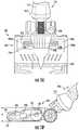
- FIG. 5is a perspective view of a surface cleaning apparatus including a surface cleaning head with a dual cyclone assembly, consistent with another embodiment of the present disclosure.
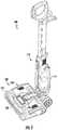
- FIG. 6is a perspective view the surface cleaning apparatus in FIG. 5 with the cyclone assembly in an open position for removal.
- FIG. 7is a side view of the surface cleaning head of the surface cleaning apparatus shown in FIG. 5 illustrating the open and closed positions of both the agitator chamber cover and the dual cyclone assembly.
- FIG. 8is a perspective view of the surface cleaning head of the surface cleaning apparatus shown in FIG. 5 with the dual cyclone assembly removed.
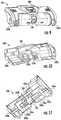
- FIG. 9is a top perspective view of the dual cyclone assembly for use in the surface cleaning apparatus shown in FIG. 5 .
- FIG. 10is a bottom perspective view of the dual cyclone assembly for use in the surface cleaning apparatus shown in FIG. 5 .
- FIG. 11is a cross-sectional view of the dual cyclone assembly shown in FIG. 10 .
- FIG. 12is a side cross-sectional view of the surface cleaning apparatus shown in FIG. 5 illustrating the air flow through the dual cyclone assembly and the suction motor.
- FIG. 13is a side cross-sectional view of the surface cleaning apparatus shown in FIG. 5 illustrating the air flow through the dual cyclone assembly in an air path to the suction motor.
- FIG. 14is a bottom view of a surface cleaning head with a conduit for blasting a cleaning surface with exhausted air.
- a surface cleaning apparatusprovides a lower profile surface cleaning head by moving at least the suction motor out of the surface cleaning head.
- the suction motormay be located in an upper portion (e.g., in a wand) pivotably coupled to the surface cleaning head and fluidly connected to a cyclone assembly located in the surface cleaning head.
- the cyclone assemblymay include first and second opposing cyclones with smaller diameters (e.g., as compared to a single cyclone used in existing “all in the head” vacuums) to provide a lower profile with substantially the same or better performance.
- cyclonerefers to a structure that causes air to flow along a spiral path for purposes of causing particles in the air to be extracted.
- pivotably coupledrefers to a coupling or connection that allows pivoting in at least one direction and possibly multiple directions (e.g., forward and back and/or side to side).
- a surface cleaning apparatus 100includes a wand or upper portion 110 and a surface cleaning head 120 pivotably connected to the upper portion 110 .
- the upper portion 110includes a handle (not shown in FIG. 1 ) and a suction motor 114 located in a motor housing section 115 of the upper portion 110 .
- the surface cleaning apparatus 100may include a battery 111 ( FIG. 1B ) to provide for cordless operation or may include a power cord for connecting to an external power source.
- the surface cleaning head 120includes a cyclone assembly 130 including first and second opposing cyclones 132 a , 132 b each located in an air path in fluid communication with the suction motor 114 .
- the cyclones 132 a , 132 beach have a longitudinal axis oriented alone the same axis 102 and may have a diameter that is less than 4 inches and specifically about 3 inches in one embodiment.
- the cyclones 132 a , 132 bare located in first and second dirt collection chambers 134 a , 134 b defined by first and second dust cups 135 a , 136 b for collecting dirt from the air as it moves around the cyclones 132 a , 132 b and toward the suction motor 114 .
- Providing two smaller diameter cyclones 132 a , 132 b and smaller dust cupsallows the height h of the surface cleaning head 120 to be reduced, for example, to less than 90 mm and more specifically in a range of about
- the surface cleaning head 120further includes an agitator drive motor 123 drivingly connected to a driven agitator member 122 .
- the driven agitator member 122may include, for example, a rotating brush roll.
- the surface cleaning head 120may further include an external cover 124 covering an agitator chamber 121 including the driven agitator member 122 , which may be removable from the agitator chamber 121 .
- One example of a surface cleaning head with an openable agitator chamber and a removable rotatable agitatoris described in greater detail in U.S. Patent Application Publication No. 2016/0220080 (Ser. No. 14/739,915), which is incorporated herein by reference.
- the upper portion 110may also include a pre-motor filter 142 upstream of the suction motor 114 and/or a post-motor filter 144 downstream of the suction motor 114 .
- the pre-motor filter 142 and the post motor filter 144may be located in a dual filter frame 140 that fits around the motor 114 .
- the air pathpasses generally up and down through the filters 142 , 144 and suction motor 114 .
- the filters 142 , 144 and frame 140have a generally cylindrical configuration.
- the dust cups 135 a , 135 b containing the cyclones 132 a , 132 bmay be removable from the surface cleaning head 120 and hingedly connected to each other at a location 136 between the cyclones.
- the dust cups 135 a , 135 bmay also be spring loaded together to present when unlocked from the surface cleaning head 120 .
- the cyclone assembly 130may include one or more rollers configured to roll within one or more respective tracks located in the surface cleaning head 120 .
- the surface cleaning head 120may include a cyclone assembly release mechanism with a spring to lift up a middle portion of the cyclone assembly 130 when the release mechanism is actuated.
- the release mechanismmay include a foot pedal 139 ( FIG.
- the cyclone assembly 130may also include a handle 138 to remove the assembly 130 from the surface cleaning head 120 .
- a wedge 128may be used to separate the dust cups 135 a , 135 b when they are inserted into the surface cleaning head 120 .
- a surface cleaning apparatus 200includes a surface cleaning head 220 with a cyclone assembly 230 having a handle 238 that engages an external cover 224 covering an agitator chamber 221 receiving a driven agitator member 222 .
- the external cover 224may be pivotable between a closed position and an open position to allow access to the agitator chamber 221 and agitator member 222 located therein.
- the handle 238may be used to hold the external cover 224 in the closed position.
- the driven agitator member 222is driven by a drive motor 223 located in the surface cleaning head 220 and drivingly connected to the agitator member 222 .
- the surface cleaning apparatus 200may include a suction motor and filters (not shown) in an upper portion 210 . As shown in FIGS. 3A and 3B , the upper portion 210 is pivotably coupled to the surface cleaning head 220 at one end and includes a handle 212 at the other end.
- the surface cleaning apparatus 200may include a battery to provide for cordless operation or may include a power cord for connecting to an external power source.
- the cyclone assembly 230 in the surface cleaning head 220includes first and second opposing cyclones 232 a , 232 b each located in an air path in fluid communication with the suction motor, for example, by way of air paths 237 a , 237 b .
- the cyclones 232 a , 232 beach have a longitudinal axis oriented alone the same axis 202 and may have a diameter that is less than 4 inches or less than 31 ⁇ 2 inches and specifically about 3 inches in one embodiment.
- the cyclones 232 a , 232 bare located in first and second dirt collection chambers 234 a , 234 b defined by dust cups 235 a , 235 b for collecting debris from the air as it moves around the cyclones 232 a , 234 b , through the air paths 237 a , 237 b and toward the suction motor (not shown).
- a common dust cup outlet 236 from the air paths 237 a , 237 bmay be fluidly coupled to an inlet 211 to an air path to the suction motor when the cyclone assembly 230 is positioned in the surface cleaning head 220 .
- the dirt collection chambers 234 a , 234 bmay be opened from either end of the cyclone assembly 230 for emptying debris.
- the surface cleaning head 220may include a foot pedal 239 for actuating a release mechanism that causes the cyclone assembly 230 to be released for removal.
- the release mechanismmay include a latch for holding the cyclone assembly 130 and a spring for causing the cyclone assembly 130 to move when the latch is released. As shown in FIGS. 4A-4C , the cyclone assembly 230 pivots at one end when released such that the handle 238 may be grasped by a user for removing the cyclone assembly 230 .
- the surface cleaning apparatus 500includes a wand or upper portion 510 pivotably coupled to a surface cleaning head 520 having a lower profile.
- the upper portion 510includes a motor housing 515 containing a suction motor.
- the surface cleaning head 520includes a dust cup and cyclone assembly 530 with dual opposing cyclones.
- the dust cup and cyclone assembly 530pivots from a closed position ( FIG. 5 ) to an open position ( FIG. 6 ) for removal. In the closed position, the dust cup and cyclone assembly 530 is fluidly coupled between a dirty air inlet and agitator chamber in the surface cleaning head 520 and the suction motor in the motor housing 515 .
- the surface cleaning head 520includes an agitator 522 , such as a rotating brush roll, located in an agitator chamber 521 , which is covered by an agitator chamber cover 524 .
- a motor 523is located in the surface cleaning head 520 for rotating the agitator 522 .
- the dust cup and cyclone assembly 530includes a handle 538 that engages and may secure the agitator chamber cover 524 in a closed position.
- the dust cup and cyclone assembly 530is moved to an open position to allow the agitator chamber cover 524 to be moved to an open position ( FIG. 7 ) for access to the agitator 522 (e.g., a removable brush roll).
- the dust cup and cyclone assembly 530is seated in a pivoting dust cup base 531 to allow the dust cup and cyclone assembly 530 to be removed ( FIG. 8 ).
- the dust cup and cyclone assembly 530When positioned in the dust cup base 531 and moved to the closed position, the dust cup and cyclone assembly 530 is fluidly coupled to first and second agitator chamber outlets 529 a , 529 b and a wand air path inlet 519 leading to the air path through the upper portion 510 .
- FIGS. 9-11show the dust cup and cyclone assembly 530 in greater detail.
- the dust cup and cyclone assembly 530includes first and second cyclones 532 a , 532 b located in first and second dirt collection chambers 534 a , 534 b defined by first and second dust cups 535 a , 535 b .
- First and second dust cup covers 531 a , 531 bare pivotably coupled to the respective dust cups 535 a , 535 b and may be held closed by releasable latches.
- the dust cup and cyclone assembly 530includes first and second dust cup inlets 537 a , 537 b to the respective first and second dirt collection chambers 534 a , 534 b and a dust cup outlet 536 from a region 539 fluidly coupled to both dirt collection chambers 534 a , 534 b .
- the first and second dust cup inlets 537 a , 537 bfluidly couple to the respective agitator chamber outlets 529 a , 529 b shown in FIG. 8 and the dust cup outlet 536 fluidly couples to the wand air path inlet 519 shown in FIG. 8 .
- a suction motor 514 in the wand or upper portion 510causes air to be drawn from an agitator chamber 521 , through the dust cup inlets 537 a , 537 b , around the cyclones 532 a , 532 b , through the dust cup outlet 536 , into a wand air path 511 , and out of an exhaust 519 .
- the surface cleaning headmay include other configurations.
- any of the embodiments of the surface cleaning apparatus described abovemay further include a conduit 1440 having an inlet 1442 coupled to an exhaust of the suction motor (e.g., suction motor 114 shown in FIG. 1A ) and an elongated outlet 1444 coupled to a lower portion of a surface cleaning head 1420 adjacent the driven agitator member 1422 .
- the elongated outlet 1444may extend substantially the length of the bottom inlet opening 1421 of the surface cleaning head 1420 .
- the conduit 1440blasts a cleaning surface with exhausted air to improve cleaning.
- the elongated outlet 1444may be located rearward of the agitator member 1422 and the air may be directed at an angle (e.g., an angle of about 45°) relative to the cleaning surface.
- This air blastmay thus agitate dust and debris that might be stuck and/or located in a dead zone.
- a valve(not shown in FIG. 14 ), such as a sliding plate, may be used to redirect air from adjacent the agitator member 1422 to a front corner of the surface cleaning head 1420 .
- a surface cleaning apparatusis configured to have a surface cleaning head with a lower profile by using dual cyclones having smaller diameters and by locating the suction motor in the wand or upper portion coupled to the surface cleaning head.
- a surface cleaning apparatusincludes an upper portion including a handle and a suction motor and a surface cleaning head pivotably connected to the upper portion.
- the surface cleaning headincludes an agitator drive motor drivingly connected to a driven agitator member and a cyclone assembly including first and second opposing cyclones each in an air path in fluid communication with the suction motor.
- the cyclone assemblyis removable from the surface cleaning head and hingedly connected at a location between the cyclones.
- surface cleaning apparatusincludes an upper portion including a handle and a suction motor and a surface cleaning head pivotably connected to the upper portion.
- the surface cleaning headincludes an agitator chamber including a driven agitator member, an external cover covering the agitator chamber, a drive motor drivingly connected to the driven agitator member, and a cyclone assembly including first and second opposing cyclones each in an air path in fluid communication with the suction motor.
- the cyclone assemblyincludes a handle for removing the cyclone assembly, and the handle is configured to engage the external cover covering the agitator chamber.
Landscapes
- Engineering & Computer Science (AREA)
- Mechanical Engineering (AREA)
- Chemical & Material Sciences (AREA)
- Chemical Kinetics & Catalysis (AREA)
- Filters For Electric Vacuum Cleaners (AREA)
- Nozzles For Electric Vacuum Cleaners (AREA)
- Cyclones (AREA)
Abstract
Description
Claims (20)
Priority Applications (1)
| Application Number | Priority Date | Filing Date | Title |
|---|---|---|---|
| US15/750,653US10966584B2 (en) | 2015-08-06 | 2016-08-05 | Low profile surface cleaning head |
Applications Claiming Priority (3)
| Application Number | Priority Date | Filing Date | Title |
|---|---|---|---|
| US201562202004P | 2015-08-06 | 2015-08-06 | |
| US15/750,653US10966584B2 (en) | 2015-08-06 | 2016-08-05 | Low profile surface cleaning head |
| PCT/US2016/045821WO2017024241A1 (en) | 2015-08-06 | 2016-08-05 | Low profile surface cleaning head |
Publications (2)
| Publication Number | Publication Date |
|---|---|
| US20200085269A1 US20200085269A1 (en) | 2020-03-19 |
| US10966584B2true US10966584B2 (en) | 2021-04-06 |
Family
ID=57943745
Family Applications (1)
| Application Number | Title | Priority Date | Filing Date |
|---|---|---|---|
| US15/750,653Active2037-09-15US10966584B2 (en) | 2015-08-06 | 2016-08-05 | Low profile surface cleaning head |
Country Status (3)
| Country | Link |
|---|---|
| US (1) | US10966584B2 (en) |
| CN (1) | CN108135414B (en) |
| WO (1) | WO2017024241A1 (en) |
Families Citing this family (19)
| Publication number | Priority date | Publication date | Assignee | Title |
|---|---|---|---|---|
| US11647881B2 (en) | 2015-10-21 | 2023-05-16 | Sharkninja Operating Llc | Cleaning apparatus with combing unit for removing debris from cleaning roller |
| WO2018049169A1 (en) | 2016-09-09 | 2018-03-15 | Sharkninja Operating Llc | Agitator with hair removal |
| CN114403741B (en) | 2017-03-10 | 2024-02-27 | 尚科宁家运营有限公司 | Agitator with a hair remover and hair removal |
| US11202542B2 (en) | 2017-05-25 | 2021-12-21 | Sharkninja Operating Llc | Robotic cleaner with dual cleaning rollers |
| EP3684237B1 (en) | 2017-09-22 | 2023-07-19 | SharkNinja Operating LLC | Hand-held surface cleaning device |
| US11399675B2 (en) | 2018-07-31 | 2022-08-02 | Sharkninja Operating Llc | Upright surface treatment apparatus having removable pod |
| EP4541243A3 (en)* | 2018-07-31 | 2025-07-23 | SharkNinja Operating LLC | Upright surface treatment apparatus having removable pod |
| CA3127792A1 (en) | 2019-01-25 | 2020-07-30 | Sharkninja Operating Llc | Cyclonic separator for a vacuum cleaner and a vacuum cleaner having the same |
| CN110037612B (en)* | 2019-05-23 | 2024-04-19 | 莱克电气股份有限公司 | Rod-type handheld multifunctional dust collector |
| CN114126463B (en) | 2019-07-11 | 2023-07-18 | 尚科宁家运营有限公司 | Smart nozzle and surface cleaning device implementing the smart nozzle |
| WO2021207139A1 (en) | 2020-04-06 | 2021-10-14 | Sharkninja Operating Llc | Allergen reduction device |
| EP4322812A4 (en) | 2021-04-12 | 2025-04-23 | SharkNinja Operating LLC | Robotic cleaner |
| GB2620092A (en) | 2021-04-23 | 2023-12-27 | Sharkninja Operating Llc | Determining state of charge for battery powered devices including battery powered surface treatment apparatuses |
| US12433461B2 (en) | 2022-07-05 | 2025-10-07 | Sharkninja Operating Llc | Vacuum cleaner |
| WO2023018947A1 (en) | 2021-08-13 | 2023-02-16 | Sharkninja Operating Llc | Robotic cleaner |
| US12358169B2 (en) | 2021-09-07 | 2025-07-15 | Sharkninja Operating Llc | Robotic cleaner |
| CN220144215U (en) | 2021-11-05 | 2023-12-08 | 尚科宁家运营有限公司 | Surface cleaning device |
| US12329350B2 (en) | 2022-05-09 | 2025-06-17 | Sharkninja Operating Llc | Robotic cleaner |
| GB2618791A (en)* | 2022-05-16 | 2023-11-22 | Techtronic Cordless Gp | A cleaner head for a cleaning appliance |
Citations (17)
| Publication number | Priority date | Publication date | Assignee | Title |
|---|---|---|---|---|
| US5664285A (en) | 1996-01-11 | 1997-09-09 | Black & Decker Inc. | Vacuum cleaner with combined filter element and collection unit |
| US5765258A (en)* | 1996-01-11 | 1998-06-16 | Black & Decker Inc. | Vacuum cleaner with all components in floor traveling head |
| WO2000074548A1 (en) | 1999-06-04 | 2000-12-14 | Lg Electronics Inc. | Multi-cyclone collector for vacuum cleaner |
| US20020059689A1 (en) | 1998-07-06 | 2002-05-23 | Tomonori Kato | Vacuum cleaner |
| US6442792B1 (en)* | 1999-01-29 | 2002-09-03 | Hitachi, Ltd. | Vacuum cleaner |
| US20060107630A1 (en)* | 2004-09-02 | 2006-05-25 | Ivarsson Bengt Ivar A | Suction cleaners |
| US20060196004A1 (en)* | 2004-10-22 | 2006-09-07 | Conrad Wayne E | Cleaning head for a surface cleaning apparatus |
| US20090056060A1 (en)* | 2007-08-28 | 2009-03-05 | Samsung Gwangju Electronics., Ltd. | Stick type vacuum cleaner |
| US20100224073A1 (en) | 2006-05-03 | 2010-09-09 | Samsung Gwangju Electronics Co., Ltd. | Dual Cyclone Dust-Collecting Apparatus Vacuum Cleaner |
| US20120167336A1 (en) | 2010-12-29 | 2012-07-05 | Bissell Homecare, Inc. | Vacuum cleaner with louvered exhaust grill |
| US8316507B2 (en)* | 2007-03-16 | 2012-11-27 | Lg Electronics Inc. | Vacuum cleaner and dust separating apparatus thereof |
| US20130291333A1 (en)* | 2010-12-22 | 2013-11-07 | Grey Technology Limited | Vacuum cleaner |
| US20140237758A1 (en) | 2013-02-27 | 2014-08-28 | G.B.D. Corp. | Surface cleaning apparatus |
| US9295363B1 (en)* | 2014-12-17 | 2016-03-29 | Omachron Intellectual Property Inc. | All in the head surface cleaning apparatus |
| US9801515B2 (en)* | 2014-09-24 | 2017-10-31 | Lg Electronics Inc. | Robot cleaner |
| US10130227B2 (en)* | 2014-08-21 | 2018-11-20 | Samsung Electronics Co., Ltd. | Robot cleaner |
| US10357136B2 (en)* | 2014-12-17 | 2019-07-23 | Omachron Intellectual Property Inc. | All in the head surface cleaning apparatus |
Family Cites Families (3)
| Publication number | Priority date | Publication date | Assignee | Title |
|---|---|---|---|---|
| JP2003125995A (en)* | 2001-10-29 | 2003-05-07 | Matsushita Electric Ind Co Ltd | Electric vacuum cleaner |
| GB2472097B (en)* | 2009-07-24 | 2013-04-17 | Dyson Technology Ltd | Separating apparatus with electrostatic filter |
| US20140237768A1 (en)* | 2013-02-28 | 2014-08-28 | G.B.D. Corp. | Surface cleaning apparatus |
- 2016
- 2016-08-05USUS15/750,653patent/US10966584B2/enactiveActive
- 2016-08-05WOPCT/US2016/045821patent/WO2017024241A1/ennot_activeCeased
- 2016-08-05CNCN201680058810.XApatent/CN108135414B/enactiveActive
Patent Citations (18)
| Publication number | Priority date | Publication date | Assignee | Title |
|---|---|---|---|---|
| US5765258A (en)* | 1996-01-11 | 1998-06-16 | Black & Decker Inc. | Vacuum cleaner with all components in floor traveling head |
| US5664285A (en) | 1996-01-11 | 1997-09-09 | Black & Decker Inc. | Vacuum cleaner with combined filter element and collection unit |
| US20020059689A1 (en) | 1998-07-06 | 2002-05-23 | Tomonori Kato | Vacuum cleaner |
| US20040088820A1 (en)* | 1998-07-06 | 2004-05-13 | Tomonori Kato | Vacuum cleaner |
| US6442792B1 (en)* | 1999-01-29 | 2002-09-03 | Hitachi, Ltd. | Vacuum cleaner |
| WO2000074548A1 (en) | 1999-06-04 | 2000-12-14 | Lg Electronics Inc. | Multi-cyclone collector for vacuum cleaner |
| US20060107630A1 (en)* | 2004-09-02 | 2006-05-25 | Ivarsson Bengt Ivar A | Suction cleaners |
| US20060196004A1 (en)* | 2004-10-22 | 2006-09-07 | Conrad Wayne E | Cleaning head for a surface cleaning apparatus |
| US20100224073A1 (en) | 2006-05-03 | 2010-09-09 | Samsung Gwangju Electronics Co., Ltd. | Dual Cyclone Dust-Collecting Apparatus Vacuum Cleaner |
| US8316507B2 (en)* | 2007-03-16 | 2012-11-27 | Lg Electronics Inc. | Vacuum cleaner and dust separating apparatus thereof |
| US20090056060A1 (en)* | 2007-08-28 | 2009-03-05 | Samsung Gwangju Electronics., Ltd. | Stick type vacuum cleaner |
| US20130291333A1 (en)* | 2010-12-22 | 2013-11-07 | Grey Technology Limited | Vacuum cleaner |
| US20120167336A1 (en) | 2010-12-29 | 2012-07-05 | Bissell Homecare, Inc. | Vacuum cleaner with louvered exhaust grill |
| US20140237758A1 (en) | 2013-02-27 | 2014-08-28 | G.B.D. Corp. | Surface cleaning apparatus |
| US10130227B2 (en)* | 2014-08-21 | 2018-11-20 | Samsung Electronics Co., Ltd. | Robot cleaner |
| US9801515B2 (en)* | 2014-09-24 | 2017-10-31 | Lg Electronics Inc. | Robot cleaner |
| US9295363B1 (en)* | 2014-12-17 | 2016-03-29 | Omachron Intellectual Property Inc. | All in the head surface cleaning apparatus |
| US10357136B2 (en)* | 2014-12-17 | 2019-07-23 | Omachron Intellectual Property Inc. | All in the head surface cleaning apparatus |
Non-Patent Citations (2)
| Title |
|---|
| Chinese Office Action with translation dated Mar. 13, 2020, received in Chinese Patent Application No. 201680058810.X, 14 pgs. |
| PCT Search Report and Written Opinion dated Oct. 13, 2016, received in corresponding PCT Application No. PCT/US16/45821, 8 pgs. |
Also Published As
| Publication number | Publication date |
|---|---|
| US20200085269A1 (en) | 2020-03-19 |
| CN108135414A (en) | 2018-06-08 |
| WO2017024241A1 (en) | 2017-02-09 |
| CN108135414B (en) | 2022-01-04 |
Similar Documents
| Publication | Publication Date | Title |
|---|---|---|
| US10966584B2 (en) | Low profile surface cleaning head | |
| US11759066B2 (en) | Hand carryable surface cleaning apparatus | |
| US20240138634A1 (en) | Hand carryable surface cleaning apparatus | |
| US20200046182A1 (en) | Configuration of a surface cleaning apparatus | |
| US11950752B2 (en) | Surface cleaning apparatus | |
| US8375508B2 (en) | Torque balancer for a surface cleaning head | |
| US11445878B2 (en) | Surface cleaning apparatus with removable air treatment member assembly | |
| US11445874B2 (en) | Hand carryable surface cleaning apparatus | |
| US10271704B2 (en) | Multistage cyclone and surface cleaning apparatus having same | |
| US10299643B2 (en) | Multistage cyclone and surface cleaning apparatus having same | |
| US10828649B2 (en) | Cyclonic air treatment member and surface cleaning apparatus including the same | |
| US8978197B2 (en) | Vacuum cleaner | |
| US20160198915A1 (en) | Surface cleaning apparatus | |
| CN106998973B (en) | Portable Surface Cleaning Unit | |
| US10016106B1 (en) | Multistage cyclone and surface cleaning apparatus having same | |
| US20240032751A1 (en) | Surface cleaning apparatus | |
| US20180177354A1 (en) | Multistage cyclone and surface cleaning apparatus having same | |
| US10405709B2 (en) | Multistage cyclone and surface cleaning apparatus having same | |
| US11766156B2 (en) | Surface cleaning apparatus with removable air treatment member assembly | |
| US11666193B2 (en) | Surface cleaning apparatus with removable air treatment member assembly | |
| US20250228419A1 (en) | Hand carryable surface cleaning apparatus |
Legal Events
| Date | Code | Title | Description |
|---|---|---|---|
| FEPP | Fee payment procedure | Free format text:ENTITY STATUS SET TO UNDISCOUNTED (ORIGINAL EVENT CODE: BIG.); ENTITY STATUS OF PATENT OWNER: LARGE ENTITY | |
| AS | Assignment | Owner name:SHARKNINJA OPERATING LLC, MASSACHUSETTS Free format text:ASSIGNMENT OF ASSIGNORS INTEREST;ASSIGNOR:THORNE, JASON B.;REEL/FRAME:048660/0509 Effective date:20190301 | |
| STPP | Information on status: patent application and granting procedure in general | Free format text:NON FINAL ACTION MAILED | |
| STPP | Information on status: patent application and granting procedure in general | Free format text:RESPONSE TO NON-FINAL OFFICE ACTION ENTERED AND FORWARDED TO EXAMINER | |
| STPP | Information on status: patent application and granting procedure in general | Free format text:FINAL REJECTION MAILED | |
| STPP | Information on status: patent application and granting procedure in general | Free format text:RESPONSE AFTER FINAL ACTION FORWARDED TO EXAMINER | |
| STPP | Information on status: patent application and granting procedure in general | Free format text:PUBLICATIONS -- ISSUE FEE PAYMENT VERIFIED | |
| STCF | Information on status: patent grant | Free format text:PATENTED CASE | |
| AS | Assignment | Owner name:BANK OF AMERICA, N.A., AS ADMINISTRATIVE AGENT, TEXAS Free format text:NOTICE OF GRANT OF SECURITY INTEREST IN PATENTS;ASSIGNOR:SHARKNINJA OPERATING LLC;REEL/FRAME:064600/0098 Effective date:20230720 | |
| MAFP | Maintenance fee payment | Free format text:PAYMENT OF MAINTENANCE FEE, 4TH YEAR, LARGE ENTITY (ORIGINAL EVENT CODE: M1551); ENTITY STATUS OF PATENT OWNER: LARGE ENTITY Year of fee payment:4 |