US10965336B2 - Apparatus to assist a user with holding a mobile device - Google Patents
Apparatus to assist a user with holding a mobile deviceDownload PDFInfo
- Publication number
- US10965336B2 US10965336B2US16/824,285US202016824285AUS10965336B2US 10965336 B2US10965336 B2US 10965336B2US 202016824285 AUS202016824285 AUS 202016824285AUS 10965336 B2US10965336 B2US 10965336B2
- Authority
- US
- United States
- Prior art keywords
- finger
- finger brace
- slot
- brace
- plastic portion
- Prior art date
- Legal status (The legal status is an assumption and is not a legal conclusion. Google has not performed a legal analysis and makes no representation as to the accuracy of the status listed.)
- Active - Reinstated
Links
Images


Classifications
- A—HUMAN NECESSITIES
- A45—HAND OR TRAVELLING ARTICLES
- A45F—TRAVELLING OR CAMP EQUIPMENT: SACKS OR PACKS CARRIED ON THE BODY
- A45F5/00—Holders or carriers for hand articles; Holders or carriers for use while travelling or camping
- A—HUMAN NECESSITIES
- A45—HAND OR TRAVELLING ARTICLES
- A45C—PURSES; LUGGAGE; HAND CARRIED BAGS
- A45C11/00—Receptacles for purposes not provided for in groups A45C1/00-A45C9/00
- A—HUMAN NECESSITIES
- A45—HAND OR TRAVELLING ARTICLES
- A45C—PURSES; LUGGAGE; HAND CARRIED BAGS
- A45C11/00—Receptacles for purposes not provided for in groups A45C1/00-A45C9/00
- A45C11/002—Receptacles for purposes not provided for in groups A45C1/00-A45C9/00 for storing portable handheld communication devices, e.g. pagers or smart phones
- A—HUMAN NECESSITIES
- A45—HAND OR TRAVELLING ARTICLES
- A45C—PURSES; LUGGAGE; HAND CARRIED BAGS
- A45C13/00—Details; Accessories
- A45C13/001—Accessories
- A—HUMAN NECESSITIES
- A45—HAND OR TRAVELLING ARTICLES
- A45C—PURSES; LUGGAGE; HAND CARRIED BAGS
- A45C13/00—Details; Accessories
- A45C13/30—Straps; Bands
- A—HUMAN NECESSITIES
- A45—HAND OR TRAVELLING ARTICLES
- A45F—TRAVELLING OR CAMP EQUIPMENT: SACKS OR PACKS CARRIED ON THE BODY
- A45F5/00—Holders or carriers for hand articles; Holders or carriers for use while travelling or camping
- A45F5/02—Fastening articles to the garment
- A45F5/021—Fastening articles to the garment to the belt
- H—ELECTRICITY
- H04—ELECTRIC COMMUNICATION TECHNIQUE
- H04B—TRANSMISSION
- H04B1/00—Details of transmission systems, not covered by a single one of groups H04B3/00 - H04B13/00; Details of transmission systems not characterised by the medium used for transmission
- H04B1/38—Transceivers, i.e. devices in which transmitter and receiver form a structural unit and in which at least one part is used for functions of transmitting and receiving
- H04B1/3827—Portable transceivers
- H04B1/385—Transceivers carried on the body, e.g. in helmets
- H—ELECTRICITY
- H04—ELECTRIC COMMUNICATION TECHNIQUE
- H04B—TRANSMISSION
- H04B1/00—Details of transmission systems, not covered by a single one of groups H04B3/00 - H04B13/00; Details of transmission systems not characterised by the medium used for transmission
- H04B1/38—Transceivers, i.e. devices in which transmitter and receiver form a structural unit and in which at least one part is used for functions of transmitting and receiving
- H04B1/3827—Portable transceivers
- H04B1/3888—Arrangements for carrying or protecting transceivers
- H—ELECTRICITY
- H04—ELECTRIC COMMUNICATION TECHNIQUE
- H04M—TELEPHONIC COMMUNICATION
- H04M1/00—Substation equipment, e.g. for use by subscribers
- H04M1/02—Constructional features of telephone sets
- H04M1/04—Supports for telephone transmitters or receivers
- A—HUMAN NECESSITIES
- A45—HAND OR TRAVELLING ARTICLES
- A45C—PURSES; LUGGAGE; HAND CARRIED BAGS
- A45C13/00—Details; Accessories
- A45C13/10—Arrangement of fasteners
- A45C2013/1015—Arrangement of fasteners of hook and loop type
- A—HUMAN NECESSITIES
- A45—HAND OR TRAVELLING ARTICLES
- A45C—PURSES; LUGGAGE; HAND CARRIED BAGS
- A45C2200/00—Details not otherwise provided for in A45C
- A45C2200/15—Articles convertible into a stand, e.g. for displaying purposes
- A—HUMAN NECESSITIES
- A45—HAND OR TRAVELLING ARTICLES
- A45F—TRAVELLING OR CAMP EQUIPMENT: SACKS OR PACKS CARRIED ON THE BODY
- A45F5/00—Holders or carriers for hand articles; Holders or carriers for use while travelling or camping
- A45F2005/008—Hand articles fastened to the wrist or to the arm or to the leg
- A45F2200/0516—
- A—HUMAN NECESSITIES
- A45—HAND OR TRAVELLING ARTICLES
- A45F—TRAVELLING OR CAMP EQUIPMENT: SACKS OR PACKS CARRIED ON THE BODY
- A45F5/00—Holders or carriers for hand articles; Holders or carriers for use while travelling or camping
- A45F5/1516—Holders or carriers for portable handheld communication devices, e.g. pagers or smart phones
- H—ELECTRICITY
- H04—ELECTRIC COMMUNICATION TECHNIQUE
- H04B—TRANSMISSION
- H04B1/00—Details of transmission systems, not covered by a single one of groups H04B3/00 - H04B13/00; Details of transmission systems not characterised by the medium used for transmission
- H04B1/38—Transceivers, i.e. devices in which transmitter and receiver form a structural unit and in which at least one part is used for functions of transmitting and receiving
- H04B1/3827—Portable transceivers
- H04B1/385—Transceivers carried on the body, e.g. in helmets
- H04B2001/3861—Transceivers carried on the body, e.g. in helmets carried in a hand or on fingers
Definitions
- the field of the present inventionrelates to accessories for hand-held mobile devices such as mobile phones and computer tablets.
- the field of the present inventionrelates to an apparatus that assists a user with holding a mobile device that has a front-facing display screen, where the user can hold the device in one hand while leaving the thumb of that hand, as well as the user's other hand, free to operate the mobile device.
- Mobile devicessuch as cellular phones or tablets, typically have front-facing display screens, which can be a touch-screen.
- mobile devicestypically include integral cases.
- some mobile device userspurchase a secondary case that partially or entirely covers the mobile device's integral case and provides additional protection. Cases can be made with any material that is rigid enough to hold its shape and protect the components of the mobile device, but cases often are made of a sufficiently low-density material so as to minimize the weight added to the mobile device. Typical materials used in cases include metal, carbon fiber, and plastic.
- a casewhether integral or secondary, has a rear-facing back portion that is positioned on the opposite side of the device from the display screen.
- the exterior surface of the back portion of the casefaces away from the mobile device and toward the palm of the user's hand when the mobile device is held with a typical grip.
- the exterior surfacecan be smooth or otherwise have a low coefficient of friction that causes the device to be difficult to grip.
- some caseshave an exterior surface that is textured or coated with a material that improves the user's ability to grip the case (e.g., rubber or leather).
- a materialthat improves the user's ability to grip the case
- a wide variety of accessoriesare available for supporting the use of a hand-held device.
- conventional accessoriesgenerally rely on rigid designs that are not easily adjustable or customizable to a user's individual hand.
- such designstypically do not provide for a smooth transition from holding the device in portrait orientation to holding it in a landscape orientation, without having to detach from and reattach the accessory to the mobile device.
- An apparatus to assist a user with holding a mobile devicecomprises a finger brace and a flexible member coupled to the finger brace at an intermediate point.
- the finger braceis sized and shaped to brace at least one finger on each of two opposed sides of the intermediate point.
- the flexible memberextends through a hole in the back portion of the mobile device's case and is anchored to the interior surface of the back portion of the case.
- the length of the flexible member between the hole and the finger braceis such that at least two fingers of a user's hand can press against the finger brace to brace the mobile device when the user is holding the mobile device in a fashion where at least two fingers of the same hand are positioned between the finger brace and the case.
- the apparatusfacilitates one-handed use of the mobile device by allowing the user to hold the mobile device with one hand while leaving the thumb of the user's same hand free to operate the mobile device.
- FIGS. 1A and 1Bare side views of an embodiment of the apparatus.
- FIG. 1Cis a perspective view of the embodiment of FIGS. 1A and 1B .
- FIGS. 2A and 2Bare perspective views of the interior surface of the rear-facing back portion of a case and the portion of the flexible member extending through the hole, as used with various embodiments of the apparatus, which could be combined with the embodiments in FIGS. 1A-1C .
- FIGS. 3A and 3Bare cross-sectional and side views of an additional example embodiment.
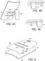
- FIGS. 4A-4Eshow an additional embodiment used with a case having slot-type holes.
- FIG. 5is an exploded perspective view of a case and a skin covering the case, as used with the embodiment of FIGS. 4A-4E .
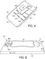
- FIG. 6is a perspective view of an additional embodiment used with a case having a plurality of holes.
- FIGS. 7A and 7Care perspective views showing an additional example embodiment used with a case having ridges on the exterior surface of the case.
- FIG. 7Bis a side view showing the embodiment of FIGS. 7A and 7C .
- FIG. 8is a perspective view showing an additional embodiment used with a case having ridges.
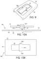
- FIG. 9is a perspective view of an additional embodiment used with a case that has a recess in the exterior surface.
- FIGS. 10A and 10Bshow an additional embodiment with a finger brace that enables adjustment of the length of the flexible member.
- FIGS. 11A, 11B, and 11Care perspective and side views of an additional embodiment with a finger brace that enables adjustment of the length of the flexible member.
- FIGS. 12A and 12Bare perspective views showing an additional embodiment where the finger brace can be used as a stand.
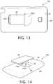
- FIG. 13shows an additional embodiment in which the finger brace can be used as a belt clip.
- FIG. 14is a perspective view showing an additional embodiment with a flexible member having multiple sections.
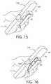
- FIG. 15is a perspective view showing an embodiment being held by a user's hand.
- FIGS. 16 and 17are perspective views showing additional embodiments with the finger brace having a strap partially enclosing the user's fingers.
- FIG. 18is a perspective view showing the embodiment of FIG. 15 with the user holding the mobile device using an alternative grip.
- FIG. 19is a perspective view showing an embodiment in which the finger brace can be used as a stand.
- FIG. 20is a cross-sectional view showing another embodiment in which the finger brace can be used as a stand.
- FIG. 21shows an embodiment where a sleeve on the case enables adjustment of the length of the flexible member.
- FIG. 22shows a side view of the embodiment depicted in FIG. 21 .
- FIGS. 1A, 1B, and 1CAn example apparatus to assist with holding a mobile device is shown in FIGS. 1A, 1B, and 1C .
- the example apparatusincludes finger brace 20 and flexible member 30 coupled to the finger brace at intermediate point 40 .
- the flexible memberextends through hole 50 in the rear-facing back portion 60 of the mobile device's case 100 and is anchored to the interior surface 80 of the back portion 60 of the case 100 .
- the exterior surface 70 of the rear-facing back portion 60 of case 100is visible in FIGS. 1A, 1B, and 1C , but interior surface 80 is shown only in other drawings.
- FIG. 15shows an embodiment of the apparatus in use.
- at least two fingers of one hand of the userare placed on either side of flexible member 30 .
- the user's fingersare between finger brace 20 and exterior surface 70 of the rear-facing back portion 60 of case 100 .
- the usercan press against finger brace 20 to brace the mobile device, thereby leaving the user's thumb free to operate the mobile device.
- FIG. 18shows the embodiment of FIG. 15 where the user has placed a finger between finger brace 20 and exterior surface 70 of the rear-facing back portion 60 of case 100 on one side of finger brace 20 and another finger on the opposite side of finger brace 20 .
- the usercan brace the mobile device using finger brace 20 as a cantilever.
- Finger brace 20can be made of a material (or combination of materials) that is rigid and that is resilient enough to counterbalance the force applied by the user's fingers with relatively little change in shape, such as plastic, carbon fiber, and metal.
- finger brace 20can be moldable from a flat or planar shape into a shape preferred by the user.
- the finger bracecan include a core made of a rigid but malleable material (e.g., a soft metal like aluminum) that can be bent by the user when sufficient force is applied but remains rigid when used as a finger brace in conjunction with holding the mobile device.
- finger brace 20can be textured, or it can be coated with a material that is soft to the touch or provides padding for the user's fingers (e.g., foam, cloth, leather, or rubber). Some embodiments can have a finger brace that is entirely coated with such a soft material. In other embodiments, only finger-bracing surface 25 is textured or padded. Texturing or padding can allow a better grip without as much slippage.
- a material that is soft to the touch or provides padding for the user's fingerse.g., foam, cloth, leather, or rubber.
- Some embodimentscan have a finger brace that is entirely coated with such a soft material. In other embodiments, only finger-bracing surface 25 is textured or padded. Texturing or padding can allow a better grip without as much slippage.
- FIG. 16shows an embodiment where optional strap 1600 is attached to finger brace 20 and partially encircles the user's fingers.
- Strap 1600can be attached to flexible member 30 , as pictured in FIG. 16 , formed as an extension of flexible member 30 (not shown), or wholly independent from flexible member 30 .
- the length of the flexible membercan be adjusted by pulling it away from the finger brace.
- FIG. 17shows an alternative to FIG. 16 , with strap 1700 on the side of finger brace 20 opposite its attachment to flexible member 30 . Similar alternatives discussed in connection with FIG. 16 can apply equally to FIG. 17 .
- finger brace 20has a flat finger-bracing surface 25 .
- the finger-bracing surfacecan be shaped to match the contours of the user's fingers.
- the finger-bracing surfacecan be scalloped or fluted when viewed in profile. Such contours can be pre-molded.
- the finger-bracing surfacecan comprise a material that is moldable to the user's fingers so that it would provide a customizable fit.
- the perimeter of the finger-bracing surfacecan be rectangular, as shown in FIG. 1C , or can take other suitable shapes (e.g., triangular, circular, elliptical, hour-glass, or figure-8).
- the shapecan be formed as an ornament or specialty shape, such as to assist marketing campaigns; such shapes can depict an object, animal, or company logo, for example.
- ornamental designscan be added to the shape with markings or engraving.
- FIG. 1Bshows flexible member 30 coupled to finger brace 20 at intermediate point 40 .
- Intermediate point 40can be equidistant from the end points of finger-bracing surface 25 , as shown, or can be positioned at a non-central point on finger-bracing surface 25 , but whether central or not, it can be sized to leave enough space so that at least one finger can fit on each of two opposed sides of intermediate point 40 .
- the radius of the average adult fingeris between about 0.5 and about 1.5 centimeters.
- the intermediate pointcan be positioned so that less than a length approximating the radius of the average adult finger is provided on each of two opposed sides of the intermediate point, although such a configuration can cause user discomfort, particularly when a user holds the mobile device for an extended period of time.
- finger brace 20can have adjustable size (e.g., by sliding, telescoping, folding, cutting, or breaking along pre-scored lines), or in some cases the intermediate point's location changed (e.g., by sliding or allowing the user to adjust it to one of several notched locations), so that the fit can be customized to the user.
- adjustable sizee.g., by sliding, telescoping, folding, cutting, or breaking along pre-scored lines
- the intermediate point's locatione.g., by sliding or allowing the user to adjust it to one of several notched locations
- Flexible member 30can be made of various flexible materials, including but not limited to, cloth, leather, rubber, and plastic.
- flexible member 30can be made of a material that has a dynamic length (e.g., elastic or rubber). Such materials, when stretched, exert a resisting force. That force provides an extra gripping force, assisting the user to hold the device in the user's hand.
- the resistive force provided by such a material's dynamic lengthcombined with the flexibility of flexible member 30 , allows flexible member 30 to be twisted and stretched to accommodate the user's hand size and preference.
- the more flexible member 30 is stretchedthe more the resistive force attempts to return flexible member 30 to its unloaded length, causing the finger brace to be held more tightly against the user's fingers.
- the elasticity of flexible member 30can hold finger brace 20 against the exterior surface 70 of the rear-facing back portion 60 of the case 100 when not in use or facilitate the cantilevered hold shown in FIG. 18 .
- flexible member 30can be made of materials that have a relatively static length, such as cloth.
- the flexibility of flexible member 30enables the user to switch easily from holding the mobile device in a portrait orientation to holding it in a landscape orientation, merely by twisting the mobile device, causing a twist in flexible member 30 , while finger brace 20 remains in place. That same flexibility also allows the user to move his or her fingers with respect to hole 50 , without having to detach and reattach, or otherwise relocate, the apparatus with respect to the rear-facing back portion 60 of case 100 , thereby providing a more universal fit without the need for customization.
- flexible member 30increases user comfort by presenting a flexible surface between the user's fingers.
- flexible member 30can be a strap (e.g., rectangular in shape) as depicted in FIG. 2A .
- Other embodimentscan use alternative shapes for flexible member 30 , e.g., a string, cord, or lace, or a plurality of straps, strings, cords, or laces.
- Flexible member 30can be thin enough to fit between two fingers of a user's hand comfortably. Any shape suitable for accomplishing that goal can be used.
- Flexible member 30is long enough to allow the user's fingers to fit comfortably between the finger brace and the exterior surface of the rear-facing back portion of the case, but not so long as to prevent the user from effectively bracing his or her fingers against the finger brace.
- FIG. 14shows an embodiment with flexible member 30 having two discrete portions (e.g., cords) separated by approximately the width of a finger.
- the embodimentcan be used as described above, where flexible member 30 includes first portion 1401 and second portion 1402 , both placed between the same two of the user's fingers.
- the user's handcan be rotated 90 degrees with respect to flexible member 30 of FIG. 14 (e.g., switching from portrait orientation to landscape orientation) and one finger of the user's hand can be placed in the gap between first portion 1401 and second portion 1402 of flexible member 30 , and the user can brace the mobile device with that finger.
- the length of flexible member 30can be adjusted via its coupling to the finger brace.
- other embodimentscan allow the length of the flexible member to be adjusted by varying where it is anchored to the interior surface of the rear-facing back portion of the case.
- FIGS. 2A and 2Bshow interior surface 80 of the rear-facing back portion 60 of case 100 , hole 50 piercing the back portion 60 , and a portion of flexible member 30 extending through hole 50 .
- FIG. 2Adepicts flexible member 30 in an unanchored state.
- FIG. 2Bshows flexible member 30 in an anchored state.
- a hook-type fasteneris shown on anchoring device 210 and corresponding loops on anchoring surface 220 on interior surface 80 of rear-facing back portion 60 of case 100 .
- Use of adjustable fastenerscan enable an individual user to adjust the length of flexible member 30 and thus customize the apparatus to fit his or her hand.
- a usercan decrease the length of flexible member 30 by detaching anchor device 210 from anchoring surface 220 and re-attaching anchoring device 210 at a point farther from hole 50 .
- a usercan increase the length of flexible member 30 by re-attaching anchoring device 210 at a point nearer to hole 50 .
- flexible member 30can be held in place between interior surface 80 of the rear-facing back portion 60 of case 100 and an adjacent surface (not shown) of the mobile device, e.g., by creating a pressure fit.
- both anchoring device 210 on flexible member 30 , and anchoring surface 220 on the interior surface 80 of the rear-facing back portion 60 of case 100can be made of or coated with a non-slip material (e.g., rubber or silicone) to prevent the flexible member from slipping out of the hole.
- Anchoring surface 220 on the interior surface 80 of the rear-facing back portion 60 of case 100can be integral to case 100 or can be applied to interior surface 80 of the rear-facing back portion 60 of case 100 , for example with adhesive.
- Anchoring device 210can be permanently attached to flexible member 30 , e.g., by glue or stitching, or anchoring device 210 can be repositionable at different points along the length of flexible member 30 , such as by use of a buckle (not shown) or another repositionable fastener.
- FIGS. 3A and 3Bshow an embodiment in which anchoring device 210 is permanently attached to flexible member 30 .
- anchoring device 210includes a first plurality of teeth or projections 315 .
- a second plurality of teeth 325is arranged on anchoring surface 220 .
- the first and second pluralities of teeth 315 and 325interlock when the rear-facing back portion 60 of the case 100 is adjacent to the mobile device, thereby anchoring flexible member 30 to interior surface 80 of the rear-facing back portion 60 of case 100 .
- the rear-facing back portion of the casecan include one or more magnets (not shown), and the finger brace can have corresponding magnets aligned so as to exert an attractive force on the magnet of the case, so that together they are capable of holding the finger brace to the exterior surface of the rear-facing back portion of the case when the finger brace is not in use.
- the casecan have clips, clasps, snaps, or other fasteners that hold the finger brace in place on the case's exterior surface.
- magnets or other fastenerscan be integral to the case or applied to a surface of the case, for example with adhesive.
- case 100can be included with the mobile phone apparatus, e.g., packaged or sold with the phone.
- Secondary protective casesare typically customized to fit one or a few models of mobile devices, as opposed to all types of mobile phones.
- the rear-facing back portion 60 of case 100includes at least one cutout 450 . Cases often require customization to accommodate one or more particular mobile device's cameras, control buttons, ventilation holes, USB outlets, headphone jacks, etc.
- the apparatuscan include a case for one or more particular models with a hole for the flexible member in the rear-facing back portion of the case.
- the holescan be formed in the cases as they are sold by the manufacturer or added after purchase.
- the finger-bracing apparatuscan be sold with a template, instructions, or tools to allow an end-user to make a hole for the flexible member in a separately acquired case.
- the casecan be integral to the mobile device but have a removable rear-facing back portion that can be interchanged with an optional rear-facing back portion that includes the apparatus or a hole for use with the apparatus.
- the exterior surface of the rear-facing back portion of the casecan be textured or coated, or can have ridges, fluting, or scalloping, or can be otherwise shaped or moldable to accommodate the user's fingers as described in connection with the finger-bracing surface.
- hole 50is located near the vertical axis of the mobile device when held in portrait fashion and closer to the bottom of case 100 than to the top.
- the typical human thumbhas a range of motion that extends from the ring or middle finger to about three or four finger-widths beyond the index finger.
- it is desirable to position hole 50 closer to the bottom of case 100because it allows many users to reach the entire touchscreen of the mobile device's front-facing display screen.
- the dimensions of different user's handsdiffer. For example embodiments that require the user to form the hole, the user can customize the position of hole 50 to his or her hand size and shape.
- FIGS. 4A-4Edepicts an embodiment with multiple holes 400 and 401 in the case.
- the usercan choose one hole for holding the mobile device in portrait mode and a second hole for holding the device in landscape mode.
- FIG. 4Ashows flexible member 30 in hole 401 , for example, while FIG. 4B shows flexible member 30 in hole 400 .
- the mobile devicehas more than one user, e.g., a parent and his or her child, and each user prefers the flexible member to be positioned differently because of the different user's hand size, additional holes in the case can be added, to accommodate the multiple users with different preferred hole positions.
- FIGS. 4A-4Ehas slot-type holes 400 and 401 that are significantly wider than the width of flexible member 30 , which allows the user to slide flexible member 30 parallel to the lengthwise direction of holes 400 and 401 .
- FIGS. 4D and 4Eshow close-ups of slot-type hole 400 , with flexible member 30 positioned to the left side of slot-type hole 400 in FIG. 4D and to the right side of slot-type hole 400 in FIG. 4E .
- flexible member 30 used with an embodiment that has a wide holecan be positioned closer to the right side of the rear-facing back portion 60 of the case 100 when viewing the case from the rear.
- Other embodimentscan include a hole (not shown) that extends along the vertical axis of the case when held in portrait orientation, thus allowing the user to reposition the flexible member up or down.
- FIGS. 4A and 4Bincludes anchoring device 210 (on flexible member 30 ), which includes a plurality of parallel of ridges 410 running orthogonally to the length of flexible member 30 .
- anchoring surface 220 on the interior surface 80 of the rear-facing back portion 60 of case 100is in the case of FIGS. 4A and 4B a plurality of ridges 420 that run parallel to elongated holes 400 and 401 .
- Ridges 410 and 420interlock when the interior surface 80 of rear-facing back portion 60 of case 100 is adjacent to the mobile device. Ridges 410 and 420 prevent the anchoring device 210 on the flexible member 30 from slipping through slot-type holes 400 and 401 .
- ridges 410 and 420allow anchoring device 210 and flexible member 30 to slide within slot-type holes 400 and 401 .
- An additional advantage of ridges 410 and 420is that the effective length of flexible member 30 can be adjusted by repositioning anchoring device 210 closer to or farther from slot-type holes 400 and 401 .
- ridges 410 and 420can have different numbers of ridges; for example, in FIGS. 4A and 4B , there are fewer ridges 410 than ridges 420 , allowing movement of anchoring device 210 to different portions of the set of ridges 420 , with all ridges 410 still engaged with corresponding ones of ridges 420 .
- anchoring device 210has flexible member attachment surface 475 and a skid surface 485 on its back side, i.e., the side opposite ridges 410 .
- Flexible member attachment surface 475is attached to flexible member 30 by a hook and loop fastener.
- Such an adjustable fastenerallows for a minor adjustment to the effective length of flexible member 30 by adjusting how much of flexible member 30 is attached to anchoring device 210 .
- Skid surface 485in the view of FIG.
- anchoring device 210rises above the flexible member attachment surface 475 to an elevation greater than the thickness of flexible member 30 , thereby allowing anchoring device 210 to slide laterally, along ridges 420 and along hole 400 or hole 401 , with relative ease, because skid surface 485 will slide readily against the flat back surface of the mobile device when case 100 is placed on the back of the mobile device, even though anchoring device 210 is fitted between case 100 and the mobile device.
- FIG. 5depicts an embodiment that is used with skin 500 that can fit over top of exterior surface 70 of the rear-facing back portion 60 of case 100 .
- Skin 500has holes 590 and 591 (corresponding to holes 400 and 401 ) and corresponding cutouts 550 for the mobile device's I/O ports (camera, etc.).
- Skin 500can act as a reinforcing structure.
- skin 500can serve a partially or purely decorative purpose (e.g., a different color or a decorative pattern), allowing the user to customize the case's appearance.
- Skin 500can clip into place (e.g., pressure-fit over the rear-facing back portion of the case) or can be a decal or sticker held in place with adhesive or static charge.
- Various materialscould be used to form skin 500 , for example, rubber over a structural mesh, plastic, leather, rubber, carbon fiber, etc.
- additional padding for the user's fingerscan be provided.
- a reinforcing structurecan be affixed to either the internal or external side of the rear-facing back portion of the case.
- the reinforcing structurecan be integral to the rear-facing back portion of the case. The reinforcing structure ensures the case's structural integrity and strengthens the case around the hole or holes.
- FIG. 6depicts such an example embodiment with a plurality of holes 600 through 605 in the rear-facing back portion 60 of the case 100 .
- the apparatuscan be sold with a multi-holed template to guide the user in making appropriate holes 600 to 605 .
- FIGS. 7A-7Cshow an example embodiment where the external surface 70 of the rear-facing back portion 60 of the case 100 includes ridges 700 that rise to the height of the finger brace when it is adjacent to the exterior surface of the case.
- the ridgesallow the mobile device's case to lie flat on a surface such as a desk or table without unevenness or wobble caused by the flexible member.
- FIG. 8shows an alternate example of an embodiment with similar ridges 800 .
- FIG. 9shows an embodiment where recess 900 in the exterior surface of the rear-facing back portion of the case allows the finger brace to lie flush with the exterior surface. Such an embodiment likewise allows the case of the mobile device to lie flat on a resting surface.
- FIGS. 10A and 10Bshow an embodiment with sleeve 1001 .
- Flexible member 30is attached to finger brace 20 at attachment point 1002 .
- Sleeve 1001is slidable in the lengthwise direction of finger brace 20 from attachment point 1002 to intermediate point 40 and holds the portion of flexible member 30 between attachment point 1002 and intermediate point 40 against finger brace 20 , thereby adjusting the effective length of flexible member 30 (i.e., the length from intermediate point 40 to hole 50 ).
- Sleeve 1001includes a locking mechanism to secure it in place once the user has adjusted the length of flexible member 30 .
- the locking mechanismhas release button 1003 to unlock the locking mechanism and allow the length to be adjusted.
- the locking mechanismcan have second release button 1004 (see FIG. 10B ) depressed simultaneously with release button 1003 .
- FIGS. 21 and 22show an embodiment with sleeve 2100 that is coupled to case 100 but is capable of sliding in the longer dimension of case 100 .
- Sleeve 2100can slide, for example, on rails or grooves 2195 in case 100 , and a locking mechanism (not shown) can prevent sleeve 2100 from sliding relative to case 100 when sleeve 2100 is positioned in the desired location.
- the locking mechanismcan be disengaged by pressing lock release button 2175 .
- sleeve 2100contains hole 2150 .
- FIG. 21depicts a portion of flexible member 30 beneath sleeve 2100 that runs between hole 50 in case 100 and hole 2150 in sleeve 2100 .
- Hole 50 and the portion of flexible member 30 that runs between hole 50 and hole 2150are shown in dashed lines to indicate that they lie beneath sleeve 2100 .
- Sliding sleeve 2100 relative to case 100allows the user to reposition the effective anchoring point of flexible member 30 (i.e., where flexible member 30 couples to case 100 ) while shortening or lengthening the effective length of flexible member 30 .
- FIG. 22shows the embodiment of FIG. 21 in side view.
- a rail or groove 2195is shown on the side of case 100 , but other embodiments show a similar rail or groove on the front-facing portion of case 100 .
- no rails or groovesare used, rather sleeve 2100 simply wraps around the front-facing portion of case 100 to grip case 100 without obscuring any portion of the front-facing display screen.
- FIGS. 11A, 11B, and 11Cshow an embodiment where finger brace 200 includes a buckle that allows adjustment of the length of flexible member 30 .
- FIG. 11Ashows buckle-type finger brace 200 in an open position.
- Flexible member 30is routed through first slot 1101 and second slot 1102 in the finger brace's lower portion 1115 and connected to the finger brace's upper portion 1125 .
- First slot 1101is at intermediate point 40 .
- Clasp member 1130 on upper portion 1125engages with one of a plurality of clasping holes 1135 in lower portion 1115 .
- the plurality of clasping holes 1135allows the length of flexible member 30 to be adjusted.
- Upper portion 1125can have retaining surface 1145 to provide extra hold to maintain the selected length of flexible member 30 .
- FIG. 11Bshows a cross-sectional view of an embodiment with buckle-type finger brace 200 in a closed position.
- FIG. 11Cshows a similar embodiment in cross section with buckle-type finger brace 200 in the open position.
- FIGS. 12A and 12Bdepict an example embodiment where finger brace 20 can be used as a stand.
- a tab or projection on finger brace 20can be placed into hole 50 (as shown in FIG. 20 ).
- finger brace 20 as a wholeis fitted into notch or indentation 1210 in the exterior surface 70 of the rear-facing back portion 60 of case 100 .
- the standcan be used to support the mobile device in either portrait or landscape orientation.
- the exterior surface 70 of the rear-facing back portion 60 of case 100can be equipped with a second notch or indentation 1220 , which allows finger brace 20 to engage the exterior surface 70 at a different angle than when the first notch or indentation 1210 is used.
- Notches 1210 and 1220can instead be near different edges of the mobile device, at 90 degrees from each other, thus alternatively allowing for support in both landscape and portrait mode.
- FIG. 19shows an alternative embodiment where finger brace 20 can be used as a stand.
- FIG. 19shows the stand orienting the mobile device in portrait mode, the features discussed here could be located differently, so as to allow the stand to orient the mobile device in landscape mode instead.
- exterior surface 70 of rear-facing back portion 60 of case 100includes tab 1900 .
- Tab 1900may be rigid or completely pliable. In certain embodiments, tab 1900 may be pliable, in which case it lies flush with exterior surface 70 until it is peeled back by the user.
- Slot 1910is formed in case 100 just below tab 1900 .
- One end of finger brace 20can be inserted into slot 1910 , allowing finger brace 20 to act as a stand for the mobile device.
- Some embodimentsmay include projections 1945 on the ends of finger brace 20 , which provide additional stability for finger brace 20 when it is acting as a stand.
- Projections 1945form a complementary shape to tab 1900 , allowing the end of finger brace 20 that is inserted into slot 1910 to mate with the shape of tab 1900 so as to facilitate the end of finger brace 20 being retained in slot 1910 .
- optional matching projections 1955on the opposite end of finger brace 20 , can add stability by acting as feet.
- the standcan hold the mobile device in the opposite direction, such as if the stand is designed to orient the mobile device in landscape mode with either edge at the top, then projections 1955 can swap locations with projections 1945 to achieve the opposite orientation.
- tab 1900 and slot 1910are positioned off-center or angled, it may be desired to have another tab/slot pair (not shown) at a transposed location to assist in reversing the orientation.
- FIG. 20shows a cross-sectional view of a different embodiment, also in which finger brace 20 can act as a stand, but in this embodiment, finger brace 20 is inserted into hole 50 , rather than needing a dedicated slot.
- the embodiment of FIG. 20depicts projection 2010 , which can be a section of exterior surface 70 of rear-facing back portion 60 of case 100 that is raised above the rest of exterior surface 70 , thereby providing extra depth to hole 50 to receive finger brace 20 .
- projection 2010can create room to accommodate anchoring device 210 (discussed above) within case 100 .
- projection 2010also provides sufficient volume to allow flexible member 30 to slide along the hole.
- FIG. 13shows an example embodiment in which finger brace 20 can be used as a belt clip.
- a first edge 1301 of finger brace 20is fitted over an edge of a belt, a waist of a pair of pants, an edge of a shirt pocket, or the like.
- the arrangementwould cause flexible member 30 to rest against the edge of the material to which the embodiment is clipped, and that would, in turn, pull finger brace 20 against that material, thus clipping the mobile device in place.
- the weight of the mobile devicecan cause the upper end of the mobile device to rotate downward. Such a configuration can cause the mobile device to be held at an outward angle, thereby giving a greater chance of the device falling or pulling the belt or shirt pocket.
- the edge of finger brace 20 opposite first edge 1301can be placed into pocket 1302 near the hole. Embodiments that include such a pocket prevent the mobile device from rotating outward, allowing the weight of the mobile device to rest more directly on top of the belt or shirt pocket.
- First edge 1301 of finger brace 20can be covered with metal or another hard material to prevent wear and to guide the finger brace over the belt.
Landscapes
- Engineering & Computer Science (AREA)
- Signal Processing (AREA)
- Computer Networks & Wireless Communication (AREA)
- Telephone Set Structure (AREA)
- Casings For Electric Apparatus (AREA)
- Prostheses (AREA)
- Orthopedics, Nursing, And Contraception (AREA)
- Purses, Travelling Bags, Baskets, Or Suitcases (AREA)
- Fittings On The Vehicle Exterior For Carrying Loads, And Devices For Holding Or Mounting Articles (AREA)
Abstract
Description
Claims (20)
Priority Applications (1)
| Application Number | Priority Date | Filing Date | Title |
|---|---|---|---|
| US16/824,285US10965336B2 (en) | 2014-08-01 | 2020-03-19 | Apparatus to assist a user with holding a mobile device |
Applications Claiming Priority (5)
| Application Number | Priority Date | Filing Date | Title |
|---|---|---|---|
| US14/449,858US9300346B2 (en) | 2014-08-01 | 2014-08-01 | Apparatus to assist a user with holding a mobile device |
| US15/081,610US9647714B2 (en) | 2014-08-01 | 2016-03-25 | Apparatus to assist a user with holding a mobile device |
| US15/588,486US10153800B2 (en) | 2014-08-01 | 2017-05-05 | Apparatus to assist a user with holding a mobile device |
| US16/213,234US10601458B2 (en) | 2014-08-01 | 2018-12-07 | Apparatus to assist a user with holding a mobile device |
| US16/824,285US10965336B2 (en) | 2014-08-01 | 2020-03-19 | Apparatus to assist a user with holding a mobile device |
Related Parent Applications (1)
| Application Number | Title | Priority Date | Filing Date |
|---|---|---|---|
| US16/213,234ContinuationUS10601458B2 (en) | 2014-08-01 | 2018-12-07 | Apparatus to assist a user with holding a mobile device |
Publications (2)
| Publication Number | Publication Date |
|---|---|
| US20200259517A1 US20200259517A1 (en) | 2020-08-13 |
| US10965336B2true US10965336B2 (en) | 2021-03-30 |
Family
ID=55181121
Family Applications (5)
| Application Number | Title | Priority Date | Filing Date |
|---|---|---|---|
| US14/449,858Active2034-09-24US9300346B2 (en) | 2014-08-01 | 2014-08-01 | Apparatus to assist a user with holding a mobile device |
| US15/081,610ActiveUS9647714B2 (en) | 2014-08-01 | 2016-03-25 | Apparatus to assist a user with holding a mobile device |
| US15/588,486ActiveUS10153800B2 (en) | 2014-08-01 | 2017-05-05 | Apparatus to assist a user with holding a mobile device |
| US16/213,234ActiveUS10601458B2 (en) | 2014-08-01 | 2018-12-07 | Apparatus to assist a user with holding a mobile device |
| US16/824,285Active - ReinstatedUS10965336B2 (en) | 2014-08-01 | 2020-03-19 | Apparatus to assist a user with holding a mobile device |
Family Applications Before (4)
| Application Number | Title | Priority Date | Filing Date |
|---|---|---|---|
| US14/449,858Active2034-09-24US9300346B2 (en) | 2014-08-01 | 2014-08-01 | Apparatus to assist a user with holding a mobile device |
| US15/081,610ActiveUS9647714B2 (en) | 2014-08-01 | 2016-03-25 | Apparatus to assist a user with holding a mobile device |
| US15/588,486ActiveUS10153800B2 (en) | 2014-08-01 | 2017-05-05 | Apparatus to assist a user with holding a mobile device |
| US16/213,234ActiveUS10601458B2 (en) | 2014-08-01 | 2018-12-07 | Apparatus to assist a user with holding a mobile device |
Country Status (20)
| Country | Link |
|---|---|
| US (5) | US9300346B2 (en) |
| EP (1) | EP3175607B1 (en) |
| JP (1) | JP6307207B2 (en) |
| KR (1) | KR101849506B1 (en) |
| CN (1) | CN106716977B (en) |
| AU (1) | AU2015296145C1 (en) |
| CA (1) | CA2956949C (en) |
| CL (1) | CL2017000248A1 (en) |
| CO (1) | CO2017002034A2 (en) |
| ES (1) | ES2845681T3 (en) |
| IL (1) | IL250297A (en) |
| MX (1) | MX360422B (en) |
| NZ (1) | NZ729657A (en) |
| PH (1) | PH12017500176A1 (en) |
| RU (1) | RU2654288C1 (en) |
| SA (1) | SA517380819B1 (en) |
| SG (1) | SG11201700707RA (en) |
| TW (1) | TWI616611B (en) |
| WO (1) | WO2016019256A1 (en) |
| ZA (1) | ZA201701499B (en) |
Cited By (1)
| Publication number | Priority date | Publication date | Assignee | Title |
|---|---|---|---|---|
| US20240138552A1 (en)* | 2022-11-01 | 2024-05-02 | National Products, Inc. | Case with rotatable handle and magnets for portable electronic devices |
Families Citing this family (86)
| Publication number | Priority date | Publication date | Assignee | Title |
|---|---|---|---|---|
| US10800024B2 (en)* | 2010-08-19 | 2020-10-13 | Michael Shayne KARMATZ | Compacting grip for handheld devices |
| GB201307605D0 (en)* | 2013-04-26 | 2013-06-12 | Safetray Products Ltd | Stabilising Device |
| USD747321S1 (en)* | 2013-07-02 | 2016-01-12 | Hand Held Products, Inc. | Electronic device enclosure |
| US9653934B2 (en)* | 2014-02-23 | 2017-05-16 | Kathryn Celeste Forristall | Mobile device case with finger grips |
| US9300346B2 (en)* | 2014-08-01 | 2016-03-29 | Allen Hirsch | Apparatus to assist a user with holding a mobile device |
| US20160049983A1 (en)* | 2014-08-15 | 2016-02-18 | Alan S Ripka | Apparatus for holding a mobile communication device |
| US9894192B2 (en)* | 2014-09-04 | 2018-02-13 | James L. Cox, III | Case with interchangeable back plate |
| US9866663B2 (en)* | 2015-03-11 | 2018-01-09 | Spigen Korea Co., Ltd. | Case having standing leg for electronic devices |
| US10728752B2 (en) | 2015-10-13 | 2020-07-28 | Confivox Inc. | Case for a portable device |
| USD786235S1 (en)* | 2015-10-16 | 2017-05-09 | Jalaka Oy | Support for a mobile device |
| USD840989S1 (en)* | 2015-11-13 | 2019-02-19 | Spigen Korea Co., Ltd. | Case for electronic communications device |
| USD839858S1 (en)* | 2015-11-13 | 2019-02-05 | Spigen Korea Co., Ltd. | Case for electronic communications device |
| USD840988S1 (en)* | 2015-11-13 | 2019-02-19 | Spigen Korea Co., Ltd. | Case for electronic communications device |
| JP2017159038A (en)* | 2016-03-04 | 2017-09-14 | ジド チェン、デイビー | Cellular phone/tablet pc case with finger stopper ring |
| US10237384B2 (en) | 2016-03-09 | 2019-03-19 | Josh Holder | Hands-free mount for mobile devices |
| CA3021774C (en) | 2016-04-22 | 2020-10-27 | Nite Ize, Inc. | Mobile device connection apparatus |
| US10001243B2 (en)* | 2016-05-13 | 2018-06-19 | Mauricio D. Cavalcante | Flexible kickstand and mounting apparatus for portable electronic device |
| US9793941B1 (en)* | 2016-05-31 | 2017-10-17 | Allen Hirsch | Apparatus to assist a user with holding a mobile device |
| KR20180001554U (en)* | 2016-11-16 | 2018-05-25 | 김재식 | Smart Phone Case Hanging Bus Handle |
| US20180177284A1 (en)* | 2016-12-27 | 2018-06-28 | Black Rapid, Inc. | Phone carrier |
| USD819603S1 (en)* | 2017-02-15 | 2018-06-05 | Creative Law Enforcement Resources, Inc. | Electronic device rotation attachment |
| US20180248580A1 (en)* | 2017-02-28 | 2018-08-30 | Robert EDMAN | Cell phone case |
| CN109716741A (en)* | 2017-08-18 | 2019-05-03 | 李基范 | Bracket-retainer for portable terminal |
| US20190058782A1 (en)* | 2017-08-18 | 2019-02-21 | Ki Beom LEE | Stand-holder for portable terminal |
| US10469640B2 (en) | 2017-09-15 | 2019-11-05 | Fellowes, Inc. | Mobile accessory system |
| CN107580430A (en)* | 2017-09-18 | 2018-01-12 | 南京宝丽晶电子科技有限公司 | A kind of panel display screen containment vessel of multiple supporting way |
| USD952623S1 (en) | 2017-11-06 | 2022-05-24 | Securegrip, Llc | Phone case |
| US10837595B2 (en)* | 2017-12-07 | 2020-11-17 | Nite Ize, Inc. | Systems and methods for a flipout phone holder and stand |
| USD878350S1 (en)* | 2017-12-12 | 2020-03-17 | Scooch, LLC | Attachable bistable spring for a handheld device |
| US10244854B1 (en)* | 2018-01-12 | 2019-04-02 | Tzumi Electronics LLC | Gripping apparatus for handheld devices |
| US10355734B1 (en)* | 2018-02-08 | 2019-07-16 | Telecom Lifestyle Fashion B.V. | Accessory for mobile device |
| US11371649B2 (en)* | 2018-02-22 | 2022-06-28 | Flipstik, Llc | Reusable adhesive mount device for portable electronics |
| US11885354B2 (en) | 2018-02-22 | 2024-01-30 | Flipstik, Llc | Reusable adhesive mount device for portable electronics |
| USD869455S1 (en)* | 2018-03-01 | 2019-12-10 | Case-Mate, Inc. | Accessory for an electronic device |
| US10561228B2 (en) | 2018-03-16 | 2020-02-18 | Securegrip, Llc | Phone grip attachment |
| WO2019226890A1 (en)* | 2018-05-24 | 2019-11-28 | Innovoducts, Llc | Mobile device elastomeric support strap with visibly identifiable expandable logo imprints |
| JP2019220804A (en)* | 2018-06-18 | 2019-12-26 | あけび動作の学校株式会社 | Terminal storage case |
| CN112567717B (en) | 2018-06-18 | 2024-04-02 | 阿克比动作学校株式会社 | Terminal holder and terminal storage case |
| JP7284489B2 (en)* | 2018-08-05 | 2023-05-31 | あけび動作の学校株式会社 | Terminal holder and terminal storage case |
| US10895345B2 (en)* | 2018-08-21 | 2021-01-19 | Broder Bros., Co. | Mobile device accessory |
| US11058194B2 (en) | 2018-09-25 | 2021-07-13 | 1Lss, Inc | Interposable magnetically coupled devices |
| USD913750S1 (en)* | 2019-01-17 | 2021-03-23 | Misaine Trade, Inc. | Combined pop handle and container |
| USD858511S1 (en)* | 2019-03-14 | 2019-09-03 | Shenzhen Wingene Electronic Development Co., Ltd. | Phone holder |
| US10774871B1 (en)* | 2019-03-15 | 2020-09-15 | Quest Usa Corp. | Sliding hinge collapsible discs |
| USD938949S1 (en) | 2019-03-18 | 2021-12-21 | Securegrip, Llc | Phone attachment |
| USD899418S1 (en)* | 2019-04-19 | 2020-10-20 | Murad H Kozelian, Jr. | Phone holder |
| US10982386B2 (en) | 2019-05-23 | 2021-04-20 | Innovoducts, Llc | Mobile device elastomeric support strap with visibly identifiable expandable logo imprints |
| USD905014S1 (en)* | 2019-05-23 | 2020-12-15 | Michael Friedman | Clip |
| US20200367632A1 (en)* | 2019-05-23 | 2020-11-26 | Westa LLC | Clipping Device with Integrated Finger Trap |
| US20210028808A1 (en)* | 2019-07-01 | 2021-01-28 | Jae Ho Kim | Phone Spinner |
| USD905040S1 (en) | 2019-08-22 | 2020-12-15 | Catalyst Medium Four, Inc. | Configurable strap accessory for a mobile communications device |
| US10855821B1 (en)* | 2019-08-30 | 2020-12-01 | Superior Communications, Inc. | Mobile device stand |
| WO2021061845A1 (en) | 2019-09-23 | 2021-04-01 | Hip Innovations, Llc | Attachment stand and extendable member for mobile devices |
| US10772404B1 (en) | 2019-10-11 | 2020-09-15 | Handl New York, Llc | Interchangeable covers for a mobile device accessory |
| CN110762374A (en)* | 2019-11-13 | 2020-02-07 | 徐州点米网络科技有限公司 | Smart phone with anti-drop function |
| US11452365B2 (en) | 2019-11-22 | 2022-09-27 | Shawshank Ledz Inc. | Grip device to enable a number of operations associated with a portable electronic device based on attachment thereto |
| US11375056B2 (en) | 2020-08-07 | 2022-06-28 | Catalyst Media Four, Inc. | Magnetically configurable strap accessory for a mobile communications device |
| US11290142B2 (en) | 2020-08-12 | 2022-03-29 | Frank S. Ferrantello | Grip for a mobile communication device |
| KR102301971B1 (en)* | 2020-08-26 | 2021-09-16 | 김예슬 | Accessories for electronic devices |
| JP7598136B2 (en) | 2020-09-08 | 2024-12-11 | あけび動作の学校株式会社 | Terminal holder and terminal storage case |
| USD972550S1 (en)* | 2020-10-14 | 2022-12-13 | Momostick Co., Ltd. | Mobile phone holder |
| US11211963B1 (en)* | 2020-10-15 | 2021-12-28 | Peak Design | Mobile device case system |
| US11722166B2 (en) | 2020-10-15 | 2023-08-08 | Peak Design | Mobile device case system |
| USD972548S1 (en)* | 2020-10-30 | 2022-12-13 | Momostick Co., Ltd. | Mobile phone case with a holder |
| JP1727276S (en)* | 2020-10-30 | 2022-10-12 | mobile phone holder | |
| USD1009849S1 (en) | 2020-11-30 | 2024-01-02 | Case-Mate, Inc. | Holder for mobile device |
| WO2022119373A1 (en) | 2020-12-04 | 2022-06-09 | 주식회사 프로펠 | Grip assistant tool for mobile device |
| KR102577883B1 (en)* | 2021-11-23 | 2023-09-13 | 주식회사 프로펠 | Grip assistant apparatus for mobile device |
| US12178309B1 (en) | 2021-01-18 | 2024-12-31 | Kyle T. Nicholson | Ergonomic grip for a mobile electronic device |
| US12119860B2 (en) | 2021-01-18 | 2024-10-15 | Kyle T. Nicholson | Protective cover for portable electronic device |
| CN215186885U (en)* | 2021-05-10 | 2021-12-14 | 深圳市兜氏科技有限公司 | Mobile phone hook |
| TWI766717B (en)* | 2021-06-04 | 2022-06-01 | 愛進化科技股份有限公司 | Accessory for handheld device |
| TWD218151S (en) | 2021-06-04 | 2022-04-11 | 愛進化科技股份有限公司 | Accessory for handheld device |
| EP4373409A1 (en)* | 2021-07-23 | 2024-05-29 | Bard Access Systems, Inc. | Triphalangeal ultrasound probe stabilization feature |
| KR20230018878A (en)* | 2021-07-30 | 2023-02-07 | 삼성전자주식회사 | Cover for foldable electronic device |
| KR20230018930A (en)* | 2021-07-30 | 2023-02-07 | 삼성전자주식회사 | Cover for foldable electronic device including ring |
| TWI786967B (en) | 2021-11-30 | 2022-12-11 | 愛進化科技股份有限公司 | Stand for a handheld device and a protective case having same |
| TWI805102B (en) | 2021-11-30 | 2023-06-11 | 愛進化科技股份有限公司 | Stand for a handheld device, protective case including said stand, and means for supporting a handheld device |
| KR20230114618A (en)* | 2022-01-25 | 2023-08-01 | 윤여신 | Holder for portable terminal |
| TWI797984B (en)* | 2022-01-28 | 2023-04-01 | 愛進化科技股份有限公司 | Accessory for handheld device |
| WO2023163242A1 (en)* | 2022-02-23 | 2023-08-31 | 윤여신 | Holder for portable terminal |
| US12425505B2 (en)* | 2023-03-02 | 2025-09-23 | Jason Paul Fraczek | Smartphone support accessory device for at least one finger of a user |
| KR102532654B1 (en) | 2023-03-31 | 2023-05-15 | 여창기 | Holder for portable terminal |
| TWI839212B (en)* | 2023-05-10 | 2024-04-11 | 秀越實業股份有限公司 | Mobile device magnetic lock assembly |
| USD1013369S1 (en)* | 2023-06-05 | 2024-02-06 | Jiqin Chen | Phone case |
| US12127650B1 (en)* | 2024-05-30 | 2024-10-29 | 1Lss, Inc | Case for a mobile device floating magnetic attachment feature |
Citations (47)
| Publication number | Priority date | Publication date | Assignee | Title |
|---|---|---|---|---|
| US4211445A (en) | 1978-08-28 | 1980-07-08 | Woods Ivan D | Soap bar holder |
| US6016248A (en) | 1996-08-19 | 2000-01-18 | International Business Machines Corporation | Hand held tablet computer having external mechanisms for facilitating positioning and operation |
| US6217095B1 (en) | 1997-11-26 | 2001-04-17 | Nec Corporation | Hand strap for a portable apparatus |
| US6250553B1 (en) | 1998-12-30 | 2001-06-26 | Garmin Corporation | Data card having a retractable handle |
| US6418010B1 (en) | 2000-08-11 | 2002-07-09 | Gateway, Inc. | Convertible flat panel display hanging support |
| US6975507B2 (en) | 2003-06-23 | 2005-12-13 | Inventec Corporation | Structure of notebook computer |
| JP2006279907A (en) | 2005-03-25 | 2006-10-12 | Motoyoshi Fujimori | Mobile phone with belt holder |
| US20070181620A1 (en) | 2006-02-09 | 2007-08-09 | Carver William H Iii | Ring system for securing devices |
| US20080083797A1 (en) | 2006-10-05 | 2008-04-10 | Myers Gregory B | Stick-on security ring for a hand held device |
| US7364126B2 (en) | 2005-10-12 | 2008-04-29 | Tatung Company | Ejectable stand |
| US20090090750A1 (en) | 2007-10-03 | 2009-04-09 | Wendell Alcenat | Finger holder for electronic accessories |
| US20090261216A1 (en) | 2008-04-22 | 2009-10-22 | Fih (Hong Kong) Limited | Support mechanism and portable electronic device using the same |
| US20090270050A1 (en) | 2008-04-24 | 2009-10-29 | Scott Brown | Accessory for handheld electronic device |
| US20110192857A1 (en) | 2008-12-18 | 2011-08-11 | Wayne Philip Rothbaum | Magnetically Attached Accessories (For A Case) for a Portable Electronics Device |
| KR101062557B1 (en) | 2011-05-27 | 2011-09-05 | 김혜련 | Mobile terminal mounting ring and mobile terminal case having the same |
| US20110240830A1 (en) | 2010-04-03 | 2011-10-06 | Basic Products, Inc. | Portable electronic device holders |
| US20110266316A1 (en) | 2010-05-03 | 2011-11-03 | Ghalib, Llc | Handheld electronic device grip |
| US20120025684A1 (en) | 2010-07-29 | 2012-02-02 | Octa Llc | Mobile Electronic Device Positioning Unit |
| US20120025039A1 (en) | 2010-07-28 | 2012-02-02 | Segal Stanley H | Cell Phone Holder and Stand |
| US20120031937A1 (en) | 2010-08-06 | 2012-02-09 | Baker Scott T | Holding a personal digital assistant |
| US20120043452A1 (en) | 2010-08-19 | 2012-02-23 | Karmatz Michael Shayne | Apparatus for gripping handheld devices |
| US20120042476A1 (en) | 2010-08-19 | 2012-02-23 | Karmatz Michael Shayne | Apparatus for gripping handheld devices |
| US20120048873A1 (en) | 2010-08-31 | 2012-03-01 | Ervis Hyseni | Electronic device case gripper |
| US20120063066A1 (en) | 2010-09-14 | 2012-03-15 | Curtis Floit | Ergonomic accessory for use with a portable electronic device |
| US20120113572A1 (en) | 2010-06-07 | 2012-05-10 | 360 Mobility Solutions, Llc | Method and system for electronic device cases |
| US20120118770A1 (en) | 2010-11-15 | 2012-05-17 | Valls William H | Tablet accessory |
| JP3176133U (en) | 2012-03-28 | 2012-06-14 | 輝生 今井 | Protective cover for mobile communication device |
| US20120267402A1 (en) | 2011-04-25 | 2012-10-25 | Steve Beatty | Grip and hands-free support for multimedia devices |
| US20120326003A1 (en) | 2011-06-27 | 2012-12-27 | Solow Michael L | Multi-function tablet computer grip with 360-degree rotating finger ringlet |
| RU125438U1 (en) | 2012-04-28 | 2013-03-10 | Сергей Геннадьевич Поздняков | SINGLE-CASE CASE FOR TABLET COMPUTERS, ELECTRONIC BOOKS |
| KR101253763B1 (en) | 2012-07-16 | 2013-04-11 | 노선수 | Multifunctional accessories for portable device |
| US8428664B1 (en) | 2010-02-27 | 2013-04-23 | Philip W. Wyers | Case assembly for handheld electronic devices and method of use therefor |
| CN202941571U (en) | 2012-07-18 | 2013-05-22 | 冯海军 | Mobile phone protection shell with elastic safety belt |
| US20130146625A1 (en) | 2011-12-13 | 2013-06-13 | Bryan Karle | Attachable holder with flexible ring for any handheld device |
| US20130148271A1 (en) | 2011-12-13 | 2013-06-13 | Feng-Dun Huang | Handset protection housing with finger ring |
| US20130206942A1 (en) | 2010-07-29 | 2013-08-15 | Octa Llc | Positioning grip for a mobile electronic device |
| US8528798B2 (en) | 2010-09-03 | 2013-09-10 | Blackberry Limited | Electronic mobile device support apparatus |
| US20130240580A1 (en) | 2012-03-16 | 2013-09-19 | David Chen Yu | Wrist-based systems and methods to carry mobile device(s) |
| US8567832B2 (en) | 2011-01-24 | 2013-10-29 | Robert E. Kannaka | Hand grip for electronic devices |
| US20130299365A1 (en) | 2011-07-01 | 2013-11-14 | MCCURDY P. Andrew | Protective case for electronic devices |
| US20140084034A1 (en) | 2012-09-25 | 2014-03-27 | George J. WANGERCYN, JR. | Finger loop for portable electronic device case |
| US20140091116A1 (en) | 2012-09-28 | 2014-04-03 | David Chen Yu | Hand-based systems and methods to carry mobile device(s) |
| US20140128130A1 (en) | 2012-11-08 | 2014-05-08 | Shi-Xun Chiu | Mobile Phone Case Structure Capable of Standing, Clamping and Coiling |
| CN203608231U (en) | 2013-08-26 | 2014-05-21 | 李才力 | Handset back cover |
| US8737066B1 (en) | 2011-06-13 | 2014-05-27 | Mobile Innovations, Inc. | Gripping device and method of use |
| KR20140003203U (en) | 2012-11-15 | 2014-05-30 | 프로체 플라스틱 컴퍼니 리미티드 | An improved mobile phone case structure capable of standing clamping and coiling |
| US10601458B2 (en)* | 2014-08-01 | 2020-03-24 | Handl New York, Llc | Apparatus to assist a user with holding a mobile device |
- 2014
- 2014-08-01USUS14/449,858patent/US9300346B2/enactiveActive
- 2015
- 2015-07-31NZNZ729657Apatent/NZ729657A/enunknown
- 2015-07-31EPEP15828092.5Apatent/EP3175607B1/enactiveActive
- 2015-07-31MXMX2017001476Apatent/MX360422B/enactiveIP Right Grant
- 2015-07-31WOPCT/US2015/043136patent/WO2016019256A1/enactiveApplication Filing
- 2015-07-31SGSG11201700707RApatent/SG11201700707RA/enunknown
- 2015-07-31TWTW104125008Apatent/TWI616611B/enactive
- 2015-07-31CACA2956949Apatent/CA2956949C/enactiveActive
- 2015-07-31ESES15828092Tpatent/ES2845681T3/enactiveActive
- 2015-07-31AUAU2015296145Apatent/AU2015296145C1/enactiveActive
- 2015-07-31KRKR1020177005933Apatent/KR101849506B1/enactiveActive
- 2015-07-31CNCN201580049502.6Apatent/CN106716977B/enactiveActive
- 2015-07-31JPJP2017514800Apatent/JP6307207B2/enactiveActive
- 2015-07-31RURU2017105102Apatent/RU2654288C1/enactive
- 2016
- 2016-03-25USUS15/081,610patent/US9647714B2/enactiveActive
- 2017
- 2017-01-26ILIL250297Apatent/IL250297A/enactiveIP Right Grant
- 2017-01-30PHPH12017500176Apatent/PH12017500176A1/enunknown
- 2017-01-31SASA517380819Apatent/SA517380819B1/enunknown
- 2017-01-31CLCL2017000248Apatent/CL2017000248A1/enunknown
- 2017-02-28ZAZA2017/01499Apatent/ZA201701499B/enunknown
- 2017-02-28COCONC2017/0002034Apatent/CO2017002034A2/enunknown
- 2017-05-05USUS15/588,486patent/US10153800B2/enactiveActive
- 2018
- 2018-12-07USUS16/213,234patent/US10601458B2/enactiveActive
- 2020
- 2020-03-19USUS16/824,285patent/US10965336B2/enactiveActive - Reinstated
Patent Citations (50)
| Publication number | Priority date | Publication date | Assignee | Title |
|---|---|---|---|---|
| US4211445A (en) | 1978-08-28 | 1980-07-08 | Woods Ivan D | Soap bar holder |
| US6016248A (en) | 1996-08-19 | 2000-01-18 | International Business Machines Corporation | Hand held tablet computer having external mechanisms for facilitating positioning and operation |
| US6217095B1 (en) | 1997-11-26 | 2001-04-17 | Nec Corporation | Hand strap for a portable apparatus |
| US6250553B1 (en) | 1998-12-30 | 2001-06-26 | Garmin Corporation | Data card having a retractable handle |
| US6418010B1 (en) | 2000-08-11 | 2002-07-09 | Gateway, Inc. | Convertible flat panel display hanging support |
| US6975507B2 (en) | 2003-06-23 | 2005-12-13 | Inventec Corporation | Structure of notebook computer |
| JP2006279907A (en) | 2005-03-25 | 2006-10-12 | Motoyoshi Fujimori | Mobile phone with belt holder |
| US7364126B2 (en) | 2005-10-12 | 2008-04-29 | Tatung Company | Ejectable stand |
| US20070181620A1 (en) | 2006-02-09 | 2007-08-09 | Carver William H Iii | Ring system for securing devices |
| US20080083797A1 (en) | 2006-10-05 | 2008-04-10 | Myers Gregory B | Stick-on security ring for a hand held device |
| US20090090750A1 (en) | 2007-10-03 | 2009-04-09 | Wendell Alcenat | Finger holder for electronic accessories |
| US20090261216A1 (en) | 2008-04-22 | 2009-10-22 | Fih (Hong Kong) Limited | Support mechanism and portable electronic device using the same |
| US20090270050A1 (en) | 2008-04-24 | 2009-10-29 | Scott Brown | Accessory for handheld electronic device |
| US20110192857A1 (en) | 2008-12-18 | 2011-08-11 | Wayne Philip Rothbaum | Magnetically Attached Accessories (For A Case) for a Portable Electronics Device |
| US8428664B1 (en) | 2010-02-27 | 2013-04-23 | Philip W. Wyers | Case assembly for handheld electronic devices and method of use therefor |
| US20110240830A1 (en) | 2010-04-03 | 2011-10-06 | Basic Products, Inc. | Portable electronic device holders |
| US20110266316A1 (en) | 2010-05-03 | 2011-11-03 | Ghalib, Llc | Handheld electronic device grip |
| US20120113572A1 (en) | 2010-06-07 | 2012-05-10 | 360 Mobility Solutions, Llc | Method and system for electronic device cases |
| US20120025039A1 (en) | 2010-07-28 | 2012-02-02 | Segal Stanley H | Cell Phone Holder and Stand |
| US20120025684A1 (en) | 2010-07-29 | 2012-02-02 | Octa Llc | Mobile Electronic Device Positioning Unit |
| US20130206942A1 (en) | 2010-07-29 | 2013-08-15 | Octa Llc | Positioning grip for a mobile electronic device |
| US20120031937A1 (en) | 2010-08-06 | 2012-02-09 | Baker Scott T | Holding a personal digital assistant |
| US20120043452A1 (en) | 2010-08-19 | 2012-02-23 | Karmatz Michael Shayne | Apparatus for gripping handheld devices |
| US20120042476A1 (en) | 2010-08-19 | 2012-02-23 | Karmatz Michael Shayne | Apparatus for gripping handheld devices |
| US20120048873A1 (en) | 2010-08-31 | 2012-03-01 | Ervis Hyseni | Electronic device case gripper |
| US8528798B2 (en) | 2010-09-03 | 2013-09-10 | Blackberry Limited | Electronic mobile device support apparatus |
| US20120063066A1 (en) | 2010-09-14 | 2012-03-15 | Curtis Floit | Ergonomic accessory for use with a portable electronic device |
| US20120118770A1 (en) | 2010-11-15 | 2012-05-17 | Valls William H | Tablet accessory |
| US8567832B2 (en) | 2011-01-24 | 2013-10-29 | Robert E. Kannaka | Hand grip for electronic devices |
| US20120267402A1 (en) | 2011-04-25 | 2012-10-25 | Steve Beatty | Grip and hands-free support for multimedia devices |
| KR101062557B1 (en) | 2011-05-27 | 2011-09-05 | 김혜련 | Mobile terminal mounting ring and mobile terminal case having the same |
| US8737066B1 (en) | 2011-06-13 | 2014-05-27 | Mobile Innovations, Inc. | Gripping device and method of use |
| US20120326003A1 (en) | 2011-06-27 | 2012-12-27 | Solow Michael L | Multi-function tablet computer grip with 360-degree rotating finger ringlet |
| US20130299365A1 (en) | 2011-07-01 | 2013-11-14 | MCCURDY P. Andrew | Protective case for electronic devices |
| US9137915B2 (en) | 2011-07-01 | 2015-09-15 | Andrew P. McCurdy | Protective case for electronic devices |
| US20130146625A1 (en) | 2011-12-13 | 2013-06-13 | Bryan Karle | Attachable holder with flexible ring for any handheld device |
| US20130148271A1 (en) | 2011-12-13 | 2013-06-13 | Feng-Dun Huang | Handset protection housing with finger ring |
| US20130240580A1 (en) | 2012-03-16 | 2013-09-19 | David Chen Yu | Wrist-based systems and methods to carry mobile device(s) |
| JP3176133U (en) | 2012-03-28 | 2012-06-14 | 輝生 今井 | Protective cover for mobile communication device |
| RU125438U1 (en) | 2012-04-28 | 2013-03-10 | Сергей Геннадьевич Поздняков | SINGLE-CASE CASE FOR TABLET COMPUTERS, ELECTRONIC BOOKS |
| US20150115112A1 (en) | 2012-07-16 | 2015-04-30 | Seonsu Noh | Multifunctional accessory for portable device |
| KR101253763B1 (en) | 2012-07-16 | 2013-04-11 | 노선수 | Multifunctional accessories for portable device |
| CN202941571U (en) | 2012-07-18 | 2013-05-22 | 冯海军 | Mobile phone protection shell with elastic safety belt |
| US20140084034A1 (en) | 2012-09-25 | 2014-03-27 | George J. WANGERCYN, JR. | Finger loop for portable electronic device case |
| US8950638B2 (en) | 2012-09-25 | 2015-02-10 | Loopy Cases Llc | Finger loop for portable electronic device case |
| US20140091116A1 (en) | 2012-09-28 | 2014-04-03 | David Chen Yu | Hand-based systems and methods to carry mobile device(s) |
| US20140128130A1 (en) | 2012-11-08 | 2014-05-08 | Shi-Xun Chiu | Mobile Phone Case Structure Capable of Standing, Clamping and Coiling |
| KR20140003203U (en) | 2012-11-15 | 2014-05-30 | 프로체 플라스틱 컴퍼니 리미티드 | An improved mobile phone case structure capable of standing clamping and coiling |
| CN203608231U (en) | 2013-08-26 | 2014-05-21 | 李才力 | Handset back cover |
| US10601458B2 (en)* | 2014-08-01 | 2020-03-24 | Handl New York, Llc | Apparatus to assist a user with holding a mobile device |
Non-Patent Citations (13)
| Title |
|---|
| 2015 Newest Universal 360 Degrees Air Vent Mount Bicycle Car Cell Phone Holder Stands for iPhone 6 Plus/5s/5/4s; at https://web.archive.org/web/20160407232230/http://coolsmartphones.net/product/2015-newest-universal-bicycle-car-cell-phone-holder-with-360-degrees-air-vent-mount-holder-stands-for-iphone-6-plus-5s-5-4s/; Apr. 7, 2015. |
| 5pcs/lot Japanese Mobile Straps Phone Grip Sticker Finger Strap for phones & Small Tablets Phone Holder Secure Comfortable at http://www.aliexpress.com/item/5pcs-lot-Japanese-Mobile-Straps-Phone-Grip-Sticker-Finger-Strap-For-phones-Small-Tablets-Phone-Holder/32277028878.html; Jan. 5, 2015. |
| FlyGrip-Booming Blue; at http://shop.flygrip.com/collections/flygrip-unmounted/products/booming-blue; Sep. 20, 2013. |
| FlyGrip—Booming Blue; at http://shop.flygrip.com/collections/flygrip-unmounted/products/booming-blue; Sep. 20, 2013. |
| HandAble: Easy Cell Phone & Tablet Holder; at http://www.disabled-world.com/assistivedevices/handable.php; Oct. 25, 2015. |
| HANGaCELL.US; at https://web.archive.org/web/20151025172337/http://2-0-0-0.com/cellphoneholder/google-hangacell-cellphoneholder.html; Oct. 25, 2015. |
| Larson, Peter; Review: HB Tune Hand-Held iPhone Case; at http://runblogger.com/2012/06/review-hb-tune-hand-held-iphone-case.html; Jun. 17, 2012. |
| Lazy-Hands-Grip Your Gear; at http://www.lazy-hands.com/buynow.html; Sep. 20, 2013. |
| Lazy-Hands—Grip Your Gear; at http://www.lazy-hands.com/buynow.html; Sep. 20, 2013. |
| Review: Handable Tablet and Cell Phone Holder at http://www.runaroundtech.com/2013/02/20/review-handable-tablet-and-cell-phone-holder/; Feb. 20, 2013. |
| TFY Security Hand-strap for iPhone iPhone Plus Samsung Phone and Other Smartphone, at http://www.amazon.com/TFY-Security-Hand-strap-Samsung-Smartphones/dp/B00R458WE0?ie=UTF8&keywords=TFY%20Security%20Handstrap%20for%20iPhone%20iPhone%20Plus%20Samsung%20Phone%20and%20Other%20Smartphones&qid=1465500725&ref_=sr_1_2&sr=8-2; Jan. 2015. |
| Wanpool iPhone 6/6S Case Cover with Strap; at http://www.amazon.com/Wanpool-iPhone-Case-Cover-Strap/dp/B00VE74QEE?ie=UTF8&keywords=Wanpool%20iPhone%206%20%2F%206S%20Case%20Cover%20with%20Strap&qid=1465500524&ref_=sr_1_1&sr=8-1; Mar. 31, 2016. |
| What is a Popsocket? and Popsockets FAQ; at https://web.archive.org/web/20150417184005/http://www.popsockets.com/pages/learn; Apr. 17, 2015. |
Cited By (2)
| Publication number | Priority date | Publication date | Assignee | Title |
|---|---|---|---|---|
| US20240138552A1 (en)* | 2022-11-01 | 2024-05-02 | National Products, Inc. | Case with rotatable handle and magnets for portable electronic devices |
| US12251010B2 (en)* | 2022-11-01 | 2025-03-18 | National Products, Inc. | Case with rotatable handle and magnets for portable electronic devices |
Also Published As
Similar Documents
| Publication | Publication Date | Title |
|---|---|---|
| US10965336B2 (en) | Apparatus to assist a user with holding a mobile device | |
| US9793941B1 (en) | Apparatus to assist a user with holding a mobile device | |
| US20230202716A1 (en) | Ergonomic case/accessory for a mobile device | |
| US10624443B2 (en) | Gripping apparatus for handheld devices | |
| US8827234B2 (en) | One-handed, back-based support for a hand-held object | |
| US8737066B1 (en) | Gripping device and method of use | |
| US9027808B2 (en) | Holders for mobile devices | |
| CN207018793U (en) | Holding device of electronic equipment | |
| BR112017002102B1 (en) | APPARATUS FOR ASSISTING A USER IN HOLDING A MOBILE DEVICE | |
| WO2018160984A1 (en) | Wrap for an electronic device |
Legal Events
| Date | Code | Title | Description |
|---|---|---|---|
| FEPP | Fee payment procedure | Free format text:ENTITY STATUS SET TO UNDISCOUNTED (ORIGINAL EVENT CODE: BIG.); ENTITY STATUS OF PATENT OWNER: SMALL ENTITY | |
| FEPP | Fee payment procedure | Free format text:ENTITY STATUS SET TO SMALL (ORIGINAL EVENT CODE: SMAL); ENTITY STATUS OF PATENT OWNER: SMALL ENTITY | |
| STPP | Information on status: patent application and granting procedure in general | Free format text:NON FINAL ACTION MAILED | |
| STPP | Information on status: patent application and granting procedure in general | Free format text:PUBLICATIONS -- ISSUE FEE PAYMENT VERIFIED | |
| STCF | Information on status: patent grant | Free format text:PATENTED CASE | |
| FEPP | Fee payment procedure | Free format text:MAINTENANCE FEE REMINDER MAILED (ORIGINAL EVENT CODE: REM.); ENTITY STATUS OF PATENT OWNER: SMALL ENTITY | |
| LAPS | Lapse for failure to pay maintenance fees | Free format text:PATENT EXPIRED FOR FAILURE TO PAY MAINTENANCE FEES (ORIGINAL EVENT CODE: EXP.); ENTITY STATUS OF PATENT OWNER: SMALL ENTITY | |
| PRDP | Patent reinstated due to the acceptance of a late maintenance fee | Effective date:20250528 | |
| FP | Lapsed due to failure to pay maintenance fee | Effective date:20250330 | |
| FEPP | Fee payment procedure | Free format text:PETITION RELATED TO MAINTENANCE FEES FILED (ORIGINAL EVENT CODE: PMFP); ENTITY STATUS OF PATENT OWNER: SMALL ENTITY Free format text:PETITION RELATED TO MAINTENANCE FEES GRANTED (ORIGINAL EVENT CODE: PMFG); ENTITY STATUS OF PATENT OWNER: SMALL ENTITY Free format text:SURCHARGE, PETITION TO ACCEPT PYMT AFTER EXP, UNINTENTIONAL. (ORIGINAL EVENT CODE: M2558); ENTITY STATUS OF PATENT OWNER: SMALL ENTITY | |
| MAFP | Maintenance fee payment | Free format text:PAYMENT OF MAINTENANCE FEE, 4TH YR, SMALL ENTITY (ORIGINAL EVENT CODE: M2551); ENTITY STATUS OF PATENT OWNER: SMALL ENTITY Year of fee payment:4 | |
| STCF | Information on status: patent grant | Free format text:PATENTED CASE |