US10962996B2 - Configuring a system of components using graphical programming environment - Google Patents
Configuring a system of components using graphical programming environmentDownload PDFInfo
- Publication number
- US10962996B2 US10962996B2US16/383,253US201916383253AUS10962996B2US 10962996 B2US10962996 B2US 10962996B2US 201916383253 AUS201916383253 AUS 201916383253AUS 10962996 B2US10962996 B2US 10962996B2
- Authority
- US
- United States
- Prior art keywords
- components
- component
- zone
- user
- user interface
- Prior art date
- Legal status (The legal status is an assumption and is not a legal conclusion. Google has not performed a legal analysis and makes no representation as to the accuracy of the status listed.)
- Active, expires
Links
Images


Classifications
- G—PHYSICS
- G05—CONTROLLING; REGULATING
- G05D—SYSTEMS FOR CONTROLLING OR REGULATING NON-ELECTRIC VARIABLES
- G05D23/00—Control of temperature
- G05D23/19—Control of temperature characterised by the use of electric means
- G05D23/1917—Control of temperature characterised by the use of electric means using digital means
- H—ELECTRICITY
- H04—ELECTRIC COMMUNICATION TECHNIQUE
- H04L—TRANSMISSION OF DIGITAL INFORMATION, e.g. TELEGRAPHIC COMMUNICATION
- H04L12/00—Data switching networks
- H04L12/28—Data switching networks characterised by path configuration, e.g. LAN [Local Area Networks] or WAN [Wide Area Networks]
- H04L12/2803—Home automation networks
- H04L12/2807—Exchanging configuration information on appliance services in a home automation network
- H04L12/2809—Exchanging configuration information on appliance services in a home automation network indicating that an appliance service is present in a home automation network
- G—PHYSICS
- G06—COMPUTING OR CALCULATING; COUNTING
- G06F—ELECTRIC DIGITAL DATA PROCESSING
- G06F15/00—Digital computers in general; Data processing equipment in general
- G06F15/16—Combinations of two or more digital computers each having at least an arithmetic unit, a program unit and a register, e.g. for a simultaneous processing of several programs
- G06F15/177—Initialisation or configuration control
- G—PHYSICS
- G06—COMPUTING OR CALCULATING; COUNTING
- G06F—ELECTRIC DIGITAL DATA PROCESSING
- G06F3/00—Input arrangements for transferring data to be processed into a form capable of being handled by the computer; Output arrangements for transferring data from processing unit to output unit, e.g. interface arrangements
- G06F3/01—Input arrangements or combined input and output arrangements for interaction between user and computer
- G06F3/048—Interaction techniques based on graphical user interfaces [GUI]
- G06F3/0484—Interaction techniques based on graphical user interfaces [GUI] for the control of specific functions or operations, e.g. selecting or manipulating an object, an image or a displayed text element, setting a parameter value or selecting a range
- G06F3/04842—Selection of displayed objects or displayed text elements
- G—PHYSICS
- G06—COMPUTING OR CALCULATING; COUNTING
- G06F—ELECTRIC DIGITAL DATA PROCESSING
- G06F9/00—Arrangements for program control, e.g. control units
- G06F9/06—Arrangements for program control, e.g. control units using stored programs, i.e. using an internal store of processing equipment to receive or retain programs
- H—ELECTRICITY
- H04—ELECTRIC COMMUNICATION TECHNIQUE
- H04L—TRANSMISSION OF DIGITAL INFORMATION, e.g. TELEGRAPHIC COMMUNICATION
- H04L41/00—Arrangements for maintenance, administration or management of data switching networks, e.g. of packet switching networks
- H04L41/08—Configuration management of networks or network elements
- H04L41/0803—Configuration setting
- H—ELECTRICITY
- H04—ELECTRIC COMMUNICATION TECHNIQUE
- H04L—TRANSMISSION OF DIGITAL INFORMATION, e.g. TELEGRAPHIC COMMUNICATION
- H04L41/00—Arrangements for maintenance, administration or management of data switching networks, e.g. of packet switching networks
- H04L41/22—Arrangements for maintenance, administration or management of data switching networks, e.g. of packet switching networks comprising specially adapted graphical user interfaces [GUI]
- H—ELECTRICITY
- H04—ELECTRIC COMMUNICATION TECHNIQUE
- H04L—TRANSMISSION OF DIGITAL INFORMATION, e.g. TELEGRAPHIC COMMUNICATION
- H04L65/00—Network arrangements, protocols or services for supporting real-time applications in data packet communication
- H04L65/40—Support for services or applications
- H—ELECTRICITY
- H04—ELECTRIC COMMUNICATION TECHNIQUE
- H04L—TRANSMISSION OF DIGITAL INFORMATION, e.g. TELEGRAPHIC COMMUNICATION
- H04L67/00—Network arrangements or protocols for supporting network services or applications
- H04L67/01—Protocols
- H04L67/06—Protocols specially adapted for file transfer, e.g. file transfer protocol [FTP]
- H—ELECTRICITY
- H04—ELECTRIC COMMUNICATION TECHNIQUE
- H04N—PICTORIAL COMMUNICATION, e.g. TELEVISION
- H04N5/00—Details of television systems
- H04N5/76—Television signal recording
- H04N5/765—Interface circuits between an apparatus for recording and another apparatus
- H—ELECTRICITY
- H04—ELECTRIC COMMUNICATION TECHNIQUE
- H04L—TRANSMISSION OF DIGITAL INFORMATION, e.g. TELEGRAPHIC COMMUNICATION
- H04L41/00—Arrangements for maintenance, administration or management of data switching networks, e.g. of packet switching networks
- H04L41/08—Configuration management of networks or network elements
- H04L41/085—Retrieval of network configuration; Tracking network configuration history
- H04L41/0853—Retrieval of network configuration; Tracking network configuration history by actively collecting configuration information or by backing up configuration information
- H—ELECTRICITY
- H04—ELECTRIC COMMUNICATION TECHNIQUE
- H04L—TRANSMISSION OF DIGITAL INFORMATION, e.g. TELEGRAPHIC COMMUNICATION
- H04L41/00—Arrangements for maintenance, administration or management of data switching networks, e.g. of packet switching networks
- H04L41/20—Network management software packages
Definitions
- the present inventionrelates generally to the fields of multimedia and communications and, more specifically, to a programmable multimedia controller for home, commercial, professional audio or video, broadcast or film studio, security, automation or other use which is capable of interfacing with, controlling and managing a wide variety of audio, video, telecommunications, data communications and other devices.
- the present inventionprovides a multimedia controller, based on a general purpose computer, which is capable of interfacing with, controlling or managing a wide variety of audio, video, telecommunications, data communications or other devices.
- a configuration toolbased on a graphical user interface, provides a simple, schematic way to configure even highly complex systems having numerous components or devices which are to be interconnected with or interfaced to the multimedia controller.
- the configuration toolhas access to a library of component profiles.
- a component profiletypically describes at least some of the physical characteristics of the component, the configuration of the component, the set of commands that the component recognizes, as well as the functions that the component is capable of performing.
- the component librarymay be updated through on-line access to a designated website or on-line service.
- the configuration tooluses the configuration tool to graphically and visually indicate possible connections among the components. For example, an audio output connector of one component may be highlighted with the same color as a compatible audio input connector of another component.
- the configuration toolmay also be used to select a connector of interest and display information regarding permissible and impermissible connections for that connector.
- a usergraphically “draws” desired connections between components. Once the desired connections are specified all component and connection information is supplied to a configuration compiler.
- the configuration compilerproduces a list of services that the multimedia controller is capable of providing based on the specified components and configuration. A user may select desired services as well as customize various services to suit individual preferences.
- the configuration toolmay also generate an output report which contains detailed wiring or installation instructions for an installer; a component summary; a bill of materials for ordering and billing purposes; configuration instructions; information regarding third party equipment, such as input assignment settings for receivers; user notes; printed labels for cabling and other information.
- the configuration tool and graphical user interfacemay be used to configure individual components or devices which interface with the programmable multimedia controller including a touchscreen remote control.
- the multimedia controllerincludes a metadata management facility which is capable of working with diverse media types including CD, MP3 among others.
- the metadata management facilityautomatically collects metadata that is available within the multimedia controller, automatically detects the presence of new media and collects metadata from it, and may also access web resources to locate additional pertinent metadata.
- the metadata manager facilitystores metadata in a structure which is well suited for queries.
- the metadata manager facilitymakes metadata available to all types of user remote controllers which may be interfaced with the multimedia controller.
- a graphical programming environmentwhich enables a user to customize the appearance and functionality of a user interface to the multimedia controller.
- the graphical programming environmentincludes a library of radio buttons and other graphical controls which are accessible through an application programming interface (API). Through the API, a user may add or remove a radio button or control from the user interface as well as modify the appearance, functionality or other attributes of the button or control.
- APIapplication programming interface
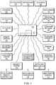
- FIG. 1is block diagram of a programmable multimedia controller, interconnected to a number of devices, according to an illustrative embodiment of the present invention
- FIG. 2is a schematic block diagram showing the high-level hardware architecture of the multimedia controller of FIG. 1 ;
- FIG. 3is a schematic block diagram showing the high-level software architecture of the system of FIG. 1 ;
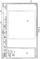
- FIG. 4is a screenshot showing a graphical programming environment in which a user may create a system configuration using the configuration tool of FIG. 3 ;
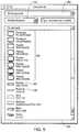
- FIG. 5is a screenshot of a component library used in conjunction with the configuration tool
- FIG. 6A and FIG. 6B togetherare a screenshot of a two room configuration created with the configuration tool
- FIG. 6Cis a screenshot of a component inspector tool by which a user may view detailed information on a component or customize or configure a component;
- FIG. 7is a screenshot showing a configuration compilation for the configuration of FIG. 6A and FIG. 6B
- FIG. 8is a screenshot showing a tool by which a user may customize services
- FIG. 9is a functional block diagram of a metadata management facility which may be incorporated in the programmable multimedia controller of FIG. 1 ;
- FIG. 10is a screenshot showing the graphical programming environment of FIG. 4 in which a user may create a component configuration or modify a user interface appearance or user profile using the configuration tool;
- FIG. 11is a flowchart showing the high level architecture of the software used to define and display a graphical user interface for the programmable multimedia controller of FIG. 1 ;
- FIG. 12is a graphical programming environment showing a series of patches which are used to implement a graphical user interface for the programmable multimedia controller of FIG. 1 ;
- FIG. 13is a screenshot showing the graphically programmable attributes of a button for performing a “play” function.
- FIG. 1is a block diagram of a programmable multimedia controller 100 , interconnected to a number of devices, according to an illustrative embodiment of the present invention.
- the term “programmable multimedia controller”should be interpreted broadly as a device capable of controlling, switching data between, and/or interoperating with a variety of electronic devices, such as audio, video, telephony, data, security, motor-driven, relay-driven, and/or other types of electronic devices . . . . By interacting with these devices the programmable multimedia controller may implement an integrated multimedia control solution.
- the programmable multimedia controller 100is connected to a wide range of audio/video components, for example, a compact disk (CD) player 105 , a digital versatile disc (DVD) player 110 , an audio/video receiver 115 , a television 120 , a personal media player 125 , speakers 122 , a microphone 123 , and/or a video camera 124 .
- the programmable multimedia controllermay also be connected to telephony devices such as a telephone network 130 and telephone handsets 132 .
- the telephone network 130may be a publicly switched telephone network (PSTN), an Integrated Services Digital Network (ISDN) or other communications network.
- PSTNpublicly switched telephone network
- ISDNIntegrated Services Digital Network
- the programmable multimedia controllermay intercommunicate with variety of light and/or home automation systems 135 . These devices may operate via the X10 protocol developed by Pico Electronics, the INSTEONTM protocol developed by SmartHome, Inc, the CEBus standard managed by the CEBus Industry Council, or another well known home automation or control protocol. Similarly the controller may be connected to motor and/or relay operated devices 137 that may include, for example, a heating, ventilation and air conditioning system (HVAC) system, an irrigation system, an automatic shade or blind system, an electronic door lock, or other types of devices.
- HVACheating, ventilation and air conditioning system
- a computer networksuch as the Internet 140 , is connected to the multimedia controller.
- a personal computer (PC) 145video game systems 150 , home recording equipment 165 or other devices may also be connected.
- one or more remote control units 170may be provided to manage the controller's functionality, and/or to control devices connected to the controller.
- Such remote control unitsmay be interconnected to the controller via a wired network connection, an infra-red link, a radiofrequency link, a BluetoothTM link, a ZigBeeTM link or another appropriate data connection. Examples of such remote control units include a touchscreen remote control 112 , a simple remote control 114 , which may be electromechanical, and an MP3 player or other device 116 .
- FIG. 2is a schematic block diagram showing a high-level hardware architecture of the programmable multimedia controller.
- the various components shownmay be arranged on a “motherboard” of the controller, or on a plurality of cards interconnected by a backplane (not shown).
- a microcontroller 210manages the general operation of the system.
- the microcontrolleris a 32-bit model MCF5234 microcontroller available from Freescale Semiconductor Inc.
- the microcontroller 210is coupled to an audio switch 215 and a video switch 220 via a bus 218 .
- the audio switch 215 and the video switch 220are preferably crosspoint switches capable of switching a number of connections simultaneously. However many other types of switches capable of switching digital signals could be employed, for example Time Division Multiplexing (TDM) switches.
- TDMTime Division Multiplexing
- a mid plane 235interconnects the switches and other devices to a variety of input and output modules such as, for example, Digital Video Input Modules with HDMI 600 , Video Output Modules with HDMI 1000 , Digital Audio Input Modules 400 , and Digital Audio Output Modules 900 .
- the mid plane 235is further coupled to an Ethernet switch 230 that permits switching of 10BaseT, 100BaseT or Gigabyte Ethernet signals.
- the Ethernet switch 230interconnects Ethernet ports 232 and a processing subsystem 240 to the microcontroller 210 .
- the processing subsystem 240includes a plurality of small form factor general purpose personal computers that provide redundant operation and/or load balancing.
- the processing subsystem 240may include one or more storage devices, external to the personal computers, to provide expanded storage capacity, for example, to store digital media.
- USBUniversal Serial Bus
- a memory card interface 225may also be connected to the USB hub 243 .
- the interfaceaccepts one or more well known memory card formats, for example CompactFlashTM cards, Memory StickTM cards, Secure DigitalTM (SD) cards, or other formats.
- a USB switch 244is employed to switch USB links among the multiple processing components that may be present.
- IEEE 1394 (FireWireTM) ports 246are interconnected to an IEEE 1394 hub 247 and to an IEEE 1394 switch 248 .
- the microcontroller 210is further connected to a Serial Peripheral Interface (SPI) and Inter-Integrated Circuit (I 2 C) distribution circuit 250 , which provides a serial communication interface to relatively low data transfer rate devices.
- SPISerial Peripheral Interface
- I 2 CInter-Integrated Circuit
- the SPI/I 2 C controller 250is connected to the mid-plane connector 235 and thereby provides control commands from the microcontroller 210 to the modules and other devices in the programmable multimedia controller 100 . Further connections from SPI/I 2 C controller 250 are provided to devices such as a fan controller 251 , a temperature sensor 252 and a power manager circuit 253 , which manage the thermal characteristics of the system and prevent overheating.
- the microcontroller 210is also connected to Infra-Red (IR) interface 260 , an RS232 interface 265 , and an RF interface 267 , that permit interconnection with external devices. Such interaction permits programmable multimedia controller 100 to control external devices.
- the interfacesmay receive control signals that control the operation of the programmable multimedia controller itself. It is expressly contemplated that various other interfaces, including WI-FI, BluetoothTM, ZigBeeTM and other wired and wireless interfaces, may be used with the multimedia controller 100 .
- an Auxiliary Audio/Video Port 700is provided for interconnecting one or more video game systems, camcorders, computers, karaoke machines or other devices.
- a telephone interface 270is provided for connecting to the PSTN or a private network, and to telephone handsets.
- a device control interface 275is provided to communicate with lighting, home automation, and motor and/or relay operated devices.
- an expansion port 280is provided for linking several programmable multimedia controllers together to form an expanded system.
- a front panel display 1150permits presentation of status, configuration, and/or other information to a user.
- the from panelcan display video data originating from any input source connected to the system, such that one may preview video content on the display.
- the front panel display 1150includes a touchscreen, and a user may enter control selections by selecting icons on the screen.
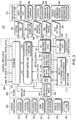
- FIG. 3is a block diagram of the high-level software architecture of the controller 100 .
- the software architectureis organized as a series of planes including a system control plane 302 , a user interface (UI) plane 304 , a control application programming interface (API) access 306 , a service plane 308 , a media plane 310 , a component control plane 312 and a configuration/setup plane 314 .
- UIuser interface
- APIapplication programming interface
- System control plane 302includes the functionalities of a system manager 316 , a system launcher 318 , a redundancy manager 320 , a web server 322 , a touchscreen/PDA server 324 , a remote system access manager 326 and system logs 328 .
- UI plane 304shares a UI server 330 with service plane 308 .
- Service plane 308includes the functionalities of a service controller 332 which itself includes an automator runtime 334 .
- Service plane 308also includes the functionalities of a Mac display controller 336 , an on-screen display (OSD) application 338 , third party applications 340 , Mac applications 342 and an audio/video component controller 344 .
- OSDon-screen display
- service controller 332is capable of controlling Mac applications including iTunes, iChat, iPhoto and iDVD that support Applescript, which enables application-to-application control. Similarly, through automator runtime 334 , service controller 332 is capable of controlling other third party applications which support AppleScript.
- Media plane 310includes the functionality of Mac input/output (I/O) in all supported formats (i.e., DVI, Ethernet, FireWireTM, USB, etc.).
- Component control plane 312includes the functionality of controlling audio/video components 348 .
- Configuration/setup plane 314includes the functionalities of a user configuration tool 350 , a configuration compiler 352 , a user services control application 354 , a workflow generator 356 and a service control workflow browser/search engine/customization application 358 .
- Configuration/setup plane 314also passes several types of information to UI plane 304 and service plane 308 including system configuration 360 , automator workflow 362 , services definitions 364 , component profiles 366 and Mac settings 368 .
- XML filesare used to represent system configuration 360 , automator workflow 362 , services definitions 364 and component profiles 366 .
- Control API access 306has responsibility for an API through which multimedia controller 100 may be controlled by a user who may choose to use a web-enabled device, an RF remote control type device, a touchscreen, a PDA or cell phone.
- UI plane 304has functional responsibility for a user interface to multimedia controller 100 .
- Service plane 308has functional responsibility for implementing services as described above.
- Automator runtime 334is responsible for receiving requests or commands from users and mapping them to a workflow for a particular service.
- Media plane 310has functional responsibility for Mac I/O as well as the other internal and external communications interfaces supported by multimedia controller 100 .
- Component control plane 312has functional responsibility for controlling the operations of audio or video components which may be interfaced with multimedia controller 100 .
- Configuration/setup plane 314has functional responsibility for enabling users to configure multimedia controller 100 ; to select, create or modify services; and to select, create or modify component profiles.
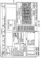
- FIG. 4is a screenshot showing how a user would use configuration tool 350 to begin to create a system configuration.
- Displayed on a screen in a graphical programming environment 400are a configuration workspace 402 , a zone map 404 and a toolbar 406 .
- An icon labeled “Rosie” and denoted by reference number 410represents a programmable multimedia controller 100 ( FIG. 1 ).
- An icon labeled “Room 1 ” and denoted by reference number 412represents a first zone, which may physically include one or more rooms, within the configuration.
- a userclicks on the show palette button 408 .
- this actioncauses a palette of icons representing components in a component library 500 to appear.
- several models of flat panel televisions 502are available in the component library 500 as are a digital surround receiver 504 , an HDMI switcher 506 , and numerous other components.
- a usermay simply drag and drop icons from component library 500 to a desired zone within zone map 404 . Thus, through a series of such drags and drops, a user may specify all of the components which he or she has or wishes to install in a specified zone.
- a usermay access a menu 508 to display only a particular type of component (e.g., receivers, DVD players, speakers, cable TV converters, etc.) or a menu 510 to display only components made by a particular manufacturer.
- a particular type of componente.g., receivers, DVD players, speakers, cable TV converters, etc.
- a menu 510to display only components made by a particular manufacturer.
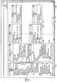
- each component dropped into workspace 402a box appears as shown in FIG. 6A and FIG. 6B .
- box 602represents a programmable multimedia controller 100 within graphical programming environment 400 .
- box 604represents a flat panel television.
- each boxcontains a photograph or other image of the physical component to which it corresponds, which provides a convenient visual reference for the user.
- each boxcontains text and graphics which identify all inputs, outputs and control ports present on the corresponding component.
- the textalso identifies signal type, connector type and other pertinent information about each input, output and control port.
- the graphicsinclude color coding which matches the colors that appear on the physical component.
- FIG. 6 A and FIG. 6BAnother aid which is provided to assist the user in configuration is a component inspector tool.
- a usermay select a component of interest in zone map 404 and then click on a button labeled “Show Inspector” denoted by reference number 614 .
- Show Inspectordenoted by reference number 614 .
- a screen 616 as shown in FIG. 6Cwill appear.
- a menu 618permits a user to examine detailed information on inputs, outputs, control ports and other aspects of the selected component.
- a usermay also configure (i.e., for components that require configuration such as programmable multimedia controllers, modular receivers having programmable input/output slots and the like) or customize the selected component.
- a user“draws” connections between the boxes (components) appearing in workspace 402 . These connections appear as lines such as line 606 , which represents a connection between an output of an amplifier 608 and a set of surround speakers 610 .
- line 606represents a connection between an output of an amplifier 608 and a set of surround speakers 610 .
- Another way a user may make connectionsis to right click on a connector (displayed within a box) and cause a popup menu to open which displays information on what types of connectors are compatible, directly or by way of conversion, as well as those which are incompatible and then select the desired connection from that menu.
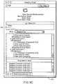
- a usermay click on a “Make Report” button denoted by reference number 616 .
- This actioncauses the underlying software to generate an output report which may contain detailed wiring instructions for the specified configuration, a summary of the components in the configuration, special instructions, user-entered notes and the like.
- the output reportmay serve a bill of materials, wiring checklist and installation instruction sheet.
- a list of realized services 700is displayed to the user.
- a description of a realized serviceappears in a panel 704 .
- a usermay disable any realized service by use of a checkbox 702 .
- a panel 706displays all of the resources that are associated with the selected service.
- a “Show Unrealized” button 708a user may view “unrealized services” which are services that might be provided if the specified configuration is modified. Viewing unrealized services is useful as a tool for debugging a configuration as well as optimizing component usage and user experiences for a given set of components.
- a “Generate” button 710This action causes the underlying software to create the actual system configuration for the programmable multimedia controller 100 and to display a screen like that shown in FIG. 8 .
- the requests associated with the realized service “TV Service”are displayed in a panel 800 .
- a usermay customize a realized service by adding or deleting requests.
- graphical programming environment 400 and configuration tool 350may be used to configure individual components or devices which interface with programmable multimedia controller 100 .
- a touchscreen remote control 1000which is sold by the assignee of the present invention may be included in component library 500 ( FIG. 5 ).
- configuration tool 350may be used to configure options specific to such a touchscreen including user interface appearance (i.e., theme and skin) and user profiles. Detailed information regarding user profiles may be found in co-pending application Ser. No. 11/314,112.
- programmable multimedia controller 100may include a metadata management facility for collecting, organizing and distributing metadata within controller 100 as well as to user remote controls which are interfaced to controller 100 .
- FIG. 9is a functional block diagram of a metadata management facility 900 .
- a metadata manager 902is responsible for several functions including responding to requests for metadata received from a controller interface 902 , receiving new metadata from a data manager 904 or content source manager 916 , and passing new metadata to a storage manager 910 .
- a data watcher 908is responsible for monitoring all possible media sources for the introduction of new media. For example, data watcher 908 detects the loading of a new CD into a CD player which is connected to the programmable multimedia controller 100 , the connection of an MP3 player to controller 100 , the insertion of a thumb drive into controller 100 and the like.
- data watcher 908When data watcher 908 detects the presence of new media, it generates a notification to data manager 904 .
- Data manager 904responds to such a notification by creating a media object which initially contains information regarding the file type, file path (if applicable) and the physical source of the new media.
- Data managerthen forwards the media object to a data interpreter 906 which corresponds to the type of media detected (e.g., MP3 file).
- Data interpreter 906works to extract as much metadata as possible from the new media source. For example, in the case of an MP3 file, data interpreter 906 may use the collect as much metadata as possible from the ID3 tag which is part of the file. All extracted metadata is encapsulated in an object and returned to data manager 904 which forwards it to metadata manager 902 .
- Metadata manager 902may issue a request to content source manager 916 which, in turn, may access one or more content sources 914 which are external to programmable multimedia controller 100 .
- Content source 914may represent a website or other remote information source which can be accessed over the Internet or other network. Additional metadata which content source manager 916 captures is returned to metadata manager 902 and eventually passed to storage manager 910 for storage.
- Storage manager 910has overall responsibility for storing, retrieving, updating or removing metadata in response to queries or messages received from metadata manager 902 .
- programmable multimedia controller 100includes a Mac computer from Apple Computer, Inc., as described in detail in co-pending application Ser. No. 11/314,664, storage manager 910 may be implemented as a database containing stub files. Such files may be indexed and queried very efficiently using Spotlight, a metadata search engine included in Mac OS X.
- Controller interface 912is responsible for communications between metadata manager 902 and user controllers such as touchscreen remote control 112 ( FIG. 1 ). Controller interface 912 is also responsible for ensuring that all user controllers have access to the most current metadata. This may be accomplished by using rsync, a synchronization function, which is party of Mac OS X.
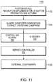
- a graphical user interface for use with programmable multimedia controller 100is based on a software architecture which enables easy modification of the appearance, functionality or other attributes of the interface.
- FIG. 11shows a software architecture 1100 for a graphical user interface.
- Adobe Photoshop® softwarewhich is included in Mac OS X, is used to create files 1102 .
- a Photoshop® file 1102is preferably created for each element or screen of a graphical user interface, like the screen shown in FIG. 13 , or for some other convenient unit up to and including an entire user interface.
- Each Photoshop® file 1102contains information, preferably organized in “groups” and “layers,” which define the appearance, functionality and other attributes of each element of a graphical user interface.
- the information in a file 1102may include notes, labels, text-to-speech commands, system control commands, graphics corresponding to different states of a radio button or other user control (e.g., enabled, pressed, mouseover), display text, font size, color, sound effect and button/control type among others.
- Files 1102which are typically stored on non-volatile media such as a hard drive, are read 1104 by Quartz Composer, another piece of software which is also included within Mac OS X, and a run-time environment that loads Quartz Composer compositions. Quartz Composer functions to parse Photoshop® files 1102 , thereby extracting all of the embedded groups and layers for the whole file, as well as for each radio button or other control.
- Quartz Composer“patches” access the extracted information and, using a Quartz Composer function called “output ports”, pass appropriate commands and information from a patch to control API access 306 ( FIG. 3 ) and user interface (UI) server 330 .
- This arrangementprovides a powerful programming capability because it permits an author of a Quartz Composer composition direct access to multiple layers of graphics as well as any other information stored in a file 1102 . Stated another way, by simply altering the information contained in a file 1102 , an author, using widely available and familiar software, may easily and rapidly configure, modify or customize any aspect of the graphical user interface represented by that file.
- control API access 306 and UI server 330issue appropriate commands and information to service controller 332 ( FIG. 3 ).
- Service controller 332issues appropriate commands to external components 1106 to effect whatever action a user has indicated through the graphical user interface.
- FIG. 12shows a on-screen display 1200 of a series of Quartz Composer patches.
- a Photoshop® file 1102is passed to an input of an “Import” patch 1202 .
- Import patch 1202produces several outputs one of which is the extracted Photoshop® file (“outputPSfile”) and the names of all of the buttons present in file 1102 (“outputAllButtonNames”).
- the extracted Photoshop® fileis passed to four LayersFromFile patches 1204 . Multiple outputs of each of patches 1204 are passed, respectively, to four Structure Key Member patches 1206 .
- An output from one of patches 1206is passed to Say Text patch 1210 , which performs a text-to-speech function. Similarly, an output from another patch 1206 is passed to Send Service Request to SVC patch 1212 , which is responsible for sending appropriate commands and data to service controller 332 . The output of a third one of patches 1206 is passed to Image With String patch 1214 , which converts text (extracted from file 1102 ) to an image for display. The output of the remaining patch 1206 is passed to a Display patch 1216 which is responsible for displaying a radio button.
- FIG. 13is a screenshot of a graphical programming environment 1300 in which a graphical user interface 1302 for an audio or video component is shown.
- a graphical user interface 1302 for an audio or video componentis shown in area 1304 of environment 1300 .
- the programmable “layers” of functionality and attributes of a “Play” button 1306are shown.
- a Photoshop® file corresponding to button 1306is loaded and a Quartz Composer patch requests the “Command” layer, the result will be the associated audio or video component will be commanded to play.
Landscapes
- Engineering & Computer Science (AREA)
- Signal Processing (AREA)
- Computer Networks & Wireless Communication (AREA)
- Automation & Control Theory (AREA)
- Theoretical Computer Science (AREA)
- Physics & Mathematics (AREA)
- General Engineering & Computer Science (AREA)
- General Physics & Mathematics (AREA)
- Multimedia (AREA)
- Human Computer Interaction (AREA)
- Software Systems (AREA)
- Computer Hardware Design (AREA)
- Stored Programmes (AREA)
- User Interface Of Digital Computer (AREA)
- Two-Way Televisions, Distribution Of Moving Picture Or The Like (AREA)
- Programmable Controllers (AREA)
- Selective Calling Equipment (AREA)
Abstract
Description
Claims (19)
Priority Applications (1)
| Application Number | Priority Date | Filing Date | Title |
|---|---|---|---|
| US16/383,253US10962996B2 (en) | 2006-09-13 | 2019-04-12 | Configuring a system of components using graphical programming environment |
Applications Claiming Priority (4)
| Application Number | Priority Date | Filing Date | Title |
|---|---|---|---|
| US11/520,215US7930644B2 (en) | 2006-09-13 | 2006-09-13 | Programming environment and metadata management for programmable multimedia controller |
| US13/042,238US8997011B2 (en) | 2006-09-13 | 2011-03-07 | Programming environment for configuring a system of audio/video components |
| US14/660,323US10261529B2 (en) | 2006-09-13 | 2015-03-17 | Configuring a system of components using graphical programming environment having a zone map |
| US16/383,253US10962996B2 (en) | 2006-09-13 | 2019-04-12 | Configuring a system of components using graphical programming environment |
Related Parent Applications (1)
| Application Number | Title | Priority Date | Filing Date |
|---|---|---|---|
| US14/660,323ContinuationUS10261529B2 (en) | 2006-09-13 | 2015-03-17 | Configuring a system of components using graphical programming environment having a zone map |
Publications (2)
| Publication Number | Publication Date |
|---|---|
| US20190235539A1 US20190235539A1 (en) | 2019-08-01 |
| US10962996B2true US10962996B2 (en) | 2021-03-30 |
Family
ID=39103195
Family Applications (4)
| Application Number | Title | Priority Date | Filing Date |
|---|---|---|---|
| US11/520,215Active2027-02-09US7930644B2 (en) | 2006-09-13 | 2006-09-13 | Programming environment and metadata management for programmable multimedia controller |
| US13/042,238Active2029-08-07US8997011B2 (en) | 2006-09-13 | 2011-03-07 | Programming environment for configuring a system of audio/video components |
| US14/660,323Active2028-05-29US10261529B2 (en) | 2006-09-13 | 2015-03-17 | Configuring a system of components using graphical programming environment having a zone map |
| US16/383,253Active2026-10-03US10962996B2 (en) | 2006-09-13 | 2019-04-12 | Configuring a system of components using graphical programming environment |
Family Applications Before (3)
| Application Number | Title | Priority Date | Filing Date |
|---|---|---|---|
| US11/520,215Active2027-02-09US7930644B2 (en) | 2006-09-13 | 2006-09-13 | Programming environment and metadata management for programmable multimedia controller |
| US13/042,238Active2029-08-07US8997011B2 (en) | 2006-09-13 | 2011-03-07 | Programming environment for configuring a system of audio/video components |
| US14/660,323Active2028-05-29US10261529B2 (en) | 2006-09-13 | 2015-03-17 | Configuring a system of components using graphical programming environment having a zone map |
Country Status (14)
| Country | Link |
|---|---|
| US (4) | US7930644B2 (en) |
| EP (1) | EP2064883B1 (en) |
| JP (1) | JP5322941B2 (en) |
| KR (1) | KR101368133B1 (en) |
| CN (1) | CN101573969B (en) |
| AU (1) | AU2007294756B2 (en) |
| BR (1) | BRPI0716782A2 (en) |
| CA (1) | CA2663167C (en) |
| ES (1) | ES2518996T3 (en) |
| IL (1) | IL197559A (en) |
| MX (1) | MX2009002783A (en) |
| NZ (1) | NZ575441A (en) |
| RU (1) | RU2453069C2 (en) |
| WO (1) | WO2008033453A2 (en) |
Families Citing this family (110)
| Publication number | Priority date | Publication date | Assignee | Title |
|---|---|---|---|---|
| US11343380B2 (en) | 2004-03-16 | 2022-05-24 | Icontrol Networks, Inc. | Premises system automation |
| US11582065B2 (en) | 2007-06-12 | 2023-02-14 | Icontrol Networks, Inc. | Systems and methods for device communication |
| US11916870B2 (en) | 2004-03-16 | 2024-02-27 | Icontrol Networks, Inc. | Gateway registry methods and systems |
| US10339791B2 (en) | 2007-06-12 | 2019-07-02 | Icontrol Networks, Inc. | Security network integrated with premise security system |
| US12063220B2 (en) | 2004-03-16 | 2024-08-13 | Icontrol Networks, Inc. | Communication protocols in integrated systems |
| US20170118037A1 (en) | 2008-08-11 | 2017-04-27 | Icontrol Networks, Inc. | Integrated cloud system for premises automation |
| US11244545B2 (en) | 2004-03-16 | 2022-02-08 | Icontrol Networks, Inc. | Cross-client sensor user interface in an integrated security network |
| US11190578B2 (en) | 2008-08-11 | 2021-11-30 | Icontrol Networks, Inc. | Integrated cloud system with lightweight gateway for premises automation |
| US10237237B2 (en) | 2007-06-12 | 2019-03-19 | Icontrol Networks, Inc. | Communication protocols in integrated systems |
| US11811845B2 (en) | 2004-03-16 | 2023-11-07 | Icontrol Networks, Inc. | Communication protocols over internet protocol (IP) networks |
| US9729342B2 (en) | 2010-12-20 | 2017-08-08 | Icontrol Networks, Inc. | Defining and implementing sensor triggered response rules |
| GB2428821B (en) | 2004-03-16 | 2008-06-04 | Icontrol Networks Inc | Premises management system |
| US11368429B2 (en) | 2004-03-16 | 2022-06-21 | Icontrol Networks, Inc. | Premises management configuration and control |
| US10721087B2 (en) | 2005-03-16 | 2020-07-21 | Icontrol Networks, Inc. | Method for networked touchscreen with integrated interfaces |
| US10999254B2 (en) | 2005-03-16 | 2021-05-04 | Icontrol Networks, Inc. | System for data routing in networks |
| US11615697B2 (en) | 2005-03-16 | 2023-03-28 | Icontrol Networks, Inc. | Premise management systems and methods |
| US11700142B2 (en) | 2005-03-16 | 2023-07-11 | Icontrol Networks, Inc. | Security network integrating security system and network devices |
| US20110128378A1 (en) | 2005-03-16 | 2011-06-02 | Reza Raji | Modular Electronic Display Platform |
| US20120324566A1 (en) | 2005-03-16 | 2012-12-20 | Marc Baum | Takeover Processes In Security Network Integrated With Premise Security System |
| US12063221B2 (en) | 2006-06-12 | 2024-08-13 | Icontrol Networks, Inc. | Activation of gateway device |
| US7930644B2 (en) | 2006-09-13 | 2011-04-19 | Savant Systems, Llc | Programming environment and metadata management for programmable multimedia controller |
| US9602880B2 (en) | 2006-12-29 | 2017-03-21 | Kip Prod P1 Lp | Display inserts, overlays, and graphical user interfaces for multimedia systems |
| WO2008085201A2 (en) | 2006-12-29 | 2008-07-17 | Prodea Systems, Inc. | Managed file backup and restore at remote storage locations through multi-services gateway device at user premises |
| US20170344703A1 (en) | 2006-12-29 | 2017-11-30 | Kip Prod P1 Lp | Multi-services application gateway and system employing the same |
| US11783925B2 (en) | 2006-12-29 | 2023-10-10 | Kip Prod P1 Lp | Multi-services application gateway and system employing the same |
| US11316688B2 (en) | 2006-12-29 | 2022-04-26 | Kip Prod P1 Lp | Multi-services application gateway and system employing the same |
| US9569587B2 (en) | 2006-12-29 | 2017-02-14 | Kip Prod Pi Lp | Multi-services application gateway and system employing the same |
| US11706279B2 (en) | 2007-01-24 | 2023-07-18 | Icontrol Networks, Inc. | Methods and systems for data communication |
| US7633385B2 (en) | 2007-02-28 | 2009-12-15 | Ucontrol, Inc. | Method and system for communicating with and controlling an alarm system from a remote server |
| US8451986B2 (en) | 2007-04-23 | 2013-05-28 | Icontrol Networks, Inc. | Method and system for automatically providing alternate network access for telecommunications |
| KR20080095722A (en)* | 2007-04-24 | 2008-10-29 | 삼성전자주식회사 | Inactive Information Provision Method and Applied Imaging Device |
| US8316309B2 (en)* | 2007-05-31 | 2012-11-20 | International Business Machines Corporation | User-created metadata for managing interface resources on a user interface |
| US12283172B2 (en) | 2007-06-12 | 2025-04-22 | Icontrol Networks, Inc. | Communication protocols in integrated systems |
| US11237714B2 (en) | 2007-06-12 | 2022-02-01 | Control Networks, Inc. | Control system user interface |
| US11601810B2 (en) | 2007-06-12 | 2023-03-07 | Icontrol Networks, Inc. | Communication protocols in integrated systems |
| US11316753B2 (en)* | 2007-06-12 | 2022-04-26 | Icontrol Networks, Inc. | Communication protocols in integrated systems |
| US11218878B2 (en) | 2007-06-12 | 2022-01-04 | Icontrol Networks, Inc. | Communication protocols in integrated systems |
| US11212192B2 (en) | 2007-06-12 | 2021-12-28 | Icontrol Networks, Inc. | Communication protocols in integrated systems |
| US12003387B2 (en) | 2012-06-27 | 2024-06-04 | Comcast Cable Communications, Llc | Control system user interface |
| US11646907B2 (en) | 2007-06-12 | 2023-05-09 | Icontrol Networks, Inc. | Communication protocols in integrated systems |
| US12184443B2 (en) | 2007-06-12 | 2024-12-31 | Icontrol Networks, Inc. | Controlling data routing among networks |
| US10223903B2 (en) | 2010-09-28 | 2019-03-05 | Icontrol Networks, Inc. | Integrated security system with parallel processing architecture |
| US11831462B2 (en) | 2007-08-24 | 2023-11-28 | Icontrol Networks, Inc. | Controlling data routing in premises management systems |
| CA2701445C (en) | 2007-09-05 | 2015-12-08 | Savant Systems, Llc | Expandable multimedia control system and method |
| US7954133B2 (en)* | 2007-10-22 | 2011-05-31 | Sony Ericsson Mobile Communications Ab | Digital living network alliance (DLNA) enabled portable electronic devices, DLNA management consoles and related methods of operating DLNA enabled portable electronic devices |
| US11916928B2 (en) | 2008-01-24 | 2024-02-27 | Icontrol Networks, Inc. | Communication protocols over internet protocol (IP) networks |
| US7859137B2 (en) | 2008-05-09 | 2010-12-28 | Tap.Tv, Inc. | Scalable switch device and system |
| US20090308543A1 (en)* | 2008-06-13 | 2009-12-17 | Lawrence Kates | Motorized window shade system and mount |
| US20170185278A1 (en) | 2008-08-11 | 2017-06-29 | Icontrol Networks, Inc. | Automation system user interface |
| US11758026B2 (en) | 2008-08-11 | 2023-09-12 | Icontrol Networks, Inc. | Virtual device systems and methods |
| ES2401363T3 (en)* | 2008-08-11 | 2013-04-19 | Deutsche Telekom Ag | Procedure for making services available in a telecommunications network infrastructure |
| US11729255B2 (en) | 2008-08-11 | 2023-08-15 | Icontrol Networks, Inc. | Integrated cloud system with lightweight gateway for premises automation |
| US11792036B2 (en) | 2008-08-11 | 2023-10-17 | Icontrol Networks, Inc. | Mobile premises automation platform |
| US10157172B2 (en)* | 2008-08-27 | 2018-12-18 | International Business Machines Corporation | Property dependency visualization |
| US11061375B2 (en)* | 2010-04-06 | 2021-07-13 | Connie R. Masters | Irrigation controller and system |
| US8565904B2 (en)* | 2009-09-03 | 2013-10-22 | Bruce Allen Bragg | Irrigation controller and system integrating no-watering restrictions and an empirically-derived evapotranspiration local characteristic curve |
| US8638211B2 (en) | 2009-04-30 | 2014-01-28 | Icontrol Networks, Inc. | Configurable controller and interface for home SMA, phone and multimedia |
| US20120005693A1 (en)* | 2010-01-08 | 2012-01-05 | Cypress Semiconductor Corporation | Development, Programming, and Debugging Environment |
| US10613704B2 (en) | 2009-06-03 | 2020-04-07 | Savant Systems, Llc | Small screen virtual room-based user interface |
| US10775960B2 (en) | 2009-06-03 | 2020-09-15 | Savant Systems, Inc. | User generated virtual room-based user interface |
| MX2011012905A (en) | 2009-06-03 | 2012-03-29 | Savant Systems Llc | Virtual room-based light fixture and device control. |
| CA2707286A1 (en)* | 2009-06-11 | 2010-12-11 | X2O Media Inc. | System and method for generating multimedia presentations |
| US8938675B2 (en)* | 2009-06-16 | 2015-01-20 | Harman International Industries, Incorporated | System for automated generation of audio/video control interfaces |
| KR101196410B1 (en)* | 2009-07-07 | 2012-11-01 | 삼성전자주식회사 | Method for auto setting configuration of television according to installation type of television and television using the same |
| US8880586B2 (en)* | 2010-04-08 | 2014-11-04 | Microsoft Corporation | Metadata subscription registry |
| US9661428B2 (en) | 2010-08-17 | 2017-05-23 | Harman International Industries, Inc. | System for configuration and management of live sound system |
| JP2012049868A (en) | 2010-08-27 | 2012-03-08 | On Semiconductor Trading Ltd | Switch circuit |
| JP2012054694A (en)* | 2010-08-31 | 2012-03-15 | On Semiconductor Trading Ltd | Bidirectional switch and switch circuit using the same |
| US8719581B2 (en) | 2010-09-22 | 2014-05-06 | Savant Systems, Llc | Programmable multimedia controller with flexible user access and shared device configurations |
| US8836467B1 (en) | 2010-09-28 | 2014-09-16 | Icontrol Networks, Inc. | Method, system and apparatus for automated reporting of account and sensor zone information to a central station |
| CA2814710A1 (en)* | 2010-10-15 | 2012-04-19 | Gridspeak Corporation | Systems and methods for automated availability and/or outage management |
| US11750414B2 (en) | 2010-12-16 | 2023-09-05 | Icontrol Networks, Inc. | Bidirectional security sensor communication for a premises security system |
| US9147337B2 (en) | 2010-12-17 | 2015-09-29 | Icontrol Networks, Inc. | Method and system for logging security event data |
| US8914724B2 (en)* | 2011-04-06 | 2014-12-16 | Savant Systems, Llc | Method and apparatus for creating and modifying graphical schedules |
| US8938312B2 (en) | 2011-04-18 | 2015-01-20 | Sonos, Inc. | Smart line-in processing |
| US9042556B2 (en) | 2011-07-19 | 2015-05-26 | Sonos, Inc | Shaping sound responsive to speaker orientation |
| EP2751664A4 (en) | 2011-09-02 | 2016-11-02 | Vu Lam | SYSTEMS AND METHODS FOR PROCESSING SOFTWARE APPLICATION METADATA ASSOCIATED WITH SOFTWARE APPLICATION |
| US11755510B2 (en) | 2011-11-08 | 2023-09-12 | Seagate Technology Llc | Data detection and device optimization |
| US20130191781A1 (en)* | 2012-01-20 | 2013-07-25 | Microsoft Corporation | Displaying and interacting with touch contextual user interface |
| US9928562B2 (en) | 2012-01-20 | 2018-03-27 | Microsoft Technology Licensing, Llc | Touch mode and input type recognition |
| US8972858B2 (en)* | 2012-04-19 | 2015-03-03 | Savant Systems, Llc | Configuration interface for a programmable multimedia controller |
| US9182954B2 (en)* | 2012-07-27 | 2015-11-10 | Microsoft Technology Licensing, Llc | Web browser having user-configurable address bar button |
| FR2994625B1 (en)* | 2012-08-20 | 2014-08-08 | Ifeelsmart | INTELLIGENT REMOTE FOR DIGITAL TELEVISION |
| KR101365614B1 (en)* | 2012-08-23 | 2014-03-12 | 엘지전자 주식회사 | Multimedia device connected to external electronic device and method for controlling the same |
| US11405463B2 (en) | 2014-03-03 | 2022-08-02 | Icontrol Networks, Inc. | Media content management |
| US9876652B2 (en)* | 2014-05-20 | 2018-01-23 | Savant Systems, Llc | Automatic configuration of control device user interface in a home automation system |
| US10042336B2 (en)* | 2014-09-09 | 2018-08-07 | Savant Systems, Llc | User-defined scenes for home automation |
| US10678204B2 (en)* | 2014-09-30 | 2020-06-09 | Honeywell International Inc. | Universal analog cell for connecting the inputs and outputs of devices |
| CN104571011A (en)* | 2014-11-27 | 2015-04-29 | 魏晓慧 | Embedded multi-media control system |
| AU2015361316B2 (en)* | 2014-12-11 | 2019-07-04 | Bitdefender Ipr Management Ltd | Systems and methods for securing network endpoints |
| CN104483865B (en)* | 2014-12-26 | 2017-11-10 | 小米科技有限责任公司 | The installation implementation method and device of intelligent hardware devices |
| US10116601B2 (en)* | 2015-02-06 | 2018-10-30 | Jamdeo Canada Ltd. | Methods and devices for display device notifications |
| CN104852967B (en)* | 2015-04-21 | 2018-03-27 | 小米科技有限责任公司 | Image sharing method and device |
| US11113022B2 (en)* | 2015-05-12 | 2021-09-07 | D&M Holdings, Inc. | Method, system and interface for controlling a subwoofer in a networked audio system |
| US11209972B2 (en) | 2015-09-02 | 2021-12-28 | D&M Holdings, Inc. | Combined tablet screen drag-and-drop interface |
| US10042339B2 (en)* | 2015-10-05 | 2018-08-07 | Savant Systems, Llc | Cloud-synchronized architecture for a home automation system |
| US10856394B2 (en)* | 2016-02-04 | 2020-12-01 | Lutron Technology Company Llc | Configuring a load control system |
| US20180004393A1 (en) | 2016-07-01 | 2018-01-04 | Autodesk, Inc. | Three dimensional visual programming interface for a network of devices |
| CN107481491B (en)* | 2016-07-20 | 2019-09-20 | 宝沃汽车(中国)有限公司 | The control system and mobile terminal of electric appliance |
| US10405041B2 (en)* | 2016-11-28 | 2019-09-03 | Rovi Guides, Inc. | Systems and methods for predictive spoiler prevention in media assets based on user behavior |
| CN108235144B (en)* | 2016-12-22 | 2021-02-19 | 阿里巴巴(中国)有限公司 | Playing content obtaining method and device and computing equipment |
| US10776887B2 (en)* | 2017-02-07 | 2020-09-15 | Enseo, Inc. | System and method for making reservations in a hospitality establishment |
| USD862512S1 (en)* | 2017-08-28 | 2019-10-08 | Siemens Healthcare Gmbh | Display screen or portion thereof with a graphical user interface |
| USD872121S1 (en)* | 2017-11-14 | 2020-01-07 | Palantir Technologies, Inc. | Display screen or portion thereof with transitional graphical user interface |
| US10860339B2 (en)* | 2018-08-03 | 2020-12-08 | Dell Products L.P. | Autonomous creation of new microservices and modification of existing microservices |
| US11408626B2 (en)* | 2019-01-11 | 2022-08-09 | Johnson Controls Tyco IP Holdings LLP | Central plant control system with dynamic computation reduction |
| US11863343B2 (en) | 2019-02-14 | 2024-01-02 | Savant Systems, Inc. | Multi-role devices for automation environments |
| US11172111B2 (en) | 2019-07-29 | 2021-11-09 | Honeywell International Inc. | Devices and methods for security camera installation planning |
| CA3153699A1 (en) | 2019-09-11 | 2021-03-18 | Savant Systems, Inc. | Energy management system and methods |
| CA3153935A1 (en) | 2019-09-11 | 2021-03-18 | Savant Systems, Inc. | Three dimensional virtual room-based user interface for a home automation system |
Citations (52)
| Publication number | Priority date | Publication date | Assignee | Title |
|---|---|---|---|---|
| WO1994014282A1 (en) | 1992-12-09 | 1994-06-23 | Discovery Communications, Inc. | Set top terminal for cable television delivery systems |
| JPH0879847A (en) | 1994-09-05 | 1996-03-22 | Hitachi Ltd | Information system, AV equipment and remote control operating device constituting the system |
| EP0727909A2 (en) | 1995-02-06 | 1996-08-21 | Sony Corporation | Interface for audio/video subscriber equipment and telecommunications line |
| WO1998059284A2 (en) | 1997-06-25 | 1998-12-30 | Samsung Electronics Co., Ltd. | Method and apparatus for creating home network macros |
| WO1999006910A1 (en) | 1997-07-31 | 1999-02-11 | Sony Electronics Inc. | A method and apparatus for including self-describing information within devices |
| WO2000017737A1 (en) | 1998-09-17 | 2000-03-30 | Koninklijke Philips Electronics N.V. | Remote control device with location dependent interface |
| US6061602A (en) | 1998-06-23 | 2000-05-09 | Creative Lifestyles, Inc. | Method and apparatus for developing application software for home automation system |
| JP2000197162A (en) | 1998-12-28 | 2000-07-14 | Toshiba Corp | Remote control device |
| US6266098B1 (en) | 1997-10-22 | 2001-07-24 | Matsushita Electric Corporation Of America | Function presentation and selection using a rotatable function menu |
| US6313880B1 (en) | 1997-04-03 | 2001-11-06 | Sony Corporation | Display with one or more display windows and placement dependent cursor and function control |
| US6469633B1 (en) | 1997-01-06 | 2002-10-22 | Openglobe Inc. | Remote control of electronic devices |
| US20030035010A1 (en) | 2001-08-14 | 2003-02-20 | Kodosky Jeffrey L. | Configuring graphical program nodes for remote execution |
| WO2003019560A2 (en) | 2001-08-27 | 2003-03-06 | Gracenote, Inc. | Playlist generation, delivery and navigation |
| US20030088852A1 (en) | 2001-11-07 | 2003-05-08 | Lone Wolf Technologies Corporation. | Visual network operating system and methods |
| US20030101459A1 (en) | 1999-08-03 | 2003-05-29 | Ucentric Holdings, Llc | Multi-service in-home network with an open interface |
| WO2003044625A2 (en) | 2001-11-20 | 2003-05-30 | Universal Electronics Inc. | Hand held remote control device having an improved user interface |
| JP2003198871A (en) | 2001-12-25 | 2003-07-11 | Matsushita Electric Ind Co Ltd | Home appliance control system and method, remote control device and home appliance used in the system |
| US20030151538A1 (en) | 2000-07-13 | 2003-08-14 | Universal Electronics Inc. | Customizable and upgradable devices and methods related thereto |
| EP1355485A1 (en) | 2002-04-18 | 2003-10-22 | Deutsche Thomson-Brandt Gmbh | Method for generating a user interface on a HAVi device for the control of a Non-HAVi device |
| WO2003098847A1 (en) | 2002-05-22 | 2003-11-27 | Helmes Josef J J | Multi-media interaction system |
| US20040031019A1 (en) | 2002-05-20 | 2004-02-12 | Richard Lamanna | Debugger for a graphical programming environment |
| US20040054789A1 (en) | 2002-09-12 | 2004-03-18 | International Business Machines Corporation | Pervasive home network portal |
| US20040059716A1 (en) | 2002-09-20 | 2004-03-25 | Fuji Xerox Co., Ltd. | Linking information making device, linking information making method, recording medium having recorded a linking information making program, and document processing system therewith |
| JP2004194011A (en) | 2002-12-11 | 2004-07-08 | Canon Inc | Remote operation control system, remote control device, remote operation method, program, and storage medium |
| US20040143349A1 (en) | 2002-10-28 | 2004-07-22 | Gracenote, Inc. | Personal audio recording system |
| RU2237275C2 (en) | 1999-02-18 | 2004-09-27 | Ситрикс Системз, Инк. | Server and method (variants) for determining software surroundings of client node in a network having client/server architecture |
| US20040260407A1 (en) | 2003-04-08 | 2004-12-23 | William Wimsatt | Home automation control architecture |
| US20040261116A1 (en) | 2001-07-03 | 2004-12-23 | Mckeown Jean Christophe | Broadband communications |
| US20040267914A1 (en) | 2003-06-30 | 2004-12-30 | Roe Bryan Y. | Method, apparatus and system for creating efficient UPnP control points |
| US20050021714A1 (en) | 2003-04-17 | 2005-01-27 | Samsung Electronics Co., Ltd. | Home network apparatus and system for cooperative work service and method thereof |
| US20050074018A1 (en) | 1999-06-11 | 2005-04-07 | Microsoft Corporation | XML-based template language for devices and services |
| JP2005122271A (en) | 2003-10-14 | 2005-05-12 | Sony Ericsson Mobilecommunications Japan Inc | Portable electronic device |
| US20050125564A1 (en) | 2003-12-04 | 2005-06-09 | Matsushita Electric Industrial Co., Ltd. | Profiling service for the automatic service discovery and control middleware frameworks |
| EP1548740A2 (en) | 2003-12-24 | 2005-06-29 | Bose Corporation | Intelligent music track selection |
| US20050251747A1 (en) | 2002-08-05 | 2005-11-10 | Siemens Aktiegesellschaft | Tool and method for configuring, designing or programming an installation |
| WO2005107408A2 (en) | 2004-04-30 | 2005-11-17 | Vulcan Inc. | Smart home control of electronic devices |
| EP1617333A1 (en) | 2003-04-24 | 2006-01-18 | Mitsubishi Denki Kabushiki Kaisha | Video device, video module unit, and video device operation method |
| US20060158838A1 (en) | 2005-01-18 | 2006-07-20 | Funai Electric Co., Ltd. | Input switching apparatus and television apparatus |
| JP2006227135A (en) | 2005-02-16 | 2006-08-31 | Sharp Corp | Remote operation device, remote operation method, and remote operation program |
| US7103660B2 (en) | 2000-02-23 | 2006-09-05 | Sony Corporation | Information processing apparatus, method thereof, network system, record medium, and program |
| US20070044073A1 (en) | 2005-08-18 | 2007-02-22 | Jacob Kornerup | Spatial Iteration Node for a Graphical Program |
| US20070055976A1 (en)* | 2005-09-07 | 2007-03-08 | Amx, Llc | Method and computer program for device configuration |
| US7234115B1 (en)* | 2002-09-26 | 2007-06-19 | Home Director, Inc. | Home entertainment system and method |
| US20070143801A1 (en) | 2005-12-20 | 2007-06-21 | Madonna Robert P | System and method for a programmable multimedia controller |
| US20070142022A1 (en) | 2005-12-20 | 2007-06-21 | Madonna Robert P | Programmable multimedia controller with programmable services |
| US20070214427A1 (en) | 2006-03-10 | 2007-09-13 | National Instruments Corporation | Automatic generation of documentation for specified systems |
| US7330189B2 (en) | 2003-01-15 | 2008-02-12 | Matsushita Electric Industrial Co., Ltd. | Information processing system for displaying image on information terminal |
| RU2321892C2 (en) | 2003-03-27 | 2008-04-10 | Майкрософт Корпорейшн | Markup language and object model for vector graphics |
| US20080126936A1 (en) | 2003-08-21 | 2008-05-29 | Gary Williams | Electronic/software multimedia library control system and methods of use thereof |
| US20090076821A1 (en)* | 2005-08-19 | 2009-03-19 | Gracenote, Inc. | Method and apparatus to control operation of a playback device |
| US7930644B2 (en) | 2006-09-13 | 2011-04-19 | Savant Systems, Llc | Programming environment and metadata management for programmable multimedia controller |
| US9183560B2 (en) | 2010-05-28 | 2015-11-10 | Daniel H. Abelow | Reality alternate |
Family Cites Families (1)
| Publication number | Priority date | Publication date | Assignee | Title |
|---|---|---|---|---|
| US20070005597A1 (en)* | 2004-11-23 | 2007-01-04 | Williams Charles K | Name classifier algorithm |
- 2006
- 2006-09-13USUS11/520,215patent/US7930644B2/enactiveActive
- 2007
- 2007-09-13AUAU2007294756Apatent/AU2007294756B2/enactiveActive
- 2007-09-13CACA2663167Apatent/CA2663167C/enactiveActive
- 2007-09-13KRKR1020097007596Apatent/KR101368133B1/enactiveActive
- 2007-09-13BRBRPI0716782-2A2Apatent/BRPI0716782A2/ennot_activeApplication Discontinuation
- 2007-09-13CNCN200780041123.8Apatent/CN101573969B/enactiveActive
- 2007-09-13RURU2009112044/07Apatent/RU2453069C2/enactive
- 2007-09-13NZNZ575441Apatent/NZ575441A/enunknown
- 2007-09-13JPJP2009528288Apatent/JP5322941B2/enactiveActive
- 2007-09-13EPEP07838167.0Apatent/EP2064883B1/enactiveActive
- 2007-09-13ESES07838167.0Tpatent/ES2518996T3/enactiveActive
- 2007-09-13WOPCT/US2007/019912patent/WO2008033453A2/enactiveApplication Filing
- 2007-09-13MXMX2009002783Apatent/MX2009002783A/enactiveIP Right Grant
- 2009
- 2009-03-12ILIL197559Apatent/IL197559A/enactiveIP Right Grant
- 2011
- 2011-03-07USUS13/042,238patent/US8997011B2/enactiveActive
- 2015
- 2015-03-17USUS14/660,323patent/US10261529B2/enactiveActive
- 2019
- 2019-04-12USUS16/383,253patent/US10962996B2/enactiveActive
Patent Citations (66)
| Publication number | Priority date | Publication date | Assignee | Title |
|---|---|---|---|---|
| RU2112325C1 (en) | 1992-12-09 | 1998-05-27 | Дискавери Коммьюникейшнз, Инк. | Hardware master terminal for system delivering tv programs and method for its use |
| WO1994014282A1 (en) | 1992-12-09 | 1994-06-23 | Discovery Communications, Inc. | Set top terminal for cable television delivery systems |
| JPH0879847A (en) | 1994-09-05 | 1996-03-22 | Hitachi Ltd | Information system, AV equipment and remote control operating device constituting the system |
| EP0727909A2 (en) | 1995-02-06 | 1996-08-21 | Sony Corporation | Interface for audio/video subscriber equipment and telecommunications line |
| US6469633B1 (en) | 1997-01-06 | 2002-10-22 | Openglobe Inc. | Remote control of electronic devices |
| US6313880B1 (en) | 1997-04-03 | 2001-11-06 | Sony Corporation | Display with one or more display windows and placement dependent cursor and function control |
| CN1496060A (en) | 1997-06-25 | 2004-05-12 | ���ǵ�����ʽ���� | Home network system and control method thereof |
| US6182094B1 (en)* | 1997-06-25 | 2001-01-30 | Samsung Electronics Co., Ltd. | Programming tool for home networks with an HTML page for a plurality of home devices |
| US20010011284A1 (en) | 1997-06-25 | 2001-08-02 | Richard James Humpleman | Method and apparatus for a home network auto-tree builder |
| WO1998059284A2 (en) | 1997-06-25 | 1998-12-30 | Samsung Electronics Co., Ltd. | Method and apparatus for creating home network macros |
| JP2002509669A (en) | 1997-06-25 | 2002-03-26 | サムソン エレクトロニクス カンパニー リミテッド | Method and apparatus for generating a home network macro |
| WO1999006910A1 (en) | 1997-07-31 | 1999-02-11 | Sony Electronics Inc. | A method and apparatus for including self-describing information within devices |
| KR20010014271A (en) | 1997-07-31 | 2001-02-26 | 밀러 제리 에이 | A method and apparatus for including self-describing information within devices |
| US6266098B1 (en) | 1997-10-22 | 2001-07-24 | Matsushita Electric Corporation Of America | Function presentation and selection using a rotatable function menu |
| US6061602A (en) | 1998-06-23 | 2000-05-09 | Creative Lifestyles, Inc. | Method and apparatus for developing application software for home automation system |
| WO2000017737A1 (en) | 1998-09-17 | 2000-03-30 | Koninklijke Philips Electronics N.V. | Remote control device with location dependent interface |
| JP2000197162A (en) | 1998-12-28 | 2000-07-14 | Toshiba Corp | Remote control device |
| RU2237275C2 (en) | 1999-02-18 | 2004-09-27 | Ситрикс Системз, Инк. | Server and method (variants) for determining software surroundings of client node in a network having client/server architecture |
| US20050074018A1 (en) | 1999-06-11 | 2005-04-07 | Microsoft Corporation | XML-based template language for devices and services |
| US20030101459A1 (en) | 1999-08-03 | 2003-05-29 | Ucentric Holdings, Llc | Multi-service in-home network with an open interface |
| US7103660B2 (en) | 2000-02-23 | 2006-09-05 | Sony Corporation | Information processing apparatus, method thereof, network system, record medium, and program |
| US20030151538A1 (en) | 2000-07-13 | 2003-08-14 | Universal Electronics Inc. | Customizable and upgradable devices and methods related thereto |
| US20040261116A1 (en) | 2001-07-03 | 2004-12-23 | Mckeown Jean Christophe | Broadband communications |
| US20030035010A1 (en) | 2001-08-14 | 2003-02-20 | Kodosky Jeffrey L. | Configuring graphical program nodes for remote execution |
| WO2003019560A2 (en) | 2001-08-27 | 2003-03-06 | Gracenote, Inc. | Playlist generation, delivery and navigation |
| US20030088852A1 (en) | 2001-11-07 | 2003-05-08 | Lone Wolf Technologies Corporation. | Visual network operating system and methods |
| US20030103088A1 (en) | 2001-11-20 | 2003-06-05 | Universal Electronics Inc. | User interface for a remote control application |
| WO2003044625A2 (en) | 2001-11-20 | 2003-05-30 | Universal Electronics Inc. | Hand held remote control device having an improved user interface |
| JP2003198871A (en) | 2001-12-25 | 2003-07-11 | Matsushita Electric Ind Co Ltd | Home appliance control system and method, remote control device and home appliance used in the system |
| CN1452390A (en) | 2002-04-18 | 2003-10-29 | 汤姆森许可贸易公司 | Method for generating user interface of controlling non-HAVI apparatus on HAVI apparatus |
| EP1355485A1 (en) | 2002-04-18 | 2003-10-22 | Deutsche Thomson-Brandt Gmbh | Method for generating a user interface on a HAVi device for the control of a Non-HAVi device |
| US20040031019A1 (en) | 2002-05-20 | 2004-02-12 | Richard Lamanna | Debugger for a graphical programming environment |
| WO2003098847A1 (en) | 2002-05-22 | 2003-11-27 | Helmes Josef J J | Multi-media interaction system |
| US20050251747A1 (en) | 2002-08-05 | 2005-11-10 | Siemens Aktiegesellschaft | Tool and method for configuring, designing or programming an installation |
| US20040054789A1 (en) | 2002-09-12 | 2004-03-18 | International Business Machines Corporation | Pervasive home network portal |
| US20040059716A1 (en) | 2002-09-20 | 2004-03-25 | Fuji Xerox Co., Ltd. | Linking information making device, linking information making method, recording medium having recorded a linking information making program, and document processing system therewith |
| CN1501267A (en) | 2002-09-20 | 2004-06-02 | ��ʿͨ��ʽ���� | Linking information making device, linking information making method, recording medium having recorded a linking information making program, and document processing system therewith |
| US7234115B1 (en)* | 2002-09-26 | 2007-06-19 | Home Director, Inc. | Home entertainment system and method |
| US20040143349A1 (en) | 2002-10-28 | 2004-07-22 | Gracenote, Inc. | Personal audio recording system |
| JP2004194011A (en) | 2002-12-11 | 2004-07-08 | Canon Inc | Remote operation control system, remote control device, remote operation method, program, and storage medium |
| US7330189B2 (en) | 2003-01-15 | 2008-02-12 | Matsushita Electric Industrial Co., Ltd. | Information processing system for displaying image on information terminal |
| RU2321892C2 (en) | 2003-03-27 | 2008-04-10 | Майкрософт Корпорейшн | Markup language and object model for vector graphics |
| US20040260407A1 (en) | 2003-04-08 | 2004-12-23 | William Wimsatt | Home automation control architecture |
| US20050021714A1 (en) | 2003-04-17 | 2005-01-27 | Samsung Electronics Co., Ltd. | Home network apparatus and system for cooperative work service and method thereof |
| US8060588B2 (en) | 2003-04-17 | 2011-11-15 | Samsung Electronics Co., Ltd. | Home network apparatus and system for cooperative work service and method thereof |
| EP1617333A1 (en) | 2003-04-24 | 2006-01-18 | Mitsubishi Denki Kabushiki Kaisha | Video device, video module unit, and video device operation method |
| US20040267914A1 (en) | 2003-06-30 | 2004-12-30 | Roe Bryan Y. | Method, apparatus and system for creating efficient UPnP control points |
| US20080126936A1 (en) | 2003-08-21 | 2008-05-29 | Gary Williams | Electronic/software multimedia library control system and methods of use thereof |
| JP2005122271A (en) | 2003-10-14 | 2005-05-12 | Sony Ericsson Mobilecommunications Japan Inc | Portable electronic device |
| US20050125564A1 (en) | 2003-12-04 | 2005-06-09 | Matsushita Electric Industrial Co., Ltd. | Profiling service for the automatic service discovery and control middleware frameworks |
| EP1548740A2 (en) | 2003-12-24 | 2005-06-29 | Bose Corporation | Intelligent music track selection |
| WO2005107408A2 (en) | 2004-04-30 | 2005-11-17 | Vulcan Inc. | Smart home control of electronic devices |
| US20060158838A1 (en) | 2005-01-18 | 2006-07-20 | Funai Electric Co., Ltd. | Input switching apparatus and television apparatus |
| JP2006227135A (en) | 2005-02-16 | 2006-08-31 | Sharp Corp | Remote operation device, remote operation method, and remote operation program |
| US20070044073A1 (en) | 2005-08-18 | 2007-02-22 | Jacob Kornerup | Spatial Iteration Node for a Graphical Program |
| US20090076821A1 (en)* | 2005-08-19 | 2009-03-19 | Gracenote, Inc. | Method and apparatus to control operation of a playback device |
| US20070055976A1 (en)* | 2005-09-07 | 2007-03-08 | Amx, Llc | Method and computer program for device configuration |
| US20070142022A1 (en) | 2005-12-20 | 2007-06-21 | Madonna Robert P | Programmable multimedia controller with programmable services |
| US20070143801A1 (en) | 2005-12-20 | 2007-06-21 | Madonna Robert P | System and method for a programmable multimedia controller |
| US9153125B2 (en) | 2005-12-20 | 2015-10-06 | Savant Systems, Llc | Programmable multimedia controller with programmable services |
| US20070214427A1 (en) | 2006-03-10 | 2007-09-13 | National Instruments Corporation | Automatic generation of documentation for specified systems |
| US7930644B2 (en) | 2006-09-13 | 2011-04-19 | Savant Systems, Llc | Programming environment and metadata management for programmable multimedia controller |
| US20110167348A1 (en) | 2006-09-13 | 2011-07-07 | Savant Systems, Llc | Programming environment for configuring a system of audio/video components |
| US8997011B2 (en) | 2006-09-13 | 2015-03-31 | Savant Systems, Llc | Programming environment for configuring a system of audio/video components |
| US20150192940A1 (en) | 2006-09-13 | 2015-07-09 | Savant Systems, Llc | Configuring a system of components using graphical programming environment having a zone map |
| US9183560B2 (en) | 2010-05-28 | 2015-11-10 | Daniel H. Abelow | Reality alternate |
Non-Patent Citations (9)
| Title |
|---|
| "Crestron SIMPL Windows,"Crestron Electronics, Inc., Nov. 1, 2003, pp. 1-76. |
| "DME Designer Version 2.0: Owner's Manual," Yamaha Corporation, 2004, pp. 1-482. |
| "Invitation to Pay Additional Fees," International Filing Date: Sep. 13, 2007, International Application No. PCT/US2007/019912, Applicant: Savant Systems LLC, dated Mar. 11, 2008, pp. 1-4. |
| "Notification of Transmittal of the International Search Report and the Written Opinion of the International Searching Authority, or the Declaration," International Filing Date: Dec. 20, 2006, International Application No. PCT/US2006/048655, Applicant: Savant Systems LLC, dated Sep. 6, 200, pp. 1-15. |
| "Notification of Transmittal of the International Search Report and the Written Opinion of the International Searching Authority, or the Declaration," International Filing Date: Mar. 14, 2008, International Application No. PCT/US2008/003434, Applicant: Savant Systems LLC, dated Sep. 19, 2008, pp. 1-12. |
| "Notification of Transmittal of the International Search Report and the Written Opinion of the International Searching Authority, or the Declaration," International Filing Date: Sep. 13, 2007, International Application No. PCT/US2007/019912, Applicant: Savant Systems LLC, dated May 13, 2008, pp. 1-18. |
| NATIONAL INSTRUMENTS CORPORATION: "LABVIEW USER MANUAL passage", LABVIEW USER MANUAL, XX, XX, 1 July 2000 (2000-07-01), XX, pages 1 - 7, XP002227650 |
| National Instruments Corporation: "Labview User Manual," XP002227650, Jul. 2000, pp. 1-7. |
| Nishiyma, et al., "Next Generation Home Network Service: Operation Service Coordination Technique Designed for Home Network Operation Support," NTT Gijutsu Journal, Japan, The Telecommunications Association, Nov. 1, 2004, vol. 16, No. 11, pp. 16-19. |
Also Published As
| Publication number | Publication date |
|---|---|
| AU2007294756B2 (en) | 2011-06-16 |
| US20150192940A1 (en) | 2015-07-09 |
| US7930644B2 (en) | 2011-04-19 |
| ES2518996T3 (en) | 2014-11-06 |
| RU2453069C2 (en) | 2012-06-10 |
| CA2663167A1 (en) | 2008-03-20 |
| RU2009112044A (en) | 2010-10-20 |
| US20110167348A1 (en) | 2011-07-07 |
| MX2009002783A (en) | 2009-04-15 |
| BRPI0716782A2 (en) | 2014-11-11 |
| US20080127063A1 (en) | 2008-05-29 |
| US10261529B2 (en) | 2019-04-16 |
| JP2010504030A (en) | 2010-02-04 |
| KR20090075690A (en) | 2009-07-08 |
| CN101573969A (en) | 2009-11-04 |
| JP5322941B2 (en) | 2013-10-23 |
| IL197559A (en) | 2015-01-29 |
| EP2064883A2 (en) | 2009-06-03 |
| WO2008033453A3 (en) | 2008-06-26 |
| EP2064883B1 (en) | 2014-07-23 |
| US8997011B2 (en) | 2015-03-31 |
| US20190235539A1 (en) | 2019-08-01 |
| KR101368133B1 (en) | 2014-03-06 |
| CA2663167C (en) | 2015-04-21 |
| WO2008033453A2 (en) | 2008-03-20 |
| CN101573969B (en) | 2015-05-20 |
| AU2007294756A1 (en) | 2008-03-20 |
| NZ575441A (en) | 2012-03-30 |
| IL197559A0 (en) | 2009-12-24 |
Similar Documents
| Publication | Publication Date | Title |
|---|---|---|
| US10962996B2 (en) | Configuring a system of components using graphical programming environment | |
| AU2006287639B2 (en) | Method and computer program for device configuration | |
| JP5128491B2 (en) | Integrated multimedia, entertainment, communication and control system and method for generating programmable services executed by the system | |
| US7480746B2 (en) | Extensible universal home automation integration framework and user interface | |
| US11099534B2 (en) | Configuration user interface for a home automation system | |
| TW594601B (en) | Fully functional remote control editor and emulator | |
| WO2008022322A2 (en) | System and method for creating a user interface | |
| CN119767067A (en) | Display device and display method |
Legal Events
| Date | Code | Title | Description |
|---|---|---|---|
| FEPP | Fee payment procedure | Free format text:ENTITY STATUS SET TO UNDISCOUNTED (ORIGINAL EVENT CODE: BIG.); ENTITY STATUS OF PATENT OWNER: LARGE ENTITY | |
| FEPP | Fee payment procedure | Free format text:ENTITY STATUS SET TO SMALL (ORIGINAL EVENT CODE: SMAL); ENTITY STATUS OF PATENT OWNER: LARGE ENTITY | |
| FEPP | Fee payment procedure | Free format text:ENTITY STATUS SET TO UNDISCOUNTED (ORIGINAL EVENT CODE: BIG.); ENTITY STATUS OF PATENT OWNER: LARGE ENTITY | |
| AS | Assignment | Owner name:SAVANT SYSTEMS, INC., MASSACHUSETTS Free format text:MERGER AND CHANGE OF NAME;ASSIGNORS:SAVANT SYSTEMS, LLC;SAVANT SYSTEMS, INC.;REEL/FRAME:052906/0588 Effective date:20200524 | |
| AS | Assignment | Owner name:PNC BANK, NATIONAL ASSOCIATION, PENNSYLVANIA Free format text:SECURITY INTEREST;ASSIGNORS:SAVANT SYSTEMS, INC.;CONSUMER LIGHTING (U.S.), LLC;REEL/FRAME:053095/0001 Effective date:20200630 | |
| STPP | Information on status: patent application and granting procedure in general | Free format text:NON FINAL ACTION MAILED | |
| STPP | Information on status: patent application and granting procedure in general | Free format text:RESPONSE TO NON-FINAL OFFICE ACTION ENTERED AND FORWARDED TO EXAMINER | |
| STPP | Information on status: patent application and granting procedure in general | Free format text:PUBLICATIONS -- ISSUE FEE PAYMENT VERIFIED | |
| STCF | Information on status: patent grant | Free format text:PATENTED CASE | |
| AS | Assignment | Owner name:RACEPOINT ENERGY, LLC, OHIO Free format text:RELEASE BY SECURED PARTY;ASSIGNOR:PNC BANK, NATIONAL ASSOCIATION;REEL/FRAME:059910/0312 Effective date:20220331 Owner name:SAVANT TECHNOLOGIES LLC, OHIO Free format text:RELEASE BY SECURED PARTY;ASSIGNOR:PNC BANK, NATIONAL ASSOCIATION;REEL/FRAME:059910/0312 Effective date:20220331 Owner name:SAVANT SYSTEMS, INC., MASSACHUSETTS Free format text:RELEASE BY SECURED PARTY;ASSIGNOR:PNC BANK, NATIONAL ASSOCIATION;REEL/FRAME:059910/0312 Effective date:20220331 | |
| MAFP | Maintenance fee payment | Free format text:PAYMENT OF MAINTENANCE FEE, 4TH YEAR, LARGE ENTITY (ORIGINAL EVENT CODE: M1551); ENTITY STATUS OF PATENT OWNER: LARGE ENTITY Year of fee payment:4 |