US10959855B2 - Fusion cage with integrated fixation and insertion features - Google Patents
Fusion cage with integrated fixation and insertion featuresDownload PDFInfo
- Publication number
- US10959855B2 US10959855B2US15/988,276US201815988276AUS10959855B2US 10959855 B2US10959855 B2US 10959855B2US 201815988276 AUS201815988276 AUS 201815988276AUS 10959855 B2US10959855 B2US 10959855B2
- Authority
- US
- United States
- Prior art keywords
- implant
- spacer
- instrument
- screws
- surgical
- Prior art date
- Legal status (The legal status is an assumption and is not a legal conclusion. Google has not performed a legal analysis and makes no representation as to the accuracy of the status listed.)
- Active, expires
Links
Images


Classifications
- A—HUMAN NECESSITIES
- A61—MEDICAL OR VETERINARY SCIENCE; HYGIENE
- A61F—FILTERS IMPLANTABLE INTO BLOOD VESSELS; PROSTHESES; DEVICES PROVIDING PATENCY TO, OR PREVENTING COLLAPSING OF, TUBULAR STRUCTURES OF THE BODY, e.g. STENTS; ORTHOPAEDIC, NURSING OR CONTRACEPTIVE DEVICES; FOMENTATION; TREATMENT OR PROTECTION OF EYES OR EARS; BANDAGES, DRESSINGS OR ABSORBENT PADS; FIRST-AID KITS
- A61F2/00—Filters implantable into blood vessels; Prostheses, i.e. artificial substitutes or replacements for parts of the body; Appliances for connecting them with the body; Devices providing patency to, or preventing collapsing of, tubular structures of the body, e.g. stents
- A61F2/02—Prostheses implantable into the body
- A61F2/30—Joints
- A61F2/44—Joints for the spine, e.g. vertebrae, spinal discs
- A61F2/4455—Joints for the spine, e.g. vertebrae, spinal discs for the fusion of spinal bodies, e.g. intervertebral fusion of adjacent spinal bodies, e.g. fusion cages
- A—HUMAN NECESSITIES
- A61—MEDICAL OR VETERINARY SCIENCE; HYGIENE
- A61B—DIAGNOSIS; SURGERY; IDENTIFICATION
- A61B17/00—Surgical instruments, devices or methods
- A61B17/56—Surgical instruments or methods for treatment of bones or joints; Devices specially adapted therefor
- A61B17/58—Surgical instruments or methods for treatment of bones or joints; Devices specially adapted therefor for osteosynthesis, e.g. bone plates, screws or setting implements
- A61B17/68—Internal fixation devices, including fasteners and spinal fixators, even if a part thereof projects from the skin
- A61B17/80—Cortical plates, i.e. bone plates; Instruments for holding or positioning cortical plates, or for compressing bones attached to cortical plates
- A—HUMAN NECESSITIES
- A61—MEDICAL OR VETERINARY SCIENCE; HYGIENE
- A61F—FILTERS IMPLANTABLE INTO BLOOD VESSELS; PROSTHESES; DEVICES PROVIDING PATENCY TO, OR PREVENTING COLLAPSING OF, TUBULAR STRUCTURES OF THE BODY, e.g. STENTS; ORTHOPAEDIC, NURSING OR CONTRACEPTIVE DEVICES; FOMENTATION; TREATMENT OR PROTECTION OF EYES OR EARS; BANDAGES, DRESSINGS OR ABSORBENT PADS; FIRST-AID KITS
- A61F2/00—Filters implantable into blood vessels; Prostheses, i.e. artificial substitutes or replacements for parts of the body; Appliances for connecting them with the body; Devices providing patency to, or preventing collapsing of, tubular structures of the body, e.g. stents
- A61F2/02—Prostheses implantable into the body
- A61F2/30—Joints
- A61F2/32—Joints for the hip
- A61F2/34—Acetabular cups
- A—HUMAN NECESSITIES
- A61—MEDICAL OR VETERINARY SCIENCE; HYGIENE
- A61F—FILTERS IMPLANTABLE INTO BLOOD VESSELS; PROSTHESES; DEVICES PROVIDING PATENCY TO, OR PREVENTING COLLAPSING OF, TUBULAR STRUCTURES OF THE BODY, e.g. STENTS; ORTHOPAEDIC, NURSING OR CONTRACEPTIVE DEVICES; FOMENTATION; TREATMENT OR PROTECTION OF EYES OR EARS; BANDAGES, DRESSINGS OR ABSORBENT PADS; FIRST-AID KITS
- A61F2/00—Filters implantable into blood vessels; Prostheses, i.e. artificial substitutes or replacements for parts of the body; Appliances for connecting them with the body; Devices providing patency to, or preventing collapsing of, tubular structures of the body, e.g. stents
- A61F2/02—Prostheses implantable into the body
- A61F2/30—Joints
- A61F2/44—Joints for the spine, e.g. vertebrae, spinal discs
- A61F2/442—Intervertebral or spinal discs, e.g. resilient
- A—HUMAN NECESSITIES
- A61—MEDICAL OR VETERINARY SCIENCE; HYGIENE
- A61F—FILTERS IMPLANTABLE INTO BLOOD VESSELS; PROSTHESES; DEVICES PROVIDING PATENCY TO, OR PREVENTING COLLAPSING OF, TUBULAR STRUCTURES OF THE BODY, e.g. STENTS; ORTHOPAEDIC, NURSING OR CONTRACEPTIVE DEVICES; FOMENTATION; TREATMENT OR PROTECTION OF EYES OR EARS; BANDAGES, DRESSINGS OR ABSORBENT PADS; FIRST-AID KITS
- A61F2/00—Filters implantable into blood vessels; Prostheses, i.e. artificial substitutes or replacements for parts of the body; Appliances for connecting them with the body; Devices providing patency to, or preventing collapsing of, tubular structures of the body, e.g. stents
- A61F2/02—Prostheses implantable into the body
- A61F2/30—Joints
- A61F2/46—Special tools for implanting artificial joints
- A61F2/4603—Special tools for implanting artificial joints for insertion or extraction of endoprosthetic joints or of accessories thereof
- A61F2/4611—Special tools for implanting artificial joints for insertion or extraction of endoprosthetic joints or of accessories thereof of spinal prostheses
- A—HUMAN NECESSITIES
- A61—MEDICAL OR VETERINARY SCIENCE; HYGIENE
- A61B—DIAGNOSIS; SURGERY; IDENTIFICATION
- A61B17/00—Surgical instruments, devices or methods
- A61B17/56—Surgical instruments or methods for treatment of bones or joints; Devices specially adapted therefor
- A61B17/58—Surgical instruments or methods for treatment of bones or joints; Devices specially adapted therefor for osteosynthesis, e.g. bone plates, screws or setting implements
- A61B17/88—Osteosynthesis instruments; Methods or means for implanting or extracting internal or external fixation devices
- A61B17/8875—Screwdrivers, spanners or wrenches
- A—HUMAN NECESSITIES
- A61—MEDICAL OR VETERINARY SCIENCE; HYGIENE
- A61F—FILTERS IMPLANTABLE INTO BLOOD VESSELS; PROSTHESES; DEVICES PROVIDING PATENCY TO, OR PREVENTING COLLAPSING OF, TUBULAR STRUCTURES OF THE BODY, e.g. STENTS; ORTHOPAEDIC, NURSING OR CONTRACEPTIVE DEVICES; FOMENTATION; TREATMENT OR PROTECTION OF EYES OR EARS; BANDAGES, DRESSINGS OR ABSORBENT PADS; FIRST-AID KITS
- A61F2/00—Filters implantable into blood vessels; Prostheses, i.e. artificial substitutes or replacements for parts of the body; Appliances for connecting them with the body; Devices providing patency to, or preventing collapsing of, tubular structures of the body, e.g. stents
- A61F2/02—Prostheses implantable into the body
- A61F2/30—Joints
- A61F2/30767—Special external or bone-contacting surface, e.g. coating for improving bone ingrowth
- A61F2/30771—Special external or bone-contacting surface, e.g. coating for improving bone ingrowth applied in original prostheses, e.g. holes or grooves
- A—HUMAN NECESSITIES
- A61—MEDICAL OR VETERINARY SCIENCE; HYGIENE
- A61F—FILTERS IMPLANTABLE INTO BLOOD VESSELS; PROSTHESES; DEVICES PROVIDING PATENCY TO, OR PREVENTING COLLAPSING OF, TUBULAR STRUCTURES OF THE BODY, e.g. STENTS; ORTHOPAEDIC, NURSING OR CONTRACEPTIVE DEVICES; FOMENTATION; TREATMENT OR PROTECTION OF EYES OR EARS; BANDAGES, DRESSINGS OR ABSORBENT PADS; FIRST-AID KITS
- A61F2/00—Filters implantable into blood vessels; Prostheses, i.e. artificial substitutes or replacements for parts of the body; Appliances for connecting them with the body; Devices providing patency to, or preventing collapsing of, tubular structures of the body, e.g. stents
- A61F2/02—Prostheses implantable into the body
- A61F2/30—Joints
- A61F2002/30001—Additional features of subject-matter classified in A61F2/28, A61F2/30 and subgroups thereof
- A61F2002/30003—Material related properties of the prosthesis or of a coating on the prosthesis
- A61F2002/3006—Properties of materials and coating materials
- A—HUMAN NECESSITIES
- A61—MEDICAL OR VETERINARY SCIENCE; HYGIENE
- A61F—FILTERS IMPLANTABLE INTO BLOOD VESSELS; PROSTHESES; DEVICES PROVIDING PATENCY TO, OR PREVENTING COLLAPSING OF, TUBULAR STRUCTURES OF THE BODY, e.g. STENTS; ORTHOPAEDIC, NURSING OR CONTRACEPTIVE DEVICES; FOMENTATION; TREATMENT OR PROTECTION OF EYES OR EARS; BANDAGES, DRESSINGS OR ABSORBENT PADS; FIRST-AID KITS
- A61F2/00—Filters implantable into blood vessels; Prostheses, i.e. artificial substitutes or replacements for parts of the body; Appliances for connecting them with the body; Devices providing patency to, or preventing collapsing of, tubular structures of the body, e.g. stents
- A61F2/02—Prostheses implantable into the body
- A61F2/30—Joints
- A61F2002/30001—Additional features of subject-matter classified in A61F2/28, A61F2/30 and subgroups thereof
- A61F2002/30316—The prosthesis having different structural features at different locations within the same prosthesis; Connections between prosthetic parts; Special structural features of bone or joint prostheses not otherwise provided for
- A61F2002/30535—Special structural features of bone or joint prostheses not otherwise provided for
- A61F2002/30561—Special structural features of bone or joint prostheses not otherwise provided for breakable or frangible
- A—HUMAN NECESSITIES
- A61—MEDICAL OR VETERINARY SCIENCE; HYGIENE
- A61F—FILTERS IMPLANTABLE INTO BLOOD VESSELS; PROSTHESES; DEVICES PROVIDING PATENCY TO, OR PREVENTING COLLAPSING OF, TUBULAR STRUCTURES OF THE BODY, e.g. STENTS; ORTHOPAEDIC, NURSING OR CONTRACEPTIVE DEVICES; FOMENTATION; TREATMENT OR PROTECTION OF EYES OR EARS; BANDAGES, DRESSINGS OR ABSORBENT PADS; FIRST-AID KITS
- A61F2/00—Filters implantable into blood vessels; Prostheses, i.e. artificial substitutes or replacements for parts of the body; Appliances for connecting them with the body; Devices providing patency to, or preventing collapsing of, tubular structures of the body, e.g. stents
- A61F2/02—Prostheses implantable into the body
- A61F2/30—Joints
- A61F2/32—Joints for the hip
- A61F2/34—Acetabular cups
- A61F2002/3401—Acetabular cups with radial apertures, e.g. radial bores for receiving fixation screws
- A61F2002/3403—Polar aperture
- A—HUMAN NECESSITIES
- A61—MEDICAL OR VETERINARY SCIENCE; HYGIENE
- A61F—FILTERS IMPLANTABLE INTO BLOOD VESSELS; PROSTHESES; DEVICES PROVIDING PATENCY TO, OR PREVENTING COLLAPSING OF, TUBULAR STRUCTURES OF THE BODY, e.g. STENTS; ORTHOPAEDIC, NURSING OR CONTRACEPTIVE DEVICES; FOMENTATION; TREATMENT OR PROTECTION OF EYES OR EARS; BANDAGES, DRESSINGS OR ABSORBENT PADS; FIRST-AID KITS
- A61F2310/00—Prostheses classified in A61F2/28 or A61F2/30 - A61F2/44 being constructed from or coated with a particular material
- A61F2310/00005—The prosthesis being constructed from a particular material
- A61F2310/00011—Metals or alloys
- A61F2310/00023—Titanium or titanium-based alloys, e.g. Ti-Ni alloys
- A—HUMAN NECESSITIES
- A61—MEDICAL OR VETERINARY SCIENCE; HYGIENE
- A61F—FILTERS IMPLANTABLE INTO BLOOD VESSELS; PROSTHESES; DEVICES PROVIDING PATENCY TO, OR PREVENTING COLLAPSING OF, TUBULAR STRUCTURES OF THE BODY, e.g. STENTS; ORTHOPAEDIC, NURSING OR CONTRACEPTIVE DEVICES; FOMENTATION; TREATMENT OR PROTECTION OF EYES OR EARS; BANDAGES, DRESSINGS OR ABSORBENT PADS; FIRST-AID KITS
- A61F2310/00—Prostheses classified in A61F2/28 or A61F2/30 - A61F2/44 being constructed from or coated with a particular material
- A61F2310/00005—The prosthesis being constructed from a particular material
- A61F2310/00179—Ceramics or ceramic-like structures
- A—HUMAN NECESSITIES
- A61—MEDICAL OR VETERINARY SCIENCE; HYGIENE
- A61F—FILTERS IMPLANTABLE INTO BLOOD VESSELS; PROSTHESES; DEVICES PROVIDING PATENCY TO, OR PREVENTING COLLAPSING OF, TUBULAR STRUCTURES OF THE BODY, e.g. STENTS; ORTHOPAEDIC, NURSING OR CONTRACEPTIVE DEVICES; FOMENTATION; TREATMENT OR PROTECTION OF EYES OR EARS; BANDAGES, DRESSINGS OR ABSORBENT PADS; FIRST-AID KITS
- A61F2310/00—Prostheses classified in A61F2/28 or A61F2/30 - A61F2/44 being constructed from or coated with a particular material
- A61F2310/00005—The prosthesis being constructed from a particular material
- A61F2310/00329—Glasses, e.g. bioglass
- B—PERFORMING OPERATIONS; TRANSPORTING
- B33—ADDITIVE MANUFACTURING TECHNOLOGY
- B33Y—ADDITIVE MANUFACTURING, i.e. MANUFACTURING OF THREE-DIMENSIONAL [3-D] OBJECTS BY ADDITIVE DEPOSITION, ADDITIVE AGGLOMERATION OR ADDITIVE LAYERING, e.g. BY 3-D PRINTING, STEREOLITHOGRAPHY OR SELECTIVE LASER SINTERING
- B33Y10/00—Processes of additive manufacturing
- B—PERFORMING OPERATIONS; TRANSPORTING
- B33—ADDITIVE MANUFACTURING TECHNOLOGY
- B33Y—ADDITIVE MANUFACTURING, i.e. MANUFACTURING OF THREE-DIMENSIONAL [3-D] OBJECTS BY ADDITIVE DEPOSITION, ADDITIVE AGGLOMERATION OR ADDITIVE LAYERING, e.g. BY 3-D PRINTING, STEREOLITHOGRAPHY OR SELECTIVE LASER SINTERING
- B33Y80/00—Products made by additive manufacturing
Definitions
- the present inventionsrelate, in general, to surgical implant systems and methods of implanting same. More particularly, the present inventions relate to surgical implant systems including monolithic structures having an implant, a fixation member, and/or an instrument that are frangibly connected for separation during a surgical procedure.
- Surgical implantsoften include several components.
- the implantitself may be comprised of different pieces, and is often secured to adjacent tissue by one or more additional fixation elements, such as screws or anchors.
- one or more instrumentsare typically needed during a surgical procedure to grasp and guide the implant and to place the fixation element(s) to secure the implant.
- the many components needed during one procedurecan pose challenges for organization in the operating room, sterilization to prevent infection, and accuracy and efficiency in properly handling and placing the implant and fixation element(s) during a procedure. For instance, dropping or mishandling smaller screws can be a challenge during a procedure. This increases manufacturing costs as well as inventory of implants and instrumentation.
- a first aspect of the present disclosureis a surgical implant system that includes an implant, a fixation member for securing the implant to tissue, and an insertion instrument.
- the implant, the fixation member, and the insertion instrumenttogether comprise a single monolithic structure.
- the implantmay be monolithically connected to the fixation member at a first frangible connection.
- the first frangible connectionmay be sheared through application of torque applied to the fixation member.
- the implantmay be monolithically connected to the insertion instrument at a second frangible connection.
- the second frangible connectionmay be broken through application of a force applied to the insertion instrument.
- the implantmay be one of a spinal implant, a cortical plate, and an acetabular cup.
- the surgical implant systemmay be manufactured by three-dimensional (3D) printing.
- the surgical implant systemmay be manufactured by additive layer manufacturing.
- the systemmay be constructed of a single material.
- a second aspect of the present disclosureis a surgical implant system that includes an implant and an insertion instrument.
- the implant and the insertion instrumenttogether comprise a single monolithic structure.
- systemmay be constructed of a single material.
- a third aspect of the present disclosureis a surgical implant system that includes an implant and a fixation member for securing the implant to tissue.
- the implant and the fixation member togethercomprise a single monolithic structure.
- the surgical systemmay include an insertion instrument.
- the implant, the fixation member, and the insertion instrument togethermay comprise a single monolithic structure.
- the systemmay be constructed of a single material.
- the implantmay be monolithically connected to the fixation member at a first frangible connection.
- the first frangible connectionmay be sheared through application of torque applied to the fixation member.
- the implantmay be monolithically connected to the insertion instrument at a second frangible connection.
- the second frangible connectionmay be broken through application of a force applied to the insertion instrument.
- the implantmay be one of a spinal implant, a cortical plate, and an acetabular cup.
- the implant systemmay be manufactured by 3-D printing.
- the surgical systemmay be manufactured by additive layer manufacturing.
- Another aspect of the present disclosureis a method of manufacturing a surgical implant system including constructing the surgical implant system by additive layer manufacturing to include an implant and a fixation member for securing the implant to tissue.
- the implantis monolithically connected to the fixation member at a first frangible connection, such that the implant and the fixation member together comprise a single monolithic structure.
- the methodmay include the step of constructing the surgical implant to include an insertion instrument.
- the insertion instrumentmay be monolithically connected to the implant at a second frangible connection, such that the implant, the fixation member, and the insertion instrument together comprise a single monolithic structure.
- Another aspect of the present disclosureis a method of manufacturing a surgical implant system that includes 3-D printing the surgical implant system to include an implant, a fixation member for securing the implant to tissue, and an insertion instrument.
- the implantis monolithically connected to the fixation member at a first frangible connection and the implant is monolithically connected to the insertion instrument at a second frangible connection, such that the implant, the fixation member, and the insertion instrument together comprise a single monolithic structure.
- the step of 3-D printingmay include 3-D printing the surgical implant system of a single material.
- Yet another aspect of the present disclosureis a method of manufacturing a surgical implant system that includes constructing the surgical implant system by additive layer manufacturing to include an implant, a fixation member for securing the implant to tissue, and an insertion instrument.
- the implantis monolithically connected to the fixation member at a first frangible connection and the implant is monolithically connected to the insertion instrument at a second frangible connection, such that that the implant, the fixation member, and the insertion instrument together comprise a single monolithic structure.
- the step of constructingmay include constructing the surgical implant system of a single material.
- Yet another aspect of the present disclosureis a method of inserting a surgical implant system including implanting a single monolithic structure including an implant, a fixation member for securing the implant to tissue, and an insertion instrument.
- the implantis monolithically connected to the fixation member at a first frangible connection and the implant is monolithically connected to the insertion instrument at a second frangible connection.
- the methodfurther includes applying a force to the fixation member to break the first frangible connection and applying a force to the insertion instrument to break the second frangible connection.
- Another aspect of the present disclosureis a device for intervertebral disc repair that includes a spacer and a fixation member.
- the fixation memberhas an initial condition in which the spacer and the fixation member are monolithically connected and an operative condition in which the fixation member and spacer are separate and distinct.
- the fixation membermay have a screw having a central axis.
- the spacermay define an aperture for receiving the screw, the aperture having a perimeter at a location about a central axis of the aperture that is fully enclosed within the spacer.
- the central axis of the screw and the central axis of the aperturemay extend through an anterior surface of the spacer at a non-perpendicular angle.
- the spacermay further define a second aperture for receiving a second screw, the second aperture defining a perimeter at a location about a central axis of the second aperture that is fully enclosed within the spacer.
- the second aperturemay have a central axis.
- the central axis of the screw and the central axis of the second aperturemay extend through an anterior surface of the spacer at a second non-perpendicular angle, the first and second non-perpendicular angles being different.
- the spacermay include a channel for receiving an anchor, the channel being a dovetail slot extending along a superior or an inferior surface of the spacer.
- the channelmay extend between and intersect both an anterior surface and a posterior surface of the spacer.
- a perimeter of the channel about a central axis of the channelmay not be fully enclosed within the spacer at a location about the central axis of the channel.
- the fixation membermay be an anchor blade. The blade may be positioned relatively further from the posterior surface of the spacer when the blade is in the initial condition, and the blade may be positioned relatively closer to the posterior surface when the blade is in the operative condition.
- an intervertebral systemincluding a spacer having a recess for receiving a bone anchor and a bone anchor frangibly coupled to the spacer and being movable relative to the spacer.
- the bone anchorhas an initial position in which the bone anchor is positioned with a distal end of the anchor in the recess of the spacer and an operative position in which the anchor is positioned with at least a proximal end of the anchor in the recess. In the initial position the bone anchor and the spacer are monolithically connected.
- movement of the bone anchor from the initial position to the operative positionmay engage the bone with the bone anchor to secure the spacer to an adjacent vertebra.
- the movementmay include torque of the bone anchor.
- a device for intervertebral repairincluding a spacer having a posterior surface and an anterior surface and a bone anchor frangibly coupled to the spacer.
- the bone anchorhas an initial position in which the bone anchor is relatively far from the posterior surface of the spacer and an operative position in which the bone anchor is relatively near to the posterior surface of the spacer. In the initial position the bone anchor is monolithically connection with the spacer.
- the devicealso includes an insertion instrument that has an initial condition in which the instrument is monolithically connected with the spacer and an operative condition in which the instrument is separate and distinct from the spacer.
- the insertion instrumentin the initial condition may be adapted to stabilize the device and/or drive the device into a disc space.
- a bone plating systemincluding a plate having a recess for receiving a bone anchor and a fixation member movable relative to the plate.
- the fixation memberhas an initial position in which the fixation member is positioned with a distal end thereof in the recess of the plate and an operative position in which the fixation member is positioned with at least a proximal end thereof in the recess.
- the systemincludes an insertion instrument that has an initial condition in which the instrument is monolithically connected with the plate and an operative condition in which the instrument is separate and distinct from the plate. In the initial position, the fixation member and plate are monolithically connected.
- a device for intervertebral repairincluding a spacer having an anterior surface and an insertion instrument.
- the insertion instrumentis frangibly coupled to the anterior surface of the spacer and has an initial condition in which the instrument is monolithically connected with the spacer and an operative condition in which the instrument is separate and distinct from the spacer.
- Another aspect of the present disclosureis a method of using an intervertebral device including inserting the device into disc space, the device including a spacer, a bone anchor monolithically coupled to the spacer, and an insertion instrument monolithically coupled to the space; moving the bone anchor relative to the spacer, such that the bone anchor and the spacer become separate and distinct pieces; and bending the insertion instrument such that it breaks apart from the spacer.
- the step of moving the bone anchormay engage the bone anchor to an adjacent vertebra.
- the step of moving the bone anchormay include rotating the anchor.
- the step of moving the anchormay include driving the anchor distally.
- the methodmay include the step of removing the insertion instrument from a patient.
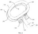
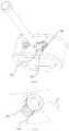
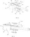
- FIGS. 1-5are front perspective, top perspective, front perspective, enlarged front perspective, and sectional front perspective views, respectively, of an intervertebral implant system according to an embodiment of the present invention
- FIG. 6is a front perspective view of an intervertebral implant system according to another embodiment of the present invention.
- FIG. 7is an enlarged front perspective view of a portion of the intervertebral implant system of FIG. 4 ;
- FIGS. 8-11are front perspective, side perspective, rear elevational, and enlarged front elevational views, respectively, of an intervertebral implant system according to another embodiment of the present invention.
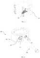
- FIG. 12is a top perspective view of a bone plate system according to another embodiment of the present invention.
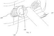
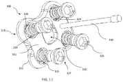
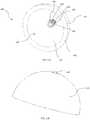
- FIGS. 13-15are front perspective, side perspective, and sectional side views, respectively, of an acetabular implant system according to an embodiment of the present invention.
- proximalrefers to the end of the fixation members and instrumentation, or portion thereof, which is closest to the operator in use
- distalrefers to the end of the fixation members and instrumentation, or portion thereof, which is farthest from the operator in use.
- an intervertebral implant system 100includes a monolithic device cast as a single piece including a spacer 110 frangibly connected with fixation members or screws 125 and an insertion instrument 130 .
- System 100is made of a single material.
- a system in accordance with the present inventionscan include a single fixation member or two or more fixation members depending on a particular procedure and/or the configuration of the associated implant.
- implant system 100includes frangible connections between spacer 110 and fixation members 125 and between spacer 110 and instrument 130 .
- the monolithic connection among the different componentscan be disconnected or broken after spacer 110 is positioned in an intervertebral disc space of the spine. While it will be discussed below that system 100 is produced through additive layer manufacturing (ALM), i.e. 3D printing, it is understood that the single, continuous or monolithic construct is created upon completion of the ALM process. The monolithic construction of system 100 is completed during a single process, which differentiates it from processes of separately manufacturing and later welding together the different components of system 100 .
- Alternate systems in accordance with the present inventionscan include a monolithic device cast as a single piece including a spacer 110 frangibly connected with fixation members or screws 125 and omitting an instrument. Systems can also include a monolithic device cast as a single piece including a spacer 110 frangibly connected with an insertion instrument 130 and omitting fixation members.
- implant system 100is manufactured as a one-piece, integral construct with integrated fixation anchors/screws as well as integrated instrumentation to facilitate implantation.
- the preferred method of manufacturing system 100is by utilizing 3D printing technology, which allows system 100 to be made monolithically with all features and components built into system 100 from the start. This improves handling of system 100 during implantation and can streamline the surgical procedure to make it more efficient.
- the initial construction and positioning of the fixation anchors/screws in system 100eliminates the need for guides, such as screw guides, since the fixation elements are already in place for insertion once the main implant is finally seated.
- System 100is fully ready to implant immediately out of its packaging, which minimizes steps for the surgeon and is designed to reduce complexity and increase operational efficiency.
- Spacer 110includes a top or superior bone-contacting surface 111 and a bottom or inferior surface 112 , a posterior or leading surface 115 , an anterior or trailing surface 116 opposite leading surface 115 , and lateral surfaces 114 extending between the leading and trailing surfaces 115 , 116 .
- spacer 110has a generally rounded, oblong shape with lateral surfaces 114 being rounded.
- spacer 110may be generally, square, rectangular, kidney, oval, circular, or other geometric shape in the superior view.
- Top and bottom surfaces or endplates 111 , 112may be flat, concave, convex, or any other shape in the anterior or lateral views and may include teeth or ridges for more secure placement against endplates of the adjacent vertebrae. Endplates 111 , 112 can be porous to optimize bone growth/fusion. In particular, in a lateral view, top and bottom sides 111 , 112 may be curved or angled to give spacer 110 a lordotic shape. Hyperlordotic and double taper implants are also contemplated.
- Spacer 110further defines opening 120 extending from top surface 111 to bottom surface 112 .
- Opening 120has a generally rounded, oblong shape and is surrounded by inner surface 122 .
- opening 120may have any shape or may comprise multiple openings.
- Opening 120may allow for receipt of bone in-growth material, such as bone chips, autograft, allograft, Demineralized Bone Matrix (DBM), or synthetics.
- bone in-growth materialsuch as bone chips, autograft, allograft, Demineralized Bone Matrix (DBM), or synthetics.
- DBMDemineralized Bone Matrix
- Spacer 110further includes two screws 125 positioned in respective holes 126 , the screws and holes each extending from trailing surface 116 to inner surface 122 and being spaced apart. Holes 126 and screws 125 each extend about a central axis that forms a non-perpendicular angle with trailing surface 116 . The angle of the screws and holes can vary as desired, and may be prepared such that the screws can reach the adjacent vertebral endplate to fix spacer 110 to the adjacent vertebra. Each hole 126 may be angled in a different direction from the other hole, and each screw 125 may be angled in a different direction from the other screw. However, in other examples, holes 126 may also extend about a central axis that is substantially perpendicular to trailing surface 116 .
- screws 125are angled in opposite directions to engage both superior and inferior positioned vertebrae.
- the illustrated embodimenthas two holes 126 and screws 125 , in other arrangements there may be more or less of the holes and screws.
- screws 125are initially monolithically connected with spacer 110 and positioned such that the distal portion of the screw extends through inner surface 122 , a portion of the screw shaft being enclosed within hole 126 of spacer 110 , and the head and a portion of the shaft is positioned anteriorly external to trailing surface 116 .
- spacer 110 and screws 125are manufactured simultaneously with at least one frangible connection 129 therebetween.
- This connectioncan be a relatively thin layer of the material of spacer 110 and screws 125 that bridges or connects adjacent locations between spacer 110 and screws 125 . For example, as best shown in FIGS.
- the frangible connection 129is a radial flange of the material extending from the shaft or a thread on the shaft of screw 125 to a surface of hole 126 .
- This flangecan be perpendicular to the screw axis or angled thereto.
- multiple connections 129can be utilized and spaced apart about the circumference of screw 125 .
- a single connection 129can also be employed.
- an annular flange between spacer 110 and screws 125can be provided via the material during 3D printing.
- the material at the connectioncan be selectively constructed to break or shear upon a force applied to one of spacer 110 and screws 125 .
- screws 125can be torqued to advance them further into holes 126 .
- the frangible connection between screw 125 and spacer 110breaks such that screw 125 becomes a separate piece from spacer 110 and screw 125 is thereafter inserted further into hole 126 and ultimately into communication with an adjacent vertebra.
- screws 125there are two threaded screws 125 , angled in opposite directions; however, in other examples there may be more or less of screws 125 and the screws may be angled in different configurations.
- Screws 125may include variable and/or fixed angle screws. Further, screws 125 may include self-drilling and/or self-tapping features to facilitate and minimize screw-hole preparation.
- Spacer 110further includes insertion instrumentation 130 .
- Instrument 130includes shaft 131 extending from a distal end 133 to a proximal end 134 .
- Distal end 133 of shaft 131is monolithically connected with and coupled to trailing surface 116 in a manner similar to the connection between spacer 110 and screws 125 .
- the monolithic construction of instrument 130 with spacer 110is strong in both compression and tension forces. That is, the interface between instrument 130 and spacer 110 is such that it can withstand forces applied by a user during a surgical procedure without breaking. As instrument 130 is bent with respect to spacer 110 , it breaks off from spacer 110 and can be removed from the patient.
- Distal end 133may be tapered, as in FIG. 2 , or it may be straight.
- the tapercan be configured to facilitate the ultimate breakage between instrument 130 and spacer 110 .
- the taper or the connectionin general can be manufactured to be stronger in some planes as opposed to others. That is, it may be easier to bend instrument 130 with respect to spacer 110 at particular angles.
- Shaft 131extends generally orthogonally to trailing surface 116 and extends in an anterior direction from the spacer 110 . Further, instrument 130 extends generally parallel to upper and lower surfaces 111 , 112 , but in other examples, the instrument may extend in an angled direction, either superiorly, inferiorly, or laterally to spacer 110 .
- Proximal end 134 of shaft 131may include raised portion 136 for easier gripping. Raised portion 136 may further include an attachment mechanism to attach to a separate handle such as a quick connect handle (not shown), if further length of insertion instrument 130 is required during a procedure. However, in other examples, shaft 131 may be flat and may not include a raised portion.
- instrument 130may be used as a driver to drive one or more of screws 125 into their fully inserted positions after instrument 130 is separated from spacer 130 .
- FIGS. 6-7depict an intervertebral implant system 100 ′ according to another embodiment of the present invention.
- Implant system 100 ′has similar features to those described above in connection with implant system 100 .
- Screws 125 ′are initially monolithically connected to spacer 110 ′ by frangible connection 129 ′ that is constructed to break or shear upon a force applied to one of spacer 110 ′ and screws 125 ′.
- frangible connection 129 ′is similar to frangible connection 129 of spacer 110 and is a radial flange of the material extending from the shaft or a thread on the shaft of screw 125 ′ to a surface of hole 126 ′.
- the frangible connection 129 ′can be configured with different geometries, including an annular flange, and one or more connections 129 ′ can be employed.
- Screws 125 ′each include a locking mechanism 127 ′ to secure the screws within spacer 110 ′ after implantation.
- locking mechanism 127 ′is located on the head of each screw 125 ′ and includes flange 128 ′ extending further radially outward from the rest of the head of screw 125 ′.
- Flange 128 ′has an outwardly extending protrusion which, when it contacts an inner surface of hole 126 ′, causes flange 128 ′ to flex inward toward screw to produce a friction fit between the head of screw 125 and hole 126 ′.
- Holes 126 ′may also include a groove (not shown) for flange 128 ′ to snap into.
- Flange 128 ′is provided to inhibit backout of screw 125 ′ once it is inserted into spacer 110 ′.
- Other types of known anti-backout mechanismssuch as split rings, spring bars, washers, rotatable cover plates, etc., can also be used. Snap fits, cover plates, and/or other compression technology known in the art may be used.
- Intervertebral implant system 100is provided in a sterile kit. Once removed from the packaging, instrument 130 is connected with a quick connect handle. In some instances, a tube can be inserted over instrument 130 for added stability during insertion. Spacer 110 and screws 125 are then inserted into the prepared disc space using insertion instrument 130 . This can include impacting a proximal end of instrument 130 . Once spacer 110 is located in the disc space, the surgeon can use instrument 130 to manipulate and stabilize spacer 110 in the desired location.
- the surgeonmay then cantilever and break off instrument 130 . Breaking off instrument 130 may allow for a flat surface, such that the break is clean without leaving any sharp edges. Instrument 130 is then removed from the patient. In certain embodiments, removal of instrument 130 can be done at an earlier stage so that it can be used as a driver for one or more screws 125 . A separate mechanism for preventing backing out of screws 125 may then be attached to the implant, if desired.
- implant system 100may be implanted from an anterior, posterior, posterior-lateral, lateral, or other surgical approach.
- FIGS. 8-11depict an intervertebral implant system 200 according to an embodiment of the present invention.
- Implant system 200includes spacer 210 , fixation members or anchor blades 245 and insertion instrument 230 .
- Spacer 210includes top and bottom surfaces 211 , 212 , respectively, leading surface 215 , a trailing surface 216 opposite leading surface 215 , and lateral surfaces 214 extending between the leading and trailing sides 215 , 216 .
- spacer 210has a generally rounded, oblong shape with lateral surfaces 214 being rounded.
- spacer 210may be generally, square, rectangular, kidney, oval, circular, or other geometric shape in the superior view.
- Top and bottom surfaces 211 , 212may be flat, concave, convex, or any other shape in the anterior or lateral views and may include teeth or ridges for more secure placement against endplates of the adjacent vertebrae.
- top and bottom surfaces 211 , 212may be curved or angled to give spacer 210 a lordotic shape.
- Spacer 210further includes channels or tracks 250 that extend across spacer 210 between and intersect with both leading side 214 and trailing side 216 .
- channels 250are dovetail slots that are formed in spacer 210 in a truncated I-beam shape.
- the channels 250may have a variety of shapes, including circular, rectangular, keyhole, T-shaped, etc.
- Each channelis preferably configured to have an enlarged profile away from the adjacent surface so that an anchor disposed therein can be secured from migrating out of that channel toward the surface.
- Each dovetail slotis configured to slidably engage with a mating feature on an anchor 245 , described in detail below.
- Spacer 210includes two channels, one channel 250 that is open toward top surface 211 of the spacer and extends across top surface 211 , and one channel 250 that is open toward bottom surface 212 of the spacer and extends across bottom side 212 . Although in other examples, there may be more or less of channels 250 .
- each channel 250may extend about a central axis that is perpendicular to leading surface 214 .
- the central axis of the channelsmay be angled, i.e. forms a non-perpendicular angle, with respect to leading surface 214 .
- Channels 250may extend across top and bottom surfaces 211 , 112 along an axis that extends straight through spacer 210 from trailing surface 216 to leading surface 214 .
- the channelsmay be configured to extend from trailing surface 216 to leading surface 214 in a variety of angles.
- each channel 250may have a perimeter about its central axis that is not fully enclosed within spacer 210 at any location along its central axis so that it is open in the superior or inferior direction, as the case may be.
- Spacer 210further includes openings 220 , 221 extending from top surface 211 to bottom surface 212 and positioned on lateral sides of channels 250 .
- Openings 220 , 221are surrounded by inner surfaces 222 and are shaped as semi-ovals; however, in other examples, the openings may be shaped as generally circular, rectangular, or any other shape. Openings 220 , 221 may allow for receipt of bone in-growth material.
- instrument 230is similar to instrument 130 and functions in the same manner.
- Anchor blades 245are used as a fixation method with spacer 210 .
- Anchor 245may include an interconnection portion 255 extending between leading end and trailing ends 246 , 248 .
- Interconnection portion 255is shaped and sized to matingly attach with the channels 250 of spacer 210 .
- the interconnection portionis a dovetail beam 255 that can slidably attach to the plates and spacers.
- Anchor 245can include a stop feature, such as a flange, near trailing end 248 to prevent the anchor from migrating too far posteriorly into prosthesis 210 after implantation.
- Anchor 245can further include a locking feature, such as a flexible tab disposed near the trailing end 248 of the dovetail beam 255 , to prevent the anchor from migrating anteriorly after implantation.
- the stop feature and the flexible tabcan cooperate with spacer 210 to maintain anchor 255 in its implanted position in the spacer.
- Anchor 245also includes a fixation portion 260 that secures anchor 245 to an adjacent vertebra. Fixation plate 260 may be sharpened around a portion of its profile to create a cutting edge to cut through bone.
- the anchors and other aspects of system 200are further disclosed in U.S. Pat. No. 8,349,015, issued on Jan. 8, 2013, and titled “Intervertebral Implant With Integrated Fixation,” the disclosure of which is hereby incorporated by reference herein.
- anchors 245are each positioned with a portion of interconnection portion 255 inserted in and frangibly attached to channel 250 .
- Thiscan be done during a 3D printing procedure by including at least one frangible connection 229 between anchor 245 and spacer 210 .
- frangible connection 229is a flange of the material extending from interconnection portion 255 to channel 250 that bridges the anchor and the spacer. This flange can be perpendicular to the interconnection portion axis or angled thereto.
- Multiple connections 229can be utilized and spaced apart about the interconnection portion 255 . However, a single connection 229 can also be employed.
- the interconnection portioncan slide within channel 250 without interference.
- the surface area of the connectioncan be small enough so that the connection shears upon a force applied to the proximal end of anchor 245 , but large enough to withstand typical forces that may be applied, purposefully or incidentally, to anchor 245 during initial insertion of spacer 210 .
- the frangible connectioncan be between the bottom surface of leading end 246 of interconnection portion 255 and the adjacent bottom surface of channel 250 .
- anchors 245can be driven into the bone, such as by manually driving anchors 245 or using a pneumatic driver, such that the blade slides into position further distally within channel 250 and the monolithic attachment of the anchors with spacer 210 is broken. As a result, a proximal portion near trailing end 248 of anchor 245 is closer to trailing side 216 and within channel 250 .
- a spacermay be configured such that it includes both screw fixation members and blade fixation members.
- a spacer similar to spacer 210may include screws similar to screws 125 or screws 125 ′. The screws may be located on either side of instrument 230 on trailing surface 216 . Further, the screws may be angled, such that one screw extends superiorly and the other screw extends inferiorly. Both the blades and screws may be formed monolithically with the spacer or one fixation mechanism, such as one of the screws and blades, may be monolithic, while the spacer is designed to allow for insertion of the non-monolithic, standalone fixation component.
- Implant systems 100 , 100 ′, and 200may include one or more radiographic markers on the top surfaces of spacers 110 , 110 ′, and 210 (not shown). Additionally, the spacers may include serrations on various surfaces, i.e. top and bottom surfaces, to allow for fixation with adjacent vertebrae.
- intervertebral systems 100 , 100 ′, 210may be configured and dimensioned for lateral spinal surgery.
- the system, in particular spacers 110 , 110 ′, 210may have dimensions that are greater in the medial-lateral direction and lesser in the anterior-posterior direction as compared to spacer 110 , 110 ′, 210 .
- spacers 110 , 110 ′, 210may include an attachment mechanism to allow for attachment of a retaining mechanism or plate at trailing surface 116 .
- the retaining mechanismmay include clips, positioned for example on a top surface, bottom surface, and/or lateral surfaces to attach to fit into recesses in corresponding locations on spacer 100 .
- Such retaining mechanismsare disclosed in U.S. Pat. No. 9,480,577, issued on Nov. 1, 2016, and titled “Retaining Mechanism, Implant, and Tool,” and U.S. Application No. 62/478,162, filed on Mar. 29, 2017, and titled “Spinal Implant System,” the disclosures of both of which are hereby incorporated by reference herein.
- a method of implanting intervertebral implant system 200 in the lumbar spine from an anterior surgical approachincludes first removing at least a portion of an intervertebral disc between adjacent vertebrae.
- Intervertebral implant system 200provided in a sterile kit and including spacer 210 , anchor blades 245 , and instrument 230 , is then inserted into the prepared disc space using insertion instrument 230 for manipulation.
- insertion instrument 230for manipulation.
- the surgeoncan use instrument 230 to stabilize the spacer 210 in the desired location.
- the surgeondrives anchor blades 245 in a posterior direction to engage the adjacent vertebrae using guiding instruments, which can be equipped to handle impaction during the insertion.
- anchors 245 and spacer 210are sheared and anchors 245 are moved into full connection with spacer 210 and the respective vertebrae.
- the surgeonmay then break off instrument 230 . Breaking off instrument 230 may allow for a flat surface, such that the break is clean. Instrument 230 is then removed from the patient.
- a mechanism for preventing backing out of anchors 245such as a cover plate, may optionally be attached to implant.
- FIG. 12shows a spinal fusion plate system 300 according to an embodiment of the invention that may be used to stabilize or fuse vertebral bodies of the spine.
- the systemis configured to span across and fixate at least two vertebrae of the spine.
- the systemcomprises a plate 315 having screws 325 extending into the plate and instrumentation 330 .
- Plate 315includes an upper surface or anterior surface 321 facing the patient's soft tissue when installed and a lower surface or posterior surface 322 facing the vertebral bodies to be immobilized.
- the upper surface 321 and lower surface 322are interconnected by curved side walls and end walls to form a generally rectangular shape that is symmetrical about a midline.
- the gently curved structure of plate 315complements the natural curved structure of the vertebral bodies and lordotic curvature of the spine.
- the corners of the plateare rounded to reduce irritation of the surrounding tissue.
- Plate 315has a low profile to minimally impinge on adjacent tissue.
- Plate system 300further includes screws 325 similar to screws 125 and including a locking feature 327 similar to locking feature 127 ′.
- Screws 325are initially monolithically connected to spacer 310 by frangible connection 329 , similar to frangible connection 129 of spacer 110 .
- Connection 329is constructed such that it can break or shear upon a force applied to one of spacer 310 and screws 325 .
- more or less frangible connectionshaving the same or different configurations can be employed, as described above.
- Screws 325are positioned within holes 326 , the screws and holes extending from upper surface 321 to lower surface 322 .
- Screws 325may be fixed and/or variable angle screws. Screws 325 are spaced apart and each one is positioned near a curved corner of plate 315 . Opening 320 is positioned generally centrally on plate 315 and extends from upper surface 321 to lower surface 322 . Opening 320 reduces the overall weight of plate 315 and provides a visualization pathway to monitor bone graft progress between the vertebral bodies. Screws 325 are frangibly connected with plate 310 in a manner similar to screws 125 with spacer 120 .
- Plate system 300further includes instrument 330 similar to instrument 130 of implant system 100 .
- the frangible connection between plate 310 and instrument 330is similar to that of spacer 110 and instrument 130 .
- Instrument 330is positioned on upper surface 321 and extends anteriorly away from the upper surface. Instrument 330 may be positioned in between two screws 325 or in any location on plate 300 where it can be used for manipulation of plate 300 by a user without interfering with the manipulation of screws 325 .
- a method of implanting bone plate system 300includes placing plate 310 adjacent to a vertebral column using instrument 330 as a guide and/or handle for insertion.
- the placement of the plate 310 relative to the vertebral bone in a patientmay be determined based on a pre-operative examination of the patient's spine using non-invasive imaging techniques known in the art. Any additional preparation may be done around the desired vertebrae prior to positioning plate 310 .
- screws 325are torqued, such that the attachment of screws 325 with plate 310 is sheared. Screws 325 are further torqued to engage the bone.
- instrument 330is broken off from the implant.
- FIGS. 13-15depict a prosthetic acetabular cup implant system 400 according to an embodiment of the present invention.
- Implant system 400includes an acetabular cup 410 and screw 425 positioned in hole 426 .
- Screw 425is frangibly connected with cup 410 by frangible connections 429 in a manner similar to screws 125 with spacer 110 .
- each frangible connection 429is radial flange of the material extending from the shaft or a thread on the shaft of screw 425 to a surface of hole 426 .
- the flangecan be perpendicular to the screw axis or angled thereto.
- the system 400may include a single connection, such as a single annular connection.
- Acetabular cup 410is a part-spherical cup adapted for location in an acetabulum and having a rounded outer surface 415 and an inner bearing surface 417 to receive a bearing liner and a part-spherical ball head which can be attached to a prosthetic stem for location in a femur.
- Acetabular cupfurther defines an opening 420 due to the semi-spherical shape of the cup.
- Acetabular cup 410further includes flat surface or rim 427 extending between outer surface 415 and inner surface 417 .
- Hole 426 and screw 425extend along a central axis from inner surface 417 to outer surface 415 .
- Screw 425is formed monolithically with acetabular cup 410 .
- Screw 425is initially positioned such that a portion of the screw shaft is enclosed within acetabular cup 410 and the tip extends proximally from the acetabular cup. Further, the head of the screw is positioned within opening 420 .
- screw 425is similar to screw 125 , but implant system 400 can also include a screw similar to screws 125 ′, in which a locking mechanism is including within the screw and/or hole to secure the screw within acetabular cup 410 .
- the systemmay include multiple screws 425 and holes 426 spaced apart on acetabular cup 410 .
- an instrument like instrument 130be connected with a portion of cup 410 , such as rim 427 so as not to interfere with bearing surface 417 .
- systems in accordance with the present inventioncan be provided with just an implant and fixation member(s), and without an insertion instrument.
- an insertion instrumentcan be provided in a system with an implant but without fixation members if none are applicable or desired.
- a method of implanting hip implant system 400includes preparing an acetabulum for insertion of implant system 400 .
- Cup 410is then inserted into the patient, and screw 425 is torqued. The torque shears the attachment of screw 425 with cup 410 .
- Screw 425is torqued further such that it engages the bone to provide securement of the implant to the bone.
- Implant systems in accordance with the present inventionsare formed using three-dimensional (3D) printing to produce a monolithic structure comprised of a spacer, one or more fixation members, and/or an insertion instrument, the fixation members and instrument being frangibly coupled to the spacer.
- the implant systemdoes not experience any additional fixation process to provide for the monolithic construction and as such the monolithic connection is not the result of welding, fusing, cement, or any similar process beyond the particulars of the ALM process used during construction.
- the systemscan be comprised of a porous metal or can have a solid internal core with a porous metal surface such as a porous titanium alloy, including Tritanium® by Howmedica Osteonics Corporation.
- the implant systemsmay be comprised of metal, such as titanium, ceramic, glass, polymer, or any other material known for use in the human body and capable of utilization in a 3D printing technique.
- the implant systemsmay also comprise one or more surface treatments to encourage bony attachment, such as porous coating, plasma spray coating, hydroxyapatite, or tricalcium phosphate.
- any of the present implants systemscan be formed, at least in part, in a layer-by layer fashion using an additive layer manufacturing (ALM), i.e. 3D printing, process using a high energy beam, such as a laser beam or an electron beam.
- ALM processesmay be but are not limited to being powder-bed based processes including but not limited to selective laser sintering (SLS), selective laser melting (SLM), and electron beam melting (EBM), as disclosed in U.S. Pat. Nos.
- the implants and systemsmay be constructed of porous geometries which have been digitally modeled using unit cells, as further described in U.S. Pat. Nos. 9,180,010 and 9,135,374, the disclosures of each of which are hereby incorporated by reference herein.
- a first layer or portion of a layer of powderis deposited and then scanned with a high energy beam to create a portion of a plurality of predetermined unit cells.
- Successive layers of powderare then deposited onto previous layers of the powder and also may be individually scanned. The scanning and depositing of successive layers of the powder continues the building process of the predetermined porous geometries.
- porous geometries of the formed porous layersmay define pores that may be interconnecting to provide an interconnected porosity.
- implantscan also be made to be solid with or without porous portions.
- frangible fixation members and/or insertion instrumentsmay be used for other prosthetic implants throughout the body.
- the present inventionis not limited to any particular type of implant and is not limited to surgical applications.
- the present inventioncan be implemented in different spinal implants, such as the implants disclosed in U.S. application Ser. No. 14/994,749, filed on Jan. 13, 2016, and titled “Spinal Implant with Porous and Solid Surfaces,” the disclosure of which is hereby incorporated by reference herein.
- an implant in accordance with the present applicationcan be a patient-specific implant generated from CAD files, for example, so that it is unique for a particular patient and application.
- Other nonsurgical applicationsare also contemplated.
- an L bracketmay be monolithically formed with a screw using additive layering manufacturing, as described above. This arrangement can be used to insert a screw into a wall. The screw may be frangibly connected to the L bracket such that torqueing the screw breaks the connection with the L bracket.
- Systems in accordance with the present inventionallow pre-packaging of the entire monolithic implant system, which can reduce manufacturing cost as well as inventory of implants and instruments as part of an instrumented fusion surgery.
- a systemcan be offered pre-packaged as a set in a sterile package. This allows the packaged implant system, provided in a blister package for example, to be supplied to an operating room and opened immediately prior to use in a surgical procedure.
Landscapes
- Health & Medical Sciences (AREA)
- Orthopedic Medicine & Surgery (AREA)
- Engineering & Computer Science (AREA)
- Biomedical Technology (AREA)
- Neurology (AREA)
- Life Sciences & Earth Sciences (AREA)
- Transplantation (AREA)
- General Health & Medical Sciences (AREA)
- Heart & Thoracic Surgery (AREA)
- Veterinary Medicine (AREA)
- Public Health (AREA)
- Animal Behavior & Ethology (AREA)
- Cardiology (AREA)
- Oral & Maxillofacial Surgery (AREA)
- Vascular Medicine (AREA)
- Surgery (AREA)
- Physical Education & Sports Medicine (AREA)
- Molecular Biology (AREA)
- Medical Informatics (AREA)
- Nuclear Medicine, Radiotherapy & Molecular Imaging (AREA)
- Prostheses (AREA)
- Surgical Instruments (AREA)
Abstract
Description
Claims (11)
Priority Applications (2)
| Application Number | Priority Date | Filing Date | Title |
|---|---|---|---|
| US15/988,276US10959855B2 (en) | 2017-05-25 | 2018-05-24 | Fusion cage with integrated fixation and insertion features |
| US17/155,756US11583412B2 (en) | 2017-05-25 | 2021-01-22 | Fusion cage with integrated fixation and insertion features |
Applications Claiming Priority (2)
| Application Number | Priority Date | Filing Date | Title |
|---|---|---|---|
| US201762511101P | 2017-05-25 | 2017-05-25 | |
| US15/988,276US10959855B2 (en) | 2017-05-25 | 2018-05-24 | Fusion cage with integrated fixation and insertion features |
Related Child Applications (1)
| Application Number | Title | Priority Date | Filing Date |
|---|---|---|---|
| US17/155,756ContinuationUS11583412B2 (en) | 2017-05-25 | 2021-01-22 | Fusion cage with integrated fixation and insertion features |
Publications (2)
| Publication Number | Publication Date |
|---|---|
| US20180338841A1 US20180338841A1 (en) | 2018-11-29 |
| US10959855B2true US10959855B2 (en) | 2021-03-30 |
Family
ID=62244379
Family Applications (2)
| Application Number | Title | Priority Date | Filing Date |
|---|---|---|---|
| US15/988,276Active2038-11-21US10959855B2 (en) | 2017-05-25 | 2018-05-24 | Fusion cage with integrated fixation and insertion features |
| US17/155,756ActiveUS11583412B2 (en) | 2017-05-25 | 2021-01-22 | Fusion cage with integrated fixation and insertion features |
Family Applications After (1)
| Application Number | Title | Priority Date | Filing Date |
|---|---|---|---|
| US17/155,756ActiveUS11583412B2 (en) | 2017-05-25 | 2021-01-22 | Fusion cage with integrated fixation and insertion features |
Country Status (4)
| Country | Link |
|---|---|
| US (2) | US10959855B2 (en) |
| EP (1) | EP3415108B1 (en) |
| JP (2) | JP7466267B2 (en) |
| AU (2) | AU2018203667B2 (en) |
Cited By (19)
| Publication number | Priority date | Publication date | Assignee | Title |
|---|---|---|---|---|
| US11376134B1 (en) | 2020-11-05 | 2022-07-05 | Warsaw Orthopedic, Inc. | Dual expanding spinal implant, system, and method of use |
| US11395743B1 (en) | 2021-05-04 | 2022-07-26 | Warsaw Orthopedic, Inc. | Externally driven expandable interbody and related methods |
| US11517363B2 (en) | 2020-11-05 | 2022-12-06 | Warsaw Orthopedic, Inc. | Screw driver and complimentary screws |
| US11517443B2 (en) | 2020-11-05 | 2022-12-06 | Warsaw Orthopedic, Inc. | Dual wedge expandable implant, system and method of use |
| US11612499B2 (en) | 2021-06-24 | 2023-03-28 | Warsaw Orthopedic, Inc. | Expandable interbody implant |
| US20230095119A1 (en)* | 2020-03-03 | 2023-03-30 | Medartis Holding Ag | Kit, plate, insert, and method for treating a clavicle |
| US11638653B2 (en) | 2020-11-05 | 2023-05-02 | Warsaw Orthopedic, Inc. | Surgery instruments with a movable handle |
| US11806250B2 (en) | 2018-02-22 | 2023-11-07 | Warsaw Orthopedic, Inc. | Expandable spinal implant system and method of using same |
| US11833059B2 (en) | 2020-11-05 | 2023-12-05 | Warsaw Orthopedic, Inc. | Expandable inter-body device, expandable plate system, and associated methods |
| US11850163B2 (en) | 2022-02-01 | 2023-12-26 | Warsaw Orthopedic, Inc. | Interbody implant with adjusting shims |
| US11963881B2 (en) | 2020-11-05 | 2024-04-23 | Warsaw Orthopedic, Inc. | Expandable inter-body device, system, and method |
| US12121453B2 (en) | 2020-11-05 | 2024-10-22 | Warsaw Orthopedic, Inc. | Dual wedge expandable implant with eyelets, system, and method of use |
| US12171439B2 (en) | 2020-11-05 | 2024-12-24 | Warsaw Orthopedic, Inc. | Protected drill |
| US12239544B2 (en) | 2020-11-05 | 2025-03-04 | Warsaw Orthopedic, Inc. | Rhomboid shaped implants |
| US12268614B2 (en) | 2021-06-24 | 2025-04-08 | Warsaw Orthopedic, Inc. | Interbody implant with adjusting shims |
| US12295865B2 (en) | 2021-06-24 | 2025-05-13 | Warsaw Orthopedic, Inc. | Expandable interbody implant and corresponding inserter |
| US12318308B2 (en) | 2020-11-05 | 2025-06-03 | Warsaw Orthopedic, Inc. | Dual expandable inter-body device |
| US12414863B2 (en) | 2021-06-24 | 2025-09-16 | Warsaw Orthopedic, Inc. | Expandable interbody implant and corresponding surgical tool |
| US12440349B2 (en) | 2022-02-04 | 2025-10-14 | Warsaw Orthopedic, Inc. | Expandable interbody implant and breakoff screw |
Families Citing this family (30)
| Publication number | Priority date | Publication date | Assignee | Title |
|---|---|---|---|---|
| EP3415108B1 (en)* | 2017-05-25 | 2024-09-04 | Stryker European Operations Holdings LLC | Fusion cage with integrated fixation and insertion features |
| US11006981B2 (en) | 2017-07-07 | 2021-05-18 | K2M, Inc. | Surgical implant and methods of additive manufacturing |
| US11166764B2 (en) | 2017-07-27 | 2021-11-09 | Carlsmed, Inc. | Systems and methods for assisting and augmenting surgical procedures |
| US11112770B2 (en) | 2017-11-09 | 2021-09-07 | Carlsmed, Inc. | Systems and methods for assisting a surgeon and producing patient-specific medical devices |
| US11083586B2 (en) | 2017-12-04 | 2021-08-10 | Carlsmed, Inc. | Systems and methods for multi-planar orthopedic alignment |
| US11432943B2 (en)* | 2018-03-14 | 2022-09-06 | Carlsmed, Inc. | Systems and methods for orthopedic implant fixation |
| US11439514B2 (en) | 2018-04-16 | 2022-09-13 | Carlsmed, Inc. | Systems and methods for orthopedic implant fixation |
| USD958151S1 (en) | 2018-07-30 | 2022-07-19 | Carlsmed, Inc. | Display screen with a graphical user interface for surgical planning |
| WO2020056186A1 (en) | 2018-09-12 | 2020-03-19 | Carlsmed, Inc. | Systems and methods for orthopedic implants |
| EP3888095A4 (en) | 2018-11-29 | 2022-08-31 | Carlsmed, Inc. | SYSTEMS AND PROCEDURES FOR ORTHOPEDIC IMPLANTS |
| US11779378B2 (en)* | 2019-01-11 | 2023-10-10 | Medcom Advisors, Llc | Self-aligning plating system and method |
| US11298244B2 (en) | 2019-01-31 | 2022-04-12 | K2M, Inc. | Interbody implants and instrumentation |
| DE102019118134B4 (en)* | 2019-07-04 | 2023-11-30 | Reoss Gmbh | Method for producing a covering device for a bone defect site; Covering device for a bone defect site; |
| US11534307B2 (en)* | 2019-09-16 | 2022-12-27 | K2M, Inc. | 3D printed cervical standalone implant |
| US20230081904A1 (en)* | 2019-11-07 | 2023-03-16 | Braces On Demand Inc. | Systems and methods for manufacture of orthodontic appliances |
| CN110811935A (en)* | 2019-11-28 | 2020-02-21 | 中国人民解放军第四军医大学 | A 3D printed half-pelvic prosthesis |
| US10902944B1 (en) | 2020-01-06 | 2021-01-26 | Carlsmed, Inc. | Patient-specific medical procedures and devices, and associated systems and methods |
| US11376076B2 (en) | 2020-01-06 | 2022-07-05 | Carlsmed, Inc. | Patient-specific medical systems, devices, and methods |
| WO2021202101A1 (en)* | 2020-04-01 | 2021-10-07 | Arthrex, Inc. | Systems and methods of forming orthopaedic implants including printed augments |
| US12226315B2 (en) | 2020-08-06 | 2025-02-18 | Carlsmed, Inc. | Kinematic data-based patient-specific artificial discs, implants and associated systems and methods |
| US11291554B1 (en) | 2021-05-03 | 2022-04-05 | Medtronic, Inc. | Unibody dual expanding interbody implant |
| US11285014B1 (en) | 2020-11-05 | 2022-03-29 | Warsaw Orthopedic, Inc. | Expandable inter-body device, system, and method |
| WO2022109259A1 (en) | 2020-11-20 | 2022-05-27 | Carlsmed, Inc. | Patient-specific jig for personalized surgery |
| US11737883B2 (en)* | 2021-03-02 | 2023-08-29 | Arthrex, Inc. | Orthopaedic implants including breakaway fastener |
| US12232980B2 (en) | 2021-06-08 | 2025-02-25 | Carlsmed, Inc. | Patient-specific expandable spinal implants and associated systems and methods |
| US11730608B2 (en) | 2021-07-13 | 2023-08-22 | Warsaw Orthopedic, Inc. | Monoblock expandable interbody implant |
| JP2024542048A (en) | 2021-11-01 | 2024-11-13 | カールスメッド インコーポレイテッド | Reduced Subsidence Spinal Implants and Surgical Procedures, and Related Systems and Methods - Patent application |
| US11443838B1 (en) | 2022-02-23 | 2022-09-13 | Carlsmed, Inc. | Non-fungible token systems and methods for storing and accessing healthcare data |
| US11806241B1 (en) | 2022-09-22 | 2023-11-07 | Carlsmed, Inc. | System for manufacturing and pre-operative inspecting of patient-specific implants |
| US11793577B1 (en) | 2023-01-27 | 2023-10-24 | Carlsmed, Inc. | Techniques to map three-dimensional human anatomy data to two-dimensional human anatomy data |
Citations (128)
| Publication number | Priority date | Publication date | Assignee | Title |
|---|---|---|---|---|
| WO1990000037A1 (en) | 1988-06-28 | 1990-01-11 | Michelson Gary K | Artificial spinal fusion implants |
| US5286573A (en) | 1990-12-03 | 1994-02-15 | Fritz Prinz | Method and support structures for creation of objects by layer deposition |
| WO1994005235A1 (en) | 1991-03-22 | 1994-03-17 | Brantigan John W | Surgical prosthetic implant for vertebrae |
| WO1994019174A1 (en) | 1993-02-19 | 1994-09-01 | Eos Gmbh Electro Optical Systems | Process for producing a three-dimensional object |
| WO1995010248A1 (en) | 1993-10-12 | 1995-04-20 | Danek Medical, Inc. | Anterior interbody fusion device |
| US5411523A (en) | 1994-04-11 | 1995-05-02 | Mitek Surgical Products, Inc. | Suture anchor and driver combination |
| WO1995032673A1 (en) | 1994-05-27 | 1995-12-07 | Michelson Gary K | Apparatus and method, delivery of electrical current |
| WO1996008360A1 (en) | 1994-09-16 | 1996-03-21 | Eos Gmbh Electro Optical Systems | Process for producing a three-dimensional object |
| US5534031A (en) | 1992-01-28 | 1996-07-09 | Asahi Kogaku Kogyo Kabushiki Kaisha | Prosthesis for spanning a space formed upon removal of an intervertebral disk |
| WO1996028117A1 (en) | 1995-03-13 | 1996-09-19 | Board Of Regents, The University Of Texas System | Biodegradable implant for fracture nonunions |
| WO1996040019A1 (en) | 1995-06-07 | 1996-12-19 | Michelson Gary K | Frusto-conical interbody spinal fusion implants |
| WO1996040015A1 (en) | 1995-06-07 | 1996-12-19 | Michelson Gary K | Lordotic interbody spinal fusion implants |
| US5595703A (en) | 1994-03-10 | 1997-01-21 | Materialise, Naamloze Vennootschap | Method for supporting an object made by means of stereolithography or another rapid prototype production method |
| WO1997034546A1 (en) | 1996-03-19 | 1997-09-25 | Axel Kirsch | Process for producing a bone substitute material |
| US5733286A (en) | 1997-02-12 | 1998-03-31 | Third Millennium Engineering, Llc | Rod securing polyaxial locking screw and coupling element assembly |
| US5768134A (en) | 1994-04-19 | 1998-06-16 | Materialise, Naamloze Vennootschap | Method for making a perfected medical model on the basis of digital image information of a part of the body |
| US5943235A (en) | 1995-09-27 | 1999-08-24 | 3D Systems, Inc. | Rapid prototyping system and method with support region data processing |
| US5968098A (en) | 1996-10-22 | 1999-10-19 | Surgical Dynamics, Inc. | Apparatus for fusing adjacent bone structures |
| US6010502A (en) | 1995-12-19 | 2000-01-04 | Spine-Tech, Inc. | Method and apparatus for conjoining bone bodies |
| US6039762A (en) | 1995-06-07 | 2000-03-21 | Sdgi Holdings, Inc. | Reinforced bone graft substitutes |
| WO2000025707A1 (en) | 1998-10-30 | 2000-05-11 | Michelson Gary K | Self-broaching, rotatable, push-in interbody fusion implant and method for deployment thereof |
| WO2000040177A1 (en) | 1999-01-05 | 2000-07-13 | Lifenet | Composite bone graft, method of making and using same |
| WO2000066045A1 (en) | 1999-05-05 | 2000-11-09 | Michelson Gary K | Spinal fusion implants with opposed locking screws |
| US6231611B1 (en)* | 1996-06-14 | 2001-05-15 | Raphael Mosseri | Total hip prosthesis for endo-articular implantation, and ancillary device therefor |
| US20010047208A1 (en) | 1999-12-08 | 2001-11-29 | Michelson Gary K. | Spinal implant surface configuration |
| WO2002002151A2 (en) | 2000-07-01 | 2002-01-10 | Bagby George W | Self-aligning and tapping bone joining implant |
| WO2002030337A2 (en) | 2000-10-11 | 2002-04-18 | Mason Michael D | Graftless spinal fusion device |
| US6391058B1 (en) | 1989-07-06 | 2002-05-21 | Sulzer Spine-Tech Inc. | Threaded spinal implant with convex trailing surface |
| US6432107B1 (en) | 2000-01-15 | 2002-08-13 | Bret A. Ferree | Enhanced surface area spinal fusion devices |
| US20020128714A1 (en) | 1999-06-04 | 2002-09-12 | Mark Manasas | Orthopedic implant and method of making metal articles |
| WO2002080820A1 (en) | 2001-02-20 | 2002-10-17 | Howmedica Osteonics Corp. | Apparatus for fusing adjacent bone structures |
| US6520996B1 (en) | 1999-06-04 | 2003-02-18 | Depuy Acromed, Incorporated | Orthopedic implant |
| US6530956B1 (en) | 1998-09-10 | 2003-03-11 | Kevin A. Mansmann | Resorbable scaffolds to promote cartilage regeneration |
| US6530955B2 (en) | 1999-06-08 | 2003-03-11 | Osteotech, Inc. | Ramp-shaped intervertebral implant |
| US20030135276A1 (en) | 2002-01-17 | 2003-07-17 | Concept Matrix, Llc | Vertebral defect device |
| US6645227B2 (en) | 2001-11-21 | 2003-11-11 | Stryker Endoscopy | Suture anchor |
| US6716247B2 (en) | 2000-02-04 | 2004-04-06 | Gary K. Michelson | Expandable push-in interbody spinal fusion implant |
| US6758849B1 (en) | 1995-02-17 | 2004-07-06 | Sdgi Holdings, Inc. | Interbody spinal fusion implants |
| EP1464307A1 (en) | 2003-03-31 | 2004-10-06 | DePuy Spine, Inc. | Intervertebral fusion implant |
| US20040243237A1 (en) | 2001-08-11 | 2004-12-02 | Paul Unwin | Surgical implant |
| US20040249471A1 (en) | 2003-06-05 | 2004-12-09 | Bindseil James J. | Fusion implant and method of making same |
| US20050021151A1 (en) | 2001-05-29 | 2005-01-27 | Klaus Landis | Bone implant |
| US20050149192A1 (en) | 2003-11-20 | 2005-07-07 | St. Francis Medical Technologies, Inc. | Intervertebral body fusion cage with keels and implantation method |
| US20050177238A1 (en) | 2001-05-01 | 2005-08-11 | Khandkar Ashok C. | Radiolucent bone graft |
| US7070601B2 (en)* | 2003-01-16 | 2006-07-04 | Triage Medical, Inc. | Locking plate for bone anchors |
| US7081120B2 (en)* | 1999-04-26 | 2006-07-25 | Sdgi Holdings, Inc. | Instrumentation and method for delivering an implant into a vertebral space |
| WO2006101837A2 (en) | 2005-03-17 | 2006-09-28 | Spinal Elements, Inc. | Flanged interbody fusion device |
| US7238206B2 (en) | 2003-10-17 | 2007-07-03 | Co-Ligne Ag | Fusion implant |
| US20070233272A1 (en) | 1999-02-23 | 2007-10-04 | Boyce Todd M | Shaped load-bearing osteoimplant and methods of making same |
| US7509183B2 (en) | 2003-04-23 | 2009-03-24 | The Regents Of The University Of Michigan | Integrated global layout and local microstructure topology optimization approach for spinal cage design and fabrication |
| US20090093881A1 (en) | 2007-10-05 | 2009-04-09 | Washington State University | Modified metal materials, surface modifications to improve cell interactions and antimicrobial properties, and methods for modifying metal surface properties |
| US7537664B2 (en) | 2002-11-08 | 2009-05-26 | Howmedica Osteonics Corp. | Laser-produced porous surface |
| WO2009068021A1 (en) | 2007-11-27 | 2009-06-04 | Kloss, Henning | Intervertebral implant |
| US20090291308A1 (en) | 2008-05-21 | 2009-11-26 | Eos Gmbh Electro Optical Systems | Method and device of layerwise manufacturing a three-dimensional object of a powdery material |
| DE102008024288A1 (en) | 2008-05-20 | 2009-12-03 | Eos Gmbh Electro Optical Systems | Preparing a three-dimensional object from a powder, comprising polymer or copolymer containing an aromatic group that non-linearly links to the main chain, comprises selective sintering of the powder by electromagnetic radiation |
| DE102008024281A1 (en) | 2008-05-20 | 2009-12-03 | Eos Gmbh Electro Optical Systems | Producing a three-dimensional object by selectively sintering a polymer powder comprises using a polymer that has a branching group in the main chain, has a modified terminal group and/or has a bulky group in the main chain |
| EP1905391B1 (en) | 2006-09-27 | 2010-01-13 | K2M, Inc. | Spinal interbody spacer |
| EP2145913A1 (en) | 2008-05-20 | 2010-01-20 | EOS GmbH Electro Optical Systems | Selective sintering of structurally modified polymers |
| US7665979B2 (en) | 2002-08-02 | 2010-02-23 | Eos Gmbh Electro Optical Systems | Device and method for the production of three-dimensional objects by means of generative production method |
| US20100100131A1 (en) | 2008-10-21 | 2010-04-22 | K2M, Inc. | Spinal buttress plate |
| US20100137990A1 (en) | 2007-02-20 | 2010-06-03 | National University Of Ireland, Galway | Porous Substrates for Implantation |
| US20100228369A1 (en) | 2007-10-10 | 2010-09-09 | Materialise Nv | Method and apparatus for automatic support generation for an object made by means of a rapid prototype production method |
| US20100312282A1 (en) | 2005-02-18 | 2010-12-09 | Samy Abdou | Devices and methods for dynamic fixation of skeletal structure |
| WO2011030017A1 (en) | 2009-09-09 | 2011-03-17 | Obl (Société Anonyme) | Porous structure having a controlled pattern, repeated in space, for producing surgical implants |
| US7909872B2 (en) | 2005-06-03 | 2011-03-22 | Zipnick Richard I | Minimally invasive apparatus to manipulate and revitalize spinal column disc |
| US20110144752A1 (en) | 2008-08-14 | 2011-06-16 | Defelice Scott F | Customized implants for bone replacement |
| US20110165340A1 (en) | 2010-01-05 | 2011-07-07 | Eos Gmbh Electro Optical Systems | Device for generatively manufacturing a three-dimensional object with continuous heat supply |
| US20110168091A1 (en) | 2010-01-05 | 2011-07-14 | Eos Gmbh Electro Optical Systems | Device of Generatively Manufacturing Three-Dimensional Objects with Insulated Building Field |
| US20110190904A1 (en) | 2009-12-30 | 2011-08-04 | Beat Lechmann | Integrated multi-material implants and methods of manufacture |
| US20110301709A1 (en) | 2010-06-03 | 2011-12-08 | Kilian Kraus | Intervertebral implant |
| WO2011156504A2 (en) | 2010-06-08 | 2011-12-15 | Smith & Nephew, Inc. | Implant components and methods |
| US20120046750A1 (en) | 2009-03-05 | 2012-02-23 | Dsm Ip Assets B.V. | Spinal fusion cage |
| EP2457538A1 (en) | 2009-07-22 | 2012-05-30 | Next21 K.K. | Artificial bone constructing unit and artificial bone constructing system |
| US20120143334A1 (en) | 1999-02-23 | 2012-06-07 | Warsaw Orthopedic, Inc. | Shaped load-bearing osteoimplant and methods of making the same |
| US20120158062A1 (en) | 2010-12-17 | 2012-06-21 | K2M, Inc. | Interbody spacer |
| US20120179261A1 (en) | 2011-01-07 | 2012-07-12 | K2M, Inc. | Interbody spacer |
| US20120191188A1 (en) | 2011-01-20 | 2012-07-26 | Huang meng-feng | Spinal implant with bone engaging projections |
| US20120191189A1 (en) | 2011-01-20 | 2012-07-26 | Huang meng-feng | Spinal implant with padded bone engaging projections |
| US8275594B2 (en) | 2006-10-30 | 2012-09-25 | The Regents Of The University Of Michigan | Engineered scaffolds for intervertebral disc repair and regeneration and for articulating joint repair and regeneration |
| US20120310364A1 (en) | 2011-05-06 | 2012-12-06 | Zimmer, Inc. | Patient-specific manufacturing of porous metal prostheses |
| US8349015B2 (en) | 2009-02-11 | 2013-01-08 | Howmedica Osteonics Corp. | Intervertebral implant with integrated fixation |
| WO2013017647A1 (en) | 2011-08-02 | 2013-02-07 | Materialise Nv | Additive manufacturing of openings with reduced dimensions |
| US20130046345A1 (en) | 2010-08-20 | 2013-02-21 | K2M, Inc. | Spinal fixation system |
| US20130110243A1 (en) | 2011-11-01 | 2013-05-02 | Titan Spine Llc | Microstructured implant surfaces |
| US20130116793A1 (en) | 2010-07-23 | 2013-05-09 | Privelop-Spine Ag | Surgical implant |
| US8439977B2 (en) | 2008-10-08 | 2013-05-14 | K2M, Inc. | Spinal interbody spacer |
| US8449585B2 (en) | 2009-11-05 | 2013-05-28 | K2M, Inc. | Semi-constrained bone screw |
| US20130171019A1 (en) | 2010-09-03 | 2013-07-04 | Eos Gmbh Electro Optical Systems | Method of manufacturing a three-dimensional object having an internal structure |
| US20130197645A1 (en) | 2010-06-15 | 2013-08-01 | Zyga Technology, Inc. | Systems and methods for facet joint treatment |
| US20130245697A1 (en) | 2012-03-13 | 2013-09-19 | Urs Hulliger | Dynamic bone fixation element |
| US20130273131A1 (en) | 2009-04-08 | 2013-10-17 | Arkema France, SA | Method of Manufacturing a Three-Dimensional Object by Use of Synthetic Powder Having Anti-Microbial Properties, and Synthetic Powder Having Anti-Microbial Properties for Such a Method |
| WO2013155500A1 (en) | 2012-04-13 | 2013-10-17 | Conformis, Inc. | Devices and methods for additive manufacturing of implant components |
| WO2013156545A1 (en) | 2012-04-18 | 2013-10-24 | Materialise N.V. | Orthopedic bone fixation systems and methods |
| US8584853B2 (en) | 2012-02-16 | 2013-11-19 | Biomedical Enterprises, Inc. | Method and apparatus for an orthopedic fixation system |
| US8585761B2 (en) | 2008-03-28 | 2013-11-19 | K2M, Inc. | Expandable cage with locking device |
| US8590157B2 (en) | 2005-01-25 | 2013-11-26 | Layerwise N.V. | Procedure for design and production of implant-based frameworks for complex dental prostheses |
| US8673011B2 (en) | 2008-03-28 | 2014-03-18 | K2M, Inc. | Expandable cage |
| US20140086780A1 (en) | 2012-09-21 | 2014-03-27 | Conformis, Inc. | Methods and systems for optimizing design and manufacture of implant components using solid freeform fabrication |
| US20140088716A1 (en) | 2012-09-21 | 2014-03-27 | Zimmer, Inc. | Variable density implant and method |
| US20140107786A1 (en) | 2012-10-11 | 2014-04-17 | Rhausler, Inc. | Fusion cage implant with lattice structure |
| US20140107785A1 (en) | 2012-10-11 | 2014-04-17 | Rhausler, Inc. | Bone plate and fusion cage interface |
| US8734491B2 (en) | 2011-08-24 | 2014-05-27 | Instratek, Inc. | Method and apparatus for the stabilization of the trapeziometacarpal joint |
| US20140172111A1 (en) | 2012-09-20 | 2014-06-19 | Conformis, Inc. | Solid freeform fabrication of implant components |
| WO2014096294A1 (en) | 2012-12-21 | 2014-06-26 | Materialise N.V. | Method for manufacturing objects by selective sintering |
| US8784721B2 (en) | 2007-11-27 | 2014-07-22 | Eos Gmbh Electro Optical Systems | Method of manufacturing three-dimensional objects by laser sintering |
| US8814919B2 (en) | 2007-10-23 | 2014-08-26 | K2M, Inc. | Posterior pedicle screw having a taper lock |
| WO2014145527A2 (en) | 2013-03-15 | 2014-09-18 | Lifenet Health | Medical implant for fixation and integration with hard tissue |
| US8843229B2 (en) | 2012-07-20 | 2014-09-23 | Biomet Manufacturing, Llc | Metallic structures having porous regions from imaged bone at pre-defined anatomic locations |
| US8870957B2 (en) | 2009-03-04 | 2014-10-28 | Amendia, Inc. | Implant for mammalian bony segment stabilization |
| US20150018956A1 (en) | 2012-06-21 | 2015-01-15 | Renovis Surgical, Inc. | Surgical implant devices incorporating porous surfaces |
| US20150045924A1 (en) | 2013-08-12 | 2015-02-12 | Materialise Nv | Data processing |
| US8967990B2 (en) | 2006-05-18 | 2015-03-03 | Eos Gmbh Electro Optical Systems | Device and method for a layerwise manufacturing of a 3-dimensional object from a building material in powder form |
| US8999711B2 (en) | 2005-12-14 | 2015-04-07 | The Invention Science Fund I, Llc | Bone delivery device |
| US9011982B2 (en) | 2007-05-25 | 2015-04-21 | Eos Gmbh Electro Optical Systems | Method for a layer-wise manufacturing of a three-dimensional object |
| US20150134063A1 (en) | 2012-06-21 | 2015-05-14 | Renovis Surgical Technologies, Inc. | Surgical implant devices incorporating porous surfaces and a locking plate |
| US20150142158A1 (en) | 2012-07-06 | 2015-05-21 | Eos Gmbh Electro Optical Systems | Method and Device for Producing a Three-Dimensional Object in Layers |
| US9135374B2 (en) | 2012-04-06 | 2015-09-15 | Howmedica Osteonics Corp. | Surface modified unit cell lattice structures for optimized secure freeform fabrication |
| US9180010B2 (en) | 2012-04-06 | 2015-11-10 | Howmedica Osteonics Corp. | Surface modified unit cell lattice structures for optimized secure freeform fabrication |
| EP1772108B1 (en) | 2005-06-30 | 2015-11-11 | Kasios | Wedge for tibial or femoral osteotomy |
| US20160058575A1 (en) | 2013-03-14 | 2016-03-03 | K2M, Inc. | Spinal fixation device |
| US9283078B2 (en) | 2012-09-21 | 2016-03-15 | Materialise N.V. | Patient-specific intraluminal implants |
| US20160157908A1 (en) | 2014-07-24 | 2016-06-09 | Renovis Surgical Technologies, Inc. | Bone screw incorporating a porous surface formed by an additive manufacturing process |
| US9456901B2 (en) | 2004-12-30 | 2016-10-04 | Howmedica Osteonics Corp. | Laser-produced porous structure |
| US9480577B2 (en) | 2013-01-17 | 2016-11-01 | Stryker European Holdings I, Llc | Retaining mechanism, implant, and tool |
| US20170071753A1 (en)* | 2015-09-14 | 2017-03-16 | Warsaw Orthopedic, Inc. | Spinal implant system and method |
| US20170325966A1 (en)* | 2016-05-11 | 2017-11-16 | Warsaw Orthopedic, Inc | Spinal implant system and method |
| US20190038318A1 (en) | 2017-08-01 | 2019-02-07 | Warsaw Orthopedic, Inc | Spinal implant and method of manufacture |
| US20190105172A1 (en)* | 2016-03-30 | 2019-04-11 | Medicrea International | Method for making an implant, notably a vertebral or intervertebral implant, and implant obtained by this method |
Family Cites Families (13)
| Publication number | Priority date | Publication date | Assignee | Title |
|---|---|---|---|---|
| FR2810874B1 (en)* | 2000-06-30 | 2002-08-23 | Materiel Orthopedique En Abreg | IMPLANT FOR OSTEOSYNTHESIS DEVICE COMPRISING A PART FOR BONE ANCHORING AND A BODY FOR FIXING ON A ROD |
| US7850733B2 (en) | 2004-02-10 | 2010-12-14 | Atlas Spine, Inc. | PLIF opposing wedge ramp |
| US20070270846A1 (en) | 2006-03-31 | 2007-11-22 | Metzinger Anthony J | Fixture, intramedullary nail kit and method of presetting a nail assembly |
| US8267939B2 (en) | 2008-02-28 | 2012-09-18 | Stryker Spine | Tool for implanting expandable intervertebral implant |
| US8382842B2 (en) | 2009-05-14 | 2013-02-26 | Stout Medical Group, L.P. | Expandable support device and method of use |
| US8062375B2 (en) | 2009-10-15 | 2011-11-22 | Globus Medical, Inc. | Expandable fusion device and method of installation thereof |
| US8795366B2 (en) | 2010-01-11 | 2014-08-05 | Innova Spinal Technologies, Llc | Expandable intervertebral implant and associated surgical method |
| US8663293B2 (en) | 2010-06-15 | 2014-03-04 | Zyga Technology, Inc. | Systems and methods for facet joint treatment |
| US8435298B2 (en) | 2010-09-03 | 2013-05-07 | Globus Medical, Inc. | Expandable fusion device and method of installation thereof |
| US8398713B2 (en) | 2010-09-03 | 2013-03-19 | Globus Medical, Inc. | Expandable fusion device and method of installation thereof |
| JP6324194B2 (en) | 2014-04-28 | 2018-05-16 | 帝人ナカシマメディカル株式会社 | Bone cutting auxiliary member, bone holding member, bone cutting auxiliary kit, method for manufacturing bone cutting auxiliary member, method for manufacturing bone holding member, and program for creating bone cutting member |
| JP3206237U (en)* | 2016-06-24 | 2016-09-08 | 京セラメディカル株式会社 | Dental implant cap |
| EP3415108B1 (en)* | 2017-05-25 | 2024-09-04 | Stryker European Operations Holdings LLC | Fusion cage with integrated fixation and insertion features |
- 2018
- 2018-05-24EPEP18173999.6Apatent/EP3415108B1/enactiveActive
- 2018-05-24AUAU2018203667Apatent/AU2018203667B2/enactiveActive
- 2018-05-24JPJP2018099615Apatent/JP7466267B2/enactiveActive
- 2018-05-24USUS15/988,276patent/US10959855B2/enactiveActive
- 2021
- 2021-01-22USUS17/155,756patent/US11583412B2/enactiveActive
- 2022
- 2022-11-02AUAU2022263517Apatent/AU2022263517B2/enactiveActive
- 2023
- 2023-03-01JPJP2023031173Apatent/JP2023081929A/enactivePending
Patent Citations (139)
| Publication number | Priority date | Publication date | Assignee | Title |
|---|---|---|---|---|
| WO1990000037A1 (en) | 1988-06-28 | 1990-01-11 | Michelson Gary K | Artificial spinal fusion implants |
| EP0425542B1 (en) | 1988-06-28 | 1995-03-01 | Karlin Technology, Inc. | Artificial spinal fusion implants |
| US6391058B1 (en) | 1989-07-06 | 2002-05-21 | Sulzer Spine-Tech Inc. | Threaded spinal implant with convex trailing surface |
| US5286573A (en) | 1990-12-03 | 1994-02-15 | Fritz Prinz | Method and support structures for creation of objects by layer deposition |
| WO1994005235A1 (en) | 1991-03-22 | 1994-03-17 | Brantigan John W | Surgical prosthetic implant for vertebrae |
| US5534031A (en) | 1992-01-28 | 1996-07-09 | Asahi Kogaku Kogyo Kabushiki Kaisha | Prosthesis for spanning a space formed upon removal of an intervertebral disk |
| WO1994019174A1 (en) | 1993-02-19 | 1994-09-01 | Eos Gmbh Electro Optical Systems | Process for producing a three-dimensional object |
| WO1995010248A1 (en) | 1993-10-12 | 1995-04-20 | Danek Medical, Inc. | Anterior interbody fusion device |
| US5595703A (en) | 1994-03-10 | 1997-01-21 | Materialise, Naamloze Vennootschap | Method for supporting an object made by means of stereolithography or another rapid prototype production method |
| US5411523A (en) | 1994-04-11 | 1995-05-02 | Mitek Surgical Products, Inc. | Suture anchor and driver combination |
| US5768134A (en) | 1994-04-19 | 1998-06-16 | Materialise, Naamloze Vennootschap | Method for making a perfected medical model on the basis of digital image information of a part of the body |
| WO1995032673A1 (en) | 1994-05-27 | 1995-12-07 | Michelson Gary K | Apparatus and method, delivery of electrical current |
| US20040024400A1 (en) | 1994-05-27 | 2004-02-05 | Michelson Gary Karlin | Method for the delivery of electrical current to promote bone growth between adjacent bone masses |
| WO1996008360A1 (en) | 1994-09-16 | 1996-03-21 | Eos Gmbh Electro Optical Systems | Process for producing a three-dimensional object |
| US6758849B1 (en) | 1995-02-17 | 2004-07-06 | Sdgi Holdings, Inc. | Interbody spinal fusion implants |
| WO1996028117A1 (en) | 1995-03-13 | 1996-09-19 | Board Of Regents, The University Of Texas System | Biodegradable implant for fracture nonunions |
| WO1996040015A1 (en) | 1995-06-07 | 1996-12-19 | Michelson Gary K | Lordotic interbody spinal fusion implants |
| WO1996040019A1 (en) | 1995-06-07 | 1996-12-19 | Michelson Gary K | Frusto-conical interbody spinal fusion implants |
| US20030040798A1 (en) | 1995-06-07 | 2003-02-27 | Michelson Gary Karlin | Lordotic interbody spinal fusion implants |
| US6039762A (en) | 1995-06-07 | 2000-03-21 | Sdgi Holdings, Inc. | Reinforced bone graft substitutes |
| US5943235A (en) | 1995-09-27 | 1999-08-24 | 3D Systems, Inc. | Rapid prototyping system and method with support region data processing |
| US6010502A (en) | 1995-12-19 | 2000-01-04 | Spine-Tech, Inc. | Method and apparatus for conjoining bone bodies |
| WO1997034546A1 (en) | 1996-03-19 | 1997-09-25 | Axel Kirsch | Process for producing a bone substitute material |
| US6231611B1 (en)* | 1996-06-14 | 2001-05-15 | Raphael Mosseri | Total hip prosthesis for endo-articular implantation, and ancillary device therefor |
| US5968098A (en) | 1996-10-22 | 1999-10-19 | Surgical Dynamics, Inc. | Apparatus for fusing adjacent bone structures |
| US5733286A (en) | 1997-02-12 | 1998-03-31 | Third Millennium Engineering, Llc | Rod securing polyaxial locking screw and coupling element assembly |
| US6530956B1 (en) | 1998-09-10 | 2003-03-11 | Kevin A. Mansmann | Resorbable scaffolds to promote cartilage regeneration |
| US20010047207A1 (en) | 1998-10-30 | 2001-11-29 | Michelson Gary K. | Self-broaching, rotatable, push-in interbody spinal fusion implant and method for deployment thereof |
| WO2000025707A1 (en) | 1998-10-30 | 2000-05-11 | Michelson Gary K | Self-broaching, rotatable, push-in interbody fusion implant and method for deployment thereof |
| WO2000040177A1 (en) | 1999-01-05 | 2000-07-13 | Lifenet | Composite bone graft, method of making and using same |
| US20070233272A1 (en) | 1999-02-23 | 2007-10-04 | Boyce Todd M | Shaped load-bearing osteoimplant and methods of making same |
| US20120143334A1 (en) | 1999-02-23 | 2012-06-07 | Warsaw Orthopedic, Inc. | Shaped load-bearing osteoimplant and methods of making the same |
| US7081120B2 (en)* | 1999-04-26 | 2006-07-25 | Sdgi Holdings, Inc. | Instrumentation and method for delivering an implant into a vertebral space |
| US8403986B2 (en) | 1999-05-05 | 2013-03-26 | Warsaw Orthopedic, Inc. | Push-in interbody spinal fusion implant with multi-lock for locking opposed screws and method for use thereof |
| WO2000066045A1 (en) | 1999-05-05 | 2000-11-09 | Michelson Gary K | Spinal fusion implants with opposed locking screws |
| US20020128714A1 (en) | 1999-06-04 | 2002-09-12 | Mark Manasas | Orthopedic implant and method of making metal articles |
| US6520996B1 (en) | 1999-06-04 | 2003-02-18 | Depuy Acromed, Incorporated | Orthopedic implant |
| US6530955B2 (en) | 1999-06-08 | 2003-03-11 | Osteotech, Inc. | Ramp-shaped intervertebral implant |
| US20010047208A1 (en) | 1999-12-08 | 2001-11-29 | Michelson Gary K. | Spinal implant surface configuration |
| US6432107B1 (en) | 2000-01-15 | 2002-08-13 | Bret A. Ferree | Enhanced surface area spinal fusion devices |
| US6716247B2 (en) | 2000-02-04 | 2004-04-06 | Gary K. Michelson | Expandable push-in interbody spinal fusion implant |
| WO2002002151A2 (en) | 2000-07-01 | 2002-01-10 | Bagby George W | Self-aligning and tapping bone joining implant |
| WO2002030337A2 (en) | 2000-10-11 | 2002-04-18 | Mason Michael D | Graftless spinal fusion device |
| WO2002080820A1 (en) | 2001-02-20 | 2002-10-17 | Howmedica Osteonics Corp. | Apparatus for fusing adjacent bone structures |
| US20050177238A1 (en) | 2001-05-01 | 2005-08-11 | Khandkar Ashok C. | Radiolucent bone graft |
| US20050021151A1 (en) | 2001-05-29 | 2005-01-27 | Klaus Landis | Bone implant |
| US20040243237A1 (en) | 2001-08-11 | 2004-12-02 | Paul Unwin | Surgical implant |
| US6645227B2 (en) | 2001-11-21 | 2003-11-11 | Stryker Endoscopy | Suture anchor |
| US20030135276A1 (en) | 2002-01-17 | 2003-07-17 | Concept Matrix, Llc | Vertebral defect device |
| US7665979B2 (en) | 2002-08-02 | 2010-02-23 | Eos Gmbh Electro Optical Systems | Device and method for the production of three-dimensional objects by means of generative production method |
| US7537664B2 (en) | 2002-11-08 | 2009-05-26 | Howmedica Osteonics Corp. | Laser-produced porous surface |
| US7070601B2 (en)* | 2003-01-16 | 2006-07-04 | Triage Medical, Inc. | Locking plate for bone anchors |
| EP1464307A1 (en) | 2003-03-31 | 2004-10-06 | DePuy Spine, Inc. | Intervertebral fusion implant |
| US7509183B2 (en) | 2003-04-23 | 2009-03-24 | The Regents Of The University Of Michigan | Integrated global layout and local microstructure topology optimization approach for spinal cage design and fabrication |
| US20040249471A1 (en) | 2003-06-05 | 2004-12-09 | Bindseil James J. | Fusion implant and method of making same |
| US7238206B2 (en) | 2003-10-17 | 2007-07-03 | Co-Ligne Ag | Fusion implant |
| US20050149192A1 (en) | 2003-11-20 | 2005-07-07 | St. Francis Medical Technologies, Inc. | Intervertebral body fusion cage with keels and implantation method |
| US9456901B2 (en) | 2004-12-30 | 2016-10-04 | Howmedica Osteonics Corp. | Laser-produced porous structure |
| US8590157B2 (en) | 2005-01-25 | 2013-11-26 | Layerwise N.V. | Procedure for design and production of implant-based frameworks for complex dental prostheses |
| US20100312282A1 (en) | 2005-02-18 | 2010-12-09 | Samy Abdou | Devices and methods for dynamic fixation of skeletal structure |
| WO2006101837A2 (en) | 2005-03-17 | 2006-09-28 | Spinal Elements, Inc. | Flanged interbody fusion device |
| US7909872B2 (en) | 2005-06-03 | 2011-03-22 | Zipnick Richard I | Minimally invasive apparatus to manipulate and revitalize spinal column disc |
| EP1772108B1 (en) | 2005-06-30 | 2015-11-11 | Kasios | Wedge for tibial or femoral osteotomy |
| US8999711B2 (en) | 2005-12-14 | 2015-04-07 | The Invention Science Fund I, Llc | Bone delivery device |
| US8967990B2 (en) | 2006-05-18 | 2015-03-03 | Eos Gmbh Electro Optical Systems | Device and method for a layerwise manufacturing of a 3-dimensional object from a building material in powder form |
| US8801791B2 (en) | 2006-09-27 | 2014-08-12 | K2M, Inc. | Spinal interbody spacer |
| EP1905391B1 (en) | 2006-09-27 | 2010-01-13 | K2M, Inc. | Spinal interbody spacer |
| US8275594B2 (en) | 2006-10-30 | 2012-09-25 | The Regents Of The University Of Michigan | Engineered scaffolds for intervertebral disc repair and regeneration and for articulating joint repair and regeneration |
| US20100137990A1 (en) | 2007-02-20 | 2010-06-03 | National University Of Ireland, Galway | Porous Substrates for Implantation |
| US9011982B2 (en) | 2007-05-25 | 2015-04-21 | Eos Gmbh Electro Optical Systems | Method for a layer-wise manufacturing of a three-dimensional object |
| US20090093881A1 (en) | 2007-10-05 | 2009-04-09 | Washington State University | Modified metal materials, surface modifications to improve cell interactions and antimicrobial properties, and methods for modifying metal surface properties |
| US8903533B2 (en) | 2007-10-10 | 2014-12-02 | Materialise Nv | Method and apparatus for automatic support generation for an object made by means of a rapid prototype production method |
| US20100228369A1 (en) | 2007-10-10 | 2010-09-09 | Materialise Nv | Method and apparatus for automatic support generation for an object made by means of a rapid prototype production method |
| US8814919B2 (en) | 2007-10-23 | 2014-08-26 | K2M, Inc. | Posterior pedicle screw having a taper lock |
| US8932356B2 (en) | 2007-11-27 | 2015-01-13 | Henning Kloss | Intervertebral implant |
| US8784721B2 (en) | 2007-11-27 | 2014-07-22 | Eos Gmbh Electro Optical Systems | Method of manufacturing three-dimensional objects by laser sintering |
| WO2009068021A1 (en) | 2007-11-27 | 2009-06-04 | Kloss, Henning | Intervertebral implant |
| US8673011B2 (en) | 2008-03-28 | 2014-03-18 | K2M, Inc. | Expandable cage |
| US8585761B2 (en) | 2008-03-28 | 2013-11-19 | K2M, Inc. | Expandable cage with locking device |
| EP2145913A1 (en) | 2008-05-20 | 2010-01-20 | EOS GmbH Electro Optical Systems | Selective sintering of structurally modified polymers |
| DE102008024281A1 (en) | 2008-05-20 | 2009-12-03 | Eos Gmbh Electro Optical Systems | Producing a three-dimensional object by selectively sintering a polymer powder comprises using a polymer that has a branching group in the main chain, has a modified terminal group and/or has a bulky group in the main chain |
| DE102008024288A1 (en) | 2008-05-20 | 2009-12-03 | Eos Gmbh Electro Optical Systems | Preparing a three-dimensional object from a powder, comprising polymer or copolymer containing an aromatic group that non-linearly links to the main chain, comprises selective sintering of the powder by electromagnetic radiation |
| US20090291308A1 (en) | 2008-05-21 | 2009-11-26 | Eos Gmbh Electro Optical Systems | Method and device of layerwise manufacturing a three-dimensional object of a powdery material |
| US20110144752A1 (en) | 2008-08-14 | 2011-06-16 | Defelice Scott F | Customized implants for bone replacement |
| US8439977B2 (en) | 2008-10-08 | 2013-05-14 | K2M, Inc. | Spinal interbody spacer |
| US20100100131A1 (en) | 2008-10-21 | 2010-04-22 | K2M, Inc. | Spinal buttress plate |
| US8349015B2 (en) | 2009-02-11 | 2013-01-08 | Howmedica Osteonics Corp. | Intervertebral implant with integrated fixation |
| US8870957B2 (en) | 2009-03-04 | 2014-10-28 | Amendia, Inc. | Implant for mammalian bony segment stabilization |
| US20120046750A1 (en) | 2009-03-05 | 2012-02-23 | Dsm Ip Assets B.V. | Spinal fusion cage |
| US20130273131A1 (en) | 2009-04-08 | 2013-10-17 | Arkema France, SA | Method of Manufacturing a Three-Dimensional Object by Use of Synthetic Powder Having Anti-Microbial Properties, and Synthetic Powder Having Anti-Microbial Properties for Such a Method |
| EP2457538A1 (en) | 2009-07-22 | 2012-05-30 | Next21 K.K. | Artificial bone constructing unit and artificial bone constructing system |
| US8697231B2 (en) | 2009-09-09 | 2014-04-15 | Obl | Porous structure having a controlled pattern, repeated in space, for producing surgical implants |
| WO2011030017A1 (en) | 2009-09-09 | 2011-03-17 | Obl (Société Anonyme) | Porous structure having a controlled pattern, repeated in space, for producing surgical implants |
| US8449585B2 (en) | 2009-11-05 | 2013-05-28 | K2M, Inc. | Semi-constrained bone screw |
| US20110190904A1 (en) | 2009-12-30 | 2011-08-04 | Beat Lechmann | Integrated multi-material implants and methods of manufacture |
| US20150352784A1 (en) | 2009-12-30 | 2015-12-10 | DePuy Synthes Products, Inc. | Integrated Multi-Material Implants and Methods of Manufacture |
| US20110168091A1 (en) | 2010-01-05 | 2011-07-14 | Eos Gmbh Electro Optical Systems | Device of Generatively Manufacturing Three-Dimensional Objects with Insulated Building Field |
| US20110165340A1 (en) | 2010-01-05 | 2011-07-07 | Eos Gmbh Electro Optical Systems | Device for generatively manufacturing a three-dimensional object with continuous heat supply |
| US20110301709A1 (en) | 2010-06-03 | 2011-12-08 | Kilian Kraus | Intervertebral implant |
| WO2011156504A2 (en) | 2010-06-08 | 2011-12-15 | Smith & Nephew, Inc. | Implant components and methods |
| US20130197645A1 (en) | 2010-06-15 | 2013-08-01 | Zyga Technology, Inc. | Systems and methods for facet joint treatment |
| US20130116793A1 (en) | 2010-07-23 | 2013-05-09 | Privelop-Spine Ag | Surgical implant |
| US20130046345A1 (en) | 2010-08-20 | 2013-02-21 | K2M, Inc. | Spinal fixation system |
| US20130171019A1 (en) | 2010-09-03 | 2013-07-04 | Eos Gmbh Electro Optical Systems | Method of manufacturing a three-dimensional object having an internal structure |
| US20120158062A1 (en) | 2010-12-17 | 2012-06-21 | K2M, Inc. | Interbody spacer |
| US20120179261A1 (en) | 2011-01-07 | 2012-07-12 | K2M, Inc. | Interbody spacer |
| US20120191188A1 (en) | 2011-01-20 | 2012-07-26 | Huang meng-feng | Spinal implant with bone engaging projections |
| US20120191189A1 (en) | 2011-01-20 | 2012-07-26 | Huang meng-feng | Spinal implant with padded bone engaging projections |
| US20120310364A1 (en) | 2011-05-06 | 2012-12-06 | Zimmer, Inc. | Patient-specific manufacturing of porous metal prostheses |
| WO2013017647A1 (en) | 2011-08-02 | 2013-02-07 | Materialise Nv | Additive manufacturing of openings with reduced dimensions |
| US8734491B2 (en) | 2011-08-24 | 2014-05-27 | Instratek, Inc. | Method and apparatus for the stabilization of the trapeziometacarpal joint |
| US20130110243A1 (en) | 2011-11-01 | 2013-05-02 | Titan Spine Llc | Microstructured implant surfaces |
| US8584853B2 (en) | 2012-02-16 | 2013-11-19 | Biomedical Enterprises, Inc. | Method and apparatus for an orthopedic fixation system |
| US20130245697A1 (en) | 2012-03-13 | 2013-09-19 | Urs Hulliger | Dynamic bone fixation element |
| US9180010B2 (en) | 2012-04-06 | 2015-11-10 | Howmedica Osteonics Corp. | Surface modified unit cell lattice structures for optimized secure freeform fabrication |
| US9135374B2 (en) | 2012-04-06 | 2015-09-15 | Howmedica Osteonics Corp. | Surface modified unit cell lattice structures for optimized secure freeform fabrication |
| WO2013155500A1 (en) | 2012-04-13 | 2013-10-17 | Conformis, Inc. | Devices and methods for additive manufacturing of implant components |
| WO2013156545A1 (en) | 2012-04-18 | 2013-10-24 | Materialise N.V. | Orthopedic bone fixation systems and methods |
| US20150134063A1 (en) | 2012-06-21 | 2015-05-14 | Renovis Surgical Technologies, Inc. | Surgical implant devices incorporating porous surfaces and a locking plate |
| US20150018956A1 (en) | 2012-06-21 | 2015-01-15 | Renovis Surgical, Inc. | Surgical implant devices incorporating porous surfaces |
| US20150142158A1 (en) | 2012-07-06 | 2015-05-21 | Eos Gmbh Electro Optical Systems | Method and Device for Producing a Three-Dimensional Object in Layers |
| US8843229B2 (en) | 2012-07-20 | 2014-09-23 | Biomet Manufacturing, Llc | Metallic structures having porous regions from imaged bone at pre-defined anatomic locations |
| US20140172111A1 (en) | 2012-09-20 | 2014-06-19 | Conformis, Inc. | Solid freeform fabrication of implant components |
| US20140088716A1 (en) | 2012-09-21 | 2014-03-27 | Zimmer, Inc. | Variable density implant and method |
| US20140086780A1 (en) | 2012-09-21 | 2014-03-27 | Conformis, Inc. | Methods and systems for optimizing design and manufacture of implant components using solid freeform fabrication |
| US9283078B2 (en) | 2012-09-21 | 2016-03-15 | Materialise N.V. | Patient-specific intraluminal implants |
| US20140107785A1 (en) | 2012-10-11 | 2014-04-17 | Rhausler, Inc. | Bone plate and fusion cage interface |
| US20140107786A1 (en) | 2012-10-11 | 2014-04-17 | Rhausler, Inc. | Fusion cage implant with lattice structure |
| WO2014096294A1 (en) | 2012-12-21 | 2014-06-26 | Materialise N.V. | Method for manufacturing objects by selective sintering |
| US20150367575A1 (en) | 2012-12-21 | 2015-12-24 | Materialise N.V. | Method for manufacturing objects by selective sintering |
| US9480577B2 (en) | 2013-01-17 | 2016-11-01 | Stryker European Holdings I, Llc | Retaining mechanism, implant, and tool |
| US20160058575A1 (en) | 2013-03-14 | 2016-03-03 | K2M, Inc. | Spinal fixation device |
| WO2014145527A2 (en) | 2013-03-15 | 2014-09-18 | Lifenet Health | Medical implant for fixation and integration with hard tissue |
| US20150045924A1 (en) | 2013-08-12 | 2015-02-12 | Materialise Nv | Data processing |
| US20160157908A1 (en) | 2014-07-24 | 2016-06-09 | Renovis Surgical Technologies, Inc. | Bone screw incorporating a porous surface formed by an additive manufacturing process |
| US20170071753A1 (en)* | 2015-09-14 | 2017-03-16 | Warsaw Orthopedic, Inc. | Spinal implant system and method |
| US20190105172A1 (en)* | 2016-03-30 | 2019-04-11 | Medicrea International | Method for making an implant, notably a vertebral or intervertebral implant, and implant obtained by this method |
| US20170325966A1 (en)* | 2016-05-11 | 2017-11-16 | Warsaw Orthopedic, Inc | Spinal implant system and method |
| US20190038318A1 (en) | 2017-08-01 | 2019-02-07 | Warsaw Orthopedic, Inc | Spinal implant and method of manufacture |
Non-Patent Citations (24)
| Title |
|---|
| ACP 1 Anterior Cervical Plating System, Surgical Technique, Stryker Spine, 2016. |
| Akamaru et al., Healing of Autologous Bone in a Titanium Mesh Cage Used in Anterior Column Reconstruction After Total Spondylectomy; SPINE vol. 27, No. 13, pp. E329-E333, 2002. |
| Bridwell et al.., Specialty Update, What's New in Spine Surgery, The Journal of Bone and Joint Surgery, Incorporated, pp. 1022-1030, Core 1st page of article, 2015. |
| Cheung et al., Spinal Instrumentation Overview in Lumbar Degenerative Disorders: Cages, Lumbar Spine: Official Publication of the International Society for the Study of Lumbar Spine (3), pp. 286-291, 2004. |
| Chong et al., The design evolution of interbody cages in anterior cervical discectomy and fusion: a systematic review; BMC Musculoskeletal Disorders 2015 16:99, pp. 1-20. |
| Costa et al., Stand-alone cage for posterior lumbar interbody fusion in the treatment of high-degree degenerative disc disease: design of a new device for an "old" technique. A prospective study on a series of 116 patients, Eur Spine J, May 2011: 20 (Suppl 1), pp. 46-56. |
| Cunningham et al, Design of Interbody Fusion Cages: Historical Considerations and Current Perspectives in Cage Technology; Surgical Techniques, Spinal Implants, pp. 421-465, 2006. |
| EBI Spine, Promotional ftyer, 1 page 2005. |
| Extended European Search Report and Written Opinion for EP Application No. 18173999.6, dated Nov. 19, 2018. |
| Extended European Search Report for EP 16 15 2952 dated Jul. 1, 2016. |
| Fukuda et al., Bone Ingrowth into Pores of Lotus Stem-Type Bioactive Titanium Implants Fabricated Using Rapid Prototyping Technique, Bioceramics Development and Applications, vol. 1 (2011), Article ID D110125, 3 pages. |
| Kim et al. Spinal Instrumentation Surgical Techniques, Thieme Medical publishers, 2004, pp. 232-245, 518-524, 532-537, 736-743, 795-800. |
| Kuslich, Lumbar Interbody Cage Fusion for Back Pain: An Update on the Bak (Bagby and Kuslich) System, SPINE: State of the Art Reviews; vol. 13, No. 2, May 1999, pp. 295-311. |
| Lin et al., Interbody Fusion Cage Design Using Integrated Global Layout and Local Microstructure Topology Optimization; SPINE, vol. 29, No. 16, pp. 1747-1754, 2004. |
| Lin, et al. Structural and mechanical evaluations of a topology optimized titanium interbody fusion cage fabricated by selective laser melting process, Journal of Biomedical Materials Research Part A DOI 10.1002/jbm.a, pp. 272-279, Apr. 2007. |
| McAfee, Interbody Fusion Cages in Reconstructive Operations on the Spine, The Journal of Bone and Joint Surgery Incorporated, vol. 81A, No. 6, Jun. 1999, pp. 859-880. |
| Sasso, Screws, Cages or Both?, <http://www.spineuniverse.com/professional/technology/surgical/thoracic/>, pp. 1-11, Sep. 2012. |
| Schultz, Christian K., et al., U.S. Appl. No. 62/478,162, filed Mar. 29, 2017, titled "Spinal Implant System". |
| Sofamar Danek Interfix Thread Fusion Device, pp. 32-45, 1999. |
| Stryker, Tlritanium basic science summary, technical monograph, pp. 1-2, 2016. |
| Synthes Contact Fusion Cage, Technique Guide, 2007, pp. 1-16. |
| Williams et al., CT Evaluation of Lumbar Interbody Fusion: Current Concepts, AJNR Am J Neuroradiol 26:2057-2066, Sep. 2005. |
| Willis, Steven, et al., U.S. Appl. No. 14/994,749, filed Jan. 13, 2016, titled "Spinal Implant With Porous and Solid Surfaces". |
| Zdeblick, et al., LT-CAGE Lumbar Tapered Fusion Device Surgical Technique, Medtronic, pp. 1-25, 2000. |
Cited By (25)
| Publication number | Priority date | Publication date | Assignee | Title |
|---|---|---|---|---|
| US12036132B2 (en) | 2018-02-22 | 2024-07-16 | Warsaw Orthopedic, Inc. | Expandable spinal implant system and method of using same |
| US11806250B2 (en) | 2018-02-22 | 2023-11-07 | Warsaw Orthopedic, Inc. | Expandable spinal implant system and method of using same |
| US20230095119A1 (en)* | 2020-03-03 | 2023-03-30 | Medartis Holding Ag | Kit, plate, insert, and method for treating a clavicle |
| US11963881B2 (en) | 2020-11-05 | 2024-04-23 | Warsaw Orthopedic, Inc. | Expandable inter-body device, system, and method |
| US11833059B2 (en) | 2020-11-05 | 2023-12-05 | Warsaw Orthopedic, Inc. | Expandable inter-body device, expandable plate system, and associated methods |
| US12364529B2 (en) | 2020-11-05 | 2025-07-22 | Warsaw Orthopedic, Inc. | Expandable inter-body device, system, and method |
| US11517443B2 (en) | 2020-11-05 | 2022-12-06 | Warsaw Orthopedic, Inc. | Dual wedge expandable implant, system and method of use |
| US11617658B2 (en) | 2020-11-05 | 2023-04-04 | Warsaw Orthopedic, Inc. | Expandable inter-body device, system and method |
| US11638653B2 (en) | 2020-11-05 | 2023-05-02 | Warsaw Orthopedic, Inc. | Surgery instruments with a movable handle |
| US11517363B2 (en) | 2020-11-05 | 2022-12-06 | Warsaw Orthopedic, Inc. | Screw driver and complimentary screws |
| US12239544B2 (en) | 2020-11-05 | 2025-03-04 | Warsaw Orthopedic, Inc. | Rhomboid shaped implants |
| US12318308B2 (en) | 2020-11-05 | 2025-06-03 | Warsaw Orthopedic, Inc. | Dual expandable inter-body device |
| US11376134B1 (en) | 2020-11-05 | 2022-07-05 | Warsaw Orthopedic, Inc. | Dual expanding spinal implant, system, and method of use |
| US11969196B2 (en) | 2020-11-05 | 2024-04-30 | Warsaw Orthopedic, Inc. | Expandable inter-body device, system, and method |
| US11564724B2 (en) | 2020-11-05 | 2023-01-31 | Warsaw Orthopedic, Inc. | Expandable inter-body device, system and method |
| US12053392B2 (en) | 2020-11-05 | 2024-08-06 | Warsaw Orthopedic, Inc. | Expandable inter-body device, expandable plate system, and associated methods |
| US12121453B2 (en) | 2020-11-05 | 2024-10-22 | Warsaw Orthopedic, Inc. | Dual wedge expandable implant with eyelets, system, and method of use |
| US12171439B2 (en) | 2020-11-05 | 2024-12-24 | Warsaw Orthopedic, Inc. | Protected drill |
| US11395743B1 (en) | 2021-05-04 | 2022-07-26 | Warsaw Orthopedic, Inc. | Externally driven expandable interbody and related methods |
| US12268614B2 (en) | 2021-06-24 | 2025-04-08 | Warsaw Orthopedic, Inc. | Interbody implant with adjusting shims |
| US12295865B2 (en) | 2021-06-24 | 2025-05-13 | Warsaw Orthopedic, Inc. | Expandable interbody implant and corresponding inserter |
| US11612499B2 (en) | 2021-06-24 | 2023-03-28 | Warsaw Orthopedic, Inc. | Expandable interbody implant |
| US12414863B2 (en) | 2021-06-24 | 2025-09-16 | Warsaw Orthopedic, Inc. | Expandable interbody implant and corresponding surgical tool |
| US11850163B2 (en) | 2022-02-01 | 2023-12-26 | Warsaw Orthopedic, Inc. | Interbody implant with adjusting shims |
| US12440349B2 (en) | 2022-02-04 | 2025-10-14 | Warsaw Orthopedic, Inc. | Expandable interbody implant and breakoff screw |
Also Published As
| Publication number | Publication date |
|---|---|
| EP3415108B1 (en) | 2024-09-04 |
| US11583412B2 (en) | 2023-02-21 |
| AU2022263517B2 (en) | 2024-06-13 |
| AU2022263517A1 (en) | 2022-12-08 |
| US20210137701A1 (en) | 2021-05-13 |
| JP7466267B2 (en) | 2024-04-12 |
| JP2023081929A (en) | 2023-06-13 |
| US20180338841A1 (en) | 2018-11-29 |
| AU2018203667B2 (en) | 2022-09-29 |
| EP3415108A1 (en) | 2018-12-19 |
| AU2018203667A1 (en) | 2018-12-13 |
| JP2019000626A (en) | 2019-01-10 |
Similar Documents
| Publication | Publication Date | Title |
|---|---|---|
| US11583412B2 (en) | Fusion cage with integrated fixation and insertion features | |
| EP2907483B1 (en) | Intervertebral implant with integrated fixation | |
| EP3244837B1 (en) | Femoral stem including an anchor to facilitate assembly and implantation | |
| EP1677686B1 (en) | Artificial spinal disc implantation instrument | |
| EP2044906B1 (en) | Apparatus for wrist arthroplasty | |
| US7125424B2 (en) | Skeletal stabilization implant | |
| EP2579816B1 (en) | Implant components and methods | |
| US6162257A (en) | Acetabular cup prosthesis with extension for deficient acetabulum | |
| EP3024418B1 (en) | Fusion plate with directional holes and implant systems employing the same | |
| US8123816B2 (en) | Acetabular shell | |
| US20030083747A1 (en) | Bone implant and isertion tools | |
| US12064354B2 (en) | Composite porous interbodies and methods of manufacture | |
| US11712348B2 (en) | Intervertebral body fusion device expanded with hardening material | |
| AU2002330146A1 (en) | Skeletal stabilization implant | |
| US20250090349A1 (en) | Tibial tray inserter | |
| EP3936085B1 (en) | Anatomic glenoid implant | |
| US20230190313A1 (en) | Screw-Through Acetabular Cup System and Methods of Using the Same | |
| US20240325161A1 (en) | Systems and methods for knee arthroplasty |
Legal Events
| Date | Code | Title | Description |
|---|---|---|---|
| FEPP | Fee payment procedure | Free format text:ENTITY STATUS SET TO UNDISCOUNTED (ORIGINAL EVENT CODE: BIG.); ENTITY STATUS OF PATENT OWNER: LARGE ENTITY | |
| STPP | Information on status: patent application and granting procedure in general | Free format text:DOCKETED NEW CASE - READY FOR EXAMINATION | |
| AS | Assignment | Owner name:STRYKER EUROPEAN HOLDINGS I, LLC, MICHIGAN Free format text:ASSIGNMENT OF ASSIGNORS INTEREST;ASSIGNORS:MILLER, M. TODD;SHARIFI-MEHR, AMIR ALI;REEL/FRAME:046453/0591 Effective date:20180719 | |
| STPP | Information on status: patent application and granting procedure in general | Free format text:NON FINAL ACTION MAILED | |
| STPP | Information on status: patent application and granting procedure in general | Free format text:RESPONSE TO NON-FINAL OFFICE ACTION ENTERED AND FORWARDED TO EXAMINER | |
| STPP | Information on status: patent application and granting procedure in general | Free format text:NOTICE OF ALLOWANCE MAILED -- APPLICATION RECEIVED IN OFFICE OF PUBLICATIONS | |
| STPP | Information on status: patent application and granting procedure in general | Free format text:PUBLICATIONS -- ISSUE FEE PAYMENT VERIFIED | |
| STCF | Information on status: patent grant | Free format text:PATENTED CASE | |
| AS | Assignment | Owner name:STRYKER EUROPEAN HOLDINGS III, LLC, DELAWARE Free format text:NUNC PRO TUNC ASSIGNMENT;ASSIGNOR:STRYKER EUROPEAN HOLDINGS I, LLC;REEL/FRAME:056969/0771 Effective date:20210219 Owner name:STRYKER EUROPEAN OPERATIONS HOLDINGS LLC, MICHIGAN Free format text:CHANGE OF NAME;ASSIGNOR:STRYKER EUROPEAN HOLDINGS III, LLC;REEL/FRAME:056969/0893 Effective date:20190226 | |
| MAFP | Maintenance fee payment | Free format text:PAYMENT OF MAINTENANCE FEE, 4TH YEAR, LARGE ENTITY (ORIGINAL EVENT CODE: M1551); ENTITY STATUS OF PATENT OWNER: LARGE ENTITY Year of fee payment:4 | |
| AS | Assignment | Owner name:STRYKER EUROPEAN OPERATIONS HOLDINGS LLC, MICHIGAN Free format text:CHANGE OF ADDRESS;ASSIGNOR:STRYKER EUROPEAN OPERATIONS HOLDINGS LLC;REEL/FRAME:069730/0754 Effective date:20241217 | |
| AS | Assignment | Owner name:VB SPINE US OPCO LLC, DELAWARE Free format text:ASSIGNMENT OF ASSIGNORS INTEREST;ASSIGNOR:STRYKER EUROPEAN OPERATIONS HOLDINGS LLC;REEL/FRAME:071267/0099 Effective date:20250401 | |
| AS | Assignment | Owner name:ANKURA TRUST COMPANY, LLC, AS COLLATERAL AGENT, CONNECTICUT Free format text:PATENT SECURITY AGREEMENT;ASSIGNORS:K2M, INC.;VB SPINE US OPCO LLC;VB SPINE LLC;REEL/FRAME:071682/0116 Effective date:20250616 | |
| AS | Assignment | Owner name:TEXAS CAPITAL BANK, AS COLLATERAL AGENT, TEXAS Free format text:SECURITY INTEREST;ASSIGNORS:K2M, INC.;VB SPINE US OPCO LLC;REEL/FRAME:072340/0397 Effective date:20250401 |