US10959687B2 - Imaging table-to-head frame adapter - Google Patents
Imaging table-to-head frame adapterDownload PDFInfo
- Publication number
- US10959687B2 US10959687B2US15/211,692US201615211692AUS10959687B2US 10959687 B2US10959687 B2US 10959687B2US 201615211692 AUS201615211692 AUS 201615211692AUS 10959687 B2US10959687 B2US 10959687B2
- Authority
- US
- United States
- Prior art keywords
- stabilizer
- frame
- imaging table
- imaging
- head
- Prior art date
- Legal status (The legal status is an assumption and is not a legal conclusion. Google has not performed a legal analysis and makes no representation as to the accuracy of the status listed.)
- Expired - Fee Related, expires
Links
Images


Classifications
- A—HUMAN NECESSITIES
- A61—MEDICAL OR VETERINARY SCIENCE; HYGIENE
- A61B—DIAGNOSIS; SURGERY; IDENTIFICATION
- A61B6/00—Apparatus or devices for radiation diagnosis; Apparatus or devices for radiation diagnosis combined with radiation therapy equipment
- A61B6/04—Positioning of patients; Tiltable beds or the like
- A61B6/0407—Supports, e.g. tables or beds, for the body or parts of the body
- A61B6/0421—Supports, e.g. tables or beds, for the body or parts of the body with immobilising means
- A—HUMAN NECESSITIES
- A61—MEDICAL OR VETERINARY SCIENCE; HYGIENE
- A61B—DIAGNOSIS; SURGERY; IDENTIFICATION
- A61B6/00—Apparatus or devices for radiation diagnosis; Apparatus or devices for radiation diagnosis combined with radiation therapy equipment
- A61B6/04—Positioning of patients; Tiltable beds or the like
- A—HUMAN NECESSITIES
- A61—MEDICAL OR VETERINARY SCIENCE; HYGIENE
- A61B—DIAGNOSIS; SURGERY; IDENTIFICATION
- A61B5/00—Measuring for diagnostic purposes; Identification of persons
- A61B5/05—Detecting, measuring or recording for diagnosis by means of electric currents or magnetic fields; Measuring using microwaves or radio waves
- A61B5/055—Detecting, measuring or recording for diagnosis by means of electric currents or magnetic fields; Measuring using microwaves or radio waves involving electronic [EMR] or nuclear [NMR] magnetic resonance, e.g. magnetic resonance imaging
- A61B5/0555—
- A—HUMAN NECESSITIES
- A61—MEDICAL OR VETERINARY SCIENCE; HYGIENE
- A61B—DIAGNOSIS; SURGERY; IDENTIFICATION
- A61B5/00—Measuring for diagnostic purposes; Identification of persons
- A61B5/70—Means for positioning the patient in relation to the detecting, measuring or recording means
- A61B5/702—Posture restraints
- A—HUMAN NECESSITIES
- A61—MEDICAL OR VETERINARY SCIENCE; HYGIENE
- A61G—TRANSPORT, PERSONAL CONVEYANCES, OR ACCOMMODATION SPECIALLY ADAPTED FOR PATIENTS OR DISABLED PERSONS; OPERATING TABLES OR CHAIRS; CHAIRS FOR DENTISTRY; FUNERAL DEVICES
- A61G13/00—Operating tables; Auxiliary appliances therefor
- A61G13/10—Parts, details or accessories
- A61G13/12—Rests specially adapted therefor; Arrangements of patient-supporting surfaces
- A61G13/1205—Rests specially adapted therefor; Arrangements of patient-supporting surfaces for specific parts of the body
- A61G13/121—Head or neck
- A—HUMAN NECESSITIES
- A61—MEDICAL OR VETERINARY SCIENCE; HYGIENE
- A61G—TRANSPORT, PERSONAL CONVEYANCES, OR ACCOMMODATION SPECIALLY ADAPTED FOR PATIENTS OR DISABLED PERSONS; OPERATING TABLES OR CHAIRS; CHAIRS FOR DENTISTRY; FUNERAL DEVICES
- A61G2210/00—Devices for specific treatment or diagnosis
- A61G2210/50—Devices for specific treatment or diagnosis for radiography
Definitions
- This inventionrelates to medical imaging apparatuses. More specifically, this invention relates to devices that fix the position of a subject's head for medical imaging.
- Medical imaging proceduresoften require a subject to be placed in a certain position and remain still during the procedure to accurately capture a desired image.
- the subjectlays flat on a table to be scanned by computed tomography (CT), magnetic resonance (MR) imaging, positron emission tomography (PET), etc., and the images are acquired.
- CTcomputed tomography
- MRmagnetic resonance
- PETpositron emission tomography
- the subjectmust often remain still for an extended period of time while the image is acquired. Remaining still and in the proper position can be difficult enough for most subjects, but the process becomes far more complicated when the subject suffers from a condition causing tremors or other uncontrolled movement, such as Parkinson's disease.
- an adjustable subject-positioning devicethat allows the subject to be oriented in a selected position, especially one that is comfortable for the subject, such that images may be acquired of the patient in that position.
- Such a devicewould greatly increase patient comfort during imaging procedures, while simultaneously reducing anxiety.
- the devicewould simplify the imaging technician's job by ensuring that they are able to properly position the subject to facilitate capturing the desired image.
- the novel imaging table-to-head frame stabilizerincludes a base, an attachment member connected to the base, a pair of upwardly extending spaced-apart supports also attached to the base, a stabilizer frame rotatably attached to the pair of supports, and a locking mechanism.
- the attachment memberselectively affixes the stabilizer to an imaging table.
- the stabilizer frameprovides an attachment position for a head frame used to secure the head of a subject during an imaging procedure.
- the locking mechanismselectively prevents the rotation of the stabilizer frame attached to the pair of supports.
- the imaging table-to-head frame stabilizercan have a stabilizer frame that provides a plurality of attachment positions for a head frame.
- the stabilizer framecould have a horizontal slot to allow the attachment of a head frame within the range of positions defined by the slot.
- the attachment positions for the head frame on the stabilizer framecould be a plurality of slots configured to securely engagement the head frame in a plurality of user selected locations on the frame. This would also facilitate the height adjustment of the head frame.
- the attachments memberscan be clamps that slidingly engage the imaging table. The clamps may then allow the stabilizer to be adjusted in a fore-aft direction along the table and locked thereto.
- the attachments members according to the first aspectcan be adapted to affix the stabilizer to a variety of tables including a magnetic resonance imaging (MRI) table, a computed tomography (CT) imaging table, positron emission tomography (PET) imaging table, and an X-ray imaging table.
- MRImagnetic resonance imaging
- CTcomputed tomography
- PETpositron emission tomography
- X-ray imaging tablean X-ray imaging table.
- the imaging table-to-head frame stabilizercan include a fore-aft adjustment member disposed between the attachment member and the base.
- the fore-aft adjustment membercan be used to facilitate the positioning of the base relative to the attachment member.
- the fore-aft adjustment membercan include a first unit coupled to the attachment member and a second unit slidingly engaged to the first unit and coupled to the base and a locking mechanism connected to one of the units and adapted to selectively lock the fore-aft adjustment member.
- the present inventionprovides an imaging table-to-head frame stabilizer that includes a base, an attachment member connected to the base to affix the base to an imaging table, a fore-aft adjustment member disposed between the attachment member and the base, a pair of upwardly extending spaced-apart supports attached to the base, a stabilizer frame rotatably attached to the pair of supports, and a locking mechanism to selectively prevent rotation of the stabilizer frame attached to the pair of supports.
- the fore-aft adjustment memberfacilitates positioning of the base relative to the attachment member, while the stabilizer frame provides an attachment position for a head frame that is used to secure the head of a subject during an imaging procedure.
- the fore-aft adjustment membercan include a first unit coupled to the attachment member and a second unit slidingly engaged to the first unit and coupled to the base and a locking mechanism connected to one of the units and adapted to selectively lock the fore-aft adjustment member.
- the imaging table-to-head frame stabilizercan have a stabilizer frame that provides a plurality of attachment positions for a head frame.
- the stabilizer framecould have a horizontal slot to allow the attachment of a head frame within the range of positions defined by the slot.
- the attachment positions for the head frame on the stabilizer framecould be a plurality of slots configured to securely engagement the head frame in a plurality of user selected locations on the frame. This would also facilitate the height adjustment of the head frame.
- the attachments memberscan be clamps that slidingly engage the imaging table. The clamps may then allow the stabilizer to be adjusted in a fore-aft direction along the table and locked thereto.
- the attachments members according to the second aspectcan be adapted to affix the stabilizer to a variety of tables including a magnetic resonance imaging (MRI) table, a computed tomography (CT) imaging table, positron emission tomography (PET) imaging table, and an X-ray imaging table.
- MRImagnetic resonance imaging
- CTcomputed tomography
- PETpositron emission tomography
- X-ray imaging tablean X-ray imaging table.
- the present inventionprovides an imaging table-to-head frame stabilizer that includes a pair of upwardly extending spaced-apart supports to secure the stabilizer to an imaging table, a stabilizer frame rotatably and slidingly attached to the pair of supports, a locking mechanism to selectively prevent rotation of the frame attached to the pair of supports, a locking mechanism to selectively lock the height of the frame slidingly attached to the pair of supports, and a locking mechanism to selectively adjust the horizontal disposition of the stabilizer frame with respect to the imaging table.
- the stabilizer frameprovides an attachment position for a head frame used to secure the head of a subject during imaging. Slidingly attaching the stabilizer frame to the supports enables a user to adjust the height of the frame.
- the imaging table-to-head frame stabilizer according to the third aspectcan have a stabilizer frame that provides a plurality of attachment positions for a head frame.
- the stabilizer framecould have a horizontal slot to allow the attachment of a head frame within the range of positions defined by the slot.
- the attachment positions for the head frame on the stabilizer framecould be a plurality of slots configured to securely engagement the head frame in a plurality of user selected locations on the frame. This would also facilitate the height adjustment of the head frame.
- the upwardly extending spaced-apart supportscan include a clamp to lock the stabilizer to an imaging table.
- the clampscan be adapted to slidingly engage the imaging table, such as through grooves integral to the imaging table, thereby allowing the stabilizer to be adjusted in a fore-aft direction along the table and locked thereto.
- the clamps according to the third aspectcan be adapted to affix the stabilizer to a variety of tables including a magnetic resonance imaging (MRI) table, a computed tomography (CT) imaging table, positron emission tomography (PET) imaging table, and an X-ray imaging table.
- MRImagnetic resonance imaging
- CTcomputed tomography
- PETpositron emission tomography
- the imaging table-to-head frame stabilizer according to the third aspectcan include a fore-aft adjustment member disposed between the clamp and the stabilizer frame.
- the fore-aft adjustment membercan be used to facilitate the positioning of the stabilizer frame relative to the clamp.
- the present inventionprovides an imaging table-to-head frame stabilizer that includes a pair of upwardly extending spaced-apart supports to secure the stabilizer to an imaging table, a stabilizer frame rotatably attached to the pair of supports, a locking mechanism to selectively prevent rotation of the frame attached to the pair of supports, and a locking mechanism to selectively adjust the horizontal disposition of the stabilizer frame with respect to the imaging table.
- the stabilizer frameprovides an attachment position for a head frame used to secure the head of a subject during imaging.
- the imaging table-to-head frame stabilizer according to the fourth aspectcan have a stabilizer frame that provides a plurality of attachment positions for a head frame.
- the stabilizer framecould have a horizontal slot to allow the attachment of a head frame within the range of positions defined by the slot.
- the attachment positions for the head frame on the stabilizer framecould be a plurality of slots configured to securely engagement the head frame in a plurality of user selected locations on the frame. This would also facilitate the height adjustment of the head frame.
- the upwardly extending spaced-apart supportscan include a clamp to lock the stabilizer to an imaging table.
- the clampscan be adapted to slidingly engage the imaging table, such as through grooves integral to the imaging table, thereby allowing the stabilizer to be adjusted in a fore-aft direction along the table and locked thereto.
- the clamps according to the fourth aspectcan be adapted to affix the stabilizer to a variety of tables including a magnetic resonance imaging (MRI) table, a computed tomography (CT) imaging table, positron emission tomography (PET) imaging table, and an X-ray imaging table.
- MRImagnetic resonance imaging
- CTcomputed tomography
- PETpositron emission tomography
- the imaging table-to-head frame stabilizer according to the fourth aspectcan include a fore-aft adjustment member disposed between the clamp and the stabilizer frame.
- the fore-aft adjustment membercan be used to facilitate the positioning of the stabilizer frame relative to the clamp.
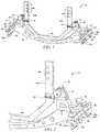
- FIG. 1is a perspective view of the front side, or first side, of an “imaging table-to-head frame adapter,” also referred to herein as a “head fixation stabilizer” or simply “adapter”, according to some embodiments of the present invention.
- FIG. 2is a perspective view of the outside right half of the front side of the imaging table-to-head frame adapter shown in FIG. 1 .
- FIG. 3is a perspective view of the inside right-half of the front side of the imaging table-to-head frame adapter shown in FIG. 1 .
- FIG. 4is a perspective view of the front side of the imaging table-to-head frame adapter shown in FIG. 1 , as viewed from the upper left of the front side of the device.
- the figureshows the imaging table-to-head frame adapter as it slides on to, and partially engages, a pair of grooves on either side of an imaging table. Note that the front attachment members on either side of the adapters are not engaged in this figure.
- FIG. 5is a perspective view of the outside left half of the front side of the imaging table-to-head frame adapter shown in FIG. 1 .
- the figureshows the imaging table-to-head frame adapter after it has slid on to, and fully engaged, a of groove on a side of an imaging table.
- FIG. 6is a perspective view of the front side of the imaging table-to-head frame adapter shown in FIG. 1 , as viewed from the upper left of the front side of the device.
- the figureshows the imaging table-to-head frame adapter after it has slid on to, and fully engaged, a pair of grooves on either side of an imaging table.
- FIG. 7is a perspective view of the inside right-half of the front side of the imaging table-to-head frame adapter shown in FIG. 1 . The figure depicts the rotation of the frame relative to the base.
- FIG. 8is a perspective view of the front side of the imaging table-to-head frame adapter shown in FIG. 1 , as viewed from the upper left of the first side of the device.
- the figureshows the imaging table-to-head frame adapter after the attachment member on the left side (or the side closest in the drawing) has slid on to, and fully engaged, the groove one side of an imaging table, while the attachment member in the right side (or the side farthest in the drawing) has only partially engaged the groove on the far side of the imaging table.
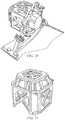
- FIG. 9is a perspective view of the front side of an alternative embodiment of an “imaging table-to-head frame adapter” according to some aspects of the present invention.
- FIG. 10is a perspective view of the front side of the “imaging table-to-head frame adapter” shown in FIG. 9 .
- the figureshows the imaging table-to-head frame adapter affixed to an imaging table.
- FIG. 11is a perspective view of the front side of the imaging table-to-head frame adapter shown in FIG. 9 with a head frame attached thereto.
- FIG. 12is a perspective view of the backside of the imaging table-to-head frame adapter shown in FIG. 9 with a head frame attached thereto.
- FIG. 13is a front elevation view of the “imaging table-to-head frame adapter” shown in FIG. 9 with a head frame attached thereto.
- FIG. 14is a front elevation view of the “imaging table-to-head frame adapter” shown in FIG. 9 .
- FIG. 15is a top plan view of the imaging table-to-head frame adapter shown in FIG. 9 .
- FIG. 16is a perspective view of the imaging table-to-head frame adapter shown in FIG. 9 .
- FIG. 17is a side elevation view of the imaging table-to-head frame adapter shown in FIG. 9 .
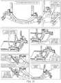
- FIG. 18is a series of images illustrating the mounting of the adapter on an imaging table and the adjustment of the imaging table-to-head frame adapter as in the embodiment shown in FIG. 1 .
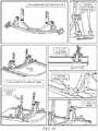
- FIG. 19is a series of images illustrating the mounting of the adapter on an imaging table and the adjustment of the imaging table-to-head frame adapter as in the embodiment shown in FIG. 9 .
- FIG. 20is a photograph of an imaging table-to-head frame adapter affixed to an imaging table, with a head frame affixed to the table-to-head frame adapter and a phantom of a subject's head in the head frame.
- FIG. 21is a perspective view of a LuminantTM MR/CT localizer frame, as produced by Integra LifeSciences Corporation of Plainsboro, N.J.
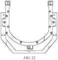
- FIG. 22is an image illustrating the frame of the adapter affixed to a head frame. The illustration shows a portion of the adapter (in darker gray) affixed to a portion of a head frame (in lighter gray).
- FIG. 23 ais a front perspective view of an alternative embodiment of an imaging table-to-head frame adapter according to some aspects of the present invention.
- FIG. 23 aillustrates the horizontal adjustment of the adapter with the adapter moved forward in the horizontal plane.
- FIG. 23 bis a front perspective view of an alternative embodiment of an imaging table-to-head frame adapter according to some aspects of the present invention.
- FIG. 23 billustrates the horizontal adjustment of the adapter with the adapter moved backward in the horizontal plane.
- FIG. 24 ais a front perspective view of the imaging table-to-head frame adapter shown in FIGS. 23 a and 23 b .
- FIG. 24 aillustrates the rotational adjustment of the adapter with the adapter in an upright position.
- FIG. 24 bis a front perspective view of the imaging table-to-head frame adapter shown in FIGS. 23 a and 23 b .
- FIG. 24 billustrates the rotational adjustment of the adapter with the adapter rotated forward.
- FIG. 25 ais a front perspective view of the imaging table-to-head frame adapter shown in FIGS. 23 a and 23 b .
- FIG. 25 aillustrates the vertical adjustment of the adapter with the adapter raised in the vertical plane.
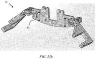
- FIG. 25 bis a front perspective view of the imaging table-to-head frame adapter shown in FIGS. 23 a and 23 b .
- FIG. 25 billustrates the vertical adjustment of the adapter with the adapter lowered in the vertical plane.
- the inventionis a new adapter to be used to position and restrain a patient's head movement during magnetic resonance imaging (MRI), computed tomography (CT) imaging, positron emission tomography (PET) imaging, X-ray imaging or other imaging or medical procedures.
- MRImagnetic resonance imaging
- CTcomputed tomography
- PETpositron emission tomography
- X-ray imagingor other imaging or medical procedures.
- DBSdeep brain stimulation
- an electrodemust be placed at a precise location in the brain, which is typically smaller than 1 cm. in diameter.
- stereotaxyis performed to map the 3-dimensional space of the patient's brain.
- a patientmust wear a head frame with radiographic markers during computed tomography (CT) and MRI scans for stereotaxy to be performed.
- CTcomputed tomography
- MRIcomputed tomography
- the present inventionprevents the patient from moving their head during MRI or other imaging procedures.
- the adapterBy interfacing with the MRI table, the adapter provides a stable constraint to enable MRI for patients who suffer from uncontrollable tremors.
- the adapteris mounted to an imaging table and a head frame is then mounted to the adapter. A patient's head can then be secured within the head frame.
- the adapterprovides a wide range of adjustments to alter the position of the head frame with respect to the imaging table.
- FIGS. 11 and 12show typical head frames used for imaging. A patient's head is secured against the four pins 74 extending from the head frame 70 .
- the adapterhas a high degree of adjustability and modularity.
- the adaptercan be fitted to accommodate a patient quickly and comfortably by offering both translational (i.e. along the length of the table), vertical/height (i.e. raising or lowering the patient's head relative to the table) and rotational adjustment (i.e. moving the patient's head as in a nodding motion) during the fitting procedure, thereby reducing the overall time for the MRI.
- the modular designcan be adapted to quickly interface with different MRI tables and stereotaxy frames. In the absence of a design such as that taught herein, if the patient isn't in the perfect position, the patient generally has to sit up again, and the imaging tech make adjustments to the devices, while modifying the positions of the patient's body. The patient then must lie flat again to fit into the frame. This can take multiple tries, a lot of time, and be frustrating for the tech and hard on the patient.
- the present modular patient handling systemmay be used in connection with ultrasound, computed tomography (CT), x-ray imaging or positron emission tomography (PET).
- CTcomputed tomography
- PETpositron emission tomography
- a head fixation stabilizer 10also referred to herein as an “imaging table-to-head frame adapter” or simply “adapter”, is illustrated.
- the illustrated head fixation stabilizer 10includes a base 20 with a pair of imaging table attachment members 21 to affix the head fixation stabilizer 10 to an imaging table.
- the head fixation stabilizer/adapter 10is configured to be removably secured to an imaging table using the imaging table attachment members 21 .
- the head fixation stabilizer/adapter 10includes first and second table attachment member 21 a and 21 b at opposing ends of the base 20 .
- FIG. 2shows a perspective view of one of the table attachment members 21 in greater detail.
- a pair of downwardly extending, curved clamps 23 a and 23 bare located at each end of the table attachment member 21 .
- the downwardly extending, curved clamps 23wrap around distal sides of an imaging table, as shown in FIG. 5 (See also FIGS. 4 and 6 ).
- the table attachment members 21includes a peg or key 24 that slots into and engages a respective groove formed within and extending along the imaging table in substantially parallel, spaced-apart relationship, as illustrated (see FIGS. 4-6 and FIG. 8 for the table grooves 62 ).
- the keys 24 a and 24 b of the table attachment member 21are configured to matingly engage a respective groove/slot 62 in the imaging table 60 .
- the keys 24are shown as having a round shape, but they may have another configuration such as a trapezoidal or t-shape configuration.
- Each groove on the imaging tablehas a corresponding shape (e.g. round, trapezoidal or t-shaped) to mate with the key.
- Each table attachment member 21has a pair of clamps 23 a and 23 b with a respective key (i.e. 24 a and 24 b , respectively).
- Key 24 bis fixed with respect to clamp 23 b , which results in the key 24 b slidingly engaging the respective groove, but the key does not provide substantial resistance to movement along the length of the groove.
- key 24 amay be drawn towards (tightened) or away from (loosened) clamp 23 a by turning knob 22 . Tightening the key 24 a to the clamp 23 a results in the adapter 10 becoming affixed to, or locked into position on, an imaging table.
- Embodiments of the present inventionare not limited to the illustrated base 20 and attachment member 21 configuration or to the illustrated engagement of attachment member 21 and imaging table 60 . Furthermore, it is anticipated that an attachment member assembly of the present invention can be customized to fit and be secured to additional types of imaging tables. In other words, the attachment member assembly may be a universal assembly usable with several different imaging tables or systems from different manufacturers, or may be table-specific.
- FIGS. 4-6 and FIG. 8show attachment of the adapter 10 to a table 60 having a groove 62 running the length of the table.
- the fore/aft adjustment of the adaptercould generally be made simply by using the clamp 23 and key 24 system of the table attachment member 21 .
- the phrase “fore/aft adjustment”refers to movement along the lengthwise aspect of a table. However, in some instances it might not possible to move an adapter 10 along the length of an imaging table.
- the groove in the tablemight only be long enough to accommodate attachment of the adapter to the table, but not have additional length to supply proper fore/aft adjustment.
- the embodiment of the imaging table-to-head frame adapter shown in FIG. 1has an additional mechanism for adjusting the fore/aft placement of the adapter, referred to herein as the fore/aft adjustment member 26 .
- the fore/aft adjustment member 26includes a peg or key 29 (not shown) extending beneath the fore/aft adjustment member 26 that slots into and engages a respective groove 28 formed within and extending along the top of the table attachment member 21 .
- the keys 29 of the fore/aft adjustment member 26are configured to matingly engage a respective groove/slot 28 in the table attachment member 21 .
- the groove 28is shown as having a trapezoidal shape (e.g. see FIG. 3 ), but they may have another configuration such as around or t-shape configuration.
- the fore/aft adjustment member 26is locked and unlocked by tightening and loosening knobs 27 .
- FIGS. 18 and 19illustrate the stepwise adjustment of the adapter, including the positioning of an adapter on an imaging table.
- the embodiment shown in FIG. 18includes fore/aft adjustment members on either side of the adapter's base, while the embodiment shown in FIG. 19 (as well as the embodiments shown in FIGS. 8-13 ) eliminates the fore/aft adjustment members. Consequently, the embodiment shown in FIGS. 9-17 must be adjusted/positioned along the length of an imaging table using only the clamp 23 and key 24 system of the table attachment member 21 .
- the base 20 of the illustrated head fixation stabilizer 10includes a pair of upwardly extending supports 30 .
- the base 20 and upwardly extending supports 30may be an integral unit, or may be separate components.
- the upwardly extending supports 30 and base 20are an integral unit.
- the upwardly extending supports 30rotateabley engage the head fixation frame 40 using a pair of pivot members 42 .
- the pivot members 42are mounted on lateral sides of the head fixation frame 40 using any number of fasteners, including screws, rivets, pins, studs or adhesives. Extending outwardly from the point of attachment, the pivot member 42 includes a rod. The rod of the pivot member is received in a complementary cavity in the upwardly extending supports 30 .
- a relief slot 34(see FIG. 2 ) is located in the upwardly extending supports 30 immediately above the pivot member cavity.
- a boltpasses through the upwardly extending supports 30 to join the opposing portions of the supports on either end of the relief slot 34 .
- the boltsare actuated by the support knobs 32 , which relieve/expand or contract the opposing portions of the supports, thereby allowing or preventing rotation of the head fixation frame 40 within the upwardly extending supports 30 .
- the head fixation frame 40can be rotated about a horizontal axis defined by the connection (i.e. pivot members 42 ) of the frame to the upwardly extending supports 30 to enable a head frame securing a subject's head to be properly oriented about that axis.
- FIG. 3shows the head fixation frame 40 in a vertical orientation
- FIG. 7show the same perspective view as shown in FIG. 3 , but with the head fixation frame 40 rotated about the axis of the pivot member 42 .
- the head fixation frame 40includes a plurality (e.g. three) slots 44 adapted to receive fasteners to affix a head frame to the vertically extending arms 40 a on the head fixation frame 40 of the head fixation stabilizer 10 .
- a head frame 70generally affixes to the head fixation frame 40 using a pair of fasteners engaging a slot 44 on opposing vertically extending arms 40 a on the head fixation frame 40 .
- the height at which a head frame is supported by the head fixation frame 40can be adjusted to meet the needs of the particular application for a subject.
- slotscan be employed, such as is shown in FIGS. 25 a and 25 b , to achieve nearly infinite adjustment with a range.
- knobs 27are omitted in FIGS. 11-13 for the purposes of illustration of other features, namely the affixed head frame.
- FIG. 20shows the image table-to-head frame adapter affixed to an imaging table.
- Affixed to the image table-to-head frame adapteris an arc adapter plate from Integra LifeSciences Corporation.
- the arc adapter plateis shown in more detail in FIG. 22 .
- Affixed to the arc adapter plate in FIG. 20is a universal compact head ring subassembly and a LuminantTM MR/CT localizer frame.
- the LuminantTM MR/CT localizer frameis shown in more detail in FIG. 21 .
- Integra LifeScienceshas a line of CT clamps that can be used to mount their head frames to a variety of tables. However, these assemblies have numerous shortcomings.
- the CT clamps from Integracannot be rotated, which forces a subject's head into a position with no options to alter the angle.
- the prior CT clampsdo not provide for height adjustments. This inability to fine tune the position of the head frame can lead to great patient discomfort, especially when an imaging procedure may requires the subject to hold still for long periods of time.
- prior systemsforce the tech to fit the patient to the device, not the device to the patient. This can take an enormous physical and emotional toll on a patient.
- the present inventionovercomes these deficiencies by providing a modular system that can interface with a wide variety of head frames and tables, while offering an extensive range of adjustability.
- the added flexibilityallows the practitioner to address the subject's positioning as may be required for a given scan.
Landscapes
- Health & Medical Sciences (AREA)
- Life Sciences & Earth Sciences (AREA)
- Engineering & Computer Science (AREA)
- Medical Informatics (AREA)
- Physics & Mathematics (AREA)
- Veterinary Medicine (AREA)
- Biomedical Technology (AREA)
- Public Health (AREA)
- General Health & Medical Sciences (AREA)
- Animal Behavior & Ethology (AREA)
- Nuclear Medicine, Radiotherapy & Molecular Imaging (AREA)
- Biophysics (AREA)
- Heart & Thoracic Surgery (AREA)
- Molecular Biology (AREA)
- Surgery (AREA)
- Pathology (AREA)
- Radiology & Medical Imaging (AREA)
- High Energy & Nuclear Physics (AREA)
- Optics & Photonics (AREA)
- Neurosurgery (AREA)
- Otolaryngology (AREA)
- Physical Education & Sports Medicine (AREA)
- Apparatus For Radiation Diagnosis (AREA)
- Nuclear Medicine (AREA)
Abstract
Description
Claims (18)
Priority Applications (1)
| Application Number | Priority Date | Filing Date | Title |
|---|---|---|---|
| US15/211,692US10959687B2 (en) | 2014-01-15 | 2016-07-15 | Imaging table-to-head frame adapter |
Applications Claiming Priority (3)
| Application Number | Priority Date | Filing Date | Title |
|---|---|---|---|
| US201461927830P | 2014-01-15 | 2014-01-15 | |
| PCT/US2015/011591WO2015109086A1 (en) | 2014-01-15 | 2015-01-15 | Imaging table-to-head frame adapter |
| US15/211,692US10959687B2 (en) | 2014-01-15 | 2016-07-15 | Imaging table-to-head frame adapter |
Related Parent Applications (1)
| Application Number | Title | Priority Date | Filing Date |
|---|---|---|---|
| PCT/US2015/011591ContinuationWO2015109086A1 (en) | 2014-01-15 | 2015-01-15 | Imaging table-to-head frame adapter |
Publications (2)
| Publication Number | Publication Date |
|---|---|
| US20160317103A1 US20160317103A1 (en) | 2016-11-03 |
| US10959687B2true US10959687B2 (en) | 2021-03-30 |
Family
ID=53543436
Family Applications (1)
| Application Number | Title | Priority Date | Filing Date |
|---|---|---|---|
| US15/211,692Expired - Fee RelatedUS10959687B2 (en) | 2014-01-15 | 2016-07-15 | Imaging table-to-head frame adapter |
Country Status (2)
| Country | Link |
|---|---|
| US (1) | US10959687B2 (en) |
| WO (1) | WO2015109086A1 (en) |
Cited By (1)
| Publication number | Priority date | Publication date | Assignee | Title |
|---|---|---|---|---|
| US20220125653A1 (en)* | 2020-10-23 | 2022-04-28 | Hill-Rom Services, Inc. | Proning frame for a patient bed |
Families Citing this family (10)
| Publication number | Priority date | Publication date | Assignee | Title |
|---|---|---|---|---|
| EP3442405B1 (en)* | 2016-04-15 | 2021-11-24 | Monteris Medical Corporation | Adjustable cradle assembly |
| CN107260477B (en)* | 2016-06-07 | 2018-12-28 | 新昌县城南乡王氏机械配件厂 | The working method of the fixed pillow in ophthalmologic operation head |
| EP3269342A1 (en) | 2016-07-12 | 2018-01-17 | Krzysztof Piasecki | A system for transporting and immobilizing a patient, in particular stroke patient for ct imaging |
| US11712580B2 (en)* | 2017-02-17 | 2023-08-01 | Medtec Llc | Body part fixation device with pitch and/or roll adjustment |
| US10561370B2 (en)* | 2017-04-26 | 2020-02-18 | Accalrent, Inc. | Apparatus to secure field generating device to chair |
| WO2021071939A1 (en)* | 2019-10-08 | 2021-04-15 | Entellus Medical, Inc. | Headrest for a procedure chair and procedure chair having a headrest |
| KR102837952B1 (en)* | 2019-10-12 | 2025-07-25 | 주식회사 우리엔 | X-ray Imaging Apparatus |
| US20210220074A1 (en)* | 2020-01-22 | 2021-07-22 | Clearpoint Neuro, Inc. | Surgical tool support systems including frame mount assemblies and related methods |
| WO2024238176A2 (en)* | 2023-05-12 | 2024-11-21 | Zap Surgical Systems, Inc. | Head immobilizer apparatus and methods of immobilizing a patient's head during radiotherapy |
| ES3006057A1 (en)* | 2023-09-14 | 2025-03-17 | Fundacion Para La Investigacion Biomedica Del Hospital Univ De La Princesa | Customized immobilization device for radiotherapy (Machine-translation by Google Translate, not legally binding) |
Citations (48)
| Publication number | Priority date | Publication date | Assignee | Title |
|---|---|---|---|---|
| US3099441A (en)* | 1959-12-29 | 1963-07-30 | Ries Mfg Company | Surgical device |
| US4064401A (en)* | 1976-02-04 | 1977-12-20 | Danny Alden Marden | Headholder assembly |
| US4256112A (en)* | 1979-02-12 | 1981-03-17 | David Kopf Instruments | Head positioner |
| US4463758A (en)* | 1981-09-18 | 1984-08-07 | Arun A. Patil | Computed tomography stereotactic frame |
| US4465069A (en)* | 1981-06-04 | 1984-08-14 | Barbier Jean Y | Cranial insertion of surgical needle utilizing computer-assisted tomography |
| US4592352A (en)* | 1984-11-30 | 1986-06-03 | Patil Arun A | Computer-assisted tomography stereotactic system |
| US4706665A (en)* | 1984-12-17 | 1987-11-17 | Gouda Kasim I | Frame for stereotactic surgery |
| US4884566A (en)* | 1988-04-15 | 1989-12-05 | The University Of Michigan | System and method for determining orientation of planes of imaging |
| US5143076A (en)* | 1988-12-23 | 1992-09-01 | Tyrone L. Hardy | Three-dimensional beam localization microscope apparatus for stereotactic diagnoses or surgery |
| US5276927A (en)* | 1992-09-21 | 1994-01-11 | Ohio Medical Instrument Co. | Radiolucent head support |
| US5663646A (en)* | 1995-03-30 | 1997-09-02 | Siemens Aktiengesellschaft | Head antenna for nuclear magnetic resonance examinations |
| US5680861A (en) | 1996-07-08 | 1997-10-28 | General Electric Company | Modular subject positioning system for medical imaging |
| US5817106A (en)* | 1995-09-19 | 1998-10-06 | Real; Douglas D. | Stereotactic guide apparatus for use with neurosurgical headframe |
| US5971997A (en)* | 1995-02-03 | 1999-10-26 | Radionics, Inc. | Intraoperative recalibration apparatus for stereotactic navigators |
| US20020079898A1 (en)* | 2000-12-22 | 2002-06-27 | Van De Spijker Arnoldus Johannes Gerardus | Device for stabilizing parts of a body particularly for computed tomography diagnostics |
| US6584630B1 (en)* | 2000-04-06 | 2003-07-01 | Ohio Medical Instrument Company, Inc. | Radiolucent surgical table extension assembly and method |
| US6594839B1 (en)* | 1999-04-30 | 2003-07-22 | The Cleveland Clinic Foundation | Surgical headrest |
| US6684428B2 (en)* | 2000-03-03 | 2004-02-03 | Theo J.J Zegers | Head-clamping device for surgical purposes |
| US6813788B2 (en)* | 2000-04-06 | 2004-11-09 | Schaerer Mayfield Usa, Inc. | Variable length radiolucent surgical table extension |
| US20050066444A1 (en)* | 2003-09-30 | 2005-03-31 | Dupaco, Inc. | Table engageable support for head cushion supporting anesthetized patient |
| US7017209B1 (en)* | 2005-03-14 | 2006-03-28 | Medtec, Inc. | Curved wing board for a CT cradle |
| US20060293589A1 (en)* | 2005-05-12 | 2006-12-28 | Calderon Paul D | System, method and apparatus for surgical patient table |
| US7313430B2 (en)* | 2003-08-28 | 2007-12-25 | Medtronic Navigation, Inc. | Method and apparatus for performing stereotactic surgery |
| US7430773B2 (en)* | 2005-09-20 | 2008-10-07 | Wisconsin Alumni Research Foundation | Device to facilitate controlled rotation of the cervical spine |
| US20090088627A1 (en)* | 2007-09-24 | 2009-04-02 | Surgi-Vision, Inc. | Mri-compatible head fixation frame with cooperating head coil apparatus |
| US20090154654A1 (en)* | 2007-12-13 | 2009-06-18 | Jared Holthe | X-ray positioning device |
| US20100059064A1 (en)* | 2008-05-09 | 2010-03-11 | Schuele Edgar Franz | Method and Apparatus for Using a Surgical Fixture in an Intra-Operative Computed Tomography Scanner |
| US7706828B2 (en) | 2006-03-20 | 2010-04-27 | Samsung Electronic Co., Ltd. | Method and procedure for self discovery of small office or home interior structure by means of ultra-wideband pulse ranging techniques |
| US7730563B1 (en)* | 2004-03-29 | 2010-06-08 | Frederick Sklar | Head support and stabilization system |
| US20100185198A1 (en)* | 2007-09-24 | 2010-07-22 | Peter Piferi | Head Fixation Assemblies for Medical Procedures |
| US20110119829A1 (en)* | 2007-08-24 | 2011-05-26 | ALLEN MEDICAL SYSTEMS ,INC. a corporation | Surgical table accessory platform |
| US20110160727A1 (en)* | 2009-12-30 | 2011-06-30 | Elekta Ab (Publ) | Rigid skull fixation |
| US20110170671A1 (en)* | 2009-11-06 | 2011-07-14 | New York Society For The Ruptured And Crippled Maintaining The Hospital For Special Surgery | System, method, and apparatus for patient positioning table |
| US20110226260A1 (en)* | 2010-03-18 | 2011-09-22 | Hanns Eder | Neurosurgical head holder in combination with a local coil |
| US20120124748A1 (en)* | 2010-11-18 | 2012-05-24 | Orlando Soto | Surgical head support apparatus |
| US20120260429A1 (en)* | 2011-04-15 | 2012-10-18 | Integra Lifesciences Corporation | Durable Connector For Base Unit Handle Of A Patient Head Support System |
| US20130019877A1 (en) | 2011-07-22 | 2013-01-24 | Sklar Frederick H | Surgical head holder and surgical accessories for use with same |
| US20130023756A1 (en)* | 2011-07-21 | 2013-01-24 | Siemens Aktiengesellschaft | Adapter for a direct-connection head coil with adjustable tilt angle |
| US20140079182A1 (en)* | 2011-06-09 | 2014-03-20 | David Roudergues | Patient head support apparatus for imaging |
| US20140096322A1 (en)* | 2012-10-09 | 2014-04-10 | The Cleveland Clinic Foundation | Adjustable headrest for patients undergoing surgery |
| US20140115786A1 (en)* | 2012-10-26 | 2014-05-01 | Medtec, Inc. | Patient positioning device for stereotactic radiosurgery |
| US20140116450A1 (en)* | 2012-10-29 | 2014-05-01 | MAQUET GmbH | Head support for operating tables |
| US8806679B2 (en)* | 2010-11-18 | 2014-08-19 | Allen Medical Systems, Inc. | Operating room table adapter |
| US20150119902A1 (en)* | 2013-10-31 | 2015-04-30 | Elekta Ab (Publ) | Frame for fixation of equipment to the head of a patient during neurological diagnosis, stereotactic imaging, therapy or surgery |
| US20150238117A1 (en)* | 2012-09-05 | 2015-08-27 | Renishaw Plc | Medical imaging accessory |
| US9216126B2 (en)* | 2012-08-28 | 2015-12-22 | Pro Med Instruments Gmbh | Table adapter with joint assembly |
| US9808322B2 (en)* | 2014-08-27 | 2017-11-07 | Vito Del Deo | Method and device for positioning and stabilization of bony structures during maxillofacial surgery |
| USD810304S1 (en)* | 2014-04-24 | 2018-02-13 | Cefla Societá Cooperativa | Head support |
Family Cites Families (1)
| Publication number | Priority date | Publication date | Assignee | Title |
|---|---|---|---|---|
| US7706858B1 (en)* | 2003-05-09 | 2010-04-27 | Fonar Corporation | Head and neck immobilization in magnetic resonance imaging |
- 2015
- 2015-01-15WOPCT/US2015/011591patent/WO2015109086A1/enactiveApplication Filing
- 2016
- 2016-07-15USUS15/211,692patent/US10959687B2/ennot_activeExpired - Fee Related
Patent Citations (51)
| Publication number | Priority date | Publication date | Assignee | Title |
|---|---|---|---|---|
| US3099441A (en)* | 1959-12-29 | 1963-07-30 | Ries Mfg Company | Surgical device |
| US4064401A (en)* | 1976-02-04 | 1977-12-20 | Danny Alden Marden | Headholder assembly |
| US4256112A (en)* | 1979-02-12 | 1981-03-17 | David Kopf Instruments | Head positioner |
| US4465069A (en)* | 1981-06-04 | 1984-08-14 | Barbier Jean Y | Cranial insertion of surgical needle utilizing computer-assisted tomography |
| US4463758A (en)* | 1981-09-18 | 1984-08-07 | Arun A. Patil | Computed tomography stereotactic frame |
| US4592352A (en)* | 1984-11-30 | 1986-06-03 | Patil Arun A | Computer-assisted tomography stereotactic system |
| US4706665A (en)* | 1984-12-17 | 1987-11-17 | Gouda Kasim I | Frame for stereotactic surgery |
| US4884566A (en)* | 1988-04-15 | 1989-12-05 | The University Of Michigan | System and method for determining orientation of planes of imaging |
| US5143076A (en)* | 1988-12-23 | 1992-09-01 | Tyrone L. Hardy | Three-dimensional beam localization microscope apparatus for stereotactic diagnoses or surgery |
| US5276927A (en)* | 1992-09-21 | 1994-01-11 | Ohio Medical Instrument Co. | Radiolucent head support |
| US5971997A (en)* | 1995-02-03 | 1999-10-26 | Radionics, Inc. | Intraoperative recalibration apparatus for stereotactic navigators |
| US5663646A (en)* | 1995-03-30 | 1997-09-02 | Siemens Aktiengesellschaft | Head antenna for nuclear magnetic resonance examinations |
| US5817106A (en)* | 1995-09-19 | 1998-10-06 | Real; Douglas D. | Stereotactic guide apparatus for use with neurosurgical headframe |
| US5680861A (en) | 1996-07-08 | 1997-10-28 | General Electric Company | Modular subject positioning system for medical imaging |
| US6594839B1 (en)* | 1999-04-30 | 2003-07-22 | The Cleveland Clinic Foundation | Surgical headrest |
| US6684428B2 (en)* | 2000-03-03 | 2004-02-03 | Theo J.J Zegers | Head-clamping device for surgical purposes |
| US6584630B1 (en)* | 2000-04-06 | 2003-07-01 | Ohio Medical Instrument Company, Inc. | Radiolucent surgical table extension assembly and method |
| US6813788B2 (en)* | 2000-04-06 | 2004-11-09 | Schaerer Mayfield Usa, Inc. | Variable length radiolucent surgical table extension |
| US20020079898A1 (en)* | 2000-12-22 | 2002-06-27 | Van De Spijker Arnoldus Johannes Gerardus | Device for stabilizing parts of a body particularly for computed tomography diagnostics |
| US7313430B2 (en)* | 2003-08-28 | 2007-12-25 | Medtronic Navigation, Inc. | Method and apparatus for performing stereotactic surgery |
| US20050066444A1 (en)* | 2003-09-30 | 2005-03-31 | Dupaco, Inc. | Table engageable support for head cushion supporting anesthetized patient |
| US7730563B1 (en)* | 2004-03-29 | 2010-06-08 | Frederick Sklar | Head support and stabilization system |
| US7017209B1 (en)* | 2005-03-14 | 2006-03-28 | Medtec, Inc. | Curved wing board for a CT cradle |
| US20060293589A1 (en)* | 2005-05-12 | 2006-12-28 | Calderon Paul D | System, method and apparatus for surgical patient table |
| US7430773B2 (en)* | 2005-09-20 | 2008-10-07 | Wisconsin Alumni Research Foundation | Device to facilitate controlled rotation of the cervical spine |
| US7706828B2 (en) | 2006-03-20 | 2010-04-27 | Samsung Electronic Co., Ltd. | Method and procedure for self discovery of small office or home interior structure by means of ultra-wideband pulse ranging techniques |
| US20110119829A1 (en)* | 2007-08-24 | 2011-05-26 | ALLEN MEDICAL SYSTEMS ,INC. a corporation | Surgical table accessory platform |
| US20090088627A1 (en)* | 2007-09-24 | 2009-04-02 | Surgi-Vision, Inc. | Mri-compatible head fixation frame with cooperating head coil apparatus |
| US8099150B2 (en)* | 2007-09-24 | 2012-01-17 | MRI Interventions, Inc. | MRI-compatible head fixation frame with cooperating head coil apparatus |
| US20100185198A1 (en)* | 2007-09-24 | 2010-07-22 | Peter Piferi | Head Fixation Assemblies for Medical Procedures |
| US8548569B2 (en)* | 2007-09-24 | 2013-10-01 | MRI Interventions, Inc. | Head fixation assemblies for medical procedures |
| US20090154654A1 (en)* | 2007-12-13 | 2009-06-18 | Jared Holthe | X-ray positioning device |
| US20100059064A1 (en)* | 2008-05-09 | 2010-03-11 | Schuele Edgar Franz | Method and Apparatus for Using a Surgical Fixture in an Intra-Operative Computed Tomography Scanner |
| US20110170671A1 (en)* | 2009-11-06 | 2011-07-14 | New York Society For The Ruptured And Crippled Maintaining The Hospital For Special Surgery | System, method, and apparatus for patient positioning table |
| US20110160727A1 (en)* | 2009-12-30 | 2011-06-30 | Elekta Ab (Publ) | Rigid skull fixation |
| US20110226260A1 (en)* | 2010-03-18 | 2011-09-22 | Hanns Eder | Neurosurgical head holder in combination with a local coil |
| US20120124748A1 (en)* | 2010-11-18 | 2012-05-24 | Orlando Soto | Surgical head support apparatus |
| US8893333B2 (en)* | 2010-11-18 | 2014-11-25 | Allen Medical Systems, Inc. | Surgical head support apparatus |
| US8806679B2 (en)* | 2010-11-18 | 2014-08-19 | Allen Medical Systems, Inc. | Operating room table adapter |
| US20120260429A1 (en)* | 2011-04-15 | 2012-10-18 | Integra Lifesciences Corporation | Durable Connector For Base Unit Handle Of A Patient Head Support System |
| US20140079182A1 (en)* | 2011-06-09 | 2014-03-20 | David Roudergues | Patient head support apparatus for imaging |
| US20130023756A1 (en)* | 2011-07-21 | 2013-01-24 | Siemens Aktiengesellschaft | Adapter for a direct-connection head coil with adjustable tilt angle |
| US20130019877A1 (en) | 2011-07-22 | 2013-01-24 | Sklar Frederick H | Surgical head holder and surgical accessories for use with same |
| US9216126B2 (en)* | 2012-08-28 | 2015-12-22 | Pro Med Instruments Gmbh | Table adapter with joint assembly |
| US20150238117A1 (en)* | 2012-09-05 | 2015-08-27 | Renishaw Plc | Medical imaging accessory |
| US20140096322A1 (en)* | 2012-10-09 | 2014-04-10 | The Cleveland Clinic Foundation | Adjustable headrest for patients undergoing surgery |
| US20140115786A1 (en)* | 2012-10-26 | 2014-05-01 | Medtec, Inc. | Patient positioning device for stereotactic radiosurgery |
| US20140116450A1 (en)* | 2012-10-29 | 2014-05-01 | MAQUET GmbH | Head support for operating tables |
| US20150119902A1 (en)* | 2013-10-31 | 2015-04-30 | Elekta Ab (Publ) | Frame for fixation of equipment to the head of a patient during neurological diagnosis, stereotactic imaging, therapy or surgery |
| USD810304S1 (en)* | 2014-04-24 | 2018-02-13 | Cefla Societá Cooperativa | Head support |
| US9808322B2 (en)* | 2014-08-27 | 2017-11-07 | Vito Del Deo | Method and device for positioning and stabilization of bony structures during maxillofacial surgery |
Non-Patent Citations (3)
| Title |
|---|
| International Preliminary Report on Patentability for PCT/US2015/011591 (filing date Jan. 15, 2015) dated Jan. 15, 2014; Applicant: The Regents of the University of Colorado, A Body Corporate et al. |
| International Search Report and Written Opinion for PCT/US15/11591 (filing date Jan. 15, 2015) dated Apr. 7, 2015; Applicant: The Regents of the University of Colorado, A Body Corporate. |
| Safaee et al., Techniques for the Application of Stereotactic Head Frames Based on a 25-Year Experience. Cureus. 2016. vol. 8 (No. 3): e543. |
Cited By (2)
| Publication number | Priority date | Publication date | Assignee | Title |
|---|---|---|---|---|
| US20220125653A1 (en)* | 2020-10-23 | 2022-04-28 | Hill-Rom Services, Inc. | Proning frame for a patient bed |
| US12414887B2 (en)* | 2020-10-23 | 2025-09-16 | Hill-Rom Services, Inc. | Proning frame for a patient bed |
Also Published As
| Publication number | Publication date |
|---|---|
| WO2015109086A1 (en) | 2015-07-23 |
| US20160317103A1 (en) | 2016-11-03 |
Similar Documents
| Publication | Publication Date | Title |
|---|---|---|
| US10959687B2 (en) | Imaging table-to-head frame adapter | |
| US8646452B2 (en) | Pediatric headrest for skull stabilization and method for use of same | |
| US6813788B2 (en) | Variable length radiolucent surgical table extension | |
| US8070221B2 (en) | Operating support for surgeons | |
| US20100059064A1 (en) | Method and Apparatus for Using a Surgical Fixture in an Intra-Operative Computed Tomography Scanner | |
| US20140323851A1 (en) | Subject placement and head positioning device | |
| US20090088627A1 (en) | Mri-compatible head fixation frame with cooperating head coil apparatus | |
| US11607357B2 (en) | Positioning device for beam radiation treatment and imaging | |
| CN111631815A (en) | Surgical positioning assembly and MRI compatible surgical navigation system | |
| JP6788599B2 (en) | Patient table assembly | |
| US8620407B2 (en) | Patient support | |
| US11589946B2 (en) | Head-holder support | |
| US20150238117A1 (en) | Medical imaging accessory | |
| US20070214570A1 (en) | Radiolucent Patient Treatment Table with Removable Tip Extension Base and Accessories | |
| US20150011869A1 (en) | Table stabilizers for scanner systems | |
| US7151816B2 (en) | Imaging tomography apparatus having an attached patient support with a movable backrest | |
| CN109938958B (en) | DSA art limb puncture fixing device | |
| EP3866695B1 (en) | Patient support mechanism for a portable medical scanner | |
| CN212816244U (en) | Special cranium brain magnetic resonance examination fixing device of parkinson disease patient | |
| KR101216921B1 (en) | Couch used for radiation accelerator having direction adjustment device | |
| CN111198345A (en) | Animal Head Coil Device for Magnetic Resonance Imaging | |
| CN215351290U (en) | A kind of psychiatric infusion aid device | |
| US20230390136A1 (en) | Prone articulated headrest |
Legal Events
| Date | Code | Title | Description |
|---|---|---|---|
| AS | Assignment | Owner name:THE REGENTS OF THE UNIVERSITY OF COLORADO, A BODY CORPORATE, COLORADO Free format text:ASSIGNMENT OF ASSIGNORS INTEREST;ASSIGNORS:YAKACKI, CHRISTOPHER;LOSTY, ERIC J.;MCDONOUGH, SEAN;AND OTHERS;SIGNING DATES FROM 20160808 TO 20160906;REEL/FRAME:039757/0916 Owner name:THE REGENTS OF THE UNIVERSITY OF COLORADO, A BODY Free format text:ASSIGNMENT OF ASSIGNORS INTEREST;ASSIGNORS:YAKACKI, CHRISTOPHER;LOSTY, ERIC J.;MCDONOUGH, SEAN;AND OTHERS;SIGNING DATES FROM 20160808 TO 20160906;REEL/FRAME:039757/0916 | |
| STPP | Information on status: patent application and granting procedure in general | Free format text:RESPONSE TO NON-FINAL OFFICE ACTION ENTERED AND FORWARDED TO EXAMINER | |
| STPP | Information on status: patent application and granting procedure in general | Free format text:NON FINAL ACTION MAILED | |
| STPP | Information on status: patent application and granting procedure in general | Free format text:RESPONSE TO NON-FINAL OFFICE ACTION ENTERED AND FORWARDED TO EXAMINER | |
| STPP | Information on status: patent application and granting procedure in general | Free format text:RESPONSE AFTER FINAL ACTION FORWARDED TO EXAMINER | |
| STPP | Information on status: patent application and granting procedure in general | Free format text:NON FINAL ACTION MAILED | |
| STPP | Information on status: patent application and granting procedure in general | Free format text:PUBLICATIONS -- ISSUE FEE PAYMENT VERIFIED | |
| STCF | Information on status: patent grant | Free format text:PATENTED CASE | |
| FEPP | Fee payment procedure | Free format text:MAINTENANCE FEE REMINDER MAILED (ORIGINAL EVENT CODE: REM.); ENTITY STATUS OF PATENT OWNER: SMALL ENTITY | |
| LAPS | Lapse for failure to pay maintenance fees | Free format text:PATENT EXPIRED FOR FAILURE TO PAY MAINTENANCE FEES (ORIGINAL EVENT CODE: EXP.); ENTITY STATUS OF PATENT OWNER: SMALL ENTITY | |
| STCH | Information on status: patent discontinuation | Free format text:PATENT EXPIRED DUE TO NONPAYMENT OF MAINTENANCE FEES UNDER 37 CFR 1.362 | |
| FP | Lapsed due to failure to pay maintenance fee | Effective date:20250330 |