US10959679B2 - Noncontact self-injection-locked sensor - Google Patents
Noncontact self-injection-locked sensorDownload PDFInfo
- Publication number
- US10959679B2 US10959679B2US16/200,826US201816200826AUS10959679B2US 10959679 B2US10959679 B2US 10959679B2US 201816200826 AUS201816200826 AUS 201816200826AUS 10959679 B2US10959679 B2US 10959679B2
- Authority
- US
- United States
- Prior art keywords
- injection
- antenna
- self
- locked
- active element
- Prior art date
- Legal status (The legal status is an assumption and is not a legal conclusion. Google has not performed a legal analysis and makes no representation as to the accuracy of the status listed.)
- Active, expires
Links
- 230000010355oscillationEffects0.000claimsdescription19
- 238000010586diagramMethods0.000description8
- 210000000707wristAnatomy0.000description7
- 230000029058respiratory gaseous exchangeEffects0.000description5
- 230000035945sensitivityEffects0.000description5
- 238000001228spectrumMethods0.000description3
- 230000005540biological transmissionEffects0.000description1
- 239000008280bloodSubstances0.000description1
- 210000004369bloodAnatomy0.000description1
- 238000001514detection methodMethods0.000description1
- 238000000034methodMethods0.000description1
Images


Classifications
- A—HUMAN NECESSITIES
- A61—MEDICAL OR VETERINARY SCIENCE; HYGIENE
- A61B—DIAGNOSIS; SURGERY; IDENTIFICATION
- A61B5/00—Measuring for diagnostic purposes; Identification of persons
- A61B5/72—Signal processing specially adapted for physiological signals or for diagnostic purposes
- A61B5/7228—Signal modulation applied to the input signal sent to patient or subject; Demodulation to recover the physiological signal
- A—HUMAN NECESSITIES
- A61—MEDICAL OR VETERINARY SCIENCE; HYGIENE
- A61B—DIAGNOSIS; SURGERY; IDENTIFICATION
- A61B5/00—Measuring for diagnostic purposes; Identification of persons
- A61B5/05—Detecting, measuring or recording for diagnosis by means of electric currents or magnetic fields; Measuring using microwaves or radio waves
- H—ELECTRICITY
- H01—ELECTRIC ELEMENTS
- H01Q—ANTENNAS, i.e. RADIO AERIALS
- H01Q3/00—Arrangements for changing or varying the orientation or the shape of the directional pattern of the waves radiated from an antenna or antenna system
- H01Q3/26—Arrangements for changing or varying the orientation or the shape of the directional pattern of the waves radiated from an antenna or antenna system varying the relative phase or relative amplitude of energisation between two or more active radiating elements; varying the distribution of energy across a radiating aperture
- H01Q3/28—Arrangements for changing or varying the orientation or the shape of the directional pattern of the waves radiated from an antenna or antenna system varying the relative phase or relative amplitude of energisation between two or more active radiating elements; varying the distribution of energy across a radiating aperture varying the amplitude
- H—ELECTRICITY
- H01—ELECTRIC ELEMENTS
- H01Q—ANTENNAS, i.e. RADIO AERIALS
- H01Q5/00—Arrangements for simultaneous operation of antennas on two or more different wavebands, e.g. dual-band or multi-band arrangements
- H01Q5/30—Arrangements for providing operation on different wavebands
- H01Q5/307—Individual or coupled radiating elements, each element being fed in an unspecified way
- H01Q5/314—Individual or coupled radiating elements, each element being fed in an unspecified way using frequency dependent circuits or components, e.g. trap circuits or capacitors
- H01Q5/328—Individual or coupled radiating elements, each element being fed in an unspecified way using frequency dependent circuits or components, e.g. trap circuits or capacitors between a radiating element and ground
- H—ELECTRICITY
- H01—ELECTRIC ELEMENTS
- H01Q—ANTENNAS, i.e. RADIO AERIALS
- H01Q9/00—Electrically-short antennas having dimensions not more than twice the operating wavelength and consisting of conductive active radiating elements
- H01Q9/04—Resonant antennas
- H01Q9/0407—Substantially flat resonant element parallel to ground plane, e.g. patch antenna
- H01Q9/0442—Substantially flat resonant element parallel to ground plane, e.g. patch antenna with particular tuning means
- A—HUMAN NECESSITIES
- A61—MEDICAL OR VETERINARY SCIENCE; HYGIENE
- A61B—DIAGNOSIS; SURGERY; IDENTIFICATION
- A61B5/00—Measuring for diagnostic purposes; Identification of persons
- A61B5/02—Detecting, measuring or recording for evaluating the cardiovascular system, e.g. pulse, heart rate, blood pressure or blood flow
- A61B5/024—Measuring pulse rate or heart rate
- A61B5/02444—Details of sensor
- A—HUMAN NECESSITIES
- A61—MEDICAL OR VETERINARY SCIENCE; HYGIENE
- A61B—DIAGNOSIS; SURGERY; IDENTIFICATION
- A61B5/00—Measuring for diagnostic purposes; Identification of persons
- A61B5/08—Measuring devices for evaluating the respiratory organs
- A61B5/0816—Measuring devices for examining respiratory frequency
- A—HUMAN NECESSITIES
- A61—MEDICAL OR VETERINARY SCIENCE; HYGIENE
- A61B—DIAGNOSIS; SURGERY; IDENTIFICATION
- A61B5/00—Measuring for diagnostic purposes; Identification of persons
- A61B5/103—Measuring devices for testing the shape, pattern, colour, size or movement of the body or parts thereof, for diagnostic purposes
- A61B5/11—Measuring movement of the entire body or parts thereof, e.g. head or hand tremor or mobility of a limb
- A61B5/113—Measuring movement of the entire body or parts thereof, e.g. head or hand tremor or mobility of a limb occurring during breathing
- G—PHYSICS
- G01—MEASURING; TESTING
- G01S—RADIO DIRECTION-FINDING; RADIO NAVIGATION; DETERMINING DISTANCE OR VELOCITY BY USE OF RADIO WAVES; LOCATING OR PRESENCE-DETECTING BY USE OF THE REFLECTION OR RERADIATION OF RADIO WAVES; ANALOGOUS ARRANGEMENTS USING OTHER WAVES
- G01S13/00—Systems using the reflection or reradiation of radio waves, e.g. radar systems; Analogous systems using reflection or reradiation of waves whose nature or wavelength is irrelevant or unspecified
- G01S13/02—Systems using reflection of radio waves, e.g. primary radar systems; Analogous systems
- G01S13/06—Systems determining position data of a target
- G01S13/08—Systems for measuring distance only
- G01S13/32—Systems for measuring distance only using transmission of continuous waves, whether amplitude-, frequency-, or phase-modulated, or unmodulated
- G01S13/34—Systems for measuring distance only using transmission of continuous waves, whether amplitude-, frequency-, or phase-modulated, or unmodulated using transmission of continuous, frequency-modulated waves while heterodyning the received signal, or a signal derived therefrom, with a locally-generated signal related to the contemporaneously transmitted signal
- G—PHYSICS
- G01—MEASURING; TESTING
- G01S—RADIO DIRECTION-FINDING; RADIO NAVIGATION; DETERMINING DISTANCE OR VELOCITY BY USE OF RADIO WAVES; LOCATING OR PRESENCE-DETECTING BY USE OF THE REFLECTION OR RERADIATION OF RADIO WAVES; ANALOGOUS ARRANGEMENTS USING OTHER WAVES
- G01S13/00—Systems using the reflection or reradiation of radio waves, e.g. radar systems; Analogous systems using reflection or reradiation of waves whose nature or wavelength is irrelevant or unspecified
- G01S13/88—Radar or analogous systems specially adapted for specific applications
- G—PHYSICS
- G01—MEASURING; TESTING
- G01S—RADIO DIRECTION-FINDING; RADIO NAVIGATION; DETERMINING DISTANCE OR VELOCITY BY USE OF RADIO WAVES; LOCATING OR PRESENCE-DETECTING BY USE OF THE REFLECTION OR RERADIATION OF RADIO WAVES; ANALOGOUS ARRANGEMENTS USING OTHER WAVES
- G01S7/00—Details of systems according to groups G01S13/00, G01S15/00, G01S17/00
- G01S7/02—Details of systems according to groups G01S13/00, G01S15/00, G01S17/00 of systems according to group G01S13/00
- G01S7/41—Details of systems according to groups G01S13/00, G01S15/00, G01S17/00 of systems according to group G01S13/00 using analysis of echo signal for target characterisation; Target signature; Target cross-section
- G01S7/415—Identification of targets based on measurements of movement associated with the target
Definitions
- This inventiongenerally relates to a sensor, and more particularly to a noncontact self-injection-locked (SIL) sensor.
- SILnoncontact self-injection-locked
- Wearable healthcare devicesare the potential consumer electronics and usually use photoelectric sensor to detect vital signs.
- a lightis applied to human skin and capturing the images of the skin by a camera.
- the skin imagesare used to observe light intensity variation which is caused by the volume variation of blood flowing through the human skin.
- the photoelectric sensorcan measure the heartbeat rate according the light intensity variation.
- the photoelectric sensorhas to be placed on the human skin tightly for accurate detection because it is sensitive to ambient light. That is the reason why the healthcare device is usually designed as a wristwatch. Additionally, the user wearing the healthcare device for a long time may feel uncomfortable due to the healthcare device is attached to the skin tightly.
- a SIL oscillating integrated antennais provided to radiate an oscillation signal to a subject and receive a reflect signal from the subject.
- the reflect signalbrings SIL oscillating integrated antenna to a SIL state.
- the reflect signalis modulated by vital signs of the subject (e.g. respiration, heartbeat and wrist pulse), so demodulating the output signal of the SIL oscillating integrated antenna can acquire a vital signal of the subject, that is a contactless way to acquire the vital signal.
- the SIL oscillating integrated antennaplays both roles of signal radiating/receiving element and oscillating element such that the output signal contains both the components of amplitude modulation and frequency modulation, and the SIL oscillating integrated antenna exhibits highly sensitivity for sensing tiny vibration.
- a noncontact SIL sensor of the present inventionincludes a SIL oscillating integrated antenna and a demodulator.
- the SIL oscillating integrated antennaincludes an antenna and an active element which are electrically connected to each other.
- the antennais configured for oscillation with the active element to generate an oscillation signal and configured for frequency selection.
- the antennais further configured to radiate the oscillation signal to a subject and receive a reflect signal reflected from the subject to bring the self-injection-locked oscillating integrated antenna to a SIL state.
- the oscillation signalis modulated by the vital signs of the subject to become a frequency- and amplitude-modulated signal.
- the demodulatorincludes a differentiator and an envelope detector.
- the differentiatoris electrically connected to the self-injection-locked oscillating integrated antenna and configured to receive and differentiate the frequency- and amplitude-modulated signal into an amplitude-modulated signal.
- the envelope detectoris electrically connected to the differentiator and is configured to demodulate the amplitude-modulated signal in amplitude to obtain a vital signal of the subject.
- the SIL oscillating integrated antennahas capabilities of oscillating, radiating and receiving signals, it can acquire the both amplitude and frequency modulation components of signals caused by vital signs under the SIL state and precisely detect vital signs of the subject after demodulation.
- the demodulatorcan realizes the signal demodulation in a simple architecture so the noncontact SIL sensor is capable of operating under extremely high frequency conditions and sensing pretty small vibration well.
- the noncontact SIL sensor of the present inventionis available for further potential applications.
- FIG. 1is a circuit diagram illustrating a noncontact SIL sensor in accordance with a first embodiment of the present invention.
- FIG. 2is a circuit diagram illustrating a noncontact SIL sensor in accordance with a second embodiment of the present invention.
- FIG. 3is a circuit diagram illustrating a noncontact SIL sensor in accordance with a third embodiment of the present invention.
- FIG. 4is a circuit diagram illustrating a noncontact SIL sensor in accordance with a fourth embodiment of the present invention.
- FIG. 5is a vital-sign waveform diagram of human chest detected by the noncontact SIL sensor in accordance with the second embodiment of the present invention.
- FIG. 6is a vital-sign waveform diagram of human wrist detected by the noncontact SIL sensor in accordance with the second embodiment of the present invention.
- FIG. 7is a circuit diagram illustrating a noncontact SIL sensor in accordance with a fifth embodiment of the present invention.
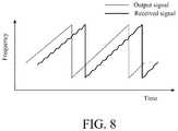
- FIG. 8is a waveform diagram of output signal and received signal when the noncontact SIL sensor in accordance with the fifth embodiment of the present invention produces a linear variation in frequency.
- a noncontact SIL sensor 100 of a first embodiment of the present inventionis shown in FIG. 1 .
- the noncontact SIL sensor 100includes a SIL oscillating integrated antenna 110 , a demodulator 120 and a baseband amplifier 130 .
- the SIL oscillating integrated antenna 110includes an antenna 111 and an active element 112 electrically connected to the antenna 111 .
- the antenna 111is a plane printed antenna and the active element 112 is a solid-state amplifier.
- the active element 112 of the first embodimenthas an input port 112 a and an output port 112 b which are both electrically connected to the antenna 111 to form a loop configuration.
- the antenna 111is configured for oscillation with the active element 112 to generate an oscillation signal S oc and for frequency-selection. Furthermore, the antenna 111 is also employed to radiate the oscillation signal S oc to a subject B. After the oscillation signal S oc contacts the subject B, a reflect signal S re is reflected from the subject B and received by the antenna 111 . The reflect signal S re injects into and locks the SIL oscillating integrated antenna 110 in a SIL state.
- the SIL oscillating integrated antenna 110is not only used as a signal radiating/receiving element but also involved in oscillation. As a result, the oscillation signal S oc is modulated by a vital sign of the subject B (e.g. respiration, heartbeat and wrist pulse) in frequency and amplitude to become a frequency- and amplitude-modulated signal S FM-AM .
- the demodulator 120is electrically connected to the SIL oscillating integrated antenna 110 in order to receive the frequency- and amplitude-modulated signal S FM-AM .
- the demodulator 120is configured to demodulate the frequency- and amplitude-modulated signal S FM-AM to obtain a vital signal S vt of the subject B.
- the demodulator 120is an envelope detector 121 configured to proceed amplitude demodulation of the frequency- and amplitude-modulated signal S FM-AM .
- the envelope detector 121can extract the amplitude modulation components of the frequency- and amplitude-modulated signal S FM-AM to obtain the vital signal S vt .
- the baseband amplifier 130is electrically connected to the demodulator 120 to receive and amplify the vital signal S vt .
- the noncontact SIL sensor 100 of the first embodimentcan acquire the vital sign S vt of the subject B through the amplitude demodulation proceeded by the envelope detector 121 only
- the demodulator 120compared with other radars, has advantages of simple architecture and low costs.
- the operation frequency band of the SIL oscillating integrated antenna 110can be increased to millimeter wave range (30-300 GHz) to improve sensitivity of sensing tiny vibration dramatically so that the noncontact SIL sensor 100 can be applied to further potential applications, not only applied to detect vital signs of large subjects with large vibration movement.
- the demodulator 120 in a second embodimentfurther includes a differentiator 122 which is added between and electrically connected to the SIL oscillating integrated antenna 110 and the envelope detector 121 .
- the differentiator 122is configured to receive the frequency- and amplitude-modulated signal S FM-AM from the SIL oscillating integrated antenna 110 and differentiate the frequency- and amplitude-modulated signal S FM-AM to convert the frequency modulation components into the amplitude modulation components. Consequently, the frequency- and amplitude-modulated signal S FM-AM is converted to an amplitude-modulated signal S AM to improve the sensitivity of sensing vital signs of the subject B.
- the envelope detector 121electrically connected to the differentiator 122 , is configured to receive and amplitude-demodulate the amplitude-modulated signal S AM for obtaining the vital signal S vt . Because the noncontact SIL sensor 100 of the second embodiment further utilize the differentiator 122 to convert frequency modulation to amplitude modulation, frequency and amplitude modulations of the oscillation signal S oc caused by vital signs of the subject B are fused to further enhance the sensitivity of the noncontact SIL sensor 100 for sensing tiny vibrations.
- the differentiator 122is a microstrip differentiator, and the operation frequency of the differentiator 122 is substantially the same as the frequency of the frequency- and amplitude-modulated signal S FM-AM .
- the noncontact SIL sensor 100 of the second embodimenthas better sensitivity when the frequency of the frequency- and amplitude-modulated signal S FM-AM and the operation frequency of the differentiator 122 are higher than or equal to 300 MHz.
- FIGS. 3 and 4represent third and fourth embodiments of the present invention.
- the active element 112 in the third and fourth embodimentsis a solid-state transistor having a gate, a source and a drain, different to the solid-state amplifier in the first and second embodiments.
- the drain of the active element 112is coupled to the antenna 111
- the gate of the active element 112is connected to ground via a first reactance element 112 c
- the source of the active element 112is connected to ground via a second reactance element 112 d such that the antenna 111 and the active element 112 constitute a reflect type configuration.
- the first reactance element 112 c and the second reactance element 112 dmay be transmission lines capable of be operated under high frequency conditions.
- the antenna 111 and the active element 112 in the third and fourth embodimentsare employed for oscillation and the oscillation signal S oc generation.
- the antenna 111is configured to radiate the oscillation signal S oc to the subject B and receive the reflect signal S re reflected from the subject B.
- the reflect signal S rebrings the SIL oscillating integrated antenna 110 into the SIL state to output the frequency- and amplitude-modulated signal S FM-AM .
- the demodulator 120is configured to demodulate the frequency- and amplitude-modulated signal S FM-AM to acquire the vital signal S vt .
- the demodulator 120 of the third embodimentonly uses the envelope detector 121 to perform the amplitude demodulate process of the frequency- and amplitude-modulated signal S FM-AM to obtain the vital signal S vt
- the demodulator 120 of the fourth embodimentuses the differentiator 122 to convert the frequency modulation components to the amplitude modulation components and then uses the envelope detector 121 to amplitude-demodulate the amplitude-modulated signal S AM to obtain the vital signal S vt .
- FIG. 5is a test result of the vital signal S vt using the noncontact SIL sensor 100 of the second embodiment.
- the SIL sensoris worn on a human chest with a separated distance due to clothes.
- Two clear spectrum peaks of the vital signal S vtrepresent respiration and heartbeat rates, and the measured heartbeat rate agrees the human heartbeat rate (the data shown on upper right corner of FIG. 5 ) acquired by a finger pulse oximeter well.
- FIG. 6is a test result of the vital signal S vt by placing the noncontact SIL sensor 100 of the second embodiment on the human wrist.
- the spectrum peak of wrist pulseis identified, and there is no spectrum peak representing respiration in the vital signal S vt because the SIL sensor located on the human wrist cannot detect respiration.
- the measured wrist pulse rateagrees the human heartbeat rate (the data shown on upper right corner of FIG. 6 ) detected by the finger pulse oximeter well.
- the test resultsdemonstrate the noncontact SIL sensor 100 of the present invention can sense human vital signs precisely by
- FIG. 7shows a fifth embodiment of the present invention.
- the SIL oscillating integrated antenna 110further includes an adjustable capacitance 113 .
- One end of the adjustable capacitance 113is electrically connected to the antenna 111 and the other end of the adjustable capacitance 113 is connected to ground.
- the capacitance value of the adjustable capacitance 113can influence the frequency selection of the antenna 111 to adjust the frequency of the SIL oscillating integrated antenna 110 .
- the SIL oscillating integrated antenna 110when the SIL oscillating integrated antenna 110 produces a linear variation in frequency because of the adjustable capacitance 113 , the SIL oscillating integrated antenna 110 is configured as a frequency-modulated continuous-wave radar (FMCW) which can demodulate the received signals by the demodulator 120 and perform a fast-Fourier transform (FFT) to calculate the distance between the SIL oscillating integrated antenna 110 and the subject B.
- FMCWfrequency-modulated continuous-wave radar
- FFTfast-Fourier transform
- the SIL oscillating integrated antenna 110is provided for oscillating, radiating and receiving signals such that it can acquire the amplitude and frequency modulation components in signals caused by vital signs of the subject B in the SIL state and demodulate the signals to detect the vital signs of the subject B precisely. Furthermore, owing to the architecture of the demodulator 120 used for demodulation is simple, the noncontact SIL sensor 100 can operate in extremely high frequency conditions and is highly sensitive to tiny vibration. For these reasons, the noncontact SIL sensor 100 of the present invention can be applied to further potential applications.
Landscapes
- Health & Medical Sciences (AREA)
- Life Sciences & Earth Sciences (AREA)
- Engineering & Computer Science (AREA)
- Public Health (AREA)
- Molecular Biology (AREA)
- Veterinary Medicine (AREA)
- General Health & Medical Sciences (AREA)
- Physics & Mathematics (AREA)
- Animal Behavior & Ethology (AREA)
- Biophysics (AREA)
- Pathology (AREA)
- Biomedical Technology (AREA)
- Heart & Thoracic Surgery (AREA)
- Medical Informatics (AREA)
- Surgery (AREA)
- Physiology (AREA)
- Computer Vision & Pattern Recognition (AREA)
- Signal Processing (AREA)
- Artificial Intelligence (AREA)
- Psychiatry (AREA)
- Nuclear Medicine, Radiotherapy & Molecular Imaging (AREA)
- Radiology & Medical Imaging (AREA)
- Measuring Pulse, Heart Rate, Blood Pressure Or Blood Flow (AREA)
- Measurement Of The Respiration, Hearing Ability, Form, And Blood Characteristics Of Living Organisms (AREA)
Abstract
Description
Claims (16)
Applications Claiming Priority (2)
| Application Number | Priority Date | Filing Date | Title |
|---|---|---|---|
| TW106143627ATWI642406B (en) | 2017-12-12 | 2017-12-12 | Non-contact self-injection locking sensor |
| TW106143627 | 2017-12-12 |
Publications (2)
| Publication Number | Publication Date |
|---|---|
| US20190175117A1 US20190175117A1 (en) | 2019-06-13 |
| US10959679B2true US10959679B2 (en) | 2021-03-30 |
Family
ID=65431771
Family Applications (1)
| Application Number | Title | Priority Date | Filing Date |
|---|---|---|---|
| US16/200,826Active2039-07-05US10959679B2 (en) | 2017-12-12 | 2018-11-27 | Noncontact self-injection-locked sensor |
Country Status (3)
| Country | Link |
|---|---|
| US (1) | US10959679B2 (en) |
| CN (1) | CN109907744B (en) |
| TW (1) | TWI642406B (en) |
Families Citing this family (12)
| Publication number | Priority date | Publication date | Assignee | Title |
|---|---|---|---|---|
| TWI675218B (en)* | 2018-06-07 | 2019-10-21 | 國立中山大學 | Vital sign sensor capable of resisting clutter |
| TWI690720B (en)* | 2019-01-30 | 2020-04-11 | 昇雷科技股份有限公司 | Noncontact vibration sensor |
| TWI705795B (en) | 2019-04-01 | 2020-10-01 | 國立臺灣科技大學 | Non-contact phase-locked and self-injection-locked vital sign sensor |
| CN112294301B (en)* | 2019-08-02 | 2024-12-31 | 华广生技股份有限公司 | Physiological signal sensor device |
| TWI750582B (en)* | 2020-02-10 | 2021-12-21 | 國立臺灣科技大學 | Perturbation-injection-locked physiological siganal sensor |
| JP7526578B2 (en)* | 2020-03-31 | 2024-08-01 | キヤノンメディカルシステムズ株式会社 | Vital Information Monitor and Magnetic Resonance Imaging Apparatus |
| TWI749527B (en)* | 2020-04-16 | 2021-12-11 | 國立成功大學 | Pulse measurement device |
| TWI719893B (en) | 2020-04-29 | 2021-02-21 | 國立中山大學 | Digital self-injection-locked radar |
| TWI723873B (en)* | 2020-05-13 | 2021-04-01 | 國立中山大學 | Six-port self-injection-locked radar |
| TWI744046B (en)* | 2020-10-22 | 2021-10-21 | 國立中山大學 | Phase-tracking self-injection-locked radar |
| TWI780543B (en) | 2020-12-18 | 2022-10-11 | 國立中山大學 | Frequency-converted frequency-modulated self-injection-locked radar |
| TWI776751B (en)* | 2021-12-10 | 2022-09-01 | 國立高雄師範大學 | System and method for detecting stimulated acupuncture point |
Citations (15)
| Publication number | Priority date | Publication date | Assignee | Title |
|---|---|---|---|---|
| US20100198083A1 (en)* | 2007-07-12 | 2010-08-05 | University Of Florida Research Foundation, Inc | Random Body Movement Cancellation for Non-Contact Vital Sign Detection |
| US20120209087A1 (en)* | 2010-09-20 | 2012-08-16 | National Sun Yat-Sen University | Non-Contact Vital Sign Sensing System and Sensing Method Using the Same |
| US20120245479A1 (en)* | 2011-03-23 | 2012-09-27 | Meena Ganesh | Physiology Monitoring and Alerting System and Process |
| TW201315437A (en) | 2011-10-12 | 2013-04-16 | Ind Tech Res Inst | Non-contact vital sign sensing system and sensing method using the same |
| TW201351353A (en) | 2012-06-14 | 2013-12-16 | Univ Nat Sun Yat Sen | Wireless detection devices and wireless detection methods |
| US20140024917A1 (en)* | 2012-07-20 | 2014-01-23 | Resmed Sensor Technologies Limited | Range gated radio frequency physiology sensor |
| US20140128748A1 (en)* | 2010-05-17 | 2014-05-08 | National Sun Yat-Sen University | Motion/vibration sensor |
| TW201428325A (en) | 2013-01-14 | 2014-07-16 | Ind Tech Res Inst | Motion/interference signal detection system and method thereof |
| US20150241555A1 (en)* | 2014-02-25 | 2015-08-27 | University Of Florida Research Foundation, Inc. | Method and apparatus for doppler radar signal recovery of target displacement |
| TWI514193B (en) | 2014-12-25 | 2015-12-21 | Univ Nat Sun Yat Sen | Motion detection apparatus |
| TWI556797B (en) | 2013-03-18 | 2016-11-11 | 財團法人工業技術研究院 | Motion/interference sensor |
| US9603555B2 (en)* | 2010-05-17 | 2017-03-28 | Industrial Technology Research Institute | Motion/vibration detection system and method with self-injection locking |
| US20180081030A1 (en)* | 2015-04-20 | 2018-03-22 | Resmed Sensor Technologies Limited | Multi sensor radio frequency detection |
| US20180235481A1 (en)* | 2017-02-13 | 2018-08-23 | Stichting Imec Nederland | Method and device for detecting a vital sign |
| US20180263502A1 (en)* | 2014-10-08 | 2018-09-20 | The University Of Florida Research Foundation, Inc. | Method and apparatus for non-contact fast vital sign acquisition based on radar signal |
Family Cites Families (13)
| Publication number | Priority date | Publication date | Assignee | Title |
|---|---|---|---|---|
| CN102046076A (en)* | 2008-04-03 | 2011-05-04 | Kai医药公司 | Non-contact physiological motion sensor and method of use thereof |
| CN102988051B (en)* | 2012-12-13 | 2014-07-02 | 中国人民解放军第四军医大学 | Device for monitoring health of computer operator |
| CN103919527B (en)* | 2013-01-14 | 2017-04-12 | 财团法人工业技术研究院 | Motion/disturbance signal detection system and method |
| CN103070687A (en)* | 2013-02-06 | 2013-05-01 | 南京理工大学 | Signal processing algorithm of non-contact type vital sign monitoring system |
| WO2014140994A1 (en)* | 2013-03-13 | 2014-09-18 | Koninklijke Philips N.V. | Apparatus and method for determining vital signs from a subject |
| CN104267394A (en)* | 2014-10-07 | 2015-01-07 | 电子科技大学 | High-resolution human body target motion feature detecting method |
| CN104644142B (en)* | 2015-02-05 | 2017-07-21 | 南京理工大学 | A kind of signal processing algorithm of non-contact vital sign monitoring |
| CN105232026A (en)* | 2015-10-29 | 2016-01-13 | 无锡南理工科技发展有限公司 | Heartbeat frequency detection algorithm of non-contact vital sign detection system |
| CN105476602B (en)* | 2015-11-25 | 2018-11-06 | 方姝阳 | Contactless humanbody life sign measurement method and device |
| CN106175723A (en)* | 2016-06-27 | 2016-12-07 | 中国人民解放军第三军医大学第附属医院 | A kind of many life monitoring systems based on FMCW wideband radar |
| CN106175731B (en)* | 2016-08-10 | 2020-02-21 | 上海交通大学 | Signal processing system for non-contact vital signs monitoring |
| CN106644030B (en)* | 2016-08-31 | 2020-05-22 | 上海交通大学 | Non-contact vibration measurement method based on Doppler radar |
| CN106821347B (en)* | 2016-12-20 | 2020-05-05 | 中国人民解放军第三军医大学 | FMCW broadband life detection radar respiration and heartbeat signal extraction algorithm |
- 2017
- 2017-12-12TWTW106143627Apatent/TWI642406B/ennot_activeIP Right Cessation
- 2018
- 2018-11-26CNCN201811437967.0Apatent/CN109907744B/enactiveActive
- 2018-11-27USUS16/200,826patent/US10959679B2/enactiveActive
Patent Citations (17)
| Publication number | Priority date | Publication date | Assignee | Title |
|---|---|---|---|---|
| US8721554B2 (en) | 2007-07-12 | 2014-05-13 | University Of Florida Research Foundation, Inc. | Random body movement cancellation for non-contact vital sign detection |
| US20100198083A1 (en)* | 2007-07-12 | 2010-08-05 | University Of Florida Research Foundation, Inc | Random Body Movement Cancellation for Non-Contact Vital Sign Detection |
| US9603555B2 (en)* | 2010-05-17 | 2017-03-28 | Industrial Technology Research Institute | Motion/vibration detection system and method with self-injection locking |
| US20140128748A1 (en)* | 2010-05-17 | 2014-05-08 | National Sun Yat-Sen University | Motion/vibration sensor |
| US20120209087A1 (en)* | 2010-09-20 | 2012-08-16 | National Sun Yat-Sen University | Non-Contact Vital Sign Sensing System and Sensing Method Using the Same |
| US20120245479A1 (en)* | 2011-03-23 | 2012-09-27 | Meena Ganesh | Physiology Monitoring and Alerting System and Process |
| TW201315437A (en) | 2011-10-12 | 2013-04-16 | Ind Tech Res Inst | Non-contact vital sign sensing system and sensing method using the same |
| TW201351353A (en) | 2012-06-14 | 2013-12-16 | Univ Nat Sun Yat Sen | Wireless detection devices and wireless detection methods |
| US20140024917A1 (en)* | 2012-07-20 | 2014-01-23 | Resmed Sensor Technologies Limited | Range gated radio frequency physiology sensor |
| CN104703533A (en) | 2012-07-20 | 2015-06-10 | 瑞思迈传感器技术有限公司 | Range gated radio frequency physiology sensor |
| TW201428325A (en) | 2013-01-14 | 2014-07-16 | Ind Tech Res Inst | Motion/interference signal detection system and method thereof |
| TWI556797B (en) | 2013-03-18 | 2016-11-11 | 財團法人工業技術研究院 | Motion/interference sensor |
| US20150241555A1 (en)* | 2014-02-25 | 2015-08-27 | University Of Florida Research Foundation, Inc. | Method and apparatus for doppler radar signal recovery of target displacement |
| US20180263502A1 (en)* | 2014-10-08 | 2018-09-20 | The University Of Florida Research Foundation, Inc. | Method and apparatus for non-contact fast vital sign acquisition based on radar signal |
| TWI514193B (en) | 2014-12-25 | 2015-12-21 | Univ Nat Sun Yat Sen | Motion detection apparatus |
| US20180081030A1 (en)* | 2015-04-20 | 2018-03-22 | Resmed Sensor Technologies Limited | Multi sensor radio frequency detection |
| US20180235481A1 (en)* | 2017-02-13 | 2018-08-23 | Stichting Imec Nederland | Method and device for detecting a vital sign |
Non-Patent Citations (9)
| Title |
|---|
| Chao-Hsiung Tseng et al., A Cost-Effective Wearable Vital-Sign Sensor with Self-Oscillating Active Antenna Based on Envelope Detection Technique, 2017 IEEE MTT-S International Microwave Symposium (IMS), Jun. 4-9, 2017. |
| Chao-Hsiung Tseng et al., A Wearable Self-Injection-Locked Sensor With Active Integrated Antenna and Differentiator-Based Envelope Detector for Vital-Sign Detection From Chest Wall and Wrist, IEEE Transactions on Microwave Theory and Techniques, vol. 66, No. 5, May 2018, Jan. 4, 2018. |
| Chao-Hsiung Tseng et al., Self-Injection-Locked Radar Sensor with Active-Integrated-Antenna and Differentiator-Based Demodulator for Noncontact Vital Sign Detection, 2018 IEEE Topical Conference on Wireless Sensors and Sensor Networks (WiSNet), Jan. 14-17, 2018. |
| F. Wang, C. Li, C. Hsiao, T. Horng, J. Lin, K. Peng, J. Jau, J. Li, C. Chen, A Novel Vital-Sign Sensor Based on a Self-Injection-Locked Oscillator, Dec. 2010, IEEE Transactions on Microwave Theory and Techniques, vol. 58, No. 12, pp. 4112-4120 (Year: 2010).* |
| F. Wang, T. Horng, K. Peng, J. Jau, J. Li, C. Cheng, Detection of Concealed Individuals Based on Their Vital Signs by Using a See-Through-Wall Imaging System With a Self-Injection-Locked Radar, Jan. 2013, IEEE Transactions on Microwave Techniques and applications, vol. 61, No. 1, pp. 696-704 (Year: 2013).* |
| Fu-Kang Wang, Mu-Cyun Tang, Sheng-Chao Su, Tzyy-Sheng Horng, Wrist Pulse Rate Monitor Using Self-Injection-Locked Radar Technology, Oct. 26, 2016, Biosensors, 2016, 6, 54, pp. 1-12 (Year: 2016).* |
| Fu-Kang Wang, Tzyy-Sheng Horng, Kang-Chun Peng, Je-Kaun Jau, J. Yu Li, Single-Antenna Doppler Radars Using Self and Mutual Injection Locking for Vital Sign Detection With Random Body Movement Cancellation, Dec. 2011, IEEE Transactions on Microwave Theory and Techniques, vol. 59, No. 12, 3577-3587 (Year: 2011).* |
| Fu-Kang Wang, You-Rung Chou, Yen-Chen Chiu, Mu-Cyun Tang, Tzyy-Sheng Horng, Chest-Worn Health Monitor Based on a Bistatic Self-Injected-Locked Radar, 2015, IEEE transactions on Biomedical Engineering, vol. 62, pp. 2931-2940 (Year: 2015).* |
| Taiwanese Notice of Allowance dated Oct. 3, 2018 for Taiwanese Patent Application No. 106143627, 3 pages. |
Also Published As
| Publication number | Publication date |
|---|---|
| CN109907744B (en) | 2022-04-08 |
| CN109907744A (en) | 2019-06-21 |
| TWI642406B (en) | 2018-12-01 |
| US20190175117A1 (en) | 2019-06-13 |
| TW201927233A (en) | 2019-07-16 |
Similar Documents
| Publication | Publication Date | Title |
|---|---|---|
| US10959679B2 (en) | Noncontact self-injection-locked sensor | |
| US11540774B2 (en) | Removable smartphone case for radio wave based health monitoring | |
| US9846226B2 (en) | Motion detection device | |
| TWI609192B (en) | Vital sign monitoring system | |
| US9477812B2 (en) | Random body movement cancellation for non-contact vital sign detection | |
| Mostafanezhad et al. | Benefits of coherent low-IF for vital signs monitoring using Doppler radar | |
| An et al. | Sensitivity enhanced vital sign detection based on antenna reflection coefficient variation | |
| US11294032B2 (en) | Doppler radar sensor with power detector | |
| Han et al. | Differential phase Doppler radar with collocated multiple receivers for noncontact vital signal detection | |
| US11350839B2 (en) | Non-contact self-injection-locked vital sign sensor | |
| TW202037330A (en) | Non-contact phase-locked and self-injection-locked vital sign sensor | |
| Fan et al. | Hand gesture recognition based on Wi-Fi chipsets | |
| CN104055519B (en) | Motion/Disturbance Detector | |
| Ganguly et al. | Sensitive transmit receive architecture for body wearable RF plethysmography sensor | |
| Franceschini et al. | MUHD: A Multi-channel Ultrasound Prototype for Remote Heartbeat Detection. | |
| Benchikh et al. | A novel millimeter wave radar sensor for medical signal detection | |
| Lin | Noncontact measurement of cardiopulmonary movements: A review of system architectures and the path to micro-radars | |
| Peng et al. | A low-cost vital-sign sensor based on bluetooth system | |
| Wang et al. | A 2.4-GHz noncontact vital-sign sensor based on two circulators and frequency-modulated/injection-locked VCO | |
| Jensen et al. | An experimental vital signs detection radar using low-IF heterodyne architecture and single-sideband transmission | |
| Banerjee et al. | PXI-based non-contact vital sign detection system |
Legal Events
| Date | Code | Title | Description |
|---|---|---|---|
| AS | Assignment | Owner name:NATIONAL TAIWAN UNIVERSITY OF SCIENCE AND TECHNOLO Free format text:ASSIGNMENT OF ASSIGNORS INTEREST;ASSIGNORS:TSENG, CHAO-HSIUNG;YU, LI-TE;HUANG, JYUN-KAI;AND OTHERS;REEL/FRAME:047592/0168 Effective date:20181123 Owner name:SIL RADAR TECHNOLOGY INC., TAIWAN Free format text:ASSIGNMENT OF ASSIGNORS INTEREST;ASSIGNORS:TSENG, CHAO-HSIUNG;YU, LI-TE;HUANG, JYUN-KAI;AND OTHERS;REEL/FRAME:047592/0168 Effective date:20181123 Owner name:NATIONAL TAIWAN UNIVERSITY OF SCIENCE AND TECHNOLOGY, TAIWAN Free format text:ASSIGNMENT OF ASSIGNORS INTEREST;ASSIGNORS:TSENG, CHAO-HSIUNG;YU, LI-TE;HUANG, JYUN-KAI;AND OTHERS;REEL/FRAME:047592/0168 Effective date:20181123 | |
| FEPP | Fee payment procedure | Free format text:ENTITY STATUS SET TO UNDISCOUNTED (ORIGINAL EVENT CODE: BIG.); ENTITY STATUS OF PATENT OWNER: SMALL ENTITY | |
| FEPP | Fee payment procedure | Free format text:ENTITY STATUS SET TO SMALL (ORIGINAL EVENT CODE: SMAL); ENTITY STATUS OF PATENT OWNER: SMALL ENTITY | |
| STPP | Information on status: patent application and granting procedure in general | Free format text:DOCKETED NEW CASE - READY FOR EXAMINATION | |
| STPP | Information on status: patent application and granting procedure in general | Free format text:NON FINAL ACTION MAILED | |
| STPP | Information on status: patent application and granting procedure in general | Free format text:PUBLICATIONS -- ISSUE FEE PAYMENT VERIFIED | |
| STCF | Information on status: patent grant | Free format text:PATENTED CASE | |
| MAFP | Maintenance fee payment | Free format text:PAYMENT OF MAINTENANCE FEE, 4TH YR, SMALL ENTITY (ORIGINAL EVENT CODE: M2551); ENTITY STATUS OF PATENT OWNER: SMALL ENTITY Year of fee payment:4 |