US10959560B2 - Steam cooking system and method - Google Patents
Steam cooking system and methodDownload PDFInfo
- Publication number
- US10959560B2 US10959560B2US15/690,470US201715690470AUS10959560B2US 10959560 B2US10959560 B2US 10959560B2US 201715690470 AUS201715690470 AUS 201715690470AUS 10959560 B2US10959560 B2US 10959560B2
- Authority
- US
- United States
- Prior art keywords
- valve
- steam
- cooking cavity
- steam cooking
- main supply
- Prior art date
- Legal status (The legal status is an assumption and is not a legal conclusion. Google has not performed a legal analysis and makes no representation as to the accuracy of the status listed.)
- Active, expires
Links
- 238000010411cookingMethods0.000titleclaimsabstractdescription154
- 238000000034methodMethods0.000titleclaimsdescription5
- 239000012530fluidSubstances0.000claimsabstractdescription10
- 239000008236heating waterSubstances0.000claimsdescription6
- 230000001960triggered effectEffects0.000description5
- 238000010438heat treatmentMethods0.000description4
- 238000004519manufacturing processMethods0.000description4
- XLYOFNOQVPJJNP-UHFFFAOYSA-NwaterSubstancesOXLYOFNOQVPJJNP-UHFFFAOYSA-N0.000description3
- 230000008901benefitEffects0.000description2
- 230000009977dual effectEffects0.000description1
- 239000000446fuelSubstances0.000description1
- 238000012986modificationMethods0.000description1
- 230000004048modificationEffects0.000description1
- 239000007787solidSubstances0.000description1
- 238000013022ventingMethods0.000description1
Images

Classifications
- A—HUMAN NECESSITIES
- A47—FURNITURE; DOMESTIC ARTICLES OR APPLIANCES; COFFEE MILLS; SPICE MILLS; SUCTION CLEANERS IN GENERAL
- A47J—KITCHEN EQUIPMENT; COFFEE MILLS; SPICE MILLS; APPARATUS FOR MAKING BEVERAGES
- A47J27/00—Cooking-vessels
- A47J27/04—Cooking-vessels for cooking food in steam; Devices for extracting fruit juice by means of steam ; Vacuum cooking vessels
- A—HUMAN NECESSITIES
- A23—FOODS OR FOODSTUFFS; TREATMENT THEREOF, NOT COVERED BY OTHER CLASSES
- A23L—FOODS, FOODSTUFFS OR NON-ALCOHOLIC BEVERAGES, NOT OTHERWISE PROVIDED FOR; PREPARATION OR TREATMENT THEREOF
- A23L5/00—Preparation or treatment of foods or foodstuffs, in general; Food or foodstuffs obtained thereby; Materials therefor
- A23L5/10—General methods of cooking foods, e.g. by roasting or frying
- A23L5/13—General methods of cooking foods, e.g. by roasting or frying using water or steam
- A—HUMAN NECESSITIES
- A47—FURNITURE; DOMESTIC ARTICLES OR APPLIANCES; COFFEE MILLS; SPICE MILLS; SUCTION CLEANERS IN GENERAL
- A47J—KITCHEN EQUIPMENT; COFFEE MILLS; SPICE MILLS; APPARATUS FOR MAKING BEVERAGES
- A47J27/00—Cooking-vessels
- A47J27/12—Multiple-unit cooking vessels
- F—MECHANICAL ENGINEERING; LIGHTING; HEATING; WEAPONS; BLASTING
- F24—HEATING; RANGES; VENTILATING
- F24C—DOMESTIC STOVES OR RANGES ; DETAILS OF DOMESTIC STOVES OR RANGES, OF GENERAL APPLICATION
- F24C15/00—Details
- F24C15/003—Details moisturising of air
- F—MECHANICAL ENGINEERING; LIGHTING; HEATING; WEAPONS; BLASTING
- F24—HEATING; RANGES; VENTILATING
- F24C—DOMESTIC STOVES OR RANGES ; DETAILS OF DOMESTIC STOVES OR RANGES, OF GENERAL APPLICATION
- F24C15/00—Details
- F24C15/32—Arrangements of ducts for hot gases, e.g. in or around baking ovens
- F24C15/322—Arrangements of ducts for hot gases, e.g. in or around baking ovens with forced circulation
- F24C15/327—Arrangements of ducts for hot gases, e.g. in or around baking ovens with forced circulation with air moisturising
- F—MECHANICAL ENGINEERING; LIGHTING; HEATING; WEAPONS; BLASTING
- F24—HEATING; RANGES; VENTILATING
- F24C—DOMESTIC STOVES OR RANGES ; DETAILS OF DOMESTIC STOVES OR RANGES, OF GENERAL APPLICATION
- F24C7/00—Stoves or ranges heated by electric energy
- F24C7/08—Arrangement or mounting of control or safety devices
- A—HUMAN NECESSITIES
- A23—FOODS OR FOODSTUFFS; TREATMENT THEREOF, NOT COVERED BY OTHER CLASSES
- A23V—INDEXING SCHEME RELATING TO FOODS, FOODSTUFFS OR NON-ALCOHOLIC BEVERAGES AND LACTIC OR PROPIONIC ACID BACTERIA USED IN FOODSTUFFS OR FOOD PREPARATION
- A23V2002/00—Food compositions, function of food ingredients or processes for food or foodstuffs
- A—HUMAN NECESSITIES
- A47—FURNITURE; DOMESTIC ARTICLES OR APPLIANCES; COFFEE MILLS; SPICE MILLS; SUCTION CLEANERS IN GENERAL
- A47J—KITCHEN EQUIPMENT; COFFEE MILLS; SPICE MILLS; APPARATUS FOR MAKING BEVERAGES
- A47J27/00—Cooking-vessels
- A47J27/04—Cooking-vessels for cooking food in steam; Devices for extracting fruit juice by means of steam ; Vacuum cooking vessels
- A47J2027/043—Cooking-vessels for cooking food in steam; Devices for extracting fruit juice by means of steam ; Vacuum cooking vessels for cooking food in steam
Definitions
- This applicationrelates generally to steam cooking ovens and, more specifically, to a steam cooking system in which a single steam generator feeds two steam cooking chambers.
- the bottom of cooking cavityitself includes a water volume from which steam is produced (i.e., steam is produced directly within the cooking cavity).
- the cooking cavityhas an outlet opening such that excess steam can exit the cavity, where it is delivered up a vent stack.
- a typical atmospheric steamer having two cooking cavitiesutilizes a separate steam generator and steam feed lines, each with a respective steam valve, run from the steam generator to the two steam cavities.
- pressurized vessel regulationsmay apply because the steam generator is not continuously vented to atmosphere.
- a steam cooking systemin one aspect, includes a first steam cooking cavity, a second steam cooking cavity and a steam generator.
- the first steam cooking cavityis accessible via a first door, the first steam cooking cavity fluidly connected to atmosphere even when the first door is closed.
- the second steam cooking cavityis accessible via a second door, the second steam cooking cavity fluidly connected to atmosphere even when the second door is closed.
- the steam generatorheats water to generate steam and includes at least one steam outlet for selectively feeding steam to one or both of the first steam cooking cavity and the second steam cooking cavity.
- the outletis selectively connectable to feed steam to the first steam cooking cavity and/or the second steam cooking cavity via a valved path arrangement.
- the valved path arrangementincludes a main supply valve, a first valve and a second valve.
- the main supply valveincludes an input, a default output and a switched output, wherein the input is fluidly connected to the outlet of the steam generator, wherein the main supply valve is configured with a default configuration that connects the outlet of the steam generator to a vent path to atmosphere via the default output.
- the first valveis downstream of the main supply valve and includes a first input, a first default output and a first switched output, the first input fluidly connected to the switched output of the main supply valve, the first default output fluidly connected to the second steam cooking cavity and the first switched output fluidly connected to the first steam cooking cavity, wherein the first valve is configured with a default configuration that fluidly connects the first input to the second cavity via the first default output.
- the second valveis downstream of the main supply valve and includes a second input, a second default output and a second switched output, the second input fluidly connected to the switched output of the main supply valve, the second default output fluidly connected to the first steam cooking cavity and the second switched output fluidly connected to the second steam cooking cavity, wherein the second valve is configured with a default configuration that connects the second input to the first cavity via the second default output.
- a steam cooking systemin another aspect, includes a first steam cooking cavity accessible via a first door, a second steam cooking cavity accessible via a second door and a steam generator for heating water to generate steam.
- the steam generatorincludes at least one steam outlet for selectively feeding steam to one or both of the first steam cooking cavity and the second steam cooking cavity, the outlet selectively connectable to feed steam to the first steam cooking cavity and/or the second steam cooking cavity via a valved fluid path.
- the valved fluid pathincludes a main supply valve, a first valve and a second valve.
- the main supply valveis connected to selectively control feed of steam from the steam generator to one or both of (i) the first valve and the second valve or (ii) a vent path to atmosphere
- the first valveis connected to selectively control delivery of steam from the main supply valve to one or both of (i) the first steam cooking cavity or (ii) the second steam cooking cavity
- the second valveis connected to selectively control delivery of steam from the main supply valve to one or both of (i) the second steam cooking cavity or (ii) the first steam cooking cavity.
- a method of operating a steam cooking systemwhere the steam cooking system includes a first steam cooking cavity accessible via a first door, the first steam cooking cavity fluidly connected to atmosphere even when the first door is closed, a second steam cooking cavity accessible via a second door, the second steam cooking cavity fluidly connected to atmosphere even when the second door is closed, and a steam generator for heating water to generate steam, the steam generator including at least one steam outlet for selectively feeding steam to one or both of the first steam cooking cavity and the second steam cooking cavity, the outlet selectively connectable to feed steam to the first steam cooking cavity and/or the second steam cooking cavity via a valved path arrangement.
- the methodinvolves: the valved path arrangement including a main supply valve fluidly connected to the outlet of the steam generator, a first valve fluidly connected downstream of the main supply valve and a second valve fluidly connected downstream of the main supply valve; controlling the main supply valve so that the main supply valve is always fluidly connected to feed of steam from the steam generator to one or both of (i) the first valve and the second valve or (ii) a vent path to atmosphere; controlling the first valve so that the first valve is always fluidly connected to feed steam from the main supply valve to one or both of (i) the first steam cooking cavity or (ii) the second steam cooking cavity; and controlling the second valve so that the second valve is always fluidly connect to feed steam from the main supply valve to one or both of (i) the second steam cooking cavity or (ii) the first steam cooking cavity.
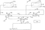
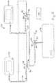
- FIG. 1is a schematic depiction of a steam cooking system in an Off condition
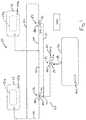
- FIG. 2is a schematic depiction of the steam cooking system in an Preheat or Hold condition
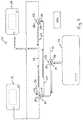
- FIG. 3is a schematic depiction of the steam cooking system when cooking in only the bottom cavity is taking place
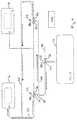
- FIG. 4is a schematic depiction of the steam cooking system when cooking in only the upper cavity is taking place.
- FIG. 5is a schematic depiction of the steam cooking system when cooking in both cavities is taking place.
- a steam cooking system 10includes a steam cooking cavity 12 (e.g., an upper cavity of a unit accessible via a door 12 a ) and a steam cooking cavity 14 (e.g., a lower cavity of a unit accessible via its own door 14 a ). Each cavity includes a respective drain opening 12, 14 b that fluidly connects to atmosphere.
- a steam generator 16is provided for heating water to generate steam (e.g., utilizing an electric or gaseous fuel heating element 16 a ).
- the steam generatorincludes a steam outlet 18 for feeding steam to both of the steam cooking cavities 12 and 14 .
- the steam outletis connected to the cavities 12 and 14 via a valved path arrangement 20 .
- the valved path arrangementincludes a main supply valve 22 and valves 32 and 52 .
- the main supply valve 22has an input 24 , a default output 26 and a switched output 28 .
- the main supply valveis configured with a default configuration (e.g., the default position of the valve) that connects the steam generator 16 to a vent path 30 to atmosphere via the default output 26 .
- the main supply valve 22is connected to selectively control feed of steam from the steam generator 16 to either (i) the valves 32 and 52 (in the switched position of the valve 22 ) or (ii) the vent path 30 to atmosphere (in the default position of the valve 22 ).
- Valve 32is downstream of the main supply valve 22 and has an input 34 , a default output 36 and a switched output 38 .
- the input 34is fluidly connected via a steam line path 40 to the switched output 28 of the main supply valve 22 .
- the default output 36is fluidly connected via a steam line path 42 to the steam cooking cavity 14
- the switched output 38is fluidly connected via a steam line path 44 to the steam cooking cavity 12 .
- the valve 32is configured with a default configuration (e.g., the default position of the valve 32 ) that connects the input 34 to the cavity 14 via the default output 36 .
- the valve 32is connected to selectively control delivery of steam from the main supply valve 22 to either (i) the steam cooking cavity 12 (in the switched position of the valve 32 ) or (ii) the steam cooking cavity 14 (in the default position of the valve 32 ).
- Valve 52is downstream of the main supply valve 22 and has an input 54 , a default output 56 and a switched output 58 .
- the input 54is fluidly connected via a steam line path 60 to the switched output 28 of the main supply valve 22 .
- the default output 56is fluidly connected via a steam line path 62 to the steam cooking cavity 12
- the switched output 58is fluidly connected via a steam line path 64 to the steam cooking cavity 14 .
- the valve 52is configured with a default configuration (e.g., the default position of the valve 52 ) that connects the input 54 to the cavity 12 via the default output 56 .
- the valve 52is connected to selectively control delivery of steam from the main supply valve 22 to either (i) the steam cooking cavity 12 (in the default position of the valve 52 ) or (ii) the steam cooking cavity 14 (in the switched position of the valve 52 ).
- the main supply valve 22 , the valve 32 and the valve 52are configured and plumbed such that, in combination with a valve control arrangement (e.g., schematically depicted by controller 100 in FIG. 1 ), the main supply valve 22 , the valve 32 and the valve 52 are controlled such that the steam generator 16 is always fluidly connected to atmosphere via at least one of the vent path 30 to atmosphere, a path to the steam cooking cavity 12 or a path the steam cooking cavity 14 .
- a valve control arrangemente.g., schematically depicted by controller 100 in FIG. 1
- controlleris intended to broadly encompass any circuit (e.g., solid state, application specific integrated circuit (ASIC), an electronic circuit, a combinational logic circuit, a field programmable gate array (FPGA)), processor(s) (e.g., shared, dedicated, or group—including hardware or software that executes code), software, firmware and/or other components, or a combination of some or all of the above, that carries out the control and/or processing functions of the steam cooking system or the control and/or processing functions of any component thereof.
- ASICapplication specific integrated circuit
- FPGAfield programmable gate array
- each valvemay be a motorized mixing valve.
- the steam supply from the generatoris always open to atmosphere.
- This valve-typeopens to one output before closing to the other output, and no matter what mode the valves are in, cooking (here switched position) or not (here default position or default configuration), the flow paths through the valves are open to atmosphere via some path.
- the main supply valve 22is controlled in part by one or more end switches on each of the valves 32 and 52 , which will only actuate after one of the valves 32 and 52 has fully moved to the default position or the switched position.
- the main supply valve 22will control the burner (or other heating element) operation between steam and hold modes.
- Each of the valves 22 , 32 and 52is biased or self-powered for movement to the default position, such that during a power failure the main valve 22 will move to its default position, opening the input 24 to the vent path 30 and drain box, both of which are open to atmosphere. Exemplary sequences of operation as described below.
- valvesare all in default positions, with the main valve 22 open to vent path 30 (per the flow arrows), and the steam generator burner will turn on and preheat the water in the steam generator to 185° F.
- a ready lightis illuminated (e.g., on a user interface of the oven cavity or cavities) indicating the system is ready to cook.
- Valve 52For cooking only with the cooking cavity 14 ( FIG. 3 ), the door to cavity 14 is closed and a timer set. Valve 52 is controlled to move to its switched position. After valve 52 is fully moved to the switched position, the end switch on the valve 52 will actuate the main valve 22 to move to its switched position to supply steam along overlapping paths 40 , 60 to the valves 32 and 52 via the switched output 28 .
- the steam generator burnerwill be activated by the main steam valve 22 end switch when the valve 22 moves fully to its switched position. Steam flow will be through both valves 32 and 52 and to the cavity 14 along paths 42 and 64 (as indicated by the flow arrows). At the end of the cooking operation within the cavity 14 , the timer will time out and sound a buzzer.
- Valve 52will then be triggered to move back to its default position, changing its flow path from output 58 to output 56 , but at all times remaining open to atmosphere via one of the cavities 14 or 12 because the path to output 56 opens before the path to output 58 closes.
- the end switch on valve 52will then trigger the main valve 22 to move to its default position, changing its flow path from switched output 28 (to the valves 32 , 52 ) to default output 26 (to the vent path 30 to a drain box), again at all times remaining open to atmosphere by some path because the path to output 26 opens before the path to output 28 closes.
- the main valve 22reaches the default position (or slightly sooner)
- an end switch on the valvewill trigger removal of steam production power from the burner, causing the steam generator burner system to return to a hold mode to maintain temperature at 185° F.
- Valve 32For cooking only with the cavity 12 ( FIG. 4 ), the door to cavity 12 is closed and a timer set. Valve 32 is controlled to move to its switched position. After valve 32 is fully moved to the switched position, the end switch on the valve 32 will actuate the main valve 22 to move to its switched position to supply steam along overlapping paths 40 , 60 to the valves 32 and 52 via the switched output 28 . The steam generator burner will be activated by the main steam valve 22 end switch when the valve 22 moves fully to its switched position. Steam flow will be through both valves 32 and 52 and to the cavity 12 along paths 44 and 62 (as indicated by the flow arrows). At the end of the cooking operation within the cavity 12 , the timer will time out and sound a buzzer.
- Valve 32will then be triggered to move back to its default position, changing its flow path from output 38 to output 36 , but at all times remaining open to atmosphere via one of the cavities 14 or 12 because the path to output 36 opens before the path to output 38 closes.
- the end switch on valve 32will then trigger the main valve 22 to move to its default position, changing its flow path from switched output 28 (to the valves 32 , 52 ) to default output 26 (to the vent path 30 to a drain box), again at all times remaining open to atmosphere by some path because the path to output 26 opens before the path to output 28 closes.
- the main valve 22reaches the default position (or slightly sooner)
- an end switch on the valve 22will trigger removal of steam production power from the burner, causing the steam generator burner system to return to a hold mode to maintain temperature at 185° F.
- the timersare set and the cavity doors closed.
- Both valves 32 and 52will move to their respective switched positions to supply steam to the atmospheric cooking cavities via switched outputs 38 and 58 .
- End switches on the valves 32 and 52will activate the main steam valve 22 to move to its switched position, causing valve 22 to open the path to switched output 28 and close the path to default output 26 .
- An end switch on the main valve 22is triggered when the valve is fully moved to the switched position, which triggers steam production power to be supplied to the generator burner.
Landscapes
- Engineering & Computer Science (AREA)
- Chemical & Material Sciences (AREA)
- Food Science & Technology (AREA)
- Combustion & Propulsion (AREA)
- Mechanical Engineering (AREA)
- General Engineering & Computer Science (AREA)
- Health & Medical Sciences (AREA)
- Nutrition Science (AREA)
- Life Sciences & Earth Sciences (AREA)
- Polymers & Plastics (AREA)
- Cookers (AREA)
Abstract
Description
Claims (12)
Priority Applications (1)
| Application Number | Priority Date | Filing Date | Title |
|---|---|---|---|
| US15/690,470US10959560B2 (en) | 2016-08-31 | 2017-08-30 | Steam cooking system and method |
Applications Claiming Priority (2)
| Application Number | Priority Date | Filing Date | Title |
|---|---|---|---|
| US201662381632P | 2016-08-31 | 2016-08-31 | |
| US15/690,470US10959560B2 (en) | 2016-08-31 | 2017-08-30 | Steam cooking system and method |
Publications (2)
| Publication Number | Publication Date |
|---|---|
| US20180055269A1 US20180055269A1 (en) | 2018-03-01 |
| US10959560B2true US10959560B2 (en) | 2021-03-30 |
Family
ID=61240997
Family Applications (1)
| Application Number | Title | Priority Date | Filing Date |
|---|---|---|---|
| US15/690,470Active2039-10-27US10959560B2 (en) | 2016-08-31 | 2017-08-30 | Steam cooking system and method |
Country Status (1)
| Country | Link |
|---|---|
| US (1) | US10959560B2 (en) |
Families Citing this family (2)
| Publication number | Priority date | Publication date | Assignee | Title |
|---|---|---|---|---|
| TR201818081A2 (en)* | 2018-11-28 | 2020-06-22 | Arcelik As | OVEN WITH STEAM GENERATOR |
| CN112716270B (en)* | 2020-12-23 | 2022-04-15 | 广西贵港市西江节能锅炉有限公司 | A multifunctional steam stove |
Citations (45)
| Publication number | Priority date | Publication date | Assignee | Title |
|---|---|---|---|---|
| US5890A (en) | 1848-10-31 | James stevens | ||
| US76231A (en) | 1868-03-31 | Improvement in culinaey appaeatus | ||
| US102608A (en) | 1870-05-03 | John g | ||
| US171411A (en) | 1875-12-21 | Improvement in cooking apparatus | ||
| US174194A (en) | 1876-02-29 | Improvement in steam-kettles | ||
| US183554A (en) | 1876-10-24 | Improvement in steam-cooking kettles | ||
| US221542A (en) | 1879-11-11 | Improvement in steam-cookers | ||
| US225584A (en) | 1880-03-16 | William gates flanders | ||
| US3000373A (en) | 1959-01-26 | 1961-09-19 | Meat Packers Equipment Co | Smoke generator |
| US3604895A (en) | 1969-10-28 | 1971-09-14 | Lincoln Mfg Co | Electrically heated steam treatment device |
| US3992984A (en) | 1975-11-14 | 1976-11-23 | Hobart Corporation | Steam pressure cooker with manually operable pressure venting |
| DE2541374A1 (en) | 1975-09-17 | 1977-03-24 | Klaus Ing Grad Pfeiffer | Food simmering oven - with satd. steam circulated along walls towards food by circulating fan and guide plates |
| US4167585A (en) | 1976-03-01 | 1979-09-11 | Heat And Control, Inc. | Method for heating and cooking foods in a closed treatment chamber by maintaining the temperature and moisture content |
| US4273991A (en) | 1979-11-29 | 1981-06-16 | B & W Metals Company, Inc. | Pressure cooker |
| US4373430A (en) | 1978-10-02 | 1983-02-15 | Oscar Lucks Company | Humidifier for a proof box |
| US4509412A (en) | 1983-03-04 | 1985-04-09 | Rival Manufacturing Company | Food steaming device |
| US4510854A (en) | 1983-04-25 | 1985-04-16 | B. B. Robertson Company | Compact barbecue oven |
| US4528975A (en) | 1983-10-03 | 1985-07-16 | Wang Gung H | Steam cooking rack and method |
| US4582047A (en) | 1979-07-26 | 1986-04-15 | Hester Industries, Inc. | High humidity steam cooker with continuously running conveyor |
| US4649898A (en) | 1984-03-05 | 1987-03-17 | Martinson Monitors Inc. | Apparatus for controlling condensate level in steam retort |
| US4995313A (en)* | 1988-03-15 | 1991-02-26 | Welbilt Corporation | Cooking apparatus |
| US5161518A (en) | 1991-07-31 | 1992-11-10 | Cleveland Range, Incorporated | Float assembly for steam cooking device |
| US5287798A (en) | 1993-03-05 | 1994-02-22 | San Shokuzai Co., Ltd. | High-temperature dry steam cooking utensil |
| US5368008A (en)* | 1992-10-09 | 1994-11-29 | Delaware Capital Formation, Inc. | Steamer apparatus |
| US5549038A (en) | 1995-11-16 | 1996-08-27 | Market Forge Industries | Modulated steam cooker |
| US5584235A (en) | 1995-12-18 | 1996-12-17 | Black & Decker Inc. | Food steamer flavoring support |
| US5619983A (en) | 1995-05-05 | 1997-04-15 | Middleby Marshall, Inc. | Combination convection steamer oven |
| US5653161A (en) | 1995-12-18 | 1997-08-05 | Black & Decker Inc. | Food steamer with pressure venting |
| US5662959A (en) | 1992-03-17 | 1997-09-02 | Tippmann; Eugene R. | Method for steam cooking a meat product |
| US5865101A (en) | 1998-05-19 | 1999-02-02 | Legion Industries, Inc. | Cooking pan lid and cooking device incorporating same |
| US5869812A (en) | 1997-09-12 | 1999-02-09 | Middleby-Marshall, Inc. | Pressure regulator for steam oven |
| JP2856699B2 (en) | 1995-09-01 | 1999-02-10 | 株式会社コメットカトウ | Cooker |
| US5968574A (en) | 1999-02-24 | 1999-10-19 | Sann; Melbourne H. | Convection food steamer and associated method |
| US6000392A (en)* | 1997-07-15 | 1999-12-14 | Crown Food Service Equipment Ltd. | Steamer gas oven |
| US6076452A (en) | 1998-02-05 | 2000-06-20 | Beaba | Device for heating and/or cooking food |
| US6107605A (en) | 1997-09-12 | 2000-08-22 | Middleby-Marshall, Inc. | Pressure regulator for steam oven |
| US6143341A (en) | 1997-09-26 | 2000-11-07 | Sikes; Jimmy A. | Convection based cooking method with flow of combined heated air and steam |
| US6237469B1 (en)* | 2000-05-03 | 2001-05-29 | Crown Food Service Equipment Ltd. | Gas powered pressureless steam cooker |
| US6602530B1 (en) | 2000-11-03 | 2003-08-05 | Premark Feg L.L.C. | Atmospheric steamer |
| US20060207440A1 (en) | 2003-08-04 | 2006-09-21 | Fujimak Corporation | Steam oven |
| US20080283040A1 (en)* | 2007-05-18 | 2008-11-20 | Mark Manganiello | High efficiency atmospheric steamer |
| US20090071346A1 (en)* | 2007-09-19 | 2009-03-19 | Atul Saksena | Steam cooking apparatus with steam flushing system |
| US20090107477A1 (en)* | 2007-10-26 | 2009-04-30 | Premark Feg L.L.C. | Steam Oven System with Steam Generator |
| US20180231330A1 (en)* | 2015-09-30 | 2018-08-16 | Siemens Aktiengesellschaft | Heat exchange system with at least two heat exchange chambers and method for exchanging heat by using the heat exchange system |
| US20190104879A1 (en)* | 2015-07-09 | 2019-04-11 | Strix Limited | Food preparation |
- 2017
- 2017-08-30USUS15/690,470patent/US10959560B2/enactiveActive
Patent Citations (49)
| Publication number | Priority date | Publication date | Assignee | Title |
|---|---|---|---|---|
| US5890A (en) | 1848-10-31 | James stevens | ||
| US76231A (en) | 1868-03-31 | Improvement in culinaey appaeatus | ||
| US102608A (en) | 1870-05-03 | John g | ||
| US171411A (en) | 1875-12-21 | Improvement in cooking apparatus | ||
| US174194A (en) | 1876-02-29 | Improvement in steam-kettles | ||
| US183554A (en) | 1876-10-24 | Improvement in steam-cooking kettles | ||
| US221542A (en) | 1879-11-11 | Improvement in steam-cookers | ||
| US225584A (en) | 1880-03-16 | William gates flanders | ||
| US3000373A (en) | 1959-01-26 | 1961-09-19 | Meat Packers Equipment Co | Smoke generator |
| US3604895A (en) | 1969-10-28 | 1971-09-14 | Lincoln Mfg Co | Electrically heated steam treatment device |
| DE2541374A1 (en) | 1975-09-17 | 1977-03-24 | Klaus Ing Grad Pfeiffer | Food simmering oven - with satd. steam circulated along walls towards food by circulating fan and guide plates |
| US3992984A (en) | 1975-11-14 | 1976-11-23 | Hobart Corporation | Steam pressure cooker with manually operable pressure venting |
| US4167585A (en) | 1976-03-01 | 1979-09-11 | Heat And Control, Inc. | Method for heating and cooking foods in a closed treatment chamber by maintaining the temperature and moisture content |
| US4167585B1 (en) | 1976-03-01 | 1985-04-02 | ||
| US4373430A (en) | 1978-10-02 | 1983-02-15 | Oscar Lucks Company | Humidifier for a proof box |
| US4582047A (en) | 1979-07-26 | 1986-04-15 | Hester Industries, Inc. | High humidity steam cooker with continuously running conveyor |
| US4273991A (en) | 1979-11-29 | 1981-06-16 | B & W Metals Company, Inc. | Pressure cooker |
| US4509412A (en) | 1983-03-04 | 1985-04-09 | Rival Manufacturing Company | Food steaming device |
| US4509412B1 (en) | 1983-03-04 | 1994-01-11 | Rival Manufacturing Company | Food steaming device |
| US4510854A (en) | 1983-04-25 | 1985-04-16 | B. B. Robertson Company | Compact barbecue oven |
| US4528975A (en) | 1983-10-03 | 1985-07-16 | Wang Gung H | Steam cooking rack and method |
| US4649898A (en) | 1984-03-05 | 1987-03-17 | Martinson Monitors Inc. | Apparatus for controlling condensate level in steam retort |
| US4995313A (en)* | 1988-03-15 | 1991-02-26 | Welbilt Corporation | Cooking apparatus |
| US5161518A (en) | 1991-07-31 | 1992-11-10 | Cleveland Range, Incorporated | Float assembly for steam cooking device |
| US5662959A (en) | 1992-03-17 | 1997-09-02 | Tippmann; Eugene R. | Method for steam cooking a meat product |
| US5368008A (en)* | 1992-10-09 | 1994-11-29 | Delaware Capital Formation, Inc. | Steamer apparatus |
| US5287798A (en) | 1993-03-05 | 1994-02-22 | San Shokuzai Co., Ltd. | High-temperature dry steam cooking utensil |
| US5619983A (en) | 1995-05-05 | 1997-04-15 | Middleby Marshall, Inc. | Combination convection steamer oven |
| JP2856699B2 (en) | 1995-09-01 | 1999-02-10 | 株式会社コメットカトウ | Cooker |
| US5631033A (en)* | 1995-11-16 | 1997-05-20 | Kolvites; Albert | Method of cooking food with steam |
| US5549038A (en) | 1995-11-16 | 1996-08-27 | Market Forge Industries | Modulated steam cooker |
| US5653161A (en) | 1995-12-18 | 1997-08-05 | Black & Decker Inc. | Food steamer with pressure venting |
| US5584235A (en) | 1995-12-18 | 1996-12-17 | Black & Decker Inc. | Food steamer flavoring support |
| US6000392A (en)* | 1997-07-15 | 1999-12-14 | Crown Food Service Equipment Ltd. | Steamer gas oven |
| US5869812A (en) | 1997-09-12 | 1999-02-09 | Middleby-Marshall, Inc. | Pressure regulator for steam oven |
| US6175100B1 (en) | 1997-09-12 | 2001-01-16 | Middleby-Marshall, Inc. | Pressure regulator for steam oven |
| US6107605A (en) | 1997-09-12 | 2000-08-22 | Middleby-Marshall, Inc. | Pressure regulator for steam oven |
| US6143341A (en) | 1997-09-26 | 2000-11-07 | Sikes; Jimmy A. | Convection based cooking method with flow of combined heated air and steam |
| US6076452A (en) | 1998-02-05 | 2000-06-20 | Beaba | Device for heating and/or cooking food |
| US5865101A (en) | 1998-05-19 | 1999-02-02 | Legion Industries, Inc. | Cooking pan lid and cooking device incorporating same |
| US5968574A (en) | 1999-02-24 | 1999-10-19 | Sann; Melbourne H. | Convection food steamer and associated method |
| US6237469B1 (en)* | 2000-05-03 | 2001-05-29 | Crown Food Service Equipment Ltd. | Gas powered pressureless steam cooker |
| US6602530B1 (en) | 2000-11-03 | 2003-08-05 | Premark Feg L.L.C. | Atmospheric steamer |
| US20060207440A1 (en) | 2003-08-04 | 2006-09-21 | Fujimak Corporation | Steam oven |
| US20080283040A1 (en)* | 2007-05-18 | 2008-11-20 | Mark Manganiello | High efficiency atmospheric steamer |
| US20090071346A1 (en)* | 2007-09-19 | 2009-03-19 | Atul Saksena | Steam cooking apparatus with steam flushing system |
| US20090107477A1 (en)* | 2007-10-26 | 2009-04-30 | Premark Feg L.L.C. | Steam Oven System with Steam Generator |
| US20190104879A1 (en)* | 2015-07-09 | 2019-04-11 | Strix Limited | Food preparation |
| US20180231330A1 (en)* | 2015-09-30 | 2018-08-16 | Siemens Aktiengesellschaft | Heat exchange system with at least two heat exchange chambers and method for exchanging heat by using the heat exchange system |
Also Published As
| Publication number | Publication date |
|---|---|
| US20180055269A1 (en) | 2018-03-01 |
Similar Documents
| Publication | Publication Date | Title |
|---|---|---|
| US10959560B2 (en) | Steam cooking system and method | |
| US8001957B2 (en) | Device for increasing power for a limited time | |
| CN101248313B (en) | Time control device for gas hobs | |
| US9404287B2 (en) | System and method for determining appliance door status | |
| US10830451B2 (en) | Boosted gas burner assembly and a method of operating the same | |
| NO841591L (en) | APPARATUS FOR CARBONATION OF LIQUIDS | |
| US20120153200A1 (en) | Device for controlling the supply of a combustible gas to a burner, particularly for water heaters | |
| JP2014149126A (en) | Hot water storage type electric water heater | |
| US11262070B2 (en) | Closed-loop simmer with a gas burner | |
| US20090192657A1 (en) | Method for controlling a household cooking appliance using a timer | |
| US10634360B2 (en) | Gas control valve, hob and gas oven | |
| US11274826B2 (en) | Delayed ignition prevention in a multi-ring gas burner for a cooktop appliance | |
| GB2571986A (en) | Galley apparatus | |
| US3428072A (en) | Liquid processing system | |
| CN105532788A (en) | Novel household steamed bun making machine | |
| US2720868A (en) | Automatically controlled water supply system for cleaning machines | |
| US10900661B2 (en) | Boosted gas burner assembly with pulse attenuation | |
| DE50208700D1 (en) | Druckgargerät | |
| US11421893B2 (en) | Cooking appliance, in particular commercial cooking appliance | |
| JP7199890B2 (en) | automatic faucet | |
| EP3653941B1 (en) | Fluid recirculation system | |
| KR101755288B1 (en) | Rice supplies and a water discharge device equipped with fully automatic rice cooker | |
| CN110017514A (en) | Electronic type door open system | |
| US1596040A (en) | Hot-water heater | |
| WO2019209210A2 (en) | Fixture with double control |
Legal Events
| Date | Code | Title | Description |
|---|---|---|---|
| AS | Assignment | Owner name:ILLINOIS TOOL WORKS INC., ILLINOIS Free format text:ASSIGNMENT OF ASSIGNORS INTEREST;ASSIGNOR:RECKNER, MICHAEL B.;REEL/FRAME:043448/0029 Effective date:20170830 | |
| FEPP | Fee payment procedure | Free format text:ENTITY STATUS SET TO UNDISCOUNTED (ORIGINAL EVENT CODE: BIG.); ENTITY STATUS OF PATENT OWNER: LARGE ENTITY | |
| STPP | Information on status: patent application and granting procedure in general | Free format text:DOCKETED NEW CASE - READY FOR EXAMINATION | |
| STPP | Information on status: patent application and granting procedure in general | Free format text:RESPONSE TO NON-FINAL OFFICE ACTION ENTERED AND FORWARDED TO EXAMINER | |
| STPP | Information on status: patent application and granting procedure in general | Free format text:AWAITING TC RESP., ISSUE FEE NOT PAID | |
| STPP | Information on status: patent application and granting procedure in general | Free format text:PUBLICATIONS -- ISSUE FEE PAYMENT RECEIVED | |
| STPP | Information on status: patent application and granting procedure in general | Free format text:PUBLICATIONS -- ISSUE FEE PAYMENT VERIFIED | |
| STCF | Information on status: patent grant | Free format text:PATENTED CASE | |
| MAFP | Maintenance fee payment | Free format text:PAYMENT OF MAINTENANCE FEE, 4TH YEAR, LARGE ENTITY (ORIGINAL EVENT CODE: M1551); ENTITY STATUS OF PATENT OWNER: LARGE ENTITY Year of fee payment:4 |