US10959540B2 - Shelf management system, components thereof, and related methods - Google Patents
Shelf management system, components thereof, and related methodsDownload PDFInfo
- Publication number
- US10959540B2 US10959540B2US15/832,500US201715832500AUS10959540B2US 10959540 B2US10959540 B2US 10959540B2US 201715832500 AUS201715832500 AUS 201715832500AUS 10959540 B2US10959540 B2US 10959540B2
- Authority
- US
- United States
- Prior art keywords
- shelf
- pusher
- shelf management
- tray
- product
- Prior art date
- Legal status (The legal status is an assumption and is not a legal conclusion. Google has not performed a legal analysis and makes no representation as to the accuracy of the status listed.)
- Active
Links
Images


Classifications
- A—HUMAN NECESSITIES
- A47—FURNITURE; DOMESTIC ARTICLES OR APPLIANCES; COFFEE MILLS; SPICE MILLS; SUCTION CLEANERS IN GENERAL
- A47F—SPECIAL FURNITURE, FITTINGS, OR ACCESSORIES FOR SHOPS, STOREHOUSES, BARS, RESTAURANTS OR THE LIKE; PAYING COUNTERS
- A47F1/00—Racks for dispensing merchandise; Containers for dispensing merchandise
- A47F1/04—Racks or containers with arrangements for dispensing articles, e.g. by means of gravity or springs
- A47F1/12—Racks or containers with arrangements for dispensing articles, e.g. by means of gravity or springs dispensing from the side of an approximately horizontal stack
- A47F1/125—Racks or containers with arrangements for dispensing articles, e.g. by means of gravity or springs dispensing from the side of an approximately horizontal stack with an article-pushing device
- A47F1/126—Racks or containers with arrangements for dispensing articles, e.g. by means of gravity or springs dispensing from the side of an approximately horizontal stack with an article-pushing device the pushing device being urged by spring means
- A—HUMAN NECESSITIES
- A47—FURNITURE; DOMESTIC ARTICLES OR APPLIANCES; COFFEE MILLS; SPICE MILLS; SUCTION CLEANERS IN GENERAL
- A47B—TABLES; DESKS; OFFICE FURNITURE; CABINETS; DRAWERS; GENERAL DETAILS OF FURNITURE
- A47B57/00—Cabinets, racks or shelf units, characterised by features for adjusting shelves or partitions
- A47B57/58—Cabinets, racks or shelf units, characterised by features for adjusting shelves or partitions with means for adjusting partitions horizontally
- A47B57/583—Cabinets, racks or shelf units, characterised by features for adjusting shelves or partitions with means for adjusting partitions horizontally by sliding
- A47B57/585—Cabinets, racks or shelf units, characterised by features for adjusting shelves or partitions with means for adjusting partitions horizontally by sliding with connection means slidable in a rail
- A—HUMAN NECESSITIES
- A47—FURNITURE; DOMESTIC ARTICLES OR APPLIANCES; COFFEE MILLS; SPICE MILLS; SUCTION CLEANERS IN GENERAL
- A47B—TABLES; DESKS; OFFICE FURNITURE; CABINETS; DRAWERS; GENERAL DETAILS OF FURNITURE
- A47B57/00—Cabinets, racks or shelf units, characterised by features for adjusting shelves or partitions
- A47B57/58—Cabinets, racks or shelf units, characterised by features for adjusting shelves or partitions with means for adjusting partitions horizontally
- A47B57/583—Cabinets, racks or shelf units, characterised by features for adjusting shelves or partitions with means for adjusting partitions horizontally by sliding
- A47B57/586—Cabinets, racks or shelf units, characterised by features for adjusting shelves or partitions with means for adjusting partitions horizontally by sliding with connection means movable by sliding on the outside of a rail
- A—HUMAN NECESSITIES
- A47—FURNITURE; DOMESTIC ARTICLES OR APPLIANCES; COFFEE MILLS; SPICE MILLS; SUCTION CLEANERS IN GENERAL
- A47F—SPECIAL FURNITURE, FITTINGS, OR ACCESSORIES FOR SHOPS, STOREHOUSES, BARS, RESTAURANTS OR THE LIKE; PAYING COUNTERS
- A47F5/00—Show stands, hangers, or shelves characterised by their constructional features
- A47F5/0043—Show shelves
- A47F5/005—Partitions therefore
Definitions
- This inventionrelates generally to merchandise display structures, and more specifically to customizable display structures capable of universally fitting and automatically facing desired products and methods relating to same.
- pushershave been designed with dampers to slow the progression of the pusher as product is removed from the merchandiser so that the pusher does not exert too much force against the displayed product (which could damage the product and/or force it out of the merchandiser unintentionally).
- dampersto slow the progression of the pusher as product is removed from the merchandiser so that the pusher does not exert too much force against the displayed product (which could damage the product and/or force it out of the merchandiser unintentionally).
- Other improvementsinclude systems having pushers that can be adjusted in width (e.g., such as by having pivoting members to widen the reach of a pusher) or adjusted in height (e.g., such as by attaching a pusher attachment that extends the upper bounds of the pusher).
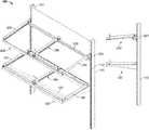
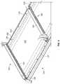
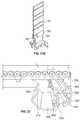
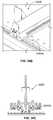
- FIGS. 1A-Care perspective, left side elevation and front elevation views, respectively, of a universal merchandiser as configured in accordance with various embodiments of the invention, with the universal merchandiser being illustrated with both a fixed shelf unit and a bar support unit or suspended bar version;
- FIG. 2comprises a perspective view of a portion of the fixed shelf unit of FIGS. 1A-C illustrating an end bracket and an interstitial bracket;
- FIGS. 3A-Bare enlarged perspective views of the front and rear, respectively, of the fully assembled interstitial bracket of FIG. 2 ;
- FIGS. 4A-Fare upper perspective, front elevation, rear elevation, left side elevation, top plan and lower perspective views, respectively, of the body of the interstitial bracket of FIG. 2 ;
- FIGS. 5A-Care upper perspective, front elevation and lower perspective views, respectively, of a right side slider or pusher structure in accordance with aspects of the invention.
- FIGS. 6A-Care upper perspective, front elevation and lower perspective views, respectively, of a left side slider or pusher structure in accordance with aspects of the invention.
- FIG. 7comprises a perspective view of the left side end bracket of FIGS. 1A-C in accordance with aspects of the invention illustrated without the friction reducing structure attached to the body of the bracket;
- FIGS. 8A-Bare upper and lower perspective views, respectively, of the right side end bracket of FIGS. 1A-C and 2 illustrated without the friction reducing structure attached to the body of the bracket;
- FIG. 9is a perspective view of the fixed shelf unit of FIGS. 1A-C illustrating the fully assembled brackets with roller type friction reducing structures and having product such as cereal boxes displayed in the universal merchandiser;
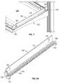
- FIG. 10Aare perspective views of an alternate friction reducing structure in accordance with the invention, with FIG. 10B being an enlarged partial perspective view of the front of the interstitial bracket illustrated in FIG. 10A ;
- FIG. 11comprises a perspective view of the alternate friction reducing structure of FIGS. 10A-B illustrating the flat bar or belt like shape of same;
- FIG. 12comprises a perspective view of the fixed shelf unit of FIGS. 1A-C using the alternate friction reducing structure of FIGS. 10A-11 to move smaller product with higher centers of gravity, such as potato chip containers, which may be easier moved with a friction reducing structure having a continuous surface rather than rollers;
- FIG. 13comprises a perspective view of an alternate fixed shelf unit in accordance with the invention, in which the brackets are mounted to the shelf in a manner that allows for a limited range of lateral movement of each bracket rather than the much wider range of lateral movement provided in the embodiment of FIGS. 1A-C ;
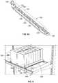
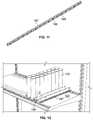
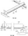
- FIG. 14is a perspective view of a portion of the suspended bar version or bar support unit of the universal merchandiser of FIGS. 1A-C ;
- FIGS. 15A-Bare perspective and cross-sectional views, respectively, of the front of the interstitial bar support unit of FIG. 14 , with the cross-section of FIG. 15B taken along line 15 B- 15 B in FIG. 15A pusher or slider assembly;
- FIGS. 15C-Dare perspective and cross-sectional views, respectively, of the rear of the interstitial bar support unit of FIG. 14 , with the cross-section of FIG. 15D being taken along line 15 D- 15 D in FIG. 15C ;
- FIG. 15Ecomprises a perspective view of the support bracket used for the bar support unit of FIG. 15A according to one aspect of the invention.
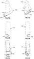
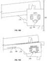
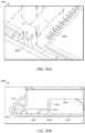
- FIGS. 16A-Care perspective, left side elevation, and cross-sectional views, respectively, of the front of the end bracket of FIG. 14 , with the cross-section taken through the center of the bracket and bracket support illustrated in FIG. 16A ;
- FIGS. 16D-Eare side elevation and cross-sectional views, respectively, of the rear of the end bracket of FIG. 14 , with the cross-section taken through the center of the bracket and bracket support illustrated in FIG. 16A ;
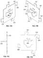
- FIGS. 17A-Dare left side perspective, right side perspective, front elevation and left side elevation views, respectively, of the mounting bracket illustrated in use with the bar support unit of FIG. 14 ;
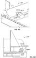
- FIGS. 18A-Dcomprise side elevation views of the mounting bar and bracket of the bar support unit of FIG. 14 with FIG. 18A illustrating the mounting bar and bracket in position to hold the bar support member at an initial horizontal position, FIG. 18B illustrating the mounting bar and bracket in position to hold the bar support member at an angled position, FIG. 18C illustrating the mounting bar and bracket in position to hold the bar support member at a raised horizontal position and FIG. 18D illustrating the mounting bar and bracket in position to hold the bar support member at a raised angled position (noting that the order of these orientations may be reversed so that the mounting bar and bracket start at an initial position that is higher and can be rotated to provide horizontal and angled positions that are lower if desired);
- FIGS. 19A-Bare perspective and left side elevation views of the mounting bar of FIG. 14 ;
- FIG. 20is a perspective view of an alternate bar support unit in accordance with the invention in which a slide and pusher assembly similar to the slide and pusher of FIGS. 10A-12 is shown used in conjunction with a conventional square bar and mounting bracket;
- FIGS. 21A-Bare front and rear perspective views, respectively, of an alternate bar support unit in accordance with the invention in which optional risers are shown connected to the universal merchandiser to accommodate dispensing of stacked products, with FIG. 21B being a rear perspective of a cross-section of FIG. 21A taken along line 21 B- 21 B in FIG. 21A ;
- FIG. 22comprises a side perspective view of an alternate mounting bar and bracket for a bar support unit in accordance with aspects of the invention in which a single pivotable stabilizing member is used to secure the support arms in position along the mounting bar;
- FIG. 23A-Bare front perspective and side elevation views, respectively, of an alternate mounting bar and bracket for a bar support unit in accordance with aspects of the invention in which an alternate pivoting stabilizer is used to secure each support arm in position along the mounting bar;
- FIGS. 24A-Dare side elevation views of an alternate mounting bar and bracket for a bar support unit in accordance with aspects of the invention inch which a multi-positional mounting bracket is used to position a conventional square mounting bar in four different positions with each position allowing the support bar to be raised or lowered a predetermined amount of distance (a reference line has been added transcending all figures to illustrate how ninety degree rotations of the mounting bracket result in corresponding changes in the positioning of the support bar);
- FIGS. 25A-Bare partially exploded and perspective views of an alternate mounting bar and support bar configuration in accordance with aspects of the invention in which FIG. 25A illustrates an alternate cammed fastener exploded from the support bracket and FIG. 25B illustrates the cammed fastener inserted into the support bracket and pivoted or turned in order to secure the support arm to the mounting bar without risking puncture of the mounting bar or other damage to same;
- FIGS. 26A-Dare perspective, front elevation, left side elevation and bottom views, respectively, of an alternate universal merchandiser assembly with a lockable dampened pusher as configured in accordance with various embodiments of the invention, with FIGS. 26C and 26D having break lines to allow for larger images to be shown with more detail;
- FIGS. 26E-Fare enlarged perspective views of the pusher assembly of FIGS. 26A-D illustrating part of an exemplary and optional lock mechanism in locked and released positions, respectively;
- FIGS. 26G-Hare enlarged partial perspective views of the rear carriage portion of the universal merchandiser of FIGS. 26A-F (illustrated without the pusher in FIG. 26G ), showing how the damper mates with the pusher and how the internal damper components are connected to the carriage and how the carriage is symmetrical to allow the internal components to be connected in a mirror image orientation for use on the opposite side of the divider;
- FIGS. 26I-Jare enlarged partial perspective and left side elevation views, respectively, of the lock mechanism and glide bar of FIGS. 26A-H , illustrating how the lock mechanism and glide bar cooperate to form the track for the damper (see FIG. 26I ) and how the lock mechanism is connected to the rear of the universal merchandiser bracket and release mechanism (see FIG. 26J );
- FIGS. 27A-Care perspective views of exemplary pusher accessories that may be mounted onto the pusher to assist front facing of certain products so that the merchandiser can be customized and readily changed to accommodate specific product being pushed, with FIG. 27A illustrating the pusher and an exemplary accessory having an open area to separate a first and section portion which assists in the manufacturing thereof and FIGS. 27B-C illustrating alternate exemplary accessories;
- FIG. 28Ais a perspective view of an alternate exemplary embodiment of a universal merchandiser assembly in accordance with various aspects of the invention illustrating an alternate embodiment of the release mechanism;
- FIG. 28Bis an enlarged rear perspective view of the front of the universal merchandiser assembly of FIG. 28A illustrating how it connects into the front mount and how the front mount connects to a shelving unit;
- FIGS. 28C-Dare enlarged perspective and side elevation views of the front of the universal merchandiser assembly of FIGS. 28A-B illustrating in greater detail the alternate embodiment of the release mechanism;
- FIGS. 29A-Bare rear and front perspective views, respectively, of an alternate universal merchandiser assembly in accordance with another embodiment of the invention, with FIG. 29A illustrating a product divider assembly having two product holders or slides on opposite sides of the divider and FIG. 29B illustrating a cleaner front perspective view of just the product holders or slides showing how the structures engage one another and the universal merchandising assembly
- FIGS. 30A-Bare enlarged side elevation views of the front of an alternate universal merchandiser assembly in accordance with another embodiment of the invention, with FIG. 30A illustrating a product divider assembly being engaged with a front portion of a rail to prevent and/or limit lateral movement along the rail, and FIG. 30B illustrating the product divider assembly being partially disengaged with the front portion of the rail to allow lateral movement along the rail while still being partially secured thereto;
- FIGS. 31A-Care enlarged perspective views of the rear of an alternate universal merchandiser assembly in accordance with another embodiment of the invention, with FIG. 31A illustrating a product divider assembly having an opening that is disengaged from a toothed or combed support structure, FIG. 31B illustrating the product divider assembly being in a raised, partially disengaged position to still allow lateral movement of the divider assembly along the length of the combed support structure, and FIG. 31C illustrating the divider assembly being in a lowered engaged configuration whereby lateral movement of the divider assembly is minimized due to engagement with the combed support structure;
- FIG. 32is a perspective view of an alternate combed support structure for a shelf-based universal merchandiser assembly
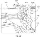
- FIGS. 33A-Care enlarged perspective and side elevation views of the rear of an alternate universal merchandiser stabilizing assembly being used in a grid-type merchandising environment in accordance with another embodiment of the invention, with FIGS. 33A-B illustrating a divider assembly being secured by the stabilizing mechanism and FIG. 33C illustrating the stabilizing mechanism being disengaged from the divider assembly to allow movement of the divider assembly;
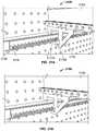
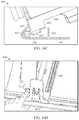
- FIGS. 34A-Care perspective, enlarged perspective, and cross sectional views of an alternate universal merchandiser assembly having an integral pusher track and damper rack, with FIGS. 34A-B illustrating a low profile front rail and a pusher release mechanism, and FIG. 34C illustrating the pusher release mechanism;
- FIGS. 34D-Eare side elevation views of the alternate universal merchandiser assembly of FIGS. 34A-C , with FIG. 34D illustrating the divider assembly being disengaged from the low profile front rail and FIG. 34E illustrating the divider assembly being movably engaged with a ridge or protrusion of the low profile front rail to limit lateral movement of the divider assembly;
- FIGS. 34F-Gare enlarged rear perspective views of the alternate universal merchandiser assembly of FIGS. 34A-G which illustrate the guide structure which ensures the pusher properly engages the pusher release mechanism and deformable hooks at the end of the integral track and rack which allow the pusher to be installed and/or removed therefrom;
- FIGS. 35A-Bare perspective and side elevation views of an alternate universal merchandiser assembly being useable on a bar-type gondola and being able to accommodate bars and/or gondolas having a number of different dimensions, with FIG. 35B illustrating an integral front rail, price channel, and pusher release mechanism; and
- FIG. 35C-Dillustrate enlarged front perspective and cross sectional rear side elevation views of the alternate universal merchandiser assembly of FIGS. 35A-B , with FIG. 35C having the pusher removed to illustrate the damper gear assembly, and with FIG. 35D illustrating the pusher assembly being secured in a rearward position using a separate gear on the damper assembly that engages the pusher release mechanism to prevent forward movement of the pusher.
- FIGS. 36A-Dillustrate a merchandiser assembly having a frictional front rail and divider engagement
- FIG. 36Abeing a perspective view of a portion of a front rail and divider
- FIG. 36Bbeing a left side elevation view of the portion of the front rail and divider shown in cross-section
- FIG. 36Cbeing another cross-section view of the portion of the front rail and divider but illustrating it being lifted to permit horizontal movement of the divider along the rail
- FIG. 36Dbeing a perspective view of the portion of the front rail being deformed or moved in an alternate way to allow for horizontal adjustment of the divider.
- FIGS. 36E-Fillustrate left side elevation views of alternative front rails for use in the assembly of FIGS. 36A-D , with FIG. 36E illustrating three potential locations for a frictional member to engage with and/or hinder the divider from horizontal movement within the rail (and two different shapes for such frictional members), and FIG. 36F illustrating yet another alternate shape and location of a frictional member for engaging and/or hindering a divider from horizontal movement within the rail.
- FIGS. 37A-Billustrate a left side elevation and perspective views respectively of a merchandiser assembly having a frictional front rail and divider engagement, with FIG. 37A illustrating three potential locations for a frictional member to be located on the divider and FIG. 37B illustrating a pair of dividers having the frictional member at one of the illustrated locations.
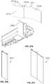
- FIGS. 38A-Cillustrate a left side elevation and perspective view of a merchandiser system having a frictional pad for securing the merchandiser assembly to a surface, such as a shelf.
- FIG. 38Ais a left side elevation illustrating the assembly of a divider, front rail, and pad.
- FIG. 38Bshows a pair of the pads with front rails and rear stabilizers.
- FIG. 38Cillustrates the pair of pads from FIG. 38B with one pad inverted to illustrate the bottom surface.
- FIGS. 39A-Dillustrate a merchandiser system shelf component assembly comprising a shelf component support and a shelf component.
- FIG. 39Ais a perspective view of the shelf component support.
- FIG. 39Bis a perspective view of the assembly including the support of FIG. 39A .
- FIG. 39Cis a side elevation of the assembly of FIG. 39B .
- FIG. 39Dis a top plan view of the assembly of FIGS. 39B-C .
- FIGS. 40A-Billustrate a shelf component support including features for reducing the weight and amount of material.
- FIG. 40Ais a top plan view of the shelf component support.
- FIG. 40Bis a bottom plan view of the shelf component support of FIG. 40A .
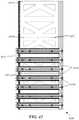
- FIG. 41is a bottom plan view of a shelf component support having a plurality of high friction strips for releasably coupling to a shelf.
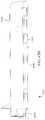
- FIG. 42is a top plan view of a merchandising system comprising a plurality of shelf component supports and shelf components.
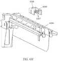
- FIG. 43Ais a perspective view of a product display system having a plurality of shelf component supports and shelf components on a shelf.
- FIG. 43Bis an end view of the product display system of FIG. 43A .
- FIG. 43Cis a bottom view of the product display system of FIGS. 43A-43B with the shelf removed to better illustrate the shelf component supports and shelf components.
- FIG. 43Dis an end view of the display system of FIGS. 43A-43C with the shelf component pivoted upward to disengage the support.
- FIG. 43Eis an end view of the display system of FIGS. 43A-43D with the shelf component pivoted downward to engage the support.
- FIG. 43Fis a bottom perspective exploded view of the shelf component of FIGS. 43A-43E showing the mounting structure.
- FIG. 43Gis a top perspective view of a shelf component support of the display system of FIGS. 43A-43E .
- FIG. 43His a bottom perspective exploded view of the shelf component support of FIG. 43G .
- the product displayincludes a pair of upstanding vertical supports, at least one product support structure having a plurality of protrusions extending laterally therefrom that is connected to the upstanding vertical supports, a friction-reducing component that couples to the protrusions of the product support structure, and a stopping mechanism coupled to a distal end of the product support structure.
- the product support structurefurther includes a biasing member coupled to the friction-reducing component configured to urge the product to an end of the product support structure.
- the biasing memberis a pusher or slider assembly having a face, bottom surface, and an attachment portion, and is configured to allow the friction-reducing component to nest within the slider attachment portion.
- the friction reducing componentcomprises a plurality of cylindrical rollers having an inner through bore and are coupled to the protrusions of the product support structure on a single side of the roller.
- the friction reducing componentcomprises an elongated flat slide bar or belt member having a plurality of holes configured to mate with the plurality of protrusions extending from the product support structure.
- a combination of rollers and slide bar or belt membersmay be used (e.g., having a roller portion and bar portion, alternating from roller to bar to roller or vice versa, etc.).
- the product displayfurther includes an information display device pivotally mated to the product support structure so that it may be rotated to display a first set of information on a front side, and a second set of information on a rear side.
- the information display devicemay be a pivotal or rotatable price channel that allows for a product price to be displayed in a first position and a SKU number or bar code to be accessed or displayed in a second position.
- the product support structuremates with a horizontal shelf and is configured to be placed at any distance between the pair of upstanding vertical supports.
- the upstanding vertical supportsare laterally movable about a plurality of positions.
- the support structuresare suspended from a bar without a shelf present.
- the product support structureextends from the upstanding vertical support at an angle less than about 90 degrees.
- the support structureis angled so that gravitational forces assist the product in moving towards a protruding or distal end of the product support structure.
- a rotatable bracketis used to allow the product support structures to be positioned at a plurality of angles with respect to the bar and/or the vertical support structure or gondola to which they are mounted.
- a product display apparatusincludes a product divider assembly having a front portion, a rear portion, and a divider, a pusher operatively coupled to the product divider assembly to assist in moving displayed products from the rear portion of the product divider assembly to the front portion thereof, and an integral forward structure and pusher locking release mechanism coupled to the front portion of the product divider assembly.
- the pusheris configured to be engageable with the rear portion of the product divider assembly such that the pusher is retained at the rear portion thereof.
- the integral forward structure and pusher locking release mechanismis configured to be actuated by effecting a force on a portion thereof to disengage the pusher from the rear portion of the product divider assembly.
- the integral forward structure and pusher locking mechanismmay comprise a front rail which is configured to couple to and support at least a portion of the front portion of the product divider assembly.
- the integral forward structure and pusher locking release mechanismmay include an information channel (e.g., a price channel) which displays information relating to the displayed product. This information channel is configured to at least partially support at least a portion of the front portion of the product divider assembly.
- the product display apparatusmay include an integral forward structure and pusher locking release mechanism includes both a front rail and an information channel.
- a product display apparatusmay include a product divider assembly having front and rear portions and a divider to divide a number of displayed products into rows, a pusher having an axis and being operatively coupled to the product divider assembly, and a damper attachment having an axis and being configured to be coupled to the pusher to dampen movement of the pusher.
- This damper attachmentis coupled to a rear portion of the pusher such that the damper attachment axis is collinear with the pusher axis. So configured, the amount of torque generated by the pusher during movement from the rear portion of the product divider assembly to the front portion of the product divider assembly is limited.
- this damper attachmentmay be removable from the pusher using any number of conventionally known methods.
- the damper attachmentmay be an integral component of the pusher.
- a product display apparatusmay include a product divider assembly having front and rear portions, a divider, and an integrally formed track assembly, a pusher being operatively coupled to the integrally formed track assembly, and at least one of a damper attachment coupled to a rear portion of the pusher and a pusher locking release mechanism configured to be actuated by effecting a force on a portion of the product divider assembly to disengage the pusher from the rear portion of the product divider assembly.
- This pusher locking release mechanismmay be coupled to the front portion of the divider assembly. It will be understood that in some forms, the damper attachment and the pusher locking release mechanism may be provided.
- a product display apparatushaving a product divider assembly, at least one attachment coupled to the product divider assembly and defining a recess, and a pusher operatively coupled to the product divider assembly. This pusher is configured to be at least partially operably disposed in the recess defined by the at least one attachment.
- a dual engagement product display apparatusincludes a rail having a length extending between a portion of a product display and a product divider assembly being operably coupled to the rail to divide a plurality of displayed products into rows.
- the product divider assemblyis configured to be movable between a first position in which the product divider is coupled to the rail while still allowing for lateral movement along the length of the rail and a second position where the assembly is frictionally coupled to the rail to hinder lateral movement along the length of the rail.
- the railmay be a front rail being coupled to the front portion of the product divider assembly and/or a rear rail being coupled to the rear portion of the product divider assembly.
- the product divider assemblymay include a clearance for allowing a stabilizing device to be disengaged such that the product display apparatus may be laterally movable when the product display is in the first position. This clearance may allow the product divider assembly to be engaged with the stabilizing device such that lateral movement of the product display apparatus is hindered when in the second position.
- the product divider assemblymay include an angled opening to allow the product divider assembly to be moved between a first position where the product divider assembly does not engage a stabilizing device so as to allow lateral movement of the product divider assembly and a second position where the angled opening engages the stabilizing device to limit lateral movement of the product divider assembly.
- a product display apparatusmay include a product divider assembly having a damper rack, a pusher being operatively coupled to the product divider assembly, and a compound gear having a first gear portion and a second gear portion.
- the first gear portionincludes gear teeth configured to engage the damper rack
- the second gear portionis configured to engage a locking device for locking the pusher at the rear portion of the product divider assembly.
- this locking deviceis a pawl which engages the second gear portion of the compound gear.
- a dual engagement product display apparatusmay include a stabilizer having a length extending between a at least a portion of a product display and a product diver assembly. Upon moving one of the stabilizer or the product divider assembly in a first direction, a clearance between the stabilizer and the product divider assembly is created that allows for lateral movement of the product divider assembly with respect to the stabilizer. Upon moving one of the stabilizer or the product divider assembly in a second direction, lateral movement of the product divider assembly with respect to the stabilizer is hindered.
- the stabilizercomprises a combed or toothed structure disposed near the rear portion of the product divider assembly. It is understood that the stabilizer may alternatively be disposed near the front portion of the product divider assembly.
- a method of displaying a productis provided.
- a product divider assemblyis provided and a pusher having an axis is operably coupled to the divider assembly.
- a damper having an axisis then coupled to the pusher such that movement of the pusher from the rear to the front portion of the product divider assembly is dampened.
- This damper attachmentis coupled to a rear portion of the pusher such that the axis of the damper attachment is in line with the axis of the pusher so as to limit the amount of torque generated by the pusher during movement of the pusher.
- an illustrative example of an upright merchandiser 100that is compatible with many of these teachings can include a vertical support structure 110 , fixed shelf display 120 , shelf 122 , bar display 202 , end brackets 150 , 250 , rotatable bracket 220 , bar 230 , and interstitial supports, such as arm support members or dividers 180 , 280 . Together the arm support members 180 , 280 and corresponding end brackets 150 , 250 serve as product support members. More of these structures may be added to provide multiple rows or columns of product as desired in a particular display.
- the fixed shelf 122 , end brackets 150 , and arm support member 180mount to the vertical support structures 110 and extend outwardly therefrom to form the shelf display 120 .
- the vertical support structures 110 , end brackets 250 , rotatable bracket 220 , bar 230 , and arm support member 280are mated together to form the bar display 202 .
- the vertical support structures 110are of the conventional nature and include elongated slots 112 for mounting a number of display devices.
- the elongated slots 112are spaced 1 inch (1′′) apart along the vertical support structures 110 , allowing a merchandiser to choose a variety of display mount heights.
- These vertical support structures 110are well known to those having skill in the art, and for the sake of brevity and the preservation of focus, will not be discussed further.
- the fixed shelf display 120includes a shelf 122 , a first shelf mount, such as rear shelf mount 124 , a second shelf mount, such as front shelf mount 126 , arm support member 180 having a support structure arm 181 extending upwardly, front mounting portion 186 and rear mounting portion 188 , and end brackets 150 having front mounting portion 156 and rear mounting portion 158 ( FIG. 8A ).
- all of components of the end brackets 150 and arm support member 180are constructed of extruded or injection molded polymers or similar materials to reduce costs as compared to conventional metal parts.
- the components of the end brackets 150 and arm support member 180are constructed of a combination of plastics and metals (e.g., plastic body with metal bushings or bearings, etc.).
- the shelf 122mounts to the vertical support structures 110 through conventional methods.
- both lateral ends of the shelf 122may include elongated hooked-shaped tabbed members (not shown) which are configured to insert into the elongated slots 112 to securely mount the shelf display 120 .
- the rear and front shelf mounts 124 , 126are configured to mate to the upper surface of the shelf 122 .
- the shelf mounts 124 , 126may be configured to be secured to the shelf by a snap or friction fit.
- the shelf mounts 124 , 126may be secured to the shelf using screws, nuts and bolts, or other conventional fastening methods.
- the shelf mounts 124 , 126include an elongated C-shaped channel 125 , 127 that extends along the longitudinal length of the shelf mount which allows the corresponding front and rear mounting attachments 186 , 188 of the arm 180 to mate or connect thereto.
- mounting attachments 186 , 188 and channels 125 , 127are configured with a mating arrangement such as a tongue and groove arrangement, a dovetail or mortise and tenon arrangement, etc.).
- the channel 125 , 127is C-shaped in cross-section and captures a rounded insert member of mounting attachments 186 , 188 .
- the front mounting attachment 186may be an integral part of the support structure arm 181 of the arm support member 180 . In other embodiments, the front mounting attachment 186 may be coupled to the support structure arm 181 through various conventional connecting methods including snap or press fitting. Similarly, in some embodiments, the rear mounting portion 188 may be an integral part of the support structure arm 181 , and in other embodiments, the rear mounting portion 188 may be coupled to the support structure arm 181 through various conventional connecting methods.
- the front and rear mounting portions 186 , 188include elongated circular tabbed portions 187 , 189 which are either snap-fitted into the elongated channels 125 , 127 or slid in through opening either in the upper surfaces or sides of the channels 125 , 127 , thus allowing the arm support member 180 to slide laterally across the shelf 122 .
- This configurationallows the retailer to select any number of positions for the support arm 180 , thus enabling the shelf display 120 to easily display products having a wide variety of widths by sliding the support arm 180 to a desired lateral position. Additional support arms 180 may be added as needed to support the desired number of products or columns/rows of product.
- the support structure arm 181includes raised portions 184 to provide adequate clearance of the shelf mounts 124 , 126 while retaining a flat, stable surface against the shelf 122 . This allows the support structure 180 to sit firmly and squarely on the shelf 122 .
- the clearance provided for raised portions 184is just enough to allow the support structure to be positioned laterally about mounts 124 , 126 with ease but allow the bottom surface of the raised portion 184 to rest against the upper surface of mounts 124 , 126 to further support structure 180 firmly and squarely on shelf 122 .
- the shelf display 120also includes end brackets 150 at opposing lateral edges of the shelf 120 or at whatever end position is desired for the display if not at the lateral edge of the shelf 122 .
- end brackets 150are configured in a similar manner as the arm support member 180 and include end bracket arm 151 which extends upwardly, front and rear mounting portions 156 , 158 which may be an integral part of the end bracket arm 151 or may be coupled to the end bracket arm 151 through various conventional connecting methods. The same is true for support member 180 .
- the front and rear mounting portions 156 , 158further include mounting member portions, such as elongated circular tabbed portions 157 , 159 , which are inserted into the elongated channels 125 , 127 , thus allowing the end brackets to slide laterally across the shelf 122 .
- the end bracketincludes raised portions 154 to provide adequate clearance of the shelf mounts 124 , 126 while retaining a flat, stable surface against the shelf 122 .
- lateral movement of the end bracket 150is restricted in at least one direction at the vertical supports 110 due to the end bracket 150 extending in a rearward distance further than the forward projection of the vertical support structures 110 .
- Such a configurationeliminates the possibility of laterally sliding an end bracket 150 off of the shelf 122 .
- spacingmay be provided so that the end brackets 150 and support structures 180 may be slid into engagement with channels 125 , 127 as desired.
- movement of the end brackets 150 away from the outer edges of the shelf 122e.g., toward the center of the shelf
- the arm support member 180includes a plurality of mounting projections 192 that span at least a portion of the longitudinal length of the support structure arm 181 .
- the projections 192span the longitudinal length of the support structure 180 .
- the mounting projections 192are integrally formed with the support structure arm 181 and thus are constructed of extruded or molded plastic or other similar materials.
- the mounting projections 192are generally cylindrically shaped posts having a recess or cutout, such as a tab, on their distal end, and are configured to allow a friction reducing component to be snap fit or press fit thereon.
- the friction reducing componentmay be connected via other types of fasteners, such as by bolt, screw, pin, rivet, etc. Preferably such connections will allow the friction reduction component to retain clearance with respect to the projections 192 and to remain moveable with respect to the projections if so desired.
- the friction reducing componentis a plurality of rollers 194 having both cylindrical inner and outer surfaces, thus providing for rotation about the mounting projections 192 . Due to the snap-fit connection between the mounting projections 192 and the rollers 194 , lateral movement of the rollers 194 along the mounting projections 192 is largely if not completely restricted.
- the rollers 194may be made from the same material as the support structure 180 and end brackets 150 .
- the rollers 194may be made of a special material specifically intended to further reduce friction between the product being displayed and the display (e.g., support structure 180 , end brackets 150 ).
- the rollersare made of polyethylene like the support structure 180 and end brackets 150 , but further include silicon to help reduce friction between the products being displayed and the display.
- the end brackets 150include mounting projections 162 that span at least a portion of the longitudinal length of the arm end bracket 150 and, preferably, the entire longitudinal length. These mounting projections 162 are configured in an identical manner to the mounting projections 192 of the support member 180 , thus they allow rollers 194 (not shown) to be attached thereto.
- each roller 194requires only a single projection 162 to attach to, both size and costs are significantly reduced. Supporting the rollers 194 on a single side of the end bracket 150 or arm support member 180 further reduces the amount of material necessary to provide a rolling surface as compared to conventional rollers having “axles” extending from opposing sides.
- the mounting projections 192are placed in offset positions. More specifically, the mounting projections 192 on one side of the support structure arm 181 are placed within the empty area between the mounting projections 192 on the other side of the support structure arm 181 , or in a half-pitch configuration. This offset configuration provides for a smoother product transition along rollers as it slides, thus reducing the potential of the product tipping during movement.
- this configurationensures that the leading edge of the product being supported by rollers 194 will always be on a roller on one side or the other thereby reducing the risk that the product will pitch, tip or lean forward as it moves from the rear of the shelf to the front of the shelf which could otherwise cause product hang-ups, misalignment or problems with getting the product to front face in the display.
- the rollers facing each other from one side of the support member 180 and the end bracket 150would also maintain this offset for the same reason. This offset is particularly helpful when dealing with smaller product and/or product with high centers of gravity and keeps these items traveling smoothly and without vibration or bounce when moving from the rear of the shelf to the front of the shelf.
- a support member 180slides laterally along the shelf 122 until the support structure arm 181 is spaced at a distance from the end bracket arm 151 that is slightly greater than the product to be displayed, thus creating a product housing region 195 ( FIG. 9 ).
- multiple support members 180are placed on the shelf 122 and are appropriately spaced so as to allow a product to be placed between support structure arms 181 , creating a similar product housing region 195 .
- the support structure arms 181 and end bracket arm 151sufficiently extend vertically to serve as a partition or divider to restrict a product from lateral movement or from tipping in the lateral direction of the shelf.
- the product 105is placed on the rollers 194 connected to either the mounting projections 162 of the end bracket 150 or the mounting projections 192 of the support arm 180 .
- the product 105may then be faced at the front of the shelf, where the front mounting attachments 156 , 186 of the end bracket 150 and arm support member 180 extend laterally inwards and upwards, such as stops projecting into the product housing region 195 to restrict the product 105 from moving beyond the length of the shelf 122 .
- the friction reducing componentcomprises a flat slide bar or belt piece 197 which replaces the rollers 194 to provide a product sliding surface.
- itis made of polyethylene and silicon (e.g., silicon infused polyethylene) to further reduce friction between the product being displayed and the slide 197 .
- this displaymay be configured with support structures 180 , 150 made of a first material (e.g., polyethylene) and friction reducing components made of a second material different from the first (e.g., silicon infused polyethylene).
- the flat slide bar or belt piece 197is constructed of plastic and formed using any of the methods previously mentioned.
- the flat slide bar or belt piece 197defines openings or holes 198 which allow it to be snap-fit onto the mounting projections 162 of the end bracket 150 or the mounting projections 192 of the support arm 180 in a manner as indicated above.
- the mounting projections 162 , 192are spaced further apart such that they only engage every other hole 198 or some other desired interval.
- the product 105is placed on the flat slide bar or belt piece 197 to provide an uninterrupted or uniform sliding surface as described above.
- the friction reducing componentsfurther include a pusher or slider assembly 170 which assists in automatically facing the product 105 .
- a pusher or slider assembly 170is provided constructed of polymers or similar materials using any of the previously-mentioned methods and is mated to the end bracket arm 151 or support structure arm 181 .
- the pusher or slider assembly 170includes a slider face 172 , slider bottom surface 174 , slider attachment portion 176 , a receptacle or coil spring area 178 , and coil spring 179 .
- the slider attachment portion 176preferably defines an open, C-shaped channel integrally formed into the bottom of the pusher or slider assembly 170 provided to slidably mate the pusher or slider assembly 170 to the end bracket 150 or the support structure 180 .
- the recess or coil spring area 178is an empty area defined by opposing rear sides of the coil spring assembly in which the coil spring may be inserted.
- the pusher or slider assembly 170 in FIGS. 5A-5Care configured to be attached to the left side of a support structure 180 or the left or inner side of the right end bracket 150 (which is the end bracket on the left as you look at the shelf from an aisle), and the pusher or slider assembly 170 in FIGS. 6A-6C are configured to be attached to the right side of a support structure 180 or the right or inner side of the end bracket 150 (which is the end bracket on the right as you look from at the shelf from the aisle). Regardless of which pusher or slider assembly 170 is used, the attachment and operation is the same. As seen in FIGS.
- pusher or slider assemblies 170may be placed on slides located on the inner sides (or inward facing sides) or opposing sides of the end bracket arm 151 or support structure arm 181 as well as rollers, and may operate independently from each other regardless of what friction reducing component is used.
- rollers 194 or flat slide bar or belt piece 197must be inserted onto the mounting projections 162 , 192 of the end bracket 150 or support structure 180 .
- some rollers 194would be installed on projections 162 , 192 and the pusher or slider assembly 170 would be slid onto those rollers 194 and the remaining rollers would be installed to capture the pusher or slider assembly 170 on the support structure 180 and end bracket 150 .
- the pusher or slider assembly 170would be slid onto the slider bar 170 and then the slider bar would be connected to the projections 162 , 192 in order to capture the pusher or slider assembly 170 on the support structure 180 and end bracket 150 .
- the slider attachment portion 176may be inserted onto either end of the end bracket arm 151 or support structure arm 181 , with the open portion of the slider attachment portion 176 facing the elongated arm 151 or 181 .
- the open area of the C-shaped slider attachment portion 176is thus filled by the rollers 194 or the flat slide bar or belt piece 197 which capture the pusher or slide assembly 170 onto the support member 180 and end bracket 150 .
- the pusher or slider assembly 170may be made of a resilient, but flexible material that allows for the pusher or slider assembly 170 to deform and be press or snap fit onto the friction reducing component.
- the bottom portion of the slider attachment portion 176is pulled downwards to provide sufficient clearance of the rollers 194 or flat slide bar or belt piece 197 .
- the pusher or slider assembly 170can be rotated upwards to snap the slider attachment portion 176 over the top of the rollers 194 or flat slide bar or belt piece 197 .
- the pusher or slider assemblyfurther includes the coil spring 179 to provide an assistive force in facing the product.
- the coil spring 179is attached to the end of the end bracket arm 151 or support structure arm 181 , and the spooled portion is placed in the coil spring area 178 to allow the coil spring 179 to wind up in its relaxed configuration.
- the end bracket arm 151 or support structure arm 181include a tabbed slot at its distal end to allow the coil spring to be snap fit therein.
- the end of the coil springis simply secured to a side of the arm 151 , 181 through conventional methods such as screwing, bolting, riveting, gluing, taping, etc.
- the pusher or slider assembly 170includes a coil spring slot 175 configured to allow the coil spring to pass through to assist in operation.
- at least the support structure 180may be configured with a common coil that recoils both pusher or slider assemblies 170 mounted to support structure 180 .
- the distal ends of a coilmay wind up to a relaxed position located about the middle of the metal coil spring.
- the middlemay be mounted on the distal end of the support structure 180 and the distal ends disposed within the receptacles defined by the pusher or slide assemblies 170 on each side of the support structure.
- the coil spring area 178includes a cylindrically tabbed protrusion (not shown) on the bottom surface the coil spring rests on to rotatably mate with an inner bore of the coil spring 179 .
- thisis a snap-fit connection which allows the coil spring 179 to quickly and easily be mated to the pusher or slider assembly 170 .
- Coil springsare generally known in the art, with U.S. Pat. No. 6,409,028 providing a detailed example of the use of a coil spring in a product display apparatus, which is incorporated herein by reference in its entirety.
- the pusher or slider assembly 170is slidably mated to the end bracket 150 or support structure 180 , movement along the length of the arm 151 , 181 may be accomplished.
- the product 105 closest to the proximal end of the end brackets 150 or support structure 180is placed on against the pusher or slider assembly 170 such that the back surface of the product 105 rests against the slider face 172 and the bottom surface of the product 105 rests on the slider bottom surface 104 .
- the coil spring 179continues to uncoil, thus biasing the pusher or slider assembly 170 to move towards the distal end of the end brackets 150 or support structure 180 .
- the coil spring 179causes the pusher or slider assembly 170 to move towards the distal end of the product housing region 195 , 196 until the product 105 comes into contact with the front mounting attachments 156 , 186 of the end bracket 150 and support structure 180 that extend inwards into the product housing region 195 , 196 to restrict the product 105 from moving beyond the length of the shelf 122 .
- an improved upright display 100is provided.
- This display 100is less expensive to manufacture than conventional displays due to the slider 170 directly attaching to the friction reducing component (e.g., rollers 194 or flat slide bar or belt piece 197 ) as opposed to a separate track member provided in or coupled to the end brackets 150 or support structure 180 , yet the pusher or slider 170 remains captured and guided by the friction reducing components so that it travels smoothly there along in a reproducible manner and without risk that the pusher or slider 170 will get misaligned.
- the friction reducing componente.g., rollers 194 or flat slide bar or belt piece 197
- the display 100is beneficial to consumers because it allows product 105 to be automatically faced (whether by gravity in the non-pusher version or by the pusher in the pusher version), thus increasing its appeal to the eye to the consumer. Further, if the consumer decides to re-merchandise the product 105 , the reduced spring force of the coil spring due to the presence of the friction reducing components results in the increased ability to push products back into the display structure without risking damaging the product packaging.
- the coil spring 179 of the pusher or slider assembly 170requires approximately 1 ⁇ 5 th of the spring force of conventional coil springs, thus greatly reducing the amount of stress on product packaging and therefore reducing the risk of damaging the packaging.
- the configuration set forth herein with respect to the pusher version of the displayallows for products to be pushed by their outer edges and corners where the products are better equipped to handle such forces rather than in the center of the product.
- the end brackets 150 or support member 180have both a plurality of rollers 194 and a flat slide bar or belt piece 197 coupled thereto.
- the end brackets 150 or support member 180may be configured to have rollers 194 coupled to the protrusions 162 for approximately half the length of the end bracket 150 or support member 180 , and further configured to have a flat slide bar or belt piece 197 coupled to the remaining protrusions 162 . It will be appreciated that any number of rollers 194 and flat slide bar or belt pieces 197 may be utilized.
- the end bracket 150 or support member 180may have a flat slide bar or belt piece 197 at its distal end, followed by a plurality of rollers 194 , followed by another flat slide bar or belt piece 197 configured at its proximal end.
- the end bracket 150 or support member 180may have a plurality of rollers mated to the protrusions 162 at its distal end, followed by a flat slide bar or belt piece 197 mated to the protrusions 162 , followed by a plurality of rollers 194 mated to the protrusions 162 at its proximal end.
- any number of configurations of rollers 194 and flat slide bar or belt pieces 197may be coupled to the end bracket 150 or support member 180 .
- the pusher or slider assembly 170may be used in this embodiment as described above.
- the end bracket 150 or support arm 180include a conveyor assembly.
- the outermost protrusions 162are coupled to rollers 194 in the above-discussed manner.
- a beltis then placed over the rollers 194 to create a conveyor belt assembly.
- the product 105rests on the belt, and frictional forces between the bottom surface of the product 105 and the belt limit sliding motion between the surfaces.
- the rollers 194rotate in the same direction, thus causing the belt to advance along the length of the end bracket 150 or support arm 180 . It will be appreciated that any number of rollers 194 may be mated to the protrusions 162 , and the belt will then be placed over the rollers to create the conveyor belt assembly.
- rollers 194 , pusher or slider assembly 170 , or flat slide bar or belt piece 197are constructed of additional materials using a molding, extrusion, or another similar technique.
- the friction reducing membersmay be molded with a silicon infused polymer which reduces the coefficient of friction between the product 195 and the display to improve movement of the product along the display.
- the displayis setup so that a majority of the components can be made from inexpensive plastic injection molded processes, but that the friction reducing components (e.g., rollers 194 and slide 197 ) can be made of a more expensive material or process to provide further friction reducing capabilities.
- the upright merchandiser 100is additionally beneficial to retailers due to the ease of providing support for products having varying widths.
- either one or two slider assemblies 170may be attached to the end bracket 150 or support structure 180 to provide assistance in facing the product.
- FIG. 12if a smaller product such as a pill bottle or can of potato chips is to be merchandised, only one pusher or slider assembly 170 will be attached to one of the two opposing end brackets 150 or support structure 180 .
- FIG. 13shows a configuration involving a larger product.
- a pusher or slider assembly 170will be mounted to both sides of the product housing regions 195 , 196 , and the slider assemblies 170 will provide a facing force on the product where the packaging is geometrically strongest, i.e., opposing outer edges of the product.
- the pusher or slider assembly 170provides for automatic facing of the desired product, reducing the amount of time retailers would normally need to spend front facing products on said display.
- the price channel 165( FIGS. 15A and 15B ) quickly allows the retailer to view the price of a particular product as well as to view additional information such as a barcode to scan for the purpose of maintaining accurate records of product stock.
- an alternative embodimentshows a fixed shelf display as described above, but removes the rear shelf mount 124 and front shelf mount 126 , thus removing the ability to slide the end brackets 150 and support structures 180 laterally along the length of the shelf 122 .
- the shelfincludes spaced holes 128 which allow the end brackets 150 and support structures 180 to be mated thereto.
- the arms 151 , 181include a reconfigured slotted projection 129 that has a horizontal mating surface on the distal end and proximal end (not shown) configured to align with the holes 128 of the shelf 122 .
- a screw, fastener, key lock, or any other securing devicemay then be used to secure the end brackets 150 and support structures 180 to the shelf 122 .
- retailersmay still adjust the spacing at different intervals depending on the spacing of the holes 128 to make fine adjustments to the product display which may be all that is needed or desired for particular applications.
- a simple deformable fastener pinis used to secure the product support structures 180 , 150 into position which can be installed and removed and re-installed without the need for any tools.
- any of the above configurationsmay be modified to allow for vertically stacking of products 105 within the product containing regions 195 , 196 .
- end bracket arms 151 and support structure arms 181include any number of openings 160 , 190 which allows an additional partitioning arms 161 to be mated thereto.
- These additional partitioning arms 161are capable of mating to both the end bracket arms 151 and support structure arms 181 to create a vertical partition, thus providing further guidance for the product housing region 195 , 196 .
- the openingis generally trapezoidal in shape.
- the openingis an elongated slot.
- the additional partitioning arms 161further include alternating offset tabs 163 to mate with the arm 151 , 181 directly below it.
- the additional partitioning arms 161are press fit onto the lower arms 151 , 181 such that approximately half of the alternating offset tabs 163 are on one side of the lower arm 151 , 181 and the other half of the alternating offset tabs 163 are on the other side of the lower arm 151 , 181 .
- a tab 163 having a protrusion clips into the opening 160 , 190 to mate the two arms and thereby restrict movementis illustrated in FIG. 21B . It is understood that the arms 151 , 181 may have any number of openings 160 , 190 , thus the additional partitioning arms 161 would include the corresponding number of tabs having a protrusion to clip into these openings.
- the additional partitioning arms 161also include flexible finger members which extend inwardly at their distal end to restrict product from sliding beyond the length of the shelf 122 .
- those fingersare shown on the front or distal edge of the partitions 161 only, it should be understood that in alternate embodiments such fingers could be produced on the rear or proximate end of the partition 161 as well to prevent products from being pushed too far back into a display.
- Such a configurationmay be desirable in situations where the display does not have a back wall or when available product height clearances reduce as you move toward the rear of the display (meaning that care must be taken not to push product too far back into the display or it may get wedged into the display causing problems with gravity feeding and/or pusher or slider assembly operation).
- the bar display 202includes the previously-discussed vertical uprights 110 , blade 210 , rotatable bracket 220 , bar 230 , end brackets 250 , and support structure 280 .
- Many components of the bar display 202are identical to those of the fixed shelf display 120 , and thus additional description of these components will not be discussed in significant further detail.
- a rotatable bracket 220which couples the bar display 202 to the vertical supports 110 .
- the rotatable bracket 220is generally square shaped and includes first, second, third, and fourth hook-shaped tabbed protrusions 221 , 222 , 223 , 224 , respectively, and a generally central opening 226 .
- the rotatable bracket 220further includes a tongue 228 having a hole 229 extending generally perpendicularly from the opening 226 .
- any one of the first 221 , second 222 , third 223 , or fourth 224 tabbed protrusionsinsert into the elongated slots 112 of the vertical support structures 110 to securely connect the bar display 202 to the upright display 100 .
- a specific tabbed protrusionis inserted into the elongated slot 112 .
- the bar 230is generally rhomboid-shaped and hollow and includes a C-shaped channel 231 , 233 , 235 , 237 on each side as well as an opening 232 , 234 , 236 , 238 on the flattened bottom surface of each corresponding C-shaped channel.
- the rhomboid shapeallows for the bar to be rotated amongst any of the four positions illustrated in FIGS. 18A-18D (which show a cross sectional view of the bar 230 and thus the rotatable bracket secured to the far end of the bar 230 ).
- the rotatable bracket 220may be mounted to the bar 230 in four ways corresponding to the four surfaces of the rhomboid-shaped bar 230 .
- the tongue 228 of the rotatable bracket 220is inserted into the bar 230 such that the upper surface of the tongue 228 rests against the inner flattened bottom surface of one of the C-shaped channels 231 , 233 , 235 , 237 .
- the first 232 , second 234 , third 236 or fourth 238 openingsalign with the tongue hole 229 of the rotatable bracket 220 to allow for securing the rotatable bracket 220 to the bar 230 .
- the securing devicemay be a countersunk screw to provide for movement along the channel, but alternative devices such as a snap fitting configuration may also be incorporated. It is understood that a rotatable bracket 220 is secured to both ends of the bar 230 . By observing the orientation of the tongue 228 relative to a corresponding side of the bar 230 , a user can ensure that the rotatable bracket 220 is configured in an identical orientation at opposing ends of the bar 230 .
- the blade 210is an elongated member formed of metal or similar material using conventional methods (e.g., stamping, pressing, forging, etc.). In other embodiments, the blade 210 is constructed of polymer using any of the previously-mentioned conventional methods.
- the blade 210includes notches 211 and groove 213 .
- the blade 210further includes a C-shaped opening 212 having a width configured to be slightly greater than the distance from one side of the bar 230 to the opposing side of the bar 230 .
- a first and second tongue 214 , 216respectively, having openings 215 , 217 , respectively, extend perpendicularly from the blade 210 .
- the C-shaped opening 212is placed over the bar 230 .
- a fastenersuch as a screw is then inserted through the opening 215 of the first tongue 214 of blade 210 and into a C-shaped channel 231 , 233 , 235 , 237 of bar 230 .
- the screwis then rotated into engagement with the bar 230 to secure the blade 210 into position on the bar 230 .
- the second tongue 216may be slidably mated to the opposing channel using similar methods.
- the tongue 214may slidably mate to any of the four channels 231 , 233 , 235 , 237 in a mating arrangement such as a tongue and groove, dovetail or mortise and tenon configuration, etc.
- the blade 210may be slidably mated to the bar 230 by use of other types of fasteners.
- a cammed fasteneris used to secure the blade 210 to bar 230 . More particularly, cam fastener 219 is inserted through opening 215 of first tongue 214 and into C-shaped channel 231 , 233 , 235 or 237 . The cammed fastener 219 is then turned (e.g., twisted a quarter turn) to cam the fastener into engagement with the C-shaped channel of bar 230 to secure the blade 210 into position on the bar 230 .
- a benefit of this embodiment over a regular fastener like those discussed aboveis that it reduces the risk of damage being done to bar 23 due to over tightening of the fastener (such as over tightening the screw such that it punctures the channel wall of bar 130 which can easily happen if aluminum is used for bar 130 ).
- the twisting cam lockcan be slid into the C-shaped channel 231 , 233 , 235 , or 237 at either end of the bar 230 prior to securing the rotatable bracket 220 to the bar 230 .
- the blademay be slidably secured to the bar 230 after the rotatable bracket 220 is secured to the bar 230 . While in the “untwisted” configuration, the blade 210 is free to slide laterally along the bar 230 or be completely removed therefrom if the user so desires.
- the blade 210is configured to slide across the entire lateral length of the bar 230 within one of the C-shaped channels 231 , 233 , 235 , 237 , it is also envisioned that in some embodiments, the blade 210 is secured to the bar 230 to restrict substantially any lateral movement of the blade 210 .
- a C-shaped channel 231 of the bar 230may include additional openings which tongue 214 may mate to through a screw or locking pin or other similar apparatuses.
- the end brackets 250 and support structures 280include similar components as in the fixed shelf display 120 discussed above, thus a detailed description of these components will not be further described.
- the underside of the end bracket arm 251 and support structure arm 281include a lower channel 255 , 285 extending the longitudinal length of the arm 251 , 281 that the elongated edge 218 of the blade 210 inserts into.
- this mating between the blade 210 and the arms 251 , 281is a friction fit connection which provides for easy installation and removal.
- the arms 151 , 181include tabs 256 , 286 which snap into the grooves 213 of the blade 210 .
- the arms 151 , 181also include at least one clasp or hook that are snap fit into one of the notches 211 of the blade 210 .
- Such a configurationallows the bar display 202 to be configured with varying outward extensions. By inserting the clasp or hook into the different notches 211 , the bar display 202 may be configured to extend outwardly at either twenty-one, twenty-one and one half and twenty two inches (21′′, 21.5′′ and 22′′).
- Such a configurationallows the retailer to tailor the product extension of upright merchandiser 100 to suit their specific shelf display size and therefor their own individual needs. Conventional shelves typically have a depth of 21′′, 21.5′′ or 22′′.
- the bar support structure 202includes a pusher or slider assembly 270 used to assist in the automatic facing of products.
- the configuration and attachment of the pusher or slider assembly 270is identical to the previously-discussed shelf support structure 120 embodiment.
- items ending with the same two-digit suffixcorrespond to the same two-digit suffix as above.
- the rotatable bracket 220has four tabbed protrusions or tangs 221 , 222 , 223 , 224 . It is understood that in the four configurations, the blade 210 mates to the arms 151 , 181 in the same manner as detailed above. Additionally, it is understood that the end brackets 250 and support structures 280 include the same components such as rollers 294 in some embodiments and flat slide bar or belt pieces 297 in other embodiments. Thus, remaining aspects of the bar display 202 are configured in a similar fashion to those of the fixed shelf display 120 embodiment.
- the bar displayis in a first horizontal configuration.
- the first tabbed protrusion 221 of the rotatable bracket 220is inserted into the elongated slots 112 .
- the blade 210and thus the arms 251 , 281 and end brackets 250 and support structures 280 extend horizontally at a first vertical height to display products 205 .
- the rotatable bracket 220is rotated 90 degrees clockwise relative to the bar 230 and mated thereto using previously discussed methods.
- the second tabbed protrusion 222 of the rotatable bracket 220is inserted into the elongated slots 112 .
- the blade 210and thus the arms 251 , 281 and end brackets 250 and support structure 280 extend at a downward angle from horizontal at the first vertical height to display products 205 .
- the blade 210 , arms 251 , 281 , and end brackets 250 and support structure 280extend at a six degree downward angle. In other embodiments, the downward angle is configured to be a value between six and 15 degrees.
- the rotatable bracket 220is rotated an additional 90 degrees clockwise relative to the bar 230 from the second configuration, or 180 degrees from the first configuration, and mated thereto using previously discussed methods.
- the third tabbed protrusion 223 of the rotatable bracket 220is inserted into the elongated slots 112 .
- the blade 210and thus the arms 251 , 281 and end brackets 250 and support structure 280 extend horizontally at a second vertical height to display products 205 .
- mating the third tabbed protrusion 223 to the elongated slots 112results in a vertical offset half an inch up from the initial configuration.
- the initial configurationis this third offset position, thus rotating the rotatable bracket 180 degrees to return to the “first” configuration results in a vertical offset that is half an inch downwards from this configuration.
- the half inch vertical offsetis beneficial over conventional displays because existing displays are only able to provide display units at one inch intervals which correspond to the spacing of the elongated slots 112 of the upright supports 110 .
- unnecessary clearance between the top of the product 205 and the next highest display unitmay provide for wasted space.
- bar displays 202By allowing bar displays 202 to be spaced at half inch intervals as opposed to one inch intervals, vertical clearances may be reduced, thus additional product 205 may be provided on the display by adding additional bar displays 202 to the merchandiser.
- This configurationmay provide retailers with the ability to display more product in the same, limited space, thus solving the common problem of having too much product to be displayed in a given display unit.
- the amount of vertical offset seen with use of the third tabbed protrusion 223is only one quarter of an inch in either the upward or downward direction, depending on whether the first or third configurations is viewed as the initial configuration. As above, unnecessary clearance between the top of the product 205 and the next highest display unit is reduced or eliminated.
- the rotatable bracket 220is rotated an additional 90 degrees clockwise relative to the bar 230 from the third configuration, or 270 degrees clockwise from the first configuration, and mated thereto using previously discussed methods.
- the fourth tabbed protrusion 224 of the rotatable bracket 220is inserted into the elongated slots 112 .
- the blade 210and thus the arms 251 , 281 and end brackets 250 and support structure 280 extend at the second horizontal height at a downward angle to display products 205 .
- benefits of the second and third configurationsare incorporated to provide for reduced vertical product clearance between display levels as well as taking advantage of gravitational forces to assist the product in automatically facing. It is understood that all of the embodiments of the second and third configurations may also be incorporated into this fourth configuration. For example, using this fourth configuration may result in the vertical offset instead being one fourth of an inch upwards from the first configuration, or the fourth configuration may actually be the first configuration, and rotating to the first configuration results in an offset that is one half or one quarter of an inch lower than the initial configuration.
- the pusher or slider assembly 270is used in configurations where the bar support structure is in its downwardly-angled configuration. In this configuration, gravitational forces combined with the spring force of the pusher or slider assembly 270 will provide an increased ability to automatically face products, thus resulting in a merchandising system that requires little to no retailer assistance to maintain a properly faced display.
- the bar merchandiser 202is configured to allow for vertically stacking products 205 .
- the configuration and attachment of the additional partitioning arms 261are identical to the previously-discussed shelf support display 120 embodiment.
- items ending with the same two-digit suffixcorrespond to the same two-digit suffixes as above.
- a price channel 165is provided at the distal end of the end bracket 150 and arm support member 180 .
- the price channel 165includes a cylindrical clip portion 166 , latch portion 167 , first display shelf 168 , and second display shelf 169 .
- the price channel 165rotatably mates to the end bracket arm 151 and/or support structure arm 181 by press fitting the cylindrical clip portion 166 into circular knob 152 , 182 of the respective arm 151 , 181 .
- a price card(not shown) is placed or secured onto the first display shelf 168 .
- the price channelis rotated upwards such that the latch portion 167 secures to the protruding tab 153 , 183 of the arm 151 , 181 , thereby securing the price channel in this configuration.
- the connection between the latch portion 167 and the protruding tab 153 , 183is friction fit, thus by simply pulling or pushing on the first display shelf 168 , the price channel 165 may engage the protruding tab 153 , 183 to provide a secure connection or disengage from the protruding tab 153 , 183 to allow rotation of the price channel 165 .
- the price channel 165is rotated downwards such that the second display shelf 169 is outwardly visible.
- the usertypically an employee of the retailer
- Examples of information contained on the second display shelf 169include, but are not limited to, bar codes for use with a scanning device to track product stock, item descriptions, and similar information.
- the bar 330is configured to mount with the blade 310 as follows.
- the bar 330includes a plurality of additional cylindrical locking channels 335 configured to engage with a locking extrusion 340 .
- the locking extrusion 340includes a rotatable locking member 342 configured to snap fit into any of the cylindrical locking channels 335 .
- the locking extrusion 340also includes a locking edge 346 configured to mate with a locking portion 312 of the blade 310 .
- one or more blades 310are placed on the bar 330 , and the rotatable locking member 342 is snap-fit into one of the cylindrical locking channels 335 .
- the locking extrusion 340is then rotated upwards so the locking edge 346 mates with the locking portion 312 .
- one or more blades 310may quickly be mounted or removed from the bar 330 by simply rotating the locking extrusion 340 in the desired direction.
- Such a configurationis advantageous in configurations where the blade 330 may not be easily mounted to the bar 330 using previously described methods due to the use of different materials which may damage one or more of the components.
- the baris configured with the plurality of cylindrical locking channels configured to engage with the locking extrusion in a manner similar to that described above with respect to the single locking extrusion of FIG. 22 .
- a plurality of locking extrusionare provided with each locking extrusion configured to engage a single locking portion of a blade, and each define or include an opening for engaging a notch contained on the blade.
- an alternative rotatable bracketis incorporated.
- rotating the rotatable bracket 90 degrees (90°) and mating the tabbed protrusion to the elongated slots of the vertical support structure or gondolaresults in a vertical offset of one quarter of an inch (0.25′′) upwards from the initial configuration.
- Rotating the gondola an additional 90 degrees (90°) and mating the tabbed protrusion to the elongated slots of the gondolaresults in a vertical offset of an additional quarter of an inch (0.25′′) for a total vertical offset of half an inch (0.5′′), and rotating the gondola an additional 90 degrees (90°) will result in a vertical offset of a further quarter of an inch (0.25′′) for a total vertical offset of three quarters of an inch (0.75′′).
- This configurationprovides additional customization of height of the support structures while still being constrained by the interval between slots of conventional gondolas (e.g., which are typically 1′′ increments), and accommodates products having varying product dimensions.
- the amount of vertical offset created by rotating the rotatable bracketmay be in either the upward or downward direction, depending on what is considered the initial configuration. Unnecessary clearance between the top of the product 205 and the next highest display unit is therefore reduced or eliminated.
- the tabbed protrusions or tangs on the rotatable mounting bracketsinclude a tapered opening area. This configuration accommodates vertical risers or gondolas having different thicknesses, thus allowing the universal merchandiser to be integrated into various existing gondola configurations.
- FIGS. 26-35alternate universal merchandiser assemblies are provided. It is understood that portions of the alternate universal merchandiser assemblies may have similar features to those previously discussed, thus these similar features will not be discussed in further detail.
- an alternate universal merchandiser assembly 2600 having a lockable dampened pusheris described.
- the assembly 2600includes an integrated toothed track or rack 2697 for accommodating the pusher thereon to guide products towards the front of the arm support (or divider) 2680 .
- the rack 2697may be formed integrally with the arm support 2680 .
- the rack 2697remains an add-on attachment which snaps onto protrusions in the arm support 2680 as previously described.
- the assembly 2600also includes a damper assembly 2678 which serves to partially offset the spring force used to urge the pusher towards the front of the assembly 2600 .
- the damper assembly 2678may include a damper housing 2678 A and a damper 2678 B which may be any type of conventionally known damper having gear teeth which engage the teeth of the rack 2697 .
- the damper 2678 Bmay be immersed in any type of viscous fluid (not shown) to further offset the spring force used to urge the pusher forwards.
- the damper housing 2678 Ainclude at least one tab to be insertably coupled with the pusher 2670 .
- the damper assembly 2678may be used as an add-on or retrofit device that may be installed on the assembly as desired by the user.
- the damper housing 2678 Afurther includes notches or protrusions on opposing sidewalls thereof to accommodate the damper 2678 B. These notches are symmetrical to each other, thus the damper housing 2678 A may be placed on either side of the support arm and the damper rotated to couple to the damper housing 2678 A. So configured, a single damper assembly 2678 may be used, thereby reducing overall manufacturing costs.
- the damper assembly 2678requires no tools to install or remove, which may result in minimal installation time.
- the damper assembly 2678is configured to be in line with the pusher spring and pusher 2670 to reduce or eliminate torque on the pusher.
- an axis of the damper 2678 Bis collinear with an axis of the pusher 2670 . Because the pusher 2670 is coupled to and traverses on the rack 2697 as opposed to being offset, it is vertically in line with the damper 2678 B which in turn causes forces to be exerted along this same line.
- the assembly 2600further includes a pusher release mechanism 2693 having a rod 2693 A which may extend a substantial length of the arm support 2680 and a hold-release apparatus 2693 B configured to hold and release the pusher 2670 .
- the rod 2693 Ais integral to the rack 2697 used by the damper assembly 2678 .
- the rod 2693 Aextends the length of the rack 2697 and is inserted into an opening in the hold-release apparatus 2693 B.
- the hold-release apparatus 2693 Bmay be made of a deformable material such as a polymer and is configured to deform to secure and release the damper assembly 2678 .
- the pushermay be pushed to the rear portion of the arm support 2680 as desired by the retailer (for example, to stock products to be supported by the support arm).
- the damper housing 2678 Aincludes a mating recess or notch which engages the hold-release apparatus 2693 B to lock the damper assembly 2678 and pusher 2670 in place. It is understood that in some examples where the damper assembly 2678 is not used, the pusher 2670 may include a similar notch to engage the hold-release apparatus 2693 B.
- the userwhen the user wishes to release the pusher 2670 and damper 2678 , they may engage the rod 2693 A by pressing on the loop portion thereof to cause the rod to rotate about its central longitudinal axis (being supported by the rack 2697 ). This rotation causes the end that engages the opening in the hold-release apparatus 2693 B to rotate as well, which in turn causes the hold-release apparatus 2693 B to lower as seen in FIG. 26F and disengage the pusher 2670 and damper 2678 . As such, the user may disengage the pusher without having to physically reach the rear of the arm support 2680 which may be difficult to access due to interfering stocked products.
- the hold-release apparatus 2693 Bincludes a flattened portion which may form a part of the rack 2697 and at least partially support the damper assembly 2678 . So configured, the ability to move the pusher 2670 and damper assembly 2678 to a rearmost point on the arm 2680 is maximized.
- the assembly 2600may have an integral damper rack, pusher release mechanism, and damper attachment are provided to reduce the number of components used in a product display.
- the pusher accessory 2771 illustrated in FIG. 27Aincludes a mating portion 2771 A, a first portion 2771 B, and a second portion 2771 C separated by a gap 2771 D.
- the mating portion 2771 Ais configured to slidably couple to the front face of the pusher 2770 .
- the first portion 2771 Bincludes a concave surface to accommodate front facing curved packages.
- the first and second portions 2771 B, 2771 Cdefine a gap 2771 D therebetween.
- the pusher accessory 2772 illustrated in FIG. 27Bis a double-high accessory which may be used with taller products to increase the surface area of the pusher face.
- the pusher accessory 2773 illustrated in FIG. 27Cis a double-high, double-wide accessory which may be used with generally larger products. So configured, the merchandiser may be customized and readily modified to accommodate the specific product being pushed.
- FIGS. 28A-Dan alternate exemplary embodiment of a universal merchandiser assembly 2800 illustrating an alternate release mechanism 2893 A, B in which the front mount 2826 integrally contains a portion of pusher release mechanism.
- the front mount 2826is mounted to a shelf at mounting portions 2827 using any known method such as bolts, push-in connectors, and the like.
- the front mount 2826may include a price channel which may be used to display information relating to the product, the retailer, and/or any other information.
- the front mount 2826includes a hooked surface to engage the rod 2893 A.
- the rodtraverses the length of the divider or support arm 2880 and terminates at the rear portion thereof to be inserted into an opening in the hold-release apparatus 2893 B.
- This hold-release apparatus 2893 Bmay be made of a deformable material such as a polymer and is configured to deform to secure and release the damper assembly 2878 .
- the pusher 2870 and damper (if installed) 2878may be pushed to the rear portion of the arm support 2880 as desired.
- the damper housing 2878includes a mating recess or notch that engages the hold-release apparatus 2893 B to lock the damper assembly 2878 and pusher 2870 in place. It is understood that in some embodiments where the damper assembly 2878 is not used, a similar notch may be included on the pusher 2870 .
- the usermay simply push or pull the front surface of the front mount 2826 . Applying a force to the front surface in turn causes the rod 2893 A to rotate such that at the rear portion of the support arm 2880 , the hold-release apparatus 2893 B is lowered, thereby disengaging the pusher 2870 and damper assembly 2878 .
- an alternate universal merchandiser assembly 2900which includes a product divider assembly having two product holders or slides 2981 on opposing sides of the support arm 2980 .
- These product holders 2981are angled so as to allow products having different shapes to be front faced.
- the product holders 2981may accommodate a pizza 2905 placed between opposing support arms 2980 .
- the product holders 2981may include a recess for disposing a pusher 2970 therein to assist in front facing the product.
- adjacent product holders 2981engage with each other via corresponding groove arrangements. Due to their symmetrical configurations, the product holders 2981 may be used on either side of the support arm 2980 .
- FIGS. 30A-Ban alternate universal merchandiser assembly 3000 is provided where the divider or support arm 3080 is movable between a first and second position to restrict or allow lateral movement along a rail.
- the assembly 3000includes a first and second elongated channel 3027 A, 3027 B contained on the front shelf mount 3026 .
- the support arm or divider assembly 3080includes corresponding first and second mounting portions 3056 A, 3056 B. It is understood that while the channels and mounting portions provided in FIGS. 30A-B are of the tongue and groove sort, any type of engagement mechanism may be employed in other examples.
- a frictional forcerestricts lateral movement of the support arm 3080 along the longitudinal length of the front shelf mount 3026 .
- the second mounting portion 3056 Bdisengages the second elongated channel 3027 B such that the support arm 3080 is only being supported by the first elongated channel 3027 A.
- a portion of the second elongated channel 3027 Bmay be deformable to assist in disengaging the second mounting portion 3056 B.
- the support arm 3080may be moved laterally along the front shelf mount 3026 to accommodate products having different sizes without disturbing any products that may be currently supported by the support. Further, because of the dual engagement between the arm 3080 and the front shelf mount 3026 , the frictional forces between the two may restrict any lateral movement of the support arm 3080 .
- an alternate universal merchandiser assembly 3100having a rear stabilizer 3116 configured to be disposed on a vertical surface of the bar 3130 to limit lateral and rotational movement of the support arm or divider 3180 .
- the blade 3110 which is coupled to the support arm 3180includes an engagement region 3112 A and a disengagement region 3112 B.
- the rear stabilizer 3116includes any number of teeth which protrude therefrom to create a number of stabilizing surfaces.
- the rear stabilizer 3116may be mounted to the bar 3130 using any conventional method.
- the bar 3130may have offset bores or holes which corresponding pegs, notches, screws and the like may be inserted into.
- Other examplesare envisioned such as adhesives and/or fasteners.
- the rear stabilizer 3116may have opposing angled end configurations allowing for multiple rear stabilizers 3116 to be placed adjacent to each other while maintaining a desired distance between teeth.
- the support arm 3180is in a completely disengaged configuration allowing the support arm 3180 to move freely relative to the bar 3130 .
- the bladeis in a raised configuration in which it is partially engaged with the bar 3130 such that the teeth of the rear stabilizer 3116 do not contact the blade. As such, the blade 3110 and support arm 3180 may move along a lateral length of the bar.
- the blade 3110is in a lowered and supported position where the engagement region 3112 A is in contact with the teeth of the rear stabilizer 3116 .
- the blade 3110 and support arm 3180are restricted from laterally moving along the bar 3130 .
- this configurationstabilizes the support arm 3180 by reducing and/or eliminating any shifting or tilting which may occur during stocking or removal of a product.
- a usermay simply lift up the rear end of the support arm so the teeth of the rear stabilizer 3116 are within the disengagement region 3112 B and slide the support arm 3180 to a new desired position.
- the rear stabilizer 3116may be disposed on the horizontal top surface of the bar 3130 . As described above, the rear stabilizer 3116 may be secured to the bar 3130 using any number of known methods. In these examples, by lifting the rear portion of the support arm 3180 up so that it is not engaged with the teeth allows the support arm 3180 to be moved laterally along a length of the bar 3130 .
- FIG. 32illustrates an alternate universal merchandising assembly 3200 in which a rear stabilizer 3216 is mounted on a shelf 3222 .
- the rear end of a support arm(not shown) may simply be raised from a first engaged position such that the teeth or combed protrusions do not contact a lower surface of the support arm. As such, lateral movement along the shelf may occur when raised in this disengaged second position.
- FIGS. 33A-Cillustrate an alternate universal merchandising assembly 3300 in which a rear stabilizer is used in a grid-type display.
- the assembly 3300includes a plurality of horizontal bars 3330 , a blade 3310 configured to couple to at least one horizontal bar 3330 , and a rear stabilizer 3316 .
- the rear stabilizer 3316has an engagement portion 3316 A on a first side thereof which frictionally couples to the horizontal bar 3330 , a disengagement device 3116 B which may include a protrusion for pushing or pulling the rear stabilizer 3316 , and a slotted portion (not shown) for accepting a length of the bar 3310 therein.
- the rear stabilizer 3316is in a first engaged position.
- the engagement portion 3316 Ais frictionally fit into one of the horizontal bars 3330 such that lateral movement of the blade 3310 is resisted due to the frictional force between the bar 3330 and the engagement portion 3316 A.
- the rear stabilizer 3316is in a second disengaged position.
- a userpulls, the disengagement device 3316 B away from the bar 3330 such that the bar 3330 is removed from the engagement portion 3316 A.
- the blade 3310may freely slide across a lateral distance of the bar 3330 to accommodate products having different sizes.
- FIGS. 34A-34Gillustrate an alternate universal merchandising assembly 3400 having an integral pusher and damper assembly 3470 , an integral pusher track and damper rack 3497 , a low profile front shelf mount or rail 3426 with a pusher release mechanism 3493 , and a rear stabilizer 3416 to reduce or eliminate tilting and/or lateral movement of the universal merchandising assembly 3400 .
- the rear portion of the support arm 3480includes a pair of deformable retaining clips 3481 for accepting the pusher and damper assembly 3470 .
- the retaining clips 3481deform to allow the pusher and damper assembly to be inserted thereon.
- the deformable retaining clips 3481extend outwardly to restrict the pusher and damper assembly 3470 from sliding off the end of the pusher track and damper rack 3497 .
- the front shelf mount 3426has a low profile design to limit interference when accessing a displayed product.
- the front shelf mount 3426may couple with a mounting portion 3456 to slidably secure the support arm 3480 therein.
- the mounting portion 3456may be in a first, disengaged position wherein the support arm 3480 may slide laterally along a length of the shelf mount 3426 .
- the support arm 3480may be slid forward such that the mounting portion 3456 engages the front shelf mount 3426 to create a friction fit between the two, thus limiting or restricting lateral movement from occurring.
- the front shelf mount 3426may include a hump or a ridge to further secure the mounting portion 3456 within the front shelf mount 3426 .
- the assembly 3400further includes a rear stabilizer 3416 to limit lateral and rotational movement of the support arm 3480 .
- the rear stabilizer 3416includes any number of teeth which protrude therefrom to create a number of stabilizing surfaces.
- the rear stabilizer 3416engages a lower surface of the support arm 3480 , and may be lifted to allow the support arm 3480 to slide along a length of the rear stabilizer 3416 .
- the assembly 3400further includes a pusher release mechanism 3493 which includes a rod 3493 A extending from the shelf mount 3426 to the rear of the support arm 3480 .
- the hold-release apparatus 3493 Bincludes a hooked surface for accepting the rod 3493 A and a protrusion for locking the pusher and damper assembly 3470 in place.
- a generally flat guide contained on the support arm 3480slidably contacts the pusher and damper assembly 3470 to ensure the pusher and damper assembly forms a solid connection with the hold-release apparatus 3493 B.
- the hold-release apparatus 3493 Bis made of a generally deformable material to allow it to easily be engaged and disengaged with the pusher and damper assembly 3470 .
- the rodUpon engaging the rood 3493 A at the front of the support arm 3480 , the rod causes the hold-release apparatus 3493 B to lower so that the hold-release apparatus 3493 B is no longer in contact with the pusher and damper assembly 3470 . As such, the pusher may be advanced towards the front of the support arm 3480 .
- FIGS. 35A-Dillustrate an alternate universal merchandising assembly 3500 being used in a bar configuration of varying dimensions and having an integral pusher and damper assembly 3570 , an integral pusher track and damper rack 3597 , an integral front rail, price channel, and pusher release mechanism, and a compound damper or gear configured to engage the rack and a separate gear to engage a hold-release apparatus of the pusher release mechanism.
- the blade 3510includes a plurality of sized openings dimensioned to accommodate bars 3530 of different sizes. Accordingly, the universal merchandiser may be used with any number of existing displays.
- the assembly 3500includes a front price channel that is operably coupled to the front mount 3526 , which in turn is operably coupled to the rod 3593 A.
- the pusher and damper assemblyis slid backwards until a generally flat guide contained on the support arm 3580 slidably contacts the pusher and damper assembly 3570 to ensure the pusher and damper assembly forms a connection with the deformable hold-release apparatus 3593 B which deforms to allow the pusher and damper assembly 35700 to be engaged thereto.
- a hump or protrusionwhich extends inwardly towards the product containing region. This hump serves to guide the displayed product away from the divider wall to reduce the possibility of the product catching on components of the assembly 3500 during movement, removal, and/or stocking of the product.
- the damper of the pusher and damper assembly 3570includes a compound damper gear having a first gear portion 3571 A and a second gear portion 3571 B.
- the first gear portion 3571 Ais configured to engage the rack to dampen movement of the pusher.
- the second gear portion 3571 Bis disengaged and travels along the rack freely.
- the second gear portion 3571 Bsecures thereto to eliminate movement along the rack.
- a usermay simply push a portion of the price channel, which causes the rod 3593 A to rotate and move the hold-release apparatus 3593 B downwards.
- the second gear portion 3571 Bis then disengaged from the hold-release apparatus 3593 B, and accordingly, the pusher and damper assembly will then be disengaged.
- FIGS. 36A-Dillustrate an alternate universal merchandising assembly 3600 being used in a bar configuration of varying dimensions having a frictional engagement between the dividers 3680 and the front rail 3620 .
- the front rail 3620is formed by extruding plastic, such as ABS plastic.
- the front rail 3620has a first wall 3621 , a second wall 3622 , and a third wall 3623 .
- the second wall 3622is substantially horizontal.
- the first wall 3621is at an acute angle with the second wall 3622 .
- the third wall 3623extends transverse to the second wall 3622 . In some forms, the third wall 3623 extends perpendicularly to the second wall 3622 .
- the junction between the first wall 3621 and the second wall 3622is rounded to form a nose, however the flat portion of the first wall 3621 is at an acute angle to the flat portion of the second wall 3622 .
- the first, second, and third walls 3621 / 3622 / 3623define a channel into which a portion of the divider 3680 is received.
- the portion of the divider 3680includes a front surface 3681 , a bottom surface 3682 , and a back surface 3683 .
- the distance between the back surface 3683 and the front surface 3681is substantially similar to the distance between the third wall 3623 and the meeting point between the first and second walls 3621 / 3622 . As such the portion of the divider 3680 fits snugly into the channel defined by the three walls.
- the bottom surface 3682is substantially flat to increase surface engagement with the second wall 3622
- the back surface 3683is substantially flat to increase surface engagement with the third wall 3623
- the front surface 3681is rounded to maximize engagement with the nose formed by the first and second walls 3621 / 3622 . Friction between these respective surfaces acts to brake the divider 3680 against horizontal movement (movement along the longitudinal axis of the front rail 3620 ).
- the front rail 3620is deformable such that the first wall 3621 and/or the third wall 3623 deform when the portion of the divider 3680 is inserted so as to allow the divider 3680 to snap into place.
- the front rail 3620 and/or divider 3680remain deformed while the divider 3680 is in the engaged position such that the strain presses the front rail 3620 and divider 3680 together, increasing friction there between. in some forms, this deformity may be visible from the outside, such as a bulge in the front of the front rail or in other forms it may be internal.
- FIGS. 36C-Dillustrate two methods of reducing engagement between the front rail 3620 and the divider 3680 .
- the rear portion of the divider 3680is lifted from a first horizontal position to a second raised position. This lifting pivots the divider 3680 about the front.
- the back surface 3823is lifted away from the third wall 3623 and the bottom surface 3682 is lifted way from the second wall 3622 . Because the back surface 3683 no longer engages the third wall 3623 , the front surface 3681 is not held snugly against the nose which reduces the friction there between.
- FIG. 36Cillustrates the front rail 3620 extending out of the page past the where the cross-section of the divider 3680 is taken in order to shown the bulge.
- the front of the front rail 3620is moved from a first, normally biased position to a second position, causing the front rail 3620 to deform.
- the distance between the first wall 3621 and the second wall 3622is greater than when the front rail is in the first, normally biased position.
- the front portion of the divider 3680is lifted with the front of the front rail 3620 due to the engagement between the front surface 3681 and the nose. This lifts the bottom surface 3682 up from the second wall 3622 to reduce and/or completely break engagement there between and slides the back surface 3683 up along the third wall 3623 to at least partially reduce engagement there between.
- this second method of disengagementallows for a user to make finite adjustments of the shelf management member, while the first method of disengagement is used for course adjustments of the shelf management member. In some instances, this second method of disengagement allows for one handed adjustments of the shelf management member to be made.
- the front rail 3620further includes one or more high friction strips 3624 .
- FIG. 36Eillustrate 3 possible locations for the high or higher friction strips 3624 a, b , and c .
- the high/higher friction strips 3624are formed of a material having a higher coefficient of friction with the divider 3680 than the material forming the rest of the front rail 3620 .
- the high friction strips 3624are formed of urethane or PVC.
- the high friction strips 3624are coextruded with the main body of the front rail 3620 .
- the high friction strips 3624comprise a coating added to the front rail 3620 after it is formed.
- this frictional member 3624will be preferably formed via a co-extrusion process where both the rail and the friction member are co-extruded with one another at the same time.
- the high friction strips 3624are located on the interior of the channel defined by the first, second, and third walls 3621 / 3622 / 3623 such that they engage one or more of the front, bottom, and back surfaces 3681 / 3682 / 3683 of the divider 3680 .
- One or more high friction strips 3624can be located proximate to the nose, or the acute angle between the first and second walls 3621 / 3622 . This can include strips located spaced apart from the nose along the first wall 3621 (strip 3624 a ) and/or the second wall 3622 (strip 3624 b ) as shown in FIG. 36 E, or a strip located in the center of the nose (strip 3624 ) as shown in FIG. 36 F.
- a high friction strip 3624 cmay be located on the third wall 3623 in order to engage the back surface 3683 as shown in FIG. 36 E.
- a front railmay include any one of the strips 3624 shown in FIGS. 36 E-F or any combination thereof.
- the front rail 3620 and the corresponding front portion of the divider 3680 of assembly 3600can be combined with the features of any of the previous assemblies described herein.
- the front rail 3620may be mounted on a shelf, bar, or other surface.
- the divider 3680may include a track for a pusher with or without a damper.
- the rear of the divider 3680may be free or may engage teeth when in the horizontal first position.
- the front rail 3620can be formed by injection molding as shown in FIG. 36F .
- the third wall 3623includes additional support to make it more rigid.
- the front rail 3620is molded in short sections by which the length of a standard shelf are divisible. For example, if standard shelves are in 4 foot or 8 foot increments, the front rail 3620 can be molded in 1 foot, 16 inch, or 2 foot sections. This allows the sections of front rail 3620 to also be used for shorter shelves or displays.
- a shorter displaymay only include one or two end brackets, such as end brackets 150 , 250 described above.
- the short displayincludes one or two end brackets as well as one or more dividers.
- the divider 3780includes one or more high friction pads 3784 .
- FIG. 37Aillustrates 3 possible locations for the high or higher friction pads 3784 a, b , and c .
- the high/higher friction pads 3784are formed of a material having a higher coefficient of friction with the front rail 3720 than the material forming the rest of the divider 3780 .
- the high friction pads 3784are formed of a urethane or PVC as described above, an adhesive foam, paint-on rubberizer, or soft, deformable rubber.
- the high friction pads 3784form a portion of the divider 3780 , such as the nub or nose 3781 .
- the divider 3780is made of a first material, such as ABS plastic, and the high friction pads 3784 are added to the exterior surface either during the forming of the divider 3780 or after the divider 3780 is formed.
- the high friction pads 3784can be added as a coating, such as a paint or foam.
- the high friction pads 3784are positioned to selectively engage the front rail 3720 when the divider 3780 is in a lowered, or secured position. As such, the high friction pads 3784 are located on one or more of the front surface 3781 , bottom surface 3782 , and back surface 3783 to engage the one or more of the first wall 3721 , second wall 3722 , and third wall 3723 respectively. When the back end of the divider 3780 is lifted, the high friction pads 3784 disengage from the front rail 3720 , allowing the divider 3780 to be moved laterally relative to the front rail 3720 .
- FIG. 37Billustrates two exemplary dividers 3780 having the high friction pad 3784 located on the front surface 3781 .
- the left divider 3780 ahas a paint soft rubber overmold high friction pad 3784 .
- the right divider 3780 bhas an adhesive foam high friction pad 3784 .
- a high friction padcan be applied to the top surface of the shelf to both prevent lateral movement of the end brackets and dividers relative to the front rail, as well as prevent movement of the front rail relative to the shelving unit.
- FIGS. 38A-CSuch an embodiment is shown in FIGS. 38A-C .
- the display system 3800includes a front rail 3820 , a divider or bracket 3880 , and a high friction pad 3890 .
- the system 3800also includes a rear stabilizer 3816 as shown in FIGS. 38B-C .
- the front rail 3820 and rear stabilizer 3816are coupled to the high friction pad 3890 .
- the front rail 3820is coupled proximate to the front edge of the pad 3890 and the rear stabilizer 3816 is coupled proximate to the rear edge of the pad 3890 .
- the high friction pad 3890is formed of a material having a relatively high coefficient of friction with standard shelving unit materials. Exemplary materials including soft, deformable rubber, or the other high friction materials listed above. In some forms, the high friction pad 3890 is formed of a first material, such as a plastic, and then coated on the bottom and/or top surfaces with the high friction material.
- the high friction pads 3890include attachment structures 3892 .
- the attachment structures 3892are snap fit structures allowing adjacent high friction pads 3890 to be coupled together, such as the dove tail joints shown.
- a plurality of high friction pads 3890are joined together by the attachment structures to extend the length of a shelf. Instead of needing to be coupled to the shelf, the friction between the high friction pad 3890 and the top surface of the shelf restricts sliding of the display system 3800 , securing the display system 3800 in position.
- the high friction pad 3890also includes a high friction material on the top surface to increase friction between the high friction pad 3890 and the bracket or divider 3880 .
- the weight of the products being displayedpushes the divider 3880 down onto the high friction pad 3890 , securing the divider 3880 against lateral movement.
- the divider 3880ceases engagement with the high friction pad 3890 and can be slid laterally within the front channel 3820 .
- the top surface of the pad 3890has a relatively low coefficient of friction to enable products to easily slide along the surface during merchandising.
- An alternative meansis used to secure the divider 3880 against lateral movement, such as the methods described in previous embodiments.
- the front nub or protrusion 3881 of the divider 3880is formed of a high friction material to increase friction with the front channel 3820 and thus prevent lateral movement.
- the pad 3890uses other securing means, such as adhesive or magnets to secure the display system 3800 to the shelf.
- the pad 3880is formed of a plastic or rubber with one or more magnets embedded in it to secure the system 3800 to a metal shelf.
- the shelf component support 3901comprises a horizontal panel 3990 extending between a front channel 3920 and a rear stabilizer 3916 .
- interlocking members 3997are shaped and configured to interlock with corresponding interlocking members 3997 on a second, adjacent shelf component support 3901 .
- the interlocking of the interlocking members 3997detachably couples the shelf component supports 3901 together. In this way, a modular shelf component support 3901 assembly can be made to expand substantially the entire length of a shelf.
- the front channel 3920is substantially similar to the front channels discussed above.
- the front channel 3920is sized and configured to receive a front projection from a divider or end bracket (collectively known as shelf components) and, when the back of the shelf component is pivoted down, the front projection engages front channel 3920 so as to restrict horizontal movement because of friction.
- the front channel 3920 and/or the front projection of the shelf componentinclude a high friction material so as to increase the friction.
- the rear stabilizer 3916is a come structures comprising a plurality of grooves.
- the groovesextend parallel to the longitudinal axis of a shelf component, which is in a direction extending from the back to the front of the shelf.
- the shelf componentsinclude at least one rear projection sized and configured to be received within a groove of the rear stabilizer 3916 .
- the rear stabilizer 3916restricts horizontal movement of the rear of the shelf component when the rear projection is received within a groove.
- the rear stabilizer 3916Spacing the front channel 3920 and the rear stabilizer 3916 by greater amounts reduces the amount of shelf component extending behind the support 3901 . Reducing the amount of overhanging shelf component decreases the amount by which the rear of the shelf component deflects during operation.
- the rear stabilizer 3916is positioned at least one third of the length of the shelf component from the front channel 3920 . In a more preferred embodiment, the rear stabilizer 3916 is spaced from the front channel 3920 by a distance of at least about one half the length of the shelf component.
- FIGS. 39B-39Dillustrate a shelf component assembly 3900 including the shelf component support 3901 and a shelf component 3980 .
- the front projection 3984 of the shelf component 3980is received in the front channel 3920 .
- the rear projection 3989is received within a groove of the rear stabilizer 3916 .
- the shelf component 3980can be moved from the first position shown to a second position by lifting the rear of the shelf component 3980 , thus removing the rear projection 3989 from the rear stabilizer 3916 and disengaging the front projection 3984 from the front channel 3920 , sliding the shelf component 3980 along the length of the channel 3920 , and then lowering the rear of the shelf component 3980 to re-engage with the front channel 3920 and rear stabilizer 3916 .
- the horizontal panel 4090includes a plurality of holes or apertures 4091 (see FIG. 40A ).
- the apertures 4091decrease the amount of material required to produce the shelf component supports 4001 .
- the amount of material used to produce the support 4001can be reduced by having a honeycombed or ribbed design as shown in FIG. 40B .
- the cavities 4092reduce the weight and total material while the ribs 4093 provide sufficient strength for the support 4001 to retain its shape in standard operation.
- the shelf componentsinclude ledges on which the products being merchandiser by the assemblies described herein rest. Because the products are supported by the shelf components, the apertures 4091 do not interfere with facing the products.
- the shelf component supports described hereininclude an attachment means or coupling device to releasably couple the shelf component assembly to a shelf.
- the horizontal panelis composed of or coated in a high friction material, such as shown in FIGS. 38A-38C .
- one or more strips of high friction material 4194are coupled to the bottom of the horizontal panel 4190 as shown in FIG. 41 .
- the coupling devicecomprises one or more projections configured to be received in recesses or apertures of the shelf, or around the exterior of the shelf.
- the shelf component supportmay include bolt holes or screw holes such that it can be coupled to the shelf by an external fastener, such as bolts or screws.
- FIG. 42illustrates a product merchandising system 4200 comprising a plurality of interlocked shelf component supports 4201 .
- the system 4200would extend substantially the entire length of a shelf.
- one or more of the supports 4201include one or more preweakened lines configured to allow the support 4201 to be snapped to a desired width.
- the supports 4201are sized such that a standard sized shelf is evenly divisible by the width of the supports 4201 .
- the supports 4201are provided having widths of 1 foot, 16 inch, 2 feet, or 4 feet.
- the interlocking members 4297detachably coupled individual supports 4201 together such that the respective front channels 4220 and rear stabilizers 4216 are aligned.
- the shelf components 4280can smoothly slide from the front channel 4220 of a first support 4201 into the front channel 4220 of a second support 4201 .
- the above disclosureincludes an exemplary modular shelf management system 4200 having a base 4201 having a shelf component guide 4220 positioned on a first side of the base and an engagement member 4216 spaced apart from the guide 4220 and first side of the base 4201 for engaging a shelf component 4280 .
- the base 4201further has at least one mating member 4297 positioned on a second side of the base different than the first side of the base for mating adjacent bases 4201 to one another if present, and wherein the base has an upper surface and a lower surface with the lower surface coated with an adhesive (such as the adhesive strips for adhering the base to a shelf).
- the product display merchandising system 4300 of FIGS. 43A-43Hincludes a plurality of shelf component supports 4301 arranged along the surface of a shelf 122 .
- the shelf component supportssupport dividers or shelf components 4380 .
- the shelf components 4380include divider walls and spring biased pushers with dampers as described above.
- the shelf components 4380include front projections 4384 sized and configured to be received in the front channels 4320 of the supports 4301 , more specifically, in a socket 4323 of each front channel 4320 . As shown in FIGS.
- the front projection 4384when the rear of the shelf components 4380 is lifted, the front projection 4384 is free to slide along the shelf in the longitudinal direction of the channels 4320 (perpendicular to the longitudinal axis 4380 a of the shelf components 4380 ).
- the front projection 4384engages the front channel 4320 to secure the shelf component 4380 against movement.
- a rearward-facing surface 4385 on the shelf component 4380engages a forward-facing surface 4321 of the front channel 4320 .
- the engagementis a frictional engagement, such that the shelf component 4380 can be infinitely adjusted along the length of the front channel 4320 .
- the engagement between the front channel 4320 and front projection 4384is substantially similar as in the embodiments described above.
- one or both of the front channel 4320 and front projection 4384include high friction materials to increase the friction therebetween.
- the system 4300includes an end cap 4325 on one or both ends of the front channel 4320 .
- the end cap 4325can be permanent or snap fit.
- a rear stabilizer 4316is positioned at the rear end of the supports 4301 .
- the rear stabilizer 4316includes one or more slots or apertures 4317 configured to receive a downward projection 4388 of the shelf components 4380 .
- the downward projection 4388is part of a mounting structure 4389 that is detachably coupled to the shelf component 4380 , see FIG. 43F .
- the mounting structure 4389comprises a resilient body, such as plastic, configured to engage existing shelf components 4380 via a snap fit engagement, such as via snap projections 4387 .
- the mounting structure 4389is configured to engage the shelf component 4380 at multiple points along the length of the bottom surface of the shelf component 4380 , such that its positions relative to the front projection 4384 can be adjusted. This adjustment allows the shelf component 4380 with the mounting structure 4389 to be used to engage with multiple different sized supports 4301 .
- the rear stabilizer 4316 and front channel 4320are separated by a substantially horizontal plate portion 4390 .
- the plate portion 4930extends co-planar with the top surface 122 t of the shelf 122 .
- the plate portionincludes cavities 4392 to reduce the weight and amount of material, such as in the honeycombed pattern of the bottom surface illustrated in FIG. 43C .
- the rear stabilizer 4316 , front channel 4320 , and plate portion 4390are a single, continuous structure 4301 .
- the support 4301is formed by injection molding.
- the distance D between the rear stabilizer 4316 and front channel 4320is at least as long as the length L of the front channel 4320 in that same direction. In a preferred from, the distance D is at least 6 inches.
- the distance Dis determined by the depth of the shelf 122 .
- a plurality of different supports 4301 having different distances Dare provided such that one can be selected that extends substantially the entire depth of the shelf.
- a single size support 4301is provided having a distance D such that it can fit on a plurality of different standard shelf sizes.
- the distance Dis less than 12 inches, or in a preferred form less than or equal to 10 inches, such that it can fit on 12 inch, 18 inch, and 24 inch shelves.
- the length of the structure 4301is equal to the distance D plus the distance L. In one form, the length is between 6 inches and 25 inches. In a preferred form, the length is between approximately 10 inches and approximately 12 inches. In some forms, the width of the structure 4301 is such that an even number of structures 4301 fill a standard sized shelf. For example, in markets that use the imperial units the width of the shelf is between 8 inches and 48 inches wide. In a preferred embodiment, the width of the structure 4301 is approximately 8 inches, 12 inches, 16 inches, 24 inches, or 48 inches such that an array of one or more structures 4301 fills a standard 48 inch or 96 inch shelf.
- the supports 4301engage the top surface 122 t of the shelf 122 so as to reduce sliding thereon.
- the supports 4301include one or more apertures through which bolts or screws can couple the supports 4301 to the shelf 122 .
- the supports 4301frictionally engage the shelf 122 .
- Portions of high friction material 4384are coupled to the bottom of the supports 4301 to increase friction with the shelf 122 .
- the high friction material 4384is an adhesive strip, such as double sided tape.
- flat portions 4395such as flat channels, are molded into the bottom surface of the supports 4301 to improve engagement to the high friction material 4384 .
- the supports 4301include interlocking portions to secure and align adjacent supports 4301 to one another.
- the interlocking portions described in previous embodimentscan be used.
- a rail and shelf management membere.g., divider, end bracket, pusher, etc.
- a rail and shelf management membere.g., divider, end bracket, pusher, etc.
- the shelf management memberis allowed to deform to provide for horizontal movement or positioning of the shelf management member.
- the shelf management memberitself is movable between a first position where it is generally secured in position with respect to the rail (e.g., hindered from horizontal movement) and a second position where it is angled to release a clamping effect the rail has on the shelf management member so that it can be moved or positioned/re-positioned as desired by the user.
- shelf management memberdoes not always have to be lifted in order to allow for horizontal movement of same (or positioning/re-positioning of same).
- planogram of the shelving displaye.g., re-planogram
- the disclosed shelf management systemallows for an alternate way for the shelf management member to be positioned/re-positioned without the need to lift same.
- a multiply adjustable method for adjusting the positioning of a shelf management member in a shelf management systemhaving a first method of adjustment that entails movement of a shelf management member (e.g., an end bracket, a divider, a pusher assembly, a combination of any of these, etc.) that entails movement of the shelf management member between first and second positions (different from one another), and a second method of adjustment that entails movement of the rail to allow for movement of the shelf management member (e.g., lateral or horizontal movement of the shelf management member, positioning/re-positioning of the shelf management member, etc.).
- a shelf management membere.g., an end bracket, a divider, a pusher assembly, a combination of any of these, etc.
- a second method of adjustmentthat entails movement of the rail to allow for movement of the shelf management member (e.g., lateral or horizontal movement of the shelf management member, positioning/re-positioning of the shelf management member, etc.).
- a method for hindering movement of a shelf management memberby clamping or frictionally fitting the member between at least two walls of a front rail.
- thisfurther entails clamping or frictionally fitting the shelf management member between the at least two walls of the front rail and a frictional member, such as a strip, that further assists in hindering movement of the shelf management member.
- a frictional membersuch as a strip
- the universal merchandiser 100may be coupled to existing retail displays.
- the universal merchandiser 100may be coupled directly to existing retail shelves or upright support structures.
- the universal merchandiser 100may be configured with any combination of shelf displays 120 and bar displays 202 .
- the universal merchandiser 100may only include shelf display units 120 or only include bar display units 202 .
- the universal display merchandiser 100may include a number of shelf display units 120 and a number of bar display units 202 .
- the bar display 202 of the universal merchandiser 100may also be configured to mount to a grid system for displaying within a retail location. The universal merchandiser 100 advantageously allows such configurations to easily suit the needs of each individual retailer.
- a front-facing universal merchandisermay be employed with products having varying shapes and/or dimensions.
- a universal front-facing merchandiseris described having a front rail having a first mating structure and a plurality of integrated pusher and divider assemblies.
- a shelf management system 4300comprises a shelf top support 4301 having a front channel 4320 , a rear engagement portion 4316 , and a substantially horizontal plate portion 4390 extending between the front channel and the rear engagement portion.
- the shelf management system 4300further comprises a shelf component 4380 comprising a front protrusion 4384 sized to extend into the front channel 4320 and a downward projection 4388 sized and positioned to engage the rear engagement portion 4316 .
- the rear engagement portion 4316comprising at least one aperture 4317 .
- the rear engagement portion 3916has a plurality of tooth-like projections defining cavities therebetween sized to receive the downward projection 3989 of the shelf component.
- the distance D between the front channel 4320 and the rear engagement portion 4316is longer than double the size of the front channel L in a direction parallel to a longitudinal axis of the shelf component.
- the distance D between the front channel 4320 and the rear engagement portion 4316is greater than 6 inches.
- the distance D between the front channel 4320 and the rear engagement portion 4316is less than 12 inches.
- Each divider assemblyincludes a second mating structure that corresponds to and mates with the first mating structure to couple the integrated pusher and divider assemblies to the front rail.
- the mating structures of each pusher and divider assembly and the front railare movable between a first position where the integrated pusher and divider assembly is coupled to and laterally movable about the front rail and is not removable from the front rail without force being applied to the integrated pusher and divider assembly and a second position where the integrated pusher and divider assembly is secured to the front rail in a desired position in a manner that hinders lateral movement of the integrated pusher and divider assembly.
- the first mating structure of the front railincludes an extruded channel defining a first socket located in a first portion of the front rail and a second socket located in a second portion of the front rail.
- the second mating structure of the integrated pusher and divider assemblyis insertable into the first socket of the first mating structure to couple the integrated pusher and divider assembly to the front rail.
- the second mating structureis movable between the first socket where the integrated pusher and divider assembly remains laterally movable within the front rail and the second socket where the assembly is secured to the front rail in a way that lateral movement of the integrated pusher and divider assembly within the front rail is hindered or prevented.
- the second mating structuremay be a protrusion extending from the integrated pusher and divider assembly which corresponds in shape to at least one of the first and second socket and creates a frictional engagement between the protrusion and second socket when the protrusion is moved from the first socket to the second socket of the front rail.
- the first socketis located in a rear portion of the front rail
- the second socketis located in a forward portion of the front rail so that movement of the protrusion extending from the assembly from the first socket to the second socket comprises linear movement of at least a portion of the assembly from the rear portion of the front rail toward the forward portion of a front rail. This movement is in a direction generally perpendicular to the permitted lateral movement of the assembly when the protrusion is in the first socket.
- the front railmay include an integral indicia channel and front rail assembly.
- the indicia channelis located at a front end of the front rail for displaying indicia related to merchandise being displayed by the universal front-facing merchandiser.
- each integrated pusher and divider assemblyalso includes at least one spring-biased pusher which moves from a rear portion of the integrated pusher and divider assembly to a forward portion of the integrated pusher and divider assembly.
- the merchandisermay further include a pusher lock mechanism having a first portion that engages the pusher and secures the pusher in a rearward stocking or re-stocking position on the integrated pusher and divider assembly.
- the locking mechanismmay also have a second portion that serves as an actuator for either locking or unlocking the pusher.
- the integral indicia channel and front rail assemblycomprises a price channel.
- This price channelis coupled to the second portion of the pusher lock mechanism and, together with the second portion of the pusher lock mechanism, serves as the actuator for unlocking the pusher when force is applied to at least a portion of the integral price channel and front rail assembly.
- the at least one spring-biased pusherincludes a damper having a damper pinion gear extending from a portion of the pusher.
- the at least one integrated pusher and divider assemblyfurther defines an integral pusher track and damper rack structure that the pusher travels along so that the damper pinion gear engages the damper rack to slow the pusher as merchandise is removed from the universal front-facing merchandiser.
- the damper rackis positioned within outer boundaries of the pusher track so that the damper is linearly aligned with the track to prevent operation of the damper from exerting racking forces on the pusher.
- the integral pusher track and damper rackdefines a channel within which at least a portion of the pusher lock mechanism is disposed.
- the pusher lock mechanismmay also include a pawl and the damper may include a compound gear with a first gear portion comprising the damper pinion gear and a second gear portion that engages the pawl to secure the pusher in the stocking or re-stocking position.
- the first and second gear portionsare coaxial with one another.
- the universal front-facing merchandisermay also include a rear stabilizer for hindering lateral movement of a rear portion of the integral pusher and divider assembly.
- the integral pusher and divider assemblymay define a recess that aligns with the rear stabilizer when the mating structures of the integral pusher and divider assembly and front rail are in the first position so that the integral pusher and divider assembly is laterally movable along the front rail.
- pusher attachmentsmay be provided that are attachable to at least a portion of the at least one pusher to customize the universal front-facing merchandiser for a particular type of merchandise.
- the universal front-facing merchandisermay further comprise a divider extender that may be removably attached to a vertical wall portion of at least one of the integral pusher and divider assemblies.
- the divider extendermay have at least one of a male or female structure for mating with a corresponding female or male structure on the vertical wall portion of the integral pusher and divider assembly.
- a method for displaying a productincludes the steps of providing a product divider assembly including a front and rear portion and a divider configured to divide displayed products into rows, operatively coupling a pusher having an axis to the product divider assembly to assist in urging the displayed products from the rear portion of the product divider assembly to the front portion of the product divider assembly, and coupling a damper attachment having an axis to the pusher such that movement of the pusher from the rear portion of the product divider assembly to the front portion of the product divider assembly is dampened.
- the damper attachmentis coupled to a rear portion of the pusher such that the axis of the damper attachment is in line with the axis of the pusher so as to limit the amount of torque generated by the pusher during movement from the rear portion of the product divider assembly to the front portion of the product divider assembly.
- a method of assembling or operating a front-facing merchandiseris provided.
- a front railhaving a first mating structure and at least one integrated pusher and divider assembly including a second mating structure that corresponds to and mates with the first mating structure to couple the integrated pusher and divider assembly to the front rail.
- the first mating structure of the front railcomprises a channel defining a first socket located in a first portion of the front rail and a second socket located in a second portion of the front rail.
- the second mating structureis inserted in the first socket of the front rail channel so that the integrated pusher and divider assembly is coupled to the front rail and laterally movable with respect to the front rail.
- the second mating structureis then moved into the second socket of the front rail channel so that the integrated pusher and divider assembly is secured to the front rail in a desired position in a manner that hinders lateral movement of the integrated pusher and divider assembly.
- a method of damping movement of a pusher in a front-facing merchandiserincludes the steps of providing an integrated pusher and divider assembly with an integral pusher track and damper rack extending therefrom, the integrated pusher and divider assembly having at least one spring biased pusher connected to the integral pusher track and damper rack, the pusher further having a damper with a damper pinion gear, and damping movement of the at least one pusher by having the damper pinion gear engage the damper rack of the integral pusher track and damper rack.
- the methodmay further include the step of aligning the damper rack between outer surfaces of the pusher track to linearly align the damper with the pusher track so that no racking forces are exerted on the pusher and damper travels along the integral pusher track and damper rack.
- a method of manufacturing an integrated pusher and divider assemblyis provided. First a plastic front rail having a first mating structure is extruded. Next, at least one integrated pusher and divider assembly having a second mating structure that corresponds to and mates with the first mating structure of the front rail to couple the integrated pusher and divider assembly to the front rail is plastic injection molded.
- the integrated pusher and divider assemblyhas an integral pusher track and damper rack extending from a main body of the integrated pusher and divider assembly, the integrated pusher and divider assembly having a resilient structure located on a distal end thereof.
- At least one pusheris molded and coupled to the integrated pusher and divider assembly by installing the at least one pusher on the resilient end of the integral pusher track and damper rack.
- the resiliency of the resilient endmaintains the at least one pusher on the integral pusher track and damper rack once installed thereon.
- a springis connected from the at least one pusher to a forward portion of the integrated pusher and divider assembly in order to normally bias the pusher toward the forward portion of the integrated pusher and divider assembly.
Landscapes
- Display Racks (AREA)
Abstract
Description
Claims (24)
Priority Applications (1)
| Application Number | Priority Date | Filing Date | Title |
|---|---|---|---|
| US15/832,500US10959540B2 (en) | 2016-12-05 | 2017-12-05 | Shelf management system, components thereof, and related methods |
Applications Claiming Priority (3)
| Application Number | Priority Date | Filing Date | Title |
|---|---|---|---|
| US201662430227P | 2016-12-05 | 2016-12-05 | |
| US201762560546P | 2017-09-19 | 2017-09-19 | |
| US15/832,500US10959540B2 (en) | 2016-12-05 | 2017-12-05 | Shelf management system, components thereof, and related methods |
Publications (2)
| Publication Number | Publication Date |
|---|---|
| US20180153313A1 US20180153313A1 (en) | 2018-06-07 |
| US10959540B2true US10959540B2 (en) | 2021-03-30 |
Family
ID=62239903
Family Applications (1)
| Application Number | Title | Priority Date | Filing Date |
|---|---|---|---|
| US15/832,500ActiveUS10959540B2 (en) | 2016-12-05 | 2017-12-05 | Shelf management system, components thereof, and related methods |
Country Status (1)
| Country | Link |
|---|---|
| US (1) | US10959540B2 (en) |
Cited By (4)
| Publication number | Priority date | Publication date | Assignee | Title |
|---|---|---|---|---|
| US11744387B1 (en)* | 2021-06-10 | 2023-09-05 | Diam Uk Ltd | Customizable product storage and display system |
| US20230346121A1 (en)* | 2022-04-27 | 2023-11-02 | Sap Products Limited | Highly Flexible Shelf Device |
| US20240262633A1 (en)* | 2023-02-03 | 2024-08-08 | Fasteners For Retail, Inc. | Selectively securable roller track |
| US12059084B2 (en)* | 2021-12-06 | 2024-08-13 | Fasteners For Retail, Inc. | Merchandise security system |
Families Citing this family (21)
| Publication number | Priority date | Publication date | Assignee | Title |
|---|---|---|---|---|
| US10638856B2 (en)* | 2017-01-05 | 2020-05-05 | Fasteners For Retail, Inc. | Retail merchandise tray and display incorporating same |
| WO2018200997A1 (en) | 2017-04-27 | 2018-11-01 | Retail Space Solutions Llc | Shelf-mounted tray and methods relating to same |
| DE102017110002A1 (en)* | 2017-05-09 | 2018-11-15 | Rickard Nilsson | Shelf unit for a shelving system and shelving system |
| US10251494B1 (en) | 2017-12-01 | 2019-04-09 | Southern Imperial Llc | Retail merchandise tray |
| US11350768B2 (en) | 2017-12-01 | 2022-06-07 | Fasteners For Retail, Inc. | Retail merchandise tray |
| US10034557B1 (en) | 2017-12-01 | 2018-07-31 | Southern Imperial Llc | Retail merchandise tray |
| US10959543B2 (en) | 2018-05-25 | 2021-03-30 | Retail Space Solutions Llc | Tray accessory and tray with mounting structure |
| US11246428B2 (en) | 2018-07-16 | 2022-02-15 | Retail Space Solutions Llc | Product display merchandiser and related methods |
| US10604342B1 (en)* | 2018-08-20 | 2020-03-31 | Amazon Technologies, Inc. | Reconfigurable sortation wall |
| US11369215B2 (en) | 2018-12-17 | 2022-06-28 | Fasteners For Retail, Inc. | Retail shelving system |
| US10912398B2 (en) | 2019-02-11 | 2021-02-09 | Retail Space Solutions Llc | Adjustable-width pusher tray assembly |
| US20210137265A1 (en)* | 2019-11-11 | 2021-05-13 | Fasteners For Retail, Inc. | Product Divider Assembly |
| WO2021195314A1 (en) | 2020-03-26 | 2021-09-30 | Walmart Apollo, Llc | Apparatus and method to facilitate identification of items |
| WO2021216357A1 (en) | 2020-04-22 | 2021-10-28 | Walmart Apollo, Llc | Systems and methods of defining and identifying product display areas on product display shelves |
| US11583110B2 (en) | 2020-04-23 | 2023-02-21 | Fasteners For Retail, Inc. | Retail merchandise shelving system |
| EP3922140A3 (en)* | 2020-04-23 | 2022-02-16 | Fasteners for Retail, Inc. | Retail merchandise shelving system |
| US12053106B2 (en) | 2020-05-28 | 2024-08-06 | Fasteners For Retail, Inc. | Retail merchandise shelving system and deck panels for same |
| US11517127B2 (en) | 2020-08-05 | 2022-12-06 | Fasteners for Retails, Inc. | Retail merchandise tray with mounting, spacing and locating |
| IT202200008855A1 (en)* | 2022-05-02 | 2023-11-02 | Trt Telecom Radio Electr | DEVICE FOR THE AUTOMATIC ADVANCEMENT OF CANNED PRODUCTS DISPLAYED ON SHELVES |
| CN218651146U (en)* | 2022-10-14 | 2023-03-21 | 东莞辰虹实业有限公司 | Goods advancing device and have this advancing device's goods shelves |
| US12245706B1 (en) | 2023-09-13 | 2025-03-11 | Fasteners For Retail, Inc. | Pull-out tray for shelving |
Citations (642)
| Publication number | Priority date | Publication date | Assignee | Title |
|---|---|---|---|---|
| SE76532C1 (en) | ||||
| SE77224C1 (en) | ||||
| US153227A (en) | 1874-07-21 | Improvement in self-adjusting book-racks | ||
| US159940A (en) | 1875-02-16 | Improvement in wheels for vehicles | ||
| US431373A (en) | 1890-07-01 | Book and paper rack | ||
| US436704A (en) | 1890-09-16 | Bernard r | ||
| US452673A (en) | 1891-05-19 | Book-support | ||
| US551642A (en) | 1895-12-17 | Combined stamp-holder and ink-pad | ||
| US607891A (en) | 1898-07-26 | Sheet-metal book-support | ||
| US607890A (en) | 1898-07-26 | Book-support | ||
| US632231A (en) | 1898-02-11 | 1899-09-05 | Nat Ticket Case Company | Ticket-case. |
| US808067A (en) | 1904-04-18 | 1905-12-26 | William Cyrus Briggs | Mechanism for feeding cigars to banding mechanisms. |
| US847863A (en) | 1906-04-19 | 1907-03-19 | Thomas A Watts | Vending-machine. |
| US927988A (en) | 1908-10-19 | 1909-07-13 | Thomas C Massey | Vise. |
| US1030317A (en) | 1911-10-26 | 1912-06-25 | Carlisle H Middauge | Separating-case. |
| US1271508A (en) | 1917-03-28 | 1918-07-02 | Lincoln Hall | Label-file. |
| US1282532A (en) | 1918-04-22 | 1918-10-22 | Paul Bochenek | Combined clamp and wrench. |
| US1674582A (en) | 1926-08-09 | 1928-06-19 | Wheeler Jacob | Bookholder |
| US1703987A (en) | 1926-10-25 | 1929-03-05 | Willard A Sloper | Store delivery apparatus |
| US1786392A (en) | 1928-12-10 | 1930-12-23 | Edward F Kemp | Holder for confectionery |
| US1910516A (en) | 1931-10-08 | 1933-05-23 | Paul E Besenberg | Letter and record file and the like |
| US1964597A (en) | 1931-10-09 | 1934-06-26 | Rapellin Rene | Cigarette dispensing device |
| US1971749A (en) | 1931-12-11 | 1934-08-28 | Hamilton Mfg Co | Type case |
| US2013284A (en) | 1932-03-30 | 1935-09-03 | Joseph A Michaud | Sectional automatic display cabinet |
| US2076941A (en) | 1935-01-14 | 1937-04-13 | Revere Copper & Brass Inc | Book end and like supports |
| US2079754A (en) | 1935-07-17 | 1937-05-11 | William V Waxgiser | Article projection apparatus for shelves |
| US2110299A (en) | 1936-11-23 | 1938-03-08 | Hinkle Cecil Edward | Bottle rack |
| US2129122A (en) | 1936-07-10 | 1938-09-06 | Beech Nut Packing Co | Display stand |
| US2218444A (en) | 1938-04-11 | 1940-10-15 | George S Vineyard | Merchandise dispenser |
| DE697994C (en) | 1933-04-20 | 1940-10-29 | Hoesch Akt Ges | Process for removing or binding nitrogen in the manufacture of steel by the duplex process |
| US2284849A (en) | 1941-08-29 | 1942-06-02 | Edward P Schreyer | Book end |
| US2308851A (en) | 1940-12-12 | 1943-01-19 | New Monarch Machine & Stamping | Carrier member for display racks |
| US2499088A (en) | 1947-03-29 | 1950-02-28 | Brill | Refrigerated display case |
| US2516122A (en) | 1945-09-20 | 1950-07-25 | Hope Metal Products Co | Metal bin |
| US2538908A (en) | 1948-05-10 | 1951-01-23 | Eugene H Mckeehan | Shelf divider |
| US2555102A (en) | 1948-10-05 | 1951-05-29 | Miner S Anderson | Combined bottle carrier and rack |
| US2652154A (en) | 1949-12-27 | 1953-09-15 | John F Mccarthy | Display rack |
| US2678045A (en) | 1952-04-15 | 1954-05-11 | Frances C Erhard | Card sorting device |
| GB740311A (en) | 1954-01-22 | 1955-11-09 | Albert Weber | A shelf support |
| US2730825A (en) | 1952-02-18 | 1956-01-17 | David L Wilds | Combination rack and price tagging device |
| US2738881A (en) | 1950-04-13 | 1956-03-20 | Michel Gino | Display and storage holder for containers |
| US2750049A (en) | 1954-08-16 | 1956-06-12 | Vendo Co | Vending machine shelf having bottle feeding mechanism |
| US2775365A (en) | 1953-03-06 | 1956-12-25 | Percy W Mestman | Bag dispenser |
| DE969003C (en) | 1952-03-14 | 1958-04-17 | Ver Werkstaetten Wittenau G M | Adjustable shaft for self-sellers |
| US2889907A (en) | 1957-02-18 | 1959-06-09 | Alvey Ferguson Co | Antifriction-type conveyor rail for article storage racks |
| US2893596A (en) | 1953-03-04 | 1959-07-07 | Rowe Mfg Co Inc | Sandwich merchandising machine |
| US2934212A (en) | 1957-12-16 | 1960-04-26 | James J Jacobson | Display and dispensing racks |
| DE1819158U (en) | 1960-07-04 | 1960-10-06 | Werner Millhan | GOODS CONTAINER WITH AUTOMATIC FEED DEVICE. |
| GB881700A (en) | 1959-09-08 | 1961-11-08 | Wilmot Breeden Ltd | Means for dispensing packets or wrapped goods of uniform shape |
| US3083067A (en) | 1960-05-05 | 1963-03-26 | Coopers Inc | Merchandise display and dispensing device |
| US3089675A (en) | 1962-05-23 | 1963-05-14 | Allan G Lozier | Multiple angle shelf bracket |
| US3110402A (en) | 1961-03-29 | 1963-11-12 | Cons Cigar Corp | Adjustable display rack |
| NL106617C (en) | 1959-10-29 | 1963-11-15 | ||
| US3121494A (en) | 1961-02-02 | 1964-02-18 | Howard E Berk | Book stop device |
| US3161295A (en) | 1963-01-24 | 1964-12-15 | Chesley Ind Inc | Display device for merchandise |
| US3166195A (en) | 1963-06-25 | 1965-01-19 | Russell E Taber | Display device |
| US3182945A (en) | 1963-08-29 | 1965-05-11 | M & D Store Fixtures Inc | Multi-angle bracket |
| US3248079A (en) | 1963-12-30 | 1966-04-26 | Clark Equipment Co | Angularly adjustable shelf bracket |
| CH412251A (en) | 1964-01-06 | 1966-04-30 | Gemperle Albert | Display and sales shelf with dividing and feeding device |
| US3308961A (en) | 1965-03-03 | 1967-03-14 | Chesley Ind Inc | Package display-dispenser |
| US3339746A (en) | 1965-08-16 | 1967-09-05 | Merlin Mfg Corp | Wall mounted book holder |
| GB1082150A (en) | 1963-12-07 | 1967-09-06 | Acker Norbert Karl | Conveyor of multi-selection vending machines |
| GB1088654A (en) | 1965-05-07 | 1967-10-25 | Stephen Arthur Jones | Disposable tongs |
| US3405716A (en) | 1967-07-03 | 1968-10-15 | Knoll Associates | Guide rod latch for card file drawer |
| US3452899A (en) | 1967-10-24 | 1969-07-01 | Albert C Libberton | Follower advanced commodity dispenser |
| US3501019A (en) | 1968-07-11 | 1970-03-17 | Armstrong Store Fixture Corp | Means for binning and banding display shelves |
| US3501016A (en) | 1968-02-05 | 1970-03-17 | Kenneth C Eaton | Article storage apparatus |
| US3550979A (en) | 1968-06-20 | 1970-12-29 | Miller Herman Inc | Molded card drawers and cabinets therefor |
| US3587867A (en) | 1969-07-18 | 1971-06-28 | Streater Ind Inc | Base nose hook lock for display stands |
| DE2002720A1 (en) | 1970-01-22 | 1971-07-29 | Matthias Scherer | Compartment, especially for pharmacies |
| DE2011792A1 (en) | 1970-03-12 | 1971-10-21 | Wirz, Hans, Neuhausen, (Schweiz) | Device for the detachable fastening of supports, in particular bookends, to documents |
| US3698568A (en) | 1970-12-18 | 1972-10-17 | Armstrong Store Fixture Corp | Partition structure with adjustable end member |
| US3751129A (en) | 1971-10-20 | 1973-08-07 | Wright Barry Corp | Card tray |
| DE7311113U (en) | 1973-03-24 | 1973-08-16 | Unternehmensberatung Koch A | Display rack |
| US3776388A (en) | 1971-12-13 | 1973-12-04 | Ethyl Dev Corp | Display tray |
| US3780876A (en) | 1972-01-18 | 1973-12-25 | Lear Siegler Inc | Shelf divider |
| DE2232398A1 (en) | 1972-07-01 | 1974-01-10 | Kurt Baumann | SHOP FACILITIES FOR PACKAGES OF GOODS |
| US3814490A (en) | 1972-10-12 | 1974-06-04 | Wright Barry Corp | File drawer follower block |
| US3815519A (en) | 1973-03-15 | 1974-06-11 | A Meyer | Snap-on adjustable sliding clip for shelf partitions |
| US3832957A (en) | 1972-11-03 | 1974-09-03 | Modern Display Plastics Inc | Interlocking display shelf arrangement |
| US3848745A (en) | 1973-08-08 | 1974-11-19 | J Smith | Tray unit |
| SE7409996L (en) | 1973-08-06 | 1975-02-07 | Siemens Ag | |
| US3868021A (en) | 1973-10-09 | 1975-02-25 | Wilhelm Heinrich | Separator panel holder for display shelves |
| US3873195A (en)* | 1973-07-05 | 1975-03-25 | Minnesota Mining & Mfg | Slide tray |
| US3893739A (en) | 1974-10-24 | 1975-07-08 | Gen Motors Corp | Retainer for refrigerator shelf |
| US3949880A (en) | 1975-02-20 | 1976-04-13 | Henschel-Steinau, Inc. | Shelf extender |
| US3960273A (en) | 1975-02-14 | 1976-06-01 | Roy Bernard Weston | Display device |
| US4007841A (en) | 1973-02-12 | 1977-02-15 | Oscar Mayer & Co. Inc. | Article display rack |
| US4015886A (en) | 1975-11-03 | 1977-04-05 | Wickenberg Chester H | Storage bins |
| US4042096A (en) | 1976-03-15 | 1977-08-16 | Smith Daniel F | Shelf aid |
| US4084703A (en) | 1977-01-06 | 1978-04-18 | Stein Industries, Inc. | Refrigeration shelf |
| US4106668A (en) | 1977-02-14 | 1978-08-15 | Kayser-Roth Corporation | Device for displaying and storing articles |
| FR2385365A1 (en) | 1977-03-30 | 1978-10-27 | Corjon Jean Louis | Self service display sales unit for cigarettes - has packets pressure pushed forward towards opening by channel guided L-shaped packet sized weights |
| US4168780A (en) | 1978-03-16 | 1979-09-25 | Engineered Products | Flow rail rack |
| EP0004921A1 (en) | 1978-04-17 | 1979-10-31 | Firma Franz Delbrouck | Dispenser, particularly for a refrigerator |
| JPS54168198U (en) | 1978-05-17 | 1979-11-27 | ||
| DE2825724A1 (en) | 1978-06-12 | 1979-12-13 | Kurt Baumann | Merchandise display unit for upright packages - contains support elements formed from single length of wire |
| GB2027339A (en) | 1978-07-14 | 1980-02-20 | Corjon J L | Racks for dispensing articles |
| US4200201A (en) | 1977-01-24 | 1980-04-29 | Rod Pierce and Associates | Machine having module with carriage for advancing row of articles |
| US4205763A (en) | 1978-12-26 | 1980-06-03 | Marlboro Marketing, Inc. | Container dispensing device |
| GB2037553A (en) | 1978-12-18 | 1980-07-16 | Deere & Co | Cutter wheel for a tillage implement |
| EP0018003A2 (en) | 1979-04-19 | 1980-10-29 | DISPLAY-DESIGN GMBH für moderne Verkaufsförderungs- mittel und Raumausstattung | Partitioning system for shelvings |
| US4239099A (en) | 1979-04-04 | 1980-12-16 | The Mead Corporation | Automatic forward-feed shelf |
| US4239100A (en) | 1978-03-02 | 1980-12-16 | Unarco Industries, Inc. | Package flow system |
| USRE30706E (en) | 1979-06-13 | 1981-08-11 | Leggett & Platt, Incorporated | Display rack with improved shelf assembly |
| US4300693A (en) | 1979-11-15 | 1981-11-17 | The Mead Corporation | Automatic feed device for merchandise display |
| US4303162A (en) | 1979-08-13 | 1981-12-01 | The Mead Corporation | Forward feed merchandising device for soft drink bottles |
| US4351439A (en) | 1980-03-11 | 1982-09-28 | Leggett & Platt, Incorporated | Merchandise display device |
| US4357439A (en) | 1980-08-21 | 1982-11-02 | Chemische Werke Huls Aktiengesellschaft | Shelf-stable ethylene-α-olefin (diene) elastomer powders comprising a release agent and a process for the production thereof |
| US4372451A (en) | 1980-06-26 | 1983-02-08 | Interlake, Inc. | Gravity-feed storage and delivery system |
| US4394910A (en) | 1980-09-22 | 1983-07-26 | Nestier Corporation | Shelf for order picking systems |
| US4397606A (en) | 1980-12-11 | 1983-08-09 | Bruton Rose L | Article handling apparatus and method for restocking store shelves |
| DE8308485U1 (en) | 1983-03-22 | 1983-09-08 | The Howard Marlboro Group, 10018 New York, N.Y. | SPECIAL CONSTRUCTION TO RECEIVE EXHIBITIONS GOODS TO BE OFFERED |
| US4405052A (en) | 1980-09-22 | 1983-09-20 | Nestier Corporation | Shelf support bracket |
| FR2526338A1 (en) | 1982-05-06 | 1983-11-10 | Corjon Jean Louis | Frame for display and distribution of cigarette packets - has frame with longitudinally sliding rod to dispense packets |
| US4416380A (en) | 1981-05-11 | 1983-11-22 | Paul Flum Ideas, Inc. | Product merchandising rack |
| US4448653A (en) | 1980-10-14 | 1984-05-15 | Balzers Aktiengesellschaft | Cathode arrangement for sputtering material from a target in a cathode sputtering unit |
| US4453641A (en) | 1980-04-01 | 1984-06-12 | Interlake, Inc. | Gravity-feed storage and delivery system |
| US4454949A (en) | 1982-04-16 | 1984-06-19 | Paul Flum Ideas, Inc. | Product merchandising display unit |
| US4454948A (en)* | 1981-11-23 | 1984-06-19 | The Mead Corporation | Gravity feed display unit |
| US4460096A (en)* | 1980-10-20 | 1984-07-17 | Bristol-Myers Company | Shelf organizer |
| US4462854A (en) | 1983-09-21 | 1984-07-31 | William W. Holes | Process and apparatus for making a multi-pocketed album page |
| US4463854A (en) | 1983-01-17 | 1984-08-07 | Mackenzie David D | Book support assembly |
| USD275058S (en) | 1982-02-26 | 1984-08-14 | Paul Flum Ideas, Inc. | Product display rack |
| US4470943A (en) | 1980-07-11 | 1984-09-11 | The Mead Corporation | Low friction plastic track and extrusion process |
| US4478337A (en) | 1982-06-29 | 1984-10-23 | Paul Flum Ideas, Inc. | Adjustable shelving unit |
| US4482066A (en) | 1982-09-24 | 1984-11-13 | Dykstra Donald P | Storage rack with an extendible shelf structure |
| JPS59218113A (en) | 1983-05-26 | 1984-12-08 | トーイン株式会社 | Commodity display case |
| US4488653A (en) | 1984-03-12 | 1984-12-18 | Paul Belokin | Magnetically mounted shelf divider |
| DE8426651U1 (en) | 1984-02-10 | 1985-02-07 | Krieger, Horst, 3500 Kassel | Tray for the presentation of goods packages arranged one behind the other within easy reach |
| US4525882A (en) | 1983-11-18 | 1985-07-02 | Stenberg Inga E | Bath-tub tray |
| US4531311A (en) | 1983-06-23 | 1985-07-30 | Marlboro Marketing, Inc. | Data information display device |
| DE8520125U1 (en) | 1985-07-12 | 1986-01-30 | Formtechnik GmbH Spritzguss und Werkzeugbau, 6149 Fürth | Shelf insert |
| EP0176209A2 (en) | 1984-08-17 | 1986-04-02 | Haworth, Inc. | Slidable work surface |
| US4590696A (en) | 1984-12-18 | 1986-05-27 | Frank Squitieri | Display frame assembly |
| US4593823A (en) | 1983-12-05 | 1986-06-10 | The Mead Corporation | Gravity feed display device |
| US4610413A (en) | 1983-07-15 | 1986-09-09 | Cannon Equipment Company | Pegbar display device |
| US4615276A (en) | 1985-09-16 | 1986-10-07 | Garabedian Aram G | Shelf divider assembly |
| US4629072A (en) | 1984-12-17 | 1986-12-16 | P.O.P. Displays, Inc. | Apparatus for storing and dispensing stacked articles |
| JPS622945B2 (en) | 1978-05-02 | 1987-01-22 | Honda Motor Co Ltd | |
| JPS6260521A (en) | 1985-09-09 | 1987-03-17 | 株式会社シノベ製作所 | Display shelf of commodity contained in regular shape container |
| US4651883A (en) | 1985-07-29 | 1987-03-24 | Leggett & Platt, Incorporated | Gravity feed pusher merchandiser |
| BE906083A (en) | 1986-12-30 | 1987-04-16 | Promo Ct Nv | Item-presentation equipment in succession - has spring component thrusting along track and against stop |
| EP0224107A2 (en) | 1985-11-16 | 1987-06-03 | Henkel Kommanditgesellschaft auf Aktien | Device for displaying articles for sale |
| US4685574A (en) | 1984-01-10 | 1987-08-11 | Visual Marketing Inc. | Shelf-supported expandable gravity feed system |
| US4688341A (en) | 1985-09-04 | 1987-08-25 | Coats & Clark, Inc. | Apparatus for providing two indicators in association with goods in a store display |
| US4705175A (en) | 1987-02-17 | 1987-11-10 | Sara Lee Corporation | Display and pull-out tray assemblies for integrated modular store fixture system |
| US4706821A (en) | 1986-07-17 | 1987-11-17 | Jockey International, Inc. | Merchandise display and dispensing device |
| US4712694A (en) | 1986-11-10 | 1987-12-15 | Rtc Industries, Inc. | Display shelf organizer |
| JPS6329463A (en) | 1986-07-22 | 1988-02-08 | Mitsubishi Electric Corp | Fuel cell power generation system |
| DE8717386U1 (en) | 1987-03-07 | 1988-03-03 | Henkel KGaA, 4000 Düsseldorf | Sales shelf dividers |
| US4730741A (en) | 1986-10-16 | 1988-03-15 | The Niven Marketing Group | Pressure-feed tray system |
| US4735324A (en) | 1986-09-12 | 1988-04-05 | H. King & Associates, Ltd. | Removable shelf separator and system |
| JPS6399810A (en) | 1986-10-17 | 1988-05-02 | 株式会社 シノベ製作所 | Display shelf of commodity received in regular shape container |
| US4742936A (en) | 1986-01-15 | 1988-05-10 | The Display Equation, Inc. | Dispensing device with numerical indicator for inventory control |
| EP0270016A2 (en)* | 1986-11-29 | 1988-06-08 | Werner Schenk | Construction kit for a goods display box |
| US4762235A (en) | 1986-07-09 | 1988-08-09 | Sara Lee Corporation | Integrated modular store fixture system and a tray and header therefor |
| US4762236A (en) | 1986-10-16 | 1988-08-09 | The Niven Marketing Group | Adjustable tray dispensing apparatus |
| US4765493A (en) | 1987-08-25 | 1988-08-23 | The Interlake Corporation | Gravity feed merchandise rack |
| DE3707410A1 (en) | 1987-03-07 | 1988-09-15 | Henkel Kgaa | Sales shelving divider |
| US4771898A (en) | 1987-02-17 | 1988-09-20 | Sara Lee Corporation | Display and pull-out tray assemblies for integrated modular store fixture system |
| US4775058A (en) | 1986-12-15 | 1988-10-04 | Jameson Pharmaceutical Corp. | Display shelf organizer |
| FR2617385A1 (en) | 1987-07-02 | 1989-01-06 | Normandie Conditionnement | Modular device for displaying and automatically dispensing articles |
| US4801025A (en) | 1986-09-12 | 1989-01-31 | Paul Flum Ideas, Inc. | Adjustable shelf organizer units having frangible side and rear portions |
| US4809855A (en) | 1987-06-24 | 1989-03-07 | Legettt & Platt, Incorporated | Display rack |
| US4826115A (en) | 1988-04-04 | 1989-05-02 | Krueger, Inc. | Self-locking mounting clip system |
| US4830201A (en) | 1988-04-11 | 1989-05-16 | Rtc Industries, Inc. | Spring-urged shelf divider system |
| US4836390A (en) | 1987-10-15 | 1989-06-06 | Polvere Dennis J | Rack for dispensing articles |
| US4887737A (en) | 1988-06-10 | 1989-12-19 | Thomas A. Schutz Co., Inc. | Dispensing device with sensory alert |
| US4896779A (en) | 1987-08-14 | 1990-01-30 | L'oreal, S.A. | Display shelf organizer |
| US4899893A (en) | 1989-02-21 | 1990-02-13 | The Mead Corporation | Adjustable space saving device |
| US4901869A (en) | 1988-08-26 | 1990-02-20 | Hawkinson Rodney B | Merchandise display rack of variable size |
| US4907707A (en) | 1988-04-04 | 1990-03-13 | Oscar Mayer Foods Corporation | Merchandiser assembly |
| US4923070A (en) | 1985-11-15 | 1990-05-08 | The Niven Marketing Group | Display and gravity dispensing apparatus |
| US4934645A (en) | 1989-03-20 | 1990-06-19 | Rtc Industries, Inc. | Shelving assembly |
| JPH02191412A (en) | 1988-06-21 | 1990-07-27 | Grosfillex Sarl | Foldable armchair of multi-position type |
| US4944924A (en) | 1987-06-11 | 1990-07-31 | Technicon Instruments Corporation | Test tube holder |
| US4958739A (en) | 1989-08-09 | 1990-09-25 | The Mead Corporation | Composite organizer and gravity feed shelf |
| SU1600615A3 (en) | 1986-07-01 | 1990-10-15 | Жан Гиган и Франк Гиган (FR) | Device for storing and dispensing articles |
| EP0398500A1 (en) | 1989-05-19 | 1990-11-22 | MARLBORO MARKETING, INC. d/b/a THE HOWARD MARLBORO GROUP | Expandable tray assembly |
| USRE33515E (en) | 1983-12-05 | 1991-01-08 | The Mead Corporation | Gravity feed display device |
| EP0408400A1 (en) | 1989-07-14 | 1991-01-16 | P.M. Crafts Ltd. | Shelving systems |
| JPH0345766A (en) | 1989-07-14 | 1991-02-27 | Ichikawa Giyomou Seizo Kk | Polyester net for ground and preparation thereof |
| US4997094A (en) | 1989-08-09 | 1991-03-05 | The Mead Corporation | Composite organizer shelf |
| US5012936A (en) | 1988-04-04 | 1991-05-07 | Oscar Meyer Foods Corporation | Merchandiser assembly |
| US5024336A (en) | 1990-07-24 | 1991-06-18 | The Mead Corporation | Composite organizer |
| JPH0369459U (en) | 1989-11-10 | 1991-07-10 | ||
| WO1991015141A1 (en) | 1990-04-06 | 1991-10-17 | Gerald Yablans | Multi-package adjustable shelf display dispenser |
| EP0454586A1 (en) | 1990-04-25 | 1991-10-30 | DIDIER BERNARDIN s.a.r.l. | Display device for a row of objects |
| US5069408A (en) | 1989-07-14 | 1991-12-03 | Knape & Vogt Manufacturing Company | Shelving mount system |
| JPH0423463A (en) | 1990-05-18 | 1992-01-27 | Sharp Corp | amorphous semiconductor memory |
| WO1992001614A1 (en) | 1990-07-20 | 1992-02-06 | The Interlake Companies, Inc. | Rack |
| US5088607A (en) | 1990-03-12 | 1992-02-18 | Sara Lee Corporation | Pull-out tray assembly for an integrated modular store fixture system |
| JPH047614Y2 (en) | 1986-06-17 | 1992-02-27 | ||
| US5123546A (en) | 1988-04-04 | 1992-06-23 | Oscar Mayer Foods Corporation | Merchandiser assembly |
| US5150885A (en) | 1991-04-18 | 1992-09-29 | Nicola Leone | Picket fence assembly |
| US5159753A (en) | 1991-02-21 | 1992-11-03 | Mechtronics Corporation | Roller shelf and method of making same |
| US5161704A (en) | 1991-12-02 | 1992-11-10 | Southern Imperial, Inc. | Shelf divider |
| US5185948A (en) | 1991-05-02 | 1993-02-16 | Markson Rosenthal & Company | Interactive shelf duo selector and shelf management system |
| US5190186A (en) | 1990-04-06 | 1993-03-02 | P.O.P. Displays, Inc. | Multi-package adjustable shelf display dispenser |
| DE9300431U1 (en) | 1993-01-14 | 1993-03-18 | Bito-Lagertechnik Bittmann GmbH, 6554 Meisenheim | Slide shelf |
| US5197610A (en) | 1987-06-24 | 1993-03-30 | Leggett & Platt, Incorporated | Display rack |
| US5197215A (en) | 1989-11-24 | 1993-03-30 | Label Plastic Holders, International, Inc. | Label holder device for goods display units |
| US5203463A (en) | 1991-12-09 | 1993-04-20 | Gold Steven K | Adjustable product display and dispensing unit |
| JPH05277023A (en) | 1992-04-01 | 1993-10-26 | Nisshin:Kk | Partition for display rack |
| EP0568396A1 (en) | 1992-05-01 | 1993-11-03 | Fords Of Bristol Limited | Package dispenser |
| US5263269A (en) | 1988-09-13 | 1993-11-23 | Svenska Scim Ab | Holder for sheet or strip shaped information carriers |
| US5265738A (en) | 1992-05-14 | 1993-11-30 | P.O.P. Displays, Inc. | Shelf display dispenser for packaged merchandise |
| US5265740A (en) | 1991-12-23 | 1993-11-30 | The Winsford Corporation | Adjustable storage apparatus for computer media |
| JPH0638735A (en) | 1992-07-22 | 1994-02-15 | Dainippon Seiki:Kk | Mic data processor in dilution test on agar plate |
| EP0587059A2 (en) | 1992-09-05 | 1994-03-16 | Scintilla Ag | Goods presentation system |
| US5295596A (en) | 1992-06-05 | 1994-03-22 | Mechtronics Corporation | In-store display having variable width |
| US5322668A (en) | 1993-07-01 | 1994-06-21 | Eastman Kodak Company | Locked bottle holder |
| US5366099A (en) | 1994-02-02 | 1994-11-22 | Consumer Promotions, Inc. | Adjustable display unit |
| JP3005457U (en) | 1994-06-21 | 1994-12-20 | 株式会社セラタ | Fixing device for rails for mounting partition plates on product display shelves |
| JPH07260A (en) | 1992-12-11 | 1995-01-06 | Masajiro Obinata | Automatic advance device for commodity |
| US5390802A (en) | 1993-02-12 | 1995-02-21 | Hmg Worldwide In-Store Marketing, Inc. | Shelf assembly for gondola display structure |
| GB2281289A (en) | 1993-08-26 | 1995-03-01 | Ppe Ltd | A display shelf/case divider system |
| US5397016A (en) | 1994-02-28 | 1995-03-14 | Mechtronics Corporation | Merchandizer for cigarette packages and the like |
| US5397006A (en) | 1993-06-22 | 1995-03-14 | Terrell; William H. | Storage tray system |
| US5405193A (en) | 1993-01-08 | 1995-04-11 | Frank Mayer & Associates, Inc. | Computer video game pak display cabinet |
| US5413229A (en) | 1993-02-03 | 1995-05-09 | Zuberbuhler; H. Richard | Shelf allocation and management system |
| GB2283407A (en) | 1993-11-01 | 1995-05-10 | Ppe Ltd | Adjustable shelf |
| US5427255A (en) | 1993-08-03 | 1995-06-27 | Harbor Industries, Inc. | Display system |
| US5439122A (en) | 1994-01-03 | 1995-08-08 | Miller/Zell, Inc. | Product display rack |
| JPH07241227A (en) | 1994-03-03 | 1995-09-19 | Sanko Hatsujo Kk | Merchandise pushing out mechanism with tape |
| US5450968A (en) | 1994-04-28 | 1995-09-19 | L&P Property Management Company | Shelving system with adjustable width merchandise channels |
| US5450969A (en) | 1993-11-08 | 1995-09-19 | Gamon International, Inc. | Shelving display |
| US5469976A (en) | 1993-04-30 | 1995-11-28 | Burchell; James R. | Shelf allocation and management system |
| GB2290077A (en) | 1994-06-10 | 1995-12-13 | Ppe Ltd | Latch for pusher on a merchandising shelf |
| FR2724098A1 (en) | 1994-09-01 | 1996-03-08 | Media 6 Gestion | Adjustable sliding shelving partition |
| US5505315A (en) | 1992-03-04 | 1996-04-09 | Carroll Products And Designs Limited | Gravity feed merchandising apparatus |
| GB2297241A (en) | 1995-01-12 | 1996-07-31 | Artform Int Ltd | Pressure feed device for shelves |
| US5570811A (en) | 1994-11-01 | 1996-11-05 | Fawn Engineering Corporation | Apparatus and method for dispensing items from a vending machine |
| US5582376A (en) | 1995-02-15 | 1996-12-10 | Valley Plastic Co., Inc. | Store display fixture with multiple function bracket |
| DE29618870U1 (en) | 1996-10-30 | 1996-12-12 | Festo Kg, 73734 Esslingen | Presentation device |
| FR2735963A1 (en) | 1995-06-29 | 1997-01-03 | Cpc France | Display stand holding soup packets for sale |
| US5597150A (en) | 1995-03-22 | 1997-01-28 | Display Technologies, Inc. | Pilfer-resistant peg hook assembly |
| USD378888S (en) | 1995-03-27 | 1997-04-22 | Sunwood AB | Wine-rack |
| US5634564A (en) | 1995-06-13 | 1997-06-03 | The Mead Corporation | Pusher device for dispensing articles |
| US5638963A (en) | 1995-03-29 | 1997-06-17 | Laurel Graphics & Fabrication Company | Product management apparatus and method |
| EP0779047A1 (en) | 1995-12-14 | 1997-06-18 | Van Geel Group B.V. | A mobile filing cabinet |
| US5641082A (en) | 1995-07-19 | 1997-06-24 | Rack Engineering (91) Limited | Pull-out shelf support systems |
| US5645176A (en) | 1996-08-08 | 1997-07-08 | Display Technologies, Inc. | Display rack with channel front member |
| US5655670A (en) | 1996-05-31 | 1997-08-12 | Stuart Shelving Llc | Clamping bookend |
| US5657702A (en) | 1993-03-09 | 1997-08-19 | Ribeyrolles; Alain Marie Rodolphe | Shelf having separations |
| JPH09238787A (en) | 1996-03-08 | 1997-09-16 | Kawajiyun Kk | Merchandise display instrument |
| US5671851A (en) | 1996-05-02 | 1997-09-30 | Gamon International, Inc. | Product display apparatus |
| US5673801A (en)* | 1996-03-25 | 1997-10-07 | Markson Rosenthal & Company | Shelf organizer display |
| US5682824A (en) | 1996-01-29 | 1997-11-04 | Rtc Industries Inc. | Display shelf system |
| US5685864A (en) | 1993-11-22 | 1997-11-11 | Interventional Research Technologies | Locking device for aspirator, syringe or like instrument |
| USD386363S (en) | 1996-09-09 | 1997-11-18 | Shahriar Dardashti | Wine bottle rack |
| US5690038A (en) | 1995-11-13 | 1997-11-25 | Merit; William | Method and apparatus for selective engagement of shelf separation structures |
| US5695076A (en) | 1996-07-15 | 1997-12-09 | Display Technologies, Inc. | Replacement track for display rack |
| US5695077A (en) | 1996-07-15 | 1997-12-09 | Display Technologies, Inc. | Replacement track for display rack |
| US5707034A (en) | 1992-12-30 | 1998-01-13 | Cotterill; Michael John | Linkage system |
| US5711432A (en) | 1996-03-15 | 1998-01-27 | Display Technologies, Inc. | Pilfer-resistant peg hook assembly |
| US5720230A (en) | 1996-08-19 | 1998-02-24 | Mansfield; Shane | Sliding pull-out shelf |
| US5738019A (en)* | 1993-11-01 | 1998-04-14 | Ppe Limited | Adjustable shelf assembly for merchandising display stand |
| US5749478A (en) | 1995-01-26 | 1998-05-12 | Burns Philp Food Inc. | In-line gravity feed shelf system |
| US5749616A (en) | 1996-10-30 | 1998-05-12 | Thomas Body Parts, Inc. | Hose bed divider for a fire truck |
| JPH10263710A (en) | 1997-03-19 | 1998-10-06 | Amada Co Ltd | Fixing device for back gage safety measures |
| US5839588A (en) | 1996-12-26 | 1998-11-24 | Hawkinson; Terry B. | Track system for feeding of product at points of sale |
| USD402490S (en) | 1997-11-07 | 1998-12-15 | The Mead Corporation | Merchandising display channel front |
| US5848709A (en) | 1997-01-09 | 1998-12-15 | Creative Point, Inc. | Multimedia stacker rack |
| US5855283A (en) | 1997-07-31 | 1999-01-05 | Dci Marketing, Inc. | Product display |
| JPH116284A (en) | 1997-06-17 | 1999-01-12 | Nippon Light Metal Co Ltd | Telescopic feet for workbench |
| JPH1118889A (en) | 1997-06-30 | 1999-01-26 | Chuniti Sangyo Kk | Merchandise displaying shelf dividing device |
| US5865324A (en) | 1997-09-25 | 1999-02-02 | Display Technologies, Inc. | Roto-track display device |
| USD405632S (en) | 1998-02-17 | 1999-02-16 | The Mead Corporation | Merchandising display channel front |
| US5873473A (en) | 1997-09-16 | 1999-02-23 | Konstant Products, Inc. | Release mechanism for carts, pallets or unit load storage systems |
| US5873489A (en) | 1995-08-25 | 1999-02-23 | Matsushita Refrigeration Company | Commodities storing apparatus of vending machine |
| JPH1155701A (en) | 1997-08-04 | 1999-02-26 | Hitachi Ltd | Subscriber circuit |
| US5887732A (en) | 1997-02-07 | 1999-03-30 | The Interlake Companies, Inc. | Rack with heavy duty rollers in back |
| US5904256A (en) | 1998-02-13 | 1999-05-18 | Display Technologies, Inc. | Offset locking device for display channels |
| WO1999025220A1 (en) | 1997-11-13 | 1999-05-27 | Rtc Industries, Inc. | Universal category management shelf system |
| DE29902688U1 (en) | 1999-02-16 | 1999-07-08 | Voßhenrich, Udo, 32108 Bad Salzuflen | Product presentation system |
| US5944201A (en) | 1997-09-29 | 1999-08-31 | The Proctor & Gamble Company | Control movement racking system |
| US5970887A (en) | 1997-11-13 | 1999-10-26 | Rtc Industries, Inc. | Anti-racking pull-out shelf |
| US5971173A (en) | 1994-09-20 | 1999-10-26 | Southern Imperial, Inc. | Shelf divider |
| US5975318A (en) | 1998-02-13 | 1999-11-02 | Display Technologies, Inc. | Display shelf assembly and bracket useful therein |
| JPH11313737A (en) | 1998-05-07 | 1999-11-16 | Kawajun Kk | Commodity partition plate for displaying shelf |
| EP0956794A2 (en) | 1998-05-11 | 1999-11-17 | HMG Worldwide In-Store Marketing, Inc. | Merchandise display system |
| US5992652A (en) | 1997-07-30 | 1999-11-30 | Newell Operating Company | Refill indicator for product display and dispensing system |
| JPH11342054A (en) | 1998-06-03 | 1999-12-14 | Kawajun Kk | Marchandise display unit |
| JPH11346879A (en) | 1998-06-05 | 1999-12-21 | Kawajun Kk | Commodity display shelf |
| JP2000004998A (en) | 1998-06-23 | 2000-01-11 | Kawajun Kk | Article display unit |
| JP2000004996A (en) | 1998-06-23 | 2000-01-11 | Kawajun Kk | Article display unit |
| JP2000004997A (en) | 1998-06-23 | 2000-01-11 | Kawajun Kk | Article display unit |
| US6021908A (en) | 1997-07-07 | 2000-02-08 | Tusco Limited Partnership | Extensible display shelf |
| US6026984A (en) | 1998-04-23 | 2000-02-22 | Mechtronics Corporation | Display carousel |
| US6029833A (en) | 1998-02-25 | 2000-02-29 | Yeh; Kuo-Huei | Clothes display rack |
| EP0986980A1 (en) | 1998-09-15 | 2000-03-22 | Driver | Pushing device for displaying articles on a shelf |
| US6041720A (en) | 1997-11-13 | 2000-03-28 | Rtc Industries, Inc. | Product management display system |
| US6044982A (en) | 1997-10-04 | 2000-04-04 | Stuart Shelving, Llc | Lever clamp |
| JP2000106988A (en) | 1998-08-07 | 2000-04-18 | Kawajun Kk | Commodity display tool |
| JP2000125998A (en) | 1998-10-27 | 2000-05-09 | Kawajun Kk | Merchandise display implement |
| US6062399A (en) | 1998-04-16 | 2000-05-16 | Hmg Worldwide In-Store Marketing, Inc. | Merchandise display system configurable for installation on a variety of merchandise display frames |
| US6068142A (en) | 1999-05-27 | 2000-05-30 | Display Industries, Llc | Front panel for a display rack |
| JP2000157378A (en) | 1998-11-30 | 2000-06-13 | Fuji Electric Co Ltd | Showcase merchandise display shelf equipment |
| US6082557A (en) | 1995-10-17 | 2000-07-04 | Checkmate International Pty. Ltd. | Shelving system |
| US6082556A (en) | 1998-05-07 | 2000-07-04 | Display Industries Llc | Merchandising display track device having attached front wall |
| JP2000217675A (en) | 1999-01-28 | 2000-08-08 | Kawajun Kk | Goods partition for display shelf |
| US6131748A (en) | 1995-11-13 | 2000-10-17 | Kawajun Co., Ltd. | Article display device |
| JP2000287795A (en) | 1999-04-05 | 2000-10-17 | Kawajun Kk | Merchandise forward feeding display tool and merchandise forward feeding display unit |
| JP2000287790A (en) | 1999-04-01 | 2000-10-17 | Kawajun Kk | Article display apparatus |
| JP2000287791A (en) | 1999-04-05 | 2000-10-17 | Kawajun Kk | Merchandise forward feeding display tool |
| US6142316A (en) | 1997-10-08 | 2000-11-07 | Paul Flum Ideas, Inc. | Product merchandising display unit with replaceable product graphics |
| US6142317A (en) | 1997-11-12 | 2000-11-07 | Merl; Milton J. | Gravity feed shelving system with track and pusher |
| JP2000316680A (en) | 1999-03-11 | 2000-11-21 | Kawajun Kk | Commodity display unit |
| WO2000071004A1 (en) | 1999-05-24 | 2000-11-30 | Rtc Industries, Inc. | Storage and display rack and shelf therefor |
| JP2000350642A (en) | 1999-06-10 | 2000-12-19 | Kawajun Kk | Merchandise display device |
| US6164462A (en) | 1999-09-28 | 2000-12-26 | L&P Property Management Company | Pull-out gravity feed shelf |
| JP2001037600A (en) | 1999-07-27 | 2001-02-13 | Kawajun Kk | Merchandise display unit |
| US6189734B1 (en) | 1996-11-18 | 2001-02-20 | Rehrig Pacific Company | Merchandise dispensing device |
| JP2001078860A (en) | 2000-08-30 | 2001-03-27 | Kawajun Kk | Merchandise exhibition unit |
| US6209731B1 (en) | 1995-02-16 | 2001-04-03 | Display Industries, Llc | Gravity feed bottle dispensing track device having front stopper |
| JP2001104117A (en) | 1999-10-08 | 2001-04-17 | Sanyo Electric Co Ltd | Open showcase |
| US6227385B1 (en) | 1999-12-03 | 2001-05-08 | Dci Marketing, Inc. | Shelf tray system |
| US6237784B1 (en) | 1999-12-06 | 2001-05-29 | Display Industries, Llc. | Label orienting display rack |
| US20010002658A1 (en) | 1997-11-08 | 2001-06-07 | Mark Higgins | Merchandising display track device of multiple-piece construction |
| US6253954B1 (en) | 1998-02-26 | 2001-07-03 | Sanyo Electric Co., Ltd. | Article storage/dispensing device for vending machine |
| JP2001197978A (en) | 2000-01-24 | 2001-07-24 | Kawajun Kk | Partition plate for displaying commodities |
| USD445615S1 (en) | 1999-02-23 | 2001-07-31 | Burke Display Systems, Inc. | Slide member |
| JP2001240225A (en) | 2000-02-29 | 2001-09-04 | Kid:Kk | Method and device for installing roller in display rack or the like |
| US20010019032A1 (en) | 1997-10-10 | 2001-09-06 | L&P Property Management Company | Shelf insert |
| GB2360514A (en) | 1999-12-18 | 2001-09-26 | Artform Internat Ltd | An assembly for a merchadise display stand |
| US6299004B1 (en)* | 1999-12-10 | 2001-10-09 | Trion Industries, Inc. | Shelf organizing system |
| US6305559B1 (en) | 1998-09-15 | 2001-10-23 | Rtc Industries, Inc | Product organizer |
| US6308839B1 (en) | 1999-10-21 | 2001-10-30 | Richard Steinberg | Media storage rack |
| US6311852B1 (en) | 1999-08-23 | 2001-11-06 | Darko Company, Inc. | Merchandising fixture and shelf divider system therefor |
| US20010042706A1 (en) | 1999-12-13 | 2001-11-22 | Pitney Bowes Incorporated | Storage rack for storing sorted mailpieces |
| US20010045403A1 (en) | 1997-10-01 | 2001-11-29 | Display Industries | Display shelf insert having anti-rotation means |
| US6325222B1 (en) | 1997-11-25 | 2001-12-04 | Rxtra, Inc. | Adjustable health improvement device for modifying a daily behavior by reminding a person to take medication |
| US6330758B1 (en) | 1999-08-09 | 2001-12-18 | Display Technologies, Inc. | Electronic article surveillance tag for eyeglasses and a method for attaching the electronic article surveillance tag to a pair of eyeglasses |
| EP1174060A1 (en) | 2000-07-21 | 2002-01-23 | Warner-Lambert Company | Product carrier tray with support member |
| US20020024273A1 (en) | 2000-08-22 | 2002-02-28 | Kawajun Co., Ltd. | Commodity display auxiliary base |
| US6357606B1 (en) | 1999-02-02 | 2002-03-19 | Hmg Worldwide In-Store Marketing, Inc. | Modular self-adjusting merchandise display system |
| US6375015B1 (en) | 2000-07-27 | 2002-04-23 | Chicago Show | Shelving system and display unit therefor |
| US6382431B1 (en) | 2000-03-03 | 2002-05-07 | Burke Display Systems, Inc. | Shelf management system |
| NL1018330C2 (en) | 2001-06-19 | 2002-05-17 | Storandc B V | Storage and display system for media carrier sleeves, has sleeves stored in swing arms individually mounted in wall brackets |
| US6389991B1 (en) | 2000-07-19 | 2002-05-21 | ALBUMS DF LTéE | Display device |
| US6394470B1 (en) | 2000-06-28 | 2002-05-28 | Kawajun Co. Ltd. | Stock cart |
| US6398044B1 (en) | 1997-10-01 | 2002-06-04 | Display Industries, Llc. | Display shelf having anti-rotation means |
| US20020066706A1 (en) | 1997-10-01 | 2002-06-06 | Display Industries | Display shelf track device having attaching means |
| US6401942B1 (en) | 2000-03-06 | 2002-06-11 | Michael P. Eckert | Transformable display and holding device |
| US6405880B1 (en) | 2001-07-02 | 2002-06-18 | Rtc Industries, Inc. | Rack merchandising system |
| US6419100B1 (en) | 2001-05-23 | 2002-07-16 | Display Technologies, Llc | Display unit with snap-in bottom cover |
| US6428123B1 (en) | 2000-11-15 | 2002-08-06 | Midwest Quality Gloves, Inc. | Product display |
| US6435359B1 (en) | 2000-11-22 | 2002-08-20 | Display Industries, Llc. | Beverage display tray |
| US6464089B1 (en) | 2001-05-11 | 2002-10-15 | Vulcan Spring & Manufacturing Company | Adjustable spring-driven pusher device for a merchandise dispenser |
| US20020148794A1 (en) | 2001-04-11 | 2002-10-17 | Marihugh Daniel W. | Merchandise display tray with spring-loaded pusher plate |
| US6471053B1 (en) | 2000-12-13 | 2002-10-29 | Display Technologies, Inc. | Display and storage device |
| US6474484B1 (en) | 2001-03-21 | 2002-11-05 | Paul Flum Ideas, Inc. | Inventory control system for walk-in display coolers and the like |
| BE1013877A6 (en) | 2000-12-18 | 2002-11-05 | Deltenre Nathalie | Wall or floor mounted cabinet for storage and display of compact disk, video disk and similar size objects |
| US20020166830A1 (en) | 2001-03-21 | 2002-11-14 | Paul Flum Ideas, Inc. | Inventory control system for walk-in display coolers and the like |
| US6481133B1 (en) | 2001-03-19 | 2002-11-19 | Henschel-Steinau, Inc. | Shelf product management and information display |
| US20020170866A1 (en) | 2001-04-26 | 2002-11-21 | Dci Marketing, Inc. | Merchandising system |
| WO2002091885A1 (en) | 2001-05-17 | 2002-11-21 | Rtc Industries, Inc. | Product management display system |
| US20020179556A1 (en) | 2001-05-30 | 2002-12-05 | Kawajun Co., Ltd. | Commodity display board |
| US20020182050A1 (en) | 2001-05-14 | 2002-12-05 | Hart Colin R. | Stack transfer device |
| US20020179553A1 (en) | 2000-12-08 | 2002-12-05 | Squitieri Anthony C. | Glide |
| US6497326B1 (en) | 1997-11-28 | 2002-12-24 | Kawajun Co., Ltd. | Goods display unit |
| US20030000957A1 (en) | 2000-01-24 | 2003-01-02 | Dirk Brexel | Cash dispenser |
| US20030000956A1 (en) | 2000-05-22 | 2003-01-02 | Alexandre Maldonado | Adjustable push forward dispensing mechanism |
| US6505747B1 (en) | 2001-08-20 | 2003-01-14 | Display Industries, Llc | Bottle display device with stackable modules |
| WO2003005862A2 (en) | 2001-07-09 | 2003-01-23 | Kleerex Patents Limited | Shelf management systems |
| US20030024889A1 (en) | 2001-08-06 | 2003-02-06 | Tablex Inc. | Universal shelving |
| US20030029824A1 (en) | 2000-04-20 | 2003-02-13 | Weiler Ray C. | Bookend |
| WO2003013316A2 (en) | 2001-08-10 | 2003-02-20 | Mechtronics Corporation | Pusher-type display system |
| US6523702B1 (en) | 2001-10-31 | 2003-02-25 | Display Industries, Llc | Inclined merchandising display track device |
| US6533131B2 (en)* | 1999-12-02 | 2003-03-18 | Plasti-Rapid | System for displaying products for sale |
| US20030057167A1 (en) | 2001-09-19 | 2003-03-27 | Dci Marketing, Inc. | Merchandising system |
| WO2003032775A2 (en) | 2003-02-26 | 2003-04-24 | Rtc Industries, Inc. | Merchandise self-facing system with interlocking pushers |
| US6554143B1 (en) | 1997-10-01 | 2003-04-29 | Display Industries, Llc. | Display shelf having anti-rotation railings |
| US20030080075A1 (en) | 2001-10-31 | 2003-05-01 | Display Industries | Merchandising display track device |
| US20030085187A1 (en) | 2001-10-15 | 2003-05-08 | Dci Marketing, Inc. | Merchandising system |
| US20030132178A1 (en) | 2002-01-14 | 2003-07-17 | Richard Jay | Depth and width adjustable display track unit with removable partitions |
| US20030136750A1 (en) | 2002-01-21 | 2003-07-24 | Sanden Corporation | Shelf apparatus for showcase |
| JP2003210286A (en) | 2002-01-22 | 2003-07-29 | Takahara:Kk | Goods storage tool and goods storage shelf |
| US6604638B1 (en) | 2002-03-11 | 2003-08-12 | Display Industries, Llc. | Merchandising display track device with bottle ramp |
| GB2386116A (en) | 2002-03-06 | 2003-09-10 | Gillette Co | Product dispenser |
| US20030168420A1 (en) | 2002-03-11 | 2003-09-11 | Display Industries | Display track device with anti-torsion front cylinder |
| US6622874B1 (en) | 2001-11-13 | 2003-09-23 | Terry Hawkinson | Apparatus and method for holding and feeding product |
| US6637604B1 (en) | 2002-05-23 | 2003-10-28 | Display Technologies, Llc | Dispensing tray with drop product rotation |
| US6659293B1 (en) | 1999-07-07 | 2003-12-09 | Odwalla, Inc. | Pull-out shelf stocking system |
| US20030226815A1 (en) | 2002-05-31 | 2003-12-11 | Gaunt Bruce William | Expandable shelf |
| US6666533B1 (en) | 2002-03-26 | 2003-12-23 | Roseanne Stavros | Drawer organizer |
| US20040000528A1 (en) | 2001-12-17 | 2004-01-01 | Nagel Thomas O. | Product pusher for merchandise displays |
| US20040004046A1 (en) | 2001-10-31 | 2004-01-08 | Display Industries | Merchandising display track device |
| US6679389B1 (en) | 2002-07-29 | 2004-01-20 | Display Industries, Llc | Front piece for a merchandising display track device |
| USD485699S1 (en) | 2002-11-18 | 2004-01-27 | Fasteners For Retail, Inc. | Paddle for a shelf system |
| US6695152B1 (en) | 2002-11-05 | 2004-02-24 | Display Industries, Llc. | Merchandising display track device |
| GB2392667A (en) | 2002-09-07 | 2004-03-10 | Nigel Francis Gamble | Pusher apparatus for merchandise |
| US6715621B2 (en) | 2002-08-01 | 2004-04-06 | Paul Flum Ideas, Inc. | Product merchandising display unit with pull through front wall members |
| JP3099639U (en) | 2003-08-01 | 2004-04-15 | 劉 文環 | Display shelf partitioning device |
| US6722509B1 (en) | 2002-10-31 | 2004-04-20 | Display Industries, Llc. | Display track device with front panels and top stop members |
| JP2004121631A (en) | 2002-10-04 | 2004-04-22 | Kid:Kk | Method for applying automatical moving power to displayed articles in showcase and device for showcase provided therewith |
| US20040079715A1 (en) | 2002-09-06 | 2004-04-29 | Dci Marketing, Inc. | Merchandising system |
| US20040084390A1 (en) | 2002-10-31 | 2004-05-06 | Display Industries | Ventilated tray for refrigerator beverage packages |
| USRE38517E1 (en) | 1998-01-14 | 2004-05-18 | Unex Conveying Systems Inc. | Universal flow track system |
| US20040094493A1 (en) | 2002-11-18 | 2004-05-20 | Display Industries | Label orienting merchandising display device and bottle |
| US6739461B1 (en) | 2003-01-22 | 2004-05-25 | Isadore W. Robinson | Adjustable merchandise display apparatus |
| US20040105556A1 (en) | 2002-11-18 | 2004-06-03 | Grove Deborah M | Electronic stethoscope measurement system and method |
| US6756975B1 (en) | 1998-12-08 | 2004-06-29 | Fujitsu Display Technologies Corporation | Matrix type display apparatus, method of production thereof, and thermo-compression bonding head |
| US6758349B1 (en) | 2001-08-10 | 2004-07-06 | Mechtronics Corporation | Tray holding display system |
| US20040140278A1 (en) | 2002-11-18 | 2004-07-22 | Fasteners For Retail, Inc. | Shelving system |
| US20040140279A1 (en) | 2003-01-21 | 2004-07-22 | Fasteners For Retail, Inc. | Shelving system |
| US6769552B1 (en) | 2001-12-17 | 2004-08-03 | Trion Industries, Inc. | Product pusher |
| US6786341B2 (en) | 2002-07-09 | 2004-09-07 | Harold K. Stinnett | Article dispensing apparatus |
| US20040178156A1 (en) | 2003-02-12 | 2004-09-16 | Knorring Edward I. | Method and apparatus for converting gondola shelf to gravity feed shelf |
| US20040182805A1 (en) | 2003-03-17 | 2004-09-23 | Harper John Michael | Stock shelving system |
| US6796445B2 (en) | 1998-09-16 | 2004-09-28 | Issac Cyrluk | Shelf-front assembly for labeling and retaining products |
| US6799523B1 (en) | 1999-09-09 | 2004-10-05 | Hl-Display Ab | Pull-out shelf |
| US20040206054A1 (en) | 2001-05-14 | 2004-10-21 | Welborn Kenneth M | Method and apparatus for packing |
| US6820754B2 (en) | 2002-10-03 | 2004-11-23 | Precision Wire Racks & Carts, Inc. | Product feed apparatus and method for shelf unit |
| US20040232092A1 (en) | 2003-05-22 | 2004-11-25 | Cash James M | Storage unit and system |
| WO2004105556A2 (en) | 2003-05-22 | 2004-12-09 | Dci Marketing, Inc. | Merchandising system |
| US6843382B2 (en) | 2002-02-28 | 2005-01-18 | Sanden Corp. | Shelf apparatus for showcase |
| US20050040123A1 (en) | 2003-08-22 | 2005-02-24 | Ala Ali | Inventory control system |
| US6860046B1 (en) | 2001-11-21 | 2005-03-01 | Mechtronics Corporation | Shelf glide divider gauge and method |
| EP1510156A2 (en) | 2003-09-01 | 2005-03-02 | W & B Mold Sp. z.o.o | Device for displacing goods on display surfaces |
| US6867824B2 (en) | 2001-12-28 | 2005-03-15 | Fujitsu Display Technologies Corporation | Display device |
| US20050072747A1 (en) | 2002-05-10 | 2005-04-07 | Roslof James P. | Merchandising system |
| US20050076817A1 (en) | 2003-04-04 | 2005-04-14 | Knape & Vogt Manufacturing Company | Lazy susan with pull-out shelving |
| WO2005037027A1 (en) | 2003-10-14 | 2005-04-28 | Fasteners For Retail, Inc. | Adjustable shelving system |
| US20050098515A1 (en) | 2003-03-18 | 2005-05-12 | Close James G. | System and method for product display, arrangement and rotation |
| US6902285B2 (en) | 2001-12-28 | 2005-06-07 | Fujitsu Display Technologies Corporation | Display apparatus and backlight apparatus |
| US20050127014A1 (en) | 2001-04-26 | 2005-06-16 | Dci Marketing, Inc. | Merchandising system |
| US20050133474A1 (en) | 2003-11-27 | 2005-06-23 | Kawajun Co., Ltd. | Merchandise display stand |
| US20050133471A1 (en) | 1999-12-08 | 2005-06-23 | Squitieri Anthony C. | Glide with product stops |
| USD506623S1 (en) | 2003-12-04 | 2005-06-28 | Kawajun Co., Ltd | Goods display stand |
| US20050139561A1 (en) | 2003-12-15 | 2005-06-30 | Kawajun Co., Ltd | Step-like display stand |
| US20050139560A1 (en)* | 2003-10-10 | 2005-06-30 | Burnes Operating Company Llc | U-channel display unit |
| US20050150847A1 (en) | 2004-01-12 | 2005-07-14 | Hawkinson Rodney B. | Adjustable divider base for a display rack |
| US6919933B2 (en) | 2001-03-30 | 2005-07-19 | Fujitsu Display Technologies Corporation | Display device and method of manufacturing the same |
| US6918495B1 (en) | 2004-01-29 | 2005-07-19 | Michael W. Hoy | Toothbrush holder |
| US6923330B1 (en) | 2003-06-27 | 2005-08-02 | Trion Industries, Inc. | Pull strip actuated pusher for merchandise displays |
| US20050166806A1 (en) | 2004-02-03 | 2005-08-04 | Rtc Industries, Inc. | Product management display system |
| USD508350S1 (en) | 2003-12-04 | 2005-08-16 | Kawajun Co., Ltd | Goods display stand |
| US6929133B1 (en) | 2000-01-10 | 2005-08-16 | Mechtronics Corporation | Display system and methods |
| WO2005074635A2 (en) | 2004-02-03 | 2005-08-18 | Rtc Industries, Inc. | Product securement and management system |
| US20050189310A1 (en) | 2001-04-26 | 2005-09-01 | Dci Marketing, Inc. | Merchandising system |
| US20050199563A1 (en) | 2004-03-12 | 2005-09-15 | Richter Gary M. | Merchandising system |
| US20050199565A1 (en) | 2004-03-11 | 2005-09-15 | Dci Marketing, Inc. | Merchandising system |
| US20050199564A1 (en) | 2004-03-11 | 2005-09-15 | Dci Marketing, Inc. | Merchandising system |
| US20050204966A1 (en) | 2003-01-31 | 2005-09-22 | Gemtron Corporation | Vertically adjustable shelves and refrigerator compartment housing the same |
| JP2005270416A (en) | 2004-03-25 | 2005-10-06 | Sanden Corp | Merchandise mounting base |
| JP2005270419A (en) | 2004-03-25 | 2005-10-06 | Sanden Corp | Merchandise mounting base |
| US20050224437A1 (en) | 2004-04-09 | 2005-10-13 | Lee Jung K | Shelf display device |
| US6955269B2 (en) | 2003-10-13 | 2005-10-18 | Display Technologies, Llc | Weighted pusher |
| US6963386B2 (en) | 1997-03-25 | 2005-11-08 | Magink Display Technologies, Ltd. | Modular front-lit display panel |
| US6964344B1 (en) | 2003-09-26 | 2005-11-15 | Kim Chang S | Display tray and rack assembly |
| JP3115812U (en) | 2005-08-15 | 2005-11-17 | 河淳株式会社 | Product divider |
| US20050263465A1 (en) | 2003-03-17 | 2005-12-01 | Custom Shelving Solutions Ltd. | Stock shelving system |
| US6976598B2 (en) | 2002-02-21 | 2005-12-20 | Zackary Engel | Shelving system |
| US20060001337A1 (en) | 2004-07-01 | 2006-01-05 | Walburn William L | Laterally stablizing drawer slide for tall cupboard pull-out |
| US20060021957A1 (en) | 2005-10-25 | 2006-02-02 | Rtc Industries, Inc. | Product management display system |
| US20060032827A1 (en) | 2004-08-13 | 2006-02-16 | Phoy Sung H | Display rack with slidable channel trays |
| WO2006019947A2 (en) | 2004-07-16 | 2006-02-23 | Dci Marketing, Inc. | Merchandising system |
| US7004334B2 (en) | 2002-04-24 | 2006-02-28 | Mechtronics Corporation | Display shelf |
| US20060049125A1 (en) | 2004-09-08 | 2006-03-09 | The October Company, Inc. | Removable space divider |
| WO2006028246A1 (en) | 2004-09-07 | 2006-03-16 | Kawajun Co., Ltd. | Automatic merchandise advancing device |
| WO2006027872A1 (en) | 2004-09-03 | 2006-03-16 | Kawajun Co., Ltd. | Automatic item pushing forward device |
| US7025217B2 (en) | 2000-06-06 | 2006-04-11 | Artform International Ltd. | Display assembly |
| USD519309S1 (en) | 2003-10-20 | 2006-04-25 | Kawajun Co., Ltd. | Goods display tray |
| US20060086680A1 (en) | 1999-08-24 | 2006-04-27 | Burke Robert P | Snap-fit adjustable display system |
| USD520776S1 (en) | 2004-10-06 | 2006-05-16 | Dci Marketing, Inc. | Merchandising system |
| USD524576S1 (en) | 2003-11-27 | 2006-07-11 | Kawajun Co., Ltd. | Goods display stand |
| US20060166830A1 (en) | 2002-05-02 | 2006-07-27 | Yoshihiro Matsuzaki | Phthalamide derivative, agricultural or horticultural insecticide, and method of use thereof |
| US7086541B2 (en) | 2004-02-02 | 2006-08-08 | Display Industries, Llc | Flexible front merchandising display device |
| US20060186064A1 (en) | 2005-02-18 | 2006-08-24 | William Merit & Associates, Inc. | Method and apparatus for selective engagement of shelf divider structures within a shelf management system |
| US20060196840A1 (en) | 2005-03-01 | 2006-09-07 | Richard Jay | Product dispenser track assembly |
| US7104410B2 (en) | 2002-10-31 | 2006-09-12 | Display Industries, Llc. | Display track device with anti-torsion bar |
| US7108143B1 (en) | 2005-03-11 | 2006-09-19 | Ruei-Hsing Lin | Sliding rail assembly for wire basket |
| US20060213852A1 (en) | 2005-03-25 | 2006-09-28 | Lg Electronics Inc. | Beverage refrigerator |
| US20060226095A1 (en) | 2005-09-12 | 2006-10-12 | Rtc Industries, Inc. | Product management display system with trackless pusher mechanism |
| USD530117S1 (en) | 2003-11-27 | 2006-10-17 | Kawajun Co., Ltd. | Goods display stand |
| US20060260518A1 (en) | 2003-04-25 | 2006-11-23 | Borje Josefsson | System for attaching accessories to a shelf |
| US7140499B2 (en) | 2002-12-23 | 2006-11-28 | Burke Display Systems, Inc. | Forward feeding modular display rack for rounded articles |
| US7140705B2 (en) | 2001-04-09 | 2006-11-28 | Russ Bassett Corporation | Infinitely adjustable module row divider for a cabinet drawer |
| US7150365B2 (en) | 2004-02-03 | 2006-12-19 | Rtc Industries, Inc. | Product securement and management system |
| US20070006885A1 (en) | 2002-12-20 | 2007-01-11 | Kimberly-Clark-Worldwide, Inc. | Method of selecting or identifying a surgical gown |
| US7198340B1 (en) | 2006-03-28 | 2007-04-03 | Maytag Corporation | Article retainer assembly for refrigerators |
| US20070090068A1 (en) | 2005-10-25 | 2007-04-26 | Rtc Industries, Inc. | Product management display system |
| US7216770B2 (en) | 2003-10-14 | 2007-05-15 | Fasteners For Retail, Inc. | Adjustable shelving system |
| US20070108142A1 (en) | 2005-11-17 | 2007-05-17 | Excell Produts, Inc. | Merchandise display rack |
| US7229143B2 (en) | 2003-09-25 | 2007-06-12 | Maytag Corporation | Refrigerator shelf retainer assembly |
| US20070138114A1 (en) | 2005-12-20 | 2007-06-21 | Tablex Inc. | Shelf tray assembly |
| WO2007073294A1 (en) | 2005-12-22 | 2007-06-28 | Hl Display Ab | A device for fixing accessories to a shelf |
| US20070175844A1 (en) | 2006-01-27 | 2007-08-02 | Display Technologies | Shelf divider |
| US20070175839A1 (en) | 2006-01-27 | 2007-08-02 | Display Technologies | Product display tray |
| US20070187344A1 (en) | 2006-02-16 | 2007-08-16 | Fasteners For Retail, Inc. | Merchandising system |
| US20070256992A1 (en) | 2006-05-04 | 2007-11-08 | Carl Olson | Shelf divider system |
| US7293663B2 (en) | 2003-12-29 | 2007-11-13 | United Video Properties, Inc. | Self-advancing literature display rack |
| EP1857021A2 (en) | 2006-05-19 | 2007-11-21 | Kabushiki-Kaisha SPIN | Merchandise display system |
| WO2007133086A1 (en) | 2006-05-16 | 2007-11-22 | Elkop As | Display trough for goods |
| USD556031S1 (en) | 2007-01-31 | 2007-11-27 | Dci Marketing, Inc. | Product hanger |
| US7318532B1 (en) | 2004-10-19 | 2008-01-15 | Sun Microsystems, Inc. | Slam latch for rackmount rail |
| US20080011696A1 (en) | 2001-04-26 | 2008-01-17 | Richter Gary M | Merchandising and product display system |
| USD564865S1 (en) | 2007-01-31 | 2008-03-25 | Dci Marketing, Inc. | Product grid hook |
| US7347335B2 (en) | 2005-01-21 | 2008-03-25 | Vulcan Spring & Manufacturing Company | Pusher assembly, merchandise dispenser and method of dispensing merchandise |
| US7357469B2 (en) | 2006-03-28 | 2008-04-15 | Whirlpool Corporation | Article retainer assembly for refrigerators |
| US20080121146A1 (en) | 2004-12-20 | 2008-05-29 | Alistair Gordon Burns | Product Display |
| US20080129161A1 (en) | 2006-10-23 | 2008-06-05 | Rtc Industries, Inc. | Merchandising System with Flippable Column and/or Item Stop |
| US20080156752A1 (en) | 2001-04-26 | 2008-07-03 | Dci Marketing, Inc. | Merchandising System |
| US7404494B2 (en) | 2004-02-03 | 2008-07-29 | Rtc Industries, Inc. | Kinetic inertial delivery system |
| US20080203040A1 (en) | 2007-02-27 | 2008-08-28 | Kologe Joseph F | Display bar assembly for merchandising displays |
| US7419062B2 (en) | 2005-10-12 | 2008-09-02 | New Dimensions Research Corporation | Shelf unit |
| US7424957B1 (en) | 2006-05-24 | 2008-09-16 | Henschel-Steinau, Inc. | Front-loading display and dispensing apparatus |
| WO2008115769A2 (en) | 2007-03-16 | 2008-09-25 | Rtc Industries, Inc. | Product management display system with retaining wall |
| US7451881B2 (en) | 2004-02-03 | 2008-11-18 | Rtc Industries, Inc. | Product securement and management system |
| US20080296241A1 (en) | 2005-01-12 | 2008-12-04 | Joalpe Industria De Expositores, S.A. | Device for Distributing at Least One Displaying Accessory on a Goods Display Surface |
| WO2008153561A1 (en) | 2007-06-08 | 2008-12-18 | Rtc Industries, Inc. | Product management display system with trackless pusher mechanism |
| US20090039040A1 (en) | 2007-08-10 | 2009-02-12 | Johnson Terry J | Product Display System for Packaged Products and Method of Use Thereof |
| US7506769B2 (en) | 2004-12-07 | 2009-03-24 | Howerton Gary N | Pusher-type display system |
| US7614350B2 (en) | 2006-10-05 | 2009-11-10 | Haworth, Inc. | Wall-mounted shelf unit |
| US7621409B2 (en) | 2004-02-03 | 2009-11-24 | Rtc Industries, Inc. | Product securement and management system |
| US7626913B2 (en) | 2005-03-31 | 2009-12-01 | Fuji Photo Film Co., Ltd. | Optical information recording method, optical information recording apparatus and optical information recording medium |
| US20100017025A1 (en) | 2003-10-17 | 2010-01-21 | Rock-Tenn Shared Services, Llc | Time delay product pushing system |
| DE202009013581U1 (en) | 2009-10-08 | 2010-03-11 | Oechsle Display Systeme Gmbh | Warentrenn- and feed system, especially for shelves, sales stands and the like. |
| US20100059469A1 (en) | 2008-09-05 | 2010-03-11 | Jeffrey Mason | Display device with slow product advancing mechanism |
| US7681743B2 (en) | 2005-11-29 | 2010-03-23 | Source 1 Displays, a division of Fortune Resources | Beverage container shelf management system |
| USD615389S1 (en) | 2008-12-24 | 2010-05-11 | Kawajun Co., Ltd. | Support for an assembling shelf |
| USD615390S1 (en) | 2009-06-24 | 2010-05-11 | Kawajun Co., Ltd. | Support for an assembling shelf |
| US20100116760A1 (en) | 2008-06-18 | 2010-05-13 | Huilin Min Fazzone | Modular shelving and methods for displaying retail products |
| US20100206829A1 (en) | 2009-02-13 | 2010-08-19 | L&P Property Management Company | Product display |
| US20100252519A1 (en)* | 2009-04-03 | 2010-10-07 | Presence From Innovation, Llc | Glide system with adjustable dividers and modular floor members |
| US7828158B2 (en) | 2005-07-14 | 2010-11-09 | Displays Plus, Inc. | Merchandise dispensing apparatus providing theft deterrence |
| US7854333B2 (en) | 2008-05-07 | 2010-12-21 | Dci Marketing, Inc. | Rear loading gate for merchandising system |
| CA2766171A1 (en) | 2009-07-01 | 2011-01-06 | Rtc Industries, Inc. | Dampened pusher for merchandiser |
| US7905364B2 (en)* | 2007-06-06 | 2011-03-15 | Opher Pail | Product display system, method and apparatus |
| US7918353B1 (en) | 2007-02-20 | 2011-04-05 | Henschel-Steinau, Inc. | Display and dispensing apparatus |
| CA2719208A1 (en) | 2009-11-05 | 2011-05-05 | Henschel-Steinau, Inc. | Modular display and dispensing apparatus with plural dispensing tiers |
| US20110139736A1 (en) | 2002-05-17 | 2011-06-16 | Rtc Industries, Inc. | Product Management Display System |
| CA2725928A1 (en) | 2009-12-21 | 2011-06-21 | Henschel-Steinau, Inc. | System and method for displaying and dispensing merchandise articles of selected dimensions |
| JP4708539B2 (en) | 2000-08-25 | 2011-06-22 | 株式会社岡村製作所 | Front stopper device for shelf boards in merchandise display shelves |
| US7980398B2 (en) | 2008-03-10 | 2011-07-19 | Fasteners For Retail, Inc. | Theft deterrent can dispenser |
| US20110174750A1 (en) | 2008-03-21 | 2011-07-21 | Dimitris Poulokefalos | Merchandise display and pusher device |
| US7992726B2 (en) | 2007-09-27 | 2011-08-09 | Shelf Advance, Inc. | Space saving manual shelf management system |
| WO2011112539A2 (en) | 2010-03-10 | 2011-09-15 | Southern Imperial, Inc. | Product dispensing system |
| US8047385B2 (en) | 2004-02-03 | 2011-11-01 | Rtc Industries, Inc. | Product securement and management system |
| US20120006773A1 (en) | 2006-02-16 | 2012-01-12 | Fasteners For Retail, Inc. | Merchandising system |
| US8113360B2 (en) | 2006-05-04 | 2012-02-14 | Carl Olson | Product shelf divider system and method |
| US8118181B2 (en) | 2008-12-24 | 2012-02-21 | Kawajun Co., Ltd. | Rack assembly |
| USD655107S1 (en) | 2008-03-20 | 2012-03-06 | Mccormick & Company, Incorporated | Merchandiser rack |
| US20120055892A1 (en) | 2004-02-03 | 2012-03-08 | Rtc Industries, Inc. | Product securement and management system |
| US8162154B2 (en) | 2006-11-28 | 2012-04-24 | True Manufacturing Co., Inc. | Shelf organizer with glide strip |
| US8167149B2 (en) | 2007-01-16 | 2012-05-01 | Fasteners For Retail, Inc. | Merchandise security system |
| US8172094B2 (en) | 2009-04-08 | 2012-05-08 | Target Brands, Inc. | Product display system |
| US8177076B2 (en) | 2006-02-16 | 2012-05-15 | Fasteners For Retail, Inc. | Merchandising system |
| US20120118840A1 (en) | 2010-11-12 | 2012-05-17 | Frito-Lay North America, Inc. | Dual plane self-adjusting shelf |
| US8215520B2 (en) | 2003-10-17 | 2012-07-10 | Rock-Tenn Shared Services, Llc | Secure merchandising system |
| US8225946B2 (en) | 2006-06-29 | 2012-07-24 | Simplehuman, Llc | Shelving system |
| US8235222B2 (en) | 2004-02-03 | 2012-08-07 | Rtc Industries, Inc. | Product securement and management system |
| US8267261B2 (en) | 2006-04-07 | 2012-09-18 | Vanderhoek Wiebe S | Rack for transportation and display of plants |
| US8276766B2 (en) | 2008-10-09 | 2012-10-02 | Fasteners For Retail, Inc. | Adjustable depth merchandising apparatus |
| US8312999B2 (en) | 2005-09-12 | 2012-11-20 | Rtc Industries, Inc. | Product management display system with trackless pusher mechanism |
| US8322544B2 (en) | 2005-09-12 | 2012-12-04 | Rtc Industries, Inc. | Product management display system with trackless pusher mechanism |
| US8353425B2 (en) | 2005-04-25 | 2013-01-15 | Rock-Tenn Shared Services, Llc | Time delay product pushing system |
| US20130015155A1 (en) | 2011-07-15 | 2013-01-17 | Dirk A. Brugmann Kunststoff-Verarbeitung Gmbh & Co. Kg | Merchandise feed insert for a merchandise feed system |
| US20130026176A1 (en) | 2011-07-27 | 2013-01-31 | Dirk A. Brügmann Kunststoff-Verarbeitung GmbH & Co KG | Product distribution device |
| US20130026122A1 (en) | 2010-02-04 | 2013-01-31 | Kawajun Co., Ltd. | Coupling member, and assembled rack provided with same |
| WO2013033555A1 (en) | 2011-09-02 | 2013-03-07 | Rtc | Product management display system |
| WO2013033545A1 (en) | 2011-09-02 | 2013-03-07 | Rtc Industries, Inc. | Product management display system |
| US20130062295A1 (en) | 2003-01-21 | 2013-03-14 | Fasteners For Retail, Inc. | Track and divider assembly |
| US8424466B2 (en) | 2007-01-31 | 2013-04-23 | Kirk J. Botkin | Shelving systems and components therefor |
| US20130112640A1 (en) | 2008-12-24 | 2013-05-09 | Brett John Desmond | Shelving system |
| US8453851B2 (en) | 2005-02-19 | 2013-06-04 | James M. Ciesick | Telescoping display rack |
| US8453850B2 (en) | 2005-09-12 | 2013-06-04 | Rtc Industries, Inc. | Product management display system with trackless pusher mechanism |
| US8485391B2 (en) | 2003-10-17 | 2013-07-16 | Rock-Tenn Shared Services, Llc | Theft deterrent system |
| US20130193095A1 (en) | 2011-11-03 | 2013-08-01 | Southern Imperial, Inc. | Anti-Sweeping Tray |
| US8561817B1 (en) | 2009-02-26 | 2013-10-22 | POP Displays USA LLC | Winged pusher |
| KR101323359B1 (en)* | 2012-05-07 | 2013-11-01 | 최용석 | Portable bookshelf |
| US8622227B2 (en) | 2007-01-16 | 2014-01-07 | Fasteners For Retail, Inc. | Merchandise security system |
| US8627965B2 (en) | 2001-05-17 | 2014-01-14 | Rtc Industries, Inc. | Multi-component display and merchandise systems |
| US8646650B2 (en) | 2010-05-19 | 2014-02-11 | Rock-Tenn Shared Services, Llc | Product dispensing system |
| US8695816B2 (en) | 2011-10-25 | 2014-04-15 | Edsal Manufacturing Co., Inc. | Dual function shelf unit |
| US20140117818A1 (en) | 2004-02-03 | 2014-05-01 | Rtc Industries, Inc. | Product Securement and Management System |
| US8720702B2 (en) | 2011-11-03 | 2014-05-13 | Southern Imperial, Inc. | Merchandise pusher tray with adjustable side barriers |
| US20140138330A1 (en) | 2005-09-12 | 2014-05-22 | Rtc Industries, Inc. | Product management display system |
| US8739984B2 (en) | 2005-09-12 | 2014-06-03 | Rtc Industries, Inc. | Product management display system with trackless pusher mechanism |
| US20140151313A1 (en) | 2005-09-12 | 2014-06-05 | Rtc Industries, Inc. | Product management display system with trackless pusher mechanism |
| US8752717B2 (en) | 2012-04-12 | 2014-06-17 | Fasteners For Retail, Inc. | Base and divider assembly |
| US20140175024A1 (en) | 2012-10-05 | 2014-06-26 | SafeSIPP, LLC | Water treatment and conveyance apparatus |
| US20140190913A1 (en) | 2004-02-03 | 2014-07-10 | Rtc Industries, Inc. | Product Securement and Management System |
| US20140217042A1 (en) | 2005-09-12 | 2014-08-07 | Rtc Industries, Inc. | Product management display system |
| US20140226315A1 (en) | 2012-06-15 | 2014-08-14 | Rtc Industries, Inc. | Low voltage power supply for a merchandise display system |
| US8820545B2 (en) | 2011-02-17 | 2014-09-02 | Trion Industries, Inc. | Position lock for product display rack |
| US20140263134A1 (en)* | 2013-03-14 | 2014-09-18 | Fasteners For Retail, Inc. | Dual end divider |
| US20140284290A1 (en) | 2005-09-12 | 2014-09-25 | Rtc Industries, Inc. | Product management display system |
| CA2848792A1 (en) | 2013-04-12 | 2014-10-12 | Marketing Impact Limited | Adjustable depth merchandising crossbar systems and methods for dividing, pushing and/or dispensing one or more retail products |
| US8863963B2 (en) | 2005-09-12 | 2014-10-21 | Rtc Industries, Inc. | Product management display system with trackless pusher mechanism |
| DE102013104023A1 (en) | 2013-04-22 | 2014-10-23 | POS TUNING Udo Voßhenrich GmbH & Co. KG | Device for feeding goods |
| US8893903B2 (en) | 2010-09-03 | 2014-11-25 | Rickard Nilsson | Retrofitting system for shelves |
| WO2014198839A1 (en) | 2013-06-12 | 2014-12-18 | Pos Tuning Udo Vosshenrich Gmbh & Co. Kg | Device for advancing goods |
| US20150053631A1 (en) | 2005-09-12 | 2015-02-26 | Rtc Industries, Inc. | Product Management Display System with Trackless Pusher Mechanism |
| US8967394B2 (en) | 2005-09-12 | 2015-03-03 | Rtc Industries, Inc. | Product management display system with trackless pusher mechanism |
| EP2859816A1 (en) | 2013-10-11 | 2015-04-15 | Walter Holding B.V. | Shelf system |
| US20150108075A1 (en) | 2005-09-12 | 2015-04-23 | Rtc Industries, Inc. | Product management display system with trackless pusher mechanism |
| US9016482B2 (en) | 2013-04-09 | 2015-04-28 | Seidae Industrial Co., Ltd. | Shelf for display of goods |
| US20150157142A1 (en) | 2013-12-02 | 2015-06-11 | Dci Marketing, Inc. | Universal merchandiser and methods relating to same |
| US9060624B2 (en) | 2005-09-12 | 2015-06-23 | Rtc Industries, Inc. | Product management display system with rail mounting clip |
| US20150223620A1 (en) | 2011-09-16 | 2015-08-13 | Rickard Nilsson | Product divider for shelf units |
| US9119488B2 (en) | 2009-09-25 | 2015-09-01 | Rock-Tenn Shared Services, Llc | Secure merchandising display with blocker mechanisms |
| US9138075B2 (en) | 2005-09-12 | 2015-09-22 | Rtc Industries, Inc. | Product management display system |
| DE202015105469U1 (en) | 2015-10-15 | 2015-10-20 | POS TUNING Udo Voßhenrich GmbH & Co. KG | Device for presenting goods |
| US9198527B2 (en) | 2007-09-27 | 2015-12-01 | William R. Goehring | Space saving manual shelf management system |
| US20150359358A1 (en) | 2014-06-16 | 2015-12-17 | Presence From Innovation, Llc | Product merchandising system |
| EP2957195A1 (en) | 2014-06-16 | 2015-12-23 | POS Tuning, Udo Vosshenrich GmbH & Co. KG | Sliding panel for a display shelf |
| DE202015008264U1 (en) | 2015-12-02 | 2016-01-11 | Oechsle Display Systeme Gmbh | Front stop of a goods presentation device |
| EP3017724A1 (en) | 2014-11-07 | 2016-05-11 | POS TUNING Udo Voßhenrich GmbH & Co. KG | Device for presentation of goods |
| WO2016124760A1 (en) | 2015-02-06 | 2016-08-11 | Hl Display Ab | System for fixation of shelf accessories to a shelf |
| DE202016104354U1 (en) | 2016-08-08 | 2016-08-18 | POS TUNING Udo Voßhenrich GmbH & Co. KG | Goods feed system and goods display shelf |
| US9486088B2 (en) | 2005-09-12 | 2016-11-08 | Rtc Industries, Inc. | Product management display system |
| DE202016006754U1 (en) | 2016-11-02 | 2016-12-22 | Oechsle Display Systeme Gmbh | Front blade operation |
| US9538860B2 (en) | 2014-09-26 | 2017-01-10 | Fasteners For Retail, Inc. | Selectively locking merchandising member |
| US9549622B2 (en) | 2010-10-26 | 2017-01-24 | Checkmate International Pty Ltd. | Shelf divider system |
| DE202016008093U1 (en) | 2016-12-13 | 2017-01-30 | POS TUNING Udo Voßhenrich GmbH & Co. KG | Pusher System |
| US20170035218A1 (en) | 2015-08-06 | 2017-02-09 | Display Technologies, Llc | Product display assembly |
| US20170164762A1 (en) | 2015-10-22 | 2017-06-15 | Process Retail Group, Inc. | Stacked Can Merchandiser |
| US9730529B2 (en)* | 2015-11-06 | 2017-08-15 | Displays Plus, Inc. | Universal merchandising system |
| US9770121B2 (en) | 2015-04-08 | 2017-09-26 | Fasteners For Retail, Inc. | Selectively locking merchandising member |
| JP6202945B2 (en) | 2013-08-28 | 2017-09-27 | シャープ株式会社 | Washing machine |
| US20170273477A1 (en) | 2016-03-23 | 2017-09-28 | DCI Marketing, Inc. dba DCI-Artform | Low product indicator for self facing merchandiser and related methods |
| US9782017B1 (en) | 2017-03-13 | 2017-10-10 | Henschel-Steinau, Inc. | Display and dispensing apparatus and method |
| USD801734S1 (en) | 2014-12-01 | 2017-11-07 | Retail Space Solutions Llc | Shelf management parts |
| US9877599B2 (en) | 2013-12-02 | 2018-01-30 | Retail Space Solutions Llc | Basket product display and related methods |
| USD810477S1 (en) | 2014-05-13 | 2018-02-20 | Reatil Space Solutions LLC | Basket display parts |
| USD812945S1 (en) | 2016-02-09 | 2018-03-20 | Retail Space Solutions Llc | Shelf components |
| US20180103775A1 (en) | 2016-10-18 | 2018-04-19 | Retail Space Solutions Llc | Illuminated merchandiser, retrofit kit and related methods |
| US9955802B2 (en) | 2015-04-08 | 2018-05-01 | Fasteners For Retail, Inc. | Divider with selectively securable track assembly |
| US20180228303A1 (en) | 2017-02-15 | 2018-08-16 | Retail Space Solutions Llc | Bracket for product display grid and related methods |
| JP6397114B1 (en) | 2017-12-14 | 2018-09-26 | Tbカワシマ株式会社 | Inclined sheet material and method of manufacturing inclined sheet material |
| WO2018200997A1 (en) | 2017-04-27 | 2018-11-01 | Retail Space Solutions Llc | Shelf-mounted tray and methods relating to same |
| US20180360233A1 (en) | 2015-07-23 | 2018-12-20 | Retail Space Solutions Llc | Merchandiser and methods relating to same |
| USD836954S1 (en) | 2016-03-02 | 2019-01-01 | Retail Space Solutions Llc | Shelf components |
| US10178909B2 (en) | 2016-01-13 | 2019-01-15 | Rtc Industries, Inc. | Anti-splay device for merchandise display system |
| USD843760S1 (en) | 2016-03-02 | 2019-03-26 | Dci Marketing, Inc. | Shelf components |
| US10314412B2 (en) | 2015-09-10 | 2019-06-11 | Retail Space Solutions Llc | Retractable hinged shelf display |
| US10334967B2 (en) | 2016-07-25 | 2019-07-02 | Retail Space Solutions Llc | Merchandiser and methods relating to same |
| USD856040S1 (en) | 2016-09-12 | 2019-08-13 | Retail Space Solutions Llc | Merchandiser parts |
Family Cites Families (1)
| Publication number | Priority date | Publication date | Assignee | Title |
|---|---|---|---|---|
| US5423147A (en)* | 1994-02-17 | 1995-06-13 | Gencorp Inc. | Wireless carrier weatherstrip seal |
- 2017
- 2017-12-05USUS15/832,500patent/US10959540B2/enactiveActive
Patent Citations (835)
| Publication number | Priority date | Publication date | Assignee | Title |
|---|---|---|---|---|
| SE76532C1 (en) | ||||
| SE77224C1 (en) | ||||
| US153227A (en) | 1874-07-21 | Improvement in self-adjusting book-racks | ||
| US159940A (en) | 1875-02-16 | Improvement in wheels for vehicles | ||
| US431373A (en) | 1890-07-01 | Book and paper rack | ||
| US436704A (en) | 1890-09-16 | Bernard r | ||
| US452673A (en) | 1891-05-19 | Book-support | ||
| US551642A (en) | 1895-12-17 | Combined stamp-holder and ink-pad | ||
| US607891A (en) | 1898-07-26 | Sheet-metal book-support | ||
| US607890A (en) | 1898-07-26 | Book-support | ||
| US632231A (en) | 1898-02-11 | 1899-09-05 | Nat Ticket Case Company | Ticket-case. |
| US808067A (en) | 1904-04-18 | 1905-12-26 | William Cyrus Briggs | Mechanism for feeding cigars to banding mechanisms. |
| US847863A (en) | 1906-04-19 | 1907-03-19 | Thomas A Watts | Vending-machine. |
| US927988A (en) | 1908-10-19 | 1909-07-13 | Thomas C Massey | Vise. |
| US1030317A (en) | 1911-10-26 | 1912-06-25 | Carlisle H Middauge | Separating-case. |
| US1271508A (en) | 1917-03-28 | 1918-07-02 | Lincoln Hall | Label-file. |
| US1282532A (en) | 1918-04-22 | 1918-10-22 | Paul Bochenek | Combined clamp and wrench. |
| US1674582A (en) | 1926-08-09 | 1928-06-19 | Wheeler Jacob | Bookholder |
| US1703987A (en) | 1926-10-25 | 1929-03-05 | Willard A Sloper | Store delivery apparatus |
| US1786392A (en) | 1928-12-10 | 1930-12-23 | Edward F Kemp | Holder for confectionery |
| US1910516A (en) | 1931-10-08 | 1933-05-23 | Paul E Besenberg | Letter and record file and the like |
| US1964597A (en) | 1931-10-09 | 1934-06-26 | Rapellin Rene | Cigarette dispensing device |
| US1971749A (en) | 1931-12-11 | 1934-08-28 | Hamilton Mfg Co | Type case |
| US2013284A (en) | 1932-03-30 | 1935-09-03 | Joseph A Michaud | Sectional automatic display cabinet |
| DE697994C (en) | 1933-04-20 | 1940-10-29 | Hoesch Akt Ges | Process for removing or binding nitrogen in the manufacture of steel by the duplex process |
| US2076941A (en) | 1935-01-14 | 1937-04-13 | Revere Copper & Brass Inc | Book end and like supports |
| US2079754A (en) | 1935-07-17 | 1937-05-11 | William V Waxgiser | Article projection apparatus for shelves |
| US2129122A (en) | 1936-07-10 | 1938-09-06 | Beech Nut Packing Co | Display stand |
| US2110299A (en) | 1936-11-23 | 1938-03-08 | Hinkle Cecil Edward | Bottle rack |
| US2218444A (en) | 1938-04-11 | 1940-10-15 | George S Vineyard | Merchandise dispenser |
| US2308851A (en) | 1940-12-12 | 1943-01-19 | New Monarch Machine & Stamping | Carrier member for display racks |
| US2284849A (en) | 1941-08-29 | 1942-06-02 | Edward P Schreyer | Book end |
| US2516122A (en) | 1945-09-20 | 1950-07-25 | Hope Metal Products Co | Metal bin |
| US2499088A (en) | 1947-03-29 | 1950-02-28 | Brill | Refrigerated display case |
| US2538908A (en) | 1948-05-10 | 1951-01-23 | Eugene H Mckeehan | Shelf divider |
| US2555102A (en) | 1948-10-05 | 1951-05-29 | Miner S Anderson | Combined bottle carrier and rack |
| US2652154A (en) | 1949-12-27 | 1953-09-15 | John F Mccarthy | Display rack |
| US2738881A (en) | 1950-04-13 | 1956-03-20 | Michel Gino | Display and storage holder for containers |
| US2730825A (en) | 1952-02-18 | 1956-01-17 | David L Wilds | Combination rack and price tagging device |
| DE969003C (en) | 1952-03-14 | 1958-04-17 | Ver Werkstaetten Wittenau G M | Adjustable shaft for self-sellers |
| US2678045A (en) | 1952-04-15 | 1954-05-11 | Frances C Erhard | Card sorting device |
| US2893596A (en) | 1953-03-04 | 1959-07-07 | Rowe Mfg Co Inc | Sandwich merchandising machine |
| US2775365A (en) | 1953-03-06 | 1956-12-25 | Percy W Mestman | Bag dispenser |
| GB740311A (en) | 1954-01-22 | 1955-11-09 | Albert Weber | A shelf support |
| US2750049A (en) | 1954-08-16 | 1956-06-12 | Vendo Co | Vending machine shelf having bottle feeding mechanism |
| US2889907A (en) | 1957-02-18 | 1959-06-09 | Alvey Ferguson Co | Antifriction-type conveyor rail for article storage racks |
| US2934212A (en) | 1957-12-16 | 1960-04-26 | James J Jacobson | Display and dispensing racks |
| GB881700A (en) | 1959-09-08 | 1961-11-08 | Wilmot Breeden Ltd | Means for dispensing packets or wrapped goods of uniform shape |
| NL106617C (en) | 1959-10-29 | 1963-11-15 | ||
| US3083067A (en) | 1960-05-05 | 1963-03-26 | Coopers Inc | Merchandise display and dispensing device |
| DE1819158U (en) | 1960-07-04 | 1960-10-06 | Werner Millhan | GOODS CONTAINER WITH AUTOMATIC FEED DEVICE. |
| US3121494A (en) | 1961-02-02 | 1964-02-18 | Howard E Berk | Book stop device |
| US3110402A (en) | 1961-03-29 | 1963-11-12 | Cons Cigar Corp | Adjustable display rack |
| US3089675A (en) | 1962-05-23 | 1963-05-14 | Allan G Lozier | Multiple angle shelf bracket |
| US3161295A (en) | 1963-01-24 | 1964-12-15 | Chesley Ind Inc | Display device for merchandise |
| US3166195A (en) | 1963-06-25 | 1965-01-19 | Russell E Taber | Display device |
| US3182945A (en) | 1963-08-29 | 1965-05-11 | M & D Store Fixtures Inc | Multi-angle bracket |
| GB1082150A (en) | 1963-12-07 | 1967-09-06 | Acker Norbert Karl | Conveyor of multi-selection vending machines |
| US3248079A (en) | 1963-12-30 | 1966-04-26 | Clark Equipment Co | Angularly adjustable shelf bracket |
| CH412251A (en) | 1964-01-06 | 1966-04-30 | Gemperle Albert | Display and sales shelf with dividing and feeding device |
| US3308961A (en) | 1965-03-03 | 1967-03-14 | Chesley Ind Inc | Package display-dispenser |
| GB1088654A (en) | 1965-05-07 | 1967-10-25 | Stephen Arthur Jones | Disposable tongs |
| US3339746A (en) | 1965-08-16 | 1967-09-05 | Merlin Mfg Corp | Wall mounted book holder |
| US3405716A (en) | 1967-07-03 | 1968-10-15 | Knoll Associates | Guide rod latch for card file drawer |
| US3452899A (en) | 1967-10-24 | 1969-07-01 | Albert C Libberton | Follower advanced commodity dispenser |
| US3501016A (en) | 1968-02-05 | 1970-03-17 | Kenneth C Eaton | Article storage apparatus |
| US3550979A (en) | 1968-06-20 | 1970-12-29 | Miller Herman Inc | Molded card drawers and cabinets therefor |
| US3501019A (en) | 1968-07-11 | 1970-03-17 | Armstrong Store Fixture Corp | Means for binning and banding display shelves |
| US3587867A (en) | 1969-07-18 | 1971-06-28 | Streater Ind Inc | Base nose hook lock for display stands |
| DE2002720A1 (en) | 1970-01-22 | 1971-07-29 | Matthias Scherer | Compartment, especially for pharmacies |
| DE2011792A1 (en) | 1970-03-12 | 1971-10-21 | Wirz, Hans, Neuhausen, (Schweiz) | Device for the detachable fastening of supports, in particular bookends, to documents |
| US3698568A (en) | 1970-12-18 | 1972-10-17 | Armstrong Store Fixture Corp | Partition structure with adjustable end member |
| US3751129A (en) | 1971-10-20 | 1973-08-07 | Wright Barry Corp | Card tray |
| US3776388A (en) | 1971-12-13 | 1973-12-04 | Ethyl Dev Corp | Display tray |
| US3780876A (en) | 1972-01-18 | 1973-12-25 | Lear Siegler Inc | Shelf divider |
| DE2232398A1 (en) | 1972-07-01 | 1974-01-10 | Kurt Baumann | SHOP FACILITIES FOR PACKAGES OF GOODS |
| US3814490A (en) | 1972-10-12 | 1974-06-04 | Wright Barry Corp | File drawer follower block |
| US3832957A (en) | 1972-11-03 | 1974-09-03 | Modern Display Plastics Inc | Interlocking display shelf arrangement |
| US4007841A (en) | 1973-02-12 | 1977-02-15 | Oscar Mayer & Co. Inc. | Article display rack |
| US3815519A (en) | 1973-03-15 | 1974-06-11 | A Meyer | Snap-on adjustable sliding clip for shelf partitions |
| DE7311113U (en) | 1973-03-24 | 1973-08-16 | Unternehmensberatung Koch A | Display rack |
| US3873195A (en)* | 1973-07-05 | 1975-03-25 | Minnesota Mining & Mfg | Slide tray |
| US3987384A (en) | 1973-08-06 | 1976-10-19 | Siemens Aktiengesellschaft | Arrangement for coupling an armature to the contact-bridge carrier |
| SE7409996L (en) | 1973-08-06 | 1975-02-07 | Siemens Ag | |
| SE394537B (en) | 1973-08-06 | 1977-06-27 | Siemens Ag | DEVICE FOR FASTENING AN ANCHOR AT A CONTACT BREWING HALLER EQUIPPED WITH ANCHOR OPENING |
| US3848745A (en) | 1973-08-08 | 1974-11-19 | J Smith | Tray unit |
| US3868021A (en) | 1973-10-09 | 1975-02-25 | Wilhelm Heinrich | Separator panel holder for display shelves |
| US3893739A (en) | 1974-10-24 | 1975-07-08 | Gen Motors Corp | Retainer for refrigerator shelf |
| US3960273A (en) | 1975-02-14 | 1976-06-01 | Roy Bernard Weston | Display device |
| US3949880A (en) | 1975-02-20 | 1976-04-13 | Henschel-Steinau, Inc. | Shelf extender |
| US4015886A (en) | 1975-11-03 | 1977-04-05 | Wickenberg Chester H | Storage bins |
| US4042096A (en) | 1976-03-15 | 1977-08-16 | Smith Daniel F | Shelf aid |
| US4084703A (en) | 1977-01-06 | 1978-04-18 | Stein Industries, Inc. | Refrigeration shelf |
| US4200201A (en) | 1977-01-24 | 1980-04-29 | Rod Pierce and Associates | Machine having module with carriage for advancing row of articles |
| US4106668A (en) | 1977-02-14 | 1978-08-15 | Kayser-Roth Corporation | Device for displaying and storing articles |
| FR2385365A1 (en) | 1977-03-30 | 1978-10-27 | Corjon Jean Louis | Self service display sales unit for cigarettes - has packets pressure pushed forward towards opening by channel guided L-shaped packet sized weights |
| US4239100A (en) | 1978-03-02 | 1980-12-16 | Unarco Industries, Inc. | Package flow system |
| US4168780A (en) | 1978-03-16 | 1979-09-25 | Engineered Products | Flow rail rack |
| EP0004921A1 (en) | 1978-04-17 | 1979-10-31 | Firma Franz Delbrouck | Dispenser, particularly for a refrigerator |
| US4269326A (en) | 1978-04-17 | 1981-05-26 | Klaus Delbrouck | Dispensing compartment, in particular for refrigerating units |
| JPS622945B2 (en) | 1978-05-02 | 1987-01-22 | Honda Motor Co Ltd | |
| JPS54168198U (en) | 1978-05-17 | 1979-11-27 | ||
| DE2825724A1 (en) | 1978-06-12 | 1979-12-13 | Kurt Baumann | Merchandise display unit for upright packages - contains support elements formed from single length of wire |
| GB2027339A (en) | 1978-07-14 | 1980-02-20 | Corjon J L | Racks for dispensing articles |
| GB2037553A (en) | 1978-12-18 | 1980-07-16 | Deere & Co | Cutter wheel for a tillage implement |
| US4205763A (en) | 1978-12-26 | 1980-06-03 | Marlboro Marketing, Inc. | Container dispensing device |
| US4239099A (en) | 1979-04-04 | 1980-12-16 | The Mead Corporation | Automatic forward-feed shelf |
| EP0018003A2 (en) | 1979-04-19 | 1980-10-29 | DISPLAY-DESIGN GMBH für moderne Verkaufsförderungs- mittel und Raumausstattung | Partitioning system for shelvings |
| USRE30706E (en) | 1979-06-13 | 1981-08-11 | Leggett & Platt, Incorporated | Display rack with improved shelf assembly |
| US4303162A (en) | 1979-08-13 | 1981-12-01 | The Mead Corporation | Forward feed merchandising device for soft drink bottles |
| US4300693A (en) | 1979-11-15 | 1981-11-17 | The Mead Corporation | Automatic feed device for merchandise display |
| US4351439A (en) | 1980-03-11 | 1982-09-28 | Leggett & Platt, Incorporated | Merchandise display device |
| US4453641A (en) | 1980-04-01 | 1984-06-12 | Interlake, Inc. | Gravity-feed storage and delivery system |
| US4372451A (en) | 1980-06-26 | 1983-02-08 | Interlake, Inc. | Gravity-feed storage and delivery system |
| US4470943A (en) | 1980-07-11 | 1984-09-11 | The Mead Corporation | Low friction plastic track and extrusion process |
| US4357439A (en) | 1980-08-21 | 1982-11-02 | Chemische Werke Huls Aktiengesellschaft | Shelf-stable ethylene-α-olefin (diene) elastomer powders comprising a release agent and a process for the production thereof |
| US4394910A (en) | 1980-09-22 | 1983-07-26 | Nestier Corporation | Shelf for order picking systems |
| US4405052A (en) | 1980-09-22 | 1983-09-20 | Nestier Corporation | Shelf support bracket |
| US4448653A (en) | 1980-10-14 | 1984-05-15 | Balzers Aktiengesellschaft | Cathode arrangement for sputtering material from a target in a cathode sputtering unit |
| US4460096A (en)* | 1980-10-20 | 1984-07-17 | Bristol-Myers Company | Shelf organizer |
| US4397606A (en) | 1980-12-11 | 1983-08-09 | Bruton Rose L | Article handling apparatus and method for restocking store shelves |
| US4416380A (en) | 1981-05-11 | 1983-11-22 | Paul Flum Ideas, Inc. | Product merchandising rack |
| US4454948A (en)* | 1981-11-23 | 1984-06-19 | The Mead Corporation | Gravity feed display unit |
| USD275058S (en) | 1982-02-26 | 1984-08-14 | Paul Flum Ideas, Inc. | Product display rack |
| US4454949A (en) | 1982-04-16 | 1984-06-19 | Paul Flum Ideas, Inc. | Product merchandising display unit |
| FR2526338A1 (en) | 1982-05-06 | 1983-11-10 | Corjon Jean Louis | Frame for display and distribution of cigarette packets - has frame with longitudinally sliding rod to dispense packets |
| US4478337A (en) | 1982-06-29 | 1984-10-23 | Paul Flum Ideas, Inc. | Adjustable shelving unit |
| US4482066A (en) | 1982-09-24 | 1984-11-13 | Dykstra Donald P | Storage rack with an extendible shelf structure |
| US4463854A (en) | 1983-01-17 | 1984-08-07 | Mackenzie David D | Book support assembly |
| DE8308485U1 (en) | 1983-03-22 | 1983-09-08 | The Howard Marlboro Group, 10018 New York, N.Y. | SPECIAL CONSTRUCTION TO RECEIVE EXHIBITIONS GOODS TO BE OFFERED |
| JPS59218113A (en) | 1983-05-26 | 1984-12-08 | トーイン株式会社 | Commodity display case |
| US4531311A (en) | 1983-06-23 | 1985-07-30 | Marlboro Marketing, Inc. | Data information display device |
| US4610413A (en) | 1983-07-15 | 1986-09-09 | Cannon Equipment Company | Pegbar display device |
| US4462854A (en) | 1983-09-21 | 1984-07-31 | William W. Holes | Process and apparatus for making a multi-pocketed album page |
| US4525882A (en) | 1983-11-18 | 1985-07-02 | Stenberg Inga E | Bath-tub tray |
| USRE33515E (en) | 1983-12-05 | 1991-01-08 | The Mead Corporation | Gravity feed display device |
| US4593823A (en) | 1983-12-05 | 1986-06-10 | The Mead Corporation | Gravity feed display device |
| US4685574A (en) | 1984-01-10 | 1987-08-11 | Visual Marketing Inc. | Shelf-supported expandable gravity feed system |
| DE8426651U1 (en) | 1984-02-10 | 1985-02-07 | Krieger, Horst, 3500 Kassel | Tray for the presentation of goods packages arranged one behind the other within easy reach |
| US4488653A (en) | 1984-03-12 | 1984-12-18 | Paul Belokin | Magnetically mounted shelf divider |
| EP0176209A2 (en) | 1984-08-17 | 1986-04-02 | Haworth, Inc. | Slidable work surface |
| US4629072A (en) | 1984-12-17 | 1986-12-16 | P.O.P. Displays, Inc. | Apparatus for storing and dispensing stacked articles |
| US4590696A (en) | 1984-12-18 | 1986-05-27 | Frank Squitieri | Display frame assembly |
| DE8520125U1 (en) | 1985-07-12 | 1986-01-30 | Formtechnik GmbH Spritzguss und Werkzeugbau, 6149 Fürth | Shelf insert |
| US4651883A (en) | 1985-07-29 | 1987-03-24 | Leggett & Platt, Incorporated | Gravity feed pusher merchandiser |
| US4688341A (en) | 1985-09-04 | 1987-08-25 | Coats & Clark, Inc. | Apparatus for providing two indicators in association with goods in a store display |
| JPS6260521A (en) | 1985-09-09 | 1987-03-17 | 株式会社シノベ製作所 | Display shelf of commodity contained in regular shape container |
| US4615276A (en) | 1985-09-16 | 1986-10-07 | Garabedian Aram G | Shelf divider assembly |
| US4923070A (en) | 1985-11-15 | 1990-05-08 | The Niven Marketing Group | Display and gravity dispensing apparatus |
| EP0224107A2 (en) | 1985-11-16 | 1987-06-03 | Henkel Kommanditgesellschaft auf Aktien | Device for displaying articles for sale |
| US4724968A (en) | 1985-11-16 | 1988-02-16 | Henkel Kommanditgesellschaft Auf Aktien | Device for the presentation of retail articles |
| US4742936A (en) | 1986-01-15 | 1988-05-10 | The Display Equation, Inc. | Dispensing device with numerical indicator for inventory control |
| JPH047614Y2 (en) | 1986-06-17 | 1992-02-27 | ||
| SU1600615A3 (en) | 1986-07-01 | 1990-10-15 | Жан Гиган и Франк Гиган (FR) | Device for storing and dispensing articles |
| US4762235A (en) | 1986-07-09 | 1988-08-09 | Sara Lee Corporation | Integrated modular store fixture system and a tray and header therefor |
| US4706821A (en) | 1986-07-17 | 1987-11-17 | Jockey International, Inc. | Merchandise display and dispensing device |
| JPS6329463A (en) | 1986-07-22 | 1988-02-08 | Mitsubishi Electric Corp | Fuel cell power generation system |
| US4735324A (en) | 1986-09-12 | 1988-04-05 | H. King & Associates, Ltd. | Removable shelf separator and system |
| US4801025A (en) | 1986-09-12 | 1989-01-31 | Paul Flum Ideas, Inc. | Adjustable shelf organizer units having frangible side and rear portions |
| US4730741A (en) | 1986-10-16 | 1988-03-15 | The Niven Marketing Group | Pressure-feed tray system |
| US4762236A (en) | 1986-10-16 | 1988-08-09 | The Niven Marketing Group | Adjustable tray dispensing apparatus |
| JPS6399810A (en) | 1986-10-17 | 1988-05-02 | 株式会社 シノベ製作所 | Display shelf of commodity received in regular shape container |
| EP0267569B1 (en) | 1986-11-10 | 1993-09-29 | Rtc Industries, Inc. | Display shelf organizer |
| US4712694A (en) | 1986-11-10 | 1987-12-15 | Rtc Industries, Inc. | Display shelf organizer |
| EP0270016A2 (en)* | 1986-11-29 | 1988-06-08 | Werner Schenk | Construction kit for a goods display box |
| US4775058A (en) | 1986-12-15 | 1988-10-04 | Jameson Pharmaceutical Corp. | Display shelf organizer |
| BE906083A (en) | 1986-12-30 | 1987-04-16 | Promo Ct Nv | Item-presentation equipment in succession - has spring component thrusting along track and against stop |
| US4705175A (en) | 1987-02-17 | 1987-11-10 | Sara Lee Corporation | Display and pull-out tray assemblies for integrated modular store fixture system |
| US4771898A (en) | 1987-02-17 | 1988-09-20 | Sara Lee Corporation | Display and pull-out tray assemblies for integrated modular store fixture system |
| DE8717386U1 (en) | 1987-03-07 | 1988-03-03 | Henkel KGaA, 4000 Düsseldorf | Sales shelf dividers |
| DE3707410A1 (en) | 1987-03-07 | 1988-09-15 | Henkel Kgaa | Sales shelving divider |
| US4944924A (en) | 1987-06-11 | 1990-07-31 | Technicon Instruments Corporation | Test tube holder |
| US4809855A (en) | 1987-06-24 | 1989-03-07 | Legettt & Platt, Incorporated | Display rack |
| US5197610A (en) | 1987-06-24 | 1993-03-30 | Leggett & Platt, Incorporated | Display rack |
| FR2617385A1 (en) | 1987-07-02 | 1989-01-06 | Normandie Conditionnement | Modular device for displaying and automatically dispensing articles |
| US4896779A (en) | 1987-08-14 | 1990-01-30 | L'oreal, S.A. | Display shelf organizer |
| US4765493A (en) | 1987-08-25 | 1988-08-23 | The Interlake Corporation | Gravity feed merchandise rack |
| US4836390A (en) | 1987-10-15 | 1989-06-06 | Polvere Dennis J | Rack for dispensing articles |
| US5123546A (en) | 1988-04-04 | 1992-06-23 | Oscar Mayer Foods Corporation | Merchandiser assembly |
| US4907707A (en) | 1988-04-04 | 1990-03-13 | Oscar Mayer Foods Corporation | Merchandiser assembly |
| US5012936A (en) | 1988-04-04 | 1991-05-07 | Oscar Meyer Foods Corporation | Merchandiser assembly |
| US4826115A (en) | 1988-04-04 | 1989-05-02 | Krueger, Inc. | Self-locking mounting clip system |
| EP0337340A3 (en) | 1988-04-11 | 1990-05-09 | Rtc Industries, Inc. | Spring-urged shelf divider system |
| US4830201A (en) | 1988-04-11 | 1989-05-16 | Rtc Industries, Inc. | Spring-urged shelf divider system |
| EP0337340A2 (en) | 1988-04-11 | 1989-10-18 | Rtc Industries, Inc. | Spring-urged shelf divider system |
| US4887737A (en) | 1988-06-10 | 1989-12-19 | Thomas A. Schutz Co., Inc. | Dispensing device with sensory alert |
| JPH02191412A (en) | 1988-06-21 | 1990-07-27 | Grosfillex Sarl | Foldable armchair of multi-position type |
| US4901869A (en) | 1988-08-26 | 1990-02-20 | Hawkinson Rodney B | Merchandise display rack of variable size |
| US5263269A (en) | 1988-09-13 | 1993-11-23 | Svenska Scim Ab | Holder for sheet or strip shaped information carriers |
| US4899893A (en) | 1989-02-21 | 1990-02-13 | The Mead Corporation | Adjustable space saving device |
| US4934645A (en) | 1989-03-20 | 1990-06-19 | Rtc Industries, Inc. | Shelving assembly |
| US5085154A (en) | 1989-05-19 | 1992-02-04 | Marlboro Marketing, Inc. | Expandable tray assembly |
| EP0398500A1 (en) | 1989-05-19 | 1990-11-22 | MARLBORO MARKETING, INC. d/b/a THE HOWARD MARLBORO GROUP | Expandable tray assembly |
| JPH0345766A (en) | 1989-07-14 | 1991-02-27 | Ichikawa Giyomou Seizo Kk | Polyester net for ground and preparation thereof |
| US5069408A (en) | 1989-07-14 | 1991-12-03 | Knape & Vogt Manufacturing Company | Shelving mount system |
| EP0408400A1 (en) | 1989-07-14 | 1991-01-16 | P.M. Crafts Ltd. | Shelving systems |
| US4958739A (en) | 1989-08-09 | 1990-09-25 | The Mead Corporation | Composite organizer and gravity feed shelf |
| US4997094A (en) | 1989-08-09 | 1991-03-05 | The Mead Corporation | Composite organizer shelf |
| JPH0369459U (en) | 1989-11-10 | 1991-07-10 | ||
| US5197215A (en) | 1989-11-24 | 1993-03-30 | Label Plastic Holders, International, Inc. | Label holder device for goods display units |
| US5088607A (en) | 1990-03-12 | 1992-02-18 | Sara Lee Corporation | Pull-out tray assembly for an integrated modular store fixture system |
| WO1991015141A1 (en) | 1990-04-06 | 1991-10-17 | Gerald Yablans | Multi-package adjustable shelf display dispenser |
| US5190186A (en) | 1990-04-06 | 1993-03-02 | P.O.P. Displays, Inc. | Multi-package adjustable shelf display dispenser |
| EP0454586A1 (en) | 1990-04-25 | 1991-10-30 | DIDIER BERNARDIN s.a.r.l. | Display device for a row of objects |
| US5111942A (en) | 1990-04-25 | 1992-05-12 | Didier Bernardin | Display tray for aligned articles |
| JPH0423463A (en) | 1990-05-18 | 1992-01-27 | Sharp Corp | amorphous semiconductor memory |
| WO1992001614A1 (en) | 1990-07-20 | 1992-02-06 | The Interlake Companies, Inc. | Rack |
| US5024336A (en) | 1990-07-24 | 1991-06-18 | The Mead Corporation | Composite organizer |
| US5159753A (en) | 1991-02-21 | 1992-11-03 | Mechtronics Corporation | Roller shelf and method of making same |
| US5150885A (en) | 1991-04-18 | 1992-09-29 | Nicola Leone | Picket fence assembly |
| US5185948A (en) | 1991-05-02 | 1993-02-16 | Markson Rosenthal & Company | Interactive shelf duo selector and shelf management system |
| US5161704A (en) | 1991-12-02 | 1992-11-10 | Southern Imperial, Inc. | Shelf divider |
| US5203463A (en) | 1991-12-09 | 1993-04-20 | Gold Steven K | Adjustable product display and dispensing unit |
| US5265740A (en) | 1991-12-23 | 1993-11-30 | The Winsford Corporation | Adjustable storage apparatus for computer media |
| US5505315A (en) | 1992-03-04 | 1996-04-09 | Carroll Products And Designs Limited | Gravity feed merchandising apparatus |
| JPH05277023A (en) | 1992-04-01 | 1993-10-26 | Nisshin:Kk | Partition for display rack |
| EP0568396A1 (en) | 1992-05-01 | 1993-11-03 | Fords Of Bristol Limited | Package dispenser |
| US5265738A (en) | 1992-05-14 | 1993-11-30 | P.O.P. Displays, Inc. | Shelf display dispenser for packaged merchandise |
| US5295596A (en) | 1992-06-05 | 1994-03-22 | Mechtronics Corporation | In-store display having variable width |
| JPH0638735A (en) | 1992-07-22 | 1994-02-15 | Dainippon Seiki:Kk | Mic data processor in dilution test on agar plate |
| EP0587059A2 (en) | 1992-09-05 | 1994-03-16 | Scintilla Ag | Goods presentation system |
| JPH07260A (en) | 1992-12-11 | 1995-01-06 | Masajiro Obinata | Automatic advance device for commodity |
| US5707034A (en) | 1992-12-30 | 1998-01-13 | Cotterill; Michael John | Linkage system |
| US5405193A (en) | 1993-01-08 | 1995-04-11 | Frank Mayer & Associates, Inc. | Computer video game pak display cabinet |
| DE9300431U1 (en) | 1993-01-14 | 1993-03-18 | Bito-Lagertechnik Bittmann GmbH, 6554 Meisenheim | Slide shelf |
| US5413229A (en) | 1993-02-03 | 1995-05-09 | Zuberbuhler; H. Richard | Shelf allocation and management system |
| US5390802A (en) | 1993-02-12 | 1995-02-21 | Hmg Worldwide In-Store Marketing, Inc. | Shelf assembly for gondola display structure |
| US5657702A (en) | 1993-03-09 | 1997-08-19 | Ribeyrolles; Alain Marie Rodolphe | Shelf having separations |
| US5469976A (en) | 1993-04-30 | 1995-11-28 | Burchell; James R. | Shelf allocation and management system |
| US5397006A (en) | 1993-06-22 | 1995-03-14 | Terrell; William H. | Storage tray system |
| US5322668A (en) | 1993-07-01 | 1994-06-21 | Eastman Kodak Company | Locked bottle holder |
| US5427255A (en) | 1993-08-03 | 1995-06-27 | Harbor Industries, Inc. | Display system |
| GB2281289A (en) | 1993-08-26 | 1995-03-01 | Ppe Ltd | A display shelf/case divider system |
| GB2283407A (en) | 1993-11-01 | 1995-05-10 | Ppe Ltd | Adjustable shelf |
| US5738019A (en)* | 1993-11-01 | 1998-04-14 | Ppe Limited | Adjustable shelf assembly for merchandising display stand |
| US5450969A (en) | 1993-11-08 | 1995-09-19 | Gamon International, Inc. | Shelving display |
| US5685864A (en) | 1993-11-22 | 1997-11-11 | Interventional Research Technologies | Locking device for aspirator, syringe or like instrument |
| US5439122A (en) | 1994-01-03 | 1995-08-08 | Miller/Zell, Inc. | Product display rack |
| US5366099A (en) | 1994-02-02 | 1994-11-22 | Consumer Promotions, Inc. | Adjustable display unit |
| US5397016A (en) | 1994-02-28 | 1995-03-14 | Mechtronics Corporation | Merchandizer for cigarette packages and the like |
| JPH07241227A (en) | 1994-03-03 | 1995-09-19 | Sanko Hatsujo Kk | Merchandise pushing out mechanism with tape |
| US5450968A (en) | 1994-04-28 | 1995-09-19 | L&P Property Management Company | Shelving system with adjustable width merchandise channels |
| GB2290077A (en) | 1994-06-10 | 1995-12-13 | Ppe Ltd | Latch for pusher on a merchandising shelf |
| JP3005457U (en) | 1994-06-21 | 1994-12-20 | 株式会社セラタ | Fixing device for rails for mounting partition plates on product display shelves |
| FR2724098A1 (en) | 1994-09-01 | 1996-03-08 | Media 6 Gestion | Adjustable sliding shelving partition |
| US5971173A (en) | 1994-09-20 | 1999-10-26 | Southern Imperial, Inc. | Shelf divider |
| US5570811A (en) | 1994-11-01 | 1996-11-05 | Fawn Engineering Corporation | Apparatus and method for dispensing items from a vending machine |
| GB2297241A (en) | 1995-01-12 | 1996-07-31 | Artform Int Ltd | Pressure feed device for shelves |
| US5749478A (en) | 1995-01-26 | 1998-05-12 | Burns Philp Food Inc. | In-line gravity feed shelf system |
| US5582376A (en) | 1995-02-15 | 1996-12-10 | Valley Plastic Co., Inc. | Store display fixture with multiple function bracket |
| US6209731B1 (en) | 1995-02-16 | 2001-04-03 | Display Industries, Llc | Gravity feed bottle dispensing track device having front stopper |
| US5597150A (en) | 1995-03-22 | 1997-01-28 | Display Technologies, Inc. | Pilfer-resistant peg hook assembly |
| USD378888S (en) | 1995-03-27 | 1997-04-22 | Sunwood AB | Wine-rack |
| US5638963A (en) | 1995-03-29 | 1997-06-17 | Laurel Graphics & Fabrication Company | Product management apparatus and method |
| US5634564A (en) | 1995-06-13 | 1997-06-03 | The Mead Corporation | Pusher device for dispensing articles |
| US5685664A (en) | 1995-06-13 | 1997-11-11 | The Mead Corporation | Arrangement for interconnecting two objects |
| FR2735963A1 (en) | 1995-06-29 | 1997-01-03 | Cpc France | Display stand holding soup packets for sale |
| US5641082A (en) | 1995-07-19 | 1997-06-24 | Rack Engineering (91) Limited | Pull-out shelf support systems |
| US5873489A (en) | 1995-08-25 | 1999-02-23 | Matsushita Refrigeration Company | Commodities storing apparatus of vending machine |
| US6082557A (en) | 1995-10-17 | 2000-07-04 | Checkmate International Pty. Ltd. | Shelving system |
| US6131748A (en) | 1995-11-13 | 2000-10-17 | Kawajun Co., Ltd. | Article display device |
| US6006678A (en) | 1995-11-13 | 1999-12-28 | Merit; William | Method and apparatus for selective engagement of shelf separation structures conformed to provide visual display surfaces |
| US5690038A (en) | 1995-11-13 | 1997-11-25 | Merit; William | Method and apparatus for selective engagement of shelf separation structures |
| US5690038B1 (en) | 1995-11-13 | 2000-07-04 | William Merit | Method and apparatus for selective engagement of shelf separation structures |
| EP0779047A1 (en) | 1995-12-14 | 1997-06-18 | Van Geel Group B.V. | A mobile filing cabinet |
| US5682824A (en) | 1996-01-29 | 1997-11-04 | Rtc Industries Inc. | Display shelf system |
| JPH09238787A (en) | 1996-03-08 | 1997-09-16 | Kawajiyun Kk | Merchandise display instrument |
| US5711432A (en) | 1996-03-15 | 1998-01-27 | Display Technologies, Inc. | Pilfer-resistant peg hook assembly |
| US5673801A (en)* | 1996-03-25 | 1997-10-07 | Markson Rosenthal & Company | Shelf organizer display |
| US5671851A (en) | 1996-05-02 | 1997-09-30 | Gamon International, Inc. | Product display apparatus |
| US5655670A (en) | 1996-05-31 | 1997-08-12 | Stuart Shelving Llc | Clamping bookend |
| US5695077A (en) | 1996-07-15 | 1997-12-09 | Display Technologies, Inc. | Replacement track for display rack |
| US5695076A (en) | 1996-07-15 | 1997-12-09 | Display Technologies, Inc. | Replacement track for display rack |
| WO1998006305A1 (en) | 1996-08-08 | 1998-02-19 | Display Technologies, Inc. | Display rack with channel front member |
| US5645176A (en) | 1996-08-08 | 1997-07-08 | Display Technologies, Inc. | Display rack with channel front member |
| US5720230A (en) | 1996-08-19 | 1998-02-24 | Mansfield; Shane | Sliding pull-out shelf |
| USD386363S (en) | 1996-09-09 | 1997-11-18 | Shahriar Dardashti | Wine bottle rack |
| US5749616A (en) | 1996-10-30 | 1998-05-12 | Thomas Body Parts, Inc. | Hose bed divider for a fire truck |
| DE29618870U1 (en) | 1996-10-30 | 1996-12-12 | Festo Kg, 73734 Esslingen | Presentation device |
| US6189734B1 (en) | 1996-11-18 | 2001-02-20 | Rehrig Pacific Company | Merchandise dispensing device |
| US5839588A (en) | 1996-12-26 | 1998-11-24 | Hawkinson; Terry B. | Track system for feeding of product at points of sale |
| US5848709A (en) | 1997-01-09 | 1998-12-15 | Creative Point, Inc. | Multimedia stacker rack |
| US5887732A (en) | 1997-02-07 | 1999-03-30 | The Interlake Companies, Inc. | Rack with heavy duty rollers in back |
| JPH10263710A (en) | 1997-03-19 | 1998-10-06 | Amada Co Ltd | Fixing device for back gage safety measures |
| US6963386B2 (en) | 1997-03-25 | 2005-11-08 | Magink Display Technologies, Ltd. | Modular front-lit display panel |
| JPH116284A (en) | 1997-06-17 | 1999-01-12 | Nippon Light Metal Co Ltd | Telescopic feet for workbench |
| JPH1118889A (en) | 1997-06-30 | 1999-01-26 | Chuniti Sangyo Kk | Merchandise displaying shelf dividing device |
| US6021908A (en) | 1997-07-07 | 2000-02-08 | Tusco Limited Partnership | Extensible display shelf |
| US5992652A (en) | 1997-07-30 | 1999-11-30 | Newell Operating Company | Refill indicator for product display and dispensing system |
| US5855283A (en) | 1997-07-31 | 1999-01-05 | Dci Marketing, Inc. | Product display |
| JPH1155701A (en) | 1997-08-04 | 1999-02-26 | Hitachi Ltd | Subscriber circuit |
| US5873473A (en) | 1997-09-16 | 1999-02-23 | Konstant Products, Inc. | Release mechanism for carts, pallets or unit load storage systems |
| US5865324A (en) | 1997-09-25 | 1999-02-02 | Display Technologies, Inc. | Roto-track display device |
| US5944201A (en) | 1997-09-29 | 1999-08-31 | The Proctor & Gamble Company | Control movement racking system |
| US20010045403A1 (en) | 1997-10-01 | 2001-11-29 | Display Industries | Display shelf insert having anti-rotation means |
| US6554143B1 (en) | 1997-10-01 | 2003-04-29 | Display Industries, Llc. | Display shelf having anti-rotation railings |
| US6398044B1 (en) | 1997-10-01 | 2002-06-04 | Display Industries, Llc. | Display shelf having anti-rotation means |
| US20020066706A1 (en) | 1997-10-01 | 2002-06-06 | Display Industries | Display shelf track device having attaching means |
| US6439402B2 (en) | 1997-10-01 | 2002-08-27 | Display Industries, Llc. | Display shelf insert having anti-rotation means |
| US6044982A (en) | 1997-10-04 | 2000-04-04 | Stuart Shelving, Llc | Lever clamp |
| US6142316A (en) | 1997-10-08 | 2000-11-07 | Paul Flum Ideas, Inc. | Product merchandising display unit with replaceable product graphics |
| US20010020604A1 (en) | 1997-10-10 | 2001-09-13 | L&P Property Management Company | Shelf assembly |
| US20010019032A1 (en) | 1997-10-10 | 2001-09-06 | L&P Property Management Company | Shelf insert |
| US6648151B2 (en) | 1997-10-10 | 2003-11-18 | L&P Property Management Company | Shelf insert |
| USD402490S (en) | 1997-11-07 | 1998-12-15 | The Mead Corporation | Merchandising display channel front |
| US20010002658A1 (en) | 1997-11-08 | 2001-06-07 | Mark Higgins | Merchandising display track device of multiple-piece construction |
| US6325221B2 (en)* | 1997-11-08 | 2001-12-04 | Display Industries, Llc | Merchandising display track device of multiple-piece construction |
| US6142317A (en) | 1997-11-12 | 2000-11-07 | Merl; Milton J. | Gravity feed shelving system with track and pusher |
| US5970887A (en) | 1997-11-13 | 1999-10-26 | Rtc Industries, Inc. | Anti-racking pull-out shelf |
| US6041720A (en) | 1997-11-13 | 2000-03-28 | Rtc Industries, Inc. | Product management display system |
| WO1999025220A1 (en) | 1997-11-13 | 1999-05-27 | Rtc Industries, Inc. | Universal category management shelf system |
| US6325222B1 (en) | 1997-11-25 | 2001-12-04 | Rxtra, Inc. | Adjustable health improvement device for modifying a daily behavior by reminding a person to take medication |
| US6497326B1 (en) | 1997-11-28 | 2002-12-24 | Kawajun Co., Ltd. | Goods display unit |
| USRE38517E1 (en) | 1998-01-14 | 2004-05-18 | Unex Conveying Systems Inc. | Universal flow track system |
| US5904256A (en) | 1998-02-13 | 1999-05-18 | Display Technologies, Inc. | Offset locking device for display channels |
| US5975318A (en) | 1998-02-13 | 1999-11-02 | Display Technologies, Inc. | Display shelf assembly and bracket useful therein |
| USD405632S (en) | 1998-02-17 | 1999-02-16 | The Mead Corporation | Merchandising display channel front |
| US6029833A (en) | 1998-02-25 | 2000-02-29 | Yeh; Kuo-Huei | Clothes display rack |
| US6253954B1 (en) | 1998-02-26 | 2001-07-03 | Sanyo Electric Co., Ltd. | Article storage/dispensing device for vending machine |
| US6062399A (en) | 1998-04-16 | 2000-05-16 | Hmg Worldwide In-Store Marketing, Inc. | Merchandise display system configurable for installation on a variety of merchandise display frames |
| US6026984A (en) | 1998-04-23 | 2000-02-22 | Mechtronics Corporation | Display carousel |
| US6082556A (en) | 1998-05-07 | 2000-07-04 | Display Industries Llc | Merchandising display track device having attached front wall |
| JPH11313737A (en) | 1998-05-07 | 1999-11-16 | Kawajun Kk | Commodity partition plate for displaying shelf |
| US6129218A (en) | 1998-05-11 | 2000-10-10 | Target Brands, Inc. | Merchandise display system |
| EP0956794A2 (en) | 1998-05-11 | 1999-11-17 | HMG Worldwide In-Store Marketing, Inc. | Merchandise display system |
| JPH11342054A (en) | 1998-06-03 | 1999-12-14 | Kawajun Kk | Marchandise display unit |
| JPH11346879A (en) | 1998-06-05 | 1999-12-21 | Kawajun Kk | Commodity display shelf |
| JP2000004996A (en) | 1998-06-23 | 2000-01-11 | Kawajun Kk | Article display unit |
| JP2000004998A (en) | 1998-06-23 | 2000-01-11 | Kawajun Kk | Article display unit |
| JP2000004997A (en) | 1998-06-23 | 2000-01-11 | Kawajun Kk | Article display unit |
| JP2000106988A (en) | 1998-08-07 | 2000-04-18 | Kawajun Kk | Commodity display tool |
| EP0986980A1 (en) | 1998-09-15 | 2000-03-22 | Driver | Pushing device for displaying articles on a shelf |
| US6305559B1 (en) | 1998-09-15 | 2001-10-23 | Rtc Industries, Inc | Product organizer |
| US6796445B2 (en) | 1998-09-16 | 2004-09-28 | Issac Cyrluk | Shelf-front assembly for labeling and retaining products |
| JP2000125998A (en) | 1998-10-27 | 2000-05-09 | Kawajun Kk | Merchandise display implement |
| JP2000157378A (en) | 1998-11-30 | 2000-06-13 | Fuji Electric Co Ltd | Showcase merchandise display shelf equipment |
| US6756975B1 (en) | 1998-12-08 | 2004-06-29 | Fujitsu Display Technologies Corporation | Matrix type display apparatus, method of production thereof, and thermo-compression bonding head |
| JP2000217675A (en) | 1999-01-28 | 2000-08-08 | Kawajun Kk | Goods partition for display shelf |
| US6357606B1 (en) | 1999-02-02 | 2002-03-19 | Hmg Worldwide In-Store Marketing, Inc. | Modular self-adjusting merchandise display system |
| DE29902688U1 (en) | 1999-02-16 | 1999-07-08 | Voßhenrich, Udo, 32108 Bad Salzuflen | Product presentation system |
| USD445615S1 (en) | 1999-02-23 | 2001-07-31 | Burke Display Systems, Inc. | Slide member |
| USD472411S1 (en) | 1999-02-23 | 2003-04-01 | Burke Display Systems, Inc. | Slide member |
| JP2000316680A (en) | 1999-03-11 | 2000-11-21 | Kawajun Kk | Commodity display unit |
| JP2000287790A (en) | 1999-04-01 | 2000-10-17 | Kawajun Kk | Article display apparatus |
| JP2000287795A (en) | 1999-04-05 | 2000-10-17 | Kawajun Kk | Merchandise forward feeding display tool and merchandise forward feeding display unit |
| JP2000287791A (en) | 1999-04-05 | 2000-10-17 | Kawajun Kk | Merchandise forward feeding display tool |
| WO2000071004A1 (en) | 1999-05-24 | 2000-11-30 | Rtc Industries, Inc. | Storage and display rack and shelf therefor |
| US6068142A (en) | 1999-05-27 | 2000-05-30 | Display Industries, Llc | Front panel for a display rack |
| JP2000350642A (en) | 1999-06-10 | 2000-12-19 | Kawajun Kk | Merchandise display device |
| US6659293B1 (en) | 1999-07-07 | 2003-12-09 | Odwalla, Inc. | Pull-out shelf stocking system |
| JP2001037600A (en) | 1999-07-27 | 2001-02-13 | Kawajun Kk | Merchandise display unit |
| US6330758B1 (en) | 1999-08-09 | 2001-12-18 | Display Technologies, Inc. | Electronic article surveillance tag for eyeglasses and a method for attaching the electronic article surveillance tag to a pair of eyeglasses |
| US6311852B1 (en) | 1999-08-23 | 2001-11-06 | Darko Company, Inc. | Merchandising fixture and shelf divider system therefor |
| US20060086680A1 (en) | 1999-08-24 | 2006-04-27 | Burke Robert P | Snap-fit adjustable display system |
| US6799523B1 (en) | 1999-09-09 | 2004-10-05 | Hl-Display Ab | Pull-out shelf |
| US6164462A (en) | 1999-09-28 | 2000-12-26 | L&P Property Management Company | Pull-out gravity feed shelf |
| JP2001104117A (en) | 1999-10-08 | 2001-04-17 | Sanyo Electric Co Ltd | Open showcase |
| US6308839B1 (en) | 1999-10-21 | 2001-10-30 | Richard Steinberg | Media storage rack |
| US6533131B2 (en)* | 1999-12-02 | 2003-03-18 | Plasti-Rapid | System for displaying products for sale |
| US6227385B1 (en) | 1999-12-03 | 2001-05-08 | Dci Marketing, Inc. | Shelf tray system |
| US6409028B2 (en) | 1999-12-03 | 2002-06-25 | Dci Marketing, Inc. | Shelf tray system |
| US20010010302A1 (en) | 1999-12-03 | 2001-08-02 | Dci Marketing, Inc. | Shelf tray system |
| US6237784B1 (en) | 1999-12-06 | 2001-05-29 | Display Industries, Llc. | Label orienting display rack |
| US7182209B2 (en) | 1999-12-08 | 2007-02-27 | Display Technologies, Llc | Glide |
| US20050133471A1 (en) | 1999-12-08 | 2005-06-23 | Squitieri Anthony C. | Glide with product stops |
| US6299004B1 (en)* | 1999-12-10 | 2001-10-09 | Trion Industries, Inc. | Shelf organizing system |
| US20010042706A1 (en) | 1999-12-13 | 2001-11-22 | Pitney Bowes Incorporated | Storage rack for storing sorted mailpieces |
| GB2360514A (en) | 1999-12-18 | 2001-09-26 | Artform Internat Ltd | An assembly for a merchadise display stand |
| US6929133B1 (en) | 2000-01-10 | 2005-08-16 | Mechtronics Corporation | Display system and methods |
| US6824046B2 (en) | 2000-01-24 | 2004-11-30 | Wincor Nixdorf Gmbh & Co. Kg | Cash dispenser |
| JP2001197978A (en) | 2000-01-24 | 2001-07-24 | Kawajun Kk | Partition plate for displaying commodities |
| US20030000957A1 (en) | 2000-01-24 | 2003-01-02 | Dirk Brexel | Cash dispenser |
| JP2001240225A (en) | 2000-02-29 | 2001-09-04 | Kid:Kk | Method and device for installing roller in display rack or the like |
| US6409026B2 (en) | 2000-02-29 | 2002-06-25 | Kid Co., Ltd. | Showcase assembly unit for showcase structure |
| US6382431B1 (en) | 2000-03-03 | 2002-05-07 | Burke Display Systems, Inc. | Shelf management system |
| US6401942B1 (en) | 2000-03-06 | 2002-06-11 | Michael P. Eckert | Transformable display and holding device |
| US6598754B2 (en) | 2000-04-20 | 2003-07-29 | Standrite Bookends, Llc | Adjustable bookend |
| US20030029824A1 (en) | 2000-04-20 | 2003-02-13 | Weiler Ray C. | Bookend |
| US6691891B2 (en) | 2000-05-22 | 2004-02-17 | Alexandre Maldonado | Adjustable push forward dispensing mechanism |
| US20030000956A1 (en) | 2000-05-22 | 2003-01-02 | Alexandre Maldonado | Adjustable push forward dispensing mechanism |
| US7025217B2 (en) | 2000-06-06 | 2006-04-11 | Artform International Ltd. | Display assembly |
| US6394470B1 (en) | 2000-06-28 | 2002-05-28 | Kawajun Co. Ltd. | Stock cart |
| US6511082B2 (en) | 2000-06-28 | 2003-01-28 | Kawajun Co., Ltd. | Stock cart |
| US20020079660A1 (en) | 2000-06-28 | 2002-06-27 | Kawajun Co., Ltd. | Stock cart |
| US6389991B1 (en) | 2000-07-19 | 2002-05-21 | ALBUMS DF LTéE | Display device |
| EP1174060A1 (en) | 2000-07-21 | 2002-01-23 | Warner-Lambert Company | Product carrier tray with support member |
| US6375015B1 (en) | 2000-07-27 | 2002-04-23 | Chicago Show | Shelving system and display unit therefor |
| US6629617B2 (en) | 2000-08-22 | 2003-10-07 | Kawajun Co., Ltd. | Commodity display auxiliary base |
| US20020024273A1 (en) | 2000-08-22 | 2002-02-28 | Kawajun Co., Ltd. | Commodity display auxiliary base |
| JP4708539B2 (en) | 2000-08-25 | 2011-06-22 | 株式会社岡村製作所 | Front stopper device for shelf boards in merchandise display shelves |
| JP2001078860A (en) | 2000-08-30 | 2001-03-27 | Kawajun Kk | Merchandise exhibition unit |
| US6428123B1 (en) | 2000-11-15 | 2002-08-06 | Midwest Quality Gloves, Inc. | Product display |
| US6435359B1 (en) | 2000-11-22 | 2002-08-20 | Display Industries, Llc. | Beverage display tray |
| US20020179553A1 (en) | 2000-12-08 | 2002-12-05 | Squitieri Anthony C. | Glide |
| US6471053B1 (en) | 2000-12-13 | 2002-10-29 | Display Technologies, Inc. | Display and storage device |
| BE1013877A6 (en) | 2000-12-18 | 2002-11-05 | Deltenre Nathalie | Wall or floor mounted cabinet for storage and display of compact disk, video disk and similar size objects |
| US6481133B1 (en) | 2001-03-19 | 2002-11-19 | Henschel-Steinau, Inc. | Shelf product management and information display |
| US6726039B2 (en) | 2001-03-21 | 2004-04-27 | Paul Flum Ideas, Inc. | Inventory control system for walk-in display coolers and the like |
| US6474484B1 (en) | 2001-03-21 | 2002-11-05 | Paul Flum Ideas, Inc. | Inventory control system for walk-in display coolers and the like |
| US20020166830A1 (en) | 2001-03-21 | 2002-11-14 | Paul Flum Ideas, Inc. | Inventory control system for walk-in display coolers and the like |
| US6919933B2 (en) | 2001-03-30 | 2005-07-19 | Fujitsu Display Technologies Corporation | Display device and method of manufacturing the same |
| US7140705B2 (en) | 2001-04-09 | 2006-11-28 | Russ Bassett Corporation | Infinitely adjustable module row divider for a cabinet drawer |
| US20020148794A1 (en) | 2001-04-11 | 2002-10-17 | Marihugh Daniel W. | Merchandise display tray with spring-loaded pusher plate |
| US20080164229A1 (en) | 2001-04-26 | 2008-07-10 | Richter Gary M | Merchandising system |
| US7028852B2 (en) | 2001-04-26 | 2006-04-18 | Dci Marketing, Inc. | Merchandising system |
| US20080314852A1 (en) | 2001-04-26 | 2008-12-25 | Richter Gary M | Merchandising system |
| US20080156751A1 (en) | 2001-04-26 | 2008-07-03 | Richter Gary M | Merchandising system |
| US20050189310A1 (en) | 2001-04-26 | 2005-09-01 | Dci Marketing, Inc. | Merchandising system |
| US20050127014A1 (en) | 2001-04-26 | 2005-06-16 | Dci Marketing, Inc. | Merchandising system |
| US20080011696A1 (en) | 2001-04-26 | 2008-01-17 | Richter Gary M | Merchandising and product display system |
| US20080156752A1 (en) | 2001-04-26 | 2008-07-03 | Dci Marketing, Inc. | Merchandising System |
| US20020170866A1 (en) | 2001-04-26 | 2002-11-21 | Dci Marketing, Inc. | Merchandising system |
| US7124898B2 (en) | 2001-04-26 | 2006-10-24 | Dci Marketing, Inc. | Merchandising system |
| EP1256296A2 (en) | 2001-05-11 | 2002-11-13 | Vulcan Spring & Mfg. Co. | Adjustable spring-driven pusher device for a merchandise dispenser |
| US6464089B1 (en) | 2001-05-11 | 2002-10-15 | Vulcan Spring & Manufacturing Company | Adjustable spring-driven pusher device for a merchandise dispenser |
| US20050249577A1 (en) | 2001-05-14 | 2005-11-10 | F.R. Drake Company | Method and apparatus for stacking discrete planar objects |
| US6918736B2 (en) | 2001-05-14 | 2005-07-19 | F.R. Drake Company | Method and apparatus for stacking discrete planar objects |
| US7104026B2 (en) | 2001-05-14 | 2006-09-12 | F.R. Drake Company | Apparatus for packing |
| US20060263192A1 (en) | 2001-05-14 | 2006-11-23 | Hart Colin R | Method and apparatus for stacking discrete planar objects |
| US7080969B2 (en) | 2001-05-14 | 2006-07-25 | F.R. Drake Company | Method and apparatus for stacking discrete planar objects |
| US20020182050A1 (en) | 2001-05-14 | 2002-12-05 | Hart Colin R. | Stack transfer device |
| US20060104758A1 (en) | 2001-05-14 | 2006-05-18 | Hart Colin R | Method and apparatus for buffering a flow of objects |
| US20020189209A1 (en) | 2001-05-14 | 2002-12-19 | Hart Colin R. | Method and apparatus for packing |
| US20060283151A1 (en) | 2001-05-14 | 2006-12-21 | Welborn Kenneth M | Method and apparatus for packing |
| US20060283150A1 (en) | 2001-05-14 | 2006-12-21 | Hart Colin R | System and method of processing and packing disk-like objects |
| US6679033B2 (en) | 2001-05-14 | 2004-01-20 | F. R. Drake Company | Method and apparatus for packing |
| US7028450B2 (en) | 2001-05-14 | 2006-04-18 | F.R. Drake Company | System and method of processing and packing disk-like objects |
| US20020189201A1 (en) | 2001-05-14 | 2002-12-19 | Hart Colin R. | Method and apparatus for buffering a flow of objects |
| US7462012B2 (en) | 2001-05-14 | 2008-12-09 | F.R. Drake Company | Stack transfer device |
| US20040206054A1 (en) | 2001-05-14 | 2004-10-21 | Welborn Kenneth M | Method and apparatus for packing |
| US6957941B2 (en) | 2001-05-14 | 2005-10-25 | F.R. Drake Company | Method and apparatus for buffering a flow of objects |
| US20030007859A1 (en) | 2001-05-14 | 2003-01-09 | Hart Colin R. | Method and apparatus for stacking discrete planar objects |
| US7093546B2 (en) | 2001-05-17 | 2006-08-22 | Rtc Industries, Inc. | Product management display system |
| US8662319B2 (en) | 2001-05-17 | 2014-03-04 | Rtc Industries, Inc. | Product management display system |
| WO2002091885A1 (en) | 2001-05-17 | 2002-11-21 | Rtc Industries, Inc. | Product management display system |
| US7891503B2 (en) | 2001-05-17 | 2011-02-22 | Rtc Industries, Inc. | Product management display system |
| EP1395152A1 (en) | 2001-05-17 | 2004-03-10 | Rtc Industries, Inc. | Product management display system |
| US7931156B2 (en) | 2001-05-17 | 2011-04-26 | Rtc Industries, Inc. | Product management display system with retaining wall |
| US20120111813A1 (en) | 2001-05-17 | 2012-05-10 | Rtc Industries, Inc. | Product Management Display System |
| US9468310B2 (en) | 2001-05-17 | 2016-10-18 | Rtc Industries, Inc. | Multi-component display and merchandise systems |
| US8627965B2 (en) | 2001-05-17 | 2014-01-14 | Rtc Industries, Inc. | Multi-component display and merchandise systems |
| US20050286700A1 (en) | 2001-05-17 | 2005-12-29 | Rtc Industries, Inc. | Product management display system |
| US20140097149A1 (en) | 2001-05-17 | 2014-04-10 | Rtc Industries, Inc. | Multi-Component Display and Merchandise Systems |
| US9730528B2 (en) | 2001-05-17 | 2017-08-15 | Rtc Industries, Inc. | Multi-component display and merchandise systems |
| US20140175035A1 (en) | 2001-05-17 | 2014-06-26 | Rtc Industries, Inc. | Product Management Display System |
| US20040118794A1 (en) | 2001-05-17 | 2004-06-24 | Hardy Stephen N | Product management display system |
| US20140305892A1 (en) | 2001-05-17 | 2014-10-16 | Rtc Industries, Inc. | Multi-Component Display and Merchandise Systems |
| US6964235B2 (en) | 2001-05-17 | 2005-11-15 | Rtc Industries, Inc. | Product management display system |
| US8910802B2 (en) | 2001-05-17 | 2014-12-16 | Rtc Industries, Inc. | Multi-component display and merchandise systems |
| US9226597B2 (en) | 2001-05-17 | 2016-01-05 | Rtc Industries, Inc. | Multi-component display and merchandise systems |
| US6419100B1 (en) | 2001-05-23 | 2002-07-16 | Display Technologies, Llc | Display unit with snap-in bottom cover |
| US6527129B2 (en) | 2001-05-30 | 2003-03-04 | Kawajun Co., Ltd. | Commodity display board |
| US20020179556A1 (en) | 2001-05-30 | 2002-12-05 | Kawajun Co., Ltd. | Commodity display board |
| NL1018330C2 (en) | 2001-06-19 | 2002-05-17 | Storandc B V | Storage and display system for media carrier sleeves, has sleeves stored in swing arms individually mounted in wall brackets |
| US6405880B1 (en) | 2001-07-02 | 2002-06-18 | Rtc Industries, Inc. | Rack merchandising system |
| WO2003005862A2 (en) | 2001-07-09 | 2003-01-23 | Kleerex Patents Limited | Shelf management systems |
| US20040245197A1 (en) | 2001-07-09 | 2004-12-09 | Mcelvaney Oliver | Shelf management systems |
| US20030024889A1 (en) | 2001-08-06 | 2003-02-06 | Tablex Inc. | Universal shelving |
| US6527127B2 (en) | 2001-08-06 | 2003-03-04 | Tablex Inc. | Universal shelving |
| US6758349B1 (en) | 2001-08-10 | 2004-07-06 | Mechtronics Corporation | Tray holding display system |
| WO2003013316A2 (en) | 2001-08-10 | 2003-02-20 | Mechtronics Corporation | Pusher-type display system |
| US6505747B1 (en) | 2001-08-20 | 2003-01-14 | Display Industries, Llc | Bottle display device with stackable modules |
| US20030057167A1 (en) | 2001-09-19 | 2003-03-27 | Dci Marketing, Inc. | Merchandising system |
| US6886699B2 (en) | 2001-10-15 | 2005-05-03 | Dci Marketing, Inc. | Merchandising system |
| US20030085187A1 (en) | 2001-10-15 | 2003-05-08 | Dci Marketing, Inc. | Merchandising system |
| US6615995B2 (en)* | 2001-10-31 | 2003-09-09 | Display Industries, Llc. | Merchandising display track device |
| US6523702B1 (en) | 2001-10-31 | 2003-02-25 | Display Industries, Llc | Inclined merchandising display track device |
| US20040004046A1 (en) | 2001-10-31 | 2004-01-08 | Display Industries | Merchandising display track device |
| US20030080075A1 (en) | 2001-10-31 | 2003-05-01 | Display Industries | Merchandising display track device |
| US6779670B2 (en) | 2001-10-31 | 2004-08-24 | Display Industries, Llc. | Merchandising display track device |
| US6622874B1 (en) | 2001-11-13 | 2003-09-23 | Terry Hawkinson | Apparatus and method for holding and feeding product |
| US6860046B1 (en) | 2001-11-21 | 2005-03-01 | Mechtronics Corporation | Shelf glide divider gauge and method |
| US20040000528A1 (en) | 2001-12-17 | 2004-01-01 | Nagel Thomas O. | Product pusher for merchandise displays |
| US6889855B2 (en) | 2001-12-17 | 2005-05-10 | Trion Industries, Inc. | Product pusher for merchandise displays |
| US6769552B1 (en) | 2001-12-17 | 2004-08-03 | Trion Industries, Inc. | Product pusher |
| US6902285B2 (en) | 2001-12-28 | 2005-06-07 | Fujitsu Display Technologies Corporation | Display apparatus and backlight apparatus |
| US6867824B2 (en) | 2001-12-28 | 2005-03-15 | Fujitsu Display Technologies Corporation | Display device |
| US20030132178A1 (en) | 2002-01-14 | 2003-07-17 | Richard Jay | Depth and width adjustable display track unit with removable partitions |
| US6874646B2 (en) | 2002-01-14 | 2005-04-05 | Display Technologies, Llc | Depth-extendable display track unit |
| US20030132182A1 (en) | 2002-01-14 | 2003-07-17 | Richard Jay | Depth-extendable display track unit |
| US6962260B2 (en) | 2002-01-14 | 2005-11-08 | Display Technologies, Llc | Depth and width adjustable display track unit with removable partitions |
| US20030136750A1 (en) | 2002-01-21 | 2003-07-24 | Sanden Corporation | Shelf apparatus for showcase |
| JP2003210286A (en) | 2002-01-22 | 2003-07-29 | Takahara:Kk | Goods storage tool and goods storage shelf |
| US6976598B2 (en) | 2002-02-21 | 2005-12-20 | Zackary Engel | Shelving system |
| US6843382B2 (en) | 2002-02-28 | 2005-01-18 | Sanden Corp. | Shelf apparatus for showcase |
| GB2386116A (en) | 2002-03-06 | 2003-09-10 | Gillette Co | Product dispenser |
| US6702127B2 (en) | 2002-03-11 | 2004-03-09 | Display Industries, Llc. | Display track device with anti-torsion front cylinder |
| US20030168420A1 (en) | 2002-03-11 | 2003-09-11 | Display Industries | Display track device with anti-torsion front cylinder |
| US6604638B1 (en) | 2002-03-11 | 2003-08-12 | Display Industries, Llc. | Merchandising display track device with bottle ramp |
| US6666533B1 (en) | 2002-03-26 | 2003-12-23 | Roseanne Stavros | Drawer organizer |
| US7004334B2 (en) | 2002-04-24 | 2006-02-28 | Mechtronics Corporation | Display shelf |
| US20060166830A1 (en) | 2002-05-02 | 2006-07-27 | Yoshihiro Matsuzaki | Phthalamide derivative, agricultural or horticultural insecticide, and method of use thereof |
| US20060273053A1 (en) | 2002-05-10 | 2006-12-07 | Dci Marketing, Inc. | Merchandising system |
| US7195123B2 (en) | 2002-05-10 | 2007-03-27 | Dci Marketing, Inc. | Merchandising system |
| US20050072747A1 (en) | 2002-05-10 | 2005-04-07 | Roslof James P. | Merchandising system |
| US20110139736A1 (en) | 2002-05-17 | 2011-06-16 | Rtc Industries, Inc. | Product Management Display System |
| US8096427B2 (en) | 2002-05-17 | 2012-01-17 | Rtc Industries, Inc. | Product management display system |
| US6637604B1 (en) | 2002-05-23 | 2003-10-28 | Display Technologies, Llc | Dispensing tray with drop product rotation |
| US20030226815A1 (en) | 2002-05-31 | 2003-12-11 | Gaunt Bruce William | Expandable shelf |
| US7007614B2 (en) | 2002-05-31 | 2006-03-07 | Rubbermaid Incorporated | Expandable shelf |
| US6786341B2 (en) | 2002-07-09 | 2004-09-07 | Harold K. Stinnett | Article dispensing apparatus |
| US6679389B1 (en) | 2002-07-29 | 2004-01-20 | Display Industries, Llc | Front piece for a merchandising display track device |
| US6715621B2 (en) | 2002-08-01 | 2004-04-06 | Paul Flum Ideas, Inc. | Product merchandising display unit with pull through front wall members |
| US7168579B2 (en) | 2002-09-06 | 2007-01-30 | Dci Marketing, Inc. | Merchandising system |
| US20040079715A1 (en) | 2002-09-06 | 2004-04-29 | Dci Marketing, Inc. | Merchandising system |
| US7681745B2 (en) | 2002-09-06 | 2010-03-23 | Dci Marketing, Inc. | Merchandising system |
| GB2392667A (en) | 2002-09-07 | 2004-03-10 | Nigel Francis Gamble | Pusher apparatus for merchandise |
| US20060163272A1 (en) | 2002-09-07 | 2006-07-27 | Gamble Nigel F | Pusher apparatus for merchandise |
| EP1549182A1 (en) | 2002-09-07 | 2005-07-06 | Nigel Francis Gamble | Pusher apparatus for merchandise |
| WO2004021843A1 (en) | 2002-09-07 | 2004-03-18 | Nigel Francis Gamble | Pusher apparatus for merchandise |
| US6820754B2 (en) | 2002-10-03 | 2004-11-23 | Precision Wire Racks & Carts, Inc. | Product feed apparatus and method for shelf unit |
| JP2004121631A (en) | 2002-10-04 | 2004-04-22 | Kid:Kk | Method for applying automatical moving power to displayed articles in showcase and device for showcase provided therewith |
| JP3932534B2 (en) | 2002-10-04 | 2007-06-20 | 株式会社ケイ・アイ・ディー | Display shelf device with automatic movement force applied to articles |
| US6722509B1 (en) | 2002-10-31 | 2004-04-20 | Display Industries, Llc. | Display track device with front panels and top stop members |
| US20040084390A1 (en) | 2002-10-31 | 2004-05-06 | Display Industries | Ventilated tray for refrigerator beverage packages |
| US7104410B2 (en) | 2002-10-31 | 2006-09-12 | Display Industries, Llc. | Display track device with anti-torsion bar |
| US6745905B2 (en) | 2002-10-31 | 2004-06-08 | Display Industries, Llc. | Ventilated tray for refrigerator beverage packages |
| US6695152B1 (en) | 2002-11-05 | 2004-02-24 | Display Industries, Llc. | Merchandising display track device |
| US6766911B2 (en) | 2002-11-18 | 2004-07-27 | Display Industries, Llc. | Label orienting merchandising display device and bottle |
| US20040094493A1 (en) | 2002-11-18 | 2004-05-20 | Display Industries | Label orienting merchandising display device and bottle |
| US8496126B2 (en) | 2002-11-18 | 2013-07-30 | Fasteners For Retail, Inc. | Shelving system |
| US20040105556A1 (en) | 2002-11-18 | 2004-06-03 | Grove Deborah M | Electronic stethoscope measurement system and method |
| USD485699S1 (en) | 2002-11-18 | 2004-01-27 | Fasteners For Retail, Inc. | Paddle for a shelf system |
| US20040140278A1 (en) | 2002-11-18 | 2004-07-22 | Fasteners For Retail, Inc. | Shelving system |
| US20070006885A1 (en) | 2002-12-20 | 2007-01-11 | Kimberly-Clark-Worldwide, Inc. | Method of selecting or identifying a surgical gown |
| US7140499B2 (en) | 2002-12-23 | 2006-11-28 | Burke Display Systems, Inc. | Forward feeding modular display rack for rounded articles |
| WO2004064484A2 (en) | 2003-01-21 | 2004-08-05 | Fasteners For Retail, Inc. | Shelving system |
| US20040140279A1 (en) | 2003-01-21 | 2004-07-22 | Fasteners For Retail, Inc. | Shelving system |
| US20130062295A1 (en) | 2003-01-21 | 2013-03-14 | Fasteners For Retail, Inc. | Track and divider assembly |
| US20060049122A1 (en) | 2003-01-21 | 2006-03-09 | Fasteners For Retail, Inc. | Shelving system |
| US20070267367A1 (en)* | 2003-01-21 | 2007-11-22 | Fasteners For Retail, Inc. | Shelving system |
| US7913861B2 (en) | 2003-01-21 | 2011-03-29 | Fasteners For Retail, Inc. | Shelving system |
| US6739461B1 (en) | 2003-01-22 | 2004-05-25 | Isadore W. Robinson | Adjustable merchandise display apparatus |
| US20050204966A1 (en) | 2003-01-31 | 2005-09-22 | Gemtron Corporation | Vertically adjustable shelves and refrigerator compartment housing the same |
| US20040178156A1 (en) | 2003-02-12 | 2004-09-16 | Knorring Edward I. | Method and apparatus for converting gondola shelf to gravity feed shelf |
| WO2003032775A2 (en) | 2003-02-26 | 2003-04-24 | Rtc Industries, Inc. | Merchandise self-facing system with interlocking pushers |
| US7040494B2 (en) | 2003-03-17 | 2006-05-09 | Custom Shelving Solutions Ltd. | Stock shelving system |
| US20050263465A1 (en) | 2003-03-17 | 2005-12-01 | Custom Shelving Solutions Ltd. | Stock shelving system |
| US20040182805A1 (en) | 2003-03-17 | 2004-09-23 | Harper John Michael | Stock shelving system |
| US7311211B2 (en) | 2003-03-17 | 2007-12-25 | Custom Shelving Solutions Ltd. | Stock shelving system |
| US20050098515A1 (en) | 2003-03-18 | 2005-05-12 | Close James G. | System and method for product display, arrangement and rotation |
| US20050076817A1 (en) | 2003-04-04 | 2005-04-14 | Knape & Vogt Manufacturing Company | Lazy susan with pull-out shelving |
| US20060260518A1 (en) | 2003-04-25 | 2006-11-23 | Borje Josefsson | System for attaching accessories to a shelf |
| WO2004105556A2 (en) | 2003-05-22 | 2004-12-09 | Dci Marketing, Inc. | Merchandising system |
| US20070170127A1 (en) | 2003-05-22 | 2007-07-26 | Dci Marketing, Inc., A Wisconsin Corporation | Merchandising system |
| US7681744B2 (en) | 2003-05-22 | 2010-03-23 | Dci Marketing, Inc. | Merchandising system |
| US20040232092A1 (en) | 2003-05-22 | 2004-11-25 | Cash James M | Storage unit and system |
| US6981597B2 (en) | 2003-05-22 | 2006-01-03 | Cash James M | Storage unit and system |
| US6923330B1 (en) | 2003-06-27 | 2005-08-02 | Trion Industries, Inc. | Pull strip actuated pusher for merchandise displays |
| JP3099639U (en) | 2003-08-01 | 2004-04-15 | 劉 文環 | Display shelf partitioning device |
| US20050040123A1 (en) | 2003-08-22 | 2005-02-24 | Ala Ali | Inventory control system |
| EP1510156A2 (en) | 2003-09-01 | 2005-03-02 | W & B Mold Sp. z.o.o | Device for displacing goods on display surfaces |
| US7229143B2 (en) | 2003-09-25 | 2007-06-12 | Maytag Corporation | Refrigerator shelf retainer assembly |
| US6964344B1 (en) | 2003-09-26 | 2005-11-15 | Kim Chang S | Display tray and rack assembly |
| US20050139560A1 (en)* | 2003-10-10 | 2005-06-30 | Burnes Operating Company Llc | U-channel display unit |
| US6955269B2 (en) | 2003-10-13 | 2005-10-18 | Display Technologies, Llc | Weighted pusher |
| US7784623B2 (en) | 2003-10-14 | 2010-08-31 | Fasteners For Retail, Inc. | Adjustable shelving system |
| US20050092703A1 (en) | 2003-10-14 | 2005-05-05 | Fasteners For Retail, Inc. | Adjustable shelving system |
| WO2005037027A1 (en) | 2003-10-14 | 2005-04-28 | Fasteners For Retail, Inc. | Adjustable shelving system |
| US7641057B2 (en) | 2003-10-14 | 2010-01-05 | Fasteners For Retail, Inc. | Adjustable shelving system |
| US7216770B2 (en) | 2003-10-14 | 2007-05-15 | Fasteners For Retail, Inc. | Adjustable shelving system |
| US8215520B2 (en) | 2003-10-17 | 2012-07-10 | Rock-Tenn Shared Services, Llc | Secure merchandising system |
| US20100017025A1 (en) | 2003-10-17 | 2010-01-21 | Rock-Tenn Shared Services, Llc | Time delay product pushing system |
| US8485391B2 (en) | 2003-10-17 | 2013-07-16 | Rock-Tenn Shared Services, Llc | Theft deterrent system |
| USD529737S1 (en) | 2003-10-20 | 2006-10-10 | Kawajun Co., Ltd | Goods display tray |
| USD519309S1 (en) | 2003-10-20 | 2006-04-25 | Kawajun Co., Ltd. | Goods display tray |
| USD524576S1 (en) | 2003-11-27 | 2006-07-11 | Kawajun Co., Ltd. | Goods display stand |
| USD541082S1 (en) | 2003-11-27 | 2007-04-24 | Kawajun Co. Ltd. | Goods display stand |
| USD529313S1 (en) | 2003-11-27 | 2006-10-03 | Kawajun Co., Ltd | Goods display stand |
| US20050133474A1 (en) | 2003-11-27 | 2005-06-23 | Kawajun Co., Ltd. | Merchandise display stand |
| USD530117S1 (en) | 2003-11-27 | 2006-10-17 | Kawajun Co., Ltd. | Goods display stand |
| USD506623S1 (en) | 2003-12-04 | 2005-06-28 | Kawajun Co., Ltd | Goods display stand |
| USD508350S1 (en) | 2003-12-04 | 2005-08-16 | Kawajun Co., Ltd | Goods display stand |
| US20050139561A1 (en) | 2003-12-15 | 2005-06-30 | Kawajun Co., Ltd | Step-like display stand |
| US7293663B2 (en) | 2003-12-29 | 2007-11-13 | United Video Properties, Inc. | Self-advancing literature display rack |
| US20050150847A1 (en) | 2004-01-12 | 2005-07-14 | Hawkinson Rodney B. | Adjustable divider base for a display rack |
| US6918495B1 (en) | 2004-01-29 | 2005-07-19 | Michael W. Hoy | Toothbrush holder |
| US7086541B2 (en) | 2004-02-02 | 2006-08-08 | Display Industries, Llc | Flexible front merchandising display device |
| US7669722B2 (en) | 2004-02-03 | 2010-03-02 | Rtc Industries, Inc. | Product securement and management system |
| US8113601B2 (en) | 2004-02-03 | 2012-02-14 | Rtc Industries, Inc. | Product securement and management system |
| US9070261B2 (en) | 2004-02-03 | 2015-06-30 | RTC Industries, Incorporated | Product securement and management system |
| US20140190913A1 (en) | 2004-02-03 | 2014-07-10 | Rtc Industries, Inc. | Product Securement and Management System |
| US9167913B2 (en) | 2004-02-03 | 2015-10-27 | Rtc Industries, Inc. | Product securement and management system |
| US20140175034A1 (en) | 2004-02-03 | 2014-06-26 | Rtc Industries, Inc. | Product Securement and Management System |
| US20050166806A1 (en) | 2004-02-03 | 2005-08-04 | Rtc Industries, Inc. | Product management display system |
| US7299934B2 (en) | 2004-02-03 | 2007-11-27 | Rtc Industries, Inc. | Product securement and management system |
| US20140117818A1 (en) | 2004-02-03 | 2014-05-01 | Rtc Industries, Inc. | Product Securement and Management System |
| US7621409B2 (en) | 2004-02-03 | 2009-11-24 | Rtc Industries, Inc. | Product securement and management system |
| US9289078B2 (en) | 2004-02-03 | 2016-03-22 | Rtc Industries, Inc. | Product securement and management system |
| US7497341B2 (en) | 2004-02-03 | 2009-03-03 | Rtc Industries, Inc. | Product securement and management system |
| US9526351B2 (en) | 2004-02-03 | 2016-12-27 | Rtc Industries, Inc. | Product securement and management system |
| US8047385B2 (en) | 2004-02-03 | 2011-11-01 | Rtc Industries, Inc. | Product securement and management system |
| US8210363B2 (en) | 2004-02-03 | 2012-07-03 | Rtc Industries, Inc. | Product securement and management system |
| US8413823B2 (en) | 2004-02-03 | 2013-04-09 | Rtc Industries, Inc. | Product securement and management system |
| US7152536B2 (en) | 2004-02-03 | 2006-12-26 | Rtc Industries, Inc. | Product management display system |
| US20140034592A1 (en) | 2004-02-03 | 2014-02-06 | Rtc Industries, Inc. | Product Securement and Management System |
| US7389886B2 (en) | 2004-02-03 | 2008-06-24 | Rtc Industries, Inc. | Product securement and management system |
| US7150365B2 (en) | 2004-02-03 | 2006-12-19 | Rtc Industries, Inc. | Product securement and management system |
| WO2005074564A2 (en) | 2004-02-03 | 2005-08-18 | Rtc Industries, Inc. | Product management display system |
| US8235227B2 (en) | 2004-02-03 | 2012-08-07 | Rtc Industries, Inc. | Product securement and management system |
| US8235222B2 (en) | 2004-02-03 | 2012-08-07 | Rtc Industries, Inc. | Product securement and management system |
| US7404494B2 (en) | 2004-02-03 | 2008-07-29 | Rtc Industries, Inc. | Kinetic inertial delivery system |
| US9723934B2 (en) | 2004-02-03 | 2017-08-08 | Rtc Industries, Inc. | Product securement and management system |
| US20130327730A1 (en) | 2004-02-03 | 2013-12-12 | Rtc Industries, Inc. | Product Securement and Management System |
| US20130193096A1 (en) | 2004-02-03 | 2013-08-01 | Rtc Industries, Inc. | Product Securement and Management System |
| US8136682B2 (en) | 2004-02-03 | 2012-03-20 | Rtc Industries, Inc. | Product securement and management system |
| US20120055892A1 (en) | 2004-02-03 | 2012-03-08 | Rtc Industries, Inc. | Product securement and management system |
| US7451881B2 (en) | 2004-02-03 | 2008-11-18 | Rtc Industries, Inc. | Product securement and management system |
| WO2005074635A2 (en) | 2004-02-03 | 2005-08-18 | Rtc Industries, Inc. | Product securement and management system |
| US7661545B2 (en) | 2004-02-03 | 2010-02-16 | Rtc Industries, Inc. | Product securement and management system |
| US20050199564A1 (en) | 2004-03-11 | 2005-09-15 | Dci Marketing, Inc. | Merchandising system |
| US20050199565A1 (en) | 2004-03-11 | 2005-09-15 | Dci Marketing, Inc. | Merchandising system |
| US20050199563A1 (en) | 2004-03-12 | 2005-09-15 | Richter Gary M. | Merchandising system |
| JP2005270419A (en) | 2004-03-25 | 2005-10-06 | Sanden Corp | Merchandise mounting base |
| JP2005270416A (en) | 2004-03-25 | 2005-10-06 | Sanden Corp | Merchandise mounting base |
| US20050224437A1 (en) | 2004-04-09 | 2005-10-13 | Lee Jung K | Shelf display device |
| US20060001337A1 (en) | 2004-07-01 | 2006-01-05 | Walburn William L | Laterally stablizing drawer slide for tall cupboard pull-out |
| US7306301B2 (en) | 2004-07-01 | 2007-12-11 | Rev-A-Shelf Company, Llc | Laterally stabilizing drawer slide for tall cupboard pull-out |
| WO2006019947A2 (en) | 2004-07-16 | 2006-02-23 | Dci Marketing, Inc. | Merchandising system |
| US7469791B2 (en) | 2004-08-13 | 2008-12-30 | Sung Ho Phoy | Display rack with slidable channel trays |
| US20060032827A1 (en) | 2004-08-13 | 2006-02-16 | Phoy Sung H | Display rack with slidable channel trays |
| WO2006027872A1 (en) | 2004-09-03 | 2006-03-16 | Kawajun Co., Ltd. | Automatic item pushing forward device |
| WO2006028246A1 (en) | 2004-09-07 | 2006-03-16 | Kawajun Co., Ltd. | Automatic merchandise advancing device |
| US20060049125A1 (en) | 2004-09-08 | 2006-03-09 | The October Company, Inc. | Removable space divider |
| USD520776S1 (en) | 2004-10-06 | 2006-05-16 | Dci Marketing, Inc. | Merchandising system |
| US7318532B1 (en) | 2004-10-19 | 2008-01-15 | Sun Microsystems, Inc. | Slam latch for rackmount rail |
| US7506769B2 (en) | 2004-12-07 | 2009-03-24 | Howerton Gary N | Pusher-type display system |
| US20080121146A1 (en) | 2004-12-20 | 2008-05-29 | Alistair Gordon Burns | Product Display |
| US7934609B2 (en) | 2005-01-12 | 2011-05-03 | Joalpe Industria De Expositores, S.A. | Device for distributing at least one displaying accessory on a goods display surface |
| US20080296241A1 (en) | 2005-01-12 | 2008-12-04 | Joalpe Industria De Expositores, S.A. | Device for Distributing at Least One Displaying Accessory on a Goods Display Surface |
| US7347335B2 (en) | 2005-01-21 | 2008-03-25 | Vulcan Spring & Manufacturing Company | Pusher assembly, merchandise dispenser and method of dispensing merchandise |
| US7395938B2 (en) | 2005-02-18 | 2008-07-08 | Jo A. Merit | Method and apparatus for selective engagement of shelf divider structures within a shelf management system |
| US20060186064A1 (en) | 2005-02-18 | 2006-08-24 | William Merit & Associates, Inc. | Method and apparatus for selective engagement of shelf divider structures within a shelf management system |
| US9038833B2 (en) | 2005-02-19 | 2015-05-26 | James M Ciesick | Telescoping display rack |
| US8453851B2 (en) | 2005-02-19 | 2013-06-04 | James M. Ciesick | Telescoping display rack |
| WO2006094058A2 (en) | 2005-03-01 | 2006-09-08 | Display Technologies | Product dispenser track assembly |
| US20060196840A1 (en) | 2005-03-01 | 2006-09-07 | Richard Jay | Product dispenser track assembly |
| US7665618B2 (en) | 2005-03-01 | 2010-02-23 | Richard Jay | Product dispenser track assembly |
| US7108143B1 (en) | 2005-03-11 | 2006-09-19 | Ruei-Hsing Lin | Sliding rail assembly for wire basket |
| US20060213852A1 (en) | 2005-03-25 | 2006-09-28 | Lg Electronics Inc. | Beverage refrigerator |
| US7626913B2 (en) | 2005-03-31 | 2009-12-01 | Fuji Photo Film Co., Ltd. | Optical information recording method, optical information recording apparatus and optical information recording medium |
| US8353425B2 (en) | 2005-04-25 | 2013-01-15 | Rock-Tenn Shared Services, Llc | Time delay product pushing system |
| US7828158B2 (en) | 2005-07-14 | 2010-11-09 | Displays Plus, Inc. | Merchandise dispensing apparatus providing theft deterrence |
| JP3115812U (en) | 2005-08-15 | 2005-11-17 | 河淳株式会社 | Product divider |
| US20140284290A1 (en) | 2005-09-12 | 2014-09-25 | Rtc Industries, Inc. | Product management display system |
| US8967394B2 (en) | 2005-09-12 | 2015-03-03 | Rtc Industries, Inc. | Product management display system with trackless pusher mechanism |
| US10045640B2 (en) | 2005-09-12 | 2018-08-14 | Rtc Industries, Inc. | Product management display system with trackless pusher mechanism |
| US9930973B2 (en)* | 2005-09-12 | 2018-04-03 | Rtc Industries, Inc. | Product management display system with trackless pusher mechanism |
| US9918565B2 (en) | 2005-09-12 | 2018-03-20 | Rtc Industries, Inc. | Product management display system |
| US8453850B2 (en) | 2005-09-12 | 2013-06-04 | Rtc Industries, Inc. | Product management display system with trackless pusher mechanism |
| US9895007B2 (en) | 2005-09-12 | 2018-02-20 | Rtc Industries, Inc. | Product management display system with trackless pusher mechanism |
| US20140138330A1 (en) | 2005-09-12 | 2014-05-22 | Rtc Industries, Inc. | Product management display system |
| US8739984B2 (en) | 2005-09-12 | 2014-06-03 | Rtc Industries, Inc. | Product management display system with trackless pusher mechanism |
| US7823734B2 (en) | 2005-09-12 | 2010-11-02 | Rtc Industries, Inc. | Product management display system with trackless pusher mechanism |
| US20060226095A1 (en) | 2005-09-12 | 2006-10-12 | Rtc Industries, Inc. | Product management display system with trackless pusher mechanism |
| US9510677B2 (en) | 2005-09-12 | 2016-12-06 | Rtc Industries, Inc. | Product management display system with rail mounting clip |
| US9504321B2 (en) | 2005-09-12 | 2016-11-29 | Rtc Industries, Inc. | Product management display system with trackless pusher mechanism |
| US9486088B2 (en) | 2005-09-12 | 2016-11-08 | Rtc Industries, Inc. | Product management display system |
| US8360253B2 (en) | 2005-09-12 | 2013-01-29 | Rtc Industries, Inc. | Product management display system with trackless pusher mechanism |
| US20140151313A1 (en) | 2005-09-12 | 2014-06-05 | Rtc Industries, Inc. | Product management display system with trackless pusher mechanism |
| US20160000235A1 (en) | 2005-09-12 | 2016-01-07 | Rtc Industries, Inc. | Product Management Display System |
| US20140217042A1 (en) | 2005-09-12 | 2014-08-07 | Rtc Industries, Inc. | Product management display system |
| US8863963B2 (en) | 2005-09-12 | 2014-10-21 | Rtc Industries, Inc. | Product management display system with trackless pusher mechanism |
| US20150374120A1 (en) | 2005-09-12 | 2015-12-31 | Rtc Industries, Inc. | Product Management Display System with Trackless Pusher Mechanism |
| US9173504B2 (en) | 2005-09-12 | 2015-11-03 | Rtc Industries, Inc. | Product management display system |
| US8322544B2 (en) | 2005-09-12 | 2012-12-04 | Rtc Industries, Inc. | Product management display system with trackless pusher mechanism |
| US9149132B2 (en) | 2005-09-12 | 2015-10-06 | Rtc Industries, Inc. | Product management display system with trackless pusher mechanism |
| US20140326690A1 (en) | 2005-09-12 | 2014-11-06 | Rtc Industries, Inc. | Product management display system with trackless pusher mechanism |
| US9138075B2 (en) | 2005-09-12 | 2015-09-22 | Rtc Industries, Inc. | Product management display system |
| US9107515B2 (en) | 2005-09-12 | 2015-08-18 | Rtc Industries, Inc. | Product management display system with trackless pusher mechanism |
| US9072394B2 (en) | 2005-09-12 | 2015-07-07 | Rtc Industries, Inc. | Product management display system with trackless pusher mechanism |
| US8312999B2 (en) | 2005-09-12 | 2012-11-20 | Rtc Industries, Inc. | Product management display system with trackless pusher mechanism |
| US8127944B2 (en) | 2005-09-12 | 2012-03-06 | Rtc Industries, Inc. | Product management display system with trackless pusher mechanism |
| US9060624B2 (en) | 2005-09-12 | 2015-06-23 | Rtc Industries, Inc. | Product management display system with rail mounting clip |
| US20150164245A1 (en) | 2005-09-12 | 2015-06-18 | Rtc Industries, Inc. | Product Management Display System with Trackless Pusher Mechanism |
| US20140332480A1 (en) | 2005-09-12 | 2014-11-13 | Rtc Industries, Inc. | Product management display system with trackless pusher mechanism |
| US20150164242A1 (en) | 2005-09-12 | 2015-06-18 | Rtc Industries, Inc. | Product Management Display System with Trackless Pusher Mechanism |
| US20150053631A1 (en) | 2005-09-12 | 2015-02-26 | Rtc Industries, Inc. | Product Management Display System with Trackless Pusher Mechanism |
| US20150108075A1 (en) | 2005-09-12 | 2015-04-23 | Rtc Industries, Inc. | Product management display system with trackless pusher mechanism |
| US8978903B2 (en) | 2005-09-12 | 2015-03-17 | Rtc Industries, Inc. | Product management display system with trackless pusher mechanism |
| US8998005B2 (en) | 2005-09-12 | 2015-04-07 | Rtc Industries, Inc. | Product management display system with trackless pusher mechanism |
| US8978904B2 (en) | 2005-09-12 | 2015-03-17 | Rtc Industries, Inc. | Product management display system with trackless pusher mechanism |
| US7419062B2 (en) | 2005-10-12 | 2008-09-02 | New Dimensions Research Corporation | Shelf unit |
| WO2007050527A2 (en) | 2005-10-25 | 2007-05-03 | Rtc Industries, Inc. | Product management display system |
| US20060021957A1 (en) | 2005-10-25 | 2006-02-02 | Rtc Industries, Inc. | Product management display system |
| US7922010B2 (en) | 2005-10-25 | 2011-04-12 | Rtc Industries, Inc. | Product management display system |
| US7628282B2 (en) | 2005-10-25 | 2009-12-08 | Rtc Industries, Inc. | Product management display system |
| US20100078398A1 (en) | 2005-10-25 | 2010-04-01 | Rtc Industries, Inc. | Product Management Display System |
| US20100276383A1 (en) | 2005-10-25 | 2010-11-04 | Rtc Industries, Inc. | Product Management Display System |
| US20070090068A1 (en) | 2005-10-25 | 2007-04-26 | Rtc Industries, Inc. | Product management display system |
| US8025162B2 (en) | 2005-10-25 | 2011-09-27 | Rtc Industries, Inc. | Product management display system |
| US7497342B2 (en) | 2005-10-25 | 2009-03-03 | Rtc Industries, Inc. | Product management display system |
| US20070108142A1 (en) | 2005-11-17 | 2007-05-17 | Excell Produts, Inc. | Merchandise display rack |
| US7681743B2 (en) | 2005-11-29 | 2010-03-23 | Source 1 Displays, a division of Fortune Resources | Beverage container shelf management system |
| US20070138114A1 (en) | 2005-12-20 | 2007-06-21 | Tablex Inc. | Shelf tray assembly |
| WO2007073294A1 (en) | 2005-12-22 | 2007-06-28 | Hl Display Ab | A device for fixing accessories to a shelf |
| US8104630B2 (en) | 2006-01-27 | 2012-01-31 | Display Technologies | Shelf divider |
| US7703614B2 (en) | 2006-01-27 | 2010-04-27 | Display Technologies | Product display tray |
| US20070175839A1 (en) | 2006-01-27 | 2007-08-02 | Display Technologies | Product display tray |
| US20070175844A1 (en) | 2006-01-27 | 2007-08-02 | Display Technologies | Shelf divider |
| US8342340B2 (en) | 2006-02-16 | 2013-01-01 | Fasteners For Retail, Inc. | Merchandising system |
| US8177076B2 (en) | 2006-02-16 | 2012-05-15 | Fasteners For Retail, Inc. | Merchandising system |
| US20070187344A1 (en) | 2006-02-16 | 2007-08-16 | Fasteners For Retail, Inc. | Merchandising system |
| US20120006773A1 (en) | 2006-02-16 | 2012-01-12 | Fasteners For Retail, Inc. | Merchandising system |
| US7971735B2 (en) | 2006-02-16 | 2011-07-05 | Fasteners For Retail, Inc. | Merchandising system |
| US8579123B2 (en) | 2006-02-16 | 2013-11-12 | Fasteners For Retail, Inc. | Merchandising system |
| US7198340B1 (en) | 2006-03-28 | 2007-04-03 | Maytag Corporation | Article retainer assembly for refrigerators |
| US7357469B2 (en) | 2006-03-28 | 2008-04-15 | Whirlpool Corporation | Article retainer assembly for refrigerators |
| US8267261B2 (en) | 2006-04-07 | 2012-09-18 | Vanderhoek Wiebe S | Rack for transportation and display of plants |
| US8113360B2 (en) | 2006-05-04 | 2012-02-14 | Carl Olson | Product shelf divider system and method |
| US20070256992A1 (en) | 2006-05-04 | 2007-11-08 | Carl Olson | Shelf divider system |
| WO2007133086A1 (en) | 2006-05-16 | 2007-11-22 | Elkop As | Display trough for goods |
| JP2007307244A (en) | 2006-05-19 | 2007-11-29 | Spin:Kk | Merchandise display apparatus |
| EP1857021A2 (en) | 2006-05-19 | 2007-11-21 | Kabushiki-Kaisha SPIN | Merchandise display system |
| US7424957B1 (en) | 2006-05-24 | 2008-09-16 | Henschel-Steinau, Inc. | Front-loading display and dispensing apparatus |
| US8225946B2 (en) | 2006-06-29 | 2012-07-24 | Simplehuman, Llc | Shelving system |
| US7614350B2 (en) | 2006-10-05 | 2009-11-10 | Haworth, Inc. | Wall-mounted shelf unit |
| US8056734B2 (en) | 2006-10-23 | 2011-11-15 | Rtc Industries, Inc. | Merchandising system with flippable column and/or item stop |
| US20080129161A1 (en) | 2006-10-23 | 2008-06-05 | Rtc Industries, Inc. | Merchandising System with Flippable Column and/or Item Stop |
| US8162154B2 (en) | 2006-11-28 | 2012-04-24 | True Manufacturing Co., Inc. | Shelf organizer with glide strip |
| US8167149B2 (en) | 2007-01-16 | 2012-05-01 | Fasteners For Retail, Inc. | Merchandise security system |
| US8622227B2 (en) | 2007-01-16 | 2014-01-07 | Fasteners For Retail, Inc. | Merchandise security system |
| USD564865S1 (en) | 2007-01-31 | 2008-03-25 | Dci Marketing, Inc. | Product grid hook |
| US9084482B2 (en) | 2007-01-31 | 2015-07-21 | Kirk J. Botkin | Shelving systems and components therefor |
| US20140116972A1 (en) | 2007-01-31 | 2014-05-01 | Kirk J. Botkin | Shelving systems and components therefor |
| US8424466B2 (en) | 2007-01-31 | 2013-04-23 | Kirk J. Botkin | Shelving systems and components therefor |
| USD556031S1 (en) | 2007-01-31 | 2007-11-27 | Dci Marketing, Inc. | Product hanger |
| US7918353B1 (en) | 2007-02-20 | 2011-04-05 | Henschel-Steinau, Inc. | Display and dispensing apparatus |
| US7438268B2 (en) | 2007-02-27 | 2008-10-21 | Trion Industries, Inc. | Display bar assembly for merchandising displays |
| US20080203040A1 (en) | 2007-02-27 | 2008-08-28 | Kologe Joseph F | Display bar assembly for merchandising displays |
| WO2008115769A2 (en) | 2007-03-16 | 2008-09-25 | Rtc Industries, Inc. | Product management display system with retaining wall |
| US7905364B2 (en)* | 2007-06-06 | 2011-03-15 | Opher Pail | Product display system, method and apparatus |
| WO2008153561A1 (en) | 2007-06-08 | 2008-12-18 | Rtc Industries, Inc. | Product management display system with trackless pusher mechanism |
| US20090039040A1 (en) | 2007-08-10 | 2009-02-12 | Johnson Terry J | Product Display System for Packaged Products and Method of Use Thereof |
| US7992726B2 (en) | 2007-09-27 | 2011-08-09 | Shelf Advance, Inc. | Space saving manual shelf management system |
| US9198527B2 (en) | 2007-09-27 | 2015-12-01 | William R. Goehring | Space saving manual shelf management system |
| US8397922B2 (en) | 2008-03-10 | 2013-03-19 | William Henry Kahl | Theft deterrent can dispenser |
| US7980398B2 (en) | 2008-03-10 | 2011-07-19 | Fasteners For Retail, Inc. | Theft deterrent can dispenser |
| USD655107S1 (en) | 2008-03-20 | 2012-03-06 | Mccormick & Company, Incorporated | Merchandiser rack |
| US8746468B2 (en) | 2008-03-21 | 2014-06-10 | American Gasket Technologies, Inc. | Merchandise display and pusher device |
| US20110174750A1 (en) | 2008-03-21 | 2011-07-21 | Dimitris Poulokefalos | Merchandise display and pusher device |
| US7854333B2 (en) | 2008-05-07 | 2010-12-21 | Dci Marketing, Inc. | Rear loading gate for merchandising system |
| US20100116760A1 (en) | 2008-06-18 | 2010-05-13 | Huilin Min Fazzone | Modular shelving and methods for displaying retail products |
| US20100059469A1 (en) | 2008-09-05 | 2010-03-11 | Jeffrey Mason | Display device with slow product advancing mechanism |
| US8276766B2 (en) | 2008-10-09 | 2012-10-02 | Fasteners For Retail, Inc. | Adjustable depth merchandising apparatus |
| US8505752B2 (en) | 2008-12-24 | 2013-08-13 | Kawajun Co., Ltd. | Rack assembly |
| US20130112640A1 (en) | 2008-12-24 | 2013-05-09 | Brett John Desmond | Shelving system |
| US8505751B2 (en) | 2008-12-24 | 2013-08-13 | Kawajun Co., Ltd. | Rack assembly |
| USD615389S1 (en) | 2008-12-24 | 2010-05-11 | Kawajun Co., Ltd. | Support for an assembling shelf |
| US8505750B2 (en) | 2008-12-24 | 2013-08-13 | Kawajun Co., Ltd. | Assembly shelf |
| US8118181B2 (en) | 2008-12-24 | 2012-02-21 | Kawajun Co., Ltd. | Rack assembly |
| US20100206829A1 (en) | 2009-02-13 | 2010-08-19 | L&P Property Management Company | Product display |
| US8561817B1 (en) | 2009-02-26 | 2013-10-22 | POP Displays USA LLC | Winged pusher |
| US8016139B2 (en) | 2009-04-03 | 2011-09-13 | Presence From Innovation, Llc | Glide system with adjustable dividers and modular floor members |
| US20100252519A1 (en)* | 2009-04-03 | 2010-10-07 | Presence From Innovation, Llc | Glide system with adjustable dividers and modular floor members |
| US8172094B2 (en) | 2009-04-08 | 2012-05-08 | Target Brands, Inc. | Product display system |
| USD615390S1 (en) | 2009-06-24 | 2010-05-11 | Kawajun Co., Ltd. | Support for an assembling shelf |
| WO2011002909A1 (en) | 2009-07-01 | 2011-01-06 | Rtc Industries, Inc. | Dampened pusher for merchandiser |
| CA2766171A1 (en) | 2009-07-01 | 2011-01-06 | Rtc Industries, Inc. | Dampened pusher for merchandiser |
| US9119488B2 (en) | 2009-09-25 | 2015-09-01 | Rock-Tenn Shared Services, Llc | Secure merchandising display with blocker mechanisms |
| DE202009013581U1 (en) | 2009-10-08 | 2010-03-11 | Oechsle Display Systeme Gmbh | Warentrenn- and feed system, especially for shelves, sales stands and the like. |
| US8317038B2 (en) | 2009-11-05 | 2012-11-27 | Henschel-Steinau, Inc. | Modular display and dispensing apparatus with plural dispensing tiers |
| CA2719208A1 (en) | 2009-11-05 | 2011-05-05 | Henschel-Steinau, Inc. | Modular display and dispensing apparatus with plural dispensing tiers |
| CA2725928A1 (en) | 2009-12-21 | 2011-06-21 | Henschel-Steinau, Inc. | System and method for displaying and dispensing merchandise articles of selected dimensions |
| US8678207B2 (en) | 2010-02-04 | 2014-03-25 | Kawajun Co., Ltd. | Coupling member, and assembled rack provided with same |
| US20130026122A1 (en) | 2010-02-04 | 2013-01-31 | Kawajun Co., Ltd. | Coupling member, and assembled rack provided with same |
| WO2011112539A2 (en) | 2010-03-10 | 2011-09-15 | Southern Imperial, Inc. | Product dispensing system |
| US8800811B2 (en) | 2010-03-10 | 2014-08-12 | Southern Imperial, Inc. | Product dispensing system |
| US8646650B2 (en) | 2010-05-19 | 2014-02-11 | Rock-Tenn Shared Services, Llc | Product dispensing system |
| WO2012030788A1 (en) | 2010-08-31 | 2012-03-08 | Rtc Industries, Inc. | Product securement and management system |
| US8893903B2 (en) | 2010-09-03 | 2014-11-25 | Rickard Nilsson | Retrofitting system for shelves |
| US9549622B2 (en) | 2010-10-26 | 2017-01-24 | Checkmate International Pty Ltd. | Shelf divider system |
| US9016483B2 (en) | 2010-11-12 | 2015-04-28 | Frito-Lay North America, Inc. | Dual plane self-adjusting shelf |
| US20120118840A1 (en) | 2010-11-12 | 2012-05-17 | Frito-Lay North America, Inc. | Dual plane self-adjusting shelf |
| US8820545B2 (en) | 2011-02-17 | 2014-09-02 | Trion Industries, Inc. | Position lock for product display rack |
| US20130015155A1 (en) | 2011-07-15 | 2013-01-17 | Dirk A. Brugmann Kunststoff-Verarbeitung Gmbh & Co. Kg | Merchandise feed insert for a merchandise feed system |
| US9038854B2 (en) | 2011-07-27 | 2015-05-26 | Dirk A. Brugmann Kunststoff-Verarbeitung Gmbh & Co. Kg | Product distribution device |
| US20130026176A1 (en) | 2011-07-27 | 2013-01-31 | Dirk A. Brügmann Kunststoff-Verarbeitung GmbH & Co KG | Product distribution device |
| WO2013033555A1 (en) | 2011-09-02 | 2013-03-07 | Rtc | Product management display system |
| WO2013033545A1 (en) | 2011-09-02 | 2013-03-07 | Rtc Industries, Inc. | Product management display system |
| US20150223620A1 (en) | 2011-09-16 | 2015-08-13 | Rickard Nilsson | Product divider for shelf units |
| US9392887B2 (en) | 2011-09-16 | 2016-07-19 | Rickard Nilsson | Product divider for shelf units |
| US8695816B2 (en) | 2011-10-25 | 2014-04-15 | Edsal Manufacturing Co., Inc. | Dual function shelf unit |
| US9033164B2 (en) | 2011-10-25 | 2015-05-19 | Edsal Manufacturing Company, Inc. | Dual function shelf unit |
| US8893901B2 (en) | 2011-11-03 | 2014-11-25 | Southern Imperial, Inc. | Merchandise pusher tray with adjustable side barriers |
| US8720702B2 (en) | 2011-11-03 | 2014-05-13 | Southern Imperial, Inc. | Merchandise pusher tray with adjustable side barriers |
| US20130193095A1 (en) | 2011-11-03 | 2013-08-01 | Southern Imperial, Inc. | Anti-Sweeping Tray |
| US8752717B2 (en) | 2012-04-12 | 2014-06-17 | Fasteners For Retail, Inc. | Base and divider assembly |
| KR101323359B1 (en)* | 2012-05-07 | 2013-11-01 | 최용석 | Portable bookshelf |
| US20140226315A1 (en) | 2012-06-15 | 2014-08-14 | Rtc Industries, Inc. | Low voltage power supply for a merchandise display system |
| US20140175024A1 (en) | 2012-10-05 | 2014-06-26 | SafeSIPP, LLC | Water treatment and conveyance apparatus |
| US20140263134A1 (en)* | 2013-03-14 | 2014-09-18 | Fasteners For Retail, Inc. | Dual end divider |
| US9016482B2 (en) | 2013-04-09 | 2015-04-28 | Seidae Industrial Co., Ltd. | Shelf for display of goods |
| CA2848792A1 (en) | 2013-04-12 | 2014-10-12 | Marketing Impact Limited | Adjustable depth merchandising crossbar systems and methods for dividing, pushing and/or dispensing one or more retail products |
| DE102013104023A1 (en) | 2013-04-22 | 2014-10-23 | POS TUNING Udo Voßhenrich GmbH & Co. KG | Device for feeding goods |
| WO2014198839A1 (en) | 2013-06-12 | 2014-12-18 | Pos Tuning Udo Vosshenrich Gmbh & Co. Kg | Device for advancing goods |
| JP6202945B2 (en) | 2013-08-28 | 2017-09-27 | シャープ株式会社 | Washing machine |
| EP2859816A1 (en) | 2013-10-11 | 2015-04-15 | Walter Holding B.V. | Shelf system |
| US20150157142A1 (en) | 2013-12-02 | 2015-06-11 | Dci Marketing, Inc. | Universal merchandiser and methods relating to same |
| US10154739B2 (en) | 2013-12-02 | 2018-12-18 | Retail Space Solutions Llc | Universal merchandiser and methods relating to same |
| US9877599B2 (en) | 2013-12-02 | 2018-01-30 | Retail Space Solutions Llc | Basket product display and related methods |
| USD810477S1 (en) | 2014-05-13 | 2018-02-20 | Reatil Space Solutions LLC | Basket display parts |
| US20150359358A1 (en) | 2014-06-16 | 2015-12-17 | Presence From Innovation, Llc | Product merchandising system |
| EP2957195A1 (en) | 2014-06-16 | 2015-12-23 | POS Tuning, Udo Vosshenrich GmbH & Co. KG | Sliding panel for a display shelf |
| US9538860B2 (en) | 2014-09-26 | 2017-01-10 | Fasteners For Retail, Inc. | Selectively locking merchandising member |
| EP3017724A1 (en) | 2014-11-07 | 2016-05-11 | POS TUNING Udo Voßhenrich GmbH & Co. KG | Device for presentation of goods |
| USD801734S1 (en) | 2014-12-01 | 2017-11-07 | Retail Space Solutions Llc | Shelf management parts |
| WO2016124760A1 (en) | 2015-02-06 | 2016-08-11 | Hl Display Ab | System for fixation of shelf accessories to a shelf |
| US9955802B2 (en) | 2015-04-08 | 2018-05-01 | Fasteners For Retail, Inc. | Divider with selectively securable track assembly |
| US9770121B2 (en) | 2015-04-08 | 2017-09-26 | Fasteners For Retail, Inc. | Selectively locking merchandising member |
| US20180360233A1 (en) | 2015-07-23 | 2018-12-20 | Retail Space Solutions Llc | Merchandiser and methods relating to same |
| US20170035218A1 (en) | 2015-08-06 | 2017-02-09 | Display Technologies, Llc | Product display assembly |
| US10314412B2 (en) | 2015-09-10 | 2019-06-11 | Retail Space Solutions Llc | Retractable hinged shelf display |
| DE202015105469U1 (en) | 2015-10-15 | 2015-10-20 | POS TUNING Udo Voßhenrich GmbH & Co. KG | Device for presenting goods |
| US20170164762A1 (en) | 2015-10-22 | 2017-06-15 | Process Retail Group, Inc. | Stacked Can Merchandiser |
| US9730529B2 (en)* | 2015-11-06 | 2017-08-15 | Displays Plus, Inc. | Universal merchandising system |
| DE202015008264U1 (en) | 2015-12-02 | 2016-01-11 | Oechsle Display Systeme Gmbh | Front stop of a goods presentation device |
| US10178909B2 (en) | 2016-01-13 | 2019-01-15 | Rtc Industries, Inc. | Anti-splay device for merchandise display system |
| USD812945S1 (en) | 2016-02-09 | 2018-03-20 | Retail Space Solutions Llc | Shelf components |
| USD843760S1 (en) | 2016-03-02 | 2019-03-26 | Dci Marketing, Inc. | Shelf components |
| USD836954S1 (en) | 2016-03-02 | 2019-01-01 | Retail Space Solutions Llc | Shelf components |
| US20170273477A1 (en) | 2016-03-23 | 2017-09-28 | DCI Marketing, Inc. dba DCI-Artform | Low product indicator for self facing merchandiser and related methods |
| US20180199733A1 (en) | 2016-03-23 | 2018-07-19 | Retail Space Solutions Llc | Low product indicator for self facing merchandiser and related methods |
| US10334967B2 (en) | 2016-07-25 | 2019-07-02 | Retail Space Solutions Llc | Merchandiser and methods relating to same |
| DE202016104354U1 (en) | 2016-08-08 | 2016-08-18 | POS TUNING Udo Voßhenrich GmbH & Co. KG | Goods feed system and goods display shelf |
| USD856040S1 (en) | 2016-09-12 | 2019-08-13 | Retail Space Solutions Llc | Merchandiser parts |
| US20180103775A1 (en) | 2016-10-18 | 2018-04-19 | Retail Space Solutions Llc | Illuminated merchandiser, retrofit kit and related methods |
| DE202016006754U1 (en) | 2016-11-02 | 2016-12-22 | Oechsle Display Systeme Gmbh | Front blade operation |
| DE202016008093U1 (en) | 2016-12-13 | 2017-01-30 | POS TUNING Udo Voßhenrich GmbH & Co. KG | Pusher System |
| US20180228303A1 (en) | 2017-02-15 | 2018-08-16 | Retail Space Solutions Llc | Bracket for product display grid and related methods |
| CA2998015A1 (en) | 2017-03-13 | 2018-09-13 | Henschel-Steinau, Inc. | Display and dispensing apparatus and method |
| US9782017B1 (en) | 2017-03-13 | 2017-10-10 | Henschel-Steinau, Inc. | Display and dispensing apparatus and method |
| WO2018200997A1 (en) | 2017-04-27 | 2018-11-01 | Retail Space Solutions Llc | Shelf-mounted tray and methods relating to same |
| US20200037784A1 (en) | 2017-04-27 | 2020-02-06 | Retail Space Solutions Llc | Shelf-Mounted Tray and Methods Relating to Same |
| JP6397114B1 (en) | 2017-12-14 | 2018-09-26 | Tbカワシマ株式会社 | Inclined sheet material and method of manufacturing inclined sheet material |
Non-Patent Citations (72)
| Title |
|---|
| Bryson, et al., M. Scott, U.S. Appl. No. 60/588,665, "Merchandising System," filed Jul. 16, 2004, 27 pp. |
| European Patent Office, Supplementary European Search Report Issued in International Application No. EP 14 86 8440 (Corresponding to PCT/US2014/068194), dated Jun. 26, 2017, 13 pp. |
| European Patent Office, Supplementary European Search Report Issued in International Application No. EP 14 86 8440 (Corresponding to PCT/US2014/068194), dated Oct. 5, 2017, 12 pp. |
| Hardy, Stephen N., Abandoned U.S. Appl. No. 08/968,599, "Universal Shelf Mounting Bracket," filed Nov. 13, 1997, 17 pp. |
| Henry, et al., Eric, Abandoned U.S. Appl. No. 09/075,647, "Merchandise Display System," filed May 11, 1998, 41 pp. |
| Johnson et al., Allen E., U.S. Appl. No. 60/329,656, "Merchandising System," filed Oct. 15, 2001, 19 pp. |
| Johnson et al., Allen E., U.S. Appl. No. 60/335,924, "Merchandising System," filed Oct. 31, 2001, 32 pp. |
| Johnson, et al., Allen E., U.S. Appl. No. 60/286,892, "Divider System for Shelf or the Like," filed Apr. 26, 2001, 45 pp. |
| Johnson, et al., Allen E., U.S. Appl. No. 60/313,894, "Shelf Divider System," filed Aug. 21, 2001, 12 pp. |
| Kologe, Joseph F., Abandoned U.S. Appl. No. 11/741,317, "Display Bar Assembly for Merchandising Displays," filed Apr. 30, 2007, 26 pp. |
| Patent Cooperation Treaty, International Searching Authority, Notification of Transmittal of the International Search Report and the Written Opinion of the International Searching Authority, or the Declaration, Issued in International Application No. PCT/US2014/068194, dated Apr. 29, 2015, 12 pp. |
| Republic of Colombia Superintendence of Industry and Commerce, Colombian Examiner's Opinion Issued in Colombian Counterpart Patent Application No. 16-175.141, 10 pp. |
| Richter et al., Gary M., U.S. Appl. No. 60/489,676, "Merchandising System," filed Jul. 23, 2003, 17 pp. |
| RTC Industries, Inc. v. Display Specialties, Inc., Case No. 04C3370, Complaint, May 12, 2004. |
| RTC Industries, Inc. v. Display Specialties, Inc., Case No. 04C3370, Defendant Display Specialties, Inc.'s Answer, Affirmative Defenses, and Counterclaim to Complaint, Jun. 9, 2004. |
| RTC Industries, Inc. v. Display Specialties, Inc., Case No. 04C3370, Reply to Counterclaim, Jul. 2, 2004. |
| RTC Industries, Inc. v. Display Specialties, Inc., Civil Docket for Case No. 1:04-CV-03370. |
| RTC Industries, Inc. v. Fasteners for Retail, Inc. et al., Case No. 05C6940, Answer of Defendant Fasteners for Retail, Inc., Jan. 18, 2006. |
| RTC Industries, Inc. v. Fasteners for Retail, Inc. et al., Case No. 05C6940, Complaint, Dec. 8, 2005. |
| RTC Industries, Inc. v. Fasteners for Retail, Inc. et al., Case No. 05C6940, Minute Order, Apr. 25, 2006. |
| RTC Industries, Inc. v. Fasteners for Retail, Inc. et al., Case No. 05C6940, Stipulation of Dismissal (undated). |
| RTC Industries, Inc. v. Fasteners for Retail, Inc. et al., Civil Docket for Case 1:05-CV-06940. |
| RTC Industries, Inc. v. Fasteners for Retail, Inc., Case No. 03C3137, Amended Complaint, Aug. 6, 2003. |
| RTC Industries, Inc. v. Fasteners for Retail, Inc., Case No. 03C3137, Defendants' Answer to Plaintiff's Amended Complaint and Counterclaim of Defendant FFR, Aug. 29, 2003. |
| RTC Industries, Inc. v. Fasteners for Retail, Inc., Case No. 03C3137, Defendants' Opposition to Plaintiff's Motion to Modify and Temporarily Quash Five Subpoenas for Violation of Federal Rule of Civil Procedure 45, Dec. 10, 2003. |
| RTC Industries, Inc. v. Fasteners for Retail, Inc., Case No. 03C3137, Minute Order, Dec. 12, 2003. |
| RTC Industries, Inc. v. Fasteners for Retail, Inc., Case No. 03C3137, Notice of Motion and Memo in Support to Modify and Temporarily Quash Five Subpoenas for Violation of Federal Rule of Civil Procedure 45, Dec. 8, 2003. |
| RTC Industries, Inc. v. Fasteners for Retail, Inc., Case No. 03C3137, Plaintiff RTC Industries, Inc.'s Complaint, May 12, 2003. |
| RTC Industries, Inc. v. Fasteners for Retail, Inc., Case No. 03C3137, Reply, Sep. 17, 2003. |
| RTC Industries, Inc. v. Fasteners for Retail, Inc., Case No. 03C3137, Responses to Plaintiff's First Set of Interrogatories to Defendant Fasteners for Retail, Inc. (Nos. 1-15), Oct. 3, 2003. |
| RTC Industries, Inc. v. Fasteners for Retail, Inc., Case No. 03C3137, RTC Industries' Reply to Defendants' Opposition to RTC's Motion to Modify and Temporarily Quash Five Subpoenas for Violation of Federal Rule of Civil Procedure 45, Dec. 11, 2003. |
| RTC Industries, Inc. v. Fasteners for Retail, Inc., Case No. 03C3137, Subpoena Issued to Rexam Beauty and Closures, Inc., Nov. 11, 2003. |
| RTC Industries, Inc. v. Fasteners for Retail, Inc., Case No. 03C3137, Subpoena Issued to Rexam Cosmetic Packaging, Inc., Nov. 11, 2003. |
| RTC Industries, Inc. v. Fasteners for Retail, Inc., Case No. 03C3137, Subpoena Issued to Vulcan Spring & MFG. Co., Oct. 28, 2003. |
| RTC Industries, Inc. v. Fasteners for Retail, Inc., Civil Docket for Case No. 1:03-CV-03137. |
| RTC Industries, Inc. v. Henschel-Steinau, Inc., Case No. 1007460, Complaint, Nov. 19, 2010. |
| RTC Industries, Inc. v. HMG Worldwide Corp., Case No. 00C3300, Amended Complaint, Jan. 19, 2001. |
| RTC Industries, Inc. v. HMG Worldwide Corp., Case No. 00C3300, Complaint, May 31, 2000. |
| RTC Industries, Inc. v. HMG Worldwide Corp., Case No. 00C3300, HMG Worldwide Corporation's Amended Answer and Counterclaims, Sep. 6, 2000. |
| RTC Industries, Inc. v. HMG Worldwide Corp., Case No. 00C3300, Notice of Filing, HMG Worldwide Corporation's Answer and Counterclaim, Jun. 26, 2000. |
| RTC Industries, Inc. v. HMG Worldwide Corp., Case No. 00C3300, Notice of Motion and Defendant-Counterclaimant HMG Worldwide Corporation's Motion for Leave to File Instanter Answer to Plaintiff's Amended Complaint and HMG Worldwide Corporation's Amended Answer and Counterclaims, Feb. 21, 2001. |
| RTC Industries, Inc. v. HMG Worldwide Corp., Case No. 00C3300, RTC's Reply to HMG Worldwide Corporation's Amended Counterclaims, Mar. 7, 2001. |
| RTC Industries, Inc. v. HMG Worldwide Corp., Case No. 00C3300, RTC's Reply to HMG Worldwide Corporation's Amended Counterclaims, Oct. 10, 2000. |
| RTC Industries, Inc. v. HMG Worldwide Corp., Civil Docket for Case No. 1:00-CV-03300. |
| RTC Industries, Inc. v. Semasys, Inc. and Uni-Sun, Inc., Case No. 04C4081, Complaint. |
| RTC Industries, Inc. v. Semasys, Inc. and Uni-Sun, Inc., Case No. 04C4081, Original Answer, Affirmative Defenses and Counterclaims of Semasys, Inc. and Uni-Sun, Inc., Aug. 3, 2004. |
| RTC Industries, Inc. v. Semasys, Inc. and Uni-Sun, Inc., Case No. 04C4081, Reply to Counterclaim, Aug. 23, 2004. |
| RTC Industries, Inc. v. Semasys, Inc. and Uni-Sun, Inc., Civil Docket for Case 1:04-CV-04081. |
| RTC Industries, Inc. v. William Merit & Associates, Inc., Case No. 0401254, RTC's Response to Defendant's Evidentiary Objections to RTC Industries, Inc.'s Memorandum in Opposition to William Merit & Associates' Motion for Partial Summary Judgment, Jul. 6, 2004. |
| RTC Industries, Inc. v. William Merit & Associates, Inc., Case No. 0401254, William Merit & Associates' Reply to RTC Industries, Inc.'s Response to William Merit & Associates' Statement Under Local Rule 56.1 of Material Facts to Which There is No Genuine Issue and Statement of Additional Facts That Require the Denial of Summary Judgment, Jul. 2, 2004. |
| RTC Industries, Inc. v. William Merit & Associates, Inc., Case No. 0401254, William Merit & Associates, Inc.'s Answer, Apr. 14, 2004. |
| RTC Industries, Inc. v. William Merit & Associates, Inc., Case No. 0401254, William Merit & Associates, Inc.'s Statement Under Local Rule 56.1 of Material Facts to Which There is No Genuine Issue, Apr. 29, 2004. |
| RTC Industries, Inc. v. William Merit & Associates, Inc., Case No. 04C1254, Complaint, Feb. 18, 2004. |
| RTC Industries, Inc. v. William Merit & Associates, Inc., Case No. 04C1254, Declaration of William Merit in Support of Defendant's Motion for Partial Summary Judgment That Claims 1-8 of U.S. Pat. No. 4,830,201 Are Not Infringed, Apr. 29, 2004. |
| RTC Industries, Inc. v. William Merit & Associates, Inc., Case No. 04C1254, Defendant's Notice of Motion and Motion for Leave to File Memorandum in Support of Motion for Partial Summary Judgment in Excess of Page Limit, Apr. 29, 2004. |
| RTC Industries, Inc. v. William Merit & Associates, Inc., Case No. 04C1254, Defendant's Notice of Motion for Partial Summary Judgment of Non-Infringement That Claims 1-8 of U.S. Pat. No. 4,830,201 Are Not Infringed, Apr. 29, 2004. |
| RTC Industries, Inc. v. William Merit & Associates, Inc., Case No. 04C1254, Evidentiary Objections to RTC Industries, Inc.'s Memorandum in Opposition to William Merit & Associates' Motion for Partial Summary Judgment, Jul. 2, 2004. |
| RTC Industries, Inc. v. William Merit & Associates, Inc., Case No. 04C1254, Exhibits and Declarations in Support of William Merit & Associates Inc.'s Reply to RTC Industries, Inc.'s Memorandum in Opposition to William Merit & Associates' Motion for Partial Summary Judgment, Jul. 2, 2004. |
| RTC Industries, Inc. v. William Merit & Associates, Inc., Case No. 04C1254, Index of Exhibits, Jun. 18, 2004. |
| RTC Industries, Inc. v. William Merit & Associates, Inc., Case No. 04C1254, Memorandum Opinion, Jul. 15, 2004. |
| RTC Industries, Inc. v. William Merit & Associates, Inc., Case No. 04C1254, Notice of Filing of Additional Exhibit (The Chesley Patent) to RTC Industries, Inc.'s Memorandum in Opposition to William Merit & Associates' Motion for Partial Summary Judgment, Jun. 22, 2004. |
| RTC Industries, Inc. v. William Merit & Associates, Inc., Case No. 04C1254, RTC Industries, Inc.'s Memorandum in Opposition to William Merit & Associates' Motion for Partial Summary Judgment, Jun. 18, 2004. |
| RTC Industries, Inc. v. William Merit & Associates, Inc., Case No. 04C1254, RTC Industries, Inc.'s Response to William Merit & Associates Statement Under Local Rule 56.1 of Material Facts to Which There Is No Genuine Issue and Statement of Additional Facts That Require the Denial of Summary Judgment, Jun. 18, 2004. |
| RTC Industries, Inc. v. William Merit & Associates, Inc., Case No. 04C1254, RTC Industries, Inc.'s Responses to Defendant William Merit & Associates, Inc.'s First Set of Requests for Admission to Plaintiff RTC Industries, Inc., Jun. 1, 2004. |
| RTC Industries, Inc. v. William Merit & Associates, Inc., Case No. 04C1254, RTC Industries, Inc.'s Sur-Reply to William Merit's Motion for Partial Summary Judgment, Jul. 6, 2004. |
| RTC Industries, Inc. v. William Merit & Associates, Inc., Case No. 04C1254, William Merit & Associates Inc.'s Reply to RTC Industries, Inc.'s Memorandum in Opposition to William Merit & Associates' Motion for Partial Summary Judgment, Jul. 2, 2004. |
| RTC Industries, Inc. v. William Merit & Associates, Inc., Civil Docket for Case No. 1:04-CV-01254. |
| Rushing, Tom, Abandoned U.S. Appl. No. 08/017,280, "Display Apparatus," filed Feb. 12, 1993, 37 pp. |
| U.S. Patent and Trademark Office, Final Office Action Issued in U.S. Appl. No. 13/625,333, dated Dec. 19, 2013, 21 pp. |
| U.S. Patent and Trademark Office, Non-Final Office Action Issued in U.S. Appl. No. 14/189,350, dated Jul. 16, 2014, 14 pp. |
| Vidpro International, Inc. v. RTC Industries, Inc., Case No. 950V1055-G, Original Complaint, Jun. 2, 1995. |
| Vidpro International, Inc. v. RTC Industries, Inc., Civil Docket for Case No. 3:95-CV-01055-G. |
Cited By (5)
| Publication number | Priority date | Publication date | Assignee | Title |
|---|---|---|---|---|
| US11744387B1 (en)* | 2021-06-10 | 2023-09-05 | Diam Uk Ltd | Customizable product storage and display system |
| US12059084B2 (en)* | 2021-12-06 | 2024-08-13 | Fasteners For Retail, Inc. | Merchandise security system |
| US20230346121A1 (en)* | 2022-04-27 | 2023-11-02 | Sap Products Limited | Highly Flexible Shelf Device |
| US11980285B2 (en)* | 2022-04-27 | 2024-05-14 | Sap Products Limited | Highly flexible shelf device |
| US20240262633A1 (en)* | 2023-02-03 | 2024-08-08 | Fasteners For Retail, Inc. | Selectively securable roller track |
Also Published As
| Publication number | Publication date |
|---|---|
| US20180153313A1 (en) | 2018-06-07 |
Similar Documents
| Publication | Publication Date | Title |
|---|---|---|
| US10959540B2 (en) | Shelf management system, components thereof, and related methods | |
| US10154739B2 (en) | Universal merchandiser and methods relating to same | |
| CA2932406C (en) | Universal merchandiser and methods relating to same | |
| US7124898B2 (en) | Merchandising system | |
| US20080164229A1 (en) | Merchandising system | |
| EP3402371B1 (en) | Merchandise display system with an anti-splay device | |
| US20080011696A1 (en) | Merchandising and product display system | |
| US11045017B2 (en) | Shelf-mounted tray and methods relating to same | |
| US4765492A (en) | Display assemblies for integrated modular store fixture system | |
| US11064817B2 (en) | Merchandiser and methods relating to same | |
| EP3257404B1 (en) | Product management display system | |
| US8025162B2 (en) | Product management display system | |
| US6923330B1 (en) | Pull strip actuated pusher for merchandise displays | |
| EP0773727B1 (en) | Display system | |
| US20080156752A1 (en) | Merchandising System | |
| WO2004112549A9 (en) | System for attaching accessories to a shelf | |
| US11691815B2 (en) | Roller tracks with removable roller support bars, cable dividers and living hinges | |
| US20180035825A1 (en) | Adjustable grid mount and related methods | |
| CN106163342B (en) | Product management display system | |
| CN108135371B (en) | Product management display system | |
| CN106413484B (en) | Product management display system | |
| CN106572758B (en) | Product management display system | |
| WO2005009178A2 (en) | Merchandising system |
Legal Events
| Date | Code | Title | Description |
|---|---|---|---|
| FEPP | Fee payment procedure | Free format text:ENTITY STATUS SET TO UNDISCOUNTED (ORIGINAL EVENT CODE: BIG.); ENTITY STATUS OF PATENT OWNER: LARGE ENTITY | |
| AS | Assignment | Owner name:RETAIL SPACE SOLUTIONS LLC, WISCONSIN Free format text:ASSIGNMENT OF ASSIGNORS INTEREST;ASSIGNORS:PADVOISKIS, JULIA;WILLS, MATTHEW;POLLPETER, ERIC;AND OTHERS;SIGNING DATES FROM 20171212 TO 20180122;REEL/FRAME:045062/0863 | |
| STPP | Information on status: patent application and granting procedure in general | Free format text:NON FINAL ACTION MAILED | |
| STPP | Information on status: patent application and granting procedure in general | Free format text:RESPONSE TO NON-FINAL OFFICE ACTION ENTERED AND FORWARDED TO EXAMINER | |
| STPP | Information on status: patent application and granting procedure in general | Free format text:FINAL REJECTION MAILED | |
| STPP | Information on status: patent application and granting procedure in general | Free format text:RESPONSE AFTER FINAL ACTION FORWARDED TO EXAMINER | |
| STPP | Information on status: patent application and granting procedure in general | Free format text:DOCKETED NEW CASE - READY FOR EXAMINATION | |
| STPP | Information on status: patent application and granting procedure in general | Free format text:NON FINAL ACTION MAILED | |
| STPP | Information on status: patent application and granting procedure in general | Free format text:RESPONSE TO NON-FINAL OFFICE ACTION ENTERED AND FORWARDED TO EXAMINER | |
| STPP | Information on status: patent application and granting procedure in general | Free format text:NOTICE OF ALLOWANCE MAILED -- APPLICATION RECEIVED IN OFFICE OF PUBLICATIONS | |
| STPP | Information on status: patent application and granting procedure in general | Free format text:PUBLICATIONS -- ISSUE FEE PAYMENT VERIFIED | |
| STCF | Information on status: patent grant | Free format text:PATENTED CASE | |
| MAFP | Maintenance fee payment | Free format text:PAYMENT OF MAINTENANCE FEE, 4TH YEAR, LARGE ENTITY (ORIGINAL EVENT CODE: M1551); ENTITY STATUS OF PATENT OWNER: LARGE ENTITY Year of fee payment:4 |