US10955977B2 - Extender object for multi-modal sensing - Google Patents
Extender object for multi-modal sensingDownload PDFInfo
- Publication number
- US10955977B2 US10955977B2US15/231,677US201615231677AUS10955977B2US 10955977 B2US10955977 B2US 10955977B2US 201615231677 AUS201615231677 AUS 201615231677AUS 10955977 B2US10955977 B2US 10955977B2
- Authority
- US
- United States
- Prior art keywords
- antennas
- array
- sensing
- antenna
- sensing surface
- Prior art date
- Legal status (The legal status is an assumption and is not a legal conclusion. Google has not performed a legal analysis and makes no representation as to the accuracy of the status listed.)
- Active
Links
Images


Classifications
- G—PHYSICS
- G06—COMPUTING OR CALCULATING; COUNTING
- G06F—ELECTRIC DIGITAL DATA PROCESSING
- G06F3/00—Input arrangements for transferring data to be processed into a form capable of being handled by the computer; Output arrangements for transferring data from processing unit to output unit, e.g. interface arrangements
- G06F3/01—Input arrangements or combined input and output arrangements for interaction between user and computer
- G06F3/03—Arrangements for converting the position or the displacement of a member into a coded form
- G06F3/041—Digitisers, e.g. for touch screens or touch pads, characterised by the transducing means
- G06F3/044—Digitisers, e.g. for touch screens or touch pads, characterised by the transducing means by capacitive means
- G06F3/0445—Digitisers, e.g. for touch screens or touch pads, characterised by the transducing means by capacitive means using two or more layers of sensing electrodes, e.g. using two layers of electrodes separated by a dielectric layer
- G—PHYSICS
- G06—COMPUTING OR CALCULATING; COUNTING
- G06F—ELECTRIC DIGITAL DATA PROCESSING
- G06F3/00—Input arrangements for transferring data to be processed into a form capable of being handled by the computer; Output arrangements for transferring data from processing unit to output unit, e.g. interface arrangements
- G06F3/01—Input arrangements or combined input and output arrangements for interaction between user and computer
- G06F3/03—Arrangements for converting the position or the displacement of a member into a coded form
- G06F3/033—Pointing devices displaced or positioned by the user, e.g. mice, trackballs, pens or joysticks; Accessories therefor
- G06F3/039—Accessories therefor, e.g. mouse pads
- G06F3/0393—Accessories for touch pads or touch screens, e.g. mechanical guides added to touch screens for drawing straight lines, hard keys overlaying touch screens or touch pads
- G—PHYSICS
- G06—COMPUTING OR CALCULATING; COUNTING
- G06F—ELECTRIC DIGITAL DATA PROCESSING
- G06F3/00—Input arrangements for transferring data to be processed into a form capable of being handled by the computer; Output arrangements for transferring data from processing unit to output unit, e.g. interface arrangements
- G06F3/01—Input arrangements or combined input and output arrangements for interaction between user and computer
- G06F3/03—Arrangements for converting the position or the displacement of a member into a coded form
- G06F3/041—Digitisers, e.g. for touch screens or touch pads, characterised by the transducing means
- G06F3/0416—Control or interface arrangements specially adapted for digitisers
- G06F3/04166—Details of scanning methods, e.g. sampling time, grouping of sub areas or time sharing with display driving
- G—PHYSICS
- G06—COMPUTING OR CALCULATING; COUNTING
- G06F—ELECTRIC DIGITAL DATA PROCESSING
- G06F3/00—Input arrangements for transferring data to be processed into a form capable of being handled by the computer; Output arrangements for transferring data from processing unit to output unit, e.g. interface arrangements
- G06F3/01—Input arrangements or combined input and output arrangements for interaction between user and computer
- G06F3/03—Arrangements for converting the position or the displacement of a member into a coded form
- G06F3/041—Digitisers, e.g. for touch screens or touch pads, characterised by the transducing means
- G06F3/044—Digitisers, e.g. for touch screens or touch pads, characterised by the transducing means by capacitive means
- G06F3/0446—Digitisers, e.g. for touch screens or touch pads, characterised by the transducing means by capacitive means using a grid-like structure of electrodes in at least two directions, e.g. using row and column electrodes
- H—ELECTRICITY
- H01—ELECTRIC ELEMENTS
- H01Q—ANTENNAS, i.e. RADIO AERIALS
- H01Q1/00—Details of, or arrangements associated with, antennas
- H01Q1/12—Supports; Mounting means
- H01Q1/22—Supports; Mounting means by structural association with other equipment or articles
- H01Q1/24—Supports; Mounting means by structural association with other equipment or articles with receiving set
- H01Q1/241—Supports; Mounting means by structural association with other equipment or articles with receiving set used in mobile communications, e.g. GSM
- H—ELECTRICITY
- H01—ELECTRIC ELEMENTS
- H01Q—ANTENNAS, i.e. RADIO AERIALS
- H01Q1/00—Details of, or arrangements associated with, antennas
- H01Q1/44—Details of, or arrangements associated with, antennas using equipment having another main function to serve additionally as an antenna, e.g. means for giving an antenna an aesthetic aspect
- H—ELECTRICITY
- H01—ELECTRIC ELEMENTS
- H01Q—ANTENNAS, i.e. RADIO AERIALS
- H01Q1/00—Details of, or arrangements associated with, antennas
- H01Q1/48—Earthing means; Earth screens; Counterpoises
- H—ELECTRICITY
- H01—ELECTRIC ELEMENTS
- H01Q—ANTENNAS, i.e. RADIO AERIALS
- H01Q9/00—Electrically-short antennas having dimensions not more than twice the operating wavelength and consisting of conductive active radiating elements
- H01Q9/04—Resonant antennas
- H01Q9/0407—Substantially flat resonant element parallel to ground plane, e.g. patch antenna
- H01Q9/0442—Substantially flat resonant element parallel to ground plane, e.g. patch antenna with particular tuning means
- H04B5/0031—
- H—ELECTRICITY
- H04—ELECTRIC COMMUNICATION TECHNIQUE
- H04B—TRANSMISSION
- H04B5/00—Near-field transmission systems, e.g. inductive or capacitive transmission systems
- H04B5/20—Near-field transmission systems, e.g. inductive or capacitive transmission systems characterised by the transmission technique; characterised by the transmission medium
- H04B5/22—Capacitive coupling
- H—ELECTRICITY
- H04—ELECTRIC COMMUNICATION TECHNIQUE
- H04B—TRANSMISSION
- H04B5/00—Near-field transmission systems, e.g. inductive or capacitive transmission systems
- H04B5/20—Near-field transmission systems, e.g. inductive or capacitive transmission systems characterised by the transmission technique; characterised by the transmission medium
- H04B5/24—Inductive coupling
- H04B5/26—Inductive coupling using coils
- G—PHYSICS
- G06—COMPUTING OR CALCULATING; COUNTING
- G06F—ELECTRIC DIGITAL DATA PROCESSING
- G06F2203/00—Indexing scheme relating to G06F3/00 - G06F3/048
- G06F2203/041—Indexing scheme relating to G06F3/041 - G06F3/045
- G06F2203/04104—Multi-touch detection in digitiser, i.e. details about the simultaneous detection of a plurality of touching locations, e.g. multiple fingers or pen and finger
- G—PHYSICS
- G06—COMPUTING OR CALCULATING; COUNTING
- G06F—ELECTRIC DIGITAL DATA PROCESSING
- G06F2203/00—Indexing scheme relating to G06F3/00 - G06F3/048
- G06F2203/041—Indexing scheme relating to G06F3/041 - G06F3/045
- G06F2203/04106—Multi-sensing digitiser, i.e. digitiser using at least two different sensing technologies simultaneously or alternatively, e.g. for detecting pen and finger, for saving power or for improving position detection
- H—ELECTRICITY
- H01—ELECTRIC ELEMENTS
- H01Q—ANTENNAS, i.e. RADIO AERIALS
- H01Q7/00—Loop antennas with a substantially uniform current distribution around the loop and having a directional radiation pattern in a plane perpendicular to the plane of the loop
Definitions
- Capacitive multi-touch surfacescan detect the positions of one or more fingers on the surface, but cannot uniquely identify objects placed on the surface.
- Optical multi-touch tableswhich use a camera/projector system or sensor-in-pixel technology, have the ability to identify objects equipped with a visual marker as well as sense multi-touch user input. However, such tables are large, have rigid form-factor limitations (because of the optical arrangement) and a high power consumption.
- An extender object for use with a multi-modal sensing surfacecomprises at least two antenna coils.
- a first antenna coil in the objectis electrically connected to a second antenna coil in the object and the two antenna coils may be spatially separated.
- At least one of the first and second antenna coilscomprises a plurality of radial elements extending in and/or out from the coil.
- FIG. 1is a schematic diagram showing an example multi-modal sensing surface
- FIG. 2is a schematic diagram showing a part of the sensing surface of FIG. 1 in more detail
- FIG. 3shows schematic diagrams of various example RF loop antennas
- FIG. 4shows schematic diagrams of further example RF loop antennas
- FIG. 5is a schematic diagram illustrating the signal response of an example RF loop antenna
- FIG. 6is a schematic diagram showing another part of the sensing surface of FIG. 1 in more detail
- FIG. 7is a schematic diagram shown an example implementation of a multi-modal sensing surface
- FIG. 8is a flow diagram showing an example method of operation of a multi-modal sensing surface
- FIG. 9is a schematic diagram showing a plurality of RF antennas
- FIG. 10is schematic diagram showing a tiled arrangement of the capacitive sensing electrode array and array of RF antennas
- FIG. 11shows schematic diagrams of various example extender objects which can be used with a multi-modal sensing surface, such as the one shown in FIG. 1 ;
- FIG. 12is a schematic diagram showing the operation of the extender object shown in FIG. 1 ;
- FIG. 13shows schematic diagrams of various other example extender objects which can be used with a multi-modal sensing surface, such as the one shown in FIG. 1 ;
- FIG. 14shows a schematic diagram of an extender object on a multi-modal sensing surface.
- the existing surface deviceswhich can detect multi-touch user input and also identify objects placed on the surface (by way of markers on the bottoms of the objects) use optical techniques to locate and identify objects. Consequently, the surface devices are bulky and consume a lot of power when operating.
- the multi-touch user input detectionmay also use optical techniques (e.g. using FTIR or imaging of the surface) or may use capacitive sensing (in a similar manner to conventional smartphones and tablets).
- NFC and RFID readerscan identify objects via parasitically powered tags which when activated transmit the identifier (ID) of the tag (which may be a unique ID); however, they do not provide information about the location of the object being identified. Furthermore, if capacitive sensing and NFC are used in close proximity to each other, they can interfere with each other.
- IDidentifier
- a multi-modal sensing surfacewhich can both detect multi-touch user input and also locate one or more objects on the surface.
- an objectcomprises a short-range wireless tag (e.g. an NFC or near-field RFID tag)
- the multi-modal sensing surfacecan both locate and identify the object.
- the sensing surfacemay operate as an input device for a computing device and may be a separate peripheral device or may be integrated into the computing device itself.
- the multi-modal sensing surface described hereincomprises a capacitive sensing electrode array and an array of RF antennas with one array being overlaid on top of the other array (e.g. the array of RF antennas may be underneath the capacitive sensing electrode array, i.e. on the opposite side of the capacitive sensing electrode array from a surface that a user touches).
- a first sensing moduleis coupled to the capacitive sensing electrode array and is configured to detect both a decrease and an increase in the capacitance between electrodes in the array.
- a second sensing moduleis coupled to the array of RF antennas and is configured to selectively tune and detune the RF antennas in the array, where, when tuned, these antennas are tuned to the same frequency as the wireless tags in the objects (e.g. 13.56 MHz for NFC) such that the second sensing module can activate a proximate wireless tag and receive data from the tag (e.g. a unique ID of the tag).
- the location and identity informationare then provided as an input to software running on a computing device.
- an extender objectwhich can be used with the multi-modal sensing surface described herein or with any other multi-modal sensing surface which comprises both capacitive touch sensing and sensing of short-range wireless tags.
- the extender objectcomprises two spatially separated antenna coils which are electrically connected together and so can be used to extend the range of the multi-modal sensing surface to sense short-range wireless tags.
- the first antenna coil in the extender objectcouples with an antenna coil in the short-range wireless tag and the second antenna coil in the extender object couples with an RF antenna in the multi-modal sensing surface.
- the two antenna coilsadditionally extend the capacitive touch sensing of the multi-modal sensing surface and at least one of the two antenna coils comprises a plurality of radial elements which extend in or out from the coil. These radial elements (or spokes) extend the touch area which can be detected using the multi-modal sensing surface and so improve the touch detection performance.
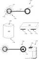
- FIG. 1is a schematic diagram showing a multi-modal sensing surface 100 which may operate as a peripheral device (e.g. an input device) for a separate computing device 102 and may communicate with the separate computing device 102 using wired or wireless technologies (e.g. USB, BluetoothTM, Wi-FiTM, etc.).
- the sensing surface 100is capable of detecting and locating both multi-touch user input (e.g. a user's fingers 104 ) and one or more objects 106 on the surface. If any of the objects 106 include a wireless tag, the sensing surface 100 is also capable of identifying those objects 106 by reading the wireless tag(s).
- the sensing surface 100has two parts—a first part 108 (which may be referred to as the sensing mat or pad) comprising the two overlaid arrays (the capacitive sensing electrode array and the array of RF antennas) and a second part 110 comprising the active electronics (the first and second sensing modules).
- the second partmay also comprise a communication interface arranged to communicate with the separate computing device 102 .
- the sensing surface 100may be integrated with a computing device (e.g. such that the second part 110 comprises a processor, memory, display interface, etc.).
- the first part 108 of the sensing surface 100is a multi-layer structure comprising one array overlaid over the other array as shown in more detail in FIG. 2 .
- the capacitive sensing electrode array 202is above the array of RF antennas 208 (e.g. when in the orientation shown in FIG. 1 and with a user touching the uppermost, touch surface of the first part 108 , as indicated by the hand 112 in FIG. 1 ), i.e. the capacitive sensing electrode array 202 is closer to the touch surface than the array of RF antennas 208 .
- Having the capacitive sensing electrode array 202 closer to the touch surface than the array of RF antennas 208enables the array of RF antennas to provide a shield beneath the capacitive sensing layer (e.g. to prevent false detection caused by objects underneath the sensing surface) and a ground touch return path for user's fingers, as described below.
- the two arrays 202 , 208may be substantially the same size so that the arrays overlap completely. In other examples, however, the two arrays may not be the same size (e.g. the capacitive sensing electrode array 202 may be larger than the array of RF antennas or vice versa) and/or the arrays may be partially offset from each other so that they do not overlap completely and such that there are portions of the sensing surface which are multi-modal (i.e. where the two arrays overlap) and there are portions of the sensing surface which are not (i.e. where there is only one of the two arrays 202 , 208 ).
- the two arraysmay not be the same size (e.g. the capacitive sensing electrode array 202 may be larger than the array of RF antennas or vice versa) and/or the arrays may be partially offset from each other so that they do not overlap completely and such that there are portions of the sensing surface which are multi-modal (i.e. where the two arrays overlap) and there are portions of the sensing surface
- the capacitive sensing electrode array 202comprises a first set of electrodes 204 in a first layer 205 and a second set of electrodes 206 in a second layer 207 .
- the two sets of electrodes 204 , 206are arranged perpendicular to each other such that one set may be referred to as the x-axis electrodes and the other set may be referred to as the y-axis electrodes.
- the sets of electrodesmay be arranged such that they are not exactly perpendicular to each other but instead the electrodes cross at a different angle.
- the sets of electrodes 204 , 206are separated by some insulation which may be in the form of an insulating layer (not shown in FIG. 2 ) or insulation over the wires that form one or both of the sets of electrodes 204 , 206 .
- the array of RF antennas 208comprises a plurality of loop antennas and the example in FIG. 2 the array 208 comprises two sets of antennas 210 , 211 in two separate layers 212 , 213 ; however, in other examples, the array of RF antennas 208 may comprise only a single set of antennas (i.e. one of the two sets 210 , 211 shown in FIG. 2 may be omitted).
- Two sets of antennas, as shown in FIG. 2may be provided to enable the sensing surface 100 to distinguish between two objects at different locations but which are both proximate to the same RF antenna (such that if there was only one set of antennas, a single RF antenna would be able to read the tags in both objects).
- Such a row/column arrangement of RF antennas(comprising two sets of antennas 210 , 211 as shown in FIG. 2 ) also enables the sensing surface to scale better (i.e. to larger sizes of sensing surface) and makes scanning across the area to find an object faster.
- a matrix (or grid) of individual antennase.g. m by n antennas arranged in a grid
- Such a griddoes not scale as well as the arrangement shown in FIG. 2 , but may enable addressing of an object at a known location to be performed faster.
- the two sets of antennas 210 , 211are arranged perpendicular to each other in a row/column matrix such that one set may be referred to as the x-axis antennas and the other set may be referred to as the y-axis antennas.
- the sets of antennasmay be arranged such that they are not exactly perpendicular to each other but instead the antennas cross at a different angle or there may be only a single set of antennas (i.e. one of the sets 210 , 211 is omitted).
- the two sets of antennas 210 , 211are separated by some insulation which may be in the form of an insulating layer (not shown in FIG. 2 ) or insulation over the wires that form one or both of the sets of antennas 210 , 211 .
- the two arrays 202 , 208are separated by a distance (e.g. by an insulating layer also not shown in FIG. 2 ) in order to reduce the mutual capacitance between the capacitive sensing electrodes and the ‘ground’ layer provided by the NFC antennas.
- the RF antennasmay be substantially rectangular loop antennas with a width (as indicated by arrows 214 ) which is close to the sizes of wireless tag used in any objects which are to be identified.
- the widthmay be around 25 mm, with typical tag diameters being 17 mm, 22 mm, 25 mm, 30 mm and 35 mm, although larger tags are available (e.g. 50 mm diameters).
- other shapes of loop antennamay be used and various examples are shown in FIG. 3 .
- the x-axis and y-axis antennasmay be aligned such that the reduced width portion 302 in an x-axis antenna 301 overlaps a similar reduced width portion in a y-axis antenna 304 .
- the second example 306is similar to the first example 301 in that it also comprises reduced width portions; however, in this example, the shape of the reduced width portions is different.
- FIG. 4Three further examples 402 - 408 of RF loop antennas are shown in FIG. 4 (diagrams 406 and 408 relate to the same example, as described below).
- the examples 402 - 408 in FIG. 4all show reduced width portions similar to those in FIG. 3 but with different shaped reduced width portions.
- the reduced width portion in an x-axis antennaoverlaps with a reduced width portion in a y-axis antenna.
- the loop antenna in the third example 406 - 408is formed from curved (rather than straight) lines and diagram 408 shows the shape of a part of a single loop antenna in this example.
- the loop antennas within each of the two sets 210 , 211may be equally spaced (where this spacing, s, between antennas is not necessarily the same as the width, w, of an antenna) or unequally spaced (and as described above, in some examples the antenna array 208 may only comprise a single set of antennas).
- Unequal spacingmay, for example, be used to achieve variable resolution at various points on the sensing surface (e.g. to provide a sensing surface with lower resolution towards the edges and higher resolution in the middle) and this may, for example, enable the same number of antennas to be used for a larger sensing surface and for a smaller sensing surface.
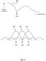
- the loop antennasmay be spaced so as to provide good coverage of the whole surface and to alleviate the effects of any nulls 502 in the signal response of a single antenna 504 .
- FIG. 5shows an example signal response of a single antenna and also how these might be overlaid to provide good response across the surface and alleviate the effects of the nulls 502 .
- the RF antennas(with responses 506 , 508 , 510 ) may be spaced such that the nulls do not align and in the example shown in FIG. 5 , the peak response of one antenna is substantially aligned with the null 502 of an adjacent RF antenna.
- a matrix of RF antennascould be used to locate and identify objects (but not multi-touch inputs by a user using their fingers) without the need for a capacitive sensing electrode array 202 , it would be slow and energy inefficient. Instead, the combination of the two arrays (which use different sensing technologies) as described above enables objects to be located and identified more quickly and more energy efficiently (which consequently increases the operating time between charges for a battery powered sensing surface). This combined use of the two arrays 202 , 208 is described below with reference to FIG. 8 .
- the first part 108 of the sensing surfacemay, for example, be formed in a multi-layer flex circuit or using an embroidery of conductive traces onto a flexible substrate (e.g. woven into a fabric) to provide a flexible, yet robust, surface area.
- the first part 108may be sufficiently flexible that when not in use it can be rolled up around the second (electronics) part (which may be rigid) for storage.
- the two partse.g. the electronics of the second part 110 may be integrated within the first part 108
- the distinctionmay be less (e.g. the second part may be formed in one or more additional layers underneath the first part 108 ).
- the second part 110 of the sensing surface 100comprises the active electronics and this can be described with reference to FIG. 6 .
- the second part 110is permanently connected to the first part 108 and in other examples, the first part 110 may be connected to the first part 108 by one or more connectors (which connect the sensing modules to the respective arrays) such that the two parts can be decoupled by a user (e.g. to enable a user to switch between a first larger and lower resolution sensing mat and a second smaller and higher resolution sensing mat with the same number of connections and use the same active electronics).
- the second part 110comprises the first sensing module 602 and the second sensing module 604 and may further comprise a power source 605 (e.g. a battery, an input connection for an external power source, etc.).
- a power source 605e.g. a battery, an input connection for an external power source, etc.
- the first sensing module 602(which may comprise a microprocessor control unit, MCU) is coupled to the capacitive sensing electrode array 202 and is configured to detect both a decrease and an increase in the capacitance between electrodes in the array.
- a decrease of mutual capacitance between electrodesi.e. between one or more electrodes in the first set of electrodes 204 and one or more electrodes in the second set of electrodes 206 ) is used to detect a user's fingers in the same way as conventional multi-touch sensing.
- the first sensing module 602can also detect an increase in the capacitance between electrodes in the array.
- An increase in mutual capacitance between electrodesi.e.
- a conductive objectsuch as a wireless tag (e.g. an NFC or RFID tag) in a non-conductive housing or other object formed from a conductive material (without a tag).
- a wireless tage.g. an NFC or RFID tag
- a non-conductive housing or other object formed from a conductive materialwithout a tag.
- an objecthas no connection to ground and instead it capacitive couples adjacent electrodes (consequently, the object does not need to have a high electrical conductivity and instead can be made from, or include, any conductive material).
- the second sensing module 604is coupled to the array of RF antennas 208 and is configured to selectively tune and detune the RF antennas in the array. For example, the second sensing module 604 may deactivate all but a selected one or more RF antennas and then power the selected RF antennas such that they can activate and read any proximate wireless tags (where the reading of tags using a selected antenna may be performed in the same way as a conventional NFC or RFID reader). Where more than one RF antenna is tuned and powered at the same time, these antennas are selected to be sufficiently far apart that there is no effect on one powered RF antenna from any of the other powered RF antennas.
- the deactivation of an RF antennamay be implemented in many different ways, for example by shorting the two halves of the loop via a transistor or making the tuning capacitors (which would otherwise tune the antenna at the right frequency) open-circuit (using a transistor).
- This selective tuning and detuning of the RF antennasstops the antennas from coupling with each other (e.g. such that the power is not coupled into another antenna, which may then activate tags proximate to that other antenna and not the original, powered antenna).
- the second sensing module 604may be further configured to connect all the RF antennas to ground when the first sensing module 602 is operating. This prevents the capacitive sensors from sensing activity on the non-touch-side of the sensing mat (e.g. legs under the table) and provides the capacitive return path to ground (which completes the circuit of the user's finger to the sensing electrodes to ground and to the user's body).
- the second partmay also comprise a communication interface 606 arranged to communicate with a separate computing device 102 using a wired or wireless technology.
- the power source 605comprises an input connection for an external power source (e.g. a USB socket) and the communication interface 606 uses a wired protocol (e.g. USB)
- the communication interface 606 and power source 605may be integrated.
- the communication interface 606may, in addition or instead, be arranged to communicate with an object 106 (e.g. following identification of the module by the second sensing module 604 ).
- the sensing surface 100may be integrated with a computing device such that the second part 110 further comprises the component parts of the computing device, such as a processor 608 , memory 610 , display interface 612 , etc.
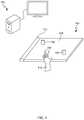
- the sensing surface 100may be integrated within a peripheral for a computing device e.g. within a keyboard 700 as shown in FIG. 7 .
- FIG. 7shows a keyboard 700 with the first part 108 of the sensing surface providing a multi-modal sensing region to one side of the track pad 702 .
- This keyboard 700may be a peripheral device (e.g. for a laptop, tablet or games console) or may be an integral part of a laptop computer.
- the sensing surface 100may be arranged to detect gestures above the surface of the first part 108 as well as fingers or conductive objects in contact with the surface (using the two arrays and the two sensing modules as described above).
- the second part 110may therefore additionally comprise a gesture recognition module 614 coupled to the capacitive sensing electrode array 202 (or this functionality may be incorporated within the first sensing module 602 ).
- the functionality of one or both of the sensing modules 602 , 604 and/or the gesture recognition module 614 described hereinmay be performed, at least in part, by one or more hardware logic components.
- illustrative types of hardware logic componentsinclude Field-programmable Gate Arrays (FPGAs), Application-specific Integrated Circuits (ASICs), Application-specific Standard Products (ASSPs), System-on-a-chip systems (SOCs), Complex Programmable Logic Devices (CPLDs), Graphics Processing Units (GPUs).
- the sensing surface 100is integrated with a computing device such that the second part 110 further comprises the component parts of the computing device, such as a processor 608 , memory 610 , input/output interface 612 , etc.
- the processor 608may be a microprocessor, controller or any other suitable type of processor for processing computer executable instructions to control the operation of the device in order to implement functionality of the computing device (e.g. to run an operating system and application software).
- Computer-readable mediamay include, for example, computer storage media such as memory 610 and communications media.
- Computer storage media, such as memory 610includes volatile and non-volatile, removable and non-removable media implemented in any method or technology for storage of information such as computer readable instructions, data structures, program modules or the like.
- Computer storage mediaincludes, but is not limited to, RAM, ROM, EPROM, EEPROM, flash memory or other memory technology, CD-ROM, digital versatile disks (DVD) or other optical storage, magnetic cassettes, magnetic tape, magnetic disk storage or other magnetic storage devices, or any other non-transmission medium that can be used to store information for access by a computing device.
- communication mediamay embody computer readable instructions, data structures, program modules, or the like in a modulated data signal, such as a carrier wave, or other transport mechanism.
- computer storage mediadoes not include communication media. Therefore, a computer storage medium should not be interpreted to be a propagating signal per se. Propagated signals per se are not examples of computer storage media.
- the computer storage mediamemory 610
- the storagemay be distributed or located remotely and accessed via a network or other communication link (e.g. using communication interface 606 ).
- the sensing surface 100may also comprise an input/output interface 612 arranged to output display information to a display device which may be separate from or integral to the sensing surface 100 .
- the display informationmay provide a graphical user interface.
- the input/output interface 612may also be arranged to receive and process input from one or more devices, such as a user input device (e.g. a mouse, keyboard, camera, microphone or other sensor).
- a user input devicee.g. a mouse, keyboard, camera, microphone or other sensor.
- the user input devicemay detect voice input, user gestures or other user actions and may provide a natural user interface (NUI).
- NUInatural user interface
- the input/output interface 612may comprise NUI technology which enables a user to interact with the computing-based device in a natural manner, free from artificial constraints imposed by input devices such as mice, keyboards, remote controls and the like.
- NUI technologyexamples include but are not limited to those relying on voice and/or speech recognition, touch and/or stylus recognition (touch sensitive displays), gesture recognition both on screen and adjacent to the screen, air gestures, head and eye tracking, voice and speech, vision, touch, gestures, and machine intelligence.
- Other examples of NUI technology that may be usedinclude intention and goal understanding systems, motion gesture detection systems using depth cameras (such as stereoscopic camera systems, infrared camera systems, RGB camera systems and combinations of these), motion gesture detection using accelerometers/gyroscopes, facial recognition, 3D displays, head, eye and gaze tracking, immersive augmented reality and virtual reality systems and technologies for sensing brain activity using electric field sensing electrodes (EEG and related methods).
- EEGelectric field sensing electrodes
- FIG. 8is a flow diagram showing an example method of operation of the sensing surface 100 . Whilst all the RF antennas (in array 208 ) are grounded (block 802 , by the second sensing module 604 ), the sensing surface 100 can detect changes in capacitance using the capacitive electrode array 202 (block 804 , by the first sensing module 602 ). If the first sensing module detects a decrease in capacitance at a location on the sensing surface (in block 804 ), this location is provided as an input to software (block 806 , e.g. where the software may be running on a processor 608 in the sensing surface 100 or in a separate computing device).
- softwaree.g. where the software may be running on a processor 608 in the sensing surface 100 or in a separate computing device.
- the locationis used to identify one of the RF antennas (block 808 , by the second sensing module 604 ) and then all other RF antennas are deactivated (block 810 , by the second sensing module 604 ).
- the identified RF antenna(which has not been deactivated in block 810 ) is then used to read any proximate wireless tags (block 812 , by the second sensing module 604 ).
- the reading of a proximate wireless tagcomprises activating the tag and then reading data transmitted by the activated tag.
- the tagis activated by the RF power coupled to it from the antenna and if the tag is a passive tag, this coupled RF power also provides sufficient power to enable the tag to transmit the data (which comprises an ID for the tag).
- the power which is coupled from the RF antenna to the tagmay also power other functionality within the object, such as a flashing LED within the object.
- the location which is identified (in block 804 , by the first sensing module 602 )may be between two RF antennas in the same set (e.g. set 210 or set 211 in FIG. 2 ) and/or correspond one RF antenna in each set of antennas 210 , 211 .
- blocks 808 - 812may be repeated for each RF antenna that corresponds to the location. Where blocks 808 - 812 are repeated for two RF antennas in the same set, the relative signal strengths of the data received from the wireless tag(s) may be used to provide further location information between the object (e.g.
- blocks 808 - 812are repeated for two RF antennas in different sets (i.e. one from each set), this may be used to correctly identify objects where there is more than one object on the sensing surface such that either or both of the RF antennas can read multiple wireless tags (e.g. with the correct tag for the location being the one that is read by both the antennas).
- the methodi.e. blocks 802 - 812
- the methodmay be repeated to track any movement of the identified object.
- the tracking of an objectmay be performed based on signal strength (block 814 , i.e. based on the strength of the signal received from the wireless tag) without reading (i.e.
- the data transmitted by the tagrepeatedly and this may be less susceptible to noise than only using the capacitive sensing to track location (in block 804 ) because the capacitive sensing may detect both the object (which results in an increase in capacitance between electrodes in the array 202 ) and a user's hand holding and moving the object (which results in a decrease in capacitance between electrodes in the array 202 ). Furthermore, by detecting whether an object is being touched or picked up by a user or not, this may be provided as additional input data to software (in block 816 ).
- the location data and object identifier (as read from the wireless tag) which are determined (in blocks 804 and 808 - 812 )are then provided as an input to software (block 816 , e.g. where the software may be running on a processor 608 in the sensing surface 100 or in a separate computing device). If the object which caused the increase in capacitance (as detected in block 804 ) does not include a wireless tag, no object ID will be read by the second sensing module 604 (in block 812 ) in which case, only location information will be provided as an input to software (in block 816 ).
- the subsequent blocks in the method of FIG. 8may be repeated and depending upon the particular situation, the subsequent blocks may be implemented serially or in parallel for each of the locations. For example, if there is one or more location where a decrease in capacitance is detected (in addition to none, one or more location where an increase in capacitance is detected), then all these locations where a decrease was detected may be provided in parallel as an input to software (in block 806 ).
- the subsequent method blocksmay be performed in turn (i.e. serially) for each location. For example by first identifying RF antenna 91 (in block 808 ), deactivating the other RF antennas 92 - 97 (in block 810 ) and reading any tags in any objects proximate to RF antenna 91 , which includes the object at location 902 (in block 812 ).
- the method blocksmay then be repeated in which the y-axis RF antenna corresponding to location 902 (antenna 95 ) is identified (in block 808 ), e.g. to distinguish between IDs read if there is also an object with a tag present at location 908 .
- the methodthen proceeds by identifying RF antenna 92 (in block 808 ), deactivating the other RF antennas 91 , 93 - 97 (in block 810 ) and reading any tags in any objects proximate to RF antenna 92 , which includes the object at location 904 (in block 812 ).
- the method blocksmay then be repeated in which the y-axis RF antenna corresponding to location 904 (antenna 96 ) is identified (in block 808 ).
- the subsequent method blocksmay be performed serially or in parallel for each location. For example by first identifying RF antennas 91 and 94 (in block 808 ), deactivating the other RF antennas 92 , 93 , 95 - 97 (in block 810 ) and reading any tags in any objects proximate to RF antennas 91 and 94 , which includes the objects at locations 902 and 906 (in block 812 ). The method blocks may then be repeated in which the y-axis RF antennas corresponding to locations 902 and 906 (antennas 95 and 97 ) are identified (in block 808 ).
- the subsequent method blocksmay be performed serially or in parallel for each location. For example by first identifying RF antenna 91 (in block 808 ), deactivating the other RF antennas 92 - 97 (in block 810 ) and reading any tags in any objects proximate to RF antenna 91 , which includes the objects at locations 902 and 908 (in block 812 ).
- the method blocksmay then be repeated, serially or in parallel, in which the y-axis RF antennas corresponding to locations 902 and 908 (antennas 95 and 97 ) are identified (in block 808 ).
- Locationsmay, for example, be determined to be ‘close together’ for this purpose if they correspond to adjacent RF antennas (e.g. as for locations 902 and 904 in FIG. 9 ) and locations may be determined to be ‘far apart’ for this purpose if, for example, they do not correspond to the same or adjacent RF antennas. In other examples and depending upon how the signal response of the individual RF antennas overlap, the locations may need to be further apart (e.g. corresponding to more widely separated RF antennas) in order that the method can proceed in parallel.
- the orientation of an objectmay also be determined.
- the orientationmay be determined using the first sensing module 602 (as part of block 804 e.g. where the object is shaped such that its orientation can be determined from the shape of the region with increased capacitance) and/or the second sensing module 604 (as part of block 812 or 814 e.g.
- Determining the orientation using the first sensing module 602is likely to be a lower power solution than using the second sensing module 604 . Where the orientation of an object is determined (in any of blocks 804 , 812 and 814 ) this may also be provided as an input to software (in block 816 ).
- FIGS. 1 and 7Two example form factors of the sensing surface are shown in FIGS. 1 and 7 .
- the sensing surface shown in FIG. 1may be referred to as a sensing mat and the sensing surface shown in FIG. 7 is integrated into a keyboard (which may be a peripheral device for a computing device, integrated into a cover for a computing device or an integral part of a computing device).
- the first part 108can be flexible, pliable and/or stretchable
- the sensing surfacemay have many different form factors. It may, for example, be integrated into a wearable item (e.g. into a piece of clothing, with the second part 110 being removable for washing by disconnecting it from the two arrays).
- the sensing surfacemay be embedded into a surface (e.g.
- the sensing surfacemay be non-planar (e.g. it may be curved or undulating).
- the first part 108may be a stretchy cover which may be fitted over another object (e.g. to turn an object, which be a passive object, into a sensing input device).
- the sensing surfacemay have any size, e.g. it may be small (e.g. less than 100 cm 2 , as in the example in FIG. 7 ) or much larger.
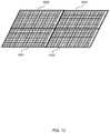
- the two arrays(the capacitive sensing array 202 and the array of RF antennas 208 ) may be scaled to the size of the surface. For some form factors it may not be possible to scale up the RF antenna arrays such that they can cover the entire surface because the antennas may become self-resonant; however, in such implementations, the configuration shown in FIG. 2 (which may be considered to be a single ‘tile’ 1002 ) may be repeated two or more times (e.g. as shown in FIG.
- each tile 1002may share some elements of the second part 110 (e.g. the power source 605 ) and other elements may be replicated for each tile 1002 (e.g. the first and second sensing modules 602 , 604 , where these may, for example, be embedded in each tile and report to a central processor that integrates the data from all the tiles).
- the second part 110e.g. the power source 605
- other elementsmay be replicated for each tile 1002 (e.g. the first and second sensing modules 602 , 604 , where these may, for example, be embedded in each tile and report to a central processor that integrates the data from all the tiles).
- FIG. 10shows the tiling of both the capacitive sensing electrode array and the array of RF antennas
- the array of RF antennasmay be tiled (i.e. repeated) across the surface of the sensing surface and there may be a single, large capacitive sensing electrode array which extends across the sensing surface.
- the sensing surface described aboveprovides a portable sensing area which can detect both multi-touch inputs (e.g. a user's fingers) and objects placed on the surface and if those objects include a wireless tag, the surface can also identify the objects.
- multi-touch inputse.g. a user's fingers
- RF sensingprovides a sensing device which has a lower power consumption than a purely RF solution and hence a longer battery life where the sensing device is battery powered.
- the location and identification of objectscan also be performed more quickly than a purely RF solution.
- the present examples of a multi-modal sensing surfaceare described and illustrated herein as being implemented in a system as shown in FIG. 1 , the system described is provided as an example and not a limitation. As those skilled in the art will appreciate, the present examples are suitable for application in a variety of different types of computing systems and the sensing surface may be implemented in many different form factors, at different scales and may or may not be integrated into another computing device or object. Furthermore, although in the examples shown in FIGS. 1 and 7 , the sensing surface is in a horizontal orientation such that the user contacts an upper surface of the first part (which may be referred to as the ‘touch surface), in other examples, the sensing surface may be positioned vertically (e.g.
- the array of RF antennasmay be described as being behind the capacitive sensing electrode array with a user touching the front surface of the first part, such that this front surface is the touch surface in this configuration) or the first part may be non-planar (e.g. with a user touching an exposed surface of the front part which is therefore the touch surface and the array of RF antennas being behind the capacitive sensing electrode array).
- the touch surfacemay provide a protective cover for the adjacent array which in many examples will be the capacitive electrode sensing array 202 or, where no protective cover is provided, the touch surface may be the capacitive electrode sensing array.
- FIG. 11shows schematic diagrams of various example extender objects 1101 - 1105 which can be used with the multi-modal sensing surface described herein (e.g. as shown in FIG. 1 ) or with any other multi-modal sensing surface which comprises both capacitive touch sensing and sensing of short-range wireless tags.
- the extender objectcomprises two spatially separated antenna coils 1110 , 1112 which are electrically connected together (e.g. by wires 1114 ) and so can be used to extend the range of the multi-modal sensing surface to sense short-range wireless tags.
- the position of any touch events which are detected by the multi-modal sensing surface via the extender objects described hereinmay be provided as an input to software (e.g. in block 806 of FIG. 8 ).
- At least one of the two antenna coilscomprises a plurality of radial elements 1116 , 1118 which extend in or out from the coil 1110 .
- the first antenna coil 1110comprises these radial elements
- both antenna coilsmay comprise radial elements where the radial elements may be the same or different in the coils.
- the two antenna coils 1110 , 1112are spatially separated and two example configurations are shown in FIG. 11 .
- the extender object 1102has the two antenna coils on two opposing faces 1120 , 1122 .
- the extender object 1103has the two antenna coils spatially separated on the same face 1130 .
- the extender objectmay have any shape and the antenna coils may be placed in any spatially separated positions on any surface of the extender object, e.g. as shown in the fifth example 1105 in FIG. 11 .
- the first antenna coil 1110 in the extender objectcouples with an antenna coil in the short-range wireless tag and the second antenna coil 1112 in the extender object couples with an RF antenna in the multi-modal sensing surface.
- the two antenna coilsadditionally extend the capacitive touch sensing of the multi-modal sensing surface and when used to extend the capacitive touch sensing, the second antenna coil 1112 in the extender object is in contact with the multi-modal sensing surface (e.g. the antenna coil without the radial elements, in this example) and the first antenna coil 1110 (e.g. the one with the radial elements) is spatially separated from the sensing surface and provides the extended touch area.
- the radial elements (or spokes) 1116 , 1118extend the touch area which can be detected using the multi-modal sensing surface and so improve the touch detection performance as can be described with reference to FIG. 12 .
- the upper two diagrams 1201 , 1202 in FIG. 12show two different antenna coil designs—the first, 1201 , does not include any radial elements and the second, 1202 , includes a plurality of radial elements.
- the two lower diagrams 1203 , 1204show examples of the areas which are sensitive to touch for the two antennas shown in the upper diagrams 1201 , 1202 and it can be seen that by adding the radial elements, the area which is sensitive to touch changes from a hollow circle (as in diagram 1203 ) where touch cannot be detected in the center to a larger filled circle (as in diagram 1204 ). It will be appreciated that if, instead the radial elements only extended into the center from the antenna coil then the area which is sensitive to touch may be a filled circle that is the same size as the hollow circle shown in FIG. 12 (in diagram 1203 ) and if instead the radial elements only extended out from the antenna coil, then the area which is sensitive to touch may be the same size as the larger circle shown in FIG. 12 (in diagram 1204 ) but may be hollow.
- one or both of the antenna coilsmay comprise thicker traces than a standard antenna coil (e.g. thicker traces than are necessary for functioning as an NFC coil). This goes against known principles which would suggest making the traces as thin as can be made without breaking.
- the extender object 1104may additionally comprise an IC 1142 (e.g. an NFC IC) connected to one of the antennas 1110 , 1112 . If the extender object comprises such an IC, the multi-modal sensing surface will be able to detect and identify the extender object (e.g. using an identifier stored within the IC which is communicated to the multi-modal sensing surface via the antenna coil which is in contact with the multi-modal sensing surface). In the absence of such an IC, the extender object is invisible to the second sensing module and array of RF antennas.
- an IC 1142e.g. an NFC IC
- the extender objectcomprises two antenna coils 1110 , 1112 connected together in a 1:1 relationship.
- the extender objectmay comprise more than one antenna coil on a single face or more than one antenna coil on multiple (e.g. both) faces and various examples are shown in FIG. 13 .
- This configurationmay enable different points on the multi-modal sensing surface to be extended to different points in space (e.g. spatially close points on the multi-modal sensing surface may be extended to spatially separate points in space, where these spatially separate points may be on the same face of the extender object or on different faces).
- the second example in FIG. 13shows a many:1 configuration in which the extender object 1302 comprises one antenna coil on one face (e.g. a face which is not in contact with the multi-modal sensing surface) connected to N antenna coils on a second face (which in this example is an opposite face and is in contact with the multi-modal sensing surface).
- This configurationhas a smaller footprint on the multi-modal sensing surface.
- the third example in FIG. 13shows a 1:many configuration in which the extender object 1303 comprises N antenna coils on one face (e.g. a face which is not in contact with the multi-modal sensing surface) connected to a single antenna coil on a second face (which in this example is an opposite face and is in contact with the multi-modal sensing surface).
- This configurationmay provide more robust sensing by allowing the short-range wireless tag or touch event to be detected by more than one row/column of RF antennas/electrodes. Additionally, the configuration may enable a short-range wireless tag to draw more power from the electromagnetic field generated by a plurality of RF antennas (e.g. if their phases are synchronized).
- the antenna coilsare positioned on opposite faces of an extender object 1301 - 1303 .
- the antenna coilsmay be spatially separated on the same face of an extender object, as shown in one of the examples 1103 in FIG. 1 or they may be positioned on multiple faces of an extender object 1304 , as shown in the fourth example in FIG. 13 .
- the antenna coils which are in contact with the multi-modal sensing surfacedo not comprise radial elements and the other antenna coils do comprise radial elements. In other examples; however, the antenna coils which are in contact with the multi-modal sensing surface may comprise radial elements and/or one or more of the antenna coils that are not in contact with the multi-modal sensing surface may not comprise radial elements. In examples where all the antenna coils comprise radial elements, the extender elements may be used either way up (e.g. to provide a 1:many or a many:1 configuration using the same extender object).
- FIG. 14shows a schematic diagram of an extender object 1402 on a multi-modal sensing surface 1404 comprising two arrays of RF antennas 1406 , 1408 and a capacitive sensing electrode array 1410 .
- a standard short-range wireless tag 1412is shown on the sensing surface 1404 . If a user places a short-range wireless tag 1414 on the distal end of the extender object (i.e. proximate to antenna coil 1416 which comprises a plurality of radial portions), the tag is detected by the sensing surface 1404 (e.g. by the RF antenna arrays 1406 , 1408 ) as if it is placed on the surface at the position of the proximal end of the extender object (i.e.
- the tagis detected by the sensing surface 1404 (e.g. by the capacitive sensing electrode array 1410 ) as if the user touched the surface at the position of the proximal end of the extender object (i.e. in the position of the second antenna coil 1415 in the extender object).
- extender objectsmay be stacked on top of each other.
- an extender objectmay have any shape (e.g. it may be shaped like a person, a miniature building, etc.) and in various examples the extender objects may be play pieces which are part of a set of play pieces (which may have different shapes).
- extender objects as described hereinenables touch sensing to be extended away from the flat, featureless surface of the multi-modal sensing surface as well as extending sensing of short-range wireless tags.
- this extension away from the flat sensing surfaceis beneficial, for example, it may facilitate user input by visually impaired users, users who are less dexterous (e.g. young children or the elderly) who may find it easier to locate and touch objects placed on a surface to provide user input than to provide user input at different positions on the flat surface.
- the extender objects as described hereinmay operate as an input to a system that facilitates collaboration through being physical, for example, an architectural model that drives a simulation. Modifying the placement and arrangement of blocks that represent buildings or architectural features change the parameters of the simulation and having the input provided by physical extender blocks may make it easier to understand and collaborate between people compared to an on-screen interface.
- a first further exampleprovides a multi-modal sensing surface comprising: two overlaid arrays, the two arrays comprising a capacitive sensing electrode array and an array of RF antennas; a first sensing module coupled to the capacitive sensing electrode array and arranged to detect both an increase and a decrease of capacitance between electrodes in the array; and a second sensing module coupled to the array of RF antennas and arranged to selectively tune and detune one or more of the RF antennas in the array of RF antennas.
- the second sensing modulemay be further arranged to receive data transmitted by one or more wireless tags proximate to a tuned RF antenna and via that tuned RF antenna.
- the second sensing modulemay be arranged to selectively tune one or more of the RF antennas in the array of RF antennas to a frequency corresponding to a wireless tag.
- the second sensing modulemay be arranged to selectively detune one or more of the RF antennas in the array of RF antennas by deactivating the antenna.
- the array of RF antennasmay comprise a first set of RF antennas at a first orientation and a second set of RF antennas at a second orientation.
- the first set of RF antennasmay be perpendicular to the second set of RF antennas and may lie in a plane parallel to a plane comprising the second set of RF antennas.
- the sensing surfacemay comprise a touch surface and the array of RF antennas may be on an opposite side of the capacitive sensing array from the touch surface.
- the second sensing modulemay be further arranged to connect the array of RF antennas to ground whilst the first sensing module is detecting capacitance changes between the electrodes in the capacitive sensing electrode array.
- each RF antennamay have a pre-defined signal response and the antennas in the array of RF antennas may be spaced such that a null in the signal response of one RF antenna does not substantially align with a null in the signal response of an adjacent RF antenna.
- the two overlaid arraysmay be formed in or on a flexible substrate. At least one of the two overlaid arrays may be woven into a fabric substrate.
- the first further examplemay further comprise a communication interface arranged to communicate data to a separate computing device, the data comprising locations of any touch events and objects detected by the first sensing module and identities of any objects determined by the second sensing module.
- the first and second sensing modulesmay be located in a detachable electronics module and may be coupled to the arrays via one or more connectors.
- a second further exampleprovides a computing device comprising the multi-modal sensing surface according to the first further example.
- a third further exampleprovides a method of detecting and locating touch events and objects using a multi-modal sensing surface, the method comprising: detecting, in a first sensing module in the multi-modal sensing surface, changes in capacitance between electrodes in a capacitive sensing electrode array in the multi-modal sensing surface; in response to detecting, in the first sensing module, a decrease in capacitance between the electrodes at a first location, providing location data identifying the first location as an input to a computer program; in response to detecting, in the first sensing module, an increase in capacitance between the electrodes at a second location: identifying, based on the second location, an RF antenna in an array of RF antennas in the multi-modal sensing surface; detuning, in a second sensing module in the multi-modal sensing surface, one or more adjacent RF antennas in the array of RF antennas; and reading, by the second sensing module and via the identified RF antenna, data from any proximate wireless tags.
- the method of the third further examplemay further comprise: prior to detecting changes in capacitance, connecting the array of RF antennas to ground.
- the method of the third further examplemay further comprise: in response to detecting, in the first sensing module, an increase in capacitance between the electrodes at a second location: providing location data identifying the second location and any data read from any proximate wireless tags as an input to a computer program.
- the method of the third further examplemay further comprise: in response to detecting, in the first sensing module, an increase in capacitance between the electrodes at a second location: tracking motion of an object initially at the second location on the multi-modal sensing surface.
- the motionmay be tracked by repeatedly analyzing strengths of signals received by the identified RF antenna from any proximate wireless tags.
- a fourth further exampleprovides a user input device comprising a multi-modal sensing surface, the multi-modal sensing surface comprising a sensing mat and an electronics module and wherein the sensing mat comprises two overlaid arrays, the two arrays comprising a capacitive sensing electrode array and an array of RF antennas and the electronics module comprises a first sensing module coupled to the capacitive sensing electrode array and arranged to detect both an increase and a decrease of capacitance between electrodes in the array and a second sensing module coupled to the array of RF antennas and arranged to selectively tune and detune one or more of the RF antennas in the array of RF antennas.
- the second sensing modulemay be further arranged to receive data transmitted by one or more wireless tags proximate to a tuned RF antenna and via that tuned RF antenna.
- the second sensing modulemay be arranged to selectively tune one or more of the RF antennas in the array of RF antennas to a frequency corresponding to a wireless tag.
- the second sensing modulemay be arranged to selectively detune one or more of the RF antennas in the array of RF antennas by deactivating the antenna.
- the array of RF antennasmay comprise a first set of RF antennas at a first orientation and a second set of RF antennas at a second orientation.
- the first set of RF antennasmay be perpendicular to the second set of RF antennas and may lie in a plane parallel to a plane comprising the second set of RF antennas.
- the sensing surfacemay comprise a touch surface and the array of RF antennas may be on an opposite side of the capacitive sensing array from the touch surface.
- the second sensing modulemay be further arranged to connect the array of RF antennas to ground whilst the first sensing module is detecting capacitance changes between the electrodes in the capacitive sensing electrode array.
- each RF antennamay have a pre-defined signal response and the antennas in the array of RF antennas may be spaced such that a null in the signal response of one RF antenna does not substantially align with a null in the signal response of an adjacent RF antenna.
- the two overlaid arraysmay be formed in or on a flexible substrate. At least one of the two overlaid arrays may be woven into a fabric substrate.
- the fourth further examplemay further comprise a communication interface arranged to communicate data to a separate computing device, the data comprising locations of any touch events and objects detected by the first sensing module and identities of any objects determined by the second sensing module.
- the first and second sensing modulesmay be located in a detachable electronics module and may be coupled to the arrays via one or more connectors.
- the first and/or second sensing modulemay be at least partially implemented using hardware logic selected from any one or more of: a field-programmable gate array, a program-specific integrated circuit, a program-specific standard product, a system-on-a-chip, a complex programmable logic device.
- a fifth further exampleprovides an object comprising a first antenna coil and a second antenna coil, wherein the first and second antenna coils are electrically connected together and wherein at least one of the first and second antenna coils comprises a plurality of radial elements extending in and/or out from the coil.
- Both the first and second antenna coilsmay comprise a plurality of radial elements extending in and/or out from the coil.
- the first and second antenna coilsmay be spatially separated.
- the first antenna coilmay be on a first face of the object and the second antenna coil may be on a second face of the object.
- the objectmay further comprise a third antenna coil and a fourth antenna coil, wherein the third and fourth antenna coils are electrically connected together and wherein at least one of the third and fourth antenna coils comprises a plurality of radial elements extending in and/or out from the coil.
- the third antenna coilmay be on the first face of the object and the fourth antenna coil may be on the second face of the object.
- the objectmay further comprise at least one additional antenna coil on the first face and wherein each additional antenna coil is electrically connected to the second antenna.
- the objectmay further comprise a further antenna coil on a third face of the object and wherein the further antenna coil is electrically connected to one of the first and second antenna coils.
- the objectmay further comprise an NFC IC.
- a sixth further exampleprovides a system comprising a multi-modal sensing surface and an extender object configured to extend sensing capabilities of the multi-modal sensing surface away from the surface, the extender object comprising a first antenna coil and a second antenna coil, wherein the first and second antenna coils are electrically connected together and wherein at least one of the first and second antenna coils comprises a plurality of radial elements extending in and/or out from the coil and the multi-modal sensing surface comprising: two overlaid arrays, the two arrays comprising a capacitive sensing electrode array and an array of RF antennas; a first sensing module coupled to the capacitive sensing electrode array and arranged to detect both an increase and a decrease of capacitance between electrodes in the array; and a second sensing module coupled to the array of RF antennas and arranged to selectively tune and detune one or more of the RF antennas in the array of RF antennas.
- the second sensing module in the multi-modal sensing surfacemay be further arranged to receive data transmitted by one or more wireless tags proximate to a tuned RF antenna and via that tuned RF antenna.
- the second sensing module in the multi-modal sensing surfacemay be arranged to selectively tune one or more of the RF antennas in the array of RF antennas to a frequency corresponding to a wireless tag.
- the second sensing module in the multi-modal sensing surfacemay be arranged to selectively detune one or more of the RF antennas in the array of RF antennas by deactivating the antenna.
- the array of RF antennas in the multi-modal sensing surfacemay comprise a first set of RF antennas at a first orientation and a second set of RF antennas at a second orientation.
- the first set of RF antennas in the multi-modal sensing surfacemay be perpendicular to the second set of RF antennas in the multi-modal sensing surface and lie in a plane parallel to a plane comprising the second set of RF antennas.
- the multi-modal sensing surfacemay comprise a touch surface and the array of RF antennas is on an opposite side of the capacitive sensing array from the touch surface.
- the second sensing module in the multi-modal sensing surfacemay be further arranged to connect the array of RF antennas to ground whilst the first sensing module is detecting capacitance changes between the electrodes in the capacitive sensing electrode array.
- Each RF antenna in the multi-modal sensing surfacemay have a pre-defined signal response and wherein the antennas in the array of RF antennas may be spaced such that a null in the signal response of one RF antenna does not substantially align with a null in the signal response of an adjacent RF antenna.
- the two overlaid arrays in the multi-modal sensing surfacemay be formed in or on a flexible substrate.
- the multi-modal sensing surfacemay further comprise a communication interface arranged to communicate data to a separate computing device, the data comprising locations of any touch events and objects detected by the first sensing module in the multi-modal sensing surface and identities of any objects determined by the second sensing module in the multi-modal sensing surface.
- computeror ‘computing-based device’ is used herein to refer to any device with processing capability such that it can execute instructions.
- processorsincluding smart phones
- tablet computersor tablet computers
- set-top boxesmedia players
- games consolespersonal digital assistants and many other devices.
- the methods described hereinmay be performed by software in machine readable form on a tangible storage medium e.g. in the form of a computer program comprising computer program code means adapted to perform all the steps of any of the methods described herein when the program is run on a computer and where the computer program may be embodied on a computer readable medium.
- tangible storage mediainclude computer storage devices such as disks, thumb drives, memory etc. and do not include propagated signals. Propagated signals per se are not examples of tangible storage media.
- the softwarecan be suitable for execution on a parallel processor or a serial processor such that the method steps may be carried out in any suitable order, or simultaneously.
- a remote computermay store an example of the process described as software.
- a local or terminal computermay access the remote computer and download a part or all of the software to run the program.
- the local computermay download pieces of the software as needed, or execute some software instructions at the local terminal and some at the remote computer (or computer network).
- a dedicated circuitsuch as a DSP, programmable logic array, or the like.
Landscapes
- Engineering & Computer Science (AREA)
- General Engineering & Computer Science (AREA)
- Theoretical Computer Science (AREA)
- Human Computer Interaction (AREA)
- Physics & Mathematics (AREA)
- General Physics & Mathematics (AREA)
- Computer Networks & Wireless Communication (AREA)
- Signal Processing (AREA)
- Position Input By Displaying (AREA)
- User Interface Of Digital Computer (AREA)
- Investigating Or Analyzing Materials By The Use Of Magnetic Means (AREA)
Abstract
Description
Claims (20)
Priority Applications (4)
| Application Number | Priority Date | Filing Date | Title |
|---|---|---|---|
| US15/231,677US10955977B2 (en) | 2015-11-03 | 2016-08-08 | Extender object for multi-modal sensing |
| EP16801898.4AEP3350680B1 (en) | 2015-11-03 | 2016-11-01 | Extender object for multi-modal sensing |
| PCT/US2016/059808WO2017079098A2 (en) | 2015-11-03 | 2016-11-01 | Extender object for multi-modal sensing |
| CN201680064138.5ACN108351733B (en) | 2015-11-03 | 2016-11-01 | Expander Objects for Multimodal Sensing |
Applications Claiming Priority (2)
| Application Number | Priority Date | Filing Date | Title |
|---|---|---|---|
| US14/931,049US10649572B2 (en) | 2015-11-03 | 2015-11-03 | Multi-modal sensing surface |
| US15/231,677US10955977B2 (en) | 2015-11-03 | 2016-08-08 | Extender object for multi-modal sensing |
Related Parent Applications (1)
| Application Number | Title | Priority Date | Filing Date |
|---|---|---|---|
| US14/931,049Continuation-In-PartUS10649572B2 (en) | 2015-11-03 | 2015-11-03 | Multi-modal sensing surface |
Publications (2)
| Publication Number | Publication Date |
|---|---|
| US20170123563A1 US20170123563A1 (en) | 2017-05-04 |
| US10955977B2true US10955977B2 (en) | 2021-03-23 |
Family
ID=57406332
Family Applications (1)
| Application Number | Title | Priority Date | Filing Date |
|---|---|---|---|
| US15/231,677ActiveUS10955977B2 (en) | 2015-11-03 | 2016-08-08 | Extender object for multi-modal sensing |
Country Status (4)
| Country | Link |
|---|---|
| US (1) | US10955977B2 (en) |
| EP (1) | EP3350680B1 (en) |
| CN (1) | CN108351733B (en) |
| WO (1) | WO2017079098A2 (en) |
Families Citing this family (6)
| Publication number | Priority date | Publication date | Assignee | Title |
|---|---|---|---|---|
| US10338753B2 (en) | 2015-11-03 | 2019-07-02 | Microsoft Technology Licensing, Llc | Flexible multi-layer sensing surface |
| US10649572B2 (en) | 2015-11-03 | 2020-05-12 | Microsoft Technology Licensing, Llc | Multi-modal sensing surface |
| CN107368201A (en)* | 2017-06-05 | 2017-11-21 | 广东工业大学 | Air mouse servicing unit and method based on single-point magnetic orientation |
| US20190361549A1 (en)* | 2018-05-23 | 2019-11-28 | Huanhuan GU | Transparent antenna-integrated touch sensor for a touch screen device |
| WO2021074026A1 (en)* | 2019-10-16 | 2021-04-22 | Giovanni Baggio | System and computer program for the management of objects |
| CN118313391B (en)* | 2024-06-06 | 2024-09-13 | 深圳一代科技有限公司 | Passive sensing tag fusing antenna and electrode and related product and device |
Citations (183)
| Publication number | Priority date | Publication date | Assignee | Title |
|---|---|---|---|---|
| US2170373A (en) | 1935-12-18 | 1939-08-22 | Kind Oscar | Apparatus for playing a table game |
| US3524188A (en)* | 1967-08-24 | 1970-08-11 | Rca Corp | Antenna arrays with elements aperiodically arranged to reduce grating lobes |
| US5214427A (en) | 1989-08-24 | 1993-05-25 | Sony Corporation | Input apparatus |
| US5355105A (en) | 1993-04-12 | 1994-10-11 | Angelucci Sr Thomas L | Multi-layer flexible printed circuit and method of making same |
| US5521601A (en) | 1995-04-21 | 1996-05-28 | International Business Machines Corporation | Power-efficient technique for multiple tag discrimination |
| US5623129A (en) | 1993-11-05 | 1997-04-22 | Microfield Graphics, Inc. | Code-based, electromagnetic-field-responsive graphic data-acquisition system |
| US6062937A (en) | 1997-11-04 | 2000-05-16 | System Watt Co., Ltd. | Assembly block for teaching material, plaything, etc |
| US6118379A (en) | 1997-12-31 | 2000-09-12 | Intermec Ip Corp. | Radio frequency identification transponder having a spiral antenna |
| US6204764B1 (en) | 1998-09-11 | 2001-03-20 | Key-Trak, Inc. | Object tracking system with non-contact object detection and identification |
| US6366260B1 (en) | 1998-11-02 | 2002-04-02 | Intermec Ip Corp. | RFID tag employing hollowed monopole antenna |
| US6404643B1 (en)* | 1998-10-15 | 2002-06-11 | Amerasia International Technology, Inc. | Article having an embedded electronic device, and method of making same |
| US20020106995A1 (en) | 2001-02-06 | 2002-08-08 | Callaway Edgar Herbert | Antenna system for a wireless information device |
| US6443796B1 (en) | 2000-06-19 | 2002-09-03 | Judith Ann Shackelford | Smart blocks |
| US6454624B1 (en) | 2001-08-24 | 2002-09-24 | Xerox Corporation | Robotic toy with posable joints |
| WO2002095674A1 (en) | 2001-05-21 | 2002-11-28 | Oji Paper Co., Ltd. | Ic chip mounting element, production method therefor and thermal transfer film used in the production method |
| US20020185981A1 (en) | 2001-05-24 | 2002-12-12 | Mitsubishi Electric Research Laboratories, Inc. | Multi-user touch surface |
| US20020196250A1 (en) | 2001-06-20 | 2002-12-26 | Gateway, Inc. | Parts assembly for virtual representation and content creation |
| US6585165B1 (en) | 1999-06-29 | 2003-07-01 | Sony Chemicals Corp. | IC card having a mica capacitor |
| US20030148700A1 (en) | 2002-02-06 | 2003-08-07 | David Arlinsky | Set of playing blocks |
| US20030178291A1 (en) | 2002-03-19 | 2003-09-25 | E. G. O. Elektro-Geraetebau Gmbh | Operating device for an electrical appliance |
| US6668447B2 (en) | 2001-11-20 | 2003-12-30 | St. Jude Children's Research Hospital | Multilayered board comprising folded flexible circuits and method of manufacture |
| US6750769B1 (en) | 2002-12-12 | 2004-06-15 | Sun Microsystems, Inc. | Method and apparatus for using RFID tags to determine the position of an object |
| US20040124248A1 (en) | 2002-12-31 | 2004-07-01 | Massachusetts Institute Of Technology | Methods and apparatus for wireless RFID cardholder signature and data entry |
| US6773322B2 (en) | 1997-05-19 | 2004-08-10 | Creator Ltd. | Programmable assembly toy |
| US6834251B1 (en) | 2001-12-06 | 2004-12-21 | Richard Fletcher | Methods and devices for identifying, sensing and tracking objects over a surface |
| US6903056B2 (en) | 2001-12-27 | 2005-06-07 | Nippon Steel Chemical Co., Ltd. | Fluid bearing unit and lubricating oil composition for bearing |
| US6903656B1 (en) | 2003-05-27 | 2005-06-07 | Applied Wireless Identifications Group, Inc. | RFID reader with multiple antenna selection and automated antenna matching |
| US20050134506A1 (en) | 2003-12-23 | 2005-06-23 | 3M Innovative Properties Company | Ultra high frequency radio frequency identification tag |
| US20050183264A1 (en) | 2004-02-23 | 2005-08-25 | Eric Eckstein | Method for aligning capacitor plates in a security tag and a capacitor formed thereby |
| US20050225451A1 (en) | 2004-04-07 | 2005-10-13 | Fuji Photo Film Co., Ltd. | RF tag, RF tag attitude detection apparatus, and RF tag attitude detection system |
| US20050242950A1 (en) | 2004-04-30 | 2005-11-03 | Kimberly-Clark Worldwide, Inc. | Activating a data tag by load or orientation or user control |
| US20050242959A1 (en)* | 2004-04-28 | 2005-11-03 | Fuji Xerox Co., Ltd | IC tag provided with three-dimensional antenna and pallet provided with the IC tag |
| US20060035611A1 (en) | 2004-08-13 | 2006-02-16 | Connell Lawrence E | High linearity and low noise CMOS mixer and signal mixing method |
| US20060045310A1 (en) | 2004-08-27 | 2006-03-02 | General Electric Company | System and method for tracking articulated body motion |
| US7058434B2 (en) | 2002-12-19 | 2006-06-06 | Nokia Corporation | Mobile communication |
| US20070062852A1 (en) | 2005-08-11 | 2007-03-22 | N-Trig Ltd. | Apparatus for Object Information Detection and Methods of Using Same |
| US7232069B1 (en)* | 2004-06-16 | 2007-06-19 | Ncr Corporation | Methods and apparatus for disabling, enabling or setting the range of radio frequency identification devices |
| WO2007094993A1 (en) | 2006-02-10 | 2007-08-23 | Milliken & Company | Flexible capacitive sensor |
| US20070222700A1 (en) | 2006-03-21 | 2007-09-27 | Broadcom Corporation, A California Corporation | Planer helical antenna |
| CN101131432A (en) | 2007-09-18 | 2008-02-27 | 澳门科技大学 | Positioning method and device of radio frequency identification system |
| KR100816616B1 (en) | 2007-03-23 | 2008-03-24 | 김현철 | Wireless Identification System and Method Using Wireless Access Point |
| US7372967B2 (en) | 2002-11-29 | 2008-05-13 | Sigmatel, Inc. | Microphone bias circuit |
| US20080184281A1 (en) | 2007-01-30 | 2008-07-31 | Sony Corporation | Optical disc case, optical disc tray, card member, and manufacturing method |
| US20080186174A1 (en) | 2007-02-02 | 2008-08-07 | Sensormatic Electronics Corporation | Item level inventory with a radio frequency identification (RFID) system |
| US20080186138A1 (en) | 2005-12-09 | 2008-08-07 | Butler Timothy P | Methods and systems of a multiple radio frequency network node rfid tag |
| US7413124B2 (en) | 2005-07-19 | 2008-08-19 | 3M Innovative Properties Company | RFID reader supporting one-touch search functionality |
| US20080238685A1 (en) | 2007-03-28 | 2008-10-02 | Micron Technology, Inc. | Methods and systems of determining physical characteristics associated with objects tagged with rfid tags |
| US20080238885A1 (en) | 2007-03-29 | 2008-10-02 | N-Trig Ltd. | System and method for multiple object detection on a digitizer system |
| US7432855B2 (en) | 2004-06-03 | 2008-10-07 | Farrokh Mohamadi | RFID reader and active tag |
| US20080246614A1 (en) | 2007-04-03 | 2008-10-09 | Nokia Corporation | Radio frequency identification tags |
| US7439972B2 (en) | 2002-10-11 | 2008-10-21 | Lego A/S | Method of generating a computer readable model |
| WO2008147820A1 (en) | 2007-05-22 | 2008-12-04 | S/R Industries, Inc. | System and method for electronic projectile play |
| US20090027210A1 (en) | 2007-07-25 | 2009-01-29 | Isao Sakama | Rfid tag mounting package and manufacturing method thereof |
| US20090029771A1 (en) | 2007-07-25 | 2009-01-29 | Mega Brands International, S.A.R.L. | Interactive story builder |
| US7488231B2 (en) | 2000-10-20 | 2009-02-10 | Creative Kingdoms, Llc | Children's toy with wireless tag/transponder |
| CN101443087A (en) | 2006-05-09 | 2009-05-27 | 皇家飞利浦电子股份有限公司 | Gaming system with moveable display |
| US20090167699A1 (en) | 2007-12-27 | 2009-07-02 | Apple Inc. | Touch screen rfid tag reader |
| WO2009142383A1 (en) | 2008-05-20 | 2009-11-26 | Lg Electronics Inc. | Electronic device with touch device and method of executing functions thereof |
| US7639237B2 (en) | 2006-03-03 | 2009-12-29 | Perkins Michael T | Roll-out touch screen support system (ROTS3) |
| US20100001923A1 (en) | 2008-07-02 | 2010-01-07 | Med Et Al, Inc. | Communication blocks having multiple-planes of detection components and associated method of conveying information based on their arrangement |
| US20100053111A1 (en) | 2008-09-04 | 2010-03-04 | Sony Ericsson Mobile Communications Ab | Multi-touch control for touch sensitive display |
| EP2172834A2 (en) | 2008-10-02 | 2010-04-07 | Wacom Co., Ltd. | Combination touch and transducer input system and method |
| US20100267421A1 (en)* | 2009-04-20 | 2010-10-21 | Broadcom Corporation | Inductive touch screen with antenna mode for use in a communication device and methods for use therewith |
| US7821274B2 (en) | 2007-05-07 | 2010-10-26 | Atmel Corporation | Capacitive position sensor |
| WO2010150232A1 (en) | 2009-06-25 | 2010-12-29 | Zyx Play Aps | A game system comprising a number of building elements |
| CN101950231A (en) | 2009-07-10 | 2011-01-19 | 群康科技(深圳)有限公司 | Method for detecting touching position for touch device |
| US7977577B2 (en) | 2006-02-14 | 2011-07-12 | Lg Innotek Co., Ltd. | Multi-layer flexible printed circuit board and method for manufacturing the same |
| US20110227871A1 (en) | 2010-03-22 | 2011-09-22 | Mattel, Inc. | Electronic Device and the Input and Output of Data |
| US20110263297A1 (en) | 2010-04-27 | 2011-10-27 | Nokia Corporation | Method and apparatus for contention resolution of passive endpoints |
| US20110273382A1 (en) | 2010-05-07 | 2011-11-10 | Samsung Electro-Mechanics Co ., Ltd. | Touch screen having antenna pattern |
| US8079890B2 (en) | 2008-02-26 | 2011-12-20 | Jsn, Inc. | Building block toy set |
| CN202094276U (en) | 2011-06-30 | 2011-12-28 | 潍柴动力股份有限公司 | Active RFID (Radio Frequency Identification) antenna adjusting device for vehicle, and vehicle controller |
| US20120062490A1 (en) | 2010-07-08 | 2012-03-15 | Disney Enterprises, Inc. | Game Pieces for Use with Touch Screen Devices and Related Methods |
| CN102394340A (en) | 2011-06-30 | 2012-03-28 | 潍柴动力股份有限公司 | Antenna adjustment device and method for vehicle active RFID (Radio Frequency Identification) and vehicle controller |
| US20120075199A1 (en) | 2010-09-24 | 2012-03-29 | Synaptics Incorporated | Input device with transmission element actuated switch |
| CN102426492A (en) | 2010-08-05 | 2012-04-25 | 美国博通公司 | Method and system for utilizing a touchscreen interface as an antenna |
| US20120146770A1 (en) | 2010-12-10 | 2012-06-14 | Brannen Nicholas A | Arrow with Embedded Deployable RFID Tag and the Methods of Using and Tracking the Same |
| US20120162032A1 (en) | 2010-12-22 | 2012-06-28 | Songnan Yang | Antenna integrated into a touch sensor of a touchscreen display |
| US8257157B2 (en) | 2008-02-04 | 2012-09-04 | Polchin George C | Physical data building blocks system for video game interaction |
| US20120258436A1 (en) | 2011-04-08 | 2012-10-11 | Case Western Reserve University | Automated assessment of cognitive, fine-motor, and memory skills |
| US8292733B2 (en) | 2009-08-31 | 2012-10-23 | Disney Enterprises, Inc. | Entertainment system providing dynamically augmented game surfaces for interactive fun and learning |
| CN102799907A (en) | 2011-05-24 | 2012-11-28 | 艾迪讯科技股份有限公司 | Equipment and method for applying radio frequency identification technology to book labeling operation |
| CN202600754U (en) | 2012-06-01 | 2012-12-12 | 北京物资学院 | RFID (Radio Frequency Identification) tag with light-sensitive device and RFID system |
| EP2535797A2 (en) | 2011-06-17 | 2012-12-19 | Konica Minolta Business Technologies, Inc. | Information viewing apparatus, control program and controlling method |
| CN202736099U (en) | 2012-06-01 | 2013-02-13 | 北京物资学院 | RFID tag with proximity sensitive device and RFID system with proximity sensitive device |
| US20130044078A1 (en) | 2011-08-17 | 2013-02-21 | Chewy Software, LLC | System and method for communicating through a capacitive touch sensor |
| CN202795320U (en) | 2012-08-15 | 2013-03-13 | 南京汇金锦元光电材料有限公司 | Capacitive touch screen with flexible transparent conducting thin film |
| US20130078914A1 (en) | 2011-09-23 | 2013-03-28 | Broadcom Corporation | Varying Load Modulation in an NFC-Enabled Device Over a Range of Field Strength |
| CN103069647A (en) | 2010-04-26 | 2013-04-24 | 剑桥企业有限公司 | RFID tag interrogation systems |
| US8463332B2 (en) | 2006-08-31 | 2013-06-11 | Semiconductor Energy Laboratory Co., Ltd. | Wireless communication device |
| US20130155005A1 (en) | 2011-12-20 | 2013-06-20 | Wistron Corporation | Touch display panel and driving method thereof |
| US20130176175A1 (en) | 2012-01-11 | 2013-07-11 | Archer Quest, Inc. | Apparatus For Arrow Locating And Game Tracking |
| US20130181937A1 (en)* | 2012-01-18 | 2013-07-18 | Chunghwa Picture Tubes, Ltd. | Dual-Mode Touch Sensing Apparatus |
| EP2620845A1 (en) | 2012-01-27 | 2013-07-31 | Research In Motion Limited | Communications device and method for having integrated nfc antenna and touch screen display |
| US20130194071A1 (en) | 2009-12-29 | 2013-08-01 | Idex Asa | Surface sensor |
| US20130196596A1 (en) | 2012-01-27 | 2013-08-01 | Research In Motion Limited | Communications device and method for having integrated nfc antenna and touch screen display |
| US20130194230A1 (en)* | 2012-01-27 | 2013-08-01 | Sony Corporation | Sensor device, input device, electronic apparatus, and information processing method |
| US20130207938A1 (en) | 2012-02-15 | 2013-08-15 | Andriy Ryshtun | Active stylus to host data transmitting method |
| US20130217295A1 (en) | 2012-02-17 | 2013-08-22 | Technology One, Inc. | Baseplate assembly for use with toy pieces |
| US8523185B1 (en) | 2011-02-03 | 2013-09-03 | Don Herbert Gilbreath | Target shooting system and method of use |
| US20130231046A1 (en) | 2012-03-01 | 2013-09-05 | Benjamin J. Pope | Electronic Device With Shared Near Field Communications and Sensor Structures |
| US20130234734A1 (en) | 2012-03-09 | 2013-09-12 | Sony Corporation | Sensor unit, input device, and electronic apparatus |
| US20130256175A1 (en) | 2012-04-02 | 2013-10-03 | Bruce W. Wilkinson | Method and Apparatus Pertaining to a Placement of a Radio-Frequency Identification Tag |
| US8550916B2 (en) | 2010-06-08 | 2013-10-08 | Ubisoft Entertainment S.A. | Interactive game systems and methods including a transceiver and transponder receptor |
| US20130278540A1 (en) | 2012-04-20 | 2013-10-24 | Esat Yilmaz | Inter Touch Sensor Communications |
| US20130285797A1 (en)* | 2012-04-27 | 2013-10-31 | Cirque Corporation | Saving power in a battery powered system having a touch sensor and an rfid tag reader |
| CN103383453A (en) | 2012-05-03 | 2013-11-06 | 德克萨斯仪器股份有限公司 | Proximity sensing of material discernment |
| US8579196B1 (en) | 2013-03-15 | 2013-11-12 | Ray Lowe | Enhanced utility tag scan method |
| CN103425373A (en) | 2013-07-25 | 2013-12-04 | 敦泰科技有限公司 | Capacitive touch screen and wireless electronic device with capacitive touch screen |
| CN103534674A (en) | 2011-02-08 | 2014-01-22 | 海沃氏公司 | Multimodal touch screen interaction device, method and system |
| US20140029017A1 (en) | 2012-07-30 | 2014-01-30 | Samsung Electronics Co., Ltd. | Flexible apparatus and method for controlling operation thereof |
| US20140043248A1 (en) | 2012-08-13 | 2014-02-13 | Chih-Shan Yeh | Touch panel structure, touch and display panel structure, and integrated touch display panel structure having antenna pattern and method of forming touch panel having antenna pattern |
| US8670711B2 (en) | 2009-04-09 | 2014-03-11 | Gemalto Sa | Method of detecting a NFC device emulating several contactless cards which may use a plurality of protocols |
| US20140092054A1 (en) | 2012-10-01 | 2014-04-03 | Stmicroelectronics Asia Pacific Pte Ltd | Hybrid stylus for use in touch screen applications |
| US20140104188A1 (en) | 2012-10-16 | 2014-04-17 | Vemund Kval Bakken | Active Stylus Communication And Position System |
| WO2014067547A1 (en) | 2012-10-29 | 2014-05-08 | St-Ericsson Sa | Nfc controller architecture for emulation of multiple nfc-a devices |
| US20140127995A1 (en) | 2012-11-06 | 2014-05-08 | Nxp B.V. | Nfc device and communication method |
| US20140139347A1 (en) | 2012-11-19 | 2014-05-22 | Avery Dennison Corporation | NFC Tags with Proximity Detection |
| US20140148095A1 (en) | 2012-11-27 | 2014-05-29 | Broadcom Corporation | Multiple antenna arrangement for near field communications |
| US8749390B2 (en) | 2008-12-11 | 2014-06-10 | Eray Innovation | RFID antenna circuit |
| EP2741183A1 (en) | 2012-12-07 | 2014-06-11 | ACER Inc. | Portable electronic apparatus and complex touch module thereof |
| US20140160692A1 (en) | 2012-12-07 | 2014-06-12 | Pc Concepts Limited | Method for surface decoration of an object with 3-dimensional geometry and the object obtained therefrom |
| US20140176819A1 (en) | 2012-12-21 | 2014-06-26 | Esat Yilmaz | Touch Sensor with Integrated Antenna |
| US20140187153A1 (en) | 2013-01-03 | 2014-07-03 | Research In Motion Limited | Mobile wireless communications device including nfc antenna matching control circuit and associated methods |
| US20140217176A1 (en) | 2011-03-30 | 2014-08-07 | Giesecke & Devrient | Method for Interaction of a Data Carrier with an End Device |
| US20140240100A1 (en) | 2013-02-22 | 2014-08-28 | Beckman Coulter, Inc. | Rack orientation detection with multiple tags |
| US20140283809A1 (en) | 2010-08-11 | 2014-09-25 | Easebon Services Limited | Toy launcher for launching projectiles and methods thereof |
| US20140340347A1 (en) | 2013-05-20 | 2014-11-20 | Google Inc. | Touch scanning and wireless scanning in a portable computing device |
| US20140342663A1 (en) | 2013-05-16 | 2014-11-20 | Research In Motion Limited | Smart covering for mobile communications device |
| US20140347244A1 (en) | 2013-05-21 | 2014-11-27 | Stmicroelectronics S.R.L. | Electronic device for electromagnetic expansion and concentration |
| CN104318279A (en) | 2014-10-23 | 2015-01-28 | 苏州健雄职业技术学院 | Supermarket goods intelligent tag system |
| EP2837651A1 (en) | 2013-05-09 | 2015-02-18 | LG Chem, Ltd. | Polymer film, flexible light emitting diode display device, and rollable display device |
| US20150049063A1 (en) | 2012-03-26 | 2015-02-19 | Light Blue Optics Ltd | Touch Sensing Systems |
| EP2208390B1 (en) | 2007-10-28 | 2015-02-25 | Tego Inc. | Methods and systems of sharing power in a multiple radio frequency network node rfid tag |
| US8970537B1 (en) | 2013-09-30 | 2015-03-03 | Synaptics Incorporated | Matrix sensor for image touch sensing |
| CN104391603A (en) | 2014-12-08 | 2015-03-04 | 京东方科技集团股份有限公司 | Method, device and system for calibrating touch screen |
| US20150062045A1 (en) | 2013-09-03 | 2015-03-05 | FTL Labs Corporation | Touch sensitive computing surface for interacting with physical surface devices |
| US8982094B2 (en) | 2012-12-28 | 2015-03-17 | Shenzhen Huiding Technology Co., Ltd. | Device-to-device communications based on capacitive sensing and coupling via human body or direct device-to-device coupling |
| CN104428781A (en) | 2012-02-24 | 2015-03-18 | 南特控股有限公司 | Content activation via interaction-based authentication, system and method |
| US20150090242A1 (en) | 2013-09-30 | 2015-04-02 | Mark Weston | Interactive play center |
| US9004976B2 (en) | 2013-08-01 | 2015-04-14 | Eyespy Toys Ltd | Toy projectile launching system |
| US9007306B2 (en) | 2011-11-22 | 2015-04-14 | Sony Corporation | Folding electronic apparatus with capacitive touch screen and method for detecting open and closed modes thereof |
| US9011327B2 (en) | 2007-12-20 | 2015-04-21 | Koninklijke Philips N.V. | Capacitive sensing and communicating |
| US20150116091A1 (en) | 2012-06-07 | 2015-04-30 | Epawn | Device for aiding the location in real time of a self-powered mobile element |
| US9022575B2 (en) | 2011-03-23 | 2015-05-05 | Microsoft Technology Licensing, Llc | Flexible mobile display |
| US9028312B1 (en) | 2014-05-06 | 2015-05-12 | SZ DJI Technology Co., Ltd | Apparatus, systems, and methods for detecting projectile hits on a surface |
| US20150138025A1 (en) | 2013-11-21 | 2015-05-21 | Lenovo (Singapore) Pte, Ltd. | Antenna and portable electronic instrument for use in near field communication |
| WO2015080696A1 (en) | 2013-11-26 | 2015-06-04 | Rinand Solutions Llc | Self-calibration of force sensors and inertial compensation |
| US20150169122A1 (en) | 2011-12-22 | 2015-06-18 | Bauhaus-Universitat Weimar | Method for operating a multi-touch-capable display and device having a multi-touch-capable display |
| US20150169011A1 (en) | 2013-12-17 | 2015-06-18 | LuxVue Technology Corporation | Display module and system applications |
| US20150193052A1 (en) | 2012-02-23 | 2015-07-09 | Cypress Semiconductor Corporation | Method and apparatus for data transmission via capacitance sensing device |
| US9088862B2 (en) | 2011-10-08 | 2015-07-21 | Thinglink Oy | Use of multiple NFC tags |
| US20150220184A1 (en) | 2014-02-03 | 2015-08-06 | Samsung Electro-Mechanics Co., Ltd. | Touch sensor |
| WO2015115527A1 (en) | 2014-01-29 | 2015-08-06 | 京セラ株式会社 | Portable device and touch position correction method |
| US9111164B1 (en) | 2015-01-19 | 2015-08-18 | Snapchat, Inc. | Custom functional patterns for optical barcodes |
| US20150242012A1 (en)* | 2012-09-14 | 2015-08-27 | Unipixel Displays, Inc. | Foldable multi-touch surface |
| WO2015131746A2 (en) | 2014-03-06 | 2015-09-11 | Zheng Shi | A system and method for directing an object to move on an interactive surface through a defined path |
| US20150258459A1 (en) | 2014-03-11 | 2015-09-17 | Microsoft Corporation | Storing state for physical modular toys |
| US20150258435A1 (en) | 2014-03-11 | 2015-09-17 | Microsoft Corporation | Modular construction for interacting with software |
| US20150268730A1 (en) | 2014-03-21 | 2015-09-24 | Dell Products L.P. | Gesture Controlled Adaptive Projected Information Handling System Input and Output Devices |
| US20150277617A1 (en) | 2014-03-28 | 2015-10-01 | Paul Gwin | Flexible sensor |
| US9152832B2 (en) | 2011-09-30 | 2015-10-06 | Broadcom Corporation | Positioning guidance for increasing reliability of near-field communications |
| US20150290536A1 (en) | 2014-04-10 | 2015-10-15 | Dean Schumacher | Video game incorporating safe live-action combat |
| CN104992595A (en) | 2015-07-03 | 2015-10-21 | 中国电子科技集团公司第四十一研究所 | Teaching experiment circuit capable of reducing cable assembly connection |
| US9229563B2 (en) | 2013-07-16 | 2016-01-05 | Samsung Display Co., Ltd. | Foldable touch screen panel |
| US20160043752A1 (en)* | 2014-08-05 | 2016-02-11 | Google Technology Holdings LLC | Tunable circuit elements for dynamic, per element power |
| US9269588B2 (en) | 2012-07-31 | 2016-02-23 | Wayne State University | Method of making flexible, foldable, and stretchable devices |
| US9270344B2 (en) | 2013-02-01 | 2016-02-23 | Creating Revolutions, LLC | Combination process interaction |
| US9274562B2 (en) | 2011-09-30 | 2016-03-01 | Apple Inc. | Flexible electronic devices |
| US20160087693A1 (en) | 2014-09-24 | 2016-03-24 | Nintendo Co., Ltd. | Information processing system, information processing apparatus, storage medium having stored therein information processing program, and information processing method |
| WO2016055290A2 (en) | 2014-10-06 | 2016-04-14 | Carebay Europe Ltd | Information provider system |
| US20160101370A1 (en) | 2014-10-08 | 2016-04-14 | DXTR Tactile IvS | Interactive learning blocks |
| US20160124574A1 (en) | 2014-10-31 | 2016-05-05 | Semtech Corporation | Method and Device for Reducing Radio Frequency Interference of Proximity and Touch Detection in Mobile Devices |
| US20160190851A1 (en) | 2013-12-24 | 2016-06-30 | Pavan Pudipeddi | Method and system for simultaneously wirelessly charging portable rechargeable devices based on wireless inductive power transfer with seamless free positioning capability |
| US20170074966A1 (en)* | 2015-09-15 | 2017-03-16 | Nxp B.V. | Tracking spatial placement of hf rfid tag objects on a surface using multiple reception antennas |
| US9627753B2 (en) | 2013-10-28 | 2017-04-18 | Achilles Technology Management Co Ii, Inc. | Antenna structures and methods thereof for determining a frequency offset based on a measured data |
| US20170124364A1 (en) | 2015-11-03 | 2017-05-04 | Microsoft Technology Licensing, Llc | Non-rotationally symmetric short-range wireless tag |
| US20170123562A1 (en) | 2015-11-03 | 2017-05-04 | Microsoft Technology Licensing, Llc | Communication with a capacitive touch-screen |
| US20170123554A1 (en) | 2015-11-03 | 2017-05-04 | Microsoft Technology Licensing, Llc | Multi-modal sensing surface |
| US20170123561A1 (en) | 2015-11-03 | 2017-05-04 | Microsoft Technology Licensing, Llc | User input comprising an event and detected motion |
| US20170123531A1 (en) | 2015-11-03 | 2017-05-04 | Microsoft Technology Licensing, Llc | Flexible multi-layer sensing surface |
| US20170132438A1 (en) | 2015-11-03 | 2017-05-11 | Microsoft Technology Licensing, Llc | Power scheduling for short-range wireless tags |
| US20170252664A1 (en) | 2016-03-07 | 2017-09-07 | Microsoft Technology Licensing, Llc | Electromagnetically coupled building blocks |
- 2016
- 2016-08-08USUS15/231,677patent/US10955977B2/enactiveActive
- 2016-11-01WOPCT/US2016/059808patent/WO2017079098A2/ennot_activeCeased
- 2016-11-01CNCN201680064138.5Apatent/CN108351733B/enactiveActive
- 2016-11-01EPEP16801898.4Apatent/EP3350680B1/enactiveActive
Patent Citations (202)
| Publication number | Priority date | Publication date | Assignee | Title |
|---|---|---|---|---|
| US2170373A (en) | 1935-12-18 | 1939-08-22 | Kind Oscar | Apparatus for playing a table game |
| US3524188A (en)* | 1967-08-24 | 1970-08-11 | Rca Corp | Antenna arrays with elements aperiodically arranged to reduce grating lobes |
| US5214427A (en) | 1989-08-24 | 1993-05-25 | Sony Corporation | Input apparatus |
| US5355105A (en) | 1993-04-12 | 1994-10-11 | Angelucci Sr Thomas L | Multi-layer flexible printed circuit and method of making same |
| US5623129A (en) | 1993-11-05 | 1997-04-22 | Microfield Graphics, Inc. | Code-based, electromagnetic-field-responsive graphic data-acquisition system |
| US5521601A (en) | 1995-04-21 | 1996-05-28 | International Business Machines Corporation | Power-efficient technique for multiple tag discrimination |
| US6773322B2 (en) | 1997-05-19 | 2004-08-10 | Creator Ltd. | Programmable assembly toy |
| US6062937A (en) | 1997-11-04 | 2000-05-16 | System Watt Co., Ltd. | Assembly block for teaching material, plaything, etc |
| US6118379A (en) | 1997-12-31 | 2000-09-12 | Intermec Ip Corp. | Radio frequency identification transponder having a spiral antenna |
| US6407665B2 (en) | 1998-09-11 | 2002-06-18 | Key-Trak, Inc. | Object tracking system with non-contact object detection and identification |
| US6204764B1 (en) | 1998-09-11 | 2001-03-20 | Key-Trak, Inc. | Object tracking system with non-contact object detection and identification |
| US6404643B1 (en)* | 1998-10-15 | 2002-06-11 | Amerasia International Technology, Inc. | Article having an embedded electronic device, and method of making same |
| US6366260B1 (en) | 1998-11-02 | 2002-04-02 | Intermec Ip Corp. | RFID tag employing hollowed monopole antenna |
| US6585165B1 (en) | 1999-06-29 | 2003-07-01 | Sony Chemicals Corp. | IC card having a mica capacitor |
| US6443796B1 (en) | 2000-06-19 | 2002-09-03 | Judith Ann Shackelford | Smart blocks |
| US7488231B2 (en) | 2000-10-20 | 2009-02-10 | Creative Kingdoms, Llc | Children's toy with wireless tag/transponder |
| US20020106995A1 (en) | 2001-02-06 | 2002-08-08 | Callaway Edgar Herbert | Antenna system for a wireless information device |
| WO2002095674A1 (en) | 2001-05-21 | 2002-11-28 | Oji Paper Co., Ltd. | Ic chip mounting element, production method therefor and thermal transfer film used in the production method |
| US20020185981A1 (en) | 2001-05-24 | 2002-12-12 | Mitsubishi Electric Research Laboratories, Inc. | Multi-user touch surface |
| US20020196250A1 (en) | 2001-06-20 | 2002-12-26 | Gateway, Inc. | Parts assembly for virtual representation and content creation |
| EP1271415A1 (en) | 2001-06-20 | 2003-01-02 | Gateway, Inc. | Parts assembly virtual representation and content creation |
| US6454624B1 (en) | 2001-08-24 | 2002-09-24 | Xerox Corporation | Robotic toy with posable joints |
| US6668447B2 (en) | 2001-11-20 | 2003-12-30 | St. Jude Children's Research Hospital | Multilayered board comprising folded flexible circuits and method of manufacture |
| US6834251B1 (en) | 2001-12-06 | 2004-12-21 | Richard Fletcher | Methods and devices for identifying, sensing and tracking objects over a surface |
| US6903056B2 (en) | 2001-12-27 | 2005-06-07 | Nippon Steel Chemical Co., Ltd. | Fluid bearing unit and lubricating oil composition for bearing |
| US20030148700A1 (en) | 2002-02-06 | 2003-08-07 | David Arlinsky | Set of playing blocks |
| US20030178291A1 (en) | 2002-03-19 | 2003-09-25 | E. G. O. Elektro-Geraetebau Gmbh | Operating device for an electrical appliance |
| US7439972B2 (en) | 2002-10-11 | 2008-10-21 | Lego A/S | Method of generating a computer readable model |
| US7372967B2 (en) | 2002-11-29 | 2008-05-13 | Sigmatel, Inc. | Microphone bias circuit |
| US6750769B1 (en) | 2002-12-12 | 2004-06-15 | Sun Microsystems, Inc. | Method and apparatus for using RFID tags to determine the position of an object |
| US7058434B2 (en) | 2002-12-19 | 2006-06-06 | Nokia Corporation | Mobile communication |
| US20040124248A1 (en) | 2002-12-31 | 2004-07-01 | Massachusetts Institute Of Technology | Methods and apparatus for wireless RFID cardholder signature and data entry |
| US6903656B1 (en) | 2003-05-27 | 2005-06-07 | Applied Wireless Identifications Group, Inc. | RFID reader with multiple antenna selection and automated antenna matching |
| US20050134506A1 (en) | 2003-12-23 | 2005-06-23 | 3M Innovative Properties Company | Ultra high frequency radio frequency identification tag |
| US20050183264A1 (en) | 2004-02-23 | 2005-08-25 | Eric Eckstein | Method for aligning capacitor plates in a security tag and a capacitor formed thereby |
| US7310045B2 (en) | 2004-04-07 | 2007-12-18 | Fujifilm Corporation | RF tag, RF tag attitude detection apparatus, and RF tag attitude detection system |
| US20050225451A1 (en) | 2004-04-07 | 2005-10-13 | Fuji Photo Film Co., Ltd. | RF tag, RF tag attitude detection apparatus, and RF tag attitude detection system |
| US20050242959A1 (en)* | 2004-04-28 | 2005-11-03 | Fuji Xerox Co., Ltd | IC tag provided with three-dimensional antenna and pallet provided with the IC tag |
| US20050242950A1 (en) | 2004-04-30 | 2005-11-03 | Kimberly-Clark Worldwide, Inc. | Activating a data tag by load or orientation or user control |
| US7432855B2 (en) | 2004-06-03 | 2008-10-07 | Farrokh Mohamadi | RFID reader and active tag |
| US7232069B1 (en)* | 2004-06-16 | 2007-06-19 | Ncr Corporation | Methods and apparatus for disabling, enabling or setting the range of radio frequency identification devices |
| US20060035611A1 (en) | 2004-08-13 | 2006-02-16 | Connell Lawrence E | High linearity and low noise CMOS mixer and signal mixing method |
| US20060045310A1 (en) | 2004-08-27 | 2006-03-02 | General Electric Company | System and method for tracking articulated body motion |
| US7413124B2 (en) | 2005-07-19 | 2008-08-19 | 3M Innovative Properties Company | RFID reader supporting one-touch search functionality |
| US20070062852A1 (en) | 2005-08-11 | 2007-03-22 | N-Trig Ltd. | Apparatus for Object Information Detection and Methods of Using Same |
| US20150084650A1 (en) | 2005-08-11 | 2015-03-26 | N-Trig Ltd. | Apparatus for object information detection and methods of using same |
| US20080186138A1 (en) | 2005-12-09 | 2008-08-07 | Butler Timothy P | Methods and systems of a multiple radio frequency network node rfid tag |
| CN101421692A (en) | 2006-02-10 | 2009-04-29 | 美利肯公司 | Flexible capacitive sensor |
| WO2007094993A1 (en) | 2006-02-10 | 2007-08-23 | Milliken & Company | Flexible capacitive sensor |
| US7977577B2 (en) | 2006-02-14 | 2011-07-12 | Lg Innotek Co., Ltd. | Multi-layer flexible printed circuit board and method for manufacturing the same |
| US7639237B2 (en) | 2006-03-03 | 2009-12-29 | Perkins Michael T | Roll-out touch screen support system (ROTS3) |
| US20070222700A1 (en) | 2006-03-21 | 2007-09-27 | Broadcom Corporation, A California Corporation | Planer helical antenna |
| CN101443087A (en) | 2006-05-09 | 2009-05-27 | 皇家飞利浦电子股份有限公司 | Gaming system with moveable display |
| US8463332B2 (en) | 2006-08-31 | 2013-06-11 | Semiconductor Energy Laboratory Co., Ltd. | Wireless communication device |
| US20080184281A1 (en) | 2007-01-30 | 2008-07-31 | Sony Corporation | Optical disc case, optical disc tray, card member, and manufacturing method |
| US20080186174A1 (en) | 2007-02-02 | 2008-08-07 | Sensormatic Electronics Corporation | Item level inventory with a radio frequency identification (RFID) system |
| CN101601196A (en) | 2007-02-02 | 2009-12-09 | 传感电子公司 | The item level inventory of radio-frequency recognition system |
| KR100816616B1 (en) | 2007-03-23 | 2008-03-24 | 김현철 | Wireless Identification System and Method Using Wireless Access Point |
| US20080238685A1 (en) | 2007-03-28 | 2008-10-02 | Micron Technology, Inc. | Methods and systems of determining physical characteristics associated with objects tagged with rfid tags |
| US7859408B2 (en) | 2007-03-28 | 2010-12-28 | Round Rock Research, Llc | Methods and systems of determining physical characteristics associated with objects tagged with RFID tags |
| US20080238885A1 (en) | 2007-03-29 | 2008-10-02 | N-Trig Ltd. | System and method for multiple object detection on a digitizer system |
| US20080246614A1 (en) | 2007-04-03 | 2008-10-09 | Nokia Corporation | Radio frequency identification tags |
| US7821274B2 (en) | 2007-05-07 | 2010-10-26 | Atmel Corporation | Capacitive position sensor |
| WO2008147820A1 (en) | 2007-05-22 | 2008-12-04 | S/R Industries, Inc. | System and method for electronic projectile play |
| US20090029771A1 (en) | 2007-07-25 | 2009-01-29 | Mega Brands International, S.A.R.L. | Interactive story builder |
| US20090027210A1 (en) | 2007-07-25 | 2009-01-29 | Isao Sakama | Rfid tag mounting package and manufacturing method thereof |
| CN101131432A (en) | 2007-09-18 | 2008-02-27 | 澳门科技大学 | Positioning method and device of radio frequency identification system |
| EP2208390B1 (en) | 2007-10-28 | 2015-02-25 | Tego Inc. | Methods and systems of sharing power in a multiple radio frequency network node rfid tag |
| US9011327B2 (en) | 2007-12-20 | 2015-04-21 | Koninklijke Philips N.V. | Capacitive sensing and communicating |
| CN101911378A (en) | 2007-12-27 | 2010-12-08 | 苹果公司 | Touch Screen RFID Tag Reader |
| US20090167699A1 (en) | 2007-12-27 | 2009-07-02 | Apple Inc. | Touch screen rfid tag reader |
| US8257157B2 (en) | 2008-02-04 | 2012-09-04 | Polchin George C | Physical data building blocks system for video game interaction |
| US8079890B2 (en) | 2008-02-26 | 2011-12-20 | Jsn, Inc. | Building block toy set |
| WO2009142383A1 (en) | 2008-05-20 | 2009-11-26 | Lg Electronics Inc. | Electronic device with touch device and method of executing functions thereof |
| US20100001923A1 (en) | 2008-07-02 | 2010-01-07 | Med Et Al, Inc. | Communication blocks having multiple-planes of detection components and associated method of conveying information based on their arrangement |
| US20100053111A1 (en) | 2008-09-04 | 2010-03-04 | Sony Ericsson Mobile Communications Ab | Multi-touch control for touch sensitive display |
| EP2172834A2 (en) | 2008-10-02 | 2010-04-07 | Wacom Co., Ltd. | Combination touch and transducer input system and method |
| CN103761000A (en) | 2008-10-02 | 2014-04-30 | 株式会社和冠 | Input system and sensor control unit |
| US8749390B2 (en) | 2008-12-11 | 2014-06-10 | Eray Innovation | RFID antenna circuit |
| US8670711B2 (en) | 2009-04-09 | 2014-03-11 | Gemalto Sa | Method of detecting a NFC device emulating several contactless cards which may use a plurality of protocols |
| US20100267421A1 (en)* | 2009-04-20 | 2010-10-21 | Broadcom Corporation | Inductive touch screen with antenna mode for use in a communication device and methods for use therewith |
| WO2010150232A1 (en) | 2009-06-25 | 2010-12-29 | Zyx Play Aps | A game system comprising a number of building elements |
| CN101950231A (en) | 2009-07-10 | 2011-01-19 | 群康科技(深圳)有限公司 | Method for detecting touching position for touch device |
| US8292733B2 (en) | 2009-08-31 | 2012-10-23 | Disney Enterprises, Inc. | Entertainment system providing dynamically augmented game surfaces for interactive fun and learning |
| US20130194071A1 (en) | 2009-12-29 | 2013-08-01 | Idex Asa | Surface sensor |
| US20110227871A1 (en) | 2010-03-22 | 2011-09-22 | Mattel, Inc. | Electronic Device and the Input and Output of Data |
| CN103069647A (en) | 2010-04-26 | 2013-04-24 | 剑桥企业有限公司 | RFID tag interrogation systems |
| US8803661B2 (en) | 2010-04-27 | 2014-08-12 | Nokia Corporation | Method and apparatus for contention resolution of passive endpoints |
| CN102906760A (en) | 2010-04-27 | 2013-01-30 | 诺基亚公司 | Method and apparatus for contention resolution for passive endpoints |
| US20110263297A1 (en) | 2010-04-27 | 2011-10-27 | Nokia Corporation | Method and apparatus for contention resolution of passive endpoints |
| US20110273382A1 (en) | 2010-05-07 | 2011-11-10 | Samsung Electro-Mechanics Co ., Ltd. | Touch screen having antenna pattern |
| US8550916B2 (en) | 2010-06-08 | 2013-10-08 | Ubisoft Entertainment S.A. | Interactive game systems and methods including a transceiver and transponder receptor |
| US20120062490A1 (en) | 2010-07-08 | 2012-03-15 | Disney Enterprises, Inc. | Game Pieces for Use with Touch Screen Devices and Related Methods |
| CN102426492A (en) | 2010-08-05 | 2012-04-25 | 美国博通公司 | Method and system for utilizing a touchscreen interface as an antenna |
| US20140283809A1 (en) | 2010-08-11 | 2014-09-25 | Easebon Services Limited | Toy launcher for launching projectiles and methods thereof |
| US20120075199A1 (en) | 2010-09-24 | 2012-03-29 | Synaptics Incorporated | Input device with transmission element actuated switch |
| US20120146770A1 (en) | 2010-12-10 | 2012-06-14 | Brannen Nicholas A | Arrow with Embedded Deployable RFID Tag and the Methods of Using and Tracking the Same |
| US20120162032A1 (en) | 2010-12-22 | 2012-06-28 | Songnan Yang | Antenna integrated into a touch sensor of a touchscreen display |
| US8523185B1 (en) | 2011-02-03 | 2013-09-03 | Don Herbert Gilbreath | Target shooting system and method of use |
| CN103534674A (en) | 2011-02-08 | 2014-01-22 | 海沃氏公司 | Multimodal touch screen interaction device, method and system |
| US9022575B2 (en) | 2011-03-23 | 2015-05-05 | Microsoft Technology Licensing, Llc | Flexible mobile display |
| US20140217176A1 (en) | 2011-03-30 | 2014-08-07 | Giesecke & Devrient | Method for Interaction of a Data Carrier with an End Device |
| US20120258436A1 (en) | 2011-04-08 | 2012-10-11 | Case Western Reserve University | Automated assessment of cognitive, fine-motor, and memory skills |
| CN102799907A (en) | 2011-05-24 | 2012-11-28 | 艾迪讯科技股份有限公司 | Equipment and method for applying radio frequency identification technology to book labeling operation |
| EP2535797A2 (en) | 2011-06-17 | 2012-12-19 | Konica Minolta Business Technologies, Inc. | Information viewing apparatus, control program and controlling method |
| CN102394340A (en) | 2011-06-30 | 2012-03-28 | 潍柴动力股份有限公司 | Antenna adjustment device and method for vehicle active RFID (Radio Frequency Identification) and vehicle controller |
| CN202094276U (en) | 2011-06-30 | 2011-12-28 | 潍柴动力股份有限公司 | Active RFID (Radio Frequency Identification) antenna adjusting device for vehicle, and vehicle controller |
| US20130044078A1 (en) | 2011-08-17 | 2013-02-21 | Chewy Software, LLC | System and method for communicating through a capacitive touch sensor |
| US20130078914A1 (en) | 2011-09-23 | 2013-03-28 | Broadcom Corporation | Varying Load Modulation in an NFC-Enabled Device Over a Range of Field Strength |
| US9274562B2 (en) | 2011-09-30 | 2016-03-01 | Apple Inc. | Flexible electronic devices |
| US9152832B2 (en) | 2011-09-30 | 2015-10-06 | Broadcom Corporation | Positioning guidance for increasing reliability of near-field communications |
| US9088862B2 (en) | 2011-10-08 | 2015-07-21 | Thinglink Oy | Use of multiple NFC tags |
| US9007306B2 (en) | 2011-11-22 | 2015-04-14 | Sony Corporation | Folding electronic apparatus with capacitive touch screen and method for detecting open and closed modes thereof |
| US20130155005A1 (en) | 2011-12-20 | 2013-06-20 | Wistron Corporation | Touch display panel and driving method thereof |
| US20150169122A1 (en) | 2011-12-22 | 2015-06-18 | Bauhaus-Universitat Weimar | Method for operating a multi-touch-capable display and device having a multi-touch-capable display |
| US20130176175A1 (en) | 2012-01-11 | 2013-07-11 | Archer Quest, Inc. | Apparatus For Arrow Locating And Game Tracking |
| US20130181937A1 (en)* | 2012-01-18 | 2013-07-18 | Chunghwa Picture Tubes, Ltd. | Dual-Mode Touch Sensing Apparatus |
| US8743086B2 (en) | 2012-01-18 | 2014-06-03 | Chunghwa Picture Tubes, Ltd. | Dual-mode touch sensing apparatus |
| US20130194230A1 (en)* | 2012-01-27 | 2013-08-01 | Sony Corporation | Sensor device, input device, electronic apparatus, and information processing method |
| CN103294301A (en) | 2012-01-27 | 2013-09-11 | 索尼公司 | Sensor device, input device, electronic apparatus, and information processing method |
| US20130196596A1 (en) | 2012-01-27 | 2013-08-01 | Research In Motion Limited | Communications device and method for having integrated nfc antenna and touch screen display |
| EP2620845A9 (en) | 2012-01-27 | 2014-05-14 | BlackBerry Limited | Communications device and method for having integrated nfc antenna and touch screen display |
| EP2620845A1 (en) | 2012-01-27 | 2013-07-31 | Research In Motion Limited | Communications device and method for having integrated nfc antenna and touch screen display |
| US20130207938A1 (en) | 2012-02-15 | 2013-08-15 | Andriy Ryshtun | Active stylus to host data transmitting method |
| US20130217295A1 (en) | 2012-02-17 | 2013-08-22 | Technology One, Inc. | Baseplate assembly for use with toy pieces |
| US9168464B2 (en) | 2012-02-17 | 2015-10-27 | Technologyone, Inc. | Baseplate assembly for use with toy pieces |
| US20150193052A1 (en) | 2012-02-23 | 2015-07-09 | Cypress Semiconductor Corporation | Method and apparatus for data transmission via capacitance sensing device |
| CN104428781A (en) | 2012-02-24 | 2015-03-18 | 南特控股有限公司 | Content activation via interaction-based authentication, system and method |
| US20130231046A1 (en) | 2012-03-01 | 2013-09-05 | Benjamin J. Pope | Electronic Device With Shared Near Field Communications and Sensor Structures |
| US20130234734A1 (en) | 2012-03-09 | 2013-09-12 | Sony Corporation | Sensor unit, input device, and electronic apparatus |
| US20150049063A1 (en) | 2012-03-26 | 2015-02-19 | Light Blue Optics Ltd | Touch Sensing Systems |
| US20130256175A1 (en) | 2012-04-02 | 2013-10-03 | Bruce W. Wilkinson | Method and Apparatus Pertaining to a Placement of a Radio-Frequency Identification Tag |
| US20130278540A1 (en) | 2012-04-20 | 2013-10-24 | Esat Yilmaz | Inter Touch Sensor Communications |
| US20130285797A1 (en)* | 2012-04-27 | 2013-10-31 | Cirque Corporation | Saving power in a battery powered system having a touch sensor and an rfid tag reader |
| CN103383453A (en) | 2012-05-03 | 2013-11-06 | 德克萨斯仪器股份有限公司 | Proximity sensing of material discernment |
| CN202600754U (en) | 2012-06-01 | 2012-12-12 | 北京物资学院 | RFID (Radio Frequency Identification) tag with light-sensitive device and RFID system |
| CN202736099U (en) | 2012-06-01 | 2013-02-13 | 北京物资学院 | RFID tag with proximity sensitive device and RFID system with proximity sensitive device |
| US20150116091A1 (en) | 2012-06-07 | 2015-04-30 | Epawn | Device for aiding the location in real time of a self-powered mobile element |
| US20140029017A1 (en) | 2012-07-30 | 2014-01-30 | Samsung Electronics Co., Ltd. | Flexible apparatus and method for controlling operation thereof |
| US9269588B2 (en) | 2012-07-31 | 2016-02-23 | Wayne State University | Method of making flexible, foldable, and stretchable devices |
| US20140043248A1 (en) | 2012-08-13 | 2014-02-13 | Chih-Shan Yeh | Touch panel structure, touch and display panel structure, and integrated touch display panel structure having antenna pattern and method of forming touch panel having antenna pattern |
| CN202795320U (en) | 2012-08-15 | 2013-03-13 | 南京汇金锦元光电材料有限公司 | Capacitive touch screen with flexible transparent conducting thin film |
| US20150242012A1 (en)* | 2012-09-14 | 2015-08-27 | Unipixel Displays, Inc. | Foldable multi-touch surface |
| US20140092054A1 (en) | 2012-10-01 | 2014-04-03 | Stmicroelectronics Asia Pacific Pte Ltd | Hybrid stylus for use in touch screen applications |
| US20140104188A1 (en) | 2012-10-16 | 2014-04-17 | Vemund Kval Bakken | Active Stylus Communication And Position System |
| WO2014067547A1 (en) | 2012-10-29 | 2014-05-08 | St-Ericsson Sa | Nfc controller architecture for emulation of multiple nfc-a devices |
| US20140127995A1 (en) | 2012-11-06 | 2014-05-08 | Nxp B.V. | Nfc device and communication method |
| US20140139347A1 (en) | 2012-11-19 | 2014-05-22 | Avery Dennison Corporation | NFC Tags with Proximity Detection |
| US20140148095A1 (en) | 2012-11-27 | 2014-05-29 | Broadcom Corporation | Multiple antenna arrangement for near field communications |
| US20140160692A1 (en) | 2012-12-07 | 2014-06-12 | Pc Concepts Limited | Method for surface decoration of an object with 3-dimensional geometry and the object obtained therefrom |
| EP2741183A1 (en) | 2012-12-07 | 2014-06-11 | ACER Inc. | Portable electronic apparatus and complex touch module thereof |
| US20140176819A1 (en) | 2012-12-21 | 2014-06-26 | Esat Yilmaz | Touch Sensor with Integrated Antenna |
| US8982094B2 (en) | 2012-12-28 | 2015-03-17 | Shenzhen Huiding Technology Co., Ltd. | Device-to-device communications based on capacitive sensing and coupling via human body or direct device-to-device coupling |
| US9270337B2 (en) | 2013-01-03 | 2016-02-23 | Blackberry Limited | Mobile wireless communications device including NFC antenna matching control circuit and associated methods |
| US20140187153A1 (en) | 2013-01-03 | 2014-07-03 | Research In Motion Limited | Mobile wireless communications device including nfc antenna matching control circuit and associated methods |
| US9270344B2 (en) | 2013-02-01 | 2016-02-23 | Creating Revolutions, LLC | Combination process interaction |
| US20140240100A1 (en) | 2013-02-22 | 2014-08-28 | Beckman Coulter, Inc. | Rack orientation detection with multiple tags |
| US8579196B1 (en) | 2013-03-15 | 2013-11-12 | Ray Lowe | Enhanced utility tag scan method |
| EP2837651A1 (en) | 2013-05-09 | 2015-02-18 | LG Chem, Ltd. | Polymer film, flexible light emitting diode display device, and rollable display device |
| US20140342663A1 (en) | 2013-05-16 | 2014-11-20 | Research In Motion Limited | Smart covering for mobile communications device |
| US20140340347A1 (en) | 2013-05-20 | 2014-11-20 | Google Inc. | Touch scanning and wireless scanning in a portable computing device |
| US20140347244A1 (en) | 2013-05-21 | 2014-11-27 | Stmicroelectronics S.R.L. | Electronic device for electromagnetic expansion and concentration |
| US9229563B2 (en) | 2013-07-16 | 2016-01-05 | Samsung Display Co., Ltd. | Foldable touch screen panel |
| CN103425373A (en) | 2013-07-25 | 2013-12-04 | 敦泰科技有限公司 | Capacitive touch screen and wireless electronic device with capacitive touch screen |
| US9004976B2 (en) | 2013-08-01 | 2015-04-14 | Eyespy Toys Ltd | Toy projectile launching system |
| US20150062045A1 (en) | 2013-09-03 | 2015-03-05 | FTL Labs Corporation | Touch sensitive computing surface for interacting with physical surface devices |
| US20150090242A1 (en) | 2013-09-30 | 2015-04-02 | Mark Weston | Interactive play center |
| US8970537B1 (en) | 2013-09-30 | 2015-03-03 | Synaptics Incorporated | Matrix sensor for image touch sensing |
| US9627753B2 (en) | 2013-10-28 | 2017-04-18 | Achilles Technology Management Co Ii, Inc. | Antenna structures and methods thereof for determining a frequency offset based on a measured data |
| US20150138025A1 (en) | 2013-11-21 | 2015-05-21 | Lenovo (Singapore) Pte, Ltd. | Antenna and portable electronic instrument for use in near field communication |
| WO2015080696A1 (en) | 2013-11-26 | 2015-06-04 | Rinand Solutions Llc | Self-calibration of force sensors and inertial compensation |
| US20150169011A1 (en) | 2013-12-17 | 2015-06-18 | LuxVue Technology Corporation | Display module and system applications |
| US20160190851A1 (en) | 2013-12-24 | 2016-06-30 | Pavan Pudipeddi | Method and system for simultaneously wirelessly charging portable rechargeable devices based on wireless inductive power transfer with seamless free positioning capability |
| WO2015115527A1 (en) | 2014-01-29 | 2015-08-06 | 京セラ株式会社 | Portable device and touch position correction method |
| US20150220184A1 (en) | 2014-02-03 | 2015-08-06 | Samsung Electro-Mechanics Co., Ltd. | Touch sensor |
| WO2015131746A2 (en) | 2014-03-06 | 2015-09-11 | Zheng Shi | A system and method for directing an object to move on an interactive surface through a defined path |
| US20150258435A1 (en) | 2014-03-11 | 2015-09-17 | Microsoft Corporation | Modular construction for interacting with software |
| US20150258459A1 (en) | 2014-03-11 | 2015-09-17 | Microsoft Corporation | Storing state for physical modular toys |
| US20150268730A1 (en) | 2014-03-21 | 2015-09-24 | Dell Products L.P. | Gesture Controlled Adaptive Projected Information Handling System Input and Output Devices |
| US20150277617A1 (en) | 2014-03-28 | 2015-10-01 | Paul Gwin | Flexible sensor |
| US20150290536A1 (en) | 2014-04-10 | 2015-10-15 | Dean Schumacher | Video game incorporating safe live-action combat |
| US9028312B1 (en) | 2014-05-06 | 2015-05-12 | SZ DJI Technology Co., Ltd | Apparatus, systems, and methods for detecting projectile hits on a surface |
| US20160043752A1 (en)* | 2014-08-05 | 2016-02-11 | Google Technology Holdings LLC | Tunable circuit elements for dynamic, per element power |
| US20160087693A1 (en) | 2014-09-24 | 2016-03-24 | Nintendo Co., Ltd. | Information processing system, information processing apparatus, storage medium having stored therein information processing program, and information processing method |
| WO2016055290A2 (en) | 2014-10-06 | 2016-04-14 | Carebay Europe Ltd | Information provider system |
| US20160101370A1 (en) | 2014-10-08 | 2016-04-14 | DXTR Tactile IvS | Interactive learning blocks |
| CN104318279A (en) | 2014-10-23 | 2015-01-28 | 苏州健雄职业技术学院 | Supermarket goods intelligent tag system |
| US20160124574A1 (en) | 2014-10-31 | 2016-05-05 | Semtech Corporation | Method and Device for Reducing Radio Frequency Interference of Proximity and Touch Detection in Mobile Devices |
| CN104391603A (en) | 2014-12-08 | 2015-03-04 | 京东方科技集团股份有限公司 | Method, device and system for calibrating touch screen |
| US9111164B1 (en) | 2015-01-19 | 2015-08-18 | Snapchat, Inc. | Custom functional patterns for optical barcodes |
| CN104992595A (en) | 2015-07-03 | 2015-10-21 | 中国电子科技集团公司第四十一研究所 | Teaching experiment circuit capable of reducing cable assembly connection |
| US20170074966A1 (en)* | 2015-09-15 | 2017-03-16 | Nxp B.V. | Tracking spatial placement of hf rfid tag objects on a surface using multiple reception antennas |
| US20170124364A1 (en) | 2015-11-03 | 2017-05-04 | Microsoft Technology Licensing, Llc | Non-rotationally symmetric short-range wireless tag |
| US20170123562A1 (en) | 2015-11-03 | 2017-05-04 | Microsoft Technology Licensing, Llc | Communication with a capacitive touch-screen |
| US20170123554A1 (en) | 2015-11-03 | 2017-05-04 | Microsoft Technology Licensing, Llc | Multi-modal sensing surface |
| US20170123561A1 (en) | 2015-11-03 | 2017-05-04 | Microsoft Technology Licensing, Llc | User input comprising an event and detected motion |
| US20170123531A1 (en) | 2015-11-03 | 2017-05-04 | Microsoft Technology Licensing, Llc | Flexible multi-layer sensing surface |
| US20170132438A1 (en) | 2015-11-03 | 2017-05-11 | Microsoft Technology Licensing, Llc | Power scheduling for short-range wireless tags |
| US9933891B2 (en) | 2015-11-03 | 2018-04-03 | Microsoft Technology Licensing, Llc | User input comprising an event and detected motion |
| US10133889B2 (en) | 2015-11-03 | 2018-11-20 | Microsoft Technology Licensing, Llc | Power scheduling for short-range wireless tags |
| US20170252664A1 (en) | 2016-03-07 | 2017-09-07 | Microsoft Technology Licensing, Llc | Electromagnetically coupled building blocks |
| US9914066B2 (en) | 2016-03-07 | 2018-03-13 | Microsoft Technology Licensing, Llc | Electromagnetically coupled building blocks |
Non-Patent Citations (82)
| Title |
|---|
| "Advisory Action Issued in U.S. Appl. No. 14/931,049", dated Mar. 20, 2018, 7 Pages. |
| "Applicant Initiated Interview Summary Issued in U.S. Appl. No. 14/931,049", dated May 28, 2019, 4 Pages. |
| "AppMates", Retrieved from https://web.archive.org/web/20160701062447/http://www.appmatestoys.com/, Retrieved on: Jul. 13, 2016, 1 Page. |
| "Final Office Action Issued in U.S. Appl. No. 14/931,049", dated Jan. 2, 2019, 29 Pages. |
| "Final Office Action Issued in U.S. Appl. No. 14/931,049", dated Oct. 4, 2017, 25 Pages. |
| "Final Office Action Issued in U.S. Appl. No. 15/231,760", dated Nov. 16, 2018, 20 Pages. |
| "Final Office Action Issued in U.S. Appl. No. 15/231,760", dated Sep. 18, 2019, 22 Pages. |
| "First Office Action and Search Report Issued in Chinese Patent Application No. 201680063752.X", dated Oct. 19, 2020, 10 Pages. |
| "First Office Action and Search Report Issued in Chinese Patent Application No. 201680064138.5", dated Sep. 2, 2020, 14 Pages. |
| "First Office Action and Search Report Issued in Chinese Patent Application No. 201680064358.8", dated Aug. 21, 2020, 10 Pages. |
| "First Office Action and Search Report Issued in Chinese Patent Application No. 201680064397.8", dated Aug. 20, 2020, 11 Pages. |
| "First Office Action and Search Report Issued in Chinese Patent Application No. 201680064403.X", dated Aug. 25, 2020, 13 Pages. |
| "First Office Action and Search Report Issued in Chinese Patent Application No. 201780015514.6", dated Feb. 6, 2020, 9 Pages. |
| "Fisher Price", Retrieved from https://web.archive.org/web/20160712103809/http://service.mattel.com/instruction_sheets/Y3610a-0920.pdf, Retrieved on Jul. 12, 2016, 20 Pages. |
| "Imaginext® Apptivity™ Fortress", Retrieved from https://web.archive.org/web/20160326105733/http://www.fisher-price.com/shop/imaginext-apptivity-fortress-y3610, Retrieved on: Jul. 12, 2016, 8 Pages. |
| "International Preliminary Report on Patentability Issued in PCT Application No. PCT/US2016/059804", dated Feb. 7, 2018, 10 Pages. |
| "International Preliminary Report on Patentability Issued in PCT Application No. PCT/US2016/059806", dated Jan. 22, 2018,10 Pages. |
| "International Preliminary Report on Patentability Issued in PCT Application No. PCT/US2016/059807", dated Jan. 15, 2018, 16 Pages. |
| "International Preliminary Report on Patentability Issued in PCT Application No. PCT/US2016/060274", dated Sep. 25, 2017, 5 Pages. |
| "International Search Report and Written Opinion Issued in PCT Application No. PCT/US17/019796", dated Jun. 6, 2017,11 Pages. |
| "International Search Report and Written Opinion Issued in PCT Application No. PCT/US2016/059804", dated Jan. 30, 2017, 14 Pages. |
| "International Search Report and Written Opinion Issued in PCT Application No. PCT/US2016/059805", dated May 9, 2017, 21 Pages. |
| "International Search Report and Written Opinion Issued in PCT Application No. PCT/US2016/059806", dated Mar. 3, 2017,14 Pages. |
| "International Search Report and Written Opinion Issued in PCT Application No. PCT/US2016/059807", dated Jan. 31, 2017, 13 Pages. |
| "International Search Report and Written Opinion Issued in PCT Application No. PCT/US2016/059808", dated May 8, 2017, 18 Pages. |
| "International Search Report and Written Opinion Issued in PCT Application No. PCT/US2016/059809", dated Feb. 27, 2017, 12 Pages. |
| "International Search Report and Written Opinion Issued in PCT Application No. PCT/US2016/060274", dated Feb. 14, 2017, 10 Pages. |
| "Laser Tag", Retrieved from https://en.wikipedia.org/wiki/Laser_tag, Retrieved on: Jul. 12, 2016, 10 Pages. |
| "Lego Shop", Retrieved from http://shop.lego.com/en-US/LEGO-Fusion-Battle-Towers-21205, Retrieved on: Dec. 4, 2015, 2 Pages. |
| "Modular Robotics", Retrieved from https://www.modrobotics.com/cubelets/, Retrieved on: Dec. 4, 2015, 17 Pages. |
| "Multilayer Circuits", Retrieved from <<http://web.archive.org/web/20170425033503/https://www.minco.com/components/Home/Flex-Circuits/Product-Technologies/Multilayer>>, Retrieved on: Jul. 13, 2016,1 Page. |
| "NFC EZ430 Reader Module Reference Design", Retrieved from http://www.ti.com/tool/TIDM-NFC-EZ430-MODULE, Sep. 24, 2014, 3 Pages. |
| "Non Final Office Action Issued in U.S. Appl. No. 14/931,049", dated Apr. 7, 2017, 19 Pages. |
| "Non Final Office Action Issued in U.S. Appl. No. 14/931,049", dated Jun. 11, 2018, 27 Pages. |
| "Non Final Office Action Issued in U.S. Appl. No. 15/063,258", dated Mar. 1, 2017, 9 Pages. |
| "Non Final Office Action Issued in U.S. Appl. No. 15/231,174", dated May 9, 2017, 22 Pages. |
| "Non Final Office Action Issued in U.S. Appl. No. 15/231,352", dated Feb. 23, 2018, 6 Pages. |
| "Non Final Office Action Issued in U.S. Appl. No. 15/231,655", dated Mar. 12, 2018, 16 Pages. |
| "Non Final Office Action Issued in U.S. Appl. No. 15/231,757", dated Jun. 25, 2018, 21 Pages. |
| "Non Final Office Action Issued in U.S. Appl. No. 15/231,760", dated Mar. 25, 2019, 21 Pages. |
| "Non Final Office Action Issued in U.S. Appl. No. 15/231,760", dated Mar. 8, 2018, 24 Pages. |
| "Non-Final Office Action Issued in U.S. Appl. No. 14/931,049", dated Apr. 30, 2019, 30 Pages. |
| "Office Action Issued in Chinese Patent Application No. 201680063588.2", dated Aug. 3, 2020, 11 Pages. |
| "Office Action Issued in Chinese Patent Application No. 201680063588.2", dated Dec. 2, 2020, 7 Pages. |
| "Office Action Issued in European Patent Application No. 16794898.3", dated May 17, 2019, 3 Pages. |
| "Office Action Issued in European Patent Application No. 16795504.6", dated Aug. 7, 2019, 4 Pages. |
| "Office Action Issued in European Patent Application No. 16801628.5", dated Feb. 27, 2019, 11 Pages. |
| "Office Action Issued in European Patent Application No. 16801629.3", dated Apr. 2, 2020, 10 Pages. |
| "Office Action Issued in European Patent Application No. 16801897.6", dated Feb. 27, 2019, 7 Pages. |
| "Office Action Issued in European Patent Application No. 16801898.4", dated Feb. 7, 2019, 7 Pages. |
| "Project Jacquard", Retrived from <<https://atap.google.com/jacquard/>>, Jul. 13, 2016, 13 Pages. |
| "Roll-Up Piano", Retrieved from <<http://www.specialneedstoys.com/uk/communication/musical-instruments/roll-up-piano-musical-instrument-toy.html?utm_campaign=gshopping&utm_source=web&utm_medium=ppc&gclid=COOI9dintc0CFdUW0wodt6YL0g>>, Retrieved on: Jul. 13, 2016,6 Pages. |
| "Satzuma 26319 USB Roll Up Flexible Keyboard, PC I Mac, Keyboard", Retrieved from <<https://www.amazon.co.uk/Satzuma-26319-ROLL-Flexible-Keyboard/dp/B00446YLCE>>, Sep. 23, 2010, 5 Pages. |
| "Second Office Action Issued in European Patent Application No. 16801628.5", dated Aug. 5, 2019, 14 Pages. |
| "Second Written Opinion Issued in PCT Application No. PCT/US2016/059804", dated Oct. 12, 2017, 6 Pages. |
| "Second Written Opinion Issued in PCT Application No. PCT/US2016/059806", dated Oct. 17, 2017,8 Pages. |
| "Second Written Opinion Issued in PCT Application No. PCT/US2016/059807", dated Sep. 12, 2017, 5 Pages. |
| "Super Scope", Retrieved from https://en.wikipedia.org/wiki/Super_Scope, Retrieved on: Jul. 12, 2016, 3 Pages. |
| Blass, Evan, "Samsung will Reportedly Launch Devices with Foldable and Rollable Screens in 2017", Retrieved from <<https://venturebeat.com/2016/06/07/samsung-will-reportedly-launch-devices-with-foldable-and-rollable-screens-in-2017/>>, Jun. 7, 2016, 7 Pages. |
| Bolotnyy, et al., "The Practicality of Multi-Tag RFID Systems", In Proceedings of the 1st International Workshop on RFID Technology—Concepts, Applications, Challenges, Jun. 1, 2007, 10 Pages. |
| Broll, et al., "Mobile and physical user interfaces for NFC-based mobile interaction with multiple tags", In Proceedings of the 12th International Conference on Human computer interaction with mobile devices and services, 10 Pages. |
| Chan, et al., "CapStones and ZebraWidgets: Sensing Stacks of Building. Blocks, Dials and Sliders on Capacitive Touch Screens", In Proceedings of the SIGCHI Conference on Human Factors in Computing Systems, May 5, 2012, pp. 2189-2192. |
| Epawn, "The Next Generation Gaming Experience, Motion Capture for ‘Toys to Life’ Games", Retrieved from http://epawn.fr/, Retrieved on: Oct. 10, 2016, 10 Pages. |
| Goh, et al., "The i-Cube: Design Considerations for Block-based Digital Manipulatives and Their Applications", In Proceedings of Designing Interactive Systems Conference, Jun. 11, 2012, 10 Pages. |
| Hardy, et al., "Touch & Interact: Touch-based Interaction of Mobile Phones with Displays", In Proceedings of 10th International Conference on Human Computer Interaction with Mobile Devices and Services, Sep. 2, 2008, pp. 245-254. |
| Hinske Steve, "Determining the Position and Orientation of Multi-Tagged Objects Using RFID Technology", Proceedings: In Proceedings of the Fifth Annual IEEE International Conference on Pervasive Computing and Communications Workshops, Mar. 19, 2007, 5 Pages. |
| Ho, et al., "Coupled Data Communication Techniques for High-Performance and Low-Power Computing", In Book—Springer Science & Business Media, Jun. 3, 2010, pp. 51-77. |
| Holz, et al., "Biometric Touch Sensing: Seamlessly Augmenting Each Touch with Continuous Authentication", In Proceedings of the 28th Annual ACM Symposium on User Interface Software and Technology, Nov. 5, 2015, pp. 303-312. |
| Jennings, et al., "CONSTRUCT/VizM: A Framework for Rendering Tangible Constructions", In SIGRADI Conference, Nov. 17, 2010, pp. 415-418. |
| Kim, et al., "A Highly Sensitive Capacitive Touch Sensor Integrated on a Thin-Film-Encapsulated Active-Matrix OLEO or Ultrathin Displays", In Proceedings of IEEE Transactions on Electron Devices, vol. 58, Issue 10, Oct. 2011, pp. 3609-3615. |
| Kitamura, et al., "Real-time 3D Interaction with ActiveCube", In Proceedings of Extended Abstracts on Human Factors in Computing Systems, Mar. 31, 2001, pp. 355-356. |
| Kramer, Kwindla Hultman, "Moveable Objects, Mobile Cod", In Doctoral Dissertation, Massachusetts Institute of Technology, Aug. 7, 1998, 29 Pages. |
| Kranz, et al., "A Display Cube as a Tangible User Interface", In Proceedings of the Seventh International Conference on Ubiquitous Computing, Sep. 11, 2005, 2 Pages. |
| Kubitza, et al., "WebCiip: A Connector for Ubiquitous Physical Input and Output for Touch Screen Devices", In Proceedings of ACM International Joint Conference on Pervasive and Ubiquitous Computing, Sep. 8, 2013, 4 Pages. |
| Macleod, Peter, "A Review of Flexible Circuit Technology and its Applications", By Prime Faraday Technology Watch, Jun. 2002, 59 Pages. |
| Opam, Kwame, "LG's Rollable Display is a Cazy Prototype from a Still-Distant Future", Retrieved from <https://www.theverge.com/2016/1/5/10720838/lg-18-inch-rollable-display-prototype-hands-on-ces-2016>>, Jan. 5, 2016, 3 Pages. |
| Puppendahl, et al., "Capacitive Near-Field Communication for Ubiquitous Interaction and Perception", In Proceedings of the ACM International Joint Conference on Pervasive and Ubiquitous Computing, Sep. 13, 2014, pp. 231-242. |
| Saenz, Aaron, "Siftables are Changing the Shape of Computing", Retrieved from https://singularityhub.com/2010/05/05/siftables-are-changing-the-shape-of-computing/#sm.0001pok8sozeqfijt972n8z9t6bir, May 5, 2010, 4 Pages. |
| Schweikardt, et al., "RoBlocks: a Robotic Construction Kit for Mathematics and Science Education", In Proceedings of the 8th International Conference on Multimodal Interfaces, Nov. 2, 2006, pp. 72-75. |
| Vidales, Carlos E., "How to Calibrate Touch Screens", In Proceedings of the Embedded Systems Programming vol. 15, Issue 6, Jun. 2002, 12 Pages. |
| Vu, et al., "Distinguishing Users with Capacitive Touch Communication", In Proceedings of the 18th Annual International Conference on Mobile Computing and Networking, Aug. 22, 2012, 12 Pages. |
| Watanabe, et al., "The Soul of ActiveCube—Implementing a Flexible, Multimodal, Three-Dimensional Spatial Tangible Interface", In Magazine-Computers in Entertainment, vol. 2, Issue 4, Oct. 1, 2004, pp. 173-180. |
Also Published As
| Publication number | Publication date |
|---|---|
| CN108351733B (en) | 2021-08-06 |
| WO2017079098A3 (en) | 2017-06-08 |
| WO2017079098A2 (en) | 2017-05-11 |
| CN108351733A (en) | 2018-07-31 |
| EP3350680A2 (en) | 2018-07-25 |
| EP3350680B1 (en) | 2020-12-23 |
| US20170123563A1 (en) | 2017-05-04 |
Similar Documents
| Publication | Publication Date | Title |
|---|---|---|
| US10649572B2 (en) | Multi-modal sensing surface | |
| US10955977B2 (en) | Extender object for multi-modal sensing | |
| CN108778437B (en) | Electromagnetically coupled building block | |
| JP5930448B2 (en) | RFID tag reader for near field communication and near field communication system | |
| US9711980B2 (en) | Charging device for removable input modules | |
| CN105518596B (en) | Device and method for local force and short distance sensing | |
| US20170124364A1 (en) | Non-rotationally symmetric short-range wireless tag | |
| US20170123562A1 (en) | Communication with a capacitive touch-screen | |
| US10338753B2 (en) | Flexible multi-layer sensing surface | |
| US9933891B2 (en) | User input comprising an event and detected motion |
Legal Events
| Date | Code | Title | Description |
|---|---|---|---|
| AS | Assignment | Owner name:MICROSOFT TECHNOLOGY LICENSING, LLC, WASHINGTON Free format text:ASSIGNMENT OF ASSIGNORS INTEREST;ASSIGNORS:SAUL, GREG;VILLAR, NICOLAS;CLETHEROE, DANIEL;AND OTHERS;SIGNING DATES FROM 20160805 TO 20160808;REEL/FRAME:039373/0629 | |
| AS | Assignment | Owner name:MICROSOFT TECHNOLOGY LICENSING, LLC, WASHINGTON Free format text:ASSIGNMENT OF ASSIGNORS INTEREST;ASSIGNOR:ZHANG, HAIYAN;REEL/FRAME:039901/0713 Effective date:20160916 | |
| STPP | Information on status: patent application and granting procedure in general | Free format text:NON FINAL ACTION MAILED | |
| STPP | Information on status: patent application and granting procedure in general | Free format text:RESPONSE TO NON-FINAL OFFICE ACTION ENTERED AND FORWARDED TO EXAMINER | |
| STPP | Information on status: patent application and granting procedure in general | Free format text:FINAL REJECTION MAILED | |
| STPP | Information on status: patent application and granting procedure in general | Free format text:DOCKETED NEW CASE - READY FOR EXAMINATION | |
| STPP | Information on status: patent application and granting procedure in general | Free format text:NON FINAL ACTION MAILED | |
| STPP | Information on status: patent application and granting procedure in general | Free format text:FINAL REJECTION MAILED | |
| STPP | Information on status: patent application and granting procedure in general | Free format text:NOTICE OF ALLOWANCE MAILED -- APPLICATION RECEIVED IN OFFICE OF PUBLICATIONS | |
| STPP | Information on status: patent application and granting procedure in general | Free format text:AWAITING TC RESP., ISSUE FEE NOT PAID | |
| STCF | Information on status: patent grant | Free format text:PATENTED CASE | |
| MAFP | Maintenance fee payment | Free format text:PAYMENT OF MAINTENANCE FEE, 4TH YEAR, LARGE ENTITY (ORIGINAL EVENT CODE: M1551); ENTITY STATUS OF PATENT OWNER: LARGE ENTITY Year of fee payment:4 |