US10955540B2 - Detection system - Google Patents
Detection systemDownload PDFInfo
- Publication number
- US10955540B2 US10955540B2US15/840,321US201715840321AUS10955540B2US 10955540 B2US10955540 B2US 10955540B2US 201715840321 AUS201715840321 AUS 201715840321AUS 10955540 B2US10955540 B2US 10955540B2
- Authority
- US
- United States
- Prior art keywords
- trailer
- distance
- sensor
- group
- ranging
- Prior art date
- Legal status (The legal status is an assumption and is not a legal conclusion. Google has not performed a legal analysis and makes no representation as to the accuracy of the status listed.)
- Active, expires
Links
Images


Classifications
- G—PHYSICS
- G01—MEASURING; TESTING
- G01S—RADIO DIRECTION-FINDING; RADIO NAVIGATION; DETERMINING DISTANCE OR VELOCITY BY USE OF RADIO WAVES; LOCATING OR PRESENCE-DETECTING BY USE OF THE REFLECTION OR RERADIATION OF RADIO WAVES; ANALOGOUS ARRANGEMENTS USING OTHER WAVES
- G01S7/00—Details of systems according to groups G01S13/00, G01S15/00, G01S17/00
- G01S7/02—Details of systems according to groups G01S13/00, G01S15/00, G01S17/00 of systems according to group G01S13/00
- G01S7/41—Details of systems according to groups G01S13/00, G01S15/00, G01S17/00 of systems according to group G01S13/00 using analysis of echo signal for target characterisation; Target signature; Target cross-section
- G01S7/411—Identification of targets based on measurements of radar reflectivity
- G01S7/412—Identification of targets based on measurements of radar reflectivity based on a comparison between measured values and known or stored values
- G—PHYSICS
- G01—MEASURING; TESTING
- G01S—RADIO DIRECTION-FINDING; RADIO NAVIGATION; DETERMINING DISTANCE OR VELOCITY BY USE OF RADIO WAVES; LOCATING OR PRESENCE-DETECTING BY USE OF THE REFLECTION OR RERADIATION OF RADIO WAVES; ANALOGOUS ARRANGEMENTS USING OTHER WAVES
- G01S13/00—Systems using the reflection or reradiation of radio waves, e.g. radar systems; Analogous systems using reflection or reradiation of waves whose nature or wavelength is irrelevant or unspecified
- G01S13/02—Systems using reflection of radio waves, e.g. primary radar systems; Analogous systems
- G01S13/06—Systems determining position data of a target
- G01S13/08—Systems for measuring distance only
- B—PERFORMING OPERATIONS; TRANSPORTING
- B60—VEHICLES IN GENERAL
- B60D—VEHICLE CONNECTIONS
- B60D1/00—Traction couplings; Hitches; Draw-gear; Towing devices
- B60D1/24—Traction couplings; Hitches; Draw-gear; Towing devices characterised by arrangements for particular functions
- B60D1/245—Traction couplings; Hitches; Draw-gear; Towing devices characterised by arrangements for particular functions for facilitating push back or parking of trailers
- B—PERFORMING OPERATIONS; TRANSPORTING
- B60—VEHICLES IN GENERAL
- B60D—VEHICLE CONNECTIONS
- B60D1/00—Traction couplings; Hitches; Draw-gear; Towing devices
- B60D1/58—Auxiliary devices
- B60D1/62—Auxiliary devices involving supply lines, electric circuits, or the like
- G—PHYSICS
- G01—MEASURING; TESTING
- G01S—RADIO DIRECTION-FINDING; RADIO NAVIGATION; DETERMINING DISTANCE OR VELOCITY BY USE OF RADIO WAVES; LOCATING OR PRESENCE-DETECTING BY USE OF THE REFLECTION OR RERADIATION OF RADIO WAVES; ANALOGOUS ARRANGEMENTS USING OTHER WAVES
- G01S13/00—Systems using the reflection or reradiation of radio waves, e.g. radar systems; Analogous systems using reflection or reradiation of waves whose nature or wavelength is irrelevant or unspecified
- G01S13/87—Combinations of radar systems, e.g. primary radar and secondary radar
- G01S13/878—Combination of several spaced transmitters or receivers of known location for determining the position of a transponder or a reflector
- G—PHYSICS
- G01—MEASURING; TESTING
- G01S—RADIO DIRECTION-FINDING; RADIO NAVIGATION; DETERMINING DISTANCE OR VELOCITY BY USE OF RADIO WAVES; LOCATING OR PRESENCE-DETECTING BY USE OF THE REFLECTION OR RERADIATION OF RADIO WAVES; ANALOGOUS ARRANGEMENTS USING OTHER WAVES
- G01S13/00—Systems using the reflection or reradiation of radio waves, e.g. radar systems; Analogous systems using reflection or reradiation of waves whose nature or wavelength is irrelevant or unspecified
- G01S13/88—Radar or analogous systems specially adapted for specific applications
- G—PHYSICS
- G01—MEASURING; TESTING
- G01S—RADIO DIRECTION-FINDING; RADIO NAVIGATION; DETERMINING DISTANCE OR VELOCITY BY USE OF RADIO WAVES; LOCATING OR PRESENCE-DETECTING BY USE OF THE REFLECTION OR RERADIATION OF RADIO WAVES; ANALOGOUS ARRANGEMENTS USING OTHER WAVES
- G01S17/00—Systems using the reflection or reradiation of electromagnetic waves other than radio waves, e.g. lidar systems
- G01S17/02—Systems using the reflection of electromagnetic waves other than radio waves
- G01S17/06—Systems determining position data of a target
- G01S17/08—Systems determining position data of a target for measuring distance only
- G—PHYSICS
- G01—MEASURING; TESTING
- G01S—RADIO DIRECTION-FINDING; RADIO NAVIGATION; DETERMINING DISTANCE OR VELOCITY BY USE OF RADIO WAVES; LOCATING OR PRESENCE-DETECTING BY USE OF THE REFLECTION OR RERADIATION OF RADIO WAVES; ANALOGOUS ARRANGEMENTS USING OTHER WAVES
- G01S7/00—Details of systems according to groups G01S13/00, G01S15/00, G01S17/00
- G01S7/02—Details of systems according to groups G01S13/00, G01S15/00, G01S17/00 of systems according to group G01S13/00
- G01S7/28—Details of pulse systems
- G01S7/285—Receivers
- G01S7/292—Extracting wanted echo-signals
- G01S7/2923—Extracting wanted echo-signals based on data belonging to a number of consecutive radar periods
- G01S7/2927—Extracting wanted echo-signals based on data belonging to a number of consecutive radar periods by deriving and controlling a threshold value
- G—PHYSICS
- G01—MEASURING; TESTING
- G01S—RADIO DIRECTION-FINDING; RADIO NAVIGATION; DETERMINING DISTANCE OR VELOCITY BY USE OF RADIO WAVES; LOCATING OR PRESENCE-DETECTING BY USE OF THE REFLECTION OR RERADIATION OF RADIO WAVES; ANALOGOUS ARRANGEMENTS USING OTHER WAVES
- G01S7/00—Details of systems according to groups G01S13/00, G01S15/00, G01S17/00
- G01S7/02—Details of systems according to groups G01S13/00, G01S15/00, G01S17/00 of systems according to group G01S13/00
- G01S7/41—Details of systems according to groups G01S13/00, G01S15/00, G01S17/00 of systems according to group G01S13/00 using analysis of echo signal for target characterisation; Target signature; Target cross-section
- G01S7/411—Identification of targets based on measurements of radar reflectivity
- G—PHYSICS
- G01—MEASURING; TESTING
- G01S—RADIO DIRECTION-FINDING; RADIO NAVIGATION; DETERMINING DISTANCE OR VELOCITY BY USE OF RADIO WAVES; LOCATING OR PRESENCE-DETECTING BY USE OF THE REFLECTION OR RERADIATION OF RADIO WAVES; ANALOGOUS ARRANGEMENTS USING OTHER WAVES
- G01S7/00—Details of systems according to groups G01S13/00, G01S15/00, G01S17/00
- G01S7/48—Details of systems according to groups G01S13/00, G01S15/00, G01S17/00 of systems according to group G01S17/00
- G01S7/4802—Details of systems according to groups G01S13/00, G01S15/00, G01S17/00 of systems according to group G01S17/00 using analysis of echo signal for target characterisation; Target signature; Target cross-section
- G—PHYSICS
- G01—MEASURING; TESTING
- G01S—RADIO DIRECTION-FINDING; RADIO NAVIGATION; DETERMINING DISTANCE OR VELOCITY BY USE OF RADIO WAVES; LOCATING OR PRESENCE-DETECTING BY USE OF THE REFLECTION OR RERADIATION OF RADIO WAVES; ANALOGOUS ARRANGEMENTS USING OTHER WAVES
- G01S17/00—Systems using the reflection or reradiation of electromagnetic waves other than radio waves, e.g. lidar systems
- G01S17/87—Combinations of systems using electromagnetic waves other than radio waves
- G—PHYSICS
- G01—MEASURING; TESTING
- G01S—RADIO DIRECTION-FINDING; RADIO NAVIGATION; DETERMINING DISTANCE OR VELOCITY BY USE OF RADIO WAVES; LOCATING OR PRESENCE-DETECTING BY USE OF THE REFLECTION OR RERADIATION OF RADIO WAVES; ANALOGOUS ARRANGEMENTS USING OTHER WAVES
- G01S17/00—Systems using the reflection or reradiation of electromagnetic waves other than radio waves, e.g. lidar systems
- G01S17/88—Lidar systems specially adapted for specific applications
- G—PHYSICS
- G01—MEASURING; TESTING
- G01S—RADIO DIRECTION-FINDING; RADIO NAVIGATION; DETERMINING DISTANCE OR VELOCITY BY USE OF RADIO WAVES; LOCATING OR PRESENCE-DETECTING BY USE OF THE REFLECTION OR RERADIATION OF RADIO WAVES; ANALOGOUS ARRANGEMENTS USING OTHER WAVES
- G01S13/00—Systems using the reflection or reradiation of radio waves, e.g. radar systems; Analogous systems using reflection or reradiation of waves whose nature or wavelength is irrelevant or unspecified
- G01S13/88—Radar or analogous systems specially adapted for specific applications
- G01S13/93—Radar or analogous systems specially adapted for specific applications for anti-collision purposes
- G01S13/931—Radar or analogous systems specially adapted for specific applications for anti-collision purposes of land vehicles
- G01S2013/9323—Alternative operation using light waves
- G—PHYSICS
- G01—MEASURING; TESTING
- G01S—RADIO DIRECTION-FINDING; RADIO NAVIGATION; DETERMINING DISTANCE OR VELOCITY BY USE OF RADIO WAVES; LOCATING OR PRESENCE-DETECTING BY USE OF THE REFLECTION OR RERADIATION OF RADIO WAVES; ANALOGOUS ARRANGEMENTS USING OTHER WAVES
- G01S13/00—Systems using the reflection or reradiation of radio waves, e.g. radar systems; Analogous systems using reflection or reradiation of waves whose nature or wavelength is irrelevant or unspecified
- G01S13/88—Radar or analogous systems specially adapted for specific applications
- G01S13/93—Radar or analogous systems specially adapted for specific applications for anti-collision purposes
- G01S13/931—Radar or analogous systems specially adapted for specific applications for anti-collision purposes of land vehicles
- G01S2013/9327—Sensor installation details
- G01S2013/93272—Sensor installation details in the back of the vehicles
Definitions
- This disclosuregenerally relates to a detection system, and more particularly relates to a trailer detection system.
- FIG. 1is an illustration of a detection system in accordance with one embodiment
- FIG. 2is an illustration of the detection system of FIG. 1 in accordance with one embodiment
- FIG. 3Ais a plot of objects detected by the detection system of FIG. 1 in accordance with one embodiment
- FIG. 3Bis a plot of the objects of FIG. 3A in a longitudinal direction in accordance with one embodiment
- FIG. 4Ais a plot of the objects in FIG. 3B in accordance with one embodiment
- FIG. 4Bis a plot of the objects in FIG. 3B in accordance with one embodiment
- FIG. 5Ais a plot of objects detected by the detection system of FIG. 1 in accordance with one embodiment
- FIG. 5Bis a plot of the objects of FIG. 5A in a lateral direction in accordance with one embodiment
- FIG. 6is an illustration of a detection system in accordance with another embodiment
- FIG. 7is an illustration of the detection system of FIG. 6 in accordance with another embodiment
- FIG. 8Ais a plot of objects detected by the detection system of FIG. 6 in accordance with another embodiment
- FIG. 8Bis a plot of the objects of FIG. 8A in a longitudinal direction in accordance with another embodiment
- FIG. 9Ais a plot of the objects in FIG. 8B in accordance with another embodiment.
- FIG. 9Bis a plot of the objects in FIG. 8B in accordance with another embodiment.
- FIG. 10Ais a plot of objects detected by the detection system of FIG. 6 in accordance with another embodiment
- FIG. 10Bis a plot of the objects of FIG. 10A in a lateral direction in accordance with another embodiment
- FIG. 11Ais a plot of objects detected by the detection system of FIG. 6 in accordance with another embodiment
- FIG. 11Bis a plot of the objects of FIG. 11A in a longitudinal direction in accordance with another embodiment
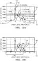
- FIG. 12Ais a plot of the objects in FIG. 11B in accordance with another embodiment
- FIG. 12Bis a plot of the objects in FIG. 11B in accordance with another embodiment
- FIG. 13Ais a plot of objects detected by the detection system of FIG. 6 in accordance with another embodiment
- FIG. 13Bis a plot of the objects of FIG. 13A in a lateral direction in accordance with another embodiment
- FIG. 14is a flow chart of a detection method in accordance with yet another embodiment.
- FIG. 15is a flow chart of another detection method in accordance with yet another embodiment.
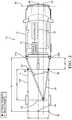
- FIG. 1illustrates a non-limiting example of a detection system 10 , hereafter referred to as the system 10 , installed on a host-vehicle 12 towing a trailer 14 .
- the system 10in an improvement over other detection systems because the system 10 estimates a trailer-length 16 and trailer-width 18 based on detected targets by filtering out erroneous detections.
- the system 10provides the technical benefit of enabling an adjustment of a blind zone of the host-vehicle 12 based on the size of the trailer 14 , improving safety for the driver and other vehicles.
- the trailer 14may be a cargo-trailer 14 A that may be an enclosed-type with solid panels, while in other embodiments of the cargo-trailer 14 A may be an open-type with an exposed frame. In the examples illustrated in FIGS. 1-5B the trailer 14 is a cargo-trailer 14 A.
- the system 10includes a ranging-sensor 20 .
- the ranging-sensor 20may be a radar-sensor or a lidar-sensor as will be understood by those in the art.
- the ranging-sensor 20is configured to detect objects 26 proximate to the host-vehicle 12 .
- the ranging-sensor 20is a radar-sensor.
- the radar-sensordetects the radar-signal that is reflected by the features of the cargo-trailer 14 A towed by the host-vehicle 12 .
- Typical radar-systems on vehiclesare capable of only determining a distance 28 (i.e. range) and azimuth-angle 30 to the target so may be referred to as a two-dimensional (2D) radar-system.
- the 2D radar-sensorincludes a left-sensor 22 A and a right-sensor 22 B. It is contemplated that the teachings presented herein are applicable to both 2D radar-systems and 3-D radar-systems with one or more sensor devices, i.e. multiple instances of the radar-sensor.
- the radar-sensoris generally configured to detect the radar-signal that may include data indicative of the detected-target present on the cargo-trailer 14 A.
- the detected-target present on the cargo-trailer 14 Amay be a feature of the cargo-trailer 14 A that is detected by the radar-sensor and tracked by a controller-circuit 32 , as will be described below.
- FIG. 2illustrates some of the types of targets located on the cargo-trailer 14 A detected by the radar-sensor.
- the radar-sensormay be configured to output a continuous or periodic data stream that includes a variety of signal characteristics associated with each target detected.
- the signal characteristicsmay include or be indicative of, but are not limited to, the range to the detected-target from the host-vehicle 12 , the azimuth-angle 30 to the detected-target relative to a host-vehicle-longitudinal-axis 34 , an amplitude (not shown) of the radar-signal, and a relative-velocity (not shown) of closure relative to the detected-target.
- a targetis generally detected because the radar-signal from the detected-target has sufficient signal strength to meet a predetermined threshold. That is, there may be targets that reflect the radar-signal, but the strength of the radar-signal is insufficient to be characterized as one of the detected-targets. Data that corresponds to a strong-target will generally be from consistent, non-intermittent signals. However, data that corresponds to a weak-target may be intermittent or have some substantial variability due to a low signal-to-noise ratio.
- the system 10also includes the controller-circuit 32 in communication with the ranging-sensor 20 .
- the ranging-sensor 20may be hardwired to the controller-circuit 32 through the host-vehicle's 12 electrical-system (not shown), or may communicate through a wireless network (not shown).
- the controller-circuit 32may include a processor (not shown) such as a microprocessor or other control circuitry such as analog and/or digital control circuitry including an application specific integrated circuit (ASIC) for processing data as should be evident to those in the art.
- ASICapplication specific integrated circuit
- the controller-circuit 32may include a memory (not specifically shown), including non-volatile memory, such as electrically erasable programmable read-only memory (EEPROM) for storing one or more routines, thresholds, and captured data.
- the one or more routinesmay be executed by the processor to perform steps for detecting the objects 26 based on signals received by the controller-circuit 32 from the ranging-sensor 20 as described herein.
- the controller-circuit 32is configured to determine that the cargo-trailer 14 A is being towed by the host-vehicle 12 (i.e. determine a trailer-presence) using the known methods of zero-range-rate (ZRR) detection of targets that will be understood by those in the art.
- ZRRzero-range-rate
- FIG. 3Aillustrates a plot of multiple radar-sensor data acquisition cycles that locate the ZRR targets along the host-vehicle-longitudinal-axis 34 and a host-vehicle-lateral-axis 36 .
- Each data acquisition cycleconsists of 64-detections per radar-sensor within a time interval of 50-milliseconds (50 ms), or a total of 128-detections for the two radar-sensors 22 A and 22 B.
- the datamay be filtered to reduce noise by any of the known filtering methods, and in FIG. 3A the data has been filtered to 64-detections for the two radar-sensors 22 A and 22 B.
- the origin of the plotis located at a center of the host-vehicle's 12 front-bumper.
- FIG. 3Billustrates a plot of the groups of the ZRR targets from FIG. 3A along the host-vehicle-longitudinal-axis 34 only.
- the groupsrepresent the ZRR targets detected in increments of 0.2 meters (0.2 m) extending from a rear-end of the host-vehicle 12 .
- every 10 points along the x-axis of the plot in FIG. 3Brepresents 2.0 m of distance 28 from the rear-end of the 5 m long host-vehicle 12 .
- the Y-axis in FIG. 3Brepresents the number of detections in a group.
- a total of 5 separate groups of detectionsare indicated by peaks in the plot and are labeled “A” through “E”, with group A being closest to the host-vehicle 12 and group E being the furthest from the host-vehicle 12 .
- Some of the groupsrepresent real-objects 38 and others represent phantom-objects 40 , as will be described below.
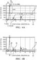
- FIGS. 4A-4Billustrate the plot of FIG. 3B with limits applied to filter out the phantom-objects 40 .
- FIG. 4Aalso includes the X-Y coordinates of the peaks of each group.
- the controller-circuit 32determines a trailer-distance 42 between the host-vehicle 12 and a front 44 of the cargo-trailer 14 A based on the distance 28 to a first-group 46 of objects 26 detected by the ranging-sensor 20 . That is, the controller-circuit 32 determines the distance 28 between a rear-end of the host-vehicle 12 and the front 44 of the cargo-trailer 14 A based on a first major group of ZRR targets closest in proximity to the host-vehicle 12 .
- the first-group 46is characterized by a first-distance 48 indicated by the ranging-sensor 20 .
- the controller-circuit 32further determines a peak-threshold 50 that represents detections of real-objects 38 detected by the ranging-sensor 20 , and a noise-threshold 52 that represents detections of phantom-objects 40 detected by the ranging-sensor 20 , with the peak-threshold 50 being greater than the noise-threshold 52 .
- the peak-threshold 50 and the noise-threshold 52may be defined by the user and in the example illustrated in FIG.
- the peak-threshold 50is set to 50% of the largest group (i.e. group B) which is indicated by a dashed line at 1495-detections.
- the noise-threshold 52is set to zero detections.
- the first-group 46 of objects 26is determined by a first-detection-count 54 that is closer in magnitude to the peak-threshold 50 than to the noise-threshold 52 , and is first closest in proximity to the host-vehicle 12 .
- Each of the groups A through Eare compared to both the peak-threshold 50 and to the noise-threshold 52 and a determination is made by the controller-circuit 32 whether each group is closer in magnitude to the peak-threshold 50 or closer to the noise-threshold 52 .
- the groups that are closest to the noise-threshold 52i.e. groups A, C, D and E in FIG. 4A ) are excluded from the determination of the first-group 46 , leaving only group B.
- group Bis classified as the first-group 46 and the first-distance 48 is determined to be 1.4 m from the rear-end of the host-vehicle 12 .
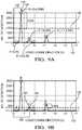
- the controller-circuit 32further determines an axle-distance 56 between the front 44 of the cargo-trailer 14 A and a trailer-axle 58 based on a second-group 60 of objects 26 detected by the ranging-sensor 20 , as illustrated in FIG. 4B . That is, the controller-circuit 32 determines the distance 28 between the rear-end of the host-vehicle 12 and the trailer-axle 58 of the cargo-trailer 14 A based on a second major group of ZRR targets behind the host-vehicle 12 that are farther from the host-vehicle 12 relative to the first-group 46 .
- the second-group 60is characterized by a second-distance 62 indicated by the ranging-sensor 20 .
- the controller-circuit 32sets the peak-threshold 50 to 50% of the largest group (i.e. group E) which is shown by the dashed line at 298-detections, and the noise-threshold 52 is set to zero detections.
- the second-group 60 of objects 26is determined by a second-detection-count 64 that is closer in magnitude to the peak-threshold 50 than to the noise-threshold 52 , and is second closest in proximity to the host-vehicle 12 .
- Each of the groups C, D, and Eare compared to both the peak-threshold 50 and to the noise-threshold 52 and a determination is made by the controller-circuit 32 whether each group is closer in magnitude to the peak-threshold 50 or closer to the noise-threshold 52 .
- the groups that are closest to the noise-threshold 52i.e. group D in FIG. 4B
- group Cis classified as the second-group 60 because group C is second closest to the host-vehicle 12
- the second-distance 62is determined to be 3 m from the rear-end of the host-vehicle 12 .
- the controller-circuit 32subtracts the first-distance 48 from the second-distance 62 to obtain the axle-distance 56 , which is 1.6 m in the example illustrated in FIG. 4B .
- the controller-circuit 32further determines the trailer-length 16 based on the trailer-distance 42 and the axle-distance 56 .
- the known-length of the cargo-trailer 14 A in the example illustrated in FIG. 4Bis 3.9 m and indicates an error of 0.22 m.
- the errormay be reduced by increasing the resolution (i.e. reducing the spacing) of the longitudinal groups along the host-vehicle-longitudinal-axis 34 , which are 0.2 m in the above example. Experimentation by the inventors has discovered that the 0.2 m spacing provides an adequate balance of memory utilization requirements and measurement error.
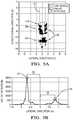
- FIG. 5Billustrates a plot of the groups of the ZRR targets from FIG. 5A along the host-vehicle-lateral-axis 36 transverse to the host-vehicle-longitudinal-axis 34 .
- the groupsrepresent the ZRR targets detected in increments of 0.1 m extending from a centerline 68 of the host-vehicle 12 in a lateral direction. For example, every 10 points along the x-axis of the plot in FIG. 5B represents 1.0 m of distance 28 from the centerline 68 of the host-vehicle 12 .
- the centerline 68is indicated by zero on the Y-axis of FIGS. 5 A- 5 B and is parallel with the host-vehicle-longitudinal-axis 34 .
- the Y-axis in FIG. 5Brepresents the number of detections in a group.
- the controller-circuit 32further determines the trailer-width 18 of the trailer 14 by the distance 28 between a third-group 72 and a fourth-group 74 of objects 26 detected by the ranging-sensor 20 .
- the third-group 72is characterized by a first-lateral-offset 76 relative to the centerline 68 of the host-vehicle 12 as indicated by the ranging-sensor 20
- the fourth-group 74is characterized by a second-lateral-offset 78 relative to the centerline 68 of the host-vehicle 12 as indicated by the ranging-sensor 20 .
- the third-group 72 and the fourth-group 74are identified by the controller-circuit 32 as the groups having the greatest number of ZRR detections on a left-side and a right-side of the centerline 68 , and no filtering of the phantom-objects 40 is required.
- the estimated trailer-width 18is 1.5 m compared to the known-width of 1.52 m, and indicates an error of 0.02 m.
- the errormay be reduced by increasing the resolution (i.e. reducing the spacing) of the lateral groups, which are 0.1 m in the above example. Experimentation by the inventors has discovered that the 0.1 m spacing provides an adequate balance of memory utilization requirements and measurement error.
- the system 10may exclude any detections that are beyond a typical maximum trailer-dimension of 2.44 m ⁇ 15.24 m.
- FIG. 6illustrates another embodiment of a detection system 110 , hereafter referred to as the system 110 , installed on a host-vehicle 112 towing a trailer 114 .
- the system 110is an improvement over other detection systems because the system 110 determines a trailer-type 113 , a trailer-length 116 and a trailer-width 118 based on detected targets by filtering out erroneous detections.
- the trailer 114may be a cargo-trailer 114 A that may be an enclosed-type with solid panels, or may be an open-type with an exposed frame.
- the trailer 114may also be a boat-trailer 114 B.
- the boat-trailer 114 Bmay, or may not, be carrying a boat, and may present a unique ranging-sensor-signal or signal-pattern compared to the cargo-trailer 114 A that may further assist in a determination of the type of trailer 114 being towed by the host-vehicle 112 .
- the system 110includes a ranging-sensor 120 .
- the ranging-sensor 120may be a radar-sensor 122 or a lidar-sensor 124 as will be understood by those in the art.
- the ranging-sensor 120is configured to detect objects 126 proximate to the host-vehicle 112 .
- the ranging-sensor 120is the radar-sensor 122 .
- the radar-sensor 122detects a radar-signal (not specifically shown) that is reflected by features of the trailer 114 towed by the host-vehicle 112 .
- radar-systems on vehiclesare capable of only determining a distance 128 (i.e.
- the 2D radar-sensor 122includes a left-sensor 122 A and a right-sensor 122 B. It is contemplated that the teachings presented herein are applicable to both 2D radar-systems and 3-D radar-systems with one or more sensor devices, i.e. multiple instances of the radar-sensor 122 .
- the radar-sensor 122is generally configured to detect the radar-signal that may include data indicative of the detected-target present on the trailer 114 .
- the detected-target present on the trailer 114may be a feature of the trailer 114 that is detected by the radar-sensor 122 and tracked by a controller-circuit 132 , as will be described below.
- FIG. 7illustrates some of the various types of targets located on the trailer 114 detected by the radar-sensor 122 .
- the radar-sensor 122may be configured to output a continuous or periodic data stream that includes a variety of signal characteristics associated with each target detected.
- the signal characteristicsmay include or be indicative of, but are not limited to, the range to the detected-target from the host-vehicle 112 , the azimuth-angle 130 to the detected-target relative to a host-vehicle-longitudinal-axis 134 , an amplitude (not shown) of the radar-signal, and a relative-velocity (not shown) of closure relative to the detected-target.
- a targetis generally detected because the radar-signal from the detected-target has sufficient signal strength to meet some predetermined threshold. That is, there may be targets that reflect the radar-signal, but the strength of the radar-signal is insufficient to be characterized as one of the detected-targets. Data that corresponds to a strong-target will generally be from consistent, non-intermittent signals. However, data that corresponds to a weak-target may be intermittent or have some substantial variability due to a low signal-to-noise ratio.
- the system 110also includes the controller-circuit 132 in communication with the ranging-sensor 120 .
- the ranging-sensor 120may be hardwired to the controller-circuit 132 through the host-vehicle's 112 electrical-system (not shown), or may communicate through a wireless network (not shown).
- the controller-circuit 132may include a processor (not shown) such as a microprocessor or other control circuitry such as analog and/or digital control circuitry including an application specific integrated circuit (ASIC) for processing data as should be evident to those in the art.
- ASICapplication specific integrated circuit
- the controller-circuit 132may include a memory (not specifically shown), including non-volatile memory, such as electrically erasable programmable read-only memory (EEPROM) for storing one or more routines, thresholds, and captured data.
- the one or more routinesmay be executed by the processor to perform steps for detecting the objects 126 based on signals received by the controller-circuit 132 from the ranging-sensor 120 as described herein.
- the controller-circuit 132is configured to determine that the trailer 114 is being towed by the host-vehicle 112 (i.e. determine a trailer-presence) using the known methods of zero-range-rate (ZRR) detection of targets that will be understood by those in the art.
- ZRRzero-range-rate
- FIG. 8Aillustrates a plot of multiple radar-sensor 122 data acquisition cycles that locate the ZRR targets along the host-vehicle-longitudinal-axis 134 and a host-vehicle-lateral-axis 136 .
- Each data acquisition cycleconsists of 64-detections per radar-sensor 122 within a time interval of 50-milliseconds (50 ms), or a total of 128-detections for the two radar-sensors 122 A and 122 B.
- the datamay be filtered to reduce noise by any of the known filtering methods, and in FIG. 8A has been filtered to 64-detections for the two radar-sensors 122 A and 122 B.
- the origin of the plotis located at a center of the host-vehicle's 112 front-bumper.
- FIG. 8Billustrates a plot of the groups of the ZRR targets from FIG. 8A along the host-vehicle-longitudinal-axis 134 only.
- the groupsrepresent the ZRR targets detected in increments of 0.2 meters (0.2 m) extending from a rear-end of the host-vehicle 112 .
- every 10 points along the x-axis of the plot in FIG. 8Brepresents 2.0 m of distance 128 from the rear-end of the 5 m long host-vehicle 112 .
- the Y-axis in FIG. 8Brepresents the number of detections in a group.
- a total of 5 separate groups of detectionsare indicated by peaks in the plot and are labeled “A” through “E”, with group A being closest to the host-vehicle 112 and group E being the furthest from the host-vehicle 112 .
- Some of the groupsrepresent real-objects 138 and others represent phantom-objects 140 , as will be described below.
- FIGS. 9A-9Billustrate the plot of FIG. 8B with limits applied to filter out the phantom-objects 140 .
- FIG. 9Aalso includes the X-Y coordinates of the peaks of each group.
- the controller-circuit 132determines a trailer-distance 142 between the host-vehicle 112 and a front 144 of the trailer 114 based on the distance 128 to a first-group 146 of objects 126 detected by the ranging-sensor 120 . That is, the controller-circuit 132 determines the distance 128 between a rear-end of the host-vehicle 112 and the front 144 of the trailer 114 based on a first major group of ZRR targets closest to the host-vehicle 112 .
- the first-group 146is characterized by a first-distance 148 indicated by the ranging-sensor 120 .
- the controller-circuit 132further determines a peak-threshold 150 that represents detections of real-objects 138 detected by the ranging-sensor 120 , and a noise-threshold 152 that represents detections of phantom-objects 140 detected by the ranging-sensor 120 , with the peak-threshold 150 being greater than the noise-threshold 152 .
- the peak-threshold 50 and the noise-threshold 52may be defined by the user and in the example illustrated in FIG.
- the peak-threshold 150is set to 50% of the largest group (i.e. group B) which is indicated by a dashed line at 1495-detections, and the noise-threshold 152 is set to zero-detections.
- the first-group 146 of objects 126is determined by a first-detection-count 154 that is closer in magnitude to the peak-threshold 150 than to the noise-threshold 152 , and is first closest in proximity to the host-vehicle 112 .
- Each of the groups A through Eare compared to both the peak-threshold 150 and to the noise-threshold 152 and a determination is made by the controller-circuit 132 whether each group is closer in magnitude to the peak-threshold 150 or to the noise-threshold 152 .
- the groups that are closest to the noise-threshold 152i.e. groups A, C, D and E in FIG. 9A ) are excluded from the determination of the first-group 146 , leaving only group B.
- group Bis classified as the first-group 146 and the first-distance 148 is determined to be 1.4 m from the rear-end of the host-vehicle 12 .
- the controller-circuit 132determines the trailer-type 113 being towed by the host-vehicle 112 based on a comparison of the trailer-distance 142 to a distance-threshold 155 .
- the trailer-type 113is characterized as a cargo-trailer 114 A in accordance with a determination that the trailer-distance 142 is less than the distance-threshold 155 that is in a range of 2 m to 3 m.
- the trailer-type 113is characterized as the boat-trailer 114 B in accordance with the determination that the trailer-distance 142 is greater than the distance-threshold 155 .
- the distance-threshold 155 of 3 mprovides adequate results in distinguishing between the cargo-trailer 114 A and the boat-trailer 114 B.
- the controller-circuit 132further determines an axle-distance 156 between the front 144 of the trailer 114 and a trailer-axle 158 based on a second-group 160 of objects 126 detected by the ranging-sensor 120 , as illustrated in FIG. 9B . That is, the controller-circuit 132 determines the distance 128 between the rear-end of the host-vehicle 112 and the trailer-axle 158 of the cargo-trailer 114 A based on a second major group of ZRR targets behind the host-vehicle 112 that are farther from the host-vehicle 112 relative to the first-group 146 .
- the second-group 160is characterized by a second-distance 162 indicated by the ranging-sensor 120 .
- the controller-circuit 132sets the peak-threshold 150 to 50% of the largest group (i.e. group E) which is indicated by the dashed line at 298-detections, and the noise-threshold 152 is set to zero-detections.
- the second-group 160 of objects 126is determined by a second-detection-count 164 that is closer in magnitude to the peak-threshold 150 than to the noise-threshold 152 , and is second closest in proximity to the host-vehicle 112 .
- Each of the groups C, D, and Eare compared to both the peak-threshold 150 and to the noise-threshold 152 and a determination is made by the controller-circuit 132 whether each group is closer in magnitude to the peak-threshold 150 or closer to the noise-threshold 152 .
- the groups that are closest to the noise-threshold 152i.e. group D in FIG. 9B ) are excluded from the determination of the second-group 160 , leaving only groups C and E.
- group Cis classified as the second-group 160 because group C is second closest to the host-vehicle 112 , and the second-distance 162 is determined to be 3 m from the rear-end of the host-vehicle 112 .
- the controller-circuit 132subtracts the first-distance 148 from the second-distance 162 to obtain the axle-distance 156 , which is 1.6 m in the example illustrated in FIG. 9B .
- the controller-circuit 132further determines a cargo-trailer-length 116 A of the cargo-trailer 114 A based on the trailer-distance 142 and the axle-distance 156 .
- the known-length of the cargo-trailer 114 A in the example illustrated in FIG. 9Bis 3.9 m and indicates an error of 0.22 m.
- the errormay be reduced by increasing the resolution (i.e. reducing the spacing) of the longitudinal groups along the host-vehicle-longitudinal-axis 134 , which are 0.2 m in the above example. Experimentation by the inventors has discovered that the 0.2 m spacing provides an adequate balance of memory utilization requirements and measurement error.
- FIG. 10Billustrates a plot of the groups of the ZRR targets from FIG. 10A along the host-vehicle-lateral-axis 136 transverse to the host-vehicle-longitudinal-axis 134 .
- the groupsrepresent the ZRR targets detected in increments of 0.1 m extending from a centerline 168 of the host-vehicle 112 in a lateral direction.
- every 10-points along the x-axis of the plot in FIG. 10Brepresents 1.0 m of distance 128 from the centerline 168 host-vehicle 112 .
- the centerline 168is indicated by zero on the Y-axis of FIGS. 10A-10B and is parallel with the host-vehicle-longitudinal-axis 134 .
- the Y-axis in FIG. 10Brepresents the number of detections in a group.
- the controller-circuit 132further determines a trailer-width 118 of the cargo-trailer 114 A by the distance 128 between a third-group 172 and a fourth-group 174 of objects 126 detected by the ranging-sensor 120 .
- the third-group 172is characterized by a first-lateral-offset 176 relative to the centerline 168 of the host-vehicle 112 as indicated by the ranging-sensor 120 and the fourth-group 174 is characterized by a second-lateral-offset 178 relative to the centerline 168 of the host-vehicle 112 as indicated by the ranging-sensor 120 .
- the third-group 172 and the fourth-group 174are identified by the controller-circuit 132 as the groups having the greatest number of detections on a left-side and a right-side of the centerline 168 , and no filtering of phantom-objects 140 is required.
- the estimated trailer-width 118is 1.5 m compared to the known-width of 1.52 m, and indicates an error of 0.02 m.
- the errormay be reduced by increasing the resolution (i.e. reducing the spacing) of the lateral groups, which are 0.1 m in the above example. Experimentation by the inventors has discovered that the 0.1 m spacing provides an adequate balance of memory utilization requirements and measurement error.
- FIG. 11Aillustrates a plot of multiple radar-sensor 122 data acquisition cycles for the boat-trailer 114 B that locate the ZRR targets along the host-vehicle-longitudinal-axis 134 and the host-vehicle-lateral-axis 136 .
- FIG. 11Billustrates a plot of the groups of the ZRR targets from FIG. 11A along the host-vehicle-longitudinal-axis 134 only.
- the controller-circuit 132further determines an end-distance 180 to an end of the boat-trailer 114 B based on a last-group 182 of objects 126 detected by the ranging-sensor 120 .
- the last-group 182is characterized by a last-distance 184 indicated by the ranging-sensor 120 and the controller-circuit 132 determines a boat-trailer-length 116 B based on the end-distance 180 .
- FIGS. 12A-12Billustrate the plot of FIG. 11B with limits applied to filter out the phantom-objects 140 just as described for the cargo-trailer 114 A above.
- FIG. 12Aalso includes the X-Y coordinates of the peaks of each group.
- the controller-circuit 132determines the trailer-distance 142 between the host-vehicle 112 and the front 144 of the boat-trailer 114 B based on the distance 128 to the first-group 146 of objects 126 detected by the ranging-sensor 120 .
- the controller-circuit 132determines the distance 128 between a rear-end of the host-vehicle 112 and the front 144 of the boat-trailer 114 B based on the first major group of ZRR targets closest to the host-vehicle 112 .
- the first-group 146is characterized by the first-distance 148 indicated by the ranging-sensor 120 .
- the controller-circuit 132further determines the peak-threshold 150 that represents detections of real-objects 138 detected by the ranging-sensor 120 , and the noise-threshold 152 that represents detections of phantom-objects 140 detected by the ranging-sensor 120 , with the peak-threshold 150 being greater than the noise-threshold 152 .
- the peak-threshold 150is set to 50% of the largest group (i.e. group B) which is indicated by a dashed line at 4031-detections, and the noise-threshold 152 is set to zero-detections.
- the first-group 146 of objects 126is determined by the first-detection-count 154 that is closer in magnitude to the peak-threshold 150 than to the noise-threshold 152 , and is first closest in proximity to the host-vehicle 112 .
- Each of the groups A through Gare compared to both the peak-threshold 150 and to the noise-threshold 152 and the determination is made by the controller-circuit 132 whether each group is closer in magnitude to the peak-threshold 150 or to the noise-threshold 152 .
- the groups that are closest to the noise-threshold 152i.e. groups A, E and G in FIG.
- group Bis classified as the first-group 146 and the first-distance 148 is determined to be 3.8 m from the rear-end of the host-vehicle 12 , which is located greater than the distance-threshold 155 of 3 m behind the host-vehicle 112 and determined to be the boat-trailer 114 B.
- the controller-circuit 32further determines the last-group 182 of objects 126 (group-F) determined by a last-detection-count 186 that is closer in magnitude to the peak-threshold 150 than to the noise-threshold 152 and is farthest in proximity to the host-vehicle 112 , as illustrated in FIG. 12B .
- the controller-circuit 132sets the peak-threshold 150 to 50% of the largest group (i.e. group D) which is indicated by the dashed line at 2329-detections, and the noise-threshold 152 is set to zero-detections.
- the last-group 182 of objects 126is determined by the last-detection-count 186 that is closer in magnitude to the peak-threshold 150 than to the noise-threshold 152 , and is farthest in proximity to the host-vehicle 112 .
- Each of the groups C, through Gare compared to both the peak-threshold 150 and to the noise-threshold 152 and a determination is made by the controller-circuit 132 whether each group is closer in magnitude to the peak-threshold 150 or closer to the noise-threshold 152 .
- the groups that are closest to the noise-threshold 152i.e. groups E and G in FIG.
- group Fis classified as the last-group 182 because group F is farthest from the host-vehicle 112 , and the last-distance 184 is determined to be 7.2 m from the rear-end of the host-vehicle 112 .
- the boat-trailer-length 116 Bis estimated to be 7.2 m compared to the known-length of 7.2 m and indicates an error of 0.0 m.
- FIG. 13Billustrates a plot of the groups of the ZRR targets from FIG. 13A along the host-vehicle-lateral-axis 136 transverse to the host-vehicle-longitudinal-axis 134 .
- the groupsrepresent the ZRR targets detected in increments of 0.1 m extending from the centerline 168 of the host-vehicle 112 in the lateral direction. For example, every 10-points along the x-axis of the plot in FIG. 13B represents 1.0 m of distance 128 from the centerline 168 host-vehicle 112 .
- the centerline 168is indicated by zero on the Y-axis of FIGS. 13A-13B and is parallel with the host-vehicle-longitudinal-axis 134 .
- the Y-axis in FIG. 13Brepresents the number of detections in a group.
- the controller-circuit 132further determines the trailer-width 118 of the boat-trailer 114 B by the distance 128 between the third-group 172 and the fourth-group 174 of objects 126 detected by the ranging-sensor 120 .
- the third-group 172is characterized by the first-lateral-offset 176 relative to the centerline 168 of the host-vehicle 112 as indicated by the ranging-sensor 120
- the fourth-group 174is characterized by the second-lateral-offset 178 relative to the centerline 168 of the host-vehicle 112 as indicated by the ranging-sensor 120 .
- the third-group 172 and the fourth-group 174are identified by the controller-circuit 132 as the groups having the greatest number of detections on the left-side and the right-side of the centerline 168 , and no filtering of phantom-objects 140 is required.
- the estimated trailer-width 118is 1.7 m compared to the known-width of 1.9 m, and indicates an error of 0.2 m.
- the errormay be reduced by increasing the resolution (i.e. reducing the spacing) of the lateral groups, which are 0.1 m in the above example. Experimentation by the inventors has discovered that the 0.1 m spacing provides an adequate balance of memory utilization requirements and measurement error.
- the system 110may exclude any detections that are beyond a typical maximum trailer-dimension of 2.44 m ⁇ 15.24 m.
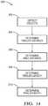
- FIG. 14is a flow chart that illustrates yet another embodiment of a detection method 200 , hereafter referred to as the method 200 , of operating a detection system 10 , hereafter referred to as the system 10 , and installed on a host-vehicle 12 towing a trailer 14 .
- the method 200in an improvement over other detection methods because the method 200 estimates a trailer-length 16 and trailer-width 18 based on detected targets by filtering out erroneous detections.
- the trailer 14may be a cargo-trailer 14 A that may be an enclosed-type with solid panels, or may be an open-type with an exposed frame. In the examples illustrated in FIGS. 1-5B the trailer 14 is the cargo-trailer 14 A.
- Step 202DETECT OBJECTS, includes detecting, with a ranging-sensor 20 , objects 26 proximate to the host-vehicle 12 .
- FIG. 1illustrates the system 10 that includes the ranging-sensor 20 and a controller-circuit 32 in communication with the ranging-sensor 20 that tracks the objects 26 as described above.
- Step 204DETERMINE TRAILER-DISTANCE, INCLUDES determining, with the controller-circuit 32 , that the trailer 14 is being towed by the host-vehicle 12 and determining a trailer-distance 42 .
- the controller-circuituses the known method of zero range rate (ZRR) detections, as described above, to determine a distance 28 to a front 44 of a cargo-trailer 14 A based on a first-group 46 of objects 26 illustrated in FIG. 4A .
- ZRRzero range rate
- Step 206DETERMINE AXLE-DISTANCE, includes determining an axle-distance 56 between the front 44 of the cargo-trailer 14 A and a trailer-axle 58 based on a second-group 60 of objects 26 , as illustrated in FIG. 4B .
- Step 208DETERMINE TRAILER-LENGTH, includes determining, with the controller-circuit 32 , a trailer-length 16 based on the trailer-distance 42 and the axle-distance 56 .
- Step 210DETERMINE TRAILER-WIDTH, includes determining, with the controller-circuit 32 , a trailer-width 18 .
- FIG. 5Billustrates a plot of the groups of the ZRR targets from FIG. 5A along the host-vehicle-lateral-axis 36 transverse to the host-vehicle-longitudinal-axis 34 .
- the controller-circuit 32further determines the trailer-width 18 of the cargo-trailer 14 A by the distance 28 between a third-group 72 and a fourth-group 74 of objects 26 detected by the ranging-sensor 20 .
- FIG. 15is a flow chart illustrating yet another embodiment of a detection method 300 , hereafter referred to as the method 300 , of operating a detection system 110 , hereafter referred to as the system 110 , installed on a host-vehicle 112 towing a trailer 114 .
- the system 110in an improvement over other detection systems because the system 110 determines a trailer-type 113 , a trailer-length 116 and a trailer-width 118 based on detected targets by filtering out erroneous detections.
- the trailer 114may be a cargo-trailer 114 A that may be an enclosed-type with solid panels, or may be an open-type with an exposed frame.
- the trailer 114may also be a boat-trailer 114 B.
- the boat-trailer 114 Bmay, or may not, be carrying a boat, and may present a unique ranging-sensor-signal compared to the cargo-trailer 114 A that may further assist in a determination of the type of trailer 114 being towed by the host-vehicle 112 .
- Step 302DETECT OBJECTS, includes detecting, with a ranging-sensor 120 , objects 126 proximate to the host-vehicle 112 .
- FIG. 6illustrates the system 110 that includes the ranging-sensor 120 and a controller-circuit 132 in communication with the ranging-sensor 120 that tracks the objects 126 as described above.
- Step 304DETERMINE TRAILER-DISTANCE, includes determining, with the controller-circuit 132 , that the trailer 114 is being towed by the host-vehicle 112 , and determining a trailer-distance 142 between the host-vehicle 112 and a front 144 of the trailer 114 based on a first-group 146 of objects 126 illustrated in FIG. 9A .
- Step 306DETERMINE TRAILER-TYPE, includes determining, with the controller-circuit 132 , a trailer-type 113 being towed by the host-vehicle 112 based on a comparison of the trailer-distance 142 to a predetermined distance-threshold 155 .
- the trailer-type 113is characterized as a cargo-trailer 114 A in accordance with a determination that the trailer-distance 142 is less than the distance-threshold 155 that is in a range of 2 m to 3 m.
- the trailer-type 113is characterized as the boat-trailer 114 B in accordance with the determination that the trailer-distance 142 is greater than the distance-threshold 155 .
- Step 308DETERMINE AXLE-DISTANCE, includes determining, with the controller-circuit 132 , an axle-distance 156 of the cargo-trailer 114 A.
- the controller-circuit 132further determines the axle-distance 156 between the front 144 of the trailer 114 and a trailer-axle 158 based on a second-group 160 of objects 126 detected by the ranging-sensor 120 , as illustrated in FIG. 9B .
- Step 310DETERMINE CARGO-TRAILER-LENGTH, includes determining, with the controller-circuit 132 , a cargo-trailer-length 116 A of the cargo-trailer 114 A based on the trailer-distance 142 and the axle-distance 156 .
- Step 312DETERMINE TRAILER-WIDTH, includes determining, with the controller-circuit 132 , a trailer-width 118 of the cargo-trailer 114 A.
- FIG. 10Billustrates a plot of the groups of the ZRR targets from FIG. 10A along the host-vehicle-lateral-axis 136 transverse to the host-vehicle-longitudinal-axis 134 .
- the controller-circuit 132further determines the trailer-width 118 of the cargo-trailer 114 A by the distance 128 between a third-group 172 and a fourth-group 174 of objects 126 detected by the ranging-sensor 120 .
- Step 314DETERMINE END-DISTANCE, includes determining, with the controller-circuit 132 , an end-distance 180 to an end of the boat-trailer 114 B.
- FIG. 11Aillustrates a plot of multiple radar-sensor 122 data acquisition cycles for the boat-trailer 114 B that locate the ZRR targets along the host-vehicle-longitudinal-axis 134 and the host-vehicle-lateral-axis 136 .
- FIG. 11Billustrates a plot of the groups of the ZRR targets from FIG. 11A along the host-vehicle-longitudinal-axis 134 only.
- the controller-circuit 132further determines the end-distance 180 to the end of the boat-trailer 114 B based on a last-group 182 of objects 126 detected by the ranging-sensor 120 .
- the last-group 182is characterized by a last-distance 184 indicated by the ranging-sensor 120 and the controller-circuit 132 determines a boat-trailer-length 116 B based on the end-distance 180 , as illustrated in FIG. 12B .
- Step 316DETERMINE BOAT-TRAILER-LENGTH, includes determining, with the controller-circuit 132 , the boat-trailer-length 116 B.
- the controller-circuit 132further determines the last-group 182 of objects 126 (group-F) determined by a last-detection-count 186 that is closer in magnitude to the peak-threshold 150 than to the noise-threshold 152 and is farthest in proximity to the host-vehicle 112 , as illustrated in FIG. 12B .
- Step 318DETERMINE TRAILER-WIDTH, includes determining, with the controller-circuit 132 , the trailer-width 118 of the boat-trailer 114 B.
- FIG. 13Billustrates a plot of the groups of the ZRR targets from FIG. 13A along the host-vehicle-lateral-axis 136 transverse to the host-vehicle-longitudinal-axis 134 .
- the controller-circuit 132further determines the trailer-width 118 of the boat-trailer 114 B by the distance 128 between the third-group 172 and the fourth-group 174 of objects 126 detected by the ranging-sensor 120 .
- the system 110may exclude any detections that are beyond a typical maximum trailer-dimension of 2.44 m ⁇ 15.24 m.
- a detection system 10(the system 10 ), a controller-circuit 32 for the system 10 , and a method 200 of operating the system 10 are provided.
- the system 10is an improvement over other detection systems because the system 10 estimates the trailer-length 16 and the trailer-width 18 by filtering out the phantom-objects 40 .
Landscapes
- Engineering & Computer Science (AREA)
- Radar, Positioning & Navigation (AREA)
- Remote Sensing (AREA)
- Physics & Mathematics (AREA)
- Computer Networks & Wireless Communication (AREA)
- General Physics & Mathematics (AREA)
- Electromagnetism (AREA)
- Transportation (AREA)
- Mechanical Engineering (AREA)
- Radar Systems Or Details Thereof (AREA)
- Length Measuring Devices With Unspecified Measuring Means (AREA)
Abstract
Description
TL=Lo+L1+L1*C
TL=1.4 m+1.6 m+(1.6 m*0.7)=4.12 m
TL=Lo+L1+L1*C
TL=1.4 m+1.6 m+(1.6 m*0.7)=4.12 m
TL=Lo+L1+L1*C
TL=Lo+L1+L1*C
Claims (44)
Priority Applications (4)
| Application Number | Priority Date | Filing Date | Title |
|---|---|---|---|
| US15/840,321US10955540B2 (en) | 2017-12-01 | 2017-12-13 | Detection system |
| EP18208733.8AEP3502739B1 (en) | 2017-12-01 | 2018-11-27 | Detection systemfor determining a trailer length |
| EP22172712.6AEP4060372B1 (en) | 2017-12-01 | 2018-11-27 | Detection system |
| US17/157,301US11474224B2 (en) | 2017-12-01 | 2021-01-25 | Detection system |
Applications Claiming Priority (2)
| Application Number | Priority Date | Filing Date | Title |
|---|---|---|---|
| US201762593418P | 2017-12-01 | 2017-12-01 | |
| US15/840,321US10955540B2 (en) | 2017-12-01 | 2017-12-13 | Detection system |
Related Child Applications (1)
| Application Number | Title | Priority Date | Filing Date |
|---|---|---|---|
| US17/157,301ContinuationUS11474224B2 (en) | 2017-12-01 | 2021-01-25 | Detection system |
Publications (2)
| Publication Number | Publication Date |
|---|---|
| US20190170867A1 US20190170867A1 (en) | 2019-06-06 |
| US10955540B2true US10955540B2 (en) | 2021-03-23 |
Family
ID=64556684
Family Applications (2)
| Application Number | Title | Priority Date | Filing Date |
|---|---|---|---|
| US15/840,321Active2038-12-20US10955540B2 (en) | 2017-12-01 | 2017-12-13 | Detection system |
| US17/157,301ActiveUS11474224B2 (en) | 2017-12-01 | 2021-01-25 | Detection system |
Family Applications After (1)
| Application Number | Title | Priority Date | Filing Date |
|---|---|---|---|
| US17/157,301ActiveUS11474224B2 (en) | 2017-12-01 | 2021-01-25 | Detection system |
Country Status (2)
| Country | Link |
|---|---|
| US (2) | US10955540B2 (en) |
| EP (2) | EP3502739B1 (en) |
Cited By (6)
| Publication number | Priority date | Publication date | Assignee | Title |
|---|---|---|---|---|
| US11092668B2 (en) | 2019-02-07 | 2021-08-17 | Aptiv Technologies Limited | Trailer detection system and method |
| US11231716B2 (en)* | 2020-01-28 | 2022-01-25 | GM Global Technology Operations LLC | Method and apparatus for determining trailer dimensions in a motor vehicle |
| US11408995B2 (en) | 2020-02-24 | 2022-08-09 | Aptiv Technologies Limited | Lateral-bin monitoring for radar target detection |
| US20220258766A1 (en)* | 2021-02-17 | 2022-08-18 | Robert Bosch Gmbh | Method for ascertaining a spatial orientation of a trailer |
| US11435466B2 (en) | 2018-10-08 | 2022-09-06 | Aptiv Technologies Limited | Detection system and method |
| US11474224B2 (en) | 2017-12-01 | 2022-10-18 | Aptiv Technologies Limited | Detection system |
Families Citing this family (12)
| Publication number | Priority date | Publication date | Assignee | Title |
|---|---|---|---|---|
| DE102017112786A1 (en)* | 2017-06-09 | 2018-12-13 | Valeo Schalter Und Sensoren Gmbh | Method for characterizing a trailer attached to a towing vehicle, driver assistance system and trailer |
| US10845478B2 (en)* | 2018-09-07 | 2020-11-24 | GM Global Technology Operations LLC | Micro-doppler apparatus and method for trailer detection and tracking |
| US10942271B2 (en)* | 2018-10-30 | 2021-03-09 | Tusimple, Inc. | Determining an angle between a tow vehicle and a trailer |
| CN116184417A (en) | 2018-12-10 | 2023-05-30 | 北京图森智途科技有限公司 | Trailer pinch angle measuring method and device and vehicle |
| US11221399B2 (en)* | 2018-12-12 | 2022-01-11 | Waymo Llc | Detecting spurious objects for autonomous vehicles |
| CN111319629B (en) | 2018-12-14 | 2021-07-16 | 北京图森智途科技有限公司 | A method, device and system for forming an autonomous vehicle fleet |
| US11105896B2 (en)* | 2019-04-17 | 2021-08-31 | Valeo Radar Systems, Inc. | Trailer detection and estimation system and related techniques |
| JP7152355B2 (en)* | 2019-05-20 | 2022-10-12 | 株式会社Soken | Obstacle detection device and obstacle detection method |
| WO2021007427A1 (en)* | 2019-07-09 | 2021-01-14 | Continental Automotive Systems, Inc. | Trailer body length detection system |
| US11525911B2 (en)* | 2019-11-14 | 2022-12-13 | GM Global Technology Operations LLC | Radar system control to perform cross-traffic management in a vehicle with a trailer |
| AU2021203567A1 (en) | 2020-06-18 | 2022-01-20 | Tusimple, Inc. | Angle and orientation measurements for vehicles with multiple drivable sections |
| US20250060454A1 (en)* | 2023-08-18 | 2025-02-20 | Torc Robotics, Inc. | Systems and methods of monitoring and control for trailer dynamics |
Citations (89)
| Publication number | Priority date | Publication date | Assignee | Title |
|---|---|---|---|---|
| US5361072A (en) | 1992-02-28 | 1994-11-01 | Codar Ocean Sensors, Ltd. | Gated FMCW DF radar and signal processing for range/doppler/angle determination |
| US5517196A (en) | 1992-08-14 | 1996-05-14 | Pakett; Allan G. | Smart blind spot sensor with object ranging |
| JPH09267762A (en) | 1996-04-01 | 1997-10-14 | Mitsubishi Motors Corp | Trailer wheel steering control method and apparatus |
| JP2002068032A (en) | 2000-08-24 | 2002-03-08 | Isuzu Motors Ltd | Detector for trailer connection angle |
| DE10312548B3 (en) | 2003-03-21 | 2004-05-19 | Audi Ag | Vehicle with two symmetrical parking and reversing sensors at rear, employs them when trailer is attached, to detect its relative angle |
| DE10325192A1 (en) | 2003-06-04 | 2005-01-05 | Daimlerchrysler Ag | Detecting positional changes of trailer connected to vehicle relative to vehicle, involves determining rotation angle change parameter using distance change parameter detected by sensor unit |
| CN1559842A (en) | 1999-06-30 | 2005-01-05 | ����-��ϣ�ɷݹ�˾ | Method and device for stabilizing a vehicle |
| US6933837B2 (en) | 2002-01-25 | 2005-08-23 | Altra Technologies Incorporated | Trailer based collision warning system and method |
| DE102004059596A1 (en) | 2004-12-09 | 2006-06-14 | Daimlerchrysler Ag | Bending angle determining method for use between tractor and trailer of motor vehicle combination, involves subjecting position data, which is determined by sensor, to filtration with model data for identifying object of trailer or tractor |
| WO2006114206A1 (en) | 2005-04-28 | 2006-11-02 | Daimlerchrysler Ag | Distance detection system for a towing vehicle and method for operating said distance detection system |
| DE102005042729A1 (en) | 2005-09-05 | 2007-03-08 | Valeo Schalter Und Sensoren Gmbh | Motor vehicle radar system with horizontal and vertical resolution |
| DE102006028625A1 (en) | 2006-04-28 | 2007-10-31 | Daimlerchrysler Ag | Vehicle e.g. passenger car, measuring method, involves carrying out information exchange between sensor and driver assistance system, where exchange contains transmission of measuring data and/or vehicle parameter from sensor to vehicle |
| US20080169938A1 (en) | 2007-01-17 | 2008-07-17 | Visteon Global Technologies, Inc. | Variable blind spot warning system |
| US20080186204A1 (en) | 2007-02-02 | 2008-08-07 | Buckley Stephen J | Trailer detection system |
| CN101268383A (en) | 2005-08-04 | 2008-09-17 | 埃森技术Enc株式会社 | Intelligent video surveillance system and method of communicating with automatic tracking radar system |
| GB2447672A (en) | 2007-03-21 | 2008-09-24 | Ford Global Tech Llc | Vehicle manoeuvring aids |
| US20090005932A1 (en) | 2007-06-27 | 2009-01-01 | Gm Global Technology Operations, Inc. | Trailer articulation angle estimation |
| EP2045155A1 (en) | 2007-10-05 | 2009-04-08 | Ford Global Technologies, LLC | A control system for a vehicle and trailer combination |
| US20100109938A1 (en) | 2007-01-31 | 2010-05-06 | Gordon Kenneth Andrew Oswald | Adaptive radar |
| DE102009007990A1 (en) | 2009-02-07 | 2010-08-12 | Hella Kgaa Hueck & Co. | Trailer data determining method, involves utilizing distance sensors provided in rear region of towing vehicle, for determining trailer data, and determining and processing different distances between vehicle and trailer |
| US20110140872A1 (en) | 2009-12-14 | 2011-06-16 | Delphi Technologies, Inc. | Vehicle Lane Departure Warning System Having Trailer Mode and Method |
| US20120041659A1 (en) | 2010-08-13 | 2012-02-16 | Robert Bosch Gmbh | Independent trailer sway controller |
| US20120169523A1 (en) | 2011-01-04 | 2012-07-05 | Mando Corporation | Method and radar apparatus for detecting target object |
| CN102609953A (en) | 2010-12-02 | 2012-07-25 | 通用汽车环球科技运作有限责任公司 | Multi-object appearance-enhanced fusion of camera and range sensor data |
| EP2551132A1 (en) | 2011-07-23 | 2013-01-30 | Volkswagen Aktiengesellschaft | Method and device for determining the total length of a trailer |
| US20130027195A1 (en) | 2011-07-25 | 2013-01-31 | John Robert Van Wiemeersch | Width calibration of lane departure warning system |
| US20130169425A1 (en) | 2010-01-19 | 2013-07-04 | Volvo Technology Corporation | Blind spot warning device and blind spot warning system |
| CN203047062U (en) | 2012-12-06 | 2013-07-10 | 同济大学第一附属中学 | Detecting and early-warning device in process of turning of vehicle |
| US20130176161A1 (en) | 2010-09-13 | 2013-07-11 | France Telecom | Object detection method, device and system |
| US20130226390A1 (en) | 2012-02-29 | 2013-08-29 | Robert Bosch Gmbh | Hitch alignment assistance |
| US20130222592A1 (en) | 2012-02-24 | 2013-08-29 | Magna Electronics Inc. | Vehicle top clearance alert system |
| GB2505666A (en) | 2012-09-06 | 2014-03-12 | Jaguar Land Rover Ltd | Instability prevention for vehicle and trailer combination |
| US20140085472A1 (en) | 2012-09-26 | 2014-03-27 | Magna Electronics Inc. | Trailer angle detection system |
| US20140160276A1 (en) | 2012-09-26 | 2014-06-12 | Magna Electronics Inc. | Vehicle vision system with trailer angle detection |
| US20140160279A1 (en) | 2012-12-06 | 2014-06-12 | The Boeing Company | Multiple-Scale Digital Image Correlation Pattern and Measurement |
| US20140176716A1 (en) | 2011-07-25 | 2014-06-26 | Ford Global Technologies, Llc | Trailer lane departure warning system |
| US20140218522A1 (en) | 2013-02-04 | 2014-08-07 | Ford Global Technologies | Trailer active back-up assist with lane width hmi |
| US20140222288A1 (en) | 2013-02-04 | 2014-08-07 | Ford Global Technologies | Trailer active back-up assist with object avoidance |
| US20140267688A1 (en) | 2011-04-19 | 2014-09-18 | Ford Global Technologies, Llc | Display system utilizing vehicle and trailer dynamics |
| US20140277942A1 (en) | 2011-04-19 | 2014-09-18 | Ford Global Technologies, Llc | Trailer length estimation in hitch angle applications |
| US20140267689A1 (en) | 2011-04-19 | 2014-09-18 | Ford Global Technologies, Llc | System and method for adjusting an image capture setting |
| US20140303849A1 (en) | 2011-04-19 | 2014-10-09 | Ford Global Technologies, Llc | Trailer backup assist system with trajectory planner for multiple waypoints |
| GB2518857A (en) | 2013-10-02 | 2015-04-08 | Jaguar Land Rover Ltd | Vehicle towing configuration system and method |
| US20150120141A1 (en) | 2013-10-31 | 2015-04-30 | Ford Global Technologies, Llc | Methods and systems for configuring of a trailer maneuvering system |
| CN104890671A (en) | 2014-03-03 | 2015-09-09 | 福特全球技术公司 | Lane departure warning system |
| DE102014107917A1 (en) | 2014-06-05 | 2015-09-10 | Valeo Schalter Und Sensoren Gmbh | A method and apparatus for avoiding a collision of a vehicle comprising a motor vehicle and a trailer with an obstacle |
| EP2942766A1 (en) | 2014-05-07 | 2015-11-11 | Robert Bosch Gmbh | Method for detecting the presence of a trailer |
| US9211889B1 (en) | 2014-07-29 | 2015-12-15 | Robert Bosch Gmbh | Enhanced blind spot detection for vehicle with trailer |
| EP2983006A1 (en) | 2014-08-08 | 2016-02-10 | Delphi Technologies, Inc. | Vehicle radar system with trailer detection |
| CN205044655U (en) | 2015-10-12 | 2016-02-24 | 山东交通学院 | Road train blind area monitoring device |
| US20160084943A1 (en) | 2014-09-19 | 2016-03-24 | Delphi Technologies, Inc. | Radar System For Automated Vehicle With Phase Change Based Target Catagorization |
| US9296423B2 (en) | 2011-04-19 | 2016-03-29 | Ford Global Technologies | Maximum trailer angle determination and control for a trailer backup assist system |
| US20160098604A1 (en) | 2014-10-07 | 2016-04-07 | Hyundai Mobis Co., Ltd. | Trailer track estimation system and method by image recognition |
| US20160101811A1 (en) | 2014-10-13 | 2016-04-14 | Ford Global Technologies, Llc | Trailer sensor module and associated method of wireless trailer identification and motion estimation |
| CN105501114A (en) | 2014-10-08 | 2016-04-20 | 福特全球技术公司 | Vehicle blind spot system operation with trailer tow |
| EP3021140A1 (en) | 2014-11-17 | 2016-05-18 | Hon Hai Precision Industry Co., Ltd. | Vehicle blind spot monitoring system and vehicle using the same |
| US20160153778A1 (en) | 2013-07-04 | 2016-06-02 | Jaguar Land Rover Limited | Trailer parameter identification system |
| EP3031687A2 (en) | 2014-12-11 | 2016-06-15 | Robert Bosch Gmbh | Lane assist functions for vehicles with a trailer |
| US20160209211A1 (en) | 2015-01-16 | 2016-07-21 | GM Global Technology Operations LLC | Method for determining misalignment of an object sensor |
| US20160252610A1 (en) | 2015-02-26 | 2016-09-01 | Delphi Technologies, Inc. | Blind-spot radar system with improved semi-trailer tracking |
| US20160297361A1 (en) | 2015-04-08 | 2016-10-13 | Jeffrey M. Drazan | Camera array system and method to detect a load status of a semi- trailer truck |
| US9477894B1 (en) | 2015-09-04 | 2016-10-25 | Ford Global Technologies, Llc | System and method for measuring object height for overhead clearance detection |
| US20170080928A1 (en) | 2015-09-19 | 2017-03-23 | GM Global Technology Operations LLC | Method for assisting a driver of a motor vehicle combination, computer software product, lane departure warning system |
| US20170217368A1 (en) | 2016-02-03 | 2017-08-03 | GM Global Technology Operations LLC | Rear vision system for a vehicle and method of using the same |
| US20170242443A1 (en) | 2015-11-02 | 2017-08-24 | Peloton Technology, Inc. | Gap measurement for vehicle convoying |
| US9796228B2 (en) | 2015-12-17 | 2017-10-24 | Ford Global Technologies, Llc | Hitch angle detection for trailer backup assist system |
| US20170305436A1 (en) | 2014-10-06 | 2017-10-26 | Jaguar Land Rover Limited | System and method for determining whether a trailer is attached to a vehicle |
| US9804022B2 (en) | 2015-03-24 | 2017-10-31 | Ford Global Technologies, Llc | System and method for hitch angle detection |
| US20170363728A1 (en) | 2016-06-20 | 2017-12-21 | Delphi Technologies, Inc. | Trailer estimation improvement |
| US20170363727A1 (en) | 2016-06-20 | 2017-12-21 | Delphi Technologies, Inc. | Trailier estimation and blind spot information system performance improvement |
| EP3267222A1 (en) | 2016-07-07 | 2018-01-10 | Delphi Technologies, Inc. | Trailer estimation |
| US20180025499A1 (en) | 2015-02-27 | 2018-01-25 | Jaguar Land Rover Limited | Trailer tracking apparatus and method |
| US20180045823A1 (en) | 2016-08-09 | 2018-02-15 | Delphi Technologies, Inc. | Trailer dimension estimation with two dimensional radar and camera |
| US20180061239A1 (en) | 2016-08-29 | 2018-03-01 | Delphi Technologies, Inc. | Camera based trailer identification and blind zone adjustment |
| US9910151B2 (en) | 2015-03-19 | 2018-03-06 | Delphi Technologies, Inc. | Radar object detection system |
| US20180068447A1 (en) | 2016-09-06 | 2018-03-08 | Delphi Technologies, Inc. | Camera based trailer detection and tracking |
| US20180068566A1 (en) | 2016-09-08 | 2018-03-08 | Delphi Technologies, Inc. | Trailer lane departure warning and sway alert |
| US9937953B2 (en) | 2011-04-19 | 2018-04-10 | Ford Global Technologies, Llc | Trailer backup offset determination |
| US9975480B2 (en) | 2016-04-12 | 2018-05-22 | Denso International America, Inc. | Methods and systems for blind spot monitoring with adaptive alert zone |
| US20180203106A1 (en) | 2017-01-19 | 2018-07-19 | Autoliv Asp, Inc. | System and method for automatic trailer detection |
| US20190086204A1 (en) | 2017-09-20 | 2019-03-21 | Continental Automotive Systems, Inc. | Trailer Length Detection System |
| US20190232964A1 (en) | 2018-01-30 | 2019-08-01 | Toyota Motor Engineering & Manufacturing North America, Inc. | Fusion of front vehicle sensor data for detection and ranging of preceding objects |
| US20190308473A1 (en) | 2018-04-04 | 2019-10-10 | Continental Automotive Systems, Inc. | Vehicle-Trailer Distance Detection Device and Method |
| US20190335100A1 (en) | 2018-04-27 | 2019-10-31 | Continental Automotive Systems, Inc. | Device and Method For Determining A Center of A Trailer Tow Coupler |
| US20190347498A1 (en) | 2018-05-09 | 2019-11-14 | Ford Global Technologies, Llc | Systems and methods for automated detection of trailer properties |
| US20200081117A1 (en) | 2018-09-07 | 2020-03-12 | GM Global Technology Operations LLC | Micro-doppler apparatus and method for trailer detection and tracking |
| US20200079165A1 (en) | 2018-09-10 | 2020-03-12 | Ford Global Technologies, Llc | Hitch assist system |
| US20200110163A1 (en) | 2018-10-08 | 2020-04-09 | Aptiv Technologies Limited | Detection system and method |
| US20200256953A1 (en) | 2019-02-07 | 2020-08-13 | Aptiv Technologies Limited | Trailer detection system and method |
Family Cites Families (14)
| Publication number | Priority date | Publication date | Assignee | Title |
|---|---|---|---|---|
| DE19928433A1 (en)* | 1999-06-23 | 2000-12-28 | Daimlerchrysler Rail Systems T | Method for positioning a lifting gun under a trailer and trailer |
| US6680689B1 (en) | 2003-03-28 | 2004-01-20 | Visteon Global Technologies, Inc. | Method for determining object classification from side-looking sensor data |
| DE10325102B3 (en) | 2003-06-03 | 2004-05-27 | Fraunhofer-Gesellschaft zur Förderung der angewandten Forschung e.V. | Rigid chain, conjugated, organic solvent-insoluble polymer dispersion in aqueous and/or organic medium used for producing thin film electronic device e.g. FET, LED or photovoltaic cell, is prepared from solution e.g. in strong acid |
| JP4148127B2 (en) | 2003-12-12 | 2008-09-10 | 株式会社デンソー | Fuel injection device |
| US20090271078A1 (en)* | 2008-04-29 | 2009-10-29 | Mike Dickinson | System and method for identifying a trailer being towed by a vehicle |
| US9229102B1 (en) | 2009-12-18 | 2016-01-05 | L-3 Communications Security And Detection Systems, Inc. | Detection of movable objects |
| US8824733B2 (en) | 2012-03-26 | 2014-09-02 | Tk Holdings Inc. | Range-cued object segmentation system and method |
| US9563808B2 (en) | 2015-01-14 | 2017-02-07 | GM Global Technology Operations LLC | Target grouping techniques for object fusion |
| US10127459B2 (en) | 2015-12-17 | 2018-11-13 | Ford Global Technologies, Llc | Trailer type identification system |
| DE102016200642A1 (en) | 2016-01-19 | 2017-07-20 | Conti Temic Microelectronic Gmbh | METHOD AND DEVICE FOR CLASSIFYING TRAFFIC LIMITS AND VEHICLE |
| US10585188B2 (en) | 2017-07-28 | 2020-03-10 | Valeo Radar Systems, Inc. | Broadside detection system and techniques for use in a vehicular radar |
| US10955540B2 (en) | 2017-12-01 | 2021-03-23 | Aptiv Technologies Limited | Detection system |
| US10635933B2 (en) | 2018-01-23 | 2020-04-28 | Ford Global Technologies, Llc | Vision-based methods and systems for determining trailer presence |
| US11408995B2 (en) | 2020-02-24 | 2022-08-09 | Aptiv Technologies Limited | Lateral-bin monitoring for radar target detection |
- 2017
- 2017-12-13USUS15/840,321patent/US10955540B2/enactiveActive
- 2018
- 2018-11-27EPEP18208733.8Apatent/EP3502739B1/enactiveActive
- 2018-11-27EPEP22172712.6Apatent/EP4060372B1/enactiveActive
- 2021
- 2021-01-25USUS17/157,301patent/US11474224B2/enactiveActive
Patent Citations (111)
| Publication number | Priority date | Publication date | Assignee | Title |
|---|---|---|---|---|
| US5361072A (en) | 1992-02-28 | 1994-11-01 | Codar Ocean Sensors, Ltd. | Gated FMCW DF radar and signal processing for range/doppler/angle determination |
| US5517196A (en) | 1992-08-14 | 1996-05-14 | Pakett; Allan G. | Smart blind spot sensor with object ranging |
| JPH09267762A (en) | 1996-04-01 | 1997-10-14 | Mitsubishi Motors Corp | Trailer wheel steering control method and apparatus |
| CN1559842A (en) | 1999-06-30 | 2005-01-05 | ����-��ϣ�ɷݹ�˾ | Method and device for stabilizing a vehicle |
| JP2002068032A (en) | 2000-08-24 | 2002-03-08 | Isuzu Motors Ltd | Detector for trailer connection angle |
| US6933837B2 (en) | 2002-01-25 | 2005-08-23 | Altra Technologies Incorporated | Trailer based collision warning system and method |
| DE10312548B3 (en) | 2003-03-21 | 2004-05-19 | Audi Ag | Vehicle with two symmetrical parking and reversing sensors at rear, employs them when trailer is attached, to detect its relative angle |
| DE10325192A1 (en) | 2003-06-04 | 2005-01-05 | Daimlerchrysler Ag | Detecting positional changes of trailer connected to vehicle relative to vehicle, involves determining rotation angle change parameter using distance change parameter detected by sensor unit |
| DE102004059596A1 (en) | 2004-12-09 | 2006-06-14 | Daimlerchrysler Ag | Bending angle determining method for use between tractor and trailer of motor vehicle combination, involves subjecting position data, which is determined by sensor, to filtration with model data for identifying object of trailer or tractor |
| WO2006114206A1 (en) | 2005-04-28 | 2006-11-02 | Daimlerchrysler Ag | Distance detection system for a towing vehicle and method for operating said distance detection system |
| DE102005019550A1 (en) | 2005-04-28 | 2006-11-09 | Daimlerchrysler Ag | A distance detection system for a towing vehicle and method for operating a distance detection system |
| CN101268383A (en) | 2005-08-04 | 2008-09-17 | 埃森技术Enc株式会社 | Intelligent video surveillance system and method of communicating with automatic tracking radar system |
| DE102005042729A1 (en) | 2005-09-05 | 2007-03-08 | Valeo Schalter Und Sensoren Gmbh | Motor vehicle radar system with horizontal and vertical resolution |
| WO2007028433A1 (en) | 2005-09-05 | 2007-03-15 | Valeo Schalter Und Sensoren Gmbh | Motor vehicle radar system comprising horizontal and vertical resolution |
| DE102006028625A1 (en) | 2006-04-28 | 2007-10-31 | Daimlerchrysler Ag | Vehicle e.g. passenger car, measuring method, involves carrying out information exchange between sensor and driver assistance system, where exchange contains transmission of measuring data and/or vehicle parameter from sensor to vehicle |
| US20080169938A1 (en) | 2007-01-17 | 2008-07-17 | Visteon Global Technologies, Inc. | Variable blind spot warning system |
| US20100109938A1 (en) | 2007-01-31 | 2010-05-06 | Gordon Kenneth Andrew Oswald | Adaptive radar |
| US20080186204A1 (en) | 2007-02-02 | 2008-08-07 | Buckley Stephen J | Trailer detection system |
| US7786849B2 (en) | 2007-02-02 | 2010-08-31 | Chrysler Group Llc | Trailer detection system |
| GB2447672A (en) | 2007-03-21 | 2008-09-24 | Ford Global Tech Llc | Vehicle manoeuvring aids |
| US9566911B2 (en) | 2007-03-21 | 2017-02-14 | Ford Global Technologies, Llc | Vehicle trailer angle detection system and method |
| US7904222B2 (en) | 2007-06-27 | 2011-03-08 | GM Global Technology Operations LLC | Trailer articulation angle estimation |
| US20090005932A1 (en) | 2007-06-27 | 2009-01-01 | Gm Global Technology Operations, Inc. | Trailer articulation angle estimation |
| EP2045155A1 (en) | 2007-10-05 | 2009-04-08 | Ford Global Technologies, LLC | A control system for a vehicle and trailer combination |
| US20110257860A1 (en) | 2007-10-05 | 2011-10-20 | Anya Lynn Getman | Trailer Oscillation Detection and Compensation Method for a Vehicle and Trailer Combination |
| DE102009007990A1 (en) | 2009-02-07 | 2010-08-12 | Hella Kgaa Hueck & Co. | Trailer data determining method, involves utilizing distance sensors provided in rear region of towing vehicle, for determining trailer data, and determining and processing different distances between vehicle and trailer |
| US20110140872A1 (en) | 2009-12-14 | 2011-06-16 | Delphi Technologies, Inc. | Vehicle Lane Departure Warning System Having Trailer Mode and Method |
| US20130169425A1 (en) | 2010-01-19 | 2013-07-04 | Volvo Technology Corporation | Blind spot warning device and blind spot warning system |
| US20120041659A1 (en) | 2010-08-13 | 2012-02-16 | Robert Bosch Gmbh | Independent trailer sway controller |
| US20130176161A1 (en) | 2010-09-13 | 2013-07-11 | France Telecom | Object detection method, device and system |
| CN102609953A (en) | 2010-12-02 | 2012-07-25 | 通用汽车环球科技运作有限责任公司 | Multi-object appearance-enhanced fusion of camera and range sensor data |
| US20120169523A1 (en) | 2011-01-04 | 2012-07-05 | Mando Corporation | Method and radar apparatus for detecting target object |
| US9296423B2 (en) | 2011-04-19 | 2016-03-29 | Ford Global Technologies | Maximum trailer angle determination and control for a trailer backup assist system |
| US20140277942A1 (en) | 2011-04-19 | 2014-09-18 | Ford Global Technologies, Llc | Trailer length estimation in hitch angle applications |
| US20140267688A1 (en) | 2011-04-19 | 2014-09-18 | Ford Global Technologies, Llc | Display system utilizing vehicle and trailer dynamics |
| US20140303849A1 (en) | 2011-04-19 | 2014-10-09 | Ford Global Technologies, Llc | Trailer backup assist system with trajectory planner for multiple waypoints |
| US9937953B2 (en) | 2011-04-19 | 2018-04-10 | Ford Global Technologies, Llc | Trailer backup offset determination |
| US20140267689A1 (en) | 2011-04-19 | 2014-09-18 | Ford Global Technologies, Llc | System and method for adjusting an image capture setting |
| EP2551132A1 (en) | 2011-07-23 | 2013-01-30 | Volkswagen Aktiengesellschaft | Method and device for determining the total length of a trailer |
| US20140176716A1 (en) | 2011-07-25 | 2014-06-26 | Ford Global Technologies, Llc | Trailer lane departure warning system |
| US9373044B2 (en) | 2011-07-25 | 2016-06-21 | Ford Global Technologies, Llc | Trailer lane departure warning system |
| US8665078B2 (en) | 2011-07-25 | 2014-03-04 | Ford Global Technologies | Width calibration of lane departure warning system |
| US20130027195A1 (en) | 2011-07-25 | 2013-01-31 | John Robert Van Wiemeersch | Width calibration of lane departure warning system |
| US20130222592A1 (en) | 2012-02-24 | 2013-08-29 | Magna Electronics Inc. | Vehicle top clearance alert system |
| US20130226390A1 (en) | 2012-02-29 | 2013-08-29 | Robert Bosch Gmbh | Hitch alignment assistance |
| GB2505666A (en) | 2012-09-06 | 2014-03-12 | Jaguar Land Rover Ltd | Instability prevention for vehicle and trailer combination |
| US20140085472A1 (en) | 2012-09-26 | 2014-03-27 | Magna Electronics Inc. | Trailer angle detection system |
| US20140160276A1 (en) | 2012-09-26 | 2014-06-12 | Magna Electronics Inc. | Vehicle vision system with trailer angle detection |
| US20140160279A1 (en) | 2012-12-06 | 2014-06-12 | The Boeing Company | Multiple-Scale Digital Image Correlation Pattern and Measurement |
| CN203047062U (en) | 2012-12-06 | 2013-07-10 | 同济大学第一附属中学 | Detecting and early-warning device in process of turning of vehicle |
| US20140222288A1 (en) | 2013-02-04 | 2014-08-07 | Ford Global Technologies | Trailer active back-up assist with object avoidance |
| US20140218522A1 (en) | 2013-02-04 | 2014-08-07 | Ford Global Technologies | Trailer active back-up assist with lane width hmi |
| US20160153778A1 (en) | 2013-07-04 | 2016-06-02 | Jaguar Land Rover Limited | Trailer parameter identification system |
| GB2518857A (en) | 2013-10-02 | 2015-04-08 | Jaguar Land Rover Ltd | Vehicle towing configuration system and method |
| US20150120141A1 (en) | 2013-10-31 | 2015-04-30 | Ford Global Technologies, Llc | Methods and systems for configuring of a trailer maneuvering system |
| CN104890671A (en) | 2014-03-03 | 2015-09-09 | 福特全球技术公司 | Lane departure warning system |
| EP2942766A1 (en) | 2014-05-07 | 2015-11-11 | Robert Bosch Gmbh | Method for detecting the presence of a trailer |
| DE102014107917A1 (en) | 2014-06-05 | 2015-09-10 | Valeo Schalter Und Sensoren Gmbh | A method and apparatus for avoiding a collision of a vehicle comprising a motor vehicle and a trailer with an obstacle |
| WO2016015938A1 (en) | 2014-07-29 | 2016-02-04 | Robert Bosch Gmbh | Enhanced blind spot detection for vehicle with trailer |
| US9211889B1 (en) | 2014-07-29 | 2015-12-15 | Robert Bosch Gmbh | Enhanced blind spot detection for vehicle with trailer |
| EP2983006A1 (en) | 2014-08-08 | 2016-02-10 | Delphi Technologies, Inc. | Vehicle radar system with trailer detection |
| US9594155B2 (en) | 2014-08-08 | 2017-03-14 | Delphi Technologies, Inc. | Vehicle radar system with trailer detection |
| US20160041258A1 (en)* | 2014-08-08 | 2016-02-11 | Delphi Technologies, Inc. | Vehicle radar system with trailer detection |
| US20160084943A1 (en) | 2014-09-19 | 2016-03-24 | Delphi Technologies, Inc. | Radar System For Automated Vehicle With Phase Change Based Target Catagorization |
| US20170305436A1 (en) | 2014-10-06 | 2017-10-26 | Jaguar Land Rover Limited | System and method for determining whether a trailer is attached to a vehicle |
| US20160098604A1 (en) | 2014-10-07 | 2016-04-07 | Hyundai Mobis Co., Ltd. | Trailer track estimation system and method by image recognition |
| CN105501114A (en) | 2014-10-08 | 2016-04-20 | 福特全球技术公司 | Vehicle blind spot system operation with trailer tow |
| US20160101811A1 (en) | 2014-10-13 | 2016-04-14 | Ford Global Technologies, Llc | Trailer sensor module and associated method of wireless trailer identification and motion estimation |
| EP3021140A1 (en) | 2014-11-17 | 2016-05-18 | Hon Hai Precision Industry Co., Ltd. | Vehicle blind spot monitoring system and vehicle using the same |
| US20160167651A1 (en) | 2014-12-11 | 2016-06-16 | Robert Bosch Gmbh | Lane assist functions for vehicles with a trailer |
| EP3031687A2 (en) | 2014-12-11 | 2016-06-15 | Robert Bosch Gmbh | Lane assist functions for vehicles with a trailer |
| US20160209211A1 (en) | 2015-01-16 | 2016-07-21 | GM Global Technology Operations LLC | Method for determining misalignment of an object sensor |
| US20160252610A1 (en) | 2015-02-26 | 2016-09-01 | Delphi Technologies, Inc. | Blind-spot radar system with improved semi-trailer tracking |
| US20180025499A1 (en) | 2015-02-27 | 2018-01-25 | Jaguar Land Rover Limited | Trailer tracking apparatus and method |
| US9910151B2 (en) | 2015-03-19 | 2018-03-06 | Delphi Technologies, Inc. | Radar object detection system |
| US9804022B2 (en) | 2015-03-24 | 2017-10-31 | Ford Global Technologies, Llc | System and method for hitch angle detection |
| US20160297361A1 (en) | 2015-04-08 | 2016-10-13 | Jeffrey M. Drazan | Camera array system and method to detect a load status of a semi- trailer truck |
| US9477894B1 (en) | 2015-09-04 | 2016-10-25 | Ford Global Technologies, Llc | System and method for measuring object height for overhead clearance detection |
| US20170080928A1 (en) | 2015-09-19 | 2017-03-23 | GM Global Technology Operations LLC | Method for assisting a driver of a motor vehicle combination, computer software product, lane departure warning system |
| CN205044655U (en) | 2015-10-12 | 2016-02-24 | 山东交通学院 | Road train blind area monitoring device |
| US20170242443A1 (en) | 2015-11-02 | 2017-08-24 | Peloton Technology, Inc. | Gap measurement for vehicle convoying |
| US9796228B2 (en) | 2015-12-17 | 2017-10-24 | Ford Global Technologies, Llc | Hitch angle detection for trailer backup assist system |
| US20170217368A1 (en) | 2016-02-03 | 2017-08-03 | GM Global Technology Operations LLC | Rear vision system for a vehicle and method of using the same |
| US9975480B2 (en) | 2016-04-12 | 2018-05-22 | Denso International America, Inc. | Methods and systems for blind spot monitoring with adaptive alert zone |
| US10351146B2 (en) | 2016-06-20 | 2019-07-16 | Aptiv Technologies Limited | Trailer estimation improvement |
| US20170363727A1 (en) | 2016-06-20 | 2017-12-21 | Delphi Technologies, Inc. | Trailier estimation and blind spot information system performance improvement |
| US20170363728A1 (en) | 2016-06-20 | 2017-12-21 | Delphi Technologies, Inc. | Trailer estimation improvement |
| US10286916B2 (en) | 2016-06-20 | 2019-05-14 | Aptiv Technologies Limited | Trailer estimation and blind spot information system performance improvement |
| EP3267222A1 (en) | 2016-07-07 | 2018-01-10 | Delphi Technologies, Inc. | Trailer estimation |
| US10393862B2 (en) | 2016-07-07 | 2019-08-27 | Aptiv Technologies Limited | Trailer estimation with elevation enhanced sensing |
| US20180011172A1 (en) | 2016-07-07 | 2018-01-11 | Delphi Technologies, Inc. | Trailer estimation with elevation enhanced sensing |
| US10481255B2 (en) | 2016-08-09 | 2019-11-19 | Aptiv Technologies Limited | Trailer dimension estimation with two dimensional radar and camera |
| US20180045823A1 (en) | 2016-08-09 | 2018-02-15 | Delphi Technologies, Inc. | Trailer dimension estimation with two dimensional radar and camera |
| US10276049B2 (en) | 2016-08-29 | 2019-04-30 | Aptiv Technologies Limited | Camera based trailer identification and blind zone adjustment |
| EP3291205A1 (en) | 2016-08-29 | 2018-03-07 | Delphi Technologies, Inc. | Camera based trailer identification and blind zone adjustment |
| US20180061239A1 (en) | 2016-08-29 | 2018-03-01 | Delphi Technologies, Inc. | Camera based trailer identification and blind zone adjustment |
| US10207643B2 (en) | 2016-09-06 | 2019-02-19 | Aptiv Technologies Limited | Camera based trailer detection and tracking |
| US20180068447A1 (en) | 2016-09-06 | 2018-03-08 | Delphi Technologies, Inc. | Camera based trailer detection and tracking |
| US20180068566A1 (en) | 2016-09-08 | 2018-03-08 | Delphi Technologies, Inc. | Trailer lane departure warning and sway alert |
| US20180203106A1 (en) | 2017-01-19 | 2018-07-19 | Autoliv Asp, Inc. | System and method for automatic trailer detection |
| US20190086204A1 (en) | 2017-09-20 | 2019-03-21 | Continental Automotive Systems, Inc. | Trailer Length Detection System |
| US20190232964A1 (en) | 2018-01-30 | 2019-08-01 | Toyota Motor Engineering & Manufacturing North America, Inc. | Fusion of front vehicle sensor data for detection and ranging of preceding objects |
| US20190308473A1 (en) | 2018-04-04 | 2019-10-10 | Continental Automotive Systems, Inc. | Vehicle-Trailer Distance Detection Device and Method |
| US20190335100A1 (en) | 2018-04-27 | 2019-10-31 | Continental Automotive Systems, Inc. | Device and Method For Determining A Center of A Trailer Tow Coupler |
| US20190347498A1 (en) | 2018-05-09 | 2019-11-14 | Ford Global Technologies, Llc | Systems and methods for automated detection of trailer properties |
| US20200081117A1 (en) | 2018-09-07 | 2020-03-12 | GM Global Technology Operations LLC | Micro-doppler apparatus and method for trailer detection and tracking |
| US20200079165A1 (en) | 2018-09-10 | 2020-03-12 | Ford Global Technologies, Llc | Hitch assist system |
| US20200110163A1 (en) | 2018-10-08 | 2020-04-09 | Aptiv Technologies Limited | Detection system and method |
| US10838054B2 (en) | 2018-10-08 | 2020-11-17 | Aptiv Technologies Limited | Detection system and method |
| US20210011145A1 (en) | 2018-10-08 | 2021-01-14 | Aptiv Technologies Limited | Detection System and Method |
| US20200256953A1 (en) | 2019-02-07 | 2020-08-13 | Aptiv Technologies Limited | Trailer detection system and method |
Non-Patent Citations (54)
| Title |
|---|
| "Advisory Action", U.S. Appl. No. 15/204,071, dated Apr. 10, 2019, 3 pages. |
| "Advisory Action", U.S. Appl. No. 15/232,577, dated Feb. 6, 2019, 3 pages. |
| "Advisory Action", U.S. Appl. No. 15/250,072, dated Sep. 11, 2018, 3 pages. |
| "Advisory Action", U.S. Appl. No. 15/257,062, dated Sep. 18, 2018, 3 pages. |
| "Corrected Notice of Allowability", U.S. Appl. No. 15/186,602, dated May 3, 2019, 4 pages. |
| "Corrected Notice of Allowance", U.S. Appl. No. 16/154,848, dated Oct. 19, 2020, 2 pages. |
| "Detection System", U.S. Appl. No. 62/593,418, filed Dec. 1, 2017, 56 pages. |
| "European Search Report", EP Application No. 19199564, dated Feb. 20, 2020, 2 pages. |
| "European Search Report", EP Application No. 20152210, dated Mar. 23, 2020, 2 pages. |
| "Extended European Search Report", EP Application No. 17174836.1, dated Nov. 22, 2017, 10 pages. |
| "Extended European Search Report", EP Application No. 17174842.9, dated Nov. 23, 2017, 10 pages. |
| "Extended European Search Report", EP Application No. 17176204.0, dated Dec. 8, 2017, 7 pages. |
| "Extended European Search Report", EP Application No. 17184001.0, dated Jan. 12, 2018, 8 pages. |
| "Extended European Search Report", EP Application No. 17186999.3, dated Jan. 17, 2018, 7 pages. |
| "Extended European Search Report", EP Application No. 17187300.3, dated Jan. 17, 2018, 7 pages. |
| "Extended European Search Report", EP Application No. 17188610.4, dated Feb. 13, 2018, 8 pages. |
| "Final Office Action", U.S. Appl. No. 15/186,602, dated Jan. 14, 2019, 10 pages. |
| "Final Office Action", U.S. Appl. No. 15/204,071, dated Dec. 17, 2018, 7 pages. |
| "Final Office Action", U.S. Appl. No. 15/232,577, dated Nov. 26, 2018, 8 pages. |
| "Final Office Action", U.S. Appl. No. 15/250,072, dated Jul. 16, 2018, 9 pages. |
| "Final Office Action", U.S. Appl. No. 15/257,062, dated Jul. 13, 2018, 7 pages. |
| "Final Office Action", U.S. Appl. No. 15/259,126, dated Jun. 1, 2018, 14 pages. |
| "Foreign Office Action", CN Application No. 201710464625.7, dated Jul. 11, 2019, 12 pages. |
| "Foreign Office Action", CN Application No. 201710464625.7, dated Jun. 17, 2020, 9 pages. |
| "Foreign Office Action", CN Application No. 201710464962.6, dated Mar. 10, 2020, 18 pages. |
| "Foreign Office Action", CN Application No. 201710542068.6, dated Mar. 9, 2020, 12 pages. |
| "Foreign Office Action", CN Application No. 201710806769.6, dated Dec. 4, 2019, 20 pages. |
| "Foreign Office Action", CN Application No. 201710806769.6, dated Jun. 9, 2020, 17 pages. |
| "Foreign Office Action", EP Application No. 17187300.3, dated May 14, 2020, 4 pages. |
| "Non-Final Office Action", U.S. Appl. No. 15/186,601, dated May 29, 2018, 7 pages. |
| "Non-Final Office Action", U.S. Appl. No. 15/186,602, dated Jul. 19, 2018, 10 pages. |
| "Non-Final Office Action", U.S. Appl. No. 15/204,071, dated Jul. 19, 2018, 6 pages. |
| "Non-Final Office Action", U.S. Appl. No. 15/232,577, dated Jun. 8, 2018, 7 pages. |
| "Non-Final Office Action", U.S. Appl. No. 15/232,577, dated Mar. 28, 2019, 10 pages. |
| "Non-Final Office Action", U.S. Appl. No. 15/250,072, dated Mar. 27, 2018, 10 pages. |
| "Non-Final Office Action", U.S. Appl. No. 15/257,062, dated Feb. 7, 2018, 7 pages. |
| "Non-Final Office Action", U.S. Appl. No. 15/259,126, dated Jan. 18, 2018, 12 pages. |
| "Non-Final Office Action", U.S. Appl. No. 17/037,307, dated Oct. 23, 2020, 7 pages. |
| "Notice of Allowance", U.S. Appl. No. 15/186,601, dated Jan. 18, 2019, 7 pages. |
| "Notice of Allowance", U.S. Appl. No. 15/186,602, dated Mar. 20, 2019, 7 pages. |
| "Notice of Allowance", U.S. Appl. No. 15/204,071, dated May 21, 2019, 8 pages. |
| "Notice of Allowance", U.S. Appl. No. 15/250,072, dated Jan. 2, 2019, 5 pages. |
| "Notice of Allowance", U.S. Appl. No. 16/154,848, dated Jul. 1, 2020, 9 pages. |
| "Trailer Detection System and Method", U.S. Appl. No. 16/270,199, filed Feb. 7, 2019, 24 pages. |
| DE102009007990 machine translation (Year: 2009).* |
| European Search Report for Application No. 18208733, European Patent Office, dated Apr. 22, 2019. |
| European Search Report for Application No. 18208733, European Patent Office, dated Sep. 6, 2019. |
| U.S. Appl. No. 15/186,601, entitled "Trailer Estimation and Blind Spot Information system Performance Improvement", filed Jun. 20, 2016, Prasad, et al. |
| U.S. Appl. No. 15/186,602, entitled "Trailer Estimation Improvement", filed Jun. 20, 2016, Prasad, et al. |
| U.S. Appl. No. 15/204,071, entitled "Trailer Estimation With Elevation Enhanced Sensing", filed Jul. 7, 2016, Cashler, et al. |
| U.S. Appl. No. 15/232,577, entitled "Trailer Dimension Estimation With Two Dimensional Radar and Camera", filed Aug. 9, 2016, Prasad, et al. |
| U.S. Appl. No. 15/250,072, entitled "Camera Based Trailer Identification and Blind Zone Adjustment", filed Aug. 29, 2016, Prasad, et al. |
| U.S. Appl. No. 15/257,062, entitled Camera Based Trailer Detection and Tracking, filed Sep. 6, 2017, Prasad, et al. |
| U.S. Appl. No. 15/259,126, entitled "Trailer Lane Departure Warning and Sway Alert", filed Sep. 8, 2016, Prasad, et al. |
Cited By (9)
| Publication number | Priority date | Publication date | Assignee | Title |
|---|---|---|---|---|
| US11474224B2 (en) | 2017-12-01 | 2022-10-18 | Aptiv Technologies Limited | Detection system |
| US11435466B2 (en) | 2018-10-08 | 2022-09-06 | Aptiv Technologies Limited | Detection system and method |
| US11768284B2 (en) | 2018-10-08 | 2023-09-26 | Aptiv Technologies Limited | Detection system and method |
| US11092668B2 (en) | 2019-02-07 | 2021-08-17 | Aptiv Technologies Limited | Trailer detection system and method |
| US11231716B2 (en)* | 2020-01-28 | 2022-01-25 | GM Global Technology Operations LLC | Method and apparatus for determining trailer dimensions in a motor vehicle |
| US11408995B2 (en) | 2020-02-24 | 2022-08-09 | Aptiv Technologies Limited | Lateral-bin monitoring for radar target detection |
| US11802961B2 (en) | 2020-02-24 | 2023-10-31 | Aptiv Technologies Limited | Lateral-bin monitoring for radar target detection |
| US20220258766A1 (en)* | 2021-02-17 | 2022-08-18 | Robert Bosch Gmbh | Method for ascertaining a spatial orientation of a trailer |
| US12391280B2 (en)* | 2021-02-17 | 2025-08-19 | Robert Bosch Gmbh | Method for ascertaining a spatial orientation of a trailer |
Also Published As
| Publication number | Publication date |
|---|---|
| US11474224B2 (en) | 2022-10-18 |
| EP3502739B1 (en) | 2022-07-06 |
| EP3502739A2 (en) | 2019-06-26 |
| US20210141075A1 (en) | 2021-05-13 |
| EP3502739A3 (en) | 2019-10-16 |
| EP4060372A1 (en) | 2022-09-21 |
| EP4060372B1 (en) | 2024-07-03 |
| US20190170867A1 (en) | 2019-06-06 |
Similar Documents
| Publication | Publication Date | Title |
|---|---|---|
| US11474224B2 (en) | Detection system | |
| EP3282284B1 (en) | Trailer dimension estimation with radar and camera | |
| US10838054B2 (en) | Detection system and method | |
| US10393862B2 (en) | Trailer estimation with elevation enhanced sensing | |
| US20180068566A1 (en) | Trailer lane departure warning and sway alert | |
| EP3940417B1 (en) | Vehicle radar system with trailer detection | |
| EP3693760B1 (en) | Trailer detection system and method | |
| CN109416885B (en) | Vehicle identification method and system | |
| CN110031844B (en) | Detection Systems | |
| US10436621B2 (en) | Detection for localizing a particle |
Legal Events
| Date | Code | Title | Description |
|---|---|---|---|
| AS | Assignment | Owner name:DELPHI TECHNOLOGIES, LLC, MICHIGAN Free format text:ASSIGNMENT OF ASSIGNORS INTEREST;ASSIGNORS:WANG, YU;MA, LIANG;CASHLER, ROBERT J.;REEL/FRAME:044385/0433 Effective date:20171204 | |
| FEPP | Fee payment procedure | Free format text:ENTITY STATUS SET TO UNDISCOUNTED (ORIGINAL EVENT CODE: BIG.); ENTITY STATUS OF PATENT OWNER: LARGE ENTITY | |
| STPP | Information on status: patent application and granting procedure in general | Free format text:DOCKETED NEW CASE - READY FOR EXAMINATION | |
| STPP | Information on status: patent application and granting procedure in general | Free format text:NON FINAL ACTION MAILED | |
| AS | Assignment | Owner name:APTIV TECHNOLOGIES LIMITED, BARBADOS Free format text:ASSIGNMENT OF ASSIGNORS INTEREST;ASSIGNOR:DELPHI TECHNOLOGIES LLC;REEL/FRAME:052044/0428 Effective date:20180101 | |
| STPP | Information on status: patent application and granting procedure in general | Free format text:NON FINAL ACTION MAILED | |
| STPP | Information on status: patent application and granting procedure in general | Free format text:RESPONSE TO NON-FINAL OFFICE ACTION ENTERED AND FORWARDED TO EXAMINER | |
| STPP | Information on status: patent application and granting procedure in general | Free format text:NOTICE OF ALLOWANCE MAILED -- APPLICATION RECEIVED IN OFFICE OF PUBLICATIONS | |
| STPP | Information on status: patent application and granting procedure in general | Free format text:AWAITING TC RESP., ISSUE FEE NOT PAID | |
| STPP | Information on status: patent application and granting procedure in general | Free format text:NOTICE OF ALLOWANCE MAILED -- APPLICATION RECEIVED IN OFFICE OF PUBLICATIONS | |
| STCF | Information on status: patent grant | Free format text:PATENTED CASE | |
| AS | Assignment | Owner name:APTIV TECHNOLOGIES (2) S.A R.L., LUXEMBOURG Free format text:ENTITY CONVERSION;ASSIGNOR:APTIV TECHNOLOGIES LIMITED;REEL/FRAME:066746/0001 Effective date:20230818 Owner name:APTIV MANUFACTURING MANAGEMENT SERVICES S.A R.L., LUXEMBOURG Free format text:MERGER;ASSIGNOR:APTIV TECHNOLOGIES (2) S.A R.L.;REEL/FRAME:066566/0173 Effective date:20231005 Owner name:APTIV TECHNOLOGIES AG, SWITZERLAND Free format text:ASSIGNMENT OF ASSIGNORS INTEREST;ASSIGNOR:APTIV MANUFACTURING MANAGEMENT SERVICES S.A R.L.;REEL/FRAME:066551/0219 Effective date:20231006 | |
| MAFP | Maintenance fee payment | Free format text:PAYMENT OF MAINTENANCE FEE, 4TH YEAR, LARGE ENTITY (ORIGINAL EVENT CODE: M1551); ENTITY STATUS OF PATENT OWNER: LARGE ENTITY Year of fee payment:4 |