US10953880B2 - System and method for automated lane change control for autonomous vehicles - Google Patents
System and method for automated lane change control for autonomous vehiclesDownload PDFInfo
- Publication number
- US10953880B2 US10953880B2US15/946,171US201815946171AUS10953880B2US 10953880 B2US10953880 B2US 10953880B2US 201815946171 AUS201815946171 AUS 201815946171AUS 10953880 B2US10953880 B2US 10953880B2
- Authority
- US
- United States
- Prior art keywords
- host vehicle
- vehicle
- lane
- data
- target position
- Prior art date
- Legal status (The legal status is an assumption and is not a legal conclusion. Google has not performed a legal analysis and makes no representation as to the accuracy of the status listed.)
- Active, expires
Links
Images


Classifications
- B—PERFORMING OPERATIONS; TRANSPORTING
- B62—LAND VEHICLES FOR TRAVELLING OTHERWISE THAN ON RAILS
- B62D—MOTOR VEHICLES; TRAILERS
- B62D15/00—Steering not otherwise provided for
- B62D15/02—Steering position indicators ; Steering position determination; Steering aids
- B62D15/025—Active steering aids, e.g. helping the driver by actively influencing the steering system after environment evaluation
- B62D15/0255—Automatic changing of lane, e.g. for passing another vehicle
- B—PERFORMING OPERATIONS; TRANSPORTING
- B60—VEHICLES IN GENERAL
- B60W—CONJOINT CONTROL OF VEHICLE SUB-UNITS OF DIFFERENT TYPE OR DIFFERENT FUNCTION; CONTROL SYSTEMS SPECIALLY ADAPTED FOR HYBRID VEHICLES; ROAD VEHICLE DRIVE CONTROL SYSTEMS FOR PURPOSES NOT RELATED TO THE CONTROL OF A PARTICULAR SUB-UNIT
- B60W10/00—Conjoint control of vehicle sub-units of different type or different function
- B60W10/04—Conjoint control of vehicle sub-units of different type or different function including control of propulsion units
- B60W10/06—Conjoint control of vehicle sub-units of different type or different function including control of propulsion units including control of combustion engines
- B—PERFORMING OPERATIONS; TRANSPORTING
- B60—VEHICLES IN GENERAL
- B60W—CONJOINT CONTROL OF VEHICLE SUB-UNITS OF DIFFERENT TYPE OR DIFFERENT FUNCTION; CONTROL SYSTEMS SPECIALLY ADAPTED FOR HYBRID VEHICLES; ROAD VEHICLE DRIVE CONTROL SYSTEMS FOR PURPOSES NOT RELATED TO THE CONTROL OF A PARTICULAR SUB-UNIT
- B60W10/00—Conjoint control of vehicle sub-units of different type or different function
- B60W10/18—Conjoint control of vehicle sub-units of different type or different function including control of braking systems
- B—PERFORMING OPERATIONS; TRANSPORTING
- B60—VEHICLES IN GENERAL
- B60W—CONJOINT CONTROL OF VEHICLE SUB-UNITS OF DIFFERENT TYPE OR DIFFERENT FUNCTION; CONTROL SYSTEMS SPECIALLY ADAPTED FOR HYBRID VEHICLES; ROAD VEHICLE DRIVE CONTROL SYSTEMS FOR PURPOSES NOT RELATED TO THE CONTROL OF A PARTICULAR SUB-UNIT
- B60W10/00—Conjoint control of vehicle sub-units of different type or different function
- B60W10/20—Conjoint control of vehicle sub-units of different type or different function including control of steering systems
- B—PERFORMING OPERATIONS; TRANSPORTING
- B60—VEHICLES IN GENERAL
- B60W—CONJOINT CONTROL OF VEHICLE SUB-UNITS OF DIFFERENT TYPE OR DIFFERENT FUNCTION; CONTROL SYSTEMS SPECIALLY ADAPTED FOR HYBRID VEHICLES; ROAD VEHICLE DRIVE CONTROL SYSTEMS FOR PURPOSES NOT RELATED TO THE CONTROL OF A PARTICULAR SUB-UNIT
- B60W30/00—Purposes of road vehicle drive control systems not related to the control of a particular sub-unit, e.g. of systems using conjoint control of vehicle sub-units
- B60W30/18—Propelling the vehicle
- B60W30/18009—Propelling the vehicle related to particular drive situations
- B60W30/18163—Lane change; Overtaking manoeuvres
- B—PERFORMING OPERATIONS; TRANSPORTING
- B60—VEHICLES IN GENERAL
- B60W—CONJOINT CONTROL OF VEHICLE SUB-UNITS OF DIFFERENT TYPE OR DIFFERENT FUNCTION; CONTROL SYSTEMS SPECIALLY ADAPTED FOR HYBRID VEHICLES; ROAD VEHICLE DRIVE CONTROL SYSTEMS FOR PURPOSES NOT RELATED TO THE CONTROL OF A PARTICULAR SUB-UNIT
- B60W50/00—Details of control systems for road vehicle drive control not related to the control of a particular sub-unit, e.g. process diagnostic or vehicle driver interfaces
- B60W50/08—Interaction between the driver and the control system
- B60W50/14—Means for informing the driver, warning the driver or prompting a driver intervention
- G—PHYSICS
- G05—CONTROLLING; REGULATING
- G05D—SYSTEMS FOR CONTROLLING OR REGULATING NON-ELECTRIC VARIABLES
- G05D1/00—Control of position, course, altitude or attitude of land, water, air or space vehicles, e.g. using automatic pilots
- G05D1/02—Control of position or course in two dimensions
- G05D1/021—Control of position or course in two dimensions specially adapted to land vehicles
- G05D1/0212—Control of position or course in two dimensions specially adapted to land vehicles with means for defining a desired trajectory
- G05D1/0214—Control of position or course in two dimensions specially adapted to land vehicles with means for defining a desired trajectory in accordance with safety or protection criteria, e.g. avoiding hazardous areas
- G—PHYSICS
- G08—SIGNALLING
- G08G—TRAFFIC CONTROL SYSTEMS
- G08G1/00—Traffic control systems for road vehicles
- G08G1/16—Anti-collision systems
- G08G1/167—Driving aids for lane monitoring, lane changing, e.g. blind spot detection
- B—PERFORMING OPERATIONS; TRANSPORTING
- B60—VEHICLES IN GENERAL
- B60W—CONJOINT CONTROL OF VEHICLE SUB-UNITS OF DIFFERENT TYPE OR DIFFERENT FUNCTION; CONTROL SYSTEMS SPECIALLY ADAPTED FOR HYBRID VEHICLES; ROAD VEHICLE DRIVE CONTROL SYSTEMS FOR PURPOSES NOT RELATED TO THE CONTROL OF A PARTICULAR SUB-UNIT
- B60W50/00—Details of control systems for road vehicle drive control not related to the control of a particular sub-unit, e.g. process diagnostic or vehicle driver interfaces
- B60W50/08—Interaction between the driver and the control system
- B60W50/14—Means for informing the driver, warning the driver or prompting a driver intervention
- B60W2050/143—Alarm means
- B—PERFORMING OPERATIONS; TRANSPORTING
- B60—VEHICLES IN GENERAL
- B60W—CONJOINT CONTROL OF VEHICLE SUB-UNITS OF DIFFERENT TYPE OR DIFFERENT FUNCTION; CONTROL SYSTEMS SPECIALLY ADAPTED FOR HYBRID VEHICLES; ROAD VEHICLE DRIVE CONTROL SYSTEMS FOR PURPOSES NOT RELATED TO THE CONTROL OF A PARTICULAR SUB-UNIT
- B60W50/00—Details of control systems for road vehicle drive control not related to the control of a particular sub-unit, e.g. process diagnostic or vehicle driver interfaces
- B60W50/08—Interaction between the driver and the control system
- B60W50/14—Means for informing the driver, warning the driver or prompting a driver intervention
- B60W2050/146—Display means
- B—PERFORMING OPERATIONS; TRANSPORTING
- B60—VEHICLES IN GENERAL
- B60W—CONJOINT CONTROL OF VEHICLE SUB-UNITS OF DIFFERENT TYPE OR DIFFERENT FUNCTION; CONTROL SYSTEMS SPECIALLY ADAPTED FOR HYBRID VEHICLES; ROAD VEHICLE DRIVE CONTROL SYSTEMS FOR PURPOSES NOT RELATED TO THE CONTROL OF A PARTICULAR SUB-UNIT
- B60W2420/00—Indexing codes relating to the type of sensors based on the principle of their operation
- B60W2420/40—Photo, light or radio wave sensitive means, e.g. infrared sensors
- B60W2420/403—Image sensing, e.g. optical camera
- B—PERFORMING OPERATIONS; TRANSPORTING
- B60—VEHICLES IN GENERAL
- B60W—CONJOINT CONTROL OF VEHICLE SUB-UNITS OF DIFFERENT TYPE OR DIFFERENT FUNCTION; CONTROL SYSTEMS SPECIALLY ADAPTED FOR HYBRID VEHICLES; ROAD VEHICLE DRIVE CONTROL SYSTEMS FOR PURPOSES NOT RELATED TO THE CONTROL OF A PARTICULAR SUB-UNIT
- B60W2420/00—Indexing codes relating to the type of sensors based on the principle of their operation
- B60W2420/40—Photo, light or radio wave sensitive means, e.g. infrared sensors
- B60W2420/408—Radar; Laser, e.g. lidar
- B—PERFORMING OPERATIONS; TRANSPORTING
- B60—VEHICLES IN GENERAL
- B60W—CONJOINT CONTROL OF VEHICLE SUB-UNITS OF DIFFERENT TYPE OR DIFFERENT FUNCTION; CONTROL SYSTEMS SPECIALLY ADAPTED FOR HYBRID VEHICLES; ROAD VEHICLE DRIVE CONTROL SYSTEMS FOR PURPOSES NOT RELATED TO THE CONTROL OF A PARTICULAR SUB-UNIT
- B60W2554/00—Input parameters relating to objects
- B60W2554/80—Spatial relation or speed relative to objects
- B—PERFORMING OPERATIONS; TRANSPORTING
- B60—VEHICLES IN GENERAL
- B60W—CONJOINT CONTROL OF VEHICLE SUB-UNITS OF DIFFERENT TYPE OR DIFFERENT FUNCTION; CONTROL SYSTEMS SPECIALLY ADAPTED FOR HYBRID VEHICLES; ROAD VEHICLE DRIVE CONTROL SYSTEMS FOR PURPOSES NOT RELATED TO THE CONTROL OF A PARTICULAR SUB-UNIT
- B60W2556/00—Input parameters relating to data
- B60W2556/45—External transmission of data to or from the vehicle
- B60W2556/50—External transmission of data to or from the vehicle of positioning data, e.g. GPS [Global Positioning System] data
- B60W2556/60—
- B—PERFORMING OPERATIONS; TRANSPORTING
- B60—VEHICLES IN GENERAL
- B60W—CONJOINT CONTROL OF VEHICLE SUB-UNITS OF DIFFERENT TYPE OR DIFFERENT FUNCTION; CONTROL SYSTEMS SPECIALLY ADAPTED FOR HYBRID VEHICLES; ROAD VEHICLE DRIVE CONTROL SYSTEMS FOR PURPOSES NOT RELATED TO THE CONTROL OF A PARTICULAR SUB-UNIT
- B60W2720/00—Output or target parameters relating to overall vehicle dynamics
- B60W2720/24—Direction of travel
- G—PHYSICS
- G05—CONTROLLING; REGULATING
- G05D—SYSTEMS FOR CONTROLLING OR REGULATING NON-ELECTRIC VARIABLES
- G05D1/00—Control of position, course, altitude or attitude of land, water, air or space vehicles, e.g. using automatic pilots
- G05D1/02—Control of position or course in two dimensions
- G05D1/021—Control of position or course in two dimensions specially adapted to land vehicles
- G05D1/0231—Control of position or course in two dimensions specially adapted to land vehicles using optical position detecting means
- G05D1/0238—Control of position or course in two dimensions specially adapted to land vehicles using optical position detecting means using obstacle or wall sensors
- G05D1/024—Control of position or course in two dimensions specially adapted to land vehicles using optical position detecting means using obstacle or wall sensors in combination with a laser
- G—PHYSICS
- G05—CONTROLLING; REGULATING
- G05D—SYSTEMS FOR CONTROLLING OR REGULATING NON-ELECTRIC VARIABLES
- G05D1/00—Control of position, course, altitude or attitude of land, water, air or space vehicles, e.g. using automatic pilots
- G05D1/02—Control of position or course in two dimensions
- G05D1/021—Control of position or course in two dimensions specially adapted to land vehicles
- G05D1/0231—Control of position or course in two dimensions specially adapted to land vehicles using optical position detecting means
- G05D1/0246—Control of position or course in two dimensions specially adapted to land vehicles using optical position detecting means using a video camera in combination with image processing means
- G—PHYSICS
- G05—CONTROLLING; REGULATING
- G05D—SYSTEMS FOR CONTROLLING OR REGULATING NON-ELECTRIC VARIABLES
- G05D1/00—Control of position, course, altitude or attitude of land, water, air or space vehicles, e.g. using automatic pilots
- G05D1/02—Control of position or course in two dimensions
- G05D1/021—Control of position or course in two dimensions specially adapted to land vehicles
- G05D1/0257—Control of position or course in two dimensions specially adapted to land vehicles using a radar
- G—PHYSICS
- G05—CONTROLLING; REGULATING
- G05D—SYSTEMS FOR CONTROLLING OR REGULATING NON-ELECTRIC VARIABLES
- G05D1/00—Control of position, course, altitude or attitude of land, water, air or space vehicles, e.g. using automatic pilots
- G05D1/02—Control of position or course in two dimensions
- G05D1/021—Control of position or course in two dimensions specially adapted to land vehicles
- G05D1/0268—Control of position or course in two dimensions specially adapted to land vehicles using internal positioning means
- G05D1/027—Control of position or course in two dimensions specially adapted to land vehicles using internal positioning means comprising intertial navigation means, e.g. azimuth detector
- G—PHYSICS
- G05—CONTROLLING; REGULATING
- G05D—SYSTEMS FOR CONTROLLING OR REGULATING NON-ELECTRIC VARIABLES
- G05D1/00—Control of position, course, altitude or attitude of land, water, air or space vehicles, e.g. using automatic pilots
- G05D1/02—Control of position or course in two dimensions
- G05D1/021—Control of position or course in two dimensions specially adapted to land vehicles
- G05D1/0276—Control of position or course in two dimensions specially adapted to land vehicles using signals provided by a source external to the vehicle
- G05D1/0278—Control of position or course in two dimensions specially adapted to land vehicles using signals provided by a source external to the vehicle using satellite positioning signals, e.g. GPS
- G05D2201/0213—
Definitions
- This patent documentpertains generally to tools (systems, apparatuses, methodologies, computer program products, etc.) for trajectory planning, lane change planning and control, vehicle control systems, and autonomous driving systems, and more particularly, but not by way of limitation, to a system and method for automated lane change control for autonomous vehicles.
- An autonomous vehicleis often configured to follow a trajectory based on a computed driving path.
- the autonomous vehiclemust perform control operations so that the vehicle may be safely driven by changing the driving path to avoid the obstacles.
- autonomous vehicle control operationshave been determined by representing spatial information (e.g., a coordinate, a heading angle, a curvature, etc.) of the driving path as a polynomial expression or mathematical function for a movement distance in order to avoid a stationary obstacle.
- spatial informatione.g., a coordinate, a heading angle, a curvature, etc.
- the autonomous vehicle according to the related artmay not accurately predict whether or not the vehicle will collide with the dynamic obstacles.
- the related artdoes not consider the interaction between the autonomous vehicle and other dynamic vehicles. Therefore, conventional autonomous vehicle control systems cannot accurately predict the future positions of other proximate dynamic vehicles. As a result, the optimal behavior of the conventional autonomous vehicle cannot be achieved. For example, the unexpected behavior of a proximate dynamic obstacle may result in a collision with the conventional autonomous vehicle.
- a system and method for automated lane change control for autonomous vehiclesis disclosed herein.
- the present disclosurerelates to automated lane change control using a system and method that considers the positions, headings, speed, and acceleration of other proximate dynamic vehicles in the vicinity of the autonomously controlled (e.g., host) vehicle.
- the system hereinmay include various sensors, configured to collect perception data, a computing device, and a lane change control module for generating a lane change trajectory to enable the host vehicle to execute a safe and comfortable lane change maneuver in the presence of other vehicles and/or dynamic objects in the vicinity of (proximate to) the host autonomous vehicle.
- the computing deviceuses the perception data to determine a current state of the host vehicle and the state of any proximate vehicles detected in the presence of or near to the host vehicle.
- the lane change control modulecan be configured to use a state prediction model to predict the locations of the vehicles at a given point in time in the future based on the current positions, headings, velocities, and accelerations of the vehicles.
- the lane change control modulecan also be configured to define a safety distance around each vehicle based on a pre-configured and modifiable parameter or set of parameters. The safety distance parameters can be used to specify a region around each vehicle into which other vehicles cannot be allowed to encroach.
- the lane change control modulecan be further configured to determine a safety zone between proximate vehicles detected in a roadway lane adjacent to a lane in which the host vehicle is currently positioned.
- the lane change control modulecan be further configured to determine a first target position within the safety zone.
- the lane change control module of the host vehiclecan also be configured to determine a second target position in the same lane in which the host vehicle is currently positioned.
- the lane change control modulecan be configured to cause the host vehicle to perform a lane change maneuver in two phases: 1) a longitudinal positioning phase or pre-turn phase to properly position the host vehicle at a second target position in the current lane for execution of a leftward or rightward turning maneuver, and 2) a lateral steering phase during which the host vehicle is controlled to perform a leftward or rightward steering operation to direct the host vehicle from the second target position in the current lane toward the first target position in the adjacent lane.
- a first phase trajectorycan be generated to direct the host vehicle toward the second target position in the current lane.
- a second phase trajectorycan be generated to direct the host vehicle toward the first target position in the adjacent lane.
- the first phase trajectory and the second phase trajectorycan be generally denoted as a lane change trajectory.
- FIG. 1illustrates a block diagram of an example ecosystem in which a lane change control module of an example embodiment can be implemented
- FIG. 2illustrates an example embodiment of the components of the lane change trajectory planning system and the lane change control module therein;
- FIGS. 3 and 4illustrate an example of the processing performed by the system and method of an example embodiment for automated lane change control for autonomous vehicles
- FIG. 5is a process flow diagram illustrating an example embodiment of a system and method for automated lane change control for autonomous vehicles.
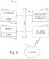
- FIG. 6shows a diagrammatic representation of machine in the example form of a computer system within which a set of instructions when executed may cause the machine to perform any one or more of the methodologies discussed herein.
- an in-vehicle control system 150 with a lane change control module 200 resident in a host vehicle 105can be configured like the architecture and ecosystem 101 illustrated in FIG. 1 .
- the lane change control module 200 described and claimed hereincan be implemented, configured, and used in a variety of other applications and systems as well.
- Ecosystem 101includes a variety of systems and components that can generate and/or deliver one or more sources of information/data and related services to the in-vehicle control system 150 and the lane change control module 200 , which can be installed in the host vehicle 105 .
- a camera installed in the vehicle 105as one of the devices of vehicle subsystems 140 , can generate image and timing data or other perception data that can be received by the in-vehicle control system 150 .
- the in-vehicle control system 150 and an image processing module executing thereincan receive this image and timing data input.
- the image processing modulecan extract object data from the image and timing data to identify objects in the proximity of the vehicle.
- the lane change control module 200can process the perception data and generate a lane change trajectory for the host vehicle based on the detected objects.
- the lane change trajectorycan be used by an autonomous vehicle control subsystem, as another one of the subsystems of vehicle subsystems 140 .
- the autonomous vehicle control subsystemfor example, can use the real-time generated lane change trajectory to safely and efficiently navigate the vehicle 105 through a real world driving environment while avoiding obstacles and safely controlling the vehicle.
- the in-vehicle control system 150can be in data communication with a plurality of vehicle subsystems 140 , all of which can be resident in a user's vehicle 105 .
- a vehicle subsystem interface 141is provided to facilitate data communication between the in-vehicle control system 150 and the plurality of vehicle subsystems 140 .
- the in-vehicle control system 150can be configured to include a data processor 171 to execute the lane change control module 200 for processing object data received from one or more of the vehicle subsystems 140 .
- the data processor 171can be combined with a data storage device 172 as part of a computing system 170 in the in-vehicle control system 150 .
- the data storage device 172can be used to store data, processing parameters, and data processing instructions.
- a processing module interface 165can be provided to facilitate data communications between the data processor 171 and the lane change control module 200 .
- a plurality of processing modules, configured similarly to lane change control module 200can be provided for execution by data processor 171 .
- the lane change control module 200can be integrated into the in-vehicle control system 150 , optionally downloaded to the in-vehicle control system 150 , or deployed separately from the in-vehicle control system 150 .
- the in-vehicle control system 150can be configured to receive or transmit data from/to a wide-area network 120 and network resources 122 connected thereto.
- An in-vehicle web-enabled device 130 and/or a user mobile device 132can be used to communicate via network 120 .
- a web-enabled device interface 131can be used by the in-vehicle control system 150 to facilitate data communication between the in-vehicle control system 150 and the network 120 via the in-vehicle web-enabled device 130 .
- a user mobile device interface 133can be used by the in-vehicle control system 150 to facilitate data communication between the in-vehicle control system 150 and the network 120 via the user mobile device 132 .
- the in-vehicle control system 150can obtain real-time access to network resources 122 via network 120 .
- the network resources 122can be used to obtain processing modules for execution by data processor 171 , data content to train internal neural networks, system parameters, or other data.
- the ecosystem 101can include a wide area data network 120 .
- the network 120represents one or more conventional wide area data networks, such as the Internet, a cellular telephone network, satellite network, pager network, a wireless broadcast network, gaming network, WiFi network, peer-to-peer network, Voice over IP (VoIP) network, etc.
- One or more of these networks 120can be used to connect a user or client system with network resources 122 , such as websites, servers, central control sites, or the like.
- the network resources 122can generate and/or distribute data, which can be received in vehicle 105 via in-vehicle web-enabled devices 130 or user mobile devices 132 .
- the network resources 122can also host network cloud services, which can support the functionality used to compute or assist in processing object input or object input analysis.
- Antennascan serve to connect the in-vehicle control system 150 and the lane change control module 200 with the data network 120 via cellular, satellite, radio, or other conventional signal reception mechanisms.
- cellular data networksare currently available (e.g., VerizonTM, AT&TTM, T-MobileTM, etc.).
- satellite-based data or content networksare also currently available (e.g., SiriusXMTM, HughesNetTM, etc.).
- the conventional broadcast networkssuch as AM/FM radio networks, pager networks, UHF networks, gaming networks, WiFi networks, peer-to-peer networks, Voice over IP (VoIP) networks, and the like are also well-known.
- the in-vehicle control system 150 and the lane change control module 200can receive web-based data or content via an in-vehicle web-enabled device interface 131 , which can be used to connect with the in-vehicle web-enabled device receiver 130 and network 120 .
- the in-vehicle control system 150 and the lane change control module 200can support a variety of network-connectable in-vehicle devices and systems from within a vehicle 105 .
- the in-vehicle control system 150 and the lane change control module 200can also receive data, object processing control parameters, and training content from user mobile devices 132 , which can be located inside or proximately to the vehicle 105 .
- the user mobile devices 132can represent standard mobile devices, such as cellular phones, smartphones, personal digital assistants (PDA's), MP3 players, tablet computing devices (e.g., iPadTM), laptop computers, CD players, and other mobile devices, which can produce, receive, and/or deliver data, object processing control parameters, and content for the in-vehicle control system 150 and the lane change control module 200 .
- the mobile devices 132can also be in data communication with the network cloud 120 .
- the mobile devices 132can source data and content from internal memory components of the mobile devices 132 themselves or from network resources 122 via network 120 . Additionally, mobile devices 132 can themselves include a GPS data receiver, accelerometers, WiFi triangulation, or other geo-location sensors or components in the mobile device, which can be used to determine the real-time geo-location of the user (via the mobile device) at any moment in time. In any case, the in-vehicle control system 150 and the lane change control module 200 can receive data from the mobile devices 132 as shown in FIG. 1 .
- the example embodiment of ecosystem 101can include vehicle operational subsystems 140 .
- vehicle operational subsystems 140For embodiments that are implemented in a vehicle 105 , many standard vehicles include operational subsystems, such as electronic control units (ECUs), supporting monitoring/control subsystems for the engine, brakes, transmission, electrical system, emissions system, interior environment, and the like.
- ECUselectronice control units
- data signals communicated from the vehicle operational subsystems 140 (e.g., ECUs of the vehicle 105 ) to the in-vehicle control system 150 via vehicle subsystem interface 141may include information about the state of one or more of the components or subsystems of the vehicle 105 .
- the data signalswhich can be communicated from the vehicle operational subsystems 140 to a Controller Area Network (CAN) bus of the vehicle 105 , can be received and processed by the in-vehicle control system 150 via vehicle subsystem interface 141 .
- CANController Area Network
- Embodiments of the systems and methods described hereincan be used with substantially any mechanized system that uses a CAN bus or similar data communications bus as defined herein, including, but not limited to, industrial equipment, boats, trucks, machinery, or automobiles; thus, the term “vehicle” as used herein can include any such mechanized systems.
- Embodiments of the systems and methods described hereincan also be used with any systems employing some form of network data communications; however, such network communications are not required.
- the example embodiment of ecosystem 101can include a variety of vehicle subsystems in support of the operation of vehicle 105 .
- the vehicle 105may take the form of a car, truck, motorcycle, bus, boat, airplane, helicopter, lawn mower, earth mover, snowmobile, aircraft, recreational vehicle, amusement park vehicle, farm equipment, construction equipment, tram, golf cart, train, and trolley, for example. Other vehicles are possible as well.
- the vehicle 105may be configured to operate fully or partially in an autonomous mode.
- the vehicle 105may control itself while in the autonomous mode, and may be operable to determine a current state of the vehicle and its context in its environment, determine a predicted behavior of at least one other vehicle in the context of the environment, determine a confidence level that may correspond to a likelihood of the at least one other vehicle to perform the predicted behavior, and control the vehicle 105 based on the determined information.
- the vehicle 105While in autonomous mode, the vehicle 105 may be configured to operate without human interaction.
- the vehicle 105may include various vehicle subsystems such as a vehicle drive subsystem 142 , vehicle sensor subsystem 144 , vehicle control subsystem 146 , and occupant interface subsystem 148 . As described above, the vehicle 105 may also include the in-vehicle control system 150 , the computing system 170 , and the lane change control module 200 . The vehicle 105 may include more or fewer subsystems and each subsystem could include multiple elements. Further, each of the subsystems and elements of vehicle 105 could be interconnected. Thus, one or more of the described functions of the vehicle 105 may be divided up into additional functional or physical components or combined into fewer functional or physical components. In some further examples, additional functional and physical components may be added to the examples illustrated by FIG. 1 .
- the vehicle drive subsystem 142may include components operable to provide powered motion for the vehicle 105 .
- the vehicle drive subsystem 142may include an engine or motor, wheels/tires, a transmission, an electrical subsystem, and a power source.
- the engine or motormay be any combination of an internal combustion engine, an electric motor, steam engine, fuel cell engine, propane engine, or other types of engines or motors.
- the enginemay be configured to convert a power source into mechanical energy.
- the vehicle drive subsystem 142may include multiple types of engines or motors. For instance, a gas-electric hybrid car could include a gasoline engine and an electric motor. Other examples are possible.
- the wheels of the vehicle 105may be standard tires.
- the wheels of the vehicle 105may be configured in various formats, including a unicycle, bicycle, tricycle, or a four-wheel format, such as on a car or a truck, for example. Other wheel geometries are possible, such as those including six or more wheels. Any combination of the wheels of vehicle 105 may be operable to rotate differentially with respect to other wheels.
- the wheelsmay represent at least one wheel that is fixedly attached to the transmission and at least one tire coupled to a rim of the wheel that could make contact with the driving surface.
- the wheelsmay include a combination of metal and rubber, or another combination of materials.
- the transmissionmay include elements that are operable to transmit mechanical power from the engine to the wheels.
- the transmissioncould include a gearbox, a clutch, a differential, and drive shafts.
- the transmissionmay include other elements as well.
- the drive shaftsmay include one or more axles that could be coupled to one or more wheels.
- the electrical systemmay include elements that are operable to transfer and control electrical signals in the vehicle 105 . These electrical signals can be used to activate lights, servos, electrical motors, and other electrically driven or controlled devices of the vehicle 105 .
- the power sourcemay represent a source of energy that may, in full or in part, power the engine or motor. That is, the engine or motor could be configured to convert the power source into mechanical energy.
- Examples of power sourcesinclude gasoline, diesel, other petroleum-based fuels, propane, other compressed gas-based fuels, ethanol, fuel cell, solar panels, batteries, and other sources of electrical power.
- the power sourcecould additionally or alternatively include any combination of fuel tanks, batteries, capacitors, or flywheels.
- the power sourcemay also provide energy for other subsystems of the vehicle 105 .
- the vehicle sensor subsystem 144may include a number of sensors configured to sense information or perception data related to an environment or condition of the vehicle 105 .
- the vehicle sensor subsystem 144may include an inertial measurement unit (IMU), a Global Positioning System (GPS) transceiver, a RADAR unit, a laser range finder/LIDAR unit, and one or more cameras or image capture devices.
- the vehicle sensor subsystem 144may also include sensors configured to monitor internal systems of the vehicle 105 (e.g., an 02 monitor, a fuel gauge, an engine oil temperature). Other sensors are possible as well.
- One or more of the sensors included in the vehicle sensor subsystem 144may be configured to be actuated separately or collectively in order to modify a position, an orientation, or both, of the one or more sensors.
- the IMUmay include any combination of sensors (e.g., accelerometers and gyroscopes) configured to sense position and orientation changes of the vehicle 105 based on inertial acceleration.
- the GPS transceivermay be any sensor configured to estimate a geographic location of the vehicle 105 .
- the GPS transceivermay include a receiver/transmitter operable to provide information regarding the position of the vehicle 105 with respect to the Earth.
- the RADAR unitmay represent a system that utilizes radio signals to sense objects within the local environment of the vehicle 105 . In some embodiments, in addition to sensing the objects, the RADAR unit may additionally be configured to sense the speed and the heading of the objects proximate to the vehicle 105 .
- the laser range finder or LIDAR unitmay be any sensor configured to sense objects in the environment in which the vehicle 105 is located using lasers.
- the laser range finder/LIDAR unitmay include one or more laser sources, a laser scanner, and one or more detectors, among other system components.
- the laser range finder/LIDAR unitcould be configured to operate in a coherent (e.g., using heterodyne detection) or an incoherent detection mode.
- the camerasmay include one or more devices configured to capture a plurality of images of the environment of the vehicle 105 .
- the camerasmay be still image cameras or motion video cameras.
- the vehicle control system 146may be configured to control operation of the vehicle 105 and its components. Accordingly, the vehicle control system 146 may include various elements such as a steering unit, a throttle, a brake unit, a navigation unit, and an autonomous control unit.
- the steering unitmay represent any combination of mechanisms that may be operable to adjust the heading of vehicle 105 .
- the throttlemay be configured to control, for instance, the operating speed of the engine and, in turn, control the speed of the vehicle 105 .
- the brake unitcan include any combination of mechanisms configured to decelerate the vehicle 105 .
- the brake unitcan use friction to slow the wheels in a standard manner. In other embodiments, the brake unit may convert the kinetic energy of the wheels to electric current.
- the brake unitmay take other forms as well.
- the navigation unitmay be any system configured to determine a driving path or route for the vehicle 105 .
- the navigation unitmay additionally be configured to update the driving path dynamically while the vehicle 105 is in operation.
- the navigation unitmay be configured to incorporate data from the lane change control module 200 , the GPS transceiver, and one or more predetermined maps so as to determine the driving path for the vehicle 105 .
- the autonomous control unitmay represent a control system configured to identify, evaluate, and avoid or otherwise negotiate potential obstacles in the environment of the vehicle 105 .
- the autonomous control unitmay be configured to control the vehicle 105 for operation without a driver or to provide driver assistance in controlling the vehicle 105 .
- the autonomous control unitmay be configured to incorporate data from the lane change control module 200 , the GPS transceiver, the RADAR, the LIDAR, the cameras, and other vehicle subsystems to determine the driving path or trajectory for the vehicle 105 .
- the vehicle control system 146may additionally or alternatively include components other than those shown and described.
- Occupant interface subsystems 148may be configured to allow interaction between the vehicle 105 and external sensors, other vehicles, other computer systems, and/or an occupant or user of vehicle 105 .
- the occupant interface subsystems 148may include standard visual display devices (e.g., plasma displays, liquid crystal displays (LCDs), touchscreen displays, heads-up displays, or the like), speakers or other audio output devices, microphones or other audio input devices, navigation interfaces, and interfaces for controlling the internal environment (e.g., temperature, fan, etc.) of the vehicle 105 .
- standard visual display devicese.g., plasma displays, liquid crystal displays (LCDs), touchscreen displays, heads-up displays, or the like
- speakers or other audio output devicese.g., speakers or other audio output devices
- microphones or other audio input devicese.g., navigation interfaces, and interfaces for controlling the internal environment (e.g., temperature, fan, etc.) of the vehicle 105 .
- the occupant interface subsystems 148may provide, for instance, means for a user/occupant of the vehicle 105 to interact with the other vehicle subsystems.
- the visual display devicesmay provide information to a user of the vehicle 105 .
- the user interface devicescan also be operable to accept input from the user via a touchscreen.
- the touchscreenmay be configured to sense at least one of a position and a movement of a user's finger via capacitive sensing, resistance sensing, or a surface acoustic wave process, among other possibilities.
- the touchscreenmay be capable of sensing finger movement in a direction parallel or planar to the touchscreen surface, in a direction normal to the touchscreen surface, or both, and may also be capable of sensing a level of pressure applied to the touchscreen surface.
- the touchscreenmay be formed of one or more translucent or transparent insulating layers and one or more translucent or transparent conducting layers. The touchscreen may take other forms as well.
- the occupant interface subsystems 148may provide means for the vehicle 105 to communicate with devices within its environment.
- the microphonemay be configured to receive audio (e.g., a voice command or other audio input) from a user of the vehicle 105 .
- the speakersmay be configured to output audio to a user of the vehicle 105 .
- the occupant interface subsystems 148may be configured to wirelessly communicate with one or more devices directly or via a communication network.
- a wireless communication systemcould use 3G cellular communication, such as CDMA, EVDO, GSM/GPRS, or 4G cellular communication, such as WiMAX or LTE.
- the wireless communication systemmay communicate with a wireless local area network (WLAN), for example, using WIFI®.
- WLANwireless local area network
- the wireless communication system 146may communicate directly with a device, for example, using an infrared link, BLUETOOTH®, or ZIGBEE®.
- BLUETOOTH®BLUETOOTH®
- ZIGBEE®ZIGBEE®
- Other wireless protocolssuch as various vehicular communication systems, are possible within the context of the disclosure.
- the wireless communication systemmay include one or more dedicated short range communications (DSRC) devices that may include public or private data communications between vehicles and/or roadside stations.
- DSRCdedicated short range communications
- the computing system 170may include at least one data processor 171 (which can include at least one microprocessor) that executes processing instructions stored in a non-transitory computer readable medium, such as the data storage device 172 .
- the computing system 170may also represent a plurality of computing devices that may serve to control individual components or subsystems of the vehicle 105 in a distributed fashion.
- the data storage device 172may contain processing instructions (e.g., program logic) executable by the data processor 171 to perform various functions of the vehicle 105 , including those described herein in connection with the drawings.
- the data storage device 172may contain additional instructions as well, including instructions to transmit data to, receive data from, interact with, or control one or more of the vehicle drive subsystem 140 , the vehicle sensor subsystem 144 , the vehicle control subsystem 146 , and the occupant interface subsystems 148 .
- the data storage device 172may store data such as object processing parameters, perception data, roadway maps, and path information, among other information. Such information may be used by the vehicle 105 and the computing system 170 during the operation of the vehicle 105 in the autonomous, semi-autonomous, and/or manual modes.
- the vehicle 105may include a user interface for providing information to or receiving input from a user or occupant of the vehicle 105 .
- the user interfacemay control or enable control of the content and the layout of interactive images that may be displayed on a display device.
- the user interfacemay include one or more input/output devices within the set of occupant interface subsystems 148 , such as the display device, the speakers, the microphones, or a wireless communication system.
- the computing system 170may control the function of the vehicle 105 based on inputs received from various vehicle subsystems (e.g., the vehicle drive subsystem 140 , the vehicle sensor subsystem 144 , and the vehicle control subsystem 146 ), as well as from the occupant interface subsystem 148 .
- the computing system 170may use input from the vehicle control system 146 in order to control the steering unit to avoid an obstacle detected by the vehicle sensor subsystem 144 and follow a path or trajectory generated by the lane change control module 200 .
- the computing system 170can be operable to provide control over many aspects of the vehicle 105 and its subsystems.
- FIG. 1shows various components of vehicle 105 , e.g., vehicle subsystems 140 , computing system 170 , data storage device 172 , and lane change control module 200 , as being integrated into the vehicle 105 , one or more of these components could be mounted or associated separately from the vehicle 105 .
- data storage device 172could, in part or in full, exist separate from the vehicle 105 .
- the vehicle 105could be provided in the form of device elements that may be located separately or together.
- the device elements that make up vehicle 105could be communicatively coupled together in a wired or wireless fashion.
- ancillary datacan be obtained from local and/or remote sources by the in-vehicle control system 150 as described above.
- the ancillary datacan be used to augment, modify, or train the operation of the lane change control module 200 based on a variety of factors including, the context in which the user is operating the vehicle (e.g., the location of the vehicle, the specified destination, direction of travel, speed, the time of day, the status of the vehicle, etc.), and a variety of other data obtainable from the variety of sources, local and remote, as described herein.
- the in-vehicle control system 150 and the lane change control module 200can be implemented as in-vehicle components of vehicle 105 .
- the in-vehicle control system 150 and the lane change control module 200 in data communication therewithcan be implemented as integrated components or as separate components.
- the software components of the in-vehicle control system 150 and/or the lane change control module 200can be dynamically upgraded, modified, and/or augmented by use of the data connection with the mobile devices 132 and/or the network resources 122 via network 120 .
- the in-vehicle control system 150can periodically query a mobile device 132 or a network resource 122 for updates or updates can be pushed to the in-vehicle control system 150 .
- a system and method for automated lane change control for autonomous vehiclesis disclosed herein.
- the present disclosurerelates to automated lane change control using a system and method that considers the positions, headings, speed, and acceleration of other proximate dynamic vehicles in the vicinity of the autonomously controlled (e.g., host) vehicle.
- the system hereinmay include various sensors, configured to collect perception data, a computing device, and a lane change control module for generating a lane change trajectory to enable the host vehicle to execute a safe and comfortable lane change maneuver in the presence of other vehicles and/or dynamic objects in the vicinity of (proximate to) the host autonomous vehicle.
- the computing deviceuses the perception data to determine a current state of the host vehicle and the state of any proximate vehicles detected in the presence of or near to the host vehicle.
- the lane change control modulecan be configured to use a state prediction model to predict the locations of the vehicles at a given point in time in the future based on the current positions, headings, velocities, and accelerations of the vehicles.
- the lane change control modulecan also be configured to define a safety distance around each vehicle based on a pre-configured and modifiable parameter or set of parameters. The safety distance parameters can be used to specify a region around each vehicle into which other vehicles cannot be allowed to encroach.
- the lane change control modulecan be further configured to determine a safety zone between proximate vehicles detected in a roadway lane adjacent to a lane in which the host vehicle is currently positioned.
- the lane change control modulecan be further configured to determine a first target position within the safety zone.
- the lane change control module of the host vehiclecan also be configured to determine a second target position in the same lane in which the host vehicle is currently positioned.
- the lane change control modulecan be configured to cause the host vehicle to perform a lane change maneuver in two phases: 1) a longitudinal positioning phase or pre-turn phase to properly position the host vehicle at a second target position in the current lane for execution of a leftward or rightward turning maneuver, and 2) a lateral steering phase during which the host vehicle is controlled to perform a leftward or rightward steering operation to direct the host vehicle from the second target position in the current lane toward the first target position in the adjacent lane.
- a first phase trajectorycan be generated to direct the host vehicle toward the second target position in the current lane.
- a second phase trajectorycan be generated to direct the host vehicle toward the first target position in the adjacent lane.
- the first phase trajectory and the second phase trajectorycan be generally denoted as a lane change trajectory.
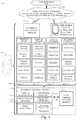
- the lane change trajectory planning system 202can include a lane change control module 200 (described in more detail below).
- the lane change trajectory planning system 202can be configured to include a data processor 171 to execute the lane change control module 200 for processing input perception data 210 received from one or more of the vehicle subsystems 140 .
- the data processor 171can be combined with a data storage or memory device 172 as part of a computing system 202 in the in-vehicle control system 150 .
- the data storage device 172can be used to store data 174 , such as processing or configuration parameters, lane change trajectory data, data processing instructions, and the like.
- data 174such as processing or configuration parameters, lane change trajectory data, data processing instructions, and the like.
- a plurality of processing modulesconfigured similarly to lane change control module 200 , can be provided for execution by data processor 171 .
- the lane change control module 200can be configured to include a longitudinal positioning module 173 and a lateral steering module 175 .
- the longitudinal positioning module 173serves to enable generation of a first phase trajectory for the host vehicle (e.g., the autonomous vehicle).
- the lateral steering module 175serves to enable generation of a second phase trajectory for the host vehicle.
- the longitudinal positioning module 173 and the lateral steering module 175can generate the first phase trajectory and the second phase trajectory, which can be generally denoted as the lane change trajectory 220 provided as an output from the lane change control module 200 .
- the lane change trajectory 220can be generated based on input perception data 210 received from one or more of the vehicle sensor subsystems 144 , including one or more cameras, and processed by an image processing module to identify proximate agents (e.g., moving vehicles, dynamic objects, or other objects in the proximate vicinity of the host vehicle).
- the longitudinal positioning module 173 and the lateral steering module 175can be configured as software modules executed by the data processor 171 of the lane change trajectory planning system 202 .
- the modules 173 and 175 of the lane change control module 200can receive the input perception data 210 and produce a lane change trajectory 220 , which can be used by the autonomous control subsystem of the vehicle control subsystem 146 to more efficiently and safely control the host vehicle 105 during a lane change maneuver.
- the longitudinal positioning module 173 and the lateral steering module 175can be configured to work with lane change trajectory planning and configuration parameters 174 , which can be used to customize and fine tune the operation of the lane change control module 200 .
- the trajectory planning and configuration parameters 174can be stored in a memory 172 of the lane change trajectory planning system 202 .
- the lane change control module 200can receive input perception data 210 from one or more of the vehicle sensor subsystems 144 , including one or more cameras.
- the image data from the vehicle sensor subsystems 144can be processed by an image processing module to identify proximate agents or other objects (e.g., moving vehicles, dynamic objects, or other objects in the proximate vicinity of the vehicle 105 ).
- the process of semantic segmentationcan be used for this purpose.
- the information related to the identified proximate agents or other detected objectscan be received by the lane change control module 200 as input perception data 210 .
- the input perception data 210can include a plurality of perception data including perception data or images from an array of perception information gathering devices or sensors that may include image generating devices (e.g., cameras), light amplification by stimulated emission of radiation (laser) devices, light detection and ranging (LIDAR) devices, global positioning system (GPS) devices, sound navigation and ranging (sonar) devices, radio detection and ranging (radar) devices, and the like.
- the perception data 210can include traffic or vehicle image data, roadway data, roadway lane marker data, environmental data, distance data and velocity/acceleration data from LIDAR or radar devices, and other sensor information received from the perception information gathering devices of the host vehicle.
- the perception data 210can include data from which a position, heading, velocity, and acceleration (e.g., a vehicle state or status) of neighboring vehicles in the vicinity of or proximate to the autonomous host vehicle can be obtained or calculated.
- the perception data 210can also include data from which a position, heading, velocity, and acceleration (e.g., a vehicle state or status) of the host vehicle can be obtained or calculated.
- the perception data, vehicle state and context data, and other available informationcan be obtained, processed, and used to build a perception dataset 210 for input to the lane change trajectory planning system 202 .
- the gathered perception or sensor data 210can be stored in a memory device of the host vehicle and transferred later to the data processor 171 of the lane change trajectory planning system 202 .
- the perception or sensor data 210 , and other related data gathered or calculated by the vehicle sensor subsystemscan be used as an input to the lane change trajectory planning system 202 and processed by the lane change control module 200 resident in a vehicle 105 , as described in more detail herein.
- the lane change control module 200can be implemented as software, firmware, or other logic components executing or activated within an executable environment of the lane change control module 200 operating within or in data communication with the in-vehicle control system 150 .
- Each of these modules of an example embodimentis described in more detail below in connection with the figures provided herein.
- an exampleillustrates the processing performed by the system and method of an example embodiment for automated lane change control for autonomous vehicles.
- the illustrated examplerelates to automated lane change control using the system and method implemented by an example embodiment of the lane change control module 200 as described above.
- the lane change control module 200 of an example embodimentcan be configured to obtain and consider the positions, speeds, and accelerations (e.g., the vehicle states or status) of other proximate dynamic vehicles in the vicinity of the autonomously controlled (e.g., host) vehicle.
- the lane change control module 200 of an example embodimentcan also be configured to obtain and consider the position, speed, and acceleration (e.g., the vehicle state or status) of the host vehicle as well.
- the example embodimentmay include various sensors, configured to collect perception data 210 , a computing device 171 , and the lane change control module 200 for generating a lane change trajectory 220 to enable the host vehicle to execute a safe and comfortable lane change maneuver in the presence of other vehicles and/or dynamic objects in the vicinity of (proximate to) the host autonomous vehicle.
- the example embodimentuses the perception data 210 to determine a current state of the host vehicle and the state of any proximate vehicles detected in the presence of the host vehicle.
- the vehicle statecan include the current position/location and heading of each vehicle and the related derivatives including velocity and acceleration of each vehicle.
- the derivative of the acceleration or jerkcan also be determined for each vehicle.
- the position/location of a vehiclecan be represented as an x,y coordinate, a geographical coordinate (e.g., latitude/longitude), a polar coordinate, or other conventional form of positional representation.
- the position/location of a vehiclecan also be represented relative to the position/location of another detected vehicle or the host vehicle.
- the velocities and/or accelerationscan be represented as absolute values or values relative to other vehicle velocities and/or accelerations.
- the lane change control module 200can be configured to use a state prediction model to predict the locations of the vehicles at a given point in time in the future based on the current positions, headings, velocities, and accelerations of the vehicles.
- the lane change control module 200can predict the future locations of each of the vehicles based on a linear extrapolation from the current position using the heading, speed, and acceleration of each of the vehicles over a given time period.
- the behavior of the proximate vehiclescan be predicted using heuristics and/or a trained machine learning model, as described in a related U.S.
- the lane change control module 200can predict the future positions/locations of each of the vehicles based on the predicted trajectories of the vehicles over the given time period. As a result, the lane change control module 200 can be configured to determine the future positions, headings, velocities, and accelerations of the host vehicle VA and each of the detected proximate vehicles (V1, V2, and V3) at a given point in time.
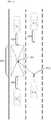
- the lane change control module 200can also be configured to define a safety distance SD around each vehicle based on a pre-configured and modifiable parameter or set of parameters.
- the safety distance SD parameterscan be common to all vehicles or specific to particular vehicles.
- the safety distance SD parameterscan also be associated with a vehicle in a particular context, such as an accelerating/decelerating vehicle, a vehicle positioned ahead of, adjacent to, or behind the host vehicle VA, a particular type of vehicle, a vehicle operating in a particular weather or environmental condition, or the like.
- the safety distance SD parameterscan be used to specify a region around each vehicle into which other vehicles cannot be allowed to encroach.
- the lane change control module 200can be configured to determine a safety zone SZ between proximate vehicles (V1 and V2) detected in a roadway lane adjacent to a lane in which the host vehicle VA is positioned or operating.
- the adjacent lanecan be a lane to the left or right of the lane in which the host vehicle VA is positioned or operating.
- the safety zone SZcan be bounded by the safety distance SD from a leading proximate vehicle V1 and the safety distance SD from a following proximate vehicle V2 in the adjacent lane.
- the safety zone SZcan be defined as a region between lane boundaries in an adjacent lane bounded at one end by the safety distance SD from a leading adjacent proximate vehicle V1 and bounded at the other end by the safety distance SD from a following adjacent proximate vehicle V2.
- the determined safety zone SZcan associated with an adjacent lane to the left or right of the lane in which the host vehicle VA is positioned or operating.
- the lane change control module 200can be configured to determine a first target position TP1 within the safety zone SZ as shown in FIGS. 3 and 4 .
- the first target position TP1can be defined as a center point of the safety zone SZ.
- the first target position TP1can be defined as a point in the safety zone SZ and located relative to the context of the host vehicle VA or the proximate vehicles V1 or V2.
- the first target position TP1corresponds to a location in an adjacent lane to which the host vehicle VA can be directed to accomplish a safe lane change maneuver.
- the first target position TP1will be sufficiently separated from the positions/locations of the proximate vehicles V1 and V2 detected in the adjacent lane.
- the first target position TP1can be represented as an x,y coordinate, a geographical coordinate (e.g., latitude/longitude), a polar coordinate, or other conventional form of positional representation.
- the first target position TP1can also be represented relative to the positions/locations of other detected vehicles V1 or V2 or the host vehicle VA. Given that the proximate vehicles V1 and V2 and the host vehicle VA are constantly moving, the first target position TP1 can be represented in a manner that accommodates the motion of the vehicles.
- the lane change control module 200 of the host vehicle VAcan be configured to determine a second target position TP2 in the same lane in which the host vehicle VA is currently positioned as shown in FIG. 4 .
- the second target position TP2is a location in the host vehicle's VA current lane from which the host vehicle VA can begin a leftward or rightward turn maneuver to safely and comfortably merge the host vehicle VA toward the first target position TP1 in the adjacent lane.
- the lane change control module 200 of an example embodimentcan generate one or more trajectories to navigate the host vehicle VA into the first target position TP1 in the adjacent lane.
- the lane change control module 200can cause the host vehicle VA to perform the lane change maneuver in two phases: 1) a longitudinal positioning phase or pre-turn phase to properly position the host vehicle VA in the current lane for execution of a leftward or rightward turning maneuver, and 2) a lateral steering phase during which the host vehicle VA is controlled to perform a leftward or rightward steering operation to direct the host vehicle VA toward the first target position TP1 in the adjacent lane.
- a longitudinal positioning phase or pre-turn phaseto properly position the host vehicle VA in the current lane for execution of a leftward or rightward turning maneuver
- a lateral steering phaseduring which the host vehicle VA is controlled to perform a leftward or rightward steering operation to direct the host vehicle VA toward the first target position TP1 in the adjacent lane.
- the lane change control module 200can be configured to include a longitudinal positioning module 173 and a lateral steering module 175 .
- the longitudinal positioning module 173serves to enable generation of a first phase trajectory for the host vehicle VA to direct the host vehicle VA from its current position toward the second target position TP2 located in the same lane in which the host vehicle VA is currently positioned.
- the lateral steering module 175serves to enable generation of a second phase trajectory for the host vehicle VA to direct the host vehicle VA from the second target position TP2 toward the first target position TP1 located in the safety zone SZ in the lane adjacent to the lane where the host vehicle VA is currently positioned.
- the longitudinal positioning module 173 and the lateral steering module 175can generate the first phase trajectory and the second phase trajectory, which can be generally denoted as the lane change trajectory 220 provided as an output from the lane change control module 200 .
- the first phasee.g., the longitudinal positioning phase or pre-turn phase
- the second target position TP2may be some distance ahead of or behind the current position of the host vehicle VA.
- the first phase trajectorycan be generated by the longitudinal positioning module 173 of the lane change control module 200 to cause the host vehicle VA to intercept the second target position TP2 in the current lane.
- the first phase trajectorymay include a velocity change command to cause the host vehicle VA to accelerate or decelerate as the host vehicle VA approaches the second target position TP2.
- the second target position TP2may correspond to the current position of the host vehicle VA.
- the host vehicle VAcan immediately begin a leftward or rightward turn maneuver to safely and comfortably merge the host vehicle VA toward the first target position TP1 in the adjacent lane.
- the first phase trajectoryis essentially null.
- the host vehicle VAcan be controlled by the lateral steering module 175 to initiate a leftward or rightward steering maneuver to cause the host vehicle VA to intercept the first target position TP1 in the adjacent lane from the second target position TP2 in the current lane.
- a second phase trajectorycan be generated by the lateral steering module 175 of the lane change control module 200 to cause the host vehicle VA to intercept the first target position TP1 in the adjacent lane from the second target position TP2.
- the second phase trajectoryis typically initiated once the host vehicle VA reaches the second target position TP2.
- the second phase trajectorymay include a velocity change command to cause the host vehicle VA to accelerate or decelerate as the host vehicle VA approaches the first target position TP1.
- the first phase trajectory and the second phase trajectorycan be integrated into a single host vehicle VA trajectory or lane change trajectory 220 that guides the host vehicle VA from its current position to intercept the first target position TP1 in the adjacent lane.
- the lane change control module 200can use one or more of several methods to generate the first phase trajectory and the second phase trajectory.
- the state of the host vehicle VA and the states of the proximate vehicles (V1, V2, and V3)can include the current position/location and heading of each vehicle and the related derivatives including velocity and acceleration of each vehicle.
- an external speed profile of the host vehicle VAcan be generated on-the-fly or off-line and retained to model the speed profile or performance characteristics of a particular vehicle when executing a lane change maneuver.
- the vehicle state information, the host vehicle speed profile information, the first target position TP1 (e.g., the target end position), and the second target position TP2can be used by the any of the various methods to generate the first phase trajectory and the second phase trajectory as described below.
- the lane change control module 200can obtain the vehicle state information, the host vehicle speed profile information, and the first target position TP1 (e.g., the target end position) as described above. In this example embodiment, the lane change control module 200 can generate or fit a Dubin's curve as the trajectory of the host vehicle from its current position to the first target position TP1 (e.g., the target end position) in an adjacent lane.
- the term Dubin's curve or pathtypically refers to the shortest curve that connects two points in the two-dimensional Euclidean plane (i.e., the x-y plane) with a constraint on the curvature of the path and with prescribed initial and terminal tangents to the path, and an assumption that the vehicle traveling the path can only travel forward.
- the lane change control module 200can obtain or determine an initial set of Dubin's parameters (a, t0, t1), where a represents a constraint on the curvature of the path or the minimum turning radius of the Dubin's vehicle, t 0 specifies the starting time when the Dubin's curve starts, and t 1 specifies the time when the Dubin's curve ends.
- the initial set of Dubin's parameterscan be determined from the vehicle state information, the host vehicle speed profile information, and the target end position.
- the set of Dubin's parametersprovides a level of flexibility for the trajectory generation to avoid collisions and to accommodate various types of vehicles with different profiles.
- the lane change control module 200can begin a loop by fitting a Dubin's curve using a current set of Dubin's parameters (a, t0, t1).
- the lane change control module 200can score the Dubin's curve and determine the gradient of the Dubin's curve corresponding to the current set of Dubin's parameters (a, t0, t1).
- the lane change control module 200can compare the gradient of the Dubin's curve with the external speed profile of the vehicle to determine if the curvature of the Dubin's path is within the vehicle's profile and if any collision might be detected as a result of the execution of the Dubin's path.
- the lane change control module 200can update the set of Dubin's parameters according to the previous score and gradient and repeat the loop described above until the score and gradient of the generated Dubin's curve is within acceptable parameters. Once the acceptable Dubin's curve is generated, the Dubin's curve can be used as the first phase trajectory and the second phase trajectory. The first and second phase trajectories generated by the lane change control module 200 can be used by lower level components of the host vehicle VA to sample a series of reference points for trajectory tracking and for controlling the host vehicle VA to intercept the reference points and thereby intercept the first target position TP1 in the adjacent lane.
- the lane change control module 200can obtain the vehicle state information, the host vehicle speed profile information, and the first target position TP1 (e.g., the target end position) as described above.
- the lane change control module 200can generate the first and second phase trajectories by fitting a spline.
- a splinerefers to a piecewise polynomial parametric curve. Splines can be used to approximate a curved trajectory from the host vehicle's current position to the first target position TP1 (e.g., the target end position). The splines generated by this example embodiment can be used as the first phase trajectory and the second phase trajectory.
- the first and second phase trajectories generated by the lane change control module 200can be used by lower level components of the host vehicle VA to sample a series of reference points for trajectory tracking and for controlling the host vehicle VA to intercept the reference points and thereby intercept the first target position TP1 in the adjacent lane.
- the lane change control module 200can fit a piecewise linear speed trajectory function, which can be configured to satisfy the constraints of the initial host vehicle VA state, the initial states of the proximate vehicles (V1, V2, and V3), the goal state of the host vehicle VA, and the configuration of the controller of the host vehicle VA with optional optimizations on various cost functions (e.g., time, fuel consumption, etc.).
- the piecewise linear speed trajectory functioncan be implemented using two uniform acceleration values, one for each of the first and second phase trajectories. As described above, one input to the piecewise linear speed trajectory function can be time t. An output of the piecewise linear speed trajectory function can be the desired state of the host vehicle VA at time t.
- the state of the host vehicle VA and the states of the proximate vehiclescan include the current position/location and heading of each vehicle and the related derivatives including velocity and acceleration of each vehicle.
- the first phase trajectory and the second phase trajectory generated by the piecewise linear speed trajectory functioncan be used by lower level components of the host vehicle VA to sample a series of reference points for trajectory tracking and for controlling the host vehicle VA to the intercept the reference points.
- the use of a piecewise linear speed trajectory functioncan considered to produce a higher level of jerk associated with the motion of the host vehicle VA through the first phase trajectory and the second phase trajectory. As such, the use of a piecewise linear speed trajectory function may produce a less comfortable and less gentle ride for host vehicle VA passengers.
- the use of a piecewise linear speed trajectory functioncan generate the first phase trajectory and the second phase trajectory more quickly and thus may require less computing power and/or processing time.
- a flow diagramillustrates an example embodiment of a system and method 600 for providing lane change trajectory planning for autonomous vehicles.
- the example embodimentcan be configured to: receive perception data associated with a host vehicle (processing block 601 ); use the perception data to determine a state of the host vehicle and a state of proximate vehicles detected near to the host vehicle (processing block 603 ); determine a first target position within a safety zone between proximate vehicles detected in a roadway lane adjacent to a lane in which the host vehicle is positioned (processing block 605 ); determine a second target position in the lane in which the host vehicle is positioned (processing block 607 ); and generate a lane change trajectory to direct the host vehicle toward the first target position in the adjacent lane after directing the host vehicle toward the second target position in the lane in which the host vehicle is positioned (processing block 609 ).
- the term “mobile device”includes any computing or communications device that can communicate with the in-vehicle control system 150 and/or the lane change control module 200 described herein to obtain read or write access to data signals, messages, or content communicated via any mode of data communications.
- the mobile device 130is a handheld, portable device, such as a smart phone, mobile phone, cellular telephone, tablet computer, laptop computer, display pager, radio frequency (RF) device, infrared (IR) device, global positioning device (GPS), Personal Digital Assistants (PDA), handheld computers, wearable computer, portable game console, other mobile communication and/or computing device, or an integrated device combining one or more of the preceding devices, and the like.
- RFradio frequency
- IRinfrared
- GPSglobal positioning device
- PDAPersonal Digital Assistants
- the mobile device 130can be a computing device, personal computer (PC), multiprocessor system, microprocessor-based or programmable consumer electronic device, network PC, diagnostics equipment, a system operated by a vehicle manufacturer or service technician, and the like, and is not limited to portable devices.
- the mobile device 130can receive and process data in any of a variety of data formats.
- the data formatmay include or be configured to operate with any programming format, protocol, or language including, but not limited to, JavaScript, C++, iOS, Android, etc.
- the term “network resource”includes any device, system, or service that can communicate with the in-vehicle control system 150 and/or the lane change control module 200 described herein to obtain read or write access to data signals, messages, or content communicated via any mode of inter-process or networked data communications.
- the network resource 122is a data network accessible computing platform, including client or server computers, websites, mobile devices, peer-to-peer (P2P) network nodes, and the like.
- the network resource 122can be a web appliance, a network router, switch, bridge, gateway, diagnostics equipment, a system operated by a vehicle manufacturer or service technician, or any machine capable of executing a set of instructions (sequential or otherwise) that specify actions to be taken by that machine. Further, while only a single machine is illustrated, the term “machine” can also be taken to include any collection of machines that individually or jointly execute a set (or multiple sets) of instructions to perform any one or more of the methodologies discussed herein.
- the network resources 122may include any of a variety of providers or processors of network transportable digital content. Typically, the file format that is employed is Extensible Markup Language (XML), however, the various embodiments are not so limited, and other file formats may be used.
- XMLExtensible Markup Language
- HTMLHypertext Markup Language
- XMLXML
- Any electronic file formatsuch as Portable Document Format (PDF), audio (e.g., Motion Picture Experts Group Audio Layer 3—MP3, and the like), video (e.g., MP4, and the like), and any proprietary interchange format defined by specific content sites can be supported by the various embodiments described herein.
- PDFPortable Document Format
- audioe.g., Motion Picture Experts Group Audio Layer 3—MP3, and the like
- videoe.g., MP4, and the like
- any proprietary interchange format defined by specific content sitescan be supported by the various embodiments described herein.
- the wide area data network 120(also denoted the network cloud) used with the network resources 122 can be configured to couple one computing or communication device with another computing or communication device.
- the networkmay be enabled to employ any form of computer readable data or media for communicating information from one electronic device to another.
- the network 120can include the Internet in addition to other wide area networks (WANs), cellular telephone networks, metro-area networks, local area networks (LANs), other packet-switched networks, circuit-switched networks, direct data connections, such as through a universal serial bus (USB) or Ethernet port, other forms of computer-readable media, or any combination thereof.
- WANswide area networks
- LANslocal area networks
- USBuniversal serial bus
- Ethernet portother forms of computer-readable media, or any combination thereof.
- the network 120can include the Internet in addition to other wide area networks (WANs), cellular telephone networks, satellite networks, over-the-air broadcast networks, AM/FM radio networks, pager networks, UHF networks, other broadcast networks, gaming networks, WiFi networks, peer-to-peer networks, Voice Over IP (VoIP) networks, metro-area networks, local area networks (LANs), other packet-switched networks, circuit-switched networks, direct data connections, such as through a universal serial bus (USB) or Ethernet port, other forms of computer-readable media, or any combination thereof.
- WANswide area networks
- AM/FM radio networkspager networks
- UHF networksother broadcast networks
- gaming networksWiFi networks
- peer-to-peer networksVoice Over IP (VoIP) networks
- metro-area networkslocal area networks
- LANslocal area networks
- USBuniversal serial bus
- Ethernet portother forms of computer-readable media, or any combination thereof.
- a router or gatewaycan act as a link between networks, enabling messages to be sent between computing devices on different networks
- communication links within networkscan typically include twisted wire pair cabling, USB, Firewire, Ethernet, or coaxial cable, while communication links between networks may utilize analog or digital telephone lines, full or fractional dedicated digital lines including T1, T2, T3, and T4, Integrated Services Digital Networks (ISDNs), Digital User Lines (DSLs), wireless links including satellite links, cellular telephone links, or other communication links known to those of ordinary skill in the art.
- ISDNsIntegrated Services Digital Networks
- DSLsDigital User Lines
- wireless linksincluding satellite links, cellular telephone links, or other communication links known to those of ordinary skill in the art.
- remote computers and other related electronic devicescan be remotely connected to the network via a modem and temporary telephone link.
- the network 120may further include any of a variety of wireless sub-networks that may further overlay stand-alone ad-hoc networks, and the like, to provide an infrastructure-oriented connection.
- Such sub-networksmay include mesh networks, Wireless LAN (WLAN) networks, cellular networks, and the like.
- the networkmay also include an autonomous system of terminals, gateways, routers, and the like connected by wireless radio links or wireless transceivers. These connectors may be configured to move freely and randomly and organize themselves arbitrarily, such that the topology of the network may change rapidly.
- the network 120may further employ one or more of a plurality of standard wireless and/or cellular protocols or access technologies including those set forth herein in connection with network interface 712 and network 714 described in the figures herewith.
- a mobile device 132 and/or a network resource 122may act as a client device enabling a user to access and use the in-vehicle control system 150 and/or the lane change control module 200 to interact with one or more components of a vehicle subsystem.
- client devices 132 or 122may include virtually any computing device that is configured to send and receive information over a network, such as network 120 as described herein.
- Such client devicesmay include mobile devices, such as cellular telephones, smart phones, tablet computers, display pagers, radio frequency (RF) devices, infrared (IR) devices, global positioning devices (GPS), Personal Digital Assistants (PDAs), handheld computers, wearable computers, game consoles, integrated devices combining one or more of the preceding devices, and the like.
- the client devicesmay also include other computing devices, such as personal computers (PCs), multiprocessor systems, microprocessor-based or programmable consumer electronics, network PC's, and the like.
- client devicesmay range widely in terms of capabilities and features.
- a client device configured as a cell phonemay have a numeric keypad and a few lines of monochrome LCD display on which only text may be displayed.
- a web-enabled client devicemay have a touch sensitive screen, a stylus, and a color LCD display screen in which both text and graphics may be displayed.
- the web-enabled client devicemay include a browser application enabled to receive and to send wireless application protocol messages (WAP), and/or wired application messages, and the like.
- WAPwireless application protocol
- the browser applicationis enabled to employ HyperText Markup Language (HTML), Dynamic HTML, Handheld Device Markup Language (HDML), Wireless Markup Language (WML), WMLScript, JavaScriptTM, EXtensible HTML (xHTML), Compact HTML (CHTML), and the like, to display and send a message with relevant information.
- HTMLHyperText Markup Language
- HDMLHandheld Device Markup Language
- WMLWireless Markup Language
- WMLScriptJavaScriptTM
- EXtensible HTMLxHTML
- Compact HTMLCompact HTML
- the client devicesmay also include at least one client application that is configured to receive content or messages from another computing device via a network transmission.
- the client applicationmay include a capability to provide and receive textual content, graphical content, video content, audio content, alerts, messages, notifications, and the like.
- the client devicesmay be further configured to communicate and/or receive a message, such as through a Short Message Service (SMS), direct messaging (e.g., Twitter), email, Multimedia Message Service (MMS), instant messaging (IM), internet relay chat (IRC), mIRC, Jabber, Enhanced Messaging Service (EMS), text messaging, Smart Messaging, Over the Air (OTA) messaging, or the like, between another computing device, and the like.
- SMSShort Message Service
- MMSMultimedia Message Service
- IMinstant messaging
- IRCinternet relay chat
- mIRCJabber
- EMSEnhanced Messaging Service
- OTAOver the Air
- the client devicesmay also include a wireless application device on which a client application is configured to
- the in-vehicle control system 150 and/or the lane change control module 200can be implemented using systems that enhance the security of the execution environment, thereby improving security and reducing the possibility that the in-vehicle control system 150 and/or the lane change control module 200 and the related services could be compromised by viruses or malware.
- the in-vehicle control system 150 and/or the lane change control module 200can be implemented using a Trusted Execution Environment, which can ensure that sensitive data is stored, processed, and communicated in a secure way.
- FIG. 6shows a diagrammatic representation of a machine in the example form of a computing system 700 within which a set of instructions when executed and/or processing logic when activated may cause the machine to perform any one or more of the methodologies described and/or claimed herein.
- the machineoperates as a standalone device or may be connected (e.g., networked) to other machines.
- the machinemay operate in the capacity of a server or a client machine in server-client network environment, or as a peer machine in a peer-to-peer (or distributed) network environment.
- the machinemay be a personal computer (PC), a laptop computer, a tablet computing system, a Personal Digital Assistant (PDA), a cellular telephone, a smartphone, a web appliance, a set-top box (STB), a network router, switch or bridge, or any machine capable of executing a set of instructions (sequential or otherwise) or activating processing logic that specify actions to be taken by that machine.
- PCpersonal computer
- PDAPersonal Digital Assistant
- STBset-top box
- STBset-top box
- network routerswitch or bridge
- the example computing system 700can include a data processor 702 (e.g., a System-on-a-Chip (SoC), general processing core, graphics core, and optionally other processing logic) and a memory 704 , which can communicate with each other via a bus or other data transfer system 706 .
- the mobile computing and/or communication system 700may further include various input/output (I/O) devices and/or interfaces 710 , such as a touchscreen display, an audio jack, a voice interface, and optionally a network interface 712 .
- I/Oinput/output
- the network interface 712can include one or more radio transceivers configured for compatibility with any one or more standard wireless and/or cellular protocols or access technologies (e.g., 2nd (2G), 2.5, 3rd (3G), 4th (4G) generation, and future generation radio access for cellular systems, Global System for Mobile communication (GSM), General Packet Radio Services (GPRS), Enhanced Data GSM Environment (EDGE), Wideband Code Division Multiple Access (WCDMA), LTE, CDMA2000, WLAN, Wireless Router (WR) mesh, and the like).
- GSMGlobal System for Mobile communication
- GPRSGeneral Packet Radio Services
- EDGEEnhanced Data GSM Environment
- WCDMAWideband Code Division Multiple Access
- LTELong Term Evolution
- CDMA2000Code Division Multiple Access 2000
- WLANWireless Router
- Network interface 712may also be configured for use with various other wired and/or wireless communication protocols, including TCP/IP, UDP, SIP, SMS, RTP, WAP, CDMA, TDMA, UMTS, UWB, WiFi, WiMax, BluetoothTM, IEEE 802.11x, and the like.
- network interface 712may include or support virtually any wired and/or wireless communication and data processing mechanisms by which information/data may travel between a computing system 700 and another computing or communication system via network 714 .
- the memory 704can represent a machine-readable medium on which is stored one or more sets of instructions, software, firmware, or other processing logic (e.g., logic 708 ) embodying any one or more of the methodologies or functions described and/or claimed herein.
- the logic 708may also reside, completely or at least partially within the processor 702 during execution thereof by the mobile computing and/or communication system 700 .
- the memory 704 and the processor 702may also constitute machine-readable media.
- the logic 708 , or a portion thereofmay also be configured as processing logic or logic, at least a portion of which is partially implemented in hardware.
- the logic 708 , or a portion thereofmay further be transmitted or received over a network 714 via the network interface 712 .
- machine-readable medium of an example embodimentcan be a single medium
- the term “machine-readable medium”should be taken to include a single non-transitory medium or multiple non-transitory media (e.g., a centralized or distributed database, and/or associated caches and computing systems) that store the one or more sets of instructions.
- the term “machine-readable medium”can also be taken to include any non-transitory medium that is capable of storing, encoding or carrying a set of instructions for execution by the machine and that cause the machine to perform any one or more of the methodologies of the various embodiments, or that is capable of storing, encoding or carrying data structures utilized by or associated with such a set of instructions.
- the term “machine-readable medium”can accordingly be taken to include, but not be limited to, solid-state memories, optical media, and magnetic media.
Landscapes
- Engineering & Computer Science (AREA)
- Transportation (AREA)
- Mechanical Engineering (AREA)
- Chemical & Material Sciences (AREA)
- Combustion & Propulsion (AREA)
- Automation & Control Theory (AREA)
- Physics & Mathematics (AREA)
- General Physics & Mathematics (AREA)
- Aviation & Aerospace Engineering (AREA)
- Radar, Positioning & Navigation (AREA)
- Remote Sensing (AREA)
- Human Computer Interaction (AREA)
- Traffic Control Systems (AREA)
Abstract
Description
Claims (20)
Priority Applications (6)
| Application Number | Priority Date | Filing Date | Title |
|---|---|---|---|
| US15/946,171US10953880B2 (en) | 2017-09-07 | 2018-04-05 | System and method for automated lane change control for autonomous vehicles |
| CN201910105018.0ACN110356401B (en) | 2018-04-05 | 2019-02-01 | Automatic driving vehicle and lane changing control method and system thereof |
| CN201980033896.4ACN112154088B (en) | 2018-04-05 | 2019-04-05 | System and method for automatic lane change control of an autonomous vehicle |
| PCT/US2019/025995WO2019204053A1 (en) | 2018-04-05 | 2019-04-05 | System and method for automated lane change control for autonomous vehicles |
| AU2019257245AAU2019257245A1 (en) | 2018-04-05 | 2019-04-05 | System and method for automated lane change control for autonomous vehicles |
| EP19788382.0AEP3758998A4 (en) | 2018-04-05 | 2019-04-05 | SYSTEM AND METHOD FOR AUTOMATIC LANE CHANGE CONTROL FOR AUTONOMOUS VEHICLES |
Applications Claiming Priority (3)
| Application Number | Priority Date | Filing Date | Title |
|---|---|---|---|
| US15/698,607US10649458B2 (en) | 2017-09-07 | 2017-09-07 | Data-driven prediction-based system and method for trajectory planning of autonomous vehicles |
| US15/805,983US10782693B2 (en) | 2017-09-07 | 2017-11-07 | Prediction-based system and method for trajectory planning of autonomous vehicles |
| US15/946,171US10953880B2 (en) | 2017-09-07 | 2018-04-05 | System and method for automated lane change control for autonomous vehicles |
Related Parent Applications (1)
| Application Number | Title | Priority Date | Filing Date |
|---|---|---|---|
| US15/805,983Continuation-In-PartUS10782693B2 (en) | 2017-09-07 | 2017-11-07 | Prediction-based system and method for trajectory planning of autonomous vehicles |
Publications (2)
| Publication Number | Publication Date |
|---|---|
| US20190071092A1 US20190071092A1 (en) | 2019-03-07 |
| US10953880B2true US10953880B2 (en) | 2021-03-23 |
Family
ID=65517737
Family Applications (1)
| Application Number | Title | Priority Date | Filing Date |
|---|---|---|---|
| US15/946,171Active2038-06-06US10953880B2 (en) | 2017-09-07 | 2018-04-05 | System and method for automated lane change control for autonomous vehicles |
Country Status (1)
| Country | Link |
|---|---|
| US (1) | US10953880B2 (en) |
Cited By (2)
| Publication number | Priority date | Publication date | Assignee | Title |
|---|---|---|---|---|
| US20210284236A1 (en)* | 2020-03-16 | 2021-09-16 | Honda Motor Co., Ltd. | Moving body control apparatus, moving body, and moving body control method |
| US11435748B2 (en)* | 2017-10-28 | 2022-09-06 | Tusimple, Inc. | System and method for real world autonomous vehicle trajectory simulation |
Families Citing this family (23)
| Publication number | Priority date | Publication date | Assignee | Title |
|---|---|---|---|---|
| US10909866B2 (en)* | 2018-07-20 | 2021-02-02 | Cybernet Systems Corp. | Autonomous transportation system and methods |
| US11548511B2 (en)* | 2019-06-14 | 2023-01-10 | GM Global Technology Operations LLC | Method to control vehicle speed to center of a lane change gap |
| US12353210B2 (en) | 2019-07-25 | 2025-07-08 | Ag Leader Technology | Apparatus, systems and methods for automated navigation of agricultural equipment |
| US11754408B2 (en)* | 2019-10-09 | 2023-09-12 | Argo AI, LLC | Methods and systems for topological planning in autonomous driving |
| US11414130B2 (en) | 2019-10-09 | 2022-08-16 | Argo AI, LLC | Methods and systems for lane changes using a multi-corridor representation of local route regions |
| KR20210044963A (en)* | 2019-10-15 | 2021-04-26 | 현대자동차주식회사 | Apparatus for determining lane change path of autonomous vehicle and method thereof |
| RU2745804C1 (en)* | 2019-11-06 | 2021-04-01 | Общество с ограниченной ответственностью "Яндекс Беспилотные Технологии" | Method and processor for control of movement of autonomous vehicle in the traffic line |
| CN110855789B (en)* | 2019-11-18 | 2022-07-08 | 东软集团股份有限公司 | Position relation determining method and device, storage medium and equipment |
| CN111833598B (en)* | 2020-05-14 | 2022-07-05 | 山东科技大学 | A method and system for automatic monitoring of highway UAV traffic incidents |
| US20220011444A1 (en)* | 2020-07-07 | 2022-01-13 | Ag Leader Technology | Apparatus, Systems And Methods For Grain Cart-Grain Truck Alignment And Control Using Gnss And / Or Distance Sensors |
| US11608067B2 (en)* | 2020-08-12 | 2023-03-21 | Honda Motor Co., Ltd. | Probabilistic-based lane-change decision making and motion planning system and method thereof |
| CN112101527B (en)* | 2020-09-15 | 2023-09-01 | 北京百度网讯科技有限公司 | Method and device for recognizing lane change, electronic device and storage medium |
| WO2022103346A1 (en)* | 2020-11-13 | 2022-05-19 | Eatron Yazilim Ve Muhendislik Teknolojileri A.S. | Automatic lane change system and control method for vehicles |
| US12227205B2 (en) | 2021-01-15 | 2025-02-18 | Tusimple, Inc. | Proactive lane change for autonomous vehicles |
| US12384410B2 (en) | 2021-03-05 | 2025-08-12 | The Research Foundation For The State University Of New York | Task-motion planning for safe and efficient urban driving |
| CN115131988B (en)* | 2021-03-25 | 2024-06-18 | 长沙智能驾驶研究院有限公司 | Vehicle lane changing method, device, equipment and computer storage medium |
| US12403950B2 (en) | 2021-04-19 | 2025-09-02 | Ag Leader Technology | Automatic steering systems and methods |
| CN114061611B (en)* | 2021-11-17 | 2025-04-25 | 腾讯科技(深圳)有限公司 | Target object positioning method, device, storage medium and computer program product |
| US12097859B2 (en)* | 2021-11-23 | 2024-09-24 | Ford Global Technologies, Llc | Vehicle lane-change operations |
| CN114103957B (en)* | 2021-12-22 | 2024-02-06 | 阿波罗智联(北京)科技有限公司 | Lane change control method, apparatus, electronic device and storage medium |
| CN115339450B (en)* | 2022-08-31 | 2025-01-10 | 重庆长安汽车股份有限公司 | A method, system and medium for scoring lane-changing safety level of an autonomous driving vehicle |
| CN116185027B (en)* | 2023-02-23 | 2025-05-23 | 西南交通大学 | Automatic driving vehicle lane change track planning method based on multi-player game |
| CN116494976B (en)* | 2023-04-17 | 2025-09-16 | 重庆长安汽车股份有限公司 | Method, apparatus and storage medium for controlling lane change of vehicle |
Citations (234)
| Publication number | Priority date | Publication date | Assignee | Title |
|---|---|---|---|---|
| DE2608513A1 (en) | 1976-03-02 | 1977-09-08 | Standard Elektrik Lorenz Ag | Remote-controlled vehicle steering system with fail-safe - stores control data for comparison with positional signals from actuator |
| US6084870A (en) | 1996-07-22 | 2000-07-04 | Qualcomm Incorporated | Method and apparatus for the remote monitoring and configuration of electronic control systems |
| US6263088B1 (en) | 1997-06-19 | 2001-07-17 | Ncr Corporation | System and method for tracking movement of objects in a scene |
| US20030114980A1 (en) | 2001-12-13 | 2003-06-19 | Markus Klausner | Autonomous in-vehicle navigation system and diagnostic system |
| US6594821B1 (en) | 2000-03-30 | 2003-07-15 | Transmeta Corporation | Translation consistency checking for modified target instructions by comparing to original copy |
| US20030174773A1 (en) | 2001-12-20 | 2003-09-18 | Dorin Comaniciu | Real-time video object generation for smart cameras |
| US6777904B1 (en) | 2003-02-25 | 2004-08-17 | Ford Global Technologies, Llc | Method and system for controlling a motor |
| US6791471B2 (en)* | 2002-10-01 | 2004-09-14 | Electric Data Systems | Communicating position information between vehicles |
| WO2005098751A1 (en) | 2004-04-08 | 2005-10-20 | Mobileye Technologies Limited | Crowd detection |
| WO2005098782A1 (en) | 2004-04-08 | 2005-10-20 | Mobileye Technologies Limited | Collision warning system |
| WO2005098739A1 (en) | 2004-04-08 | 2005-10-20 | Mobileye Technologies Limited | Pedestrian detection |
| US6975923B2 (en) | 2002-10-01 | 2005-12-13 | Roke Manor Research Limited | Autonomous vehicle guidance on or near airports |
| US7103460B1 (en) | 1994-05-09 | 2006-09-05 | Automotive Technologies International, Inc. | System and method for vehicle diagnostics |
| US20070183661A1 (en) | 2006-02-07 | 2007-08-09 | El-Maleh Khaled H | Multi-mode region-of-interest video object segmentation |
| US20070183662A1 (en) | 2006-02-07 | 2007-08-09 | Haohong Wang | Inter-mode region-of-interest video object segmentation |
| US20070286526A1 (en) | 2006-03-20 | 2007-12-13 | GENERAL DYNAMICS C4 SYSTEMS and ARIZONA BOARD OF REGENTS FOR AND ON BEHALF OF ARIZONA STATE | Methods for Multi-Point Descriptors for Image Registrations |
| KR100802511B1 (en) | 2005-10-11 | 2008-02-13 | 주식회사 코리아 와이즈넛 | Topic based search service provision system and method |
| US20080249667A1 (en) | 2007-04-09 | 2008-10-09 | Microsoft Corporation | Learning and reasoning to enhance energy efficiency in transportation systems |
| US20090040054A1 (en) | 2007-04-11 | 2009-02-12 | Nec Laboratories America, Inc. | Real-time driving danger level prediction |
| US20090087029A1 (en) | 2007-08-22 | 2009-04-02 | American Gnc Corporation | 4D GIS based virtual reality for moving target prediction |
| US20100049397A1 (en) | 2008-08-22 | 2010-02-25 | Garmin Ltd. | Fuel efficient routing |
| US7689559B2 (en) | 2006-02-08 | 2010-03-30 | Telenor Asa | Document similarity scoring and ranking method, device and computer program product |
| US20100111417A1 (en) | 2008-11-03 | 2010-05-06 | Microsoft Corporation | Converting 2d video into stereo video |
| US7742841B2 (en) | 2005-02-23 | 2010-06-22 | Panasonic Electric Works Co., Ltd. | Autonomous vehicle and planar obstacle recognition method |
| US7783403B2 (en) | 1994-05-23 | 2010-08-24 | Automotive Technologies International, Inc. | System and method for preventing vehicular accidents |
| US20100226564A1 (en) | 2009-03-09 | 2010-09-09 | Xerox Corporation | Framework for image thumbnailing based on visual similarity |
| WO2010109419A1 (en) | 2009-03-26 | 2010-09-30 | Koninklijke Philips Electronics N.V. | Method and apparatus for modifying an image by using a saliency map based on color frequency |
| US20100256836A1 (en)* | 2009-04-06 | 2010-10-07 | Gm Global Technology Operations, Inc. | Autonomous vehicle management |
| US20100281361A1 (en) | 2009-04-30 | 2010-11-04 | Xerox Corporation | Automated method for alignment of document objects |
| US20110071731A1 (en) | 2006-09-08 | 2011-03-24 | Volvo Car Corporation | Method and system for collision avoidance |
| US20110142283A1 (en) | 2009-12-10 | 2011-06-16 | Chung-Hsien Huang | Apparatus and method for moving object detection |
| US20110190972A1 (en)* | 2010-02-02 | 2011-08-04 | Gm Global Technology Operations, Inc. | Grid unlock |
| US20110206282A1 (en) | 2010-02-25 | 2011-08-25 | Kazuki Aisaka | Device, Method, and Program for Image Processing |
| US20110247031A1 (en) | 2010-04-02 | 2011-10-06 | Yahoo!, Inc. | Methods and Systems for Application Rendering and Management on Internet Television Enabled Displays |
| US8041111B1 (en) | 2007-10-15 | 2011-10-18 | Adobe Systems Incorporated | Subjective and locatable color theme extraction for images |
| US8064643B2 (en) | 2006-12-06 | 2011-11-22 | Mobileye Technologies Limited | Detecting and recognizing traffic signs |
| US20120041636A1 (en) | 2010-08-13 | 2012-02-16 | Johnson Michael R | Method and system for performing diagnostics or software maintenance for a vehicle |
| US8164628B2 (en) | 2006-01-04 | 2012-04-24 | Mobileye Technologies Ltd. | Estimating distance to an object using a sequence of images recorded by a monocular camera |
| EP2448251A2 (en) | 2010-10-31 | 2012-05-02 | Mobileye Technologies Limited | Bundling night vision and other driver assistance systems (DAS) using near infra red (NIR) illumination and a rolling shutter |
| US20120140076A1 (en) | 2010-12-07 | 2012-06-07 | Rosenbaum Dan | Forward collision warning trap and pedestrian advanced warning system |
| US8265850B2 (en)* | 2009-02-02 | 2012-09-11 | GM Global Technology Operations LLC | Method and apparatus for target vehicle following control for adaptive cruise control |
| US20120274629A1 (en) | 2011-04-28 | 2012-11-01 | Baek Heumeil | Stereoscopic image display and method of adjusting stereoscopic image thereof |
| US20120314070A1 (en) | 2011-06-09 | 2012-12-13 | GM Global Technology Operations LLC | Lane sensing enhancement through object vehicle information for lane centering/keeping |
| US8346480B2 (en) | 2006-03-16 | 2013-01-01 | Gray & Company, Inc. | Navigation and control system for autonomous vehicles |
| US8378851B2 (en) | 2006-05-31 | 2013-02-19 | Mobileye Technologies Limited | Fusion of images in enhanced obstacle detection |
| US20130051613A1 (en) | 2011-08-29 | 2013-02-28 | International Business Machines Corporation | Modeling of temporarily static objects in surveillance video data |
| US8392117B2 (en) | 2009-05-22 | 2013-03-05 | Toyota Motor Engineering & Manufacturing North America, Inc. | Using topological structure for path planning in semi-structured environments |
| US8401292B2 (en) | 2011-04-26 | 2013-03-19 | Eastman Kodak Company | Identifying high saliency regions in digital images |
| US8412449B2 (en) | 2008-10-24 | 2013-04-02 | Gray & Company, Inc. | Control and systems for autonomously driven vehicles |
| WO2013045612A1 (en) | 2011-09-29 | 2013-04-04 | Aktiebolaget Skf | Device and method for detecting a distance value |
| US20130083959A1 (en) | 2011-09-29 | 2013-04-04 | The Boeing Company | Multi-Modal Sensor Fusion |
| US8428820B2 (en)* | 2005-12-09 | 2013-04-23 | Hella KGAA Huek and Co. | Path planning |
| US8436880B2 (en) | 2010-02-10 | 2013-05-07 | Citizen Holdings Co., Ltd. | Thermal printer |
| US20130182134A1 (en) | 2012-01-16 | 2013-07-18 | Google Inc. | Methods and Systems for Processing a Video for Stabilization Using Dynamic Crop |
| US20130204465A1 (en) | 2006-07-14 | 2013-08-08 | Irobot Corporation | Autonomous Behaviors For A Remote Vehicle |
| US8553088B2 (en) | 2005-11-23 | 2013-10-08 | Mobileye Technologies Limited | Systems and methods for detecting obstructions in a camera field of view |
| US20130266187A1 (en) | 2012-04-06 | 2013-10-10 | Xerox Corporation | Video-based method for parking angle violation detection |
| US20130329052A1 (en) | 2011-02-21 | 2013-12-12 | Stratech Systems Limited | Surveillance system and a method for detecting a foreign object, debris, or damage in an airfield |
| US20140072170A1 (en) | 2012-09-12 | 2014-03-13 | Objectvideo, Inc. | 3d human pose and shape modeling |
| US20140104051A1 (en) | 2002-05-20 | 2014-04-17 | Intelligent Technologies International, Inc. | Vehicular anticipatory sensor system |
| US8718861B1 (en) | 2012-04-11 | 2014-05-06 | Google Inc. | Determining when to drive autonomously |
| US20140142799A1 (en) | 2012-03-15 | 2014-05-22 | Google Inc. | Modifying Behavior of Autonomous Vehicle Based on Predicted Behavior of Other Vehicles |
| US20140143839A1 (en) | 2011-11-16 | 2014-05-22 | Flextronics Ap, Llc. | On board vehicle remote control module |
| US20140145516A1 (en) | 2011-07-28 | 2014-05-29 | Honda Motor Co., Ltd. | Wireless power transmission method |
| US20140198184A1 (en) | 2013-01-15 | 2014-07-17 | Mobileye Technologies Ltd. | Stereo assist with rolling shutters |
| US8788134B1 (en)* | 2013-01-04 | 2014-07-22 | GM Global Technology Operations LLC | Autonomous driving merge management system |
| US20140207325A1 (en)* | 2013-01-21 | 2014-07-24 | GM Global Technology Operations LLC | Efficient data flow algorithms for autonomous lane changing, passing and overtaking behaviors |
| US20140253722A1 (en) | 2013-03-11 | 2014-09-11 | U.S. Army Research Laboratory Attn: Rdrl-Loc-I | Apparatus and method for estimating and using a predicted vehicle speed in an indirect vision driving task |
| WO2014166245A1 (en) | 2013-04-11 | 2014-10-16 | 苏州阔地网络科技有限公司 | Data searching method and system for cloud education platform |
| US20140321704A1 (en) | 2013-04-30 | 2014-10-30 | Canon Kabushiki Kaisha | Method, system and apparatus for tracking objects of a scene |
| US20140334668A1 (en) | 2013-05-10 | 2014-11-13 | Palo Alto Research Center Incorporated | System and method for visual motion based object segmentation and tracking |
| WO2014201324A1 (en) | 2013-06-13 | 2014-12-18 | Gideon Stein | Vision augmented navigation |
| US8917169B2 (en) | 1993-02-26 | 2014-12-23 | Magna Electronics Inc. | Vehicular vision system |
| US20150046060A1 (en) | 2013-08-12 | 2015-02-12 | Mitsubishi Electric Research Laboratories, Inc. | Method and System for Adjusting Vehicle Settings |
| US8965621B1 (en) | 2010-10-05 | 2015-02-24 | Google Inc. | Driving pattern recognition and safety control |
| US8983708B2 (en) | 2010-05-11 | 2015-03-17 | Agency For Defense Development | Steering control device of autonomous vehicle, autonomous vehicle having the same and steering control method of autonomous vehicle |
| US8993951B2 (en) | 1996-03-25 | 2015-03-31 | Magna Electronics Inc. | Driver assistance system for a vehicle |
| US9002632B1 (en) | 2009-07-19 | 2015-04-07 | Aaron T. Emigh | Fuel cost optimized routing |
| US9008369B2 (en) | 2004-04-15 | 2015-04-14 | Magna Electronics Inc. | Vision system for vehicle |
| US9025880B2 (en) | 2012-08-29 | 2015-05-05 | Disney Enterprises, Inc. | Visual saliency estimation for images and video |
| US9042648B2 (en) | 2012-02-23 | 2015-05-26 | Microsoft Technology Licensing, Llc | Salient object segmentation |
| WO2015083009A1 (en) | 2013-12-04 | 2015-06-11 | Mobileye Vision Technologies Ltd. | Systems and methods for mimicking a leading vehicle |
| WO2015103159A1 (en) | 2013-12-30 | 2015-07-09 | Tieman Craig Arnold | Connected vehicle system with infotainment interface for mobile devices |
| US9081385B1 (en) | 2012-12-21 | 2015-07-14 | Google Inc. | Lane boundary detection using images |
| US9088744B2 (en) | 2012-04-18 | 2015-07-21 | Brightway Vision Ltd. | Mulitple gated pixel per readout |
| US9111444B2 (en) | 2012-10-31 | 2015-08-18 | Raytheon Company | Video and lidar target detection and tracking system and method for segmenting moving targets |
| US9118816B2 (en) | 2011-12-06 | 2015-08-25 | Mobileye Vision Technologies Ltd. | Road vertical contour detection |
| US9117133B2 (en) | 2008-06-18 | 2015-08-25 | Spectral Image, Inc. | Systems and methods for hyperspectral imaging |
| WO2015125022A2 (en) | 2014-02-20 | 2015-08-27 | Mobileye Vision Technologies Ltd. | Navigation based on radar-cued visual imaging |
| US9120485B1 (en) | 2012-09-14 | 2015-09-01 | Google Inc. | Methods and systems for smooth trajectory generation for a self-driving vehicle |
| US9122954B2 (en) | 2013-10-01 | 2015-09-01 | Mobileye Vision Technologies Ltd. | Performing a histogram using an array of addressable registers |
| US9134402B2 (en) | 2012-08-13 | 2015-09-15 | Digital Signal Corporation | System and method for calibrating video and lidar subsystems |
| US20150266390A1 (en) | 2014-03-24 | 2015-09-24 | The Regents Of The University Of Michigan | Prediction of battery power requirements for electric vehicles |
| US9147255B1 (en) | 2013-03-14 | 2015-09-29 | Hrl Laboratories, Llc | Rapid object detection by combining structural information from image segmentation with bio-inspired attentional mechanisms |
| US20150310370A1 (en) | 2014-04-24 | 2015-10-29 | Xerox Corporation | Video tracking based method for automatic sequencing of vehicles in drive-thru applications |
| US9176006B2 (en) | 2008-01-15 | 2015-11-03 | Mobileye Vision Technologies Ltd. | Detection and classification of light sources using a diffraction grating |
| US9183447B1 (en) | 2011-06-09 | 2015-11-10 | Mobileye Vision Technologies Ltd. | Object detection using candidate object alignment |
| US20150353082A1 (en) | 2014-06-05 | 2015-12-10 | Carnegie Mellon University | Unified motion planning algorithm for autonomous driving vehicle in obstacle avoidance maneuver |
| WO2015186002A2 (en) | 2014-06-03 | 2015-12-10 | Mobileye Vision Technologies Ltd. | Systems and methods for detecting an object |
| US9214084B2 (en) | 2011-12-05 | 2015-12-15 | Brightway Vision Ltd. | Smart traffic sign system and method |
| US9233659B2 (en) | 2011-04-27 | 2016-01-12 | Mobileye Vision Technologies Ltd. | Pedestrian collision warning system |
| US9233688B2 (en) | 2014-01-30 | 2016-01-12 | Mobileye Vision Technologies Ltd. | Systems and methods for lane end recognition |
| US20160026787A1 (en) | 2014-07-25 | 2016-01-28 | GM Global Technology Operations LLC | Authenticating messages sent over a vehicle bus that include message authentication codes |
| US9248835B2 (en) | 2014-03-20 | 2016-02-02 | Bayerische Motoren Werke Aktiengesellschaft | Method and device for establishing a trajectory for a vehicle |
| US9248834B1 (en) | 2014-10-02 | 2016-02-02 | Google Inc. | Predicting trajectories of objects based on contextual information |
| US9277132B2 (en) | 2013-02-21 | 2016-03-01 | Mobileye Vision Technologies Ltd. | Image distortion correction of a camera with a rolling shutter |
| US9282144B2 (en) | 2011-01-14 | 2016-03-08 | Bae Systems Plc | Unmanned vehicle selective data transfer system and method thereof |
| US9280711B2 (en) | 2010-09-21 | 2016-03-08 | Mobileye Vision Technologies Ltd. | Barrier and guardrail detection using a single camera |
| US9299004B2 (en) | 2013-10-24 | 2016-03-29 | Adobe Systems Incorporated | Image foreground detection |
| US9297641B2 (en) | 2011-12-12 | 2016-03-29 | Mobileye Vision Technologies Ltd. | Detection of obstacles at night by analysis of shadows |
| US20160094774A1 (en) | 2014-09-29 | 2016-03-31 | Yahoo! Inc. | Mobile device image acquisition using objects of interest recognition |
| US9317033B2 (en) | 2011-12-16 | 2016-04-19 | Renault S.A.S. | Control of the autonomous mode of bimodal vehicles |
| US9317776B1 (en) | 2013-03-13 | 2016-04-19 | Hrl Laboratories, Llc | Robust static and moving object detection system via attentional mechanisms |
| US9315192B1 (en) | 2013-09-30 | 2016-04-19 | Google Inc. | Methods and systems for pedestrian avoidance using LIDAR |
| US20160118080A1 (en) | 2014-10-23 | 2016-04-28 | Qnap Systems, Inc. | Video playback method |
| US9330334B2 (en) | 2013-10-24 | 2016-05-03 | Adobe Systems Incorporated | Iterative saliency map estimation |
| US20160129907A1 (en) | 2014-11-12 | 2016-05-12 | Hyundai Motor Company | Driving path planning apparatus and method for autonomous vehicle |
| US9342074B2 (en) | 2013-04-05 | 2016-05-17 | Google Inc. | Systems and methods for transitioning control of an autonomous vehicle to a driver |
| US9347779B1 (en) | 2014-12-10 | 2016-05-24 | Here Global B.V. | Method and apparatus for determining a position of a vehicle based on driving behavior |
| US9355635B2 (en) | 2010-11-15 | 2016-05-31 | Futurewei Technologies, Inc. | Method and system for video summarization |
| WO2016090282A1 (en) | 2014-12-05 | 2016-06-09 | Cowbyt Technologies Llc | Autonomous navigation system |
| US20160210528A1 (en) | 2014-02-24 | 2016-07-21 | Beijing University Of Technology | Method for detecting visual saliencies of video image based on spatial and temporal features |
| US9399397B2 (en) | 2012-02-13 | 2016-07-26 | Denso Corporation | Cruise control apparatus |
| US9418549B2 (en) | 2013-07-17 | 2016-08-16 | Hyundai Mobis Co., Ltd. | Apparatus and method for recognizing position of vehicle |
| WO2016135736A2 (en) | 2015-02-26 | 2016-09-01 | Mobileye Vision Technologies Ltd. | Road vertical contour detection using a stabilized coordinate frame |
| US9436880B2 (en) | 1999-08-12 | 2016-09-06 | Magna Electronics Inc. | Vehicle vision system |
| US9438878B2 (en) | 2013-05-01 | 2016-09-06 | Legend3D, Inc. | Method of converting 2D video to 3D video using 3D object models |
| US9443163B2 (en) | 2014-05-14 | 2016-09-13 | Mobileye Vision Technologies Ltd. | Systems and methods for curb detection and pedestrian hazard assessment |
| US20160275766A1 (en) | 2000-10-24 | 2016-09-22 | Avigilon Fortress Corportion | Video surveillance system employing video primitives |
| US9459515B2 (en) | 2008-12-05 | 2016-10-04 | Mobileye Vision Technologies Ltd. | Adjustable camera mount for a vehicle windshield |
| EP3081419A1 (en) | 2015-04-17 | 2016-10-19 | Iseki & Co., Ltd. | Working vehicle |
| US9476970B1 (en) | 2012-03-19 | 2016-10-25 | Google Inc. | Camera based localization |
| US20160314687A1 (en) | 2015-04-21 | 2016-10-27 | Honda Motor Co., Ltd. | Driving assistance method, program, and driving assistance apparatus |
| US9483839B1 (en) | 2015-05-06 | 2016-11-01 | The Boeing Company | Occlusion-robust visual object fingerprinting using fusion of multiple sub-region signatures |
| US20160321381A1 (en) | 2015-04-29 | 2016-11-03 | Energid Technologies Corporation | System and method for evaluation of object autonomy |
| US9494935B2 (en) | 2014-11-13 | 2016-11-15 | Toyota Motor Engineering & Manufacturing North America, Inc. | Remote operation of autonomous vehicle in unexpected environment |
| US20160334230A1 (en) | 2015-05-13 | 2016-11-17 | Uber Technologies, Inc. | Providing remote assistance to an autonomous vehicle |
| US20160342837A1 (en) | 2015-05-19 | 2016-11-24 | Toyota Motor Engineering & Manufacturing North America, Inc. | Apparatus and method for object tracking |
| US9507346B1 (en) | 2015-11-04 | 2016-11-29 | Zoox, Inc. | Teleoperation system and method for trajectory modification of autonomous vehicles |
| US9513634B2 (en) | 2004-10-22 | 2016-12-06 | Irobot Corporation | System and method for behavior based control of an autonomous vehicle |
| US20160375907A1 (en) | 2015-06-26 | 2016-12-29 | Robert Bosch Gmbh | Method and device for ascertaining or evaluating a setpoint trajectory of a motor vehicle |
| US9535423B1 (en) | 2016-03-29 | 2017-01-03 | Adasworks Kft. | Autonomous vehicle with improved visual detection ability |
| US9549158B2 (en) | 2012-04-18 | 2017-01-17 | Brightway Vision Ltd. | Controllable single pixel sensors |
| US9547985B2 (en) | 2014-11-05 | 2017-01-17 | Here Global B.V. | Method and apparatus for providing access to autonomous vehicles based on user context |
| CN106340197A (en) | 2016-08-31 | 2017-01-18 | 北京万集科技股份有限公司 | A vehicle-road cooperative driving assistance system and method |
| WO2017013875A1 (en) | 2015-07-23 | 2017-01-26 | 日本電気株式会社 | Route switching device, route switching system, and route switching method |
| US9555803B2 (en) | 2002-05-03 | 2017-01-31 | Magna Electronics Inc. | Driver assistance system for vehicle |
| US9568915B1 (en) | 2016-02-11 | 2017-02-14 | Mitsubishi Electric Research Laboratories, Inc. | System and method for controlling autonomous or semi-autonomous vehicle |
| US20170053169A1 (en) | 2015-08-20 | 2017-02-23 | Motionloft, Inc. | Object detection and analysis via unmanned aerial vehicle |
| US9587952B1 (en) | 2015-09-09 | 2017-03-07 | Allstate Insurance Company | Altering autonomous or semi-autonomous vehicle operation based on route traversal values |
| US9599712B2 (en) | 2011-07-15 | 2017-03-21 | Softkinetic Sensors Nv | Method and time-of-flight camera for providing distance information |
| US9600889B2 (en) | 2013-12-20 | 2017-03-21 | Thomson Licensing | Method and apparatus for performing depth estimation |
| US9602807B2 (en) | 2012-12-19 | 2017-03-21 | Microsoft Technology Licensing, Llc | Single frequency time of flight de-aliasing |
| US9612123B1 (en) | 2015-11-04 | 2017-04-04 | Zoox, Inc. | Adaptive mapping to navigate autonomous vehicles responsive to physical environment changes |
| US9620010B2 (en) | 2012-08-21 | 2017-04-11 | Brightway Vision Ltd. | Simultaneously illuminating traffic light signals at different ranges |
| US9628565B2 (en) | 2014-07-23 | 2017-04-18 | Here Global B.V. | Highly assisted driving platform |
| US9625569B2 (en) | 2012-12-17 | 2017-04-18 | pmdtechnologies ag | Time-of-flight camera with motion detection |
| US9632502B1 (en)* | 2015-11-04 | 2017-04-25 | Zoox, Inc. | Machine-learning systems and techniques to optimize teleoperation and/or planner decisions |
| US20170124476A1 (en) | 2015-11-04 | 2017-05-04 | Zoox, Inc. | Automated extraction of semantic information to enhance incremental mapping modifications for robotic vehicles |
| US20170120926A1 (en) | 2015-10-28 | 2017-05-04 | Hyundai Motor Company | Method and system for predicting driving path of neighboring vehicle |
| WO2017079349A1 (en) | 2015-11-04 | 2017-05-11 | Zoox, Inc. | System for implementing an active safety system in an autonomous vehicle |
| US20170134631A1 (en) | 2015-09-15 | 2017-05-11 | SZ DJI Technology Co., Ltd. | System and method for supporting smooth target following |
| US9649999B1 (en) | 2015-04-28 | 2017-05-16 | Sprint Communications Company L.P. | Vehicle remote operations control |
| US9652860B1 (en) | 2013-03-15 | 2017-05-16 | Puretech Systems, Inc. | System and method for autonomous PTZ tracking of aerial targets |
| CN106781591A (en) | 2016-12-19 | 2017-05-31 | 吉林大学 | A kind of city vehicle navigation system based on bus or train route collaboration |
| US9672446B1 (en) | 2016-05-06 | 2017-06-06 | Uber Technologies, Inc. | Object detection for an autonomous vehicle |
| US9672734B1 (en) | 2016-04-08 | 2017-06-06 | Sivalogeswaran Ratnasingam | Traffic aware lane determination for human driver and autonomous vehicle driving system |
| US20170177951A1 (en) | 2015-12-22 | 2017-06-22 | Omnivision Technologies, Inc. | Lane Detection System And Method |
| US9690290B2 (en) | 2015-06-04 | 2017-06-27 | Toyota Motor Engineering & Manufacturing North America, Inc. | Situation-based transfer of vehicle sensor data during remote operation of autonomous vehicles |
| US9691286B2 (en) | 2015-04-22 | 2017-06-27 | The Boeing Company | Data driven airplane intent inferencing |
| US9701023B2 (en) | 2012-12-03 | 2017-07-11 | Abb Schweiz Ag | Teleoperation of machines having at least one actuated mechanism and one machine controller comprising a program code including instructions for transferring control of the machine from said controller to a remote control station |
| WO2017120336A2 (en) | 2016-01-05 | 2017-07-13 | Mobileye Vision Technologies Ltd. | Trained navigational system with imposed constraints |
| US9712754B2 (en) | 2013-06-30 | 2017-07-18 | Brightway Vision Ltd. | Method and system for selective imaging of objects in a scene to yield enhanced image |
| US20170210378A1 (en) | 2016-01-22 | 2017-07-27 | Toyota Motor Engineering & Manufacturing North America, Inc. | Surrounding vehicle classification and path prediction |
| US9723097B2 (en) | 2013-01-02 | 2017-08-01 | International Business Machines Corporation | Assigning shared catalogs to cache structures in a cluster computing system |
| US9723233B2 (en) | 2012-04-18 | 2017-08-01 | Brightway Vision Ltd. | Controllable gated sensor |
| US9720418B2 (en) | 2014-05-27 | 2017-08-01 | Here Global B.V. | Autonomous vehicle monitoring and control |
| US9723099B2 (en) | 2014-04-28 | 2017-08-01 | Cisco Technology, Inc. | Screen sharing cache management |
| US9729860B2 (en) | 2013-05-24 | 2017-08-08 | Microsoft Technology Licensing, Llc | Indirect reflection suppression in depth imaging |
| US9726754B2 (en) | 2009-10-28 | 2017-08-08 | Ifm Electronic Gmbh | Method and device for calibrating a 3D TOF camera system |
| US9739609B1 (en) | 2014-03-25 | 2017-08-22 | Amazon Technologies, Inc. | Time-of-flight sensor with configurable phase delay |
| US9738280B2 (en) | 2013-10-03 | 2017-08-22 | Robert Bosch Gmbh | Adaptive cruise control with on-ramp detection |
| US9746550B2 (en) | 2014-10-08 | 2017-08-29 | Ford Global Technologies, Llc | Detecting low-speed close-range vehicle cut-in |
| US20170248960A1 (en) | 2015-02-10 | 2017-08-31 | Mobileye Vision Technologies Ltd. | Sparse map for autonomous vehicle navigation |
| US9753128B2 (en) | 2010-07-23 | 2017-09-05 | Heptagon Micro Optics Pte. Ltd. | Multi-path compensation using multiple modulation frequencies in time of flight sensor |
| US9753141B2 (en) | 2014-06-24 | 2017-09-05 | Brightway Vision Ltd. | Gated sensor based imaging system with minimized delay time between sensor exposures |
| US9754490B2 (en) | 2015-11-04 | 2017-09-05 | Zoox, Inc. | Software application to request and control an autonomous vehicle service |
| US9760837B1 (en) | 2016-03-13 | 2017-09-12 | Microsoft Technology Licensing, Llc | Depth from time-of-flight using machine learning |
| US9766625B2 (en) | 2014-07-25 | 2017-09-19 | Here Global B.V. | Personalized driving of autonomously driven vehicles |
| US9769456B2 (en) | 2014-11-13 | 2017-09-19 | Samsung Electronics Co., Ltd. | Camera for measuring depth image and method of measuring depth image |
| US9773155B2 (en) | 2014-10-14 | 2017-09-26 | Microsoft Technology Licensing, Llc | Depth from time of flight camera |
| US9779276B2 (en) | 2014-10-10 | 2017-10-03 | Hand Held Products, Inc. | Depth sensor based auto-focus system for an indicia scanner |
| US9785149B2 (en) | 2011-01-28 | 2017-10-10 | Intouch Technologies, Inc. | Time-dependent navigation of telepresence robots |
| US9785145B2 (en)* | 2015-08-07 | 2017-10-10 | International Business Machines Corporation | Controlling driving modes of self-driving vehicles |
| US20170301104A1 (en) | 2015-12-16 | 2017-10-19 | Objectvideo, Inc. | Profile matching of buildings and urban structures |
| US20170305423A1 (en) | 2016-04-20 | 2017-10-26 | GM Global Technology Operations LLC | Remote interrogation and override for automated driving system |
| US9805294B2 (en) | 2015-02-12 | 2017-10-31 | Mitsubishi Electric Research Laboratories, Inc. | Method for denoising time-of-flight range images |
| US9810785B2 (en) | 2012-05-29 | 2017-11-07 | Brightway Vision Ltd. | Gated imaging using an adaptive depth of field |
| US9823339B2 (en) | 2010-12-21 | 2017-11-21 | Microsoft Technology Licensing, Llc | Plural anode time-of-flight sensor |
| US9953236B1 (en) | 2017-03-10 | 2018-04-24 | TuSimple | System and method for semantic segmentation using dense upsampling convolution (DUC) |
| CN108010360A (en) | 2017-12-27 | 2018-05-08 | 中电海康集团有限公司 | A kind of automatic Pilot context aware systems based on bus or train route collaboration |
| US20180151063A1 (en) | 2016-11-30 | 2018-05-31 | University Of Macau | Real-time detection system for parked vehicles |
| US20180158197A1 (en) | 2016-12-01 | 2018-06-07 | Skydio, Inc. | Object tracking by an unmanned aerial vehicle using visual sensors |
| US10019011B1 (en) | 2017-10-09 | 2018-07-10 | Uber Technologies, Inc. | Autonomous vehicles featuring machine-learned yield model |
| US10037699B1 (en) | 2017-05-05 | 2018-07-31 | Toyota Motor Engineering & Manufacturing North America, Inc. | Systems and methods for motivating a driver according to behaviors of nearby vehicles |
| US20180260956A1 (en) | 2017-03-10 | 2018-09-13 | TuSimple | System and method for semantic segmentation using hybrid dilated convolution (hdc) |
| US20180286258A1 (en) | 2017-03-31 | 2018-10-04 | Airprox USA, Inc. | Virtual Radar Apparatus and Method |
| US20180283892A1 (en) | 2017-04-03 | 2018-10-04 | Robert Bosch Gmbh | Automated image labeling for vehicles based on maps |
| US10133275B1 (en) | 2017-03-01 | 2018-11-20 | Zoox, Inc. | Trajectory generation using temporal logic and tree search |
| US20180341269A1 (en)* | 2017-05-24 | 2018-11-29 | Qualcomm Incorporated | Holistic planning with multiple intentions for self-driving cars |
| US20180373980A1 (en) | 2017-06-27 | 2018-12-27 | drive.ai Inc. | Method for training and refining an artificial intelligence |
| US20190025841A1 (en) | 2017-07-21 | 2019-01-24 | Uber Technologies, Inc. | Machine Learning for Predicting Locations of Objects Perceived by Autonomous Vehicles |
| US20190025853A1 (en) | 2016-03-23 | 2019-01-24 | Netradyne Inc. | Advanced path prediction |
| US20190034794A1 (en) | 2017-07-27 | 2019-01-31 | Waymo Llc | Neural Networks for Vehicle Trajectory Planning |
| US20190049987A1 (en) | 2017-08-08 | 2019-02-14 | Uber Technologies, Inc. | Object Motion Prediction and Autonomous Vehicle Control |
| US20190066329A1 (en) | 2017-08-23 | 2019-02-28 | TuSimple | System and method for centimeter precision localization using camera-based submap and lidar-based global map |
| US20190065863A1 (en) | 2017-08-23 | 2019-02-28 | TuSimple | Feature matching and correspondence refinement and 3d submap position refinement system and method for centimeter precision localization using camera-based submap and lidar-based global map |
| US20190066330A1 (en) | 2017-08-23 | 2019-02-28 | TuSimple | Feature extraction from 3d submap and global map system and method for centimeter precision localization using camera-based submap and lidar-based global map |
| WO2019040800A1 (en) | 2017-08-23 | 2019-02-28 | TuSimple | 3d submap reconstruction system and method for centimeter precision localization using camera-based submap and lidar-based global map |
| US20190072965A1 (en) | 2017-09-07 | 2019-03-07 | TuSimple | Prediction-based system and method for trajectory planning of autonomous vehicles |
| US20190072966A1 (en) | 2017-09-07 | 2019-03-07 | TuSimple | Prediction-based system and method for trajectory planning of autonomous vehicles |
| US20190072973A1 (en) | 2017-09-07 | 2019-03-07 | TuSimple | Data-driven prediction-based system and method for trajectory planning of autonomous vehicles |
| US20190079526A1 (en) | 2017-09-08 | 2019-03-14 | Uber Technologies, Inc. | Orientation Determination in Object Detection and Tracking for Autonomous Vehicles |
| US20190108384A1 (en) | 2017-10-05 | 2019-04-11 | TuSimple | System and method for aerial video traffic analysis |
| US10268200B2 (en) | 2016-12-21 | 2019-04-23 | Baidu Usa Llc | Method and system to predict one or more trajectories of a vehicle based on context surrounding the vehicle |
| US20190132392A1 (en) | 2017-10-28 | 2019-05-02 | TuSimple | Storage architecture for heterogeneous multimedia data |
| US20190132391A1 (en) | 2017-10-28 | 2019-05-02 | TuSimple | Storage architecture for heterogeneous multimedia data |
| US20190129436A1 (en) | 2017-10-28 | 2019-05-02 | TuSimple | System and method for real world autonomous vehicle trajectory simulation |
| US20190210613A1 (en) | 2018-01-11 | 2019-07-11 | TuSimple | Monitoring system for autonomous vehicle operation |
| US20190210564A1 (en) | 2018-01-09 | 2019-07-11 | TuSimple | Real-time remote control of vehicles with high redundancy |
| US20190236950A1 (en) | 2018-01-11 | 2019-08-01 | TuSimple | System of automatic driving assistance, roadside assistance and vehicle-side assistance |
| US20190266420A1 (en) | 2018-02-27 | 2019-08-29 | TuSimple | System and method for online real-time multi-object tracking |
| US10449962B2 (en)* | 2016-06-23 | 2019-10-22 | Honda Motor Co., Ltd. | System and method for vehicle control using vehicular communication |
| US20190325325A1 (en) | 2018-04-19 | 2019-10-24 | International Business Machines Corporation | Vehicular driving actions in the presence of non-recurrent events |
- 2018
- 2018-04-05USUS15/946,171patent/US10953880B2/enactiveActive
Patent Citations (288)
| Publication number | Priority date | Publication date | Assignee | Title |
|---|---|---|---|---|
| DE2608513A1 (en) | 1976-03-02 | 1977-09-08 | Standard Elektrik Lorenz Ag | Remote-controlled vehicle steering system with fail-safe - stores control data for comparison with positional signals from actuator |
| US8917169B2 (en) | 1993-02-26 | 2014-12-23 | Magna Electronics Inc. | Vehicular vision system |
| US7103460B1 (en) | 1994-05-09 | 2006-09-05 | Automotive Technologies International, Inc. | System and method for vehicle diagnostics |
| US7783403B2 (en) | 1994-05-23 | 2010-08-24 | Automotive Technologies International, Inc. | System and method for preventing vehicular accidents |
| US8993951B2 (en) | 1996-03-25 | 2015-03-31 | Magna Electronics Inc. | Driver assistance system for a vehicle |
| US6084870A (en) | 1996-07-22 | 2000-07-04 | Qualcomm Incorporated | Method and apparatus for the remote monitoring and configuration of electronic control systems |
| US6263088B1 (en) | 1997-06-19 | 2001-07-17 | Ncr Corporation | System and method for tracking movement of objects in a scene |
| US9436880B2 (en) | 1999-08-12 | 2016-09-06 | Magna Electronics Inc. | Vehicle vision system |
| US6594821B1 (en) | 2000-03-30 | 2003-07-15 | Transmeta Corporation | Translation consistency checking for modified target instructions by comparing to original copy |
| US20160275766A1 (en) | 2000-10-24 | 2016-09-22 | Avigilon Fortress Corportion | Video surveillance system employing video primitives |
| US20030114980A1 (en) | 2001-12-13 | 2003-06-19 | Markus Klausner | Autonomous in-vehicle navigation system and diagnostic system |
| US20030174773A1 (en) | 2001-12-20 | 2003-09-18 | Dorin Comaniciu | Real-time video object generation for smart cameras |
| US9555803B2 (en) | 2002-05-03 | 2017-01-31 | Magna Electronics Inc. | Driver assistance system for vehicle |
| US20140104051A1 (en) | 2002-05-20 | 2014-04-17 | Intelligent Technologies International, Inc. | Vehicular anticipatory sensor system |
| US6975923B2 (en) | 2002-10-01 | 2005-12-13 | Roke Manor Research Limited | Autonomous vehicle guidance on or near airports |
| US6791471B2 (en)* | 2002-10-01 | 2004-09-14 | Electric Data Systems | Communicating position information between vehicles |
| US6777904B1 (en) | 2003-02-25 | 2004-08-17 | Ford Global Technologies, Llc | Method and system for controlling a motor |
| WO2005098751A1 (en) | 2004-04-08 | 2005-10-20 | Mobileye Technologies Limited | Crowd detection |
| WO2005098739A1 (en) | 2004-04-08 | 2005-10-20 | Mobileye Technologies Limited | Pedestrian detection |
| US20070230792A1 (en) | 2004-04-08 | 2007-10-04 | Mobileye Technologies Ltd. | Pedestrian Detection |
| WO2005098782A1 (en) | 2004-04-08 | 2005-10-20 | Mobileye Technologies Limited | Collision warning system |
| EP1754179A1 (en) | 2004-04-08 | 2007-02-21 | Mobileye Technologies Limited | Pedestrian detection |
| US8082101B2 (en) | 2004-04-08 | 2011-12-20 | Mobileye Technologies Ltd. | Collision warning system |
| US9008369B2 (en) | 2004-04-15 | 2015-04-14 | Magna Electronics Inc. | Vision system for vehicle |
| US9191634B2 (en) | 2004-04-15 | 2015-11-17 | Magna Electronics Inc. | Vision system for vehicle |
| US9428192B2 (en) | 2004-04-15 | 2016-08-30 | Magna Electronics Inc. | Vision system for vehicle |
| US9513634B2 (en) | 2004-10-22 | 2016-12-06 | Irobot Corporation | System and method for behavior based control of an autonomous vehicle |
| US7742841B2 (en) | 2005-02-23 | 2010-06-22 | Panasonic Electric Works Co., Ltd. | Autonomous vehicle and planar obstacle recognition method |
| KR100802511B1 (en) | 2005-10-11 | 2008-02-13 | 주식회사 코리아 와이즈넛 | Topic based search service provision system and method |
| US9185360B2 (en) | 2005-11-23 | 2015-11-10 | Mobileye Vision Technologies Ltd. | Systems and methods for detecting obstructions in a camera field of view |
| US8553088B2 (en) | 2005-11-23 | 2013-10-08 | Mobileye Technologies Limited | Systems and methods for detecting obstructions in a camera field of view |
| US8428820B2 (en)* | 2005-12-09 | 2013-04-23 | Hella KGAA Huek and Co. | Path planning |
| US8164628B2 (en) | 2006-01-04 | 2012-04-24 | Mobileye Technologies Ltd. | Estimating distance to an object using a sequence of images recorded by a monocular camera |
| US20070183662A1 (en) | 2006-02-07 | 2007-08-09 | Haohong Wang | Inter-mode region-of-interest video object segmentation |
| US20070183661A1 (en) | 2006-02-07 | 2007-08-09 | El-Maleh Khaled H | Multi-mode region-of-interest video object segmentation |
| US7844595B2 (en) | 2006-02-08 | 2010-11-30 | Telenor Asa | Document similarity scoring and ranking method, device and computer program product |
| US7689559B2 (en) | 2006-02-08 | 2010-03-30 | Telenor Asa | Document similarity scoring and ranking method, device and computer program product |
| US8346480B2 (en) | 2006-03-16 | 2013-01-01 | Gray & Company, Inc. | Navigation and control system for autonomous vehicles |
| US20070286526A1 (en) | 2006-03-20 | 2007-12-13 | GENERAL DYNAMICS C4 SYSTEMS and ARIZONA BOARD OF REGENTS FOR AND ON BEHALF OF ARIZONA STATE | Methods for Multi-Point Descriptors for Image Registrations |
| US8378851B2 (en) | 2006-05-31 | 2013-02-19 | Mobileye Technologies Limited | Fusion of images in enhanced obstacle detection |
| US8981966B2 (en) | 2006-05-31 | 2015-03-17 | Mobileye Vision Technologies Ltd. | Fusion of far infrared and visible images in enhanced obstacle detection in automotive applications |
| US20130204465A1 (en) | 2006-07-14 | 2013-08-08 | Irobot Corporation | Autonomous Behaviors For A Remote Vehicle |
| US20110071731A1 (en) | 2006-09-08 | 2011-03-24 | Volvo Car Corporation | Method and system for collision avoidance |
| US8064643B2 (en) | 2006-12-06 | 2011-11-22 | Mobileye Technologies Limited | Detecting and recognizing traffic signs |
| US20080249667A1 (en) | 2007-04-09 | 2008-10-09 | Microsoft Corporation | Learning and reasoning to enhance energy efficiency in transportation systems |
| US20090040054A1 (en) | 2007-04-11 | 2009-02-12 | Nec Laboratories America, Inc. | Real-time driving danger level prediction |
| US20090087029A1 (en) | 2007-08-22 | 2009-04-02 | American Gnc Corporation | 4D GIS based virtual reality for moving target prediction |
| US8041111B1 (en) | 2007-10-15 | 2011-10-18 | Adobe Systems Incorporated | Subjective and locatable color theme extraction for images |
| US9176006B2 (en) | 2008-01-15 | 2015-11-03 | Mobileye Vision Technologies Ltd. | Detection and classification of light sources using a diffraction grating |
| US9117133B2 (en) | 2008-06-18 | 2015-08-25 | Spectral Image, Inc. | Systems and methods for hyperspectral imaging |
| US20100049397A1 (en) | 2008-08-22 | 2010-02-25 | Garmin Ltd. | Fuel efficient routing |
| US8412449B2 (en) | 2008-10-24 | 2013-04-02 | Gray & Company, Inc. | Control and systems for autonomously driven vehicles |
| US8706394B2 (en) | 2008-10-24 | 2014-04-22 | Gray & Company, Inc. | Control and systems for autonomously driven vehicles |
| US20100111417A1 (en) | 2008-11-03 | 2010-05-06 | Microsoft Corporation | Converting 2d video into stereo video |
| US9459515B2 (en) | 2008-12-05 | 2016-10-04 | Mobileye Vision Technologies Ltd. | Adjustable camera mount for a vehicle windshield |
| US8265850B2 (en)* | 2009-02-02 | 2012-09-11 | GM Global Technology Operations LLC | Method and apparatus for target vehicle following control for adaptive cruise control |
| US20100226564A1 (en) | 2009-03-09 | 2010-09-09 | Xerox Corporation | Framework for image thumbnailing based on visual similarity |
| US8175376B2 (en) | 2009-03-09 | 2012-05-08 | Xerox Corporation | Framework for image thumbnailing based on visual similarity |
| WO2010109419A1 (en) | 2009-03-26 | 2010-09-30 | Koninklijke Philips Electronics N.V. | Method and apparatus for modifying an image by using a saliency map based on color frequency |
| US20100256836A1 (en)* | 2009-04-06 | 2010-10-07 | Gm Global Technology Operations, Inc. | Autonomous vehicle management |
| US8271871B2 (en) | 2009-04-30 | 2012-09-18 | Xerox Corporation | Automated method for alignment of document objects |
| US20100281361A1 (en) | 2009-04-30 | 2010-11-04 | Xerox Corporation | Automated method for alignment of document objects |
| US8392117B2 (en) | 2009-05-22 | 2013-03-05 | Toyota Motor Engineering & Manufacturing North America, Inc. | Using topological structure for path planning in semi-structured environments |
| US9002632B1 (en) | 2009-07-19 | 2015-04-07 | Aaron T. Emigh | Fuel cost optimized routing |
| US9726754B2 (en) | 2009-10-28 | 2017-08-08 | Ifm Electronic Gmbh | Method and device for calibrating a 3D TOF camera system |
| US20110142283A1 (en) | 2009-12-10 | 2011-06-16 | Chung-Hsien Huang | Apparatus and method for moving object detection |
| US20110190972A1 (en)* | 2010-02-02 | 2011-08-04 | Gm Global Technology Operations, Inc. | Grid unlock |
| US8436880B2 (en) | 2010-02-10 | 2013-05-07 | Citizen Holdings Co., Ltd. | Thermal printer |
| US8478072B2 (en) | 2010-02-25 | 2013-07-02 | Sony Corporation | Device, method, and program for image processing |
| US20110206282A1 (en) | 2010-02-25 | 2011-08-25 | Kazuki Aisaka | Device, Method, and Program for Image Processing |
| US20110247031A1 (en) | 2010-04-02 | 2011-10-06 | Yahoo!, Inc. | Methods and Systems for Application Rendering and Management on Internet Television Enabled Displays |
| US8983708B2 (en) | 2010-05-11 | 2015-03-17 | Agency For Defense Development | Steering control device of autonomous vehicle, autonomous vehicle having the same and steering control method of autonomous vehicle |
| US9753128B2 (en) | 2010-07-23 | 2017-09-05 | Heptagon Micro Optics Pte. Ltd. | Multi-path compensation using multiple modulation frequencies in time of flight sensor |
| US20120041636A1 (en) | 2010-08-13 | 2012-02-16 | Johnson Michael R | Method and system for performing diagnostics or software maintenance for a vehicle |
| US9280711B2 (en) | 2010-09-21 | 2016-03-08 | Mobileye Vision Technologies Ltd. | Barrier and guardrail detection using a single camera |
| US8965621B1 (en) | 2010-10-05 | 2015-02-24 | Google Inc. | Driving pattern recognition and safety control |
| US20160037064A1 (en) | 2010-10-31 | 2016-02-04 | Mobileye Vision Technologies Ltd. | Bundling night vision and other driver assistance systems (das) using near infra red (nir) illumination and a rolling shutter |
| US9179072B2 (en) | 2010-10-31 | 2015-11-03 | Mobileye Vision Technologies Ltd. | Bundling night vision and other driver assistance systems (DAS) using near infra red (NIR) illumination and a rolling shutter |
| EP2448251A2 (en) | 2010-10-31 | 2012-05-02 | Mobileye Technologies Limited | Bundling night vision and other driver assistance systems (DAS) using near infra red (NIR) illumination and a rolling shutter |
| EP2448251A3 (en) | 2010-10-31 | 2015-10-28 | Mobileye Vision Technologies Ltd. | Bundling night vision and other driver assistance systems (DAS) using near infra red (NIR) illumination and a rolling shutter |
| US20120105639A1 (en) | 2010-10-31 | 2012-05-03 | Mobileye Technologies Ltd. | Bundling night vision and other driver assistance systems (das) using near infra red (nir) illumination and a rolling shutter |
| US9355635B2 (en) | 2010-11-15 | 2016-05-31 | Futurewei Technologies, Inc. | Method and system for video summarization |
| EP2463843B1 (en) | 2010-12-07 | 2015-07-29 | Mobileye Vision Technologies Ltd. | Method and system for forward collision warning |
| EP2993654A1 (en) | 2010-12-07 | 2016-03-09 | Mobileye Vision Technologies Ltd. | Method and system for forward collision warning |
| US20120140076A1 (en) | 2010-12-07 | 2012-06-07 | Rosenbaum Dan | Forward collision warning trap and pedestrian advanced warning system |
| EP2463843A2 (en) | 2010-12-07 | 2012-06-13 | Mobileye Technologies Limited | Method and system for forward collision warning |
| US9251708B2 (en) | 2010-12-07 | 2016-02-02 | Mobileye Vision Technologies Ltd. | Forward collision warning trap and pedestrian advanced warning system |
| EP2463843A3 (en) | 2010-12-07 | 2013-07-03 | Mobileye Technologies Limited | Method and system for forward collision warning |
| US9823339B2 (en) | 2010-12-21 | 2017-11-21 | Microsoft Technology Licensing, Llc | Plural anode time-of-flight sensor |
| US9282144B2 (en) | 2011-01-14 | 2016-03-08 | Bae Systems Plc | Unmanned vehicle selective data transfer system and method thereof |
| US9785149B2 (en) | 2011-01-28 | 2017-10-10 | Intouch Technologies, Inc. | Time-dependent navigation of telepresence robots |
| US20130329052A1 (en) | 2011-02-21 | 2013-12-12 | Stratech Systems Limited | Surveillance system and a method for detecting a foreign object, debris, or damage in an airfield |
| US8401292B2 (en) | 2011-04-26 | 2013-03-19 | Eastman Kodak Company | Identifying high saliency regions in digital images |
| US9233659B2 (en) | 2011-04-27 | 2016-01-12 | Mobileye Vision Technologies Ltd. | Pedestrian collision warning system |
| US20120274629A1 (en) | 2011-04-28 | 2012-11-01 | Baek Heumeil | Stereoscopic image display and method of adjusting stereoscopic image thereof |
| US8963913B2 (en) | 2011-04-28 | 2015-02-24 | Lg Display Co., Ltd. | Stereoscopic image display and method of adjusting stereoscopic image thereof |
| US9183447B1 (en) | 2011-06-09 | 2015-11-10 | Mobileye Vision Technologies Ltd. | Object detection using candidate object alignment |
| US20120314070A1 (en) | 2011-06-09 | 2012-12-13 | GM Global Technology Operations LLC | Lane sensing enhancement through object vehicle information for lane centering/keeping |
| US9599712B2 (en) | 2011-07-15 | 2017-03-21 | Softkinetic Sensors Nv | Method and time-of-flight camera for providing distance information |
| US9490064B2 (en) | 2011-07-28 | 2016-11-08 | Honda Motor Co., Ltd. | Wireless power transmission method |
| US20140145516A1 (en) | 2011-07-28 | 2014-05-29 | Honda Motor Co., Ltd. | Wireless power transmission method |
| US20130051613A1 (en) | 2011-08-29 | 2013-02-28 | International Business Machines Corporation | Modeling of temporarily static objects in surveillance video data |
| WO2013045612A1 (en) | 2011-09-29 | 2013-04-04 | Aktiebolaget Skf | Device and method for detecting a distance value |
| EP2761249A1 (en) | 2011-09-29 | 2014-08-06 | Aktiebolaget SKF (publ) | Device and method for detecting a distance value |
| US20130083959A1 (en) | 2011-09-29 | 2013-04-04 | The Boeing Company | Multi-Modal Sensor Fusion |
| US20140143839A1 (en) | 2011-11-16 | 2014-05-22 | Flextronics Ap, Llc. | On board vehicle remote control module |
| US9214084B2 (en) | 2011-12-05 | 2015-12-15 | Brightway Vision Ltd. | Smart traffic sign system and method |
| US9118816B2 (en) | 2011-12-06 | 2015-08-25 | Mobileye Vision Technologies Ltd. | Road vertical contour detection |
| US9297641B2 (en) | 2011-12-12 | 2016-03-29 | Mobileye Vision Technologies Ltd. | Detection of obstacles at night by analysis of shadows |
| US9317033B2 (en) | 2011-12-16 | 2016-04-19 | Renault S.A.S. | Control of the autonomous mode of bimodal vehicles |
| US20130182134A1 (en) | 2012-01-16 | 2013-07-18 | Google Inc. | Methods and Systems for Processing a Video for Stabilization Using Dynamic Crop |
| US9399397B2 (en) | 2012-02-13 | 2016-07-26 | Denso Corporation | Cruise control apparatus |
| US9042648B2 (en) | 2012-02-23 | 2015-05-26 | Microsoft Technology Licensing, Llc | Salient object segmentation |
| US20140142799A1 (en) | 2012-03-15 | 2014-05-22 | Google Inc. | Modifying Behavior of Autonomous Vehicle Based on Predicted Behavior of Other Vehicles |
| US9476970B1 (en) | 2012-03-19 | 2016-10-25 | Google Inc. | Camera based localization |
| US20130266187A1 (en) | 2012-04-06 | 2013-10-10 | Xerox Corporation | Video-based method for parking angle violation detection |
| US8718861B1 (en) | 2012-04-11 | 2014-05-06 | Google Inc. | Determining when to drive autonomously |
| US9723233B2 (en) | 2012-04-18 | 2017-08-01 | Brightway Vision Ltd. | Controllable gated sensor |
| US9549158B2 (en) | 2012-04-18 | 2017-01-17 | Brightway Vision Ltd. | Controllable single pixel sensors |
| US9219873B2 (en) | 2012-04-18 | 2015-12-22 | Brightway Vision Ltd. | Mulitple gated pixel per readout |
| US9088744B2 (en) | 2012-04-18 | 2015-07-21 | Brightway Vision Ltd. | Mulitple gated pixel per readout |
| US9538113B2 (en) | 2012-04-18 | 2017-01-03 | Brightway Vision Ltd. | Multiple gated pixel per readout |
| US9810785B2 (en) | 2012-05-29 | 2017-11-07 | Brightway Vision Ltd. | Gated imaging using an adaptive depth of field |
| US9134402B2 (en) | 2012-08-13 | 2015-09-15 | Digital Signal Corporation | System and method for calibrating video and lidar subsystems |
| US9620010B2 (en) | 2012-08-21 | 2017-04-11 | Brightway Vision Ltd. | Simultaneously illuminating traffic light signals at different ranges |
| US9025880B2 (en) | 2012-08-29 | 2015-05-05 | Disney Enterprises, Inc. | Visual saliency estimation for images and video |
| US20140072170A1 (en) | 2012-09-12 | 2014-03-13 | Objectvideo, Inc. | 3d human pose and shape modeling |
| US9120485B1 (en) | 2012-09-14 | 2015-09-01 | Google Inc. | Methods and systems for smooth trajectory generation for a self-driving vehicle |
| US9111444B2 (en) | 2012-10-31 | 2015-08-18 | Raytheon Company | Video and lidar target detection and tracking system and method for segmenting moving targets |
| US9701023B2 (en) | 2012-12-03 | 2017-07-11 | Abb Schweiz Ag | Teleoperation of machines having at least one actuated mechanism and one machine controller comprising a program code including instructions for transferring control of the machine from said controller to a remote control station |
| US9625569B2 (en) | 2012-12-17 | 2017-04-18 | pmdtechnologies ag | Time-of-flight camera with motion detection |
| US9602807B2 (en) | 2012-12-19 | 2017-03-21 | Microsoft Technology Licensing, Llc | Single frequency time of flight de-aliasing |
| US9081385B1 (en) | 2012-12-21 | 2015-07-14 | Google Inc. | Lane boundary detection using images |
| US9723097B2 (en) | 2013-01-02 | 2017-08-01 | International Business Machines Corporation | Assigning shared catalogs to cache structures in a cluster computing system |
| US8788134B1 (en)* | 2013-01-04 | 2014-07-22 | GM Global Technology Operations LLC | Autonomous driving merge management system |
| EP2946336A2 (en) | 2013-01-15 | 2015-11-25 | Mobileye Vision Technologies Ltd. | Stereo assist with rolling shutters |
| US9286522B2 (en) | 2013-01-15 | 2016-03-15 | Mobileye Vision Technologies Ltd. | Stereo assist with rolling shutters |
| WO2014111814A2 (en) | 2013-01-15 | 2014-07-24 | Mobileye Technologies Limited | Stereo assist with rolling shutters |
| US8908041B2 (en) | 2013-01-15 | 2014-12-09 | Mobileye Vision Technologies Ltd. | Stereo assist with rolling shutters |
| US20140198184A1 (en) | 2013-01-15 | 2014-07-17 | Mobileye Technologies Ltd. | Stereo assist with rolling shutters |
| WO2014111814A3 (en) | 2013-01-15 | 2015-02-19 | Mobileye Vision Technologies Ltd. | Stereo assist with rolling shutters |
| US20150062304A1 (en) | 2013-01-15 | 2015-03-05 | Mobileye Vision Technologies Ltd. | Stereo assist with rolling shutters |
| US9531966B2 (en) | 2013-01-15 | 2016-12-27 | Mobileye Vision Technologies Ltd. | Stereo assist with rolling shutters |
| US20160165157A1 (en) | 2013-01-15 | 2016-06-09 | Mobileye Vision Technologies Ltd. | Stereo assist with rolling shutters |
| US20140207325A1 (en)* | 2013-01-21 | 2014-07-24 | GM Global Technology Operations LLC | Efficient data flow algorithms for autonomous lane changing, passing and overtaking behaviors |
| US9277132B2 (en) | 2013-02-21 | 2016-03-01 | Mobileye Vision Technologies Ltd. | Image distortion correction of a camera with a rolling shutter |
| US20140253722A1 (en) | 2013-03-11 | 2014-09-11 | U.S. Army Research Laboratory Attn: Rdrl-Loc-I | Apparatus and method for estimating and using a predicted vehicle speed in an indirect vision driving task |
| US9317776B1 (en) | 2013-03-13 | 2016-04-19 | Hrl Laboratories, Llc | Robust static and moving object detection system via attentional mechanisms |
| US9147255B1 (en) | 2013-03-14 | 2015-09-29 | Hrl Laboratories, Llc | Rapid object detection by combining structural information from image segmentation with bio-inspired attentional mechanisms |
| US9652860B1 (en) | 2013-03-15 | 2017-05-16 | Puretech Systems, Inc. | System and method for autonomous PTZ tracking of aerial targets |
| US9342074B2 (en) | 2013-04-05 | 2016-05-17 | Google Inc. | Systems and methods for transitioning control of an autonomous vehicle to a driver |
| WO2014166245A1 (en) | 2013-04-11 | 2014-10-16 | 苏州阔地网络科技有限公司 | Data searching method and system for cloud education platform |
| US20140321704A1 (en) | 2013-04-30 | 2014-10-30 | Canon Kabushiki Kaisha | Method, system and apparatus for tracking objects of a scene |
| US9438878B2 (en) | 2013-05-01 | 2016-09-06 | Legend3D, Inc. | Method of converting 2D video to 3D video using 3D object models |
| US20140334668A1 (en) | 2013-05-10 | 2014-11-13 | Palo Alto Research Center Incorporated | System and method for visual motion based object segmentation and tracking |
| US9729860B2 (en) | 2013-05-24 | 2017-08-08 | Microsoft Technology Licensing, Llc | Indirect reflection suppression in depth imaging |
| WO2014201324A1 (en) | 2013-06-13 | 2014-12-18 | Gideon Stein | Vision augmented navigation |
| US9712754B2 (en) | 2013-06-30 | 2017-07-18 | Brightway Vision Ltd. | Method and system for selective imaging of objects in a scene to yield enhanced image |
| US9418549B2 (en) | 2013-07-17 | 2016-08-16 | Hyundai Mobis Co., Ltd. | Apparatus and method for recognizing position of vehicle |
| US20150046060A1 (en) | 2013-08-12 | 2015-02-12 | Mitsubishi Electric Research Laboratories, Inc. | Method and System for Adjusting Vehicle Settings |
| US9315192B1 (en) | 2013-09-30 | 2016-04-19 | Google Inc. | Methods and systems for pedestrian avoidance using LIDAR |
| US9122954B2 (en) | 2013-10-01 | 2015-09-01 | Mobileye Vision Technologies Ltd. | Performing a histogram using an array of addressable registers |
| US9738280B2 (en) | 2013-10-03 | 2017-08-22 | Robert Bosch Gmbh | Adaptive cruise control with on-ramp detection |
| US9299004B2 (en) | 2013-10-24 | 2016-03-29 | Adobe Systems Incorporated | Image foreground detection |
| US9330334B2 (en) | 2013-10-24 | 2016-05-03 | Adobe Systems Incorporated | Iterative saliency map estimation |
| US20160347322A1 (en) | 2013-12-04 | 2016-12-01 | Mobileye Vision Technologies Ltd. | Systems and methods for navigating a vehicle to a default lane |
| US9156473B2 (en) | 2013-12-04 | 2015-10-13 | Mobileye Vision Technologies Ltd. | Multi-threshold reaction zone for autonomous vehicle navigation |
| WO2015083009A1 (en) | 2013-12-04 | 2015-06-11 | Mobileye Vision Technologies Ltd. | Systems and methods for mimicking a leading vehicle |
| US9145116B2 (en) | 2013-12-04 | 2015-09-29 | Mobileye Vision Technologies Ltd. | Systems and methods for implementing a multi-segment braking profile for a vehicle |
| US9600889B2 (en) | 2013-12-20 | 2017-03-21 | Thomson Licensing | Method and apparatus for performing depth estimation |
| WO2015103159A1 (en) | 2013-12-30 | 2015-07-09 | Tieman Craig Arnold | Connected vehicle system with infotainment interface for mobile devices |
| US9248832B2 (en) | 2014-01-30 | 2016-02-02 | Mobileye Vision Technologies Ltd. | Systems and methods for detecting traffic signal details |
| US9233688B2 (en) | 2014-01-30 | 2016-01-12 | Mobileye Vision Technologies Ltd. | Systems and methods for lane end recognition |
| US9446765B2 (en) | 2014-01-30 | 2016-09-20 | Mobileye Vision Technologies Ltd. | Systems and methods for identifying relevant traffic lights |
| US9365214B2 (en) | 2014-01-30 | 2016-06-14 | Mobileye Vision Technologies Ltd. | Systems and methods for determining the status of a turn lane traffic light |
| WO2015125022A2 (en) | 2014-02-20 | 2015-08-27 | Mobileye Vision Technologies Ltd. | Navigation based on radar-cued visual imaging |
| US9466006B2 (en) | 2014-02-24 | 2016-10-11 | Beijing University Of Technology | Method for detecting visual saliencies of video image based on spatial and temporal features |
| US20160210528A1 (en) | 2014-02-24 | 2016-07-21 | Beijing University Of Technology | Method for detecting visual saliencies of video image based on spatial and temporal features |
| US9248835B2 (en) | 2014-03-20 | 2016-02-02 | Bayerische Motoren Werke Aktiengesellschaft | Method and device for establishing a trajectory for a vehicle |
| US20150266390A1 (en) | 2014-03-24 | 2015-09-24 | The Regents Of The University Of Michigan | Prediction of battery power requirements for electric vehicles |
| US9739609B1 (en) | 2014-03-25 | 2017-08-22 | Amazon Technologies, Inc. | Time-of-flight sensor with configurable phase delay |
| US20150310370A1 (en) | 2014-04-24 | 2015-10-29 | Xerox Corporation | Video tracking based method for automatic sequencing of vehicles in drive-thru applications |
| US9723099B2 (en) | 2014-04-28 | 2017-08-01 | Cisco Technology, Inc. | Screen sharing cache management |
| US9443163B2 (en) | 2014-05-14 | 2016-09-13 | Mobileye Vision Technologies Ltd. | Systems and methods for curb detection and pedestrian hazard assessment |
| US9720418B2 (en) | 2014-05-27 | 2017-08-01 | Here Global B.V. | Autonomous vehicle monitoring and control |
| WO2015186002A2 (en) | 2014-06-03 | 2015-12-10 | Mobileye Vision Technologies Ltd. | Systems and methods for detecting an object |
| WO2015186002A3 (en) | 2014-06-03 | 2016-03-31 | Mobileye Vision Technologies Ltd. | Systems and methods for detecting an object |
| US20150353082A1 (en) | 2014-06-05 | 2015-12-10 | Carnegie Mellon University | Unified motion planning algorithm for autonomous driving vehicle in obstacle avoidance maneuver |
| US9753141B2 (en) | 2014-06-24 | 2017-09-05 | Brightway Vision Ltd. | Gated sensor based imaging system with minimized delay time between sensor exposures |
| US9628565B2 (en) | 2014-07-23 | 2017-04-18 | Here Global B.V. | Highly assisted driving platform |
| US20160026787A1 (en) | 2014-07-25 | 2016-01-28 | GM Global Technology Operations LLC | Authenticating messages sent over a vehicle bus that include message authentication codes |
| US9766625B2 (en) | 2014-07-25 | 2017-09-19 | Here Global B.V. | Personalized driving of autonomously driven vehicles |
| US20160094774A1 (en) | 2014-09-29 | 2016-03-31 | Yahoo! Inc. | Mobile device image acquisition using objects of interest recognition |
| US9248834B1 (en) | 2014-10-02 | 2016-02-02 | Google Inc. | Predicting trajectories of objects based on contextual information |
| US9669827B1 (en) | 2014-10-02 | 2017-06-06 | Google Inc. | Predicting trajectories of objects based on contextual information |
| US9746550B2 (en) | 2014-10-08 | 2017-08-29 | Ford Global Technologies, Llc | Detecting low-speed close-range vehicle cut-in |
| US9779276B2 (en) | 2014-10-10 | 2017-10-03 | Hand Held Products, Inc. | Depth sensor based auto-focus system for an indicia scanner |
| US9773155B2 (en) | 2014-10-14 | 2017-09-26 | Microsoft Technology Licensing, Llc | Depth from time of flight camera |
| US20160118080A1 (en) | 2014-10-23 | 2016-04-28 | Qnap Systems, Inc. | Video playback method |
| US9547985B2 (en) | 2014-11-05 | 2017-01-17 | Here Global B.V. | Method and apparatus for providing access to autonomous vehicles based on user context |
| US20160129907A1 (en) | 2014-11-12 | 2016-05-12 | Hyundai Motor Company | Driving path planning apparatus and method for autonomous vehicle |
| US9718466B2 (en)* | 2014-11-12 | 2017-08-01 | Hyundai Motor Company | Driving path planning apparatus and method for autonomous vehicle |
| US9494935B2 (en) | 2014-11-13 | 2016-11-15 | Toyota Motor Engineering & Manufacturing North America, Inc. | Remote operation of autonomous vehicle in unexpected environment |
| US9769456B2 (en) | 2014-11-13 | 2017-09-19 | Samsung Electronics Co., Ltd. | Camera for measuring depth image and method of measuring depth image |
| WO2016090282A1 (en) | 2014-12-05 | 2016-06-09 | Cowbyt Technologies Llc | Autonomous navigation system |
| US9347779B1 (en) | 2014-12-10 | 2016-05-24 | Here Global B.V. | Method and apparatus for determining a position of a vehicle based on driving behavior |
| US20170248960A1 (en) | 2015-02-10 | 2017-08-31 | Mobileye Vision Technologies Ltd. | Sparse map for autonomous vehicle navigation |
| US9805294B2 (en) | 2015-02-12 | 2017-10-31 | Mitsubishi Electric Research Laboratories, Inc. | Method for denoising time-of-flight range images |
| WO2016135736A2 (en) | 2015-02-26 | 2016-09-01 | Mobileye Vision Technologies Ltd. | Road vertical contour detection using a stabilized coordinate frame |
| EP3081419A1 (en) | 2015-04-17 | 2016-10-19 | Iseki & Co., Ltd. | Working vehicle |
| US20160314687A1 (en) | 2015-04-21 | 2016-10-27 | Honda Motor Co., Ltd. | Driving assistance method, program, and driving assistance apparatus |
| US9691286B2 (en) | 2015-04-22 | 2017-06-27 | The Boeing Company | Data driven airplane intent inferencing |
| US9649999B1 (en) | 2015-04-28 | 2017-05-16 | Sprint Communications Company L.P. | Vehicle remote operations control |
| US20160321381A1 (en) | 2015-04-29 | 2016-11-03 | Energid Technologies Corporation | System and method for evaluation of object autonomy |
| US9483839B1 (en) | 2015-05-06 | 2016-11-01 | The Boeing Company | Occlusion-robust visual object fingerprinting using fusion of multiple sub-region signatures |
| US20160334230A1 (en) | 2015-05-13 | 2016-11-17 | Uber Technologies, Inc. | Providing remote assistance to an autonomous vehicle |
| US20160342837A1 (en) | 2015-05-19 | 2016-11-24 | Toyota Motor Engineering & Manufacturing North America, Inc. | Apparatus and method for object tracking |
| US9690290B2 (en) | 2015-06-04 | 2017-06-27 | Toyota Motor Engineering & Manufacturing North America, Inc. | Situation-based transfer of vehicle sensor data during remote operation of autonomous vehicles |
| US20160375907A1 (en) | 2015-06-26 | 2016-12-29 | Robert Bosch Gmbh | Method and device for ascertaining or evaluating a setpoint trajectory of a motor vehicle |
| WO2017013875A1 (en) | 2015-07-23 | 2017-01-26 | 日本電気株式会社 | Route switching device, route switching system, and route switching method |
| US9785145B2 (en)* | 2015-08-07 | 2017-10-10 | International Business Machines Corporation | Controlling driving modes of self-driving vehicles |
| US20170053169A1 (en) | 2015-08-20 | 2017-02-23 | Motionloft, Inc. | Object detection and analysis via unmanned aerial vehicle |
| US9587952B1 (en) | 2015-09-09 | 2017-03-07 | Allstate Insurance Company | Altering autonomous or semi-autonomous vehicle operation based on route traversal values |
| US20170134631A1 (en) | 2015-09-15 | 2017-05-11 | SZ DJI Technology Co., Ltd. | System and method for supporting smooth target following |
| US20170120926A1 (en) | 2015-10-28 | 2017-05-04 | Hyundai Motor Company | Method and system for predicting driving path of neighboring vehicle |
| US20170124476A1 (en) | 2015-11-04 | 2017-05-04 | Zoox, Inc. | Automated extraction of semantic information to enhance incremental mapping modifications for robotic vehicles |
| US9507346B1 (en) | 2015-11-04 | 2016-11-29 | Zoox, Inc. | Teleoperation system and method for trajectory modification of autonomous vehicles |
| US9612123B1 (en) | 2015-11-04 | 2017-04-04 | Zoox, Inc. | Adaptive mapping to navigate autonomous vehicles responsive to physical environment changes |
| WO2017079460A2 (en) | 2015-11-04 | 2017-05-11 | Zoox, Inc. | Aptive mapping to navigate autonomous vehicles responsive to physical environment changes |
| WO2017079349A1 (en) | 2015-11-04 | 2017-05-11 | Zoox, Inc. | System for implementing an active safety system in an autonomous vehicle |
| US9632502B1 (en)* | 2015-11-04 | 2017-04-25 | Zoox, Inc. | Machine-learning systems and techniques to optimize teleoperation and/or planner decisions |
| US9754490B2 (en) | 2015-11-04 | 2017-09-05 | Zoox, Inc. | Software application to request and control an autonomous vehicle service |
| US20170301104A1 (en) | 2015-12-16 | 2017-10-19 | Objectvideo, Inc. | Profile matching of buildings and urban structures |
| US20170177951A1 (en) | 2015-12-22 | 2017-06-22 | Omnivision Technologies, Inc. | Lane Detection System And Method |
| WO2017120336A2 (en) | 2016-01-05 | 2017-07-13 | Mobileye Vision Technologies Ltd. | Trained navigational system with imposed constraints |
| US20170210378A1 (en) | 2016-01-22 | 2017-07-27 | Toyota Motor Engineering & Manufacturing North America, Inc. | Surrounding vehicle classification and path prediction |
| US9568915B1 (en) | 2016-02-11 | 2017-02-14 | Mitsubishi Electric Research Laboratories, Inc. | System and method for controlling autonomous or semi-autonomous vehicle |
| US9760837B1 (en) | 2016-03-13 | 2017-09-12 | Microsoft Technology Licensing, Llc | Depth from time-of-flight using machine learning |
| US20190025853A1 (en) | 2016-03-23 | 2019-01-24 | Netradyne Inc. | Advanced path prediction |
| US9535423B1 (en) | 2016-03-29 | 2017-01-03 | Adasworks Kft. | Autonomous vehicle with improved visual detection ability |
| US9672734B1 (en) | 2016-04-08 | 2017-06-06 | Sivalogeswaran Ratnasingam | Traffic aware lane determination for human driver and autonomous vehicle driving system |
| US20170305423A1 (en) | 2016-04-20 | 2017-10-26 | GM Global Technology Operations LLC | Remote interrogation and override for automated driving system |
| US9672446B1 (en) | 2016-05-06 | 2017-06-06 | Uber Technologies, Inc. | Object detection for an autonomous vehicle |
| US10449962B2 (en)* | 2016-06-23 | 2019-10-22 | Honda Motor Co., Ltd. | System and method for vehicle control using vehicular communication |
| CN106340197A (en) | 2016-08-31 | 2017-01-18 | 北京万集科技股份有限公司 | A vehicle-road cooperative driving assistance system and method |
| US20180151063A1 (en) | 2016-11-30 | 2018-05-31 | University Of Macau | Real-time detection system for parked vehicles |
| US20180158197A1 (en) | 2016-12-01 | 2018-06-07 | Skydio, Inc. | Object tracking by an unmanned aerial vehicle using visual sensors |
| CN106781591A (en) | 2016-12-19 | 2017-05-31 | 吉林大学 | A kind of city vehicle navigation system based on bus or train route collaboration |
| US10268200B2 (en) | 2016-12-21 | 2019-04-23 | Baidu Usa Llc | Method and system to predict one or more trajectories of a vehicle based on context surrounding the vehicle |
| US10133275B1 (en) | 2017-03-01 | 2018-11-20 | Zoox, Inc. | Trajectory generation using temporal logic and tree search |
| US9953236B1 (en) | 2017-03-10 | 2018-04-24 | TuSimple | System and method for semantic segmentation using dense upsampling convolution (DUC) |
| US20180260956A1 (en) | 2017-03-10 | 2018-09-13 | TuSimple | System and method for semantic segmentation using hybrid dilated convolution (hdc) |
| US10147193B2 (en) | 2017-03-10 | 2018-12-04 | TuSimple | System and method for semantic segmentation using hybrid dilated convolution (HDC) |
| US20180286258A1 (en) | 2017-03-31 | 2018-10-04 | Airprox USA, Inc. | Virtual Radar Apparatus and Method |
| US20180283892A1 (en) | 2017-04-03 | 2018-10-04 | Robert Bosch Gmbh | Automated image labeling for vehicles based on maps |
| US10037699B1 (en) | 2017-05-05 | 2018-07-31 | Toyota Motor Engineering & Manufacturing North America, Inc. | Systems and methods for motivating a driver according to behaviors of nearby vehicles |
| US20180341269A1 (en)* | 2017-05-24 | 2018-11-29 | Qualcomm Incorporated | Holistic planning with multiple intentions for self-driving cars |
| US20180373980A1 (en) | 2017-06-27 | 2018-12-27 | drive.ai Inc. | Method for training and refining an artificial intelligence |
| US20190025841A1 (en) | 2017-07-21 | 2019-01-24 | Uber Technologies, Inc. | Machine Learning for Predicting Locations of Objects Perceived by Autonomous Vehicles |
| US20190034794A1 (en) | 2017-07-27 | 2019-01-31 | Waymo Llc | Neural Networks for Vehicle Trajectory Planning |
| US20190049987A1 (en) | 2017-08-08 | 2019-02-14 | Uber Technologies, Inc. | Object Motion Prediction and Autonomous Vehicle Control |
| US20190066329A1 (en) | 2017-08-23 | 2019-02-28 | TuSimple | System and method for centimeter precision localization using camera-based submap and lidar-based global map |
| US20190065863A1 (en) | 2017-08-23 | 2019-02-28 | TuSimple | Feature matching and correspondence refinement and 3d submap position refinement system and method for centimeter precision localization using camera-based submap and lidar-based global map |
| US20190066330A1 (en) | 2017-08-23 | 2019-02-28 | TuSimple | Feature extraction from 3d submap and global map system and method for centimeter precision localization using camera-based submap and lidar-based global map |
| WO2019040800A1 (en) | 2017-08-23 | 2019-02-28 | TuSimple | 3d submap reconstruction system and method for centimeter precision localization using camera-based submap and lidar-based global map |
| US10223807B1 (en) | 2017-08-23 | 2019-03-05 | TuSimple | Feature extraction from 3D submap and global map system and method for centimeter precision localization using camera-based submap and lidar-based global map |
| US10223806B1 (en) | 2017-08-23 | 2019-03-05 | TuSimple | System and method for centimeter precision localization using camera-based submap and LiDAR-based global map |
| WO2019060927A2 (en) | 2017-09-07 | 2019-03-28 | TuSimple | Prediction-based system and method for trajectory planning of autonomous vehicles |
| US20190072966A1 (en) | 2017-09-07 | 2019-03-07 | TuSimple | Prediction-based system and method for trajectory planning of autonomous vehicles |
| US20190072973A1 (en) | 2017-09-07 | 2019-03-07 | TuSimple | Data-driven prediction-based system and method for trajectory planning of autonomous vehicles |
| US20190072965A1 (en) | 2017-09-07 | 2019-03-07 | TuSimple | Prediction-based system and method for trajectory planning of autonomous vehicles |
| US20190079526A1 (en) | 2017-09-08 | 2019-03-14 | Uber Technologies, Inc. | Orientation Determination in Object Detection and Tracking for Autonomous Vehicles |
| US20190108384A1 (en) | 2017-10-05 | 2019-04-11 | TuSimple | System and method for aerial video traffic analysis |
| US10410055B2 (en) | 2017-10-05 | 2019-09-10 | TuSimple | System and method for aerial video traffic analysis |
| US10019011B1 (en) | 2017-10-09 | 2018-07-10 | Uber Technologies, Inc. | Autonomous vehicles featuring machine-learned yield model |
| WO2019084491A1 (en) | 2017-10-28 | 2019-05-02 | TuSimple | Storage architecture for heterogeneous multimedia data |
| US20190129436A1 (en) | 2017-10-28 | 2019-05-02 | TuSimple | System and method for real world autonomous vehicle trajectory simulation |
| WO2019084494A1 (en) | 2017-10-28 | 2019-05-02 | TuSimple | Storage architecture for heterogeneous multimedia data |
| US20190132391A1 (en) | 2017-10-28 | 2019-05-02 | TuSimple | Storage architecture for heterogeneous multimedia data |
| US20190132392A1 (en) | 2017-10-28 | 2019-05-02 | TuSimple | Storage architecture for heterogeneous multimedia data |
| CN108010360A (en) | 2017-12-27 | 2018-05-08 | 中电海康集团有限公司 | A kind of automatic Pilot context aware systems based on bus or train route collaboration |
| US20190210564A1 (en) | 2018-01-09 | 2019-07-11 | TuSimple | Real-time remote control of vehicles with high redundancy |
| US20190210613A1 (en) | 2018-01-11 | 2019-07-11 | TuSimple | Monitoring system for autonomous vehicle operation |
| WO2019140277A2 (en) | 2018-01-11 | 2019-07-18 | TuSimple | Monitoring system for autonomous vehicle operation |
| US20190236950A1 (en) | 2018-01-11 | 2019-08-01 | TuSimple | System of automatic driving assistance, roadside assistance and vehicle-side assistance |
| US20190266420A1 (en) | 2018-02-27 | 2019-08-29 | TuSimple | System and method for online real-time multi-object tracking |
| WO2019168986A1 (en) | 2018-02-27 | 2019-09-06 | TuSimple | System and method for online real-time multi-object tracking |
| US20190325325A1 (en) | 2018-04-19 | 2019-10-24 | International Business Machines Corporation | Vehicular driving actions in the presence of non-recurrent events |
Non-Patent Citations (45)
| Title |
|---|
| Adam Paszke, Abhishek Chaurasia, Sangpil Kim, and Eugenio Culurciello. Enet: A deep neural network architecture for real-time semantic segmentation. CoRR, abs/1606.02147, 2016. |
| Adhiraj Somani, Nan Ye, David Hsu, and Wee Sun Lee, "DESPOT: Online POMDP Planning with Regularization", Department of Computer Science, National University of Singapore, date unknown. |
| C. Yang, Z. Li, R. Cui and B. Xu, "Neural Network-Based Motion Control of an Underactuated Wheeled Inverted Pendulum Model," in IEEE Transactions on Neural Networks and Learning Systems, vol. 25, No. 11, pp. 2004-2016, Nov. 2014. |
| Dai, Jifeng, Kaiming He, Jian Sun, (Microsoft Research), "Instance-aware Semantic Segmentation via Multi-task Network Cascades", CVPR 2016. |
| Gieseanw. "A Comprehensive, Step-by-Step Tutorial to Computing Dubin's Paths". Oct. 2012. https://gieseanw.wordpress.com/2012/10/21/a-comprehensive-step-by-step-tutorial-to-computing-dubins-paths/ (Year: 2012).* |
| Hameed, Ibrahim A. "Coverage Path Planning Software for Autonomous Robotic Lawn Mower using Dubins' Curve". Jul. 2017. Proceedings of the 2017 IEEE International Conference on Real-time Computing and Robotics Jul. 14-18, Okinawa, Japan. pp. 517-522 (Year: 2017).* |
| Hou, Xiaodi , "Computational Modeling and Psychophysics in Low and Mid-Level Vision", California Institute of Technology, 2014. |
| Hou, Xiaodi and Harel, Jonathan and Koch, Christof, "Image Signature: Highlighting Sparse Salient Regions", IEEE Transactions on Pattern Analysis and Machine Intelligence, vol. 34, No. 1, pp. 194-201, 2012. |
| Hou, Xiaodi and Yuille, Alan and Koch, Christof, "A Meta-Theory of Boundary Detection Benchmarks", arXiv preprint arXiv:1302.5985, 2013. |
| Hou, Xiaodi and Yuille, Alan and Koch, Christof, "Boundary Detection Benchmarking: Beyond F-Measures", Computer Vision and Pattern Recognition, CVPR'13, vol. 2013, pp. 1-8, IEEE, 2013. |
| Hou, Xiaodi and Zhang, Liqing, "A Time-Dependent Model of Information Capacity of Visual Attention", International Conference on Neural Information Processing, pp. 127-136, Springer Berlin Heidelberg, 2006. |
| Hou, Xiaodi and Zhang, Liqing, "Color Conceptualization", Proceedings of the 15th ACM International Conference on Multimedia, pp. 265-268, ACM, 2007. |
| Hou, Xiaodi and Zhang, Liqing, "Dynamic Visual Attention: Searching for Coding Length Increments", Advances in Neural Information Processing Systems, vol. 21, pp. 681-688, 2008. |
| Hou, Xiaodi and Zhang, Liqing, "Saliency Detection: A Spectral Residual Approach", Computer Vision and Pattern Recognition, CVPR'07—IEEE Conference, pp. 1-8, 2007. |
| Hou, Xiaodi and Zhang, Liqing, "Thumbnail Generation Based on Global Saliency", Advances in Cognitive Neurodynamics, ICCN 2007, pp. 999-1003, Springer Netherlands, 2008. |
| Huval, Brody, Tao Wang, Sameep Tandon, Jeff Kiske, Will Song, Joel Pazhayampallil, Mykhaylo Andriluka, Pranav Rajpurkar, Toki Migimatsu, Royce Cheng-Yue, Fernando Mujica, Adam Coates, Andrew Y. Ng, "An Empirical Evaluation of Deep Learning on Highway Driving", arXiv:1504.01716v3 [cs.RO] Apr. 17, 2015. |
| International Preliminary Report on Patentability, International Application No. PCT/2018/059689, dated Mar. 10, 2020., dated Mar. 10, 2020. |
| J. Guarneri, G. Rocca and M. Gobbi, "A Neural-Network-Based Model for the Dynamic Simulation of the Tire/Suspension System While Traversing Road Irregularities," in IEEE Transactions on Neural Networks, vol. 19, No. 9, pp. 1549-1563, Sep. 2008. |
| Jain, Suyong Dull, Grauman, Kristen, "Active Image Segmentation Propagation", In Proceedings of the IEEE Conference on Computer Vision and Pattern Recognition (CVPR), Las Vegas, Jun. 2016. |
| Jain, Suyong Dutt, Grauman, Kristen, "Active Image Segmentation Propagation", In Proceedings of the IEEE Conference on Computer Vision and Pattern Recognition (CVPR), Las Vegas, Jun. 2016. |
| Kai Yu, Yang Zhou, Da Li, Zhang Zhang, Kaiqi Huang, "Large-scale Distributed Video Parsing and Evaluation Platform", Center for Research on Intelligent Perception and Computing, Institute of Automation, Chinese Academy of Sciences, China, arXiv:1611.09580v1 [cs.CV] Nov. 29, 2016. |
| Kendall, Alex, Gal, Yarin, "What Uncertainties Do We Need in Bayesian Deep Learning for Computer Vision", arXiv:1703.04977v1 [cs.CV] Mar. 15, 2017. |
| Kyoungho Ahn, Hesham Rakha, "The Effects of Route Choice Decisions on Vehicle Energy Consumption and Emissions", Virginia Tech Transportation Institute, Blacksburg, VA 24061, date unknown. |
| Li, Yanghao and Wang, Naiyan and Liu, Jiaying and Hou, Xiaodi, "Demystifying Neural Style Transfer", arXiv preprint arXiv:1701.01036, 2017. |
| Li, Yanghao and Wang, Naiyan and Liu, Jiaying and Hou, Xiaodi, "Factorized Bilinear Models for Image Recognition", arXiv preprint arXiv:1611.05709, 2016. |
| Li, Yanghao and Wang, Naiyan and Shi, Jianping and Liu, Jiaying and Hou, Xiaodi, "Revisiting Batch Normalization for Practical Domain Adaptation", arXiv preprint arXiv:1603.04779, 2016. |
| Li, Yin and Hou, Xiaodi and Koch, Christof and Rehg, James M. and Yuille, Alan L., "The Secrets of Salient Object Segmentation", Proceedings of the IEEE Conference on Computer Vision and Pattern Recognition, pp. 280-287, 2014. |
| MacAodha, Oisin, Campbell, Neill D.F., Kautz, Jan, Brostow, Gabriel J., "Hierarchical Subquery Evaluation for Active Learning on a Graph", In Proceedings of the IEEE Conference on Computer Vision and Pattern Recognition (CVPR), 2014. |
| Marius Cordts, Mohamed Omran, Sebastian Ramos, Timo Rehfeld, Markus Enzweiler Rodrigo Benenson, Uwe Franke, Stefan Roth, and Bernt Schiele, "The Cityscapes Dataset for Semantic Urban Scene Understanding", Proceedings of the IEEE Computer Society Conference on Computer Vision and Pattern Recognition (CVPR), Las Vegas, Nevada, 2016. |
| Matthew Barth, Carrie Malcolm, Theodore Younglove, and Nicole Hill, "Recent Validation Efforts for a Comprehensive Modal Emissions Model", Transportation Research Record 1750, Paper No. 01-0326, College of Engineenng, Center for Environmental Research and Technology, University of California, Riverside, CA 92521, date unknown. |
| Matthew Barth, Carrie Malcolm, Theodore Younglove, and Nicole Hill, "Recent Validation Efforts for a Comprehensive Modal Emissions Model", Transportation Research Record 1750, Paper No. 01-0326, College of Engineering, Center for Environmental Research and Technology, University of California, Riverside, CA 92521, date inknown. |
| Mohammad Norouzi, David J. Fleet, Ruslan Salakhutdinov, "Hamming Distance Metric Learning", Departments of Computer Science and Statistics, University of Toronto, date unknown. |
| P. Guarneri, G. Rocca and M. Gobbi, "A Neural-Network-Based Model for the Dynamic Simulation of the Tire/Suspension System While Traversing Road Irregularities," in IEEE Transactions on Neural Networks, vol. 19, No. 9, pp. 1549-1563, Sep. 2008. |
| PCT International Search Report and Written Opinion, International Application No. PCT/US2018/059689, dated Apr. 24, 2019., dated Apr. 24, 2019. |
| Peter Welinder, Steve Branson, Serge Belongie, Pietro Perona, "The Multidimensional Wisdom of Crowds"; http://www.vision.caltech.edu/visipedia/papers/WelinderEtaINIPS10.pdf, 2010. |
| Ramos, Sebastian, Gehrig, Stefan, Pinggera, Peter, Franke, Uwe, Rother, Carsten, "Detecting Unexpected Obstacles for Self-Driving Cars: Fusing Deep Learning and Geometric Modeling", arXiv:1612.06573v1 [cs.CV] Dec. 20, 2016. |
| Schroff, Florian, Dmitry Kalenichenko, James Philbin, (Google), "FaceNet: A Unified Embedding for Face Recognition and Clustering", CVPR 2015. |
| Spinello, Luciano, Triebel, Rudolph, Siegwart, Roland, "Multiclass Multimodal Detection and Tracking in Urban Environments", Sage Journals, vol. 29 issue: 12, pp. 1498-1515 Article first published online: Oct. 7, 2010;Issue published: Oct. 1, 2010. |
| Stephan R. Richter, Vibhav Vineet, Stefan Roth, Vladlen Koltun, "Playing for Data: Ground Truth from Computer Games", Intel Labs, European Conference on Computer Vision (ECCV), Amsterdam, the Netherlands, 2016. |
| Szeliski, Richard, "Computer Vision: Algorithms and Applications" http://szeliski.org/Book/, 2010. |
| Thanos Athanasiadis, Phivos Mylonas, Yannis Avrithis, and Stefanos Kollias, "Semantic Image Segmentation and Object Labeling", IEEE Transactions on Circuits and Systems for Video Technology, vol. 17, No. 3, Mar. 2007. |
| Tian Li, "Proposal Free Instance Segmentation Based on Instance-aware Metric", Department of Computer Science, Cranberry-Lemon University, Pittsburgh, PA., date unknown. |
| Wang, Panqu and Chen, Pengfei and Yuan, Ye and Liu, Ding and Huang, Zehua and Hou, Xiaodi and Cottrell, Garrison, "Understanding Convolution for Semantic Segmentation", arXiv preprint arXiv:1702.08502, 2017. |
| Wei, Junqing, John M. Dolan, Bakhtiar Litkhouhi, "A Prediction- and Cost Function-Based Algorithm for Robust Autonomous Freeway Driving", 2010 IEEE Intelligent Vehicles Symposium, University of California, San Diego, CA, USA, Jun. 21-24, 2010. |
| Zhou, Bolei and Hou, Xiaodi and Zhang, Liqing, "A Phase Discrepancy Analysis of Object Motion", Asian Conference on Computer Vision, pp. 225-238, Springer Berlin Heidelberg, 2010. |
Cited By (8)
| Publication number | Priority date | Publication date | Assignee | Title |
|---|---|---|---|---|
| US11435748B2 (en)* | 2017-10-28 | 2022-09-06 | Tusimple, Inc. | System and method for real world autonomous vehicle trajectory simulation |
| US20230004165A1 (en)* | 2017-10-28 | 2023-01-05 | Tusimple, Inc. | System and method for real world autonomous vehicle trajectory simulation |
| US11853072B2 (en)* | 2017-10-28 | 2023-12-26 | Tusimple, Inc. | System and method for real world autonomous vehicle trajectory simulation |
| US20240103523A1 (en)* | 2017-10-28 | 2024-03-28 | Tusimple, Inc. | System and method for real world autonomous vehicle trajectory simulation |
| US12242274B2 (en)* | 2017-10-28 | 2025-03-04 | Tusimple, Inc. | System and method for real world autonomous vehicle trajectory simulation |
| US20210284236A1 (en)* | 2020-03-16 | 2021-09-16 | Honda Motor Co., Ltd. | Moving body control apparatus, moving body, and moving body control method |
| US11760415B2 (en)* | 2020-03-16 | 2023-09-19 | Honda Motor Co., Ltd. | Moving body control apparatus, moving body, and moving body control method |
| US12286155B2 (en)* | 2020-03-16 | 2025-04-29 | Honda Motor Co., Ltd. | Moving body control apparatus, moving body, and moving body control method |
Also Published As
| Publication number | Publication date |
|---|---|
| US20190071092A1 (en) | 2019-03-07 |
Similar Documents
| Publication | Publication Date | Title |
|---|---|---|
| US10953881B2 (en) | System and method for automated lane change control for autonomous vehicles | |
| US10953880B2 (en) | System and method for automated lane change control for autonomous vehicles | |
| US11673557B2 (en) | System and method for path planning of autonomous vehicles based on gradient | |
| US11753008B2 (en) | System and method for adaptive cruise control with proximate vehicle detection | |
| US11853071B2 (en) | Data-driven prediction-based system and method for trajectory planning of autonomous vehicles | |
| US11892846B2 (en) | Prediction-based system and method for trajectory planning of autonomous vehicles | |
| US12243428B2 (en) | System and method for lateral vehicle detection | |
| US10782693B2 (en) | Prediction-based system and method for trajectory planning of autonomous vehicles | |
| CN112154088B (en) | System and method for automatic lane change control of an autonomous vehicle | |
| US10737695B2 (en) | System and method for adaptive cruise control for low speed following | |
| US11500387B2 (en) | System and method for providing multiple agents for decision making, trajectory planning, and control for autonomous vehicles | |
| US10493988B2 (en) | System and method for adaptive cruise control for defensive driving |
Legal Events
| Date | Code | Title | Description |
|---|---|---|---|
| FEPP | Fee payment procedure | Free format text:ENTITY STATUS SET TO UNDISCOUNTED (ORIGINAL EVENT CODE: BIG.); ENTITY STATUS OF PATENT OWNER: LARGE ENTITY Free format text:ENTITY STATUS SET TO UNDISCOUNTED (ORIGINAL EVENT CODE: BIG.); ENTITY STATUS OF PATENT OWNER: SMALL ENTITY | |
| FEPP | Fee payment procedure | Free format text:ENTITY STATUS SET TO SMALL (ORIGINAL EVENT CODE: SMAL); ENTITY STATUS OF PATENT OWNER: LARGE ENTITY Free format text:ENTITY STATUS SET TO SMALL (ORIGINAL EVENT CODE: SMAL); ENTITY STATUS OF PATENT OWNER: SMALL ENTITY | |
| STPP | Information on status: patent application and granting procedure in general | Free format text:DOCKETED NEW CASE - READY FOR EXAMINATION | |
| AS | Assignment | Owner name:TUSIMPLE, CALIFORNIA Free format text:ASSIGNMENT OF ASSIGNORS INTEREST;ASSIGNORS:SUN, XING;MA, KAI-CHIEH;SIGNING DATES FROM 20180403 TO 20180404;REEL/FRAME:047468/0140 | |
| AS | Assignment | Owner name:TUSIMPLE, INC., CALIFORNIA Free format text:CHANGE OF NAME;ASSIGNOR:TUSIMPLE;REEL/FRAME:051757/0470 Effective date:20190412 | |
| STPP | Information on status: patent application and granting procedure in general | Free format text:NON FINAL ACTION MAILED | |
| STPP | Information on status: patent application and granting procedure in general | Free format text:RESPONSE TO NON-FINAL OFFICE ACTION ENTERED AND FORWARDED TO EXAMINER | |
| STPP | Information on status: patent application and granting procedure in general | Free format text:NOTICE OF ALLOWANCE MAILED -- APPLICATION RECEIVED IN OFFICE OF PUBLICATIONS | |
| STPP | Information on status: patent application and granting procedure in general | Free format text:DOCKETED NEW CASE - READY FOR EXAMINATION | |
| STPP | Information on status: patent application and granting procedure in general | Free format text:AWAITING TC RESP., ISSUE FEE NOT PAID | |
| STCF | Information on status: patent grant | Free format text:PATENTED CASE | |
| CC | Certificate of correction | ||
| FEPP | Fee payment procedure | Free format text:ENTITY STATUS SET TO UNDISCOUNTED (ORIGINAL EVENT CODE: BIG.); ENTITY STATUS OF PATENT OWNER: LARGE ENTITY | |
| FEPP | Fee payment procedure | Free format text:ENTITY STATUS SET TO SMALL (ORIGINAL EVENT CODE: SMAL); ENTITY STATUS OF PATENT OWNER: SMALL ENTITY | |
| MAFP | Maintenance fee payment | Free format text:PAYMENT OF MAINTENANCE FEE, 4TH YR, SMALL ENTITY (ORIGINAL EVENT CODE: M2551); ENTITY STATUS OF PATENT OWNER: SMALL ENTITY Year of fee payment:4 |