US10953259B2 - Resistance-generating device - Google Patents
Resistance-generating deviceDownload PDFInfo
- Publication number
- US10953259B2 US10953259B2US16/323,549US201716323549AUS10953259B2US 10953259 B2US10953259 B2US 10953259B2US 201716323549 AUS201716323549 AUS 201716323549AUS 10953259 B2US10953259 B2US 10953259B2
- Authority
- US
- United States
- Prior art keywords
- resistance
- mounting
- mounting member
- mounting members
- generating device
- Prior art date
- Legal status (The legal status is an assumption and is not a legal conclusion. Google has not performed a legal analysis and makes no representation as to the accuracy of the status listed.)
- Expired - Fee Related
Links
Images


Classifications
- A—HUMAN NECESSITIES
- A63—SPORTS; GAMES; AMUSEMENTS
- A63B—APPARATUS FOR PHYSICAL TRAINING, GYMNASTICS, SWIMMING, CLIMBING, OR FENCING; BALL GAMES; TRAINING EQUIPMENT
- A63B21/00—Exercising apparatus for developing or strengthening the muscles or joints of the body by working against a counterforce, with or without measuring devices
- A63B21/02—Exercising apparatus for developing or strengthening the muscles or joints of the body by working against a counterforce, with or without measuring devices using resilient force-resisters
- A63B21/055—Exercising apparatus for developing or strengthening the muscles or joints of the body by working against a counterforce, with or without measuring devices using resilient force-resisters extension element type
- A63B21/0552—Elastic ropes or bands
- A—HUMAN NECESSITIES
- A63—SPORTS; GAMES; AMUSEMENTS
- A63B—APPARATUS FOR PHYSICAL TRAINING, GYMNASTICS, SWIMMING, CLIMBING, OR FENCING; BALL GAMES; TRAINING EQUIPMENT
- A63B21/00—Exercising apparatus for developing or strengthening the muscles or joints of the body by working against a counterforce, with or without measuring devices
- A63B21/00058—Mechanical means for varying the resistance
- A63B21/00065—Mechanical means for varying the resistance by increasing or reducing the number of resistance units
- A—HUMAN NECESSITIES
- A63—SPORTS; GAMES; AMUSEMENTS
- A63B—APPARATUS FOR PHYSICAL TRAINING, GYMNASTICS, SWIMMING, CLIMBING, OR FENCING; BALL GAMES; TRAINING EQUIPMENT
- A63B21/00—Exercising apparatus for developing or strengthening the muscles or joints of the body by working against a counterforce, with or without measuring devices
- A63B21/00058—Mechanical means for varying the resistance
- A63B21/00069—Setting or adjusting the resistance level; Compensating for a preload prior to use, e.g. changing length of resistance or adjusting a valve
- A63B21/00072—Setting or adjusting the resistance level; Compensating for a preload prior to use, e.g. changing length of resistance or adjusting a valve by changing the length of a lever
- A—HUMAN NECESSITIES
- A63—SPORTS; GAMES; AMUSEMENTS
- A63B—APPARATUS FOR PHYSICAL TRAINING, GYMNASTICS, SWIMMING, CLIMBING, OR FENCING; BALL GAMES; TRAINING EQUIPMENT
- A63B21/00—Exercising apparatus for developing or strengthening the muscles or joints of the body by working against a counterforce, with or without measuring devices
- A63B21/02—Exercising apparatus for developing or strengthening the muscles or joints of the body by working against a counterforce, with or without measuring devices using resilient force-resisters
- A63B21/04—Exercising apparatus for developing or strengthening the muscles or joints of the body by working against a counterforce, with or without measuring devices using resilient force-resisters attached to static foundation, e.g. a user
- A63B21/0407—Anchored at two end points, e.g. installed within an apparatus
- A63B21/0428—Anchored at two end points, e.g. installed within an apparatus the ends moving relatively by linear reciprocation
- A—HUMAN NECESSITIES
- A63—SPORTS; GAMES; AMUSEMENTS
- A63B—APPARATUS FOR PHYSICAL TRAINING, GYMNASTICS, SWIMMING, CLIMBING, OR FENCING; BALL GAMES; TRAINING EQUIPMENT
- A63B21/00—Exercising apparatus for developing or strengthening the muscles or joints of the body by working against a counterforce, with or without measuring devices
- A63B21/02—Exercising apparatus for developing or strengthening the muscles or joints of the body by working against a counterforce, with or without measuring devices using resilient force-resisters
- A63B21/055—Exercising apparatus for developing or strengthening the muscles or joints of the body by working against a counterforce, with or without measuring devices using resilient force-resisters extension element type
- A63B21/0552—Elastic ropes or bands
- A63B21/0557—Details of attachments, e.g. clips or clamps
Definitions
- the applicationrelates generally to force-generating objects and, more particularly, to a resistance-generating device.
- a resistance-generating devicecomprising: an elongated resilient body having opposed ends, a first mounting member attached to the resilient body at one of the ends, and a second mounting member attached to the other end of the resilient body, the first and second mounting members being made of an inelastic material, at least one of the first and second mounting members being removably mountable to a corresponding one of the first and second mounting members of another device, the first mounting member being removably mountable to a first structure and the second mounting member being removably mountable to a second structure being displaceable relative to the first structure, the resilient body generating resistance upon being elastically deformed by displacement of the second mounting member mounted to the second structure relative to the first mounting member mounted to the first structure.
- At least one of the first and second mounting membersincludes a first surface having a mounting feature, and a second surface having a receiving feature, the mounting feature of each device being removably mountable to the receiving feature of another device.
- the mounting featureis a projection extending outwardly from the first surface
- the receiving featureis a recess extending into the second surface
- the projection and the recesshave complementary shapes.
- each of the first and second mounting membershave the mounting feature and the receiving feature, the first and second mounting members having a same construction.
- the resilient bodyis a resilient band.
- At least one of the first mounting member, the second mounting member, and the resilient bodyhave a visual indicia indicative of a resistance of the device.
- a set of the resistance-generating devicewherein at least one of the first and second mounting members of each device are removably mountable to the corresponding first and second mounting members of another device to increase a resistance provided by the set.
- At least two devices of the sethave a common first or second mounting member, the other first or second mounting members of the at least two devices being separate.
- only one of the first or second mounting members of one of the devices of the setis removable from the corresponding first and second mounting members of another device to detach said device from the set.
- a method of generating resistancecomprising: connecting one end of a first resilient body to a stationary first structure; connecting another end of the first resilient body to a displaceable second structure; connecting one end of at least another resilient body to one of the ends of the first resilient body; and displacing the second structure relative to the first structure to elastically deform at least the first resilient body to generate resistance.
- the methodfurther comprises disconnecting at least one end of the at least one another resilient body from the corresponding end of the first resilient body to decrease the resistance.
- disconnecting at least one end of the at least one another resilient bodyincludes disconnecting only one end of the at least one another resilient body from the corresponding end of the first resilient body while maintaining the other end of the at least one another resilient body connected to the corresponding end of the first resilient body.
- connecting one end of the at least another resilient bodyincludes connecting the ends of multiple resilient bodies together to form a set of resilient bodies, a resistance of the set being greater than a resistance of any one of the resilient bodies alone.
- an exercise apparatuscomprising: a first structure spaced apart from a second structure, the second structure being displaceable relative to the first structure; and at least one resistance-generating device having an elongated resilient body having opposed ends, a first mounting member attached to the resilient body at one of the ends, and a second mounting member attached to the other end of the resilient body, the first and second mounting members being made of an inelastic material, at least one of the first and second mounting members being removably mountable to a corresponding one of the first and second mounting members of another device, the first mounting member being removably mountable to the first structure and the second mounting member being removably mountable to the second structure, the resilient body generating resistance upon being elastically deformed by displacement of the second mounting member mounted to the second structure relative to the first mounting member mounted to the first structure.
- At least one of the first and second mounting membersincludes a first surface having a mounting feature, and a second surface having a receiving feature, the mounting feature of each device being removably mountable to the receiving feature of another device.
- the mounting featureis a projection extending outwardly from the first surface
- the receiving featureis a recess extending into the second surface
- the projection and the recesshave complementary shapes.
- each of the first and second mounting membershave the mounting feature and the receiving feature, the first and second mounting members having a same construction.
- the resilient bodyis a resilient band.
- At least one of the first mounting member, the second mounting member, and the resilient bodyhave a visual indicia indicative of a resistance of the at least one device.
- the at least one resistance-generating deviceincludes a set of resistance-generating devices, at least one of the first and second mounting members of each device are removably mountable to the corresponding first and second mounting members of another device to increase a resistance provided by the set.
- At least two devices of the sethave a common first or second mounting member, the other first or second mounting members of the at least two devices being separate.
- only one of the first or second mounting members of one of the devices of the setis removable from the corresponding first and second mounting members of another device to detach said device from the set.
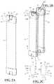
- FIG. 1is a perspective view of a resistance-generating device mounted to a first structure and to a second structure, according to an embodiment of the present disclosure
- FIG. 2Ais a perspective view of the resistance-generating device of FIG. 1 ;
- FIG. 2Bis a perspective view of a plurality of the resistance-generating device of FIG. 1 ;
- FIG. 2Cis a schematic side view of part of two of the resistance-generating devices of FIG. 1 ;
- FIG. 3is a perspective view of a plurality of the resistance-generating device of mounted to the first structure and to the second structure of FIG. 1 ;
- FIG. 4Ais a perspective view of the second structure of FIG. 1 for receiving a resistance-generating device
- FIG. 4Bis a perspective view of a mounting member of the resistance-generating device mounted to the second structure of FIG. 4A ;
- FIG. 5Ais a perspective view of an end cap for a resistance-generating device, according to another embodiment of the present disclosure.
- FIG. 5Bis another perspective view of the end cap of FIG. 5A ;
- FIG. 5Cis a side elevational view of the end cap of FIG. 5A .
- FIG. 1illustrates an exercise apparatus 8 .
- the exercise apparatus 8can be used by a person in a training or exercise regimen.
- the exercise apparatus 8includes a first structure 11 and a spaced-apart second structure 12 .
- the first structure 11 and second structure 12are displaceable relative to one another.
- the first structure 11is a stationary object that does not displace
- the second structure 12is a moveable object which displaces along direction D toward and away from the first structure 11 .
- Other configurations for the displacement of the second structure 12 relative to the first structure 11are also possible.
- both the first and the second structures 11 , 12can be displaceable.
- the first and second structures 11 , 12can be any body, object, or member which allows for the above-described relative displacement of the exercise apparatus 8 .
- the second structure 12has a pulley-housing body 12 A which is slidingly displaceable in direction D along support post 13 when cables 14 actuate the pulley.
- the first structure 11 shown in FIG. 1is a block or protrusion that is fixedly attached to the support post 13 , such that the pulley-housing body 12 A is able to displace in the direction D relative to the first structure 11 .
- FIG. 1also illustrates a resistance-generating device 10 mounted to the first structure 11 and to the second structure 12 .
- the resistance-generating device 10is mounted to the first and second structures 11 , 12 such that it can be easily removed therefrom.
- the displacement of the second structure 12 relative to the first structure 11causes the resistance-generating device 10 attached to the first and second structure 11 , 12 to generate resistance.
- the resistance-generating device 10(referred to herein sometimes simply as “device 10 ”) generates resistance when the second structure 12 is displaced away from the first structure 11 .
- the device 10may also generate resistance in other ways.
- the configuration of the first and second structures 11 , 12 and the attachment of the device 10 theretomay allow the device 10 to generate resistance through the relative displacement of the first and second structures 11 , 12 toward one another.
- the resistance generatedcan be used for any suitable purpose.
- the resistance generated by device 10is used by a person in a training or exercise regimen.
- the device 10has an elongated resilient body 15 .
- the resilient body 15(referred to herein sometimes simply as “body 15 ”) is an object having a length, and extends between two opposed ends 16 .
- the body 15is elastically deformable and returns to its original form or configuration after being stretched.
- the resistance of the body 15 to deformationis what generates the resistance of the device 10 .
- the resiliency of the body 15can be obtained from the material from which it is made.
- the body 15can be made from any suitable polymer material which undergoes elastic deformation.
- the material of the body 15can be a naturally-occurring or synthetic elastomer, such as natural rubber, butyl rubber, or neoprene.
- the body 15is in the form of a resilient band 15 A.
- the body 15may take other forms as well.
- the body 15can be in the form of a resilient elongated cylinder, or can be in the form of a hollow resilient tube.
- the device 10also has a first mounting member 21 and a second mounting member 22 .
- the first mounting member 21is disposed at one of the ends 16 of the body 15
- the second mounting member 22is disposed at the other end 16 of the body 15 .
- Each of the first and second mounting members 21 , 22is a separate component from the body 15 , and is attached or connected to their respective ends 16 of the body 15 , or integral therewith.
- the first and second mounting members 21 , 22are permanently attached to body 15 .
- the first and second mounting members 21 , 22are removably mounted to the ends 16 of the body 15 .
- the first and second mounting members 21 , 22are also removably mounted to the first and second structures 11 , 12 , respectively.
- the first and second mounting members 21 , 22link the body 15 to the relative displacement of the first and second structures 11 , 12 , thereby allowing the body 15 to generate resistance.
- the resilient body 15therefore generates resistance upon being elastically deformed by the displacement of the second mounting member 22 mounted to the second structure 12 relative to the first mounting member 21 mounted to the first structure 11 .
- the relative displacement of the first and second mounting members 21 , 22occurs when the first and second structures 11 , 12 , to which they are attached, are displaced relative to one another.
- the first and second mounting members 21 , 22are made of an inelastic material. In contrast to the body 15 , which undergoes elastic deformation, the first and second mounting members 21 , 22 are rigid and inflexible. Therefore, when the body 15 is undergoing elastic deformation, for example from tension being applied thereto, the first and second mounting members 21 , 22 will not significantly expand or enlarge in shape.
- the non-elasticity or rigidity of the first and second mounting members 21 , 22allows the body 15 to be the principal generator of resistance in the device 10 .
- Some non-limiting examples of materials from which the first and second mounting members 21 , 22 can be madeinclude plastic, wood, metal, rigid elastomers, and composites thereof. It will thus be appreciated that the material of the first and second mounting members 21 , 22 is not the same as the elastomeric material of the body 15 .
- FIG. 2Ashows a single device 10 as described above, and FIG. 2B shows a plurality or set 40 of devices 10 connected together.
- each of the devices 10 in the set 40is removably mounted to one another.
- Thisallows multiple devices 10 to be combined, or “stacked”, together.
- the set 40 of devices 10can be mounted to the first and second structures and the combined resistance they generate will be greater than the resistance generated by any one of the devices 10 of the set 40 alone.
- the ability to removably mount or stack one device 10 to another device 10 ′allows the user to quickly and easily increase the resistance required for resistance-based exercise or training, for example.
- This “resistance multiplier” effectcontrasts with trying to increase resistance with conventional free weights, which typically requires heavy or cumbersome weights to be added about a space-occupying support.
- the removable mounting of one device 10 to another device 10 ′can take different forms.
- the first and second mounting members 21 , 22 of one device 10are removably mounted to the corresponding first and second mounting members 21 ′, 22 ′ of another device 10 ′.
- Other configurations for removably mounting one device 10 to another device 10 ′are possible.
- the two devices 10 , 10 ′share a common first or second mounting member 21 , 22 at one end 16 of the body 15 , and have separate first and second mounting members 21 , 22 at the other end of the body 15 .
- This configurationis represented in FIG. 2B , where two devices 10 , 10 ′ are shown having a common first mounting member 21 ′.
- the resistance of the devices 10 , 10 ′can be combined by removably mounting only the separate corresponding first and second mounting members 21 , 22 together. Similarly, in such a configuration, the resistance of the devices 10 , 10 ′ can be decoupled by disconnecting only the separate corresponding first and second mounting members 21 , 22 .
- each of the first and second mounting members 21 , 22includes an end cap 23 secured to one of the ends 16 of the body 15 .
- the end cap 23is a molded plastic piece that is secured to the end 16 of the body 15 during a molding manufacturing procedure.
- the end cap 23has a first surface 24 A and a second surface 24 B disposed opposite to the first surface 24 A on the other side of the end cap 23 .
- the first surface 24 Ahas a mounting feature 25 and the second surface 24 B has a receiving feature 26 .
- the mounting feature 25 of one device 10is removably mountable to the receiving feature 26 ′ of another device 10 ′, which allows the devices 10 , 10 ′ to be combined together.
- each mounting feature 25includes a projection 27 extending outwardly from the first surface 24 A.
- Each receiving feature 26includes a groove or recess 28 in the second surface 24 B.
- the shape of the projection 27corresponds to that of the recess 28 so that the projection 27 can be inserted into the recess 28 and secured therein, thereby combining corresponding first and second mounting members 21 , 22 and first and second devices 10 , 10 ′.
- the shape of the projection 27 and recess 28can vary.
- the projection 27 and the recess 28have complementary shapes.
- the projection 27has a U-shape, and the recess 28 also has a U-shape as it extends into the second surface 24 B.
- the U-shaped projection 27 of one mounting memberis slid into the U-shaped recess 28 of a corresponding mounting member.
- the configuration of the mounting feature 25 and the receiving feature 26can vary, and is not limited to the depicted configuration. Another embodiment of the mounting and receiving features 25 , 26 is described below. In other embodiments, the mounting feature 25 and receiving feature 26 can also be another configuration of male-female mating objects, a hook-and-loop fastener, a biased mechanism, magnets, or any other suitable mechanical connection.
- decreasing the resistance generated by the set 40can also be easily achieved through the removable mounting of the first and second mounting members 21 , 22 of one device 10 to those of another device 10 ′. More particularly, if the user wishes to reduce the resistance generated by the set 40 , she can simply detach or decouple one or both of the first and second mounting members 21 , 22 of one device 10 from the corresponding first and second mounting member 21 ′, 22 ′ of another device 10 ′.
- first or second mounting members 21 , 22 of one device 10is removed from the corresponding first and second mounting member 21 ′, 22 ′ of another device 10 ′, while maintaining the other mounting member 21 , 22 of the device 10 connected to the corresponding mounting member 21 ′, 22 ′ of the other device 10 ′.
- This disconnectionallows the user to detach only part of one device 10 from the set 40 , thereby providing a reduction in resistance without having to disconnect the entirety of the device 10 . Since one of the mounting members is no longer attached to the remainder of the devices 10 of the set 40 , the device 10 corresponding to that mounting member will not generate resistance when its band 15 A undergoes elastic deformation. If the user wishes to increase the resistance of the set 40 , she can quickly reattach the detached mounting member. This functionality allows the user of the set 40 to quickly modify (i.e. increase and decrease) the resistance generated by a set 40 of devices 10 .
- FIG. 3shows the set 40 , wherein one of its devices 10 is removably mounted to the first and second structures 11 , 12 . More particularly, the first mounting member 21 of the device 10 is mounted to the first structure 11 , and the second mounting member 22 is mounted to the second structure 12 . The remaining devices 10 ′ of the set 40 are combined together by mounting the first and second mounting members 21 , 22 of each device 10 ′ together. As the second structure 12 is displaced along direction D relative to the first structure 11 , the second mounting members 22 of all the devices 10 , 10 ′ are also displaced, thereby causing the bodies 15 of the devices 10 , 10 ′ to generate resistance. If the user wishes to decrease the resistance generated by the set 40 , she can simply detach or decouple one or more mounting members 21 , 22 of each device 10 , 10 ′ from the corresponding mounting member 21 , 22 of another device 10 , 10 ′.
- each of the devices 10 , 10 ′have one or more visual indicia 15 B which provides information to the user on the resistance provided by the device 10 .
- the visual indicia 15 Bis a colour that is unique to each device 10 , each colour being indicative of the stiffness of the body 15 , or how much resistance it generates.
- Other visual indiciasuch as markings, alphanumeric characters, or symbols, may also be used to indicate resistance.
- the visual indicia 15 Bis provided on one of, or both, of the first and second mounting members 21 , 22 . It can thus be appreciated that the user can select a device 10 whose resistance is similar to that generated by a 10 lbs free weight, for example.
- the usercan combine this device 10 with another device 10 whose colour is indicative of a resistance similar to that generated by a 20 lbs free weight.
- the combined resistance of this set 40 of devices 10 , 10 ′will be similar to that generated by lifting 30 lbs of free weights.
- each of the first and second mounting members 21 , 22 of each device 10 , 10 ′have the mounting feature 25 and the receiving feature 26 . This allows the device 10 , 10 ′ to be reversed because each mounting member 21 , 22 is compatible with either one of the mounting members 21 , 22 of another device 10 ′.
- the first and second mounting members 21 , 22 of each device 10therefore have the same construction or structure.
- the end cap 23 of the second mounting member 22is mounted to the displaceable second structure 12 . More particularly, the dovetail projection 27 from the first surface 24 A of the end cap 23 is slid into a similarly shaped recess 12 A of the second structure 12 .
- the first mounting member 21is similarly mounted to the stationary first structure 11 .
- the userapplies force to an exercise accessory which is linked to the first and second structure 11 , 12 via cables 14 and pulleys.
- the tension this creates in the cables 14causes the second structure 12 (and the second mounting member 22 mounted thereto) to displace relative to the first structure (and the first mounting member 21 mounted thereto) along direction D.
- the body 15is thus stretched, which generates the resistance of the device 10 .
- FIGS. 5A to 5Cshow another embodiment of the end cap 123 of the first and second mounting members 21 , 22 .
- the end cap 123is a molded plastic piece that is secured to the end 16 of the body 15 during a molding manufacturing procedure.
- the end cap 123has a first surface 124 A and a second surface 124 B disposed opposite to the first surface 124 A on the other side of the end cap 123 .
- the first surface 124 Ahas a mounting feature 125 and the second surface 124 B has a receiving feature 126 .
- the mounting feature 125 of one device 10is removably mountable to the receiving feature 126 of another device 10 ′, which allows the devices 10 , 10 ′ to be combined together.
- the shape of the projection 127corresponds to that of the recess 128 so that the projection 127 can be inserted into the recess 128 and secured therein, thereby combining corresponding first and second mounting members 21 , 22 and first and second devices 10 , 10 ′.
- the projection 127 and the recess 128have complementary shapes.
- the projection 127has a dovetail shape, and the recess 128 flares outwardly as it extends into the second surface 124 B.
- the dovetail projection 127 of one mounting memberis slid into the flared recess 128 of a corresponding mounting member.
- the first and second structures 11 , 12can have complementary shaped recesses to accommodate the projections 127 .
- the methodincludes connecting one end 16 of a first resilient body 15 to the stationary first structure 11 .
- the methodincludes connecting another end 16 of the first resilient body 16 to the displaceable second structure 12 .
- the methodincludes connecting one end 16 of at least another resilient body 15 to one of the ends 16 of the first resilient body 15 .
- the methodincludes displacing the second structure 12 relative to the first structure 11 to elastically deform at least the first resilient body 15 to generate resistance.
- the device 10 disclosed hereinallows the user to easily modify the resistance desired for training. For example, if the user wants to experience more resistance, such as for weight training, she may simply combine the devices 10 together, and mount the set 40 of devices 10 to the first and second structures 11 , 12 . Similarly, if the user wants to experience less resistance, such as for cardiovascular training, she may simply detach or decouple one or more of the devices 10 from the set 40 , or change the devices 10 for one offering less resistance.
- the device 10 disclosed hereinallows resistance to be rapidly scaled up or down, without the above-described inconveniences and potential dangers associated with free weights.
- the device 10therefore facilitates cardiovascular and/or weight-training exercises by allowing the user to easily increase the resistance by adding more of the relatively light-weight and easily-stored devices 10 .
- the device 10are both space and weight efficient, and easy to transport.
- first and secondare used herein merely to distinguish components from one another. It will be appreciated that the descriptors can be reversed, and that the components described as “first” can also be described as “second”.
Landscapes
- Health & Medical Sciences (AREA)
- Life Sciences & Earth Sciences (AREA)
- Biophysics (AREA)
- Orthopedic Medicine & Surgery (AREA)
- General Health & Medical Sciences (AREA)
- Physical Education & Sports Medicine (AREA)
- Rehabilitation Tools (AREA)
- Toys (AREA)
- Orthopedics, Nursing, And Contraception (AREA)
Abstract
Description
Claims (16)
Priority Applications (1)
| Application Number | Priority Date | Filing Date | Title |
|---|---|---|---|
| US16/323,549US10953259B2 (en) | 2016-08-17 | 2017-08-16 | Resistance-generating device |
Applications Claiming Priority (3)
| Application Number | Priority Date | Filing Date | Title |
|---|---|---|---|
| US201662375940P | 2016-08-17 | 2016-08-17 | |
| PCT/CA2017/050969WO2018032103A1 (en) | 2016-08-17 | 2017-08-16 | Resistance-generating device, exercise apparatus, and method |
| US16/323,549US10953259B2 (en) | 2016-08-17 | 2017-08-16 | Resistance-generating device |
Related Parent Applications (1)
| Application Number | Title | Priority Date | Filing Date |
|---|---|---|---|
| PCT/CA2017/050969A-371-Of-InternationalWO2018032103A1 (en) | 2016-08-17 | 2017-08-16 | Resistance-generating device, exercise apparatus, and method |
Related Child Applications (1)
| Application Number | Title | Priority Date | Filing Date |
|---|---|---|---|
| US17/177,741ContinuationUS11452898B2 (en) | 2016-08-17 | 2021-02-17 | Resistance-generating device, exercise apparatus, and method |
Publications (2)
| Publication Number | Publication Date |
|---|---|
| US20190192895A1 US20190192895A1 (en) | 2019-06-27 |
| US10953259B2true US10953259B2 (en) | 2021-03-23 |
Family
ID=61195963
Family Applications (2)
| Application Number | Title | Priority Date | Filing Date |
|---|---|---|---|
| US16/323,549Expired - Fee RelatedUS10953259B2 (en) | 2016-08-17 | 2017-08-16 | Resistance-generating device |
| US17/177,741Active2037-08-27US11452898B2 (en) | 2016-08-17 | 2021-02-17 | Resistance-generating device, exercise apparatus, and method |
Family Applications After (1)
| Application Number | Title | Priority Date | Filing Date |
|---|---|---|---|
| US17/177,741Active2037-08-27US11452898B2 (en) | 2016-08-17 | 2021-02-17 | Resistance-generating device, exercise apparatus, and method |
Country Status (9)
| Country | Link |
|---|---|
| US (2) | US10953259B2 (en) |
| EP (1) | EP3500350B1 (en) |
| JP (1) | JP6944206B2 (en) |
| KR (1) | KR102444319B1 (en) |
| CN (1) | CN110248704B (en) |
| CA (1) | CA3073220A1 (en) |
| ES (1) | ES2890460T3 (en) |
| SG (1) | SG11202007768YA (en) |
| WO (1) | WO2018032103A1 (en) |
Families Citing this family (4)
| Publication number | Priority date | Publication date | Assignee | Title |
|---|---|---|---|---|
| US11141620B2 (en)* | 2017-05-08 | 2021-10-12 | 1195143 B.C. Ltd. | Seated exercise device |
| US12417852B1 (en) | 2020-01-14 | 2025-09-16 | Beam Alpha, Inc. | Ion transport |
| US12272537B2 (en) | 2020-06-08 | 2025-04-08 | Beam Alpha, Inc. | Ion source |
| US12337207B2 (en)* | 2022-08-02 | 2025-06-24 | Jason Chevalier | Multi-purpose exercise device using bands |
Citations (40)
| Publication number | Priority date | Publication date | Assignee | Title |
|---|---|---|---|---|
| US679784A (en)* | 1900-03-29 | 1901-08-06 | Michael B Ryan | Exercising-machine. |
| FR541324A (en) | 1921-09-20 | 1922-07-26 | Improvements to chamber gymnastics equipment | |
| US1538844A (en)* | 1923-03-13 | 1925-05-19 | Mary Weimar | Progressive exerciser |
| US1620910A (en)* | 1923-02-15 | 1927-03-15 | Harry E Minnich | Exercising device |
| US1633124A (en)* | 1925-10-28 | 1927-06-21 | Roy H Noe | Exercising apparatus |
| US1749544A (en)* | 1928-02-13 | 1930-03-04 | Pagano Joseph | Exercising apparatus |
| US2930614A (en)* | 1954-08-06 | 1960-03-29 | Judson C Mcintosh | Body exercising device |
| US3427023A (en)* | 1966-04-19 | 1969-02-11 | Diversified Prod | Handle for stretchable exercising device |
| US4072309A (en) | 1976-06-21 | 1978-02-07 | Wilson Jerry Lee | Multi-purpose exercise device |
| US4492375A (en) | 1982-08-16 | 1985-01-08 | Contractor Equipment Manufacturers, Inc. | Resilient type exercising device with removable weights |
| US4582320A (en) | 1984-09-21 | 1986-04-15 | Shaw James H | Exercise equipment |
| US5135216A (en)* | 1991-01-29 | 1992-08-04 | Proform Fitness Products, Inc. | Modular resistance assembly for exercise machines |
| US5242353A (en)* | 1991-11-13 | 1993-09-07 | Dayco Products, Inc. | Biasing means, components therefor and methods of making same |
| US5387171A (en) | 1994-01-14 | 1995-02-07 | National Barbell Supply, Inc. | Variable resistance band exercise machine |
| US5603681A (en) | 1995-10-23 | 1997-02-18 | Olschansky; Brad | Portable multi-exercise system |
| US5616111A (en) | 1993-04-30 | 1997-04-01 | Randolph; Lucian | Exoskeletal exercise system |
| US5722922A (en)* | 1991-01-23 | 1998-03-03 | Icon Health & Fitness, Inc. | Aerobic and anaerobic exercise machine |
| US5885196A (en)* | 1996-11-25 | 1999-03-23 | Kordun, Ltd. | Multiple elastic cable exercise device |
| US6042523A (en)* | 1997-06-06 | 2000-03-28 | Graham; Gary A. | Therapeutic exercise apparatus and method |
| US20030023270A1 (en) | 2001-07-26 | 2003-01-30 | Rudi Danz | Physically active patch, methods of manufacturing same and its use |
| US20030195095A1 (en)* | 1999-03-11 | 2003-10-16 | Ken Endelman | Reformer exercise apparatus |
| US20030232707A1 (en) | 2002-06-14 | 2003-12-18 | Icon Ip, Inc. | Exercise device with centrally mounted resistance rod |
| US6676576B1 (en) | 2003-01-21 | 2004-01-13 | Ying-Ching Wu | Adjustable pull exerciser |
| US20040166999A1 (en)* | 2003-02-20 | 2004-08-26 | Dodge David J. | Exercise equipment resistance unit |
| US20050113223A1 (en)* | 2003-11-24 | 2005-05-26 | Dovner Edward R. | Exercise device with elastic resistance |
| CN2805828Y (en) | 2005-08-01 | 2006-08-16 | 吴盈庆 | drawstring exercise machine |
| US20090247376A1 (en)* | 2008-03-25 | 2009-10-01 | Merrithew Lindsay G | Adjustable reformer |
| US20100304939A1 (en)* | 2007-11-29 | 2010-12-02 | Tomas Svenberg | Dumbbell |
| US20100323856A1 (en)* | 2007-11-29 | 2010-12-23 | Thomas Svenberg | Dumbbell |
| CN201768299U (en) | 2009-11-13 | 2011-03-23 | 曾俊明 | Damping device of sports equipment |
| US7931570B2 (en)* | 2006-01-30 | 2011-04-26 | Balanced Body, Inc. | Exercise device |
| US8317667B1 (en)* | 2012-01-19 | 2012-11-27 | Karl Thomas | Portable exercise device and method of using the same |
| CN203075534U (en) | 2013-02-28 | 2013-07-24 | 山东体育学院 | Training instrument capable of regulating waist resistance |
| US20130190148A1 (en)* | 2012-01-23 | 2013-07-25 | Kasper Allison | Strength Training System and Method Having Elastic Resistance and Suspension Devices |
| CN203763761U (en) | 2014-04-10 | 2014-08-13 | 张仲甫 | Pull cord exerciser structure |
| US20150133276A1 (en) | 2013-03-15 | 2015-05-14 | Arqex Outdoor Fitness Systems, Llc | Strength training and stretching system and resistance band assembly for use therewith |
| US20160074691A1 (en)* | 2012-05-08 | 2016-03-17 | Frog Fitness, Inc. | Resistance device, system, and method for use with an exercise apparatus |
| US20160193490A1 (en)* | 2015-01-06 | 2016-07-07 | Prism Fitness, Inc. | Interchangeable Resistance Tube Assembly |
| US9643042B2 (en)* | 2012-10-26 | 2017-05-09 | Vintage Gold Holdings Limited | Freestanding selectable free weight assembly |
| US20170144009A1 (en)* | 2012-05-08 | 2017-05-25 | Frog Fitness, Inc. | Resistance Member Assembly, System, and Method for use with an Exercise Apparatus |
Family Cites Families (56)
| Publication number | Priority date | Publication date | Assignee | Title |
|---|---|---|---|---|
| US254108A (en) | 1882-02-28 | Apparatus | ||
| US2977120A (en) | 1959-06-30 | 1961-03-28 | Wesley B Morris | Exercising device |
| US3863521A (en) | 1971-10-26 | 1975-02-04 | Carlisle Corp | Adjustable handlebars |
| GB1475447A (en) | 1974-07-03 | 1977-06-01 | Geisselbrecht W | Gymnastic exercise appliance |
| US4749286A (en)* | 1984-01-17 | 1988-06-07 | The Gates Rubber Company | Elastomeric bearing system |
| CH665777A5 (en) | 1984-09-17 | 1988-06-15 | Maurice Chillier | MECHANOTHERAPY APPARATUS. |
| US4685670A (en) | 1984-10-01 | 1987-08-11 | Harold Zinkin | Elastic tension exercising apparatus with multiple pass cable and pulley |
| US4621805A (en) | 1985-07-29 | 1986-11-11 | Chen Yi S | Handle structure for an exercycle |
| CA1284666C (en) | 1986-08-01 | 1991-06-04 | Robert S. Hinds | Exercise apparatus |
| FR2629071B1 (en) | 1988-03-22 | 1991-03-15 | Produits Refractaires | REACTIVE ZIRCONIUM OXIDE AND ITS PREPARATION |
| US5144859A (en) | 1989-02-22 | 1992-09-08 | Malone Robert D | Multiple position swivel for handlebars |
| US5029850A (en) | 1989-08-21 | 1991-07-09 | Verimark (Proprietary) Limited | Exercising apparatus |
| US5050869A (en) | 1990-06-07 | 1991-09-24 | Frate Richard A | Portable exercise machine |
| US5039092A (en)* | 1990-06-08 | 1991-08-13 | Lifeing, Inc. | Multi-exercise system |
| US5468205A (en) | 1994-11-02 | 1995-11-21 | Mcfall; Michael | Portable door mounted exercise apparatus |
| US5584782A (en)* | 1995-07-06 | 1996-12-17 | William J. Szabo | Low impact aerobic exercise device |
| USD389205S (en)* | 1996-07-05 | 1998-01-13 | Van Straaten Willem J | Resistive exerciser |
| US5820529A (en) | 1997-04-25 | 1998-10-13 | Mitchell Weintraub | Dual operational exercise resistance device |
| US5842939A (en) | 1997-05-27 | 1998-12-01 | Act Labs Ltd. | Portable sporting goal framework and net |
| US6015371A (en) | 1998-12-24 | 2000-01-18 | Davitt; Christopher | Exercise mechanism |
| US6319179B1 (en) | 1998-12-28 | 2001-11-20 | Robert Sylvester Hinds | Single spine elastic cord exercise assembly |
| US7163500B2 (en) | 2003-11-25 | 2007-01-16 | Balanced Body, Inc. | Reformer exercise apparatus anchor bar assembly |
| US6142919A (en) | 1999-04-12 | 2000-11-07 | Jorgensen; Adam A. | Multi-purpose low profile physical exercising device |
| US20010046928A1 (en) | 2000-03-06 | 2001-11-29 | Nette Terry Van | Variable resistance exercise device |
| TW453207U (en) | 2001-01-18 | 2001-09-01 | Superweigh Entpr Co Ltd | Multifunctional exercise machine |
| US6494817B2 (en) | 2001-02-20 | 2002-12-17 | Victoria Jo Whited Lake | Portable exercising device |
| US20030069112A1 (en) | 2001-10-09 | 2003-04-10 | Patrick Williams | Exercise machine |
| CA2466435C (en) | 2001-11-13 | 2009-03-17 | Keiser Corporation | Exercise apparatus |
| US7041041B1 (en)* | 2002-03-21 | 2006-05-09 | Robert Scott Evans | Exercise equipment |
| US7806805B2 (en) | 2003-10-27 | 2010-10-05 | Stamina Products, Inc. | Exercise apparatus with resilient foot support |
| DE102004013737A1 (en) | 2004-03-18 | 2005-10-06 | Peter Kindermann | Unit for training muscles/muscle groups comprises a vertical support unit with two receiving units that are fixed on a wall a distance apart and have assembly aids for cables/deviating rollers for a force displacement unit/tension unit |
| JP3112700U (en)* | 2005-05-10 | 2005-08-25 | 十二 菊地 | Leg exercise equipment |
| US20070105696A1 (en) | 2005-11-09 | 2007-05-10 | Castel J C | Method and apparatus for physical therapy exercise |
| US8033921B2 (en)* | 2006-06-23 | 2011-10-11 | Dream Visions, Llc | Bungee teeter-totter |
| US20140031182A1 (en) | 2008-08-19 | 2014-01-30 | Darren Donofrio | Wall-Mounted Home Fitness Training Equipment |
| US7976445B2 (en)* | 2009-05-21 | 2011-07-12 | Nabile Lalaoua | Door mounted gym |
| US8360940B2 (en) | 2009-11-17 | 2013-01-29 | Rk Inventions, Llc | Lower leg and foot exercise device |
| US8840075B2 (en)* | 2010-01-19 | 2014-09-23 | Icon Ip, Inc. | Door mounted exercise devices and systems |
| CN201815046U (en)* | 2010-08-25 | 2011-05-04 | 谭炳堂 | portable fitness equipment |
| US20120142503A1 (en) | 2010-12-02 | 2012-06-07 | Mardig Sevadjian | Pulley Apparatus for Resistance Exercises |
| US9609925B2 (en) | 2011-02-04 | 2017-04-04 | Lekisport Ag | Folding pole, in particular for nordic walking |
| EP2686077B1 (en)* | 2011-03-16 | 2020-06-24 | Mad Dogg Athletics, Inc. | Improved exercise table |
| US8485951B1 (en) | 2011-08-02 | 2013-07-16 | Frederick R. Adams | Vehicle mounted multi-position resistance tube exercise apparatus |
| US8485950B2 (en) | 2011-08-02 | 2013-07-16 | Frederick R. Adams | Multi-position resistance tube exercise apparatus |
| US8668632B2 (en)* | 2011-09-15 | 2014-03-11 | Eric Ellis | Exercise apparatus |
| JP2013123634A (en)* | 2011-12-14 | 2013-06-24 | Hashimoto Rashi Kk | Muscle training tool |
| JPWO2013190605A1 (en)* | 2012-06-18 | 2016-02-08 | 株式会社ゼロイニシャライズ | Exercise equipment |
| WO2014047080A1 (en) | 2012-09-18 | 2014-03-27 | Rockit Body Pilates, Llc | Pilates reformer |
| US9028381B2 (en)* | 2012-10-16 | 2015-05-12 | Michael J. Mestemaker | Door-mounted fitness device with removable pulley members |
| US9220966B2 (en) | 2013-03-11 | 2015-12-29 | David Kent Garner | Watersport resistance training device |
| US9005086B1 (en) | 2013-08-28 | 2015-04-14 | Douglas L. Hermann | Portable rowing machine |
| US10661112B2 (en) | 2016-07-25 | 2020-05-26 | Tonal Systems, Inc. | Digital strength training |
| CN106218788B (en) | 2016-08-31 | 2019-02-01 | 杭州速控软件有限公司 | The corner of electrodynamic balance vehicle is adjustable manipulation handle |
| US10518125B2 (en)* | 2016-12-21 | 2019-12-31 | Brian Patrick Janowski | Translating carriage exercise machines and methods of use |
| KR20190069203A (en)* | 2017-12-11 | 2019-06-19 | 안태진 | Fitness equipment |
| US10569119B2 (en)* | 2018-03-08 | 2020-02-25 | Balanced Body, Inc. | Coil spring anchor ring retainer device |
- 2017
- 2017-08-16USUS16/323,549patent/US10953259B2/ennot_activeExpired - Fee Related
- 2017-08-16SGSG11202007768YApatent/SG11202007768YA/enunknown
- 2017-08-16CACA3073220Apatent/CA3073220A1/enactivePending
- 2017-08-16WOPCT/CA2017/050969patent/WO2018032103A1/ennot_activeCeased
- 2017-08-16KRKR1020197007643Apatent/KR102444319B1/enactiveActive
- 2017-08-16EPEP17840668.2Apatent/EP3500350B1/enactiveActive
- 2017-08-16CNCN201780064169.5Apatent/CN110248704B/ennot_activeExpired - Fee Related
- 2017-08-16ESES17840668Tpatent/ES2890460T3/enactiveActive
- 2017-08-16JPJP2019509468Apatent/JP6944206B2/ennot_activeExpired - Fee Related
- 2021
- 2021-02-17USUS17/177,741patent/US11452898B2/enactiveActive
Patent Citations (42)
| Publication number | Priority date | Publication date | Assignee | Title |
|---|---|---|---|---|
| US679784A (en)* | 1900-03-29 | 1901-08-06 | Michael B Ryan | Exercising-machine. |
| FR541324A (en) | 1921-09-20 | 1922-07-26 | Improvements to chamber gymnastics equipment | |
| US1620910A (en)* | 1923-02-15 | 1927-03-15 | Harry E Minnich | Exercising device |
| US1538844A (en)* | 1923-03-13 | 1925-05-19 | Mary Weimar | Progressive exerciser |
| US1633124A (en)* | 1925-10-28 | 1927-06-21 | Roy H Noe | Exercising apparatus |
| US1749544A (en)* | 1928-02-13 | 1930-03-04 | Pagano Joseph | Exercising apparatus |
| US2930614A (en)* | 1954-08-06 | 1960-03-29 | Judson C Mcintosh | Body exercising device |
| US3427023A (en)* | 1966-04-19 | 1969-02-11 | Diversified Prod | Handle for stretchable exercising device |
| US4072309A (en) | 1976-06-21 | 1978-02-07 | Wilson Jerry Lee | Multi-purpose exercise device |
| US4072309B1 (en) | 1976-06-21 | 1984-03-06 | ||
| US4492375A (en) | 1982-08-16 | 1985-01-08 | Contractor Equipment Manufacturers, Inc. | Resilient type exercising device with removable weights |
| US4582320A (en) | 1984-09-21 | 1986-04-15 | Shaw James H | Exercise equipment |
| US5722922A (en)* | 1991-01-23 | 1998-03-03 | Icon Health & Fitness, Inc. | Aerobic and anaerobic exercise machine |
| US5135216A (en)* | 1991-01-29 | 1992-08-04 | Proform Fitness Products, Inc. | Modular resistance assembly for exercise machines |
| US5242353A (en)* | 1991-11-13 | 1993-09-07 | Dayco Products, Inc. | Biasing means, components therefor and methods of making same |
| US5334122A (en) | 1991-11-13 | 1994-08-02 | Dayco Products, Inc. | Biasing means, components therefor and methods of making same |
| US5616111A (en) | 1993-04-30 | 1997-04-01 | Randolph; Lucian | Exoskeletal exercise system |
| US5387171A (en) | 1994-01-14 | 1995-02-07 | National Barbell Supply, Inc. | Variable resistance band exercise machine |
| US5603681A (en) | 1995-10-23 | 1997-02-18 | Olschansky; Brad | Portable multi-exercise system |
| US5885196A (en)* | 1996-11-25 | 1999-03-23 | Kordun, Ltd. | Multiple elastic cable exercise device |
| US6042523A (en)* | 1997-06-06 | 2000-03-28 | Graham; Gary A. | Therapeutic exercise apparatus and method |
| US20030195095A1 (en)* | 1999-03-11 | 2003-10-16 | Ken Endelman | Reformer exercise apparatus |
| US20030023270A1 (en) | 2001-07-26 | 2003-01-30 | Rudi Danz | Physically active patch, methods of manufacturing same and its use |
| US20030232707A1 (en) | 2002-06-14 | 2003-12-18 | Icon Ip, Inc. | Exercise device with centrally mounted resistance rod |
| US6676576B1 (en) | 2003-01-21 | 2004-01-13 | Ying-Ching Wu | Adjustable pull exerciser |
| US20040166999A1 (en)* | 2003-02-20 | 2004-08-26 | Dodge David J. | Exercise equipment resistance unit |
| US20050113223A1 (en)* | 2003-11-24 | 2005-05-26 | Dovner Edward R. | Exercise device with elastic resistance |
| CN2805828Y (en) | 2005-08-01 | 2006-08-16 | 吴盈庆 | drawstring exercise machine |
| US7931570B2 (en)* | 2006-01-30 | 2011-04-26 | Balanced Body, Inc. | Exercise device |
| US20100304939A1 (en)* | 2007-11-29 | 2010-12-02 | Tomas Svenberg | Dumbbell |
| US20100323856A1 (en)* | 2007-11-29 | 2010-12-23 | Thomas Svenberg | Dumbbell |
| US20090247376A1 (en)* | 2008-03-25 | 2009-10-01 | Merrithew Lindsay G | Adjustable reformer |
| CN201768299U (en) | 2009-11-13 | 2011-03-23 | 曾俊明 | Damping device of sports equipment |
| US8317667B1 (en)* | 2012-01-19 | 2012-11-27 | Karl Thomas | Portable exercise device and method of using the same |
| US20130190148A1 (en)* | 2012-01-23 | 2013-07-25 | Kasper Allison | Strength Training System and Method Having Elastic Resistance and Suspension Devices |
| US20160074691A1 (en)* | 2012-05-08 | 2016-03-17 | Frog Fitness, Inc. | Resistance device, system, and method for use with an exercise apparatus |
| US20170144009A1 (en)* | 2012-05-08 | 2017-05-25 | Frog Fitness, Inc. | Resistance Member Assembly, System, and Method for use with an Exercise Apparatus |
| US9643042B2 (en)* | 2012-10-26 | 2017-05-09 | Vintage Gold Holdings Limited | Freestanding selectable free weight assembly |
| CN203075534U (en) | 2013-02-28 | 2013-07-24 | 山东体育学院 | Training instrument capable of regulating waist resistance |
| US20150133276A1 (en) | 2013-03-15 | 2015-05-14 | Arqex Outdoor Fitness Systems, Llc | Strength training and stretching system and resistance band assembly for use therewith |
| CN203763761U (en) | 2014-04-10 | 2014-08-13 | 张仲甫 | Pull cord exerciser structure |
| US20160193490A1 (en)* | 2015-01-06 | 2016-07-07 | Prism Fitness, Inc. | Interchangeable Resistance Tube Assembly |
Non-Patent Citations (3)
| Title |
|---|
| International Search Report and the Written Opinion dated Nov. 2, 2017. |
| Partial English translation of Office Action dated Jul. 3, 2020 in the corresponding Chinese patent application No. 2017800641695. |
| Supplementary European Search Report, EP17840668, dated Feb. 27, 2020. |
Also Published As
| Publication number | Publication date |
|---|---|
| CA3073220A1 (en) | 2018-02-22 |
| ES2890460T3 (en) | 2022-01-19 |
| JP6944206B2 (en) | 2021-10-06 |
| SG11202007768YA (en) | 2020-09-29 |
| US20190192895A1 (en) | 2019-06-27 |
| US20210252325A1 (en) | 2021-08-19 |
| KR102444319B1 (en) | 2022-09-15 |
| JP2019524349A (en) | 2019-09-05 |
| KR20190087402A (en) | 2019-07-24 |
| US11452898B2 (en) | 2022-09-27 |
| CN110248704A (en) | 2019-09-17 |
| WO2018032103A1 (en) | 2018-02-22 |
| CN110248704B (en) | 2021-09-03 |
| EP3500350A4 (en) | 2020-04-08 |
| EP3500350A1 (en) | 2019-06-26 |
| EP3500350B1 (en) | 2021-08-04 |
Similar Documents
| Publication | Publication Date | Title |
|---|---|---|
| US10953259B2 (en) | Resistance-generating device | |
| EP3426359B1 (en) | Exercise apparatus | |
| US10265570B2 (en) | Exercise machine with flexible handles | |
| JP2015202407A (en) | Belt pulling exercise apparatus | |
| US8652015B2 (en) | Safety device | |
| US11931615B2 (en) | Exercise machine resistance selection system | |
| WO2018205018A1 (en) | Seated exercise device | |
| KR101626945B1 (en) | Complex weight training apparatus | |
| EP0943357A1 (en) | Portable inclimetric resistance exercise device | |
| US20240139579A1 (en) | Exercise Machine Rail System | |
| EP3173656A1 (en) | Shock absorbing device | |
| US11020645B2 (en) | Ring-shaped punchbag with inner punchball | |
| KR20210002477U (en) | Yoga rope with anti-slip structure | |
| EP3026314A1 (en) | Fixing element, installation assembly, device assembly and method of fixing | |
| US20160045776A1 (en) | Torsion bar | |
| KR101410868B1 (en) | tension spring | |
| US7608027B2 (en) | Exercise apparatus | |
| JP2012239867A (en) | Muscle training tool | |
| TH163442A (en) | A load carrier with a tension spring assembly is assembled in a tubular housing. | |
| TH72155B (en) | A load carrier with a tension spring assembly is assembled in a tubular housing. |
Legal Events
| Date | Code | Title | Description |
|---|---|---|---|
| FEPP | Fee payment procedure | Free format text:ENTITY STATUS SET TO UNDISCOUNTED (ORIGINAL EVENT CODE: BIG.); ENTITY STATUS OF PATENT OWNER: SMALL ENTITY | |
| FEPP | Fee payment procedure | Free format text:ENTITY STATUS SET TO SMALL (ORIGINAL EVENT CODE: SMAL); ENTITY STATUS OF PATENT OWNER: SMALL ENTITY | |
| STPP | Information on status: patent application and granting procedure in general | Free format text:DOCKETED NEW CASE - READY FOR EXAMINATION | |
| STPP | Information on status: patent application and granting procedure in general | Free format text:NON FINAL ACTION MAILED | |
| STPP | Information on status: patent application and granting procedure in general | Free format text:RESPONSE TO NON-FINAL OFFICE ACTION ENTERED AND FORWARDED TO EXAMINER | |
| STPP | Information on status: patent application and granting procedure in general | Free format text:FINAL REJECTION MAILED | |
| STPP | Information on status: patent application and granting procedure in general | Free format text:NOTICE OF ALLOWANCE MAILED -- APPLICATION RECEIVED IN OFFICE OF PUBLICATIONS | |
| AS | Assignment | Owner name:9614206 CANADA INC., CANADA Free format text:ASSIGNMENT OF ASSIGNORS INTEREST;ASSIGNORS:CORRIGAN, GREGORY LLOYD;ZUCKERMAN, BENJAMIN CHARLES;REEL/FRAME:054907/0045 Effective date:20160816 Owner name:BKR FITNESS GROUP LIMITED, HONG KONG Free format text:ASSIGNMENT OF ASSIGNORS INTEREST;ASSIGNORS:7286139 CANADA LTD;ROBINSON, SAMUEL;ROSYCHUK, RICK;SIGNING DATES FROM 20181213 TO 20190122;REEL/FRAME:054907/0186 Owner name:TUT FITNESS GROUP ASIA LIMITED, HONG KONG Free format text:CHANGE OF NAME;ASSIGNOR:BKR FITNESS GROUP LIMITED;REEL/FRAME:054907/0221 Effective date:20190129 Owner name:1195143 B.C. LTD., CANADA Free format text:ASSIGNMENT OF ASSIGNORS INTEREST;ASSIGNOR:TUT FITNESS GROUP ASIA LIMITED;REEL/FRAME:054907/0285 Effective date:20190215 Owner name:1195143 B.C. LTD., CANADA Free format text:ASSIGNMENT OF ASSIGNORS INTEREST;ASSIGNOR:FADER, TIMA;REEL/FRAME:054907/0374 Effective date:20201210 Owner name:7286139 CANADA LTD, CANADA Free format text:ASSIGNMENT OF ASSIGNORS INTEREST;ASSIGNOR:9614206 CANADA INC.;REEL/FRAME:054978/0599 Effective date:20181213 Owner name:ROBINSON, SAMUEL, CANADA Free format text:ASSIGNMENT OF ASSIGNORS INTEREST;ASSIGNOR:9614206 CANADA INC.;REEL/FRAME:054978/0599 Effective date:20181213 Owner name:ROSYCHUK, RICK, CANADA Free format text:ASSIGNMENT OF ASSIGNORS INTEREST;ASSIGNOR:9614206 CANADA INC.;REEL/FRAME:054978/0599 Effective date:20181213 | |
| STCF | Information on status: patent grant | Free format text:PATENTED CASE | |
| FEPP | Fee payment procedure | Free format text:MAINTENANCE FEE REMINDER MAILED (ORIGINAL EVENT CODE: REM.); ENTITY STATUS OF PATENT OWNER: SMALL ENTITY | |
| LAPS | Lapse for failure to pay maintenance fees | Free format text:PATENT EXPIRED FOR FAILURE TO PAY MAINTENANCE FEES (ORIGINAL EVENT CODE: EXP.); ENTITY STATUS OF PATENT OWNER: SMALL ENTITY | |
| STCH | Information on status: patent discontinuation | Free format text:PATENT EXPIRED DUE TO NONPAYMENT OF MAINTENANCE FEES UNDER 37 CFR 1.362 | |
| FP | Lapsed due to failure to pay maintenance fee | Effective date:20250323 |