US10952884B2 - Multi-fabric endovascular stent-graft - Google Patents
Multi-fabric endovascular stent-graftDownload PDFInfo
- Publication number
- US10952884B2 US10952884B2US15/976,317US201815976317AUS10952884B2US 10952884 B2US10952884 B2US 10952884B2US 201815976317 AUS201815976317 AUS 201815976317AUS 10952884 B2US10952884 B2US 10952884B2
- Authority
- US
- United States
- Prior art keywords
- stent
- graft
- distal
- fluid flow
- flow guide
- Prior art date
- Legal status (The legal status is an assumption and is not a legal conclusion. Google has not performed a legal analysis and makes no representation as to the accuracy of the status listed.)
- Active, expires
Links
- 239000004744fabricSubstances0.000titleclaimsabstractdescription35
- 239000000463materialSubstances0.000claimsabstractdescription58
- 239000012530fluidSubstances0.000claimsabstractdescription48
- 210000005166vasculatureAnatomy0.000claimsdescription110
- 238000000034methodMethods0.000claimsdescription107
- 210000002376aorta thoracicAnatomy0.000claimsdescription30
- 210000004204blood vesselAnatomy0.000claimsdescription13
- 229920000728polyesterPolymers0.000claimsdescription10
- 229920000295expanded polytetrafluoroethylenePolymers0.000claimsdescription9
- 230000002885thrombogenetic effectEffects0.000claimsdescription7
- 239000007943implantSubstances0.000description215
- 230000000452restraining effectEffects0.000description147
- 230000002792vascularEffects0.000description104
- 238000002513implantationMethods0.000description25
- 210000003090iliac arteryAnatomy0.000description17
- 238000006073displacement reactionMethods0.000description13
- 230000007704transitionEffects0.000description11
- 210000001367arteryAnatomy0.000description10
- 210000000709aortaAnatomy0.000description8
- 239000012636effectorSubstances0.000description8
- 208000006011StrokeDiseases0.000description7
- 206010002329AneurysmDiseases0.000description6
- 210000001105femoral arteryAnatomy0.000description6
- 239000005020polyethylene terephthalateSubstances0.000description6
- 210000000702aorta abdominalAnatomy0.000description5
- 238000002224dissectionMethods0.000description5
- -1polyethylenePolymers0.000description5
- 229920000139polyethylene terephthalatePolymers0.000description5
- 230000017531blood circulationEffects0.000description4
- 210000001168carotid artery commonAnatomy0.000description4
- 230000005012migrationEffects0.000description4
- 238000013508migrationMethods0.000description4
- 210000003270subclavian arteryAnatomy0.000description4
- 238000013519translationMethods0.000description4
- 208000007474aortic aneurysmDiseases0.000description3
- 238000013459approachMethods0.000description3
- 239000008280bloodSubstances0.000description2
- 210000004369bloodAnatomy0.000description2
- 210000002302brachial arteryAnatomy0.000description2
- 230000003993interactionEffects0.000description2
- 230000003902lesionEffects0.000description2
- 229910001092metal group alloyInorganic materials0.000description2
- 230000006641stabilisationEffects0.000description2
- 238000011105stabilizationMethods0.000description2
- 102000008186CollagenHuman genes0.000description1
- 108010035532CollagenProteins0.000description1
- 206010010356Congenital anomalyDiseases0.000description1
- 208000036829Device dislocationDiseases0.000description1
- 208000005189EmbolismDiseases0.000description1
- 208000001750EndoleakDiseases0.000description1
- 239000004698PolyethyleneSubstances0.000description1
- 201000008982Thoracic Aortic AneurysmDiseases0.000description1
- 208000007536ThrombosisDiseases0.000description1
- 208000002223abdominal aortic aneurysmDiseases0.000description1
- 239000008186active pharmaceutical agentSubstances0.000description1
- 230000004087circulationEffects0.000description1
- 229920001436collagenPolymers0.000description1
- 230000010339dilationEffects0.000description1
- 201000010099diseaseDiseases0.000description1
- 208000037265diseases, disorders, signs and symptomsDiseases0.000description1
- 230000000694effectsEffects0.000description1
- 238000000605extractionMethods0.000description1
- 238000002594fluoroscopyMethods0.000description1
- 208000014674injuryDiseases0.000description1
- 238000007726management methodMethods0.000description1
- 239000002184metalSubstances0.000description1
- 238000012986modificationMethods0.000description1
- 230000004048modificationEffects0.000description1
- HLXZNVUGXRDIFK-UHFFFAOYSA-Nnickel titaniumChemical compound[Ti].[Ti].[Ti].[Ti].[Ti].[Ti].[Ti].[Ti].[Ti].[Ti].[Ti].[Ni].[Ni].[Ni].[Ni].[Ni].[Ni].[Ni].[Ni].[Ni].[Ni].[Ni].[Ni].[Ni].[Ni]HLXZNVUGXRDIFK-UHFFFAOYSA-N0.000description1
- 229910001000nickel titaniumInorganic materials0.000description1
- 229920000573polyethylenePolymers0.000description1
- 229920000642polymerPolymers0.000description1
- 229920001343polytetrafluoroethylenePolymers0.000description1
- 239000004810polytetrafluoroethyleneSubstances0.000description1
- 230000002265preventionEffects0.000description1
- 210000002254renal arteryAnatomy0.000description1
- 230000008439repair processEffects0.000description1
- 210000003752saphenous veinAnatomy0.000description1
- 238000001356surgical procedureMethods0.000description1
- 239000004753textileSubstances0.000description1
- 230000008733traumaEffects0.000description1
- 238000011144upstream manufacturingMethods0.000description1
Images


Classifications
- A—HUMAN NECESSITIES
- A61—MEDICAL OR VETERINARY SCIENCE; HYGIENE
- A61F—FILTERS IMPLANTABLE INTO BLOOD VESSELS; PROSTHESES; DEVICES PROVIDING PATENCY TO, OR PREVENTING COLLAPSING OF, TUBULAR STRUCTURES OF THE BODY, e.g. STENTS; ORTHOPAEDIC, NURSING OR CONTRACEPTIVE DEVICES; FOMENTATION; TREATMENT OR PROTECTION OF EYES OR EARS; BANDAGES, DRESSINGS OR ABSORBENT PADS; FIRST-AID KITS
- A61F2/00—Filters implantable into blood vessels; Prostheses, i.e. artificial substitutes or replacements for parts of the body; Appliances for connecting them with the body; Devices providing patency to, or preventing collapsing of, tubular structures of the body, e.g. stents
- A61F2/95—Instruments specially adapted for placement or removal of stents or stent-grafts
- A61F2/962—Instruments specially adapted for placement or removal of stents or stent-grafts having an outer sleeve
- A—HUMAN NECESSITIES
- A61—MEDICAL OR VETERINARY SCIENCE; HYGIENE
- A61F—FILTERS IMPLANTABLE INTO BLOOD VESSELS; PROSTHESES; DEVICES PROVIDING PATENCY TO, OR PREVENTING COLLAPSING OF, TUBULAR STRUCTURES OF THE BODY, e.g. STENTS; ORTHOPAEDIC, NURSING OR CONTRACEPTIVE DEVICES; FOMENTATION; TREATMENT OR PROTECTION OF EYES OR EARS; BANDAGES, DRESSINGS OR ABSORBENT PADS; FIRST-AID KITS
- A61F2/00—Filters implantable into blood vessels; Prostheses, i.e. artificial substitutes or replacements for parts of the body; Appliances for connecting them with the body; Devices providing patency to, or preventing collapsing of, tubular structures of the body, e.g. stents
- A61F2/02—Prostheses implantable into the body
- A61F2/04—Hollow or tubular parts of organs, e.g. bladders, tracheae, bronchi or bile ducts
- A61F2/06—Blood vessels
- A61F2/07—Stent-grafts
- A—HUMAN NECESSITIES
- A61—MEDICAL OR VETERINARY SCIENCE; HYGIENE
- A61F—FILTERS IMPLANTABLE INTO BLOOD VESSELS; PROSTHESES; DEVICES PROVIDING PATENCY TO, OR PREVENTING COLLAPSING OF, TUBULAR STRUCTURES OF THE BODY, e.g. STENTS; ORTHOPAEDIC, NURSING OR CONTRACEPTIVE DEVICES; FOMENTATION; TREATMENT OR PROTECTION OF EYES OR EARS; BANDAGES, DRESSINGS OR ABSORBENT PADS; FIRST-AID KITS
- A61F2/00—Filters implantable into blood vessels; Prostheses, i.e. artificial substitutes or replacements for parts of the body; Appliances for connecting them with the body; Devices providing patency to, or preventing collapsing of, tubular structures of the body, e.g. stents
- A61F2/95—Instruments specially adapted for placement or removal of stents or stent-grafts
- A61F2/962—Instruments specially adapted for placement or removal of stents or stent-grafts having an outer sleeve
- A61F2/966—Instruments specially adapted for placement or removal of stents or stent-grafts having an outer sleeve with relative longitudinal movement between outer sleeve and prosthesis, e.g. using a push rod
- A—HUMAN NECESSITIES
- A61—MEDICAL OR VETERINARY SCIENCE; HYGIENE
- A61F—FILTERS IMPLANTABLE INTO BLOOD VESSELS; PROSTHESES; DEVICES PROVIDING PATENCY TO, OR PREVENTING COLLAPSING OF, TUBULAR STRUCTURES OF THE BODY, e.g. STENTS; ORTHOPAEDIC, NURSING OR CONTRACEPTIVE DEVICES; FOMENTATION; TREATMENT OR PROTECTION OF EYES OR EARS; BANDAGES, DRESSINGS OR ABSORBENT PADS; FIRST-AID KITS
- A61F2/00—Filters implantable into blood vessels; Prostheses, i.e. artificial substitutes or replacements for parts of the body; Appliances for connecting them with the body; Devices providing patency to, or preventing collapsing of, tubular structures of the body, e.g. stents
- A61F2/02—Prostheses implantable into the body
- A61F2/04—Hollow or tubular parts of organs, e.g. bladders, tracheae, bronchi or bile ducts
- A61F2/06—Blood vessels
- A61F2002/061—Blood vessels provided with means for allowing access to secondary lumens
- A—HUMAN NECESSITIES
- A61—MEDICAL OR VETERINARY SCIENCE; HYGIENE
- A61F—FILTERS IMPLANTABLE INTO BLOOD VESSELS; PROSTHESES; DEVICES PROVIDING PATENCY TO, OR PREVENTING COLLAPSING OF, TUBULAR STRUCTURES OF THE BODY, e.g. STENTS; ORTHOPAEDIC, NURSING OR CONTRACEPTIVE DEVICES; FOMENTATION; TREATMENT OR PROTECTION OF EYES OR EARS; BANDAGES, DRESSINGS OR ABSORBENT PADS; FIRST-AID KITS
- A61F2/00—Filters implantable into blood vessels; Prostheses, i.e. artificial substitutes or replacements for parts of the body; Appliances for connecting them with the body; Devices providing patency to, or preventing collapsing of, tubular structures of the body, e.g. stents
- A61F2/02—Prostheses implantable into the body
- A61F2/04—Hollow or tubular parts of organs, e.g. bladders, tracheae, bronchi or bile ducts
- A61F2/06—Blood vessels
- A61F2002/065—Y-shaped blood vessels
- A61F2002/067—Y-shaped blood vessels modular
- A—HUMAN NECESSITIES
- A61—MEDICAL OR VETERINARY SCIENCE; HYGIENE
- A61F—FILTERS IMPLANTABLE INTO BLOOD VESSELS; PROSTHESES; DEVICES PROVIDING PATENCY TO, OR PREVENTING COLLAPSING OF, TUBULAR STRUCTURES OF THE BODY, e.g. STENTS; ORTHOPAEDIC, NURSING OR CONTRACEPTIVE DEVICES; FOMENTATION; TREATMENT OR PROTECTION OF EYES OR EARS; BANDAGES, DRESSINGS OR ABSORBENT PADS; FIRST-AID KITS
- A61F2/00—Filters implantable into blood vessels; Prostheses, i.e. artificial substitutes or replacements for parts of the body; Appliances for connecting them with the body; Devices providing patency to, or preventing collapsing of, tubular structures of the body, e.g. stents
- A61F2/02—Prostheses implantable into the body
- A61F2/04—Hollow or tubular parts of organs, e.g. bladders, tracheae, bronchi or bile ducts
- A61F2/06—Blood vessels
- A61F2/07—Stent-grafts
- A61F2002/075—Stent-grafts the stent being loosely attached to the graft material, e.g. by stitching
- A—HUMAN NECESSITIES
- A61—MEDICAL OR VETERINARY SCIENCE; HYGIENE
- A61F—FILTERS IMPLANTABLE INTO BLOOD VESSELS; PROSTHESES; DEVICES PROVIDING PATENCY TO, OR PREVENTING COLLAPSING OF, TUBULAR STRUCTURES OF THE BODY, e.g. STENTS; ORTHOPAEDIC, NURSING OR CONTRACEPTIVE DEVICES; FOMENTATION; TREATMENT OR PROTECTION OF EYES OR EARS; BANDAGES, DRESSINGS OR ABSORBENT PADS; FIRST-AID KITS
- A61F2/00—Filters implantable into blood vessels; Prostheses, i.e. artificial substitutes or replacements for parts of the body; Appliances for connecting them with the body; Devices providing patency to, or preventing collapsing of, tubular structures of the body, e.g. stents
- A61F2/95—Instruments specially adapted for placement or removal of stents or stent-grafts
- A61F2/962—Instruments specially adapted for placement or removal of stents or stent-grafts having an outer sleeve
- A61F2/966—Instruments specially adapted for placement or removal of stents or stent-grafts having an outer sleeve with relative longitudinal movement between outer sleeve and prosthesis, e.g. using a push rod
- A61F2002/9665—Instruments specially adapted for placement or removal of stents or stent-grafts having an outer sleeve with relative longitudinal movement between outer sleeve and prosthesis, e.g. using a push rod with additional retaining means
- A—HUMAN NECESSITIES
- A61—MEDICAL OR VETERINARY SCIENCE; HYGIENE
- A61F—FILTERS IMPLANTABLE INTO BLOOD VESSELS; PROSTHESES; DEVICES PROVIDING PATENCY TO, OR PREVENTING COLLAPSING OF, TUBULAR STRUCTURES OF THE BODY, e.g. STENTS; ORTHOPAEDIC, NURSING OR CONTRACEPTIVE DEVICES; FOMENTATION; TREATMENT OR PROTECTION OF EYES OR EARS; BANDAGES, DRESSINGS OR ABSORBENT PADS; FIRST-AID KITS
- A61F2230/00—Geometry of prostheses classified in groups A61F2/00 - A61F2/26 or A61F2/82 or A61F9/00 or A61F11/00 or subgroups thereof
- A61F2230/0063—Three-dimensional shapes
- A61F2230/0069—Three-dimensional shapes cylindrical
Definitions
- Endovascular prosthesesare sometimes used to treat aortic aneurysms.
- Such treatmentincludes implanting a stent or stent-graft within the diseased vessel to bypass the anomaly.
- An aneurysmis a sac formed by the dilation of the wall of the artery. Aneurysms may be congenital, but are usually caused by disease or, occasionally, by trauma.
- Aortic aneurysms which commonly form between the renal arteries and the iliac arteriesare referred to as abdominal aortic aneurysms (“AAAs”).
- TAAsthoracic aortic aneurysms
- Endo-Vascular Aneurysm Repairhas transformed the practice of treatment of aortic aneurysms from an open surgical approach to a much less invasive surgical approach.
- an endovascular systemwhich comprises an endovascular implant and a delivery tool.
- the delivery toolis configured to minimize or prevent migration of the endovascular implant during an implantation procedure.
- the delivery toolcomprises a proximal main delivery catheter, which has a distal portion in which the implant is initially disposed while in a radially-compressed delivery state.
- the delivery toolfurther comprises a distal restraining assembly, which comprises a restraining-assembly tubular shaft disposed distal to the proximal main delivery catheter.
- the distal restraining assemblyis configured to assume (a) an engaged state, in which the distal restraining assembly prevents proximal displacement of the implant relative to the distal restraining assembly, and (b) a disengaged state, in which the distal restraining assembly does not engage the implant.
- the distal restraining assemblycomprises one or more flexible elongated members, such as sutures, wires, or strings.
- the flexible elongated membersextend from a proximal end of the restraining-assembly tubular shaft.
- the flexible elongated membersreleasably couple the distal restraining assembly to a distal portion of the implant.
- the delivery toolfurther comprises a tip disposed longitudinally between the proximal main delivery catheter and the restraining-assembly tubular shaft.
- the tipWhen the implant is in the radially-expanded deployment state and the distal restraining assembly is in the engaged state, the tip is proximally withdrawable into the implant without entangling the tip with the flexible elongated members.
- the flexible elongated memberspass over an external surface of the tip when the distal restraining assembly is in the engaged state.
- the flexible elongated membersare slidably disposed within the restraining-assembly tubular shaft, at least when the distal restraining assembly is in the engaged state.
- the tipis conically shaped. Typically, the tip narrows toward a distal end thereof.
- the endovascular systemfurther comprises a guidewire.
- the delivery toolis configured to receive the guidewire therethrough, typically such that the guidewire extends from a proximal end of the proximal main delivery catheter to a distal end of the restraining-assembly tubular shaft, at least when the distal restraining assembly is in the engaged state.
- the proximal main delivery catheter and the restraining-assembly tubular shaftare shaped so as to define respective guidewire longitudinal lumens therethrough.
- the guidewire of the delivery toolis endovascularly (preferably percutaneously) introduced into the vasculature at a first vascular access site, advanced through the vasculature, and extracted from the vasculature and the patient's body at a second vascular access site different from the first.
- the guidewireis endovascularly introduced into the vasculature at the second vascular access site, advanced through the vasculature towards the first vascular access site, captured and thereafter extracted from the vasculature and the patient's body at the first vascular access site.
- the guidewireextends between two vascular access sites through the vasculature.
- the distal restraining assembly and the proximal main delivery catheterare introduced, through the first vascular access site, into the vasculature over the guidewire.
- the restraining-assembly tubular shaftis advanced over the guidewire until a distal end of the restraining-assembly tubular shaft exits the vasculature through the second vascular access site, and the distal end is held (e.g., fixed and/or secured) stationary outside the patient's body.
- the restraining-assembly tubular shaft of the distal restraining assemblyis positioned distal to the proximal main delivery catheter.
- the distal restraining assemblyis in the engaged state at this stage of the implantation procedure.
- the tip of the delivery toolis disposed longitudinally between the proximal main delivery catheter and the restraining-assembly tubular shaft.
- Respective first portions of the flexible elongated members of the distal restraining assemblyextend from the proximal end of the restraining-assembly tubular shaft, and thus pass through the second vascular access site together with (within) the restraining-assembly tubular shaft, and thus are accessible from outside the patient's body.
- the flexible elongated membersare positioned such that they pass through the restraining-assembly tubular shaft, pass over the external surface of the tip, and are releasably coupled to the distal portion of the implant.
- the proximal main delivery catheter(and the distal restraining assembly) is advanced through the vasculature to a desired deployment site.
- the implantis released from the proximal main delivery catheter in the vasculature.
- the implantradially expands and transitions to the radially-expanded deployment state as it is released.
- one or more second endovascular implantsare introduced into the vasculature.
- the one or more second implantsare advanced at least partially through the first implant, such as through a lateral opening defined by the first implant, and deployed in the vasculature.
- the one or more second implantsare typically introduced over one or more second guidewires, separate from the guidewire over which the first implant was introduced, which typically remains in place in the vasculature during the deployment of the one or more second implants.
- the distal restraining assemblyAfter deployment of the one or more second endovascular implants, the distal restraining assembly is transitioned to the disengaged state, in which the distal restraining assembly allows proximal displacement of the implant relative to the distal restraining assembly.
- the disengaged statein which the distal restraining assembly allows proximal displacement of the implant relative to the distal restraining assembly.
- distal portions of the flexible elongated members that extend beyond the distal end of the restraining-assembly tubular shaftare cut, in order to release the flexible elongated members from the distal portion of the implant.
- apparatusincluding an endovascular system, which includes:
- an endovascular implantwhich is configured to assume a radially-compressed delivery state, and a radially-expanded deployment state
- a delivery toolwhich includes:
- the distal restraining assemblyincludes one or more flexible elongated members, which extend from a proximal end of the restraining-assembly tubular shaft and releasably couple an element of the endovascular system to a distal portion of the implant when the distal restraining assembly is in the engaged state, the element selected from the group consisting of: the distal restraining assembly and the restraining-assembly tubular shaft.
- the endovascular implantincludes a stent member, and the flexible elongated members releasably couple the selected element of the endovascular system to a distal portion of the stent member when the distal restraining assembly is in the engaged state.
- the delivery toolfurther includes a tip disposed longitudinally between the proximal main delivery catheter and the restraining-assembly tubular shaft, and, when the implant is in the radially-expanded deployment state and the distal restraining assembly is in the engaged state, the tip is proximally withdrawable into the implant without entangling the tip with the flexible elongated members.
- the flexible elongated memberspass over an external surface of the tip when the distal restraining assembly is in the engaged state.
- the external surface of the tipis shaped so as to define one or more grooves, and the flexible elongated members are disposed within the grooves while the flexible elongated members pass over the external surface.
- a first longitudinal portion of the delivery toolmay extend between a proximal end of the implant and a proximal end of the delivery tool
- a second longitudinal portion of the delivery toolmay extend between a distal end of the implant and a distal end of the delivery tool
- the first and the second longitudinal portionsmay have respective lengths, each of which is at least 20 cm.
- the delivery toolmay further include a tip disposed longitudinally between the proximal main delivery catheter and the restraining-assembly tubular shaft.
- the proximal main delivery catheterincludes inner and outer tubular shafts, and the tip is fixed to a distal end of the inner shaft.
- the tipis conically shaped.
- the proximal main delivery catheterincludes inner and outer tubular shafts, and the tip gradually tapers from (a) a proximal-end diameter equal to between 90% and 110% of an outer diameter of a distal end of the outer tubular shaft to (b) a distal-end diameter equal to between 70% and 100% of an outer diameter of the proximal end of the restraining-assembly tubular shaft.
- the proximal main delivery cathetermay include inner and outer tubular shafts, which are longitudinally translatable with respect to each other, and the implant may be disposed radially between the inner and the outer shafts while in the radially-compressed delivery state.
- the delivery toolis configured such that proximal longitudinal translation of the outer shaft relative to the inner shaft transitions the implant from the radially-compressed delivery state to the radially-expanded deployment state.
- the proximal main delivery catheterincludes a stopper member, which is disposed between the inner and the outer shafts, and is fixed to exactly one of the inner and the outer shafts.
- the endovascular implantincludes a stent member, and the stopper member is shaped and sized to interface with the stent member while the implant is in its radially-compressed delivery state, thereby substantially preventing proximal translation of the implant relative to the inner shaft as the outer shaft is proximally translated relative to the inner shaft.
- the stopper memberis fixed to the inner shaft.
- the stopper memberis positioned adjacent a distal end of the implant while the implant is in the radially-compressed delivery state, disposed radially between the inner and the outer shafts.
- the endovascular implantmay include a stent-graft, which includes a flexible stent member, and a generally tubular fluid flow guide, which is securely attached to and covers at least a portion of the stent member.
- the stent-graftis shaped so as to define at least one lateral opening.
- the stent-graftis a first stent-graft
- the endovascular systemfurther includes a second stent-graft, which is sized to pass at least partially through the lateral opening.
- the openingis generally circular.
- the endovascular systemmay further include a guidewire, and the delivery tool may be configured to receive the guidewire therethrough.
- the delivery toolis configured to receive the guidewire therethrough such that the guidewire extends from a proximal end of the proximal main delivery catheter to a distal end of the restraining-assembly tubular shaft.
- the proximal main delivery catheter and the restraining-assembly tubular shaftare shaped so as to define respective guidewire longitudinal lumens therethrough.
- the proximal main delivery catheterincludes inner and outer tubular shafts, and the inner shaft is shaped so as to define the guidewire longitudinal lumen of the proximal main delivery catheter.
- the guidewire longitudinal lumen of the restraining-assembly tubular shaftis disposed along a central longitudinal axis of the restraining-assembly tubular shaft.
- the endovascular systemmay further include a guidewire, and the restraining-assembly tubular shaft may be shaped so as to define a longitudinal guidewire lumen therethrough, through which the guidewire is removably disposed.
- the guidewireis a first guidewire, and the endovascular system includes a second guidewire.
- the endovascular implantincludes a stent-graft, which includes a flexible stent member, and a generally tubular fluid flow guide, which is securely attached to and covers at least a portion of the stent member, and the release effector flexible elongated members securely engage the fluid flow guide when the distal restraining assembly is in the engaged state.
- the release effector flexible elongated membersare disengaged from the implant when the distal restraining assembly is in the disengaged state.
- the one or more release effector flexible elongated memberspass from the distal end of the restraining-assembly tubular shaft to the proximal end of the restraining-assembly tubular shaft, engage the endovascular implant, and return to the distal end of the restraining-assembly tubular shaft, and distally extracting respective first ends of the release wires transitions the distal restraining assembly from the engaged state to the disengaged state.
- the one or more release effector flexible longitudinal membersare configured to transition the distal restraining assembly from the engaged state to the disengaged state by rotation of each of the flexible longitudinal members around a longitudinal axis thereof.
- the stent-graftis configured to assume a radially-compressed delivery state and a radially-expanded deployment state
- the stent-grafthas first and second ends
- a perimeter of the stent-graft at the first endis less than a perimeter of the stent-graft at the second end, when the stent-graft is in the radially-expanded deployment state
- the first longitudinal portionextends to the first end of the stent-graft.
- the stent-graftis a fenestrated stent-graft
- the apparatusfurther includes a main stent-graft, which is shaped so as to define a lateral opening, and
- the second longitudinal portion of the fenestrated stent-graftis shaped so as to define an interface portion configured to form a blood-tight seal with the lateral opening of the main stent-graft.
- the first materialincludes expanded polytetrafluoroethylene (ePTFE).
- ePTFEexpanded polytetrafluoroethylene
- the second materialmay include a polyester.
- first and the second longitudinal portionsmay be non-longitudinally-overlapping.
- first and the second longitudinal portionsare longitudinally adjacent each other.
- first and the second fabricsare coupled to each other at a longitudinal junction between the first and the second longitudinal portions.
- the first and the second longitudinal portionsmay be partially longitudinally overlapping along a longitudinally overlapping portion of the stent-graft.
- the first and the second fabricsare coupled to each other at one or more locations along the longitudinally overlapping portion.
- the longitudinally overlapping portion of the stent-grafthas a length that is less than 5% of an overall length of the stent-graft.
- the longitudinally overlapping portion of the stent-grafthas a length of between 2 and 10 mm.
- the longitudinally overlapping portion of the stent-graftis positioned at a location along the stent-graft that has a diameter that is less than a greatest diameter of the stent-graft.
- an endovascular implantand (b) a delivery tool which includes a proximal main delivery catheter and a distal restraining assembly, which includes a restraining-assembly tubular shaft disposed distal to the proximal main delivery catheter;
- inventive concept 2The method according to inventive concept 1, wherein endovascularly introducing and advancing the delivery tool comprise:
- distal restraining assemblyincludes one or more flexible elongated members, which extend from a proximal end of the restraining-assembly tubular shaft and releasably couple the distal restraining assembly to a distal portion of the implant when the distal restraining assembly is in the engaged state,
- restraining-assembly tubular shaftis shaped so as to define one or more longitudinal elongated-member lumens and a longitudinal guidewire lumen therethrough, and
- endovascularly introducing the delivery toolcomprises endovascularly introducing the delivery tool while the flexible elongated members are slidably disposed through the longitudinal elongated-member lumens, and the guidewire is removably disposed through the longitudinal guidewire lumen.
- inventive concept 4The method according to inventive concept 2, further comprising, after releasing the endovascular implant from the proximal main delivery catheter, using the guidewire to help hold the implant in place in the vasculature.
- Inventive concept 5The method according to inventive concept 1, further comprising fixing the distal end of the restraining-assembly tubular shaft stationary outside the second vascular access site, such that the distal restraining assembly prevents proximal displacement of the implant relative to the distal restraining assembly.
- fixing stationarycomprises fixing the distal end of the restraining-assembly tubular shaft stationary before releasing the endovascular implant from the proximal main delivery catheter.
- Inventive concept 7The method according to inventive concept 5, wherein fixing stationary comprises fixing the distal end of the restraining-assembly tubular shaft stationary after releasing the endovascular implant from the proximal main delivery catheter.
- inventive concept 1further comprising, after releasing the endovascular implant, pulling the distal end of the restraining-assembly tubular shaft distally from outside the second vascular access site, thereby distally displacing the endovascular implant.
- inventive concept 9The method according to inventive concept 1, further comprising, after releasing the endovascular implant, rotating the distal restraining assembly from outside the second vascular access site, thereby rotating the endovascular implant.
- Inventive concept 10The method according to inventive concept 9, wherein rotating the distal restraining assembly comprises rotating the restraining-assembly tubular shaft from outside the second vascular access site.
- inventive concept 11The method according to inventive concept 1,
- distal restraining assemblyincludes one or more flexible elongated members, which extend from a proximal end of the restraining-assembly tubular shaft and releasably couple the distal restraining assembly to a distal portion of the implant when the distal restraining assembly is in the engaged state, and
- advancing the delivery tool through the vasculature until the distal end of the restraining-assembly tubular shaft exits the vasculature through the second vascular access sitecomprises passing the flexible elongated members through the second vascular access site together with the distal end of the restraining-assembly tubular shaft, such that the flexible elongated members are accessible from outside a body of the patient.
- the delivery toolfurther includes a tip
- Inventive concept 15The method according to inventive concept 14, wherein releasing the endovascular implant from the proximal main delivery catheter further comprises, after the implant transitions to the radially-expanded deployment state, proximally withdrawing the tip into the implant without entangling the tip with the flexible elongated members.
- Inventive concept 16The method according to inventive concept 14, wherein providing the delivery tool comprises providing the delivery tool in which the proximal main delivery catheter includes inner and outer tubular shafts, and the tip is fixed to a distal end of the inner shaft.
- Inventive concept 19The method according to inventive concept 14, wherein the external surface of the tip is shaped so as to define one or more grooves, and wherein endovascularly introducing the delivery tool comprises endovascularly introducing the delivery tool while the flexible elongated members are disposed within the grooves while the flexible elongated members pass over the external surface.
- Inventive concept 20The method according to inventive concept 1, wherein transitioning the distal restraining assembly to the disengaged state comprises transitioning the distal restraining assembly to the disengaged state from a distal disengagement site provided by the distal restraining assembly at a distal location on the restraining-assembly tubular shaft.
- Inventive concept 21The method according to inventive concept 14, wherein the external surface of the tip is shaped so as to define one or more grooves, and wherein endovascularly introducing the delivery tool comprises endovascularly introducing the delivery tool while the flexible elongated members are disposed within the grooves while the flexible elongated members pass
- providing the endovascular implantcomprises providing a stent-graft, which comprises a flexible stent member, and a generally tubular fluid flow guide, which is securely attached to and covers at least a portion of the stent member.
- a stent-graftwhich comprises a flexible stent member, and a generally tubular fluid flow guide, which is securely attached to and covers at least a portion of the stent member.
- the stent-graftis a first stent-graft shaped so as to define at least one lateral opening
- the methodfurther comprises providing a second stent-graft, which is sized to be securely deployed partially outside and partially inside the lateral opening,
- endovascularly introducing and advancing the delivery toolcomprise:
- Inventive concept 24The method according to inventive concept 1, wherein introducing the delivery tool into the vasculature comprises introducing the delivery tool into an artery.
- Inventive concept 25The method according to inventive concept 24, wherein the artery is aneurysmatic.
- inventive concept 26The method according to inventive concept 24, wherein a wall of the artery suffers from a dissection.
- an elongated delivery toolhaving proximal and distal ends, and (b) an endovascular implant, which is removably connected to the distal end of the delivery tool, such that proximal movement of the implant toward the first proximal of the delivery tool is substantially prevented;
- a proximal longitudinal portion of the delivery toolwhich includes the proximal end, passes through a first vascular access site
- a distal longitudinal portion of the delivery tool, which includes the distal endpasses through a second vascular access site
- an intermediate longitudinal portion of the delivery toolis disposed between the first and the second vascular access sites within the vasculature
- Inventive concept 28The method according to inventive concept 27, wherein releasing comprises releasing the implant from the delivery tool by longitudinally translating a component of the delivery tool toward the proximal end of the delivery tool.
- inventive concept 29The method according to inventive concept 27, wherein endovascularly introducing comprises endovascularly introducing the delivery tool such that the implant generally spans a lesion within the blood vessel.
- Inventive concept 31The method according to inventive concept 27, wherein providing the endovascular implant comprises providing a stent-graft, which comprises a flexible stent member, and a generally tubular fluid flow guide, which is securely attached to and covers at least a portion of the stent member.
- Inventive concept 32The method according to inventive concept 31,
- the stent-graftis a first stent-graft shaped so as to define at least one lateral opening
- the methodfurther comprises providing a second stent-graft, which is sized to pass at least partially through the lateral opening,
- releasing the endovascular implant from the delivery toolcomprises releasing the first stent-graft from the delivery tool
- the methodfurther comprises, (a) after releasing the first stent-graft from the delivery tool, and (c) before effecting the detachment of the distal end of the delivery tool from the first stent-graft:
- endovascularly introducing the delivery toolcomprises:
- introducing and advancing the second stent-graftcomprises introducing a second guidewire into the vasculature through the first vascular access site, and introducing and advancing the second stent-graft over the second guidewire, while the first guidewire remains in the vasculature.
- an endovascular stent-graftwhich includes (a) a flexible stent member, and (b) a tubular fluid flow guide, which includes (i) a first fabric, which comprises a first biologically-compatible substantially blood-impervious material, and which is attached to and covers the stent member along a first longitudinal portion of the stent-graft, and (ii) a second fabric, which comprises a second biologically-compatible substantially blood-impervious material different from the first material, and which is attached to and covers the stent member along a second longitudinal portion of the stent-graft, which second longitudinal portion is at least partially non-longitudinally-overlapping with the first longitudinal portion; and
- inventive concept 35The method according to inventive concept 34, wherein providing the stent-graft comprises providing the stent-graft in which the first material is less thrombogenic than the second material.
- inventive concept 36The method according to inventive concept 35, wherein providing the stent-graft comprises providing the stent-graft in which the second material is stronger than the first material.
- Inventive concept 37The method according to any one of inventive concepts 35 and 36,
- implanting the stent-graftcomprises endovascularly introducing the stent-graft into the vasculature while the stent-graft is in radially-compressed delivery state, and transitioning the stent-graft to a radially-expanded deployment state in the vasculature, and
- inventive concept 38The method according to inventive concept 34, wherein implanting the stent-graft comprises positioning the stent-graft such that the second longitudinal portion is at least partially positioned in a main body lumen, and the first longitudinal portion is at least partially positioned in a branching body lumen that branched from the main body lumen.
- inventive concept 39The method according to any one of inventive concepts 35 and 36,
- the methodfurther comprises providing a main stent-graft, which is shaped so as to define a lateral opening, and
- providing the stent-graftcomprises providing a branching stent graft, in which the second longitudinal portion is shaped so as to define an interface portion configured to form a blood-tight seal with the lateral opening of the main stent-graft.
- inventive concept 40The method according to inventive concept 35, wherein providing the stent-graft comprises providing the stent-graft in which the first material comprises expanded polytetrafluoroethylene (ePTFE).
- ePTFEexpanded polytetrafluoroethylene
- Inventive concept 41The method according to any one of inventive concepts 34, 35, 36, and 40, wherein providing the stent-graft comprises providing the stent-graft in which the second material comprises a polyester.
- inventive concept 42The method according to inventive concept 34, wherein providing the stent-graft comprises providing the stent-graft in which the first and the second longitudinal portions are non-longitudinally-overlapping.
- inventive concept 43The method according to inventive concept 42, wherein providing the stent-graft comprises providing the stent-graft in which the first and the second longitudinal portions are longitudinally adjacent each other.
- Inventive concept 44The method according to inventive concept 43, wherein providing the stent-graft comprises providing the stent-graft in which the first and the second fabrics are coupled to each other at a longitudinal junction between the first and the second longitudinal portions.
- Inventive concept 45The method according to inventive concept 34, wherein providing the stent-graft comprises providing the stent-graft in which the first and the second longitudinal portions are partially longitudinally overlapping along an longitudinally overlapping portion of the stent-graft.
- Inventive concept 46The method according to inventive concept 45, wherein providing the stent-graft comprises providing the stent-graft in which the first and the second fabrics are coupled to each other at one or more locations along the longitudinally overlapping portion.
- FIGS. 1A-Dare schematic illustrations of several stages of deployment of an endovascular system, in accordance with an application of the present invention
- FIG. 2Ais a schematic illustration of a portion of the endovascular system of FIGS. 1A-D , in accordance with an application of the present invention
- FIG. 2Bis another schematic illustration of a portion of the endovascular system of FIGS. 1A-D , in accordance with an application of the present invention
- FIG. 3is a schematic illustration of the engagement of a distal restraining assembly with an endovascular implant, in accordance with an application of the present invention
- FIG. 4is another schematic illustration of the engagement of a distal restraining assembly with an endovascular implant, in accordance with an application of the present invention
- FIGS. 5A-Kare schematic illustrations of an exemplary method of deploying endovascular implants in an aneurysmatic abdominal aorta, using a delivery tool of the endovascular system of FIGS. 1A-D , in accordance with an application of the present invention
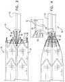
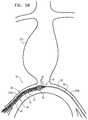
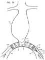
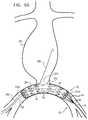
- FIGS. 6A-Gare schematic illustrations of an exemplary method of deploying endovascular implants in an aneurysmatic aortic arch, using a delivery tool of the endovascular system of FIGS. 1A-D , in accordance with an application of the present invention
- FIG. 7is a schematic illustration of an alternative configuration of a stent-graft of FIG. 6G , in accordance with an application of the present invention.
- FIG. 8is a schematic illustration of one of the second endovascular stent-grafts of FIG. 6G , in accordance with an application of the present invention.
- FIG. 9is a schematic illustration of a bifurcated endovascular stent-graft, in accordance with an application of the present invention.
- FIGS. 1A-Dare schematic illustrations of several stages of deployment of an endovascular system 10 , in accordance with an application of the present invention.
- Endovascular system 10comprises an endovascular implant 20 and a delivery tool 30 .
- the delivery toolis configured to minimize or prevent migration of endovascular implant 20 during an implantation procedure.
- Endovascular implant 20comprises a self-expandable, typically tubular, stent member 32 , and, optionally, a tubular fluid flow guide 34 (in which case endovascular implant 20 comprises a stent-graft).
- Endovascular implant 20is configured to be initially positioned in a proximal main delivery catheter 36 of delivery tool 30 in a radially-compressed delivery state, such as shown in FIG. 1A , and in FIGS.
- Endovascular implant 20is configured to assume a radially-expanded deployment state upon being deployed from the delivery catheter in a body lumen, such as a blood vessel, such as shown in FIGS. 1B-D , and in FIGS. 5D-K and 6 D-G described hereinbelow.
- a body lumensuch as a blood vessel
- proximalmeans toward the vascular access site through which the endovascular implant is introduced into the patient's vasculature, and “distal” means away from this site.
- Stent member 32is typically flexible, and comprises a plurality of structural stent elements 38 (i.e., struts), which optionally are axially separate from one another, such as shown in FIGS. 1B-D .
- Fluid flow guide 34if provided, is securely attached to structural stent elements 38 , such as by suturing or stitching, such that the fluid flow guide covers at least a portion of the stent member.
- Structural stent elements 38may be attached to an internal surface and/or an external surface of the fluid flow guide.
- a portion of the structural stent elementsmay be attached (e.g., sutured) to the internal surface, and another portion to the external surface.
- structural stent elements 38comprise a metal.
- the structural stent elementscomprise a self-expanding material, such that stent member 32 is self-expandable.
- the structural stent elementscomprise a superelastic metal alloy, a shape memory metallic alloy, and/or Nitinol.
- the stent-graftis heat-set to assume the radially-expanded state.
- Fluid flow guide 34comprises at least one piece of biologically-compatible substantially blood-impervious fabric.
- the fabricmay comprise, for example, a polyester, a polyethylene (e.g., a poly-ethylene-terephthalate), a polymeric film material (e.g., polytetrafluoroethylene), a polymeric textile material (e.g., woven polyethylene terephthalate (PET)), natural tissue graft (e.g., saphenous vein or collagen), or a combination thereof.
- PETwoven polyethylene terephthalate
- natural tissue grafte.g., saphenous vein or collagen
- Delivery tool 30comprises proximal main delivery catheter 36 , which has a distal portion 46 in which implant 20 is disposed while in the radially-compressed delivery state, as shown in FIG. 1A (and FIGS. 5B-C and 6 B-C described hereinbelow). Delivery tool 30 further comprises a distal restraining assembly 50 , which comprises a restraining-assembly tubular shaft 52 disposed distal to proximal main delivery catheter 36 . Distal restraining assembly 50 is configured to assume:
- distal restraining assembly 50When in the engaged state, distal restraining assembly 50 is configured to prevent distal migration of implant 20 during the implantation procedure.
- restraining-assembly tubular shaft 52has a length of between 10 and 80 cm.
- distal restraining assembly 50comprises one or more release effector flexible elongated members 56 , such as sutures, wires, or strings.
- Flexible elongated members 56extend from a proximal end 58 of restraining-assembly tubular shaft 52 .
- flexible elongated members 56releasably couple distal restraining assembly 50 and/or restraining-assembly tubular shaft 52 to a distal portion 60 of implant 20 , such as a distal portion of stent member 32 (for example, a portion of the stent member that extends distally beyond a distal end of tubular fluid flow guide 34 , if provided, such as shown in FIGS. 1B-1C (and FIGS. 2A-B )), or a distal portion of tubular fluid flow guide 34 , such as shown in FIG. 3 .
- a distal portion of stent member 32for example, a portion of the stent member that extends distally beyond a distal end of tubular fluid flow guide 34 , if provided, such as shown in FIGS. 1B-1C (and FIGS. 2A-B )
- a distal portion of tubular fluid flow guide 34such as shown in FIG. 3 .
- flexible elongated members 56may releasably couple distal restraining assembly 50 to distal-most one of stent element 38 , or to a more proximal one of the stent elements.
- flexible elongated members 56are releasably coupled to distal portion 60 of implant 20 at at least three locations on the distal portion, e.g., distributed around a circumference of the distal portion.
- a first longitudinal portion of delivery tool 30extends between a proximal end of the implant and a first (proximal) end of the delivery tool
- a second longitudinal portion of delivery tool 30extends between a distal end of the implant and second (distal) end of the delivery tool.
- the first and the second longitudinal portionshave respective lengths, each of which is at least 10 cm, such as at least 20 cm.
- a total length of the delivery toolis at least 60 cm.
- delivery tool 30further comprises a tip 70 disposed longitudinally between proximal main delivery catheter 36 and restraining-assembly tubular shaft 52 , at least prior to deployment of implant 20 from proximal main delivery catheter 36 .
- tip 70is proximally withdrawable into the implant without entangling the tip with flexible elongated members 56 .
- flexible elongated members 56pass over an external surface 72 of tip 70 when distal restraining assembly 50 is in the engaged state.
- Flexible elongated members 56are slidably disposed within restraining-assembly tubular shaft 52 , at least when distal restraining assembly 50 is in the engaged state, as described in more detail hereinbelow with reference to FIGS. 2A-4 .
- tip 70is conically shaped. Typically, the tip narrows toward a distal end 73 thereof.
- proximal main delivery catheter 36comprises inner and outer tubular shafts 74 and 76 .
- the shaftsare longitudinally translatable with respect to each other, and implant 20 is disposed radially between inner and outer shafts 74 and 76 while in the radially-compressed delivery state, such as shown in FIG. 1A .
- Delivery tool 30is typically configured such that proximal longitudinal translation of outer shaft 76 relative to inner shaft 74 transitions implant 20 from the radially-compressed delivery state, such as shown in FIG. 1A , to the radially-expanded deployment state, such as shown in FIG. 1B .
- tip 70is fixed to a distal end of inner shaft 74 .
- tip 70gradually tapers from (a) a proximal-end diameter D P at a proximal end 78 thereof equal to between 90% and 110% of an outer diameter D T of a distal end 79 of outer tubular shaft 76 to (b) a distal-end diameter D D at distal end 73 thereof equal to between 70% and 100% of an outer diameter D S of proximal end 58 of restraining-assembly tubular shaft 52 .
- endovascular system 10further comprises a guidewire 80 .
- Delivery tool 30is configured to receive the guidewire therethrough, such that the delivery tool radially surrounds the guidewire.
- the delivery toolis advanceable over the guidewire.
- the delivery toolis configured to receive the guidewire therethrough such that the guidewire extends from a proximal end of proximal main delivery catheter 36 to a distal end 111 of restraining-assembly tubular shaft 52 , at least when distal restraining assembly 50 is in the engaged state, as described in more detail hereinbelow with reference to FIGS. 2A-4 .
- proximal main delivery catheter 36 and restraining-assembly tubular shaft 52are shaped so as to define respective guidewire longitudinal lumens 82 and 112 therethrough.
- inner shaft 74 of proximal main delivery catheter 36is shaped so as to define guidewire longitudinal lumen 82 .
- tip 70is shaped so as to define a tip guidewire longitudinal lumen 84 .
- FIG. 2Ais a schematic illustration of a portion of endovascular system 10 , in accordance with an application of the present invention.
- Section A-A and B-Bare drawn to different scales.
- external surface 72 of tip 70is shaped so as to define one or more grooves 100 , which generally extend longitudinally between proximal and distal ends 78 and 73 of tip 70 .
- Flexible elongated members 56are disposed within grooves 100 while the flexible elongated members pass over external surface 72 .
- a portion of external surface 72is within grooves 100 .
- the restraining-assembly tubular shaft 52is shaped so as to define one or more longitudinal elongated-member lumens 110 therethrough, through which flexible elongated members 56 are slidably disposed at least when distal restraining assembly 50 is in the engaged state.
- Flexible elongated members 56exit lumens 110 at distal end 111 of restraining-assembly tubular shaft 52 .
- flexible elongated members 56are looped through respective sites of distal portion 60 of implant 20 , and looped at distal portions of the members that extend distally out of lumens 110 .
- Each membermay be doubled, such that a first portion of the member is in one of lumens 110 and a second portion of the member is another of lumens 110 . Cutting the loops of the distal portions of the members that extend out of lumens 110 frees the members from implant 20 , such as described hereinbelow with reference to FIG. 5J .
- flexible elongated members 56pass from distal end 111 of restraining-assembly tubular shaft 52 to proximal end 58 of restraining-assembly tubular shaft 52 , engage the endovascular implant, and return to distal end 111 .
- restraining-assembly tubular shaft 52is typically shaped so as to further define longitudinal guidewire lumen 112 therethrough, through which guidewire 80 is removably disposed.
- Guidewire 80exits lumen 112 at distal end 111 of restraining-assembly tubular shaft 52 .
- guidewire lumen 112is disposed along a central longitudinal axis of restraining-assembly tubular shaft 52 .
- proximal main delivery catheter 36comprises a stopper member 120 , which is disposed between inner and outer shafts 74 and 76 , and is fixed to exactly one of the inner and the outer shafts (in FIG. 2B , it is shown fixed to inner shaft 74 ).
- the stopper memberis shaped and sized to interface with structural stent elements 38 of stent member 32 while implant 20 is in its radially-compressed delivery state, thereby substantially preventing proximal translation of implant 20 relative to inner shaft 74 as outer shaft 76 is proximally translated relative to inner shaft 74 .
- stopper member 120is positioned adjacent a distal end of implant 20 while the implant is in the radially-compressed delivery state, disposed radially between inner and outer shafts 74 and 76 , as shown in FIG. 2B .
- stopper member 120comprises one or more engagement elements 122 , which are configured to engage structural stent elements 38 .
- the engagement elementsmay extend is a generally distal direction, as shown in FIG. 2B .
- stopper member 120is implemented in a delivery tool that does not comprise distal restraining assembly 50 .
- flexible longitudinal members 56are configured to transition distal restraining assembly 50 from the engaged state to the disengaged state by rotation of each of the flexible longitudinal members around a longitudinal axis thereof.
- flexible longitudinal members 56may be shaped so as to define proximal hooks 130 .
- the hooksmay be stiff enough to engage stent elements 38 when distal restraining assembly 50 is in the engaged state, as shown in FIG. 4 , and flexible enough to straighten when withdrawn distally through longitudinal elongated-member lumens 110 of restraining-assembly tubular shaft 52 (shown in FIG. 2A ).
- FIGS. 5A-Kare schematic illustrations of an exemplary method of deploying endovascular implant 20 and one or more second endovascular implants 200 in an aneurysmatic abdominal aorta 210 , using delivery tool 30 , in accordance with an application of the present invention.
- endovascular implant 20 and second endovascular implants 200comprise respective stent-grafts
- endovascular implant 20is shaped so as to define at least one lateral opening 212 , such as shown in FIGS. 5E-K , which may be circular.
- the aortic wallmay alternatively suffer from a dissection.
- a “lesion” of a blood vesselmeans an aneurysm and/or a dissection.
- guidewire 80 of delivery tool 30is endovascularly (typically percutaneously) introduced into the vasculature at a first vascular access site, advanced through the vasculature, and extracted from the vasculature and the patient's body at a second vascular access site different from the first, such that the guidewire extends between two vascular access sites through the vasculature.
- guidewire 80is introduced into the vasculature at the second vascular access site, advanced through the vasculature towards the first vascular access site, captured, and thereafter extracted from the vasculature and the patient's body at the first vascular access site.
- the guidewireis introduced into a right iliac artery 214 A through a first vascular access site 215 A, such as on the right femoral artery or the right iliac artery.
- the guidewireis advanced across to left iliac artery 214 B, and extracted from the vasculature and the patient's body through a second vascular access site 215 B, such as on the left femoral artery or the left iliac artery.
- the guidewireis introduced into left iliac artery 214 B through second vascular access site 215 B, such as on the left femoral artery or the left iliac artery.
- the guidewireis advanced across to right iliac artery 214 A, and extracted from the vasculature and the patient's body through first vascular access site 215 A, such as on the right femoral artery or the right iliac artery.
- First and second vascular access sites 215 A and 215 Bmay be considered proximal and distal vascular access sites, respectively.
- the operatore.g., a physician
- distal restraining assembly 50 and proximal main delivery catheter 36are introduced, through the first vascular access site, into the vasculature over guidewire 80 .
- restraining-assembly tubular shaft 52is advanced over the guidewire until a distal end of the restraining-assembly tubular shaft exits the vasculature through the second vascular access site, and the distal end is held (e.g., fixed and/or secured) stationary outside the patient's body.
- Restraining-assembly tubular shaft 52 of distal restraining assembly 50is positioned distal to proximal main delivery catheter 36 .
- Distal restraining assembly 50is in the engaged state at this stage of the implantation procedure.
- Tip 70 of delivery tool 30is disposed longitudinally between proximal main delivery catheter 36 and restraining-assembly tubular shaft 52 .
- Respective first portions of flexible elongated members 56 of distal restraining assembly 50extend out of distal end 111 of restraining-assembly tubular shaft 52 , and thus pass through the second vascular access site together with (within) restraining-assembly tubular shaft 52 , and thus are accessible from outside the patient's body.
- flexible elongated members 56are positioned such that they pass through restraining-assembly tubular shaft 52 (and are typically longitudinally slidable therewithin), pass over external surface 72 of tip 70 , and are releasably coupled to the distal portion of implant 20 .
- Flexible elongated members 56thus are configured to be effected, from a site distal to distal end 111 restraining-assembly tubular shaft 52 , to effect the disengagement (i.e., release) of implant 20 from distal restraining assembly 50 at the proximal ends of the flexible elongated members.
- proximal main delivery catheter 36(and distal restraining assembly 50 ) is advanced through the vasculature to a desired deployment site.
- a proximal longitudinal portion of the delivery toolwhich includes a proximal end of the delivery tool, passes through first vascular access site 215 A
- a distal longitudinal portion of the delivery toolwhich includes a distal end of the delivery tool, passes through second vascular access site 215 B
- an intermediate longitudinal portion of the delivery toolis disposed between the first and the second vascular access sites within the vasculature.
- FIG. 5Douter shaft 76 of proximal main delivery catheter 36 is proximally withdrawn while implant 20 is held in place (optionally using distal restraining assembly 50 ), releasing implant 20 in the vasculature (in right and left iliac arteries 214 A and 214 B spanning an aorto-iliac bifurcation 216 , in the illustrated method). Implant 20 radially expands and transitions to the radially-expanded deployment state as it is released.
- FIG. 5Dshows the implant partially released from the catheter, while FIG. 5E shows the implant fully released from the catheter.
- distal restraining assembly 50is still in the engaged state, in which distal restraining assembly 50 prevents proximal displacement of implant 20 relative to distal restraining assembly 50 .
- a distal end of restraining-assembly tubular shaft 52is held (e.g., fixed and/or secured) stationary outside the second vascular access site, which prevents proximal movement of restraining-assembly tubular shaft 52 and the remainder of distal restraining assembly 50 , including flexible elongated members 56 , and thus implant 20 .
- the implantsometimes migrates during a subsequent step of the implantation procedure, such as the advancement of one or more second implants 200 , such as described hereinbelow with reference to FIGS. 5G-K .
- device motionmay increase the risk of stroke.
- guidewire 80helps hold implant 20 in place in the vasculature.
- the operatortypically fixes and/or secures (e.g., using forceps) one end (such as the distal end) of the guidewire securely outside the vasculature, while manually making a “fixed point” on the other end. Holding the guidewire tightly in place creates a more constrained path for advancement of delivery tool 30 thereover.
- the delivery tooltracks over the guidewire, the delivery tool tracks a more predictable and stable trajectory inside the vasculature than if the guidewire were not secured at both ends thereof.
- inadvertent interaction between the delivery tool and the blood vessel wallis reduced, thereby reducing debris release and the risk of stroke.
- holding the guidewire tightly in placemay also press one aspect of the implant against the wall of the blood vessel.
- This techniquealso helps hold the implant in place during a subsequent step of the implantation procedure, such as the advancement of one or more second implants 200 , such as described hereinbelow with reference to FIGS. 5G-K .
- device motionmay increase the risk of stroke.
- stabilization techniquesallow a significantly increased level of migration resistance for the already deployed implant(s) of endovascular system 10 , especially when bulky and/or stiff delivery systems containing additional branching endovascular implants of system 10 are subsequently inserted via side-facing fenestrations of a previously deployed endovascular implant, and during such deployment may exert significant longitudinal forces on the already-deployed endovascular implants.
- implant 20is fully in the radially-expanded deployment state, and tip 70 is proximally withdrawn into the implant, and the tip and inner shaft 74 of proximal main delivery catheter 36 are proximally withdrawn through the implant.
- Proximal main delivery catheter 36including inner and outer shafts 74 and 76 , is proximally withdrawn from the vasculature through the first vascular access site.
- flexible elongated members 56remain coupled to distal portion 60 of implant 20 . Because the flexible elongated members passed outside of tip 70 during the earlier stages of the procedure, as shown in FIGS. 5B-D , the flexible elongated members do not become entangled with or otherwise interfere with the proximal withdrawal of the tip.
- FIG. 5Fshows implant 20 and distal restraining assembly 50 after proximal main delivery catheter 36 and tip 70 have been fully withdrawn from the patient's vasculature.
- lateral opening 212is positioned at aorto-iliac bifurcation 216 , facing aneurysmatic abdominal aorta 210 .
- Distal restraining assembly 50remains in the engaged state at this stage of the implantation procedure, preventing proximal movement of implant 20 .
- Guidewire 80may also prevent movement of implant 20 , as described above with reference to FIG. 5D .
- the operatormay pull the distal end of restraining-assembly tubular shaft 52 distally from outside second vascular access site 215 B, thereby distally displacing endovascular implant 20 .
- repositioningmay be desired if the implant was inadvertently deployed too proximally, or if the implant slid proximally after deployment, such as during deployment of additional endovascular implants, as described immediately hereinbelow.
- the operatormay rotate distal restraining assembly 50 (e.g., restraining-assembly tubular shaft 52 thereof) from outside the second vascular access site, thereby rotating endovascular implant 20 .
- such rotationmay be desired the implant was inadvertently deployed with improper rotational alignment.
- flexible elongated members 56may comprise wires; these wires may be configured to apply a rotational force to the implant.
- Second endovascular implants 200are sized to pass at least partially through lateral opening 212 of first implant 20 .
- a second guidewire 280is introduced into the vasculature, typically via the first vascular access site.
- the first guidewire 80remains in implant 20 and the vasculature at this step of the procedure.
- the second guidewireis advanced into the implant through a proximal end of implant 20 , and then out of the implant through lateral opening 212 and into aorta 210 .
- a second catheter 236in which second endovascular implant 200 A is positioned in a radially-compressed delivery state, is advanced over second guidewire 80 , through a portion of the first implant 20 , partially out of lateral opening 212 , and into aorta 210 .
- second catheter 236is proximally withdrawn, thereby deploying and transitioning second endovascular implant 200 A in aorta 210 , such that it is securely deployed partially outside and partially inside lateral opening 212 .
- distal restraining assembly 50remains in the engaged state at this stage of the implantation procedure, preventing proximal movement of implant 20 .
- Guidewire 80may also prevent movement of implant 20 , as described above with reference to FIG. 5D .
- another second endovascular implant 200 Bmay optionally be deployed through first implant 20 and second implant 200 A, using the techniques described hereinabove with reference to FIGS. 5H-I , mutatis mutandis.
- Second guidewire 80or yet another guidewire, may be used for this deployment.
- distal restraining assembly 50remains in the engaged state at this stage of the implantation procedure, preventing proximal movement of implant 20 .
- Guidewire 80may also prevent movement of implant 20 , as described above with reference to FIG. 5D .
- the one or more second implants 200are coupled to first implant 20 , in order to provide one or more continuous blood-flow lumens through aneurysmatic abdominal aorta 210 to iliac arteries 214 A and 214 B.
- the implantsare coupled together to form substantially blood impervious seals. As a result, blood flows through the one or more second implants 200 into first implant 20 and feeds both iliac arteries.
- distal restraining assembly 50is transitioned to the disengaged state, in which state distal restraining assembly 50 does not engage implant 20 .
- Disengaging distal restraining assembly 50 from implant 20allows the distal extraction of distal restraining assembly 50 from the vasculature and the patient's body through the second vascular access site.
- Distal restraining assembly 50is then removed from the patient's vasculature via the second vascular access site. It is noted that at this stage of the procedure, after the deployment of implants 200 , the risk of proximal displacement of implant 20 is low even after the disengagement of distal restraining assembly 50 .
- distal portions of flexible elongated members 56 that extend beyond distal end 111 of restraining-assembly tubular shaft 52are cut, as shown in blow-up A of FIG. 5J , in order to release the flexible elongated members from distal portion 60 of implant 20 .
- One end of each cut membermay be extracted (e.g., pulled distally) from its lumen 110 , in order to disengage the member from distal portion 60 of implant 20 , as shown in blow-up B of FIG. 5J .
- distal restraining assembly 50is configured to provide a distal disengagement site at a distal location on restraining-assembly tubular shaft 52 , from which site the distal restraining assembly is transitionable from the engaged state to the disengaged state.
- FIG. 5Kshows first implant 20 and one or more second implants 200 fully implanted in right and left iliac arteries 214 A and 214 B and aneurysmatic abdominal aorta 210 , spanning aorto-iliac bifurcation 216 .
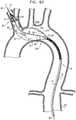
- FIGS. 6A-Gare schematic illustrations of an exemplary method of deploying endovascular implant 20 and one or more second endovascular implants 322 in an aneurysmatic aortic arch 300 , using delivery tool 30 , in accordance with an application of the present invention.
- endovascular implant 20comprises an endovascular stent-graft 320 , which comprises a stent member 324 and a fluid flow guide 326
- second endovascular implants 322comprise respective stent-grafts, which comprise respective stent members 328 and fluid flow guides 330 .
- the aortic wallmay alternatively suffer from a dissection.
- stent-graft 320is generally similar to, and may implement any or all of the features of first stent-graft 20 , described with reference to FIGS. 4-6H of PCT Publication WO 2011/064782, which is incorporated herein by reference.
- stent-graft 320is shaped so as to define three first lateral openings 334 through stent-graft 320 when the stent-graft is in its radially-expanded state:
- proximal and distal superior first lateral openings 334 A and 334 Bface in a first radial direction
- distal inferior first lateral opening 334 Cfaces in a second radially direction generally circumferentially opposite the first radial direction.
- proximal and distal superior first lateral openings 334 A and 334 Bmay be disposed at between 11 o'clock and 1 o'clock (e.g., at 12 o'clock), and distal inferior first lateral opening 334 C may be disposed at between 5 o'clock and 7 o'clock (e.g., at 6 o'clock).
- guidewire 80 of delivery tool 30is endovascularly (preferably percutaneously) introduced into the vasculature at a first vascular access site, advanced through the vasculature, and extracted from the vasculature and the patient's body at a second vascular access site different from the first, such that the guidewire extends between two vascular access sites through the vasculature.
- guidewire 80is introduced into the vasculature at the second vascular access site, advanced through the vasculature, and extracted from the vasculature and the patient's body at the first vascular access site.
- the guidewireis introduced into aortic arch 100 via one of the iliac arteries through a first vascular access site 315 A, such as on the right femoral artery or the right iliac artery.
- the guidewireis advanced up a descending aorta 302 and into a first one of the branches of the aortic arch, such as a brachiocephalic artery 303 , and extracted from the vasculature and the patient's body through a second vascular access site 315 B, such as on the brachial artery.
- a second vascular access site 315 Bsuch as on the brachial artery.
- the guidewireis introduced into a first one of the branches of the aortic arch, such as brachiocephalic artery 303 , through second vascular access site 315 B, such as on the brachial artery.
- the guidewireis advanced into aortic arch 100 , advanced down descending aorta 302 and one of the iliac arteries, and extracted from the vasculature and the patient's body through first vascular access site 315 A, such as on the right femoral artery or the right iliac artery.
- First and second vascular access sites 315 A and 315 Bmay be considered proximal and distal vascular access sites, respectively.
- the operatormay draw the distal end of the guidewire out through the exit vascular access site using a lasso introduced to the vasculature through the exit vascular access site, or using introducer sheath introduced to the vasculature through the exit vascular access site (for example, the introducer sheath may have a diameter about equal to blood vessels as the introducer sheath narrows at the end thereof distal to the user, and the operator may radiographically introduce the guidewire into the sheath).
- distal restraining assembly 50 and proximal main delivery catheter 36are introduced, through the first vascular access site, into the vasculature over guidewire 80 .
- restraining-assembly tubular shaft 52is advanced over the guidewire until a distal end of the restraining-assembly tubular shaft exits the vasculature through the second vascular access site, and the distal end is held (e.g., fixed and/or secured) stationary outside the patient's body.
- Restraining-assembly tubular shaft 52 of distal restraining assembly 50is positioned distal to proximal main delivery catheter 36 .
- main delivery catheter 36is advanced over guidewire 80 , until stent-graft 320 is partially disposed in brachiocephalic artery 103 , partially disposed in aortic arch 100 , and partially disposed an upper part of descending aorta 302 .
- a proximal longitudinal portion of the delivery toolwhich includes a proximal end of the delivery tool, passes through first vascular access site 315 A
- a distal longitudinal portion of the delivery toolwhich includes a distal end of the delivery tool, passes through second vascular access site 315 B
- an intermediate longitudinal portion of the delivery toolis disposed between the first and the second vascular access sites within the vasculature.
- distal restraining assembly 50is still in the engaged state, in which distal restraining assembly 50 prevents proximal displacement of stent-graft 320 relative to distal restraining assembly 50 .
- a distal end of restraining-assembly tubular shaft 52is held (e.g., fixed and/or secured) stationary outside the second vascular access site, which prevents proximal movement of restraining-assembly tubular shaft 52 and the remainder of distal restraining assembly 50 , including flexible elongated members 56 , and thus stent-graft 320 .
- the implantsometimes migrates during a subsequent step of the implantation procedure, such as the advancement of one or more second endovascular stent-grafts 322 , such as described hereinbelow with reference to FIG. 6G .
- device motionmay increase the risk of stroke.
- guidewire 80helps hold stent-graft 320 in place.
- the operatortypically fixes and/or secures (e.g., using forceps) one end (such as the distal end) of the guidewire securely outside the vasculature, while manually making a “fixed point” on the other end. Holding the guidewire tightly in place creates a more constrained path for advancement of delivery tool 30 thereover.
- the delivery tooltracks over the guidewire, the delivery tool tracks a more predictable and stable trajectory inside the vasculature than if the guidewire were not secured at both ends thereof.
- inadvertent interaction between the delivery tool and the blood vessel wallis reduced, thereby reducing debris release and the risk of stroke.
- holding the guidewire tightly in placemay also press one aspect of the implant against the wall of the blood vessel.
- This techniquealso helps hold the implant in place during a subsequent step of the implantation procedure, such as the advancement of one or more second endovascular stent-grafts 322 , such as described hereinbelow with reference to FIG. 6G .
- device motionmay increase the risk of stroke.
- stabilization techniquesallow a significantly increased level of migration resistance for the already deployed implant(s) of endovascular system 10 , especially when bulky and/or stiff delivery systems containing additional branching endovascular implants of system 10 are subsequently inserted via side-facing fenestrations of a previously deployed endovascular implant, and during such deployment may exert significant longitudinal forces on the already-deployed endovascular implants.
- stent-graft 320is fully in the radially-expanded deployment state, and tip 70 and inner shaft 74 of proximal main delivery catheter 36 are proximally withdrawn through the implant.
- flexible elongated members 56remain coupled to distal portion 60 of stent-graft 320 . Because the flexible elongated members passed outside of tip 70 during the earlier stages of the procedure, as shown in FIGS. 6B-D , the flexible elongated members do not interfere with the proximal withdrawal of the tip.
- FIG. 6Fshows stent-graft 320 and distal restraining assembly 50 after proximal main delivery catheter 36 and tip 70 have been fully withdrawn from the patient's vasculature.
- a proximal portion of stent-graft 320including a proximal end thereof, is positioned in the upper part of descending aorta 302
- a middle portion of stent-graft 320is positioned in aortic arch 300
- a distal portion of stent-graft 320including a distal end thereof, is positioned in brachiocephalic artery 303 .
- the operatormay pull the distal end of restraining-assembly tubular shaft 52 distally from outside second vascular access site 315 B, thereby distally displacing stent-graft 320 .
- repositioningmay be desired if the stent-graft was inadvertently deployed too proximally, or if the stent-graft slid proximally after deployment, such as during deployment of additional stent-grafts, as described immediately hereinbelow.
- FIG. 6Gshows stent-graft 320 and distal restraining assembly 50 after the subsequent deployment of three second endovascular stent-grafts 322 .
- Distal restraining assembly 50remains in the engaged state, and guidewire 80 remains in place, during the deployment of these three second endovascular stent-grafts.
- These three second endovascular stent-graftsare deployed using one or more guidewires and delivery catheters separate from guidewire 80 and proximal main delivery catheter 36 .
- these three second endovascular stent-graftscomprise:
- the multi-component stent-graft systemupon deployment of all four stent-grafts, defines a blood-flow path from ascending aorta 301 , over aortic arch 300 , and to descending aorta 302 .
- the multi-component stent-graft systemadditionally provides blood-flow paths to the three branches of the aortic arch: brachiocephalic artery 303 , left common carotid artery 304 , and left subclavian artery 305 .
- distal restraining assembly 50is transitioned to the disengaged state, in which distal restraining assembly 50 allows proximal displacement of stent-graft 320 relative to distal restraining assembly 50 .
- distal portions of flexible elongated members 56 that extend beyond distal end 111 of restraining-assembly tubular shaft 52are cut, as shown in blow-up A of FIG. 6G , in order to release the flexible elongated members from distal portion 60 of stent-graft 320 .
- distal restraining assembly 50is configured to provide a distal disengagement site at a distal location on restraining-assembly tubular shaft 52 , from which site the distal restraining assembly is transitionable from the engaged state to the disengaged state. Distal restraining assembly 50 is then removed from the patient's vasculature via the second vascular access site.
- a stent-graftthat comprises a tubular flow guide that comprises two fabrics that comprise two different biologically-compatible substantially blood-impervious materials, such as expanded polytetrafluoroethylene (ePTFE) and polyester (e.g., polyethylene terephthalate (PET).
- ePTFEexpanded polytetrafluoroethylene
- PETpolyethylene terephthalate
- First and second fabrics 356 and 358comprise first and second biologically-compatible substantially blood-impervious materials, respectively, which are different from each other.
- the first materialis less thrombogenic than the second material, and may comprise, for example, ePTFE.
- thrombogenicmeans the tendency of a material in contact with the blood to produce a thrombus or embolus.
- the second materialless deformable than the first material, and may comprise, for example, polyester, such as a biostable polymer, e.g., PET.
- first and second longitudinal portions 350 and 352are non-longitudinally-overlapping.
- first and second longitudinal portions 350 and 352are typically longitudinally adjacent each other, as shown in FIG. 6G .
- first and second fabrics 356 and 358are coupled to each other at a longitudinal junction 354 between first and second longitudinal portions 350 and 352 , such as by suturing or stitching, so as to form a blood-tight seal between the first and second fabrics.
- first and second longitudinal portions 350 and 352are partially longitudinally overlapping along a longitudinally overlapping portion 370 of stent-graft 320 .
- the first and second fabrics 356 and 358are coupled to each other at one or more locations 372 along longitudinally overlapping portion 370 , such as by suturing or stitching, so as to form a blood-tight seal between the first and second fabrics.
- a length of longitudinally overlapping portion 370is less than 5% of an overall length of the stent-graft, and/or is at least 2 mm, no more than 10 mm, and/or between 2 and 20 mm.
- longitudinally overlapping portion 370is positioned at a location along the stent-graft that has a diameter that is less than a greatest diameter of the stent-graft.
- second endovascular stent-graft 322comprises two different fabrics, as described above regarding endovascular stent-graft 320 , optionally including any of the described variations in configuration (e.g., overlapping vs. non-overlapping).
- second endovascular stent-graft 322is a branching stent-graft
- endovascular stent-graft 320is a main stent-graft, which is shaped so as to define a lateral opening 334 .
- Second longitudinal portion 352 of branching stent-graft 322is shaped so as to define an interface portion 374 configured to form a blood-tight seal with lateral opening 334 of main stent-graft 320 .
- the second material of second fabric 358may comprise a less deformable material, such as polyester, which strengthens the interface between the stent-grafts, which is generally subject to greater stress than other portions of the stent-grafts.
- first longitudinal portion 352extends to a narrower end of the branching stent-graft, as described hereinabove regarding stent-graft 320 .
- endovascular implant 20comprises bifurcated endovascular stent-graft 420 , which comprises a stent member 424 and a fluid flow guide 426 .
- Bifurcated endovascular stent-graft 420is shaped so as to define a distal main lumen 430 , which bifurcates into two proximal branching lumens 432 A and 432 B.
- distal restraining assembly 50is removably coupled to an end of one of the branching lumens, such as shown in FIG. 9 .
- a length of a first one of the branching lumensis less than 90% of a length of a second one of the branching lumens.
- the length of the first one of the branching lumensis at least 10% greater than the length of the second one of the branching lumens.
Landscapes
- Health & Medical Sciences (AREA)
- Engineering & Computer Science (AREA)
- Biomedical Technology (AREA)
- Life Sciences & Earth Sciences (AREA)
- General Health & Medical Sciences (AREA)
- Transplantation (AREA)
- Heart & Thoracic Surgery (AREA)
- Vascular Medicine (AREA)
- Cardiology (AREA)
- Animal Behavior & Ethology (AREA)
- Oral & Maxillofacial Surgery (AREA)
- Public Health (AREA)
- Veterinary Medicine (AREA)
- Gastroenterology & Hepatology (AREA)
- Pulmonology (AREA)
- Prostheses (AREA)
- Media Introduction/Drainage Providing Device (AREA)
Abstract
Description
- a proximal main delivery catheter, having a distal portion in which the implant is disposed while in the radially-compressed delivery state; and
- a distal restraining assembly, which (a) includes a restraining-assembly tubular shaft disposed distal to the proximal main delivery catheter, and (b) which is configured to assume:
- an engaged state, in which the distal restraining assembly prevents proximal displacement of the implant relative to the distal restraining assembly, and
- a disengaged state, in which the distal restraining assembly allows proximal displacement of the implant relative to the distal restraining assembly.
- a first fabric, which includes a first biologically-compatible substantially blood-impervious material, and which is attached to and covers the stent member along a first longitudinal portion of the stent-graft; and
- a second fabric, which includes a second biologically-compatible substantially blood-impervious material different from the first material, and which is attached to and covers the stent member along a second longitudinal portion of the stent-graft, which second longitudinal portion is at least partially non-longitudinally-overlapping with the first longitudinal portion.
Inventive concept 6. The method according to inventive concept 5, wherein fixing stationary comprises fixing the distal end of the restraining-assembly tubular shaft stationary before releasing the endovascular implant from the proximal main delivery catheter.
Inventive concept 7. The method according to inventive concept 5, wherein fixing stationary comprises fixing the distal end of the restraining-assembly tubular shaft stationary after releasing the endovascular implant from the proximal main delivery catheter.
Inventive concept 8. The method according to inventive concept 1, further comprising, after releasing the endovascular implant, pulling the distal end of the restraining-assembly tubular shaft distally from outside the second vascular access site, thereby distally displacing the endovascular implant.
Inventive concept 9. The method according to inventive concept 1, further comprising, after releasing the endovascular implant, rotating the distal restraining assembly from outside the second vascular access site, thereby rotating the endovascular implant.
Inventive concept 11. The method according to inventive concept 1,
Inventive concept 13. The method according to inventive concept 11, wherein transitioning the distal restraining assembly to the disengaged state comprises cutting distal portions of the flexible elongated members that extend beyond the distal end of the restraining-assembly tubular shaft.
Inventive concept 14. The method according to inventive concept 11,
Inventive concept 16. The method according to inventive concept 14, wherein providing the delivery tool comprises providing the delivery tool in which the proximal main delivery catheter includes inner and outer tubular shafts, and the tip is fixed to a distal end of the inner shaft.
Inventive concept 17. The method according to inventive concept 14, wherein providing the delivery tool comprises providing the delivery tool in which the proximal main delivery catheter comprises inner and outer tubular shafts, and the tip gradually tapers from (a) a proximal-end circumference equal to between 90% and 110% of an outer circumference of a distal end of the outer tubular shaft to (b) a distal-end circumference equal to between 70% and 100% of an outer circumference of the proximal end of the restraining-assembly tubular shaft.
Inventive concept 18. The method according to inventive concept 14, wherein endovascularly introducing the delivery tool comprises endovascularly introducing the delivery tool while the flexible elongated members pass over an external surface of the tip, while the distal restraining assembly is in the engaged state.
Inventive concept 19. The method according to inventive concept 14, wherein the external surface of the tip is shaped so as to define one or more grooves, and wherein endovascularly introducing the delivery tool comprises endovascularly introducing the delivery tool while the flexible elongated members are disposed within the grooves while the flexible elongated members pass over the external surface.
Inventive concept 21. The method according to inventive concept 1, wherein providing the endovascular implant comprises providing a stent-graft, which comprises a flexible stent member, and a generally tubular fluid flow guide, which is securely attached to and covers at least a portion of the stent member.
Inventive concept 22. The method according to inventive concept 21,
- endovascularly introducing a first guidewire of the delivery tool through one of the first and the second vascular access sites into the vasculature;
- advancing the first guidewire through the vasculature to the other of the first and the second vascular access sites;
- extracting a portion of the first guidewire from the vasculature and a body of the patient through the other of the first and the second vascular access sites, such that the first guidewire extends between the first and the second vascular access sites through the vasculature; and
- endovascularly introducing and advancing the delivery tool over the first guidewire until the distal end of the restraining-assembly tubular shaft exits the vasculature and the body of the patient through the second vascular access site, and
- endovascularly introducing a first guidewire of the delivery tool through one of the first and the second vascular access sites into the vasculature;
- advancing the first guidewire through the vasculature to the other of the first and the second vascular access sites;
- extracting a portion of the first guidewire from the vasculature and the body of the patient through the other of the first and the second vascular access sites, such that the first guidewire extends between the first and the second vascular access sites through the vasculature; and
- endovascularly introducing the delivery tool over the first guidewire until the distal end of the delivery tool exits the vasculature and the body of the patient through the second vascular access site, and
Inventive concept 39. The method according to any one of
Inventive concept 45. The method according to
- an engaged state, in which distal restraining
assembly 50 prevents proximal displacement ofimplant 20 relative to distal restrainingassembly 50, as shown inFIGS. 1B-C (andFIGS. 5D-J and6D-F), and - a disengaged state, in which distal restraining
assembly 50 does not engage implant20 (andFIGS. 5J and 6F ).
- an engaged state, in which distal restraining
- a proximal superior first
lateral opening 334A; - a distal superior first
lateral opening 334B; and - a distal inferior first
lateral opening 334C.
- a proximal superior first
- second endovascular stent-
graft 322A, which is deployed up descendingaorta 302, through a proximal portion of stent-graft 320, partially out of distal inferior firstlateral opening 334C, and intoaortic arch 300 and/or the upper part of ascendingaorta 301, such as described with reference to FIGS. 6B-D of the above-mentioned '782 publication; second endovascular stent-graft 322A is thus securely deployed partially outside and partially insidelateral opening 334C; - second endovascular stent-
graft 322B, which is deployed up descendingaorta 302, through a proximal portion of stent-graft 320, partially out of one of proximal superior firstlateral opening 334A and distal superior firstlateral opening 334B, and into a second one of the branches ofaortic arch 300, such as left commoncarotid artery 304 or leftsubclavian artery 305, such as described with reference to FIGS. 6E-F of the '782 publication; second endovascular stent-graft 322B is thus securely deployed partially outside and partially insidelateral opening 334A; and - third endovascular stent-
graft 322C, which is deployed up descendingaorta 302, through a proximal portion of stent-graft 320, partially out of the other one of proximal superior firstlateral opening 334A and distal superior firstlateral opening 334B, and into a second one of the branches ofaortic arch 300, such as left commoncarotid artery 304 or leftsubclavian artery 305, such as described with reference to FIG. 6H of the '782 publication; second endovascular stent-graft 322C is thus securely deployed partially outside and partially insidelateral opening 334B.
- second endovascular stent-
- PCT Application PCT/IL2008/000287, filed Mar. 5, 2008, which published as PCT Publication WO 2008/107885 to Shalev et al., and U.S. application Ser. No. 12/529,936 in the national stage thereof, which published as US Patent Application Publication 2010/0063575 to Shalev et al.
U.S. Provisional Application 60/892,885, filed Mar. 5, 2007U.S. Provisional Application 60/991,726, filed Dec. 2, 2007- U.S. Provisional Application 61/219,758, filed Jun. 23, 2009
- U.S. Provisional Application 61/221,074, filed Jun. 28, 2009
- PCT Application PCT/IB2010/052861, filed Jun. 23, 2010, which published as PCT Publication WO 2010/150208
- PCT Application PCT/IL2010/000564, filed Jul. 14, 2010, which published as PCT Publication WO 2011/007354
- PCT Application PCT/IL2010/000917, filed Nov. 4, 2010, which published as PCT Publication WO 2011/055364
- PCT Application PCT/IL2010/000999, filed Nov. 30, 2010, which published as PCT Publication WO 2011/064782
- PCT Application PCT/IL2010/001018, filed Dec. 2, 2010, which published as PCT Publication WO 2011/067764
- PCT Application PCT/IL2010/001037, filed Dec. 8, 2010, which published as PCT Publication WO 2011/070576
- PCT Application PCT/IL2011/000135, filed Feb. 8, 2011, entitled, “Thermal energy application for prevention and management of endoleaks in stent-grafts,” which published as PCT Publication WO 2011/095979
- U.S. application Ser. No. 13/031,871, filed Feb. 22, 2011, entitled, “Flexible stent-grafts,” which published as US Patent Application Publication 2011/0208289
- U.S. Provisional Application 61/496,613, filed Jun. 14, 2011
- U.S. Provisional Application 61/505,132, filed Jul. 7, 2011
- U.S. Provisional Application 61/529,931, filed Sep. 1, 2011
- PCT Application PCT/IL2012/000060, filed Feb. 2, 2012, which published as PCT Publication WO 2012/104842
- PCT Application PCT/IL2012/000083, filed Feb. 16, 2012, which published as PCT Publication WO 2012/111006
- PCT Application PCT/IL2012/000095, filed Mar. 1, 2012, which published as PCT Publication WO 2012/117395
- PCT Application PCT/IL2012/000148, filed Apr. 4, 2012, which published as PCT Publication WO 2013/030818
- PCT Application PCT/IL2012/000190, filed May 15, 2012, which published as PCT Publication WO 2013/171730, entitled, “Stent-graft with fixation elements that are radially confined for delivery”
- U.S. patent application Ser. No. 13/523,296, filed Jun. 14, 2012, which issued as U.S. Pat. No. 8,574,287
- PCT Application PCT/IL2012/000241, filed Jun. 19, 2012, which published as PCT Publication WO 2012/176187
- PCT Application PCT/IL2012/000269, filed Jul. 2, 2012, which published as PCT Publication WO 2013/005207
- PCT Application PCT/IL2012/050424, filed Oct. 29, 2012, which published as PCT Publication WO 2013/065040
- PCT Application PCT/IL2012/050506, filed Dec. 4, 2012, which published as PCT Publication WO 2013/084235
Claims (21)
Priority Applications (1)
| Application Number | Priority Date | Filing Date | Title |
|---|---|---|---|
| US15/976,317US10952884B2 (en) | 2013-01-08 | 2018-05-10 | Multi-fabric endovascular stent-graft |
Applications Claiming Priority (4)
| Application Number | Priority Date | Filing Date | Title |
|---|---|---|---|
| US201361749965P | 2013-01-08 | 2013-01-08 | |
| PCT/IL2014/050019WO2014108895A2 (en) | 2013-01-08 | 2014-01-07 | Minimization of stent-graft migration during implantation |
| US201514759736A | 2015-07-08 | 2015-07-08 | |
| US15/976,317US10952884B2 (en) | 2013-01-08 | 2018-05-10 | Multi-fabric endovascular stent-graft |
Related Parent Applications (2)
| Application Number | Title | Priority Date | Filing Date |
|---|---|---|---|
| US14/759,736ContinuationUS9993360B2 (en) | 2013-01-08 | 2014-01-07 | Minimization of stent-graft migration during implantation |
| PCT/IL2014/050019ContinuationWO2014108895A2 (en) | 2013-01-08 | 2014-01-07 | Minimization of stent-graft migration during implantation |
Publications (2)
| Publication Number | Publication Date |
|---|---|
| US20180256377A1 US20180256377A1 (en) | 2018-09-13 |
| US10952884B2true US10952884B2 (en) | 2021-03-23 |
Family
ID=50033612
Family Applications (2)
| Application Number | Title | Priority Date | Filing Date |
|---|---|---|---|
| US14/759,736Active2034-10-16US9993360B2 (en) | 2013-01-08 | 2014-01-07 | Minimization of stent-graft migration during implantation |
| US15/976,317Active2034-10-16US10952884B2 (en) | 2013-01-08 | 2018-05-10 | Multi-fabric endovascular stent-graft |
Family Applications Before (1)
| Application Number | Title | Priority Date | Filing Date |
|---|---|---|---|
| US14/759,736Active2034-10-16US9993360B2 (en) | 2013-01-08 | 2014-01-07 | Minimization of stent-graft migration during implantation |
Country Status (4)
| Country | Link |
|---|---|
| US (2) | US9993360B2 (en) |
| EP (1) | EP2943154B1 (en) |
| CN (2) | CN105007860B (en) |
| WO (1) | WO2014108895A2 (en) |
Families Citing this family (44)
| Publication number | Priority date | Publication date | Assignee | Title |
|---|---|---|---|---|
| CA3009244C (en) | 2009-06-23 | 2020-04-28 | Endospan Ltd. | Vascular prostheses for treating aneurysms |
| US8870950B2 (en) | 2009-12-08 | 2014-10-28 | Mitral Tech Ltd. | Rotation-based anchoring of an implant |
| US20110224785A1 (en) | 2010-03-10 | 2011-09-15 | Hacohen Gil | Prosthetic mitral valve with tissue anchors |
| US9839510B2 (en) | 2011-08-28 | 2017-12-12 | Endospan Ltd. | Stent-grafts with post-deployment variable radial displacement |
| US9427339B2 (en) | 2011-10-30 | 2016-08-30 | Endospan Ltd. | Triple-collar stent-graft |
| US9597204B2 (en) | 2011-12-04 | 2017-03-21 | Endospan Ltd. | Branched stent-graft system |
| WO2013171730A1 (en) | 2012-05-15 | 2013-11-21 | Endospan Ltd. | Stent-graft with fixation elements that are radially confined for delivery |
| US9993360B2 (en) | 2013-01-08 | 2018-06-12 | Endospan Ltd. | Minimization of stent-graft migration during implantation |
| US20150351906A1 (en) | 2013-01-24 | 2015-12-10 | Mitraltech Ltd. | Ventricularly-anchored prosthetic valves |
| US9668892B2 (en) | 2013-03-11 | 2017-06-06 | Endospan Ltd. | Multi-component stent-graft system for aortic dissections |
| WO2015075708A1 (en) | 2013-11-19 | 2015-05-28 | Endospan Ltd. | Stent system with radial-expansion locking |
| US10765544B2 (en)* | 2014-05-02 | 2020-09-08 | W. L. Gore & Associates, Inc. | Push and pull medical device delivery system |
| EP3174502B1 (en) | 2014-07-30 | 2022-04-06 | Cardiovalve Ltd | Apparatus for implantation of an articulatable prosthetic valve |
| CN106029005B (en) | 2014-12-18 | 2018-01-19 | 恩都思潘有限公司 | The Endovascular stent-graft of horizontal conduit with tired resistance |
| WO2016113731A1 (en) | 2015-01-12 | 2016-07-21 | Endospan Ltd. | Self-curving stent-graft |
| WO2016125137A1 (en) | 2015-02-02 | 2016-08-11 | Endospan Ltd. | Self-orienting endovascular delivery system |
| CN110141399B (en) | 2015-02-05 | 2021-07-27 | 卡迪尔维尔福股份有限公司 | Prosthetic valve with axial sliding frame |
| JP6854282B2 (en)* | 2015-09-18 | 2021-04-07 | テルモ株式会社 | Pressable implant delivery system |
| WO2017081679A1 (en) | 2015-11-12 | 2017-05-18 | Endospan Ltd. | Stent-grafts systems with skirt |
| DE102016101272A1 (en)* | 2016-01-25 | 2017-07-27 | Christian-Albrechts-Universität Zu Kiel | Trans Aortic Proximal Aortic Stent Graft |
| US10531866B2 (en) | 2016-02-16 | 2020-01-14 | Cardiovalve Ltd. | Techniques for providing a replacement valve and transseptal communication |
| US20190231525A1 (en) | 2016-08-01 | 2019-08-01 | Mitraltech Ltd. | Minimally-invasive delivery systems |
| JP7241405B2 (en)* | 2016-11-29 | 2023-03-17 | ファウンドリー イノベーション アンド リサーチ 1,リミテッド | Wireless resonant circuit and variable inductance vascular implant for monitoring vascular and fluid status in patients, and systems and methods utilizing same |
| US10433993B2 (en) | 2017-01-20 | 2019-10-08 | Medtronic Vascular, Inc. | Valve prosthesis having a radially-expandable sleeve integrated thereon for delivery and prevention of paravalvular leakage |
| CN110337279A (en)* | 2017-01-25 | 2019-10-15 | W.L.戈尔及同仁股份有限公司 | For treating and preventing the method and apparatus in the patient's body fluid excess load with heart failure |
| US10869762B2 (en)* | 2017-03-14 | 2020-12-22 | Boston Scientific Scimed, Inc. | Medical device with inner assembly |
| JP2020512914A (en)* | 2017-03-21 | 2020-04-30 | エンドスパン リミテッド | Stent graft for sealing around external disturbances |
| WO2018232134A1 (en)* | 2017-06-16 | 2018-12-20 | Boston Scientific Scimed, Inc. | Stent and sleeve deployment |
| US11793633B2 (en) | 2017-08-03 | 2023-10-24 | Cardiovalve Ltd. | Prosthetic heart valve |
| US12064347B2 (en) | 2017-08-03 | 2024-08-20 | Cardiovalve Ltd. | Prosthetic heart valve |
| GB201713329D0 (en)* | 2017-08-18 | 2017-10-04 | Clearstream Tech Ltd | An implant system comprising a delivery wire assembly and an implant |
| US10595874B2 (en) | 2017-09-21 | 2020-03-24 | W. L. Gore & Associates, Inc. | Multiple inflation endovascular medical device |
| EP3492024A1 (en)* | 2017-11-29 | 2019-06-05 | Spartan Micro, Inc. | Systems for delivering intravascular implants |
| FI3941392T3 (en) | 2019-03-20 | 2025-07-28 | Inqb8 Medical Tech Llc | Aortic dissection implant |
| CN110151368B (en)* | 2019-06-28 | 2025-07-18 | 微创神通医疗科技(上海)有限公司 | Vascular implant, delivery device and medical equipment |
| EP4096591A1 (en)* | 2020-01-31 | 2022-12-07 | Boston Scientific Scimed Inc. | Atraumatic delivery system |
| US12357459B2 (en) | 2020-12-03 | 2025-07-15 | Cardiovalve Ltd. | Transluminal delivery system |
| US12383395B2 (en) | 2020-12-22 | 2025-08-12 | Medtronic, Inc. | Skirt-reinforcement members for prosthetic valve devices |
| US12016777B2 (en) | 2021-01-26 | 2024-06-25 | Boston Scientific Scimed, Inc. | Medical device including attachable components |
| US12396852B2 (en) | 2021-01-26 | 2025-08-26 | Boston Scientific Scimed, Inc. | Medical device including attachable components |
| US12171678B2 (en) | 2021-02-24 | 2024-12-24 | Medtronic, Inc. | Skirt-reinforcement members for prosthetic valve devices |
| EP4586970A1 (en) | 2022-09-15 | 2025-07-23 | Endospan Ltd. | Double-branching ascending aortic stent-graft systems |
| WO2025013097A1 (en)* | 2023-07-12 | 2025-01-16 | Institute Of Advanced Medical Research & Innovations Forum | Pulmonary flow regulating device |
| WO2025196748A1 (en) | 2024-03-20 | 2025-09-25 | Endospan Ltd. | Double- and triple-branching ascending aortic stent-graft systems |
Citations (39)
| Publication number | Priority date | Publication date | Assignee | Title |
|---|---|---|---|---|
| US5575818A (en) | 1995-02-14 | 1996-11-19 | Corvita Corporation | Endovascular stent with locking ring |
| US5609627A (en) | 1994-02-09 | 1997-03-11 | Boston Scientific Technology, Inc. | Method for delivering a bifurcated endoluminal prosthesis |
| US5628788A (en) | 1995-11-07 | 1997-05-13 | Corvita Corporation | Self-expanding endoluminal stent-graft |
| US5653743A (en) | 1994-09-09 | 1997-08-05 | Martin; Eric C. | Hypogastric artery bifurcation graft and method of implantation |
| US6030415A (en) | 1997-01-29 | 2000-02-29 | Endovascular Technologies, Inc. | Bell-bottom modular stent-graft |
| WO2000028923A1 (en) | 1998-11-18 | 2000-05-25 | Revasc Llc | Endovascular prosthesis and method of making |
| US6368345B1 (en) | 1998-09-30 | 2002-04-09 | Edwards Lifesciences Corporation | Methods and apparatus for intraluminal placement of a bifurcated intraluminal garafat |
| US20020052643A1 (en) | 2000-08-02 | 2002-05-02 | Wholey Michael H. | Tapered endovascular stent graft and method of treating abdominal aortic aneurysms and distal iliac aneurysms |
| US6613078B1 (en) | 2000-08-02 | 2003-09-02 | Hector Daniel Barone | Multi-component endoluminal graft assembly, use thereof and method of implanting |
| US20040034403A1 (en) | 2002-04-27 | 2004-02-19 | Klaus Schmitt | Self-expanding stent |
| US20040117003A1 (en) | 2002-05-28 | 2004-06-17 | The Cleveland Clinic Foundation | Minimally invasive treatment system for aortic aneurysms |
| US6814752B1 (en) | 2000-03-03 | 2004-11-09 | Endovascular Technologies, Inc. | Modular grafting system and method |
| WO2005046524A1 (en) | 2003-11-06 | 2005-05-26 | Carpenter Judith T | Endovascular prosthesis, system and method |
| EP1621159A1 (en) | 2004-07-28 | 2006-02-01 | Cordis Corporation | Abdominal aortic aneurism (AAA) low profile support structure |
| WO2006028925A1 (en) | 2004-09-02 | 2006-03-16 | Med Institute, Inc. | Modular prosthesis and method for branch vessels |
| US20060095118A1 (en)* | 2004-09-21 | 2006-05-04 | William A. Cook Australia Pty. Ltd. | Side branch stent graft |
| US20060100684A1 (en) | 2003-02-26 | 2006-05-11 | Elliott Christopher J | Endoluminal device having enhanced affixation characteristics |
| US7083822B2 (en) | 2002-04-26 | 2006-08-01 | Medtronic Vascular, Inc. | Overlapping coated stents |
| WO2006088905A1 (en) | 2005-02-17 | 2006-08-24 | Khoury Michael D | Vascular endograft |
| WO2006130755A2 (en) | 2005-06-01 | 2006-12-07 | William A. Cook Australia Pty. Ltd. | Side branch stent graft |
| EP1779809A1 (en) | 2004-08-17 | 2007-05-02 | Microport Medical (Shanghai) Co., Ltd. | Combined film-coated stent which can bend in any direction |
| WO2008021557A1 (en) | 2006-08-18 | 2008-02-21 | William A. Cook Australia Pty. Ltd. | Stent graft |
| US20090099649A1 (en)* | 2007-10-04 | 2009-04-16 | Chobotov Michael V | Modular vascular graft for low profile percutaneous delivery |
| WO2009104000A1 (en) | 2008-02-22 | 2009-08-27 | Barts And The London Nhs Trust | Blood vessel prosthesis and delivery apparatus |
| US20100063575A1 (en) | 2007-03-05 | 2010-03-11 | Alon Shalev | Multi-component expandable supportive bifurcated endoluminal grafts and methods for using same |
| US20100082091A1 (en) | 2004-05-25 | 2010-04-01 | Chestnut Medical Technologies, Inc. | Vascular stenting and other procedures |
| US7887575B2 (en) | 2002-05-22 | 2011-02-15 | Boston Scientific Scimed, Inc. | Stent with segmented graft |
| US20110093002A1 (en) | 2009-10-20 | 2011-04-21 | Wilson-Cook Medical Inc. | Stent-within-stent arrangements |
| WO2011064782A2 (en) | 2009-11-30 | 2011-06-03 | Endospan Ltd. | Multi-component stent-graft system for implantation in a blood vessel with multiple branches |
| CN202122626U (en) | 2011-05-11 | 2012-01-25 | 微创医疗器械(上海)有限公司 | Intraoperative branch coated stent |
| US20120150274A1 (en) | 2009-06-23 | 2012-06-14 | Endospan Ltd. | Vascular prostheses for treating aneurysms |
| US20120179236A1 (en) | 2009-07-14 | 2012-07-12 | Endospan Ltd. | Sideport engagement and sealing mechanism for endoluminal stent-grafts |
| US20120310319A1 (en) | 2010-12-21 | 2012-12-06 | Tieu Tai D | Stent |
| CN102813969A (en) | 2012-07-27 | 2012-12-12 | 上海交通大学医学院附属新华医院 | Degradable nano composite hollow viscera bracket having strengthening and toughening effects |
| WO2013030819A1 (en) | 2011-09-01 | 2013-03-07 | Endospan Ltd. | Cross-reference to related applications |
| US20130172984A1 (en)* | 2011-12-28 | 2013-07-04 | Cleveland Clinic Foundation | Endoluminal prosthesis with a valve arrangement |
| US8540764B2 (en) | 2009-04-17 | 2013-09-24 | Medtronic Vascular, Inc. | Mobile external coupling for branch vessel connection |
| US20140188207A1 (en)* | 2012-12-31 | 2014-07-03 | Cook Medical Technologies Llc | Endoluminal prosthesis |
| US20150351943A1 (en) | 2013-01-08 | 2015-12-10 | Endospan Ltd. | Minimization of stent-graft migration during implantation |
Family Cites Families (418)
| Publication number | Priority date | Publication date | Assignee | Title |
|---|---|---|---|---|
| US4281669A (en) | 1975-05-09 | 1981-08-04 | Macgregor David C | Pacemaker electrode with porous system |
| US4505767A (en) | 1983-10-14 | 1985-03-19 | Raychem Corporation | Nickel/titanium/vanadium shape memory alloy |
| US4665906A (en) | 1983-10-14 | 1987-05-19 | Raychem Corporation | Medical devices incorporating sim alloy elements |
| US4787899A (en) | 1983-12-09 | 1988-11-29 | Lazarus Harrison M | Intraluminal graft device, system and method |
| US4562596A (en) | 1984-04-25 | 1986-01-07 | Elliot Kornberg | Aortic graft, device and method for performing an intraluminal abdominal aortic aneurysm repair |
| US4617932A (en) | 1984-04-25 | 1986-10-21 | Elliot Kornberg | Device and method for performing an intraluminal abdominal aortic aneurysm repair |
| US4577631A (en) | 1984-11-16 | 1986-03-25 | Kreamer Jeffry W | Aneurysm repair apparatus and method |
| US4733665C2 (en) | 1985-11-07 | 2002-01-29 | Expandable Grafts Partnership | Expandable intraluminal graft and method and apparatus for implanting an expandable intraluminal graft |
| US4878906A (en) | 1986-03-25 | 1989-11-07 | Servetus Partnership | Endoprosthesis for repairing a damaged vessel |
| US4969458A (en) | 1987-07-06 | 1990-11-13 | Medtronic, Inc. | Intracoronary stent and method of simultaneous angioplasty and stent implant |
| US4886062A (en) | 1987-10-19 | 1989-12-12 | Medtronic, Inc. | Intravascular radially expandable stent and method of implant |
| US5133732A (en) | 1987-10-19 | 1992-07-28 | Medtronic, Inc. | Intravascular stent |
| US5782903A (en) | 1987-10-19 | 1998-07-21 | Medtronic, Inc. | Intravascular stent and method |
| US4938740A (en) | 1988-05-25 | 1990-07-03 | Trustees Of The University Of Pennsylvania | Reducing stress at vascular graft anastomoses |
| US5425739A (en) | 1989-03-09 | 1995-06-20 | Avatar Design And Development, Inc. | Anastomosis stent and stent selection system |
| US5632746A (en) | 1989-08-16 | 1997-05-27 | Medtronic, Inc. | Device or apparatus for manipulating matter |
| US5509923A (en) | 1989-08-16 | 1996-04-23 | Raychem Corporation | Device for dissecting, grasping, or cutting an object |
| US6004330A (en) | 1989-08-16 | 1999-12-21 | Medtronic, Inc. | Device or apparatus for manipulating matter |
| US5749879A (en) | 1989-08-16 | 1998-05-12 | Medtronic, Inc. | Device or apparatus for manipulating matter |
| IE73670B1 (en) | 1989-10-02 | 1997-07-02 | Medtronic Inc | Articulated stent |
| US5439446A (en) | 1994-06-30 | 1995-08-08 | Boston Scientific Corporation | Stent and therapeutic delivery system |
| US5122136A (en) | 1990-03-13 | 1992-06-16 | The Regents Of The University Of California | Endovascular electrolytically detachable guidewire tip for the electroformation of thrombus in arteries, veins, aneurysms, vascular malformations and arteriovenous fistulas |
| US5360443A (en) | 1990-06-11 | 1994-11-01 | Barone Hector D | Aortic graft for repairing an abdominal aortic aneurysm |
| US5064435A (en) | 1990-06-28 | 1991-11-12 | Schneider (Usa) Inc. | Self-expanding prosthesis having stable axial length |
| ATE197906T1 (en) | 1990-10-09 | 2000-12-15 | Medtronic Inc | DEVICE FOR MANIPULATING MATTER |
| US5042707A (en) | 1990-10-16 | 1991-08-27 | Taheri Syde A | Intravascular stapler, and method of operating same |
| US5129910A (en) | 1991-07-26 | 1992-07-14 | The Regents Of The University Of California | Stone expulsion stent |
| US5693084A (en) | 1991-10-25 | 1997-12-02 | Cook Incorporated | Expandable transluminal graft prosthesis for repair of aneurysm |
| CA2081424C (en) | 1991-10-25 | 2008-12-30 | Timothy A. Chuter | Expandable transluminal graft prosthesis for repair of aneurysm |
| US5417699A (en) | 1992-12-10 | 1995-05-23 | Perclose Incorporated | Device and method for the percutaneous suturing of a vascular puncture site |
| US5639278A (en) | 1993-10-21 | 1997-06-17 | Corvita Corporation | Expandable supportive bifurcated endoluminal grafts |
| US5632772A (en) | 1993-10-21 | 1997-05-27 | Corvita Corporation | Expandable supportive branched endoluminal grafts |
| US5527322A (en) | 1993-11-08 | 1996-06-18 | Perclose, Inc. | Device and method for suturing of internal puncture sites |
| DE9319267U1 (en) | 1993-12-15 | 1994-02-24 | Günther, Rudolf W., Prof. Dr., 52074 Aachen | Aortic endoprosthesis |
| US5507769A (en) | 1994-10-18 | 1996-04-16 | Stentco, Inc. | Method and apparatus for forming an endoluminal bifurcated graft |
| US6165210A (en) | 1994-04-01 | 2000-12-26 | Gore Enterprise Holdings, Inc. | Self-expandable helical intravascular stent and stent-graft |
| US5554181A (en) | 1994-05-04 | 1996-09-10 | Regents Of The University Of Minnesota | Stent |
| WO1995032671A1 (en) | 1994-06-01 | 1995-12-07 | Perclose, Inc. | Method and device for providing vascular hemostasis |
| DE69530891T2 (en) | 1994-06-27 | 2004-05-13 | Corvita Corp., Miami | Bistable luminal graft endoprostheses |
| US5609605A (en) | 1994-08-25 | 1997-03-11 | Ethicon, Inc. | Combination arterial stent |
| US6015429A (en) | 1994-09-08 | 2000-01-18 | Gore Enterprise Holdings, Inc. | Procedures for introducing stents and stent-grafts |
| JP2911763B2 (en) | 1994-10-27 | 1999-06-23 | 三桜子 布川 | Artificial blood vessel |
| CA2134997C (en) | 1994-11-03 | 2009-06-02 | Ian M. Penn | Stent |
| NL9500094A (en) | 1995-01-19 | 1996-09-02 | Industrial Res Bv | Y-shaped stent and method of deployment. |
| US5755770A (en) | 1995-01-31 | 1998-05-26 | Boston Scientific Corporatiion | Endovascular aortic graft |
| US5683449A (en) | 1995-02-24 | 1997-11-04 | Marcade; Jean Paul | Modular bifurcated intraluminal grafts and methods for delivering and assembling same |
| WO1996036297A1 (en) | 1995-05-19 | 1996-11-21 | Kanji Inoue | Transplantation instrument, method of bending same and method of transplanting same |
| DE69629698T2 (en) | 1995-06-06 | 2004-02-26 | Endotex Interventional Systems, Inc., Menlo Park | TRANSPLANT TO MEND ANEURYSM |
| US5902311A (en) | 1995-06-15 | 1999-05-11 | Perclose, Inc. | Low profile intraluminal suturing device and method |
| US6814747B2 (en) | 1995-09-08 | 2004-11-09 | Anthony Walter Anson | Surgical graft/stent system |
| US5769882A (en) | 1995-09-08 | 1998-06-23 | Medtronic, Inc. | Methods and apparatus for conformably sealing prostheses within body lumens |
| US6071300A (en) | 1995-09-15 | 2000-06-06 | Sub-Q Inc. | Apparatus and method for percutaneous sealing of blood vessel punctures |
| US6287315B1 (en) | 1995-10-30 | 2001-09-11 | World Medical Manufacturing Corporation | Apparatus for delivering an endoluminal prosthesis |
| US5824040A (en) | 1995-12-01 | 1998-10-20 | Medtronic, Inc. | Endoluminal prostheses and therapies for highly variable body lumens |
| US6576009B2 (en) | 1995-12-01 | 2003-06-10 | Medtronic Ave, Inc. | Bifurcated intraluminal prostheses construction and methods |
| US6042605A (en) | 1995-12-14 | 2000-03-28 | Gore Enterprose Holdings, Inc. | Kink resistant stent-graft |
| ATE290832T1 (en) | 1996-01-05 | 2005-04-15 | Medtronic Inc | EXPANDABLE ENDOLUMINAL PROSTHESES |
| FR2748199B1 (en) | 1996-05-02 | 1998-10-09 | Braun Celsa Sa | TRANSCUTANEOUS SURGICAL ANASTOMOSABLE VASCULAR PROSTHESIS |
| CN1194577A (en) | 1996-05-31 | 1998-09-30 | 巴德·戈尔韦有限公司 | Bifurcated endovascular stent and method and apparatus for placement thereof |
| US5676697A (en) | 1996-07-29 | 1997-10-14 | Cardiovascular Dynamics, Inc. | Two-piece, bifurcated intraluminal graft for repair of aneurysm |
| US5755781A (en) | 1996-08-06 | 1998-05-26 | Iowa-India Investments Company Limited | Embodiments of multiple interconnected stents |
| WO1998006355A1 (en) | 1996-08-09 | 1998-02-19 | Edoga John K | Endoluminal graft replacement of abdominal aortic aneurysms |
| US6325819B1 (en) | 1996-08-19 | 2001-12-04 | Cook Incorporated | Endovascular prosthetic device, an endovascular graft prothesis with such a device, and a method for repairing an abdominal aortic aneurysm |
| US5728134A (en) | 1996-09-17 | 1998-03-17 | Barak; Shlomo | Method and apparatus for hemostasis |
| US5749825A (en) | 1996-09-18 | 1998-05-12 | Isostent, Inc. | Means method for treatment of stenosed arterial bifurcations |
| US6432127B1 (en) | 1996-10-11 | 2002-08-13 | Transvascular, Inc. | Devices for forming and/or maintaining connections between adjacent anatomical conduits |
| US7341598B2 (en) | 1999-01-13 | 2008-03-11 | Boston Scientific Scimed, Inc. | Stent with protruding branch portion for bifurcated vessels |
| US6325826B1 (en) | 1998-01-14 | 2001-12-04 | Advanced Stent Technologies, Inc. | Extendible stent apparatus |
| US6599316B2 (en) | 1996-11-04 | 2003-07-29 | Advanced Stent Technologies, Inc. | Extendible stent apparatus |
| US6596020B2 (en) | 1996-11-04 | 2003-07-22 | Advanced Stent Technologies, Inc. | Method of delivering a stent with a side opening |
| US6692483B2 (en) | 1996-11-04 | 2004-02-17 | Advanced Stent Technologies, Inc. | Catheter with attached flexible side sheath |
| US6036702A (en) | 1997-04-23 | 2000-03-14 | Vascular Science Inc. | Medical grafting connectors and fasteners |
| US5976178A (en) | 1996-11-07 | 1999-11-02 | Vascular Science Inc. | Medical grafting methods |
| WO1998020810A1 (en) | 1996-11-12 | 1998-05-22 | Medtronic, Inc. | Flexible, radially expansible luminal prostheses |
| US6015431A (en) | 1996-12-23 | 2000-01-18 | Prograft Medical, Inc. | Endolumenal stent-graft with leak-resistant seal |
| US6152956A (en) | 1997-01-28 | 2000-11-28 | Pierce; George E. | Prosthesis for endovascular repair of abdominal aortic aneurysms |
| US5824055A (en) | 1997-03-25 | 1998-10-20 | Endotex Interventional Systems, Inc. | Stent graft delivery system and methods of use |
| CA2424551A1 (en) | 1997-05-27 | 1998-11-27 | Schneider (Usa) Inc. | Stent and stent-graft for treating branched vessels |
| US5906641A (en) | 1997-05-27 | 1999-05-25 | Schneider (Usa) Inc | Bifurcated stent graft |
| US5944750A (en) | 1997-06-30 | 1999-08-31 | Eva Corporation | Method and apparatus for the surgical repair of aneurysms |
| US5984955A (en) | 1997-09-11 | 1999-11-16 | Wisselink; Willem | System and method for endoluminal grafting of bifurcated or branched vessels |
| US6520988B1 (en) | 1997-09-24 | 2003-02-18 | Medtronic Ave, Inc. | Endolumenal prosthesis and method of use in bifurcation regions of body lumens |
| US6074416A (en) | 1997-10-09 | 2000-06-13 | St. Jude Medical Cardiovascular Group, Inc. | Wire connector structures for tubular grafts |
| US6231516B1 (en) | 1997-10-14 | 2001-05-15 | Vacusense, Inc. | Endoluminal implant with therapeutic and diagnostic capability |
| US6033435A (en) | 1997-11-03 | 2000-03-07 | Divysio Solutions Ulc | Bifurcated stent and method for the manufacture and delivery of same |
| US6030414A (en) | 1997-11-13 | 2000-02-29 | Taheri; Syde A. | Variable stent and method for treatment of arterial disease |
| US6049824A (en) | 1997-11-21 | 2000-04-11 | Adc Telecommunications, Inc. | System and method for modifying an information signal in a telecommunications system |
| US6395018B1 (en) | 1998-02-09 | 2002-05-28 | Wilfrido R. Castaneda | Endovascular graft and process for bridging a defect in a main vessel near one of more branch vessels |
| US6099497A (en) | 1998-03-05 | 2000-08-08 | Scimed Life Systems, Inc. | Dilatation and stent delivery system for bifurcation lesions |
| EP1065993B1 (en) | 1998-03-05 | 2010-08-11 | Boston Scientific Limited | Intraluminal stent |
| US6224609B1 (en) | 1998-03-16 | 2001-05-01 | Teramed Inc. | Bifurcated prosthetic graft |
| US6129756A (en) | 1998-03-16 | 2000-10-10 | Teramed, Inc. | Biluminal endovascular graft system |
| EP1067883A1 (en) | 1998-04-02 | 2001-01-17 | Salviac Limited | An implant comprising a support structure and a transition material made of porous plastics material |
| US20020099438A1 (en) | 1998-04-15 | 2002-07-25 | Furst Joseph G. | Irradiated stent coating |
| US6206914B1 (en) | 1998-04-30 | 2001-03-27 | Medtronic, Inc. | Implantable system with drug-eluting cells for on-demand local drug delivery |
| US6168615B1 (en) | 1998-05-04 | 2001-01-02 | Micrus Corporation | Method and apparatus for occlusion and reinforcement of aneurysms |
| US20050283188A1 (en) | 1998-05-29 | 2005-12-22 | By-Pass, Inc. | Vascular closure device |
| US6599302B2 (en) | 1998-06-10 | 2003-07-29 | Converge Medical, Inc. | Aortic aneurysm treatment systems |
| US6129738A (en) | 1998-06-20 | 2000-10-10 | Medtronic Ave, Inc. | Method and apparatus for treating stenoses at bifurcated regions |
| US6325820B1 (en) | 1998-11-16 | 2001-12-04 | Endotex Interventional Systems, Inc. | Coiled-sheet stent-graft with exo-skeleton |
| US6692520B1 (en) | 1998-12-15 | 2004-02-17 | C. R. Bard, Inc. | Systems and methods for imbedded intramuscular implants |
| EP1073385A2 (en) | 1999-01-22 | 2001-02-07 | Gore Enterprise Holdings, Inc. | A biliary stent-graft |
| US7914564B2 (en) | 1999-02-09 | 2011-03-29 | Innercool Therapies, Inc. | System and method for patient temperature control employing temperature projection algorithm |
| US6077298A (en) | 1999-02-20 | 2000-06-20 | Tu; Lily Chen | Expandable/retractable stent and methods thereof |
| US6200339B1 (en) | 1999-02-23 | 2001-03-13 | Datascope Investment Corp. | Endovascular split-tube bifurcated graft prosthesis and an implantation method for such a prosthesis |
| JP4067225B2 (en) | 1999-03-31 | 2008-03-26 | テルモ株式会社 | Angioplasty vessel stent |
| US6565597B1 (en) | 1999-07-16 | 2003-05-20 | Med Institute, Inc. | Stent adapted for tangle-free deployment |
| AU7373700A (en) | 1999-09-13 | 2001-04-17 | Rex Medical, Lp | Vascular closure |
| US7662161B2 (en) | 1999-09-13 | 2010-02-16 | Rex Medical, L.P | Vascular hole closure device |
| US6344056B1 (en) | 1999-12-29 | 2002-02-05 | Edwards Lifesciences Corp. | Vascular grafts for bridging a vessel side branch |
| AU1084101A (en) | 1999-10-14 | 2001-04-23 | United Stenting, Inc. | Stents with multilayered struts |
| US6325823B1 (en) | 1999-10-29 | 2001-12-04 | Revasc Corporation | Endovascular prosthesis accommodating torsional and longitudinal displacements and methods of use |
| US6652567B1 (en) | 1999-11-18 | 2003-11-25 | David H. Deaton | Fenestrated endovascular graft |
| US6280466B1 (en) | 1999-12-03 | 2001-08-28 | Teramed Inc. | Endovascular graft system |
| US6663667B2 (en) | 1999-12-29 | 2003-12-16 | Edwards Lifesciences Corporation | Towel graft means for enhancing tissue ingrowth in vascular grafts |
| US6537311B1 (en) | 1999-12-30 | 2003-03-25 | Advanced Cardiovascular Systems, Inc. | Stent designs for use in peripheral vessels |
| US6544285B1 (en) | 2000-01-17 | 2003-04-08 | Heinemen Medical Research, Inc. | Aortic root prosthesis with compliant sinuses |
| US6652571B1 (en) | 2000-01-31 | 2003-11-25 | Scimed Life Systems, Inc. | Braided, branched, implantable device and processes for manufacture thereof |
| GB0003387D0 (en) | 2000-02-14 | 2000-04-05 | Angiomed Ag | Stent matrix |
| US6808534B1 (en) | 2000-02-16 | 2004-10-26 | Endovascular Technologies, Inc. | Collapsible jacket guard |
| DK1263349T3 (en) | 2000-03-14 | 2009-10-19 | Cook Inc | Endovascular stent graft |
| US6942691B1 (en) | 2000-04-27 | 2005-09-13 | Timothy A. M. Chuter | Modular bifurcated graft for endovascular aneurysm repair |
| US6729356B1 (en) | 2000-04-27 | 2004-05-04 | Endovascular Technologies, Inc. | Endovascular graft for providing a seal with vasculature |
| US6616689B1 (en) | 2000-05-03 | 2003-09-09 | Advanced Cardiovascular Systems, Inc. | Intravascular stent |
| US8133698B2 (en) | 2000-05-15 | 2012-03-13 | Silver James H | Sensors for detecting substances indicative of stroke, ischemia, infection or inflammation |
| US6846321B2 (en) | 2000-06-21 | 2005-01-25 | Cardiodex, Ltd. | Mechanical method and apparatus for enhancing hemostatis following arterial catheterization |
| JP2002035135A (en) | 2000-07-31 | 2002-02-05 | Manii Kk | Stent and method for manufacturing stent |
| US6695833B1 (en) | 2000-09-27 | 2004-02-24 | Nellix, Inc. | Vascular stent-graft apparatus and forming method |
| US7616997B2 (en) | 2000-09-27 | 2009-11-10 | Kieval Robert S | Devices and methods for cardiovascular reflex control via coupled electrodes |
| WO2002030329A2 (en) | 2000-10-13 | 2002-04-18 | Rex Medical, L.P. | Covered stents with side branch |
| US7029481B1 (en) | 2000-11-06 | 2006-04-18 | Abbott Laboratories | Systems, devices and methods for suturing patient tissue |
| US6506211B1 (en) | 2000-11-13 | 2003-01-14 | Scimed Life Systems, Inc. | Stent designs |
| US20040098091A1 (en) | 2000-11-17 | 2004-05-20 | Raimund Erbel | Endovascular prosthesis |
| US20040106972A1 (en) | 2000-11-20 | 2004-06-03 | Deaton David H. | Fenestrated endovascular graft |
| US7306598B2 (en) | 2000-11-24 | 2007-12-11 | Dfine, Inc. | Polymer matrix devices for treatment of vascular malformations |
| US8870946B1 (en) | 2000-12-11 | 2014-10-28 | W.L. Gore & Associates, Inc. | Method of deploying a bifurcated side-access intravascular stent graft |
| US6645242B1 (en) | 2000-12-11 | 2003-11-11 | Stephen F. Quinn | Bifurcated side-access intravascular stent graft |
| US6929660B1 (en) | 2000-12-22 | 2005-08-16 | Advanced Cardiovascular Systems, Inc. | Intravascular stent |
| US20020123791A1 (en) | 2000-12-28 | 2002-09-05 | Harrison William J. | Stent design with increased vessel coverage |
| US6445953B1 (en) | 2001-01-16 | 2002-09-03 | Kenergy, Inc. | Wireless cardiac pacing system with vascular electrode-stents |
| CA2438005A1 (en) | 2001-02-07 | 2002-08-15 | Synthes (U.S.A.) | Device and method for intraoperative navigation |
| IL157732A0 (en) | 2001-03-08 | 2004-03-28 | Atritech Inc | Atrial filter implants |
| US6743195B2 (en) | 2001-03-14 | 2004-06-01 | Cardiodex | Balloon method and apparatus for vascular closure following arterial catheterization |
| FR2822370B1 (en) | 2001-03-23 | 2004-03-05 | Perouse Lab | TUBULAR ENDOPROSTHESIS COMPRISING A DEFORMABLE RING AND REQUIRED OF INTERVENTION FOR ITS IMPLANTATION |
| US20040215322A1 (en) | 2001-07-06 | 2004-10-28 | Andrew Kerr | Stent/graft assembly |
| US7175651B2 (en) | 2001-07-06 | 2007-02-13 | Andrew Kerr | Stent/graft assembly |
| US6761733B2 (en)* | 2001-04-11 | 2004-07-13 | Trivascular, Inc. | Delivery system and method for bifurcated endovascular graft |
| US6824560B2 (en) | 2001-06-13 | 2004-11-30 | Advanced Cardiovascular Systems, Inc. | Double-butted superelastic nitinol tubing |
| US6635083B1 (en) | 2001-06-25 | 2003-10-21 | Advanced Cardiovascular Systems, Inc. | Stent with non-linear links and method of use |
| US6675809B2 (en) | 2001-08-27 | 2004-01-13 | Richard S. Stack | Satiation devices and methods |
| US6953469B2 (en) | 2001-08-30 | 2005-10-11 | Ethicon, Inc, | Device and method for treating intraluminal tissue |
| AUPR748801A0 (en) | 2001-09-04 | 2001-09-27 | Stentco Llc | A stent |
| US7912554B2 (en) | 2001-09-26 | 2011-03-22 | Medtronic Cryocath Lp | Method for treatment of aneurysms |
| US20030065345A1 (en) | 2001-09-28 | 2003-04-03 | Kevin Weadock | Anastomosis devices and methods for treating anastomotic sites |
| AUPR847201A0 (en) | 2001-10-26 | 2001-11-15 | Cook Incorporated | Endoluminal graft |
| AUPR847301A0 (en) | 2001-10-26 | 2001-11-15 | Cook Incorporated | Endoluminal prostheses for curved lumens |
| US8740973B2 (en) | 2001-10-26 | 2014-06-03 | Icon Medical Corp. | Polymer biodegradable medical device |
| US6776794B1 (en) | 2001-11-28 | 2004-08-17 | Advanced Cardiovascular Systems, Inc. | Stent pattern with mirror image |
| US20090112303A1 (en) | 2001-11-28 | 2009-04-30 | Lee Bolduc | Devices, systems, and methods for endovascular staple and/or prosthesis delivery and implantation |
| US20030212449A1 (en) | 2001-12-28 | 2003-11-13 | Cox Daniel L. | Hybrid stent |
| US20030130720A1 (en) | 2002-01-08 | 2003-07-10 | Depalma Donald F. | Modular aneurysm repair system |
| US7018404B2 (en) | 2002-01-24 | 2006-03-28 | St. Jude Medical, Inc. | Conduit for aorta or pulmonary artery replacement |
| EP1336392A1 (en) | 2002-02-14 | 2003-08-20 | John S. Geis | Body vessel support and catheter system |
| US7918883B2 (en) | 2002-02-25 | 2011-04-05 | Boston Scientific Scimed, Inc. | Non-invasive heating of implanted vascular treatment device |
| EP1487380B1 (en) | 2002-03-25 | 2008-02-27 | Cook Incorporated | Branched vessel prothesis |
| US7789903B2 (en) | 2002-04-04 | 2010-09-07 | Boston Scientific Scimed, Inc. | Stent-graft with adjustable length |
| US7655036B2 (en) | 2002-04-24 | 2010-02-02 | Medtronic Vascular, Inc. | Bifurcated endoluminal prosthetic assembly and method |
| US7131991B2 (en) | 2002-04-24 | 2006-11-07 | Medtronic Vascular, Inc. | Endoluminal prosthetic assembly and extension method |
| DE60302459T2 (en)* | 2002-05-29 | 2006-08-03 | Cook Inc., Bloomington | TRIGGER WIRE SYSTEM FOR A PROSTHESIS PLASMA DEVICE |
| US7261733B1 (en) | 2002-06-07 | 2007-08-28 | Endovascular Technologies, Inc. | Endovascular graft with sensors design and attachment methods |
| US7399313B2 (en) | 2002-06-07 | 2008-07-15 | Brown Peter S | Endovascular graft with separable sensors |
| US6748953B2 (en) | 2002-06-11 | 2004-06-15 | Scimed Life Systems, Inc. | Method for thermal treatment of type II endoleaks in arterial aneurysms |
| US7044962B2 (en) | 2002-06-25 | 2006-05-16 | Scimed Life Systems, Inc. | Implantable prosthesis with displaceable skirt |
| US20040002752A1 (en) | 2002-06-26 | 2004-01-01 | Scimed Life Systems, Inc. | Sacrificial anode stent system |
| US7232459B2 (en) | 2002-06-28 | 2007-06-19 | Cook Incorporated | Thoracic aortic aneurysm stent graft |
| US8043365B2 (en) | 2002-08-19 | 2011-10-25 | Jeffery Thramann | Methods for placement of vascular stent grafts and vascular stents |
| AU2003258337A1 (en) | 2002-08-23 | 2004-03-11 | Cook Incorporated | Asymmetric stent graft attachment |
| DK1545396T3 (en) | 2002-08-23 | 2009-03-02 | Cook William A Australia | composite prosthesis |
| US8518096B2 (en) | 2002-09-03 | 2013-08-27 | Lifeshield Sciences Llc | Elephant trunk thoracic endograft and delivery system |
| US7485143B2 (en) | 2002-11-15 | 2009-02-03 | Abbott Cardiovascular Systems Inc. | Apparatuses and methods for heart valve repair |
| DE60326000D1 (en) | 2002-12-04 | 2009-03-12 | Cook Inc | METHOD AND DEVICE FOR TREATMENT IN AORTASE ACTION |
| US7371256B2 (en) | 2002-12-16 | 2008-05-13 | Poly-Med, Inc | Composite vascular constructs with selectively controlled properties |
| JP4829098B2 (en) | 2003-01-14 | 2011-11-30 | ザ クリーヴランド クリニック ファウンデーション | Branch vessel endoluminal device |
| US8080026B2 (en) | 2003-01-21 | 2011-12-20 | Angioscore, Inc. | Apparatus and methods for treating hardened vascular lesions |
| US7223266B2 (en) | 2003-02-04 | 2007-05-29 | Cardiodex Ltd. | Methods and apparatus for hemostasis following arterial catheterization |
| US7115127B2 (en) | 2003-02-04 | 2006-10-03 | Cardiodex, Ltd. | Methods and apparatus for hemostasis following arterial catheterization |
| US7220274B1 (en) | 2003-03-21 | 2007-05-22 | Quinn Stephen F | Intravascular stent grafts and methods for deploying the same |
| EP1608293B1 (en) | 2003-04-03 | 2015-06-03 | Cook Medical Technologies LLC | Deployment system for a branched stent graft |
| US7279003B2 (en) | 2003-04-24 | 2007-10-09 | Medtronic Vascular, Inc. | Stent graft tapered spring |
| US20040215320A1 (en) | 2003-04-25 | 2004-10-28 | James Machek | Integral stent graft |
| US7438721B2 (en) | 2003-04-25 | 2008-10-21 | Medtronic Vascular, Inc. | Universal modular stent graft assembly to accommodate flow to collateral branches |
| JP4692902B2 (en) | 2003-04-28 | 2011-06-01 | キップス・ベイ・メディカル・インコーポレーテッド | Flexible vein graft |
| US7691140B2 (en) | 2003-05-12 | 2010-04-06 | Cook Incorporated | Anastomosis device for vascular access |
| US20040254628A1 (en) | 2003-06-13 | 2004-12-16 | Patrice Nazzaro | One-branch stent-graft for bifurcated lumens |
| US7105015B2 (en) | 2003-06-17 | 2006-09-12 | Medtronic Vascular, Inc. | Method and system for treating an ostium of a side-branch vessel |
| BRPI0412362A (en) | 2003-07-08 | 2006-09-05 | Ventor Technologies Ltd | prosthetic implant devices particularly for transarterial transport in the treatment of aortic stenoses and implantation methods for such devices |
| US7201772B2 (en) | 2003-07-08 | 2007-04-10 | Ventor Technologies, Ltd. | Fluid flow prosthetic device |
| US20050033406A1 (en) | 2003-07-15 | 2005-02-10 | Barnhart William H. | Branch vessel stent and graft |
| US7763063B2 (en) | 2003-09-03 | 2010-07-27 | Bolton Medical, Inc. | Self-aligning stent graft delivery system, kit, and method |
| US8500792B2 (en) | 2003-09-03 | 2013-08-06 | Bolton Medical, Inc. | Dual capture device for stent graft delivery system and method for capturing a stent graft |
| US20050059923A1 (en) | 2003-09-17 | 2005-03-17 | Ricardo Gamboa | Fenestration with intrinsic means of selective closure incorporated to a tubular body and used in interventional cardiovascular procedures |
| US7789891B2 (en) | 2003-09-23 | 2010-09-07 | Boston Scientific Scimed, Inc. | External activation of vaso-occlusive implants |
| US7122052B2 (en) | 2003-09-29 | 2006-10-17 | Stout Medical Group Lp | Integral support stent graft assembly |
| US7425219B2 (en) | 2003-10-10 | 2008-09-16 | Arshad Quadri | System and method for endoluminal grafting of bifurcated and branched vessels |
| ATE392865T1 (en) | 2003-10-10 | 2008-05-15 | Cook William A Australia | STENT IMPLANTS WITH WINDOWS |
| US8808351B2 (en) | 2003-10-10 | 2014-08-19 | Cook Medical Technologies Llc | Stretchable prosthesis fenestration |
| DE602004018169D1 (en) | 2003-10-10 | 2009-01-15 | Cook William Europ | STENT WINDOW |
| US7998186B2 (en) | 2003-10-14 | 2011-08-16 | William A. Cook Australia Pty. Ltd. | Introducer for a side branch device |
| EP1691719B1 (en) | 2003-10-14 | 2016-09-14 | Cook Medical Technologies LLC | Introducer for an iliac side branch device |
| WO2005037138A2 (en) | 2003-10-14 | 2005-04-28 | Peacock James C Iii | Aneurysm treatment system and method |
| WO2005041781A1 (en) | 2003-10-30 | 2005-05-12 | Sunshine Heart Company Pty Ltd | Methods and devices for tensioning a wrap around a blood vessel |
| GB2423028B (en) | 2003-10-30 | 2007-12-19 | Sunshine Heart Co Pty Ltd | A wrap |
| EP3424463A1 (en) | 2003-11-08 | 2019-01-09 | Cook Medical Technologies LLC | Aorta and branch vessel stent grafts and system |
| US20050177224A1 (en) | 2004-02-11 | 2005-08-11 | Fogarty Thomas J. | Vascular fixation device and method |
| US20050203606A1 (en) | 2004-03-09 | 2005-09-15 | Vancamp Daniel H. | Stent system for preventing restenosis |
| US7674284B2 (en) | 2004-03-31 | 2010-03-09 | Cook Incorporated | Endoluminal graft |
| US8034096B2 (en) | 2004-03-31 | 2011-10-11 | Cook Medical Technologies Llc | Stent-graft with graft to graft attachment |
| US8715340B2 (en) | 2004-03-31 | 2014-05-06 | Merlin Md Pte Ltd. | Endovascular device with membrane |
| US8048140B2 (en) | 2004-03-31 | 2011-11-01 | Cook Medical Technologies Llc | Fenestrated intraluminal stent system |
| CA2573922C (en) | 2004-06-15 | 2012-12-11 | Cook Incorporated | Stent graft with internal tube |
| AU2005262541B2 (en) | 2004-06-16 | 2011-04-21 | Cook Incorporated | Thoracic deployment device and stent graft |
| US7955373B2 (en) | 2004-06-28 | 2011-06-07 | Boston Scientific Scimed, Inc. | Two-stage stent-graft and method of delivering same |
| US20060015170A1 (en) | 2004-07-16 | 2006-01-19 | Jones Ryan A | Contrast coated stent and method of fabrication |
| GB0417078D0 (en) | 2004-07-30 | 2004-09-01 | Angiomed Ag | Flexible implant |
| US20060030911A1 (en) | 2004-08-03 | 2006-02-09 | Medtronic Vascular, Inc. | Stabilization of aortic iliac neck diameter by use of radio frequency |
| DE602005023033D1 (en) | 2004-09-21 | 2010-09-30 | Cook Inc | STENT GRAFT CONNECTION ARRANGEMENT |
| EP1791498B1 (en) | 2004-09-22 | 2018-02-28 | Cook Medical Technologies, LLC | Stent graft with integral side arm |
| US20060069426A1 (en) | 2004-09-27 | 2006-03-30 | Weinberger Judah Z | Methods and devices for extravascular intervention |
| US20060155366A1 (en) | 2005-01-10 | 2006-07-13 | Laduca Robert | Apparatus and method for deploying an implantable device within the body |
| US8128680B2 (en) | 2005-01-10 | 2012-03-06 | Taheri Laduca Llc | Apparatus and method for deploying an implantable device within the body |
| US20070150051A1 (en) | 2005-01-10 | 2007-06-28 | Duke Fiduciary, Llc | Vascular implants and methods of fabricating the same |
| WO2008098255A2 (en)* | 2007-02-09 | 2008-08-14 | Taheri Laduca Llc | Apparatus and method for deploying an implantable device within the body |
| US8287583B2 (en) | 2005-01-10 | 2012-10-16 | Taheri Laduca Llc | Apparatus and method for deploying an implantable device within the body |
| US7306623B2 (en) | 2005-01-13 | 2007-12-11 | Medtronic Vascular, Inc. | Branch vessel graft design and deployment method |
| EP1838242A2 (en) | 2005-01-21 | 2007-10-03 | Gen 4, LLC | Modular stent graft employing bifurcated graft and leg locking stent elements |
| US7544160B2 (en) | 2005-02-10 | 2009-06-09 | Yossi Gross | Extracardiac blood flow amplification device |
| US20060190070A1 (en) | 2005-02-23 | 2006-08-24 | Dieck Martin S | Rail stent and methods of use |
| US20060212113A1 (en) | 2005-02-24 | 2006-09-21 | Shaolian Samuel M | Externally adjustable endovascular graft implant |
| JP2008534108A (en) | 2005-03-30 | 2008-08-28 | ユニバーシティ・オブ・リムリック | Vascular graft |
| WO2006113501A1 (en) | 2005-04-13 | 2006-10-26 | The Cleveland Clinic Foundation | Endoluminal prosthesis |
| US7637939B2 (en) | 2005-06-30 | 2009-12-29 | Boston Scientific Scimed, Inc. | Hybrid stent |
| WO2007014088A2 (en) | 2005-07-25 | 2007-02-01 | Cook Incorporated | Intraluminal prosthesis and stent |
| WO2007016166A2 (en) | 2005-07-27 | 2007-02-08 | Cook Critical Care Incorporated | Stent/graft device and method for open surgical placement |
| US7914574B2 (en) | 2005-08-02 | 2011-03-29 | Reva Medical, Inc. | Axially nested slide and lock expandable device |
| US7473272B2 (en) | 2005-08-17 | 2009-01-06 | Medtronic Vascular, Inc. | Recapturable stent with minimum crossing profile |
| EP1922029B1 (en) | 2005-08-18 | 2014-11-19 | Cook Medical Technologies LLC | Assembly of stent grafts |
| US8702777B2 (en) | 2005-08-22 | 2014-04-22 | Incept, Llc | Steep-taper flared stents and apparatus and methods for delivering them |
| CN100408003C (en) | 2005-08-24 | 2008-08-06 | 褚建国 | Pre-stressed rack of intrahepatic portacaval shunt |
| JP4901872B2 (en) | 2005-09-01 | 2012-03-21 | メドトロニック ヴァスキュラー インコーポレイテッド | Method and apparatus for treating thoracic aortic aneurysm |
| WO2007028112A2 (en) | 2005-09-02 | 2007-03-08 | Medtronic Vascular, Inc. | Methods and apparatus for treatment of aneurysms adjacent to branch arteries |
| US7955374B2 (en) | 2005-09-02 | 2011-06-07 | Medtronic Vascular, Inc. | Modular branch vessel stent-graft assembly |
| JP2009506873A (en) | 2005-09-07 | 2009-02-19 | ザ ファウンドリー, インコーポレイテッド | Apparatus and method for disrupting subcutaneous structures |
| US20070067014A1 (en) | 2005-09-22 | 2007-03-22 | Microport Medical Co., Ltd. | Method for aortic graft installation |
| WO2007038476A2 (en) | 2005-09-26 | 2007-04-05 | Atteneux Technologies, Inc. | Pressure attenuation device |
| US8562666B2 (en) | 2005-09-28 | 2013-10-22 | Nitinol Development Corporation | Intraluminal medical device with nested interlocking segments |
| US7670369B2 (en) | 2005-10-13 | 2010-03-02 | Cook Incorporated | Endoluminal prosthesis |
| WO2007053592A2 (en) | 2005-10-31 | 2007-05-10 | Cook Incorporated | Composite stent graft |
| WO2007054015A1 (en) | 2005-11-09 | 2007-05-18 | Ning Wen | An artificial heart valve stent and weaving method thereof |
| US7540881B2 (en) | 2005-12-22 | 2009-06-02 | Boston Scientific Scimed, Inc. | Bifurcation stent pattern |
| US8900287B2 (en) | 2006-01-13 | 2014-12-02 | Aga Medical Corporation | Intravascular deliverable stent for reinforcement of abdominal aortic aneurysm |
| AU2007207612B2 (en) | 2006-01-18 | 2012-02-23 | Cook Incorporated | Endoluminal delivery device |
| US20070168013A1 (en) | 2006-01-19 | 2007-07-19 | Myles Douglas | Vascular graft and deployment system |
| EP1983933B1 (en) | 2006-02-13 | 2013-01-23 | William A. Cook Australia Pty. Ltd. | Side branch stent graft construction |
| US8211168B2 (en) | 2006-02-21 | 2012-07-03 | Cook Biotech Incorporated | Graft material, stent graft and method |
| US8585753B2 (en) | 2006-03-04 | 2013-11-19 | John James Scanlon | Fibrillated biodegradable prosthesis |
| US9155641B2 (en) | 2006-03-09 | 2015-10-13 | Cook Medical Technologies Llc | Expandable stent grafts |
| US20070219610A1 (en) | 2006-03-20 | 2007-09-20 | Israel Henry M | Stent with flap |
| US20070239256A1 (en) | 2006-03-22 | 2007-10-11 | Jan Weber | Medical devices having electrical circuits with multilayer regions |
| US9757260B2 (en) | 2006-03-30 | 2017-09-12 | Medtronic Vascular, Inc. | Prosthesis with guide lumen |
| CN101045022B (en)* | 2006-03-30 | 2010-08-25 | 温宁 | Self-expanding stent axial wire-drawing tensioning mechanism |
| US8066760B2 (en) | 2006-04-18 | 2011-11-29 | Medtronic Vascular, Inc. | Stent with movable crown |
| US20070244547A1 (en) | 2006-04-18 | 2007-10-18 | Medtronic Vascular, Inc., A Delaware Corporation | Device and Method for Controlling the Positioning of a Stent Graft Fenestration |
| US7678141B2 (en) | 2006-04-18 | 2010-03-16 | Medtronic Vascular, Inc. | Stent graft having a flexible, articulable, and axially compressible branch graft |
| AU2007240703C1 (en) | 2006-04-19 | 2012-06-14 | Cleveland Clinic Foundation | Twin bifurcated stent graft |
| EP1849440A1 (en) | 2006-04-28 | 2007-10-31 | Younes Boudjemline | Vascular stents with varying diameter |
| DE102006024242A1 (en) | 2006-05-23 | 2007-11-29 | Siemens Ag | X-ray system`s deviation detecting method for e.g. medical examination device, involves recording current image of actual position of measuring object by x-ray system, and comparing current image with provided reference image of object |
| US7867270B2 (en) | 2006-06-02 | 2011-01-11 | William A. Cook Australia Pty. Ltd. | Multi-port delivery device |
| US7771465B2 (en) | 2006-06-23 | 2010-08-10 | Gore Enterprise Holdings, Inc. | Branched stent delivery system |
| EP2046242A4 (en) | 2006-07-07 | 2010-08-25 | Endotronix Inc | Methods and systems for monitoring an endoprosthetic implant |
| US8632581B2 (en) | 2006-07-10 | 2014-01-21 | Cook Medical Technologies Llc | Conformable end sealing stent |
| WO2008008291A2 (en) | 2006-07-13 | 2008-01-17 | Icon Medical Corp. | Stent |
| WO2008021556A1 (en) | 2006-08-18 | 2008-02-21 | William A. Cook Australia Pty. Ltd. | Stent graft extension |
| WO2008031033A2 (en) | 2006-09-07 | 2008-03-13 | Spence Paul A | Ultrasonic implant, systems and methods related to diverting material in blood flow away from the head |
| US8876894B2 (en) | 2006-09-19 | 2014-11-04 | Medtronic Ventor Technologies Ltd. | Leaflet-sensitive valve fixation member |
| ES2382364T3 (en) | 2006-09-28 | 2012-06-07 | St George Medical Inc | Thoracic aortic aneurysm repair device. |
| WO2008042270A1 (en) | 2006-09-28 | 2008-04-10 | Med Institute, Inc. | Endovascular delivery device |
| GB0620495D0 (en) | 2006-10-16 | 2006-11-22 | Anson Medical Ltd | Apparatus and method for positioning a stent graft |
| DK2083901T3 (en) | 2006-10-16 | 2018-02-26 | Medtronic Ventor Tech Ltd | TRANSAPICAL DELIVERY SYSTEM WITH VENTRICULO-ARTERIAL OVERFLOW BYPASS |
| US20080097578A1 (en) | 2006-10-20 | 2008-04-24 | Medtronic Vascular, Inc. | Extender Cuff for Branch Vessel |
| ATE461675T1 (en) | 2006-10-24 | 2010-04-15 | Cook Inc | STENT ELEMENT |
| WO2008053469A2 (en) | 2006-10-29 | 2008-05-08 | Alon Shalev | An extra-vascular wrapping for treating aneurysmatic aorta and methods thereof |
| WO2008057568A1 (en) | 2006-11-07 | 2008-05-15 | William A. Cook Australia Pty. Ltd | Fenestrations for stent graft arrangements and stent graft including the same |
| US20080114444A1 (en) | 2006-11-09 | 2008-05-15 | Chun Ho Yu | Modular stent graft and delivery system |
| US20090099648A1 (en) | 2006-11-09 | 2009-04-16 | Chun Ho Yu | Modular stent graft and delivery system |
| EP2088961A4 (en) | 2006-11-21 | 2014-04-16 | Medical Res Infrastructure & Health Services Fund Tel Aviv Medical Ct | STENT-CONNECTED GRAFT FOR REPAIR OF AORTIC ANEVISM |
| WO2008066923A1 (en) | 2006-11-30 | 2008-06-05 | William Cook Europe Aps | Implant release mechanism |
| US20080147173A1 (en) | 2006-12-18 | 2008-06-19 | Medtronic Vascular, Inc. | Prosthesis Deployment Apparatus and Methods |
| US8216298B2 (en) | 2007-01-05 | 2012-07-10 | Medtronic Vascular, Inc. | Branch vessel graft method and delivery system |
| US20080228256A1 (en) | 2007-03-13 | 2008-09-18 | Medtronic Vascular, Inc. | Braided Flange Branch Graft for Branch Vessel |
| US8715336B2 (en) | 2007-04-19 | 2014-05-06 | Medtronic Vascular, Inc. | Methods and apparatus for treatment of aneurysms adjacent to branch arteries |
| US8273115B2 (en) | 2007-04-24 | 2012-09-25 | W. L. Gore & Associates, Inc. | Side branched endoluminal prostheses and methods of delivery thereof |
| US20080269871A1 (en) | 2007-04-27 | 2008-10-30 | Uri Eli | Implantable device with miniature rotating portion and uses thereof |
| AU2008251804B2 (en) | 2007-05-11 | 2013-01-10 | Cook Incorporated | Stent grafts for the thoracic aorta |
| US20110022149A1 (en) | 2007-06-04 | 2011-01-27 | Cox Brian J | Methods and devices for treatment of vascular defects |
| US20080319528A1 (en) | 2007-06-25 | 2008-12-25 | Abbott Laboratories | Modular endoprosthesis with flexible interconnectors between modules |
| US8048147B2 (en) | 2007-06-27 | 2011-11-01 | Aga Medical Corporation | Branched stent/graft and method of fabrication |
| US8092510B2 (en)* | 2007-07-25 | 2012-01-10 | Cook Medical Technologies Llc | Retention wire for self-expanding stent |
| US20090030502A1 (en) | 2007-07-26 | 2009-01-29 | Jichao Sun | Socket For Fenestrated Tubular Prosthesis |
| WO2009020653A1 (en) | 2007-08-08 | 2009-02-12 | Cleveland Clinic Foundation | Branched stent graft system |
| US8172871B2 (en) | 2007-08-31 | 2012-05-08 | Ken Christopher G M | Closure medical device |
| US7959669B2 (en) | 2007-09-12 | 2011-06-14 | Boston Scientific Scimed, Inc. | Bifurcated stent with open ended side branch support |
| US9414842B2 (en) | 2007-10-12 | 2016-08-16 | St. Jude Medical, Cardiology Division, Inc. | Multi-component vascular device |
| US20090105809A1 (en) | 2007-10-19 | 2009-04-23 | Lee Michael J | Implantable and lumen-supporting stents and related methods of manufacture and use |
| US8821366B2 (en) | 2007-10-24 | 2014-09-02 | Circulite, Inc. | Transseptal cannula, tip, delivery system, and method |
| US20090112233A1 (en) | 2007-10-30 | 2009-04-30 | Medtronic Vascular, Inc. | Prosthesis Fixation Apparatus and Methods |
| US20090125096A1 (en) | 2007-11-12 | 2009-05-14 | Medtronic Vascular, Inc. | Stent Graft With Pins |
| US8540758B2 (en) | 2007-11-27 | 2013-09-24 | Vimal I. Nanavati | Bifurcation stent and delivery system |
| US8551128B2 (en) | 2007-12-06 | 2013-10-08 | Cardiovascular Systems, Inc. | Rotational atherectomy device with pre-curved drive shaft |
| CN101965162B (en) | 2007-12-15 | 2014-12-10 | 恩多斯潘有限公司 | Extra-vascular wrapping for treating aneurysmatic aorta in conjunction with endovascular stent-graft and methods thereof |
| US9440058B2 (en) | 2007-12-17 | 2016-09-13 | Cook Medical Technologies, LLC | Device for enabling repeated access to a vessel |
| US20090164001A1 (en) | 2007-12-21 | 2009-06-25 | Biggs David P | Socket For Fenestrated Tubular Prosthesis |
| CN101969883B (en) | 2007-12-26 | 2014-07-30 | 梅德学会公司 | Stent and method of making a stent |
| US8574284B2 (en) | 2007-12-26 | 2013-11-05 | Cook Medical Technologies Llc | Low profile non-symmetrical bare alignment stents with graft |
| US9180030B2 (en) | 2007-12-26 | 2015-11-10 | Cook Medical Technologies Llc | Low profile non-symmetrical stent |
| US8157853B2 (en) | 2008-01-24 | 2012-04-17 | Medtronic, Inc. | Delivery systems and methods of implantation for prosthetic heart valves |
| DE102008012113A1 (en)* | 2008-03-02 | 2009-09-03 | Transcatheter Technologies Gmbh | Implant e.g. heart-valve-carrying stent, for e.g. arresting blood vessel, has fiber by which section of implant is reducible according to increasing of implant at extended diameter by unfolding or expansion of diameter with expansion unit |
| US8197475B2 (en) | 2008-03-17 | 2012-06-12 | Medtronic Vascular, Inc. | Method and structure for ameliorating side-effects of performing in situ fenestration using a plasma RF catheter |
| US8696689B2 (en) | 2008-03-18 | 2014-04-15 | Medtronic Ventor Technologies Ltd. | Medical suturing device and method for use thereof |
| US8313525B2 (en) | 2008-03-18 | 2012-11-20 | Medtronic Ventor Technologies, Ltd. | Valve suturing and implantation procedures |
| US8100960B2 (en) | 2008-03-20 | 2012-01-24 | Medtronic Vascular, Inc. | Bloused stent-graft and fenestration method |
| IL190438A0 (en) | 2008-03-25 | 2008-12-29 | K M B Y Ltd | A method of setting a drill for drilling a hole in a bone coaxial to the hole in the nail and aiming device for realizing this method |
| US7815673B2 (en) | 2008-04-01 | 2010-10-19 | Medtronic Vascular, Inc. | Double-walled stent system |
| US8236040B2 (en) | 2008-04-11 | 2012-08-07 | Endologix, Inc. | Bifurcated graft deployment systems and methods |
| US7806923B2 (en) | 2008-04-11 | 2010-10-05 | Medtronic Vascular, Inc. | Side branch stent having a proximal split ring |
| US20090259290A1 (en) | 2008-04-14 | 2009-10-15 | Medtronic Vascular, Inc. | Fenestration Segment Stent-Graft and Fenestration Method |
| US7655037B2 (en) | 2008-04-17 | 2010-02-02 | Cordis Corporation | Combination barb restraint and stent attachment deployment mechanism |
| US8292885B2 (en) | 2008-04-21 | 2012-10-23 | Medtronic Vascular, Inc. | Family of electrodes for use in performing in situ fenestration using a plasma RF catheter |
| US20090287145A1 (en) | 2008-05-15 | 2009-11-19 | Altura Interventional, Inc. | Devices and methods for treatment of abdominal aortic aneurysms |
| EP2349085B1 (en) | 2008-08-26 | 2018-01-03 | Cook Medical Technologies LLC | Thoracic aorta stent graft with access region |
| US8353943B2 (en) | 2008-08-29 | 2013-01-15 | Cook Medical Technologies Llc | Variable weave graft with metal strand reinforcement for in situ fenestration |
| WO2010031060A1 (en) | 2008-09-15 | 2010-03-18 | Medtronic Ventor Technologies Ltd. | Prosthetic heart valve having identifiers for aiding in radiographic positioning |
| EP2358312B1 (en)* | 2008-10-10 | 2017-05-24 | Cook Medical Technologies LLC | Apparatus for curving an implantable medical device in a lumen |
| US8137398B2 (en) | 2008-10-13 | 2012-03-20 | Medtronic Ventor Technologies Ltd | Prosthetic valve having tapered tip when compressed for delivery |
| GB2464977B (en) | 2008-10-31 | 2010-11-03 | William Cook Europe As | Introducer for deploying a stent graft in a curved lumen and stent graft therefor |
| EP2403441B1 (en) | 2009-02-09 | 2018-08-15 | Evysio Medical Devices ULC | Stent |
| CN101836911A (en) | 2009-03-18 | 2010-09-22 | 微创医疗器械(上海)有限公司 | Collateral filmed stent |
| US8052741B2 (en) | 2009-03-23 | 2011-11-08 | Medtronic Vascular, Inc. | Branch vessel prosthesis with a roll-up sealing assembly |
| US8672993B2 (en) | 2009-03-26 | 2014-03-18 | Cook Medical Technologies Llc | Pararenal stent graft |
| US8506622B2 (en) | 2009-04-17 | 2013-08-13 | Medtronic Vascular, Inc. | Mobile external coupling for branch vessel connection |
| US8292941B2 (en) | 2009-04-23 | 2012-10-23 | Medtronic Vascular, Inc. | Delivery system for deployment of a one-piece iliac-branch device |
| US8876877B2 (en) | 2009-04-23 | 2014-11-04 | Medtronic Vascular, Inc. | Centering for a TAA |
| US8876883B2 (en) | 2009-04-24 | 2014-11-04 | Medtronic Vascular, Inc. | Self-flaring active fixation element for a stent graft |
| GB2470083A (en) | 2009-05-08 | 2010-11-10 | Nat Univ Ireland | Closed loop stent |
| US20100318180A1 (en) | 2009-06-15 | 2010-12-16 | Boston Scientific Scimed, Inc. | Multi-layer stent assembly |
| WO2011004374A1 (en) | 2009-07-09 | 2011-01-13 | Endospan Ltd. | Apparatus for closure of a lumen and methods of using the same |
| WO2011008989A2 (en) | 2009-07-15 | 2011-01-20 | Endologix, Inc. | Stent graft |
| WO2011017123A2 (en) | 2009-07-27 | 2011-02-10 | Endologix, Inc. | Stent graft |
| CA2780048A1 (en) | 2009-11-04 | 2011-05-12 | Endospan Ltd. | Treatment of a main body lumen in the vicinity of a branching body lumen |
| EP2506809A4 (en) | 2009-12-02 | 2016-10-26 | Endospan Ltd | Endovascular fenestrated stent-grafting |
| US8475513B2 (en) | 2009-12-02 | 2013-07-02 | Nedunchezian Sithian | Stent graft apparatus and method |
| EP2509535B1 (en) | 2009-12-08 | 2016-12-07 | Endospan Ltd | Endovascular stent-graft system with fenestrated and crossing stent-grafts |
| WO2011080738A1 (en) | 2009-12-31 | 2011-07-07 | Endospan Ltd. | Endovascular flow direction indicator |
| US9468517B2 (en) | 2010-02-08 | 2016-10-18 | Endospan Ltd. | Thermal energy application for prevention and management of endoleaks in stent-grafts |
| AU2011215968B2 (en) | 2010-02-09 | 2013-08-01 | Cook Medical Technologies Llc | Thoracic aorta stent graft |
| US20110218609A1 (en) | 2010-02-10 | 2011-09-08 | Trivascular, Inc. | Fill tube manifold and delivery methods for endovascular graft |
| US9414914B2 (en) | 2010-02-24 | 2016-08-16 | Medtronic Ventor Technologies Ltd. | Catheter assembly with valve crimping accessories |
| US10433956B2 (en) | 2010-02-24 | 2019-10-08 | Medtronic Ventor Technologies Ltd. | Mitral prosthesis and methods for implantation |
| US20110208289A1 (en) | 2010-02-25 | 2011-08-25 | Endospan Ltd. | Flexible Stent-Grafts |
| US20110218617A1 (en) | 2010-03-02 | 2011-09-08 | Endologix, Inc. | Endoluminal vascular prosthesis |
| AU2010201067B1 (en) | 2010-03-19 | 2011-06-09 | Cook Incorporated | Thoracic stent graft |
| WO2011122444A1 (en) | 2010-03-30 | 2011-10-06 | テルモ株式会社 | Stent delivery system |
| US20110257725A1 (en) | 2010-04-20 | 2011-10-20 | Medtronic Vascular, Inc. | Blood Inflating Prosthesis |
| US8764811B2 (en) | 2010-04-20 | 2014-07-01 | Medtronic Vascular, Inc. | Controlled tip release stent graft delivery system and method |
| EP2380526B1 (en) | 2010-04-23 | 2019-01-02 | Biotronik AG | Implant and method for producing the same |
| AU2010201676B1 (en) | 2010-04-23 | 2010-07-22 | Cook Medical Technologies Llc | Curve forming stent graft |
| US20110264184A1 (en) | 2010-04-26 | 2011-10-27 | Paul Heltai | Sleeve and tubing device for restricting and constricting aneurysms and a system and method for using such a device |
| US8333800B2 (en) | 2010-04-29 | 2012-12-18 | Medtronic Vascular, Inc. | Mobile external coupling with internal sealing cuff for branch vessel connection |
| US8337546B2 (en) | 2010-04-29 | 2012-12-25 | Medtronic Vascular, Inc. | Mobile external coupling for branch vessel connection |
| US8292951B2 (en) | 2010-04-29 | 2012-10-23 | Medtronic Vascular, Inc. | Tethered pop up branch structure stent graft and method |
| US20130204311A1 (en) | 2010-05-12 | 2013-08-08 | Helical Solutions, Inc. | Implants and methods for treating cardiac arrhythmias |
| US9561102B2 (en)* | 2010-06-02 | 2017-02-07 | Medtronic, Inc. | Transcatheter delivery system and method with controlled expansion and contraction of prosthetic heart valve |
| US8870939B2 (en) | 2010-08-21 | 2014-10-28 | Cook Medical Technologies Llc | Prosthesis having pivoting fenestration |
| WO2012039748A2 (en) | 2010-09-20 | 2012-03-29 | St. Jude Medical, Cardiology Division, Inc. | Delivery device having a curved shaft and a straightening member for transcatheter aortic valve implantation |
| WO2012049679A2 (en) | 2010-10-12 | 2012-04-19 | Endospan Ltd. | Accelerated bench-testing of medical devices |
| US8915950B2 (en) | 2010-12-06 | 2014-12-23 | Covidien Lp | Vascular remodeling device |
| WO2012087277A1 (en) | 2010-12-20 | 2012-06-28 | Empire Technology Development Llc | Implantable apparatus for facilitating imaging-based diagnoses |
| US9198787B2 (en) | 2010-12-31 | 2015-12-01 | Cook Medical Technologies Llc | Conformable prosthesis delivery system and method for deployment thereof |
| WO2012099731A1 (en)* | 2011-01-19 | 2012-07-26 | Cook Medical Technologies Llc | Rotary and linear handle mechanism for constrained stent delivery system |
| CA2826022A1 (en) | 2011-02-03 | 2012-08-09 | Endospan Ltd. | Implantable medical devices constructed of shape memory material |
| WO2012111006A1 (en) | 2011-02-17 | 2012-08-23 | Endospan Ltd. | Vascular bands and delivery systems therefor |
| AU2011200858B1 (en) | 2011-02-28 | 2012-04-05 | Cook Medical Technologies Llc | Stent graft with valve arrangement |
| WO2012117395A1 (en) | 2011-03-02 | 2012-09-07 | Endospan Ltd. | Reduced-strain extra- vascular ring for treating aortic aneurysm |
| US9839542B2 (en)* | 2011-04-19 | 2017-12-12 | Medtronic Ardian Luxembourg S.A.R.L. | Mobile external coupling for branch vessel connection |
| EP2702964B1 (en) | 2011-04-27 | 2017-07-19 | Piolax Medical Devices, Inc. | Stent |
| EP3583916B1 (en) | 2011-04-28 | 2023-12-06 | Cook Medical Technologies LLC | Apparatus for facilitating deployment of an endoluminal prosthesis |
| US8574287B2 (en) | 2011-06-14 | 2013-11-05 | Endospan Ltd. | Stents incorporating a plurality of strain-distribution locations |
| US8951298B2 (en) | 2011-06-21 | 2015-02-10 | Endospan Ltd. | Endovascular system with circumferentially-overlapping stent-grafts |
| US9254209B2 (en) | 2011-07-07 | 2016-02-09 | Endospan Ltd. | Stent fixation with reduced plastic deformation |
| US9839510B2 (en) | 2011-08-28 | 2017-12-12 | Endospan Ltd. | Stent-grafts with post-deployment variable radial displacement |
| US9427339B2 (en) | 2011-10-30 | 2016-08-30 | Endospan Ltd. | Triple-collar stent-graft |
| US8771341B2 (en) | 2011-11-04 | 2014-07-08 | Reverse Medical Corporation | Protuberant aneurysm bridging device and method of use |
| US8728148B2 (en) | 2011-11-09 | 2014-05-20 | Cook Medical Technologies Llc | Diameter reducing tie arrangement for endoluminal prosthesis |
| US9597204B2 (en) | 2011-12-04 | 2017-03-21 | Endospan Ltd. | Branched stent-graft system |
| US9555217B2 (en) | 2012-01-31 | 2017-01-31 | Terumo Kabushiki Kaisha | Catheter |
| US8968384B2 (en) | 2012-04-27 | 2015-03-03 | Medtronic Vascular, Inc. | Circumferentially constraining sutures for a stent-graft |
| WO2013171730A1 (en) | 2012-05-15 | 2013-11-21 | Endospan Ltd. | Stent-graft with fixation elements that are radially confined for delivery |
| US9173756B2 (en)* | 2012-06-13 | 2015-11-03 | Cook Medical Technologies Llc | Systems and methods for deploying a portion of a stent using at least one coiled member |
| US9066828B2 (en) | 2012-06-15 | 2015-06-30 | Trivascular, Inc. | Endovascular delivery system with flexible and torqueable hypotube |
| WO2014020609A1 (en) | 2012-08-01 | 2014-02-06 | Endospan Ltd. | Stent-grafts configured for post-implantation expansion |
| AU2012258394B1 (en) | 2012-11-27 | 2013-03-07 | Cook Medical Technologies Llc | Stent graft having a closeable fenestration |
| US10350096B2 (en) | 2012-12-26 | 2019-07-16 | Cook Medical Technologies Llc | Expandable stent-graft system having diameter reducing connectors |
| US9668892B2 (en) | 2013-03-11 | 2017-06-06 | Endospan Ltd. | Multi-component stent-graft system for aortic dissections |
| CN105407836B (en) | 2013-05-23 | 2018-10-02 | 恩都思潘有限公司 | Aorta ascendens holder implanting body system |
| AU2013206712B1 (en) | 2013-07-03 | 2013-11-28 | Cook Medical Technologies Llc | Endovascular graft having a cannulation pocket |
| WO2015075708A1 (en) | 2013-11-19 | 2015-05-28 | Endospan Ltd. | Stent system with radial-expansion locking |
| GB2522034B (en) | 2014-01-10 | 2015-12-02 | Cook Medical Technologies Llc | Implantable medical device with flexible connection |
| GB2527550B (en) | 2014-06-25 | 2016-09-21 | Cook Medical Technologies Llc | Implantable medical device with lumen constriction |
| US10314699B2 (en) | 2015-03-13 | 2019-06-11 | St. Jude Medical, Cardiology Division, Inc. | Recapturable valve-graft combination and related methods |
- 2014
- 2014-01-07USUS14/759,736patent/US9993360B2/enactiveActive
- 2014-01-07CNCN201480012648.9Apatent/CN105007860B/enactiveActive
- 2014-01-07CNCN201710222239.7Apatent/CN107456297A/enactivePending
- 2014-01-07EPEP14702646.2Apatent/EP2943154B1/enactiveActive
- 2014-01-07WOPCT/IL2014/050019patent/WO2014108895A2/enactiveApplication Filing
- 2018
- 2018-05-10USUS15/976,317patent/US10952884B2/enactiveActive
Patent Citations (40)
| Publication number | Priority date | Publication date | Assignee | Title |
|---|---|---|---|---|
| US5609627A (en) | 1994-02-09 | 1997-03-11 | Boston Scientific Technology, Inc. | Method for delivering a bifurcated endoluminal prosthesis |
| US5653743A (en) | 1994-09-09 | 1997-08-05 | Martin; Eric C. | Hypogastric artery bifurcation graft and method of implantation |
| US5575818A (en) | 1995-02-14 | 1996-11-19 | Corvita Corporation | Endovascular stent with locking ring |
| US5628788A (en) | 1995-11-07 | 1997-05-13 | Corvita Corporation | Self-expanding endoluminal stent-graft |
| US6030415A (en) | 1997-01-29 | 2000-02-29 | Endovascular Technologies, Inc. | Bell-bottom modular stent-graft |
| US6368345B1 (en) | 1998-09-30 | 2002-04-09 | Edwards Lifesciences Corporation | Methods and apparatus for intraluminal placement of a bifurcated intraluminal garafat |
| WO2000028923A1 (en) | 1998-11-18 | 2000-05-25 | Revasc Llc | Endovascular prosthesis and method of making |
| US6814752B1 (en) | 2000-03-03 | 2004-11-09 | Endovascular Technologies, Inc. | Modular grafting system and method |
| US6613078B1 (en) | 2000-08-02 | 2003-09-02 | Hector Daniel Barone | Multi-component endoluminal graft assembly, use thereof and method of implanting |
| US20020052643A1 (en) | 2000-08-02 | 2002-05-02 | Wholey Michael H. | Tapered endovascular stent graft and method of treating abdominal aortic aneurysms and distal iliac aneurysms |
| US7083822B2 (en) | 2002-04-26 | 2006-08-01 | Medtronic Vascular, Inc. | Overlapping coated stents |
| US20040034403A1 (en) | 2002-04-27 | 2004-02-19 | Klaus Schmitt | Self-expanding stent |
| US7887575B2 (en) | 2002-05-22 | 2011-02-15 | Boston Scientific Scimed, Inc. | Stent with segmented graft |
| US20040117003A1 (en) | 2002-05-28 | 2004-06-17 | The Cleveland Clinic Foundation | Minimally invasive treatment system for aortic aneurysms |
| US20060100684A1 (en) | 2003-02-26 | 2006-05-11 | Elliott Christopher J | Endoluminal device having enhanced affixation characteristics |
| WO2005046524A1 (en) | 2003-11-06 | 2005-05-26 | Carpenter Judith T | Endovascular prosthesis, system and method |
| US20100082091A1 (en) | 2004-05-25 | 2010-04-01 | Chestnut Medical Technologies, Inc. | Vascular stenting and other procedures |
| EP1621159A1 (en) | 2004-07-28 | 2006-02-01 | Cordis Corporation | Abdominal aortic aneurism (AAA) low profile support structure |
| EP1779809A1 (en) | 2004-08-17 | 2007-05-02 | Microport Medical (Shanghai) Co., Ltd. | Combined film-coated stent which can bend in any direction |
| WO2006028925A1 (en) | 2004-09-02 | 2006-03-16 | Med Institute, Inc. | Modular prosthesis and method for branch vessels |
| US20060095118A1 (en)* | 2004-09-21 | 2006-05-04 | William A. Cook Australia Pty. Ltd. | Side branch stent graft |
| WO2006088905A1 (en) | 2005-02-17 | 2006-08-24 | Khoury Michael D | Vascular endograft |
| WO2006130755A2 (en) | 2005-06-01 | 2006-12-07 | William A. Cook Australia Pty. Ltd. | Side branch stent graft |
| WO2008021557A1 (en) | 2006-08-18 | 2008-02-21 | William A. Cook Australia Pty. Ltd. | Stent graft |
| US20100063575A1 (en) | 2007-03-05 | 2010-03-11 | Alon Shalev | Multi-component expandable supportive bifurcated endoluminal grafts and methods for using same |
| US20090099649A1 (en)* | 2007-10-04 | 2009-04-16 | Chobotov Michael V | Modular vascular graft for low profile percutaneous delivery |
| WO2009104000A1 (en) | 2008-02-22 | 2009-08-27 | Barts And The London Nhs Trust | Blood vessel prosthesis and delivery apparatus |
| US8540764B2 (en) | 2009-04-17 | 2013-09-24 | Medtronic Vascular, Inc. | Mobile external coupling for branch vessel connection |
| US20120150274A1 (en) | 2009-06-23 | 2012-06-14 | Endospan Ltd. | Vascular prostheses for treating aneurysms |
| US20120179236A1 (en) | 2009-07-14 | 2012-07-12 | Endospan Ltd. | Sideport engagement and sealing mechanism for endoluminal stent-grafts |
| US20110093002A1 (en) | 2009-10-20 | 2011-04-21 | Wilson-Cook Medical Inc. | Stent-within-stent arrangements |
| WO2011064782A2 (en) | 2009-11-30 | 2011-06-03 | Endospan Ltd. | Multi-component stent-graft system for implantation in a blood vessel with multiple branches |
| US20120310319A1 (en) | 2010-12-21 | 2012-12-06 | Tieu Tai D | Stent |
| CN202122626U (en) | 2011-05-11 | 2012-01-25 | 微创医疗器械(上海)有限公司 | Intraoperative branch coated stent |
| WO2013030819A1 (en) | 2011-09-01 | 2013-03-07 | Endospan Ltd. | Cross-reference to related applications |
| US20130172984A1 (en)* | 2011-12-28 | 2013-07-04 | Cleveland Clinic Foundation | Endoluminal prosthesis with a valve arrangement |
| CN102813969A (en) | 2012-07-27 | 2012-12-12 | 上海交通大学医学院附属新华医院 | Degradable nano composite hollow viscera bracket having strengthening and toughening effects |
| US20140188207A1 (en)* | 2012-12-31 | 2014-07-03 | Cook Medical Technologies Llc | Endoluminal prosthesis |
| US20150351943A1 (en) | 2013-01-08 | 2015-12-10 | Endospan Ltd. | Minimization of stent-graft migration during implantation |
| US9993360B2 (en) | 2013-01-08 | 2018-06-12 | Endospan Ltd. | Minimization of stent-graft migration during implantation |
Non-Patent Citations (5)
| Title |
|---|
| An English translation of an Office Action dated Jun. 10, 2019, which issued during the prosecution of Chinese Patent Application No. 201710222239.7. |
| An Office Action dated Mar. 8, 2019, which issued during the prosecution of Canadian Patent Application No. 3009244. |
| Criado 2000 Endovascular Management of Aortic Aneurysm Chapter from Aortic Surgery. |
| English Summary of an Office Action issued in corresponding Chinese Appl. No. 201710222239.7, dated Sep. 29, 2018. |
| U.S. Appl. No. 61/749,965, filed Jan. 8, 2013. |
Also Published As
| Publication number | Publication date |
|---|---|
| CN107456297A (en) | 2017-12-12 |
| US20150351943A1 (en) | 2015-12-10 |
| CN105007860A (en) | 2015-10-28 |
| WO2014108895A3 (en) | 2014-09-18 |
| EP2943154A2 (en) | 2015-11-18 |
| CN105007860B (en) | 2017-05-10 |
| EP2943154B1 (en) | 2017-08-23 |
| US9993360B2 (en) | 2018-06-12 |
| WO2014108895A2 (en) | 2014-07-17 |
| US20180256377A1 (en) | 2018-09-13 |
Similar Documents
| Publication | Publication Date | Title |
|---|---|---|
| US10952884B2 (en) | Multi-fabric endovascular stent-graft | |
| US12133793B2 (en) | Endoluminal prosthesis having multiple branches or fenestrations and methods of deployment | |
| US10517748B2 (en) | Prosthesis with guide lumen | |
| JP6522483B2 (en) | Pre-mounted wire for intraluminal devices | |
| US10603197B2 (en) | Stent system with radial-expansion locking | |
| EP3210568B1 (en) | Endovascular stent graft assembly | |
| US20100268318A1 (en) | Prosthesis for Antegrade Deployment | |
| EP2985007B1 (en) | Preloaded wire for endoluminal device | |
| EP2792336B1 (en) | Delivery system comprising a pre-loaded iliac branch device | |
| EP4586970A1 (en) | Double-branching ascending aortic stent-graft systems | |
| US12226304B2 (en) | Closure mechanism |
Legal Events
| Date | Code | Title | Description |
|---|---|---|---|
| FEPP | Fee payment procedure | Free format text:ENTITY STATUS SET TO UNDISCOUNTED (ORIGINAL EVENT CODE: BIG.); ENTITY STATUS OF PATENT OWNER: LARGE ENTITY Free format text:ENTITY STATUS SET TO UNDISCOUNTED (ORIGINAL EVENT CODE: BIG.); ENTITY STATUS OF PATENT OWNER: SMALL ENTITY | |
| FEPP | Fee payment procedure | Free format text:ENTITY STATUS SET TO SMALL (ORIGINAL EVENT CODE: SMAL); ENTITY STATUS OF PATENT OWNER: LARGE ENTITY Free format text:ENTITY STATUS SET TO SMALL (ORIGINAL EVENT CODE: SMAL); ENTITY STATUS OF PATENT OWNER: SMALL ENTITY | |
| STPP | Information on status: patent application and granting procedure in general | Free format text:DOCKETED NEW CASE - READY FOR EXAMINATION | |
| AS | Assignment | Owner name:ENDOSPAN LTD., ISRAEL Free format text:ASSIGNMENT OF ASSIGNORS INTEREST;ASSIGNORS:SHALEV, ALON;MARMUR, YANIV;NISSAN, ORI;AND OTHERS;REEL/FRAME:049654/0860 Effective date:20160105 | |
| STPP | Information on status: patent application and granting procedure in general | Free format text:NON FINAL ACTION MAILED | |
| STPP | Information on status: patent application and granting procedure in general | Free format text:RESPONSE TO NON-FINAL OFFICE ACTION ENTERED AND FORWARDED TO EXAMINER | |
| STPP | Information on status: patent application and granting procedure in general | Free format text:FINAL REJECTION MAILED | |
| STCF | Information on status: patent grant | Free format text:PATENTED CASE | |
| FEPP | Fee payment procedure | Free format text:ENTITY STATUS SET TO UNDISCOUNTED (ORIGINAL EVENT CODE: BIG.); ENTITY STATUS OF PATENT OWNER: LARGE ENTITY | |
| MAFP | Maintenance fee payment | Free format text:PAYMENT OF MAINTENANCE FEE, 4TH YEAR, LARGE ENTITY (ORIGINAL EVENT CODE: M1551); ENTITY STATUS OF PATENT OWNER: LARGE ENTITY Year of fee payment:4 |