US10952882B2 - Systems and methods for treating a carotid artery - Google Patents
Systems and methods for treating a carotid arteryDownload PDFInfo
- Publication number
- US10952882B2 US10952882B2US16/148,849US201816148849AUS10952882B2US 10952882 B2US10952882 B2US 10952882B2US 201816148849 AUS201816148849 AUS 201816148849AUS 10952882 B2US10952882 B2US 10952882B2
- Authority
- US
- United States
- Prior art keywords
- sheath
- flow
- suture
- carotid artery
- shunt
- Prior art date
- Legal status (The legal status is an assumption and is not a legal conclusion. Google has not performed a legal analysis and makes no representation as to the accuracy of the status listed.)
- Active, expires
Links
Images


Classifications
- A—HUMAN NECESSITIES
- A61—MEDICAL OR VETERINARY SCIENCE; HYGIENE
- A61M—DEVICES FOR INTRODUCING MEDIA INTO, OR ONTO, THE BODY; DEVICES FOR TRANSDUCING BODY MEDIA OR FOR TAKING MEDIA FROM THE BODY; DEVICES FOR PRODUCING OR ENDING SLEEP OR STUPOR
- A61M1/00—Suction or pumping devices for medical purposes; Devices for carrying-off, for treatment of, or for carrying-over, body-liquids; Drainage systems
- A61M1/36—Other treatment of blood in a by-pass of the natural circulatory system, e.g. temperature adaptation, irradiation ; Extra-corporeal blood circuits
- A61M1/3613—Reperfusion, e.g. of the coronary vessels, e.g. retroperfusion
- A—HUMAN NECESSITIES
- A61—MEDICAL OR VETERINARY SCIENCE; HYGIENE
- A61B—DIAGNOSIS; SURGERY; IDENTIFICATION
- A61B17/00—Surgical instruments, devices or methods
- A61B17/0057—Implements for plugging an opening in the wall of a hollow or tubular organ, e.g. for sealing a vessel puncture or closing a cardiac septal defect
- A—HUMAN NECESSITIES
- A61—MEDICAL OR VETERINARY SCIENCE; HYGIENE
- A61B—DIAGNOSIS; SURGERY; IDENTIFICATION
- A61B17/00—Surgical instruments, devices or methods
- A61B17/02—Surgical instruments, devices or methods for holding wounds open, e.g. retractors; Tractors
- A61B17/0218—Surgical instruments, devices or methods for holding wounds open, e.g. retractors; Tractors for minimally invasive surgery
- A—HUMAN NECESSITIES
- A61—MEDICAL OR VETERINARY SCIENCE; HYGIENE
- A61B—DIAGNOSIS; SURGERY; IDENTIFICATION
- A61B17/00—Surgical instruments, devices or methods
- A61B17/04—Surgical instruments, devices or methods for suturing wounds; Holders or packages for needles or suture materials
- A61B17/0469—Suturing instruments for use in minimally invasive surgery, e.g. endoscopic surgery
- A—HUMAN NECESSITIES
- A61—MEDICAL OR VETERINARY SCIENCE; HYGIENE
- A61B—DIAGNOSIS; SURGERY; IDENTIFICATION
- A61B17/00—Surgical instruments, devices or methods
- A61B17/12—Surgical instruments, devices or methods for ligaturing or otherwise compressing tubular parts of the body, e.g. blood vessels or umbilical cord
- A61B17/12022—Occluding by internal devices, e.g. balloons or releasable wires
- A61B17/12131—Occluding by internal devices, e.g. balloons or releasable wires characterised by the type of occluding device
- A61B17/12136—Balloons
- A—HUMAN NECESSITIES
- A61—MEDICAL OR VETERINARY SCIENCE; HYGIENE
- A61B—DIAGNOSIS; SURGERY; IDENTIFICATION
- A61B17/00—Surgical instruments, devices or methods
- A61B17/32—Surgical cutting instruments
- A61B17/3205—Excision instruments
- A61B17/3207—Atherectomy devices working by cutting or abrading; Similar devices specially adapted for non-vascular obstructions
- A—HUMAN NECESSITIES
- A61—MEDICAL OR VETERINARY SCIENCE; HYGIENE
- A61F—FILTERS IMPLANTABLE INTO BLOOD VESSELS; PROSTHESES; DEVICES PROVIDING PATENCY TO, OR PREVENTING COLLAPSING OF, TUBULAR STRUCTURES OF THE BODY, e.g. STENTS; ORTHOPAEDIC, NURSING OR CONTRACEPTIVE DEVICES; FOMENTATION; TREATMENT OR PROTECTION OF EYES OR EARS; BANDAGES, DRESSINGS OR ABSORBENT PADS; FIRST-AID KITS
- A61F2/00—Filters implantable into blood vessels; Prostheses, i.e. artificial substitutes or replacements for parts of the body; Appliances for connecting them with the body; Devices providing patency to, or preventing collapsing of, tubular structures of the body, e.g. stents
- A61F2/82—Devices providing patency to, or preventing collapsing of, tubular structures of the body, e.g. stents
- A61F2/844—Devices providing patency to, or preventing collapsing of, tubular structures of the body, e.g. stents folded prior to deployment
- A—HUMAN NECESSITIES
- A61—MEDICAL OR VETERINARY SCIENCE; HYGIENE
- A61F—FILTERS IMPLANTABLE INTO BLOOD VESSELS; PROSTHESES; DEVICES PROVIDING PATENCY TO, OR PREVENTING COLLAPSING OF, TUBULAR STRUCTURES OF THE BODY, e.g. STENTS; ORTHOPAEDIC, NURSING OR CONTRACEPTIVE DEVICES; FOMENTATION; TREATMENT OR PROTECTION OF EYES OR EARS; BANDAGES, DRESSINGS OR ABSORBENT PADS; FIRST-AID KITS
- A61F2/00—Filters implantable into blood vessels; Prostheses, i.e. artificial substitutes or replacements for parts of the body; Appliances for connecting them with the body; Devices providing patency to, or preventing collapsing of, tubular structures of the body, e.g. stents
- A61F2/82—Devices providing patency to, or preventing collapsing of, tubular structures of the body, e.g. stents
- A61F2/86—Stents in a form characterised by the wire-like elements; Stents in the form characterised by a net-like or mesh-like structure
- A61F2/90—Stents in a form characterised by the wire-like elements; Stents in the form characterised by a net-like or mesh-like structure characterised by a net-like or mesh-like structure
- A61F2/91—Stents in a form characterised by the wire-like elements; Stents in the form characterised by a net-like or mesh-like structure characterised by a net-like or mesh-like structure made from perforated sheets or tubes, e.g. perforated by laser cuts or etched holes
- A61F2/915—Stents in a form characterised by the wire-like elements; Stents in the form characterised by a net-like or mesh-like structure characterised by a net-like or mesh-like structure made from perforated sheets or tubes, e.g. perforated by laser cuts or etched holes with bands having a meander structure, adjacent bands being connected to each other
- A—HUMAN NECESSITIES
- A61—MEDICAL OR VETERINARY SCIENCE; HYGIENE
- A61F—FILTERS IMPLANTABLE INTO BLOOD VESSELS; PROSTHESES; DEVICES PROVIDING PATENCY TO, OR PREVENTING COLLAPSING OF, TUBULAR STRUCTURES OF THE BODY, e.g. STENTS; ORTHOPAEDIC, NURSING OR CONTRACEPTIVE DEVICES; FOMENTATION; TREATMENT OR PROTECTION OF EYES OR EARS; BANDAGES, DRESSINGS OR ABSORBENT PADS; FIRST-AID KITS
- A61F2/00—Filters implantable into blood vessels; Prostheses, i.e. artificial substitutes or replacements for parts of the body; Appliances for connecting them with the body; Devices providing patency to, or preventing collapsing of, tubular structures of the body, e.g. stents
- A61F2/95—Instruments specially adapted for placement or removal of stents or stent-grafts
- A61F2/954—Instruments specially adapted for placement or removal of stents or stent-grafts for placing stents or stent-grafts in a bifurcation
- A—HUMAN NECESSITIES
- A61—MEDICAL OR VETERINARY SCIENCE; HYGIENE
- A61F—FILTERS IMPLANTABLE INTO BLOOD VESSELS; PROSTHESES; DEVICES PROVIDING PATENCY TO, OR PREVENTING COLLAPSING OF, TUBULAR STRUCTURES OF THE BODY, e.g. STENTS; ORTHOPAEDIC, NURSING OR CONTRACEPTIVE DEVICES; FOMENTATION; TREATMENT OR PROTECTION OF EYES OR EARS; BANDAGES, DRESSINGS OR ABSORBENT PADS; FIRST-AID KITS
- A61F2/00—Filters implantable into blood vessels; Prostheses, i.e. artificial substitutes or replacements for parts of the body; Appliances for connecting them with the body; Devices providing patency to, or preventing collapsing of, tubular structures of the body, e.g. stents
- A61F2/95—Instruments specially adapted for placement or removal of stents or stent-grafts
- A61F2/962—Instruments specially adapted for placement or removal of stents or stent-grafts having an outer sleeve
- A61F2/966—Instruments specially adapted for placement or removal of stents or stent-grafts having an outer sleeve with relative longitudinal movement between outer sleeve and prosthesis, e.g. using a push rod
- A—HUMAN NECESSITIES
- A61—MEDICAL OR VETERINARY SCIENCE; HYGIENE
- A61M—DEVICES FOR INTRODUCING MEDIA INTO, OR ONTO, THE BODY; DEVICES FOR TRANSDUCING BODY MEDIA OR FOR TAKING MEDIA FROM THE BODY; DEVICES FOR PRODUCING OR ENDING SLEEP OR STUPOR
- A61M1/00—Suction or pumping devices for medical purposes; Devices for carrying-off, for treatment of, or for carrying-over, body-liquids; Drainage systems
- A61M1/36—Other treatment of blood in a by-pass of the natural circulatory system, e.g. temperature adaptation, irradiation ; Extra-corporeal blood circuits
- A61M1/3621—Extra-corporeal blood circuits
- A61M1/3653—Interfaces between patient blood circulation and extra-corporal blood circuit
- A61M1/3659—Cannulae pertaining to extracorporeal circulation
- A—HUMAN NECESSITIES
- A61—MEDICAL OR VETERINARY SCIENCE; HYGIENE
- A61M—DEVICES FOR INTRODUCING MEDIA INTO, OR ONTO, THE BODY; DEVICES FOR TRANSDUCING BODY MEDIA OR FOR TAKING MEDIA FROM THE BODY; DEVICES FOR PRODUCING OR ENDING SLEEP OR STUPOR
- A61M25/00—Catheters; Hollow probes
- A61M25/10—Balloon catheters
- A61M25/104—Balloon catheters used for angioplasty
- A—HUMAN NECESSITIES
- A61—MEDICAL OR VETERINARY SCIENCE; HYGIENE
- A61M—DEVICES FOR INTRODUCING MEDIA INTO, OR ONTO, THE BODY; DEVICES FOR TRANSDUCING BODY MEDIA OR FOR TAKING MEDIA FROM THE BODY; DEVICES FOR PRODUCING OR ENDING SLEEP OR STUPOR
- A61M27/00—Drainage appliance for wounds or the like, i.e. wound drains, implanted drains
- A61M27/002—Implant devices for drainage of body fluids from one part of the body to another
- A—HUMAN NECESSITIES
- A61—MEDICAL OR VETERINARY SCIENCE; HYGIENE
- A61B—DIAGNOSIS; SURGERY; IDENTIFICATION
- A61B17/00—Surgical instruments, devices or methods
- A61B17/0057—Implements for plugging an opening in the wall of a hollow or tubular organ, e.g. for sealing a vessel puncture or closing a cardiac septal defect
- A61B2017/00575—Implements for plugging an opening in the wall of a hollow or tubular organ, e.g. for sealing a vessel puncture or closing a cardiac septal defect for closure at remote site, e.g. closing atrial septum defects
- A61B2017/00623—Introducing or retrieving devices therefor
- A—HUMAN NECESSITIES
- A61—MEDICAL OR VETERINARY SCIENCE; HYGIENE
- A61B—DIAGNOSIS; SURGERY; IDENTIFICATION
- A61B17/00—Surgical instruments, devices or methods
- A61B17/0057—Implements for plugging an opening in the wall of a hollow or tubular organ, e.g. for sealing a vessel puncture or closing a cardiac septal defect
- A61B2017/00646—Type of implements
- A61B2017/0065—Type of implements the implement being an adhesive
- A—HUMAN NECESSITIES
- A61—MEDICAL OR VETERINARY SCIENCE; HYGIENE
- A61B—DIAGNOSIS; SURGERY; IDENTIFICATION
- A61B17/00—Surgical instruments, devices or methods
- A61B17/0057—Implements for plugging an opening in the wall of a hollow or tubular organ, e.g. for sealing a vessel puncture or closing a cardiac septal defect
- A61B2017/00646—Type of implements
- A61B2017/00654—Type of implements entirely comprised between the two sides of the opening
- A—HUMAN NECESSITIES
- A61—MEDICAL OR VETERINARY SCIENCE; HYGIENE
- A61B—DIAGNOSIS; SURGERY; IDENTIFICATION
- A61B17/00—Surgical instruments, devices or methods
- A61B17/0057—Implements for plugging an opening in the wall of a hollow or tubular organ, e.g. for sealing a vessel puncture or closing a cardiac septal defect
- A61B2017/00646—Type of implements
- A61B2017/00663—Type of implements the implement being a suture
- A—HUMAN NECESSITIES
- A61—MEDICAL OR VETERINARY SCIENCE; HYGIENE
- A61B—DIAGNOSIS; SURGERY; IDENTIFICATION
- A61B17/00—Surgical instruments, devices or methods
- A61B17/0057—Implements for plugging an opening in the wall of a hollow or tubular organ, e.g. for sealing a vessel puncture or closing a cardiac septal defect
- A61B2017/00646—Type of implements
- A61B2017/00668—Type of implements the implement being a tack or a staple
- A—HUMAN NECESSITIES
- A61—MEDICAL OR VETERINARY SCIENCE; HYGIENE
- A61B—DIAGNOSIS; SURGERY; IDENTIFICATION
- A61B17/00—Surgical instruments, devices or methods
- A61B2017/00743—Type of operation; Specification of treatment sites
- A61B2017/00778—Operations on blood vessels
- A—HUMAN NECESSITIES
- A61—MEDICAL OR VETERINARY SCIENCE; HYGIENE
- A61B—DIAGNOSIS; SURGERY; IDENTIFICATION
- A61B17/00—Surgical instruments, devices or methods
- A61B2017/00982—General structural features
- A61B2017/00986—Malecots, e.g. slotted tubes, of which the distal end is pulled to deflect side struts
- A—HUMAN NECESSITIES
- A61—MEDICAL OR VETERINARY SCIENCE; HYGIENE
- A61B—DIAGNOSIS; SURGERY; IDENTIFICATION
- A61B17/00—Surgical instruments, devices or methods
- A61B17/04—Surgical instruments, devices or methods for suturing wounds; Holders or packages for needles or suture materials
- A61B17/0469—Suturing instruments for use in minimally invasive surgery, e.g. endoscopic surgery
- A61B2017/0472—Multiple-needled, e.g. double-needled, instruments
- A—HUMAN NECESSITIES
- A61—MEDICAL OR VETERINARY SCIENCE; HYGIENE
- A61B—DIAGNOSIS; SURGERY; IDENTIFICATION
- A61B17/00—Surgical instruments, devices or methods
- A61B17/064—Surgical staples, i.e. penetrating the tissue
- A61B2017/0641—Surgical staples, i.e. penetrating the tissue having at least three legs as part of one single body
- A—HUMAN NECESSITIES
- A61—MEDICAL OR VETERINARY SCIENCE; HYGIENE
- A61B—DIAGNOSIS; SURGERY; IDENTIFICATION
- A61B17/00—Surgical instruments, devices or methods
- A61B17/22—Implements for squeezing-off ulcers or the like on inner organs of the body; Implements for scraping-out cavities of body organs, e.g. bones; for invasive removal or destruction of calculus using mechanical vibrations; for removing obstructions in blood vessels, not otherwise provided for
- A61B2017/22038—Implements for squeezing-off ulcers or the like on inner organs of the body; Implements for scraping-out cavities of body organs, e.g. bones; for invasive removal or destruction of calculus using mechanical vibrations; for removing obstructions in blood vessels, not otherwise provided for with a guide wire
- A61B2017/22047—Means for immobilising the guide wire in the patient
- A—HUMAN NECESSITIES
- A61—MEDICAL OR VETERINARY SCIENCE; HYGIENE
- A61B—DIAGNOSIS; SURGERY; IDENTIFICATION
- A61B17/00—Surgical instruments, devices or methods
- A61B17/32—Surgical cutting instruments
- A61B17/3205—Excision instruments
- A61B17/3207—Atherectomy devices working by cutting or abrading; Similar devices specially adapted for non-vascular obstructions
- A61B2017/320716—Atherectomy devices working by cutting or abrading; Similar devices specially adapted for non-vascular obstructions comprising means for preventing embolism by dislodged material
- A—HUMAN NECESSITIES
- A61—MEDICAL OR VETERINARY SCIENCE; HYGIENE
- A61B—DIAGNOSIS; SURGERY; IDENTIFICATION
- A61B17/00—Surgical instruments, devices or methods
- A61B17/34—Trocars; Puncturing needles
- A61B2017/348—Means for supporting the trocar against the body or retaining the trocar inside the body
- A61B2017/3482—Means for supporting the trocar against the body or retaining the trocar inside the body inside
- A61B2017/3484—Anchoring means, e.g. spreading-out umbrella-like structure
- A—HUMAN NECESSITIES
- A61—MEDICAL OR VETERINARY SCIENCE; HYGIENE
- A61B—DIAGNOSIS; SURGERY; IDENTIFICATION
- A61B2217/00—General characteristics of surgical instruments
- A61B2217/002—Auxiliary appliance
- A61B2217/007—Auxiliary appliance with irrigation system
- A—HUMAN NECESSITIES
- A61—MEDICAL OR VETERINARY SCIENCE; HYGIENE
- A61F—FILTERS IMPLANTABLE INTO BLOOD VESSELS; PROSTHESES; DEVICES PROVIDING PATENCY TO, OR PREVENTING COLLAPSING OF, TUBULAR STRUCTURES OF THE BODY, e.g. STENTS; ORTHOPAEDIC, NURSING OR CONTRACEPTIVE DEVICES; FOMENTATION; TREATMENT OR PROTECTION OF EYES OR EARS; BANDAGES, DRESSINGS OR ABSORBENT PADS; FIRST-AID KITS
- A61F2/00—Filters implantable into blood vessels; Prostheses, i.e. artificial substitutes or replacements for parts of the body; Appliances for connecting them with the body; Devices providing patency to, or preventing collapsing of, tubular structures of the body, e.g. stents
- A61F2/01—Filters implantable into blood vessels
- A61F2/011—Instruments for their placement or removal
- A—HUMAN NECESSITIES
- A61—MEDICAL OR VETERINARY SCIENCE; HYGIENE
- A61F—FILTERS IMPLANTABLE INTO BLOOD VESSELS; PROSTHESES; DEVICES PROVIDING PATENCY TO, OR PREVENTING COLLAPSING OF, TUBULAR STRUCTURES OF THE BODY, e.g. STENTS; ORTHOPAEDIC, NURSING OR CONTRACEPTIVE DEVICES; FOMENTATION; TREATMENT OR PROTECTION OF EYES OR EARS; BANDAGES, DRESSINGS OR ABSORBENT PADS; FIRST-AID KITS
- A61F2/00—Filters implantable into blood vessels; Prostheses, i.e. artificial substitutes or replacements for parts of the body; Appliances for connecting them with the body; Devices providing patency to, or preventing collapsing of, tubular structures of the body, e.g. stents
- A61F2/01—Filters implantable into blood vessels
- A61F2/013—Distal protection devices, i.e. devices placed distally in combination with another endovascular procedure, e.g. angioplasty or stenting
- A61F2/014—Retrograde blood flow filters, i.e. device inserted against the blood flow direction
- A—HUMAN NECESSITIES
- A61—MEDICAL OR VETERINARY SCIENCE; HYGIENE
- A61F—FILTERS IMPLANTABLE INTO BLOOD VESSELS; PROSTHESES; DEVICES PROVIDING PATENCY TO, OR PREVENTING COLLAPSING OF, TUBULAR STRUCTURES OF THE BODY, e.g. STENTS; ORTHOPAEDIC, NURSING OR CONTRACEPTIVE DEVICES; FOMENTATION; TREATMENT OR PROTECTION OF EYES OR EARS; BANDAGES, DRESSINGS OR ABSORBENT PADS; FIRST-AID KITS
- A61F2/00—Filters implantable into blood vessels; Prostheses, i.e. artificial substitutes or replacements for parts of the body; Appliances for connecting them with the body; Devices providing patency to, or preventing collapsing of, tubular structures of the body, e.g. stents
- A61F2/82—Devices providing patency to, or preventing collapsing of, tubular structures of the body, e.g. stents
- A61F2/856—Single tubular stent with a side portal passage
- A—HUMAN NECESSITIES
- A61—MEDICAL OR VETERINARY SCIENCE; HYGIENE
- A61F—FILTERS IMPLANTABLE INTO BLOOD VESSELS; PROSTHESES; DEVICES PROVIDING PATENCY TO, OR PREVENTING COLLAPSING OF, TUBULAR STRUCTURES OF THE BODY, e.g. STENTS; ORTHOPAEDIC, NURSING OR CONTRACEPTIVE DEVICES; FOMENTATION; TREATMENT OR PROTECTION OF EYES OR EARS; BANDAGES, DRESSINGS OR ABSORBENT PADS; FIRST-AID KITS
- A61F2/00—Filters implantable into blood vessels; Prostheses, i.e. artificial substitutes or replacements for parts of the body; Appliances for connecting them with the body; Devices providing patency to, or preventing collapsing of, tubular structures of the body, e.g. stents
- A61F2/82—Devices providing patency to, or preventing collapsing of, tubular structures of the body, e.g. stents
- A61F2/86—Stents in a form characterised by the wire-like elements; Stents in the form characterised by a net-like or mesh-like structure
- A61F2/90—Stents in a form characterised by the wire-like elements; Stents in the form characterised by a net-like or mesh-like structure characterised by a net-like or mesh-like structure
- A—HUMAN NECESSITIES
- A61—MEDICAL OR VETERINARY SCIENCE; HYGIENE
- A61F—FILTERS IMPLANTABLE INTO BLOOD VESSELS; PROSTHESES; DEVICES PROVIDING PATENCY TO, OR PREVENTING COLLAPSING OF, TUBULAR STRUCTURES OF THE BODY, e.g. STENTS; ORTHOPAEDIC, NURSING OR CONTRACEPTIVE DEVICES; FOMENTATION; TREATMENT OR PROTECTION OF EYES OR EARS; BANDAGES, DRESSINGS OR ABSORBENT PADS; FIRST-AID KITS
- A61F2/00—Filters implantable into blood vessels; Prostheses, i.e. artificial substitutes or replacements for parts of the body; Appliances for connecting them with the body; Devices providing patency to, or preventing collapsing of, tubular structures of the body, e.g. stents
- A61F2/95—Instruments specially adapted for placement or removal of stents or stent-grafts
- A61F2/9517—Instruments specially adapted for placement or removal of stents or stent-grafts handle assemblies therefor
- A—HUMAN NECESSITIES
- A61—MEDICAL OR VETERINARY SCIENCE; HYGIENE
- A61F—FILTERS IMPLANTABLE INTO BLOOD VESSELS; PROSTHESES; DEVICES PROVIDING PATENCY TO, OR PREVENTING COLLAPSING OF, TUBULAR STRUCTURES OF THE BODY, e.g. STENTS; ORTHOPAEDIC, NURSING OR CONTRACEPTIVE DEVICES; FOMENTATION; TREATMENT OR PROTECTION OF EYES OR EARS; BANDAGES, DRESSINGS OR ABSORBENT PADS; FIRST-AID KITS
- A61F2/00—Filters implantable into blood vessels; Prostheses, i.e. artificial substitutes or replacements for parts of the body; Appliances for connecting them with the body; Devices providing patency to, or preventing collapsing of, tubular structures of the body, e.g. stents
- A61F2/95—Instruments specially adapted for placement or removal of stents or stent-grafts
- A61F2/958—Inflatable balloons for placing stents or stent-grafts
- A—HUMAN NECESSITIES
- A61—MEDICAL OR VETERINARY SCIENCE; HYGIENE
- A61F—FILTERS IMPLANTABLE INTO BLOOD VESSELS; PROSTHESES; DEVICES PROVIDING PATENCY TO, OR PREVENTING COLLAPSING OF, TUBULAR STRUCTURES OF THE BODY, e.g. STENTS; ORTHOPAEDIC, NURSING OR CONTRACEPTIVE DEVICES; FOMENTATION; TREATMENT OR PROTECTION OF EYES OR EARS; BANDAGES, DRESSINGS OR ABSORBENT PADS; FIRST-AID KITS
- A61F2/00—Filters implantable into blood vessels; Prostheses, i.e. artificial substitutes or replacements for parts of the body; Appliances for connecting them with the body; Devices providing patency to, or preventing collapsing of, tubular structures of the body, e.g. stents
- A61F2/02—Prostheses implantable into the body
- A61F2/04—Hollow or tubular parts of organs, e.g. bladders, tracheae, bronchi or bile ducts
- A61F2/06—Blood vessels
- A61F2002/065—Y-shaped blood vessels
- A61F2002/067—Y-shaped blood vessels modular
- A—HUMAN NECESSITIES
- A61—MEDICAL OR VETERINARY SCIENCE; HYGIENE
- A61F—FILTERS IMPLANTABLE INTO BLOOD VESSELS; PROSTHESES; DEVICES PROVIDING PATENCY TO, OR PREVENTING COLLAPSING OF, TUBULAR STRUCTURES OF THE BODY, e.g. STENTS; ORTHOPAEDIC, NURSING OR CONTRACEPTIVE DEVICES; FOMENTATION; TREATMENT OR PROTECTION OF EYES OR EARS; BANDAGES, DRESSINGS OR ABSORBENT PADS; FIRST-AID KITS
- A61F2/00—Filters implantable into blood vessels; Prostheses, i.e. artificial substitutes or replacements for parts of the body; Appliances for connecting them with the body; Devices providing patency to, or preventing collapsing of, tubular structures of the body, e.g. stents
- A61F2/95—Instruments specially adapted for placement or removal of stents or stent-grafts
- A61F2002/9505—Instruments specially adapted for placement or removal of stents or stent-grafts having retaining means other than an outer sleeve, e.g. male-female connector between stent and instrument
- A61F2002/9511—Instruments specially adapted for placement or removal of stents or stent-grafts having retaining means other than an outer sleeve, e.g. male-female connector between stent and instrument the retaining means being filaments or wires
- A—HUMAN NECESSITIES
- A61—MEDICAL OR VETERINARY SCIENCE; HYGIENE
- A61F—FILTERS IMPLANTABLE INTO BLOOD VESSELS; PROSTHESES; DEVICES PROVIDING PATENCY TO, OR PREVENTING COLLAPSING OF, TUBULAR STRUCTURES OF THE BODY, e.g. STENTS; ORTHOPAEDIC, NURSING OR CONTRACEPTIVE DEVICES; FOMENTATION; TREATMENT OR PROTECTION OF EYES OR EARS; BANDAGES, DRESSINGS OR ABSORBENT PADS; FIRST-AID KITS
- A61F2250/00—Special features of prostheses classified in groups A61F2/00 - A61F2/26 or A61F2/82 or A61F9/00 or A61F11/00 or subgroups thereof
- A61F2250/0014—Special features of prostheses classified in groups A61F2/00 - A61F2/26 or A61F2/82 or A61F9/00 or A61F11/00 or subgroups thereof having different values of a given property or geometrical feature, e.g. mechanical property or material property, at different locations within the same prosthesis
- A61F2250/0037—Special features of prostheses classified in groups A61F2/00 - A61F2/26 or A61F2/82 or A61F9/00 or A61F11/00 or subgroups thereof having different values of a given property or geometrical feature, e.g. mechanical property or material property, at different locations within the same prosthesis differing in height or in length
- A—HUMAN NECESSITIES
- A61—MEDICAL OR VETERINARY SCIENCE; HYGIENE
- A61M—DEVICES FOR INTRODUCING MEDIA INTO, OR ONTO, THE BODY; DEVICES FOR TRANSDUCING BODY MEDIA OR FOR TAKING MEDIA FROM THE BODY; DEVICES FOR PRODUCING OR ENDING SLEEP OR STUPOR
- A61M25/00—Catheters; Hollow probes
- A61M25/01—Introducing, guiding, advancing, emplacing or holding catheters
- A61M25/06—Body-piercing guide needles or the like
- A61M25/0662—Guide tubes
- A61M2025/0681—Systems with catheter and outer tubing, e.g. sheath, sleeve or guide tube
- A—HUMAN NECESSITIES
- A61—MEDICAL OR VETERINARY SCIENCE; HYGIENE
- A61M—DEVICES FOR INTRODUCING MEDIA INTO, OR ONTO, THE BODY; DEVICES FOR TRANSDUCING BODY MEDIA OR FOR TAKING MEDIA FROM THE BODY; DEVICES FOR PRODUCING OR ENDING SLEEP OR STUPOR
- A61M25/00—Catheters; Hollow probes
- A61M25/10—Balloon catheters
- A61M2025/1043—Balloon catheters with special features or adapted for special applications
- A61M2025/1052—Balloon catheters with special features or adapted for special applications for temporarily occluding a vessel for isolating a sector
- A—HUMAN NECESSITIES
- A61—MEDICAL OR VETERINARY SCIENCE; HYGIENE
- A61M—DEVICES FOR INTRODUCING MEDIA INTO, OR ONTO, THE BODY; DEVICES FOR TRANSDUCING BODY MEDIA OR FOR TAKING MEDIA FROM THE BODY; DEVICES FOR PRODUCING OR ENDING SLEEP OR STUPOR
- A61M25/00—Catheters; Hollow probes
- A61M25/01—Introducing, guiding, advancing, emplacing or holding catheters
- A61M25/02—Holding devices, e.g. on the body
- A61M25/04—Holding devices, e.g. on the body in the body, e.g. expansible
Definitions
- the present disclosurerelates generally to medical methods and devices. More particularly, the present disclosure relates to methods, systems and devices to treat carotid artery disease.
- Carotid artery diseaseusually consists of deposits of plaque which narrow the internal carotid artery ICA at or near the junction between the common carotid artery and the internal carotid artery. These deposits increase the risk of embolic particles being generated and entering the cerebral vasculature, leading to neurologic consequences such as transient ischemic attacks TIA, ischemic stroke, or death. In addition, should such narrowings become severe, blood flow to the brain is inhibited with serious and sometimes fatal consequences.
- carotid endarterectomy CEAan open surgical procedure which relies on clamping the common, internal and external carotid arteries, surgically opening the carotid artery at the site of the disease (usually the carotid bifurcation where the common carotid artery divides into the internal carotid artery and external carotid artery), dissecting away and removing the plaque, and then closing the carotid artery with a suture.
- the risk of emboli release into the internal and external arteriesis minimized.
- all the carotid artery branchesare clamped so particles are unable to enter the vasculature.
- the arteriesare debrided and vigorously flushed before closing the vessels and restoring blood flow. Because the clinical consequence of emboli release into the external carotid artery is less significant, the common carotid and external carotid arteries are usually unclamped first, so that any embolic particles which remain in the bifurcation or in the common carotid artery are flushed from the common carotid artery into the external carotid artery. As a last step, the internal carotid artery clamp is opened to restore arterial flow throughout the carotid circulation.
- carotid artery stenting CASrelies on deployment and expansion of a metallic stent across the carotid artery stenosis, typically at or across the branch from the common carotid artery into the internal carotid artery, or entirely in the internal carotid artery, depending on the position of the disease.
- a self-expanding stentis introduced through a percutaneous puncture into the femoral artery in the groin and up the aortic arch into the target common carotid artery.
- a balloon dilatation of the stenosisis performed before the stent is inserted, to open the lesion and facilitate the placement of the stent delivery catheter and of other devices.
- a balloon dilatationis performed on the stenosis after the stent is placed, to optimize the luminal diameter of the stented segment.
- a guide wireremains in place across the stenosis during the entire intervention of the stenosis to facilitate the exchange of the various devices for pre-dilatation, stent delivery, and post-dilatation. The guide wire remains in place until a final angiogram confirms an acceptable outcome.
- adjunct embolic protection devicesare usually used to at least partially alleviate the risk of emboli.
- One category of embolic protection devicesis distal filters. These filters are positioned in the internal carotid artery distal to the region of stenting, prior to balloon dilatation and stent deployment. The filter is intended to capture the embolic particles to prevent passage into the cerebral vasculature. After the intervention is complete, the filter is retrieved from the vasculature.
- Another category of embolic protectionis flow occlusion or reversal in the internal carotid artery to prevent embolic debris entering the cerebral vasculature during the procedure.
- flow occlusionis the method described by Henry et al. (1999) “Carotid stenting with cerebral protection: First clinical experience using the PercuSurge GuardWire System” J. Endovasc. Surg. 6:321-331, which is incorporated by reference herein in its entirety, whereby an occlusion balloon is placed in the ICA distal to the region of stenting and then inflated to occlude flow and prevent embolic particles from travelling to the brain. Prior to deflation of the distal occlusion balloon, a separate aspiration catheter is introduced into the treatment site to remove embolic debris.
- An opening in the catheter between the two balloonsis used to deliver the interventional devices into the target internal carotid artery.
- aspirationis performed between the two balloons to remove embolic debris.
- an arterial access cannulais connected to a venous cannula in order to establish a reverse or retrograde flow from the internal carotid artery through the arterial cannula and away from the cerebral vasculature.
- Flow in the common carotid arteryis occluded, typically by inflating a balloon on the distal tip of the cannula.
- Flow into the external carotid arterycan also be occluded, typically using a balloon catheter introduced through the cannula.
- the transcervical accessoffers a potentially safer and more rapid access to carotid artery interventions.
- this accesscan have some drawbacks.
- the tip of the sheathcan contact diseased material and cause embolic particles to be generated at the target site before any embolic protection system is employed. There is a need to limit the length of sheath insertion.
- TCDTranscranial Doppler
- the disclosed methods, apparatus, and systemsestablish and facilitate a carotid artery stenting procedure utilizing a transcervical approach.
- These disclosed methods and devicesinclude arterial access sheaths, closure devices, and interventional catheters. These methods and devices are useful for procedures utilizing any method of embolic protection, including distal filters, flow occlusion, retrograde flow, or combinations of these methods, or for procedures which do not use any method of embolic protection. Specific methods and devices for embolic protection are also described.
- methods and devicesare disclosed for enabling retrograde or reverse flow blood circulation in the region of the carotid artery bifurcation in order to limit or prevent the release of emboli into the cerebral vasculature, particularly into the internal carotid artery.
- Methods and devicesare also described for enabling static flow in the region of the carotid artery bifurcation, or for reducing the level of antegrade flow in the internal carotid artery. These latter methods can be useful in providing embolic protection to patients who are not tolerant of reverse flow protocols and methods.
- arterial access deviceswith features which are particularly useful for transcervical access to the carotid artery, including features for sheath retention and securement during the procedure and features which enable the user to introduce devices without subjecting his or her hands to the radiation from fluoroscopy.
- arterial access devicewhich are particularly useful if reverse flow embolic protection methods are used, including connection to and optimization of a flow reversal circuit and automatic control of the flow circuit during contrast injection and/or active aspiration.
- interventional devices and methodsare described for carotid intervention with features which are particularly useful for transcervical access to the carotid artery, including dimensional features and catheter flexibility and construction features. Other aspects of interventional devices and methods are also described.
- carotid artery interventional proceduressuch as stenting, angioplasty, and atherectomy
- carotid artery interventional proceduresperformed through a transcervical or transfemoral approach into the common carotid artery, either using an open surgical technique or using a percutaneous technique, such as a modified Seldinger technique.
- Some of these methods and devicesare particularly useful in procedures which use reverse or retrograde flow protocols.
- a method for treating a carotid arterycomprising: forming a penetration in a wall of a common carotid artery; positioning an arterial access sheath through the penetration; causing retrograde blood flow from the carotid artery into the sheath; inserting a stent delivery catheter through the sheath into a treatment site comprised of the internal carotid artery or the bifurcation between the internal and external carotid arteries; and releasing the stent so that the stent expands and deploys at the treatment site.
- causing retrograde flowmay comprise connecting the arterial access sheath to a passive flow reversal circuit, or it may comprise connecting the arterial access sheath to an active aspiration source such as a syringe or suction pump.
- a method for treating a carotid arterycomprising: forming a penetration in a wall of a common carotid artery; positioning an arterial access sheath through the penetration wherein the sheath includes means for limiting the access distance into the artery, means for securing the sheath in position, and means for extending the proximal port of the sheath away from the radiation field; inserting a stent delivery catheter through the sheath into a treatment site comprised of the internal carotid artery or the bifurcation between the internal and external carotid arteries wherein the stent delivery device is dimensioned to be optimal for transcervical access of the carotid artery; and releasing the stent so that the stent expands and deploys at the treatment site.
- a method for treating a carotid arterycomprising: inserting a guidewire into the common carotid artery through a puncture in the wall of the common carotid artery; inserting a suture delivery device over the guidewire into the common carotid artery such that a distal tip of the suture delivery device dilates an opening of an arteriotomy into the artery; drawing at least one end of a suture outside the body of the patient using the suture closure device such that the suture can be held until such time as the suture is to be tied off to create a permanent closure of the arteriotomy; removing the suture delivery device while leaving the guidewire in place; inserting an arterial access sheath over the guidewire into the common carotid artery; inserting a stent delivery catheter through the sheath into a treatment site comprised of the internal carotid artery or the bifurcation between the internal and external carotid arteries; releasing the stent so that
- a method for treating a carotid arterycomprising: inserting a suture delivery device with a premounted sheath into the common carotid artery through an arteriotomy in the wall of the common carotid artery; drawing at least one end of a suture outside the body of the patient using the suture delivery device such that the suture can be held until such time as the suture is to be tied off to create a permanent closure of the arteriotomy; separating the suture from the body of the suture delivery device; advancing the premounted sheath through the arteriotomy into the common carotid artery; removing the suture delivery device; inserting a stent delivery catheter through the sheath into a treatment site comprised of the internal carotid artery or the bifurcation between the internal and external carotid arteries; releasing the stent so that the stent expands and deploys at the treatment site; removing the stent delivery catheter from the sheath;
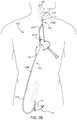
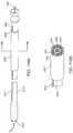
- FIG. 1is a schematic illustration of an access system and interventional device for transcervical carotid artery intervention.
- FIG. 2Ais a schematic illustration of a system of devices for transcervical carotid artery stenting using a retrograde blood flow embolic protection system including a flow control assembly wherein an arterial access device accesses the common carotid artery via a transcervical approach and a venous return device communicates with the internal jugular vein.
- FIG. 2Cis a schematic illustration of a system of devices for carotid artery stenting using a retrograde blood flow embolic protection system wherein an arterial access device accesses the common carotid artery via a transfemoral approach and a venous return device communicates with the femoral vein.
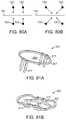
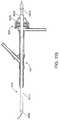
- FIG. 3Ais an enlarged view of the carotid artery wherein the carotid artery is occluded and connected to a reverse flow shunt via an arterial access device, and an interventional device, such as a stent delivery system or other working catheter, is introduced into the carotid artery via the arterial access device.
- an interventional devicesuch as a stent delivery system or other working catheter
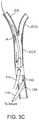
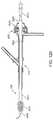
- FIG. 3Cis an alternate system wherein the carotid artery is occluded and the artery is connected to a reverse flow shunt via an arterial access device and the interventional device, such as a stent delivery system, is introduced into the carotid artery via an arterial introducer device.
- the interventional devicesuch as a stent delivery system
- FIG. 4illustrates a Criado flow shunt system.
- FIG. 5illustrates a normal cerebral circulation diagram including the Circle of Willis CW.
- FIG. 6illustrates the vasculature in a patient's neck, including the common carotid artery CCA, the internal carotid artery ICA, the external carotid artery ECA, and the internal jugular vein IJV.
- FIG. 7illustrates an arterial access device useful in the methods and systems of the present disclosure.
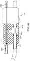
- FIG. 8Billustrates an additional arterial access device construction with a reduced diameter distal end.
- FIG. 15Aillustrates an additional arterial access device construction with an expandable occlusion element.
- FIG. 16illustrates a first embodiment of a venous return device useful in the methods and systems of the present disclosure.
- FIG. 18illustrates the system of FIG. 2A including a flow control assembly.
- FIG. 19A-19D , FIGS. 20A-20D , FIGS. 21A and 21B , FIGS. 22A-22D , and FIGS. 23A and 23Billustrate different embodiments of a variable flow resistance component useful in the methods and systems of the present disclosure.
- FIGS. 24A-24B , FIGS. 25A-25B , FIGS. 26A-26D , and FIGS. 27A-27Billustrate further embodiments of a variable flow resistance system useful in the methods and systems of the present disclosure.
- FIGS. 28A-28Eillustrate examples of blood flow paths during a procedure for implanting a stent at the carotid bifurcation in accordance with the principles of the present disclosure.
- FIGS. 29A-29Cshow an embodiment of the sheath that has a retention feature that includes an expandable member that expands through inflation.
- FIG. 30shows an embodiment of the sheath that includes an occlusion element and a separate retention feature that includes an inflatable balloon.
- FIG. 31shows another embodiment where the occlusion element and retention feature are combined into a single expandable balloon.
- FIG. 32shows another embodiment of a retention feature that includes an inflatable balloon that has a first section that enlarges to a first diameter and a second section that enlarges to a second diameter.
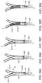
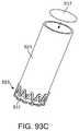
- FIGS. 33A-33Cshow an embodiment of the sheath that has a retention feature that includes an expandable member that expands when shortened along the axial length of the sheath.
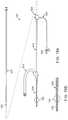
- FIGS. 34A and 34Bshow an embodiment of a sheath having a retention feature with more than two elongate members.
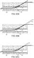
- FIGS. 35A and 35Bshow an embodiment of a sheath having a retention feature with only two elongate members.
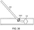
- FIG. 36shows an embodiment of the sheath that includes an occlusion element and a retention feature that expands when shortened.
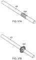
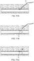
- FIGS. 37A and 37Bshows another embodiment of a sheath with a retention feature that expands when shortened along the axial length of the sheath.
- FIGS. 38A-38Cshow another embodiment of a sheath with a retention feature formed of one or more strips of material that follow the circumference of the sheath.
- FIG. 39shows a sheath with a with a retention feature having a reduced diameter distal region.
- FIG. 40shows another embodiment of a sheath with a with a retention feature having a reduced diameter distal region.
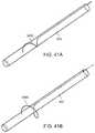
- FIGS. 41A and 41Bshow another embodiment of a sheath having a retention feature that includes a wire that is expanded outward.
- FIG. 42shows another embodiment of a sheath with a dual expandable feature including a first expandable element and a second expandable element.
- FIG. 43illustrates a modified retrograde blood flow system including a flow control assembly with an automatic shunt valve that is connected to a flush line.
- FIGS. 44A, 44B, 45A, and 45Billustrate examples of contrast pressure actuated shunt valves.
- FIGS. 46A-46Cillustrate yet another embodiment of a retrograde flow system including a flow control assembly with an automatic shunt valve that is connected to the flush line that is built in to the flow control assembly.
- FIGS. 47 and 48A-48Cillustrate another embodiment of a retrograde flow system with an automatic shunt valve connected to a flush line.
- FIG. 49shows another embodiment of a flow control assembly.
- FIGS. 50A-50Cshow a schematic view of a shunt line shut-off controller for automatically shutting off the shunt when contrast is injected.
- FIGS. 51A and 51Bshow another embodiment of the shunt line shut off controller.
- FIGS. 52A-52Bshow yet another embodiment of the shunt line shut off controller.
- FIGS. 53A-53Cshow a suture-based vessel closure device or suture delivery device that can be used to position a loop of suture across a puncture in a blood vessel.
- FIG. 54shows a close-up view of a distal region of the closure device with the vessel wall locator in the deployed position.
- FIGS. 55A and 55Bshow cross-sectional views of the delivery shaft of the closure device along line 55 A- 55 A of FIG. 54 .
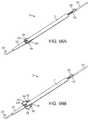
- FIGS. 56A and 56Bshow a close-up view of an alternate embodiment of the distal portion of a suture delivery device that can be used to position a loop of suture across a puncture in a blood vessel.
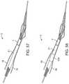
- FIGS. 57 and 58show two embodiments of a pre-mounted sheath being advanced along the closure device after the suture has been placed across the arteriotomy.
- FIGS. 59A-59Bshow another embodiment of a suture-based vessel closure device or suture delivery device.
- FIGS. 60 and 61show portions of another embodiment of a suture delivery device.
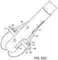
- FIG. 62Ais a perspective view of an embodiment of a distal region of a suture delivery device with the suture clasp arms partially deployed.
- FIG. 62Bis a perspective view of the suture delivery device with the suture clasp arms fully deployed.
- FIG. 62Cshows two flexible needles extending out of needle apertures and engaging the suture clasp arms.
- FIGS. 63A-63C, 64, and 65show a guidewire with deployment of an expandable sealing element or elements to be used with a closure device.
- FIG. 66shows a guidewire embodiment having an intravascular anchor.
- FIGS. 67-69show another guidewire anchor embodiment wherein the guidewire attaches to one or more clips that can be secured to the skin of the patient to hold the guidewire in place.
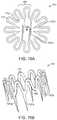
- FIGS. 70A-70Cshow an embodiment of the closure device wherein a self closing material is pre-loaded on a proximal region of the delivery shaft.
- FIGS. 71A-71Cshow an embodiment wherein a hemostasis material is positioned over the arteriotomy location after removal of a procedural sheath.
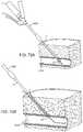
- FIGS. 72A-72E, 73, and 74A-74Fshow operations in an embodiment of an interventional procedure.
- FIG. 75shows an example of a closure device.
- FIG. 76Ashows another embodiment of a closure device.
- FIG. 76Bshows a perspective view of the closure device of FIG. 76A during deployment.
- FIG. 76Cshows the closure device of FIG. 76A mounted on a delivery system.
- FIGS. 77, 78, 79A, and 79Bshow alternate embodiments of closure devices.
- FIGS. 80A and 80Bshow a schematic representation of an arteriotomy including an incision.
- FIGS. 81A-81Bshow a first embodiment of a closure device that applies linear closing forces.
- FIGS. 82A-82Bshow another embodiment of a closure device that applies linear closing forces.
- FIGS. 83A and 83Bshow an embodiment of a sealing closure device.
- FIG. 84shows another embodiment of a sealing closure device.
- FIGS. 85A-85Cshow another embodiment of a sealing closure device.
- FIGS. 86A, 86B, 87, and 88show embodiments of a pre-tied closure device.
- FIGS. 89A-89Cshow an embodiment of a combination closure device that combines a closure clip with a spring-loaded sealing element.
- FIGS. 90A-90Dshow another embodiment of a closure device that includes an upper clip member positioned over a lower clip member and trapping a sealing member.
- FIGS. 91A-91D and 92show additional embodiments of combination closure devices.
- FIGS. 93A-93Cshow a closure device with an embodiment of a delivery device.
- FIGS. 94A-94Cshow another embodiment of a closure device.
- FIGS. 95A-95Bshow a suction delivery system that is used to deliver a closure device.
- FIGS. 96A-96Bshow a locating device that can be used in conjunction with delivery of a closure device.
- FIGS. 97A-97Cshow an example of a closure device pre-mounted on a procedural sheath such that the procedural sheath serves as a central delivery shaft of the delivery system.
- FIGS. 98A-98Cshow an example of the procedural sheath mounted on the central delivery shaft of the delivery system.
- FIG. 99shows a tube located on the outside of a delivery sheath.
- FIG. 100shows a schematic view of an embodiment of an interventional catheter.
- FIG. 101shows a cross-sectional view of the distal region of the catheter.
- FIG. 102shows a cross-sectional view of another embodiment of the catheter.
- FIGS. 103A and 103Bshow additional embodiments of the catheter.
- FIGS. 104A-104Dshow a method of use of any of the catheters having a dilation balloon and stent delivery capabilities on a single system.
- FIG. 105shows a cross-sectional view of a distal region of a tri-lumen dilatation balloon catheter that has flushing capabilities.
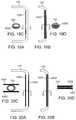
- FIG. 106shows another embodiment with an outer tubing positioned coaxial with a dual lumen shaft that carries the balloon.
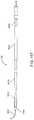
- FIG. 107shows another embodiment that includes a dilation balloon catheter with an external, single-lumen tubing for flushing.
- FIGS. 108A and 108Bshow a dilatation balloon catheter that has an internal flush lumen through which a flush solution can be passed.
- FIGS. 109A and 109Bshow a dual dilatation balloon and occlusion balloon catheter.
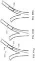
- FIGS. 110A and 110Bshow a variation of the dual balloon catheter with flushing capabilities.
- FIGS. 111A-111Cshow a catheter with a single balloon with a dual diameter.
- FIG. 112shows an occlusion balloon catheter that has a distal occlusion balloon and flushing capabilities.
- FIG. 113shows a stent delivery catheter that has an internal coaxial tubing member that terminates at a distal tapered tip, creating an annular flush lumen.
- FIG. 114shows a catheter with a guidewire lumen that doubles as a flush or aspiration lumen.
- FIGS. 115-121show alternate embodiments of a stent delivery catheter.
- FIG. 1shows an embodiment of a transcervical access and stent delivery system that is adapted to provide transcervical access to the region of the carotid artery bifurcation and to deliver a treatment device such as a stent.
- the systemincludes an arterial access device 10 adapted to be inserted into the common carotid artery so as to provide access to the common carotid artery and associated regions via an internal lumen of the arterial access device 10 .
- transcervical access to the common carotid arteryis achieved percutaneously via a puncture in the skin through which the arterial access device 10 is inserted.
- the arterial access device 110accesses the common carotid artery CCA via a direct surgical incision I.
- a stent delivery catheter 12can be inserted into the arterial access device 10 via an access port such that a portion of the stent delivery catheter 12 can be guided through the arterial access device 10 into the common carotid artery.
- the distal region of the stent delivery catheter 12can be guided into a desired location of the vasculature, such as into the internal carotid artery.
- a stent 14can be located on the distal region of the stent delivery catheter 12 and can be deployed in the vasculature using an actuator 16 .
- the stent delivery catheter 12has a working length that is particularly configured for insertion into the artery via a transcervical access location in the artery.
- An embolic protection devicesuch as a filter 17 or an occlusion balloon can be delivered to a location distal of the stent 14 .
- the filter 17 or occlusion ballooncan be delivered using a separate delivery catheter or guidewire that is inserted into the artery via the arterial access device 10 .
- the arterial access device 10can include a distal sheath 15 , a connector 26 , a proximal extension 20 that is optionally removable from the arterial access device 10 .
- the connectormay include a sheath securement member 25 such as a suture eyelet.
- the distal sheath 15can be adapted to be introduced through the incision or puncture in the wall of the common carotid artery.
- the distal sheath 15can have a stepped or other configuration having a reduced diameter insertion region or distal region, as described in detail below.
- the proximal extension 20can have an inner lumen which is contiguous with an inner lumen of the distal sheath 15 .
- a flush line 22can be connected to a proximal end of the proximal extension 20 .
- the flush line 22can be connected to the connector 26 .
- the flush-line 22can allow for the introduction of saline, contrast fluid, or the like, during a procedure.
- an external tube 24can be provided which is coaxially received over the exterior of the distal sheath 15 .
- the tube 24can have a proximal end that engages a sheath connector 26 .
- the length of the tube 24can limit the introduction of the sheath 15 to the portion of the sheath 15 that extends distally out of the tube 24 .
- the tube 24can have a dimension that is larger than the dimension of the puncture into the common carotid artery such that the tube cannot be inserted into the common carotid artery.
- the tube 24can engage a pre-deployed puncture closure device disposed in the carotid artery wall, if present, to permit the sheath 24 to be withdrawn without dislodging the closure device.
- a pre-deployed puncture closure devicedisposed in the carotid artery wall, if present, to permit the sheath 24 to be withdrawn without dislodging the closure device.
- Alternate embodiments of arterial access devicesare described below for use with a retrograde flow system.
- the arterial access device 10can be configured with any of the features of the arterial access devices described below.
- FIG. 2Ashows a first embodiment of a retrograde flow system 100 that is adapted to establish and facilitate retrograde or reverse flow blood circulation in the region of the carotid artery bifurcation in order to limit or prevent the release of emboli into the cerebral vasculature, particularly into the internal carotid artery.
- the flow control assembly 125can interact with the flow pathway through the shunt 120 , either external to the flow path, inside the flow path, or both.
- the arterial access device 110can at least partially insert into the common carotid artery CCA and the venous return device 115 at least partially inserts into a venous return site such as the internal jugular vein IJV, as described in more detail below.
- the arterial access device 110 and the venous return device 115couple to the shunt 120 at connection locations 127 a and 127 b .
- the natural pressure gradient between the internal carotid artery and the venous systemcan cause blood to flow in a retrograde or reverse direction RG ( FIG. 2A ) from the cerebral vasculature through the internal carotid artery and through the shunt 120 into the venous system.
- the flow control assembly 125can modulate, augment, assist, monitor, and/or otherwise regulate the retrograde blood flow.
- the arterial access device 110can access the common carotid artery CCA via a transcervical approach.
- Transcervical accessprovides a short length and non-tortuous pathway from the vascular access point to the target treatment site thereby easing the time and difficulty of the procedure, compared for example to a transfemoral approach. Additionally, this access route reduces the risk of emboli generation from navigation of diseased, angulated, or tortuous aortic arch or common carotid artery anatomy.
- At least a portion of the venous return device 115can be placed in the internal jugular vein IJV.
- the arterial access device 110accesses the common carotid artery CCA via a transcervical approach while the venous return device 115 access a venous return site other than the jugular vein, such as a venous return site including the femoral vein FV.
- the venous return device 115can be inserted into a central vein such as the femoral vein FV via a percutaneous puncture in the groin.
- the arterial access device 110accesses the common carotid artery via a femoral approach.
- the arterial access device 110approaches the CCA via a percutaneous puncture into the femoral artery FA, such as in the groin, and up the aortic arch AA into the target common carotid artery CCA.
- the venous return device 115can communicate with the jugular vein JV or the femoral vein FV.
- FIG. 2Dshows yet another embodiment, wherein the system provides retrograde flow from the carotid artery to an external receptacle 130 rather than to a venous return site.
- the arterial access device 110can connect to the receptacle 130 via the shunt 120 , which communicates with the flow control assembly 125 .
- the retrograde flow of bloodcan be collected in the receptacle 130 . If desired, the blood can be filtered and subsequently returned to the patient.
- the pressure of the receptacle 130can be set at zero pressure (atmospheric pressure) or even lower by positioning the receptacle below the level of the patient, causing the blood to flow in a reverse direction from the cerebral vasculature to the receptacle 130 .
- an interventional devicesuch as a stent delivery system 135 or other working catheter, can be introduced into the carotid artery via the arterial access device 110 , as described in detail below.
- the stent delivery system 135can be used to treat the plaque P such as to deploy a stent into the carotid artery.
- the arrow RG in FIG. 3Arepresents the direction of retrograde flow.
- FIG. 3Bshows another embodiment, wherein the arterial access device 110 is used for the purpose of creating an arterial-to-venous shunt as well as introduction of at least one interventional device into the carotid artery.
- a separate arterial occlusion device 112 with an occlusion element 129can be used to occlude the common carotid artery CCA at a location proximal to the distal end of the arterial access device 110 .
- FIG. 3Cshows yet another embodiment wherein the arterial access device 110 is used for the purpose of creating an arterial-to-venous shunt as well as arterial occlusion using an occlusion element 129 .
- a separate arterial introducer devicecan be used for the introduction of at least one interventional device into the carotid artery at a location distal to the arterial access device 110 .
- the Circle of Willis CWis the main arterial anastomatic trunk of the brain where all major arteries which supply the brain, namely the two internal carotid arteries (ICAs) and the vertebral basilar system, connect.
- the bloodis carried from the Circle of Willis by the anterior, middle and posterior cerebral arteries to the brain. This communication between arteries makes collateral circulation through the brain possible. Blood flow through alternate routes is made possible thereby providing a safety mechanism in case of blockage to one or more vessels providing blood to the brain.
- the braincan continue receiving adequate blood supply in most instances even when there is a blockage somewhere in the arterial system (e.g., when the ICA is ligated as described herein). Flow through the Circle of Willis ensures adequate cerebral blood flow by numerous pathways that redistribute blood to the deprived side.
- FIG. 5depicts a normal cerebral circulation and formation of Circle of Willis CW.
- the aorta AOgives rise to the brachiocephalic artery BCA, which branches into the left common carotid artery LCCA and left subclavian artery LSCA.
- the aorta AOfurther gives rise to the right common carotid artery RCCA and right subclavian artery RSCA.
- the left and right common carotid arteries CCAgives rise to internal carotid arteries ICA which branch into the middle cerebral arteries MCA, posterior communicating artery PcoA, and anterior cerebral artery ACA.
- the anterior cerebral arteries ACAdeliver blood to some parts of the frontal lobe and the corpus striatum.
- the Circle of Willisis formed by the anterior cerebral arteries ACA and the anterior communicating artery ACoA which connects the two ACAs.
- the two posterior communicating arteries PCoAconnect the Circle of Willis to the two posterior cerebral arteries PCA, which branch from the basilar artery BA and complete the Circle posteriorly.
- the common carotid artery CCAalso gives rise to external carotid artery ECA, which branches extensively to supply most of the structures of the head except the brain and the contents of the orbit.
- the ECAalso helps supply structures in the neck and face.
- FIG. 6shows an enlarged view of the relevant vasculature in the patient's neck.
- the common carotid artery CCAbranches at bifurcation B into the internal carotid artery ICA and the external carotid artery ECA.
- the bifurcationis located at approximately the level of the fourth cervical vertebra.
- FIG. 6shows plaque P formed at the bifurcation B.
- the arterial access device 110can access the common carotid artery CCA via a transcervical approach.
- the arterial access device 110can be inserted into the common carotid artery CCA at an arterial access location L, which can be, for example, a surgical incision or puncture in the wall of the common carotid artery CCA.
- in an embodimentonly about 2-4 cm of the distal region of the arterial access device is inserted into the common carotid artery CCA during a procedure.
- the common carotid arteriesare encased on each side in a layer of fascia called the carotid sheath.
- This sheathalso envelops the internal jugular vein and the vagus nerve.
- Anterior to the sheathis the sternocleidomastoid muscle.
- Transcervical access to the common carotid artery and internal jugular vein, either percutaneous or surgical,can be made immediately superior to the clavicle, between the two heads of the sternocleidomastoid muscle and through the carotid sheath, with care taken to avoid the vagus nerve.
- the common carotid arterybifurcates into the internal and external carotid arteries.
- the internal carotid arterycontinues upward without branching until it enters the skull to supply blood to the retina and brain.
- the external carotid arterybranches to supply blood to the scalp, facial, ocular, and other superficial structures. Intertwined both anterior and posterior to the arteries are several facial and cranial nerves. Additional neck muscles can also overlay the bifurcation. These nerve and muscle structures can be dissected and pushed aside to access the carotid bifurcation during a carotid endarterectomy procedure.
- the carotid bifurcationis closer to the level of the mandible, where access is more challenging and with less room available to separate it from the various nerves which should be spared. In these instances, the risk of inadvertent nerve injury can increase and an open endarterectomy procedure may not be a good option.
- FIG. 7shows the arterial access device 10 of FIG. 1 .
- the arterial access device 10can include a distal sheath 15 , a connector 26 , a proximal extension 20 that is optionally removable from the arterial access device 10 , and a hemostasis valve 625 .
- the connector 26can include a suture eyelet 25 that can be used to suture the arterial access device 10 to the patient's skin. If the proximal extension 20 is removable, there may be a second hemostasis valve located between the connector 26 and the proximal extension 20 , to maintain hemostasis of the sheath upon removal of the proximal extension 20 .
- the flush line 22can be connected to a proximal end of the proximal extension 20 , as shown, or to the connector 26 , or two flush lines connected at both locations.
- the flush-line 22allows for the introduction of saline, contrast fluid, or the like, during a procedure.
- an external tube 24can be coaxially received over the exterior of the distal sheath 15 .
- the arterial access device 10can include any of the features of the other embodiments of the arterial access devices described below.
- FIG. 8Ashows an embodiment of the arterial access device 110 of FIG. 2A , which can include a distal sheath 605 , a proximal extension 610 , a hemostasis valve 625 , a flow line 615 and an adaptor or Y-connector 620 for connecting the arterial access device to a flow reverse circuit (see below).
- the distal sheath 605is adapted to be introduced through an incision or puncture in a wall of a common carotid artery, either an open surgical incision or a percutaneous puncture established, for example, using the Seldinger technique.
- the length of the sheathcan be in the range from 5 to 15 cm, usually being from 10 cm to 12 cm.
- the sheath 605be highly flexible while retaining hoop strength to resist kinking and buckling.
- the distal sheath 605can be circumferentially reinforced, such as by braid, helical ribbon, helical wire, or the like.
- the distal sheath 605can have a stepped or other configuration having a reduced diameter insertion region or distal region 630 , as shown in FIG. 8B , which shows an enlarged view of the distal region 630 of the sheath 605 .
- the distal region 630 of the sheathcan be sized for insertion into the carotid artery, typically having an inner diameter in the range from 2.16 mm (0.085 inch) to 2.92 mm (0.115 inch) with the remaining proximal region of the sheath having larger outside and luminal diameters, with the inner diameter typically being in the range from 2.794 mm (0.110 inch) to 3.43 mm (0.135 inch).
- the reduced-diameter distal section 630has a length of approximately 2 cm to 4 cm.
- the relatively short length of the reduced-diameter distal section 630permits this section to be positioned in the common carotid artery CCA via the transcervical approach with reduced risk that the distal end of the sheath 605 will contact the bifurcation B.
- the reduced diameter section 630also permits a reduction in size of the arteriotomy for introducing the sheath 605 into the artery while having a minimal impact in the level of flow resistance.
- the proximal extension 610can have an inner lumen which is contiguous with an inner lumen of the sheath 605 .
- the lumenscan be joined by the Y-connector 620 which can also connect a lumen of the flow line 615 to the sheath.
- the flow line 615can connect to and form a first leg of the retrograde shunt 120 ( FIG. 1 ).
- the proximal extension 610can have a length sufficient to space the hemostasis valve 625 well away from the Y-connector 620 , which is adjacent to the percutaneous or surgical insertion site.
- the physiciancan introduce a stent delivery system or other working catheter into the proximal extension 610 and sheath 605 while staying out of the fluoroscopic field when fluoroscopy is being performed.
- a flush line 635can be connected to the side of the hemostasis valve 625 and can have a stopcock 640 at its proximal or remote end.
- the flush-line 635can allow for the introduction of saline, contrast fluid, or the like, during the procedures.
- the flush line 635can also allow pressure monitoring during the procedure.
- a dilator 645 having a tapered distal end 650can be provided to facilitate introduction of the distal sheath 605 into the common carotid artery.
- the dilator 645can be introduced through the hemostasis valve 625 so that the tapered distal end 650 extends through the distal end of the sheath 605 , as best seen in FIG. 9A .
- the dilator 645can have a central lumen to accommodate a guide wire. Typically, the guide wire is placed first into the vessel, and the dilator/sheath combination travels over the guide wire as it is being introduced into the vessel.
- a tube 705can be provided which is coaxially received over the exterior of the distal sheath 605 , also as seen in FIG. 9A .
- the tube 705has a flared proximal end 710 which engages the adapter 620 and a distal end 715 .
- the distal end 715can be beveled, as shown in FIG. 9B .
- the tube 705can serve at least two purposes. First, the length of the tube 705 can limit the introduction of the sheath 605 to the exposed distal portion of the sheath 605 , as seen in FIG. 9A . Second, the tube 705 can engage a pre-deployed puncture closure device disposed in the carotid artery wall, if present, to permit the sheath 605 to be withdrawn without dislodging the closure device.
- the sheath 605includes a retention feature that is adapted to retain the sheath within a blood vessel (such as the common carotid artery) into which the sheath 605 has been inserted.
- the retention featurereduces the likelihood that the sheath 605 will be inadvertently pulled out of the blood vessel.
- the retention featureinteracts with the blood vessel to resist and/or eliminate undesired pull-out.
- the retention featurecan also include additional elements that interact with the vessel wall to prevent the sheath from entering too far into the vessel.
- the retention featurecan also include sealing elements which help seal the sheath against arterial blood pressure at the puncture site.
- the distal sheath 605can be configured to establish a curved transition from a generally anterior-posterior approach over the common carotid artery to a generally axial luminal direction within the common carotid artery.
- the transition in directionis particularly useful when a percutaneous access is provided through the common carotid wall. While an open surgical access can allow for some distance in which to angle a straight sheath into the lumen of the common carotid artery, percutaneous access will generally be in a normal or perpendicular direction relative to the access of the lumen, and in such cases, a sheath that can flex or turn at an angle will find great use.
- the sheath 605can be formed in a variety of ways.
- the sheath 605can be pre-shaped to have a curve or an angle some set distance from the tip, for example 2 to 3 cm.
- the pre-shaped curve or anglecan provide for a turn in the range from 20° to 90°, preferably from 30° to 70°.
- the sheath 605can be straightened with an obturator or other straight or shaped instrument such as the dilator 645 placed into its lumen. After the sheath 605 has been at least partially introduced through the percutaneous or other arterial wall penetration, the obturator can be withdrawn to allow the sheath 605 to reassume its pre-shaped configuration into the arterial lumen.
- sheath configurationsinclude having a deflection mechanism such that the sheath can be placed and the catheter can be deflected in situ to the desired deployment angle.
- the catheterhas a non-rigid configuration when placed into the lumen of the common carotid artery. Once in place, a pull wire or other stiffening mechanism can be deployed in order to shape and stiffen the sheath into its desired configuration.
- a pull wire or other stiffening mechanismcan be deployed in order to shape and stiffen the sheath into its desired configuration.
- One particular example of such a mechanismis commonly known as a “shape-lock” mechanism as well described in medical and patent literature.
- Another sheath configurationincludes a curved dilator inserted into a straight but flexible sheath, so that the dilator and sheath are curved during insertion.
- the sheathcan be flexible enough to conform to the anatomy after dilator removal.
- the sheathhas built-in puncturing capability and atraumatic tip analogous to a guide wire tip. This eliminates the need for needle and wire exchange currently used for arterial access according to the micropuncture technique, and can thus save time, reduce blood loss, and require less surgeon skill.
- the proximal extension 610can be removably connected to the Y-arm connector 620 at a connection site.
- an additional hemostasis valve 621can be included at the connection site of the proximal extension 610 to the Y-arm connector 620 , so that hemostasis is maintained when the proximal extension is not attached.
- FIG. 10shows the arterial access sheath 605 , with the proximal extension 610 attached to the Y-connector 620 .
- FIG. 10also shows an additional connection line 623 for balloon inflation of an occlusion element 129 .
- FIG. 11shows the proximal extension 610 removed from the Y-connector 620 .
- the Y-connector in these figurescan be a flush, aspiration, and/or contrast line or can be a connection to a reverse flow shunt.
- the distal sheath 605includes an occlusion member 129 on the distal end.
- the occlusion member 129can be any member that is configured to occlude a blood vessel, such as an inflatable balloon.
- the occlusion member 129can allow for occlusion of the CCA and prevent antegrade flow from the CCA into the ICA and ECA during the procedure.
- the sheathcan include a flush line for attachment of an aspiration device so that active aspiration can be performed during certain, critical moments of the procedure.
- the distal sheath 605includes two occlusion members 129 a and 129 b on a distal region of the sheath, wherein proximal occlusion member 129 a and distal occlusion member 129 b are spaced apart from one another such that one occlusion member can be positioned in the CCA and another can be positioned in the ECA.
- the occlusion members 129 a and 129 benable occlusion of both the CCA and the ECA with a single device.
- the sheathcan have an exit port distal to the proximal occlusion member 129 a that enables a treatment device to exit the sheath and be positioned at the target site in the ICA or the carotid bifurcation.
- the distal sheath 605includes a flow restriction member 131 , such as an inflatable member which is sized and shaped to partially block but not totally occlude flow in the blood vessel. This can allow for the antegrade flow through the ICA to be reduced but not eliminated, and can be an alternative embolic protection method for patients who cannot tolerate reverse or static flow in the ICA and for whom distal protection methods are not possible.
- a flow restriction member 131such as an inflatable member which is sized and shaped to partially block but not totally occlude flow in the blood vessel.
- the retrograde flow system 100can include the arterial access device 110 , venous return device 115 , and shunt 120 which provides a passageway for retrograde flow from the arterial access device 110 to the venous return device 115 .
- the systemalso includes the flow control assembly 125 , which interacts with the shunt 120 to regulate and/or monitor retrograde blood flow through the shunt 120 .
- Embodiments of the components of the retrograde flow system 100are described below.
- FIG. 4shows a prior flow shunt system, referred to as the Criado system.
- the Criado systemuses a flow shunt which includes an arterial sheath 210 and a venous sheath 212 .
- Each sheathhas a side arm 214 , terminating in a stopcock 216 .
- the two sheaths stopcocksare connected by a connector tubing 218 , thus completing a reverse flow shunt from the arterial sheath 210 to the venous sheath 212 .
- the arterial sheathcan be placed in the common carotid artery CCA through an open surgical incision in the neck below the carotid bifurcation.
- Occlusion of the common carotid artery CCAcan be accomplished using a temporary vessel ligation, for example using a Rummel tourniquet and umbilical tape or vessel loop.
- the venous return sheath 212can be placed into the internal jugular vein IJV, such as via an open surgical incision. Retrograde flow from the internal carotid artery ICA and the external carotid artery ECA can then be established by opening the stopcock 216 .
- the Criado protocolis an improvement over the earlier retrograde flow protocols since it eliminates the need for femoral access. This method can also utilize and arterial access sheath with the improvements described in the previous section.
- the arterial access devicecan have features particularly useful in a retrograde blood flow system.
- the arterial access device 110can include a flow line 615 and Y-adaptor 620 to connect the sheath to a retrograde flow system.
- FIG. 15Ashows another embodiment of the arterial access device 110 . This embodiment similar is substantially the same as the embodiment shown in FIG. 8A , except that the distal sheath 605 includes an occlusion element 129 for occluding flow through, for example the common carotid artery.
- the distal sheath 605 with the occlusion element 129can have a stepped or other configuration having a reduced diameter distal region 630 .
- the distal region 630can be sized for insertion into the carotid artery with the remaining proximal region of the sheath 605 having larger outside and luminal diameters, with the inner diameter typically being in the range from 2.794 mm (0.110 inch) to 3.43 mm (0.135 inch).
- the larger luminal diameter of the proximal regioncan minimize the overall flow resistance of the sheath.
- the reduced-diameter distal section 630has a length of approximately 2 cm to 4 cm.
- FIG. 3Bshows an alternative embodiment, wherein the occlusion element 129 can be introduced into the carotid artery on a second sheath 112 separate from the distal sheath 605 of the arterial access device 110 .
- the second or “proximal” sheath 112can be adapted for insertion into the common carotid artery in a proximal or “downward” direction away from the cerebral vasculature.
- the second, proximal sheathcan include an inflatable balloon 129 or other occlusion element, generally as described above.
- FIG. 3Cshows yet another embodiment of a two arterial sheath system, wherein the interventional devices are introduced via an introducer sheath 114 separate from the distal sheath 605 of the arterial device 110 .
- a second or “distal” sheath 114can be adapted for insertion into the common carotid artery distal to the arterial access device 110 .
- the use of two separate access sheathsallows the size of each arteriotomy to be reduced.
- the arterial access flow line 615 ( FIG. 8A ) and the venous return flow line 915 , and Y-connectors 620 ( FIG. 8A ) and 1005can each have a relatively large flow lumen inner diameter, typically being in the range from 2.54 mm (0.100 inch) to 5.08 mm (0.200 inch), and a relatively short length, typically being in the range from 10 cm to 20 cm.
- the low system flow resistanceis desirable since it permits the flow to be maximized during portions of a procedure when the risk of emboli is at its greatest.
- the low system flow resistancealso allows the use of a variable flow resistance for controlling flow in the system, as described in more detail below.
- the dimensions of the venous return sheath 910can be generally the same as those described for the arterial access sheath 605 above. In the venous return sheath, an extension for the hemostasis valve 1010 is not required.
- a femoral vein return sitecan be accomplished percutaneously, with lower risk of serious complication, and also offers an alternative venous access to the central vein if the internal jugular vein UV is not available. Furthermore, the femoral venous return changes the layout of the reverse flow shunt such that the shunt controls can be located closer to the “working area” of the intervention, where the devices are being introduced and the contrast injection port is located.
- the shunt 120has an internal diameter of 4.76 mm ( 3/16 inch) and has a length of 40-70 cm. As mentioned, the length of the shunt can be adjusted.
- the ability to control the continuous retrograde flow rateallows the physician to adjust the protocol for individual patients and stages of the procedure.
- the retrograde blood flow ratewill typically be controlled over a range from a low rate to a high rate.
- the high ratecan be at least two-fold higher than the low rate, typically being at least three-fold higher than the low rate, and often being at least five-fold higher than the low rate, or even higher.
- the high rateis at least three-fold higher than the low rate and in another embodiment the high rate is at least six-fold higher than the low rate. While it is generally desirable to have a high retrograde blood flow rate to maximize the extraction of emboli from the carotid arteries, the ability of patients to tolerate retrograde blood flow will vary.
- the treating physiciancan determine when the flow rate exceeds the tolerable level for that patient and set the reverse flow rate accordingly.
- the physiciancan chose to turn on high flow only for brief, critical portions of the procedure when the risk of embolic debris is highest. At short intervals, for example between 15 seconds and 1 minute, patient tolerance limitations are usually not a factor.
- the retrograde blood flow ratecan be increased above the base line when the stent catheter is being introduced, when the stent is being deployed, pre- and post-dilatation of the stent, removal of the common carotid artery occlusion, and the like.
- the flow rate control systemcan be cycled between a relatively low flow rate and a relatively high flow rate in order to “flush” the carotid arteries in the region of the carotid bifurcation prior to reestablishing antegrade flow.
- Such cyclingcan be established with a high flow rate which can be approximately two- to six-fold greater than the low flow rate, typically being about three-fold greater.
- the cyclescan typically have a length in the range from 0.5 seconds to 10 seconds, usually from 2 seconds to 5 seconds, with the total duration of the cycling being in the range from 5 seconds to 60 seconds, usually from 10 seconds to 30 seconds.
- FIG. 18shows an example of the system 100 with a schematic representation of the flow control assembly 125 , which is positioned along the shunt 120 such that retrograde blood flow passes through or otherwise communicates with at least a portion of the flow control assembly 125 .
- the flow control assembly 125can include various controllable mechanisms for regulating and/or monitoring retrograde flow.
- the mechanismscan include various means of controlling the retrograde flow, including one or more pumps 1110 , valves 1115 , syringes 1120 and/or a variable resistance component 1125 .
- the flow control assembly 125can be manually controlled by a user and/or automatically controlled via a controller 1130 to vary the flow through the shunt 120 .
- the rate of retrograde blood flow through the shunt 120can be controlled.
- the controller 1130which is described in more detail below, can be integrated into the flow control assembly 125 or it can be a separate component that communicates with the components of the flow control assembly 125 .
- the flow control assembly 125can include one or more flow sensors 1135 and/or anatomical data sensors 1140 (described in detail below) for sensing one or more aspects of the retrograde flow.
- a filter 1145can be positioned along the shunt 120 for removing emboli before the blood is returned to the venous return site. When the filter 1145 is positioned upstream of the controller 1130 , the filter 1145 can prevent emboli from entering the controller 1145 and potentially clogging the variable flow resistance component 1125 .
- the various components of the flow control assembly 125can be positioned at various locations along the shunt 120 and at various upstream or downstream locations relative to one another.
- the components of the flow control assembly 125are not limited to the locations shown in FIG. 18 .
- the flow control assembly 125does not necessarily include all of the components but can rather include various sub-combinations of the components.
- a syringecan optionally be used within the flow control assembly 125 for purposes of regulating flow or it can be used outside of the assembly for purposes other than flow regulation, such as to introduce fluid such as radiopaque contrast into the artery in an antegrade direction via the shunt 120 .
- variable resistance component 1125 and the pump 1110can be coupled to the shunt 120 to control the retrograde flow rate.
- the variable resistance component 1125controls the flow resistance
- the pump 1110provides for positive displacement of the blood through the shunt 120 .
- the pumpcan be activated to drive the retrograde flow rather than relying on the perfusion stump pressures of the ECA and ICA and the venous back pressure to drive the retrograde flow.
- the pump 1110can be a peristaltic tube pump or any type of pump including a positive displacement pump.
- the pump 1110can be activated and deactivated (either manually or automatically via the controller 1130 ) to selectively achieve blood displacement through the shunt 120 and to control the flow rate through the shunt 120 .
- Displacement of the blood through the shunt 120can also be achieved in other manners including using the aspiration syringe 1120 , or a suction source such as a VACUTAINER, VACULOK syringe, or wall suction can be used.
- the pump 1110can communicate with the controller 1130 .
- One or more flow control valves 1115can be positioned along the pathway of the shunt.
- the valve(s)can be manually actuated or automatically actuated (via the controller 1130 ).
- the flow control valves 1115can be, for example one-way valves to prevent flow in the antegrade direction in the shunt 120 , check valves, or high pressure valves which would close off the shunt 120 , for example during high-pressure contrast injections (which are intended to enter the arterial vasculature in an antegrade direction).
- the controller 1130communicates with components of the system 100 including the flow control assembly 125 to enable manual and/or automatic regulation and/or monitoring of the retrograde flow through the components of the system 100 (including, for example, the shunt 120 , the arterial access device 110 , the venous return device 115 and the flow control assembly 125 ).
- a usercan actuate one or more actuators on the controller 1130 to manually control the components of the flow control assembly 125 .
- Manual controlscan include switches or dials or similar components located directly on the controller 1130 or components located remote from the controller 1130 such as a foot pedal or similar device.
- the controller 1130can also automatically control the components of the system 100 without requiring input from the user.
- the usercan program software in the controller 1130 to enable such automatic control.
- the controller 1130can control actuation of the mechanical portions of the flow control assembly 125 .
- the controller 1130can include circuitry or programming that interprets signals generated by sensors 1135 / 1140 such that the controller 1130 can control actuation of the flow control assembly 125 in response to such signals generated by the sensors.
- the representation of the controller 1130 in FIG. 18is merely an example. It should be appreciated that the controller 1130 can vary in appearance and structure.
- the controller 1130is shown in FIG. 18 as being integrated in a single housing. This permits the user to control the flow control assembly 125 from a single location. It should be appreciated that any of the components of the controller 1130 can be separated into separate housings. Further, FIG. 18 shows the controller 1130 and flow control assembly 125 as separate housings. It should be appreciated that the controller 1130 and flow control regulator 125 can be integrated into a single housing or can be divided into multiple housings or components.
- the controller 1130can include one or more indicators that provide a visual and/or audio signal to the user regarding the state of the retrograde flow.
- An audio indicationadvantageously reminds the user of a flow state without requiring the user to visually check the flow controller 1130 .
- the indicator(s)can include a speaker 1150 and/or a light 1155 or any other means for communicating the state of retrograde flow to the user.
- the controller 1130can communicate with one or more sensors of the system to control activation of the indicator. Or, activation of the indicator can be tied directly to the user actuating one of the flow control actuators 1165 .
- the indicatorneed not be a speaker or a light.
- the indicatorcan be a button or switch that visually indicates the state of the retrograde flow.
- the button being in a certain statecan be a visual indication that the retrograde flow is in a high state.
- a switch or dial pointing toward a particular labeled flow statecan be a visual indication that the retrograde flow is in the labeled state.
- the indicatorcan provide a signal indicative of one or more states of the retrograde flow.
- the indicatoridentifies two discrete states: a state of “high” flow rate and a state of “low” flow rate.
- the indicatoridentifies more than two flow rates, including a “high” flow rate, a “medium” flow rate, and a “low” rate.
- the indicatorcan be configured to identify any quantity of discrete states of the retrograde flow or it can identify a graduated signal that corresponds to the state of the retrograde flow.
- the indicatorcan be a digital or analog meter 1160 that indicates a value of the retrograde flow rate, such as in ml/min or any other units.
- the indicatoris configured to indicate to the user whether the retrograde flow rate is in a state of “high” flow rate or a “low” flow rate.
- the indicatorcan illuminate in a first manner (e.g., level of brightness) and/or emit a first audio signal when the flow rate is high and then change to a second manner of illumination and/or emit a second audio signal when the flow rate is low.
- the indicatorcan illuminate and/or emit an audio signal only when the flow rate is high, or only when the flow rate is low. Given that some patients can be intolerant of a high flow rate or intolerant of a high flow rate beyond an extended period of time, it can be desirable that the indicator provide notification to the user when the flow rate is in the high state. This would serve as a fail safe feature.
- the indicatorprovides a signal (audio and/or visual) when the flow rate changes state, such as when the flow rate changes from high to low and/or vice-versa.
- the indicatorprovides a signal when no retrograde flow is present, such as when the shunt 120 is blocked or one of the stopcocks in the shunt 120 is closed.
- the controller 1130can include one or more actuators that the user can press, switch, manipulate, or otherwise actuate to regulate the retrograde flow rate and/or to monitor the flow rate.
- the controller 1130can include a flow control actuator 1165 (such as one or more buttons, knobs, dials, switches, etc.) that the user can actuate to cause the controller to selectively vary an aspect of the reverse flow.
- the flow control actuator 1165is a knob that can be turned to various discrete positions each of which corresponds to the controller 1130 causing the system 100 to achieve a particular retrograde flow state.
- the statesinclude, for example, (a) OFF; (b) LO-FLOW; (c) HI-FLOW; and (d) ASPIRATE.
- the controller 1130can achieve the various retrograde flow states by interacting with one or more components of the system, including the sensor(s), valve(s), variable resistance component, and/or pump(s). It should be appreciated that the controller 1130 can also include circuitry and software that regulates the retrograde flow rate and/or monitors the flow rate such that the user need not actively actuate the controller 1130 .
- the OFF statecorresponds to a state where there is no retrograde blood flow through the shunt 120 .
- the controller 1130causes the retrograde flow to cease, such as by shutting off valves or closing a stop cock in the shunt 120 .
- the LO-FLOW and HI-FLOW statescorrespond to a low retrograde flow rate and a high retrograde flow rate, respectively.
- the controller 1130interacts with components of the flow control regulator 125 including pump(s) 1110 , valve(s) 1115 and/or variable resistance component 1125 to increase or decrease the flow rate accordingly.
- the ASPIRATE statecorresponds to opening the circuit to a suction source, for example a VACUTAINER or suction unit, if active retrograde flow is desired.
- the systemcan be used to vary the blood flow between various states including an active state, a passive state, an aspiration state, and an off state.
- the active statecan correspond to the system using a means that actively drives retrograde blood flow. Such active means can include, for example, a pump, syringe, vacuum source, etc.
- the passive statecan correspond to when retrograde blood flow is driven by the perfusion stump pressures of the ECA and ICA and possibly the venous pressure.
- the aspiration statecorresponds to the system using a suction source, for example a VACUTAINER or suction unit, to drive retrograde blood flow.
- the off statecan correspond to the system having zero retrograde blood flow such as the result of closing a stopcock or valve.
- the low and high flow ratescan be either passive or active flow states.
- the particular value (such as in ml/min) of either the low flow rate and/or the high flow ratecan be predetermined and/or pre-programmed into the controller such that the user does not actually set or input the value. Rather, the user selects “high flow” and/or “low flow” (such as by pressing an actuator such as a button on the controller 1130 ) and the controller 1130 interacts with one or more of the components of the flow control assembly 125 to cause the flow rate to achieve the predetermined high or low flow rate value.
- the usersets or inputs a value for low flow rate and/or high flow rate such as into the controller.
- the low flow rate and/or high flow rateis not actually set. Rather, external data (such as data from the anatomical data sensor 1140 ) is used as the basis for affects the flow rate.
- the flow control actuator 1165can be multiple actuators, for example one actuator, such as a button or switch, to switch state from LO-FLOW to HI-FLOW and another to close the flow loop to OFF, for example during a contrast injection where the contrast is directed antegrade into the carotid artery.
- the flow control actuator 1165can include multiple actuators. For example, one actuator can be operated to switch flow rate from low to high, another actuator can be operated to temporarily stop flow, and a third actuator (such as a stopcock) can be operated for aspiration using a syringe. In another example, one actuator is operated to switch to LO-FLOW and another actuator is operated to switch to HI-FLOW.
- the flow control actuator 1165can include multiple actuators to switch states from LO-FLOW to HI-FLOW and additional actuators for fine-tuning flow rate within the high flow state and low flow state. Upon switching between LO-FLOW and HI-FLOW, these additional actuators can be used to fine-tune the flow rates within those states.
- LO-FLOWLO-FLOW
- HI-FLOWHI-FLOW
- additional actuatorscan be used to fine-tune the flow rates within those states.
- a wide variety of actuatorscan be used to achieve control over the state of flow.
- the controller 1130 or individual components of the controller 1130can be located at various positions relative to the patient and/or relative to the other components of the system 100 .
- the flow control actuator 1165can be located near the hemostasis valve where interventional tools are introduced into the patient in order to facilitate access to the flow control actuator 1165 during introduction of the tools.
- the locationcan vary, for example, based on whether a transfemoral or a transcervical approach is used, as shown in FIGS. 2A-C .
- the controller 1130can have a wireless connection to the remainder of the system 100 and/or a wired connection of adjustable length to permit remote control of the system 100 .
- the controller 1130can have a wireless connection with the flow control regulator 125 and/or a wired connection of adjustable length to permit remote control of the flow control regulator 125 .
- the controller 1130can also be integrated in the flow control regulator 125 .
- a tether with mechanical actuation capabilitiescan connect the controller 1130 to one or more of the components.
- the controller 1130can be positioned a sufficient distance from the system 100 to permit positioning the controller 1130 outside of a radiation field when fluoroscopy is in use.
- the controller 1130 and any of its componentscan interact with other components of the system (such as the pump(s), sensor(s), shunt, etc.) in various manners.
- any of a variety of mechanical connectionscan be used to enable communication between the controller 1130 and the system components.
- the controller 1130can communicate electronically or magnetically with the system components.
- Electro-mechanical connectionscan also be used.
- the controller 1130can be equipped with control software that enables the controller 1130 to implement control functions with the system components.
- the controller 1130itself can be a mechanical, electrical or electro-mechanical device.
- the controller 1130can be mechanically, pneumatically, or hydraulically actuated or electromechanically actuated (for example in the case of solenoid actuation of flow control state).
- the controller 1130can include a computer, computer processor, and memory, as well as data storage capabilities.
- the flow control assembly 125can include or interact with one or more sensors, which communicate with the system 100 and/or communicate with the patient's anatomy.
- Each of the sensorscan be adapted to respond to a physical stimulus (including, for example, heat, light, sound, pressure, magnetism, motion, etc.) and to transmit a resulting signal for measurement or display or for operating the controller 1130 .
- the flow sensor 1135interacts with the shunt 120 to sense an aspect of the flow through the shunt 120 , such as flow velocity or volumetric rate of blood flow.
- the flow sensor 1135can be directly coupled to a display that directly displays the value of the volumetric flow rate or the flow velocity. Or the flow sensor 1135 can feed data to the controller 1130 for display of the volumetric flow rate or the flow velocity.
- the type of flow sensor 1135can vary.
- the flow sensor 1135can be a mechanical device, such as a paddle wheel, flapper valve, rolling ball, or any mechanical component that responds to the flow through the shunt 120 . Movement of the mechanical device in response to flow through the shunt 120 can serve as a visual indication of fluid flow and can also be calibrated to a scale as a visual indication of fluid flow rate.
- the mechanical devicecan be coupled to an electrical component.
- a paddle wheelcan be positioned in the shunt 120 such that fluid flow causes the paddle wheel to rotate, with greater rate of fluid flow causing a greater speed of rotation of the paddle wheel.
- the paddle wheelcan be coupled magnetically to a Hall-effect sensor to detect the speed of rotation, which is indicative of the fluid flow rate through the shunt 120 .
- the flow sensor 1135is an ultrasonic or electromagnetic flow meter, which allows for blood flow measurement without contacting the blood through the wall of the shunt 120 .
- An ultrasonic or electromagnetic flow metercan be configured such that it does not have to contact the internal lumen of the shunt 120 .
- the flow sensor 1135at least partially includes a Doppler flow meter, such as a transonic flow meter, that measures fluid flow through the shunt 120 . It should be appreciated that any of a wide variety of sensor types can be used including an ultrasound flow meter and transducer.
- the systemcan include multiple sensors.
- the system 100is not limited to using a flow sensor 1135 that is positioned in the shunt 120 or a sensor that interacts with the venous return device 115 or the arterial access device 110 .
- an anatomical data sensor 1140can communicate with or otherwise interact with the patient's anatomy such as the patient's neurological anatomy. In this manner, the anatomical data sensor 1140 can sense a measurable anatomical aspect that is directly or indirectly related to the rate of retrograde flow from the carotid artery.
- the anatomical data sensor 1140can measure blood flow conditions in the brain, for example the flow velocity in the middle cerebral artery, and communicate such conditions to a display and/or to the controller 1130 for adjustment of the retrograde flow rate based on predetermined criteria.
- the anatomical data sensor 1140includes a transcranial Doppler ultrasonography (TCD), which is an ultrasound test that uses reflected sound waves to evaluate blood as it flows through the brain. Use of TCD results in a TCD signal that can be communicated to the controller 1130 for controlling the retrograde flow rate to achieve or maintain a desired TCD profile.
- TCDtranscranial Doppler ultrasonography
- the anatomical data sensor 1140can be based on any physiological measurement, including reverse flow rate, blood flow through the middle cerebral artery, TCD signals of embolic particles, or other neuromonitoring signals.
- the system 100includes a closed-loop control system.
- one or more of the sensorssenses or monitors a predetermined aspect of the system 100 or the anatomy (such as, for example, reverse flow rate and/or neuromonitoring signal).
- the sensor(s)can feed relevant data to the controller 1130 , which continuously adjusts an aspect of the system as necessary to maintain a desired retrograde flow rate.
- the sensorscan communicate feedback on how the system 100 is operating to the controller 1130 so that the controller 1130 can translate that data and actuate the components of the flow control regulator 125 to dynamically compensate for disturbances to the retrograde flow rate.
- the controller 1130can include software that causes the controller 1130 to signal the components of the flow control assembly 125 to adjust the flow rate such that the flow rate is maintained at a constant state despite differing blood pressures from the patient.
- the system 100need not rely on the user to determine when, how long, and/or what value to set the reverse flow rate in either a high or low state. Rather, software in the controller 1130 can govern such factors.
- the controller 1130can control the components of the flow control assembly 125 to establish the level or state of retrograde flow (either analog level or discreet state such as high, low, baseline, medium, etc.) based on the retrograde flow rate sensed by the sensor 1135 .
- the anatomical data sensor 1140(which measures a physiologic measurement in the patient) communicates a signal to the controller 1130 , which adjusts the flow rate based on the signal.
- the physiological measurementcan be based on flow velocity through the MCA, TCD signal, or some other cerebral vascular signal.
- TCDcan be used to monitor cerebral flow changes and to detect microemboli.
- the controller 1130can adjust the flow rate to maintain the TCD signal within a desired profile.
- the TCD signalcan indicate the presence of microemboli (“TCD hits”) and the controller 1130 can adjust the retrograde flow rate to maintain the TCD hits below a threshold value of hits.
- the controller 1130can set the retrograde flow rate at the “maximum” flow rate that is tolerated by the patient, as assessed by perfusion to the brain.
- the controller 1130can thus control the reverse flow rate to optimize the level of protection for the patient without relying on the user to intercede.
- the feedbackis based on a state of the devices in the system 100 or the interventional tools being used. For example, a sensor can notify the controller 1130 when the system 100 is in a high risk state, such as when an interventional catheter is positioned in the sheath 605 . The controller 1130 then adjusts the flow rate to compensate for such a state.
- the controller 1130can be used to selectively augment the retrograde flow in a variety of manners. For example, it has been observed that greater reverse flow rates can cause a resultant greater drop in blood flow to the brain, most importantly the ipsilateral MCA, which may not be compensated enough with collateral flow from the Circle of Willis. Thus a higher reverse flow rate for an extended period of time can lead to conditions where the patient's brain is not getting enough blood flow, leading to patient intolerance as exhibited by neurologic symptoms. Studies show that MCA blood velocity less than 10 cm/sec is a threshold value below which patient is at risk for neurological blood deficit. There are other markers for monitoring adequate perfusion to the brains, such as EEG signals. However, a high flow rate can be tolerated even up to a complete stoppage of MCA flow for a short period, up to about 15 seconds to 1 minute.
- the controller 1130can optimize embolic debris capture by automatically increasing the reverse flow only during limited time periods which correspond to periods of heightened risk of emboli generation during a procedure.
- These periods of heightened riskinclude the period of time while an interventional device (such as a dilatation balloon for pre or post stenting dilatation or a stent delivery device) crosses the plaque P.
- Another periodis during an interventional maneuver such as deployment of the stent or inflation and deflation of the balloon pre- or post-dilatation.
- a third periodis during injection of contrast for angiographic imaging of treatment area.
- the controllercan cause the reverse flow rate to revert to a lower, baseline level. This lower level can correspond to a low reverse flow rate in the ICA, or even slight antegrade flow in those patients with a high ECA to ICA perfusion pressure ratio.
- the default flow rateis the low flow rate. This serves as a failsafe measure for patients that are intolerant of a high flow rate.
- the controller 1130can be biased toward the default rate such that the controller causes the system to revert to the low flow rate after passage of a predetermined period of time of high flow rate.
- the bias toward low flow ratecan be achieved via electronics or software, or it can be achieved using mechanical components, or a combination thereof.
- the flow control actuator 1165 of the controller 1130 and/or valve(s) 1115 and/or pump(s) 1110 of the flow control regulator 125are spring loaded toward a state that achieves a low flow rate.
- the controller 1130is configured such that the user can over-ride the controller 1130 such as to manually cause the system to revert to a state of low flow rate if desired.
- the controller 1130includes a timer 1170 ( FIG. 18 ) that keeps time with respect to how long the flow rate has been at a high flow rate.
- the controller 1130can be programmed to automatically cause the system 100 to revert to a low flow rate after a predetermined time period of high flow rate, for example after 15, 30, or 60 seconds or more of high flow rate. After the controller reverts to the low flow rate, the user can initiate another predetermined period of high flow rate as desired. Moreover, the user can override the controller 1130 to cause the system 100 to move to the low flow rate (or high flow rate) as desired.
- embolic debris capturecan be optimized while not causing patient tolerance issues by initially setting the level of retrograde flow at a low rate, and then switching to a high rate for discreet periods of time during critical stages in the procedure.
- the flow rateis initially set at a high rate, and then verifying patient tolerance to that level before proceeding with the rest of the procedure. If the patient shows signs of intolerance, the retrograde flow rate is lowered.
- Patient tolerancecan be determined automatically by the controller based on feedback from the anatomical data sensor 1140 or it can be determined by a user based on patient observation. The adjustments to the retrograde flow rate can be performed automatically by the controller or manually by the user.
- the usercan monitor the flow velocity through the middle cerebral artery (MCA), for example using TCD, and then to set the maximum level of reverse flow which keeps the MCA flow velocity above the threshold level.
- MCAmiddle cerebral artery
- TCDmiddle cerebral artery
- Adjustmentscan be made as needed if the MCA flow velocity changes during the course of the procedure, or the patient exhibits neurologic symptoms.
- the system 100is adapted to regulate retrograde flow in a variety of manners. Any combination of the pump 1110 , valve 1115 , syringe 1120 , and/or variable resistance component 1125 can be manually controlled by the user or automatically controlled via the controller 1130 to adjust the retrograde flow rate.
- the system 100can regulate retrograde flow in various manners, including controlling an active flow component (e.g., pump, syringe, etc.), reducing the flow restriction, switching to an aspiration source (such as a pre-set VACULOK syringe, VACUTAINER, suction system, or the like), or any combination thereof.
- an active flow componente.g., pump, syringe, etc.
- an aspiration sourcesuch as a pre-set VACULOK syringe, VACUTAINER, suction system, or the like
- the retrograde flowcan be augmented in various manners.
- the reservoirhas a head height that is of the height of the blood inside the reservoir and the height of the reservoir with respect to the patient.
- Reverse flow into the reservoircan be modulated by setting the reservoir height to increase or decrease the amount of pressure gradient from the CCA to the reservoir.
- the reservoiris raised to increase the reservoir pressure to a pressure that is greater than venous pressure.
- the reservoircan be positioned below the patient, such as down to a level of the floor, to lower the reservoir pressure to a pressure below venous or atmospheric pressure.
- variable flow resistance in shunt 120can be provided in a wide variety of ways.
- flow resistance component 1125can cause a change in the size or shape of the shunt to vary flow conditions and thereby vary the flow rate.
- the flow resistance component 1125can re-route the blood flow through one or more alternate flow pathways in the shunt to vary the flow conditions.
- the shunt 120has an inflatable bladder 1205 formed along a portion of its interior lumen. As shown in FIGS. 19A and 19C , when the bladder 1205 is deflated, the inner lumen of the shunt 120 remains substantially unrestricted, providing for a low resistance flow. By inflating the bladder 1205 , however, as shown in FIGS. 19B and 19D , the flow lumen can be greatly restricted, thus greatly increasing the flow resistance and reducing the flow rate of atrial blood to the venous vasculature.
- the controller 1130can control inflation/deflation of the bladder 1205 or it can be controlled manually by the user.
- the cross-sectional area of the lumen in the shunt 120can be decreased by applying an external force, such as flattening the shunt 120 with a pair of opposed plates 1405 , as shown in FIGS. 20A-20D .
- the opposed platesare adapted to move toward and away from one another with the shunt 120 positioned between the plates.
- the lumen of the shunt 120remains unrestricted.
- the plates 1405constrict the shunt 120 . In this manner, the lumen remaining in shunt 120 can be greatly decreased to increase flow resistance through the shunt.
- the controller 1130can control movement of the plates 1405 or such movement can be controlled manually by the user.
- the available cross-sectional area of the shunt 120can also be restricted by axially elongating a portion 1505 of the shunt 120 .
- the portion 1505Prior to axial elongation, the portion 1505 will be generally unchanged, providing a full luminal flow area in the portion 1505 , as shown in FIG. 21A .
- the internal luminal area of the shunt 120 in the portion 1505can be significantly decreased and the length increased, both of which have the effect of increasing the flow resistance.
- a mesh or braid structurein the shunt at least in the portion 1505 .
- the mesh or braid structureprovides the shunt 120 with a pliable feature that facilitates axial elongation without breaking.
- the controller 1130can control elongation of the shunt 120 or it can be controlled manually by the user.
- a portion of the shunt 120can be manufactured having a small diameter, as shown in FIGS. 22A and 22C .
- the shunt 120can pass through a chamber 1600 which is sealed at both ends.
- a vacuumcan be applied within the chamber 1600 exterior of the shunt 120 to cause a pressure gradient.
- the pressure gradientcan cause the shunt 120 to increase in size within the chamber 120 , as shown in FIGS. 19B and 19D .
- the vacuumcan be applied in a receptacle 1605 attached to a vacuum source 1610 .
- a similar systemcan be employed with a shunt 120 having resting configuration that is in the increased size. Pressure can be applied to the chamber to shrink or flatten the shunt to decrease the flow resistance.
- the controller 1130can control the vacuum or it can be controlled manually by the user.
- the flow resistance through shunt 120can be changed by providing two or more alternative flow paths.
- the flow through shunt 120can pass through a main lumen 1700 as well as secondary lumen 1705 .
- the secondary lumen 1705can be longer and/or have a smaller diameter than the main lumen 1700 .
- the secondary lumen 1705has higher flow resistance than the main lumen 1700 .
- the flow resistancewill be at a minimum. Blood can flow through both lumens 1700 and 1705 due to the pressure drop created in the main lumen 1700 across the inlet and outlet of the secondary lumen 1705 . This has the benefit of preventing stagnant blood. As shown in FIG.
- FIGS. 23A and 23Bby blocking flow through the main lumen 1700 of shunt 120 , the flow can be diverted to the secondary lumen 1705 , thus increasing the flow resistance and reducing the blood flow rate. It will be appreciated that additional flow lumens can also be provided in parallel to allow for a three, four, or more discrete flow resistances.
- the shunt 120can be equipped with a valve 1710 that controls flow to the main lumen 1700 and the secondary lumen 1705 with the valve 1710 being controlled by the controller 1130 or being controlled manually by the user.
- the embodiment of FIGS. 23A and 23Bhas an advantage in that this embodiment in that it does not require as small of lumen sizes to achieve desired retrograde flow rates as some of the other embodiments of variable flow resistance mechanisms. This is a benefit in blood flow lines in that there is less chance of clogging and causing clots in larger lumen sizes than smaller lumen sizes.
- the shunt 120can also be arranged in a variety of coiled configurations which permit external compression to vary the flow resistance in a variety of ways. Arrangement of a portion of the shunt 120 in a coil contains a long section of the shunt in a relatively small area. This allows compression of a long length of the shunt 120 over a small space. As shown in FIGS. 24A and 24B , a portion of the shunt 120 can be wound around a dowel 1805 to form a coiled region.
- the dowel 1805can have plates 1810 a and 1810 b which can move toward and away from each other in an axial direction.
- the coiled portion of the shunt 105is uncompressed and flow resistance is at a minimum.
- the shunt 120is large diameter, so when the shunt is non-compressed, the flow resistance is low, allowing a high-flow state.
- the two plates 1810 a and 1810 bcan be pushed together, compressing the coil of shunt 120 .
- the controller 1130can control the plates or they can be controlled manually by the user.
- FIGS. 25A and 25BA similar compression apparatus is shown in FIGS. 25A and 25B .
- the coiled shunt 120can be encased between two movable cylinder halves 1905 a and 1905 b .
- the halves 1905 a and 1905 bcan slide along dowel pins 1910 to move toward and away from one another.
- the coiled shunt 120is uncompressed and flow resistance is at a minimum.
- the coiled shunt 120is compressed circumferentially to increase flow resistance.
- the controller 1130can control the halves 1905 or they can be controlled manually by the user.
- the shunt 120can also be wound around an axially split mandrel 2010 having wedge elements 2015 on opposed ends.
- the split portions of the mandrelcan be opened and closed relative to one another, causing the coil of tubing to be stretched (when the mandrel portions 2010 are spread apart, FIG. 26C, 26D ) or relaxed (when the mandrel portions 2010 are closed, FIG. 26A, 26B .)
- the outward pressure on the shunt 120is at a minimum and the flow resistance is also at a minimum.
- FIGS. 27A and 27Bshow an embodiment of the variable resistance component 1125 that uses a dowel to vary the resistance to flow.
- a housing 2030can be inserted into a section of the shunt 120 .
- the housing 2030can have an internal lumen 2035 that is contiguous with the internal lumen of the shunt 120 .
- a dowel 2040can move into and out of a portion of the internal lumen 2035 .
- the internal lumen 2035is annular with a cross-sectional area that is much smaller than the cross-sectional area of the internal lumen 2035 when the dowel is not present.
- the annular internal lumen 2035has a length S that can be varied by varying the portion of the dowel 2040 that is inserted into the lumen 2035 .
- the length S of the annular lumen 2035increases and vice-versa. This can be used to vary the level of flow resistance caused by the presence of the dowel 2040 .
- the dowel 2040can enter the internal lumen 2035 via a hemostasis valve in the housing 2030 .
- a cap 2050 and an O-ring 2055can provide a sealing engagement that seals the housing 2030 and dowel 2040 against leakage.
- the cap 2050can have a locking feature, such as threads, that can be used to lock the cap 2050 against the housing 2030 and to also fix the position of the dowel 2040 in the housing 2040 .
- the cap 2050exerts pressure against the O-ring 2055 to tighten it against the dowel 2040 in a sealed engagement.
- the dowel 2040is free to move in and out of the housing 2030 .
- FIGS. 28A-28Eflow through the carotid artery bifurcation at different stages of the methods of the present disclosure will be described.
- the distal sheath 605 of the arterial access device 110is introduced into the common carotid artery CCA.
- entry into the common carotid artery CCAcan be via a transcervical or transfemoral approach.
- the blood flowwill continue in antegrade direction AG with flow from the common carotid artery entering both the internal carotid artery ICA and the external carotid artery ECA, as shown in FIG. 28A .
- the venous return device 115can then be inserted into a venous return site, such as the internal jugular vein IJV (not shown in FIGS. 28A-28E ).
- the shunt 120can be used to connect the flow lines 615 and 915 of the arterial access device 110 and the venous return device 115 , respectively (as shown in FIG. 2A ). In this manner, the shunt 120 provides a passageway for retrograde flow from the atrial access device 110 to the venous return device 115 .
- the shunt 120can connect to an external receptacle 130 rather than to the venous return device 115 , as shown in FIG. 2C .
- the occlusion element 129can be expanded at a location proximal to the distal opening of the sheath 605 to occlude the CCA.
- the tourniquet 2105FIG. 2A
- the occlusion element 129can be introduced on second occlusion device 112 separate from the distal sheath 605 of the arterial access device 110 , as shown in FIG. 3B .
- the ECAcan also be occluded with a separate occlusion element, either on the same device 110 or on a separate occlusion device.
- FIG. 28Bshows the occurrence of retrograde flow RG.
- a stent delivery catheter 2110can be introduced into the sheath 605 , as shown in FIG. 28C .
- the stent delivery catheter 2110can be introduced into the sheath 605 through the hemostasis valve 615 and the proximal extension 610 (not shown in FIGS. 28A-28E ) of the arterial access device 110 .
- the stent delivery catheter 2110can be advanced into the internal carotid artery ICA and a stent 2115 deployed at the bifurcation B, as shown in FIG. 28D .
- the rate of retrograde flowcan be increased during periods of higher risk for emboli generation for example while the stent delivery catheter 2110 is being introduced and optionally while the stent 2115 is being deployed.
- the rate of retrograde flowcan be increased also during placement and expansion of balloons for dilitation prior to or after stent deployment.
- An atherectomycan also be performed before stenting under retrograde flow.
- the bifurcation Bcan be flushed by cycling the retrograde flow between a low flow rate and high flow rate.
- the region within the carotid arteries where the stent has been deployed or other procedure performedcan be flushed with blood prior to reestablishing normal blood flow.
- a balloon catheter or other occlusion elementcan be advanced into the internal carotid artery and deployed to fully occlude that artery. The same maneuver can also be used to perform a post-deployment stent dilatation, which can be done in self-expanding stent procedures.
- Flow from the common carotid artery and into the external carotid arterycan then be reestablished by temporarily opening the occluding means present in the artery.
- the resulting flowcan flush the common carotid artery which was exposed to slow, turbulent, or stagnant flow during carotid artery occlusion into the external carotid artery.
- the same ballooncan be positioned distally of the stent during reverse flow and forward flow then established by temporarily relieving occlusion of the common carotid artery and flushing.
- the flushing actionoccurs in the stented area to help remove loose or loosely adhering embolic debris in that region.
- measurescan be taken to further loosen emboli from the treated region.
- mechanical elementscan be used to clean or remove loose or loosely attached plaque or other potentially embolic debris within the stent
- thrombolytic or other fluid delivery catheterscan be used to clean the area, or other procedures can be performed.
- treatment of in-stent restenosis using balloons, atherectomy, or more stentscan be performed under retrograde flow.
- the occlusion balloon cathetercan include flow or aspiration lumens or channels which open proximal to the balloon.
- Saline, thrombolytics, or other fluidscan be infused and/or blood and debris aspirated to or from the treated area without the need for an additional device. While the emboli thus released can flow into the external carotid artery, the external carotid artery is generally less sensitive to emboli release than the internal carotid artery. By prophylactically removing potential emboli which remain when flow to the internal carotid artery is reestablished the risk of emboli release is even further reduced. The emboli can also be released under retrograde flow so that the emboli flows through the shunt 120 to the venous system, a filter in the shunt 120 , or the receptacle 130 .
- the occlusion element 129 or alternately the tourniquet 2105can be released, reestablishing antegrade flow, as shown in FIG. 28E .
- the sheath 605can then be removed.
- carotid artery stentingcan be performed after the sheath is placed and an occlusion balloon catheter deployed in the external carotid artery.
- the stent having a side hole or other element intended to not block the ostium of the external carotid arterycan be delivered through the sheath with a guidewire or a shaft of an external carotid artery occlusion balloon received through the side hole.
- the side holecan prevent trapping the external carotid artery occlusion balloon shaft with the stent, which can be a disadvantage of the other flow reversal systems.
- This approachalso avoids “jailing” the external carotid artery, and if the stent is covered with a graft material, avoids blocking flow to the external carotid artery.
- stentscan be placed that have a shape which substantially conforms to any preexisting angle between the common carotid artery and the internal carotid artery. Due to significant variation in the anatomy among patients, the bifurcation between the internal carotid artery and the external carotid artery can have a wide variety of angles and shapes.
- the physiciancan choose a stent that matches the patient's particular anatomy prior to deployment.
- the patient's anatomycan be determined using angiography or by other conventional means.
- the stentcan have sections of articulation.
- stentscan be placed first and then articulated in situ in order to match the angle of bifurcation between a common carotid artery and internal carotid artery. Stents can be placed in the carotid arteries where the stents have a sidewall with different density zones.
- a stentin another embodiment, can be placed where the stent is at least partly covered with a graft material at either or both ends.
- the stentcan be free from graft material and the middle section of the stent that can be deployed adjacent to the ostium to the external carotid artery to allow blood flow from the common carotid artery into the external carotid artery.
- a stent delivery systemcan be optimized for transcervical access by making them shorter and/or more rigid than systems designed for transfemoral access. These changes can improve the ability to torque and position the stent accurately during deployment.
- the stent delivery systemcan be designed to align the stent with the ostium of the external carotid artery, either by using the external carotid occlusion balloon or a separate guide wire in the external carotid artery, which is especially useful for stents with side holes or for stents with curves, bends, or angulation where orientation is critical.
- a catheter of the stent delivery systemhas a working length that is particularly configured for insertion into the artery via a transcervical access location in the artery.
- the working lengthis within the range of approximately 40-60 cm.
- the working lengthis within the range of approximately 40-75 cm.
- the working lengthis in the range of 25 cm to 60 cm. This embodiment may be suitable for use with an arterial access device that does not have a proximal extension.
- the shuntis fixedly connected to the arterial access sheath and the venous return sheath so that the entire assembly of the replaceable flow assembly and sheaths can be disposable and replaceable as a unit.
- the flow control assemblycan be removably attached to either or both of the sheaths.
- the userfirst determines whether any periods of heightened risk of emboli generation can exist during the procedure.
- periods of heightened riskinclude (1) during periods when the plaque P is being crossed by a device; (2) during an interventional procedure, such as during delivery of a stent or during inflation or deflation of a balloon catheter or guidewire; (3) during injection or contrast.
- the usercan set the retrograde flow at a high rate for a discreet period of time. At the end of the high risk period, or if the patient exhibits any intolerance to the high flow rate, then the user can revert the flow state to baseline flow. If the system has a timer, the flow state can automatically revert to baseline flow after a set period of time. In this case, the user can re-set the flow state to high flow if the procedure is still in a period of heightened embolic risk.
- retrograde flowcan be established only during placement of a filter in the ICA distal to the plaque P. Retrograde flow can then be ceased while an interventional procedure is performed on the plaque P. Retrograde flow can then be re-established while the filter is removed.
- a filtercan be placed in the ICA distal of the plaque P and retrograde flow established while the filter is in place. This embodiment combines the use of a distal filter with retrograde flow.
- the sheath 605can include a retention feature that is adapted to retain the sheath within a blood vessel (such as the common carotid artery) into which the sheath 605 has been inserted.
- the retention featurereduces the likelihood that the sheath 605 will be inadvertently pulled out of the blood vessel.
- the retention featurecan interact with the blood vessel to resist and/or eliminate undesired pull-out.
- the retention featurecan also include additional elements that interact with the vessel wall to prevent the sheath from entering too far into the vessel.
- the retention featurecan also include sealing elements which help seal the sheath against arterial blood pressure at the puncture site.
- the structure of the retention featurecan vary and some examples of retention features are described below.
- FIG. 29Bshows the sheath 605 positioned in the blood vessel with the dilator 645 and guidewire 2216 still in place.
- the retention feature 2206has been expanded (relative to its size in FIG. 29A ) and positioned such that it is lodged against the interior surface of the blood vessel wall.
- the retention feature 2206is expanded to a size that is greater than the size of the opening through which the sheath 605 was inserted into the blood vessel. In this manner, the retention feature 2206 resists being pulled out of the blood vessel through the opening.
- FIG. 29Cshows the sheath 605 after the dilator 645 and guidewire 2216 have been removed.
- the sheath 605can include an occlusion element 129 that occludes the blood vessel when the sheath 605 is positioned in the blood vessel.
- FIG. 30shows an embodiment of the sheath 605 that includes an occlusion element 129 and a separate retention feature 2206 that includes an inflatable balloon.
- the sheath 605can be positioned in the blood vessel such that the occlusion element 129 is expanded to a size that occludes the blood vessel and the retention feature 2206 can be expanded and positioned such that it is lodged against the interior surface of the blood vessel wall.
- the retention feature 2206can be expanded to a size that is greater than the size of the opening through which the sheath 605 was inserted into the blood vessel.
- the two featurescan include separate inflation lumens and be independently inflatable, such that the retention feature can be expanded during the entire time the sheath is in the artery, whereas the occlusion element can be inflated and deflated as dictated by the procedure.
- FIG. 31shows another embodiment where the occlusion element and retention feature are combined into a single expandable balloon 2405 .
- the balloon 2405can expand to a size such that it lodges against the interior wall of the blood vessel to occlude the blood vessel.
- the balloon 2405can exert a force on the interior wall of the blood vessel that is sufficient to retain the sheath 605 in a fixed position relative to the blood vessel to resist and/or eliminate undesired pull-out of the sheath 605 .
- FIG. 32shows another embodiment of a retention feature 2206 that includes an inflatable balloon that has a first section 2509 that enlarges to a first diameter D 1 and a second section 2516 that enlarges to a second diameter D 2 larger than the first diameter D 1 .
- the larger diameter section 2516expands to a size that occludes the blood vessel, while the smaller diameter section 2509 expands to a size that is greater than the size of the opening through which the sheath 605 was inserted into the blood vessel.
- the dual diameter ballooncan inflate to the first diameter when exposed to a first inflation pressure and to a second diameter when exposed to a second inflation pressure. Thus it can be inflated to a first lower pressure when sheath retention is desired, and to a second, higher pressure when vessel occlusion is desired.
- the retention feature 2605can be shortened and expanded in various manners.
- the sheath 605can include an actuator (such as a pull wire or pull tube) that can be pulled on to cause longitudinal shortening of the retention feature 2605 and radial expansion of the elongate members.
- the retention feature 2605can include one or more elongate members that deform when shortened to expand radially outward.
- FIGS. 34A and 34Bshow the retention feature 2605 with more than two elongate members in the non-expanded state ( FIG. 34A ) and in the expanded state ( FIG. 34B ).
- FIGS. 35A and 35Bshow the retention feature 2605 with only two elongate members in the non-expanded state ( FIG. 34A ) and in the expanded state ( FIG. 34B ).
- the elongate membersare positioned 180 degrees apart from one another although variations in the spacing between the elongate members are possible.
- FIG. 36shows an embodiment of the sheath 605 that includes an occlusion element 129 and a retention feature 2605 that expands when shortened.
- any of the embodiments of retention features described hereincan be used in combination with a sheath having an occlusion element.
- any of the retention elements described hereincan also be an occlusion element for occluding the blood vessel.
- the retention featurescan be configured such that they expand to a first, larger diameter sufficient to occlude the blood vessel, and a second, smaller diameter sufficient to prevent or resist pull out of the sheath 605 from the blood vessel.
- FIG. 37Ashows another embodiment of a sheath with a retention feature 3006 that expands when shortened along the axial length of the sheath 605 .
- the retention feature 3006can be an expandable element that can be formed of one or more strands of material (such as wire or ribbon).
- the elementcan be a single strand wound in a helical configuration, or multiple strands that are braided together, for example.
- the strands of the retention feature 3006can expand radially outward, as shown in FIG. 37B .
- FIGS. 38A-38Bshow another embodiment of a sheath 605 with a retention feature 3106 formed of one or more strips of material that follow or wrap entirely or partially around the circumference of the sheath 605 .
- the strips of materialcan be attached at one end to the sheath 605 and at an opposite end to a rotation member that can be rotated relative to the sheath 605 .
- the stripscan expand radially outward when the rotation member is rotated relative to a portion of the sheath 605 .
- the rotation membercan be rotated (about the longitudinal axis of the sheath) relative to the sheath 605 .
- the relative rotationcan cause the strip to expand radially outward.
- the rotation elementcan be a tube co-axially attached to the sheath 605 .
- the rotation elementcan be a flexible tube that transmits torque to the retention feature 3106 .
- FIG. 38Cshows another embodiment of the retention feature 3106 that includes two strips of material.
- any of the embodiments of the retention featurecan be positioned at various locations along the sheath 605 , such as at the distal tip of the sheath 605 or at a predetermined distance from the distal tip.
- any of the embodiments of the retention featurecan be used on a stepped sheath of the type described above with respect to FIG. 8B .
- FIG. 39shows a sheath 605 with a stepped or other configuration having a reduced diameter distal region 630 .
- the sheathcan include a single expandable balloon 2405 .
- the balloon 2405expands to a size such that it lodges against the interior wall of the blood vessel to occlude the blood vessel.
- the balloon 2405exerts a force on the interior wall of the blood vessel that is sufficient to retain the sheath 605 in a fixed position relative to the blood vessel to resist and/or eliminate undesired pull-out of the sheath 605 .
- FIG. 40shows another embodiment of a sheath 605 with a stepped or other configuration having a reduced diameter distal region 630 .
- the sheath 605can include an occlusion element 129 and a separate retention feature 2206 that includes an inflatable balloon.
- the sheath 605can be positioned in the blood vessel such that the occlusion element 129 is expanded to a size that occludes the blood vessel and the retention feature 2206 can be expanded and positioned such that it is lodged against the interior surface of the blood vessel wall.
- the retention feature 2206can be expanded to a size that is greater than the size of the opening through which the sheath 605 was inserted into the blood vessel.
- FIGS. 41A and 41Bshow another embodiment of a sheath 605 having a retention feature that includes a wire 3406 that expands outward, as described below.
- the wire 3406can have a distal end that is fixed to the sheath 605 while the remainder of the wire 3406 is free to move relative to the sheath.
- a distal region of the wire 3406can be wound about the circumference of the sheath 605 with a portion of the wire 3406 slidably embedded into a groove that extends along the length of the sheath 605 . In a retracted state (shown in FIG.
- the wire 3406can be wound tightly against the outer surface of the sheath 605 such that the wire does not significantly contribute to the outer dimension of the sheath 605 .
- the wire 3406can be pushed distally to cause the distal region of the wire 3406 to expand outward relative to the sheath 605 .
- the expanded region of the wire 3406can serve as a retention feature that is greater than the size of the opening through which the sheath 605 was inserted into the blood vessel.
- FIG. 42shows another embodiment of a sheath with a dual expandable feature including a first expandable element 3506 and a second expandable element 3511 .
- the expandable elements 3506 and 3511can expand ‘on both sides of the vessel wall. This construction serves the dual purpose of preventing the sheath from inadvertent removal, and inadvertent advancement too far into the carotid artery.
- the expandable elements 3506 and 3511can be expanded at the same time, for example with one inflation lumen or one rotatable or retractable actuator, or be independently actuated.
- the inflatable retention featurescan also serve the purpose of sealing the puncture site of the arterial sheath.
- the arterial blood pressurecan have the effect of pressing this feature against the inner wall which in effect assists the sealing function.
- the retention featureis mechanical, for example a single or multiple wire loops, these features can be covered by a sealing membrane to enable the sealing function of the retaining feature. This sealing function can be optimized when applied to both sides of the vessel wall, as shown in FIG. 42 .
- a retrograde flow systemhaving a shunt valve that automatically actuates and shuts off flow through the shunt 120 in response to injection of a contrast into the flush line 635 and also aspiration from the flush line 635 of the arterial access device 110 or access port 2230 .
- FIG. 43show a first embodiment of a retrograde flow system 100 with a flow control assembly 125 that contains a shunt valve assembly or shut-off valve assembly having an automatic shunt valve 2210 (also referred to as a shut-off valve) that regulates fluid flow through the shunt 120 .
- the flow control assembly 125can be a single housing that contains the various components described herein.
- the automatic shunt valve 2210can actuate in response to injection of a fluid such as a contrast fluid into the flush line 635 of the arterial access device 110 . That is, the shunt valve 2210 automatically closes and prevents flow through the shunt 120 when contrast is injected into the flush line 635 of the arterial access device 110 .
- the automatic nature of the shut-off valve assemblypermits the user to inject the contrast fluid using a single hand without requiring the user to use a second hand to close and/or open a device such as a stopcock while fluid is being injected.
- the shut-off valve assemblymay also permit the user to aspirate fluid from the arterial access device 110 with an aspiration device such as a syringe 2225 using a single hand without requiring the user to use a second hand to close and/or open a device such as a stopcock while fluid is being aspirated.
- the shut-off valvealso eliminates the possibility of the user forgetting to open the stopcock and re-establish flow through the shunt 120 after either flushing or aspirating.
- the automatic shunt valve 2210can be fluidly connected via a fluid line 2215 to the flush line 635 of the arterial access device 110 . Both the fluid line 2215 and the flush line 635 have internal lumens through which fluid can flow.
- a syringe 2225can be fluidly coupled to the flush line 635 and the fluid line 2215 .
- the fluid line 2215can provide a fluid connection between the syringe 2225 and flush line 635 to the automatic shunt valve 2210 .
- the syringe 2225can contain contrast and can deliver contrast into the flush line 635 and the arterial access sheath 605 and into the artery.
- FIG. 43also shows a port 2230 in the shunt 120 .
- the port 2230can be used to connect an aspiration device, such as a syringe, an aspiration pump, or other aspiration source, to the shunt 120 .
- the port 2230 as shown in FIG. 43is a stopcock, which can require actuation, such as a manual turn of the stopcock valve 2235 , to connect the port 2230 to the arterial side of the shunt.
- the port 2230can also contain a valve which automatically opens when a device is connected to it, and shuts off when the device is removed. These types of valves are called needleless or needle-free access ports. The automatic opening and closing of the valve permits the user to use a single hand to aspirate while not needing to use a second hand to actuate the stopcock or other mechanism.
- FIGS. 44A and 44Bshow an embodiment of an automatic shunt valve 2210 .
- the shunt valve 2210is in an open state such that it permits fluid to flow through the shunt 120 .
- the shunt valve 2210can include a movable blocking member such as an anvil 2310 that is slidably positioned in a housing 2315 that communicates with the fluid line 2215 of the shunt 120 , as described below.
- the anvil 2310can be situated adjacent to a thin-walled segment 2320 of the shunt 120 .
- a plunger 2325can be positioned above the anvil 2310 within the housing 2315 .
- An upper end of the plunger 2325can be sealably connected to an end of the fluid line 2215 such that fluid from the syringe 2225 cannot flow past the plunger into the shunt 120 .
- the pressure increasecan cause the shunt valve 2210 to transition to a closed state that prevents fluid flow through the shunt 120 , as shown in FIG. 44B . That is, the pressure increase pushes the plunger 2325 forward (toward the shunt 120 ).
- the plunger 2325in turn can push the anvil 2310 toward the thin-walled segment 2320 of the shunt 120 to pinch off the thin-walled segment 2320 of the shunt 120 and prevent flow through the shunt 120 .
- a biasing member 2330such as a spring, in the housing 2315 can urge the plunger and anvil toward the open position when there is no pressure in the fluid line.
- a one-way valve 2335can also be located in the shunt 120 .
- the valve 2335can close to prevent aspiration from the venous side of the shunt 120 and instead enables aspiration entirely from the sheath 605 of the arterial access device 110 .
- FIGS. 45A and 45Bshow another embodiment of the shunt valve 2210 .
- FIG. 45Ashows the shunt valve 2210 in the open state
- FIG. 45Bshows the shunt valve 2210 in the closed state.
- the plunger 2325can include a seal member 2405 on the lower end of the plunger 2325 .
- the attached seal member 2405also can move downward into the lumen of the shunt 120 to directly shut off the fluid flow in the shunt 120 .
- the seal member 2405can be sized and shaped to form a sealed engagement with the internal walls of the shunt 120 such that fluid cannot flow past the seal member 2405 when it is properly positioned in the shunt 120 .
- a spring member 2420can maintain the plunger and seal in the open position when there is no increased pressure in the fluid line 2215 .
- the contrast injection between the syringe 2225 and the fluid line 2215can be coupled to a pressure sensor, having an output connected to a solenoid coupled to the shunt valve 2210 .
- the solenoidactuates the shunt valve 2210 to close the valve 2210 in response to a predetermined pressure increase. This can move the plunger 2325 in the automatic shunt valve 2210 to close the shunt 120 .
- This embodimentis more complex than a direct fluid connection, but can enable a better control between contrast injection pressure and valve actuation.
- FIGS. 46A-46Cshows an alternate layout of the automatic shunt valve 2210 .
- the flush line 635can connect directly to the flow control assembly 125 such that the syringe 2225 injects fluid directly into the flow control assembly 125 via the flush line 635 , which communicates with the shunt 120 .
- the shunt valve 2210can be positioned inside the flow control assembly 125 .
- the shunt valve 2210can include a spring-loaded plunger 2505 . In a default, open state, the plunger 2505 can be positioned outside of the shunt 120 such that it does not interfere with fluid flow through the shunt, as shown in FIG. 46A . Thus, fluid can flow unimpeded through the shunt, as represented by fluid flow line F in FIG. 46A .
- contrastWhen contrast is injected into the flush line 635 , as shown in FIG. 46B , pressure increases in the flush line 635 , which can cause the plunger 2505 to move toward and into the shunt 120 .
- the plunger 2505can block flow through the shunt 120 , shutting off the shunt 120 and directing the contrast towards the sheath 605 of the arterial access device 110 .
- the contrastcan flow along a flow pathway as represented by line P in FIG. 46B .
- the contrast flow pathwaycan include a narrowed region 2510 , which acts as a throttle to increase the pressure on the plunger 2505 during injection.
- the flow control assembly 125also can include a less-restrictive, parallel flow pathway 2515 through which fluid can flow in an opposite direction during aspiration, as represented by line R in FIG. 46C .
- a one-way valve 2520 in the aspiration flow pathwaycan prevent solution from flowing in this opposite direction during an injection.
- FIG. 47shows an alternate layout of a retrograde flow system 100 with an automatic shunt valve 2210 .
- the syringe 2225can fluidly communicate with a fluid line that can include a flush line 2603 that passes through a single housing of the flow control assembly 125 and connects directly to the Y-arm 620 of the arterial access device 110 , but is parallel to the shunt line 120 .
- the flush line 2603can be separate from the flush line 635 of the arterial access device 110 .
- At least a portion of the shunt 120 and a portion of the flush line 2603can pass through the housing of the flow control assembly 125 .
- the internal lumen of the flush line 2603can have a smaller diameter than the internal lumen of the shunt 120 . In this arrangement, the amount of contrast entering the shunt 120 , and subsequently the patient, is minimized.
- FIGS. 48A-48Cshow cross-sectional views of the flow control assembly 125 in FIG. 47 .
- the shunt valve 2210can include a spring-loaded plunger 2705 that is in the shunt-open position when there is no increased pressure in the flush line 2603 . That is, in a default, open state, the plunger 2705 can be positioned outside the shunt 120 such that it does not interfere with fluid flow through the shunt, as shown in FIG. 48A .
- FIG. 48BWhen contrast is injected into the flush line 2603 , as shown in FIG. 48B , pressure increases in the flush line 2603 , which can cause the plunger 2705 to move toward and into the shunt 120 .
- the plunger 2705can block flow through the shunt 120 , shutting off the shunt 120 . Contrast thus flows through the separate flush line 2603 (as represented by line P in FIG. 48B ) into the Y-arm 620 of the sheath 605 , and subsequently the artery, rather than into the shunt 120 .
- a one way valve 2715 in the shunt 120can prevent suction from the shunt line during aspiration, as shown in FIG. 48C . Thus, aspiration can occur entirely from the arterial sheath 605 .
- FIG. 49shows another embodiment of a flow control assembly 125 that can be used in the layout shown in FIG. 47 .
- the flush line 2603can communicate with a supply of fluid such as contrast.
- the flush line 2603also can communicate with a chamber 2810 that is in contact with a thin-walled section 2815 of the shunt 120 .
- the pressure within the chamber 2810can increase. The pressure increase can be sufficiently high to pinch closed the thin-walled section 2815 of the shunt 120 and prevent flow through the shunt 120 .
- the chamber 2810can be made of a material that maintains its shape sufficiently to be pressurized up to a maximum injection pressure.
- the materialcan be rigid plastic such as polycarbonate or ABS and the maximum pressure can be about 320 kPa, although different materials and pressures can be used.
- the material used for the chamber 2810can be rigid, semi-flexible or flexible.
- the chamber 2810can be coupled to one or more seal members 2825 that creates a seal with the outside of the shunt 120 .
- An O-ring or a clamping mechanism, for example,can be used as the seal member.
- the thin-walled section 2815 of the shunt 120can be made of flexible tubing having a wall thickness that allows it to be collapsed when exposed to an injection pressure some level below the maximum pressure.
- a throttle 2820can be utilized in the flush line 2603 to increase the pressure exerted onto the shunt 120 .
- the thin-walled section 2815collapses under a pressure less than 320 kPa.
- FIGS. 50A-50Cshows a schematic view of another embodiment of a shut-off valve assembly that includes a shut-off valve 2901 in flow control assembly 125 which prevents this.
- a valve housing 2915can be fluidly connected to a chamber 2920 .
- the chamber 2920can be in contact with a thin-walled section 2918 of the flow shunt 120 .
- a first leg 2917 of the flush linecan enter the housing 2915 and a second leg 2921 of the flush line can exit the housing 2915 .
- a spring 2935can be positioned in the housing 2915 and exert a force FS onto a plunger 2940 inside the housing 2915 .
- the plunger 2940can be positioned inside the housing 2915 to block off communication between the first leg 2917 and the second leg 2921 of the flush line.
- FIG. 50Bshows the control assembly 2910 as contrast is injected into the first leg 2917 of the flush line.
- contrastis first injected into the valve housing 2915 , the pressure is increased inside the chamber 2920 and exerts a force FT which pinches off the thin-walled section 2918 of shunt 120 .
- the pressure inside the chamber 2920increases further, and eventually overcomes the spring force FS.
- the spring-loaded plunger 2940can then be pushed to above the opening to the second leg 2921 . In this position, the plunger 2940 no longer blocks communication between the first leg 2917 and the second leg 2921 of the flush line.
- the valve housing 2915 and the shunt housing 2920can be made of a material of suitable rigidity, such as a rigid plastic or high durometer elastomer.
- the spring 2935can be any force resisting member with a resisting force FS greater than the force FT required to collapse completely the thin-walled region 2918 of the shunt 120 .
- the housing 2915can include a section of reduced diameter that acts as a throttle which raises the level of pressure inside the housing 2915 that is exerted on the plunger 2940 during injection of fluid.
- FIGS. 51A and 51Bshow a variation of the previous embodiment of the shut-off valve 2901 in the flow control assembly 125 .
- This variationincludes an actuator for enabling aspiration, such as a button 3010 that communicates with the spring 2935 in a manner that permits a user to exert a force onto the spring 2935 and the plunger 2940 .
- a button 3010that communicates with the spring 2935 in a manner that permits a user to exert a force onto the spring 2935 and the plunger 2940 .
- the valve 2901behaves as in the previous embodiment to shut off the flow shunt 120 during contrast injections.
- the usercan aspirate from the first leg 2917 of the flow line by pushing on the button 3010 to move the plunger to a location below where the first leg 2917 of the flush line connects to the housing 2915 .
- the first and second legs of the flush linecan be in fluid communication with each other, but not with chamber 2920 and the aspiration device is able to aspirate from the access device via the second leg 2921 .
- the first leg 2917 of the flush linecan be connected to an aspiration device for aspirating through the shunt line.
- the check valve 3120can prevent flow via the bypass 3110 into second leg 2921 . Instead, pressure is built up in housing 2915 until the resulting pressure increase eventually overcomes the spring force FS and the spring-loaded plunger 2940 is then pushed to above the opening to the second leg 2921 (as described above with reference to FIG. 50C ). The contrast is then free to flow from the first leg 2917 to the second leg 2921 , as represented by the flow arrows F in FIG. 52B .
- a suture-based blood vessel closure devicethat can perform the dilation of an arteriotomy puncture, and therefore does not require previous dilation of the arteriotomy puncture by a separate device or by a procedural sheath dilator.
- the suture-based vessel closure devicecan place one or more sutures across a vessel access site such that, when the suture ends are tied off after sheath removal, the stitch or stitches provide hemostasis to the access site.
- the suturescan be applied either prior to insertion of a procedural sheath through the arteriotomy or after removal of the sheath from the arteriotomy.
- the devicecan maintain temporary hemostasis of the arteriotomy after placement of sutures but before and during placement of a procedural sheath and can also maintain temporary hemostasis after withdrawal of the procedural sheath but before tying off the suture.
- a suture-based vessel closure devicealso desirably can provide rapid access and control of suture ends in the instance of inadvertent sheath removal as well as provide a highly reliable hemostatic closure of the access site.
- FIG. 53Ashows a suture-based vessel closure device or suture delivery device 5 that can be used to position a loop of suture across a puncture in a blood vessel.
- the suture delivery device 5generally includes a body that includes a delivery shaft 7 attached to a proximal housing 9 having control elements such as a movable actuation handle 11 and/or actuation lever 13 .
- the type, number, and shape of the control elementscan vary.
- the actuation handle 11controls movement of a pair of suture capture rods 15 (shown in FIG. 53C ).
- the actuation lever 13controls positioning of a vessel wall locator 17 (shown in FIGS. 53B and 53C ).
- At least one of the suture capture rods 15is coupled to a suture 19 ( FIG. 54 ) in a manner that permits a loop of the suture to be positioned across an arteriotomy for closure of the arteriotomy.
- the delivery device 5can be at least partially configured in the manner described in U.S. Pat. No. 7,001,400, which is incorporated herein by reference in its entirety. As used herein, the term “proximal” means closer to the user and the term “distal” means further from the user.
- the device 5includes a distal tip 21 that extends distally of a distal end of the delivery shaft 7 .
- the distal tip 21can be adapted to dilate an arteriotomy.
- a guidewire lumencan extend entirely through the suture delivery device 5 from the distal end of the distal tip 21 to a proximal exit port of the delivery device 5 .
- the guidewire lumencan permit the entire delivery device 5 to be placed over a guidewire, for example, a 0.035 or a 0.038 inch guidewire.
- the axis of the delivery shaft 7need not be straight, as the shaft can curve somewhat.
- a vessel wall locator 17 in the form of a footcan be movably positioned near the distal end of the delivery shaft 7 .
- the vessel wall locator 17can move between a stored position, in which the vessel wall locator 17 is substantially aligned along an axis of the delivery shaft 7 (as shown in FIG. 53A ), and a deployed position, in which the vessel wall locator 17 extends laterally from the delivery shaft 7 (as shown in FIGS. 53B and 53C ).
- the vessel wall locator 17In the stored position, the vessel wall locator 17 can be disposed within a receptacle of the delivery shaft 7 so as to minimize the cross-section of the device adjacent the vessel wall locator 17 prior to deployment.
- the vessel wall locator 17can be coupled via a control element such as a control wire to the actuation element 13 on the handle 9 . As shown in FIGS. 53A-53C , movement of the actuation element 13 can cause movement of the vessel wall locator 17 between the stored position and deployed position. Actuation of the actuation element 13 can slide the control wire (contained within the delivery shaft 7 ) proximally, pulling the vessel wall locator 17 from the stored position to the deployed position.
- a control elementsuch as a control wire
- Suture capture rods 15can be coupled to the actuation handle 11 .
- Actuation of the actuation handle 11can cause the capture rods 15 to move between a non-deployed position wherein the capture rods 15 are contained in the delivery shaft 7 (shown in FIGS. 53A and 53B ), and a deployed position (shown in FIG. 53C ) wherein the capture rods advance distally outward of the delivery shaft 7 toward the vessel wall locator 17 .
- distal ends of the capture rods 15can mate with suture capture collars contained in lateral ends of the vessel wall locator 17 .
- Movement of the suture capture rods 15 to the deployed positioncauses at least one end of the suture to couple to the suture capture rods 15 .
- the suture capture rods 15can then be used to proximally draw the ends of the sutures through the vessel wall for forming a suture loop around the arteriotomy.
- the suturecan be tied in a knot and tightened distally against the arteriotomy to seal the arteriotomy. This can be achieved in various manners, some of which are described in U.S. Pat. No. 7,001,400, which is incorporated by reference in its entirety.
- a short length of flexible filament 29FIG.
- suture capture rod 54can extend substantially directly between suture capture elements in the vessel wall locator 17 .
- One suture capture rodcan attach a suture 19 to one end of flexible filament.
- the flexible filamentlinks the suture 19 to the opposing suture capture rod.
- the flexible filamentpulls the suture 19 through the vessel wall on one side of the arteriotomy, across the arteriotomy, and out the other side.
- both ends of the suture 19can be retrieved.
- FIG. 54shows a close-up view of a distal region of the delivery device 5 with the vessel wall locator 17 in the deployed position.
- the delivery device 5is shown in partial cross-section to illustrate the internal components.
- the distal tip 21can taper smoothly to the diameter of the delivery shaft 7 to permit the distal tip 21 to be used as a dilator.
- the tapered distal tip 21can dilate the arteriotomy as the delivery device 5 enters the blood vessel.
- the distal tip 21can have features that are particularly adapted for dilating an arteriotomy. Such features include size, shape, materials, and/or material properties that are specifically adapted to dilate an arteriotomy.
- the dilating distal tip 21can be constructed from materials and dimensions to reproduce the dilating function of a standard sheath dilator.
- at least a portion of the tipcan have a taper angle of 3° to 7° relative to a longitudinal midline axis of the suture closure device.
- the distal tiphas an equivalent stiffness and smoothness to polyethylene material.
- the tapered portion of the tip 21extends over a length of about 1 to 3 cm or about 1 to 2 cm. The tapered portion can taper outward from the distal-most location of the distal tip 21 . It should be appreciated that the distal tip 21 is not required to be a dilating tip.
- the distal tip 21can include a guidewire lumen 31 .
- the guidewire lumencan extend through the entire device, or alternately through the entire distal region and delivery shaft 7 and exit distal to the proximal handle 9 .
- the guidewire lumencan extend through the dilator tip to a point on one side of the distal region of the suture delivery device distal to the vessel wall locator. In this latter case, the guidewire rides only over the distal region of the suture delivery device, rather than through the delivery shaft.
- the guidewire lumen 31can form an opening or exit at the distal end of the distal tip 21 .
- the distal exit of the guidewire lumen 31can provide a smooth transition to the guidewire, so the device can smoothly and atraumatically be inserted into the vessel over the guidewire.
- the diameter of the guidewire lumencan be close to the diameter of the guidewire itself when it exits the dilating tip.
- the dilating tip of the devicecan have a guidewire lumen of from 0.039′′ to 0.041′′ as it exits the tip (although it can be slightly larger for the remainder of the device).
- the leading edge of the dilating tipcan be radiused, for example 0.050′′ to 0.075′′ radius, so there are no abrupt transitions as the device enters the vessel.
- a separate dilatoris not needed to dilate the arteriotomy before deployment of the delivery device 5 through the arteriotomy.
- the distal tipis located about 3 cm beyond the stitch delivery location, thus, about 3 cm distal of the vessel wall locator 17 .
- the distal portion of the delivery shaft 7can include a position verification lumen that extends proximally from a position verification port just proximal to the vessel wall locator 17 to a position indicator at the housing 9 .
- a position verification lumenthat extends proximally from a position verification port just proximal to the vessel wall locator 17 to a position indicator at the housing 9 .
- blood pressurecauses blood to flow proximally into the position verification port, through the position verification lumen, and to the position indicator in the housing 9 .
- Presence of blood in the position indicatorprovides an indication that the vessel wall locator 17 has entered the blood vessel and can be actuated to the “open” position (as in FIG. 53B ).
- the position indicatorcan include a blood exit port, a clear receptacle in which blood is visible, or the like. It should be understood that a wide variety of alternative position verifications sensors might be used, including electrical pressure sensors, electrolytic fluid detectors, or the like.
- a guidewire 33can slidably extend through the guidewire lumen 31 via an opening in the center of the distal tip 21 of the device 5 .
- the guidewire lumen 31can be centered in the distal tip 21 . That is, the guidewire 31 is aligned with the longitudinal midline or center-axis of the distal tip 21 .
- the guidewire lumen 31can transition toward an off-center position moving proximally through the delivery shaft 7 . That is, at a location proximal of the distal most location of the distal tip 21 , the guidewire lumen transitions to a position that is offset from the longitudinal center-axis of the delivery shaft 7 .
- the vessel wall locator 17can be positioned on the delivery shaft 7 such that the suture placement site is centered around the delivery shaft 7 .
- the suturescan be placed at the center of the vessel puncture even though the guidewire 33 is off-center in the delivery shaft 7 .
- the guidewire lumencan be positioned in the central axis of the delivery shaft, and the vessel wall locator and suture placement sites are centered offset from the shaft central axis.
- FIGS. 55A and 55Bshow a cross-sectional view of the delivery shaft 7 along line 55 A- 55 A of FIG. 54 .
- a pair of channels 35can extend longitudinally through the delivery shaft 7 near the outer surface of the delivery shaft.
- Each of the channels 35communicates with a slot 37 that provides external access to the respective channel 35 .
- a suture capture rod 15can be positioned within each of the channels 35 .
- the slotcan be sized and shaped such that the suture capture rod 15 is securely contained within the channel 35 .
- the suture capture rodshave been pulled proximally, pulling the suture 19 with them; thus the figure shows the suture 19 positioned within each of the channels 35 .
- the slotsare larger than the suture 19 such that the suture 19 can be removed through the slots 37 , such as by being peeled out of the slots 37 .
- FIGS. 56A and 56Bshow a close-up view of an alternate embodiment of the distal portion of a suture delivery device 5 that can be used to position a loop of suture across a puncture in a blood vessel.
- a similar deviceis described in U.S. Pat. No. 7,004,952, which is incorporated by reference in its entirety.
- FIGS. 56A and 56Bshow the device 5 with a body that includes the shaft 7 truncated in order to illustrate features of the device 5 .
- the vessel wall locatoris in the form of two extendable arms 39 . As with the previous embodiment, the vessel wall locator can be coupled via a rod or other coupler to an actuation element 13 on a handle 9 .
- a loop of suture 19can be positioned down the center of the delivery shaft 7 such that both ends of the suture 19 exit out a distal port 23 of the delivery shaft 7 .
- the middle 25 of the loop of suture 19can exit out the proximal end of the delivery device 5 .
- Each end of the suture loopcan be attached to the end of each extendable arm 39 .
- the devicecan include a distal tip 21 with a central lumen for a guide wire 33 .
- the distal tip 21can optionally be a dilating tip as described above in the previous embodiment.
- the guide wire lumencan extend along the entire length of the delivery device, such that a guidewire can ride along the entire length of the suture delivery device 5 and exit out the proximal end, or can exit at a point in the delivery shaft distal to the proximal handle 9 .
- FIG. 56Ashows the device with the extendable arms 39 in the retracted position.
- the delivery device 5can be advanced over a guidewire into an arterial puncture.
- the extendable arms 39can be extended outward which allows the device to be positioned accurately with respect to the vessel wall.
- FIG. 56Bshows the device with the arms 39 in the extended position, with the ends of the suture loop 19 now also extended outwards.
- the suture capture rods 15can now be extended and pierce the vessel wall to each side of the arterial puncture through which the delivery shaft 7 is located.
- the suture capture rods 15can be configured to capture each end of the suture loop 19 .
- the capture rods 15When the capture rods 15 are retracted, they draw the suture loop 19 through the vessel wall across the arterial puncture, until the loop of suture is entirely in the vessel wall and no length of suture loop remains in the delivery shaft.
- the extendable arms 39can now be retracted to enable removal of the device from the arterial puncture.
- the ends of the suture 19can be held in tension during removal of the suture delivery device 5 while the guidewire 33 remains in place.
- a procedural sheath and dilatorcan then be placed over the guidewire and through the pre-placed sutures into the vessel.
- the guidewire and dilatorcan be removed, and the procedural sheath can remain in place.
- the suturescan be relaxed during the subsequent procedure. However, they can be tagged or anchored in some manner so that they can be grasped and held in tension to achieve rapid hemostasis in the case of inadvertent sheath removal.
- the suturescan be again held in tension during removal of the procedural sheath.
- the ends of the suturecan be tied and the knot pushed against the arteriotomy to achieve permanent hemostasis.
- a sheath 41can be pre-mounted on the suture delivery device 5 (which can be any of the embodiments of delivery devices described herein).
- the sheath 41can be an elongated body, such as a tubular body, having an internal lumen sized to receive the delivery shaft 7 of the suture delivery device 5 .
- the pre-mounted sheath 41can be initially positioned in a parked configuration wherein the sheath 41 is located on the proximal end or proximal region of the delivery shaft 7 .
- the sheath 41can remain in the parked configuration during suture placement. After the suture is deployed across the arteriotomy, the ends of the suture can be captured and peeled away from the delivery shaft 7 .
- the sheath 41can then slide distally over the delivery device 5 into the arteriotomy.
- FIG. 57shows the pre-mounted sheath being advanced after the suture 19 has been placed across the arteriotomy.
- the step of advancing the pre-mounted sheath 41can facilitate peeling away the sutures from the delivery shaft 7 in that the sheath 41 , as it moves, physically abuts the sutures to cause the sutures to peel away.
- the delivery device 5can then be removed through the sheath 41 .
- the pre-mounted sheath 41can be an exchange sheath that provides a means for maintaining hemostasis of the arteriotomy while removing the suture delivery device 5 and then inserting a separate procedural sheath (such as the arterial access sheath 605 described below) for performing a procedure in the blood vessel.
- a separate procedural sheathsuch as the arterial access sheath 605 described below.
- the exchange sheath 41is configured to be removed from the procedural sheath in a peel-away fashion.
- the pre-mounted sheath 41can have a hemostasis valve either on its distal end or on its proximal end to prevent bleeding during this exchange.
- the hemostasis valvecan be in the form of a closed end or membrane, with a slit or cross slit, or other expandable opening. The membrane is normally closed and opens to allow passage of a procedural sheath therethrough.
- the pre-mounted sheath 41is an outer sheath which remains in place during the procedure.
- the outer sheath 41can include an occlusion element 129 , as shown in FIG. 58 , that is adapted to increase in size within the blood vessel to occlude the blood vessel.
- the procedural sheathis a sheath such as the sheath 605 (described below), which is used to connect the blood vessel to a reverse flow shunt, such as the reverse flow shunt described below.
- the occlusion element 129 on the sheath 41can be used to occlude the blood vessel during the procedure.
- the intravascular occlusion elementcan be an inflatable balloon, an expandable member such as a braid, cage, or slotted tube around which is a sealing membrane, or the like.
- the outer sheath 41can also include a sheath retention element such as an inflatable structure or an expandable wire, cage, or articulating structure which prevents inadvertent sheath removal when deployed.
- This dual sheath configurationallows the pre-mounted sheath to be relatively short compared to the procedural sheath.
- the procedural sheathcan require an extended proximal section such that the proximal adaptor where interventional devices are introduced into the sheath are at a site distance from the vessel access site, which can be advantageous in procedures where the vessel access site is near the fluoroscopy field.
- the delivery shaft 7can be kept shorter.
- the pre-mounted sheath 41is the procedural sheath itself, such that use of an exchange or outer sheath is not necessary.
- the procedural sheath 41can have a hemostasis valve, such as on the proximal end of the procedural sheath.
- a procedural sheath 41is used which requires a proximal extended section, an extension can be added to the proximal end of the procedural sheath 41 after removal of the suture delivery device 5 .
- the delivery shaft 7can have an extended length to allow pre-mounting of both the procedural sheath and proximal extension.
- the procedural sheath 41can include an intravascular occlusion element for procedures requiring arterial occlusion.
- the intravascular occlusion elementcan be an inflatable balloon, an expandable member such as a braid, cage, or slotted tube around which is a sealing membrane, or the like.
- the procedural sheathcan also include a sheath retention element such as an inflatable structure or an expandable wire, cage, or articulating structure which prevents inadvertent sheath removal when deployed.
- a puncturecan be formed into a blood vessel to provide access to the interior of the vessel.
- a guidewirecan be inserted so that the guidewire extends into the skin and down through tissue along tissue tract.
- the suture delivery device 5can be advanced over the guidewire via the guidewire lumen 31 ( FIG. 54 ) such that the guidewire directs the suture delivery device 5 along the tissue tract and into the vessel through the arteriotomy.
- the distal tip of the delivery devicecan act as a dilator such that it dilates the arteriotomy to facilitate entry.
- the distal tip of the delivery devicecan be used to dilate the arteriotomy without using any separate dilator device to dilate the arteriotomy.
- the delivery shaft 7can include a position verification lumen. When the vessel wall locator 17 enters the blood vessel, blood flows through the position verification lumen to the proximal indicator to notify the operator that the vessel wall locator has entered the blood vessel.
- the actuation lever 13 on the handle 9can be actuated to move the vessel wall locator 17 to the deployed position inside the blood vessel.
- the deployed vessel wall locator 17can extend laterally from the delivery shaft 7 , so that the vessel wall locator 17 can be drawn up against the vessel wall by pulling the delivery shaft 7 .
- the actuation handle 11can then be actuated to deploy the suture capture rods 15 toward the vessel wall locator 17 .
- the suture capture rodscan mate with ends of the flexible link 29 contained in lateral ends of the vessel wall locator 17 . This couples at least one end of the suture 19 to one end of the flexible link 29 , and a suture capture rod 15 to the other end of the flexible link.
- the suture capture rods 15can then be used to proximally draw the flexible link, and with it the suture 19 , through the vessel wall for forming a suture loop across the arteriotomy.
- the suture capture rods 15can mate directly with ends of the suture 19 , which are located in the lateral ends of the vessel locator.
- the suture capture rods 15can then be used to draw the ends of the suture 19 through the vessel wall to form a suture loop across the arteriotomy.
- the suture capture rodsthen can pull the suture ends out of the tissue tract above the skin, where then can be retrieved by the user.
- the suture delivery device 5can be removed over the guidewire, and exchanged for the procedure sheath.
- Manual compressioncan be applied over the arteriotomy site if needed for additional hemostasis control during the exchange of the suture delivery device 5 for the procedure sheath.
- the procedure sheathcan be removed and the pre-placed suture ends can be knotted and the knot pushed in place, in a similar manner to standard percutaneous suture closure devices.
- the suture endscan be pre-tied in a knot, in which case the knot is simply pushed into place.
- the tied suture endsare then trimmed.
- the suture delivery device 5can be inserted into the artery and the sutures placed across the arteriotomy and drawn out of the tissue tract and above the skin, where they can be retrieved by the user, as described above. The sutures can then be separated from the delivery shaft 7 .
- Prior suture delivery devicesdo not allow the sutures to “peel away” from the delivery shaft. Instead, in prior devices, the sutures can be pulled out through the proximal end of the delivery device.
- the delivery device 5 disclosed hereincan permit the sutures to be peeled from the side of the delivery shaft 7 .
- the sutures and suture capture rodscan be disposed in open-sided channels in the delivery shaft 7 , as shown in FIGS. 55A and 55B .
- the channelscan be sized relative to the sutures such that the sutures can be lifted or pulled out of the channels.
- the suture capture rodsstill can exit out the proximal end of the delivery device 5 .
- the suture end that is attached to the suture capture rodcan be extracted from the delivery shaft 7 using a hook or pre-applied loop, and cut free of the suture capture rods.
- the other suture endcan be pulled out of the side channels 35 .
- the suturecan have a pre-tied knot, as is disclosed in prior art. In this configuration, the knot can be located outside the body of the patient such that both ends of the suture can be grasped below the knot after the suture ends are retrieved.
- the delivery device 5can then be removed from the vessel while the guidewire 33 remains in the vessel.
- the guidewire channelextends entirely through the delivery device 5 to permit the delivery device to be easily removed from the guidewire.
- a pre-mounted sheath 41Prior to removing the delivery device 5 , a pre-mounted sheath 41 is slid distally from the parked position (on the proximal end of the delivery shaft 7 ) into the tissue tract and through the arteriotomy. The act of pushing the sheath 41 forward can assist in pushing the sutures out of the channels 35 and away from the delivery shaft 7 .
- the pre-mounted sheathcan be an exchange sheath, an outer sheath for a dual-sheath configuration, or the procedural sheath itself
- the sheathcan further contain an intravascular occlusion element.
- a variation on this configurationis to insert the suture delivery device 5 in the opposite direction from the ultimate direction of the sheath 41 .
- This methodcan be used if there are anatomic restraints on the amount of blood vessel which can be entered, for example in a transcervical approach to carotid artery stenosis treatment.
- the delivery devicecan be inserted into the vessel in a more perpendicular approach, so that the tissue tract from the skin to the artery created by the initial wire puncture and subsequently the suture delivery device can also be used to approach the artery with the procedural sheath in the opposite direction.
- the suture delivery devicecan be removed while keeping the guidewire in place.
- the guidewirecan then be re-positioned such that the tip is now in the opposite direction.
- the guidewirecan be advanced enough to provide support for the procedural sheath, which can now be advanced over the guidewire and inserted into the vessel.
- a featurecan be added to the guidewire which prevents it from being removed from the vessel, for example an expandable element as described below.
- the suture delivery device 5 and the sheath 41can be used to gain access to the common carotid artery pursuant to treatment of a carotid artery stenosis, or an intracerebral arterial procedure such as treatment of acute ischemic stroke, intracerebral artery stenosis, intracerebral aneurysm, or other neurointerventional procedure.
- the suture delivery device 5 and the sheath 41can be used to gain access to the common carotid artery pursuant to treatment of a vascular or cardiac structure such as transcatheter aortic valve replacement.
- the sheath 41can be directed in a proximal or caudal direction.
- transcervical access to the common carotid arterycan be achieved percutaneously via an incision or puncture in the skin through which the arterial access device 110 is inserted.
- suture delivery deviceas well as any of the devices and methods described herein can be used with a variety of interventional procedures.
- the suture delivery devicedoes not have a dilating tip and does not have a premounted sheath. Rather, the suture delivery device can be configured as described, for example, in U.S. Pat. No. 7,001,400, which is incorporated by reference in its entirety.
- the suture delivery devicecan be used to suture an arteriotomy performed in the common carotid artery via transcervical access.
- the suture delivery deviceshown in FIGS. 59A and 59 B, the suture delivery device generally can have a shaft 7 having a proximal end 14 and a distal end 16 .
- a proximal housing 18can support a needle actuation handle 20 .
- a flexible, atraumatic monorail guidebody 22can extend distally of distal end 16 of shaft 12 .
- a foot 17can be articulatably mounted near the distal end of shaft 12 .
- the foot 17can move between a low profile configuration, in which the foot is substantially aligned along an axis of shaft 12 (as illustrated in FIG. 59A ), to a deployed position, in which the foot extends laterally from the shaft, upon actuation of a foot actuation handle 26 disposed on proximal housing 18 .
- the suture delivery device shown in FIGS. 56A-59Bcan deliver the sutures in a similar manner to the way that the suture delivery device of FIGS. 53A-53C delivers the suture.
- FIG. 60shows another embodiment of a suture delivery device, generally designated 71 , for suturing vessel walls and other biological tissue.
- the devicecan be for use in suturing an arterial vessel walls W.
- the device 71can include a suture introducer housing 73 for insertion into an opening O in the arterial wall W.
- Vessel wall locators in the form of suture clasp arms 75 , 77can be deployably housed in the housing during insertion and after insertion into the vessel, the arms can be deployed to the position shown in FIG. 60 .
- the suture clasp armscan extend outside the circumference of the suture introducer housing 73 .
- Each armcan have at least one means, generally designated 78 and schematically illustrated, for clasping a suture 19 .
- a penetrating mechanism, generally designated 79 , with needles 89can be provided for penetrating the vessel wall W.
- the penetrating mechanismcan be provided on either the suture introducer housing 73 or on a suture catch assembly, generally designated 80 .
- the penetrating mechanismalso can include a suture catch 81 for catching the suture 19 and dislodging it from the clasping means 78 .
- the suture catch assemblycan operate to pull the suture held by the suture catch through the vessel wall. After the ends of the suture are pulled outside the vessel, the introducing housing can be removed and the suture tied to close the vessel.
- the suture introducer housing 73can be a generally cylindrical and thin walled hypo tube such as a hollow elongated cylindrical member with a thin wall such that the inner diameter and outer diameter vary by a relatively small amount in the range of few thousandths of an inch to tens of thousandths of an inch.
- the outer surface 42 of the housingcan include a key way groove 82 (exaggerated for clarity) to align the housing with a key on the inner surface of the suture catch assembly 80 ( FIG. 60 ).
- An arm actuation assembly 83 for deploying the suture clasp armscan protrude from the proximal end of the housing, and an actuating rod 85 can extend from the actuation assembly through the housing to the suture clasp arms.
- U.S. Pat. Nos. 5,860,990 and 7,004,952both of which are incorporated by reference in their entirety, described suture delivery devices.
- the suture delivery device of FIGS. 60 and 61generally works by actuating an arm on the suture delivery device from a first position wherein the arm is within the suture delivery device to a second position wherein the arm is extended away from the elongate body.
- the armholds a portion of a suture.
- At least one of the needles 89is advanced in a proximal to distal direction along at least a portion of the suture delivery device toward the arm, the needle being advanced through tissue of the artery.
- a portion of the needleis engaged with the portion of the suture and the needle is retracted in a distal to proximal direction to draw the suture through the artery tissue.
- FIG. 62Ais a perspective view of an embodiment of a distal region of a suture delivery device with the suture clasp arms 75 , 77 partially deployed out of apertures 87 .
- FIG. 62Bis a perspective view of the suture delivery device with the suture clasp arms 75 , 77 fully deployed.
- FIG. 62Cshows two flexible needles 89 extending out of needle apertures 91 and engaging the suture clasp arms 75 , 77 .
- the device of FIGS. 62A-62Cis not shown with a dilating tip although it should be appreciated that the device can be configured with a dilating tip pursuant to this disclosure.
- the ends of the suture 19can be provided with loops 92 that are configured to engage with the needles 89 .
- the suture clasp arms 75 , 77each include an annular recess 93 for holding the suture looped end 92 , a slit 94 for the length of the suture 19 , and a sloped end 95 .
- Each of the flexible needles 89can include an extended shaft, a penetrating distal tip 96 , and a groove 97 near the distal tip 96 .
- the needle groove 97can act as a detent mechanism or suture catch. In an embodiment, the grooves 97 can extend around the complete circumference of the needles 89 .
- the grooves 97can be partially circumferential along the radial edge of the needles 89 .
- the loops 92can correspond generally in diameter to grooves 97 of the needles 89 , but can be sufficiently resilient to expand in diameter in response to the downward force of the needles 89 .
- the general use and operation of the suture clasp arms 75 , 77is now described.
- the looped ends 92 of the suture 19can be placed within the annular recess 93 of the suture clasp arms 75 , 77 .
- the distal end of the devicecan be inserted into biological tissue, and the suture clasp arms 75 , 77 are deployed radially outward, as shown in FIG. 62B .
- the penetrating flexible needles 89can pass distally through the biological tissue (e.g., artery tissue) to be sutured and engage the suture clasp arms 75 , 77 , as shown in FIG. 62C .
- the looped ends 92can flex radially outward momentarily. As the needles 89 continue to advance distally, the looped ends 92 can come in contact with the grooves 97 . The looped ends flex radially inward and fasten around the needle grooves 97 , such that pulling the needles 89 proximally causes the suture ends 92 to follow the proximal movement of the needles 89 to draw the suture proximally through the artery tissue.
- FIGS. 72A-72E, 73, and 74A-74Fan example method of use of a suture delivery device in connection with an interventional procedure is described.
- the procedureis described in the context of the carotid artery stenting procedure of FIGS. 28A-28E , above, although it should be appreciated that the suture delivery devices described herein can be used with various types of interventional procedures.
- the suture delivery device 5 with a pre-mounted distal sheath 605can be inserted into the common carotid artery CCA over a pre-placed guidewire 31 .
- the suture delivery device 5can be positioned relative to the premounted sheath 605 such that a distal region of the suture delivery device's shaft 7 protrudes out of the distal end of the sheath 605 to provide access to the blood vessel wall for the suture delivery device 5 .
- the suture delivery device 5can then be used to deploy closing suture 19 into the vessel wall as described above to achieve pre-placement of the closing suture prior to insertion of the sheath 605 into the vessel. At least one end of the suture 19 can be drawn outside the body of the patient using the suture delivery device such that the suture 19 can be held until such time as the suture is to be tied off to create a permanent closure of the arteriotomy.
- the distal sheath 605can then be advanced distally over the shaft 7 of the suture delivery device 5 into the vessel such that the distal end of the sheath 605 is positioned in the vessel and a proximal end of the sheath 605 protrudes out of the patient, as shown in FIG. 72C . In this manner, the sheath 605 can provide access to the inside of the vessel.
- FIG. 72Dshows the sheath 605 positioned to provide access to the interior of the vessel with the suture delivery device removed.
- a detachable proximal extension tube 610can then be attached to the procedural sheath, as shown in FIG. 72E .
- the arterial access device 110can be inserted into the common carotid artery CCA without pre-placement of closing sutures, using either a direct surgical access or a percutaneous access.
- the blood flowcan continue in antegrade direction AG with flow from the common carotid artery entering both the internal carotid artery ICA and the external carotid artery ECA, as shown in FIG. 28A .
- the steps described with respect to FIGS. 28B-28Ecan then be performed.
- proximal extension tube 610was attached to the sheath 605 (as shown in FIG. 73 ), the proximal extension tube 610 is detached from the sheath 605 , as shown in FIG. 74 A.
- a suture-based vessel closure devicesuch as described herein can be inserted through the hemostasis valve 621 on the distal sheath 605 and into the vessel. As shown in FIG. 74C , the distal sheath 605 can then be withdrawn proximally to expose the distal region of the suture-based vessel closure device to the vessel wall.
- FIG. 74DThis is shown in more detail in the enlarged view of FIG. 74D .
- the closing suture 19can then be inserted into the vessel wall and the suture-based vessel closure device as well as the sheath 605 are removed from the blood vessel, as shown in FIG. 74E .
- the suture endscan be tied off to achieve hemostasis of the arterial access site, as shown in FIG. 74F .
- a self-closing elementcan be deployed about the penetration in the wall of the common carotid artery prior to withdrawing the sheath 605 at the end of the procedure.
- the self-closing elementwill be deployed at or near the beginning of the procedure, but optionally, the self-closing element can be deployed as the sheath is being withdrawn, often being released from a distal end of the sheath onto the wall of the common carotid artery.
- Use of the self-closing elementis advantageous since it affects substantially the rapid closure of the penetration in the common carotid artery as the sheath is being withdrawn. Such rapid closure can reduce or eliminate unintended blood loss either at the end of the procedure or during accidental dislodgement of the sheath.
- such a self-closing elementcan reduce the risk of arterial wall dissection during access.
- the self-closing elementcan be configured to exert a frictional or other retention force on the sheath during the procedure. Such a retention force is advantageous and can reduce the chance of accidentally dislodging the sheath during the procedure.
- a self-closing elementeliminates the need for vascular surgical closure of the artery with suture after sheath removal, reducing the need for a large surgical field and greatly reducing the surgical skill required for the procedure.
- the disclosed systems and methodscan employ a wide variety of self-closing elements, typically being mechanical elements which include an anchor portion and a self-closing portion.
- the anchor portioncan include hooks, pins, staples, clips, tines, sutures, or the like, which are engaged in the exterior surface of the common carotid artery about the penetration to immobilize the self-closing element when the penetration is fully open.
- the self-closing elementcan also include a spring-like or other self-closing portion which, upon removal of the sheath, will close the anchor portion in order to draw the tissue in the arterial wall together to provide closure. Usually, the closure will be sufficient so that no further measures need be taken to close or seal the penetration.
- the self-closing element and/or the tissue tract in the region of the elementcan be treated with hemostatic materials, such as bioabsorbable polymers, collagen plugs, glues, sealants, clotting factors, or other clot-promoting agents.
- the tissue or self-closing elementcan be sealed using other sealing protocols, such as electrocautery, suturing, clipping, stapling, or the like.
- the self-closing elementwill be a self-sealing membrane or gasket material which is attached to the outer wall of the vessel with clips, glue, bands, or other means.
- the self-sealing membranecan have an inner opening such as a slit or cross cut, which would be normally closed against blood pressure. Any of these self-closing elements can be designed to be placed in an open surgical procedure, or deployed percutaneously.
- the guidewire 33can include at least one expandable sealing element 43 mounted on the guidewire.
- the expandable element 43shown in FIGS. 63A-63C , can expand against the interior vessel wall to maintain hemostasis of the vessel access site, such as during exchange of the suture delivery device 5 for the procedural sheath, and during removal of procedural sheath.
- the guidewirecan be used to maintain hemostasis if the suture delivery device did not adequately place the suture in the tissue, and the device is needed to be exchanged for another vessel closure device.
- the second vessel closure devicecan be another suture delivery device, or can be another type of vessel closure device. This guidewire with sealing element can be used to exchange vessel closure devices either if the sutures are placed before the procedural sheath is placed or at the end of the procedure after sheath removal.
- the expandable element 43can be positioned a predetermined distance proximal from the distal tip of the guidewire. In an embodiment, the expandable element 43 is positioned about 3 cm proximal of the distal tip of the guidewire. This ensures that the distal tip of the guidewire is inserted a predetermined distance beyond the expandable element 43 .
- the expandable elementcan be collapsed when the suture delivery device is inserted into the vessel.
- the dilator tip 21 of the suture delivery device 5can have an indicator lumen 45 for a blood mark.
- an indicationcan be provided to the operator so that the operator knows to deflate or collapse the expandable element 43 on the guidewire.
- the expandable element 43can vary in structure.
- the expandable element 43can be a balloon, an expandable member such as a braid, cage, or slotted tube around which is a sealing membrane, or the like.
- the expandable sealing element 43can be positioned inside the blood vessel during use. Once the expandable element 43 is positioned in the blood vessel, the operator can pull it back proximally such that the expandable element 43 is sealed against the interior vessel wall. Arterial blood pressure within the vessel can also help exert pressure of the sealing element against the interior vessel wall, so that only a small amount of force, if any, can be needed to maintain hemostasis.
- the expandable element 43can be positioned outside the blood vessel. The operator can push the expandable element forward against the exterior vessel wall such that the expandable element 43 exerts pressure against the exterior vessel wall to achieve and maintain hemostasis.
- the guidewirecan include a pair of expandable sealing elements 43 a and 43 b , as shown in FIG. 65 .
- the blood vessel wallis interposed between the expandable elements 43 a and 43 b with the expandable elements 43 exerting pressure on the vessel wall. This advantageously locks the position of the guidewire against movement relative to the vessel wall.
- the expandable elements 43 a and 43 bcan be spring-loaded toward each other to achieve the pressure on the vessel wall.
- the expandable elements 43can be inflatable balloons. During use, care can be taken that expandable portion does not increase the size of the arteriotomy, unless it is to be used to “pre-dilate” the arteriotomy.
- the guidewirecan include an intravascular anchor that maintains the position of the guidewire relative to the blood vessel during insertion of the delivery device 5 and/or the procedural sheath into the blood vessel.
- the anchor 47can be, for example, an inflatable balloon, expandable cage or braid, or other element that secures to the interior vessel wall.
- the anchor 47can expand to a size such that the anchor 47 exerts sufficient force against the vessel wall to secure the anchor 47 in place.
- the expandable elementcan serve as both an expandable sealing element and an intravascular anchor.
- inflation at one diametercan be sufficient to create a seal around the arteriotomy as well as anchor the guidewire in the vessel.
- the expandable elementcan be inflated to one diameter to seal the arteriotomy, and a greater diameter to anchor against the vessel wall.
- a mechanically expandable elementcan be expanded to both seal and anchor, or be expanded to one state sufficient to create a seal, and expanded further to anchor against the vessel wall. The device can need to be repositioned between the sealing expansion and the anchor expansion states.
- FIG. 67shows another embodiment wherein the guidewire 33 attaches to one or more clips 51 that can be secured to the skin of the patient to hold the guidewire in place.
- the clips 51can be secured to the patient using various means including an adhesive backing.
- the clips 51can be positioned on the patient's skin in any of a variety of configurations. In the embodiment of FIG. 67 , two clips 51 are used including one clip 51 a near the entry location into skin and another clip 51 b further from the entry location.
- the clips 51can serve to hold the guidewire in place at all times.
- the clip 51 bcan be released as the delivery device 5 is loaded onto wire, then re-clipped and the clip 51 a is released as the delivery device 5 inserted into skin and positioned into the blood vessel.
- the clipscan be used to maintain the guidewire 33 position while the delivery device is removed, and while the procedural sheath is inserted into the blood vessel.
- the clips 51can also be used for management of the closure suture 19 .
- the clips 51can include one or more attachment means, such as slots, into which the suture can be inserted and held.
- FIGS. 68 and 69show an example wherein the suture is not pre-tied ( FIG. 68 ) and when the suture is pre-tied ( FIG. 69 ).
- the suturescan also be both placed to the same side of the clip 51 .
- the clips 51can be configured to hold the suture in tension, such as during times when hemostasis is needed to keep sutures in tension to maintain hemostasis until procedural sheath can be placed. In this case, the knot is either not pre-tied or tied but far enough back that it is outside the skin and both sides of the stitch can be held in tension.
- the suturecan be held in tension either manually, or with a clip or cleat on the skin.
- the suture back endcan be attached to a tag or handle, or preattached to the clip or cleat which is then secured to the skin, to make this process easier.
- the suturescan either be kept in this clip or cleat during the intervention, or be removed if they are in the way, then reinserted after sheath removal but before knot tying. Or, the sutures can be manually held in tension and then the knot tied immediately afterwards. Or, if the knot is pre-tied, the knot can simply be pushed down in to place.
- a self-closing material 53is pre-loaded on a proximal region of the delivery shaft 7 .
- a holecan extend through the center of the self-closing material and the delivery shaft 7 can be positioned through the hole.
- the self-closing materialcan be configured to automatically close over the hole when the delivery device 5 is pulled out of the hole.
- the self-closing materialcan be a rubber plug or membrane with a hole, slit, cross slit, duck-bill valve, or a compressible material such as a foam, or simply a pair of spring members (such as a wire or a flat spring) that close over the arteriotomy when the device 5 is pulled out.
- the self-closing materialcan also be a collagen plug, a bioabsorbable polymer, a non-bioabsorbable polymer such as Dacron or ePTFE, or other appropriate biocompatible material. If the self-closing material is temporary, the material can be a soft elastomer, such as silicone rubber, or polyurethane.
- the self-closing materialcan be pushed distally over the arteriotomy such as with a pushing element 55 such as push rod or tube, as shown in FIG. 70A .
- the pushing element 55can be integral to the delivery device 5 or it can be a separate accessory item.
- the self-closing materialcan be held in compression over the arteriotomy to maintain hemostasis, as shown in FIG. 70B .
- the sutures 19 that were just placed, as well as the guidewire which can remain in place,can pass through the center opening of the self-closing material.
- the procedural sheathcan then be placed over the guidewire through the self-closing material, through the arteriotomy and into the blood vessel, as shown in FIG.
- the pusher holding the self-closing material in compression against outside of vessel wallcan then be relaxed. After the procedure is completed, the pusher can again be pushed to apply compression to arteriotomy until a knot is tied in the suture. Where the pusher is a rigid sleeve, the pusher can double as a means to provide a channel for facilitating device exchange through tissue tract.
- the self-closing materialremains in place to act as a hemostasis material at the end of the procedure.
- the materialcan be pre-loaded on the delivery shaft, and the suture capture rods can be threaded through locations to each side of the delivery shaft.
- the sutureswhen pulled out of the delivery shaft, they can also be pulled through two side holes of the self-closing material.
- the materialcan be pushed into place and acts as temporary hemostasis during device exchange.
- the materialremains in place when the suture ends are tied off to achieve permanent hemostasis.
- a hemostasis material 57can be positioned over the arteriotomy location after removal of the procedural sheath.
- the hemostasis material 57can be placed over the suture 19 before the suture knot is tied or during the tying of the suture knot.
- the knotcan secure the hemostasis material in place over the arteriotomy.
- the hemostasis materialcan be inserted over the arteriotomy after the suture knot is tied, and either another tie or a clip can be used to hold the hemostasis material against the arteriotomy.
- the hemostasis materialcan be, for example, a collagen plug, a bioabsorbable polymer, a non-bioabsorbable polymer such as Dacron or ePTFE, or other appropriate biocompatible material.
- the hemostasis materialcan be a temporary or a permanent material.
- vascular closure devicesthat are configured to be pre-applied to a blood vessel prior to insertion of a vascular access device (such as a procedural sheath) through an incision, puncture, penetration or other passage through the blood vessel.
- the clip-based vascular closure devicescan also be applied to the blood vessel after insertion of the vascular access device but before removal of the vascular access device, or after removal of the vascular access device.
- the closure devicescan achieve rapid hemostasis upon either deliberate or inadvertent sheath removal.
- the disclosed devicesrequire minimal entry into the vessel to be deployed. Furthermore, the devices leave minimal material or no material inside the vessel and have an extremely reliable means of achieving hemostasis, making the chance of a hematoma remote.
- the disclosed closure devicecan be applied in a carotid artery via a transcervical access such as by forming an incision in the patient's neck to in order to access the blood vessel or other body lumen.
- the existing closure deviceincludes a clip for closing an incision, puncture, penetration, or other passage through a blood vessel or other body lumen.
- the clipcan be adapted to transition between a cylindrical configuration and a flat or planar configuration, as described more fully below.
- FIG. 75shows the clip in the planar configuration.
- the clipcan include a body, which can be generally annular in shape and which surrounds a central axis 103 .
- the central axis 103can extend outward normal to the plane of FIG. 75 and can be at the center of a central opening of the body.
- the clipcan further include a plurality of attachment features such as tines 107 extending from the body.
- the tines 107can extend along an axis that intersects or abuts the central axis 103 .
- U.S. Patent Application Publication Nos. 2004-0153122, 2004-0153123, 2006-0020270, 2008-0004636, 2008-0312666describe examples of closure devices and delivery systems. These applications are incorporated by reference in their entirety.
- the annular bodycan include a plurality of looped or curved elements 109 that are connected to one another to form the body.
- Each looped element 109can include an inner or first curved region 111 and an outer or second curved region 113 .
- the first and second curved regions 111 , 113can be out of phase with one another and can be connected alternately to one another, thereby defining an endless sinusoidal pattern.
- the first curved regions 111can define an inner periphery of the body and the clip
- the second curved regions 113can define an outer periphery of the body.
- a disadvantage of the clip shown in FIG. 75 and the clips described in U.S. Pat. No. 6,623,510is that the tines 107 of the clip are arranged in a manner that tends to interfere with passage of a vascular access device such as a procedural sheath through the center of the clip.
- FIG. 76Ashows an improved embodiment of a closure device that includes a clip 101 .
- the annular body of the clip 101can have a central opening that is configured to receive a procedural sheath that can be inserted into a blood vessel, as described more fully below.
- the tines 107can be arranged in a manner such that they do not interfere with, impede or interrupt insertion and/or removal of the procedural sheath through the body.
- the bodycan include any hollow body, for example, including one or more structures surrounding an opening, whether the body is substantially flat or has a significant thickness or depth.
- an annular-shaped bodycan be circular, it can include other noncircular shapes as well, such as elliptical or other shapes that are asymmetrical about a central axis.
- the plurality of tines 107can be biased to extend generally inwardly towards one another and such that the tines do not intersect the central axis 103 .
- the tines 107extend along an axis that is offset or angled away from the central axis 103 .
- the tines 107can be disposed on the first curved regions 111 generally toward the body's central region but not intersecting the central axis 103 when the clip 101 is in the planar configuration.
- the tines 107can be provided in pairs opposite from one another or provided otherwise symmetrically with respect to the central axis 103 .
- the tines 107can include one or more major tines 107 a that are of a longer length as well as one or more minor tines 107 b that are shorter in length than the major tines 107 a .
- the major tines 107 acan extend along an axis that is offset a distance from intersection with the central axis 103 .
- the major tines 107 acan be offset a distance of 0.010′′ to 0.030′′ from the central axis 103 .
- Such a configurationcan minimize or eliminate interference with the sheath that is inserted through the center of the body.
- two pairs of major tines 107 acan extend inwardly toward the center of the body but offset from the central axis 103 .
- the longer length of the major tines 107 acan make them more likely to interfere with passage of the procedural sheath through the body so it is desirable that the major tines 107 a have a maximum amount of offset from the central axis 103 while still preserving the function of compressing the vessel wall around the area of an arteriotomy to provide hemostasis after removal of the access device.
- the annular body and/or the tines 107can be deflected into a cylindrical configuration such that the tines 107 are oriented parallel to the central axis 103 and the body can have a generally annular shape having a length that extends generally parallel to the central axis 103 , and corresponds generally to an amplitude of the zigzag pattern.
- the bodycan be sufficiently flexible so that the clip 101 can assume a generally circular or elliptical shape, such that it can be placed around the exterior surface of a central shaft 606 of a delivery system, as shown in FIG. 76C .
- the central shaft of the delivery systemcan be a procedural sheath or other vascular access device.
- the tines 107 and/or bodycan be biased to move from the cylindrical configuration (shown in FIG. 76B ) towards the planar configuration (shown in FIG. 76A ).
- the tines 107can penetrate and/or be engaged with tissue at a puncture site.
- the tines 107can attempt to return towards one another as the clip 101 moves towards the planar configuration, thereby drawing the engaged tissue together and substantially closing and/or sealing the puncture site, as explained further below.
- the loops 109 a around two opposing sections of the clip 101are thinner than the remainder of the loops 109 b .
- the loops 109 acan deform more easily than the loops 109 b .
- the clip 101can act as a spring with a closing force is not radially uniform but rather directed linearly towards the arteriotomy.
- FIG. 78shows another embodiment wherein all of the tines 107 (including the major tines 107 a and minor tines 107 b ) extend along respective axes that do not intersect the central axis 103 .
- at least one of the tinescan extend along an axis that intersects an axis of another tine. None of the axes of the attachment features intersect the central axis.
- the tines 107can point off-center from the central point 103 of the opening when the device is in the planar configuration. In this manner, the tines 107 can be arranged in an iris-like configuration around the central axis 103 . This configuration reduces the likelihood that the tines 107 will interfere with the sheath during insertion and removal through the central axis 103 .
- the tines 107can include a variety of pointed tips, such as a bayonet tip, and/or can include barbs for penetrating or otherwise engaging tissue.
- each tine 107can include a tapered edge extending towards the tip along one side of the tine 107 .
- each tine 107can be provided with a tapered edge on each side of the tine 107 extending towards the tip.
- the tines 107can be disposed on alternating first curved regions 111 .
- at least one period of a zigzag patterncan be disposed between adjacent tines 107 , which can enhance flexibility of the clip 101 .
- the looped elements 109can distribute stresses in the clip 101 as it is deformed between the cylindrical and the planar configurations, thereby minimizing localized stresses that can otherwise plastically deform, break, or otherwise damage the clip 101 during delivery.
- the body and the tines 107can be integrally formed from a single sheet of material, e.g., a superelastic alloy, such as a nickel-titanium alloy (“Nitinol”). Portions of the sheet can be removed using conventional methods, such as laser cutting, chemical etching, photo chemical etching, stamping, using an electrical discharge machine (EDM), and the like, to form the clip.
- the tines 107can be sharpened to a point, i.e., tips can be formed on the tines 107 using conventional methods, such as machining, mechanical grinding, and the like.
- the clip 101can be polished to a desired finish using conventional methods, such as electro-polishing, chemical etching, tumbling, sandblasting, sanding, and the like. Polishing can perform various functions depending on the method used to form the clip 101 . For a clip formed by laser cutting or using an EDM, polishing can remove heat affected zones (HAZ) and/or burrs from the clip. For a clip formed by photo chemical etching, polishing can create a smoother surface finish. For a clip formed by stamping, polishing can remove or reduce burrs from the bottom side of the clip, and/or can smooth the “roll” that can result on the topside of the clip from the stamping process.
- HZheat affected zones
- stampingpolishing can remove or reduce burrs from the bottom side of the clip, and/or can smooth the “roll” that can result on the topside of the clip from the stamping process.
- FIGS. 79A and 79Bshow another embodiment of the clip 101 in the cylindrical and planar states, respectively.
- the major tines 107 acan have an increased length with respect to the previous embodiments.
- the increased length of the major tines 107 areduces the likelihood that the major tines 107 a will interfere with a sheath as the tines would tend to deflect to one or the other side of the sheath as the sheath is inserted through the central axis 103 .
- the tinesoverlap in the planar configuration in this embodiment (as shown in FIG. 79B ), the clip can be manufactured from a tube rather than a flat sheet, as shown in FIG. 79A .
- the clipcan be flattened and heat set to the planar state of FIG. 79B , such as by using Nitinol processing methods well known in the art.
- the annular bodycan also include one or more upwardly extending bars (not shown) that can be used to assist in flattening the clip to the planar state during the flattening and heat-set process. The bars can be removed from the clip after the heat set process is complete.
- FIGS. 80A and 80Bshow a schematic representation of an arteriotomy including an incision 151 .
- the arrowsshow the direction of force caused by conventional suture closure.
- FIG. 80Ashows the forces created by two interrupted sutures
- FIG. 80Bshows the force of a suture placed in a Z-configuration.
- the following clip embodimentsrecreate these forces on the arteriotomy.
- the clipapplies closure forces that are directed linearly across the incision 151 , as in FIG. 80A .
- the clipapplies closure forces along vectors that intersect one another as in FIG. 80B .
- the attachment locations 153 of the clip to the blood vessel tissueare positioned out of the entry pathway of the procedural sheath as the sheath enters the blood vessel. This minimizes interference of the clip with the sheath.
- FIGS. 81A-81Bshow a first embodiment of the clip 201 that applies linear closing forces as described above. That is, the clip has a spring force that closes the annular body of the clip from the cylindrical configuration to the planar configuration pursuant to a generally linear rather than radial bias.
- the clip 201can include an annular body that includes a ring member 207 , and a set of attachment tines 211 that are configured to be positioned on either side of the arteriotomy such as in the arrangement of the attachment locations 153 shown in FIGS. 80A and 80B .
- the ring member 207can be of an annular or partially annular configuration in that it surrounds a central opening 209 for receipt of the procedural sheath.
- the ring member 207can be biased from an expanded state toward a radially inward state or compressed state relating to a decreased size of the opening 209 to provide a closing force to the arteriotomy when the procedural sheath or delivery shaft is removed.
- the clip 201can be fully expanded such that the ring member 207 is round or substantially round, and the attachment tines 211 are constrained to be pointing downwards.
- the clipcan be biased inward.
- the clipcan collapse inward and the attachment tines 211 deflect to their biased state parallel to the vessel wall to anchor the clip, as shown in FIG. 81B .
- the clip 201can provide a linear closing force to the arteriotomy. That is, the tines move toward one another in pairs along a linear vector, such as in the manner shown in FIG. 80A or 80B . The tines thereby draw the arteriotomy closed.
- a procedural sheathcan then be inserted through the clip such that the clip re-expands to accept the sheath.
- the clipcan revert to its biased, radially inward state to provide a closing force on the arteriotomy.
- FIGS. 82A and 82Bshow another embodiment wherein the linear closure clip 201 is of a partially annular configuration.
- FIG. 82Ashows the clip 201 with the ring member 207 in an expanded or non-collapsed state.
- the ring 207is not fully enclosed but rather has an opening 213 that permits the ring 207 to collapse, as shown in FIG. 82B . It should be appreciated that variations on the configuration of the ring 207 are possible.
- a seal membercan be pre-attached to a clip.
- the clipcan attach to the blood vessel via tines and provide a closure force to the arteriotomy.
- the seal membercan act as a compressive seal to the arteriotomy.
- the sealcan be pre-cut and/or a self-sealing material.
- FIG. 83Ashows a first embodiment of a sealing clip 301 that includes an annular body formed of a central ring 303 , and a plurality of tines 307 .
- the central ring 303can have an opening through which the procedural sheath can be inserted.
- a seal member 309can be coupled to the clip 301 such that the ring 303 inserts through the seal member 309 via the tines 307 .
- the seal member 309can have a pre-cut opening that permits the procedural sheath to be inserted through the seal member 309 .
- the sealing clip 301can flatten when deployed onto the blood vessel wall and splay outward into the vessel wall, as shown in FIG. 83B . In this manner, the central ring 303 and tines 307 provide a closing force to the arteriotomy while anchoring the seal member to the vessel wall, while the seal member 309 provides additional sealing force to the arteriotomy.
- FIG. 84shows another embodiment of a sealing clip 301 .
- the sealing clip 301includes an annular body 311 having one or more tines 307 extending therefrom.
- the tines 307can be arranged in a manner that permits them to be screwed into the tissue of the vessel.
- the tines 307can be arranged in a spiral or “cork-screw” configuration.
- the annular body 307can include one or more engagement features 313 , such as one or more slots or other engagement features that can be coupled to a torquing tool. The tool can then be used to apply a rotational force to the annular body 311 for screwing the clip into the vessel wall.
- a seal member 309can be coupled to the annular body 311 .
- the seal member 309can have a pre-cut opening that permits the procedural sheath to be inserted through the seal member 309 and through the center of the annular body 311 .
- the seal member material and design in relation to the annular bodycan be configured such that the seal is “self-sealing”. In other words when the delivery device or procedural sheath is removed from the central opening, the seal member can provide a hemostatic seal over the arteriotomy.
- the seal member materialcan be a soft elastomer such as silicone rubber or polyurethane and the seal member can be in a slight compressed state when assembled in the annular body.
- the annular body 311 and tines 307can attach the seal member to the vessel wall, while the seal member 309 seals the arteriotomy.
- FIG. 85Ashows another embodiment of a sealing clip 301 .
- the sealing clip 301can include an annular body 317 having one or more tines 307 extending therefrom.
- the annular body 317has a similar configuration to the undulating loop annular body described above with reference to FIG. 76 although it should be appreciated that the configuration of the annular body can vary.
- a plurality of upwardly-extending posts 321extend from the annular body and can be arranged in a spiral or cork-screw configuration.
- a seal membercan be positioned on the posts for sealing the arteriotomy.
- the sealing clip 301can collapse when deployed such that the posts 321 collapse and fold in an iris pattern over the arteriotomy. That is, the posts 321 can cause the seal to close in a circular, contractile manner.
- the clip 301 of FIG. 85Acan be manufactured by cutting it out of a tube such that it has the configuration shown in FIG. 85A .
- the clip 301can then be flattened to the achieve the configuration shown in FIG. 85B such that the tines 307 splay outward into the vessel wall.
- the spiral arrangement of the posts 321causes them to fold over one another in an iris fashion such that they fold over the arteriotomy.
- FIG. 85Cshows the clip 301 in the planar state with the seal member 309 mounted on the clip.
- the seal member 309can be mounted over the clip 301 such that a region of the seal member 309 is coupled to the posts 321 . As the posts 321 fold downward, they pull the seal member 309 over the arteriotomy.
- the seal member 309can fold over itself to create a compressive iris-style seal.
- the iris-style sealcan be stretched open during insertion of a procedural sheath through the central opening, and then re-seal over the arteriotomy once the sheath is removed.
- a cliphas a pre-attached suture.
- the clipcan attach to the vessel wall in a pattern around the arteriotomy location, for example with deflectable attachment tines as shown in FIGS. 81A and 81B .
- the suturecan be threaded through the clip (such as through one or more eyelets) in a manner that permits tightening of the suture.
- the suturecan be arranged in a purse-string or X pattern relative to the clip.
- This embodimentvaries from the previous embodiments in that there is no automatic hemostasis or sheath retentions force.
- the suturesact as “preclose” sutures as described in the introduction, but can be applied in more limited incision areas and require less surgical skill. After the procedural sheath is removed from the clip, the pre-threaded suture can be tied off, to accomplish hemostasis.
- FIGS. 86A and 86Bshow a first embodiment of the pre-tied clip wherein a single clip 401 (formed of an annular body) has at least one tissue attachment member such as a tine for attaching to tissue and one or more sutures 403 threaded through the clip, such as through eyelets 407 in the clip member 401 .
- FIG. 86Ashows the clip member 401 in a first, untightened state such that the clip 401 is round or otherwise enlarged.
- a tightening forcecan be applied to clip 401 by pulling on the one or more sutures 403 .
- the suture 403can exert sufficient force to cause the clip member 401 to collapse and thereby close the arteriotomy to which it is attached, as shown in FIG. 86B .
- the pre-tied clipcan include a pair of clip members 401 a and 401 b that are attached to one another by one or more sutures 403 threaded through the clip members 401 .
- the clip members 401 a and 401 bcan have any of a variety of shapes including curved clip members 401 (shown in FIG. 87 ), straight clip members 401 (shown in FIG. 88 ) and/or curvilinear clip members.
- the suture 403can be tightened to draw the clip members 401 a and 401 b toward one another so as to apply a closure force to the arteriotomy. Any quantity of clip members can be used in combination with one or more sutures.
- the closure deviceis a combination of a clip and separate seal member.
- the clipcan anchor to the vessel wall and include features which capture the seal member over the arteriotomy after removal of the procedural sheath.
- the seal membercan be any hemostatic material such as Dacron, collagen or other biologic matrix, bioabsorbable polymer, or other known hemostatic material.
- FIGS. 89A-89Cshow an embodiment of a combination clip 501 that combines a closure clip with a spring-loaded sealing element 507 .
- the clip 501can be configured the same as or similar to the clip 101 described above or the clip 501 can be a ring.
- the clip 501can include an annular body, which can be generally annular in shape and which surrounds a central axis, and a plurality of tines 509 extending from the body.
- the bodycan be configured to receive a procedural sheath that can be inserted into a blood vessel, as described more fully below.
- the sealing element 507can be an element that is adapted to seal with the wall of the blood vessel.
- the sealing element 507can include one or more parts. In the embodiment of FIGS.
- the sealing element 507can include a first sealing element 507 a that includes a U-shaped member that extends upwardly from the clip body.
- a second sealing element 507 balso extends upward from the clip body and has a shape that fits within the cavity between the arms of the U-shaped first sealing element 507 a.
- FIG. 89Ashows the clip 501 in a pre-deployed state as it would be configured during delivery over a central shaft of a delivery system.
- the sealing element 507can be retained in an open position such that it does not interfere with the central passageway in the clip 501 , thereby permitting a procedural sheath to be positioned in the central passageway.
- the sealing element 507(both the first sealing element 507 a and the second sealing element 507 b ) can be spring-loaded or otherwise biased to a position where it extends into the central passageway or opening and seals the arteriotomy as described more fully below.
- a retaining ring 511can be removably coupled to the clip 501 in a manner that interferes with the sealing element 507 . That is, the retaining ring 511 can prevent the sealing element 507 from moving into the central passageway of the clip and thereby retains the sealing element 507 in the pre-deployed state. This permits the delivery sheath to be passed through the clip 501 without interference from the sealing elements 507 .
- one or more tethersare attached to eyelets 519 in the retaining ring to prevent potential loss of the ring in the body cavity during removal. The tether or tethers can also be used to remove the retaining ring.
- FIG. 89Bshows the clip 501 after it has deployed in the vessel wall over the arteriotomy.
- the annular body of the clip 501has achieved the planar state so that it exerts a closure force onto the arteriotomy.
- One or more removal elementssuch as tethers (not shown) can be attached to eyelets 519 on the retaining ring 511 for exerting a removal force thereon.
- the tetherscan be pulled to disengage the retaining ring 511 from the clip 511 and the sealing elements 507 .
- the sealing elements 507can then spring to the deployed state shown in FIG. 89C . In the deployed state, the sealing elements 507 can mate with one another to seal the arteriotomy. Note that the second sealing element 507 b fits within the cavity in the first sealing element 507 a.
- FIGS. 90A-90Dshow another embodiment of a clip that includes an upper clip member 501 a positioned over a lower clip member 501 b .
- the upper clip membercan act as fastener element that fastens a seal member to the clip.
- Each of the clip members 501 a and 501 bcan be formed of an annular body with an undulating loop configuration in the manner described above with reference to FIG. 76 .
- One or more tines 509can extend downward from the lower clip member 501 b .
- FIG. 90Ashows the clip in a pre-deployed state as it would be configured during delivery over a central shaft of a delivery system.
- a retaining ring 511can couple to the clips 501 a and 501 b to maintain the clips in the cylindrical or open state.
- the bottom clip member 501 bcan insert into the blood vessel wall via the tines 509 .
- the bottom clip member 501 bcan then be permitted to collapse into the planar state, as shown in FIG. 90B .
- a procedural sheathcan then be inserted through the center of the upper and lower clip members into the blood vessel. After the procedural sheath is removed, the retaining ring 511 can maintain the upper clip member 501 a in the open or cylindrical state, as shown in FIG. 90B .
- a sealing member 517can then be positioned between the lower clip member 501 b and the upper clip member 501 a such that the sealing member 517 can be positioned over the arteriotomy.
- the retaining ring 511can then be removed such as by pulling on the retaining ring 511 using a tether attached to eyelets 519 .
- the removal of the retaining ring 511removes interference with the upper clip member 501 a such that the upper clip member 501 a can collapse over the sealing member 517 , as shown in FIG. 90D .
- the upper clip member 501 a and lower clip member 501 bthus can capture and retain the sealing member 517 in a fixed position over the arteriotomy.
- FIGS. 91A-91Dshows yet another embodiment of a combination clip 501 having an annular body that includes one or more tines 509 .
- the tines 509can insert into and attach to the blood vessel wall.
- the clip 501also can include one or more upwardly extending fasteners that include prongs 513 that are configured to couple or fasten to a sealing element 517 ( FIG. 91C ) such as by inserting through holes in the sealing element 517 .
- a retaining ring 511can interfere with and retains the prongs 513 in an open state as shown in FIG. 91A .
- FIG. 91Bshows the clip 501 as it is when deployed in the vessel wall so as to apply a closure force to the arteriotomy in the manner described above with reference to the clip 101 .
- the prongs 513can still be retained in the open position by the presence of the retaining ring 511 .
- the procedural sheathcan then be inserted into and out of the clip 501 .
- a sealing element 517can be loaded onto the prongs 513 , as shown in FIG. 91C .
- the retaining ring 511can then be removed such as by pulling on a tether attached to eyelets 519 .
- the prongs 513can then be allowed to transition downward into a closed state onto the sealing element 517 .
- the prongs 513when in the downward position or closed state, retain the sealing element 517 in place as shown in FIG. 91D .
- the clip member 501can include one or more prongs 513 that have a default closed state which allows passage of the procedure sheath, such that a retaining ring is not required to maintain the prongs 513 in an open state.
- the clip member 501can also include tines that attach to the blood vessel. The tines are not visible from the view of FIG. 92 .
- the sealing member 517can be applied to the clip by lifting the prongs upward to provide a seat for the sealing member 517 over the clip. The sealing member 517 can then be placed onto the clip member 501 and the prongs 513 are released so that they return to the closed state and retain the sealing member 517 in place.
- FIGS. 93A-93Cshow an example of a device for removing the retaining ring from any of the clip embodiments with retaining rings.
- a removal membercan include an elongate tube 521 having a lower end that attaches to the retaining ring 511 .
- the lower end of the tube 521can have one or more features, such as notches 527 , that attach to one or more features, such as protrusions 531 , on the retaining ring 511 .
- the protrusions 531insert into the notches 527 in a manner that couples the tube 521 to the retaining ring 511 .
- the tube 521can also be used to guide the seal member 517 in place, as shown in FIG. 93C .
- the seal member 517can be pushed down with a push rod. While the rod is holding the seal material in place, the tube 521 can then be lifted off the clip to remove the attached retaining ring 511 .
- the tube itselfcan serve as the retaining ring. The tube 521 then can remain in place during the entire procedure. As before, the tube can then be used to guide the seal material in place before being removed.
- the tube 521can also be pre-loaded onto the procedural sheath so it can slide down over the procedural sheath before the procedural sheath is removed. In this way, the tube 521 can act as a counter traction against the clip 501 while the procedural sheath is being removed.
- the sealing membercan be a cylindrical sealing sleeve 537 that is preattached to the clip 501 .
- the sleeve 537can have a height such that a set of prongs 513 can be positioned over the sleeve 537 to retain it in place during deployment of the clip 501 , as shown in FIG. 94A .
- the prongs 513 and sealing sleeve 537can be initially maintained in an open state as shown in FIG. 94B .
- the prongs 513can then be permitted to collapse inward and retain the sealing sleeve 537 in place as shown in FIG. 94C .
- a delivery systemcan be coupled to the clip and used to deliver the clip onto the blood vessel.
- the delivery systemcan include a delivery device including a central delivery shaft such as a cylindrical member over which the clip is mounted.
- a retaining sleevecan be positioned coaxially over the central delivery shaft and clip and prevent the clip from expanding outward and/or slipping from the central delivery shaft during delivery.
- a vessel locatorcan be included to assist in locating the distal tip of the delivery system securely against the vessel wall.
- a proximal actuatorcan push the clip from the central delivery shaft and retract the retaining sleeve to deploy the clip into the vessel wall.
- the delivery systemcan also include a central guidewire lumen (such as through the central delivery shaft) and be delivered to the outer surface of the vessel over a guidewire pre-positioned in the vessel.
- the guidewirecan then remain in place while the delivery system is removed and then be used to deliver the procedural sheath through the deployed clip.
- the delivery systemcan incorporate the procedural sheath as the central delivery shaft of the delivery system.
- the central delivery shaft and procedural sheathare two separate components that are integrated into a single delivery system.
- the clip delivery shaft and procedural sheath combination systemscan also be delivered over a guidewire.
- suctioncan be used in combination with the delivery system during delivery of the clip.
- Various configurationscan be used to apply suction, such as a syringe, suction cartridge, suction pump, wall suction, etc.
- the suctionfunctions to secure at least a portion of the delivery system to the exterior surface of the vessel wall for reliable clip delivery to the vessel wall.
- FIG. 95Ashows a suction delivery system 609 that is used to deliver the clip 611 (which can be any of the clip embodiments described herein or any type of closure clip not limited to the clips described herein) to a blood vessel V.
- the clip 611can be mounted on a central delivery shaft 606 that is positioned coaxially within a retaining sleeve 608 . As shown in FIG.
- a suction forcecan be applied to the vessel wall via the delivery system 609 .
- the delivery system 609can apply suction via an internal lumen in a component of the delivery system 609 such that the suction force gathers a region 607 of tissue into a portion of the delivery system 609 , such as the retaining sleeve 608 .
- the clip 611With the region 607 gathered into the retaining sleeve 608 , the clip 611 can more easily latch onto the tissue.
- the gathered tissuealso can create the ability to create a bigger “bite” for closure, in other words, a greater distance between attachment points, thus potentially improving the security and closure force of the clip device.
- the delivery systemcan include a clip carrier assembly having an elongated member that retains the vessel closure clip in a deliverable configuration during clip delivery.
- the carrier assemblycan be adapted to deploy the vessel closure clip onto the artery.
- the carrier assemblycan include an actuation element that actuates a pusher member with respect to an elongated member to push the clip off the elongated member and deploy the clip.
- the carrier assemblycan further include a cover member for retaining the vessel closure clip on the elongated member during delivery.
- FIG. 96Ashows a locating device 701 in the form of a guidewire having an expandable vessel wall locator 703 positioned thereon.
- the locating device 701can be first inserted into the vessel with the vessel wall locator 703 in a collapsed, generally mandrel state, as shown in FIG. 96A .
- the vessel wall locator 703can then be expanded, for example by an actuator (not shown) on the proximal end of the locating device 701 .
- the vessel wall locator 703can then be positioned against the vessel wall from inside the vessel.
- the clip delivery system 609(including the central delivery shaft 606 and the retaining sleeve 608 ) can be guided to the vessel wall over the locating device 701 and the clip 611 is deployed. If a guidewire form is used, it can remain in place after the clip 611 is deployed and the delivery device is removed, and then be used to deliver the procedural sheath. Suction can be applied in combination with the vessel locating device 701 .
- the clip 611can be pre-mounted on the procedural sheath 605 such that the procedural sheath 605 serves as the central delivery shaft of the delivery system.
- the procedural sheath 605can be inserted through the penetration in the vessel and into the vessel V via conventional means such as a micropuncture technique or modified Seldinger technique.
- the procedural sheath 605can be coupled to a dilator 614 and a guidewire 616 .
- the pre-mounted clip 611is then pushed over the procedural sheath 605 toward the blood vessel V.
- the clip 611can be deployed around the vessel at the site of procedural sheath insertion, as shown in FIG. 97B .
- the guidewire 616 and dilator 614can be removed, as shown in FIG. 97C , while the procedural sheath 605 stays in place to provide access for a procedural device that can be inserted through the procedural sheath 605 into the blood vessel V for performing a procedure.
- the clipthen closes the arteriotomy.
- the procedural sheath 605can be mounted on the central delivery shaft 606 of the delivery system 609 .
- the procedural sheath 605can be pre-mounted on a proximal region of the central delivery shaft 606 such that the procedural sheath 605 can slide distally over the delivery shaft 606 and through the central opening of the clip 611 .
- the procedural sheath 605can have a hemostasis valve, such as on the proximal end of the procedural sheath. Thus, when the delivery system 609 is removed, hemostasis can be maintained.
- an attachable extensioncan be added to the proximal end of the procedural sheath 605 after removal of the clip delivery system 609 .
- the delivery shaft 606can have an extended length that permits pre-mounting of both the procedural sheath and proximal extension.
- the procedural sheath 605is not pre-mounted on the central delivery shaft 606 but is exchanged with the central delivery shaft 605 in conjunction with or after removal of the delivery shaft 606 from the blood vessel V.
- the procedural sheath 605can be advanced through the retaining sleeve 608 of the delivery system 609 and through the clip 611 into the blood vessel V, as shown in FIG. 98B .
- the procedural sheath 605can be coupled to a dilator 614 during this process.
- the delivery shaft 606 , retaining sheath 608 , dilator 614 , and guidewire 616(if present) can then be removed, leaving the procedural sheath 605 and clip 611 in place, as shown in FIG. 98C .
- the procedural sheath 605can stay in place to provide access for a procedural device that can be inserted through the procedural sheath 605 into the blood vessel V for performing a procedure.
- the procedural sheath 605can be removed, and the clip 611 can seal the vessel opening.
- the procedural sheath 605can include an intravascular occlusion element for procedures requiring arterial occlusion.
- the intravascular occlusion elementcan be, for example, an inflatable balloon, an expandable member such as a braid, cage, or slotted tube around which is a sealing membrane, or the like.
- the procedural sheathcan also include a sheath retention element such as an inflatable structure or an expandable wire, cage, or articulating structure which prevents inadvertent sheath removal from the blood vessel when the sheath is deployed.
- the delivery devicecan include a countertraction feature that prevents the clip from being detached from the blood vessel during removal of the delivery device.
- the procedural sheathcan include a counter traction feature that prevents the clip from being detached during removal of the sheath.
- a tube 711can be located on the outside of the sheath. The tube 711 can act as a countertraction feature and can be pushed forward along the outer surface of the procedural during sheath removal. The distal tip of the countertraction tube 711 can abut the clip and be held against the vessel wall to hold the preclose clip in place and prevent inadvertent removal of the clip during sheath removal.
- the distal tip of the tube 711can be shaped in various manners depending on which pre-close clip embodiment is being used.
- the tipcan be blunt or beveled, to act as “sheath stop” to prevent the sheath from entering vessel too far.
- the tube 711can have an extended tip that goes through clip so that clip does not interfere with sheath removal.
- FIG. 100shows a schematic view of an example of an interventional catheter 2205 .
- the catheter 2205can have an external dimension that is sized and shaped for insertion into a blood vessel.
- the catheter 2205is sized and shaped for insertion into an access sheath of a carotid artery access system.
- the proximal region of the catheter 2205can have one or more mechanical or electro-mechanical control mechanisms 2207 for controlling different components on or near a distal end of the catheter 2205 .
- control mechanism(s)can be used to control inflation of a balloon or balloons, advancement/deployment of a system component (such as a stent), flushing or aspirating a fluid through the catheter, and combinations thereof
- proximalmeans closer to the user and the term “distal” means further from the user.
- the interventional catheters described hereinprovide several advantages over prior systems.
- the disclosed catheterscan be used to reduce the number of device exchanges required to perform a carotid artery stenting (CAS) procedure.
- the cathetersalso permit flush, aspiration, and clearing of embolic debris to a higher degree than prior systems.
- the disclosed cathetersprovide augmented embolic protection through the use of intermittent internal carotid artery occlusion during specific, critical points in a carotid artery treatment procedure.
- flow restrictions in the retrograde flow circuitcan be decreased through use of the disclosed interventional catheters.
- the retrograde flow regimencan be optimized by communicating the timing of balloon deflation (which is a period of heightened risk for embolic debris release) to a retrograde flow controller.
- the interventional catheters used herecan be optimally sized for insertion through a transcervical access into the carotid artery.
- the length of these catheterscan be up to half, or even shorter, than currently available catheters which are designed for a transfemoral access route. This shorter length makes the catheters much easier to manipulate, and makes catheter exchanges simpler and more rapid.
- the working length of the catheteris within the range of approximately 40-60 cm. In another embodiment, the working length is within the range of approximately 40-75 cm.
- the devices and methods described hereinafterare sometimes described in the context of treatment of the carotid artery (such as carotid artery stenting), it should be appreciated that the devices and methods described herein would also be useful for angioplasty, atherectomy, and any other interventional procedures which might be carried out in the carotid arterial system, particularly at a location near the bifurcation between the internal and external carotid arteries. In addition, it will be appreciated that some of the disclosed devices and methods can be used in other vascular interventional procedures.
- FIG. 101shows a cross-sectional view of the distal region of the catheter 2205 , which includes an outer, stent constraint or containment member including an outer sheath 2305 having an internal lumen.
- a stent delivery shaft 2310can be coaxially positioned in the internal lumen with a stent 2312 mounted on the stent delivery shaft 2310 .
- a tubing 2315 with an internal lumencan be coaxially positioned inside the stent delivery shaft 2310 . The lumen of the tubing 2315 can allow passage of a guide wire through the stent delivery shaft 2310 , as is typical in cardiovascular and vascular interventional procedures.
- a tip 2320can be positioned at the distal end of the stent delivery shaft 2310 such that the tip 2320 protrudes distally outside of the outer sheath 2305 .
- the tubing 2315can extend through the tip 2320 to form an opening at the tip's distal edge.
- the tip 2320can have any of a variety of shapes and can be atraumatic, tapered, etc.
- the stent 2312can be a self-expanding stent that is compressed on the distal end of the stent delivery shaft 2310 over a length of the stent delivery shaft 2310 .
- the outer sheath 2305can cover the stent 2312 to maintain the stent 2312 in a low profile during access and delivery.
- the outer sheath 2305can be retractable relative to the stent delivery shaft 2310 .
- the outer sheath 2305can be retracted to a position such that it no longer covers the stent 2312 .
- the self-expanding stent 2312can then spring open to position itself into the target treatment area.
- a control mechanism on the proximal end of the catheter 2205can be used to retract the outer sheath 2305 .
- a dilatation balloon 2325can be positioned under the compressed stent 2312 .
- the balloon 2325can be continuous with the stent delivery shaft 2310 .
- the balloon 2325can communicate with an inflation lumen that includes the annular space between stent delivery shaft 2310 and the tubing 2315 .
- the inflation lumencan be used to inflate the balloon 2325 at a desired time during the procedure.
- the position of the balloon 2325can be adjusted relative to the stent 2312 .
- the balloonOnce the balloon is properly positioned, such as at the area of maximum stent “waist”, the balloon can be inflated to perform a post-dilatation procedure on the stent.
- the stent delivery shaft 2310can contain two separate lumens in a single tubing.
- the two separate lumenscan include a balloon inflation lumen and a guidewire lumen.
- the balloon inflation lumenexits the side of the shaft at a location between the proximal and distal bonding locations between the balloon ands shaft.
- the guidewire lumenexits at the distal end of the catheter as shown in FIG. 101 .
- FIG. 102shows a cross-sectional view of another embodiment of the catheter 2205 .
- the balloon 2325can be positioned proximal to the stent 2312 and under the retractable outer sheath 2305 .
- the embodiment of FIG. 102can have lower profile than the embodiment of FIG. 101 , as the balloon thickness is not layered under the stent 2312 and the outer sheath 2305 .
- the outer dimension of the outer sheath 2305does not have to compensate for the stent 2312 being layered directly over the balloon 2325 .
- the balloonis positioned proximal to the stent while the stent is being deployed.
- the ballooncan be repositioned forward (i.e., distal) to place the balloon at the location of maximum stent “waist”.
- the ballooncan be repositioned forward (i.e., distal) to place the balloon at the location of maximum stent “waist”.
- FIGS. 101 and 102are used for dilating the stent 2312 prior to stent deployment, as these embodiments would require deployment of the stent before the balloon can be inflated.
- FIG. 103Ashows another embodiment where the balloon 2325 is positioned distal to the stent 2312 .
- the balloon 2325can also be positioned distal of the distal end of the outer stent constraint sheath 2305 .
- This embodimentcan have the smallest outer dimension of the embodiments of FIGS. 101-103 , as a balloon crossing profile is typically smaller than that of a stent delivery catheter.
- This embodimentcan also be used for pre-dilatation of the stent.
- the balloon 2325can be repositioned after stent deployment to perform the post-dilatation step if desired.
- the foregoing devicesdo not preclude the exchange of further dilatation balloon catheters should the procedure require different balloon sizes to provide the desired end result.
- the catheters shown in FIGS. 101-103Acan have the guidewire lumen extend either through the entire length of the catheter, in an over-the-wire configuration, or have the guidewire lumen exit the catheter shaft at a position from 10 to 30 cm from the distal tip, in a rapid-exchange configuration. These configurations are well-known in the art for interventional catheters.
- the stent delivery catheter 2205contains an independently positionable balloon catheter shaft in its central lumen.
- the balloon catheter shaftcan extend about 10-15 cm past the distal end of the stent delivery catheter, enabling the balloon to be advanced first to cross a lesion, and dilate the lesion if desired.
- the stent deployment portion of the cathetercan then be advanced across the lesion to deploy the stent.
- the ballooncan be repositioned after stent deployment to perform the post-dilatation step if desired.
- the balloon catheter shaftcan be either a “fixed-wire” type with a built in guidewire tip, negating the need for a separate guide wire, or an over the wire or rapid exchange version wherein the central lumen of the balloon catheter shaft accepts a guidewire.
- FIGS. 104A-104Dshow an example method of use of any of the stent delivery catheters having a dilation balloon 2325 and stent delivery capabilities on a single system.
- FIGS. 104A-104Dare shown in the context of the catheter being used for carotid artery stenting although the catheter can be used in other anatomic locations.
- an arterial access sheath 605can be introduced into the common carotid artery CCA via an access site in the CCA. Retrograde flow can then be established using a retrograde flow system, such as the type described above, and a catheter 2205 can be introduced through the sheath 605 and positioned across the target lesion.
- the stent 2312can be deployed at the bifurcation by retracting the outer sheath 2305 , which permits the stent to expand and deploy, as shown in FIG. 104B .
- the rate of retrograde flowcan be increased while the catheter 2205 is being introduced and optionally while the stent 2312 is being deployed.
- the balloon 2325can be expanded to perform a post dilation procedure on the stent 2312 .
- post dilationrefers to a procedure where a balloon is used to dilate the stent after the stent has been deployed, to achieve an optimal stent expansion.
- the rate of retrograde flowcan be increased while the stent delivery catheter 2205 is performing the post-dilation procedure.
- the stent delivery catheter 2205can be removed and antegrade flow reestablished, as shown in FIG. 104D .
- the sheath 605can then be removed.
- stent delivery systemcan be used in a variety of procedures that are not limited to retrograde flow. The described method is an example and the stent delivery catheter need not be used with a retrograde flow system or with retrograde flow.
- the catheter 2205can be configured for dilation of the stent and can also be configured to flush or aspirate the blood vessel at a location proximal to the location of the balloon 2325 .
- thisenables the user to flush or aspirate the internal carotid artery ICA just proximal to the balloon dilatation area, while the balloon occludes the ICA during post-dilatation.
- the CCAcan be un-occluded to allow forward flow of arterial blood into the ECA. Any embolic debris flowing towards the ICA can be removed by this flushing action.
- the CCAcan be un-occluded while the balloon occludes the ICA during post-dilatation and any embolic debris can be aspirated from the carotid arteries via this lumen.
- FIG. 105shows a cross-sectional view of a distal region of a tri-lumen dilatation balloon catheter that has flushing capabilities.
- a flush lumen 2710can be located inside the shaft 2715 that carries the balloon 2325 .
- the flush lumen 2710can terminate proximal to the balloon 2325 .
- the lumen 2710can communicate with one or more exit ports that include side holes 2720 in the outer shaft 2715 .
- a flush solutioncan be flowed through the lumen 2710 and out of the catheter 605 via the side hole(s) 2720 .
- a proximal end of the flush lumen 2710can be connected to a proximal adaptor, which enables the flush lumen to be connected to a syringe, pressurized bag, or other source for flushing.
- the catheteralso can have a second lumen 2712 for inflation of the balloon 2325 and a third lumen 2714 for entry of a guide wire.
- an outer tubing 2805can be positioned coaxial with a dual lumen shaft 2815 that carries the balloon 2325 .
- the two lumens of the shaftinclude a guide wire lumen 2820 and a balloon inflation lumen 2825 .
- the outer tubing 2805can terminate proximal to the balloon 2325 and in this manner forms an annular flush lumen 2710 positioned between the internal surface of the outer tubing 2805 and the external surface of the shaft 2815 .
- the outer tubing 2805 and the flush lumen 2710can be connected on the proximal end to a flush connector as discussed above.
- the flush lumen 2710can have an annular opening at the distal end of the outer tubing between the outer tubing 2805 and the shaft 2815 .
- the flush solutioncan flow through the flush lumen 2710 and exit out the annular opening.
- the distal tip of the outer tubing 2805can be tapered down to the diameter of the shaft 2715 and can be bonded to the shaft to create a smooth transition between the outer tubing 2805 and the shaft 2715 .
- the outer tubing 2805can have one or more side holes 2720 that permit the flush solution to exit the flush shaft 2710 . Unlike the previous embodiment of FIG. 105 , the exit ports can be placed around the entire circumference of the shaft to provide optimal flushing. If the outer tubing 2805 is not bonded to the shaft 2715 , outer tubing can be slideable with respect to the shaft. Thus, the outer tubing 2805 can be retracted from the shaft 2715 if desired. In this manner, the outer tubing 2805 can remain retracted if flushing the ICA is deemed not necessary.
- the shaft 2715can have a lower profile if the outer tubing 2805 is retracted. When flushing is desired, the outer tubing 2805 and flush shaft 2710 can be advanced for flushing purposes.
- FIG. 107shows another embodiment that includes a dilation balloon catheter 2905 with an external, single-lumen tubing 2910 for flushing.
- the dilation balloon catheter 2905is shown as a dual-lumen construction with a dilation balloon 2325 and an inflation lumen 2920 as well as a guidewire lumen 2925 .
- the dilatation ballooncan be a co-axial construction, with an inner and an outer tubing, where the inner lumen of the inner tubing forms the guidewire lumen and the annular space between the inner and outer tubing form the balloon inflation lumen.
- the flushing tubing 2910having a flush lumen 2710 with one or more distal side holes 2720 for the flush solution to exit.
- the distal tip of the flushing tubing 2910can terminate proximal to the balloon 2325 .
- This tubingcan be fixed or slideably attached to all or a portion of the dilatation balloon catheter 2905 , or be a completely separate flushing catheter. If completely separate, this infusion catheter can be inserted, if needed, during the flushing step, and be removed when not in use. This catheter can be placed over a separate guide wire.
- the dilatation balloon catheter with the proximal flushing capabilitiescan be also positioned, or repositioned, as desired, at a location distal to the stented area.
- the dilatation ballooncan then be inflated at a low pressure simply to occlude the ICA.
- the ICAincluding the stented area
- This procedural maneuvercorresponds to the post-debridement flushing step performed during a CEA procedure.
- the side holes 2720can further be designed to flush in a variety of directions, to improve the efficiency of the flush solution to clear embolic debris which can be trapped, or loosely attached, in the stented region.
- the flush lumen in these embodimentscan alternately be used to aspirate, rather than flush, during balloon deflation, to augment the reverse flow capture of embolic debris during this critical period of the procedure.
- a dilatation balloon catheter 3005can have an occlusion balloon 3010 and an internal flush lumen through which a flush solution can be passed.
- a distal region 3015 of the cathetercan extend distally beyond the balloon 3010 .
- the flush lumencommunicates with side holes 3017 positioned distal in this distal region 3015 .
- the catheter 3005can include a guide wire lumen and a separate flush lumen or the guide wire lumen can also serve as a flush lumen. In the latter case, the cross sectional area for flushing is limited by the annular space between the guide wire and the diameter of the lumen. The size of the annular space can be increased by increasing the guide wire lumen diameter.
- the diameter of the guide wire lumencan taper down at the distal tip to create a smooth transition where the guide wire exits the catheter.
- a variation of the embodiments of FIG. 108A-108Bis a dilatation balloon catheter 3005 with ports or side holes for flushing and/or aspiration in locations both distal and proximal to the balloon 3010 .
- solutioncan be flushed from side holes distal to the balloon 3010 and aspirated into side holes proximal to the balloon 3010 .
- One method of use of the catheter 3005is to flush the stented segment of the carotid artery under reverse flow during balloon deflation.
- the flush solutioncan flow retrograde along with the blood flow in the internal carotid artery ICA into a reverse or retrograde flow shunt line as described above.
- the reverse flowcan be either passive or actively aspirated, or can be modulated between different states.
- the flush side holes in the distal region 3015 of the catheter 3005can be configured to point in a variety of directions, in order to improve efficiency of embolic debris capture. This method can also increase the velocity of flow past the stented region, again potentially improving the efficiency of embolic debris capture.
- Another method of useis to aspirate from the flush lumen, which can augment the debris capture from the reverse flow. Alternately, some of the lumens can be used to flush while others are used to aspirate.
- a dual-balloon catheterin another embodiment, includes a dilatation balloon for pre-dilating the target lesion or post-dilating a stented segment, and also includes an occlusion balloon distal of the dilation balloon.
- the occlusion ballooncan be a lower pressure balloon relative to the dilation balloon.
- This catheteris advantageous during the period of the procedure when the dilation balloon is deflated after pre or post-dilation.
- the period of balloon deflation after dilationis typically a period when a heightened level of emboli is observed during a CAS procedure, as documented in studies utilizing transcranial Doppler measurements.
- the dual balloon cathetercan be used to flush or aspirate the stented area during post-dilatation.
- the potential embolican be cleared from the stented area by first occluding the internal carotid artery distal to the stented zone by inflating the occlusion balloon positioned distal of the dilation balloon and then deflating the dilation balloon.
- the common carotid artery occlusioncan then be opened to allow antegrade arterial flow to flush the common carotid artery and proximal internal carotid artery into the external carotid artery.
- the distal occlusion ballooncan be inflated to occlude the internal carotid artery while the stented segment is exposed to retrograde blood flow, either passively or with active aspiration, such as a syringe or other suction source.
- FIGS. 109A and 109Bshow the foregoing procedure.
- the dual balloon catheter 3105can have a dilation balloon 3110 and an occlusion balloon 3115 located distal of the dilation balloon.
- the dilation balloon 3110can be inflated to dilate the stent 3112 .
- the occlusion balloon 3115can be inflated to occlude the ICA distal to the location of the stent 3112 .
- the dual balloon catheter 3105can have two balloons combined onto a single shaft.
- the single shaftcan have a pair of inflation lumens, one for each balloon.
- the separate inflation lumenscan be used to inflate both balloons independently and at different pressures.
- the balloon catheter 3105can have only a dilation balloon with the catheter having a central lumen.
- a low profile balloon catheter or guide wire with an inflatable balloonalso known as an inflatable guide wire
- an inflatable balloonalso known as an inflatable guide wire
- This embodimentallows the occlusion balloon 3115 to be independently positionable with respect to the dilatation balloon 3110 , and eliminates the need for an additional inflation lumen in the balloon catheter shaft.
- FIGS. 110A and 110Bshow a variation of the dual balloon catheter 3105 wherein the catheter includes a flush lumen that communicates with one or more flush holes positioned between the dilation balloon 3110 and the occlusion balloon 3115 .
- the flush lumencan be a separate lumen in the catheter shaft, which terminates proximal to the distal occlusion balloon.
- the catheter shaftcan have side holes to allow flush solution to exit the catheter.
- this flush lumenis the annular space between the occlusion balloon shaft or wire and the central lumen.
- a separate micro-cathetercan be positioned proximal to the distal occlusion balloon 3115 and can be used to flush the stented area. If a separate inflatable guide wire with inflatable balloon is used, the annular space between the two balloons can be used for flushing.
- a catheter 3305has a single balloon 3310 with a dual diameter, as shown in FIGS. 111A-111C .
- the single balloon 3310can be configured to inflate to two different diameters based on the inflation pressure of the balloon.
- a distal portion 3315 of the balloon 3310can inflate to a larger diameter than a proximal portion 3320 of the balloon 3310 , as shown in FIG. 111A .
- the distal portion 3315can be inflated to a larger diameter and occlude the artery, as shown in FIG. 111B .
- the proximal portion 3320can inflate to a diameter the same as or greater than the distal portion 3315 , as shown in FIG. 111C . In this manner, the proximal portion 3320 can dilate the “waist” of the stented segment.
- the balloon 3310can be designed of layered low and high durometer material, or reinforced material in which the reinforcement provides a limit to the expansion dimensions, such that the distal occlusive segment will not over inflate during the higher pressure inflation.
- an occlusion balloon catheter 3405can have a distal occlusion balloon 3410 and an internal flush lumen through which a flush solution can be passed.
- the flush lumencan communicate with side holes 3415 be positioned proximal of the occlusion balloon 3410 .
- the balloon catheter 3405can be positioned in the internal carotid artery such that the occlusion balloon 3410 can be inflated to block the internal carotid artery.
- the flush lumencan be used to flush or aspirate the internal carotid artery proximal to the occlusion balloon 3410 .
- the catheter 3405can be exchanged over a guide wire under retrograde flow so that the balloon 3410 can be at a position distal to the stented segment. This allows the catheter 3405 to flush the internal carotid artery stented segment during a period when the common carotid artery occlusion is opened to forward flush arterial flow from the internal carotid artery and common carotid artery into the external carotid artery.
- the flush lumencan be either integral to the occlusion balloon catheter 3410 , via a separate elongate member having a lumen, coaxial to the catheter 3410 via a separate tubing over the outside of the catheter shaft, or via a separate single lumen infusion catheter. In the case of a separate lumen or a coaxial outer member, the flush solution can exit from side holes in the shaft of the catheter.
- the side holes used for flushingcan be configured to flush in a variety of directions, to improve the efficiency of the flush solution to clear embolic debris which can be trapped, or loosely attached, in the stented region.
- the side holescan point in a desired direction or can have a shape or size that facilitates directional flow of the flushing solution.
- stent delivery cathetersthat are combined with an occlusion balloon.
- Such systemscan be used in a carotid artery retrograde flow system where the retrograde flow rate is insufficient to reverse the flow in the internal carotid artery when the stent delivery catheter is in a delivery sheath.
- the combined stent delivery catheter and occlusion ballooncan provide protection against embolic release distal of the stent delivery location.
- the combined stent delivery catheter and occlusion ballooncan also be used with an embolic protection system which uses occlusion distal of the stenosis.
- the occlusion ballooncan be an inflatable guide wire with a removable inflation device.
- the stent delivery cathetercan be backloaded onto the inflatable guide wire once the balloon is inflated. That is, the distal end of the stent delivery catheter can be loaded over the proximal end of the guidewire.
- the inflated balloonoccludes the internal carotid artery during positioning of the stent delivery catheter and deployment of the stent.
- the inflatable guide wirecan also be pre-loaded onto the stent delivery catheter such that the stent delivery catheter cannot be removed from the stent delivery catheter.
- the inflatable guide wirecan be longer than the stent delivery catheter by a fixed amount (such as around 5-10 cm).
- the stent delivery cathetercan be moved into place and the stent deployed.
- the occlusion ballooncan remain inflated during any number of steps which are perceived as higher risk for embolic generation, for example the removal of the stent delivery catheter, flushing, and opening the CCA to arterial flow into the ECA.
- the stent delivery cathetercan have an internal lumen that receives a low profile balloon catheter.
- the low profile ballooncan be a fixed or movable wire catheter.
- the low profile ballooncan be an over the wire or rapid exchange catheter that is placed over a standard PTCA catheter.
- an occlusion ballooncan be built into a central lumen of a stent delivery catheter.
- the ballooncan be used for vessel occlusion and positioned a predetermined distance from the stent.
- This embodimentcan have a low profile but does not permit independent movement between the stent delivery catheter and the occlusion balloon.
- the cathetercan include an aspiration lumen that can be connected at a proximal end with a lower pressure receptacle or the venous side of a flow reversal circuit.
- an active aspiration sourcesuch as a syringe, suction pump, or the like.
- the stent delivery catheter 3505can have an internal coaxial tubing member 3510 that terminates at the distal tapered tip.
- the annular space between the tubing 3510 and the central guidewire lumencan include an aspiration lumen 3515 .
- Side holes 3520 at the distal tipcan create entry ports for aspiration of blood and potential capture of embolic debris.
- the proximal end of the aspiration lumen 3515can be a connection to a passive or active aspiration source.
- the guidewire lumen 3515can double as the aspiration lumen.
- the distal end of the guidewire lumen 3515can be an entry port 3525 into the aspiration lumen.
- Side holes 3520 in the tapered tipcan create additional entry ports for augmented aspiration.
- the guidewire lumen 3515can be connected to an aspiration port at the proximal end.
- the guidewirecan enter the stent delivery catheter through a hemostasis valve; the aspiration source can be connected to a Y-arm in fluid communication with this hemostasis valve.
- the aspiration lumencan be used for flushing solution.
- the flow solutioncan increase flow past the lesion in procedures where the stent is being deployed in conjunction with reverse flow embolic protection, to improve the efficiency of the reverse flow hemodynamics to clear embolic debris which can be trapped, or loosely attached, in the stented region.
- the arterial access sheathis used as part of a reverse flow embolic protection system, it can be desirable to minimize the level of flow resistance caused by the presence of the stent delivery catheter in the arterial access sheath.
- the stent delivery catheteradds resistance to reverse flow by taking up cross sectional area in the arterial access sheath
- one way of minimizing the flow resistanceis to reduce the diameter of the stent delivery catheter. This can be achieved by employing a retractable or removable stent constraint sleeve (or outer sheath) on the stent delivery catheter.
- the stent constraint sleevecan be retracted sufficient to be removed entirely from the remainder of the catheter.
- the outer stent constraint sleevecan be nearly or completely removed from the catheter in a peel-away manner.
- the outer stent constraint sleevecan have a slit along its length or is split along its length.
- the outer stent constraint sleevecan also be a tear-away sleeve which is pre-weakened along the length and is split on removal, or a sleeve which is slit with a blade on removal.
- the outer sleeve retraction lengthdoes not need to be as great as in the transfemoral approach.
- the outer sleevecan retract from this distal portion of the stent delivery catheter, for example about 25 cm, in order to be removed from the reverse flow path.
- Current stent delivery systemsretract the outer sleeve enough to release the stent, a little more than the length of the stent (typically less than 5 cm).
- the disclosed stent delivery systemis modified to allow a longer retraction length, for example 25 cm, to ensure that the sleeve can be removed from the reverse flow path. In an embodiment, this is facilitated by a slit or split sheath on the proximal portion of the sheath.
- the stent delivery systemincludes a shaft configuration that allows a much simpler long pull-back of the outer stent constraint sleeve.
- the proximal ends of the inner catheter member and the outer stent constraint sleevecan be secured to two proximal terminating elements, with the outer stent constraint sleeve terminating element spaced forward of (distal to) the inner member terminating element such that a gap is located between the two proximal terminating elements.
- the two terminating elementscan be moved toward one another to movably retract the outer stent constraint sleeve in a proximal direction.
- the outer stent constraint sleevecan be configured such that the inner catheter member can be grasped at a location distal to the outer stent constraint sleeve.
- the stent delivery system 135can include an elongated inner member 2505 on which the stent 2610 is mounted.
- An outer stent constraint sleeve 2515is slidably positioned over the inner member 2505 and can be positioned over the stent 2610 to retain the stent 2610 in an unexpanded state.
- the stent 2610is shown in phantom lines in FIG. 115 to indicate that the stent is positioned beneath the outer stent constraint sleeve 2515 .
- the outer stent constraint sleeve 2515can include a slit 2520 that extends at least partially along the length of the outer constraint sleeve 2515 .
- the inner member 2505can include a protrusion or coupling member, such as a tab 2525 that extends outward through the slit 2520 .
- the tab 2525can be grasped to fix the position of the inner member 2505 while sliding the outer stent constraint sleeve 2515 relative to the inner member 2505 .
- the outer stent constraint sleeve 2515can include a protrusion such as a tab 2530 positioned proximal to the proximal end of the end of the inner member 2505 .
- the tab 2530 of the stent constraint sleeve 2515can be located behind (proximal to) the tab 2525 of the inner member.
- the two tabs 2525 and 2530can be positioned side-by-side rather than in series along the length of the catheter.
- the tabs 2525 and 2530can be moved apart from one another such that the stent constraint sleeve 2515 slides relative to the inner member 2505 to expose the stent 2610 and allow the stent 2610 to expand, as shown in FIG. 116 .
- Movement of the stent constraint sleeve 2515 relative to the inner member 2505is not limited by the initial distance between the tabs 2525 and 2530 as in prior systems. Pull-back of the stent constraint sleeve 2515 can thus be longer and faster than that in prior stent delivery systems.
- the stent delivery system 135can include an inner member 2600 on which the stent 2610 is mounted on a distal region of the inner member 2600 .
- a guidewire 2607can extend through the inner member 2600 .
- the outer stent constraint sleeve 2615can be initially positioned over the inner member 2600 such that the outer stent constraint sleeve 2615 covers the stent 2610 and restrains the stent 2610 in an unexpanded state.
- the inner member 2600can include a tube member 2620 that is positioned outside of the outer stent constraint sleeve 2615 .
- the tube member 2620can connect to the inner member 2600 via one or more connecting web elements 2625 that extend between the inner member 2600 and the tube member 2620 , as shown in the partial cross-section view of FIGS. 118A-118B .
- the cross-sectional view of FIG. 118Cshows that the web element 2625 is positioned through a slot or slots 2621 in the outer stent constraint sleeve 2615 .
- the web element 2625extends through the slot 2621 from the inner member 2600 to the tube member 2620 .
- FIG. 119shows the stent delivery system 135 being delivered through an arterial access device 110 .
- the arterial access device 110is shown in cross-section to provide a view of the stent delivery system.
- the tube member 2620can be positioned in a hemostasis valve 625 at a proximal region of the arterial access device 110 during positioning of the stent delivery system 135 .
- a securement member 2630 attached to the hemostasis valve 625can be actuated to secure the tube member 2620 to the hemostasis valve 625 when the tube member portion of the stent delivery system is traversing the hemostasis valve 625 In this manner, the securement member 2630 also grasps and secures the inner member 2600 (which is attached to the tube member 2620 ) to the hemostasis valve 625 .
- the securement members 2630can grasp the tube member 2620 in a pinching configuration such that the user can quickly manually secure the stent delivery system 135 to the hemostasis valve 625 , or a snap down or other locking configuration which would not require manual holding to keep the stent delivery system 135 secured to the hemostasis valve 625 .
- the securement member 2630can be preferably used to secure the inner member 2600 to the hemostasis valve 625 .
- the proximal end of the outer stent constraint sleeve 2615can then be pulled back in a proximal direction (with the inner member 2600 fixed relative to the hemostasis valve 625 ) such that the outer stent constraint sleeve 2615 no longer covers the stent 2610 , as shown in FIG. 120 , such that the stent is free to expand and deploy in the blood vessel.
- the securement member 2630can release the tube member 2620 so the user may move the stent delivery system, and then re-secure as needed to complete stent deployment.
- the outer stent constraint sleeve 2615can be desirably pulled back a distance sufficient so that the outer stent constraint sleeve 2615 does not block the entryway 2640 to the reverse flow path.
- the catheter shaft construction for the configuration of FIGS. 117-121can be desirably configured to maintain its function and performance throughout all stages of stent positioning and deployment.
- the proximal region of the outer stent constraint sleeve 2615which can contain one or more slots 2621 for the web elements 2625 , can be constructed of relatively stiff material, for example stainless steel or nitinol hypotube or stiff plastic extrusion such as PEEK or PET. It can be also beneficial to construct the proximal region of the outer stent constraint sleeve 2615 such that it is stiff in the radial direction but can maintain flexibility. This can be done through catheter shaft constructions such as a hypotube with a laser-cut pattern.
- the inner member 2600 and tube member 2620can also be flexible enough to be easily positioned in the vasculature, but maintain structural integrity.
- the inner member 2600can be configured to slide easily with respect to the outer stent constraint sleeve 2615 .
- itcan be constructed from low friction material such as PTFE, FEP, or PE.
- low friction materialsuch as PTFE, FEP, or PE.
- itcan be constructed using multiple materials, for example nylon, Pebax or PE for the inner member, with a low friction material such as PTFE, FEP, or PE or a thin-walled stiffer material such as stainless steel, nitinol, polyimide, PET or PEEK for the outer tube, or alternately incorporate lubricating coatings such as Teflon, Parylene, or the like.
- the sleeve retractiononly needs to be long enough to pull the sleeve back into the proximal section of the arterial access sheath with the larger diameter.
- a distal portion(such as a 4 cm distal portion) of the sleeve can be adapted to be manually retracted by the operator. This permits precise placement of the stent as the sleeve can be moved back and forth during the stent placement process.
- the remainder of the sheath retractioncan be implemented automatically, such as using a spring-loaded retraction system with a trigger or other control mechanism on the proximal end of the stent delivery catheter. Actuation of the control mechanism causes automatic and rapid retraction of the sleeve.
- the stent constraint sleeveis adapted to be able to shrink in size. For example, after the sleeve is pulled back from stent, the sleeve can shrink down from a larger size that fits over the stent to a smaller size that fits over the stent delivery shaft. This can be accomplished by constructing the stent constraint sleeve out of a compressible spring construction such as a braid, or an elastomeric material.
- the stent constraintis not a fully circumferential sleeve, but is something of lower profile, such as a rip cord tightly wound around a stent, a partial sleeve with at least one lace-up thread that pulls out to open up sleeve, wire(s) intertwined with a stent that are pulled for release, or wire(s) engaged with shaft under a stent which is pulled to release the stent.
- the stentcan also be constrained using wires which can be released with an electric current or magnetic constraint which can be released by intravascular or external magnet.
- the distal portion of constraint sleeveis a tube but proximal the portion is a rod or rods which can pull back the distal portion of the sleeve.
- a sensor devicecan be coupled to the balloon inflation device wherein the sensor device can sense the moment of balloon deflation and output a signal to the controller 1112 of the reverse flow system 100 .
- the sensorcan be located on the balloon inflation device of at some location between the balloon inflation device and the balloon.
- the signalcan automatically instruct the reverse flow system to switch to a higher level of reverse flow, either by reducing the flow restriction, switching to an active flow system, or switching to an aspiration source such as a pre-set VACULOK syringe, VACUTAINER, suction system, or the like.
- This signalcan be electronic, such as an electromechanical vacuum sensor, or hydraulic, using the pressure drop to activate a pressure valve or similar hydraulically-controlled flow control component.
- transcervical access to the common carotid arteryis gained about 4 to 7 cm proximal to the carotid artery bifurcation.
- This accesscan be obtained either via a percutaneous puncture or a surgical cut-down to the carotid artery.
- the arterial access device 10can be inserted into the common carotid artery and secured to the patient.
- a limitation of the amount of insertion of the arterial access device into the arterycan be controlled by the external tube 24 .
- a guidewire 19can be introduced via the arterial access device 10 into the carotid artery and across the target treatment site.
- the common carotid arteryis occluded, either surgically using a vessel loop or umbilical tape, or intravascularly with an occlusion balloon on the arterial access device 10 such as shown in FIG. 12 .
- an aspiration devicecan be connected to a side port of the arterial access device 10 , and aspiration applied to the sheath at specific moments during the procedure.
- the ECAcan also be occluded, either via a separate balloon or through use of an arterial access device with two occlusion members, as shown in FIG. 13 .
- the embolic protection systemincludes restricting flow through the common carotid artery using a flow restriction element on the sheath, as shown in FIG. 14 .
- a distal protection devicesuch as a distal filter or distal occlusion device is positioned distal to the target treatment site.
- an interventional procedurecan be performed.
- the target lesion sitecan be imaged using angiography.
- Contrast agentcan be injected into the target lesion site via a flush port connected to the arterial sheath.
- a reverse flow system with automatic contrast control featurescan be used so that the reverse flow line is automatically closed during injection of the contrast agent.
- the target lesion sitecan also be imaged using intravascular ultrasound (IVUS).
- IVUS cathetercan be positioned at the target lesion site and the lesion viewed on a monitor.
- External ultrasound devicescan also be used during any point in the procedure to image the access site and/or treatment site.
- Therapeutic interventional devicescan then be introduced through the arterial access device into the CCA and from there to the target treatment site.
- a balloon dilatation devicecan be used to pre-dilate the target treatment site.
- a stent delivery catheter which has been configured for transcervical accesscan be inserted into the arterial access device, and a stent can be deployed at the target treatment site. If desired, additional dilatation of the stent can be performed after removal of the stent delivery catheter using a balloon dilatation catheter.
- a preclose devicecan be used to apply vessel closure means prior to insertion of the access sheath, as described previously.
- a vessel closure devicecan be used at the time of removal of the arterial access device.
- an arterial access device with a removable proximal extensioncan be used for the procedure, and the proximal extension removed at the conclusion of the procedure so that the vessel closure device can be inserted as required through the arterial access device, or exchanged for a sheath suitable for vessel closure device used.
- the embolic protection systemincludes a reverse flow system wherein the common carotid artery is occluded and arterial access device is connected to a reverse flow shunt, as shown in FIG. 2A , and the CCA is occluded and reverse flow is initiated to provide embolic protection.
- Reverse flowcan be achieved in various manners, including via either a passive shunt or active aspiration, or a combination of the two, during the course of the procedure.
- the ECAcan also be occluded, either via a separate balloon or through use of an arterial access device with two occlusion members, similar to the device shown in FIG. 13 .
- a stent delivery catheterwith features to optimize flow reversal can be used.
- the outer retention sleeve of the stent delivery cathetercan have a reduced outer diameter to minimize flow restriction through the arterial sheath when the stent delivery catheter is in the arterial sheath.
- the retention sleevecan be pulled back until it is completely removed from the reverse flow path portion of the arterial access device.
Landscapes
- Health & Medical Sciences (AREA)
- Life Sciences & Earth Sciences (AREA)
- Heart & Thoracic Surgery (AREA)
- Engineering & Computer Science (AREA)
- Biomedical Technology (AREA)
- Animal Behavior & Ethology (AREA)
- General Health & Medical Sciences (AREA)
- Public Health (AREA)
- Veterinary Medicine (AREA)
- Vascular Medicine (AREA)
- Surgery (AREA)
- Cardiology (AREA)
- Anesthesiology (AREA)
- Hematology (AREA)
- Nuclear Medicine, Radiotherapy & Molecular Imaging (AREA)
- Medical Informatics (AREA)
- Molecular Biology (AREA)
- Oral & Maxillofacial Surgery (AREA)
- Transplantation (AREA)
- Pulmonology (AREA)
- Biophysics (AREA)
- Child & Adolescent Psychology (AREA)
- Otolaryngology (AREA)
- Reproductive Health (AREA)
- Ophthalmology & Optometry (AREA)
- Physics & Mathematics (AREA)
- Optics & Photonics (AREA)
- Surgical Instruments (AREA)
Abstract
Description
Claims (8)
Priority Applications (7)
| Application Number | Priority Date | Filing Date | Title |
|---|---|---|---|
| US12/834,869US8858490B2 (en) | 2007-07-18 | 2010-07-12 | Systems and methods for treating a carotid artery |
| US14/511,830US9259215B2 (en) | 2007-07-18 | 2014-10-10 | Systems and methods for treating a carotid artery |
| US15/044,493US9655755B2 (en) | 2007-07-18 | 2016-02-16 | Systems and methods for treating a carotid artery |
| US15/601,587US10085864B2 (en) | 2007-07-18 | 2017-05-22 | Systems and methods for treating a carotid artery |
| US16/148,849US10952882B2 (en) | 2007-07-18 | 2018-10-01 | Systems and methods for treating a carotid artery |
| US17/206,665US12156960B2 (en) | 2007-07-18 | 2021-03-19 | Systems and methods for treating a carotid artery |
| US18/921,706US20250114506A1 (en) | 2007-07-18 | 2024-10-21 | Systems and methods for treating a carotid artery |
Applications Claiming Priority (18)
| Application Number | Priority Date | Filing Date | Title |
|---|---|---|---|
| US95038407P | 2007-07-18 | 2007-07-18 | |
| US2630808P | 2008-02-05 | 2008-02-05 | |
| US12/176,250US8157760B2 (en) | 2007-07-18 | 2008-07-18 | Methods and systems for establishing retrograde carotid arterial blood flow |
| US8868008P | 2008-08-13 | 2008-08-13 | |
| US9479708P | 2008-09-05 | 2008-09-05 | |
| US9781208P | 2008-09-17 | 2008-09-17 | |
| US10938308P | 2008-10-29 | 2008-10-29 | |
| US13840308P | 2008-12-17 | 2008-12-17 | |
| US15636709P | 2009-02-27 | 2009-02-27 | |
| US16217309P | 2009-03-20 | 2009-03-20 | |
| US16539209P | 2009-03-31 | 2009-03-31 | |
| US18158809P | 2009-05-27 | 2009-05-27 | |
| US18391409P | 2009-06-03 | 2009-06-03 | |
| US12/834,869US8858490B2 (en) | 2007-07-18 | 2010-07-12 | Systems and methods for treating a carotid artery |
| US14/511,830US9259215B2 (en) | 2007-07-18 | 2014-10-10 | Systems and methods for treating a carotid artery |
| US15/044,493US9655755B2 (en) | 2007-07-18 | 2016-02-16 | Systems and methods for treating a carotid artery |
| US15/601,587US10085864B2 (en) | 2007-07-18 | 2017-05-22 | Systems and methods for treating a carotid artery |
| US16/148,849US10952882B2 (en) | 2007-07-18 | 2018-10-01 | Systems and methods for treating a carotid artery |
Related Parent Applications (1)
| Application Number | Title | Priority Date | Filing Date |
|---|---|---|---|
| US15/601,587ContinuationUS10085864B2 (en) | 2007-07-18 | 2017-05-22 | Systems and methods for treating a carotid artery |
Related Child Applications (1)
| Application Number | Title | Priority Date | Filing Date |
|---|---|---|---|
| US17/206,665ContinuationUS12156960B2 (en) | 2007-07-18 | 2021-03-19 | Systems and methods for treating a carotid artery |
Publications (2)
| Publication Number | Publication Date |
|---|---|
| US20190269538A1 US20190269538A1 (en) | 2019-09-05 |
| US10952882B2true US10952882B2 (en) | 2021-03-23 |
Family
ID=68069428
Family Applications (6)
| Application Number | Title | Priority Date | Filing Date |
|---|---|---|---|
| US12/834,869Active2029-10-15US8858490B2 (en) | 2007-07-18 | 2010-07-12 | Systems and methods for treating a carotid artery |
| US14/511,830ActiveUS9259215B2 (en) | 2007-07-18 | 2014-10-10 | Systems and methods for treating a carotid artery |
| US15/044,493ActiveUS9655755B2 (en) | 2007-07-18 | 2016-02-16 | Systems and methods for treating a carotid artery |
| US15/601,587ActiveUS10085864B2 (en) | 2007-07-18 | 2017-05-22 | Systems and methods for treating a carotid artery |
| US16/148,849Active2028-11-11US10952882B2 (en) | 2007-07-18 | 2018-10-01 | Systems and methods for treating a carotid artery |
| US17/206,665Active2031-01-23US12156960B2 (en) | 2007-07-18 | 2021-03-19 | Systems and methods for treating a carotid artery |
Family Applications Before (4)
| Application Number | Title | Priority Date | Filing Date |
|---|---|---|---|
| US12/834,869Active2029-10-15US8858490B2 (en) | 2007-07-18 | 2010-07-12 | Systems and methods for treating a carotid artery |
| US14/511,830ActiveUS9259215B2 (en) | 2007-07-18 | 2014-10-10 | Systems and methods for treating a carotid artery |
| US15/044,493ActiveUS9655755B2 (en) | 2007-07-18 | 2016-02-16 | Systems and methods for treating a carotid artery |
| US15/601,587ActiveUS10085864B2 (en) | 2007-07-18 | 2017-05-22 | Systems and methods for treating a carotid artery |
Family Applications After (1)
| Application Number | Title | Priority Date | Filing Date |
|---|---|---|---|
| US17/206,665Active2031-01-23US12156960B2 (en) | 2007-07-18 | 2021-03-19 | Systems and methods for treating a carotid artery |
Country Status (1)
| Country | Link |
|---|---|
| US (6) | US8858490B2 (en) |
Cited By (5)
| Publication number | Priority date | Publication date | Assignee | Title |
|---|---|---|---|---|
| US20210307945A1 (en)* | 2007-07-18 | 2021-10-07 | Silk Road Medical, Inc. | Systems and methods for treating a carotid artery |
| US11679195B2 (en) | 2021-04-27 | 2023-06-20 | Contego Medical, Inc. | Thrombus aspiration system and methods for controlling blood loss |
| US11844893B2 (en) | 2021-01-17 | 2023-12-19 | Inspire M.D Ltd. | Shunts with blood-flow indicators |
| US12070542B2 (en) | 2021-03-25 | 2024-08-27 | Inspire M.D Ltd. | Device for shunting blood between the arterial and venous systems |
| US12208279B2 (en) | 2020-09-21 | 2025-01-28 | Reversal Solutions, Inc. | Light therapy as an adjuvant to carotid endarterectomy |
Families Citing this family (165)
| Publication number | Priority date | Publication date | Assignee | Title |
|---|---|---|---|---|
| US7686825B2 (en) | 2004-03-25 | 2010-03-30 | Hauser David L | Vascular filter device |
| US8202248B2 (en) | 2004-08-18 | 2012-06-19 | Sequana Medical Ag | Dialysis implant and methods of use |
| GB0419954D0 (en) | 2004-09-08 | 2004-10-13 | Advotek Medical Devices Ltd | System for directing therapy |
| US20130190676A1 (en) | 2006-04-20 | 2013-07-25 | Limflow Gmbh | Devices and methods for fluid flow through body passages |
| EP3689274A1 (en) | 2007-02-05 | 2020-08-05 | Boston Scientific Limited | Thrombectomy system |
| EP2497520B1 (en) | 2007-07-18 | 2022-04-13 | Silk Road Medical, Inc. | Systems for establishing retrograde carotid arterial blood flow |
| JP2011510796A (en)* | 2008-02-05 | 2011-04-07 | シルク・ロード・メディカル・インコーポレイテッド | Intervention catheter system and method |
| EP2323566A2 (en)* | 2008-08-13 | 2011-05-25 | Silk Road Medical, Inc. | Suture delivery device |
| US8574245B2 (en)* | 2008-08-13 | 2013-11-05 | Silk Road Medical, Inc. | Suture delivery device |
| US9510854B2 (en) | 2008-10-13 | 2016-12-06 | Boston Scientific Scimed, Inc. | Thrombectomy catheter with control box having pressure/vacuum valve for synchronous aspiration and fluid irrigation |
| WO2010075445A1 (en)* | 2008-12-23 | 2010-07-01 | Silk Road Medical, Inc. | Methods and systems for treatment of acute ischemic stroke |
| US20100204684A1 (en)* | 2009-01-13 | 2010-08-12 | Garrison Michi E | Methods and systems for performing neurointerventional procedures |
| WO2010099437A1 (en)* | 2009-02-27 | 2010-09-02 | Silk Road Medical, Inc. | Vessel closure clip device |
| US8545552B2 (en) | 2010-02-26 | 2013-10-01 | Silk Road Medical, Inc. | Systems and methods for transcatheter aortic valve treatment |
| WO2012021406A2 (en) | 2010-08-12 | 2012-02-16 | Silk Road Medical, Inc. | Systems and methods for treating a carotid artery |
| US9675327B2 (en) | 2011-02-16 | 2017-06-13 | Sequana Medical Ag | Apparatus and methods for noninvasive monitoring of cancerous cells |
| CA2827095C (en)* | 2011-02-16 | 2018-11-20 | Sequana Medical Ag | Apparatus and methods for treating intracorporeal fluid accumulation |
| US8728011B2 (en) | 2011-07-22 | 2014-05-20 | Michael D. Khoury | Multi wire sheath |
| EP4101399B1 (en) | 2011-08-05 | 2025-04-09 | Route 92 Medical, Inc. | System for treatment of acute ischemic stroke |
| US10779855B2 (en) | 2011-08-05 | 2020-09-22 | Route 92 Medical, Inc. | Methods and systems for treatment of acute ischemic stroke |
| US8951222B2 (en)* | 2011-08-10 | 2015-02-10 | Western Vascular Institute | Arterial shunt |
| US10118020B2 (en)* | 2011-12-07 | 2018-11-06 | Traumatek Solutions B.V. | Devices and methods for endovascular access and therapy |
| US8585635B2 (en) | 2012-02-15 | 2013-11-19 | Sequana Medical Ag | Systems and methods for treating chronic liver failure based on peritoneal dialysis |
| US9084857B2 (en) | 2012-04-16 | 2015-07-21 | W. L. Gore & Associates, Inc. | Single access flow-reversal catheter devices and methods |
| FR2992544B1 (en)* | 2012-07-02 | 2014-08-08 | Perouse Medical | DEVICE FOR DERIVING A FLUID CIRCULATING THROUGH A BODILY CONDUIT OF A PATIENT |
| US10342699B2 (en) | 2012-08-03 | 2019-07-09 | J.D. Franco & Co., Llc | Systems and methods for treating eye diseases |
| US10159479B2 (en) | 2012-08-09 | 2018-12-25 | Silk Road Medical, Inc. | Suture delivery device |
| US10272269B2 (en) | 2012-11-13 | 2019-04-30 | Silk Road Medical, Inc. | Devices and methods for endoluminal delivery of either fluid or energy for denervation |
| US8784434B2 (en) | 2012-11-20 | 2014-07-22 | Inceptus Medical, Inc. | Methods and apparatus for treating embolism |
| US20160030472A1 (en)* | 2013-03-05 | 2016-02-04 | Air Liquide Santé (International) | Xenon-based anesthetic gas composition usable during an endarterectomy involving the clamping of the carotid artery |
| US10835367B2 (en) | 2013-03-08 | 2020-11-17 | Limflow Gmbh | Devices for fluid flow through body passages |
| CA2898879C (en) | 2013-03-08 | 2023-05-02 | Limflow Gmbh | Methods and systems for providing or maintaining fluid flow through body passages |
| US12343198B2 (en)* | 2013-03-14 | 2025-07-01 | Philips Image Guided Therapy Corporation | Delivery catheter having imaging capabilities |
| CN105228688B (en)* | 2013-03-15 | 2019-02-19 | 伊瑟拉医疗公司 | Vascular treatment devices and methods |
| WO2014160887A2 (en)* | 2013-03-28 | 2014-10-02 | Silk Road Medical, Inc. | Methods and systems for establishing retrograde carotid arterial blood flow |
| US9693789B2 (en) | 2013-03-29 | 2017-07-04 | Silk Road Medical, Inc. | Systems and methods for aspirating from a body lumen |
| EP2801325B1 (en)* | 2013-05-06 | 2016-03-16 | CaveoMed GmbH | Vascular closure device |
| US10441744B2 (en) | 2013-05-13 | 2019-10-15 | Yannan Ouyang | Flushable catheter affixed to a wash line activated by a microfluidic pressure switch |
| FR3010319A1 (en)* | 2013-09-06 | 2015-03-13 | Francis Gadrat | DEVICE FOR FIXING AND STABILIZING A CATHETER THROUGH A PATIENT'S DERMAT |
| US10238406B2 (en) | 2013-10-21 | 2019-03-26 | Inari Medical, Inc. | Methods and apparatus for treating embolism |
| US9486347B2 (en)* | 2013-12-18 | 2016-11-08 | Timothy A. M. Chuter | Balloon catheters and systems and methods for delivering stents using such catheters |
| US9265512B2 (en) | 2013-12-23 | 2016-02-23 | Silk Road Medical, Inc. | Transcarotid neurovascular catheter |
| CN106102561A (en)* | 2014-01-14 | 2016-11-09 | 塞奎阿纳医疗股份公司 | Apparatus and method for the non-intruding monitor of cancerous tumor cell |
| WO2015116004A1 (en)* | 2014-01-30 | 2015-08-06 | Singapore Health Services Pte Ltd | Arterial sheath which allows distal perfusion within a cannulated vessel |
| US9241699B1 (en) | 2014-09-04 | 2016-01-26 | Silk Road Medical, Inc. | Methods and devices for transcarotid access |
| US9248221B2 (en) | 2014-04-08 | 2016-02-02 | Incuvate, Llc | Aspiration monitoring system and method |
| WO2015175537A1 (en) | 2014-05-16 | 2015-11-19 | Silk Road Medical, Inc. | Vessel access and closure assist system and method |
| US9883877B2 (en) | 2014-05-19 | 2018-02-06 | Walk Vascular, Llc | Systems and methods for removal of blood and thrombotic material |
| US9545263B2 (en) | 2014-06-19 | 2017-01-17 | Limflow Gmbh | Devices and methods for treating lower extremity vasculature |
| US10828051B2 (en)* | 2014-07-28 | 2020-11-10 | Shaw P. Wan | Suction evacuation device |
| US11027104B2 (en) | 2014-09-04 | 2021-06-08 | Silk Road Medical, Inc. | Methods and devices for transcarotid access |
| WO2016061373A1 (en)* | 2014-10-17 | 2016-04-21 | Transmed7, Llc | Thrombo-embolic protection and embolectomy/thrombectomy devices and methods |
| US20160175569A1 (en)* | 2014-12-22 | 2016-06-23 | Richard R. Heuser | Device for treating vascular occlusion |
| EP3240507A4 (en) | 2014-12-29 | 2018-12-05 | Ocudyne LLC | Apparatus and method for treating eye diseases |
| US10426497B2 (en) | 2015-07-24 | 2019-10-01 | Route 92 Medical, Inc. | Anchoring delivery system and methods |
| CN119949953A (en) | 2015-02-04 | 2025-05-09 | 92号医疗公司 | Intravascular access system, dilator and system including dilator |
| US11065019B1 (en) | 2015-02-04 | 2021-07-20 | Route 92 Medical, Inc. | Aspiration catheter systems and methods of use |
| CA2976805C (en) | 2015-02-23 | 2020-04-07 | C.R. Bard, Inc. | Access system |
| US11083869B2 (en)* | 2015-03-16 | 2021-08-10 | Bard Peripheral Vascular, Inc. | Braided crescent ribbon catheter reinforcement |
| US10238853B2 (en) | 2015-04-10 | 2019-03-26 | Silk Road Medical, Inc. | Methods and systems for establishing retrograde carotid arterial blood flow |
| ES2929709T3 (en) | 2015-04-30 | 2022-12-01 | Silk Road Medical Inc | Systems for the treatment of transcatheter aortic valve |
| EP3313289B1 (en) | 2015-06-23 | 2021-03-17 | Traumatek Solutions B.V. | Vessel cannulation device |
| US10561440B2 (en) | 2015-09-03 | 2020-02-18 | Vesatek, Llc | Systems and methods for manipulating medical devices |
| CN113796927B (en) | 2015-10-23 | 2025-03-04 | 伊纳里医疗公司 | Intravascular treatment of vascular occlusion and related devices, systems and methods |
| FR3042702B1 (en) | 2015-10-26 | 2021-12-24 | Id Nest Medical | ELASTIC CROWN AND ASSOCIATED TREATMENT DEVICE FOR IMPLEMENTATION IN A BODY FLUID CIRCULATION DUCT |
| USD816215S1 (en) | 2016-02-23 | 2018-04-24 | C.R. Bard Inc. | Access device |
| WO2017147493A1 (en) | 2016-02-24 | 2017-08-31 | Incept, Llc | Enhanced flexibility neurovascular catheter |
| AU2017229852B2 (en) | 2016-03-09 | 2022-03-03 | J.D. Franco & Co., Llc | Systems and methods for treating eye diseases using retrograde blood flow |
| US10492805B2 (en) | 2016-04-06 | 2019-12-03 | Walk Vascular, Llc | Systems and methods for thrombolysis and delivery of an agent |
| US10716922B2 (en) | 2016-08-26 | 2020-07-21 | Sequana Medical Nv | Implantable fluid management system having clog resistant catheters, and methods of using same |
| CA3034358A1 (en) | 2016-08-26 | 2018-03-01 | Sequana Medical Ag | Systems and methods for managing and analyzing data generated by an implantable device |
| US10709433B2 (en) | 2016-09-23 | 2020-07-14 | Boston Scientific Scimed, Inc. | Large bore vascular closure system |
| US11690985B2 (en) | 2016-09-24 | 2023-07-04 | J.D. Franco & Co., Llc | Systems and methods for single puncture percutaneous reverse blood flow |
| FI3528717T3 (en) | 2016-10-24 | 2024-08-09 | Inari Medical Inc | Devices for treating vascular occlusion |
| WO2018106858A1 (en) | 2016-12-08 | 2018-06-14 | J.D. Franco & Company | Methods and devices for treating an eye using a filter |
| JP7264581B2 (en) | 2017-01-06 | 2023-04-25 | インセプト、リミテッド、ライアビリティ、カンパニー | Antithrombotic coating for aneurysm treatment devices |
| CN110392591B (en)* | 2017-01-10 | 2022-06-03 | 92号医疗公司 | Aspiration catheter system and method of use |
| US9770551B1 (en)* | 2017-01-13 | 2017-09-26 | Joel S. Faden | Apparatus and methods of dispensing fluid intravenously and flushing lines of intravenous fluid administration systems |
| US10864350B2 (en) | 2017-01-20 | 2020-12-15 | Route 92 Medical, Inc. | Single operator intracranial medical device delivery systems and methods of use |
| US20180207397A1 (en)* | 2017-01-23 | 2018-07-26 | Walk Vascular, Llc | Systems and methods for removal of blood and thrombotic material |
| AU2018213053A1 (en) | 2017-01-25 | 2019-08-29 | J.D. Franco & Co., Llc | Blood vessel access and closure devices and related methods of use |
| US10918504B2 (en) | 2017-02-21 | 2021-02-16 | Silk Road Medical, Inc. | Vascular implant |
| CN110381896B (en)* | 2017-03-31 | 2022-09-13 | 日本瑞翁株式会社 | stent transfer device |
| EP3609415B1 (en) | 2017-04-10 | 2023-08-23 | LimFlow GmbH | Devices for treating lower extremity vasculature |
| EP4018946A1 (en) | 2017-05-03 | 2022-06-29 | Medtronic Vascular, Inc. | Tissue-removing catheter |
| US11690645B2 (en) | 2017-05-03 | 2023-07-04 | Medtronic Vascular, Inc. | Tissue-removing catheter |
| US10898212B2 (en) | 2017-05-07 | 2021-01-26 | J.D. Franco & Co., Llc | Devices and methods for treating an artery |
| US11559618B2 (en) | 2017-05-24 | 2023-01-24 | Sequana Medical Nv | Formulations and methods for direct sodium removal in patients having severe renal dysfunction |
| EP3612246B1 (en) | 2017-05-24 | 2020-12-30 | Sequana Medical NV | Direct sodium removal method, solution and apparatus to reduce fluid overload in heart failure patients |
| WO2019050765A1 (en) | 2017-09-06 | 2019-03-14 | Inari Medical, Inc. | Hemostasis valves and methods of use |
| US10779929B2 (en) | 2017-10-06 | 2020-09-22 | J.D. Franco & Co., Llc | Treating eye diseases by deploying a stent |
| US11351346B2 (en) | 2017-10-24 | 2022-06-07 | Venkat Tummala | Balloon sheath and associated methods |
| WO2019089385A1 (en) | 2017-11-02 | 2019-05-09 | Silk Road Medical, Inc. | Fenestrated sheath for embolic protection during transcarotid carotid artery revascularization |
| US10398880B2 (en) | 2017-11-02 | 2019-09-03 | J.D. Franco & Co., Llc | Medical systems, devices, and related methods |
| US10758254B2 (en) | 2017-12-15 | 2020-09-01 | J.D. Franco & Co., Llc | Medical systems, devices, and related methods |
| CN108143447B (en)* | 2017-12-26 | 2021-04-06 | 许尚栋 | Aortic dissection distal end breach plugging device |
| US11154314B2 (en) | 2018-01-26 | 2021-10-26 | Inari Medical, Inc. | Single insertion delivery system for treating embolism and associated systems and methods |
| US11478249B2 (en) | 2018-02-23 | 2022-10-25 | J.D. Franco & Co., Llc | Ophthalmic artery therapy under reverse flow |
| JP7102846B2 (en)* | 2018-03-27 | 2022-07-20 | 日本ゼオン株式会社 | Stent delivery device |
| WO2019195860A2 (en) | 2018-04-04 | 2019-10-10 | Vdyne, Llc | Devices and methods for anchoring transcatheter heart valve |
| AU2019262972B2 (en) | 2018-05-01 | 2025-02-27 | Incept, Llc | Devices and methods for removing obstructive material from an intravascular site |
| US11395665B2 (en) | 2018-05-01 | 2022-07-26 | Incept, Llc | Devices and methods for removing obstructive material, from an intravascular site |
| JP7616642B2 (en) | 2018-05-17 | 2025-01-17 | ルート92メディカル・インコーポレイテッド | Suction catheter system and method of use |
| US11517335B2 (en) | 2018-07-06 | 2022-12-06 | Incept, Llc | Sealed neurovascular extendable catheter |
| US11471582B2 (en) | 2018-07-06 | 2022-10-18 | Incept, Llc | Vacuum transfer tool for extendable catheter |
| US11678905B2 (en) | 2018-07-19 | 2023-06-20 | Walk Vascular, Llc | Systems and methods for removal of blood and thrombotic material |
| JP2021533189A (en)* | 2018-08-03 | 2021-12-02 | ネクテロ・メディカル・インコーポレイテッド | Purified pentagalloyl glucose and delivery device |
| CA3114285A1 (en) | 2018-08-13 | 2020-02-20 | Inari Medical, Inc. | System for treating embolism and associated devices and methods |
| US11071627B2 (en) | 2018-10-18 | 2021-07-27 | Vdyne, Inc. | Orthogonally delivered transcatheter heart valve frame for valve in valve prosthesis |
| US10595994B1 (en) | 2018-09-20 | 2020-03-24 | Vdyne, Llc | Side-delivered transcatheter heart valve replacement |
| US12186187B2 (en) | 2018-09-20 | 2025-01-07 | Vdyne, Inc. | Transcatheter deliverable prosthetic heart valves and methods of delivery |
| US11344413B2 (en) | 2018-09-20 | 2022-05-31 | Vdyne, Inc. | Transcatheter deliverable prosthetic heart valves and methods of delivery |
| US11278437B2 (en) | 2018-12-08 | 2022-03-22 | Vdyne, Inc. | Compression capable annular frames for side delivery of transcatheter heart valve replacement |
| US10321995B1 (en) | 2018-09-20 | 2019-06-18 | Vdyne, Llc | Orthogonally delivered transcatheter heart valve replacement |
| US10828038B2 (en) | 2018-10-05 | 2020-11-10 | Lakshmikumar Pillai, MD | Carotid artery embolic protection method using percutaneous transjugular carotid flow reversal |
| SG11202102500UA (en) | 2018-10-09 | 2021-04-29 | Limflow Gmbh | Devices and methods for catheter alignment |
| US11109969B2 (en) | 2018-10-22 | 2021-09-07 | Vdyne, Inc. | Guidewire delivery of transcatheter heart valve |
| CN118697424A (en) | 2018-11-16 | 2024-09-27 | 美敦力瓦斯科尔勒公司 | Tissue Removal Catheter |
| US12420069B2 (en) | 2018-12-19 | 2025-09-23 | Covidien Lp | Internal carotid artery thrombectomy devices and methods |
| US10653522B1 (en) | 2018-12-20 | 2020-05-19 | Vdyne, Inc. | Proximal tab for side-delivered transcatheter heart valve prosthesis |
| US11253359B2 (en) | 2018-12-20 | 2022-02-22 | Vdyne, Inc. | Proximal tab for side-delivered transcatheter heart valves and methods of delivery |
| US10765843B2 (en) | 2018-12-31 | 2020-09-08 | J.D. Franco & Co., Llc | Intravascular devices, systems, and methods to address eye disorders |
| US11426173B2 (en)* | 2019-01-04 | 2022-08-30 | Lakshmikumar Pillai | Devices and methods using percutaneous transjugular carotid flow reversal |
| WO2020146842A1 (en) | 2019-01-10 | 2020-07-16 | Vdyne, Llc | Anchor hook for side-delivery transcatheter heart valve prosthesis |
| US11185409B2 (en) | 2019-01-26 | 2021-11-30 | Vdyne, Inc. | Collapsible inner flow control component for side-delivered transcatheter heart valve prosthesis |
| US11273032B2 (en) | 2019-01-26 | 2022-03-15 | Vdyne, Inc. | Collapsible inner flow control component for side-deliverable transcatheter heart valve prosthesis |
| WO2020181154A2 (en) | 2019-03-05 | 2020-09-10 | Vdyne, Inc. | Tricuspid regurgitation control devices for orthogonal transcatheter heart valve prosthesis |
| US11173027B2 (en) | 2019-03-14 | 2021-11-16 | Vdyne, Inc. | Side-deliverable transcatheter prosthetic valves and methods for delivering and anchoring the same |
| US10631983B1 (en) | 2019-03-14 | 2020-04-28 | Vdyne, Inc. | Distal subannular anchoring tab for side-delivered transcatheter valve prosthesis |
| US11076956B2 (en) | 2019-03-14 | 2021-08-03 | Vdyne, Inc. | Proximal, distal, and anterior anchoring tabs for side-delivered transcatheter mitral valve prosthesis |
| US10758346B1 (en) | 2019-03-14 | 2020-09-01 | Vdyne, Inc. | A2 clip for side-delivered transcatheter mitral valve prosthesis |
| US11766539B2 (en) | 2019-03-29 | 2023-09-26 | Incept, Llc | Enhanced flexibility neurovascular catheter |
| CA3138875A1 (en) | 2019-05-04 | 2020-11-12 | Vdyne, Inc. | Cinch device and method for deployment of a side-delivered prosthetic heart valve in a native annulus |
| US11819236B2 (en) | 2019-05-17 | 2023-11-21 | Medtronic Vascular, Inc. | Tissue-removing catheter |
| EP4480458A3 (en) | 2019-08-20 | 2025-04-09 | Vdyne, Inc. | Delivery devices for side-deliverable transcatheter prosthetic valves |
| US10835258B1 (en)* | 2019-08-21 | 2020-11-17 | Lakshmikumar Pillai | Systems and methods for retrograde perfusion and clearance of emboli |
| US12042152B2 (en) | 2019-08-21 | 2024-07-23 | Lakshmikumar Pillai | Systems and methods for retrograde perfusion and clearance of emboli |
| CN120531525A (en) | 2019-08-26 | 2025-08-26 | 维迪内股份有限公司 | Laterally deliverable transcatheter prosthetic valve and method for its delivery and anchoring |
| US11134859B2 (en) | 2019-10-15 | 2021-10-05 | Imperative Care, Inc. | Systems and methods for multivariate stroke detection |
| JP7638273B2 (en) | 2019-10-16 | 2025-03-03 | イナリ メディカル, インコーポレイテッド | Systems, devices and methods for treating vascular obstructions |
| CN114727811A (en)* | 2019-10-31 | 2022-07-08 | 丝路医疗公司 | System and method for neurovascular intervention |
| EP4051174A4 (en) | 2019-11-01 | 2023-11-22 | LimFlow GmbH | Devices and methods for increasing blood perfusion to a distal extremity |
| US20210316127A1 (en) | 2019-12-18 | 2021-10-14 | Imperative Care, Inc. | Hemostasis valve |
| US20230248502A1 (en) | 2019-12-18 | 2023-08-10 | Imperative Care, Inc. | Sterile field clot capture module for use in thrombectomy system |
| EP4076611A4 (en) | 2019-12-18 | 2023-11-15 | Imperative Care, Inc. | Methods and systems for treating venous thromboembolic disease |
| US11638637B2 (en) | 2019-12-18 | 2023-05-02 | Imperative Care, Inc. | Method of removing embolic material with thrombus engagement tool |
| US11234813B2 (en) | 2020-01-17 | 2022-02-01 | Vdyne, Inc. | Ventricular stability elements for side-deliverable prosthetic heart valves and methods of delivery |
| CN113747934B (en) | 2020-03-10 | 2024-07-09 | 因普瑞缇夫护理公司 | Enhanced flexibility neurovascular catheter |
| US12208221B2 (en) | 2020-04-08 | 2025-01-28 | Covidien Lp | Balloon guiding sheath having a textured surface |
| US11642143B2 (en) | 2020-04-08 | 2023-05-09 | Covidien Lp | Balloon guiding sheath having an inflation trough |
| US11207497B1 (en) | 2020-08-11 | 2021-12-28 | Imperative Care, Inc. | Catheter with enhanced tensile strength |
| WO2022076893A1 (en) | 2020-10-09 | 2022-04-14 | Route 92 Medical, Inc. | Aspiration catheter systems and methods of use |
| JP2024500772A (en)* | 2020-12-18 | 2024-01-10 | シルク・ロード・メディカル・インコーポレイテッド | Vascular conduits to facilitate temporary direct access to blood vessels |
| JP2024506374A (en) | 2021-02-15 | 2024-02-13 | ウォーク バスキュラー, エルエルシー | System and method for removing blood and thrombotic material |
| US12274458B2 (en)* | 2021-02-15 | 2025-04-15 | Walk Vascular, Llc | Systems and methods for removal of blood and thrombotic material |
| US20230052862A1 (en) | 2021-08-12 | 2023-02-16 | Imperative Care, Inc. | Sterile packaging assembly for robotic interventional device |
| USD1077996S1 (en) | 2021-10-18 | 2025-06-03 | Imperative Care, Inc. | Inline fluid filter |
| EP4463083A1 (en) | 2022-01-11 | 2024-11-20 | Inari Medical, Inc. | Devices for removing clot material from intravascularly implanted devices, and associated systems and methods |
| CN117159103A (en)* | 2022-05-26 | 2023-12-05 | 上海拓脉医疗科技有限公司 | Puncture components and puncture needles |
| WO2023237410A1 (en)* | 2022-06-09 | 2023-12-14 | Koninklijke Philips N.V. | Aspiration flow control valve |
| AU2023305430A1 (en)* | 2022-07-12 | 2025-01-09 | Route 92 Medical, Inc. | Devices for accessing and treating venous sinuses and methods of use |
| CN119947778A (en)* | 2022-07-21 | 2025-05-06 | 丝路医疗公司 | Occlusion sheath configured for percutaneous vascular access |
| WO2024097325A1 (en)* | 2022-11-03 | 2024-05-10 | NeuroFine Corp. | Embolic protection system and related methods |
| US12171917B1 (en) | 2024-01-08 | 2024-12-24 | Imperative Care, Inc. | Devices for blood capture and reintroduction during aspiration procedure |
| CN118000988B (en)* | 2024-03-18 | 2024-12-06 | 广东省第二人民医院(广东省卫生应急医院) | A distal embolic protection device recovery system after carotid artery stent implantation |
Citations (405)
| Publication number | Priority date | Publication date | Assignee | Title |
|---|---|---|---|---|
| US4301803A (en) | 1978-10-06 | 1981-11-24 | Kuraray Co., Ltd. | Balloon catheter |
| JPS59161808U (en) | 1983-02-10 | 1984-10-30 | 株式会社日本メディカル・サプライ | aortic cannula |
| US4771777A (en) | 1987-01-06 | 1988-09-20 | Advanced Cardiovascular Systems, Inc. | Perfusion type balloon dilatation catheter, apparatus and method |
| US4840690A (en) | 1986-08-25 | 1989-06-20 | Becton, Dickinson And Company | Method of constructing a blood flow conduit |
| US4865581A (en) | 1987-05-29 | 1989-09-12 | Retroperfusion Systems, Inc. | Retroperfusion control apparatus, system and method |
| US4921478A (en) | 1988-02-23 | 1990-05-01 | C. R. Bard, Inc. | Cerebral balloon angioplasty system |
| US4921479A (en) | 1987-10-02 | 1990-05-01 | Joseph Grayzel | Catheter sheath with longitudinal seam |
| US4954126A (en) | 1982-04-30 | 1990-09-04 | Shepherd Patents S.A. | Prosthesis comprising an expansible or contractile tubular body |
| JPH02237574A (en) | 1988-09-27 | 1990-09-20 | Schneider Europ Ag | Expansion cathetel |
| US5007921A (en) | 1989-10-26 | 1991-04-16 | Brown Alan W | Surgical staple |
| EP0427429A2 (en) | 1989-10-25 | 1991-05-15 | C.R. Bard, Inc. | Occluding catheter for treating cerebral arteries |
| US5026390A (en) | 1989-10-26 | 1991-06-25 | Brown Alan W | Surgical staple |
| US5031636A (en) | 1985-09-18 | 1991-07-16 | C. R. Bard, Inc. | Guide wire extension |
| US5045061A (en) | 1990-02-02 | 1991-09-03 | C. R. Bard, Inc. | Balloon catheter and locking guidewire system |
| US5061275A (en) | 1986-04-21 | 1991-10-29 | Medinvent S.A. | Self-expanding prosthesis |
| US5135484A (en) | 1990-05-09 | 1992-08-04 | Pioneering Technologies, Inc. | Method of removing plaque from vessels |
| US5207656A (en) | 1990-04-19 | 1993-05-04 | Cordis Corporation | Medical instrument valve having foam partition member |
| US5250060A (en) | 1992-06-26 | 1993-10-05 | Carbo Paul L | Angioplasty apparatus |
| US5304184A (en) | 1992-10-19 | 1994-04-19 | Indiana University Foundation | Apparatus and method for positive closure of an internal tissue membrane opening |
| US5306250A (en) | 1992-04-02 | 1994-04-26 | Indiana University Foundation | Method and apparatus for intravascular drug delivery |
| US5312356A (en) | 1989-05-22 | 1994-05-17 | Target Therapeutics | Catheter with low-friction distal segment |
| USRE34633E (en) | 1987-11-13 | 1994-06-07 | Cook Incorporated | Balloon guide |
| US5318529A (en) | 1989-09-06 | 1994-06-07 | Boston Scientific Corporation | Angioplasty balloon catheter and adaptor |
| US5324262A (en) | 1993-02-09 | 1994-06-28 | Cathco, Inc. | Introducer sheath with expandable outer tube and method of use |
| US5328471A (en) | 1990-02-26 | 1994-07-12 | Endoluminal Therapeutics, Inc. | Method and apparatus for treatment of focal disease in hollow tubular organs and other tissue lumens |
| US5328470A (en) | 1989-03-31 | 1994-07-12 | The Regents Of The University Of Michigan | Treatment of diseases by site-specific instillation of cells or site-specific transformation of cells and kits therefor |
| US5380284A (en) | 1993-08-13 | 1995-01-10 | Don Michael; T. Anthony | Obstruction dissolution catheter with variably expanding blocking balloons and method of use |
| US5389090A (en) | 1994-02-07 | 1995-02-14 | Cathco, Inc. | Guiding catheter with straightening dilator |
| WO1995005209A1 (en) | 1993-08-18 | 1995-02-23 | Technology Development Center | Treatment chamber catheter |
| US5403328A (en) | 1992-04-22 | 1995-04-04 | United States Surgical Corporation | Surgical apparatus and method for suturing body tissue |
| US5417699A (en) | 1992-12-10 | 1995-05-23 | Perclose Incorporated | Device and method for the percutaneous suturing of a vascular puncture site |
| US5429609A (en) | 1990-07-26 | 1995-07-04 | Yoon; Inbae | Endoscopic portal for use in endoscopic procedures and methods therefor |
| US5429605A (en) | 1994-01-26 | 1995-07-04 | Target Therapeutics, Inc. | Microballoon catheter |
| US5437632A (en) | 1993-06-02 | 1995-08-01 | Target Therapeutics, Inc. | Variable stiffness balloon catheter |
| US5443454A (en) | 1992-12-09 | 1995-08-22 | Terumo Kabushiki Kaisha | Catheter for embolectomy |
| EP0669103A1 (en) | 1994-02-24 | 1995-08-30 | LaserSurge, Inc. | Surgical crimping device and method of use |
| US5454795A (en) | 1994-06-27 | 1995-10-03 | Target Therapeutics, Inc. | Kink-free spiral-wound catheter |
| JPH07265412A (en) | 1994-03-31 | 1995-10-17 | Terumo Corp | Auxiliary circulating device for blood |
| US5476450A (en) | 1993-11-04 | 1995-12-19 | Ruggio; Joseph M. | Apparatus and method for aspirating intravascular, pulmonary and cardiac obstructions |
| US5478328A (en) | 1992-05-22 | 1995-12-26 | Silverman; David G. | Methods of minimizing disease transmission by used hypodermic needles, and hypodermic needles adapted for carrying out the method |
| US5484418A (en) | 1991-12-13 | 1996-01-16 | Endovascular Technologies, Inc. | Dual valve reinforced sheath and method |
| US5484412A (en) | 1994-04-19 | 1996-01-16 | Pierpont; Brien E. | Angioplasty method and means for performing angioplasty |
| US5492530A (en) | 1994-02-07 | 1996-02-20 | Cathco, Inc. | Method for accessing the coronary arteries from the radial or brachial artery in the arm |
| US5496294A (en) | 1994-07-08 | 1996-03-05 | Target Therapeutics, Inc. | Catheter with kink-resistant distal tip |
| JPH0871161A (en) | 1994-09-12 | 1996-03-19 | Terumo Corp | Introducer |
| US5520702A (en) | 1994-02-24 | 1996-05-28 | United States Surgical Corporation | Method and apparatus for applying a cinch member to the ends of a suture |
| US5527322A (en) | 1993-11-08 | 1996-06-18 | Perclose, Inc. | Device and method for suturing of internal puncture sites |
| US5542937A (en) | 1994-06-24 | 1996-08-06 | Target Therapeutics, Inc. | Multilumen extruded catheter |
| US5549633A (en) | 1994-08-24 | 1996-08-27 | Kensey Nash Corporation | Apparatus and methods of use for preventing blood seepage at a percutaneous puncture site |
| US5558635A (en) | 1994-12-06 | 1996-09-24 | Medtronic, Inc. | Exchangeable guide system |
| US5573520A (en) | 1991-09-05 | 1996-11-12 | Mayo Foundation For Medical Education And Research | Flexible tubular device for use in medical applications |
| US5584803A (en) | 1991-07-16 | 1996-12-17 | Heartport, Inc. | System for cardiac procedures |
| US5599326A (en) | 1994-12-20 | 1997-02-04 | Target Therapeutics, Inc. | Catheter with multi-layer section |
| US5628754A (en) | 1995-08-01 | 1997-05-13 | Medtronic, Inc. | Stent delivery guide catheter |
| US5643292A (en) | 1995-01-10 | 1997-07-01 | Applied Medical Resources Corporation | Percutaneous suturing device |
| US5649959A (en) | 1995-02-10 | 1997-07-22 | Sherwood Medical Company | Assembly for sealing a puncture in a vessel |
| US5658264A (en) | 1994-11-10 | 1997-08-19 | Target Therapeutics, Inc. | High performance spiral-wound catheter |
| US5667499A (en) | 1994-10-04 | 1997-09-16 | Scimed Life Systems, Inc. | Guide catheter unibody |
| US5669881A (en) | 1995-01-10 | 1997-09-23 | Baxter International Inc. | Vascular introducer system incorporating inflatable occlusion balloon |
| US5674231A (en) | 1995-10-20 | 1997-10-07 | United States Surgical Corporation | Apparatus and method for vascular hole closure |
| US5702373A (en) | 1995-08-31 | 1997-12-30 | Target Therapeutics, Inc. | Composite super-elastic alloy braid reinforced catheter |
| US5707376A (en) | 1992-08-06 | 1998-01-13 | William Cook Europe A/S | Stent introducer and method of use |
| JPH1033666A (en) | 1996-07-19 | 1998-02-10 | Buaayu:Kk | Bypass tube |
| JPH1043192A (en) | 1996-06-11 | 1998-02-17 | Cardiologics Llc | Suture device for blood vessel and the like and method therefor |
| JPH1052490A (en) | 1996-05-02 | 1998-02-24 | Hagiwara Denki Kk | Monitoring device for blood flow status at shunt formation site |
| US5730734A (en) | 1996-11-14 | 1998-03-24 | Scimed Life Systems, Inc. | Catheter systems with interchangeable parts |
| US5746755A (en) | 1994-06-01 | 1998-05-05 | Perclose, Inc. | Method and device for providing hemostasis at vascular penetration sites |
| US5749858A (en) | 1993-06-24 | 1998-05-12 | Schneider (Europe) A.G. | Method of using an aspiration catheter |
| US5766183A (en) | 1996-10-21 | 1998-06-16 | Lasersurge, Inc. | Vascular hole closure |
| US5769821A (en) | 1992-03-02 | 1998-06-23 | Quinton Instrument Company | Catheter tip retainer |
| US5769830A (en) | 1991-06-28 | 1998-06-23 | Cook Incorporated | Soft tip guiding catheter |
| US5782800A (en) | 1988-07-22 | 1998-07-21 | Yoon; Inbae | Expandable multifunctional manipulating instruments for various medical procedures and methods therefor |
| US5794629A (en) | 1996-11-27 | 1998-08-18 | The Regents Of The University Of California | Method for treating ischemic brain stroke |
| US5797929A (en) | 1994-06-01 | 1998-08-25 | Perclose, Inc. | Apparatus and methods for advancing surgical knots |
| WO1998038930A1 (en) | 1997-03-06 | 1998-09-11 | Percusurge, Inc. | Catheter system for containing and removing vascular occlusions |
| US5810846A (en) | 1995-08-03 | 1998-09-22 | United States Surgical Corporation | Vascular hole closure |
| US5810869A (en) | 1996-11-18 | 1998-09-22 | Localmed, Inc. | Methods for loading coaxial catheters |
| US5827229A (en) | 1995-05-24 | 1998-10-27 | Boston Scientific Corporation Northwest Technology Center, Inc. | Percutaneous aspiration thrombectomy catheter system |
| US5833650A (en) | 1995-06-05 | 1998-11-10 | Percusurge, Inc. | Catheter apparatus and method for treating occluded vessels |
| US5836926A (en) | 1996-05-13 | 1998-11-17 | Schneider (Usa) Inc | Intravascular catheter |
| US5846251A (en) | 1996-07-22 | 1998-12-08 | Hart; Charles C. | Access device with expandable containment member |
| US5846253A (en) | 1995-07-14 | 1998-12-08 | C. R. Bard, Inc. | Wound closure apparatus and method |
| US5851210A (en) | 1997-03-21 | 1998-12-22 | Torossian; Richard | Stent delivery system and method |
| US5860990A (en) | 1995-08-24 | 1999-01-19 | Nr Medical, Inc. | Method and apparatus for suturing |
| JPH1142233A (en) | 1996-09-19 | 1999-02-16 | C R Bard Inc | Improved device and method for wound suturing |
| US5876367A (en) | 1996-12-05 | 1999-03-02 | Embol-X, Inc. | Cerebral protection during carotid endarterectomy and downstream vascular protection during other surgeries |
| US5882334A (en) | 1995-12-04 | 1999-03-16 | Target Therapeutics, Inc. | Balloon/delivery catheter assembly with adjustable balloon positioning |
| WO1999015085A1 (en) | 1997-09-25 | 1999-04-01 | Sub-Q, Inc. | Percutaneous hemostatic suturing device and method |
| US5895399A (en) | 1996-07-17 | 1999-04-20 | Embol-X Inc. | Atherectomy device having trapping and excising means for removal of plaque from the aorta and other arteries |
| US5902311A (en) | 1995-06-15 | 1999-05-11 | Perclose, Inc. | Low profile intraluminal suturing device and method |
| WO1999025419A1 (en) | 1997-11-14 | 1999-05-27 | Fox Hollow Technologies, Inc. | Recanalization apparatus and devices for use therein and method |
| US5908407A (en) | 1997-07-25 | 1999-06-01 | Neuroperfusion, Inc. | Retroperfusion catheter apparatus and method |
| US5910154A (en) | 1997-05-08 | 1999-06-08 | Embol-X, Inc. | Percutaneous catheter and guidewire having filter and medical device deployment |
| US5913848A (en) | 1996-06-06 | 1999-06-22 | Luther Medical Products, Inc. | Hard tip over-the-needle catheter and method of manufacturing the same |
| US5916193A (en) | 1991-07-16 | 1999-06-29 | Heartport, Inc. | Endovascular cardiac venting catheter and method |
| US5921952A (en) | 1997-08-14 | 1999-07-13 | Boston Scientific Corporation | Drainage catheter delivery system |
| US5935122A (en) | 1991-12-13 | 1999-08-10 | Endovascular Technologies, Inc. | Dual valve, flexible expandable sheath and method |
| US5938645A (en) | 1995-05-24 | 1999-08-17 | Boston Scientific Corporation Northwest Technology Center Inc. | Percutaneous aspiration catheter system |
| WO1999045835A2 (en) | 1998-03-13 | 1999-09-16 | Arteria Medical Science, Inc. | Protective device and method against embolization in carotid angioplasty |
| US5976093A (en) | 1990-12-17 | 1999-11-02 | Cardiovascular Imaging Systems, Inc. | Vascular catheter having low-profile distal end |
| US5997508A (en) | 1996-03-28 | 1999-12-07 | Medtronic, Inc. | Expandable percutaneous introducer sheath |
| US6004310A (en) | 1998-06-17 | 1999-12-21 | Target Therapeutics, Inc. | Multilumen catheter shaft with reinforcement |
| US6004341A (en) | 1996-12-05 | 1999-12-21 | Loma Linda University Medical Center | Vascular wound closure device |
| WO1999065420A1 (en) | 1998-06-15 | 1999-12-23 | Gore Enterprise Holdings, Inc. | Remotely removable covering and support |
| WO2000009028A1 (en) | 1998-08-14 | 2000-02-24 | Cardiovention, Inc. | Perfusion catheter system having sutureless arteriotomy seal and methods of use |
| US6030395A (en) | 1997-05-22 | 2000-02-29 | Kensey Nash Corporation | Anastomosis connection system |
| US6030369A (en) | 1997-07-03 | 2000-02-29 | Target Therapeutics Inc. | Micro catheter shaft |
| US6033388A (en) | 1998-04-10 | 2000-03-07 | Medtronic Ave, Inc. | Catheter introducer with thin walled sheath |
| US6036699A (en) | 1992-12-10 | 2000-03-14 | Perclose, Inc. | Device and method for suturing tissue |
| US6042601A (en) | 1998-03-18 | 2000-03-28 | United States Surgical Corporation | Apparatus for vascular hole closure |
| US6053904A (en) | 1996-04-05 | 2000-04-25 | Robert M. Scribner | Thin wall catheter introducer system |
| US6071263A (en) | 1992-03-02 | 2000-06-06 | Kirkman; Thomas R. | Apparatus and method for retaining a catheter in a blood vessel in a fixed position |
| WO2000032266A1 (en) | 1998-12-03 | 2000-06-08 | Benedini, Roberto | Endovascular system for the treatment of stenoses of the carotid and catheter for this system |
| US6074398A (en) | 1998-01-13 | 2000-06-13 | Datascope Investment Corp. | Reduced diameter stent/graft deployment catheter |
| US6077279A (en) | 1998-05-08 | 2000-06-20 | X-Site L.L.C. | Device and method employing adhesive for sealing blood vessels and the like |
| US6090072A (en) | 1992-10-15 | 2000-07-18 | Scimed Life Systems, Inc. | Expandable introducer sheath |
| US6110185A (en) | 1999-01-19 | 2000-08-29 | Medtronic, Inc. | Cannula having integral suture tourniquet |
| US6110139A (en) | 1997-10-21 | 2000-08-29 | Loubser; Paul Gerhard | Retrograde perfusion monitoring and control system |
| US6117144A (en) | 1995-08-24 | 2000-09-12 | Sutura, Inc. | Suturing device and method for sealing an opening in a blood vessel or other biological structure |
| WO2000056223A1 (en) | 1999-03-19 | 2000-09-28 | By-Pass, Inc. | Vascular closure device |
| US6136010A (en) | 1999-03-04 | 2000-10-24 | Perclose, Inc. | Articulating suturing device and method |
| US6139524A (en) | 1998-10-16 | 2000-10-31 | Scimed Life Systems, Inc. | Stent delivery system with perfusion |
| US6146415A (en) | 1999-05-07 | 2000-11-14 | Advanced Cardiovascular Systems, Inc. | Stent delivery system |
| US6146370A (en) | 1999-04-07 | 2000-11-14 | Coaxia, Inc. | Devices and methods for preventing distal embolization from the internal carotid artery using flow reversal by partial occlusion of the external carotid artery |
| US6146373A (en) | 1997-10-17 | 2000-11-14 | Micro Therapeutics, Inc. | Catheter system and method for injection of a liquid embolic composition and a solidification agent |
| WO2000069350A1 (en) | 1999-05-19 | 2000-11-23 | Innerdyne, Inc. | System and method for establishing vascular access |
| US6152912A (en) | 1997-06-10 | 2000-11-28 | Target Therapeutics, Inc. | Optimized high performance spiral-wound vascular catheter |
| US6159230A (en) | 1997-10-23 | 2000-12-12 | Samuels; Shaun L. W. | Expandable lumen device and method of use |
| US6161547A (en) | 1999-01-15 | 2000-12-19 | Coaxia, Inc. | Medical device for flow augmentation in patients with occlusive cerebrovascular disease and methods of use |
| WO2000076390A2 (en) | 1999-06-14 | 2000-12-21 | Arteria Medical Science, Inc. | Methods and low profile apparatus for reducing embolization during treatment of carotid artery disease |
| US6165199A (en) | 1999-01-12 | 2000-12-26 | Coaxia, Inc. | Medical device for removing thromboembolic material from cerebral arteries and methods of use |
| US6176844B1 (en) | 1997-05-22 | 2001-01-23 | Peter Y. Lee | Catheter system for the isolation of a segment of blood vessel |
| US6190396B1 (en) | 1999-09-14 | 2001-02-20 | Perclose, Inc. | Device and method for deploying and organizing sutures for anastomotic and other attachments |
| US6197042B1 (en) | 2000-01-05 | 2001-03-06 | Medical Technology Group, Inc. | Vascular sheath with puncture site closure apparatus and methods of use |
| US6206868B1 (en) | 1998-03-13 | 2001-03-27 | Arteria Medical Science, Inc. | Protective device and method against embolization during treatment of carotid artery disease |
| US6210370B1 (en) | 1997-01-10 | 2001-04-03 | Applied Medical Resources Corporation | Access device with expandable containment member |
| WO2001034061A1 (en) | 1999-11-11 | 2001-05-17 | Angiomed Gmbh & Co. | Implant delivery device |
| US6258115B1 (en) | 1997-04-23 | 2001-07-10 | Artemis Medical, Inc. | Bifurcated stent and distal protection system |
| US6258080B1 (en) | 1997-07-01 | 2001-07-10 | Target Therapeutics, Inc. | Kink-free spiral-wound catheter |
| WO2001054588A1 (en) | 2000-01-26 | 2001-08-02 | Heartport, Inc. | Vascular incisor and method |
| US6270477B1 (en) | 1996-05-20 | 2001-08-07 | Percusurge, Inc. | Catheter for emboli containment |
| WO2001058365A1 (en) | 2000-02-09 | 2001-08-16 | Boston Scientific Limited | Method for detecting separation of a vasoocclusion device |
| US6287319B1 (en) | 1999-03-30 | 2001-09-11 | Amed Systems, Inc. | Cannula with balloon tip |
| US6295989B1 (en) | 1997-02-06 | 2001-10-02 | Arteria Medical Science, Inc. | ICA angioplasty with cerebral protection |
| US6302898B1 (en) | 1994-06-24 | 2001-10-16 | Advanced Closure Systems, Inc. | Devices for sealing punctures in body vessels |
| US6306163B1 (en) | 1998-08-04 | 2001-10-23 | Advanced Cardiovascular Systems, Inc. | Assembly for collecting emboli and method of use |
| US6306106B1 (en) | 2000-06-19 | 2001-10-23 | Advanced Cardiovascular Systems, Inc. | Diagnostic sheath for reduced embolic risk |
| US20010034509A1 (en) | 1998-05-01 | 2001-10-25 | Cragg Andrew H. | Method of hydrating a sponge material for delivery to a body |
| US6319230B1 (en) | 1999-05-07 | 2001-11-20 | Scimed Life Systems, Inc. | Lateral needle injection apparatus and method |
| US20010044634A1 (en) | 2000-03-10 | 2001-11-22 | Don Michael T. Anthony | Vascular embolism prevention device employing filters |
| US20010044638A1 (en) | 1999-07-13 | 2001-11-22 | Scion Cardio-Vascular, Inc. | Suture with toggle and method of manufacture therefor |
| US20010044598A1 (en) | 1998-03-13 | 2001-11-22 | Nicola A. Pisano | Apparatus and methods for reducing embolization during treatment of carotid artery disease |
| US20010049517A1 (en) | 1997-03-06 | 2001-12-06 | Gholam-Reza Zadno-Azizi | Method for containing and removing occlusions in the carotid arteries |
| US20010049486A1 (en) | 1999-12-31 | 2001-12-06 | Evans Michael A. | Method and system for re-infusing filtered bodily aspirates |
| US6355050B1 (en) | 1992-12-10 | 2002-03-12 | Abbott Laboratories | Device and method for suturing tissue |
| US6358258B1 (en) | 1999-09-14 | 2002-03-19 | Abbott Laboratories | Device and method for performing end-to-side anastomosis |
| US6364900B1 (en) | 1999-07-14 | 2002-04-02 | Richard R. Heuser | Embolism prevention device |
| US6368344B1 (en) | 1999-12-16 | 2002-04-09 | Advanced Cardiovascular Systems, Inc. | Stent deployment system with reinforced inner member |
| US6368316B1 (en) | 1998-06-11 | 2002-04-09 | Target Therapeutics, Inc. | Catheter with composite stiffener |
| WO2002032495A1 (en) | 2000-10-17 | 2002-04-25 | Arteria Medical Science, Inc. | Puncture resistant branch artery occlusion device and methods of use |
| US6379325B1 (en) | 1996-04-24 | 2002-04-30 | The Regents Of The University Of California | Opto-acoustic transducer for medical applications |
| US20020052640A1 (en) | 2000-08-04 | 2002-05-02 | Steve Bigus | Sheath for self-expanding stents |
| US6383172B1 (en) | 1999-04-02 | 2002-05-07 | Coaxia, Inc. | Retrograde venous perfusion with isolation of cerebral circulation |
| US20020058910A1 (en) | 1994-10-24 | 2002-05-16 | Hermann George D. | Large-diameter introducer sheath having hemostasis valve and removable steering mechanism |
| US6391048B1 (en) | 2000-01-05 | 2002-05-21 | Integrated Vascular Systems, Inc. | Integrated vascular device with puncture site closure component and sealant and methods of use |
| US20020068899A1 (en) | 2000-12-06 | 2002-06-06 | Rex Medical | Introducer sheath with retainer |
| US20020072706A1 (en) | 2000-12-11 | 2002-06-13 | Thomas Hiblar | Transluminal drug delivery catheter |
| US20020077600A1 (en) | 2000-12-19 | 2002-06-20 | Laksen Sirimanne | Percutaneous catheter assembly |
| US6413235B1 (en) | 1998-03-13 | 2002-07-02 | Arteria Medical Science, Inc. | Protective device against embolization in carotid angioplasty |
| US6419653B2 (en) | 1992-08-12 | 2002-07-16 | Vidamed, Inc. | Medical probe device and method |
| US6423086B1 (en) | 1995-11-07 | 2002-07-23 | Embol-X, Inc. | Cannula with associated filter and methods of use during cardiac surgery |
| US20020103459A1 (en) | 2000-12-05 | 2002-08-01 | Sparks Kurt D. | Catheter system for vascular re-entry from a sub-intimal space |
| US6428549B1 (en) | 1996-06-11 | 2002-08-06 | X-Site, L.L.C. | Device and method for suturing blood vessels and the like |
| US6435189B1 (en) | 1998-02-03 | 2002-08-20 | Salient Interventional Systems, Inc. | Methods and systems for treating ischemia |
| US20020128679A1 (en) | 2001-03-08 | 2002-09-12 | Embol-X, Inc. | Cerebral protection during carotid endarterectomy and methods of use |
| US6454741B1 (en) | 1997-03-06 | 2002-09-24 | Medtronic Percusurge, Inc. | Aspiration method |
| US6458151B1 (en) | 1999-09-10 | 2002-10-01 | Frank S. Saltiel | Ostial stent positioning device and method |
| US6461364B1 (en) | 2000-01-05 | 2002-10-08 | Integrated Vascular Systems, Inc. | Vascular sheath with bioabsorbable puncture site closure apparatus and methods of use |
| US6464664B1 (en) | 1996-04-26 | 2002-10-15 | Medtronic, Inc. | Method for using intravascular balloon occlusion device |
| US20020151866A1 (en) | 2001-04-11 | 2002-10-17 | Lundkvist Andre-Jean S. | Method and apparatus for intracellular delivery of an agent |
| US6471672B1 (en) | 1999-11-10 | 2002-10-29 | Scimed Life Systems | Selective high pressure dilation balloon |
| US20020165598A1 (en) | 2001-05-01 | 2002-11-07 | Velocimed | Emboli Protection devices and related methods of use |
| US6482172B1 (en) | 2000-02-09 | 2002-11-19 | Jeffrey J. Thramann | Flow-by channel catheter and method of use |
| US20020173815A1 (en) | 1998-05-13 | 2002-11-21 | Michael Hogendijk | Apparatus and methods for reducing embolization during treatment of carotid artery disease |
| US20020172706A1 (en) | 2000-02-09 | 2002-11-21 | Children's Hospital Of Philadelphia | Stabilization of implantable bioprosthetic tissue |
| US6485500B1 (en) | 2000-03-21 | 2002-11-26 | Advanced Cardiovascular Systems, Inc. | Emboli protection system |
| WO2002096295A1 (en) | 2001-05-30 | 2002-12-05 | Scimed Life Systems, Inc. | Implantable septal defects closure device |
| US20030004543A1 (en) | 1996-10-17 | 2003-01-02 | Malachy Gleeson | Device for closure of puncture wound |
| US6517520B2 (en) | 2000-12-21 | 2003-02-11 | Ethicon Endo Surgery, Inc. | Peripherally inserted catheter with flushable guide-tube |
| US20030032936A1 (en) | 2001-08-10 | 2003-02-13 | Lederman Robert J. | Side-exit catheter and method for its use |
| US20030036755A1 (en) | 2001-08-15 | 2003-02-20 | Integrated Vascular Systems, Inc. | Apparatus and methods for reducing lung volume |
| US20030040762A1 (en) | 2001-08-22 | 2003-02-27 | Gerald Dorros | Apparatus and methods for treating stroke and controlling cerebral flow characteristics |
| US6527746B1 (en) | 2000-08-03 | 2003-03-04 | Ev3, Inc. | Back-loading catheter |
| US20030050600A1 (en) | 2001-05-01 | 2003-03-13 | Velocimed, L.L.C. | Emboli protection devices and related methods of use |
| US6533800B1 (en) | 2001-07-25 | 2003-03-18 | Coaxia, Inc. | Devices and methods for preventing distal embolization using flow reversal in arteries having collateral blood flow |
| US6540712B1 (en) | 1998-03-13 | 2003-04-01 | Arteria Medical Science, Inc. | Methods and low profile apparatus for reducing embolization during treatment of carotid artery disease |
| US6544276B1 (en) | 1996-05-20 | 2003-04-08 | Medtronic Ave. Inc. | Exchange method for emboli containment |
| US20030069468A1 (en) | 1997-10-09 | 2003-04-10 | Bolling Steven F. | Implantable heart assist system and method of applying same |
| US6555057B1 (en) | 1998-02-25 | 2003-04-29 | Coaxia, Inc. | Intravascular methods and apparatus for isolation and selective cooling of the cerebral vasculature during surgical procedures |
| US6558399B1 (en) | 2000-06-30 | 2003-05-06 | Abbott Laboratories | Devices and method for handling a plurality of suture elements during a suturing procedure |
| US6562049B1 (en) | 2000-03-01 | 2003-05-13 | Cook Vascular Incorporated | Medical introducer apparatus |
| US6562052B2 (en) | 1995-08-24 | 2003-05-13 | Sutura, Inc. | Suturing device and method |
| US20030093093A1 (en) | 1999-03-04 | 2003-05-15 | Modesitt D. Bruce | Articulating suturing device and method |
| US6569182B1 (en) | 1998-09-09 | 2003-05-27 | Embol-X, Inc. | Introducer/dilator with balloon protection and methods of use |
| US6582396B1 (en) | 1998-05-13 | 2003-06-24 | Arteria Medical Science, Inc. | Puncture resistant balloon for use in carotid artery procedures and methods of use |
| US6582448B1 (en) | 2000-12-21 | 2003-06-24 | Advanced Cardiovascular Systems, Inc. | Vessel occlusion device for embolic protection system |
| US6582390B1 (en) | 2000-11-08 | 2003-06-24 | Endovascular Technologies, Inc. | Dual lumen peel-away sheath introducer |
| US6589206B1 (en) | 1998-01-23 | 2003-07-08 | Heartport, Inc. | Methods and devices for occluding the ascending aorta and maintaining circulation of oxygenated blood in the patient when the patient's heart is arrested |
| US6589214B2 (en) | 2000-12-06 | 2003-07-08 | Rex Medical, L.P. | Vascular introducer sheath with retainer |
| US20030135206A1 (en) | 1998-02-27 | 2003-07-17 | Curon Medical, Inc. | Method for treating a sphincter |
| US6595980B1 (en) | 2001-02-23 | 2003-07-22 | Coaxia, Inc. | Devices and methods for preventing distal embolization using flow reversal by occlusion of the brachiocephalic artery |
| US6596003B1 (en) | 2000-06-28 | 2003-07-22 | Genzyme Corporation | Vascular anastomosis device |
| US20030163086A1 (en) | 2000-05-04 | 2003-08-28 | Stephen Denyer | Fluid delivery device |
| US6612999B2 (en) | 2001-12-06 | 2003-09-02 | Cardiac Pacemakers, Inc. | Balloon actuated guide catheter |
| WO2003071955A2 (en) | 2002-02-21 | 2003-09-04 | Integrated Vascular Systems, Inc. | Closure device and methods for making and using them |
| US6623518B2 (en) | 2001-02-26 | 2003-09-23 | Ev3 Peripheral, Inc. | Implant delivery system with interlock |
| US6623491B2 (en) | 2001-01-18 | 2003-09-23 | Ev3 Peripheral, Inc. | Stent delivery system with spacer member |
| US6626918B1 (en) | 2000-10-06 | 2003-09-30 | Medical Technology Group | Apparatus and methods for positioning a vascular sheath |
| US20030186203A1 (en) | 2002-03-28 | 2003-10-02 | Aboud Emad T. | Method and apparatus for surgical training |
| US6632236B2 (en) | 1999-03-12 | 2003-10-14 | Arteria Medical Science, Inc. | Catheter having radially expandable main body |
| US6635070B2 (en) | 2001-05-21 | 2003-10-21 | Bacchus Vascular, Inc. | Apparatus and methods for capturing particulate material within blood vessels |
| US6638243B2 (en) | 1995-10-06 | 2003-10-28 | Target Therapeutics, Inc. | Balloon catheter with delivery side holes |
| US6638245B2 (en) | 2001-06-26 | 2003-10-28 | Concentric Medical, Inc. | Balloon catheter |
| US6641592B1 (en) | 1999-11-19 | 2003-11-04 | Lsi Solutions, Inc. | System for wound closure |
| JP2003310625A (en) | 2002-04-25 | 2003-11-05 | Terumo Corp | In-vivo tissue suturing device |
| WO2003090831A2 (en) | 2002-04-25 | 2003-11-06 | Arteria Medical Science, Inc. | Infusion catheter having an atraumatic tip |
| WO2003090628A1 (en) | 2002-04-25 | 2003-11-06 | Terumo Kabushiki Kaisha | Organism tissue suturing apparatus |
| US6645160B1 (en) | 2000-03-17 | 2003-11-11 | Christian M. Heesch | Guide support catheter |
| US20030212304A1 (en) | 2002-03-16 | 2003-11-13 | Lattouf Omar M. | Systems and method for practicing counter-cardiac retrograde perfusion |
| US6652480B1 (en) | 1997-03-06 | 2003-11-25 | Medtronic Ave., Inc. | Methods for reducing distal embolization |
| US6656152B2 (en) | 2001-11-16 | 2003-12-02 | Ad-Tech Medical Instrument Corp. | Drug delivery catheter assembly with inflatable balloon |
| US6663650B2 (en) | 2000-06-29 | 2003-12-16 | Concentric Medical, Inc. | Systems, methods and devices for removing obstructions from a blood vessel |
| US6663652B2 (en) | 1997-03-06 | 2003-12-16 | John M. K. Daniel | Distal protection device and method |
| US20030233065A1 (en) | 2000-10-26 | 2003-12-18 | Jeffrey Steward | Directional needle injection drug delivery device and method of use |
| US6669721B1 (en) | 1998-06-04 | 2003-12-30 | New York University | Endovascular thin film devices and methods for treating and preventing stroke |
| US6673040B1 (en) | 1996-04-16 | 2004-01-06 | Cardeon Corporation | System and methods for catheter procedures with circulatory support in high risk patients |
| US6679893B1 (en) | 2000-11-16 | 2004-01-20 | Chestnut Medical Technologies, Inc. | Grasping device and method of use |
| WO2004006803A1 (en) | 2002-07-12 | 2004-01-22 | Ev3 Inc. | Device to create proximal stasis |
| US6682505B2 (en) | 1999-03-12 | 2004-01-27 | Arteria Medical Science, Inc. | Catheter for removing emboli from saphenous vein grafts and native coronary arteries |
| US20040024371A1 (en) | 1998-12-14 | 2004-02-05 | Gianni Plicchi | Catheter system for performing intramyocardiac therapeutic treatment |
| US6692466B1 (en) | 2000-12-21 | 2004-02-17 | Advanced Cardiovascular Systems, Inc. | Drug delivery catheter with retractable needle |
| US6695861B1 (en) | 2002-09-20 | 2004-02-24 | Interrad Medical, Inc. | Sutureless retention device |
| US6695867B2 (en) | 2002-02-21 | 2004-02-24 | Integrated Vascular Systems, Inc. | Plunger apparatus and methods for delivering a closure device |
| US20040044329A1 (en) | 2002-08-29 | 2004-03-04 | Trudell Leonard A. | Catheter for cardiac injection and method for delivery of therapeutic agents to specified tissues |
| WO2004017865A1 (en) | 2002-08-20 | 2004-03-04 | Devax, Inc. | Endoprosthesis deployment system for treating vascular bifurcations |
| US6702782B2 (en) | 2001-06-26 | 2004-03-09 | Concentric Medical, Inc. | Large lumen balloon catheter |
| US6702744B2 (en) | 2001-06-20 | 2004-03-09 | Advanced Cardiovascular Systems, Inc. | Agents that stimulate therapeutic angiogenesis and techniques and devices that enable their delivery |
| US6711436B1 (en) | 1997-08-08 | 2004-03-23 | Duke University | Compositions, apparatus and methods for facilitating surgical procedures |
| US20040064179A1 (en) | 2001-11-09 | 2004-04-01 | Rubicon Medical, Inc. | Stent delivery device with embolic protection |
| WO2004026144A1 (en) | 2002-09-23 | 2004-04-01 | Green David T | Apparatus for suturing a blood vessel |
| US6719717B1 (en) | 2000-03-17 | 2004-04-13 | Advanced Research & Technology Institute, Inc. | Thrombectomy treatment system and method |
| US6719777B2 (en) | 2000-12-07 | 2004-04-13 | Integrated Vascular Systems, Inc. | Closure device and methods for making and using them |
| US6730102B1 (en) | 2000-11-06 | 2004-05-04 | Abbott Laboratories | Systems, devices and methods for deploying needles |
| US6733517B1 (en) | 2001-06-13 | 2004-05-11 | Alsius Corporation | Angling introducer sheath for catheter having temperature control system |
| US20040093003A1 (en) | 1999-05-19 | 2004-05-13 | Mackenzie Andrew J. | System and method for establishing vascular access |
| US6736790B2 (en) | 1998-02-25 | 2004-05-18 | Denise R. Barbut | Method and system for selective or isolated integrate cerebral perfusion and cooling |
| US6746457B2 (en) | 2001-12-07 | 2004-06-08 | Abbott Laboratories | Snared suture trimmer |
| US6749627B2 (en) | 2001-01-18 | 2004-06-15 | Ev3 Peripheral, Inc. | Grip for stent delivery system |
| US20040116946A1 (en) | 1996-11-07 | 2004-06-17 | St. Jude Medical Atg, Inc. | Medical grafting methods and apparatus |
| US20040122360A1 (en) | 2002-12-23 | 2004-06-24 | Waldhauser Steven L. | Steerable catheter |
| US6755847B2 (en) | 2001-10-05 | 2004-06-29 | Scimed Life Systems, Inc. | Emboli capturing device and method of manufacture therefor |
| US20040127913A1 (en) | 2002-12-31 | 2004-07-01 | Voss Laveille Kao | Systems for anchoring a medical device in a body lumen |
| US6758854B1 (en) | 1997-05-09 | 2004-07-06 | St. Jude Medical | Splittable occlusion balloon sheath and process of use |
| US20040133154A1 (en) | 1996-10-11 | 2004-07-08 | Flaherty J. Christopher | Systems and methods for delivering drugs to selected locations within the body |
| US20040138562A1 (en) | 2002-01-17 | 2004-07-15 | Joshua Makower | Devices, systems and methods for acute or chronic delivery of substances or apparatus to extravascular treatment sites |
| WO2004060169A2 (en) | 2002-12-31 | 2004-07-22 | Integrated Vascular Systems, Inc. | Methods for manufacturing a clip and clip |
| US20040153123A1 (en) | 2003-01-30 | 2004-08-05 | Integrated Vascular Systems, Inc. | Clip applier and methods of use |
| US6783511B2 (en) | 2001-04-12 | 2004-08-31 | Heartport, Inc. | Methods and devices for occluding a patient's ascending aorta and delivering oxygenated blood to the patient |
| US6790197B2 (en) | 2002-09-25 | 2004-09-14 | Becton Dickinson And Company | Single use syringe and plunger rod locking device therefor |
| US20040204675A1 (en) | 2001-09-20 | 2004-10-14 | Seward Kirk Patrick | Microfabricated surgical device for interventional procedures |
| US20040210251A1 (en) | 2003-04-17 | 2004-10-21 | Stavros Kontos | Surgical device |
| US20040215181A1 (en) | 2003-04-25 | 2004-10-28 | Medtronic, Inc. | Delivery of fluid during transurethral prostate treatment |
| US20040215312A1 (en) | 2001-12-03 | 2004-10-28 | Xtent, Inc. | Stent delivery apparatus and method |
| US6827730B1 (en) | 1998-01-13 | 2004-12-07 | Endovascular Technologies, Inc. | Reduced diameter stent/graft deployment catheter |
| US20040249435A1 (en) | 2003-06-09 | 2004-12-09 | Xtent, Inc. | Stent deployment systems and methods |
| US6830579B2 (en) | 2001-05-01 | 2004-12-14 | Coaxia, Inc. | Devices and methods for preventing distal embolization using flow reversal and perfusion augmentation within the cerebral vasculature |
| US20040260333A1 (en) | 1997-11-12 | 2004-12-23 | Dubrul William R. | Medical device and method |
| US6849068B1 (en) | 1997-03-06 | 2005-02-01 | Medtronic Ave, Inc. | Aspiration catheter |
| US20050049671A1 (en) | 2001-01-04 | 2005-03-03 | Lixiao Wang | Combined shaped balloon and stent protector |
| US6875231B2 (en) | 2002-09-11 | 2005-04-05 | 3F Therapeutics, Inc. | Percutaneously deliverable heart valve |
| US6884235B2 (en) | 2000-12-06 | 2005-04-26 | Rex Medical, L.P. | Introducer sheath with retainer and radiopaque insert |
| US6887227B1 (en) | 2001-02-23 | 2005-05-03 | Coaxia, Inc. | Devices and methods for preventing distal embolization from the vertebrobasilar artery using flow reversal |
| US6902540B2 (en) | 2001-08-22 | 2005-06-07 | Gerald Dorros | Apparatus and methods for treating stroke and controlling cerebral flow characteristics |
| US20050124973A1 (en) | 2001-08-22 | 2005-06-09 | Gerald Dorros | Apparatus and methods for treating stroke and controlling cerebral flow characteristics |
| WO2005051206A1 (en) | 2003-11-21 | 2005-06-09 | Vnus Medical Technologies, Inc. | Method and apparatus for treating a carotid artery |
| US6905505B2 (en) | 1996-07-26 | 2005-06-14 | Kensey Nash Corporation | System and method of use for agent delivery and revascularizing of grafts and vessels |
| US20050131453A1 (en) | 1998-03-13 | 2005-06-16 | Parodi Juan C. | Apparatus and methods for reducing embolization during treatment of carotid artery disease |
| US20050149065A1 (en) | 2003-12-19 | 2005-07-07 | Modesitt D. B. | Device and method for suturing of internal puncture sites |
| US20050154349A1 (en) | 2003-08-08 | 2005-07-14 | Playtex Products, Inc. | Manual breast pump |
| US6929634B2 (en) | 2001-08-22 | 2005-08-16 | Gore Enterprise Holdings, Inc. | Apparatus and methods for treating stroke and controlling cerebral flow characteristics |
| US6932824B1 (en) | 2004-03-02 | 2005-08-23 | St. Jude Medical Puerto Rico B.V. | Three-needle closure device |
| US6936060B2 (en) | 1998-05-13 | 2005-08-30 | Arteria Medical Sciences, Inc. | Apparatus and methods for removing emboli during a surgical procedure |
| US6942674B2 (en) | 2000-01-05 | 2005-09-13 | Integrated Vascular Systems, Inc. | Apparatus and methods for delivering a closure device |
| US20050228402A1 (en) | 2002-01-24 | 2005-10-13 | Lawrence Hofmann | Methods and devices for percutaneous and surgical interventions |
| US6958059B2 (en) | 1996-05-20 | 2005-10-25 | Medtronic Ave, Inc. | Methods and apparatuses for drug delivery to an intravascular occlusion |
| US20050251162A1 (en) | 2004-05-07 | 2005-11-10 | Usgi Medical Inc. | Apparatus and methods for manipulating and securing tissue |
| US20050267520A1 (en) | 2004-05-12 | 2005-12-01 | Modesitt D B | Access and closure device and method |
| US6972030B2 (en) | 2002-09-17 | 2005-12-06 | Lee Don W | Stent with combined distal protection device |
| US6979346B1 (en) | 2001-08-08 | 2005-12-27 | Advanced Cardiovascular Systems, Inc. | System and method for improved stent retention |
| US20060015171A1 (en) | 2004-07-16 | 2006-01-19 | Armstrong Joseph R | Deployment system for intraluminal devices |
| US20060020270A1 (en) | 2003-01-30 | 2006-01-26 | Ronald Jabba | Clip applier and methods of use |
| US7001400B1 (en) | 1999-03-04 | 2006-02-21 | Abbott Laboratories | Articulating suturing device and method |
| US7004924B1 (en) | 1998-02-11 | 2006-02-28 | Nxstage Medical, Inc. | Methods, systems, and kits for the extracorporeal processing of blood |
| US7004931B2 (en) | 2002-03-29 | 2006-02-28 | Gore Enterprise Holdings, Inc. | Proximal catheter assembly having a self-limiting aspiration valve |
| US7008411B1 (en) | 2002-09-30 | 2006-03-07 | Advanced Cardiovascular Systems, Inc. | Method and apparatus for treating vulnerable plaque |
| US20060058836A1 (en) | 2004-09-10 | 2006-03-16 | Arani Bose | System and method for treating ischemic stroke |
| US20060064124A1 (en) | 1995-12-07 | 2006-03-23 | Zhu Yong H | Vascular wound closure device |
| US7022100B1 (en) | 1999-09-03 | 2006-04-04 | A-Med Systems, Inc. | Guidable intravascular blood pump and related methods |
| US7029488B2 (en) | 2001-08-22 | 2006-04-18 | Gore Enterprise Holdings, Inc. | Mechanical thrombectomy device for use in cerebral vessels |
| US7029480B2 (en) | 2001-01-24 | 2006-04-18 | Abott Laboratories | Device and method for suturing of internal puncture sites |
| US7029487B2 (en) | 1998-07-06 | 2006-04-18 | Microvention, Inc. | Vascular embolization with an expansible implant |
| EP1649829A1 (en) | 2004-10-14 | 2006-04-26 | Kieran P. Murphy | Stent delivery system with a balloon for a self-expandable stent |
| US20060106338A1 (en) | 2004-11-18 | 2006-05-18 | Chang David W | Endoluminal delivery of anesthesia |
| US20060111741A1 (en) | 2004-11-23 | 2006-05-25 | Instrasurgical, Llc | Wound closure device |
| US20060129125A1 (en) | 2004-12-09 | 2006-06-15 | Ams Research Corporation | Needleless delivery systems |
| US20060149350A1 (en) | 2003-06-05 | 2006-07-06 | Flowmedica, Inc. | Systems and methods for performing bi-lateral interventions or diagnosis in branched body lumens |
| US20060167437A1 (en) | 2003-06-17 | 2006-07-27 | Flowmedica, Inc. | Method and apparatus for intra aortic substance delivery to a branch vessel |
| US20060167476A1 (en) | 2000-11-06 | 2006-07-27 | Perclose, Inc | Systems, devices and methods for suturing patient tissue |
| US7094246B2 (en) | 2001-12-07 | 2006-08-22 | Abbott Laboratories | Suture trimmer |
| US20060200191A1 (en) | 1996-05-20 | 2006-09-07 | Gholam-Reza Zadno-Azizi | Method and apparatuses for treating an intravascular occlusion |
| US7108677B2 (en) | 2000-05-31 | 2006-09-19 | Kerberos Proximal Solutions, Inc. | Embolization protection system for vascular procedures |
| WO2006128017A2 (en) | 2005-05-25 | 2006-11-30 | The Board Of Trustees Of The Leland Stanford Junior University | Devices and methods for the controlled formation and closure of vascular openings |
| US7144386B2 (en) | 2001-06-29 | 2006-12-05 | Ab Korkor Medical, Inc. | Catheter introducer having an expandable tip |
| US20060282088A1 (en) | 2005-06-08 | 2006-12-14 | Ryan Timothy J | Apparatus and methods for delivering sutures |
| US7150712B2 (en) | 2000-11-07 | 2006-12-19 | Buehlmann Eric L | Target tissue localization assembly and method |
| US20060287673A1 (en) | 2005-04-29 | 2006-12-21 | Zerusa Limited | Interventional medical closure device |
| US7152605B2 (en) | 1998-11-06 | 2006-12-26 | Ev3 Endovascular, Inc. | Adjustable left atrial appendage implant deployment system |
| US20070010787A1 (en) | 2005-07-07 | 2007-01-11 | Hackett Steven S | Embolic protection device and methods of use |
| US7166088B2 (en) | 2003-01-27 | 2007-01-23 | Heuser Richard R | Catheter introducer system |
| US7172621B2 (en) | 2004-09-24 | 2007-02-06 | Laurence Theron | Method of performing protected angioplasty and stenting at a carotid bifurcation |
| US20070078430A1 (en) | 2005-09-15 | 2007-04-05 | Adams Mark L | Method for positioning a catheter guide element in a patient and kit for use in said method |
| US7208008B2 (en) | 2003-10-02 | 2007-04-24 | Medtronic Vascular, Inc. | Balloonless direct stenting device |
| US7223253B2 (en) | 2002-07-29 | 2007-05-29 | Gore Enterprise Holdings, Inc. | Blood aspiration system and methods of use |
| US20070123926A1 (en) | 2005-11-28 | 2007-05-31 | Medtronic Vascular, Inc. | Pre-curved guiding catheter with mechanically actuated occluder for embolic protection |
| US20070123925A1 (en) | 2005-11-28 | 2007-05-31 | Medtronic Vascular, Inc. | Pre-curved guiding catheter with mechanically actuated anchor |
| US7232453B2 (en) | 2001-12-05 | 2007-06-19 | Sagax, Inc. | Endovascular device for entrapment of particulate matter and method for use |
| US7250042B2 (en) | 2003-01-22 | 2007-07-31 | Nipro Corporation | Thrombus suction catheter with improved suction and crossing |
| JP2007244902A (en) | 2007-06-01 | 2007-09-27 | Fujinon Corp | Overtube |
| US20070249997A1 (en) | 2002-09-20 | 2007-10-25 | Flowmedica, Inc. | Method and apparatus for selective material delivery via an intra-renal catheter |
| US20070270888A1 (en) | 2006-05-16 | 2007-11-22 | Joel Kwan Barrientos | Catheter having end including grooved needle guides |
| JP2007301326A (en) | 2006-05-09 | 2007-11-22 | Akio Ichihara | Deep blood vessel puncture appliance |
| WO2007136946A2 (en) | 2001-12-03 | 2007-11-29 | Xtent, Inc. | Delivery catheter having active engagement mechanism for prosthesis |
| US7306585B2 (en) | 2004-09-30 | 2007-12-11 | Engineering Resources Group, Inc. | Guide catheter |
| US7309334B2 (en) | 2002-07-23 | 2007-12-18 | Von Hoffmann Gerard | Intracranial aspiration catheter |
| US20080004636A1 (en) | 2005-07-01 | 2008-01-03 | Abbott Laboratories | Clip applier and methods of use |
| US20080045979A1 (en) | 2006-08-18 | 2008-02-21 | Abbott Laboratories | Articulating suture device and method |
| DE102006039236A1 (en) | 2006-08-21 | 2008-02-28 | Variomed Ag | Apparatus and method for reducing or removing stenoses |
| US20080058839A1 (en) | 2006-02-07 | 2008-03-06 | Nobles Anthony A | Reverse tapered guidewire and method of use |
| US20080086164A1 (en) | 2006-10-04 | 2008-04-10 | Rowe Stanton J | Method and apparatus for reshaping a ventricle |
| US20080097479A1 (en) | 2006-10-20 | 2008-04-24 | Raimar Boehlke | Device and method for vascular closure |
| US7367982B2 (en) | 1996-07-26 | 2008-05-06 | Kensey Nash Corporation | Method for opening a lumen in an occluded blood vessel |
| US7374560B2 (en) | 2001-05-01 | 2008-05-20 | St. Jude Medical, Cardiology Division, Inc. | Emboli protection devices and related methods of use |
| US20080140010A1 (en) | 2006-09-13 | 2008-06-12 | Wilson-Cook Medical Inc. | Medical catheter with stress riser at access port to reduce rupture force |
| US7396359B1 (en) | 1998-05-29 | 2008-07-08 | Bypass, Inc. | Vascular port device |
| US7402151B2 (en) | 2004-12-17 | 2008-07-22 | Biocardia, Inc. | Steerable guide catheters and methods for their use |
| US20080188890A1 (en) | 2006-12-01 | 2008-08-07 | Barry Weitzner | Multi-part instrument systems and methods |
| US20080200946A1 (en) | 2007-02-16 | 2008-08-21 | Reverse Medical Corporation | Occlusion device and method of use |
| US20080208329A1 (en) | 2006-10-20 | 2008-08-28 | Gordon Bishop | Handle mechanism to adjust a medical device |
| US20080221614A1 (en) | 2007-03-09 | 2008-09-11 | Medtronic Vascular, Inc. | Method for Closing an Arteriotomy |
| WO2008144587A2 (en) | 2007-05-18 | 2008-11-27 | Boston Scientific Scimed, Inc. | Medical implant detachment systems |
| US20080312666A1 (en) | 2003-01-30 | 2008-12-18 | Abbott Laboratories | Clip applier and methods of use |
| US20090005738A1 (en) | 2007-06-29 | 2009-01-01 | Ethicon Endo-Surgery | Insertion device with floating housing and method of use |
| US20090024072A1 (en) | 2007-07-18 | 2009-01-22 | Enrique Criado | Methods and systems for establishing retrograde carotid arterial blood flow |
| US7524303B1 (en) | 2004-06-21 | 2009-04-28 | T. Anthony Don Michael | Arterial obstruction treatment kit |
| US7534250B2 (en) | 2002-06-28 | 2009-05-19 | Cook Critical Care | Introducer sheath |
| US20090143789A1 (en) | 2007-12-03 | 2009-06-04 | Houser Russell A | Vascular closure devices, systems, and methods of use |
| US20090198172A1 (en) | 2008-02-05 | 2009-08-06 | Garrison Michi E | Interventional sheath with retention features |
| WO2009100210A1 (en) | 2008-02-05 | 2009-08-13 | Silk Road Medical, Inc. | Interventional catheter system and methods |
| US7578839B2 (en) | 2002-11-27 | 2009-08-25 | Celonova Biosciences, Inc. | Method for treating abdominal aortic aneurysms using a combined laparoscopic/open and endovascular technique |
| US20100042118A1 (en) | 2008-08-13 | 2010-02-18 | Garrison Michi E | Suture delivery device |
| US20100114002A1 (en) | 2004-04-08 | 2010-05-06 | O'mahony John J | Method and apparatus for an extracorporeal control of blood glucose |
| US7731683B2 (en) | 1999-12-22 | 2010-06-08 | Boston Scientific Scimed, Inc. | Endoluminal occlusion-irrigation catheter with aspiration capabilities and methods of use |
| US20100185216A1 (en) | 2008-08-13 | 2010-07-22 | Garrison Michi E | Suture delivery device |
| US7766820B2 (en) | 2002-10-25 | 2010-08-03 | Nmt Medical, Inc. | Expandable sheath tubing |
| US20100204684A1 (en) | 2009-01-13 | 2010-08-12 | Garrison Michi E | Methods and systems for performing neurointerventional procedures |
| US20100217276A1 (en) | 2008-12-23 | 2010-08-26 | Garrison Michi E | Methods and systems for treatment of acute ischemic stroke |
| US20100228269A1 (en) | 2009-02-27 | 2010-09-09 | Garrison Michi E | Vessel closure clip device |
| US7803168B2 (en) | 2004-12-09 | 2010-09-28 | The Foundry, Llc | Aortic valve repair |
| US7815626B1 (en) | 1998-06-12 | 2010-10-19 | Target Therapeutics, Inc. | Catheter with knit section |
| US20110034986A1 (en) | 2007-07-18 | 2011-02-10 | Chou Tony M | Systems and methods for treating a carotid artery |
| US7905877B1 (en) | 2006-05-12 | 2011-03-15 | Micrus Design Technology, Inc. | Double helix reinforced catheter |
| US7927309B2 (en) | 2007-05-29 | 2011-04-19 | Cordis Corporation | Expandable sheath introducer |
| US7972308B2 (en) | 2003-04-25 | 2011-07-05 | Ad-Tech Medical Instrument Corp. | Intracranial catheter assembly for precise treatment of brain tissue |
| US8029533B2 (en) | 2008-04-04 | 2011-10-04 | Accessclosure, Inc. | Apparatus and methods for sealing a vascular puncture |
| US8066757B2 (en) | 2007-10-17 | 2011-11-29 | Mindframe, Inc. | Blood flow restoration and thrombus management methods |
| USRE43330E1 (en) | 2005-02-22 | 2012-05-01 | Molex Incorporated | Circuit board via arrangement for differential signal connector |
| US8252010B1 (en) | 2009-07-28 | 2012-08-28 | Seshadri Raju | Thrombectomy removal method |
| US8262622B2 (en) | 2003-10-28 | 2012-09-11 | Applied Medical Resources Corporation | Surgical gel seal |
| US20130035628A1 (en) | 2011-08-05 | 2013-02-07 | Garrison Michi E | Methods and systems for treatment of acute ischemic stroke |
| US20130197621A1 (en) | 2010-08-12 | 2013-08-01 | Silk Road Medical, Inc. | Systems and methods for treating a carotid artery |
| US8545432B2 (en) | 2009-06-03 | 2013-10-01 | Silk Road Medical, Inc. | System and methods for controlling retrograde carotid arterial blood flow |
| US20130281788A1 (en) | 2011-08-05 | 2013-10-24 | Silk Road Medical, Inc. | Methods and systems for treatment of acute ischemic stroke |
| US20140031925A1 (en) | 2010-02-26 | 2014-01-30 | Silk Road Medical, Inc. | Systems and methods for transcervical aortic valve treatment |
| US20140046346A1 (en) | 2012-08-09 | 2014-02-13 | Silk Road Medical, Inc. | Suture Delivery Device |
| US20140135661A1 (en) | 2012-11-13 | 2014-05-15 | Silk Road Medical, Inc. | Devices and methods for endoluminal delivery of either fluid or energy for denervation |
| US20140296769A1 (en) | 2013-03-28 | 2014-10-02 | Silk Road Medical, Inc. | Methods and Systems for Establishing Retrograde Carotid Arterial Blood Flow |
| US20140296868A1 (en) | 2013-03-29 | 2014-10-02 | Silk Road Medical, Inc. | Systems and methods for aspirating from a body lumen |
| US20150080942A1 (en) | 2013-09-13 | 2015-03-19 | Silk Road Medical, Inc. | System and Method for Assisted Manual Compression of Blood Vessel |
| US20150173782A1 (en) | 2013-12-23 | 2015-06-25 | Silk Road Medical, Inc. | Methods and Systems for Treatment of Acute Ischemic Stroke |
| US20150327843A1 (en) | 2014-05-16 | 2015-11-19 | Silk Road Medical, Inc. | Vessel access and closure assist system and method |
| US20160242764A1 (en) | 2015-02-24 | 2016-08-25 | Silk Road Medical, Inc. | Suture Delivery Device |
| US20160296690A1 (en) | 2015-04-10 | 2016-10-13 | Silk Road Medical, Inc. | Methods and systems for establishing retrograde carotid arterial blood flow |
| US20160317288A1 (en) | 2015-04-30 | 2016-11-03 | Silk Road Medical, Inc. | Systems and methods for transcatheter aortic valve treatment |
| US20170296798A1 (en) | 2014-09-04 | 2017-10-19 | Silk Road Medical, Inc. | Methods and Devices for Transcarotid Access |
| US20180235789A1 (en) | 2017-02-21 | 2018-08-23 | Silk Road Medical, Inc. | Vascular implant |
Family Cites Families (3)
| Publication number | Priority date | Publication date | Assignee | Title |
|---|---|---|---|---|
| US5916194A (en) | 1996-05-24 | 1999-06-29 | Sarcos, Inc. | Catheter/guide wire steering apparatus and method |
| US6051008A (en) | 1996-12-02 | 2000-04-18 | Angiotrax, Inc. | Apparatus having stabilization members for percutaneously performing surgery and methods of use |
| US6458098B1 (en) | 2000-03-17 | 2002-10-01 | Nozomu Kanesaka | Vascular therapy device |
- 2010
- 2010-07-12USUS12/834,869patent/US8858490B2/enactiveActive
- 2014
- 2014-10-10USUS14/511,830patent/US9259215B2/enactiveActive
- 2016
- 2016-02-16USUS15/044,493patent/US9655755B2/enactiveActive
- 2017
- 2017-05-22USUS15/601,587patent/US10085864B2/enactiveActive
- 2018
- 2018-10-01USUS16/148,849patent/US10952882B2/enactiveActive
- 2021
- 2021-03-19USUS17/206,665patent/US12156960B2/enactiveActive
Patent Citations (551)
| Publication number | Priority date | Publication date | Assignee | Title |
|---|---|---|---|---|
| US4301803A (en) | 1978-10-06 | 1981-11-24 | Kuraray Co., Ltd. | Balloon catheter |
| US4954126B1 (en) | 1982-04-30 | 1996-05-28 | Ams Med Invent S A | Prosthesis comprising an expansible or contractile tubular body |
| US4954126A (en) | 1982-04-30 | 1990-09-04 | Shepherd Patents S.A. | Prosthesis comprising an expansible or contractile tubular body |
| US4493707A (en) | 1983-02-10 | 1985-01-15 | Japan Medical Supply Co. Ltd. | Tubage used for intubation |
| JPS59161808U (en) | 1983-02-10 | 1984-10-30 | 株式会社日本メディカル・サプライ | aortic cannula |
| US5031636A (en) | 1985-09-18 | 1991-07-16 | C. R. Bard, Inc. | Guide wire extension |
| US5061275A (en) | 1986-04-21 | 1991-10-29 | Medinvent S.A. | Self-expanding prosthesis |
| US4840690A (en) | 1986-08-25 | 1989-06-20 | Becton, Dickinson And Company | Method of constructing a blood flow conduit |
| US4771777A (en) | 1987-01-06 | 1988-09-20 | Advanced Cardiovascular Systems, Inc. | Perfusion type balloon dilatation catheter, apparatus and method |
| US4865581A (en) | 1987-05-29 | 1989-09-12 | Retroperfusion Systems, Inc. | Retroperfusion control apparatus, system and method |
| US4921479A (en) | 1987-10-02 | 1990-05-01 | Joseph Grayzel | Catheter sheath with longitudinal seam |
| USRE34633E (en) | 1987-11-13 | 1994-06-07 | Cook Incorporated | Balloon guide |
| US4921478A (en) | 1988-02-23 | 1990-05-01 | C. R. Bard, Inc. | Cerebral balloon angioplasty system |
| US5782800A (en) | 1988-07-22 | 1998-07-21 | Yoon; Inbae | Expandable multifunctional manipulating instruments for various medical procedures and methods therefor |
| JPH02237574A (en) | 1988-09-27 | 1990-09-20 | Schneider Europ Ag | Expansion cathetel |
| US5163906A (en) | 1988-09-27 | 1992-11-17 | Schneider (Europe) Ag | Dilatation catheter and method for widening of strictures |
| US5328470A (en) | 1989-03-31 | 1994-07-12 | The Regents Of The University Of Michigan | Treatment of diseases by site-specific instillation of cells or site-specific transformation of cells and kits therefor |
| US5312356A (en) | 1989-05-22 | 1994-05-17 | Target Therapeutics | Catheter with low-friction distal segment |
| US5318529A (en) | 1989-09-06 | 1994-06-07 | Boston Scientific Corporation | Angioplasty balloon catheter and adaptor |
| EP0427429A2 (en) | 1989-10-25 | 1991-05-15 | C.R. Bard, Inc. | Occluding catheter for treating cerebral arteries |
| US5007921A (en) | 1989-10-26 | 1991-04-16 | Brown Alan W | Surgical staple |
| US5026390A (en) | 1989-10-26 | 1991-06-25 | Brown Alan W | Surgical staple |
| US5045061A (en) | 1990-02-02 | 1991-09-03 | C. R. Bard, Inc. | Balloon catheter and locking guidewire system |
| US5328471A (en) | 1990-02-26 | 1994-07-12 | Endoluminal Therapeutics, Inc. | Method and apparatus for treatment of focal disease in hollow tubular organs and other tissue lumens |
| US5207656A (en) | 1990-04-19 | 1993-05-04 | Cordis Corporation | Medical instrument valve having foam partition member |
| US5135484A (en) | 1990-05-09 | 1992-08-04 | Pioneering Technologies, Inc. | Method of removing plaque from vessels |
| US5429609A (en) | 1990-07-26 | 1995-07-04 | Yoon; Inbae | Endoscopic portal for use in endoscopic procedures and methods therefor |
| US5976093A (en) | 1990-12-17 | 1999-11-02 | Cardiovascular Imaging Systems, Inc. | Vascular catheter having low-profile distal end |
| US6234971B1 (en) | 1990-12-17 | 2001-05-22 | Cardiovascular Imaging Systems, Inc. | Vascular catheter having low-profile distal end |
| US5769830A (en) | 1991-06-28 | 1998-06-23 | Cook Incorporated | Soft tip guiding catheter |
| US5916193A (en) | 1991-07-16 | 1999-06-29 | Heartport, Inc. | Endovascular cardiac venting catheter and method |
| US5584803A (en) | 1991-07-16 | 1996-12-17 | Heartport, Inc. | System for cardiac procedures |
| US5573520A (en) | 1991-09-05 | 1996-11-12 | Mayo Foundation For Medical Education And Research | Flexible tubular device for use in medical applications |
| US6197016B1 (en) | 1991-12-13 | 2001-03-06 | Endovascular Technologies, Inc. | Dual valve, flexible expandable sheath and method |
| US5484418A (en) | 1991-12-13 | 1996-01-16 | Endovascular Technologies, Inc. | Dual valve reinforced sheath and method |
| US5935122A (en) | 1991-12-13 | 1999-08-10 | Endovascular Technologies, Inc. | Dual valve, flexible expandable sheath and method |
| US6071263A (en) | 1992-03-02 | 2000-06-06 | Kirkman; Thomas R. | Apparatus and method for retaining a catheter in a blood vessel in a fixed position |
| US5769821A (en) | 1992-03-02 | 1998-06-23 | Quinton Instrument Company | Catheter tip retainer |
| US5306250A (en) | 1992-04-02 | 1994-04-26 | Indiana University Foundation | Method and apparatus for intravascular drug delivery |
| US5403328A (en) | 1992-04-22 | 1995-04-04 | United States Surgical Corporation | Surgical apparatus and method for suturing body tissue |
| US5478328A (en) | 1992-05-22 | 1995-12-26 | Silverman; David G. | Methods of minimizing disease transmission by used hypodermic needles, and hypodermic needles adapted for carrying out the method |
| US5250060A (en) | 1992-06-26 | 1993-10-05 | Carbo Paul L | Angioplasty apparatus |
| US5707376A (en) | 1992-08-06 | 1998-01-13 | William Cook Europe A/S | Stent introducer and method of use |
| US6419653B2 (en) | 1992-08-12 | 2002-07-16 | Vidamed, Inc. | Medical probe device and method |
| US6090072A (en) | 1992-10-15 | 2000-07-18 | Scimed Life Systems, Inc. | Expandable introducer sheath |
| US5476469A (en) | 1992-10-19 | 1995-12-19 | Indiana University Foundation | Apparatus and method for positive closure of an internal tissue membrane opening |
| US6348059B1 (en) | 1992-10-19 | 2002-02-19 | Advanced Research & Technology Institute, Inc. | Apparatus and method for positive closure of an internal tissue membrane opening |
| US5720757A (en) | 1992-10-19 | 1998-02-24 | Indiana University Foundation | Apparatus and method for positive closure of an internal tissue membrane opening |
| US5304184A (en) | 1992-10-19 | 1994-04-19 | Indiana University Foundation | Apparatus and method for positive closure of an internal tissue membrane opening |
| US5810850A (en) | 1992-10-19 | 1998-09-22 | Indiana University Foundation | Apparatus and method for positive closure of an internal tissue membrane opening |
| US6132440A (en) | 1992-10-19 | 2000-10-17 | Advanced Research & Technology Institute | Apparatus and method for positive closure of an internal tissue membrane opening |
| US5443454A (en) | 1992-12-09 | 1995-08-22 | Terumo Kabushiki Kaisha | Catheter for embolectomy |
| US5417699A (en) | 1992-12-10 | 1995-05-23 | Perclose Incorporated | Device and method for the percutaneous suturing of a vascular puncture site |
| US5860991A (en) | 1992-12-10 | 1999-01-19 | Perclose, Inc. | Method for the percutaneous suturing of a vascular puncture site |
| US6036699A (en) | 1992-12-10 | 2000-03-14 | Perclose, Inc. | Device and method for suturing tissue |
| US5779719A (en) | 1992-12-10 | 1998-07-14 | Perclose, Inc. | Device and method for the percutaneous suturing of a vascular puncture site |
| US5613974A (en) | 1992-12-10 | 1997-03-25 | Perclose, Inc. | Apparatus and method for vascular closure |
| US6355050B1 (en) | 1992-12-10 | 2002-03-12 | Abbott Laboratories | Device and method for suturing tissue |
| US20080287967A1 (en) | 1992-12-10 | 2008-11-20 | Abbott Laboratories | Device and Methods for Suturing Tissue |
| US5324262A (en) | 1993-02-09 | 1994-06-28 | Cathco, Inc. | Introducer sheath with expandable outer tube and method of use |
| US5749849A (en) | 1993-06-02 | 1998-05-12 | Target Therapeutics, Inc. | Variable stiffness balloon catheter |
| US5437632A (en) | 1993-06-02 | 1995-08-01 | Target Therapeutics, Inc. | Variable stiffness balloon catheter |
| US5749858A (en) | 1993-06-24 | 1998-05-12 | Schneider (Europe) A.G. | Method of using an aspiration catheter |
| US5380284A (en) | 1993-08-13 | 1995-01-10 | Don Michael; T. Anthony | Obstruction dissolution catheter with variably expanding blocking balloons and method of use |
| WO1995005209A1 (en) | 1993-08-18 | 1995-02-23 | Technology Development Center | Treatment chamber catheter |
| US5476450A (en) | 1993-11-04 | 1995-12-19 | Ruggio; Joseph M. | Apparatus and method for aspirating intravascular, pulmonary and cardiac obstructions |
| US5792152A (en) | 1993-11-08 | 1998-08-11 | Perclose, Inc. | Device and method for suturing of internal puncture sites |
| US6517553B2 (en) | 1993-11-08 | 2003-02-11 | Abbott Laboratories | Device and method for suturing of internal puncture sites |
| US5527322A (en) | 1993-11-08 | 1996-06-18 | Perclose, Inc. | Device and method for suturing of internal puncture sites |
| US6206893B1 (en) | 1993-11-08 | 2001-03-27 | Perclose, Inc. | Device and method for suturing of internal puncture sites |
| US5429605A (en) | 1994-01-26 | 1995-07-04 | Target Therapeutics, Inc. | Microballoon catheter |
| US5389090A (en) | 1994-02-07 | 1995-02-14 | Cathco, Inc. | Guiding catheter with straightening dilator |
| US5492530A (en) | 1994-02-07 | 1996-02-20 | Cathco, Inc. | Method for accessing the coronary arteries from the radial or brachial artery in the arm |
| EP0669103A1 (en) | 1994-02-24 | 1995-08-30 | LaserSurge, Inc. | Surgical crimping device and method of use |
| US5669917A (en) | 1994-02-24 | 1997-09-23 | Lasersurge, Inc. | Surgical crimping device and method of use |
| US5643289A (en) | 1994-02-24 | 1997-07-01 | Lasersurge, Inc. | Surgical crimping device and method of use |
| US5520702A (en) | 1994-02-24 | 1996-05-28 | United States Surgical Corporation | Method and apparatus for applying a cinch member to the ends of a suture |
| JPH07265412A (en) | 1994-03-31 | 1995-10-17 | Terumo Corp | Auxiliary circulating device for blood |
| US5484412A (en) | 1994-04-19 | 1996-01-16 | Pierpont; Brien E. | Angioplasty method and means for performing angioplasty |
| US5746755A (en) | 1994-06-01 | 1998-05-05 | Perclose, Inc. | Method and device for providing hemostasis at vascular penetration sites |
| US6117145A (en) | 1994-06-01 | 2000-09-12 | Perclose, Inc. | Method and device for providing hemostasis at vascular penetration sites |
| US5797929A (en) | 1994-06-01 | 1998-08-25 | Perclose, Inc. | Apparatus and methods for advancing surgical knots |
| US5542937A (en) | 1994-06-24 | 1996-08-06 | Target Therapeutics, Inc. | Multilumen extruded catheter |
| US6302898B1 (en) | 1994-06-24 | 2001-10-16 | Advanced Closure Systems, Inc. | Devices for sealing punctures in body vessels |
| US5454795A (en) | 1994-06-27 | 1995-10-03 | Target Therapeutics, Inc. | Kink-free spiral-wound catheter |
| US5876386A (en) | 1994-06-27 | 1999-03-02 | Target Therapeutics, Inc. | Kink-free spiral-wound catheter |
| US5695483A (en) | 1994-06-27 | 1997-12-09 | Target Therapeutics Inc. | Kink-free spiral-wound catheter |
| US5496294A (en) | 1994-07-08 | 1996-03-05 | Target Therapeutics, Inc. | Catheter with kink-resistant distal tip |
| US5549633A (en) | 1994-08-24 | 1996-08-27 | Kensey Nash Corporation | Apparatus and methods of use for preventing blood seepage at a percutaneous puncture site |
| JPH0871161A (en) | 1994-09-12 | 1996-03-19 | Terumo Corp | Introducer |
| US5667499A (en) | 1994-10-04 | 1997-09-16 | Scimed Life Systems, Inc. | Guide catheter unibody |
| US20020058910A1 (en) | 1994-10-24 | 2002-05-16 | Hermann George D. | Large-diameter introducer sheath having hemostasis valve and removable steering mechanism |
| US5853400A (en) | 1994-11-10 | 1998-12-29 | Target Therapeutics, Inc. | High performance spiral-wound catheter |
| US6053903A (en) | 1994-11-10 | 2000-04-25 | Target Therapeutics, Inc. | High performance spiral-wound catheter |
| US5795341A (en) | 1994-11-10 | 1998-08-18 | Target Therapeutics, Inc. | High performance spiral-wound catheter |
| US5658264A (en) | 1994-11-10 | 1997-08-19 | Target Therapeutics, Inc. | High performance spiral-wound catheter |
| US5558635A (en) | 1994-12-06 | 1996-09-24 | Medtronic, Inc. | Exchangeable guide system |
| US5599326A (en) | 1994-12-20 | 1997-02-04 | Target Therapeutics, Inc. | Catheter with multi-layer section |
| US5643292A (en) | 1995-01-10 | 1997-07-01 | Applied Medical Resources Corporation | Percutaneous suturing device |
| US5669881A (en) | 1995-01-10 | 1997-09-23 | Baxter International Inc. | Vascular introducer system incorporating inflatable occlusion balloon |
| US5649959A (en) | 1995-02-10 | 1997-07-22 | Sherwood Medical Company | Assembly for sealing a puncture in a vessel |
| US5827229A (en) | 1995-05-24 | 1998-10-27 | Boston Scientific Corporation Northwest Technology Center, Inc. | Percutaneous aspiration thrombectomy catheter system |
| US5938645A (en) | 1995-05-24 | 1999-08-17 | Boston Scientific Corporation Northwest Technology Center Inc. | Percutaneous aspiration catheter system |
| US5833650A (en) | 1995-06-05 | 1998-11-10 | Percusurge, Inc. | Catheter apparatus and method for treating occluded vessels |
| US5921994A (en) | 1995-06-15 | 1999-07-13 | Perclose, Inc. | Low profile intraluminal suturing device and method |
| US5902311A (en) | 1995-06-15 | 1999-05-11 | Perclose, Inc. | Low profile intraluminal suturing device and method |
| US5846253A (en) | 1995-07-14 | 1998-12-08 | C. R. Bard, Inc. | Wound closure apparatus and method |
| US5628754A (en) | 1995-08-01 | 1997-05-13 | Medtronic, Inc. | Stent delivery guide catheter |
| US5810846A (en) | 1995-08-03 | 1998-09-22 | United States Surgical Corporation | Vascular hole closure |
| US6117144A (en) | 1995-08-24 | 2000-09-12 | Sutura, Inc. | Suturing device and method for sealing an opening in a blood vessel or other biological structure |
| US6245079B1 (en) | 1995-08-24 | 2001-06-12 | Sutura, Inc. | Suturing device and method for sealing an opening in a blood vessel or other biological structure |
| US20040092966A1 (en) | 1995-08-24 | 2004-05-13 | Nobles Anthony A. | Suturing device and method for sealing an opening in a blood vessel for other biological structure |
| US7004952B2 (en) | 1995-08-24 | 2006-02-28 | Sutura, Inc. | Suturing device and method for sealing an opening in a blood vessel for other biological structure |
| US7090686B2 (en) | 1995-08-24 | 2006-08-15 | Sutura, Inc. | Suturing device and method |
| US6551331B2 (en) | 1995-08-24 | 2003-04-22 | Sutura, Inc. | Suturing device and method for sealing an opening in a blood vessel or other biological structure |
| US5860990A (en) | 1995-08-24 | 1999-01-19 | Nr Medical, Inc. | Method and apparatus for suturing |
| US6562052B2 (en) | 1995-08-24 | 2003-05-13 | Sutura, Inc. | Suturing device and method |
| US5702373A (en) | 1995-08-31 | 1997-12-30 | Target Therapeutics, Inc. | Composite super-elastic alloy braid reinforced catheter |
| US6638243B2 (en) | 1995-10-06 | 2003-10-28 | Target Therapeutics, Inc. | Balloon catheter with delivery side holes |
| US5674231A (en) | 1995-10-20 | 1997-10-07 | United States Surgical Corporation | Apparatus and method for vascular hole closure |
| US6423086B1 (en) | 1995-11-07 | 2002-07-23 | Embol-X, Inc. | Cannula with associated filter and methods of use during cardiac surgery |
| US5882334A (en) | 1995-12-04 | 1999-03-16 | Target Therapeutics, Inc. | Balloon/delivery catheter assembly with adjustable balloon positioning |
| US6022340A (en) | 1995-12-04 | 2000-02-08 | Target Therapeutics Inc. | Ballon/delivery catheter assembly with adjustable balloOn positioning |
| US20060064124A1 (en) | 1995-12-07 | 2006-03-23 | Zhu Yong H | Vascular wound closure device |
| US5997508A (en) | 1996-03-28 | 1999-12-07 | Medtronic, Inc. | Expandable percutaneous introducer sheath |
| US6053904A (en) | 1996-04-05 | 2000-04-25 | Robert M. Scribner | Thin wall catheter introducer system |
| US6673040B1 (en) | 1996-04-16 | 2004-01-06 | Cardeon Corporation | System and methods for catheter procedures with circulatory support in high risk patients |
| US6379325B1 (en) | 1996-04-24 | 2002-04-30 | The Regents Of The University Of California | Opto-acoustic transducer for medical applications |
| US6464664B1 (en) | 1996-04-26 | 2002-10-15 | Medtronic, Inc. | Method for using intravascular balloon occlusion device |
| JPH1052490A (en) | 1996-05-02 | 1998-02-24 | Hagiwara Denki Kk | Monitoring device for blood flow status at shunt formation site |
| US5836926A (en) | 1996-05-13 | 1998-11-17 | Schneider (Usa) Inc | Intravascular catheter |
| US6270477B1 (en) | 1996-05-20 | 2001-08-07 | Percusurge, Inc. | Catheter for emboli containment |
| US6958059B2 (en) | 1996-05-20 | 2005-10-25 | Medtronic Ave, Inc. | Methods and apparatuses for drug delivery to an intravascular occlusion |
| US20060200191A1 (en) | 1996-05-20 | 2006-09-07 | Gholam-Reza Zadno-Azizi | Method and apparatuses for treating an intravascular occlusion |
| US6544276B1 (en) | 1996-05-20 | 2003-04-08 | Medtronic Ave. Inc. | Exchange method for emboli containment |
| US5916208A (en) | 1996-06-06 | 1999-06-29 | Luther Medical Products, Inc. | Hard tip over-the-needle catheter and method of manufacturing the same |
| US5913848A (en) | 1996-06-06 | 1999-06-22 | Luther Medical Products, Inc. | Hard tip over-the-needle catheter and method of manufacturing the same |
| JPH1043192A (en) | 1996-06-11 | 1998-02-17 | Cardiologics Llc | Suture device for blood vessel and the like and method therefor |
| US6428549B1 (en) | 1996-06-11 | 2002-08-06 | X-Site, L.L.C. | Device and method for suturing blood vessels and the like |
| US6436109B1 (en) | 1996-06-11 | 2002-08-20 | X-Site, L.L.C. | Device and method for suturing blood vessels and the like |
| US6024747A (en) | 1996-06-11 | 2000-02-15 | X-Site L.L.C. | Device and method for suturing blood vessels and the like |
| US5855585A (en) | 1996-06-11 | 1999-01-05 | X-Site, L.L.C. | Device and method for suturing blood vessels and the like |
| US5895399A (en) | 1996-07-17 | 1999-04-20 | Embol-X Inc. | Atherectomy device having trapping and excising means for removal of plaque from the aorta and other arteries |
| JPH1033666A (en) | 1996-07-19 | 1998-02-10 | Buaayu:Kk | Bypass tube |
| US5846251A (en) | 1996-07-22 | 1998-12-08 | Hart; Charles C. | Access device with expandable containment member |
| US6905505B2 (en) | 1996-07-26 | 2005-06-14 | Kensey Nash Corporation | System and method of use for agent delivery and revascularizing of grafts and vessels |
| US7367982B2 (en) | 1996-07-26 | 2008-05-06 | Kensey Nash Corporation | Method for opening a lumen in an occluded blood vessel |
| JPH1142233A (en) | 1996-09-19 | 1999-02-16 | C R Bard Inc | Improved device and method for wound suturing |
| US20040133154A1 (en) | 1996-10-11 | 2004-07-08 | Flaherty J. Christopher | Systems and methods for delivering drugs to selected locations within the body |
| US20030004543A1 (en) | 1996-10-17 | 2003-01-02 | Malachy Gleeson | Device for closure of puncture wound |
| US6368334B1 (en) | 1996-10-21 | 2002-04-09 | Lasersurge, Inc. | Vascular hole closure |
| US5766183A (en) | 1996-10-21 | 1998-06-16 | Lasersurge, Inc. | Vascular hole closure |
| US20040116946A1 (en) | 1996-11-07 | 2004-06-17 | St. Jude Medical Atg, Inc. | Medical grafting methods and apparatus |
| US5730734A (en) | 1996-11-14 | 1998-03-24 | Scimed Life Systems, Inc. | Catheter systems with interchangeable parts |
| US5810869A (en) | 1996-11-18 | 1998-09-22 | Localmed, Inc. | Methods for loading coaxial catheters |
| US5794629A (en) | 1996-11-27 | 1998-08-18 | The Regents Of The University Of California | Method for treating ischemic brain stroke |
| US5876367A (en) | 1996-12-05 | 1999-03-02 | Embol-X, Inc. | Cerebral protection during carotid endarterectomy and downstream vascular protection during other surgeries |
| US6551268B1 (en) | 1996-12-05 | 2003-04-22 | Embol-X, Inc. | Cerebral protection during carotid endarterectomy and downstream vascular protection during other surgeries |
| US6004341A (en) | 1996-12-05 | 1999-12-21 | Loma Linda University Medical Center | Vascular wound closure device |
| US6210370B1 (en) | 1997-01-10 | 2001-04-03 | Applied Medical Resources Corporation | Access device with expandable containment member |
| US6295989B1 (en) | 1997-02-06 | 2001-10-02 | Arteria Medical Science, Inc. | ICA angioplasty with cerebral protection |
| US6849068B1 (en) | 1997-03-06 | 2005-02-01 | Medtronic Ave, Inc. | Aspiration catheter |
| US6652480B1 (en) | 1997-03-06 | 2003-11-25 | Medtronic Ave., Inc. | Methods for reducing distal embolization |
| US7033344B2 (en) | 1997-03-06 | 2006-04-25 | Medtronic Vascular, Inc. | Methods for reducing distal embolization |
| US6663652B2 (en) | 1997-03-06 | 2003-12-16 | John M. K. Daniel | Distal protection device and method |
| WO1998038930A1 (en) | 1997-03-06 | 1998-09-11 | Percusurge, Inc. | Catheter system for containing and removing vascular occlusions |
| US6454741B1 (en) | 1997-03-06 | 2002-09-24 | Medtronic Percusurge, Inc. | Aspiration method |
| US20010049517A1 (en) | 1997-03-06 | 2001-12-06 | Gholam-Reza Zadno-Azizi | Method for containing and removing occlusions in the carotid arteries |
| US5851210A (en) | 1997-03-21 | 1998-12-22 | Torossian; Richard | Stent delivery system and method |
| US6258115B1 (en) | 1997-04-23 | 2001-07-10 | Artemis Medical, Inc. | Bifurcated stent and distal protection system |
| US5910154A (en) | 1997-05-08 | 1999-06-08 | Embol-X, Inc. | Percutaneous catheter and guidewire having filter and medical device deployment |
| US20030065356A1 (en) | 1997-05-08 | 2003-04-03 | Embol-X, Inc. | Methods of protecting a patient from embolization during surgery |
| US6758854B1 (en) | 1997-05-09 | 2004-07-06 | St. Jude Medical | Splittable occlusion balloon sheath and process of use |
| US6176844B1 (en) | 1997-05-22 | 2001-01-23 | Peter Y. Lee | Catheter system for the isolation of a segment of blood vessel |
| US6030395A (en) | 1997-05-22 | 2000-02-29 | Kensey Nash Corporation | Anastomosis connection system |
| US6152912A (en) | 1997-06-10 | 2000-11-28 | Target Therapeutics, Inc. | Optimized high performance spiral-wound vascular catheter |
| US6258080B1 (en) | 1997-07-01 | 2001-07-10 | Target Therapeutics, Inc. | Kink-free spiral-wound catheter |
| US6030369A (en) | 1997-07-03 | 2000-02-29 | Target Therapeutics Inc. | Micro catheter shaft |
| US5908407A (en) | 1997-07-25 | 1999-06-01 | Neuroperfusion, Inc. | Retroperfusion catheter apparatus and method |
| US6711436B1 (en) | 1997-08-08 | 2004-03-23 | Duke University | Compositions, apparatus and methods for facilitating surgical procedures |
| US5921952A (en) | 1997-08-14 | 1999-07-13 | Boston Scientific Corporation | Drainage catheter delivery system |
| JP2001517472A (en) | 1997-09-25 | 2001-10-09 | サブ−キュー・インコーポレーテッド | Percutaneous hemostatic suturing device and method |
| WO1999015085A1 (en) | 1997-09-25 | 1999-04-01 | Sub-Q, Inc. | Percutaneous hemostatic suturing device and method |
| US20030069468A1 (en) | 1997-10-09 | 2003-04-10 | Bolling Steven F. | Implantable heart assist system and method of applying same |
| US6146373A (en) | 1997-10-17 | 2000-11-14 | Micro Therapeutics, Inc. | Catheter system and method for injection of a liquid embolic composition and a solidification agent |
| US6110139A (en) | 1997-10-21 | 2000-08-29 | Loubser; Paul Gerhard | Retrograde perfusion monitoring and control system |
| US6159230A (en) | 1997-10-23 | 2000-12-12 | Samuels; Shaun L. W. | Expandable lumen device and method of use |
| US20040260333A1 (en) | 1997-11-12 | 2004-12-23 | Dubrul William R. | Medical device and method |
| JP2001523492A (en) | 1997-11-14 | 2001-11-27 | ルーメンド インコーポレイテッド | Recommunication device, apparatus and method used therein |
| WO1999025419A1 (en) | 1997-11-14 | 1999-05-27 | Fox Hollow Technologies, Inc. | Recanalization apparatus and devices for use therein and method |
| US6827730B1 (en) | 1998-01-13 | 2004-12-07 | Endovascular Technologies, Inc. | Reduced diameter stent/graft deployment catheter |
| US6074398A (en) | 1998-01-13 | 2000-06-13 | Datascope Investment Corp. | Reduced diameter stent/graft deployment catheter |
| US6589206B1 (en) | 1998-01-23 | 2003-07-08 | Heartport, Inc. | Methods and devices for occluding the ascending aorta and maintaining circulation of oxygenated blood in the patient when the patient's heart is arrested |
| US6435189B1 (en) | 1998-02-03 | 2002-08-20 | Salient Interventional Systems, Inc. | Methods and systems for treating ischemia |
| US7004924B1 (en) | 1998-02-11 | 2006-02-28 | Nxstage Medical, Inc. | Methods, systems, and kits for the extracorporeal processing of blood |
| US6736790B2 (en) | 1998-02-25 | 2004-05-18 | Denise R. Barbut | Method and system for selective or isolated integrate cerebral perfusion and cooling |
| US6555057B1 (en) | 1998-02-25 | 2003-04-29 | Coaxia, Inc. | Intravascular methods and apparatus for isolation and selective cooling of the cerebral vasculature during surgical procedures |
| US20030135206A1 (en) | 1998-02-27 | 2003-07-17 | Curon Medical, Inc. | Method for treating a sphincter |
| US6540712B1 (en) | 1998-03-13 | 2003-04-01 | Arteria Medical Science, Inc. | Methods and low profile apparatus for reducing embolization during treatment of carotid artery disease |
| US6423032B2 (en)* | 1998-03-13 | 2002-07-23 | Arteria Medical Science, Inc. | Apparatus and methods for reducing embolization during treatment of carotid artery disease |
| US6206868B1 (en) | 1998-03-13 | 2001-03-27 | Arteria Medical Science, Inc. | Protective device and method against embolization during treatment of carotid artery disease |
| US6905490B2 (en) | 1998-03-13 | 2005-06-14 | Gore Enterprise Holdings, Inc. | Apparatus and methods for reducing embolization during treatment of carotid artery disease |
| US20050131453A1 (en) | 1998-03-13 | 2005-06-16 | Parodi Juan C. | Apparatus and methods for reducing embolization during treatment of carotid artery disease |
| US20020087119A1 (en) | 1998-03-13 | 2002-07-04 | Arteria Medical Science, Inc. | Apparatus and methods for reducing embolization during treatment of carotid artery disease |
| US20010044598A1 (en) | 1998-03-13 | 2001-11-22 | Nicola A. Pisano | Apparatus and methods for reducing embolization during treatment of carotid artery disease |
| WO1999045835A2 (en) | 1998-03-13 | 1999-09-16 | Arteria Medical Science, Inc. | Protective device and method against embolization in carotid angioplasty |
| US6413235B1 (en) | 1998-03-13 | 2002-07-02 | Arteria Medical Science, Inc. | Protective device against embolization in carotid angioplasty |
| US6042601A (en) | 1998-03-18 | 2000-03-28 | United States Surgical Corporation | Apparatus for vascular hole closure |
| US6033388A (en) | 1998-04-10 | 2000-03-07 | Medtronic Ave, Inc. | Catheter introducer with thin walled sheath |
| US20010034509A1 (en) | 1998-05-01 | 2001-10-25 | Cragg Andrew H. | Method of hydrating a sponge material for delivery to a body |
| US6077279A (en) | 1998-05-08 | 2000-06-20 | X-Site L.L.C. | Device and method employing adhesive for sealing blood vessels and the like |
| US20020173815A1 (en) | 1998-05-13 | 2002-11-21 | Michael Hogendijk | Apparatus and methods for reducing embolization during treatment of carotid artery disease |
| US6936060B2 (en) | 1998-05-13 | 2005-08-30 | Arteria Medical Sciences, Inc. | Apparatus and methods for removing emboli during a surgical procedure |
| US6645222B1 (en) | 1998-05-13 | 2003-11-11 | Arteria Medical Science, Inc. | Puncture resistant branch artery occlusion device and methods of use |
| US20050228432A1 (en) | 1998-05-13 | 2005-10-13 | Michael Hogendijk | Apparatus and methods for reducing embolization during treatment of carotid artery disease |
| US6908474B2 (en) | 1998-05-13 | 2005-06-21 | Gore Enterprise Holdings, Inc. | Apparatus and methods for reducing embolization during treatment of carotid artery disease |
| US6582396B1 (en) | 1998-05-13 | 2003-06-24 | Arteria Medical Science, Inc. | Puncture resistant balloon for use in carotid artery procedures and methods of use |
| US7396359B1 (en) | 1998-05-29 | 2008-07-08 | Bypass, Inc. | Vascular port device |
| US6669721B1 (en) | 1998-06-04 | 2003-12-30 | New York University | Endovascular thin film devices and methods for treating and preventing stroke |
| US7909812B2 (en) | 1998-06-11 | 2011-03-22 | Target Therapeutics, Inc. | Catheter with composite stiffener |
| US7104979B2 (en) | 1998-06-11 | 2006-09-12 | Target Therapeutics, Inc. | Catheter with composite stiffener |
| US6368316B1 (en) | 1998-06-11 | 2002-04-09 | Target Therapeutics, Inc. | Catheter with composite stiffener |
| US8181324B2 (en) | 1998-06-12 | 2012-05-22 | Target Therapeutics, Inc. | Catheter with knit section |
| US7815626B1 (en) | 1998-06-12 | 2010-10-19 | Target Therapeutics, Inc. | Catheter with knit section |
| WO1999065420A1 (en) | 1998-06-15 | 1999-12-23 | Gore Enterprise Holdings, Inc. | Remotely removable covering and support |
| JP2002518086A (en) | 1998-06-15 | 2002-06-25 | ゴア エンタープライズ ホールディングス,インコーポレイティド | Remotely removable covering and support |
| US6004310A (en) | 1998-06-17 | 1999-12-21 | Target Therapeutics, Inc. | Multilumen catheter shaft with reinforcement |
| US7029487B2 (en) | 1998-07-06 | 2006-04-18 | Microvention, Inc. | Vascular embolization with an expansible implant |
| US6306163B1 (en) | 1998-08-04 | 2001-10-23 | Advanced Cardiovascular Systems, Inc. | Assembly for collecting emboli and method of use |
| JP2002522149A (en) | 1998-08-14 | 2002-07-23 | カーディオベンション, インコーポレイテッド | Perfusion catheter system having a sutureless arteriotomy seal and method of use thereof |
| WO2000009028A1 (en) | 1998-08-14 | 2000-02-24 | Cardiovention, Inc. | Perfusion catheter system having sutureless arteriotomy seal and methods of use |
| US6569182B1 (en) | 1998-09-09 | 2003-05-27 | Embol-X, Inc. | Introducer/dilator with balloon protection and methods of use |
| US6139524A (en) | 1998-10-16 | 2000-10-31 | Scimed Life Systems, Inc. | Stent delivery system with perfusion |
| US7152605B2 (en) | 1998-11-06 | 2006-12-26 | Ev3 Endovascular, Inc. | Adjustable left atrial appendage implant deployment system |
| US20050273051A1 (en) | 1998-12-03 | 2005-12-08 | Invatec S.R.I | Endovascular system for the treatment of stenoses of the carotid and catheter for this system |
| US7083594B2 (en) | 1998-12-03 | 2006-08-01 | Invatec S.R.L. | Endovascular system for the treatment of stenoses of the carotid and catheter for this system |
| US6595953B1 (en) | 1998-12-03 | 2003-07-22 | Gioacchino Coppi | Endovascular system for the treatment of stenoses of the carotid and catheter for this system |
| WO2000032266A1 (en) | 1998-12-03 | 2000-06-08 | Benedini, Roberto | Endovascular system for the treatment of stenoses of the carotid and catheter for this system |
| US20040024371A1 (en) | 1998-12-14 | 2004-02-05 | Gianni Plicchi | Catheter system for performing intramyocardiac therapeutic treatment |
| US6165199A (en) | 1999-01-12 | 2000-12-26 | Coaxia, Inc. | Medical device for removing thromboembolic material from cerebral arteries and methods of use |
| US20020052620A1 (en) | 1999-01-12 | 2002-05-02 | Coaxia, Inc. | Medical device for removing thromboembolic material from cerebral arteries and methods of use |
| US6312444B1 (en) | 1999-01-12 | 2001-11-06 | Coaxia, Inc. | Medical device for removing thromboembolic material from cerebral arteries and methods of use |
| US6878140B2 (en) | 1999-01-15 | 2005-04-12 | Coaxia, Inc. | Methods for flow augmentation in patients with occlusive cerebrovascular disease |
| US6558356B2 (en) | 1999-01-15 | 2003-05-06 | Coaxia, Inc. | Medical device for flow augmentation in patients with occlusive cerebrovascular disease and methods of use |
| US6161547A (en) | 1999-01-15 | 2000-12-19 | Coaxia, Inc. | Medical device for flow augmentation in patients with occlusive cerebrovascular disease and methods of use |
| US20020156455A1 (en) | 1999-01-15 | 2002-10-24 | Denise Barbut | Medical device for flow augmentation in patients with occlusive cerebrovascular disease and methods of use |
| US6110185A (en) | 1999-01-19 | 2000-08-29 | Medtronic, Inc. | Cannula having integral suture tourniquet |
| US20030093093A1 (en) | 1999-03-04 | 2003-05-15 | Modesitt D. Bruce | Articulating suturing device and method |
| US6136010A (en) | 1999-03-04 | 2000-10-24 | Perclose, Inc. | Articulating suturing device and method |
| US6964668B2 (en) | 1999-03-04 | 2005-11-15 | Abbott Laboratories | Articulating suturing device and method |
| US7001400B1 (en) | 1999-03-04 | 2006-02-21 | Abbott Laboratories | Articulating suturing device and method |
| US6682505B2 (en) | 1999-03-12 | 2004-01-27 | Arteria Medical Science, Inc. | Catheter for removing emboli from saphenous vein grafts and native coronary arteries |
| US6632236B2 (en) | 1999-03-12 | 2003-10-14 | Arteria Medical Science, Inc. | Catheter having radially expandable main body |
| US6605074B2 (en) | 1999-03-16 | 2003-08-12 | Medtronic Ave, Inc. | Method for containing and removing occlusions in the carotid arteries |
| WO2000056223A1 (en) | 1999-03-19 | 2000-09-28 | By-Pass, Inc. | Vascular closure device |
| US6287319B1 (en) | 1999-03-30 | 2001-09-11 | Amed Systems, Inc. | Cannula with balloon tip |
| US6383172B1 (en) | 1999-04-02 | 2002-05-07 | Coaxia, Inc. | Retrograde venous perfusion with isolation of cerebral circulation |
| US7374561B2 (en) | 1999-04-07 | 2008-05-20 | Coaxia, Inc. | Devices and methods for preventing distal embolization during interventional procedures |
| US6626886B1 (en) | 1999-04-07 | 2003-09-30 | Coaxia, Inc. | Devices and methods for preventing distal embolization during interventional procedures |
| US6146370A (en) | 1999-04-07 | 2000-11-14 | Coaxia, Inc. | Devices and methods for preventing distal embolization from the internal carotid artery using flow reversal by partial occlusion of the external carotid artery |
| US6623471B1 (en) | 1999-04-07 | 2003-09-23 | Coaxia, Inc. | Devices and methods for preventing distal embolization from the internal carotid artery using flow reversal by partial occlusion of the external carotid artery |
| US6319230B1 (en) | 1999-05-07 | 2001-11-20 | Scimed Life Systems, Inc. | Lateral needle injection apparatus and method |
| US6146415A (en) | 1999-05-07 | 2000-11-14 | Advanced Cardiovascular Systems, Inc. | Stent delivery system |
| JP2002543914A (en) | 1999-05-19 | 2002-12-24 | インナーダイン, インコーポレイテッド | System and method for establishing access to vessels |
| WO2000069350A1 (en) | 1999-05-19 | 2000-11-23 | Innerdyne, Inc. | System and method for establishing vascular access |
| US20040093003A1 (en) | 1999-05-19 | 2004-05-13 | Mackenzie Andrew J. | System and method for establishing vascular access |
| JP2003521286A (en) | 1999-06-14 | 2003-07-15 | アルテリア メディカル サイエンス, インコーポレイテッド | Method and low profile device for reducing embolization during treatment of carotid artery disease |
| WO2000076390A2 (en) | 1999-06-14 | 2000-12-21 | Arteria Medical Science, Inc. | Methods and low profile apparatus for reducing embolization during treatment of carotid artery disease |
| US20010044638A1 (en) | 1999-07-13 | 2001-11-22 | Scion Cardio-Vascular, Inc. | Suture with toggle and method of manufacture therefor |
| US6364900B1 (en) | 1999-07-14 | 2002-04-02 | Richard R. Heuser | Embolism prevention device |
| US7022100B1 (en) | 1999-09-03 | 2006-04-04 | A-Med Systems, Inc. | Guidable intravascular blood pump and related methods |
| US6458151B1 (en) | 1999-09-10 | 2002-10-01 | Frank S. Saltiel | Ostial stent positioning device and method |
| US6190396B1 (en) | 1999-09-14 | 2001-02-20 | Perclose, Inc. | Device and method for deploying and organizing sutures for anastomotic and other attachments |
| US6358258B1 (en) | 1999-09-14 | 2002-03-19 | Abbott Laboratories | Device and method for performing end-to-side anastomosis |
| US7048747B2 (en) | 1999-09-14 | 2006-05-23 | Abbott Laboratories | Device and method for performing end-to-side anastomosis |
| US6471672B1 (en) | 1999-11-10 | 2002-10-29 | Scimed Life Systems | Selective high pressure dilation balloon |
| JP2003516178A (en) | 1999-11-11 | 2003-05-13 | アンギオメット ゲゼルシャフト ミット ベシュレンクテル ハフツング ウント コムパニー メディツィンテヒニク コマンデイトゲゼルシャフト | Implant delivery device |
| WO2001034061A1 (en) | 1999-11-11 | 2001-05-17 | Angiomed Gmbh & Co. | Implant delivery device |
| US6641592B1 (en) | 1999-11-19 | 2003-11-04 | Lsi Solutions, Inc. | System for wound closure |
| US6368344B1 (en) | 1999-12-16 | 2002-04-09 | Advanced Cardiovascular Systems, Inc. | Stent deployment system with reinforced inner member |
| US7731683B2 (en) | 1999-12-22 | 2010-06-08 | Boston Scientific Scimed, Inc. | Endoluminal occlusion-irrigation catheter with aspiration capabilities and methods of use |
| US8152782B2 (en) | 1999-12-22 | 2012-04-10 | Boston Scientific Scimed, Inc. | Endoluminal occlusion-irrigation catheter with aspiration capabilities and methods of use |
| US20010049486A1 (en) | 1999-12-31 | 2001-12-06 | Evans Michael A. | Method and system for re-infusing filtered bodily aspirates |
| US6632238B2 (en) | 2000-01-05 | 2003-10-14 | Integrated Vascular Systems, Inc. | Vascular sheath with puncture site closure apparatus and methods of use |
| US6461364B1 (en) | 2000-01-05 | 2002-10-08 | Integrated Vascular Systems, Inc. | Vascular sheath with bioabsorbable puncture site closure apparatus and methods of use |
| US6391048B1 (en) | 2000-01-05 | 2002-05-21 | Integrated Vascular Systems, Inc. | Integrated vascular device with puncture site closure component and sealant and methods of use |
| US6277140B2 (en) | 2000-01-05 | 2001-08-21 | Integrated Vascular Systems, Inc. | Vascular sheath with puncture site closure apparatus and methods of use |
| US6942674B2 (en) | 2000-01-05 | 2005-09-13 | Integrated Vascular Systems, Inc. | Apparatus and methods for delivering a closure device |
| US6197042B1 (en) | 2000-01-05 | 2001-03-06 | Medical Technology Group, Inc. | Vascular sheath with puncture site closure apparatus and methods of use |
| JP2003521299A (en) | 2000-01-26 | 2003-07-15 | ハートポート インコーポレイテッド | Vascular incision device and blood vessel incision method |
| WO2001054588A1 (en) | 2000-01-26 | 2001-08-02 | Heartport, Inc. | Vascular incisor and method |
| US6482172B1 (en) | 2000-02-09 | 2002-11-19 | Jeffrey J. Thramann | Flow-by channel catheter and method of use |
| WO2001058365A1 (en) | 2000-02-09 | 2001-08-16 | Boston Scientific Limited | Method for detecting separation of a vasoocclusion device |
| US20020172706A1 (en) | 2000-02-09 | 2002-11-21 | Children's Hospital Of Philadelphia | Stabilization of implantable bioprosthetic tissue |
| US6562049B1 (en) | 2000-03-01 | 2003-05-13 | Cook Vascular Incorporated | Medical introducer apparatus |
| US20010044634A1 (en) | 2000-03-10 | 2001-11-22 | Don Michael T. Anthony | Vascular embolism prevention device employing filters |
| US6719717B1 (en) | 2000-03-17 | 2004-04-13 | Advanced Research & Technology Institute, Inc. | Thrombectomy treatment system and method |
| US6645160B1 (en) | 2000-03-17 | 2003-11-11 | Christian M. Heesch | Guide support catheter |
| US6485500B1 (en) | 2000-03-21 | 2002-11-26 | Advanced Cardiovascular Systems, Inc. | Emboli protection system |
| US20030163086A1 (en) | 2000-05-04 | 2003-08-28 | Stephen Denyer | Fluid delivery device |
| US20050096726A1 (en) | 2000-05-30 | 2005-05-05 | Jacques Sequin | Noncylindrical stent deployment system for treating vascular bifurcations |
| US7108677B2 (en) | 2000-05-31 | 2006-09-19 | Kerberos Proximal Solutions, Inc. | Embolization protection system for vascular procedures |
| US6306106B1 (en) | 2000-06-19 | 2001-10-23 | Advanced Cardiovascular Systems, Inc. | Diagnostic sheath for reduced embolic risk |
| US6596003B1 (en) | 2000-06-28 | 2003-07-22 | Genzyme Corporation | Vascular anastomosis device |
| US6663650B2 (en) | 2000-06-29 | 2003-12-16 | Concentric Medical, Inc. | Systems, methods and devices for removing obstructions from a blood vessel |
| US6558399B1 (en) | 2000-06-30 | 2003-05-06 | Abbott Laboratories | Devices and method for handling a plurality of suture elements during a suturing procedure |
| US6527746B1 (en) | 2000-08-03 | 2003-03-04 | Ev3, Inc. | Back-loading catheter |
| US20020052640A1 (en) | 2000-08-04 | 2002-05-02 | Steve Bigus | Sheath for self-expanding stents |
| US7144411B2 (en) | 2000-10-06 | 2006-12-05 | Integrated Vascular Systems, Inc. | Apparatus and methods for positioning a vascular sheath |
| US6626918B1 (en) | 2000-10-06 | 2003-09-30 | Medical Technology Group | Apparatus and methods for positioning a vascular sheath |
| WO2002032495A1 (en) | 2000-10-17 | 2002-04-25 | Arteria Medical Science, Inc. | Puncture resistant branch artery occlusion device and methods of use |
| US20030233065A1 (en) | 2000-10-26 | 2003-12-18 | Jeffrey Steward | Directional needle injection drug delivery device and method of use |
| US20060167476A1 (en) | 2000-11-06 | 2006-07-27 | Perclose, Inc | Systems, devices and methods for suturing patient tissue |
| US6730102B1 (en) | 2000-11-06 | 2004-05-04 | Abbott Laboratories | Systems, devices and methods for deploying needles |
| US7150712B2 (en) | 2000-11-07 | 2006-12-19 | Buehlmann Eric L | Target tissue localization assembly and method |
| US6582390B1 (en) | 2000-11-08 | 2003-06-24 | Endovascular Technologies, Inc. | Dual lumen peel-away sheath introducer |
| US6679893B1 (en) | 2000-11-16 | 2004-01-20 | Chestnut Medical Technologies, Inc. | Grasping device and method of use |
| US20020103459A1 (en) | 2000-12-05 | 2002-08-01 | Sparks Kurt D. | Catheter system for vascular re-entry from a sub-intimal space |
| US6884235B2 (en) | 2000-12-06 | 2005-04-26 | Rex Medical, L.P. | Introducer sheath with retainer and radiopaque insert |
| US7905856B2 (en) | 2000-12-06 | 2011-03-15 | Rex Medical, L.P. | Introducer sheath with retainer |
| US6764464B2 (en) | 2000-12-06 | 2004-07-20 | Rex Medical, L.P. | Introducer sheath with retainer |
| US6589214B2 (en) | 2000-12-06 | 2003-07-08 | Rex Medical, L.P. | Vascular introducer sheath with retainer |
| US20020068899A1 (en) | 2000-12-06 | 2002-06-06 | Rex Medical | Introducer sheath with retainer |
| US6623510B2 (en) | 2000-12-07 | 2003-09-23 | Integrated Vascular Systems, Inc. | Closure device and methods for making and using them |
| US6719777B2 (en) | 2000-12-07 | 2004-04-13 | Integrated Vascular Systems, Inc. | Closure device and methods for making and using them |
| US7001398B2 (en) | 2000-12-07 | 2006-02-21 | Integrated Vascular Systems, Inc. | Closure device and methods for making and using them |
| US6847234B2 (en) | 2000-12-07 | 2005-01-25 | Hynix Semiconductor Inc. | Comparison apparatus operated at a low voltage |
| US20020072706A1 (en) | 2000-12-11 | 2002-06-13 | Thomas Hiblar | Transluminal drug delivery catheter |
| US20020077600A1 (en) | 2000-12-19 | 2002-06-20 | Laksen Sirimanne | Percutaneous catheter assembly |
| US7048758B2 (en) | 2000-12-21 | 2006-05-23 | Advanced Cardiovascular Systems, Inc. | Vessel occlusion device for embolic protection system |
| US6582448B1 (en) | 2000-12-21 | 2003-06-24 | Advanced Cardiovascular Systems, Inc. | Vessel occlusion device for embolic protection system |
| US6517520B2 (en) | 2000-12-21 | 2003-02-11 | Ethicon Endo Surgery, Inc. | Peripherally inserted catheter with flushable guide-tube |
| US6692466B1 (en) | 2000-12-21 | 2004-02-17 | Advanced Cardiovascular Systems, Inc. | Drug delivery catheter with retractable needle |
| US20050049671A1 (en) | 2001-01-04 | 2005-03-03 | Lixiao Wang | Combined shaped balloon and stent protector |
| US6623491B2 (en) | 2001-01-18 | 2003-09-23 | Ev3 Peripheral, Inc. | Stent delivery system with spacer member |
| US6749627B2 (en) | 2001-01-18 | 2004-06-15 | Ev3 Peripheral, Inc. | Grip for stent delivery system |
| US7029480B2 (en) | 2001-01-24 | 2006-04-18 | Abott Laboratories | Device and method for suturing of internal puncture sites |
| US6887227B1 (en) | 2001-02-23 | 2005-05-03 | Coaxia, Inc. | Devices and methods for preventing distal embolization from the vertebrobasilar artery using flow reversal |
| US6595980B1 (en) | 2001-02-23 | 2003-07-22 | Coaxia, Inc. | Devices and methods for preventing distal embolization using flow reversal by occlusion of the brachiocephalic artery |
| US6837881B1 (en) | 2001-02-23 | 2005-01-04 | Coaxia, Inc. | Devices and methods for preventing distal embolization using flow reversal by partial occlusion of the brachiocephalic artery |
| US6623518B2 (en) | 2001-02-26 | 2003-09-23 | Ev3 Peripheral, Inc. | Implant delivery system with interlock |
| US20020128679A1 (en) | 2001-03-08 | 2002-09-12 | Embol-X, Inc. | Cerebral protection during carotid endarterectomy and methods of use |
| US20020151866A1 (en) | 2001-04-11 | 2002-10-17 | Lundkvist Andre-Jean S. | Method and apparatus for intracellular delivery of an agent |
| US6783511B2 (en) | 2001-04-12 | 2004-08-31 | Heartport, Inc. | Methods and devices for occluding a patient's ascending aorta and delivering oxygenated blood to the patient |
| US20020165598A1 (en) | 2001-05-01 | 2002-11-07 | Velocimed | Emboli Protection devices and related methods of use |
| US7374560B2 (en) | 2001-05-01 | 2008-05-20 | St. Jude Medical, Cardiology Division, Inc. | Emboli protection devices and related methods of use |
| US6830579B2 (en) | 2001-05-01 | 2004-12-14 | Coaxia, Inc. | Devices and methods for preventing distal embolization using flow reversal and perfusion augmentation within the cerebral vasculature |
| US7422579B2 (en) | 2001-05-01 | 2008-09-09 | St. Jude Medical Cardiology Divison, Inc. | Emboli protection devices and related methods of use |
| US7867216B2 (en) | 2001-05-01 | 2011-01-11 | St. Jude Medical, Cardiology Division, Inc. | Emboli protection device and related methods of use |
| US7604612B2 (en) | 2001-05-01 | 2009-10-20 | St. Jude Medical, Cardiology Division, Inc. | Emboli protection devices and related methods of use |
| US20030050600A1 (en) | 2001-05-01 | 2003-03-13 | Velocimed, L.L.C. | Emboli protection devices and related methods of use |
| US6635070B2 (en) | 2001-05-21 | 2003-10-21 | Bacchus Vascular, Inc. | Apparatus and methods for capturing particulate material within blood vessels |
| WO2002096295A1 (en) | 2001-05-30 | 2002-12-05 | Scimed Life Systems, Inc. | Implantable septal defects closure device |
| US6733517B1 (en) | 2001-06-13 | 2004-05-11 | Alsius Corporation | Angling introducer sheath for catheter having temperature control system |
| US6702744B2 (en) | 2001-06-20 | 2004-03-09 | Advanced Cardiovascular Systems, Inc. | Agents that stimulate therapeutic angiogenesis and techniques and devices that enable their delivery |
| US6638245B2 (en) | 2001-06-26 | 2003-10-28 | Concentric Medical, Inc. | Balloon catheter |
| US7766049B2 (en) | 2001-06-26 | 2010-08-03 | Concentric Medical, Inc. | Balloon catheter |
| US6702782B2 (en) | 2001-06-26 | 2004-03-09 | Concentric Medical, Inc. | Large lumen balloon catheter |
| US7144386B2 (en) | 2001-06-29 | 2006-12-05 | Ab Korkor Medical, Inc. | Catheter introducer having an expandable tip |
| US6840949B2 (en) | 2001-07-25 | 2005-01-11 | Coaxia, Inc. | Devices and methods for preventing distal embolization using flow reversal in arteries having collateral blood flow |
| US6533800B1 (en) | 2001-07-25 | 2003-03-18 | Coaxia, Inc. | Devices and methods for preventing distal embolization using flow reversal in arteries having collateral blood flow |
| US20070198049A1 (en) | 2001-07-25 | 2007-08-23 | Coaxia, Inc. | Devices and methods for preventing distal embolization using flow reversal in arteries having collateral blood flow |
| US7458980B2 (en) | 2001-07-25 | 2008-12-02 | Coaxia, Inc. | Devices and methods for preventing distal embolization using flow reversal in arteries having collateral blood flow |
| US6979346B1 (en) | 2001-08-08 | 2005-12-27 | Advanced Cardiovascular Systems, Inc. | System and method for improved stent retention |
| US20030032936A1 (en) | 2001-08-10 | 2003-02-13 | Lederman Robert J. | Side-exit catheter and method for its use |
| US20030036755A1 (en) | 2001-08-15 | 2003-02-20 | Integrated Vascular Systems, Inc. | Apparatus and methods for reducing lung volume |
| US6929634B2 (en) | 2001-08-22 | 2005-08-16 | Gore Enterprise Holdings, Inc. | Apparatus and methods for treating stroke and controlling cerebral flow characteristics |
| US20030040762A1 (en) | 2001-08-22 | 2003-02-27 | Gerald Dorros | Apparatus and methods for treating stroke and controlling cerebral flow characteristics |
| US20050124973A1 (en) | 2001-08-22 | 2005-06-09 | Gerald Dorros | Apparatus and methods for treating stroke and controlling cerebral flow characteristics |
| US7063714B2 (en) | 2001-08-22 | 2006-06-20 | Gore Enterprise Holdings, Inc. | Apparatus and methods for treating stroke and controlling cerebral flow characteristics |
| US6902540B2 (en) | 2001-08-22 | 2005-06-07 | Gerald Dorros | Apparatus and methods for treating stroke and controlling cerebral flow characteristics |
| US20050267323A1 (en) | 2001-08-22 | 2005-12-01 | Gerald Dorros | Apparatus and methods for treating stroke and controlling cerebral flow characteristics |
| US7029488B2 (en) | 2001-08-22 | 2006-04-18 | Gore Enterprise Holdings, Inc. | Mechanical thrombectomy device for use in cerebral vessels |
| US20040204675A1 (en) | 2001-09-20 | 2004-10-14 | Seward Kirk Patrick | Microfabricated surgical device for interventional procedures |
| US6755847B2 (en) | 2001-10-05 | 2004-06-29 | Scimed Life Systems, Inc. | Emboli capturing device and method of manufacture therefor |
| US20040064179A1 (en) | 2001-11-09 | 2004-04-01 | Rubicon Medical, Inc. | Stent delivery device with embolic protection |
| US6656152B2 (en) | 2001-11-16 | 2003-12-02 | Ad-Tech Medical Instrument Corp. | Drug delivery catheter assembly with inflatable balloon |
| US20040215312A1 (en) | 2001-12-03 | 2004-10-28 | Xtent, Inc. | Stent delivery apparatus and method |
| WO2007136946A2 (en) | 2001-12-03 | 2007-11-29 | Xtent, Inc. | Delivery catheter having active engagement mechanism for prosthesis |
| US7232453B2 (en) | 2001-12-05 | 2007-06-19 | Sagax, Inc. | Endovascular device for entrapment of particulate matter and method for use |
| US6612999B2 (en) | 2001-12-06 | 2003-09-02 | Cardiac Pacemakers, Inc. | Balloon actuated guide catheter |
| US6746457B2 (en) | 2001-12-07 | 2004-06-08 | Abbott Laboratories | Snared suture trimmer |
| US7094246B2 (en) | 2001-12-07 | 2006-08-22 | Abbott Laboratories | Suture trimmer |
| US20040138562A1 (en) | 2002-01-17 | 2004-07-15 | Joshua Makower | Devices, systems and methods for acute or chronic delivery of substances or apparatus to extravascular treatment sites |
| US20050228402A1 (en) | 2002-01-24 | 2005-10-13 | Lawrence Hofmann | Methods and devices for percutaneous and surgical interventions |
| US6749621B2 (en) | 2002-02-21 | 2004-06-15 | Integrated Vascular Systems, Inc. | Sheath apparatus and methods for delivering a closure device |
| WO2003071955A2 (en) | 2002-02-21 | 2003-09-04 | Integrated Vascular Systems, Inc. | Closure device and methods for making and using them |
| US6695867B2 (en) | 2002-02-21 | 2004-02-24 | Integrated Vascular Systems, Inc. | Plunger apparatus and methods for delivering a closure device |
| US20030212304A1 (en) | 2002-03-16 | 2003-11-13 | Lattouf Omar M. | Systems and method for practicing counter-cardiac retrograde perfusion |
| US20030186203A1 (en) | 2002-03-28 | 2003-10-02 | Aboud Emad T. | Method and apparatus for surgical training |
| US7004931B2 (en) | 2002-03-29 | 2006-02-28 | Gore Enterprise Holdings, Inc. | Proximal catheter assembly having a self-limiting aspiration valve |
| US6855136B2 (en) | 2002-04-03 | 2005-02-15 | Gore Enterprise Holdings, Inc. | Infusion catheter having an atraumatic tip |
| WO2003090628A1 (en) | 2002-04-25 | 2003-11-06 | Terumo Kabushiki Kaisha | Organism tissue suturing apparatus |
| JP2003310625A (en) | 2002-04-25 | 2003-11-05 | Terumo Corp | In-vivo tissue suturing device |
| WO2003090831A2 (en) | 2002-04-25 | 2003-11-06 | Arteria Medical Science, Inc. | Infusion catheter having an atraumatic tip |
| US7534250B2 (en) | 2002-06-28 | 2009-05-19 | Cook Critical Care | Introducer sheath |
| WO2004006803A1 (en) | 2002-07-12 | 2004-01-22 | Ev3 Inc. | Device to create proximal stasis |
| US7232452B2 (en) | 2002-07-12 | 2007-06-19 | Ev3 Inc. | Device to create proximal stasis |
| US7309334B2 (en) | 2002-07-23 | 2007-12-18 | Von Hoffmann Gerard | Intracranial aspiration catheter |
| US8231600B2 (en) | 2002-07-23 | 2012-07-31 | Onset Medical Corporation | Intracranial aspiration catheter |
| US7223253B2 (en) | 2002-07-29 | 2007-05-29 | Gore Enterprise Holdings, Inc. | Blood aspiration system and methods of use |
| JP2005536284A (en) | 2002-08-20 | 2005-12-02 | デバックス、 インク. | Endoprosthesis deployment system for treating vascular bifurcations |
| WO2004017865A1 (en) | 2002-08-20 | 2004-03-04 | Devax, Inc. | Endoprosthesis deployment system for treating vascular bifurcations |
| US20040044329A1 (en) | 2002-08-29 | 2004-03-04 | Trudell Leonard A. | Catheter for cardiac injection and method for delivery of therapeutic agents to specified tissues |
| US6875231B2 (en) | 2002-09-11 | 2005-04-05 | 3F Therapeutics, Inc. | Percutaneously deliverable heart valve |
| US6972030B2 (en) | 2002-09-17 | 2005-12-06 | Lee Don W | Stent with combined distal protection device |
| US6695861B1 (en) | 2002-09-20 | 2004-02-24 | Interrad Medical, Inc. | Sutureless retention device |
| US20070249997A1 (en) | 2002-09-20 | 2007-10-25 | Flowmedica, Inc. | Method and apparatus for selective material delivery via an intra-renal catheter |
| WO2004026144A1 (en) | 2002-09-23 | 2004-04-01 | Green David T | Apparatus for suturing a blood vessel |
| JP2006500095A (en) | 2002-09-23 | 2006-01-05 | グリーン,デイビッド,ティー. | Device for suturing a blood vessel |
| US6790197B2 (en) | 2002-09-25 | 2004-09-14 | Becton Dickinson And Company | Single use syringe and plunger rod locking device therefor |
| US7008411B1 (en) | 2002-09-30 | 2006-03-07 | Advanced Cardiovascular Systems, Inc. | Method and apparatus for treating vulnerable plaque |
| US7766820B2 (en) | 2002-10-25 | 2010-08-03 | Nmt Medical, Inc. | Expandable sheath tubing |
| US7578839B2 (en) | 2002-11-27 | 2009-08-25 | Celonova Biosciences, Inc. | Method for treating abdominal aortic aneurysms using a combined laparoscopic/open and endovascular technique |
| US20040122360A1 (en) | 2002-12-23 | 2004-06-24 | Waldhauser Steven L. | Steerable catheter |
| WO2004060169A2 (en) | 2002-12-31 | 2004-07-22 | Integrated Vascular Systems, Inc. | Methods for manufacturing a clip and clip |
| US20040127913A1 (en) | 2002-12-31 | 2004-07-01 | Voss Laveille Kao | Systems for anchoring a medical device in a body lumen |
| US7250042B2 (en) | 2003-01-22 | 2007-07-31 | Nipro Corporation | Thrombus suction catheter with improved suction and crossing |
| US7166088B2 (en) | 2003-01-27 | 2007-01-23 | Heuser Richard R | Catheter introducer system |
| US20040153123A1 (en) | 2003-01-30 | 2004-08-05 | Integrated Vascular Systems, Inc. | Clip applier and methods of use |
| US20040153122A1 (en) | 2003-01-30 | 2004-08-05 | Integrated Vascular Systems, Inc. | Clip applier and methods of use |
| US7905900B2 (en) | 2003-01-30 | 2011-03-15 | Integrated Vascular Systems, Inc. | Clip applier and methods of use |
| US7857828B2 (en) | 2003-01-30 | 2010-12-28 | Integrated Vascular Systems, Inc. | Clip applier and methods of use |
| US8202293B2 (en) | 2003-01-30 | 2012-06-19 | Integrated Vascular Systems, Inc. | Clip applier and methods of use |
| US7867249B2 (en) | 2003-01-30 | 2011-01-11 | Integrated Vascular Systems, Inc. | Clip applier and methods of use |
| US20060020270A1 (en) | 2003-01-30 | 2006-01-26 | Ronald Jabba | Clip applier and methods of use |
| US20080312666A1 (en) | 2003-01-30 | 2008-12-18 | Abbott Laboratories | Clip applier and methods of use |
| US20040210251A1 (en) | 2003-04-17 | 2004-10-21 | Stavros Kontos | Surgical device |
| US20040215181A1 (en) | 2003-04-25 | 2004-10-28 | Medtronic, Inc. | Delivery of fluid during transurethral prostate treatment |
| US7972308B2 (en) | 2003-04-25 | 2011-07-05 | Ad-Tech Medical Instrument Corp. | Intracranial catheter assembly for precise treatment of brain tissue |
| US20060149350A1 (en) | 2003-06-05 | 2006-07-06 | Flowmedica, Inc. | Systems and methods for performing bi-lateral interventions or diagnosis in branched body lumens |
| JP2007500577A (en) | 2003-06-09 | 2007-01-18 | エクステント・インコーポレーテッド | Stent deployment system and method |
| WO2004110303A2 (en) | 2003-06-09 | 2004-12-23 | Xtent, Inc. | Stent deployment systems and methods |
| US20040249435A1 (en) | 2003-06-09 | 2004-12-09 | Xtent, Inc. | Stent deployment systems and methods |
| US20060167437A1 (en) | 2003-06-17 | 2006-07-27 | Flowmedica, Inc. | Method and apparatus for intra aortic substance delivery to a branch vessel |
| US20050154349A1 (en) | 2003-08-08 | 2005-07-14 | Playtex Products, Inc. | Manual breast pump |
| US7208008B2 (en) | 2003-10-02 | 2007-04-24 | Medtronic Vascular, Inc. | Balloonless direct stenting device |
| US8262622B2 (en) | 2003-10-28 | 2012-09-11 | Applied Medical Resources Corporation | Surgical gel seal |
| US20050154344A1 (en)* | 2003-11-21 | 2005-07-14 | Chang David W. | Method and apparatus for treating a carotid artery |
| US20150025616A1 (en) | 2003-11-21 | 2015-01-22 | Silk Road Medical, Inc. | Method And Apparatus For Treating A Carotid Artery |
| US20150150562A1 (en) | 2003-11-21 | 2015-06-04 | Silk Road Medical, Inc. | Method and Apparatus for Treating a Carotid Artery |
| WO2005051206A1 (en) | 2003-11-21 | 2005-06-09 | Vnus Medical Technologies, Inc. | Method and apparatus for treating a carotid artery |
| US20160271315A1 (en) | 2003-11-21 | 2016-09-22 | Silk Road Medical, Inc. | Method and Apparatus for Treating a Carotid Artery |
| US20090018455A1 (en) | 2003-11-21 | 2009-01-15 | Silk Road Medical, Inc. | Method and apparatus for treating a carotid artery |
| US20110082408A1 (en) | 2003-11-21 | 2011-04-07 | Chang David W | Method and apparatus for treating a carotid artery |
| US7390328B2 (en) | 2003-12-19 | 2008-06-24 | Abbott Laboratories | Device and method for suturing of internal puncture sites |
| US20050149065A1 (en) | 2003-12-19 | 2005-07-07 | Modesitt D. B. | Device and method for suturing of internal puncture sites |
| US6932824B1 (en) | 2004-03-02 | 2005-08-23 | St. Jude Medical Puerto Rico B.V. | Three-needle closure device |
| US20100114002A1 (en) | 2004-04-08 | 2010-05-06 | O'mahony John J | Method and apparatus for an extracorporeal control of blood glucose |
| US20050251162A1 (en) | 2004-05-07 | 2005-11-10 | Usgi Medical Inc. | Apparatus and methods for manipulating and securing tissue |
| US20050267520A1 (en) | 2004-05-12 | 2005-12-01 | Modesitt D B | Access and closure device and method |
| US7524303B1 (en) | 2004-06-21 | 2009-04-28 | T. Anthony Don Michael | Arterial obstruction treatment kit |
| US20060015171A1 (en) | 2004-07-16 | 2006-01-19 | Armstrong Joseph R | Deployment system for intraluminal devices |
| US20060058836A1 (en) | 2004-09-10 | 2006-03-16 | Arani Bose | System and method for treating ischemic stroke |
| US7172621B2 (en) | 2004-09-24 | 2007-02-06 | Laurence Theron | Method of performing protected angioplasty and stenting at a carotid bifurcation |
| US7306585B2 (en) | 2004-09-30 | 2007-12-11 | Engineering Resources Group, Inc. | Guide catheter |
| EP1649829A1 (en) | 2004-10-14 | 2006-04-26 | Kieran P. Murphy | Stent delivery system with a balloon for a self-expandable stent |
| US20130172852A1 (en) | 2004-11-18 | 2013-07-04 | Silk Road Medical, Inc. | Endoluminal delivery of anesthesia |
| WO2006055826A2 (en) | 2004-11-18 | 2006-05-26 | Chang David W | Endoluminal delivery of anesthesia |
| US20060106338A1 (en) | 2004-11-18 | 2006-05-18 | Chang David W | Endoluminal delivery of anesthesia |
| US20170368296A1 (en) | 2004-11-18 | 2017-12-28 | Silk Road Medical, Inc. | Endoluminal Delivery Of Anesthesia |
| US20160279379A1 (en) | 2004-11-18 | 2016-09-29 | Silk Road Medical, Inc. | Endoluminal Delivery Of Anesthesia |
| US20060111741A1 (en) | 2004-11-23 | 2006-05-25 | Instrasurgical, Llc | Wound closure device |
| US7803168B2 (en) | 2004-12-09 | 2010-09-28 | The Foundry, Llc | Aortic valve repair |
| US20060129125A1 (en) | 2004-12-09 | 2006-06-15 | Ams Research Corporation | Needleless delivery systems |
| US7402151B2 (en) | 2004-12-17 | 2008-07-22 | Biocardia, Inc. | Steerable guide catheters and methods for their use |
| USRE43330E1 (en) | 2005-02-22 | 2012-05-01 | Molex Incorporated | Circuit board via arrangement for differential signal connector |
| US20060287673A1 (en) | 2005-04-29 | 2006-12-21 | Zerusa Limited | Interventional medical closure device |
| WO2006128017A2 (en) | 2005-05-25 | 2006-11-30 | The Board Of Trustees Of The Leland Stanford Junior University | Devices and methods for the controlled formation and closure of vascular openings |
| US20060282088A1 (en) | 2005-06-08 | 2006-12-14 | Ryan Timothy J | Apparatus and methods for delivering sutures |
| US20080004636A1 (en) | 2005-07-01 | 2008-01-03 | Abbott Laboratories | Clip applier and methods of use |
| US8313497B2 (en) | 2005-07-01 | 2012-11-20 | Abbott Laboratories | Clip applier and methods of use |
| US8221348B2 (en) | 2005-07-07 | 2012-07-17 | St. Jude Medical, Cardiology Division, Inc. | Embolic protection device and methods of use |
| US20070010787A1 (en) | 2005-07-07 | 2007-01-11 | Hackett Steven S | Embolic protection device and methods of use |
| US20070078430A1 (en) | 2005-09-15 | 2007-04-05 | Adams Mark L | Method for positioning a catheter guide element in a patient and kit for use in said method |
| US20070123925A1 (en) | 2005-11-28 | 2007-05-31 | Medtronic Vascular, Inc. | Pre-curved guiding catheter with mechanically actuated anchor |
| US20070123926A1 (en) | 2005-11-28 | 2007-05-31 | Medtronic Vascular, Inc. | Pre-curved guiding catheter with mechanically actuated occluder for embolic protection |
| US20080058839A1 (en) | 2006-02-07 | 2008-03-06 | Nobles Anthony A | Reverse tapered guidewire and method of use |
| JP2007301326A (en) | 2006-05-09 | 2007-11-22 | Akio Ichihara | Deep blood vessel puncture appliance |
| US7905877B1 (en) | 2006-05-12 | 2011-03-15 | Micrus Design Technology, Inc. | Double helix reinforced catheter |
| US20070270888A1 (en) | 2006-05-16 | 2007-11-22 | Joel Kwan Barrientos | Catheter having end including grooved needle guides |
| US20080045979A1 (en) | 2006-08-18 | 2008-02-21 | Abbott Laboratories | Articulating suture device and method |
| DE102006039236A1 (en) | 2006-08-21 | 2008-02-28 | Variomed Ag | Apparatus and method for reducing or removing stenoses |
| US20080140010A1 (en) | 2006-09-13 | 2008-06-12 | Wilson-Cook Medical Inc. | Medical catheter with stress riser at access port to reduce rupture force |
| US20080086164A1 (en) | 2006-10-04 | 2008-04-10 | Rowe Stanton J | Method and apparatus for reshaping a ventricle |
| US20080097479A1 (en) | 2006-10-20 | 2008-04-24 | Raimar Boehlke | Device and method for vascular closure |
| US20080208329A1 (en) | 2006-10-20 | 2008-08-28 | Gordon Bishop | Handle mechanism to adjust a medical device |
| US20080188890A1 (en) | 2006-12-01 | 2008-08-07 | Barry Weitzner | Multi-part instrument systems and methods |
| US20080200946A1 (en) | 2007-02-16 | 2008-08-21 | Reverse Medical Corporation | Occlusion device and method of use |
| US20080221614A1 (en) | 2007-03-09 | 2008-09-11 | Medtronic Vascular, Inc. | Method for Closing an Arteriotomy |
| WO2008144587A2 (en) | 2007-05-18 | 2008-11-27 | Boston Scientific Scimed, Inc. | Medical implant detachment systems |
| US7927309B2 (en) | 2007-05-29 | 2011-04-19 | Cordis Corporation | Expandable sheath introducer |
| JP2007244902A (en) | 2007-06-01 | 2007-09-27 | Fujinon Corp | Overtube |
| US20090005738A1 (en) | 2007-06-29 | 2009-01-01 | Ethicon Endo-Surgery | Insertion device with floating housing and method of use |
| WO2009012473A2 (en) | 2007-07-18 | 2009-01-22 | Silk Road Medical, Inc. | Methods and systems for establishing retrograde carotid arterial blood flow |
| US20100280431A1 (en) | 2007-07-18 | 2010-11-04 | Enrique Criado | Methods and systems for establishing retrograde carotid arterial blood flow |
| US20110034986A1 (en) | 2007-07-18 | 2011-02-10 | Chou Tony M | Systems and methods for treating a carotid artery |
| US20110166497A1 (en) | 2007-07-18 | 2011-07-07 | Enrique Criado | Methods and systems for establishing retrograde carotid arterial blood flow |
| US20110166496A1 (en) | 2007-07-18 | 2011-07-07 | Enrique Criado | Methods and systems for establishing retrograde carotid arterial blood flow |
| US20140371653A1 (en) | 2007-07-18 | 2014-12-18 | Silk Road Medical, Inc. | Methods and Systems for Establishing Retrograde Carotid Arterial Blood Flow |
| US8858490B2 (en)* | 2007-07-18 | 2014-10-14 | Silk Road Medical, Inc. | Systems and methods for treating a carotid artery |
| US20160158044A1 (en) | 2007-07-18 | 2016-06-09 | Silk Road Medical, Inc. | Systems And Methods For Treating A Carotid Artery |
| US8157760B2 (en) | 2007-07-18 | 2012-04-17 | Silk Road Medical, Inc. | Methods and systems for establishing retrograde carotid arterial blood flow |
| US20180289884A1 (en) | 2007-07-18 | 2018-10-11 | Silk Road Medical, Inc. | Methods And Systems For Establishing Retrograde Carotid Arterial Blood Flow |
| US10085864B2 (en)* | 2007-07-18 | 2018-10-02 | Silk Road Medical, Inc. | Systems and methods for treating a carotid artery |
| US20180154063A1 (en) | 2007-07-18 | 2018-06-07 | Silk Road Medical, Inc. | Methods and systems for establishing retrograde carotid arterial blood flow |
| US20090024072A1 (en) | 2007-07-18 | 2009-01-22 | Enrique Criado | Methods and systems for establishing retrograde carotid arterial blood flow |
| US9259215B2 (en)* | 2007-07-18 | 2016-02-16 | Silk Road Medical, Inc. | Systems and methods for treating a carotid artery |
| US9655755B2 (en)* | 2007-07-18 | 2017-05-23 | Silk Road Medical, Inc. | Systems and methods for treating a carotid artery |
| WO2009012473A3 (en) | 2007-07-18 | 2009-04-23 | Silk Road Medical Inc | Methods and systems for establishing retrograde carotid arterial blood flow |
| US8066757B2 (en) | 2007-10-17 | 2011-11-29 | Mindframe, Inc. | Blood flow restoration and thrombus management methods |
| US20090143789A1 (en) | 2007-12-03 | 2009-06-04 | Houser Russell A | Vascular closure devices, systems, and methods of use |
| WO2009100210A1 (en) | 2008-02-05 | 2009-08-13 | Silk Road Medical, Inc. | Interventional catheter system and methods |
| US20090254166A1 (en) | 2008-02-05 | 2009-10-08 | Chou Tony M | Interventional catheter system and methods |
| US20170361072A1 (en) | 2008-02-05 | 2017-12-21 | Silk Road Medical, Inc. | Interventional Catheter System And Methods |
| US20090198172A1 (en) | 2008-02-05 | 2009-08-06 | Garrison Michi E | Interventional sheath with retention features |
| WO2009099764A1 (en) | 2008-02-05 | 2009-08-13 | Silk Road Medical, Inc. | Interventional sheath with retention features |
| US8029533B2 (en) | 2008-04-04 | 2011-10-04 | Accessclosure, Inc. | Apparatus and methods for sealing a vascular puncture |
| US20100042118A1 (en) | 2008-08-13 | 2010-02-18 | Garrison Michi E | Suture delivery device |
| US20140058414A1 (en) | 2008-08-13 | 2014-02-27 | Silk Road Medical, Inc. | Suture delivery device |
| US20100185216A1 (en) | 2008-08-13 | 2010-07-22 | Garrison Michi E | Suture delivery device |
| US20160128688A1 (en) | 2008-08-13 | 2016-05-12 | Silk Road Medical, Inc. | Suture Delivery Device |
| WO2010019719A2 (en) | 2008-08-13 | 2010-02-18 | Silk Road Medical, Inc. | Suture delivery device |
| US20100217276A1 (en) | 2008-12-23 | 2010-08-26 | Garrison Michi E | Methods and systems for treatment of acute ischemic stroke |
| US20110087147A1 (en) | 2008-12-23 | 2011-04-14 | Garrison Michi E | Methods and systems for treatment of acute ischemic stroke |
| US20100204684A1 (en) | 2009-01-13 | 2010-08-12 | Garrison Michi E | Methods and systems for performing neurointerventional procedures |
| US20100228269A1 (en) | 2009-02-27 | 2010-09-09 | Garrison Michi E | Vessel closure clip device |
| US20140031682A1 (en) | 2009-06-03 | 2014-01-30 | Silk Road Medical, Inc. | System and methods for controlling retrograde carotid arterial blood flow |
| US8545432B2 (en) | 2009-06-03 | 2013-10-01 | Silk Road Medical, Inc. | System and methods for controlling retrograde carotid arterial blood flow |
| US8252010B1 (en) | 2009-07-28 | 2012-08-28 | Seshadri Raju | Thrombectomy removal method |
| US20170209260A1 (en) | 2010-02-26 | 2017-07-27 | Silk Road Medical, Inc. | Systems and methods for transcatheter aortic valve treatment |
| US20140031925A1 (en) | 2010-02-26 | 2014-01-30 | Silk Road Medical, Inc. | Systems and methods for transcervical aortic valve treatment |
| US20170312491A1 (en) | 2010-08-12 | 2017-11-02 | Silk Road Medical, Inc. | Systems And Methods For Treating A Carotid Artery |
| US20130197621A1 (en) | 2010-08-12 | 2013-08-01 | Silk Road Medical, Inc. | Systems and methods for treating a carotid artery |
| US20130281788A1 (en) | 2011-08-05 | 2013-10-24 | Silk Road Medical, Inc. | Methods and systems for treatment of acute ischemic stroke |
| US20130035628A1 (en) | 2011-08-05 | 2013-02-07 | Garrison Michi E | Methods and systems for treatment of acute ischemic stroke |
| US20140046346A1 (en) | 2012-08-09 | 2014-02-13 | Silk Road Medical, Inc. | Suture Delivery Device |
| US20140135661A1 (en) | 2012-11-13 | 2014-05-15 | Silk Road Medical, Inc. | Devices and methods for endoluminal delivery of either fluid or energy for denervation |
| US20140296769A1 (en) | 2013-03-28 | 2014-10-02 | Silk Road Medical, Inc. | Methods and Systems for Establishing Retrograde Carotid Arterial Blood Flow |
| US20140296868A1 (en) | 2013-03-29 | 2014-10-02 | Silk Road Medical, Inc. | Systems and methods for aspirating from a body lumen |
| US20180008294A1 (en) | 2013-03-29 | 2018-01-11 | Silk Road Medical, Inc. | Systems and methods for aspirating from a body lumen |
| US20150080942A1 (en) | 2013-09-13 | 2015-03-19 | Silk Road Medical, Inc. | System and Method for Assisted Manual Compression of Blood Vessel |
| US20160166804A1 (en) | 2013-12-23 | 2016-06-16 | Silk Road Medical, Inc. | Transcarotid Neurovascular Catheter |
| US20150173782A1 (en) | 2013-12-23 | 2015-06-25 | Silk Road Medical, Inc. | Methods and Systems for Treatment of Acute Ischemic Stroke |
| US20180185614A1 (en) | 2013-12-23 | 2018-07-05 | Silk Road Medical, Inc. | Transcarotid Neurovascular Catheter |
| US20150327843A1 (en) | 2014-05-16 | 2015-11-19 | Silk Road Medical, Inc. | Vessel access and closure assist system and method |
| US20170296798A1 (en) | 2014-09-04 | 2017-10-19 | Silk Road Medical, Inc. | Methods and Devices for Transcarotid Access |
| US20160242764A1 (en) | 2015-02-24 | 2016-08-25 | Silk Road Medical, Inc. | Suture Delivery Device |
| US20160296690A1 (en) | 2015-04-10 | 2016-10-13 | Silk Road Medical, Inc. | Methods and systems for establishing retrograde carotid arterial blood flow |
| US20160317288A1 (en) | 2015-04-30 | 2016-11-03 | Silk Road Medical, Inc. | Systems and methods for transcatheter aortic valve treatment |
| US20180235789A1 (en) | 2017-02-21 | 2018-08-23 | Silk Road Medical, Inc. | Vascular implant |
Non-Patent Citations (83)
| Title |
|---|
| Adami, M.D., et al., (2002) "Use of the Parodi Anti-Embolism System in Carotid Stenting: Italian Trial Results" J Endovasc Ther 2002; 9:147-154. |
| Alexandrescu et al. (2006) "Filter-protected carotid stenting via a minimal cervical access with transitory aspirated reversed flow during initial passage of the target lesion" J. Endovasc. Ther. 13(2):196-204. |
| Alvarez et al. (2008). "Transcervical carotid stenting with flow reversal is safe in octogenarians: A preliminary safety study" J. Vasc. Surg. 47:96-100. |
| Bates M.D., et al. "Reversal of the Direction of Internal Carotid Artery Blood Flow by Occlusion of the Common and External Carotid Arteries in a Swine Model" Catherization and Cardiovascular Intervention 60:270-275 (2003). |
| Bates, M.D., et al. "Internal Carotid Artery Flow Arrest/Reversal Cerebral Protection Techniques" The West Virginal Medical Journal, Mar./Apr. 2004, vol. 99: 60-63. |
| Bergeron et al. (1999). "Percutaneous stenting of the internal carotid artery: the European CAST I Study" J. Endovasc. Surg. 6:15-159. |
| Bergeron et al. (2008) MEET Presentation, Cannes, French Riviera "Why I do not use routine femoral access for CAS." 12 pages. |
| Bergeron P. et al. (1996) "Recurrent Carotid Disease: Will Stents be an alternative to surgery?" J Endovasc Surg; 3: 76-79. |
| Bettmann, M. et al, "Carotid Stenting and Angioplasty: A Statement for Healthcare Professionals From the Councils on Cardiovascular Radiology, Stroke, Cardio-Thoracic and Vascular Surgery, Epidemiology and Prevention, and Clinical Cardiology, American Heart Association". Circulation Journal of the American Heart Association. 1998. 97:121-123. Retrieved Feb. 16, 2012. |
| Bhatt, D. L., R. E. Raymond, et al. (2002). "Successful "pre-closure" of 7Fr and 8Fr femoral arteriotomies with a 6Fr suture-based device (the Multicenter Interventional Closer Registry)." Am J Cardiol 89(6): 777-9. |
| Blanc, R., C. Mounayer, et al. (2002). "Hemostatic closure device after carotid puncture for stent and coil placement in an intracranial aneurysm: technical note." AJNR Am J Neuroradiol 23(6): 978-81. |
| Blanc, R., M. Piotin, et al. (2006). "Direct cervical arterial access for intracranial endovascular treatment." Neuroradiology 48(12): 925-9. |
| Bourekas, E. C., A. P. Slivka, et al. (2004). "Intraarterial thrombolytic therapy within 3 hours of the onset of stroke." Neurosurgery 54(1): 39-44; discussion 44-6. |
| Chang, M.D., "Carotid Angioplasty and Stenting Using Transcervical Occlusion and Protective Shunting via a Mini Incision in the Neck: A New Technique for Difficult Femoral Access or Filter Placement May Be The Better Carotid Artery Intervention" 30th Global: Vascular and Endovascular Issues, Techniques and Horizons Symposium, New York, NY, Nov. 20-23, 2003; XXVII 6.1-XXVII 6.2. |
| Chang, M.D., et al, "A new approach to carotid angioplasty and stenting with transcervical occlusion and protective shunting: Why it may be a better carotid artery intervention" (J Vasc Surg 2004; 39:994-1002.). |
| Coppi et al. (2005). "Priamus Proximal flow blockage cerebral protection during carotid stenting: Results from a multicenter Italian registry" J. Cardiovasc. Surg. 46:219-227. |
| Criado et al. (1997) "Evolving indications for and early results of carotid artery stenting" Am. J. Surg.; 174:111-114. |
| Criado et al. (2004). "Transcervical carotid artery angioplasty and stenting with carotid flow reversal: Surgical technique" J. Vasc. Surg. 18:257-261. |
| Criado et al. (2004). "Transcervical carotid stenting with internal carotid artery flow reversal: Feasibility and preliminary results" J. Vasc. Surg. 40:476-483. |
| Criado, E., J. Fontcuberta, et al. (2007). "Transcervical carotid stenting with carotid artery flow reversal: 3-year follow-up of 103 stents." J Vasc Surg 46(5): 864-9. |
| Criado, F.J., et al., Access strategies for carotid artery intervention. J Invasive Cardiol, 2000. 12(1): p. 61-8. |
| Criado, M.D., et al. (2004) "Carotid angioplasty with internal carotid artery flow reversal is well tolerated in the awake patient" Journal of Vascular Surgery, 40(1):92-7. |
| Diederich et al. (2004) "First Clinical experiences with an endovascular clamping system for neuroprotection during carotid stenting" Eur. J. Vasc. Endovasc. Surg. 28:629-633. |
| Diethrich et al., (1996). "Percutaneous techniques for endoluminal carotid interventions" J. Endovasc. Surg. 3:182-202. |
| Diethrich, E. B. (2004). The Direct Cervical Carotid Artery Approach. Carotid Artery Stenting: Current Practice and Techniques. N. Al-Mubarak, G. S. Roubin, S. Iyer and J. Vitek. Philadephia, Lippincott Williams & Wilkins: Chapter 11. pp. 124-136. |
| Feldtman, R. W., C. J. Buckley, et al. (2006). "How I do it: cervical access for carotid artery stenting." Am J Surg 192(6): 779-81. |
| Fiorella, D., M. Kelly, et al. (2008). "Endovascular Treatment of Cerebral Aneurysms." Endovascular Today Jun. 2008. pp. 53-65. |
| Frazee, J. G. and X. Luo (1999). "Retrograde transvenous perfusion." Crit Care Clin 15(4): 777-88, vii. |
| Frazee, J. G., X. Luo, et al. (1998). "Retrograde transvenous neuroperfusion: a back door treatment for stroke." Stroke 29(9): 1912-6. |
| Goldstein (2007) "Acute Ischemic Stroke Treatment in 2007" Circ 116:1504-1514. |
| Gray et al. (2007) "The CAPTURE registry: Results of carotid stenting with embolic protection in the post approval setting" Cath. Cardovasc. Interven. 69:341-348. |
| Henry et al. (1999) "Carotid stenting with cerebral protection: First clinical experience using the PercuSurge GuardWire System" J. Endovasc. Surg. 6:321-331. |
| Hoffer et al. "Percutaneous Arterial Closure Devices" J. Vasc. Interv. Radiol. 14:865-885 (2003). |
| Howell, M., K. Doughtery, et al. (2002). "Percutaneous repair of abdominal aortic aneurysms using the AneuRx stent graft and the percutaneous vascular surgery device." Catheter Cardiovasc Interv 55(3): 281-7. |
| Koebbe, C. J., E. Veznedaroglu, et al. (2006). "Endovascular management of intracranial aneurysms: current experience and future advances." Neurosurgery 59(5 Suppl 3): S93-102; discussion S3-13. |
| Lin et al. (2005) "Protected carotid artery stenting and angioplasty via transfemoral versus transcervical approaches" Vasc. Endovasc. Surg. 39(6):499-503. |
| Lo et al. (2005) "Advantages and indications of transcervical carotid artery stenting with carotid flow reversal" J. Cardovasc. Surg (Torino). 46(3):229-239. |
| Luebke, T et al. (2007) "Meta-analysis of randomized trials comparing carotid endarterectomy and endovascular treatment" Eur. J. Vasc. Endovasc. Surg. 34:470-479. |
| MacDonald, S. (2006) "Is there any evidence that cerebral protection is beneficial?" J. Cardiovasc. Surg. 47:127-36. |
| Mas et al. (2006) "Endarterectomy versus stenting in patients with symptomatic severe carotid stenosis" NEJM355:1660-71. |
| Massiere, B., A. von Ristow, et al. (2009). "Closure of Carotid Artery Puncture Site With a Percutaneous Device." Ann Vasc Surg. 23(2): 256 e5-7. |
| Matas et al. (2007). "Transcervical carotid stenting with flow reversal protection: Experience in high-risk patients" J. Vasc. Surg. 46:49-54. |
| Mo.Ma Brochure; Proximal Flow Blockage Cerebral Protection Device—INVATEC. 3 pages. |
| Momapresn (AET) 2002 Biamino, G; Mo.Ma as a distal protective device, University of Leipzig—Heart Center Department of Clinical and Interventional; Angiology Leipzig, Germany; 2002. 37 pages. |
| Nesbit, G. M., G. Luh, et al. (2004). "New and future endovascular treatment strategies for acute ischemic stroke." J Vasc Interv Radiol 15(1 Pt 2): S103-10. |
| Nii, K., K. Kazekawa, et al. (2006). "Direct carotid puncture for the endovascular treatment of anterior circulation aneurysms." AJNR Am J Neuroradiol 27(7): 1502-4. |
| Ohki, M.D., et al., "Efficacy of a proximal occlusion catheter with reversal of flow in the prevention of embolic events during carotid artery stenting: An experimental analysis" (J Vasc Surg 2001; 33:504-9). |
| Ouriel, K., R. K. Greenberg, et al. (2001). "Hemodynamic conditions at the carotid bifurcation during protective common carotid occlusion." J Vasc Surg 34(4): 577-80. |
| Parodi (2005). "Is flow reversal the best method of protection during carotid stenting?" J Endovasc. Ther. 12:166-170. |
| Parodi et al. (2000). "Initial evaluation of carotid angioplasty and stenting with three different cerebral protection devices" J. Vasc. Surg. 32:1127-1136. |
| Parodi, J. C., L. M. Ferreira, et al. (2005). "Cerebral protection during carotid stenting using flow reversal." J Vasc Surg 41(3): 416-22. |
| PCT/US18/18943, Feb. 21, 2018, WO 2018/156574. |
| Perez-Arjona, E. A., Z. DelProsto, et al. (2004). "Direct percutaneous carotid artery stenting with distal protection: technical case report." Neurol Res 26(3): 338-41. |
| Pipinos et al. (2005). "Transcervical approach with protective flow reversal for carotid angioplasty and stenting" J. Endovasc. Ther. 12:446-453. |
| Pipinos et al. (2006). "Transcervical carotid stenting with flow reversal for neuroprotection: Technique, results, advantages, and limitations" 14(5):243-255. |
| Reekers, J. A. (1998). "A balloon protection sheath to prevent peripheral embolization during aortoiliac endovascular procedures." Cardiovasc Intervent Radiol 21(5): 431-3. |
| Reimers et al. (2005). "Proximal endovascular flow blockage for cerebral protection during carotid artery stenting: Results from a prospective multicenter registry" J. Endovasc. Ther. 12:156-165. |
| Ribo et al. (2006). "Transcranial doppler monitoring of transcervical carotid stenting with flow reversal protection: a novel carotid revascularization technique" 37:2846-2849 (originally published online Sep. 28, 2006). |
| Ribo, M., C. Molina, et al. (2008). "Buying Time for Recanalization in Acute Stroke: Arterial Blood Infusion Beyond the Occluding Clot as a Neuroprotective Strategy." J Neuroimaging, pp. 1-3. |
| Ross, I. B. and G. D. Luzardo (2006). "Direct access to the carotid circulation by cut down for endovascular neuro-interventions." Surg Neurol 65(2): 207-11; discussion 211. |
| Ruiz et al., "Feasibility of patent foramen ovale closure with no-device left behind: first-in-man percutaneous suture closure" Catheterization and Cardiovascular interventions 71:921-926 (2008). |
| Stecker et al., "Stent Placement in Common Carotid and Internal Carotid Artery Stenoses with Use of an Open Transcervical Approach in a Patient with Previous Endarterectomy"; J. Vasc Intery Radiol 2002; 13:413-417. |
| Stejskal, et al., "Experience of 500 Cases of Neurophysiological Monitoring in Carotid Endarterectomy", Acta Neurochir, 2007, 149:681-689. |
| Theron, et al. "New Triple Coaxial Catheter System for Carotid Angioplasty with Cerebral Protection" AJNR 11:869-874, Sep./Oct. 1990 0195-6108/90/1106-0869 @ American Society of Neurology. |
| U.S. Appl. No. 12/645,179, filed Dec. 22, 2009, US 2010-0217276. |
| U.S. Appl. No. 14/078,149, filed Nov. 12, 2013, US 2014-0135661. |
| U.S. Appl. No. 14/227,585, filed Mar. 27, 2014, US 2014-0296769. |
| U.S. Appl. No. 14/710,400, filed May 12, 2015, US 2015-0327843. |
| U.S. Appl. No. 14/935,252, filed Nov. 6, 2015, US 2016-0128688. |
| U.S. Appl. No. 15/049,637, filed Feb. 22, 2016, US 2016-0242764. |
| U.S. Appl. No. 15/093,406, filed Apr. 7, 2016, US 2016-0296690. |
| U.S. Appl. No. 15/141,060, filed Apr. 28, 2016, US 2016-0317288. |
| U.S. Appl. No. 15/168,786, filed May 31, 2016, US 2016-0271315. |
| U.S. Appl. No. 15/399,638, filed Jan. 5, 2017, US 2017-0209260. |
| U.S. Appl. No. 15/489,055, filed Apr. 17, 2017, US 2017-0312491. |
| U.S. Appl. No. 15/613,891, filed Jun. 5, 2017, US 2017-0361072. |
| U.S. Appl. No. 15/613,921, filed Jun. 5, 2017, US 2017-0368296. |
| U.S. Appl. No. 15/628,190, filed Jun. 20, 2017, US 2018-0008294. |
| U.S. Appl. No. 15/641,966, filed Jul. 5, 2017, US 2017-0296798. |
| U.S. Appl. No. 15/728,747, filed Oct. 10, 2017, US 2018-0154063. |
| U.S. Appl. No. 15/728,915, filed Oct. 10, 2017, US 2018-0185614. |
| U.S. Appl. No. 15/901,502, filed Feb. 21, 2018, US 2018-0235789. |
| U.S. Appl. No. 16/008,703, filed Jun. 14, 2018, US 2018-0289884. |
Cited By (9)
| Publication number | Priority date | Publication date | Assignee | Title |
|---|---|---|---|---|
| US20210307945A1 (en)* | 2007-07-18 | 2021-10-07 | Silk Road Medical, Inc. | Systems and methods for treating a carotid artery |
| US12156960B2 (en)* | 2007-07-18 | 2024-12-03 | Silk Road Medical, Inc. | Systems and methods for treating a carotid artery |
| US12208279B2 (en) | 2020-09-21 | 2025-01-28 | Reversal Solutions, Inc. | Light therapy as an adjuvant to carotid endarterectomy |
| US11844893B2 (en) | 2021-01-17 | 2023-12-19 | Inspire M.D Ltd. | Shunts with blood-flow indicators |
| US12070542B2 (en) | 2021-03-25 | 2024-08-27 | Inspire M.D Ltd. | Device for shunting blood between the arterial and venous systems |
| US11679195B2 (en) | 2021-04-27 | 2023-06-20 | Contego Medical, Inc. | Thrombus aspiration system and methods for controlling blood loss |
| US11679194B2 (en) | 2021-04-27 | 2023-06-20 | Contego Medical, Inc. | Thrombus aspiration system and methods for controlling blood loss |
| US11717603B2 (en) | 2021-04-27 | 2023-08-08 | Contego Medical, Inc. | Thrombus aspiration system and methods for controlling blood loss |
| US11931502B2 (en) | 2021-04-27 | 2024-03-19 | Contego Medical, Inc. | Thrombus aspiration system and methods for controlling blood loss |
Also Published As
| Publication number | Publication date |
|---|---|
| US20160158044A1 (en) | 2016-06-09 |
| US9259215B2 (en) | 2016-02-16 |
| US12156960B2 (en) | 2024-12-03 |
| US10085864B2 (en) | 2018-10-02 |
| US20210307945A1 (en) | 2021-10-07 |
| US20190269538A1 (en) | 2019-09-05 |
| US20110034986A1 (en) | 2011-02-10 |
| US20170354523A1 (en) | 2017-12-14 |
| US8858490B2 (en) | 2014-10-14 |
| US20150141760A1 (en) | 2015-05-21 |
| US9655755B2 (en) | 2017-05-23 |
Similar Documents
| Publication | Publication Date | Title |
|---|---|---|
| US20210307945A1 (en) | Systems and methods for treating a carotid artery | |
| US20250114586A1 (en) | Systems and methods for treating a carotid artery | |
| US12245763B2 (en) | Suture delivery device | |
| US20230001161A1 (en) | Interventional catheter system and methods | |
| US11389155B2 (en) | Suture delivery device | |
| US20100228269A1 (en) | Vessel closure clip device | |
| WO2010141752A1 (en) | System and methods for controlling retrograde carotid arterial blood flow | |
| WO2009099764A1 (en) | Interventional sheath with retention features | |
| EP2323566A2 (en) | Suture delivery device | |
| US20250114506A1 (en) | Systems and methods for treating a carotid artery | |
| HK40048708B (en) | Systems for establishing retrograde carotid arterial blood flow | |
| HK40048708A (en) | Systems for establishing retrograde carotid arterial blood flow |
Legal Events
| Date | Code | Title | Description |
|---|---|---|---|
| FEPP | Fee payment procedure | Free format text:ENTITY STATUS SET TO UNDISCOUNTED (ORIGINAL EVENT CODE: BIG.); ENTITY STATUS OF PATENT OWNER: SMALL ENTITY | |
| FEPP | Fee payment procedure | Free format text:ENTITY STATUS SET TO SMALL (ORIGINAL EVENT CODE: SMAL); ENTITY STATUS OF PATENT OWNER: SMALL ENTITY | |
| AS | Assignment | Owner name:SILK ROAD MEDICAL, INC., CALIFORNIA Free format text:ASSIGNMENT OF ASSIGNORS INTEREST;ASSIGNORS:CHOU, TONY M.;GARRISON, MICHI E.;HYDE, GREGORY M.;AND OTHERS;SIGNING DATES FROM 20101130 TO 20101205;REEL/FRAME:048371/0082 | |
| STPP | Information on status: patent application and granting procedure in general | Free format text:DOCKETED NEW CASE - READY FOR EXAMINATION | |
| STPP | Information on status: patent application and granting procedure in general | Free format text:NON FINAL ACTION MAILED | |
| STPP | Information on status: patent application and granting procedure in general | Free format text:RESPONSE TO NON-FINAL OFFICE ACTION ENTERED AND FORWARDED TO EXAMINER | |
| STPP | Information on status: patent application and granting procedure in general | Free format text:NOTICE OF ALLOWANCE MAILED -- APPLICATION RECEIVED IN OFFICE OF PUBLICATIONS | |
| STCF | Information on status: patent grant | Free format text:PATENTED CASE | |
| AS | Assignment | Owner name:OXFORD FINANCE LLC, VIRGINIA Free format text:SECURITY INTEREST;ASSIGNOR:SILK ROAD MEDICAL, INC.;REEL/FRAME:064252/0197 Effective date:20220527 | |
| MAFP | Maintenance fee payment | Free format text:PAYMENT OF MAINTENANCE FEE, 4TH YR, SMALL ENTITY (ORIGINAL EVENT CODE: M2551); ENTITY STATUS OF PATENT OWNER: SMALL ENTITY Year of fee payment:4 | |
| AS | Assignment | Owner name:SILK ROAD MEDICAL, INC., CALIFORNIA Free format text:RELEASE BY SECURED PARTY;ASSIGNOR:OXFORD FINANCE, LLC;REEL/FRAME:068979/0196 Effective date:20240917 | |
| FEPP | Fee payment procedure | Free format text:ENTITY STATUS SET TO UNDISCOUNTED (ORIGINAL EVENT CODE: BIG.); ENTITY STATUS OF PATENT OWNER: LARGE ENTITY | |
| AS | Assignment | Owner name:BOSTON SCIENTIFIC SCIMED, INC., MINNESOTA Free format text:ASSIGNMENT OF ASSIGNORS INTEREST;ASSIGNOR:SILK ROAD MEDICAL, INC.;REEL/FRAME:070671/0426 Effective date:20240917 |