US10952852B2 - Double basket assembly for valve repair - Google Patents
Double basket assembly for valve repairDownload PDFInfo
- Publication number
- US10952852B2 US10952852B2US15/441,823US201715441823AUS10952852B2US 10952852 B2US10952852 B2US 10952852B2US 201715441823 AUS201715441823 AUS 201715441823AUS 10952852 B2US10952852 B2US 10952852B2
- Authority
- US
- United States
- Prior art keywords
- basket
- proximal
- distal
- medical device
- diameter
- Prior art date
- Legal status (The legal status is an assumption and is not a legal conclusion. Google has not performed a legal analysis and makes no representation as to the accuracy of the status listed.)
- Expired - Fee Related, expires
Links
Images


Classifications
- A—HUMAN NECESSITIES
- A61—MEDICAL OR VETERINARY SCIENCE; HYGIENE
- A61B—DIAGNOSIS; SURGERY; IDENTIFICATION
- A61B17/00—Surgical instruments, devices or methods
- A61B17/12—Surgical instruments, devices or methods for ligaturing or otherwise compressing tubular parts of the body, e.g. blood vessels or umbilical cord
- A61B17/122—Clamps or clips, e.g. for the umbilical cord
- A—HUMAN NECESSITIES
- A61—MEDICAL OR VETERINARY SCIENCE; HYGIENE
- A61B—DIAGNOSIS; SURGERY; IDENTIFICATION
- A61B17/00—Surgical instruments, devices or methods
- A61B17/12—Surgical instruments, devices or methods for ligaturing or otherwise compressing tubular parts of the body, e.g. blood vessels or umbilical cord
- A61B17/128—Surgical instruments, devices or methods for ligaturing or otherwise compressing tubular parts of the body, e.g. blood vessels or umbilical cord for applying or removing clamps or clips
- A—HUMAN NECESSITIES
- A61—MEDICAL OR VETERINARY SCIENCE; HYGIENE
- A61F—FILTERS IMPLANTABLE INTO BLOOD VESSELS; PROSTHESES; DEVICES PROVIDING PATENCY TO, OR PREVENTING COLLAPSING OF, TUBULAR STRUCTURES OF THE BODY, e.g. STENTS; ORTHOPAEDIC, NURSING OR CONTRACEPTIVE DEVICES; FOMENTATION; TREATMENT OR PROTECTION OF EYES OR EARS; BANDAGES, DRESSINGS OR ABSORBENT PADS; FIRST-AID KITS
- A61F2/00—Filters implantable into blood vessels; Prostheses, i.e. artificial substitutes or replacements for parts of the body; Appliances for connecting them with the body; Devices providing patency to, or preventing collapsing of, tubular structures of the body, e.g. stents
- A61F2/02—Prostheses implantable into the body
- A61F2/24—Heart valves ; Vascular valves, e.g. venous valves; Heart implants, e.g. passive devices for improving the function of the native valve or the heart muscle; Transmyocardial revascularisation [TMR] devices; Valves implantable in the body
- A61F2/2442—Annuloplasty rings or inserts for correcting the valve shape; Implants for improving the function of a native heart valve
- A61F2/246—Devices for obstructing a leak through a native valve in a closed condition
- A—HUMAN NECESSITIES
- A61—MEDICAL OR VETERINARY SCIENCE; HYGIENE
- A61F—FILTERS IMPLANTABLE INTO BLOOD VESSELS; PROSTHESES; DEVICES PROVIDING PATENCY TO, OR PREVENTING COLLAPSING OF, TUBULAR STRUCTURES OF THE BODY, e.g. STENTS; ORTHOPAEDIC, NURSING OR CONTRACEPTIVE DEVICES; FOMENTATION; TREATMENT OR PROTECTION OF EYES OR EARS; BANDAGES, DRESSINGS OR ABSORBENT PADS; FIRST-AID KITS
- A61F2/00—Filters implantable into blood vessels; Prostheses, i.e. artificial substitutes or replacements for parts of the body; Appliances for connecting them with the body; Devices providing patency to, or preventing collapsing of, tubular structures of the body, e.g. stents
- A61F2/02—Prostheses implantable into the body
- A61F2/24—Heart valves ; Vascular valves, e.g. venous valves; Heart implants, e.g. passive devices for improving the function of the native valve or the heart muscle; Transmyocardial revascularisation [TMR] devices; Valves implantable in the body
- A61F2/2442—Annuloplasty rings or inserts for correcting the valve shape; Implants for improving the function of a native heart valve
- A61F2/2463—Implants forming part of the valve leaflets
- A—HUMAN NECESSITIES
- A61—MEDICAL OR VETERINARY SCIENCE; HYGIENE
- A61F—FILTERS IMPLANTABLE INTO BLOOD VESSELS; PROSTHESES; DEVICES PROVIDING PATENCY TO, OR PREVENTING COLLAPSING OF, TUBULAR STRUCTURES OF THE BODY, e.g. STENTS; ORTHOPAEDIC, NURSING OR CONTRACEPTIVE DEVICES; FOMENTATION; TREATMENT OR PROTECTION OF EYES OR EARS; BANDAGES, DRESSINGS OR ABSORBENT PADS; FIRST-AID KITS
- A61F2/00—Filters implantable into blood vessels; Prostheses, i.e. artificial substitutes or replacements for parts of the body; Appliances for connecting them with the body; Devices providing patency to, or preventing collapsing of, tubular structures of the body, e.g. stents
- A61F2/02—Prostheses implantable into the body
- A61F2/24—Heart valves ; Vascular valves, e.g. venous valves; Heart implants, e.g. passive devices for improving the function of the native valve or the heart muscle; Transmyocardial revascularisation [TMR] devices; Valves implantable in the body
- A61F2/2442—Annuloplasty rings or inserts for correcting the valve shape; Implants for improving the function of a native heart valve
- A61F2/2466—Delivery devices therefor
- A—HUMAN NECESSITIES
- A61—MEDICAL OR VETERINARY SCIENCE; HYGIENE
- A61B—DIAGNOSIS; SURGERY; IDENTIFICATION
- A61B17/00—Surgical instruments, devices or methods
- A61B17/00234—Surgical instruments, devices or methods for minimally invasive surgery
- A61B2017/00238—Type of minimally invasive operation
- A61B2017/00243—Type of minimally invasive operation cardiac
- A—HUMAN NECESSITIES
- A61—MEDICAL OR VETERINARY SCIENCE; HYGIENE
- A61B—DIAGNOSIS; SURGERY; IDENTIFICATION
- A61B90/00—Instruments, implements or accessories specially adapted for surgery or diagnosis and not covered by any of the groups A61B1/00 - A61B50/00, e.g. for luxation treatment or for protecting wound edges
- A61B90/03—Automatic limiting or abutting means, e.g. for safety
- A61B2090/037—Automatic limiting or abutting means, e.g. for safety with a frangible part, e.g. by reduced diameter
- A—HUMAN NECESSITIES
- A61—MEDICAL OR VETERINARY SCIENCE; HYGIENE
- A61F—FILTERS IMPLANTABLE INTO BLOOD VESSELS; PROSTHESES; DEVICES PROVIDING PATENCY TO, OR PREVENTING COLLAPSING OF, TUBULAR STRUCTURES OF THE BODY, e.g. STENTS; ORTHOPAEDIC, NURSING OR CONTRACEPTIVE DEVICES; FOMENTATION; TREATMENT OR PROTECTION OF EYES OR EARS; BANDAGES, DRESSINGS OR ABSORBENT PADS; FIRST-AID KITS
- A61F2230/00—Geometry of prostheses classified in groups A61F2/00 - A61F2/26 or A61F2/82 or A61F9/00 or A61F11/00 or subgroups thereof
- A61F2230/0002—Two-dimensional shapes, e.g. cross-sections
- A61F2230/0017—Angular shapes
- A61F2230/0019—Angular shapes rectangular
- A—HUMAN NECESSITIES
- A61—MEDICAL OR VETERINARY SCIENCE; HYGIENE
- A61F—FILTERS IMPLANTABLE INTO BLOOD VESSELS; PROSTHESES; DEVICES PROVIDING PATENCY TO, OR PREVENTING COLLAPSING OF, TUBULAR STRUCTURES OF THE BODY, e.g. STENTS; ORTHOPAEDIC, NURSING OR CONTRACEPTIVE DEVICES; FOMENTATION; TREATMENT OR PROTECTION OF EYES OR EARS; BANDAGES, DRESSINGS OR ABSORBENT PADS; FIRST-AID KITS
- A61F2230/00—Geometry of prostheses classified in groups A61F2/00 - A61F2/26 or A61F2/82 or A61F9/00 or A61F11/00 or subgroups thereof
- A61F2230/0063—Three-dimensional shapes
- A61F2230/0093—Umbrella-shaped, e.g. mushroom-shaped
- A—HUMAN NECESSITIES
- A61—MEDICAL OR VETERINARY SCIENCE; HYGIENE
- A61F—FILTERS IMPLANTABLE INTO BLOOD VESSELS; PROSTHESES; DEVICES PROVIDING PATENCY TO, OR PREVENTING COLLAPSING OF, TUBULAR STRUCTURES OF THE BODY, e.g. STENTS; ORTHOPAEDIC, NURSING OR CONTRACEPTIVE DEVICES; FOMENTATION; TREATMENT OR PROTECTION OF EYES OR EARS; BANDAGES, DRESSINGS OR ABSORBENT PADS; FIRST-AID KITS
- A61F2250/00—Special features of prostheses classified in groups A61F2/00 - A61F2/26 or A61F2/82 or A61F9/00 or A61F11/00 or subgroups thereof
- A61F2250/0014—Special features of prostheses classified in groups A61F2/00 - A61F2/26 or A61F2/82 or A61F9/00 or A61F11/00 or subgroups thereof having different values of a given property or geometrical feature, e.g. mechanical property or material property, at different locations within the same prosthesis
- A61F2250/0039—Special features of prostheses classified in groups A61F2/00 - A61F2/26 or A61F2/82 or A61F9/00 or A61F11/00 or subgroups thereof having different values of a given property or geometrical feature, e.g. mechanical property or material property, at different locations within the same prosthesis differing in diameter
Definitions
- the present inventionrelates generally to medical methods, devices, and systems.
- the present inventionrelates to methods, devices, and systems for the endovascular, percutaneous or minimally invasive surgical treatment of bodily tissues, such as tissue approximation or valve repair.
- the present inventionrelates to repair of valves of the heart and venous valves.
- tissue approximationincludes coapting the leaflets of the valves in a therapeutic arrangement which may then be maintained by fastening or fixing the leaflets.
- Such coaptationcan be used to treat regurgitation which most commonly occurs in the mitral valve.
- Mitral valve regurgitationis characterized by retrograde flow from the left ventricle of a heart through an incompetent mitral valve into the left atrium.
- the mitral valveacts as a check valve to prevent flow of oxygenated blood back into the left atrium. In this way, the oxygenated blood is pumped into the aorta through the aortic valve.
- Regurgitation of the valvecan significantly decrease the pumping efficiency of the heart, placing the patient at risk of severe, progressive heart failure.
- Mitral valve regurgitationcan result from a number of different medical defects in the mitral valve or the left ventricular wall.
- the valve leaflets, the valve chordae that connect the leaflets to the papillary muscles, and/or the papillary muscles or the left ventricular wallmay be damaged or otherwise dysfunctional.
- the valve annulusmay be damaged, dilated, or weakened, limiting the ability of the mitral valve to close adequately against the high pressures of the left ventricle during ventricular contraction (systole).
- valve replacement or repairincluding leaflet and annulus remodeling, the latter generally referred to as valve annuloplasty.
- a recent technique for mitral valve repairwhich relies on suturing adjacent segments of the opposed valve leaflets together is referred to as the “bow-tie” or “edge-to-edge” technique. While all these techniques can be very effective, they usually rely on open heart surgery where the patient's chest is opened, typically via a sternotomy, and the patient placed on cardiopulmonary bypass. The need to both open the chest and place the patient on bypass is traumatic and has associated high mortality and morbidity.
- Such methods, devices, and systemspreferably do not require open chest access and are capable of being performed either endovascularly, i.e., using devices which are advanced to the heart from a point in the patient's vasculature remote from the heart or by a minimally invasive approach.
- the leafletsmay be difficult to grasp, and even when grasped, the leaflets may not be desirably grasped. For example, a leaflet may only be partially grasped rather than having full contact with a grasping element. This may lead to less desirable coaptation and/or eventual slippage of the leaflet from fixation.
- devices, systems and methodsare desired which stabilize the tissue, to resist flailing and other movement, prior to and/or during grasping of the tissue. Further, devices, systems and methods are desired which assist in grasping the tissue, enable more desirable coaptation of tissues, provide grasping assessment, and enable the practitioner to determine if desirable grasping of the tissues has occurred, particularly prior to fixation. Further, devices, systems and methods are desired which enable fixation assessment, enabling the practitioner to determine if desirable fixation of the tissues has occurred. These would be useful for repair of tissues in the body other than leaflets and other than heart valves. At least some of these objectives will be met by the embodiments described herein below.
- the present inventionprovides a variety of devices, systems and methods for stabilizing, grasping, assessing and fixating tissues, particularly valve leaflets in the treatment of cardiac valve regurgitation, more particularly mitral valve regurgitation.
- Many of the devices, systems and methodsutilize or are utilized in conjunction with a preferred embodiment of a fixation device having at least one distal element and at least one proximal element, wherein the tissue is grasped therebetween.
- the leafletsare typically grasped to position the fixation device at a location along the line of coaptation at a location that reduces regurgitation of the valve, such as near the center of the valve simulating a standard surgical bow-tie repair.
- proximalshall refer to the direction closer to the user of the device, out-of-body.
- distalshall refer to the direction further into the body of the patient and away from the user.
- the inventionprovides an interventional system comprising a tubular guide having a proximal end, a proximal end and a lumen therebetween, the proximal end of the tubular guide being deflectable about a first axis; a delivery catheter positionable through the lumen, the delivery catheter having a flexible shaft with a proximal end, a distal end, a lumen therebetween, and an actuation element movably disposed in the lumen; and a fixation device having a coupling member releasably coupled to the proximal end of the shaft, a first proximal member movably coupled to the coupling member, and a first distal member, the first proximal element being releasably coupled to the actuation element and movable therewith, the first proximal element and the first distal element being adapted to engage tissue therebetween.
- a medical device for repairing valve tissueincludes a proximal member having a tapered shape in an expanded configuration and a tubular shape in a compressed configuration and a distal member having a tapered shape in an expanded configuration and a tubular shape in a compressed configuration.
- An elongated shaftextends through the proximal member and the distal member to connect the proximal member to the distal member.
- the distal memberis fixed to the elongated shaft and the proximal member is configured for slidable axial movement along the elongated shaft.
- a locking memberis used to lock the proximal member to the distal member after the proximal member is moved into contact with distal member with the valve tissue positioned therebetween.
- the proximal member and the distal memberare formed from a lattice structure having rigidity in the expanded configuration, and longitudinal flexibility in the compressed configuration.
- the proximal member and the distal memberare self-expanding from the compressed configuration to the expanded configuration and are formed from a self-expanding shape memory material including NITINOL®, ELGILOY®, or a self-expanding polymer.
- the locking memberincludes a ball mounted to a distal end of the elongated shaft and having a diameter that is greater than a diameter of a proximal portion of the proximal member so that as the elongated shaft is moved proximally, the ball pulls a proximal end of the distal member into the distal portion of the proximal member thereby locking the proximal member to the distal member with the valve tissue therebetween.
- a medical device for repairing valve tissuein another embodiment, includes a proximal basket having a tapered shape in an expanded configuration and a tubular shape in a compressed configuration and a distal basket having a tapered shape in an expanded configuration and a tubular shape in a compressed configuration.
- An elongated shaftextends through the proximal basket and the distal basket to connect the proximal basket to the distal basket.
- the distal basketbeing fixed to the elongated shaft and the proximal basket being configured for slidable axial movement along the elongated shaft; and a locking ball to lock the proximal basket to the distal basket after the proximal basket is moved into contact with distal basket with the valve tissue positioned therebetween.
- the proximal basket and the distal basketare formed from a lattice structure having rigidity in the expanded configuration, and longitudinal flexibility in the compressed configuration.
- the proximal basket and the distal basketare self-expanding from the compressed configuration to the expanded configuration.
- the locking memberincludes a ball mounted to a distal end of the elongated shaft and having a diameter that is greater than a diameter of a distal portion of the proximal basket so that as the elongated shaft is moved proximally, the ball pulls a proximal end of the distal basket into the proximal portion of the proximal basket thereby locking the proximal basket to the distal basket with the valve tissue therebetween.
- the delivery device of the inventionis adapted to allow the user to deliver the fixation device to the target site from a remote access point, whether through endovascular or surgical approaches, align the device with the target tissue, and to selectively lock or unlock the proximal element.
- the delivery devicewill have a highly flexible, kink resistant, torsionally stiff shaft with minimal elongation and high compressive strength.
- the delivery devicewill also have the movable components and associated actuators to move the distal member and the proximal member between the open and closed positions, to move the distal member into engagement with the target tissue, to lock the locking mechanism, and to detach the proximal member and the distal member from the delivery catheter.
- the delivery devicecomprises a delivery catheter having an elongated shaft which has an inner lumen.
- the proximal end of the shaftis configured for detachable connection to the coupling member of the fixation device.
- An actuator rodis slidably disposed in the inner lumen and is adapted for detachable coupling to the ball or other component of the fixation device that moves the proximal member. Lines for actuating the distal member and the unlocking mechanism of the fixation device extend through these tubular guides and are detachably coupled to the distal member and unlocking mechanisms.
- FIG. 1depicts the left ventricle and left atrium of the heart during systole.
- FIG. 2Adepicts free edges of leaflets in normal coaptation
- FIG. 2Billustrates the free edges in regurgitative coaptation.
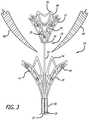
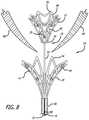
- FIG. 3is a schematic view in side perspective depicting the valve repair assembly in a deployed configuration with the mitral valve leaflets positioned therebetween.
- FIG. 4Ais a schematic view in side perspective depicting the distal member or basket of the valve repair assembly.
- FIG. 4Bis a schematic view in side perspective depicting the proximal member or basket of the valve repair assembly.
- FIGS. 4C-4Eare alternative transverse cross-sectional views taken along the lines 4 C- 4 E through 4 C- 4 E depicting alternative cross-sectional shapes that the struts may assume in making up the lattice structure of the valve repair assembly.
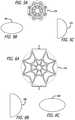
- FIGS. 5A-5Care top schematic views depicting a circular, ovoid, and D-shaped configurations, respectively, of the distal member or basket of the valve repair assembly.
- FIGS. 6A-6Care top schematic views of the proximal member or basket depicting circular, ovoid and D-shaped configurations, respectively, of the valve repair assembly.
- FIG. 7is a cross-sectional view of the valve repair assembly in a compressed configuration inside a tubular member.
- FIG. 8is a schematic view in side perspective of the valve repair assembly, partially in section, with the valve leaflets positioned between the distal member and the proximal member. This view shows insertion of the assembly via a transapical approach, from the bottom of the left ventricle.
- FIG. 9is a cross-sectional side view of the valve repair assembly depicting the distal member being drawn into locking engagement with the proximal member, with the valve leaflets sandwiched therebetween. This view shows insertion of the assembly via a transapical approach, from the bottom of the left ventrical.
- FIG. 9Ais a cross-sectional side view of another embodiment of the valve repair assembly.
- a delivery systemis located on an opposite side of a repair assembly, thereby permitting insertion of the resulting assembly via a trans-septal approach from the left atrium.
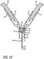
- FIG. 10is a partial side cross-sectional view of the valve repair assembly depicting the locking ball positioned in the tubular portion of the proximal member of the valve repair assembly, with the valve leaflets sandwiched between the distal member and the proximal member.
- FIG. 10Ais a partial side cross-sectional view of the embodiment shown in FIG. 9A , with valve leaflets sandwiched between two members that are locked together by a locking ball.
- FIG. 11is a top plan view of the mitral valve with a valve repair assembly implanted across the leaflets of the valve.
- FIG. 12is a schematic view of a delivery catheter assembly for delivering and implanting the valve repair assembly in a mitral valve.
- FIG. 13is a cross-sectional view of the delivery catheter of FIG. 12 .
- the left ventricle LV of a normal heart H in systoleis illustrated in FIG. 1 .
- the left ventricle LVis contracting and blood flows outwardly through the aortic valve AV in the direction of the arrows.
- Back flow of blood or “regurgitation” through the mitral valve MVis prevented since the mitral valve is configured as a “check valve” which prevents back flow when pressure in the left ventricle is higher than that in the left atrium LA.
- the mitral valve MVcomprises a pair of leaflets having free edges FE which meet evenly to close, as illustrated in FIG. 1 .
- the opposite ends of the leaflets LFare attached to the surrounding heart structure along an annular region referred to as the annulus AN.
- chordae tendineae CT(referred to hereinafter as the chordae) which include plurality of branching tendons secured over the lower surfaces of each of the valve leaflets LF.
- the chordae CTin turn, are attached to the papillary muscles PM which extend upwardly from the lower portions of the left ventricle and intraventricular septum IVS.
- a number of structural defects in the heartcan cause mitral valve regurgitation. Regurgitation occurs when the valve leaflets do not close properly allowing leakage from the ventricle into the atrium. As shown in FIG. 2A , the free edges of the anterior and posterior leaflets normally meet along a line of coaptation C. An example of a defect causing regurgitation is shown in FIG. 2B . Here an enlargement of the heart causes the mitral annulus to become enlarged, making it impossible for the free edges FE to meet during systole. This results in a gap G which allows blood to leak through the valve during ventricular systole.
- Ruptured or elongated chordaecan also cause a valve leaflet to prolapse since inadequate tension is transmitted to the leaflet via the chordae.
- the two valve leafletsdo not properly meet and leakage from the left ventricle into the left atrium will occur.
- Such regurgitationcan also occur in patients who have suffered ischemic heart disease where the left ventricle does not contract sufficiently to effect proper valve closure.
- the foregoing remarks concerning problems and failures encountered in the mitral valve in the human heartmay be made with equal validity concerning the tricuspid valve.
- This valvehas three leaflets rather than two, The three leaflets all meet at a single point near the center of the valve and they demonstrate similar problems of malfunctioning to those shown by the mitral valve.
- the present inventionprovides devices, systems and methods for stabilizing and grasping tissues such as valve leaflets, assessing the grasp of these tissues, approximating and fixating the tissues, and assessing the fixation of the tissues to treat cardiac valve regurgitation, particularly mitral valve regurgitation or tricuspid regurgitation.
- Graspingwill preferably be atraumatic providing a number of benefits.
- atraumaticit is meant that the devices and methods of the invention may be applied to the valve leaflets and then removed without causing any significant clinical impairment of leaflet structure or function.
- the leaflets and valvecontinue to function substantially the same as before the invention was applied. Thus, some minor penetration or denting of the leaflets may occur using the invention while still meeting the definition of “atraumatic.”
- leafletmay be grasped to provide the user with feedback that sufficient leaflet is incorporated, and/or to provide the user an indication of the resulting placement, both prior to releasing the fixation device thereby allowing repositioning or correction of the placement if desired.
- each step of stabilizing, grasping, approximating, fixating and assessingmay be accomplished by a separate device or a plurality of steps may be accomplished by a single device. In some embodiments, all of the steps may be achieved by a single device. Further, in some embodiments, steps are provided by separate devices which approach the tissue from different directions. For example, when treating a mitral valve, some devices may use an atrial approach while other devices use a ventricular approach.
- a valve repair assembly 10is configured in the form of a pair of basket shaped members in order to repair a mitral valve, or similar body organ.
- a “basket” shapeis one having a concave surface on one side and, on a reverse side, a convex surface. The result is a shape having an overall conical taper towards a center point on both surfaces.
- a distal member 12 and a proximal member 14are attached to each other by elongated shaft 16 .
- the distal member 12 and proximal member 14can be referred to as a first basket and a second basket respectively.
- a locking member 18is associated with the distal member 12 .
- the locking member 18includes a ball 20 that resides at a proximal end 24 of the distal member 12 .
- the ball 20is attached to the elongated shaft and has a ball diameter 22 in the range of 0.0787 in. to 0.5512 in. (2 mm to 14 mm).
- the proximal end 24 and a distal end 26define a length 27 of the distal member 12 .
- the length 27 of the distal membercan vary depending upon the body organ in which it is used. In one embodiment, for use in mitral valve repair, the distal member 12 has a length 27 in the range of 0.3937 in. to 1.5748 in. (10 mm to 40 mm). Similarly, the proximal member 14 has a proximal end 32 and a distal end 34 , with a length 35 being the distance between the proximal end and the distal end. The length 35 of the proximal member 14 also can vary, and in this embodiment for treating a mitral valve, is in the range of 0.3937 in. to 1.5748 in. (10 mm to 40 mm).
- the distal member 12has a first diameter 28 at the distal end 26 and a second diameter 30 at the proximal end 24 .
- the diameters of the distal member 12can vary depending upon the body organ in which the device is implanted.
- the first diameter 28 of the distal end 26is in the range of 0.1575 in. to 1.1811 in. (4 mm to 30 mm) and the second diameter 30 of the proximal end 24 is in the range of 0.0787 in. to 0.6299 in. (2 mm to 16 mm).
- the first diameter 28is greater than the second diameter 30 resulting in the distal member 12 having a tapered configuration, in which the diameter reduces towards the proximal end.
- the proximal member 14has a proximal member first diameter 36 and a proximal member second diameter 38 .
- the second diameter 38 at the proximal end 32 of the proximal member 14is in the range of 0.0787 in. to 0.6299 in. (2 mm to 16 mm).
- the first diameter 36 of the proximal member 14is greater than the second diameter 38 , resulting in the proximal member 14 having a tapered configuration in which the diameter reduces towards the proximal end.
- the length of the distal member 12is less than the length of the proximal member 14 for use in repairing a mitral valve.
- first diameter 28 and second diameter 30 of the distal member 12be smaller respectively than the first diameter 36 and the second diameter 38 of the proximal member 14 .
- the smaller distal member 12thereby can lock into the larger proximal member 14 with the valve tissue pressed and locked therebetween.
- both distal member and proximal memberdefining a tapered outer shape, also define a tapered inner volume wherein the tapered inner volume reduces in diameter towards the proximal direction.
- the valve repair assembly 10is formed from a lattice structure 40 that includes struts 41 arranged so that the valve repair assembly can be compressed and expanded as necessary.
- the distal member 12 and the proximal member 14are formed from a lattice structure 40 that has struts 41 that are interconnected so that the distal and proximal members can be compressed and inserted into a tubular member for delivery through the vasculature, and expanded into a tapered basket shape and locked together to repair valve tissue.
- the struts 41 of the lattice structurehave a rectangular cross-sectional configuration 42 , and in other embodiments, have a circular cross-sectional configuration 44 and an ovoid cross-sectional configuration 45 .
- the distal member 12has a transverse cross-sectional shape having any of the alternative forms of circular 47 A, ovoid 48 A, elliptical (not shown), D-shaped 49 A and non-circular (not shown).
- the proximal member 14as shown in FIGS. 6A-6C , has a transverse cross-sectional shape having any of the alternative forms of circular 47 B, ovoid 48 B, and D-shaped 49 B.
- FIG. 6A-6Chas a transverse cross-sectional shape having any of the alternative forms of circular 47 B, ovoid 48 B, and D-shaped 49 B.
- the distal member 12has a tapered portion 50 and the proximal member 14 has a tapered portion 52 .
- the tapered portion 52 of the proximal memberis attached to a tubular portion 54 extending proximally of the tapered portion 52 .
- the tubular portion 54has a diameter in the range of 0.0787 in. to 0.4724 in. (2 mm to 12 mm).
- valve repair assembly 10is compressed and positioned inside of tubular member 55 .
- the valve repair assemblyis axially slidable inside the tubular member. Since the compressed distal member 56 and the compressed proximal member 57 of the valve repair assembly are formed from a shape memory alloy, their lattice structure 40 is easily compressible to fit inside the tubular member 55 , and each will self-expand when pushed out of the tubular member.
- FIGS. 8, 9 and 10depict the locking member 18 including ball 20 which is attached at attachment point 60 on the distal end 61 of the elongated shaft 16 .
- the elongated shaft proximal end 62extends past the proximal end 32 of proximal member 14 and S-shaped discontinuity 58 is at the proximal end 62 of the elongated shaft.
- a sheath(not shown) surrounds the discontinuity, and when the sheath is withdrawn from around the discontinuity 58 , the shortened portion of the shaft 16 ( FIG. 10 ) is all that remains in the body.
- the proximal member 14In order to lock the proximal member 14 to the distal member 12 , the proximal member 14 is positioned under the valve leaflets 66 (proximal to the valve leaflets) and the distal member 12 is pulled proximally by pulling proximally on the elongated shaft 16 .
- the distal member 12is attached to the elongated shaft 16 while the proximal member 14 is sized for slidable movement over the elongated shaft.
- the ball 20 of the locking memberhas a diameter 22 that is greater than the second diameter 30 at the proximal end 24 of the distal member 12 so that the ball will not pull through the proximal end of the distal member.
- the distal member 12By continuing to pull proximally on the elongated shaft, the distal member 12 is pulled into contact with the proximal member 14 thereby wedging the valve leaflets 66 therebetween.
- the ball 20 and the proximal end 24 of the distal memberare forced through opening 68 in the proximal member 14 and into the tubular portion 54 of the proximal member 14 .
- the ball diameter 22is slightly greater than the diameter 70 of opening 68 in the proximal member 14 , thereby creating a friction fit sufficient to lock the distal member 12 and the proximal member 14 securely together, even in the high pressure blood flow environment associated with the mitral valve.
- the term friction fitshall include detent fit and mechanical engagement.
- the ball diameteris in the range of 0.0787 in. to 0.5512 in. (2 mm to 14 mm) and the opening diameter 70 is in the range of 0.0787 in. to 0.4724 in (2 mm to 12 mm).
- the ball 20has a diameter of 0.1575 in. (4 mm), and the opening diameter 70 of the tubular portion is 0.1181 in. (3 mm). Since the proximal member is formed from the expandable lattice structure 40 , and hence the tubular portion 54 as well, as the ball is pulled into the tubular portion, the tubular portion will stretch or expand slightly to accommodate the ball and create a locking friction fit.
- the ballis pulled into the tubular portion 54 of the proximal member 14 , which is also smaller in diameter than the ball.
- the distal member 12 and proximal member 14are firmly attached with the mitral valve leaflets 66 sandwiched therebetween.
- the distal member 12preferably is smaller in overall size than the proximal member 14 , so that as the two members are brought into contact as described above, the smaller distal member 12 wedges into the larger proximal member 14 , thereby coapting the mitral valve leaflets therebetween.
- discontinuity 64operates in a known manner so that only the short portion attached to the proximal member 14 of the tubular portion 54 remains in the body while the rest of the tubular portion is withdrawn from the body in a known manner.
- FIGS. 9 and 10show an approach by the assembly towards the leaflets via a transapical approach, namely via the bottom of the left ventrical.
- FIG. 9A and FIG. 10Ashow an alternative embodiment in which the delivery mechanism is positioned on a reverse side of the repair mechanism from that depicted in FIG. 9 and FIG. 10 .
- the logic of deliveryis similar to the foregoing, but entry to the heart is achieved, for example, trans-septally from above the valve via the left atrium.
- each element of the previous embodimentis identified in the new embodiment by appending a “dash” to the identifying numeral. For example, the first member 12 shown in FIGS.
- FIGS. 9A and 10is shown as first member 12 ′ in FIGS. 9A and 10A .
- One of ordinary skill in the artwill follow the procedure for deploying the embodiment of FIGS. 9A and 10A from the description of the previous embodiment, when read together with FIGS. 9A and 10A .
- FIG. 11depicts the valve repair assembly 10 fastened to the mitral valve leaflets and closing any unwanted opening between the leaflets.
- the mitral valvecan function normally with the valve repair assembly attached since the valve can open and close around the assembly.
- the leaflets 66 of the mitral valvecan function normally with the support of the assembly, thereby reducing the likelihood of regurgitation.
- FIG. 12shows an embodiment of a delivery device or delivery catheter 100 which may be used to introduce and position the valve repair assembly 10 as described above.
- the delivery catheter 100includes a shaft 102 , having a distal end 122 and a proximal end 124 , and a handle 104 attached to the distal end 122 .
- a valve repair assembly 10(not shown) is removably coupleable to the proximal end 124 for delivery to a site within the body, typically for endovascular delivery to the mitral valve.
- a coupling structure 120for coupling with the valve repair assembly 10 .
- an actuator rod 107is also extending from the proximal end 124 .
- the actuator rod 107is connectable with the valve repair assembly 10 and acts to manipulate the valve repair assembly 10 , typically opening and deploying the distal member 12 and the proximal member 14 .
- the handle 104is attached to the distal end 122 of the shaft 107 and is used to manipulate the valve repair assembly 10 and to optionally decouple the valve repair assembly 10 for permanent implantation.
- the valve repair assembly 10is primarily manipulated by the actuator rod 107 .
- the actuator rod 107manipulates the distal member 12 , the proximal member 14 , and the elongated shaft 16 to push the valve repair assembly 10 out of the proximal end 124 of the shaft 102 .
- the actuator rod 107may be translated (extended or retracted) to manipulate the valve repair assembly 10 . This is achieved with the use of the actuator rod control 114 .
- the actuator rod 107may also be rotated to better position the valve repair assembly 10 in the vasculature or in the mitral valve. This is achieved with the use of the actuator rod handle 116 .
- the actuator rod handle 116 and actuator rod control 114are joined with a main body 108 within which the actuator rod 107 is guided into the shaft 102 .
- the handle 104further includes a support base 106 connected with the main body 108 .
- the main body 108is slideable along the support base 106 to provide translation of the shaft 102 . Further, the main body 108 is rotatable around the support base 106 to rotate the shaft.
- FIG. 13illustrates a cross-sectional view of the delivery catheter shaft 102 of FIG. 12 .
- the shaft 102has a tubular shape with inner lumen 148 and is comprised of a material which provides hoop strength while maintaining flexibility and kink resistance, such as a braided laminated material.
- a material which provides hoop strength while maintaining flexibility and kink resistancesuch as a braided laminated material.
- Such materialmay include stainless steel braided or coiled wire embedded in a polymer such as polyurethane, polyester, Pebax, Grilamid TR55, and AESNO to name a few.
- the tubular member 155( FIG. 9 ) is disposed within the lumen 148 of shaft 102 as illustrated in FIG. 13 , and the tubular member 55 carries the valve repair assembly 10 .
- the lumen 148Passing through the lumen 148 are a variety of elongated bodies, including tubular guides and cylindrical rods as required to carry or house various rods or lines for manipulating and deploying the valve repair assembly 10 in the mitral valve.
- one type of tubular guideis a compression coil 126 extending through lumen 148 from the distal end 122 to the proximal end 124 of the shaft 102 , and the actuator rod 107 extends through the compression coil 126 . Therefore, the compression coil typically has a length in the range of 48 to 60 in. (121.92 cm to 152.40 cm) and an inner diameter in the range of 0.020 to 0.035 in. (0.5080 mm to 0.8890 mm) to allow passage of the actuator rod 107 therethrough.
- the actuator rod 107is manipulable to rotate and translate within and relative to the compression coil 126 .
- the compression coil 126allows lateral flexibility of the actuator rod 107 and therefore the shaft 102 while resisting buckling and providing column strength under compression.
- the compression coilmay be comprised of 304V stainless steel to provide these properties.
- a tension cable 144may also pass through the support coil 146 .
- the tension cable 144extends through lumen 148 from the distal end 122 to the proximal end 124 of the shaft 102 . Therefore, the tension cable 144 typically has a diameter in the range of 0.005 in. to 0.010 in. (0.1270 mm to 0.2540 mm) and a length in the range of 48 to 60 in. (121.92 cm to 152.40 cm).
- the tension cable 144is comprised of 304V stainless steel.
- FIG. 13Various other lumens (shafts) are shown in FIG. 13 and can carry rods, lines, or coils to further manipulate and deploy the valve repair assembly 10 .
- the elongated bodieseach “float” freely in inner lumen 148 within the tubular member 55 and are fixed only at the distal end 122 and proximal end 124 of shaft 102 .
- the lumen 148is typically filled and flushed with heparinized saline during use.
- the lumen 148may be filled with one or more fillers, such as flexible rods, beads, extruded sections, gels or other fluids.
- the fillersallow for some lateral movement or deflection of the elongated bodies within lumen 148 but in some cases may restrict such movement.
- the elongated bodiesare fixed at the distal and proximal ends of the shaft and are free to move laterally and rotationally therebetween. Such freedom of movement of the elongated bodies provides the shaft 102 with an increased flexibility as the elongated bodies self-adjust and reposition during bending and/or torquing of the shaft 102 . It may be appreciated that the elongated bodies may not be fixed at the distal and proximal ends.
- the elongated bodiesare simply unconstrained relative to the shaft 102 in at least one location so as to be laterally moveable within the lumen 148 .
- the elongated bodiesare unrestrained in at least a proximal portion of the catheter, e.g., 1.969 in. to 5.906 in. (5 cm to 15 cm) from the proximal end 124 , so as to provide maximum flexibility in the proximal portion.
- the inventionmay be used in the treatment of a variety of other tissue structures besides heart valves, and will find usefulness in a variety of tissue approximation, attachment, closure, clamping and ligation applications, some endovascular, some endoscopic, and some open surgical.
Landscapes
- Health & Medical Sciences (AREA)
- Cardiology (AREA)
- Life Sciences & Earth Sciences (AREA)
- General Health & Medical Sciences (AREA)
- Veterinary Medicine (AREA)
- Biomedical Technology (AREA)
- Heart & Thoracic Surgery (AREA)
- Vascular Medicine (AREA)
- Engineering & Computer Science (AREA)
- Animal Behavior & Ethology (AREA)
- Public Health (AREA)
- Surgery (AREA)
- Transplantation (AREA)
- Oral & Maxillofacial Surgery (AREA)
- Reproductive Health (AREA)
- Nuclear Medicine, Radiotherapy & Molecular Imaging (AREA)
- Medical Informatics (AREA)
- Molecular Biology (AREA)
- Prostheses (AREA)
- Surgical Instruments (AREA)
Abstract
Description
Claims (33)
Priority Applications (3)
| Application Number | Priority Date | Filing Date | Title |
|---|---|---|---|
| US15/441,823US10952852B2 (en) | 2017-02-24 | 2017-02-24 | Double basket assembly for valve repair |
| EP18708848.9AEP3585277A1 (en) | 2017-02-24 | 2018-02-21 | Double basket assembly for valve repair |
| PCT/US2018/019033WO2018156640A1 (en) | 2017-02-24 | 2018-02-21 | Double basket assembly for valve repair |
Applications Claiming Priority (1)
| Application Number | Priority Date | Filing Date | Title |
|---|---|---|---|
| US15/441,823US10952852B2 (en) | 2017-02-24 | 2017-02-24 | Double basket assembly for valve repair |
Publications (2)
| Publication Number | Publication Date |
|---|---|
| US20180243086A1 US20180243086A1 (en) | 2018-08-30 |
| US10952852B2true US10952852B2 (en) | 2021-03-23 |
Family
ID=61563527
Family Applications (1)
| Application Number | Title | Priority Date | Filing Date |
|---|---|---|---|
| US15/441,823Expired - Fee RelatedUS10952852B2 (en) | 2017-02-24 | 2017-02-24 | Double basket assembly for valve repair |
Country Status (3)
| Country | Link |
|---|---|
| US (1) | US10952852B2 (en) |
| EP (1) | EP3585277A1 (en) |
| WO (1) | WO2018156640A1 (en) |
Cited By (2)
| Publication number | Priority date | Publication date | Assignee | Title |
|---|---|---|---|---|
| US20210369453A1 (en)* | 2017-02-17 | 2021-12-02 | Mitrapex, Inc. | Artificial heart valve |
| USD1098432S1 (en) | 2023-10-02 | 2025-10-14 | Mirus Llc | Expandable frame for prosthetic heart valve |
Families Citing this family (99)
| Publication number | Priority date | Publication date | Assignee | Title |
|---|---|---|---|---|
| US8652202B2 (en) | 2008-08-22 | 2014-02-18 | Edwards Lifesciences Corporation | Prosthetic heart valve and delivery apparatus |
| US10517719B2 (en) | 2008-12-22 | 2019-12-31 | Valtech Cardio, Ltd. | Implantation of repair devices in the heart |
| US9968452B2 (en) | 2009-05-04 | 2018-05-15 | Valtech Cardio, Ltd. | Annuloplasty ring delivery cathethers |
| US8449599B2 (en) | 2009-12-04 | 2013-05-28 | Edwards Lifesciences Corporation | Prosthetic valve for replacing mitral valve |
| US8870950B2 (en) | 2009-12-08 | 2014-10-28 | Mitral Tech Ltd. | Rotation-based anchoring of an implant |
| US20110224785A1 (en) | 2010-03-10 | 2011-09-15 | Hacohen Gil | Prosthetic mitral valve with tissue anchors |
| US9763657B2 (en) | 2010-07-21 | 2017-09-19 | Mitraltech Ltd. | Techniques for percutaneous mitral valve replacement and sealing |
| US11653910B2 (en) | 2010-07-21 | 2023-05-23 | Cardiovalve Ltd. | Helical anchor implantation |
| EP3345573B1 (en) | 2011-06-23 | 2020-01-29 | Valtech Cardio, Ltd. | Closure element for use with annuloplasty structure |
| EP2739214B1 (en) | 2011-08-05 | 2018-10-10 | Cardiovalve Ltd | Percutaneous mitral valve replacement and sealing |
| US8852272B2 (en) | 2011-08-05 | 2014-10-07 | Mitraltech Ltd. | Techniques for percutaneous mitral valve replacement and sealing |
| WO2013021374A2 (en) | 2011-08-05 | 2013-02-14 | Mitraltech Ltd. | Techniques for percutaneous mitral valve replacement and sealing |
| US8945177B2 (en) | 2011-09-13 | 2015-02-03 | Abbott Cardiovascular Systems Inc. | Gripper pusher mechanism for tissue apposition systems |
| US9011468B2 (en) | 2011-09-13 | 2015-04-21 | Abbott Cardiovascular Systems Inc. | Independent gripper |
| US20150351906A1 (en) | 2013-01-24 | 2015-12-10 | Mitraltech Ltd. | Ventricularly-anchored prosthetic valves |
| US9439763B2 (en) | 2013-02-04 | 2016-09-13 | Edwards Lifesciences Corporation | Prosthetic valve for replacing mitral valve |
| US9622863B2 (en) | 2013-11-22 | 2017-04-18 | Edwards Lifesciences Corporation | Aortic insufficiency repair device and method |
| EP3174502B1 (en) | 2014-07-30 | 2022-04-06 | Cardiovalve Ltd | Apparatus for implantation of an articulatable prosthetic valve |
| WO2016090308A1 (en) | 2014-12-04 | 2016-06-09 | Edwards Lifesciences Corporation | Percutaneous clip for repairing a heart valve |
| US9974651B2 (en) | 2015-02-05 | 2018-05-22 | Mitral Tech Ltd. | Prosthetic valve with axially-sliding frames |
| CN110141399B (en) | 2015-02-05 | 2021-07-27 | 卡迪尔维尔福股份有限公司 | Prosthetic valve with axial sliding frame |
| EP3294219B1 (en) | 2015-05-14 | 2020-05-13 | Edwards Lifesciences Corporation | Heart valve sealing devices and delivery devices therefor |
| US10531866B2 (en) | 2016-02-16 | 2020-01-14 | Cardiovalve Ltd. | Techniques for providing a replacement valve and transseptal communication |
| US10835714B2 (en) | 2016-03-21 | 2020-11-17 | Edwards Lifesciences Corporation | Multi-direction steerable handles for steering catheters |
| US11219746B2 (en) | 2016-03-21 | 2022-01-11 | Edwards Lifesciences Corporation | Multi-direction steerable handles for steering catheters |
| US10799676B2 (en) | 2016-03-21 | 2020-10-13 | Edwards Lifesciences Corporation | Multi-direction steerable handles for steering catheters |
| US10799677B2 (en) | 2016-03-21 | 2020-10-13 | Edwards Lifesciences Corporation | Multi-direction steerable handles for steering catheters |
| US10799675B2 (en) | 2016-03-21 | 2020-10-13 | Edwards Lifesciences Corporation | Cam controlled multi-direction steerable handles |
| EP3868306A1 (en) | 2016-06-20 | 2021-08-25 | Evalve, Inc. | Transapical removal device |
| US10973638B2 (en) | 2016-07-07 | 2021-04-13 | Edwards Lifesciences Corporation | Device and method for treating vascular insufficiency |
| US20190231525A1 (en) | 2016-08-01 | 2019-08-01 | Mitraltech Ltd. | Minimally-invasive delivery systems |
| CA3031187A1 (en) | 2016-08-10 | 2018-02-15 | Cardiovalve Ltd. | Prosthetic valve with concentric frames |
| US10653862B2 (en) | 2016-11-07 | 2020-05-19 | Edwards Lifesciences Corporation | Apparatus for the introduction and manipulation of multiple telescoping catheters |
| US10905554B2 (en) | 2017-01-05 | 2021-02-02 | Edwards Lifesciences Corporation | Heart valve coaptation device |
| US11224511B2 (en) | 2017-04-18 | 2022-01-18 | Edwards Lifesciences Corporation | Heart valve sealing devices and delivery devices therefor |
| EP4613214A2 (en) | 2017-04-18 | 2025-09-10 | Edwards Lifesciences Corporation | Heart valve sealing devices and delivery devices therefor |
| US10799312B2 (en) | 2017-04-28 | 2020-10-13 | Edwards Lifesciences Corporation | Medical device stabilizing apparatus and method of use |
| US10959846B2 (en) | 2017-05-10 | 2021-03-30 | Edwards Lifesciences Corporation | Mitral valve spacer device |
| CA3066361A1 (en) | 2017-06-07 | 2018-12-13 | Shifamed Holdings, Llc | Intravascular fluid movement devices, systems, and methods of use |
| US10888421B2 (en) | 2017-09-19 | 2021-01-12 | Cardiovalve Ltd. | Prosthetic heart valve with pouch |
| US11793633B2 (en) | 2017-08-03 | 2023-10-24 | Cardiovalve Ltd. | Prosthetic heart valve |
| US12064347B2 (en) | 2017-08-03 | 2024-08-20 | Cardiovalve Ltd. | Prosthetic heart valve |
| US11051940B2 (en) | 2017-09-07 | 2021-07-06 | Edwards Lifesciences Corporation | Prosthetic spacer device for heart valve |
| US11065117B2 (en) | 2017-09-08 | 2021-07-20 | Edwards Lifesciences Corporation | Axisymmetric adjustable device for treating mitral regurgitation |
| US20190083242A1 (en) | 2017-09-19 | 2019-03-21 | Cardiovalve Ltd. | Systems and methods for implanting a prosthetic valve within a native heart valve |
| US11040174B2 (en) | 2017-09-19 | 2021-06-22 | Edwards Lifesciences Corporation | Multi-direction steerable handles for steering catheters |
| US9895226B1 (en) | 2017-10-19 | 2018-02-20 | Mitral Tech Ltd. | Techniques for use with prosthetic valve leaflets |
| WO2019079252A1 (en)* | 2017-10-20 | 2019-04-25 | Edwards Lifesciences Corporation | Localized fusion of native leaflets using activated adhesive |
| WO2019094963A1 (en) | 2017-11-13 | 2019-05-16 | Shifamed Holdings, Llc | Intravascular fluid movement devices, systems, and methods of use |
| US10507109B2 (en) | 2018-01-09 | 2019-12-17 | Edwards Lifesciences Corporation | Native valve repair devices and procedures |
| US10238493B1 (en) | 2018-01-09 | 2019-03-26 | Edwards Lifesciences Corporation | Native valve repair devices and procedures |
| US10245144B1 (en) | 2018-01-09 | 2019-04-02 | Edwards Lifesciences Corporation | Native valve repair devices and procedures |
| US10105222B1 (en) | 2018-01-09 | 2018-10-23 | Edwards Lifesciences Corporation | Native valve repair devices and procedures |
| US10159570B1 (en) | 2018-01-09 | 2018-12-25 | Edwards Lifesciences Corporation | Native valve repair devices and procedures |
| US10136993B1 (en) | 2018-01-09 | 2018-11-27 | Edwards Lifesciences Corporation | Native valve repair devices and procedures |
| US10111751B1 (en) | 2018-01-09 | 2018-10-30 | Edwards Lifesciences Corporation | Native valve repair devices and procedures |
| US10973639B2 (en) | 2018-01-09 | 2021-04-13 | Edwards Lifesciences Corporation | Native valve repair devices and procedures |
| US10231837B1 (en) | 2018-01-09 | 2019-03-19 | Edwards Lifesciences Corporation | Native valve repair devices and procedures |
| US10123873B1 (en) | 2018-01-09 | 2018-11-13 | Edwards Lifesciences Corporation | Native valve repair devices and procedures |
| FI3964175T3 (en) | 2018-01-09 | 2024-12-03 | Edwards Lifesciences Corp | Native valve repair devices |
| US10076415B1 (en) | 2018-01-09 | 2018-09-18 | Edwards Lifesciences Corporation | Native valve repair devices and procedures |
| GB201800399D0 (en) | 2018-01-10 | 2018-02-21 | Mitraltech Ltd | Temperature-control during crimping of an implant |
| CN112004563B (en) | 2018-02-01 | 2024-08-06 | 施菲姆德控股有限责任公司 | Intravascular blood pump and methods of use and manufacture |
| US11389297B2 (en) | 2018-04-12 | 2022-07-19 | Edwards Lifesciences Corporation | Mitral valve spacer device |
| US11207181B2 (en) | 2018-04-18 | 2021-12-28 | Edwards Lifesciences Corporation | Heart valve sealing devices and delivery devices therefor |
| US12161857B2 (en) | 2018-07-31 | 2024-12-10 | Shifamed Holdings, Llc | Intravascular blood pumps and methods of use |
| US10779946B2 (en) | 2018-09-17 | 2020-09-22 | Cardiovalve Ltd. | Leaflet-testing apparatus |
| WO2020073047A1 (en) | 2018-10-05 | 2020-04-09 | Shifamed Holdings, Llc | Intravascular blood pumps and methods of use |
| WO2020073056A1 (en)* | 2018-10-06 | 2020-04-09 | Gifford Iii Hanson S | Modular valve replacement systems and associated devices and methods of use |
| US10945844B2 (en) | 2018-10-10 | 2021-03-16 | Edwards Lifesciences Corporation | Heart valve sealing devices and delivery devices therefor |
| CN113226223A (en) | 2018-11-20 | 2021-08-06 | 爱德华兹生命科学公司 | Deployment tools and methods for delivering devices to native heart valves |
| CA3118988A1 (en) | 2018-11-21 | 2020-05-28 | Edwards Lifesciences Corporation | Heart valve sealing devices, delivery devices therefor, and retrieval devices |
| CR20210312A (en) | 2018-11-29 | 2021-09-14 | Edwards Lifesciences Corp | Catheterization method and apparatus |
| GB201901887D0 (en) | 2019-02-11 | 2019-04-03 | Cardiovalve Ltd | Device for conditioning ex vivo pericardial tissue |
| ES2969252T3 (en) | 2019-02-14 | 2024-05-17 | Edwards Lifesciences Corp | Heart valve sealing devices and delivery devices therefor |
| US11534303B2 (en) | 2020-04-09 | 2022-12-27 | Evalve, Inc. | Devices and systems for accessing and repairing a heart valve |
| WO2021011473A1 (en) | 2019-07-12 | 2021-01-21 | Shifamed Holdings, Llc | Intravascular blood pumps and methods of manufacture and use |
| JP7543391B2 (en) | 2019-07-15 | 2024-09-02 | エバルブ,インコーポレイティド | Method of Actuating Individual Proximal Elements |
| JP7566004B2 (en) | 2019-07-15 | 2024-10-11 | エバルブ,インコーポレイティド | Wide clip with non-deforming wings |
| CA3147410A1 (en) | 2019-07-15 | 2021-01-21 | Evalve, Inc. | Proximal element actuator fixation and release mechanisms |
| US11654275B2 (en) | 2019-07-22 | 2023-05-23 | Shifamed Holdings, Llc | Intravascular blood pumps with struts and methods of use and manufacture |
| US12121713B2 (en) | 2019-09-25 | 2024-10-22 | Shifamed Holdings, Llc | Catheter blood pumps and collapsible blood conduits |
| WO2021062265A1 (en) | 2019-09-25 | 2021-04-01 | Shifamed Holdings, Llc | Intravascular blood pump systems and methods of use and control thereof |
| EP4501393A3 (en) | 2019-09-25 | 2025-04-09 | Shifamed Holdings, LLC | Catheter blood pumps and collapsible pump housings |
| EP4033970B1 (en) | 2019-09-26 | 2024-11-20 | Evalve, Inc. | Systems for intra-procedural cardiac pressure monitoring |
| US11464636B2 (en) | 2019-10-11 | 2022-10-11 | Evalve, Inc. | Repair clip for variable tissue thickness |
| WO2021092107A1 (en) | 2019-11-06 | 2021-05-14 | Evalve, Inc. | Stabilizer for a medical delivery system |
| EP4292546B1 (en) | 2019-11-08 | 2025-04-23 | Evalve, Inc. | Medical device delivery system with locking system |
| US11801140B2 (en) | 2019-11-14 | 2023-10-31 | Evalve, Inc. | Catheter assembly with coaptation aid and methods for valve repair |
| US11701229B2 (en) | 2019-11-14 | 2023-07-18 | Evalve, Inc. | Kit with coaptation aid and fixation system and methods for valve repair |
| EP4072650A4 (en) | 2019-12-11 | 2024-01-10 | Shifamed Holdings, LLC | Descending aorta and vena cava blood pumps |
| US12109115B2 (en) | 2019-12-18 | 2024-10-08 | Evalve, Inc. | Wide clip with deformable width |
| US11857417B2 (en) | 2020-08-16 | 2024-01-02 | Trilio Medical Ltd. | Leaflet support |
| WO2022081328A1 (en) | 2020-10-15 | 2022-04-21 | Evalve, Inc. | Biased distal assemblies with locking mechanism |
| US12357459B2 (en) | 2020-12-03 | 2025-07-15 | Cardiovalve Ltd. | Transluminal delivery system |
| EP4082481B1 (en) | 2021-04-30 | 2024-04-17 | Evalve Inc. | Fixation device having a flexure portion |
| CN118382408A (en)* | 2021-11-19 | 2024-07-23 | 爱德华兹生命科学公司 | Heart valve repair device |
| CN115517826A (en)* | 2022-09-30 | 2022-12-27 | 瀚芯医疗科技(深圳)有限公司 | Mitral valve clamping device and mitral valve clamping system |
| USD1071198S1 (en) | 2023-06-28 | 2025-04-15 | Edwards Lifesciences Corporation | Cradle |
Citations (53)
| Publication number | Priority date | Publication date | Assignee | Title |
|---|---|---|---|---|
| WO1991015155A1 (en) | 1990-04-02 | 1991-10-17 | Kanji Inoue | Device for closing shunt opening by nonoperative method |
| US5607445A (en)* | 1992-06-18 | 1997-03-04 | American Biomed, Inc. | Stent for supporting a blood vessel |
| US5924424A (en) | 1993-02-22 | 1999-07-20 | Heartport, Inc. | Method and apparatus for thoracoscopic intracardiac procedures |
| US6129758A (en) | 1995-10-06 | 2000-10-10 | Cardiomend Llc | Products and methods for circulatory system valve repair |
| US20020013571A1 (en) | 1999-04-09 | 2002-01-31 | Evalve, Inc. | Methods and devices for capturing and fixing leaflets in valve repair |
| US20030018358A1 (en) | 1999-06-25 | 2003-01-23 | Vahid Saadat | Apparatus and methods for treating tissue |
| US20030139819A1 (en) | 2002-01-18 | 2003-07-24 | Beer Nicholas De | Method and apparatus for closing septal defects |
| US20040073242A1 (en) | 2002-06-05 | 2004-04-15 | Nmt Medical, Inc. | Patent foramen ovale (PFO) closure device with radial and circumferential support |
| WO2004069055A2 (en) | 2003-02-04 | 2004-08-19 | Ev3 Sunnyvale Inc. | Patent foramen ovale closure system |
| US20040176799A1 (en) | 2002-12-09 | 2004-09-09 | Nmt Medical, Inc. | Septal closure devices |
| US20040220610A1 (en)* | 1999-11-08 | 2004-11-04 | Kreidler Marc S. | Thin film composite lamination |
| US20050043759A1 (en) | 2003-07-14 | 2005-02-24 | Nmt Medical, Inc. | Tubular patent foramen ovale (PFO) closure device with catch system |
| US20050065548A1 (en) | 2003-09-23 | 2005-03-24 | Marino Joseph A. | Right retrieval mechanism |
| US20050273135A1 (en) | 2004-05-07 | 2005-12-08 | Nmt Medical, Inc. | Catching mechanisms for tubular septal occluder |
| US20050288786A1 (en) | 2004-05-07 | 2005-12-29 | Nmt Medical, Inc. | Closure device with hinges |
| US20060122646A1 (en) | 2004-12-08 | 2006-06-08 | Cardia, Inc. | Daisy design for occlusion device |
| US7112207B2 (en) | 1999-10-21 | 2006-09-26 | Edwards Lifesciences Corporation | Minimally invasive mitral valve repair method and apparatus |
| US20060265004A1 (en) | 2005-03-18 | 2006-11-23 | Nmt Medical, Inc. | Catch member for PFO occluder |
| US20060271089A1 (en) | 2005-04-11 | 2006-11-30 | Cierra, Inc. | Methods and apparatus to achieve a closure of a layered tissue defect |
| US20070010851A1 (en) | 2003-07-14 | 2007-01-11 | Chanduszko Andrzej J | Tubular patent foramen ovale (PFO) closure device with catch system |
| US20070027533A1 (en) | 2005-07-28 | 2007-02-01 | Medtronic Vascular, Inc. | Cardiac valve annulus restraining device |
| US20070073337A1 (en) | 2001-09-06 | 2007-03-29 | Ryan Abbott | Clip-Based Systems And Methods For Treating Septal Defects |
| US20070112380A1 (en) | 2005-11-14 | 2007-05-17 | Jen.Meditec Gmbh | Occlusion device for occluding an atrial auricula and method for producing same |
| US20070167981A1 (en) | 2005-12-22 | 2007-07-19 | Nmt Medical, Inc. | Catch members for occluder devices |
| US20070179527A1 (en) | 2006-02-02 | 2007-08-02 | Boston Scientific Scimed, Inc. | Occlusion apparatus, system, and method |
| US20070250081A1 (en) | 2006-03-31 | 2007-10-25 | Nmt Medical, Inc. | Adjustable length patent foramen ovale (PFO) occluder and catch system |
| US20070260305A1 (en) | 2006-04-29 | 2007-11-08 | Drews Michael J | Guide shields for multiple component prosthetic heart valve assemblies and apparatus and methods for using them |
| US7563267B2 (en) | 1999-04-09 | 2009-07-21 | Evalve, Inc. | Fixation device and methods for engaging tissue |
| US20090188964A1 (en) | 2006-06-01 | 2009-07-30 | Boris Orlov | Membrane augmentation, such as of for treatment of cardiac valves, and fastening devices for membrane augmentation |
| US7569062B1 (en) | 1998-07-15 | 2009-08-04 | St. Jude Medical, Inc. | Mitral and tricuspid valve repair |
| US20100004740A1 (en) | 1999-11-17 | 2010-01-07 | Jacques Seguin | Prosthetic Valve for Transluminal Delivery |
| US20100234878A1 (en) | 2009-03-16 | 2010-09-16 | Cook Incorporated | Closure device with string retractable umbrella |
| US20110060407A1 (en) | 2005-02-07 | 2011-03-10 | Ted Ketai | Methods, systems and devices for cardiac valve repair |
| US20110276086A1 (en) | 2010-05-04 | 2011-11-10 | Al-Qbandi Mustafa H | Atrial Septal Occluder Device and Method |
| US20130066341A1 (en) | 2011-09-13 | 2013-03-14 | Abbott Cardiovascular Systems, Inc. | Independent gripper |
| US8470028B2 (en) | 2005-02-07 | 2013-06-25 | Evalve, Inc. | Methods, systems and devices for cardiac valve repair |
| US20130282110A1 (en) | 2012-04-19 | 2013-10-24 | Caisson Interventional, LLC | Valve replacement systems and methods |
| US20130289718A1 (en) | 2010-08-04 | 2013-10-31 | Valcare, Inc. | Percutaneous transcatheter repair of heart valves |
| US20140005778A1 (en) | 2010-09-01 | 2014-01-02 | Mvalve Technologies Ltd. | Cardiac valve support structure |
| WO2014018907A1 (en) | 2012-07-26 | 2014-01-30 | University Of Louisville Research Foundation, Inc. | Atrial appendage closure device and related methods |
| US20140163669A1 (en) | 2012-12-06 | 2014-06-12 | Mitralix Ltd. | Devices and methods for the replacement of the functioning of heart valves |
| US8753362B2 (en) | 2003-12-09 | 2014-06-17 | W.L. Gore & Associates, Inc. | Double spiral patent foramen ovale closure clamp |
| US20140200662A1 (en) | 2013-01-16 | 2014-07-17 | Mvalve Technologies Ltd. | Anchoring elements for intracardiac devices |
| WO2014182849A1 (en) | 2013-05-07 | 2014-11-13 | Amsel Medical Corporation | Method and apparatus for occluding a blood vessel and/or securing two objects together |
| US20150066077A1 (en) | 2012-02-29 | 2015-03-05 | Occlutech Holding Ag | Device For Occluding An Opening In A Body And Associated Methods |
| US20150173765A1 (en) | 2011-01-11 | 2015-06-25 | Amsel Medical Corporation | Method and apparatus for occluding a blood vessel and/or for occluding other tubular structures and/or for closing openings in structures and/or for securing at least two objects together |
| US9180005B1 (en) | 2014-07-17 | 2015-11-10 | Millipede, Inc. | Adjustable endolumenal mitral valve ring |
| US20160022417A1 (en) | 2014-07-22 | 2016-01-28 | Edwards Lifesciences Corporation | Mitral valve anchoring |
| US20160030169A1 (en) | 2013-03-13 | 2016-02-04 | Aortic Innovations, Llc | Dual frame stent and valve devices and implantation |
| US9750505B2 (en) | 2009-01-08 | 2017-09-05 | Coherex Medical, Inc. | Medical device for modification of left atrial appendage and related systems and methods |
| US9770232B2 (en) | 2011-08-12 | 2017-09-26 | W. L. Gore & Associates, Inc. | Heart occlusion devices |
| US20180055633A1 (en) | 2016-09-01 | 2018-03-01 | Medtronic Vascular, Inc. | Heart valve prosthesis and separate support flange for attachment thereto |
| US20180133010A1 (en)* | 2016-11-11 | 2018-05-17 | Evalve, Inc. | Opposing disk device for grasping cardiac valve tissue |
Family Cites Families (1)
| Publication number | Priority date | Publication date | Assignee | Title |
|---|---|---|---|---|
| US10058426B2 (en)* | 2016-07-20 | 2018-08-28 | Abbott Cardiovascular Systems Inc. | System for tricuspid valve repair |
- 2017
- 2017-02-24USUS15/441,823patent/US10952852B2/ennot_activeExpired - Fee Related
- 2018
- 2018-02-21WOPCT/US2018/019033patent/WO2018156640A1/ennot_activeCeased
- 2018-02-21EPEP18708848.9Apatent/EP3585277A1/ennot_activeWithdrawn
Patent Citations (59)
| Publication number | Priority date | Publication date | Assignee | Title |
|---|---|---|---|---|
| WO1991015155A1 (en) | 1990-04-02 | 1991-10-17 | Kanji Inoue | Device for closing shunt opening by nonoperative method |
| US5171259A (en) | 1990-04-02 | 1992-12-15 | Kanji Inoue | Device for nonoperatively occluding a defect |
| US5607445A (en)* | 1992-06-18 | 1997-03-04 | American Biomed, Inc. | Stent for supporting a blood vessel |
| US5924424A (en) | 1993-02-22 | 1999-07-20 | Heartport, Inc. | Method and apparatus for thoracoscopic intracardiac procedures |
| US6129758A (en) | 1995-10-06 | 2000-10-10 | Cardiomend Llc | Products and methods for circulatory system valve repair |
| US7569062B1 (en) | 1998-07-15 | 2009-08-04 | St. Jude Medical, Inc. | Mitral and tricuspid valve repair |
| US20020013571A1 (en) | 1999-04-09 | 2002-01-31 | Evalve, Inc. | Methods and devices for capturing and fixing leaflets in valve repair |
| US20110307055A1 (en)* | 1999-04-09 | 2011-12-15 | Abbott Vascular | Methods and devices for capturing and fixing leaflets in valve repair |
| US7666204B2 (en) | 1999-04-09 | 2010-02-23 | Evalve, Inc. | Multi-catheter steerable guiding system and methods of use |
| US7563267B2 (en) | 1999-04-09 | 2009-07-21 | Evalve, Inc. | Fixation device and methods for engaging tissue |
| US7563273B2 (en) | 1999-04-09 | 2009-07-21 | Evalve, Inc. | Methods and devices for capturing and fixing leaflets in valve repair |
| US20030018358A1 (en) | 1999-06-25 | 2003-01-23 | Vahid Saadat | Apparatus and methods for treating tissue |
| US7112207B2 (en) | 1999-10-21 | 2006-09-26 | Edwards Lifesciences Corporation | Minimally invasive mitral valve repair method and apparatus |
| US20040220610A1 (en)* | 1999-11-08 | 2004-11-04 | Kreidler Marc S. | Thin film composite lamination |
| US20100004740A1 (en) | 1999-11-17 | 2010-01-07 | Jacques Seguin | Prosthetic Valve for Transluminal Delivery |
| US20070073337A1 (en) | 2001-09-06 | 2007-03-29 | Ryan Abbott | Clip-Based Systems And Methods For Treating Septal Defects |
| US20030139819A1 (en) | 2002-01-18 | 2003-07-24 | Beer Nicholas De | Method and apparatus for closing septal defects |
| US20040073242A1 (en) | 2002-06-05 | 2004-04-15 | Nmt Medical, Inc. | Patent foramen ovale (PFO) closure device with radial and circumferential support |
| US20040176799A1 (en) | 2002-12-09 | 2004-09-09 | Nmt Medical, Inc. | Septal closure devices |
| US20100234885A1 (en) | 2003-02-04 | 2010-09-16 | Ev3 Endovascular, Inc. | Patent foramen ovale closure system |
| WO2004069055A3 (en) | 2003-02-04 | 2004-12-09 | Ev3 Sunnyvale Inc | Patent foramen ovale closure system |
| WO2004069055A2 (en) | 2003-02-04 | 2004-08-19 | Ev3 Sunnyvale Inc. | Patent foramen ovale closure system |
| US20070010851A1 (en) | 2003-07-14 | 2007-01-11 | Chanduszko Andrzej J | Tubular patent foramen ovale (PFO) closure device with catch system |
| US20050043759A1 (en) | 2003-07-14 | 2005-02-24 | Nmt Medical, Inc. | Tubular patent foramen ovale (PFO) closure device with catch system |
| US20050065548A1 (en) | 2003-09-23 | 2005-03-24 | Marino Joseph A. | Right retrieval mechanism |
| US8753362B2 (en) | 2003-12-09 | 2014-06-17 | W.L. Gore & Associates, Inc. | Double spiral patent foramen ovale closure clamp |
| US20050288786A1 (en) | 2004-05-07 | 2005-12-29 | Nmt Medical, Inc. | Closure device with hinges |
| US20050273135A1 (en) | 2004-05-07 | 2005-12-08 | Nmt Medical, Inc. | Catching mechanisms for tubular septal occluder |
| US20060122646A1 (en) | 2004-12-08 | 2006-06-08 | Cardia, Inc. | Daisy design for occlusion device |
| US8470028B2 (en) | 2005-02-07 | 2013-06-25 | Evalve, Inc. | Methods, systems and devices for cardiac valve repair |
| US20110060407A1 (en) | 2005-02-07 | 2011-03-10 | Ted Ketai | Methods, systems and devices for cardiac valve repair |
| US20060265004A1 (en) | 2005-03-18 | 2006-11-23 | Nmt Medical, Inc. | Catch member for PFO occluder |
| US20060271089A1 (en) | 2005-04-11 | 2006-11-30 | Cierra, Inc. | Methods and apparatus to achieve a closure of a layered tissue defect |
| US20070027533A1 (en) | 2005-07-28 | 2007-02-01 | Medtronic Vascular, Inc. | Cardiac valve annulus restraining device |
| US20070112380A1 (en) | 2005-11-14 | 2007-05-17 | Jen.Meditec Gmbh | Occlusion device for occluding an atrial auricula and method for producing same |
| US20070167981A1 (en) | 2005-12-22 | 2007-07-19 | Nmt Medical, Inc. | Catch members for occluder devices |
| US20070179527A1 (en) | 2006-02-02 | 2007-08-02 | Boston Scientific Scimed, Inc. | Occlusion apparatus, system, and method |
| US20070250081A1 (en) | 2006-03-31 | 2007-10-25 | Nmt Medical, Inc. | Adjustable length patent foramen ovale (PFO) occluder and catch system |
| US20070260305A1 (en) | 2006-04-29 | 2007-11-08 | Drews Michael J | Guide shields for multiple component prosthetic heart valve assemblies and apparatus and methods for using them |
| US20090188964A1 (en) | 2006-06-01 | 2009-07-30 | Boris Orlov | Membrane augmentation, such as of for treatment of cardiac valves, and fastening devices for membrane augmentation |
| US9750505B2 (en) | 2009-01-08 | 2017-09-05 | Coherex Medical, Inc. | Medical device for modification of left atrial appendage and related systems and methods |
| US20100234878A1 (en) | 2009-03-16 | 2010-09-16 | Cook Incorporated | Closure device with string retractable umbrella |
| US20110276086A1 (en) | 2010-05-04 | 2011-11-10 | Al-Qbandi Mustafa H | Atrial Septal Occluder Device and Method |
| US20130289718A1 (en) | 2010-08-04 | 2013-10-31 | Valcare, Inc. | Percutaneous transcatheter repair of heart valves |
| US20140005778A1 (en) | 2010-09-01 | 2014-01-02 | Mvalve Technologies Ltd. | Cardiac valve support structure |
| US20150173765A1 (en) | 2011-01-11 | 2015-06-25 | Amsel Medical Corporation | Method and apparatus for occluding a blood vessel and/or for occluding other tubular structures and/or for closing openings in structures and/or for securing at least two objects together |
| US9770232B2 (en) | 2011-08-12 | 2017-09-26 | W. L. Gore & Associates, Inc. | Heart occlusion devices |
| US20130066341A1 (en) | 2011-09-13 | 2013-03-14 | Abbott Cardiovascular Systems, Inc. | Independent gripper |
| US20150066077A1 (en) | 2012-02-29 | 2015-03-05 | Occlutech Holding Ag | Device For Occluding An Opening In A Body And Associated Methods |
| US20130282110A1 (en) | 2012-04-19 | 2013-10-24 | Caisson Interventional, LLC | Valve replacement systems and methods |
| WO2014018907A1 (en) | 2012-07-26 | 2014-01-30 | University Of Louisville Research Foundation, Inc. | Atrial appendage closure device and related methods |
| US20140163669A1 (en) | 2012-12-06 | 2014-06-12 | Mitralix Ltd. | Devices and methods for the replacement of the functioning of heart valves |
| US20140200662A1 (en) | 2013-01-16 | 2014-07-17 | Mvalve Technologies Ltd. | Anchoring elements for intracardiac devices |
| US20160030169A1 (en) | 2013-03-13 | 2016-02-04 | Aortic Innovations, Llc | Dual frame stent and valve devices and implantation |
| WO2014182849A1 (en) | 2013-05-07 | 2014-11-13 | Amsel Medical Corporation | Method and apparatus for occluding a blood vessel and/or securing two objects together |
| US9180005B1 (en) | 2014-07-17 | 2015-11-10 | Millipede, Inc. | Adjustable endolumenal mitral valve ring |
| US20160022417A1 (en) | 2014-07-22 | 2016-01-28 | Edwards Lifesciences Corporation | Mitral valve anchoring |
| US20180055633A1 (en) | 2016-09-01 | 2018-03-01 | Medtronic Vascular, Inc. | Heart valve prosthesis and separate support flange for attachment thereto |
| US20180133010A1 (en)* | 2016-11-11 | 2018-05-17 | Evalve, Inc. | Opposing disk device for grasping cardiac valve tissue |
Non-Patent Citations (4)
| Title |
|---|
| International Search Report dated Jan. 29, 2018 in International Application No. PCT/US2017/062734, European Patent Office, pp. 1-4. |
| International Search Report dated Jun. 12, 2018. |
| International Search Report dated Oct. 13, 2017 from International Application No. PCT/US2017/039811, European Patent Office ISA/EP. |
| Vismara et al., "Transcatheter Edge-to-Edge Treatment of Functional Tricuspid Regurgitation in an Ex Vivo Pulsatile Heart Model," JACC 68(10):1024-1033 (2016). |
Cited By (3)
| Publication number | Priority date | Publication date | Assignee | Title |
|---|---|---|---|---|
| US20210369453A1 (en)* | 2017-02-17 | 2021-12-02 | Mitrapex, Inc. | Artificial heart valve |
| US12336906B2 (en)* | 2017-02-17 | 2025-06-24 | Mitrapex, Inc. | Artificial heart valve |
| USD1098432S1 (en) | 2023-10-02 | 2025-10-14 | Mirus Llc | Expandable frame for prosthetic heart valve |
Also Published As
| Publication number | Publication date |
|---|---|
| EP3585277A1 (en) | 2020-01-01 |
| WO2018156640A1 (en) | 2018-08-30 |
| US20180243086A1 (en) | 2018-08-30 |
Similar Documents
| Publication | Publication Date | Title |
|---|---|---|
| US10952852B2 (en) | Double basket assembly for valve repair | |
| US20230131595A1 (en) | Devices and systems for accessing and repairing a heart valve | |
| US11654018B2 (en) | Heart and peripheral vascular valve replacement in conjunction with a support ring | |
| CN109715078B (en) | Tissue grasping device and related methods | |
| RU2491035C2 (en) | Device and method for reducing heart valve size | |
| JP5198431B2 (en) | Annuloplasty device with helical anchor | |
| US9011531B2 (en) | Method and apparatus for repairing a mitral valve | |
| US9271833B2 (en) | Transcatheter coronary sinus mitral valve annuloplasty procedure and coronary artery and myocardial protection device | |
| US20180289482A1 (en) | Coronary sinus mitral valve annuloplasty procedure and coronary artery and myocardial protection device | |
| US20070100439A1 (en) | Chordae tendinae restraining ring | |
| US20070265702A1 (en) | Percutaneous treatment for heart valves | |
| US9987135B2 (en) | Devices and methods for treating functional tricuspid valve regurgitation | |
| JP2008534085A (en) | Apparatus, system, and method for reshaping a heart valve annulus | |
| US11534303B2 (en) | Devices and systems for accessing and repairing a heart valve | |
| WO2020123731A1 (en) | Heart valve repair | |
| CN215019730U (en) | Implantable fixation device for engaging cardiac tissue including improved locking mechanism | |
| CN113274168B (en) | Implantable fixation device for engaging cardiac tissue including an improved locking mechanism | |
| US20240382308A1 (en) | Variable Stiffness Delivery System for Edge-To-Edge Transcatheter Valve Repair and Methods of Making and Using Same | |
| US20250107893A1 (en) | Anchor delivery and assessment | |
| Laing et al. | Beating-heart mitral valve chordal replacement | |
| Thornton et al. | MitraClip® system design and history of development |
Legal Events
| Date | Code | Title | Description |
|---|---|---|---|
| AS | Assignment | Owner name:ABBOTT CARDIOVASCULAR SYSTEMS INC., CALIFORNIA Free format text:ASSIGNMENT OF ASSIGNORS INTEREST;ASSIGNORS:BARBARINO, CASEY M.;LEE, BENJAMIN L.;ABUNASSAR, CHAD;REEL/FRAME:041371/0840 Effective date:20170213 | |
| STPP | Information on status: patent application and granting procedure in general | Free format text:RESPONSE TO NON-FINAL OFFICE ACTION ENTERED AND FORWARDED TO EXAMINER | |
| STPP | Information on status: patent application and granting procedure in general | Free format text:NON FINAL ACTION MAILED | |
| STPP | Information on status: patent application and granting procedure in general | Free format text:RESPONSE TO NON-FINAL OFFICE ACTION ENTERED AND FORWARDED TO EXAMINER | |
| STPP | Information on status: patent application and granting procedure in general | Free format text:FINAL REJECTION MAILED | |
| STPP | Information on status: patent application and granting procedure in general | Free format text:RESPONSE AFTER FINAL ACTION FORWARDED TO EXAMINER | |
| STPP | Information on status: patent application and granting procedure in general | Free format text:NON FINAL ACTION MAILED | |
| STPP | Information on status: patent application and granting procedure in general | Free format text:RESPONSE TO NON-FINAL OFFICE ACTION ENTERED AND FORWARDED TO EXAMINER | |
| STCF | Information on status: patent grant | Free format text:PATENTED CASE | |
| FEPP | Fee payment procedure | Free format text:MAINTENANCE FEE REMINDER MAILED (ORIGINAL EVENT CODE: REM.); ENTITY STATUS OF PATENT OWNER: LARGE ENTITY | |
| LAPS | Lapse for failure to pay maintenance fees | Free format text:PATENT EXPIRED FOR FAILURE TO PAY MAINTENANCE FEES (ORIGINAL EVENT CODE: EXP.); ENTITY STATUS OF PATENT OWNER: LARGE ENTITY | |
| STCH | Information on status: patent discontinuation | Free format text:PATENT EXPIRED DUE TO NONPAYMENT OF MAINTENANCE FEES UNDER 37 CFR 1.362 | |
| FP | Lapsed due to failure to pay maintenance fee | Effective date:20250323 |