US10952777B2 - Pivotal bone screw assembly with receiver having threaded open channel and lower opening - Google Patents
Pivotal bone screw assembly with receiver having threaded open channel and lower openingDownload PDFInfo
- Publication number
- US10952777B2 US10952777B2US12/462,623US46262309AUS10952777B2US 10952777 B2US10952777 B2US 10952777B2US 46262309 AUS46262309 AUS 46262309AUS 10952777 B2US10952777 B2US 10952777B2
- Authority
- US
- United States
- Prior art keywords
- shank
- capture structure
- head
- bone screw
- thread
- Prior art date
- Legal status (The legal status is an assumption and is not a legal conclusion. Google has not performed a legal analysis and makes no representation as to the accuracy of the status listed.)
- Expired - Fee Related
Links
Images


Classifications
- A—HUMAN NECESSITIES
- A61—MEDICAL OR VETERINARY SCIENCE; HYGIENE
- A61B—DIAGNOSIS; SURGERY; IDENTIFICATION
- A61B17/00—Surgical instruments, devices or methods
- A61B17/56—Surgical instruments or methods for treatment of bones or joints; Devices specially adapted therefor
- A61B17/58—Surgical instruments or methods for treatment of bones or joints; Devices specially adapted therefor for osteosynthesis, e.g. bone plates, screws or setting implements
- A61B17/68—Internal fixation devices, including fasteners and spinal fixators, even if a part thereof projects from the skin
- A61B17/70—Spinal positioners or stabilisers, e.g. stabilisers comprising fluid filler in an implant
- A61B17/7001—Screws or hooks combined with longitudinal elements which do not contact vertebrae
- A61B17/7035—Screws or hooks, wherein a rod-clamping part and a bone-anchoring part can pivot relative to each other
- A61B17/7037—Screws or hooks, wherein a rod-clamping part and a bone-anchoring part can pivot relative to each other wherein pivoting is blocked when the rod is clamped
- A—HUMAN NECESSITIES
- A61—MEDICAL OR VETERINARY SCIENCE; HYGIENE
- A61B—DIAGNOSIS; SURGERY; IDENTIFICATION
- A61B17/00—Surgical instruments, devices or methods
- A61B17/56—Surgical instruments or methods for treatment of bones or joints; Devices specially adapted therefor
- A61B17/58—Surgical instruments or methods for treatment of bones or joints; Devices specially adapted therefor for osteosynthesis, e.g. bone plates, screws or setting implements
- A61B17/68—Internal fixation devices, including fasteners and spinal fixators, even if a part thereof projects from the skin
- A61B17/70—Spinal positioners or stabilisers, e.g. stabilisers comprising fluid filler in an implant
- A61B17/7001—Screws or hooks combined with longitudinal elements which do not contact vertebrae
- A61B17/7032—Screws or hooks with U-shaped head or back through which longitudinal rods pass
- A—HUMAN NECESSITIES
- A61—MEDICAL OR VETERINARY SCIENCE; HYGIENE
- A61B—DIAGNOSIS; SURGERY; IDENTIFICATION
- A61B17/00—Surgical instruments, devices or methods
- A61B17/56—Surgical instruments or methods for treatment of bones or joints; Devices specially adapted therefor
- A61B17/58—Surgical instruments or methods for treatment of bones or joints; Devices specially adapted therefor for osteosynthesis, e.g. bone plates, screws or setting implements
- A61B17/68—Internal fixation devices, including fasteners and spinal fixators, even if a part thereof projects from the skin
- A61B17/84—Fasteners therefor or fasteners being internal fixation devices
- A61B17/86—Pins or screws or threaded wires; nuts therefor
- A61B17/864—Pins or screws or threaded wires; nuts therefor hollow, e.g. with socket or cannulated
Definitions
- the present inventionrelates to apparatuses and methods for use in performing spinal surgery and, in particular, to polyaxial bone screws for use in spinal surgery.
- Such screwshave a head that can swivel about a shank of the bone screw, allowing the head to be positioned in any of a number of angular configurations relative to the shank.
- Bone screwsare utilized in many types of spinal surgery in order to secure various implants to vertebrae along the spinal column.
- Spinal implant screwstypically have a shank that is threaded and configured for implantation into a pedicle or vertebral body of a vertebra.
- Such a screwalso includes a head designed to extend beyond the vertebra and also defines a channel to receive a rod or other implant.
- the headmay be open, in which case a closure member must be used to close between opposite sides of the head once a rod or other implant is placed therein.
- the headmay be closed, wherein a rod-like implant is threaded through the head of the bone screw.
- swivel-head implantsOne undesirable attribute of some of the swivel-head implants is the need for a multitude of components that may loosen or even disassemble within the body. It is most often undesirable for components to become moveable in the body after the completion of surgery. Loosening of components relative to each other may result in related undesirable movement of the bone or vertebra that the implant was intended to stabilize.
- a polyaxial bone screw assemblyincludes an elongate shank having a lower threaded body for fixation to a bone.
- the shankfurther has an upper capture structure connected to the threaded body by a neck.
- the capture structurehas an upper end or top and a lower surface.
- the capture structurehas a radially outward surface with a first helically wound guide and advancement structure thereon.
- the helically wound guide and advancement structurehas a major diameter (passing through the crests) that is larger than a diameter of the aperture into which the capture structure is inserted.
- the assemblyalso includes a head having a base with an inner surface defining a cavity.
- the cavityopens onto a bottom of the head through a neck opening or aperture with a portion of the inner surface defining the opening having a second helically wound guide and advancement structure sized and shaped to rotatingly mate with the first guide and advancement structure of the capture structure.
- the capture structurescrews upwardly into the head so as to be disposed within the cavity and captured by the head upon mating and operable rotation of the first guide and advancement structure with respect to the second guide and advancement structure until the first guide and advancement structure fully enters the cavity and becomes disengaged from the second guide and advancement structure.
- the capture structureis then disposed in the head cavity and free to rotate or swivel relative to the head.
- the capture structurehas a first orientation wherein the capture structure is within the cavity and the shank body is freely swivelable relative to the head. In a second orientation, the capture structure is in a non-mated, frictional engagement with the second guide and advancement structure and the shank body is in a fixed position with respect to the head, resulting from a force being applied to the top of the capture structure.
- the first and second guide and advancement structuresare first and second threads.
- inverted buttress threadsare utilized, although square threads, reverse angle threads and other similar mating structures can be utilized.
- the elongate shankhas a first axis and the head has a second axis.
- the first and second guide and advancement structuresare configured to enter into frictional engagement when the capture structure is urged downwardly against the base neck without rotation.
- the capture structuremay expand in response to downward pressure, further frictionally engaging and locking the first and second guide and advancement structures.
- a polyaxial bone screw capture structuremay include a tool engagement formation disposed at or near the top of the capture structure.
- the tool engagement formationhas a projection and a recessed tool seating surface with a bottom and an outer wall. Both the bottom and outer wall are sized and shaped to receive and frictionally engage with a driving tool, such as a socket tool, engaged with the tool engagement projection for driving the shank body into bone.
- a driving toolsuch as a socket tool
- other structure for driving the shank bodycan be used, such as off axis apertures into the threaded hemisphere.
- a method according to the inventionincludes the steps of attaching a bone screw shank to a head by mating a first helically wound guide and advancement structure disposed on an upper portion of the bone screw shank with a second helically wound guide and advancement structure of the head to guide and advance the shank into the head until the first guide and advancement structure becomes disengaged from the second guide and advancement structure with the capture structure or upper portion slidingly received and captured in a cavity of the head.
- Another method stepincludes driving the shank body into bone by rotating the shank body with a tool engaged with a tool engagement formation disposed on or in the capture structure. The step of driving the shank into bone may take place after or before the step of mating the bone shank with the head.
- An object of the present inventionis to overcome one or more of the problems with polyaxial bone screw assemblies described above.
- An object of the inventionis to provide a shank that rotatably uploads into a cavity in a head of the screw and that utilizes frictional contact of threads under pressure to fix the head relative to the shank once a desired configuration is acquired.
- Another object of the inventionis to provide a polyaxial bone screw with features that present frictional or gripping surfaces, planar surfaces, internal apertures or the like for bone implantation tools and may be readily and securely fastened to each other as well as to the bone. Also, if part of the implant should slip relative to another part or become loose for some reason, an object of the invention is to provide an implant wherein all of the parts remain together and do not separate.
- FIG. 1is an exploded perspective view of a polyaxial bone screw assembly according to the present invention having a shank with a capture structure at an end thereof, a head, and a closure structure.
- FIG. 2is an enlarged and fragmentary view of the assembly of FIG. 1 , showing the head in cross-section, taken along the line 2 - 2 of FIG. 1 , and illustrating the shank in front elevation prior to the insertion of the shank capture structure into the head according to a method of the invention.
- FIG. 3is a reduced and fragmentary cross-sectional view of the head and shank, taken along the line 2 - 2 of FIG. 1 , showing the shank capture structure partially screwed into the head.
- FIG. 4is a reduced and fragmentary cross-sectional view of the head and shank of FIG. 3 , illustrating the shank capture structure disposed and rotatable within the head.
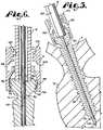
- FIG. 5is a reduced and fragmentary cross-sectional view of the head and the attached shank of FIG. 4 , and further showing the shank being implanted into a vertebra using a driving tool mounted on the shank capture structure.
- FIG. 6is an enlarged and fragmentary cross-sectional view of the head, shank and driving tool of FIG. 5 .
- FIG. 7is a reduced and fragmentary cross-sectional view of the head, similar to FIG. 5 , showing the shank in front elevation and implanted in the vertebra, a rod, in cross-section, disposed in the head, and illustrating the insertion of the closure structure using a driver.
- FIG. 8is a reduced front-elevational view of the assembly of FIG. 1 , shown with a rod in cross-section, the shank implanted in the vertebra and with the closure structure fully installed.
- FIG. 9is an enlarged and fragmentary view of the assembly of FIG. 8 with the head and rod in cross-section, showing the details thereof.
- FIG. 10is a front-elevational view of the shank of FIG. 1 shown implanted in a vertebra (shown in cross-section) according to an alternative method of the invention.
- FIG. 11is a front-elevation view of the shank of FIG. 10 , and including a reduced cross-sectional view of the head of FIG. 2 , illustrating insertion of the head on the implanted shank according to an alternative method of the invention.
- the reference number 1generally represents a polyaxial bone screw apparatus or assembly according to the present invention.
- the assembly 1includes a shank 4 and a head 6 .
- the shank 4further includes a body 8 integral with an upwardly extending capture structure 10 .
- the shank 4 and head 6are often assembled prior to implantation of the shank body 8 into a vertebra 13 , as seen in FIGS. 3 and 4 .
- the shank body 8is first implanted in the vertebra 13 , followed by joining the head 6 to the shank 4 .
- FIG. 1further shows a closure structure 16 of the invention for biasing a longitudinal member such as a rod 19 against the capture structure 10 which in turn biases the structure 10 into fixed frictional contact with the head 6 , so as to fix the rod 19 relative to the vertebra 13 .
- the head 6 and shank 4cooperate in such a manner that the head 6 and shank 4 can be secured at any of a plurality of angles, articulations or rotational alignments relative to one another and within a selected range of angles both from side to side and from front to rear, to enable flexible or articulated engagement of the head 6 with the shank 4 until both are locked or fixed relative to each other near an end of an implantation procedure.
- the shank 4is elongate, with the shank body 8 having a helically wound bone engaging thread 24 extending from near a neck 26 located adjacent to the capture structure 10 to near a tip 28 of the body 8 and projecting radially outward therefrom.
- rotation of the body 8utilizes the thread 24 for gripping and advancement in the bone and is implanted into the vertebra 13 leading with the tip 28 and driven down into the vertebra 13 with an installation or driving tool 31 , so as to be implanted in the vertebra 13 to near the neck 26 , as shown in FIG. 5 and as is described more fully in the paragraphs below.
- the shank 4has an elongate axis of rotation generally identified by the reference letter A. It is noted that any reference to the words top, bottom, up and down, and the like, in this application refers to the alignment shown in the various drawings, as well as the normal connotations applied to such devices, and is not intended to restrict positioning of the assembly 1 in actual use.
- the neck 26extends axially outward and upward from the shank body 8 to a base 34 of the capture structure 10 .
- the neck 26generally has a reduced radius as compared to an adjacent top 36 of the shank body 8 .
- the capture structure 10Further extending axially and outwardly from the neck 26 is the capture structure 10 that provides a connective or capture apparatus disposed at a distance from the body top 36 and thus at a distance from the vertebra 13 when the shank body 8 is implanted in the vertebra 13 .
- the capture structure 10is configured for connecting the shank 4 to the head 6 and then capturing the shank 4 in the head 6 .
- the capture structure 10has an outer substantially hemi-spherically or partial spherically shaped surface 40 extending from the base 34 to a top portion 44 .
- a guide and advancement structureillustrated in the drawing figures as an inverted or reverse buttress thread 48 .
- the thread 48is sized and shaped to mate with a cooperating guide and advancement structure 50 disposed on an inner surface 52 of the head 6 disposed adjacent to and defining an opening 54 of a lower end or bottom 56 of the head 6 .
- the thread 48is relatively thick and heavy to give strength to the thread and prevent the threads from being easily bent or deformed when axial pressure is applied to the shank 4 to maintain the capture structure 10 in the head 6 , as described further below.
- the thread 48winds about the upper portion 46 in a generally helical pattern or configuration that is typical of threads and can have various pitches, be clockwise or counterclockwise advanced, or vary in most of the ways that conventional buttress threads vary.
- the thread 48has a leading surface or flank 58 and a trailing surface or flank 59 .
- leading and trailingrefer to the direction of advancement of the capture structure 10 into the guide and advancement structure 50 of the head 6 aligning the axis A of the shank 4 with an elongate axis of rotation B of the head 6 and directing the capture structure 10 toward the head 6 , as shown by the straight arrow C illustrated in FIG. 2 .
- the leading surface 58has an inner edge 62 and an outer edge 63 .
- the trailing surface 59has an inner edge 66 and an outer edge 67 .
- At the crests of the thread 48where the leading surface outer edge 63 and the trailing surface outer edge 67 meet or are closely spaced relative to one another, preferably there is a slight relief as shown in the drawings so as to have a slight connecting wall or crest surface 70 therebetween along a substantial length of the thread that decreases the sharpness of the buttress thread 48 and increases the strength and surface contact thereof.
- the size of the crest or connecting surface 70varies, generally increasing as the thread 48 winds from the top surface 44 to a non-threaded lower portion 72 of the surface 40 .
- the general shape of the cross section of the thread 48is that of a right triangle, with the leading surface 58 sloping away from the axis A and downwardly from the inner edge 62 and the trailing surface 59 extending substantially horizontally from the inner edge 66 and thus substantially perpendicular to the axis A.
- a reverse or inverted buttress thread as described hereinis preferable for use according to the invention, it is foreseen that other thread types, such as V-threads, square threads, other inverted thread types or other thread like or non-thread like guide and advancement structures, such as flange form, helically wound advancement structures may be utilized according to the invention.
- Other preferred thread-typesalso include square threads with wide strong teeth and greater surface contact as well as modified inverted buttress threads, for example buttress threads wherein the angular relationship between the trailing and leading surfaces are modified somewhat, or wherein the size, shape or orientation of the connecting wall between the leading and trailing surfaces is modified somewhat.
- Advancement of the capture structure 10 into the head 6is accomplished by rotating the shank 4 in a counterclockwise direction about the axes A and B and into the head 6 as illustrated by the arrow T in FIG. 2 .
- an outer edge of the trailing surface or flank 59 and/or the connecting surface 70may also be a loading surface after the capture structure 10 is fully disposed in the head 6 .
- the non-threaded lower portion 72 of the capture structure 10 surface 40 that is disposed between the base 34 and the thread 48may have a smooth or a high-friction or roughened surface, such as a scored or knurled surface 73 illustrated on FIG. 9 . As also illustrated in FIG. 9 and will be described more fully below, the lower portion 72 may come into contact with the head guide and advancement structure 50 during a rod reduction process according to the present invention.
- the shank 4further includes a rod and tool engagement structure 74 projecting upwardly from the top portion 44 of the capture structure 10 .
- the tool engagement structure 74has a hexagonally shaped head 76 with a substantially domed top 78 .
- the structure 74is coaxial with both the threaded shank body 8 and the capture structure 10 .
- the head 76is sized and shaped for engagement with the driving tool 31 shown in FIGS. 5 and 6 that includes a driving and mating structure in the form of a socket.
- the tool 31is configured to fit about the head 76 so as to form a socket and mating projection for both operably driving and rotating the shank body 8 into the vertebra 13 .
- the capture structure 10includes a counter-sunk portion 80 formed in the top 44 , the portion 80 adjacent to and surrounding the head 76 .
- the portion 80includes a planar seating surface 82 disposed perpendicular to the axis A and spaced from the top portion 44 .
- Contiguous to both the surface 82 and the top 44are faces 84 that are disposed parallel to the axis A and thus are substantially perpendicular to the surface 82 .
- the faces 84form a hex-shaped outer periphery of the counter-sunk portion 80 .
- the tool 31includes an outer surface portion 90 sized and shaped to mate with the bottom and both side walls of the counter-sunk portion 80 , such that a bottom of the tool 31 seats on the surface 82 and the outer surface portion 90 is adjacent to and engaging the faces 84 when the tool 31 is disposed about and engaging with the hexagonally shaped head 76 .
- the domed top end surface 78 of the shank 4is preferably convex, curved or dome-shaped as shown in the drawings, for positive engagement with the rod 19 when the bone screw assembly 1 is assembled, as shown in FIGS. 7-9 , and in any alignment of the shank 4 relative to the head 6 .
- the surface 78is smooth. While not required in accordance with the practice of the invention, the surface 78 may be scored or knurled to further increase frictional engagement between the dome 78 and the rod 19 .
- the dome 78may be radiused so that the dome 78 engages the rod 19 slightly above a surface 100 defining a lower portion of a rod receiving channel in the head 6 , even as the head 6 is swiveled relative to the shank 4 so that pressure is always exerted on the dome surface 78 by the rod 19 when the assembly 1 is fully assembled. It is foreseen that in other embodiments the dome 78 can have other shapes which may include off-axis apertures for driving the shank with a mating tool.
- the shank 4 shown in the drawingsis cannulated, having a small central bore 92 extending an entire length of the shank 4 along the axis A.
- the bore 92is defined by an inner substantially cylindrical wall 95 of the shank 4 and has a first circular opening 96 at the shank tip 28 and a second circular opening 98 at the top domed surface 78 .
- the bore 92is coaxial with the threaded body 8 and the capture structure 10 .
- the bore 92provides a passage through the shank 4 interior for a guide pin or length of wire 103 inserted into a small pre-drilled tap bore 105 in the vertebra 13 prior to the insertion of the shank body 8 , the pin 103 providing a guide for insertion of the shank body 8 into the vertebra 13 .
- the head 6is partially cylindrical in external profile and includes a base portion 110 extending from the end 56 to a V-shaped surface 111 disposed at a periphery of the surface 100 and extending radially outwardly and downwardly therefrom.
- the base 110is integral with a pair of upstanding and spaced arms 112 and 114 .
- the surface 100 and the arms 112 and 114forming a U-shaped channel 116 between the arms 112 and 114 with an upper opening 119 .
- the lower surface 100 defining the channel 116preferably has substantially the same radius as the rod 19 .
- the rod 19preferably is located just above the channel lower surface 100 , as shown in FIGS. 7-9 .
- Each of the arms 112 and 114has an interior surface 122 that defines an inner cylindrical profile and includes a discontinuous helically wound guide and advancement structure 124 beginning at a top 125 of the head 6 and extending downwardly therefrom.
- the guide and advancement structure 124is a partial helically wound flange-form configured to mate under rotation about the axis B with a similar structure disposed on the closure structure 16 , as described more fully below.
- the guide and advancement structure 124could alternatively be a V-shaped thread, a buttress thread, a reverse angle thread or other thread-like or non-thread-like helically wound guide and advancement structure for operably guiding under rotation and advancing the closure structure 16 between the arms 112 and 114 , as well as eventual torquing when the closure structure 16 abuts against the rod 19 .
- the head 6includes external, grip bores 128 and 129 disposed on the respective arms 112 and 114 for positive engagement by a holding tool (not shown) to facilitate secure gripping of the head 6 during assembly of the head 6 with the shank 4 .
- the grip bores 128 and 129may be utilized to hold the head 6 during the implantation of the shank body 8 into the vertebra 13 .
- the bores 128 and 129are centrally located on the respective arms 112 and 114 and may communicate with upwardly projecting hidden recesses to further aid in securely holding the head 6 to a holding tool (not shown). It is foreseen that the bores 128 and 129 may be configured to be of a variety of sizes, shapes and locations along outer surfaces of the arms 112 and 114 .
- a chamber or cavity 136substantially defined by a partially spherical inner surface 138 that is disposed in the base portion 110 of the head beneath the interior cylindrical surface 122 of the arms 112 and 114 and extending into the inner surface 52 that defines the guide and advancement structure 50 .
- the cavity 136communicates with both the U-shaped channel 116 and a bore 140 that also is defined by the guide and advancement structure 50 , that in turn communicates with the opening 54 at the bottom 56 of the head 6 .
- the guide and advancement structure 50includes a leading surface 152 and a trailing surface 156 . Similar to what is described herein with respect to the reverse buttress thread 48 of the capture structure 10 , the guide and advancement structure 50 is preferably of a buttress thread type as such structure provides strength and stability to the assembly 1 , with the trailing surface 156 that extends substantially perpendicular to the axis B.
- the cross-sectional configuration of an inverted buttress threadalso results in an orientation for the structure 50 that improves strength and desirably resists pushing of the capture structure 10 out of the opening 54 .
- thread 48it is foreseen that other types of threaded and non-threaded helical structures may be utilized in accordance with the present invention.
- a juncture of the interior surface 122 and the cavity inner surface 138forms an opening or neck 158 that has a radius extending from the Axis B that is smaller than a radius extending from the Axis B to the inner surface 138 .
- a radius from the lower opening 54 to the Axis Bis smaller than the radius extending from the Axis B to the inner surface 138 and the inner surface portion 52 defining the guide and advancement structure 50 .
- the cavity or chamber 136is substantially spherical, widening and opening outwardly and then inwardly in a direction toward the lower opening 54 .
- other shapessuch as a cone or conical shape, may be utilized for a head inner cavity according to the invention.
- the capture structure 10is rotatable or swingable within the cavity 136 until later frictionally locked in place, and cannot be removed from the head 6 through the upper neck 158 or through the lower bore 140 without reversing the assembly process with the components in axial alignment. As shown in FIG. 4 , the capture structure 10 is held within the cavity 136 from above by the partially spherical surface 138 and from below by the threaded inner surface 52 .
- the thick strong thread 50 of the head 6 disposed along the surface 52 , and the unmated, thick strong thread 48 of the capture structure 10prevent the capture structure 10 from being pushed or pulled from the chamber 136 , unless the capture structure 10 is rotated and unscrewed therefrom again through the bore 140 in axial alignment. More specifically, the buttress thread 48 , particularly the trailing surface 59 , resists pushing out of the bore 140 and bottom opening 54 due to the strength and orientation of the buttress thread and the fact that the greatest diameter of the threaded portion 46 of the capture structure 10 is greater than the interior diameter of the bore 140 .
- the buttress thread 48 and mating thread 50further provide a frictional interface when pushed from above, as by a closure structure 16 pushing on a rod 19 or other tool pushing against the dome 78 , with outer edges of the thread 48 contacting the inner surface 52 or portions of the thread 50 , resulting in a digging or abrasion into the surface 52 by the thread 48 .
- the cavity or chamber 136allows the structure 10 to freely rotate in the chamber 136 to a position or orientation desired by a surgeon. In this manner, the head 6 is able to swivel or swing about the shank 4 until subsequently locked in place.
- the elongate rod or longitudinal member 19 that is utilized with the assembly 1can be any of a variety of implants utilized in reconstructive spinal surgery, but is normally a cylindrical elongate structure having a cylindrical surface 162 of uniform diameter and preferably having a generally smooth surface.
- the rod 19is also preferably sized and shaped to snugly seat near the bottom of the U-shaped channel 116 of the head 6 and, during normal operation, is positioned slightly above the bottom of the channel 116 near, but spaced from, the lower surface 100 .
- the rod 19normally directly or abutingly engages the shank top surface 78 , as shown in FIGS. 8 and 9 and is biased against the dome shank top surface 78 , consequently biasing the shank 4 downwardly in a direction toward the base 110 of the head 6 when the assembly 1 is fully assembled with the rod 19 and the closure member 16 .
- the shank top surface 78must extend at least slightly into the space of the channel 116 , above the surface 100 when the capture structure 10 is snugly seated in the lower part of the head cavity 136 as shown in FIG. 9 with a portion of the buttress thread 48 contacting a portion of the structure 50 , resulting in a frictional interface between the thread 48 and the thread 50 .
- the pressure placed on the capture structure 10 by the rod 19 and closure member 16may also cause a spreading or expansion of the capture structure 10 , causing an interlocking or interdigitation of the threads 48 and 50 , or an abrading of the surface 52 at the thread 50 by the thread 48 .
- the shank 4 and the capture structure 10are thereby locked or held in position relative to the head 6 by the rod 19 firmly pushing downward on the shank domed surface 78 .
- the closure structure or closure top 16can be any of a variety of different types of closure structures for use in conjunction with the present invention with suitable mating structure on the upstanding arms 112 and 114 .
- the closure top 16screws between the spaced arms 112 and 114 and closes the top of the channel 116 to capture the rod 19 therein.
- the illustrated closure top 16has a generally cylindrically shaped body 170 , with a helically wound guide and advancement structure 172 that is sized, shaped and positioned so as to engage the guide and advancement structure 124 on the arms 112 and 114 to provide for rotating advancement of the closure structure 16 into the head 6 when rotated clockwise and, in particular, to cover the top or upwardly open portion of the U-shaped channel 116 to capture the rod 19 , preferably without splaying of the arms 112 and 114 .
- the body 170further includes a base or bottom 174 having a pointed rod engaging projection or point 175 extending or projecting axially beyond a lower rim 176 .
- the closure structure 16with the projection 175 frictionally engaging and abrading the rod surface 162 , thereby applies pressure to the rod 19 under torquing, so that the rod 19 is urged downwardly against the shank domed surface 78 that extends into the channel 116 .
- Downward biasing of the shank surface 78operably produces a frictional engagement between the rod 19 and the surface 78 and also urges the capture structure 10 toward the base 110 of the head 6 , as will be described more fully below, so as to frictionally seat the capture structure buttress thread 48 and/or lower portion 72 against the threaded inner surface 52 of the head 6 , also fixing the shank 4 and capture structure 10 in a selected, rigid position relative to the head 6 .
- the illustrated closure structure 16further includes a substantially planar top surface 178 that has a centrally located, hexalobular internal driving feature 180 formed therein (sold under the trademark TORX), which is characterized by an aperture with a 6-point star-shaped pattern. It is foreseen that other driving features or apertures, such as slotted, hex, tri-wing, spanner, and the like may also be utilized according to the invention.
- TORXhexalobular internal driving feature 180 formed therein
- other driving features or aperturessuch as slotted, hex, tri-wing, spanner, and the like may also be utilized according to the invention.
- a driving/torquing tool 179having a cooperating hexalobular driving head is used to rotate and torque the closure structure 16 .
- the tool 179may also be utilized for removal of the closure structure 16 , if necessary.
- a closure structure according to the inventionmay be equipped with a break-off feature or head, the closure structure sized and shaped to produce a break-way region that breaks at a preselected torque that is designed to properly seat the closure structure in the head 6 .
- a closure structurewould include removal tool engagement structure, such as a pair of spaced bores, a countersunk hex-shaped aperture, a left hand threaded bore, or the like, fully accessible after the break-off head feature breaks away from a base of the closure structure.
- the shank capture structure 10is often pre-loaded by insertion or bottom-loading into the head 6 through the opening 54 at the bottom end 56 of the head 6 .
- the capture structure 10is aligned with the head 6 , with the axes A and B aligned so that the reverse buttress thread 48 of the capture structure 10 is inserted into and rotatingly mated with the guide and advancement structure 50 on the head 6 .
- the shank 4is rotated in a counter-clockwise direction as illustrated by the arrow T in FIG. 2 to fully mate the structures 48 and 50 , as shown in FIG. 3 , and the counter-clockwise rotation is continued until the thread 48 disengages from the thread 50 and the capture structure 10 is fully disposed in the head cavity 136 .
- the shank 4is in slidable and rotatable engagement with the head 6 , while the capture structure 10 is maintained in the head 6 with the shank body 8 in rotational relation with the head 10 .
- an extent of rotationis shown in FIGS.
- the shank body 8can be rotated through a substantial angular rotation relative to the head 6 , both from side to side and from front to rear so as to substantially provide a universal or ball joint wherein the angle of rotation is only restricted by engagement of the thread 48 of the capture structure 10 and the thread 50 of the head 6 at a lower portion or area of the head 6 and by the thread 48 contacting the inner spherical surface 138 of the head 6 at an upper portion or area of the head 6 .
- the assembly 1is then typically screwed into a bone, such as the vertebra 13 , by rotation of the shank body 8 using the driving tool 31 that operably drives and rotates the shank 8 by engagement thereof with the hexagonally shaped extension head 76 of the shank 4 .
- the driving tool 31engages the head 76 during rotation of the driving tool 31
- the outer portion 90also engages the faces 84 and a bottom of the tool 31 is fully seated upon and frictionally engages with the planar surface 82 disposed in the counter-sunk portion 80 of the capture structure 10 .
- the counter-sunk portionmay be defined by more or fewer engaging surfaces.
- the vertebra 13may be pre-drilled with the small tap bore 105 to minimize stressing the bone and thereafter have the guide wire or pin 103 inserted therein to provide a guide for the placement and angle of the shank 4 with respect to the vertebra 13 .
- a further tap bore(not shown) may be made using a tap with the guide pin 103 as a guide.
- the assembly 1is threaded onto the guide pin 103 utilizing the cannulation bore 92 by first threading the pin 103 into the bottom opening 96 and then out of the top opening 98 .
- the shank body 8is then driven into the vertebra 13 , using the pin 103 as a placement guide.
- the rod 19is eventually positioned within the head U-shaped channel 116 , and the closure structure or top 16 is then inserted into and advanced in a clock-wise direction between the arms 112 and 114 so as to bias or push against the rod 19 .
- the closure structure 16is rotated, utilizing the tool 179 in engagement with the driving feature or aperture 180 until an appropriate torque is achieved, for example 90 to 120 inch pounds, to urge the rod 19 downwardly.
- the shank top domed surface 78because it is rounded to approximately equally extend upward into the channel 116 approximately the same amount no matter what degree of rotation exists between the shank 8 and the head 6 and because the surface 78 is sized to extend upwardly into the U-shaped channel 116 , the surface 78 is engaged by the rod 19 and pushed downwardly toward the base 110 of the head 6 when the closure structure 16 biases downwardly toward and onto the rod 19 .
- the Axis A and the Axis Bare aligned and in such a case the surface 72 of the capture structure 10 engages and sets atop the thread 50 of the head 6 . Downward pressure on the shank 4 produces frictional fixing between the surface 72 and the thread 50 in such an alignment.
- the head 6is tilted relative to the shank 4 , so that the Axes A and B are not aligned.
- downward pressure on the shank 4urges the capture structure 10 downward toward the head inner surface 52 and associated guide and advancement structure 50 , with a portion of the buttress thread 48 being urged into frictional engagement with a portion of the threaded surface 52 on the head 6 .
- another portion of the thread 50engages and frictionally locks with a portion of the capture structure surface 72 , as seen in FIG. 9 .
- the closure structure 16 presses against the rod 19the rod 19 presses against the shank 4 , and the capture structure 10 becomes frictionally and rigidly attached to the head 10 .
- FIG. 8illustrates the polyaxial bone screw assembly 1 with the rod 19 and the closure structure 16 positioned in a vertebra 13 .
- the axis A of the bone shank 8is illustrated as not being coaxial with the axis B of the head 6 and the shank body 8 is fixed in this angular locked configuration.
- FIG. 9an implanted polyaxial bone screw assembly 1 is shown wherein the shank body 8 is fixed in a desired angular orientation with respect to the head 6 with the rod 19 in frictional contact with the domed surface 78 , a portion of the wall 70 disposed between the leading surface 52 and the trailing surface 59 being in frictional contact with the thread 50 of the head 6 , and a portion of the lower spherical surface 72 of the capture structure 10 in contact with the thread 50 of the head 6 .
- the geometry of the surface 72may be modified slightly so that when a coaxial orientation of the shank 4 and the head 6 is desired, the buttress thread 48 will frictionally engage with the thread 50 with no contact being made between the head 6 and the capture structure 10 at either the spherical surface 138 or the spherical surface 72 .
- disassemblyis accomplished by using the driving tool 179 that is received in and mates with the driving feature 180 and then turned counterclockwise to rotate the closure structure 16 and reverse the advancement thereof in the head 6 . Then, disassembly of the assembly 1 is continued in reverse order to the procedure described previously herein for assembly.
- the shank 4is first implanted into the vertebra 13 by rotation of the shank 8 into the vertebra 13 using the driving tool 31 that operably drives and rotates the shank 8 by engagement thereof with the hexagonally shaped extension head 76 of the shank 4 .
- the driving tool 31engages the head 76 during rotation of the driving tool 31
- the outer portion 90also engages the faces 84 and a bottom of the tool 31 is fully seated upon and frictionally engages with the planar surface 82 disposed in the counter-sunk portion 80 of the capture structure 10 . It may be desirable to only partially implant the shank 8 into the vertebra 13 , with the capture structure 10 extending proud to provide space for the attachment of the head 6 to the shank 4 .
- the head 6is then attached to the shank 4 by inserting the head 6 onto the capture structure with the axes A and B aligned and mating the thread 48 with the thread 50 by rotating the head 6 in a clockwise direction.
- the headis then rotated until the thread 48 disengages with the thread 50 and the capture structure 10 is freely rotatably disposed in the head cavity 136 .
- the shank body the shank 4can be further driven into the vertebra 13 , if necessary, utilizing the driving tool 31 as already described herein.
- the remainder of the implant assemblyincludes elements that have been previously described.
Landscapes
- Health & Medical Sciences (AREA)
- Orthopedic Medicine & Surgery (AREA)
- Life Sciences & Earth Sciences (AREA)
- Neurology (AREA)
- Surgery (AREA)
- Heart & Thoracic Surgery (AREA)
- Engineering & Computer Science (AREA)
- Biomedical Technology (AREA)
- Nuclear Medicine, Radiotherapy & Molecular Imaging (AREA)
- Medical Informatics (AREA)
- Molecular Biology (AREA)
- Animal Behavior & Ethology (AREA)
- General Health & Medical Sciences (AREA)
- Public Health (AREA)
- Veterinary Medicine (AREA)
- Surgical Instruments (AREA)
- Prostheses (AREA)
Abstract
Description
The present application is a continuation of U.S. application Ser. No. 10/958,743, filed Oct. 5, 2004, now U.S. Pat. No. 8,540,753 which was a continuation-in-part of U.S. application Ser. No. 10/409,935, filed Apr. 9, 2003, now U.S. Pat. No. 6,964,666.
The present invention relates to apparatuses and methods for use in performing spinal surgery and, in particular, to polyaxial bone screws for use in spinal surgery. Such screws have a head that can swivel about a shank of the bone screw, allowing the head to be positioned in any of a number of angular configurations relative to the shank.
Bone screws are utilized in many types of spinal surgery in order to secure various implants to vertebrae along the spinal column. Spinal implant screws typically have a shank that is threaded and configured for implantation into a pedicle or vertebral body of a vertebra. Such a screw also includes a head designed to extend beyond the vertebra and also defines a channel to receive a rod or other implant. In bone screws of this type, the head may be open, in which case a closure member must be used to close between opposite sides of the head once a rod or other implant is placed therein. Alternatively, the head may be closed, wherein a rod-like implant is threaded through the head of the bone screw.
When the head and shank of the bone screw are fixed in position relative to each other, it is not always possible to insert a bone screw in such a manner that the head will be in the best position for receiving other implants. Consequently, swivel head bone screws have been designed that allow the head of the bone screw to rotate or swivel about an upper end of the shank of the bone screw while the surgeon is positioning other implants and finding the best position for the bone screw head. However, once the surgeon has determined that the head is in the best position, it is then necessary to lock or fix the head relative to the shank. Different types of structures have been previously developed for such purpose.
Because bone screws are for placement within the human body, it is desirable for the implant to have as little effect on the body as possible. Consequently, heavy, high profile, bulky implants are undesirable and lighter implants with a relatively small profile both in height and width are more desirable. However, a drawback to smaller, lighter implants is that they may be more difficult to rigidly fix in position relative to each other and in a desired position. Reduced bulk may also reduce strength, resulting in slippage under high loading. Also, more component parts may be required to rigidly fix the implant in a desired position. A further drawback of smaller components is that they may be difficult to handle during surgery because of their small size, failing to provide adequate driving or gripping surfaces for tools used to drive the shank into bone.
One undesirable attribute of some of the swivel-head implants is the need for a multitude of components that may loosen or even disassemble within the body. It is most often undesirable for components to become moveable in the body after the completion of surgery. Loosening of components relative to each other may result in related undesirable movement of the bone or vertebra that the implant was intended to stabilize.
A polyaxial bone screw assembly according to the present invention includes an elongate shank having a lower threaded body for fixation to a bone. The shank further has an upper capture structure connected to the threaded body by a neck. The capture structure has an upper end or top and a lower surface. The capture structure has a radially outward surface with a first helically wound guide and advancement structure thereon. The helically wound guide and advancement structure has a major diameter (passing through the crests) that is larger than a diameter of the aperture into which the capture structure is inserted.
The assembly also includes a head having a base with an inner surface defining a cavity. The cavity opens onto a bottom of the head through a neck opening or aperture with a portion of the inner surface defining the opening having a second helically wound guide and advancement structure sized and shaped to rotatingly mate with the first guide and advancement structure of the capture structure.
The capture structure screws upwardly into the head so as to be disposed within the cavity and captured by the head upon mating and operable rotation of the first guide and advancement structure with respect to the second guide and advancement structure until the first guide and advancement structure fully enters the cavity and becomes disengaged from the second guide and advancement structure. The capture structure is then disposed in the head cavity and free to rotate or swivel relative to the head.
The capture structure has a first orientation wherein the capture structure is within the cavity and the shank body is freely swivelable relative to the head. In a second orientation, the capture structure is in a non-mated, frictional engagement with the second guide and advancement structure and the shank body is in a fixed position with respect to the head, resulting from a force being applied to the top of the capture structure.
Preferably according to the invention, the first and second guide and advancement structures are first and second threads. Most preferably according to the invention, inverted buttress threads are utilized, although square threads, reverse angle threads and other similar mating structures can be utilized.
Also according to the invention, the elongate shank has a first axis and the head has a second axis. The first and second guide and advancement structures are configured to enter into frictional engagement when the capture structure is urged downwardly against the base neck without rotation. The capture structure may expand in response to downward pressure, further frictionally engaging and locking the first and second guide and advancement structures.
Further according to the invention, a polyaxial bone screw capture structure may include a tool engagement formation disposed at or near the top of the capture structure. Preferably, the tool engagement formation has a projection and a recessed tool seating surface with a bottom and an outer wall. Both the bottom and outer wall are sized and shaped to receive and frictionally engage with a driving tool, such as a socket tool, engaged with the tool engagement projection for driving the shank body into bone. However, other structure for driving the shank body can be used, such as off axis apertures into the threaded hemisphere.
A method according to the invention includes the steps of attaching a bone screw shank to a head by mating a first helically wound guide and advancement structure disposed on an upper portion of the bone screw shank with a second helically wound guide and advancement structure of the head to guide and advance the shank into the head until the first guide and advancement structure becomes disengaged from the second guide and advancement structure with the capture structure or upper portion slidingly received and captured in a cavity of the head. Another method step includes driving the shank body into bone by rotating the shank body with a tool engaged with a tool engagement formation disposed on or in the capture structure. The step of driving the shank into bone may take place after or before the step of mating the bone shank with the head.
Therefore, it is an object of the present invention to overcome one or more of the problems with polyaxial bone screw assemblies described above. An object of the invention is to provide a shank that rotatably uploads into a cavity in a head of the screw and that utilizes frictional contact of threads under pressure to fix the head relative to the shank once a desired configuration is acquired. Another object of the invention is to provide a polyaxial bone screw with features that present frictional or gripping surfaces, planar surfaces, internal apertures or the like for bone implantation tools and may be readily and securely fastened to each other as well as to the bone. Also, if part of the implant should slip relative to another part or become loose for some reason, an object of the invention is to provide an implant wherein all of the parts remain together and do not separate. Furthermore, it is an object of the invention to provide a lightweight, reduced volume, low profile polyaxial bone screw that assembles in such a manner that the components cooperate to create an overall structure that prevents unintentional disassembly. Furthermore, it is an object of the invention to provide apparatus and methods that are easy to use and especially adapted for the intended use thereof and wherein the tools are comparatively inexpensive to produce.
Other objects and advantages of this invention will become apparent from the following description taken in conjunction with the accompanying drawings wherein are set forth, by way of illustration and example, certain embodiments of this invention.
The drawings constitute a part of this specification and include exemplary embodiments of the present invention and illustrate various objects and features thereof.
As required, detailed embodiments of the present invention are disclosed herein; however, it is to be understood that the disclosed embodiments are merely exemplary of the invention, which may be embodied in various forms. Therefore, specific structural and functional details disclosed herein are not to be interpreted as limiting, but merely as a basis for the claims and as a representative basis for teaching one skilled in the art to variously employ the present invention in virtually any appropriately detailed structure.
With reference toFIGS. 1-9 , the reference number1 generally represents a polyaxial bone screw apparatus or assembly according to the present invention. The assembly1 includes ashank 4 and ahead 6. Theshank 4 further includes abody 8 integral with an upwardly extendingcapture structure 10. Theshank 4 andhead 6 are often assembled prior to implantation of theshank body 8 into avertebra 13, as seen inFIGS. 3 and 4 . However, in a method of the invention shown inFIGS. 10 and 11 , theshank body 8 is first implanted in thevertebra 13, followed by joining thehead 6 to theshank 4.
With reference toFIGS. 1 and 2 , theshank 4 is elongate, with theshank body 8 having a helically woundbone engaging thread 24 extending from near aneck 26 located adjacent to thecapture structure 10 to near atip 28 of thebody 8 and projecting radially outward therefrom.
During use, rotation of thebody 8 utilizes thethread 24 for gripping and advancement in the bone and is implanted into thevertebra 13 leading with thetip 28 and driven down into thevertebra 13 with an installation or drivingtool 31, so as to be implanted in thevertebra 13 to near theneck 26, as shown inFIG. 5 and as is described more fully in the paragraphs below.
Theshank 4 has an elongate axis of rotation generally identified by the reference letter A. It is noted that any reference to the words top, bottom, up and down, and the like, in this application refers to the alignment shown in the various drawings, as well as the normal connotations applied to such devices, and is not intended to restrict positioning of the assembly1 in actual use.
Theneck 26 extends axially outward and upward from theshank body 8 to abase 34 of thecapture structure 10. Theneck 26 generally has a reduced radius as compared to anadjacent top 36 of theshank body 8. Further extending axially and outwardly from theneck 26 is thecapture structure 10 that provides a connective or capture apparatus disposed at a distance from thebody top 36 and thus at a distance from thevertebra 13 when theshank body 8 is implanted in thevertebra 13.
Thecapture structure 10 is configured for connecting theshank 4 to thehead 6 and then capturing theshank 4 in thehead 6. Thecapture structure 10 has an outer substantially hemi-spherically or partial sphericallyshaped surface 40 extending from the base34 to atop portion 44. Formed on anupper part 46 of thesurface 40 is a guide and advancement structure illustrated in the drawing figures as an inverted or reverse buttressthread 48. Thethread 48 is sized and shaped to mate with a cooperating guide andadvancement structure 50 disposed on aninner surface 52 of thehead 6 disposed adjacent to and defining anopening 54 of a lower end or bottom56 of thehead 6. Preferably, thethread 48 is relatively thick and heavy to give strength to the thread and prevent the threads from being easily bent or deformed when axial pressure is applied to theshank 4 to maintain thecapture structure 10 in thehead 6, as described further below.
Thethread 48 winds about theupper portion 46 in a generally helical pattern or configuration that is typical of threads and can have various pitches, be clockwise or counterclockwise advanced, or vary in most of the ways that conventional buttress threads vary. Thethread 48 has a leading surface orflank 58 and a trailing surface orflank 59. As used herein, the terms leading and trailing refer to the direction of advancement of thecapture structure 10 into the guide andadvancement structure 50 of thehead 6 aligning the axis A of theshank 4 with an elongate axis of rotation B of thehead 6 and directing thecapture structure 10 toward thehead 6, as shown by the straight arrow C illustrated inFIG. 2 .
The leadingsurface 58 has aninner edge 62 and anouter edge 63. The trailingsurface 59 has aninner edge 66 and anouter edge 67. At the crests of thethread 48, where the leading surfaceouter edge 63 and the trailing surfaceouter edge 67 meet or are closely spaced relative to one another, preferably there is a slight relief as shown in the drawings so as to have a slight connecting wall orcrest surface 70 therebetween along a substantial length of the thread that decreases the sharpness of thebuttress thread 48 and increases the strength and surface contact thereof. The size of the crest or connectingsurface 70 varies, generally increasing as thethread 48 winds from thetop surface 44 to a non-threadedlower portion 72 of thesurface 40.
As can be seen in the drawing figures, the general shape of the cross section of thethread 48 is that of a right triangle, with the leadingsurface 58 sloping away from the axis A and downwardly from theinner edge 62 and the trailingsurface 59 extending substantially horizontally from theinner edge 66 and thus substantially perpendicular to the axis A.
Although a reverse or inverted buttress thread as described herein is preferable for use according to the invention, it is foreseen that other thread types, such as V-threads, square threads, other inverted thread types or other thread like or non-thread like guide and advancement structures, such as flange form, helically wound advancement structures may be utilized according to the invention. Other preferred thread-types also include square threads with wide strong teeth and greater surface contact as well as modified inverted buttress threads, for example buttress threads wherein the angular relationship between the trailing and leading surfaces are modified somewhat, or wherein the size, shape or orientation of the connecting wall between the leading and trailing surfaces is modified somewhat.
Advancement of thecapture structure 10 into thehead 6 is accomplished by rotating theshank 4 in a counterclockwise direction about the axes A and B and into thehead 6 as illustrated by the arrow T inFIG. 2 . As will be described more fully below, an outer edge of the trailing surface orflank 59 and/or the connectingsurface 70 may also be a loading surface after thecapture structure 10 is fully disposed in thehead 6.
The non-threadedlower portion 72 of thecapture structure 10surface 40 that is disposed between the base34 and thethread 48 may have a smooth or a high-friction or roughened surface, such as a scored orknurled surface 73 illustrated onFIG. 9 . As also illustrated inFIG. 9 and will be described more fully below, thelower portion 72 may come into contact with the head guide andadvancement structure 50 during a rod reduction process according to the present invention.
In the embodiment shown, theshank 4 further includes a rod andtool engagement structure 74 projecting upwardly from thetop portion 44 of thecapture structure 10. Thetool engagement structure 74 has a hexagonally shapedhead 76 with a substantially domed top78. Thestructure 74 is coaxial with both the threadedshank body 8 and thecapture structure 10. Thehead 76 is sized and shaped for engagement with the drivingtool 31 shown inFIGS. 5 and 6 that includes a driving and mating structure in the form of a socket. Thetool 31 is configured to fit about thehead 76 so as to form a socket and mating projection for both operably driving and rotating theshank body 8 into thevertebra 13.
In the embodiment shown, to provide further mechanical advantage during installation of theshank 4 into thevertebra 13, thecapture structure 10 includes acounter-sunk portion 80 formed in the top44, theportion 80 adjacent to and surrounding thehead 76. Theportion 80 includes aplanar seating surface 82 disposed perpendicular to the axis A and spaced from thetop portion 44. Contiguous to both thesurface 82 and the top44 are faces84 that are disposed parallel to the axis A and thus are substantially perpendicular to thesurface 82. The faces84 form a hex-shaped outer periphery of thecounter-sunk portion 80. Thetool 31 includes anouter surface portion 90 sized and shaped to mate with the bottom and both side walls of thecounter-sunk portion 80, such that a bottom of thetool 31 seats on thesurface 82 and theouter surface portion 90 is adjacent to and engaging thefaces 84 when thetool 31 is disposed about and engaging with the hexagonally shapedhead 76.
The domedtop end surface 78 of theshank 4 is preferably convex, curved or dome-shaped as shown in the drawings, for positive engagement with therod 19 when the bone screw assembly1 is assembled, as shown inFIGS. 7-9 , and in any alignment of theshank 4 relative to thehead 6. In certain embodiments, thesurface 78 is smooth. While not required in accordance with the practice of the invention, thesurface 78 may be scored or knurled to further increase frictional engagement between thedome 78 and therod 19. Thedome 78 may be radiused so that thedome 78 engages therod 19 slightly above asurface 100 defining a lower portion of a rod receiving channel in thehead 6, even as thehead 6 is swiveled relative to theshank 4 so that pressure is always exerted on thedome surface 78 by therod 19 when the assembly1 is fully assembled. It is foreseen that in other embodiments thedome 78 can have other shapes which may include off-axis apertures for driving the shank with a mating tool.
Theshank 4 shown in the drawings is cannulated, having a smallcentral bore 92 extending an entire length of theshank 4 along the axis A. Thebore 92 is defined by an inner substantiallycylindrical wall 95 of theshank 4 and has a firstcircular opening 96 at theshank tip 28 and a secondcircular opening 98 at the topdomed surface 78. Thebore 92 is coaxial with the threadedbody 8 and thecapture structure 10. Thebore 92 provides a passage through theshank 4 interior for a guide pin or length ofwire 103 inserted into a small pre-drilled tap bore105 in thevertebra 13 prior to the insertion of theshank body 8, thepin 103 providing a guide for insertion of theshank body 8 into thevertebra 13.
Thehead 6 is partially cylindrical in external profile and includes abase portion 110 extending from theend 56 to a V-shapedsurface 111 disposed at a periphery of thesurface 100 and extending radially outwardly and downwardly therefrom. Thebase 110 is integral with a pair of upstanding and spacedarms surface 100 and thearms U-shaped channel 116 between thearms upper opening 119. Thelower surface 100 defining thechannel 116 preferably has substantially the same radius as therod 19. In operation, therod 19 preferably is located just above the channellower surface 100, as shown inFIGS. 7-9 .
Each of thearms interior surface 122 that defines an inner cylindrical profile and includes a discontinuous helically wound guide andadvancement structure 124 beginning at a top125 of thehead 6 and extending downwardly therefrom. The guide andadvancement structure 124 is a partial helically wound flange-form configured to mate under rotation about the axis B with a similar structure disposed on theclosure structure 16, as described more fully below. However, it is foreseen that the guide andadvancement structure 124 could alternatively be a V-shaped thread, a buttress thread, a reverse angle thread or other thread-like or non-thread-like helically wound guide and advancement structure for operably guiding under rotation and advancing theclosure structure 16 between thearms closure structure 16 abuts against therod 19.
Thehead 6 includes external, grip bores128 and129 disposed on therespective arms head 6 during assembly of thehead 6 with theshank 4. Furthermore, the grip bores128 and129 may be utilized to hold thehead 6 during the implantation of theshank body 8 into thevertebra 13. Thebores respective arms head 6 to a holding tool (not shown). It is foreseen that thebores arms
Communicating with theU-shaped channel 116 of thehead 6 is a chamber orcavity 136 substantially defined by a partially sphericalinner surface 138 that is disposed in thebase portion 110 of the head beneath the interiorcylindrical surface 122 of thearms inner surface 52 that defines the guide andadvancement structure 50. Thecavity 136 communicates with both theU-shaped channel 116 and abore 140 that also is defined by the guide andadvancement structure 50, that in turn communicates with theopening 54 at the bottom56 of thehead 6.
The guide andadvancement structure 50 includes a leadingsurface 152 and a trailingsurface 156. Similar to what is described herein with respect to the reverse buttressthread 48 of thecapture structure 10, the guide andadvancement structure 50 is preferably of a buttress thread type as such structure provides strength and stability to the assembly1, with the trailingsurface 156 that extends substantially perpendicular to the axis B. The cross-sectional configuration of an inverted buttress thread also results in an orientation for thestructure 50 that improves strength and desirably resists pushing of thecapture structure 10 out of theopening 54. However, as with thethread 48, it is foreseen that other types of threaded and non-threaded helical structures may be utilized in accordance with the present invention.
A juncture of theinterior surface 122 and the cavityinner surface 138 forms an opening orneck 158 that has a radius extending from the Axis B that is smaller than a radius extending from the Axis B to theinner surface 138. Also, a radius from thelower opening 54 to the Axis B is smaller than the radius extending from the Axis B to theinner surface 138 and theinner surface portion 52 defining the guide andadvancement structure 50. Thus, the cavity orchamber 136 is substantially spherical, widening and opening outwardly and then inwardly in a direction toward thelower opening 54. However, it is foreseen that other shapes, such as a cone or conical shape, may be utilized for a head inner cavity according to the invention.
After the reverse buttressthread 48 of thecapture structure 10 is mated and rotated to a position within thecavity 136 and further upwardly and axially into non-engagement beyond the trailingsurface 156 of the guide andadvancement structure 50, thecapture structure 10 is rotatable or swingable within thecavity 136 until later frictionally locked in place, and cannot be removed from thehead 6 through theupper neck 158 or through thelower bore 140 without reversing the assembly process with the components in axial alignment. As shown inFIG. 4 , thecapture structure 10 is held within thecavity 136 from above by the partiallyspherical surface 138 and from below by the threadedinner surface 52. Stated in another way, the thickstrong thread 50 of thehead 6 disposed along thesurface 52, and the unmated, thickstrong thread 48 of thecapture structure 10, prevent thecapture structure 10 from being pushed or pulled from thechamber 136, unless thecapture structure 10 is rotated and unscrewed therefrom again through thebore 140 in axial alignment. More specifically, the buttressthread 48, particularly the trailingsurface 59, resists pushing out of thebore 140 andbottom opening 54 due to the strength and orientation of the buttress thread and the fact that the greatest diameter of the threadedportion 46 of thecapture structure 10 is greater than the interior diameter of thebore 140.
As shown inFIG. 9 and described more fully below, the buttressthread 48 andmating thread 50 further provide a frictional interface when pushed from above, as by aclosure structure 16 pushing on arod 19 or other tool pushing against thedome 78, with outer edges of thethread 48 contacting theinner surface 52 or portions of thethread 50, resulting in a digging or abrasion into thesurface 52 by thethread 48. However, if there is no pushing from above, the cavity orchamber 136 allows thestructure 10 to freely rotate in thechamber 136 to a position or orientation desired by a surgeon. In this manner, thehead 6 is able to swivel or swing about theshank 4 until subsequently locked in place.
The elongate rod orlongitudinal member 19 that is utilized with the assembly1 can be any of a variety of implants utilized in reconstructive spinal surgery, but is normally a cylindrical elongate structure having acylindrical surface 162 of uniform diameter and preferably having a generally smooth surface. Therod 19 is also preferably sized and shaped to snugly seat near the bottom of theU-shaped channel 116 of thehead 6 and, during normal operation, is positioned slightly above the bottom of thechannel 116 near, but spaced from, thelower surface 100.
In particular, therod 19 normally directly or abutingly engages theshank top surface 78, as shown inFIGS. 8 and 9 and is biased against the dome shanktop surface 78, consequently biasing theshank 4 downwardly in a direction toward thebase 110 of thehead 6 when the assembly1 is fully assembled with therod 19 and theclosure member 16. For this to occur, theshank top surface 78 must extend at least slightly into the space of thechannel 116, above thesurface 100 when thecapture structure 10 is snugly seated in the lower part of thehead cavity 136 as shown inFIG. 9 with a portion of thebuttress thread 48 contacting a portion of thestructure 50, resulting in a frictional interface between thethread 48 and thethread 50. The pressure placed on thecapture structure 10 by therod 19 andclosure member 16 may also cause a spreading or expansion of thecapture structure 10, causing an interlocking or interdigitation of thethreads surface 52 at thethread 50 by thethread 48. Theshank 4 and thecapture structure 10 are thereby locked or held in position relative to thehead 6 by therod 19 firmly pushing downward on the shankdomed surface 78.
With reference toFIGS. 1, 7 and 8 , the closure structure or closure top16 can be any of a variety of different types of closure structures for use in conjunction with the present invention with suitable mating structure on theupstanding arms arms channel 116 to capture therod 19 therein.
The illustratedclosure top 16 has a generally cylindrically shapedbody 170, with a helically wound guide andadvancement structure 172 that is sized, shaped and positioned so as to engage the guide andadvancement structure 124 on thearms closure structure 16 into thehead 6 when rotated clockwise and, in particular, to cover the top or upwardly open portion of theU-shaped channel 116 to capture therod 19, preferably without splaying of thearms body 170 further includes a base or bottom174 having a pointed rod engaging projection orpoint 175 extending or projecting axially beyond alower rim 176. Theclosure structure 16, with theprojection 175 frictionally engaging and abrading therod surface 162, thereby applies pressure to therod 19 under torquing, so that therod 19 is urged downwardly against the shankdomed surface 78 that extends into thechannel 116. Downward biasing of theshank surface 78 operably produces a frictional engagement between therod 19 and thesurface 78 and also urges thecapture structure 10 toward thebase 110 of thehead 6, as will be described more fully below, so as to frictionally seat the capture structure buttressthread 48 and/orlower portion 72 against the threadedinner surface 52 of thehead 6, also fixing theshank 4 and capturestructure 10 in a selected, rigid position relative to thehead 6.
The illustratedclosure structure 16 further includes a substantially planartop surface 178 that has a centrally located, hexalobularinternal driving feature 180 formed therein (sold under the trademark TORX), which is characterized by an aperture with a 6-point star-shaped pattern. It is foreseen that other driving features or apertures, such as slotted, hex, tri-wing, spanner, and the like may also be utilized according to the invention. With reference toFIG. 7 , a driving/torquing tool 179 having a cooperating hexalobular driving head is used to rotate and torque theclosure structure 16. Thetool 179 may also be utilized for removal of theclosure structure 16, if necessary.
It is foreseen that a closure structure according to the invention may be equipped with a break-off feature or head, the closure structure sized and shaped to produce a break-way region that breaks at a preselected torque that is designed to properly seat the closure structure in thehead 6. Such a closure structure would include removal tool engagement structure, such as a pair of spaced bores, a countersunk hex-shaped aperture, a left hand threaded bore, or the like, fully accessible after the break-off head feature breaks away from a base of the closure structure.
In use, prior to the polyaxial bone screw assembly1 being implanted in a vertebra according to the invention, theshank capture structure 10 is often pre-loaded by insertion or bottom-loading into thehead 6 through theopening 54 at thebottom end 56 of thehead 6. Thecapture structure 10 is aligned with thehead 6, with the axes A and B aligned so that the reverse buttressthread 48 of thecapture structure 10 is inserted into and rotatingly mated with the guide andadvancement structure 50 on thehead 6. Theshank 4 is rotated in a counter-clockwise direction as illustrated by the arrow T inFIG. 2 to fully mate thestructures FIG. 3 , and the counter-clockwise rotation is continued until thethread 48 disengages from thethread 50 and thecapture structure 10 is fully disposed in thehead cavity 136.
In the position shown inFIG. 4 , theshank 4 is in slidable and rotatable engagement with thehead 6, while thecapture structure 10 is maintained in thehead 6 with theshank body 8 in rotational relation with thehead 10. For example, an extent of rotation is shown inFIGS. 4 and 9 where it can be deduced that theshank body 8 can be rotated through a substantial angular rotation relative to thehead 6, both from side to side and from front to rear so as to substantially provide a universal or ball joint wherein the angle of rotation is only restricted by engagement of thethread 48 of thecapture structure 10 and thethread 50 of thehead 6 at a lower portion or area of thehead 6 and by thethread 48 contacting the innerspherical surface 138 of thehead 6 at an upper portion or area of thehead 6.
With reference toFIGS. 5 and 6 , the assembly1 is then typically screwed into a bone, such as thevertebra 13, by rotation of theshank body 8 using thedriving tool 31 that operably drives and rotates theshank 8 by engagement thereof with the hexagonally shapedextension head 76 of theshank 4. Preferably, when the drivingtool 31 engages thehead 76 during rotation of the drivingtool 31, theouter portion 90 also engages thefaces 84 and a bottom of thetool 31 is fully seated upon and frictionally engages with theplanar surface 82 disposed in thecounter-sunk portion 80 of thecapture structure 10. It is foreseen that in other embodiments according to the invention, the counter-sunk portion may be defined by more or fewer engaging surfaces.
With particular reference toFIG. 5 , thevertebra 13 may be pre-drilled with the small tap bore105 to minimize stressing the bone and thereafter have the guide wire or pin103 inserted therein to provide a guide for the placement and angle of theshank 4 with respect to thevertebra 13. A further tap bore (not shown) may be made using a tap with theguide pin 103 as a guide. Then, the assembly1 is threaded onto theguide pin 103 utilizing the cannulation bore92 by first threading thepin 103 into thebottom opening 96 and then out of thetop opening 98. Theshank body 8 is then driven into thevertebra 13, using thepin 103 as a placement guide.
With reference toFIGS. 7-9 , therod 19 is eventually positioned within the headU-shaped channel 116, and the closure structure or top16 is then inserted into and advanced in a clock-wise direction between thearms rod 19. Theclosure structure 16 is rotated, utilizing thetool 179 in engagement with the driving feature oraperture 180 until an appropriate torque is achieved, for example 90 to 120 inch pounds, to urge therod 19 downwardly. The shank topdomed surface 78, because it is rounded to approximately equally extend upward into thechannel 116 approximately the same amount no matter what degree of rotation exists between theshank 8 and thehead 6 and because thesurface 78 is sized to extend upwardly into theU-shaped channel 116, thesurface 78 is engaged by therod 19 and pushed downwardly toward thebase 110 of thehead 6 when theclosure structure 16 biases downwardly toward and onto therod 19.
In very unusual circumstances, the Axis A and the Axis B are aligned and in such a case thesurface 72 of thecapture structure 10 engages and sets atop thethread 50 of thehead 6. Downward pressure on theshank 4 produces frictional fixing between thesurface 72 and thethread 50 in such an alignment.
In most final placements, thehead 6 is tilted relative to theshank 4, so that the Axes A and B are not aligned. In such a situation, downward pressure on theshank 4 in turn urges thecapture structure 10 downward toward the headinner surface 52 and associated guide andadvancement structure 50, with a portion of thebuttress thread 48 being urged into frictional engagement with a portion of the threadedsurface 52 on thehead 6. Further, another portion of thethread 50 engages and frictionally locks with a portion of thecapture structure surface 72, as seen inFIG. 9 . As theclosure structure 16 presses against therod 19, therod 19 presses against theshank 4, and thecapture structure 10 becomes frictionally and rigidly attached to thehead 10. Outer edges formed by the leading58 and trailing59 surfaces of thethread 48 frictionally engage and abrade the inner threadedsurface 52 and thespherical surface 138. If the pressure is such that thecapture structure 10 expands, a meshing and/or interlocking of thethread 48 and thethread 50 may occur. Thus, this interlocking or meshing of the surfaces of thethread 48 with the surfaces of thethread 50 further fixes theshank body 8 in a desired angular configuration with respect to thehead 6 and therod 19.
Other angular configurations can be achieved, as required during installation surgery due to positioning of therod 19 or the like. With reference toFIG. 9 , an implanted polyaxial bone screw assembly1 is shown wherein theshank body 8 is fixed in a desired angular orientation with respect to thehead 6 with therod 19 in frictional contact with thedomed surface 78, a portion of thewall 70 disposed between the leadingsurface 52 and the trailingsurface 59 being in frictional contact with thethread 50 of thehead 6, and a portion of the lowerspherical surface 72 of thecapture structure 10 in contact with thethread 50 of thehead 6.
It is foreseen that, when theshank 4 is not disposed at an angle with respect to the head, in other words, when the axes A and B remain aligned and theshank body 8 is locked into a position substantially coaxial with the head, then thesurface 72 abuts against the guide andadvance structure 50 only. Such a locked position adequately holds the shank in place, with outer edges of thethread 50 frictionally engaging and abrading thesurface 72, but as noted before, this is not common. Theshank 4 typically is locked into place with a portion of thethread 48 frictionally interfacing with thethread 50. It is foreseen that according to the invention, the geometry of thesurface 72 may be modified slightly so that when a coaxial orientation of theshank 4 and thehead 6 is desired, the buttressthread 48 will frictionally engage with thethread 50 with no contact being made between thehead 6 and thecapture structure 10 at either thespherical surface 138 or thespherical surface 72.
If removal of the assembly1 and associatedrod 19 andclosure structure 16 is necessary, disassembly is accomplished by using thedriving tool 179 that is received in and mates with the drivingfeature 180 and then turned counterclockwise to rotate theclosure structure 16 and reverse the advancement thereof in thehead 6. Then, disassembly of the assembly1 is continued in reverse order to the procedure described previously herein for assembly.
With reference toFIGS. 10 and 11 , in an alternative method according to the invention, theshank 4 is first implanted into thevertebra 13 by rotation of theshank 8 into thevertebra 13 using thedriving tool 31 that operably drives and rotates theshank 8 by engagement thereof with the hexagonally shapedextension head 76 of theshank 4. As already described herein, when the drivingtool 31 engages thehead 76 during rotation of the drivingtool 31, theouter portion 90 also engages thefaces 84 and a bottom of thetool 31 is fully seated upon and frictionally engages with theplanar surface 82 disposed in thecounter-sunk portion 80 of thecapture structure 10. It may be desirable to only partially implant theshank 8 into thevertebra 13, with thecapture structure 10 extending proud to provide space for the attachment of thehead 6 to theshank 4.
Thehead 6 is then attached to theshank 4 by inserting thehead 6 onto the capture structure with the axes A and B aligned and mating thethread 48 with thethread 50 by rotating thehead 6 in a clockwise direction. The head is then rotated until thethread 48 disengages with thethread 50 and thecapture structure 10 is freely rotatably disposed in thehead cavity 136. Then, the shank body theshank 4 can be further driven into thevertebra 13, if necessary, utilizing the drivingtool 31 as already described herein. The remainder of the implant assembly includes elements that have been previously described.
It is to be understood that while certain forms of the present invention have been illustrated and described herein, it is not to be limited to the specific forms or arrangement of parts described and shown.
Claims (14)
1. A pivotal bone screw assembly for securing an elongate rod to a bone of a patient via a closure top, the pivotal bone screw assembly comprising:
a shank having a first longitudinal axis, a capture structure at a proximal end, and a body extending distally from the capture structure with an anchor portion configured for fixation to the bone, the capture structure having a partially spherical lower surface and a top end with a tool engagement structure formed therein; and
a head member having a second longitudinal axis, a base defining a cavity communicating with a bottom of the head member through a lower opening, and a pair of upstanding arms extending upward from the base to define an upwardly-open channel extending perpendicular to the second longitudinal axis and configured to receive the elongate rod, the upwardly-open channel communicating with the cavity and having parallel opposed interior surfaces with a discontinuous inner thread formed therein, the cavity having an inner surface configured to pivotably engage the partially spherical lower surface of the capture structure so as to provide for pivotal motion between the head member and the shank when the capture structure is received therein prior to a locking of the elongate rod in the upwardly-open channel via the closure top,
wherein at least a partial thread is cut into the lower opening of the head member and configured to provide for assembly of the shank into the head member prior to the pivotal engagement between the partially spherical lower surface of the capture structure and the inner surface of the cavity.
2. The pivotal bone screw assembly ofclaim 1 , wherein the tool engagement structure further comprises a drive socket extending inward from an upper surface of the capture structure and configured to receive a tool to drive the shank into the bone.
3. The pivotal bone screw assembly ofclaim 2 , wherein the socket is defined by a plurality of planar tool engagement faces centered about and aligned parallel with the first longitudinal axis.
4. The pivotal bone screw assembly ofclaim 1 , wherein an upper surface of the capture structure further comprises a partially spherical shape.
5. The pivotal bone screw assembly ofclaim 1 , wherein the anchor portion of the body of the shank includes a helically wound bone engaging thread extending from near a neck located adjacent to the capture structure to near a tip of the body of the shank.
6. The pivotal bone screw assembly ofclaim 1 , wherein the capture structure of the shank includes an exterior thread engageable with the at least partial thread cut into the lower opening of the head member so as to enable the capture structure of the shank to be positioned within the head member through the lower opening.
7. The pivotal bone screw assembly ofclaim 1 , further comprising the closure top, wherein the closure top is configured to threadably engage the discontinuous inner thread of the upwardly-open channel to apply a downward force to the elongate rod to lock the elongate rod within the upwardly-open channel.
8. The pivotal bone screw assembly ofclaim 1 , wherein the inner surface of the cavity of the head member includes a partially spherical surface adjacent to the lower opening.
9. The pivotal bone screw assembly ofclaim 1 , wherein the lower opening of the head member includes a downwardly-opening beveled surface adjacent to the bottom of the head member and defining a partial conical-shaped structure.
10. A pivotal bone screw assembly for securing an elongate rod to a bone of a patient, the pivotal bone screw assembly comprising:
a shank having a first longitudinal axis, a capture structure at a proximal end, and a body extending distally from the capture structure with a helically wound thread configured for fixation to the bone, the capture structure having an upper surface with a tool engagement structure formed therein and a partially spherical lower surface;
a head member having a second longitudinal axis, a base defining a cavity communicating with a bottom of the head member through a lower opening, and a pair of upstanding arms extending upward from the base with parallel opposed interior surfaces defining an upwardly-open channel configured to receive the elongate rod, the upwardly-open channel communicating with the cavity, the parallel opposed interior surfaces having a discontinuous inner thread formed therein, and the cavity including an inner surface configured to pivotably engage the partially spherical lower surface of the capture structure so as to provide for pivotal motion between the head member and the shank when the capture structure is received therein prior to a locking of the assembly; and
a closure top configured to threadably engage the discontinuous inner thread so as to apply a downward force to the elongate rod and thereby lock the elongate rod within the upwardly-open channel,
wherein at least a partial thread is cut into the lower opening of the head member and configured to provide for assembly of the shank into the head member prior to the pivotal engagement between the partially spherical lower surface of the capture structure and the cavity inner surface of the head member.
11. The pivotal bone screw assembly ofclaim 10 , wherein the capture structure includes a thread engageable with the at least partial thread cut into the lower opening of the head member so as to enable the proximal end of the shank to be positioned within the head member through the lower opening.
12. The pivotal bone screw assembly ofclaim 10 , wherein the tool engagement structure further comprises a drive socket extending inward from the upper surface of the capture structure and configured to receive a tool to drive the shank into the bone.
13. The pivotal bone screw assembly ofclaim 12 , wherein the socket is defined by a plurality of planar tool engagement faces centered about and aligned parallel with the first longitudinal axis.
14. The pivotal bone screw assembly ofclaim 10 , wherein the upper surface of the capture structure further comprises a partially spherical shape.
Priority Applications (4)
| Application Number | Priority Date | Filing Date | Title |
|---|---|---|---|
| US12/462,623US10952777B2 (en) | 2003-04-09 | 2009-08-06 | Pivotal bone screw assembly with receiver having threaded open channel and lower opening |
| US17/209,023US11246627B2 (en) | 2004-10-05 | 2021-03-22 | Pivotal bone anchor assembly with receiver having threaded lower opening |
| US17/665,311US11684396B2 (en) | 2004-10-05 | 2022-02-04 | Pivotal bone anchor assembly having a threaded shank head and a threaded receiver lower opening |
| US18/317,676US20230277223A1 (en) | 2004-10-05 | 2023-05-15 | Pivotal bone anchor assembly having threaded receiver lower opening and shank head |
Applications Claiming Priority (3)
| Application Number | Priority Date | Filing Date | Title |
|---|---|---|---|
| US10/409,935US6964666B2 (en) | 2003-04-09 | 2003-04-09 | Polyaxial bone screw locking mechanism |
| US10/958,743US8540753B2 (en) | 2003-04-09 | 2004-10-05 | Polyaxial bone screw with uploaded threaded shank and method of assembly and use |
| US12/462,623US10952777B2 (en) | 2003-04-09 | 2009-08-06 | Pivotal bone screw assembly with receiver having threaded open channel and lower opening |
Related Parent Applications (1)
| Application Number | Title | Priority Date | Filing Date |
|---|---|---|---|
| US10/958,743ContinuationUS8540753B2 (en) | 2003-04-09 | 2004-10-05 | Polyaxial bone screw with uploaded threaded shank and method of assembly and use |
Related Child Applications (1)
| Application Number | Title | Priority Date | Filing Date |
|---|---|---|---|
| US17/209,023ContinuationUS11246627B2 (en) | 2004-10-05 | 2021-03-22 | Pivotal bone anchor assembly with receiver having threaded lower opening |
Publications (2)
| Publication Number | Publication Date |
|---|---|
| US20090299414A1 US20090299414A1 (en) | 2009-12-03 |
| US10952777B2true US10952777B2 (en) | 2021-03-23 |
Family
ID=36148755
Family Applications (6)
| Application Number | Title | Priority Date | Filing Date |
|---|---|---|---|
| US10/958,743Active2026-11-08US8540753B2 (en) | 2003-04-09 | 2004-10-05 | Polyaxial bone screw with uploaded threaded shank and method of assembly and use |
| US11/973,361Expired - Fee RelatedUS8092502B2 (en) | 2003-04-09 | 2007-10-05 | Polyaxial bone screw with uploaded threaded shank and method of assembly and use |
| US12/462,623Expired - Fee RelatedUS10952777B2 (en) | 2003-04-09 | 2009-08-06 | Pivotal bone screw assembly with receiver having threaded open channel and lower opening |
| US17/209,023Expired - LifetimeUS11246627B2 (en) | 2004-10-05 | 2021-03-22 | Pivotal bone anchor assembly with receiver having threaded lower opening |
| US17/665,311Expired - LifetimeUS11684396B2 (en) | 2004-10-05 | 2022-02-04 | Pivotal bone anchor assembly having a threaded shank head and a threaded receiver lower opening |
| US18/317,676PendingUS20230277223A1 (en) | 2004-10-05 | 2023-05-15 | Pivotal bone anchor assembly having threaded receiver lower opening and shank head |
Family Applications Before (2)
| Application Number | Title | Priority Date | Filing Date |
|---|---|---|---|
| US10/958,743Active2026-11-08US8540753B2 (en) | 2003-04-09 | 2004-10-05 | Polyaxial bone screw with uploaded threaded shank and method of assembly and use |
| US11/973,361Expired - Fee RelatedUS8092502B2 (en) | 2003-04-09 | 2007-10-05 | Polyaxial bone screw with uploaded threaded shank and method of assembly and use |
Family Applications After (3)
| Application Number | Title | Priority Date | Filing Date |
|---|---|---|---|
| US17/209,023Expired - LifetimeUS11246627B2 (en) | 2004-10-05 | 2021-03-22 | Pivotal bone anchor assembly with receiver having threaded lower opening |
| US17/665,311Expired - LifetimeUS11684396B2 (en) | 2004-10-05 | 2022-02-04 | Pivotal bone anchor assembly having a threaded shank head and a threaded receiver lower opening |
| US18/317,676PendingUS20230277223A1 (en) | 2004-10-05 | 2023-05-15 | Pivotal bone anchor assembly having threaded receiver lower opening and shank head |
Country Status (6)
| Country | Link |
|---|---|
| US (6) | US8540753B2 (en) |
| EP (1) | EP1799131A4 (en) |
| JP (1) | JP4612683B2 (en) |
| AU (1) | AU2005294799B2 (en) |
| CA (1) | CA2578569C (en) |
| WO (1) | WO2006041532A2 (en) |
Cited By (2)
| Publication number | Priority date | Publication date | Assignee | Title |
|---|---|---|---|---|
| US12082851B2 (en) | 2010-08-30 | 2024-09-10 | Zimmer Spine, Inc. | Polyaxial pedicle screw |
| US12295621B2 (en) | 2014-06-13 | 2025-05-13 | Orthopediatrics Corp. | Bottom loaded pedicle screw |
Families Citing this family (69)
| Publication number | Priority date | Publication date | Assignee | Title |
|---|---|---|---|---|
| US6716214B1 (en) | 2003-06-18 | 2004-04-06 | Roger P. Jackson | Polyaxial bone screw with spline capture connection |
| US8540753B2 (en)* | 2003-04-09 | 2013-09-24 | Roger P. Jackson | Polyaxial bone screw with uploaded threaded shank and method of assembly and use |
| US7776067B2 (en) | 2005-05-27 | 2010-08-17 | Jackson Roger P | Polyaxial bone screw with shank articulation pressure insert and method |
| US7967850B2 (en) | 2003-06-18 | 2011-06-28 | Jackson Roger P | Polyaxial bone anchor with helical capture connection, insert and dual locking assembly |
| US7503924B2 (en) | 2004-04-08 | 2009-03-17 | Globus Medical, Inc. | Polyaxial screw |
| US8475495B2 (en) | 2004-04-08 | 2013-07-02 | Globus Medical | Polyaxial screw |
| US8444681B2 (en) | 2009-06-15 | 2013-05-21 | Roger P. Jackson | Polyaxial bone anchor with pop-on shank, friction fit retainer and winged insert |
| US7722620B2 (en) | 2004-12-06 | 2010-05-25 | Dfine, Inc. | Bone treatment systems and methods |
| DE102005021879B4 (en)* | 2005-05-04 | 2007-04-12 | Aesculap Ag & Co. Kg | Orthopedic anchoring element and osteosynthesis device |
| US7833252B2 (en)* | 2006-01-27 | 2010-11-16 | Warsaw Orthopedic, Inc. | Pivoting joints for spinal implants including designed resistance to motion and methods of use |
| US8057519B2 (en)* | 2006-01-27 | 2011-11-15 | Warsaw Orthopedic, Inc. | Multi-axial screw assembly |
| US7722652B2 (en) | 2006-01-27 | 2010-05-25 | Warsaw Orthopedic, Inc. | Pivoting joints for spinal implants including designed resistance to motion and methods of use |
| US7922748B2 (en)* | 2006-06-16 | 2011-04-12 | Zimmer Spine, Inc. | Removable polyaxial housing for a pedicle screw |
| DE102006036722A1 (en)* | 2006-08-05 | 2008-02-14 | Ulrich Gmbh & Co. Kg | Bone screw especially for securing into vertebra has a central bore for a locating wire separate to the screw |
| US20090198291A1 (en)* | 2006-10-26 | 2009-08-06 | Warsaw Orthopedic, Inc. | Bone screw |
| US8414628B2 (en)* | 2006-10-26 | 2013-04-09 | Warsaw Orthopedic, Inc. | Bone screw |
| US8636783B2 (en)* | 2006-12-29 | 2014-01-28 | Zimmer Spine, Inc. | Spinal stabilization systems and methods |
| WO2008082836A1 (en)* | 2006-12-29 | 2008-07-10 | Abbott Spine Inc. | Spinal stabilization systems and methods |
| US8197517B1 (en) | 2007-05-08 | 2012-06-12 | Theken Spine, Llc | Frictional polyaxial screw assembly |
| US7947065B2 (en) | 2008-11-14 | 2011-05-24 | Ortho Innovations, Llc | Locking polyaxial ball and socket fastener |
| US7942910B2 (en)* | 2007-05-16 | 2011-05-17 | Ortho Innovations, Llc | Polyaxial bone screw |
| US7942911B2 (en)* | 2007-05-16 | 2011-05-17 | Ortho Innovations, Llc | Polyaxial bone screw |
| US20090005815A1 (en)* | 2007-06-28 | 2009-01-01 | Scott Ely | Dynamic stabilization system |
| US9597118B2 (en)* | 2007-07-20 | 2017-03-21 | Dfine, Inc. | Bone anchor apparatus and method |
| US20090105756A1 (en)* | 2007-10-23 | 2009-04-23 | Marc Richelsoph | Spinal implant |
| EP2211742A4 (en) | 2007-10-24 | 2012-12-19 | Nuvasive Inc | Surgical fixation system and related methods |
| US8439922B1 (en) | 2008-02-06 | 2013-05-14 | NiVasive, Inc. | Systems and methods for holding and implanting bone anchors |
| US9060813B1 (en) | 2008-02-29 | 2015-06-23 | Nuvasive, Inc. | Surgical fixation system and related methods |
| US9603629B2 (en) | 2008-09-09 | 2017-03-28 | Intelligent Implant Systems Llc | Polyaxial screw assembly |
| US8506601B2 (en)* | 2008-10-14 | 2013-08-13 | Pioneer Surgical Technology, Inc. | Low profile dual locking fixation system and offset anchor member |
| US8388659B1 (en) | 2008-10-17 | 2013-03-05 | Theken Spine, Llc | Spondylolisthesis screw and instrument for implantation |
| US8252030B2 (en)* | 2009-03-10 | 2012-08-28 | Globus Medical, Inc. | Spinal implant connection assembly |
| US8241341B2 (en) | 2009-03-20 | 2012-08-14 | Spinal Usa, Inc. | Pedicle screws and methods of using the same |
| US8267968B2 (en)* | 2009-06-24 | 2012-09-18 | Neuropro Technologies, Inc. | Percutaneous system for dynamic spinal stabilization |
| ES2383445T3 (en)* | 2009-07-23 | 2012-06-21 | Heinrich Böhm | Bone anchoring element |
| WO2011106339A1 (en)* | 2010-02-23 | 2011-09-01 | K2M, Inc. | Polyaxial bone screw assembly |
| US20110313466A1 (en)* | 2010-06-17 | 2011-12-22 | Butler Michael S | Spinal Facet Bone Screw System |
| US10603083B1 (en) | 2010-07-09 | 2020-03-31 | Theken Spine, Llc | Apparatus and method for limiting a range of angular positions of a screw |
| US9084634B1 (en) | 2010-07-09 | 2015-07-21 | Theken Spine, Llc | Uniplanar screw |
| FR2964031B1 (en)* | 2010-09-01 | 2013-07-12 | Medicrea International | VERTEBRAL OSTEOSYNTHESIS ASSEMBLY FORMED BY VERTEBRAL OSTEOSYNTHESIS EQUIPMENT AND BY INSTALLATION INSTRUMENTS THEREOF |
| US8491641B2 (en)* | 2010-09-28 | 2013-07-23 | Spinofix, Inc. | Pedicle screws and dynamic adaptors |
| EP2457527B1 (en) | 2010-11-24 | 2014-04-16 | Biedermann Technologies GmbH & Co. KG | Polyaxial bone anchoring device with enlarged pivot angle |
| US9198698B1 (en) | 2011-02-10 | 2015-12-01 | Nuvasive, Inc. | Minimally invasive spinal fixation system and related methods |
| US9387013B1 (en) | 2011-03-01 | 2016-07-12 | Nuvasive, Inc. | Posterior cervical fixation system |
| US9198694B2 (en) | 2011-07-15 | 2015-12-01 | Globus Medical, Inc. | Orthopedic fixation devices and methods of installation thereof |
| US9358047B2 (en) | 2011-07-15 | 2016-06-07 | Globus Medical, Inc. | Orthopedic fixation devices and methods of installation thereof |
| US9993269B2 (en) | 2011-07-15 | 2018-06-12 | Globus Medical, Inc. | Orthopedic fixation devices and methods of installation thereof |
| US8888827B2 (en) | 2011-07-15 | 2014-11-18 | Globus Medical, Inc. | Orthopedic fixation devices and methods of installation thereof |
| US9186187B2 (en) | 2011-07-15 | 2015-11-17 | Globus Medical, Inc. | Orthopedic fixation devices and methods of installation thereof |
| EP2559391B1 (en)* | 2011-08-18 | 2014-06-18 | Biedermann Technologies GmbH & Co. KG | Polyaxial bone anchoring system |
| ES2504067T3 (en) | 2011-08-18 | 2014-10-08 | Biedermann Technologies Gmbh & Co. Kg | Polyaxial bone anchoring device with extended turning angle |
| US8956361B2 (en) | 2011-12-19 | 2015-02-17 | Amendia, Inc. | Extended tab bone screw system |
| US10405893B2 (en)* | 2012-07-12 | 2019-09-10 | DePuy Synthes Products, Inc. | Device, kit and method for correction of spinal deformity |
| US20140074169A1 (en)* | 2012-09-13 | 2014-03-13 | Warsaw Orthopedic, Inc. | Spinal correction system and method |
| US20140277169A1 (en)* | 2013-03-14 | 2014-09-18 | Nadi Salah Hibri | Vertebral Implant |
| US9486256B1 (en) | 2013-03-15 | 2016-11-08 | Nuvasive, Inc. | Rod reduction assemblies and related methods |
| US9044273B2 (en) | 2013-10-07 | 2015-06-02 | Intelligent Implant Systems, Llc | Polyaxial plate rod system and surgical procedure |
| US10076373B2 (en)* | 2014-03-12 | 2018-09-18 | Intrepid Orthopedics | Self-retaining fastener and driver |
| US10064657B2 (en)* | 2014-04-02 | 2018-09-04 | FloSpine, LLC | Polyaxial bone anchor incorporating a threaded bone screw and compression saddle |
| CN105982728B (en)* | 2015-02-10 | 2018-01-19 | 焦作市新港医疗设备有限公司 | A kind of medical universal nail |
| US9974577B1 (en) | 2015-05-21 | 2018-05-22 | Nuvasive, Inc. | Methods and instruments for performing leveraged reduction during single position spine surgery |
| US10034691B1 (en) | 2015-12-03 | 2018-07-31 | Nuvasive, Inc. | Bone anchor |
| US10398481B2 (en) | 2016-10-03 | 2019-09-03 | Nuvasive, Inc. | Spinal fixation system |
| FR3058312B1 (en)* | 2016-11-04 | 2019-05-10 | Neosteo | BONE POLYAXIAL FIXATION ASSEMBLY |
| US10610265B1 (en) | 2017-07-31 | 2020-04-07 | K2M, Inc. | Polyaxial bone screw with increased angulation |
| US10507043B1 (en) | 2017-10-11 | 2019-12-17 | Seaspine Orthopedics Corporation | Collet for a polyaxial screw assembly |
| US11051861B2 (en) | 2018-06-13 | 2021-07-06 | Nuvasive, Inc. | Rod reduction assemblies and related methods |
| US20210393394A1 (en)* | 2020-06-23 | 2021-12-23 | Thomas Zink | Multiple drive interference screw system and device |
| US11751915B2 (en) | 2021-07-09 | 2023-09-12 | Roger P. Jackson | Modular spinal fixation system with bottom-loaded universal shank heads |
Citations (376)
| Publication number | Priority date | Publication date | Assignee | Title |
|---|---|---|---|---|
| US2362999A (en) | 1943-06-28 | 1944-11-21 | Hewitt Elmer Spencer | Screwhead |
| US2531892A (en)* | 1947-01-27 | 1950-11-28 | Richard T Reese | Bolt and nut fixture |
| US2531896A (en) | 1946-10-12 | 1950-11-28 | Louis E Telbizoff | Variable area nozzle |
| US2813450A (en) | 1954-05-03 | 1957-11-19 | Dzus William | Rotatable fastener having circular toothed tool receiving groove |
| US3013244A (en) | 1957-05-01 | 1961-12-12 | Verdugo Products Company | Clamp connection and spacer for electrical transmission lines |
| US3861269A (en)* | 1971-01-04 | 1975-01-21 | Superior Dry Wall Screw Mfg Co | Fastener with improved thread construction |
| US4033139A (en) | 1974-02-08 | 1977-07-05 | Frederick Leonard L | Pile driving hammer, apparatus and method |
| US4448191A (en) | 1981-07-07 | 1984-05-15 | Rodnyansky Lazar I | Implantable correctant of a spinal curvature and a method for treatment of a spinal curvature |
| US4743260A (en) | 1985-06-10 | 1988-05-10 | Burton Charles V | Method for a flexible stabilization system for a vertebral column |
| US4748260A (en) | 1986-12-22 | 1988-05-31 | Ethyl Corporation | Preparation of amine alanes |
| US4759672A (en) | 1987-05-08 | 1988-07-26 | Illinois Tool Works Inc. | Fastener head with stabilizing ring |
| US4805602A (en) | 1986-11-03 | 1989-02-21 | Danninger Medical Technology | Transpedicular screw and rod system |
| US4836196A (en) | 1988-01-11 | 1989-06-06 | Acromed Corporation | Surgically implantable spinal correction system |
| US4917606A (en)* | 1988-05-09 | 1990-04-17 | Ipco Corporation | Threaded dental anchor |
| US4946458A (en) | 1986-04-25 | 1990-08-07 | Harms Juergen | Pedicle screw |
| US5019080A (en) | 1990-02-13 | 1991-05-28 | Trextron Inc. | Drive system for prosthetic fasteners |
| DE9202745U1 (en) | 1992-03-02 | 1992-04-30 | Howmedica Gmbh, 2314 Schoenkirchen | Device for bracing vertebrae of the human spine |
| US5129388A (en) | 1989-02-09 | 1992-07-14 | Vignaud Jean Louis | Device for supporting the spinal column |
| US5167664A (en) | 1991-08-26 | 1992-12-01 | Zimmer, Inc. | Ratcheting bone screw |
| US5176680A (en) | 1990-02-08 | 1993-01-05 | Vignaud Jean Louis | Device for the adjustable fixing of spinal osteosynthesis rods |
| US5176678A (en) | 1991-03-14 | 1993-01-05 | Tsou Paul M | Orthopaedic device with angularly adjustable anchor attachments to the vertebrae |
| US5180393A (en) | 1990-09-21 | 1993-01-19 | Polyclinique De Bourgogne & Les Hortensiad | Artificial ligament for the spine |
| US5207678A (en) | 1989-07-20 | 1993-05-04 | Prufer | Pedicle screw and receiver member therefore |
| US5261912A (en) | 1990-08-21 | 1993-11-16 | Synthes (U.S.A.) | Implant for an osteosynthesis device, in particular for spinal column correction |
| US5312404A (en) | 1990-07-24 | 1994-05-17 | Acromed Corporation | Spinal column retaining apparatus |
| US5360431A (en) | 1990-04-26 | 1994-11-01 | Cross Medical Products | Transpedicular screw system and method of use |
| US5375823A (en) | 1992-06-25 | 1994-12-27 | Societe Psi | Application of an improved damper to an intervertebral stabilization device |
| US5395371A (en) | 1991-07-15 | 1995-03-07 | Danek Group, Inc. | Spinal fixation system |
| US5415661A (en) | 1993-03-24 | 1995-05-16 | University Of Miami | Implantable spinal assist device |
| US5423816A (en) | 1993-07-29 | 1995-06-13 | Lin; Chih I. | Intervertebral locking device |
| US5429639A (en) | 1993-05-17 | 1995-07-04 | Tornier S.A. | Spine fixator for holding a vertebral column |
| EP0667127A1 (en) | 1994-02-10 | 1995-08-16 | Acromed B.V. | Device for implantation for the purpose of limiting the movements between two vertebrae |
| US5443467A (en) | 1993-03-10 | 1995-08-22 | Biedermann Motech Gmbh | Bone screw |
| FR2717370A1 (en) | 1994-03-18 | 1995-09-22 | Moreau Patrice | Intervertebral stabilising prosthesis for spinal reinforcement inserted during spinal surgery |
| EP0677277A2 (en) | 1994-03-18 | 1995-10-18 | Patrice Moreau | Spinal prosthetic assembly |
| FR2718946A1 (en) | 1994-04-25 | 1995-10-27 | Soprane Sa | Lumbar-sacral osteosynthesis fixing |
| US5466237A (en) | 1993-11-19 | 1995-11-14 | Cross Medical Products, Inc. | Variable locking stabilizer anchor seat and screw |
| US5476462A (en) | 1992-06-30 | 1995-12-19 | Zimmer, Inc. | Spinal implant system |
| US5476464A (en) | 1993-02-25 | 1995-12-19 | Howmedica Gmbh | Device for setting a spine |
| US5480401A (en) | 1993-02-17 | 1996-01-02 | Psi | Extra-discal inter-vertebral prosthesis for controlling the variations of the inter-vertebral distance by means of a double damper |
| US5489307A (en) | 1993-02-10 | 1996-02-06 | Spine-Tech, Inc. | Spinal stabilization surgical method |
| US5496321A (en) | 1993-11-19 | 1996-03-05 | Cross Medical Products, Inc. | Rod anchor seat having a sliding interlocking rod connector |
| FR2729291A1 (en) | 1995-01-12 | 1996-07-19 | Euros Sa | RACHIDIAN IMPLANT |
| US5540688A (en) | 1991-05-30 | 1996-07-30 | Societe "Psi" | Intervertebral stabilization device incorporating dampers |
| US5554157A (en) | 1995-07-13 | 1996-09-10 | Fastenetix, L.L.C. | Rod securing polyaxial locking screw and coupling element assembly |
| DE19507141A1 (en) | 1995-03-01 | 1996-09-12 | Juergen Prof Dr Med Harms | Tool for stopping movement between adaptor and head of bone screw |
| US5569247A (en) | 1995-03-27 | 1996-10-29 | Smith & Nephew Richards, Inc. | Enhanced variable angle bone bolt |
| US5584834A (en) | 1995-07-13 | 1996-12-17 | Fastenetix, L.L.C. | Polyaxial locking screw and coupling element assembly for use with side loading rod fixation apparatus |
| US5586984A (en) | 1995-07-13 | 1996-12-24 | Fastenetix, L.L.C. | Polyaxial locking screw and coupling element assembly for use with rod fixation apparatus |
| US5591166A (en) | 1995-03-27 | 1997-01-07 | Smith & Nephew Richards, Inc. | Multi angle bone bolt |
| US5601553A (en) | 1994-10-03 | 1997-02-11 | Synthes (U.S.A.) | Locking plate and bone screw |
| US5607426A (en) | 1995-04-13 | 1997-03-04 | Fastenletix, L.L.C. | Threaded polyaxial locking screw plate assembly |
| US5669911A (en) | 1995-04-13 | 1997-09-23 | Fastenetix, L.L.C. | Polyaxial pedicle screw |
| US5672176A (en) | 1995-03-15 | 1997-09-30 | Biedermann; Lutz | Anchoring member |
| US5672175A (en) | 1993-08-27 | 1997-09-30 | Martin; Jean Raymond | Dynamic implanted spinal orthosis and operative procedure for fitting |
| US5716356A (en) | 1994-07-18 | 1998-02-10 | Biedermann; Lutz | Anchoring member and adjustment tool therefor |
| US5725528A (en) | 1997-02-12 | 1998-03-10 | Third Millennium Engineering, Llc | Modular polyaxial locking pedicle screw |
| US5728098A (en) | 1996-11-07 | 1998-03-17 | Sdgi Holdings, Inc. | Multi-angle bone screw assembly using shape-memory technology |
| US5733286A (en) | 1997-02-12 | 1998-03-31 | Third Millennium Engineering, Llc | Rod securing polyaxial locking screw and coupling element assembly |
| US5738685A (en) | 1993-05-18 | 1998-04-14 | Schafer Micomed Gmbh | Osteosynthesis device |
| US5782833A (en) | 1996-12-20 | 1998-07-21 | Haider; Thomas T. | Pedicle screw system for osteosynthesis |
| US5797911A (en) | 1996-09-24 | 1998-08-25 | Sdgi Holdings, Inc. | Multi-axial bone screw assembly |
| US5800435A (en) | 1996-10-09 | 1998-09-01 | Techsys, Llc | Modular spinal plate for use with modular polyaxial locking pedicle screws |
| US5863293A (en) | 1996-10-18 | 1999-01-26 | Spinal Innovations | Spinal implant fixation assembly |
| US5873878A (en) | 1996-04-30 | 1999-02-23 | Harms; Juergen | Anchoring member |
| US5879350A (en) | 1996-09-24 | 1999-03-09 | Sdgi Holdings, Inc. | Multi-axial bone screw assembly |
| US5879351A (en) | 1998-04-03 | 1999-03-09 | Eurosurgical | Spinal osteosynthesis device adaptable to differences of alignment, angulation and depth of penetration of pedicle screws |
| US5882350A (en) | 1995-04-13 | 1999-03-16 | Fastenetix, Llc | Polyaxial pedicle screw having a threaded and tapered compression locking mechanism |
| US5885286A (en) | 1996-09-24 | 1999-03-23 | Sdgi Holdings, Inc. | Multi-axial bone screw assembly |
| US5891145A (en) | 1997-07-14 | 1999-04-06 | Sdgi Holdings, Inc. | Multi-axial screw |
| US5902303A (en) | 1997-01-23 | 1999-05-11 | Aesculap Ag & Co. Kg | Pin-type holding element for an orthopaedic holding system |
| USRE36221E (en) | 1989-02-03 | 1999-06-01 | Breard; Francis Henri | Flexible inter-vertebral stabilizer as well as process and apparatus for determining or verifying its tension before installation on the spinal column |
| US5961517A (en) | 1994-07-18 | 1999-10-05 | Biedermann; Lutz | Anchoring member and adjustment tool therefor |
| US5964760A (en) | 1996-10-18 | 1999-10-12 | Spinal Innovations | Spinal implant fixation assembly |
| US6010503A (en) | 1998-04-03 | 2000-01-04 | Spinal Innovations, Llc | Locking mechanism |
| US6019759A (en) | 1996-07-29 | 2000-02-01 | Rogozinski; Chaim | Multi-Directional fasteners or attachment devices for spinal implant elements |
| US6022350A (en) | 1996-05-13 | 2000-02-08 | Stryker France S.A. | Bone fixing device, in particular for fixing to the sacrum during osteosynthesis of the backbone |
| US6063090A (en) | 1996-12-12 | 2000-05-16 | Synthes (U.S.A.) | Device for connecting a longitudinal support to a pedicle screw |
| US6074391A (en) | 1997-06-16 | 2000-06-13 | Howmedica Gmbh | Receiving part for a retaining component of a vertebral column implant |
| US6077262A (en) | 1993-06-04 | 2000-06-20 | Synthes (U.S.A.) | Posterior spinal implant |
| US6086588A (en) | 1997-05-07 | 2000-07-11 | Aesculap Ag & Co. Kg | Osteosynthesis system for vertebra arthrodesis |
| US6090111A (en) | 1998-06-17 | 2000-07-18 | Surgical Dynamics, Inc. | Device for securing spinal rods |
| US6099528A (en) | 1997-05-29 | 2000-08-08 | Sofamor S.N.C. | Vertebral rod for spinal osteosynthesis instrumentation and osteosynthesis instrumentation, including said rod |
| US6110172A (en) | 1998-07-31 | 2000-08-29 | Jackson; Roger P. | Closure system for open ended osteosynthesis apparatus |
| US6113601A (en) | 1998-06-12 | 2000-09-05 | Bones Consulting, Llc | Polyaxial pedicle screw having a loosely coupled locking cap |
| US6132431A (en) | 1996-04-18 | 2000-10-17 | Tresona Instrument Ab | Device and method for correcting and stabilizing a deviating curvature of a spinal column |
| US6136002A (en) | 1999-02-05 | 2000-10-24 | Industrial Technology Research Institute | Anterior spinal fixation system |
| US6146383A (en) | 1998-02-02 | 2000-11-14 | Sulzer Orthopadie Ag | Pivotal securing system at a bone screw |
| JP2000325358A (en) | 1999-05-17 | 2000-11-28 | Robert Riido Shokai:Kk | Wire rod fixing device |
| FR2796545A1 (en) | 1999-07-22 | 2001-01-26 | Dimso Sa | Polyaxial connector for spinal support frame has head, coupling and connector with deformable seating |
| US6183472B1 (en) | 1998-04-09 | 2001-02-06 | Howmedica Gmbh | Pedicle screw and an assembly aid therefor |
| US6186718B1 (en) | 1998-06-18 | 2001-02-13 | Northrop Grumman Corporation | Threaded fastener having a head with a triangle centerpost within a triangle recess |
| US6187005B1 (en) | 1998-09-11 | 2001-02-13 | Synthes (Usa) | Variable angle spinal fixation system |
| US6214012B1 (en) | 1998-11-13 | 2001-04-10 | Harrington Arthritis Research Center | Method and apparatus for delivering material to a desired location |
| FR2799949A1 (en) | 1999-10-22 | 2001-04-27 | Abder Benazza | Spinal osteosynthesis apparatus has lengthwise supports in form of single or double spiral springs to allow for movement |
| USRE37161E1 (en) | 1995-06-07 | 2001-05-01 | Gary Karlin Michelson | Anterior spinal instrumentation and method for implantation and revision |
| US6224596B1 (en) | 1997-01-06 | 2001-05-01 | Roger P. Jackson | Set screw for use with osteosynthesis apparatus |
| US20010001119A1 (en) | 1999-09-27 | 2001-05-10 | Alan Lombardo | Surgical screw system and related methods |
| US6241730B1 (en) | 1997-11-26 | 2001-06-05 | Scient'x (Societe A Responsabilite Limitee) | Intervertebral link device capable of axial and angular displacement |
| US6248105B1 (en) | 1997-05-17 | 2001-06-19 | Synthes (U.S.A.) | Device for connecting a longitudinal support with a pedicle screw |
| WO2001045576A1 (en) | 1999-12-20 | 2001-06-28 | Synthes Ag Chur | Device for the stabilisation of two adjacent verterbral bodies of the spine |
| US6254602B1 (en) | 1999-05-28 | 2001-07-03 | Sdgi Holdings, Inc. | Advanced coupling device using shape-memory technology |
| WO2001049191A1 (en) | 2000-01-06 | 2001-07-12 | Spinal Concepts, Inc. | System and method for stabilizing the human spine with a bone plate |
| US6267764B1 (en) | 1996-11-15 | 2001-07-31 | Stryker France S.A. | Osteosynthesis system with elastic deformation for spinal column |
| US6267765B1 (en) | 1997-06-03 | 2001-07-31 | Jean Taylor | Multidirectional adaptable vertebral osteosyntsis device with reduced space requirement |
| EP1121902A2 (en) | 2000-02-07 | 2001-08-08 | Ulrich GmbH & Co. KG | Pedicle screw |
| US6273888B1 (en) | 1999-05-28 | 2001-08-14 | Sdgi Holdings, Inc. | Device and method for selectively preventing the locking of a shape-memory alloy coupling system |
| US6280442B1 (en) | 1999-09-01 | 2001-08-28 | Sdgi Holdings, Inc. | Multi-axial bone screw assembly |
| US6280445B1 (en) | 1999-04-16 | 2001-08-28 | Sdgi Holdings, Inc. | Multi-axial bone anchor system |
| US6287308B1 (en) | 1997-07-14 | 2001-09-11 | Sdgi Holdings, Inc. | Methods and apparatus for fusionless treatment of spinal deformities |
| US6296643B1 (en) | 1999-04-23 | 2001-10-02 | Sdgi Holdings, Inc. | Device for the correction of spinal deformities through vertebral body tethering without fusion |
| US6299613B1 (en) | 1999-04-23 | 2001-10-09 | Sdgi Holdings, Inc. | Method for the correction of spinal deformities through vertebral body tethering without fusion |
| US6302888B1 (en) | 1999-03-19 | 2001-10-16 | Interpore Cross International | Locking dovetail and self-limiting set screw assembly for a spinal stabilization member |
| US6309391B1 (en) | 2000-03-15 | 2001-10-30 | Sdgi Holding, Inc. | Multidirectional pivoting bone screw and fixation system |
| US20010037111A1 (en) | 2000-05-08 | 2001-11-01 | Dixon Robert A. | Method and apparatus for dynamized spinal stabilization |
| US20020013586A1 (en) | 2000-03-01 | 2002-01-31 | Justis Jeff R. | Superelastic spinal stabilization system and method |
| GB2365345A (en) | 2000-07-22 | 2002-02-20 | Corin Spinal Systems Ltd | A pedicle attachment assembly |
| US20020035366A1 (en) | 2000-09-18 | 2002-03-21 | Reto Walder | Pedicle screw for intervertebral support elements |
| EP1190678A2 (en) | 2000-09-22 | 2002-03-27 | DePuy Acromed, Inc. | Lock cap anchor assembly for orthopaedic fixation |
| US6368321B1 (en) | 2000-12-04 | 2002-04-09 | Roger P. Jackson | Lockable swivel head bone screw |
| US20020058942A1 (en) | 2000-11-10 | 2002-05-16 | Biedermann Motech Gmbh | Bone screw |
| US20020082602A1 (en) | 2000-12-22 | 2002-06-27 | Lutz Biedermann | Fixing element |
| US20020091386A1 (en)* | 2001-01-05 | 2002-07-11 | Greg Martin | Pedicle screw assembly |
| WO2002054966A2 (en) | 2001-01-12 | 2002-07-18 | Depuy Acromed, Inc. | Polyaxial screw with improved locking |
| US20020111626A1 (en) | 2001-02-15 | 2002-08-15 | Ralph James D. | Polyaxial pedicle screw having a rotating locking element |
| US6440137B1 (en) | 2000-04-18 | 2002-08-27 | Andres A. Horvath | Medical fastener cap system |
| US6443953B1 (en) | 2000-02-08 | 2002-09-03 | Cross Medical Products, Inc. | Self-aligning cap nut for use with a spinal rod anchor |
| US20020123511A1 (en) | 1998-03-24 | 2002-09-05 | Smithkline Beecham Plc | Paroxetine compositions |
| US20020133154A1 (en) | 2001-03-15 | 2002-09-19 | Saint Martin Pierre Henri | Anchoring member with safety ring |
| US20020143341A1 (en) | 2001-03-27 | 2002-10-03 | Lutz Biedermann | Anchoring element |
| US6471703B1 (en) | 1999-04-21 | 2002-10-29 | Sdgi Holdings, Inc. | Variable angle connection assembly for a spinal implant system |
| US6471705B1 (en) | 1999-08-02 | 2002-10-29 | Lutz Biedermann | Bone screw |
| US20020173789A1 (en) | 2001-05-17 | 2002-11-21 | Howland Robert S. | Spinal fixation apparatus and methods for use |
| US6485491B1 (en) | 2000-09-15 | 2002-11-26 | Sdgi Holdings, Inc. | Posterior fixation system |
| US20020193795A1 (en) | 1995-01-25 | 2002-12-19 | Stanley Gertzbein | Spinal rod transverse connectors |
| WO2002102259A2 (en) | 2001-06-16 | 2002-12-27 | Dilip Kumar Sengupta | An assembly for the stabilisation of vertebral bodies of the spine |
| US6508818B2 (en) | 1998-08-21 | 2003-01-21 | Synthes (U.S.A.) | Bone anchoring assembly with a snap-in ballhead |
| US20030023243A1 (en) | 2001-07-27 | 2003-01-30 | Biedermann Motech Gmbh | Bone screw and fastening tool for same |
| US6520963B1 (en) | 2001-08-13 | 2003-02-18 | Mckinley Lawrence M. | Vertebral alignment and fixation assembly |
| US6520962B1 (en) | 2000-10-23 | 2003-02-18 | Sdgi Holdings, Inc. | Taper-locked adjustable connector |
| US6527804B1 (en) | 1998-12-11 | 2003-03-04 | Dimso (Distribution Medicale Du Sud-Quest) | Intervertebral disk prosthesis |
| US6530929B1 (en) | 1999-10-20 | 2003-03-11 | Sdgi Holdings, Inc. | Instruments for stabilization of bony structures |
| US6533786B1 (en) | 1999-10-13 | 2003-03-18 | Sdgi Holdings, Inc. | Anterior cervical plating system |
| US6540749B2 (en) | 2001-02-17 | 2003-04-01 | Bernd Schäfer | Bone screw |
| WO2003026523A1 (en) | 2001-09-28 | 2003-04-03 | Stephen Ritland | Connection rod for screw or hook polyaxial system and method of use |
| US6547790B2 (en) | 2000-08-08 | 2003-04-15 | Depuy Acromed, Inc. | Orthopaedic rod/plate locking mechanisms and surgical methods |
| US20030073996A1 (en) | 2001-10-17 | 2003-04-17 | Doubler Robert L. | Split ring bone screw for a spinal fixation system |
| US6551320B2 (en) | 2000-11-08 | 2003-04-22 | The Cleveland Clinic Foundation | Method and apparatus for correcting spinal deformity |
| US6554831B1 (en) | 2000-09-01 | 2003-04-29 | Hopital Sainte-Justine | Mobile dynamic system for treating spinal disorder |
| US6554832B2 (en) | 2001-04-02 | 2003-04-29 | Endius Incorporated | Polyaxial transverse connector |
| US6554834B1 (en) | 1999-10-07 | 2003-04-29 | Stryker Spine | Slotted head pedicle screw assembly |
| US20030083657A1 (en) | 2001-10-30 | 2003-05-01 | Drewry Troy D. | Flexible spinal stabilization system and method |
| US6558387B2 (en) | 2001-01-30 | 2003-05-06 | Fastemetix, Llc | Porous interbody fusion device having integrated polyaxial locking interference screws |
| US6562040B1 (en) | 1996-10-24 | 2003-05-13 | Spinal Concepts, Inc. | Spinal fixation system |
| US6565565B1 (en) | 1998-06-17 | 2003-05-20 | Howmedica Osteonics Corp. | Device for securing spinal rods |
| GB2382304A (en) | 2001-10-10 | 2003-05-28 | Dilip Kumar Sengupta | An assembly for soft stabilisation of vertebral bodies of the spine |
| US20030100896A1 (en)* | 2001-11-27 | 2003-05-29 | Lutz Biedermann | Element with a shank and a holding element connected to it for connecting to a rod |
| US20030105460A1 (en) | 2000-03-15 | 2003-06-05 | Dennis Crandall | Multidirectional pivoting bone screw and fixation system |
| US20030109880A1 (en) | 2001-08-01 | 2003-06-12 | Showa Ika Kohgyo Co., Ltd. | Bone connector |
| US20030114852A1 (en) | 2001-01-12 | 2003-06-19 | Lutz Biedermann | Connector element for bone rods or spinal rods |
| US6582436B2 (en) | 1998-09-29 | 2003-06-24 | Synthes (U.S.A.) | Device for connecting a longitudinal support to a bone anchor |
| US6582466B1 (en) | 1998-12-11 | 2003-06-24 | Stryker Spine | Intervertebral disc prosthesis with reduced friction |
| US6585740B2 (en) | 1998-11-26 | 2003-07-01 | Synthes (U.S.A.) | Bone screw |
| US20030125741A1 (en) | 2001-12-28 | 2003-07-03 | Biedermann Motech Gmbh | Locking device for securing a rod-shaped element in a holding element connected to a shank |
| US6595993B2 (en) | 2000-05-12 | 2003-07-22 | Suler Orthopedics Ltd. | Connection of a bone screw to a bone plate |
| US20030149431A1 (en) | 2002-02-01 | 2003-08-07 | Varieur Michael S. | Closure system for spinal fixation instrumentation |
| US20030149432A1 (en) | 2000-08-24 | 2003-08-07 | Robert Frigg | Apparatus for connecting a bone fastener to a longitudinal rod |
| WO2003068088A1 (en) | 2002-02-13 | 2003-08-21 | Cross Medical Products, Inc. | Posterior polyaxial system for the spine |
| US6610063B2 (en) | 2000-07-28 | 2003-08-26 | Synthes (Usa) | Spinal fixation system |
| US20030163133A1 (en) | 2002-02-13 | 2003-08-28 | Moti Altarac | Posterior rod system |
| US6613050B1 (en) | 1996-10-24 | 2003-09-02 | Spinal Concepts, Inc. | Method and apparatus for spinal fixation |
| US20030171749A1 (en) | 2000-07-25 | 2003-09-11 | Regis Le Couedic | Semirigid linking piece for stabilizing the spine |
| US6626907B2 (en) | 1998-05-19 | 2003-09-30 | Alphatec Manufacturing, Inc. | Anterior cervical plate and fixation system |
| US6626908B2 (en) | 2000-07-22 | 2003-09-30 | Corin Spinal Systems Limited | Pedicle attachment assembly |
| US20030187433A1 (en) | 2002-01-17 | 2003-10-02 | A-Spine Inc. | Rotary device for fixing vertebrae under treatment |
| US20030191470A1 (en) | 2002-04-05 | 2003-10-09 | Stephen Ritland | Dynamic fixation device and method of use |
| US6635059B2 (en) | 2001-01-03 | 2003-10-21 | Bernard L. Randall | Cannulated locking screw system especially for transiliac implant |
| US20030199873A1 (en) | 2002-04-18 | 2003-10-23 | Marc Richelsoph | Screw and rod fixation assembly and device |
| US20030208204A1 (en) | 2001-04-17 | 2003-11-06 | Bailey Kirk J. | Anterior cervical plating system |
| US6648887B2 (en) | 2002-01-23 | 2003-11-18 | Richard B. Ashman | Variable angle spinal implant connection assembly |
| US6648885B1 (en) | 1998-11-12 | 2003-11-18 | Sdgi Holdings, Inc. | Device for the osteosynthesis of a spinal segment |
| US20030216735A1 (en) | 2002-05-15 | 2003-11-20 | Moti Altarac | Variable locking spinal screw having a knurled collar |
| US6652526B1 (en) | 2001-10-05 | 2003-11-25 | Ruben P. Arafiles | Spinal stabilization rod fastener |
| US6652765B1 (en) | 1994-11-30 | 2003-11-25 | Implant Innovations, Inc. | Implant surface preparation |
| US20030220642A1 (en) | 2002-05-21 | 2003-11-27 | Stefan Freudiger | Elastic stabilization system for vertebral columns |
| US6656179B1 (en) | 1999-10-18 | 2003-12-02 | Bernd Schaefer | Bone plate |
| US6656181B2 (en) | 2000-11-22 | 2003-12-02 | Robert A Dixon | Method and device utilizing tapered screw shanks for spinal stabilization |
| US6663635B2 (en) | 1999-07-07 | 2003-12-16 | Synthes (U.S.A.) | Bone screw with two-part screw head |
| US6663632B1 (en) | 1998-05-19 | 2003-12-16 | Synthes (U.S.A.) | Osteosynthetic implant with an embedded hinge joint |
| US20040002708A1 (en) | 2002-05-08 | 2004-01-01 | Stephen Ritland | Dynamic fixation device and method of use |
| US6673073B1 (en) | 1999-11-29 | 2004-01-06 | Schaefer Bernd | Transverse connector |
| US20040006342A1 (en) | 2002-02-13 | 2004-01-08 | Moti Altarac | Posterior polyaxial plate system for the spine |
| US6676661B1 (en) | 1999-07-23 | 2004-01-13 | Antonio Martin Benlloch | Multiaxial connector for spinal implant |
| US6679833B2 (en) | 1996-03-22 | 2004-01-20 | Sdgi Holdings, Inc. | Devices and methods for percutaneous surgery |
| US6682530B2 (en) | 2002-01-14 | 2004-01-27 | Robert A Dixon | Dynamized vertebral stabilizer using an outrigger implant |
| US6682529B2 (en) | 2002-06-11 | 2004-01-27 | Stahurski Consulting, Inc. | Connector assembly with multidimensional accommodation and associated method |
| US6689133B2 (en) | 1999-04-16 | 2004-02-10 | Sdgi Holdings, Inc. | Multi-axial bone anchor system |
| US6689134B2 (en) | 2002-02-13 | 2004-02-10 | Third Millennium Engineering, Llc | Longitudinal plate assembly having an adjustable length |
| US6695851B2 (en) | 1995-03-27 | 2004-02-24 | Sdgi Holdings, Inc. | Methods and instruments for interbody fusion |
| US6699249B2 (en) | 1999-05-14 | 2004-03-02 | Synthes (U.S.A.) | Bone fixation device with a rotation joint |
| US20040049190A1 (en) | 2002-08-09 | 2004-03-11 | Biedermann Motech Gmbh | Dynamic stabilization device for bones, in particular for vertebrae |
| US20040049189A1 (en) | 2000-07-25 | 2004-03-11 | Regis Le Couedic | Flexible linking piece for stabilising the spine |
| US6706045B2 (en) | 1997-05-15 | 2004-03-16 | Howmedica Osteonics Corp. | Clamping connector for spinal fixation systems |
| US6712818B1 (en) | 1997-02-11 | 2004-03-30 | Gary K. Michelson | Method for connecting adjacent vertebral bodies of a human spine with a plating system |
| US6716213B2 (en) | 2000-04-28 | 2004-04-06 | Hideo Shitoto | Spinal-rod connecting apparatus and a connector thereof |
| US6716247B2 (en) | 2000-02-04 | 2004-04-06 | Gary K. Michelson | Expandable push-in interbody spinal fusion implant |
| US6716214B1 (en) | 2003-06-18 | 2004-04-06 | Roger P. Jackson | Polyaxial bone screw with spline capture connection |
| US20040073218A1 (en)* | 2002-10-15 | 2004-04-15 | The University Of North Carolina At Chapel Hill | Multi-angular fastening apparatus and method for surgical bone screw/plate systems |
| US20040073215A1 (en) | 2002-10-14 | 2004-04-15 | Scient ' X | Dynamic intervertebral connection device with controlled multidirectional deflection |
| US20040078082A1 (en) | 2001-02-28 | 2004-04-22 | Lange Eric C. | Flexible spine stabilization systems |
| US6730093B2 (en) | 2001-03-15 | 2004-05-04 | Stryker Spine | Anchoring member with packer |
| US6730127B2 (en) | 2000-07-10 | 2004-05-04 | Gary K. Michelson | Flanged interbody spinal fusion implants |
| US20040087949A1 (en) | 2002-10-31 | 2004-05-06 | Bono Frank S. | Snap-in washers and assemblies thereof |
| US20040087952A1 (en) | 2002-10-31 | 2004-05-06 | Amie Borgstrom | Universal polyaxial washer assemblies |
| US20040092934A1 (en) | 2002-04-24 | 2004-05-13 | Howland Robert S. | Multi selective axis spinal fixation system |
| US6736816B2 (en) | 2000-06-30 | 2004-05-18 | Stephen Ritland | Polyaxial connection device and method |
| US20040097933A1 (en) | 2002-11-19 | 2004-05-20 | Rodolphe Lourdel | Vertebral anchoring device and its blocking device on a polyaxial screw |
| WO2004041100A1 (en) | 2002-10-30 | 2004-05-21 | Spinal Concepts, Inc. | Spinal stabilization system insertion and methods |
| US6746449B2 (en) | 2001-09-12 | 2004-06-08 | Spinal Concepts, Inc. | Spinal rod translation instrument |
| US6755835B2 (en) | 1999-08-14 | 2004-06-29 | Aesculap Ag & Co. Kg | Bone screw |
| US6755836B1 (en) | 2002-12-20 | 2004-06-29 | High Plains Technology Group, Llc | Bone screw fastener and apparatus for inserting and removing same |
| US6761723B2 (en) | 2002-01-14 | 2004-07-13 | Dynamic Spine, Inc. | Apparatus and method for performing spinal surgery |
| US20040138660A1 (en)* | 2003-01-10 | 2004-07-15 | Serhan Hassan A. | Locking cap assembly for spinal fixation instrumentation |
| US6767351B2 (en) | 2000-02-01 | 2004-07-27 | Hand Innovations, Inc. | Fixation system with multidirectional stabilization pegs |
| US20040147929A1 (en) | 2002-12-20 | 2004-07-29 | Biedermann Motech Gmbh | Tubular element for an implant for use in spine or bone surgery and implant having such an element |
| US20040147928A1 (en) | 2002-10-30 | 2004-07-29 | Landry Michael E. | Spinal stabilization system using flexible members |
| US6770075B2 (en) | 2001-05-17 | 2004-08-03 | Robert S. Howland | Spinal fixation apparatus with enhanced axial support and methods for use |
| US20040153068A1 (en) | 2003-02-05 | 2004-08-05 | Pioneer Laboratories, Inc. | Low profile spinal fixation system |
| US20040158247A1 (en) | 2003-02-07 | 2004-08-12 | Arthit Sitiso | Polyaxial pedicle screw system |
| US6780186B2 (en) | 1995-04-13 | 2004-08-24 | Third Millennium Engineering Llc | Anterior cervical plate having polyaxial locking screws and sliding coupling elements |
| US20040176766A1 (en) | 2002-02-13 | 2004-09-09 | Shluzas Alan E. | Apparatus for connecting a longitudinal member to a bone portion |
| WO2004075778A2 (en) | 2003-02-25 | 2004-09-10 | Stephen Ritland | Adjustable rod and connector device and method of use |
| US6790209B2 (en) | 2001-07-03 | 2004-09-14 | Sdgi Holdings, Inc. | Rod reducer instruments and methods |
| US20040186474A1 (en)* | 2002-12-02 | 2004-09-23 | Biedermann Motech Gmbh | Implant having a shaft and a holding element connected therewith for connecting with a rod |
| US20040186473A1 (en) | 2003-03-21 | 2004-09-23 | Cournoyer John R. | Spinal fixation devices of improved strength and rigidity |
| US6802844B2 (en) | 2001-03-26 | 2004-10-12 | Nuvasive, Inc | Spinal alignment apparatus and methods |
| US20040210216A1 (en) | 2003-04-17 | 2004-10-21 | Farris Robert A | Spinal fixation system and method |
| WO2004089245A2 (en) | 2003-04-04 | 2004-10-21 | Theken Surgical, Llc | Bone anchor |
| US20040225289A1 (en) | 2003-05-07 | 2004-11-11 | Biedermann Motech Gmbh | Dynamic anchoring device and dynamic stabilization device for bones, in particular for vertebrae, with such an anchoring device |
| US20040236330A1 (en)* | 2003-05-22 | 2004-11-25 | Thomas Purcell | Variable angle spinal screw assembly |
| US20040236329A1 (en) | 2003-05-02 | 2004-11-25 | Panjabi Manohar M. | Dynamic spine stabilizer |
| US20040236328A1 (en) | 2003-05-23 | 2004-11-25 | Paul David C. | Spine stabilization system |
| US6830571B2 (en) | 2000-07-31 | 2004-12-14 | Sdgi Holdings, Inc. | Contourable spinal staple with centralized and unilateral prongs |
| WO2004107997A2 (en) | 2003-05-28 | 2004-12-16 | Spinevision | Connecting device for spinal osteosynthesis |
| US20040267264A1 (en) | 2003-06-27 | 2004-12-30 | Konieczynski David D. | Polyaxial bone screw |
| FR2856578A1 (en) | 2003-06-27 | 2004-12-31 | Medicrea | Vertebral osteosynthesis material, has screw with deformable elastic circular wall interposed between connection piece and threaded distal screw body, where wall permits mobility of piece with respect to body |
| US6837889B2 (en) | 2002-03-01 | 2005-01-04 | Endius Incorporated | Apparatus for connecting a longitudinal member to a bone portion |
| WO2005000137A1 (en) | 2003-06-27 | 2005-01-06 | Medicrea Technologies | Vertebral osteosynthesis equipment |
| WO2005000136A1 (en) | 2003-06-27 | 2005-01-06 | Medicrea Technologies | Vertebral osteosynthesis equipment |
| FR2857850A1 (en) | 2003-06-27 | 2005-01-28 | Medicrea International | Vertebral osteosynthesis material for immobilizing vertebras, has flange located such that coupling unit coupling connection rod and pedicle screw, allows articulated movement of proximal slug with respect to base part |
| US20050027296A1 (en) | 2002-06-24 | 2005-02-03 | Jeffrey Thramann | Cervical plate with backout protection |
| US20050033298A1 (en) | 2001-10-31 | 2005-02-10 | Ortho Development Corporation | Cervical plate for stabilizing the human spine |
| US20050038432A1 (en) | 2003-04-25 | 2005-02-17 | Shaolian Samuel M. | Articulating spinal fixation rod and system |
| US20050049708A1 (en) | 2000-04-04 | 2005-03-03 | Atkinson Robert E. | Devices and methods for the treatment of spinal disorders |
| US20050055026A1 (en) | 2002-10-02 | 2005-03-10 | Biedermann Motech Gmbh | Bone anchoring element |
| WO2005020829A1 (en) | 2003-09-01 | 2005-03-10 | Ldr Medical | Osseous anchoring implant with a polyaxial head and method for installing the implant |
| US6869432B2 (en) | 2000-04-19 | 2005-03-22 | Synthes (U.S.A.) | Device for the articulated connection of two bodies |
| US20050065516A1 (en) | 2003-09-24 | 2005-03-24 | Tae-Ahn Jahng | Method and apparatus for flexible fixation of a spine |
| US6872208B1 (en) | 2000-10-06 | 2005-03-29 | Spinal Concepts, Inc. | Adjustable transverse connector |
| US20050070899A1 (en) | 2003-09-26 | 2005-03-31 | Doubler Robert L. | Polyaxial bone screw with torqueless fastening |
| US20050080415A1 (en) | 2003-10-14 | 2005-04-14 | Keyer Thomas R. | Polyaxial bone anchor and method of spinal fixation |
| US20050085815A1 (en) | 2003-10-17 | 2005-04-21 | Biedermann Motech Gmbh | Rod-shaped implant element for application in spine surgery or trauma surgery, stabilization apparatus comprising said rod-shaped implant element, and production method for the rod-shaped implant element |
| US20050085816A1 (en) | 2001-06-04 | 2005-04-21 | Michelson Gary K. | Method for installation of dynamic anterior cervical plate system having moveable segments |
| US20050096652A1 (en) | 2003-10-31 | 2005-05-05 | Burton Charles V. | Integral flexible spine stabilization device and method |
| US20050107788A1 (en) | 2001-12-12 | 2005-05-19 | Jacques Beaurain | Implant for osseous anchoring with polyaxial head |
| US6896676B2 (en) | 2003-03-06 | 2005-05-24 | Spinecore, Inc. | Instrumentation and methods for use in implanting a cervical disc replacement device |
| US20050113927A1 (en) | 2003-11-25 | 2005-05-26 | Malek Michel H. | Spinal stabilization systems |
| US20050124991A1 (en) | 2003-12-05 | 2005-06-09 | Tae-Ahn Jahng | Method and apparatus for flexible fixation of a spine |
| US20050131404A1 (en) | 2002-02-25 | 2005-06-16 | Keyvan Mazda | Device for the connection between a shaft and a screw head with spherical symmetry |
| US20050131413A1 (en) | 2003-06-20 | 2005-06-16 | O'driscoll Shawn W. | Bone plate with interference fit screw |
| US20050131407A1 (en) | 2003-12-16 | 2005-06-16 | Sicvol Christopher W. | Flexible spinal fixation elements |
| US20050137597A1 (en) | 2003-12-22 | 2005-06-23 | Life Spine | Dynamic cervical plates and cervical plate constructs |
| US20050143737A1 (en) | 2003-12-31 | 2005-06-30 | John Pafford | Dynamic spinal stabilization system |
| US20050143823A1 (en) | 2003-12-31 | 2005-06-30 | Boyd Lawrence M. | Dynamic spinal stabilization system |
| US20050154391A1 (en) | 2003-12-30 | 2005-07-14 | Thomas Doherty | Bone anchor assemblies |
| US20050154389A1 (en) | 2003-12-16 | 2005-07-14 | Depuy Spine, Inc. | Methods and devices for minimally invasive spinal fixation element placement |
| US20050154390A1 (en) | 2003-11-07 | 2005-07-14 | Lutz Biedermann | Stabilization device for bones comprising a spring element and manufacturing method for said spring element |
| US20050159750A1 (en) | 2003-12-30 | 2005-07-21 | Thomas Doherty | Bone anchor assemblies and methods of manufacturing bone anchor assemblies |
| US20050165400A1 (en) | 2004-01-26 | 2005-07-28 | Fernandez Alberto A. | Variable angle locked bone fixation system |
| FR2865375A1 (en) | 2004-01-27 | 2005-07-29 | Medicrea International | Vertebral osteosynthesis material for scoliosis treatment, has connection rods connected to pedicle screws, where one screw is of polyaxial type and has flexible extended unit connecting threaded pin and base piece fixed to vertebrate |
| FR2865373A1 (en) | 2004-01-27 | 2005-07-29 | Medicrea International | Vertebral osteosynthesis material for use in treatment of scoliosis, has polyaxial pedicle screw with proximal threaded pin having distal ring engaged in fixed ring of distal threaded screw body that is fixed to vertebrae |
| FR2865377A1 (en) | 2004-01-27 | 2005-07-29 | Medicrea | Vertebral osteosynthesis equipment for use in correcting position of vertebrae has polyaxial anchor with nut that is elastically deformable and is interposed between the connecting portion and a bearing surface of the base |
| US20050171543A1 (en) | 2003-05-02 | 2005-08-04 | Timm Jens P. | Spine stabilization systems and associated devices, assemblies and methods |
| US20050171540A1 (en) | 2004-01-30 | 2005-08-04 | Roy Lim | Instruments and methods for minimally invasive spinal stabilization |
| US20050182401A1 (en) | 2003-05-02 | 2005-08-18 | Timm Jens P. | Systems and methods for spine stabilization including a dynamic junction |
| US6932817B2 (en) | 2002-02-01 | 2005-08-23 | Innovative Spinal Design | Polyaxial modular skeletal hook |
| US6932820B2 (en) | 2002-01-08 | 2005-08-23 | Said G. Osman | Uni-directional dynamic spinal fixation device |
| US20050187548A1 (en) | 2004-01-13 | 2005-08-25 | Butler Michael S. | Pedicle screw constructs for spine fixation systems |
| US20050187555A1 (en) | 2004-02-24 | 2005-08-25 | Biedermann Motech Gmbh | Bone anchoring element |
| US20050192580A1 (en) | 2004-02-26 | 2005-09-01 | Dalton Brian E. | Polyaxial locking screw plate assembly |
| EP1570795A1 (en) | 2004-03-05 | 2005-09-07 | BIEDERMANN MOTECH GmbH | Apparatus for dynamic stabilisation of the spine or bones and rod-like element for same |
| US20050203517A1 (en) | 2003-09-24 | 2005-09-15 | N Spine, Inc. | Spinal stabilization device |
| US20050203516A1 (en) | 2004-03-03 | 2005-09-15 | Biedermann Motech Gmbh | Anchoring element and stabilization device for the dynamic stabilization of vertebrae or bones using such anchoring elements |
| US20050203511A1 (en) | 2004-03-02 | 2005-09-15 | Wilson-Macdonald James | Orthopaedics device and system |
| US20050203514A1 (en) | 2003-09-24 | 2005-09-15 | Tae-Ahn Jahng | Adjustable spinal stabilization system |
| US20050203519A1 (en) | 2004-03-09 | 2005-09-15 | Jurgen Harms | Rod-like element for application in spinal or trauma surgery, and stabilization device with such a rod-like element |
| US20050216000A1 (en)* | 2004-03-22 | 2005-09-29 | Innovative Spinal Technologies | Closure member for a medical implant device |
| US20050216001A1 (en) | 2004-03-23 | 2005-09-29 | Stryker Spine | Sphere and bone plate |
| US20050216003A1 (en) | 2004-03-03 | 2005-09-29 | Biedermann Motech Gmbh | Bone anchoring element for anchoring in a bone or vertebra, and stabilization device with such a bone anchoring element |
| US6953462B2 (en) | 2000-10-05 | 2005-10-11 | The Cleveland Clinic Foundation | Apparatus for implantation into bone |
| US20050228501A1 (en) | 2003-09-15 | 2005-10-13 | Sdgi Holdings, Inc. | Spinal implant system |
| US20050234453A1 (en) | 2000-06-23 | 2005-10-20 | Shaolian Samuel M | Formed in place fixation system with thermal acceleration |
| US20050234454A1 (en) | 2003-09-24 | 2005-10-20 | Chin Kingsley R | Multi-axial screw with a spherical landing |
| US20050234452A1 (en) | 2004-04-16 | 2005-10-20 | Malandain Hugues F | Subcutaneous support |
| US20050234450A1 (en) | 2004-04-15 | 2005-10-20 | Barker B T | Transfer ring for offset tapered 3D connector |
| US20050234451A1 (en) | 2004-04-16 | 2005-10-20 | Markworth Aaron D | Pedicle screw assembly |
| US20050234456A1 (en) | 2004-04-16 | 2005-10-20 | Malandain Hugues F | Plate system for minimally invasive support of the spine |
| US6958065B2 (en) | 2000-09-22 | 2005-10-25 | Showa Ika Kohgyo Co., Ltd. | Rod for cervical vertebra and connecting system thereof |
| US20050240183A1 (en) | 2001-10-03 | 2005-10-27 | Vaughan Medical Technologies, Inc. | Vertebral stabilization assembly and method |
| US20050240181A1 (en) | 2004-04-23 | 2005-10-27 | Boomer Mark C | Spinal implant connectors |
| US20050245930A1 (en) | 2003-05-02 | 2005-11-03 | Timm Jens P | Dynamic spine stabilizer |
| US20050251137A1 (en) | 2003-12-12 | 2005-11-10 | Kinetikos Medical Inc. | Apparatuses, systems and methods for bone fixation |
| US6964665B2 (en) | 2000-12-29 | 2005-11-15 | Thomas James C | Vertebral alignment system |
| US20050261685A1 (en) | 2001-07-18 | 2005-11-24 | Frederic Fortin | Flexible vertebral linking device |
| US20050261687A1 (en) | 2004-04-20 | 2005-11-24 | Laszlo Garamszegi | Pedicle screw assembly |
| US20050260058A1 (en) | 2004-05-18 | 2005-11-24 | Cassagne Alphonse G Iii | Hex fastener |
| US20050267470A1 (en) | 2004-05-13 | 2005-12-01 | Mcbride Duncan Q | Spinal stabilization system to flexibly connect vertebrae |
| US20050267471A1 (en) | 2004-05-04 | 2005-12-01 | Lutz Biedermann | Flexible space holder |
| US20050267474A1 (en) | 2003-07-07 | 2005-12-01 | Dalton Brian E | Bone fixation assembly and method of securement |
| US20050273101A1 (en) | 2004-05-28 | 2005-12-08 | Aesculap Ag & Co. Kg | Bone screw and osteosynthesis device |
| US20050273099A1 (en) | 2002-10-07 | 2005-12-08 | Christian Baccelli | Plate fixing system |
| US6974460B2 (en) | 2001-09-14 | 2005-12-13 | Stryker Spine | Biased angulation bone fixation assembly |
| US20050277922A1 (en) | 2004-06-09 | 2005-12-15 | Trieu Hai H | Systems and methods for flexible spinal stabilization |
| US20050277923A1 (en) | 2004-06-09 | 2005-12-15 | Sweeney Patrick J | Spinal fixation system |
| US20050277919A1 (en) | 2004-05-28 | 2005-12-15 | Depuy Spine, Inc. | Anchoring systems and methods for correcting spinal deformities |
| US20050277927A1 (en) | 2004-06-14 | 2005-12-15 | Guenther Kevin V | Fastening system for spinal stabilization system |
| US20050277928A1 (en) | 2004-06-14 | 2005-12-15 | Boschert Paul F | Spinal implant fixation assembly |
| US20050277925A1 (en) | 2004-06-09 | 2005-12-15 | Mujwid James R | Spinal fixation device with internal drive structure |
| US20050283157A1 (en)* | 2004-06-17 | 2005-12-22 | Coates Bradley J | Multi-axial bone attachment assembly |
| US20050283244A1 (en) | 2003-08-05 | 2005-12-22 | Gordon Charles R | Method of insertion of an expandable intervertebral implant |
| US20050283152A1 (en) | 2004-06-17 | 2005-12-22 | Lindemann Gary S | Method and apparatus for retaining screws in a plate |
| US20050283238A1 (en) | 1999-10-22 | 2005-12-22 | Reiley Mark A | Facet arthroplasty devices and methods |
| US20050288669A1 (en) | 2004-06-14 | 2005-12-29 | Abdou M S | Occipito fixation system and method of use |
| US20050288673A1 (en) | 2003-12-19 | 2005-12-29 | Adrian Catbagan | Low profile anterior thoracic and thoracolumbar plate |
| US20050288672A1 (en) | 2003-05-23 | 2005-12-29 | Nuvasive, Inc. | Devices to prevent spinal extension |
| US20050288670A1 (en) | 2004-06-23 | 2005-12-29 | Panjabi Manohar M | Dynamic stabilization device including overhanging stabilizing member |
| US6981973B2 (en) | 2003-08-11 | 2006-01-03 | Mckinley Laurence M | Low profile vertebral alignment and fixation assembly |
| US20060004357A1 (en) | 2004-04-08 | 2006-01-05 | Andrew Lee | Polyaxial screw |
| US20060004360A1 (en) | 2002-09-04 | 2006-01-05 | Aesculap Ag & Co. Kg | Orthopedic fixation device |
| US20060004359A1 (en) | 2002-09-04 | 2006-01-05 | Aesculap Ag & Co. Kg | Orthopedic fixation device |
| US20060004363A1 (en) | 2004-05-25 | 2006-01-05 | University Of Utah Research Foundation | Occipitocervical plate |
| US20060009767A1 (en) | 2004-07-02 | 2006-01-12 | Kiester P D | Expandable rod system to treat scoliosis and method of using the same |
| US20060009846A1 (en) | 2001-02-28 | 2006-01-12 | Hai Trieu | Flexible systems for spinal stabilization and fixation |
| US20060009770A1 (en) | 2003-11-18 | 2006-01-12 | Andrew Speirs | Bone plate and bone screw system |
| US20060015099A1 (en) | 2004-07-14 | 2006-01-19 | Cannon Bradley J | Force diffusion spinal hook |
| US20060025767A1 (en)* | 2002-11-04 | 2006-02-02 | Khalili Farid B | Orthopedic rod system |
| US20060025770A1 (en) | 2002-12-06 | 2006-02-02 | Fridolin Schlapfer | Device for stabilizing bones |
| US20060025768A1 (en) | 2003-07-03 | 2006-02-02 | Andy Iott | Top loading spinal fixation device and instruments for loading and handling the same |
| US20060036252A1 (en) | 2004-08-12 | 2006-02-16 | Baynham Bret O | Polyaxial screw |
| US20060036244A1 (en) | 2003-10-21 | 2006-02-16 | Innovative Spinal Technologies | Implant assembly and method for use in an internal structure stabilization system |
| US20060036323A1 (en) | 2004-08-03 | 2006-02-16 | Carl Alan L | Facet device and method |
| US20060036256A1 (en) | 2004-08-03 | 2006-02-16 | Carl Allen L | Spine stabilization device and method |
| US20060036240A1 (en) | 2004-08-09 | 2006-02-16 | Innovative Spinal Technologies | System and method for dynamic skeletal stabilization |
| US20060036259A1 (en) | 2004-08-03 | 2006-02-16 | Carl Allen L | Spine treatment devices and methods |
| US20060036242A1 (en) | 2004-08-10 | 2006-02-16 | Nilsson C M | Screw and rod fixation system |
| US20060041259A1 (en) | 2003-05-23 | 2006-02-23 | Paul David C | Spine stabilization system |
| US7008424B2 (en) | 2000-06-23 | 2006-03-07 | University Of Southern California | Percutaneous vertebral fusion system |
| US20060052783A1 (en) | 2004-08-17 | 2006-03-09 | Dant Jack A | Polyaxial device for spine stabilization during osteosynthesis |
| US20060052784A1 (en) | 2004-08-17 | 2006-03-09 | Zimmer Spine, Inc. | Polyaxial device for spine stabilization during osteosynthesis |
| US20060052780A1 (en) | 2001-02-15 | 2006-03-09 | Spinecore, Inc. | Wedge plate inserter/impactor and related methods for use in implanting an artificial intervertebral disc |
| US20060052786A1 (en) | 2004-08-17 | 2006-03-09 | Zimmer Spine, Inc. | Polyaxial device for spine stabilization during osteosynthesis |
| EP1634537A1 (en) | 1996-10-09 | 2006-03-15 | K2 Medical, L.L.C. | A modular polyaxial locking pedicle screw |
| US20060058788A1 (en) | 2004-08-27 | 2006-03-16 | Hammer Michael A | Multi-axial connection system |
| US20060058790A1 (en) | 2004-08-03 | 2006-03-16 | Carl Allen L | Spinous process reinforcement device and method |
| USRE39035E1 (en) | 1994-11-18 | 2006-03-21 | Howmedica Osteonics Corp. | Universal coupler for spinal fixation |
| US20060064092A1 (en) | 2001-05-17 | 2006-03-23 | Howland Robert S | Selective axis serrated rod low profile spinal fixation system |
| US20060064091A1 (en) | 2004-03-31 | 2006-03-23 | Depuy Spine, Inc. | Rod attachment for head to head cross connector |
| US20060064090A1 (en) | 2004-09-22 | 2006-03-23 | Kyung-Woo Park | Bio-flexible spinal fixation apparatus with shape memory alloy |
| US20060064089A1 (en)* | 2004-09-07 | 2006-03-23 | Jackson Roger P | Bone screw closure having domed rod engaging surface |
| US7018378B2 (en) | 2000-12-27 | 2006-03-28 | Biedermann Motech Gmbh | Screw |
| US20060084979A1 (en)* | 2003-04-09 | 2006-04-20 | Jackson Roger P | Polyaxial bone screw with uploaded threaded shank and method of assembly and use |
| US7066062B2 (en) | 2003-10-24 | 2006-06-27 | Flesher Robert W | Torque-setting, tamper-resistant fastener and method and tool for use with same |
| US20070016200A1 (en)* | 2003-04-09 | 2007-01-18 | Jackson Roger P | Dynamic stabilization medical implant assemblies and methods |
| US20080009862A1 (en)* | 2006-06-16 | 2008-01-10 | Zimmer Spine, Inc. | Removable polyaxial housing for a pedicle screw |
| US7618444B2 (en) | 2002-09-06 | 2009-11-17 | Zimmer Spine, Inc. | Surgical instrument for moving a vertebra |
| US7967850B2 (en)* | 2003-06-18 | 2011-06-28 | Jackson Roger P | Polyaxial bone anchor with helical capture connection, insert and dual locking assembly |
Family Cites Families (18)
| Publication number | Priority date | Publication date | Assignee | Title |
|---|---|---|---|---|
| US815907A (en)* | 1905-03-27 | 1906-03-20 | Cleveland G Davis | Dental expander or dilator. |
| US3729006A (en)* | 1971-05-27 | 1973-04-24 | M Kanbar | Disposable surgical retractors |
| US4254763A (en)* | 1979-06-07 | 1981-03-10 | Codman & Shurtleff, Inc. | Surgical retractor assembly |
| US4492220A (en)* | 1982-11-15 | 1985-01-08 | Hayes Allen L | Vaginal speculum protector |
| US4807600A (en)* | 1986-10-15 | 1989-02-28 | Hayes Allen L | Speculum protector |
| US4945897A (en)* | 1989-05-22 | 1990-08-07 | Automated Medical Products Corp. | Surgical retractor |
| US5007409A (en)* | 1989-10-12 | 1991-04-16 | Pope Susan G | Medical speculum blade sheath |
| US5709646A (en)* | 1994-09-23 | 1998-01-20 | Lange; Nancy Erin | Surgical retractor covers |
| US5545122A (en)* | 1994-10-12 | 1996-08-13 | Spruill; Theresa | Inflatable speculum |
| US6296642B1 (en)* | 1998-11-09 | 2001-10-02 | Sdgi Holdings, Inc. | Reverse angle thread for preventing splaying in medical devices |
| JP3063079U (en)* | 1999-04-14 | 1999-10-19 | 小林ソファモアダネック株式会社 | Bone anchor |
| FR2820306B1 (en)* | 2001-02-06 | 2004-01-23 | Eurosurgical | SPINAL OSTEOSYNTHESIS DEVICE AND ITS DEVICE FOR STRAIGHTENING CONNECTORS IN RELATION TO POLY AXIAL SCREWS |
| US7678136B2 (en) | 2002-02-04 | 2010-03-16 | Spinal, Llc | Spinal fixation assembly |
| US6733442B1 (en)* | 2002-10-21 | 2004-05-11 | Seacoast Technologies, Inc. | Accessory for surgical instrument |
| US6964666B2 (en) | 2003-04-09 | 2005-11-15 | Jackson Roger P | Polyaxial bone screw locking mechanism |
| US7160300B2 (en) | 2004-02-27 | 2007-01-09 | Jackson Roger P | Orthopedic implant rod reduction tool set and method |
| EP1740111B1 (en) | 2004-04-28 | 2009-08-05 | Synthes GmbH | Device for dynamic bone stabilization |
| US7306606B2 (en) | 2004-12-15 | 2007-12-11 | Orthopaedic Innovations, Inc. | Multi-axial bone screw mechanism |
- 2004
- 2004-10-05USUS10/958,743patent/US8540753B2/enactiveActive
- 2005
- 2005-04-21AUAU2005294799Apatent/AU2005294799B2/ennot_activeCeased
- 2005-04-21WOPCT/US2005/013420patent/WO2006041532A2/enactiveApplication Filing
- 2005-04-21CACA2578569Apatent/CA2578569C/ennot_activeExpired - Fee Related
- 2005-04-21EPEP05736323Apatent/EP1799131A4/ennot_activeWithdrawn
- 2005-04-21JPJP2007533453Apatent/JP4612683B2/ennot_activeExpired - Fee Related
- 2007
- 2007-10-05USUS11/973,361patent/US8092502B2/ennot_activeExpired - Fee Related
- 2009
- 2009-08-06USUS12/462,623patent/US10952777B2/ennot_activeExpired - Fee Related
- 2021
- 2021-03-22USUS17/209,023patent/US11246627B2/ennot_activeExpired - Lifetime
- 2022
- 2022-02-04USUS17/665,311patent/US11684396B2/ennot_activeExpired - Lifetime
- 2023
- 2023-05-15USUS18/317,676patent/US20230277223A1/enactivePending
Patent Citations (465)
| Publication number | Priority date | Publication date | Assignee | Title |
|---|---|---|---|---|
| US2362999A (en) | 1943-06-28 | 1944-11-21 | Hewitt Elmer Spencer | Screwhead |
| US2531896A (en) | 1946-10-12 | 1950-11-28 | Louis E Telbizoff | Variable area nozzle |
| US2531892A (en)* | 1947-01-27 | 1950-11-28 | Richard T Reese | Bolt and nut fixture |
| US2813450A (en) | 1954-05-03 | 1957-11-19 | Dzus William | Rotatable fastener having circular toothed tool receiving groove |
| US3013244A (en) | 1957-05-01 | 1961-12-12 | Verdugo Products Company | Clamp connection and spacer for electrical transmission lines |
| US3861269A (en)* | 1971-01-04 | 1975-01-21 | Superior Dry Wall Screw Mfg Co | Fastener with improved thread construction |
| US4033139A (en) | 1974-02-08 | 1977-07-05 | Frederick Leonard L | Pile driving hammer, apparatus and method |
| US4448191A (en) | 1981-07-07 | 1984-05-15 | Rodnyansky Lazar I | Implantable correctant of a spinal curvature and a method for treatment of a spinal curvature |
| US5282863A (en) | 1985-06-10 | 1994-02-01 | Charles V. Burton | Flexible stabilization system for a vertebral column |
| US4743260A (en) | 1985-06-10 | 1988-05-10 | Burton Charles V | Method for a flexible stabilization system for a vertebral column |
| US4946458A (en) | 1986-04-25 | 1990-08-07 | Harms Juergen | Pedicle screw |
| US4805602A (en) | 1986-11-03 | 1989-02-21 | Danninger Medical Technology | Transpedicular screw and rod system |
| US4748260A (en) | 1986-12-22 | 1988-05-31 | Ethyl Corporation | Preparation of amine alanes |
| US4759672A (en) | 1987-05-08 | 1988-07-26 | Illinois Tool Works Inc. | Fastener head with stabilizing ring |
| US4836196A (en) | 1988-01-11 | 1989-06-06 | Acromed Corporation | Surgically implantable spinal correction system |
| US4917606A (en)* | 1988-05-09 | 1990-04-17 | Ipco Corporation | Threaded dental anchor |
| USRE36221E (en) | 1989-02-03 | 1999-06-01 | Breard; Francis Henri | Flexible inter-vertebral stabilizer as well as process and apparatus for determining or verifying its tension before installation on the spinal column |
| US5129388A (en) | 1989-02-09 | 1992-07-14 | Vignaud Jean Louis | Device for supporting the spinal column |
| US5207678A (en) | 1989-07-20 | 1993-05-04 | Prufer | Pedicle screw and receiver member therefore |
| US5176680A (en) | 1990-02-08 | 1993-01-05 | Vignaud Jean Louis | Device for the adjustable fixing of spinal osteosynthesis rods |
| US5019080A (en) | 1990-02-13 | 1991-05-28 | Trextron Inc. | Drive system for prosthetic fasteners |
| US5624442A (en) | 1990-04-26 | 1997-04-29 | Cross Medical Products, Inc. | Transverse link for use with a spinal implant system |
| US5474555A (en) | 1990-04-26 | 1995-12-12 | Cross Medical Products | Spinal implant system |
| US5360431A (en) | 1990-04-26 | 1994-11-01 | Cross Medical Products | Transpedicular screw system and method of use |
| US5312404A (en) | 1990-07-24 | 1994-05-17 | Acromed Corporation | Spinal column retaining apparatus |
| US5261912A (en) | 1990-08-21 | 1993-11-16 | Synthes (U.S.A.) | Implant for an osteosynthesis device, in particular for spinal column correction |
| US5180393A (en) | 1990-09-21 | 1993-01-19 | Polyclinique De Bourgogne & Les Hortensiad | Artificial ligament for the spine |
| US5176678A (en) | 1991-03-14 | 1993-01-05 | Tsou Paul M | Orthopaedic device with angularly adjustable anchor attachments to the vertebrae |
| US5540688A (en) | 1991-05-30 | 1996-07-30 | Societe "Psi" | Intervertebral stabilization device incorporating dampers |
| US5395371A (en) | 1991-07-15 | 1995-03-07 | Danek Group, Inc. | Spinal fixation system |
| US5167664A (en) | 1991-08-26 | 1992-12-01 | Zimmer, Inc. | Ratcheting bone screw |
| US6090110A (en) | 1992-03-02 | 2000-07-18 | Howmedica Gmbh | Apparatus for bracing vertebrae |
| DE9202745U1 (en) | 1992-03-02 | 1992-04-30 | Howmedica Gmbh, 2314 Schoenkirchen | Device for bracing vertebrae of the human spine |
| US5375823A (en) | 1992-06-25 | 1994-12-27 | Societe Psi | Application of an improved damper to an intervertebral stabilization device |
| US5476462A (en) | 1992-06-30 | 1995-12-19 | Zimmer, Inc. | Spinal implant system |
| US5489307A (en) | 1993-02-10 | 1996-02-06 | Spine-Tech, Inc. | Spinal stabilization surgical method |
| US5480401A (en) | 1993-02-17 | 1996-01-02 | Psi | Extra-discal inter-vertebral prosthesis for controlling the variations of the inter-vertebral distance by means of a double damper |
| US5476464A (en) | 1993-02-25 | 1995-12-19 | Howmedica Gmbh | Device for setting a spine |
| US5443467A (en) | 1993-03-10 | 1995-08-22 | Biedermann Motech Gmbh | Bone screw |
| US5415661A (en) | 1993-03-24 | 1995-05-16 | University Of Miami | Implantable spinal assist device |
| US5429639A (en) | 1993-05-17 | 1995-07-04 | Tornier S.A. | Spine fixator for holding a vertebral column |
| US5738685A (en) | 1993-05-18 | 1998-04-14 | Schafer Micomed Gmbh | Osteosynthesis device |
| US6077262A (en) | 1993-06-04 | 2000-06-20 | Synthes (U.S.A.) | Posterior spinal implant |
| US5423816A (en) | 1993-07-29 | 1995-06-13 | Lin; Chih I. | Intervertebral locking device |
| US5672175A (en) | 1993-08-27 | 1997-09-30 | Martin; Jean Raymond | Dynamic implanted spinal orthosis and operative procedure for fitting |
| US5466237A (en) | 1993-11-19 | 1995-11-14 | Cross Medical Products, Inc. | Variable locking stabilizer anchor seat and screw |
| US5496321A (en) | 1993-11-19 | 1996-03-05 | Cross Medical Products, Inc. | Rod anchor seat having a sliding interlocking rod connector |
| EP0667127A1 (en) | 1994-02-10 | 1995-08-16 | Acromed B.V. | Device for implantation for the purpose of limiting the movements between two vertebrae |
| EP0677277A2 (en) | 1994-03-18 | 1995-10-18 | Patrice Moreau | Spinal prosthetic assembly |
| FR2717370A1 (en) | 1994-03-18 | 1995-09-22 | Moreau Patrice | Intervertebral stabilising prosthesis for spinal reinforcement inserted during spinal surgery |
| FR2718946A1 (en) | 1994-04-25 | 1995-10-27 | Soprane Sa | Lumbar-sacral osteosynthesis fixing |
| US5716356A (en) | 1994-07-18 | 1998-02-10 | Biedermann; Lutz | Anchoring member and adjustment tool therefor |
| US5961517A (en) | 1994-07-18 | 1999-10-05 | Biedermann; Lutz | Anchoring member and adjustment tool therefor |
| US5601553A (en) | 1994-10-03 | 1997-02-11 | Synthes (U.S.A.) | Locking plate and bone screw |
| USRE39035E1 (en) | 1994-11-18 | 2006-03-21 | Howmedica Osteonics Corp. | Universal coupler for spinal fixation |
| US6652765B1 (en) | 1994-11-30 | 2003-11-25 | Implant Innovations, Inc. | Implant surface preparation |
| FR2729291A1 (en) | 1995-01-12 | 1996-07-19 | Euros Sa | RACHIDIAN IMPLANT |
| US20020193795A1 (en) | 1995-01-25 | 2002-12-19 | Stanley Gertzbein | Spinal rod transverse connectors |
| US5681319A (en) | 1995-03-01 | 1997-10-28 | Biedermann; Lutz | Locking tool |
| DE19507141A1 (en) | 1995-03-01 | 1996-09-12 | Juergen Prof Dr Med Harms | Tool for stopping movement between adaptor and head of bone screw |
| US5672176A (en) | 1995-03-15 | 1997-09-30 | Biedermann; Lutz | Anchoring member |
| US6695851B2 (en) | 1995-03-27 | 2004-02-24 | Sdgi Holdings, Inc. | Methods and instruments for interbody fusion |
| US5591166A (en) | 1995-03-27 | 1997-01-07 | Smith & Nephew Richards, Inc. | Multi angle bone bolt |
| US5569247A (en) | 1995-03-27 | 1996-10-29 | Smith & Nephew Richards, Inc. | Enhanced variable angle bone bolt |
| USRE37665E1 (en) | 1995-04-13 | 2002-04-16 | Fastenetix, Llc | Polyaxial pedicle screw having a threaded and tapered compression locking mechanism |
| US5669911A (en) | 1995-04-13 | 1997-09-23 | Fastenetix, L.L.C. | Polyaxial pedicle screw |
| US6780186B2 (en) | 1995-04-13 | 2004-08-24 | Third Millennium Engineering Llc | Anterior cervical plate having polyaxial locking screws and sliding coupling elements |
| US5647873A (en) | 1995-04-13 | 1997-07-15 | Fastenetix, L.L.C. | Bicentric polyaxial locking screw and coupling element |
| US5817094A (en) | 1995-04-13 | 1998-10-06 | Fastenetix, Llc | Polyaxial locking screw and coupling element |
| US5882350A (en) | 1995-04-13 | 1999-03-16 | Fastenetix, Llc | Polyaxial pedicle screw having a threaded and tapered compression locking mechanism |
| US5690630A (en) | 1995-04-13 | 1997-11-25 | Fastenetix, Llc | Polyaxial pedicle screw |
| US5876402A (en) | 1995-04-13 | 1999-03-02 | Errico; Joseph P. | Anterior spinal polyaxial locking screw plate assembly having recessed retaining rings |
| US5607426A (en) | 1995-04-13 | 1997-03-04 | Fastenletix, L.L.C. | Threaded polyaxial locking screw plate assembly |
| USRE37161E1 (en) | 1995-06-07 | 2001-05-01 | Gary Karlin Michelson | Anterior spinal instrumentation and method for implantation and revision |
| US5554157A (en) | 1995-07-13 | 1996-09-10 | Fastenetix, L.L.C. | Rod securing polyaxial locking screw and coupling element assembly |
| US5584834A (en) | 1995-07-13 | 1996-12-17 | Fastenetix, L.L.C. | Polyaxial locking screw and coupling element assembly for use with side loading rod fixation apparatus |
| US5586984A (en) | 1995-07-13 | 1996-12-24 | Fastenetix, L.L.C. | Polyaxial locking screw and coupling element assembly for use with rod fixation apparatus |
| US6679833B2 (en) | 1996-03-22 | 2004-01-20 | Sdgi Holdings, Inc. | Devices and methods for percutaneous surgery |
| US6132431A (en) | 1996-04-18 | 2000-10-17 | Tresona Instrument Ab | Device and method for correcting and stabilizing a deviating curvature of a spinal column |
| US5873878A (en) | 1996-04-30 | 1999-02-23 | Harms; Juergen | Anchoring member |
| US6022350A (en) | 1996-05-13 | 2000-02-08 | Stryker France S.A. | Bone fixing device, in particular for fixing to the sacrum during osteosynthesis of the backbone |
| US6019759A (en) | 1996-07-29 | 2000-02-01 | Rogozinski; Chaim | Multi-Directional fasteners or attachment devices for spinal implant elements |
| US5885286A (en) | 1996-09-24 | 1999-03-23 | Sdgi Holdings, Inc. | Multi-axial bone screw assembly |
| US6053917A (en) | 1996-09-24 | 2000-04-25 | Sdgi Holdings, Inc. | Multi-axial bone screw assembly |
| US5879350A (en) | 1996-09-24 | 1999-03-09 | Sdgi Holdings, Inc. | Multi-axial bone screw assembly |
| US5797911A (en) | 1996-09-24 | 1998-08-25 | Sdgi Holdings, Inc. | Multi-axial bone screw assembly |
| US5800435A (en) | 1996-10-09 | 1998-09-01 | Techsys, Llc | Modular spinal plate for use with modular polyaxial locking pedicle screws |
| EP1634537A1 (en) | 1996-10-09 | 2006-03-15 | K2 Medical, L.L.C. | A modular polyaxial locking pedicle screw |
| US6132432A (en) | 1996-10-18 | 2000-10-17 | Spinal Innovations Llc | Spinal implant fixation assembly |
| US5964760A (en) | 1996-10-18 | 1999-10-12 | Spinal Innovations | Spinal implant fixation assembly |
| US5863293A (en) | 1996-10-18 | 1999-01-26 | Spinal Innovations | Spinal implant fixation assembly |
| US6595992B1 (en) | 1996-10-24 | 2003-07-22 | Spinal Concepts, Inc. | Method and apparatus for spinal fixation |
| US6613050B1 (en) | 1996-10-24 | 2003-09-02 | Spinal Concepts, Inc. | Method and apparatus for spinal fixation |
| US6562040B1 (en) | 1996-10-24 | 2003-05-13 | Spinal Concepts, Inc. | Spinal fixation system |
| US5728098A (en) | 1996-11-07 | 1998-03-17 | Sdgi Holdings, Inc. | Multi-angle bone screw assembly using shape-memory technology |
| US6132434A (en) | 1996-11-07 | 2000-10-17 | Sdgi Holdings, Inc. | Multi-angle bone screw assembly using shape-memory technology |
| US5954725A (en) | 1996-11-07 | 1999-09-21 | Sdgi Holdings, Inc. | Multi-angle bone screw assembly using shape memory technology |
| US6287311B1 (en) | 1996-11-07 | 2001-09-11 | Sdgi Holdings, Inc. | Multi-angle bone screw assembly using shape-memory technology |
| US6267764B1 (en) | 1996-11-15 | 2001-07-31 | Stryker France S.A. | Osteosynthesis system with elastic deformation for spinal column |
| US6063090A (en) | 1996-12-12 | 2000-05-16 | Synthes (U.S.A.) | Device for connecting a longitudinal support to a pedicle screw |
| US5782833A (en) | 1996-12-20 | 1998-07-21 | Haider; Thomas T. | Pedicle screw system for osteosynthesis |
| US6565567B1 (en) | 1996-12-20 | 2003-05-20 | Thomas T. Haider | Pedicle screw for osteosynthesis |
| US6485494B1 (en) | 1996-12-20 | 2002-11-26 | Thomas T. Haider | Pedicle screw system for osteosynthesis |
| US6224596B1 (en) | 1997-01-06 | 2001-05-01 | Roger P. Jackson | Set screw for use with osteosynthesis apparatus |
| US5902303A (en) | 1997-01-23 | 1999-05-11 | Aesculap Ag & Co. Kg | Pin-type holding element for an orthopaedic holding system |
| US6712818B1 (en) | 1997-02-11 | 2004-03-30 | Gary K. Michelson | Method for connecting adjacent vertebral bodies of a human spine with a plating system |
| US5733286A (en) | 1997-02-12 | 1998-03-31 | Third Millennium Engineering, Llc | Rod securing polyaxial locking screw and coupling element assembly |
| US5725528A (en) | 1997-02-12 | 1998-03-10 | Third Millennium Engineering, Llc | Modular polyaxial locking pedicle screw |
| US6086588A (en) | 1997-05-07 | 2000-07-11 | Aesculap Ag & Co. Kg | Osteosynthesis system for vertebra arthrodesis |
| US6706045B2 (en) | 1997-05-15 | 2004-03-16 | Howmedica Osteonics Corp. | Clamping connector for spinal fixation systems |
| US6248105B1 (en) | 1997-05-17 | 2001-06-19 | Synthes (U.S.A.) | Device for connecting a longitudinal support with a pedicle screw |
| US6099528A (en) | 1997-05-29 | 2000-08-08 | Sofamor S.N.C. | Vertebral rod for spinal osteosynthesis instrumentation and osteosynthesis instrumentation, including said rod |
| US6267765B1 (en) | 1997-06-03 | 2001-07-31 | Jean Taylor | Multidirectional adaptable vertebral osteosyntsis device with reduced space requirement |
| US6074391A (en) | 1997-06-16 | 2000-06-13 | Howmedica Gmbh | Receiving part for a retaining component of a vertebral column implant |
| US6287308B1 (en) | 1997-07-14 | 2001-09-11 | Sdgi Holdings, Inc. | Methods and apparatus for fusionless treatment of spinal deformities |
| US5891145A (en) | 1997-07-14 | 1999-04-06 | Sdgi Holdings, Inc. | Multi-axial screw |
| US6241730B1 (en) | 1997-11-26 | 2001-06-05 | Scient'x (Societe A Responsabilite Limitee) | Intervertebral link device capable of axial and angular displacement |
| US6146383A (en) | 1998-02-02 | 2000-11-14 | Sulzer Orthopadie Ag | Pivotal securing system at a bone screw |
| US20020123511A1 (en) | 1998-03-24 | 2002-09-05 | Smithkline Beecham Plc | Paroxetine compositions |
| US5879351A (en) | 1998-04-03 | 1999-03-09 | Eurosurgical | Spinal osteosynthesis device adaptable to differences of alignment, angulation and depth of penetration of pedicle screws |
| US6355040B1 (en) | 1998-04-03 | 2002-03-12 | Spinal Innovations, L.L.C. | Locking mechanism |
| US6010503A (en) | 1998-04-03 | 2000-01-04 | Spinal Innovations, Llc | Locking mechanism |
| US6183472B1 (en) | 1998-04-09 | 2001-02-06 | Howmedica Gmbh | Pedicle screw and an assembly aid therefor |
| US6626907B2 (en) | 1998-05-19 | 2003-09-30 | Alphatec Manufacturing, Inc. | Anterior cervical plate and fixation system |
| US6663632B1 (en) | 1998-05-19 | 2003-12-16 | Synthes (U.S.A.) | Osteosynthetic implant with an embedded hinge joint |
| US6113601A (en) | 1998-06-12 | 2000-09-05 | Bones Consulting, Llc | Polyaxial pedicle screw having a loosely coupled locking cap |
| US6565565B1 (en) | 1998-06-17 | 2003-05-20 | Howmedica Osteonics Corp. | Device for securing spinal rods |
| US20050288671A1 (en) | 1998-06-17 | 2005-12-29 | Hansen Yuan | Methods for securing spinal rods |
| US6090111A (en) | 1998-06-17 | 2000-07-18 | Surgical Dynamics, Inc. | Device for securing spinal rods |
| US6186718B1 (en) | 1998-06-18 | 2001-02-13 | Northrop Grumman Corporation | Threaded fastener having a head with a triangle centerpost within a triangle recess |
| US6110172A (en) | 1998-07-31 | 2000-08-29 | Jackson; Roger P. | Closure system for open ended osteosynthesis apparatus |
| US6508818B2 (en) | 1998-08-21 | 2003-01-21 | Synthes (U.S.A.) | Bone anchoring assembly with a snap-in ballhead |
| US6187005B1 (en) | 1998-09-11 | 2001-02-13 | Synthes (Usa) | Variable angle spinal fixation system |
| US6582436B2 (en) | 1998-09-29 | 2003-06-24 | Synthes (U.S.A.) | Device for connecting a longitudinal support to a bone anchor |
| US6648885B1 (en) | 1998-11-12 | 2003-11-18 | Sdgi Holdings, Inc. | Device for the osteosynthesis of a spinal segment |
| US6214012B1 (en) | 1998-11-13 | 2001-04-10 | Harrington Arthritis Research Center | Method and apparatus for delivering material to a desired location |
| US6585740B2 (en) | 1998-11-26 | 2003-07-01 | Synthes (U.S.A.) | Bone screw |
| US6527804B1 (en) | 1998-12-11 | 2003-03-04 | Dimso (Distribution Medicale Du Sud-Quest) | Intervertebral disk prosthesis |
| US6582466B1 (en) | 1998-12-11 | 2003-06-24 | Stryker Spine | Intervertebral disc prosthesis with reduced friction |
| US6136002A (en) | 1999-02-05 | 2000-10-24 | Industrial Technology Research Institute | Anterior spinal fixation system |
| US6302888B1 (en) | 1999-03-19 | 2001-10-16 | Interpore Cross International | Locking dovetail and self-limiting set screw assembly for a spinal stabilization member |
| US6689133B2 (en) | 1999-04-16 | 2004-02-10 | Sdgi Holdings, Inc. | Multi-axial bone anchor system |
| US6858031B2 (en) | 1999-04-16 | 2005-02-22 | Sdgi Holdings, Inc. | Multi-axial bone anchor system |
| US6280445B1 (en) | 1999-04-16 | 2001-08-28 | Sdgi Holdings, Inc. | Multi-axial bone anchor system |
| US6471703B1 (en) | 1999-04-21 | 2002-10-29 | Sdgi Holdings, Inc. | Variable angle connection assembly for a spinal implant system |
| US6296643B1 (en) | 1999-04-23 | 2001-10-02 | Sdgi Holdings, Inc. | Device for the correction of spinal deformities through vertebral body tethering without fusion |
| US20020007184A1 (en) | 1999-04-23 | 2002-01-17 | James Ogilvie | Method for the correction of spinal deformities through vertebral body tethering without fusion |
| US6299613B1 (en) | 1999-04-23 | 2001-10-09 | Sdgi Holdings, Inc. | Method for the correction of spinal deformities through vertebral body tethering without fusion |
| US6699249B2 (en) | 1999-05-14 | 2004-03-02 | Synthes (U.S.A.) | Bone fixation device with a rotation joint |
| JP2000325358A (en) | 1999-05-17 | 2000-11-28 | Robert Riido Shokai:Kk | Wire rod fixing device |
| US6273888B1 (en) | 1999-05-28 | 2001-08-14 | Sdgi Holdings, Inc. | Device and method for selectively preventing the locking of a shape-memory alloy coupling system |
| US6254602B1 (en) | 1999-05-28 | 2001-07-03 | Sdgi Holdings, Inc. | Advanced coupling device using shape-memory technology |
| US6663635B2 (en) | 1999-07-07 | 2003-12-16 | Synthes (U.S.A.) | Bone screw with two-part screw head |
| FR2796545A1 (en) | 1999-07-22 | 2001-01-26 | Dimso Sa | Polyaxial connector for spinal support frame has head, coupling and connector with deformable seating |
| US6676661B1 (en) | 1999-07-23 | 2004-01-13 | Antonio Martin Benlloch | Multiaxial connector for spinal implant |
| US6471705B1 (en) | 1999-08-02 | 2002-10-29 | Lutz Biedermann | Bone screw |
| US6755835B2 (en) | 1999-08-14 | 2004-06-29 | Aesculap Ag & Co. Kg | Bone screw |
| US6660004B2 (en) | 1999-09-01 | 2003-12-09 | Sdgi Holdings, Inc. | Multi-axial bone screw assembly |
| US20020026193A1 (en) | 1999-09-01 | 2002-02-28 | B. Thomas Barker | Multi-axial bone screw assembly |
| US6280442B1 (en) | 1999-09-01 | 2001-08-28 | Sdgi Holdings, Inc. | Multi-axial bone screw assembly |
| US20040116929A1 (en) | 1999-09-01 | 2004-06-17 | Barker B. Thomas | Multi-axial bone screw assembly |
| US20010001119A1 (en) | 1999-09-27 | 2001-05-10 | Alan Lombardo | Surgical screw system and related methods |
| US6554834B1 (en) | 1999-10-07 | 2003-04-29 | Stryker Spine | Slotted head pedicle screw assembly |
| US6533786B1 (en) | 1999-10-13 | 2003-03-18 | Sdgi Holdings, Inc. | Anterior cervical plating system |
| US6656179B1 (en) | 1999-10-18 | 2003-12-02 | Bernd Schaefer | Bone plate |
| US6530929B1 (en) | 1999-10-20 | 2003-03-11 | Sdgi Holdings, Inc. | Instruments for stabilization of bony structures |
| FR2799949A1 (en) | 1999-10-22 | 2001-04-27 | Abder Benazza | Spinal osteosynthesis apparatus has lengthwise supports in form of single or double spiral springs to allow for movement |
| US20050283238A1 (en) | 1999-10-22 | 2005-12-22 | Reiley Mark A | Facet arthroplasty devices and methods |
| US6673073B1 (en) | 1999-11-29 | 2004-01-06 | Schaefer Bernd | Transverse connector |
| WO2001045576A1 (en) | 1999-12-20 | 2001-06-28 | Synthes Ag Chur | Device for the stabilisation of two adjacent verterbral bodies of the spine |
| US20020045898A1 (en) | 2000-01-06 | 2002-04-18 | Spinal Concepts, Inc. | System and method for stabilizing the human spine with a bone plate |
| US6964664B2 (en) | 2000-01-06 | 2005-11-15 | Spinal Concepts Inc. | System and method for stabilizing the human spine with a bone plate |
| WO2001049191A1 (en) | 2000-01-06 | 2001-07-12 | Spinal Concepts, Inc. | System and method for stabilizing the human spine with a bone plate |
| US6331179B1 (en) | 2000-01-06 | 2001-12-18 | Spinal Concepts, Inc. | System and method for stabilizing the human spine with a bone plate |
| US6767351B2 (en) | 2000-02-01 | 2004-07-27 | Hand Innovations, Inc. | Fixation system with multidirectional stabilization pegs |
| US6716247B2 (en) | 2000-02-04 | 2004-04-06 | Gary K. Michelson | Expandable push-in interbody spinal fusion implant |
| US6402752B2 (en) | 2000-02-07 | 2002-06-11 | Ulrich Gmbh & Co. Kg | Polyaxial pedicle-screw |
| EP1121902A2 (en) | 2000-02-07 | 2001-08-08 | Ulrich GmbH & Co. KG | Pedicle screw |
| US6443953B1 (en) | 2000-02-08 | 2002-09-03 | Cross Medical Products, Inc. | Self-aligning cap nut for use with a spinal rod anchor |
| US20020013586A1 (en) | 2000-03-01 | 2002-01-31 | Justis Jeff R. | Superelastic spinal stabilization system and method |
| US20030105460A1 (en) | 2000-03-15 | 2003-06-05 | Dennis Crandall | Multidirectional pivoting bone screw and fixation system |
| US6309391B1 (en) | 2000-03-15 | 2001-10-30 | Sdgi Holding, Inc. | Multidirectional pivoting bone screw and fixation system |
| US20050049708A1 (en) | 2000-04-04 | 2005-03-03 | Atkinson Robert E. | Devices and methods for the treatment of spinal disorders |
| US6440137B1 (en) | 2000-04-18 | 2002-08-27 | Andres A. Horvath | Medical fastener cap system |
| US6869432B2 (en) | 2000-04-19 | 2005-03-22 | Synthes (U.S.A.) | Device for the articulated connection of two bodies |
| US6716213B2 (en) | 2000-04-28 | 2004-04-06 | Hideo Shitoto | Spinal-rod connecting apparatus and a connector thereof |
| US20010037111A1 (en) | 2000-05-08 | 2001-11-01 | Dixon Robert A. | Method and apparatus for dynamized spinal stabilization |
| US6595993B2 (en) | 2000-05-12 | 2003-07-22 | Suler Orthopedics Ltd. | Connection of a bone screw to a bone plate |
| US20050251140A1 (en) | 2000-06-23 | 2005-11-10 | Shaolian Samuel M | Formed in place fixation system with thermal acceleration |
| US7008424B2 (en) | 2000-06-23 | 2006-03-07 | University Of Southern California | Percutaneous vertebral fusion system |
| US6964667B2 (en) | 2000-06-23 | 2005-11-15 | Sdgi Holdings, Inc. | Formed in place fixation system with thermal acceleration |
| US20050234453A1 (en) | 2000-06-23 | 2005-10-20 | Shaolian Samuel M | Formed in place fixation system with thermal acceleration |
| US6736816B2 (en) | 2000-06-30 | 2004-05-18 | Stephen Ritland | Polyaxial connection device and method |
| US6730127B2 (en) | 2000-07-10 | 2004-05-04 | Gary K. Michelson | Flanged interbody spinal fusion implants |
| US6626908B2 (en) | 2000-07-22 | 2003-09-30 | Corin Spinal Systems Limited | Pedicle attachment assembly |
| GB2365345A (en) | 2000-07-22 | 2002-02-20 | Corin Spinal Systems Ltd | A pedicle attachment assembly |
| US20040049189A1 (en) | 2000-07-25 | 2004-03-11 | Regis Le Couedic | Flexible linking piece for stabilising the spine |
| US20030171749A1 (en) | 2000-07-25 | 2003-09-11 | Regis Le Couedic | Semirigid linking piece for stabilizing the spine |
| US6610063B2 (en) | 2000-07-28 | 2003-08-26 | Synthes (Usa) | Spinal fixation system |
| US6830571B2 (en) | 2000-07-31 | 2004-12-14 | Sdgi Holdings, Inc. | Contourable spinal staple with centralized and unilateral prongs |
| US6547790B2 (en) | 2000-08-08 | 2003-04-15 | Depuy Acromed, Inc. | Orthopaedic rod/plate locking mechanisms and surgical methods |
| US20050251141A1 (en) | 2000-08-24 | 2005-11-10 | Synthes Usa | Apparatus for connecting a bone fastener to a longitudinal rod |
| US6945972B2 (en) | 2000-08-24 | 2005-09-20 | Synthes | Apparatus for connecting a bone fastener to a longitudinal rod |
| US20030149432A1 (en) | 2000-08-24 | 2003-08-07 | Robert Frigg | Apparatus for connecting a bone fastener to a longitudinal rod |
| US6554831B1 (en) | 2000-09-01 | 2003-04-29 | Hopital Sainte-Justine | Mobile dynamic system for treating spinal disorder |
| US6485491B1 (en) | 2000-09-15 | 2002-11-26 | Sdgi Holdings, Inc. | Posterior fixation system |
| US20020035366A1 (en) | 2000-09-18 | 2002-03-21 | Reto Walder | Pedicle screw for intervertebral support elements |
| US6958065B2 (en) | 2000-09-22 | 2005-10-25 | Showa Ika Kohgyo Co., Ltd. | Rod for cervical vertebra and connecting system thereof |
| EP1190678A2 (en) | 2000-09-22 | 2002-03-27 | DePuy Acromed, Inc. | Lock cap anchor assembly for orthopaedic fixation |
| US6755829B1 (en) | 2000-09-22 | 2004-06-29 | Depuy Acromed, Inc. | Lock cap anchor assembly for orthopaedic fixation |
| US20060009769A1 (en) | 2000-10-05 | 2006-01-12 | The Cleveland Clinic Foundation | Apparatus for implantation into bone |
| US6953462B2 (en) | 2000-10-05 | 2005-10-11 | The Cleveland Clinic Foundation | Apparatus for implantation into bone |
| US6872208B1 (en) | 2000-10-06 | 2005-03-29 | Spinal Concepts, Inc. | Adjustable transverse connector |
| US6520962B1 (en) | 2000-10-23 | 2003-02-18 | Sdgi Holdings, Inc. | Taper-locked adjustable connector |
| US20030176862A1 (en) | 2000-10-23 | 2003-09-18 | Taylor Harold Sparr | Taper-locked adjustable connector |
| US6551320B2 (en) | 2000-11-08 | 2003-04-22 | The Cleveland Clinic Foundation | Method and apparatus for correcting spinal deformity |
| US20020058942A1 (en) | 2000-11-10 | 2002-05-16 | Biedermann Motech Gmbh | Bone screw |
| US6736820B2 (en) | 2000-11-10 | 2004-05-18 | Biedermann Motech Gmbh | Bone screw |
| US6656181B2 (en) | 2000-11-22 | 2003-12-02 | Robert A Dixon | Method and device utilizing tapered screw shanks for spinal stabilization |
| US6368321B1 (en) | 2000-12-04 | 2002-04-09 | Roger P. Jackson | Lockable swivel head bone screw |
| US6695843B2 (en) | 2000-12-22 | 2004-02-24 | Biedermann Motech Gmbh | Fixing element |
| US20020082602A1 (en) | 2000-12-22 | 2002-06-27 | Lutz Biedermann | Fixing element |
| US7018378B2 (en) | 2000-12-27 | 2006-03-28 | Biedermann Motech Gmbh | Screw |
| US6964665B2 (en) | 2000-12-29 | 2005-11-15 | Thomas James C | Vertebral alignment system |
| US6635059B2 (en) | 2001-01-03 | 2003-10-21 | Bernard L. Randall | Cannulated locking screw system especially for transiliac implant |
| US6488681B2 (en) | 2001-01-05 | 2002-12-03 | Stryker Spine S.A. | Pedicle screw assembly |
| US20020091386A1 (en)* | 2001-01-05 | 2002-07-11 | Greg Martin | Pedicle screw assembly |
| US20020151900A1 (en)* | 2001-01-12 | 2002-10-17 | Craig Glascott | Polyaxial screw with improved locking |
| US20030114852A1 (en) | 2001-01-12 | 2003-06-19 | Lutz Biedermann | Connector element for bone rods or spinal rods |
| WO2002054966A2 (en) | 2001-01-12 | 2002-07-18 | Depuy Acromed, Inc. | Polyaxial screw with improved locking |
| US20040249380A1 (en) | 2001-01-12 | 2004-12-09 | Craig Glascott | Polyaxial screw with improved locking |
| US6869433B2 (en) | 2001-01-12 | 2005-03-22 | Depuy Acromed, Inc. | Polyaxial screw with improved locking |
| US6558387B2 (en) | 2001-01-30 | 2003-05-06 | Fastemetix, Llc | Porous interbody fusion device having integrated polyaxial locking interference screws |
| US6840940B2 (en) | 2001-02-15 | 2005-01-11 | K2 Medical, Llc | Polyaxial pedicle screw having a rotating locking element |
| US20060052780A1 (en) | 2001-02-15 | 2006-03-09 | Spinecore, Inc. | Wedge plate inserter/impactor and related methods for use in implanting an artificial intervertebral disc |
| US6451021B1 (en) | 2001-02-15 | 2002-09-17 | Third Millennium Engineering, Llc | Polyaxial pedicle screw having a rotating locking element |
| US6827719B2 (en) | 2001-02-15 | 2004-12-07 | K2 Medical, Llc | Polyaxial pedicle screw having a rotating locking element |
| US20020111628A1 (en)* | 2001-02-15 | 2002-08-15 | Ralph James D. | Polyaxial pedicle screw having a rotating locking element |
| US20020111626A1 (en) | 2001-02-15 | 2002-08-15 | Ralph James D. | Polyaxial pedicle screw having a rotating locking element |
| US6540749B2 (en) | 2001-02-17 | 2003-04-01 | Bernd Schäfer | Bone screw |
| US20060009846A1 (en) | 2001-02-28 | 2006-01-12 | Hai Trieu | Flexible systems for spinal stabilization and fixation |
| US20040078082A1 (en) | 2001-02-28 | 2004-04-22 | Lange Eric C. | Flexible spine stabilization systems |
| US6730093B2 (en) | 2001-03-15 | 2004-05-04 | Stryker Spine | Anchoring member with packer |
| US20020133154A1 (en) | 2001-03-15 | 2002-09-19 | Saint Martin Pierre Henri | Anchoring member with safety ring |
| US6802844B2 (en) | 2001-03-26 | 2004-10-12 | Nuvasive, Inc | Spinal alignment apparatus and methods |
| US20020143341A1 (en) | 2001-03-27 | 2002-10-03 | Lutz Biedermann | Anchoring element |
| US6835196B2 (en) | 2001-03-27 | 2004-12-28 | Biedermann Motech Gmbh | Anchoring element |
| US6554832B2 (en) | 2001-04-02 | 2003-04-29 | Endius Incorporated | Polyaxial transverse connector |
| US20030208204A1 (en) | 2001-04-17 | 2003-11-06 | Bailey Kirk J. | Anterior cervical plating system |
| US6770075B2 (en) | 2001-05-17 | 2004-08-03 | Robert S. Howland | Spinal fixation apparatus with enhanced axial support and methods for use |
| US20060064092A1 (en) | 2001-05-17 | 2006-03-23 | Howland Robert S | Selective axis serrated rod low profile spinal fixation system |
| US20020173789A1 (en) | 2001-05-17 | 2002-11-21 | Howland Robert S. | Spinal fixation apparatus and methods for use |
| US20050085816A1 (en) | 2001-06-04 | 2005-04-21 | Michelson Gary K. | Method for installation of dynamic anterior cervical plate system having moveable segments |
| WO2002102259A2 (en) | 2001-06-16 | 2002-12-27 | Dilip Kumar Sengupta | An assembly for the stabilisation of vertebral bodies of the spine |
| US6790209B2 (en) | 2001-07-03 | 2004-09-14 | Sdgi Holdings, Inc. | Rod reducer instruments and methods |
| US20050261685A1 (en) | 2001-07-18 | 2005-11-24 | Frederic Fortin | Flexible vertebral linking device |
| US6723100B2 (en) | 2001-07-27 | 2004-04-20 | Biedermann Motech Gmbh | Bone screw and fastening tool for same |
| US20030023243A1 (en) | 2001-07-27 | 2003-01-30 | Biedermann Motech Gmbh | Bone screw and fastening tool for same |
| US20030109880A1 (en) | 2001-08-01 | 2003-06-12 | Showa Ika Kohgyo Co., Ltd. | Bone connector |
| US6520963B1 (en) | 2001-08-13 | 2003-02-18 | Mckinley Lawrence M. | Vertebral alignment and fixation assembly |
| US6746449B2 (en) | 2001-09-12 | 2004-06-08 | Spinal Concepts, Inc. | Spinal rod translation instrument |
| US6974460B2 (en) | 2001-09-14 | 2005-12-13 | Stryker Spine | Biased angulation bone fixation assembly |
| WO2003026523A1 (en) | 2001-09-28 | 2003-04-03 | Stephen Ritland | Connection rod for screw or hook polyaxial system and method of use |
| US20030093078A1 (en) | 2001-09-28 | 2003-05-15 | Stephen Ritland | Connection rod for screw or hook polyaxial system and method of use |
| US6991632B2 (en) | 2001-09-28 | 2006-01-31 | Stephen Ritland | Adjustable rod and connector device and method of use |
| US20050149023A1 (en) | 2001-09-28 | 2005-07-07 | Stephen Ritland | Adjustable rod and connector device and method of use |
| US20050240183A1 (en) | 2001-10-03 | 2005-10-27 | Vaughan Medical Technologies, Inc. | Vertebral stabilization assembly and method |
| US6652526B1 (en) | 2001-10-05 | 2003-11-25 | Ruben P. Arafiles | Spinal stabilization rod fastener |
| GB2382304A (en) | 2001-10-10 | 2003-05-28 | Dilip Kumar Sengupta | An assembly for soft stabilisation of vertebral bodies of the spine |
| US6623485B2 (en) | 2001-10-17 | 2003-09-23 | Hammill Manufacturing Company | Split ring bone screw for a spinal fixation system |
| US20030073996A1 (en) | 2001-10-17 | 2003-04-17 | Doubler Robert L. | Split ring bone screw for a spinal fixation system |
| US6783527B2 (en) | 2001-10-30 | 2004-08-31 | Sdgi Holdings, Inc. | Flexible spinal stabilization system and method |
| US20030083657A1 (en) | 2001-10-30 | 2003-05-01 | Drewry Troy D. | Flexible spinal stabilization system and method |
| US7018379B2 (en) | 2001-10-30 | 2006-03-28 | Sdgi Holdings, Inc. | Flexible spinal stabilization system and method |
| US20050033298A1 (en) | 2001-10-31 | 2005-02-10 | Ortho Development Corporation | Cervical plate for stabilizing the human spine |
| US20030100896A1 (en)* | 2001-11-27 | 2003-05-29 | Lutz Biedermann | Element with a shank and a holding element connected to it for connecting to a rod |
| US20050107788A1 (en) | 2001-12-12 | 2005-05-19 | Jacques Beaurain | Implant for osseous anchoring with polyaxial head |
| US20030125741A1 (en) | 2001-12-28 | 2003-07-03 | Biedermann Motech Gmbh | Locking device for securing a rod-shaped element in a holding element connected to a shank |
| US6932820B2 (en) | 2002-01-08 | 2005-08-23 | Said G. Osman | Uni-directional dynamic spinal fixation device |
| US6682530B2 (en) | 2002-01-14 | 2004-01-27 | Robert A Dixon | Dynamized vertebral stabilizer using an outrigger implant |
| US6761723B2 (en) | 2002-01-14 | 2004-07-13 | Dynamic Spine, Inc. | Apparatus and method for performing spinal surgery |
| US20030187433A1 (en) | 2002-01-17 | 2003-10-02 | A-Spine Inc. | Rotary device for fixing vertebrae under treatment |
| US6648887B2 (en) | 2002-01-23 | 2003-11-18 | Richard B. Ashman | Variable angle spinal implant connection assembly |
| US6932817B2 (en) | 2002-02-01 | 2005-08-23 | Innovative Spinal Design | Polyaxial modular skeletal hook |
| US20030149431A1 (en) | 2002-02-01 | 2003-08-07 | Varieur Michael S. | Closure system for spinal fixation instrumentation |
| WO2003068088A1 (en) | 2002-02-13 | 2003-08-21 | Cross Medical Products, Inc. | Posterior polyaxial system for the spine |
| US6689134B2 (en) | 2002-02-13 | 2004-02-10 | Third Millennium Engineering, Llc | Longitudinal plate assembly having an adjustable length |
| US7066937B2 (en) | 2002-02-13 | 2006-06-27 | Endius Incorporated | Apparatus for connecting a longitudinal member to a bone portion |
| US20030163133A1 (en) | 2002-02-13 | 2003-08-28 | Moti Altarac | Posterior rod system |
| US20040176766A1 (en) | 2002-02-13 | 2004-09-09 | Shluzas Alan E. | Apparatus for connecting a longitudinal member to a bone portion |
| US7144396B2 (en) | 2002-02-13 | 2006-12-05 | Endius Incorporated | Apparatus for connecting a longitudinal member to a bone portion |
| US20040006342A1 (en) | 2002-02-13 | 2004-01-08 | Moti Altarac | Posterior polyaxial plate system for the spine |
| US20050131404A1 (en) | 2002-02-25 | 2005-06-16 | Keyvan Mazda | Device for the connection between a shaft and a screw head with spherical symmetry |
| US6837889B2 (en) | 2002-03-01 | 2005-01-04 | Endius Incorporated | Apparatus for connecting a longitudinal member to a bone portion |
| US20060009768A1 (en) | 2002-04-05 | 2006-01-12 | Stephen Ritland | Dynamic fixation device and method of use |
| US20030191470A1 (en) | 2002-04-05 | 2003-10-09 | Stephen Ritland | Dynamic fixation device and method of use |
| US6966910B2 (en) | 2002-04-05 | 2005-11-22 | Stephen Ritland | Dynamic fixation device and method of use |
| US20030199873A1 (en) | 2002-04-18 | 2003-10-23 | Marc Richelsoph | Screw and rod fixation assembly and device |
| US20040193160A1 (en) | 2002-04-18 | 2004-09-30 | Marc Richelsoph | Screw and rod fixation asembly and device |
| US6740086B2 (en) | 2002-04-18 | 2004-05-25 | Spinal Innovations, Llc | Screw and rod fixation assembly and device |
| US20040092934A1 (en) | 2002-04-24 | 2004-05-13 | Howland Robert S. | Multi selective axis spinal fixation system |
| US20040002708A1 (en) | 2002-05-08 | 2004-01-01 | Stephen Ritland | Dynamic fixation device and method of use |
| US6733502B2 (en) | 2002-05-15 | 2004-05-11 | Cross Medical Products, Inc. | Variable locking spinal screw having a knurled collar |
| US20030216735A1 (en) | 2002-05-15 | 2003-11-20 | Moti Altarac | Variable locking spinal screw having a knurled collar |
| US20030220642A1 (en) | 2002-05-21 | 2003-11-27 | Stefan Freudiger | Elastic stabilization system for vertebral columns |
| US6682529B2 (en) | 2002-06-11 | 2004-01-27 | Stahurski Consulting, Inc. | Connector assembly with multidimensional accommodation and associated method |
| US20050027296A1 (en) | 2002-06-24 | 2005-02-03 | Jeffrey Thramann | Cervical plate with backout protection |
| US20040049190A1 (en) | 2002-08-09 | 2004-03-11 | Biedermann Motech Gmbh | Dynamic stabilization device for bones, in particular for vertebrae |
| US20060004360A1 (en) | 2002-09-04 | 2006-01-05 | Aesculap Ag & Co. Kg | Orthopedic fixation device |
| US20060004359A1 (en) | 2002-09-04 | 2006-01-05 | Aesculap Ag & Co. Kg | Orthopedic fixation device |
| US7618444B2 (en) | 2002-09-06 | 2009-11-17 | Zimmer Spine, Inc. | Surgical instrument for moving a vertebra |
| US20050055026A1 (en) | 2002-10-02 | 2005-03-10 | Biedermann Motech Gmbh | Bone anchoring element |
| US20050273099A1 (en) | 2002-10-07 | 2005-12-08 | Christian Baccelli | Plate fixing system |
| US20040073215A1 (en) | 2002-10-14 | 2004-04-15 | Scient ' X | Dynamic intervertebral connection device with controlled multidirectional deflection |
| US6955677B2 (en) | 2002-10-15 | 2005-10-18 | The University Of North Carolina At Chapel Hill | Multi-angular fastening apparatus and method for surgical bone screw/plate systems |
| US20040073218A1 (en)* | 2002-10-15 | 2004-04-15 | The University Of North Carolina At Chapel Hill | Multi-angular fastening apparatus and method for surgical bone screw/plate systems |
| US20040172022A1 (en) | 2002-10-30 | 2004-09-02 | Landry Michael E. | Bone fastener assembly for a spinal stabilization system |
| WO2004041100A1 (en) | 2002-10-30 | 2004-05-21 | Spinal Concepts, Inc. | Spinal stabilization system insertion and methods |
| US20040147928A1 (en) | 2002-10-30 | 2004-07-29 | Landry Michael E. | Spinal stabilization system using flexible members |
| US20040138662A1 (en)* | 2002-10-30 | 2004-07-15 | Landry Michael E. | Spinal stabilization systems and methods |
| US20040143265A1 (en) | 2002-10-30 | 2004-07-22 | Landry Michael E. | Spinal stabilization systems and methods using minimally invasive surgical procedures |
| US20040087952A1 (en) | 2002-10-31 | 2004-05-06 | Amie Borgstrom | Universal polyaxial washer assemblies |
| US20040087949A1 (en) | 2002-10-31 | 2004-05-06 | Bono Frank S. | Snap-in washers and assemblies thereof |
| US20060025767A1 (en)* | 2002-11-04 | 2006-02-02 | Khalili Farid B | Orthopedic rod system |
| US20040097933A1 (en) | 2002-11-19 | 2004-05-20 | Rodolphe Lourdel | Vertebral anchoring device and its blocking device on a polyaxial screw |
| US20040186474A1 (en)* | 2002-12-02 | 2004-09-23 | Biedermann Motech Gmbh | Implant having a shaft and a holding element connected therewith for connecting with a rod |
| US20060025770A1 (en) | 2002-12-06 | 2006-02-02 | Fridolin Schlapfer | Device for stabilizing bones |
| US6755836B1 (en) | 2002-12-20 | 2004-06-29 | High Plains Technology Group, Llc | Bone screw fastener and apparatus for inserting and removing same |
| US20040147929A1 (en) | 2002-12-20 | 2004-07-29 | Biedermann Motech Gmbh | Tubular element for an implant for use in spine or bone surgery and implant having such an element |
| US6843791B2 (en) | 2003-01-10 | 2005-01-18 | Depuy Acromed, Inc. | Locking cap assembly for spinal fixation instrumentation |
| US20040138660A1 (en)* | 2003-01-10 | 2004-07-15 | Serhan Hassan A. | Locking cap assembly for spinal fixation instrumentation |
| US20040153068A1 (en) | 2003-02-05 | 2004-08-05 | Pioneer Laboratories, Inc. | Low profile spinal fixation system |
| US20040158247A1 (en) | 2003-02-07 | 2004-08-12 | Arthit Sitiso | Polyaxial pedicle screw system |
| WO2004075778A2 (en) | 2003-02-25 | 2004-09-10 | Stephen Ritland | Adjustable rod and connector device and method of use |
| US6896676B2 (en) | 2003-03-06 | 2005-05-24 | Spinecore, Inc. | Instrumentation and methods for use in implanting a cervical disc replacement device |
| US20040186473A1 (en) | 2003-03-21 | 2004-09-23 | Cournoyer John R. | Spinal fixation devices of improved strength and rigidity |
| WO2004089245A2 (en) | 2003-04-04 | 2004-10-21 | Theken Surgical, Llc | Bone anchor |
| US20060200128A1 (en)* | 2003-04-04 | 2006-09-07 | Richard Mueller | Bone anchor |
| US20060084979A1 (en)* | 2003-04-09 | 2006-04-20 | Jackson Roger P | Polyaxial bone screw with uploaded threaded shank and method of assembly and use |
| US20070016200A1 (en)* | 2003-04-09 | 2007-01-18 | Jackson Roger P | Dynamic stabilization medical implant assemblies and methods |
| US8540753B2 (en)* | 2003-04-09 | 2013-09-24 | Roger P. Jackson | Polyaxial bone screw with uploaded threaded shank and method of assembly and use |
| US20040210216A1 (en) | 2003-04-17 | 2004-10-21 | Farris Robert A | Spinal fixation system and method |
| US20050038432A1 (en) | 2003-04-25 | 2005-02-17 | Shaolian Samuel M. | Articulating spinal fixation rod and system |
| US20050171543A1 (en) | 2003-05-02 | 2005-08-04 | Timm Jens P. | Spine stabilization systems and associated devices, assemblies and methods |
| US20040236329A1 (en) | 2003-05-02 | 2004-11-25 | Panjabi Manohar M. | Dynamic spine stabilizer |
| US20050182401A1 (en) | 2003-05-02 | 2005-08-18 | Timm Jens P. | Systems and methods for spine stabilization including a dynamic junction |
| US20050245930A1 (en) | 2003-05-02 | 2005-11-03 | Timm Jens P | Dynamic spine stabilizer |
| US20040225289A1 (en) | 2003-05-07 | 2004-11-11 | Biedermann Motech Gmbh | Dynamic anchoring device and dynamic stabilization device for bones, in particular for vertebrae, with such an anchoring device |
| US20040236330A1 (en)* | 2003-05-22 | 2004-11-25 | Thomas Purcell | Variable angle spinal screw assembly |
| US7377923B2 (en)* | 2003-05-22 | 2008-05-27 | Alphatec Spine, Inc. | Variable angle spinal screw assembly |
| US20080243189A1 (en)* | 2003-05-22 | 2008-10-02 | Alphatec Spine, Inc., | Variable angle spinal screw assembly |
| US20060041259A1 (en) | 2003-05-23 | 2006-02-23 | Paul David C | Spine stabilization system |
| US20050288672A1 (en) | 2003-05-23 | 2005-12-29 | Nuvasive, Inc. | Devices to prevent spinal extension |
| US6989011B2 (en) | 2003-05-23 | 2006-01-24 | Globus Medical, Inc. | Spine stabilization system |
| US20040236327A1 (en) | 2003-05-23 | 2004-11-25 | Paul David C. | Spine stabilization system |
| US20040236328A1 (en) | 2003-05-23 | 2004-11-25 | Paul David C. | Spine stabilization system |
| US6986771B2 (en) | 2003-05-23 | 2006-01-17 | Globus Medical, Inc. | Spine stabilization system |
| WO2004107997A2 (en) | 2003-05-28 | 2004-12-16 | Spinevision | Connecting device for spinal osteosynthesis |
| US7967850B2 (en)* | 2003-06-18 | 2011-06-28 | Jackson Roger P | Polyaxial bone anchor with helical capture connection, insert and dual locking assembly |
| US6716214B1 (en) | 2003-06-18 | 2004-04-06 | Roger P. Jackson | Polyaxial bone screw with spline capture connection |
| US20050131413A1 (en) | 2003-06-20 | 2005-06-16 | O'driscoll Shawn W. | Bone plate with interference fit screw |
| WO2005000137A1 (en) | 2003-06-27 | 2005-01-06 | Medicrea Technologies | Vertebral osteosynthesis equipment |
| US20040267264A1 (en) | 2003-06-27 | 2004-12-30 | Konieczynski David D. | Polyaxial bone screw |
| FR2856578A1 (en) | 2003-06-27 | 2004-12-31 | Medicrea | Vertebral osteosynthesis material, has screw with deformable elastic circular wall interposed between connection piece and threaded distal screw body, where wall permits mobility of piece with respect to body |
| WO2005000136A1 (en) | 2003-06-27 | 2005-01-06 | Medicrea Technologies | Vertebral osteosynthesis equipment |
| FR2857850A1 (en) | 2003-06-27 | 2005-01-28 | Medicrea International | Vertebral osteosynthesis material for immobilizing vertebras, has flange located such that coupling unit coupling connection rod and pedicle screw, allows articulated movement of proximal slug with respect to base part |
| US20060025768A1 (en) | 2003-07-03 | 2006-02-02 | Andy Iott | Top loading spinal fixation device and instruments for loading and handling the same |
| US20050267474A1 (en) | 2003-07-07 | 2005-12-01 | Dalton Brian E | Bone fixation assembly and method of securement |
| US6979334B2 (en) | 2003-07-07 | 2005-12-27 | Aesculap, Inc. | Bone fixation assembly and method of securement |
| US20060015104A1 (en) | 2003-07-07 | 2006-01-19 | Dalton Brian E | Bone fixation assembly and method of securement |
| US20050283244A1 (en) | 2003-08-05 | 2005-12-22 | Gordon Charles R | Method of insertion of an expandable intervertebral implant |
| US6981973B2 (en) | 2003-08-11 | 2006-01-03 | Mckinley Laurence M | Low profile vertebral alignment and fixation assembly |
| WO2005020829A1 (en) | 2003-09-01 | 2005-03-10 | Ldr Medical | Osseous anchoring implant with a polyaxial head and method for installing the implant |
| US20050228501A1 (en) | 2003-09-15 | 2005-10-13 | Sdgi Holdings, Inc. | Spinal implant system |
| US20050177157A1 (en) | 2003-09-24 | 2005-08-11 | N Spine, Inc. | Method and apparatus for flexible fixation of a spine |
| US20050065515A1 (en) | 2003-09-24 | 2005-03-24 | Tae-Ahn Jahng | Marking and guidance method and system for flexible fixation of a spine |
| US20050065516A1 (en) | 2003-09-24 | 2005-03-24 | Tae-Ahn Jahng | Method and apparatus for flexible fixation of a spine |
| US20050203517A1 (en) | 2003-09-24 | 2005-09-15 | N Spine, Inc. | Spinal stabilization device |
| US20050234454A1 (en) | 2003-09-24 | 2005-10-20 | Chin Kingsley R | Multi-axial screw with a spherical landing |
| US20050203514A1 (en) | 2003-09-24 | 2005-09-15 | Tae-Ahn Jahng | Adjustable spinal stabilization system |
| US20050203513A1 (en) | 2003-09-24 | 2005-09-15 | Tae-Ahn Jahng | Spinal stabilization device |
| US20050070899A1 (en) | 2003-09-26 | 2005-03-31 | Doubler Robert L. | Polyaxial bone screw with torqueless fastening |
| US20050080415A1 (en) | 2003-10-14 | 2005-04-14 | Keyer Thomas R. | Polyaxial bone anchor and method of spinal fixation |
| US20050085815A1 (en) | 2003-10-17 | 2005-04-21 | Biedermann Motech Gmbh | Rod-shaped implant element for application in spine surgery or trauma surgery, stabilization apparatus comprising said rod-shaped implant element, and production method for the rod-shaped implant element |
| US20060036244A1 (en) | 2003-10-21 | 2006-02-16 | Innovative Spinal Technologies | Implant assembly and method for use in an internal structure stabilization system |
| US7066062B2 (en) | 2003-10-24 | 2006-06-27 | Flesher Robert W | Torque-setting, tamper-resistant fastener and method and tool for use with same |
| US20050096652A1 (en) | 2003-10-31 | 2005-05-05 | Burton Charles V. | Integral flexible spine stabilization device and method |
| US20050154390A1 (en) | 2003-11-07 | 2005-07-14 | Lutz Biedermann | Stabilization device for bones comprising a spring element and manufacturing method for said spring element |
| US20060009770A1 (en) | 2003-11-18 | 2006-01-12 | Andrew Speirs | Bone plate and bone screw system |
| US20050113927A1 (en) | 2003-11-25 | 2005-05-26 | Malek Michel H. | Spinal stabilization systems |
| US20050124991A1 (en) | 2003-12-05 | 2005-06-09 | Tae-Ahn Jahng | Method and apparatus for flexible fixation of a spine |
| US20050149020A1 (en) | 2003-12-05 | 2005-07-07 | Tae-Ahn Jahng | Method and apparatus for flexible fixation of a spine |
| US20050251137A1 (en) | 2003-12-12 | 2005-11-10 | Kinetikos Medical Inc. | Apparatuses, systems and methods for bone fixation |
| US20050154389A1 (en) | 2003-12-16 | 2005-07-14 | Depuy Spine, Inc. | Methods and devices for minimally invasive spinal fixation element placement |
| US20050131407A1 (en) | 2003-12-16 | 2005-06-16 | Sicvol Christopher W. | Flexible spinal fixation elements |
| US20050288673A1 (en) | 2003-12-19 | 2005-12-29 | Adrian Catbagan | Low profile anterior thoracic and thoracolumbar plate |
| US20050137597A1 (en) | 2003-12-22 | 2005-06-23 | Life Spine | Dynamic cervical plates and cervical plate constructs |
| US20050159750A1 (en) | 2003-12-30 | 2005-07-21 | Thomas Doherty | Bone anchor assemblies and methods of manufacturing bone anchor assemblies |
| US20050154391A1 (en) | 2003-12-30 | 2005-07-14 | Thomas Doherty | Bone anchor assemblies |
| WO2005065375A2 (en) | 2003-12-31 | 2005-07-21 | Spine Wave, Inc. | Dynamic spinal stabilization system |
| WO2005065374A2 (en) | 2003-12-31 | 2005-07-21 | Spine Wave, Inc. | Dynamic spinal stabilization system |
| US20050143823A1 (en) | 2003-12-31 | 2005-06-30 | Boyd Lawrence M. | Dynamic spinal stabilization system |
| US20050143737A1 (en) | 2003-12-31 | 2005-06-30 | John Pafford | Dynamic spinal stabilization system |
| US20050187548A1 (en) | 2004-01-13 | 2005-08-25 | Butler Michael S. | Pedicle screw constructs for spine fixation systems |
| US20050165400A1 (en) | 2004-01-26 | 2005-07-28 | Fernandez Alberto A. | Variable angle locked bone fixation system |
| FR2865378A1 (en) | 2004-01-27 | 2005-07-29 | Medicrea International | Vertebral osteosynthesis equipment for immobilizing vertebras, has pin, bolt, nut, unit with structure and ring, forming assembly to connect rod to base part, where articulation of assembly is formed by flexible structure of elongated unit |
| FR2865375A1 (en) | 2004-01-27 | 2005-07-29 | Medicrea International | Vertebral osteosynthesis material for scoliosis treatment, has connection rods connected to pedicle screws, where one screw is of polyaxial type and has flexible extended unit connecting threaded pin and base piece fixed to vertebrate |
| FR2865373A1 (en) | 2004-01-27 | 2005-07-29 | Medicrea International | Vertebral osteosynthesis material for use in treatment of scoliosis, has polyaxial pedicle screw with proximal threaded pin having distal ring engaged in fixed ring of distal threaded screw body that is fixed to vertebrae |
| FR2865377A1 (en) | 2004-01-27 | 2005-07-29 | Medicrea | Vertebral osteosynthesis equipment for use in correcting position of vertebrae has polyaxial anchor with nut that is elastically deformable and is interposed between the connecting portion and a bearing surface of the base |
| WO2005072632A1 (en) | 2004-01-27 | 2005-08-11 | Medicrea International | Vertebral osteosynthesis equipment |
| US20050171540A1 (en) | 2004-01-30 | 2005-08-04 | Roy Lim | Instruments and methods for minimally invasive spinal stabilization |
| US20050187555A1 (en) | 2004-02-24 | 2005-08-25 | Biedermann Motech Gmbh | Bone anchoring element |
| US20050192580A1 (en) | 2004-02-26 | 2005-09-01 | Dalton Brian E. | Polyaxial locking screw plate assembly |
| US20050203511A1 (en) | 2004-03-02 | 2005-09-15 | Wilson-Macdonald James | Orthopaedics device and system |
| US20050216003A1 (en) | 2004-03-03 | 2005-09-29 | Biedermann Motech Gmbh | Bone anchoring element for anchoring in a bone or vertebra, and stabilization device with such a bone anchoring element |
| US20050203516A1 (en) | 2004-03-03 | 2005-09-15 | Biedermann Motech Gmbh | Anchoring element and stabilization device for the dynamic stabilization of vertebrae or bones using such anchoring elements |
| EP1579816A1 (en) | 2004-03-03 | 2005-09-28 | BIEDERMANN MOTECH GmbH | Enchoring element and dynamic stabilisation device for vertebral bodies or bones |
| US20050203518A1 (en) | 2004-03-05 | 2005-09-15 | Biedermann Motech Gmbh | Stabilization device for the dynamic stabilization of vertebrae or bones and rod like element for such a stabilization device |
| EP1570795A1 (en) | 2004-03-05 | 2005-09-07 | BIEDERMANN MOTECH GmbH | Apparatus for dynamic stabilisation of the spine or bones and rod-like element for same |
| US20050203519A1 (en) | 2004-03-09 | 2005-09-15 | Jurgen Harms | Rod-like element for application in spinal or trauma surgery, and stabilization device with such a rod-like element |
| US20050216000A1 (en)* | 2004-03-22 | 2005-09-29 | Innovative Spinal Technologies | Closure member for a medical implant device |
| US20050216001A1 (en) | 2004-03-23 | 2005-09-29 | Stryker Spine | Sphere and bone plate |
| US20060064091A1 (en) | 2004-03-31 | 2006-03-23 | Depuy Spine, Inc. | Rod attachment for head to head cross connector |
| US7717939B2 (en) | 2004-03-31 | 2010-05-18 | Depuy Spine, Inc. | Rod attachment for head to head cross connector |
| US20060004357A1 (en) | 2004-04-08 | 2006-01-05 | Andrew Lee | Polyaxial screw |
| US20050234450A1 (en) | 2004-04-15 | 2005-10-20 | Barker B T | Transfer ring for offset tapered 3D connector |
| US20050234452A1 (en) | 2004-04-16 | 2005-10-20 | Malandain Hugues F | Subcutaneous support |
| US20050234451A1 (en) | 2004-04-16 | 2005-10-20 | Markworth Aaron D | Pedicle screw assembly |
| US20050234456A1 (en) | 2004-04-16 | 2005-10-20 | Malandain Hugues F | Plate system for minimally invasive support of the spine |
| US20050261687A1 (en) | 2004-04-20 | 2005-11-24 | Laszlo Garamszegi | Pedicle screw assembly |
| US20050240181A1 (en) | 2004-04-23 | 2005-10-27 | Boomer Mark C | Spinal implant connectors |
| US20050267471A1 (en) | 2004-05-04 | 2005-12-01 | Lutz Biedermann | Flexible space holder |
| US20050267470A1 (en) | 2004-05-13 | 2005-12-01 | Mcbride Duncan Q | Spinal stabilization system to flexibly connect vertebrae |
| US20050260058A1 (en) | 2004-05-18 | 2005-11-24 | Cassagne Alphonse G Iii | Hex fastener |
| US20060004363A1 (en) | 2004-05-25 | 2006-01-05 | University Of Utah Research Foundation | Occipitocervical plate |
| US20050273101A1 (en) | 2004-05-28 | 2005-12-08 | Aesculap Ag & Co. Kg | Bone screw and osteosynthesis device |
| US20050277919A1 (en) | 2004-05-28 | 2005-12-15 | Depuy Spine, Inc. | Anchoring systems and methods for correcting spinal deformities |
| US20050277922A1 (en) | 2004-06-09 | 2005-12-15 | Trieu Hai H | Systems and methods for flexible spinal stabilization |
| US20050277923A1 (en) | 2004-06-09 | 2005-12-15 | Sweeney Patrick J | Spinal fixation system |
| US20050277925A1 (en) | 2004-06-09 | 2005-12-15 | Mujwid James R | Spinal fixation device with internal drive structure |
| US20050277928A1 (en) | 2004-06-14 | 2005-12-15 | Boschert Paul F | Spinal implant fixation assembly |
| US20050277927A1 (en) | 2004-06-14 | 2005-12-15 | Guenther Kevin V | Fastening system for spinal stabilization system |
| US20050288669A1 (en) | 2004-06-14 | 2005-12-29 | Abdou M S | Occipito fixation system and method of use |
| US20050283157A1 (en)* | 2004-06-17 | 2005-12-22 | Coates Bradley J | Multi-axial bone attachment assembly |
| US20050283152A1 (en) | 2004-06-17 | 2005-12-22 | Lindemann Gary S | Method and apparatus for retaining screws in a plate |
| US20050288670A1 (en) | 2004-06-23 | 2005-12-29 | Panjabi Manohar M | Dynamic stabilization device including overhanging stabilizing member |
| US20060009767A1 (en) | 2004-07-02 | 2006-01-12 | Kiester P D | Expandable rod system to treat scoliosis and method of using the same |
| US20060015099A1 (en) | 2004-07-14 | 2006-01-19 | Cannon Bradley J | Force diffusion spinal hook |
| US20060036256A1 (en) | 2004-08-03 | 2006-02-16 | Carl Allen L | Spine stabilization device and method |
| US20060036246A1 (en) | 2004-08-03 | 2006-02-16 | Carl Allen L | Device and method for correcting a spinal deformity |
| US20060036259A1 (en) | 2004-08-03 | 2006-02-16 | Carl Allen L | Spine treatment devices and methods |
| US20060058790A1 (en) | 2004-08-03 | 2006-03-16 | Carl Allen L | Spinous process reinforcement device and method |
| US20060036323A1 (en) | 2004-08-03 | 2006-02-16 | Carl Alan L | Facet device and method |
| US20060036324A1 (en) | 2004-08-03 | 2006-02-16 | Dan Sachs | Adjustable spinal implant device and method |
| US20060036240A1 (en) | 2004-08-09 | 2006-02-16 | Innovative Spinal Technologies | System and method for dynamic skeletal stabilization |
| US20060036242A1 (en) | 2004-08-10 | 2006-02-16 | Nilsson C M | Screw and rod fixation system |
| US20060036252A1 (en) | 2004-08-12 | 2006-02-16 | Baynham Bret O | Polyaxial screw |
| US20060052784A1 (en) | 2004-08-17 | 2006-03-09 | Zimmer Spine, Inc. | Polyaxial device for spine stabilization during osteosynthesis |
| US20060052783A1 (en) | 2004-08-17 | 2006-03-09 | Dant Jack A | Polyaxial device for spine stabilization during osteosynthesis |
| US20060052786A1 (en) | 2004-08-17 | 2006-03-09 | Zimmer Spine, Inc. | Polyaxial device for spine stabilization during osteosynthesis |
| US20060058788A1 (en) | 2004-08-27 | 2006-03-16 | Hammer Michael A | Multi-axial connection system |
| US20060064089A1 (en)* | 2004-09-07 | 2006-03-23 | Jackson Roger P | Bone screw closure having domed rod engaging surface |
| US20060064090A1 (en) | 2004-09-22 | 2006-03-23 | Kyung-Woo Park | Bio-flexible spinal fixation apparatus with shape memory alloy |
| US20080009862A1 (en)* | 2006-06-16 | 2008-01-10 | Zimmer Spine, Inc. | Removable polyaxial housing for a pedicle screw |
| US7922748B2 (en)* | 2006-06-16 | 2011-04-12 | Zimmer Spine, Inc. | Removable polyaxial housing for a pedicle screw |
Non-Patent Citations (12)
| Title |
|---|
| CD Horizon M8 Multi Axial Screw Spinal System Brochure, Medtronic Sofamor Danek, no publish date. |
| Claris Instrumentation Brochure, G Med, pub. 1997. |
| Contour Spinal System Brochure, Ortho Development, no publish date. |
| EBI Omega 21 Brochure, EBI Spine Systems, pub. 1999. |
| SDRS Surgical Dynamics Rod System Brochure, Surgical Dynamics, pub. 1998-99. |
| Silhouette Spinal Fixation System Brochure, Sulzer Medica Spine-Tech, no publish date. |
| The Moss Miami 6.0mm System Advertisement, author unknown, no publish date. |
| The Rod Plate System Brochure, Stryker Howmedica Osteonics, pub. Oct. 1999. |
| The Strength of Innovation Advertisement, Blackstone Medical Inc., no publish date. |
| Versalok Low Back Fixation System Brochure, Wright Medical Technology, Inc., pub. 1997. |
| VLS System Variable Locking Screw Brochure, Interpore Cross International,1999. |
| Xia Spinal System Brochure, Stryker Howmedica Osteonics, no publish date. |
Cited By (2)
| Publication number | Priority date | Publication date | Assignee | Title |
|---|---|---|---|---|
| US12082851B2 (en) | 2010-08-30 | 2024-09-10 | Zimmer Spine, Inc. | Polyaxial pedicle screw |
| US12295621B2 (en) | 2014-06-13 | 2025-05-13 | Orthopediatrics Corp. | Bottom loaded pedicle screw |
Also Published As
| Publication number | Publication date |
|---|---|
| US20090299414A1 (en) | 2009-12-03 |
| US8540753B2 (en) | 2013-09-24 |
| CA2578569A1 (en) | 2006-04-20 |
| US8092502B2 (en) | 2012-01-10 |
| US11684396B2 (en) | 2023-06-27 |
| EP1799131A2 (en) | 2007-06-27 |
| US20080039844A1 (en) | 2008-02-14 |
| US20210204984A1 (en) | 2021-07-08 |
| US20220151661A1 (en) | 2022-05-19 |
| US20060084979A1 (en) | 2006-04-20 |
| CA2578569C (en) | 2010-06-01 |
| JP4612683B2 (en) | 2011-01-12 |
| WO2006041532A2 (en) | 2006-04-20 |
| US11246627B2 (en) | 2022-02-15 |
| AU2005294799B2 (en) | 2009-03-12 |
| WO2006041532A3 (en) | 2006-12-14 |
| AU2005294799A1 (en) | 2006-04-20 |
| US20230277223A1 (en) | 2023-09-07 |
| EP1799131A4 (en) | 2011-01-05 |
| JP2008513179A (en) | 2008-05-01 |
Similar Documents
| Publication | Publication Date | Title |
|---|---|---|
| US11246627B2 (en) | Pivotal bone anchor assembly with receiver having threaded lower opening | |
| US11672568B2 (en) | Spinal stabilization implant assemblies with interchangeable threaded closures | |
| US11737790B2 (en) | Pivotal bone anchor assembly with preloaded articulating retainer and bottom loaded shank | |
| AU2005305304B9 (en) | Polyaxial bone screw with discontinuously threaded capture connection | |
| US20240008902A1 (en) | Pivotal bone anchor assembly with cannulated shank having a planar top surface and method of assembly |
Legal Events
| Date | Code | Title | Description |
|---|---|---|---|
| STCB | Information on status: application discontinuation | Free format text:ABANDONED -- FAILURE TO RESPOND TO AN OFFICE ACTION | |
| STPP | Information on status: patent application and granting procedure in general | Free format text:RESPONSE TO NON-FINAL OFFICE ACTION ENTERED AND FORWARDED TO EXAMINER | |
| STPP | Information on status: patent application and granting procedure in general | Free format text:FINAL REJECTION MAILED | |
| STPP | Information on status: patent application and granting procedure in general | Free format text:NON FINAL ACTION MAILED | |
| STPP | Information on status: patent application and granting procedure in general | Free format text:NOTICE OF ALLOWANCE MAILED -- APPLICATION RECEIVED IN OFFICE OF PUBLICATIONS | |
| STCF | Information on status: patent grant | Free format text:PATENTED CASE | |
| FEPP | Fee payment procedure | Free format text:MAINTENANCE FEE REMINDER MAILED (ORIGINAL EVENT CODE: REM.); ENTITY STATUS OF PATENT OWNER: SMALL ENTITY | |
| LAPS | Lapse for failure to pay maintenance fees | Free format text:PATENT EXPIRED FOR FAILURE TO PAY MAINTENANCE FEES (ORIGINAL EVENT CODE: EXP.); ENTITY STATUS OF PATENT OWNER: SMALL ENTITY | |
| STCH | Information on status: patent discontinuation | Free format text:PATENT EXPIRED DUE TO NONPAYMENT OF MAINTENANCE FEES UNDER 37 CFR 1.362 | |
| FP | Lapsed due to failure to pay maintenance fee | Effective date:20250323 |