US10952675B2 - Apparatus and methods for non-invasively measuring a patient's arterial blood pressure - Google Patents
Apparatus and methods for non-invasively measuring a patient's arterial blood pressureDownload PDFInfo
- Publication number
- US10952675B2 US10952675B2US14/331,081US201414331081AUS10952675B2US 10952675 B2US10952675 B2US 10952675B2US 201414331081 AUS201414331081 AUS 201414331081AUS 10952675 B2US10952675 B2US 10952675B2
- Authority
- US
- United States
- Prior art keywords
- sensor
- electrical interface
- host device
- actuator
- subject
- Prior art date
- Legal status (The legal status is an assumption and is not a legal conclusion. Google has not performed a legal analysis and makes no representation as to the accuracy of the status listed.)
- Active, expires
Links
Images


Classifications
- A—HUMAN NECESSITIES
- A61—MEDICAL OR VETERINARY SCIENCE; HYGIENE
- A61B—DIAGNOSIS; SURGERY; IDENTIFICATION
- A61B5/00—Measuring for diagnostic purposes; Identification of persons
- A61B5/68—Arrangements of detecting, measuring or recording means, e.g. sensors, in relation to patient
- A61B5/6801—Arrangements of detecting, measuring or recording means, e.g. sensors, in relation to patient specially adapted to be attached to or worn on the body surface
- A61B5/6843—Monitoring or controlling sensor contact pressure
- A—HUMAN NECESSITIES
- A61—MEDICAL OR VETERINARY SCIENCE; HYGIENE
- A61B—DIAGNOSIS; SURGERY; IDENTIFICATION
- A61B5/00—Measuring for diagnostic purposes; Identification of persons
- A61B5/02—Detecting, measuring or recording for evaluating the cardiovascular system, e.g. pulse, heart rate, blood pressure or blood flow
- A61B5/021—Measuring pressure in heart or blood vessels
- A61B5/022—Measuring pressure in heart or blood vessels by applying pressure to close blood vessels, e.g. against the skin; Ophthalmodynamometers
- A—HUMAN NECESSITIES
- A61—MEDICAL OR VETERINARY SCIENCE; HYGIENE
- A61B—DIAGNOSIS; SURGERY; IDENTIFICATION
- A61B5/00—Measuring for diagnostic purposes; Identification of persons
- A61B5/02—Detecting, measuring or recording for evaluating the cardiovascular system, e.g. pulse, heart rate, blood pressure or blood flow
- A61B5/021—Measuring pressure in heart or blood vessels
- A61B5/02141—Details of apparatus construction, e.g. pump units or housings therefor, cuff pressurising systems, arrangements of fluid conduits or circuits
- A—HUMAN NECESSITIES
- A61—MEDICAL OR VETERINARY SCIENCE; HYGIENE
- A61B—DIAGNOSIS; SURGERY; IDENTIFICATION
- A61B5/00—Measuring for diagnostic purposes; Identification of persons
- A61B5/06—Devices, other than using radiation, for detecting or locating foreign bodies ; Determining position of diagnostic devices within or on the body of the patient
- A61B5/061—Determining position of a probe within the body employing means separate from the probe, e.g. sensing internal probe position employing impedance electrodes on the surface of the body
- A—HUMAN NECESSITIES
- A61—MEDICAL OR VETERINARY SCIENCE; HYGIENE
- A61B—DIAGNOSIS; SURGERY; IDENTIFICATION
- A61B5/00—Measuring for diagnostic purposes; Identification of persons
- A61B5/48—Other medical applications
- A61B5/4887—Locating particular structures in or on the body
- A61B5/489—Blood vessels
- A—HUMAN NECESSITIES
- A61—MEDICAL OR VETERINARY SCIENCE; HYGIENE
- A61B—DIAGNOSIS; SURGERY; IDENTIFICATION
- A61B5/00—Measuring for diagnostic purposes; Identification of persons
- A61B5/68—Arrangements of detecting, measuring or recording means, e.g. sensors, in relation to patient
- A61B5/6801—Arrangements of detecting, measuring or recording means, e.g. sensors, in relation to patient specially adapted to be attached to or worn on the body surface
- A61B5/684—Indicating the position of the sensor on the body
- A61B5/6841—Indicating the position of the sensor on the body by using templates
- A—HUMAN NECESSITIES
- A61—MEDICAL OR VETERINARY SCIENCE; HYGIENE
- A61B—DIAGNOSIS; SURGERY; IDENTIFICATION
- A61B2562/00—Details of sensors; Constructional details of sensor housings or probes; Accessories for sensors
- A61B2562/02—Details of sensors specially adapted for in-vivo measurements
- A61B2562/0247—Pressure sensors
- A—HUMAN NECESSITIES
- A61—MEDICAL OR VETERINARY SCIENCE; HYGIENE
- A61B—DIAGNOSIS; SURGERY; IDENTIFICATION
- A61B2562/00—Details of sensors; Constructional details of sensor housings or probes; Accessories for sensors
- A61B2562/04—Arrangements of multiple sensors of the same type
- A61B2562/043—Arrangements of multiple sensors of the same type in a linear array
- A—HUMAN NECESSITIES
- A61—MEDICAL OR VETERINARY SCIENCE; HYGIENE
- A61B—DIAGNOSIS; SURGERY; IDENTIFICATION
- A61B5/00—Measuring for diagnostic purposes; Identification of persons
- A61B5/02—Detecting, measuring or recording for evaluating the cardiovascular system, e.g. pulse, heart rate, blood pressure or blood flow
- A61B5/0205—Simultaneously evaluating both cardiovascular conditions and different types of body conditions, e.g. heart and respiratory condition
Definitions
- This inventionrelates generally to methods and apparatus for monitoring parameters associated with fluid systems, and specifically in one aspect to the non-invasive monitoring of arterial blood pressure in a living subject.
- A-linesinvasive arterial catheters
- Occlusive cuff instruments of the kind described briefly abovehave generally been somewhat effective in sensing long-term trends in a subject's blood pressure. However, such instruments generally have been ineffective in sensing short-term blood pressure variations, which are of critical importance in many medical applications, including surgery.
- the technique of arterial tonometryis also well known in the medical arts.
- the pressure in a superficial artery with sufficient bony support, such as the radial arterymay be accurately recorded during an applanation sweep when the transmural pressure equals zero.
- the term “applanation”refers generally to the process of varying the pressure applied to the artery.
- An applanation sweeprefers to a time period during which pressure over the artery is varied from overcompression to undercompression or vice versa. At the onset of a decreasing applanation sweep the artery is overcompressed into a “dog bone” shape, so that pressure pulses are not recorded.
- the arteryis undercompressed, so that minimum amplitude pressure pulses are recorded.
- an applanationoccurs during which the arterial wall tension is parallel to the tonometer surface.
- the arterial pressureis perpendicular to the surface and is the only stress detected by the tonometer sensor.
- the maximum peak-to-peak amplitudecorresponds to zero transmural pressure.
- One prior art device for implementing the tonometry techniqueincludes a rigid array of miniature pressure transducers that is applied against the tissue overlying a peripheral artery, e.g., the radial artery.
- the transducerseach directly sense the mechanical forces in the underlying subject tissue, and each is sized to cover only a fraction of the underlying artery.
- the arrayis urged against the tissue, to applanate the underlying artery and thereby cause beat-to-beat pressure variations within the artery to be coupled through the tissue to at least some of the transducers.
- An array of different transducersis used to ensure that at least one transducer is always over the artery, regardless of array position on the subject. This type of tonometer, however, is subject to several drawbacks.
- the array of discrete transducersgenerally is not anatomically compatible with the continuous contours of the subject's tissue overlying the artery being sensed. This has historically led to inaccuracies in the resulting transducer signals. In addition, in some cases, this incompatibility can cause tissue injury and nerve damage and can restrict blood flow to distal tissue.
- Prior art tonometry systemsare also commonly quite sensitive to the orientation of the pressure transducer on the subject being monitored. Specifically, such systems show degradation in accuracy when the angular relationship between the transducer and the artery is varied from an “optimal” incidence angle. This is an important consideration, since no two measurements are likely to have the device placed or maintained at precisely the same angle with respect to the artery. Many of the foregoing approaches similarly suffer from not being able to maintain a constant angular relationship with the artery regardless of lateral position, due in many cases to positioning mechanisms which are not adapted to account for the anatomic features of the subject, such as curvature of the wrist surface.
- Another deficiency of prior art non-invasive hemodynamic measurement technologyrelates to the lack of disposability of components associated with the device. Specifically, it is desirable to make portions of the device which may (i) be contaminated in any fashion through direct or indirect contact with the subject(s) being monitored); (ii) be specifically calibrated or adapted tor use on that subject; (iii) lose calibration through normal use, thereby necessitating a more involved recalibration process (as opposed to simply replacing the component with an unused, calibrated counterpart), or (iv) disposable after one or a limited number of uses.
- Yet another disability of the prior artconcerns the ability to conduct multiple hemodynamic measurements on a subject at different times and/or different locations.
- first and second locationse.g., the operating room and recovery room of a hospital
- prior art methodologiesnecessitate either (i) the use of an invasive catheter (A-line), (ii) transport of the entire blood pressure monitoring system between the locations, or (iii) disconnection of the subject at the first monitoring location, transport, and then subsequent connection to a second blood pressure monitoring system at the second location.
- the disabilities associated with invasive cathetersare well understood. These include the need to perforate the subject's skin (with attendant risk of infection), and discomfort to the subject.
- Disconnection and subsequent connection of the subjectis also undesirable, since it requires placing a sensor or apparatus on the patient's anatomy a second time, thereby necessitating recalibration, and reducing the level of confidence that the measurements takes at the two different locations are in fact directly comparable to one another.
- the sensor and supporting apparatusis physically withdrawn at the first location, and then a new sensor subsequently placed again on the subject's tissue at the second location, the likelihood of having different coupling between the sensor and the underlying blood vessel at the two locations is significant.
- identical intra-vascular pressure valuesmay be reflected as two different values at the different locations due to changes in coupling, calibration, sensor parameters, and related factors, thereby reducing the repeatability and confidence level associated the two readings.
- the senoris often electrically connected to an actuator or other host device via an external electrical connection via a cable or “pigtail”.
- Such connection apparatusadds additional costs and complexity to the system.
- an improved apparatus and methodologyfor accurately, continuously, and non-invasively measuring parameters (such as for example those associated with the hemodynamic system) associated with a living subject.
- Such improved apparatus and methodologywould ideally allow for prompt and accurate initial placement of the sensor(s) (e.g., a tone-metric pressure sensor, ultrasonic sensor, etc.) without requiring additional alignment apparatus or elements, while also providing robustness and repeatability of placement under varying patient physiology and environmental conditions.
- Such apparatuswould also incorporate low-cost and disposable components.
- Such apparatus and methodswould furthermore be substantially self-aligning and calibrating (i.e., automatically place itself and “zero” itself) with respect to a patient. Ease of use would also be considered.
- the present inventionsatisfies the aforementioned needs by an improved apparatus and methods for non-invasively and continuously assessing hemodynamic properties, including arterial blood pressure, within a living subject.
- an apparatus adapted to measure at least one hemodynamic parameter of a living subjectis disclosed.
- the apparatusis comprised in one embodiment of a sensor assembly adapted to substantially conform to the anatomy of the subject. This is accomplished via a frame comprising a conforming element and a hemodynamic pressure sensor element coupled to the frame.
- the pressure sensor elementis coupled to the frame by a flexible support structure.
- the sensor elementfurther comprises an electrical interface adapted for direct simultaneous mating with a corresponding connector of an actuator when the sensor element is mechanically mated to the actuator.
- the apparatuscomprises a substantially conformal frame
- a sensor elementcoupled to the frame by an at least partly flexible support structure.
- the sensor elementfurther comprises an electrical interface, and the sensor element is configured so as to form an electrical connection with a corresponding electrical interface of a host device simultaneously during mating of the sensor element to the host device.
- the sensor elementcomprises a blood pressure sensor, and further comprises: a biasing element; a pressure transducer; a plurality of electrical conductors disposed on at least one printed circuit board and adapted to electrically interface with the host device; and a housing element adapted to encase at least a portion of the sensor element.
- the housing elementcomprises a substantially pyramid-shaped portion, at least a portion of the electrical conductors being disposed thereon.
- the host devicecomprises an actuator
- the at least partly flexible support structurecomprises a plurality of at least partly arcuate linkages.
- the mating of the sensor element to the host deviceis facilitated via one or more retention features on the frame and the sensor element.
- the framehas a substantially smaller surface area on a radial side than on an ulnar side when disposed on the subject.
- the framefurther comprises a substantially compliant foam backing having at least one adhesive surface adapted to adhere to tissue of the subject.
- the assemblycomprises apparatus adapted to facilitate alignment of the sensor element above an artery of the subject without the use of an external alignment apparatus.
- the apparatuscomprises: a support element, comprising a conforming element adapted to substantially conform to the anatomy of the subject; and a sensing apparatus flexibly coupled to the support element, the sensing apparatus comprising a combined electrical and mechanical interface, the sensing apparatus adapted to be at least initially aligned into position over an artery of the living subject without utilizing any additional alignment apparatus.
- the combined electrical and mechanical interlacecomprises one or more features adapted to mate the sensing apparatus to a host device.
- the combined interface of the sensing apparatuscomprise at least a plurality of electrical conductors disposed on at least one printed circuit board.
- the support elementfurther comprises an alignment element adapted to assist in the alignment of the sensing apparatus over the artery, and fee alignment element comprises at least one arrow, the arrow being adapted to align with at least a point associated with an artery of the subject.
- the sensing apparatusis flexibly coupled to the support element via (i) a substantially resilient suspension loop encircling at least a portion of the sensing apparatus; and (ii) one or more associated suspension arms joining the loop to the support element.
- the apparatusfurther comprises a second support element adapted to stabilize the sensing apparatus.
- the apparatuscomprises: a sensor assembly comprising: a biasing element; a pressure sensor; and a connector adapted to electrically connect to a recessed portion of a sensor assembly actuator; and a substantially flexible frame element adapted to: flexibly support the sensor assembly, the support further enabling the sensor assembly to be moved by an actuator substantially within the frame element; at least partly conform to the anatomy of the subject proximate the blood vessel; and provide an optical alignment feature to aid an operator in placing the apparatus on the subject.
- the sensor assemblyfurther comprises a multi-layered housing element, the housing element adapted to encase at least a portion of the connector, and the electrical connection between the connector and the actuator is accomplished via one or more friction fit features disposed on the housing element or the frame.
- the connectorcomprises a plurality of electrical conductors disposed on a printed circuit board and adapted to electrically connect with electrical components of the recessed portion of the actuator.
- the sensor assemblyfurther comprises a substantially compliant contact material adapted to interface between an active surface of the transducer and tissue of the subject.
- the sensor assemblyis physically connected to the frame element by at least one substantially flexible serpentine arm.
- hemodynamic sensorin a second aspect of the invention, comprises a substantially oval or elliptically shaped sensor having a pressure sensor, one or more electronic data storage devices, and an electrical interface to a parent device (e.g., actuator).
- the sensing face of the sensoris substantially covered with a pliable material (e.g., silicone-based compound) that couples the sensor active area to the subject's skin surface.
- the sensor apparatuscomprises: a biasing element; a pressure sensor; a connector, the connector comprising: one or more electronic data storage devices; and a sensor electrical interface adapted to electrically connect to a corresponding electrical interface that is disposed at least partly within a recessed portion of a host device; and a housing element adapted to enclose at least a portion of the electrical interface.
- the sensor electrical interfaceis adapted to mate with the corresponding interface simultaneously during the mechanical mating of fee sensor apparatus to the host device.
- the sensor electrical interfaceis comprised of a plurality of electrical conductors disposed on at least one printed circuit board and formed into a substantially pyramidal shape.
- the mechanical matingcomprises frictional coupling of one or more features disposed on the housing element with one or more corresponding features disposed on the host device.
- the senor apparatusis substantially elliptically shaped.
- a sensing face of the sensoris substantially covered with a pliable material adapted to couple the sensing face the surface of the skin of a living subject.
- apparatus for non-invasively measuring the pressure in a subject's blood vesselcomprises: a sensor, and support element, and an actuator apparatus.
- the actuator apparatuscouples to the support element and the sensor, the latter being movably coupled to the actuator.
- a second support elementis used to further stabilize the actuator. This second element may comprise for example an arm brace or similar structure.
- a method of operating an apparatuscomprises a hemodynamic assessment apparatus, and the method comprises: disposing a sensor proximate to a blood vessel; coupling an actuator to the sensor; calibrating the sensor; and measuring the hemodynamic parameter.
- the sensoris disposed onto the subject's anatomy using a disposable support element which is movably coupled to the sensor.
- the actuatorcan be electrically and mechanically coupled simply by “snapping” the actuator into place on the support element.
- the methodcomprises: disposing a sensor proximate to a blood vessel of the subject, the sensor being substantially supported by a flexible coupling to a support element; coupling an actuator to the sensor; calibrating the sensor; and measuring the one or more hemodynamic parameters.
- the couplingcomprises electrically and mechanically coupling the sensor to the actuator in a single user action.
- the act of disposingcomprises disposing the support element such that the sensor is generally proximate the blood vessel.
- the act of calibratingcomprises using a positioning algorithm to adjust the position of the sensor with respect to the blood vessel so that the measuring is substantially optimized.
- a method of measuring one or more physiologic parameters of a living subjectcomprises: disposing at least one sensor element on the subject; mating the sensor element to a host device; using the host device to automatically position the sensor element at a prescribed monitoring location, and calibrate the sensor element; and measuring the one or more parameters of the subject using the sensor element.
- the act of positioning the sensor elementfurther comprises automatically zeroing the sensor with respect to the placement of the sensor element on the subject.
- the automatic zeroingcomprises for example at least one of: checking for a quiescent state comprising a substantially steady sensor electrical output; and retracting the sensor away from tissue of the living subject, and performing one or more sample applanation functions.
- the mating of the host device with the sensor dementcomprises simultaneously forming both electrical and mechanical connections.
- the methodfurther comprises: decoupling the host device from the sensor element; re-mating the host device and the sensor element after a period of time; and obtaining second measurements of the one or more hemodynamic parameters of the subject without having to recalibrate the sensor element.
- the methodfurther comprises determining whether a sensor element is coupled to the host device by at least: attempting to couple the sensor to the host device; and evaluating whether proper mechanical and electrical coupling has been achieved by evaluating the presence of an electrical attribute associated with the sensor element.
- the attributecomprises for example at least one of: determining whether electrical continuity between the sensor element and host device exists; or attempting to access a storage device on the sensor element using circuitry in the host device.
- a method of providing treatmentis disclosed.
- a method, of determining whether a sensor element is coupled to an actuator elementcomprises: attempting to couple the sensor to the actuator; and evaluating whether proper mechanical and electrical coupling has been achieved by evaluating the presence of an electrical attribute associated with the sensor.
- the attributecomprises determining whether electrical continuity between the sensor and actuator exists.
- the attributecomprises attempting to access a storage device on the sensor using circuitry in the actuator.
- a method of positioning at least one sensor with respect to the anatomy of a living subjectcomprises: providing the at least one sensor; determining a general location for disposal of the at least one sensor; disposing the at least one sensor at the general location using only an alignment apparatus that is coupled to the at least one sensor; coupling the at least one sensor to an actuator; and adjusting the general location of the at least one sensor using the actuator.
- the adjustingcomprises implementing a position location algorithm.
- the position location algorithmcomprises at least one of: checking for a quiescent state having a substantially steady sensor output; or retracting the sensor and performing one or more applanation functions.
- the act of determining a general location for disposal of the at least one sensorcomprises manually locating an artery of the subject.
- a method and apparatus for automatic zeroing of the hemodynamic assessment apparatusare disclosed.
- FIG. 1is a bottom perspective view of one exemplary embodiment of the hemodynamic assessment apparatus of the present invention, shown with sensor assembly coupled to the top portion of the actuator assembly.
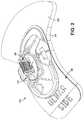
- FIG. 2is a perspective view of one exemplary embodiment of the sensor assembly used with the apparatus of FIG. 1 .
- FIG. 2 ais an illustration of one exemplary embodiment of the fully encapsulated sensor connector assembly.
- FIG. 2 bis an illustration of the sensor connector of the exemplary embodiment of the sensor connector assembly of FIG. 2 a.
- FIG. 2 cis an illustration of the sensor connector of the exemplary embodiment of the sensor connector assembly mounted on a printed circuit board with a pressure sensor and a storage device (e.g., EEPROM).
- FIG. 2 dis an illustration of the sensor connector, pressure sensor and EEPROM of the exemplary embodiment of the sensor connector assembly mounted on a printed circuit board and placed in the connector housing.
- FIG. 2 eis an illustration of the exemplary embodiment of the sensor connector assembly placed in the connector housing and encapsulated by the upper encapsulation.
- FIG. 2 fis an illustration of one exemplary embodiment of the sensor connector assembly mounted in the flexible frame.
- FIG. 2 gis an illustration of one exemplary embodiment of the sensor connector assembly and frame mounted on a foam hacking.
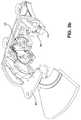
- FIG. 3is a perspective view of the underside of one exemplary embodiment of the actuator element illustrating the connector and sensor attachment plate.
- FIG. 3 ais a cross-sectional view of the mated actuator and sensor assembly of FIG. 3 a.
- FIG. 3 bis a break-away view of the mated actuator and sensor assembly of FIG. 3 a.
- FIG. 3 cis a cut-away view of the exemplary embodiment of the sensor assembly mated with the attachment plate of the actuator.
- FIG. 4is a block diagram of the general method by which the hemodynamic assessment apparatus may be utilized.
- the inventionis described herein primarily in terms of a method and apparatus for assessment of hemodynamic parameters of the circulatory system via the radial artery (i.e., wrist or forearm) of a human subject, the invention may also be readily embodied or adapted to monitor such parameters at other blood vessels and locations on the human body, as well as monitoring these parameters on other warm-blooded species. All such adaptations and alternate embodiments are readily implemented by those of ordinary skill in the relevant arts, and are considered to fall within the scope of the claims appended hereto.
- hemodynamic parameteris meant to include parameters associated with the circulatory system of the subject, including for example pressure (e.g., diastolic, systolic, pulse, or mean), blood flow kinetic energy, velocity, density, time-frequency distribution, the presence of stenoses, SpO 2 , pulse period, as well as any artifacts relating to the pressure waveform of the subject.
- pressuree.g., diastolic, systolic, pulse, or mean
- blood flow kinetic energye.g., velocity, density, time-frequency distribution
- the presence of stenoses, SpO 2e.g., stenoses, SpO 2 , pulse period
- any artifactsrelating to the pressure waveform of the subject.
- tissueometrictonometer
- tonometryas used herein are intended to broadly refer to non-invasive surface measurement of one or more hemodynamic parameters such as pressure, such as by placing a sensor in communication with the surface of the skin, although contact with the skin need not be direct (e.g., such as through a coupling medium or other interface).
- applanateand “applanation” as used herein refer to the compression (relative to a state of non-compression) of tissue, blood vessel(s), and other structures such as tendon or muscle of the subject's physiology.
- an applanation “sweep”refers to one or more periods of time during which the applanation level is varied (either increasingly, decreasingly, or any combination thereof).
- the term “applanation” as used hereinmay conceivably take on any variety of other forms, including without limitation (i) a continuous non-linear (e.g., logarithmic) increasing or decreasing compression over time; (ii) a non-continuous or piece-wise continuous linear or non-linear compression; (iii) alternating compression and relaxation; (iv) sinusoidal or triangular waves functions; (v) random motion (such as a “random walk”; or (vi) a deterministic profile. All such forms are considered to be encompassed by the term.
- integrated circuitrefers to any type of device having any level of integration (including without limitation ULSI, VLSI, and LSI) and irrespective of process or base materials (including, without limitation Si, SiGe, CMOS and GaAs).
- ICsmay include, for example, memory devices (e.g., DRAM, SRAM, DDRAM, EEPROM/Flash, ROM), digital processors, SoC devices, FPGAs, ASICs, ADCs, DACs, transceivers, memory controllers, and other devices, as well as any combinations thereof.
- memoryincludes any type of integrated circuit or other storage device adapted for storing digital data including, without limitation, ROM, PROM, EEPROM, DRAM, SDRAM, DDR/2 SDRAM, EDO/FPMS, RLDRAM, SRAM, “flash” memory (e.g., NAND/NOR), and PSRAM.
- the present inventioncomprises apparatus and associated methods for accurately and repeatably (if desired) disposing one or more sensors with respect to the anatomy of a subject to facilitate subsequent hemodynamic parameter measurements using the sensor(s).
- the present inventionis useful for accurately placing a pressure sensor assembly for continuously and non-invasively measuring the blood pressure from the radial artery of a human being.
- any kind of sensorcan be used alone or in combination consistent with the invention, including for example the devices and associated techniques described in co-pending U.S. patent application Ser. No. 10/961,460 filed Oct.
- the aforementioned pressure sensoris coupled to an actuator mechanism carried by a brace or “bracelet” assembly worn by the subject in the area of the radial artery.
- the actuator mechanismwhen coupled to the sensor, controls the sensor lateral (and proximal, if desired) position as well as the level of applanation of the underlying tissue according to any number of control schemes, including for example that set forth in Assignee's co-pending U.S. patent application Ser. No. 10/211,115 filed Aug. 1, 2002, entitled “Method and Apparatus for Control of Non-Invasive Parameter Measurements”, now U.S. Pat. No. 6,974,419, and in co-pending application Ser. No. 10/072,508 filed Feb.
- the present inventionis also compatible with systems having separate sensor(s) and applanation mechanisms, as well as combinations of the foregoing features and sensors.
- the actuatoris advantageously “displacement” driven, and accordingly does not rely on measurements of applied force, but rather merely displacement. This approach greatly simplifies the construction and operation of the actuator (and parent control system) by obviating force sensors and signal processing relating thereto, and further makes the actuator and system more robust.
- the apparatus of the present inventionalso advantageously maintains a highly rigid coupling between the sensor assembly and the bracelet element (actuator) used to receive the subject's anatomy, thereby further enhancing the accuracy of the system through elimination of nearly all compliance within the apparatus.
- the present inventionis superior to the prior art in that it incorporates automatic zeroing of the sensor.
- the automatic zeroing capabilitypermits the sensor connector assembly to be positioned without the use of additional elements thereby supporting efficient placement of the sensor.
- Another significant feature of the present inventionis that it incorporates electrical circuitry directly on the sensor so as to facilitate simplified assembly, operation and calibration of the assembly.
- the present inventionovercomes the disabilities associated with the prior art by providing a sensor assembly which is detachable from the parent apparatus and remains positioned on the subject during transport, thereby facilitating highly repeatable measurements using the same sensor at different physical locations within the care facility (e.g., hospital), as described in Assignee's co-pending U.S. patent application Ser. No. 11/336,222 filed Jan. 20, 2006 entitled “Apparatus and methods for non-invasively measuring hemodynamic parameters” which Assignee hereby incorporates by reference in its entirety.
- the abovementioned features and other featuresare now described in detail.
- This embodimentgenerally comprises an actuator assembly 300 mated with a sensor assembly 200 .
- the actuator 300is optionally in the form of a wrist bracelet as shown, and controls the movement of the sensor/applanation element 210 of the sensor assembly 200 .
- the sensor assembly 200comprises a flexible frame 204 with a foam backing 206 .
- the sensor assembly 200is further described in detail with regard to FIGS. 2-2 g below.
- this structureis preferably made disposable through use of inexpensive materials (e.g., low-cost plastic moldings) and design features facilitating such disposability; however in certain applications (such as where the apparatus is intended for reuse), more durable materials may be chosen.
- inexpensive materialse.g., low-cost plastic moldings
- design featuresfacilitating such disposability; however in certain applications (such as where the apparatus is intended for reuse), more durable materials may be chosen.
- the aforementioned embodiment of the hemodynamic assessment apparatusdoes not comprise an alignment apparatus (e.g., paddle) as in prior embodiments.
- the exemplary embodiment of the present inventionis adapted to utilize automatic zeroing, a technique by which the sensor element is aligned without the use of extraneous apparatus.
- the sensor elementwill be automatically positioned in the most appropriate location relative to the subject's anatomy.
- the frame 204incorporates arrows that are used to align with a line drawn on the patient's arm (e.g., by the caregiver after manually locating the optimal location on the subject's anatomy which represents the artery location).
- the clinicianpalpates and marks the artery with a pen on the skin, drawing a line where the artery lies. Then he/she lines the two arrows on the top of the frame with the line drawn on the skin.
- FIG. 2depicts an exemplary embodiment of a sensor assembly 200 .
- the sensor assembly 200generally comprises a sensor connector assembly 202 (described in more detail in FIG. 2 a -2 e below) mounted on a sensor element 210 , the element 210 being movably coupled to a flexible frame element 204 (described in further detail in FIG. 2 f below), the latter which comprises a foam backing 206 (described in detail in FIG. 2 g below).
- the sensor assembly 200further comprises a label or other covering 208 which (i) covers the end of the foam which would otherwise be bare adhesive, and (ii) shows inter alia a user the correct placement of the device on the arm. Since the frame ends at the edge of the label, the foam is much more flexible, which allows it to conform better to the wrist.
- the label of the illustratedallows us to use one piece of foam that has adhesive on the top surface, to attach it to the frame, although it will be appreciated that other approaches may be used with equal success.
- FIG. 2 aillustrates the sensor connector assembly 202 which is comprised of a sensor connector 218 disposed on the sensor/applanation element 210 .
- the sensor connector assembly 202is further comprised of an electrically erasable programmable read-only memory (EEPROM) IC (element 248 on FIG. 2 c ), one or more pressure sensor elements (e.g., a transducer, strain beam device, piezoelectric or piezoresistive device, etc.), and a multi-layered housing element 214 .
- EEPROMelectrically erasable programmable read-only memory
- the sensor/applanation element 210is used to compress the tissue surrounding the blood vessel of interest under the force of the actuator 300 , and to thereby apply force to the blood vessel wall so as to overcome the wall or hoop stress thereof.
- the applanation element 210has a specially designed configuration adapted to mitigate the effects of transfer loss in a simple, repeatable, and reliable way such that it can be either (i) ignored or (ii) compensated for as part of the tonometric measurement.
- the sensor connector assembly 202further comprises a sensor connector 218 , which may be viewed in more detail in FIG. 2 b.
- FIG. 2 bdepicts the sensor connector 218 .
- the sensor connectoris comprised of a plurality of conductors (e.g. wires 220 or alternatively flat strips, conductive traces, etc.).
- the wiresfollow along the periphery of one side of a generally pyramidal or tapered spool or block 224 , although other profiles and shapes (e.g., conic, trapezoidal, hemispherical, hexagonal, etc.) are contemplated.
- the use of a shapehelps to guide the connector into the receptacle without getting stuck or misaligned.
- the wires 220are maintained electrically separate from each other by a series of ridges 222 along the inner portion of the pyramidal spool 224 .
- the wires 220are adapted such that when the sensor connector assembly 202 is mated with the connector recess 308 the actuator 300 , the wires 220 are positioned to electrically communicate with the electrical contacts 312 of the recess 308 .
- the exemplary embodiment of the sensor connector 218 as illustrated in FIG. 2 bfurther depicts a plurality of wire terminals 226 . It is appreciated that although eight wire terminals 226 are illustrated in the exemplary embodiment, any number of such terminals may be utilized consistent with the present invention.
- the plurality of exposed wires 220is made large so as to provide maximum opportunity for making a good connection with the corresponding electrical connector in the actuator, described below. In the illustrated embodiment, two of the eight wires egress from one side of the assembly, and six from the others, so as to provide mechanical stability during assembly.
- the overall tapered 230 pyramidal shape of the top portion of the sensor connector 218is merely exemplary in that it promotes a frictional coupling between the sensor assembly 200 and the associated actuator receptacle 304 .
- the associated actuator receptacle 304(see FIG. 3 and associated discussion below) is effectively the inverse of the top portion of the sensor connector 218 ; i.e., it is adapted to generally match at least most of the contours of the sensor connector 218 and the frame lip 282 (discussed below).
- Indentions 212are provided in the top surface of the bottom portion of the sensor element to allow mating to the top portion thereof.
- the top portion of the sensor connector 218can be considered the “male” element, and the associated actuator receptacle 304 the “female” element.
- the substantially square shape of the base of the sensor connector 218advantageously controls rotation of the sensor connector 218 with respect to the actuator receptacle 304 under torsional loads.
- This coupling of the two elements 218 , 304allows for a highly rigid and non-compliant joint between the actuator 300 and sensor assembly 200 in the applanation (normal) dimension, thereby effectively eliminating errors in resulting hemodynamic measurements which could arise from such compliance.
- a discussion of the contribution of the frame lip 282 to this couplingis discussed below.
- the sensor connector assembly 202further comprises a printed circuit board 240 on which the connector 218 is disposed.
- the tabs 228 of the sensor connector 218facilitate mounting the sensor connector 218 on the printed circuit board 240 as they are received in tab recesses (not shown) on the circuit board 240 .
- the sensor connector wire terminals 226are situated such that when the sensor connector 218 is mounted on the printed circuit board 240 , the wire terminals 226 align with the sensor connector terminal electrical contacts 244 on the printed circuit board 240 . It is through this contact that information from the sensor (not shown) is transmitted, although other approaches may be used.
- the sensor connector assembly 202comprises the sensing elements (not shown) accommodated within a lower sensor housing 246 below the sensor connector 218 .
- a retention featuresuch as, for example, cantilever snap, is used to secure the lower housing element 246 to the other layers of the sensor connector assembly 202 .
- the sensorhas four leads that protrude, and are formed into “legs” that are soldered to the other side of the board. The part is also adhered to the board to ensure it is rigidly held.
- vent portprotruding from the pressure sensor ( 246 ).
- This ventis a cylinder that sticks through the board and thereby allows for the pressure die in the sensor to be a gage device. It has effectively a vent on each side of the pressure diaphragm, with one side communicating with the silicone rubber gel which touches the skin and the other side of the diaphragm communicating with the air in the environment in which it is being us
- the sensor elementsare situated within the lower sensor housing 246 such that the sensor is positioned to contact the skin of a subject.
- the bias element 216then forms a substantially elliptical profile “pocket” adapted to house the sensor elements.
- an electrically erasable programmable read-only memory (EEPROM) IC 248 or other memory deviceis disposed on the printed circuit board 240 .
- the EEPROM chip terminals 250are situated such that when the EEPROM chip 248 is disposed on the printed circuit board 240 , the terminals 250 are placed in contact with EEPROM terminal electrical contacts 252 on the circuit board 240 .
- the circular feature 242 shownis a vent port protruding from the pressure sensor 246 .
- This ventis a cylinder that protrudes through the board and thereby allows for the pressure die in the sensor to be a gauge device. It comprises a vent on each side of the pressure diaphragm, with one side communicating with the silicone rubber gel which touches the skin of the subject, and the other side of the diaphragm communicating with the air in the environment in which it is being used. This allows for the device to not read the atmospheric pressure differences at different altitudes.
- the sensor connector assembly 202 in tins embodimentis adapted to contain the necessary circuitry and sensor electronics such that the assembly 202 , when mated with the actuator 300 will be able to transmit electrical signals from the sensor element(s) (e.g., pressure transducer, not shown) to the actuator 300 without the use of other apparatus.
- the assemblycan detect and monitor pressure immediately upon electrical connection of the sensor assembly 200 to the actuator 300 , and the need to form any other electrical or mechanical connections is obviated. Therefore, the above-described embodiment determines and constantly monitors hemodynamic pressure efficiently and with increased ease of operation.
- FIG. 2 dillustrates the disposition of the exemplary multi-layered housing element 214 around the printed circuit board 240 containing the EEPROM chip 248 and sensor connector 218 .
- the multi-layered housing element 214helps maintain and encase the printed circuit board 240 and its components. Therefore, the face of the housing element 214 contains an indentation that is substantially formed to suit the printed circuit board 240 . Further, the face of the housing element 214 contains a protrusion 260 which aligns with the printed circuit board indention 254 ( FIG. 2 c ).
- each layer of the multi-layered housing element 214includes various protrusions and complimentary indentions so that the layers may fit together in a unique manner, and may be held together without adhesives or other such mechanisms if desired.
- the various featurescan be obviated in favor of such an adhesive or other mechanism.
- other mechanisms for hold the housing elements togethermay be utilized consistent with the present invention.
- a single layered housing elementmay also be substituted in place of the multi-layered configuration described herein.
- the assemblyis made as a “pallet” of boards that are snapped apart. The connectors and EEPROMs are soldered to one side of this array or matrix of boards, then the sensor is glued and then soldered to the other side of each board.
- the housingscomprise a housing and a cap to hold the board in the housing.
- the exemplary capis made out of ABS plastic and is placed over the connector and then solvent-bonded to the housing, effectively trapping the connector, the board and the sensor in place.
- FIG. 2 edemonstrates the placement of the final layer of the example multi-layer housing element 214 .
- This layer of the housing element 214further includes a plurality of coupling indentions 212 a , 212 b , 212 c which are adapted to cooperate in coupling the sensor connector assembly 202 to its parent actuator 300 (described in greater detail with respect to FIGS. 3-3 d herein). It is appreciated that different configurations and number of coupling mechanisms may be utilized to facilitate mating of the sensor connector assembly 202 with the actuator 300 .
- the biasing element 216 of the sensor connector assembly 202surrounds the outer/bottom edge portions of the multi-layered housing element 214 as well as the portion of the pressure sensor element (not shown) which will come into contact with the subject's skin.
- the biasing element 216is, in one embodiment, made wholly from a silicone-based encapsulation material.
- encapsulation materialeases fabrication, as smaller size foam is more difficult to handle in production environments.
- the bottom edge of the biasing element 216can now have a radius or other transitional shape molded into the profile, reducing the size of the shearing effect on the skin as the sensor connector assembly 202 is pressed into the skin during lateral and proximal movements.
- the otherwise “unitary” encapsulation material shownmay also be comprised of two or more independent or coupled component moldings if desired.
- biasing element 216 in the present embodimentcomprises a silicone rubber based compound that is applied over the active face of the pressure transducer (and selective portions of the housing element 214 ) to provide coupling between the active face and the subject's skin
- other materials which provide sufficient pressure couplingwhether alone or in conjunction with an external coupling medium (such as a gel or liquid of the type well known in the art) may be used as well.
- an external coupling mediumsuch as a gel or liquid of the type well known in the art
- bias elementneed not necessarily be uniform in material construction, but rather could be constructed using hybrid materials integrated to perform the desirable functions of the bias element when used in combination. This may include mixing materials, doping the silicone material to provide other desirable properties, coating the material (as previously described), and so forth. Myriad other design choices would be readily apparent to those of ordinary skill given the present disclosure.
- the bias element 216is formed by molding the encapsulant (e.g., silicone compound) around the sensor element (not shown) and housing element 214 after the sensor (not shown) has been placed in the housing 214 . This ensures that the encapsulant completely covers the sensor, and fills all voids. In effect the bias element 216 is molded around the sensor (not shown), thereby ensuring a conformal fit and direct coupling between the encapsulant material and the sensor's active face. It will also be recognized that the sensor and applanation element configuration of FIG.
- the encapsulante.g., silicone compound
- sensor configurationse.g., single or multiple transducer, homogeneous or heterogeneous sensors (i.e., combined with the same or other types of sensors), and/or using different bias element geometry) may be used consistent with the present invention.
- FIG. 2 fdepicts the sensor/applanation element 210 and its connector assembly 202 mounted movably within the flexible frame element 204 .
- This exemplary embodimentgenerally comprises a single frame element 204 , which is distinguished over prior art implementations having two frame elements. This approach advantageously simplifies the construction of the apparatus, and also provides opportunities for reducing manufacturing cost while also increasing ease of use by the caregiver or subject being monitored.
- the single frame element 204comprises a generally planar (yet curved), thin profile. This approach (i.e., flatter and thinner material) has significant advantages over the prior art including allowing for increased conformity and adaptation to the anatomy of the subject being monitored.
- the single frame element 204is advantageously shaped from a polymer molding formed from polypropylene or polyethylene, although other materials and degrees of flexibility may be used consistent with the principles of the present invention.
- fine frame 204 of the apparatusis notably smaller in surface area with respect to the portion of the frame 204 that extends on the radial side of the apparatus when it is disposed on a human subject. Utilizing a shape with a minimized frame in this area permits the apparatus to be placed at a more distal location while avoiding the thenar eminence (the body of muscle on the palm of the human hand just beneath the thumb).
- the aforementioned level of flexibility of the frame 204is further selected to permit some deformation and accommodation by the frame to the shape and radius of the wrist of the subject as well. Accordingly, the foregoing optional features coordinate to provide a more comfortable and well-fitted frame and sensing apparatus, thereby also increasing accuracy of the measurements obtained thereby.
- the exemplary embodiment of the frame 204presents the user with a miniature placement “map” by way of the graphic illustration of the location of local physiology through labeling and the like.
- the lettering “ulnar side” 270is produced by way of cutout on the frame element 204 , although other approaches such as labels, painting/marking, etc. may be used to accomplish this function.
- This phraserefers the user to the fact that this ulnar side of the frame element should be positioned on the ulnar side of the patient's forearm.
- the cut-through design of the illustrated embodimentis advantageous in that the lettering can be more legible to a user of a device than other approaches, and cannot be removed or fall off.
- the userthen deforms the frame 204 around the subject's wrist, thereby adhering the frame 204 in place on the patient's forearm using an adhesive placed on the contact (skin) side of the frame and exposed after its protective sheet is removed.
- a set of ribs or risers 272are provided; these ribs 272 are notable as they are received within corresponding features (e.g., cavities) present on the actuator 300 .
- the embodiment of FIG. 2 fadvantageously simplifies the design and molding of the alignment apparatus frame 204 , as compared to prior art embodiments which utilize complex structures that fit both within and outside of actuator cavities.
- the ribs 272are further adapted to comprise an intrusion or aperture 274 on the outer surface of each with respect to the sensor connector assembly 202 .
- the intrusions 274are adapted to receive complementary tabs 322 associated with the actuator 300 thereby allowing the actuator 300 to be set in place (i.e.
- This featureensures an easily formed, robust, and uninterrupted connection of the actuator 300 to the sensor assembly 200 .
- coupling of the sensor connector assembly 202 to the frame element 204 in the exemplary embodimentis accomplished using a flexible and resilient serpentine-like suspension loop 276 and associated suspending arms 278 .
- the suspension loop 276is attached to the circumference of the multi-layered housing element 214 ; the loop substantially encircles the sensor connector assembly 202 and fits within a groove formed in the outer edge of the sensor element 210 , although other arrangements may be used. As illustrated in the figure, sections of the suspension loop 276 are formed so as not to be in contact with the housing element 214 as previously described. These sections form arches 280 which receive the pins 314 located within the actuator receptacle 304 when the actuator 300 is mated with the sensor assembly 200 . However, other methods for assisting and maintaining the sensor connector assembly 202 within the actuator receptacle 304 may be used with equal success.
- the end loopsalso facilitate putting the elliptical ring feature of the suspension loop around the groove of the sensor multi-layer assembly. They allow the ring to “stretch” for assembly.
- the suspending arms 278are coupled rigidly to the frame element 204 via integral injection molding, adhesive or other means and attached flexibly to the suspension loop 276 .
- the suspending arms 278 in the present embodimentprovide sufficient “slack” such that the frame element 204 and the sensor element 210 can move to an appreciable degree laterally (and in other degrees of freedom) within the frame 204 , thereby allowing the actuator 300 to move the sensor element 210 relative to the radial artery during execution of its positioning algorithm and automatic zeroing of the sensor.
- the present inventionalso allows for such freedom of movement in the proximal direction as well as in the direction of applanation or blood vessel compression.
- sufficient slackmay be provided in the suspending anus 278 to allow a desired degree of proximal movement of the sensor element 210 by the actuator 300 , as well as rotation of the sensor element in the X-Y plane (i.e., “yaw” of the sensor assembly about its vertical axis).
- Other arrangementsmay also be used, such alternatives being readily implemented by those of ordinary skill in the mechanical arts.
- suspension loop 276 and associated suspending arms 278maintain the sensor element 210 (including most notably the active surface of the assembly) in a raised position completely disengaged or elevated above the surface of the skin. This advantageously allows the operator and the system to verify no bias of the sensor and pressure transducer during periods when bias is undesirable, such as during calibration of the sensor.
- the exemplary zeroing algorithmincludes various features, including (i) checking for a quiescent state wherein the output from the sensor is steady (e.g., monotonic, although not necessarily constant, due to e.g., sensor warmup or other temperature effects), which does not happen when the sensor is touching skin, and/or (ii) retracting the sensor up into the actuator and “dithering” the applanation position in order to ensure that if the pressure does not change the sensor is truly off the skin. Either or both of these approaches may be used.
- FIG. 2 falso depicts an exemplary frame lip 282 which is formed along the circumference of the central aperture of the frame element 204 .
- the frame lip 282is designed to fit snugly within the actuator receptacle 304 thereby holding the sensor assembly 200 in contact with the actuator 300 .
- the lipalso adds rigidity to the frame in the direction in which the snap fits act for the attachment of the frame to the actuator. It also prohibits the actuator from being placed on backwards by interfering with features on the opposite side of the actuator.
- the actuator receptacle 304is comprised of a “moat” to accept the protruding frame lip 282 .
- the frame lip 282 configuration of the exemplary embodimentis preferable to other prior art configurations because, inter alia, this configuration permits a single-step, unobstructed connection of the sensor assembly 200 to the actuator 300 . There is also better automatic guidance, thereby minimizing the chance of a mismatch.
- the foam backing 206 onto which the frame element 204 is disposalis described in detail.
- the foam backing 206is comprised of compliant foam with adhesive surfaces that is mounted to the contact-side of the element 204 .
- the foam backingcan advantageously be conformed to the unique profiles and shapes associated with living subjects of varying shapes and sizes.
- the frame element 204is substantially minimized with respect to the radial portion in this embodiment as compared to prior art embodiments.
- the foam backing 206may be adapted to extend the radial portion of the sensor assembly 200 in order to permit increased surface area for attachment to a subject.
- the shape of the foam backing 206will be such that the thenar eminence (“thumb muscle”) of a human subject continues to be accommodated.
- the attachment of the sensor assembly 200is not obstructed, but rather conforms to the natural raises and indentations in a subject's anatomy.
- the adhesive on the underside of the compliant foam backing 206is adapted such that when the frame element 204 is disposed atop the subject's skin, it bonds to the skin, the frame element 204 deforming somewhat to match the surface contour of the skin.
- the adhesiveis selected so as to provide a firm and long-lasting bond (especially under potentially moist conditions resulting from patient perspiration, etc.), yet be readily removed when disposal is desired without significant discomfort to the subject.
- other means for maintaining the frame element 204 in a constant position with respect to the subject's anatomymay be used, including for example Velcro straps, tape, application of an adhesive directly to the underside of the frame element 204 itself, etc.
- a thermally- or light-sensitive frame materialis used that allows the initially deformable and pliable frame element to become substantially more rigid upon exposure to heat, light, or other such “curing” process.
- a low-cost removable backing sheete.g., waxed or coated on one side
- a low-cost removable backing sheete.g., waxed or coated on one side
- the usersimply peels off the backing sheet, places the frame element 204 on the desired anatomy location, and gently compresses it against the subject's skin to form the aforementioned bond, deforming the frame element 204 as needed to the contour of the subject's anatomy.
- the adhesive bondis strong enough, and the frame element pliable enough, such that any deformation of the frame element is substantially preserved by the bond as discussed above.
- the paddle elementis used in the prior art to place the sensor assembly in a desired location relative to the subject's anatomy.
- the necessity for the user to place the sensor assembly manuallyis obviated in favor of an automatic zeroing process.
- the automatic zeroingadvantageously simplifies the operation of the apparatus, and also provides opportunities for reducing manufacturing cost, because there is no need to manufacture a paddle, assemble it, and so forth.
- the present inventionpermits a user to merely place the apparatus on the subjects anatomy, and line up the arrow marks on the sides of the frame with the line of the artery. Further, the straight edges of the frame are supposed to line up with the “wrist break” where the wrist ends and the hand starts.
- the shape of the foamis also supposed to seat the frame in close proximity to where it is needed due to the flare shape which simulates the thump flaring to one side.
- the present inventiongreatly increases the ease of use by the caregiver or subject being monitored.
- the substantially elliptical sensor shapealso accommodates moving the edge of the frame 204 closer to the centerline of the apparatus, so that the frame 204 can accommodate the thenar eminence.
- the reduced sensor size and profile in the lateral/medial directionalso allows the frame to be smaller than it otherwise would, and the sides of the sensor impinge less on tendons that run in the proximal/distal direction.
- the surface area being pressed into the skinis reduced, which reduces the power needed to drive the sensor into the skin.
- the applanation/positioning mechanismscan be made smaller, and less electrical power is required (important for “stand-alone” or battery powered variants).
- Another advantage of the smaller elliptically-shaped sensor element 210is that because of the reduced lateral/medial length, the sensor impinges less on tendons during sensor travel (e.g., in the lateral/medial direction) as previously noted, thereby allowing the sensor to slide across the surface of the skin in a more uniform and smooth manner.
- the elliptical shape of the sensor 210 of FIGS. 2-2 gprovides a continuously curved surface on the outer periphery of die sensor connector assembly 202 , facilitating movements in both the lateral and proximal axes by reducing shear effects.
- the elimination of “corners” on the elliptical variantmakes changes in direction and movement smoother in all directions, and when coupled with the curved sidewall or cross-sectional profile of the assembly, allows for some degree of roll, pitch, and/or yaw of the sensor relative to the tissue surface (or conversely, greater irregularities within the tissue shape or surface) without adversely impacting movement of the sensor assembly across the tissue.
- the actuator 300 described hereinis designed to provide adjustment or movement of the position of the sensor element 210 in both sagittal and lateral (transverse) directions; however, it will be appreciated that it may be modified to provide more or less degrees of freedom (including, for example, proximal adjustment).
- the following embodimentsare merely exemplary in nature.
- FIG. 3illustrates the underside of one embodiment of the actuator assembly 300 .
- the underside of the actuator in this embodimentis generally comprised of an attachment plate 302 onto which various coupling mechanisms and receiving apparatus are disposed.
- the receiving apparatuse.g. the actuator receptacle 304 , the connector disk 310 and connector recess 308
- the coupling mechanismse.g. the frame lip receiving walls 320 and complementary tabs 322 , and the actuator receptacle rings provide a secure connection between the actuator 300 and the sensor connector assembly 202 .
- a rubber bellows 318is also provided that allows the receptacle to move with respect to the rest of the actuator and seals the opening around the receptacle from fluid or dirt ingress.
- the exemplary attachment plate 302further comprises a plurality of plate attachment features by which the attachment plate is fastened to the underside of the actuator 300 .
- the plate attachment featuresconsist of threaded cavities which are designed permit assembly via screwing the attachment plate into the actuator 300 body. It is appreciated that other methods and techniques may be utilized to secure the attachment plate 302 to the actuator 300 body, such as, for example, via a glue, latch, or similar technique.
- the underside of the actuator 300features an actuator receptacle 304 .
- the actuator receptacle 304is a recess in the actuator plate 302 which is adapted to receive the sensor assembly 200 .
- the actuator receptacle 304is comprised of a plurality of inner rings, a connector disk 310 and frame lip receiving walls 320 .
- the connector disk 310is adapted to accept portions of the sensor connector assembly 202 and promote secure mating therewith. Accordingly, the connector disk 310 comprises a partial bearing ring 316 which conforms substantially to the corresponding features of the sensor connector assembly 202 and helps secure the actuator 300 in place, especially under conditions of transverse loading or rotation of the actuator 300 around the lateral or proximal axis.
- the connector disk 310also comprises a plurality of pins 314 which fit into the arches 280 of the suspension loop 276 . As described previously, when the actuator 300 is mated with the sensor assembly 200 , the pins 314 will be received snugly within the aperture created by the suspension loop arches 280 .
- the connector recess 307is disposed on the connector disk 310 of the actuator receptacle 304 .
- the connector recess 307is specifically adapted to accept the pyramidal sensor connector 218 .
- itconsists of an inverted pyramidal shaped recess.
- the inverted pyramidal shaped recess of the connector recess 307is further adapted to maintain electrical contact with the plurality of wires 220 on the sensor connector 218 when the two 307 , 218 are mated. This electrical communication occurs via placement of electrical contacts 308 on the connector recess 307 by which electrical signals are transmitted.
- the receptaclealso has a “U” shape that precludes the connector from being put in backwards.
- FIG. 3further illustrates the frame lip receiving walls 320 , which are disposed on the actuator receptacle 304 .
- the frame lip receiving walls 320conform substantially to the corresponding features of the frame element 204 and help secure the actuator 300 in place.
- the frame lip receiving walls 320create a moat wherein the ribs or risers 272 of the frame element 204 are fitted when the actuator 300 and sensor assembly 200 are mated.
- the frame lip receiving walls 320are further adapted to include complementary tabs 322 which are designed to snap into the matching intrusions 274 on the ribs 272 , thereby allowing the actuator 300 to be set in place (i.e. mated with the sensor assembly 200 ) and unable to rotate.
- the receiving wallsWhen viewed from the side the receiving walls also have a shape that precludes the actuator from being put on backwards.
- FIGS. 1 and 3 a - 3 cillustrate the exemplary coupling between the actuator 300 and sensor assembly 200 .
- the various coupling mechanisms(described above) are configured so as to mate the actuator 300 and sensor assembly 200 together in a unitary (but readily separable) assembly.
- the top of the sensor connector assembly 202is substantially elongated pyramidal in shape due to the pyramidal shaped sensor connector 218 .
- the connecter recess 308 attached to the actuator 300is effectively the inverse of the sensor connector assembly 202 in shape; i.e. it is adapted to generally match the contours of the sensor connector assembly 202 and the alignment and retention features almost exactly.
- portions of the sensor connector assembly 202 which are received into the actuator 300can be considered the “male” elements while the connector recess 308 is considered the “female” element.
- the substantially square shape of the base of the sensor connector 218aids in controlling rotation of the connector recess 308 with respect to the sensor assembly 200 under torsional load.
- This coupling of the two elements 218 , 308allows for a highly rigid and non-compliant joint between the actuator and sensor assembly in the applanation (normal dimension), thereby effectively eliminating errors in resulting hemodynamic measurements which would arise from such compliance.
- This designalso includes enough tolerance between the coupling components to facilitate easy decoupling of the sensor assembly 200 from the actuator 30 .
- the serpentine like suspending arms 278provide more than sufficient strength to prevent separation of the sensor connector assembly 202 from its parent sensor assembly 200 while still permitting movement therein; the sensor assembly 200 is specifically configured such that, under all attitudes, the sensor connector assembly 202 will separate from its coupling to the actuator 300 well before the serpentine arms 278 yield significantly.
- the elongated pyramid shape of the coupling elementsfurther allows for coupling of the two devices under conditions of substantial misalignment; i.e., where the apex of the sensor connector assembly 202 is displaced somewhat in the lateral (i.e., X-Y) plane from the corresponding connector recess 308 of the actuator 300 , and/or the sensor assembly 200 is rotated or cocked with respect to the actuator 300 prior to coupling.
- This featureaids in ease of clinical operation, in that the instrument can tolerate some misalignment of the sensor and actuator (the latter due to, e.g., the actuator arm of the actuator 300 (not shown) not being in perfect alignment over the sensor assembly 200 and sensor element 210 ).
- the illustrated embodimentcomprises elongated substantially pyramid-shaped elements
- the apparatusmay comprise complementary conic or frustoconical sections.
- a substantially spherical shapecould be utilized.
- Other alternativesinclude use of multiple “domes” and/or alignment features, inversion of the first and second elements (i.e., the first element being substantially female and the second element being male), or even devices utilizing electronic sensors to aid in alignment of the two elements.
- the apparatusis adapted to notify the user/operator of the presence of the sensor assembly (as well as the status of its coupling to the actuator 300 and the sufficiency of electrical tests of the sensor assembly) through an integrated indication.
- Any type of indication scheme well known to those of ordinary skill in the electronic artsmay be used, including for example one or more single color LED which blinks at varying periods (including no blinking) to indicate the presence or status of the components, such as by using varying blink patters, sequences, and periods as error codes which the operator can use to diagnose problems, multiple LEDs, light pipes.
- the devicefurther comprises a circuit which evaluates parameters in the pressure transducer and thereby can determine if the connection has been made to the transducer and EEPROM.
- the devicemay also be configured to look for the information in the EEPROM to know if it is connected if desired.
- FIG. 3 ais a cross sectional view of the actuator 300 coupled to the sensor assembly 200 . Specifically, the illustration demonstrates the electrical and mechanical connector of the sensor connector assembly 202 within the connector recess 308 .
- FIG. 3 bThe break-away view depicted in FIG. 3 b further demonstrates the precise cooperation between the sensor connector assembly 202 and the attachment plate 302 .
- FIG. 3 cis an illustration of the latching mechanism of the frame lip 282 and receiving walls 320 .
- the underside of the actuator 300is also configured to include two ridges or walls 320 with complementary tabs 322 .
- the sensor assembly 200is configured to include risers or ribs 272 with corresponding intrusions 274 .
- the tabs 322 of the actuator 300fit within the intrusions 274 of the sensor assembly 200 as shown.
- the snaps on fee attachment platedo indeed snap into the recesses in the sides of the frame ribs (element 322 fits into element 274 ), As shown best in FIG.
- the underside of the actuator 300is configured to include two ridges or walls 320 .
- the sensor assembly 200is configured to include a frame lip 282 .
- the frame lipdoes not interlock with anything in the actuator; rather it sits below the actuator.
- the frame lipalso make the frame stiffer in that area which improves the snap of the latching tabs on the underside of the actuator to the frame.
- the interior components (not shown) of the actuator 300will be of the type described in Assignee's co-pending U.S. patent application Ser. No. 10/961,460 entitled “Compact Apparatus and Methods For Non-Invasively Measuring Hemodynamic Parameters” filed Oct. 7, 2004, which Assignee hereby incorporates by reference in its entirety.
- Thesegenerally comprise, inter alia, a motor chassis assembly with associated sensor drive coupling, and substrate (e.g., PCB) assembly.
- an exemplary embodiment of the actuator mechanismwould allow for fee separation of the movement of the sensor connector assembly in the various directions; i.e., applanation, lateral, and proximal. Specifically, the actuator mechanism would permit concurrent yet independent movement in the various directions, as well as allow for a highly compact and space/weight efficient actuator. An exemplary actuator mechanism would further be adapted so as to minimize the number of components within the actuator (including the motors), thereby reducing electrical power consumption as well as any effect on pressure measurements resulting from the translation of a mass within the actuator during such measurements.
- FIG. 4the general and improved method 400 of positioning a sensor with respect to the anatomy of the subject and recurrently measuring the blood pressure of the subject is now described.
- a tonometric pressure sensore.g., silicon strain beam device
- the methodologyis equally applicable to both other types of sensors and other parts of the subject's anatomy, human or otherwise.
- the illustrated embodiment of the method 400generally comprises first determining the location of the anatomy on which the apparatus is to be placed (step 402 ).
- the senoris disposed relative to the marker (step 404 ). Specifically, in this step of the method, the user or clinician removes the backing sheet to expose the adhesive on the foam backing 206 , and then bonds the frame element 204 to the subject's skin, such that the sensor connector assembly 202 is aligned generally over the pulse point of interest.
- the sensoris automatically zeroed (e.g., by the zeroing algorithm previously described) once placed on the subject's anatomy, and may also be adjusted laterally and or proximally according to a placement or locating algorithm of the type referenced elsewhere herein, thereby obviating a need for manual precise placement.
- the frame element 204 and sensor connector assembly 202come “assembled” and pre-packaged, such that the user merely opens the package, removes the sensor assembly 200 (including installed sensor connector assembly 202 ), and removes the backing sheet from the adhesive and places the frame element 204 as previously described.
- the actuator 300is securely mated with the sensor assembly.
- an optional wrist braceis first attached to the subject so as to provide stability to the subject's anatomy. The actuator 300 is then attached to the sensor assembly 200 and wrist brace. As described above, in one embodiment, an indicator will signify when the actuator 300 is properly mated with the sensor assembly 200 .
- step 408the device is “zeroed” and calibrated if required.
- step 410the blood pressure or other parameter(s) of the subject are measured using the sensor(s) subsequent to the calibration (step 408 ).
- the sensor positionis maintained with respect to the anatomy between measurements using the frame element 204 and adhesive on foam backing 206 as well as the optional wrist brace. These cooperate to maintain the sensor element 210 generally atop the desired pulse point of the subject even after the actuator 300 is decoupled from the sensor.
- the actuator 300(and even the remainder of the hemodynamic monitoring apparatus 100 , including brace) can be removed from the subject, leaving the sensor assembly 200 and hence sensor element 210 in place. It may be desirable to remove actuator 300 for example where transport of the subject is desired and the present location has dedicated equipment which must remain, or the monitored subject must have the apparatus 100 removed to permit another procedure (such as postsurgical cleaning, rotation of the subject's body, etc.).
- the sensor element 210is maintained effectively constant with respect to the subject pulse point because it is securely attached to the frame element 204 via the suspension loop 276 .
- the bracelet with actuator 300(or another similar device at the destination), if used, is fitted to the subject.
- the user/caregiverthen merely places the bracelet and presses to attach the actuator 300 to the sensor element 210 (and sensor assembly 200 ) since the sensor assembly is still disposed in the same location with the frame element 204 as when the first actuator was decoupled.
- the sensoris automatically zeroed, as described above, accordingly, no use of any alignment apparatus or other techniques for positioning the sensor “from scratch” is needed, thereby saving time and cost.
- This featurefurther allows for more clinically significant or comparable results since the same sensor is used with effectively identical placement on the same subject; hence, and differences noted between the first and second measurements discussed above are likely not an artifact of the measurement apparatus 100 .
- the sensor assembly 200 and methodology of the inventionallow for multiple such sequential decoupling-movement-recoupling events without having any significant effect on the accuracy of any measurements.
- a “marker”may be used in conjunction with the frame.
- the markermay comprise a tangible marker or sight (e.g., plastic reticle), light source (such as an LED, incandescent bulb, or even low-energy laser light) which is projected onto the desired pulse point of the subject.
- a tangible marker or sighte.g., plastic reticle
- light sourcesuch as an LED, incandescent bulb, or even low-energy laser light
- an acoustic or ultrasonic marker(or marker based on a physical parameter sensed from the subject such as pressure) can be employed.
- the sensor or arraymay be used to precisely localize the pulse point using for example a search algorithm, such as that described in Assignee's co-pending applications previously incorporated herein, to find the optimal lateral position. This advantageously obviates the need for a reticle or other marker, since the onus is on the clinician/user to place the frame 204 properly within at least the proximal dimension.
- search methodcan also be extended into the proximal dimension if desired, such by including an actuator with a proximal drive motor, and a broader frame dimension.
- one of the significant advantages of the present inventionrelates to its flexibility; i.e., that it is essentially agnostic to the hardware/firmware/software on which it is used, and can be readily adapted to various different platforms or systems for measuring hemodynamic or other physiologic parameters.
- the methods and apparatus of the present inventionare substantially compatible with, inter alia, those described in: co-pending U.S. patent application Ser. No. 10/393,660 “Method and Apparatus for Control of Non-Invasive Parameter Measurements” filed Mar. 20, 2003; co-pending U.S. patent application Ser. No. 10/269,801 entitled “Apparatus and Methods for Non-Invasively Measuring Hemodynamic Parameters” filed Oct.
Landscapes
- Health & Medical Sciences (AREA)
- Life Sciences & Earth Sciences (AREA)
- Engineering & Computer Science (AREA)
- Heart & Thoracic Surgery (AREA)
- Public Health (AREA)
- Veterinary Medicine (AREA)
- Biophysics (AREA)
- Pathology (AREA)
- Physics & Mathematics (AREA)
- Biomedical Technology (AREA)
- General Health & Medical Sciences (AREA)
- Medical Informatics (AREA)
- Molecular Biology (AREA)
- Surgery (AREA)
- Animal Behavior & Ethology (AREA)
- Cardiology (AREA)
- Vascular Medicine (AREA)
- Physiology (AREA)
- Human Computer Interaction (AREA)
- Ophthalmology & Optometry (AREA)
- Measuring Pulse, Heart Rate, Blood Pressure Or Blood Flow (AREA)
- Measurement Of The Respiration, Hearing Ability, Form, And Blood Characteristics Of Living Organisms (AREA)
- Pulmonology (AREA)
Abstract
Description
Claims (13)
Priority Applications (1)
| Application Number | Priority Date | Filing Date | Title |
|---|---|---|---|
| US14/331,081US10952675B2 (en) | 2007-10-12 | 2014-07-14 | Apparatus and methods for non-invasively measuring a patient's arterial blood pressure |
Applications Claiming Priority (3)
| Application Number | Priority Date | Filing Date | Title |
|---|---|---|---|
| US99863207P | 2007-10-12 | 2007-10-12 | |
| US12/287,630US8777862B2 (en) | 2007-10-12 | 2008-10-09 | Apparatus and methods for non-invasively measuring a patient's arterial blood pressure |
| US14/331,081US10952675B2 (en) | 2007-10-12 | 2014-07-14 | Apparatus and methods for non-invasively measuring a patient's arterial blood pressure |
Related Parent Applications (1)
| Application Number | Title | Priority Date | Filing Date |
|---|---|---|---|
| US12/287,630ContinuationUS8777862B2 (en) | 2007-10-12 | 2008-10-09 | Apparatus and methods for non-invasively measuring a patient's arterial blood pressure |
Publications (2)
| Publication Number | Publication Date |
|---|---|
| US20150011841A1 US20150011841A1 (en) | 2015-01-08 |
| US10952675B2true US10952675B2 (en) | 2021-03-23 |
Family
ID=40549475
Family Applications (2)
| Application Number | Title | Priority Date | Filing Date |
|---|---|---|---|
| US12/287,630Active2031-06-15US8777862B2 (en) | 2007-10-12 | 2008-10-09 | Apparatus and methods for non-invasively measuring a patient's arterial blood pressure |
| US14/331,081Active2032-01-23US10952675B2 (en) | 2007-10-12 | 2014-07-14 | Apparatus and methods for non-invasively measuring a patient's arterial blood pressure |
Family Applications Before (1)
| Application Number | Title | Priority Date | Filing Date |
|---|---|---|---|
| US12/287,630Active2031-06-15US8777862B2 (en) | 2007-10-12 | 2008-10-09 | Apparatus and methods for non-invasively measuring a patient's arterial blood pressure |
Country Status (5)
| Country | Link |
|---|---|
| US (2) | US8777862B2 (en) |
| EP (1) | EP2211703B1 (en) |
| CN (1) | CN101896117B (en) |
| CA (1) | CA2705352A1 (en) |
| WO (1) | WO2009048602A1 (en) |
Families Citing this family (17)
| Publication number | Priority date | Publication date | Assignee | Title |
|---|---|---|---|---|
| JP5441689B2 (en) | 2006-05-13 | 2014-03-12 | テンシス メディカル インコーポレイテッド | Continuous positioning apparatus and method |
| CN101896117B (en) | 2007-10-12 | 2015-03-04 | 坦西斯医药股份有限公司 | Device and method for non-invasive measurement of arterial blood pressure in a patient |
| US20110060224A1 (en)* | 2009-08-09 | 2011-03-10 | Tz Medical, Inc. | Non-invasive continuous doppler monitoring device for arterial blood flow to distal body parts |
| US9655530B2 (en)* | 2011-04-29 | 2017-05-23 | Tensys Medical, Inc. | Apparatus and methods for non-invasively measuring physiologic parameters of one or more subjects |
| DE112014004260T5 (en)* | 2013-09-17 | 2016-06-23 | Elcam Medical Agricultural Cooperative Association Ltd. | Medical sensor assembly and mounting kit for it |
| CN104116500B (en)* | 2013-11-14 | 2016-01-20 | 广州思沛烁越医疗用品有限公司 | In the medical Multifunctional pulse phase diagnostic equipment |
| US9931076B2 (en)* | 2014-06-18 | 2018-04-03 | Hong Kong Applied Science and Technology Research Institute Company Limited | Method and device for tonometric blood pressure measurement |
| CN107072538B (en) | 2014-09-08 | 2021-07-13 | 苹果公司 | Electrically coupling a pulse transit time (PTT) measurement system to the heart for blood pressure measurement |
| US10517489B2 (en) | 2014-09-08 | 2019-12-31 | Apple Inc. | Wrist worn accelerometer for pulse transit time (PTT) measurements of blood pressure |
| US10702171B2 (en)* | 2014-09-08 | 2020-07-07 | Apple Inc. | Systems, devices, and methods for measuring blood pressure of a user |
| WO2016040253A1 (en) | 2014-09-08 | 2016-03-17 | Braintree Analytics Llc | Blood pressure monitoring using a multi-function wrist-worn device |
| JP6506726B2 (en)* | 2015-06-19 | 2019-04-24 | シナノケンシ株式会社 | Biological information acquisition device |
| JP6750294B2 (en)* | 2016-04-28 | 2020-09-02 | オムロンヘルスケア株式会社 | Pulse wave detection device and biological information measurement device |
| US11337657B2 (en) | 2016-06-24 | 2022-05-24 | Philips Healthcare Informatics, Inc. | Dynamic calibration of a blood pressure measurement device |
| US11166638B2 (en)* | 2016-08-16 | 2021-11-09 | Indian Institute Of Technology Delhi | Device for measuring pressure pulses based on applanation tonometry |
| US11185244B2 (en)* | 2018-08-13 | 2021-11-30 | Medtronic Vascular, Inc. | FFR catheter with suspended pressure sensor |
| CN114767083A (en)* | 2022-05-09 | 2022-07-22 | 西安力邦医疗电子有限公司 | Novel blood pressure measuring and positioning device and application |
Citations (288)
| Publication number | Priority date | Publication date | Assignee | Title |
|---|---|---|---|---|
| US2630914A (en) | 1949-06-04 | 1953-03-10 | Bekoff Irving | Display card and tray unit |
| US2753863A (en) | 1955-01-07 | 1956-07-10 | Bailey Ray | Sphygmomanometers |
| US3090377A (en) | 1961-10-30 | 1963-05-21 | Peter F Salisbury | Blood pressure measurement |
| US3095873A (en) | 1961-03-27 | 1963-07-02 | Boeing Co | Mechanically driven electrical recording sphygmomanometer |
| US3460123A (en) | 1965-07-14 | 1969-08-05 | Jack V Bass | Clothing alarm means |
| US3527197A (en) | 1966-04-19 | 1970-09-08 | Southwest Res Inst | Indirect blood pressure measurement |
| US3535067A (en) | 1967-03-07 | 1970-10-20 | Electro O Mech Inc | Blood pressure and pulse indicator |
| US3601120A (en) | 1969-04-14 | 1971-08-24 | Hoffmann La Roche | Ultrasonic doppler body surface movement detector |
| US3617993A (en) | 1969-09-10 | 1971-11-02 | Hoffmann La Roche | Cw doppler transceiver system |
| US3640123A (en) | 1969-03-21 | 1972-02-08 | Herbert Vogt | Apparatus for nondestructive materials testing of continuously advanced workpieces |
| US3663932A (en) | 1970-07-15 | 1972-05-16 | Hoffmann La Roche | Reconstruction of reflecting surface velocity and displacement from doppler signals |
| US3675640A (en) | 1970-04-09 | 1972-07-11 | Gatts J D | Method and apparatus for dynamic health testing evaluation and treatment |
| US3704708A (en) | 1970-05-04 | 1972-12-05 | Gen Technical Services Inc | Blood pressure measuring mechanism |
| US3724274A (en) | 1971-02-11 | 1973-04-03 | Millar Instruments | Pressure transducers and method of physiological pressure transducers |
| US3727250A (en) | 1971-12-02 | 1973-04-17 | Under Sea Industries | Vest inflation/exhaust valve assembly |
| US3791378A (en) | 1971-04-01 | 1974-02-12 | Hoffmann La Roche | Blood pressure monitor with rate sensing artifact rejection processing circuitry |
| US3880145A (en) | 1972-10-02 | 1975-04-29 | Stein Paul D | Method and apparatus for continuously monitoring blood pressure |
| US3885551A (en) | 1971-04-01 | 1975-05-27 | Hoffmann La Roche | Artifact rejection for blood pressure monitoring |
| US3935984A (en) | 1974-09-09 | 1976-02-03 | Ambitex Company | Automatic cuff mechanism for blood pressure measuring system |
| US4109647A (en) | 1977-03-16 | 1978-08-29 | The United States Of America As Represented By The Secretary Of The Department Of Health, Education And Welfare | Method of and apparatus for measurement of blood flow using coherent light |
| US4122843A (en) | 1977-08-10 | 1978-10-31 | Electro-Technics, Inc. | Electrode system for a heart rate monitor |
| US4127114A (en) | 1976-08-30 | 1978-11-28 | Carba S.A. | Apparatus for the automatic measurement of the arterial pressure of a patient |
| US4154231A (en) | 1977-11-23 | 1979-05-15 | Russell Robert B | System for non-invasive cardiac diagnosis |
| US4205386A (en) | 1978-03-01 | 1980-05-27 | The Valeron Corporation | Electrocardiographic and blood pressure waveform simulator device |
| US4206765A (en) | 1977-08-18 | 1980-06-10 | Vita-Stat Neducak Services, Inc. | Cuff mechanism |
| US4239047A (en) | 1978-05-22 | 1980-12-16 | William L. Griggs, III | Method and apparatus for aurally determining presence or absence of pathological stenosis |
| US4249540A (en) | 1978-04-24 | 1981-02-10 | President Of Hokkaido University | Optical somato-measuring apparatus |
| US4274424A (en) | 1978-06-12 | 1981-06-23 | Fuji Electric Co., Ltd. | Device for automatically winding a blood pressure measuring cuff |
| US4280494A (en) | 1979-06-26 | 1981-07-28 | Cosgrove Robert J Jun | System for automatic feedback-controlled administration of drugs |
| US4301512A (en) | 1979-11-09 | 1981-11-17 | The Valeron Corporation | Test device for blood pressure monitor |
| US4318413A (en) | 1978-10-20 | 1982-03-09 | Tokyo Shibaura Denki Kabushiki Kaisha | Ultrasonic diagnostic apparatus |
| US4349034A (en) | 1978-04-10 | 1982-09-14 | Johnson & Johnson | Automatic mean blood pressure reading device |
| US4380240A (en) | 1977-06-28 | 1983-04-19 | Duke University, Inc. | Apparatus for monitoring metabolism in body organs |
| US4406289A (en) | 1980-09-12 | 1983-09-27 | Nederlandse Centrale Organisatie Voor Toegepast-Natuurwetenschappelijk | Device for the indirect, non-invasive and continuous measurement of blood pressure |
| US4409983A (en) | 1981-08-20 | 1983-10-18 | Albert David E | Pulse measuring device |
| WO1984000290A1 (en) | 1982-07-19 | 1984-02-02 | Bomed Medical Mfg | Non-invasive real time blood pressure measurement system |
| US4441504A (en) | 1982-05-10 | 1984-04-10 | Stoelting Company | Electronic cuff to monitor blood pressure in polygraph instruments |
| US4476875A (en) | 1978-10-31 | 1984-10-16 | Nilsson Gert E | Method and apparatus for measuring flow motions in a fluid |
| US4500933A (en) | 1982-04-02 | 1985-02-19 | Ampex Corporation | Universal interface unit |
| FR2557318A1 (en) | 1983-12-26 | 1985-06-28 | A2F | ELECTRONIC DEVICE PROVIDING A UNIVERSAL INTERFACE BETWEEN SENSORS AND AN APPARATUS FOR INPUT AND SIGNAL PROCESSING FROM SUCH SENSORS |
| US4539997A (en) | 1981-10-28 | 1985-09-10 | Nederlandse Centrale Organisatie Voor Toegepast-Natuurwetenschappelijk Onderzoek | Method and device for controlling the cuff pressure in measuring the blood pressure in a finger by means of photo-electric plethysmograph |
| US4566462A (en) | 1983-11-21 | 1986-01-28 | School Of Medicine Texas Tech. Univ. Health Servcs. Ctr. | Venous pressure measuring method and apparatus |
| US4584880A (en) | 1984-06-04 | 1986-04-29 | Dymax Corporation | Tissue signature tracking tranceiver |
| US4590948A (en) | 1984-01-20 | 1986-05-27 | Perimed Kb | Method and apparatus for measuring the blood flow in the superficial blood vessels of tissue |
| US4595023A (en) | 1981-11-16 | 1986-06-17 | Kenneth Bonnet | Apparatus and method for detecting body vibrations |
| US4596254A (en) | 1984-12-18 | 1986-06-24 | Tsi Research Associates Limited Partnership | Laser Doppler flow monitor |
| US4604616A (en) | 1983-12-01 | 1986-08-05 | The Arthur G. Russell Company, Incorporated | Apparatus for programming an electrically erasable programmable read-only memory |
| US4608994A (en) | 1984-12-20 | 1986-09-02 | Matsushita Electric Industrial Co., Ltd. | Physiological monitoring system |
| US4630612A (en) | 1983-05-25 | 1986-12-23 | Aloka Co., Ltd. | Ultrasonic diagnostic apparatus |
| EP0212278A2 (en) | 1985-07-23 | 1987-03-04 | Charles J. Policastro | Apparatus for monitoring storing and transmitting detected physiological information |
| US4651747A (en) | 1984-06-20 | 1987-03-24 | Baxter Travenol Laboratories, Inc. | Waveform information obtaining techniques associated with an individual's blood pressure |
| US4660564A (en) | 1984-04-02 | 1987-04-28 | Teltec Electronic Equipment Ab | Apparatus for measuring pulsetile part-structures within a living body |
| US4664126A (en) | 1984-12-21 | 1987-05-12 | Baxter Travenol Laboratories, Inc. | Techniques for obtaining information associated with an individual's blood pressure including specifically a stat mode technique |
| US4688579A (en) | 1984-06-18 | 1987-08-25 | Nihon Kohden Corporation | Input device for hard-wire patient monitoring system |
| US4705047A (en) | 1985-09-30 | 1987-11-10 | Camino Laboratories, Inc. | Output circuit for physiological measuring instruments |
| US4718428A (en) | 1984-02-17 | 1988-01-12 | Cortronic Corporation | Method for determining diastolic arterial blood pressure in a subject |
| US4718427A (en) | 1984-02-17 | 1988-01-12 | Cortronic Corporation | Method for determining systolic arterial blood pressure in a subject |
| US4719923A (en) | 1985-05-06 | 1988-01-19 | American Telephone And Telegraph Company, At&T Bell Laboratories | Non-invasive blood flow measurements utilizing autoregressive analysis with averaged reflection coefficients |
| US4721113A (en) | 1985-09-20 | 1988-01-26 | Temple University Of The Commonwealth System Of Higher Education | Method of predicting the occurrence of deep vein thrombosis by non-invasive measurement of vessel diameter |
| US4729382A (en) | 1986-09-02 | 1988-03-08 | Schaffer John D | Method and apparatus for automatically determining pulse rate and diastolic and systolic blood pressure |
| US4733668A (en) | 1979-09-04 | 1988-03-29 | North American Philips Corporation | Method and apparatus for compensation during ultrasound examination |
| US4736322A (en) | 1985-07-12 | 1988-04-05 | Clifford Ralph D | Cardiological simulator |
| US4754401A (en) | 1986-05-05 | 1988-06-28 | Spacelabs, Inc. | System for servicing a removable RAM package for an ambulatory medical monitor |
| US4754761A (en) | 1985-07-05 | 1988-07-05 | Critikon, Inc. | Automated mean arterial blood pressure monitor with data enhancement |
| US4760730A (en) | 1987-07-14 | 1988-08-02 | Medex, Inc. | Calibration system for blood pressure transducer |
| US4771792A (en) | 1985-02-19 | 1988-09-20 | Seale Joseph B | Non-invasive determination of mechanical characteristics in the body |
| EP0284095A1 (en) | 1987-03-27 | 1988-09-28 | Tno Biomedical Instrumentation | Method and apparatus for automatic non-invasive blood pressure measurement |
| EP0284096A2 (en) | 1987-03-27 | 1988-09-28 | Sumitomo Electric Industries Limited | Method of producing superconducting wire |
| US4796184A (en) | 1986-08-01 | 1989-01-03 | Cas Medical Systems, Inc. | Automatic blood pressure measuring device and method |
| EP0299827A1 (en) | 1987-07-03 | 1989-01-18 | Gérard Boutin | Device for measuring the blood pressure in a superficial artery |
| US4802488A (en) | 1986-11-06 | 1989-02-07 | Sri International | Blood pressure monitoring method and apparatus |
| US4838275A (en) | 1985-11-29 | 1989-06-13 | Lee Arnold St J | Home medical surveillance system |
| US4868476A (en) | 1987-10-30 | 1989-09-19 | Hewlett-Packard Company | Transducer with integral memory |
| US4867170A (en) | 1987-07-03 | 1989-09-19 | Kabuskiki Kaisha Hi Bridge | Measuring apparatus for blood pressure |
| US4880013A (en) | 1988-03-24 | 1989-11-14 | Chio Shiu Shin | Method and apparatus for determining blood pressure and cardiovascular condition |
| EP0342249A1 (en) | 1988-05-14 | 1989-11-23 | Hewlett-Packard GmbH | Blood pressure monitor |
| US4889132A (en) | 1986-09-26 | 1989-12-26 | The University Of North Carolina At Chapel Hill | Portable automated blood pressure monitoring apparatus and method |
| US4901733A (en) | 1988-02-23 | 1990-02-20 | Colin Electronics Co., Ltd. | Pulse wave detecting apparatus |
| US4924871A (en) | 1988-02-26 | 1990-05-15 | Colin Electronics Co., Ltd. | Motion artifact detection for continuous blood pressure monitor transducer |
| JPH02177937A (en) | 1988-12-28 | 1990-07-11 | Koorin Denshi Kk | Blood pressure monitoring device |
| US4960128A (en) | 1988-11-14 | 1990-10-02 | Paramed Technology Incorporated | Method and apparatus for continuously and non-invasively measuring the blood pressure of a patient |
| US4974607A (en) | 1987-08-20 | 1990-12-04 | Satoru Miwa | System for centralized management of medical data |
| JPH037139A (en) | 1989-06-02 | 1991-01-14 | Koorin Denshi Kk | Pulse wave sensing device |
| US4993422A (en) | 1986-05-02 | 1991-02-19 | The Hon Group | Apparatus for measuring blood pressure |
| US4995399A (en) | 1988-07-26 | 1991-02-26 | Colin Electronisc Co., Ltd. | Blood pressure measuring system |
| US4998534A (en) | 1989-10-19 | 1991-03-12 | Medical Devices Limited Partnership | Blood pressure monitor with compensation for physique and method of use |
| US5005581A (en) | 1988-02-25 | 1991-04-09 | Colin Electronics Co., Ltd. | Motion artifact detection for continuous blood pressure monitor transducer |
| US5016631A (en) | 1990-03-23 | 1991-05-21 | The Johns Hopkins University | Minimum interface biomedical monitoring system |
| US5030956A (en) | 1989-04-25 | 1991-07-09 | Murphy Quentin M | Radar tomography |
| US5029589A (en) | 1988-07-01 | 1991-07-09 | Sharp Kabushiki Kaisha | Apparatus for automatically measuring blood pressure |
| US5033471A (en) | 1988-03-23 | 1991-07-23 | Colin Electronics Co., Ltd. | Method and apparatus measuring blood pressure |
| US5042307A (en) | 1989-07-19 | 1991-08-27 | Fuji Electric Co., Ltd. | Amplifying compensation circuit for semiconductor |
| US5050613A (en) | 1989-09-15 | 1991-09-24 | Imex Corporation | Method and apparatus for vascular testing |
| US5072733A (en) | 1990-03-14 | 1991-12-17 | Avner Spector | Shock wave lithotripter and method for using the same |
| EP0466272A1 (en) | 1990-07-10 | 1992-01-15 | Viggo-Spectramed B.V. | Connection device |
| US5094244A (en) | 1989-08-25 | 1992-03-10 | Health Monitors, Inc. | Apparatus and process for determining systolic blood pressure, diastolic blood pressure, mean arterial blood pressure, pulse rate, pulse wave shape, respiratory pattern, and respiratory rate |
| US5101828A (en) | 1991-04-11 | 1992-04-07 | Rutgers, The State University Of Nj | Methods and apparatus for nonivasive monitoring of dynamic cardiac performance |
| WO1992007508A1 (en) | 1990-10-31 | 1992-05-14 | Medwave, Inc. | Noninvasive, non-occlusive blood pressure method and apparatus |
| US5119822A (en) | 1988-10-19 | 1992-06-09 | Colin Electronics Co., Ltd. | Pulse wave detecting apparatus |
| US5124661A (en) | 1990-07-23 | 1992-06-23 | I-Stat Corporation | Reusable test unit for simulating electrochemical sensor signals for quality assurance of portable blood analyzer instruments |
| US5135002A (en) | 1989-08-29 | 1992-08-04 | Abbott Laboratories | Pressure transducer compensation system |
| US5146401A (en) | 1989-09-05 | 1992-09-08 | Honeywell Inc. | Apparatus for providing a universal interface in a process control system |
| US5152297A (en) | 1989-03-08 | 1992-10-06 | Asulab Sa | Method and apparatus for establishing the pressure-diameter relationship of an artery by non-invasive measures |
| US5158091A (en) | 1990-11-30 | 1992-10-27 | Ivac Corporation | Tonometry system for determining blood pressure |
| US5163438A (en) | 1988-11-14 | 1992-11-17 | Paramed Technology Incorporated | Method and apparatus for continuously and noninvasively measuring the blood pressure of a patient |
| US5165416A (en) | 1990-08-23 | 1992-11-24 | Colin Electronics Co., Ltd. | Continuous blood pressure monitoring system having a digital cuff calibration system and method |
| US5170796A (en) | 1990-03-01 | 1992-12-15 | Colin Electronics Co., Ltd. | Pulse wave detecting apparatus |
| US5193547A (en) | 1984-07-16 | 1993-03-16 | Evans Ii George D | Universal connector means for transducer/monitor systems |
| US5238000A (en) | 1990-09-10 | 1993-08-24 | Colin Electronics Co., Ltd. | Pulse wave detecting apparatus |
| US5240007A (en) | 1991-05-14 | 1993-08-31 | Ivac Corporation | Apparatus and method for moving a tissue stress sensor for applanating an artery |
| US5251631A (en) | 1990-11-07 | 1993-10-12 | Kabushiki Kaisha Toshiba | Ultrasonic imaging apparatus |
| US5261414A (en) | 1991-06-28 | 1993-11-16 | Colin Electronics Co., Ltd. | Blood pressure monitor system |
| US5261412A (en) | 1992-11-20 | 1993-11-16 | Ivac Corporation | Method of continuously monitoring blood pressure |
| US5264958A (en) | 1991-11-12 | 1993-11-23 | International Business Machines Corp. | Universal communications interface adaptable for a plurality of interface standards |
| DE4218319A1 (en) | 1992-06-03 | 1993-12-09 | Siemens Ag | Device and method for signal (modulation) analysis |
| US5269312A (en) | 1991-07-29 | 1993-12-14 | Colin Electronics Co., Ltd. | Pressure pulse wave transmitting sheet used with pressure pulse wave sensor |
| US5271405A (en) | 1991-05-14 | 1993-12-21 | Boyer Stanley J | Wrist mount apparatus for use in blood pressure tonometry |
| US5273046A (en) | 1992-04-15 | 1993-12-28 | Ivac Corporation | Method of determining optimum artery applanation |
| US5280787A (en) | 1990-01-25 | 1994-01-25 | Commonwealth Scientific And Industrial Research Organisation | Ultrasonic method and apparaus for determination of vessel location and size |
| US5289823A (en) | 1992-05-12 | 1994-03-01 | Colin Electronics Co., Ltd. | Non-invasive aortic blood flow sensor and method for non-invasively measuring aortic blood flow |
| EP0595668A1 (en) | 1992-10-27 | 1994-05-04 | Atlantic Research Corporation | Two-part igniter for gas generating compositions |
| EP0595666A2 (en) | 1992-09-21 | 1994-05-04 | Institut National De La Sante Et De La Recherche Medicale (Inserm) | Procedure for precise determination of velocity of a liquid, in particular of aortic flow using an intracorporal probe |
| US5309916A (en) | 1990-07-18 | 1994-05-10 | Avl Medical Instruments Ag | Blood pressure measuring device and method |
| US5313952A (en) | 1992-09-23 | 1994-05-24 | Hoch Richard W | Electrode attachment apparatus |
| US5322069A (en) | 1991-11-12 | 1994-06-21 | Stuart Medical Inc. | Ambulatory ECG triggered blood pressure monitoring system and method therefor |
| EP0603666A2 (en) | 1992-12-11 | 1994-06-29 | Siemens Medical Systems, Inc. | Pressure data acquisition device for a patient monitoring system |
| US5325865A (en) | 1990-02-26 | 1994-07-05 | Baxter International, Inc. | Intracranial pressure monitoring system |
| US5327893A (en) | 1992-10-19 | 1994-07-12 | Rensselaer Polytechnic Institute | Detection of cholesterol deposits in arteries |
| US5329931A (en) | 1989-02-21 | 1994-07-19 | William L. Clauson | Apparatus and method for automatic stimulation of mammals in response to blood gas analysis |
| US5332069A (en) | 1989-08-31 | 1994-07-26 | Kayaba Kogyo Kabushiki Kaisha | Shock absorber |
| US5351694A (en) | 1992-11-16 | 1994-10-04 | Protocol Systems, Inc. | Noninvasive-blood-pressure (NIBP) monitoring apparatus with noninflatable, pressure-information-providing (PIP) structure |
| US5363849A (en) | 1994-01-26 | 1994-11-15 | Cardiovascular Imaging Systems, Inc. | Enhancing intravascular ultrasonic blood vessel image |
| US5368039A (en) | 1993-07-26 | 1994-11-29 | Moses; John A. | Method and apparatus for determining blood pressure |
| WO1995000074A1 (en) | 1993-06-23 | 1995-01-05 | Akinyemi Samuel Nathaniel Olal | Blood pressure measuring apparatus |
| US5391131A (en) | 1994-05-09 | 1995-02-21 | Gordon; Kirk L. | Snow ski enhancer |
| US5406952A (en) | 1993-02-11 | 1995-04-18 | Biosyss Corporation | Blood pressure monitoring system |
| US5409010A (en) | 1992-05-19 | 1995-04-25 | Board Of Regents Of The University Of Washington | Vector doppler medical devices for blood velocity studies |
| WO1995013014A1 (en) | 1993-11-09 | 1995-05-18 | Medwave, Inc. | Continuous noninvasive blood pressure monitoring system |
| US5425375A (en) | 1993-09-09 | 1995-06-20 | Cardiac Pathways Corporation | Reusable medical device with usage memory, system using same |
| US5437284A (en) | 1993-12-30 | 1995-08-01 | Camino Laboratories, Inc. | System and method for in vivo calibration of a sensor |
| US5439002A (en) | 1993-11-08 | 1995-08-08 | Colin Corporation | Blood pressure monitor system |
| US5439001A (en) | 1993-11-17 | 1995-08-08 | Ivac Corporation | Flexible diaphragm tonometer |
| US5450850A (en) | 1993-11-05 | 1995-09-19 | Kabushiki Kaisha Toshiba | System for examining cardiac function |
| US5467771A (en) | 1993-10-26 | 1995-11-21 | Colin Corporation | Pulse wave sensor |
| US5479096A (en) | 1994-08-08 | 1995-12-26 | Lucas Industries, Inc. | Analog sensing system with digital temperature and measurement gain and offset correction |
| US5485848A (en) | 1991-01-31 | 1996-01-23 | Jackson; Sandra R. | Portable blood pressure measuring device and method of measuring blood pressure |
| US5487386A (en) | 1993-04-22 | 1996-01-30 | Kabushiki Kaisha Toshiba | Ultrasonic diagnostic apparatus |
| US5494043A (en) | 1993-05-04 | 1996-02-27 | Vital Insite, Inc. | Arterial sensor |
| US5495852A (en) | 1995-01-27 | 1996-03-05 | Boston Heart Foundation | Method and apparatus for estimating diameter of an artery using B-mode ultrasonic images |
| JPH0880285A (en) | 1994-09-14 | 1996-03-26 | Matsushita Electric Ind Co Ltd | Monitoring device |
| US5533511A (en) | 1994-01-05 | 1996-07-09 | Vital Insite, Incorporated | Apparatus and method for noninvasive blood pressure measurement |
| WO1996025087A1 (en) | 1995-02-16 | 1996-08-22 | Medwave, Inc. | Wrist mounted blood pressure sensor |
| US5551437A (en) | 1992-12-05 | 1996-09-03 | Avl Medical Instruments Ag | Sensor for measuring blood pressure |
| US5551434A (en) | 1994-06-22 | 1996-09-03 | Kabushiki Kaisha Toshiba | Ultrasonic imaging diagnosis apparatus |
| US5551440A (en) | 1988-03-15 | 1996-09-03 | Omron Corporation | Electronic blood pressure meter |
| US5568815A (en) | 1994-11-21 | 1996-10-29 | Becton Dickinson And Company | Self-powered interface circuit for use with a transducer sensor |
| US5590649A (en) | 1994-04-15 | 1997-01-07 | Vital Insite, Inc. | Apparatus and method for measuring an induced perturbation to determine blood pressure |
| US5606977A (en) | 1995-01-04 | 1997-03-04 | Critikon, Inc. | Oscillometric blood pressure monitor which automatically determines when to take blood pressure measurements |
| US5617867A (en) | 1994-11-23 | 1997-04-08 | Ivac Medical Systems, Inc. | Tonometer mounting device |
| US5617857A (en) | 1995-06-06 | 1997-04-08 | Image Guided Technologies, Inc. | Imaging system having interactive medical instruments and methods |
| US5623925A (en) | 1995-06-05 | 1997-04-29 | Cmed, Inc. | Virtual medical instrument for performing medical diagnostic testing on patients |
| US5630914A (en) | 1993-09-21 | 1997-05-20 | Pharm-Eco Laboratories, Inc. | Method and apparatus for decontaminating a liquid |
| US5634467A (en) | 1993-11-08 | 1997-06-03 | Robin Medical Technologies | Method and apparatus for assessing cardiovascular performance |
| US5642733A (en) | 1996-04-08 | 1997-07-01 | Medwave, Inc. | Blood pressure sensor locator |
| US5649543A (en) | 1994-06-06 | 1997-07-22 | Nihon Kohden Corporation | Pulse-wave propagation time basis blood pressure monitor |
| WO1997029678A2 (en) | 1996-02-15 | 1997-08-21 | Biosense Inc. | Catheter calibration and usage monitoring system |
| US5680869A (en) | 1995-09-20 | 1997-10-28 | Colin Corporation | Blood pressure measuring apparatus |
| US5699807A (en) | 1994-07-26 | 1997-12-23 | Nihon Kohden Corporation | Blood pressure measuring system |
| US5701898A (en) | 1994-09-02 | 1997-12-30 | The United States Of America As Represented By The Department Of Health And Human Services | Method and system for Doppler ultrasound measurement of blood flow |
| EP0818176A1 (en) | 1996-07-03 | 1998-01-14 | Colin Corporation | Pressure pulse wave detecting apparatus |
| US5709212A (en) | 1994-03-30 | 1998-01-20 | Nihon Kohden Corporation | Blood pressure measuring apparatus |
| US5718229A (en) | 1996-05-30 | 1998-02-17 | Advanced Technology Laboratories, Inc. | Medical ultrasonic power motion imaging |
| US5720293A (en) | 1991-01-29 | 1998-02-24 | Baxter International Inc. | Diagnostic catheter with memory |
| US5720292A (en) | 1996-07-31 | 1998-02-24 | Medwave, Inc. | Beat onset detector |
| US5735799A (en) | 1993-01-06 | 1998-04-07 | Seiko Epson Corporation | Pulse-wave processing device |
| US5738103A (en) | 1996-07-31 | 1998-04-14 | Medwave, Inc. | Segmented estimation method |
| US5749364A (en) | 1996-06-21 | 1998-05-12 | Acuson Corporation | Method and apparatus for mapping pressure and tissue properties |
| US5749361A (en) | 1995-06-13 | 1998-05-12 | Mateyko; Peter T. | Soft-tissue injury assessment system |
| US5755670A (en) | 1991-01-29 | 1998-05-26 | Baxter International Inc. | System and method for controlling the temperature of a catheter-mounted heater |
| WO1998025511A2 (en) | 1996-12-13 | 1998-06-18 | Vitalwave Corporation | Apparatus and method for non-invasively monitoring a patient's blood pressure |
| US5785650A (en) | 1995-08-09 | 1998-07-28 | Akasaka; Noboru | Medical system for at-home patients |
| US5785654A (en) | 1995-11-21 | 1998-07-28 | Kabushiki Kaisha Toshiba | Ultrasound diagnostic apparatus |
| FR2758709A1 (en) | 1997-01-24 | 1998-07-31 | Didier Pierre Rincourt | MEDICAL MEASUREMENT APPARATUS AND INTERACTIVE EXPERT METHODS |
| US5797850A (en) | 1993-11-09 | 1998-08-25 | Medwave, Inc. | Method and apparatus for calculating blood pressure of an artery |
| US5810724A (en) | 1995-12-01 | 1998-09-22 | Nellcor Puritan Bennett Incorporated | Reusable sensor accessory containing a conformable spring activated rubber sleeved clip |
| US5833602A (en) | 1993-09-20 | 1998-11-10 | Osemwota; Omoigui | Process of continuous noninvasive hemometry |
| US5832924A (en) | 1995-02-16 | 1998-11-10 | Medwave, Inc. | Method of positioning a sensor for determining blood pressure of an artery |
| WO1998051211A1 (en) | 1997-05-14 | 1998-11-19 | Silem, Heiki | Apparatuses and methods for a noninvasive measurement of physiological parameters |
| US5855557A (en) | 1996-12-30 | 1999-01-05 | Siemens Medical Systems, Inc. | Ultrasonic imaging system and method for generating and displaying velocity field information |
| US5857777A (en) | 1996-09-25 | 1999-01-12 | Claud S. Gordon Company | Smart temperature sensing device |
| US5857967A (en) | 1997-07-09 | 1999-01-12 | Hewlett-Packard Company | Universally accessible healthcare devices with on the fly generation of HTML files |
| US5868679A (en) | 1996-11-14 | 1999-02-09 | Colin Corporation | Blood-pressure monitor apparatus |
| US5873834A (en) | 1994-11-15 | 1999-02-23 | Omron Corporation | Blood pressure detecting device |
| US5876346A (en) | 1996-10-07 | 1999-03-02 | Corso; Albert Mario | Artery locating device |
| US5876347A (en) | 1990-12-28 | 1999-03-02 | Regents Of The University Of Minnesota | Method for vascular impedance measurement |
| US5876343A (en) | 1997-09-23 | 1999-03-02 | Scimed Life Systems, Inc. | Methods and apparatus for blood speckle detection in an intravascular ultrasound imaging system |
| US5882311A (en) | 1995-06-05 | 1999-03-16 | Pwv Medical Pty Ltd. | Calibration for blood pressure pulses |
| US5895359A (en) | 1997-06-06 | 1999-04-20 | Southwest Research Institute | System and method for correcting a living subject's measured blood pressure |
| US5904654A (en) | 1995-10-20 | 1999-05-18 | Vital Insite, Inc. | Exciter-detector unit for measuring physiological parameters |
| US5908027A (en) | 1994-08-22 | 1999-06-01 | Alaris Medical Systems, Inc. | Tonometry system for monitoring blood pressure |
| US5916180A (en) | 1997-10-03 | 1999-06-29 | Uromed Corporation | Calibrating pressure sensors |
| US5919141A (en) | 1994-11-15 | 1999-07-06 | Life Sensing Instrument Company, Inc. | Vital sign remote monitoring device |
| US5921936A (en) | 1995-12-22 | 1999-07-13 | Colin Corporation | System and method for evaluating the circulatory system of a living subject |
| US5931791A (en) | 1997-11-05 | 1999-08-03 | Instromedix, Inc. | Medical patient vital signs-monitoring apparatus |
| US5938597A (en) | 1995-05-04 | 1999-08-17 | Stratbucker; Robert A. | Electrocardiograph bioelectric interface system and method of use |
| US5938518A (en) | 1993-09-01 | 1999-08-17 | Nordischer Maschinenbau Rud. Baader Gmbh + Co. Kg | Method for separating a superficial layer and apparatus for carrying out the method |
| US5941828A (en) | 1993-11-09 | 1999-08-24 | Medwave, Inc. | Hand-held non-invasive blood pressure measurement device |
| US5987519A (en) | 1996-09-20 | 1999-11-16 | Georgia Tech Research Corporation | Telemedicine system using voice video and data encapsulation and de-encapsulation for communicating medical information between central monitoring stations and remote patient monitoring stations |
| US6010457A (en) | 1996-03-15 | 2000-01-04 | Pmv Medical Pty Ltd | Non-invasive determination of aortic flow velocity waveforms |
| US6018677A (en) | 1997-11-25 | 2000-01-25 | Tectrix Fitness Equipment, Inc. | Heart rate monitor and method |
| WO2000003635A1 (en) | 1998-07-20 | 2000-01-27 | Tensys Medical, Inc. | Apparatus and method for non-invasively monitoring a subject's arterial blood pressure |
| US6027452A (en) | 1996-06-26 | 2000-02-22 | Vital Insite, Inc. | Rapid non-invasive blood pressure measuring device |
| US6032109A (en) | 1996-10-21 | 2000-02-29 | Telemonitor, Inc. | Smart sensor module |
| US6047201A (en) | 1998-04-02 | 2000-04-04 | Jackson, Iii; William H. | Infant blood oxygen monitor and SIDS warning device |
| US6068601A (en) | 1995-09-20 | 2000-05-30 | Colin Corporation | Blood pressure measuring apparatus |
| US6080106A (en) | 1997-10-28 | 2000-06-27 | Alere Incorporated | Patient interface system with a scale |
| US6105055A (en) | 1998-03-13 | 2000-08-15 | Siemens Corporate Research, Inc. | Method and apparatus for asynchronous multimedia collaboration |
| US6132382A (en) | 1998-10-16 | 2000-10-17 | Medwave, Inc. | Non-invasive blood pressure sensor with motion artifact reduction |
| US6132383A (en) | 1998-03-20 | 2000-10-17 | Hypertension Diagnostics, Inc. | Apparatus for holding and positioning an arterial pulse pressure sensor |
| US6141572A (en) | 1999-02-18 | 2000-10-31 | Bio-Tek Instruments, Inc. | Process and system for simultaneously simulating arterial and non-arterial blood oxygen values for pulse oximetry |
| US6159157A (en) | 1999-04-23 | 2000-12-12 | Medwave, Inc. | Blood pressure measurement device with a sensor locator |
| WO2001000087A1 (en) | 1999-06-29 | 2001-01-04 | Tensys Medical, Inc. | Method and apparatus for the noninvasive determination of arterial blood pressure |
| US6171237B1 (en) | 1998-03-30 | 2001-01-09 | Boaz Avitall | Remote health monitoring system |
| US6176831B1 (en) | 1998-07-20 | 2001-01-23 | Tensys Medical, Inc. | Apparatus and method for non-invasively monitoring a subject's arterial blood pressure |
| US6176931B1 (en) | 1999-10-29 | 2001-01-23 | International Business Machines Corporation | Wafer clamp ring for use in an ionized physical vapor deposition apparatus |
| US6228034B1 (en) | 1998-07-20 | 2001-05-08 | Tensys Medical, Inc. | Apparatus and method for non-invasively monitoring a subjects arterial blood pressure |
| US6231517B1 (en) | 1998-05-28 | 2001-05-15 | Microlife Corporation | Apparatus and a method for non-invasive measurement of the arterial blood pressure |
| US6232764B1 (en) | 1998-06-12 | 2001-05-15 | Tektronix, Inc. | Accessory with internal adjustments controlled by host |
| US6241679B1 (en) | 1999-05-24 | 2001-06-05 | Medwave, Inc. | Non-invasive blood pressure sensing device and method using transducer with associate memory |
| US6258031B1 (en) | 1999-08-24 | 2001-07-10 | Matsushita Electric Industrial Co., Ltd. | Ultrasound diagnostic apparatus |
| US6267728B1 (en) | 1999-06-23 | 2001-07-31 | Steven Mark Hayden | Method for evaluating atherosclerosis and its affect on the elasticity of arterial walls |
| US6270461B1 (en) | 1993-12-17 | 2001-08-07 | Pulse Metric, Inc. | Method for diagnosing, monitoring and treating hypertension and other cardiac problems |
| US6271921B1 (en) | 1996-01-23 | 2001-08-07 | Brown University Research Foundation | Optical stress generator and detector |
| US6298255B1 (en) | 1999-06-09 | 2001-10-02 | Aspect Medical Systems, Inc. | Smart electrophysiological sensor system with automatic authentication and validation and an interface for a smart electrophysiological sensor system |
| US6313729B1 (en) | 1996-06-28 | 2001-11-06 | Siemens Aktiengesellschaft | Semiconductor device |
| US20010039383A1 (en) | 1996-12-18 | 2001-11-08 | Sailor Mohler | Passive/non-invasive systemic and pulmonary blood pressure measurement |
| US6322516B1 (en) | 1998-03-09 | 2001-11-27 | Colin Corporation | Blood-pressure monitor apparatus |
| US6334850B1 (en) | 1997-11-19 | 2002-01-01 | Seiko Epson Corporation | Method of detecting pulse wave, method of detecting artery position, and pulse wave detecting apparatus |
| US6336900B1 (en) | 1999-04-12 | 2002-01-08 | Agilent Technologies, Inc. | Home hub for reporting patient health parameters |
| US20020026121A1 (en) | 1999-04-21 | 2002-02-28 | Jie Kan | Noninvasive blood pressure measuring method and apparatus |
| US20020038090A1 (en) | 2000-08-11 | 2002-03-28 | Colin Corporation | Central-artery-pressure-waveform estimating apparatus |
| US6371921B1 (en) | 1994-04-15 | 2002-04-16 | Masimo Corporation | System and method of determining whether to recalibrate a blood pressure monitor |
| US6381562B2 (en) | 1998-07-13 | 2002-04-30 | John A. Keane | Configurable bio-transport system simulator |
| US6390985B1 (en) | 1999-07-21 | 2002-05-21 | Scimed Life Systems, Inc. | Impedance matching transducers |
| US20020062086A1 (en) | 2000-03-23 | 2002-05-23 | Miele Frank R. | Method and apparatus for assessing hemodynamic parameters within the circulatory system of a living subject |
| USD458375S1 (en) | 2000-12-19 | 2002-06-04 | Medwave, Inc. | Blood pressure sensor |
| US6443906B1 (en) | 2000-10-09 | 2002-09-03 | Healthstats International Pte Ltd. | Method and device for monitoring blood pressure |
| US20020125164A1 (en) | 2000-12-21 | 2002-09-12 | Bassinson Oscar M. | Personal medical dispensing card |
| US20020133210A1 (en) | 1999-05-07 | 2002-09-19 | Woodside Biomedical Inc. | Method of blood pressure moderation |
| US20020138136A1 (en) | 2001-03-23 | 2002-09-26 | Scimed Life Systems, Inc. | Medical device having radio-opacification and barrier layers |
| US6471646B1 (en) | 2001-07-19 | 2002-10-29 | Medwave, Inc. | Arterial line emulator |
| US20030004421A1 (en) | 2000-10-09 | 2003-01-02 | Healthstats International Pte Ltd | Method and device for monitoring blood pressure |
| US6520920B2 (en) | 2000-02-16 | 2003-02-18 | Polar Electro Oy | Arrangement for measuring biosignal |
| US6554773B1 (en) | 1997-09-12 | 2003-04-29 | Polar Electro Oy | Method and arrangement for blood pressure measurement |
| US6558335B1 (en) | 2000-11-22 | 2003-05-06 | Medwave, Inc | Wrist-mounted blood pressure measurement device |
| US20030111005A1 (en) | 2001-12-19 | 2003-06-19 | Gregory Lord | Wearable diet counter |
| US20030141916A1 (en) | 2002-01-30 | 2003-07-31 | Take Action | Apparatus and method for interfacing time-variant signals |
| US6602198B2 (en) | 2000-10-30 | 2003-08-05 | Colin Corporation | Automatic blood-pressure measuring apparatus |
| US20030149369A1 (en) | 2002-02-05 | 2003-08-07 | Gallant Stuart L | Method and apparatus for non-invasively measuring hemodynamic parameters using parametrics |
| US20030153824A1 (en) | 2002-01-28 | 2003-08-14 | Keisuke Tsubata | Biological information sensing device |
| US20030158487A1 (en)* | 2002-02-21 | 2003-08-21 | Medwave, Inc. | Disposable non-invasive blood pressure sensor |
| US6612993B2 (en) | 2001-07-02 | 2003-09-02 | Colin Corporation | Arteriosclerosis evaluating apparatus |
| JP2003325463A (en) | 2002-05-09 | 2003-11-18 | Omron Corp | Sphygmograph |
| US6673062B2 (en) | 2000-03-14 | 2004-01-06 | Visx, Inc. | Generating scanning spot locations for laser eye surgery |
| US6676600B1 (en) | 1999-09-03 | 2004-01-13 | Tensys Medical, Inc. | Smart physiologic parameter sensor and method |
| US6705990B1 (en) | 2000-07-25 | 2004-03-16 | Tensys Medical, Inc. | Method and apparatus for monitoring physiologic parameters of a living subject |
| US6711424B1 (en) | 1999-12-22 | 2004-03-23 | Orsense Ltd. | Method of optical measurement for determing various parameters of the patient's blood |
| US20040059234A1 (en) | 2002-08-01 | 2004-03-25 | Martin Gregory J. | Method and apparatus for control of non-invasive parameter measurements |
| US20040073123A1 (en)* | 2002-10-11 | 2004-04-15 | Hessel Stephen R. | Apparatus and methods for non-invasively measuring hemodynamic parameters |
| US6733462B1 (en) | 1999-11-16 | 2004-05-11 | Microlife Intellectual Property Gmbh | Blood pressure monitor calibrating device |
| US6741340B2 (en) | 2000-10-18 | 2004-05-25 | Agency Of Industrial Science & Technology Ministry Of International Trade & Industry | Optical axis adjustment method, and storage medium recorded with a program that executes said adjustment method |
| US20040152957A1 (en) | 2000-06-16 | 2004-08-05 | John Stivoric | Apparatus for detecting, receiving, deriving and displaying human physiological and contextual information |
| US20040167409A1 (en) | 2003-01-15 | 2004-08-26 | Salutron, Inc. | Ultrasonic monitor for measuring heart and pulse rates |
| US20040186386A1 (en) | 2003-03-18 | 2004-09-23 | Ge Medical Systems Information Technologies, Inc. | Method and system for determination of pulse rate |
| US20050049820A1 (en) | 2001-06-26 | 2005-03-03 | Northern Digital, Canada Corporation | Gain factor and position determination system |
| US6869254B1 (en) | 2002-10-23 | 2005-03-22 | Electrowaveusa | Riser tensioner sensor assembly |
| US20050070837A1 (en) | 2003-09-25 | 2005-03-31 | Gambro Lundia Ab. | User interface for an extracorporeal blood treatment machine |
| US20050080345A1 (en)* | 2002-10-11 | 2005-04-14 | Finburgh Simon E. | Apparatus and methods for non-invasively measuring hemodynamic parameters |
| US20060079792A1 (en)* | 2004-10-07 | 2006-04-13 | Finburgh Simon E | Compact apparatus and methods for non-invasively measuring hemodynamic parameters |
| US20060135896A1 (en) | 2004-12-17 | 2006-06-22 | Vision Quest Industries, Inc. | Electrode with integrated pull-tab |
| US20060184051A1 (en)* | 2002-10-11 | 2006-08-17 | Hempstead Russell D | Apparatus and methods for non-invasively measuring hemodynamic parameters |
| US7163877B2 (en) | 2004-08-18 | 2007-01-16 | Tokyo Electron Limited | Method and system for modifying a gate dielectric stack containing a high-k layer using plasma processing |
| WO2007133759A2 (en) | 2006-05-13 | 2007-11-22 | Tensys Medical, Inc. | Continuous positioning apparatus and methods |
| US20080021334A1 (en) | 2006-07-19 | 2008-01-24 | Finburgh Simon E | Apparatus and methods for non-invasively measuring hemodynamic parameters |
| US20090131806A1 (en) | 2007-10-12 | 2009-05-21 | Finburgh Simon E | Apparatus and methods for non-invasively measuring a patient's arterial blood pressure |
| CN201664313U (en) | 2010-02-26 | 2010-12-08 | 赵聪 | Medical Ultrasound Examination Isolation Film |
| US20110009723A1 (en) | 2002-10-01 | 2011-01-13 | Nellcor Puritan Bennett Llc | Forehead sensor placement |
| US7976471B2 (en) | 2002-08-01 | 2011-07-12 | Tensys Medical, Inc. | Method and apparatus for control of non-invasive parameter measurements |
Family Cites Families (1)
| Publication number | Priority date | Publication date | Assignee | Title |
|---|---|---|---|---|
| US6242679B1 (en) | 1997-09-29 | 2001-06-05 | David L. Carlson | Multimembrane percussive instrument and a method for mounting multiple drum heads |
- 2008
- 2008-10-09CNCN200880120207.5Apatent/CN101896117B/enactiveActive
- 2008-10-09CACA2705352Apatent/CA2705352A1/ennot_activeAbandoned
- 2008-10-09EPEP08838390.6Apatent/EP2211703B1/enactiveActive
- 2008-10-09USUS12/287,630patent/US8777862B2/enactiveActive
- 2008-10-09WOPCT/US2008/011629patent/WO2009048602A1/enactiveApplication Filing
- 2014
- 2014-07-14USUS14/331,081patent/US10952675B2/enactiveActive
Patent Citations (341)
| Publication number | Priority date | Publication date | Assignee | Title |
|---|---|---|---|---|
| US2630914A (en) | 1949-06-04 | 1953-03-10 | Bekoff Irving | Display card and tray unit |
| US2753863A (en) | 1955-01-07 | 1956-07-10 | Bailey Ray | Sphygmomanometers |
| US3095873A (en) | 1961-03-27 | 1963-07-02 | Boeing Co | Mechanically driven electrical recording sphygmomanometer |
| US3090377A (en) | 1961-10-30 | 1963-05-21 | Peter F Salisbury | Blood pressure measurement |
| US3460123A (en) | 1965-07-14 | 1969-08-05 | Jack V Bass | Clothing alarm means |
| US3527197A (en) | 1966-04-19 | 1970-09-08 | Southwest Res Inst | Indirect blood pressure measurement |
| US3535067A (en) | 1967-03-07 | 1970-10-20 | Electro O Mech Inc | Blood pressure and pulse indicator |
| US3640123A (en) | 1969-03-21 | 1972-02-08 | Herbert Vogt | Apparatus for nondestructive materials testing of continuously advanced workpieces |
| US3601120A (en) | 1969-04-14 | 1971-08-24 | Hoffmann La Roche | Ultrasonic doppler body surface movement detector |
| US3617993A (en) | 1969-09-10 | 1971-11-02 | Hoffmann La Roche | Cw doppler transceiver system |
| US3675640A (en) | 1970-04-09 | 1972-07-11 | Gatts J D | Method and apparatus for dynamic health testing evaluation and treatment |
| US3704708A (en) | 1970-05-04 | 1972-12-05 | Gen Technical Services Inc | Blood pressure measuring mechanism |
| US3663932A (en) | 1970-07-15 | 1972-05-16 | Hoffmann La Roche | Reconstruction of reflecting surface velocity and displacement from doppler signals |
| US3724274A (en) | 1971-02-11 | 1973-04-03 | Millar Instruments | Pressure transducers and method of physiological pressure transducers |
| US3791378A (en) | 1971-04-01 | 1974-02-12 | Hoffmann La Roche | Blood pressure monitor with rate sensing artifact rejection processing circuitry |
| US3885551A (en) | 1971-04-01 | 1975-05-27 | Hoffmann La Roche | Artifact rejection for blood pressure monitoring |
| US3727250A (en) | 1971-12-02 | 1973-04-17 | Under Sea Industries | Vest inflation/exhaust valve assembly |
| US3880145A (en) | 1972-10-02 | 1975-04-29 | Stein Paul D | Method and apparatus for continuously monitoring blood pressure |
| US3935984A (en) | 1974-09-09 | 1976-02-03 | Ambitex Company | Automatic cuff mechanism for blood pressure measuring system |
| US4127114A (en) | 1976-08-30 | 1978-11-28 | Carba S.A. | Apparatus for the automatic measurement of the arterial pressure of a patient |
| US4109647A (en) | 1977-03-16 | 1978-08-29 | The United States Of America As Represented By The Secretary Of The Department Of Health, Education And Welfare | Method of and apparatus for measurement of blood flow using coherent light |
| US4380240A (en) | 1977-06-28 | 1983-04-19 | Duke University, Inc. | Apparatus for monitoring metabolism in body organs |
| US4122843A (en) | 1977-08-10 | 1978-10-31 | Electro-Technics, Inc. | Electrode system for a heart rate monitor |
| US4206765A (en) | 1977-08-18 | 1980-06-10 | Vita-Stat Neducak Services, Inc. | Cuff mechanism |
| US4154231A (en) | 1977-11-23 | 1979-05-15 | Russell Robert B | System for non-invasive cardiac diagnosis |
| US4205386A (en) | 1978-03-01 | 1980-05-27 | The Valeron Corporation | Electrocardiographic and blood pressure waveform simulator device |
| US4349034A (en) | 1978-04-10 | 1982-09-14 | Johnson & Johnson | Automatic mean blood pressure reading device |
| US4249540A (en) | 1978-04-24 | 1981-02-10 | President Of Hokkaido University | Optical somato-measuring apparatus |
| US4239047A (en) | 1978-05-22 | 1980-12-16 | William L. Griggs, III | Method and apparatus for aurally determining presence or absence of pathological stenosis |
| US4274424A (en) | 1978-06-12 | 1981-06-23 | Fuji Electric Co., Ltd. | Device for automatically winding a blood pressure measuring cuff |
| US4318413A (en) | 1978-10-20 | 1982-03-09 | Tokyo Shibaura Denki Kabushiki Kaisha | Ultrasonic diagnostic apparatus |
| US4476875A (en) | 1978-10-31 | 1984-10-16 | Nilsson Gert E | Method and apparatus for measuring flow motions in a fluid |
| US4280494A (en) | 1979-06-26 | 1981-07-28 | Cosgrove Robert J Jun | System for automatic feedback-controlled administration of drugs |
| US4733668A (en) | 1979-09-04 | 1988-03-29 | North American Philips Corporation | Method and apparatus for compensation during ultrasound examination |
| US4301512A (en) | 1979-11-09 | 1981-11-17 | The Valeron Corporation | Test device for blood pressure monitor |
| US4406289A (en) | 1980-09-12 | 1983-09-27 | Nederlandse Centrale Organisatie Voor Toegepast-Natuurwetenschappelijk | Device for the indirect, non-invasive and continuous measurement of blood pressure |
| US4409983A (en) | 1981-08-20 | 1983-10-18 | Albert David E | Pulse measuring device |
| US4539997A (en) | 1981-10-28 | 1985-09-10 | Nederlandse Centrale Organisatie Voor Toegepast-Natuurwetenschappelijk Onderzoek | Method and device for controlling the cuff pressure in measuring the blood pressure in a finger by means of photo-electric plethysmograph |
| US4595023A (en) | 1981-11-16 | 1986-06-17 | Kenneth Bonnet | Apparatus and method for detecting body vibrations |
| US4500933A (en) | 1982-04-02 | 1985-02-19 | Ampex Corporation | Universal interface unit |
| US4441504A (en) | 1982-05-10 | 1984-04-10 | Stoelting Company | Electronic cuff to monitor blood pressure in polygraph instruments |
| WO1984000290A1 (en) | 1982-07-19 | 1984-02-02 | Bomed Medical Mfg | Non-invasive real time blood pressure measurement system |
| US4630612A (en) | 1983-05-25 | 1986-12-23 | Aloka Co., Ltd. | Ultrasonic diagnostic apparatus |
| US4566462A (en) | 1983-11-21 | 1986-01-28 | School Of Medicine Texas Tech. Univ. Health Servcs. Ctr. | Venous pressure measuring method and apparatus |
| US4604616A (en) | 1983-12-01 | 1986-08-05 | The Arthur G. Russell Company, Incorporated | Apparatus for programming an electrically erasable programmable read-only memory |
| FR2557318A1 (en) | 1983-12-26 | 1985-06-28 | A2F | ELECTRONIC DEVICE PROVIDING A UNIVERSAL INTERFACE BETWEEN SENSORS AND AN APPARATUS FOR INPUT AND SIGNAL PROCESSING FROM SUCH SENSORS |
| US4695955A (en) | 1983-12-26 | 1987-09-22 | A2F | Electronic device providing a universal interface between sensors and an acquisition and processing unit of the signals originating from said sensors |
| US4590948A (en) | 1984-01-20 | 1986-05-27 | Perimed Kb | Method and apparatus for measuring the blood flow in the superficial blood vessels of tissue |
| US4718427A (en) | 1984-02-17 | 1988-01-12 | Cortronic Corporation | Method for determining systolic arterial blood pressure in a subject |
| US4718428A (en) | 1984-02-17 | 1988-01-12 | Cortronic Corporation | Method for determining diastolic arterial blood pressure in a subject |
| US4660564A (en) | 1984-04-02 | 1987-04-28 | Teltec Electronic Equipment Ab | Apparatus for measuring pulsetile part-structures within a living body |
| US4584880A (en) | 1984-06-04 | 1986-04-29 | Dymax Corporation | Tissue signature tracking tranceiver |
| US4688579A (en) | 1984-06-18 | 1987-08-25 | Nihon Kohden Corporation | Input device for hard-wire patient monitoring system |
| US4651747A (en) | 1984-06-20 | 1987-03-24 | Baxter Travenol Laboratories, Inc. | Waveform information obtaining techniques associated with an individual's blood pressure |
| US5193547A (en) | 1984-07-16 | 1993-03-16 | Evans Ii George D | Universal connector means for transducer/monitor systems |
| US4596254A (en) | 1984-12-18 | 1986-06-24 | Tsi Research Associates Limited Partnership | Laser Doppler flow monitor |
| US4608994A (en) | 1984-12-20 | 1986-09-02 | Matsushita Electric Industrial Co., Ltd. | Physiological monitoring system |
| US4664126A (en) | 1984-12-21 | 1987-05-12 | Baxter Travenol Laboratories, Inc. | Techniques for obtaining information associated with an individual's blood pressure including specifically a stat mode technique |
| US4771792A (en) | 1985-02-19 | 1988-09-20 | Seale Joseph B | Non-invasive determination of mechanical characteristics in the body |
| US4719923A (en) | 1985-05-06 | 1988-01-19 | American Telephone And Telegraph Company, At&T Bell Laboratories | Non-invasive blood flow measurements utilizing autoregressive analysis with averaged reflection coefficients |
| US4754761A (en) | 1985-07-05 | 1988-07-05 | Critikon, Inc. | Automated mean arterial blood pressure monitor with data enhancement |
| US4736322A (en) | 1985-07-12 | 1988-04-05 | Clifford Ralph D | Cardiological simulator |
| EP0212278A2 (en) | 1985-07-23 | 1987-03-04 | Charles J. Policastro | Apparatus for monitoring storing and transmitting detected physiological information |
| US5012411A (en) | 1985-07-23 | 1991-04-30 | Charles J. Policastro | Apparatus for monitoring, storing and transmitting detected physiological information |
| US4721113A (en) | 1985-09-20 | 1988-01-26 | Temple University Of The Commonwealth System Of Higher Education | Method of predicting the occurrence of deep vein thrombosis by non-invasive measurement of vessel diameter |
| US4705047A (en) | 1985-09-30 | 1987-11-10 | Camino Laboratories, Inc. | Output circuit for physiological measuring instruments |
| US4838275A (en) | 1985-11-29 | 1989-06-13 | Lee Arnold St J | Home medical surveillance system |
| US4993422A (en) | 1986-05-02 | 1991-02-19 | The Hon Group | Apparatus for measuring blood pressure |
| US4754401A (en) | 1986-05-05 | 1988-06-28 | Spacelabs, Inc. | System for servicing a removable RAM package for an ambulatory medical monitor |
| US4796184A (en) | 1986-08-01 | 1989-01-03 | Cas Medical Systems, Inc. | Automatic blood pressure measuring device and method |
| US4729382A (en) | 1986-09-02 | 1988-03-08 | Schaffer John D | Method and apparatus for automatically determining pulse rate and diastolic and systolic blood pressure |
| US4889132A (en) | 1986-09-26 | 1989-12-26 | The University Of North Carolina At Chapel Hill | Portable automated blood pressure monitoring apparatus and method |
| US4802488A (en) | 1986-11-06 | 1989-02-07 | Sri International | Blood pressure monitoring method and apparatus |
| EP0284096A2 (en) | 1987-03-27 | 1988-09-28 | Sumitomo Electric Industries Limited | Method of producing superconducting wire |
| EP0284095A1 (en) | 1987-03-27 | 1988-09-28 | Tno Biomedical Instrumentation | Method and apparatus for automatic non-invasive blood pressure measurement |
| US4869261A (en) | 1987-03-27 | 1989-09-26 | University J.E. Purkyne V Brne | Automatic noninvasive blood pressure monitor |
| EP0299827A1 (en) | 1987-07-03 | 1989-01-18 | Gérard Boutin | Device for measuring the blood pressure in a superficial artery |
| US4867170A (en) | 1987-07-03 | 1989-09-19 | Kabuskiki Kaisha Hi Bridge | Measuring apparatus for blood pressure |
| US4760730A (en) | 1987-07-14 | 1988-08-02 | Medex, Inc. | Calibration system for blood pressure transducer |
| US4974607A (en) | 1987-08-20 | 1990-12-04 | Satoru Miwa | System for centralized management of medical data |
| US4868476A (en) | 1987-10-30 | 1989-09-19 | Hewlett-Packard Company | Transducer with integral memory |
| US4901733A (en) | 1988-02-23 | 1990-02-20 | Colin Electronics Co., Ltd. | Pulse wave detecting apparatus |
| US5005581A (en) | 1988-02-25 | 1991-04-09 | Colin Electronics Co., Ltd. | Motion artifact detection for continuous blood pressure monitor transducer |
| US4924871A (en) | 1988-02-26 | 1990-05-15 | Colin Electronics Co., Ltd. | Motion artifact detection for continuous blood pressure monitor transducer |
| US5551440A (en) | 1988-03-15 | 1996-09-03 | Omron Corporation | Electronic blood pressure meter |
| US5033471A (en) | 1988-03-23 | 1991-07-23 | Colin Electronics Co., Ltd. | Method and apparatus measuring blood pressure |
| US4880013A (en) | 1988-03-24 | 1989-11-14 | Chio Shiu Shin | Method and apparatus for determining blood pressure and cardiovascular condition |
| EP0342249A1 (en) | 1988-05-14 | 1989-11-23 | Hewlett-Packard GmbH | Blood pressure monitor |
| US4953557A (en) | 1988-05-14 | 1990-09-04 | Hewlett-Packard Company | Blood pressure monitor |
| US5029589A (en) | 1988-07-01 | 1991-07-09 | Sharp Kabushiki Kaisha | Apparatus for automatically measuring blood pressure |
| US4995399A (en) | 1988-07-26 | 1991-02-26 | Colin Electronisc Co., Ltd. | Blood pressure measuring system |
| US5119822A (en) | 1988-10-19 | 1992-06-09 | Colin Electronics Co., Ltd. | Pulse wave detecting apparatus |
| US4960128A (en) | 1988-11-14 | 1990-10-02 | Paramed Technology Incorporated | Method and apparatus for continuously and non-invasively measuring the blood pressure of a patient |
| US5163438A (en) | 1988-11-14 | 1992-11-17 | Paramed Technology Incorporated | Method and apparatus for continuously and noninvasively measuring the blood pressure of a patient |
| JPH02177937A (en) | 1988-12-28 | 1990-07-11 | Koorin Denshi Kk | Blood pressure monitoring device |
| US5329931A (en) | 1989-02-21 | 1994-07-19 | William L. Clauson | Apparatus and method for automatic stimulation of mammals in response to blood gas analysis |
| US5152297A (en) | 1989-03-08 | 1992-10-06 | Asulab Sa | Method and apparatus for establishing the pressure-diameter relationship of an artery by non-invasive measures |
| US5030956A (en) | 1989-04-25 | 1991-07-09 | Murphy Quentin M | Radar tomography |
| JPH037139A (en) | 1989-06-02 | 1991-01-14 | Koorin Denshi Kk | Pulse wave sensing device |
| US5042307A (en) | 1989-07-19 | 1991-08-27 | Fuji Electric Co., Ltd. | Amplifying compensation circuit for semiconductor |
| US5094244A (en) | 1989-08-25 | 1992-03-10 | Health Monitors, Inc. | Apparatus and process for determining systolic blood pressure, diastolic blood pressure, mean arterial blood pressure, pulse rate, pulse wave shape, respiratory pattern, and respiratory rate |
| US5135002A (en) | 1989-08-29 | 1992-08-04 | Abbott Laboratories | Pressure transducer compensation system |
| US5332069A (en) | 1989-08-31 | 1994-07-26 | Kayaba Kogyo Kabushiki Kaisha | Shock absorber |
| US5146401A (en) | 1989-09-05 | 1992-09-08 | Honeywell Inc. | Apparatus for providing a universal interface in a process control system |
| US5050613A (en) | 1989-09-15 | 1991-09-24 | Imex Corporation | Method and apparatus for vascular testing |
| US4998534A (en) | 1989-10-19 | 1991-03-12 | Medical Devices Limited Partnership | Blood pressure monitor with compensation for physique and method of use |
| US5280787A (en) | 1990-01-25 | 1994-01-25 | Commonwealth Scientific And Industrial Research Organisation | Ultrasonic method and apparaus for determination of vessel location and size |
| US5325865A (en) | 1990-02-26 | 1994-07-05 | Baxter International, Inc. | Intracranial pressure monitoring system |
| US5170796A (en) | 1990-03-01 | 1992-12-15 | Colin Electronics Co., Ltd. | Pulse wave detecting apparatus |
| US5072733A (en) | 1990-03-14 | 1991-12-17 | Avner Spector | Shock wave lithotripter and method for using the same |
| US5016631A (en) | 1990-03-23 | 1991-05-21 | The Johns Hopkins University | Minimum interface biomedical monitoring system |
| EP0466272A1 (en) | 1990-07-10 | 1992-01-15 | Viggo-Spectramed B.V. | Connection device |
| US5309916A (en) | 1990-07-18 | 1994-05-10 | Avl Medical Instruments Ag | Blood pressure measuring device and method |
| US5124661A (en) | 1990-07-23 | 1992-06-23 | I-Stat Corporation | Reusable test unit for simulating electrochemical sensor signals for quality assurance of portable blood analyzer instruments |
| US5165416A (en) | 1990-08-23 | 1992-11-24 | Colin Electronics Co., Ltd. | Continuous blood pressure monitoring system having a digital cuff calibration system and method |
| US5238000A (en) | 1990-09-10 | 1993-08-24 | Colin Electronics Co., Ltd. | Pulse wave detecting apparatus |
| US5241964A (en) | 1990-10-31 | 1993-09-07 | Medwave, Incorporated | Noninvasive, non-occlusive method and apparatus which provides a continuous indication of arterial pressure and a beat-by-beat characterization of the arterial system |
| WO1992007508A1 (en) | 1990-10-31 | 1992-05-14 | Medwave, Inc. | Noninvasive, non-occlusive blood pressure method and apparatus |
| US5251631A (en) | 1990-11-07 | 1993-10-12 | Kabushiki Kaisha Toshiba | Ultrasonic imaging apparatus |
| US5284150A (en) | 1990-11-30 | 1994-02-08 | Ivac Corporation | Tonometry system for determining blood pressure |
| US5158091A (en) | 1990-11-30 | 1992-10-27 | Ivac Corporation | Tonometry system for determining blood pressure |
| US5876347A (en) | 1990-12-28 | 1999-03-02 | Regents Of The University Of Minnesota | Method for vascular impedance measurement |
| US5755670A (en) | 1991-01-29 | 1998-05-26 | Baxter International Inc. | System and method for controlling the temperature of a catheter-mounted heater |
| US5720293A (en) | 1991-01-29 | 1998-02-24 | Baxter International Inc. | Diagnostic catheter with memory |
| US5485848A (en) | 1991-01-31 | 1996-01-23 | Jackson; Sandra R. | Portable blood pressure measuring device and method of measuring blood pressure |
| US5101828A (en) | 1991-04-11 | 1992-04-07 | Rutgers, The State University Of Nj | Methods and apparatus for nonivasive monitoring of dynamic cardiac performance |
| US5271405A (en) | 1991-05-14 | 1993-12-21 | Boyer Stanley J | Wrist mount apparatus for use in blood pressure tonometry |
| EP0587686A1 (en) | 1991-05-14 | 1994-03-23 | IVAC MEDICAL SYSTEMS, Inc. | Apparatus for applanating an artery |
| EP0587686B1 (en) | 1991-05-14 | 2000-10-04 | Alaris Medical Systems, Inc. | Apparatus for applanating an artery and method for determining blood pressure |
| US5240007A (en) | 1991-05-14 | 1993-08-31 | Ivac Corporation | Apparatus and method for moving a tissue stress sensor for applanating an artery |
| US5261414A (en) | 1991-06-28 | 1993-11-16 | Colin Electronics Co., Ltd. | Blood pressure monitor system |
| US5269312A (en) | 1991-07-29 | 1993-12-14 | Colin Electronics Co., Ltd. | Pressure pulse wave transmitting sheet used with pressure pulse wave sensor |
| US5322069A (en) | 1991-11-12 | 1994-06-21 | Stuart Medical Inc. | Ambulatory ECG triggered blood pressure monitoring system and method therefor |
| US5264958A (en) | 1991-11-12 | 1993-11-23 | International Business Machines Corp. | Universal communications interface adaptable for a plurality of interface standards |
| US5273046A (en) | 1992-04-15 | 1993-12-28 | Ivac Corporation | Method of determining optimum artery applanation |
| US5289823A (en) | 1992-05-12 | 1994-03-01 | Colin Electronics Co., Ltd. | Non-invasive aortic blood flow sensor and method for non-invasively measuring aortic blood flow |
| US5409010A (en) | 1992-05-19 | 1995-04-25 | Board Of Regents Of The University Of Washington | Vector doppler medical devices for blood velocity studies |
| DE4218319A1 (en) | 1992-06-03 | 1993-12-09 | Siemens Ag | Device and method for signal (modulation) analysis |
| US5479928A (en) | 1992-09-21 | 1996-01-02 | Institut National De La Sante Et De La Recherche Medicale | Ultrasonic method and apparatus for flow measurement |
| EP0595666A2 (en) | 1992-09-21 | 1994-05-04 | Institut National De La Sante Et De La Recherche Medicale (Inserm) | Procedure for precise determination of velocity of a liquid, in particular of aortic flow using an intracorporal probe |
| US5313952A (en) | 1992-09-23 | 1994-05-24 | Hoch Richard W | Electrode attachment apparatus |
| US5327893A (en) | 1992-10-19 | 1994-07-12 | Rensselaer Polytechnic Institute | Detection of cholesterol deposits in arteries |
| EP0595668A1 (en) | 1992-10-27 | 1994-05-04 | Atlantic Research Corporation | Two-part igniter for gas generating compositions |
| US5351694A (en) | 1992-11-16 | 1994-10-04 | Protocol Systems, Inc. | Noninvasive-blood-pressure (NIBP) monitoring apparatus with noninflatable, pressure-information-providing (PIP) structure |
| US5261412A (en) | 1992-11-20 | 1993-11-16 | Ivac Corporation | Method of continuously monitoring blood pressure |
| US5551437A (en) | 1992-12-05 | 1996-09-03 | Avl Medical Instruments Ag | Sensor for measuring blood pressure |
| EP0603666A2 (en) | 1992-12-11 | 1994-06-29 | Siemens Medical Systems, Inc. | Pressure data acquisition device for a patient monitoring system |
| US5735799A (en) | 1993-01-06 | 1998-04-07 | Seiko Epson Corporation | Pulse-wave processing device |
| US5406952A (en) | 1993-02-11 | 1995-04-18 | Biosyss Corporation | Blood pressure monitoring system |
| US5487386A (en) | 1993-04-22 | 1996-01-30 | Kabushiki Kaisha Toshiba | Ultrasonic diagnostic apparatus |
| US5494043A (en) | 1993-05-04 | 1996-02-27 | Vital Insite, Inc. | Arterial sensor |
| WO1995000074A1 (en) | 1993-06-23 | 1995-01-05 | Akinyemi Samuel Nathaniel Olal | Blood pressure measuring apparatus |
| US5368039A (en) | 1993-07-26 | 1994-11-29 | Moses; John A. | Method and apparatus for determining blood pressure |
| US5938518A (en) | 1993-09-01 | 1999-08-17 | Nordischer Maschinenbau Rud. Baader Gmbh + Co. Kg | Method for separating a superficial layer and apparatus for carrying out the method |
| US5425375A (en) | 1993-09-09 | 1995-06-20 | Cardiac Pathways Corporation | Reusable medical device with usage memory, system using same |
| US5833602A (en) | 1993-09-20 | 1998-11-10 | Osemwota; Omoigui | Process of continuous noninvasive hemometry |
| US5630914A (en) | 1993-09-21 | 1997-05-20 | Pharm-Eco Laboratories, Inc. | Method and apparatus for decontaminating a liquid |
| US5467771A (en) | 1993-10-26 | 1995-11-21 | Colin Corporation | Pulse wave sensor |
| US5450850A (en) | 1993-11-05 | 1995-09-19 | Kabushiki Kaisha Toshiba | System for examining cardiac function |
| US5634467A (en) | 1993-11-08 | 1997-06-03 | Robin Medical Technologies | Method and apparatus for assessing cardiovascular performance |
| US5439002A (en) | 1993-11-08 | 1995-08-08 | Colin Corporation | Blood pressure monitor system |
| US6340349B1 (en) | 1993-11-09 | 2002-01-22 | Medwave, Inc. | Hand-held non-invasive blood pressure measurement device |
| US5797850A (en) | 1993-11-09 | 1998-08-25 | Medwave, Inc. | Method and apparatus for calculating blood pressure of an artery |
| WO1995013014A1 (en) | 1993-11-09 | 1995-05-18 | Medwave, Inc. | Continuous noninvasive blood pressure monitoring system |
| US5941828A (en) | 1993-11-09 | 1999-08-24 | Medwave, Inc. | Hand-held non-invasive blood pressure measurement device |
| US5722414A (en) | 1993-11-09 | 1998-03-03 | Medwave, Inc. | Continuous non-invasive blood pressure monitoring system |
| US6099477A (en) | 1993-11-09 | 2000-08-08 | Medwave, Inc. | Method and apparatus for calculating blood pressure of an artery |
| US5450852A (en) | 1993-11-09 | 1995-09-19 | Medwave, Inc. | Continuous non-invasive blood pressure monitoring system |
| US6589185B1 (en) | 1993-11-09 | 2003-07-08 | Medwave, Inc. | Method and apparatus for calculating blood pressure of an artery |
| US5649542A (en) | 1993-11-09 | 1997-07-22 | Medwave, Inc. | Continuous non-invasive blood pressure monitoring system |
| US5439001A (en) | 1993-11-17 | 1995-08-08 | Ivac Corporation | Flexible diaphragm tonometer |
| US6270461B1 (en) | 1993-12-17 | 2001-08-07 | Pulse Metric, Inc. | Method for diagnosing, monitoring and treating hypertension and other cardiac problems |
| US5437284A (en) | 1993-12-30 | 1995-08-01 | Camino Laboratories, Inc. | System and method for in vivo calibration of a sensor |
| US5533511A (en) | 1994-01-05 | 1996-07-09 | Vital Insite, Incorporated | Apparatus and method for noninvasive blood pressure measurement |
| US5363849A (en) | 1994-01-26 | 1994-11-15 | Cardiovascular Imaging Systems, Inc. | Enhancing intravascular ultrasonic blood vessel image |
| US5709212A (en) | 1994-03-30 | 1998-01-20 | Nihon Kohden Corporation | Blood pressure measuring apparatus |
| US5590649A (en) | 1994-04-15 | 1997-01-07 | Vital Insite, Inc. | Apparatus and method for measuring an induced perturbation to determine blood pressure |
| US6371921B1 (en) | 1994-04-15 | 2002-04-16 | Masimo Corporation | System and method of determining whether to recalibrate a blood pressure monitor |
| US5833618A (en) | 1994-04-15 | 1998-11-10 | Vital Insite, Inc. | Apparatus and method for measuring an induced perturbation to determine a physiological parameter |
| US5391131A (en) | 1994-05-09 | 1995-02-21 | Gordon; Kirk L. | Snow ski enhancer |
| US5649543A (en) | 1994-06-06 | 1997-07-22 | Nihon Kohden Corporation | Pulse-wave propagation time basis blood pressure monitor |
| US5551434A (en) | 1994-06-22 | 1996-09-03 | Kabushiki Kaisha Toshiba | Ultrasonic imaging diagnosis apparatus |
| US5699807A (en) | 1994-07-26 | 1997-12-23 | Nihon Kohden Corporation | Blood pressure measuring system |
| US5479096A (en) | 1994-08-08 | 1995-12-26 | Lucas Industries, Inc. | Analog sensing system with digital temperature and measurement gain and offset correction |
| US6290650B1 (en) | 1994-08-22 | 2001-09-18 | Alaris Medical Systems, Inc. | Tonometry system for monitoring blood pressure |
| US5908027A (en) | 1994-08-22 | 1999-06-01 | Alaris Medical Systems, Inc. | Tonometry system for monitoring blood pressure |
| US5701898A (en) | 1994-09-02 | 1997-12-30 | The United States Of America As Represented By The Department Of Health And Human Services | Method and system for Doppler ultrasound measurement of blood flow |
| JPH0880285A (en) | 1994-09-14 | 1996-03-26 | Matsushita Electric Ind Co Ltd | Monitoring device |
| US5919141A (en) | 1994-11-15 | 1999-07-06 | Life Sensing Instrument Company, Inc. | Vital sign remote monitoring device |
| US5873834A (en) | 1994-11-15 | 1999-02-23 | Omron Corporation | Blood pressure detecting device |
| US5568815A (en) | 1994-11-21 | 1996-10-29 | Becton Dickinson And Company | Self-powered interface circuit for use with a transducer sensor |
| US5617867A (en) | 1994-11-23 | 1997-04-08 | Ivac Medical Systems, Inc. | Tonometer mounting device |
| US5606977A (en) | 1995-01-04 | 1997-03-04 | Critikon, Inc. | Oscillometric blood pressure monitor which automatically determines when to take blood pressure measurements |
| US5495852A (en) | 1995-01-27 | 1996-03-05 | Boston Heart Foundation | Method and apparatus for estimating diameter of an artery using B-mode ultrasonic images |
| US5938618A (en) | 1995-02-16 | 1999-08-17 | Medwave, Inc. | Method of positioning a sensor for determining blood pressure of an artery |
| US5640964A (en) | 1995-02-16 | 1997-06-24 | Medwave, Inc. | Wrist mounted blood pressure sensor |
| US5832924A (en) | 1995-02-16 | 1998-11-10 | Medwave, Inc. | Method of positioning a sensor for determining blood pressure of an artery |
| WO1996025087A1 (en) | 1995-02-16 | 1996-08-22 | Medwave, Inc. | Wrist mounted blood pressure sensor |
| US5938597A (en) | 1995-05-04 | 1999-08-17 | Stratbucker; Robert A. | Electrocardiograph bioelectric interface system and method of use |
| US5882311A (en) | 1995-06-05 | 1999-03-16 | Pwv Medical Pty Ltd. | Calibration for blood pressure pulses |
| US5623925A (en) | 1995-06-05 | 1997-04-29 | Cmed, Inc. | Virtual medical instrument for performing medical diagnostic testing on patients |
| US5617857A (en) | 1995-06-06 | 1997-04-08 | Image Guided Technologies, Inc. | Imaging system having interactive medical instruments and methods |
| US5749361A (en) | 1995-06-13 | 1998-05-12 | Mateyko; Peter T. | Soft-tissue injury assessment system |
| US5785650A (en) | 1995-08-09 | 1998-07-28 | Akasaka; Noboru | Medical system for at-home patients |
| US6068601A (en) | 1995-09-20 | 2000-05-30 | Colin Corporation | Blood pressure measuring apparatus |
| US5680869A (en) | 1995-09-20 | 1997-10-28 | Colin Corporation | Blood pressure measuring apparatus |
| US5904654A (en) | 1995-10-20 | 1999-05-18 | Vital Insite, Inc. | Exciter-detector unit for measuring physiological parameters |
| US5785654A (en) | 1995-11-21 | 1998-07-28 | Kabushiki Kaisha Toshiba | Ultrasound diagnostic apparatus |
| US5810724A (en) | 1995-12-01 | 1998-09-22 | Nellcor Puritan Bennett Incorporated | Reusable sensor accessory containing a conformable spring activated rubber sleeved clip |
| US5921936A (en) | 1995-12-22 | 1999-07-13 | Colin Corporation | System and method for evaluating the circulatory system of a living subject |
| US6271921B1 (en) | 1996-01-23 | 2001-08-07 | Brown University Research Foundation | Optical stress generator and detector |
| WO1997029678A2 (en) | 1996-02-15 | 1997-08-21 | Biosense Inc. | Catheter calibration and usage monitoring system |
| US6010457A (en) | 1996-03-15 | 2000-01-04 | Pmv Medical Pty Ltd | Non-invasive determination of aortic flow velocity waveforms |
| US5642733A (en) | 1996-04-08 | 1997-07-01 | Medwave, Inc. | Blood pressure sensor locator |
| US5718229A (en) | 1996-05-30 | 1998-02-17 | Advanced Technology Laboratories, Inc. | Medical ultrasonic power motion imaging |
| US5749364A (en) | 1996-06-21 | 1998-05-12 | Acuson Corporation | Method and apparatus for mapping pressure and tissue properties |
| US6632181B2 (en) | 1996-06-26 | 2003-10-14 | Masimo Corporation | Rapid non-invasive blood pressure measuring device |
| US6027452A (en) | 1996-06-26 | 2000-02-22 | Vital Insite, Inc. | Rapid non-invasive blood pressure measuring device |
| US6313729B1 (en) | 1996-06-28 | 2001-11-06 | Siemens Aktiengesellschaft | Semiconductor device |
| US5762610A (en) | 1996-07-03 | 1998-06-09 | Colin Corporation | Pressure pulse wave detecting apparatus |
| EP0818176A1 (en) | 1996-07-03 | 1998-01-14 | Colin Corporation | Pressure pulse wave detecting apparatus |
| US5738103A (en) | 1996-07-31 | 1998-04-14 | Medwave, Inc. | Segmented estimation method |
| US5720292A (en) | 1996-07-31 | 1998-02-24 | Medwave, Inc. | Beat onset detector |
| US5993394A (en) | 1996-07-31 | 1999-11-30 | Medwave, Inc. | Segmented estimation method |
| US6017314A (en) | 1996-07-31 | 2000-01-25 | Medwave, Inc. | Segmented estimation method |
| US5987519A (en) | 1996-09-20 | 1999-11-16 | Georgia Tech Research Corporation | Telemedicine system using voice video and data encapsulation and de-encapsulation for communicating medical information between central monitoring stations and remote patient monitoring stations |
| US5857777A (en) | 1996-09-25 | 1999-01-12 | Claud S. Gordon Company | Smart temperature sensing device |
| US5876346A (en) | 1996-10-07 | 1999-03-02 | Corso; Albert Mario | Artery locating device |
| US6032109A (en) | 1996-10-21 | 2000-02-29 | Telemonitor, Inc. | Smart sensor module |
| US5868679A (en) | 1996-11-14 | 1999-02-09 | Colin Corporation | Blood-pressure monitor apparatus |
| WO1998025511A2 (en) | 1996-12-13 | 1998-06-18 | Vitalwave Corporation | Apparatus and method for non-invasively monitoring a patient's blood pressure |
| US5848970A (en) | 1996-12-13 | 1998-12-15 | Vitalwave Corp. | Apparatus and method for non-invasively monitoring a subject's arterial blood pressure |
| US5964711A (en) | 1996-12-13 | 1999-10-12 | Vitalwave Corporation | Apparatus and method for non-invasively monitoring a subject's arterial blood pressure |
| US6478744B2 (en) | 1996-12-18 | 2002-11-12 | Sonomedica, Llc | Method of using an acoustic coupling for determining a physiologic signal |
| US20010039383A1 (en) | 1996-12-18 | 2001-11-08 | Sailor Mohler | Passive/non-invasive systemic and pulmonary blood pressure measurement |
| US5855557A (en) | 1996-12-30 | 1999-01-05 | Siemens Medical Systems, Inc. | Ultrasonic imaging system and method for generating and displaying velocity field information |
| FR2758709A1 (en) | 1997-01-24 | 1998-07-31 | Didier Pierre Rincourt | MEDICAL MEASUREMENT APPARATUS AND INTERACTIVE EXPERT METHODS |
| WO1998051211A1 (en) | 1997-05-14 | 1998-11-19 | Silem, Heiki | Apparatuses and methods for a noninvasive measurement of physiological parameters |
| US6228033B1 (en) | 1997-05-14 | 2001-05-08 | Tiit Koobi | Apparatuses and methods for a noninvasive measurement of physiological parameters |
| US5895359A (en) | 1997-06-06 | 1999-04-20 | Southwest Research Institute | System and method for correcting a living subject's measured blood pressure |
| US5857967A (en) | 1997-07-09 | 1999-01-12 | Hewlett-Packard Company | Universally accessible healthcare devices with on the fly generation of HTML files |
| US6554773B1 (en) | 1997-09-12 | 2003-04-29 | Polar Electro Oy | Method and arrangement for blood pressure measurement |
| US5876343A (en) | 1997-09-23 | 1999-03-02 | Scimed Life Systems, Inc. | Methods and apparatus for blood speckle detection in an intravascular ultrasound imaging system |
| US5916180A (en) | 1997-10-03 | 1999-06-29 | Uromed Corporation | Calibrating pressure sensors |
| US6080106A (en) | 1997-10-28 | 2000-06-27 | Alere Incorporated | Patient interface system with a scale |
| US5931791A (en) | 1997-11-05 | 1999-08-03 | Instromedix, Inc. | Medical patient vital signs-monitoring apparatus |
| US6334850B1 (en) | 1997-11-19 | 2002-01-01 | Seiko Epson Corporation | Method of detecting pulse wave, method of detecting artery position, and pulse wave detecting apparatus |
| US6018677A (en) | 1997-11-25 | 2000-01-25 | Tectrix Fitness Equipment, Inc. | Heart rate monitor and method |
| US6322516B1 (en) | 1998-03-09 | 2001-11-27 | Colin Corporation | Blood-pressure monitor apparatus |
| US6105055A (en) | 1998-03-13 | 2000-08-15 | Siemens Corporate Research, Inc. | Method and apparatus for asynchronous multimedia collaboration |
| US6132383A (en) | 1998-03-20 | 2000-10-17 | Hypertension Diagnostics, Inc. | Apparatus for holding and positioning an arterial pulse pressure sensor |
| US6544188B1 (en) | 1998-03-20 | 2003-04-08 | Hypertension Diagnostics, Inc. | Apparatus and method for holding and positioning an arterial pulse pressure sensor |
| US6171237B1 (en) | 1998-03-30 | 2001-01-09 | Boaz Avitall | Remote health monitoring system |
| US6047201A (en) | 1998-04-02 | 2000-04-04 | Jackson, Iii; William H. | Infant blood oxygen monitor and SIDS warning device |
| US6231517B1 (en) | 1998-05-28 | 2001-05-15 | Microlife Corporation | Apparatus and a method for non-invasive measurement of the arterial blood pressure |
| US6232764B1 (en) | 1998-06-12 | 2001-05-15 | Tektronix, Inc. | Accessory with internal adjustments controlled by host |
| US6381562B2 (en) | 1998-07-13 | 2002-04-30 | John A. Keane | Configurable bio-transport system simulator |
| WO2000003635A1 (en) | 1998-07-20 | 2000-01-27 | Tensys Medical, Inc. | Apparatus and method for non-invasively monitoring a subject's arterial blood pressure |
| US6228034B1 (en) | 1998-07-20 | 2001-05-08 | Tensys Medical, Inc. | Apparatus and method for non-invasively monitoring a subjects arterial blood pressure |
| US6176831B1 (en) | 1998-07-20 | 2001-01-23 | Tensys Medical, Inc. | Apparatus and method for non-invasively monitoring a subject's arterial blood pressure |
| US6245022B1 (en) | 1998-10-16 | 2001-06-12 | Medwave, Inc. | Non-invasive blood pressure sensor with motion artifact reduction and constant gain adjustment during pressure pulses |
| US6132382A (en) | 1998-10-16 | 2000-10-17 | Medwave, Inc. | Non-invasive blood pressure sensor with motion artifact reduction |
| US6141572A (en) | 1999-02-18 | 2000-10-31 | Bio-Tek Instruments, Inc. | Process and system for simultaneously simulating arterial and non-arterial blood oxygen values for pulse oximetry |
| US6336900B1 (en) | 1999-04-12 | 2002-01-08 | Agilent Technologies, Inc. | Home hub for reporting patient health parameters |
| US6932772B2 (en) | 1999-04-21 | 2005-08-23 | Jie Kan | Noninvasive blood pressure measuring method and apparatus |
| US20020026121A1 (en) | 1999-04-21 | 2002-02-28 | Jie Kan | Noninvasive blood pressure measuring method and apparatus |
| US6159157A (en) | 1999-04-23 | 2000-12-12 | Medwave, Inc. | Blood pressure measurement device with a sensor locator |
| US6658298B2 (en) | 1999-05-07 | 2003-12-02 | Abbott Laboratories | Method of blood pressure moderation |
| US20020133210A1 (en) | 1999-05-07 | 2002-09-19 | Woodside Biomedical Inc. | Method of blood pressure moderation |
| US6241679B1 (en) | 1999-05-24 | 2001-06-05 | Medwave, Inc. | Non-invasive blood pressure sensing device and method using transducer with associate memory |
| US6298255B1 (en) | 1999-06-09 | 2001-10-02 | Aspect Medical Systems, Inc. | Smart electrophysiological sensor system with automatic authentication and validation and an interface for a smart electrophysiological sensor system |
| US6267728B1 (en) | 1999-06-23 | 2001-07-31 | Steven Mark Hayden | Method for evaluating atherosclerosis and its affect on the elasticity of arterial walls |
| WO2001000087A1 (en) | 1999-06-29 | 2001-01-04 | Tensys Medical, Inc. | Method and apparatus for the noninvasive determination of arterial blood pressure |
| US7503896B2 (en) | 1999-06-29 | 2009-03-17 | Tensys Medical, Inc. | Method and apparatus for the noninvasive assessment of hemodynamic parameters including blood vessel location |
| US6471655B1 (en) | 1999-06-29 | 2002-10-29 | Vitalwave Corporation | Method and apparatus for the noninvasive determination of arterial blood pressure |
| US6514211B1 (en) | 1999-06-29 | 2003-02-04 | Tensys Medical, Inc. | Method and apparatus for the noninvasive determination of arterial blood pressure |
| US20020055680A1 (en) | 1999-06-29 | 2002-05-09 | Miele Frank R. | Method and apparatus for the noninvasive assessment of hemodynamic parameters including blood vessel location |
| US6390985B1 (en) | 1999-07-21 | 2002-05-21 | Scimed Life Systems, Inc. | Impedance matching transducers |
| US6258031B1 (en) | 1999-08-24 | 2001-07-10 | Matsushita Electric Industrial Co., Ltd. | Ultrasound diagnostic apparatus |
| US20050049501A1 (en) | 1999-09-03 | 2005-03-03 | Conero Ronald S. | Smart physiologic parameter sensor and method |
| US6676600B1 (en) | 1999-09-03 | 2004-01-13 | Tensys Medical, Inc. | Smart physiologic parameter sensor and method |
| US6176931B1 (en) | 1999-10-29 | 2001-01-23 | International Business Machines Corporation | Wafer clamp ring for use in an ionized physical vapor deposition apparatus |
| US6733462B1 (en) | 1999-11-16 | 2004-05-11 | Microlife Intellectual Property Gmbh | Blood pressure monitor calibrating device |
| US6711424B1 (en) | 1999-12-22 | 2004-03-23 | Orsense Ltd. | Method of optical measurement for determing various parameters of the patient's blood |
| US6520920B2 (en) | 2000-02-16 | 2003-02-18 | Polar Electro Oy | Arrangement for measuring biosignal |
| US6673062B2 (en) | 2000-03-14 | 2004-01-06 | Visx, Inc. | Generating scanning spot locations for laser eye surgery |
| US20020062086A1 (en) | 2000-03-23 | 2002-05-23 | Miele Frank R. | Method and apparatus for assessing hemodynamic parameters within the circulatory system of a living subject |
| US6554774B1 (en) | 2000-03-23 | 2003-04-29 | Tensys Medical, Inc. | Method and apparatus for assessing hemodynamic properties within the circulatory system of a living subject |
| US7048691B2 (en) | 2000-03-23 | 2006-05-23 | Tensys Medical, Inc. | Method and apparatus for assessing hemodynamic parameters within the circulatory system of a living subject |
| US20050038346A1 (en) | 2000-03-23 | 2005-02-17 | Miele Frank R. | Method and apparatus for assessing hemodynamic properties within the circulatory system of a living subject |
| US20060206032A1 (en) | 2000-03-23 | 2006-09-14 | Miele Frank R | Method and apparatus for assessing hemodynamic parameters within the circulatory system of a living subject |
| US20040152957A1 (en) | 2000-06-16 | 2004-08-05 | John Stivoric | Apparatus for detecting, receiving, deriving and displaying human physiological and contextual information |
| US6705990B1 (en) | 2000-07-25 | 2004-03-16 | Tensys Medical, Inc. | Method and apparatus for monitoring physiologic parameters of a living subject |
| US20020038090A1 (en) | 2000-08-11 | 2002-03-28 | Colin Corporation | Central-artery-pressure-waveform estimating apparatus |
| US6443906B1 (en) | 2000-10-09 | 2002-09-03 | Healthstats International Pte Ltd. | Method and device for monitoring blood pressure |
| US20030004421A1 (en) | 2000-10-09 | 2003-01-02 | Healthstats International Pte Ltd | Method and device for monitoring blood pressure |
| US6741340B2 (en) | 2000-10-18 | 2004-05-25 | Agency Of Industrial Science & Technology Ministry Of International Trade & Industry | Optical axis adjustment method, and storage medium recorded with a program that executes said adjustment method |
| US6602198B2 (en) | 2000-10-30 | 2003-08-05 | Colin Corporation | Automatic blood-pressure measuring apparatus |
| US6558335B1 (en) | 2000-11-22 | 2003-05-06 | Medwave, Inc | Wrist-mounted blood pressure measurement device |
| USD458375S1 (en) | 2000-12-19 | 2002-06-04 | Medwave, Inc. | Blood pressure sensor |
| US20020125164A1 (en) | 2000-12-21 | 2002-09-12 | Bassinson Oscar M. | Personal medical dispensing card |
| US20020138136A1 (en) | 2001-03-23 | 2002-09-26 | Scimed Life Systems, Inc. | Medical device having radio-opacification and barrier layers |
| US20050049820A1 (en) | 2001-06-26 | 2005-03-03 | Northern Digital, Canada Corporation | Gain factor and position determination system |
| US6612993B2 (en) | 2001-07-02 | 2003-09-02 | Colin Corporation | Arteriosclerosis evaluating apparatus |
| US6471646B1 (en) | 2001-07-19 | 2002-10-29 | Medwave, Inc. | Arterial line emulator |
| US20030111005A1 (en) | 2001-12-19 | 2003-06-19 | Gregory Lord | Wearable diet counter |
| US20030153824A1 (en) | 2002-01-28 | 2003-08-14 | Keisuke Tsubata | Biological information sensing device |
| US7317409B2 (en) | 2002-01-30 | 2008-01-08 | Tensys Medical, Inc. | Apparatus and method for interfacing time-variant signals |
| US20030141916A1 (en) | 2002-01-30 | 2003-07-31 | Take Action | Apparatus and method for interfacing time-variant signals |
| US20030149369A1 (en) | 2002-02-05 | 2003-08-07 | Gallant Stuart L | Method and apparatus for non-invasively measuring hemodynamic parameters using parametrics |
| US20110166458A1 (en) | 2002-02-05 | 2011-07-07 | Gallant Stuart L | Method and apparatus for non-invasively measuring hemodynamic parameters using parametrics |
| US20040210143A1 (en)* | 2002-02-05 | 2004-10-21 | Gallant Stuart L. | Method and apparatus for non-invasively measuring hemodynamic parameters using parametrics |
| US6730038B2 (en) | 2002-02-05 | 2004-05-04 | Tensys Medical, Inc. | Method and apparatus for non-invasively measuring hemodynamic parameters using parametrics |
| US6695789B2 (en) | 2002-02-21 | 2004-02-24 | Medwave, Inc. | Disposable non-invasive blood pressure sensor |
| US20070021674A1 (en) | 2002-02-21 | 2007-01-25 | Thede Roger C | Disposable non-invasive blood pressure sensor |
| US20030158487A1 (en)* | 2002-02-21 | 2003-08-21 | Medwave, Inc. | Disposable non-invasive blood pressure sensor |
| JP2003325463A (en) | 2002-05-09 | 2003-11-18 | Omron Corp | Sphygmograph |
| US7291112B2 (en) | 2002-08-01 | 2007-11-06 | Tensys Medical, Inc. | Method and apparatus for control of non-invasive parameter measurements |
| US6974419B1 (en) | 2002-08-01 | 2005-12-13 | Tensys Medical, Inc. | Method and apparatus for control of non-invasive parameter measurements |
| US20060094965A1 (en) | 2002-08-01 | 2006-05-04 | Voss Gregory I | Apparatus for control of non-invasive parameter measurements |
| US20040059234A1 (en) | 2002-08-01 | 2004-03-25 | Martin Gregory J. | Method and apparatus for control of non-invasive parameter measurements |
| US7955267B2 (en) | 2002-08-01 | 2011-06-07 | Voss Gregory I | Apparatus for control of non-invasive parameter measurements |
| US7976471B2 (en) | 2002-08-01 | 2011-07-12 | Tensys Medical, Inc. | Method and apparatus for control of non-invasive parameter measurements |
| US20110009723A1 (en) | 2002-10-01 | 2011-01-13 | Nellcor Puritan Bennett Llc | Forehead sensor placement |
| US20060184051A1 (en)* | 2002-10-11 | 2006-08-17 | Hempstead Russell D | Apparatus and methods for non-invasively measuring hemodynamic parameters |
| US20040073123A1 (en)* | 2002-10-11 | 2004-04-15 | Hessel Stephen R. | Apparatus and methods for non-invasively measuring hemodynamic parameters |
| US20050080345A1 (en)* | 2002-10-11 | 2005-04-14 | Finburgh Simon E. | Apparatus and methods for non-invasively measuring hemodynamic parameters |
| US6869254B1 (en) | 2002-10-23 | 2005-03-22 | Electrowaveusa | Riser tensioner sensor assembly |
| US20040167409A1 (en) | 2003-01-15 | 2004-08-26 | Salutron, Inc. | Ultrasonic monitor for measuring heart and pulse rates |
| US20040186386A1 (en) | 2003-03-18 | 2004-09-23 | Ge Medical Systems Information Technologies, Inc. | Method and system for determination of pulse rate |
| US20050070837A1 (en) | 2003-09-25 | 2005-03-31 | Gambro Lundia Ab. | User interface for an extracorporeal blood treatment machine |
| US7163877B2 (en) | 2004-08-18 | 2007-01-16 | Tokyo Electron Limited | Method and system for modifying a gate dielectric stack containing a high-k layer using plasma processing |
| US7946994B2 (en) | 2004-10-07 | 2011-05-24 | Tensys Medical, Inc. | Compact apparatus and methods for non-invasively measuring hemodynamic parameters |
| US20060079792A1 (en)* | 2004-10-07 | 2006-04-13 | Finburgh Simon E | Compact apparatus and methods for non-invasively measuring hemodynamic parameters |
| US20060135896A1 (en) | 2004-12-17 | 2006-06-22 | Vision Quest Industries, Inc. | Electrode with integrated pull-tab |
| WO2007133759A2 (en) | 2006-05-13 | 2007-11-22 | Tensys Medical, Inc. | Continuous positioning apparatus and methods |
| JP2009543664A (en) | 2006-07-19 | 2009-12-10 | テンシス メディカル インコーポレイテッド | Apparatus and method for non-invasively measuring hemodynamic parameters |
| US20080021334A1 (en) | 2006-07-19 | 2008-01-24 | Finburgh Simon E | Apparatus and methods for non-invasively measuring hemodynamic parameters |
| CN101896117A (en) | 2007-10-12 | 2010-11-24 | 坦西斯医药股份有限公司 | Apparatus and methods for non-invasively measuring a patient's arterial blood pressure |
| US20090131806A1 (en) | 2007-10-12 | 2009-05-21 | Finburgh Simon E | Apparatus and methods for non-invasively measuring a patient's arterial blood pressure |
| CN201664313U (en) | 2010-02-26 | 2010-12-08 | 赵聪 | Medical Ultrasound Examination Isolation Film |
Non-Patent Citations (30)
| Title |
|---|
| Al-Riyami, et al., SQU Journal for Scientific Research, Non-dipping Blood Pressure in Normotensive Patients with Obstructive Sleep Apnea (1 page), 1999. |
| Anderson, E.A., et al (1989) "Flow-Mediated and Reflex Changes in Large Peripheral Artery Tone in Humans," Circulation 79:93-100. |
| Attached is form PTO-1449 listing sixteen (16) references, all of which were previously disclosed to or cited by the Patent and Trademark Office in the prosecution of U.S. Appl. No. 12/287,630, filed Oct. 9, 2008, which is the parent of the continuation application, and is relied upon for an eariier filing date under 35 U.S. C. 120. Copies of these references are not submitted pursuant to 37 C.F.R. §1.98(d). |
| Baura, "System Theory and Frequency-Selective Filters", System Theory and Practical Applications of Biomedical Signals, (advance copy) (Jun. 20, 2002) Wiley-Interscience, a John Wiley & Sons, Inc., publication. |
| Boashash, B., et al. (1987) "An Efficient Real-Time Implementation of the Wigner-Ville Distribution," IEEE Trans ASSP 35:1611-1618. |
| Bright, "Monitoring Vital Signs in Clinical and Research Animals", Cardiology Consultant, Vetronics, Inc., Current Separations 16:2 (1997) (4 pages/pp. 43-46). |
| Cariou, Alain, et al. (1998) "Noninvasive Cardiac Output Monitoring by Aortic Blood Flow Determination: Evaluation of the Somete Cynemo-3000 System," Critical Care Medicine, vol. 26, No. 12, pp. 2066-2072. |
| Carson, E. R. et al. (1983) "The Mathematical Modeling of Metabolic and Endocrine Systems: Model Formulation, Identification, and Validation", John Wiley & Sons, NY, pp. 185-189. |
| Cavallino, et al., Annals of Internal Medicine, "Association of the Auscultatory Gap with Vascular Disease in Hypertensive Patients", vol. 124, Issue 10, (11 pages/pp. 877-883), (May 15, 1996). |
| CircMon, Noninvasive Cardiovascular Monitoring, JR Medical Ltd. (5 pages), 2000. |
| Definition of "transient", The American Heritage Dictionary of the English Language, 2000. |
| Drzewiecki, et al., (1985) Generalization of the Transmural Pressure-Area Relation for the Femoral Artery, 7.sup.th Annual IEEE EMBS Conference 507,510. |
| Drzewiecki, G (1995) "Noninvasive Assessment of Arterial Blood Pressure and Mechanics," The Biomedical Engineering Handbook CRC Press, Boca Raton, FL, pp. 1196-1211. |
| Hartley, C.J., et al., "An Ultrasonic Method for Measuring Tissue Displacement: Technical Details and Validation for Measuring Myocardial Thickening," IEEE Trans Biomed, (1991) 38:735-747. |
| HemoSonic advertisement, Arrow International, licensed under U.S. Pat. No. 5,479,928. |
| Hoeks, A.P.G., et al. (1985) Transcutaneous Detection of Relative Changes in Artery Diameter, Ultrasound in Med and Bio 11:51-59. |
| Hudgel, et al., American Journal of Respiratory and Critical Care Medicine, vol. 158, No. 4 article entitled "Instability of Ventilatory Control in Patients with Obstructive Sleep Apnea", Case Western Reserve Univ. MetroHealth Medical Center, Cleveland, Ohio (Oct. 1998) (pp. 1142-1149) (http://aircom.aisjournals.org). |
| Jackson, et al., "A Fourier Transform Based TOF-HREELS Spectrometer", Laboratory for Surface Science and Technology and Dept. of Chemistry, Univ. of Maine (undated) (1 page). |
| JAMECO Electronics Catalog, pp. 1-14, Copyright 1998 by the National Semiconductor Corporation (USA), http://www.national.com. |
| Liang, et al., Clinical Science (1998) 95, 669-679, "Non-Invasive Measurements of Arterial Structure and Function: Repeatability, Interrelationships and Trial Sample Size" (13 pages) (http://www.clinsci.org). |
| Littman, et al., "Apparent Bigeminy and Pulsus Alternans in Intermittent Left Bundle-Branch Block" Departments of Internal Medicine and Family Practice, Carolinas Medical Center, Charlotte, NC (Jun. 1999) ( 3 pages) (www.clinicalcardiology.org). |
| Liu, et al. "Dynamic Baroreflex Control of Blood Pressure: Influence of the Heart vs. Peripheral Resistance" Amer. Journal Regulatory Integrative Comp Physiol, Depts. of Physiology and Electrical and Electronic Engineering, Univ. of Auckland, New Zealand (accepted Mar. 22, 2002) (10 pages/pp. R533-R542) (www.alpregu.org). |
| Mehra, M.D., et al., "Emergence of Electronic Home Monitoring in Chronic Heart Failure: Rationale, Feasibility, and Early Results with the HomMed Sentry-Observer System," CHF, 2000, 6:137-139. |
| Press Release: "Computerized Screening, Inc. (CSI) Celebrates 25 Years as Visionary Pioneer in Preventive Screening Technology", KNB Communications, May 2, 2003 (2 pages). |
| Rector, et al., "Randomized, Double-Blind, Placebo-Controlled Study of Supplemental Oral L-Arginine in Patients With Heart Failure", (pp. 1-5 of 18) (http://circ.ahajoamals.org). |
| Rutenbar, Simulated Annealing Algorithms: An Overview, IEEE Circuits Devices Mag., No. 1, pp. 19-26, Jan. 1989. |
| SphygmoCor Pulse Wave Analysis System: Model SCOR-Px, System Specification (2 pages) (http://www.pwvmedical.com). |
| Topor, et al., "Dynamic Ventilatory Response to CO.sub.2 in Congestive Heart Failure Patients With and Without Central Sleep Apnea", Center for Biomedical Engineering, Univ. of Kentucky (accepted Feb. 28, 2001) (9 pages/pp. 408-416) (www.jap.org). |
| VANDERBILT, D. ; LOUIE, S.G.: "A Monte carlo simulated annealing approach to optimization over continuous variables", JOURNAL OF COMPUTATIONAL PHYSICS., LONDON, GB, vol. 56, no. 2, 1 November 1984 (1984-11-01), GB, pages 259 - 271, XP024750505, ISSN: 0021-9991, DOI: 10.1016/0021-9991(84)90095-0 |
| Vanderbilt, et al., A Monte Carlo Simulated Annealing Approach to Optimization Over Continuous Variables, Journal of Computational Physics, London, vol. 56, No. 1, Nov. 1, 1984, pp. 259-271, XP024750505, ISSN; 0021-9991. |
Also Published As
| Publication number | Publication date |
|---|---|
| US8777862B2 (en) | 2014-07-15 |
| EP2211703A1 (en) | 2010-08-04 |
| CA2705352A1 (en) | 2009-04-16 |
| CN101896117B (en) | 2015-03-04 |
| US20090131806A1 (en) | 2009-05-21 |
| WO2009048602A1 (en) | 2009-04-16 |
| CN101896117A (en) | 2010-11-24 |
| EP2211703B1 (en) | 2020-03-04 |
| EP2211703A4 (en) | 2013-11-20 |
| US20150011841A1 (en) | 2015-01-08 |
Similar Documents
| Publication | Publication Date | Title |
|---|---|---|
| US10952675B2 (en) | Apparatus and methods for non-invasively measuring a patient's arterial blood pressure | |
| US9655530B2 (en) | Apparatus and methods for non-invasively measuring physiologic parameters of one or more subjects | |
| US20150196204A1 (en) | Apparatus and methods for non-invasively measuring hemodynamic parameters | |
| US10478107B2 (en) | Non-invasive physiological sensor cover | |
| US20080021334A1 (en) | Apparatus and methods for non-invasively measuring hemodynamic parameters | |
| US20060184051A1 (en) | Apparatus and methods for non-invasively measuring hemodynamic parameters | |
| US20050080345A1 (en) | Apparatus and methods for non-invasively measuring hemodynamic parameters | |
| US20230233179A1 (en) | Transducer fixation apparatus | |
| AU2003284042B2 (en) | Non-invasively measuring hemodynamic parameters | |
| CN103889318B (en) | The apparatus and method of one or more physiological parameters of non-invasive measurement experimenter | |
| Rey et al. | Towards ultrasound wearable technology for cardiovascular monitoring: from device development to clinical validation | |
| WO2025205846A1 (en) | Biometric information monitoring device, biometric information monitoring system, and patch type biometric information monitoring device | |
| NZ548974A (en) | Pressure sensor apparatus for non-invasively measuring hemodynamic parameters |
Legal Events
| Date | Code | Title | Description |
|---|---|---|---|
| AS | Assignment | Owner name:GAZDZINSKI, ROBERT F., CALIFORNIA Free format text:SECURITY INTEREST;ASSIGNOR:TENSYS MEDICAL, INC.;REEL/FRAME:040941/0936 Effective date:20000309 | |
| AS | Assignment | Owner name:TENSYS MEDICAL, INC., CALIFORNIA Free format text:RELEASE BY SECURED PARTY;ASSIGNOR:GAZDZINSKI & ASSOCIATES, PC;REEL/FRAME:041453/0361 Effective date:20170120 | |
| AS | Assignment | Owner name:UNITED STATES GTM MEDICAL DEVICES, CALIFORNIA Free format text:ASSIGNMENT OF ASSIGNORS INTEREST;ASSIGNOR:TENSYS MEDICAL, INC.;REEL/FRAME:046249/0907 Effective date:20180601 | |
| STPP | Information on status: patent application and granting procedure in general | Free format text:FINAL REJECTION MAILED | |
| AS | Assignment | Owner name:SHANGYI MEDICAL TECHNOLOGY (HANGZHOU) CO., LTD, CHINA Free format text:ASSIGNMENT OF ASSIGNORS INTEREST;ASSIGNOR:UNITED STATES GTM MEDICAL DEVICES;REEL/FRAME:047314/0920 Effective date:20180620 Owner name:SHANGYI MEDICAL TECHNOLOGY (HANGZHOU) CO., LTD, CH Free format text:ASSIGNMENT OF ASSIGNORS INTEREST;ASSIGNOR:UNITED STATES GTM MEDICAL DEVICES;REEL/FRAME:047314/0920 Effective date:20180620 | |
| STPP | Information on status: patent application and granting procedure in general | Free format text:DOCKETED NEW CASE - READY FOR EXAMINATION | |
| STPP | Information on status: patent application and granting procedure in general | Free format text:NON FINAL ACTION MAILED | |
| STPP | Information on status: patent application and granting procedure in general | Free format text:NOTICE OF ALLOWANCE MAILED -- APPLICATION RECEIVED IN OFFICE OF PUBLICATIONS | |
| STCF | Information on status: patent grant | Free format text:PATENTED CASE | |
| AS | Assignment | Owner name:ZHEJIANG SHANSHI BIOLOGICAL MEDICAL DEVICES(SHANGQIU)CO.,LTD, CHINA Free format text:ASSIGNMENT OF ASSIGNORS INTEREST;ASSIGNOR:SHANGYI MEDICAL TECHNOLOGY (HANGZHOU) CO., LTD;REEL/FRAME:058038/0110 Effective date:20211104 | |
| MAFP | Maintenance fee payment | Free format text:PAYMENT OF MAINTENANCE FEE, 4TH YR, SMALL ENTITY (ORIGINAL EVENT CODE: M2551); ENTITY STATUS OF PATENT OWNER: SMALL ENTITY Year of fee payment:4 |