US10951522B2 - IP-based forwarding of bridged and routed IP packets and unicast ARP - Google Patents
IP-based forwarding of bridged and routed IP packets and unicast ARPDownload PDFInfo
- Publication number
- US10951522B2 US10951522B2US14/301,239US201414301239AUS10951522B2US 10951522 B2US10951522 B2US 10951522B2US 201414301239 AUS201414301239 AUS 201414301239AUS 10951522 B2US10951522 B2US 10951522B2
- Authority
- US
- United States
- Prior art keywords
- network
- network device
- request packet
- leaf
- arp request
- Prior art date
- Legal status (The legal status is an assumption and is not a legal conclusion. Google has not performed a legal analysis and makes no representation as to the accuracy of the status listed.)
- Active
Links
- 238000000034methodMethods0.000claimsabstractdescription72
- 238000005538encapsulationMethods0.000claimsdescription45
- 239000004744fabricSubstances0.000claimsdescription41
- 230000004044responseEffects0.000claimsdescription9
- 238000002372labellingMethods0.000claimsdescription7
- 238000004891communicationMethods0.000description30
- 230000000903blocking effectEffects0.000description27
- 238000013507mappingMethods0.000description27
- 230000002776aggregationEffects0.000description12
- 238000004220aggregationMethods0.000description12
- 230000006870functionEffects0.000description10
- 230000005540biological transmissionEffects0.000description8
- 230000008901benefitEffects0.000description6
- 230000006855networkingEffects0.000description5
- 230000008569processEffects0.000description5
- 230000004048modificationEffects0.000description4
- 238000012986modificationMethods0.000description4
- 238000004002angle-resolved photoelectron spectroscopyMethods0.000description3
- 238000013461designMethods0.000description3
- 238000013459approachMethods0.000description2
- 230000006399behaviorEffects0.000description2
- 230000007246mechanismEffects0.000description2
- 238000012545processingMethods0.000description2
- 230000009467reductionEffects0.000description2
- 230000003466anti-cipated effectEffects0.000description1
- 230000009286beneficial effectEffects0.000description1
- 230000015572biosynthetic processEffects0.000description1
- 230000000694effectsEffects0.000description1
- 238000005516engineering processMethods0.000description1
- 230000001747exhibiting effectEffects0.000description1
- 239000000835fiberSubstances0.000description1
- 230000000977initiatory effectEffects0.000description1
- 230000003287optical effectEffects0.000description1
- 230000001737promoting effectEffects0.000description1
- 238000006467substitution reactionMethods0.000description1
- 230000001960triggered effectEffects0.000description1
Images


Classifications
- H—ELECTRICITY
- H04—ELECTRIC COMMUNICATION TECHNIQUE
- H04L—TRANSMISSION OF DIGITAL INFORMATION, e.g. TELEGRAPHIC COMMUNICATION
- H04L45/00—Routing or path finding of packets in data switching networks
- H04L45/74—Address processing for routing
- H—ELECTRICITY
- H04—ELECTRIC COMMUNICATION TECHNIQUE
- H04L—TRANSMISSION OF DIGITAL INFORMATION, e.g. TELEGRAPHIC COMMUNICATION
- H04L61/00—Network arrangements, protocols or services for addressing or naming
- H04L61/09—Mapping addresses
- H04L61/10—Mapping addresses of different types
- H04L61/103—Mapping addresses of different types across network layers, e.g. resolution of network layer into physical layer addresses or address resolution protocol [ARP]
Definitions
- This disclosurerelates to computer networking apparatuses and to methods and apparatuses for forwarding data on computer networks.
- Modern data networkstypically handle a tremendous and ever-increasing quantity of data transmission, and thus it is beneficial to implement techniques and specialized hardware which may reduce the amount of extraneous and/or unnecessary traffic flow in modern network architectures.
- current network architecturesoftentimes employ various procedures which are far from optimal.
- ARP-ingis typically employed in both the bridging and routing context to facilitate communication between hosts as follows:
- the process of initiating communication between source and destination hostsbegins with the source host determining the IP address of the intended destination host through, for example, a ‘domain name service’ (DNS) hosted on a network-accessible server.
- DNSdomain name service
- a source host operating in a traditional Layer 3 networkwill decide whether a ‘bridging’ or ‘routing’ procedure will be used for forwarding packets to the destination host by assessing whether or not the destination host is located on the source host's own subnet (for example, by comparing the result of applying a subnet mask (255.255.255.0), to its own and the destination host's IP addresses).
- source and destination hostsare located on the same subnet and packets are to be ‘bridged,’ between hosts, the source host will employ ARP to determine the MAC address of the destination host which is needed to label the IP packets for forwarding.
- ARPTo determine the MAC address via ARP, the source host sends an ARP packet out onto its local subnet.
- the ARP packetis a Layer 2 broadcast packet.
- the relevant fields of a broadcast ARP packetare schematically illustrated in FIG. 1 . All hosts on the local subnet receive the broadcast ARP packet and compare their own IP addresses with that of the target IP address listed in the broadcast ARP packet.
- the host on the local subnet having the IP address in questionsignals that it is the correct destination host through an ARP response packet it prepares by modifying the target MAC address field of the ARP packet with it's own MAC address.
- the relevant fields of an ARP response packetare schematically illustrated in FIG. 2 .
- the ARP response packetis then forwarded back to the source host.
- the source hostnow has the destination MAC address it needs to properly label IP packets for forwarding to the intended destination host.
- this packet-forwarding procedureis known in the art as ‘bridging’ and works for packet-forwarding between source and destination hosts located on the same subnet. Note that in bridging, the source host was able to identify the Layer 2 MAC address of the destination host without employing the use of a router-type network device. Further note that once the source host learns the correct MAC address of the destination host, packets transmitted by the source arrive at the destination without intervening modification.
- routingis employed to forward packets instead of the ‘bridging’ procedure just described.
- routingdoes involve the use of a router (as its name implies), and furthermore, unlike bridging, does result in the modification of the original packet.
- the source hostforwards packets by setting their Layer 3 destination address field to the intended destination host's IP address, but setting their Layer 2 destination address field to that of the router's MAC address. If the source host doesn't know the router's MAC address, it first ‘ARPs’ for it by sending out a broadcast ARP request packet with Layer 3 destination address field set to the router's IP address. The router then responds with an ARP reply packet carrying the router's MAC address in essentially the same manner described above with respect to local hosts. As indicated, once the router's MAC address is known to the source host, the source host may begin forwarding packets to the destination host by labeling them with the destination host's IP address and the router's MAC address.
- the routerWhen the router receives packets labeled with the router's Layer 2 MAC address, but another host's Layer 3 IP address, the router consults its routing table to forward the packets. If the routing table indicates that the destination IP address is on another directly attached subnet, the router will consult an ARP table to check whether it has the MAC address of the host corresponding to the destination IP address. If it finds the MAC address, the router rewrites the packet's Layer 2 destination address field with this MAC address and forwards the packet to the destination host. If the router does not find the destination host's MAC address in its ARP table, the router ARPs for the destination host's MAC address before rewriting the packet's Layer 2 destination address field and forwarding the packet.
- the routerdetermines if the destination host is accessible through another router. If so, the first router forwards the packet to the second router, rewriting the packet's Layer 2 destination address with this second router's MAC address.
- the first routerdoesn't know the second router's MAC address, it ARPs for it, in the same manner as the original source host used ARP to determine the first router's MAC address.
- This processmay repeat—and the packet may thus hop from router to router—until it arrives at a router having the intended destination host connected on one of its directly attached subnets (as indicated in that router's routing table).
- bridging and routingare typically maintained in the operation of a traditional network.
- a packetWhen a packet is bridged by a network device, it is forwarded by the device on the network without modification of the original packet.
- This functionalityis typically embodied in a device generally referred to in the art as a “switch.”
- a “router” type network devicemodifies packets prior to forwarding them, as illustrated by the routing technique just described.
- the packetis typically forwarded without modification via bridging, and when a packet's destination is on a different subnet than its source the packet is typically modified and forwarded via routing.
- the methodsmay include receiving a packet from a source host connected to the IP network, identifying the IP address of a destination host designated in the packet, determining the location on the IP network where the destination host designated by the packet is connected, without reference to the MAC address specified in the packet, by using location-identification information stored on the IP network, and forwarding the packet to the location on the IP network where the destination host is connected without reference to the MAC address specified in the packet.
- the location-identification informationmay include a list matching one or more host IP addresses with one or more locations on the IP network where the hosts are connected.
- the network devicesmay include logic for receiving a packet from a source host connected to said network device, logic for identifying the IP address of a destination host designated in a received packet, logic for determining the location on the network where a destination host designated by a received packet is connected, without reference to the MAC address specified in the received packet, via look-up of the destination IP address in a list of location-identification information stored on the network, and logic for forwarding the received packet to the network device which is said location on the network.
- IP networkswhich include a first set of multiple network devices for connecting multiple hosts to the network, and a second set of multiple network devices for connecting together the first set of network devices.
- the network devices in the first setmay include logic for receiving a packet from a source host connected to said network device, logic for identifying the IP address of a destination host designated in a received packet, logic for attempting to determine the location on the network where a destination host designated by a received packet is connected, without reference to the MAC address specified in the received packet, via look-up of the destination IP address in a first list of location-identification information stored on the network, logic for labeling a received packet with said location, and logic for forwarding a received packet to a network device in the second set when said location is not the same network device in the first set having received the packet.
- the network devices in the second setmay include logic for receiving a packet from a network device in the first set, and forwarding the received packet to the network device in the first set which is the location of the
- FIG. 1Aschematically illustrates the format of an IP packet.
- FIG. 1Bschematically illustrates the format of an ARP packet.
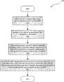
- FIG. 2is a flowchart schematically illustrating a sequence of operations for forwarding packets generated by a host connected to an IP network according to the disclosure provided herein.
- FIG. 3is a flowchart schematically illustrating a sequence of operations for network response to an ARP packet generated by a host connected to the network according to the disclosure provided herein.
- FIG. 4schematically illustrates a simple network made up of 12 end devices which, following the “access-aggregation-core” (AAC) model, are connected through an access tier, an aggregation tier, and a top-level core tier.
- AACaccess-aggregation-core
- FIG. 5schematically illustrates a particular example of a basic leaf-spine network.
- FIGS. 6A-1, 6A-2, and 6Bschematically illustrate how a simple example of a 3-tier leaf-spine network may be built from just 4-port switches.
- FIG. 7schematically illustrates a leaf-spine network wherein various IP-based packet forwarding operations are performed.
- ARP procedureused to determine host MAC addresses.
- ARP request packetsare broadcast to every host on a given subnet. Such broadcasts flood a network with traffic.
- broadcast loopsmay result.
- routing protocols based on spanning-tree type algorithmsmay be used to eliminate the broadcast loops, in so doing, many optimal paths through the network's topology are oftentimes eliminated.
- the current state of artis to forward IP Packets using combo switch-router network devices based on their destination MAC addresses and VLAN IDs if the packets arrive at a network device carrying a destination MAC address different than that of the router's (or if routing is simply not enabled on the network device), and otherwise, if the packet's destination MAC address does match that of the switch/router (and assuming routing is enabled), the switch/router forwards packets based on the destination IP addresses designated in the packets.
- a source hosttypically utilizes an ARP procedure to discover the MAC addresses of its desired destination host on the local subnet—leading to inefficient flooding on the local subnet and imposing a significant burden on the end hosts who aren't interested in the flooded traffic.
- ARP requestsare typically flooded to all the end devices in the flood domain (often a VLAN), unnecessarily sapping the processing power of the end devices on the local subnet.
- flooded trafficvery frequently consumes a large portion of the potentially available server CPU processing power.
- network devicesmay operate, whenever possible, by forwarding packets based on the destination IP address (IPv4 or IPv6) designated in the packets that they receive.
- IPv4 or IPv6IP address designated in the packets that they receive.
- network deviceshould be understood to encompass both switches and routers, and also combo switch/routers (except where it is clear from the context that one particular type of device or another is being referred to), since the same physical device typically implements both switching/bridging functionality as well as routing functionality.
- IP-based forwardingmay be performed by network devices for IP packets, and also, in some cases, for non-IP packets (example ARP family of protocols). In case of ARP packets, the network devices forward the packets based on the IP address inside the ARP payload after examining the ARP opcode (request or reply).
- the network devicesmay note whether a packet would have been routed or bridged.
- a packete.g., packet received by a network device labeled with a MAC address other than that of the network device, e.g., routing is disabled on a network device's ingress interface, etc.
- the network deviceforwards the packet based on the IP address but does not perform the rewrite operations which might typically be associated with IP routing—rewrite of the source and destination MAC address fields, decrementing the TTL, etc. may be suppressed.
- packetsare such that a legacy network would expect them to be routed, the packets would be forwarded based on their IP address and the typical routing rewrite operations would be performed.
- IP-based forwarding techniques disclosed hereinmay be particularly advantageous because: (i) they eliminate (or significantly reduces) one of the most common sources of broadcast or flooded traffic (which is especially important for cloud and data center networks); and (ii) they improve network scaling properties by allowing networks to operate with forwarding tables based on IP addresses along with local forwarding tables having the MAC addresses of locally attached hosts, rather than operating with forwarding tables which generally store an IP address and MAC address pair for all hosts/end devices connected to the network.
- the foregoing ARP forwarding techniquemay provide benefits in that it may: (i) eliminate the need for external directory services, (ii) allow resolution of ARP requests in-line with regular packet flow to end hosts/devices, (iii) better distribute the burden of responding to ARP requests to the end devices targeted by the ARP requests, (iv) efficiently provide opportunities for end devices to update their ARP caches, (v) use remote station (top) and local station (bottom) table efficiently, i.e. reduce/eliminate need for learning MAC addresses, and (vi) allow source IP learning based on conversations (triggered by ARP).
- MAC addresses specified in the packetsare IP packets but, as described above, ARP request packets may also be forwarded in this manner since they do provide a destination IP address in their payloads, and by doing so, subnet-wide broadcast of ARP request packets may be avoided.
- ARP request packetsmay also be forwarded in this manner since they do provide a destination IP address in their payloads, and by doing so, subnet-wide broadcast of ARP request packets may be avoided.
- certain such method embodimentsare schematically illustrated by the flowchart in FIG. 2 .
- a method 200 of forwarding data over an IP networkmay include: receiving a packet from a source host connected to the IP network in operation 210 , identifying the IP address of a destination host designated in the packet in operation 220 , determining in operation 230 the location on the IP network where the destination host designated by the packet is connected, without reference to the MAC address specified in the packet, by using location-identification information stored on the IP network, and, finally, in operation 240 , forwarding the packet to the location on the IP network where the destination host is connected, the forwarding to said location done without reference to the MAC address specified in the packet.
- the location-identification informationmay reside in a database which may be implemented, for example, as a list which matches one or more host IP addresses with one or more locations on the IP network where the hosts are connected.
- a listor more generally, such a database of location-identification information, may be associated with (e.g., stored locally on) the network device receiving the packet as it enters the IP network—typically the first network device initially encountered by the packet when it reaches the IP network after it issues from the source host.
- such a list or databasemay be associated with (e.g., stored on) another network device, or multiple other network devices on the IP network, or the database/list may be distributed across multiple network devices, or stored in-whole on one network device or devices while portions of the list/database may be locally-cached on other network devices. Examples will be illustrated below in the context of leaf-spine fabric overlay networks.
- the destination host's location on the networkmay be determined before or after the packet is forwarded from the first initially-encountered network device receiving the packet. For example, if the relevant destination host information is accessible from another network device, the packet may be forwarded to this second network device and, after said forwarding, the destination host's location on the network may be determined at this second network device.
- the IP network which implements the disclosed IP-based packet forwarding techniquesmay be a leaf-spine network fabric. Accordingly, presented below and provided in U.S. Provisional Pat. App. No. 61/900,228, filed Nov. 5, 2013, and titled “NETWORK FABRIC OVERLAY” (incorporated by reference in its entirety and for all purposes) are detailed descriptions of leaf-spine fabric overlay networks which, according to this disclosure, may employ mechanisms for forwarding incoming packets to destination hosts based on the destination IP addresses designated in the incoming packets, and in some embodiments, without reference to the destination MAC address designated in the incoming packets.
- an ARP request packetalthough in a legacy layer 2 network an ARP request packet is broadcast to all end devices on a local subnet, in various embodiments of the leaf-spine fabric overlay network set forth below and in U.S. Provisional Pat. App. No. 61/900,228, because an ARP request packet includes the intended destination host's IP address, and because network devices within the leaf-spine network fabric are aware of the locations where hosts are connected to the network, these network devices may forward ARP request packets to their intended destination hosts without broadcasting the ARP request packets within the fabric.
- a mapping databasemay keep the relevant location-identification information concerning the connection of end hosts to the leaf-spine network, in some embodiments, in the form of a list which matches one or more host IP addresses with one or more locations on the leaf-spine network where the hosts are connected.
- various IP-based packet forwarding methods 200may include an operation 210 of receiving a packet from a source host connected to the IP network where the receiving is performed by a leaf network device in the fabric which serves as the initial network device encountered by the packet when it reaches the leaf-spine fabric overlay network after the packet issues from the source host. After receipt of the packet by the leaf network device, methods proceed as shown in FIG.
- the location determined in operation 230would typically be a leaf network device within the fabric of the leaf-spine network, although it could also be, for example, be a virtual switch device running within the overlay network's virtualization layer.
- the packetis forwarded in operation 240 to the location within the leaf-spine IP network fabric where the destination host is connected, once again, the forwarding to said location done without reference to the MAC address specified in the packet.
- the location where the destination host connectsis a leaf network device which therefore serves as the packets egress point from the network.
- IP-based forwarding techniques and operations disclosed hereinmay be used in connection with IP networks which provide a data abstraction layer oftentimes referred to as an overlay wherein packets are encapsulated with a packet encapsulation scheme/protocol such as VXLAN upon ingress to the network, and are de-encapsulated upon egress from the network.
- a packet encapsulation scheme/protocolsuch as VXLAN upon ingress to the network
- Examples of overlay networks in the context of leaf-spine network architectures utilizing a VXLAN encapsulation scheme/protocolare described in U.S. Provisional Pat. App. No. 61/900,228.
- methods of IP-based packet forwardingmay include applying an encapsulation to a packet after being received by the initial network device encountered by the packet as it reaches the network, and removing the encapsulation from the packet as it exits the IP network before it reaches the destination host.
- the initially encountered network deviceis typically a leaf network device and so the encapsulation may be applied by this initially encountered leaf network device.
- IP-based packet forwarding techniques and operationsdo not require the existence of an overlay network in order to function and provide the benefits described above.
- the location where the destination host connectsmay be a virtual switch device operating in a virtualization layer (running on an underlying physical host) and moreover that the destination host itself may be a virtual machine operating in the virtualization layer.
- virtualization in the context of a leaf-spine fabric overlay networkis also described in detail in U.S. Provisional Pat. App. No.
- the source host which issued the IP packetmay be a physical host connected to a leaf network device which—as the initial network device encountered by the packet when it reaches the leaf-spine fabric overlay network—receives the packet and serves as the packet's ingress point to the network.
- the source hostmay be a virtual machine operating in a virtualization layer (running on an underlying physical host), and the first network “device” in the fabric overlay network encountered by a packet after being issued from the source host may be a virtual switch device also running in the virtualization layer, which then serves as the packet's ingress point to the network.
- the mapping database containing the location-identification information used for determining destination host locationis associated with the leaf network devices, the spine network devices, with both types of devices, or with a third type of device which provides this information with respect to packets forwarded from a leaf or spine network device, or in some combination of the foregoing.
- a partial mapping databaseis associated with each leaf network device which may be a locally-cached subset of a full global location-identification mapping database associated with the spine network devices—in some embodiments, stored directly on each spine network device, and in other embodiments stored on a third type of network device which is associated with the spine network devices. Portions of the spine's global mapping database—which typically lists the location-identification information associated with every host connected to the network through each leaf network device—may be learned by the leaf network devices as the network operates, as described in U.S. Provisional Pat. App. No. 61/900,228 (incorporated by reference herein).
- various embodiments of the IP-based forwarding techniques and operations disclosed hereinwork (in the ARP context or in the more general IP-based forwarding context) by looking-up an inbound packet's destination IP address in a mapping database associated locally with the leaf network device which receives the inbound packet.
- the destination host's location on the networkis determined at the initially encountered leaf network device before the packet is first forwarded from the initially encountered leaf network device.
- the mapping databasemay be associated with a spine network device and therefore the destination host's location on the network is determined from a global mapping database associated with the spine network device after forwarding the packet from the leaf network device to a spine network device having access to this global mapping database.
- the listmay be associated with another type of network device—a proxy-function network device—which is associated with the spine network device receiving the packet, but which is used to perform the actual lookup/determination of the location of the correct destination host.
- a proxy-function network devicewhich is associated with the spine network device receiving the packet, but which is used to perform the actual lookup/determination of the location of the correct destination host.
- the encapsulation headere.g., VXLAN header
- the proxy-addressmay be carried in the destination address field of the encapsulation header, and after the packet is received at the proxy-function network device, said device may replace the proxy-address with the actual location/address on the network where the destination host connects.
- mapping database(s)which have the relevant location-identification information are employed in the foregoing manner to determine the location within an IP network where a given destination host is located and connected.
- FIGS. 4 and 5collectively present a comparison between a traditional “access-aggregation-core” (ACC) network 400 and a simple leaf-spine network 500 .
- Both networksconsist of 12 end hosts connected together via 8 network devices.
- FIG. 4schematically illustrates an ACC network of 12 end devices/hosts 410 (e.g., servers) connected through an access tier 420 , an aggregation tier 430 , and a top-level core tier 440 .
- the network devices 425 within each tiere.g., ethernet switches) control the flow of network traffic over the various links 415 (e.g., ethernet cable) between it and the other network devices 425 , and ultimately to and from end devices/hosts 110 .
- links 415e.g., ethernet cable
- itis access tier 420 which provides each end device 410 with immediate access to the network. From there, traffic may pass to the aggregation tier 430 , and then to the core tier 440 , depending on its final destination.
- leaf-spine network 500resembles (to a certain extent) the AAC network 400 of FIG. 4 .
- leaf-spine network 500provides connectivity for 12 end devices which directly connect to 5 network devices in a first tier.
- the 12 hostsconnect to the 5 leaf network devices 525 of leaf tier 520 , which are analogous to the 5 network devices 425 of the access tier 420 of the AAC network 400 .
- the leaf-spine network 500employs just a single additional tier, the spine tier 530 , which consists of 3 spine-network devices 535 .
- FIGS. 6A-1, 6A-2, and 6B described belowschematically illustrate the formation of leaf-spine networks having more than two tiers.
- a benefit of the leaf-spine architectureis that it is less hierarchical than its traditional ACC counterpart.
- trafficmay be routed through the single network device 425 in core tier 440 , whereas in the leaf-spine network 500 , traffic may be routed between any combination of end hosts 510 connected to leaf network devices 525 through several different spine network devices 535 in the spine tier 530 .
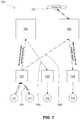
- FIG. 7schematically illustrates the operation of an IP-based packet forwarding technique in the context of a simple leaf-spine network 700 having 3 leaf network devices 721 , 722 , 723 and 2 spine network devices 731 , 732 which collectively connect together 4 end hosts 711 , 712 , 713 , 714 .
- leaf network devices 721 , 722 , 723 and 2 spine network devices 731 , 732which collectively connect together 4 end hosts 711 , 712 , 713 , 714 .
- proxy-function network device 741Also shown in the figure as a component of network 700 is shown in the figure as a component of network 700 .
- proxy-function network device 741is shown communicating with spine network device 732 , depending on the embodiment, it may also be used to determine the network locations of end hosts designated by packets routed through spine network device 731 ; or spine network device 731 may utilize a separate dedicated proxy-function network device.
- FIG. 7presents an IP network having a first set of multiple network devices (leaf network devices 721 , 722 , and 223 ) for connecting multiple hosts ( 711 , 712 , 713 , 714 ) to the network, and a second set of multiple network devices (spine network devices 731 , and 732 ) for connecting together the first set of network devices, and a third type/set of network device(s) (in this example, just one device, proxy-function network device 741 ) which in certain circumstances (described below) may provide the locations of destination hosts on the network.
- FIG. 7involves a leaf-spine architecture having local mapping databases associated with each leaf network device 721 , 722 , 723 each of which represents a locally-cached partial copy of a global mapping database associated with spine network devices 731 , 732 , utilized by the spine through proxy-function network device 741 .
- Three paths through the fabricare illustrated in FIG. 7, 751 (dotted line), 752 (dotted-dashed line), and 753 (dashed line)—each of which represent the communication of a packet from source host 711 to one of three destination hosts, 712 , 713 , and 714 , respectively.
- each leaf network device's locally-cached partial mapping databasewill contain entries for the end hosts directly connected to it.
- communication between end hosts 711 and 712 , which are both directly connected to leaf network device 721may be accomplished without involving the spine, as illustrated by path 751 labeled ‘local’ in FIG. 7 .
- IP-based forwarding of this particular packetis accomplished with a local mapping database (e.g., list of location-identification information) associated with this initially encountered leaf network device 721 , which is used to determine destination host 712 's location on the network (e.g., its direct connection to leaf network device 721 ) so that the packet may be forwarded directly from leaf network device 721 to end host 712 .
- a local mapping databasee.g., list of location-identification information
- packet encapsulatione.g., VXLAN
- packet forwarding between source and destination hosts connected to the same leaf network deviceonly involves local forwarding and not communication through the fabric of the network to the spine
- this local forwardingmay be done without using packet encapsulation.
- the encapsulationwould be applied by leaf network device 721 , for example, upon receipt of a packet from host 711 , and then immediately removed before forwarding the packet to destination host 712 . In other words, the encapsulated packet would not be transmitted, making the encapsulation effectively superfluous.
- Path 752 shown in FIG. 7schematically illustrates another packet communication through the fabric of leaf-spine network 700 , this time between end hosts 711 and 713 which are not connected to the same leaf network device. As shown by path 752 , in this instance, the packet does get routed through the spine—specifically spine network device 731 .
- the packetwould be encapsulated by leaf network device 721 with the destination address field of the encapsulation header set to the address of leaf network device 722 , the leaf network device connecting destination host 713 to the network.
- an encapsulation schemee.g., VXLAN
- an IP networkmay include a first set of network devices (e.g., leaf network devices 721 , 722 , and 223 ) which have logic (e.g., implemented in hardware and/or software) for receiving a packet from a connected source host (e.g., 711 , 712 , 713 , 714 ), logic for identifying the IP address of a destination host designated in a received packet, logic for attempting to determine the location on the network where a destination host designated by a received packet is connected (without reference to the MAC address specified in the received packet), logic for labeling the packet with this location, and logic for forwarding the packet to a network device in a second set of network devices (e.g., spine network devices 731 , 732 ) when the determined location not local to network device having received the packet.
- a connected source hoste.g., 711 , 712 , 713 , 714
- logic for identifying the IP address of a destination host designated in a received packete.g.
- an IP networkmay include this second set of network devices (e.g., spine network devices 731 , and 732 ) each of which have logic for receiving packets from the network devices in the first set.
- the network devices in the first and second setsmay employ logic (e.g., implemented in hardware and/or software) for performing any, many, or all of the operations appropriate for their function as discussed herein.
- the network devices of the first setmay include logic for applying an encapsulation (e.g., a VXLAN encapsulation) before forwarding a packet to the spine, and logic for removing the encapsulation before forwarding the packet to end host from egress leaf network device, as described above.
- path 753represents a communication between end hosts 711 and 714 .
- the communication between end hostsis non-local and involves multiple leaf network devices but, as indicated by the path 753 's label in FIG. 7 , the location-identification information associated with end host 714 is not found in the locally-cached mapping database associated with leaf network device 711 .
- leaf network device 721labels this packet with the location of the proxy-function network device 741 —e.g., sets the destination address field of the encapsulation header to the proxy address in networks employing an encapsulation scheme (e.g., VXLAN)—and after this packet is forwarded to the spine—in this instance, to spine network device 732 —the packet is forwarded to proxy-function network device 741 .
- an encapsulation schemee.g., VXLAN
- the proxy-function network device 721determines end host 714 's location on the network (e.g., its connection to leaf network device 723 ) by looking up end host 714 in the global mapping database and replaces the contents of the packet header field designating the proxy-function location—e.g., the destination address field of the encapsulation header—with that of end host 714 's network location.
- forwardingis accomplished utilizing a mapping database associated with spine network device 732 (via proxy-function network device 741 ) which is used to determine destination host 714 's location on the network after the packet is initially forwarded from leaf network device 721 to the spine.
- logic for identifying the IP address of the destination host designated in the received packetresides on the proxy-function network device 741 , however in other embodiments, said logic may reside on the spine network device itself.
- the packetif location-identification information corresponding to the destination IP address designated in an inbound packet is found in the local mapping database associated with the initial network device receiving the inbound packet, the packet will be forwarded accordingly—e.g., if the destination host is local to the leaf network device receiving the packet, the packet will be forwarded out a local port on the leaf network device to the destination host. However, if the destination host is remote from the ingress leaf network device, the packet will be encapsulated (e.g. with VXLAN), the encapsulation carrying the address of the remote leaf network device to which the destination host is connected, and sent towards an appropriate spine network device.
- VXLANvirtual extensible Markup Language
- the packetif there is a miss in the local mapping database (cache of location-identification information), the packet will be encapsulated with the proxy IP address and sent towards a spine network device that has the proxy function or is associated with a third type of network device providing the proxy function.
- the proxy functionthen operates to determine the location of the host on the network having the destination IP address designated in the received packet.
- the spine network devicehaving received the packet forwards the packet (whether an ARP request packet or an IP packet, generally) to the leaf network device which is the location on the IP network where the designated destination host is connected/attached.
- the packetis forwarded from spine network device 731 to leaf network device 722
- the packetis forwarded from spine network device 732 to leaf network device 723 (after spine network device 732 receives the packet back from proxy-function network device 741 ).
- paths 752 and 753illustrate their corresponding packets being forwarded from leaf network devices 722 and 723 to end hosts 713 and 714 , respectively.
- the encapsulationwould typically be removed from the packet at this point—before forwarding from egress leaf network device to end host.
- a virtual switch deviceV-switch within the virtualization layer may represent the packet's egress point from the overlay network and also the location on the network where the virtual host connects.
- packetswould be un-encapsulated by this V-switch device.
- virtualization technology within the context of leaf-spine fabric overlay networksis described in detail in U.S. Provisional Pat. App. No. 61/900,228 (incorporated by reference herein).
- Layer 2 communication protocolsmay be used to complete the packet's final hop from the edge of the leaf-spine network fabric to the connected host.
- the packetafter the packet is de-encapsulated, it may be labeled with the MAC address of the destination host, prior to forwarding to the destination host.
- the egress leaf network devicewould typically have this MAC address in its local forwarding table, along with the MAC addresses of any other physical hosts it connects to the leaf-spine fabric overlay network.
- an ARP request packetmay be forwarded via the IP-based forwarding techniques described above to the leaf network device which connects the end host having the IP address designated in the ARP request packet.
- this leaf network devicesince it serves as the ARP request packet's egress point from the network—may de-encapsulate the ARP request packet prior to forwarding the packet to target destination host designated in the packet.
- the leaf network device which connects the destination host to the networkmay itself prepare an ARP response packet in reply to the ARP request packet, without notifying the attached target device, saving a potential forwarding step, but at the expense of the “live-ness” check. This may be done using a locally stored MAC address for the destination host present in a forwarding table associated with the leaf network device which identifies the MAC addresses of each attached/connected host and/or other device.
- a leaf network device in a leaf-spine network fabricmay receive an ARP request packet from one of its attached hosts or other external devices which is labeled for broadcast.
- the leaf deviceprevents the packet's broadcasting by forwarding the packet based on the “target IP” address found in the payload of the packet, rather than in the conventional way by forwarding the packet based on the Layer 2 destination address, which is a broadcast address.
- host A connected to a leaf-spine fabric overlay networkwants to communicate with host B also connected to the network, but host A does not know host B's MAC address. Host A therefore generates an ARP request packet and forwards it onto the network.
- the first network device receiving the ARP request packetis the leaf network device to which host A is attached.
- the ARP request packetincludes the following information similarly to that shown in FIG. 1A :
- the ingress leaf network deviceanalyzes this ARP request packet and identifies Host B's IP address in the packet's payload. If this leaf network device determines from Host B's IP address that host B is locally connected to itself, this leaf network device forwards the packet directly to host B without encapsulating it. If the ingress leaf network device recognizes host B's IP address, but determines that it isn't a local IP address, this leaf network device encapsulates the packet and forwards it to the spine, the encapsulation identifying the IP address of the leaf network device connecting host B.
- this leaf network deviceproduces an encapsulation identifying the IP address of a network device providing the proxy function as the destination IP address—either a spine network device or another class of network device which provides the proxy function—and forwards the packet to the spine—which then either applies the proxy function or forwards the packet to a proxy-function network device which applies the proxy function and forwards the packet back to the spine.
- the spine network deviceWith the packet's encapsulation now identifying the leaf network device connecting host B, the spine network device then sends the ARP request packet to this leaf network device. Note, once again, that the same forwarding procedure generally applies to other types of packets which specify a destination IP address.
- the receiving leaf network devicerecognizes the packet as an ARP request and recognizes host B's IP address.
- the receiving leaf network devicemay optionally update its forwarding table with information about host A.
- the leaf network devicethen forwards the packet to host B, which prepares and sends an ARP reply packet back to the leaf network device.
- the leaf network devicenow receives and forwards this ARP reply packet to the spine, which then routes the ARP reply to the leaf network device locally connecting host A. That leaf network device then de-encapsulates the ARP reply and forwards the ARP reply to host A.
- the leaf network device connecting host Amay update its own forwarding table with information about host B.
- the gathering of the location-identification information for the mapping database cached at the leaf network devicesmay be done through protocols or through learning of the devices attached to the network, for example, as demonstrated in the preceding ARP example.
- the location-identification information in a local mapping databasemay include MAC and IP addresses of most or all locally connected host devices, however, as described above, these local mapping databases need not contain the MAC addresses of every host connected to every leaf network device on the network.
- the learned location-identification informationmay be provided in a mapping database resident on the spine, portions of which are locally-cached in the leaf network devices.
- IP-based packet forwardingmay be implemented without an overlay network, and also in networks having other topologies besides the leaf-spine fabric now described in detail.
- Datacenter network designmay follow a variety of topological paradigms—a given topology just referring to the system of networking lines/links which carry network traffic (i.e., data) and the networking switches, which control the flow of traffic over the lines/links in the network.
- topological paradigmsa given topology just referring to the system of networking lines/links which carry network traffic (i.e., data) and the networking switches, which control the flow of traffic over the lines/links in the network.
- One of the most common topological paradigms in use todayis the aptly-named “access-aggregation-core” architecture.
- FIG. 4schematically illustrates a simple network 400 made up of 12 “end devices” 410 (e.g., servers) which, following the “access-aggregation-core” (AAC) model, are connected through an access tier 420 , an aggregation tier 430 , and a top-level core tier 440 .
- end devicese.g., servers
- AACaccess-aggregation-core
- Each tierare “network devices” 425 (e.g., ethernet switches) each of which controls flow of network traffic over various “links” 415 (e.g., ethernet cable) between it and the other network devices 425 and ultimately to and from end devices 110 .
- linkse.g., ethernet cable
- trafficmay pass to the aggregation tier 430 , and then to the core tier 440 , depending on its final destination. It is noted that for traffic whose final destination is within the network 400 shown in FIG. 4 , how far up the hierarchy the traffic must be directed to reach this destination depends on the location of the destination within the network. Traffic whose final destination is outside the network shown in FIG. 4 —e.g., to some server on the worldwide intenet—will typically travel all the way up the hierarchy, since the connection or connections to the outside internet typically reside in the core tier. It is also noted that while FIG.
- each network device 425portrays each network device 425 identically for purposes of illustration, actual hardware implementations of such devices may possess substantial differences depending on whether the device is located in the access tier 420 , the aggregation tier 430 , or the core tier 440 .
- the single network device in the core tier 440 of FIG. 4would typically route more traffic (for the reasons just described) than those network devices in the other layers, and so it's hardware would be chosen accordingly.
- differing hardware implementations in one tier versus anothermay be dictated by whether the devices in each tier do bridging or routing, or both.
- the access tiertypically does only bridging, the aggregation tier a combination of bridging and routing—bridging and routing between interfaces going to the access tier and routing to all others—and the core tier, only routing.
- the term “end device” 410refers to a device connected to the network which is identified on the network and uses the network to communicate with other devices connected to the network.
- the end device 410may be personal computer, a workstation, a server, or a device which may not be a computer per se such as, for example, a network printer, scanner, network storage device, etc.
- an end device 410may be a physical device having one or more processors (each potentially having one or more cores) connected to an array of random-access memory (RAM) and possibly a non-volatile storage medium (such as a magnetic disc, flash drive, optical disc, magnetic tape, etc.), an end device 410 may also be a virtual device, such as a virtualized server running in a virtualization environment—such as VMWare—atop an actual physical server.
- an end devicemay actually refer to multiple computers, the distinction being that for purposes of network topology they share the same connection to the network and therefore operate substantially as a single networked unit.
- FIG. 4illustrates the hierarchal connectivity of a access-aggregation-core (AAC) network model and shows that, from core to end device, the architecture follows a tree structure or graph—meaning that each network device within the network is only connected to a single device above it in the hierarchy, but is potentially connected to multiple network devices below it.
- the tree structurealso implies, as seen from the figure, that there is a single unique path—i.e., sequence of links—connecting any two end devices on the network.
- sequence of linksconnecting any two end devices on the network.
- paths between different pairs of end devicesmay, but not necessarily, use the same links along some portion of their route. For example, with regards to the specific network shown in FIG.
- end device Athe end devices 410 labeled A and F (hereinafter “end device A” and so forth) communicate over a path through network devices 1 , II, and then 3 .
- end devices I and Jcommunicate over a path through network devices 4 , III, and then 5 , and so these two paths do not overlap (i.e. the paths have no links in common).
- end device Ainstead communicates with end device K (while I communicates with J), then both paths pass through network devices III and 5 (and the link adjoining devices III and 5 ).
- end device Aattempts to communicate with end device K while end device I is communicating with end device J
- blockingoccurs—e.g., either both pairs of end devices communicate at half maximum bandwidth, or they communicate at full bandwidth sequentially, one pair waiting for the other pair to finish.
- end devices which are topologically-separate from each otheri.e., their communication paths involve many links
- Another way of addressing the ubiquitous “blocking” problem manifested in the modern datacenter's networking infrastructureis to design a new network around a topological paradigm where blocking does not present as much of an inherent problem.
- One such topologyis often referred to as a “multi-rooted tree” topology (as opposed to a “tree”), which can be said to embody a full bi-partite graph if each spine network device is connected to each Leaf network device and vice versa.
- Networks based on this topologyare oftentimes referred to as “Clos Networks,” “flat networks,” “multi-rooted networks,” or just as “multi-rooted trees.”
- a “leaf-spine” network architecture designed around the concept of a “multi-rooted tree” topologywill be described. While it is true that real-world networks are unlikely to completely eliminate the “blocking” problem, the described “leaf-spine” network architecture, as well as others based on “multi-rooted tree” topologies, are designed so that blocking does not occur to the same extent as in traditional network architectures.
- leaf-spine networkslessen the blocking problem experienced by traditional networks by being less hierarchical and, moreover, by including considerable active path redundancy.
- a leaf-spine networkrealizes higher performance, at least to a certain extent, by building the network “out” instead of building it “up” in a hierarchical fashion.
- a leaf-spine network in its basic formconsists of two-tiers, a spine tier and leaf tier. Network devices within the leaf tier—i.e.
- leaf network devicesprovide connections to all the end devices, and network devices within the spine tier—i.e., “spine network devices”—provide connections among the leaf network devices.
- spine network devicesprovide connections among the leaf network devices.
- leaf network devicesdo not directly communicate with each other, and the same is true of spine network devices.
- a leaf-spine network in its basic formhas no third core tier connecting the network devices within the second tier to a much smaller number of core network device(s), typically configured in a redundant fashion, which then connect to the outside internet. Instead, the third tier core is absent and connection to the internet is provided through one of the leaf network devices, again effectively making the network less hierarchical.
- internet connectivity through a leaf network deviceavoids forming a traffic hotspot on the spine which would tend to bog down traffic not travelling to and from the outside internet.
- leaf-spine networksmay actually be formed from 3 tiers of network devices.
- the third tiermay function as a “spine” which connects “leaves” formed from first and second tier network devices, but a 3-tier leaf-spine network still works very differently than a traditional AAC network due to the fact that it maintains the multi-rooted tree topology as well as other features.
- the top tier of a 3-tier leaf-spine networkstill does not directly provide the internet connection(s), that still being provided through a leaf network device, as in a basic 2-tier leaf-spine network.
- FIG. 5schematically illustrates a particular example of a basic leaf-spine network 500 .
- network 500is analogous (or is the counterpart of) the AAC network 400 shown in FIG. 4 .
- Bothprovide connectivity for 12 end devices which directly connect to 5 network devices in a first tier, in the case of network 500 , to the 5 leaf network devices 525 of leaf tier 520 , which are analogous to the 5 network devices 425 of the access tier 420 of the AAC network 400 .
- the leaf-spine network 500employs just a single additional tier, the spine tier 530 , which consists of 3 spine-network devices 535 .
- FIG. 5shows that in a prototypical leaf-spine network, every leaf network device 525 is connected to multiple spine network devices 535 creating the so-called “multi-rooted tree” topology—differing from the ordinary tree topology of an AAC network where each network device is connected to only one network device above it in the hierarchy.
- multi-rooted treetopology—differing from the ordinary tree topology of an AAC network where each network device is connected to only one network device above it in the hierarchy.
- leaf-spine networksare such that if a sufficient number of spine network devices are connected with sufficient bandwidth to the leaf network devices, a leaf-spine network may provide what is referred to as “full bisectional bandwidth,” as described in more detail below.
- additional tierssuch as a third tier as mentioned above and as described in greater detail below
- a network of arbitrary sizecan be built that still provides “full bisectional bandwidth.”
- the extent to which a given network is non-blockingmay be characterized by the network's “bisectional bandwidth,” which is determined by dividing a network that has N end devices attached to it into 2 equal sized groups of size N/2, and determining the total bandwidth available for communication between the two groups. If this is done for all possible divisions into groups of size N/2, the minimum bandwidth over all such divisions is the “bisectional bandwidth” of the network.
- a networkmay then be said to have “full bisectional bandwidth” and have the property of being “fully non-blocking” if each leaf network device's total uplink bandwidth to the spine tier 530 (the sum of the bandwidths of all links connecting the leaf network device 525 to any spine network device 535 ) is at least equal to the maximum downlink bandwidth to end devices associated with any of the leaf network devices on the network.
- the leaf-spine network 500thus exhibits full bisectional bandwidth because each leaf network device has at least as much bandwidth to the spine tier (i.e., summing bandwidth over all links to spine network devices) as it does bandwidth to the end devices to which it is connected (i.e., summing bandwidth over all links to end devices).
- the non-blocking property of network 500with respect to admissible sets of communications, consider that if the 12 end devices in FIG. 5 are arbitrarily divided into 6 pairs, simultaneous communications between the 6 pairs are admissible, and thus may occur without blocking in network 500 .
- the non-blocking property of leaf-spine network 500will be preserved if up to 15 end devices are connected, 3 to each of the 5 leaf network devices.
- the leaf tier 520would typically be formed from 5 ethernet switches of 6 ports or more, and the spine tier 530 from 3 ethernet switches of 5 ports or more.
- the number of ports m on each spine tier switchis equal to the number of leaf tier switches j (so long as the maximum number of leaf tier switches are used), and so the total number of end devices is also given by 1 ⁇ 2 ⁇ m ⁇ n, where m is the number of ports on the spine tier switches, and n is the number of ports on the leaf tier switches.
- leaf-spine networksstill provide advantages over traditional networks, and they can be made more cost-effective, when appropriate, by reducing the number of devices used in the spine tier, or by reducing the link bandwidth between individual spine and leaf tier devices, or both.
- the cost-savings associated with using fewer spine-network devicescan be achieved without a corresponding reduction in bandwidth between the leaf and spine tiers by using a leaf-to-spine link speed which is greater than the link speed between the leaf tier and the end devices. If the leaf-to-spine link speed is chosen to be high enough, a leaf-spine network may still be made to be fully non-blocking—despite saving costs by using fewer spine network devices.
- the extent to which a network having fewer spine tier devices is non-blockingis given by the ratio of bandwidth from leaf network device to spine tier versus bandwidth from leaf network device to end devices. By adjusting this ratio, an appropriate balance between cost and performance can be dialed in.
- This concept of oversubscription and building cost-effective networks having fewer than optimal spine network devicesalso illustrates the improved failure domain provided by leaf-spine networks versus their traditional counterparts.
- a traditional AAC networkif a device in the aggregation tier fails, then every device below it in the network's hierarchy will become inaccessible until the device can be restored to operation. Furthermore, even if redundancy is built-in to that particular device, or if it is paired with a redundant device, or if it is a link to the device which has failed and there are redundant links in place, such a failure will still result in a 50% reduction in bandwidth, or a doubling of the oversubscription.
- redundancyis intrinsically built into a leaf-spine network and such redundancy is much more extensive.
- absence or failure of a single device in the spine (or link to the spine)will only typically reduce bandwidth by 1/k where k is the total number of spine network devices.
- the oversubscription ratemay still be reduced (or eliminated) by the use of higher bandwidth links between the leaf and spine network devices relative to those used to connect end devices to the leaf network devices.
- leaf-spine networksmay be implemented as follows:
- Leaf network devicesmay be implemented as ethernet switches having: (i) 48 ports for connecting up to 48 end devices (e.g., servers) at data transmission speeds of 10 GB/s (gigabits per second)—i.e. ‘downlink ports’; and (ii) 12 ports for connecting to up to 12 spine network devices at data transmission speeds of 40 GB/s—i.e. ‘uplink ports.’
- each leaf network devicehas 480 GB/s total bandwidth available for server connections and an equivalent 480 GB/s total bandwidth available for connections to the spine tier.
- leaf network devicesmay be chosen to have a number of ports in the range of 10 to 50 ports, or 20 to 100 ports, or 50 to 1000 ports, or 100 to 2000 ports, wherein some fraction of the total number of ports are used to connect end devices (‘downlink ports’) and some fraction are used to connect to spine network devices (‘uplink ports’).
- the ratio of uplink to downlink ports of a leaf network devicemay be 1:1, or 1:2, or 1:4, or the aforementioned ratio may be in the range of 1:1 to 1:20, or 1:1 to 1:10, or 1:1 to 1:5, or 1:2 to 1:5.
- the uplink ports for connection to the spine tiermay have the same bandwidth as the downlink ports used for end device connection, or they may have different bandwidths, and in some embodiments, higher bandwidths.
- uplink portsmay have bandwidths which are in a range of 1 to 100 times, or 1 to 50 times, or 1 to 10 times, or 1 to 5 times, or 2 to 5 times the bandwidth of downlink ports.
- leaf network devicesmay be switches having a fixed number of ports, or they may be modular, wherein the number of ports in a leaf network device may be increased by adding additional modules.
- the leaf network device just described having 48 10 GB/s downlink ports (for end device connection) and 12 40 GB/s uplink ports (for spine tier connection)may be a fixed-sized switch, and is sometimes referred to as a ‘Top-of-Rack’ switch.
- Fixed-sized switches having a larger number of portsare also possible, however, typically ranging in size from 50 to 150 ports, or more specifically from 64 to 128 ports, and may or may not have additional uplink ports (for communication to the spine tier) potentially of higher bandwidth than the downlink ports.
- the number of portsobviously depends on how many modules are employed.
- portsare added via multi-port line cards in similar manner to that described below with regards to modular spine network devices.
- Spine network devicesmay be implemented as ethernet switches having 576 ports for connecting with up to 576 leaf network devices at data transmission speeds of 40 GB/s. More generally, spine network devices may be chosen to have a number of ports for leaf network device connections in the range of 10 to 50 ports, or 20 to 100 ports, or 50 to 1000 ports, or 100 to 2000 ports. In some embodiments, ports may be added to a spine network device in modular fashion. For example, a module for adding ports to a spine network device may contain a number of ports in a range of 10 to 50 ports, or 20 to 100 ports. In this manner, the number of ports in the spine network devices of a growing network may be increased as needed by adding line cards, each providing some number of ports.
- a 36-port spine network devicecould be assembled from a single 36-port line card, a 72-port spine network device from two 36-port line cards, a 108-port spine network device from a trio of 36-port line cards, a 576-port spine network device could be assembled from 16 36-port line cards, and so on.
- Links between the spine and leaf tiersmay be implemented as 40 GB/s-capable ethernet cable (such as appropriate fiber optic cable) or the like, and server links to the leaf tier may be implemented as 10 GB/s-capable ethernet cable or the like. More generally, links, e.g. cables, for connecting spine network devices to leaf network devices may have bandwidths which are in a range of 1 GB/s to 1000 GB/s, or 10 GB/s to 100 GB/s, or 20 GB/s to 50 GB/s. Likewise, links, e.g.
- cables, for connecting leaf network devices to end devicesmay have bandwidths which are in a range of 10 MB/s to 100 GB/s, or 1 GB/s to 50 GB/s, or 5 GB/s to 20 GB/s.
- links, e.g. cables, between leaf network devices and spine network devicesmay have higher bandwidth than links, e.g. cable, between leaf network devices and end devices.
- links, e.g. cables, for connecting leaf network devices to spine network devicesmay have bandwidths which are in a range of 1 to 100 times, or 1 to 50 times, or 1 to 10 times, or 1 to 5 times, or 2 to 5 times the bandwidth of links, e.g. cables, used to connect leaf network devices to end devices.
- the maximum leaf-to-spine transmission rate (of 40 GB/s)being 4 times that of the maximum leaf-to-server transmission rate (of 10 GB/s)
- such a network having 12 spine network devicesis fully non-blocking and has full cross-sectional bandwidth.
- a setup employing 576-port switches as spine network devicesmay typically employ 4 spine network devices which, in a network of 576 leaf network devices, corresponds to an oversubscription rate of 3:1. Adding a set of 4 more 576-port spine network devices changes the oversubscription rate to 3:2, and so forth.
- Datacenterstypically consist of servers mounted in racks.
- one leaf network devicesuch as the ‘Top-of-Rack’ device described above, can be placed in each rack providing connectivity for up to 48 rack-mounted servers.
- the total networkthen may consist of up to 576 of these racks connected via their leaf-network devices to a spine-tier rack containing between 4 and 12 576-port spine tier devices.
- the two-tier leaf-spine network architecture described above having 576-port @ 40 GB/s switches as spine network devices and 48-port @ 10 GB/s downlink & 12-port @ 40 GB/s uplink switches as leaf network devicescan support a network of up to 27,648 servers, and while this may be adequate for most datacenters, it may not be adequate for all.
- Even larger networkscan be created by employing spine tier devices with more than 576 ports accompanied by a corresponding increased number of leaf tier devices.
- another mechanism for assembling a larger networkis to employ a multi-rooted tree topology built from more than two tiers of network devices—e.g., forming the network from 3 tiers of network devices, or from 4 tiers of network devices, etc.
- 6A-1shows 4 4-port switches 622 (labeled “ 1 - 1 ,” “ 1 - 2 ,” “ 1 - 3 ,” “ 1 - 4 ”) connected to form a 2-tier leaf-spine network 601 for connecting 4 end devices 610 (labeled “A,” “B,” “C,” “D”) with switches 1 - 1 and 1 - 2 serving as leaf network devices, and switches 1 - 3 and 1 - 4 serving as spine network devices.
- a leaf-spine network assembled from 4-port switcheswould generally support a network of 8 end devices 610 , connected through 2 spine-network devices and 4 leaf network devices, but here, half the ports on the switches serving as spine network devices, switches 1 - 3 and 1 - 4 , have their links pointed upward in FIG.
- FIG. 6A-1to schematically indicate these links are reserved for uplink connection to a third tier.
- the 4 4-port switches 622may collectively be viewed as functioning as an 8 port switch 625 , as schematically illustrated in FIG. 6A-2 (and labeled “ 1 ”), with 4 downlinks 605 to potential end devices 610 and 4 uplinks 615 to a potential third tier.
- Such an effective 8-port switchmay then serve as a building-block for a 3-tier leaf-spine network.
- FIG. 6Bshows how a 3-tier leaf-spine network 602 may be assembled from these 8-port building blocks.
- 4 8-port building blocks 625may effectively serve as 4 leaf-network devices (labeled “ 1 ,” “ 2 ,” “ 3 ,” “ 4 ,”) in the leaf tier 620 of network 602 .
- the spine tier 630 of network 602is formed from 4 additional 4-port switches 635 (labeled “I,” “II,” “III,” “IV”), similar to those used to form each 8-port leaf network device 625 .
- network 602when viewed in terms of 4-port switches, network 602 consists of 3 tiers with 8 4-port switches in the bottom tier, 8 4-port switches in the middle tier, and 4 4-port switches in the top tier, though this network may still be viewed as having a leaf tier 620 and spine tier 630 , as just described. It is seen in the figure, that network 602 may connect up to 16 end devices 610 . Generalizing this, it is noted that a 3-tier leaf-spine network may connect a total number of end devices equal to 1 ⁇ 4 ⁇ l ⁇ m ⁇ n, where l, m, and n are the number of ports in the devices forming the top, middle, and bottom tiers, respectively (e.g., in FIG.
Landscapes
- Engineering & Computer Science (AREA)
- Computer Networks & Wireless Communication (AREA)
- Signal Processing (AREA)
- Data Exchanges In Wide-Area Networks (AREA)
Abstract
Description
- L2 Destination MAC Address=Broadcast
- L2 Source MAC address=Host A's MAC address
- Payload contains: Host B's IP address
Claims (38)
Priority Applications (3)
| Application Number | Priority Date | Filing Date | Title |
|---|---|---|---|
| US14/301,239US10951522B2 (en) | 2013-11-05 | 2014-06-10 | IP-based forwarding of bridged and routed IP packets and unicast ARP |
| US17/187,332US12244496B2 (en) | 2013-11-05 | 2021-02-26 | IP-based forwarding of bridged and routed IP packets and unicast ARP |
| US18/986,237US20250119381A1 (en) | 2013-11-05 | 2024-12-18 | Ip-based forwarding of bridged and routed ip packets and unicast arp |
Applications Claiming Priority (3)
| Application Number | Priority Date | Filing Date | Title |
|---|---|---|---|
| US201361900349P | 2013-11-05 | 2013-11-05 | |
| US201361900228P | 2013-11-05 | 2013-11-05 | |
| US14/301,239US10951522B2 (en) | 2013-11-05 | 2014-06-10 | IP-based forwarding of bridged and routed IP packets and unicast ARP |
Related Child Applications (1)
| Application Number | Title | Priority Date | Filing Date |
|---|---|---|---|
| US17/187,332ContinuationUS12244496B2 (en) | 2013-11-05 | 2021-02-26 | IP-based forwarding of bridged and routed IP packets and unicast ARP |
Publications (2)
| Publication Number | Publication Date |
|---|---|
| US20150124817A1 US20150124817A1 (en) | 2015-05-07 |
| US10951522B2true US10951522B2 (en) | 2021-03-16 |
Family
ID=53007007
Family Applications (3)
| Application Number | Title | Priority Date | Filing Date |
|---|---|---|---|
| US14/301,239ActiveUS10951522B2 (en) | 2013-11-05 | 2014-06-10 | IP-based forwarding of bridged and routed IP packets and unicast ARP |
| US17/187,332Active2035-06-04US12244496B2 (en) | 2013-11-05 | 2021-02-26 | IP-based forwarding of bridged and routed IP packets and unicast ARP |
| US18/986,237PendingUS20250119381A1 (en) | 2013-11-05 | 2024-12-18 | Ip-based forwarding of bridged and routed ip packets and unicast arp |
Family Applications After (2)
| Application Number | Title | Priority Date | Filing Date |
|---|---|---|---|
| US17/187,332Active2035-06-04US12244496B2 (en) | 2013-11-05 | 2021-02-26 | IP-based forwarding of bridged and routed IP packets and unicast ARP |
| US18/986,237PendingUS20250119381A1 (en) | 2013-11-05 | 2024-12-18 | Ip-based forwarding of bridged and routed ip packets and unicast arp |
Country Status (1)
| Country | Link |
|---|---|
| US (3) | US10951522B2 (en) |
Cited By (1)
| Publication number | Priority date | Publication date | Assignee | Title |
|---|---|---|---|---|
| US20230031462A1 (en)* | 2021-07-30 | 2023-02-02 | Oracle International Corporation | Selective handling of traffic received from on-premises data centers |
Families Citing this family (37)
| Publication number | Priority date | Publication date | Assignee | Title |
|---|---|---|---|---|
| US9977685B2 (en) | 2013-10-13 | 2018-05-22 | Nicira, Inc. | Configuration of logical router |
| US9397946B1 (en) | 2013-11-05 | 2016-07-19 | Cisco Technology, Inc. | Forwarding to clusters of service nodes |
| US9655232B2 (en) | 2013-11-05 | 2017-05-16 | Cisco Technology, Inc. | Spanning tree protocol (STP) optimization techniques |
| US10951522B2 (en) | 2013-11-05 | 2021-03-16 | Cisco Technology, Inc. | IP-based forwarding of bridged and routed IP packets and unicast ARP |
| US9825857B2 (en) | 2013-11-05 | 2017-11-21 | Cisco Technology, Inc. | Method for increasing Layer-3 longest prefix match scale |
| US9888405B2 (en) | 2013-11-05 | 2018-02-06 | Cisco Technology, Inc. | Networking apparatuses and packet statistic determination methods employing atomic counters |
| US9374294B1 (en) | 2013-11-05 | 2016-06-21 | Cisco Technology, Inc. | On-demand learning in overlay networks |
| US9876711B2 (en) | 2013-11-05 | 2018-01-23 | Cisco Technology, Inc. | Source address translation in overlay networks |
| US10778584B2 (en) | 2013-11-05 | 2020-09-15 | Cisco Technology, Inc. | System and method for multi-path load balancing in network fabrics |
| US9502111B2 (en) | 2013-11-05 | 2016-11-22 | Cisco Technology, Inc. | Weighted equal cost multipath routing |
| US9769078B2 (en) | 2013-11-05 | 2017-09-19 | Cisco Technology, Inc. | Dynamic flowlet prioritization |
| US9674086B2 (en) | 2013-11-05 | 2017-06-06 | Cisco Technology, Inc. | Work conserving schedular based on ranking |
| EP3066796B1 (en) | 2013-11-05 | 2020-01-01 | Cisco Technology, Inc. | Network fabric overlay |
| CN104753789B (en)* | 2013-12-26 | 2018-10-30 | 华为技术有限公司 | A kind of method and system to E-Packet |
| JP6264625B2 (en)* | 2014-03-13 | 2018-01-24 | パナソニックIpマネジメント株式会社 | Information device identification system, information device identification method, and program |
| US9893988B2 (en) | 2014-03-27 | 2018-02-13 | Nicira, Inc. | Address resolution using multiple designated instances of a logical router |
| US10216853B2 (en)* | 2014-06-27 | 2019-02-26 | Arista Networks, Inc. | Method and system for implementing a VXLAN control plane |
| US10250443B2 (en) | 2014-09-30 | 2019-04-02 | Nicira, Inc. | Using physical location to modify behavior of a distributed virtual network element |
| US10511458B2 (en) | 2014-09-30 | 2019-12-17 | Nicira, Inc. | Virtual distributed bridging |
| US9768980B2 (en) | 2014-09-30 | 2017-09-19 | Nicira, Inc. | Virtual distributed bridging |
| US10020960B2 (en)* | 2014-09-30 | 2018-07-10 | Nicira, Inc. | Virtual distributed bridging |
| US20170289033A1 (en)* | 2015-04-03 | 2017-10-05 | Hewlett Packard Enterprise Development Lp | Address cache for tunnel endpoint associated with an overlay network |
| US10361952B2 (en) | 2015-06-30 | 2019-07-23 | Nicira, Inc. | Intermediate logical interfaces in a virtual distributed router environment |
| CN107135118B (en)* | 2016-02-29 | 2020-06-26 | 华为技术有限公司 | A unicast communication method, gateway and VXLAN access device |
| CN107800628B (en)* | 2016-09-07 | 2020-12-01 | 华为技术有限公司 | Data forwarding device and data forwarding method used in software-defined network |
| US20180176181A1 (en)* | 2016-12-19 | 2018-06-21 | Cisco Technology, Inc. | Endpoint admission control |
| CN111226427B (en)* | 2017-08-14 | 2021-11-26 | 华为技术有限公司 | Method and apparatus for avoiding paging storm during ARP broadcast of Ethernet type PDUs |
| US10791065B2 (en)* | 2017-09-19 | 2020-09-29 | Cisco Technology, Inc. | Systems and methods for providing container attributes as part of OAM techniques |
| US10374827B2 (en) | 2017-11-14 | 2019-08-06 | Nicira, Inc. | Identifier that maps to different networks at different datacenters |
| US10511459B2 (en) | 2017-11-14 | 2019-12-17 | Nicira, Inc. | Selection of managed forwarding element for bridge spanning multiple datacenters |
| US10574566B2 (en)* | 2018-05-25 | 2020-02-25 | Juniper Networks, Inc. | Reducing or eliminating routing microloops in networks having a CLOS topology, such as data center CLOS networks employing the exterior border gateway protocol (EBGP) for example |
| CN109451093B (en)* | 2018-12-13 | 2022-01-28 | 新华三技术有限公司 | Loopback interface address allocation method and device |
| US11153261B2 (en) | 2020-01-22 | 2021-10-19 | Cisco Technology, Inc. | Routing traffic for virtualized/containerized network functions |
| US11171882B2 (en)* | 2020-03-12 | 2021-11-09 | Mellanox Technologies Tlv Ltd. | Flexible Clos topology switch |
| US11470038B1 (en) | 2020-05-19 | 2022-10-11 | Marvell Asia Pte Ltd. | Line side multiplexers with protection switching |
| US11310115B2 (en) | 2020-05-20 | 2022-04-19 | Mellanox Technologies, Ltd. | TClos—scalable network topology and system architecture |
| CN113726632B (en)* | 2021-07-31 | 2023-04-18 | 新华三信息安全技术有限公司 | Message forwarding method and device |
Citations (232)
| Publication number | Priority date | Publication date | Assignee | Title |
|---|---|---|---|---|
| US4298770A (en) | 1978-08-25 | 1981-11-03 | Fujitsu Limited | Printed board |
| US4636919A (en) | 1985-03-20 | 1987-01-13 | Hitachi, Ltd. | Multilayer printed circuit board |
| US4700016A (en) | 1986-05-16 | 1987-10-13 | International Business Machines Corporation | Printed circuit board with vias at fixed and selectable locations |
| US5115431A (en) | 1990-09-28 | 1992-05-19 | Stratacom, Inc. | Method and apparatus for packet communications signaling |
| US5859835A (en) | 1996-04-15 | 1999-01-12 | The Regents Of The University Of California | Traffic scheduling system and method for packet-switched networks |
| US5926458A (en) | 1997-01-31 | 1999-07-20 | Bay Networks | Method and apparatus for servicing multiple queues |
| US6389031B1 (en) | 1997-11-05 | 2002-05-14 | Polytechnic University | Methods and apparatus for fairly scheduling queued packets using a ram-based search engine |
| US20020126671A1 (en) | 2001-03-06 | 2002-09-12 | Ellis Steven Clay | Method and apparatus for distributing routing instructions over multiple interfaces of a data router |
| US20020136268A1 (en) | 2001-01-25 | 2002-09-26 | Hongbing Gan | Approach for selecting communications channels based on performance |
| US20020146026A1 (en) | 2000-05-14 | 2002-10-10 | Brian Unitt | Data stream filtering apparatus & method |
| US20030035385A1 (en) | 2001-08-09 | 2003-02-20 | William Walsh | Method, apparatus, and system for identifying and efficiently treating classes of traffic |
| US20030058860A1 (en) | 2001-09-25 | 2003-03-27 | Kunze Aaron R. | Destination address filtering |
| US20030058837A1 (en) | 2001-09-27 | 2003-03-27 | Lisa Denney | Method and system for upstream priority lookup at physical interface |
| US20030067924A1 (en) | 2001-10-05 | 2003-04-10 | Samsung Electronics Co., Ltd. | Redundancy mechanization protocol for a massively parallel router |
| US20030097461A1 (en) | 2001-11-08 | 2003-05-22 | Paul Barham | System and method for controlling network demand via congestion pricing |
| US20030115319A1 (en) | 2001-12-17 | 2003-06-19 | Dawson Jeffrey L. | Network paths |
| US20030137940A1 (en) | 1998-11-24 | 2003-07-24 | Schwartz Steven J. | Pass/drop apparatus and method for network switching node |
| US20030142629A1 (en) | 2001-12-10 | 2003-07-31 | Rajeev Krishnamurthi | Method and apparatus for testing traffic and auxiliary channels in a wireless data communication system |
| US20030174650A1 (en) | 2002-03-15 | 2003-09-18 | Broadcom Corporation | Weighted fair queuing (WFQ) shaper |
| US20030223376A1 (en) | 2002-05-30 | 2003-12-04 | Agilent Technologies, Inc. | Testing network communications |
| US20030231646A1 (en) | 2002-06-14 | 2003-12-18 | Chandra Prashant R. | Method and system for efficient random packet enqueue, drop or mark processing in network traffic |
| US6677831B1 (en) | 2001-01-31 | 2004-01-13 | 3Pardata, Inc. | Differential impedance control on printed circuit |
| US6714553B1 (en) | 1998-04-15 | 2004-03-30 | Top Layer Networks, Inc. | System and process for flexible queuing of data packets in network switching |
| US20040062259A1 (en) | 2002-09-27 | 2004-04-01 | International Business Machines Corporation | Token-based active queue management |
| US20040073715A1 (en) | 2002-07-16 | 2004-04-15 | Folkes Ronald P. | Method to enable routing protocol communication and transit packet forwarding between virtual routers |
| US20040100901A1 (en) | 2002-11-27 | 2004-05-27 | International Business Machines Corporation | Method and apparatus for automatic congestion avoidance for differentiated service flows |
| US20040103310A1 (en) | 2002-11-27 | 2004-05-27 | Sobel William E. | Enforcement of compliance with network security policies |
| US20040111507A1 (en) | 2002-12-05 | 2004-06-10 | Michael Villado | Method and system for monitoring network communications in real-time |
| US6757897B1 (en) | 2000-02-29 | 2004-06-29 | Cisco Technology, Inc. | Apparatus and methods for scheduling and performing tasks |
| US20040160956A1 (en) | 2001-03-27 | 2004-08-19 | Hardy William Geoffrey | Network tunnelling |
| US20040249960A1 (en) | 2001-03-27 | 2004-12-09 | Hardy William Geoffrey | Access networks |
| US20050007961A1 (en) | 2003-07-09 | 2005-01-13 | Fujitsu Network Communications, Inc. | Processing data packets using markers |
| US20050013280A1 (en) | 2003-07-14 | 2005-01-20 | Buddhikot Milind M. | Method and system for mobility across heterogeneous address spaces |
| US6876952B1 (en) | 2003-04-30 | 2005-04-05 | Cisco Technology, Inc. | Methods and apparatus for maintaining queues |
| US20050073958A1 (en) | 2003-10-03 | 2005-04-07 | Avici Systems, Inc. | Selecting alternate paths for network destinations |
| US20050091239A1 (en) | 2000-12-21 | 2005-04-28 | Ward Wayne D. | Queue bank repository and method for sharing limited queue banks in memory |
| US6907039B2 (en) | 2002-07-20 | 2005-06-14 | Redback Networks Inc. | Method and apparatus for routing and forwarding between virtual routers within a single network element |
| US20050175020A1 (en) | 2004-02-05 | 2005-08-11 | Samsung Electronics Co., Ltd. | Tunneling service method and system |
| US6941649B2 (en) | 2002-02-05 | 2005-09-13 | Force10 Networks, Inc. | Method of fabricating a high-layer-count backplane |
| US20050201375A1 (en) | 2003-01-14 | 2005-09-15 | Yoshihide Komatsu | Uninterrupted transfer method in IP network in the event of line failure |
| US20050207410A1 (en) | 2004-03-19 | 2005-09-22 | Akshay Adhikari | Automatic determination of connectivity problem locations or other network-characterizing information in a network utilizing an encapsulation protocol |
| US20050213504A1 (en) | 2004-03-25 | 2005-09-29 | Hiroshi Enomoto | Information relay apparatus and method for collecting flow statistic information |
| US6952421B1 (en) | 1999-10-07 | 2005-10-04 | Cisco Technology, Inc. | Switched Ethernet path detection |
| US6954463B1 (en) | 2000-12-11 | 2005-10-11 | Cisco Technology, Inc. | Distributed packet processing architecture for network access servers |
| US20050232227A1 (en) | 2004-02-06 | 2005-10-20 | Loki Jorgenson | Method and apparatus for characterizing an end-to-end path of a packet-based network |
| US6996099B1 (en) | 1999-03-17 | 2006-02-07 | Broadcom Corporation | Network switch having a programmable counter |
| US20060028285A1 (en) | 2004-07-26 | 2006-02-09 | Samsung Electronics Co., Ltd. | Method and apparatus for automatic tunnel configuration |
| US20060031643A1 (en) | 2004-05-21 | 2006-02-09 | Nortel Networks Limited | Implementing FIFOs in shared memory using linked lists and interleaved linked lists |
| US20060075093A1 (en) | 2004-10-05 | 2006-04-06 | Enterasys Networks, Inc. | Using flow metric events to control network operation |
| US20060083179A1 (en) | 2004-10-14 | 2006-04-20 | Kevin Mitchell | Probe apparatus and metod therefor |
| US20060083256A1 (en) | 2004-10-19 | 2006-04-20 | Kevin Mitchell | Processing apparatus and method of analysing datagrams |
| US7068667B2 (en) | 2001-04-27 | 2006-06-27 | The Boeing Company | Method and system for path building in a communications network |
| US20060182036A1 (en) | 2005-02-16 | 2006-08-17 | Fujitsu Limited | Fault detection device |
| US20060198315A1 (en) | 2005-03-02 | 2006-09-07 | Fujitsu Limited | Communication apparatus |
| US20060209688A1 (en) | 2005-03-02 | 2006-09-21 | Hitachi Communication Technologies, Ltd. | Packet forwarding apparatus |
| US20060209702A1 (en) | 2003-03-19 | 2006-09-21 | Jean Schmitt | Method for evaluating the bandwith of a digital link |
| US20060215572A1 (en) | 2005-03-23 | 2006-09-28 | Microsoft Corporation | Available bandwidth estimation |
| US20060215623A1 (en)* | 2005-03-25 | 2006-09-28 | Lucent Technologies Inc. | Method and apparatus for seamless roaming for wireless networks |
| US20060221835A1 (en) | 2005-03-30 | 2006-10-05 | Cisco Technology, Inc. | Converting a network device from data rate traffic management to packet rate |
| US20060239204A1 (en) | 1999-07-01 | 2006-10-26 | Cisco Technology, Inc. | Method and apparatus for measuring network data packet delay, jitter and loss |
| US20060250982A1 (en) | 2005-05-05 | 2006-11-09 | Harrow Products Llc | Methods and systems for discovering and configuring network devices |
| US20060268742A1 (en) | 2005-05-31 | 2006-11-30 | Lingkun Chu | Topology-centric resource management for large scale service clusters |
| US20060274657A1 (en) | 2005-06-01 | 2006-12-07 | Christian Olgaard | Method for measuring sensitivity of data packet signal receiver |
| US20060280179A1 (en) | 2001-04-25 | 2006-12-14 | Meier Robert C | Dhcp over mobile ip |
| US7152117B1 (en) | 2001-10-04 | 2006-12-19 | Cisco Technology, Inc. | Techniques for dynamic host configuration using overlapping network |
| US20060285500A1 (en) | 2005-06-15 | 2006-12-21 | Booth Earl H Iii | Method and apparatus for packet loss detection |
| US20070016590A1 (en) | 2005-06-29 | 2007-01-18 | Appleby Richard M | Method and system for determining a plurality of scheduling endpoints in a grid network |
| US20070025241A1 (en) | 2005-07-26 | 2007-02-01 | Nadeau Thomas D | System and methods for sending trace messages |
| US7177946B1 (en) | 2001-12-06 | 2007-02-13 | Cisco Technology, Inc. | Optimal sync for rapid spanning tree protocol |
| US20070053303A1 (en) | 2005-09-08 | 2007-03-08 | Acterna Llc | Transmission Quality Monitoring For Multimedia Streams |
| US20070058557A1 (en) | 2005-09-15 | 2007-03-15 | Interdigital Technology Corporation | Method and apparatus for scheduling data transmissions based on a traffic data pattern model |
| US20070061451A1 (en) | 2002-12-05 | 2007-03-15 | Michael Villado | Method and system for monitoring network communications in real-time |
| US20070076605A1 (en) | 2005-09-13 | 2007-04-05 | Israel Cidon | Quality of service testing of communications networks |
| US20070091795A1 (en) | 2005-10-20 | 2007-04-26 | Olivier Bonaventure | Method of constructing a backup path in an autonomous system |
| US20070097872A1 (en) | 2005-10-27 | 2007-05-03 | Inventec Corporation | Network connection apparatus testing method |
| US20070160073A1 (en) | 2006-01-10 | 2007-07-12 | Kunihiko Toumura | Packet communications unit |
| US20070159987A1 (en) | 2006-01-10 | 2007-07-12 | Cisco Technology, Inc. | Seamless spanning tree restart of a single supervisor |
| US20070211625A1 (en) | 2006-03-09 | 2007-09-13 | Changwen Liu | Wireless communication device and method for dynamic bidirectional aggregation of MAC frames with delayed channel access in a wireless network |
| US20070223372A1 (en) | 2006-03-23 | 2007-09-27 | Lucent Technologies Inc. | Method and apparatus for preventing congestion in load-balancing networks |
| US20070233847A1 (en) | 2006-03-29 | 2007-10-04 | Alfredo Aldereguia | Apparatus, system, and method for error assessment over a communication link |
| US20070258383A1 (en) | 2004-09-03 | 2007-11-08 | Takeshi Wada | Packet Loss Measurement Device and Error Rate Measurement Device Using the Same |
| US20070258382A1 (en) | 2006-05-02 | 2007-11-08 | Acterna France Sas | System and method for monitoring a data network segment |
| US20070274229A1 (en) | 2006-05-24 | 2007-11-29 | Sbc Knowledge Ventures, L.P. | Method and apparatus for reliable communications in a packet network |
| US20070280264A1 (en) | 2006-05-30 | 2007-12-06 | Motorola, Inc. | Method and system for intertechnology handoff of a hybrid access terminal |
| US20080031130A1 (en) | 2006-08-01 | 2008-02-07 | Raj Alex E | Methods and apparatus for minimizing duplicate traffic during point to multipoint tree switching in a network |
| US20080031146A1 (en) | 2006-08-03 | 2008-02-07 | Kwak Dong Y | Method and apparatus for measuring label switch path performance parameters using performance monitoring operation and management packet in multi-protocol label switching network |
| US20080031247A1 (en) | 2006-08-04 | 2008-02-07 | Fujitsu Limited | Network device and data control program |
| US20080092213A1 (en) | 2005-04-29 | 2008-04-17 | Huawei Technologies Co., Ltd. | Method, system and server for realizing secure assignment of dhcp address |
| US7372857B1 (en) | 2003-05-28 | 2008-05-13 | Cisco Technology, Inc. | Methods and apparatus for scheduling tasks |
| US20080147830A1 (en) | 2006-12-14 | 2008-06-19 | Ridgill Stephen P | Selective sub-net filtering in a pre-boot execution environment (pxe) |
| US20080151863A1 (en) | 2006-02-03 | 2008-06-26 | Level 3 Communications Llc | System and method for switching traffic through a network |
| US20080177896A1 (en) | 2007-01-19 | 2008-07-24 | Cisco Technology, Inc. | Service insertion architecture |
| US7411915B1 (en) | 2004-07-21 | 2008-08-12 | Cisco Technology, Inc. | Automatically configuring switch ports with appropriate features |
| US20080219173A1 (en) | 2007-03-09 | 2008-09-11 | Fujitsu Limited | Network test apparatus, network test method and network test program |
| US7426604B1 (en) | 2006-06-14 | 2008-09-16 | Sun Microsystems, Inc. | Virtual output buffer architecture |
| US20080225853A1 (en) | 2007-02-14 | 2008-09-18 | Melman David | Logical bridging system and method |
| US20080259925A1 (en) | 2007-04-23 | 2008-10-23 | Ralph Edward Droms | Extensions to IPv6 neighbor discovery protocol for automated prefix delegation |
| US20080259809A1 (en) | 2004-05-07 | 2008-10-23 | Frandce Telecom | Performance Measurement in a Packet Transmission Network |
| US20080310421A1 (en) | 2007-06-12 | 2008-12-18 | Teisberg Robert R | Managing Connectivity in a Virtual Network |
| US20090052332A1 (en) | 2007-08-20 | 2009-02-26 | Fujitsu Limited | Device, system, method and program for collecting network fault information |
| US7516211B1 (en) | 2003-08-05 | 2009-04-07 | Cisco Technology, Inc. | Methods and apparatus to configure a communication port |
| US20090094357A1 (en) | 2007-10-05 | 2009-04-09 | Susann Marie Keohane | Rogue router hunter |
| US20090103566A1 (en) | 2003-09-03 | 2009-04-23 | Cisco Technology, Inc. | Switch port analyzers |
| US20090116402A1 (en) | 2004-10-21 | 2009-05-07 | Nec Corporation | Communication quality measuring apparatus and communication quality measuring method |
| US20090122805A1 (en) | 2007-11-14 | 2009-05-14 | Gary Paul Epps | Instrumenting packet flows |
| US7539131B2 (en) | 2003-11-26 | 2009-05-26 | Redback Networks Inc. | Nexthop fast rerouter for IP and MPLS |
| US20090188711A1 (en) | 2008-01-30 | 2009-07-30 | Cisco Technology, Inc. | Ground straddling in pth pinfield for improved impedance |
| US20090193103A1 (en) | 2008-01-29 | 2009-07-30 | Small Keith M | Method of and System for Support of User Devices Roaming Between Routing Realms by a Single Network Server |
| US7580409B1 (en) | 2003-09-08 | 2009-08-25 | Extreme Networks, Inc. | System for and method of communicating control information between entities interconnected by backplane connections |
| US20090225671A1 (en) | 2008-03-06 | 2009-09-10 | Cisco Technology, Inc. | Monitoring Quality of a Packet Flow in Packet-Based Communication Networks |
| US20090232011A1 (en) | 2007-02-14 | 2009-09-17 | Huawei Technologies Co., Ltd. | Method, apparatus, and system for diagnosing route in network based on diameter protocol |
| US20090271508A1 (en) | 2008-04-25 | 2009-10-29 | Joel Sommers | Method and apparatus for providing a measurement of performance for a network |
| US20090268614A1 (en) | 2006-12-18 | 2009-10-29 | British Telecommunications Public Limited Company | Method and system for congestion marking |
| US7630368B2 (en) | 2006-06-30 | 2009-12-08 | Sun Microsystems, Inc. | Virtual network interface card loopback fastpath |
| US20100128619A1 (en) | 2007-10-30 | 2010-05-27 | Sony Corporation | Relay device, relay method, and program |
| US7729296B1 (en) | 2007-09-07 | 2010-06-01 | Force 10 Networks, Inc. | Distributed BPDU processing for spanning tree protocols |
| US20100150155A1 (en) | 2008-12-12 | 2010-06-17 | Maria Napierala | Methods and apparatus to dynamically store network routes for a communication network |
| US20100189080A1 (en) | 2006-12-13 | 2010-07-29 | Rong Hu | Method of scheduling data transmission in a radio network |
| US20100191813A1 (en) | 2009-01-28 | 2010-07-29 | Juniper Networks, Inc. | Automatically releasing resources reserved for subscriber devices within a broadband access network |
| US20100191839A1 (en) | 2009-01-28 | 2010-07-29 | Juniper Networks, Inc. | Synchronizing resource bindings within computer network |
| US20100223655A1 (en) | 2007-11-20 | 2010-09-02 | Huawei Technologies Co., Ltd. | Method, System, and Apparatus for DHCP Authentication |
| US20100260197A1 (en) | 2009-04-09 | 2010-10-14 | Nortel Networks Limited | In-band signaling for point-multipoint packet protection switching |
| US7826469B1 (en) | 2009-03-09 | 2010-11-02 | Juniper Networks, Inc. | Memory utilization in a priority queuing system of a network device |
| US20100287227A1 (en) | 2009-05-05 | 2010-11-11 | Deepak Goel | Systems and methods for identifying a processor from a plurality of processors to provide symmetrical request and response processing |
| US20100299553A1 (en) | 2009-05-25 | 2010-11-25 | Alibaba Group Holding Limited | Cache data processing using cache cluster with configurable modes |
| US20100312875A1 (en) | 2009-06-05 | 2010-12-09 | Square D. Company | Automated discovery of monitoring devices on a network |
| US20110110241A1 (en) | 2009-11-06 | 2011-05-12 | Brocade Communications Systems, Inc. | Presentation of a selected port |
| US20110138310A1 (en) | 2009-12-08 | 2011-06-09 | Hand Held Products, Inc. | Remote device management interface |
| US20110158248A1 (en) | 2009-12-24 | 2011-06-30 | Juniper Networks, Inc. | Dynamic prioritized fair share scheduling scheme in over-subscribed port scenario |
| US20110170426A1 (en) | 2008-09-30 | 2011-07-14 | Juniper Networks, Inc. | Lsp ping and traceroute for bypass tunnels |
| US20110203834A1 (en) | 2010-02-25 | 2011-08-25 | Hitachi, Ltd. | Printed circuit board |
| US20110228795A1 (en) | 2010-03-17 | 2011-09-22 | Juniper Networks, Inc. | Multi-bank queuing architecture for higher bandwidth on-chip memory buffer |
| US20110249682A1 (en) | 2010-04-09 | 2011-10-13 | Kean Brian R | Scalable distributed user plane partitioned two-stage forwarding information base lookup for subscriber internet protocol host routes |
| US20110268118A1 (en)* | 2010-04-30 | 2011-11-03 | Michael Schlansker | Method for routing data packets using vlans |
| US20110286447A1 (en) | 2010-05-20 | 2011-11-24 | Comcast Cable Communications, Llc | Ascertaining per-hop network characteristics |
| US20110299406A1 (en) | 2010-06-02 | 2011-12-08 | Brocade Communications Systems, Inc. | Path detection in trill networks |
| US20110310738A1 (en) | 2010-06-22 | 2011-12-22 | Verizon Patent And Licensing, Inc. | Congestion buffer control in wireless networks |
| US20110321031A1 (en) | 2010-06-25 | 2011-12-29 | Microsoft Corporation | Updating nodes considering service model constraints |
| US20120007688A1 (en) | 2010-07-12 | 2012-01-12 | Hon Hai Precision Industry Co., Ltd. | Printed circuit board |
| US20120063318A1 (en) | 2002-04-04 | 2012-03-15 | Juniper Networks, Inc. | Dequeuing and congestion control systems and methods for single stream multicast |
| US20120102114A1 (en) | 2010-10-25 | 2012-04-26 | Salesforce.Com, Inc. | Systems and methods for tracking responses on an online social network |
| US20120147752A1 (en) | 2004-04-19 | 2012-06-14 | Rockstar Bidco, LP | Method and apparatus for indicating congestion in a source routed network |
| US20120163396A1 (en) | 2010-12-22 | 2012-06-28 | Brocade Communications Systems, Inc. | Queue speed-up by using multiple linked lists |
| US8233384B2 (en) | 2005-12-21 | 2012-07-31 | Rockstar Bidco, LP | Geographic redundancy in communication networks |
| US20120195233A1 (en) | 2009-10-19 | 2012-08-02 | Zte Corporation | Topology Management Method of Ether Multi-Ring Network, and System Thereof |
| US20120275304A1 (en) | 2011-04-28 | 2012-11-01 | Alcatel-Lucent Canada Inc. | Hierarchical profiled scheduling and shaping |
| US8302301B2 (en) | 2010-03-31 | 2012-11-06 | Flextronics Ap, Llc | Method for backdrilling via stubs of multilayer printed circuit boards with reduced backdrill diameters |
| US20120281697A1 (en) | 2010-06-24 | 2012-11-08 | Xiaofeng Huang | Method, device and system for implementing multicast |
| US20120300787A1 (en) | 2009-12-04 | 2012-11-29 | Napatech A/S | apparatus and a method of receiving and storing data packets controlled by a central controller |
| US8325459B2 (en) | 2009-12-08 | 2012-12-04 | International Business Machines Corporation | Channel performance of electrical lines |
| US20120314581A1 (en) | 2011-06-10 | 2012-12-13 | Force 10 Networks, Inc. | Method & apparatus for optimizing data traffic path through a stacked switch lag configuration |
| US8339973B1 (en) | 2010-09-07 | 2012-12-25 | Juniper Networks, Inc. | Multicast traceroute over MPLS/BGP IP multicast VPN |
| US8378223B1 (en) | 2011-08-09 | 2013-02-19 | Chung Yuan Christian University | Delay line structure |
| US20130055155A1 (en) | 2011-08-31 | 2013-02-28 | Vmware, Inc. | Interactive and visual planning tool for managing installs and upgrades |
| US20130090014A1 (en) | 2011-10-07 | 2013-04-11 | Tyco Electronics Corporation | Circuit board for an electrical connector |
| US20130097335A1 (en) | 2011-10-14 | 2013-04-18 | Kanzhe Jiang | System and methods for managing network protocol address assignment with a controller |
| US8442063B1 (en) | 2009-12-21 | 2013-05-14 | Xuyang Zhou | System and method for scheduling unicast and multicast traffic |
| US20130124708A1 (en) | 2011-11-10 | 2013-05-16 | Electronics And Telecommunications Research Institute | Method and system for adaptive composite service path management |
| US20130182712A1 (en) | 2012-01-13 | 2013-07-18 | Dan Aguayo | System and method for managing site-to-site vpns of a cloud managed network |
| US8514712B1 (en) | 2007-12-06 | 2013-08-20 | Force10 Networks, Inc. | Non-stop VoIP support |
| US20130227108A1 (en)* | 2012-02-24 | 2013-08-29 | Futurewei Technologies, Inc. | Balancing of Forwarding and Address Resolution in Overlay Networks |
| US20130250951A1 (en)* | 2012-03-22 | 2013-09-26 | Brocade Communications Systems, Inc. | Overlay tunnel in a fabric switch |
| US20130311663A1 (en) | 2012-05-15 | 2013-11-21 | International Business Machines Corporation | Overlay tunnel information exchange protocol |
| US20130311991A1 (en) | 2011-01-13 | 2013-11-21 | Huawei Technologies Co., Ltd. | Virtual machine migration method, switch, and virtual machine system |
| US20130322453A1 (en) | 2012-06-04 | 2013-12-05 | David Ian Allan | Routing vlan tagged packets to far end addresses of virtual forwarding instances using separate administrations |
| US20130322258A1 (en) | 2012-06-05 | 2013-12-05 | Cisco Technology, Inc. | Managing trace requests over tunneled links |
| US20130322446A1 (en) | 2012-06-05 | 2013-12-05 | International Business Machines Corporation | Virtual ethernet port aggregation (vepa)-enabled multi-tenant overlay network |
| US20130332577A1 (en) | 2012-06-06 | 2013-12-12 | Juniper Networks, Inc. | Multitenant server for virtual networks within datacenter |
| US20130332602A1 (en) | 2012-06-06 | 2013-12-12 | Juniper Networks, Inc. | Physical path determination for virtual network packet flows |
| US20140006549A1 (en) | 2012-06-29 | 2014-01-02 | Juniper Networks, Inc. | Methods and apparatus for providing services in distributed switch |
| US20140016501A1 (en) | 2012-07-16 | 2014-01-16 | International Business Machines Corporation | Flow based overlay network |
| US20140043972A1 (en) | 2011-04-26 | 2014-02-13 | Huawei Technologies Co., Ltd. | Service Instance Mapping Method, Apparatus and System |
| US20140043535A1 (en) | 2011-04-04 | 2014-02-13 | Sharp Kabushiki Kaisha | Display apparatus, information processing system and recording medium |
| US20140047264A1 (en) | 2012-08-07 | 2014-02-13 | Tencent Technology (Shenzhen) Company Limited | Computer information system and dynamic disaster recovery method therefor |
| US20140050223A1 (en) | 2012-08-15 | 2014-02-20 | Futurewei Technologies, Inc. | Method and System for Creating Software Defined Ordered Service Patterns in a Communications Network |
| US20140056298A1 (en) | 2012-08-21 | 2014-02-27 | Brocade Communiations Systems, Inc. | Global vlans for fabric switches |
| US20140064281A1 (en) | 2012-08-29 | 2014-03-06 | International Business Machines Corporation | Sliced routing table management |
| US20140068750A1 (en) | 2012-08-30 | 2014-03-06 | Tropos Networks, Inc. | Establishing an ipsec (internet protocol security) vpn (virtual private network) tunnel |
| US20140086253A1 (en) | 2012-09-26 | 2014-03-27 | Futurewei Technologies, Inc. | Overlay Virtual Gateway for Overlay Networks |
| US8687629B1 (en) | 2009-11-18 | 2014-04-01 | Juniper Networks, Inc. | Fabric virtualization for packet and circuit switching |
| US20140092907A1 (en)* | 2012-08-14 | 2014-04-03 | Vmware, Inc. | Method and system for virtual and physical network integration |
| US20140105062A1 (en) | 2012-10-17 | 2014-04-17 | Verizon Patent And Licensing Inc. | Feature peer network with scalable state information |
| US20140105216A1 (en) | 2012-10-17 | 2014-04-17 | Verizon Patent And Licensing Inc. | Network devices with feature peer network logic |
| US20140105039A1 (en) | 2012-10-17 | 2014-04-17 | Verizon Patent And Licensing Inc. | Dynamic feature peer network for application flows |
| WO2014071996A1 (en) | 2012-11-12 | 2014-05-15 | Abb Technology Ag | System and method for visualizing a combined physical and virtual communication network of a power plant |
| US20140146817A1 (en) | 2012-11-29 | 2014-05-29 | Futurewei Technologies, Inc. | System and Method for VXLAN Intern-Domain Communications |
| US20140146824A1 (en) | 2012-11-29 | 2014-05-29 | International Business Machines Corporation | Management of routing tables shared by logical switch partitions in a distributed network switch |
| US20140201375A1 (en) | 2013-01-11 | 2014-07-17 | Anuta Networks, Inc. | Method, apparatus and system pertaining to cloud computing |
| US20140219275A1 (en) | 2013-02-01 | 2014-08-07 | Telefonaktiebolaget L M Ericsson (Publ) | Method and system of shortest path bridging (spb) enhanced resilience with loop mitigation |
| US20140241353A1 (en) | 2013-02-28 | 2014-08-28 | Hangzhou H3C Technologies Co., Ltd. | Switch controller |
| US20140244779A1 (en) | 2013-02-27 | 2014-08-28 | Marvell World Trade Ltd. | Efficient Longest Prefix Matching Techniques for Network Devices |
| US20140269712A1 (en) | 2013-03-14 | 2014-09-18 | International Business Machines Corporation | Tagging virtual overlay packets in a virtual networking system |
| US20140269705A1 (en) | 2013-03-15 | 2014-09-18 | International Business Machines Corporation | Heterogeneous overlay network translation for domain unification |
| US20140307744A1 (en) | 2013-04-12 | 2014-10-16 | Futurewei Technologies, Inc. | Service Chain Policy for Distributed Gateways in Virtual Overlay Networks |
| US8868766B1 (en) | 2011-03-29 | 2014-10-21 | Amazon Technologies, Inc. | Optimizing communication among collections of computing resources |
| US20140321277A1 (en) | 2013-04-30 | 2014-10-30 | Comcast Cable Communications, Llc | Network Validation |
| US20140328206A1 (en) | 2013-05-06 | 2014-11-06 | Jds Uniphase Corporation | Method and system for measuring packet loss |
| US20140334295A1 (en) | 2013-05-10 | 2014-11-13 | Cisco Technology, Inc. | Symmetric Service Chain Binding |
| US20140341029A1 (en) | 2013-05-20 | 2014-11-20 | Telefonaktiebolaget L M Ericsson (Publ) | Encoding a payload hash in the da-mac to facilitate elastic chaining of packet processing elements |
| US20140372582A1 (en) | 2013-06-12 | 2014-12-18 | Dell Products L.P. | Systems and methods for providing vlan-independent gateways in a network virtualization overlay implementation |
| US20150010001A1 (en)* | 2013-07-02 | 2015-01-08 | Arista Networks, Inc. | Method and system for overlay routing with vxlan |
| US20150009992A1 (en) | 2013-07-08 | 2015-01-08 | Futurewei Technologies, Inc. | Communication Between Endpoints in Different VXLAN Networks |
| US20150092551A1 (en) | 2013-09-30 | 2015-04-02 | Juniper Networks, Inc. | Session-aware service chaining within computer networks |
| US20150092593A1 (en) | 2013-09-30 | 2015-04-02 | Juniper Networks, Inc. | Methods and apparatus for implementing connectivity between edge devices via a switch fabric |
| US20150113143A1 (en) | 2013-10-18 | 2015-04-23 | Hewlett-Packard Development Company, L.P | Network resource automation management |
| US20150124611A1 (en) | 2013-11-05 | 2015-05-07 | Insieme Networks, Inc. | Dynamic flowlet prioritization |
| US20150124825A1 (en) | 2013-11-05 | 2015-05-07 | Cisco Technology, Inc. | System and method for identification of large-data flows |
| US20150124833A1 (en) | 2013-11-05 | 2015-05-07 | Cisco Technology, Inc. | Boosting linked list throughput |
| US20150124823A1 (en) | 2013-11-05 | 2015-05-07 | Cisco Technology, Inc. | Tenant dhcp in an overlay network |
| US20150124826A1 (en) | 2013-11-05 | 2015-05-07 | Cisco Technology, Inc. | Network fabric overlay |
| US20150124821A1 (en) | 2013-11-05 | 2015-05-07 | Cisco Technology, Inc. | Source address translation in overlay networks |
| US20150127797A1 (en) | 2013-11-05 | 2015-05-07 | Cisco Technology, Inc. | System and method for multi-path load balancing in network fabrics |
| US20150124631A1 (en) | 2013-11-05 | 2015-05-07 | Insieme Networks Inc. | Networking apparatuses and packet statistic determination methods employing atomic counters |
| US20150124806A1 (en) | 2013-11-05 | 2015-05-07 | Cisco Technology, Inc. | Hierarchical routing with table management across hardware modules |
| US20150124824A1 (en) | 2013-11-05 | 2015-05-07 | Cisco Technology, Inc. | Incast drop cause telemetry |
| US9036481B1 (en) | 2010-05-05 | 2015-05-19 | Marvell International Ltd. | Method and apparatus for adaptive packet load balancing |
| US9106508B2 (en) | 2012-04-30 | 2015-08-11 | International Business Machines Corporation | Providing services to virtual overlay network traffic |
| US20150236900A1 (en) | 2012-08-31 | 2015-08-20 | Bce Inc. | Ip mpls pop virtualization and fault tolerant virtual router |
| US9178715B2 (en) | 2012-10-01 | 2015-11-03 | International Business Machines Corporation | Providing services to virtual overlay network traffic |
| US9203188B1 (en) | 2013-11-06 | 2015-12-01 | Cisco Technology, Inc. | Single-motion trigger ejector with optical switch actuator |
| US20150378712A1 (en) | 2014-06-28 | 2015-12-31 | Vmware,Inc. | Selection of relevant software bundles |
| US20150378969A1 (en) | 2014-06-28 | 2015-12-31 | Vmware, Inc. | Unified graphical user interface for displaying a plan of operations in a datacenter |
| US9258195B1 (en) | 2012-08-08 | 2016-02-09 | Shoretel, Inc. | Logical topology visualization |
| US9325524B2 (en) | 2012-09-07 | 2016-04-26 | International Business Machines Corporation | Overlay network capable of supporting storage area network (SAN) traffic |
| US20160119204A1 (en) | 2013-05-21 | 2016-04-28 | National Institute Of Information And Communications Technology | Network configuration and operation visualizing apparatus |
| US9402470B2 (en) | 2013-11-05 | 2016-08-02 | Cisco Technology, Inc. | Rack mounting kit for telecommunications equipment and rack cross brace |
| US9407501B2 (en) | 2013-11-05 | 2016-08-02 | Cisco Technology, Inc. | Provisioning services in legacy mode in a data center network |
| US9426060B2 (en) | 2013-08-07 | 2016-08-23 | International Business Machines Corporation | Software defined network (SDN) switch clusters having layer-3 distributed router functionality |
| US9433081B1 (en) | 2013-11-05 | 2016-08-30 | Cisco Technology, Inc | Differential signal crosstalk minimization for dual stripline |
| US9502111B2 (en) | 2013-11-05 | 2016-11-22 | Cisco Technology, Inc. | Weighted equal cost multipath routing |
| US9544185B1 (en) | 2013-11-05 | 2017-01-10 | Cisco Technology, Inc. | Hardware based fast convergence for network failures |
| US9590914B2 (en) | 2013-11-05 | 2017-03-07 | Cisco Technology, Inc. | Randomized per-packet port channel load balancing |
Family Cites Families (12)
| Publication number | Priority date | Publication date | Assignee | Title |
|---|---|---|---|---|
| US5309437A (en)* | 1990-06-29 | 1994-05-03 | Digital Equipment Corporation | Bridge-like internet protocol router |
| US20090092136A1 (en) | 2007-10-09 | 2009-04-09 | Broadcom Corporation | System and method for packet classification, modification and forwarding |
| US8996683B2 (en) | 2008-06-09 | 2015-03-31 | Microsoft Technology Licensing, Llc | Data center without structural bottlenecks |
| US8416692B2 (en) | 2009-05-28 | 2013-04-09 | Microsoft Corporation | Load balancing across layer-2 domains |
| US9319335B1 (en) | 2010-12-07 | 2016-04-19 | Pluribus Networks, Inc. | Distributed operating system for a layer 2 fabric |
| US8499093B2 (en) | 2010-05-14 | 2013-07-30 | Extreme Networks, Inc. | Methods, systems, and computer readable media for stateless load balancing of network traffic flows |
| US9172603B2 (en) | 2011-11-15 | 2015-10-27 | Nicira, Inc. | WAN optimizer for logical networks |
| CN103259727B (en) | 2012-08-31 | 2016-12-28 | 杭州华三通信技术有限公司 | A kind of message forwarding method and equipment |
| US9014191B1 (en) | 2012-09-28 | 2015-04-21 | Google Inc. | Separating routing domains for virtualized networks when implementing a tunneling protocol |
| US9300483B2 (en) | 2013-03-15 | 2016-03-29 | International Business Machines Corporation | Self-routing multicast in a software defined network fabric |
| US9977685B2 (en) | 2013-10-13 | 2018-05-22 | Nicira, Inc. | Configuration of logical router |
| US10951522B2 (en) | 2013-11-05 | 2021-03-16 | Cisco Technology, Inc. | IP-based forwarding of bridged and routed IP packets and unicast ARP |
- 2014
- 2014-06-10USUS14/301,239patent/US10951522B2/enactiveActive
- 2021
- 2021-02-26USUS17/187,332patent/US12244496B2/enactiveActive
- 2024
- 2024-12-18USUS18/986,237patent/US20250119381A1/enactivePending
Patent Citations (268)
| Publication number | Priority date | Publication date | Assignee | Title |
|---|---|---|---|---|
| US4298770A (en) | 1978-08-25 | 1981-11-03 | Fujitsu Limited | Printed board |
| US4636919A (en) | 1985-03-20 | 1987-01-13 | Hitachi, Ltd. | Multilayer printed circuit board |
| US4700016A (en) | 1986-05-16 | 1987-10-13 | International Business Machines Corporation | Printed circuit board with vias at fixed and selectable locations |
| US5115431A (en) | 1990-09-28 | 1992-05-19 | Stratacom, Inc. | Method and apparatus for packet communications signaling |
| US5859835A (en) | 1996-04-15 | 1999-01-12 | The Regents Of The University Of California | Traffic scheduling system and method for packet-switched networks |
| US5926458A (en) | 1997-01-31 | 1999-07-20 | Bay Networks | Method and apparatus for servicing multiple queues |
| US6389031B1 (en) | 1997-11-05 | 2002-05-14 | Polytechnic University | Methods and apparatus for fairly scheduling queued packets using a ram-based search engine |
| US6714553B1 (en) | 1998-04-15 | 2004-03-30 | Top Layer Networks, Inc. | System and process for flexible queuing of data packets in network switching |
| US20030137940A1 (en) | 1998-11-24 | 2003-07-24 | Schwartz Steven J. | Pass/drop apparatus and method for network switching node |
| US6996099B1 (en) | 1999-03-17 | 2006-02-07 | Broadcom Corporation | Network switch having a programmable counter |
| US20060239204A1 (en) | 1999-07-01 | 2006-10-26 | Cisco Technology, Inc. | Method and apparatus for measuring network data packet delay, jitter and loss |
| US6952421B1 (en) | 1999-10-07 | 2005-10-04 | Cisco Technology, Inc. | Switched Ethernet path detection |
| US6757897B1 (en) | 2000-02-29 | 2004-06-29 | Cisco Technology, Inc. | Apparatus and methods for scheduling and performing tasks |
| US20020146026A1 (en) | 2000-05-14 | 2002-10-10 | Brian Unitt | Data stream filtering apparatus & method |
| US6954463B1 (en) | 2000-12-11 | 2005-10-11 | Cisco Technology, Inc. | Distributed packet processing architecture for network access servers |
| US20050091239A1 (en) | 2000-12-21 | 2005-04-28 | Ward Wayne D. | Queue bank repository and method for sharing limited queue banks in memory |
| US20020136268A1 (en) | 2001-01-25 | 2002-09-26 | Hongbing Gan | Approach for selecting communications channels based on performance |
| US6677831B1 (en) | 2001-01-31 | 2004-01-13 | 3Pardata, Inc. | Differential impedance control on printed circuit |
| US20020126671A1 (en) | 2001-03-06 | 2002-09-12 | Ellis Steven Clay | Method and apparatus for distributing routing instructions over multiple interfaces of a data router |
| US20040160956A1 (en) | 2001-03-27 | 2004-08-19 | Hardy William Geoffrey | Network tunnelling |
| US20040249960A1 (en) | 2001-03-27 | 2004-12-09 | Hardy William Geoffrey | Access networks |
| US20060280179A1 (en) | 2001-04-25 | 2006-12-14 | Meier Robert C | Dhcp over mobile ip |
| US7068667B2 (en) | 2001-04-27 | 2006-06-27 | The Boeing Company | Method and system for path building in a communications network |
| US20030035385A1 (en) | 2001-08-09 | 2003-02-20 | William Walsh | Method, apparatus, and system for identifying and efficiently treating classes of traffic |
| US20030058860A1 (en) | 2001-09-25 | 2003-03-27 | Kunze Aaron R. | Destination address filtering |
| US20030058837A1 (en) | 2001-09-27 | 2003-03-27 | Lisa Denney | Method and system for upstream priority lookup at physical interface |
| US7152117B1 (en) | 2001-10-04 | 2006-12-19 | Cisco Technology, Inc. | Techniques for dynamic host configuration using overlapping network |
| US20030067924A1 (en) | 2001-10-05 | 2003-04-10 | Samsung Electronics Co., Ltd. | Redundancy mechanization protocol for a massively parallel router |
| US20030097461A1 (en) | 2001-11-08 | 2003-05-22 | Paul Barham | System and method for controlling network demand via congestion pricing |
| US7177946B1 (en) | 2001-12-06 | 2007-02-13 | Cisco Technology, Inc. | Optimal sync for rapid spanning tree protocol |
| US20030142629A1 (en) | 2001-12-10 | 2003-07-31 | Rajeev Krishnamurthi | Method and apparatus for testing traffic and auxiliary channels in a wireless data communication system |
| US20030115319A1 (en) | 2001-12-17 | 2003-06-19 | Dawson Jeffrey L. | Network paths |
| US6941649B2 (en) | 2002-02-05 | 2005-09-13 | Force10 Networks, Inc. | Method of fabricating a high-layer-count backplane |
| US20030174650A1 (en) | 2002-03-15 | 2003-09-18 | Broadcom Corporation | Weighted fair queuing (WFQ) shaper |
| US20120063318A1 (en) | 2002-04-04 | 2012-03-15 | Juniper Networks, Inc. | Dequeuing and congestion control systems and methods for single stream multicast |
| US20030223376A1 (en) | 2002-05-30 | 2003-12-04 | Agilent Technologies, Inc. | Testing network communications |
| US20030231646A1 (en) | 2002-06-14 | 2003-12-18 | Chandra Prashant R. | Method and system for efficient random packet enqueue, drop or mark processing in network traffic |
| US20040073715A1 (en) | 2002-07-16 | 2004-04-15 | Folkes Ronald P. | Method to enable routing protocol communication and transit packet forwarding between virtual routers |
| US6907039B2 (en) | 2002-07-20 | 2005-06-14 | Redback Networks Inc. | Method and apparatus for routing and forwarding between virtual routers within a single network element |
| US20040062259A1 (en) | 2002-09-27 | 2004-04-01 | International Business Machines Corporation | Token-based active queue management |
| US20040103310A1 (en) | 2002-11-27 | 2004-05-27 | Sobel William E. | Enforcement of compliance with network security policies |
| US20040100901A1 (en) | 2002-11-27 | 2004-05-27 | International Business Machines Corporation | Method and apparatus for automatic congestion avoidance for differentiated service flows |
| US20040111507A1 (en) | 2002-12-05 | 2004-06-10 | Michael Villado | Method and system for monitoring network communications in real-time |
| US20070061451A1 (en) | 2002-12-05 | 2007-03-15 | Michael Villado | Method and system for monitoring network communications in real-time |
| US20050201375A1 (en) | 2003-01-14 | 2005-09-15 | Yoshihide Komatsu | Uninterrupted transfer method in IP network in the event of line failure |
| US20060209702A1 (en) | 2003-03-19 | 2006-09-21 | Jean Schmitt | Method for evaluating the bandwith of a digital link |
| US6876952B1 (en) | 2003-04-30 | 2005-04-05 | Cisco Technology, Inc. | Methods and apparatus for maintaining queues |
| US7372857B1 (en) | 2003-05-28 | 2008-05-13 | Cisco Technology, Inc. | Methods and apparatus for scheduling tasks |
| US20050007961A1 (en) | 2003-07-09 | 2005-01-13 | Fujitsu Network Communications, Inc. | Processing data packets using markers |
| US20050013280A1 (en) | 2003-07-14 | 2005-01-20 | Buddhikot Milind M. | Method and system for mobility across heterogeneous address spaces |
| US7516211B1 (en) | 2003-08-05 | 2009-04-07 | Cisco Technology, Inc. | Methods and apparatus to configure a communication port |
| US20090103566A1 (en) | 2003-09-03 | 2009-04-23 | Cisco Technology, Inc. | Switch port analyzers |
| US7580409B1 (en) | 2003-09-08 | 2009-08-25 | Extreme Networks, Inc. | System for and method of communicating control information between entities interconnected by backplane connections |
| US20050073958A1 (en) | 2003-10-03 | 2005-04-07 | Avici Systems, Inc. | Selecting alternate paths for network destinations |
| US7539131B2 (en) | 2003-11-26 | 2009-05-26 | Redback Networks Inc. | Nexthop fast rerouter for IP and MPLS |
| US20050175020A1 (en) | 2004-02-05 | 2005-08-11 | Samsung Electronics Co., Ltd. | Tunneling service method and system |
| US20050232227A1 (en) | 2004-02-06 | 2005-10-20 | Loki Jorgenson | Method and apparatus for characterizing an end-to-end path of a packet-based network |
| US20050207410A1 (en) | 2004-03-19 | 2005-09-22 | Akshay Adhikari | Automatic determination of connectivity problem locations or other network-characterizing information in a network utilizing an encapsulation protocol |
| US20050213504A1 (en) | 2004-03-25 | 2005-09-29 | Hiroshi Enomoto | Information relay apparatus and method for collecting flow statistic information |
| US20120147752A1 (en) | 2004-04-19 | 2012-06-14 | Rockstar Bidco, LP | Method and apparatus for indicating congestion in a source routed network |
| US20080259809A1 (en) | 2004-05-07 | 2008-10-23 | Frandce Telecom | Performance Measurement in a Packet Transmission Network |
| US20060031643A1 (en) | 2004-05-21 | 2006-02-09 | Nortel Networks Limited | Implementing FIFOs in shared memory using linked lists and interleaved linked lists |
| US7411915B1 (en) | 2004-07-21 | 2008-08-12 | Cisco Technology, Inc. | Automatically configuring switch ports with appropriate features |
| US20060028285A1 (en) | 2004-07-26 | 2006-02-09 | Samsung Electronics Co., Ltd. | Method and apparatus for automatic tunnel configuration |
| US20070258383A1 (en) | 2004-09-03 | 2007-11-08 | Takeshi Wada | Packet Loss Measurement Device and Error Rate Measurement Device Using the Same |
| US20060075093A1 (en) | 2004-10-05 | 2006-04-06 | Enterasys Networks, Inc. | Using flow metric events to control network operation |
| US20060083179A1 (en) | 2004-10-14 | 2006-04-20 | Kevin Mitchell | Probe apparatus and metod therefor |
| US20060083256A1 (en) | 2004-10-19 | 2006-04-20 | Kevin Mitchell | Processing apparatus and method of analysing datagrams |
| US20090116402A1 (en) | 2004-10-21 | 2009-05-07 | Nec Corporation | Communication quality measuring apparatus and communication quality measuring method |
| US20060182036A1 (en) | 2005-02-16 | 2006-08-17 | Fujitsu Limited | Fault detection device |
| US20060198315A1 (en) | 2005-03-02 | 2006-09-07 | Fujitsu Limited | Communication apparatus |
| US20060209688A1 (en) | 2005-03-02 | 2006-09-21 | Hitachi Communication Technologies, Ltd. | Packet forwarding apparatus |
| US20060215572A1 (en) | 2005-03-23 | 2006-09-28 | Microsoft Corporation | Available bandwidth estimation |
| US20060215623A1 (en)* | 2005-03-25 | 2006-09-28 | Lucent Technologies Inc. | Method and apparatus for seamless roaming for wireless networks |
| US20060221835A1 (en) | 2005-03-30 | 2006-10-05 | Cisco Technology, Inc. | Converting a network device from data rate traffic management to packet rate |
| US20080092213A1 (en) | 2005-04-29 | 2008-04-17 | Huawei Technologies Co., Ltd. | Method, system and server for realizing secure assignment of dhcp address |
| US20060250982A1 (en) | 2005-05-05 | 2006-11-09 | Harrow Products Llc | Methods and systems for discovering and configuring network devices |
| US20060268742A1 (en) | 2005-05-31 | 2006-11-30 | Lingkun Chu | Topology-centric resource management for large scale service clusters |
| US20060274657A1 (en) | 2005-06-01 | 2006-12-07 | Christian Olgaard | Method for measuring sensitivity of data packet signal receiver |
| US20060285500A1 (en) | 2005-06-15 | 2006-12-21 | Booth Earl H Iii | Method and apparatus for packet loss detection |
| US20070016590A1 (en) | 2005-06-29 | 2007-01-18 | Appleby Richard M | Method and system for determining a plurality of scheduling endpoints in a grid network |
| US20070025241A1 (en) | 2005-07-26 | 2007-02-01 | Nadeau Thomas D | System and methods for sending trace messages |
| US20070053303A1 (en) | 2005-09-08 | 2007-03-08 | Acterna Llc | Transmission Quality Monitoring For Multimedia Streams |
| US20070076605A1 (en) | 2005-09-13 | 2007-04-05 | Israel Cidon | Quality of service testing of communications networks |
| US20070058557A1 (en) | 2005-09-15 | 2007-03-15 | Interdigital Technology Corporation | Method and apparatus for scheduling data transmissions based on a traffic data pattern model |
| US20070091795A1 (en) | 2005-10-20 | 2007-04-26 | Olivier Bonaventure | Method of constructing a backup path in an autonomous system |
| US20070097872A1 (en) | 2005-10-27 | 2007-05-03 | Inventec Corporation | Network connection apparatus testing method |
| US8233384B2 (en) | 2005-12-21 | 2012-07-31 | Rockstar Bidco, LP | Geographic redundancy in communication networks |
| US20070160073A1 (en) | 2006-01-10 | 2007-07-12 | Kunihiko Toumura | Packet communications unit |
| US20070159987A1 (en) | 2006-01-10 | 2007-07-12 | Cisco Technology, Inc. | Seamless spanning tree restart of a single supervisor |
| US20080151863A1 (en) | 2006-02-03 | 2008-06-26 | Level 3 Communications Llc | System and method for switching traffic through a network |
| US20070211625A1 (en) | 2006-03-09 | 2007-09-13 | Changwen Liu | Wireless communication device and method for dynamic bidirectional aggregation of MAC frames with delayed channel access in a wireless network |
| US20070223372A1 (en) | 2006-03-23 | 2007-09-27 | Lucent Technologies Inc. | Method and apparatus for preventing congestion in load-balancing networks |
| US20070233847A1 (en) | 2006-03-29 | 2007-10-04 | Alfredo Aldereguia | Apparatus, system, and method for error assessment over a communication link |
| US20070258382A1 (en) | 2006-05-02 | 2007-11-08 | Acterna France Sas | System and method for monitoring a data network segment |
| US20070274229A1 (en) | 2006-05-24 | 2007-11-29 | Sbc Knowledge Ventures, L.P. | Method and apparatus for reliable communications in a packet network |
| US20070280264A1 (en) | 2006-05-30 | 2007-12-06 | Motorola, Inc. | Method and system for intertechnology handoff of a hybrid access terminal |
| US7426604B1 (en) | 2006-06-14 | 2008-09-16 | Sun Microsystems, Inc. | Virtual output buffer architecture |
| US7630368B2 (en) | 2006-06-30 | 2009-12-08 | Sun Microsystems, Inc. | Virtual network interface card loopback fastpath |
| US20080031130A1 (en) | 2006-08-01 | 2008-02-07 | Raj Alex E | Methods and apparatus for minimizing duplicate traffic during point to multipoint tree switching in a network |
| US20080031146A1 (en) | 2006-08-03 | 2008-02-07 | Kwak Dong Y | Method and apparatus for measuring label switch path performance parameters using performance monitoring operation and management packet in multi-protocol label switching network |
| US20080031247A1 (en) | 2006-08-04 | 2008-02-07 | Fujitsu Limited | Network device and data control program |
| US20100189080A1 (en) | 2006-12-13 | 2010-07-29 | Rong Hu | Method of scheduling data transmission in a radio network |
| US20080147830A1 (en) | 2006-12-14 | 2008-06-19 | Ridgill Stephen P | Selective sub-net filtering in a pre-boot execution environment (pxe) |
| US20090268614A1 (en) | 2006-12-18 | 2009-10-29 | British Telecommunications Public Limited Company | Method and system for congestion marking |
| US20080177896A1 (en) | 2007-01-19 | 2008-07-24 | Cisco Technology, Inc. | Service insertion architecture |
| US20080225853A1 (en) | 2007-02-14 | 2008-09-18 | Melman David | Logical bridging system and method |
| US20090232011A1 (en) | 2007-02-14 | 2009-09-17 | Huawei Technologies Co., Ltd. | Method, apparatus, and system for diagnosing route in network based on diameter protocol |
| US20080219173A1 (en) | 2007-03-09 | 2008-09-11 | Fujitsu Limited | Network test apparatus, network test method and network test program |
| US20080259925A1 (en) | 2007-04-23 | 2008-10-23 | Ralph Edward Droms | Extensions to IPv6 neighbor discovery protocol for automated prefix delegation |
| US20080310421A1 (en) | 2007-06-12 | 2008-12-18 | Teisberg Robert R | Managing Connectivity in a Virtual Network |
| US20090052332A1 (en) | 2007-08-20 | 2009-02-26 | Fujitsu Limited | Device, system, method and program for collecting network fault information |
| US7729296B1 (en) | 2007-09-07 | 2010-06-01 | Force 10 Networks, Inc. | Distributed BPDU processing for spanning tree protocols |
| US20090094357A1 (en) | 2007-10-05 | 2009-04-09 | Susann Marie Keohane | Rogue router hunter |
| US20100128619A1 (en) | 2007-10-30 | 2010-05-27 | Sony Corporation | Relay device, relay method, and program |
| US20090122805A1 (en) | 2007-11-14 | 2009-05-14 | Gary Paul Epps | Instrumenting packet flows |
| US20100223655A1 (en) | 2007-11-20 | 2010-09-02 | Huawei Technologies Co., Ltd. | Method, System, and Apparatus for DHCP Authentication |
| US8514712B1 (en) | 2007-12-06 | 2013-08-20 | Force10 Networks, Inc. | Non-stop VoIP support |
| US20090193103A1 (en) | 2008-01-29 | 2009-07-30 | Small Keith M | Method of and System for Support of User Devices Roaming Between Routing Realms by a Single Network Server |
| US20090188711A1 (en) | 2008-01-30 | 2009-07-30 | Cisco Technology, Inc. | Ground straddling in pth pinfield for improved impedance |
| US20090225671A1 (en) | 2008-03-06 | 2009-09-10 | Cisco Technology, Inc. | Monitoring Quality of a Packet Flow in Packet-Based Communication Networks |
| US20090271508A1 (en) | 2008-04-25 | 2009-10-29 | Joel Sommers | Method and apparatus for providing a measurement of performance for a network |
| US20110170426A1 (en) | 2008-09-30 | 2011-07-14 | Juniper Networks, Inc. | Lsp ping and traceroute for bypass tunnels |
| US20100150155A1 (en) | 2008-12-12 | 2010-06-17 | Maria Napierala | Methods and apparatus to dynamically store network routes for a communication network |
| US20100191813A1 (en) | 2009-01-28 | 2010-07-29 | Juniper Networks, Inc. | Automatically releasing resources reserved for subscriber devices within a broadband access network |
| US20100191839A1 (en) | 2009-01-28 | 2010-07-29 | Juniper Networks, Inc. | Synchronizing resource bindings within computer network |
| US7826469B1 (en) | 2009-03-09 | 2010-11-02 | Juniper Networks, Inc. | Memory utilization in a priority queuing system of a network device |
| US20100260197A1 (en) | 2009-04-09 | 2010-10-14 | Nortel Networks Limited | In-band signaling for point-multipoint packet protection switching |
| US20100287227A1 (en) | 2009-05-05 | 2010-11-11 | Deepak Goel | Systems and methods for identifying a processor from a plurality of processors to provide symmetrical request and response processing |
| US20100299553A1 (en) | 2009-05-25 | 2010-11-25 | Alibaba Group Holding Limited | Cache data processing using cache cluster with configurable modes |
| US20100312875A1 (en) | 2009-06-05 | 2010-12-09 | Square D. Company | Automated discovery of monitoring devices on a network |
| US20120195233A1 (en) | 2009-10-19 | 2012-08-02 | Zte Corporation | Topology Management Method of Ether Multi-Ring Network, and System Thereof |
| US20110110241A1 (en) | 2009-11-06 | 2011-05-12 | Brocade Communications Systems, Inc. | Presentation of a selected port |
| US8687629B1 (en) | 2009-11-18 | 2014-04-01 | Juniper Networks, Inc. | Fabric virtualization for packet and circuit switching |
| US20120300787A1 (en) | 2009-12-04 | 2012-11-29 | Napatech A/S | apparatus and a method of receiving and storing data packets controlled by a central controller |
| US20110138310A1 (en) | 2009-12-08 | 2011-06-09 | Hand Held Products, Inc. | Remote device management interface |
| US8325459B2 (en) | 2009-12-08 | 2012-12-04 | International Business Machines Corporation | Channel performance of electrical lines |
| US8442063B1 (en) | 2009-12-21 | 2013-05-14 | Xuyang Zhou | System and method for scheduling unicast and multicast traffic |
| US20110158248A1 (en) | 2009-12-24 | 2011-06-30 | Juniper Networks, Inc. | Dynamic prioritized fair share scheduling scheme in over-subscribed port scenario |
| US20110203834A1 (en) | 2010-02-25 | 2011-08-25 | Hitachi, Ltd. | Printed circuit board |
| US20110228795A1 (en) | 2010-03-17 | 2011-09-22 | Juniper Networks, Inc. | Multi-bank queuing architecture for higher bandwidth on-chip memory buffer |
| US8302301B2 (en) | 2010-03-31 | 2012-11-06 | Flextronics Ap, Llc | Method for backdrilling via stubs of multilayer printed circuit boards with reduced backdrill diameters |
| US20110249682A1 (en) | 2010-04-09 | 2011-10-13 | Kean Brian R | Scalable distributed user plane partitioned two-stage forwarding information base lookup for subscriber internet protocol host routes |
| US20110268118A1 (en)* | 2010-04-30 | 2011-11-03 | Michael Schlansker | Method for routing data packets using vlans |
| US9036481B1 (en) | 2010-05-05 | 2015-05-19 | Marvell International Ltd. | Method and apparatus for adaptive packet load balancing |
| US20110286447A1 (en) | 2010-05-20 | 2011-11-24 | Comcast Cable Communications, Llc | Ascertaining per-hop network characteristics |
| US20110299406A1 (en) | 2010-06-02 | 2011-12-08 | Brocade Communications Systems, Inc. | Path detection in trill networks |
| US20110310738A1 (en) | 2010-06-22 | 2011-12-22 | Verizon Patent And Licensing, Inc. | Congestion buffer control in wireless networks |
| US20120281697A1 (en) | 2010-06-24 | 2012-11-08 | Xiaofeng Huang | Method, device and system for implementing multicast |
| US20110321031A1 (en) | 2010-06-25 | 2011-12-29 | Microsoft Corporation | Updating nodes considering service model constraints |
| US20120007688A1 (en) | 2010-07-12 | 2012-01-12 | Hon Hai Precision Industry Co., Ltd. | Printed circuit board |
| US8339973B1 (en) | 2010-09-07 | 2012-12-25 | Juniper Networks, Inc. | Multicast traceroute over MPLS/BGP IP multicast VPN |
| US20120102114A1 (en) | 2010-10-25 | 2012-04-26 | Salesforce.Com, Inc. | Systems and methods for tracking responses on an online social network |
| US20120163396A1 (en) | 2010-12-22 | 2012-06-28 | Brocade Communications Systems, Inc. | Queue speed-up by using multiple linked lists |
| US20130311991A1 (en) | 2011-01-13 | 2013-11-21 | Huawei Technologies Co., Ltd. | Virtual machine migration method, switch, and virtual machine system |
| US8868766B1 (en) | 2011-03-29 | 2014-10-21 | Amazon Technologies, Inc. | Optimizing communication among collections of computing resources |
| US20140043535A1 (en) | 2011-04-04 | 2014-02-13 | Sharp Kabushiki Kaisha | Display apparatus, information processing system and recording medium |
| US20140043972A1 (en) | 2011-04-26 | 2014-02-13 | Huawei Technologies Co., Ltd. | Service Instance Mapping Method, Apparatus and System |
| US20120275304A1 (en) | 2011-04-28 | 2012-11-01 | Alcatel-Lucent Canada Inc. | Hierarchical profiled scheduling and shaping |
| US20120314581A1 (en) | 2011-06-10 | 2012-12-13 | Force 10 Networks, Inc. | Method & apparatus for optimizing data traffic path through a stacked switch lag configuration |
| US8378223B1 (en) | 2011-08-09 | 2013-02-19 | Chung Yuan Christian University | Delay line structure |
| US20130055155A1 (en) | 2011-08-31 | 2013-02-28 | Vmware, Inc. | Interactive and visual planning tool for managing installs and upgrades |
| US20130090014A1 (en) | 2011-10-07 | 2013-04-11 | Tyco Electronics Corporation | Circuit board for an electrical connector |
| US20130097335A1 (en) | 2011-10-14 | 2013-04-18 | Kanzhe Jiang | System and methods for managing network protocol address assignment with a controller |
| US20130124708A1 (en) | 2011-11-10 | 2013-05-16 | Electronics And Telecommunications Research Institute | Method and system for adaptive composite service path management |
| US20130182712A1 (en) | 2012-01-13 | 2013-07-18 | Dan Aguayo | System and method for managing site-to-site vpns of a cloud managed network |
| US20130227108A1 (en)* | 2012-02-24 | 2013-08-29 | Futurewei Technologies, Inc. | Balancing of Forwarding and Address Resolution in Overlay Networks |
| US20130250951A1 (en)* | 2012-03-22 | 2013-09-26 | Brocade Communications Systems, Inc. | Overlay tunnel in a fabric switch |
| US9106508B2 (en) | 2012-04-30 | 2015-08-11 | International Business Machines Corporation | Providing services to virtual overlay network traffic |
| US20130311663A1 (en) | 2012-05-15 | 2013-11-21 | International Business Machines Corporation | Overlay tunnel information exchange protocol |
| US20130322453A1 (en) | 2012-06-04 | 2013-12-05 | David Ian Allan | Routing vlan tagged packets to far end addresses of virtual forwarding instances using separate administrations |
| US20130322446A1 (en) | 2012-06-05 | 2013-12-05 | International Business Machines Corporation | Virtual ethernet port aggregation (vepa)-enabled multi-tenant overlay network |
| US8908691B2 (en) | 2012-06-05 | 2014-12-09 | International Business Machines Corporation | Virtual ethernet port aggregation (VEPA)-enabled multi-tenant overlay network |
| US20130322258A1 (en) | 2012-06-05 | 2013-12-05 | Cisco Technology, Inc. | Managing trace requests over tunneled links |
| US20130332399A1 (en) | 2012-06-06 | 2013-12-12 | Juniper Networks, Inc. | Identifying likely faulty components in a distributed system |
| US20130332602A1 (en) | 2012-06-06 | 2013-12-12 | Juniper Networks, Inc. | Physical path determination for virtual network packet flows |
| US20130332577A1 (en) | 2012-06-06 | 2013-12-12 | Juniper Networks, Inc. | Multitenant server for virtual networks within datacenter |
| US20140006549A1 (en) | 2012-06-29 | 2014-01-02 | Juniper Networks, Inc. | Methods and apparatus for providing services in distributed switch |
| US20140016501A1 (en) | 2012-07-16 | 2014-01-16 | International Business Machines Corporation | Flow based overlay network |
| US20140047264A1 (en) | 2012-08-07 | 2014-02-13 | Tencent Technology (Shenzhen) Company Limited | Computer information system and dynamic disaster recovery method therefor |
| US9258195B1 (en) | 2012-08-08 | 2016-02-09 | Shoretel, Inc. | Logical topology visualization |
| US20140092907A1 (en)* | 2012-08-14 | 2014-04-03 | Vmware, Inc. | Method and system for virtual and physical network integration |
| US20140050223A1 (en) | 2012-08-15 | 2014-02-20 | Futurewei Technologies, Inc. | Method and System for Creating Software Defined Ordered Service Patterns in a Communications Network |
| US20140056298A1 (en) | 2012-08-21 | 2014-02-27 | Brocade Communiations Systems, Inc. | Global vlans for fabric switches |
| US20140064281A1 (en) | 2012-08-29 | 2014-03-06 | International Business Machines Corporation | Sliced routing table management |
| US20140068750A1 (en) | 2012-08-30 | 2014-03-06 | Tropos Networks, Inc. | Establishing an ipsec (internet protocol security) vpn (virtual private network) tunnel |
| US20150236900A1 (en) | 2012-08-31 | 2015-08-20 | Bce Inc. | Ip mpls pop virtualization and fault tolerant virtual router |
| US9325524B2 (en) | 2012-09-07 | 2016-04-26 | International Business Machines Corporation | Overlay network capable of supporting storage area network (SAN) traffic |
| US20140086253A1 (en) | 2012-09-26 | 2014-03-27 | Futurewei Technologies, Inc. | Overlay Virtual Gateway for Overlay Networks |
| US9178715B2 (en) | 2012-10-01 | 2015-11-03 | International Business Machines Corporation | Providing services to virtual overlay network traffic |
| US20140105062A1 (en) | 2012-10-17 | 2014-04-17 | Verizon Patent And Licensing Inc. | Feature peer network with scalable state information |
| US20140105039A1 (en) | 2012-10-17 | 2014-04-17 | Verizon Patent And Licensing Inc. | Dynamic feature peer network for application flows |
| US20140105216A1 (en) | 2012-10-17 | 2014-04-17 | Verizon Patent And Licensing Inc. | Network devices with feature peer network logic |
| WO2014071996A1 (en) | 2012-11-12 | 2014-05-15 | Abb Technology Ag | System and method for visualizing a combined physical and virtual communication network of a power plant |
| US20140146824A1 (en) | 2012-11-29 | 2014-05-29 | International Business Machines Corporation | Management of routing tables shared by logical switch partitions in a distributed network switch |
| US20140146817A1 (en) | 2012-11-29 | 2014-05-29 | Futurewei Technologies, Inc. | System and Method for VXLAN Intern-Domain Communications |
| US20140201375A1 (en) | 2013-01-11 | 2014-07-17 | Anuta Networks, Inc. | Method, apparatus and system pertaining to cloud computing |
| US20140219275A1 (en) | 2013-02-01 | 2014-08-07 | Telefonaktiebolaget L M Ericsson (Publ) | Method and system of shortest path bridging (spb) enhanced resilience with loop mitigation |
| US20140244779A1 (en) | 2013-02-27 | 2014-08-28 | Marvell World Trade Ltd. | Efficient Longest Prefix Matching Techniques for Network Devices |
| US20140241353A1 (en) | 2013-02-28 | 2014-08-28 | Hangzhou H3C Technologies Co., Ltd. | Switch controller |
| US20140269712A1 (en) | 2013-03-14 | 2014-09-18 | International Business Machines Corporation | Tagging virtual overlay packets in a virtual networking system |
| US20140269705A1 (en) | 2013-03-15 | 2014-09-18 | International Business Machines Corporation | Heterogeneous overlay network translation for domain unification |
| US9197551B2 (en) | 2013-03-15 | 2015-11-24 | International Business Machines Corporation | Heterogeneous overlay network translation for domain unification |
| US20160036697A1 (en) | 2013-03-15 | 2016-02-04 | International Business Machines Corporation | Heterogeneous overlay network translation for domain unification |
| US20140307744A1 (en) | 2013-04-12 | 2014-10-16 | Futurewei Technologies, Inc. | Service Chain Policy for Distributed Gateways in Virtual Overlay Networks |
| US20140321277A1 (en) | 2013-04-30 | 2014-10-30 | Comcast Cable Communications, Llc | Network Validation |
| US20140328206A1 (en) | 2013-05-06 | 2014-11-06 | Jds Uniphase Corporation | Method and system for measuring packet loss |
| US20140334295A1 (en) | 2013-05-10 | 2014-11-13 | Cisco Technology, Inc. | Symmetric Service Chain Binding |
| US20140341029A1 (en) | 2013-05-20 | 2014-11-20 | Telefonaktiebolaget L M Ericsson (Publ) | Encoding a payload hash in the da-mac to facilitate elastic chaining of packet processing elements |
| US20160119204A1 (en) | 2013-05-21 | 2016-04-28 | National Institute Of Information And Communications Technology | Network configuration and operation visualizing apparatus |
| US20140372582A1 (en) | 2013-06-12 | 2014-12-18 | Dell Products L.P. | Systems and methods for providing vlan-independent gateways in a network virtualization overlay implementation |
| US20150010001A1 (en)* | 2013-07-02 | 2015-01-08 | Arista Networks, Inc. | Method and system for overlay routing with vxlan |
| US20150009992A1 (en) | 2013-07-08 | 2015-01-08 | Futurewei Technologies, Inc. | Communication Between Endpoints in Different VXLAN Networks |
| US9426060B2 (en) | 2013-08-07 | 2016-08-23 | International Business Machines Corporation | Software defined network (SDN) switch clusters having layer-3 distributed router functionality |
| US20150092593A1 (en) | 2013-09-30 | 2015-04-02 | Juniper Networks, Inc. | Methods and apparatus for implementing connectivity between edge devices via a switch fabric |
| US20150092551A1 (en) | 2013-09-30 | 2015-04-02 | Juniper Networks, Inc. | Session-aware service chaining within computer networks |
| US20150113143A1 (en) | 2013-10-18 | 2015-04-23 | Hewlett-Packard Development Company, L.P | Network resource automation management |
| US9544224B2 (en) | 2013-11-05 | 2017-01-10 | Cisco Technology, Inc. | Virtual port channel bounce in overlay network |
| US20170237651A1 (en) | 2013-11-05 | 2017-08-17 | Cisco Technology, Inc. | Method and system for constructing a loop free multicast tree in a data-center fabric |
| US20150124824A1 (en) | 2013-11-05 | 2015-05-07 | Cisco Technology, Inc. | Incast drop cause telemetry |
| US20150124806A1 (en) | 2013-11-05 | 2015-05-07 | Cisco Technology, Inc. | Hierarchical routing with table management across hardware modules |
| US20150124631A1 (en) | 2013-11-05 | 2015-05-07 | Insieme Networks Inc. | Networking apparatuses and packet statistic determination methods employing atomic counters |
| US20150127797A1 (en) | 2013-11-05 | 2015-05-07 | Cisco Technology, Inc. | System and method for multi-path load balancing in network fabrics |
| US20150124821A1 (en) | 2013-11-05 | 2015-05-07 | Cisco Technology, Inc. | Source address translation in overlay networks |
| US20150124826A1 (en) | 2013-11-05 | 2015-05-07 | Cisco Technology, Inc. | Network fabric overlay |
| US9876715B2 (en) | 2013-11-05 | 2018-01-23 | Cisco Technology, Inc. | Network fabric overlay |
| US20170346748A1 (en) | 2013-11-05 | 2017-11-30 | Cisco Technology, Inc. | Dynamic flowlet prioritization |
| US9769078B2 (en) | 2013-11-05 | 2017-09-19 | Cisco Technology, Inc. | Dynamic flowlet prioritization |
| US20150124644A1 (en) | 2013-11-05 | 2015-05-07 | Cisco Technology, Inc. | Stage upgrade of image versions on devices in a cluster |
| US20150124823A1 (en) | 2013-11-05 | 2015-05-07 | Cisco Technology, Inc. | Tenant dhcp in an overlay network |
| US20150124833A1 (en) | 2013-11-05 | 2015-05-07 | Cisco Technology, Inc. | Boosting linked list throughput |
| US20150124825A1 (en) | 2013-11-05 | 2015-05-07 | Cisco Technology, Inc. | System and method for identification of large-data flows |
| US9374294B1 (en) | 2013-11-05 | 2016-06-21 | Cisco Technology, Inc. | On-demand learning in overlay networks |
| US9402470B2 (en) | 2013-11-05 | 2016-08-02 | Cisco Technology, Inc. | Rack mounting kit for telecommunications equipment and rack cross brace |
| US9407501B2 (en) | 2013-11-05 | 2016-08-02 | Cisco Technology, Inc. | Provisioning services in legacy mode in a data center network |
| US20150124611A1 (en) | 2013-11-05 | 2015-05-07 | Insieme Networks, Inc. | Dynamic flowlet prioritization |
| US9433081B1 (en) | 2013-11-05 | 2016-08-30 | Cisco Technology, Inc | Differential signal crosstalk minimization for dual stripline |
| US9444634B2 (en) | 2013-11-05 | 2016-09-13 | Cisco Technology, Inc. | Miscabling detection protocol |
| US20160315811A1 (en) | 2013-11-05 | 2016-10-27 | Cisco Technology, Inc. | Provisioning services in legacy mode in a data center network |
| US9502111B2 (en) | 2013-11-05 | 2016-11-22 | Cisco Technology, Inc. | Weighted equal cost multipath routing |
| US9755965B1 (en) | 2013-11-05 | 2017-09-05 | Cisco Technology, Inc. | Forwarding tables for virtual networking devices |
| US20150124629A1 (en) | 2013-11-05 | 2015-05-07 | Cisco Technology, Inc. | Traceroute in a dense vxlan network |
| US9544185B1 (en) | 2013-11-05 | 2017-01-10 | Cisco Technology, Inc. | Hardware based fast convergence for network failures |
| US9667431B2 (en) | 2013-11-05 | 2017-05-30 | Cisco Technology, Inc. | Method and system for constructing a loop free multicast tree in a data-center fabric |
| US20170085469A1 (en) | 2013-11-05 | 2017-03-23 | Cisco Technology, Inc. | Virtual port channel bounce in overlay network |
| US9627063B2 (en) | 2013-11-05 | 2017-04-18 | Cisco Technology, Inc. | Ternary content addressable memory utilizing common masks and hash lookups |
| US9634846B2 (en) | 2013-11-05 | 2017-04-25 | Cisco Technology, Inc. | Running link state routing protocol in CLOS networks |
| US9635937B2 (en) | 2013-11-05 | 2017-05-02 | Cisco Technology, Inc. | Rack mounting kit for telecommunications equipment and rack cross brace |
| US9655232B2 (en) | 2013-11-05 | 2017-05-16 | Cisco Technology, Inc. | Spanning tree protocol (STP) optimization techniques |
| US9654300B2 (en) | 2013-11-05 | 2017-05-16 | Cisco Technology, Inc. | N-way virtual port channels using dynamic addressing and modified routing |
| US9654385B2 (en) | 2013-11-05 | 2017-05-16 | Cisco Technology, Inc | Multicast multipathing in an IP overlay network |
| US9654409B2 (en) | 2013-11-05 | 2017-05-16 | Cisco Technology, Inc. | Method for scaling address lookups using synthetic addresses |
| US9590914B2 (en) | 2013-11-05 | 2017-03-07 | Cisco Technology, Inc. | Randomized per-packet port channel load balancing |
| US9667551B2 (en) | 2013-11-05 | 2017-05-30 | Cisco Technology, Inc. | Policy enforcement proxy |
| US9674086B2 (en) | 2013-11-05 | 2017-06-06 | Cisco Technology, Inc. | Work conserving schedular based on ranking |
| US9686180B2 (en) | 2013-11-05 | 2017-06-20 | Cisco Technology, Inc. | Managing routing information for tunnel endpoints in overlay networks |
| US9698994B2 (en) | 2013-11-05 | 2017-07-04 | Cisco Technology, Inc. | Loop detection and repair in a multicast tree |
| US20170207961A1 (en) | 2013-11-05 | 2017-07-20 | Cisco Technology, Inc. | Spanning tree protocol optimization |
| US9716665B2 (en) | 2013-11-05 | 2017-07-25 | Cisco Technology, Inc. | Method for sharding address lookups |
| US20170214619A1 (en) | 2013-11-05 | 2017-07-27 | Cisco Technology, Inc. | Multicast multipathing in an overlay network |
| US20170237678A1 (en) | 2013-11-05 | 2017-08-17 | Cisco Technology, Inc. | Work conserving schedular based on ranking |
| US20150124640A1 (en) | 2013-11-05 | 2015-05-07 | Cisco Technology, Inc. | Hardware percentile latency measurement |
| US9742673B2 (en) | 2013-11-05 | 2017-08-22 | Cisco Technology, Inc. | Increasing multicast scale via localization of indices |
| US20170250912A1 (en) | 2013-11-05 | 2017-08-31 | Cisco Technology, Inc. | Managing routing information for tunnel endpoints in overlay networks |
| US9509092B2 (en) | 2013-11-06 | 2016-11-29 | Cisco Technology, Inc. | System and apparatus for network device heat management |
| US9203188B1 (en) | 2013-11-06 | 2015-12-01 | Cisco Technology, Inc. | Single-motion trigger ejector with optical switch actuator |
| US20150378969A1 (en) | 2014-06-28 | 2015-12-31 | Vmware, Inc. | Unified graphical user interface for displaying a plan of operations in a datacenter |
| US20150378712A1 (en) | 2014-06-28 | 2015-12-31 | Vmware,Inc. | Selection of relevant software bundles |
Non-Patent Citations (23)
| Title |
|---|
| Aslam, F. et. al., "NPP: A Facility Based Computation Framework for Restoration Routing Using Aggregate Link Usage Information," Proceedings of QoS-IP: quality of service in multiservice IP network, Feb. 2005, pp. 150-163. |
| Chandy, K. Mani, et al., "Distribution Snapshots: Determining Golbal States of Distributed Systems," ACM Transaction on Computer Systems, Feb. 1985, vol. 3, No. 1, pp. 63-75. |
| Final Office Action issued in U.S. Appl. No. 14/099,742, dated May 27, 2016. |
| Final Office Action issued in U.S. Appl. No. 14/099,742, dated Nov. 13, 2015. |
| International Search Report and Written Opinion dated Feb. 18, 2015, issued in Application No. PCT/US14/63568. |
| Khasnabish, et al., "Mobility and Interconnection of Virtual Machines and Virtual Network Elements; draft-khasnabish-vmmi-problems-03.txt," Network Working Group, Dec. 30, 2012, pp. 1-29. |
| Kodialam, M. et. al., "Dynamic Routing of Locally Restorable Bandwidth Guaranteed Tunnels using Aggregated Link Usage Information," Proceedings of IEEE INFOCOM, 2001, vol. 1, pp. 376-385. |
| Li, L. et al., "Routing Bandwidth Guaranteed Paths with Local Restoration in Label Switched Networks," IEEE Journal on Selected Areas in Communications, Feb. 7, 2005, vol. 23, No. 2, pp. 437-449. |
| Mahalingam, M., et al. "VXLAN: A Framework for Overlaying Virtualized Layer 2 Networks over Layer 3 Networks," VXLAN, Internet Engineering Task Force, Internet Draft, located at https://tools.ietf.org/html/draft-mahalingam-dutt-dcops-vxlan-06, Oct. 2013, pp. 1-24. |
| Moncaster, T., et al., "The Need for Congestion Exposure in the Internet", Oct. 26, 2009, Internet-Draft, pp. 1-22. |
| Narten, et al., "Problem Statement: Overlays for Network Virtualization," draft-ietf-nvo3-overlay-problem-statement-04.txt11, Internet Engineering Task Force, Jul. 31, 2013, pp. 1-24. |
| Office Action issued in U.S. Appl. No. 14/099,742, dated Dec. 21, 2015. |
| Office Action issued in U.S. Appl. No. 14/099,742, dated Jan. 29, 2016. |
| Office Action issued in U.S. Appl. No. 14/099,742, dated Mar. 7, 2016. |
| Office Action issued in U.S. Appl. No. 14/099,742, dated May 6, 2015. |
| Office Action issued in U.S. Appl. No. 14/530,550, dated Dec. 26, 2016. |
| Office Action issued in U.S. Appl. No. 14/530,550, dated May 24, 2016. |
| Pan, P. et al., "Fast Reroute Extensions to RSVP-TE for LSP Tunnels," RFC-4090. May 2005, pp. 1-38. |
| Raza, S. et al., "Online routing of bandwidth guaranteed paths with local restoration using optimized aggregate usage information," IEEE-ICC '05 Communications, May 2005, vol. 1, pp. 201-207. |
| Sinha, Shan et al., "Harnessing TCP's burstiness with flowlet switching," Nov. 2004, 6 pages. |
| U.S. Appl. No. 14/086,803, titled "Hardware Based Fast Convergence for Network Failures," by Yadav et al., filed Nov. 21, 2013. |
| U.S. Appl. No. 14/450,172, titled "Service Tag Switching," by Yadav et al., filed Aug. 1, 2014. |
| U.S. Appl. No. 14/530,550, titled "Network Fabric Overlay," by Edsall et al., filed Oct. 31, 2014. |
Cited By (2)
| Publication number | Priority date | Publication date | Assignee | Title |
|---|---|---|---|---|
| US20230031462A1 (en)* | 2021-07-30 | 2023-02-02 | Oracle International Corporation | Selective handling of traffic received from on-premises data centers |
| US12047290B2 (en)* | 2021-07-30 | 2024-07-23 | Oracle International Corporation | Selective handling of traffic received from on-premises data centers |
Also Published As
| Publication number | Publication date |
|---|---|
| US12244496B2 (en) | 2025-03-04 |
| US20150124817A1 (en) | 2015-05-07 |
| US20210184972A1 (en) | 2021-06-17 |
| US20250119381A1 (en) | 2025-04-10 |
Similar Documents
| Publication | Publication Date | Title |
|---|---|---|
| US12244496B2 (en) | IP-based forwarding of bridged and routed IP packets and unicast ARP | |
| US10547544B2 (en) | Network fabric overlay | |
| US10749742B2 (en) | Managing virtual port channel switch peers from software-defined network controller | |
| US10374878B2 (en) | Forwarding tables for virtual networking devices | |
| US10187302B2 (en) | Source address translation in overlay networks | |
| US10333836B2 (en) | Convergence for EVPN multi-homed networks | |
| US20210036951A1 (en) | Segment routing with fast reroute for container networking | |
| US8948181B2 (en) | System and method for optimizing next-hop table space in a dual-homed network environment | |
| US8594100B2 (en) | Data frame forwarding using a distributed virtual bridge | |
| US9413612B2 (en) | Automatic resolution of virtual network instance to VLAN mapping conflicts in dual-homed deployments in a dynamic fabric automation network architecture | |
| US20180006969A1 (en) | Technique for gleaning mac and ip address bindings | |
| US9282056B2 (en) | Metrics and forwarding actions on logical switch partitions in a distributed network switch | |
| US10103980B1 (en) | Methods and apparatus for maintaining an integrated routing and bridging interface | |
| US10412047B2 (en) | Method and system for network traffic steering towards a service device | |
| US9473420B2 (en) | Metrics and forwarding actions on logical switch partitions in a distributed network switch | |
| US20250240236A1 (en) | Improved scaling efficiency for internal transport services in distributed network elements | |
| US11516123B2 (en) | Configuring logical network devices for label-switched networks |
Legal Events
| Date | Code | Title | Description |
|---|---|---|---|
| AS | Assignment | Owner name:CISCO TECHNOLOGY, INC., CALIFORNIA Free format text:ASSIGNMENT OF ASSIGNORS INTEREST;ASSIGNORS:MERCHANT, SAMEER;EDSALL, THOMAS JAMES;YADAV, NAVINDRA;SIGNING DATES FROM 20141119 TO 20141124;REEL/FRAME:034291/0978 Owner name:CISCO TECHNOLOGY, INC., CALIFORNIA Free format text:ASSIGNMENT OF ASSIGNORS INTEREST;ASSIGNORS:MERCHANT, SAMEER;EDSALL, THOMAS JAMES;YADAV, NAVINDRA;SIGNING DATES FROM 20141119 TO 20141124;REEL/FRAME:034291/0829 | |
| STPP | Information on status: patent application and granting procedure in general | Free format text:FINAL REJECTION MAILED | |
| STPP | Information on status: patent application and granting procedure in general | Free format text:RESPONSE AFTER FINAL ACTION FORWARDED TO EXAMINER | |
| STPP | Information on status: patent application and granting procedure in general | Free format text:ADVISORY ACTION MAILED | |
| STCV | Information on status: appeal procedure | Free format text:NOTICE OF APPEAL FILED | |
| STPP | Information on status: patent application and granting procedure in general | Free format text:RESPONSE TO NON-FINAL OFFICE ACTION ENTERED AND FORWARDED TO EXAMINER | |
| STPP | Information on status: patent application and granting procedure in general | Free format text:NON FINAL ACTION MAILED | |
| STPP | Information on status: patent application and granting procedure in general | Free format text:RESPONSE TO NON-FINAL OFFICE ACTION ENTERED AND FORWARDED TO EXAMINER | |
| STPP | Information on status: patent application and granting procedure in general | Free format text:FINAL REJECTION MAILED | |
| STPP | Information on status: patent application and granting procedure in general | Free format text:RESPONSE AFTER FINAL ACTION FORWARDED TO EXAMINER | |
| STPP | Information on status: patent application and granting procedure in general | Free format text:NOTICE OF ALLOWANCE MAILED -- APPLICATION RECEIVED IN OFFICE OF PUBLICATIONS | |
| STCF | Information on status: patent grant | Free format text:PATENTED CASE | |
| MAFP | Maintenance fee payment | Free format text:PAYMENT OF MAINTENANCE FEE, 4TH YEAR, LARGE ENTITY (ORIGINAL EVENT CODE: M1551); ENTITY STATUS OF PATENT OWNER: LARGE ENTITY Year of fee payment:4 |