US10945874B2 - Custom-formable night grinding appliance and method of use - Google Patents
Custom-formable night grinding appliance and method of useDownload PDFInfo
- Publication number
- US10945874B2 US10945874B2US13/894,469US201313894469AUS10945874B2US 10945874 B2US10945874 B2US 10945874B2US 201313894469 AUS201313894469 AUS 201313894469AUS 10945874 B2US10945874 B2US 10945874B2
- Authority
- US
- United States
- Prior art keywords
- perforations
- upstanding wall
- teeth
- dental
- appliance
- Prior art date
- Legal status (The legal status is an assumption and is not a legal conclusion. Google has not performed a legal analysis and makes no representation as to the accuracy of the status listed.)
- Active, expires
Links
Images


Classifications
- A—HUMAN NECESSITIES
- A61—MEDICAL OR VETERINARY SCIENCE; HYGIENE
- A61F—FILTERS IMPLANTABLE INTO BLOOD VESSELS; PROSTHESES; DEVICES PROVIDING PATENCY TO, OR PREVENTING COLLAPSING OF, TUBULAR STRUCTURES OF THE BODY, e.g. STENTS; ORTHOPAEDIC, NURSING OR CONTRACEPTIVE DEVICES; FOMENTATION; TREATMENT OR PROTECTION OF EYES OR EARS; BANDAGES, DRESSINGS OR ABSORBENT PADS; FIRST-AID KITS
- A61F5/00—Orthopaedic methods or devices for non-surgical treatment of bones or joints; Nursing devices ; Anti-rape devices
- A61F5/56—Devices for preventing snoring
- A61F5/566—Intra-oral devices
- A—HUMAN NECESSITIES
- A61—MEDICAL OR VETERINARY SCIENCE; HYGIENE
- A61F—FILTERS IMPLANTABLE INTO BLOOD VESSELS; PROSTHESES; DEVICES PROVIDING PATENCY TO, OR PREVENTING COLLAPSING OF, TUBULAR STRUCTURES OF THE BODY, e.g. STENTS; ORTHOPAEDIC, NURSING OR CONTRACEPTIVE DEVICES; FOMENTATION; TREATMENT OR PROTECTION OF EYES OR EARS; BANDAGES, DRESSINGS OR ABSORBENT PADS; FIRST-AID KITS
- A61F5/00—Orthopaedic methods or devices for non-surgical treatment of bones or joints; Nursing devices ; Anti-rape devices
- A61F5/56—Devices for preventing snoring
- A61F2005/563—Anti-bruxisme
Definitions
- the present inventionrelates generally to night grinding appliances. More particularly, the invention relates to custom-formable night-grinding dental appliances that are thin and have a multiplicity of strategically placed perforations.
- the perforationsfacilitate breathing and the flow of saliva while maximizing the protection of teeth with regard to bruxism or other mechanisms leading to biomechanical wear of dental surfaces.
- TMDtemporomandibular joint disorder
- bruxismthe subconscious clenching and grinding of teeth that typically occurs during sleep, but that may also occur while the patient is awake.
- the forces from jaw movementslead to tooth enamel damage, and over time the exerted excessive pressure can cause damage to the TMJ's articulating surfaces and lead to abrasion of the teeth surfaces.
- One of the treatments for bruxismis to insert custom-formed dental appliances, also known as “night grinding appliances”, or “bruxism protective device” or “mouth guards” to prevent direct contact of the occlusal surfaces of the teeth.
- Night grinding appliances or fitted mouth guardsare typically prescribed by dentists and custom formed.
- the dentistfirst takes an impression of the patient's teeth, and a cast of the maxillary upper arch is fabricated. Then, a polymeric material, usually an acrylic material is molded over the cast while applying a vacuum. The resulting fitted mouth guard is then trimmed and polished. Alternatively, multiple layers of polymer are laminated together under pressure in an attempt to improve the physical properties of the protective layers.
- These custom-made fitted mouth guardstend to be very expensive, and require a visit to the dentist, and, in some cases, fabrication in a dental laboratory.
- Sports guardsare developed to accommodate single, quick, large forces that are acting substantially normal to the tooth outer surface. Sports guards have no mechanism to contend with constant, low level shear forces from the user's own teeth.
- the inventionis a generally U-shaped dental appliance made of polycaprolactone or other thermoplastic polymer with a low softening point.
- the applianceis substantially thinner than conventional dental trays and has strategically located perforations. The majority of the perforations are disposed primarily outside of an arc-shaped region associated with a user's bite line. The perforations facilitate breathing and unrestricted flow of saliva.
- the appliancecan easily be heated to its softening point and custom-fitted by a dentist, other health professional, or even by the patient conforming exactly to the contours of the user's dentitions.
- the fitted dental applianceprovides superior protection against damage to the enamel of the teeth and abrasion of the teeth due to bruxism or other mechanisms leading to biomechanical wear of dental surfaces.
- the appliancefacilitates the custom-fitting process by allowing the user to suck air and saliva through the perforations, thus applying a negative pressure between the material and the teeth while the material is still soft and pliable.
- the resultis within a short time a conformal fit around every tooth as the material hardens, thus enabling a user or health professional to create a final product that rivals the quality and fit of an appliance made by dental laboratories using dentist made impressions.
- the appliancehas a periphery including a plurality of lobes and cusps to enhance custom fitting by allowing the softened material to envelop the teeth without buckling.
- the fitted applianceAfter fitting to the patient's dentitions, the fitted appliance cools to ambient temperature and contracts slightly, thus conforming even better to the contours of the user's dentitions, and thereby preventing the appliance from getting dislodged or falling out during sleep.
- the appliancecovers only the teeth and not the gum line on the labial side and the palate on the lingual side, in order to not cause discomfort, irritation of the gums, gagging, or inhibited breathing and saliva flow.
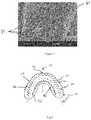
- FIG. 1is a scanning electron micrograph of an unformed tray taken at 8,000 ⁇ magnification, showing the interwoven strands of the polymer imparting high abrasion resistance.
- FIG. 2is a schematic illustration of an unformed tray with strategically placed perforations.
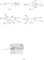
- FIG. 3is a schematic cross section of two adjacent perforations before (a) and during (b) application of grinding forces, illustrating how the shape of the perforations changes during application of grinding forces.
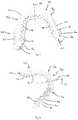
- FIG. 4shows a frontal view of the fitted appliance.
- FIG. 5shows a bottom view of the fitted appliance depicting a lower surface of the appliance that is in contact with the dental surfaces.
- FIG. 6shows another bottom view of the formed appliance.
- FIG. 7 adepicts one embodiment of a formed appliance with circular perforations.
- FIG. 7 bdepicts another embodiment of a formed appliance with circular and teardrop perforations.
- FIG. 7 cdepicts another embodiment of a formed appliance with half moon and teardrop perforations.
- FIG. 7 ddepicts another embodiment of a formed appliance with half moon perforations.
- FIG. 8shows one embodiment of the formed appliance on the dentitions of a user.
- the mouth guard 10has an inner upstanding wall 12 with an inner surface 14 and an outer surface 16 .
- the two surfaces 14 , 16are generally parallel one another.
- the guard 10also has an outer upstanding wall 18 with an inner surface 20 and an outer surface 22 .
- the two surfaces 20 , 22are generally parallel one another.
- the inner upstanding wall 12 and the outer upstanding wall 18are connected at their base portions with a U-shaped occlusal line portion 24 to form a U-shaped cross section.
- the walls 12 , 18 of the guard 10 and the occlusal line portion 24are unitarily formed as one piece.
- the occlusal line portion 24is the part of the device that covers the bite line—the surface of the protected dentition that comes in contact with the surface of the dentition on the other jaw when the individual bites down during grinding or clenching.
- the occlusal line portion 24can also be appreciated from FIG. 8 .
- the guard 10may have an upper edge portion 26 of the outer upstanding wall 18 that is relatively straight, in the preferred embodiment a number of small lobes and cusps are located in the outer upstanding wall 18 .
- the lobes and cuspsare used to enhance the custom fitting process of the guard 10 to the user's teeth by allowing the softened guard material to adapt to any shape of the user's dentitions during the fitting process.
- the upper edge portion 26 of the outer upstanding wall 18is provided with at least one cusp.
- a first cusp 28is provided between a right half 30 and a left half 32 on a centerline 34 at a forward portion 36 of the outer upstanding wall 18 .
- the guard 10is symmetric about the centerline 34 .
- a second cusp 38is provided on the upper edge portion 26 of the outer upstanding wall 18 as well.
- the second cusp 38is provided at a rearward portion 40 of the outer upstanding wall 18 .
- the second cusp 38is positioned so that it is located between the user's incisors and molars (see also FIG. 8 ).
- a lobe 42formed between points 44 and 46 .
- Lobes 42 and cusps 28 , 38are not depicted on the inner upstanding wall 12 but they may be used on this wall 12 as well.
- a cusp 28 , 38is defined as an indentation of the wall 18 of the mouth guard 10
- a lobe 42is defined as a protruding portion of the wall 18 of the guard 10 .
- Multiphysics computer simulation analysishas shown that the cusps 28 , 38 , representing singular points on the curvature of the fitted mouth guard 10 , act as zones where stresses in the material are concentrated and energy is dissipated, adsorbing and dissipating forces from high impact areas, i.e. the occlusal line portion 24 .
- a deformation wave fronttravels though the walls 12 , 18 and crests at a cusp 28 and/or 38 . This directs the impact energy away from the dentition and concentrates it harmlessly in the cusp 28 and/or 38 .
- a plurality of openings 48are located in the inner upstanding wall outer surface 16 .
- the openings 48connect with a plurality of perforations 50 extending through to the inner upstanding wall 12 .
- the perforations 50connect with a plurality of exits 52 in the inner upstanding wall inner surface 14 .
- a plurality of openings 54are located in the outer upstanding wall outer surface 22 .
- the openings 54connect with a plurality of perforations 56 extending through the outer upstanding wall 18 .
- the perforations 56connect with to a plurality of exits 58 in the outer upstanding wall inner surface 20 .
- the strategically placed perforations 50 , 56 in the guard 10distribute the forces from clenched teeth more evenly and prevent abrasion of the teeth.
- the perforations 50 , 56increase the ability of the guard 10 to dissipate energy produced during grinding and clenching of teeth by redirecting the forces generated when teeth are clenched and dissipating the energy by temporarily distorting their shape.
- the openings 48 , 54 and exits 52 , 58maybe circular in shape and the perforations 50 , 56 may be cylindrical.
- the openings 48 , 54 , exits 52 , 58 , and perforations 50 , 56temporarily deform from circles into ovals in the region where a grinding and/or clenching force is applied, as schematically depicted in FIG. 3 b.
- FIGS. 3 a and 3 bdepict two openings 48 , exits 52 and corresponding perforations 50 in the inner upstanding wall 12 .
- a shear force 60which is applied during grinding, travels along the outer surface 16 (in this example) as a wave.
- the waveencounters a first perforation 64 , which becomes temporarily deformed by the wave.
- the wavedeforms the first perforation 64 , which has a circular cross-section, into a perforation with an oval cross-section, which expends some of the energy of the wave.
- the guard 10 in which the perforation 64 is locatedmaintains a constant volume.
- a second perforation 66which is proximate the first perforation 64 gets compressed to account for the deformation of the first perforation 64 .
- the combination of perforation 64 deformation and the compression of an adjacent perforation 66acts to absorb the laterally moving shear force in the guard 10 .
- the amount of compression of an adjacent perforation 66is a function of the amount of deformation caused by the first perforation 64 . It can be appreciated that the deformation and compression occurs across many perforations simultaneously in the guard 10 .
- a shear force generated at a rear portion 68 of the guard 10can be dissipated before it reaches a forward portion 70 of the guard 10 thus causing no distortion in the forward portion 70 perforations.
- the perforations 50 , 56are placed in the walls 12 , 18 to maximize the tensile strength of the guard 10 without exposing any of the protected dental surfaces to the unprotected teeth on the opposite jaw.
- the location of the perforations 50 , 56also optimizes saliva flow around the dentitions, which improves comfort.
- the perforations 50 , 56improve comfort, i.e. improve breathing and decrease drooling, i.e. the flow of saliva outside the mouth. Breathing is improved since the perforations 50 , 56 allow the guard 10 to be thinner and thus take up less space in the mouth. Drooling is decreased since saliva can be sucked straight through the perforations 50 , 56 in the guard 10 . Drooling is a common problem with conventional dental devices and a major reason for poor compliance to use them.
- the optimized saliva flow in the current inventionthat enables the user to suck saliva straight through the guard 10 , thus avoiding saliva accumulation around it, mimics the natural sucking and swallowing of saliva an individual does automatically during sleep.
- the perforations 50 , 56also improve the fitting procedure.
- the fitting procedurebegins by taking the tray 72 depicted in FIG. 2 .
- the tray 72is heated, such as by hot water, microwave energy, or the like. Upon application of heat, the tray 72 becomes malleable.
- the heated tray 72is put into the user's mouth and against the occlusal line of one set of teeth, such as the top set of teeth.
- the perforations 50 , 56allow the user to suck saliva and air through the perforations 50 , 56 during the fitting process. This creates a slight vacuum between the softened guard 10 and the dentitions thus attracting the softened material to the dental surfaces and molding it perfectly around the contours of every tooth.
- the perforations 50 , 56allow the user to suck the softened appliance down onto the dental surface without having to apply any external mechanical pressure. The result is a perfect fit around every individual tooth, no matter the shape or relative location of an individual tooth. Upon cooling, the material retains the shape obtained during the molding process. This overcomes a major problem with conventional fitted mouth guards, where the user has to press the fingers onto the lips from the outside to form the softened fitted mouth guard to the teeth, with generally poor results.
- the perforations 50 , 56can be manufactured in a variety of shapes, sizes, and directions through the unformed tray 72 , but are typically in the range of 1-2 mm in diameter and shaped as cylindrical, straight, horizontal channels penetrating the walls 12 , 18 of the formed guard 10 .
- the location, shape, and direction of these perforations 50 , 56may vary depending on demands on saliva flow, since saliva flow is not uniform throughout the oral cavity. For instance, the saliva flow is higher close to the ducts of the Parotid and submandibular saliva glands, located in the buccal mucosa and in the floor of the mouth.
- salivary glands ductscorrespond to the rear portion 68 of the fitted guard 10 (Parotid glands) and the inner wall in the midline (Submandibular glands), and the perforations 50 , 56 could be bigger in these locations to compensate for greater saliva flow.
- perforations 50 , 56have been proven to increase the ability of the material to dissipate energy produced during grinding and clenching of teeth by temporarily deforming the cylindrical shape of the perforations 50 , 56 , a wide variety of the number of perforations 50 , 56 and of their exact locations and directions in the material can be used.
- the present inventioncan be used on upper as well as lower teeth to improve protection.
- the location, size and shape of the perforations 50 , 56are arranged in special patterns that are optimized to dissipate the shear forces applied to the grinding guard by the teeth of the user suffering from bruxism. Enhanced absorption and dissipation of shear forces can be achieved by strategically placing perforations 50 , 56 having complex shapes such as tear drop shapes or half-moon shapes, as illustrated in FIG. 7 a - d . In some cases, nonsymmetrical perforations, whose shapes are not symmetrical to the laterally traveling shear force wave, are preferable for their ability to absorb and dissipate shear forces.
- a guard 10might have a circular perforation directly adjacent a teardrop perforation.
- adjacentmeans that the adjacent perforations are no more than 1-2 perforation diameters away from one another with no intervening structure. This close relationship of perforations is preferred because it allows them to be in force transmitting communication with one another.
- the distance between perforationsis less than approximately 3 mm and preferably between approximately 1-2 mm.
- FIG. 7 adepicts one embodiment where two rows of perforations are provided. These perforations 56 are from the outer upstanding wall 18 . A first upper row 74 is above a second lower row 76 wherein the perforations 56 in the respective rows are laterally offset from one another and do not overlap. In this embodiment, the perforations 56 in both rows are circular/cylindrical.
- FIG. 7 bdepicts another embodiment where two rows of perforations are provided.
- a first upper row 74is above a second lower row 76 wherein the perforations 56 in the respective rows are laterally offset from one another and do not overlap.
- the perforations in the first row 74are circular/cylindrical 78 ; the perforations in the second row 76 are a teardrop shape 80 .
- FIG. 7 cdepicts another embodiment where two rows of perforations are provided.
- a first upper row 74is above a second lower row 76 wherein the perforations 56 in the respective rows are laterally offset from one another and do not overlap.
- the perforations in the first row 74are a combination of circular/cylindrical 78 and tear dropped shaped 80 ; the perforations in the second row 76 are a combination of half moon shape 82 and circular/cylindrical 78 .
- FIG. 7 ddepicts another embodiment where two rows of perforations are provided.
- a first upper row 74is above a second lower row 76 wherein the perforations in the respective rows are laterally offset from one another and do not overlap.
- the perforations in the first row 74are circular/cylindrical 78 ; the perforations in the second row 76 are a half moon shape 82 .
- guards 10can be highly customized to individual bruxism issues of a user.
- the location, size and shape of perforationscan be tailored to the specific type and severity of bruxism experienced by a user.
- the shapes, sizes, and exact location of these perforationsare determined by multiphysics computer simulations. These multiphysics computer simulations allow to determine the optimum pattern distribution and perforation shapes that allow the guard 10 to deform in such a way that the shear forces applied during grinding are directed into distortions of the perforation shapes in a lateral direction, thereby dissipating energy and protecting the underlying teeth. This permits the appliance to dissipate shear forces by deformation of selected perforations in grinding guard regions that experience shear forces, while maintaining the remaining perforations unaltered. This feature preserves the excellent fit of the grinding guard 10 even under severe bruxism conditions.
- Dental appliances 10are made from a material that is considerably tougher than conventional stock boil and bite appliances, typically made of ethyl vinyl acetate (EVA).
- EVAethyl vinyl acetate
- the increased toughness of the materialimproves its ability to absorb energy and its resistance to damage when stressed during clenching and grinding of teeth.
- the material used in this inventionis substantially less compressible than the materials used in conventional boil and bite appliances.
- the materialis substantially incompressible and substantially constant volume.
- the materialmay be such as polycaprolactone or other thermoplastic polymers.
- the material in the current inventiondeforms only 1.4% under a static load of 2 MPa in comparison to 35% for EVA used in conventional appliances. The less a dental device compresses under impact the less it “caves in”. This means that the impact forces dissipate laterally over the device rather than being transferred through the material to the underlying teeth. Better dissipation of forces increases the protection of the dental surfaces.
- EVA based appliancesneed to be about 4 mm thick to provide adequate protection. Thanks to the superior properties of the material in the current invention, a thickness of on average 1.6 mm (range 1.0-2.5 mm) is sufficient to provide adequate protection of the dentitions against abrasion during grinding of teeth.
- the thinner a night grinding fitted mouth guard 10is the more comfortable it is, which in turn is important for compliance to use the guard. Bulkier dental device tend to cause gagging.
- a thinner fitted mouth guard 10is easier to fit around individual teeth, especially when perforations and the pliability of the current material allows custom fitting to any surface.
- the unformed tray 72may have a uniform thickness, however, when it is fitted the thickness of the appliance may vary.
- the thickness of the fitted guard 10may vary in different areas between 1.0 and 1.8 mm when the unformed tray thickness is approximately 1.6 mm.
- the varying thicknessmay occur in different areas of the unformed tray to provide increased comfort to the user.
- the unformed tray 72may be deliberately made thicker in specific areas where dental abrasion is suspected to occur. This can be accomplished by starting from an unformed tray 72 that has regions of different thickness.
- the material covering the bite linecould be made thicker uniformly or only in specific areas, such as the molar region.
- the appliance according to the inventionis based on a thermo-plastic polymer with low compressibility.
- the polymersoftens when heated to temperatures above 50° C., allowing it to be conformally fitted to the dentitions.
- the physical properties of this thermo-plastic polymersuch as compressibility, toughness, tensile strength, pliability, and melting point can be adjusted by synthesizing the polymer with different molecular weight distributions (with mean molecular weight in the range of 20,000-80,000), or by incorporating nano-particles and other materials like bentonite clay nanoparticles modified by surfactants such as Stepantex SP-90, to get additional benefits, e.g. increased tensile strength, lower melting temperature, etc.
- the polymeris highly abrasion resistant thanks to its structure that contains interwoven strands 84 of polymer, as shown in a magnified scanning electron microscope image ( FIG. 1 ). Since these strands 84 are interwoven and extend deep into the material, they will not easily be pulled out or removed from the material during grinding of teeth, thereby making the appliance more abrasion resistant.
- the shape of the unformed tray 72facilitates the fitting of the softened material by being wide enough to cover all teeth and wrap around them, and by being narrow enough not to cause pressure on the teeth when the fitted mouth guard 10 cools off and contracts around the teeth.
- night grinding fitted mouth guardsare used for 6-10 hours straight, and therefore need to be extremely comfortable to guarantee compliance to use them during an entire night's sleep.
- the carefully designed shape, with cusps 28 , 38 and lobes 42prevents the material from folding when the soft material is molded up against the teeth.
- the width of the dental unformed trayhas also been carefully designed to cover the curved occlusal line portion 24 with solid material without perforations and still allow the user to mold the material up on the inside and outside of each tooth.
- FIG. 3shows an example of a fitted appliance.
- the usercan fit the mouth guard 10 on site or at home without assistance of health professionals. Fitting is superior due to the distinct properties of the polymer (thin and pliable at moderate temperatures), and to the design of the unformed dental tray 72 with strategically placed perforations 50 , 56 , as described above, and lobes 42 and cusps 28 , 38 as described above. These properties permit the user to place and fit the heated, softened material over the dentition through a rapid process wherein the material is sucked onto the teeth.
- the perforations 50 , 56enhance the effect of the suctioning by allowing the user to create a negative pressure between the teeth and the material, thus sucking the material down to every irregularity of the teeth.
- the suctioning maneuvercreates a minimal dead space between the material and the teeth, thus leading to a perfect, conformal fit.
- conformal fittingcannot be done since not enough negative pressure can be built up between a solid material and the dentition. This is reflected in the instructions of conventional fitted mouth guards, where the user is directed to apply downward mechanical pressure on the material, from outside with the fingers, to force the material to come closer to the teeth.
- Polymer-based guard 10 according to this inventionare inexpensive and disposable thereby improving oral hygiene. Users can move their jaws in any way without risking the guard 10 becoming dislodged.
- the guard 10can be re-shaped to optimize fitting by re-heating to the softening point and repeating the fitting.
- the superior fit of the guard 10also results in the need for less material on the inside of the teeth, which in turn reduces gagging and improves comfort.
Landscapes
- Health & Medical Sciences (AREA)
- Otolaryngology (AREA)
- Pulmonology (AREA)
- Nursing (AREA)
- Orthopedic Medicine & Surgery (AREA)
- Engineering & Computer Science (AREA)
- Biomedical Technology (AREA)
- Heart & Thoracic Surgery (AREA)
- Vascular Medicine (AREA)
- Life Sciences & Earth Sciences (AREA)
- Animal Behavior & Ethology (AREA)
- General Health & Medical Sciences (AREA)
- Public Health (AREA)
- Veterinary Medicine (AREA)
- Dental Tools And Instruments Or Auxiliary Dental Instruments (AREA)
Abstract
Description
Claims (18)
Priority Applications (3)
| Application Number | Priority Date | Filing Date | Title |
|---|---|---|---|
| US13/894,469US10945874B2 (en) | 2012-05-15 | 2013-05-15 | Custom-formable night grinding appliance and method of use |
| US17/179,791US20210236325A1 (en) | 2012-05-15 | 2021-02-19 | Custom-formable night grinding appliance and method of use |
| US17/369,516US11419752B2 (en) | 2012-05-15 | 2021-07-07 | Custom-formable night grinding appliance and method of use |
Applications Claiming Priority (2)
| Application Number | Priority Date | Filing Date | Title |
|---|---|---|---|
| US201261647093P | 2012-05-15 | 2012-05-15 | |
| US13/894,469US10945874B2 (en) | 2012-05-15 | 2013-05-15 | Custom-formable night grinding appliance and method of use |
Related Child Applications (1)
| Application Number | Title | Priority Date | Filing Date |
|---|---|---|---|
| US17/179,791ContinuationUS20210236325A1 (en) | 2012-05-15 | 2021-02-19 | Custom-formable night grinding appliance and method of use |
Publications (2)
| Publication Number | Publication Date |
|---|---|
| US20140338675A1 US20140338675A1 (en) | 2014-11-20 |
| US10945874B2true US10945874B2 (en) | 2021-03-16 |
Family
ID=51894777
Family Applications (3)
| Application Number | Title | Priority Date | Filing Date |
|---|---|---|---|
| US13/894,469Active2036-01-05US10945874B2 (en) | 2012-05-15 | 2013-05-15 | Custom-formable night grinding appliance and method of use |
| US17/179,791AbandonedUS20210236325A1 (en) | 2012-05-15 | 2021-02-19 | Custom-formable night grinding appliance and method of use |
| US17/369,516ActiveUS11419752B2 (en) | 2012-05-15 | 2021-07-07 | Custom-formable night grinding appliance and method of use |
Family Applications After (2)
| Application Number | Title | Priority Date | Filing Date |
|---|---|---|---|
| US17/179,791AbandonedUS20210236325A1 (en) | 2012-05-15 | 2021-02-19 | Custom-formable night grinding appliance and method of use |
| US17/369,516ActiveUS11419752B2 (en) | 2012-05-15 | 2021-07-07 | Custom-formable night grinding appliance and method of use |
Country Status (1)
| Country | Link |
|---|---|
| US (3) | US10945874B2 (en) |
Cited By (1)
| Publication number | Priority date | Publication date | Assignee | Title |
|---|---|---|---|---|
| US11793665B1 (en) | 2022-04-14 | 2023-10-24 | Gregory Todd Steiger | Vented dental appliance for bruxism relief |
Families Citing this family (6)
| Publication number | Priority date | Publication date | Assignee | Title |
|---|---|---|---|---|
| US10945874B2 (en)* | 2012-05-15 | 2021-03-16 | Akervall Technologies, Inc. | Custom-formable night grinding appliance and method of use |
| US10070941B2 (en)* | 2015-05-21 | 2018-09-11 | Nordic Design, Llc | Thin-form nightguard |
| CN108670533A (en)* | 2018-07-25 | 2018-10-19 | 湖南省天骑医学新技术股份有限公司 | A kind of metal snore relieving facing and preparation method thereof |
| KR102325958B1 (en)* | 2021-05-31 | 2021-11-12 | 이동훈 | Guard for the prevention of bruxism |
| KR102392434B1 (en)* | 2021-10-20 | 2022-04-29 | 이동훈 | A mouse guard that can absorb shock and manufacturing method therefor |
| KR102736255B1 (en)* | 2022-07-04 | 2024-11-28 | 이동훈 | Guard for prevention of bruxism by exchanging partial tooth |
Citations (86)
| Publication number | Priority date | Publication date | Assignee | Title |
|---|---|---|---|---|
| US4374690A (en)* | 1980-12-31 | 1983-02-22 | Mobil Oil Corporation | Multidirectionally oriented films |
| US4537689A (en) | 1983-12-19 | 1985-08-27 | The Board Of Regents, University Of Texas System | Oral lubricant for athletic mouth protector |
| US4838283A (en) | 1987-11-13 | 1989-06-13 | Lee Jr Alexander Y | Anti-bruxism device |
| US4995404A (en) | 1988-08-25 | 1991-02-26 | Nemir David C | Apparatus for treating bruxism |
| RO101093B1 (en) | 1988-04-18 | 1992-11-03 | Dental protection composition | |
| US5163840A (en) | 1990-06-25 | 1992-11-17 | Bourke Kevin J | Method and apparatus for dental treatment |
| US5190051A (en) | 1990-04-12 | 1993-03-02 | Wilson Mark J | Bruxism-relaxing trainer |
| US5313960A (en) | 1992-11-04 | 1994-05-24 | Marc S. Bernstein | Apparatus and method for reducing snoring and method of making same |
| US5490520A (en) | 1993-09-27 | 1996-02-13 | Schaefer Partnership | Dental applicance for treating bruxism |
| US5499633A (en) | 1993-12-17 | 1996-03-19 | Fenton; Douglas F. | Anti-snoring device with adjustable upper and lower relational members |
| US5586562A (en) | 1995-07-14 | 1996-12-24 | Matz; Warren W. | Device for sensing and treating bruxism |
| US5666973A (en) | 1990-11-28 | 1997-09-16 | Walter; Janos | Device to reduce or prevent night clenching and grinding of teeth and snoring |
| US5678993A (en) | 1994-04-26 | 1997-10-21 | Austenal, Inc. | Methods of lining dentures and denture voids and forming denture extensions |
| US5692523A (en)* | 1996-10-15 | 1997-12-02 | Theodore P. Croll | Two-piece mouthguard |
| US5823193A (en) | 1997-01-27 | 1998-10-20 | Singer; Gary H. | Dental appliance for alleviating snoring and protecting teeth from bruxism |
| US5876199A (en) | 1997-08-28 | 1999-03-02 | Ortho-Tain, Inc. | Appliance adapted to fit many mouth and tooth sizes for orthodontic correction and other uses |
| US5934907A (en) | 1997-06-23 | 1999-08-10 | Oro-Health International, Inc. | Dental prosthesis with multi-section infrastructure and method for replacement of teeth |
| US6036487A (en) | 1994-02-23 | 2000-03-14 | Fastcote Pty Ltd. | Mouthguard blank and mouthguard |
| US6080923A (en) | 1995-12-27 | 2000-06-27 | Austin; Joel Andrew | Reusable lip guard for brass and woodwind musicians who wear braces |
| US6109266A (en) | 1997-04-30 | 2000-08-29 | Quattroti Dentech S.A.S. Di Turchetti Mauro E.C. | Mouthguard and mouth-piece for the prevention of oro-maxillofacial traumas deriving in particular from sport activities |
| US6117092A (en) | 1996-05-24 | 2000-09-12 | Bruxcare L.L.C. | Bruxism biofeedback apparatus and method |
| WO2001012896A1 (en)* | 1999-08-13 | 2001-02-22 | Gore Enterprise Holdings, Inc. | Fibrous polymeric material and its composites |
| US6241518B1 (en) | 1999-11-22 | 2001-06-05 | Terrence C. Sullivan | Apparatus and method for preventing tooth grinding in patients wearing braces |
| US6295988B1 (en) | 1997-09-17 | 2001-10-02 | Steven K. Sue | Tongue lift and lip seal mouthpiece |
| US6302110B1 (en) | 1998-01-20 | 2001-10-16 | Nobutaka Yoshida | Dental protector against bruxism |
| US20020168451A1 (en) | 2000-08-18 | 2002-11-14 | O'donnell Kiely Alice Mary | Edible malleable supports for comestibles with optional, edible mess guards and drip guards |
| JP2002336286A (en) | 2001-05-17 | 2002-11-26 | Sorueesu:Kk | Mouth tape |
| US20020189608A1 (en) | 2001-04-04 | 2002-12-19 | Bryan Raudenbush | Enhancing athletic performance through the administration of peppermint odor |
| US20030075184A1 (en) | 2001-10-19 | 2003-04-24 | Persichetti Stephen J. | Disposable mouthguard |
| US20040154625A1 (en)* | 2002-12-31 | 2004-08-12 | Foley Timothy W. | Mouthguard and method of making the mouthguard |
| US20050034733A1 (en) | 2003-08-13 | 2005-02-17 | All Dental Prodx, Llc | System and method for fabricating an interim dental guard device |
| USD504744S1 (en) | 2002-07-15 | 2005-05-03 | Dental Campus Llc | Bruxism guard |
| US20050113654A1 (en) | 2001-08-27 | 2005-05-26 | Weber Paul J. | Body function monitoring mouth guard |
| US20050137514A1 (en)* | 2001-08-27 | 2005-06-23 | Vito Robert A. | Vibration dampening material and method of making same |
| US20060021622A1 (en) | 2004-07-30 | 2006-02-02 | Buffington Robert T | Bruxism appliance |
| US7004756B2 (en) | 2003-01-24 | 2006-02-28 | Ultradent Products, Inc. | Pre-shaped dental trays and treatment devices and methods that utilize such dental trays |
| US20060096602A1 (en) | 2004-11-10 | 2006-05-11 | Brown Thomas W | Dental appliance for minimizing effects of bruxism |
| US7047978B2 (en) | 2000-01-13 | 2006-05-23 | Michael Yar Zuk | Bruxism appliance and method of forming |
| US20070023055A1 (en) | 2005-07-30 | 2007-02-01 | Roth Steven E | Dental appliance to prevent the negative effects of bruxism |
| US20070142498A1 (en)* | 2005-12-20 | 2007-06-21 | Brennan Joan V | Dental compositions including thermally responsive additives, and the use thereof |
| US20070151568A1 (en) | 2006-01-05 | 2007-07-05 | John Maurello | Mouthguard |
| US20070151567A1 (en) | 2006-01-05 | 2007-07-05 | John Maurello | Easy breathing mouthguard |
| US20070235039A1 (en) | 2006-04-10 | 2007-10-11 | Gottsch Sheila L | Flavored mouthguard |
| CA2591466A1 (en) | 2006-06-14 | 2007-12-14 | Leonard Wayne Halstrom | Intra-oral appliance for treatment of sleep disorders |
| US20080044797A1 (en) | 2006-08-15 | 2008-02-21 | Laura Bardach | Inserts for use with oral appliances |
| US20080066768A1 (en) | 2006-09-19 | 2008-03-20 | Dembro Jay L | Flexible dental appliance |
| US20080115792A1 (en) | 2004-01-13 | 2008-05-22 | Michael Albertus Burger | Device for Preventing Bruxism |
| US20080156324A1 (en) | 2007-01-02 | 2008-07-03 | Isen Innovations, Llc | Scented and flavored oral airways |
| BRPI0605444A (en) | 2006-11-24 | 2008-07-08 | Marcelo Costa Bolzan | occlusal plate of conditional function |
| US7404404B2 (en) | 2004-04-29 | 2008-07-29 | Lbb Enterprises, Llc | Anterior sextant dental bite tray apparatus |
| US20080199824A1 (en) | 2007-02-21 | 2008-08-21 | Hargadon Paul K | Magnetic dental appliance |
| US20080243023A1 (en) | 2004-06-22 | 2008-10-02 | Cornelis Albert Valkhof | Device For Preventing Bruxism |
| US20080289638A1 (en) | 2007-05-22 | 2008-11-27 | Scott Alan Peters | Mouthpiece with soft low-friction overlay |
| US20080295850A1 (en) | 2007-06-04 | 2008-12-04 | Frank Lesniak | Interocclusal appliance and method |
| US7481653B2 (en) | 2003-01-24 | 2009-01-27 | Oratech Lc | Preshaped thin-walled dental trays and methods of manufacturing and using such trays |
| US20090038624A1 (en)* | 2007-08-09 | 2009-02-12 | Jan Akervall | Custom-formable mouth guard and method of fabrication |
| US20090056726A1 (en) | 2002-05-06 | 2009-03-05 | Dynamic Mouth Devices Llc | Therapeutic and protective dental device useful as an intra-oral delivery system |
| US20090087812A1 (en) | 2007-10-02 | 2009-04-02 | Ultradent Products, Inc. | Self-customizable dental treatment trays |
| US20090130624A1 (en) | 2007-11-20 | 2009-05-21 | Benjamin Jiemin Sun | Methods and kits for making flexible dental guards |
| US20090159089A1 (en) | 2007-12-21 | 2009-06-25 | Dentek Oral Care, Inc. | Low profile mouthguard |
| US20090165805A1 (en) | 2007-12-30 | 2009-07-02 | Oral Technology, Llc | Mouth Guard |
| US20090277461A1 (en) | 2006-02-01 | 2009-11-12 | Gallagher Jr John H | Oral appliance |
| US7637262B2 (en) | 2006-06-12 | 2009-12-29 | Bailey Dennis R | Anti-retrusion oral appliance |
| US20100009311A1 (en) | 2006-01-25 | 2010-01-14 | Pelerin Joseph J | Mouth guard |
| US20100028829A1 (en) | 2008-07-31 | 2010-02-04 | Ultradent Products, Inc. | Chemically activated dental bleaching trays |
| US20100055233A1 (en) | 2008-08-29 | 2010-03-04 | A. Schulman, Inc | Optimized Flavored Polymeric Compositions |
| WO2010023655A1 (en) | 2008-08-25 | 2010-03-04 | Toam Shemesh | Apparatus for the diagnosis and treatment of bruxism |
| WO2010040050A2 (en) | 2008-10-03 | 2010-04-08 | Sleeping Well Llc | Mandibular advancement device with positive positioning hinge |
| US20100104998A1 (en) | 2008-10-25 | 2010-04-29 | Stanley Edward Farrell | Dental Splint |
| US20100147315A1 (en) | 2008-12-16 | 2010-06-17 | Chodorow Ingram S | Bruxism protective device |
| US20100206314A1 (en) | 2009-02-16 | 2010-08-19 | Brown Thomas W | Dental appliance for minimizing effects of bruxism |
| BRPI0901237A2 (en) | 2009-04-15 | 2010-12-28 | Kenya Karla Felicissimo Goncalves | snoring and sleep apnea treatment apparatus and for use as a mouthguard |
| US20110030704A1 (en) | 2009-08-07 | 2011-02-10 | Hanna Wadia M | Method and apparatus for protecting teeth, preventing the effects of bruxism and protecting oral structures from sports injuries |
| US7891976B2 (en) | 2004-12-03 | 2011-02-22 | Rocky Mountain Morita Corp. | Bruxism evaluation sheet |
| US20110067711A1 (en) | 2009-09-23 | 2011-03-24 | Dentek Oral Care Inc. | Night time dental protector |
| US20110067710A1 (en) | 2009-09-23 | 2011-03-24 | Dentek Oral Care Inc. | Night time dental protector |
| US20110139162A1 (en) | 2009-11-16 | 2011-06-16 | Chodorow Ingram S | Bruxism protective device |
| US20110168186A1 (en) | 2010-01-13 | 2011-07-14 | Leonard Wayne Halstrom | Intra-oral appliance for treatment of sleep disorders |
| US20110174319A1 (en) | 2010-01-15 | 2011-07-21 | Busciglio David J | Apparatus for the suppression of grinding and/or clenching of teeth |
| US20110180077A1 (en) | 2010-01-22 | 2011-07-28 | Rene Garcia | Device and Methods for Treatment of Temporomandibular Joint (TMJ) Disorder |
| US20110195376A1 (en) | 2010-02-09 | 2011-08-11 | Boyd Sr James P | Multipurpose therapeutic mouthpiece assembly |
| US8007277B2 (en) | 2006-08-25 | 2011-08-30 | Ultradent Products, Inc. | Non-custom dental treatment trays and mouth guards having improved anatomical features |
| US20110230587A1 (en) | 2008-08-29 | 2011-09-22 | A. Schulman, Inc. | Flavored polymeric articles |
| DE102010023256B3 (en) | 2010-06-09 | 2011-11-10 | Jürgen Schmitt-Bylandt | Mouth insert for dental treatment, has biting elements fastened to wire-type element provided with U-shaped retainers that are connected with each other, where biting elements are fastened to leg-sided passages between retainers |
| US20130299317A1 (en)* | 2012-05-03 | 2013-11-14 | Big Dutchman International Gmbh | Egg belt |
| US20140259330A1 (en)* | 2013-03-13 | 2014-09-18 | Nike, Inc. | Monolithic protective article with flexible region |
Family Cites Families (6)
| Publication number | Priority date | Publication date | Assignee | Title |
|---|---|---|---|---|
| US6302100B1 (en) | 1996-06-12 | 2001-10-16 | Leonard Vandenberg | System for collimating and concentrating direct and diffused radiation |
| US6079977A (en)* | 1999-03-03 | 2000-06-27 | Persichetti; Joseph A. | Dental impression tray |
| US20120017922A1 (en)* | 2010-07-23 | 2012-01-26 | Jr286 Technologies, Inc. | Mouthguard having breathing cavities and breathing holes incorporated into the body of the mouthguard |
| US20120325225A1 (en)* | 2011-06-24 | 2012-12-27 | Trevor Scott Small | Swing bite mini mouthpiece |
| JP2013180090A (en)* | 2012-03-02 | 2013-09-12 | Gc Corp | Impression tray for lower jaw |
| US10945874B2 (en)* | 2012-05-15 | 2021-03-16 | Akervall Technologies, Inc. | Custom-formable night grinding appliance and method of use |
- 2013
- 2013-05-15USUS13/894,469patent/US10945874B2/enactiveActive
- 2021
- 2021-02-19USUS17/179,791patent/US20210236325A1/ennot_activeAbandoned
- 2021-07-07USUS17/369,516patent/US11419752B2/enactiveActive
Patent Citations (88)
| Publication number | Priority date | Publication date | Assignee | Title |
|---|---|---|---|---|
| US4374690A (en)* | 1980-12-31 | 1983-02-22 | Mobil Oil Corporation | Multidirectionally oriented films |
| US4537689A (en) | 1983-12-19 | 1985-08-27 | The Board Of Regents, University Of Texas System | Oral lubricant for athletic mouth protector |
| US4838283A (en) | 1987-11-13 | 1989-06-13 | Lee Jr Alexander Y | Anti-bruxism device |
| RO101093B1 (en) | 1988-04-18 | 1992-11-03 | Dental protection composition | |
| US4995404A (en) | 1988-08-25 | 1991-02-26 | Nemir David C | Apparatus for treating bruxism |
| US5190051A (en) | 1990-04-12 | 1993-03-02 | Wilson Mark J | Bruxism-relaxing trainer |
| US5163840A (en) | 1990-06-25 | 1992-11-17 | Bourke Kevin J | Method and apparatus for dental treatment |
| US5666973A (en) | 1990-11-28 | 1997-09-16 | Walter; Janos | Device to reduce or prevent night clenching and grinding of teeth and snoring |
| US5313960A (en) | 1992-11-04 | 1994-05-24 | Marc S. Bernstein | Apparatus and method for reducing snoring and method of making same |
| US5490520A (en) | 1993-09-27 | 1996-02-13 | Schaefer Partnership | Dental applicance for treating bruxism |
| US5499633A (en) | 1993-12-17 | 1996-03-19 | Fenton; Douglas F. | Anti-snoring device with adjustable upper and lower relational members |
| US6036487A (en) | 1994-02-23 | 2000-03-14 | Fastcote Pty Ltd. | Mouthguard blank and mouthguard |
| US5678993A (en) | 1994-04-26 | 1997-10-21 | Austenal, Inc. | Methods of lining dentures and denture voids and forming denture extensions |
| US5586562A (en) | 1995-07-14 | 1996-12-24 | Matz; Warren W. | Device for sensing and treating bruxism |
| US6080923A (en) | 1995-12-27 | 2000-06-27 | Austin; Joel Andrew | Reusable lip guard for brass and woodwind musicians who wear braces |
| US6117092A (en) | 1996-05-24 | 2000-09-12 | Bruxcare L.L.C. | Bruxism biofeedback apparatus and method |
| US5692523A (en)* | 1996-10-15 | 1997-12-02 | Theodore P. Croll | Two-piece mouthguard |
| US5823193A (en) | 1997-01-27 | 1998-10-20 | Singer; Gary H. | Dental appliance for alleviating snoring and protecting teeth from bruxism |
| US6109266A (en) | 1997-04-30 | 2000-08-29 | Quattroti Dentech S.A.S. Di Turchetti Mauro E.C. | Mouthguard and mouth-piece for the prevention of oro-maxillofacial traumas deriving in particular from sport activities |
| US5934907A (en) | 1997-06-23 | 1999-08-10 | Oro-Health International, Inc. | Dental prosthesis with multi-section infrastructure and method for replacement of teeth |
| US5876199A (en) | 1997-08-28 | 1999-03-02 | Ortho-Tain, Inc. | Appliance adapted to fit many mouth and tooth sizes for orthodontic correction and other uses |
| US6295988B1 (en) | 1997-09-17 | 2001-10-02 | Steven K. Sue | Tongue lift and lip seal mouthpiece |
| US6302110B1 (en) | 1998-01-20 | 2001-10-16 | Nobutaka Yoshida | Dental protector against bruxism |
| WO2001012896A1 (en)* | 1999-08-13 | 2001-02-22 | Gore Enterprise Holdings, Inc. | Fibrous polymeric material and its composites |
| US6241518B1 (en) | 1999-11-22 | 2001-06-05 | Terrence C. Sullivan | Apparatus and method for preventing tooth grinding in patients wearing braces |
| US7047978B2 (en) | 2000-01-13 | 2006-05-23 | Michael Yar Zuk | Bruxism appliance and method of forming |
| US20020168451A1 (en) | 2000-08-18 | 2002-11-14 | O'donnell Kiely Alice Mary | Edible malleable supports for comestibles with optional, edible mess guards and drip guards |
| US20020189608A1 (en) | 2001-04-04 | 2002-12-19 | Bryan Raudenbush | Enhancing athletic performance through the administration of peppermint odor |
| JP2002336286A (en) | 2001-05-17 | 2002-11-26 | Sorueesu:Kk | Mouth tape |
| US20050113654A1 (en) | 2001-08-27 | 2005-05-26 | Weber Paul J. | Body function monitoring mouth guard |
| US20050137514A1 (en)* | 2001-08-27 | 2005-06-23 | Vito Robert A. | Vibration dampening material and method of making same |
| US20030075184A1 (en) | 2001-10-19 | 2003-04-24 | Persichetti Stephen J. | Disposable mouthguard |
| US20090075230A1 (en) | 2002-05-06 | 2009-03-19 | Dynamic Mouth Devices Llc | Teething ring |
| US20090056726A1 (en) | 2002-05-06 | 2009-03-05 | Dynamic Mouth Devices Llc | Therapeutic and protective dental device useful as an intra-oral delivery system |
| USD504744S1 (en) | 2002-07-15 | 2005-05-03 | Dental Campus Llc | Bruxism guard |
| US20040154625A1 (en)* | 2002-12-31 | 2004-08-12 | Foley Timothy W. | Mouthguard and method of making the mouthguard |
| US7004756B2 (en) | 2003-01-24 | 2006-02-28 | Ultradent Products, Inc. | Pre-shaped dental trays and treatment devices and methods that utilize such dental trays |
| US7481653B2 (en) | 2003-01-24 | 2009-01-27 | Oratech Lc | Preshaped thin-walled dental trays and methods of manufacturing and using such trays |
| US20050034733A1 (en) | 2003-08-13 | 2005-02-17 | All Dental Prodx, Llc | System and method for fabricating an interim dental guard device |
| US20080115792A1 (en) | 2004-01-13 | 2008-05-22 | Michael Albertus Burger | Device for Preventing Bruxism |
| US7404404B2 (en) | 2004-04-29 | 2008-07-29 | Lbb Enterprises, Llc | Anterior sextant dental bite tray apparatus |
| US20080243023A1 (en) | 2004-06-22 | 2008-10-02 | Cornelis Albert Valkhof | Device For Preventing Bruxism |
| US20060021622A1 (en) | 2004-07-30 | 2006-02-02 | Buffington Robert T | Bruxism appliance |
| US20060096602A1 (en) | 2004-11-10 | 2006-05-11 | Brown Thomas W | Dental appliance for minimizing effects of bruxism |
| US7891976B2 (en) | 2004-12-03 | 2011-02-22 | Rocky Mountain Morita Corp. | Bruxism evaluation sheet |
| US20070023055A1 (en) | 2005-07-30 | 2007-02-01 | Roth Steven E | Dental appliance to prevent the negative effects of bruxism |
| US20070142498A1 (en)* | 2005-12-20 | 2007-06-21 | Brennan Joan V | Dental compositions including thermally responsive additives, and the use thereof |
| US20070151567A1 (en) | 2006-01-05 | 2007-07-05 | John Maurello | Easy breathing mouthguard |
| US20070151568A1 (en) | 2006-01-05 | 2007-07-05 | John Maurello | Mouthguard |
| US20100009311A1 (en) | 2006-01-25 | 2010-01-14 | Pelerin Joseph J | Mouth guard |
| US20090277461A1 (en) | 2006-02-01 | 2009-11-12 | Gallagher Jr John H | Oral appliance |
| US20070235039A1 (en) | 2006-04-10 | 2007-10-11 | Gottsch Sheila L | Flavored mouthguard |
| US7637262B2 (en) | 2006-06-12 | 2009-12-29 | Bailey Dennis R | Anti-retrusion oral appliance |
| CA2591466A1 (en) | 2006-06-14 | 2007-12-14 | Leonard Wayne Halstrom | Intra-oral appliance for treatment of sleep disorders |
| US20080044797A1 (en) | 2006-08-15 | 2008-02-21 | Laura Bardach | Inserts for use with oral appliances |
| US8007277B2 (en) | 2006-08-25 | 2011-08-30 | Ultradent Products, Inc. | Non-custom dental treatment trays and mouth guards having improved anatomical features |
| US20080066768A1 (en) | 2006-09-19 | 2008-03-20 | Dembro Jay L | Flexible dental appliance |
| BRPI0605444A (en) | 2006-11-24 | 2008-07-08 | Marcelo Costa Bolzan | occlusal plate of conditional function |
| US20080156324A1 (en) | 2007-01-02 | 2008-07-03 | Isen Innovations, Llc | Scented and flavored oral airways |
| US20080199824A1 (en) | 2007-02-21 | 2008-08-21 | Hargadon Paul K | Magnetic dental appliance |
| US20080289638A1 (en) | 2007-05-22 | 2008-11-27 | Scott Alan Peters | Mouthpiece with soft low-friction overlay |
| US20080295850A1 (en) | 2007-06-04 | 2008-12-04 | Frank Lesniak | Interocclusal appliance and method |
| US20090038624A1 (en)* | 2007-08-09 | 2009-02-12 | Jan Akervall | Custom-formable mouth guard and method of fabrication |
| US20090087812A1 (en) | 2007-10-02 | 2009-04-02 | Ultradent Products, Inc. | Self-customizable dental treatment trays |
| US20090130624A1 (en) | 2007-11-20 | 2009-05-21 | Benjamin Jiemin Sun | Methods and kits for making flexible dental guards |
| US20090159089A1 (en) | 2007-12-21 | 2009-06-25 | Dentek Oral Care, Inc. | Low profile mouthguard |
| US20090165805A1 (en) | 2007-12-30 | 2009-07-02 | Oral Technology, Llc | Mouth Guard |
| US20100028829A1 (en) | 2008-07-31 | 2010-02-04 | Ultradent Products, Inc. | Chemically activated dental bleaching trays |
| WO2010023655A1 (en) | 2008-08-25 | 2010-03-04 | Toam Shemesh | Apparatus for the diagnosis and treatment of bruxism |
| US20100055233A1 (en) | 2008-08-29 | 2010-03-04 | A. Schulman, Inc | Optimized Flavored Polymeric Compositions |
| US20110230587A1 (en) | 2008-08-29 | 2011-09-22 | A. Schulman, Inc. | Flavored polymeric articles |
| WO2010040050A2 (en) | 2008-10-03 | 2010-04-08 | Sleeping Well Llc | Mandibular advancement device with positive positioning hinge |
| US20100104998A1 (en) | 2008-10-25 | 2010-04-29 | Stanley Edward Farrell | Dental Splint |
| WO2010074822A1 (en) | 2008-12-16 | 2010-07-01 | Ranir Llc | Bruxism protective device |
| US20100147315A1 (en) | 2008-12-16 | 2010-06-17 | Chodorow Ingram S | Bruxism protective device |
| US20100206314A1 (en) | 2009-02-16 | 2010-08-19 | Brown Thomas W | Dental appliance for minimizing effects of bruxism |
| BRPI0901237A2 (en) | 2009-04-15 | 2010-12-28 | Kenya Karla Felicissimo Goncalves | snoring and sleep apnea treatment apparatus and for use as a mouthguard |
| US20110030704A1 (en) | 2009-08-07 | 2011-02-10 | Hanna Wadia M | Method and apparatus for protecting teeth, preventing the effects of bruxism and protecting oral structures from sports injuries |
| US20110067710A1 (en) | 2009-09-23 | 2011-03-24 | Dentek Oral Care Inc. | Night time dental protector |
| US20110067711A1 (en) | 2009-09-23 | 2011-03-24 | Dentek Oral Care Inc. | Night time dental protector |
| US20110139162A1 (en) | 2009-11-16 | 2011-06-16 | Chodorow Ingram S | Bruxism protective device |
| US20110168186A1 (en) | 2010-01-13 | 2011-07-14 | Leonard Wayne Halstrom | Intra-oral appliance for treatment of sleep disorders |
| US20110174319A1 (en) | 2010-01-15 | 2011-07-21 | Busciglio David J | Apparatus for the suppression of grinding and/or clenching of teeth |
| US20110180077A1 (en) | 2010-01-22 | 2011-07-28 | Rene Garcia | Device and Methods for Treatment of Temporomandibular Joint (TMJ) Disorder |
| US20110195376A1 (en) | 2010-02-09 | 2011-08-11 | Boyd Sr James P | Multipurpose therapeutic mouthpiece assembly |
| DE102010023256B3 (en) | 2010-06-09 | 2011-11-10 | Jürgen Schmitt-Bylandt | Mouth insert for dental treatment, has biting elements fastened to wire-type element provided with U-shaped retainers that are connected with each other, where biting elements are fastened to leg-sided passages between retainers |
| US20130299317A1 (en)* | 2012-05-03 | 2013-11-14 | Big Dutchman International Gmbh | Egg belt |
| US20140259330A1 (en)* | 2013-03-13 | 2014-09-18 | Nike, Inc. | Monolithic protective article with flexible region |
Non-Patent Citations (2)
| Title |
|---|
| Jansen, Jeffrey A., Plastics—Its All About Molecular Structure, Sep. 2016, Plastics Engineering, p. 31 (Year: 2016).* |
| Sigma Aldrich, Polycaprolactone, 2019, https://www.sigmaaldrich.com/catalog/product/aldrich/440744?lang=en®ion=US (Year: 2019).* |
Cited By (1)
| Publication number | Priority date | Publication date | Assignee | Title |
|---|---|---|---|---|
| US11793665B1 (en) | 2022-04-14 | 2023-10-24 | Gregory Todd Steiger | Vented dental appliance for bruxism relief |
Also Published As
| Publication number | Publication date |
|---|---|
| US20210361472A1 (en) | 2021-11-25 |
| US11419752B2 (en) | 2022-08-23 |
| US20140338675A1 (en) | 2014-11-20 |
| US20210236325A1 (en) | 2021-08-05 |
Similar Documents
| Publication | Publication Date | Title |
|---|---|---|
| US11419752B2 (en) | Custom-formable night grinding appliance and method of use | |
| TWI704909B (en) | Oropharyngeal swallowing training aid with open occlusal surface and manufacturing method thereof | |
| US8573224B2 (en) | Custom-molded oral appliance and method of forming | |
| CN105451681B (en) | Dental appliances removably mounted on teeth | |
| CA2687296C (en) | Interocclusal appliance and method | |
| AU2010200550B2 (en) | An orthodontic appliance | |
| EP1511440B1 (en) | Reducing facial ageing and appliance therefor | |
| US20090165805A1 (en) | Mouth Guard | |
| JP4476583B2 (en) | Oral appliance and method for manufacturing the same | |
| GB2141937A (en) | Craniomandibular appliance | |
| CA2728920A1 (en) | Composite oral appliances and methods for manufacture | |
| US8752554B2 (en) | Mouth guards for treating of temporomandibular disorder and associated methods | |
| US20140087332A1 (en) | Multilayer mouthpiece, manufacturing method and manufacturing device thereof | |
| JP7471664B2 (en) | Dental Equipment | |
| CN1292252A (en) | anti snoring device | |
| CN209884376U (en) | A custom orthodontic system | |
| US20110171592A1 (en) | Method of Direct Fabrication of Intraoral Devices | |
| US20080289638A1 (en) | Mouthpiece with soft low-friction overlay | |
| US20040214140A1 (en) | Anatomical preformed tray incorporating a severable handle | |
| CN105517513B (en) | Appliance for reducing facial aging and/or oral parafunctional activity | |
| US11612456B2 (en) | Clear plastic aligner protrusions for anterior or open bite treatment and mattress plastic material for invisible aligners | |
| US8656926B2 (en) | Intra-oral device and method of relieving head, neck, facial, joint and tooth pain | |
| EP3164184B1 (en) | A dental appliance and method of protecting dentition during a transoral procedure with the appliance | |
| CN220834079U (en) | Shape memory basketball mouthguard | |
| US20180325722A1 (en) | Mouthguard |
Legal Events
| Date | Code | Title | Description |
|---|---|---|---|
| AS | Assignment | Owner name:AKERVALL TECHNOLOGIES, INC., MICHIGAN Free format text:ASSIGNMENT OF ASSIGNORS INTEREST;ASSIGNORS:AKERVALL, JAN;AKERVALL, SASSA;SCHWANK, JOHANNES W.;SIGNING DATES FROM 20130515 TO 20130614;REEL/FRAME:030630/0726 | |
| AS | Assignment | Owner name:AKERVALL TECHNOLOGIES, INC, MICHIGAN Free format text:ASSIGNMENT OF ASSIGNORS INTEREST;ASSIGNOR:AKERVALL, CHARLOTTE;REEL/FRAME:031641/0437 Effective date:20131117 | |
| STPP | Information on status: patent application and granting procedure in general | Free format text:FINAL REJECTION MAILED | |
| STCV | Information on status: appeal procedure | Free format text:NOTICE OF APPEAL FILED | |
| STCV | Information on status: appeal procedure | Free format text:APPEAL BRIEF (OR SUPPLEMENTAL BRIEF) ENTERED AND FORWARDED TO EXAMINER | |
| STPP | Information on status: patent application and granting procedure in general | Free format text:NON FINAL ACTION MAILED | |
| STPP | Information on status: patent application and granting procedure in general | Free format text:RESPONSE TO NON-FINAL OFFICE ACTION ENTERED AND FORWARDED TO EXAMINER | |
| STPP | Information on status: patent application and granting procedure in general | Free format text:FINAL REJECTION MAILED | |
| STPP | Information on status: patent application and granting procedure in general | Free format text:NON FINAL ACTION MAILED | |
| AS | Assignment | Owner name:AKERVALL TECHNOLOGIES, INC., MICHIGAN Free format text:CORRECTIVE ASSIGNMENT TO CORRECT THE 3RD INVENTOR GIVEN NAME PREVIOUSLY RECORDED AT REEL: 030630 FRAME: 0726. ASSIGNOR(S) HEREBY CONFIRMS THE ASSIGNMENT;ASSIGNORS:AKERVALL, JAN;AKERVALL, SASSA;SCHWANK, JOHANN W;SIGNING DATES FROM 20130515 TO 20130614;REEL/FRAME:055007/0855 | |
| STCF | Information on status: patent grant | Free format text:PATENTED CASE | |
| MAFP | Maintenance fee payment | Free format text:PAYMENT OF MAINTENANCE FEE, 4TH YR, SMALL ENTITY (ORIGINAL EVENT CODE: M2551); ENTITY STATUS OF PATENT OWNER: SMALL ENTITY Year of fee payment:4 |