US10945859B2 - Expanding fusion cages - Google Patents
Expanding fusion cagesDownload PDFInfo
- Publication number
- US10945859B2 US10945859B2US16/261,383US201916261383AUS10945859B2US 10945859 B2US10945859 B2US 10945859B2US 201916261383 AUS201916261383 AUS 201916261383AUS 10945859 B2US10945859 B2US 10945859B2
- Authority
- US
- United States
- Prior art keywords
- link
- post
- links
- cage
- wedge
- Prior art date
- Legal status (The legal status is an assumption and is not a legal conclusion. Google has not performed a legal analysis and makes no representation as to the accuracy of the status listed.)
- Active
Links
- 230000004927fusionEffects0.000titleclaimsabstractdescription88
- 238000003780insertionMethods0.000claimsdescription22
- 230000037431insertionEffects0.000claimsdescription22
- 238000005516engineering processMethods0.000description11
- 210000000988bone and boneAnatomy0.000description10
- 238000000034methodMethods0.000description8
- 230000003416augmentationEffects0.000description5
- 239000012634fragmentSubstances0.000description5
- 230000007480spreadingEffects0.000description4
- 230000008901benefitEffects0.000description3
- 239000012530fluidSubstances0.000description3
- 239000007943implantSubstances0.000description3
- 238000004891communicationMethods0.000description2
- 238000002513implantationMethods0.000description2
- 230000003993interactionEffects0.000description2
- 230000004044responseEffects0.000description2
- 230000000295complement effectEffects0.000description1
- 230000008878couplingEffects0.000description1
- 238000010168coupling processMethods0.000description1
- 238000005859coupling reactionMethods0.000description1
- 230000001419dependent effectEffects0.000description1
- 208000014674injuryDiseases0.000description1
- 230000003447ipsilateral effectEffects0.000description1
- 238000012986modificationMethods0.000description1
- 230000004048modificationEffects0.000description1
- 210000004872soft tissueAnatomy0.000description1
- 230000008733traumaEffects0.000description1
Images


Classifications
- A—HUMAN NECESSITIES
- A61—MEDICAL OR VETERINARY SCIENCE; HYGIENE
- A61F—FILTERS IMPLANTABLE INTO BLOOD VESSELS; PROSTHESES; DEVICES PROVIDING PATENCY TO, OR PREVENTING COLLAPSING OF, TUBULAR STRUCTURES OF THE BODY, e.g. STENTS; ORTHOPAEDIC, NURSING OR CONTRACEPTIVE DEVICES; FOMENTATION; TREATMENT OR PROTECTION OF EYES OR EARS; BANDAGES, DRESSINGS OR ABSORBENT PADS; FIRST-AID KITS
- A61F2/00—Filters implantable into blood vessels; Prostheses, i.e. artificial substitutes or replacements for parts of the body; Appliances for connecting them with the body; Devices providing patency to, or preventing collapsing of, tubular structures of the body, e.g. stents
- A61F2/02—Prostheses implantable into the body
- A61F2/30—Joints
- A61F2/44—Joints for the spine, e.g. vertebrae, spinal discs
- A61F2/4455—Joints for the spine, e.g. vertebrae, spinal discs for the fusion of spinal bodies, e.g. intervertebral fusion of adjacent spinal bodies, e.g. fusion cages
- A61F2/447—Joints for the spine, e.g. vertebrae, spinal discs for the fusion of spinal bodies, e.g. intervertebral fusion of adjacent spinal bodies, e.g. fusion cages substantially parallelepipedal, e.g. having a rectangular or trapezoidal cross-section
- A—HUMAN NECESSITIES
- A61—MEDICAL OR VETERINARY SCIENCE; HYGIENE
- A61F—FILTERS IMPLANTABLE INTO BLOOD VESSELS; PROSTHESES; DEVICES PROVIDING PATENCY TO, OR PREVENTING COLLAPSING OF, TUBULAR STRUCTURES OF THE BODY, e.g. STENTS; ORTHOPAEDIC, NURSING OR CONTRACEPTIVE DEVICES; FOMENTATION; TREATMENT OR PROTECTION OF EYES OR EARS; BANDAGES, DRESSINGS OR ABSORBENT PADS; FIRST-AID KITS
- A61F2/00—Filters implantable into blood vessels; Prostheses, i.e. artificial substitutes or replacements for parts of the body; Appliances for connecting them with the body; Devices providing patency to, or preventing collapsing of, tubular structures of the body, e.g. stents
- A61F2/02—Prostheses implantable into the body
- A61F2/30—Joints
- A61F2/44—Joints for the spine, e.g. vertebrae, spinal discs
- A61F2/4455—Joints for the spine, e.g. vertebrae, spinal discs for the fusion of spinal bodies, e.g. intervertebral fusion of adjacent spinal bodies, e.g. fusion cages
- A—HUMAN NECESSITIES
- A61—MEDICAL OR VETERINARY SCIENCE; HYGIENE
- A61F—FILTERS IMPLANTABLE INTO BLOOD VESSELS; PROSTHESES; DEVICES PROVIDING PATENCY TO, OR PREVENTING COLLAPSING OF, TUBULAR STRUCTURES OF THE BODY, e.g. STENTS; ORTHOPAEDIC, NURSING OR CONTRACEPTIVE DEVICES; FOMENTATION; TREATMENT OR PROTECTION OF EYES OR EARS; BANDAGES, DRESSINGS OR ABSORBENT PADS; FIRST-AID KITS
- A61F2/00—Filters implantable into blood vessels; Prostheses, i.e. artificial substitutes or replacements for parts of the body; Appliances for connecting them with the body; Devices providing patency to, or preventing collapsing of, tubular structures of the body, e.g. stents
- A61F2/02—Prostheses implantable into the body
- A61F2/30—Joints
- A61F2/46—Special tools for implanting artificial joints
- A61F2/4603—Special tools for implanting artificial joints for insertion or extraction of endoprosthetic joints or of accessories thereof
- A61F2/4611—Special tools for implanting artificial joints for insertion or extraction of endoprosthetic joints or of accessories thereof of spinal prostheses
- A—HUMAN NECESSITIES
- A61—MEDICAL OR VETERINARY SCIENCE; HYGIENE
- A61F—FILTERS IMPLANTABLE INTO BLOOD VESSELS; PROSTHESES; DEVICES PROVIDING PATENCY TO, OR PREVENTING COLLAPSING OF, TUBULAR STRUCTURES OF THE BODY, e.g. STENTS; ORTHOPAEDIC, NURSING OR CONTRACEPTIVE DEVICES; FOMENTATION; TREATMENT OR PROTECTION OF EYES OR EARS; BANDAGES, DRESSINGS OR ABSORBENT PADS; FIRST-AID KITS
- A61F2/00—Filters implantable into blood vessels; Prostheses, i.e. artificial substitutes or replacements for parts of the body; Appliances for connecting them with the body; Devices providing patency to, or preventing collapsing of, tubular structures of the body, e.g. stents
- A61F2/02—Prostheses implantable into the body
- A61F2/30—Joints
- A61F2002/30001—Additional features of subject-matter classified in A61F2/28, A61F2/30 and subgroups thereof
- A61F2002/30108—Shapes
- A61F2002/3011—Cross-sections or two-dimensional shapes
- A61F2002/30138—Convex polygonal shapes
- A61F2002/30148—Convex polygonal shapes lozenge- or diamond-shaped
- A—HUMAN NECESSITIES
- A61—MEDICAL OR VETERINARY SCIENCE; HYGIENE
- A61F—FILTERS IMPLANTABLE INTO BLOOD VESSELS; PROSTHESES; DEVICES PROVIDING PATENCY TO, OR PREVENTING COLLAPSING OF, TUBULAR STRUCTURES OF THE BODY, e.g. STENTS; ORTHOPAEDIC, NURSING OR CONTRACEPTIVE DEVICES; FOMENTATION; TREATMENT OR PROTECTION OF EYES OR EARS; BANDAGES, DRESSINGS OR ABSORBENT PADS; FIRST-AID KITS
- A61F2/00—Filters implantable into blood vessels; Prostheses, i.e. artificial substitutes or replacements for parts of the body; Appliances for connecting them with the body; Devices providing patency to, or preventing collapsing of, tubular structures of the body, e.g. stents
- A61F2/02—Prostheses implantable into the body
- A61F2/30—Joints
- A61F2002/30001—Additional features of subject-matter classified in A61F2/28, A61F2/30 and subgroups thereof
- A61F2002/30108—Shapes
- A61F2002/3011—Cross-sections or two-dimensional shapes
- A61F2002/30138—Convex polygonal shapes
- A61F2002/30151—Convex polygonal shapes rhomboidal or parallelogram-shaped
- A—HUMAN NECESSITIES
- A61—MEDICAL OR VETERINARY SCIENCE; HYGIENE
- A61F—FILTERS IMPLANTABLE INTO BLOOD VESSELS; PROSTHESES; DEVICES PROVIDING PATENCY TO, OR PREVENTING COLLAPSING OF, TUBULAR STRUCTURES OF THE BODY, e.g. STENTS; ORTHOPAEDIC, NURSING OR CONTRACEPTIVE DEVICES; FOMENTATION; TREATMENT OR PROTECTION OF EYES OR EARS; BANDAGES, DRESSINGS OR ABSORBENT PADS; FIRST-AID KITS
- A61F2/00—Filters implantable into blood vessels; Prostheses, i.e. artificial substitutes or replacements for parts of the body; Appliances for connecting them with the body; Devices providing patency to, or preventing collapsing of, tubular structures of the body, e.g. stents
- A61F2/02—Prostheses implantable into the body
- A61F2/30—Joints
- A61F2002/30001—Additional features of subject-matter classified in A61F2/28, A61F2/30 and subgroups thereof
- A61F2002/30108—Shapes
- A61F2002/3011—Cross-sections or two-dimensional shapes
- A61F2002/30138—Convex polygonal shapes
- A61F2002/30154—Convex polygonal shapes square
- A—HUMAN NECESSITIES
- A61—MEDICAL OR VETERINARY SCIENCE; HYGIENE
- A61F—FILTERS IMPLANTABLE INTO BLOOD VESSELS; PROSTHESES; DEVICES PROVIDING PATENCY TO, OR PREVENTING COLLAPSING OF, TUBULAR STRUCTURES OF THE BODY, e.g. STENTS; ORTHOPAEDIC, NURSING OR CONTRACEPTIVE DEVICES; FOMENTATION; TREATMENT OR PROTECTION OF EYES OR EARS; BANDAGES, DRESSINGS OR ABSORBENT PADS; FIRST-AID KITS
- A61F2/00—Filters implantable into blood vessels; Prostheses, i.e. artificial substitutes or replacements for parts of the body; Appliances for connecting them with the body; Devices providing patency to, or preventing collapsing of, tubular structures of the body, e.g. stents
- A61F2/02—Prostheses implantable into the body
- A61F2/30—Joints
- A61F2002/30001—Additional features of subject-matter classified in A61F2/28, A61F2/30 and subgroups thereof
- A61F2002/30108—Shapes
- A61F2002/30199—Three-dimensional shapes
- A61F2002/30261—Three-dimensional shapes parallelepipedal
- A61F2002/30265—Flat parallelepipeds
- A—HUMAN NECESSITIES
- A61—MEDICAL OR VETERINARY SCIENCE; HYGIENE
- A61F—FILTERS IMPLANTABLE INTO BLOOD VESSELS; PROSTHESES; DEVICES PROVIDING PATENCY TO, OR PREVENTING COLLAPSING OF, TUBULAR STRUCTURES OF THE BODY, e.g. STENTS; ORTHOPAEDIC, NURSING OR CONTRACEPTIVE DEVICES; FOMENTATION; TREATMENT OR PROTECTION OF EYES OR EARS; BANDAGES, DRESSINGS OR ABSORBENT PADS; FIRST-AID KITS
- A61F2/00—Filters implantable into blood vessels; Prostheses, i.e. artificial substitutes or replacements for parts of the body; Appliances for connecting them with the body; Devices providing patency to, or preventing collapsing of, tubular structures of the body, e.g. stents
- A61F2/02—Prostheses implantable into the body
- A61F2/30—Joints
- A61F2002/30001—Additional features of subject-matter classified in A61F2/28, A61F2/30 and subgroups thereof
- A61F2002/30316—The prosthesis having different structural features at different locations within the same prosthesis; Connections between prosthetic parts; Special structural features of bone or joint prostheses not otherwise provided for
- A61F2002/30535—Special structural features of bone or joint prostheses not otherwise provided for
- A61F2002/30537—Special structural features of bone or joint prostheses not otherwise provided for adjustable
- A61F2002/3055—Special structural features of bone or joint prostheses not otherwise provided for adjustable for adjusting length
- A—HUMAN NECESSITIES
- A61—MEDICAL OR VETERINARY SCIENCE; HYGIENE
- A61F—FILTERS IMPLANTABLE INTO BLOOD VESSELS; PROSTHESES; DEVICES PROVIDING PATENCY TO, OR PREVENTING COLLAPSING OF, TUBULAR STRUCTURES OF THE BODY, e.g. STENTS; ORTHOPAEDIC, NURSING OR CONTRACEPTIVE DEVICES; FOMENTATION; TREATMENT OR PROTECTION OF EYES OR EARS; BANDAGES, DRESSINGS OR ABSORBENT PADS; FIRST-AID KITS
- A61F2/00—Filters implantable into blood vessels; Prostheses, i.e. artificial substitutes or replacements for parts of the body; Appliances for connecting them with the body; Devices providing patency to, or preventing collapsing of, tubular structures of the body, e.g. stents
- A61F2/02—Prostheses implantable into the body
- A61F2/30—Joints
- A61F2002/30001—Additional features of subject-matter classified in A61F2/28, A61F2/30 and subgroups thereof
- A61F2002/30316—The prosthesis having different structural features at different locations within the same prosthesis; Connections between prosthetic parts; Special structural features of bone or joint prostheses not otherwise provided for
- A61F2002/30535—Special structural features of bone or joint prostheses not otherwise provided for
- A61F2002/30537—Special structural features of bone or joint prostheses not otherwise provided for adjustable
- A61F2002/30556—Special structural features of bone or joint prostheses not otherwise provided for adjustable for adjusting thickness
- A—HUMAN NECESSITIES
- A61—MEDICAL OR VETERINARY SCIENCE; HYGIENE
- A61F—FILTERS IMPLANTABLE INTO BLOOD VESSELS; PROSTHESES; DEVICES PROVIDING PATENCY TO, OR PREVENTING COLLAPSING OF, TUBULAR STRUCTURES OF THE BODY, e.g. STENTS; ORTHOPAEDIC, NURSING OR CONTRACEPTIVE DEVICES; FOMENTATION; TREATMENT OR PROTECTION OF EYES OR EARS; BANDAGES, DRESSINGS OR ABSORBENT PADS; FIRST-AID KITS
- A61F2/00—Filters implantable into blood vessels; Prostheses, i.e. artificial substitutes or replacements for parts of the body; Appliances for connecting them with the body; Devices providing patency to, or preventing collapsing of, tubular structures of the body, e.g. stents
- A61F2/02—Prostheses implantable into the body
- A61F2/30—Joints
- A61F2002/30001—Additional features of subject-matter classified in A61F2/28, A61F2/30 and subgroups thereof
- A61F2002/30316—The prosthesis having different structural features at different locations within the same prosthesis; Connections between prosthetic parts; Special structural features of bone or joint prostheses not otherwise provided for
- A61F2002/30535—Special structural features of bone or joint prostheses not otherwise provided for
- A61F2002/30579—Special structural features of bone or joint prostheses not otherwise provided for with mechanically expandable devices, e.g. fixation devices
- A—HUMAN NECESSITIES
- A61—MEDICAL OR VETERINARY SCIENCE; HYGIENE
- A61F—FILTERS IMPLANTABLE INTO BLOOD VESSELS; PROSTHESES; DEVICES PROVIDING PATENCY TO, OR PREVENTING COLLAPSING OF, TUBULAR STRUCTURES OF THE BODY, e.g. STENTS; ORTHOPAEDIC, NURSING OR CONTRACEPTIVE DEVICES; FOMENTATION; TREATMENT OR PROTECTION OF EYES OR EARS; BANDAGES, DRESSINGS OR ABSORBENT PADS; FIRST-AID KITS
- A61F2/00—Filters implantable into blood vessels; Prostheses, i.e. artificial substitutes or replacements for parts of the body; Appliances for connecting them with the body; Devices providing patency to, or preventing collapsing of, tubular structures of the body, e.g. stents
- A61F2/02—Prostheses implantable into the body
- A61F2/30—Joints
- A61F2002/30001—Additional features of subject-matter classified in A61F2/28, A61F2/30 and subgroups thereof
- A61F2002/30316—The prosthesis having different structural features at different locations within the same prosthesis; Connections between prosthetic parts; Special structural features of bone or joint prostheses not otherwise provided for
- A61F2002/30535—Special structural features of bone or joint prostheses not otherwise provided for
- A61F2002/30593—Special structural features of bone or joint prostheses not otherwise provided for hollow
- A—HUMAN NECESSITIES
- A61—MEDICAL OR VETERINARY SCIENCE; HYGIENE
- A61F—FILTERS IMPLANTABLE INTO BLOOD VESSELS; PROSTHESES; DEVICES PROVIDING PATENCY TO, OR PREVENTING COLLAPSING OF, TUBULAR STRUCTURES OF THE BODY, e.g. STENTS; ORTHOPAEDIC, NURSING OR CONTRACEPTIVE DEVICES; FOMENTATION; TREATMENT OR PROTECTION OF EYES OR EARS; BANDAGES, DRESSINGS OR ABSORBENT PADS; FIRST-AID KITS
- A61F2/00—Filters implantable into blood vessels; Prostheses, i.e. artificial substitutes or replacements for parts of the body; Appliances for connecting them with the body; Devices providing patency to, or preventing collapsing of, tubular structures of the body, e.g. stents
- A61F2/02—Prostheses implantable into the body
- A61F2/30—Joints
- A61F2002/30001—Additional features of subject-matter classified in A61F2/28, A61F2/30 and subgroups thereof
- A61F2002/30621—Features concerning the anatomical functioning or articulation of the prosthetic joint
- A61F2002/30622—Implant for fusing a joint or bone material
- A—HUMAN NECESSITIES
- A61—MEDICAL OR VETERINARY SCIENCE; HYGIENE
- A61F—FILTERS IMPLANTABLE INTO BLOOD VESSELS; PROSTHESES; DEVICES PROVIDING PATENCY TO, OR PREVENTING COLLAPSING OF, TUBULAR STRUCTURES OF THE BODY, e.g. STENTS; ORTHOPAEDIC, NURSING OR CONTRACEPTIVE DEVICES; FOMENTATION; TREATMENT OR PROTECTION OF EYES OR EARS; BANDAGES, DRESSINGS OR ABSORBENT PADS; FIRST-AID KITS
- A61F2/00—Filters implantable into blood vessels; Prostheses, i.e. artificial substitutes or replacements for parts of the body; Appliances for connecting them with the body; Devices providing patency to, or preventing collapsing of, tubular structures of the body, e.g. stents
- A61F2/02—Prostheses implantable into the body
- A61F2/30—Joints
- A61F2/30767—Special external or bone-contacting surface, e.g. coating for improving bone ingrowth
- A61F2/30771—Special external or bone-contacting surface, e.g. coating for improving bone ingrowth applied in original prostheses, e.g. holes or grooves
- A61F2002/3082—Grooves
- A61F2002/30827—Plurality of grooves
- A61F2002/30828—Plurality of grooves parallel
Definitions
- the present disclosurerelates to expanding fusion cages for use between bones or bone fragments. More specifically, the present disclosure relates to intervertebral fusion cages that are expandable in the transverse plane and along the cephalad-caudal axis.
- Fusion cagesmay be inserted between bones or bone fragments to stabilize the bones or bone fragments relative to each other so that fusion may occur. It is desirable for the fusion cages to be movable between an insertion configuration and a final implanted configuration which is larger in at least one direction or dimension (length, width, height) than the insertion configuration. It is desirable for the insertion configuration to be small, at least in the width and/or height dimensions, transverse to the insertion trajectory, so that the fusion cage may be inserted into its implantation site through a small opening, incision, portal, cannula, or the like, so as to minimize surgical trauma to the patient due to creating a surgical exposure to the implantation site.
- the final implanted configurationprefferably be larger in at least one direction or dimension, such as the width and/or height dimensions transverse to the insertion trajectory, so that the fusion cage may be expanded to fill the anatomical space between the bones or bone fragments, thus tensioning the surrounding soft tissues to stabilize the bones or bone fragments.
- the insertion configurationmay be referred to as a collapsed configuration and the final implanted configuration may be referred to as an expanded configuration.
- the expanded configurationmay be a partially or fully expanded configuration.
- the fusion cages disclosed hereinmove between the insertion or collapsed configuration and the final implanted or expanded configuration.
- the fusion cagesmay move through one or more intermediate configurations as they move between the insertion or collapsed configuration and the final implanted or expanded configuration.
- one intermediate configurationmay be a laterally expanded configuration in which the fusion cage expands in the transverse plane.
- Another intermediate configurationmay be a vertically expanded configuration in which the fusion cage expands along the cephalad-caudal axis.
- the final implanted or expanded configurationmay be a laterally and/or vertically expanded configuration.
- the various systems and methods of the present inventionhave been developed in response to the present state of the art, and in particular, in response to the problems and needs in the art that have not yet been fully solved by currently available expandable fusion cage system.
- the systems and methods of the present inventionmay provide a preferred expandable fusion cage system.
- an expandable fusion cage systemcomprising a first link extending between a first end and an opposite second end; a second link extending between a first end and an opposite second end, the second link comprising a plane extending between the first and second ends and an axis extending normal to the plane; and a third link extending between a first end and an opposite second end; a center cam extending through the second link, between the first and second end; wherein the first ends of the first and second links are hinged together and the second ends of the second and third links are hinged together, so that the first and third links are rotatable relative to the second link in the plane; wherein the first link comprises a first upper member and a first lower member, wherein at the second end of the first link, the first upper member is a first fixed distance from the first lower member along the axis; wherein the second link comprises a second upper member and a second lower
- an expandable fusion cage systemcomprising an upper body having an outer perimeter; a lower body having an outer perimeter and movably coupled to the upper body for movement along an axis that extends between the upper and lower bodies; and a lateral element movably coupled to the upper body for movement in a plane that is perpendicular to the axis, wherein the lateral element is movable between a first position and a second position, wherein in the first position, more than half of the lateral element is recessed within the outer perimeters of the upper and lower bodies when viewed along the axis, wherein in the second position, the lateral element protrudes outwardly beyond the outer perimeters of the upper and lower bodies when viewed along the axis.
- a further embodiment of the disclosureis an expandable fusion cage system comprising a cage comprising a plurality of links hinged together end to end, wherein the links are rotatable relative to each other in a plane; a wedge component having a tapered first end; and wherein each one of the plurality of links comprises an upper member and a lower member, wherein the upper members are movable relative to the lower members along an axis normal to the plane; and wherein the wedge component is receivable between the upper and lower members.
- FIG. 1is a schematic drawing of an expanding fusion cage, with and without an inserter instrument
- FIG. 2is a schematic drawing of another expanding fusion cage
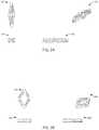
- FIG. 3Aincludes top, isometric, front, and side views of yet another expanding fusion cage in an insertion configuration
- FIG. 3Bincludes top, isometric, front, and side views of the fusion cage of FIG. 3A in a laterally expanded configuration
- FIG. 3Cincludes top, isometric, front, and side views of the fusion cage of FIG. 3B in a laterally and vertically expanded configuration, including a wedge or spreading clip
- FIG. 3Dincludes top, front, and side views of the fusion cage of FIG. 3C in a final implanted configuration with the wedge or spreading clip installed;
- FIG. 4Ais a top view of the fusion cage of FIG. 3A in the insertion configuration
- FIG. 4Bis an isometric view of the fusion cage of FIG. 4A
- FIG. 4Cis a front view of the fusion cage of FIG. 4A
- FIG. 4Dis a side view of the fusion cage of FIG. 4A ;
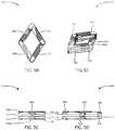
- FIG. 5Ais a top view of the fusion cage of FIG. 3B in the laterally expanded configuration;
- FIG. 5Bis an isometric view of the fusion cage of FIG. 5A ;
- FIG. 5Cis a front view of the fusion cage of FIG. 5A ;
- FIG. 5Dis a side view of the fusion cage of FIG. 5A ;
- FIG. 6Ais a top view of the fusion cage and wedge of FIG. 3C in the laterally and vertically expanded configuration
- FIG. 6Bis an isometric view of the fusion cage and wedge of FIG. 6A
- FIG. 6Cis a front view of the fusion cage and wedge of FIG. 6A
- FIG. 6Dis a side view of the fusion cage and wedge of FIG. 6A ;
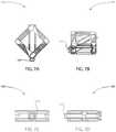
- FIG. 7Ais a top view of the fusion cage and wedge of FIG. 3D in the final implanted configuration
- FIG. 7Bis an isometric view of the fusion cage and wedge of FIG. 7A
- FIG. 7Cis a front view of the fusion cage and wedge of FIG. 7A
- FIG. 7Dis a side view of the fusion cage and wedge of FIG. 7A ;
- FIG. 8Ais an exploded perspective view of the fusion cage and wedge of FIG. 7A ; and FIG. 8B is another exploded perspective view of the fusion cage and wedge of FIG. 7A from a different direction;
- FIG. 9Ais a hand sketch of yet another expanding fusion cage
- FIG. 9Bis a schematic drawing of the fusion cage of the hand sketch of FIG. 9A ;
- phrases “connected to,” “coupled to” and “in communication with”refer to any form of interaction between two or more entities, including mechanical, electrical, magnetic, electromagnetic, fluid, and thermal interaction. Two components may be functionally coupled to each other even though they are not in direct contact with each other.
- the term “abutting”refers to items that are in direct physical contact with each other, although the items may not necessarily be attached together.
- the phrase “fluid communication”refers to two features that are connected such that a fluid within one feature is able to pass into the other feature.
- a sagittal planedivides a body into right and left portions.
- a mid-sagittal planedivides the body into bilaterally symmetric right and left halves.
- a coronal planedivides a body into anterior and posterior portions.
- a transverse planedivides a body into superior and inferior portions.
- Anteriormeans toward the front of the body.
- Posteriormeans toward the back of the body.
- Superior or cephaladmeans toward the head.
- Inferiormeans toward the feet.
- Caudalmeans toward the tail/coccyx.
- a cephalad-caudal axisis a vertical axis which extends along the central midline axis of the vertebral bodies of the spine. Medial means toward the midline of the body.
- Lateralmeans away from the midline of the body.
- Axialmeans toward a central axis of the body.
- Abaxialmeans away from a central axis of the body.
- Ipsilateralmeans on the same side of the body. Contralateral means on the opposite side of the body.
- Proximalmeans located toward a center of a body, or toward a user.
- Distalmeans located away from the center of the body, or away from a user.
- FIG. 1an expanding fusion cage 100 , inserter instrument 200 , lower vertebra 2 , and upper vertebra 4 are shown.
- the expanding fusion cage 100may include a first link 102 , a second link 104 , and a third link 106 .
- the first and second linksmay be hinged together at a first hinge 108 and the second and third links may be hinged together at a second hinge 110 .
- the first, second, and third linksmay be movable relative to each other about the first and second hinges in the transverse plane for lateral expansion.
- the first, second, and third linksmay each be divided into an upper link, for example upper second link 104 ′, and a lower link, for example lower second link 104 ′′.
- Each pair of upper and lower linksmay be movable relative to each other along the cephalad-caudal axis 6 for vertical expansion.
- the free ends of the first and third linksmay have a fixed height along the cephalad-caudal axis so that vertical expansion occurs mainly in the vicinity of the second link 104 .
- the inserter instrument 200may include a shaft with a distal end that removably couples to the fusion cage 100 .
- the illustrated inserter instrument 200couples to a proximal end of the second link 104 near the second hinge 110 , and may extend along the second link 104 to the first hinge 108 .
- the inserter instrument 200may be actuated to cause lateral and vertical expansion of the fusion cage 100 . Lateral and vertical expansion may occur as separate steps, as seamlessly sequential steps, or simultaneously. Lateral expansion may occur before vertical expansion, or vice versa.
- a cam on a screwmay drive vertical expansion.
- the screwis shown along the centerline of the implant.
- the screwrotates a cam which provides vertical motion to separate the upper and lower sections of the implant.
- Fusion cage 300may operate according to the principles of a reverse iris.
- Fusion cage 300may include an upper ring 302 , a lower ring 304 , and at least one lateral element 306 .
- three lateral elements 306 , 308 , 310are shown.
- the lateral elementsmay be connected to the rings via complementary dovetail features.
- the lateral elementsmay be movable between an insertion configuration, in which the lateral elements are mostly or entirely recessed within the outer perimeter of the rings, and a laterally expanded configuration, in which the lateral elements protrude outwardly beyond the outer perimeter of the rings.
- the upper and lower ringsmay be movable between an insertion configuration, in which the rings are close together, and a vertically expanded configuration, in which the rings are spaced farther apart.
- the fusion cage 300may have a final implanted configuration after lateral and vertical expansion.
- FIGS. 3A-8Byet another expanding fusion cage 400 and wedge or spreading clip 500 are shown.
- the wedge 500may be considered a component part of the fusion cage 400 , or the fusion cage 400 and wedge 500 may be considered to form an implant system.
- the fusion cage 400may include four upper links 402 , 404 , 406 , 408 and four lower links 412 , 414 , 416 , 418 .
- the four upper linksmay be hinged together end to end to form a quadrilateral polygon with four sides and four vertices or corners.
- the four lower linksmay also be hinged together to form a quadrilateral. Any number of upper and lower links may be present. For example, there may be five upper or lower links, forming a pentagon, or eight links forming an octagon. There may be a different number of lower links versus the upper links.
- Each linkmay have an outer side, which is shown with transverse ridges and grooves, and an opposite inner side.
- the outer sides of links 402 , 404 , 406 , 408are shown in FIG. 8A ; the outer sides of links 412 , 414 , 416 , 418 are shown in FIG. 8B .
- the upper link 402may include a post 420 that protrudes from the inner side near one end, and a through hole 422 that extends through the outer and inner sides near the opposite end.
- the upper link 404may include a through hole 424 that extends through the outer and inner sides near one end, and a post 426 that protrudes from the inner side near the opposite end.
- the upper link 406may include a through hole 428 that extends through the outer and inner sides near one end.
- the inner side at the opposite endmay be featureless as shown, or it may optionally include a hole (not shown).
- the upper link 408may include a post 430 that protrudes from the inner side near one end, and a snap boss 432 that protrudes from the outer side near the opposite end.
- the lower link 412may include a through hole 434 that extends through the outer and inner sides near one end, and a post 436 that protrudes from the inner side near the opposite end.
- the post 436may include a longitudinal through hole 438 .
- the lower link 414may include a post 440 that protrudes from the inner side near one end.
- the post 440may include a longitudinal through hole 442 .
- a through hole 444may extend through the outer and inner sides near the opposite end.
- the lower link 416may include a post 446 that protrudes from the inner side near one end.
- the post 446may include a longitudinal through hole 448 .
- a snap boss 450may protrude from the outer side near the opposite end.
- the lower link 418may include a through hole 452 that extends through the outer and inner sides near one end.
- the inner side at the opposite endmay be featureless as shown, or it may optionally include a hole (not shown).
- the post 440 of the lower link 414may be received in the through hole 434 of the lower link 412 and the through hole 424 of the upper link 404
- the post 420 of the upper link 402may be received in the hole 442 of the lower link 414
- the post 446 of the lower link 416may be received in the through hole 444 of the lower link 414 and the through hole 428 of the upper link 406
- the post 426 of the upper link 404may be received in the hole 448 of the lower link 416 .
- the post 436 of the lower link 412may be received in the through hole 452 of the lower link 418 and the through hole 422 of the upper link 402
- the post 430 of the upper link 408may be received in the hole 438 of the lower link 412
- the snap boss 432 of the 408may be received in the optional hole (if present) of the 406
- the snap boss 450 of the 416may be received in the optional hole (if present) of the 418 .
- These connectionsmay hinge the links together to enable lateral expansion.
- the connectionsmay permit the through holes 422 , 424 , 428 to slide along the posts 436 , 440 , 446 , respectively, to enable vertical expansion.
- the connectionsmay permit the posts 420 , 426 , 430 to slide within the holes 442 , 448 , 438 , respectively, to enable vertical expansion.
- the wedge 500may include a leading end 502 and a trailing end 504 .
- the trailing end 504may support right and left prongs 506 , 508 which extend to the leading end 502 .
- Each prongmay taper down in height towards the leading end 502 .
- Each prongmay include a snap feature to engage with the fusion cage 400 .
- Snap features 514 , 516are illustrated as vertically extending ridges on the inner sides of the prongs 506 , 508 .
- the snap featuresmay be located toward the leading end 502 to engage with the post 440 or the boss surrounding the hole 424 .
- a gap 510may separate the prongs.
- a longitudinal hole 512may extend through the trailing end along a direction between the leading and trailing ends.
- the fusion cage 400may be expanded laterally by coupling it to an instrument (not shown) and actuating the instrument to draw the post 420 , hole 424 , hole 434 , and post 440 (the leading end) toward the snap boss 432 (the trailing end) and urge the hole 422 , post 430 , post 436 , and hole 452 away from the post 426 , hole 428 , hole 444 , and post 446 .
- the instrumentmay abut the trailing end and may extend between the upper and lower quadrilaterals to engage the leading end.
- the instrumentmay grasp the post 440 (for example) with a pair of jaws, or may partially or fully encircle the post 440 or the boss surrounding the hole 424 .
- the fusion cage 400may be expanded vertically by an instrument (not shown) which is actuated to urge the upper links away from the lower links.
- an instrumentnot shown
- Separate instrumentsmay be used for lateral and vertical expansion, or one instrument may be used for both lateral and vertical expansion.
- the fusion cagemay be laterally and/or vertically expanded by the wedge 500 .
- the wedge 500may lock the fusion cage 400 in its laterally and/or vertically expanded configuration.
- the illustrated embodimentshows a wedge that locks the fusion cage vertically by filling the gap between the upper and lower quadrilaterals.
- the wedge 500may be modified to also lock the fusion cage laterally. Referring to FIGS.
- the leading end of the prong 506may include a lower augmentation that fills the gap between the lower links 412 , 414 ; the trailing end of the prong 506 may include an upper augmentation that fills the gap between the upper links 406 , the 408 ; the leading end of the prong 508 may include an upper augmentation that fills the gap between the upper links 402 , 404 ; and the trailing end of the prong 508 may include a lower augmentation that fills the gap between the lower links 416 , 418 .
- a single one of these four augmentationsmay be sufficient to lock the fusion cage laterally.
- the wedge 500may connect to the expanded fusion cage 400 via the snap features 514 , 516 , as described above.
- An optional locking screw(not shown) may be inserted through the hole 512 and into a hole (not shown) in the post 440 or the boss surrounding the hole 424 .
- Fusion cage 600expands laterally via a screw drive and linkages.
- the horizontal line with arrowhead endsindicates the lateral direction.
- the linkagesare not shown.
- Fusion cage 600is expanded vertically via the addition of struts.
- the leading and trailing components 606 and 608are brought together via a screw 610 , which causes the left and right lateral components 604 and 602 to expand out laterally.
- Vertical expansionis achieved via the addition of one or more struts, such as strut 612 .
- strutscan be added to any or all locations to achieve proper anatomic fit.
- the strutsmay be connected to the components 604 , 602 , 606 , or 608 via dovetails. Note the presence of some optional additional dovetail channels in dashed lines in FIG. 9B .
- Any methods disclosed hereinincludes one or more steps or actions for performing the described method.
- the method steps and/or actionsmay be interchanged with one another.
- the order and/or use of specific steps and/or actionsmay be modified.
Landscapes
- Health & Medical Sciences (AREA)
- Engineering & Computer Science (AREA)
- Biomedical Technology (AREA)
- Orthopedic Medicine & Surgery (AREA)
- Neurology (AREA)
- Transplantation (AREA)
- Heart & Thoracic Surgery (AREA)
- Oral & Maxillofacial Surgery (AREA)
- Cardiology (AREA)
- Vascular Medicine (AREA)
- Life Sciences & Earth Sciences (AREA)
- Animal Behavior & Ethology (AREA)
- General Health & Medical Sciences (AREA)
- Public Health (AREA)
- Veterinary Medicine (AREA)
- Physical Education & Sports Medicine (AREA)
- Prostheses (AREA)
Abstract
Description
Claims (18)
Priority Applications (1)
| Application Number | Priority Date | Filing Date | Title |
|---|---|---|---|
| US16/261,383US10945859B2 (en) | 2018-01-29 | 2019-01-29 | Expanding fusion cages |
Applications Claiming Priority (2)
| Application Number | Priority Date | Filing Date | Title |
|---|---|---|---|
| US201862623278P | 2018-01-29 | 2018-01-29 | |
| US16/261,383US10945859B2 (en) | 2018-01-29 | 2019-01-29 | Expanding fusion cages |
Publications (2)
| Publication Number | Publication Date |
|---|---|
| US20190231548A1 US20190231548A1 (en) | 2019-08-01 |
| US10945859B2true US10945859B2 (en) | 2021-03-16 |
Family
ID=67391710
Family Applications (1)
| Application Number | Title | Priority Date | Filing Date |
|---|---|---|---|
| US16/261,383ActiveUS10945859B2 (en) | 2018-01-29 | 2019-01-29 | Expanding fusion cages |
Country Status (1)
| Country | Link |
|---|---|
| US (1) | US10945859B2 (en) |
Cited By (4)
| Publication number | Priority date | Publication date | Assignee | Title |
|---|---|---|---|---|
| US11464648B2 (en)* | 2019-09-09 | 2022-10-11 | Amplify Surgical, Inc. | Multi-portal surgical systems |
| US11950770B1 (en) | 2022-12-01 | 2024-04-09 | Amplify Surgical, Inc. | Multi-portal split cannulas, endoscopic hemostatic dispensers and surgical tools |
| US12245791B2 (en) | 2019-09-09 | 2025-03-11 | Amplify Surgical, Inc. | Multi-portal surgical systems, cannulas, and related technologies |
| US12318307B2 (en) | 2021-07-16 | 2025-06-03 | Blue Ocean Spine Gmbh | Adjustable spinal implants, associated instruments and methods |
Families Citing this family (6)
| Publication number | Priority date | Publication date | Assignee | Title |
|---|---|---|---|---|
| WO2018081322A1 (en) | 2016-10-25 | 2018-05-03 | Imds Llc | Methods and instrumentation for intervertebral cage expansion |
| US11154405B2 (en)* | 2020-01-23 | 2021-10-26 | Globus Medical, Inc. | Articulating expandable interbody fusions devices |
| WO2022133130A1 (en) | 2020-12-16 | 2022-06-23 | Amplify Surgical, Inc. | Anchored intervertebral implants |
| CN113040983A (en)* | 2021-05-12 | 2021-06-29 | 华中科技大学同济医学院附属同济医院 | Expansion type vertebral body fusion device |
| CN114917061A (en)* | 2022-05-16 | 2022-08-19 | 上海以心医疗器械有限公司 | Adjustable flow dividing device |
| US20240238098A1 (en)* | 2023-01-17 | 2024-07-18 | Dynamic Implants Inc. | Expandable spinal cage |
Citations (216)
| Publication number | Priority date | Publication date | Assignee | Title |
|---|---|---|---|---|
| US4164225A (en) | 1977-12-28 | 1979-08-14 | Johnson & Lorenz, Inc. | Surgical suturing instrument |
| US4657550A (en) | 1984-12-21 | 1987-04-14 | Daher Youssef H | Buttressing device usable in a vertebral prosthesis |
| EP0260044A1 (en) | 1986-08-29 | 1988-03-16 | John Anthony Norman Shepperd | Spinal implant |
| US4834757A (en) | 1987-01-22 | 1989-05-30 | Brantigan John W | Prosthetic implant |
| US5059193A (en) | 1989-11-20 | 1991-10-22 | Spine-Tech, Inc. | Expandable spinal implant and surgical method |
| US5171278A (en) | 1991-02-22 | 1992-12-15 | Madhavan Pisharodi | Middle expandable intervertebral disk implants |
| US5290312A (en) | 1991-09-03 | 1994-03-01 | Alphatec | Artificial vertebral body |
| US5306310A (en) | 1991-08-27 | 1994-04-26 | Man Ceramics Gmbh | Vertebral prosthesis |
| US5336223A (en) | 1993-02-04 | 1994-08-09 | Rogers Charles L | Telescoping spinal fixator |
| US5390683A (en) | 1991-02-22 | 1995-02-21 | Pisharodi; Madhavan | Spinal implantation methods utilizing a middle expandable implant |
| US5405391A (en) | 1993-02-16 | 1995-04-11 | Hednerson; Fraser C. | Fusion stabilization chamber |
| US5425772A (en) | 1993-09-20 | 1995-06-20 | Brantigan; John W. | Prosthetic implant for intervertebral spinal fusion |
| US5443514A (en) | 1993-10-01 | 1995-08-22 | Acromed Corporation | Method for using spinal implants |
| US5458641A (en) | 1993-09-08 | 1995-10-17 | Ramirez Jimenez; Juan J. | Vertebral body prosthesis |
| US5554191A (en) | 1994-01-26 | 1996-09-10 | Biomat | Intersomatic vertebral cage |
| US5571192A (en) | 1994-07-02 | 1996-11-05 | Heinrich Ulrich | Prosthetic vertebral implant |
| US5653762A (en) | 1994-03-18 | 1997-08-05 | Pisharodi; Madhavan | Method of stabilizing adjacent vertebrae with rotating, lockable, middle-expanded intervertebral disk stabilizer |
| US5653763A (en) | 1996-03-29 | 1997-08-05 | Fastenetix, L.L.C. | Intervertebral space shape conforming cage device |
| US5658335A (en) | 1995-03-09 | 1997-08-19 | Cohort Medical Products Group, Inc. | Spinal fixator |
| US5665122A (en) | 1995-01-31 | 1997-09-09 | Kambin; Parviz | Expandable intervertebral cage and surgical method |
| US5693100A (en) | 1991-02-22 | 1997-12-02 | Pisharodi; Madhavan | Middle expandable intervertebral disk implant |
| US5702455A (en) | 1996-07-03 | 1997-12-30 | Saggar; Rahul | Expandable prosthesis for spinal fusion |
| US5716415A (en) | 1993-10-01 | 1998-02-10 | Acromed Corporation | Spinal implant |
| US5776198A (en) | 1994-12-09 | 1998-07-07 | Sdgi Holdings, Inc. | Adjustable vertebral body replacement |
| US5782832A (en) | 1996-10-01 | 1998-07-21 | Surgical Dynamics, Inc. | Spinal fusion implant and method of insertion thereof |
| WO1998034568A1 (en) | 1997-02-12 | 1998-08-13 | Li Medical Technologies, Inc. | Intervertebral spacer and tool and method for emplacement thereof |
| US5865848A (en) | 1997-09-12 | 1999-02-02 | Artifex, Ltd. | Dynamic intervertebral spacer and method of use |
| US5980522A (en) | 1994-07-22 | 1999-11-09 | Koros; Tibor | Expandable spinal implants |
| US5989290A (en) | 1995-05-24 | 1999-11-23 | Biedermann; Lutz | Height-adjustable artificial vertebral body |
| US6015436A (en) | 1996-06-07 | 2000-01-18 | Heinrich Ulrich | Implant for filling a space between vertebrae |
| US6045579A (en) | 1997-05-01 | 2000-04-04 | Spinal Concepts, Inc. | Adjustable height fusion device |
| WO2000025706A1 (en) | 1998-10-29 | 2000-05-11 | Sdgi Holdings, Inc. | Expandable intervertebral spacers |
| US6093207A (en) | 1994-03-18 | 2000-07-25 | Pisharodi; Madhavan | Middle expanded, removable intervertebral disk stabilizer disk |
| US6102950A (en) | 1999-01-19 | 2000-08-15 | Vaccaro; Alex | Intervertebral body fusion device |
| US6117174A (en) | 1998-09-16 | 2000-09-12 | Nolan; Wesley A. | Spinal implant device |
| US6126689A (en) | 1998-06-15 | 2000-10-03 | Expanding Concepts, L.L.C. | Collapsible and expandable interbody fusion device |
| US6126869A (en) | 1998-07-15 | 2000-10-03 | Mobium Enterprises, Inc. | Solar blind optical filter |
| US6129763A (en) | 1996-09-13 | 2000-10-10 | Chauvin; Jean-Luc | Expandable osteosynthesis cage |
| US6159244A (en) | 1999-07-30 | 2000-12-12 | Suddaby; Loubert | Expandable variable angle intervertebral fusion implant |
| US6174334B1 (en) | 1998-12-16 | 2001-01-16 | Loubert Suddaby | Expandable intervertebral fusion implant and applicator |
| US6176881B1 (en) | 1997-04-15 | 2001-01-23 | Synthes | Telescopic vertebral prosthesis |
| US6190414B1 (en) | 1996-10-31 | 2001-02-20 | Surgical Dynamics Inc. | Apparatus for fusion of adjacent bone structures |
| US6190413B1 (en) | 1998-04-16 | 2001-02-20 | Ulrich Gmbh & Co. Kg | Vertebral implant |
| US6193755B1 (en) | 1996-09-26 | 2001-02-27 | Howmedica Gmbh | Spinal cage assembly |
| US6193756B1 (en) | 1997-09-30 | 2001-02-27 | Sulzer Orthopaedie Ag | Tubular support body for bridging two vertebrae |
| US6200348B1 (en) | 1998-02-06 | 2001-03-13 | Biedermann, Motech Gmbh | Spacer with adjustable axial length |
| US6214050B1 (en) | 1999-05-11 | 2001-04-10 | Donald R. Huene | Expandable implant for inter-bone stabilization and adapted to extrude osteogenic material, and a method of stabilizing bones while extruding osteogenic material |
| US6296647B1 (en) | 1998-08-07 | 2001-10-02 | Stryker Trauma Gmbh | Instrument for the positioning of an implant in the human spine |
| US6299644B1 (en) | 1997-06-16 | 2001-10-09 | Paul Vanderschot | Vertebral replacement implant |
| US20010032017A1 (en) | 1999-12-30 | 2001-10-18 | Alfaro Arthur A. | Intervertebral implants |
| US6332895B1 (en) | 2000-03-08 | 2001-12-25 | Loubert Suddaby | Expandable intervertebral fusion implant having improved stability |
| US20020010511A1 (en) | 2000-07-07 | 2002-01-24 | Michelson Gary Karlin | Expandable implant with interlocking walls |
| US6395034B1 (en) | 1999-11-24 | 2002-05-28 | Loubert Suddaby | Intervertebral disc prosthesis |
| US6413278B1 (en) | 1998-03-30 | 2002-07-02 | J. Alexander Marchosky | Prosthetic system |
| US6419705B1 (en) | 1999-06-23 | 2002-07-16 | Sulzer Spine-Tech Inc. | Expandable fusion device and method |
| US6436140B1 (en) | 1998-08-28 | 2002-08-20 | Sofamor S.N.C. | Expandable interbody fusion cage and method for insertion |
| US6454806B1 (en) | 1999-07-26 | 2002-09-24 | Advanced Prosthetic Technologies, Inc. | Spinal surgical prosthesis |
| WO2002076335A2 (en) | 2001-03-27 | 2002-10-03 | Michelson Gary K | Radially expanding interbody spinal fusion implants and instrumentation for insertion thereof |
| US6491724B1 (en) | 1999-08-13 | 2002-12-10 | Bret Ferree | Spinal fusion cage with lordosis correction |
| WO2003032812A2 (en) | 2001-10-17 | 2003-04-24 | Medicinelodge, Inc. | Adjustable bone fusion implant and method |
| US6582431B1 (en) | 1997-02-06 | 2003-06-24 | Howmedica Osteonics Corp. | Expandable non-threaded spinal fusion device |
| US6660038B2 (en) | 2000-03-22 | 2003-12-09 | Synthes (Usa) | Skeletal reconstruction cages |
| US20030229355A1 (en) | 2002-06-10 | 2003-12-11 | Link Spine Group, Inc. | Surgical instrument for inserting intervertebral prosthesis |
| US6666891B2 (en) | 2000-11-13 | 2003-12-23 | Frank H. Boehm, Jr. | Device and method for lumbar interbody fusion |
| US20040002758A1 (en) | 2002-03-11 | 2004-01-01 | Landry Michael E. | Spinal implant including a compressible connector |
| US6685742B1 (en) | 2002-11-12 | 2004-02-03 | Roger P. Jackson | Articulated anterior expandable spinal fusion cage system |
| US20040034430A1 (en) | 2002-06-14 | 2004-02-19 | Falahee Mark H. | Anatomic vertebral cage |
| US6706070B1 (en) | 1997-05-01 | 2004-03-16 | Spinal Concepts, Inc. | Multi-variable-height fusion device |
| US6709458B2 (en) | 2000-02-04 | 2004-03-23 | Gary Karlin Michelson | Expandable push-in arcuate interbody spinal fusion implant with tapered configuration during insertion |
| US6723126B1 (en) | 2002-11-01 | 2004-04-20 | Sdgi Holdings, Inc. | Laterally expandable cage |
| US6746484B1 (en) | 1997-08-26 | 2004-06-08 | Society De Fabrication De Materiel De Orthopedique, S.A. | Spinal implant |
| US6893464B2 (en) | 2002-03-05 | 2005-05-17 | The Regents Of The University Of California | Method and apparatus for providing an expandable spinal fusion cage |
| US20050177235A1 (en) | 2004-02-10 | 2005-08-11 | Baynham Bret O. | Spinal fusion device |
| US20050182416A1 (en) | 2004-02-13 | 2005-08-18 | Roy Lim | Spacer with height and angle adjustments for spacing vertebral members |
| US20050222681A1 (en) | 2002-06-17 | 2005-10-06 | Richard Richley | Devices and methods for minimally invasive treatment of degenerated spinal discs |
| US20050234555A1 (en) | 2004-04-16 | 2005-10-20 | Depuy Spine, Inc. | Intervertebral disc with monitoring and adjusting capabilities |
| WO2005112834A2 (en) | 2004-05-12 | 2005-12-01 | Moskowitz Nathan C | 3-d expansile intervertebral disc implant |
| US20050278036A1 (en) | 2004-06-09 | 2005-12-15 | Ceravic | Method for restoration of human or animal bone anatomy, and expansible prosthetic implant allowing implementation of this method |
| US20060142858A1 (en) | 2004-12-16 | 2006-06-29 | Dennis Colleran | Expandable implants for spinal disc replacement |
| US7070598B2 (en) | 2002-06-25 | 2006-07-04 | Sdgi Holdings, Inc. | Minimally invasive expanding spacer and method |
| US20060167547A1 (en) | 2005-01-21 | 2006-07-27 | Loubert Suddaby | Expandable intervertebral fusion implants having hinged sidewalls |
| US20070043440A1 (en) | 2003-09-19 | 2007-02-22 | William Michael S | Method and apparatus for treating diseased or fractured bone |
| US20070049935A1 (en) | 2005-02-17 | 2007-03-01 | Edidin Avram A | Percutaneous spinal implants and methods |
| US20070067034A1 (en) | 2005-08-31 | 2007-03-22 | Chirico Paul E | Implantable devices and methods for treating micro-architecture deterioration of bone tissue |
| US20070118222A1 (en) | 2005-11-21 | 2007-05-24 | Vertegen, Inc. | Intervertebral devices and methods |
| US20070198089A1 (en) | 2004-05-13 | 2007-08-23 | Nathan Moskowitz | Artificial total lumbar disc for unilateral safe and simple posterior placement in the lumbar spine, and removable bifunctional screw which drives vertical sliding expansile plate expansion, and interplate widening,and angled traction spikes |
| US20070219634A1 (en) | 2004-09-21 | 2007-09-20 | Greenhalgh E S | Expandable support device and method of use |
| US20070260315A1 (en) | 2006-05-03 | 2007-11-08 | Foley Kevin T | Devices and methods for disc height restoration |
| US20070282449A1 (en) | 2006-04-12 | 2007-12-06 | Spinalmotion, Inc. | Posterior spinal device and method |
| US20080033440A1 (en) | 2005-04-12 | 2008-02-07 | Moskowitz Ahmnon D | Bi-directional fixating transvertebral body screws and posterior cervical and lumbar interarticulating joint calibrated stapling devices for spinal fusion |
| US20080045968A1 (en) | 2006-08-18 | 2008-02-21 | Warsaw Orthopedic, Inc. | Instruments and Methods for Spinal Surgery |
| US20080082167A1 (en) | 2005-02-17 | 2008-04-03 | Kyphon, Inc. | Percutaneous spinal implants and methods |
| US20080108990A1 (en) | 2006-11-02 | 2008-05-08 | St. Francis Medical Technologies, Inc. | Interspinous process implant having a fixed wing and a deployable wing and method of implantation |
| US20080114367A1 (en) | 2006-11-10 | 2008-05-15 | Syberspine Limited | Method and relaxable distracters for in-situ formation of intervertebral disc prosthesis |
| WO2008070863A2 (en) | 2006-12-07 | 2008-06-12 | Interventional Spine, Inc. | Intervertebral implant |
| US20080167657A1 (en) | 2006-12-31 | 2008-07-10 | Stout Medical Group, L.P. | Expandable support device and method of use |
| US20080183204A1 (en) | 2005-07-14 | 2008-07-31 | Stout Medical Group, L.P. | Expandable support device and method of use |
| US20080195152A1 (en) | 2004-10-20 | 2008-08-14 | Moti Altarac | Interspinous spacer |
| US20080221686A1 (en) | 1999-10-08 | 2008-09-11 | Ferree Bret A | Devices used to treat disc herniation and attachment mechanisms therefore |
| US20080219604A1 (en) | 2007-03-08 | 2008-09-11 | Hsin-Liang Chen | Synchronous Chain for a Linear Guideway |
| US20080243255A1 (en) | 2007-03-29 | 2008-10-02 | Butler Michael S | Radially expandable spinal interbody device and implantation tool |
| US20080249604A1 (en) | 2007-03-30 | 2008-10-09 | Brian Donovan | Apparatus and method for medical procedures within a spine |
| US20080281346A1 (en) | 2005-12-19 | 2008-11-13 | Stout Medical Group, L.P. | Expandable support device |
| US20080288072A1 (en) | 2005-02-17 | 2008-11-20 | Kohm Andrew C | Percutaneous spinal implants and methods |
| US20080288078A1 (en) | 2005-02-17 | 2008-11-20 | Kohm Andrew C | Percutaneous spinal implants and methods |
| US20080319549A1 (en) | 2005-12-28 | 2008-12-25 | Stout Medical Group, L.P. | Expandable support device and method of use |
| US20090076607A1 (en) | 2007-09-19 | 2009-03-19 | Arthur Martinus Aalsma | Collapsible and Expandable Device and Methods of Using Same |
| US7513900B2 (en) | 2003-09-29 | 2009-04-07 | Boston Scientific Scimed, Inc. | Apparatus and methods for reducing compression bone fractures using high strength ribbed members |
| US20090157084A1 (en) | 2007-09-19 | 2009-06-18 | Arthur Martinus Michael Aalsma | Collapsible and expandable device and methods of using same |
| WO2009092102A1 (en) | 2008-01-17 | 2009-07-23 | Synthes Usa, Llc | An expandable intervertebral implant and associated method of manufacturing the same |
| US20090198338A1 (en) | 2008-02-04 | 2009-08-06 | Phan Christopher U | Medical implants and methods |
| US20090222093A1 (en) | 2008-02-28 | 2009-09-03 | Warsaw Orthopedic, Inc. | Nucleus Implant and Method of Installing Same |
| US20090222100A1 (en) | 2008-02-28 | 2009-09-03 | Stryker Spine | Tool for implanting expandable intervertebral implant |
| US20090281628A1 (en) | 2008-04-08 | 2009-11-12 | Jean-Francois Oglaza | Apparatus for restoration of the spine and methods of use thereof |
| US7625377B2 (en) | 2001-07-02 | 2009-12-01 | Mandaco 569 Ltd | Collapsible and expandable instrument for insertion in a dorsal vertebra |
| US20100082109A1 (en) | 2008-09-22 | 2010-04-01 | Stout Medical Group, L.P. | Expandable intervertebral implant |
| WO2010078468A2 (en) | 2008-12-31 | 2010-07-08 | Jimenez Omar F | Methods and apparatus for vertebral body distraction and fusion employing flexure members |
| US20100185291A1 (en) | 2008-12-31 | 2010-07-22 | Jimenez Omar F | Methods and apparatus for vertebral body distraction and fusion employing flexure members |
| WO2010105181A1 (en) | 2009-03-13 | 2010-09-16 | University Of Toledo | Minimally invasive collapsible cage |
| US7799081B2 (en) | 2004-09-14 | 2010-09-21 | Aeolin, Llc | System and method for spinal fusion |
| US20100249720A1 (en) | 2009-03-31 | 2010-09-30 | Ashok Biyani | Integrated device for the storage and delivery of a bone graft or other implantable material to a surgical site |
| US7824427B2 (en) | 2007-01-16 | 2010-11-02 | Perez-Cruet Miquelangelo J | Minimally invasive interbody device |
| US20100305705A1 (en) | 2005-03-31 | 2010-12-02 | Life Spine, Inc. | Expandable spinal interbody and intravertebral body devices |
| US20100318127A1 (en) | 2009-06-12 | 2010-12-16 | Kyphon Sarl | Interspinous implant and methods of use |
| US20110004307A1 (en) | 2006-10-16 | 2011-01-06 | Ahn Edward S | Fusion device, systems and methods thereof |
| US7879098B1 (en) | 2005-10-19 | 2011-02-01 | Simmons Jr James W | Expandable lordosis stabilizing cage |
| US7922729B2 (en) | 2001-02-04 | 2011-04-12 | Warsaw Orthopedic, Inc. | Instrumentation for inserting and deploying an expandable interbody spinal fusion implant |
| US20110125270A1 (en) | 2009-11-23 | 2011-05-26 | David C Paul | Prosthetic Spinal Disc Replacement |
| US20110172774A1 (en) | 2010-01-11 | 2011-07-14 | Armando Varela | Expandable intervertebral implant and associated surgical method |
| US8012207B2 (en) | 2004-10-20 | 2011-09-06 | Vertiflex, Inc. | Systems and methods for posterior dynamic stabilization of the spine |
| US20110270396A1 (en) | 2010-04-29 | 2011-11-03 | Warsaw Orthopedic, Inc | Expandable implants for stabilizing adjacent anatomical structures |
| US20110276141A1 (en) | 2010-05-05 | 2011-11-10 | Alexandre Caratsch | Intervertebral spacer, system and method to distract adjacent vertebrae and insert a spacer |
| US20110282453A1 (en) | 2010-05-13 | 2011-11-17 | Stout Medical Group, L.P. | Fixation device and method |
| US20110319997A1 (en) | 2010-06-25 | 2011-12-29 | Chad Glerum | Expandable Fusion Device and Method of Installation Thereof |
| US8097035B2 (en) | 2001-03-27 | 2012-01-17 | Glenn Bradley J | Intervertebral space implant for use in spinal fusion procedures |
| US8097018B2 (en) | 2005-02-17 | 2012-01-17 | Kyphon Sarl | Percutaneous spinal implants and methods |
| US8109972B2 (en) | 2005-04-18 | 2012-02-07 | Kyphon Sarl | Interspinous process implant having deployable wings and method of implantation |
| US8110004B2 (en) | 2008-08-21 | 2012-02-07 | The Trustees Of The Stevens Institute Of Technology | Expandable interbody fusion cage with rotational insert |
| US20120053642A1 (en) | 2010-08-31 | 2012-03-01 | Lozier Antony J | Osteochondral graft delivery device and uses thereof |
| US20120071977A1 (en) | 2009-03-12 | 2012-03-22 | Vexim | Apparatus for Bone Restoration of the Spine and Methods of Use |
| US20120083889A1 (en) | 2010-10-05 | 2012-04-05 | Alphatec Spine, Inc. | Intervertebral device and methods of use |
| US20120083887A1 (en) | 2010-10-05 | 2012-04-05 | Alphatec Spine, Inc. | Intervertebral device and methods of use |
| US8152837B2 (en) | 2004-10-20 | 2012-04-10 | The Board Of Trustees Of The Leland Stanford Junior University | Systems and methods for posterior dynamic stabilization of the spine |
| US20120123546A1 (en) | 2010-11-15 | 2012-05-17 | MEDevice IP Holdings, LLC. | Implant apparatus for spinal fusion |
| US20120136442A1 (en) | 2009-09-18 | 2012-05-31 | Kleiner Jeffrey | Fusion cage with combined biological delivery system |
| US20120150241A1 (en) | 2010-12-13 | 2012-06-14 | Ragab Ashraf A | Bone Cage Placement Device |
| US20120185047A1 (en) | 2011-01-17 | 2012-07-19 | Cibor, Inc. | Reinforced carbon fiber/carbon foam intervertebral spine fusion device |
| US20120185045A1 (en) | 2011-01-14 | 2012-07-19 | Zimmer Spine, Inc. | Articulating spinal implant insertion instrument |
| US20120185049A1 (en) | 2010-01-11 | 2012-07-19 | Innova Spinal Technologies, Llc | Expandable intervertebral implant and associated surgical method |
| US20120209386A1 (en)* | 2011-02-14 | 2012-08-16 | Medicinelodge, Inc. Dba Imds Co-Innovation | Expandable intervertebral implants and instruments |
| US20120215313A1 (en) | 2011-02-23 | 2012-08-23 | Sean Saidha | Expandable interbody fusion implant |
| US20120215316A1 (en) | 2011-02-14 | 2012-08-23 | Medicinelodge, Inc. Dba Imds Co-Innovation | Expandable intervertebral spacer |
| US20120226357A1 (en) | 2010-01-11 | 2012-09-06 | Innova Spinal Technologies, Llc | Expandable intervertebral implant and associated surgical method |
| US20120245691A1 (en) | 2011-03-23 | 2012-09-27 | Alphatec Spine, Inc. | Expandable interbody spacer |
| CN202458786U (en) | 2012-03-14 | 2012-10-03 | 吉林医药学院 | Expandable box type interbody fusion cage and embedding device thereof |
| US20120259416A1 (en)* | 2011-04-07 | 2012-10-11 | Warsaw Orthopedic, Inc. | Laterally expandable interbody spinal fusion implant |
| WO2012141715A1 (en) | 2011-04-15 | 2012-10-18 | Synthes Usa, Llc | Fixation assembly |
| US8317798B2 (en) | 2002-06-25 | 2012-11-27 | Warsaw Orthopedic | Minimally invasive expanding spacer and method |
| US8323344B2 (en) | 2006-03-24 | 2012-12-04 | Ebi, Llc | Expandable spinal prosthesis |
| US20130079882A1 (en) | 2011-07-25 | 2013-03-28 | Steve Wolfe | Far lateral spacer |
| US20130079883A1 (en) | 2007-03-29 | 2013-03-28 | Life Spine, Inc. | Radially expandable spinal interbody device and implantation tool |
| WO2013052807A2 (en) | 2011-10-05 | 2013-04-11 | H. Lee Moffitt Cancer Center And Research Institute, Inc. | Bone fusion system |
| US20130144391A1 (en) | 2010-07-15 | 2013-06-06 | Nlt Spine Ltd | Surgical systems and methods for implanting deflectable implants |
| US20130158669A1 (en) | 2012-02-13 | 2013-06-20 | Arno Sungarian | Expandable Self-Anchoring Interbody Cage for Orthopedic Applications |
| AU2013206287A1 (en) | 2008-03-26 | 2013-07-04 | Depuy Spine, Inc. | Instruments for expandable corpectomy spinal fusion cage |
| US8491657B2 (en) | 2007-03-28 | 2013-07-23 | Gerald Schaumberg | Expanding cage for vertebral surgery |
| WO2013109346A1 (en) | 2012-01-19 | 2013-07-25 | Warsaw Orthopedic, Inc. | Expandable interbody implant and methods of use |
| US8496709B2 (en) | 2010-03-22 | 2013-07-30 | Amendia, Inc | Spinal Implant |
| US8506635B2 (en) | 2010-06-02 | 2013-08-13 | Warsaw Orthopedic, Inc. | System and methods for a laterally expanding implant |
| US8541355B2 (en) | 2009-11-04 | 2013-09-24 | Colgate-Palmolive Company | Process to produce stable suspending system |
| US20130297029A1 (en)* | 2011-11-02 | 2013-11-07 | Spinesmith Partners, L.P. | Interbody fusion device with separable retention component for lateral approach and associated methods |
| US20130310939A1 (en) | 2005-09-27 | 2013-11-21 | Henry F. Fabian | Spine surgery method and implant |
| WO2013173767A1 (en) | 2012-05-18 | 2013-11-21 | Trinity Orthopedics, Llc | Articulating interbody cage and methods thereof |
| US20130325128A1 (en) | 2012-05-30 | 2013-12-05 | Jonathan Perloff | Expandable Interbody Spacer |
| US20140031940A1 (en) | 2011-04-07 | 2014-01-30 | Ezzine Banouskou | Expandable Orthopedic Device |
| US20140039622A1 (en) | 2010-09-03 | 2014-02-06 | Chad Glerum | Expandable Fusion Device and Method of Installation Thereof |
| US8652174B2 (en) | 2008-12-22 | 2014-02-18 | DePuy Synthes Products, LLC | Expandable interspinous process spacer |
| US8663329B2 (en) | 2012-01-28 | 2014-03-04 | Mark J Ernst | Expandable implant for mammalian bony segment stabilization |
| US8678576B2 (en) | 2012-06-14 | 2014-03-25 | Funai Electric Co., Ltd. | Fluid container with bubble eliminator |
| US20140088714A1 (en) | 2011-12-19 | 2014-03-27 | Warsaw Orthopedic, Inc. | Expandable interbody implant and methods of use |
| US8685095B2 (en) | 2011-04-19 | 2014-04-01 | Warsaw Orthopedic, Inc. | Expandable implant system and methods of use |
| US20140121774A1 (en) | 2009-10-15 | 2014-05-01 | Chad Glerum | Expandable Fusion Device and Method of Installation Thereof |
| US20140128977A1 (en) | 2009-10-15 | 2014-05-08 | Globus Medical, Inc. | Expandable Fusion Device and Method of Installation Thereof |
| US20140172106A1 (en) | 2012-12-13 | 2014-06-19 | Ouroboros Medical, Inc. | Intervertebral scaffolding system |
| US20140188224A1 (en) | 2012-12-14 | 2014-07-03 | Facet-Link Inc. | Laterally expandable intervertebral fusion implant |
| US20140194991A1 (en) | 2009-03-19 | 2014-07-10 | Ex Technology, Llc | Stable device for intervertebral distraction and fusion |
| US20140194992A1 (en) | 2013-01-04 | 2014-07-10 | Medevice Ip Holdings, Llc | Expandable interbody (lateral, posterior, anterior) multi-access cage for spinal surgery |
| US8777993B2 (en) | 2011-07-14 | 2014-07-15 | Nlt Spine Ltd | Laterally deflectable implant |
| US8778027B2 (en) | 2012-01-23 | 2014-07-15 | Medevice Ip Holdings, Llc | Implant apparatus and method including tee and screw mechanism for spinal fusion |
| US8808385B1 (en) | 2013-01-06 | 2014-08-19 | Medshape, Inc. | Mechanically-activated shape memory polymer spinal cage |
| US20140257484A1 (en) | 2013-03-07 | 2014-09-11 | Interventional Spine, Inc. | Intervertebral implant |
| WO2014144696A1 (en) | 2013-03-15 | 2014-09-18 | Lanx, Inc. | Expandable fusion cage system |
| US20140277490A1 (en)* | 2012-05-30 | 2014-09-18 | Jonathan Perloff | Expandable Interbody Spacer |
| WO2014164625A1 (en) | 2013-03-11 | 2014-10-09 | Globus Medical, Inc. | Expandable fusion device and method of installation thereof |
| EP2793760A1 (en) | 2011-12-19 | 2014-10-29 | Warsaw Orthopedic, Inc. | Expandable interbody implant and methods of use |
| US8900305B2 (en) | 2007-03-30 | 2014-12-02 | DePuy Synthes Products, LLC | Intervertebral device having expandable endplates |
| US20140379086A1 (en) | 2011-09-20 | 2014-12-25 | The University Of Toledo | Expandable Inter-Vertebral Cage and Method of Installing Same |
| US8926704B2 (en) | 2009-10-15 | 2015-01-06 | Globus Medical, Inc. | Expandable fusion device and method of installation thereof |
| US20150012098A1 (en) | 2013-07-03 | 2015-01-08 | Spine Innovation, Inc. | Methods and apparatus for implanting an interbody device |
| US20150018951A1 (en) | 2013-07-09 | 2015-01-15 | Nlt Spine Ltd. | Orthopedic Implant with Adjustable Angle between Tissue Contact Surfaces |
| WO2015009998A1 (en) | 2013-07-18 | 2015-01-22 | The University Of Toledo | Expandable inter-vertebral cage and method of installing same |
| US8940048B2 (en) | 2005-03-31 | 2015-01-27 | Life Spine, Inc. | Expandable spinal interbody and intravertebral body devices |
| WO2015031291A1 (en) | 2013-08-27 | 2015-03-05 | Imds Llc | Expandable intervertebral implants and instruments |
| US20150073552A1 (en) | 2013-09-09 | 2015-03-12 | Ouroboros Medical, Inc. | Staged, bilaterally expandable trial |
| WO2015063719A1 (en) | 2013-10-31 | 2015-05-07 | Nlt Spine Ltd. | Adjustable orthopedic implants with releasable retention mechanisms |
| US9060876B1 (en) | 2015-01-20 | 2015-06-23 | Ouroboros Medical, Inc. | Stabilized intervertebral scaffolding systems |
| US20150257894A1 (en)* | 2013-03-15 | 2015-09-17 | Mark M. Levy | Orthopedic expandable devices |
| US20150351923A1 (en)* | 2014-06-04 | 2015-12-10 | Wenzel Spine, Inc. | Bilaterally Expanding Intervertebral Body Fusion Device |
| US20150351928A1 (en)* | 2007-03-29 | 2015-12-10 | Life Spine, Inc. | Radially expandable spinal interbody device and implantation tool |
| US9308099B2 (en) | 2011-02-14 | 2016-04-12 | Imds Llc | Expandable intervertebral implants and instruments |
| US9445918B1 (en) | 2012-10-22 | 2016-09-20 | Nuvasive, Inc. | Expandable spinal fusion implants and related instruments and methods |
| EP2729092B1 (en) | 2011-08-16 | 2016-09-21 | Stryker European Holdings I, LLC | Expandable implant |
| WO2017035155A1 (en) | 2015-08-25 | 2017-03-02 | Imds Llc | Expandable intervertebral implants |
| US9913727B2 (en)* | 2015-07-02 | 2018-03-13 | Medos International Sarl | Expandable implant |
| US20180110629A1 (en) | 2016-10-25 | 2018-04-26 | Imds Llc | Methods and instrumentation for intervertebral cage expansion |
| US20200205992A1 (en)* | 2016-10-27 | 2020-07-02 | Ldr Medical, S.A.S. | Expansible intervertebral implant |
- 2019
- 2019-01-29USUS16/261,383patent/US10945859B2/enactiveActive
Patent Citations (251)
| Publication number | Priority date | Publication date | Assignee | Title |
|---|---|---|---|---|
| US4164225A (en) | 1977-12-28 | 1979-08-14 | Johnson & Lorenz, Inc. | Surgical suturing instrument |
| US4657550A (en) | 1984-12-21 | 1987-04-14 | Daher Youssef H | Buttressing device usable in a vertebral prosthesis |
| EP0260044A1 (en) | 1986-08-29 | 1988-03-16 | John Anthony Norman Shepperd | Spinal implant |
| US4863476A (en) | 1986-08-29 | 1989-09-05 | Shepperd John A N | Spinal implant |
| US4834757A (en) | 1987-01-22 | 1989-05-30 | Brantigan John W | Prosthetic implant |
| US5059193A (en) | 1989-11-20 | 1991-10-22 | Spine-Tech, Inc. | Expandable spinal implant and surgical method |
| US5171278A (en) | 1991-02-22 | 1992-12-15 | Madhavan Pisharodi | Middle expandable intervertebral disk implants |
| US5693100A (en) | 1991-02-22 | 1997-12-02 | Pisharodi; Madhavan | Middle expandable intervertebral disk implant |
| US5390683A (en) | 1991-02-22 | 1995-02-21 | Pisharodi; Madhavan | Spinal implantation methods utilizing a middle expandable implant |
| US5306310A (en) | 1991-08-27 | 1994-04-26 | Man Ceramics Gmbh | Vertebral prosthesis |
| US5290312A (en) | 1991-09-03 | 1994-03-01 | Alphatec | Artificial vertebral body |
| US5336223A (en) | 1993-02-04 | 1994-08-09 | Rogers Charles L | Telescoping spinal fixator |
| US5405391A (en) | 1993-02-16 | 1995-04-11 | Hednerson; Fraser C. | Fusion stabilization chamber |
| US5458641A (en) | 1993-09-08 | 1995-10-17 | Ramirez Jimenez; Juan J. | Vertebral body prosthesis |
| US5425772A (en) | 1993-09-20 | 1995-06-20 | Brantigan; John W. | Prosthetic implant for intervertebral spinal fusion |
| US5443514A (en) | 1993-10-01 | 1995-08-22 | Acromed Corporation | Method for using spinal implants |
| US5716415A (en) | 1993-10-01 | 1998-02-10 | Acromed Corporation | Spinal implant |
| US5554191A (en) | 1994-01-26 | 1996-09-10 | Biomat | Intersomatic vertebral cage |
| US5653762A (en) | 1994-03-18 | 1997-08-05 | Pisharodi; Madhavan | Method of stabilizing adjacent vertebrae with rotating, lockable, middle-expanded intervertebral disk stabilizer |
| US6093207A (en) | 1994-03-18 | 2000-07-25 | Pisharodi; Madhavan | Middle expanded, removable intervertebral disk stabilizer disk |
| US5571192A (en) | 1994-07-02 | 1996-11-05 | Heinrich Ulrich | Prosthetic vertebral implant |
| US5980522A (en) | 1994-07-22 | 1999-11-09 | Koros; Tibor | Expandable spinal implants |
| US5776198A (en) | 1994-12-09 | 1998-07-07 | Sdgi Holdings, Inc. | Adjustable vertebral body replacement |
| US5665122A (en) | 1995-01-31 | 1997-09-09 | Kambin; Parviz | Expandable intervertebral cage and surgical method |
| US5658335A (en) | 1995-03-09 | 1997-08-19 | Cohort Medical Products Group, Inc. | Spinal fixator |
| US5989290A (en) | 1995-05-24 | 1999-11-23 | Biedermann; Lutz | Height-adjustable artificial vertebral body |
| US5653763A (en) | 1996-03-29 | 1997-08-05 | Fastenetix, L.L.C. | Intervertebral space shape conforming cage device |
| US6015436A (en) | 1996-06-07 | 2000-01-18 | Heinrich Ulrich | Implant for filling a space between vertebrae |
| US5702455A (en) | 1996-07-03 | 1997-12-30 | Saggar; Rahul | Expandable prosthesis for spinal fusion |
| US6129763A (en) | 1996-09-13 | 2000-10-10 | Chauvin; Jean-Luc | Expandable osteosynthesis cage |
| US6193755B1 (en) | 1996-09-26 | 2001-02-27 | Howmedica Gmbh | Spinal cage assembly |
| US5782832A (en) | 1996-10-01 | 1998-07-21 | Surgical Dynamics, Inc. | Spinal fusion implant and method of insertion thereof |
| US6190414B1 (en) | 1996-10-31 | 2001-02-20 | Surgical Dynamics Inc. | Apparatus for fusion of adjacent bone structures |
| US6582431B1 (en) | 1997-02-06 | 2003-06-24 | Howmedica Osteonics Corp. | Expandable non-threaded spinal fusion device |
| EP1006956A1 (en) | 1997-02-12 | 2000-06-14 | Li Medical Technologies, Inc. | Intervertebral spacer and tool and method for emplacement thereof |
| WO1998034568A1 (en) | 1997-02-12 | 1998-08-13 | Li Medical Technologies, Inc. | Intervertebral spacer and tool and method for emplacement thereof |
| US6039761A (en) | 1997-02-12 | 2000-03-21 | Li Medical Technologies, Inc. | Intervertebral spacer and tool and method for emplacement thereof |
| US6176881B1 (en) | 1997-04-15 | 2001-01-23 | Synthes | Telescopic vertebral prosthesis |
| US6045579A (en) | 1997-05-01 | 2000-04-04 | Spinal Concepts, Inc. | Adjustable height fusion device |
| US6080193A (en) | 1997-05-01 | 2000-06-27 | Spinal Concepts, Inc. | Adjustable height fusion device |
| US6706070B1 (en) | 1997-05-01 | 2004-03-16 | Spinal Concepts, Inc. | Multi-variable-height fusion device |
| US6299644B1 (en) | 1997-06-16 | 2001-10-09 | Paul Vanderschot | Vertebral replacement implant |
| US6746484B1 (en) | 1997-08-26 | 2004-06-08 | Society De Fabrication De Materiel De Orthopedique, S.A. | Spinal implant |
| US5865848A (en) | 1997-09-12 | 1999-02-02 | Artifex, Ltd. | Dynamic intervertebral spacer and method of use |
| US6193756B1 (en) | 1997-09-30 | 2001-02-27 | Sulzer Orthopaedie Ag | Tubular support body for bridging two vertebrae |
| US6200348B1 (en) | 1998-02-06 | 2001-03-13 | Biedermann, Motech Gmbh | Spacer with adjustable axial length |
| US6413278B1 (en) | 1998-03-30 | 2002-07-02 | J. Alexander Marchosky | Prosthetic system |
| US6190413B1 (en) | 1998-04-16 | 2001-02-20 | Ulrich Gmbh & Co. Kg | Vertebral implant |
| US6126689A (en) | 1998-06-15 | 2000-10-03 | Expanding Concepts, L.L.C. | Collapsible and expandable interbody fusion device |
| US6126869A (en) | 1998-07-15 | 2000-10-03 | Mobium Enterprises, Inc. | Solar blind optical filter |
| US6296647B1 (en) | 1998-08-07 | 2001-10-02 | Stryker Trauma Gmbh | Instrument for the positioning of an implant in the human spine |
| US6436140B1 (en) | 1998-08-28 | 2002-08-20 | Sofamor S.N.C. | Expandable interbody fusion cage and method for insertion |
| US6117174A (en) | 1998-09-16 | 2000-09-12 | Nolan; Wesley A. | Spinal implant device |
| US6193757B1 (en) | 1998-10-29 | 2001-02-27 | Sdgi Holdings, Inc. | Expandable intervertebral spacers |
| US6833006B2 (en) | 1998-10-29 | 2004-12-21 | Sdgi Holdings, Inc. | Expandable intervertebral spacers |
| WO2000025706A1 (en) | 1998-10-29 | 2000-05-11 | Sdgi Holdings, Inc. | Expandable intervertebral spacers |
| US6174334B1 (en) | 1998-12-16 | 2001-01-16 | Loubert Suddaby | Expandable intervertebral fusion implant and applicator |
| US6183517B1 (en) | 1998-12-16 | 2001-02-06 | Loubert Suddaby | Expandable intervertebral fusion implant and applicator |
| US6102950A (en) | 1999-01-19 | 2000-08-15 | Vaccaro; Alex | Intervertebral body fusion device |
| US6214050B1 (en) | 1999-05-11 | 2001-04-10 | Donald R. Huene | Expandable implant for inter-bone stabilization and adapted to extrude osteogenic material, and a method of stabilizing bones while extruding osteogenic material |
| US6419705B1 (en) | 1999-06-23 | 2002-07-16 | Sulzer Spine-Tech Inc. | Expandable fusion device and method |
| US6454806B1 (en) | 1999-07-26 | 2002-09-24 | Advanced Prosthetic Technologies, Inc. | Spinal surgical prosthesis |
| US6159244A (en) | 1999-07-30 | 2000-12-12 | Suddaby; Loubert | Expandable variable angle intervertebral fusion implant |
| US6491724B1 (en) | 1999-08-13 | 2002-12-10 | Bret Ferree | Spinal fusion cage with lordosis correction |
| US20080221686A1 (en) | 1999-10-08 | 2008-09-11 | Ferree Bret A | Devices used to treat disc herniation and attachment mechanisms therefore |
| US6395034B1 (en) | 1999-11-24 | 2002-05-28 | Loubert Suddaby | Intervertebral disc prosthesis |
| US20010032017A1 (en) | 1999-12-30 | 2001-10-18 | Alfaro Arthur A. | Intervertebral implants |
| US6709458B2 (en) | 2000-02-04 | 2004-03-23 | Gary Karlin Michelson | Expandable push-in arcuate interbody spinal fusion implant with tapered configuration during insertion |
| US6332895B1 (en) | 2000-03-08 | 2001-12-25 | Loubert Suddaby | Expandable intervertebral fusion implant having improved stability |
| US6660038B2 (en) | 2000-03-22 | 2003-12-09 | Synthes (Usa) | Skeletal reconstruction cages |
| US20020010511A1 (en) | 2000-07-07 | 2002-01-24 | Michelson Gary Karlin | Expandable implant with interlocking walls |
| US6666891B2 (en) | 2000-11-13 | 2003-12-23 | Frank H. Boehm, Jr. | Device and method for lumbar interbody fusion |
| US6730126B2 (en) | 2000-11-13 | 2004-05-04 | Frank H. Boehm, Jr. | Device and method for lumbar interbody fusion |
| US7922729B2 (en) | 2001-02-04 | 2011-04-12 | Warsaw Orthopedic, Inc. | Instrumentation for inserting and deploying an expandable interbody spinal fusion implant |
| US8097035B2 (en) | 2001-03-27 | 2012-01-17 | Glenn Bradley J | Intervertebral space implant for use in spinal fusion procedures |
| WO2002076335A2 (en) | 2001-03-27 | 2002-10-03 | Michelson Gary K | Radially expanding interbody spinal fusion implants and instrumentation for insertion thereof |
| US7625377B2 (en) | 2001-07-02 | 2009-12-01 | Mandaco 569 Ltd | Collapsible and expandable instrument for insertion in a dorsal vertebra |
| US6852129B2 (en) | 2001-10-17 | 2005-02-08 | Movdice Holding, Inc. | Adjustable bone fusion implant and method |
| US6648917B2 (en) | 2001-10-17 | 2003-11-18 | Medicinelodge, Inc. | Adjustable bone fusion implant and method |
| US6562074B2 (en) | 2001-10-17 | 2003-05-13 | Medicinelodge, Inc. | Adjustable bone fusion implant and method |
| WO2003032812A2 (en) | 2001-10-17 | 2003-04-24 | Medicinelodge, Inc. | Adjustable bone fusion implant and method |
| US6863673B2 (en) | 2001-10-17 | 2005-03-08 | Movdice Holding, Inc. | Methods for adjustable bone fusion implants |
| US6893464B2 (en) | 2002-03-05 | 2005-05-17 | The Regents Of The University Of California | Method and apparatus for providing an expandable spinal fusion cage |
| US20040002758A1 (en) | 2002-03-11 | 2004-01-01 | Landry Michael E. | Spinal implant including a compressible connector |
| US20030229355A1 (en) | 2002-06-10 | 2003-12-11 | Link Spine Group, Inc. | Surgical instrument for inserting intervertebral prosthesis |
| US20040034430A1 (en) | 2002-06-14 | 2004-02-19 | Falahee Mark H. | Anatomic vertebral cage |
| US20050222681A1 (en) | 2002-06-17 | 2005-10-06 | Richard Richley | Devices and methods for minimally invasive treatment of degenerated spinal discs |
| US8317798B2 (en) | 2002-06-25 | 2012-11-27 | Warsaw Orthopedic | Minimally invasive expanding spacer and method |
| US7070598B2 (en) | 2002-06-25 | 2006-07-04 | Sdgi Holdings, Inc. | Minimally invasive expanding spacer and method |
| US6723126B1 (en) | 2002-11-01 | 2004-04-20 | Sdgi Holdings, Inc. | Laterally expandable cage |
| US6685742B1 (en) | 2002-11-12 | 2004-02-03 | Roger P. Jackson | Articulated anterior expandable spinal fusion cage system |
| US20070043440A1 (en) | 2003-09-19 | 2007-02-22 | William Michael S | Method and apparatus for treating diseased or fractured bone |
| US7513900B2 (en) | 2003-09-29 | 2009-04-07 | Boston Scientific Scimed, Inc. | Apparatus and methods for reducing compression bone fractures using high strength ribbed members |
| US20050177235A1 (en) | 2004-02-10 | 2005-08-11 | Baynham Bret O. | Spinal fusion device |
| US20050182416A1 (en) | 2004-02-13 | 2005-08-18 | Roy Lim | Spacer with height and angle adjustments for spacing vertebral members |
| US8579907B2 (en) | 2004-02-13 | 2013-11-12 | Warsaw Orthopedic, Inc. | Spacer with height and angle adjustments for spacing vertebral members |
| US20050234555A1 (en) | 2004-04-16 | 2005-10-20 | Depuy Spine, Inc. | Intervertebral disc with monitoring and adjusting capabilities |
| WO2005112834A2 (en) | 2004-05-12 | 2005-12-01 | Moskowitz Nathan C | 3-d expansile intervertebral disc implant |
| US20070198089A1 (en) | 2004-05-13 | 2007-08-23 | Nathan Moskowitz | Artificial total lumbar disc for unilateral safe and simple posterior placement in the lumbar spine, and removable bifunctional screw which drives vertical sliding expansile plate expansion, and interplate widening,and angled traction spikes |
| US20050278036A1 (en) | 2004-06-09 | 2005-12-15 | Ceravic | Method for restoration of human or animal bone anatomy, and expansible prosthetic implant allowing implementation of this method |
| US7846206B2 (en) | 2004-06-09 | 2010-12-07 | Vexim Sas | Methods and apparatuses for bone restoration |
| CA2567274C (en) | 2004-06-09 | 2014-11-25 | Vexim S.A. | Methods and apparatuses for bone restoration |
| US7799081B2 (en) | 2004-09-14 | 2010-09-21 | Aeolin, Llc | System and method for spinal fusion |
| US20070219634A1 (en) | 2004-09-21 | 2007-09-20 | Greenhalgh E S | Expandable support device and method of use |
| US20080195152A1 (en) | 2004-10-20 | 2008-08-14 | Moti Altarac | Interspinous spacer |
| US8012207B2 (en) | 2004-10-20 | 2011-09-06 | Vertiflex, Inc. | Systems and methods for posterior dynamic stabilization of the spine |
| US8152837B2 (en) | 2004-10-20 | 2012-04-10 | The Board Of Trustees Of The Leland Stanford Junior University | Systems and methods for posterior dynamic stabilization of the spine |
| US20060142858A1 (en) | 2004-12-16 | 2006-06-29 | Dennis Colleran | Expandable implants for spinal disc replacement |
| US20060167547A1 (en) | 2005-01-21 | 2006-07-27 | Loubert Suddaby | Expandable intervertebral fusion implants having hinged sidewalls |
| US20080288078A1 (en) | 2005-02-17 | 2008-11-20 | Kohm Andrew C | Percutaneous spinal implants and methods |
| US20080082167A1 (en) | 2005-02-17 | 2008-04-03 | Kyphon, Inc. | Percutaneous spinal implants and methods |
| US8097018B2 (en) | 2005-02-17 | 2012-01-17 | Kyphon Sarl | Percutaneous spinal implants and methods |
| US20080288072A1 (en) | 2005-02-17 | 2008-11-20 | Kohm Andrew C | Percutaneous spinal implants and methods |
| US20070049935A1 (en) | 2005-02-17 | 2007-03-01 | Edidin Avram A | Percutaneous spinal implants and methods |
| US8940048B2 (en) | 2005-03-31 | 2015-01-27 | Life Spine, Inc. | Expandable spinal interbody and intravertebral body devices |
| US20100305705A1 (en) | 2005-03-31 | 2010-12-02 | Life Spine, Inc. | Expandable spinal interbody and intravertebral body devices |
| US20080033440A1 (en) | 2005-04-12 | 2008-02-07 | Moskowitz Ahmnon D | Bi-directional fixating transvertebral body screws and posterior cervical and lumbar interarticulating joint calibrated stapling devices for spinal fusion |
| US8109972B2 (en) | 2005-04-18 | 2012-02-07 | Kyphon Sarl | Interspinous process implant having deployable wings and method of implantation |
| US20080183204A1 (en) | 2005-07-14 | 2008-07-31 | Stout Medical Group, L.P. | Expandable support device and method of use |
| US20070067034A1 (en) | 2005-08-31 | 2007-03-22 | Chirico Paul E | Implantable devices and methods for treating micro-architecture deterioration of bone tissue |
| US20130310939A1 (en) | 2005-09-27 | 2013-11-21 | Henry F. Fabian | Spine surgery method and implant |
| US7879098B1 (en) | 2005-10-19 | 2011-02-01 | Simmons Jr James W | Expandable lordosis stabilizing cage |
| US20070118222A1 (en) | 2005-11-21 | 2007-05-24 | Vertegen, Inc. | Intervertebral devices and methods |
| US20080281346A1 (en) | 2005-12-19 | 2008-11-13 | Stout Medical Group, L.P. | Expandable support device |
| US20080319549A1 (en) | 2005-12-28 | 2008-12-25 | Stout Medical Group, L.P. | Expandable support device and method of use |
| US8323344B2 (en) | 2006-03-24 | 2012-12-04 | Ebi, Llc | Expandable spinal prosthesis |
| US20070282449A1 (en) | 2006-04-12 | 2007-12-06 | Spinalmotion, Inc. | Posterior spinal device and method |
| US20070260315A1 (en) | 2006-05-03 | 2007-11-08 | Foley Kevin T | Devices and methods for disc height restoration |
| US20080045968A1 (en) | 2006-08-18 | 2008-02-21 | Warsaw Orthopedic, Inc. | Instruments and Methods for Spinal Surgery |
| US20110004307A1 (en) | 2006-10-16 | 2011-01-06 | Ahn Edward S | Fusion device, systems and methods thereof |
| US20080108990A1 (en) | 2006-11-02 | 2008-05-08 | St. Francis Medical Technologies, Inc. | Interspinous process implant having a fixed wing and a deployable wing and method of implantation |
| US20080114367A1 (en) | 2006-11-10 | 2008-05-15 | Syberspine Limited | Method and relaxable distracters for in-situ formation of intervertebral disc prosthesis |
| WO2008070863A2 (en) | 2006-12-07 | 2008-06-12 | Interventional Spine, Inc. | Intervertebral implant |
| US8568481B2 (en) | 2006-12-07 | 2013-10-29 | Interventional Spine, Inc. | Intervertebral implant |
| US20080167657A1 (en) | 2006-12-31 | 2008-07-10 | Stout Medical Group, L.P. | Expandable support device and method of use |
| US7824427B2 (en) | 2007-01-16 | 2010-11-02 | Perez-Cruet Miquelangelo J | Minimally invasive interbody device |
| US20080219604A1 (en) | 2007-03-08 | 2008-09-11 | Hsin-Liang Chen | Synchronous Chain for a Linear Guideway |
| US8491657B2 (en) | 2007-03-28 | 2013-07-23 | Gerald Schaumberg | Expanding cage for vertebral surgery |
| US20150351928A1 (en)* | 2007-03-29 | 2015-12-10 | Life Spine, Inc. | Radially expandable spinal interbody device and implantation tool |
| US20130079883A1 (en) | 2007-03-29 | 2013-03-28 | Life Spine, Inc. | Radially expandable spinal interbody device and implantation tool |
| US20080243255A1 (en) | 2007-03-29 | 2008-10-02 | Butler Michael S | Radially expandable spinal interbody device and implantation tool |
| US8900305B2 (en) | 2007-03-30 | 2014-12-02 | DePuy Synthes Products, LLC | Intervertebral device having expandable endplates |
| US20080249604A1 (en) | 2007-03-30 | 2008-10-09 | Brian Donovan | Apparatus and method for medical procedures within a spine |
| US20090157084A1 (en) | 2007-09-19 | 2009-06-18 | Arthur Martinus Michael Aalsma | Collapsible and expandable device and methods of using same |
| WO2009037509A1 (en) | 2007-09-19 | 2009-03-26 | Mandaco 569 Limited | Collapsible and expandable device for vertebral portions and method of using same |
| US20090076607A1 (en) | 2007-09-19 | 2009-03-19 | Arthur Martinus Aalsma | Collapsible and Expandable Device and Methods of Using Same |
| US20100286783A1 (en) | 2008-01-17 | 2010-11-11 | Synthes Usa, Llc | Expandable intervertebral implant and associated method of manufacturing the same |
| WO2009092102A1 (en) | 2008-01-17 | 2009-07-23 | Synthes Usa, Llc | An expandable intervertebral implant and associated method of manufacturing the same |
| US20090198338A1 (en) | 2008-02-04 | 2009-08-06 | Phan Christopher U | Medical implants and methods |
| US20090222093A1 (en) | 2008-02-28 | 2009-09-03 | Warsaw Orthopedic, Inc. | Nucleus Implant and Method of Installing Same |
| US20090222100A1 (en) | 2008-02-28 | 2009-09-03 | Stryker Spine | Tool for implanting expandable intervertebral implant |
| AU2013206287A1 (en) | 2008-03-26 | 2013-07-04 | Depuy Spine, Inc. | Instruments for expandable corpectomy spinal fusion cage |
| US20090281628A1 (en) | 2008-04-08 | 2009-11-12 | Jean-Francois Oglaza | Apparatus for restoration of the spine and methods of use thereof |
| US8110004B2 (en) | 2008-08-21 | 2012-02-07 | The Trustees Of The Stevens Institute Of Technology | Expandable interbody fusion cage with rotational insert |
| US20100082109A1 (en) | 2008-09-22 | 2010-04-01 | Stout Medical Group, L.P. | Expandable intervertebral implant |
| US8652174B2 (en) | 2008-12-22 | 2014-02-18 | DePuy Synthes Products, LLC | Expandable interspinous process spacer |
| WO2010078468A2 (en) | 2008-12-31 | 2010-07-08 | Jimenez Omar F | Methods and apparatus for vertebral body distraction and fusion employing flexure members |
| US20100185291A1 (en) | 2008-12-31 | 2010-07-22 | Jimenez Omar F | Methods and apparatus for vertebral body distraction and fusion employing flexure members |
| US20120071977A1 (en) | 2009-03-12 | 2012-03-22 | Vexim | Apparatus for Bone Restoration of the Spine and Methods of Use |
| US20120004732A1 (en) | 2009-03-13 | 2012-01-05 | University Of Toledo | Minimally Invasive Collapsible Cage |
| WO2010105181A1 (en) | 2009-03-13 | 2010-09-16 | University Of Toledo | Minimally invasive collapsible cage |
| US20140194991A1 (en) | 2009-03-19 | 2014-07-10 | Ex Technology, Llc | Stable device for intervertebral distraction and fusion |
| US20100249720A1 (en) | 2009-03-31 | 2010-09-30 | Ashok Biyani | Integrated device for the storage and delivery of a bone graft or other implantable material to a surgical site |
| US20100318127A1 (en) | 2009-06-12 | 2010-12-16 | Kyphon Sarl | Interspinous implant and methods of use |
| US20120136442A1 (en) | 2009-09-18 | 2012-05-31 | Kleiner Jeffrey | Fusion cage with combined biological delivery system |
| US20140121774A1 (en) | 2009-10-15 | 2014-05-01 | Chad Glerum | Expandable Fusion Device and Method of Installation Thereof |
| US20140128977A1 (en) | 2009-10-15 | 2014-05-08 | Globus Medical, Inc. | Expandable Fusion Device and Method of Installation Thereof |
| US8926704B2 (en) | 2009-10-15 | 2015-01-06 | Globus Medical, Inc. | Expandable fusion device and method of installation thereof |
| US8541355B2 (en) | 2009-11-04 | 2013-09-24 | Colgate-Palmolive Company | Process to produce stable suspending system |
| US20110125270A1 (en) | 2009-11-23 | 2011-05-26 | David C Paul | Prosthetic Spinal Disc Replacement |
| US20120226357A1 (en) | 2010-01-11 | 2012-09-06 | Innova Spinal Technologies, Llc | Expandable intervertebral implant and associated surgical method |
| US20120185049A1 (en) | 2010-01-11 | 2012-07-19 | Innova Spinal Technologies, Llc | Expandable intervertebral implant and associated surgical method |
| US20110172774A1 (en) | 2010-01-11 | 2011-07-14 | Armando Varela | Expandable intervertebral implant and associated surgical method |
| US8496709B2 (en) | 2010-03-22 | 2013-07-30 | Amendia, Inc | Spinal Implant |
| US20110270396A1 (en) | 2010-04-29 | 2011-11-03 | Warsaw Orthopedic, Inc | Expandable implants for stabilizing adjacent anatomical structures |
| US20110276141A1 (en) | 2010-05-05 | 2011-11-10 | Alexandre Caratsch | Intervertebral spacer, system and method to distract adjacent vertebrae and insert a spacer |
| US20110282453A1 (en) | 2010-05-13 | 2011-11-17 | Stout Medical Group, L.P. | Fixation device and method |
| US8506635B2 (en) | 2010-06-02 | 2013-08-13 | Warsaw Orthopedic, Inc. | System and methods for a laterally expanding implant |
| US20110319997A1 (en) | 2010-06-25 | 2011-12-29 | Chad Glerum | Expandable Fusion Device and Method of Installation Thereof |
| US20130144391A1 (en) | 2010-07-15 | 2013-06-06 | Nlt Spine Ltd | Surgical systems and methods for implanting deflectable implants |
| US20120053642A1 (en) | 2010-08-31 | 2012-03-01 | Lozier Antony J | Osteochondral graft delivery device and uses thereof |
| US20140039622A1 (en) | 2010-09-03 | 2014-02-06 | Chad Glerum | Expandable Fusion Device and Method of Installation Thereof |
| US20120083889A1 (en) | 2010-10-05 | 2012-04-05 | Alphatec Spine, Inc. | Intervertebral device and methods of use |
| US20120083887A1 (en) | 2010-10-05 | 2012-04-05 | Alphatec Spine, Inc. | Intervertebral device and methods of use |
| WO2012047712A1 (en) | 2010-10-05 | 2012-04-12 | Alphatec Spine, Inc. | Minimally invasive intervertebral systems and methods |
| US20120123546A1 (en) | 2010-11-15 | 2012-05-17 | MEDevice IP Holdings, LLC. | Implant apparatus for spinal fusion |
| US20120150241A1 (en) | 2010-12-13 | 2012-06-14 | Ragab Ashraf A | Bone Cage Placement Device |
| US20120185045A1 (en) | 2011-01-14 | 2012-07-19 | Zimmer Spine, Inc. | Articulating spinal implant insertion instrument |
| US20120185047A1 (en) | 2011-01-17 | 2012-07-19 | Cibor, Inc. | Reinforced carbon fiber/carbon foam intervertebral spine fusion device |
| US10201431B2 (en) | 2011-02-14 | 2019-02-12 | Imds Llc | Expandable intervertebral implants and instruments |
| EP2693989B1 (en) | 2011-02-14 | 2017-09-20 | Imds Llc | Expandable intervertebral implants |
| US20120215316A1 (en) | 2011-02-14 | 2012-08-23 | Medicinelodge, Inc. Dba Imds Co-Innovation | Expandable intervertebral spacer |
| US20120209386A1 (en)* | 2011-02-14 | 2012-08-16 | Medicinelodge, Inc. Dba Imds Co-Innovation | Expandable intervertebral implants and instruments |
| US9308099B2 (en) | 2011-02-14 | 2016-04-12 | Imds Llc | Expandable intervertebral implants and instruments |
| US8628576B2 (en) | 2011-02-14 | 2014-01-14 | Imds Corporation | Expandable intervertebral implants and instruments |
| WO2012112596A1 (en) | 2011-02-14 | 2012-08-23 | Imds Corporation | Expandable intervertebral implants |
| US20120215313A1 (en) | 2011-02-23 | 2012-08-23 | Sean Saidha | Expandable interbody fusion implant |
| US20120245691A1 (en) | 2011-03-23 | 2012-09-27 | Alphatec Spine, Inc. | Expandable interbody spacer |
| US20120259416A1 (en)* | 2011-04-07 | 2012-10-11 | Warsaw Orthopedic, Inc. | Laterally expandable interbody spinal fusion implant |
| US20140031940A1 (en) | 2011-04-07 | 2014-01-30 | Ezzine Banouskou | Expandable Orthopedic Device |
| US8409291B2 (en) | 2011-04-07 | 2013-04-02 | Warsaw Orthopedic, Inc. | Laterally expandable interbody spinal fusion implant |
| WO2012141715A1 (en) | 2011-04-15 | 2012-10-18 | Synthes Usa, Llc | Fixation assembly |
| US8685095B2 (en) | 2011-04-19 | 2014-04-01 | Warsaw Orthopedic, Inc. | Expandable implant system and methods of use |
| US8777993B2 (en) | 2011-07-14 | 2014-07-15 | Nlt Spine Ltd | Laterally deflectable implant |
| US20130079882A1 (en) | 2011-07-25 | 2013-03-28 | Steve Wolfe | Far lateral spacer |
| EP2729092B1 (en) | 2011-08-16 | 2016-09-21 | Stryker European Holdings I, LLC | Expandable implant |
| US20140379086A1 (en) | 2011-09-20 | 2014-12-25 | The University Of Toledo | Expandable Inter-Vertebral Cage and Method of Installing Same |
| WO2013052807A2 (en) | 2011-10-05 | 2013-04-11 | H. Lee Moffitt Cancer Center And Research Institute, Inc. | Bone fusion system |
| US20130297029A1 (en)* | 2011-11-02 | 2013-11-07 | Spinesmith Partners, L.P. | Interbody fusion device with separable retention component for lateral approach and associated methods |
| EP2793760A1 (en) | 2011-12-19 | 2014-10-29 | Warsaw Orthopedic, Inc. | Expandable interbody implant and methods of use |
| US20140088714A1 (en) | 2011-12-19 | 2014-03-27 | Warsaw Orthopedic, Inc. | Expandable interbody implant and methods of use |
| US20130190876A1 (en) | 2012-01-19 | 2013-07-25 | Warsaw Orthopedic, Inc. | Expandable interbody implant and methods of use |
| WO2013109346A1 (en) | 2012-01-19 | 2013-07-25 | Warsaw Orthopedic, Inc. | Expandable interbody implant and methods of use |
| US8778027B2 (en) | 2012-01-23 | 2014-07-15 | Medevice Ip Holdings, Llc | Implant apparatus and method including tee and screw mechanism for spinal fusion |
| US8663329B2 (en) | 2012-01-28 | 2014-03-04 | Mark J Ernst | Expandable implant for mammalian bony segment stabilization |
| US20130158669A1 (en) | 2012-02-13 | 2013-06-20 | Arno Sungarian | Expandable Self-Anchoring Interbody Cage for Orthopedic Applications |
| CN202458786U (en) | 2012-03-14 | 2012-10-03 | 吉林医药学院 | Expandable box type interbody fusion cage and embedding device thereof |
| WO2013173767A1 (en) | 2012-05-18 | 2013-11-21 | Trinity Orthopedics, Llc | Articulating interbody cage and methods thereof |
| AU2013262504B2 (en) | 2012-05-18 | 2017-04-20 | Trinity Orthopedics, Llc | Articulating interbody cage and methods thereof |
| US20140277490A1 (en)* | 2012-05-30 | 2014-09-18 | Jonathan Perloff | Expandable Interbody Spacer |
| US20130325128A1 (en) | 2012-05-30 | 2013-12-05 | Jonathan Perloff | Expandable Interbody Spacer |
| US20140052253A1 (en) | 2012-05-30 | 2014-02-20 | Jonathan Perloff | Expandable Interbody Spacer |
| US8678576B2 (en) | 2012-06-14 | 2014-03-25 | Funai Electric Co., Ltd. | Fluid container with bubble eliminator |
| US9445918B1 (en) | 2012-10-22 | 2016-09-20 | Nuvasive, Inc. | Expandable spinal fusion implants and related instruments and methods |
| US20140172106A1 (en) | 2012-12-13 | 2014-06-19 | Ouroboros Medical, Inc. | Intervertebral scaffolding system |
| US20140188224A1 (en) | 2012-12-14 | 2014-07-03 | Facet-Link Inc. | Laterally expandable intervertebral fusion implant |
| US20140194992A1 (en) | 2013-01-04 | 2014-07-10 | Medevice Ip Holdings, Llc | Expandable interbody (lateral, posterior, anterior) multi-access cage for spinal surgery |
| US8808385B1 (en) | 2013-01-06 | 2014-08-19 | Medshape, Inc. | Mechanically-activated shape memory polymer spinal cage |
| US20140257484A1 (en) | 2013-03-07 | 2014-09-11 | Interventional Spine, Inc. | Intervertebral implant |
| WO2014164625A1 (en) | 2013-03-11 | 2014-10-09 | Globus Medical, Inc. | Expandable fusion device and method of installation thereof |
| WO2014144696A1 (en) | 2013-03-15 | 2014-09-18 | Lanx, Inc. | Expandable fusion cage system |
| WO2014151162A1 (en) | 2013-03-15 | 2014-09-25 | Globus Medical, Inc. | Expandable interbody spacer |
| US20150257894A1 (en)* | 2013-03-15 | 2015-09-17 | Mark M. Levy | Orthopedic expandable devices |
| US20150012098A1 (en) | 2013-07-03 | 2015-01-08 | Spine Innovation, Inc. | Methods and apparatus for implanting an interbody device |
| US20150018951A1 (en) | 2013-07-09 | 2015-01-15 | Nlt Spine Ltd. | Orthopedic Implant with Adjustable Angle between Tissue Contact Surfaces |
| WO2015009998A1 (en) | 2013-07-18 | 2015-01-22 | The University Of Toledo | Expandable inter-vertebral cage and method of installing same |
| WO2015031291A1 (en) | 2013-08-27 | 2015-03-05 | Imds Llc | Expandable intervertebral implants and instruments |
| EP3038566A1 (en) | 2013-08-27 | 2016-07-06 | Imds Llc | Expandable intervertebral implants and instruments |
| US20150073552A1 (en) | 2013-09-09 | 2015-03-12 | Ouroboros Medical, Inc. | Staged, bilaterally expandable trial |
| WO2015063719A1 (en) | 2013-10-31 | 2015-05-07 | Nlt Spine Ltd. | Adjustable orthopedic implants with releasable retention mechanisms |
| US20150351923A1 (en)* | 2014-06-04 | 2015-12-10 | Wenzel Spine, Inc. | Bilaterally Expanding Intervertebral Body Fusion Device |
| US9060876B1 (en) | 2015-01-20 | 2015-06-23 | Ouroboros Medical, Inc. | Stabilized intervertebral scaffolding systems |
| US9913727B2 (en)* | 2015-07-02 | 2018-03-13 | Medos International Sarl | Expandable implant |
| WO2017035155A1 (en) | 2015-08-25 | 2017-03-02 | Imds Llc | Expandable intervertebral implants |
| US20170056200A1 (en)* | 2015-08-25 | 2017-03-02 | Imds Llc | Expandable intervertebral implants |
| EP3340938A1 (en) | 2015-08-25 | 2018-07-04 | Imds Llc | Expandable intervertebral implants |
| US10105238B2 (en) | 2015-08-25 | 2018-10-23 | Imds Llc | Expandable intervertebral implants |
| US20180344476A1 (en) | 2015-08-25 | 2018-12-06 | Imds Llc | Expandable intervertebral implants |
| US20180110629A1 (en) | 2016-10-25 | 2018-04-26 | Imds Llc | Methods and instrumentation for intervertebral cage expansion |
| WO2018081322A1 (en) | 2016-10-25 | 2018-05-03 | Imds Llc | Methods and instrumentation for intervertebral cage expansion |
| US20200205992A1 (en)* | 2016-10-27 | 2020-07-02 | Ldr Medical, S.A.S. | Expansible intervertebral implant |
Cited By (5)
| Publication number | Priority date | Publication date | Assignee | Title |
|---|---|---|---|---|
| US11464648B2 (en)* | 2019-09-09 | 2022-10-11 | Amplify Surgical, Inc. | Multi-portal surgical systems |
| US12226319B2 (en) | 2019-09-09 | 2025-02-18 | Amplify Surgical, Inc. | Multi-portal surgical systems |
| US12245791B2 (en) | 2019-09-09 | 2025-03-11 | Amplify Surgical, Inc. | Multi-portal surgical systems, cannulas, and related technologies |
| US12318307B2 (en) | 2021-07-16 | 2025-06-03 | Blue Ocean Spine Gmbh | Adjustable spinal implants, associated instruments and methods |
| US11950770B1 (en) | 2022-12-01 | 2024-04-09 | Amplify Surgical, Inc. | Multi-portal split cannulas, endoscopic hemostatic dispensers and surgical tools |
Also Published As
| Publication number | Publication date |
|---|---|
| US20190231548A1 (en) | 2019-08-01 |
Similar Documents
| Publication | Publication Date | Title |
|---|---|---|
| US10945859B2 (en) | Expanding fusion cages | |
| US11007067B2 (en) | Expandable spinal fusion cage | |
| CN109688980B (en) | Expandable and angularly adjustable intervertebral cage with articulation joint | |
| JP7337087B2 (en) | expandable implant device | |
| US20250213372A1 (en) | Expandable intervertebral implants | |
| US11896495B2 (en) | Expandable interbody devices and related instruments and methods for spinal fusion surgery | |
| US12042393B2 (en) | Expandable inter vertebral implant | |
| CN112087988B (en) | Angularly adjustable intervertebral cage with integrated ratchet assembly | |
| JP7377864B2 (en) | Implants, systems and how to use them | |
| US8241358B2 (en) | Radially expandable spinal interbody device and implantation tool | |
| JP5891231B2 (en) | Surgical graft with guide rail | |
| US10363142B2 (en) | Expandable spinal implants | |
| US9044342B2 (en) | Expandable interbody spacer | |
| JP4197845B2 (en) | Expandable intervertebral spacer | |
| US9138328B2 (en) | Radially expandable spinal interbody device and implantation tool | |
| US20120029639A1 (en) | Interbody spinal implants and insertion techniques | |
| US9610172B2 (en) | Radially expandable spinal interbody device and implantation tool | |
| US20170231780A1 (en) | Expandable fusion cage | |
| US10251759B2 (en) | Radially expandable spinal interbody device and implantation tool | |
| US20080306557A1 (en) | Inserter for a spinal implant | |
| US10561504B2 (en) | Surgical instrument and methods of use thereof | |
| JP2008520400A (en) | Minimally invasive spinal disc stabilizer and insertion tool | |
| CN103338727A (en) | Interbody spinal implants with modular add-on devices | |
| US11311314B2 (en) | Spinal surgery systems and methods | |
| US12048634B2 (en) | Radially expandable spinal interbody device and implantation tool |
Legal Events
| Date | Code | Title | Description |
|---|---|---|---|
| FEPP | Fee payment procedure | Free format text:ENTITY STATUS SET TO UNDISCOUNTED (ORIGINAL EVENT CODE: BIG.); ENTITY STATUS OF PATENT OWNER: SMALL ENTITY | |
| FEPP | Fee payment procedure | Free format text:ENTITY STATUS SET TO SMALL (ORIGINAL EVENT CODE: SMAL); ENTITY STATUS OF PATENT OWNER: SMALL ENTITY | |
| AS | Assignment | Owner name:IMDS LLC, UTAH Free format text:ASSIGNMENT OF ASSIGNORS INTEREST;ASSIGNORS:EWER, DARIN;LEWIS, TREVOR K.;HYER, JUSTIN;AND OTHERS;SIGNING DATES FROM 20190522 TO 20190528;REEL/FRAME:049520/0781 | |
| STPP | Information on status: patent application and granting procedure in general | Free format text:NON FINAL ACTION MAILED | |
| AS | Assignment | Owner name:AMPLIFY SURGICAL, INC., CALIFORNIA Free format text:NUNC PRO TUNC ASSIGNMENT;ASSIGNOR:IMDS LLC;REEL/FRAME:054711/0634 Effective date:20201102 | |
| STCF | Information on status: patent grant | Free format text:PATENTED CASE | |
| MAFP | Maintenance fee payment | Free format text:PAYMENT OF MAINTENANCE FEE, 4TH YR, SMALL ENTITY (ORIGINAL EVENT CODE: M2551); ENTITY STATUS OF PATENT OWNER: SMALL ENTITY Year of fee payment:4 |