US10945784B2 - Electrosurgical device - Google Patents
Electrosurgical deviceDownload PDFInfo
- Publication number
- US10945784B2 US10945784B2US15/404,598US201715404598AUS10945784B2US 10945784 B2US10945784 B2US 10945784B2US 201715404598 AUS201715404598 AUS 201715404598AUS 10945784 B2US10945784 B2US 10945784B2
- Authority
- US
- United States
- Prior art keywords
- moulding
- blade
- handle
- jaws
- region
- Prior art date
- Legal status (The legal status is an assumption and is not a legal conclusion. Google has not performed a legal analysis and makes no representation as to the accuracy of the status listed.)
- Active, expires
Links
- 230000007246mechanismEffects0.000claimsabstractdescription102
- 238000000576coating methodMethods0.000claimsabstractdescription9
- 239000011248coating agentSubstances0.000claimsabstractdescription8
- 239000012636effectorSubstances0.000abstractdescription50
- 238000007789sealingMethods0.000abstractdescription13
- 230000001112coagulating effectEffects0.000abstractdescription3
- 238000000465mouldingMethods0.000description288
- 238000005345coagulationMethods0.000description13
- 230000015271coagulationEffects0.000description13
- 241000237509Patinopecten sp.Species0.000description11
- 235000020637scallopNutrition0.000description11
- 230000006870functionEffects0.000description7
- 239000007787solidSubstances0.000description7
- 239000008280bloodSubstances0.000description6
- 210000004369bloodAnatomy0.000description6
- 230000006835compressionEffects0.000description6
- 238000007906compressionMethods0.000description6
- 230000000717retained effectEffects0.000description6
- 230000003313weakening effectEffects0.000description6
- 230000004913activationEffects0.000description5
- 238000009429electrical wiringMethods0.000description5
- 210000003813thumbAnatomy0.000description5
- 238000005452bendingMethods0.000description4
- 230000000694effectsEffects0.000description4
- 230000013011matingEffects0.000description4
- 238000005240physical vapour depositionMethods0.000description4
- 229920001343polytetrafluoroethylenePolymers0.000description4
- 239000004810polytetrafluoroethyleneSubstances0.000description4
- 238000000926separation methodMethods0.000description4
- 230000003213activating effectEffects0.000description3
- 238000000429assemblyMethods0.000description3
- 230000000712assemblyEffects0.000description3
- 239000002131composite materialSubstances0.000description3
- 238000013461designMethods0.000description3
- 210000003811fingerAnatomy0.000description3
- 230000002452interceptive effectEffects0.000description3
- 230000008447perceptionEffects0.000description3
- 238000003825pressingMethods0.000description3
- 230000002829reductive effectEffects0.000description3
- 230000004888barrier functionEffects0.000description2
- 230000008901benefitEffects0.000description2
- 238000005229chemical vapour depositionMethods0.000description2
- 230000003247decreasing effectEffects0.000description2
- 239000012530fluidSubstances0.000description2
- -1for exampleSubstances0.000description2
- 239000002783friction materialSubstances0.000description2
- 210000004247handAnatomy0.000description2
- 238000009413insulationMethods0.000description2
- 239000003550markerSubstances0.000description2
- 239000000463materialSubstances0.000description2
- 239000002184metalSubstances0.000description2
- 239000004033plasticSubstances0.000description2
- 229920000642polymerPolymers0.000description2
- 239000000126substanceSubstances0.000description2
- 230000009471actionEffects0.000description1
- 238000007792additionMethods0.000description1
- 230000009286beneficial effectEffects0.000description1
- 230000008878couplingEffects0.000description1
- 238000010168coupling processMethods0.000description1
- 238000005859coupling reactionMethods0.000description1
- 230000007423decreaseEffects0.000description1
- 230000003111delayed effectEffects0.000description1
- 238000012217deletionMethods0.000description1
- 230000037430deletionEffects0.000description1
- 238000000151depositionMethods0.000description1
- 230000008021depositionEffects0.000description1
- 230000008713feedback mechanismEffects0.000description1
- 238000003780insertionMethods0.000description1
- 230000037431insertionEffects0.000description1
- 238000009434installationMethods0.000description1
- 238000002955isolationMethods0.000description1
- 230000000670limiting effectEffects0.000description1
- 238000000034methodMethods0.000description1
- 238000012986modificationMethods0.000description1
- 230000004048modificationEffects0.000description1
- 230000007935neutral effectEffects0.000description1
- 230000035699permeabilityEffects0.000description1
- 239000013641positive controlSubstances0.000description1
- 230000008569processEffects0.000description1
- 230000004044responseEffects0.000description1
- 238000006467substitution reactionMethods0.000description1
- 238000001356surgical procedureMethods0.000description1
- 238000012546transferMethods0.000description1
Images


Classifications
- A—HUMAN NECESSITIES
- A61—MEDICAL OR VETERINARY SCIENCE; HYGIENE
- A61B—DIAGNOSIS; SURGERY; IDENTIFICATION
- A61B18/00—Surgical instruments, devices or methods for transferring non-mechanical forms of energy to or from the body
- A61B18/04—Surgical instruments, devices or methods for transferring non-mechanical forms of energy to or from the body by heating
- A61B18/12—Surgical instruments, devices or methods for transferring non-mechanical forms of energy to or from the body by heating by passing a current through the tissue to be heated, e.g. high-frequency current
- A—HUMAN NECESSITIES
- A61—MEDICAL OR VETERINARY SCIENCE; HYGIENE
- A61B—DIAGNOSIS; SURGERY; IDENTIFICATION
- A61B17/00—Surgical instruments, devices or methods
- A61B17/28—Surgical forceps
- A61B17/29—Forceps for use in minimally invasive surgery
- A—HUMAN NECESSITIES
- A61—MEDICAL OR VETERINARY SCIENCE; HYGIENE
- A61B—DIAGNOSIS; SURGERY; IDENTIFICATION
- A61B17/00—Surgical instruments, devices or methods
- A61B17/28—Surgical forceps
- A61B17/29—Forceps for use in minimally invasive surgery
- A61B17/2909—Handles
- A—HUMAN NECESSITIES
- A61—MEDICAL OR VETERINARY SCIENCE; HYGIENE
- A61B—DIAGNOSIS; SURGERY; IDENTIFICATION
- A61B18/00—Surgical instruments, devices or methods for transferring non-mechanical forms of energy to or from the body
- A61B18/04—Surgical instruments, devices or methods for transferring non-mechanical forms of energy to or from the body by heating
- A61B18/12—Surgical instruments, devices or methods for transferring non-mechanical forms of energy to or from the body by heating by passing a current through the tissue to be heated, e.g. high-frequency current
- A61B18/14—Probes or electrodes therefor
- A61B18/1442—Probes having pivoting end effectors, e.g. forceps
- A61B18/1445—Probes having pivoting end effectors, e.g. forceps at the distal end of a shaft, e.g. forceps or scissors at the end of a rigid rod
- A—HUMAN NECESSITIES
- A61—MEDICAL OR VETERINARY SCIENCE; HYGIENE
- A61B—DIAGNOSIS; SURGERY; IDENTIFICATION
- A61B18/00—Surgical instruments, devices or methods for transferring non-mechanical forms of energy to or from the body
- A61B18/04—Surgical instruments, devices or methods for transferring non-mechanical forms of energy to or from the body by heating
- A61B18/12—Surgical instruments, devices or methods for transferring non-mechanical forms of energy to or from the body by heating by passing a current through the tissue to be heated, e.g. high-frequency current
- A61B18/14—Probes or electrodes therefor
- A61B18/1482—Probes or electrodes therefor having a long rigid shaft for accessing the inner body transcutaneously in minimal invasive surgery, e.g. laparoscopy
- A—HUMAN NECESSITIES
- A61—MEDICAL OR VETERINARY SCIENCE; HYGIENE
- A61B—DIAGNOSIS; SURGERY; IDENTIFICATION
- A61B17/00—Surgical instruments, devices or methods
- A61B17/28—Surgical forceps
- A61B17/29—Forceps for use in minimally invasive surgery
- A61B17/295—Forceps for use in minimally invasive surgery combined with cutting implements
- A—HUMAN NECESSITIES
- A61—MEDICAL OR VETERINARY SCIENCE; HYGIENE
- A61B—DIAGNOSIS; SURGERY; IDENTIFICATION
- A61B18/00—Surgical instruments, devices or methods for transferring non-mechanical forms of energy to or from the body
- A—HUMAN NECESSITIES
- A61—MEDICAL OR VETERINARY SCIENCE; HYGIENE
- A61B—DIAGNOSIS; SURGERY; IDENTIFICATION
- A61B18/00—Surgical instruments, devices or methods for transferring non-mechanical forms of energy to or from the body
- A61B18/04—Surgical instruments, devices or methods for transferring non-mechanical forms of energy to or from the body by heating
- A61B18/12—Surgical instruments, devices or methods for transferring non-mechanical forms of energy to or from the body by heating by passing a current through the tissue to be heated, e.g. high-frequency current
- A61B18/14—Probes or electrodes therefor
- A61B18/1442—Probes having pivoting end effectors, e.g. forceps
- A—HUMAN NECESSITIES
- A61—MEDICAL OR VETERINARY SCIENCE; HYGIENE
- A61B—DIAGNOSIS; SURGERY; IDENTIFICATION
- A61B17/00—Surgical instruments, devices or methods
- A61B2017/00017—Electrical control of surgical instruments
- A—HUMAN NECESSITIES
- A61—MEDICAL OR VETERINARY SCIENCE; HYGIENE
- A61B—DIAGNOSIS; SURGERY; IDENTIFICATION
- A61B17/00—Surgical instruments, devices or methods
- A61B2017/00367—Details of actuation of instruments, e.g. relations between pushing buttons, or the like, and activation of the tool, working tip, or the like
- A61B2017/00371—Multiple actuation, e.g. pushing of two buttons, or two working tips becoming operational
- A—HUMAN NECESSITIES
- A61—MEDICAL OR VETERINARY SCIENCE; HYGIENE
- A61B—DIAGNOSIS; SURGERY; IDENTIFICATION
- A61B17/00—Surgical instruments, devices or methods
- A61B17/28—Surgical forceps
- A61B17/29—Forceps for use in minimally invasive surgery
- A61B2017/2901—Details of shaft
- A61B2017/2902—Details of shaft characterized by features of the actuating rod
- A61B2017/2903—Details of shaft characterized by features of the actuating rod transferring rotary motion
- A—HUMAN NECESSITIES
- A61—MEDICAL OR VETERINARY SCIENCE; HYGIENE
- A61B—DIAGNOSIS; SURGERY; IDENTIFICATION
- A61B17/00—Surgical instruments, devices or methods
- A61B17/28—Surgical forceps
- A61B17/29—Forceps for use in minimally invasive surgery
- A61B17/2909—Handles
- A61B2017/2912—Handles transmission of forces to actuating rod or piston
- A61B2017/2913—Handles transmission of forces to actuating rod or piston cams or guiding means
- A—HUMAN NECESSITIES
- A61—MEDICAL OR VETERINARY SCIENCE; HYGIENE
- A61B—DIAGNOSIS; SURGERY; IDENTIFICATION
- A61B17/00—Surgical instruments, devices or methods
- A61B17/28—Surgical forceps
- A61B17/29—Forceps for use in minimally invasive surgery
- A61B17/2909—Handles
- A61B2017/2912—Handles transmission of forces to actuating rod or piston
- A61B2017/2919—Handles transmission of forces to actuating rod or piston details of linkages or pivot points
- A61B2017/292—Handles transmission of forces to actuating rod or piston details of linkages or pivot points connection of actuating rod to handle, e.g. ball end in recess
- A—HUMAN NECESSITIES
- A61—MEDICAL OR VETERINARY SCIENCE; HYGIENE
- A61B—DIAGNOSIS; SURGERY; IDENTIFICATION
- A61B17/00—Surgical instruments, devices or methods
- A61B17/28—Surgical forceps
- A61B17/29—Forceps for use in minimally invasive surgery
- A61B2017/2926—Details of heads or jaws
- A61B2017/2927—Details of heads or jaws the angular position of the head being adjustable with respect to the shaft
- A61B2017/2929—Details of heads or jaws the angular position of the head being adjustable with respect to the shaft with a head rotatable about the longitudinal axis of the shaft
- A61B2017/293—Details of heads or jaws the angular position of the head being adjustable with respect to the shaft with a head rotatable about the longitudinal axis of the shaft with means preventing relative rotation between the shaft and the actuating rod
- A—HUMAN NECESSITIES
- A61—MEDICAL OR VETERINARY SCIENCE; HYGIENE
- A61B—DIAGNOSIS; SURGERY; IDENTIFICATION
- A61B17/00—Surgical instruments, devices or methods
- A61B17/28—Surgical forceps
- A61B17/29—Forceps for use in minimally invasive surgery
- A61B2017/2926—Details of heads or jaws
- A61B2017/2932—Transmission of forces to jaw members
- A—HUMAN NECESSITIES
- A61—MEDICAL OR VETERINARY SCIENCE; HYGIENE
- A61B—DIAGNOSIS; SURGERY; IDENTIFICATION
- A61B17/00—Surgical instruments, devices or methods
- A61B17/28—Surgical forceps
- A61B17/29—Forceps for use in minimally invasive surgery
- A61B2017/2926—Details of heads or jaws
- A61B2017/2945—Curved jaws
- A—HUMAN NECESSITIES
- A61—MEDICAL OR VETERINARY SCIENCE; HYGIENE
- A61B—DIAGNOSIS; SURGERY; IDENTIFICATION
- A61B17/00—Surgical instruments, devices or methods
- A61B17/28—Surgical forceps
- A61B17/29—Forceps for use in minimally invasive surgery
- A61B2017/2946—Locking means
- A—HUMAN NECESSITIES
- A61—MEDICAL OR VETERINARY SCIENCE; HYGIENE
- A61B—DIAGNOSIS; SURGERY; IDENTIFICATION
- A61B17/00—Surgical instruments, devices or methods
- A61B17/28—Surgical forceps
- A61B17/29—Forceps for use in minimally invasive surgery
- A61B2017/2948—Sealing means, e.g. for sealing the interior from fluid entry
- A—HUMAN NECESSITIES
- A61—MEDICAL OR VETERINARY SCIENCE; HYGIENE
- A61B—DIAGNOSIS; SURGERY; IDENTIFICATION
- A61B17/00—Surgical instruments, devices or methods
- A61B17/32—Surgical cutting instruments
- A61B17/3209—Incision instruments
- A61B17/3211—Surgical scalpels, knives; Accessories therefor
- A61B2017/32113—Surgical scalpels, knives; Accessories therefor with extendable or retractable guard or blade
- A—HUMAN NECESSITIES
- A61—MEDICAL OR VETERINARY SCIENCE; HYGIENE
- A61B—DIAGNOSIS; SURGERY; IDENTIFICATION
- A61B18/00—Surgical instruments, devices or methods for transferring non-mechanical forms of energy to or from the body
- A61B2018/00053—Mechanical features of the instrument of device
- A61B2018/00059—Material properties
- A61B2018/00071—Electrical conductivity
- A61B2018/00083—Electrical conductivity low, i.e. electrically insulating
- A—HUMAN NECESSITIES
- A61—MEDICAL OR VETERINARY SCIENCE; HYGIENE
- A61B—DIAGNOSIS; SURGERY; IDENTIFICATION
- A61B18/00—Surgical instruments, devices or methods for transferring non-mechanical forms of energy to or from the body
- A61B2018/00053—Mechanical features of the instrument of device
- A61B2018/00107—Coatings on the energy applicator
- A61B2018/00142—Coatings on the energy applicator lubricating
- A—HUMAN NECESSITIES
- A61—MEDICAL OR VETERINARY SCIENCE; HYGIENE
- A61B—DIAGNOSIS; SURGERY; IDENTIFICATION
- A61B18/00—Surgical instruments, devices or methods for transferring non-mechanical forms of energy to or from the body
- A61B2018/00053—Mechanical features of the instrument of device
- A61B2018/00172—Connectors and adapters therefor
- A61B2018/00178—Electrical connectors
- A—HUMAN NECESSITIES
- A61—MEDICAL OR VETERINARY SCIENCE; HYGIENE
- A61B—DIAGNOSIS; SURGERY; IDENTIFICATION
- A61B18/00—Surgical instruments, devices or methods for transferring non-mechanical forms of energy to or from the body
- A61B2018/00053—Mechanical features of the instrument of device
- A61B2018/00184—Moving parts
- A61B2018/00202—Moving parts rotating
- A—HUMAN NECESSITIES
- A61—MEDICAL OR VETERINARY SCIENCE; HYGIENE
- A61B—DIAGNOSIS; SURGERY; IDENTIFICATION
- A61B18/00—Surgical instruments, devices or methods for transferring non-mechanical forms of energy to or from the body
- A61B2018/00315—Surgical instruments, devices or methods for transferring non-mechanical forms of energy to or from the body for treatment of particular body parts
- A61B2018/00345—Vascular system
- A61B2018/00351—Heart
- A—HUMAN NECESSITIES
- A61—MEDICAL OR VETERINARY SCIENCE; HYGIENE
- A61B—DIAGNOSIS; SURGERY; IDENTIFICATION
- A61B18/00—Surgical instruments, devices or methods for transferring non-mechanical forms of energy to or from the body
- A61B2018/00571—Surgical instruments, devices or methods for transferring non-mechanical forms of energy to or from the body for achieving a particular surgical effect
- A61B2018/00589—Coagulation
- A—HUMAN NECESSITIES
- A61—MEDICAL OR VETERINARY SCIENCE; HYGIENE
- A61B—DIAGNOSIS; SURGERY; IDENTIFICATION
- A61B18/00—Surgical instruments, devices or methods for transferring non-mechanical forms of energy to or from the body
- A61B2018/00571—Surgical instruments, devices or methods for transferring non-mechanical forms of energy to or from the body for achieving a particular surgical effect
- A61B2018/00601—Cutting
- A—HUMAN NECESSITIES
- A61—MEDICAL OR VETERINARY SCIENCE; HYGIENE
- A61B—DIAGNOSIS; SURGERY; IDENTIFICATION
- A61B18/00—Surgical instruments, devices or methods for transferring non-mechanical forms of energy to or from the body
- A61B2018/00571—Surgical instruments, devices or methods for transferring non-mechanical forms of energy to or from the body for achieving a particular surgical effect
- A61B2018/00607—Coagulation and cutting with the same instrument
- A—HUMAN NECESSITIES
- A61—MEDICAL OR VETERINARY SCIENCE; HYGIENE
- A61B—DIAGNOSIS; SURGERY; IDENTIFICATION
- A61B18/00—Surgical instruments, devices or methods for transferring non-mechanical forms of energy to or from the body
- A61B2018/00571—Surgical instruments, devices or methods for transferring non-mechanical forms of energy to or from the body for achieving a particular surgical effect
- A61B2018/0063—Sealing
- A—HUMAN NECESSITIES
- A61—MEDICAL OR VETERINARY SCIENCE; HYGIENE
- A61B—DIAGNOSIS; SURGERY; IDENTIFICATION
- A61B18/00—Surgical instruments, devices or methods for transferring non-mechanical forms of energy to or from the body
- A61B2018/00636—Sensing and controlling the application of energy
- A61B2018/00696—Controlled or regulated parameters
- A61B2018/00702—Power or energy
- A—HUMAN NECESSITIES
- A61—MEDICAL OR VETERINARY SCIENCE; HYGIENE
- A61B—DIAGNOSIS; SURGERY; IDENTIFICATION
- A61B18/00—Surgical instruments, devices or methods for transferring non-mechanical forms of energy to or from the body
- A61B2018/0091—Handpieces of the surgical instrument or device
- A—HUMAN NECESSITIES
- A61—MEDICAL OR VETERINARY SCIENCE; HYGIENE
- A61B—DIAGNOSIS; SURGERY; IDENTIFICATION
- A61B18/00—Surgical instruments, devices or methods for transferring non-mechanical forms of energy to or from the body
- A61B2018/0091—Handpieces of the surgical instrument or device
- A61B2018/00916—Handpieces of the surgical instrument or device with means for switching or controlling the main function of the instrument or device
- A61B2018/0094—Types of switches or controllers
- A61B2018/00952—Types of switches or controllers rotatable
- A—HUMAN NECESSITIES
- A61—MEDICAL OR VETERINARY SCIENCE; HYGIENE
- A61B—DIAGNOSIS; SURGERY; IDENTIFICATION
- A61B18/00—Surgical instruments, devices or methods for transferring non-mechanical forms of energy to or from the body
- A61B18/04—Surgical instruments, devices or methods for transferring non-mechanical forms of energy to or from the body by heating
- A61B18/12—Surgical instruments, devices or methods for transferring non-mechanical forms of energy to or from the body by heating by passing a current through the tissue to be heated, e.g. high-frequency current
- A61B18/14—Probes or electrodes therefor
- A61B18/1442—Probes having pivoting end effectors, e.g. forceps
- A61B2018/1452—Probes having pivoting end effectors, e.g. forceps including means for cutting
- A61B2018/1455—Probes having pivoting end effectors, e.g. forceps including means for cutting having a moving blade for cutting tissue grasped by the jaws
- A—HUMAN NECESSITIES
- A61—MEDICAL OR VETERINARY SCIENCE; HYGIENE
- A61B—DIAGNOSIS; SURGERY; IDENTIFICATION
- A61B18/00—Surgical instruments, devices or methods for transferring non-mechanical forms of energy to or from the body
- A61B18/04—Surgical instruments, devices or methods for transferring non-mechanical forms of energy to or from the body by heating
- A61B18/12—Surgical instruments, devices or methods for transferring non-mechanical forms of energy to or from the body by heating by passing a current through the tissue to be heated, e.g. high-frequency current
- A61B18/14—Probes or electrodes therefor
- A61B2018/1467—Probes or electrodes therefor using more than two electrodes on a single probe
- A—HUMAN NECESSITIES
- A61—MEDICAL OR VETERINARY SCIENCE; HYGIENE
- A61B—DIAGNOSIS; SURGERY; IDENTIFICATION
- A61B90/00—Instruments, implements or accessories specially adapted for surgery or diagnosis and not covered by any of the groups A61B1/00 - A61B50/00, e.g. for luxation treatment or for protecting wound edges
- A61B90/03—Automatic limiting or abutting means, e.g. for safety
- A61B2090/032—Automatic limiting or abutting means, e.g. for safety pressure limiting, e.g. hydrostatic
- A—HUMAN NECESSITIES
- A61—MEDICAL OR VETERINARY SCIENCE; HYGIENE
- A61B—DIAGNOSIS; SURGERY; IDENTIFICATION
- A61B90/00—Instruments, implements or accessories specially adapted for surgery or diagnosis and not covered by any of the groups A61B1/00 - A61B50/00, e.g. for luxation treatment or for protecting wound edges
- A61B90/03—Automatic limiting or abutting means, e.g. for safety
- A61B2090/033—Abutting means, stops, e.g. abutting on tissue or skin
- A61B2090/034—Abutting means, stops, e.g. abutting on tissue or skin abutting on parts of the device itself
- A61B2090/035—Abutting means, stops, e.g. abutting on tissue or skin abutting on parts of the device itself preventing further rotation
Definitions
- Embodiments of the present invention described hereinrelate to an electrosurgical device, and in particular an electrosurgical forceps device wherein a mechanical blade provides a tissue cutting action in combination with electrosurgical electrodes providing a tissue coagulation or sealing effect.
- Electrosurgical instrumentsprovide advantages over traditional surgical instruments in that they can be used for coagulation and tissue sealing purposes.
- One such prior art arrangementis known from US2015/223870A1, which describes an endoscopic bipolar forceps including a housing and a shaft, the shaft having an electrosurgical end effector assembly at a distal end thereof, which includes two jaw members for grasping tissue therebetween. Each jaw member is adapted to connect to an electrosurgical energy source, enabling them to affect a tissue seal to tissue held therebetween.
- a drive assemblyis included within the housing for moving the jaw members.
- a movable handleis also included, such that movement of the handle actuates the drive assembly to move the jaw members relative to each other.
- a knife channelis included within the end effector configured to allow reciprocation of a knife blade within the knife channel, to allow cutting of tissue.
- Embodiments of the present inventionprovide an improved surgical instrument having an end effector mounted on the end of an elongate shaft extending from a handle.
- the end-effectoris capable of several different operations, including grasping, cutting, and sealing and/or coagulating tissue, and one of the operations is controlled by a trigger mechanism contained within the handle.
- the end effectorincludes a pair of curved jaw members and a blade assembly having a cutting blade at its distal end.
- the trigger mechanismis arranged to drive the blade assembly longitudinally within the elongate shaft such that the cutting blade protrudes between the jaw members.
- the distal end of the bladehas a graduated flexibility such that it can more easily bend to the shape of the jaw members.
- the distal end of the blademay also be provided with a low friction coating so that it can more easily slide between the jaw members.
- a surgical instrumentincluding:
- the blade assemblybeing formed into at least two regions, a first region having a lateral flexibility greater than that of the second region, the first region being located distally of the second region and the arrangement being such that the second region is at least partially located within the curved track formed by the jaw members when the blade assembly is in its deployed position.
- the trigger mechanismis required to push the cutting blade around a curve, thus adding to the frictional forces working against the blade travel. This can therefore be reduced by making the blade gradually more flexible towards the distal end such that it is easier for the blade to follow the curved path between the jaws.
- the blade assemblymay be in the form of a bar, having a thickness substantially less than either its width or its length.
- the first region of the blade assemblyis provided with one or more apertures so as to increase the lateral flexibility thereof, wherein the apertures may be in the form of one or more slots.
- the first region of the blade assemblymay be provided with a single longitudinally extending slot.
- both the first and second regions of the blade assemblyare provided with a single longitudinally extending slot, the width of the slot in the first region being greater than that of the slot in the second region.
- the slots in the first and second regionsmay also be contiguous.
- the first region of the blade assemblyis provided with a plurality of apertures. Further still, both the first and second regions of the blade assembly may be provided with a plurality of apertures, the number of apertures in the first region being greater than the number of apertures in the second region.
- the area of the apertures in the first regionmay be greater than the area of the apertures in the second region.
- the aperturesmay be located within the body of the blade assembly. Moreover, the apertures may be formed as cut-outs along an external surface of the blade assembly.
- the thickness of the blade assemblymay be less in the first region as compared with its thickness in the second region.
- At least a part of the blade assemblyis coated with a low-friction coating.
- the blade assemblymay also be formed into at least three regions, a first distal region having a lateral flexibility greater than that of a second intermediate region, the second intermediate region having a lateral flexibility greater than that of a third proximal region.
- the handlemay further comprise an actuating mechanism movable between a first position and a second position, movement of the actuating mechanism from its first position to its second position causing at least one of the curved jaw members to move relative to the other from a first open position in which the jaw members are disposed in a spaced relation relative to one another, to a second closed position in which the curved jaw members cooperate to grasp tissue therebetween.
- an actuating mechanismmovable between a first position and a second position, movement of the actuating mechanism from its first position to its second position causing at least one of the curved jaw members to move relative to the other from a first open position in which the jaw members are disposed in a spaced relation relative to one another, to a second closed position in which the curved jaw members cooperate to grasp tissue therebetween.
- a surgical instrumentincluding:
- the trigger mechanismis required to push the cutting blade around a curve, thus adding to the frictional forces working against the blade travel. These frictional forces can therefore be reduced by coating the blade with a low friction material such that it is easier for the blade to follow the curved path between the jaws.
- the blade assemblymay be coated using physical vapour deposition (PVD).
- PVDphysical vapour deposition
- chemic vapour depositionSuitable coatings may include low-friction polymer composites such as PTFE.
- the handlemay further comprise an actuating mechanism movable between a first position and a second position, movement of the actuating mechanism from its first position to its second position causing at least one of the curved jaw members to move relative to the other from a first open position in which the jaw members are disposed in a spaced relation relative to one another, to a second closed position in which the curved jaw members cooperate to grasp tissue therebetween.
- an actuating mechanismmovable between a first position and a second position, movement of the actuating mechanism from its first position to its second position causing at least one of the curved jaw members to move relative to the other from a first open position in which the jaw members are disposed in a spaced relation relative to one another, to a second closed position in which the curved jaw members cooperate to grasp tissue therebetween.
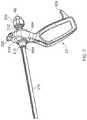
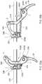
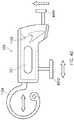
- FIG. 1is a side view of an electrosurgical instrument according to an embodiment of the present invention
- FIG. 2is a side view of the handle of the electrosurgical instrument according to the embodiment of the present invention.
- FIG. 3is an exploded view of an electrosurgical instrument according to the embodiment the present invention.
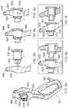
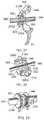
- FIG. 4is a sectional view of the clamping mechanism of the electrosurgical instrument of FIG. 3 , shown in an open configuration;
- FIG. 5 ais a sectional view of the clamping mechanism of the electrosurgical instrument of FIG. 3 , shown in a closed configuration;
- FIG. 5 bis a sectional view of the clamping mechanism of the electrosurgical instrument of FIG. 3 , shown in a closed configuration with tissue clamped therebetween;
- FIG. 6is a sectional view of part of the clamping mechanism of the electrosurgical instrument of FIG. 3 ;
- FIG. 7is a perspective view of the clamping mechanism of the electrosurgical instrument of FIG. 3 ;
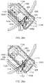
- FIGS. 8 a -8 fillustrate the assembly of a part of the electrosurgical instrument of FIG. 3 ;
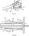
- FIGS. 9 a -9 bare sectional views of a part of the electrosurgical instrument of FIG. 3 ;
- FIGS. 10 a -10 cshow a blade guide part of the electrosurgical instrument of FIG. 3 ;
- FIG. 11shows a latch part of the electrosurgical instrument of FIG. 3 ;
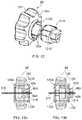
- FIG. 12shows a blade angle adjustment part of the electrosurgical instrument of FIG. 3 ;
- FIGS. 13 a -13 bare sectional views of the blade angle adjustment part of the electrosurgical instrument of FIG. 3 ;
- FIGS. 14 a -14 bshow a blade angle control wheel part of the electrosurgical instrument of FIG. 3 ;
- FIGS. 15 a -15 billustrate the rotational movement of the blade angle control wheel of the electrosurgical instrument of FIG. 3 ;
- FIGS. 16 a -16 dillustrate the rotational movement of the end effector of the electrosurgical instrument of FIG. 3 ;
- FIG. 17is a sectional view of the electrosurgical instrument of FIG. 3 illustrating a wiring path
- FIGS. 18 a -18 bshow further details of an electrical wiring path used in the electrosurgical instrument of FIG. 3 ;
- FIG. 19shows further details of an electrical wiring path used in the electrosurgical instrument of FIG. 3 ;
- FIGS. 20 a -20 bare side views of part of the cutting mechanism of the electrosurgical instrument of FIG. 3 ;
- FIG. 21is a sectional view of part of the cutting mechanism of the electrosurgical instrument of FIG. 3 ;
- FIG. 22is a sectional view of another part of the cutting mechanism of the electrosurgical instrument of FIG. 3 ;
- FIG. 23is a partially transparent perspective view of part of the cutting mechanism of the electrosurgical instrument of FIG. 3 ;
- FIGS. 24 a -24 cillustrate the assembly of one part of the cutting mechanism of the electrosurgical instrument of FIG. 3 ;
- FIGS. 25 a -25 care sectional views of the cutting mechanism and clamping mechanism of the electrosurgical instrument of FIG. 3 ;
- FIGS. 26 a -26 fare sectional views illustrating the operation of the latching mechanism of the electrosurgical instrument of FIG. 3 ;
- FIG. 27is a graph illustrating the cutting mechanism of the electrosurgical instrument of FIG. 3 ;
- FIGS. 28 a -28 bare line drawings illustrating the cutting mechanism of the electrosurgical instrument of FIG. 3 ;
- FIGS. 29 a -29 bshow a blade angle adjustment part of the electrosurgical instrument of FIG. 3 ;
- FIG. 30is a perspective view of part of the clamping mechanism of the electrosurgical instrument of FIG. 3
- FIG. 31is a partially section view of the cutting mechanism and clamping mechanism of the electrosurgical instrument of FIG. 3 ;
- FIG. 32is a partially section view of the cutting mechanism and clamping mechanism of the electrosurgical instrument of FIG. 3 ;
- FIG. 33shows the blade angle control wheel part and the electrode control switch of the electrosurgical instrument of FIG. 3 ;
- FIG. 34shows the blade angle control wheel part of the electrosurgical instrument of FIG. 3 ;
- FIGS. 35 a -35 billustrate the handle of the electrosurgical instrument of FIG. 3 , held by users with different size hands;
- FIGS. 36 a -36 cillustrate the rotational movement of the end effector of the electrosurgical instrument of FIG. 3 ;
- FIG. 37illustrates the rotational movement of the blade angle control wheel of the electrosurgical instrument of FIG. 3 ;
- FIG. 38is a schematic perspective view of an example end effector
- FIG. 39is an enlarged perspective view of a part of the end effector of FIG. 38 ;
- FIG. 40is a schematic sectional view of a part of the end effector of FIG. 38 ;
- FIG. 41is a schematic perspective view of an alternative end effector
- FIG. 42is an enlarged perspective view of a part of the end effector of FIG. 41 .
- FIG. 43is a schematic sectional view of a part of the end effector of FIG. 41 .
- FIG. 44is a schematic sectional view of a part of a further alternative end effector
- FIG. 45is a representation of an electro-surgical system including a generator and an instrument in accordance with embodiments of the invention.
- FIG. 46further illustrates a latch part of the electrosurgical instrument of FIG. 3 ;
- FIGS. 47 a -47 eillustrate the distal end of the cutting blade used in the electrosurgical instrument of FIG. 3 .
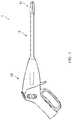
- FIG. 1illustrates an electrosurgical instrument 1 according to an example of the present invention.
- the instrument 1includes a proximal handle portion 10 , an outer shaft 12 extending in a distal direction away from the proximal handle portion, and a distal end effector assembly 14 mounted on a distal end of the outer shaft.
- the end effector assembly 14may by way of example be a set of opposed jaws arranged to open and close, and comprising one or more electrodes arranged on or as the inner opposed surfaces of the jaws and which in use have connections to receive an electrosurgical radio frequency (RF) signal for the sealing or coagulation of tissue.
- RFradio frequency
- the jawsare further provided with a slot or other opening within the inner opposed surfaces through which a mechanical cutting blade or the like may protrude, when activated by the user.
- the handle 10is activated by the user in a first manner to clamp tissue between the jaws 14 , and in a second manner to supply the RF current to the electrodes in order to coagulate the tissue.
- the jaws 14may be curved so that the active elements of the instrument 1 are always in view. This is important in vessel sealing devices that are used to operate on regions of the body that obscure the user's vision of the device during use.
- the handle 10may be activated by the user in a third manner to cause the blade to protrude between the jaws 14 , thereby cutting the tissue clamped between. Once the required cutting and sealing has been completed, the user can release the tissue from the jaws 14 .
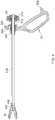
- the handle 10comprises a casing 20 formed of two clamshell mouldings 300 , 302 which houses all of the components required to operate and rotate the jaws 14 , coagulate and cut tissue.
- the clamshell mouldings in the assembled deviceare ultrasonically welded together, once the internal components have been assembled inside.
- the handle 10includes a clamping handle 22 for clamping tissue between the jaws 14 , a trigger 24 for cutting the tissue, switch 26 for activating and deactivating the RF supply to the electrodes in the jaws 14 in order to coagulate tissue, and a rotation wheel 28 for rotating the jaws 14 in order to reach tissue from different angles.
- the configuration of handle 10is such that the instrument 1 and all its functions can be operated using a single hand, with all of the operational mechanisms being easily accessible.
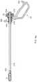
- FIG. 3shows all of the features of instrument 1 required to perform its functions, including those housed within the two clamshell mouldings 300 , 302 of the casing 20 .
- a clamping mechanismis actuated using the clamping handle 22 .
- the clamp handle 22further comprises a collar 304 , the collar 304 comprising a hinge 306 that functions as a fulcrum around which the clamping handle 22 rotates.
- the hinge 306may be two outward facing pins that click in to corresponding mouldings 308 integral to the clamshell mouldings 300 , 302 to thereby provide an anchor point around which the clamping handle 22 rotates.
- the clamping mechanismfurther comprises a collar moulding 310 , a spring 312 , and an inner moulding 314 , as further illustrated by FIGS. 4 to 7 , all of which are threaded along a drive shaft 316 .
- the collar 304comprises a keyhole aperture 318 in which the collar moulding 310 sits.
- the aperture 318has a larger diameter at the top than that at the bottom, wherein the collar moulding 310 is arranged to sit within the lower part of the aperture 318 , as illustrated by FIG. 8 a .
- the collar moulding 310easily fits through the larger part of the aperture 318 such that the collar 304 sits between two flanges 800 , 802 , as shown by FIGS. 8 b -8 c .
- FIG. 8 dthe collar 304 is then pushed upwards to engage the smaller part of the keyhole aperture 318 with the collar moulding 310 .
- the hinge 306is connected to the hinge mouldings 308 within the casing 20 , the collar moulding 310 is retained within the lower part of the aperture 318 where it is free to move rotationally within the aperture 318 .
- the collar moulding 310 , spring 312 and inner moulding 314are retained between protruding members 600 , 602 such that they cannot travel axially beyond these protruding members 600 , 602 .
- the protruding members 602 at the proximal end of the drive shaft 316are compressible so as to allow the drive shaft 316 to be passed through a channel 604 in the proximal end of the inner moulding 314 .
- the drive shaft 316is pushed through the channel 604 until it reaches an opening 606 , wherein the protruding members 602 are no longer compressed such that they lie flush against the walls of the drive shaft 316 .
- the protruding members 602fan out and push against the walls of the opening 606 such that the span of the protruding members 602 extends beyond the diameter of the channel 604 . Consequently, the drive shaft 316 cannot be pulled back through the channel 604 and is thus locked in place.
- the distance between the protruding members 600 , 602is such that the spring 312 is at least partially compressed between the collar moulding 310 and the inner moulding 314 . This pre-compression is important for ensuring that the correct clamping load is applied when the clamping mechanism is activated, as will be described in more detail below.
- Both the collar moulding 310 and the inner moulding 314comprise cavities 608 , 610 into which the spring 312 extends. In particular, a substantial proportion of the length of the collar moulding 310 houses the spring 312 . This arrangement allows for a longer spring 312 which is important for ensuring that the spring 312 does not ever reach its solid length during use.
- the main body of the drive shaft 316lies within the outer shaft 12 , the distal end of the drive shaft 316 being coupled to both the distal end of the outer shaft 12 and the jaws 14 .
- the drive shaft 316moves axially within the outer shaft 12 and it is this axial movement that moves the jaws 14 from an open to a closed position, as can be seen from FIGS. 4 and 5 a .
- the drive shaft 316is coupled to the jaws 14 by means of a drive pin 400 in a cam slot 402 , whereby movement of the drive pin 400 within the cam slot 402 moves the jaws 14 between the open and closed position.
- the coupling between the drive shaft 316 , the outer shaft 12 and the jaws 14is such that rotational movement of the drive shaft 316 is transferred to the outer shaft 12 and jaws 14 .
- the outer shaft 12 and drive shaft 316are coupled at a further point by means of a shaft moulding 320 .
- the shaft moulding 320sits within a socket 322 of the casing 20 , and thus couples the outer shaft 12 to the casing 20 .
- the outer shaft 12is attached to the shaft moulding 320 by any suitable means, for example, snap-fit tabs 900 that cooperate with corresponding notches 902 within the shaft moulding 320 , as shown in FIG. 9 b .
- the drive shaft 316is threaded through the body of the shaft moulding 320 via an aperture (not shown) that matches the cross-sectional “T” shape of the drive shaft 316 , as illustrated by FIG. 10 a .
- the shaft moulding 320is arranged such that it is free to rotate within the socket 322 .
- the shaft moulding 320may comprise cylindrical flange features 904 , 906 that rotate within concentric mating faces 908 , 910 provided within the clamshell mouldings 300 , 302 . Therefore, the shaft moulding 320 rotates with the drive shaft 316 , which in turn translates this rotational movement to the outer shaft 12 and the jaws 4 .
- the shaft moulding 320thus acts as a rotational and axial guide for the drive shaft 316 .
- the clamping handle 22comprises a latch 324 arranged to cooperate with a latch moulding 326 which sits within the proximal end 328 of the casing 20 .
- the latch moulding 326may be held in place by any suitable means, for example, by means of a moulded pin 330 integral to one of the clamshell mouldings 300 , 302 , as shown by FIG. 3 , or by simply by the moulded walls 1100 integral to the clamshell moulding 300 , as shown by FIG. 11 .
- the latch 324enters the casing 20 via an opening 1102 and engages with the latch moulding 326 so as to retain the clamping handle 22 in this position.
- the latch moulding 326comprises a two way spring 1104 and a cam path 1106 along which the latch 324 traverses.
- the latch mechanismmay also include an override component 4600 to allow the user to manually release the latch 324 if it gets stuck, and a lock-out component 4602 to disable the latch mechanism altogether.
- the override component 4600 and lock-out component 4602may be provided on the latch moulding 326 or may be integral to the inside of the casing 20 .
- the handle 10further comprises a rotation wheel 28 , wherein the rotation wheel 28 is arranged to encase the inner moulding 314 .
- the rotation wheel 28 and inner moulding 314have interlocking members 1200 , 1202 , as shown by FIG. 12 .
- These interlocking members 1200 , 1202couple together such that the rotation wheel 28 and inner moulding 314 rotate together, whilst still allowing axial movement of the inner moulding 314 within the rotation wheel 28 , as can be seen from FIGS. 13 a -13 b . Therefore, rotation of the rotation wheel 28 causes rotation of the inner moulding 314 , which subsequently rotates the drive shaft 316 and the collar moulding 310 .
- the rotation wheel 28comprises cylindrical faces 1204 that rotationally slide on internal mating faces (not shown) integral to the clamshell mouldings 300 , 302 .
- the casing 20has two openings 332 , 334 through which scalloped portions 336 of the rotation wheel 28 protrude.
- the two openings 332 , 334are opposite one another on each side of the handle, and are trapezoidal in shape.
- the trapezoidal apertureshave parallel sides orthogonal to the longitudinal axis of the handle, and one of the parallel sides may be longer than the other, the longer side being at the forward end of the aperture, and the shorter side being at the rearward end.
- the scalloped portions 336are conveniently sloped so as to comfortably fit the thumb or fingers of the user.
- the scalloped portions 336are cut at an angle to the plane of rotation, as shown in FIGS. 14 a -14 b .
- the angle of the sloping part of the scalloped portionsshould be substantially equal to the angle of the external casing in the region of the rotation wheel 28 .
- the rotation wheel 28also comprises at least one stop member 1500 for limiting the degree of rotation, as illustrated in FIGS. 5 a -5 b .
- the stop member 1500interacts with stop features 1502 , 1504 integral to the casing 20 .
- the stop member 1500is obstructed by the stop features 1502 , 1504 , thereby preventing further rotation.
- the stop features 1502 , 1504may limit the rotation wheel to 270° of rotation.
- the shaft moulding 320also comprises a stop member 1600 that interacts with stop features 1602 , 1604 integral to the casing 20 , as shown by FIGS. 16 a -16 d .
- the stop member 1600 of the shaft moulding 320 and its respective stop feature 1602 , 1604are radially aligned with the stop member 1500 of the rotation wheel 28 and its respective stop features 1502 , 1504 such that rotation is limited to the same extent. That is, as the rotation wheel 28 is turned, the radial point at which stop member 1500 on the rotation wheel 28 is obstructed will be the same as the radial point at which stop member 1600 on the shaft moulding 320 will be obstructed. For example, in FIGS. 15 b and 16 a , the jaws 14 have been rotated 90° anticlockwise from a neutral orientation (shown in FIG. 16 b ). This rotational freedom means that the user can grasp at tissue from different angles without needing to rotate the whole instrument 1 .
- the switch button 26is provided for activating and de-activating the RF signal delivered to the electrodes in the jaws 14 via some appropriate circuitry, for example, two ingress-protected switches on a small printed circuit board (PCB) 338 .
- the PCB 338is connected to a connection cord 1700 for receiving the RF output from a generator (not shown) and electrical wiring 1702 , 1704 for supplying the RF current to the electrodes in the jaws 14 , for example, one wire for the active electrode and one for the return electrode.
- a connection cord 1700for receiving the RF output from a generator (not shown) and electrical wiring 1702 , 1704 for supplying the RF current to the electrodes in the jaws 14 , for example, one wire for the active electrode and one for the return electrode.
- the wires 1702 , 1704are wrapped underneath and around the shaft moulding 320 before entering a guide slot 1800 into the internal cavity 1802 of the shaft moulding 320 and down the outer shaft 12 . Wrapping the wires 1702 , 1704 around the shaft moulding 320 in this way keeps the wires 1702 , 1704 in a compact arrangement, so as to enable easy assembly, whilst allowing for the rotation of the drive shaft 316 . In this respect, the wires 1702 , 1704 un-wind and re-wind with the rotation of the drive shaft 316 .
- one of the clamshell mouldings 300also comprises two moulded pockets 1900 , 1902 located in series for housing the wire contacts 1904 , 1906 that connect the active and return wires 1702 , 1704 to the wiring 1908 , 1910 of the ingress-protected switches 338 .
- the opposite clamshell moulding 302comprises corresponding rib features (not shown) to retain the contacts 1904 , 1906 within the pockets 1900 , 1902 .
- the two wire contacts 1904 , 1906are longitudinally separated such that only one contact can pass through each pocket 1900 , 1902 , thereby providing a physical barrier between each contact 1904 , 1906 and any wiring. This prevents the risk of insulation damage to any of the wiring caused by the contacts 1904 , 1906 , whilst also protecting the contacts 1904 , 1906 themselves from any fluid that may make its way down the outer shaft 12 and into the casing 20 .
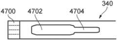
- a blade 340 for cutting tissue clamped between the jaws 14is provided within a central track 342 along the length of the drive shaft 316 .
- the mechanism for actuating the blade 340 along the track 342 and between the jaws 14is operated via the trigger 24 .
- the trigger 24actuates a drive assembly formed of a trigger moulding 344 , a blade drive moulding 346 , a blade collar moulding 348 , an extension spring 350 and a blade moulding 352 .
- the drive assemblyis positioned between the shaft moulding 320 and the handle collar 304 of the clamping mechanism. As shown in FIGS.
- the drive assemblyfunctions as an offset slider-crank mechanism whereby the force exerted by the user on the trigger 24 is transferred into axial movement of the blade moulding 352 along the drive shaft 316 , which in turn drives the attached blade 340 .
- the blade moulding 352is arranged to sit within the blade collar moulding 348 .
- the blade collar moulding 348comprises a lip 2200 the interlocks with a groove 2202 around the circumference of the blade moulding 352 .
- the blade moulding 352has a “T” shaped aperture 2300 for receiving the drive shaft 316 and blade 340 .
- the blade moulding 352further comprises an internal cut-out 2100 , as shown by FIG.
- FIGS. 24 a -24 cfor the proximal end of the blade 340 , wherein the end of the blade 2102 is shaped to match the internal cut-out 2100 of the blade moulding 352 so as to allow ease of assembly, as demonstrated by FIGS. 24 a -24 c .
- the blade moulding 352is isolated rotationally from the blade collar moulding 348 such that the two mouldings can rotate concentrically. Consequently, the blade moulding 352 is able to rotate with the drive shaft 316 .
- the jaws 14may be curved.
- the frictional forceis a product of the frictional coefficient of the blade 340 within the track 342 , and the force due to bending that the blade 340 exerts on the walls of the track 342 .
- This frictional forcemay be reduced, for example, by adding a low friction coating to the sides of the blade, and/or preferentially weakening the blade 340 to graduate the flexibility of the blade's distal end such that it is able to bend along the track 342 whilst remaining rigid in the direction of the cutting force.
- Preferential weakeningmay be provided, for example, by the provision of one or more apertures 354 in the distal end, as shown in FIG. 3 and FIGS. 47 a -47 c , or by graduating the blade 340 thickness, as illustrated in FIG. 47 d .
- patterned laser cuts 4712 or chemical etches in the distal endcould be used to control the bending stiffness over a length of the blade, whereby the spacing between such cuts may be constant or gradually increase from the distal to proximal end.
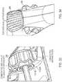
- the distal end of the drive shaft 316may include cut-out portions 1000 , 1002 in order to reduce the surface area of the drive shaft 316 to which blood and tissue build stick, as shown in FIGS. 10 b -10 c .
- the cut-out portionsmay be such that the distal end comprises two side walls with no base support, or the distal end comprises a base support with bifurcated side walls.
- the handle 10 of the electrosurgical instrumentis arranged to i) clamp tissue between a set of jaws 14 , ii) latch the jaws in place (if desired by the user), iii) deliver an RF signal to electrodes in the jaws 14 so as to coagulate the tissue clamped between, and iv) launch a blade 340 between the jaws 14 so as to cut the tissue clamped between.
- the handle 10can also rotate the jaws 14 so as to allow the user to clamp tissue at different angles without needing to rotate the entire handle 10 .
- the resultis that the tissue between the jaws can be sealed prior to or at the same time as being cut by the same electrosurgical instrument.
- these effectscan be achieved by the instrument via a one handed operation thereof by the surgeon.
- the usersqueezes the clamping handle 22 towards the proximal end 328 of the casing 20 until the latch 324 engages with the latch moulding 326 within the casing 20 .
- This movementpivots the drive handle 22 about its hinge 306 , as shown by FIGS. 8 e -8 f , and pushes the edge of the collar 304 against the flange 800 to drive the collar moulding 310 , the spring and the inner moulding 314 along the drive shaft 316 in the proximal direction, as illustrated by FIGS. 4 and 5 a .
- the inner moulding 314is attached to the drive shaft 316 via protruding members 602 .
- the drive shaft 316is also moved axially which drives the pin 400 in the cam slot 402 of the jaws 14 , thereby closing the jaws 14 .
- the load from the drive handle 22is transferred to the drive shaft 316 via the spring mechanism of the collar moulding 310 , spring 312 and inner moulding 314 .
- the spring 312acts to limit the force loaded onto the tissue.
- the threshold compression force on the spring 312is eventually reached such that the spring 312 begins to compress between the collar moulding 310 and inner moulding 314 .
- the drive handle 22can be driven all the way into the latched position without exerting any more force on the clamped tissue. That is, the load of the drive handle 22 is no longer transferred to the drive shaft 316 , but is effectively absorbed by the spring 312 .
- the spring 312ensures that the correct amount of load is transferred onto the jaws 14 . Without the spring 312 , actuation of the drive handle 22 will continue to increase the load transferred to the drive shaft 316 and subsequently the jaws 14 and tissue. This could result in mechanical damage to the tissue as the user continues to squeeze the drive handle 22 in order to engage the latch 324 .
- the cavities 608 , 610 in the collar moulding 310 and inner moulding 314act together to allow for a larger spring 312 . This allows for greater spring travel so that the spring 312 does not completely compress to its solid length during use. If the spring 312 was to reach its solid length, the spring would no longer absorb the load exerted by the drive handle 22 and the force would once again be transferred to the jaws 14 .
- the jaws 14can be locked into a closed position by engaging the latch 324 on the drive handle with the latch moulding 326 inside the casing 20 as shown by FIGS. 26 a -26 f .
- the latch 324engages the latch moulding 326 , pushing the moulding 326 down within the casing 20 and thereby extending the spring 1104 .
- the latch 324runs up the side of the cam path 1106 until it reaches its maximum position.
- the userTo release the latch 324 from the casing 20 and open the jaws 14 , the user must squeeze drive handle 22 towards the casing 20 to release the latch 324 from the pocket of the cam path 1106 , as shown by FIG. 26 e .
- the force of the spring 1104pulls the latch moulding 326 further up into the casing 20 , such that the latch 324 travels in the opposite direction down the side of the cam path 1106 , as shown by FIGS. 26 e -26 f , and back out of the opening 1102 .
- the latch moulding 326will then return back to its original position within the casing 20 .
- a blade 340is driven between the jaws 14 by actuation of the drive assembly.
- the drive assemblyis a three pivot arrangement that acts as a slider-crank mechanism.
- the userpulls the trigger 24 back towards the casing 20 , as shown by FIGS. 25 b -25 c , it levers the trigger moulding 344 around a pivot point A which is anchored to the casing 20 , for example, by means of outward facing pins 358 that connect with corresponding mouldings 356 integral to the clamshell mouldings 300 , 302 shown in FIG. 3 .
- the shaft moulding 320acts as a stopping point for the blade collar 348 and blade moulding 352 . Consequently, the pivot point B always remains above the two other pivot points A, C with respect to the drive shaft 316 .
- the force exerted on the trigger 24is big enough to overcome the compression force of the extension spring 350 such that it extends along the same plane as the drive shaft 316 to allow for the axial movement of the blade collar 348 and blade moulding 352 .
- the extension spring 350re-compresses to retract the drive assembly to its original position. In this respect, the tension of the extension spring 350 is strong enough to retract the blade 340 through thick tissue without the need for user intervention.
- the jaws 14are advantageously rotatable relative to the handle 10 by means of the rotation wheel 28 . This is particularly beneficial where the jaws 14 are on a curved track, such as those shown in FIGS. 16 a -16 d .
- the rotation wheel 28is coupled to the inner moulding 314 via interlocking members 1200 , 1202 such that the inner moulding 314 rotates with the rotation wheel 28 .
- the drive shaft 316As the end of the drive shaft 316 is connected to the inner moulding 314 , the drive shaft 316 also rotates which subsequently rotates the jaws 14 at its opposite end.
- the collar moulding 310is rotationally isolated within the handle collar 304 such that the collar moulding 310 also rotates with the drive shaft 316 .
- the blade moulding 352is rotationally isolated within the blade collar 348 .
- the shaft moulding 320is rotationally isolated within its socket 322 .
- the shaft moulding 320acts as a rotational guide so as to control the rotational movement relative to the shaft 316 along the entire length of the instrument 1 .
- the active and return wires 1702 , 1704are arranged within the casing 20 so as to prevent damage to these wires 1702 , 1704 as a result of the rotating components.
- the wires 1702 , 1704are wrapped around the shaft moulding 320 so as to allow for the degree of rotation of the drive shaft 316 . Consequently, the wires 1702 , 1704 un-wind and re-wind around the shaft moulding 320 as it rotates.
- the userWhilst the jaws 14 are in a closed position, the user may wish to coagulate and seal the tissue clamped between. To do this, the user initiates electrode activation using the switch button 26 on the top of the casing 20 , positioned conveniently so that the user can easily access the button 26 whilst using the device single handed. In doing this, an appropriate RF signal is delivered to the electrodes in the jaws 14 so as to coagulate and seal the tissue.
- the RF signalmay be a pure or blended waveform, depending on the desired effect.
- the proximal handle portion 10 of the electrosurgical instrument 1includes a first mechanism for actuating one aspect of a distal end effector assembly 14 such that the end effector assembly 14 moves between a first and second condition.
- the end effector assembly 14may be a set of opposed jaws 14 arranged to open and close.
- the mechanism used to trigger movement of these jaws 14is the so called clamping mechanism comprising a drive handle 22 and two barrel shaped mouldings 310 , 314 with a spring 312 compressed therebetween, all of which are threaded along an elongate bar 316 that extends between the jaws 14 and the handle 10 , as shown in FIGS. 4 and 5 a - 5 b.
- the drive handle 22comprises a collar 304 in which the collar moulding 310 sits.
- the collar 304comprises an aperture 318 shaped like a keyhole or a figure of eight.
- the aperture 318is formed of two contiguous apertures 804 , 806 , wherein the top aperture 804 has a larger diameter across it than the bottom aperture 806 .
- the collar moulding 310is a cylindrical or barrel shaped component having two flange portions 800 , 802 spaced apart longitudinally.
- the diameter of the proximal flange 800is larger than both the upper and the lower apertures 804 , 806 .
- the diameter of the distal flange 802is smaller than the upper aperture 804 and larger than the lower aperture 806 .
- the collar moulding 310is first inserted through the upper aperture 804 , as shown by FIGS. 8 b -8 c .
- the distal flange 802is smaller than the upper aperture 804 , it easily passes through, whereas the proximal flange 800 may be large enough to prevent the collar moulding 310 from advancing the entire way through the upper aperture 804 .
- the collar 304is then pushed upwards to engage the lower aperture 806 with the collar moulding 310 .
- the collar moulding 310remains within the lower aperture 806 of the collar 304 and is positioned such that its two flanges 800 , 802 lie either side of the collar 304 , as shown in FIG. 8 e .
- the collar moulding 310cannot be removed by simply pushing the collar moulding 310 through the lower aperture 806 .
- the body of the collar moulding 310 between the two flanges 800 , 802has a slightly smaller diameter than the lower aperture 806 . Therefore, the collar moulding 310 sits within the lower aperture 808 loosely enough to allow rotational movement.
- the longitudinal distance between the two flanges 800 , 802is only slightly larger than the thickness of the collar 304 such that the collar 304 sits snugly between the flanges 800 , 802 .
- the drive shaft 316is an elongated bar with one or more protruding members 602 located at its proximal end, as shown in FIG. 6 .
- the protruding members 602are flexible tabs that fan out from the surface of the drive shaft 316 . That is to say, the protruding members 602 are deformable such that they may be pressed flush against the surface of the drive shaft 316 , but will return to their original positions upon release of any resistive force. This allows the drive shaft 316 to be easily threaded through all of the components of the clamping mechanism during assembly, as will now be described.
- the collar moulding 310has an internal cavity divided into two parts.
- the first partis a narrow channel or slot 607 for receiving the drive shaft 316 , wherein the distal end of the collar moulding 310 comprises an opening 311 , as shown in FIG. 3 , which matches the cross-sectional “T” shape of the drive shaft 316 .
- the diameter of the channel 607is only slightly wider than that of the drive shaft 316 so as to provide a snug fit for stability.
- the protruding members 602are pressed flat to allow the drive shaft to be pushed all the way through.
- the second partis a chamber 608 large enough to house one end of the spring 312 .
- the chamber 608can extend over any suitable proportion of the length of the collar moulding 310 .
- the length of the chamber 608may be around 25% of the length of the collar moulding 310 , or as much as 75% of the length of the collar moulding 310 .
- the chamber 608is substantially larger than the collar moulding channel 607 such that as the drive shaft 316 is pushed through the collar moulding 310 , the protruding members 602 span back out to their original configuration when they reach the chamber 608 .
- the collar moulding 310 and drive handle 22 assemblyis threaded down along the drive shaft 316 until the collar moulding 310 reaches a second set of protruding members 600 .
- These protruding members 600have a span wider than the opening 311 on the collar moulding 310 so as to provide an obstruction that prevents the collar moulding 310 from advancing further along the drive shaft 316 .
- the protruding members 600must be sufficiently rigid that the collar moulding 310 cannot be pushed passed the protruding members 600 by exerting some force or pressing the protruding members 600 inwards.
- the drive shaft 316is then threaded through the centre of the spring 312 .
- the spring 312has a diameter that is only slightly larger than that of the drive shaft 312 to provide a close fit between the spring 312 and the drive shaft 316 .
- the spring 312is then pushed along the drive shaft 316 until the end of the spring 312 fills the collar moulding chamber 608 .
- the inner moulding 314is a cylindrical or barrel shaped component having an internal cavity divided into two sections.
- the first sectionis a chamber 610 in which one end of the spring 312 is housed such that the spring 312 is partially encased by the collar moulding 310 and inner moulding 314 .
- the second sectionis a narrow channel or slot 603 for receiving the proximal end of the drive shaft 316 .
- the channel 603is divided into two parts 604 , 606 .
- the first part of the channel 604is shaped so as to allow the drive shaft 316 to be passed through, the flexible tabs 602 being pressed flat in doing so. As such, the diameter of the first channel part 604 is only slightly wider than that of the drive shaft 316 so as to provide a snug fit.
- the snug fit of the drive shaft 316 within both the collar moulding channel 607 and inner moulding channel 603means that the drive shaft 316 is held firmly in place. This adds to the stability of the drive shaft 316 within the casing 20 , which is particularly important for ensuring maximum control of the end effector 14 .
- the second part of the channel 606provides a shoulder 605 into which the protruding members 602 can extend. Consequently, as the drive shaft 316 passes through the channel 604 and into the second channel part 606 , the flattened protruding members 602 fan back out to their original decompressed positions. Once the protruding members 602 have engaged with the shoulder 605 of the second channel part 606 , the drive shaft 316 cannot be pulled back through the first channel part 604 and is thus retained in the inner moulding 314 . As such, the diameter of the second channel part 606 must be sufficiently wide that the protruding members 602 are able to expand beyond the diameter of the first channel part 604 . To achieve this snap-fit connection, a protruding member 602 is only required on one side of the drive shaft 316 .
- This snap-fit connectionis such that any axial movement of the inner moulding 314 will be transferred to the drive shaft 316 .
- any rotational movement of the inner moulding 314for example, by means of the rotation wheel 28 formed around the inner moulding 314 , is also transferred to the drive shaft 316 .
- the drive shaft 316is simply threaded through the collar moulding 310 , the spring 312 and finally the inner moulding 314 , until the protruding members 602 snap into the second channel part 606 .
- the collar moulding 310 , the spring 312 and the inner moulding 314are arranged such that the spring 312 is partially encased by the collar moulding 310 and inner moulding 314 .
- a longer spring 312can be used without using up any additional space within the handle 10 . As such, the larger the collar moulding chamber 608 and inner moulding chamber 610 , the longer the spring 312 .
- the distance between the protruding members 600 , 602means that the ends of the spring 312 are compressed by the end walls 612 , 614 of the collar moulding chamber 608 and inner moulding chamber 610 respectively so that the spring 312 experiences an initial pre-compression upon installation. This is important for ensuring that when the handle 22 is actuated so as to activate the clamping mechanism, the correct load is applied to the jaws 14 .
- the inner moulding 314may be contained within a further barrel shaped moulding such as the rotation wheel 28 shown in FIGS. 13 a -13 b .
- the inner moulding 314rotates with the rotation wheel 28 , but is free to move axially within the internal cavity 1300 of the rotation wheel 28 , moving between a first position as shown in FIG. 13 a and a second position as shown in FIG. 13 b . Consequently, rotation of the wheel 28 rotates the inner moulding 314 , which in turn rotates the drive shaft 316 and the jaws 14 .
- the drive handle 22can be installed inside the casing 20 .
- the drive handle 22is connected to the casing at its hinge 306 .
- the hinge 306may be two outwardly extending pins that mate with corresponding hinge mouldings 308 integral to the clamshell mouldings 300 , 302 . This provides an anchor point around which the drive handle 22 can rotate.
- the above arrangementprovides a mechanism for actuating the end effector assembly 14 which can be assembled easily and securely without the need for any additional components.
- the usersqueezes the drive handle 22 towards the proximal end 328 of the casing 20 , thereby rotating the drive handle 22 about its hinge 306 .
- the collar 304pushes against the proximal flange 800 , thus moving the collar moulding 310 longitudinally.
- This longitudinal movementdrives the spring 312 , inner moulding 314 and the drive shaft 316 back towards the proximal end of the handle portion 10 , as shown by FIG. 5 a .
- the drive shaft 316is coupled to the jaws 14 , for example, by means of a pin 400 and cam slot 402 arrangement, the jaws 14 are moved from the open to the closed position.
- the load from the drive handle 22is transferred to the drive shaft 316 via the spring mechanism of the collar moulding 310 , spring 312 and inner moulding 314 .
- This spring mechanismis particularly important as it acts to limit the force loaded onto any tissue that is clamped between the jaws 14 .
- the collar moulding 310 , spring 312 and inner moulding 314continue to move axially until either the inner moulding 314 reaches its furthest proximal position such that the jaws 14 are fully closed, as shown in FIG. 5 a , or the jaws 14 are unable to close any further due to tissue 500 clamped between, as shown by FIG. 5 b , in which case the drive handle 22 has not been fully actuated such that it is held in place by the latch 324 .
- the threshold compression force on the spring 312is eventually reached such that the spring 312 begins to compress between the collar moulding 310 and inner moulding 314 , as can be seen in FIG. 5 b.
- the drive handle 22can be driven all the way into the latched position without exerting any more force on the clamped tissue 500 . That is, the load of the drive handle 22 is no longer transferred to the drive shaft 316 , but is effectively absorbed by the spring 312 . As such, the spring 312 ensures that the correct amount of load is transferred onto the jaws 14 . Without the spring 312 , actuation of the drive handle 22 will continue to increase the load transferred to the drive shaft 316 and subsequently the jaws 14 and tissue 500 . This could result in mechanical damage to the tissue 500 as the user continues to squeeze the drive handle 22 in order to engage the latch 324 .
- the pre-compression of the spring 312is important for ensuring that the spring 312 bears the load of the handle 22 as soon as the inner moulding 314 reaches its axial limit.
- having a longer spring 312allows for greater spring travel so that the spring 312 does not completely compress to its solid length during use. If the spring 312 was to reach its solid length, the spring 312 would no longer absorb the load exerted by the drive handle 22 and the force would once again be transferred to the jaws 14 .
- the latch 324 on the drive handle 22must be engaged with the latch moulding 326 inside the proximal end 328 of the casing 20 , as shown in FIGS. 26 a - 26 f.
- the latch moulding 326is a single integrally moulded component comprising a body portion 1108 , a spring element 1104 and a cam path 1106 .
- the proximal end 328 of the casing 20has parallel walls 1100 that define a channel 1110 in which the body portion 1108 sits.
- the width of the channel 1110is such that the body portion 1108 is retained within the channel 1110 but is still able to slide up and down the channel 1110 during use, as will be described below.
- the latch moulding 326is preferably made of a low friction material, for example, polytetrafluoroethylene (PTFE), to allow the body portion 1108 to easily slide within the channel 1110 without sticking.
- a moulded pin 330may be provided in the casing 20 which engages with a cam slot 331 provided on the body portion 1108 , as shown in FIG. 46 .
- the spring 1104is located at the end of the body portion 1108 and is arranged to bias the body portion 1108 up the channel 1110 towards the distal end of the casing 20 .
- the spring 1104can be of any suitable configuration, for example, the spring 1104 may be an arcuate or loop shape such as that shown in FIG. 11 .
- the cam path 1106is a moulded projection formed on the body portion 1108 .
- the cam path 1106comprises a first cam surface 1112 , a notch 1114 and a second cam surface 1116 to form a “V” shaped moulding.
- the latch 324is formed of an arm 1118 extending from the bottom of the drive handle 22 .
- the arm 1118has a pin 1120 located at its end which is suitable for traversing the cam path 1106 .
- the latch 324enters the casing 20 via an opening 1102 .
- the pin 1120engages the latch moulding 326 such that the body portion 1108 is pulled down channel 1110 and the spring 1104 thereby being extended.
- the pin 1120runs up the side of the first cam surface 1112 until it reaches the top of the “V”.
- the drive handle 22cannot be compressed any further, and the spring 1104 pulls the body portion 1108 back up the channel 1110 such that the pin 1110 slots into the notch 1114 , thus retaining the drive handle 22 in the compressed position and the jaws 14 in the closed position, as shown in FIG. 26 d.
- the userTo release the latch 324 from the casing 20 and open the jaws 14 , the user must squeeze drive handle 22 towards the casing 20 once more. This releases the pin 1120 from the notch 1114 , as shown by FIG. 26 e .
- the force of the extended spring 1104pulls the body portion 1108 back up the channel 1110 , such that the pin 1120 runs down the side of the second cam surface 1116 , as shown by FIGS. 26 e -26 f
- the pin 1120reaches the bottom of the second cam surface 1116 , it pushes the body portion 1108 further up the channel 1110 so that the pin 1120 can pass back out of the opening 1102 .
- the body portion 1108will then return back to its original position within the channel 1110 .
- the latch moulding 324may include an override button 4600 integrally formed on the body portion 1108 as shown in FIG. 46 , wherein the override button 4600 is engaged so as to alter the position of the cam path 1106 such that the pin 1120 automatically disengages with the notch 1114 and releases the drive handle 22 . Consequently, if the latch mechanism was to fail for any reason, the user would be able to release the drive handle 22 to open the jaws 14 .
- the body portion 1108may also be provided with an integrated lock-out bar 4602 to allow the user to disengage the latch mechanism altogether, wherein the lock-out bar 4602 is moveable between a first and second position to manually slide the body portion 1108 within the channel 1110 .
- the lock-out bar 4602When the lock-out bar 4602 is in the first position, the body portion 1108 is in its normal position such that the latch mechanism operates as described above. The user may then move the lock-out bar 4602 to its second position, whereby the body portion 1108 is moved up the channel 1110 such that the pin 1120 can only traverse along the second cam surface 1116 and is thus prevented from engaging with the notch 1114 .
- such a latch mechanismmay also be suitable for many end effector assemblies.
- such a latchmay be provided on the trigger 24 for the cutting mechanism so as to retain the cutting blade 340 in the actuated position.
- the drive handle 22can be moved back to its original position.
- the collar 304releases the load exerted on the proximal flange 800 and pushes against the distal flange 802 , thus pulling the collar moulding 310 back to its original axial position. Consequently, the spring 312 , the inner moulding 314 and the drive shaft 316 are also pulled back axially, which in turn moves the jaws 14 back to the open configuration.
- the proximal handle portion 10 of the electrosurgical instrument 1includes a second mechanism for actuating a further aspect of a distal end effector assembly 14 .
- the end effector assembly 14may be a set of opposed jaws 14 and a blade 340 , wherein the distal end of the blade 340 is arranged to slide between the jaws 14 in order to cut tissue clamped between said jaws 14 .
- the mechanism used to trigger movement of the blade 340which is disposed within a central track 341 of the drive shaft 316 , is the so called cutting mechanism.
- the cutting mechanismcomprises a drive arm 2000 , a blade drive moulding 346 , a blade collar moulding 348 , a blade moulding 352 and an extension spring 350 , all of which are coupled together to form a three pivot slider-crank mechanism, as shown in FIGS. 20 a -20 b and FIGS. 31 and 32 .
- the drive arm 2000is formed of a trigger 24 and the trigger moulding 344 , wherein the trigger 24 is a finger gripping member for actuating the cutting mechanism and the trigger moulding 344 is a collar having a “C” shaped side profile and an aperture 364 through which the drive shaft 316 is threaded.
- the point which the trigger 24 and trigger moulding 344 meetprovides a pivot point A about which the drive arm 2000 is rotated.
- This first pivot point Ais anchored to the casing 20 , for example, by means of outward facing pins 358 that connect with corresponding mouldings 356 integral to the clamshell mouldings 300 , 302 .
- the distal end of the drive arm 2000that is, the end of the trigger moulding 344 is pivotally connected to the blade drive moulding 346 to form a second pivot point B.
- the blade drive moulding 346is an “H” shaped frame having two parallel arms and a strut therebetween.
- the parallel arms of the blade drive moulding 346are pivotally connected at one end to the trigger moulding 344 , for example, by means of outward facing pins 366 and mating connectors 368 .
- the parallel arms of the blade drive moulding 346are also pivotally connected to the blade collar moulding 348 to form a third pivot point C, for example, by means of outward facing pins 372 and mating connectors 370 .
- the blade collar moulding 348is a cylindrical or barrel shaped component having a chamber 2104 in which the blade moulding 352 sits, wherein the blade moulding 352 is a cylindrical or barrel shaped component having a body 362 that fits inside the chamber 2104 of the blade collar moulding 348 .
- the blade moulding 352further comprises a flange 360 having a diameter larger than that of the chamber 2104 such that the flange 360 abuts the distal lip 2200 of the blade collar moulding 348 , as shown in FIG. 22 . Consequently, the flange 360 ensures that the correct end of the blade moulding 352 is interested to the blade collar moulding 348 .
- the body 362is provided with a small groove 2202 around its circumference so as to provide a shoulder with which the distal lip 2200 interlocks such that the blade moulding 352 and blade collar moulding 348 are coupled via a snap-fit connection.
- the distal lip 2200mates with the groove 2202 so as to retain the blade moulding 352 within the blade collar moulding 348 whilst allowing the blade moulding 352 to freely rotate within the chamber 2104 . As such, the blade moulding 352 and blade collar moulding 348 are free to rotate concentrically.
- the blade 340can be connected as illustrated by FIGS. 24 a -24 c .
- the blade moulding 352comprises a “T” shaped aperture 2300 which extends throughout its length, shaped as such so as to receive both the blade 340 and the drive shaft 316 , as shown by FIG. 23 .
- the proximal end of the blade 340comprises a tab feature 2102 which extends beyond the general profile of rest of the blade 340 , that is, it does not lie in the same axial plane.
- the body 362further comprises a recess 2100 in which the tab 2100 is retained.
- the proximal end of the blade 340is cut away at a first point opposite the tab 2102 in order to provide a bevelled edge 2400 , and is cut away a second point adjacent to the tab 2102 to provide a recessed portion 2402 .
- the proximal end of the blade 340has an “L” shaped profile.
- the blade 340is presented to the “T” shaped aperture 2300 at an angle to the longitudinal axis of the instrument 1 so that the tab 2102 and bevelled edge 2400 can be inserted to the internal cavity 2404 of the blade moulding 352 , as shown in FIGS. 24 a -24 b .
- the blade 340is then pulled down in line with the longitudinal axis so as to push the tab 2102 into the recess 2100 , as shown by FIG. 24 c .
- the tab 2102is effectively hooked on to the shoulder 2406 of the blade moulding 352 , thereby retaining the proximal end of the blade 340 within the internal cavity 2404 .
- the drive shaft 316may then be threaded through the “T” shaped aperture 2300 , the blade 340 being received in the central track 342 , as illustrated by FIGS. 22 and 23 . As such, longitudinal movement of the blade collar moulding 348 and blade moulding 352 assembly along the drive shaft 316 drives the blade 340 along the track 342 .
- an extension spring 350extends between the blade collar moulding 348 and drive arm 2000 , for example, by means of hooks 2002 , 2004 .
- the userpulls the trigger 24 back towards the casing 20 , as shown by FIGS. 25 b -25 c , so as to pivot the drive arm 2000 around the first pivot point A.
- the second pivot point Bis pushed forwards in the distal direction which cause the drive moulding 346 to push the blade collar moulding 348 and blade moulding 352 assembly along the drive shaft.
- the load exerted on the trigger 24is therefore transferred to the blade collar moulding 348 and blade moulding 352 via the trigger moulding 344 and drive moulding 346 .
- the proximal end of the blade 340is retained inside the blade moulding 352 as described above, the blade 340 slides along the central track 342 with the blade collar moulding 348 and blade moulding 352 assembly.
- the draft shaft 316can also be rotated without interfering with the operation of the cutting mechanism.
- the functionality of the mechanismis optimised so as to provide good mechanical advantage at the beginning of the blade 340 travel, when the user's finger is extended and not as strong, and also at the end of the blade 340 travel, where there are more forces working against the blade 340 travel such as the force of the spring 350 , friction within the track 342 and the force required to penetrate thick tissue.
- a constant forceis applied to the trigger 24 by the user.
- the mechanismconverts this trigger force into a high initial blade 340 force, which decreases as the blade 340 is driven along the track 342 , and increases again as the blade 340 reaches the jaws 14 . Therefore, as the pivot point B moves from its retracted position to its protracted position as shown by FIGS.
- the mechanismis able to drive the blade 340 with enough force to effectively cut the tissue clamped between the jaws 14 without the user needing to exert any additional force on the trigger 24 .
- the cutting mechanismmay be required to push the blade 340 around a curved set of jaws 14 , adding to the frictional forces working against the blade 340 travel.
- the frictional forceis a product of the frictional coefficient of the blade 340 within the track 342 , and the force due to bending that the blade 340 exerts on the walls of the track 342 .
- the lateral flexibility of the blade's distal endmay be graduated.
- Such graduated flexibilitymay be achieved, for example, by preferentially weakening the blade 340 such that it is able to bend along the track 342 whilst remaining rigid in the direction of the cutting force.
- Preferential weakeningmay be provided, for example, by the provision of one or more apertures or slots 354 in the distal end, as shown in FIG. 47 a .
- Such aperturesmay be of constant or varying size of shape, depending on the degree of flexibility required. For example, in FIG. 47 b , two contiguous apertures 4702 , 4704 having different sizes are provided, wherein the larger aperture 4702 provides a greater degree of flexibility than the smaller aperture 4704 .
- FIG. 47 btwo contiguous apertures 4702 , 4704 having different sizes are provided, wherein the larger aperture 4702 provides a greater degree of flexibility than the smaller aperture 4704 .
- FIG. 47 btwo contiguous apertures 4702 , 4704 having different sizes are
- Preferential weakeningmay also be achieved by graduating the thickness of the blade 340 such that the distal end of the blade 340 is bevelled 4700 , as shown in FIG. 47 d.
- patterned laser cuts 4702 or chemical etches in the distal endmay be used to control the bending stiffness over a length of the blade 340 , as shown in FIG. 47 e , whereby the spacing between such cuts may be constant or gradually increase from the distal to proximal end.
- the blade 340is divided into at least three regions of varying flexibility.
- a distal regionfor example, a distal region, an intermediate region and a proximal region, wherein the distal region has a greater lateral flexibility than the intermediate region, and the intermediate region has greater flexibility than the proximal region.
- the distal regionmay be formed of a bevelled end 4700 to give the greatest degree of flexibility, the intermediate region formed of an aperture 354 to provide a relatively lower amount of flexibility, and the proximal region formed of a solid bar to give even less flexibility, as illustrated by FIG. 47 a .
- FIG. 47 aIn a further example shown by FIG.
- the distal regionincludes a large aperture 4702 to give the greatest degree of flexibility
- the intermediate regionincludes a smaller aperture 4704 to provide decreased flexibility
- the proximal regionis once again a solid bar having the lowest degree of flexibility.
- the distal region, intermediate region and proximal regionmay be achieved using any suitable combination of the preferential weakening described above.
- a further way of reducing the frictional force due to the curved trackis to add a low friction coating to at least one side of the distal end of the blade 340 .
- the blademay be coated, for example using physical vapour deposition (PVD) or chemical vapour deposition (CVD) processes, with a low friction or non-stick material, such as a PTFE composite or other low friction polymer composite.
- PVDphysical vapour deposition
- CVDchemical vapour deposition
- the drive shaft 316is an elongate bar having a “T” shaped cross-section, as illustrated by FIG. 10 a .
- the drive shaft 316comprises a slot or track 342 along its length suitable for housing a further elongate member, such as the cutting blade 340 used in the cutting mechanism described above.
- the cutting blade 340is caused to slide along the length of the drive shaft 316 so as to drive the distal end of the cutting blade 340 between the jaws 14 in order to cut tissue clamped therebetween.
- blood and tissuecan start to build up within the distal end of the instrument 1 , particularly down the length of the outer shaft 12 and drive shaft 316 .
- This build-up of blood and tissuecan cause the blade 340 to stick within the drive shaft 316 , thus reducing the functionality of the instrument 1 , in particular, that of the cutting mechanism.
- portions of the distal end of the drive shaft 318are cut out in order to reduce the area of contact between the drive shaft 316 and the blade 340 and thereby reduce the surface area to which blood and tissue can stick.
- These cut out portionsmay be apertures such as the elongate windows 1000 , 1002 shown in FIGS. 10 b -10 c , such that the distal end of the drive shaft 316 comprises a base support with bifurcated side walls.
- the cut out portionsmay also extend to the base of the drive shaft 316 such that the distal end comprises bifurcated side walls and an open bottom.
- the aperturesare preferably more than 50% of the depth of the drive shaft 316 .
- these apertures 1000 , 1002provide drainage passages between the central track 342 , and the exterior of the drive shaft 316 .
- the thumbwheel 28is provided to allow the user to rotate the outer shaft 12 on which is mounted the end effector assembly 14 .
- the inner volume 1300 of the thumbwheel 28is also utilised to provide movement space for the inner moulding 314 , that forms part of the clamping mechanism described previously. With such an arrangement, a more compact mechanism can be obtained.
- the rotation wheel 28(also referred to herein as a thumbwheel), comprises a plastic cog-like wheel, having a plurality of scallop portions 336 located around its external diameter.
- the thumbwheel 28takes the appearance of a cog, having the scalloped cut out portions arranged to receive a user's thumb, in an ergonomic fashion.
- the scallop portionsare angled to the plane of rotation of the thumbwheel when in use, such that generally the thumbwheel or rotation wheel 28 is slightly frusto-conical in shape, being wider at a distal end from the user than it is at the proximal end towards the user.
- the scallop portions 336each extend from the distal edge of the thumbwheel to the proximal edge, and are curved or saddle like in shape to receive a user's thumb, when in use. As shown in detail in FIG. 14 a , the angling of the scallop portions 336 to give the frusto-conical shape of the rotation wheel 28 generally matches the angle of the body of the instrument. In FIG. 14 a the dot-dash lines illustrate the angling of the scalloping 336 around the edge of the wheel 28 , which can be seen to be tangential to the angle of the outer walls of the instrument at the point around the wheel, and in particular of the portion of the outer walls of the instrument immediately in front of the wheel, in a distal direction. Such an arrangement where the angled scalloping of the outer rim of the rotation wheel matches the angling of the wall of the instrument around the wheel provides a comfortable and ergonomic design, which is easy to operate by the surgeon.
- scallop portions 336are evenly distributed around the outer diameter of the wheel. In other embodiments, fewer, or larger number of scallop portions may be used, for example as few as six or seven, or as many as nine or ten. If a larger wheel 28 was to be employed, then a greater number of scallop portions 336 may be included, and conversely if a smaller wheel is employed then the number of portions may be fewer in number. In this respect, the actual size of each scallop portion 336 should typically remain the same, as the scallop portions have been ergonomically chosen so as to be able to receive a user's thumb comfortably.
- the rotation or thumbwheel 28is positioned vertically oriented beneath the switch 26 , and spaced from the thumbwheel in a direction orthogonal to a longitudinal axis defined for example by the longitudinal direction of drive shaft 316 .
- the hand-switch 26lies directly on an axis orthogonal to such a longitudinal axis and which also passes through the thumbwheel 28 .
- the switch 26is relatively large in size, and extends from one side of the upper surface of the instrument to the other, above the thumbwheel.
- the switch 26is curved in nature, generally to match the curved upper surface of the outer wall of the instrument, and has bumps, grooves, or other raised protrusions on the outer surface thereof, to aid with the user being able to grip the switch in order to be able to press it, with his or her thumb.
- the surface area of the switch 26is relatively large, being in excess of 3 cm 2 or even 5 cm 2 . This provides a large surface area, to allow for ergonomic activation thereof by the user.
- the vertical orientation of the switch 26 directly above the thumbwheel 28also allows for ergonomic activation. As explained elsewhere, the switch 26 in use operates to cause an RF coagulation signal to be fed to the end effector, for coagulation of any tissue located therein. Concerning the ergonomics of the switch and thumbwheel, FIGS.
- 35 a and 35 bare two respective photographs of different users with different size hands.
- the switch 26being of a relatively large surface area is easy to operate by users with different hand sizes, at the same time as operating clamping handle 22 (and blade trigger 24 , if desired).
- the thumbwheel 28has an internal cavity 1300 within which is received in use the inner moulding 314 .
- the inner moulding 314comprises an inner moulding chamber 610 and has a T-shaped cut through portion 1208 therein, into which the drive shaft 316 is received therethrough, and fastened therein, as described previously.
- the inner moulding 314snap fits into the interior cavity of the wheel 28 , and flanges 1206 , as shown in FIG. 12 and FIGS. 29 a and 29 b are provided around the outer edge of the cylindrical interior cavity 1300 of the thumbwheel 28 , to hold the inner moulding 314 in place within the cavity, once it has been inserted therein.
- the interior cavity 1300 of the thumbwheel 28is also provided with interlocking members 1200 , which interact with corresponding interlocking members 1202 provided around the outer circumference of the inner cylindrical moulding 314 .
- the respective interlocking members 1200 and 1202comprise respective raised step portions that fit together side by side circumferentially around the inner surface of the cavity 1300 when the thumbwheel 28 and the inner cylindrical moulding 314 are in the correct rotational alignment with respect to each other.
- the respective interlocking members 1200 and 1202are provided so that in use the inner cylindrical moulding 314 may slide from side to side within the interior cavity of the wheel 28 , but may not rotate within the wheel 28 .
- FIGS. 29 a and 29 bshow the inner moulding 314 inserted into the interior cavity of the thumbwheel 28 , and illustrate how the inner moulding 314 may slide axially within the inner cavity 1300 of the wheel 28 .
- FIGS. 13 a and 13 balso show in more detail how the inner moulding 314 is able to move within the inner cavity 1300 of the wheel 28 .
- the drive shaft 316passes through the T-shaped aperture 1208 in the inner moulding 314 , and is secured therein via snap fit protruding catch or latch members 602 , provided on the end of the drive shaft. That is, latch or catch members 602 are in the form of sprung metal tabs that are able to pass through the T-shaped aperture 1208 within the inner moulding 314 , and are then received in an inner moulding second channel part 606 forming a cavity which allows the spring tabs to spring apart, thus securing the drive shaft within the inner moulding.
- the inner moulding 314is then pushed into the inner cavity of the thumbwheel 1208 , and is held in place by the snap fit tabs 1206 , as described above.
- the inner mouldingmay move axially within the inner cavity 1300 so as to abut against the inner surface of the distal wall of the wheel 28 , as shown in FIG. 13 a , or, at its opposite end of travel, to abut against the tabs 1206 at the distal edge of the wheel.
- the inner moulding 314is provided with a degree of axial sliding movement within the cavity of the thumbwheel 28 , which is required as part of the mechanism to control the force applied by the user to material contained within the jaws, as described above.
- the snap fit nature of the inner moulding 314 into the inner cavity of the thumbwheel 28hugely improves the assembly of the device, and makes the device significantly easier, and hence cheaper to assemble.
- the outer distal wall 1310 of the thumbwheel 28is concentric with and aligned to an internal supporting wall 1320 , provided as a projection from the casing of the device. This also allows for easy and accurate assembly and positioning of the wheel 28 within the casing.
- shaft 12 having end effector 14 thereonis rotatable to allow the end effector to be moved into desired rotational positions for the cutting and coagulation of tissue.
- a mechanism to control the rotation of the shaft 12is required, in particular to limit the amount of rotation, and thereby prevent excess strain on the wiring.
- providing positive control of the rotation of the shaft 12improves the ergonomic experience of the instrument when in use, and enhances the user perception of quality.
- thumbwheel 28 having scallop portions 36is provided on its proximal surface (i.e. rearward face, facing the user) with a ring 1506 that projects slightly from the proximal surface arranged concentric with the axis of the wheel 28 .
- the ring 1506rests in use on guide stop features 1502 and 1504 , being projections from the inner surface of the outer casing, that project up to make contact with the outer circumference of the ring 1506 .
- Stop feature 1502is smaller than stop feature 1504 due to their positioning on the casing with respect to the axis of the ring, but both stop features 1502 and 1504 have angled upper guide faces 1510 and 1512 (see FIG. 15 a ) respectively, that contact with the outer circumferential surface of ring 1506 forming part of the thumbwheel, and help to support and guide the thumbwheel in its rotation.
- stop features 1502 and 1504also act as stop members to prevent the rotation of the thumbwheel past the angular position of the stop features.
- the ring 1506is provided with a rectangular stop projection 1500 radially extending therefrom. As the thumbwheel 28 is rotated the stop projection 1500 abuts against respective stop faces 1514 and 1516 of the stop features 1502 and 1504 .
- the stop facesare angled to be parallel to the rectangular stop projection 1500 when the stop position is angularly positioned so as to be abutted thereagainst.
- the stop features 1502 and 1504 arranged as described aboveare positioned, and are of such a length so as to provide a known amount of rotation of the wheel 28 from stop feature 1500 to stop feature 1502 .
- the stop features 1502 and 1504are positioned on the casing with a spacing therebetween so as to allow the thumbwheel to rotate 270° from stop to stop.
- the amount of rotationcan be varied slightly by increasing or decreasing the distance between the stop features, with the stop features being adapted in length and angle of the guide and stop faces accordingly so as to still meet the wheel and the stop features substantially normally, respectively.
- the stop featuresmay be positioned and shaped to provide angular rotation of the wheel of between 250° and 300°.
- FIGS. 16 a to 16 dshow a further rotational control mechanism that is applied to the shaft at the opposite end of the shaft, using shaft moulding 320 .
- shaft moulding 320is provided with rectangular stop member 1600 projecting therefrom.
- the inner surface of the outer casingis further provided with respective moulded stop features 1602 , and 1604 , shown in the form of stepped feature providing respective stop surfaces that present to the rectangular stop member 1600 respective parallel stop surfaces at respective angular positions of the shaft moulding 320 .
- the moulded stop featuresare positioned on the casing and present respective stop surfaces to the stop member 1600 to permit a rotation of 270° of the shaft 12 carrying the end effector from stop to stop.
- the moulded stop features 1602 and 1604may be positioned to present stop surfaces to the stop member 1600 at other rotational angular positions of the moulding 320 , to provide a greater or lesser amount of rotation, for example from 180° to 360°, or more preferably from 250° to 300°, or most preferably 270°.
- the respective rotation control mechanisms provided in the thumbwheel 28 and the shaft moulding 320may be provided independently from each other i.e. they need not both be provided in any particular embodiment, but only one or the other may be provided to provide for rotational control of the shaft. However, it is advantageous in terms of operation and the perception of quality of the device for both the rotation control mechanisms to be provided in the same device, and to be aligned such that they provide for stopping of rotation at the same respective points, in either rotational direction. Such an arrangement means that the rotation of the shaft is stopped independently at both ends of the handle portion 10 , and it becomes very difficult for a user to force further undesirable rotation of the shaft past the allowed limits represented by the stops.
- FIGS. 36 and 37An alternative rotational control mechanism is shown in FIGS. 36 and 37 .
- FIG. 36illustrates again the shaft moulding 320 , but here the moulding is provided with ring 3220 on which is mounted a primary rectangular stop member 3202 projecting radially therefrom, and secondary position marker members 3204 , 3206 , and 3208 , positioned around the ring substantially equiangularly, preferably at orthogonal positions.
- the secondary position marker members 3204 , 3206 , and 3208constitute small raised projections that are not large enough to about against stop faces 3212 and 3214 .
- Stop faces 3212 and 3214are provided as integral mouldings with the outer casing, and are positioned here so as to permit the shaft moulding 320 to be rotated by 180°.
- the stop member 320abuts against the stop faces 3212 and 3214 at the ends of the rotation range, to prevent further rotation of the shaft moulding.
- the shaft moulding 320 carrying the shaft 12may rotate through 180°, to allow the end effector to be positioned rotationally as desired.
- a sprung projection 3216comprising a plastic projection of substantially triangular cross-section that projects upwardly from the moulding forming stop face 3214 , such that its tip contacts the outer circumferential surface of ring 3220 .
- the secondary position markers in the form of the small raised projectionspress against the tip of the sprung projection as the shaft moulding 320 rotates, causing the tip of the sprung projection to move out of its rest position to allow the respective projection to move past the tip.
- the effect of this operationis to provide some user feedback in that the user must apply more force to rotate the mechanism past the rotational positions where the raised projections contact the tip of the sprung projection, because sufficient force must be provided to cause the tip of the sprung projection to deflect, to allow the projection to move past the tip.
- FIG. 37illustrates the corresponding thumbwheel 28 for the mechanism of FIG. 36 .
- the thumbwheelis also provided with respective small stops 3222 , arranged orthogonally at 90° intervals around the thumbwheel.
- a similar mechanism to the sprung projection 3216may be provided, projecting from the casing, to provide similar haptic feedback as in the case of the shaft moulding 320 .
- haptic feedback as to the rotational position of the shaftis provided from both ends of the handle, and hence the user perception of the device is improved.
- the switch button 26is provided for activating and de-activating the RF signal for operating the electrodes in the end effector assembly 14 via some appropriate circuitry, for example, two ingress-protected switches on a small printed circuit board (PCB) 338 .
- the PCB 338is connected to a connection cord 1700 for receiving the RF output from a generator (not shown) and electrical wiring 1702 , 1704 for supplying the RF current to the electrodes in the jaws 14 , for example, one wire for the active electrode and one for the return electrode.
- the wiring 1702 , 1704 from the electrodesis fed down the outer shaft 12 alongside the drive shaft 316 and up to the shaft moulding 320 , as illustrated by FIG. 17 .
- the shaft moulding 320is a cylindrical or barrel shaped component having an opening 912 at the distal end to receive the outer shaft 12 .
- the outer shaft 12is attached to the shaft moulding 320 , for example, by snap-fit tabs 900 that cooperate with corresponding notches 902 within the shaft moulding 320 . Consequently, if the shaft moulding 320 rotates, the outer shaft 12 rotates with it.
- the shaft moulding 320further comprises a further aperture 914 at the proximal end, the aperture 914 having a “T” shape so as to receive the drive shaft 316 , wherein the drive shaft 316 extends through the internal cavity 1802 of the shaft moulding 320 and down the length of the outer shaft 12 .
- the drive shaft 316is able to slide within the shaft moulding 320 and outer shaft 12 , but any rotational movement of the drive shaft 316 is transferred to the shaft moulding 320 and subsequently the outer shaft 12 .
- the electrode wires 1702 , 1704are fed out of the internal cavity 1802 through an opening 1800 in the wall of the shaft moulding 320 before being wrapped over and around the body 1804 of the shaft moulding 320 . Wrapping the wires 1702 , 1704 around the shaft moulding 320 in this way keeps the wires 1702 , 1704 in a compact arrangement so as prevent the wires 1702 , 1704 from getting in the way when assembling the rest of the instrument 1 .
- wrapping the wires 1702 , 1704 around the shaft moulding 320means that as the shaft moulding 320 rotates with the drive shaft 316 , the wires 1702 , 1704 un-wind and re-wind with said rotation without pulling on the wires 1702 , 1704 and causing them to short.
- wrapping the wires 1702 , 1704 in this particular wayallows for up to 270° of rotation, as described with reference to FIGS. 15 a -15 b and 16 a - 16 d.
- the electrical wiring 1702 , 1704is then passed along the top of the casing 20 .
- one of the clamshell mouldings 300is provided with two pockets 1900 , 1902 located in series for housing the wire contacts 1904 , 1906 that connect the active and return wires 1702 , 1704 to the wiring 1908 , 1910 of the ingress-protected switches 338 . Consequently, all of the electrical wires 1702 , 1704 , 1908 , 1910 are routed in and around the pockets 1900 , 1902 so that only one contact 1904 , 1906 is housed in each pocket 1900 , 1902 .
- the routing of the wiresmay be aided by guide portions 1912 , 1914 , 1916 which direct one set of the wires 1702 , 1910 around the outside of the pockets 1900 , 1902 .
- guide portions 1912 , 1914 , 1916which direct one set of the wires 1702 , 1910 around the outside of the pockets 1900 , 1902 .
- the respective active wire 1702is longitudinally aligned with wire 1908
- return wire 1704is longitudinally aligned with wire 1910 .
- the two wire contacts 1904 , 1906are longitudinally separated such that only one contact can pass through each pocket 1900 , 1902 , thereby providing a physical barrier between each contact 1904 , 1906 and any wiring. This prevents the risk of insulation damage to any of the wiring caused by the contacts 1904 , 1906 themselves.
- the wires 1702 , 1704 , 1908 , 1708all enter their respective pockets 1900 , 1902 through small openings 1918 , 1920 , 1922 , 1924 in the walls of the pockets.
- the dimensions of the apertures 1918 , 1920 , 1922 , 1924are such that only one electrical wire can fit through.
- the opposite clamshell moulding 302also comprise corresponding rib features (not shown) to retain the contacts 1904 , 1906 within the pockets 1900 , 1902 , so as to form a substantially sealed housing.
- Example end-effector assembliesthat may be used with the apparatus will now be described.
- the examples to be describedare given for completeness only, and it should be understood that other designs of end-effector may also be used with the instrument, provided they are able to be driven by drive shaft 316 . That is, embodiments of the invention are not limited to the specific end-effectors described herein, and other designs of end-effector may also be used.
- FIGS. 38 to 44show example instruments where the electrically conductive stop members are disposed on one or both of the sealing electrodes.
- an end effector shown generally at 3801comprises an upper jaw 3802 pivotably connected to a lower jaw 3803 about a pivot 3804 .
- Flanges 3805are present at the proximal end of upper jaw 3802
- flanges 3806are present at the proximal end of lower jaw 3803 .
- the flanges 3805 & 3806each have slots 3807 through which a drive pin 8 extends, such that proximal and distal movement of the drive pin 3808 (by means of a drive mechanism (not shown) causes the jaws 3802 & 3803 to pivot between open and closed positions.
- a metallic shim 3809is present on the inward face of upper jaw 3802
- a metallic shim 3810is present on the inward face of lower jaw 3803 .
- the upper shim 3809has a generally planar surface, with the exception of a longitudinal groove (not visible in FIG. 38 ) running the length thereof.
- the lower shim 3810has a corresponding groove 3811 , the grooves in the shims 3809 & 3810 accommodating the longitudinal movement of a cutting blade (not shown).
- the lower shim 3810is also provided with a plurality of metallic stop members 3812 , disposed along the length of the shim and situated on either side of the groove 3811 .
- the stop members 3812will now be described in more detail, with reference to FIGS. 39 & 40 .
- Each metallic stop member 3812is constituted by the upper dome of a stop element 3813 , which is enclosed in an insulating member 3814 such that it encapsulates the stop element isolating it from the remainder of the shim 3810 .
- Each insulating member 3814 and stop element 3813is positioned in a corresponding aperture 3815 present within the shim 3810 , such that the upper portion of the insulating member forms an insulating ring 3816 around each stop member 3812 .
- the stop members 3812contact the upper shim 3809 maintaining a separation between the upper and lower shims of between 20 ⁇ m and about 350 ⁇ m (0.00079 inches to about 0.014 inches).
- a coagulating electrosurgical voltageis supplied between the shims 3809 & 3810 , and the separation of the shims ensures effective sealing of tissue grasped between the jaw members 3802 & 3803 .
- electrical shorting between the shimsis prevented, as the stop members 3812 are electrically isolated such they do not carry the same electric potential as the remainder of the shim 3810 .
- the metallic stop members 3812are rigid, allowing for a consistent separation of the shim surfaces, while it is feasible that the electric potential of the stop elements 3813 can be monitored in order to detect when they contact the upper shim 3809 to give an indication of the closure of the jaws.
- FIGS. 41 to 43show an alternative arrangement in which the metallic stop members 3812 are mounted directly on the lower shim 3810 , without the provision of the insulating members surrounding the stop members.
- insulating members 3817are provided on the upper shim 3809 , in corresponding relationship to each of the stop members. In this way, when the jaws 3802 & 3803 are closed, the insulating members 3817 ensure that there is no electrical shorting between the upper shim 3809 and the lower shim 3810 .
- the metallic stop members 3812ensure that the appropriate separation of the jaw members is maintained during the application of electrosurgical energy in order to seal tissue grasped between the jaws.
- FIG. 44shows a further alternative, in which the metallic stop members 3812 are once again mounted directly on the lower shim 3810 .
- a metallic anvil 3818is located opposite each of the stop members, each metallic anvil 3818 being surrounded by an insulating member 3819 in order to isolate it from the remainder of the upper shim 3809 .
- metal-to-metal contacttakes place between the stop members 3812 and the metallic anvils 3818 , with the isolation of the anvils ensuring that electrical shorting between the shims 3809 & 3810 is once again avoided.
- the electric potential of each of the metallic anvilscan be monitored in order to detect when they assume the potential of the lower shim, indicating closure of the jaws.
- Electrosurgical generator 4500having a controllable radiofrequency (RF) source therein (not shown) that in use produces an RF coagulation signal that coagulates or seals tissue when applied thereto via the electrodes of the end-effector of the instrument 1 .
- Electrosurgical generator 4500includes control input switches 4504 and 4502 , to respectively allow the generator to be turned on and off, and to allow the power of the RF coagulation signal fed to the instrument 1 to be controlled. In these respects, the electrosurgical generator 4500 is conventional.
- the instrument 1is connected in use to generator 4500 by control and power line 4506 , which contains separate electrical lines to allow an RF signal to be fed to the end-effector of the instrument 1 via the internal wiring described previously, and also to allow a control signal to be received from the switch 26 of the instrument 1 , to command the electrosurgical generator to output an RF coagulation signal to the instrument 1 .
- control and power line 4506contains separate electrical lines to allow an RF signal to be fed to the end-effector of the instrument 1 via the internal wiring described previously, and also to allow a control signal to be received from the switch 26 of the instrument 1 , to command the electrosurgical generator to output an RF coagulation signal to the instrument 1 .
- the surgeonactivates the generator via on-off switch 4504 , and selects the coagulation or sealing signal strength to be generated by the internal RF source using buttons 4502 .
- the surgeoncontrols the generator to produce such a signal by pressing the switch 26 on the instrument, the generated RF signal then being passed via the electrical lines 4506 to the end-effector. That is, pressing of the switch 26 in use causes an RF coagulation or sealing signal to be supplied to the appropriate electrodes contained within the end-effector.
- embodiments of the inventionprovide an advanced electrosurgical forceps instrument which allows for easy and ergonomic one-handed operation by the user, provides rotational flexibility of the end-effector, controls the force that is applied by the end-effector to the tissue being grasped so as to prevent excessive force being applied, and allows for a convenient mechanical cut of the grasped tissue whilst at the same time providing for electrosurgical coagulation or sealing of the tissue.
- the instrumenthas been further designed so as to be simple and low-cost to construct, whilst providing a compact instrument through efficient use of the space available within the respective internal activation mechanisms.
Landscapes
- Health & Medical Sciences (AREA)
- Life Sciences & Earth Sciences (AREA)
- Surgery (AREA)
- Engineering & Computer Science (AREA)
- Medical Informatics (AREA)
- Veterinary Medicine (AREA)
- Biomedical Technology (AREA)
- Heart & Thoracic Surgery (AREA)
- Nuclear Medicine, Radiotherapy & Molecular Imaging (AREA)
- Molecular Biology (AREA)
- Animal Behavior & Ethology (AREA)
- General Health & Medical Sciences (AREA)
- Public Health (AREA)
- Physics & Mathematics (AREA)
- Plasma & Fusion (AREA)
- Otolaryngology (AREA)
- Ophthalmology & Optometry (AREA)
- Surgical Instruments (AREA)
Abstract
Description
- a handle,
- a pair of curved first and second jaw members, one or both of the curved jaw members including a curved slot so as to form a curved track therebetween,
- a blade assembly located for longitudinal movement into a deployed position within the curved track, the blade assembly including a cutting blade at its distal end,
- a trigger mechanism located on the handle and movable between a first position and a second position, movement of the actuating mechanism from its first position to its second position causing the longitudinal movement of the blade assembly into its deployed position,
- a handle,
- a pair of curved first and second jaw members, one or both of the curved jaw members including a curved slot so as to form a curved track therebetween,
- a blade assembly located for longitudinal movement within the curved track, the blade assembly including a cutting blade at its distal end,
- a trigger mechanism located on the handle and movable between a first position and a second position, movement of the actuating mechanism from its first position to its second position causing the longitudinal movement of the blade assembly,
- characterised in that at least a part of the blade assembly is coated with a low-friction coating.
Claims (5)
Priority Applications (2)
| Application Number | Priority Date | Filing Date | Title |
|---|---|---|---|
| US17/181,560US11844564B2 (en) | 2016-01-12 | 2021-02-22 | Electrosurgical device |
| US18/385,631US12343067B2 (en) | 2016-01-12 | 2023-10-31 | Electrosurgical device |
Applications Claiming Priority (6)
| Application Number | Priority Date | Filing Date | Title |
|---|---|---|---|
| GB1600546.4 | 2016-01-12 | ||
| GB1600546 | 2016-01-12 | ||
| GBGB1600558.9AGB201600558D0 (en) | 2016-01-12 | 2016-01-12 | Electrosurgical device |
| GB1600558.9 | 2016-01-12 | ||
| GBGB1600546.4AGB201600546D0 (en) | 2016-01-12 | 2016-01-12 | Electrosurgical device |
| GB1600558 | 2016-01-12 |
Related Child Applications (1)
| Application Number | Title | Priority Date | Filing Date |
|---|---|---|---|
| US17/181,560ContinuationUS11844564B2 (en) | 2016-01-12 | 2021-02-22 | Electrosurgical device |
Publications (2)
| Publication Number | Publication Date |
|---|---|
| US20170196635A1 US20170196635A1 (en) | 2017-07-13 |
| US10945784B2true US10945784B2 (en) | 2021-03-16 |
Family
ID=55445903
Family Applications (16)
| Application Number | Title | Priority Date | Filing Date |
|---|---|---|---|
| US15/404,532Active2039-04-14US10751113B2 (en) | 2016-01-12 | 2017-01-12 | Electrosurgical device |
| US15/404,497AbandonedUS20170196632A1 (en) | 2016-01-12 | 2017-01-12 | Electrosurgical device |
| US15/404,342Active2038-04-01US10517664B2 (en) | 2016-01-12 | 2017-01-12 | Electrosurgical device |
| US15/404,270Active2038-06-28US10881450B2 (en) | 2016-01-12 | 2017-01-12 | Electrosurgical device |
| US15/404,286Active2039-03-30US11241273B2 (en) | 2016-01-12 | 2017-01-12 | Electrosurgical device |
| US15/404,290Active2038-05-08US10568683B2 (en) | 2016-01-12 | 2017-01-12 | Electrosurgical device |
| US15/404,354AbandonedUS20170196630A1 (en) | 2016-01-12 | 2017-01-12 | Electrosurgical device |
| US15/404,326Active2038-10-07US10653477B2 (en) | 2016-01-12 | 2017-01-12 | Electrosurgical device |
| US15/404,598Active2039-05-27US10945784B2 (en) | 2016-01-12 | 2017-01-12 | Electrosurgical device |
| US15/404,274Active2038-04-03US10758296B2 (en) | 2016-01-12 | 2017-01-12 | Electrosurgical device |
| US15/404,295Active2038-02-21US10537383B2 (en) | 2016-01-12 | 2017-01-12 | Electrosurgical device |
| US15/404,278Active2038-02-14US10617465B2 (en) | 2016-01-12 | 2017-01-12 | Electrosurgical device |
| US15/404,506Active2039-01-01US10758297B2 (en) | 2016-01-12 | 2017-01-12 | Electrosurgical device |
| US15/404,359Active2038-11-03US10743930B2 (en) | 2016-01-12 | 2017-01-12 | Electrosurgical device |
| US17/181,560Active2037-07-27US11844564B2 (en) | 2016-01-12 | 2021-02-22 | Electrosurgical device |
| US18/385,631ActiveUS12343067B2 (en) | 2016-01-12 | 2023-10-31 | Electrosurgical device |
Family Applications Before (8)
| Application Number | Title | Priority Date | Filing Date |
|---|---|---|---|
| US15/404,532Active2039-04-14US10751113B2 (en) | 2016-01-12 | 2017-01-12 | Electrosurgical device |
| US15/404,497AbandonedUS20170196632A1 (en) | 2016-01-12 | 2017-01-12 | Electrosurgical device |
| US15/404,342Active2038-04-01US10517664B2 (en) | 2016-01-12 | 2017-01-12 | Electrosurgical device |
| US15/404,270Active2038-06-28US10881450B2 (en) | 2016-01-12 | 2017-01-12 | Electrosurgical device |
| US15/404,286Active2039-03-30US11241273B2 (en) | 2016-01-12 | 2017-01-12 | Electrosurgical device |
| US15/404,290Active2038-05-08US10568683B2 (en) | 2016-01-12 | 2017-01-12 | Electrosurgical device |
| US15/404,354AbandonedUS20170196630A1 (en) | 2016-01-12 | 2017-01-12 | Electrosurgical device |
| US15/404,326Active2038-10-07US10653477B2 (en) | 2016-01-12 | 2017-01-12 | Electrosurgical device |
Family Applications After (7)
| Application Number | Title | Priority Date | Filing Date |
|---|---|---|---|
| US15/404,274Active2038-04-03US10758296B2 (en) | 2016-01-12 | 2017-01-12 | Electrosurgical device |
| US15/404,295Active2038-02-21US10537383B2 (en) | 2016-01-12 | 2017-01-12 | Electrosurgical device |
| US15/404,278Active2038-02-14US10617465B2 (en) | 2016-01-12 | 2017-01-12 | Electrosurgical device |
| US15/404,506Active2039-01-01US10758297B2 (en) | 2016-01-12 | 2017-01-12 | Electrosurgical device |
| US15/404,359Active2038-11-03US10743930B2 (en) | 2016-01-12 | 2017-01-12 | Electrosurgical device |
| US17/181,560Active2037-07-27US11844564B2 (en) | 2016-01-12 | 2021-02-22 | Electrosurgical device |
| US18/385,631ActiveUS12343067B2 (en) | 2016-01-12 | 2023-10-31 | Electrosurgical device |
Country Status (6)
| Country | Link |
|---|---|
| US (16) | US10751113B2 (en) |
| JP (12) | JP6915947B2 (en) |
| CN (12) | CN107019556B (en) |
| DE (10) | DE102017100303A1 (en) |
| GB (10) | GB201600546D0 (en) |
| IE (13) | IE87136B1 (en) |
Cited By (1)
| Publication number | Priority date | Publication date | Assignee | Title |
|---|---|---|---|---|
| US20240058053A1 (en)* | 2016-01-12 | 2024-02-22 | Gyrus Medical Limited | Electrosurgical device |
Families Citing this family (419)
| Publication number | Priority date | Publication date | Assignee | Title |
|---|---|---|---|---|
| US20070084897A1 (en) | 2003-05-20 | 2007-04-19 | Shelton Frederick E Iv | Articulating surgical stapling instrument incorporating a two-piece e-beam firing mechanism |
| US9060770B2 (en) | 2003-05-20 | 2015-06-23 | Ethicon Endo-Surgery, Inc. | Robotically-driven surgical instrument with E-beam driver |
| US8215531B2 (en) | 2004-07-28 | 2012-07-10 | Ethicon Endo-Surgery, Inc. | Surgical stapling instrument having a medical substance dispenser |
| US11998198B2 (en) | 2004-07-28 | 2024-06-04 | Cilag Gmbh International | Surgical stapling instrument incorporating a two-piece E-beam firing mechanism |
| US9072535B2 (en) | 2011-05-27 | 2015-07-07 | Ethicon Endo-Surgery, Inc. | Surgical stapling instruments with rotatable staple deployment arrangements |
| US11890012B2 (en) | 2004-07-28 | 2024-02-06 | Cilag Gmbh International | Staple cartridge comprising cartridge body and attached support |
| US9237891B2 (en) | 2005-08-31 | 2016-01-19 | Ethicon Endo-Surgery, Inc. | Robotically-controlled surgical stapling devices that produce formed staples having different lengths |
| US11246590B2 (en) | 2005-08-31 | 2022-02-15 | Cilag Gmbh International | Staple cartridge including staple drivers having different unfired heights |
| US10159482B2 (en) | 2005-08-31 | 2018-12-25 | Ethicon Llc | Fastener cartridge assembly comprising a fixed anvil and different staple heights |
| US7934630B2 (en) | 2005-08-31 | 2011-05-03 | Ethicon Endo-Surgery, Inc. | Staple cartridges for forming staples having differing formed staple heights |
| US7669746B2 (en) | 2005-08-31 | 2010-03-02 | Ethicon Endo-Surgery, Inc. | Staple cartridges for forming staples having differing formed staple heights |
| US11484312B2 (en) | 2005-08-31 | 2022-11-01 | Cilag Gmbh International | Staple cartridge comprising a staple driver arrangement |
| US20070106317A1 (en) | 2005-11-09 | 2007-05-10 | Shelton Frederick E Iv | Hydraulically and electrically actuated articulation joints for surgical instruments |
| US7845537B2 (en) | 2006-01-31 | 2010-12-07 | Ethicon Endo-Surgery, Inc. | Surgical instrument having recording capabilities |
| US8708213B2 (en) | 2006-01-31 | 2014-04-29 | Ethicon Endo-Surgery, Inc. | Surgical instrument having a feedback system |
| US20110295295A1 (en) | 2006-01-31 | 2011-12-01 | Ethicon Endo-Surgery, Inc. | Robotically-controlled surgical instrument having recording capabilities |
| US11793518B2 (en) | 2006-01-31 | 2023-10-24 | Cilag Gmbh International | Powered surgical instruments with firing system lockout arrangements |
| US20110024477A1 (en) | 2009-02-06 | 2011-02-03 | Hall Steven G | Driven Surgical Stapler Improvements |
| US11278279B2 (en) | 2006-01-31 | 2022-03-22 | Cilag Gmbh International | Surgical instrument assembly |
| US8186555B2 (en) | 2006-01-31 | 2012-05-29 | Ethicon Endo-Surgery, Inc. | Motor-driven surgical cutting and fastening instrument with mechanical closure system |
| US20120292367A1 (en) | 2006-01-31 | 2012-11-22 | Ethicon Endo-Surgery, Inc. | Robotically-controlled end effector |
| US8820603B2 (en) | 2006-01-31 | 2014-09-02 | Ethicon Endo-Surgery, Inc. | Accessing data stored in a memory of a surgical instrument |
| US7753904B2 (en) | 2006-01-31 | 2010-07-13 | Ethicon Endo-Surgery, Inc. | Endoscopic surgical instrument with a handle that can articulate with respect to the shaft |
| US11224427B2 (en) | 2006-01-31 | 2022-01-18 | Cilag Gmbh International | Surgical stapling system including a console and retraction assembly |
| US8992422B2 (en) | 2006-03-23 | 2015-03-31 | Ethicon Endo-Surgery, Inc. | Robotically-controlled endoscopic accessory channel |
| US8322455B2 (en) | 2006-06-27 | 2012-12-04 | Ethicon Endo-Surgery, Inc. | Manually driven surgical cutting and fastening instrument |
| US10568652B2 (en) | 2006-09-29 | 2020-02-25 | Ethicon Llc | Surgical staples having attached drivers of different heights and stapling instruments for deploying the same |
| US11980366B2 (en) | 2006-10-03 | 2024-05-14 | Cilag Gmbh International | Surgical instrument |
| US8684253B2 (en) | 2007-01-10 | 2014-04-01 | Ethicon Endo-Surgery, Inc. | Surgical instrument with wireless communication between a control unit of a robotic system and remote sensor |
| US8632535B2 (en) | 2007-01-10 | 2014-01-21 | Ethicon Endo-Surgery, Inc. | Interlock and surgical instrument including same |
| US11291441B2 (en) | 2007-01-10 | 2022-04-05 | Cilag Gmbh International | Surgical instrument with wireless communication between control unit and remote sensor |
| US20080169333A1 (en) | 2007-01-11 | 2008-07-17 | Shelton Frederick E | Surgical stapler end effector with tapered distal end |
| US11039836B2 (en) | 2007-01-11 | 2021-06-22 | Cilag Gmbh International | Staple cartridge for use with a surgical stapling instrument |
| US7673782B2 (en) | 2007-03-15 | 2010-03-09 | Ethicon Endo-Surgery, Inc. | Surgical stapling instrument having a releasable buttress material |
| US8931682B2 (en) | 2007-06-04 | 2015-01-13 | Ethicon Endo-Surgery, Inc. | Robotically-controlled shaft based rotary drive systems for surgical instruments |
| US11564682B2 (en) | 2007-06-04 | 2023-01-31 | Cilag Gmbh International | Surgical stapler device |
| US7753245B2 (en) | 2007-06-22 | 2010-07-13 | Ethicon Endo-Surgery, Inc. | Surgical stapling instruments |
| US11849941B2 (en) | 2007-06-29 | 2023-12-26 | Cilag Gmbh International | Staple cartridge having staple cavities extending at a transverse angle relative to a longitudinal cartridge axis |
| US11986183B2 (en) | 2008-02-14 | 2024-05-21 | Cilag Gmbh International | Surgical cutting and fastening instrument comprising a plurality of sensors to measure an electrical parameter |
| US8636736B2 (en) | 2008-02-14 | 2014-01-28 | Ethicon Endo-Surgery, Inc. | Motorized surgical cutting and fastening instrument |
| US7819298B2 (en) | 2008-02-14 | 2010-10-26 | Ethicon Endo-Surgery, Inc. | Surgical stapling apparatus with control features operable with one hand |
| US9179912B2 (en) | 2008-02-14 | 2015-11-10 | Ethicon Endo-Surgery, Inc. | Robotically-controlled motorized surgical cutting and fastening instrument |
| US8573465B2 (en) | 2008-02-14 | 2013-11-05 | Ethicon Endo-Surgery, Inc. | Robotically-controlled surgical end effector system with rotary actuated closure systems |
| US7866527B2 (en) | 2008-02-14 | 2011-01-11 | Ethicon Endo-Surgery, Inc. | Surgical stapling apparatus with interlockable firing system |
| JP5410110B2 (en) | 2008-02-14 | 2014-02-05 | エシコン・エンド−サージェリィ・インコーポレイテッド | Surgical cutting / fixing instrument with RF electrode |
| US9585657B2 (en) | 2008-02-15 | 2017-03-07 | Ethicon Endo-Surgery, Llc | Actuator for releasing a layer of material from a surgical end effector |
| US9386983B2 (en) | 2008-09-23 | 2016-07-12 | Ethicon Endo-Surgery, Llc | Robotically-controlled motorized surgical instrument |
| US9005230B2 (en) | 2008-09-23 | 2015-04-14 | Ethicon Endo-Surgery, Inc. | Motorized surgical instrument |
| US11648005B2 (en) | 2008-09-23 | 2023-05-16 | Cilag Gmbh International | Robotically-controlled motorized surgical instrument with an end effector |
| US8210411B2 (en) | 2008-09-23 | 2012-07-03 | Ethicon Endo-Surgery, Inc. | Motor-driven surgical cutting instrument |
| US8608045B2 (en) | 2008-10-10 | 2013-12-17 | Ethicon Endo-Sugery, Inc. | Powered surgical cutting and stapling apparatus with manually retractable firing system |
| US8517239B2 (en) | 2009-02-05 | 2013-08-27 | Ethicon Endo-Surgery, Inc. | Surgical stapling instrument comprising a magnetic element driver |
| RU2525225C2 (en) | 2009-02-06 | 2014-08-10 | Этикон Эндо-Серджери, Инк. | Improvement of drive surgical suturing instrument |
| US8851354B2 (en) | 2009-12-24 | 2014-10-07 | Ethicon Endo-Surgery, Inc. | Surgical cutting instrument that analyzes tissue thickness |
| US8220688B2 (en) | 2009-12-24 | 2012-07-17 | Ethicon Endo-Surgery, Inc. | Motor-driven surgical cutting instrument with electric actuator directional control assembly |
| US8783543B2 (en) | 2010-07-30 | 2014-07-22 | Ethicon Endo-Surgery, Inc. | Tissue acquisition arrangements and methods for surgical stapling devices |
| US9386988B2 (en) | 2010-09-30 | 2016-07-12 | Ethicon End-Surgery, LLC | Retainer assembly including a tissue thickness compensator |
| US12213666B2 (en) | 2010-09-30 | 2025-02-04 | Cilag Gmbh International | Tissue thickness compensator comprising layers |
| US9016542B2 (en) | 2010-09-30 | 2015-04-28 | Ethicon Endo-Surgery, Inc. | Staple cartridge comprising compressible distortion resistant components |
| US9629814B2 (en) | 2010-09-30 | 2017-04-25 | Ethicon Endo-Surgery, Llc | Tissue thickness compensator configured to redistribute compressive forces |
| US9788834B2 (en) | 2010-09-30 | 2017-10-17 | Ethicon Llc | Layer comprising deployable attachment members |
| US11812965B2 (en) | 2010-09-30 | 2023-11-14 | Cilag Gmbh International | Layer of material for a surgical end effector |
| US11298125B2 (en) | 2010-09-30 | 2022-04-12 | Cilag Gmbh International | Tissue stapler having a thickness compensator |
| US11925354B2 (en) | 2010-09-30 | 2024-03-12 | Cilag Gmbh International | Staple cartridge comprising staples positioned within a compressible portion thereof |
| US10945731B2 (en) | 2010-09-30 | 2021-03-16 | Ethicon Llc | Tissue thickness compensator comprising controlled release and expansion |
| US9351730B2 (en) | 2011-04-29 | 2016-05-31 | Ethicon Endo-Surgery, Llc | Tissue thickness compensator comprising channels |
| US8695866B2 (en) | 2010-10-01 | 2014-04-15 | Ethicon Endo-Surgery, Inc. | Surgical instrument having a power control circuit |
| AU2012250197B2 (en) | 2011-04-29 | 2017-08-10 | Ethicon Endo-Surgery, Inc. | Staple cartridge comprising staples positioned within a compressible portion thereof |
| US11207064B2 (en) | 2011-05-27 | 2021-12-28 | Cilag Gmbh International | Automated end effector component reloading system for use with a robotic system |
| JP6224070B2 (en) | 2012-03-28 | 2017-11-01 | エシコン・エンド−サージェリィ・インコーポレイテッドEthicon Endo−Surgery,Inc. | Retainer assembly including tissue thickness compensator |
| BR112014024098B1 (en) | 2012-03-28 | 2021-05-25 | Ethicon Endo-Surgery, Inc. | staple cartridge |
| MX358135B (en) | 2012-03-28 | 2018-08-06 | Ethicon Endo Surgery Inc | Tissue thickness compensator comprising a plurality of layers. |
| US9101358B2 (en) | 2012-06-15 | 2015-08-11 | Ethicon Endo-Surgery, Inc. | Articulatable surgical instrument comprising a firing drive |
| US9408606B2 (en) | 2012-06-28 | 2016-08-09 | Ethicon Endo-Surgery, Llc | Robotically powered surgical device with manually-actuatable reversing system |
| US9289256B2 (en) | 2012-06-28 | 2016-03-22 | Ethicon Endo-Surgery, Llc | Surgical end effectors having angled tissue-contacting surfaces |
| JP6290201B2 (en) | 2012-06-28 | 2018-03-07 | エシコン・エンド−サージェリィ・インコーポレイテッドEthicon Endo−Surgery,Inc. | Lockout for empty clip cartridge |
| BR112014032776B1 (en) | 2012-06-28 | 2021-09-08 | Ethicon Endo-Surgery, Inc | SURGICAL INSTRUMENT SYSTEM AND SURGICAL KIT FOR USE WITH A SURGICAL INSTRUMENT SYSTEM |
| US12383267B2 (en) | 2012-06-28 | 2025-08-12 | Cilag Gmbh International | Robotically powered surgical device with manually-actuatable reversing system |
| US11278284B2 (en) | 2012-06-28 | 2022-03-22 | Cilag Gmbh International | Rotary drive arrangements for surgical instruments |
| US9282974B2 (en) | 2012-06-28 | 2016-03-15 | Ethicon Endo-Surgery, Llc | Empty clip cartridge lockout |
| US20140001231A1 (en) | 2012-06-28 | 2014-01-02 | Ethicon Endo-Surgery, Inc. | Firing system lockout arrangements for surgical instruments |
| RU2672520C2 (en) | 2013-03-01 | 2018-11-15 | Этикон Эндо-Серджери, Инк. | Hingedly turnable surgical instruments with conducting ways for signal transfer |
| BR112015021082B1 (en) | 2013-03-01 | 2022-05-10 | Ethicon Endo-Surgery, Inc | surgical instrument |
| US9629629B2 (en) | 2013-03-14 | 2017-04-25 | Ethicon Endo-Surgey, LLC | Control systems for surgical instruments |
| US9808244B2 (en) | 2013-03-14 | 2017-11-07 | Ethicon Llc | Sensor arrangements for absolute positioning system for surgical instruments |
| BR112015026109B1 (en) | 2013-04-16 | 2022-02-22 | Ethicon Endo-Surgery, Inc | surgical instrument |
| US9826976B2 (en) | 2013-04-16 | 2017-11-28 | Ethicon Llc | Motor driven surgical instruments with lockable dual drive shafts |
| MX369362B (en) | 2013-08-23 | 2019-11-06 | Ethicon Endo Surgery Llc | Firing member retraction devices for powered surgical instruments. |
| US9775609B2 (en) | 2013-08-23 | 2017-10-03 | Ethicon Llc | Tamper proof circuit for surgical instrument battery pack |
| US9962161B2 (en) | 2014-02-12 | 2018-05-08 | Ethicon Llc | Deliverable surgical instrument |
| US10004497B2 (en) | 2014-03-26 | 2018-06-26 | Ethicon Llc | Interface systems for use with surgical instruments |
| US20150272580A1 (en) | 2014-03-26 | 2015-10-01 | Ethicon Endo-Surgery, Inc. | Verification of number of battery exchanges/procedure count |
| US12232723B2 (en) | 2014-03-26 | 2025-02-25 | Cilag Gmbh International | Systems and methods for controlling a segmented circuit |
| BR112016021943B1 (en) | 2014-03-26 | 2022-06-14 | Ethicon Endo-Surgery, Llc | SURGICAL INSTRUMENT FOR USE BY AN OPERATOR IN A SURGICAL PROCEDURE |
| US10013049B2 (en) | 2014-03-26 | 2018-07-03 | Ethicon Llc | Power management through sleep options of segmented circuit and wake up control |
| CN106456176B (en) | 2014-04-16 | 2019-06-28 | 伊西康内外科有限责任公司 | Fastener Cartridge Including Extensions With Different Configurations |
| US20150297225A1 (en) | 2014-04-16 | 2015-10-22 | Ethicon Endo-Surgery, Inc. | Fastener cartridges including extensions having different configurations |
| US10470768B2 (en) | 2014-04-16 | 2019-11-12 | Ethicon Llc | Fastener cartridge including a layer attached thereto |
| BR112016023825B1 (en) | 2014-04-16 | 2022-08-02 | Ethicon Endo-Surgery, Llc | STAPLE CARTRIDGE FOR USE WITH A SURGICAL STAPLER AND STAPLE CARTRIDGE FOR USE WITH A SURGICAL INSTRUMENT |
| US10327764B2 (en) | 2014-09-26 | 2019-06-25 | Ethicon Llc | Method for creating a flexible staple line |
| CN106456159B (en) | 2014-04-16 | 2019-03-08 | 伊西康内外科有限责任公司 | Fastener Cartridge Assembly and Nail Retainer Cover Arrangement |
| US11311294B2 (en) | 2014-09-05 | 2022-04-26 | Cilag Gmbh International | Powered medical device including measurement of closure state of jaws |
| BR112017004361B1 (en) | 2014-09-05 | 2023-04-11 | Ethicon Llc | ELECTRONIC SYSTEM FOR A SURGICAL INSTRUMENT |
| US10135242B2 (en) | 2014-09-05 | 2018-11-20 | Ethicon Llc | Smart cartridge wake up operation and data retention |
| US10105142B2 (en) | 2014-09-18 | 2018-10-23 | Ethicon Llc | Surgical stapler with plurality of cutting elements |
| US11523821B2 (en) | 2014-09-26 | 2022-12-13 | Cilag Gmbh International | Method for creating a flexible staple line |
| CN107427300B (en) | 2014-09-26 | 2020-12-04 | 伊西康有限责任公司 | Surgical suture buttresses and auxiliary materials |
| US9924944B2 (en) | 2014-10-16 | 2018-03-27 | Ethicon Llc | Staple cartridge comprising an adjunct material |
| US10517594B2 (en) | 2014-10-29 | 2019-12-31 | Ethicon Llc | Cartridge assemblies for surgical staplers |
| US11141153B2 (en) | 2014-10-29 | 2021-10-12 | Cilag Gmbh International | Staple cartridges comprising driver arrangements |
| US9844376B2 (en) | 2014-11-06 | 2017-12-19 | Ethicon Llc | Staple cartridge comprising a releasable adjunct material |
| US10736636B2 (en) | 2014-12-10 | 2020-08-11 | Ethicon Llc | Articulatable surgical instrument system |
| US9844375B2 (en) | 2014-12-18 | 2017-12-19 | Ethicon Llc | Drive arrangements for articulatable surgical instruments |
| US9844374B2 (en) | 2014-12-18 | 2017-12-19 | Ethicon Llc | Surgical instrument systems comprising an articulatable end effector and means for adjusting the firing stroke of a firing member |
| US9943309B2 (en) | 2014-12-18 | 2018-04-17 | Ethicon Llc | Surgical instruments with articulatable end effectors and movable firing beam support arrangements |
| US10085748B2 (en) | 2014-12-18 | 2018-10-02 | Ethicon Llc | Locking arrangements for detachable shaft assemblies with articulatable surgical end effectors |
| US9987000B2 (en) | 2014-12-18 | 2018-06-05 | Ethicon Llc | Surgical instrument assembly comprising a flexible articulation system |
| MX389118B (en) | 2014-12-18 | 2025-03-20 | Ethicon Llc | SURGICAL INSTRUMENT WITH AN ANVIL THAT CAN BE SELECTIVELY MOVED ON A DISCRETE, NON-MOBILE AXIS RELATIVE TO A STAPLE CARTRIDGE. |
| US11154301B2 (en) | 2015-02-27 | 2021-10-26 | Cilag Gmbh International | Modular stapling assembly |
| US10548504B2 (en) | 2015-03-06 | 2020-02-04 | Ethicon Llc | Overlaid multi sensor radio frequency (RF) electrode system to measure tissue compression |
| JP2020121162A (en) | 2015-03-06 | 2020-08-13 | エシコン エルエルシーEthicon LLC | Time dependent evaluation of sensor data to determine stability element, creep element and viscoelastic element of measurement |
| US10245033B2 (en) | 2015-03-06 | 2019-04-02 | Ethicon Llc | Surgical instrument comprising a lockable battery housing |
| US9993248B2 (en) | 2015-03-06 | 2018-06-12 | Ethicon Endo-Surgery, Llc | Smart sensors with local signal processing |
| US10441279B2 (en) | 2015-03-06 | 2019-10-15 | Ethicon Llc | Multiple level thresholds to modify operation of powered surgical instruments |
| US10433844B2 (en) | 2015-03-31 | 2019-10-08 | Ethicon Llc | Surgical instrument with selectively disengageable threaded drive systems |
| US10835249B2 (en) | 2015-08-17 | 2020-11-17 | Ethicon Llc | Implantable layers for a surgical instrument |
| US10238386B2 (en) | 2015-09-23 | 2019-03-26 | Ethicon Llc | Surgical stapler having motor control based on an electrical parameter related to a motor current |
| US10105139B2 (en) | 2015-09-23 | 2018-10-23 | Ethicon Llc | Surgical stapler having downstream current-based motor control |
| US10299878B2 (en) | 2015-09-25 | 2019-05-28 | Ethicon Llc | Implantable adjunct systems for determining adjunct skew |
| US10478188B2 (en) | 2015-09-30 | 2019-11-19 | Ethicon Llc | Implantable layer comprising a constricted configuration |
| US11890015B2 (en) | 2015-09-30 | 2024-02-06 | Cilag Gmbh International | Compressible adjunct with crossing spacer fibers |
| US10980539B2 (en) | 2015-09-30 | 2021-04-20 | Ethicon Llc | Implantable adjunct comprising bonded layers |
| US10433846B2 (en) | 2015-09-30 | 2019-10-08 | Ethicon Llc | Compressible adjunct with crossing spacer fibers |
| US10368865B2 (en) | 2015-12-30 | 2019-08-06 | Ethicon Llc | Mechanisms for compensating for drivetrain failure in powered surgical instruments |
| US10265068B2 (en) | 2015-12-30 | 2019-04-23 | Ethicon Llc | Surgical instruments with separable motors and motor control circuits |
| US10292704B2 (en) | 2015-12-30 | 2019-05-21 | Ethicon Llc | Mechanisms for compensating for battery pack failure in powered surgical instruments |
| BR112018016098B1 (en) | 2016-02-09 | 2023-02-23 | Ethicon Llc | SURGICAL INSTRUMENT |
| US11213293B2 (en) | 2016-02-09 | 2022-01-04 | Cilag Gmbh International | Articulatable surgical instruments with single articulation link arrangements |
| US10448948B2 (en) | 2016-02-12 | 2019-10-22 | Ethicon Llc | Mechanisms for compensating for drivetrain failure in powered surgical instruments |
| US11224426B2 (en) | 2016-02-12 | 2022-01-18 | Cilag Gmbh International | Mechanisms for compensating for drivetrain failure in powered surgical instruments |
| US10357247B2 (en) | 2016-04-15 | 2019-07-23 | Ethicon Llc | Surgical instrument with multiple program responses during a firing motion |
| US10828028B2 (en) | 2016-04-15 | 2020-11-10 | Ethicon Llc | Surgical instrument with multiple program responses during a firing motion |
| US10335145B2 (en) | 2016-04-15 | 2019-07-02 | Ethicon Llc | Modular surgical instrument with configurable operating mode |
| US11179150B2 (en) | 2016-04-15 | 2021-11-23 | Cilag Gmbh International | Systems and methods for controlling a surgical stapling and cutting instrument |
| US11607239B2 (en) | 2016-04-15 | 2023-03-21 | Cilag Gmbh International | Systems and methods for controlling a surgical stapling and cutting instrument |
| US10492783B2 (en) | 2016-04-15 | 2019-12-03 | Ethicon, Llc | Surgical instrument with improved stop/start control during a firing motion |
| US10456137B2 (en) | 2016-04-15 | 2019-10-29 | Ethicon Llc | Staple formation detection mechanisms |
| US10426467B2 (en) | 2016-04-15 | 2019-10-01 | Ethicon Llc | Surgical instrument with detection sensors |
| US11317917B2 (en) | 2016-04-18 | 2022-05-03 | Cilag Gmbh International | Surgical stapling system comprising a lockable firing assembly |
| US10363037B2 (en) | 2016-04-18 | 2019-07-30 | Ethicon Llc | Surgical instrument system comprising a magnetic lockout |
| US20170296173A1 (en) | 2016-04-18 | 2017-10-19 | Ethicon Endo-Surgery, Llc | Method for operating a surgical instrument |
| CA3021433A1 (en)* | 2016-04-25 | 2017-11-02 | Les Solutions Medicales Soundbite Inc. | Connector device for connecting mechanical waveguides |
| US10856933B2 (en)* | 2016-08-02 | 2020-12-08 | Covidien Lp | Surgical instrument housing incorporating a channel and methods of manufacturing the same |
| US10500000B2 (en) | 2016-08-16 | 2019-12-10 | Ethicon Llc | Surgical tool with manual control of end effector jaws |
| US10813638B2 (en) | 2016-12-21 | 2020-10-27 | Ethicon Llc | Surgical end effectors with expandable tissue stop arrangements |
| US11134942B2 (en) | 2016-12-21 | 2021-10-05 | Cilag Gmbh International | Surgical stapling instruments and staple-forming anvils |
| US11419606B2 (en) | 2016-12-21 | 2022-08-23 | Cilag Gmbh International | Shaft assembly comprising a clutch configured to adapt the output of a rotary firing member to two different systems |
| CN110087565A (en) | 2016-12-21 | 2019-08-02 | 爱惜康有限责任公司 | Surgical stapling system |
| US20180168625A1 (en) | 2016-12-21 | 2018-06-21 | Ethicon Endo-Surgery, Llc | Surgical stapling instruments with smart staple cartridges |
| JP6983893B2 (en) | 2016-12-21 | 2021-12-17 | エシコン エルエルシーEthicon LLC | Lockout configuration for surgical end effectors and replaceable tool assemblies |
| MX2019007295A (en) | 2016-12-21 | 2019-10-15 | Ethicon Llc | Surgical instrument system comprising an end effector lockout and a firing assembly lockout. |
| US10542982B2 (en) | 2016-12-21 | 2020-01-28 | Ethicon Llc | Shaft assembly comprising first and second articulation lockouts |
| JP7010957B2 (en) | 2016-12-21 | 2022-01-26 | エシコン エルエルシー | Shaft assembly with lockout |
| US10485543B2 (en) | 2016-12-21 | 2019-11-26 | Ethicon Llc | Anvil having a knife slot width |
| JP2020501815A (en) | 2016-12-21 | 2020-01-23 | エシコン エルエルシーEthicon LLC | Surgical stapling system |
| US10582928B2 (en) | 2016-12-21 | 2020-03-10 | Ethicon Llc | Articulation lock arrangements for locking an end effector in an articulated position in response to actuation of a jaw closure system |
| US20180168615A1 (en) | 2016-12-21 | 2018-06-21 | Ethicon Endo-Surgery, Llc | Method of deforming staples from two different types of staple cartridges with the same surgical stapling instrument |
| US10973516B2 (en) | 2016-12-21 | 2021-04-13 | Ethicon Llc | Surgical end effectors and adaptable firing members therefor |
| US10568625B2 (en) | 2016-12-21 | 2020-02-25 | Ethicon Llc | Staple cartridges and arrangements of staples and staple cavities therein |
| JP7010956B2 (en) | 2016-12-21 | 2022-01-26 | エシコン エルエルシー | How to staple tissue |
| US11090048B2 (en) | 2016-12-21 | 2021-08-17 | Cilag Gmbh International | Method for resetting a fuse of a surgical instrument shaft |
| US10980536B2 (en) | 2016-12-21 | 2021-04-20 | Ethicon Llc | No-cartridge and spent cartridge lockout arrangements for surgical staplers |
| US10898186B2 (en) | 2016-12-21 | 2021-01-26 | Ethicon Llc | Staple forming pocket arrangements comprising primary sidewalls and pocket sidewalls |
| US11229480B2 (en)* | 2017-02-02 | 2022-01-25 | Covidien Lp | Latching mechanism for in-line activated electrosurgical device |
| US10898192B2 (en)* | 2017-06-15 | 2021-01-26 | Roberto Tapia Espriu | Adjustable pressure surgical clamp with releasable or integrated remote manipulator for laparoscopies |
| US11090046B2 (en) | 2017-06-20 | 2021-08-17 | Cilag Gmbh International | Systems and methods for controlling displacement member motion of a surgical stapling and cutting instrument |
| US11071554B2 (en) | 2017-06-20 | 2021-07-27 | Cilag Gmbh International | Closed loop feedback control of motor velocity of a surgical stapling and cutting instrument based on magnitude of velocity error measurements |
| US10881399B2 (en) | 2017-06-20 | 2021-01-05 | Ethicon Llc | Techniques for adaptive control of motor velocity of a surgical stapling and cutting instrument |
| US10888321B2 (en) | 2017-06-20 | 2021-01-12 | Ethicon Llc | Systems and methods for controlling velocity of a displacement member of a surgical stapling and cutting instrument |
| US11517325B2 (en) | 2017-06-20 | 2022-12-06 | Cilag Gmbh International | Closed loop feedback control of motor velocity of a surgical stapling and cutting instrument based on measured displacement distance traveled over a specified time interval |
| US10307170B2 (en) | 2017-06-20 | 2019-06-04 | Ethicon Llc | Method for closed loop control of motor velocity of a surgical stapling and cutting instrument |
| US11382638B2 (en) | 2017-06-20 | 2022-07-12 | Cilag Gmbh International | Closed loop feedback control of motor velocity of a surgical stapling and cutting instrument based on measured time over a specified displacement distance |
| US10980537B2 (en) | 2017-06-20 | 2021-04-20 | Ethicon Llc | Closed loop feedback control of motor velocity of a surgical stapling and cutting instrument based on measured time over a specified number of shaft rotations |
| US10779820B2 (en) | 2017-06-20 | 2020-09-22 | Ethicon Llc | Systems and methods for controlling motor speed according to user input for a surgical instrument |
| USD879809S1 (en) | 2017-06-20 | 2020-03-31 | Ethicon Llc | Display panel with changeable graphical user interface |
| US11653914B2 (en) | 2017-06-20 | 2023-05-23 | Cilag Gmbh International | Systems and methods for controlling motor velocity of a surgical stapling and cutting instrument according to articulation angle of end effector |
| US11266405B2 (en) | 2017-06-27 | 2022-03-08 | Cilag Gmbh International | Surgical anvil manufacturing methods |
| US10993716B2 (en) | 2017-06-27 | 2021-05-04 | Ethicon Llc | Surgical anvil arrangements |
| US11090049B2 (en) | 2017-06-27 | 2021-08-17 | Cilag Gmbh International | Staple forming pocket arrangements |
| US11324503B2 (en) | 2017-06-27 | 2022-05-10 | Cilag Gmbh International | Surgical firing member arrangements |
| US11259805B2 (en) | 2017-06-28 | 2022-03-01 | Cilag Gmbh International | Surgical instrument comprising firing member supports |
| US11564686B2 (en) | 2017-06-28 | 2023-01-31 | Cilag Gmbh International | Surgical shaft assemblies with flexible interfaces |
| US11246592B2 (en) | 2017-06-28 | 2022-02-15 | Cilag Gmbh International | Surgical instrument comprising an articulation system lockable to a frame |
| US10903685B2 (en) | 2017-06-28 | 2021-01-26 | Ethicon Llc | Surgical shaft assemblies with slip ring assemblies forming capacitive channels |
| US11484310B2 (en) | 2017-06-28 | 2022-11-01 | Cilag Gmbh International | Surgical instrument comprising a shaft including a closure tube profile |
| US10758232B2 (en) | 2017-06-28 | 2020-09-01 | Ethicon Llc | Surgical instrument with positive jaw opening features |
| USD906355S1 (en) | 2017-06-28 | 2020-12-29 | Ethicon Llc | Display screen or portion thereof with a graphical user interface for a surgical instrument |
| US10765427B2 (en) | 2017-06-28 | 2020-09-08 | Ethicon Llc | Method for articulating a surgical instrument |
| EP3420947B1 (en) | 2017-06-28 | 2022-05-25 | Cilag GmbH International | Surgical instrument comprising selectively actuatable rotatable couplers |
| US10932772B2 (en) | 2017-06-29 | 2021-03-02 | Ethicon Llc | Methods for closed loop velocity control for robotic surgical instrument |
| CN107174309A (en)* | 2017-07-21 | 2017-09-19 | 李旭亚 | A kind of bent operating forceps applied in Minimally Invasive Surgery |
| CN107320193B (en)* | 2017-07-31 | 2023-06-30 | 成都博恩思医学机器人有限公司 | Connecting assembly, surgical instrument of surgical robot and surgical robot |
| US11304695B2 (en) | 2017-08-03 | 2022-04-19 | Cilag Gmbh International | Surgical system shaft interconnection |
| US11471155B2 (en) | 2017-08-03 | 2022-10-18 | Cilag Gmbh International | Surgical system bailout |
| US11974742B2 (en) | 2017-08-03 | 2024-05-07 | Cilag Gmbh International | Surgical system comprising an articulation bailout |
| US11944300B2 (en) | 2017-08-03 | 2024-04-02 | Cilag Gmbh International | Method for operating a surgical system bailout |
| GB2565133B (en)* | 2017-08-04 | 2022-09-21 | Gyrus Medical Ltd | Bipolar surgical instruments |
| GB2565132B (en)* | 2017-08-04 | 2022-09-21 | Gyrus Medical Ltd | Bipolar surgical instruments |
| US11272975B2 (en)* | 2017-09-22 | 2022-03-15 | Covidien Lp | Systems and methods for controlled electrosurgical dissection |
| USD907648S1 (en) | 2017-09-29 | 2021-01-12 | Ethicon Llc | Display screen or portion thereof with animated graphical user interface |
| US10743872B2 (en) | 2017-09-29 | 2020-08-18 | Ethicon Llc | System and methods for controlling a display of a surgical instrument |
| USD907647S1 (en) | 2017-09-29 | 2021-01-12 | Ethicon Llc | Display screen or portion thereof with animated graphical user interface |
| US11399829B2 (en) | 2017-09-29 | 2022-08-02 | Cilag Gmbh International | Systems and methods of initiating a power shutdown mode for a surgical instrument |
| WO2019069457A1 (en) | 2017-10-06 | 2019-04-11 | オリンパス株式会社 | Medical apparatus |
| GB2567435B (en)* | 2017-10-10 | 2021-11-03 | Gyrus Medical Ltd | Bipolar surgical instruments |
| US11090075B2 (en) | 2017-10-30 | 2021-08-17 | Cilag Gmbh International | Articulation features for surgical end effector |
| US11134944B2 (en) | 2017-10-30 | 2021-10-05 | Cilag Gmbh International | Surgical stapler knife motion controls |
| WO2019089305A1 (en)* | 2017-10-30 | 2019-05-09 | Ethicon Llc | Surgical suturing instrument configured to manipulate tissue using mechanical and electrical power |
| US10842490B2 (en) | 2017-10-31 | 2020-11-24 | Ethicon Llc | Cartridge body design with force reduction based on firing completion |
| US11179190B2 (en) | 2017-12-12 | 2021-11-23 | Gyrus Acmi, Inc. | Laparoscopic forceps assembly with an operable mechanism |
| US10966718B2 (en) | 2017-12-15 | 2021-04-06 | Ethicon Llc | Dynamic clamping assemblies with improved wear characteristics for use in connection with electromechanical surgical instruments |
| US10828033B2 (en) | 2017-12-15 | 2020-11-10 | Ethicon Llc | Handheld electromechanical surgical instruments with improved motor control arrangements for positioning components of an adapter coupled thereto |
| US10779825B2 (en) | 2017-12-15 | 2020-09-22 | Ethicon Llc | Adapters with end effector position sensing and control arrangements for use in connection with electromechanical surgical instruments |
| US11033267B2 (en) | 2017-12-15 | 2021-06-15 | Ethicon Llc | Systems and methods of controlling a clamping member firing rate of a surgical instrument |
| US10869666B2 (en) | 2017-12-15 | 2020-12-22 | Ethicon Llc | Adapters with control systems for controlling multiple motors of an electromechanical surgical instrument |
| US10779826B2 (en) | 2017-12-15 | 2020-09-22 | Ethicon Llc | Methods of operating surgical end effectors |
| US11071543B2 (en) | 2017-12-15 | 2021-07-27 | Cilag Gmbh International | Surgical end effectors with clamping assemblies configured to increase jaw aperture ranges |
| US11197670B2 (en) | 2017-12-15 | 2021-12-14 | Cilag Gmbh International | Surgical end effectors with pivotal jaws configured to touch at their respective distal ends when fully closed |
| USD910847S1 (en) | 2017-12-19 | 2021-02-16 | Ethicon Llc | Surgical instrument assembly |
| US11020112B2 (en) | 2017-12-19 | 2021-06-01 | Ethicon Llc | Surgical tools configured for interchangeable use with different controller interfaces |
| US10835330B2 (en) | 2017-12-19 | 2020-11-17 | Ethicon Llc | Method for determining the position of a rotatable jaw of a surgical instrument attachment assembly |
| US11179151B2 (en) | 2017-12-21 | 2021-11-23 | Cilag Gmbh International | Surgical instrument comprising a display |
| US11129680B2 (en) | 2017-12-21 | 2021-09-28 | Cilag Gmbh International | Surgical instrument comprising a projector |
| US12336705B2 (en) | 2017-12-21 | 2025-06-24 | Cilag Gmbh International | Continuous use self-propelled stapling instrument |
| US11311290B2 (en) | 2017-12-21 | 2022-04-26 | Cilag Gmbh International | Surgical instrument comprising an end effector dampener |
| US11076853B2 (en) | 2017-12-21 | 2021-08-03 | Cilag Gmbh International | Systems and methods of displaying a knife position during transection for a surgical instrument |
| CN109984789B (en)* | 2017-12-29 | 2021-08-06 | 江苏风和医疗器材股份有限公司 | Transmission assembly and surgical cutting and suturing device |
| US10779813B2 (en) | 2018-01-10 | 2020-09-22 | C.R. Bard, Inc. | Articulating surgical instruments |
| ES2998767T3 (en)* | 2018-02-06 | 2025-02-21 | Conmed Corp | Force limiting assembly for surgical instrument |
| US10786299B2 (en) | 2018-03-30 | 2020-09-29 | Gyrus Acmi, Inc. | Closure assembly that is laterally movable for selective locking |
| KR102781655B1 (en)* | 2018-04-09 | 2025-03-18 | 콘메드 코포레이션 | Pencil-grip wire driver operated with distally located actuator |
| AU2019261320A1 (en)* | 2018-04-25 | 2020-12-03 | InnoMed Five, L.L.C. | Device and method for improving implantation of fertilized egg during pregnancy |
| PL3578118T3 (en)* | 2018-06-05 | 2022-11-21 | Erbe Elektromedizin Gmbh | Surgical instrument |
| US11039834B2 (en) | 2018-08-20 | 2021-06-22 | Cilag Gmbh International | Surgical stapler anvils with staple directing protrusions and tissue stability features |
| USD914878S1 (en) | 2018-08-20 | 2021-03-30 | Ethicon Llc | Surgical instrument anvil |
| US11083458B2 (en) | 2018-08-20 | 2021-08-10 | Cilag Gmbh International | Powered surgical instruments with clutching arrangements to convert linear drive motions to rotary drive motions |
| US11045192B2 (en) | 2018-08-20 | 2021-06-29 | Cilag Gmbh International | Fabricating techniques for surgical stapler anvils |
| US11291440B2 (en) | 2018-08-20 | 2022-04-05 | Cilag Gmbh International | Method for operating a powered articulatable surgical instrument |
| US11324501B2 (en) | 2018-08-20 | 2022-05-10 | Cilag Gmbh International | Surgical stapling devices with improved closure members |
| US11207065B2 (en) | 2018-08-20 | 2021-12-28 | Cilag Gmbh International | Method for fabricating surgical stapler anvils |
| US10912559B2 (en) | 2018-08-20 | 2021-02-09 | Ethicon Llc | Reinforced deformable anvil tip for surgical stapler anvil |
| US11253256B2 (en) | 2018-08-20 | 2022-02-22 | Cilag Gmbh International | Articulatable motor powered surgical instruments with dedicated articulation motor arrangements |
| US20200054321A1 (en)* | 2018-08-20 | 2020-02-20 | Ethicon Llc | Surgical instruments with progressive jaw closure arrangements |
| US10856870B2 (en) | 2018-08-20 | 2020-12-08 | Ethicon Llc | Switching arrangements for motor powered articulatable surgical instruments |
| WO2020046921A1 (en)* | 2018-08-27 | 2020-03-05 | Invuity, Inc. | Electrosurgical device, methods of making an electrosurgical device, and methods of using an electrosurgical device |
| US11419665B2 (en) | 2018-10-26 | 2022-08-23 | Covidien Lp | Electrosurgical forceps |
| CA3120184A1 (en)* | 2018-11-15 | 2020-05-22 | Applied Medical Resources Corporation | Laparoscopic grasper with force-limiting grasping mechanism |
| DE102018128870A1 (en)* | 2018-11-16 | 2020-05-20 | Aesculap Ag | Bipolar sealing instrument with partially automated actuation mechanism |
| JP2022525823A (en)* | 2019-01-10 | 2022-05-20 | アトリキュア, インコーポレイテッド | Surgical forceps |
| US11510725B2 (en) | 2019-01-30 | 2022-11-29 | Covidien Lp | Electrosurgical forceps |
| US11304743B2 (en) | 2019-01-30 | 2022-04-19 | Covidien Lp | Electrosurgical forceps |
| US11497545B2 (en) | 2019-02-14 | 2022-11-15 | Covidien Lp | Electrosurgical forceps |
| EP3927265A1 (en)* | 2019-02-22 | 2021-12-29 | Smith&Nephew, Inc. | Combination electrosurgical and mechanical resection device |
| US11147553B2 (en) | 2019-03-25 | 2021-10-19 | Cilag Gmbh International | Firing drive arrangements for surgical systems |
| US11147551B2 (en) | 2019-03-25 | 2021-10-19 | Cilag Gmbh International | Firing drive arrangements for surgical systems |
| US11172929B2 (en) | 2019-03-25 | 2021-11-16 | Cilag Gmbh International | Articulation drive arrangements for surgical systems |
| US11696761B2 (en) | 2019-03-25 | 2023-07-11 | Cilag Gmbh International | Firing drive arrangements for surgical systems |
| AU2020253238B2 (en) | 2019-03-29 | 2025-03-06 | Gyrus Acmi, Inc. D/B/A Olympus Surgical Technologies America | Forceps motion transfer assembly |
| US11452528B2 (en) | 2019-04-30 | 2022-09-27 | Cilag Gmbh International | Articulation actuators for a surgical instrument |
| US11426251B2 (en) | 2019-04-30 | 2022-08-30 | Cilag Gmbh International | Articulation directional lights on a surgical instrument |
| US11253254B2 (en) | 2019-04-30 | 2022-02-22 | Cilag Gmbh International | Shaft rotation actuator on a surgical instrument |
| US11648009B2 (en) | 2019-04-30 | 2023-05-16 | Cilag Gmbh International | Rotatable jaw tip for a surgical instrument |
| US11903581B2 (en) | 2019-04-30 | 2024-02-20 | Cilag Gmbh International | Methods for stapling tissue using a surgical instrument |
| US11471157B2 (en) | 2019-04-30 | 2022-10-18 | Cilag Gmbh International | Articulation control mapping for a surgical instrument |
| US11432816B2 (en) | 2019-04-30 | 2022-09-06 | Cilag Gmbh International | Articulation pin for a surgical instrument |
| EP4014901A3 (en)* | 2019-05-17 | 2022-09-07 | Covidien LP | Manually-actuated tissue resecting instruments |
| GB2585056B (en)* | 2019-06-27 | 2023-12-27 | Gyrus Medical Ltd | Sprung latch |
| US11497492B2 (en) | 2019-06-28 | 2022-11-15 | Cilag Gmbh International | Surgical instrument including an articulation lock |
| US11224497B2 (en) | 2019-06-28 | 2022-01-18 | Cilag Gmbh International | Surgical systems with multiple RFID tags |
| US11399837B2 (en) | 2019-06-28 | 2022-08-02 | Cilag Gmbh International | Mechanisms for motor control adjustments of a motorized surgical instrument |
| US11771419B2 (en) | 2019-06-28 | 2023-10-03 | Cilag Gmbh International | Packaging for a replaceable component of a surgical stapling system |
| US11684434B2 (en) | 2019-06-28 | 2023-06-27 | Cilag Gmbh International | Surgical RFID assemblies for instrument operational setting control |
| US11426167B2 (en) | 2019-06-28 | 2022-08-30 | Cilag Gmbh International | Mechanisms for proper anvil attachment surgical stapling head assembly |
| US11259803B2 (en) | 2019-06-28 | 2022-03-01 | Cilag Gmbh International | Surgical stapling system having an information encryption protocol |
| US11627959B2 (en) | 2019-06-28 | 2023-04-18 | Cilag Gmbh International | Surgical instruments including manual and powered system lockouts |
| US11246678B2 (en) | 2019-06-28 | 2022-02-15 | Cilag Gmbh International | Surgical stapling system having a frangible RFID tag |
| US11660163B2 (en) | 2019-06-28 | 2023-05-30 | Cilag Gmbh International | Surgical system with RFID tags for updating motor assembly parameters |
| US12004740B2 (en) | 2019-06-28 | 2024-06-11 | Cilag Gmbh International | Surgical stapling system having an information decryption protocol |
| US11298127B2 (en) | 2019-06-28 | 2022-04-12 | Cilag GmbH Interational | Surgical stapling system having a lockout mechanism for an incompatible cartridge |
| US11051807B2 (en) | 2019-06-28 | 2021-07-06 | Cilag Gmbh International | Packaging assembly including a particulate trap |
| US11219455B2 (en) | 2019-06-28 | 2022-01-11 | Cilag Gmbh International | Surgical instrument including a lockout key |
| US11638587B2 (en) | 2019-06-28 | 2023-05-02 | Cilag Gmbh International | RFID identification systems for surgical instruments |
| US11291451B2 (en) | 2019-06-28 | 2022-04-05 | Cilag Gmbh International | Surgical instrument with battery compatibility verification functionality |
| US11464601B2 (en) | 2019-06-28 | 2022-10-11 | Cilag Gmbh International | Surgical instrument comprising an RFID system for tracking a movable component |
| US11241235B2 (en) | 2019-06-28 | 2022-02-08 | Cilag Gmbh International | Method of using multiple RFID chips with a surgical assembly |
| US11523822B2 (en) | 2019-06-28 | 2022-12-13 | Cilag Gmbh International | Battery pack including a circuit interrupter |
| US11376098B2 (en) | 2019-06-28 | 2022-07-05 | Cilag Gmbh International | Surgical instrument system comprising an RFID system |
| US11298132B2 (en) | 2019-06-28 | 2022-04-12 | Cilag GmbH Inlernational | Staple cartridge including a honeycomb extension |
| US11553971B2 (en) | 2019-06-28 | 2023-01-17 | Cilag Gmbh International | Surgical RFID assemblies for display and communication |
| US11478241B2 (en) | 2019-06-28 | 2022-10-25 | Cilag Gmbh International | Staple cartridge including projections |
| US20220346816A1 (en)* | 2019-08-27 | 2022-11-03 | Conmed Corporation | Force limiting mechanism for surgical instruments |
| US11457947B2 (en) | 2019-11-06 | 2022-10-04 | C.R. Bard, Inc. | Endovascular translating scoring mechanism utilizing motorized blade |
| EP3824836B1 (en)* | 2019-11-22 | 2025-02-12 | Erbe Elektromedizin GmbH | Probe |
| US11911032B2 (en) | 2019-12-19 | 2024-02-27 | Cilag Gmbh International | Staple cartridge comprising a seating cam |
| US11304696B2 (en) | 2019-12-19 | 2022-04-19 | Cilag Gmbh International | Surgical instrument comprising a powered articulation system |
| US11701111B2 (en) | 2019-12-19 | 2023-07-18 | Cilag Gmbh International | Method for operating a surgical stapling instrument |
| US11529137B2 (en) | 2019-12-19 | 2022-12-20 | Cilag Gmbh International | Staple cartridge comprising driver retention members |
| US11576672B2 (en) | 2019-12-19 | 2023-02-14 | Cilag Gmbh International | Surgical instrument comprising a closure system including a closure member and an opening member driven by a drive screw |
| US11559304B2 (en) | 2019-12-19 | 2023-01-24 | Cilag Gmbh International | Surgical instrument comprising a rapid closure mechanism |
| US11234698B2 (en) | 2019-12-19 | 2022-02-01 | Cilag Gmbh International | Stapling system comprising a clamp lockout and a firing lockout |
| US11931033B2 (en) | 2019-12-19 | 2024-03-19 | Cilag Gmbh International | Staple cartridge comprising a latch lockout |
| US11607219B2 (en) | 2019-12-19 | 2023-03-21 | Cilag Gmbh International | Staple cartridge comprising a detachable tissue cutting knife |
| US12035913B2 (en) | 2019-12-19 | 2024-07-16 | Cilag Gmbh International | Staple cartridge comprising a deployable knife |
| US11844520B2 (en) | 2019-12-19 | 2023-12-19 | Cilag Gmbh International | Staple cartridge comprising driver retention members |
| US11464512B2 (en) | 2019-12-19 | 2022-10-11 | Cilag Gmbh International | Staple cartridge comprising a curved deck surface |
| US11446029B2 (en) | 2019-12-19 | 2022-09-20 | Cilag Gmbh International | Staple cartridge comprising projections extending from a curved deck surface |
| US11504122B2 (en) | 2019-12-19 | 2022-11-22 | Cilag Gmbh International | Surgical instrument comprising a nested firing member |
| US11291447B2 (en) | 2019-12-19 | 2022-04-05 | Cilag Gmbh International | Stapling instrument comprising independent jaw closing and staple firing systems |
| US11529139B2 (en) | 2019-12-19 | 2022-12-20 | Cilag Gmbh International | Motor driven surgical instrument |
| DE102019220537A1 (en) | 2019-12-23 | 2021-06-24 | Albert-Ludwigs-Universität Freiburg | Devices for enucleation of intracorporeal tissue areas |
| GB2629553B (en)* | 2020-03-31 | 2025-05-28 | Gyrus Acmi Inc | Drive shaft for a surgical instrument |
| WO2021210059A1 (en)* | 2020-04-14 | 2021-10-21 | オリンパス株式会社 | Clip device and method for connecting clip unit to actuator |
| USD967421S1 (en) | 2020-06-02 | 2022-10-18 | Cilag Gmbh International | Staple cartridge |
| USD975851S1 (en) | 2020-06-02 | 2023-01-17 | Cilag Gmbh International | Staple cartridge |
| USD966512S1 (en) | 2020-06-02 | 2022-10-11 | Cilag Gmbh International | Staple cartridge |
| USD975278S1 (en) | 2020-06-02 | 2023-01-10 | Cilag Gmbh International | Staple cartridge |
| USD976401S1 (en) | 2020-06-02 | 2023-01-24 | Cilag Gmbh International | Staple cartridge |
| USD974560S1 (en) | 2020-06-02 | 2023-01-03 | Cilag Gmbh International | Staple cartridge |
| USD975850S1 (en) | 2020-06-02 | 2023-01-17 | Cilag Gmbh International | Staple cartridge |
| CN111658130A (en)* | 2020-07-09 | 2020-09-15 | 福建医科大学附属协和医院 | Electric coagulation hook |
| DE102020118965A1 (en)* | 2020-07-17 | 2022-02-10 | Olympus Winter & Ibe Gmbh | Surgical handpiece, insulating liner for a surgical handpiece and method of handling a surgical handpiece |
| US11871925B2 (en) | 2020-07-28 | 2024-01-16 | Cilag Gmbh International | Surgical instruments with dual spherical articulation joint arrangements |
| CN112043224B (en)* | 2020-09-30 | 2024-12-13 | 珠海万图医疗技术有限公司 | Internal skeleton component, endoscope handle and endoscope |
| JP7520678B2 (en)* | 2020-10-07 | 2024-07-23 | 株式会社メディカロイド | Surgical instruments |
| US11452526B2 (en) | 2020-10-29 | 2022-09-27 | Cilag Gmbh International | Surgical instrument comprising a staged voltage regulation start-up system |
| US11517390B2 (en) | 2020-10-29 | 2022-12-06 | Cilag Gmbh International | Surgical instrument comprising a limited travel switch |
| USD1013170S1 (en) | 2020-10-29 | 2024-01-30 | Cilag Gmbh International | Surgical instrument assembly |
| US11844518B2 (en) | 2020-10-29 | 2023-12-19 | Cilag Gmbh International | Method for operating a surgical instrument |
| US11717289B2 (en) | 2020-10-29 | 2023-08-08 | Cilag Gmbh International | Surgical instrument comprising an indicator which indicates that an articulation drive is actuatable |
| US11779330B2 (en) | 2020-10-29 | 2023-10-10 | Cilag Gmbh International | Surgical instrument comprising a jaw alignment system |
| US12053175B2 (en) | 2020-10-29 | 2024-08-06 | Cilag Gmbh International | Surgical instrument comprising a stowed closure actuator stop |
| US11896217B2 (en) | 2020-10-29 | 2024-02-13 | Cilag Gmbh International | Surgical instrument comprising an articulation lock |
| US11534259B2 (en) | 2020-10-29 | 2022-12-27 | Cilag Gmbh International | Surgical instrument comprising an articulation indicator |
| US11617577B2 (en) | 2020-10-29 | 2023-04-04 | Cilag Gmbh International | Surgical instrument comprising a sensor configured to sense whether an articulation drive of the surgical instrument is actuatable |
| USD980425S1 (en) | 2020-10-29 | 2023-03-07 | Cilag Gmbh International | Surgical instrument assembly |
| US11931025B2 (en) | 2020-10-29 | 2024-03-19 | Cilag Gmbh International | Surgical instrument comprising a releasable closure drive lock |
| CN112168340A (en)* | 2020-11-10 | 2021-01-05 | 湖南菁益医疗科技有限公司 | Detachable electrosurgical instrument |
| US11653920B2 (en) | 2020-12-02 | 2023-05-23 | Cilag Gmbh International | Powered surgical instruments with communication interfaces through sterile barrier |
| US11890010B2 (en) | 2020-12-02 | 2024-02-06 | Cllag GmbH International | Dual-sided reinforced reload for surgical instruments |
| US11653915B2 (en) | 2020-12-02 | 2023-05-23 | Cilag Gmbh International | Surgical instruments with sled location detection and adjustment features |
| US11744581B2 (en) | 2020-12-02 | 2023-09-05 | Cilag Gmbh International | Powered surgical instruments with multi-phase tissue treatment |
| US11944296B2 (en) | 2020-12-02 | 2024-04-02 | Cilag Gmbh International | Powered surgical instruments with external connectors |
| US11737751B2 (en) | 2020-12-02 | 2023-08-29 | Cilag Gmbh International | Devices and methods of managing energy dissipated within sterile barriers of surgical instrument housings |
| US11849943B2 (en) | 2020-12-02 | 2023-12-26 | Cilag Gmbh International | Surgical instrument with cartridge release mechanisms |
| US11678882B2 (en) | 2020-12-02 | 2023-06-20 | Cilag Gmbh International | Surgical instruments with interactive features to remedy incidental sled movements |
| US11627960B2 (en) | 2020-12-02 | 2023-04-18 | Cilag Gmbh International | Powered surgical instruments with smart reload with separately attachable exteriorly mounted wiring connections |
| US12059196B2 (en) | 2020-12-15 | 2024-08-13 | Covidien Lp | Energy-based surgical instrument for grasping, treating, and/or dividing tissue |
| US11806068B2 (en) | 2020-12-15 | 2023-11-07 | Covidien Lp | Energy-based surgical instrument for grasping, treating, and/or dividing tissue |
| US12343065B2 (en) | 2020-12-15 | 2025-07-01 | Covidien Lp | Energy-based surgical instrument for grasping, treating, and/or dividing tissue |
| US12108951B2 (en) | 2021-02-26 | 2024-10-08 | Cilag Gmbh International | Staple cartridge comprising a sensing array and a temperature control system |
| US11730473B2 (en) | 2021-02-26 | 2023-08-22 | Cilag Gmbh International | Monitoring of manufacturing life-cycle |
| US11925349B2 (en) | 2021-02-26 | 2024-03-12 | Cilag Gmbh International | Adjustment to transfer parameters to improve available power |
| US11950779B2 (en) | 2021-02-26 | 2024-04-09 | Cilag Gmbh International | Method of powering and communicating with a staple cartridge |
| US11819230B2 (en)* | 2021-02-26 | 2023-11-21 | Olympus Medical Systems Corp. | Surgical tool with reduced actuation force |
| US11701113B2 (en) | 2021-02-26 | 2023-07-18 | Cilag Gmbh International | Stapling instrument comprising a separate power antenna and a data transfer antenna |
| US11793514B2 (en) | 2021-02-26 | 2023-10-24 | Cilag Gmbh International | Staple cartridge comprising sensor array which may be embedded in cartridge body |
| US11812964B2 (en) | 2021-02-26 | 2023-11-14 | Cilag Gmbh International | Staple cartridge comprising a power management circuit |
| US11749877B2 (en) | 2021-02-26 | 2023-09-05 | Cilag Gmbh International | Stapling instrument comprising a signal antenna |
| US11696757B2 (en) | 2021-02-26 | 2023-07-11 | Cilag Gmbh International | Monitoring of internal systems to detect and track cartridge motion status |
| US12324580B2 (en) | 2021-02-26 | 2025-06-10 | Cilag Gmbh International | Method of powering and communicating with a staple cartridge |
| US11751869B2 (en) | 2021-02-26 | 2023-09-12 | Cilag Gmbh International | Monitoring of multiple sensors over time to detect moving characteristics of tissue |
| US11980362B2 (en) | 2021-02-26 | 2024-05-14 | Cilag Gmbh International | Surgical instrument system comprising a power transfer coil |
| US11950777B2 (en) | 2021-02-26 | 2024-04-09 | Cilag Gmbh International | Staple cartridge comprising an information access control system |
| US11744583B2 (en) | 2021-02-26 | 2023-09-05 | Cilag Gmbh International | Distal communication array to tune frequency of RF systems |
| US11723657B2 (en) | 2021-02-26 | 2023-08-15 | Cilag Gmbh International | Adjustable communication based on available bandwidth and power capacity |
| GB2604352B (en) | 2021-03-01 | 2025-07-30 | Gyrus Acmi Inc | Electrosurgical device |
| US11759202B2 (en) | 2021-03-22 | 2023-09-19 | Cilag Gmbh International | Staple cartridge comprising an implantable layer |
| US11737749B2 (en) | 2021-03-22 | 2023-08-29 | Cilag Gmbh International | Surgical stapling instrument comprising a retraction system |
| US11826012B2 (en) | 2021-03-22 | 2023-11-28 | Cilag Gmbh International | Stapling instrument comprising a pulsed motor-driven firing rack |
| US11723658B2 (en) | 2021-03-22 | 2023-08-15 | Cilag Gmbh International | Staple cartridge comprising a firing lockout |
| US11826042B2 (en) | 2021-03-22 | 2023-11-28 | Cilag Gmbh International | Surgical instrument comprising a firing drive including a selectable leverage mechanism |
| US11806011B2 (en) | 2021-03-22 | 2023-11-07 | Cilag Gmbh International | Stapling instrument comprising tissue compression systems |
| US11717291B2 (en) | 2021-03-22 | 2023-08-08 | Cilag Gmbh International | Staple cartridge comprising staples configured to apply different tissue compression |
| US11832816B2 (en) | 2021-03-24 | 2023-12-05 | Cilag Gmbh International | Surgical stapling assembly comprising nonplanar staples and planar staples |
| US11857183B2 (en) | 2021-03-24 | 2024-01-02 | Cilag Gmbh International | Stapling assembly components having metal substrates and plastic bodies |
| US11896218B2 (en) | 2021-03-24 | 2024-02-13 | Cilag Gmbh International | Method of using a powered stapling device |
| US12102323B2 (en) | 2021-03-24 | 2024-10-01 | Cilag Gmbh International | Rotary-driven surgical stapling assembly comprising a floatable component |
| US11786239B2 (en) | 2021-03-24 | 2023-10-17 | Cilag Gmbh International | Surgical instrument articulation joint arrangements comprising multiple moving linkage features |
| US11944336B2 (en) | 2021-03-24 | 2024-04-02 | Cilag Gmbh International | Joint arrangements for multi-planar alignment and support of operational drive shafts in articulatable surgical instruments |
| US11896219B2 (en) | 2021-03-24 | 2024-02-13 | Cilag Gmbh International | Mating features between drivers and underside of a cartridge deck |
| US11744603B2 (en) | 2021-03-24 | 2023-09-05 | Cilag Gmbh International | Multi-axis pivot joints for surgical instruments and methods for manufacturing same |
| US11786243B2 (en) | 2021-03-24 | 2023-10-17 | Cilag Gmbh International | Firing members having flexible portions for adapting to a load during a surgical firing stroke |
| US11903582B2 (en) | 2021-03-24 | 2024-02-20 | Cilag Gmbh International | Leveraging surfaces for cartridge installation |
| US11849944B2 (en) | 2021-03-24 | 2023-12-26 | Cilag Gmbh International | Drivers for fastener cartridge assemblies having rotary drive screws |
| US11793516B2 (en) | 2021-03-24 | 2023-10-24 | Cilag Gmbh International | Surgical staple cartridge comprising longitudinal support beam |
| US11849945B2 (en) | 2021-03-24 | 2023-12-26 | Cilag Gmbh International | Rotary-driven surgical stapling assembly comprising eccentrically driven firing member |
| CN113081247B (en)* | 2021-04-09 | 2022-10-04 | 珠海市司迈科技有限公司 | Universal bending multifunctional operation electrode |
| CN112971995B (en)* | 2021-05-19 | 2021-08-31 | 成都博恩思医学机器人有限公司 | Separable manipulator device |
| US11826047B2 (en) | 2021-05-28 | 2023-11-28 | Cilag Gmbh International | Stapling instrument comprising jaw mounts |
| US11980363B2 (en) | 2021-10-18 | 2024-05-14 | Cilag Gmbh International | Row-to-row staple array variations |
| US11957337B2 (en) | 2021-10-18 | 2024-04-16 | Cilag Gmbh International | Surgical stapling assembly with offset ramped drive surfaces |
| US11877745B2 (en) | 2021-10-18 | 2024-01-23 | Cilag Gmbh International | Surgical stapling assembly having longitudinally-repeating staple leg clusters |
| US12239317B2 (en) | 2021-10-18 | 2025-03-04 | Cilag Gmbh International | Anvil comprising an arrangement of forming pockets proximal to tissue stop |
| US12432790B2 (en) | 2021-10-28 | 2025-09-30 | Cilag Gmbh International | Method and device for transmitting UART communications over a security short range wireless communication |
| US11937816B2 (en) | 2021-10-28 | 2024-03-26 | Cilag Gmbh International | Electrical lead arrangements for surgical instruments |
| US12089841B2 (en) | 2021-10-28 | 2024-09-17 | Cilag CmbH International | Staple cartridge identification systems |
| CN114788728B (en)* | 2021-12-02 | 2025-06-10 | 厚凯(北京)医疗科技有限公司 | Surgical instruments |
| CN114376677B (en)* | 2021-12-31 | 2025-01-21 | 杭州德柯医疗科技有限公司 | Separation controlled puncture clamp |
| WO2024009264A1 (en)* | 2022-07-07 | 2024-01-11 | Covidien Lp | Motorized vessel sealer override |
| DE102022118626A1 (en)* | 2022-07-26 | 2024-02-01 | Karl Storz Se & Co. Kg | Connection device, surgical instrument |
| CN115137477A (en)* | 2022-09-05 | 2022-10-04 | 外科先锋(北京)医疗器械有限公司 | Rotatable scalpel and assembling method thereof |
| CN119997891A (en)* | 2022-09-30 | 2025-05-13 | 柯惠有限合伙公司 | Spring-assisted sealing device |
| CN115444551B (en)* | 2022-11-11 | 2023-03-17 | 海杰亚(北京)医疗器械有限公司 | Radio frequency ablation electrode needle |
| CN116158837A (en)* | 2023-03-03 | 2023-05-26 | 苏州锐诺医疗技术有限公司 | Disposable tissue closed cutting instrument |
| WO2025111472A1 (en)* | 2023-11-21 | 2025-05-30 | Gyrus Acmi, Inc. D/B/A Olympus Surgical Technologies America | Rotational limiter for surgical instrument end effector shaft |
| CN117462188B (en)* | 2023-12-28 | 2024-03-29 | 杭州德晋医疗科技有限公司 | Interventional medical instrument |
| CN118557276B (en)* | 2024-07-30 | 2025-09-23 | 南京首量医疗器材有限责任公司 | A high-frequency electrosurgical instrument |
| CN118986445B (en)* | 2024-10-23 | 2025-02-25 | 江苏科曼医疗科技有限公司 | A surgical instrument |
| CN120241192B (en)* | 2025-03-05 | 2025-08-19 | 术众(杭州)医疗科技有限公司 | Driving module, operating handle and surgical instrument |
Citations (34)
| Publication number | Priority date | Publication date | Assignee | Title |
|---|---|---|---|---|
| US4485810A (en) | 1980-10-28 | 1984-12-04 | Oximetrix, Inc. | Surgical cutting blade |
| US4800880A (en) | 1984-09-26 | 1989-01-31 | Catalano J Denis | Surgical needle holder |
| US5104397A (en) | 1989-04-14 | 1992-04-14 | Codman & Shurtleff, Inc. | Multi-position latching mechanism for forceps |
| US5352235A (en) | 1992-03-16 | 1994-10-04 | Tibor Koros | Laparoscopic grasper and cutter |
| US5730740A (en) | 1995-11-09 | 1998-03-24 | Ethicon Endo-Surgery, Inc. | Latch mechanism for surgical instruments |
| WO1998014124A1 (en) | 1996-10-04 | 1998-04-09 | Klieman Charles H | Surgical instrument for endoscopic and general surgery |
| US5776130A (en) | 1995-09-19 | 1998-07-07 | Valleylab, Inc. | Vascular tissue sealing pressure control |
| US5797938A (en) | 1995-10-20 | 1998-08-25 | Ethicon Endo-Surgery, Inc. | Self protecting knife for curved jaw surgical instruments |
| US20010031950A1 (en) | 1999-07-16 | 2001-10-18 | Samantha Bell | Surgical blade coatings |
| US20020188294A1 (en) | 2001-04-06 | 2002-12-12 | Couture Gary M. | Vessel sealer and divider |
| WO2005011744A2 (en) | 2003-07-29 | 2005-02-10 | Alcon, Inc. | Surgical knife |
| US20050222598A1 (en) | 2004-04-05 | 2005-10-06 | Manoa Medical, Inc., A Delaware Corporation | Tissue cutting device |
| US7101373B2 (en) | 2001-04-06 | 2006-09-05 | Sherwood Services Ag | Vessel sealer and divider |
| US20080033466A1 (en) | 2006-02-28 | 2008-02-07 | Trans1 Inc. | Surgical cutter with exchangeable cutter blades |
| WO2008024911A2 (en) | 2006-08-25 | 2008-02-28 | Kyphon Sarl | Apparatus and methods for use of expandable members in surgical applications |
| US20090248020A1 (en) | 2008-03-31 | 2009-10-01 | Applied Medical Resources Corporation | Electrosurgical system |
| US7766910B2 (en) | 2006-01-24 | 2010-08-03 | Tyco Healthcare Group Lp | Vessel sealer and divider for large tissue structures |
| US7846161B2 (en) | 2005-09-30 | 2010-12-07 | Covidien Ag | Insulating boot for electrosurgical forceps |
| US20110009864A1 (en) | 2009-07-08 | 2011-01-13 | Tyco Healthcare Group Lp | Electrosurgical Jaws with Offset Knife |
| US20110155784A1 (en) | 2006-01-31 | 2011-06-30 | Shelton Iv Frederick E | Accessing Data Stored In A Memory Of Surgical Instrument |
| WO2012044606A2 (en) | 2010-10-01 | 2012-04-05 | Ethicon Endo-Surgery, Inc. | Surgical instrument with jaw member |
| US20120080473A1 (en) | 2010-10-01 | 2012-04-05 | Tyco Healthcare Group Lp | Tissue Stop for Surgical Instrument |
| US20120109186A1 (en) | 2010-10-29 | 2012-05-03 | Parrott David A | Articulating laparoscopic surgical instruments |
| EP2489318A1 (en) | 2011-02-17 | 2012-08-22 | Tyco Healthcare Group, LP | Vessel sealer and divider with a cutting element retained by a ledge |
| EP2628459A2 (en) | 2012-02-20 | 2013-08-21 | Covidien LP | Knife deployment mechanisms for surgical forceps |
| EP2659848A2 (en) | 2012-05-01 | 2013-11-06 | Covidien LP | Surgical instrument with stamped double-flag jaws and actuation mechanism |
| WO2014074807A1 (en) | 2012-11-09 | 2014-05-15 | GYRUS ACMI, INC. (d/b/a OLYMPUS SURGICAL TECHNOLOGIES AMERICA) | Forceps with a rotation assembly |
| US20140155878A1 (en)* | 2012-12-03 | 2014-06-05 | Ethicon Endo-Surgery, Inc. | Surgical instrument with curved blade firing path |
| US20140221999A1 (en) | 2013-02-05 | 2014-08-07 | Covidien Lp | Electrosurgical forceps |
| US20150209103A1 (en) | 2014-01-29 | 2015-07-30 | Covidien Lp | Tissue sealing instrument with tissue-dissecting electrode |
| US20150223870A1 (en) | 2008-12-10 | 2015-08-13 | Covidien Lp | Vessel sealer and divider |
| US20150272606A1 (en) | 2014-03-28 | 2015-10-01 | Ethicon Endo-Surgery, Inc. | Surgical Cutting Devices and Methods that Include a Self-Adjusting Cutting Blade |
| WO2015175298A2 (en) | 2014-05-16 | 2015-11-19 | Gyrus Acmi, Inc., D.B.A. Olympus Surgical | Endoscopic cutting forceps with jaw clamp lever latching mechanism |
| US9814463B2 (en)* | 2013-03-13 | 2017-11-14 | Covidien Lp | Surgical stapling apparatus |
Family Cites Families (129)
| Publication number | Priority date | Publication date | Assignee | Title |
|---|---|---|---|---|
| US531311A (en) | 1894-12-25 | Gael von der heyde | ||
| US4354628A (en)* | 1980-09-29 | 1982-10-19 | United States Surgical Corporation | Surgical stapler apparatus having pivotally related staple holder and anvil |
| US4427006A (en)* | 1982-01-18 | 1984-01-24 | Medical Research Associates, Ltd. #1 | Electrosurgical instruments |
| US5307976A (en)* | 1991-10-18 | 1994-05-03 | Ethicon, Inc. | Linear stapling mechanism with cutting means |
| US5254117A (en)* | 1992-03-17 | 1993-10-19 | Alton Dean Medical | Multi-functional endoscopic probe apparatus |
| US5807393A (en)* | 1992-12-22 | 1998-09-15 | Ethicon Endo-Surgery, Inc. | Surgical tissue treating device with locking mechanism |
| JPH0743804A (en)* | 1993-07-30 | 1995-02-14 | Canon Inc | Function selection device |
| US5868760A (en)* | 1994-12-07 | 1999-02-09 | Mcguckin, Jr.; James F. | Method and apparatus for endolumenally resectioning tissue |
| US5611798A (en)* | 1995-03-02 | 1997-03-18 | Eggers; Philip E. | Resistively heated cutting and coagulating surgical instrument |
| US6464701B1 (en)* | 1995-03-07 | 2002-10-15 | Enable Medical Corporation | Bipolar electrosurgical scissors |
| WO1997010762A1 (en)* | 1995-09-19 | 1997-03-27 | Symbiosis Corporation | A bipolar push rod assembly and bipolar endoscopic instruments incorporating same |
| US5925043A (en)* | 1997-04-30 | 1999-07-20 | Medquest Products, Inc. | Electrosurgical electrode with a conductive, non-stick coating |
| FR2777443B1 (en)* | 1998-04-21 | 2000-06-30 | Tornier Sa | ANCILLARY FOR THE PLACEMENT AND REMOVAL OF AN IMPLANT AND MORE PARTICULARLY A SUTURE ANCHOR |
| US6585735B1 (en)* | 1998-10-23 | 2003-07-01 | Sherwood Services Ag | Endoscopic bipolar electrosurgical forceps |
| JP2002171877A (en)* | 2000-12-04 | 2002-06-18 | Shimano Inc | Switch operation member of reel for fishing |
| DE60142587D1 (en)* | 2001-04-06 | 2010-08-26 | Covidien Ag | Blood vessel sealing and separating device |
| US20030229344A1 (en)* | 2002-01-22 | 2003-12-11 | Dycus Sean T. | Vessel sealer and divider and method of manufacturing same |
| US6776765B2 (en)* | 2001-08-21 | 2004-08-17 | Synovis Life Technologies, Inc. | Steerable stylet |
| US7150749B2 (en) | 2003-06-13 | 2006-12-19 | Sherwood Services Ag | Vessel sealer and divider having elongated knife stroke and safety cutting mechanism |
| US7156846B2 (en) | 2003-06-13 | 2007-01-02 | Sherwood Services Ag | Vessel sealer and divider for use with small trocars and cannulas |
| DE10357105B3 (en)* | 2003-12-06 | 2005-04-07 | Richard Wolf Gmbh | Medical instrument for medical applications comprises an insert and a handle detachedly connected to each other |
| US7632270B2 (en)* | 2004-01-26 | 2009-12-15 | Bovie Medical Corporation | Multi-mode surgical instrument |
| US8216255B2 (en)* | 2004-06-14 | 2012-07-10 | Ethicon Endo-Surgery, Inc. | Endoscopic clip applier actuator |
| USD531311S1 (en) | 2004-10-06 | 2006-10-31 | Sherwood Services Ag | Pistol grip style elongated dissecting and dividing instrument |
| EP2641548B1 (en)* | 2004-10-08 | 2015-08-19 | Covidien LP | Endoscopic surgical clip applier |
| US9763668B2 (en)* | 2004-10-08 | 2017-09-19 | Covidien Lp | Endoscopic surgical clip applier |
| US20060079879A1 (en) | 2004-10-08 | 2006-04-13 | Faller Craig N | Actuation mechanism for use with an ultrasonic surgical instrument |
| JP4643250B2 (en)* | 2004-12-24 | 2011-03-02 | オリンパスメディカルシステムズ株式会社 | Surgical instrument |
| US7559452B2 (en)* | 2005-02-18 | 2009-07-14 | Ethicon Endo-Surgery, Inc. | Surgical instrument having fluid actuated opposing jaws |
| US7500974B2 (en)* | 2005-06-28 | 2009-03-10 | Covidien Ag | Electrode with rotatably deployable sheath |
| US7451904B2 (en)* | 2005-09-26 | 2008-11-18 | Ethicon Endo-Surgery, Inc. | Surgical stapling instrument having end effector gripping surfaces |
| CN2868227Y (en)* | 2005-10-24 | 2007-02-14 | 钟李宽 | Five-in-one cutting knife |
| US8298232B2 (en)* | 2006-01-24 | 2012-10-30 | Tyco Healthcare Group Lp | Endoscopic vessel sealer and divider for large tissue structures |
| US8734443B2 (en)* | 2006-01-24 | 2014-05-27 | Covidien Lp | Vessel sealer and divider for large tissue structures |
| US7568603B2 (en)* | 2006-01-31 | 2009-08-04 | Ethicon Endo-Surgery, Inc. | Motor-driven surgical cutting and fastening instrument with articulatable end effector |
| US7753904B2 (en)* | 2006-01-31 | 2010-07-13 | Ethicon Endo-Surgery, Inc. | Endoscopic surgical instrument with a handle that can articulate with respect to the shaft |
| US8409244B2 (en)* | 2007-04-16 | 2013-04-02 | Intuitive Surgical Operations, Inc. | Tool with end effector force limiter |
| US7479752B2 (en)* | 2006-06-21 | 2009-01-20 | Ethicon-Endo Surgery, Inc. | Rotation actuator for endoscopic devices |
| US8029531B2 (en)* | 2006-07-11 | 2011-10-04 | Cambridge Endoscopic Devices, Inc. | Surgical instrument |
| US7708758B2 (en)* | 2006-08-16 | 2010-05-04 | Cambridge Endoscopic Devices, Inc. | Surgical instrument |
| JP5225996B2 (en)* | 2006-10-06 | 2013-07-03 | タイコ ヘルスケア グループ リミテッド パートナーシップ | Endoscopic vessel sealer and divider with flexible articulation shaft |
| US7810693B2 (en)* | 2007-05-30 | 2010-10-12 | Ethicon Endo-Surgery, Inc. | Surgical stapling and cutting instrument with articulatable end effector |
| US8808319B2 (en)* | 2007-07-27 | 2014-08-19 | Ethicon Endo-Surgery, Inc. | Surgical instruments |
| US7766929B2 (en)* | 2007-09-28 | 2010-08-03 | Olympus Medical Systems Corp. | Surgical operating apparatus |
| US8967443B2 (en)* | 2007-10-05 | 2015-03-03 | Covidien Lp | Method and apparatus for determining parameters of linear motion in a surgical instrument |
| US10010339B2 (en) | 2007-11-30 | 2018-07-03 | Ethicon Llc | Ultrasonic surgical blades |
| GB2467883B (en)* | 2007-12-18 | 2013-02-13 | Bovie Medical Corp | Surgical apparatus with removable tool cartridge |
| DE102007063302B3 (en)* | 2007-12-27 | 2009-04-09 | Olympus Winter & Ibe Gmbh | Surgical forceps for endoscope purpose of coagulate tissue of patient, has sleeve supporting shaft gripping part in longitudinal slidable manner, and removably fixed at proximal end of shaft, where sleeve is surrounded by coil spring |
| US10660690B2 (en)* | 2007-12-28 | 2020-05-26 | St. Jude Medical, Atrial Fibrillation Division, Inc. | System and method for measurement of an impedance using a catheter such as an ablation catheter |
| US20090171147A1 (en)* | 2007-12-31 | 2009-07-02 | Woojin Lee | Surgical instrument |
| US7819298B2 (en)* | 2008-02-14 | 2010-10-26 | Ethicon Endo-Surgery, Inc. | Surgical stapling apparatus with control features operable with one hand |
| US7789283B2 (en)* | 2008-06-06 | 2010-09-07 | Tyco Healthcare Group Lp | Knife/firing rod connection for surgical instrument |
| US8801752B2 (en)* | 2008-08-04 | 2014-08-12 | Covidien Lp | Articulating surgical device |
| US8409223B2 (en)* | 2008-08-29 | 2013-04-02 | Covidien Lp | Endoscopic surgical clip applier with clip retention |
| US8628544B2 (en) | 2008-09-23 | 2014-01-14 | Covidien Lp | Knife bar for surgical instrument |
| US8128649B2 (en)* | 2008-12-16 | 2012-03-06 | Slater Charles R | Spring scissor blade |
| US8808345B2 (en)* | 2008-12-31 | 2014-08-19 | Medtronic Ardian Luxembourg S.A.R.L. | Handle assemblies for intravascular treatment devices and associated systems and methods |
| US8632539B2 (en)* | 2009-01-14 | 2014-01-21 | Covidien Lp | Vessel sealer and divider |
| JP2009148576A (en)* | 2009-01-19 | 2009-07-09 | Covidien Ag | Sealer and divider for blood vessel |
| US8485413B2 (en)* | 2009-02-05 | 2013-07-16 | Ethicon Endo-Surgery, Inc. | Surgical stapling instrument comprising an articulation joint |
| GB0906572D0 (en)* | 2009-04-16 | 2009-05-20 | Gyrus Medical Ltd | A surgical instrument |
| US9192430B2 (en)* | 2009-05-01 | 2015-11-24 | Covidien Lp | Electrosurgical instrument with time limit circuit |
| US8679115B2 (en) | 2009-08-19 | 2014-03-25 | Covidien Lp | Electrical cutting and vessel sealing jaw members |
| US8323310B2 (en)* | 2009-09-29 | 2012-12-04 | Covidien Lp | Vessel sealing jaw with offset sealing surface |
| US8398633B2 (en) | 2009-10-30 | 2013-03-19 | Covidien Lp | Jaw roll joint |
| US8357161B2 (en)* | 2009-10-30 | 2013-01-22 | Covidien Lp | Coaxial drive |
| US8556929B2 (en) | 2010-01-29 | 2013-10-15 | Covidien Lp | Surgical forceps capable of adjusting seal plate width based on vessel size |
| DE102010016291A1 (en)* | 2010-04-01 | 2011-10-06 | Erbe Elektromedizin Gmbh | Surgical instrument, in particular electrosurgical instrument |
| US8597295B2 (en)* | 2010-04-12 | 2013-12-03 | Covidien Lp | Surgical instrument with non-contact electrical coupling |
| DE202010005263U1 (en)* | 2010-04-20 | 2010-06-24 | Aesculap Ag | Surgical tubular shaft instrument |
| US8469991B2 (en)* | 2010-06-02 | 2013-06-25 | Covidien Lp | Apparatus for performing an electrosurgical procedure |
| US9028495B2 (en)* | 2010-06-23 | 2015-05-12 | Covidien Lp | Surgical instrument with a separable coaxial joint |
| US9011437B2 (en)* | 2010-07-23 | 2015-04-21 | Ethicon Endo-Surgery, Inc. | Electrosurgical cutting and sealing instrument |
| CN101947131B (en)* | 2010-08-20 | 2016-10-05 | 上海祥秀医药科技有限公司 | Elastic separating plier for the band suction device of surgery Minimally Invasive Surgery |
| US20120078244A1 (en) | 2010-09-24 | 2012-03-29 | Worrell Barry C | Control features for articulating surgical device |
| JP2012065975A (en)* | 2010-09-27 | 2012-04-05 | Terumo Corp | Medical manipulator |
| US9364233B2 (en)* | 2010-09-30 | 2016-06-14 | Ethicon Endo-Surgery, Llc | Tissue thickness compensators for circular surgical staplers |
| JP5902177B2 (en)* | 2010-09-30 | 2016-04-13 | エシコン・エンド−サージェリィ・インコーポレイテッドEthicon Endo−Surgery,Inc. | Implantable fastener cartridge including support retainer |
| US8888809B2 (en)* | 2010-10-01 | 2014-11-18 | Ethicon Endo-Surgery, Inc. | Surgical instrument with jaw member |
| US8979890B2 (en)* | 2010-10-01 | 2015-03-17 | Ethicon Endo-Surgery, Inc. | Surgical instrument with jaw member |
| US8906018B2 (en)* | 2010-10-18 | 2014-12-09 | Covidien Lp | Surgical forceps |
| US8568425B2 (en) | 2010-11-01 | 2013-10-29 | Covidien Lp | Wire spool for passing of wire through a rotational coupling |
| WO2012088564A1 (en)* | 2010-12-27 | 2012-07-05 | Cathrx Ltd | A modular catheter |
| US8734464B2 (en)* | 2011-01-06 | 2014-05-27 | Covidien Lp | Surgical retrieval apparatus for thoracic procedures |
| US9113940B2 (en) | 2011-01-14 | 2015-08-25 | Covidien Lp | Trigger lockout and kickback mechanism for surgical instruments |
| US8945175B2 (en)* | 2011-01-14 | 2015-02-03 | Covidien Lp | Latch mechanism for surgical instruments |
| CN202015245U (en)* | 2011-02-01 | 2011-10-26 | 杭州康基医疗器械有限公司 | Bi-directionally bendable cutting forceps |
| US10045811B2 (en)* | 2011-02-16 | 2018-08-14 | Covidien Lp | Surgical instrument with dispensable components |
| US9168050B1 (en)* | 2011-03-24 | 2015-10-27 | Cambridge Endoscopic Devices, Inc. | End effector construction |
| US9381059B2 (en)* | 2011-04-05 | 2016-07-05 | Covidien Lp | Electrically-insulative hinge for electrosurgical jaw assembly, bipolar forceps including same, and methods of jaw-assembly alignment using fastened electrically-insulative hinge |
| CN202086580U (en)* | 2011-05-24 | 2011-12-28 | 胡伟九 | Opening/closing and locking device for jaws of high-frequency bipolar closed cutting forceps |
| EP2532315B1 (en)* | 2011-06-10 | 2015-08-05 | University of Dundee | Medical instrument |
| US9028492B2 (en)* | 2011-08-18 | 2015-05-12 | Covidien Lp | Surgical instruments with removable components |
| US8945112B2 (en)* | 2011-10-03 | 2015-02-03 | Covidien Lp | External cooling devices and systems for surgical instruments |
| GB201119897D0 (en)* | 2011-11-18 | 2011-12-28 | Gyrus Medical Ltd | Electrosurgical instrument |
| CN202397592U (en)* | 2011-12-20 | 2012-08-29 | 杭州光典医疗器械有限公司 | Disposable double-pole electrocoagulation forceps |
| US8968360B2 (en) | 2012-01-25 | 2015-03-03 | Covidien Lp | Surgical instrument with resilient driving member and related methods of use |
| JP3175740U (en)* | 2012-03-08 | 2012-05-24 | 大同通商株式会社 | Illuminated level |
| US9713493B2 (en)* | 2012-04-30 | 2017-07-25 | Covidien Lp | Method of switching energy modality on a cordless RF device |
| US9820765B2 (en)* | 2012-05-01 | 2017-11-21 | Covidien Lp | Surgical instrument with stamped double-flange jaws |
| US9668807B2 (en)* | 2012-05-01 | 2017-06-06 | Covidien Lp | Simplified spring load mechanism for delivering shaft force of a surgical instrument |
| US9510891B2 (en)* | 2012-06-26 | 2016-12-06 | Covidien Lp | Surgical instruments with structures to provide access for cleaning |
| US9039691B2 (en) | 2012-06-29 | 2015-05-26 | Covidien Lp | Surgical forceps |
| DE102012013735B4 (en)* | 2012-07-12 | 2016-09-15 | Olympus Winter & Ibe Gmbh | resectoscope |
| JP6324966B2 (en)* | 2012-09-19 | 2018-05-16 | エシコン・エンド−サージェリィ・インコーポレイテッドEthicon Endo−Surgery,Inc. | Surgical instrument with multi-phase trigger bias |
| US9265566B2 (en) | 2012-10-16 | 2016-02-23 | Covidien Lp | Surgical instrument |
| US9375205B2 (en)* | 2012-11-15 | 2016-06-28 | Covidien Lp | Deployment mechanisms for surgical instruments |
| US9398905B2 (en)* | 2012-12-13 | 2016-07-26 | Ethicon Endo-Surgery, Llc | Circular needle applier with offset needle and carrier tracks |
| WO2014133664A1 (en)* | 2013-02-26 | 2014-09-04 | GYRUS ACMI, INC. (d/b/a OLYMPUS SURGICAL TECHNOLOGIES AMERICA) | Replaceable debrider blade module with latching mechanism |
| US9655673B2 (en)* | 2013-03-11 | 2017-05-23 | Covidien Lp | Surgical instrument |
| US9877775B2 (en) | 2013-03-12 | 2018-01-30 | Covidien Lp | Electrosurgical instrument with a knife blade stop |
| US10398458B2 (en)* | 2013-03-15 | 2019-09-03 | Nico Corporation | Microsurgical instruments |
| KR102526549B1 (en) | 2013-03-15 | 2023-04-27 | 어플라이드 메디컬 리소시스 코포레이션 | Surgical stapler having actuation mechanism with rotatable shaft |
| WO2014162511A1 (en)* | 2013-04-02 | 2014-10-09 | カール シュトルツ ゲゼルシャフト ミット ベシュレンクテル ハフツング ウント コンパニー コマンディートゲゼルシャフト | Medical manipulator |
| GB2513326A (en)* | 2013-04-23 | 2014-10-29 | Gyrus Medical Ltd | Electrosurgical instrument |
| CN105188573B (en)* | 2013-05-07 | 2018-04-10 | 捷锐士阿希迈公司(以奥林巴斯美国外科技术名义) | Surgical clamp with continuous breech lock |
| CA2914820A1 (en)* | 2013-05-20 | 2014-11-27 | Medrobotics Corporation | Articulating surgical instruments and method of deploying the same |
| US9579117B2 (en) | 2013-09-25 | 2017-02-28 | Covidien Lp | Multi-function surgical instruments |
| US10231772B2 (en) | 2013-09-25 | 2019-03-19 | Covidien Lp | Wire retention unit for a surgical instrument |
| CN203776996U (en)* | 2014-01-20 | 2014-08-20 | 北京安和加利尔科技有限公司 | Ultrasonic surgical knife carrier with replaceable tool bit |
| US10463421B2 (en)* | 2014-03-27 | 2019-11-05 | Ethicon Llc | Two stage trigger, clamp and cut bipolar vessel sealer |
| US10092310B2 (en)* | 2014-03-27 | 2018-10-09 | Ethicon Llc | Electrosurgical devices |
| US10420577B2 (en)* | 2014-03-31 | 2019-09-24 | Covidien Lp | Apparatus and method for tissue thickness sensing |
| US9700333B2 (en) | 2014-06-30 | 2017-07-11 | Ethicon Llc | Surgical instrument with variable tissue compression |
| US10258360B2 (en)* | 2014-09-25 | 2019-04-16 | Covidien Lp | Surgical instruments |
| US9814517B2 (en) | 2014-11-17 | 2017-11-14 | Covidien Lp | Deployment mechanisms for multi-function surgical instruments |
| CN104739504B (en)* | 2015-02-28 | 2017-03-22 | 上海凯利泰医疗科技股份有限公司 | Radiofrequency ablation device for spinal neoplasms operation |
| US10624662B2 (en) | 2015-05-22 | 2020-04-21 | Covidien Lp | Surgical instruments and methods for performing tonsillectomy, adenoidectomy, and other surgical procedures |
| GB201600546D0 (en)* | 2016-01-12 | 2016-02-24 | Gyrus Medical Ltd | Electrosurgical device |
- 2016
- 2016-01-12GBGBGB1600546.4Apatent/GB201600546D0/ennot_activeCeased
- 2017
- 2017-01-09GBGB1700324.5Apatent/GB2546415B/enactiveActive
- 2017-01-09GBGB1700327.8Apatent/GB2546625B/enactiveActive
- 2017-01-09DEDE102017100303.7Apatent/DE102017100303A1/ennot_activeWithdrawn
- 2017-01-09GBGB1700328.6Apatent/GB2546626B/enactiveActive
- 2017-01-09GBGB1700326.0Apatent/GB2546416B/enactiveActive
- 2017-01-09GBGB1816085.3Apatent/GB2567318B/enactiveActive
- 2017-01-09GBGB1800391.3Apatent/GB2557047B/enactiveActive
- 2017-01-09GBGB1700329.4Apatent/GB2553386B/enactiveActive
- 2017-01-09DEDE102017012545.7Apatent/DE102017012545B4/enactiveActive
- 2017-01-09DEDE102017100296.0Apatent/DE102017100296B4/enactiveActive
- 2017-01-09DEDE102017100294.4Apatent/DE102017100294B4/enactiveActive
- 2017-01-09GBGB1700325.2Apatent/GB2546624B/ennot_activeExpired - Fee Related
- 2017-01-09DEDE102017100311.8Apatent/DE102017100311B4/enactiveActive
- 2017-01-09GBGB1700322.9Apatent/GB2546414B/enactiveActive
- 2017-01-10DEDE102017100319.3Apatent/DE102017100319B4/enactiveActive
- 2017-01-10IEIE20170007Apatent/IE87136B1/enunknown
- 2017-01-10IEIE20170012Apatent/IE20170012A1/enunknown
- 2017-01-10DEDE102017100322.3Apatent/DE102017100322B4/enactiveActive
- 2017-01-10IEIE20170005Apatent/IE87080B1/enunknown
- 2017-01-10DEDE102017100391.6Apatent/DE102017100391B4/enactiveActive
- 2017-01-10IEIE20170011Apatent/IE87070B1/enunknown
- 2017-01-10IEIE20170006Apatent/IE87312B1/enunknown
- 2017-01-10IEIE20170009Apatent/IE20170009A1/ennot_activeIP Right Cessation
- 2017-01-10IEIE20170016Apatent/IE87138B1/enunknown
- 2017-01-10IEIE20170010Apatent/IE87140B1/enunknown
- 2017-01-10IEIE20170014Apatent/IE87141B1/enunknown
- 2017-01-10IEIE20210190Apatent/IE20210190A2/enunknown
- 2017-01-10IEIE20170008Apatent/IE20170008A1/ennot_activeIP Right Cessation
- 2017-01-10IEIE20170015Apatent/IE20170015A1/enunknown
- 2017-01-10IEIE20170013Apatent/IE87044B1/enunknown
- 2017-01-11JPJP2017002908Apatent/JP6915947B2/enactiveActive
- 2017-01-11JPJP2017002900Apatent/JP6888957B2/enactiveActive
- 2017-01-11JPJP2017002907Apatent/JP6887809B2/enactiveActive
- 2017-01-11JPJP2017002901Apatent/JP6915945B2/enactiveActive
- 2017-01-11JPJP2017002910Apatent/JP6943368B2/enactiveActive
- 2017-01-11JPJP2017002904Apatent/JP6901205B2/enactiveActive
- 2017-01-11JPJP2017002905Apatent/JP6896433B2/enactiveActive
- 2017-01-11JPJP2017002899Apatent/JP7140318B2/enactiveActive
- 2017-01-11DEDE102017100409.2Apatent/DE102017100409B4/enactiveActive
- 2017-01-11JPJP2017002902Apatent/JP6888802B2/enactiveActive
- 2017-01-11JPJP2017002903Apatent/JP7040868B2/enactiveActive
- 2017-01-11JPJP2017002909Apatent/JP7107626B2/enactiveActive
- 2017-01-11JPJP2017002906Apatent/JP2017164485A/enactivePending
- 2017-01-11DEDE102017100406.8Apatent/DE102017100406B4/enactiveActive
- 2017-01-12USUS15/404,532patent/US10751113B2/enactiveActive
- 2017-01-12USUS15/404,497patent/US20170196632A1/ennot_activeAbandoned
- 2017-01-12USUS15/404,342patent/US10517664B2/enactiveActive
- 2017-01-12USUS15/404,270patent/US10881450B2/enactiveActive
- 2017-01-12USUS15/404,286patent/US11241273B2/enactiveActive
- 2017-01-12CNCN201710021025.3Apatent/CN107019556B/enactiveActive
- 2017-01-12CNCN201710020550.3Apatent/CN106955152B/enactiveActive
- 2017-01-12USUS15/404,290patent/US10568683B2/enactiveActive
- 2017-01-12USUS15/404,354patent/US20170196630A1/ennot_activeAbandoned
- 2017-01-12USUS15/404,326patent/US10653477B2/enactiveActive
- 2017-01-12USUS15/404,598patent/US10945784B2/enactiveActive
- 2017-01-12CNCN201710020976.9Apatent/CN106955154B/enactiveActive
- 2017-01-12CNCN201710021202.8Apatent/CN106955155B/enactiveActive
- 2017-01-12CNCN201710020549.0Apatent/CN107019555B/enactiveActive
- 2017-01-12CNCN201710021408.0Apatent/CN106955156B/enactiveActive
- 2017-01-12CNCN201710021169.9Apatent/CN106955159B/enactiveActive
- 2017-01-12USUS15/404,274patent/US10758296B2/enactiveActive
- 2017-01-12USUS15/404,295patent/US10537383B2/enactiveActive
- 2017-01-12CNCN201710028094.7Apatent/CN106955157B/enactiveActive
- 2017-01-12CNCN201710020802.2Apatent/CN106963480B/enactiveActive
- 2017-01-12CNCN201710020586.1Apatent/CN106955158A/enactivePending
- 2017-01-12USUS15/404,278patent/US10617465B2/enactiveActive
- 2017-01-12CNCN201710021238.6Apatent/CN107019557B/enactiveActive
- 2017-01-12USUS15/404,506patent/US10758297B2/enactiveActive
- 2017-01-12CNCN201710020790.3Apatent/CN106955153B/enactiveActive
- 2017-01-12USUS15/404,359patent/US10743930B2/enactiveActive
- 2021
- 2021-02-22USUS17/181,560patent/US11844564B2/enactiveActive
- 2023
- 2023-10-31USUS18/385,631patent/US12343067B2/enactiveActive
Patent Citations (40)
| Publication number | Priority date | Publication date | Assignee | Title |
|---|---|---|---|---|
| US4485810A (en) | 1980-10-28 | 1984-12-04 | Oximetrix, Inc. | Surgical cutting blade |
| US4800880A (en) | 1984-09-26 | 1989-01-31 | Catalano J Denis | Surgical needle holder |
| US5104397A (en) | 1989-04-14 | 1992-04-14 | Codman & Shurtleff, Inc. | Multi-position latching mechanism for forceps |
| US5352235A (en) | 1992-03-16 | 1994-10-04 | Tibor Koros | Laparoscopic grasper and cutter |
| US6039733A (en) | 1995-09-19 | 2000-03-21 | Valleylab, Inc. | Method of vascular tissue sealing pressure control |
| US6179834B1 (en) | 1995-09-19 | 2001-01-30 | Sherwood Services Ag | Vascular tissue sealing pressure control and method |
| US5776130A (en) | 1995-09-19 | 1998-07-07 | Valleylab, Inc. | Vascular tissue sealing pressure control |
| US5797938A (en) | 1995-10-20 | 1998-08-25 | Ethicon Endo-Surgery, Inc. | Self protecting knife for curved jaw surgical instruments |
| US5730740A (en) | 1995-11-09 | 1998-03-24 | Ethicon Endo-Surgery, Inc. | Latch mechanism for surgical instruments |
| WO1998014124A1 (en) | 1996-10-04 | 1998-04-09 | Klieman Charles H | Surgical instrument for endoscopic and general surgery |
| US20010031950A1 (en) | 1999-07-16 | 2001-10-18 | Samantha Bell | Surgical blade coatings |
| US20020188294A1 (en) | 2001-04-06 | 2002-12-12 | Couture Gary M. | Vessel sealer and divider |
| US7083618B2 (en)* | 2001-04-06 | 2006-08-01 | Sherwood Services Ag | Vessel sealer and divider |
| US7101373B2 (en) | 2001-04-06 | 2006-09-05 | Sherwood Services Ag | Vessel sealer and divider |
| US7131971B2 (en) | 2001-04-06 | 2006-11-07 | Sherwood Services Ag | Vessel sealer and divider |
| WO2005011744A2 (en) | 2003-07-29 | 2005-02-10 | Alcon, Inc. | Surgical knife |
| US20050222598A1 (en) | 2004-04-05 | 2005-10-06 | Manoa Medical, Inc., A Delaware Corporation | Tissue cutting device |
| US7846161B2 (en) | 2005-09-30 | 2010-12-07 | Covidien Ag | Insulating boot for electrosurgical forceps |
| US7766910B2 (en) | 2006-01-24 | 2010-08-03 | Tyco Healthcare Group Lp | Vessel sealer and divider for large tissue structures |
| US20110155784A1 (en) | 2006-01-31 | 2011-06-30 | Shelton Iv Frederick E | Accessing Data Stored In A Memory Of Surgical Instrument |
| US20080033466A1 (en) | 2006-02-28 | 2008-02-07 | Trans1 Inc. | Surgical cutter with exchangeable cutter blades |
| WO2008024911A2 (en) | 2006-08-25 | 2008-02-28 | Kyphon Sarl | Apparatus and methods for use of expandable members in surgical applications |
| US20090248020A1 (en) | 2008-03-31 | 2009-10-01 | Applied Medical Resources Corporation | Electrosurgical system |
| US20150223870A1 (en) | 2008-12-10 | 2015-08-13 | Covidien Lp | Vessel sealer and divider |
| US20110009864A1 (en) | 2009-07-08 | 2011-01-13 | Tyco Healthcare Group Lp | Electrosurgical Jaws with Offset Knife |
| JP2013541988A (en) | 2010-10-01 | 2013-11-21 | エシコン・エンド−サージェリィ・インコーポレイテッド | Surgical instrument having jaw members |
| WO2012044606A2 (en) | 2010-10-01 | 2012-04-05 | Ethicon Endo-Surgery, Inc. | Surgical instrument with jaw member |
| US20120080473A1 (en) | 2010-10-01 | 2012-04-05 | Tyco Healthcare Group Lp | Tissue Stop for Surgical Instrument |
| US20120109186A1 (en) | 2010-10-29 | 2012-05-03 | Parrott David A | Articulating laparoscopic surgical instruments |
| EP2489318A1 (en) | 2011-02-17 | 2012-08-22 | Tyco Healthcare Group, LP | Vessel sealer and divider with a cutting element retained by a ledge |
| US20120215215A1 (en)* | 2011-02-17 | 2012-08-23 | Tyco Healthcare Group Lp | Vessel Sealer and Divider with Captured Cutting Element |
| EP2628459A2 (en) | 2012-02-20 | 2013-08-21 | Covidien LP | Knife deployment mechanisms for surgical forceps |
| EP2659848A2 (en) | 2012-05-01 | 2013-11-06 | Covidien LP | Surgical instrument with stamped double-flag jaws and actuation mechanism |
| WO2014074807A1 (en) | 2012-11-09 | 2014-05-15 | GYRUS ACMI, INC. (d/b/a OLYMPUS SURGICAL TECHNOLOGIES AMERICA) | Forceps with a rotation assembly |
| US20140155878A1 (en)* | 2012-12-03 | 2014-06-05 | Ethicon Endo-Surgery, Inc. | Surgical instrument with curved blade firing path |
| US20140221999A1 (en) | 2013-02-05 | 2014-08-07 | Covidien Lp | Electrosurgical forceps |
| US9814463B2 (en)* | 2013-03-13 | 2017-11-14 | Covidien Lp | Surgical stapling apparatus |
| US20150209103A1 (en) | 2014-01-29 | 2015-07-30 | Covidien Lp | Tissue sealing instrument with tissue-dissecting electrode |
| US20150272606A1 (en) | 2014-03-28 | 2015-10-01 | Ethicon Endo-Surgery, Inc. | Surgical Cutting Devices and Methods that Include a Self-Adjusting Cutting Blade |
| WO2015175298A2 (en) | 2014-05-16 | 2015-11-19 | Gyrus Acmi, Inc., D.B.A. Olympus Surgical | Endoscopic cutting forceps with jaw clamp lever latching mechanism |
Non-Patent Citations (6)
| Title |
|---|
| Dec. 1, 2020 Office Action issued in Japanese Patent Application No. 2017-002909. |
| Jul. 11, 2016 Search Report issued in British Patent Application No. 1600546.4. |
| Jul. 11, 2016 Search Report issued in British Patent Application No. 1600558.9. |
| Jul. 12, 2018 Search Report issued in British Patent Application No. 1700322.9. |
| Jun. 1, 2020 Office Action issued on Chinese Patent Application No. 201710021408.0. |
| Nov. 21, 2016 Search Report issued in British Patent Application No. 1600558.9. |
Cited By (2)
| Publication number | Priority date | Publication date | Assignee | Title |
|---|---|---|---|---|
| US20240058053A1 (en)* | 2016-01-12 | 2024-02-22 | Gyrus Medical Limited | Electrosurgical device |
| US12343067B2 (en)* | 2016-01-12 | 2025-07-01 | Gyrus Acmi, Inc. | Electrosurgical device |
Also Published As
Similar Documents
| Publication | Publication Date | Title |
|---|---|---|
| US12343067B2 (en) | Electrosurgical device | |
| GB2546275A (en) | Electrosurgical device | |
| GB2546268A (en) | Electrosurgical device | |
| GB2559622A (en) | Electrosurgical instrument | |
| GB2546278A (en) | Electrosurgical device | |
| GB2546266A (en) | Electrosurgical device |
Legal Events
| Date | Code | Title | Description |
|---|---|---|---|
| AS | Assignment | Owner name:GYRUS MEDICAL LIMITED, UNITED KINGDOM Free format text:ASSIGNMENT OF ASSIGNORS INTEREST;ASSIGNORS:BRENNAN, NEILL TOMAS;JONES, LEWIS MEURIG;REEL/FRAME:041578/0148 Effective date:20170109 | |
| STPP | Information on status: patent application and granting procedure in general | Free format text:DOCKETED NEW CASE - READY FOR EXAMINATION | |
| STPP | Information on status: patent application and granting procedure in general | Free format text:NON FINAL ACTION MAILED | |
| STPP | Information on status: patent application and granting procedure in general | Free format text:RESPONSE TO NON-FINAL OFFICE ACTION ENTERED AND FORWARDED TO EXAMINER | |
| STPP | Information on status: patent application and granting procedure in general | Free format text:FINAL REJECTION MAILED | |
| STPP | Information on status: patent application and granting procedure in general | Free format text:DOCKETED NEW CASE - READY FOR EXAMINATION | |
| STCF | Information on status: patent grant | Free format text:PATENTED CASE | |
| AS | Assignment | Owner name:GYRUS ACMI, INC, TENNESSEE Free format text:ASSIGNMENT OF ASSIGNORS INTEREST;ASSIGNOR:GYRUS MEDICAL LIMITED;REEL/FRAME:066000/0508 Effective date:20230321 | |
| MAFP | Maintenance fee payment | Free format text:PAYMENT OF MAINTENANCE FEE, 4TH YEAR, LARGE ENTITY (ORIGINAL EVENT CODE: M1551); ENTITY STATUS OF PATENT OWNER: LARGE ENTITY Year of fee payment:4 | |
| AS | Assignment | Owner name:GYRUS ACMI, INC., TENNESSEE Free format text:ASSIGNMENT OF ASSIGNORS INTEREST;ASSIGNOR:GYRUS MEDICAL LIMITED;REEL/FRAME:070741/0498 Effective date:20230314 |