US10945740B2 - Surgical clip - Google Patents
Surgical clipDownload PDFInfo
- Publication number
- US10945740B2 US10945740B2US16/016,022US201816016022AUS10945740B2US 10945740 B2US10945740 B2US 10945740B2US 201816016022 AUS201816016022 AUS 201816016022AUS 10945740 B2US10945740 B2US 10945740B2
- Authority
- US
- United States
- Prior art keywords
- leg member
- surgical clip
- curvature
- teeth
- tooth
- Prior art date
- Legal status (The legal status is an assumption and is not a legal conclusion. Google has not performed a legal analysis and makes no representation as to the accuracy of the status listed.)
- Active, expires
Links
Images


Classifications
- A—HUMAN NECESSITIES
- A61—MEDICAL OR VETERINARY SCIENCE; HYGIENE
- A61B—DIAGNOSIS; SURGERY; IDENTIFICATION
- A61B17/00—Surgical instruments, devices or methods
- A61B17/12—Surgical instruments, devices or methods for ligaturing or otherwise compressing tubular parts of the body, e.g. blood vessels or umbilical cord
- A61B17/122—Clamps or clips, e.g. for the umbilical cord
- A—HUMAN NECESSITIES
- A61—MEDICAL OR VETERINARY SCIENCE; HYGIENE
- A61B—DIAGNOSIS; SURGERY; IDENTIFICATION
- A61B17/00—Surgical instruments, devices or methods
- A61B17/04—Surgical instruments, devices or methods for suturing wounds; Holders or packages for needles or suture materials
- A61B17/0487—Suture clamps, clips or locks, e.g. for replacing suture knots; Instruments for applying or removing suture clamps, clips or locks
- A—HUMAN NECESSITIES
- A61—MEDICAL OR VETERINARY SCIENCE; HYGIENE
- A61B—DIAGNOSIS; SURGERY; IDENTIFICATION
- A61B17/00—Surgical instruments, devices or methods
- A61B17/04—Surgical instruments, devices or methods for suturing wounds; Holders or packages for needles or suture materials
- A61B17/0482—Needle or suture guides
- A—HUMAN NECESSITIES
- A61—MEDICAL OR VETERINARY SCIENCE; HYGIENE
- A61B—DIAGNOSIS; SURGERY; IDENTIFICATION
- A61B17/00—Surgical instruments, devices or methods
- A61B2017/00743—Type of operation; Specification of treatment sites
- A61B2017/00778—Operations on blood vessels
- A—HUMAN NECESSITIES
- A61—MEDICAL OR VETERINARY SCIENCE; HYGIENE
- A61B—DIAGNOSIS; SURGERY; IDENTIFICATION
- A61B17/00—Surgical instruments, devices or methods
- A61B2017/00831—Material properties
- A61B2017/00955—Material properties thermoplastic
Definitions
- the present inventionrelates generally to medical devices, and more particularly, to surgical clips for ligation of tissue.
- Ligation of tissueis a common practice for many surgical procedures. This can be performed by closing the vessel with a surgical clip or by suturing the vessel with the surgical thread.
- the use of surgical threadrequires complex manipulations of a needle and surgical thread to form knots required to secure the vessel. Such complex manipulations are time consuming and difficult to perform, particularly in endoscopic surgical procedures characterized by limited space and/or visibility.
- surgical clipsare relatively quick and easy to apply. Accordingly, the use of surgical clips in endoscopic and open surgical procedures has grown dramatically.
- the present inventorsrecognize that there is a need to improve one or more features of the surgical clips, such as the closure of small vessels.
- Current surgical clipsare often provided with teeth extending between tissue engaging surfaces that may not sufficiently engage and/or compress small vessels. The teeth often interfere with the approximation or contact of the clamping surfaces and prevent full closure of the surgical clip.
- current surgical clipsoften apply a non-uniform pressure distribution on the compressed tissue.
- current surgical clipsare often provided with substantially rigid leg members that do not sufficiently conform to different sizes of tissue, causing stress localization. The non-uniform pressure distribution may result in tissue damage and/or rupture, especially with overstressed, fibrotic, and/or infarcted tissue.
- the disclosed devices and methodsare directed to mitigating or overcoming one or more of the problems set forth above and/or other problems in the prior art.
- a first aspect of the present inventionis directed to a surgical clip.
- the surgical clipmay include a first leg member having a first inner surface, a first outer surface, and a first side surface.
- the first inner surfacemay have a concave curvature.
- the surgical clipmay also include a second leg member having a second inner surface, a second outer surface, and a second side surface.
- the second inner surfacemay have a convex curvature.
- the surgical clipmay further include at least one first tooth positioned on the first leg member and at least one second tooth positioned on the second leg member.
- the at least one first toothmay be attached to the first side surface laterally of the first inner surface, and the at least one second tooth may be attached to the second side surface laterally of the second inner surface.
- the first and second leg membersmay be configured to move between an open configuration and a closed configuration.
- the at least one first toothmay be configured to extend along the second side surface laterally of the second inner surface
- the at least one second toothmay be configured to extend along the first side surface laterally of the first inner surface.
- a second aspect of the present inventionis directed to a surgical clip.
- the surgical clipmay include a first leg member having a first inner surface and a first outer surface.
- the surgical clipmay also include a second leg member having a second inner surface, a second outer surface, an inner portion, and an outer portion.
- the inner portionmay at least partially form the second inner surface and have a first radius of curvature.
- the outer portionmay at least partially form the second outer surface and have a second radius of curvature that is different than the first radius of curvature.
- a third aspect of the present inventionis directed to a surgical clip.
- the surgical clipmay include a first leg member having a first inner surface, a first outer surface, and a first side surface, the first inner surface having a concave curvature.
- the surgical clipmay also include a second leg member having a second inner surface, a second outer surface, and a second side surface, the second inner surface having a convex curvature.
- the second leg membermay further include an inner portion and an outer portion separated by a transverse channel.
- the inner portionmay at least partially form the second inner surface and having a first radius of curvature
- the outer portionmay have a second radius of curvature, where the second radius of curvature is different than the first radius of curvature for substantially the entire length of the inner and outer portions.
- the surgical clipmay also include at least one first tooth positioned on the first leg member and at least one second tooth positioned on the second leg member.
- the first and second leg membersmay be configured to move between an open configuration and a closed configuration. In the closed configuration, the at least one first tooth may be configured to extend along the second side surface laterally of the second inner surface, and the at least one second tooth may be configured to extend along the first side surface laterally of the first inner surface.
- a fourth aspect of the present inventionis directed to a surgical clip.
- the surgical clipmay include a first leg member having an inner surface, an outer surface, and first and second side surfaces, the inner surface of the first leg member having a concave curvature.
- the surgical clipmay also include a second leg member having an inner surface, an outer surface, and first and second side surfaces, the inner surface of the second leg member having a convex curvature.
- the surgical clipmay further include at least one tooth extending from a first lateral side of the inner surface of the second leg member, and a channel in the first side surface of the first leg member.
- the first and second leg membersmay be configured to move between an open configuration and a closed configuration, and in the closed configuration, the at least one tooth may be received in the channel.
- a fifth aspect of the present inventionis directed to a surgical clip.
- the surgical clipmay include a first leg member having an inner surface and an outer surface, the inner surface of the first leg member having a concave curvature, and the outer surface of the first leg member having a convex curvature.
- the surgical clipmay also include a second leg member having an inner surface, an outer surface, an inner portion, and an outer portion, the inner surface of the second leg member having a convex curvature, and the outer surface of the second leg member having a convex curvature.
- the inner portion and the outer portionmay be separated by a transverse channel through the second leg member.
- the inner portionmay at least partially form the convex curvature of the inner surface of the second leg member, and the outer portion may at least partially form the convex curvature of the outer surface of the second leg member.
- a sixth aspect of the present inventionis directed to a surgical clip.
- a surgical clipmay include: a first leg member having an inner surface, an outer surface, and first and second side surfaces, the inner surface of the first leg member having a concave curvature; a second leg member having an inner surface, an outer surface, and first and second side surfaces, the inner surface of the second leg member having a convex curvature; at least one first tooth extending from a first lateral side of the inner surface of the second leg member; and a first channel defined between the first side surface and the inner surface of the first leg member.
- the first and second leg membersmay be configured to move between an open configuration and a closed configuration, and in the closed configuration, the at least one first tooth is received in the first channel.
- a seventh aspect of the present inventionis directed to a surgical clip.
- the surgical clipmay include a first leg member having an inner surface and an outer surface, the inner surface of the first leg member having a concave curvature, and the outer surface of the first leg member having a convex curvature.
- the surgical clipmay include a second leg member having an inner surface, an outer surface, an inner portion, and an outer portion, the inner surface of the second leg member having a convex curvature, and the outer surface of the second leg member having a convex curvature.
- the surgical clipmay include at least one tooth extending from a first lateral side of the inner surface of the second leg member, and a channel in the first side surface of the first leg member.
- the inner portion and the outer portionmay be separated by a transverse channel through the second leg member.
- the inner portionmay at least partially form the convex curvature of the inner surface of the second leg member, and the outer portion may at least partially form the convex curvature of the outer surface of the second leg member.
- the first and second leg membersmay be configured to move between an open configuration and a closed configuration, and in the closed configuration, the at least one tooth may be received in the channel.
- FIG. 1illustrates a first perspective view of a first exemplary embodiment of a surgical clip of the present invention.
- FIG. 2illustrates a second perspective view of the first exemplary embodiment of the surgical clip of FIG. 1 .
- FIG. 3illustrates a side view of the first exemplary embodiment of the surgical clip of FIGS. 1 and 2 .
- FIG. 4illustrates a rear view of the first exemplary embodiment of the surgical clip of FIGS. 1-3 .
- FIG. 5illustrates a side view of a deflected configuration of the first exemplary embodiment of the surgical clip of FIGS. 1-4 .
- FIG. 6illustrates a side view of an exemplary closed configuration of the first exemplary embodiment of the surgical clip of FIGS. 1-5 .
- FIG. 7illustrates a first perspective view of a second exemplary embodiment of a surgical clip of the present invention.
- FIG. 8illustrates a second perspective view of the second exemplary embodiment of the surgical clip of FIG. 7 .
- FIG. 9illustrates a side view of the second exemplary embodiment of the surgical clip of FIGS. 7 and 8 .
- FIG. 10illustrates a rear view of the second exemplary embodiment of the surgical clip of FIGS. 7-9 .
- FIG. 11illustrates a perspective view of a third exemplary embodiment of the surgical clip of the present invention.
- FIG. 12illustrates a perspective view of a fourth exemplary embodiment of the surgical clip of the present invention.
- FIG. 13illustrates a perspective view of a fifth exemplary embodiment of the surgical clip of the present invention.
- FIG. 14illustrates a perspective view of a sixth exemplary embodiment of the surgical clip of the present invention.
- FIG. 15illustrates a perspective view of a seventh exemplary embodiment of the surgical clip of the present invention.
- FIG. 16illustrates a side view of the seventh exemplary embodiment of the surgical clip of FIG. 15 .
- FIG. 17illustrates a perspective view of an eighth exemplary embodiment of the surgical clip of the present invention.
- FIG. 18illustrates a side view of the eighth exemplary embodiment of the surgical clip of FIG. 17 .
- FIG. 19illustrates a front view of the eighth exemplary embodiment of the surgical clip of FIGS. 17 and 18 .
- FIG. 20illustrates a side view of an exemplary closed configuration of the eighth exemplary embodiment of the surgical clip of FIGS. 17-19 .
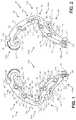
- FIG. 21illustrates a side view of an exemplary open configuration of a ninth exemplary embodiment of the surgical clip of the present invention.
- FIG. 22illustrates a side view of an exemplary open configuration of a tenth exemplary embodiment of the surgical clip of the present invention.
- FIG. 23illustrates a side view of an exemplary open configuration of an eleventh exemplary embodiment of the surgical clip of the present invention.
- the present inventionis generally directed to a surgical clip configured to compress and/or ligate tissue (e.g., blood vessels, lymph nodes, nerves, cystic tubes, or cardiac tissue).
- tissuee.g., blood vessels, lymph nodes, nerves, cystic tubes, or cardiac tissue.
- the surgical clipmay comprise out-board teeth that do not impede full closure of the surgical clip, providing more effective occlusion of smaller vessels. In that sense, clamping surfaces may be substantially smooth, and the teeth may be spaced apart.
- the out-board teethmay also allow the teeth to be larger and more effective in tissue interaction.
- the out-board teethmay be easy to mold and not interfere with clip appliers.
- the teethmay also be substantially atraumatic, such that the surgical clip would not pinch tissue between adjacent teeth.
- the teethmay minimize sharp edges, and have substantially flat or convex inner surfaces, and substantially flat side surfaces.
- the teethmay include a convex distal portion and a concave proximal portion.
- the concave proximal portionmay be configured to improve tissue retention and prevent the tissue from slipping distally out of the surgical clip in a “watermelon-seeding” effect as the surgical clip closes.
- the surgical clipmay also include a first leg member having a concave inner surface, and a second leg member having a convex inner surface.
- the convex inner surfacemay be provided by a flexible inner portion configured to resiliently compress when the surgical clip engages tissue.
- the flexibility of the inner portionmay enable favorable pressure distribution on tissue of different shapes, sizes, and/or stiffnesses, and/or tissue compressed at different positions along the length of the surgical clip.
- the inner portionmay be spaced from an outer portion by a transverse channel, for example, in a split-leg configuration.
- the inner and outer portionsmay also have different radii of curvature. In some embodiments, the inner and outer portions may have different radii of curvature along at least half a length of the inner and outer portions.
- the inner and outer portionsmay have different radii of curvature along substantially the entire length of the inner and outer portions.
- the outer portionmay include a convex portion having a convex outer surface and a concave portion having a concave outer surface.
- the convex portionmay be positioned on the proximal portion of the second leg member, providing the second leg member a proximal portion having a greater height than a distal portion. The height of the proximal portion may provide a contact point to improve alignment of the surgical clip as it is fed through a channel of a clip applier and/or received in the jaws of the clip applier.
- the surgical clipmay further include compression members extending between the inner and outer portions and being configured to improve compressive load distribution between the inner and outer portions as the surgical clip is compressed, while maintaining flexibility and accommodating the complex deformation that the surgical clip goes through to close and/or lock.
- FIGS. 1-6illustrate a first embodiment of a surgical clip 100 of the present invention.
- the surgical clip 100may have a proximal end portion 100 A and a distal end portion 100 B.
- the surgical clip 100may further include a first leg member 102 having a proximal end portion 102 A and a distal end portion 102 B, and a second leg member 104 having a proximal end portion 104 A and a distal end portion 104 B.
- the first and second leg members 102 , 104may be integrally joined at the proximal end portions 102 A, 104 A by a hinge portion 106 .
- proximal portionrefers to the specified portion of a device or its component which is generally closer to the medical personnel handling or manipulating the device as it is intended to be used
- distal portionrefers to the specified portion of a device or its component which is opposite the proximal portion.
- longitudinalis directed to the dimension which extends along the length of the surgical clip 100 and/or leg members 102 , 104 from their respective proximal end portions 100 A, 102 A, 104 A to their respective distal end portions 100 B, 102 B, 104 B, as would be commonly understood by one of skill in the art.
- the “transverse” directionis directed to any axis or direction which is orthogonal to the longitudinal lengths of the surgical clip 100 or leg members 102 , 104 .
- the term “length”refers to a dimension of the surgical clip 100 and/or one or more components along its longitudinal direction.
- the term “height” or “vertical”refers to a dimension of the surgical clip 100 and/or one or more components along a compression axis of the leg members 102 , 104 .
- the term “thickness”refers to the dimension between opposing edges of the surgical clip 100 and/or one or more components along the compression or vertical axis.
- widthrefers to a dimension of the surgical clip 100 and/or one or more components in a lateral direction substantially transverse to the length and the height.
- concave and convexrefers to the curvature of a surface or component visible when viewing an exterior of the surface or component. Similar terminology is used throughout the written disclosure.
- the first and second leg members 102 , 104may include surfaces having curved portions.
- the first leg member 102may include a first inner surface 108 and a first outer surface 110
- the second leg member 104may include a second inner surface 112 and a second outer surface 114 .
- the first inner surface 108may have a concave curvature
- the first outer surface 110may have a convex curvature
- the second inner surface 112may have a convex curvature
- the second outer surface 114may have one or more of at least one convex curvature and/or at least one concave curvature.
- the concave curvature of the first inner surface 108 and/or the convex curvature of the first outer surface 110may extend substantially the entire length of the first leg member 102 .
- the convex curvature of the second inner surface 112may extend substantially the entire length of the second leg member 104 .
- the first and second inner surfaces 108 , 112may be approximated or contact in a closed configuration.
- the first and second inner surfaces 108 , 112may also be substantially smooth.
- the first leg member 102may also include opposing side surfaces 138 , 140
- the second leg member 104may include opposing side surfaces 142 , 144 .
- the second leg member 104may include an inner portion 162 (e.g., an inner rib) and an outer portion 164 (e.g., an outer rib) integrally joined at a first portion 166 and a second portion 168 .
- the inner portion 162may have a convex inner surface 170 and a concave outer surface 172 .
- At least one of the inner portion 162 and the outer portion 164may have a thickness less than a thickness of the first leg member 102 .
- the smaller thickness of the inner portion 162 and/or outer portion 164may provide more flexibility relative to the second leg member 104 than the first leg member 102 .
- the inner portion 162may have a greater thickness than the outer portion 164 , and/or the outer portion 164 may have a greater length than the inner portion 162 .
- the inner surface 170 of the inner portion 162may form at least a portion of second inner surface 112
- the outer surface of the outer portion 164may form at least a portion of first outer surface 114 of the surgical clip 100 .
- the inner portion 162may be configured to resiliently deflect in the vertical, compression direction along at least a portion of its length to properly distribute pressure to tissue of varying shapes, sizes, locations and/or stiffnesses.
- the inner portion 162may, additionally or alternatively, deflect along any portion of its length based on the positioning of the tissue. For example, if tissue is positioned proximate to the hinge portion 106 , a proximal portion of the inner portion 162 may deflect to accommodate the tissue. However, if the tissue is positioned proximate to a latching mechanism, a distal portion of the inner portion 162 may deflect. In that sense, the surgical clip 100 may reduce stress localization due to proximity of the tissue to either of the latching mechanism and/or the hinge portion 106 .
- the resilient compression of the inner portion 162may also provide continuous ligating pressure to tissue in a closed and/or latched configuration, even as the tissue necrotizes and shrinks.
- the inner portion 162 and the outer portion 164may be separated by at least one transverse aperture or channel 178 extending between side surfaces 142 , 144 of the second leg member 104 to enable compression of second leg member 104 .
- the channel 178may enable the inner portion 162 to resiliently compress toward the outer portion 164 and distribute load along the length of the tissue, while more effectively gripping and retaining the tissue within the surgical clip 100 .
- the channel 178may also allow the outer portion 164 to have a longer length to reduce constraint on the deflection of the inner portion 162 .
- the increased length of the outer portion 164may reduce constraint of the flexibility of the inner portion 162 as the inner portion 162 flexes and flattens during closing and/or latching.
- the inner portion 162 , the outer portion 164 , and/or the channel 178may extend greater than half of a quarter of a length of the second leg member 104 . In some embodiments, the inner portion 162 , the outer portion 164 , and/or the channel 178 may extend greater than half of a half of a length of the second leg member 104 . In some embodiments, the inner portion 162 , the outer portion 164 , and/or the channel 178 may extend substantially the entire length of first leg member 102 .
- the inner portion 162 and the outer portion 164may have different radii of curvature between adjacent corresponding points along the length of the inner and outer portions 162 , 164 .
- a first radius of of curvature of the inner portion 162 and a second radius of curvature of the outer portion 164 between adjacent corresponding pointsmay be different for at least half of the length of the inner and outer portions 162 , 164 .
- the first radius of curvature and the second radius of curvaturemay be different for substantially the entire length of the inner and outer portions 162 , 164 .
- the inner portion 162may have a substantially continuous radius of curvature without any points of inflection, and the outer portion 164 may have a variable radius of curvature with at least one point of inflection.
- the variable radius of curvature of the outer portionmay provide a variable height and vertical stability when positioned in a feeding channel 12 of a surgical clip applier 10 as illustrated in FIG. 5 .
- a proximal portion 174 of the outer portion 164may have a greater height than a distal portion 176 of the outer portion 164 .
- the proximal portion 174may include a convex outer surface and a concave inner surface
- the distal portion 176may include a concave outer surface and a convex inner surface.
- the concave outer surface of the distal portion 176may provide a smooth transition with the distal portion 104 B to reduce irregular stress concentrations.
- the convex outer surface of the proximal portion 174may project vertically to provide a contact point with walls 14 , 16 of the feeding channel 12 and reduce vertical movement of the proximal end of the surgical clip 100 relative to the clip applier 10 .
- Additional contact pointsmay include the outer surface 110 of the first leg member 102 , the bosses 146 , 148 , and 150 of the first leg member 102 , and/or the bosses 152 , 154 of the second leg member 104 .
- the increased vertical stability of the surgical clip 100may eliminate the need for a stability finger on a pusher member of the clip applier 10 and/or proper loading of the surgical clip 100 into jaws of the clip applier 10 .
- the channel 178may also provide an anchoring point for an elongated member, such as a suture.
- a surgeonmay apply the surgical clip 100 to a tissue (e.g., a blood vessel), pass or loop the suture through the channel 178 , and pass the suture through another place in the same or a different tissue to secure the clip in place.
- the suture passed through the channel 178may, additionally or alternatively, secure the tissue near another location and/or approximate two tissues together.
- the hinge portion 106may be resiliently flexible and integral to the first and second leg members 102 , 104 .
- the hinge portion 106may have a concave inner surface 116 and a convex outer surface 118 .
- the concave inner surface 116 of the hinge portion 106may join the first inner surface 108 of the first leg member 102 and the second inner surface 112 of the second leg member 104 .
- the convex outer surface 118 of the hinge portion 106may join the first outer surface 110 of the first leg member 102 and the second outer surface 114 of the second leg member 104 .
- the hinge portion 106may also include a curved slot 120 located between the hinge surfaces 116 , 118 , and may be positioned closer to the concave inner surface 116 than to the convex outer surface 118 .
- the curved slot 120may extend completely through the hinge portion 106 from side to side and its opposite ends may extend into the proximal end portions 102 A, 102 B of first and second leg members 102 , 104 , respectively.
- the curved slot 120may provide added flexibility and resiliency to the hinge portion 106 , but the concave inner surface 116 may prevent any portion of a clamped vessel from being trapped within curved slot 120 .
- the surgical clip 100may also include a latching mechanism having one or more latching elements.
- the first leg member 102may transition to a hook portion 126 at its distal end portion 102 B
- the second leg member 104may transition to a complementary grooved and pointed tip portion 128 at its distal end portion 104 B.
- a distal end portion of the hook portion 126may curve inwardly and point generally toward the concave inner surface 116 of the hinge portion 106 .
- the hook portion 126may have one or more transverse beveled surfaces 130 and a concave inner surface which merges with the first inner surface 108 to define a latching recess 132 .
- the tip portion 128may be V-shaped defining a slot configured to receive the beveled surfaces 130 , as the hook portion 126 deflects around the tip portion 128 .
- the hook portion 126 and the tip portion 128may engage to form the latching mechanism.
- the latching recess 132may engage with the tip portion 128 in the course of compressing the surgical clip 100 into the closed configuration (e.g., FIG. 6 ) that may be secured position around a vessel or other tissue.
- the leg members 102 , 104may include one or more bosses along the length to engage jaws of the clip applier 10 .
- the first leg member 102may include bosses 146 , 148 protruding perpendicular to each of opposing side surfaces 138 , 140 adjacent to the distal end portion 102 B of the first leg member 102 and immediately inward of the hook portion 126 .
- the bosses 146 , 148may be cylindrical and project outwardly beyond the first outer surface 110 of first leg member 102 .
- the bosses 146 , 148may also be coupled together by a bridge section 150 .
- the second leg member 104may also include bosses 152 , 154 at the distal end portion 104 B.
- the bosses 152 , 154may be cylindrical and protrude perpendicular to each of opposing side surfaces 142 , 144 of the second leg member 104 , extending longitudinally forward beyond the point of tip portion 128 .
- the jaws of the clip applier 10may engage the bosses 146 , 148 , 150 , 152 , 154 and pivot the leg members 102 , 104 about the hinge portion 106 to compress the surgical clip 100 into a closed and/or latched configuration around a vessel.
- the surgical clip 100may include at least one first tooth 134 positioned on the first leg member 102 , and at least one second tooth 136 positioned on the second leg member 104 .
- the teeth 134 , 136may be substantially rigid, such that the teeth 134 , 136 do not substantially deflect when engaging tissue.
- the teeth 134 , 136may be positioned out-board relative to the surgical clip 100 .
- the term “out-board”shall refer to the positioning of the teeth 134 , 136 on one or more exterior side surfaces of the surgical clip 100 .
- the teeth 134 , 136may be attached to and extend from one of the side surfaces 138 - 144 and laterally of the one or more of the inner surfaces 108 , 112 .
- the teeth 134 , 136may extend substantially parallel to at least one of the side surfaces 138 - 144 and/or substantially perpendicular to at least one of the inner surfaces 108 , 112 . Therefore, the teeth 134 , 136 may be positioned to clear the opposing inner surface 108 , 112 and along a side surface 138 - 144 of the opposing leg member 102 , 104 to enable the surgical clip 100 to close with minimal or no gap between the inner surfaces 108 , 112 ensuring effective closure of small vessels.
- the inner surfaces 108 , 112may have no teeth and comprise a substantially smooth surface extending from the proximal ends 102 A, 104 B to the distal end portions 102 B, 104 B of the leg members 102 , 104 .
- the teeth 134 , 136may be positioned on one or both sides of at least one of the inner surfaces 108 , 112 of the leg members 102 , 104 .
- the out-board teeth 134 , 136may be larger and more effective in tissue interaction. For example, the larger size of the teeth 134 , 136 may be improve tissue retention and prevent the tissue from slipping out of the surgical clip.
- the teeth 134 , 136may be sufficiently spaced apart and not pinch tissue between adjacent teeth 134 , 136 .
- the teeth 134 , 136may further be easy to mold and not interfere with clip appliers.
- the teeth 134 , 136may have a variety of configurations, as discussed herein.
- the teeth 134 , 136may include a convex distal portion 180 and a concave proximal portion 182 (e.g., a cut-out).
- the concave portion 182may extend about 90° of a proximal surface of the teeth 134 , 136 .
- the concave portion 182may be configured to receive the tissue and prevent the tissue from slipping distally out of the surgical clip 100 .
- the convex portion 180 and the concave portion 182may reduce trauma to tissue compressed by the surgical clip 100 .
- the convex portion of the teeth 134 , 136may have any number of shapes, including round, disk-shaped, circular, spherical, oval, elliptical, bulbous, ring-shaped, and/or torus. It is also contemplated that the concave portion may be any number of shapes, including round, circular, spherical, oval, elliptical, U-shaped, L-shaped, and/or V-shaped.
- the teeth 134 , 136may further include substantially flat side surfaces on one or both sides of the teeth 134 , 136 .
- the substantially flat side surfaces 184may facilitate approximation or contact of inner surfaces 108 , 112 and reduce trauma to adjacent tissue.
- the surgical clip 100may be configured to close with minimal or no gap between the first inner surface 108 and the second inner surface 112 .
- the first teeth 134may extend beyond the second inner surface 112 and along at least one of the side surfaces 142 , 144
- the second teeth 134may extend beyond the first inner surface 108 and along at least one of the side surfaces 138 , 140 . Therefore, the teeth 134 , 136 may clear the respective inner surfaces 108 , 112 , such that tissue may be directly compressed by the inner surfaces 108 , 112 without being obstructed by the teeth 134 , 136 .
- the teeth 134 , 136When the teeth 134 , 136 are positioned on the same side of the surgical clip 100 , the teeth 134 , 136 may be staggered to reduce interference.
- the closed and/or latched configurationmay enhance compression of smaller tissue of smaller vessels, while the inner surface 112 of the second leg member 104 may resiliently deflect to accommodate the vascular tissue.
- the surgical clip 100may further be configured to clinch a suture, for example, during a partial nephrectomy.
- a surgeonmay pass the suture with a needle through a portion of the tissue, for example, a portion of the kidney to shut off a top/bottom half of the kidney.
- the surgeonmay close the surgical clip 100 on the suture and slide the surgical clip 100 against the tissue.
- the surgeonmay then continue to suture the tissue without the suture pulling through the tissue or having to create a retention knot.
- the teeth 134 , 136may be configured to retain the suture in the middle of the surgical clip 100 without the suture sliding longitudinally toward the proximal end portion 100 A or the distal end portion 100 B where there may be reduced clamping pressure.
- the suture retentionmay be increased by the increased size of the teeth 134 , 136 .
- FIGS. 1-6illustrate the teeth 134 , 136 being positioned on both sides of the first and second leg members 102 , 104 .
- the surgical clip 100may include two large teeth 134 , 136 on each side of the first and second leg members, as illustrated in FIGS. 1-6 .
- the teeth 134 , 136may be positioned only on one side of at least one of the leg members 102 , 104 .
- the teeth 134 , 136may be positioned only on the same side of each of the leg members 102 , 104 (e.g., as illustrated in FIGS.
- the teethmay be positioned on only one of the leg members 102 , 104 .
- the first leg member 102may include the first teeth 134 (as illustrated in FIGS. 1-6 ), and the second leg member 104 may have no teeth.
- the first leg member 102may have no teeth
- the second leg membermay include the second teeth 136 (as illustrated in FIGS. 1-6 ).
- the teeth 134 , 136may alternate side surfaces of the respectively leg member 102 , 104 , as further illustrated in FIGS. 1-6 . It is further contemplated that the teeth 134 , 136 may have different configurations, such as illustrated one or more of FIGS. 12-20 .
- FIGS. 7-10illustrate a second embodiment of a surgical clip 200 of the present invention.
- the surgical clip 200may have features similar to the surgical clip 100 , and may be similarly represented in FIGS. 7-10 .
- features similar to surgical clip 100may not be discussed with reference to the surgical clip 300 .
- the surgical clip 200may include a first leg member 202 and a second leg member 204 connected by a hinge portion 206 .
- the first and second leg members 202 , 204may include surfaces having curved portions.
- the first leg member 202may include a first inner surface 208 and a first outer surface 210
- the second leg member 204may include a second inner surface 212 and a second outer surface 214 .
- the first inner surface 208may have a concave curvature
- the first outer surface 210may have a convex curvature.
- the second inner surface 212may have a convex curvature
- the second outer surface 214may have a concave curvature.
- the concave curvature of the first inner surface 208 and/or the convex curvature of the first outer surface 210may extend substantially the entire length of the first leg member 202 .
- the convex curvature of the second inner surface 212 and/or the concave curvature of the second outer surface 214may extend substantially the entire length of the second leg member 204 .
- the first and second inner surfaces 208 , 212may be approximated or contact in a closed configuration.
- the first and second inner surfaces 208 , 212may be substantially smooth.
- the first leg member 202may also include opposing side surfaces 238 , 240
- the second leg member 204may include opposing side surfaces 242 , 244 .
- the second leg member 204may include an inner portion 262 (e.g., an inner rib) and an outer portion 264 (e.g., an outer rib) integrally joined at a first portion 266 and a second portion 268 .
- the inner portion 262may include a convex inner surface 270 and a concave outer surface 272 .
- the outer portion 264may include a convex inner surface 274 and a concave outer surface 276 .
- the inner portion 262 and the outer portion 264may have different radii of curvature between adjacent corresponding points of the inner and outer portions 262 , 264 .
- a first radius of curvature of the inner portion 262 and a second radius of curvature of the outer portion 264may be different for at least half of the lengths of the inner and outer portions 262 , 264 .
- the first radius of curvature and the second radius of curvaturemay be different for substantially the entire length of the inner and outer portions 262 , 264 .
- the inner portion 262may have a smaller radius curvature than the outer portion, making the inner portion 262 more convex.
- the inner portion 262may have a smaller radius of curvature than the first leg member 202 , such that the inner portion 262 may compress in a closed and/or latched configuration even in the absence of tissue.
- the inner portion 262 and/or the outer portion 264may have a thickness less than a thickness of the first leg member 202 , providing an increased flexibility and/or compressibility of the second leg member 204 .
- the inner portion 262 and the outer portion 264may be separated by at least one transverse aperture or channel 278 , as discussed herein.
- the surgical clip 200may be configured to anchor and/or clinch a suture, as further discussed above.
- the first and second leg members 202 , 204may be integrally joined at proximal end portions 202 A, 202 B by a hinge portion 206 .
- the surgical clip 200may also include a latching mechanism having one or more latching elements.
- the first leg member 202may transition to a hook portion 226 at its distal end portion 202 B
- the second leg member 204may transition to a complementary grooved and pointed tip portion 228 at its distal end portion 204 B.
- the leg members 202 , 204may further include one or more bosses along the length to engage jaws of the clip applier 10 .
- the first leg member 202may include bosses 246 , 248 protruding perpendicular to each of opposing side surfaces 238 , 240 , and the second leg member 204 bosses 252 , 254 protruding perpendicular to each of the opposing sides surfaces 242 , 244 .
- the bosses 246 , 248 of the first leg member 202may be coupled together by a bridge section 250 .
- the surgical clip 200may also include at least one first tooth 234 attached to a side of the first leg member 202 and at least one second tooth 236 attached to the same side of the second leg member 204 .
- the first teeth 234may be attached to and extend from a side surface 238
- the second teeth 236may be attached to and extend from a side surface 242 substantially parallel to the side surface 238 .
- the first teeth 234 and the second teeth 236may be positioned on the same side of the surgical clip 200 (e.g., side surfaces 238 , 242 ), and the opposite side of the surgical clip 200 may be free of teeth (e.g., side surfaces 240 , 244 ).
- Positioning the teeth 234 , 236 on the same side of the surgical clip 200may reduce trauma induced on more sensitive tissue.
- the teeth 234 , 236may be positioned out-board similar to the surgical clip 100 and/or closed with minimal or no gap between the inner surfaces 208 , 212 , as discussed above.
- the teeth 234 , 236may also have any number of shapes, as further discussed above.
- first leg member 202may include the first teeth 234 (as illustrated in FIGS. 7-10 ), and the second leg member 204 may have no teeth.
- first leg member 202may have no teeth
- the second leg membermay include the second teeth 236 (as illustrated in FIGS. 7-10 ).
- the teeth 234 , 236may alternate side surfaces of the respectively leg member 202 , 204 .
- FIG. 11illustrates a third embodiment of a surgical clip 300 of the present invention.
- the surgical clip 300may have features similar to at least one of surgical clips 100 , 200 , and may be similarly represented in FIG. 11 .
- features similar to at least one of surgical clips 100 , 200may not be discussed with reference to the surgical clip 300 .
- the surgical clip 300may include a first leg member 302 and a second leg member 304 connected by a hinge portion 306 .
- the first and second leg members 302 , 304may include surfaces having curved portions.
- the first leg member 302may include a first inner surface 308 and a first outer surface 310
- the second leg member 304may include a second inner surface 312 and a second outer surface 314 .
- the first inner surface 308may have a concave curvature
- the first outer surface 310may have a convex curvature.
- the second inner surface 312may have a convex curvature
- the second outer surface 314may have a concave curvature.
- the concave curvature of the first inner surface 308 and/or the convex curvature of the first outer surface 310may extend substantially the entire length of the first leg member 302 .
- the convex curvature of the second inner surface 312 and/or the concave curvature of the second outer surface 314may extend substantially the entire length of the second leg member 304 .
- the first and second inner surfaces 308 , 312may be approximated or contact in a closed configuration.
- the first and second inner surfaces 308 , 312may be substantially smooth.
- the first leg member 302may also include opposing side surfaces 338 , 340
- the second leg member 304may include opposing side surfaces 342 , 344 .
- the second leg member 304may include an inner portion 362 (e.g., an inner rib) and an outer portion 364 (e.g., an outer rib) integrally joined at a first portion 366 and a second portion 368 .
- the inner portion 362may have a convex inner surface and a concave outer surface.
- the outer portion 364may have a convex inner surface and a concave outer surface.
- the inner portion 362 and the outer portion 364may have a different radii of curvature between adjacent corresponding points along the length of the inner and outer portions 362 , 364 .
- a first radius of curvature of the inner portion 362 and a second radius of curvature of the outer portion 364may be different for at least half of the lengths of the inner and outer portions 362 , 364 .
- the first radius of curvature and the second radius of curvaturemay be different for substantially the entire length of the inner and outer portions 362 , 364 .
- the inner portion 362may have a smaller radius curvature than the outer portion, making the inner portion 362 more convex.
- the inner portion 362may have a smaller radius of curvature than the first leg member 302 , such that the inner portion 362 may compress in a closed and/or latched configuration even in the absence of tissue.
- the inner portion 362 and/or the outer portion 364may have a thickness less than a thickness of the first leg member 302 , providing an increased flexibility and/or compressibility of the second leg member 304 .
- the inner portion 362 and the outer portion 364may be separated by at least one transverse aperture or channel 378 , as discussed above.
- the surgical clip 300may be configured to anchor and/or clinch a suture, as further discussed above.
- the surgical clip 300may also include a latching mechanism having one or more latching elements.
- the first leg member 302may transition to a hook portion 326 at its distal end portion 302 B
- the second leg member 304may transition to a complementary grooved and pointed tip portion 328 at its distal end portion 304 B.
- the leg members 302 , 304may further include one or more bosses along the length to engage jaws of the clip applier 10 .
- first leg member 302may include bosses 346 , 348 protruding perpendicular to each of opposing side surfaces 338 , 340 , and the second leg member 304 bosses 352 , 354 protruding perpendicular to each of the opposing sides 342 , 344 .
- the bosses 346 , 348 of the first leg member 302may be coupled together by a bridge section 350 .
- the surgical clip 300may include at least one first tooth 334 positioned on a first side the first leg member 302 and at least one second tooth 336 positioned on a second side of the second leg member 304 opposite of the first side.
- the first teeth 334may extend from a side surface 338
- the second teeth 336may extend from a side surface 344 .
- the teeth 334 , 336may be positioned on opposite sides of the surgical clip 300 , and a side surface 340 of the first leg member 302 and a side surface 342 of the second leg member 304 may have no teeth.
- Positioning the teeth 334 , 336 on opposite sides of the surgical clip 300may enhance engagement of the tissue while reducing the number of teeth and resultant tissue trauma.
- the teeth 234 , 236may be positioned out-board similar to the surgical clip 100 , as discussed above.
- the teeth 234 , 236may also have any number of shapes, as further discussed above.
- FIG. 12illustrates a fourth embodiment of a surgical clip 400 of the present invention.
- the surgical clip 400may include one or more features similar to at least one of surgical clips 100 - 300 , and may be similarly represented in FIG. 12 .
- features similar to those of at least one of surgical clips 100 - 300may not be discussed with reference to the surgical clip 400 .
- the surgical clip 400may include a first leg member 402 and a second leg member 404 connected by a hinge portion 406 .
- the first and second leg members 402 , 404may include surfaces having curved portions.
- the first leg member 402may include a first inner surface 408 and a first outer surface 410
- the second leg member 404may include a second inner surface 412 and a second outer surface 414 .
- the first inner surface 408may have a concave curvature
- the first outer surface 410may have a convex curvature.
- the second inner surface 412may have a convex curvature
- the second outer surface 414may have a concave curvature.
- the concave curvature of the first inner surface 408 and/or the convex curvature of the first outer surface 410may extend substantially the entire length of the first leg member 402 .
- the convex curvature of the second inner surface 412 and/or the concave curvature of the second outer surface 414may extend substantially the entire length of the second leg member 404 .
- the first and second inner surfaces 408 , 412may be approximated or contact in a closed configuration.
- the first and second inner surfaces 408 , 412may be substantially smooth.
- the first leg member 402may also include opposing side surfaces 438 , 440
- the second leg member 404may include opposing side surfaces 442 , 444 .
- the second leg member 404may include an inner portion 462 (e.g., an inner rib) and an outer portion 464 (e.g., an outer rib) integrally joined at a first portion 466 and a second portion 468 .
- the inner portion 462may have a convex inner surface and a concave outer surface.
- the outer portion 464may have a convex inner surface and a concave outer surface.
- the inner portion 462 and the outer portion 464may have different radii of curvature between adjacent corresponding points along the length of the inner and outer portions 462 , 464 .
- a first radius of curvature of the inner portion 462 and a second radius of curvature of the outer portion 464may be different for at least half of the lengths of the inner and outer portions 462 , 464 .
- the first radius of curvature and the second radius of curvaturemay be different for substantially the entire length of the inner and outer portions 462 , 464 .
- the inner portion 462may have a smaller radius curvature than the outer portion 464 , making the inner portion 462 more convex.
- the inner portion 462may have a smaller radius of curvature than the first leg member 402 , such that the inner portion 462 may compress in a closed and/or latched configuration even in the absence of tissue.
- the inner portion 462 and/or the outer portion 464may have a thickness less than a thickness of the first leg member 402 , providing an increased flexibility and/or compressibility of the second leg member 404 .
- the inner portion 462 and the outer portion 464may be separated by at least one transverse aperture or channel 478 , as discussed above.
- the surgical clip 400may be configured to anchor and/or clinch a suture, as further discussed above.
- the surgical clip 400may also include a latching mechanism having one or more latching elements.
- the first leg member 402may transition to a hook portion 426 at its distal end portion 402 B
- the second leg member 404may transition to a complementary grooved and pointed tip portion 428 at its distal end portion 404 B.
- the leg members 402 , 404may further include one or more bosses along the length to engage jaws of the clip applier 10 .
- first leg member 402may include bosses 446 , 448 protruding perpendicular to each of opposing side surfaces 438 , 440 , and the second leg member 404 bosses 452 , 454 protruding perpendicular to each of the opposing sides 442 , 444 .
- the bosses 446 , 448 of the first leg member 402may be coupled together by a bridge section 450 .
- the surgical clip 400may include at least one first tooth 434 and/or at least one second tooth 436 comprising convex members that provide atraumatic tissue clamping surfaces.
- the convex membersmay include convex segments greater than about 180°.
- the convex membersmay include convex segments greater than about 270°.
- the convex membersmay include a convex segment about 360°. It is contemplated that the one or more convex members may be any number of shapes, including round, circular, disk-shaped, spherical, oval, elliptical, bulbous, ring-shaped, and/or torus.
- the first teeth 434may extend from a first side surface 438 of the first leg member 402 laterally of a first inner surface 408
- the one or more second teeth 435may extend from a second side surface 442 of the second leg member 404 laterally of a second inner surface 512
- the sides 438 , 442may be on the same side of the leg members 402 , 404 .
- the teeth 434 , 436may be positioned on both sides of at least one of the leg members 402 , 404 , e.g., as illustrated in FIGS. 1-6 .
- the teeth 434 , 436may be positioned only on opposite sides of the leg members 402 , 404 , e.g., as illustrated in FIG. 11 .
- the circular configuration of the teeth 434 , 436may even further reduce trauma to tissue.
- the teeth 434 , 436may be positioned out-board similar to the surgical clip 100 , as discussed above.
- the teethmay be positioned on only one of the leg members 402 , 404 .
- the first leg member 402may include the first teeth 434
- the second leg member 404may have no teeth.
- the first leg member 402may have no teeth
- the second leg member 404may include the second teeth 436 .
- the teeth 434 , 436may alternate side surfaces of the respectively leg member 402 , 404 as discussed above.
- FIG. 13illustrates a fifth embodiment of a surgical clip 500 of the present invention.
- the surgical clip 500may include one or more features similar to at least one of surgical clips 100 - 400 , and may be similarly represented in FIG. 13 .
- features similar to those of at least one of surgical clips 100 - 400may not be discussed with reference to the surgical clip 500 .
- the surgical clip 500may include a first leg member 502 and a second leg member 504 connected by a hinge portion 506 .
- the first and second leg members 502 , 504may include surfaces having curved portions.
- the first leg member 502may include a first inner surface 508 and a first outer surface 510
- the second leg member 504may include a second inner surface 512 and a second outer surface 514 .
- the first inner surface 508may have a concave curvature
- the first outer surface 510may have a convex curvature.
- the second inner surface 512may have a convex curvature
- the second outer surface 514may have a concave curvature.
- the concave curvature of the first inner surface 508 and/or the convex curvature of the first outer surface 510may extend substantially the entire length of the first leg member 502 .
- the convex curvature of the second inner surface 512 and/or the concave curvature of the second outer surface 514may extend substantially the entire length of the second leg member 504 .
- the first and second inner surfaces 508 , 512may be approximated or contact in a closed configuration.
- the first and second inner surfaces 508 , 512may be substantially smooth.
- the first leg member 502may also include opposing side surfaces 538 , 540
- the second leg member 504may include opposing side surfaces 542 , 544 .
- the second leg member 504may include an inner portion 562 (e.g., an inner rib) and an outer portion 564 (e.g., an outer rib) integrally joined at a first portion 566 and a second portion 568 .
- the inner portion 562may have a convex inner surface 570 and a concave outer surface 572 .
- the outer portion 564may have a convex inner surface and a concave outer surface.
- the inner portion 562 and the outer portion 564may have different radii of curvature between adjacent corresponding points along the length of the inner and outer portions 562 , 564 .
- a first radius of curvature of the inner portion 562 and a second radius of curvature of the outer portion 564may be different for at least half of the lengths of the inner and outer portions 562 , 564 .
- the first radius of curvature and the second radius of curvaturemay be different for substantially the entire length of the inner and outer portions 562 , 564 .
- the inner portion 562may have a smaller radius curvature than the outer portion, making the inner portion 562 more convex.
- the inner portion 562may have a smaller radius of curvature than the first leg member 502 , such that the inner portion 562 may compress in a closed and/or latched configuration even in the absence of tissue.
- the inner portion 562 and/or the outer portion 564may have a thickness less than a thickness of the first leg member 502 , providing an increased flexibility and/or compressibility of the second leg member 504 .
- the inner portion 562 and the outer portion 564may be separated by at least one transverse aperture or channel 578 , as discussed above.
- the surgical clip 500may be configured to anchor and/or clinch a suture, as further discussed above.
- the surgical clip 500may also include a latching mechanism having one or more latching elements.
- the first leg member 502may transition to a hook portion 526 at its distal end portion 502 B
- the second leg member 504may transition to a complementary grooved and pointed tip portion 528 at its distal end portion 504 B.
- the leg members 502 , 504may further include one or more bosses along the length to engage jaws of the clip applier 10 .
- first leg member 502may include bosses 546 , 548 protruding perpendicular to each of opposing side surfaces 538 , 540 , and the second leg member 504 bosses 552 , 554 protruding perpendicular to each of the opposing sides 542 , 544 .
- the bosses 546 , 548 of the first leg member 502may be coupled together by a bridge section 550 .
- the surgical clip 500may include at least one first tooth 534 and/or at least one second teeth 536 .
- One or more of the teeth 534 , 536may comprise proximally angled protrusions.
- the proximally angled protrusionsmay improve tissue retention and prevent the tissue form sliding out of the clip 500 distally (e.g., a “watermelon-seeding” effect) when the surgical clip 500 is closed.
- the tips of the protrusionsmay be relatively sharp or rounded to reduce trauma to tissue.
- the first teeth 534may extend from a first side surface 538 of the first leg member 502 laterally of a first inner surface 508
- the one or more second teeth 535may extend from a second side surface 544 of the second leg member 504 laterally of a second inner surface 512
- the teeth 534 , 536may be positioned on both sides of at least one of the leg members 502 , 504 , e.g., as illustrated in FIGS. 1-6
- the teeth 534 , 536may be positioned only on the same side of the leg members 502 , 504 , e.g., as illustrated in FIGS. 7-10 .
- the teeth 534 , 536may be positioned only on opposite sides of the leg members 502 , 504 , as illustrated in FIG. 11 .
- the teeth 534 , 536may be positioned out-board similar to the surgical clip 100 , as discussed above.
- the teethmay be positioned on only one of the leg members 502 , 504 .
- the first leg member 502may include the first teeth 534
- the second leg member 504may have no teeth.
- the first leg member 502may have no teeth
- the second leg member 504may include the second teeth 536 .
- the teeth 534 , 536may alternate side surfaces of the respectively leg member 502 , 504 as discussed above.
- FIG. 14illustrates a sixth embodiment of a surgical clip 600 of the present invention.
- the surgical clip 600may include one or more features similar to at least one of surgical clips 100 - 500 , and may be similarly represented in FIG. 13 .
- features similar to those of at least one of surgical clips 100 - 500may not be discussed with reference to the surgical clip 600 .
- the surgical clip 600may include a first leg member 602 and a second leg member 604 connected by a hinge portion 606 .
- the first and second leg members 602 , 604may include surfaces having curved portions.
- the first leg member 602may include a first inner surface 608 and a first outer surface 610
- the second leg member 604may include a second inner surface 612 and a second outer surface 614 .
- the first inner surface 608may have a concave curvature
- the first outer surface 610may have a convex curvature.
- the second inner surface 612may have a convex curvature
- the second outer surface 614may have a concave curvature.
- the concave curvature of the first inner surface 608 and/or the convex curvature of the first outer surface 610may extend substantially the entire length of the first leg member 602 .
- the convex curvature of the second inner surface 612 and/or the concave curvature of the second outer surface 614may extend substantially the entire length of the second leg member 604 .
- the first and second inner surfaces 608 , 612may be approximated or contact in a closed configuration.
- the first and second inner surfaces 608 , 612may be substantially smooth.
- the first leg member 602may also include opposing side surfaces 638 , 640
- the second leg member 604may include opposing side surfaces 642 , 644 .
- the second leg member 604may include an inner portion 662 (e.g., an inner rib) and an outer portion 664 (e.g., an outer rib) integrally joined at a first portion 666 and a second portion 668 .
- the inner portion 662may have a convex inner surface 670 and a concave outer surface.
- the outer portion 664may have a convex inner surface and a concave outer surface.
- the inner portion 662 and outer portion 664may have different radii of curvature between adjacent corresponding points along the lengths of the inner and outer portions 662 , 664 .
- a first radius of curvature of the inner portion 662 and a second radius of curvature of the outer portion 664may be different for at least half of the lengths of the inner and outer portions 662 , 664 .
- the first radius of curvature and the second radius of curvaturemay be different for substantially the entire length of the inner and outer portions 662 , 664 .
- the inner portion 662may have a smaller radius curvature than the outer portion, making the inner portion 662 more convex.
- the inner portion 662may have a smaller radius of curvature than the first leg member 602 , such that the inner portion 662 may compress in a closed and/or latched configuration even in the absence of tissue.
- the inner portion 662 and/or the outer portion 664may have a thickness less than a thickness of the first leg member 602 , providing an increased flexibility and/or compressibility of the second leg member 604 .
- the inner portion 662 and the outer portion 664may be separated by at least one transverse aperture or channel 678 , as discussed above.
- the surgical clip 600may be configured to anchor and/or clinch a suture, as further discussed above.
- the surgical clip 600may also include a latching mechanism having one or more latching elements.
- the first leg member 602may transition to a hook portion 626 at its distal end portion 602 B
- the second leg member 604may transition to a complementary grooved and pointed tip portion 628 at its distal end portion 604 B.
- the leg members 602 , 604may further include one or more bosses along the length to engage jaws of the clip applier 10 .
- first leg member 602may include bosses 646 , 648 protruding perpendicular to each of opposing side surfaces 638 , 640 , and the second leg member 604 bosses 652 , 654 protruding perpendicular to each of the opposing sides 642 , 644 .
- the bosses 646 , 648 of the first leg member 602may be coupled together by a bridge section 650 .
- the surgical clip 600may include one or more first teeth 634 and/or one or more second teeth 636 having a plurality a prongs.
- the first teeth 634may extend from a first side surface 638 of the first leg member 602 laterally of a first inner surface 608
- the one or more second teeth 635may extend from a second side surface 644 of the second leg member 604 laterally of a second inner surface 612 .
- the teeth 634 , 636may be positioned on both sides of at least one of the leg member 602 , 604 , e.g., as illustrated in FIGS. 1-6 .
- the teeth 634 , 636may be positioned only on the same side of the leg members 602 , 604 , e.g., as illustrated in FIGS. 7-10 . In some embodiments, the teeth 634 , 636 may be positioned only on opposite sides of the leg members 602 , 604 , as illustrated in FIG. 11 . The teeth 634 , 636 may be positioned out-board similar to the surgical clip 100 , as discussed above.
- the teethmay be positioned on only one of the leg members 602 , 604 .
- the first leg member 602may include the first teeth 634
- the second leg member 604may have no teeth.
- the first leg member 602may have no teeth
- the second leg member 604may include the second teeth 636 .
- the teeth 634 , 636may alternate side surfaces of the respectively leg member 602 , 604 as discussed above.
- FIGS. 15 and 16illustrate a seventh embodiment of a surgical clip 700 of the present invention.
- the surgical clip 700may include one or more features similar to at least one of surgical clips 100 - 600 , and may be similarly represented in FIGS. 15 and 16 .
- features similar to those of at least one of surgical clips 100 - 600may not be discussed with reference to the surgical clip 700 .
- the surgical clip 700may include a first leg member 702 and a second leg member 704 connected by a hinge portion 706 .
- the first and second leg members 702 , 704may include surfaces having curved portions.
- the first leg member 702may include a first inner surface 708 and a first outer surface 710
- the second leg member 704may include a second inner surface 712 and a second outer surface 714 .
- the first inner surface 708may have a concave curvature
- the first outer surface 710may have a convex curvature.
- the second inner surface 712may have a convex curvature
- the second outer surface 714may have a concave curvature.
- the concave curvature of the first inner surface 708 and/or the convex curvature of the first outer surface 710may extend substantially the entire length of the first leg member 702 .
- the convex curvature of the second inner surface 712 and/or the concave curvature of the second outer surface 714may extend substantially the entire length of the second leg member 704 .
- the first and second inner surfaces 708 , 712may be approximated or contact in a closed configuration.
- the first and second inner surfaces 708 , 712may be substantially smooth.
- the first leg member 702may also include opposing side surfaces 738 , 740
- the second leg member 704may include opposing side surfaces 742 , 744 .
- the second leg member 704may include an inner portion 762 (e.g., an inner rib) and an outer portion 764 (e.g., an outer rib) integrally joined at a first portion 766 and a second portion 768 .
- the inner portion 762may have a convex inner surface 770 and a concave outer surface 772 .
- the outer portion 764may have a convex inner surface and a concave outer surface.
- the inner portion 762 and outer portion 764may have different radii of curvature between adjacent corresponding points along the length of the inner and outer portions 762 , 764 .
- a first radius of curvature of the inner portion 762 and a second radius of curvature of the outer portion 764may be different for at least half of the lengths of the inner and outer portions 762 , 764 .
- the first radius of curvature and the second radius of curvaturemay be different for substantially the entire length of the inner and outer portions 762 , 764 .
- the inner portion 762may have a smaller radius curvature than the outer portion, making the inner portion 762 more convex.
- the inner portion 762may have a smaller radius of curvature than the first leg member 602 , such that the inner portion 762 may compress in a closed and/or latched configuration even in the absence of tissue.
- the inner portion 762 and/or the outer portion 764may have a thickness less than a thickness of the first leg member 702 , providing an increased flexibility and/or compressibility of the second leg member 704 .
- the inner portion 762 and the outer portion 764may be separated by at least one transverse aperture or channel 778 , as discussed above.
- the surgical clip 700may be configured to anchor and/or clinch a suture, as further discussed above.
- the surgical clip 700may also include a latching mechanism having one or more latching elements.
- the first leg member 702may transition to a hook portion 726 at its distal end portion 702 B
- the second leg member 704may transition to a complementary grooved and pointed tip portion 728 at its distal end portion 704 B.
- the leg members 702 , 704may further include one or more bosses along the length to engage jaws of the clip applier 10 .
- first leg member 702may include bosses 746 , 748 protruding perpendicular to each of opposing side surfaces 738 , 740 , and the second leg member 704 bosses 752 , 754 protruding perpendicular to each of the opposing sides 742 , 744 .
- the bosses 746 , 748 of the first leg member 702may be coupled together by a bridge section 750 .
- the first tooth 734may be a single elongated tooth or ridge on the first leg member 702 and, in some embodiments, the first tooth 734 may extend between a proximal end portion 702 A and a distal end portion 702 B.
- the second tooth 736may be a single elongated tooth or ridge on the second leg member 704 and, in some embodiments, the second tooth 736 may extend between a proximal end portion 704 A and a distal end portion 704 B.
- the first tooth 734may include first and second planar side sides and an inner surface having one or grooves 738 to improve tissue retention.
- the teeth 734 , 736may be positioned out-board similar to the surgical clip 100 , as discussed above.
- only one of the leg members 702 , 704has teeth.
- the first leg member 702may include one or more first teeth 734 on side surfaces, and the second leg member 704 has no teeth.
- the first leg member 702has no teeth, and the second leg member 704 may include one or more second teeth 736 on side surfaces.
- FIGS. 17-20illustrate an eighth embodiment of a surgical clip 800 of the present invention.
- the surgical clip 800may include one or more features similar to at least one of surgical clips 100 - 700 , and may be similarly represented in FIGS. 17-20 .
- features similar to those of at least one of surgical clips 100 - 700may not be discussed with reference to the surgical clip 800 .
- the surgical clip 800may include a first leg member 802 and a second leg member 804 connected by a hinge portion 806 .
- the first and second leg members 802 , 804may include surfaces having curved portions.
- the first leg member 802may include a first inner surface 808 and a first outer surface 810
- the second leg member 804may include a second inner surface 812 and a second outer surface 814 .
- the first inner surface 808may have a concave curvature
- the first outer surface 810may have a convex curvature.
- the second inner surface 812may have a convex curvature
- the second outer surface 814may have one or more of at least one convex curvature and/or at least one concave curvature.
- the concave curvature of the first inner surface 808 and/or the convex curvature of the first outer surface 810may extend substantially the entire length of the first leg member 802 .
- the convex curvature of the second inner surface 812may extend substantially the entire length of the second leg member 804 .
- the first and second inner surfaces 808 , 812may be approximated or contact in a closed configuration.
- the first and second inner surfaces 808 , 812may be substantially smooth.
- the first leg member 802may also include opposing side surfaces 838 , 840
- the second leg member 804may include opposing side surfaces 842 , 844 .
- the second leg member 804may include an inner portion 862 (e.g., an inner rib) and an outer portion 864 (e.g., an outer rib) integrally joined at a first portion 866 and a second portion 868 .
- the inner portion 862may include a convex inner surface 870 and a concave outer surface 872 .
- the outer portion 864may include a concave inner surface and a convex outer surface.
- the inner portion 862 and outer portion 864may have different radii of curvature between adjacent corresponding points along the length of the inner and outer portions 862 , 864 .
- a first radius of curvature of the inner portion 862 and a second radius of curvature of the outer portion 864may be different for at least half of the lengths of the inner and outer portions 862 , 864 .
- the first radius of curvature and the second radius of curvaturemay be different for substantially the entire length of the inner and outer portions 862 , 864 .
- the inner portion 862may have a larger radius curvature than the outer portion 864 , making the inner portion 862 less curved than the outer portion 864 .
- the more curvature of the outer portion 864may reduce constraint on the deflection of the inner portion 864 during closure and/latching of the surgical clip 800 .
- the outer surface 814may have a concave curvature at the first and second portions 866 , 868 where the inner portion 862 and outer portion 864 join.
- the inner portion 862 and/or the outer portion 864may have a thickness less than a thickness of the first leg member 802 , providing an increased flexibility and/or compressibility of the second leg member 804 .
- the inner portion 862 and the outer portion 864may be separated by at least one transverse aperture or channel 878 , as discussed above.
- the surgical clip 800may be configured to anchor and/or clinch a suture, as further discussed above.
- the surgical clip 800may also include a latching mechanism having one or more latching elements.
- the first leg member 802may transition to a hook portion 826 at its distal end portion 802 B
- the second leg member 804may transition to a complementary grooved and pointed tip portion 828 at its distal end portion 804 B.
- the leg members 802 , 804may further include one or more bosses along the length to engage jaws of the clip applier 10 .
- first leg member 802may include bosses 846 , 848 protruding perpendicular to each of opposing side surfaces 838 , 840 , and the second leg member 804 bosses 852 , 854 protruding perpendicular to each of the opposing sides 842 , 844 .
- the bosses 846 , 848 of the first leg member 802may be coupled together by a bridge section 850 .
- the surgical clip 800may include at least one tooth 836 positioned on at least one of the first leg member 802 and the second leg member 804 .
- the second leg member 804may have at least one tooth 836 positioned on the second inner surface 812
- the first leg membermay have no teeth.
- the at least one tooth 836may be spaced apart and positioned on at least one lateral side of the second inner surface 812 .
- the one or more teeth 836may have a side surface that extends continuously from or flush with one of the side surfaces 842 , 844 .
- the second leg member 804may have a first row of at least one first tooth 836 on a first lateral side of the second inner surface 812 and a second row of at least one second tooth 836 on a second lateral side of the second inner surface 812 .
- a plurality of first teeth 836 and a plurality of second teeth 836may alternate laterally along a length of the inner surface 812 of the second leg member 804 .
- the at least one tooth 836may include an inner surface substantially parallel to the second second inner surface 812 and/or substantially flat. As illustrated in FIG.
- the tooth 836may be substantially flat and substantially parallel to the inner surface 812 along at least a portion of the length of the first leg member 802 .
- the at least one tooth 836may further have first and second substantially flat side surfaces that extend substantially vertically from the inner surface of the second leg member, for example, with one of the side surfaces being flush with one of the side surfaces 842 , 844 .
- the at least one tooth 836may also include substantially flat proximal and distal surfaces that extend at an angle from the second inner surface 812 .
- the proximal and distal surfaces of the tooth 836may extend at an obtuse angle from the second inner surface 812 .
- the proximal and distal surfaces of the tooth 836may extend at substantially the same obtuse angle forming a longitudinally symmetrical shape of the tooth 836 .
- the teeth 836may be substantially atraumatic without any sharp angles and be sufficiently spaced apart, such that the surgical clip 800 would not cause unnecessary trauma to the tissue and/or pinch tissue between adjacent teeth 836 .
- the teeth 836may have similar advantages as the “out-board” teeth discussed above.
- the teeth 836would not impede full closure of the surgical clip, providing more effective occlusion of smaller vessels.
- inner surfaces 808 , 812may be substantially smooth, and the teeth 836 may be spaced apart.
- the teeth 836may also allow the teeth 836 to be larger and more effective in tissue interaction.
- the larger number of teeth 836may further allow for reduced number of teeth 836 .
- the surgical clip 800may have two rows of three teeth 836 .
- the teeth 836may be easy to mold and not interfere with clip appliers.
- the surgical clip 800may further provide a favorable low-profile in the vertical and lateral direction when in the closed configuration, as illustrated in FIG. 20 .
- the first leg member 802may have at least one longitudinal channel 837 in one or more of the side surface 838 , 840 , recessed from and adjacent to the first inner surface 808 , such that the longitudinal channel 837 is defined between one of the side surfaces 838 , 840 and the first inner surface 808 .
- the at least one longitudinal channel 837may be configured to receive the one or more teeth 836 to approximate or contact the inner surfaces 808 , 812 with minimal or no gap.
- the first inner surface 808may be substantially smooth
- the second inner surface 812 extending between the teeth 836may be substantially smooth.
- a first longitudinal channel 837 through the side surface 838may receive the plurality of first teeth
- a second longitudinal channel 837 through the side surface 840may receive the plurality of second teeth.
- each of the longitudinal channels 837may be positioned on opposite sides of the first leg member 802 and configured to receive the teeth 836 spaced in a row along the second leg member 804 . Therefore, the first inner surface 808 may be disposed on the inner surface of an inner rib 860 defined by the flanking longitudinal channels 837 .
- the inner surface of the rib 860may be continuous with the inner surface 816 of the hinge member 806 and/or the inner surface of the hook portion 826 .
- the first leg member 802may have a substantially constant thickness between the inner and outer surface 808 , 810 along a length including the inner rib 860 the inner rib 860 may be solid and continuously formed on the first leg member 802 without any channels or openings therethrough to facilitate manufacturing (e.g., molding) of such a small component.
- the inner rib 860may extend substantially the entire length of the first leg member 802 .
- the first and second longitudinal channels 837may be distinct and not connected with each other.
- the inner rib 860may be received between the rows of teeth 836 in the closed configuration.
- the one or more teeth 836may be positioned on the first leg member 802
- the at least one longitudinal channel 837may be positioned on the first leg member 804
- each of the first and second leg members 802 , 804may include one or more teeth 836 and at least one longitudinal channel 837 .
- the first inner surface 808may have a row of one or more teeth 836 on a first lateral side and a longitudinal channel 837 on a second lateral side
- the second inner surface 812may comprise a longitudinal channel 837 on the first lateral side and a row of one or more teeth 836 on the second lateral side. Therefore, each of the longitudinal channels 837 may receive the one or more teeth 836 on the opposite leg member.
- FIGS. 21-23illustrate side views of additional embodiments of surgical clips 900 - 1100 of the present invention.
- the surgical clips 900 - 1100may include one or more compression members 990 , 1092 , 1194 extending between inner and outer portions.
- the compression members 990 , 1092 , 1194may allow for additional flexibility to the surgical clip, without substantially reducing overall compression strength of the surgical clip.
- the strength of the surgical clipmay vary depending on how much material the surgical clip is closed over. For example, the surgical clip may have a reduced compression strength if the gap between the inner and outer portions was not fully compression.
- the compression members 990 , 1092 , 1194may be configured to improve compressive load distribution between the inner and outer portions, while maintaining flexibility and accommodating the complex deformation that the surgical clip goes through to close and/or lock.
- the compression members 990 , 1092 , 1194may be resilient and support the inner portion to ensure sufficient compression through the length of the surgical clip.
- any one or more of the embodiments of the compression members 900 , 1092 , 1194may be applied to any of the embodiments of the surgical clips 100 - 1100 of the present invention.
- FIG. 21illustrates a ninth embodiment of a surgical clip 900 of the present invention.
- the surgical clip 900may include one or more features similar to at least one of surgical clips 100 - 800 , and may be similarly represented in FIG. 21 .
- features similar to those of at least one of surgical clips 100 - 800may not be discussed with reference to the surgical clip 900 .
- the surgical clip 900may include a first leg member 902 and a second leg member 904 connected by a hinge portion 906 .
- the first and second leg members 902 , 904may include surfaces having curved portions.
- the first leg member 902may include a first inner surface 908 and a first outer surface 910
- the second leg member 904may include a second inner surface 912 and a second outer surface 914 .
- the first inner surface 908may have a concave curvature
- the first outer surface 910may have a convex curvature.
- the second inner surface 912may have a convex curvature, and the second outer surface 914 may have one or more of at least one convex curvature and/or at least one concave curvature.
- the first and second inner surfaces 908 , 912may be approximated or contact in a closed configuration.
- the first and second inner surfaces 908 , 912may be substantially smooth.
- the second leg member 904may include an inner portion 962 (e.g., an inner rib) and an outer portion 964 (e.g., an outer rib) separated by at least one transverse aperture or channel 978 and integrally joined at a first portion 966 and a second portion 968 .
- the inner portion 962 and the outer portion 964may have different radii of curvature between adjacent corresponding points along the length of the inner and outer portions 962 , 964 .
- a first radius of curvature of the inner portion 962 and a second radius of curvature of the outer portion 964may be different for at least half of the lengths of the inner and outer portions 962 , 964 .
- the first radius of curvature and the second radius of curvaturemay be different for substantially the entire length of the inner and outer portions 962 , 964 .
- the inner portion 962may have a substantially continuous radius of curvature without any points of inflection
- the outer portion 964may have a variable radius of curvature with at least one point of inflection.
- the variable radius of curvature of the outer portionmay provide a variable height and vertical stability when positioned in a feeding channel 12 of a clip applier 10 , as illustrated in FIG. 5 .
- a proximal portion 974 of the outer portion 964may have a greater height than a distal portion 976 of the outer portion 964 .
- the proximal portion 974may include a convex outer surface and a concave inner surface
- the distal portion 976may include a concave outer surface and a convex inner surface.
- the concave outer surface of the distal portion 976may provide a smooth transition with the distal portion to reduce irregular stress concentrations.
- the convex outer surface of the proximal portion 974may project vertically to provide a contact point with walls 14 , 16 of the feeding channel 12 and reduce vertical movement of the proximal end of the surgical clip 900 relative to the clip applier 10 .
- Additional contact pointsmay include the outer surface 910 of the first leg member 902 , the bosses 946 , 948 , and 950 of the first leg member 902 , and/or the bosses 952 , 954 of the second leg member 904 .
- the increased vertical stability of the surgical clip 900may ensure eliminate the need for a stability finger on a pusher member of the surgical clip applier 10 and/or proper loading of the surgical clip 900 into jaws of the clip applier 10 .
- the surgical clipmay further include one or more compressions members 990 extending between the inner portion 962 and outer portion 964 .
- the compression member 990may comprise a single curved member integrally formed with an outer surface of the inner portion 962 and an inner surface of the outer portion 964 .
- the compression member 990may be integrally formed with only one of the inner portion 962 and outer portion 964 and releasably contact the other of the inner portion 962 and outer portion 964 .
- the compression member 990may extend through the channel 978 between a distal portion of the inner portion 962 to a proximal portion of the outer portion 964 .
- the compression member 990may be joined or contact to a convex inner surface of the proximal portion 974 of the outer portion 964 . As the surgical clip 900 is compressed, the compression member 990 may straighten and engage an increasing surface area of the inner portion 962 and/or outer portion 964 , distributing the compressive load.
- the surgical clip 900may also include a latching mechanism having one or more latching elements.
- the first leg member 902may transition to a hook portion 926 at its distal end portion
- the second leg member 904may transition to a complementary grooved and pointed tip portion 928 at its distal end portion.
- the leg members 902 , 904may further include one or more bosses along the length to engage the clip applier 10 .
- the first leg member 902may include bosses 946 , 948 protruding perpendicular to each of opposing side surfaces 938 , 940
- the second leg member 904may include bosses 952 , 954 protruding perpendicular to each of the opposing sides 942 , 944 .
- the bosses 946 , 948 of the first leg member 902may be coupled together by a bridge section 950 .
- the surgical clip 900may include at least one first tooth 934 positioned on the first leg member 902 , and at least one second tooth 936 positioned on the second leg member 904 .
- the teeth 934 , 936may be substantially rigid, such that the teeth 934 , 936 do not substantially deflect when engaging tissue.
- the teeth 934 , 936may be positioned out-board relative to the surgical clip 900 , as discussed herein.
- FIG. 22illustrates a tenth embodiment of a surgical clip 1000 of the present invention.
- the surgical clip 1000may include one or more features similar to at least one of surgical clips 100 - 900 , and may be similarly represented in FIG. 22 .
- features similar to those of at least one of surgical clips 100 - 900may not be discussed with reference to the surgical clip 1000 .
- the surgical clip 1000may include a first leg member 1002 and a second leg member 1004 connected by a hinge portion 1006 .
- the first and second leg members 1002 , 1004may include surfaces having curved portions.
- the first leg member 1002may include a first inner surface 1008 and a first outer surface 1010
- the second leg member 1004may include a second inner surface 1012 and a second outer surface 1014 .
- the first inner surface 1008may have a concave curvature
- the first outer surface 1010may have a convex curvature.
- the second inner surface 1012may have a convex curvature, and the second outer surface 1014 may have one or more of at least one convex curvature and/or at least one concave curvature.
- the first and second inner surfaces 1008 , 1012may be approximated or contact in a closed configuration.
- the first and second inner surfaces 1008 , 1012may be substantially smooth.
- the second leg member 1004may include an inner portion 1062 (e.g., an inner rib) and an outer portion 1064 (e.g., an outer rib) separated by at least one transverse aperture or channel 1078 and integrally joined at a first portion 1066 and a second portion 1068 .
- the inner portion 1062 and the outer portion 1064may have different radii of curvature between adjacent corresponding points along the length of the inner and outer portions 1062 , 1064 .
- a first radius of curvature of the inner portion 1062 and a second radius of curvature of the outer portion 1064may be different for at least half of the lengths of the inner and outer portions 1062 , 1064 .
- the first radius of curvature and the second radius of curvaturemay be different substantially the entire length of the inner and outer portions 1062 , 1064 .
- the inner portion 1062may have a substantially continuous radius of curvature without any points of inflection
- the outer portion 1064may have a variable radius of curvature with at least one point of inflection.
- the variable radius of curvature of the outer portionmay provide a variable height and vertical stability when positioned in a feeding channel 12 of a clip applier 10 , as illustrated in FIG. 5 .
- a proximal portion 1074 of the outer portion 1064may have a greater height than a distal portion 1076 of the outer portion 1064 .
- the proximal portion 1074may include a convex outer surface and a concave inner surface
- the distal portion 1076may include a concave outer surface and a convex inner surface.
- the concave outer surface of the distal portion 1076may provide a smooth transition with the distal portion to reduce irregular stress concentrations.
- the convex outer surface of the proximal portion 1074may project vertically to provide a contact point with walls 14 , 16 of the feeding channel 12 and reduce vertical movement of the proximal end of the surgical clip 1000 relative to the clip applier 10 .
- Additional contact pointsmay include the outer surface 1010 of the first leg member 1002 , the bosses 1046 , 1048 , and 1050 of the first leg member 1002 , and/or the bosses 1052 , 1054 of the second leg member 1004 .
- the increased vertical stability of the surgical clip 1000may ensure eliminate the need for a stability finger on a pusher member of the surgical clip applier 10 and/or proper loading of the surgical clip 1000 into jaws of the clip applier 10 .
- the surgical clipmay further include one or more compressions members 1092 extending between the inner portion 1062 and outer portion 1064 .
- the compression members 1092may comprise a plurality of curved members integrally formed with at least one of an outer surface of the inner portion 1062 and an inner surface of the outer portion 1064 .
- the compression members 1092may extend distally through the channel 978 from a plurality of locations of the outer surface of the inner portion 1062 .
- the compression members 1092may straighten and engage an increasing surface area of the inner portion 1062 and/or outer portion 1064 , distributing the compressive load along the length of the inner portion 1062 .
- the surgical clip 1000may also include a latching mechanism having one or more latching elements.
- the first leg member 1002may transition to a hook portion 1026 at its distal end portion
- the second leg member 1004may transition to a complementary grooved and pointed tip portion 1028 at its distal end portion.
- the leg members 1002 , 1004may further include one or more bosses along the length to engage the clip applier 10 .
- the first leg member 1002may include bosses 1046 , 1048 protruding perpendicular to each of opposing side surfaces 1038 , 1040
- the second leg member 1004may include bosses 1052 , 1054 protruding perpendicular to each of the opposing sides 1042 , 1044 .
- the bosses 1046 , 1048 of the first leg member 1002may be coupled together by a bridge section 1050 .
- the surgical clip 1000may include at least one first tooth 1034 positioned on the first leg member 1002 , and at least one second tooth 1036 positioned on the second leg member 1004 .
- the teeth 1034 , 1036may be substantially rigid, such that the teeth 1034 , 1036 do not substantially deflect when engaging tissue.
- the teeth 1034 , 1036may be positioned out-board relative to the surgical clip 1000 , as discussed herein.
- FIG. 23illustrates an eleventh embodiment of a surgical clip 1100 of the present invention.
- the surgical clip 1100may include one or more features similar to at least one of surgical clips 100 - 1000 , and may be similarly represented in FIG. 23 .
- features similar to those of at least one of surgical clips 100 - 1000may not be discussed with reference to the surgical clip 1100 .
- the surgical clip 1100may include a first leg member 1102 and a second leg member 1104 connected by a hinge portion 1106 .
- the first and second leg members 1102 , 1104may include surfaces having curved portions.
- the first leg member 1102may include a first inner surface 1108 and a first outer surface 1110
- the second leg member 1104may include a second inner surface 1112 and a second outer surface 1114 .
- the first inner surface 1108may have a concave curvature
- the first outer surface 1110may have a convex curvature.
- the second inner surface 1112may have a convex curvature, and the second outer surface 1114 may have one or more of at least one convex curvature and/or at least one concave curvature.
- the first and second inner surfaces 1108 , 1112may be approximated or contact in a closed configuration.
- the first and second inner surfaces 1108 , 1112may be substantially smooth.
- the second leg member 1104may include an inner portion 1162 (e.g., an inner rib) and an outer portion 1164 (e.g., an outer rib) separated by at least one transverse aperture or channel 1178 and integrally joined at a first portion 1166 and a second portion 1168 .
- the inner portion 1162 and the outer portion 1164may have different radii of curvature between adjacent corresponding points along the length of the inner and outer portions 1162 , 1164 .
- a first radius of curvature of the inner portion 962 and a second radius of curvature of the outer portion 964may be different for at least half of the lengths of the inner and outer portions 962 , 964 .
- the first radius of curvature and the second radius of curvaturemay be different for substantially the entire length of the inner and outer portions 962 , 964 .
- the inner portion 1162may have a substantially continuous radius of curvature without any points of inflection
- the outer portion 1164may have a variable radius of curvature with at least one point of inflection.
- the variable radius of curvature of the outer portionmay provide a variable height and vertical stability when positioned in a feeding channel 12 of a clip applier 10 , as illustrated in FIG. 5 .
- a proximal portion 1174 of the outer portion 1164may have a greater height than a distal portion 1176 of the outer portion 1164 .
- the proximal portion 1174may include a convex outer surface and a concave inner surface
- the distal portion 1176may include a concave outer surface and a convex inner surface.
- the concave outer surface of the distal portion 1176may provide a smooth transition with the distal portion to reduce irregular stress concentrations.
- the convex outer surface of the proximal portion 1174may project vertically to provide a contact point with walls 14 , 16 of the feeding channel 12 and reduce vertical movement of the proximal end of the surgical clip 1100 relative to the clip applier 10 .
- Additional contact pointsmay include the outer surface 1110 of the first leg member 1102 , the bosses 1146 , 1148 , and 1150 of the first leg member 1102 , and/or the bosses 1152 , 1154 of the second leg member 1104 .
- the increased vertical stability of the surgical clip 1100may ensure eliminate the need for a stability finger on a pusher member of the surgical clip applier 10 and/or proper loading of the surgical clip 1100 into jaws of the clip applier 10 .
- the surgical clipmay further include one or more compressions members 1194 extending between the inner portion 1162 and outer portion 1164 .
- the compression members 1194may comprise a plurality of hook members integrally formed with at least one of an outer surface of the inner portion 1162 and an inner surface of the outer portion 1164 .
- the compression members 1194may extend through the channel 1178 from a plurality of locations of the outer surface of the inner portion 962 .
- the compression member 1194may flatten and engage an increasing surface area of the inner portion 1162 and/or outer portion 1164 , distributing the compressive load the compressive load along the length of the inner portion 1162 .
- the surgical clip 1100may also include a latching mechanism having one or more latching elements.
- the first leg member 1102may transition to a hook portion 1126 at its distal end portion
- the second leg member 1104may transition to a complementary grooved and pointed tip portion 1128 at its distal end portion.
- the leg members 1102 , 1104may further include one or more bosses along the length to engage the clip applier 10 .
- the first leg member 1102may include bosses 1146 , 1148 protruding perpendicular to each of opposing side surfaces 1138 , 1140
- the second leg member 1104may include bosses 1152 , 1154 protruding perpendicular to each of the opposing sides 1142 , 1144 .
- the bosses 1146 , 1148 of the first leg member 1102may be coupled together by a bridge section 1150 .
- the surgical clip 1100may include at least one first tooth 1134 positioned on the first leg member 1102 , and at least one second tooth 1136 positioned on the second leg member 1104 .
- the teeth 1134 , 1136may be substantially rigid, such that the teeth 1134 , 1136 do not substantially deflect when engaging tissue.
- the teeth 1134 , 1136may be positioned out-board relative to the surgical clip 1100 , as discussed herein.
- the various embodiments of the surgical clip of the present inventionmay be made of any suitable size and may be applied to any number of tissues, such as blood vessels, lymph nodes, nerves, cystic ducts, or cardiac tissue.
- the various embodiments of the surgical clipmay be constructed from any suitable biocompatible material, such as certain metals and polymers.
- the present inventionis particularly suitable for practice with polymeric clips.
- the various embodiments of the surgical clippreferably comprises a one-piece integral polymeric body formed from a suitable strong biocompatible engineering plastic such as the type commonly used for surgical implants.
- Exemplary materialsinclude homopolymer or co-polymer polyacetal, polyethylene terephthalate (PET), polybutylene terephthalate (PBT), polyoxymethylene, or other thermoplastic materials having similar properties that can be injection-molded, extruded or otherwise processed into like articles.
- PETpolyethylene terephthalate
- PBTpolybutylene terephthalate
- polyoxymethylenepolyoxymethylene
Landscapes
- Health & Medical Sciences (AREA)
- Life Sciences & Earth Sciences (AREA)
- Surgery (AREA)
- Molecular Biology (AREA)
- General Health & Medical Sciences (AREA)
- Biomedical Technology (AREA)
- Heart & Thoracic Surgery (AREA)
- Medical Informatics (AREA)
- Nuclear Medicine, Radiotherapy & Molecular Imaging (AREA)
- Animal Behavior & Ethology (AREA)
- Engineering & Computer Science (AREA)
- Public Health (AREA)
- Veterinary Medicine (AREA)
- Reproductive Health (AREA)
- Vascular Medicine (AREA)
- Surgical Instruments (AREA)
- Materials For Medical Uses (AREA)
Abstract
Description
Claims (28)
Priority Applications (3)
| Application Number | Priority Date | Filing Date | Title |
|---|---|---|---|
| US16/016,022US10945740B2 (en) | 2017-06-22 | 2018-06-22 | Surgical clip |
| US17/202,166US11911043B2 (en) | 2017-06-22 | 2021-03-15 | Surgical clip |
| US18/587,650US20240188962A1 (en) | 2017-06-22 | 2024-02-26 | Surgical clip |
Applications Claiming Priority (3)
| Application Number | Priority Date | Filing Date | Title |
|---|---|---|---|
| US201762523562P | 2017-06-22 | 2017-06-22 | |
| US201862675383P | 2018-05-23 | 2018-05-23 | |
| US16/016,022US10945740B2 (en) | 2017-06-22 | 2018-06-22 | Surgical clip |
Related Child Applications (1)
| Application Number | Title | Priority Date | Filing Date |
|---|---|---|---|
| US17/202,166ContinuationUS11911043B2 (en) | 2017-06-22 | 2021-03-15 | Surgical clip |
Publications (2)
| Publication Number | Publication Date |
|---|---|
| US20180368852A1 US20180368852A1 (en) | 2018-12-27 |
| US10945740B2true US10945740B2 (en) | 2021-03-16 |
Family
ID=64691660
Family Applications (3)
| Application Number | Title | Priority Date | Filing Date |
|---|---|---|---|
| US16/016,022Active2038-10-03US10945740B2 (en) | 2017-06-22 | 2018-06-22 | Surgical clip |
| US17/202,166Active2039-03-26US11911043B2 (en) | 2017-06-22 | 2021-03-15 | Surgical clip |
| US18/587,650PendingUS20240188962A1 (en) | 2017-06-22 | 2024-02-26 | Surgical clip |
Family Applications After (2)
| Application Number | Title | Priority Date | Filing Date |
|---|---|---|---|
| US17/202,166Active2039-03-26US11911043B2 (en) | 2017-06-22 | 2021-03-15 | Surgical clip |
| US18/587,650PendingUS20240188962A1 (en) | 2017-06-22 | 2024-02-26 | Surgical clip |
Country Status (7)
| Country | Link |
|---|---|
| US (3) | US10945740B2 (en) |
| EP (1) | EP3641667A4 (en) |
| JP (3) | JP7068355B2 (en) |
| CN (2) | CN116407202A (en) |
| AU (3) | AU2018290343B2 (en) |
| CA (1) | CA3068282C (en) |
| WO (1) | WO2018237277A1 (en) |
Cited By (4)
| Publication number | Priority date | Publication date | Assignee | Title |
|---|---|---|---|---|
| US11648014B2 (en)* | 2017-11-14 | 2023-05-16 | Teleflex Medical Incorporated | Surgical clip |
| USD993411S1 (en)* | 2017-11-03 | 2023-07-25 | Covidien Lp | Ligation clip with controlled tissue compression |
| US11911043B2 (en) | 2017-06-22 | 2024-02-27 | Teleflex Medical Incorporated | Surgical clip |
| US11992222B2 (en) | 2019-12-19 | 2024-05-28 | Teleflex Medical Incorporated | Surgical clip |
Families Citing this family (11)
| Publication number | Priority date | Publication date | Assignee | Title |
|---|---|---|---|---|
| US20220401180A1 (en)* | 2021-06-21 | 2022-12-22 | Marginview, Llc | Specimen Marking Clip |
| US10548609B2 (en) | 2016-08-03 | 2020-02-04 | Teleflex Medical Incorporated | Surgical ligation clip |
| US11317923B2 (en)* | 2018-08-13 | 2022-05-03 | Covidien Lp | Ligation clip with improved hinge |
| KR102852635B1 (en)* | 2018-11-16 | 2025-08-29 | 텔리플렉스 메디컬 인코포레이티드 | Surgical clip |
| US11395660B2 (en) | 2019-08-05 | 2022-07-26 | Covidien Lp | Stackable ligation clip |
| CN115768362A (en)* | 2020-05-11 | 2023-03-07 | 格雷美国责任公司 | polymer ligation clip |
| WO2022010464A1 (en)* | 2020-07-08 | 2022-01-13 | A2 Medical Systems LLC | Ligation clips with anti-migration features |
| US11246600B1 (en)* | 2020-08-13 | 2022-02-15 | Geoff Brown | Surgical ligation clip with advanced incising means and bifurcated guide track |
| CN112006748B (en)* | 2020-08-29 | 2022-05-06 | 江苏省肿瘤医院 | Curved forceps for minimally invasive surgery vagina |
| FR3118573A1 (en)* | 2021-01-07 | 2022-07-08 | Peters Surgical | surgical staple for pinching biological tissue |
| US20240415515A1 (en)* | 2023-03-22 | 2024-12-19 | Lsi Solutions, Inc. | Atrial clip assembly and delivery device |
Citations (170)
| Publication number | Priority date | Publication date | Assignee | Title |
|---|---|---|---|---|
| US1728322A (en) | 1928-02-22 | 1929-09-17 | Badrian Max | Device for elastically clamping off the male urethra |
| US2635238A (en) | 1949-07-11 | 1953-04-21 | Garland Mather | Apparatus for clamping umbilical cords and the like |
| US3171184A (en) | 1962-10-30 | 1965-03-02 | Posse Nils Lage Wilhelm | Clamp |
| US3503397A (en) | 1967-09-21 | 1970-03-31 | American Hospital Supply Corp | Atraumatic surgical clamp |
| US3766925A (en) | 1971-05-25 | 1973-10-23 | Eljay Hospital Prod Corp | Surgical clamp with cam-action lever |
| US3825012A (en) | 1973-04-13 | 1974-07-23 | H Nicoll | Reusable umbilical cord clamp for veterinary use |
| US3867944A (en) | 1972-10-27 | 1975-02-25 | Wood Ernest C | Hemostatic clip and applicator therefor |
| US3874042A (en) | 1973-01-22 | 1975-04-01 | Biospectrum Inc | Clamp for thin walled tubing |
| GB2069848A (en) | 1980-02-25 | 1981-09-03 | Ethicon Inc | Double-latched plastic ligating clips |
| US4337774A (en) | 1978-06-14 | 1982-07-06 | Metatech Corporation | Micro surgical clip |
| US4340061A (en) | 1977-10-25 | 1982-07-20 | Mayfield Education And Research Fund | Aneurysm clip |
| US4345600A (en) | 1980-08-04 | 1982-08-24 | Senco Products, Inc. | Purse-stringer |
| US4346869A (en) | 1981-03-12 | 1982-08-31 | Macneill Robert L | Tube clamp |
| US4390019A (en) | 1979-02-28 | 1983-06-28 | Leveen Harry H | Blood vessel clamp |
| EP0086640A2 (en) | 1982-02-12 | 1983-08-24 | Ethicon, Inc. | Non-metallic, bio-compatible hemostatic clips |
| US4418694A (en) | 1979-06-18 | 1983-12-06 | Ethicon, Inc. | Non-metallic, bio-compatible hemostatic clips |
| US4450840A (en) | 1982-02-26 | 1984-05-29 | Ethicon, Inc. | Ligating clip with flanged base having a recessed engaging face |
| US4458682A (en) | 1982-08-02 | 1984-07-10 | Ethicon, Inc. | Non-metallic, bio-compatible hemostatic clips (ring lock clips) |
| EP0122046A1 (en) | 1983-03-11 | 1984-10-17 | Ethicon, Inc. | Absorbable fastening device with internal locking means |
| US4487205A (en) | 1982-04-26 | 1984-12-11 | Ethicon, Inc. | Non-metallic, bio-compatible hemostatic clips |
| US4519392A (en) | 1982-10-12 | 1985-05-28 | Lingua Robert W | Hemostasing muscle clips for needleless surgery |
| US4527562A (en) | 1979-06-18 | 1985-07-09 | Ethicon, Inc. | Non-metallic, bio-compatible hemostatic clips |
| US4550729A (en) | 1981-08-27 | 1985-11-05 | Ethicon, Inc. | Non-metallic, bio-compatible hemostatic clips with interlocking latch means |
| US4579118A (en) | 1983-06-01 | 1986-04-01 | Ethicon, Inc. | Hemostatic clip with penetration means |
| US4588160A (en) | 1985-03-27 | 1986-05-13 | Sherwood Medical Company | Tube clamping device |
| US4589626A (en) | 1985-03-13 | 1986-05-20 | Bioresearch Inc. | Hose clamp |
| JPS61259652A (en) | 1985-05-10 | 1986-11-17 | エチコン・インコ−ポレ−テツド | Bonding clip and clip adapting instrument |
| US4638804A (en) | 1980-02-25 | 1987-01-27 | Ethicon, Inc. | Double-latched non-metallic, bio-compatible hemostatic clip |
| US4712549A (en) | 1985-07-01 | 1987-12-15 | Edward Weck & Co. | Automatic hemostatic clip applier |
| US4716886A (en) | 1986-05-01 | 1988-01-05 | Norman Schulman | Umbilical cord clamp and cutters |
| US4726372A (en) | 1986-09-19 | 1988-02-23 | Metatech Corporation | Hemostatic clip |
| US4807622A (en) | 1985-09-20 | 1989-02-28 | Kato Hatsujo Kaisha, Ltd. | Tube cutting and separating implement for conduit of blood or the like |
| US4822348A (en) | 1987-05-13 | 1989-04-18 | Donn Casey | Surgical clips |
| EP0314064A2 (en) | 1987-10-26 | 1989-05-03 | Pilling Weck Incorporated | Plastic ligating clips |
| US4870965A (en) | 1988-03-04 | 1989-10-03 | Jahanger Mohammed S | Umbilical cord cutting and clamping device |
| US4936447A (en) | 1989-09-26 | 1990-06-26 | Horizon Surgical Inc. | Hemostatic clip holder |
| US4938765A (en) | 1989-06-22 | 1990-07-03 | Life Centers, Inc. | Surgical silicon loops |
| US4942886A (en) | 1989-02-22 | 1990-07-24 | Timmons John W | External incontinency device |
| US4950275A (en) | 1989-07-19 | 1990-08-21 | Cyanamid Italia S.P.A. | Bowel-anastomosis-ring holder pincers |
| US4955897A (en) | 1988-08-22 | 1990-09-11 | Ship Arthur G | Tissue forceps |
| US4961499A (en) | 1990-01-04 | 1990-10-09 | Pilling Co. | Hemostatic clip cartridge |
| US4972949A (en) | 1989-09-26 | 1990-11-27 | Horizon Surgical, Inc. | Hemostatic clip holder for small clips |
| US4976722A (en) | 1989-05-22 | 1990-12-11 | Ethicon, Inc. | Surgical hemostatic clips |
| US5002552A (en) | 1987-11-10 | 1991-03-26 | Donn Casey | Surgical clip |
| US5009657A (en) | 1989-12-14 | 1991-04-23 | Mohammed S. Jahanger | Umbilical cord cutting and clamping device |
| US5026382A (en) | 1990-08-27 | 1991-06-25 | Horizon Surgical, Inc. | Hemostatic clip |
| JPH03178648A (en) | 1989-10-17 | 1991-08-02 | Edward Weck Inc | Penetration type plastic clip for clipper |
| US5047038A (en) | 1985-07-01 | 1991-09-10 | Edward Weck Incorporated | Automatic hemostatic clip applier |
| US5046611A (en) | 1990-10-22 | 1991-09-10 | Edward Weck Incorporated | Hemostatic clip cartridge |
| US5078731A (en) | 1990-06-05 | 1992-01-07 | Hayhurst John O | Suture clip |
| US5100416A (en) | 1989-10-17 | 1992-03-31 | Edward Weck Incorporated | Ligating clip applying instrument |
| US5104395A (en) | 1989-07-03 | 1992-04-14 | Edward Weck Incorporated | Automatic hemostatic clip applicator |
| US5112343A (en) | 1991-04-05 | 1992-05-12 | Edward Weck Incorporated | Endoscopic clip appliers |
| US5127915A (en) | 1984-10-29 | 1992-07-07 | Mattson Philip D | Surgical instrument for severing and clamping an umbilical cord |
| US5160339A (en) | 1991-06-18 | 1992-11-03 | Ethicon, Inc. | Endoscopic suture clip |
| US5171252A (en) | 1991-02-05 | 1992-12-15 | Friedland Thomas W | Surgical fastening clip formed of a shape memory alloy, a method of making such a clip and a method of using such a clip |
| US5171251A (en) | 1992-03-02 | 1992-12-15 | Ethicon, Inc. | Surgical clip having hole therein and method of anchoring suture |
| US5201416A (en) | 1990-10-22 | 1993-04-13 | Edward Weck Incorporated | Hemostatic clip cartridge |
| US5234449A (en) | 1992-07-16 | 1993-08-10 | Ethicon, Inc. | Suture clip with reduced hinge mass |
| US5259405A (en) | 1992-01-29 | 1993-11-09 | Hua Chou Kuo | Structure of a barette |
| US5279416A (en) | 1992-06-05 | 1994-01-18 | Edward Weck Incorporated | Ligating device cartridge with separable retainer |
| US5330487A (en) | 1992-12-17 | 1994-07-19 | Tfi Acquistion Corp. | Drive mechanism for surgical instruments |
| US5330442A (en) | 1992-10-09 | 1994-07-19 | United States Surgical Corporation | Suture retaining clip |
| US5366458A (en) | 1990-12-13 | 1994-11-22 | United States Surgical Corporation | Latchless surgical clip |
| US5366459A (en) | 1987-05-14 | 1994-11-22 | Inbae Yoon | Surgical clip and clip application procedures |
| US5462555A (en) | 1993-12-30 | 1995-10-31 | United States Surgical Corporation | Umbilical cord clip and applicator |
| US5487746A (en) | 1994-11-23 | 1996-01-30 | Yu; George W. | Surgical clip having a longitudinal opening through which clamped tissue protrudes |
| US5501693A (en) | 1994-07-06 | 1996-03-26 | United States Surgical Corporation | Surgical hemostatic clip |
| US5509920A (en) | 1993-04-16 | 1996-04-23 | United States Surgical Corporation | Surgical hemostatic clip |
| US5549621A (en) | 1993-05-14 | 1996-08-27 | Byron C. Sutherland | Apparatus and method for performing vertical banded gastroplasty |
| US5575802A (en) | 1994-01-15 | 1996-11-19 | Femcare (Cyprus) Limited | Medical clip |
| US5667516A (en) | 1995-05-01 | 1997-09-16 | Allen; Sean A. | Mechanism for cutting an umbilical cord |
| US5697938A (en) | 1993-09-30 | 1997-12-16 | Price Invena Aps | Device for squeezing and cutting an umbilical cord |
| US5713911A (en) | 1996-10-03 | 1998-02-03 | United States Surgical Corporation | Surgical clip |
| US5713912A (en) | 1995-08-30 | 1998-02-03 | Stress Management, Inc. | Ligating clip having ramp-shaped vessel clamping members and tool for applying same |
| US5722982A (en) | 1996-09-26 | 1998-03-03 | University Technology Corporation | Strabismus surgery apparatus and method |
| US5725542A (en) | 1995-03-09 | 1998-03-10 | Yoon; Inbae | Multifunctional spring clips and cartridges and applicators therefor |
| US5810853A (en) | 1996-01-16 | 1998-09-22 | Yoon; Inbae | Knotting element for use in suturing anatomical tissue and methods therefor |
| US5846255A (en) | 1996-01-31 | 1998-12-08 | Casey Medical Products Limited | Surgical clip |
| US5908430A (en) | 1995-06-07 | 1999-06-01 | Appleby; Timothy | Easy loading hemostatic clip and cartridge |
| US5921991A (en) | 1997-10-23 | 1999-07-13 | Biomax Technologies Inc. | Multi-colored umbilical cord clamp |
| US5925052A (en) | 1996-06-26 | 1999-07-20 | Simmons; Paul L. | Umbilical surgical scissors |
| US5997548A (en) | 1998-07-22 | 1999-12-07 | Jahanger; Mohammed S. | Umbilical cord cutting and clamping device |
| US6015417A (en) | 1996-01-25 | 2000-01-18 | Reynolds, Jr.; Walker | Surgical fastener |
| US6099539A (en) | 1998-07-27 | 2000-08-08 | Thomas J. Fogarty | Surgical clamp pad with interdigitating teeth |
| US6131576A (en) | 1998-03-23 | 2000-10-17 | Davis; Paul K. | Male incontinence clamp, kit and method of use |
| GB2353710A (en) | 1999-08-06 | 2001-03-07 | Henleys Medical Supplies Ltd | Umbilical cord clamp |
| US6210419B1 (en) | 1998-12-18 | 2001-04-03 | Aesculap Ag & Co. Kg | Surgical clip |
| US6217590B1 (en) | 1999-01-22 | 2001-04-17 | Scion International, Inc. | Surgical instrument for applying multiple staples and cutting blood vessels and organic structures and method therefor |
| US6261303B1 (en) | 1998-12-18 | 2001-07-17 | Aesculap Ag & Co. Kg | Surgical clip |
| US6305387B1 (en) | 2000-03-14 | 2001-10-23 | Becky K. Atchison | Hair styling tool |
| US6349727B1 (en) | 2000-05-25 | 2002-02-26 | Pos-T-Vac, Inc. | Penile clamp for inhibiting incontinence |
| US6391035B1 (en) | 2000-03-24 | 2002-05-21 | Timothy Appleby | Hemostatic clip removal instrument |
| US20020068946A1 (en) | 2000-12-06 | 2002-06-06 | Kortenbach Juergen A. | Apparatus for the endoluminal treatment of gastroesophageal reflux disease (GERD) |
| US6419682B1 (en) | 2000-03-24 | 2002-07-16 | Timothy Appleby | Hemostatic clip cartridge |
| US20020111640A1 (en) | 2001-02-13 | 2002-08-15 | Krause William R. | Urological device for the incontinent male |
| US20020169459A1 (en) | 1999-11-14 | 2002-11-14 | Michael Porat | Device for clamping and cutting a flexible deformable tube |
| JP2002345828A (en) | 2001-05-23 | 2002-12-03 | Asahi Optical Co Ltd | Endoscope clip device |
| US6537289B1 (en) | 1999-11-29 | 2003-03-25 | General Surgical Innovations, Inc. | Blood vessel clip applicator |
| US20030074009A1 (en) | 2001-10-16 | 2003-04-17 | Cetus, Lc | Umbilical cord cutting and clamping device |
| US6699258B1 (en) | 1999-11-17 | 2004-03-02 | Femcare (Cyprus) Limited | Sterilization and ligation clips |
| US20040059359A1 (en) | 2002-09-20 | 2004-03-25 | Wilson Donald F. | Ligating clip with integral penetrating hook |
| US6719766B1 (en) | 2000-08-24 | 2004-04-13 | Novare Surgical Systems, Inc. | Surgical clamp pads having surface overlay |
| US20040172043A1 (en) | 2001-06-05 | 2004-09-02 | Watson Richard L. | Umbilical cord clamp and cutter |
| US6824547B2 (en) | 2001-07-13 | 2004-11-30 | Pilling Weck Incorporated | Endoscopic clip applier and method |
| US6843253B2 (en) | 2002-12-11 | 2005-01-18 | C&L Medical Supply Corporation | Urinary-control device |
| US6880699B2 (en) | 2002-08-27 | 2005-04-19 | Pilling Weck Incorporated | Cartridge for holding asymmetric surgical clips |
| US20050149069A1 (en) | 2001-12-04 | 2005-07-07 | Bertolero Arthur A. | Left atrial appendage devices and methods |
| US20050165429A1 (en) | 2004-01-23 | 2005-07-28 | Peter Douglas | Surgical clamp possessing a combined parallel and scissor style clamp head |
| US20050165421A1 (en) | 2004-01-22 | 2005-07-28 | Pilling Weck Incorporated | Ligating clip with integral interlocking latch mechanism |
| US20050165422A1 (en) | 2004-01-22 | 2005-07-28 | Pilling Weck Incorporated | Ligating clip with integral cutting guide |
| US20050165423A1 (en) | 2004-01-23 | 2005-07-28 | Pilling Weck Incorporated | Ligating clip with integral tissue-securing mechanism |
| US20050165424A1 (en) | 2004-01-28 | 2005-07-28 | Pilling Weck Incorporated | Surgical clip with integral suture-securing mechanism |
| US7052504B2 (en) | 2002-11-19 | 2006-05-30 | Teleflex Incorporated | Automated-feed surgical clip applier and related methods |
| US20060217749A1 (en) | 2005-03-24 | 2006-09-28 | Pilling Weck Incorporated | Reduced closure force ligating clip |
| WO2006102578A1 (en) | 2005-03-24 | 2006-09-28 | Pilling Weck Incorporated | Reduced closure force ligating clip |
| US7131977B2 (en) | 2002-08-27 | 2006-11-07 | Pilling Weck Incorporated | Apparatus and method for removing a clip |
| US20070083218A1 (en) | 2005-10-12 | 2007-04-12 | A Morris Steven | Coated ligating clip |
| US7211092B2 (en) | 2002-11-19 | 2007-05-01 | Pilling Weck Incorporated | Automated-feed surgical clip applier and related methods |
| US7211091B2 (en) | 2002-08-27 | 2007-05-01 | Pilling Weck Incorporated | Fingertip-actuated surgical clip applier and related methods |
| US20070118161A1 (en) | 2005-11-22 | 2007-05-24 | Kennedy Daniel L | Non-snag polymer ligating clip |
| US20070149989A1 (en) | 2005-12-22 | 2007-06-28 | Santilli Albert N | Vascular and Intestinal Occlusion |
| US20070213585A1 (en) | 2006-03-09 | 2007-09-13 | Leonid Monassevitch | Endoscopic full thickness resection using surgical compression clips |
| US20070213747A1 (en) | 2006-03-09 | 2007-09-13 | Leonid Monassevitch | Surgical compression clips |
| US20070276417A1 (en) | 2004-07-02 | 2007-11-29 | Mendes Jr Jose B | Laterally Curved Surgical Clip |
| US7329266B2 (en) | 2001-07-31 | 2008-02-12 | Research Surgical Pty Ltd | Surgical clamps |
| US20080039879A1 (en) | 2006-08-09 | 2008-02-14 | Chin Albert K | Devices and methods for atrial appendage exclusion |
| US20080045981A1 (en) | 2005-04-22 | 2008-02-21 | Ilya Margolin | Ligating clip and ligating clip applicator |
| US20080208324A1 (en) | 2007-02-23 | 2008-08-28 | Glithero Jason I | Method and apparatus for occluding an anatomical structure |
| US20080287976A1 (en) | 2007-05-14 | 2008-11-20 | Weaner Lauren S | Gastric band with engagement member |
| US20080312670A1 (en) | 2006-01-11 | 2008-12-18 | Aesculap Ag | Surgical ligature clip |
| US20090012545A1 (en) | 2005-07-14 | 2009-01-08 | Idx Medical, Ltd. | Apparatus and Methods for Occluding a Hallow Anatomical Structure |
| US20090171380A1 (en) | 2007-12-31 | 2009-07-02 | Whiting Paul E | Ligation clip with flexible clamping feature |
| US7585304B2 (en) | 2004-02-02 | 2009-09-08 | Teleflex Medical Incorporated | Endoscopic clip applying apparatus with improved aperture for clip release and related method |
| US20090240266A1 (en) | 2008-03-21 | 2009-09-24 | Dennis William G | Vessel Occlusion Clip and Application Thereof |
| CN101543418A (en) | 2009-04-30 | 2009-09-30 | 何定甫 | Single-side umbilical clamp |
| US7645285B2 (en) | 2004-05-26 | 2010-01-12 | Idx Medical, Ltd | Apparatus and methods for occluding a hollow anatomical structure |
| US20100114131A1 (en) | 2008-11-05 | 2010-05-06 | Adam Rotunda | Skin tag removal system |
| GB2465560A (en) | 2008-11-19 | 2010-05-26 | Frank Vinzenz Benedikt | Absorbable veterinary sterilisation clamp |
| US20100211080A1 (en) | 2009-02-13 | 2010-08-19 | Dean Trivisani | Umbiliguard |
| US20100274268A1 (en) | 2009-04-24 | 2010-10-28 | Singh Errol O | Squeeze-to-set medical clamp |
| US20110022079A1 (en) | 2009-01-08 | 2011-01-27 | Coherex Medical, Inc. | Medical device for modification of left atrial appendage and related systems and methods |
| US7963964B2 (en) | 2000-02-10 | 2011-06-21 | Santilli Albert N | Surgical clamp assembly with electrodes |
| US7992757B2 (en) | 2006-05-03 | 2011-08-09 | Raptor Ridge Llc | Systems and methods of tissue closure |
| US20110245848A1 (en) | 2002-08-08 | 2011-10-06 | Interrad Medical, Inc. | Non-invasive surgical ligation clip system and method of using |
| US20110270285A1 (en) | 2009-07-23 | 2011-11-03 | Lissa Fernando Cesar Toniazzi | Disposition introduced to a surgical clip |
| US20110295291A1 (en) | 2010-05-28 | 2011-12-01 | Dean Trivisani | Novel Vascular Clamp |
| US20120083803A1 (en) | 2010-10-02 | 2012-04-05 | Patel Manoj B | Asymmetrical surgical clip with penetrating lock, non-slip clamping surface, severable hinge, hinge boss and pivoting applicator tip |
| WO2012075532A1 (en) | 2010-12-07 | 2012-06-14 | Globetek 2000 Pty Ltd | Surgical clip and clip manipulation device therefor |
| US8262639B2 (en) | 2002-01-31 | 2012-09-11 | Fenwal, Inc. | Irreversible flow control clamp |
| US20130006271A1 (en) | 2011-03-29 | 2013-01-03 | Ocunetics, Inc. | Fasteners, Deployment Systems, and Methods for Ophthalmic Tissue Closure and Fixation of Ophthalmic Prostheses and Other Uses |
| US20130226200A1 (en) | 2012-02-28 | 2013-08-29 | Boston Scientific Scimed, Inc. | Clip applier |
| US20130261642A1 (en) | 2011-09-15 | 2013-10-03 | Teleflex Medical Incorporated | Manual surgical ligation clip applier |
| US20140018832A1 (en) | 2013-09-13 | 2014-01-16 | Ethicon Endo-Surgery, Inc. | Method For Applying A Surgical Clip Having A Compliant Portion |
| US20140243862A1 (en) | 2011-10-20 | 2014-08-28 | Atsina Surgical, Llc | Ligation clip |
| US9084596B2 (en) | 2012-02-27 | 2015-07-21 | Cook Medical Technologies Llc | Suture clamp and gastrointestinal suture anchor set device using same |
| CN105054989A (en) | 2015-07-03 | 2015-11-18 | 桐庐洲济医疗器械有限公司 | Disposable vascular clamp |
| US9220507B1 (en) | 2012-10-14 | 2015-12-29 | Manoj B. Patel | Tissue spreading vascular clips with locking mechanism and non-slip clamping surfaces |
| US9282972B1 (en) | 2012-10-14 | 2016-03-15 | Innovative Urololy, Llc | Surgical clips with penetrating locking mechanism and non-slip clamping surfaces |
| US20160174981A1 (en) | 2014-12-12 | 2016-06-23 | Atricure, Inc. | Occlusion clip |
| WO2016205343A1 (en) | 2015-06-16 | 2016-12-22 | Nanova Biomaterials, Inc. | Anti-migration surgical ligation clip |
| US20170009895A1 (en) | 2015-07-07 | 2017-01-12 | Halkey-Roberts Corporation | Tubing Clamp |
| US20170209151A1 (en) | 2016-05-25 | 2017-07-27 | Geoff Brown | Surgical ligation clip |
| US20170311954A1 (en) | 2016-04-28 | 2017-11-02 | Wieslaw Mieczyslaw Brodaczewski | Polymeric ligating clip |
| US20180036008A1 (en) | 2016-08-03 | 2018-02-08 | Teleflex Medical Incorporated | Surgical ligation clip |
| US20180221029A1 (en) | 2017-02-03 | 2018-08-09 | Pavel Menn | Ligation clip |
| WO2019099462A1 (en) | 2017-11-14 | 2019-05-23 | Teleflex Medical Incorporated | Surgical clip |
| WO2019169580A1 (en) | 2018-03-07 | 2019-09-12 | Covidien Lp | Ligation clip with retention features |
| US20190314031A1 (en) | 2018-04-11 | 2019-10-17 | Covidien Lp | Ligation clip with latching and retention features |
| US20200046359A1 (en) | 2018-08-13 | 2020-02-13 | Covidien Lp | Ligation clip with improved hinge |
Family Cites Families (80)
| Publication number | Priority date | Publication date | Assignee | Title |
|---|---|---|---|---|
| US2384697A (en) | 1944-10-18 | 1945-09-11 | Riccardi Peter | Umbilical clip |
| US2498372A (en) | 1946-10-04 | 1950-02-21 | Jr Frederick F Kortlucke | Clamping device |
| US2626608A (en) | 1949-12-08 | 1953-01-27 | Garland Mather | Clamp for umbilical cords and the like |
| US2598901A (en) | 1950-03-10 | 1952-06-03 | Garland Mather | Clamp for constricting flexible tubular elements and the like |
| US3924629A (en) | 1973-01-20 | 1975-12-09 | Taichiro Akiyama | Method for closing a cut end of a blood vessel |
| US4212303A (en) | 1978-07-17 | 1980-07-15 | Hollister Incorporated | Umbilical cord clamp |
| US4227730A (en) | 1979-05-29 | 1980-10-14 | Baxter Travenol Laboratories, Inc. | Gripper member for retention of a plastic tube |
| CA1157335A (en) | 1979-06-18 | 1983-11-22 | Namassivaya Doddi | Plastic ligating clips |
| US4434795A (en) | 1979-06-18 | 1984-03-06 | Ethicon, Inc. | Instrument for applying ligating clips |
| US4449531A (en)* | 1981-08-27 | 1984-05-22 | Ethicon, Inc. | Non-metallic, bio-compatible hemostatic clips with interlocking latch means |
| US4558699A (en) | 1983-01-03 | 1985-12-17 | Bashour Samuel B | Method of and apparatus for restricting the passage of food through the stomach |
| US4673161A (en) | 1985-03-27 | 1987-06-16 | Sherwood Medical Company | Tube clamping device |
| US4667671A (en) | 1985-11-15 | 1987-05-26 | Danzig Fred G | Apparatus for ligating blood vessels, nerves and other anatomical structures |
| US4938215A (en) | 1986-05-01 | 1990-07-03 | Norman M. Schulman | Umbilical cord clamp and cutters |
| US4844066A (en) | 1987-04-06 | 1989-07-04 | Richard-Allan Medical Industries, Inc. | Surgical clip |
| US5222961A (en) | 1989-12-26 | 1993-06-29 | Naomi Nakao | Endoscopic stapling device and related staple |
| USRE36720E (en) | 1990-12-13 | 2000-05-30 | United States Surgical Corporation | Apparatus and method for applying latchless surgical clips |
| US5171253A (en) | 1991-03-22 | 1992-12-15 | Klieman Charles H | Velcro-like closure system with absorbable suture materials for absorbable hemostatic clips and surgical strips |
| US5242456A (en) | 1991-11-21 | 1993-09-07 | Kensey Nash Corporation | Apparatus and methods for clamping tissue and reflecting the same |
| CA2094463A1 (en) | 1992-04-28 | 1993-10-29 | Claude Vidal | Vessel clips |
| WO1994015535A1 (en)* | 1993-01-07 | 1994-07-21 | Hayhurst, John, O. | Clip for suture |
| US5676676A (en) | 1995-08-30 | 1997-10-14 | Porter; Wayne | Ligating clip having ramp-shaped vessel-clamping members |
| US20030236537A1 (en) | 1999-08-09 | 2003-12-25 | Applied Medical Resources Corporation | Surgical instruments with improved traction |
| US6007552A (en) | 1997-12-18 | 1999-12-28 | Minumys | Vascular clamps and surgical retractors with directional filaments for tissue engagement |
| US6273903B1 (en) | 1999-11-08 | 2001-08-14 | Peter J. Wilk | Endoscopic stapling device and related staple |
| US6610074B2 (en) | 2000-02-10 | 2003-08-26 | Albert N. Santilli | Aorta cross clamp assembly |
| US6485503B2 (en) | 2000-05-19 | 2002-11-26 | Coapt Systems, Inc. | Multi-point tissue tension distribution device, a brow and face lift variation, and a method of tissue approximation using the device |
| US6348057B1 (en) | 2000-08-18 | 2002-02-19 | Kencap Ltd. | Umbilical cord clamp and cutter |
| ATE480293T1 (en) | 2002-01-31 | 2010-09-15 | Fenwal Inc | IRREVERSIBLY CLOSABLE CURRENT CONTROL TERMINAL |
| US7107995B2 (en) | 2002-12-11 | 2006-09-19 | C&L Medical Supply Corporation | Urinary-control device |
| EP1572009A2 (en) | 2002-12-17 | 2005-09-14 | Applied Medical Resources Corporation | Surgical staple-clip and applier |
| GB0302098D0 (en) | 2003-01-29 | 2003-02-26 | Univ London | Improvements in and relating to surgical clips |
| GB0305976D0 (en) | 2003-03-14 | 2003-04-23 | Wild Andrew M | Surgical clip |
| US20050273122A1 (en) | 2004-06-02 | 2005-12-08 | Microline, Inc. | Clip with enhanced gripping arrangement |
| US8945151B2 (en) | 2005-07-13 | 2015-02-03 | Atricure, Inc. | Surgical clip applicator and apparatus including the same |
| US9486225B2 (en) | 2005-12-22 | 2016-11-08 | Robert E. Michler | Exclusion of the left atrial appendage |
| US20070173866A1 (en) | 2006-01-23 | 2007-07-26 | Tyco Healthcare Group, Lp | Surgical hemostatic clip |
| US20080103512A1 (en) | 2006-10-23 | 2008-05-01 | G&L Consulting, Llc | Clamping system and method for fusing vertebral elements in a spine |
| US8118826B2 (en) | 2007-09-27 | 2012-02-21 | Swan Valley Medical, Incorporated | Method of performing a suprapubic transurethral cystostomy and associated procedures and apparatus therefor |
| DE102008057213A1 (en) | 2008-11-06 | 2010-05-12 | Aesculap Ag | Medical device product, a surgical kit and a manufacturing process for the medical device product |
| CN101507646B (en) | 2009-03-26 | 2012-08-22 | 杭州康基医疗器械有限公司 | Vascular clamp die |
| ES2592173T3 (en) | 2009-09-25 | 2016-11-28 | Boston Scientific Scimed, Inc. | Tissue approach devices |
| US10136898B2 (en) | 2010-03-09 | 2018-11-27 | Teleflex Medical Incorporated | Narrow profile surgical ligation clip |
| US8858577B2 (en) | 2010-05-19 | 2014-10-14 | University Of Utah Research Foundation | Tissue stabilization system |
| CN201939414U (en)* | 2011-01-21 | 2011-08-24 | 常州市三联星海医疗器械制造有限公司 | Tissue clamp |
| CN102028517A (en)* | 2011-01-21 | 2011-04-27 | 常州市三联星海医疗器械制造有限公司 | Tissue clamp |
| CA2830073A1 (en)* | 2011-03-21 | 2012-09-27 | The Administrators Of The Tulane Educational Fund | Multi-component detachable jaw tools and methods of using and making same |
| US9451959B2 (en) | 2011-06-09 | 2016-09-27 | Covidien Lp | Surgical fastener applying apparatus |
| CN104039247A (en) | 2011-09-14 | 2014-09-10 | 泰利福医疗公司 | Narrow profile surgical ligation clip |
| EP2755576B1 (en) | 2011-09-15 | 2019-05-22 | Teleflex Medical Incorporated | Automatic surgical ligation clip applier |
| WO2013142443A1 (en) | 2012-03-19 | 2013-09-26 | Litherland Craig Michael | Zero artifact vascular clip method and apparatus |
| JP2016534794A (en) | 2013-11-04 | 2016-11-10 | コヴィディエン リミテッド パートナーシップ | Surgical fastener application device |
| US9433493B2 (en) | 2013-11-04 | 2016-09-06 | Biomet Sports Medicine, Llc | Tissue contacting member |
| CN103919589A (en) | 2014-03-10 | 2014-07-16 | 浙江微度医疗器械有限公司 | Anti-shedding hemostatic clamp |
| US10125906B2 (en) | 2014-08-21 | 2018-11-13 | Nordson Corporation | Reusable clamp with latch release arm for connecting conduit sections and associated methods |
| KR102365594B1 (en) | 2015-03-26 | 2022-02-22 | 주식회사 메타바이오메드 | Surgical Clip |
| US10327762B2 (en) | 2015-07-17 | 2019-06-25 | Suturegard Medical, Inc. | Suture locks |
| WO2017017587A2 (en) | 2015-07-24 | 2017-02-02 | Cliptip Medical Ltd | Thickness-adjustable hemostatic clips, clip appliers, and applications thereof |
| US10383637B2 (en) | 2015-07-30 | 2019-08-20 | Teleflex Medical Incorporated | Snap-on surgical clip cartridge |
| CN105534558A (en) | 2016-02-04 | 2016-05-04 | 徐斌 | Vascular clamp |
| CN106264646A (en) | 2016-08-29 | 2017-01-04 | 张大宏 | Strongly run-resistant hemostatic clamp |
| JP7159189B2 (en) | 2017-03-21 | 2022-10-24 | テレフレックス メディカル インコーポレイテッド | Flexible stabilizing member for clip applier |
| CN110740694B (en) | 2017-03-21 | 2023-03-28 | 泰利福医疗公司 | Clip applier with replaceable tip |
| WO2018175610A1 (en) | 2017-03-21 | 2018-09-27 | Teleflex Medical Incorporated | Surgical clip and clip applier |
| CN116784923A (en) | 2017-03-21 | 2023-09-22 | 泰利福医疗公司 | Clip applier with stabilizing member |
| WO2018196935A1 (en) | 2017-04-27 | 2018-11-01 | Price Invena Aps | A clamp and cutting device |
| US10722235B2 (en) | 2017-05-11 | 2020-07-28 | Covidien Lp | Spring-release surgical clip |
| CA3068282C (en) | 2017-06-22 | 2022-06-28 | Teleflex Medical Incorporated | Surgical clip |
| WO2019089440A1 (en) | 2017-10-30 | 2019-05-09 | Teleflex Medical Incorporated | Latching wire clip |
| US10932788B2 (en)* | 2018-04-11 | 2021-03-02 | Covidien Lp | Ligation clip with latching and retention features |
| KR102647625B1 (en) | 2018-07-18 | 2024-03-14 | 텔리플렉스 메디컬 인코포레이티드 | Clip Appliers and Cartridges |
| US11304704B2 (en) | 2018-08-22 | 2022-04-19 | Covidien Lp | Surgical clip applier and ligation clips |
| KR102852635B1 (en) | 2018-11-16 | 2025-08-29 | 텔리플렉스 메디컬 인코포레이티드 | Surgical clip |
| WO2020102697A1 (en) | 2018-11-16 | 2020-05-22 | Teleflex Medical Incorporated | Clip cartridge |
| WO2021062170A1 (en) | 2019-09-26 | 2021-04-01 | Teleflex Medical Incorporated | Clip applier |
| EP4076216A1 (en) | 2019-12-19 | 2022-10-26 | Teleflex Medical Incorporated | Surgical clip |
| US12114866B2 (en) | 2020-03-26 | 2024-10-15 | Covidien Lp | Interoperative clip loading device |
| CN115768362A (en) | 2020-05-11 | 2023-03-07 | 格雷美国责任公司 | polymer ligation clip |
| WO2022010464A1 (en) | 2020-07-08 | 2022-01-13 | A2 Medical Systems LLC | Ligation clips with anti-migration features |
| US11246600B1 (en) | 2020-08-13 | 2022-02-15 | Geoff Brown | Surgical ligation clip with advanced incising means and bifurcated guide track |
- 2018
- 2018-06-22CACA3068282Apatent/CA3068282C/enactiveActive
- 2018-06-22CNCN202310240058.2Apatent/CN116407202A/enactivePending
- 2018-06-22USUS16/016,022patent/US10945740B2/enactiveActive
- 2018-06-22AUAU2018290343Apatent/AU2018290343B2/enactiveActive
- 2018-06-22CNCN201880044284.0Apatent/CN110831521B/enactiveActive
- 2018-06-22JPJP2019571273Apatent/JP7068355B2/enactiveActive
- 2018-06-22WOPCT/US2018/039016patent/WO2018237277A1/ennot_activeCeased
- 2018-06-22EPEP18820201.4Apatent/EP3641667A4/enactivePending
- 2021
- 2021-02-23AUAU2021201164Apatent/AU2021201164B2/enactiveActive
- 2021-03-15USUS17/202,166patent/US11911043B2/enactiveActive
- 2022
- 2022-04-28JPJP2022074686Apatent/JP7422804B2/enactiveActive
- 2023
- 2023-07-20AUAU2023206161Apatent/AU2023206161A1/enactivePending
- 2024
- 2024-01-16JPJP2024004367Apatent/JP2024032785A/enactivePending
- 2024-02-26USUS18/587,650patent/US20240188962A1/enactivePending
Patent Citations (203)
| Publication number | Priority date | Publication date | Assignee | Title |
|---|---|---|---|---|
| US1728322A (en) | 1928-02-22 | 1929-09-17 | Badrian Max | Device for elastically clamping off the male urethra |
| US2635238A (en) | 1949-07-11 | 1953-04-21 | Garland Mather | Apparatus for clamping umbilical cords and the like |
| US3171184A (en) | 1962-10-30 | 1965-03-02 | Posse Nils Lage Wilhelm | Clamp |
| US3503397A (en) | 1967-09-21 | 1970-03-31 | American Hospital Supply Corp | Atraumatic surgical clamp |
| US3766925A (en) | 1971-05-25 | 1973-10-23 | Eljay Hospital Prod Corp | Surgical clamp with cam-action lever |
| US3867944A (en) | 1972-10-27 | 1975-02-25 | Wood Ernest C | Hemostatic clip and applicator therefor |
| US3874042A (en) | 1973-01-22 | 1975-04-01 | Biospectrum Inc | Clamp for thin walled tubing |
| US3825012A (en) | 1973-04-13 | 1974-07-23 | H Nicoll | Reusable umbilical cord clamp for veterinary use |
| US4340061A (en) | 1977-10-25 | 1982-07-20 | Mayfield Education And Research Fund | Aneurysm clip |
| US4337774A (en) | 1978-06-14 | 1982-07-06 | Metatech Corporation | Micro surgical clip |
| US4390019A (en) | 1979-02-28 | 1983-06-28 | Leveen Harry H | Blood vessel clamp |
| US4527562A (en) | 1979-06-18 | 1985-07-09 | Ethicon, Inc. | Non-metallic, bio-compatible hemostatic clips |
| US4418694A (en) | 1979-06-18 | 1983-12-06 | Ethicon, Inc. | Non-metallic, bio-compatible hemostatic clips |
| US4638804A (en) | 1980-02-25 | 1987-01-27 | Ethicon, Inc. | Double-latched non-metallic, bio-compatible hemostatic clip |
| JPS56151034A (en) | 1980-02-25 | 1981-11-21 | Ethicon Inc | Plastic double latch clamp clip |
| GB2069848A (en) | 1980-02-25 | 1981-09-03 | Ethicon Inc | Double-latched plastic ligating clips |
| US4345600A (en) | 1980-08-04 | 1982-08-24 | Senco Products, Inc. | Purse-stringer |
| US4346869A (en) | 1981-03-12 | 1982-08-31 | Macneill Robert L | Tube clamp |
| US4550729A (en) | 1981-08-27 | 1985-11-05 | Ethicon, Inc. | Non-metallic, bio-compatible hemostatic clips with interlocking latch means |
| US4476865A (en) | 1982-02-12 | 1984-10-16 | Ethicon, Inc. | Non-metallic, bio-compatible hemostatic clips |
| EP0086640A2 (en) | 1982-02-12 | 1983-08-24 | Ethicon, Inc. | Non-metallic, bio-compatible hemostatic clips |
| US4450840A (en) | 1982-02-26 | 1984-05-29 | Ethicon, Inc. | Ligating clip with flanged base having a recessed engaging face |
| US4487205A (en) | 1982-04-26 | 1984-12-11 | Ethicon, Inc. | Non-metallic, bio-compatible hemostatic clips |
| US4458682A (en) | 1982-08-02 | 1984-07-10 | Ethicon, Inc. | Non-metallic, bio-compatible hemostatic clips (ring lock clips) |
| US4519392A (en) | 1982-10-12 | 1985-05-28 | Lingua Robert W | Hemostasing muscle clips for needleless surgery |
| EP0122046A1 (en) | 1983-03-11 | 1984-10-17 | Ethicon, Inc. | Absorbable fastening device with internal locking means |
| US4579118A (en) | 1983-06-01 | 1986-04-01 | Ethicon, Inc. | Hemostatic clip with penetration means |
| US5127915A (en) | 1984-10-29 | 1992-07-07 | Mattson Philip D | Surgical instrument for severing and clamping an umbilical cord |
| US4589626A (en) | 1985-03-13 | 1986-05-20 | Bioresearch Inc. | Hose clamp |
| US4588160A (en) | 1985-03-27 | 1986-05-13 | Sherwood Medical Company | Tube clamping device |
| JPS61259652A (en) | 1985-05-10 | 1986-11-17 | エチコン・インコ−ポレ−テツド | Bonding clip and clip adapting instrument |
| EP0201344B1 (en) | 1985-05-10 | 1989-12-27 | Ethicon, Inc. | Ligating clip and clip applier |
| US5047038A (en) | 1985-07-01 | 1991-09-10 | Edward Weck Incorporated | Automatic hemostatic clip applier |
| US4712549A (en) | 1985-07-01 | 1987-12-15 | Edward Weck & Co. | Automatic hemostatic clip applier |
| US4807622A (en) | 1985-09-20 | 1989-02-28 | Kato Hatsujo Kaisha, Ltd. | Tube cutting and separating implement for conduit of blood or the like |
| US4716886A (en) | 1986-05-01 | 1988-01-05 | Norman Schulman | Umbilical cord clamp and cutters |
| US4726372A (en) | 1986-09-19 | 1988-02-23 | Metatech Corporation | Hemostatic clip |
| US4822348A (en) | 1987-05-13 | 1989-04-18 | Donn Casey | Surgical clips |
| US5366459A (en) | 1987-05-14 | 1994-11-22 | Inbae Yoon | Surgical clip and clip application procedures |
| US4834096A (en) | 1987-10-26 | 1989-05-30 | Edward Weck Incorporated | Plastic ligating clips |
| EP0314064A2 (en) | 1987-10-26 | 1989-05-03 | Pilling Weck Incorporated | Plastic ligating clips |
| US5002552A (en) | 1987-11-10 | 1991-03-26 | Donn Casey | Surgical clip |
| US4870965A (en) | 1988-03-04 | 1989-10-03 | Jahanger Mohammed S | Umbilical cord cutting and clamping device |
| US4955897A (en) | 1988-08-22 | 1990-09-11 | Ship Arthur G | Tissue forceps |
| US4942886A (en) | 1989-02-22 | 1990-07-24 | Timmons John W | External incontinency device |
| US5062846A (en) | 1989-03-28 | 1991-11-05 | Edward Weck Incorporated | Penetrating plastic ligating clip |
| US4976722A (en) | 1989-05-22 | 1990-12-11 | Ethicon, Inc. | Surgical hemostatic clips |
| US4938765A (en) | 1989-06-22 | 1990-07-03 | Life Centers, Inc. | Surgical silicon loops |
| US5104395A (en) | 1989-07-03 | 1992-04-14 | Edward Weck Incorporated | Automatic hemostatic clip applicator |
| US4950275A (en) | 1989-07-19 | 1990-08-21 | Cyanamid Italia S.P.A. | Bowel-anastomosis-ring holder pincers |
| US4972949A (en) | 1989-09-26 | 1990-11-27 | Horizon Surgical, Inc. | Hemostatic clip holder for small clips |
| US4936447A (en) | 1989-09-26 | 1990-06-26 | Horizon Surgical Inc. | Hemostatic clip holder |
| JPH03178648A (en) | 1989-10-17 | 1991-08-02 | Edward Weck Inc | Penetration type plastic clip for clipper |
| US5100416A (en) | 1989-10-17 | 1992-03-31 | Edward Weck Incorporated | Ligating clip applying instrument |
| US5009657A (en) | 1989-12-14 | 1991-04-23 | Mohammed S. Jahanger | Umbilical cord cutting and clamping device |
| US4961499A (en) | 1990-01-04 | 1990-10-09 | Pilling Co. | Hemostatic clip cartridge |
| US5078731A (en) | 1990-06-05 | 1992-01-07 | Hayhurst John O | Suture clip |
| US5026382A (en) | 1990-08-27 | 1991-06-25 | Horizon Surgical, Inc. | Hemostatic clip |
| US5046611A (en) | 1990-10-22 | 1991-09-10 | Edward Weck Incorporated | Hemostatic clip cartridge |
| US5201416A (en) | 1990-10-22 | 1993-04-13 | Edward Weck Incorporated | Hemostatic clip cartridge |
| US5366458A (en) | 1990-12-13 | 1994-11-22 | United States Surgical Corporation | Latchless surgical clip |
| US5171252A (en) | 1991-02-05 | 1992-12-15 | Friedland Thomas W | Surgical fastening clip formed of a shape memory alloy, a method of making such a clip and a method of using such a clip |
| US5112343A (en) | 1991-04-05 | 1992-05-12 | Edward Weck Incorporated | Endoscopic clip appliers |
| US5160339A (en) | 1991-06-18 | 1992-11-03 | Ethicon, Inc. | Endoscopic suture clip |
| US5259405A (en) | 1992-01-29 | 1993-11-09 | Hua Chou Kuo | Structure of a barette |
| US5171251A (en) | 1992-03-02 | 1992-12-15 | Ethicon, Inc. | Surgical clip having hole therein and method of anchoring suture |
| US5279416A (en) | 1992-06-05 | 1994-01-18 | Edward Weck Incorporated | Ligating device cartridge with separable retainer |
| US5234449A (en) | 1992-07-16 | 1993-08-10 | Ethicon, Inc. | Suture clip with reduced hinge mass |
| US5330442A (en) | 1992-10-09 | 1994-07-19 | United States Surgical Corporation | Suture retaining clip |
| US5330487A (en) | 1992-12-17 | 1994-07-19 | Tfi Acquistion Corp. | Drive mechanism for surgical instruments |
| US5626592A (en) | 1993-04-16 | 1997-05-06 | United States Surgical Corporation | Surgical hemostatic clip |
| US5509920A (en) | 1993-04-16 | 1996-04-23 | United States Surgical Corporation | Surgical hemostatic clip |
| US5549621A (en) | 1993-05-14 | 1996-08-27 | Byron C. Sutherland | Apparatus and method for performing vertical banded gastroplasty |
| US5697938A (en) | 1993-09-30 | 1997-12-16 | Price Invena Aps | Device for squeezing and cutting an umbilical cord |
| US5462555A (en) | 1993-12-30 | 1995-10-31 | United States Surgical Corporation | Umbilical cord clip and applicator |
| US5575802A (en) | 1994-01-15 | 1996-11-19 | Femcare (Cyprus) Limited | Medical clip |
| US5501693A (en) | 1994-07-06 | 1996-03-26 | United States Surgical Corporation | Surgical hemostatic clip |
| US5487746A (en) | 1994-11-23 | 1996-01-30 | Yu; George W. | Surgical clip having a longitudinal opening through which clamped tissue protrudes |
| US5725542A (en) | 1995-03-09 | 1998-03-10 | Yoon; Inbae | Multifunctional spring clips and cartridges and applicators therefor |
| US5667516A (en) | 1995-05-01 | 1997-09-16 | Allen; Sean A. | Mechanism for cutting an umbilical cord |
| US5908430A (en) | 1995-06-07 | 1999-06-01 | Appleby; Timothy | Easy loading hemostatic clip and cartridge |
| US5713912A (en) | 1995-08-30 | 1998-02-03 | Stress Management, Inc. | Ligating clip having ramp-shaped vessel clamping members and tool for applying same |
| US5810853A (en) | 1996-01-16 | 1998-09-22 | Yoon; Inbae | Knotting element for use in suturing anatomical tissue and methods therefor |
| US6015417A (en) | 1996-01-25 | 2000-01-18 | Reynolds, Jr.; Walker | Surgical fastener |
| US5846255A (en) | 1996-01-31 | 1998-12-08 | Casey Medical Products Limited | Surgical clip |
| US5925052A (en) | 1996-06-26 | 1999-07-20 | Simmons; Paul L. | Umbilical surgical scissors |
| US5722982A (en) | 1996-09-26 | 1998-03-03 | University Technology Corporation | Strabismus surgery apparatus and method |
| US5713911A (en) | 1996-10-03 | 1998-02-03 | United States Surgical Corporation | Surgical clip |
| US5921991A (en) | 1997-10-23 | 1999-07-13 | Biomax Technologies Inc. | Multi-colored umbilical cord clamp |
| US6131576A (en) | 1998-03-23 | 2000-10-17 | Davis; Paul K. | Male incontinence clamp, kit and method of use |
| US5997548A (en) | 1998-07-22 | 1999-12-07 | Jahanger; Mohammed S. | Umbilical cord cutting and clamping device |
| US6099539A (en) | 1998-07-27 | 2000-08-08 | Thomas J. Fogarty | Surgical clamp pad with interdigitating teeth |
| US6989017B2 (en) | 1998-07-27 | 2006-01-24 | Thomas J. Fogarty | Surgical clamp pad with interdigitating teeth |
| US6206896B1 (en) | 1998-07-27 | 2001-03-27 | Thomas J. Fogarty | Surgical clamp pad with interdigitating teeth |
| US20020183785A1 (en) | 1998-07-27 | 2002-12-05 | Howell Thomas A. | Surgical clamp pad with interdigitatin teeth |
| US6387106B1 (en) | 1998-07-27 | 2002-05-14 | Thomas J. Fogarty, M.D. | Surgical clamp pad with interdigitating teeth |
| US6210419B1 (en) | 1998-12-18 | 2001-04-03 | Aesculap Ag & Co. Kg | Surgical clip |
| US6261303B1 (en) | 1998-12-18 | 2001-07-17 | Aesculap Ag & Co. Kg | Surgical clip |
| US6217590B1 (en) | 1999-01-22 | 2001-04-17 | Scion International, Inc. | Surgical instrument for applying multiple staples and cutting blood vessels and organic structures and method therefor |
| GB2353710A (en) | 1999-08-06 | 2001-03-07 | Henleys Medical Supplies Ltd | Umbilical cord clamp |
| US20020169459A1 (en) | 1999-11-14 | 2002-11-14 | Michael Porat | Device for clamping and cutting a flexible deformable tube |
| US6699258B1 (en) | 1999-11-17 | 2004-03-02 | Femcare (Cyprus) Limited | Sterilization and ligation clips |
| US8137368B2 (en) | 1999-11-29 | 2012-03-20 | Tyco Healthcare Group Lp | Method for blood vessel clip application |
| EP1233705B1 (en) | 1999-11-29 | 2008-01-23 | General Surgical Innovations, Inc. | Blood vessel clip and applicator background of the invention |
| US6537289B1 (en) | 1999-11-29 | 2003-03-25 | General Surgical Innovations, Inc. | Blood vessel clip applicator |
| US7963964B2 (en) | 2000-02-10 | 2011-06-21 | Santilli Albert N | Surgical clamp assembly with electrodes |
| US6305387B1 (en) | 2000-03-14 | 2001-10-23 | Becky K. Atchison | Hair styling tool |
| US6391035B1 (en) | 2000-03-24 | 2002-05-21 | Timothy Appleby | Hemostatic clip removal instrument |
| US6419682B1 (en) | 2000-03-24 | 2002-07-16 | Timothy Appleby | Hemostatic clip cartridge |
| US6349727B1 (en) | 2000-05-25 | 2002-02-26 | Pos-T-Vac, Inc. | Penile clamp for inhibiting incontinence |
| US6719766B1 (en) | 2000-08-24 | 2004-04-13 | Novare Surgical Systems, Inc. | Surgical clamp pads having surface overlay |
| US20020068946A1 (en) | 2000-12-06 | 2002-06-06 | Kortenbach Juergen A. | Apparatus for the endoluminal treatment of gastroesophageal reflux disease (GERD) |
| US20020111640A1 (en) | 2001-02-13 | 2002-08-15 | Krause William R. | Urological device for the incontinent male |
| JP2002345828A (en) | 2001-05-23 | 2002-12-03 | Asahi Optical Co Ltd | Endoscope clip device |
| US20040172043A1 (en) | 2001-06-05 | 2004-09-02 | Watson Richard L. | Umbilical cord clamp and cutter |
| US7402164B2 (en) | 2001-06-05 | 2008-07-22 | Watson Jr Richard L | Umbilical cord clamp and cutter |
| US6824547B2 (en) | 2001-07-13 | 2004-11-30 | Pilling Weck Incorporated | Endoscopic clip applier and method |
| US7329266B2 (en) | 2001-07-31 | 2008-02-12 | Research Surgical Pty Ltd | Surgical clamps |
| US6638282B2 (en) | 2001-10-16 | 2003-10-28 | Cetus, Lc | Umbilical cord cutting and clamping device |
| US20030074009A1 (en) | 2001-10-16 | 2003-04-17 | Cetus, Lc | Umbilical cord cutting and clamping device |
| US20050149069A1 (en) | 2001-12-04 | 2005-07-07 | Bertolero Arthur A. | Left atrial appendage devices and methods |
| US8262639B2 (en) | 2002-01-31 | 2012-09-11 | Fenwal, Inc. | Irreversible flow control clamp |
| US20110245848A1 (en) | 2002-08-08 | 2011-10-06 | Interrad Medical, Inc. | Non-invasive surgical ligation clip system and method of using |
| US6880699B2 (en) | 2002-08-27 | 2005-04-19 | Pilling Weck Incorporated | Cartridge for holding asymmetric surgical clips |
| US7211091B2 (en) | 2002-08-27 | 2007-05-01 | Pilling Weck Incorporated | Fingertip-actuated surgical clip applier and related methods |
| US7131977B2 (en) | 2002-08-27 | 2006-11-07 | Pilling Weck Incorporated | Apparatus and method for removing a clip |
| US6863675B2 (en) | 2002-09-20 | 2005-03-08 | Pilling Weck Incorporated | Ligating clip with integral penetrating hook |
| US20040059359A1 (en) | 2002-09-20 | 2004-03-25 | Wilson Donald F. | Ligating clip with integral penetrating hook |
| US7052504B2 (en) | 2002-11-19 | 2006-05-30 | Teleflex Incorporated | Automated-feed surgical clip applier and related methods |
| US7211092B2 (en) | 2002-11-19 | 2007-05-01 | Pilling Weck Incorporated | Automated-feed surgical clip applier and related methods |
| US6843253B2 (en) | 2002-12-11 | 2005-01-18 | C&L Medical Supply Corporation | Urinary-control device |
| US7316696B2 (en) | 2004-01-22 | 2008-01-08 | Teleflex Medical Incorporated | Ligating clip with integral interlocking latch mechanism |
| US20050165422A1 (en) | 2004-01-22 | 2005-07-28 | Pilling Weck Incorporated | Ligating clip with integral cutting guide |
| US20050165421A1 (en) | 2004-01-22 | 2005-07-28 | Pilling Weck Incorporated | Ligating clip with integral interlocking latch mechanism |
| US7326223B2 (en) | 2004-01-22 | 2008-02-05 | Teleflex Medical Incorporated | Ligating clip with integral cutting guide |
| US20050165429A1 (en) | 2004-01-23 | 2005-07-28 | Peter Douglas | Surgical clamp possessing a combined parallel and scissor style clamp head |
| US20050165423A1 (en) | 2004-01-23 | 2005-07-28 | Pilling Weck Incorporated | Ligating clip with integral tissue-securing mechanism |
| US7001412B2 (en) | 2004-01-28 | 2006-02-21 | Pilling Weck Incorporated | Surgical clip with integral suture-securing mechanism |
| US20050165424A1 (en) | 2004-01-28 | 2005-07-28 | Pilling Weck Incorporated | Surgical clip with integral suture-securing mechanism |
| US7585304B2 (en) | 2004-02-02 | 2009-09-08 | Teleflex Medical Incorporated | Endoscopic clip applying apparatus with improved aperture for clip release and related method |
| US7645285B2 (en) | 2004-05-26 | 2010-01-12 | Idx Medical, Ltd | Apparatus and methods for occluding a hollow anatomical structure |
| US20070276417A1 (en) | 2004-07-02 | 2007-11-29 | Mendes Jr Jose B | Laterally Curved Surgical Clip |
| WO2006102578A1 (en) | 2005-03-24 | 2006-09-28 | Pilling Weck Incorporated | Reduced closure force ligating clip |
| US20060217749A1 (en) | 2005-03-24 | 2006-09-28 | Pilling Weck Incorporated | Reduced closure force ligating clip |
| US20080045981A1 (en) | 2005-04-22 | 2008-02-21 | Ilya Margolin | Ligating clip and ligating clip applicator |
| US20090012545A1 (en) | 2005-07-14 | 2009-01-08 | Idx Medical, Ltd. | Apparatus and Methods for Occluding a Hallow Anatomical Structure |
| US20070083218A1 (en) | 2005-10-12 | 2007-04-12 | A Morris Steven | Coated ligating clip |
| US20070118161A1 (en) | 2005-11-22 | 2007-05-24 | Kennedy Daniel L | Non-snag polymer ligating clip |
| US20070149989A1 (en) | 2005-12-22 | 2007-06-28 | Santilli Albert N | Vascular and Intestinal Occlusion |
| US20080312670A1 (en) | 2006-01-11 | 2008-12-18 | Aesculap Ag | Surgical ligature clip |
| US7635374B2 (en) | 2006-03-09 | 2009-12-22 | Niti Surgical Solutions Ltd. | Endoscopic full thickness resection using surgical compression clips |
| US7892244B2 (en) | 2006-03-09 | 2011-02-22 | Niti Surgical Solutions Ltd. | Surgical compression clips |
| US20070213585A1 (en) | 2006-03-09 | 2007-09-13 | Leonid Monassevitch | Endoscopic full thickness resection using surgical compression clips |
| US20070213747A1 (en) | 2006-03-09 | 2007-09-13 | Leonid Monassevitch | Surgical compression clips |
| US20110112559A1 (en) | 2006-03-09 | 2011-05-12 | Niti Surgical Solutions Ltd. | Surgical compression clips |
| US20100331862A1 (en) | 2006-03-09 | 2010-12-30 | Niti Surgical Solutions Ltd. | Tissue compression using surgical clips |
| US7992757B2 (en) | 2006-05-03 | 2011-08-09 | Raptor Ridge Llc | Systems and methods of tissue closure |
| US20080039879A1 (en) | 2006-08-09 | 2008-02-14 | Chin Albert K | Devices and methods for atrial appendage exclusion |
| US20080208324A1 (en) | 2007-02-23 | 2008-08-28 | Glithero Jason I | Method and apparatus for occluding an anatomical structure |
| US20080287976A1 (en) | 2007-05-14 | 2008-11-20 | Weaner Lauren S | Gastric band with engagement member |
| EP2074954B1 (en) | 2007-12-31 | 2011-08-17 | Teleflex Medical Incorporated | Ligation clip with flexible clamping feature |
| US20090171380A1 (en) | 2007-12-31 | 2009-07-02 | Whiting Paul E | Ligation clip with flexible clamping feature |
| US20160354089A1 (en) | 2007-12-31 | 2016-12-08 | Teleflex Medical Incorporated | Ligation clip with flexible clamping feature |
| US9445820B2 (en) | 2007-12-31 | 2016-09-20 | Teleflex Medical Incorporated | Ligation clip with flexible clamping feature |
| US20090240266A1 (en) | 2008-03-21 | 2009-09-24 | Dennis William G | Vessel Occlusion Clip and Application Thereof |
| US20100114131A1 (en) | 2008-11-05 | 2010-05-06 | Adam Rotunda | Skin tag removal system |
| GB2465560A (en) | 2008-11-19 | 2010-05-26 | Frank Vinzenz Benedikt | Absorbable veterinary sterilisation clamp |
| US20110022079A1 (en) | 2009-01-08 | 2011-01-27 | Coherex Medical, Inc. | Medical device for modification of left atrial appendage and related systems and methods |
| US20100211080A1 (en) | 2009-02-13 | 2010-08-19 | Dean Trivisani | Umbiliguard |
| US20100274268A1 (en) | 2009-04-24 | 2010-10-28 | Singh Errol O | Squeeze-to-set medical clamp |
| CN101543418A (en) | 2009-04-30 | 2009-09-30 | 何定甫 | Single-side umbilical clamp |
| US20110270285A1 (en) | 2009-07-23 | 2011-11-03 | Lissa Fernando Cesar Toniazzi | Disposition introduced to a surgical clip |
| US20110295291A1 (en) | 2010-05-28 | 2011-12-01 | Dean Trivisani | Novel Vascular Clamp |
| US20120083803A1 (en) | 2010-10-02 | 2012-04-05 | Patel Manoj B | Asymmetrical surgical clip with penetrating lock, non-slip clamping surface, severable hinge, hinge boss and pivoting applicator tip |
| US20140058411A1 (en) | 2010-12-07 | 2014-02-27 | Mikhail Soutorine | Surgical Clip and Clip Manipulation Device Therefor |
| WO2012075532A1 (en) | 2010-12-07 | 2012-06-14 | Globetek 2000 Pty Ltd | Surgical clip and clip manipulation device therefor |
| US20130006271A1 (en) | 2011-03-29 | 2013-01-03 | Ocunetics, Inc. | Fasteners, Deployment Systems, and Methods for Ophthalmic Tissue Closure and Fixation of Ophthalmic Prostheses and Other Uses |
| US20130261642A1 (en) | 2011-09-15 | 2013-10-03 | Teleflex Medical Incorporated | Manual surgical ligation clip applier |
| US9456824B2 (en) | 2011-09-15 | 2016-10-04 | Teleflex Medical Incorporated | Manual surgical ligation clip applier |
| US20140243862A1 (en) | 2011-10-20 | 2014-08-28 | Atsina Surgical, Llc | Ligation clip |
| US9855053B2 (en) | 2011-10-20 | 2018-01-02 | Teleflex Life Sciences Unlimited Copmany | Ligation clip |
| US20180168659A1 (en) | 2011-10-20 | 2018-06-21 | Teleflex Life Sciences Unlimited Company | Ligation clip |
| US9084596B2 (en) | 2012-02-27 | 2015-07-21 | Cook Medical Technologies Llc | Suture clamp and gastrointestinal suture anchor set device using same |
| US20130226200A1 (en) | 2012-02-28 | 2013-08-29 | Boston Scientific Scimed, Inc. | Clip applier |
| US20190314025A1 (en) | 2012-10-14 | 2019-10-17 | Covidien Lp | SURGICAL CLIPS WITH PENETRATING LOCKing mechanism and NON-SLIP CLAMPING SURFACES |
| US9282972B1 (en) | 2012-10-14 | 2016-03-15 | Innovative Urololy, Llc | Surgical clips with penetrating locking mechanism and non-slip clamping surfaces |
| US9220507B1 (en) | 2012-10-14 | 2015-12-29 | Manoj B. Patel | Tissue spreading vascular clips with locking mechanism and non-slip clamping surfaces |
| US20140018832A1 (en) | 2013-09-13 | 2014-01-16 | Ethicon Endo-Surgery, Inc. | Method For Applying A Surgical Clip Having A Compliant Portion |
| US20160174981A1 (en) | 2014-12-12 | 2016-06-23 | Atricure, Inc. | Occlusion clip |
| WO2016205343A1 (en) | 2015-06-16 | 2016-12-22 | Nanova Biomaterials, Inc. | Anti-migration surgical ligation clip |
| CN105054989A (en) | 2015-07-03 | 2015-11-18 | 桐庐洲济医疗器械有限公司 | Disposable vascular clamp |
| US20170009895A1 (en) | 2015-07-07 | 2017-01-12 | Halkey-Roberts Corporation | Tubing Clamp |
| US10384049B2 (en) | 2015-07-07 | 2019-08-20 | Halkey-Roberts Corporation | Tubing clamp |
| US20170311954A1 (en) | 2016-04-28 | 2017-11-02 | Wieslaw Mieczyslaw Brodaczewski | Polymeric ligating clip |
| US10265079B2 (en) | 2016-04-28 | 2019-04-23 | Grena Usa Llc | Polymeric ligating clip |
| US20170209151A1 (en) | 2016-05-25 | 2017-07-27 | Geoff Brown | Surgical ligation clip |
| US20180036008A1 (en) | 2016-08-03 | 2018-02-08 | Teleflex Medical Incorporated | Surgical ligation clip |
| US20180221029A1 (en) | 2017-02-03 | 2018-08-09 | Pavel Menn | Ligation clip |
| US10201353B2 (en) | 2017-02-03 | 2019-02-12 | Pavel Menn | Ligation clip |
| WO2019099462A1 (en) | 2017-11-14 | 2019-05-23 | Teleflex Medical Incorporated | Surgical clip |
| WO2019169580A1 (en) | 2018-03-07 | 2019-09-12 | Covidien Lp | Ligation clip with retention features |
| US20190314031A1 (en) | 2018-04-11 | 2019-10-17 | Covidien Lp | Ligation clip with latching and retention features |
| US20200046359A1 (en) | 2018-08-13 | 2020-02-13 | Covidien Lp | Ligation clip with improved hinge |
Cited By (7)
| Publication number | Priority date | Publication date | Assignee | Title |
|---|---|---|---|---|
| US11911043B2 (en) | 2017-06-22 | 2024-02-27 | Teleflex Medical Incorporated | Surgical clip |
| US20240188962A1 (en)* | 2017-06-22 | 2024-06-13 | Teleflex Medical Incorporated | Surgical clip |
| USD993411S1 (en)* | 2017-11-03 | 2023-07-25 | Covidien Lp | Ligation clip with controlled tissue compression |
| US11648014B2 (en)* | 2017-11-14 | 2023-05-16 | Teleflex Medical Incorporated | Surgical clip |
| US11998215B2 (en) | 2017-11-14 | 2024-06-04 | Teleflex Medical Incorporated | Surgical clip |
| US12426889B2 (en) | 2017-11-14 | 2025-09-30 | Teleflex Medical Incorporated | Surgical clip |
| US11992222B2 (en) | 2019-12-19 | 2024-05-28 | Teleflex Medical Incorporated | Surgical clip |
Also Published As
| Publication number | Publication date |
|---|---|
| CA3068282A1 (en) | 2018-12-27 |
| EP3641667A4 (en) | 2021-03-10 |
| JP2022093568A (en) | 2022-06-23 |
| AU2023206161A1 (en) | 2023-08-24 |
| AU2018290343A1 (en) | 2020-01-16 |
| US20240188962A1 (en) | 2024-06-13 |
| AU2021201164A1 (en) | 2021-03-11 |
| US11911043B2 (en) | 2024-02-27 |
| EP3641667A1 (en) | 2020-04-29 |
| CN116407202A (en) | 2023-07-11 |
| JP2024032785A (en) | 2024-03-12 |
| US20210196279A1 (en) | 2021-07-01 |
| JP2020525109A (en) | 2020-08-27 |
| AU2018290343B2 (en) | 2020-11-26 |
| AU2021201164B2 (en) | 2023-04-27 |
| JP7422804B2 (en) | 2024-01-26 |
| CN110831521B (en) | 2023-03-31 |
| CN110831521A (en) | 2020-02-21 |
| WO2018237277A1 (en) | 2018-12-27 |
| JP7068355B2 (en) | 2022-05-16 |
| US20180368852A1 (en) | 2018-12-27 |
| CA3068282C (en) | 2022-06-28 |
Similar Documents
| Publication | Publication Date | Title |
|---|---|---|
| US11911043B2 (en) | Surgical clip | |
| US20230225739A1 (en) | Surgical clip and clip applier | |
| US12064115B2 (en) | Clip applier having stabilizing member | |
| US12433603B2 (en) | Flexible stabilizing member for a clip applier | |
| US11576680B2 (en) | Surgical ligation clip | |
| US10925616B2 (en) | Clip applier with replaceable tips | |
| US11992222B2 (en) | Surgical clip | |
| JP7303877B2 (en) | surgical clip |
Legal Events
| Date | Code | Title | Description |
|---|---|---|---|
| FEPP | Fee payment procedure | Free format text:ENTITY STATUS SET TO UNDISCOUNTED (ORIGINAL EVENT CODE: BIG.); ENTITY STATUS OF PATENT OWNER: LARGE ENTITY | |
| STPP | Information on status: patent application and granting procedure in general | Free format text:DOCKETED NEW CASE - READY FOR EXAMINATION | |
| AS | Assignment | Owner name:JPMORGAN CHASE BANK, N.A., AS ADMINISTRATIVE AGENT Free format text:SECURITY INTEREST;ASSIGNOR:TELEFLEX MEDICAL INCORPORATED;REEL/FRAME:050620/0904 Effective date:20190925 Owner name:JPMORGAN CHASE BANK, N.A., AS ADMINISTRATIVE AGENT, ILLINOIS Free format text:SECURITY INTEREST;ASSIGNOR:TELEFLEX MEDICAL INCORPORATED;REEL/FRAME:050620/0904 Effective date:20190925 | |
| STPP | Information on status: patent application and granting procedure in general | Free format text:NON FINAL ACTION MAILED | |
| AS | Assignment | Owner name:TELEFLEX MEDICAL INCORPORATED, NORTH CAROLINA Free format text:ASSIGNMENT OF ASSIGNORS INTEREST;ASSIGNORS:FOSHEE, DAVID LEE;RAMSEY, MICHAEL DELL;REEL/FRAME:052438/0397 Effective date:20180731 | |
| STPP | Information on status: patent application and granting procedure in general | Free format text:NOTICE OF ALLOWANCE MAILED -- APPLICATION RECEIVED IN OFFICE OF PUBLICATIONS | |
| STCF | Information on status: patent grant | Free format text:PATENTED CASE | |
| MAFP | Maintenance fee payment | Free format text:PAYMENT OF MAINTENANCE FEE, 4TH YEAR, LARGE ENTITY (ORIGINAL EVENT CODE: M1551); ENTITY STATUS OF PATENT OWNER: LARGE ENTITY Year of fee payment:4 |