US10942276B2 - Augmented three dimensional point collection of vertical structures - Google Patents
Augmented three dimensional point collection of vertical structuresDownload PDFInfo
- Publication number
- US10942276B2 US10942276B2US16/798,670US202016798670AUS10942276B2US 10942276 B2US10942276 B2US 10942276B2US 202016798670 AUS202016798670 AUS 202016798670AUS 10942276 B2US10942276 B2US 10942276B2
- Authority
- US
- United States
- Prior art keywords
- image
- dimensional
- point cloud
- aerial image
- oblique
- Prior art date
- Legal status (The legal status is an assumption and is not a legal conclusion. Google has not performed a legal analysis and makes no representation as to the accuracy of the status listed.)
- Active
Links
Images


Classifications
- G—PHYSICS
- G01—MEASURING; TESTING
- G01S—RADIO DIRECTION-FINDING; RADIO NAVIGATION; DETERMINING DISTANCE OR VELOCITY BY USE OF RADIO WAVES; LOCATING OR PRESENCE-DETECTING BY USE OF THE REFLECTION OR RERADIATION OF RADIO WAVES; ANALOGOUS ARRANGEMENTS USING OTHER WAVES
- G01S17/00—Systems using the reflection or reradiation of electromagnetic waves other than radio waves, e.g. lidar systems
- G01S17/88—Lidar systems specially adapted for specific applications
- G01S17/89—Lidar systems specially adapted for specific applications for mapping or imaging
- G—PHYSICS
- G01—MEASURING; TESTING
- G01C—MEASURING DISTANCES, LEVELS OR BEARINGS; SURVEYING; NAVIGATION; GYROSCOPIC INSTRUMENTS; PHOTOGRAMMETRY OR VIDEOGRAMMETRY
- G01C11/00—Photogrammetry or videogrammetry, e.g. stereogrammetry; Photographic surveying
- G01C11/04—Interpretation of pictures
- G—PHYSICS
- G01—MEASURING; TESTING
- G01S—RADIO DIRECTION-FINDING; RADIO NAVIGATION; DETERMINING DISTANCE OR VELOCITY BY USE OF RADIO WAVES; LOCATING OR PRESENCE-DETECTING BY USE OF THE REFLECTION OR RERADIATION OF RADIO WAVES; ANALOGOUS ARRANGEMENTS USING OTHER WAVES
- G01S7/00—Details of systems according to groups G01S13/00, G01S15/00, G01S17/00
- G01S7/48—Details of systems according to groups G01S13/00, G01S15/00, G01S17/00 of systems according to group G01S17/00
- G01S7/4808—Evaluating distance, position or velocity data
- G06K9/00476—
- G06K9/00637—
- G06K9/4604—
- G—PHYSICS
- G06—COMPUTING OR CALCULATING; COUNTING
- G06T—IMAGE DATA PROCESSING OR GENERATION, IN GENERAL
- G06T7/00—Image analysis
- G06T7/0002—Inspection of images, e.g. flaw detection
- G06T7/0004—Industrial image inspection
- G—PHYSICS
- G06—COMPUTING OR CALCULATING; COUNTING
- G06T—IMAGE DATA PROCESSING OR GENERATION, IN GENERAL
- G06T7/00—Image analysis
- G06T7/10—Segmentation; Edge detection
- G06T7/13—Edge detection
- G—PHYSICS
- G06—COMPUTING OR CALCULATING; COUNTING
- G06T—IMAGE DATA PROCESSING OR GENERATION, IN GENERAL
- G06T7/00—Image analysis
- G06T7/50—Depth or shape recovery
- G06T7/521—Depth or shape recovery from laser ranging, e.g. using interferometry; from the projection of structured light
- G—PHYSICS
- G06—COMPUTING OR CALCULATING; COUNTING
- G06T—IMAGE DATA PROCESSING OR GENERATION, IN GENERAL
- G06T7/00—Image analysis
- G06T7/60—Analysis of geometric attributes
- G06T7/66—Analysis of geometric attributes of image moments or centre of gravity
- G—PHYSICS
- G06—COMPUTING OR CALCULATING; COUNTING
- G06T—IMAGE DATA PROCESSING OR GENERATION, IN GENERAL
- G06T7/00—Image analysis
- G06T7/70—Determining position or orientation of objects or cameras
- G06T7/73—Determining position or orientation of objects or cameras using feature-based methods
- G—PHYSICS
- G06—COMPUTING OR CALCULATING; COUNTING
- G06V—IMAGE OR VIDEO RECOGNITION OR UNDERSTANDING
- G06V20/00—Scenes; Scene-specific elements
- G06V20/10—Terrestrial scenes
- G06V20/176—Urban or other man-made structures
- G—PHYSICS
- G06—COMPUTING OR CALCULATING; COUNTING
- G06V—IMAGE OR VIDEO RECOGNITION OR UNDERSTANDING
- G06V30/00—Character recognition; Recognising digital ink; Document-oriented image-based pattern recognition
- G06V30/40—Document-oriented image-based pattern recognition
- G06V30/42—Document-oriented image-based pattern recognition based on the type of document
- G06V30/422—Technical drawings; Geographical maps
- H—ELECTRICITY
- H04—ELECTRIC COMMUNICATION TECHNIQUE
- H04N—PICTORIAL COMMUNICATION, e.g. TELEVISION
- H04N13/00—Stereoscopic video systems; Multi-view video systems; Details thereof
- H04N13/10—Processing, recording or transmission of stereoscopic or multi-view image signals
- G—PHYSICS
- G06—COMPUTING OR CALCULATING; COUNTING
- G06T—IMAGE DATA PROCESSING OR GENERATION, IN GENERAL
- G06T2207/00—Indexing scheme for image analysis or image enhancement
- G06T2207/10—Image acquisition modality
- G06T2207/10028—Range image; Depth image; 3D point clouds
- G—PHYSICS
- G06—COMPUTING OR CALCULATING; COUNTING
- G06T—IMAGE DATA PROCESSING OR GENERATION, IN GENERAL
- G06T2207/00—Indexing scheme for image analysis or image enhancement
- G06T2207/10—Image acquisition modality
- G06T2207/10032—Satellite or aerial image; Remote sensing
- G—PHYSICS
- G06—COMPUTING OR CALCULATING; COUNTING
- G06T—IMAGE DATA PROCESSING OR GENERATION, IN GENERAL
- G06T2207/00—Indexing scheme for image analysis or image enhancement
- G06T2207/10—Image acquisition modality
- G06T2207/10032—Satellite or aerial image; Remote sensing
- G06T2207/10044—Radar image
- G—PHYSICS
- G06—COMPUTING OR CALCULATING; COUNTING
- G06T—IMAGE DATA PROCESSING OR GENERATION, IN GENERAL
- G06T2207/00—Indexing scheme for image analysis or image enhancement
- G06T2207/30—Subject of image; Context of image processing
- G06T2207/30181—Earth observation
- G06T2207/30184—Infrastructure
Definitions
- the utility industrycontinually tracks and measures physical assets of its networks (e.g., utility wires, utility poles, utility towers), and assesses the current conditions of those assets. With tracking and measurement, the industry seeks to understand information on the current state of the utilities including infringement rights, growth of vegetation, and the like.
- networkse.g., utility wires, utility poles, utility towers
- assessment of the utility corridorincludes the use of ground crews that walk or drive along the right of way. Companies may also use anything from helicopter flights carrying experts observing assets from the air, to aerial sensor platforms capturing photographic, positional, or other information through the use of remote sensing technology.
- Remote sensing technologymay have the ability to be the most cost effective while providing pertinent information for assessment of the utility corridor.
- Cost efficiencymay be increased further with capture efficiency. For example, cost efficiency may be increased by using faster aircraft (e.g., fixed wing aircraft), allowing for collection of data over a large number of utility line miles, and the like.
- the use of multiple sensorsmay aid in collecting large amounts of sensor data, such as, for example, visible cameras, infra-red cameras, and LIDAR scanners.
- Method 1 structure modelOne direction that the utility industry is developing is modeling assets and features in three dimensions.
- One base representation of this structureis known as a Method 1 structure model.
- Thisis produced by collecting three-dimensional data points through the use of a LIDAR scanner. By flying low and slow, helicopter systems capture 10 to 20 points per square meter, producing dense point grids. Even at 40 points per grid, however, the average spacing between each point may be 15-cm or about 6 inches. For smaller structures, this may cause measurement inaccuracy.
- the high density point cloudsmay require flying lower and slower, running counter to a goal of higher efficiency.
- LIDAR scanner collection methodstypically direct and orient the LIDAR collection system straight down (i.e., nadir). This may only allow for 10 to 20 points per square meter on the ground or on a horizontal structure. When vertical structures are present, however, the point density is even further reduced. For a fully vertical surface, the LIDAR scanner may only collect points prior to the vertical structure and on a horizontal surface of the structure at the vertical top. To produce vertical points, the LIDAR scanner may be tilted at an angle, however, now either multiple LIDAR system may need to be installed to capture multiple sides of the structure, or a conical collection path may need to be collected as described in a patent application identified by U.S. Ser. No. 13/797,172 that was filed on Mar. 12, 2013, and issued as U.S. Pat. No. 9,244,272 on Jan. 26, 2016, which is hereby incorporated by reference in its entirety.
- FIG. 1illustrates an exemplary embodiment of a platform or vehicle carrying an image-capturing system and illustrates exemplary orthogonal and oblique images taken thereby.
- FIG. 2is a diagrammatic view of the image-capturing system of FIG. 1 .
- FIG. 3is a block diagram of the image-capturing computer system of FIG. 2 .
- FIG. 4is a block diagram of the image-capturing computer system of FIG. 2 communicating via a network with multiple processors and a geographical information system (GIS) data system.
- GISgeographical information system
- FIG. 5is an exemplary LIDAR 3D point cloud depiction illustrating classification of structures therein.
- FIG. 6is an exemplary diagram illustrating an exemplary utility tower having utility wires, a cross bar, and insulators.
- FIG. 7is another exemplary LIDAR 3D point cloud depiction illustrating parabolas fitted to adjacent utility wires, wherein the location of intersection of the parabolas estimates the location of a utility tower.
- FIG. 8A and FIG. 8Bare exemplary LIDAR 3D point clouds illustrating location and identification of clusters as utility wires and/or cross bars within the utility corridor.
- FIG. 9is a side view of the utility tower illustrated in FIG. 6 having a TGP vertical plane provided therethrough.
- FIG. 10is an exemplary diagrammatic view illustrating multiple rays projected from a platform to objects of interest on a utility tower based on the view of an oblique image, the rays intersecting the TGP vertical plane of the utility tower.
- FIG. 11Ais another exemplary diagrammatic view illustrating a single ray projected from a platform to an object of interest on a utility pole based on the view of an oblique image, the ray intersecting the TGP vertical plane of the utility tower.
- FIG. 11Bis a diagrammatic view illustrating boundaries of the opposing view of the oblique image illustrated in FIG. 11A .
- FIG. 12is an exemplary nadir image illustrating utility wires and a cross bar.
- FIG. 13Ais an exemplary image produced after a Gabor Filter is applied to the utility wires in the nadir image of FIG. 12 .
- FIG. 13Bis an exemplary image produced after a maximum response threshold is applied to the image of FIG. 13A providing detected utility wires.
- FIG. 14Ais an exemplary image produced after a Gabor Filter is applied to the cross bar in the nadir image of FIG. 12 .
- FIG. 14Bis an exemplary image produced after a maximum response threshold is applied to the image of FIG. 14A providing a detected cross bar.
- FIG. 15Ais an exemplary image produced after overlapping the images of FIG. 13B and FIG. 14B illustrating detected utility wires and a detected cross bar.
- FIG. 15Bis an exemplary image of the detected utility wires and detected cross bar of FIG. 15A having an extension applied to the detected cross bar.
- FIG. 16is an exemplary oblique image having the detected cross bar of FIG. 14B positioned therein.
- FIG. 17is another exemplary oblique image having the detected cross bar of FIG. 14B positioned therein, the oblique images of FIG. 16 and FIG. 17 being opposing views.
- FIGS. 18A-18Dillustrate an exemplary image displayed on the system of FIG. 2 , and the use of an exemplary template for aligning to a utility tower within the image.
- FIG. 19is a diagrammatic view illustrating boundaries of two successive oblique images for finding additional three-dimensional points on the surface of a utility tower.
- FIG. 20is a LIDAR 3D point cloud generated from stereo pair oblique images showing ground points and utility tower points.
- the terms “comprises,” “comprising,” “includes,” “including,” “has,” “having,” or any other variations thereof,are intended to cover a non-exclusive inclusion.
- a process, method, article, or apparatus that comprises a list of elementsis not necessarily limited to only those elements, but may also include other elements not expressly listed or inherent to such process, method, article, or apparatus.
- the terms “provide”, “providing”, and variations thereofcomprise displaying or providing for display a webpage (e.g., webpage having one or more images and software to permit measurement within the images), electronic communications, e-mail, and/or electronic correspondence to one or more user terminals interfacing with a computer and/or computer network(s) and/or allowing the one or more user terminal(s) to participate, such as by interacting with one or more mechanisms on a webpage, electronic communications, e-mail, and/or electronic correspondence by sending and/or receiving signals (e.g., digital, optical, and/or the like) via a computer network interface (e.g., Ethernet port, TCP/IP port, optical port, cable modem, combinations thereof, and/or the like).
- a usermay be provided with a web page in a web browser, or in a software application, for example.
- “or”refers to an inclusive and not to an exclusive “or”. For example, a condition A or B is satisfied by one of the following: A is true (or present) and B is false (or not present), A is false (or not present) and B is true (or present), and both A and B are true (or present).
- any reference to “one embodiment,” “an embodiment,” “some embodiments,” “one example,” “for example,” or “an example”means that a particular element, feature, structure or characteristic described in connection with the embodiment is included in at least one embodiment.
- the appearance of the phrase “in some embodiments” or “one example” in various places in the specificationis not necessarily all referring to the same embodiment, for example.
- Circuitrymay be analog and/or digital components, or one or more suitably programmed processors (e.g., microprocessors) and associated hardware and software, or hardwired logic. Also, “components” may perform one or more functions.
- the term “component,”may include hardware, such as a processor (e.g., microprocessor), an application specific integrated circuit (ASIC), field programmable gate array (FPGA), a combination of hardware and software, and/or the like.
- Softwaremay include one or more computer readable instructions that when executed by one or more components cause the component to perform a specified function. It should be understood that the algorithms described herein may be stored on one or more non-transient memory. Exemplary non-transient memory may include random access memory, read only memory, flash memory, and/or the like. Such non-transient memory may be electrically based, optically based, and/or the like.
- the term useris not limited to a human being, and may comprise, a computer, a server, a website, a processor, a network interface, a human, a user terminal, a virtual computer, combinations thereof, and the like, for example.
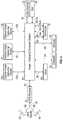
- FIG. 1shown therein is a schematic diagram of hardware forming an exemplary embodiment of an apparatus 10 for three-dimensional point collection of vertical structures.
- the apparatus 10may include a platform and/or vehicle 12 carrying an image-capturing and geo-locating system 14 .
- the platform 12may be an airplane, space shuttle, rocket, satellite, or any other suitable vehicle capable of carry the image-capturing system 14 .
- the platform 12may be a fixed wing aircraft.
- the platform 12may carry the image-capturing system 14 over an area of and at one or more altitudes above a surface 16 .
- the platform 12may carry the image-capturing system 14 over a predefined area and at one or more predefined altitudes above the Earth's surface and/or any other surface of interest.
- the platform 12may be capable of controlled movement and/or flight. As such, the platform 12 may be manned or unmanned. In some embodiments, the platform 12 may be capable of controlled movement and/or flight along a pre-defined flight path and/or course. For example, the platform 12 may be capable of controlled movement and/or flight along the Earth's atmosphere and/or outer space. In some embodiments, the platform 12 may be capable of controlled movement and/or flight along a utility corridor.
- the platform 12may include a system for generating and/or regulating power.
- the platform 12may include one or more generators, fuel cells, solar panels, and/or batteries for powering the image-capturing and geo-locating system 14 .
- the image-capturing and geo-locating system 14may include two or more oblique image capturing devices 18 a and 18 b , one or more vertical image-capturing devices 20 , one or more LIDAR scanners 22 , one or more global positioning system (GPS) receivers 24 , one or more inertial navigation units (INU) 26 , one or more clocks 28 , one or more gyroscopes 30 , one or more compasses 32 , one or more altimeters 34 .
- GPSglobal positioning system
- INUinertial navigation units
- clocks 28one or more gyroscopes 30
- compasses 32one or more altimeters 34
- each of the elements of the image-capturing and geo-locating system 14may be interconnected with an image-capturing computer system 36 .
- the oblique image-capturing devices 18 a and 18 b and the vertical image-capturing device 20may be capable of capturing images photographically and/or electronically.
- the oblique image-capturing devices 18 a and 18 b and the vertical image-capturing device 20may include, but are not limited to, conventional cameras, digital cameras, digital sensors, charge-coupled devices, and/or the like.
- the oblique image-capturing devices 18 a and 18 b and the vertical image-capturing device 20may be an ultra-high resolution cameras.
- the oblique image-capturing devices 18 a and 18 bmay be ultra-high resolution oblique capture systems, such as may be found in the Pictometry PentaView Capture System, manufactured and distributed by Pictometry International based in Henrietta, N.Y.
- the vertical image-capturing device 20may also be a high resolution vertical capture system, such as may be found in the Pictometry PentaView Capture System.
- the oblique image-capturing devices 18 a and 18 b and the vertical image-capturing device 20may include known or determinable characteristics including, but not limited to, focal length, sensor size, aspect ratio, radial and other distortion terms, principal point offset, pixel pitch, alignment, and/or the like.
- the oblique image-capturing devices 18 a and 18 bmay include respective central axes A 1 and A 2 .
- the oblique image-capturing devices 18 a and 18 bmay be mounted to the platform 12 such that axes A 1 and A 2 each may be at an angle of declination ⁇ relative to a horizontal plane P as illustrated in FIG. 1 .
- Declination angle ⁇may be any oblique angle. Generally, declination angle ⁇ may be from approximately 20° (twenty degrees) to approximately 60° (sixty degrees). In some embodiments, the declination angle ⁇ may be approximately 45° (forty-five degrees).
- the vertical image-capturing device 20may include central axis A 3 .
- the vertical image-capturing device 20may be mounted to the platform 12 such that the angle of declination ⁇ relative to a horizontal plane P of axis A 3 is approximately 90° (ninety degrees). As such, the vertical image-capturing device 20 may generally be mounted at nadir.
- the oblique image-capturing devices 18 a and 18 bmay acquire one or more oblique images and issue one or more image data signals (IDS) 40 a and 40 b corresponding to one or more particular oblique images or oblique photographs taken.
- the vertical image-capturing device 20may acquire one or more nadir images and issue one or more image data signals (IDS) 42 corresponding to one or more particular nadir images or nadir photographs taken.
- Oblique images and/or nadir imagesmay be stored in the image-capturing computer system 36 .
- the LIDAR scanner 22may determine a distance between the platform 12 and an object of interest by illuminating the object of interest with a laser and analyzing the reflected light.
- An exemplary LIDAR scanner 22may be the Riegl LMS-Q680i, manufactured and distributed by Riegl Laser Measurement Systems located in Horn, Austria.
- the LIDAR scanner 22may be a downward projecting high pulse rate LIDAR scanning system.
- the LIDAR scanner 22may be mounted in an off-vertical position on the platform 12 .
- the LIDAR scanner 22may be mounted to the platform 12 such that axis A 4 may be at an angle of declination ⁇ relative to a horizontal plane P.
- Declination angle ⁇may be any oblique angle.
- the declination angle ⁇may be any angle less than or equal to 80 degrees such that the axis A 4 is roughly 10 degrees or more up from nadir in either a forward or rearward direction. Mounting in an off-vertical position (i.e., non-nadir) may aid in obtaining points on a face of a vertical structure as described in further detail herein.
- the LIDAR scanner 22may collect on average between 5 and 10 points per square meter.
- a helical scan LIDAR systemmay be used in lieu of, or in addition to, the LIDAR scanner 22 .
- the helical scan LIDAR systemmay be mounted such that at least one portion of the scan pattern may be roughly 10 degrees or more up from nadir.
- the GPS receiver 24may receive global positioning system (GPS) signals 48 that may be transmitted by one or more global positioning system satellites 50 .
- GPSglobal positioning system
- the GPS signals 48may enable the location of the platform 12 relative to the surface 16 and/or an object of interest to be determined.
- the GPS receiver 24may decode the GPS signals 48 and/or issue location signals and/or data 52 .
- the location signals and/or data 52may be dependent, at least in part, on the GPS signals 48 and may be indicative of the location of the platform 12 relative to the surface 16 and/or an object of interest.
- the location signals and/or data 52 corresponding to each image captured by the oblique image-capturing devices 18 a and 18 b and/or the vertical image-capturing device 20may be received and/or stored by the image-capturing computer system 36 in a manner in which the location signals are associated with the corresponding image.
- the INU 26may be a conventional inertial navigation unit.
- the INU 26may be coupled to and detect changes in the velocity (e.g., translational velocity, rotational velocity) of the oblique image capturing devices 18 a and 18 b , the vertical image-capturing devices 20 , the LIDAR scanner 22 , and/or the platform 12 .
- the INU 26may issue velocity signals and/or data 54 indicative of such velocities and/or changes therein to image-capturing computer system 36 .
- the image-capturing computer system 36may then store the velocity signals and/or data 54 corresponding to each oblique and/or nadir image captured by the oblique image-capturing devices 18 a and 18 b , the vertical image-capturing device 20 , and/or points collected by the LIDAR scanner 22 .
- the clock 28may keep a precise time measurement.
- the clock 28may keep a precise time measurement used to synchronize events within the image capturing and geo-locating system 14 .
- the clock 28may include a time data/clock signal 56 .
- the time data/clock signal 56may include a precise time that an oblique and/or nadir image is taken by the oblique image-capturing devices 18 a and 18 b and/or the vertical image-capturing device 20 , and/or the precise time that points are collected by the LIDAR scanner 22 .
- the time data 56may be received by and/or stored by the image-capturing computer system 36 .
- the clock 28may be integral with the image-capturing computer system 36 , such as, for example, a clock software program.
- the gyroscope 30may be a conventional gyroscope commonly found on airplanes and/or within navigation systems (e.g., commercial navigation systems for airplanes). Gyroscope 30 may submit signals including a yaw signal 58 , a roll signal 60 , and/or a pitch signal 62 . In some embodiments, the yaw signal 58 , the roll signal 60 , and/or the pitch signal 62 may be indicative of the yaw, roll and pitch of the platform 12 . The yaw signal 58 , the roll signal 60 , and/or the pitch signal 62 may be received and/or stored by the image-capturing computer system 36 .
- the compass 32may be any conventional compass (e.g., conventional electronic compass) capable of indicating the heading of the platform 12 .
- the compass 32may issue a heading signal and/or data 64 .
- the heading signal and/or data 64may be indicative of the heading of the platform 12 .
- the image-capturing computer system 36may receive, store and/or provide the heading signal and/or data 64 corresponding to each oblique and/or nadir image captured by the oblique image-capturing devices 18 a and 18 b and/or the vertical image-capturing device 20 .
- the altimeter 34may indicate the altitude of the platform 12 .
- the altimeter 34may issue an altimeter signal and/or data 66 .
- the image-capturing computer system 36may receive, store and/or provide the altimeter signal and/or data 66 corresponding to each oblique and/or nadir image captured by the oblique image-capturing devices 18 a and 18 b , and/or the vertical image-capturing device 20 .
- the image-capturing computer system 36may be a system or systems that are able to embody and/or execute the logic of the processes described herein.
- Logic embodied in the form of software instructions and/or firmwaremay be executed on any appropriate hardware.
- logic embodied in the form of software instructions or firmwaremay be executed on a dedicated system or systems, or on a personal computer system, or on a distributed processing computer system, and/or the like.
- logicmay be implemented in a stand-alone environment operating on a single computer system and/or logic may be implemented in a networked environment, such as a distributed system using multiple computers and/or processors.
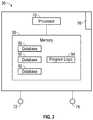
- the image-capturing computer system 36may include one or more processors 70 communicating with one or more image capturing input devices 72 , image capturing output devices 74 , and/or I/O ports 76 enabling the input and/or output of data to and from the image-capturing computer system 36 .
- FIG. 3illustrates the image-capturing computer system 36 having a single processor 70 . It should be noted, however, that the image-capturing computer system 36 may include multiple processors 70 . In some embodiments, the processor 70 may be partially or completely network-based or cloud-based. The processor 70 may or may not be located in a single physical location. Additionally, multiple processors 70 may or may not necessarily be located in a single physical location.
- the one or more image capturing input devices 72may be capable of receiving information input from a user and/or processor(s), and transmitting such information to the processor 70 .
- the one or more image capturing input devices 72may include, but are not limited to, implementation as a keyboard, touchscreen, mouse, trackball, microphone, fingerprint reader, infrared port, slide-out keyboard, flip-out keyboard, cell phone, PDA, video game controller, remote control, fax machine, network interface, speech recognition, gesture recognition, eye tracking, brain-computer interface, combinations thereof, and/or the like.
- the one or more image capturing output devices 74may be capable of outputting information in a form perceivable by a user and/or processor(s).
- the one or more image capturing output devices 74may include, but are not limited to, implementations as a computer monitor, a screen, a touchscreen, a speaker, a website, a television set, a smart phone, a PDA, a cell phone, a fax machine, a printer, a laptop computer, an optical head-mounted display (OHMD), combinations thereof, and/or the like.
- the one or more image capturing input devices 72 and the one or more image capturing output devices 74may be implemented as a single device, such as, for example, a touchscreen or a tablet.
- Each of the data signals 40 a , 40 b , 42 , 46 , 52 , 54 , 56 , 58 , 60 , 62 , and/or 64may be provided to the image capturing computer system 36 .
- each of the data signals 40 a , 40 b , 42 , 46 , 52 , 54 , 56 , 58 , 60 , 62 , and/or 64may be received by the image capturing computer system 36 via the I/O port 76 .
- the I/O portmay comprise one or more physical and/or virtual ports.
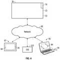
- the image-capturing computer system 36may be in communication with one or more additional processors 82 as illustrated in FIG. 4 .
- the image-capturing computer system 36may communicate with the one or more additional processors 82 via a network 80 .
- the terms “network-based”, “cloud-based”, and any variations thereofmay include the provision of configurable computational resources on demand via interfacing with a computer and/or computer network, with software and/or data at least partially located on the computer and/or computer network, by pooling processing power of two or more networked processors.
- the network 80may be the Internet and/or other network.
- a primary user interface of the image capturing software and/or image manipulation softwaremay be delivered through a series of web pages. It should be noted that the primary user interface of the image capturing software and/or image manipulation software may be replaced by another type of interface, such as, for example, a Windows-based application.
- the network 80may be almost any type of network.
- the network 80may interface by optical and/or electronic interfaces, and/or may use a plurality of network topographies and/or protocols including, but not limited to, Ethernet, TCP/IP, circuit switched paths, and/or combinations thereof.
- the network 80may be implemented as the World Wide Web (or Internet), a local area network (LAN), a wide area network (WAN), a metropolitan network, a wireless network, a cellular network, a Global System for Mobile Communications (GSM) network, a code division multiple access (CDMA) network, a 3G network, a 4G network, a satellite network, a radio network, an optical network, a cable network, a public switched telephone network, an Ethernet network, combinations thereof, and/or the like.
- GSMGlobal System for Mobile Communications
- CDMAcode division multiple access
- 3G networkThird Generation
- 4Gfourth generation
- satellite networka radio network
- an optical networka cable network
- public switched telephone networkan Ethernet network, combinations thereof, and/or the like.
- the network 80may use a variety of network protocols to permit bi-directional interface and/or communication of data and/or information. It is conceivable that in the near future, embodiments of the present disclosure may use more advanced networking topologies.
- the image capturing computer system 36may be capable of interfacing and/or communicating with the one or more computer systems including processors 82 via the network 80 . Additionally, the one or more processors 82 may be capable of communicating with each other via the network 80 . For example, the image capturing computer system 36 may be capable of interfacing by exchanging signals (e.g., analog, digital, optical, and/or the like) via one or more ports (e.g., physical ports or virtual ports) using a network protocol, for example.
- signalse.g., analog, digital, optical, and/or the like
- portse.g., physical ports or virtual ports
- the processors 82may include, but are not limited to implementation as a variety of different types of computer systems, such as a server system having multiple servers in a configuration suitable to provide a commercial computer based business system (such as a commercial web-site), a personal computer, a smart phone, a network-capable television set, a television set-top box, a tablet, an e-book reader, a laptop computer, a desktop computer, a network-capable handheld device, a video game console, a server, a digital video recorder, a DVD player, a Blu-Ray player, a wearable computer, a ubiquitous computer, combinations thereof, and/or the like.
- a server system having multiple servers in a configuration suitable to provide a commercial computer based business systemsuch as a commercial web-site
- a personal computersuch as a smart phone, a network-capable television set, a television set-top box, a tablet, an e-book reader, a laptop computer, a desktop computer, a network-capable
- the computer systems comprising the processors 82may include one or more input devices 84 , one or more output devices 86 , processor executable code, and/or a web browser capable of accessing a website and/or communicating information and/or data over a network, such as network 80 .
- the computer systems comprising the one or more processors 82may include one or more non-transient memory comprising processor executable code and/or software applications, for example.
- the image capturing computer system 36may be modified to communicate with any of these processors 82 and/or future developed devices capable of communicating with the image capturing computer system 36 via the network 80 .
- the one or more input devices 84may be capable of receiving information input from a user, processors, and/or environment, and transmit such information to the processor 82 and/or the network 80 .
- the one or more input devices 84may include, but are not limited to, implementation as a keyboard, touchscreen, mouse, trackball, microphone, fingerprint reader, infrared port, slide-out keyboard, flip-out keyboard, cell phone, PDA, video game controller, remote control, fax machine, network interface, speech recognition, gesture recognition, eye tracking, brain-computer interface, combinations thereof, and/or the like.
- the one or more output devices 86may be capable of outputting information in a form perceivable by a user and/or processor(s).
- the one or more output devices 86may include, but are not limited to, implementations as a computer monitor, a screen, a touchscreen, a speaker, a website, a television set, a smart phone, a PDA, a cell phone, a fax machine, a printer, a laptop computer, an optical head-mounted display (OHMD), combinations thereof, and/or the like.
- the one or more input devices 84 and the one or more output devices 86may be implemented as a single device, such as, for example, a touchscreen or a tablet.
- the image-capturing computer system 36may include one or more processors 70 working together, or independently to execute processor executable code, and one or more memories 90 capable of storing processor executable code.
- each element of the image-capturing computer system 36may be partially or completely network-based or cloud-based, and may or may not be located in a single physical location.
- the one or more processors 70may be implemented as a single or plurality of processors working together, or independently, to execute the logic as described herein. Exemplary embodiments of the one or more processors 70 may include, but are not limited to, a digital signal processor (DSP), a central processing unit (CPU), a field programmable gate array (FPGA), a microprocessor, a multi-core processor, and/or combination thereof, for example.
- DSPdigital signal processor
- CPUcentral processing unit
- FPGAfield programmable gate array
- microprocessore.g., a microprocessor
- multi-core processore.g., multi-core processor, and/or combination thereof, for example.
- the one or more processors 70may be capable of communicating via the network 80 , illustrated in FIG. 4 , by exchanging signals (e.g., analog, digital, optical, and/or the like) via one or more ports (e.g., physical or virtual ports) using a network protocol.
- the processors 70may be located remotely from one another, in the same location, or comprising a unitary multi-core processor.
- the one or more processors 70may be capable of reading and/or executing processor executable code and/or capable of creating, manipulating, retrieving, altering, and/or storing data structures into one or more memories 90 .
- the one or more memories 90may be capable of storing processor executable code. Additionally, the one or more memories 90 may be implemented as a conventional non-transient memory, such as, for example, random access memory (RAM), a CD-ROM, a hard drive, a solid state drive, a flash drive, a memory card, a DVD-ROM, a floppy disk, an optical drive, combinations thereof, and/or the like, for example.
- RAMrandom access memory
- the one or more memories 90may be located in the same physical location as the image capturing computer system 36 .
- one or more memories 90may be located in a different physical location as the image capturing computer system 36 , the with image capturing computer system 36 communicating with one or more memories 90 via a network such as the network 80 , for example.
- one or more of the memories 90may be implemented as a “cloud memory” (i.e., one or more memories 90 may be partially or completely based on or accessed using a network, such as network 80 , for example).
- the one or more memories 90may store processor executable code and/or information comprising one or more databases 92 and program logic 94 .
- the processor executable codemay be stored as a data structure, such as a database and/or data table, for example.
- the image-capturing computer system 36may execute the program logic 94 which may control the reading, manipulation, and/or storing of data signals 40 a , 40 b , 42 , 46 , 52 , 54 , 56 , 58 , 60 , 62 , and/or 64 .
- the program logicmay read data signals 40 a , 40 b , and/or 42 , and may store them within the one or more memories 90 .
- Each of the location signals, 46 , 52 , 54 , 56 , 58 , 60 , 62 , and/or 64may represent the conditions existing at the instance that an oblique image and/or nadir image is acquired and/or captured by the oblique image capturing devices 18 a and/or 18 b , and/or the vertical image-capturing device 20 .
- the image capturing computer system 36may issue an image capturing signal to the oblique image-capturing devices 18 a and/or 18 b , and/or the vertical image-capturing device 20 to thereby cause those devices to acquire and/or capture an oblique image and/or a nadir image at a predetermined location and/or at a predetermined interval.
- the image capturing computer system 36may issue the image capturing signal dependent on at least in part on the velocity of the platform 12 .
- the image capturing computer system 36may issue a point collection signal to the LIDAR scanner 22 to thereby cause the LIDAR scanner to collect points at a predetermined location and/or at a predetermined interval.
- Program logic 94 of the image capturing computer system 36may decode, as necessary, and/or store the aforementioned signals within the memory 90 , and/or associate the data signals with the corresponding image data signals 40 a , 40 b and/or 42 , or the corresponding LIDAR scanner signals 46 .
- the altitude, orientation, roll, pitch, yaw, and the location of each oblique image capturing device 18 a and 18 b , and/or vertical image-capturing device 20 relative to the surface 16 and/or object of interest for images capturedmay be known. More particularly, the [X, Y, Z] location (e.g., latitude, longitude, and altitude) of an object or location seen within the images or location seen in each image may be determined.
- the altitude, orientation, roll, pitch, yaw, and the location of the LIDAR scanner 22 relative to the surface 16 and/or object of interest for collection of data pointsmay be known. More particularly, the [X, Y, Z] location (e.g., latitude, longitude, and altitude) of a targeted object or location may be determined.
- the platform 12may be piloted and/or guided through an image capturing path that may pass over a particular area of the surface 16 .
- the image capturing pathmay follow one or more utility lines.
- the number of times the platform 12 and/or oblique image capturing devices 18 a and 18 b and/or vertical image-capturing device 20 pass over the area of interestmay be dependent at least in part upon the size of the area and the amount of detail desired in the captured images.
- a number of oblique images and/or nadir imagesmay be captured by the oblique image-capturing devices 18 a and 18 b and/or the vertical image-capturing device 20 .
- the imagesmay be captured and/or acquired by the oblique image-capturing devices 18 a and 18 b , and/or the vertical image-capturing device 20 at predetermined image capture intervals that may be dependent, at least in part, upon the velocity of the platform 12 .
- the safe flying height for a fixed wing aircraftmay be a minimum clearance of 2,000′ above the surface 16 , and may have a general forward flying speed of 120 knots.
- the oblique image-capturing devices 18 a and 18 bmay capture 1 cm to 2 cm ground sample distance imagery
- the vertical image-capturing device 20may be capable of capturing 2 cm to 4 cm ground sample distance imagery.
- the image data signals 40 a , 40 b and 42 corresponding to each image acquiredmay be received by and/or stored within the one or more memories 90 of the image capturing computer system 36 via the I/O port 76 .
- the location signals, 52 , 54 , 56 , 58 , 60 , 62 , and/or 64 corresponding to each captured imagemay be received and stored within the one or more memories 90 of the image-capturing computer system 36 via the I/O port 76 .
- the LIDAR scanner signals 46may be received and stored as LIDAR 3D point clouds.
- the location of the oblique image capturing devices 18 a and 18 b , and/or the location of the vertical image-capturing device 20 relative to the surface 16 at the precise moment each image is capturedis recorded within the one or more memories 90 and associated with the corresponding captured oblique and/or nadir image.
- the processor 70may create and/or store in the one or more memories 90 , one or more output image and data files.
- the processor 70may convert image data signals 40 a , 40 b and/or 42 , location signals, 52 , 54 , 56 , 58 , 60 , 62 , and/or 64 , and the LIDAR scanner signals 46 into computer-readable output image, data files, and LIDAR 3D point cloud files.
- the output image, data files, and LIDAR 3D point cloud filesmay include a plurality of captured image files corresponding to captured oblique and/or nadir images, positional data, and/or LIDAR 3D point clouds corresponding thereto.
- Output image, data files, and LIDAR 3D point cloud filesmay then be further provided, displayed and/or used for obtaining measurements of and between objects depicted within the captured images, including measurements of the heights of such objects.
- the image capturing computer system 36may be used to provide, display and/or obtain measurements of and between objects depicted within the captured images.
- the image capturing computer system 36may deliver the output image, data files, and/or LIDAR 3D point clouds to one or more processors, such as, for example, the processors 82 illustrated in FIG. 4 for processors 82 to provide, display and/or obtain measurement.
- delivery of the output image, data files, and/or LIDAR 3D point cloud filesmay also be by physical removal of the files from the image capturing computer system 36 .
- the output image, data files, and/or LIDAR 3D point cloud filesmay be stored on a removable storage device and transported to one or more processors 82 .
- the image capturing computer system 36may provide at least a portion of the display and/or determine at least a portion of the measurements further described herein.
- the following description for measurement of objects of interest as described hereinincludes reference to utility wires, utility poles, and utility towers, however, it should be understood by one skilled in the art that the methods described herein may be applied to any structure of interest.
- the methodsmay be applied to a building structure, such as a roof, wherein the roof is the object of interest.
- the output image file and data filesmay be used to geo-reference the oblique and/or nadir images.
- Exemplary methods for georeferencing the imagerymay be found in at least U.S. Pat. Nos. 7,424,133 and 5,247,356, which are hereby incorporated by reference in their entirety.
- the LIDAR 3D point cloud filesmay be processed and geo-referenced.
- the LIDAR 3D point cloud filesmay be processed and geo-referenced using software such as Reigl's RiProcess application, distributed by Reigl located in Horn, Austria.
- processing of the LIDAR 3D point cloud filesmay include classifying points in the data into at least three categories: objects of interest 100 (e.g., towers 114 , utility wires 110 ), background structures 102 (e.g., background vegetation, background structures), and surface points 16 (e.g., ground points).
- the LIDAR post processing softwaremay classify points as being the surface 16 , e.g., ground, utility wires 110 , towers 114 , and/or foliage or other background items.
- the towers 114can be utility towers configured to support the utility wires 110 .
- the towers 114can be implemented in a variety of forms, such as H-style utility towers, utility poles, steel truss style utility towers, concrete utility towers and combinations thereof. In some embodiments, the classifications listed above may be further subdivided as needed.
- the images and/or 3D point cloud filescan be scanned for horizontal objects of interest to locate utility wires 110 , for example. Scanning for horizontal objects of interest, such as the utility wires 110 , may be aided by the use of a geographical information system (GIS) data system 120 illustrated in FIG. 4 .
- GIS data system 120may include data from a utility company.
- GIS datamay include, but is not limited to, right of way centerlines, GIS data for location of towers 114 , GIS data for utility wires 110 , Computer Aided Design (CAD) data for the utility wires 110 , and/or the like.
- CADComputer Aided Design
- the GIS centerline vector datamay be used to automatically follow the path of the utility network.
- the GIS centerline datais typically maintained by the utility companies and may include the geographical position on the Earth of individual towers 114 ; however, such data may not be updated and/or may be changed.
- the geographical positioncan be in any suitable coordinate system, such as Latitude/Longitude.
- the centerlinesmay remain largely unchanged as they may typically be tied to a property boundary.
- utility wires 110may also be identified using either LIDAR 3D point cloud files and/or the image data without the use of GIS data.
- utility wires 110may generally be relatively straight lines and distinctive as compared to other structures within the image. In three-dimensional space, utility lines 110 may be above ground and at a relatively consistent elevation range.
- standard edge detection algorithmsmay be used to identify the utility lines 110 .
- Standard edge detection algorithmsmay include, but are not limited to, a Laplacian filter and/or the like. Additionally, in some embodiments, a Hough Transform and/or similar algorithm, may determine the long straight feature of the utility wires 110 .
- a Gabor filtermay be used to identify the utility wires 110 .
- the general use of a Gabor filter in identifying utility linesis described in Mu, Chao, et al. “Power lines extraction from aerial images based on Gabor filter.” International Symposium on Spatial Analysis, Spatial Temporal Data Modelling, and Data Mining. International Society for Optics and Photonics, 2009, which is hereby incorporated by reference in its entirety.
- This methodmay be further modified to identify utility wires 110 and cross bars 112 of the towers 114 . Even further, the method may be modified to apply photogrammetry to automatically isolate features in the oblique image(s) as discussed in further detail herein.
- intensity values of pointsmay be identified and reviewed to determine the location of the utility wires 110 .
- parallel lines having periodic perpendicular edgesmay be identified as utility wires 110 .
- Additional LIDAR data points of the LIDAR 3D point cloud filemay be discarded if the LIDAR data points do not correspond to the parallel lines and/or periodic perpendicular edges. For example, single lines having no close parallel line (e.g., within 15′ or less, for example) may be discarded. Additional discrimination may be performed if there are no identifiable cross arms 112 in the LIDAR data points of the LIDAR 3D point cloud file. For example, if there are no periodic edges running perpendicular to parallel lines, the points are probably not associated with utility wires 110 .
- a wire centerline W cmay be determined to follow the utility corridor.
- the wire centerline W cmay be determined using a line fitting algorithm (e.g., RANSAC least squares algorithm). Using the wire centerline W c as a guide, measurements may be taken at predetermined increments of the utility corridor along the wire centerline W c . In some embodiments, the increments may be less than the height of the smallest tower 114 being searched. At each increment, a search may be performed to identify one or more clusters of LIDAR data points corresponding to one or more towers 114 , cross arms 112 , and/or utility wires 110 .
- a searchmay be performed to identify one or more clusters of LIDAR data points corresponding to one or more towers 114 , cross arms 112 , and/or utility wires 110 .
- LIDAR data points for utilitiesmay further be discarded based on elevation. For example, if the LIDAR data point(s) are unclassified (i.e., not classified as an object of interest 100 , background structures 102 , or surface 16 ), then the unclassified points within a predetermined distance of the lowest elevation points that are classified may be discarded. These points may be discarded as they may relate to the surface 16 and/or background vegetation. Unclassified points above the lowest elevation points that are classified may be considered to be part of the tower 114 . Typically, taller vegetation may be kept below utility lines 110 , and as such, vegetation point may not be included in the search.
- the algorithmmay also look for an increased number of points at a predetermined radius (e.g., 30′ radius) from a search point having unclassified points, since such points will not be related to utility wires 110 if they are vegetation.
- a predetermined radiuse.g. 30′ radius
- towers 114may be identified using catenary curves of the utility lines 110 .
- utility wires 110generally form parabolic curves 130 and 132 meeting at a distinct attachment point 134 . Analyzing the utility wires 110 to find adjacent and intersecting parabolic curves 130 and 132 may determine the distinct attachment point 134 at the location of intersection. The towers 114 location may be found at the distinct attachment point 134 .
- an algorithmmay calculate a center of mass and grow the cluster such that it includes all of points reasonably within the area of interest. For example, a point density algorithm may be used to grow the cluster such that new points may be below a selected density threshold. A Convex Hull algorithm may then be used to isolate the cluster of points and identify a grouping of points, classifying the points as the tower 114 .
- cross arms 112may be identified within the oblique and/or nadir images.
- Cross arms 112may be identified as horizontally extending, beam-like structures located close to or at relatively the same elevation of the utility wires 110 .
- cross arms 112may have a major axis extending near perpendicular (e.g., within 10 degrees of perpendicular) to and at relatively the same elevation of the utility wires 110 .
- the search and/or scanningmay be aided by the use of GIS data for the location of the towers 114 and/or from the CAD data of the towers 114 .
- the output image files and/or the LIDAR 3D point cloud filesmay be scanned for horizontally extending structures (e.g., having a major axis extending horizontally) indicative of cross arms 112 , as discussed above.
- FIGS. 8A and 8Bshow a LIDAR 3D point cloud with FIG. 8B as a magnified view of the portion around the object of interest 100 .
- the LIDAR 3D point cloud filesmay classify objects of interest 100 and background vegetation 102 .
- the utility wires 110may be identified in the LIDAR 3D point cloud file and/or the output image files.
- the cross arms 112may be identified as horizontal structures near perpendicular to and/or interesting with the utility wires 110 as illustrated in FIG. 8B .
- the industry standard edge detection and line identification algorithmsmay be used to determine the location of the utility wires 110 using the LIDAR data files.
- Utility wires 110may make a turn in the utility line.
- the angle of the structure of the cross arm 112may not be perpendicular, but may typically be either perpendicular to a single utility wire 110 or the other wire, bisecting the angle formed by the two utility wires, or somewhere in between the perpendiculars and the angle bisector.
- the vertical structures beneath the cross arms 112may be identified.
- Vertical structuresmay include towers 114 , and/or insulators 116 .
- the vertical structuresmay be identified using LIDAR data points and/or algorithms capable of isolating points corresponding to the vertical structures.
- the images filescan be processed to create a pre-calculated tessellated ground plane for each of the images files.
- the tessellated ground planecan be implemented as a data file or data table having elevation values that are correlated to specific geographical locations on the surface 16 of the Earth.
- the tessellated ground planeincludes a plurality of individual facets having respective elevations. Adjacent pairs of facets share at least two vertices. Each facet has a respective pitch and slope. Tessellated ground plane can be created based upon various data and resources, such as, for example, topographical maps, and/or digital raster graphics, survey data, and various other sources. Techniques for making and using an exemplary tessellated ground plane is described in U.S. Pat. No. 7,424,133, which is hereby incorporated herein by reference.
- the tessellated ground planecan be supplemented with further information and/or data points indicative of TGP Vertical planes Pv representative of a mathematical model of and to permit measurements to be made on an object of interest, such as a vertical structure.
- a TGP vertical plane P Vmay be placed transversely through the tower 114 and may be relatively parallel to the orientation of the cross arms 112 .
- the TGP vertical plane P V of each tower 114may be formed by identifying points of the tower 114 positioned at a distance farthest from the wire centerline We in the (x, y) direction and generally perpendicular to the utility wires 110 .
- the TGP vertical plane P Vmay be formed of TGP vertical plane data of real-world three-dimensional location values representative of at least two points on the object of interest depicted in the oblique image and positioned at a distance farthest from a centerline of the object of interest. These points may correspond to the ends 116 a and 116 b of the cross arms 112 .
- points (X 1 , Y 1 , Z 1A ) and (X 3 , Y 3 , Z 3A )are positioned at the farthest extent of the tower 114 away from the centerline of the utility wires 110 (X 2 , Y 2 , Z 2A ).
- Connecting corresponding points at roughly the same vertical elevationmay produce a three-dimensional line roughly corresponding to a center C of the cross arm 112 .
- a line fitting algorithmmay be used to manipulate the line L 1 such that the line L 1 is as close to parallel to the cross arm 112 data points and the “center of mass” of the tower 114 .
- the TGP vertical plane Pvmay be formed such that it terminates the height of the cross arms 112 , or anywhere on the pole and/or tower 114 .
- the TGP vertical plane Pvmay be formed such that it extends to the very top height of the pole and/or tower 114 .
- any and all features on the pole and/or tower 114may be identified and/or measured using the single ray projection method once the TGP vertical plane Pv is incorporated into the standard ground plane.
- a line L 1may be fitted therebetween.
- the line L 1may generally be through the “center of mass” of the structure points of the tower 114 .
- the line L 1may be extended in a z-direction to the top of the tower 114 , and may also be extended in a z-direction down to the surface 16 to form the TGP vertical plane P V .
- the TGP vertical plane datamay include at least one real-world three-dimensional location value representative of a three-dimensional location where the object of interest over lies the Earth and having an elevation value indicative of an elevation of the terrain underneath the object of interest.
- the line L 1may be extended upwards in the z-direction to include points (X 1 , Y 1 , Z 1C ) and (X 1 , Y 1 , Z 3C ).
- the line L 1may also be extended downwards in the z-direction to the surface 16 to include points (X 1 , Y 1 , Z 1B ) and (X 3 , Y 3 , Z 3B ). Modification of the line L 1 with Z values greater than or lower than Z 1A and Z 3A may form an outer boundary of the TGP vertical plane P V .
- the TGP vertical plane P Vmay be used as a facet within the tessellated ground plane (TGP) for single ray projection measurement methods as described in U.S. Pat. No. 7,424,133, which is hereby incorporated by reference in its entirety.
- the one or more processors 82may receive one or more signal indicative of a selection and pixel location within a displayed image of a first point and a second point on the tower 114 depicted within the displayed oblique image.
- the one or more processors 82may then retrieve from a data file, location data indicative of a position and orientation of an image capturing device (e.g., the oblique image capturing devices 18 a and 18 b ) used to capture the displayed oblique image, and a TGP vertical plane approximating a center of mass of the tower 114 .
- the one or more processors 82may then determining real-world locations of the first point and the second point utilizing the pixel location of the one or more selected points within the oblique image, the location data and the TGP vertical plane data using the single ray projection measurement methods.
- location of points within the oblique and/or nadir imagemay be determined using the TGP vertical plane P V for reference as a facet within the tessellated ground plane.
- Element 150illustrates the boundaries of a view of a metric oblique image.
- the oblique image view 150includes a view of the tower 114 seen within the LIDAR data points.
- the TGP vertical plane P Vis shown extending through the tower 114 .
- the geo-location of a point of interest within the oblique image view 150may be calculated by determining the point of intersection of a ray 152 projected from the platform 12 towards the surface 16 .
- a usermay select a point in the image 150 corresponding to an object on the tower 114 .
- the ray 152may be projected to intersect the TGP vertical plane P V prior to the ray 152 intersecting the surface 16 .
- the ray 152interests the vertical plane P V in FIG. 10 at intersection point 154 .
- the location for the point of intersection 154may be determined on the tower 114 rather than a point on the surface 16 or other tessellated ground plane.
- the TGP vertical plane P Vmay also be used to determine a length L O of an object on the tower 114 .
- the row and column (e.g., (X, Y) location) of that pixel in the image 150may be used to calculate projection of the ray 152 towards the surface 16 .
- the algorithmmay then identify where the intersection point 154 of the ray 152 occurs on the TGP vertical plane P V and report the intersection point 154 location on the TGP vertical plane P V .
- the three-dimensional location of the intersection point 154can be determined using bilinear interpolation using the coordinates (X 1 , Y 1 , Z 1A ), (X 1 , Y 1 , Z 1B ), (X 3 , Y 3 , Z 3A ), (X 3 , Y 3 , Z 3B ). If a pixel corresponding to a second point of the object of interest on the tower 114 is selected within the image 150 , the algorithm may again be used to produce a second ray 156 and identify the intersection point 158 of the vertical plane P V . The distance between the first intersection point 154 and the second intersection point 158 may be determined (e.g., using Pythagorean Theorem), resulting in the length L o of the object measured in the image 150 .
- an object 50′ up on the tower 114may be over 2,750′ away.
- being 5′ away from the TGP vertical plane P Vmay only result in a measurement scaling error of less than 0.2% of the actual measurement.
- a facet conforming to a portion of the surface 16 , 50′ below the objecti.e., surface 16
- the corresponding point on the groundmay be 70′ away (i.e., 14 ⁇ the 5′ distance).
- the ground planei.e., surface 16
- the ground planemay not be parallel to the object being measured.
- the TGP vertical plane P Vmay also be used to determine a height H above ground of an object of interest.
- the TGP vertical plane P Vmay be used to determine the height H above ground of connection points of the utility wires 110 to the tower 114 .
- a usere.g., human, processor
- the insulators 116 a - 116 care generally the mechanism used to connect the utility wires 110 to the tower 114 .
- An algorithmmay use a pixel location (e.g., x, y) within the image 150 that is indicative of the user selected point to project the ray 152 through the focal plane and down towards the surface 16 .
- a pixel locatione.g., x, y
- the location of the intersection point 154 located on the insulators 116 a , 116 b , and/or 116 cmay be determined on the TGP vertical plane P V .
- the second point of intersectionmay be selected on the surface 16 providing the point of intersection on a facet within the tessellated ground plane 158 .
- the Z distance between the two points 154 and 158 in spacemay be determined to be the height H above ground for the connection point.
- the tessellated ground plane 158 having facets conforming to the contours of the surface 16 of the Earth, as described in U.S. Pat. No. 7,424,133,may also be determined using data points collected by the LIDAR scanner 22 .
- the intersection of the groundmay be determined as the intersection of the TGP vertical plane P V with the tessellated ground plane 158 .
- the measurement of the height Hmay be increased in accuracy in some embodiments, and also may be used for purposes of thermal line ratings.
- a usermay select the same or similar connection point on the tower 114 in two or more oblique image views 150 and 150 b .
- the usermay select the insulator 116 a on the tower 114 in a forward facing oblique image 150 as illustrated in FIG. 11A and a rear facing oblique image 150 b as illustrated in FIG. 11B .
- the heights H and H 2 respectively of the insulator 116 amay be determined as described herein.
- intersection points 154 , 154 b and 156 , 156 bmay be found using standard stereo pair photogrammetry techniques such that the location of each point may be determined with increased accuracy as compared to using a single image.
- the tessellated ground plane 158may also be used to determine the heights H and H 2 increasing accuracy of the determination even further.
- the tessellated ground plane 158may further increase accuracy due to the error balancing nature of stereo-photogrammetry, however, single ray projection measurements may also be used to review the measurements for proper selection.
- the stereo analysis using standard stereo pair photogrammetry techniquesmay be automated or substantially automated.
- a corner detection algorithmmay be used to find points of interest in two separate oblique image views 150 and 150 b for an object.
- a correlation for the two points of interestmay be determined to identify common points between the two points of interest. The strongest correlation may generally be on the desired object.
- the ray 152may be determined.
- the resulting intersection point 154may be used to select a second oblique image view 150 b from an opposing direction.
- the TGP vertical plane P Vmay then be used to find an end of the insulator 116 a .
- a standard corner detection algorithm and/or a correlation algorithmmay then be used to find a pixel indicative of the end of the insulator 116 a in the second image 150 b .
- the location of the pixel within the second image 150 b , the TGP vertical plane P V , and the camera position and orientation of the second image 150 bmay be used to cast a second ray 152 b through the end of the insulator 116 a in the second image 150 b .
- the resulting two rays 152 and 152 bmay then be used in industry standard stereo photogrammetry to locate the intersection points 154 , 154 b and 156 , 156 b .
- the resulting identification and measurement of and between the points 154 , 154 b and 156 , 156 bmay be further incorporated into CAD modeling, thermal line ratings, engineering plans, and/or any other use for three-dimensional point determinations. Even further, identification and/or measurement between multiple points between multiple images may aid in formation of Method 1 structure models as known in the industry.
- identification of matching points between two opposing oblique images 150 a and 150 bmay also be identified using a Gabor filter.
- the orientation and spatial frequency of the Gabor filtermay be tuned such that the filter acts as an oriented bandpass filter.
- the utility wires 110include distinct oriented spatial frequencies that may be identified using a Gabor filter providing a Gabor filters image 13 A.
- the orientation of the utility wires 110 in the nadir image 200may be identified based on the orientation of the platform 12 (illustrated in FIG. 1 ) during flight. Additionally, identification of the spacing between each utility wire 110 may aid in tuning the Gabor filter to produce maximum response, however, a reasonable estimation of the frequency may be used.
- a maximum value thresholdmay isolate the highest response from the Gabor filtered image 210 creating a threshold image 220 .
- linear featuresmay be identified within the threshold image 220 producing detected utility wires 222 .
- detected utility wires 222may be identified within the threshold image 220 using the Hough Transform, filtering for lines that may only be at two specified orientations of the Gabor filter.
- the cross arm 112 connecting the utility wires 110may be extracted using a Gabor filter.
- the cross arm 112may be extracted by rotating the orientation of the Gabor filter within a range from 85-95 degrees (preferably 90 degrees) producing a Gabor filter image 230 in FIG. 14A having Gabor detected features 232 .
- a maximum value thresholdmay isolate the highest response from the Gabor filtered image 230 creating a threshold image 240 . Once the threshold image 240 is created, linear features may be identified within the image similar to threshold image 220 producing detected cross bar lines 232 .
- each detected utility wire 222 of threshold image 220may be intersected with the detected cross bar lines 242 of threshold image 240 (illustrated in FIG. 14B ) to define endpoints 250 and 252 of the cross arm 112 between the utility wires 110 as illustrated in FIG. 15A .
- An extension 254may be applied to the detected cross bar 242 based on the defined maximum and minimum endpoints 250 and 252 as illustrated in FIG. 15B .
- a correlation of endpoints 250 and 252 for the detected cross bar 242may be initiated using an oblique image 260 of the object identified in the nadir image of FIG. 12 .
- the correlation region in the oblique image 260may be produced by projecting the endpoints 250 and 252 of the detected cross bar 242 into the oblique image 260 , and correlating a region around epipolar lines 262 a and 262 b for each endpoint 250 and 252 of the detected cross bar 242 .
- the detected cross bar 242may be correlated such that the detected cross bar 242 substantially lies on the cross bar 212 .
- a region of interestmay be determined around each detected cross arm 242 .
- Other features of the tower 114may then be further identified using the region of interest.
- a second TGP vertical plane P V2may be defined and/or extended from the identified cross arm 112 such that the TGP vertical plane P V2 extends a pre-determined distance from the identified cross arm 112 and contains remaining features to be identified using methods as described herein.
- a templatemay be used to determine location of objects of interest on structures (e.g., cross bars 112 on tower 114 ).
- FIGS. 12A-12Dillustrate an exemplary embodiment of a utility template 159 for use in determining location of objects of interest, such as towers 114 .
- a usermay be supplied with one or more template structures.
- the templatesmay correlate with identified structures within the oblique images and/or vertical images.
- the template 159 illustrated in FIGS. 12A-12Dis a template of a “H” style tower 114 .
- the usere.g., human, processor
- the usermay align a first leg section 160 a of the “H” with a first leg 113 a of the tower 114 .
- the usermay then laterally stretch the template 159 such that a second leg section 113 b of the “H” of the template 159 may be aligned with a second leg 113 b of the tower 114 as illustrated in FIG. 12B .
- the usermay vertically stretch the template 159 such that a cross line 162 of the template 159 may be aligned with the cross arm 112 of the tower 114 as illustrated in FIG. 12C .
- the usermay adjust one or more lengths of the cross line 162 of the template 159 to substantially lie on the insulators 116 a - 116 c of the tower 114 .
- the template 159once adjusted, may lie directly on the tower 114 .
- the location of the tower 114 in spacemay be known.
- the same template 159may be projected onto one or more images with opposing views of the tower 114 . Slight adjustments may be made to compensate for any minor errors in the position and/or orientation measurements (e.g., position and/or orientation measurements due to camera error).
- Standard stereo triangulationmay also be used to determine location of each end of the line segments within the template 159 .
- the structure and location of the tower 114 within spacemay be determined and applied to one or more additional oblique and/or nadir images.
- the TGP vertical plane P Vmay also aid in generation of additional three-dimensional points to augment the three-dimensional point cloud generated by the LIDAR scanner 22 .
- the LIDAR scanner 22may not identify a significant number of points on faces of the towers 114 , as will be explained below. If, the LIDAR scanner is positioned and aimed towards nadir, upper structures of the tower 114 may obscure elements below the tower 114 . In addition, truly vertical structures may not produce a significant return to the LIDAR scanner 22 if the LIDAR scanner 22 is aimed towards nadir.
- the point densitymay still be low due to the cosine effect. For example, if the LIDAR scanner 22 is tilted forward by 10 degrees, and the LIDAR scanner collects data at 50 points per square meter such that there is a 6′′ sampling distance on the surface 16 . Because the laser beam of the LIDAR scanner 22 intersects the tower 114 at an angle of 10 degrees, a 100 foot tall pole may only appear to be about 17 feet in length, and as such, may only get approximately 34 points over the height of the tower 114 (as compared to over 200 points produced the same distance on the surface 16 ). Additionally, the angle of incidence of the imagery may be closer to 45 degrees.
- the same 6′′ resolutionmay produce 140 points on a face of the tower 114 .
- the imageryisn't at the same 6′′ resolution, it may be at a 2′′ resolution. This may produce increased resolution in each direction, such that if each pixel yields a correlation point, more than 420 points along the height of the tower 114 may be produced. Even further, the pixel resolution being generally smaller than the diameter of the tower 114 , multiple points across the diameter of the tower 114 may be produced.
- additional three dimensional points to include in the 3D point cloudmay also be determined using successive oblique image (e.g., a first oblique image view 150 c and a second oblique image view 150 d ).
- Both the first oblique image view 150 c and the second oblique image view 150 dmay include an object of interest, such as, for example, the tower 114 .
- the TGP vertical plane P Vmay be determined using the methods as described herein. Once identified, the TGP vertical plane P V may be used to select one or more overlapping oblique images oriented in the same direction (e.g., both forward looking camera orientations or both rearward looking camera orientation).
- the TGP vertical plane P Vmay be used to identify the location of the tower 114 in each image 150 c and 150 d as described in detail herein using either one or both of rays 152 c and 152 d .
- the locations of the tower 114 in each image 150 c and 150 dmay be used in an automated point matching algorithm (e.g., Semi Global Image Mapping algorithm) to find corresponding points between the two images 150 c and 150 d.
- an automated point matching algorithme.g., Semi Global Image Mapping algorithm
- Either one of the projected rays 152 c and 152 dmay then be used in a single ray-projection algorithm or (both of the rays 152 c and 152 d in a standard stereo photogrammetry algorithm) to find the real-world, three-dimensional location of the point of intersection that may be added to the point cloud produced by the LIDAR scanner 22 .
- alignment errorse.g., inertial navigation system (INS) errors
- INSinertial navigation system
- the transformmay iteratively estimate the distance between the results produced by the LIDAR scanner 22 and a point cloud produced by the images 150 c and 150 d .
- the resulting point cloud from combining results produced by the LIDAR scanner 22 and the point cloud produced by the images 150 c and 150 dmay be denser and include points located on multiple faces of structures. For example, having two oblique image capturing devices 18 a and 18 b as illustrated in FIG. 1 may produce images on multiple sides of structures as compared to having only a single LIDAR scanner titled in a single direction gathering points on a single side of a structure.
- the point cloud produced by the oblique imagesincludes points on the horizontal surfaces (e.g., ground 16 ) and points on the vertical surfaces (e.g., vertical facet of the utility towers 114 ).
Landscapes
- Engineering & Computer Science (AREA)
- Physics & Mathematics (AREA)
- General Physics & Mathematics (AREA)
- Theoretical Computer Science (AREA)
- Computer Vision & Pattern Recognition (AREA)
- Multimedia (AREA)
- Radar, Positioning & Navigation (AREA)
- Remote Sensing (AREA)
- Computer Networks & Wireless Communication (AREA)
- Electromagnetism (AREA)
- Quality & Reliability (AREA)
- Geometry (AREA)
- Signal Processing (AREA)
- Optics & Photonics (AREA)
- Artificial Intelligence (AREA)
- Image Processing (AREA)
- Image Analysis (AREA)
- Processing Or Creating Images (AREA)
- Magnetic Resonance Imaging Apparatus (AREA)
- Control Of Motors That Do Not Use Commutators (AREA)
- Apparatus For Radiation Diagnosis (AREA)
Abstract
Description
Claims (16)
Priority Applications (2)
| Application Number | Priority Date | Filing Date | Title |
|---|---|---|---|
| US16/798,670US10942276B2 (en) | 2014-01-31 | 2020-02-24 | Augmented three dimensional point collection of vertical structures |
| US17/193,758US11686849B2 (en) | 2014-01-31 | 2021-03-05 | Augmented three dimensional point collection of vertical structures |
Applications Claiming Priority (5)
| Application Number | Priority Date | Filing Date | Title |
|---|---|---|---|
| US14/169,872US9292913B2 (en) | 2014-01-31 | 2014-01-31 | Augmented three dimensional point collection of vertical structures |
| US15/060,264US9542738B2 (en) | 2014-01-31 | 2016-03-03 | Augmented three dimensional point collection of vertical structures |
| US15/364,812US10338222B2 (en) | 2014-01-31 | 2016-11-30 | Augmented three dimensional point collection of vertical structures |
| US16/458,767US10571575B2 (en) | 2014-01-31 | 2019-07-01 | Augmented three dimensional point collection of vertical structures |
| US16/798,670US10942276B2 (en) | 2014-01-31 | 2020-02-24 | Augmented three dimensional point collection of vertical structures |
Related Parent Applications (1)
| Application Number | Title | Priority Date | Filing Date |
|---|---|---|---|
| US16/458,767ContinuationUS10571575B2 (en) | 2014-01-31 | 2019-07-01 | Augmented three dimensional point collection of vertical structures |
Related Child Applications (1)
| Application Number | Title | Priority Date | Filing Date |
|---|---|---|---|
| US17/193,758ContinuationUS11686849B2 (en) | 2014-01-31 | 2021-03-05 | Augmented three dimensional point collection of vertical structures |
Publications (2)
| Publication Number | Publication Date |
|---|---|
| US20200191969A1 US20200191969A1 (en) | 2020-06-18 |
| US10942276B2true US10942276B2 (en) | 2021-03-09 |
Family
ID=53755261
Family Applications (6)
| Application Number | Title | Priority Date | Filing Date |
|---|---|---|---|
| US14/169,872Active2034-04-22US9292913B2 (en) | 2014-01-31 | 2014-01-31 | Augmented three dimensional point collection of vertical structures |
| US15/060,264ActiveUS9542738B2 (en) | 2014-01-31 | 2016-03-03 | Augmented three dimensional point collection of vertical structures |
| US15/364,812Active2034-08-17US10338222B2 (en) | 2014-01-31 | 2016-11-30 | Augmented three dimensional point collection of vertical structures |
| US16/458,767ActiveUS10571575B2 (en) | 2014-01-31 | 2019-07-01 | Augmented three dimensional point collection of vertical structures |
| US16/798,670ActiveUS10942276B2 (en) | 2014-01-31 | 2020-02-24 | Augmented three dimensional point collection of vertical structures |
| US17/193,758Active2034-11-11US11686849B2 (en) | 2014-01-31 | 2021-03-05 | Augmented three dimensional point collection of vertical structures |
Family Applications Before (4)
| Application Number | Title | Priority Date | Filing Date |
|---|---|---|---|
| US14/169,872Active2034-04-22US9292913B2 (en) | 2014-01-31 | 2014-01-31 | Augmented three dimensional point collection of vertical structures |
| US15/060,264ActiveUS9542738B2 (en) | 2014-01-31 | 2016-03-03 | Augmented three dimensional point collection of vertical structures |
| US15/364,812Active2034-08-17US10338222B2 (en) | 2014-01-31 | 2016-11-30 | Augmented three dimensional point collection of vertical structures |
| US16/458,767ActiveUS10571575B2 (en) | 2014-01-31 | 2019-07-01 | Augmented three dimensional point collection of vertical structures |
Family Applications After (1)
| Application Number | Title | Priority Date | Filing Date |
|---|---|---|---|
| US17/193,758Active2034-11-11US11686849B2 (en) | 2014-01-31 | 2021-03-05 | Augmented three dimensional point collection of vertical structures |
Country Status (4)
| Country | Link |
|---|---|
| US (6) | US9292913B2 (en) |
| AU (3) | AU2015210742B2 (en) |
| CA (2) | CA2937518C (en) |
| WO (1) | WO2015116993A1 (en) |
Families Citing this family (81)
| Publication number | Priority date | Publication date | Assignee | Title |
|---|---|---|---|---|
| US7424133B2 (en)* | 2002-11-08 | 2008-09-09 | Pictometry International Corporation | Method and apparatus for capturing, geolocating and measuring oblique images |
| US9383753B1 (en) | 2012-09-26 | 2016-07-05 | Google Inc. | Wide-view LIDAR with areas of special attention |
| US9330435B2 (en)* | 2014-03-19 | 2016-05-03 | Raytheon Company | Bare earth finding and feature extraction for 3D point clouds |
| US10203692B2 (en)* | 2014-07-21 | 2019-02-12 | King Abdullah University Of Science And Technology | Structure from motion (SfM) processing for unmanned aerial vehicle (UAV) |
| US9460517B2 (en) | 2014-10-22 | 2016-10-04 | Pointivo, Inc | Photogrammetric methods and devices related thereto |
| US11016276B2 (en)* | 2014-12-18 | 2021-05-25 | Fugro Roames Pty Limited | Imaging system |
| NO340705B1 (en)* | 2014-12-22 | 2017-06-06 | Kleon Prosjekt As | Method and apparatus for detecting an airspace from an aircraft |
| EP3345129A4 (en) | 2015-08-31 | 2019-07-24 | Cape Analytics, Inc. | SYSTEMS AND METHODS FOR ANALYZING REMOTE DETECTION IMAGING |
| US10332309B2 (en)* | 2015-09-23 | 2019-06-25 | Here Global B.V. | Method and apparatus for identifying buildings in textured 3D mesh data and generating 3D building models |
| US9740200B2 (en)* | 2015-12-30 | 2017-08-22 | Unmanned Innovation, Inc. | Unmanned aerial vehicle inspection system |
| US10288720B1 (en) | 2015-12-31 | 2019-05-14 | Waymo Llc | Vehicle sensor alignment using photogrammetry |
| DE102016002186A1 (en)* | 2016-02-24 | 2017-08-24 | Testo SE & Co. KGaA | Method and image processing device for determining a geometric measured variable of an object |
| US20170277187A1 (en)* | 2016-02-29 | 2017-09-28 | Optecks, Llc | Aerial Three-Dimensional Scanner |
| EP3430591A4 (en)* | 2016-03-16 | 2019-11-27 | ADCOR Magnet Systems, LLC | System for georeferenced, geo-oriented real time video streams |
| US10628802B2 (en)* | 2016-05-19 | 2020-04-21 | Lockheed Martin Corporation | Systems and methods for assessing damage to infrastructure assets |
| US10032267B2 (en) | 2016-06-09 | 2018-07-24 | Lockheed Martin Corporation | Automating the assessment of damage to infrastructure assets |
| CN106131390B (en)* | 2016-08-31 | 2021-10-26 | 南京理工大学 | Straight and curved rail trolley and positioning device thereof |
| US10521694B2 (en)* | 2016-09-09 | 2019-12-31 | The Chinese University Of Hong Kong | 3D building extraction apparatus, method and system |
| US11328822B2 (en)* | 2017-02-01 | 2022-05-10 | Conflu3Nce Ltd | Multi-purpose interactive cognitive platform |
| US10297074B2 (en)* | 2017-07-18 | 2019-05-21 | Fuscoe Engineering, Inc. | Three-dimensional modeling from optical capture |
| US10223807B1 (en)* | 2017-08-23 | 2019-03-05 | TuSimple | Feature extraction from 3D submap and global map system and method for centimeter precision localization using camera-based submap and lidar-based global map |
| CN107607929B (en)* | 2017-09-20 | 2021-02-02 | 云南电网有限责任公司电力科学研究院 | A method and device for measuring the tilt angle of a tower based on laser point cloud data |
| CN107833273B (en)* | 2017-11-02 | 2021-03-02 | 重庆市勘测院 | Object-based application method of oblique photography 3D model based on 3D simulation model |
| CA3030513A1 (en) | 2018-01-19 | 2019-07-19 | Sofdesk Inc. | Automated roof surface measurement from combined aerial lidar data and imagery |
| CN108960241A (en)* | 2018-07-26 | 2018-12-07 | 国网安徽省电力公司检修公司 | Insulator based on statistical shape model falls to go here and there detection algorithm |
| US11747444B2 (en)* | 2018-08-14 | 2023-09-05 | Intel Corporation | LiDAR-based object detection and classification |
| US10948907B2 (en)* | 2018-08-24 | 2021-03-16 | Ford Global Technologies, Llc | Self-driving mobile robots using human-robot interactions |
| JP7039420B2 (en)* | 2018-08-27 | 2022-03-22 | 株式会社日立ソリューションズ | Antenna extraction system and method |
| WO2020060921A1 (en) | 2018-09-17 | 2020-03-26 | Blakely Charles | Systems, methods and apparatus for characterizing stick-up height, position and orientation of a drill pipe |
| US11429333B2 (en)* | 2018-09-22 | 2022-08-30 | BadVR, Inc. | Immersive data visualization |
| US10878580B2 (en) | 2018-10-15 | 2020-12-29 | Tusimple, Inc. | Point cluster refinement processing of image data for LiDAR-based vehicle tracking system and method |
| US10878282B2 (en)* | 2018-10-15 | 2020-12-29 | Tusimple, Inc. | Segmentation processing of image data for LiDAR-based vehicle tracking system and method |
| US10984540B2 (en)* | 2018-10-15 | 2021-04-20 | Tusimple, Inc. | Tracking and modeling processing of image data for LiDAR-based vehicle tracking system and method |
| EP3881161A1 (en) | 2018-11-14 | 2021-09-22 | Cape Analytics, Inc. | Systems, methods, and computer readable media for predictive analytics and change detection from remotely sensed imagery |
| WO2020106984A1 (en) | 2018-11-21 | 2020-05-28 | Eagle View Technologies, Inc. | Navigating unmanned aircraft using pitch |
| CN109387186B (en)* | 2018-12-13 | 2021-11-05 | 广州极飞科技股份有限公司 | Surveying and mapping information acquisition method and device, electronic equipment and storage medium |
| US11391844B2 (en) | 2018-12-19 | 2022-07-19 | Fca Us Llc | Detection and tracking of road-side pole-shaped static objects from LIDAR point cloud data |
| US11294042B2 (en)* | 2018-12-31 | 2022-04-05 | Wipro Limited | Method and system for detecting presence of partial visual fault in Lidar sensor of vehicle |
| US10339646B1 (en) | 2019-01-14 | 2019-07-02 | Sourcewater, Inc. | Image processing of aerial imagery for energy infrastructure analysis using pre-processing image selection |
| US10460169B1 (en)* | 2019-01-14 | 2019-10-29 | Sourcewater, Inc. | Image processing of aerial imagery for energy infrastructure analysis using joint image identification |
| US10467473B1 (en) | 2019-01-14 | 2019-11-05 | Sourcewater, Inc. | Image processing of aerial imagery for energy infrastructure analysis |
| US10460170B1 (en)* | 2019-01-14 | 2019-10-29 | Sourcewater, Inc. | Image processing of aerial imagery for energy infrastructure site status analysis |
| US11610337B2 (en)* | 2019-02-17 | 2023-03-21 | Purdue Research Foundation | Calibration of cameras and scanners on UAV and mobile platforms |
| IL265818A (en)* | 2019-04-02 | 2020-10-28 | Ception Tech Ltd | System and method for determining location and orientation of an object in a space |
| CN109917349B (en)* | 2019-04-04 | 2021-11-19 | 山东富锐光学科技有限公司 | Scanning laser radar |
| US11866167B2 (en)* | 2019-04-10 | 2024-01-09 | Rhoman Aerospace Corporation | Method and algorithm for flight, movement, autonomy, in GPS, communication, degraded, denied, obstructed non optimal environment |
| US10635904B1 (en) | 2019-07-09 | 2020-04-28 | Sourcewater, Inc. | Identification and validation of roads using aerial imagery and mobile location information |
| CN110802608A (en)* | 2019-10-29 | 2020-02-18 | 许昌许继软件技术有限公司 | Live working robot and positioning method of high-voltage cable |
| US11584377B2 (en)* | 2019-11-21 | 2023-02-21 | Gm Cruise Holdings Llc | Lidar based detection of road surface features |
| CN110849326B (en)* | 2019-12-25 | 2022-06-07 | 深圳供电局有限公司 | A kind of monitoring method and monitoring equipment of electric pole |
| US11457200B2 (en)* | 2020-01-23 | 2022-09-27 | At&T Intellectual Property I, L.P. | Method of determining occlusion based visibility for volumetric video streaming |
| RU2726256C1 (en)* | 2020-03-01 | 2020-07-10 | Дмитрий Александрович Рощин | Method of constructing three-dimensional model of terrain along railway track bed |
| US11184740B2 (en) | 2020-03-25 | 2021-11-23 | Sourcewater, Inc. | Location data based intelligence for supply chain information platforms |
| EP4133235A4 (en) | 2020-04-10 | 2024-04-03 | Cape Analytics, Inc. | GEOCODING SYSTEM AND METHOD |
| US11386444B2 (en)* | 2020-04-27 | 2022-07-12 | Coracias Advanced Technologies LLC | Methods and systems for providing reward based verified recommendations |
| EP4150378A1 (en)* | 2020-05-13 | 2023-03-22 | Luminar, LLC | Lidar system with high-resolution scan pattern |
| US12117974B2 (en)* | 2020-05-29 | 2024-10-15 | Constellation Energy Generation, Llc | Methods and systems for construct identification and analysis |
| WO2021247603A1 (en) | 2020-06-02 | 2021-12-09 | Cape Analytics, Inc. | Method for property feature segmentation |
| CN111854697B (en)* | 2020-06-22 | 2021-08-10 | 中国船舶重工集团公司第七一六研究所 | Recognition positioning attitude determination system based on visual sensor |
| CN111812658B (en)* | 2020-07-09 | 2021-11-02 | 北京京东乾石科技有限公司 | Location determination method, apparatus, system, and computer-readable storage medium |
| CN111928824A (en)* | 2020-08-07 | 2020-11-13 | 贵州正业工程技术投资有限公司 | Engineering investigation method combining laser radar and oblique photography |
| KR20230063363A (en)* | 2020-09-09 | 2023-05-09 | 벨로다인 라이더 유에스에이, 인크. | Devices and methods for long-range, high-resolution LIDAR |
| WO2022082007A1 (en) | 2020-10-15 | 2022-04-21 | Cape Analytics, Inc. | Method and system for automated debris detection |
| TWI768548B (en)* | 2020-11-19 | 2022-06-21 | 財團法人資訊工業策進會 | System and method for generating basic information for positioning and self-positioning determination device |
| CN112884823B (en)* | 2021-01-13 | 2023-09-22 | 上海建工四建集团有限公司 | Guiding rule simulation point cloud selection and calculation method for actual measurement actual quantity application |
| CN112462348B (en)* | 2021-02-01 | 2021-04-27 | 知行汽车科技(苏州)有限公司 | Method and device for amplifying laser point cloud data and storage medium |
| US20220300681A1 (en)* | 2021-03-16 | 2022-09-22 | Yuan Ren | Devices, systems, methods, and media for point cloud data augmentation using model injection |
| US20220299649A1 (en)* | 2021-03-19 | 2022-09-22 | Qualcomm Incorporated | Object detection for a rotational sensor |
| IL283638B2 (en)* | 2021-05-18 | 2023-04-01 | Elbit Systems Ltd | Systems and methods for generating focused three-dimensional (3d) point clouds |
| US12405615B2 (en)* | 2021-06-04 | 2025-09-02 | Rhoman Aerospace Corporation | Cloud and hybrid-cloud flight vehicle and robotic control system AI and ML enabled cloud-based software and data system method for the optimization and distribution of flight control and robotic system solutions and capabilities |
| US11875413B2 (en) | 2021-07-06 | 2024-01-16 | Cape Analytics, Inc. | System and method for property condition analysis |
| US11852745B2 (en)* | 2021-09-23 | 2023-12-26 | Rockwell Collins, Inc. | System and method to select and display prioritized azimuth slice vertical radar image |
| JP2023048057A (en)* | 2021-09-27 | 2023-04-06 | 晃洋設計測量株式会社 | Forest survey method |
| JP2023056726A (en)* | 2021-10-08 | 2023-04-20 | ヤマハ発動機株式会社 | Measurement system and method for measurement |
| WO2023114027A1 (en) | 2021-12-16 | 2023-06-22 | Cape Analytics, Inc. | System and method for change analysis |
| AU2023208758A1 (en) | 2022-01-19 | 2024-06-20 | Cape Analytics, Inc. | System and method for object analysis |
| US11935276B2 (en) | 2022-01-24 | 2024-03-19 | Cape Analytics, Inc. | System and method for subjective property parameter determination |
| CN115014224B (en)* | 2022-05-27 | 2023-05-02 | 广东省核工业地质局测绘院 | Surface deformation monitoring method based on LiDAR point cloud and oblique aerial images |
| US12229845B2 (en) | 2022-06-13 | 2025-02-18 | Cape Analytics, Inc. | System and method for property group analysis |
| WO2025019516A2 (en)* | 2023-07-17 | 2025-01-23 | SeeScan, Inc. | Smartphone mounting apparatus and imaging methods for asset tagging and utilty mapping as used with utility locator devices |
| TW202507452A (en)* | 2023-08-02 | 2025-02-16 | 緯創資通股份有限公司 | Method, apparatus and non-transitory computer-readable storage medium for route planning for aerial vehicle |
Citations (165)
| Publication number | Priority date | Publication date | Assignee | Title |
|---|---|---|---|---|
| US2273876A (en) | 1940-02-12 | 1942-02-24 | Frederick W Lutz | Apparatus for indicating tilt of cameras |
| US3153784A (en) | 1959-12-24 | 1964-10-20 | Us Industries Inc | Photo radar ground contour mapping system |
| US3594556A (en) | 1969-01-08 | 1971-07-20 | Us Navy | Optical sight with electronic image stabilization |
| US3614410A (en) | 1969-06-12 | 1971-10-19 | Knight V Bailey | Image rectifier |
| US3621326A (en) | 1968-09-30 | 1971-11-16 | Itek Corp | Transformation system |
| US3661061A (en) | 1969-05-05 | 1972-05-09 | Atomic Energy Commission | Picture position finder |
| US3716669A (en) | 1971-05-14 | 1973-02-13 | Japan Eng Dev Co | Mapping rectifier for generating polarstereographic maps from satellite scan signals |
| US3725563A (en) | 1971-12-23 | 1973-04-03 | Singer Co | Method of perspective transformation in scanned raster visual display |
| US3864513A (en) | 1972-09-11 | 1975-02-04 | Grumman Aerospace Corp | Computerized polarimetric terrain mapping system |
| US3866602A (en) | 1973-05-29 | 1975-02-18 | Olympus Optical Co | Endoscope camera with orientation indicator |
| US3877799A (en) | 1974-02-06 | 1975-04-15 | United Kingdom Government | Method of recording the first frame in a time index system |
| US4015080A (en) | 1973-04-30 | 1977-03-29 | Elliott Brothers (London) Limited | Display devices |
| US4044879A (en) | 1975-03-07 | 1977-08-30 | Siemens Aktiengesellschaft | Arrangement for recording characters using mosaic recording mechanisms |
| US4184711A (en) | 1977-10-14 | 1980-01-22 | Yasuo Wakimoto | Folding canvas chair |
| US4240108A (en) | 1977-10-03 | 1980-12-16 | Grumman Aerospace Corporation | Vehicle controlled raster display system |
| US4281354A (en) | 1978-05-19 | 1981-07-28 | Raffaele Conte | Apparatus for magnetic recording of casual events relating to movable means |
| US4344683A (en) | 1979-09-29 | 1982-08-17 | Agfa-Gevaert Aktiengesellschaft | Quality control method and apparatus for photographic pictures |
| US4360876A (en) | 1979-07-06 | 1982-11-23 | Thomson-Csf | Cartographic indicator system |
| US4382678A (en) | 1981-06-29 | 1983-05-10 | The United States Of America As Represented By The Secretary Of The Army | Measuring of feature for photo interpretation |
| US4387056A (en) | 1981-04-16 | 1983-06-07 | E. I. Du Pont De Nemours And Company | Process for separating zero-valent nickel species from divalent nickel species |
| US4396942A (en) | 1979-04-19 | 1983-08-02 | Jackson Gates | Video surveys |
| US4463380A (en) | 1981-09-25 | 1984-07-31 | Vought Corporation | Image processing system |
| US4489322A (en) | 1983-01-27 | 1984-12-18 | The United States Of America As Represented By The Secretary Of The Air Force | Radar calibration using direct measurement equipment and oblique photometry |
| US4490742A (en) | 1982-04-23 | 1984-12-25 | Vcs, Incorporated | Encoding apparatus for a closed circuit television system |
| US4491399A (en) | 1982-09-27 | 1985-01-01 | Coherent Communications, Inc. | Method and apparatus for recording a digital signal on motion picture film |
| US4495500A (en) | 1982-01-26 | 1985-01-22 | Sri International | Topographic data gathering method |
| US4527055A (en) | 1982-11-15 | 1985-07-02 | Honeywell Inc. | Apparatus for selectively viewing either of two scenes of interest |
| US4543603A (en) | 1982-11-30 | 1985-09-24 | Societe Nationale Industrielle Et Aerospatiale | Reconnaissance system comprising an air-borne vehicle rotating about its longitudinal axis |
| US4586138A (en) | 1982-07-29 | 1986-04-29 | The United States Of America As Represented By The United States Department Of Energy | Route profile analysis system and method |
| US4635136A (en) | 1984-02-06 | 1987-01-06 | Rochester Institute Of Technology | Method and apparatus for storing a massive inventory of labeled images |
| US4653316A (en) | 1986-03-14 | 1987-03-31 | Kabushiki Kaisha Komatsu Seisakusho | Apparatus mounted on vehicles for detecting road surface conditions |
| US4653136A (en) | 1985-06-21 | 1987-03-31 | Denison James W | Wiper for rear view mirror |
| US4673988A (en) | 1985-04-22 | 1987-06-16 | E.I. Du Pont De Nemours And Company | Electronic mosaic imaging process |
| US4686474A (en) | 1984-04-05 | 1987-08-11 | Deseret Research, Inc. | Survey system for collection and real time processing of geophysical data |
| US4688092A (en) | 1986-05-06 | 1987-08-18 | Ford Aerospace & Communications Corporation | Satellite camera image navigation |
| US4689748A (en) | 1979-10-09 | 1987-08-25 | Messerschmitt-Bolkow-Blohm Gesellschaft Mit Beschrankter Haftung | Device for aircraft and spacecraft for producing a digital terrain representation |
| US4707698A (en) | 1976-03-04 | 1987-11-17 | Constant James N | Coordinate measurement and radar device using image scanner |
| US4758850A (en) | 1985-08-01 | 1988-07-19 | British Aerospace Public Limited Company | Identification of ground targets in airborne surveillance radar returns |
| US4805033A (en) | 1987-02-18 | 1989-02-14 | Olympus Optical Co., Ltd. | Method of forming oblique dot pattern |
| US4807024A (en) | 1987-06-08 | 1989-02-21 | The University Of South Carolina | Three-dimensional display methods and apparatus |
| US4814896A (en) | 1987-03-06 | 1989-03-21 | Heitzman Edward F | Real time video data acquistion systems |
| US4814711A (en) | 1984-04-05 | 1989-03-21 | Deseret Research, Inc. | Survey system and method for real time collection and processing of geophysicals data using signals from a global positioning satellite network |
| US4843463A (en) | 1988-05-23 | 1989-06-27 | Michetti Joseph A | Land vehicle mounted audio-visual trip recorder |
| US4899296A (en) | 1987-11-13 | 1990-02-06 | Khattak Anwar S | Pavement distress survey system |
| US4906198A (en) | 1988-12-12 | 1990-03-06 | International Business Machines Corporation | Circuit board assembly and contact pin for use therein |
| US4953227A (en) | 1986-01-31 | 1990-08-28 | Canon Kabushiki Kaisha | Image mosaic-processing method and apparatus |
| US4956872A (en) | 1986-10-31 | 1990-09-11 | Canon Kabushiki Kaisha | Image processing apparatus capable of random mosaic and/or oil-painting-like processing |
| US5034812A (en) | 1988-11-14 | 1991-07-23 | Smiths Industries Public Limited Company | Image processing utilizing an object data store to determine information about a viewed object |
| US5086314A (en) | 1990-05-21 | 1992-02-04 | Nikon Corporation | Exposure control apparatus for camera |
| US5121222A (en) | 1989-06-14 | 1992-06-09 | Toshiaki Endoh | Method and apparatus for producing binary picture with detection and retention of plural binary picture blocks having a thin line pattern including an oblique line |
| US5138444A (en) | 1991-09-05 | 1992-08-11 | Nec Corporation | Image pickup system capable of producing correct image signals of an object zone |
| US5155597A (en) | 1990-11-28 | 1992-10-13 | Recon/Optical, Inc. | Electro-optical imaging array with motion compensation |
| US5164825A (en) | 1987-03-30 | 1992-11-17 | Canon Kabushiki Kaisha | Image processing method and apparatus for mosaic or similar processing therefor |
| US5166789A (en) | 1989-08-25 | 1992-11-24 | Space Island Products & Services, Inc. | Geographical surveying using cameras in combination with flight computers to obtain images with overlaid geographical coordinates |
| US5191174A (en) | 1990-08-01 | 1993-03-02 | International Business Machines Corporation | High density circuit board and method of making same |
| US5200793A (en) | 1990-10-24 | 1993-04-06 | Kaman Aerospace Corporation | Range finding array camera |
| US5210586A (en) | 1990-06-27 | 1993-05-11 | Siemens Aktiengesellschaft | Arrangement for recognizing obstacles for pilots of low-flying aircraft |
| US5231435A (en) | 1991-07-12 | 1993-07-27 | Blakely Bruce W | Aerial camera mounting apparatus |
| US5247356A (en) | 1992-02-14 | 1993-09-21 | Ciampa John A | Method and apparatus for mapping and measuring land |
| US5251037A (en) | 1992-02-18 | 1993-10-05 | Hughes Training, Inc. | Method and apparatus for generating high resolution CCD camera images |
| US5265173A (en) | 1991-03-20 | 1993-11-23 | Hughes Aircraft Company | Rectilinear object image matcher |
| US5267042A (en) | 1991-01-11 | 1993-11-30 | Pioneer Electronic Corporation | Image pickup device for automatically recording the location where an image is recorded |
| US5270756A (en) | 1992-02-18 | 1993-12-14 | Hughes Training, Inc. | Method and apparatus for generating high resolution vidicon camera images |
| US5296884A (en) | 1990-02-23 | 1994-03-22 | Minolta Camera Kabushiki Kaisha | Camera having a data recording function |
| US5335072A (en) | 1990-05-30 | 1994-08-02 | Minolta Camera Kabushiki Kaisha | Photographic system capable of storing information on photographed image data |
| US5342999A (en) | 1992-12-21 | 1994-08-30 | Motorola, Inc. | Apparatus for adapting semiconductor die pads and method therefor |
| US5345086A (en) | 1962-11-28 | 1994-09-06 | Eaton Corporation | Automatic map compilation system |
| US5353055A (en) | 1991-04-16 | 1994-10-04 | Nec Corporation | Image pickup system with an image pickup device for control |
| US5369443A (en) | 1991-04-12 | 1994-11-29 | Abekas Video Systems, Inc. | Digital video effects generator |
| US5402170A (en) | 1991-12-11 | 1995-03-28 | Eastman Kodak Company | Hand-manipulated electronic camera tethered to a personal computer |
| US5414462A (en) | 1993-02-11 | 1995-05-09 | Veatch; John W. | Method and apparatus for generating a comprehensive survey map |
| US5467271A (en) | 1993-12-17 | 1995-11-14 | Trw, Inc. | Mapping and analysis system for precision farming applications |
| US5481479A (en) | 1992-12-10 | 1996-01-02 | Loral Fairchild Corp. | Nonlinear scanning to optimize sector scan electro-optic reconnaissance system performance |
| US5486948A (en) | 1989-03-24 | 1996-01-23 | Canon Hanbai Kabushiki Kaisha | Stereo image forming apparatus having a light deflection member in each optical path |
| US5506644A (en) | 1992-08-18 | 1996-04-09 | Olympus Optical Co., Ltd. | Camera |
| US5508736A (en) | 1993-05-14 | 1996-04-16 | Cooper; Roger D. | Video signal processing apparatus for producing a composite signal for simultaneous display of data and video information |
| US5555018A (en) | 1991-04-25 | 1996-09-10 | Von Braun; Heiko S. | Large-scale mapping of parameters of multi-dimensional structures in natural environments |
| US5604534A (en) | 1995-05-24 | 1997-02-18 | Omni Solutions International, Ltd. | Direct digital airborne panoramic camera system and method |
| US5617224A (en) | 1989-05-08 | 1997-04-01 | Canon Kabushiki Kaisha | Imae processing apparatus having mosaic processing feature that decreases image resolution without changing image size or the number of pixels |
| US5633946A (en) | 1994-05-19 | 1997-05-27 | Geospan Corporation | Method and apparatus for collecting and processing visual and spatial position information from a moving platform |
| US5668593A (en) | 1995-06-07 | 1997-09-16 | Recon/Optical, Inc. | Method and camera system for step frame reconnaissance with motion compensation |
| US5677515A (en) | 1991-10-18 | 1997-10-14 | Trw Inc. | Shielded multilayer printed wiring board, high frequency, high isolation |
| US5798786A (en) | 1996-05-07 | 1998-08-25 | Recon/Optical, Inc. | Electro-optical imaging detector array for a moving vehicle which includes two axis image motion compensation and transfers pixels in row directions and column directions |
| US5835133A (en) | 1996-01-23 | 1998-11-10 | Silicon Graphics, Inc. | Optical system for single camera stereo video |
| US5841574A (en) | 1996-06-28 | 1998-11-24 | Recon/Optical, Inc. | Multi-special decentered catadioptric optical system |
| US5844602A (en) | 1996-05-07 | 1998-12-01 | Recon/Optical, Inc. | Electro-optical imaging array and camera system with pitch rate image motion compensation which can be used in an airplane in a dive bomb maneuver |
| US5852753A (en) | 1997-11-10 | 1998-12-22 | Lo; Allen Kwok Wah | Dual-lens camera with shutters for taking dual or single images |
| US5894323A (en) | 1996-03-22 | 1999-04-13 | Tasc, Inc, | Airborne imaging system using global positioning system (GPS) and inertial measurement unit (IMU) data |
| WO1999018732A1 (en) | 1997-10-06 | 1999-04-15 | Ciampa John A | Digital-image mapping |
| US5899945A (en) | 1995-04-17 | 1999-05-04 | Space Systems/Loral, Inc. | Attitude control and navigation system for high resolution imaging |
| US5963664A (en) | 1995-06-22 | 1999-10-05 | Sarnoff Corporation | Method and system for image combination using a parallax-based technique |
| US6037945A (en) | 1997-12-16 | 2000-03-14 | Xactware, Inc. | Graphical method for modeling and estimating construction costs |
| EP1010966A1 (en) | 1998-12-15 | 2000-06-21 | Aerowest GmbH | Method for generating a three dimensional object description |
| US6094215A (en) | 1998-01-06 | 2000-07-25 | Intel Corporation | Method of determining relative camera orientation position to create 3-D visual images |
| US6097854A (en) | 1997-08-01 | 2000-08-01 | Microsoft Corporation | Image mosaic construction system and apparatus with patch-based alignment, global block adjustment and pair-wise motion-based local warping |
| US6108032A (en) | 1996-11-05 | 2000-08-22 | Lockheed Martin Fairchild Systems | System and method for image motion compensation of a CCD image sensor |
| CA2402234A1 (en) | 1999-03-08 | 2000-09-14 | Tci Incorporated | Electric mammograph |
| US6130705A (en) | 1998-07-10 | 2000-10-10 | Recon/Optical, Inc. | Autonomous electro-optical framing camera system with constant ground resolution, unmanned airborne vehicle therefor, and methods of use |
| US6157747A (en) | 1997-08-01 | 2000-12-05 | Microsoft Corporation | 3-dimensional image rotation method and apparatus for producing image mosaics |
| US6222583B1 (en) | 1997-03-27 | 2001-04-24 | Nippon Telegraph And Telephone Corporation | Device and system for labeling sight images |
| US6236886B1 (en) | 1996-12-11 | 2001-05-22 | Technology Commercialization International | Method for producing a tomographic image of the body and electric impedance tomograph |
| US6256057B1 (en) | 1996-11-05 | 2001-07-03 | Lockhead Martin Corporation | Electro-optical reconnaissance system with forward motion compensation |
| US20020041717A1 (en) | 2000-08-30 | 2002-04-11 | Ricoh Company, Ltd. | Image processing method and apparatus and computer-readable storage medium using improved distortion correction |
| US20020041328A1 (en) | 2000-03-29 | 2002-04-11 | Astrovision International, Inc. | Direct broadcast imaging satellite system apparatus and method for providing real-time, continuous monitoring of earth from geostationary earth orbit and related services |
| US6421610B1 (en) | 2000-09-15 | 2002-07-16 | Ernest A. Carroll | Method of preparing and disseminating digitized geospatial data |
| US6434280B1 (en) | 1997-11-10 | 2002-08-13 | Gentech Corporation | System and method for generating super-resolution-enhanced mosaic images |
| US20020114536A1 (en) | 1998-09-25 | 2002-08-22 | Yalin Xiong | Aligning rectilinear images in 3D through projective registration and calibration |
| US20020154812A1 (en) | 2001-03-12 | 2002-10-24 | Eastman Kodak Company | Three dimensional spatial panorama formation with a range imaging system |
| US20020176635A1 (en) | 2001-04-16 | 2002-11-28 | Aliaga Daniel G. | Method and system for reconstructing 3D interactive walkthroughs of real-world environments |
| US20030014224A1 (en) | 2001-07-06 | 2003-01-16 | Yanlin Guo | Method and apparatus for automatically generating a site model |
| US20030043824A1 (en) | 2001-08-31 | 2003-03-06 | Remboski Donald J. | Vehicle active network and device |
| US20030088362A1 (en) | 2000-08-16 | 2003-05-08 | Imagelinks, Inc. | 3-dimensional interactive image modeling system |
| US6597818B2 (en) | 1997-05-09 | 2003-07-22 | Sarnoff Corporation | Method and apparatus for performing geo-spatial registration of imagery |
| US20030164962A1 (en) | 2002-03-01 | 2003-09-04 | Nims Jerry C. | Multiple angle display produced from remote optical sensing devices |
| US6639596B1 (en) | 1999-09-20 | 2003-10-28 | Microsoft Corporation | Stereo reconstruction from multiperspective panoramas |
| JP2003317089A (en) | 2002-04-24 | 2003-11-07 | Dainippon Printing Co Ltd | Image correction method and system |
| US20030214585A1 (en) | 2002-01-09 | 2003-11-20 | Bakewell Charles Adams | Mobile enforcement platform with aimable violation identification and documentation system for multiple traffic violation types across all lanes in moving traffic, generating composite display images and data to support citation generation, homeland security, and monitoring |
| US6711475B2 (en) | 2000-03-16 | 2004-03-23 | The Johns Hopkins University | Light detection and ranging (LIDAR) mapping system |
| US6731329B1 (en) | 1999-05-14 | 2004-05-04 | Zsp Geodaetische Systeme Gmbh | Method and an arrangement for determining the spatial coordinates of at least one object point |
| CA2505566A1 (en) | 2002-11-08 | 2004-05-27 | Stephen Schultz | Oblique geolocation and measurement system |
| US6747686B1 (en) | 2001-10-05 | 2004-06-08 | Recon/Optical, Inc. | High aspect stereoscopic mode camera and method |
| US20040167709A1 (en) | 2002-09-20 | 2004-08-26 | M7 Visual Intelligence, Lp | Vehicle based data collection and processing system |
| US6810383B1 (en) | 2000-01-21 | 2004-10-26 | Xactware, Inc. | Automated task management and evaluation |
| US6826539B2 (en) | 1999-12-31 | 2004-11-30 | Xactware, Inc. | Virtual structure data repository and directory |
| US6829584B2 (en) | 1999-12-31 | 2004-12-07 | Xactware, Inc. | Virtual home data repository and directory |
| US6834128B1 (en) | 2000-06-16 | 2004-12-21 | Hewlett-Packard Development Company, L.P. | Image mosaicing system and method adapted to mass-market hand-held digital cameras |
| US6876763B2 (en) | 2000-02-03 | 2005-04-05 | Alst Technical Excellence Center | Image resolution improvement using a color mosaic sensor |
| US20050073241A1 (en) | 1999-06-21 | 2005-04-07 | Semiconductor Energy Laboratory Co., Ltd. | EL display device, driving method thereof, and electronic equipment provided with the display device |
| US20050088251A1 (en) | 2003-10-23 | 2005-04-28 | Nihon Dempa Kogyo Co., Ltd. | Crystal oscillator |
| US20050128196A1 (en) | 2003-10-08 | 2005-06-16 | Popescu Voicu S. | System and method for three dimensional modeling |
| US20050169521A1 (en) | 2004-01-31 | 2005-08-04 | Yacov Hel-Or | Processing of mosaic digital images |
| WO2005088251A1 (en) | 2004-02-27 | 2005-09-22 | Intergraph Software Technologies Company | Forming a single image from overlapping images |
| US20060028550A1 (en) | 2004-08-06 | 2006-02-09 | Palmer Robert G Jr | Surveillance system and method |
| US7009638B2 (en) | 2001-05-04 | 2006-03-07 | Vexcel Imaging Gmbh | Self-calibrating, digital, large format camera with single or multiple detector arrays and single or multiple optical systems |
| US7018050B2 (en) | 2003-09-08 | 2006-03-28 | Hewlett-Packard Development Company, L.P. | System and method for correcting luminance non-uniformity of obliquely projected images |
| US20060092043A1 (en) | 2004-11-03 | 2006-05-04 | Lagassey Paul J | Advanced automobile accident detection, data recordation and reporting system |
| US7046401B2 (en) | 2001-06-01 | 2006-05-16 | Hewlett-Packard Development Company, L.P. | Camera-based document scanning system using multiple-pass mosaicking |
| US7061650B2 (en) | 1999-05-25 | 2006-06-13 | Silverbrook Research Pty Ltd | Method and apparatus for bayer mosaic image conversion |
| US7065260B2 (en) | 2000-10-27 | 2006-06-20 | Microsoft Corporation | Rebinning methods and arrangements for use in compressing image-based rendering (IBR) data |
| EP1696204A2 (en) | 2002-11-08 | 2006-08-30 | Pictometry International Corp. | Method and apparatus for capturing, geolocating and measuring oblique images |
| US20060238383A1 (en) | 2005-04-21 | 2006-10-26 | Microsoft Corporation | Virtual earth rooftop overlay and bounding |
| US7133551B2 (en) | 2002-02-07 | 2006-11-07 | National Central University | Semi-automatic reconstruction method of 3-D building models using building outline segments |
| US20060250515A1 (en) | 1998-09-16 | 2006-11-09 | Olympus Optical Co., Ltd. | Image pickup apparatus |
| US7142984B2 (en) | 2005-02-08 | 2006-11-28 | Harris Corporation | Method and apparatus for enhancing a digital elevation model (DEM) for topographical modeling |
| US20070024612A1 (en) | 2005-07-27 | 2007-02-01 | Balfour Technologies Llc | System for viewing a collection of oblique imagery in a three or four dimensional virtual scene |
| US7184072B1 (en) | 2000-06-15 | 2007-02-27 | Power View Company, L.L.C. | Airborne inventory and inspection system and apparatus |
| US20070046448A1 (en) | 2002-09-20 | 2007-03-01 | M7 Visual Intelligence | Vehicle based data collection and processing system and imaging sensor system and methods thereof |
| US7233691B2 (en) | 1999-12-29 | 2007-06-19 | Geospan Corporation | Any aspect passive volumetric image processing method |
| US20070237420A1 (en) | 2006-04-10 | 2007-10-11 | Microsoft Corporation | Oblique image stitching |
| WO2008028040A2 (en) | 2006-08-30 | 2008-03-06 | Pictometry International Corp. | Mosaic oblique images and methods of making and using same |
| US20080120031A1 (en) | 2006-11-16 | 2008-05-22 | Daniel Rosenfeld | Tracking method |
| US20080158256A1 (en) | 2006-06-26 | 2008-07-03 | Lockheed Martin Corporation | Method and system for providing a perspective view image by intelligent fusion of a plurality of sensor data |
| US20090079730A1 (en) | 2007-09-21 | 2009-03-26 | Samsung Electronics Co., Ltd. | Method and apparatus for generating 3D image using 2D photograph images |
| US20090177458A1 (en) | 2007-06-19 | 2009-07-09 | Ch2M Hill, Inc. | Systems and methods for solar mapping, determining a usable area for solar energy production and/or providing solar information |
| US20090208095A1 (en) | 2008-02-15 | 2009-08-20 | Microsoft Corporation | Site modeling using image data fusion |
| US20090304227A1 (en) | 2008-02-01 | 2009-12-10 | Daniel Ian Kennedy | Methods and Systems for Provisioning Energy Systems |
| US7728833B2 (en) | 2004-08-18 | 2010-06-01 | Sarnoff Corporation | Method for generating a three-dimensional model of a roof structure |
| US7832267B2 (en) | 2007-04-25 | 2010-11-16 | Ecometriks, Llc | Method for determining temporal solar irradiance values |
| US20100296693A1 (en) | 2009-05-22 | 2010-11-25 | Thornberry Dale R | System and process for roof measurement using aerial imagery |
| US7844499B2 (en) | 2005-12-23 | 2010-11-30 | Sharp Electronics Corporation | Integrated solar agent business model |
| US20110033110A1 (en) | 2008-04-23 | 2011-02-10 | Pasco Corporation | Building roof outline recognizing device, building roof outline recognizing method, and building roof outline recognizing program |
| US8078396B2 (en) | 2004-08-31 | 2011-12-13 | Meadow William D | Methods for and apparatus for generating a continuum of three dimensional image data |
| US20130246204A1 (en) | 2012-03-19 | 2013-09-19 | Chris T. Thornberry | Method and System for Quick Square Roof Reporting |
| US8705843B2 (en) | 2006-10-11 | 2014-04-22 | Gta Geoinformatik Gmbh | Method for texturizing virtual three-dimensional objects |
| US20150092184A1 (en) | 2013-03-12 | 2015-04-02 | Pictometry International Corp. | Lidar System Producing Multiple Scan Paths and Method of Making and Using Same |
Family Cites Families (4)
| Publication number | Priority date | Publication date | Assignee | Title |
|---|---|---|---|---|
| US4567619A (en) | 1984-04-12 | 1986-02-04 | Clark Gaylord J | Adjustable length cloth pad |
| US6746242B1 (en) | 2002-11-01 | 2004-06-08 | Tp Orthodontics, Inc. | Appliance with bilayer base |
| FR2869494B1 (en)* | 2004-04-23 | 2006-11-24 | Centre Nat Rech Scient Cnrse | METHOD AND DEVICE FOR HIGHLY DETECTING A SUBSTANTIALLY RECTILINE CONSTRASTE EDGE AND SYSTEM FOR FIXING AND FINE PUSHING ON THE EDGE |
| US8909375B2 (en)* | 2012-05-25 | 2014-12-09 | The United States Of America, As Represented By The Secretary Of The Navy | Nodding mechanism for a single-scan sensor |
- 2014
- 2014-01-31USUS14/169,872patent/US9292913B2/enactiveActive
- 2015
- 2015-01-30CACA2937518Apatent/CA2937518C/enactiveActive
- 2015-01-30CACA3152514Apatent/CA3152514A1/enactivePending
- 2015-01-30WOPCT/US2015/013896patent/WO2015116993A1/enactiveApplication Filing
- 2015-01-30AUAU2015210742Apatent/AU2015210742B2/enactiveActive
- 2016
- 2016-03-03USUS15/060,264patent/US9542738B2/enactiveActive
- 2016-11-30USUS15/364,812patent/US10338222B2/enactiveActive
- 2019
- 2019-07-01USUS16/458,767patent/US10571575B2/enactiveActive
- 2019-09-05AUAU2019226185Apatent/AU2019226185B2/enactiveActive
- 2020
- 2020-02-24USUS16/798,670patent/US10942276B2/enactiveActive
- 2021
- 2021-03-05USUS17/193,758patent/US11686849B2/enactiveActive
- 2021-09-30AUAU2021240246Apatent/AU2021240246B2/enactiveActive
Patent Citations (188)
| Publication number | Priority date | Publication date | Assignee | Title |
|---|---|---|---|---|
| US2273876A (en) | 1940-02-12 | 1942-02-24 | Frederick W Lutz | Apparatus for indicating tilt of cameras |
| US3153784A (en) | 1959-12-24 | 1964-10-20 | Us Industries Inc | Photo radar ground contour mapping system |
| US5345086A (en) | 1962-11-28 | 1994-09-06 | Eaton Corporation | Automatic map compilation system |
| US3621326A (en) | 1968-09-30 | 1971-11-16 | Itek Corp | Transformation system |
| US3594556A (en) | 1969-01-08 | 1971-07-20 | Us Navy | Optical sight with electronic image stabilization |
| US3661061A (en) | 1969-05-05 | 1972-05-09 | Atomic Energy Commission | Picture position finder |
| US3614410A (en) | 1969-06-12 | 1971-10-19 | Knight V Bailey | Image rectifier |
| US3716669A (en) | 1971-05-14 | 1973-02-13 | Japan Eng Dev Co | Mapping rectifier for generating polarstereographic maps from satellite scan signals |
| US3725563A (en) | 1971-12-23 | 1973-04-03 | Singer Co | Method of perspective transformation in scanned raster visual display |
| US3864513A (en) | 1972-09-11 | 1975-02-04 | Grumman Aerospace Corp | Computerized polarimetric terrain mapping system |
| US4015080A (en) | 1973-04-30 | 1977-03-29 | Elliott Brothers (London) Limited | Display devices |
| US3866602A (en) | 1973-05-29 | 1975-02-18 | Olympus Optical Co | Endoscope camera with orientation indicator |
| US3877799A (en) | 1974-02-06 | 1975-04-15 | United Kingdom Government | Method of recording the first frame in a time index system |
| US4044879A (en) | 1975-03-07 | 1977-08-30 | Siemens Aktiengesellschaft | Arrangement for recording characters using mosaic recording mechanisms |
| US4707698A (en) | 1976-03-04 | 1987-11-17 | Constant James N | Coordinate measurement and radar device using image scanner |
| US4240108A (en) | 1977-10-03 | 1980-12-16 | Grumman Aerospace Corporation | Vehicle controlled raster display system |
| US4184711A (en) | 1977-10-14 | 1980-01-22 | Yasuo Wakimoto | Folding canvas chair |
| US4281354A (en) | 1978-05-19 | 1981-07-28 | Raffaele Conte | Apparatus for magnetic recording of casual events relating to movable means |
| US4396942A (en) | 1979-04-19 | 1983-08-02 | Jackson Gates | Video surveys |
| US4360876A (en) | 1979-07-06 | 1982-11-23 | Thomson-Csf | Cartographic indicator system |
| US4344683A (en) | 1979-09-29 | 1982-08-17 | Agfa-Gevaert Aktiengesellschaft | Quality control method and apparatus for photographic pictures |
| US4689748A (en) | 1979-10-09 | 1987-08-25 | Messerschmitt-Bolkow-Blohm Gesellschaft Mit Beschrankter Haftung | Device for aircraft and spacecraft for producing a digital terrain representation |
| US4387056A (en) | 1981-04-16 | 1983-06-07 | E. I. Du Pont De Nemours And Company | Process for separating zero-valent nickel species from divalent nickel species |
| US4382678A (en) | 1981-06-29 | 1983-05-10 | The United States Of America As Represented By The Secretary Of The Army | Measuring of feature for photo interpretation |
| US4463380A (en) | 1981-09-25 | 1984-07-31 | Vought Corporation | Image processing system |
| US4495500A (en) | 1982-01-26 | 1985-01-22 | Sri International | Topographic data gathering method |
| US4490742A (en) | 1982-04-23 | 1984-12-25 | Vcs, Incorporated | Encoding apparatus for a closed circuit television system |
| US4586138A (en) | 1982-07-29 | 1986-04-29 | The United States Of America As Represented By The United States Department Of Energy | Route profile analysis system and method |
| US4491399A (en) | 1982-09-27 | 1985-01-01 | Coherent Communications, Inc. | Method and apparatus for recording a digital signal on motion picture film |
| US4527055A (en) | 1982-11-15 | 1985-07-02 | Honeywell Inc. | Apparatus for selectively viewing either of two scenes of interest |
| US4543603A (en) | 1982-11-30 | 1985-09-24 | Societe Nationale Industrielle Et Aerospatiale | Reconnaissance system comprising an air-borne vehicle rotating about its longitudinal axis |
| US4489322A (en) | 1983-01-27 | 1984-12-18 | The United States Of America As Represented By The Secretary Of The Air Force | Radar calibration using direct measurement equipment and oblique photometry |
| US4635136A (en) | 1984-02-06 | 1987-01-06 | Rochester Institute Of Technology | Method and apparatus for storing a massive inventory of labeled images |
| US4814711A (en) | 1984-04-05 | 1989-03-21 | Deseret Research, Inc. | Survey system and method for real time collection and processing of geophysicals data using signals from a global positioning satellite network |
| US4686474A (en) | 1984-04-05 | 1987-08-11 | Deseret Research, Inc. | Survey system for collection and real time processing of geophysical data |
| US4673988A (en) | 1985-04-22 | 1987-06-16 | E.I. Du Pont De Nemours And Company | Electronic mosaic imaging process |
| US4653136A (en) | 1985-06-21 | 1987-03-31 | Denison James W | Wiper for rear view mirror |
| US4758850A (en) | 1985-08-01 | 1988-07-19 | British Aerospace Public Limited Company | Identification of ground targets in airborne surveillance radar returns |
| US4953227A (en) | 1986-01-31 | 1990-08-28 | Canon Kabushiki Kaisha | Image mosaic-processing method and apparatus |
| US4653316A (en) | 1986-03-14 | 1987-03-31 | Kabushiki Kaisha Komatsu Seisakusho | Apparatus mounted on vehicles for detecting road surface conditions |
| US4688092A (en) | 1986-05-06 | 1987-08-18 | Ford Aerospace & Communications Corporation | Satellite camera image navigation |
| US4956872A (en) | 1986-10-31 | 1990-09-11 | Canon Kabushiki Kaisha | Image processing apparatus capable of random mosaic and/or oil-painting-like processing |
| US4805033A (en) | 1987-02-18 | 1989-02-14 | Olympus Optical Co., Ltd. | Method of forming oblique dot pattern |
| US4814896A (en) | 1987-03-06 | 1989-03-21 | Heitzman Edward F | Real time video data acquistion systems |
| US5164825A (en) | 1987-03-30 | 1992-11-17 | Canon Kabushiki Kaisha | Image processing method and apparatus for mosaic or similar processing therefor |
| US4807024A (en) | 1987-06-08 | 1989-02-21 | The University Of South Carolina | Three-dimensional display methods and apparatus |
| US4899296A (en) | 1987-11-13 | 1990-02-06 | Khattak Anwar S | Pavement distress survey system |
| US4843463A (en) | 1988-05-23 | 1989-06-27 | Michetti Joseph A | Land vehicle mounted audio-visual trip recorder |
| US5034812A (en) | 1988-11-14 | 1991-07-23 | Smiths Industries Public Limited Company | Image processing utilizing an object data store to determine information about a viewed object |
| US4906198A (en) | 1988-12-12 | 1990-03-06 | International Business Machines Corporation | Circuit board assembly and contact pin for use therein |
| US5486948A (en) | 1989-03-24 | 1996-01-23 | Canon Hanbai Kabushiki Kaisha | Stereo image forming apparatus having a light deflection member in each optical path |
| US5617224A (en) | 1989-05-08 | 1997-04-01 | Canon Kabushiki Kaisha | Imae processing apparatus having mosaic processing feature that decreases image resolution without changing image size or the number of pixels |
| US5121222A (en) | 1989-06-14 | 1992-06-09 | Toshiaki Endoh | Method and apparatus for producing binary picture with detection and retention of plural binary picture blocks having a thin line pattern including an oblique line |
| US5166789A (en) | 1989-08-25 | 1992-11-24 | Space Island Products & Services, Inc. | Geographical surveying using cameras in combination with flight computers to obtain images with overlaid geographical coordinates |
| US5296884A (en) | 1990-02-23 | 1994-03-22 | Minolta Camera Kabushiki Kaisha | Camera having a data recording function |
| US5086314A (en) | 1990-05-21 | 1992-02-04 | Nikon Corporation | Exposure control apparatus for camera |
| US5335072A (en) | 1990-05-30 | 1994-08-02 | Minolta Camera Kabushiki Kaisha | Photographic system capable of storing information on photographed image data |
| US5210586A (en) | 1990-06-27 | 1993-05-11 | Siemens Aktiengesellschaft | Arrangement for recognizing obstacles for pilots of low-flying aircraft |
| US5191174A (en) | 1990-08-01 | 1993-03-02 | International Business Machines Corporation | High density circuit board and method of making same |
| US5200793A (en) | 1990-10-24 | 1993-04-06 | Kaman Aerospace Corporation | Range finding array camera |
| US5155597A (en) | 1990-11-28 | 1992-10-13 | Recon/Optical, Inc. | Electro-optical imaging array with motion compensation |
| US5267042A (en) | 1991-01-11 | 1993-11-30 | Pioneer Electronic Corporation | Image pickup device for automatically recording the location where an image is recorded |
| US5265173A (en) | 1991-03-20 | 1993-11-23 | Hughes Aircraft Company | Rectilinear object image matcher |
| US5369443A (en) | 1991-04-12 | 1994-11-29 | Abekas Video Systems, Inc. | Digital video effects generator |
| US5353055A (en) | 1991-04-16 | 1994-10-04 | Nec Corporation | Image pickup system with an image pickup device for control |
| US5555018A (en) | 1991-04-25 | 1996-09-10 | Von Braun; Heiko S. | Large-scale mapping of parameters of multi-dimensional structures in natural environments |
| US5231435A (en) | 1991-07-12 | 1993-07-27 | Blakely Bruce W | Aerial camera mounting apparatus |
| US5138444A (en) | 1991-09-05 | 1992-08-11 | Nec Corporation | Image pickup system capable of producing correct image signals of an object zone |
| US5677515A (en) | 1991-10-18 | 1997-10-14 | Trw Inc. | Shielded multilayer printed wiring board, high frequency, high isolation |
| US5402170A (en) | 1991-12-11 | 1995-03-28 | Eastman Kodak Company | Hand-manipulated electronic camera tethered to a personal computer |
| US5247356A (en) | 1992-02-14 | 1993-09-21 | Ciampa John A | Method and apparatus for mapping and measuring land |
| US5270756A (en) | 1992-02-18 | 1993-12-14 | Hughes Training, Inc. | Method and apparatus for generating high resolution vidicon camera images |
| US5251037A (en) | 1992-02-18 | 1993-10-05 | Hughes Training, Inc. | Method and apparatus for generating high resolution CCD camera images |
| US5506644A (en) | 1992-08-18 | 1996-04-09 | Olympus Optical Co., Ltd. | Camera |
| US5481479A (en) | 1992-12-10 | 1996-01-02 | Loral Fairchild Corp. | Nonlinear scanning to optimize sector scan electro-optic reconnaissance system performance |
| US5342999A (en) | 1992-12-21 | 1994-08-30 | Motorola, Inc. | Apparatus for adapting semiconductor die pads and method therefor |
| US5414462A (en) | 1993-02-11 | 1995-05-09 | Veatch; John W. | Method and apparatus for generating a comprehensive survey map |
| US5508736A (en) | 1993-05-14 | 1996-04-16 | Cooper; Roger D. | Video signal processing apparatus for producing a composite signal for simultaneous display of data and video information |
| US5467271A (en) | 1993-12-17 | 1995-11-14 | Trw, Inc. | Mapping and analysis system for precision farming applications |
| US5633946A (en) | 1994-05-19 | 1997-05-27 | Geospan Corporation | Method and apparatus for collecting and processing visual and spatial position information from a moving platform |
| US5899945A (en) | 1995-04-17 | 1999-05-04 | Space Systems/Loral, Inc. | Attitude control and navigation system for high resolution imaging |
| US5604534A (en) | 1995-05-24 | 1997-02-18 | Omni Solutions International, Ltd. | Direct digital airborne panoramic camera system and method |
| US5668593A (en) | 1995-06-07 | 1997-09-16 | Recon/Optical, Inc. | Method and camera system for step frame reconnaissance with motion compensation |
| US5963664A (en) | 1995-06-22 | 1999-10-05 | Sarnoff Corporation | Method and system for image combination using a parallax-based technique |
| US5835133A (en) | 1996-01-23 | 1998-11-10 | Silicon Graphics, Inc. | Optical system for single camera stereo video |
| US5894323A (en) | 1996-03-22 | 1999-04-13 | Tasc, Inc, | Airborne imaging system using global positioning system (GPS) and inertial measurement unit (IMU) data |
| US5844602A (en) | 1996-05-07 | 1998-12-01 | Recon/Optical, Inc. | Electro-optical imaging array and camera system with pitch rate image motion compensation which can be used in an airplane in a dive bomb maneuver |
| US6088055A (en) | 1996-05-07 | 2000-07-11 | Recon /Optical, Inc. | Electro-optical imaging array and camera system with pitch rate image motion compensation |
| US5798786A (en) | 1996-05-07 | 1998-08-25 | Recon/Optical, Inc. | Electro-optical imaging detector array for a moving vehicle which includes two axis image motion compensation and transfers pixels in row directions and column directions |
| US5841574A (en) | 1996-06-28 | 1998-11-24 | Recon/Optical, Inc. | Multi-special decentered catadioptric optical system |
| US6373522B2 (en) | 1996-11-05 | 2002-04-16 | Bae Systems Information And Electronic Systems Integration Inc. | Electro-optical reconnaissance system with forward motion compensation |
| US6108032A (en) | 1996-11-05 | 2000-08-22 | Lockheed Martin Fairchild Systems | System and method for image motion compensation of a CCD image sensor |
| US6256057B1 (en) | 1996-11-05 | 2001-07-03 | Lockhead Martin Corporation | Electro-optical reconnaissance system with forward motion compensation |
| US6236886B1 (en) | 1996-12-11 | 2001-05-22 | Technology Commercialization International | Method for producing a tomographic image of the body and electric impedance tomograph |
| US6222583B1 (en) | 1997-03-27 | 2001-04-24 | Nippon Telegraph And Telephone Corporation | Device and system for labeling sight images |
| US6597818B2 (en) | 1997-05-09 | 2003-07-22 | Sarnoff Corporation | Method and apparatus for performing geo-spatial registration of imagery |
| US6097854A (en) | 1997-08-01 | 2000-08-01 | Microsoft Corporation | Image mosaic construction system and apparatus with patch-based alignment, global block adjustment and pair-wise motion-based local warping |
| US6157747A (en) | 1997-08-01 | 2000-12-05 | Microsoft Corporation | 3-dimensional image rotation method and apparatus for producing image mosaics |
| WO1999018732A1 (en) | 1997-10-06 | 1999-04-15 | Ciampa John A | Digital-image mapping |
| US5852753A (en) | 1997-11-10 | 1998-12-22 | Lo; Allen Kwok Wah | Dual-lens camera with shutters for taking dual or single images |
| US6434280B1 (en) | 1997-11-10 | 2002-08-13 | Gentech Corporation | System and method for generating super-resolution-enhanced mosaic images |
| US6816819B1 (en) | 1997-12-16 | 2004-11-09 | Xactware, Inc. | Graphical method and system for modeling and estimating construction parameters |
| US6037945A (en) | 1997-12-16 | 2000-03-14 | Xactware, Inc. | Graphical method for modeling and estimating construction costs |
| US6094215A (en) | 1998-01-06 | 2000-07-25 | Intel Corporation | Method of determining relative camera orientation position to create 3-D visual images |
| US6130705A (en) | 1998-07-10 | 2000-10-10 | Recon/Optical, Inc. | Autonomous electro-optical framing camera system with constant ground resolution, unmanned airborne vehicle therefor, and methods of use |
| US20060250515A1 (en) | 1998-09-16 | 2006-11-09 | Olympus Optical Co., Ltd. | Image pickup apparatus |
| US20020114536A1 (en) | 1998-09-25 | 2002-08-22 | Yalin Xiong | Aligning rectilinear images in 3D through projective registration and calibration |
| EP1010966A1 (en) | 1998-12-15 | 2000-06-21 | Aerowest GmbH | Method for generating a three dimensional object description |
| DE60017384T2 (en) | 1999-03-08 | 2006-03-02 | Tci Inc., Albuquerque | ELECTRIC MAMMOGRAPH |
| EP1180967A1 (en) | 1999-03-08 | 2002-02-27 | TCI Incorporated | Electric mammograph |
| US6167300A (en) | 1999-03-08 | 2000-12-26 | Tci Incorporated | Electric mammograph |
| CA2402234A1 (en) | 1999-03-08 | 2000-09-14 | Tci Incorporated | Electric mammograph |
| WO2000053090A1 (en) | 1999-03-08 | 2000-09-14 | Tci Incorporated | Electric mammograph |
| US6731329B1 (en) | 1999-05-14 | 2004-05-04 | Zsp Geodaetische Systeme Gmbh | Method and an arrangement for determining the spatial coordinates of at least one object point |
| US7123382B2 (en) | 1999-05-25 | 2006-10-17 | Silverbrook Research Pty Ltd | Method for bayer mosaic image conversion |
| US7061650B2 (en) | 1999-05-25 | 2006-06-13 | Silverbrook Research Pty Ltd | Method and apparatus for bayer mosaic image conversion |
| US20050073241A1 (en) | 1999-06-21 | 2005-04-07 | Semiconductor Energy Laboratory Co., Ltd. | EL display device, driving method thereof, and electronic equipment provided with the display device |
| US6639596B1 (en) | 1999-09-20 | 2003-10-28 | Microsoft Corporation | Stereo reconstruction from multiperspective panoramas |
| US7233691B2 (en) | 1999-12-29 | 2007-06-19 | Geospan Corporation | Any aspect passive volumetric image processing method |
| US6826539B2 (en) | 1999-12-31 | 2004-11-30 | Xactware, Inc. | Virtual structure data repository and directory |
| US6829584B2 (en) | 1999-12-31 | 2004-12-07 | Xactware, Inc. | Virtual home data repository and directory |
| US6810383B1 (en) | 2000-01-21 | 2004-10-26 | Xactware, Inc. | Automated task management and evaluation |
| US6876763B2 (en) | 2000-02-03 | 2005-04-05 | Alst Technical Excellence Center | Image resolution improvement using a color mosaic sensor |
| US6711475B2 (en) | 2000-03-16 | 2004-03-23 | The Johns Hopkins University | Light detection and ranging (LIDAR) mapping system |
| US20020041328A1 (en) | 2000-03-29 | 2002-04-11 | Astrovision International, Inc. | Direct broadcast imaging satellite system apparatus and method for providing real-time, continuous monitoring of earth from geostationary earth orbit and related services |
| US7184072B1 (en) | 2000-06-15 | 2007-02-27 | Power View Company, L.L.C. | Airborne inventory and inspection system and apparatus |
| US6834128B1 (en) | 2000-06-16 | 2004-12-21 | Hewlett-Packard Development Company, L.P. | Image mosaicing system and method adapted to mass-market hand-held digital cameras |
| US20030088362A1 (en) | 2000-08-16 | 2003-05-08 | Imagelinks, Inc. | 3-dimensional interactive image modeling system |
| US20020041717A1 (en) | 2000-08-30 | 2002-04-11 | Ricoh Company, Ltd. | Image processing method and apparatus and computer-readable storage medium using improved distortion correction |
| US6421610B1 (en) | 2000-09-15 | 2002-07-16 | Ernest A. Carroll | Method of preparing and disseminating digitized geospatial data |
| US7065260B2 (en) | 2000-10-27 | 2006-06-20 | Microsoft Corporation | Rebinning methods and arrangements for use in compressing image-based rendering (IBR) data |
| US20020154812A1 (en) | 2001-03-12 | 2002-10-24 | Eastman Kodak Company | Three dimensional spatial panorama formation with a range imaging system |
| US20020176635A1 (en) | 2001-04-16 | 2002-11-28 | Aliaga Daniel G. | Method and system for reconstructing 3D interactive walkthroughs of real-world environments |
| US7009638B2 (en) | 2001-05-04 | 2006-03-07 | Vexcel Imaging Gmbh | Self-calibrating, digital, large format camera with single or multiple detector arrays and single or multiple optical systems |
| US7046401B2 (en) | 2001-06-01 | 2006-05-16 | Hewlett-Packard Development Company, L.P. | Camera-based document scanning system using multiple-pass mosaicking |
| US7509241B2 (en) | 2001-07-06 | 2009-03-24 | Sarnoff Corporation | Method and apparatus for automatically generating a site model |
| US20030014224A1 (en) | 2001-07-06 | 2003-01-16 | Yanlin Guo | Method and apparatus for automatically generating a site model |
| US20030043824A1 (en) | 2001-08-31 | 2003-03-06 | Remboski Donald J. | Vehicle active network and device |
| US6747686B1 (en) | 2001-10-05 | 2004-06-08 | Recon/Optical, Inc. | High aspect stereoscopic mode camera and method |
| US7262790B2 (en) | 2002-01-09 | 2007-08-28 | Charles Adams Bakewell | Mobile enforcement platform with aimable violation identification and documentation system for multiple traffic violation types across all lanes in moving traffic, generating composite display images and data to support citation generation, homeland security, and monitoring |
| US20030214585A1 (en) | 2002-01-09 | 2003-11-20 | Bakewell Charles Adams | Mobile enforcement platform with aimable violation identification and documentation system for multiple traffic violation types across all lanes in moving traffic, generating composite display images and data to support citation generation, homeland security, and monitoring |
| US7133551B2 (en) | 2002-02-07 | 2006-11-07 | National Central University | Semi-automatic reconstruction method of 3-D building models using building outline segments |
| US20030164962A1 (en) | 2002-03-01 | 2003-09-04 | Nims Jerry C. | Multiple angle display produced from remote optical sensing devices |
| JP2003317089A (en) | 2002-04-24 | 2003-11-07 | Dainippon Printing Co Ltd | Image correction method and system |
| US7127348B2 (en) | 2002-09-20 | 2006-10-24 | M7 Visual Intelligence, Lp | Vehicle based data collection and processing system |
| US20070046448A1 (en) | 2002-09-20 | 2007-03-01 | M7 Visual Intelligence | Vehicle based data collection and processing system and imaging sensor system and methods thereof |
| US20040167709A1 (en) | 2002-09-20 | 2004-08-26 | M7 Visual Intelligence, Lp | Vehicle based data collection and processing system |
| CA2505566A1 (en) | 2002-11-08 | 2004-05-27 | Stephen Schultz | Oblique geolocation and measurement system |
| MXPA05004987A (en) | 2002-11-08 | 2006-02-17 | Pictometry Int Corp | Oblique geolocation and measurement system. |
| US20040105090A1 (en) | 2002-11-08 | 2004-06-03 | Schultz Stephen L. | Method and apparatus for capturing, geolocating and measuring oblique images |
| CN1735897A (en) | 2002-11-08 | 2006-02-15 | 皮克托米特里国际公司 | Tilt Geolocation and Measurement System |
| EP1418402B1 (en) | 2002-11-08 | 2006-06-21 | Pictometry International Corp. | Method and apparatus for capturing, geolocating and measuring oblique images |
| EP1696204A2 (en) | 2002-11-08 | 2006-08-30 | Pictometry International Corp. | Method and apparatus for capturing, geolocating and measuring oblique images |
| BR0316110A (en) | 2002-11-08 | 2005-09-27 | Pictometry Int Corp | Systems for capturing images and geolocation data corresponding to them and for viewing, geolocating and measuring based on oblique captured images and methods for taking measurements within an obliquely viewed image and for capturing oblique images of an area of interest. |
| DK1418402T3 (en) | 2002-11-08 | 2006-10-23 | Pictometry Int Corp | Method and apparatus for recording, geolocating and measuring oblique images |
| US20120288158A1 (en) | 2002-11-08 | 2012-11-15 | Schultz Stephen L | Method and Apparatus for Capturing, Geolocating and Measuring Oblique Images |
| WO2004044692A2 (en) | 2002-11-08 | 2004-05-27 | Pictometry International Corp. | Oblique geolocation and measurement system |
| DE60306301T2 (en) | 2002-11-08 | 2006-11-16 | Pictometry International Corp. | Method and device for detecting, geolocating and measuring obliquely recorded images |
| US7018050B2 (en) | 2003-09-08 | 2006-03-28 | Hewlett-Packard Development Company, L.P. | System and method for correcting luminance non-uniformity of obliquely projected images |
| US20050128196A1 (en) | 2003-10-08 | 2005-06-16 | Popescu Voicu S. | System and method for three dimensional modeling |
| US20050088251A1 (en) | 2003-10-23 | 2005-04-28 | Nihon Dempa Kogyo Co., Ltd. | Crystal oscillator |
| US20050169521A1 (en) | 2004-01-31 | 2005-08-04 | Yacov Hel-Or | Processing of mosaic digital images |
| WO2005088251A1 (en) | 2004-02-27 | 2005-09-22 | Intergraph Software Technologies Company | Forming a single image from overlapping images |
| US20060028550A1 (en) | 2004-08-06 | 2006-02-09 | Palmer Robert G Jr | Surveillance system and method |
| US7728833B2 (en) | 2004-08-18 | 2010-06-01 | Sarnoff Corporation | Method for generating a three-dimensional model of a roof structure |
| US8078396B2 (en) | 2004-08-31 | 2011-12-13 | Meadow William D | Methods for and apparatus for generating a continuum of three dimensional image data |
| US7348895B2 (en) | 2004-11-03 | 2008-03-25 | Lagassey Paul J | Advanced automobile accident detection, data recordation and reporting system |
| US20060092043A1 (en) | 2004-11-03 | 2006-05-04 | Lagassey Paul J | Advanced automobile accident detection, data recordation and reporting system |
| US7142984B2 (en) | 2005-02-08 | 2006-11-28 | Harris Corporation | Method and apparatus for enhancing a digital elevation model (DEM) for topographical modeling |
| US20060238383A1 (en) | 2005-04-21 | 2006-10-26 | Microsoft Corporation | Virtual earth rooftop overlay and bounding |
| US20070024612A1 (en) | 2005-07-27 | 2007-02-01 | Balfour Technologies Llc | System for viewing a collection of oblique imagery in a three or four dimensional virtual scene |
| US7844499B2 (en) | 2005-12-23 | 2010-11-30 | Sharp Electronics Corporation | Integrated solar agent business model |
| US20070237420A1 (en) | 2006-04-10 | 2007-10-11 | Microsoft Corporation | Oblique image stitching |
| US20080158256A1 (en) | 2006-06-26 | 2008-07-03 | Lockheed Martin Corporation | Method and system for providing a perspective view image by intelligent fusion of a plurality of sensor data |
| US20080123994A1 (en) | 2006-08-30 | 2008-05-29 | Stephen Schultz | Mosaic Oblique Images and Methods of Making and Using Same |
| WO2008028040A2 (en) | 2006-08-30 | 2008-03-06 | Pictometry International Corp. | Mosaic oblique images and methods of making and using same |
| US8705843B2 (en) | 2006-10-11 | 2014-04-22 | Gta Geoinformatik Gmbh | Method for texturizing virtual three-dimensional objects |
| US20080120031A1 (en) | 2006-11-16 | 2008-05-22 | Daniel Rosenfeld | Tracking method |
| US7832267B2 (en) | 2007-04-25 | 2010-11-16 | Ecometriks, Llc | Method for determining temporal solar irradiance values |
| US20090177458A1 (en) | 2007-06-19 | 2009-07-09 | Ch2M Hill, Inc. | Systems and methods for solar mapping, determining a usable area for solar energy production and/or providing solar information |
| US20090079730A1 (en) | 2007-09-21 | 2009-03-26 | Samsung Electronics Co., Ltd. | Method and apparatus for generating 3D image using 2D photograph images |
| US20090304227A1 (en) | 2008-02-01 | 2009-12-10 | Daniel Ian Kennedy | Methods and Systems for Provisioning Energy Systems |
| US20090208095A1 (en) | 2008-02-15 | 2009-08-20 | Microsoft Corporation | Site modeling using image data fusion |
| US20110033110A1 (en) | 2008-04-23 | 2011-02-10 | Pasco Corporation | Building roof outline recognizing device, building roof outline recognizing method, and building roof outline recognizing program |
| US20100296693A1 (en) | 2009-05-22 | 2010-11-25 | Thornberry Dale R | System and process for roof measurement using aerial imagery |
| US20130246204A1 (en) | 2012-03-19 | 2013-09-19 | Chris T. Thornberry | Method and System for Quick Square Roof Reporting |
| US20150092184A1 (en) | 2013-03-12 | 2015-04-02 | Pictometry International Corp. | Lidar System Producing Multiple Scan Paths and Method of Making and Using Same |
| US9244272B2 (en)* | 2013-03-12 | 2016-01-26 | Pictometry International Corp. | Lidar system producing multiple scan paths and method of making and using same |
Non-Patent Citations (100)
| Title |
|---|
| "Airvideo Analysis", Microimages, Inc., Lincoln, NE, 1 page, Dec. 1992. |
| "Image Measurement and Aerial Photography", Magazine for all branches of Photogrammetry and its fringe areas, Organ of the German Photogrammetry Association, Berlin-Wilmersdorf, No. 1, 1958. |
| "Mobile Mapping Systems Lesson 4", Lesson 4 SURE 382 Geographic Information Systems II, pp. 1-29, Jul. 2, 2006. |
| "POS AV" APPLANIX, Product Outline, airborne@applanix.com, 3 pages, Mar. 28, 2007. |
| "POS AV" georeferenced by APPLANIX aided inertial technology, http://www.applanix.com/products/posav_index.php. |
| "POSTrack V5 Specifications" 2005. |
| "Protecting Natural Resources with Remote Sensing", Proceeding of the Third Forest Service Remote Sensing Applications Conference—Apr. 9-13, 1990. |
| "Remote Sensing for Resource Inventory Planning and Monitoring", Proceeding of the Second Forest Service Remote Sensing Applications Conference—Slidell, Louisiana and NSTL, Mississippi, Apr. 11-15, 1988. |
| "RGB Spectrum Videographics Report, vol. 4, No. 1, McDonnell Douglas Integrates RGB Spectrum Systems in Helicopter Similators", pp. 1-6, 1995. |
| "Standards for Digital Orthophotos", National Mapping Program Technical Instructions, US Department of the Interior, Dec. 1996. |
| "The First Scan Converter with Digital Video Output", Introducing . . . The RGB/Videolink 1700D-1, RGB Spectrum, 2 pages, 1995. |
| Ackermann, Prospects of Kinematic GPS Aerial Triangulation, ITC Journal, 1992. |
| AeroDach® Online Roof Evaluation Standard Delivery Format and 3D Data File: Document Version 01.00.2002 with publication in 2002, 13 pages. |
| Aerowest Pricelist of Geodata as of Oct. 21, 2005 and translations to English 3 pages. |
| Anonymous, "Live automatic coordinates for aerial images," Advanced Imaging, 12(6):51, Jun. 1997. |
| Anonymous, "Pictornetry and US Geological Survey announce—Cooperative Research and Development Agreement," Press Release published Oct. 20, 1999. |
| Applanix Corp, Robust, Precise Position and Orientation Solutions, POS/AV & POS/DG Installation & Operation Manual, Redefining the way you survey, May 19, 1999, Ontario, Canada. |
| Applanix Corp, Robust, Precise Position and Orientation Solutions, POS/AV V4 Ethernet & Disk Logging ICD, Redefining the way you survey, Revision 3, Apr. 18, 2001, Ontario, Canada. |
| Applicad Online Product Bulletin archive from Jan. 7, 2003, 4 pages. |
| Applicad Reports dated Nov. 25, 1999-Mar. 9, 2005, 50 pages. |
| Applicad Sorcerer Guide, Version 3, Sep. 8, 1999, 142 pages. |
| Artes F., & Hutton, J., "GPS and Inertial Navigation Delivering", Sep. 2005, GEOconnexion International Magazine, p. 52-53, Sep. 2005. |
| Bignone et al, Automatic Extraction of Generic House Roofs from High Resolution Aerial Imagery, Communication Technology Laboratory, Swiss Federal Institute of Technology ETH, CH-8092 Zurich, Switzerland, 12 pages, 1996. |
| Ciampa, J. A., Oversee, Presented at Reconstruction After Urban earthquakes, Buffalo, NY, 1989. |
| Ciampa, John A., "Pictometry Digital Video Mapping", SPIE, vol. 2598, pp. 140-148, 1995. |
| Dillow, "Grin, or bare it, for aerial shot," Orange County Register (California), Feb. 25, 2001. |
| Dunford et at., Remote Sensing for Rural Development Planning in Africa, The Journal for the International Institute for Aerial Survey and Earth Sciences, 2:99-108, 1983. |
| ERDAS Field Guide, Version 7.4, A Manual for a commercial image processing system, 1990. |
| Gagnon, P.A., Agnard, J. P., Nolette, C., & Boulianne, M., "A Micro-Computer based General Photogrammetric System", Photogrammetric Engineering and Remote Sensing, vol. 56, No. 5., pp. 623-625, 1990. |
| Garrett, "Pictometry: Aerial photography on steroids," Law Enforcement Technology 29(7):114-116, Jul. 2002. |
| Geospan 2007 Job proposal. |
| Graham, Horita TRG-50 SMPTE Time-Code Reader, Generator, Window Inserter, 1990. |
| Graham, Lee A., "Airborne Video for Near-Real-Time Vegetation Mapping", Journal of Forestry, 8:28-32, 1993. |
| Greening et al., Commercial Applications of GPS-Assisted Photogrammetry, Presented at GIS/LIS Annual Conference and Exposition, Phoenix, AZ, Oct. 1994. |
| Heipke, et al, "Test Goals and Test Set Up for the OEEPE Test—Integrated Sensor Orientation", 1999. |
| Hess, L.L, et al., "Geocoded Digital Videography for Validation of Land Cover Mapping in the Amazon Basin", International Journal of Remote Sensing, vol. 23, No. 7, pp. 1527-1555, 2002. |
| Hiatt, "Sensor Integration Aids Mapping at Ground Zero", Photogrammetric Engineering and Remote Sensing, Sep. 2002, p. 877-878. |
| Hinthorne, J., et al., "Image Processing in the Grass GIS", Geoscience and Remote Sensing Symposium, 4:2227-2229, 1991. |
| Imhof, Ralph K., "Mapping from Oblique Photographs", Manual of Photogrammetry, Chapter 18, 1966. |
| International Search Report and Written Opinion of PCT/US2015/013896, Korean Intellectual Property Office, dated May 19, 2015. |
| Jensen, John R., Introductory Digital Image Processing: A Remote Sensing Perspective, Prentice-Hall, 1986; 399 pages. |
| Konecny, G., "Analytical Aerial Triangulation with Convergent Photography", Department of Surveying Engineering, University of New Brunswick, pp. 37-57, 1966. |
| Konecny, G., "Interior Orientation and Convergent Photography", Photogrammetric Engineering, pp. 625-634, 1965. |
| Konecny, G., "Issues of Digital Mapping", Leibniz University Hannover, Germany, GIS Ostrava 2008, Ostrava 27.-Jan. 30, 2008, pp. 1-8. |
| Konecny, G., "Mechanische Radialtriangulation mit Konvergentaufnahmen", Bildmessung and Luftbildwesen, 1958, Nr. 1. |
| Kumar, et al., "Registration of Video to Georeferenced Imagery", Sarnoff Corporation, CN5300, Princeton, NJ, 1998. |
| Lapine, Lewis A., "Practical Photogrammetric Control by Kinematic GPS", GPS World, 1(3):44-49, 1990. |
| Lapine, Lewis A., Airborne Kinematic GPS Positioning for Photogrammetry—The Determination of the Camera Exposure Station, Silver Spring, MD, 11 pages, at least as early as 2000. |
| Linden et al., Airborne Video Automated Processing, US Forest Service Internal report, Fort Collins, CO, 1993. |
| McConnel, Proceedings Aerial Pest Detection and Monitoring Workshop —1994.pdf, USDA Forest Service Forest Pest Management, Northern Region, Intermountain region, Forest Insects and Diseases, Pacific Northwest Region. |
| Miller, "Digital software gives small Arlington the Big Picture," Government Computer NewsState & Local, 7(12), Dec. 2001. |
| Mostafa, "Camera/IMU Boresight Calibration: New Advances and Performance Analysis", Proceedings of the ASPRS Annual Meeting, Washington, D.C., Apr. 21-26, 2002. |
| Mostafa, "ISAT Direct Exterior Orientation QA/QC Strategy Using POS Data", Proceedings of OEEPE Workshop: Integrated Sensor Orientation, Hanover, Germany, Sep. 17-18, 2001. |
| Mostafa, "Precision Aircraft GPS Positioning Using CORS", Photograrnmetric Engineering and Remote Sensing, Nov. 2002, p. 1125-1126. |
| Mostafa, et al., "Airborne DGPS Without Dedicated Base Stations for Mapping Applications", Proceedings of ION-GPS 2001, Salt Lake City, Utah, USA, Sep. 11-14. |
| Mostafa, et al., "Airborne Direct Georeferencing of Frame Imagery: An Error Budget", The 3rd International Symposium on Mobile Mapping Technology, Cairo, Egypt, Jan. 3-5, 2001. |
| Mostafa, et al., "Digital image georeferencing from a multiple camera system by GPS/INS," ISP RS Journal of Photogrammetry & Remote Sensing, 56(l): I-12, Jun. 2001. |
| Mostafa, et al., "Direct Positioning and Orientation Systems How do they Work? What is the Attainable Accuracy?", Proceeding, American Society of Photogrammetry and Remote Sensing Annual Meeting, St. Louis, MO, Apr. 24-27, 2001. |
| Mostafa, et al., "Ground Accuracy from Directly Georeferenced Imagery", Published in GIM International vol. 14 N. 12 Dec. 2000. |
| Mostafa, et al., System Performance Analysis of INS/DGPS Integrated System for Mobile Mapping System (MMS), Department of Geomatics Engineering, University of Calgary, Commission VI, WG VI/4, Mar. 2004. |
| Mostafa, M.R. and Hutton, J., "Airborne Kinematic Positioning and Attitude Determination Without Base Stations", Proceedings, International Symposium on Kinematic Systems in Geodesy, Geomatics, and Navigation (KIS 2001) Banff, Alberta, Canada, Jun. 4-8, 2001. |
| Myhre et al., "Airborne Video Technology", Forest Pest Management/Methods Application Group, Fort Collins, CO, pp. 1-6, at least as early as Jul. 30, 2006. |
| Myhre et al., "Airborne Videography—A Potential Tool for Resource Managers"—Proceedings: Resource Technology 90, 2nd International Symposium on Advanced Technology in Natural Resource Management, 5 pages, 1990. |
| Myhre et al., "An Airborne Video System Developed Within Forest Pest Management—Status and Activities", 10 pages, 1992. |
| Myhre et al., Aerial Photography for Forest Pest Management, Proceedings of Second Forest Service Remote Sensing Applications Conference, Slidell, Louisiana, 153-162, 1988. |
| Myhre, "ASPRS/ACSM/RT 92" Technical papers, Washington, D.C., vol. 5 Resource Technology 92, Aug. 3-8, 1992. |
| Myhre, Dick, "Airborne Video System Users Guide", USDA Forest Service, Forest Pest Management Applications Group, published by Management Assistance Corporation of America, 6 pages, 1992. |
| Noronha et al., "Detection and Modeling of Building from Multiple Aerial Images," Institute for Robotics and Intelligent Systems, University of Southern California, Nov. 27, 2001, 32 pages. |
| Norton-Griffiths et al., "Aerial Point Sampling for Land Use Surveys", Journal of Biogeography, 15:149-156, 1988. |
| Norton-Griffiths et al., 1982. "Sample surveys from light aircraft combining visual observations and very large scale color photography". University of Arizona Remote Sensing Newsletter 82-2:1-4. |
| Novak, Rectification of Digital Imagery, Photogrammetric Engineering and Remote Sensing, 339-344, 1992. |
| POS AV "Digital Frame Camera Applications", 3001 Inc., Brochure, 2007. |
| POS AV "Digital Scanner Applications", Earthdata Brochure, Mar. 2007. |
| POS AV "Film Camera Applications" AeroMap Brochure, Mar. 2007. |
| POS AV "LIDAR Applications" MD Atlantic Brochure, Mar. 2007. |
| POS AV "OEM System Specifications", 2005. |
| POS AV "Synthetic Aperture Radar Applications", Overview, Orbisat Brochure, Mar. 2007. |
| POSTrack, "Factsheet", APPLANIX, Ontario, Canada, www.applanix.com, Mar. 2007. |
| Rattigan, "Towns get new view from above," The Boston Globe, Sep. 5, 2002. |
| Reed, "Firm gets latitude to map O.C. in 3D," Orange County Register (California), Sep. 27, 2000. |
| Reyes, "Orange County freezes ambitious aerial photography project," Los Angeles Times, Oct. 16, 2000. |
| RGB "Computer Wall", RGB Spectrum, 4 pages, 1995. |
| Slaymaker et al., Mapping Deciduous Forests in Southern New England using Aerial Videography and Hyperclustered Multi-Temporal Landsat TM Imagery, Department of Forestry and Wildlife Management, University of Massachusetts, 1996. |
| Slaymaker, Dana M., "Point Sampling Surveys with GPS-logged Aerial Videography", Gap Bulletin No. 5, University of Idaho, http://www.gap.uidaho.edu/Bulletins/5/PSSwGPS.html, 1996. |
| Slaymaker, et al., "A System for Real-time Generation of Geo-referenced Terrain Models", 4232A-08, SPIE Enabling Technologies for Law Enforcement Boston, MA, ftp://vis-ftp.cs.umass.edu/Papers/schultz/spie2000.pdf, 2000. |
| Slaymaker, et al., "Calculating Forest Biomass With Small Format Aerial Photography, Videography And A Profiling Laser", In Proceedings of the 17th Biennial Workshop on Color Photography and Videography in Resource Assessment, Reno, NV, 1999. |
| Slaymaker, et al., "Cost-effective Determination of Biomass from Aerial Images", Lecture Notes In Computer Science, 1737:67-76, http://portal.acm.org/citation.cfm?id=648004.743267&coll=GUIDE&dl=, 1999. |
| Slaymaker, et al., "Integrating Small Format Aerial Photography, Videography, and a Laser Profiler for Environmental Monitoring", In ISPRS WG III/1 Workshop on Integrated Sensor Calibration and Orientation, Portland, Maine, 1999. |
| Slaymaker, et al., "Madagascar Protected Areas Mapped with GPS-logged Aerial Video and 35mm Air Photos", Earth Observation magazine, vol. 9, No. 1, http://www.eomonline.com/Common/Archives/2000jan/00jan_tableofcontents.html, pp. 1-4, 2000. |
| Snyder, J., Barr, A., "Ray Tracing Complex Models Containing Surface Tessellations", California Institute of Technology, Pasadena, CA Jul. 1987, pp. 119-128. |
| Star et al., "Geographic Information Systems an Introduction", Prentice-Hall, 1990. |
| Tao, "Mobile Mapping Technology for Road Network Data Acquisition", Journal of Geospatial Engineering, vol. 2, No. 2, pp. 1-13, 2000. |
| Tomasi et al., "Shape and Motion from Image Streams: a Factorization Method"—Full Report on the Orthographic Case, pp. 9795-9802, 1992. |
| Warren, Fire Mapping with the Fire Mousetrap, Aviation and Fire Management, Advanced Electronics System Development Group, USDA Forest Service, 1986. |
| Weaver, "County gets an eyeful," The Post-Standard (Syracuse, NY), May 18, 2002. |
| Welch, R., "Desktop Mapping with Personal Computers", Photogrammetric Engineering and Remote Sensing, 1651-1662, 1989. |
| Westervelt, James, "Introduction to GRASS 4", pp. 1-25, 1991. |
| www.archive.org Web site showing archive of German AeroDach Web Site http://www.aerodach.de from Jun. 13, 2004 (retrieved Sep. 20, 2012) and translations to English 4 pages. |
| Xactimate Claims Estimating Software archive from Feb. 12, 2010, 8 pages. |
| Zhu, Zhigang, Hanson, Allen R., "Mosaic-Based 3D Scene Representation and Rendering", Image Processing, 2005, ICIP 2005, IEEE International Conference on 1(2005). |
Also Published As
| Publication number | Publication date |
|---|---|
| CA2937518C (en) | 2023-03-21 |
| US20210263158A1 (en) | 2021-08-26 |
| AU2021240246A1 (en) | 2021-10-28 |
| US10338222B2 (en) | 2019-07-02 |
| AU2015210742B2 (en) | 2019-06-06 |
| US9292913B2 (en) | 2016-03-22 |
| US20200033479A1 (en) | 2020-01-30 |
| US20170082750A1 (en) | 2017-03-23 |
| AU2021240246B2 (en) | 2023-09-21 |
| AU2019226185A1 (en) | 2019-09-26 |
| US20150221079A1 (en) | 2015-08-06 |
| AU2015210742A1 (en) | 2016-07-28 |
| US20160189367A1 (en) | 2016-06-30 |
| CA2937518A1 (en) | 2015-08-06 |
| US9542738B2 (en) | 2017-01-10 |
| WO2015116993A1 (en) | 2015-08-06 |
| AU2019226185B2 (en) | 2021-07-08 |
| US20200191969A1 (en) | 2020-06-18 |
| CA3152514A1 (en) | 2015-08-06 |
| US10571575B2 (en) | 2020-02-25 |
| US11686849B2 (en) | 2023-06-27 |
Similar Documents
| Publication | Publication Date | Title |
|---|---|---|
| US11686849B2 (en) | Augmented three dimensional point collection of vertical structures | |
| US11416644B2 (en) | Supervised automatic roof modeling | |
| AU2022206780B2 (en) | Automated system and methodology for feature extraction | |
| US12332660B2 (en) | Navigating unmanned aircraft using pitch | |
| KR101933216B1 (en) | River topography information generation method using drone and geospatial information | |
| US10430961B2 (en) | Using satellite imagery to enhance a 3D surface model of a real world cityscape | |
| US10915673B2 (en) | Device, method, apparatus, and computer-readable medium for solar site assessment | |
| Cosido et al. | Hybridization of convergent photogrammetry, computer vision, and artificial intelligence for digital documentation of cultural heritage-a case study: the magdalena palace |
Legal Events
| Date | Code | Title | Description |
|---|---|---|---|
| AS | Assignment | Owner name:PICTOMETRY INTERNATIONAL CORP., NEW YORK Free format text:ASSIGNMENT OF ASSIGNORS INTEREST;ASSIGNORS:SCHULTZ, STEPHEN L.;NILOSEK, DAVID R.;PETTERSON, DAVID S.;AND OTHERS;SIGNING DATES FROM 20140203 TO 20140204;REEL/FRAME:051899/0738 | |
| FEPP | Fee payment procedure | Free format text:ENTITY STATUS SET TO UNDISCOUNTED (ORIGINAL EVENT CODE: BIG.); ENTITY STATUS OF PATENT OWNER: LARGE ENTITY | |
| STPP | Information on status: patent application and granting procedure in general | Free format text:DOCKETED NEW CASE - READY FOR EXAMINATION | |
| STCF | Information on status: patent grant | Free format text:PATENTED CASE | |
| CC | Certificate of correction | ||
| MAFP | Maintenance fee payment | Free format text:PAYMENT OF MAINTENANCE FEE, 4TH YEAR, LARGE ENTITY (ORIGINAL EVENT CODE: M1551); ENTITY STATUS OF PATENT OWNER: LARGE ENTITY Year of fee payment:4 | |
| AS | Assignment | Owner name:MORGAN STANLEY SENIOR FUNDING, INC. AS COLLATERAL AGENT, NEW YORK Free format text:FIRST LIEN PATENT SECURITY AGREEMENT SUPPLEMENT;ASSIGNORS:EAGLE VIEW TECHNOLOGIES, INC.;OMNIEARTH, INC.;PICTOMETRY INTERNATIONAL CORP.;REEL/FRAME:070096/0485 Effective date:20210224 | |
| AS | Assignment | Owner name:MORGAN STANLEY SENIOR FUNDING, INC., MARYLAND Free format text:FIRST LIEN SECURITY AGREEMENT;ASSIGNORS:EAGLE VIEW TECHNOLOGIES, INC.;PICTOMETRY INTERNATIONAL CORP.;REEL/FRAME:070671/0078 Effective date:20250327 | |
| AS | Assignment | Owner name:OMNIEARTH, INC., VIRGINIA Free format text:RELEASE OF FIRST LIEN SECURITY INTEREST IN PATENTS;ASSIGNOR:MORGAN STANLEY SENIOR FUNDING, INC.;REEL/FRAME:070786/0022 Effective date:20250407 Owner name:EAGLE VIEW TECHNOLOGIES, INC., WASHINGTON Free format text:RELEASE OF FIRST LIEN SECURITY INTEREST IN PATENTS;ASSIGNOR:MORGAN STANLEY SENIOR FUNDING, INC.;REEL/FRAME:070786/0022 Effective date:20250407 Owner name:PICTOMETRY INTERNATIONAL CORP., NEW YORK Free format text:RELEASE OF FIRST LIEN SECURITY INTEREST IN PATENTS;ASSIGNOR:MORGAN STANLEY SENIOR FUNDING, INC.;REEL/FRAME:070786/0022 Effective date:20250407 |