US10941972B2 - Portable cooler with active temperature control - Google Patents
Portable cooler with active temperature controlDownload PDFInfo
- Publication number
- US10941972B2 US10941972B2US17/071,846US202017071846AUS10941972B2US 10941972 B2US10941972 B2US 10941972B2US 202017071846 AUS202017071846 AUS 202017071846AUS 10941972 B2US10941972 B2US 10941972B2
- Authority
- US
- United States
- Prior art keywords
- container
- chamber
- heat sink
- cooling system
- temperature
- Prior art date
- Legal status (The legal status is an assumption and is not a legal conclusion. Google has not performed a legal analysis and makes no representation as to the accuracy of the status listed.)
- Active
Links
Images


Classifications
- F—MECHANICAL ENGINEERING; LIGHTING; HEATING; WEAPONS; BLASTING
- F25—REFRIGERATION OR COOLING; COMBINED HEATING AND REFRIGERATION SYSTEMS; HEAT PUMP SYSTEMS; MANUFACTURE OR STORAGE OF ICE; LIQUEFACTION SOLIDIFICATION OF GASES
- F25D—REFRIGERATORS; COLD ROOMS; ICE-BOXES; COOLING OR FREEZING APPARATUS NOT OTHERWISE PROVIDED FOR
- F25D11/00—Self-contained movable devices, e.g. domestic refrigerators
- F25D11/003—Transport containers
- F—MECHANICAL ENGINEERING; LIGHTING; HEATING; WEAPONS; BLASTING
- F25—REFRIGERATION OR COOLING; COMBINED HEATING AND REFRIGERATION SYSTEMS; HEAT PUMP SYSTEMS; MANUFACTURE OR STORAGE OF ICE; LIQUEFACTION SOLIDIFICATION OF GASES
- F25B—REFRIGERATION MACHINES, PLANTS OR SYSTEMS; COMBINED HEATING AND REFRIGERATION SYSTEMS; HEAT PUMP SYSTEMS
- F25B21/00—Machines, plants or systems, using electric or magnetic effects
- F25B21/02—Machines, plants or systems, using electric or magnetic effects using Peltier effect; using Nernst-Ettinghausen effect
- F25B21/04—Machines, plants or systems, using electric or magnetic effects using Peltier effect; using Nernst-Ettinghausen effect reversible
- F—MECHANICAL ENGINEERING; LIGHTING; HEATING; WEAPONS; BLASTING
- F25—REFRIGERATION OR COOLING; COMBINED HEATING AND REFRIGERATION SYSTEMS; HEAT PUMP SYSTEMS; MANUFACTURE OR STORAGE OF ICE; LIQUEFACTION SOLIDIFICATION OF GASES
- F25D—REFRIGERATORS; COLD ROOMS; ICE-BOXES; COOLING OR FREEZING APPARATUS NOT OTHERWISE PROVIDED FOR
- F25D17/00—Arrangements for circulating cooling fluids; Arrangements for circulating gas, e.g. air, within refrigerated spaces
- F25D17/04—Arrangements for circulating cooling fluids; Arrangements for circulating gas, e.g. air, within refrigerated spaces for circulating air, e.g. by convection
- F25D17/06—Arrangements for circulating cooling fluids; Arrangements for circulating gas, e.g. air, within refrigerated spaces for circulating air, e.g. by convection by forced circulation
- F25D17/067—Evaporator fan units
- F—MECHANICAL ENGINEERING; LIGHTING; HEATING; WEAPONS; BLASTING
- F25—REFRIGERATION OR COOLING; COMBINED HEATING AND REFRIGERATION SYSTEMS; HEAT PUMP SYSTEMS; MANUFACTURE OR STORAGE OF ICE; LIQUEFACTION SOLIDIFICATION OF GASES
- F25D—REFRIGERATORS; COLD ROOMS; ICE-BOXES; COOLING OR FREEZING APPARATUS NOT OTHERWISE PROVIDED FOR
- F25D29/00—Arrangement or mounting of control or safety devices
- F25D29/005—Mounting of control devices
- F—MECHANICAL ENGINEERING; LIGHTING; HEATING; WEAPONS; BLASTING
- F25—REFRIGERATION OR COOLING; COMBINED HEATING AND REFRIGERATION SYSTEMS; HEAT PUMP SYSTEMS; MANUFACTURE OR STORAGE OF ICE; LIQUEFACTION SOLIDIFICATION OF GASES
- F25D—REFRIGERATORS; COLD ROOMS; ICE-BOXES; COOLING OR FREEZING APPARATUS NOT OTHERWISE PROVIDED FOR
- F25D31/00—Other cooling or freezing apparatus
- F—MECHANICAL ENGINEERING; LIGHTING; HEATING; WEAPONS; BLASTING
- F25—REFRIGERATION OR COOLING; COMBINED HEATING AND REFRIGERATION SYSTEMS; HEAT PUMP SYSTEMS; MANUFACTURE OR STORAGE OF ICE; LIQUEFACTION SOLIDIFICATION OF GASES
- F25B—REFRIGERATION MACHINES, PLANTS OR SYSTEMS; COMBINED HEATING AND REFRIGERATION SYSTEMS; HEAT PUMP SYSTEMS
- F25B2321/00—Details of machines, plants or systems, using electric or magnetic effects
- F25B2321/02—Details of machines, plants or systems, using electric or magnetic effects using Peltier effects; using Nernst-Ettinghausen effects
- F25B2321/021—Control thereof
- F25B2321/0211—Control thereof of fans
- F—MECHANICAL ENGINEERING; LIGHTING; HEATING; WEAPONS; BLASTING
- F25—REFRIGERATION OR COOLING; COMBINED HEATING AND REFRIGERATION SYSTEMS; HEAT PUMP SYSTEMS; MANUFACTURE OR STORAGE OF ICE; LIQUEFACTION SOLIDIFICATION OF GASES
- F25B—REFRIGERATION MACHINES, PLANTS OR SYSTEMS; COMBINED HEATING AND REFRIGERATION SYSTEMS; HEAT PUMP SYSTEMS
- F25B2321/00—Details of machines, plants or systems, using electric or magnetic effects
- F25B2321/02—Details of machines, plants or systems, using electric or magnetic effects using Peltier effects; using Nernst-Ettinghausen effects
- F25B2321/021—Control thereof
- F25B2321/0212—Control thereof of electric power, current or voltage
- F—MECHANICAL ENGINEERING; LIGHTING; HEATING; WEAPONS; BLASTING
- F25—REFRIGERATION OR COOLING; COMBINED HEATING AND REFRIGERATION SYSTEMS; HEAT PUMP SYSTEMS; MANUFACTURE OR STORAGE OF ICE; LIQUEFACTION SOLIDIFICATION OF GASES
- F25B—REFRIGERATION MACHINES, PLANTS OR SYSTEMS; COMBINED HEATING AND REFRIGERATION SYSTEMS; HEAT PUMP SYSTEMS
- F25B2321/00—Details of machines, plants or systems, using electric or magnetic effects
- F25B2321/02—Details of machines, plants or systems, using electric or magnetic effects using Peltier effects; using Nernst-Ettinghausen effects
- F25B2321/025—Removal of heat
- F25B2321/0251—Removal of heat by a gas
- F—MECHANICAL ENGINEERING; LIGHTING; HEATING; WEAPONS; BLASTING
- F25—REFRIGERATION OR COOLING; COMBINED HEATING AND REFRIGERATION SYSTEMS; HEAT PUMP SYSTEMS; MANUFACTURE OR STORAGE OF ICE; LIQUEFACTION SOLIDIFICATION OF GASES
- F25D—REFRIGERATORS; COLD ROOMS; ICE-BOXES; COOLING OR FREEZING APPARATUS NOT OTHERWISE PROVIDED FOR
- F25D2400/00—General features of, or devices for refrigerators, cold rooms, ice-boxes, or for cooling or freezing apparatus not covered by any other subclass
- F25D2400/34—Temperature balancing devices
- F—MECHANICAL ENGINEERING; LIGHTING; HEATING; WEAPONS; BLASTING
- F25—REFRIGERATION OR COOLING; COMBINED HEATING AND REFRIGERATION SYSTEMS; HEAT PUMP SYSTEMS; MANUFACTURE OR STORAGE OF ICE; LIQUEFACTION SOLIDIFICATION OF GASES
- F25D—REFRIGERATORS; COLD ROOMS; ICE-BOXES; COOLING OR FREEZING APPARATUS NOT OTHERWISE PROVIDED FOR
- F25D2400/00—General features of, or devices for refrigerators, cold rooms, ice-boxes, or for cooling or freezing apparatus not covered by any other subclass
- F25D2400/36—Visual displays
- F25D2400/361—Interactive visual displays
- F—MECHANICAL ENGINEERING; LIGHTING; HEATING; WEAPONS; BLASTING
- F25—REFRIGERATION OR COOLING; COMBINED HEATING AND REFRIGERATION SYSTEMS; HEAT PUMP SYSTEMS; MANUFACTURE OR STORAGE OF ICE; LIQUEFACTION SOLIDIFICATION OF GASES
- F25D—REFRIGERATORS; COLD ROOMS; ICE-BOXES; COOLING OR FREEZING APPARATUS NOT OTHERWISE PROVIDED FOR
- F25D2400/00—General features of, or devices for refrigerators, cold rooms, ice-boxes, or for cooling or freezing apparatus not covered by any other subclass
- F25D2400/40—Refrigerating devices characterised by electrical wiring
- F—MECHANICAL ENGINEERING; LIGHTING; HEATING; WEAPONS; BLASTING
- F25—REFRIGERATION OR COOLING; COMBINED HEATING AND REFRIGERATION SYSTEMS; HEAT PUMP SYSTEMS; MANUFACTURE OR STORAGE OF ICE; LIQUEFACTION SOLIDIFICATION OF GASES
- F25D—REFRIGERATORS; COLD ROOMS; ICE-BOXES; COOLING OR FREEZING APPARATUS NOT OTHERWISE PROVIDED FOR
- F25D2700/00—Means for sensing or measuring; Sensors therefor
- F25D2700/12—Sensors measuring the inside temperature
Definitions
- the inventionis directed to a portable cooler (e.g., for medicine such as insulin, vaccines, epinephrine, medicine injectors, cartridges, biological fluids, etc.), and more particularly to a portable cooler with active temperature control.
- a portable coolere.g., for medicine such as insulin, vaccines, epinephrine, medicine injectors, cartridges, biological fluids, etc.
- Certain medicineneeds to be maintained at a certain temperature or temperature range to be effective (e.g., to maintain potency). Once potency of medicine (e.g., a vaccine) is lost, it cannot be restored, rendering the medicine ineffective and/or unusable.
- maintaining the cold chaine.g., a record of the medicine's temperature history as it travels through various distribution channels
- maintaining the cold chaine.g., a record of the medicine's temperature history as it travels through various distribution channels
- maintaining the medicine in the required temperature rangemay be difficult, especially when travelling through harsh (e.g., desert) climates.
- Existing medicine transport coolersare passive and inadequate for proper cold chain control (e.g., when used in extreme weather, such as in desert climates, tropical or subtropical climates, etc.).
- a portable cooler container with active temperature control systemis provided.
- the active temperature control systemis operated to heat or cool a chamber of a vessel to approach a temperature set point suitable for a medication stored in the cooler container.
- a portable coolerin accordance with another aspect, includes a temperature control system operable (e.g., automatically) to maintain the chamber of the cooler at a desired temperature or temperature range for a prolonged period of time.
- the portable cooleris sized to house one or more liquid containers (e.g., medicine vials, cartridges or containers, such as a vaccine vials or insulin vials/cartridges, medicine injectors).
- the portable coolerautomatically logs (e.g., stores on a memory of the cooler) and/or communicates data on one or more sensed parameters (e.g., of the temperature of the chamber) to a remote electronic device (e.g., remote computer, mobile electronic device such as a smartphone or tablet computer, remote server, etc.).
- the portable coolercan automatically log and/or transmit the data to the remote electronic device (e.g., automatically in real time, periodically at set intervals, etc.).
- a portable cooler container with active temperature controlcomprises a container body having a chamber configured to receive and hold one or more volumes of perishable liquid, the chamber defined by a base and an inner peripheral wall of the container body.
- the containeralso comprises a temperature control system comprising one or more thermoelectric elements configured to actively heat or cool at least a portion of the chamber, and circuitry configured to control an operation of the one or more thermoelectric elements to heat or cool at least a portion of the chamber to a predetermined temperature or temperature range.
- the containercan include one or more batteries configured to provide power to one or both of the circuitry and the one or more thermoelectric elements.
- the circuitryis further configured to wirelessly communicate with a cloud-based data storage system and/or a remote electronic device.
- the containerincludes a first heat sink in communication with the chamber, the first sink being selectively thermally coupled to the one or more thermoelectric elements.
- the containerincludes a second heat sink in communication with the one or more thermoelectric elements (TECs), such that the one or more TECs are disposed between the first heat sink and the second heat sink.
- TECsthermoelectric elements
- the second heat sinkis in thermal communication with a fan operable to draw heat from the second heat sink.
- the temperature control systemis operable to draw heat from the chamber via the first heat sink, which transfers said heat to the one or more TECs, which transfer said heat to the second heat sink, where the optional fan dissipates heat from the second heat sink.
- the temperature control systemis operable to add heat to the chamber via the first heat sink, which transfers said heat from the one or more TECs.
- a portable cooler container with active temperature controlcomprises a container body having a chamber configured to receive and hold one or more containers (e.g., of medicine).
- the portable cooler containeralso comprises a lid removably coupleable to the container body to access the chamber, and a temperature control system.
- the temperature control systemcomprises one or more thermoelectric elements configured to actively heat or cool at least a portion of the chamber, one or more batteries and circuitry configured to control an operation of the one or more thermoelectric elements to heat or cool at least a portion of the chamber to a predetermined temperature or temperature range.
- a display screenis disposed on one or both of the container body and the lid, the display screen configured to selectively display shipping information for the portable cooler container using electronic ink.
- a portable cooler container with active temperature controlcomprises a container body having a chamber configured to receive and hold one or more containers (e.g., of medicine), the chamber defined by a base and an inner peripheral wall of the container body.
- a lidis removably coupleable to the container body to access the chamber.
- the portable cooler containeralso comprises a temperature control system.
- the temperature control systemcomprises one or more thermoelectric elements and one or more fans, one or both of the thermoelectric elements and fans configured to actively heat or cool at least a portion of the chamber, one or more batteries and circuitry configured to control an operation of the one or more thermoelectric elements to heat or cool at least a portion of the chamber to a predetermined temperature or temperature range.
- a portable cooler container with active temperature controlcomprises a container body having a chamber configured to receive and hold one or more volumes of perishable liquid, the chamber defined by a base and an inner peripheral wall of the container body, and a lid movably coupled to the container body by one or more hinges.
- the portable cooler containeralso comprises a temperature control system that comprises one or more thermoelectric elements configured to actively heat or cool at least a portion of the chamber, and one or more power storage elements.
- the temperature control systemalso comprises circuitry configured to control an operation of the one or more thermoelectric elements to heat or cool at least a portion of the chamber to a predetermined temperature or temperature range, the circuitry further configured to wirelessly communicate with a cloud-based data storage system or a remote electronic device.
- An electronic display screenis disposed on one or both of the container body and the lid, the display screen configured to selectively display shipping information for the portable cooler container.
- FIGS. 1A-1Dare schematic views of one embodiment of a cooler container.
- FIGS. 2A-2Bare schematic partial views of another embodiment of a cooler container.
- FIG. 2Cis a schematic view of another embodiment of a cooler container.
- FIGS. 3A-3Care schematic partial views of another embodiment of a cooler container.
- FIGS. 4A-4Care schematic partial views of another embodiment of a cooler container.
- FIGS. 5A-5Bare schematic partial views of another embodiment of a cooler container.
- FIGS. 6A-6Bare schematic partial views of another embodiment of a cooler container.
- FIGS. 7A-7Bare schematic partial views of another embodiment of a cooler container.
- FIGS. 8A-8Bare schematic partial views of another embodiment of a cooler container.
- FIGS. 9A-9Bare schematic partial views of another embodiment of a cooler container.
- FIGS. 10A-10Bare schematic partial views of another embodiment of a cooler container.
- FIG. 11Ais a schematic view of another embodiment of a cooler container.
- FIG. 11Bis a schematic view of another embodiment of a cooler container.
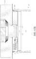
- FIGS. 12A-12Bare schematic partial views of another embodiment of a cooler container.
- FIG. 12Cis a schematic view of another embodiment of a cooler container.
- FIGS. 13A-13Bare schematic partial views of another embodiment of a cooler container.
- FIGS. 14A-14Bare schematic partial views of another embodiment of a cooler container.
- FIGS. 15A-15Bare schematic partial views of another embodiment of a cooler container.
- FIGS. 16A-16Bare schematic partial views of another embodiment of a cooler container.
- FIGS. 17A-17Bare schematic partial views of another embodiment of a cooler container.
- FIG. 18Ais a schematic view of a portion of another embodiment of a cooler container.
- FIG. 18Bis a schematic view of a portion of another embodiment of a cooler container.
- FIG. 18Cis a schematic view of one embodiment of a coupling mechanism between the lid and vessel of the cooler container.
- FIG. 18Dis a schematic view of another embodiment of a coupling mechanism between the lid and the vessel of the cooler container.
- FIG. 18Eis a schematic view of one embodiment of a vessel for the cooler container.
- FIG. 18Fis a schematic view of another embodiment of a vessel for the cooler container.
- FIG. 19is a schematic view of another embodiment of a cooler container.
- FIG. 20is a schematic front view of another embodiment of a cooler container.
- FIG. 21is a schematic rear view of the cooler container of FIG. 20 .
- FIG. 22is a schematic perspective view of the cooler container of FIG. 20 .
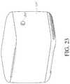
- FIG. 23is a schematic perspective view of the cooler container of FIG. 20 .
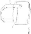
- FIG. 24is a schematic perspective view of the cooler container of FIG. 20 .
- FIG. 25Ais a schematic view of a tray removed from the container.
- FIG. 25Bis a schematic view of an interchangeable tray system for use with the container.
- FIG. 25Cis a schematic top view of one embodiment of a tray for use in the container of FIG. 20 .
- FIG. 25Dis a schematic top view of another embodiment of a tray for use in the container of FIG. 20 .
- FIG. 26is a schematic bottom view of the cooler container of FIG. 20 .
- FIG. 27is a schematic cross-sectional view of the cooler container of FIG. 20 with the tray disposed in the container.
- FIG. 28is a schematic view of the container in an open position with one or more lighting elements.
- FIGS. 29A-29Care schematic views of a graphical user interface for use with the container.
- FIG. 30is a schematic view of a visual display of the container.
- FIG. 31is a schematic view of security features of the container.
- FIG. 32is a schematic perspective view of another embodiment of a cooler container.
- FIGS. 33A-33Bare schematic side views of various containers of different sizes.
- FIG. 34is a schematic view a container disposed on a power base.
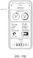
- FIGS. 35A-35Care schematic views of a graphical user interface for use with the container.
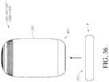
- FIG. 36is a schematic view of another embodiment of a cooler container.
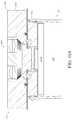
- FIG. 37is a schematic cross-sectional view of the cooler container of FIG. 32 .
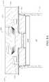
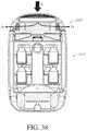
- FIG. 38is a schematic cross-sectional view of the cooler container of FIG. 37 with one fan in operation.
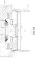
- FIG. 39is a schematic cross-sectional view of the cooler container of FIG. 37 with another fan in operation.
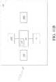
- FIG. 40is a schematic block diagram showing communication between the cooler container and a remote electronic device.
- FIG. 41Ashows a schematic perspective view of a cooler container.
- FIG. 41Bis a is a schematic block diagram showing electronics in the cooler container associated with operation of the display screen of the cooler container.
- FIGS. 42A-42Bshow block diagrams of a method for operating the cooler container of FIG. 41A .
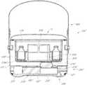
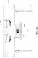
- FIGS. 1A-1Dshow a schematic cross-sectional view of a container system 100 that includes a cooling system 200 .
- the container system 100has a container vessel 120 that is optionally cylindrical and symmetrical about a longitudinal axis Z, and one of ordinary skill in the art will recognize that the features shown in cross-section in FIGS. 1A-1D are defined by rotating them about the axis Z to define the features of the container 100 and cooling system 200 .
- the container vessel 120is optionally a cooler with active temperature control provided by the cooling system 200 to cool the contents of the container vessel 120 and/or maintain the contents of the vessel 120 in a cooled or chilled state.
- the vessel 120can hold therein one or more (e.g., a plurality of) separate containers (e.g., vials, cartridges, packages, injectors, etc.).
- the one or more (e.g., plurality of) separate containers that can be inserted into the container vessel 120are medicine containers (e.g., vaccine vials, insulin cartridges, injectors, etc.).
- the container vessel 120has an outer wall 121 that extends between a proximal end 122 that has an opening 123 and a distal end 124 having a base 125 .
- the opening 123is selectively closed by a lid L removably attached to the proximal end 122 .
- the vessel 120has an inner wall 126 A and a base wall 126 B that defines an open chamber 126 that can receive and hold contents to be cooled therein (e.g., one or more volumes of liquid, such as one or more vials, cartridges, packages, injectors, etc.).
- the vessel 120can be made of metal (e.g., stainless steel).
- the vessel 120can be made of plastic.
- the vessel 120has a cavity 128 (e.g., annular cavity or chamber) between the inner wall 126 A and the outer wall 121 .
- the cavity 128can be under vacuum.
- the cavity 128can be filled with air but not be under vacuum.
- the cavity 128can be filled with a thermally insulative material (e.g., foam).
- the vessel 120can exclude a cavity so that the vessel 120 is solid between the inner wall 126 A and the outer wall 121 .
- the cooling system 200is optionally implemented in the lid L that releasably closes the opening 123 of the vessel 120 (e.g., lid L can be attached to vessel 120 to closer the opening 123 , and detached or decoupled from the vessel 120 to access the chamber 126 through the opening 123 ).
- the cooling system 200optionally includes a cold side heat sink 210 that faces the chamber 126 , one or more thermoelectric elements (TECs) 220 (such as one or more Peltier elements) that selectively contacts the cold side heat sink 210 , a hot side heat sink 230 in contact with the thermoelectric element 220 and disposed on an opposite side of the TEC 220 from the cold side heat sink 210 , an insulator member 240 disposed between the cold side heat sink 210 and the hot side heat sink 230 , one or more distal magnets 250 proximate a surface of the insulator 240 , one or more proximal magnets 260 and one or more electromagnets 270 disposed axially between the distal magnets 250 and the proximal magnets 260 .
- TECsthermoelectric elements
- the proximal magnets 260have an opposite polarity than the distal magnets 250 .
- the electromagnets 270are disposed about and connected to the hot side heat sink 230 , which as noted above is attached to the TEC 220 .
- the cooling system 200also optionally includes a fan 280 in communication with the hot side heat sink 230 and one or more sealing gaskets 290 disposed between the cold side heat sink 210 and the hot side heat sink 230 and circumferentially about the TEC 220 .
- circuitry and one or more batteriesare optionally disposed in or on the vessel 120 .
- circuitry, sensors and/or batteriesare disposed in a cavity in the distal end 124 of the vessel body 120 , such as below the base wall 126 B of the vessel 120 , and can communicate with electrical contacts on the proximal end 122 of the vessel 120 that can contact corresponding electrical contacts (e.g., pogo pins, contact rings) on the lid L.
- the lid Lcan be connected to the proximal end 122 of the vessel 120 via a hinge, and electrical wires can extend through the hinge between the circuitry disposed in the distal end 124 of the vessel 120 and the fan 280 and TEC 220 in the lid L.
- the circuitry and one or more batteriescan be in a removable pack (e.g., DeWalt battery pack) that attaches to the distal end 124 of the vessel 120 , where one or more contacts in the removable pack contact one or more contacts on the distal end 124 of the vessel 120 .
- the one or more contacts on the distal end 124 of the vessel 120are electrically connected (via one or more wires or one or more intermediate components) with the electrical connections on the proximal 122 of the vessel 120 , or via the hinge, as discussed above, to provide power to the components of the cooling system 200 .
- the one or more electromagnets 270are operated to have a polarity that is opposite that of the one or more distal magnets 250 and/or the same as the polarity of the one or more proximal magnets 260 , causing the electromagnets 270 to move toward and contact the distal magnets 250 , thereby causing the TEC 220 to contact the cold side heat sink 210 (see FIG. 1C ).
- the TEC 220can be operated to draw heat from the chamber 126 via the cold side heat sink 210 , which the TEC 220 transfers to the hot side heat sink 230 .
- the fan 280can optionally be operated to dissipate heat from the hot side heat sink 230 , allowing the TEC 220 to draw more heat out of the chamber 126 to thereby cool the chamber 126 .
- the fan 280is turned off and the polarity of the one or more electromagnets 270 can be switched (e.g., switched off) so that the electromagnets 270 are repelled from the distal magnets 250 and/or attracted to the proximal magnets 260 , thereby causing the TEC 220 to be spaced apart from (i.e., no longer contact) the cold side heat sink 210 (see FIG.
- the separation between the TEC 220 and the cold side heat sink 210advantageously prevents heat in the hot side heat sink or due to ambient temperature from flowing back to the cold side heat sink, which prolongs the cooled state in the chamber 126 .
- FIGS. 2A-2Bschematically illustrate a container system 100 B that includes the cooling system 200 B.
- the container system 100 Bcan include the vessel 120 (as described above).
- Some of the features of the cooling system 200 Bare similar to features in the cooling system 200 in FIGS. 1A-1D .
- references numerals used to designate the various components of the cooling system 200 Bare identical to those used for identifying the corresponding components of the cooling system 200 in FIGS. 1A-1D , except that a “B” is added to the numerical identifier. Therefore, the structure and description for the various components of the cooling system 200 in FIGS. 1A-1D are understood to also apply to the corresponding components of the cooling system 200 B in FIGS. 2A-2B , except as described below.
- the TEC 220 Bcan optionally be selectively slid into alignment between the cold side heat sink 210 B and the hot side heat sink 230 B, such that operation of the TEC 220 B draws heat from the chamber 126 via the cold side heat sink 210 B and transfers it to the hot side heat sink 230 B.
- the fan 280 Bis optionally operated to further dissipate heat from the hot side heat sink 230 B, allowing it to draw more heat from the chamber 126 via the TEC 220 B.
- one or more springs 212 Be.g., coil springs
- the TEC 220 Bcan optionally be selectively slid out of alignment between the cold side heat sink 210 B and the hot side heat sink 230 B to thereby disallow heat transfer through the TEC 220 B (e.g., once the desired temperature in the chamber 126 has been achieved).
- the TEC 220 Bis slid into a cavity 242 B in the insulator 240 B.
- the TEC 220 Bcan be slid into and out or alignment between the cold side heat sink 210 B and the hot side heat sink 230 B with a number of suitable mechanisms.
- an electric motorcan drive a gear in contact with a gear rack (e.g., rack and pinion), where the TEC 220 B can be attached to the rack that linearly moved via rotation of the gear by the electric motor.
- a solenoid motorcan be attached to TEC 220 B to effect the linear movement of the TEC 220 B.
- a pneumatic or electromechanical systemcan actuate movement of a piston attached to the TEC 220 B to effect the linear movement of the TEC 220 B.
- FIG. 2Cschematically illustrates a portion of a container system 100 B′ that includes the cooling system 200 B′.
- the container system 100 B′can include the vessel 120 (as described above).
- Some of the features of the cooling system 200 B′are similar to features in the cooling system 200 B in FIGS. 2A-2B .
- references numerals used to designate the various components of the cooling system 200 B′are identical to those used for identifying the corresponding components of the cooling system 200 B in FIGS. 2A-2B , except that a “′” is added to the numerical identifier. Therefore, the structure and description for the various components of the cooling system 200 B in FIGS. 2A-2B are understood to also apply to the corresponding components of the cooling system 200 B′ in FIG. 2C , except as described below.
- the cooling system 200 B′differs from the cooling system 200 B in that the TEC 220 B′ is tapered or wedge shaped.
- An actuator 20 Ae.g., electric motor
- the actuator 20 Ais selectively actuatable to move the TEC 220 B′ into and out of engagement (e.g., into and out of contact) with the hot side heat sink 230 B′ and the cold side heat sink 210 B′ to allow for heat transfer therebetween.
- the hot side heat sink 230 B′ and/or the cold side heat sink 210 B′can have a tapered surface that thermally communicates with (e.g., operatively contacts) one or more tapered surfaces (e.g., wedge shaped surfaces) of the TEC 220 B′ when the TEC 220 B′ is moved into thermal communication (e.g., into contact) with the hot side heat sink 230 B′ and the cold side heat sink 210 B′.
- a tapered surfacethat thermally communicates with (e.g., operatively contacts) one or more tapered surfaces (e.g., wedge shaped surfaces) of the TEC 220 B′ when the TEC 220 B′ is moved into thermal communication (e.g., into contact) with the hot side heat sink 230 B′ and the cold side heat sink 210 B′.
- FIGS. 3A-3Cschematically illustrate a container system 100 C that includes the cooling system 200 C.
- the container system 100 Ccan include the vessel 120 (as described above).
- Some of the features of the cooling system 200 Care similar to features in the cooling system 200 B in FIGS. 2A-2B .
- references numerals used to designate the various components of the cooling system 200 Care identical to those used for identifying the corresponding components of the cooling system 200 B in FIGS. 2A-2B , except that a “C” is used instead of a “B”. Therefore, the structure and description for the various components of the cooling system 200 B in FIGS. 2A-2B are understood to also apply to the corresponding components of the cooling system 200 C in FIGS. 3A-3C , except as described below.
- the cooling system 200 Cdiffers from the cooling system 200 B in that the TEC 220 C is in a fixed position adjacent the hot side heat sink 230 C.
- the insulator member 240 Chas one or more thermal conductors 244 C embedded therein, and the insulator member 240 C can be selectively rotated about an axis (e.g., an axis offset from the axis Z of the vessel 120 ) to align at least one of the thermal conductors 244 C with the TEC 220 C and the cold side heat sink 210 C to allow heat transfer between the chamber 126 and the hot side heat sink 230 C.
- the insulator member 240 Ccan also be selectively rotated to move the one or more thermal conductors 244 C out of alignment with the TEC 220 C so that instead an insulating portion 246 C is interposed between the TEC 220 C and the cold side heat sink 210 C, thereby inhibiting (e.g., preventing) heat transfer between the TEC 220 C and the cold side heat sink 210 C to prolong the cooled state in the chamber 126 .
- the insulator member 240 Ccan be rotated by a motor 248 C (e.g., electric motor) via a pulley cable or band 249 C.
- FIGS. 4A-4Cschematically illustrate a container system 100 D that includes the cooling system 200 D.
- the container system 100 Dcan include the vessel 120 (as described above).
- Some of the features of the cooling system 200 Dare similar to features in the cooling system 200 C in FIGS. 3A-3C .
- references numerals used to designate the various components of the cooling system 200 Dare identical to those used for identifying the corresponding components of the cooling system 200 C in FIGS. 3A-3C , except that a “D” is used instead of a “C”. Therefore, the structure and description for the various components of the cooling system 200 C in FIGS. 3A-3C are understood to also apply to the corresponding components of the cooling system 200 D in FIGS. 4A-4C , except as described below.
- the cooling system 200 Ddiffers from the cooling system 200 C in the mechanism for rotating the insulator member 240 D.
- the insulator member 240 Dhas one or more thermal conductors 244 D embedded therein, and the insulator member 240 D can be selectively rotated about an axis (e.g., an axis offset from the axis Z of the vessel 120 ) to align at least one of the thermal conductors 244 D with the TEC 220 D and the cold side heat sink 210 D to allow heat transfer between the chamber 126 and the hot side heat sink 230 D.
- an axise.g., an axis offset from the axis Z of the vessel 120
- the insulator member 240 Dcan also be selectively rotated to move the one or more thermal conductors 244 D out of alignment with the TEC 220 D so that instead an insulating portion 246 D is interposed between the TEC 220 D and the cold side heat sink 210 D, thereby inhibiting (e.g., preventing) heat transfer between the TEC 220 D and the cold side heat sink 210 D to prolong the cooled state in the chamber 126 .
- the insulator member 240 Dcan be rotated by a motor 248 D (e.g., electric motor) via a gear train or geared connection 249 D.
- FIGS. 5A-5Bschematically illustrate a container system 100 E that includes the cooling system 200 E.
- the container system 100 Ecan include the vessel 120 (as described above).
- Some of the features of the cooling system 200 Dare similar to features in the cooling system 200 B in FIGS. 2A-2B .
- references numerals used to designate the various components of the cooling system 200 Eare identical to those used for identifying the corresponding components of the cooling system 200 B in FIGS. 2A-2B , except that an “E” is used instead of a “B”. Therefore, the structure and description for the various components of the cooling system 200 B in FIGS. 2A-2B are understood to also apply to the corresponding components of the cooling system 200 E in FIGS. 5A-5B , except as described below.
- An assembly A including the hot side heat sink 230 E, fan 280 E, TEC 220 E and an insulator segment 244 Ecan optionally be selectively slid relative to the vessel 120 to bring the TEC 220 E into alignment (e.g., contact) between the cold side heat sink 210 E and the hot side heat sink 230 E, such that operation of the TEC 220 E draws heat from the chamber 126 via the cold side heat sink 210 E and transfers it to the hot side heat sink 230 E.
- the fan 280 Eis optionally operated to further dissipate heat from the hot side heat sink 230 E, allowing it to draw more heat from the chamber 126 via the TEC 220 E.
- one or more springs 212 Eresiliently couple the cold side heat sink 210 E with the insulator 240 E to maintain an efficient thermal connection between the cold side heat sink 210 E and the TEC 220 E when aligned together.
- the assembly Acan optionally be selectively slid to move the TEC 200 E out of alignment (e.g., contact) between the cold side heat sink 210 E and the hot side heat sink 230 E.
- Thiscauses the insulator segment 244 E to instead be placed in alignment (e.g., contact) between the cold side heat sink 210 E and the hot side heat sink 230 E, which disallows heat transfer through the TEC 220 E (e.g., once the desired temperature in the chamber 126 has been achieved).
- the assembly Acan be slid with a number of suitable mechanisms.
- an electric motorcan drive a gear in contact with a gear rack (e.g., rack and pinion), where the assembly A can be attached to the rack that linearly moves via rotation of the gear by the electric motor.
- a solenoid motorand be attached to assembly A to effect the linear movement of the assembly A.
- a pneumatic or electromechanical systemcan actuate movement of a piston attached to the assembly A to effect the linear movement of the assembly A.
- FIGS. 6A-6Bschematically illustrate a container system 100 F that includes the cooling system 200 F.
- the container system 100 Fcan include the vessel 120 (as described above).
- Some of the features of the cooling system 200 Fare similar to features in the cooling system 200 in FIGS. 1A-1D .
- references numerals used to designate the various components of the cooling system 200 Fare identical to those used for identifying the corresponding components of the cooling system 200 in FIGS. 1A-1D , except that a “G” is added to the numerical identifiers. Therefore, the structure and description for the various components of the cooling system 200 in FIGS. 1A-1D are understood to also apply to the corresponding components of the cooling system 200 F in FIGS. 6A-6B , except as described below.
- the hot side heat sink 230 Fis in contact with the TEC 220 F.
- One or more springs 212 Fe.g., coil springs
- the one or more springs 212 Fexert a (bias) force on the hot side heat sink 230 F to bias it toward contact with the insulator member 240 F.
- One or more expandable bladders 250 Fare disposed between the insulator member 240 F and the hot side heat sink 230 F.
- the one or more expandable bladders 250 FWhen the one or more expandable bladders 250 F are in a collapsed state (see FIG. 6A ), the one or more springs 212 F draw the hot side heat sink 230 F toward the insulator member 240 F so that the TEC 220 F contacts the cold side heat sink 210 F.
- the TEC 220 Fcan be operated to draw heat out of the chamber 126 via the cold side heat sink 210 F, which is then transferred via the TEC 220 F to the hot side heat sink 230 F.
- the fan 280 Fcan be operated to dissipate heat from the hot side heat sink 230 F, allowing the hot side heat sink 230 F to draw additional heat from the chamber 126 via the contact between the cold side heat sink 210 F, the TEC 220 F and the hot side heat sink 230 F.
- the cooling system 200 Fcan be operated to draw heat from the chamber 126 to cool the chamber to a predetermined temperature or temperature range.
- the one or more expandable bladders 250 FWhen the one or more expandable bladders 250 F are in an expanded state (see FIG. 6B ), they can exert a force on the hot side heat sink 230 F in a direction opposite to the bias force of the one or more springs 212 F, causing the hot side heat sink 230 F to separate from (e.g., lift from) the insulator member 240 F. Such separation between the hot side heat sink 230 F and the insulator member 240 F also causes the TEC 220 F to become spaced apart from the cold side heat sink 210 F, inhibiting (e.g., preventing) heat transfer between the cold side heat sink 210 F and the TEC 220 F.
- the one or more expandable bladders 250 Fcan be transitioned to the expanded state to thermally disconnect the cold side heat sink 210 F from the TEC 220 F to thereby maintain the chamber 126 in a prolonged cooled state.
- the one or more expandable bladders 250 Fform part of a pneumatic system (e.g., having a pump, one or more valves, and/or a gas reservoir) that selectively fills the bladders 250 F with a gas to move the bladders 250 F to the expanded state and selectively empties the one or more expandable bladders 250 F to move the bladders 250 F to the collapsed state.
- a pneumatic systeme.g., having a pump, one or more valves, and/or a gas reservoir
- the one or more expandable bladders 250 Fform part of a hydraulic system (e.g., having a pump, one or more valves, and/or a liquid reservoir) that selectively fills the bladders 250 F with a liquid to move the bladders 250 F to the expanded state and selectively empties the one or more expandable bladders 250 F to move the bladders 250 F to the collapsed state.
- a hydraulic systeme.g., having a pump, one or more valves, and/or a liquid reservoir
- FIGS. 7A-7Bschematically illustrate a container system 100 G that includes the cooling system 200 G.
- the container system 100 Gcan include the vessel 120 (as described above).
- Some of the features of the cooling system 200 Gare similar to features in the cooling system 200 F in FIGS. 6A-6B .
- references numerals used to designate the various components of the cooling system 200 Gare identical to those used for identifying the corresponding components of the cooling system 200 F in FIGS. 6A-6B , except that a “G” is used instead of an “F”. Therefore, the structure and description for the various components of the cooling system 200 F in FIGS. 6A-6B are understood to also apply to the corresponding components of the cooling system 200 G in FIGS. 7A-7B , except as described below.
- the cooling system 200 Gdiffers from the cooling system 200 F in the position of the one or more springs 212 G and the one or more expandable bladders 250 G.
- the one or more springs 212 Ge.g., coil springs
- the one or more springs 212 Gexert a (bias) force on the cold side heat sink 210 G to bias it toward contact with the insulator member 240 G.
- the one or more expandable bladders 250 Gare disposed between the insulator member 240 G and the cold side heat sink 230 G.
- the one or more springs 212 Gdraw the cold side heat sink 230 G (up) toward the insulator member 240 G so that the TEC 220 G contacts the cold side heat sink 210 G.
- the TEC 220 Gcan be operated to draw heat out of the chamber 126 via the cold side heat sink 210 G, which is then transferred via the TEC 220 G to the hot side heat sink 230 G.
- the fan 280 Gcan be operated to dissipate heat from the hot side heat sink 230 G, allowing the hot side heat sink 230 G to draw additional heat from the chamber 126 via the contact between the cold side heat sink 210 G, the TEC 220 G and the hot side heat sink 230 G. Accordingly, with the one or more expandable bladders 250 G in the collapsed state, the cooling system 200 G can be operated to draw heat from the chamber 126 to cool the chamber to a predetermined temperature or temperature range.
- the one or more expandable bladders 250 GWhen the one or more expandable bladders 250 G are in an expanded state (see FIG. 7B ), they can exert a force on the cold side heat sink 210 G in a direction opposite to the bias force of the one or more springs 212 G, causing the cold side heat sink 210 G to separate from (e.g., move down relative to) the insulator member 240 G. Such separation between the cold side heat sink 210 G and the insulator member 240 G also causes the TEC 220 G to become spaced apart from the cold side heat sink 210 G, inhibiting (e.g., preventing) heat transfer between the cold side heat sink 210 G and the TEC 220 G.
- the one or more expandable bladders 250 Gcan be transitioned to the expanded state to thermally disconnect the cold side heat sink 210 G from the TEC 220 G to thereby maintain the chamber 126 in a prolonged cooled state.
- the one or more expandable bladders 250 Gform part of a pneumatic system (e.g., having a pump, one or more valves, and/or a gas reservoir) that selectively fills the bladders 250 G with a gas to move the bladders 250 G to the expanded state and selectively empties the one or more expandable bladders 250 G to move the bladders 250 G to the collapsed state.
- a pneumatic systeme.g., having a pump, one or more valves, and/or a gas reservoir
- the one or more expandable bladders 250 Gform part of a hydraulic system (e.g., having a pump, one or more valves, and/or a liquid reservoir) that selectively fills the bladders 250 G with a liquid to move the bladders 250 G to the expanded state and selectively empties the one or more expandable bladders 250 G to move the bladders 250 G to the collapsed state.
- a hydraulic systeme.g., having a pump, one or more valves, and/or a liquid reservoir
- FIGS. 8A-8Bschematically illustrate a container system 100 H that includes the cooling system 200 H.
- the container system 100 Hcan include the vessel 120 (as described above).
- Some of the features of the cooling system 200 Hare similar to features in the cooling system 200 F in FIGS. 6A-6B .
- references numerals used to designate the various components of the cooling system 200 Hare identical to those used for identifying the corresponding components of the cooling system 200 F in FIGS. 6A-6B , except that an “H” is used instead of an “F”. Therefore, the structure and description for the various components of the cooling system 200 F in FIGS. 6A-6B are understood to also apply to the corresponding components of the cooling system 200 H in FIGS. 8A-8B , except as described below.
- the cooling system 200 Hdiffers from the cooling system 200 F in that one or more expandable bladders 255 H are included instead of the one or more springs 212 F to provide a force in a direction opposite to the force exerted by the one or more expandable bladders 250 H.
- the one or more expandable bladders 255 Hare disposed between a housing 225 H and a portion of the hot side heat sink 230 H, and one or more expandable bladders 250 H are disposed between the insulator member 240 H and the hot side heat sink 230 H.
- the one or more expandable bladders 250 Hare in fluid communication with the one or more expandable bladders 255 H, and the fluid is moved between the two expandable bladders 250 H, 255 H. That is, when the one or more expandable bladders 250 H are in the expanded state, the one or more expandable bladders 255 H are in the collapsed state, and when the expandable bladders 250 H are in the collapsed state, the expandable bladders 255 H are in the expanded state.
- the one or more expandable bladders 250 HWhen the one or more expandable bladders 250 H are in a collapsed state (see FIG. 8A ), the one or more expandable bladders 255 H are in the expanded state and exert a force on the hot side heat sink 230 H toward the insulator member 240 H so that the TEC 220 H contacts the cold side heat sink 210 H.
- the TEC 220 Hcan be operated to draw heat out of the chamber 126 via the cold side heat sink 210 H, which is then transferred via the TEC 220 H to the hot side heat sink 230 H.
- the fan 280 Hcan be operated to dissipate heat from the hot side heat sink 230 H, allowing the hot side heat sink 230 H to draw additional heat from the chamber 126 via the contact between the cold side heat sink 210 H, the TEC 220 H and the hot side heat sink 230 H. Accordingly, with the one or more expandable bladders 250 H in the collapsed state, the cooling system 200 H can be operated to draw heat from the chamber 126 to cool the chamber to a predetermined temperature or temperature range.
- the one or more expandable bladders 255 Hare in a collapsed state.
- the expanded state of the expandable bladders 250 Hexerts a force on the hot side heat sink 230 H that causes the hot side heat sink 230 H to separate from (e.g., lift from) the insulator member 240 H.
- Such separation between the hot side heat sink 230 H and the insulator member 240 Halso causes the TEC 220 H to become spaced apart from (e.g., lift from) the cold side heat sink 210 H, thereby thermally disconnecting (e.g., inhibiting heat transfer between) the cold side heat sink 210 H and the TEC 220 H.
- the one or more expandable bladders 250 Hcan be transitioned to the expanded state (e.g., by transferring the fluid from the expandable bladders 255 H to the expandable bladders 250 H) to thermally disconnect the cold side heat sink 210 H from the TEC 220 H to thereby maintain the chamber 126 in a prolonged cooled state.
- the one or more expandable bladders 250 H, 255 Hform part of a pneumatic system (e.g., having a pump, one or more valves, and/or a gas reservoir) that selectively fills and empties the bladders 250 H, 255 H with a gas to move them between an expanded and a collapsed state.
- a pneumatic systeme.g., having a pump, one or more valves, and/or a gas reservoir
- FIGS. 9A-9Bschematically illustrate a container system 100 I that includes the cooling system 200 I.
- the container system 100 Ican include the vessel 120 (as described above).
- Some of the features of the cooling system 200 Iare similar to features in the cooling system 200 G in FIGS. 7A-7B .
- references numerals used to designate the various components of the cooling system 200 Iare identical to those used for identifying the corresponding components of the cooling system 200 G in FIGS. 7A-7B , except that an “I” is used instead of a “G”. Therefore, the structure and description for the various components of the cooling system 200 G in FIGS. 7A-7B are understood to also apply to the corresponding components of the cooling system 200 I in FIGS. 9A-9B , except as described below.
- the cooling system 200 Idiffers from the cooling system 200 G in that the one or more rotatable cams 250 I are used instead of one or more expandable bladders 250 G.
- the one or more springs 212 Ie.g., coil springs
- the one or more springs 212 Iexert a (bias) force on the cold side heat sink 210 I to bias it toward contact with the insulator member 240 I.
- the one or more rotatable cams 250 Iare rotatably coupled to the insulator member 240 I and rotatable to selectively contact a proximal surface of the cold side heat sink 230 I.
- the rotatable cams 250 Iare not in contact with the cold side heat sink 210 I, such that the one or more springs 212 I bias the cold side heat sink 210 I into contact with the TEC 220 I, thereby allowing heat transfer therebetween.
- the TEC 220 Ican be operated to draw heat out of the chamber 126 via the cold side heat sink 210 I, which is then transferred via the TEC 220 I to the hot side heat sink 230 I.
- the fan 280 Ican be operated to dissipate heat from the hot side heat sink 230 I, allowing the hot side heat sink 230 I to draw additional heat from the chamber 126 via the contact between the cold side heat sink 210 I, the TEC 220 I and the hot side heat sink 230 I. Accordingly, with the one or more rotatable cams 250 I in a retracted state, the cooling system 200 I can be operated to draw heat from the chamber 126 to cool the chamber to a predetermined temperature or temperature range.
- the cams 250 IWhen the one or more rotatable cams 250 I are moved to the deployed state (see FIG. 9B ), the cams 250 I bear against the cold side heat sink 210 I, overcoming the bias force of the springs 212 I. In the deployed state, the one or more cams 250 I exert a force on the cold side heat sink 210 I that causes the cold side heat sink 210 I to separate from (e.g., move down relative to) the insulator member 240 I.
- Such separation between the cold side heat sink 210 I and the insulator member 240 Ialso causes the cold side heat sink 210 I to become spaced apart from (e.g., move down relative to) the TEC 220 I, thereby thermally disconnecting (e.g., inhibiting heat transfer between) the cold side heat sink 210 I and the TEC 220 I. Accordingly, once the predetermined temperature or temperature range has been achieved in the chamber 126 , the one or more rotatable cams 250 I can be moved to the deployed state to thermally disconnect the cold side heat sink 210 I from the TEC 220 I to thereby maintain the chamber 126 in a prolonged cooled state.
- FIGS. 10A-10Bschematically illustrate a container system 100 J that includes the cooling system 200 J.
- the container system 100 Jcan include the vessel 120 (as described above).
- Some of the features of the cooling system 200 Jare similar to features in the cooling system 200 I in FIGS. 9A-9B .
- references numerals used to designate the various components of the cooling system 200 Jare identical to those used for identifying the corresponding components of the cooling system 200 I in FIGS. 9A-9B , except that an “J” is used instead of an “I”. Therefore, the structure and description for the various components of the cooling system 200 I in FIGS. 9A-9B are understood to also apply to the corresponding components of the cooling system 200 J in FIGS. 10A-10B , except as described below.
- the cooling system 200 Jdiffers from the cooling system 200 I in the location of the one or more springs 212 J and the one or more cams 250 J.
- the one or more springs 212 Jare disposed between the insulator member 240 J and the hot side heat sink 230 J and exert a bias force between the two biasing the hot side heat sink 230 J down toward contact with the insulator member 240 J.
- Such bias forcealso biases the TEC 220 J (which is attached to or in contact with the hot side heat sink 230 J) into contact with the cold side heat sink 210 J.
- the cams 250 Jallow the TEC 220 J to contact the cold side heat sink 210 J.
- the TEC 220 Jcan be operated to draw heat out of the chamber 126 via the cold side heat sink 210 J, which is then transferred via the TEC 220 J to the hot side heat sink 230 J.
- the fan 280 Jcan be operated to dissipate heat from the hot side heat sink 230 J, allowing the hot side heat sink 230 J to draw additional heat from the chamber 126 via the contact between the cold side heat sink 210 J, the TEC 220 J and the hot side heat sink 230 J.
- the cooling system 200 Jcan be operated to draw heat from the chamber 126 to cool the chamber to a predetermined temperature or temperature range.
- the cams 250 JWhen the one or more rotatable cams 250 J are moved to the deployed state (see FIG. 10B ), the cams 250 J bear against the hot side heat sink 230 J, overcoming the bias force of the springs 212 J. In the deployed state, the one or more cams 250 J exert a force on the hot side heat sink 230 J that causes the hot side heat sink 230 J to separate from (e.g., lift from) the insulator member 240 J.
- Such separationalso causes the TEC 220 J (attached to the hot side heat sink 230 J) to become spaced apart from (e.g., lift from) the cold side heat sink 210 J, thereby thermally disconnecting (e.g., inhibiting heat transfer between) the cold side heat sink 210 J and the TEC 220 J. Accordingly, once the predetermined temperature or temperature range has been achieved in the chamber 126 , the one or more rotatable cams 250 J can be moved to the deployed state to thermally disconnect the cold side heat sink 210 J from the TEC 220 J to thereby maintain the chamber 126 in a prolonged cooled state.
- FIG. 11Aschematically illustrates a container system 100 K that includes the cooling system 200 K.
- the container system 100 Kcan include the vessel 120 (as described above) removably sealed by a lid L′.
- Some of the features of the cooling system 200 Kare similar to features in the cooling system 200 in FIGS. 1A-1D .
- reference numerals used to designate the various components of the cooling system 200 Kare similar to those used for identifying the corresponding components of the cooling system 200 in FIGS. 1A-1D , except that an “K” is used. Therefore, the structure and description for said similar components of the cooling system 200 in FIGS. 1A-1D are understood to also apply to the corresponding components of the cooling system 200 K in FIG. 11 , except as described below.
- the vessel 120optionally has a cavity 128 (e.g., annular cavity or chamber) between the inner wall 126 A and the outer wall 121 .
- the cavity 128can be under vacuum, so that the vessel 120 is vacuum sealed.
- the lid L′ that removably seals the vessel 120is optionally also a vacuum sealed lid.
- the vacuum sealed vessel 120 and/or lid L′advantageously inhibits heat transfer therethrough, thereby inhibiting a passive change in temperature in the chamber 126 when the lid L′ is attached to the vessel 120 (e.g., via passive loss of cooling through the wall of the vessel 120 and/or lid L′).
- the cooling system 200 Kincludes a hot side heat sink 230 K in thermal communication with the thermoelectric element (TEC) (e.g., Peltier element) 220 K, so that the heat sink 230 K can draw heat away from the TEC 220 K.
- TECthermoelectric element
- a fan 280 Kcan be in thermal communication with the hot side heat sink 230 K and be selectively operable to further dissipate heat from the hot side heat sink 230 K, thereby allowing the heat sink 230 K to further draw heat from the TEC 230 K.
- the TEC 230 Kis in thermal communication with a cold side heat sink 210 K, which is in turn in thermal communication with the chamber 126 in the vessel 120 .
- the cold side heat sink 210 Koptionally includes a flow path 214 K that extends from an opening 132 K in the lid L′ adjacent the chamber 126 to an opening 134 K in the lid L′ adjacent the chamber 126 .
- the opening 132 Kis optionally located generally at a center of the lid L′, as shown in FIG. 11 .
- the opening 134 Kis optionally located in the lid L′ at a location proximate the inner wall 126 A of the vessel 120 when the lid L′ is attached to the vessel 120 .
- the cold side heat sink 210 Kincludes a fan 216 K disposed along the flow path 214 K between the openings 132 K, 134 K. As shown in FIG. 11 , at least a portion of the flow path 214 K is in thermal communication with the TEC 220 K (e.g., with a cold side of the TEC).
- air in the chamber 126enters the flow path 214 K via the opening 132 K and flows through the flow path 214 K so that it passes through the portion of the flow path 214 K that is proximate the TEC 220 K, where the TEC 220 K is selectively operated to cool (e.g., reduce the temperature of) the air flow passing therein.
- the cooled airflowcontinues to flow through the flow path 214 K and exits the flow path 214 K at opening 134 K where it enters the chamber 126 .
- the fan 216 Kis operable to draw (e.g., cause or facilitate) the flow of air through the flow path 214 K.
- FIG. 11Ashows the cooling system 200 disposed on a side of the vessel 120
- the cooling system 200can be disposed in other suitable locations (e.g., on the bottom of the vessel 120 , on top of the lid L′, in a separate module attachable to the top of the lid L′, etc.) and that such implementations are contemplated by the invention.
- FIG. 11Bschematically illustrates a container system 100 K′ that includes the cooling system 200 K′.
- the container system 100 K′can include the vessel 120 (as described above).
- Some of the features of the cooling system 200 K′are similar to features in the cooling system 200 K in FIG. 11A .
- reference numerals used to designate the various components of the cooling system 200 K′are similar to those used for identifying the corresponding components of the cooling system 200 K in FIG. 11A , except that an “′” is used. Therefore, the structure and description for said similar components of the cooling system 200 K in FIG. 11A are understood to also apply to the corresponding components of the cooling system 200 K′ in FIG. 11B , except as described below.
- the container system 100 K′is optionally a self-chilled container (e.g. self-chilled water container, such as a water bottle).
- the cooling system 200 K′differs from the cooling system 200 K in that a liquid is used as a cooling medium that is circulated through the body of the vessel 120 .
- a conduit 134 K′can deliver chilled liquid to the body of the vessel 120
- a conduit 132 K′can remove a warm liquid from the body of the vessel 120 .
- the chilled liquidcan absorb energy from one or more walls of the vessel 120 (e.g., one or more walls that define the chamber 126 ) of a liquid in the chamber 126 , and the heated liquid can exit the body of the vessel 120 via conduit 132 K′.
- conduits 132 K′, 134 K′connect to a cooling system, such as one having a TEC 220 K in contact with a hot side heat sink 230 K, as described above for container system 100 K.
- FIGS. 12A-12Bschematically illustrate a container system 100 L that includes the cooling system 200 L.
- the container system 100 Lcan include the vessel 120 (as described above).
- Some of the features of the cooling system 200 L, which optionally serves as part of the lid L that selectively seals the vessel 120are similar to features in the cooling system 200 in FIGS. 1A-1D .
- references numerals used to designate the various components of the cooling system 200 Lare similar to those used for identifying the corresponding components of the cooling system 200 in FIGS. 1A-1D , except that an “L” is used. Therefore, the structure and description for said similar components of the cooling system 200 in FIGS. 1A-1D are understood to also apply to the corresponding components of the cooling system 200 L in FIGS. 12A-12B , except as described below.
- the cooling system 200 Lcan optionally include a cavity 214 L disposed between the thermoelectric element (TEC) 220 L and the cold side heat sink 210 L.
- the cooling system 200 Lcan optionally include a pump 216 L (e.g., a peristaltic pump) in fluid communication with the cavity 214 L and with a reservoir 213 L.
- the pump 216 Lis operable to move a conductive fluid 217 L (e.g., a conductive liquid), such as a volume of conductive fluid 217 L, between the reservoir 213 L and the cavity 214 L.
- the conductive fluid 217 Lcan be mercury; however, the conductive fluid 217 L can be other suitable liquids.
- the pump 216 Lis selectively operable to pump the conductive fluid 217 L into the cavity 214 L (e.g., to fill the cavity 214 L), thereby allowing heat transfer between the cold side heat sink 210 L and the TEC 220 L (e.g., allowing the TEC 220 L to be operated to draw heat from the cold side heat sink 210 L and transfer it to the hot side heat sink 230 L).
- the fan 280 Lis selectively operable to dissipate heat from the hot side heat sink 230 L, thereby allowing the TEC 220 L to draw further heat from the chamber 126 via the cold side heat sink 210 L and the conductive fluid 217 L.
- the pump 216 Lis selectively operated to remove (e.g., drain) the conductive fluid 217 L from the cavity 214 L (e.g., by moving the conductive fluid 217 L into the reservoir 213 L), thereby leaving the cavity 214 L unfilled (e.g., empty).
- Such removal (e.g., complete removal) of the conductive fluid 217 L from the cavity 214 Lthermally disconnects the cold side heat sink 210 L from the TEC 220 L, thereby inhibiting (e.g., preventing) heat transfer between the TEC 220 L and the chamber 126 via the cold side heat sink 210 L, which advantageously prevents heat in the hot side heat sink 230 L or due to ambient temperature from flowing back to the cold side heat sink 210 L, thereby prolonging the cooled state in the chamber 126 .
- FIG. 12Cschematically illustrate a container system 100 L′ that includes the cooling system 200 L′.
- the container system 100 L′can include the vessel 120 (as described above).
- Some of the features of the cooling system 200 L′are similar to features in the cooling system 200 L in FIGS. 12A-12B .
- references numerals used to designate the various components of the cooling system 200 L′are similar to those used for identifying the corresponding components of the cooling system 200 L in FIGS. 12A-12B , except that an “′” is used. Therefore, the structure and description for said similar components of the cooling system 200 L in FIGS. 12A-12B are understood to also apply to the corresponding components of the cooling system 200 L′ in FIG. 12C , except as described below.
- the cooling system 200 L′differs from the cooling system 200 L in that a heat pipe 132 L′ is used to connect the hot side heat sink 230 L′ to the cold side heat sink 210 L′.
- the heat pipe 132 L′can be selectively turned on and off.
- the heat pipe 132 L′can include a phase change material (PCM).
- PCMphase change material
- the heat pipe 132 L′can be turned off by removing the working fluid from inside the heat pipe 132 L′, and turned on by inserting or injecting the working fluid in the heat pipe 132 L′.
- the TEC 210 Lwhen in operation, can freeze the liquid in the heat pipe 132 L′, to thereby provide a thermal break within the heat pipe 132 L′, disconnecting the chamber of the vessel 120 from the TEC 220 L′ that is operated to cool the chamber.
- the liquid in the heat pipe 132 L′can flow along the length of the heat pipe 132 L′.
- the fluidcan flow within the heat pipe 132 L′ into thermal contact with a cold side of the TEC 220 L′, which can cool the liquid, the liquid can then flow to the hot side of the heat pipe 132 L′ and draw heat away from the chamber of the vessel 120 which heats such liquid, and the heated liquid can then again flow to the opposite end of the heat pipe 132 L′ where the TEC 220 L′ can again remove heat from it to cool the liquid before it again flows back to the other end of the heat pipe 132 L′ to draw more heat from the chamber.
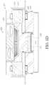
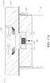
- FIGS. 13A-13Bschematically illustrate a container system 100 M that includes the cooling system 200 M.
- the container system 100 Mcan include the vessel 120 (as described above).
- Some of the features of the cooling system 200 M, which optionally serves as part of the lid L that selectively seals the vessel 120are similar to features in the cooling system 200 in FIGS. 1A-1D .
- references numerals used to designate the various components of the cooling system 200 Mare similar to those used for identifying the corresponding components of the cooling system 200 in FIGS. 1A-1D , except that an “M” is used. Therefore, the structure and description for said similar components of the cooling system 200 in FIGS. 1A-1D are understood to also apply to the corresponding components of the cooling system 200 M in FIGS. 13A-13B , except as described below.
- the cooling system 200 Mcan include a cold side heat sink 210 M in thermal communication with a thermoelectric element (TEC) 220 M and can selectively be in thermal communication with the chamber 126 of the vessel.
- the cooling system 200can include a fan 216 M selectively operable to draw air from the chamber 126 into contact with the cold side heat sink 210 M.
- cooling system 200 Mcan include an insulator member 246 M selectively movable (e.g., slidable) between one or more positions. As shown in FIGS. 13A-13B , the insulator member 246 M can be disposed adjacent or in communication with the chamber 126 .
- the insulator member 246 Mis disposed at least partially apart (e.g., laterally apart) relative to the cold side heat sink 210 M and fan 216 M.
- the TEC 220 Mis selectively operated to draw heat from the cold side heat sink 210 M and transfer it to the hot side heat sink 230 M.
- a fan 280 Mis selectively operable to dissipate heat from the hot side heat sink 230 M, thereby allowing the TEC 220 M to draw further heat from the chamber 126 via the cold side heat sink 210 M.
- the insulator member 246 Mis moved (e.g., slid) into a position adjacent to the cold side heat sink 210 M so as to be disposed between the cold side heat sink 210 M and the chamber 126 , thereby blocking air flow to the cold side heat sink 210 M (e.g., thermally disconnecting the cold side heat sink 210 M from the chamber 126 ) to thereby inhibit heat transfer to and from the chamber 126 (e.g., to maintain the chamber 126 in an insulated state).
- the insulator member 246 Mis moved (e.g., slid) into a position adjacent to the cold side heat sink 210 M so as to be disposed between the cold side heat sink 210 M and the chamber 126 , thereby blocking air flow to the cold side heat sink 210 M (e.g., thermally disconnecting the cold side heat sink 210 M from the chamber 126 ) to thereby inhibit heat transfer to and from the chamber 126 (e.g., to maintain the chamber 126 in an insulated state).
- the insulator member 246 Mcan be moved between the position in the cooling state (see FIG. 13A ) and the position in the insulating stage (see FIG. 13B ) using any suitable mechanism (e.g., electric motor, solenoid motor, a pneumatic or electromechanical system actuating a piston attached to the insulator member 246 M, etc.). Though the insulator member 246 M is shown in FIGS. 13A-13B as sliding between said positions, in another implementation, the insulator member 246 M can rotate between the cooling stage position and the insulating stage position.
- any suitable mechanisme.g., electric motor, solenoid motor, a pneumatic or electromechanical system actuating a piston attached to the insulator member 246 M, etc.
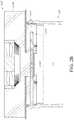
- FIGS. 14A-14Bschematically illustrate a container system 100 N that includes the cooling system 200 N.
- the container system 100 Ncan include the vessel 120 (as described above).
- Some of the features of the cooling system 200 N, which optionally serves as part of the lid L that selectively seals the vessel 120are similar to features in the cooling system 200 M in FIGS. 13A-13B .
- references numerals used to designate the various components of the cooling system 200 Nare similar to those used for identifying the corresponding components of the cooling system 200 M in FIGS. 13A-13B , except that an “N” is used. Therefore, the structure and description for said similar components of the cooling system 200 M in FIGS. 13A-13B are understood to also apply to the corresponding components of the cooling system 200 N in FIGS. 14A-14B , except as described below.
- the cooling system 200 Ncan include a cold side heat sink 210 N in thermal communication with a thermoelectric element (TEC) 220 N and can selectively be in thermal communication with the chamber 126 of the vessel 120 .
- the cooling system 200 Ncan include a fan 216 N selectively operable to draw air from the chamber 126 into contact with the cold side heat sink 210 N via openings 132 N, 134 N and cavities or chambers 213 N, 214 N.
- cooling system 200 Ncan include insulator members 246 N, 247 N selectively movable (e.g., pivotable) between one or more positions relative to the openings 134 N, 132 N, respectively. As shown in FIGS.
- the insulator member 246 Ncan be disposed adjacent or in communication with the chamber 126 and be movable to selectively allow and disallow airflow through the opening 134 N
- the insulator member 247 Ncan be disposed in the chamber 214 N and be movable to selectively allow and disallow airflow through the opening 132 N.
- the insulator members 246 N, 247 Nare disposed at least partially apart from the openings 134 N, 132 N, respectively, allowing air flow from the chamber 126 through the openings 132 N, 134 N and cavities 213 N, 214 N.
- the fan 216 Ncan be operated to draw said airflow from the chamber 126 , through the opening 132 N into the chamber 214 N and over the cold side heat sink 210 N, then through the chamber 213 N and opening 134 N and back to the chamber 126 .
- the TEC 220 Nis selectively operated to draw heat from the cold side heat sink 210 N and transfer it to the hot side heat sink 230 N.
- a fan 280 Nis selectively operable to dissipate heat from the hot side heat sink 230 N, thereby allowing the TEC 220 N to draw further heat from the chamber 126 via the cold side heat sink 210 N.
- the insulator members 246 N, 247 Nare moved (e.g., pivoted) into a position adjacent to the openings 134 N, 132 N, respectively to close said openings, thereby blocking air flow to the cold side heat sink 210 N (e.g., thermally disconnecting the cold side heat sink 210 N from the chamber 126 ) to thereby inhibit heat transfer to and from the chamber 126 (e.g., to maintain the chamber 126 in an insulated state).
- the insulator members 246 N, 247 Ncan be moved between the position in the cooling state (see FIG. 14A ) and the position in the insulating stage (see FIG. 14B ) using any suitable mechanism (e.g., electric motor, solenoid motor, etc.).
- the insulator members 246 N, 247 Nare spring loaded into the closed position (e.g., adjacent the openings 134 N, 132 N), such that the insulator members 246 N, 247 N are pivoted to the open position (see FIG. 14A ) automatically with an increase in air pressure generated by the operation of the fan 216 N.
- the insulator members 246 N, 247 Nare shown in FIGS. 14A-14B as pivoting between said positions, in another implementation, the insulator members 246 N, 247 N can slide or translate between the cooling stage position and the insulating stage position.
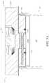
- FIGS. 15A-15Bschematically illustrate a container system 100 P that includes the cooling system 200 P.
- the container system 100 Pcan include the vessel 120 (as described above).
- Some of the features of the cooling system 200 P, which optionally serves as part of the lid L that selectively seals the vessel 120are similar to features in the cooling system 200 M in FIGS. 13A-13B .
- references numerals used to designate the various components of the cooling system 200 Pare similar to those used for identifying the corresponding components of the cooling system 200 M in FIGS. 13A-13B , except that an “P” is used. Therefore, the structure and description for said similar components of the cooling system 200 M in FIGS. 13A-13B are understood to also apply to the corresponding components of the cooling system 200 P in FIGS. 15A-15B , except as described below.
- the cooling system 200 Pcan include a cold side heat sink 210 P in thermal communication with a thermoelectric element (TEC) 220 P and can selectively be in thermal communication with the chamber 126 of the vessel 120 .
- the cooling system 200 Pcan include a fan 216 P selectively operable to draw air from the chamber 126 into contact with the cold side heat sink 210 P.
- cooling system 200 Pcan include insulator members 246 P, 247 P selectively movable (e.g., slidable) between one or more positions relative to the cold side heat sink 210 P.
- the insulator members 246 P, 247 Pare disposed at least partially apart from the cold side heat sink 210 P, allowing air flow from the chamber 126 to contact (e.g., be cooled by) the cold side heat sink 210 P.
- the fan 216 Pcan be operated to draw said airflow from the chamber 126 and over the cold side heat sink 210 P.
- the TEC 220 Pis selectively operated to draw heat from the cold side heat sink 210 P and transfer it to the hot side heat sink 230 P.
- a fan 280 Pis selectively operable to dissipate heat from the hot side heat sink 230 P, thereby allowing the TEC 220 P to draw further heat from the chamber 126 via the cold side heat sink 210 P.
- the insulator members 246 P, 247 Pare moved (e.g., slid) into a position between the cold side heat sink 210 P and the chamber 126 , thereby blocking air flow to the cold side heat sink 210 P (e.g., thermally disconnecting the cold side heat sink 210 P from the chamber 126 ) to thereby inhibit heat transfer to and from the chamber 126 (e.g., to maintain the chamber 126 in an insulated state).
- the insulator members 246 P, 247 Pcan be moved between the position in the cooling state (see FIG. 15A ) and the position in the insulating stage (see FIG. 15B ) using any suitable mechanism (e.g., electric motor, solenoid motor, etc.). Though the insulator members 246 P, 247 P are shown in FIGS. 15A-15B as sliding between said positions, in another implementation, the insulator members 246 P, 247 P can pivot between the cooling stage position and the insulating stage position.
- any suitable mechanisme.g., electric motor, solenoid motor, etc.
- FIGS. 16A-16Bschematically illustrate a container system 100 Q that includes the cooling system 200 Q.
- the container system 100 Qcan include the vessel 120 (as described above).
- Some of the features of the cooling system 200 Q, which optionally serves as part of the lid L that selectively seals the vessel 120are similar to features in the cooling system 200 M in FIGS. 13A-13B .
- references numerals used to designate the various components of the cooling system 200 Qare similar to those used for identifying the corresponding components of the cooling system 200 M in FIGS. 13A-13B , except that an “Q” is used. Therefore, the structure and description for said similar components of the cooling system 200 M in FIGS. 13A-13B are understood to also apply to the corresponding components of the cooling system 200 Q in FIGS. 16A-16B , except as described below.
- the cooling system 200 Qcan include a cold side heat sink 210 Q in thermal communication with a thermoelectric element (TEC) 220 Q and can selectively be in thermal communication with the chamber 126 of the vessel 120 .
- the cooling system 200 Qcan include a fan 216 Q selectively operable to draw air from the chamber 126 into contact with the cold side heat sink 210 Q.
- the cooling system 200 Qcan include an expandable members 246 Q selectively movable between A deflated state and an expanded state relative to the cold side heat sink 210 P.
- the expandable member 246 Qwhen the cooling system 200 Q is operated in a cooling state, the expandable member 246 Q is in the deflated state, allowing air flow from the chamber 126 to contact (e.g., be cooled by) the cold side heat sink 210 Q.
- the fan 216 Qcan be operated to draw said airflow from the chamber 126 and over the cold side heat sink 210 Q.
- the TEC 220 Qis selectively operated to draw heat from the cold side heat sink 210 Q and transfer it to the hot side heat sink 230 Q.
- a fan 280 Qis selectively operable to dissipate heat from the hot side heat sink 230 Q, thereby allowing the TEC 220 Q to draw further heat from the chamber 126 via the cold side heat sink 210 Q.
- the expandable member 246 Qwhen the cooling system 200 Q is operated in an insulating stage, the expandable member 246 Q is moved into the expanded state so that the expandable member 246 Q is between the cold side heat sink 210 Q and the chamber 126 , thereby blocking air flow to the cold side heat sink 210 Q (e.g., thermally disconnecting the cold side heat sink 210 Q from the chamber 126 ) to thereby inhibit heat transfer to and from the chamber 126 (e.g., to maintain the chamber 126 in an insulated state).
- the cold side heat sink 210 Qe.g., thermally disconnecting the cold side heat sink 210 Q from the chamber 126
- the expandable member 246 Qis optionally disposed or house in a cavity or chamber 242 Q defined in the insulator member 240 Q.
- the expandable member 246 Qis part of a pneumatic system and filled with a gas (e.g., air) to move it into the expanded state.
- the expandable member 246 Qis part of a hydraulic system and filled with a liquid (e.g., water) to move it into the expanded state.
- FIGS. 17A-17Bschematically illustrate a container system 100 R that includes the cooling system 200 R.
- the container system 100 Rcan include the vessel 120 (as described above).
- references numerals used to designate the various components of the cooling system 200 Rare similar to those used for identifying the corresponding components of the cooling system 200 M in FIGS. 13A-13B , except that an “R” is used. Therefore, the structure and description for said similar components of the cooling system 200 M in FIGS. 13A-13B are understood to also apply to the corresponding components of the cooling system 200 R in FIGS. 17A-17B , except as described below.
- the cooling system 200 Rcan include a cold side heat sink 210 R in thermal communication with a thermoelectric element (TEC) 220 R and can selectively be in thermal communication with the chamber 126 of the vessel.
- the cooling system 200can include a fan 216 R selectively operable to draw air from the chamber 126 into contact with the cold side heat sink 210 R.
- cooling system 200 Rcan include an insulator element 246 R selectively movable (e.g., pivotable) between one or more positions. As shown in FIGS. 17A-17B , the insulator element 246 R can be disposed in a cavity or chamber 242 R defined in the insulator member 240 R.
- the insulator element 246 Ris disposed relative to the cold side heat sink 210 R so as to allow air flow through the chamber 242 R from the chamber 126 to the cold side heat sink 210 R.
- the fan 216 Ris selectively operated to draw air from the chamber 126 into contact with the cold side heat sink 210 R (e.g., to cool said air flow and return it to the chamber 126 ).
- the TEC 220 Ris selectively operated to draw heat from the cold side heat sink 210 R and transfer it to the hot side heat sink 230 R.
- a fan 280 Ris selectively operable to dissipate heat from the hot side heat sink 230 R, thereby allowing the TEC 220 R to draw further heat from the chamber 126 via the cold side heat sink 210 R.
- the insulator element 246 Ris moved (e.g., rotated, pivoted) into a position relative to the cold side heat sink 210 P so as to close off the chamber 242 R, thereby blocking air flow from the chamber 126 to the cold side heat sink 210 R (e.g., thermally disconnecting the cold side heat sink 210 R from the chamber 126 ) to thereby inhibit heat transfer to and from the chamber 126 (e.g., to maintain the chamber 126 in an insulated state).
- the insulator element 246 Ris moved (e.g., rotated, pivoted) into a position relative to the cold side heat sink 210 P so as to close off the chamber 242 R, thereby blocking air flow from the chamber 126 to the cold side heat sink 210 R (e.g., thermally disconnecting the cold side heat sink 210 R from the chamber 126 ) to thereby inhibit heat transfer to and from the chamber 126 (e.g., to maintain the chamber 126 in an insulated state).
- the insulator element 246 Rcan be moved between the position in the cooling state (see FIG. 17A ) and the position in the insulating stage (see FIG. 17B ) using any suitable mechanism (e.g., electric motor, solenoid motor, etc.).
- any suitable mechanisme.g., electric motor, solenoid motor, etc.
- FIG. 18Ais a schematic view of a portion of a cooling system 200 S.
- the cooling system 200 Sis similar to the cooling systems disclosed herein, such as cooling systems 200 - 200 X, except as described below.
- the fan 280 Shas air intake I that is generally vertical and air exhaust E that is generally horizontal, so that the air flows generally horizontally over one or more heat sink surfaces, such as surfaces of the hot side heat sink 230 S.
- FIG. 18Bis a schematic view of a portion of a cooling system 200 T.
- the cooling system 200 T in a cylindrical container 100 Thas a fan 280 T that optionally blows air over a heat sink 230 T.
- the cooling system 200 Thas a heat pipe 132 T in thermal communication with another portion of the container 100 T via end portion 134 T of heat pipe 132 T, allowing the fan 280 T and heat sink 230 T to remove heat from said portions via the heat pipe 132 T.
- FIG. 18Cis a schematic view of a coupling mechanism 30 A for coupling the lid L and the vessel 120 for one or more implementations of the container system 100 - 100 X disclosed herein.
- the lid Lcan be connected to one or more portions of the vessel 120 via a hinge that allows the lid L to be selectively moved between an open position (see FIG. 18C ) to allow access to the chamber 126 , and a closed position to disallow access to the chamber 126 .
- FIG. 18Dis a schematic view of another embodiment of a coupling mechanism 30 B between the lid L and the vessel 120 of the container system 100 - 100 X.
- the lid Lcan have one or more electrical connectors 31 B that communicate with one or more electrical contacts 32 B on the vessel 120 when the lid L is coupled to the vessel 120 , thereby allowing operation of the fan 280 , TEC 220 , etc. that are optionally in the lid L.
- one of the electrical connectors 31 B and electrical contacts 32 Bcan be contact pins (e.g., Pogo pins) and the other of the electrical connectors 31 B and electrical contacts 32 B can be electrical contact pads (e.g., circular contacts) that optionally allows connection of the lid L to the vessel 120 irrespective of the angular orientation of the lid L relative to the vessel 120 .
- contact pinse.g., Pogo pins
- electrical contact padse.g., circular contacts
- FIG. 18Eshows a schematic view of an embodiment of a vessel for the cooler container system, such as the cooler container systems 100 - 100 X disclosed herein.
- the vessel 120has electronics (e.g., one or more optional batteries, circuitry, optional transceiver) housed in a compartment E on a bottom of the vessel 120 .
- the electronicscan communicate or connect to the fan 280 , TEC 220 or other components in the lid L via electrical connections (such as those shown and described in connection with FIG. 18D ), or via wires that extend through the hinge 30 A (such as that shown in FIG. 18C ).
- FIG. 18Fshows a schematic view of an embodiment of a vessel for the cooler container system, such as the cooler container systems 100 - 100 X disclosed herein.
- the vessel 120has electronics (e.g., one or more optional batteries, circuitry, optional transceiver) housed in a compartment E on a side of the vessel 120 .
- the electronicscan communicate or connect to the fan 280 , TEC 220 or other components in the lid L via electrical connections (such as those shown and described in connection with FIG. 18D ), or via wires that extend through the hinge 30 A (such as that shown in FIG. 18C ).
- FIG. 19shows another embodiment of a container system 100 U having a cooling system 200 U.
- the container system 100 Uincludes a vessel 120 with a chamber 126 .
- the vessel 120can be double walled, as shown, with the space between the inner wall and outer wall under vacuum.
- a TEC 220 Ucan be in contact with a cold delivery member (e.g., stud) 225 U, which is in contact with the inner wall and can selectively thermally communicate with a hot side heat sink 230 U.
- the cold delivery member 225can be small relative to the size of the vessel 120 , and can extend through an opening 122 U in the vessel 120 .
- the container system 100 Ucan have a pump P operable to pull a vacuum out from the cavity between the inner and outer walls of the vessel 120 .
- FIGS. 20-31show a container system 100 ′ that includes a cooling system 200 ′.
- the container system 100 ′has a body 120 ′ that extends from a proximal end 122 ′ to a distal end 124 ′ and has an opening 123 ′ selectively closed by a lid L′′.
- the body 120 ′can optionally be box shaped.
- the lid L′′can optionally be connected to the proximal end 122 ′ of the body 120 ′ by a hinge 130 ′ on one side of the body 120 ′.
- a groove or handle 106 ′can be defined on an opposite side of the body 120 ′ (e.g., at least partially defined by the lid L′′ and/or body 120 ′), allowing a user to lift the lid L′′ to access a chamber 126 ′ in the container 100 ′.
- one or both of the lid L′′ and proximal end 122 ′ of the body 120 ′can have one or more magnets (e.g., electromagnets, permanent magnets) that can apply a magnetic force between the lid L′ and body 120 ′ to maintain the lid L′ in a closed state over the body 120 ′ until a user overcomes said magnetic force to lift the lid L′.
- magnetse.g., electromagnets, permanent magnets
- other suitable fastenerscan be used to retain the lid L′ in a closed position over the body 120 ′.
- the body 120 ′can include an outer wall 121 ′ and optionally include an inner wall 126 A′ spaced apart from the outer wall 121 ′ to define a gap (e.g., annular gap, annular chamber) 128 ′ therebetween.
- the inner wall 126 A′can be suspended relative to the outer wall 121 ′ in a way that provides the inner wall 126 A′ with shock absorption (e.g., energy dissipation).
- shock absorptione.g., energy dissipation
- one or more springscan be disposed between the inner wall 126 A′ and the outer wall 121 ′ that provide said shock absorption.
- the container 100 ′includes one or more accelerometers (e.g., in communication with the circuitry of the container 100 ′) that sense motion (e.g., acceleration) of the container 100 ′.
- the one or more accelerometerscommunicate sensed motion information to the circuitry, and the circuitry optionally operates one or more components to adjust a shock absorption provided by the inner wall 126 A′ (e.g., by tuning a shock absorption property of one or more springs, such as magnetorheological (MRE) springs) that support the inner surface 126 A′.
- the container 100 ′can include a plastic and/or rubber structure in the gap 128 ′ between the inner wall 126 A′ and the outer wall 121 ′ to aid in providing such shock absorption.
- the gap 128 ′can optionally be filled with an insulative material (e.g., foam). In another implementation, the gap 128 ′ can be under vacuum. In still another implementation, the gap 128 ′ can be filled with a gas (e.g., air).
- the inner wall 126 A′can be made of metal.
- the outer wall 121 ′can be made of plastic. In another implementation, the outer wall 121 ′ and the inner wall 126 A′ are optionally made of the same material.
- the cooling system 200 ′can optionally be housed in a cavity 127 ′ disposed between a base 125 ′ of the container body 120 ′ and the inner wall 126 A′.
- the cooling system 200 ′can optionally include one or more thermoelectric elements (TEC) (e.g., Peltier elements) 220 ′ in thermal communication with (e.g., in direct contact with) the inner wall 126 A′.
- TECthermoelectric elements
- the cooling system 200 ′has only one TEC 220 ′.
- the one or more TECs 220 ′can optionally be in thermal communication with one or more heat sinks 230 ′.
- the one or more heat sinks 230 ′can be a structure with a plurality of fins.
- one or more fans 280 ′can be in thermal communication with (e.g., in fluid communication with) the one or more heat sinks 230 ′.
- the cooling system 200 ′can optionally have one or more batteries 277 ′, optionally have a converter 279 ′, and optionally have a power button 290 ′, that communicate with circuitry (e.g., on a printed circuit board 278 ′) that controls the operation of the cooling system 200 ′.
- the optional batteries 277 ′provide power to one or more of the circuitry, one of more fans 280 ′, one or more TECs 220 ′, and one or more sensors (described further below).
- at least a portion of the body 120 ′ (e.g., a portion of the base 125 ′) of the container 100 ′is removable to access the one or more optional batteries 277 ′.
- the one or more optional batteries 277 ′can be provided in a removable battery pack, which can readily be removed and replaced from the container 100 ′.
- the container 100 ′can include an integrated adaptor and/or retractable cable to allow connection of the container 100 ′ to a power source (e.g., wall outlet, vehicle power connector) to one or both of power the cooling system 200 ′ directly and charge the one or more optional batteries 277 ′.
- a power sourcee.g., wall outlet, vehicle power connector
- the container system 100 ′can have two or more handles 300 on opposite sides of the body 120 ′ to which a strap 400 can be removably coupled (see FIG. 24 ) to facilitate transportation of the container 100 ′.
- a strap 400can be removably coupled (see FIG. 24 ) to facilitate transportation of the container 100 ′.
- the usercan carry the container 100 ′ by placing the strap 400 over their shoulder.
- the strap 400is adjustable in length.
- the strap 400can be used to secure the container system 100 ′ to a vehicle (e.g., moped, bicycle, motorcycle, etc.) for transportation.
- the one or more handles 300can be movable relative to the outer surface 121 ′ of the body 120 ′.
- the handles 300can be selectively movable between a retracted position (see e.g., FIG. 22 ) and an extended position (see e.g., FIG. 23 ).
- the handles 300can be mounted within the body 120 ′ in a spring-loaded manner and be actuated in a push-to-open and push-to-close manner.
- the body 120 ′can include one or more sets of vents on a surface thereof to allow air flow into and out of the body 120 ′.
- the body 120 ′can have one or more vents 203 ′ defined on the bottom portion of the base 125 ′ of the body 120 ′ and can optionally have one or more vents 205 ′ at one or both ends of the base 125 ′.
- the vents 203 ′can be air intake vents
- the vents 205 ′can be air exhaust vents.
- the chamber 126is optionally sized to receive and hold one or more trays 500 therein (e.g., hold a plurality of trays in a stacked configuration).
- Each tray 500optionally has a plurality of receptacles 510 , where each receptacle 510 is sized to receive a container (e.g., a vial) 520 therein.
- the container 520can optionally hold a liquid (e.g., a medication, such as insulin or a vaccine).
- the tray 500(e.g., the receptacle 510 ) can releasably lock the containers 520 therein (e.g., lock the containers 520 in the receptacles 510 ) to inhibit movement, dislodgement and/or damage to the containers 520 during transit of the container system 100 ′.
- the tray 500can have one or more handles 530 to facilitate carrying of the tray 500 and/or pulling the tray 500 out of the chamber 126 or placing the tray 500 in the chamber 126 .
- the one or more handles 530are movable between a retracted position (see FIG. 28 ) and an extended position (see FIG. 26 ).
- the one or more handles 530can be mounted within the tray 500 in a spring-loaded manner and be actuated in a push-to-extend and push-to-retract manner.
- the one or more handles 530are fixed (e.g., not movable between a retracted and an extended position).
- the tray 500can include an outer tray 502 that removably receives one or more inner trays 504 , 504 ′, where different inner trays 504 , 504 ′ can have a different number and/or arrangement of the plurality of receptacles 510 that receive the one or more containers (e.g., vials) 520 therein, thereby advantageously allowing the container 100 ′ to accommodate different number of containers 520 (e.g., for different medications, etc.).
- the inner tray 504can have a relatively smaller number of receptacles 510 (e.g., sixteen), for example to accommodate relatively larger sized containers 520 (e.g., vials of medicine, such as vaccines and insulin, biological fluid, such as blood, etc.), and in another implementation, shown in FIG. 25D , the inner tray 504 ′ can have a relatively larger number of receptacles 510 (e.g., thirty-eight), for example to accommodate relatively smaller sized containers 520 (e.g., vials of medicine, biological fluid, such as blood, etc.).
- receptacles 510e.g., sixteen
- relatively larger sized containers 520e.g., vials of medicine, such as vaccines and insulin, biological fluid, such as blood, etc.
- the inner tray 504 ′can have a relatively larger number of receptacles 510 (e.g., thirty-eight), for example to accommodate relatively smaller sized containers 520 (e.g
- the container system 100 ′can have one or more lighting elements 550 that can advantageously facilitate users to readily see the contents in the chamber 126 ′ when in a dark environment (e.g., outdoors at night, in a rural or remote environment, such as mountainous, desert or rainforest region).
- the one or more lighting elementscan be one or more light strips (e.g., LED strips) disposed at least partially on one or more surfaces of the chamber 126 ′ (e.g., embedded in a surface of the chamber 126 ′, such as near the proximal opening of the chamber 126 ′).
- the one or more lighting elements 550can automatically illuminate when the lid L′′ is opened.
- the one or more lighting elements 550can optionally automatically shut off when the lid L′′ is closed over the chamber 126 ′.
- the one or more lighting elements 550can communicate with circuitry of the container 100 ′, which can also communicate with a light sensor of the container 100 ′ (e.g., a light sensor disposed on an outer surface of the container 100 ′).
- the light sensorcan generate a signal when the sensed light is below a predetermined level (e.g., when container 100 ′ in a building without power or is in the dark, etc.) and communicate said signal to the circuitry, and the circuitry can operate the one or more lighting elements 550 upon receipt of such signal (e.g., and upon receipt of the signal indicating the lid L′′ is open).
- the container system 100 ′can have a housing with one of a plurality of colors.
- Such different color housingscan optionally be used with different types of contents (e.g., medicines, biological fluids), allowing a user to readily identify the contents of the container 100 ′ by its housing color.
- such different colorscan aid users in distinguishing different containers 100 ′ in their possession/use without having to open the containers 100 ′ to check their contents.
- the container 100 ′can optionally communicate (e.g., one-way communication, two-way communication) with one or more remote electronic device (e.g., mobile phone, tablet computer, desktop computer, remote server) 600 , via one or both of a wired or wireless connection (e.g., 802.11b, 802.11a, 802.11g, 802.11n standards, etc.).
- the container 100 ′can communicate with the remote electronic device 600 via an app (mobile application software) that is optionally downloaded (e.g., from the cloud) onto the remote electronic device 600 .
- the appcan provide one or more graphical user interface screens 610 A, 610 B, 610 C via which the remote electronic device 600 can display one or more data received from the container 100 ′.
- a usercan provide instructions to the container 100 ′ via one or more of the graphical user interface screens 610 A, 610 B, 610 C on the remote electronic device 600 .
- the graphical user interface (GUI) screen 610 Acan provide one or more temperature presets corresponding to one or more particular medications (e.g., epinephrine/adrenaline for allergic reactions, insulin, vaccines, etc.).
- the GUI screen 610 Acan optionally allow the turning on and off of the cooling system 200 ′.
- the GUI screen 610 Acan optionally allow the setting of the control temperature to which the chamber 126 ′ in the container 100 ′ is cooled by the cooling system 200 ′.
- the graphical user interface (GUI) screen 610 Bcan provide a dashboard display of one or more parameters of the container 100 ′ (e.g., ambient temperature, internal temperature in the chamber 126 ′, temperature of the heat sink 230 ′, temperature of the battery 277 , etc.).
- the GUI screen 610 Bcan optionally provide an indication (e.g., display) of power supply left in the one or more batteries 277 (e.g., % of life left, time remaining before battery power drains completely).
- the GUI screen 610 Bcan also include information (e.g., a display) of how many of the receptacles 510 in the tray 500 are occupied (e.g., by containers 520 ).
- the GUI screen 610 Bcan also include information on the contents of the container 100 ′ (e.g., medication type or disease medication is meant to treat), information on the destination for the container 100 ′ and/or information (e.g., name, identification no.) for the individual assigned to the container 100 ′.
- information on the contents of the container 100 ′e.g., medication type or disease medication is meant to treat
- information on the destination for the container 100 ′e.g., name, identification no.
- the GUI screen 610 Ccan include a list of notifications provided to the user of the container 100 ′, including alerts on battery power available, alerts on ambient temperature effect on operation of container 100 ′, alerts on a temperature of a heat sink of the container 100 ′, alert on temperature of the chamber 126 , 126 ′, 126 V, alert on low air flow through the intake vent 203 ′, 203 ′′, 203 V and/or exhaust vent 205 ′, 205 ′′, 205 V indicating they may be blocked/clogged, etc.
- the appcan provide the plurality of GUI screens 610 A, 610 B, 610 C to the user, allowing the user to swipe between the different screens.
- the container 100 ′can communicate information, such as temperature history of the chamber 126 ′ and/or first heat sink 210 that generally corresponds to a temperature of the containers 520 , 520 V (e.g., medicine containers, vials, cartridges, injectors), power level history of the batteries 277 , ambient temperature history, etc.
- informationsuch as temperature history of the chamber 126 ′ and/or first heat sink 210 that generally corresponds to a temperature of the containers 520 , 520 V (e.g., medicine containers, vials, cartridges, injectors), power level history of the batteries 277 , ambient temperature history, etc.
- the cloude.g., on a periodic basis, such as every hour; on a continuous basis in real time, etc.
- a remote electronic devicee.g., a mobile electronic device such as a smartphone or tablet computer or laptop computer or desktop computer
- wirelesslye.g., via WiFi 802.11, BLUETOOTH®, or other RF communication
- the cloude.g., to a cloud-based data storage system or server
- wirelesslye.g., via WiFi 802.11, BLUETOOTH®, or other RF communication
- Such communicationcan occur on a periodic basis (e.g., every hour; on a continuous basis in real time, etc.).
- a periodic basise.g., every hour; on a continuous basis in real time, etc.
- remote electronic devicese.g., via a dashboard on a smart phone, tablet computer, laptop computer, desktop computer, etc.
- the container system 100 , 100 ′, 100 ′′, 100 B- 100 Vcan store in a memory (e.g., part of the electronics in the container system 100 , 100 ′, 100 ′′, 100 B- 100 V) information, such as temperature history of the chamber 126 , 126 ′, 126 V, temperature history of the first heat sink 210 , 210 B- 210 V, power level history of the batteries 277 , ambient temperature history, etc., which can be accessed from the container system 100 , 100 ′, 100 ′′, 100 B- 100 V by the user via a wired or wireless connection (e.g., via the remote electronic device 600 ).
- a memorye.g., part of the electronics in the container system 100 , 100 ′, 100 ′′, 100 B- 100 V
- informationsuch as temperature history of the chamber 126 , 126 ′, 126 V, temperature history of the first heat sink 210 , 210 B- 210 V, power level history of the batteries 277 , ambient temperature history
- the body 120 ′ of the container 100 ′can have a visual display 140 on an outer surface 121 ′ of the body 120 ′.
- the visual display 140 ′can optionally display one or more of the temperature in the chamber 126 ′, the ambient temperature, a charge level or percentage for the one or more batteries 277 , and amount of time left before recharging of the batteries 277 is needed.
- the visual display 140 ′can include a user interface (e.g., pressure sensitive buttons, capacitance touch buttons, etc.) to adjust (up or down) the temperature preset at which the cooling system 200 ′ is to cool the chamber 126 ′ to.
- the operation of the container 100 ′can be selected via the visual display and user interface 140 ′ on a surface of the container 100 ′.
- the visual display 140 ′can include one or more hidden-til-lit LEDs.
- the visual display 140 ′can include an electronic ink (e-ink) display.
- the container 100 ′can optionally include a hidden-til-lit LED 142 ′ (see FIG. 34 ) that can selectively illuminate (e.g., to indicate one or more operating functions of the container 100 ′, such as to indicate that the cooling system 200 ′ is in operation).
- the LED 142 ′can optionally be a multi-color LED selectively operable to indicate one or more operating conditions of the container 100 ′ (e.g., green if normal operation, red if abnormal operation, such as low battery charge or inadequate cooling for sensed ambient temperature, etc.).
- one or more operating conditions of the container 100 ′e.g., green if normal operation, red if abnormal operation, such as low battery charge or inadequate cooling for sensed ambient temperature, etc.
- the container 100 ′can include one or more security features that allow opening of the container 100 ′ only when the security feature(s) are met.
- the container 100 ′can include a keypad 150 via which an access code can be entered to unlock the lid L′′ to allow access to the chamber 126 ′ when it matches the access code key programmed to the container 100 ′.
- the container 100 ′can additionally or alternatively have a biometric sensor 150 ′, via which the user can provide a biometric identification (e.g., fingerprint) that will unlock the lid L′′ and allow access to the chamber 126 ′ when it matches the biometric key programmed to the container 100 ′.
- the container 100 ′remains locked until it reaches its destination, at which point the access code and/or biometric identification can be utilized to unlock the container 100 ′ to access the contents (e.g., medication) in the chamber 126 ′.
- the container 100 ′can optionally be powered in a variety of ways.
- the container system 100 ′is powered using 12 VDC power (e.g., from one or more batteries 277 ′).
- the container system 100 ′is powered using 120 VAC or 240 VAC power.
- the cooling system 200 ′can be powered via solar power.
- the container 100 ′can be removably connected to one or more solar panels so that electricity generated by the solar panels is transferred to the container 100 ′, where circuitry of the container 100 ′ optionally charges the one or more batteries 277 with the solar power.
- the solar power from said one or more solar panelsdirectly operates the cooling system 200 ′ (e.g., where batteries 277 are excluded from the container 100 ′).
- the circuitry in the container 100 ′can include a surge protector to inhibit damage to the electronics in the container 100 ′ from a power surge.
- the cooling system 200 ′can optionally be actuated by pressing the power button 290 .
- the cooling system 200 ′can additionally (or alternatively) be actuated remotely (e.g., wirelessly) via a remote electronic device, such as a mobile phone, tablet computer, laptop computer, etc. that wirelessly communicates with the cooling system 200 ′ (e.g., with a receiver or transceiver of the circuitry).
- the chamber 126 ′can be cooled to a predetermined and/or a user selected temperature or temperature range.
- the user selected temperature or temperature rangecan be selected via a user interface on the container 100 ′ and/or via the remote electronic device.
- the circuitryoptionally operates the one or more TECs 220 ′ so that the side of the one or more TECs 220 ′ adjacent the inner wall 126 A′ is cooled and so that the side of the one or more TECs 220 ′ adjacent the one or more heat sinks 230 ′ is heated.
- the TECs 220 ′thereby cool the inner wall 126 A′ and thereby cools the chamber 126 ′ and the contents (e.g., tray 500 with containers (e.g., vials) 520 therein).
- one or more sensorse.g., temperature sensors
- the circuitryoperates one or more of the TECs 220 ′ and one or more fans 280 ′ based at least in part on the sensed temperature information to cool the chamber 126 ′ to the predetermined temperature and/or user selected temperature.
- the circuitryoperates the one or more fans 280 ′ to flow air (e.g., received via the intake vents 203 ′) over the one or more heat sinks 230 ′ to dissipate heat therefrom, thereby allowing the one or more heat sinks 230 ′ to draw more heat from the one or more TECs 220 ′, which in turn allows the one or more TECs 220 ′ to draw more heat from (i.e., cool) the inner wall 126 A′ to thereby further cool the chamber 126 ′.
- Said air flowonce it passes over the one or more heat sinks 230 ′, is exhausted from the body 120 ′ via the exhaust vents 205 ′.
- FIGS. 32-34schematically illustrate a container 100 ′′ that includes a cooling system 200 ′′.
- the container system 100 ′′can include a vessel body 120 removably sealed by a lid L′′′.
- Some of the features of the container 100 ′′ and cooling system 200 ′′are similar to the features of the container 100 ′ and cooling system 200 ′ in FIGS. 20-31 .
- reference numerals used to designate the various components of the container 100 ′′ and cooling system 200 ′′are similar to those used for identifying the corresponding components of the cooling system 200 ′ in FIGS. 20-31 , except that an “ ” “is used. Therefore, the structure and description for said components of the cooling system 200 ′ of FIGS.
- FIG. 33Ais a front view of the container 100 ′′ in FIG. 32 .
- FIG. 33Bis a smaller version of the container 100 ′′ and optionally has the same internal components as shown for the container in FIG. 33A (e.g., as shown in FIGS. 37-39 ).
- the container 100 ′′differs from the container 100 ′ in that the container 100 ′′ has a generally cylindrical or tube-like body 120 ′′ with a generally cylindrical outer surface 121 ′′.
- the container 100 ′′can have similar internal components as the container 100 ′, such as a chamber 126 ′′ defined by an inner wall 126 A′′, TEC 220 ′′, heat sink 230 ′′, one or more fans 280 ′′, one or more optional batteries 277 ′, converter 279 ′′ and power button 290 ′′.
- the lid L′′′can have one or more vents 203 ′′, 205 ′′ defined therein, and operate in a similar manner as the vents 203 ′, 205 ′ described above.
- the container 100 ′′can have a variety of sizes (see FIG. 35 ) that can accommodate a different number and/or size of containers 520 ′′.
- the container 100 ′′ and cooling system 200 ′′operate in a similar manner described above for the container 100 ′ and cooling system 200 ′.
- the container 100 ′′can optionally include a display similar to the display 140 ′ described above for the container 100 ′ (e.g., that displays one or more of the temperature in the chamber 126 ′′, the ambient temperature, a charge level or percentage for the one or more batteries 277 ′′, and amount of time left before recharging of the batteries 277 ′′ is needed).
- the container 100 ′′can optionally include a hidden-til-lit LED 142 ′′ (see FIG. 36 ) that can selectively illuminate (e.g., to indicate one or more operating functions of the container 100 ′′, such as to indicate that the cooling system 200 ′ is in operation).
- the LED 142 ′′can optionally be a multi-color LED selectively operable to indicate one or more operating conditions of the container 100 ′′ (e.g., green if normal operation, red if abnormal operation, such as low battery charge or inadequate cooling for sensed ambient temperature, etc.).
- one or more operating conditions of the container 100 ′′e.g., green if normal operation, red if abnormal operation, such as low battery charge or inadequate cooling for sensed ambient temperature, etc.
- the container 100 ′′can be removably placed on a base 700 ′′, which can connect to a power source (e.g., wall outlet) via a cable 702 ′′.
- a power sourcee.g., wall outlet
- the base 700 ′′directly powers the cooling system 200 ′′ of the container 100 ′′ (e.g., to cool the contents in the container 100 ′′) to the desired temperature (e.g., the temperature required by the medication, such as insulin, in the chamber 126 ′′ of the container 100 ′′).
- the base 700 ′′can additionally or alternatively charge the one or more optional batteries 277 ′′, so that the batteries 277 ′′ take over powering of the cooling system 200 ′′ when the container 100 ′′ is removed from the base 700 ′′.
- the vessel 120 ′′ of the container system 100 ′′can have one or more electrical contacts EC 1 (e.g., contact rings) that communicate with one or more electrical contacts EC 2 (e.g., pogo pins) of the base 700 ′′ when the vessel 120 ′′ is placed on the base 700 ′′.
- the base 700 ′′can transfer power to the vessel 120 ′′ of the container system 100 ′′ via inductive coupling (e.g., electromagnetic induction).
- the container 100 ′′can optionally communicate (e.g., one-way communication, two-way communication) with one or more remote electronic device (e.g., mobile phone, tablet computer, desktop computer) 600 , via one or both of a wired or wireless connection.
- the container 100 ′′can communicate with the remote electronic device 600 via an app (mobile application software) that is optionally downloaded (e.g., from the cloud) onto the remote electronic device 600 .
- the appcan provide one or more graphical user interface screens 610 A′′, 610 B′′, 610 C′′ via which the remote electronic device 600 can display one or more data received from the container 100 ′′.
- a usercan provide instructions to the container 100 ′′ via one or more of the graphical user interface screens 610 A′′, 610 B′′, 610 C′′ on the remote electronic device 600 .
- the graphical user interface (GUI) screen 610 A′′can provide one or more temperature presets corresponding to one or more particular medications (e.g., insulin).
- the GUI 610 A′′can optionally allow the turning on and off of the cooling system 200 ′′.
- the GUI 610 A′′can optionally allow the setting of the control temperature to which the chamber 126 ′′ in the container 100 ′′ is cooled by the cooling system 200 ′′.
- the graphical user interface (GUI) screen 610 B′′can provide a dashboard display of one or more parameters of the container 100 ′′ (e.g., ambient temperature, internal temperature in the chamber 126 ′′, etc.).
- the GUI screen 610 B′′can optionally provide an indication (e.g., display) of power supply left in the one or more batteries 277 ′′ (e.g., % of life left, time remaining before battery power drains completely).
- the GUI screen 610 B′′can also include information (e.g., a display) of how many of the receptacles 510 ′′ in the tray 500 ′′ are occupied (e.g., by containers 520 ′′).
- the GUI screen 610 B′′can also include information on the contents of the container 100 ′ (e.g., medication type or disease medication is meant to treat), information on the physician (e.g., name of doctor and contact phone no) and/or information (e.g., name, date of birth, medical record no.) for the individual assigned to the container 100 ′′.
- information on the contents of the container 100 ′e.g., medication type or disease medication is meant to treat
- information on the physiciane.g., name of doctor and contact phone no
- informatione.g., name, date of birth, medical record no.
- the GUI screen 610 C′′can include a list of notifications provided to the user of the container 100 ′′, including alerts on battery power available, alerts on ambient temperature effect on operation of container 100 ′′, etc.
- the appcan provide the plurality of GUI screens 610 A′′, 610 B′′, 610 C′′ to the user, allowing the user to swipe between the different screens.
- the container 100 ′′can communicate information, such as temperature history of the chamber 126 ′′, power level history of the batteries 277 ′′, ambient temperature history, etc. to the cloud (e.g., on a periodic basis, such as every hour; on a continuous basis in real time, etc.).
- the container system 100 , 100 ′, 100 ′′, 100 B- 100 Xcan include one or both of a radiofrequency identification (RFID) reader and a barcode reader.
- RFIDradiofrequency identification
- the RFID reader and/or barcode readercan be disposed proximate (e.g., around) a rim of the chamber 126 , 126 ′, 126 ′′ to that it can read content units (e.g., vials, containers) placed into or removed from the chamber 126 , 126 ′, 126 ′′.
- content unitse.g., vials, containers
- the RFID reader or barcode readercan communicate data to the circuitry in the container system, which as discussed above, can optionally store such data in a memory or the container system and/or communicate such data to a separate or remote computing system, such as a remote computer server (e.g., accessible by a doctor treating the patient with the medication in the container), a mobile electronic device, such as a mobile phone or tablet computer.
- a remote computer servere.g., accessible by a doctor treating the patient with the medication in the container
- a mobile electronic devicesuch as a mobile phone or tablet computer.
- Such communicationcan optionally be in one or both of a wired manner (via a connector on the container body) or wireless manner (via a transmitter or transceiver of the container in communication with the circuitry of the container).
- Each of the contents placed in the chamber of the containeroptionally has an RFID tag or barcode that is read by the RFID reader or barcode reader as it is placed in and/or removed from the chamber of the container, thereby allowing the tracking of the contents of the container system 100 , 100 ′, 100 ′′, 100 B- 100 X.
- the container systeme.g., the RFID reader, barcode reader and/or circuitry
- send a notificatione.g., to a remote computer server, to one or more computing systems, to a mobile electronic device such as a smartphone or tablet computer or laptop computer or desktop computer
- a medicine unite.g., vial, container
- the container system 100 , 100 ′, 100 ′′, 100 B- 100 Xcan additionally or alternatively (to the RFID reader and/or barcode reader) include a proximity sensor, for example in the chamber 126 , 126 ′, 126 ′′ to advantageously track one or both of the insertion of and removal of content units (e.g., medicine units such as vials, containers, pills, etc.) from the container system.
- a proximity sensorcan communication with the circuitry of the container and advantageously facilitate tracking, for example, of the user taking medication in the container, or the frequency with which the user takes the medication.
- operation of the proximity sensorcan be triggered by a signal indicating the lid L, L′, L′′ has been opened.
- the proximity sensorcan communicate data to the circuitry in the container system, which as discussed above, can optionally store such data in a memory or the container system and/or communicate such data to a separate or remote computing system, such as a remote computer server (e.g., accessible by a doctor treating the patient with the medication in the container), a mobile electronic device, such as a mobile phone or tablet computer.
- a remote computer servere.g., accessible by a doctor treating the patient with the medication in the container
- a mobile electronic devicesuch as a mobile phone or tablet computer.
- Such communicationcan optionally be in one or both of a wired manner (via a connector on the container body) or wireless manner (via a transmitter or transceiver of the container in communication with the circuitry of the container).
- the container system 100 , 100 ′, 100 ′′, 100 B- 100 Xcan additionally or alternatively (to the RFID reader and/or barcode reader) include a weight sensor, for example in the chamber 126 , 126 ′, 126 ′′ to advantageously track the removal of content units (e.g. medicine units such as vials, containers, pills, etc.) from the container system.
- a weight sensorcan communicate with the circuitry of the container and advantageously facilitate tracking, for example, of the user taking medication in the container, or the frequency with which the user takes the medication.
- operation of the weight sensorcan be triggered by a signal indicating the lid L, L′, L′′ has been opened.
- the weight sensorcan communicate data to the circuitry in the container system, which as discussed above, can optionally store such data in a memory or the container system and/or communicate such data to a separate or remote computing system, such as a remote computer server (e.g., accessible by a doctor treating the patient with the medication in the container), a mobile electronic device, such as a mobile phone or tablet computer.
- a remote computer servere.g., accessible by a doctor treating the patient with the medication in the container
- a mobile electronic devicesuch as a mobile phone or tablet computer.
- Such communicationcan optionally be in one or both of a wired manner (via a connector on the container body) or wireless manner (via a transmitter or transceiver of the container in communication with the circuitry of the container).
- FIG. 36shows a container system, such as the container systems 100 , 100 ′, 100 ′′, 100 A- 100 X described herein, removably connectable to a battery pack B (e.g., a Dewalt battery pack), which can provide power to one or more electrical components (e.g., TEC, fan, circuitry, etc.) of the container systems or the cooling systems 200 , 200 ′, 200 ′′, 200 A- 200 T.
- the vessel 120 of the container systemcan have one or more electrical contacts EC 1 (e.g., contact rings) that communicate with one or more electrical contacts EC 2 (e.g., pogo pins) when the vessel 120 is placed on the battery pack B.
- the battery pack Bcan transfer power to the vessel 120 of the container system via inductive coupling (e.g., electromagnetic induction).
- FIGS. 37-39show a schematic cross-sectional view of a container system 100 V that includes a cooling system 200 V.
- the container system 100 Vhas a container vessel 120 V that is optionally cylindrical and symmetrical about a longitudinal axis, and one of ordinary skill in the art will recognize that at least some of the features shown in cross-section in FIGS. 37-39 are defined by rotating them about the axis to define the features of the container 100 V and cooling system 200 V.
- Some of the features of the cooling system 200 V, which optionally serves as part of the lid L′′′ that selectively seals the vessel 120 V,are similar to features in the cooling system 200 M in FIGS. 13A-13B .
- references numerals used to designate the various components of the cooling system 200 Vare similar to those used for identifying the corresponding components of the cooling system 200 M in FIGS. 13A-13B , except that an “V” is used. Therefore, the structure and description for said similar components of the cooling system 200 M in FIGS. 13A-13B are understood to also apply to the corresponding components of the cooling system 200 V in FIGS. 37-39 , except as described below.
- the cooling system 200 Vcan include a heat sink (cold side heat sink) 210 V in thermal communication with a thermoelectric element (TEC) 220 V and can be in thermal communication with the chamber 126 V of the vessel 120 V.
- the cooling system 200 Vcan include a fan 216 V selectively operable to draw air from the chamber 126 V into contact with the cold side heat sink 210 V.
- cooling system 200 Vcan include an insulator member 270 V disposed between the heat sink 210 V and an optional lid top plate 202 V, where the lid top plate 202 V is disposed between the heat sink (hot side heat sink) 230 V and the insulator 270 V, the insulator 270 V disposed about the TEC 220 V.
- air flow Fris drawn by the fan 216 V from the chamber 126 V and into contact with the heat sink (cold side heat sink) 210 V (e.g., to cool the air flow Fr), and then returned to the chamber 126 V.
- the air flow Fris returned via one or more openings 218 V in a cover plate 217 V located distally of the heat sink 210 V and fan 216 V.
- the TEC 220 Vis selectively operated to draw heat from the heat sink (e.g., cold-side heat sink) 210 V and transfer it to the heat sink (hot-side heat sink) 230 V.
- a fan 280 Vis selectively operable to dissipate heat from the heat sink 230 V, thereby allowing the TEC 220 V to draw further heat from the chamber 126 V via the heat sink 210 V. As show in FIG.
- intake air flow Fiis drawn through one or more openings 203 V in the lid cover L′′′ and over the heat sink 230 V (where the air flow removes heat from the heat sink 230 V), after which the exhaust air flow Fe flows out of one or more openings 205 V in the lid cover L′′′.
- both the fan 280 V and the fan 216 Vare operated simultaneously.
- the fan 280 V and the fan 216 Vare operated at different times (e.g., so that operation of the fan 216 V does not overlap with operation of the fan 280 V).
- the chamber 126 Voptionally receives and holds one or more (e.g., a plurality of) trays 500 V, each tray 500 V supporting one or more (e.g., a plurality of) liquid containers 520 V (e.g., vials, such as vaccines, medications, etc.).
- the lid L′′′can have a handle 400 V used to remove the lid L′′′ from the vessel 120 V to remove contents from the chamber 126 V or place contents in the chamber 126 V (e.g., remove the trays 500 via handle 530 V).
- the lid L′′′can have a sealing gasket G, such as disposed circumferentially about the insulator 270 V to seal the lid L′′′ against the chamber 126 V.
- the inner wall 136 V of the vessel 120 Vis spaced from the outer wall 121 V to define a gap (e.g., an annular gap) 128 V therebetween.
- the gap 128 Vcan be under vacuum.
- the inner wall 136 Vdefines at least a portion of an inner vessel 130 V.
- the inner vessel 130 Vis disposed on a bottom plate 272 V.
- the bottom plate 272 Vcan be spaced from a bottom 275 V of the vessel 120 V to define a cavity 127 V therebetween.
- the cavity 127 Vcan optionally house one or more batteries 277 V, a printed circuit board (PCBA) 278 V and at least partially house a power button or switch 290 V.
- the bottom 275 Vdefines at least a portion of an end cap 279 V attached to the outer wall 121 V.
- the end cap 279 Vis removable to access the electronics in the cavity 127 V (e.g., to replace the one or more batteries 277 V, perform maintenance on the electronics, such as the PCBA 278 V, etc.).
- the power button or switch 290 Vis accessible by a user (e.g., can be pressed to turn on the cooling system 200 V, pressed to turn off the cooling system 200 V, pressed to pair the cooling system 200 V with a mobile electronic device, etc.). As shown in FIG. 37 , the power switch 290 V can be located generally at the center of the end cap 279 V (e.g., so that it aligns/extends along the longitudinal axis of the vessel 120 V).
- the electronicscan electrically communicate with the fans 280 V, 216 V and TEC 220 V in the lid L′′′ via one or more electrical contacts (e.g., electrical contact pads, Pogo pins) in the lid L′′′ that contact one or more electrical contacts (e.g., Pogo pins, electrical contact pads) in the portion of the vessel 120 V that engages the lid L′′′, such as in a similar manner to that described above for FIG. 18D .
- electrical contactse.g., electrical contact pads, Pogo pins
- electrical contactse.g., electrical contact pads, Pogo pins
- FIG. 40shows a block diagram of a communication system for (e.g., incorporated into) the devices described herein (e.g., the one or more container systems 100 , 100 ′, 100 ′′, 100 A- 100 X).
- circuitry EMcan receive sensed information from one or more sensors S 1 -Sn (e.g., level sensors, volume sensors, temperature sensors, battery charge sensors, biometric sensors, load sensors, Global Positioning System or GPS sensors, radiofrequency identification or RFID reader, etc.).
- the circuitry EMcan be housed in the container, such as in the vessel 120 (e.g., bottom of vessel 120 , side of vessel 120 , as discussed above) or in a lid L of the container.
- the circuitry 120can receive information from and/or transmit information (e.g., instructions) to one or more heating or cooling elements HC, such as the TEC 220 , 220 ′, 220 A- 220 X (e.g., to operate each of the heating or cooling elements in a heating mode and/or in a cooling mode, turn off, turn on, vary power output of, etc.) and optionally to one or more power storage devices PS (e.g., batteries, such as to charge the batteries or manage the power provided by the batteries to the one or more heating or cooling elements).
- informatione.g., instructions
- one or more heating or cooling elements HCsuch as the TEC 220 , 220 ′, 220 A- 220 X
- PSe.g., batteries, such as to charge the batteries or manage the power provided by the batteries to the one or more heating or cooling elements.
- the circuitry EMcan include a wireless transmitter, receiver and/or transceiver to communicate with (e.g., transmit information, such as sensed temperature and/or position data, to and receive information, such as user instructions, from one or more of: a) a user interface UI 1 on the unit (e.g., on the body of the vessel 120 ), b) an electronic device ED (e.g., a mobile electronic device such as a mobile phone, PDA, tablet computer, laptop computer, electronic watch, a desktop computer, remote server), c) via the cloud CL, or d) via a wireless communication system such as WiFi and/or Bluetooth BT.
- a wireless transmitter, receiver and/or transceiverto communicate with (e.g., transmit information, such as sensed temperature and/or position data, to and receive information, such as user instructions, from one or more of: a) a user interface UI 1 on the unit (e.g., on the body of the vessel 120 ), b) an electronic device ED (e.
- the electronic device EDcan have a user interface UI 2 , that can display information associated with the operation of the container system (such as the interfaces disclosed above, see FIGS. 31A-31C, 38A-38C ), and that can receive information (e.g., instructions) from a user and communicate said information to the container system 100 , 100 ′, 100 ′′, 100 A- 100 X (e.g., to adjust an operation of the cooling system 200 , 200 ′, 200 ′′, 200 A- 200 X).
- informatione.g., instructions
- the container systemcan operate to maintain the chamber 126 of the vessel 120 at a preselected temperature or a user selected temperature.
- the cooling systemcan operate the one or more TECs to cool the chamber 126 (e.g., if the temperature of the chamber is above the preselected temperature, such as when the ambient temperature is above the preselected temperature) or to heat the chamber 126 (e.g., if the temperature of the chamber 126 is below the preselected temperature, such as when the ambient temperature is below the preselected temperature).
- the preselected temperaturemay be tailored to the contents of the container (e.g., a specific medication, a specific vaccine), and can be stored in a memory of the container, and the cooling system or heating system, depending on how the temperature control system is operated, can operate the TEC to approach the preselected or set point temperature.
- the circuitry EMcan communicate (e.g., wirelessly) information to a remote location (e.g., cloud-based data storage system, remote computer, remote server, mobile electronic device such as a smartphone or tablet computer or laptop or desktop computer) and/or to the individual carrying the container (e.g., via their mobile phone, via a visual interface on the container, etc.), such as a temperature history of the chamber 126 to provide a record that can be used to evaluate the efficacy of the medication in the container and/or alerts on the status of the medication in the container.
- the temperature control systeme.g., cooling system, heating system
- the cooling system 200 , 200 ′, 200 ′′, 200 B- 200 Xcan cool and maintain one or both of the chamber 126 , 126 ′, 126 V and the containers 520 , 520 V at or below 15 degrees Celsius, such as at or below 10 degrees Celsius, in some examples at approximately 5 degrees Celsius.
- the one or more sensors S 1 -Sncan include one more air flow sensors in the lid L that can monitor airflow through one or both of the intake vent 203 ′, 203 ′′, 203 V and exhaust vent 205 ′, 205 ′′, 205 V.
- the circuitry EMcan optionally reverse the operation of the fan 280 , 280 ′, 280 B- 280 P, 280 V for one or more predetermined periods of time to draw air through the exhaust vent 205 ′, 205 ′′, 205 V and exhaust air through the intake vent 203 ′, 203 ′′, 203 V to clear (e.g., unclog, remove the dust from) the intake vent 203 ′, 203 ′′, 203 V.
- the circuitry EMcan additionally or alternatively send an alert to the user (e.g., via a user interface on the container 100 , 100 ′, 100 ′′, 100 B- 100 X, wirelessly to a remote electronic device such as the user's mobile phone via GUI 610 A- 610 C, 610 A′- 610 C′) to inform the user of the potential clogging of the intake vent 203 ′, 203 ′′, 203 V, so that the user can inspect the container 100 , 100 ′, 100 ′′, 100 B- 100 X and can instruct the circuitry EM (e.g., via an app on the user's mobile phone) to run an “cleaning” operation, for example, by running the fan 280 , 280 ′, 280 B- 280 P, 280 V in reverse to exhaust air through the intake vent 203 ′, 203 ′′, 203 V.
- an alerte.g., via a user interface on the container 100 , 100 ′, 100 ′′, 100 B- 100
- the one or more sensors S 1 -Sncan include one more Global Positioning System (GPS) sensors for tracking the location of the container system 100 , 100 ′, 100 ′′, 100 B- 100 X.
- GPSGlobal Positioning System
- the location informationcan be communicated, as discussed above, by a transmitter and/or transceiver associated with the circuitry EM to a remote location (e.g., a mobile electronic device, a cloud-based data storage system, etc.).
- a remote locatione.g., a mobile electronic device, a cloud-based data storage system, etc.
- FIG. 41Ashows a container system 100 X (e.g., a medicine cooler container) that includes a cooling system 200 X.
- the container system 100 Xhas a generally box shape, in other implementations it can have a generally cylindrical or tube shape, similar to the container system 100 , 100 ′′, 100 B, 100 C, 100 D, 100 E, 100 F, 100 G, 100 H, 100 I, 100 J, 100 K, 100 K′, 100 L, 100 L′, 100 M, 100 N, 100 P, 100 Q, 100 R, 100 T, 100 U, 100 V, or the features disclosed below for container system 100 X can be incorporated into the generally cylindrical or tube shaped containers noted above.
- the cooling system 200 Xcan be in the lid L of the container system 100 X and can be similar to (e.g., have the same or similar components as) the cooling system 200 , 200 ′′, 200 B, 200 B′, 200 C, 200 D, 200 E, 200 F, 200 G, 200 H, 200 I, 200 J, 200 K, 200 K′, 200 L, 200 L′, 200 M, 200 N, 200 P, 200 Q, 200 R, 200 S, 200 T, 200 V described above.
- the cooling systemcan be disposed in a portion of the container vessel 120 X (e.g. a bottom portion of the container vessel 120 X, similar to cooling system 200 ′ in vessel 120 ′ described above).
- the container system 100 Xcan include a display screen 188 X.
- FIG. 41Ashows the display screen 188 X on the lid L, it can alternatively (or additionally) be incorporated into a side surface 122 X of the container vessel 120 X.
- the display screen 188 Xcan optionally be an electronic ink or E-ink display (e.g., electrophoretic ink display).
- the display screen 188 Xcan be a digital display (e.g., liquid crystal display or LCD, light emitting diode or LED, etc.).
- the display screen 188 Xcan display a label 189 X (e.g., a shipping label with one or more of an address of sender, an address of recipient, a Maxi Code machine readable symbol, a QR code, a routing code, a barcode, and a tracking number), but can optionally additionally or alternatively display other information (e.g., temperature history information, information on the contents of the container system 100 X).
- the container system 100 Xcan optionally also include a user interface 184 X.
- the user interface 184 Xis a button on the lid L.
- the user interface 184 Xis disposed on the side surface 122 X of the container vessel 120 X.
- the user interface 184 Xis a depressible button.
- the user interface 184 Xis a capacitive sensor (e.g., touch sensitive sensor).
- the user interface 184 Xis a sliding switch (e.g., sliding lever).
- the user interface 184 Xis a rotatable dial.
- the user interface 184 Xcan be a touch screen portion (e.g., separate from or incorporated as part of the display screen 188 X).
- actuation of the user interface 184 Xcan alter the information shown on the display 188 X, such as the form of a shipping label shown on an E-ink display 188 X.
- actuation of the user interface 184 Xcan switch the text associated with the sender and receiver, allowing the container system 100 X to be shipped back to the sender once the receiving party is done with it.
- FIG. 41Bshows a block diagram of electronics 180 of the container system 100 X.
- the electronics 180can include circuitry EM′ (e.g., including one or more processors on a printed circuit board).
- the circuitry EM′communicate with one or more batteries PS′, with the display screen 188 X, and with the user interface 184 X.
- a memory module 185 Xis in communication with the circuitry EM′.
- the memory module 185 Xcan optionally be disposed on the same printed circuit board as other components of the circuitry EM′.
- the circuitry EM′optionally controls the information displayed on the display screen 188 X.
- Informationcan be communicated to the circuitry EM′ via an input module 186 X.
- the input module 186 Xcan receive such information wirelessly (e.g., via radiofrequency or RF communication, via infrared or IR communication, via WiFi 802.11, via BLUETOOTH®, etc.), such as using a wand (e.g., a radiofrequency or RF wand that is waved over the container system 100 X, such as over the display screen 188 X, where the wand is connected to a computer system where the shipping information is contained).
- a wande.g., a radiofrequency or RF wand that is waved over the container system 100 X, such as over the display screen 188 X, where the wand is connected to a computer system where the shipping information is contained.
- the informatione.g., shipping information for a shipping label to be displayed on the display screen 188 X can be electronically saved in the memory module 185 X).
- the one or more batteries PS'can power the electronics 180 , and therefore the display screen 188 X for a plurality of uses of the container 100 X (e.g., during shipping of the container system 100 X up to one-thousand times).
- FIG. 42Ashows a block diagram of one method 800 A for shipping the container system 100 X.
- one or more containerssuch as containers 520 (e.g., medicine containers, such as vials, cartridges (such as for injector pens), injector pens, vaccines, medicine such as insulin, epinephrine, etc.) are placed in the container vessel 120 X of the container system 100 X, such as at a distribution facility for the containers 520 .
- the lid Lis closed over the container vessel 120 X once finished loading all containers 520 into the container vessel 120 X.
- the lid Lis locked to the container vessel 120 X (e.g., via a magnetically actuated lock, including an electromagnet actuated when the lid is closed that can be turned off with a code, such as a digital code).
- informatione.g., shipping label information
- a radiofrequency (RF) wandcan be waved over the container system 100 X (e.g., over the lid L) to transfer the shipping information to the input module 186 X of the electronics 80 of the container system 100 X.
- the container system 100 Xis shipped to the recipient (e.g., displayed on the shipping label 189 X on the display screen 188 X).
- FIG. 42Bshows a block diagram of a method 800 B for returning the container 100 X.
- the lid Lcan be opened relative to the container vessel 120 X.
- the lid Lis unlocked relative to the container vessel 100 X (e.g., using a code, such as a digital code, provided to the recipient from the shipper) via keypad and/or biometric identification (e.g., fingerprint on the container vessel, as discussed above with respect to FIG. 31 ).
- the one or more containers 520are removed from the container vessel 120 X.
- the lid Lis closed over the container vessel 120 X.
- the user interface 184 X(e.g., button) is actuated to switch the information of the sender and recipient in the display screen 188 X with each other, advantageously allowing the return of the container system 100 X to the original sender to be used again without having to reenter shipping information on the display screen 188 X.
- the display screen 188 X and label 189 Xadvantageously facilitate the shipping of the container system 100 X without having to print any separate labels for the container system 100 X.
- the display screen 188 X and user interface 184 Xadvantageously facilitate return of the container system 100 X to the sender (e.g.
- the container system 100 Xcan be reused to ship containers 520 (e.g., medicine containers, such as vials, cartridges (such as for injector pens), injector pens, vaccines, medicine such as insulin, epinephrine, etc.) again, such as to the same or a different recipient.
- containers 520e.g., medicine containers, such as vials, cartridges (such as for injector pens), injector pens, vaccines, medicine such as insulin, epinephrine, etc.
- the reuse of the container system 100 K for delivery of perishable materialadvantageously reduces the cost of shipping by allowing the reuse of the container vessel 120 X (e.g., as compared to commonly used cardboard containers, which are disposed of after one use).
- a portable cooler container with active temperature controlmay be in accordance with any of the following clauses:
- a portable cooler container with active temperature controlcomprising:
- the bodycomprises an outer peripheral wall and a bottom portion attached to the outer peripheral wall, the inner peripheral wall being spaced relative to the outer peripheral wall to define a gap between the inner peripheral wall and the outer peripheral wall, the base spaced apart from the bottom portion to define a cavity between the base and the bottom portion, the one or more batteries and circuitry at least partially disposed in the cavity.
- thermoelectric elementsare housed in the lid
- the temperature control systemfurther comprising a first heat sink unit in thermal communication with one side of the one or more thermoelectric elements, a second heat sink unit in thermal communication with an opposite side of the one or more thermoelectric elements, and one or more fans, wherein the one or more fans, first heat sink unit and second heat sink unit are at least partially housed in the lid, the first heat sink configured to heat or cool at least a portion of the chamber.
- At least one of the one or more sensorsis a temperature sensor configured to sense a temperature in the chamber and to communicate the sensed temperature to the circuitry, the circuitry configured to communicate the sensed temperature data to the cloud-based data storage system or remote electronic device.
- thermoelectric containerof any preceding clause, further comprising means for thermally disconnecting the one or more thermoelectric elements from the chamber to inhibit heat transfer between the one or more thermoelectric elements and the chamber.
- a portable cooler container with active temperature controlcomprising:
- Clause 12The portable container of clause 11, wherein the body comprises an outer peripheral wall and a bottom portion attached to the outer peripheral wall, the inner peripheral wall being spaced relative to the outer peripheral wall to define a gap between the inner peripheral wall and the outer peripheral wall, the base spaced apart from the bottom portion to define a cavity between the base and the bottom portion, the one or more batteries and circuitry at least partially disposed in the cavity.
- thermoelectric elementsare housed in the lid
- the temperature control systemfurther comprising a first heat sink unit in thermal communication with one side of the one or more thermoelectric elements, a second heat sink unit in thermal communication with an opposite side of the one or more thermoelectric elements, wherein the one or more fans, first heat sink unit and second heat sink unit are at least partially housed in the lid, the first heat sink configured to heat or cool at least a portion of the chamber.
- Clause 14The portable cooler container of any of clauses 11-13, further comprising one or more sensors, at least one of the one or more sensors is a temperature sensor configured to sense a temperature in the chamber and to communicate the sensed temperature to the circuitry.
- Clause 15The portable cooler container of any of clauses 11-14, wherein the circuitry further comprises a transmitter configured to transmit one or both of temperature and position information for the portable cooler container to one or more of a memory of the portable cooler container, a radiofrequency identification tag of the portable cooler containers, a cloud-based data storage system, and a remote electronic device.
- a transmitterconfigured to transmit one or both of temperature and position information for the portable cooler container to one or more of a memory of the portable cooler container, a radiofrequency identification tag of the portable cooler containers, a cloud-based data storage system, and a remote electronic device.
- Clause 16The portable cooler container of any of clauses 11-15, further comprising a display on one or both of the container body and the lid, the display configured to display information indicative of a temperature of the chamber.
- Clause 17The container of any of clauses 11-16, further comprising one or more electrical contacts on a rim of the container body configured to contact one or more electrical contacts on the lid when the lid is coupled to the container body, the circuitry being housed in the container body and the one or more thermoelectric elements being housed in the lid, the electrical contacts facilitating control of the operation of the one or more thermoelectric elements and one or more fans by the circuitry when the lid is coupled to the container body.
- Clause 19The portable cooler container of any of clauses 11-18, further comprising means for thermally disconnecting the one or more thermoelectric elements from the chamber to inhibit heat transfer between the one or more thermoelectric elements and the chamber.
- a portable cooler container with active temperature controlcomprising:
- Clause 22The portable cooler container of any of clauses 20-21, further comprising a button or touch screen actuatable by a user to automatically switch sender and recipient information on the display screen to facilitate return of the portable cooler container to a sender.
- Clause 23The portable cooler container of any of clauses 20-22, further comprising means for thermally disconnecting the one or more thermoelectric elements from the chamber to inhibit heat transfer between the one or more thermoelectric elements and the chamber.
- Conditional languagesuch as “can,” “could,” “might,” or “may,” unless specifically stated otherwise, or otherwise understood within the context as used, is generally intended to convey that certain embodiments include, while other embodiments do not include, certain features, elements, and/or steps. Thus, such conditional language is not generally intended to imply that features, elements, and/or steps are in any way required for one or more embodiments or that one or more embodiments necessarily include logic for deciding, with or without user input or prompting, whether these features, elements, and/or steps are included or are to be performed in any particular embodiment.
- the terms “generally parallel” and “substantially parallel”refer to a value, amount, or characteristic that departs from exactly parallel by less than or equal to 15 degrees, 10 degrees, 5 degrees, 3 degrees, 1 degree, or 0.1 degree.
Landscapes
- Engineering & Computer Science (AREA)
- Physics & Mathematics (AREA)
- Mechanical Engineering (AREA)
- Thermal Sciences (AREA)
- General Engineering & Computer Science (AREA)
- Chemical & Material Sciences (AREA)
- Combustion & Propulsion (AREA)
- Devices That Are Associated With Refrigeration Equipment (AREA)
- Cold Air Circulating Systems And Constructional Details In Refrigerators (AREA)
- Medical Preparation Storing Or Oral Administration Devices (AREA)
Abstract
Description
- a container body having a chamber configured to receive and hold one or more containers of medicine;
- a lid removably coupleable to the container body to access the chamber; and
- a temperature control system comprising
- one or more thermoelectric elements configured to actively heat or cool at least a portion of the chamber,
- one or more batteries,
- circuitry configured to control an operation of the one or more thermoelectric elements to heat or cool at least a portion of the chamber to a predetermined temperature or temperature range; and
- a display screen disposed on one or both of the container body and the lid, the display screen configured to selectively display shipping information for the portable cooler container using electronic ink.
- a container body having a chamber configured to receive and hold one or more medicine containers, the chamber defined by a base and an inner peripheral wall of the container body;
- a lid removably coupleable to the container body to access the chamber; and
- a temperature control system comprising
- one or more thermoelectric elements and one or more fans, one or both of the thermoelectric elements and fans configured to actively heat or cool at least a portion of the chamber,
- one or more batteries, and
- circuitry configured to control an operation of the one or more thermoelectric elements to heat or cool at least a portion of the chamber to a predetermined temperature or temperature range.
- a container body having a chamber configured to receive and hold one or more volumes of perishable liquid, the chamber defined by a base and an inner peripheral wall of the container body;
- a lid movably coupled to the container body by one or more hinges; and
- a temperature control system, comprising
- one or more thermoelectric elements configured to actively heat or cool at least a portion of the chamber,
- one or more power storage elements,
- circuitry configured to control an operation of the one or more thermoelectric elements to heat or cool at least a portion of the chamber to a predetermined temperature or temperature range, the circuitry further configured to wirelessly communicate with a cloud-based data storage system or a remote electronic device; and
- an electronic display screen disposed on one or both of the container body and the lid, the display screen configured to selectively display shipping information for the portable cooler container.
Claims (20)
Priority Applications (1)
| Application Number | Priority Date | Filing Date | Title |
|---|---|---|---|
| US17/071,846US10941972B2 (en) | 2018-04-19 | 2020-10-15 | Portable cooler with active temperature control |
Applications Claiming Priority (6)
| Application Number | Priority Date | Filing Date | Title |
|---|---|---|---|
| US201862660013P | 2018-04-19 | 2018-04-19 | |
| US201862673596P | 2018-05-18 | 2018-05-18 | |
| US201862694584P | 2018-07-06 | 2018-07-06 | |
| US16/389,483US10670323B2 (en) | 2018-04-19 | 2019-04-19 | Portable cooler with active temperature control |
| US16/565,030US10852047B2 (en) | 2018-04-19 | 2019-09-09 | Portable cooler with active temperature control |
| US17/071,846US10941972B2 (en) | 2018-04-19 | 2020-10-15 | Portable cooler with active temperature control |
Related Parent Applications (1)
| Application Number | Title | Priority Date | Filing Date |
|---|---|---|---|
| US16/565,030ContinuationUS10852047B2 (en) | 2018-04-19 | 2019-09-09 | Portable cooler with active temperature control |
Publications (2)
| Publication Number | Publication Date |
|---|---|
| US20210025636A1 US20210025636A1 (en) | 2021-01-28 |
| US10941972B2true US10941972B2 (en) | 2021-03-09 |
Family
ID=66397483
Family Applications (8)
| Application Number | Title | Priority Date | Filing Date |
|---|---|---|---|
| US16/389,483ActiveUS10670323B2 (en) | 2018-04-19 | 2019-04-19 | Portable cooler with active temperature control |
| US16/565,030ActiveUS10852047B2 (en) | 2018-04-19 | 2019-09-09 | Portable cooler with active temperature control |
| US16/889,005ActiveUS11067327B2 (en) | 2018-04-19 | 2020-06-01 | Portable cooler with active temperature control |
| US17/071,846ActiveUS10941972B2 (en) | 2018-04-19 | 2020-10-15 | Portable cooler with active temperature control |
| US17/305,551Active2039-07-24US11927382B2 (en) | 2018-04-19 | 2021-07-09 | Portable cooler with active temperature control |
| US18/597,068PendingUS20250067496A1 (en) | 2018-04-19 | 2024-03-06 | Portable cooler with active temperature control |
| US18/774,779PendingUS20240369284A1 (en) | 2018-04-19 | 2024-07-16 | Portable cooler with active temperature control |
| US18/774,766ActiveUS12410964B2 (en) | 2018-04-19 | 2024-07-16 | Portable cooler with active temperature control |
Family Applications Before (3)
| Application Number | Title | Priority Date | Filing Date |
|---|---|---|---|
| US16/389,483ActiveUS10670323B2 (en) | 2018-04-19 | 2019-04-19 | Portable cooler with active temperature control |
| US16/565,030ActiveUS10852047B2 (en) | 2018-04-19 | 2019-09-09 | Portable cooler with active temperature control |
| US16/889,005ActiveUS11067327B2 (en) | 2018-04-19 | 2020-06-01 | Portable cooler with active temperature control |
Family Applications After (4)
| Application Number | Title | Priority Date | Filing Date |
|---|---|---|---|
| US17/305,551Active2039-07-24US11927382B2 (en) | 2018-04-19 | 2021-07-09 | Portable cooler with active temperature control |
| US18/597,068PendingUS20250067496A1 (en) | 2018-04-19 | 2024-03-06 | Portable cooler with active temperature control |
| US18/774,779PendingUS20240369284A1 (en) | 2018-04-19 | 2024-07-16 | Portable cooler with active temperature control |
| US18/774,766ActiveUS12410964B2 (en) | 2018-04-19 | 2024-07-16 | Portable cooler with active temperature control |
Country Status (7)
| Country | Link |
|---|---|
| US (8) | US10670323B2 (en) |
| EP (1) | EP3781884A1 (en) |
| JP (3) | JP2021522462A (en) |
| CN (2) | CN112136012A (en) |
| AU (2) | AU2019256534A1 (en) |
| CA (1) | CA3095760A1 (en) |
| WO (1) | WO2019204660A1 (en) |
Cited By (5)
| Publication number | Priority date | Publication date | Assignee | Title |
|---|---|---|---|---|
| US11162716B2 (en) | 2019-06-25 | 2021-11-02 | Ember Technologies, Inc. | Portable cooler |
| USD981163S1 (en) | 2022-05-06 | 2023-03-21 | Nextboom, Inc. | Beverage warmer |
| US11668508B2 (en) | 2019-06-25 | 2023-06-06 | Ember Technologies, Inc. | Portable cooler |
| WO2024149775A1 (en)* | 2023-01-12 | 2024-07-18 | Sanofi | Transportation device for medicaments |
| US12280936B2 (en) | 2022-04-21 | 2025-04-22 | Prototitan, LLC | Tobacco can cooler |
Families Citing this family (38)
| Publication number | Priority date | Publication date | Assignee | Title |
|---|---|---|---|---|
| US10722427B2 (en)* | 2018-03-29 | 2020-07-28 | Simon Charles Cantor | Hermetically sealable case for medical device and medicine |
| EP3781884A1 (en) | 2018-04-19 | 2021-02-24 | Ember Technologies, Inc. | Portable cooler with active temperature control |
| US11135131B2 (en)* | 2018-09-14 | 2021-10-05 | Board Of Trustees Of Michigan State University | Medication bottle with anti-tampering features |
| CA3125017A1 (en) | 2019-01-11 | 2020-07-16 | Ember Technologies, Inc. | Portable cooler with active temperature control |
| USD997721S1 (en)* | 2019-03-08 | 2023-09-05 | Lara Vu | Container handle |
| WO2020201868A1 (en)* | 2019-04-01 | 2020-10-08 | Blackfrog Technologies Private Limited | Refrigeration device |
| EP4621318A2 (en) | 2019-06-25 | 2025-09-24 | YETI Coolers, LLC | Portable cooler |
| US20220354229A1 (en)* | 2019-06-27 | 2022-11-10 | Mondishkumar Dineshkumar PATEL | A modular lunch box |
| CN114641661B (en)* | 2019-10-25 | 2025-06-10 | 伊莱克斯巴西有限公司 | Door hinge and foot assembly |
| WO2021116989A1 (en)* | 2019-12-11 | 2021-06-17 | Venturino Riccardo | Recreational bags |
| JP2023508480A (en)* | 2019-12-26 | 2023-03-02 | フォノニック インコーポレイテッド | Storage and transport coolers for thermoelectric refrigeration/refrigeration products |
| JP7642246B2 (en)* | 2020-01-03 | 2025-03-10 | スカイベル テクノロジーズ、インコーポレイテッド | Doorbell communication system and method |
| US11913841B2 (en) | 2020-02-07 | 2024-02-27 | Carrier Corporation | Item and a method for sensing and displaying temperature therof |
| US20210278109A1 (en)* | 2020-03-03 | 2021-09-09 | Arjun Menta | Coolers Including Movable Thermoelectric Coolers and Related Methods |
| US11989042B1 (en)* | 2020-04-03 | 2024-05-21 | Oneevent Technologies, Inc. | Systems and methods for smart temperature control devices |
| JP2023521040A (en)* | 2020-04-03 | 2023-05-23 | エンバー ライフサイエンシズ, インコーポレイテッド | Portable cooler with active temperature control |
| JP7510779B2 (en)* | 2020-04-09 | 2024-07-04 | 株式会社マキタ | Refrigerator |
| US11204206B2 (en) | 2020-05-18 | 2021-12-21 | Envertic Thermal Systems, Llc | Thermal switch |
| US12359857B2 (en) | 2020-08-14 | 2025-07-15 | Hussmann Corporation | Temperature-controlled container |
| KR20230088359A (en)* | 2020-10-12 | 2023-06-19 | 포노닉, 인크. | active cooling container |
| US11897689B2 (en)* | 2020-10-26 | 2024-02-13 | Intelligrated Headquarters, Llc | Universal robotic-enabled storage and retrieval system |
| US20240003598A1 (en)* | 2020-11-18 | 2024-01-04 | DTP Thermoelectrics LLC | Containers for transport and storage of temperature sensitive contents using solid state heat pumps |
| ES1262194Y (en)* | 2020-12-18 | 2021-05-31 | Groenlandia Ventures S L | Container for transporting medical devices |
| WO2022140525A1 (en) | 2020-12-23 | 2022-06-30 | Chillware, LLC | Apparatus for selectively heating or cooling a food product and methods of assembling and using same |
| US20220205707A1 (en)* | 2020-12-24 | 2022-06-30 | Eric Clifton Roberts | Climate Control Lids |
| WO2022150242A1 (en)* | 2021-01-06 | 2022-07-14 | Ember Technologies, Inc. | Portable cooler container |
| CN114992949B (en)* | 2021-03-02 | 2023-04-18 | 青岛海尔特种电冰箱有限公司 | Refrigerating and freezing device and control method thereof |
| US11821660B2 (en)* | 2021-04-07 | 2023-11-21 | University Of Guelph | Portable temperature controlled storage system |
| KR102519370B1 (en)* | 2021-06-14 | 2023-04-10 | 주식회사 지앤시바이오 | Portable syringe locks in custody including the cooling function |
| CN113597206A (en)* | 2021-07-17 | 2021-11-02 | 广州市声鑫电子有限公司 | Vehicle-mounted sound equipment host computer forced heat dissipation mechanism |
| AU2021221480A1 (en)* | 2021-08-24 | 2023-03-16 | Fridge Insights Pty Ltd | System and method for monitoring and controlling environmental conditions for pharmaceutical products |
| US20230071826A1 (en)* | 2021-09-07 | 2023-03-09 | Intertape Polymer Corp. | Reusable container with a programable label and a transport system and method of use thereof |
| CN114061258A (en)* | 2021-11-17 | 2022-02-18 | 浙江汉恒热电科技有限公司 | Touch-sensitive type digital display control and semiconductor electronic refrigerator with LIN communication |
| US11827075B1 (en)* | 2022-07-26 | 2023-11-28 | Artyc PBC | Temperature-controlled shipping container |
| US20240271851A1 (en)* | 2023-02-10 | 2024-08-15 | Greg Reel | Cooling container using phase change material and method for operating |
| US12252325B1 (en) | 2024-07-15 | 2025-03-18 | Ember Lifesciences, Inc. | Reusable portable shipping container |
| US12325572B1 (en) | 2025-02-07 | 2025-06-10 | Ember Lifesciences, Inc. | Reusable portable shipping container |
| US12398939B1 (en) | 2025-03-03 | 2025-08-26 | Ember Lifesciences, Inc. | Portable container |
Citations (513)
| Publication number | Priority date | Publication date | Assignee | Title |
|---|---|---|---|---|
| US1649067A (en) | 1925-07-13 | 1927-11-15 | Julius H Karlson | Electrically-heated cup and method of producing same |
| US1721311A (en) | 1925-09-28 | 1929-07-16 | Arctic Refrigeration Mfg Corp | Refrigerating vessel |
| US1727913A (en) | 1928-06-09 | 1929-09-10 | Svenn Alfred | Electric heating element for hot-water bottles |
| US2046125A (en) | 1935-07-22 | 1936-06-30 | Herman E Lacy | Electrically heated cup |
| US2483979A (en) | 1947-04-07 | 1949-10-04 | Lewis H Morrill | Electric nursing bottle warmer |
| US2548076A (en) | 1949-09-30 | 1951-04-10 | Strezoff Bogoia | Hot-water bottle heating element |
| US2746265A (en) | 1955-01-07 | 1956-05-22 | Evan D Mills | Container cooling device |
| US3064113A (en) | 1960-01-05 | 1962-11-13 | Pitrone Mani | Electrically heated nursing bottle |
| US3129116A (en) | 1960-03-02 | 1964-04-14 | Westinghouse Electric Corp | Thermoelectric device |
| US3155260A (en) | 1960-12-20 | 1964-11-03 | Maurice W Widener | Heat control device |
| US3345934A (en) | 1964-10-27 | 1967-10-10 | Griswold Coffee Company | Coffee brewing and serving apparatus |
| US3435622A (en) | 1965-12-23 | 1969-04-01 | Rue Frigistor Ltd De | Temperature reference apparatus |
| US3463140A (en) | 1967-10-11 | 1969-08-26 | Edward A Rollor Jr | Container for heated liquids |
| US3536893A (en) | 1968-09-24 | 1970-10-27 | Vincent J Cranley | Immersion heater |
| US3539399A (en) | 1966-05-09 | 1970-11-10 | Teledyne Inc | Bellows-loaded thermoelectric module |
| US3543842A (en) | 1966-10-13 | 1970-12-01 | Bolkow Gmbh | Device for elastic and heat conducting connection of thermo-couples |
| US3603106A (en) | 1969-03-27 | 1971-09-07 | John W Ryan | Thermodynamic container |
| US3607444A (en) | 1966-12-06 | 1971-09-21 | Siemens Ag | Thermoelectric assembly |
| US3622753A (en) | 1970-08-14 | 1971-11-23 | Ruth F Lax | Portable heat-maintaining and warming food tray |
| US3678248A (en) | 1971-03-15 | 1972-07-18 | Yves P Tricault | Household dish-heating appliance |
| GB1311955A (en) | 1970-08-04 | 1973-03-28 | Ryan J W | Thermodynamic container |
| US3739148A (en) | 1972-01-28 | 1973-06-12 | Gen Electric | Food warming dish |
| US3757085A (en) | 1972-04-24 | 1973-09-04 | R Balaguer | Removable top with a heating element for a vacuum insulated bottle |
| US3766975A (en) | 1970-09-17 | 1973-10-23 | G Todd | Drinking receptacle |
| US3797563A (en) | 1971-11-18 | 1974-03-19 | Carter Hoffmann Corp | Portable food service equipment |
| US3823567A (en) | 1973-04-05 | 1974-07-16 | Melbro Corp | Thermoelectric-vacuum shipping container |
| US3892945A (en) | 1973-07-26 | 1975-07-01 | Robert Lerner | Electric bottle warmer |
| US3931494A (en) | 1975-04-01 | 1976-01-06 | Barbara Fisher | Rechargeable battery heating unit |
| JPS5127819B2 (en) | 1971-04-27 | 1976-08-14 | ||
| US4038831A (en) | 1975-06-27 | 1977-08-02 | Air Industrie | Thermoelectric installations |
| US4068115A (en) | 1974-05-09 | 1978-01-10 | Sweetheart Plastics, Inc. | Food serving tray |
| US4095090A (en) | 1976-12-27 | 1978-06-13 | Anthony Pianezza | Electrically-heated container |
| US4134004A (en) | 1977-07-18 | 1979-01-09 | American Can Company | Electrically heated pizza package |
| JPS54147575U (en) | 1978-04-04 | 1979-10-13 | ||
| US4240272A (en) | 1979-06-18 | 1980-12-23 | The United States Of America As Represented By The Secretary Of The Navy | Arctic canteen |
| CH631614A5 (en) | 1978-02-09 | 1982-08-31 | Karl Schmutz | Device for preheating and/or keeping hot a plate of food whilst eating |
| US4442343A (en) | 1982-04-16 | 1984-04-10 | Koffee Keeper, Inc. | Adjustable cup and fluid heater |
| US4470999A (en) | 1982-02-01 | 1984-09-11 | Carpiac Joseph L | High speed, high volume coffee making apparatus and method |
| US4531046A (en) | 1983-01-10 | 1985-07-23 | Bunn-O-Matic Corporation | Beverage brewing apparatus with constant temperature water reservoir |
| US4537044A (en) | 1985-01-11 | 1985-08-27 | David Putnam | Food storage container |
| US4751368A (en) | 1986-11-17 | 1988-06-14 | Daifotes Theodore S | Food warming device |
| USD296509S (en) | 1985-07-04 | 1988-07-05 | Mitsutaka Fuke | Hot plate |
| JPS63249519A (en) | 1987-04-07 | 1988-10-17 | 松下電器産業株式会社 | electric water heater |
| US4785637A (en) | 1987-05-22 | 1988-11-22 | Beckman Instruments, Inc. | Thermoelectric cooling design |
| US4801782A (en) | 1986-07-07 | 1989-01-31 | Leonard Ineson | Heated cup |
| US4827107A (en) | 1987-08-31 | 1989-05-02 | Peery William W | Battery-powered food warmer |
| JPH01164322A (en) | 1987-12-18 | 1989-06-28 | Matsushita Electric Ind Co Ltd | Electric jar pot |
| US4865986A (en) | 1988-10-06 | 1989-09-12 | Coy Corporation | Temperature control apparatus |
| EP0332355A2 (en) | 1988-03-05 | 1989-09-13 | Akio Yata | Nursing bottle assembly |
| US4978833A (en) | 1989-01-27 | 1990-12-18 | Bunn-O-Matic Corporation | Hot water dispenser having improved water temperature control system |
| US4980539A (en) | 1990-02-02 | 1990-12-25 | Walton Charles A | Portable warmer |
| US4982722A (en) | 1989-06-06 | 1991-01-08 | Aladdin Synergetics, Inc. | Heat retentive server with phase change core |
| US4983798A (en) | 1989-04-18 | 1991-01-08 | Eckler Paul E | Warming devices and method using a material with a solid-solid phase change |
| US5042258A (en) | 1989-08-07 | 1991-08-27 | Sundhar Shaam P | Drinking container |
| US5090209A (en) | 1990-10-01 | 1992-02-25 | General Cryogenics Incorporated | Enthalpy control for co2 refrigeration system |
| US5163290A (en) | 1992-03-11 | 1992-11-17 | Texaco Inc. | Ignition system battery for preheating of automotive catalytic converter |
| US5199275A (en) | 1990-10-01 | 1993-04-06 | General Cryogenics Incorporated | Refrigeration trailer |
| US5208896A (en) | 1990-08-31 | 1993-05-04 | Alexander Katayev | Electrically warmed baby bottle with rechargeable battery recharging system |
| US5217064A (en) | 1991-11-05 | 1993-06-08 | Robert C. Kellow | Temperature controlled pharmaceutical storage device with alarm detection and indication means |
| US5243684A (en) | 1991-09-19 | 1993-09-07 | Edwards F Dwayne | Portable electrically heated container for liquids |
| JPH05306472A (en) | 1992-04-30 | 1993-11-19 | Nisshin Steel Co Ltd | Coated metallic tableware |
| US5274215A (en) | 1992-11-02 | 1993-12-28 | Jackson Emily R | Portable electric food warming apparatus having a removable tray insert |
| US5283420A (en) | 1991-05-06 | 1994-02-01 | Montalto Bartolino P | Electrically heated beverage container |
| JPH0621549U (en) | 1992-08-21 | 1994-03-22 | 有限会社セルバス工業 | Portable insulation container |
| US5313787A (en) | 1990-10-01 | 1994-05-24 | General Cryogenics Incorporated | Refrigeration trailer |
| US5343368A (en) | 1993-01-22 | 1994-08-30 | Welch Allyn, Inc. | Thermally neutral portable power sources |
| US5388565A (en) | 1994-04-01 | 1995-02-14 | Ou; Lih-Horng | Self-heating container system |
| US5448809A (en) | 1993-03-09 | 1995-09-12 | Trw United Carr Gmbh & Co. Kg | Holding element made of plastic |
| US5497883A (en) | 1994-02-22 | 1996-03-12 | Monetti S.P.A. | Warm food isothermal container, particularly for collective catering |
| US5508600A (en) | 1993-05-03 | 1996-04-16 | Ncr Corporation | Method for displaying a charge level of a battery |
| US5508494A (en) | 1994-11-15 | 1996-04-16 | Sarris; Louis L. | Portable cup for warming beverages |
| US5535815A (en) | 1995-05-24 | 1996-07-16 | The United States Of America As Represented By The Secretary Of The Navy | Package-interface thermal switch |
| EP0722708A1 (en) | 1995-01-18 | 1996-07-24 | Seb S.A. | Baby bottle heated by induction |
| US5549035A (en) | 1994-04-12 | 1996-08-27 | Simatelex Manufactory Co., Ltd. | Coffee making machines |
| US5550452A (en) | 1993-07-26 | 1996-08-27 | Nintendo Co., Ltd. | Induction charging apparatus |
| FR2737380A1 (en) | 1995-07-26 | 1997-01-31 | Serigraphie Ind Soc Nouv | Electric resistance heating element fitted in wall of water vessel e.g. aquarium, kettle or drinking mug - has insulating sheet, with resistive element deposited on it in serpentine pattern, with sheet wrapping over vessel and has external controller to regulate temperature |
| US5603858A (en) | 1995-06-02 | 1997-02-18 | Aladdin Synergetics, Inc. | Heat retentive server for induction heating |
| US5603220A (en) | 1995-09-11 | 1997-02-18 | Cool Med L.L.C. | Electronically controlled container for storing temperature sensitive material |
| US5605047A (en) | 1994-01-12 | 1997-02-25 | Owens-Corning Fiberglas Corp. | Enclosure for thermoelectric refrigerator and method |
| GB2304179A (en) | 1995-08-11 | 1997-03-12 | Fraser Milne Ltd | Cooling apparatus |
| US5643485A (en) | 1988-04-15 | 1997-07-01 | Midwest Research Institute | Cooking utensil with improved heat retention |
| US5678925A (en) | 1995-10-16 | 1997-10-21 | Garmaise; Ian | Temperature sensing and indicating beverage mug |
| FR2752377A1 (en) | 1996-08-16 | 1998-02-20 | Seb Sa | Feeding bottle for baby |
| US5731568A (en) | 1995-10-13 | 1998-03-24 | Arctic Fox, Inc. | Battery heating device and method |
| US5737923A (en) | 1995-10-17 | 1998-04-14 | Marlow Industries, Inc. | Thermoelectric device with evaporating/condensing heat exchanger |
| JPH10146276A (en) | 1996-11-21 | 1998-06-02 | Matsushita Electric Ind Co Ltd | Electric water heater |
| US5771788A (en) | 1996-07-23 | 1998-06-30 | Mando Machinery Corp. | Food storage device employing a thermoelectric element as a heat source and sink |
| FR2763463A3 (en) | 1997-05-16 | 1998-11-20 | Jannick Jacques Simeray | Heating food vessel |
| US5842353A (en) | 1996-12-13 | 1998-12-01 | Kuo-Liang; Lin | Apparatus for heating or cooling drinks |
| EP0895772A1 (en) | 1997-08-07 | 1999-02-10 | Seb S.A. | Heating device for a feeding bottle with a metallic bottom |
| US5884006A (en) | 1997-10-17 | 1999-03-16 | Frohlich; Sigurd | Rechargeable phase change material unit and food warming device |
| DE19744526A1 (en) | 1997-10-09 | 1999-04-15 | Joachim Stuepp | Drinking bottle with integrated thermometer for infant use |
| US5903133A (en) | 1998-02-23 | 1999-05-11 | Motorola, Inc. | Vehicular beverage holder and charger |
| US5948301A (en) | 1997-01-31 | 1999-09-07 | Bel Group Llc | Food thermalization device |
| US5954984A (en) | 1996-07-31 | 1999-09-21 | Thermal Solutions Inc. | Heat retentive food servingware with temperature self-regulating phase change core |
| US5959433A (en) | 1997-08-22 | 1999-09-28 | Centurion Intl., Inc. | Universal inductive battery charger system |
| JPH11268777A (en) | 1998-01-22 | 1999-10-05 | Toyo Alum Kk | Electro-heating food-container |
| US6000224A (en) | 1998-03-05 | 1999-12-14 | Foye; Matthew R. | Travel mug |
| US6000225A (en) | 1998-04-27 | 1999-12-14 | International Business Machines Corporation | Two dimensional thermoelectric cooler configuration |
| US6005233A (en) | 1997-07-15 | 1999-12-21 | Aladdin Synergetics, Inc. | Pressure relief system for inductively heated heat retentive server |
| US6013901A (en) | 1997-09-18 | 2000-01-11 | Lavoie; Manon | Portable heated cup with motion sensor and timer |
| US6020575A (en) | 1998-04-20 | 2000-02-01 | Tcp/Reliable Inc. | Temperature-controlled container with heating means and eutectic pack |
| US6032481A (en) | 1997-08-26 | 2000-03-07 | Mosby; Sharon D. | Thermoregulating container |
| US6042720A (en) | 1996-12-19 | 2000-03-28 | Motorola, Inc. | Apparatus for storing and disinfecting a fluid |
| US6072161A (en) | 1996-08-06 | 2000-06-06 | Stein; Todd Anthony | Beverage container |
| US6075229A (en) | 1998-01-29 | 2000-06-13 | Vanselow; Terry | Cup warmer holder |
| US6089409A (en) | 1997-04-18 | 2000-07-18 | Bunn-O-Matic Corporation | Beverage server |
| US6106784A (en) | 1997-09-26 | 2000-08-22 | Applied Chemical & Engineering Systems, Inc. | Thawing station |
| US6108489A (en) | 1997-10-17 | 2000-08-22 | Phase Change Laboratories, Inc. | Food warning device containing a rechargeable phase change material |
| US6110159A (en) | 1997-07-29 | 2000-08-29 | Niles Parts Co., Ltd. | Device for disposing excrement |
| US6119460A (en) | 1998-05-25 | 2000-09-19 | Huang; Yun | Temperature control system for test heads |
| US6123065A (en) | 1996-06-11 | 2000-09-26 | Teglbjarg; Caspar | Feeding bottle |
| JP2000279302A (en) | 1999-03-31 | 2000-10-10 | Miyazawa Kensetsu Kk | Tableware for induction heating, serving utensil set for induction heating, and table set for induction heating |
| US6140614A (en) | 1999-10-25 | 2000-10-31 | Global Sales, Inc. | Electric drinking cup for vehicles |
| US6141975A (en) | 1998-10-30 | 2000-11-07 | Shimadzu Corporation | Sample cooler |
| US6144016A (en) | 1999-06-21 | 2000-11-07 | Garvin; Tomika | Heating element lunch box |
| US6158227A (en) | 1998-10-29 | 2000-12-12 | Seeley; Eric E | Monitoring system for beverage chilling |
| US6178753B1 (en) | 1999-04-19 | 2001-01-30 | Ontro, Inc. | Container with self-heating module having liquid reactant and breakable reactant barrier at distal end of module |
| US6209343B1 (en) | 1998-09-29 | 2001-04-03 | Life Science Holdings, Inc. | Portable apparatus for storing and/or transporting biological samples, tissues and/or organs |
| US6212959B1 (en) | 1999-08-03 | 2001-04-10 | Craig R. Perkins | Hydration insuring system comprising liquid-flow meter |
| US6232585B1 (en) | 1998-05-19 | 2001-05-15 | Thermal Solutions, Inc. | Temperature self-regulating food delivery system |
| USRE37213E1 (en) | 1992-01-14 | 2001-06-12 | Jeff J. Staggs | Container for producing cold foods and beverages |
| US6260360B1 (en) | 1997-11-24 | 2001-07-17 | Isosafe Limited | Container |
| US20010009609A1 (en) | 1999-07-27 | 2001-07-26 | Bradenbaugh Kenneth A. | Proportional band temperature control for one or more heating elements |
| DE20108363U1 (en) | 2001-05-17 | 2001-08-09 | Chen Hugh | Baby bottle with heater |
| US6281611B1 (en) | 1998-02-10 | 2001-08-28 | Light Sciences Corporation | Use of moving element to produce heat |
| US6279470B2 (en) | 1998-06-04 | 2001-08-28 | Biontronics S.A. | Portable and self-contained system for maintaining prepared meals in a cool state and reheating them |
| US20010022304A1 (en) | 1999-09-16 | 2001-09-20 | Howard Roche | Container |
| US20010023866A1 (en) | 2000-03-23 | 2001-09-27 | Dongming Wang | Temperature-preserving electrically heated cooker |
| US6310329B1 (en) | 2000-09-08 | 2001-10-30 | Tina H. Carter | Heatable container assembly |
| US6308518B1 (en) | 1999-09-28 | 2001-10-30 | Rick C. Hunter | Thermal barrier enclosure system |
| US6316753B2 (en) | 1998-05-19 | 2001-11-13 | Thermal Solutions, Inc. | Induction heating, temperature self-regulating |
| US6314867B1 (en) | 2000-06-02 | 2001-11-13 | David K. Russell | Inductively coupled beverage warmer |
| US6320169B1 (en) | 1999-09-07 | 2001-11-20 | Thermal Solutions, Inc. | Method and apparatus for magnetic induction heating using radio frequency identification of object to be heated |
| US20020001297A1 (en) | 2000-05-22 | 2002-01-03 | Hirofumi Yamagiwa | Mobile communication system, base station demodulator for said mobile communication system, and method for treminating plurality of ATM lines in base station demodulator |
| US6350972B1 (en) | 1999-05-26 | 2002-02-26 | Aladdin Temp-Rite, Llc | Induction-based heated delivery container system |
| US20020023912A1 (en) | 2000-08-22 | 2002-02-28 | Mcgee Roy | 12-volt heated coffee mug |
| US6351952B1 (en) | 2000-12-19 | 2002-03-05 | Goodfaith Innovations, Inc. | Interruptible thermal bridge system |
| US6353208B1 (en) | 2000-02-15 | 2002-03-05 | Vesture Corporation | Apparatus and method for heated food delivery |
| CN1338240A (en) | 2000-08-15 | 2002-03-06 | 前基实业有限公司 | cooking utensils |
| US6376803B1 (en) | 1998-09-10 | 2002-04-23 | Thermo Vision Eniwicklings-Und Handels Gmbh | Serving and transport receptacle |
| US6384387B1 (en) | 2000-02-15 | 2002-05-07 | Vesture Corporation | Apparatus and method for heated food delivery |
| US6403928B1 (en) | 2001-05-18 | 2002-06-11 | Tracy L. Ford | Beverage heating assembly |
| US6414278B1 (en) | 2000-03-21 | 2002-07-02 | Sigurd Frohlich | Pizza warmer and oven system |
| US20020083840A1 (en) | 2000-04-25 | 2002-07-04 | Lassota Zbigniew G. | Self-heating hot beverage serving urn and method |
| US6415624B1 (en) | 2000-08-25 | 2002-07-09 | Frank R. Connors | Drinking bottle having a separate thermally regulating container |
| US6427863B1 (en) | 2001-12-29 | 2002-08-06 | Karen Nichols | Baby bottle warmer |
| US20020104318A1 (en) | 2001-02-08 | 2002-08-08 | Ali Jaafar | Miniature thermoelectric cooler |
| US6433313B1 (en) | 2000-02-15 | 2002-08-13 | Vesture Corporation | Apparatus and method for heated food delivery |
| US6434000B1 (en) | 1998-12-03 | 2002-08-13 | Iv Phoenix Group, Inc. | Environmental system for rugged disk drive |
| WO2002067737A2 (en) | 2001-02-27 | 2002-09-06 | Societe Des Produits Nestle S.A. | Apparatus and method of rapidly heating a packaged food product |
| US20020129712A1 (en) | 2001-03-16 | 2002-09-19 | The Procter & Gamble Co. | Beverage brewing system |
| US20020162339A1 (en) | 2001-05-04 | 2002-11-07 | Harrison Howard R. | High performance thermoelectric systems |
| US20020175158A1 (en) | 2001-05-25 | 2002-11-28 | Hughes Sanoner | Electronic drinking mug |
| US20030010768A1 (en) | 2001-07-11 | 2003-01-16 | Li George T. C. | Multifunctional cooking system |
| US20030024250A1 (en) | 2001-05-15 | 2003-02-06 | Michael Haas | Hand-held, heat sink cryoprobe, system for heat extraction thereof, and method therefore |
| FR2828082A1 (en) | 2001-08-06 | 2003-02-07 | Estienne Bertrand D | Baby feeding bottle and warmer assembly has elongated tubular heating element on warmer that fits into matching cavity in bottle |
| US20030029862A1 (en) | 2001-05-21 | 2003-02-13 | Thermal Solutions, Inc. | Thermal seat and thermal device dispensing and vending system employing RFID-based induction heating devices |
| US20030029876A1 (en) | 2000-07-17 | 2003-02-13 | Jean-Pierre Giraud | Dual wall insulated cup assembly and a method of manufacturing an insulated cup assembly |
| US6539725B2 (en) | 2001-02-09 | 2003-04-01 | Bsst Llc | Efficiency thermoelectrics utilizing thermal isolation |
| US6543335B1 (en) | 1996-09-18 | 2003-04-08 | Food Equipment Technologies Company, Inc. | Brewing system with electrical controller and method |
| US20030066638A1 (en) | 2001-08-13 | 2003-04-10 | Yuzhi Qu | Devices using a medium having a high heat transfer rate |
| US20030074903A1 (en) | 2001-10-23 | 2003-04-24 | Shashank Upadhye | Timed container warmer and cooler |
| US6558947B1 (en) | 1997-09-26 | 2003-05-06 | Applied Chemical & Engineering Systems, Inc. | Thermal cycler |
| US6584374B2 (en) | 2000-03-23 | 2003-06-24 | Samsung Electronics Co., Ltd. | Cooking system and method for controlling the same |
| US20030122455A1 (en) | 2001-11-20 | 2003-07-03 | Caldwell David W. | Intelligent shelving system |
| US6598405B2 (en) | 2001-02-09 | 2003-07-29 | Bsst Llc | Thermoelectric power generation utilizing convective heat flow |
| US20030145621A1 (en) | 1992-06-12 | 2003-08-07 | Kidwell John E. | Centrifugal heat transfer engine and heat transfer systems embodying the same |
| US6609392B1 (en) | 2002-03-25 | 2003-08-26 | G. C. Hanford Manufacturing Co. | Apparatus and method for a temperature protected container |
| WO2003073030A1 (en) | 2002-02-27 | 2003-09-04 | Energy Storage Technologies, Inc. | Temperature-controlled system including a thermal barrier |
| US6622515B2 (en) | 2000-12-19 | 2003-09-23 | Itb Solutions Llc | Interruptible thermal bridge system |
| JP2003299255A (en) | 2002-04-02 | 2003-10-17 | Nippon Telegr & Teleph Corp <Ntt> | Portable charging device |
| US6634417B1 (en) | 1997-04-07 | 2003-10-21 | J. Bruce Kolowich | Thermal receptacle with phase change material |
| US6637210B2 (en) | 2001-02-09 | 2003-10-28 | Bsst Llc | Thermoelectric transient cooling and heating systems |
| US6651445B1 (en) | 2002-07-10 | 2003-11-25 | Delta T, Llc | Food chiller with ductless air circulation |
| US6662978B2 (en) | 2002-05-13 | 2003-12-16 | Shin-Shuoh Lin | Stopper with interchangeable plug |
| DE20314416U1 (en) | 2003-09-17 | 2003-12-18 | Grötsch, Erwin | Heated bowl for animal food has bowl made of plastics, metal or stoneware with heater coil underneath, connected to electric power supply |
| US6668577B2 (en) | 2001-02-16 | 2003-12-30 | Bcf Holding | Insulated container |
| US6674052B1 (en) | 2002-11-25 | 2004-01-06 | Chin-Kuang Luo | Thermal cup |
| US6672076B2 (en) | 2001-02-09 | 2004-01-06 | Bsst Llc | Efficiency thermoelectrics utilizing convective heat flow |
| US20040006996A1 (en) | 2002-07-11 | 2004-01-15 | Butcher Dana G. | Workpiece chuck with temperature control assembly having spacers between layers providing clearance for thermoelectric modules |
| US20040007553A1 (en) | 1997-09-19 | 2004-01-15 | Smolko Daniel D. | Pervaporatively cooled containers |
| GB2390798A (en) | 2002-07-18 | 2004-01-21 | Gavin John Murphy | A rechargeable food container |
| US6702138B1 (en) | 2002-09-04 | 2004-03-09 | Starbucks Corporation | Insulated beverage container and lid assembly |
| US6703590B1 (en) | 2003-02-05 | 2004-03-09 | Insta-Mix, Inc. | Bottle warmer for disposable baby bottle |
| CN1502513A (en) | 2002-11-20 | 2004-06-09 | 中国科学技术大学 | Self-balancing two-wheeled electric vehicle |
| US6751963B2 (en) | 2002-09-24 | 2004-06-22 | The Coleman Company, Inc. | Portable insulated container with refrigeration |
| US6753775B2 (en) | 2002-08-27 | 2004-06-22 | Hi-G-Tek Ltd. | Smart container monitoring system |
| WO2004055654A2 (en) | 2002-12-16 | 2004-07-01 | Splashpower Limited | Adapting portable electrical devices to receive power wirelessly |
| US6771183B2 (en) | 2000-07-03 | 2004-08-03 | Kodiak Technologies, Inc. | Advanced thermal container |
| US20040159240A1 (en) | 2003-02-14 | 2004-08-19 | Lyall Lucian H. | Beverage brewing apparatus and method |
| US20040167592A1 (en) | 2003-02-25 | 2004-08-26 | Grove Robert E. | Method and apparatus for the treatment of benign pigmented lesions |
| JP2004261493A (en) | 2003-03-04 | 2004-09-24 | Hitachi Metals Ltd | Drink container holder |
| US20040212120A1 (en) | 2001-05-25 | 2004-10-28 | Jean-Pierre Giraud | Dual wall insulated overmold cup assembly and a method of manufacturing an insulated overmold cup assembly |
| US6818867B2 (en) | 2001-06-09 | 2004-11-16 | Braun Gmbh | Method for heating liquid in an electric kettle |
| US6822198B2 (en) | 2001-11-06 | 2004-11-23 | Gorix Limited | Container for transporting temperature sensitive materials |
| US6852954B1 (en) | 2002-12-23 | 2005-02-08 | J Sheng Co., Ltd. | Built-in electric heating structure for a travel mug or thermos bottle |
| US20050045618A1 (en) | 2001-07-09 | 2005-03-03 | Ibiden Co., Ltd. | Ceramic heater and ceramic joined article |
| US6870135B2 (en) | 2003-01-14 | 2005-03-22 | Hlc Efficiency Products Llc | Beverage container warmer |
| US20050121431A1 (en) | 2003-12-05 | 2005-06-09 | Yuen Se K. | Micro computer thermal mug |
| CN2708795Y (en) | 2004-03-16 | 2005-07-13 | 袁仕杰 | Electric heating thermos cup having temperature display |
| US6953913B1 (en) | 2004-07-26 | 2005-10-11 | Premier Restaurant Equipment Co. | Hot pan |
| US20050242804A1 (en) | 2004-04-28 | 2005-11-03 | Imation Corp. | Magnetic field strength detector |
| JP2005308353A (en) | 2004-04-23 | 2005-11-04 | Matsushita Electric Works Ltd | Method of detecting failure of water supply flow rate sensor of hot water storage type hot water supply system, and hot water storage type hot water supply system using the same |
| GB2414922A (en) | 2004-06-08 | 2005-12-14 | John Se-Kit Yuen | Cup with heating means and temperature regulation |
| US20060005873A1 (en) | 2004-07-06 | 2006-01-12 | Mitsuru Kambe | Thermoelectric conversion module |
| US20060023480A1 (en) | 2004-07-27 | 2006-02-02 | Paccar Inc. | electrical power system for vehicles requiring electrical power while the vehicle engine is not in operation |
| US20060021513A1 (en) | 2004-03-22 | 2006-02-02 | Eddy Enterprise Co., Ltd. | Wine storage of ageing type |
| US7002111B2 (en) | 2004-03-19 | 2006-02-21 | Dbk David & Baader Gmbh | Electric warmer with a current sensor |
| CN1748112A (en) | 2002-12-23 | 2006-03-15 | 杰里·彼得森 | Refrigerated container and method |
| JP2006068152A (en) | 2004-08-31 | 2006-03-16 | Seven Seven:Kk | Method for manufacturing cold insulation body and cold insulation apparatus |
| US20060081599A1 (en) | 2002-12-17 | 2006-04-20 | Anderson Keith J | Heating device for a feeding bottle |
| JP2006102234A (en) | 2004-10-06 | 2006-04-20 | Cleanup Corp | Cordless type thermal insulation device, cordless type thermal insulation device, and cordless type thermal insulation device |
| US7034256B1 (en) | 2004-09-16 | 2006-04-25 | Phillips Richard D | Popcorn heating device |
| CN1776992A (en) | 2004-10-27 | 2006-05-24 | 捷通国际有限公司 | Implement rack and system for energizing implements |
| JP2006166522A (en) | 2004-12-03 | 2006-06-22 | Oyama Yoshio | Current supply method |
| US7069739B2 (en) | 2002-12-18 | 2006-07-04 | Porter Michael A | Device for cooling or heating liquids in a bottle |
| US7073678B1 (en) | 2003-08-04 | 2006-07-11 | Helen Of Troy Limited | Travel beverage container |
| US20060173259A1 (en) | 2004-10-04 | 2006-08-03 | Flaherty J C | Biological interface system |
| US7091455B2 (en) | 2004-06-25 | 2006-08-15 | Shiu Po Fung | Electric thermos jug |
| US7109445B2 (en) | 2002-02-07 | 2006-09-19 | Sunbeam Products, Inc. | Cooking apparatus with electronic recipe display |
| US20060209628A1 (en) | 2003-05-23 | 2006-09-21 | Jones Anthony P | Energy delivery system |
| US7117684B2 (en) | 2004-03-15 | 2006-10-10 | Ontech Delaware Inc. | Container with integral module for heating or cooling the contents |
| US20060261233A1 (en) | 2005-04-22 | 2006-11-23 | Williams Don P | Spill-resistant beverage container with detection and notification indicator |
| US7140508B2 (en) | 2002-09-26 | 2006-11-28 | Hasenkamp Internationale Transporte Gmbh | Shipping box for shipping of highly-value high sensitive objects |
| US7140768B2 (en) | 2002-07-15 | 2006-11-28 | Cold Chain Technologies, Inc. | System and method of monitoring temperature |
| JP2006345957A (en) | 2005-06-14 | 2006-12-28 | Beokang I & T Co Ltd | Self-generating type light-emitting glass |
| US20070024237A1 (en) | 2003-10-14 | 2007-02-01 | Credo Technology Corporation And Robert Bosch Gmbh | Battery charging jobsite lunchbox |
| US7174720B2 (en) | 2003-07-07 | 2007-02-13 | Kennedy Brian C | Cooker utilizing a peltier device |
| US20070051727A1 (en) | 2005-05-17 | 2007-03-08 | Insta-Mix, Inc., Subsidiary A (Dba Umix, Inc.) | Beverage Container With Integral Flow Control Member Having Vent And Outlet Pinhole Membranes And Safety Button |
| JP2007064557A (en) | 2005-08-31 | 2007-03-15 | Sanyo Electric Co Ltd | Cooling system |
| US7193190B2 (en) | 2004-11-19 | 2007-03-20 | Kissel Jr Waldemar F | Portable plate warming apparatus with rechargeable battery |
| US7208707B2 (en) | 2003-06-27 | 2007-04-24 | S.C. Johnson & Son, Inc. | Dispenser assemblies and systems including a heat storage unit |
| US20070092773A1 (en) | 2005-10-26 | 2007-04-26 | Jiusheng Guo | Organic vapor fuel cell |
| US7212955B2 (en) | 2001-08-16 | 2007-05-01 | Hewlett-Packard Development Company, L.P. | Consumer product status monitoring |
| US7225632B2 (en) | 2003-07-07 | 2007-06-05 | Rodney Derifield | Insulated shipping containers |
| US7227108B2 (en) | 2003-06-27 | 2007-06-05 | S.C. Johnson & Son, Inc. | Dispenser assemblies and systems including a heat storage unit |
| JP2007139328A (en) | 2005-11-18 | 2007-06-07 | Seishi Takagi | Cooling/cold insulating vessel and peltier module thereof |
| US20070144205A1 (en) | 2005-10-11 | 2007-06-28 | Moore Pamela R | Cooling container assembly |
| US20070151457A1 (en) | 2005-12-30 | 2007-07-05 | Michelle Rabin | On demand hot liquid dispenser |
| CN2922666Y (en) | 2005-07-14 | 2007-07-18 | 袁仕杰 | thermos cup |
| US20070182367A1 (en) | 2006-01-31 | 2007-08-09 | Afshin Partovi | Inductive power source and charging system |
| US20070186577A1 (en) | 2006-02-16 | 2007-08-16 | Michael Goncharko | Passively temperature-regulated shipping container suitable for biological, pharmaceutical materials or food products |
| US20070193297A1 (en) | 2006-02-21 | 2007-08-23 | Healthcare Products International, Inc. | Method and device for the transportation of temperature sensitive materials |
| US7263283B2 (en) | 2002-11-08 | 2007-08-28 | Bunn-O-Matic Corporation | Electronic thermostat for liquid heating apparatus |
| US7263855B2 (en) | 2005-06-08 | 2007-09-04 | Doubleday Acquisitions, Llc | Cargo container for transporting temperature sensitive items |
| US20070223895A1 (en) | 2006-03-21 | 2007-09-27 | Kelly Flemm | Baby feeding system |
| US7276676B1 (en) | 2006-02-02 | 2007-10-02 | Thompson Jennifer J | Combined food and food-plate warming device |
| US7278270B2 (en) | 2004-07-01 | 2007-10-09 | The Coleman Company, Inc. | Insulated container with thermoelectric unit |
| JP2007260838A (en) | 2006-03-28 | 2007-10-11 | Brother Ind Ltd | Transfer robot and transfer program |
| US20070257766A1 (en) | 2003-11-18 | 2007-11-08 | Richards Robert F | Micro-Transducer and Thermal Switch for Same |
| US7294374B2 (en) | 2003-08-07 | 2007-11-13 | Tcp Reliable, Inc. | Thermal packaging system |
| CN101069606A (en) | 2007-05-24 | 2007-11-14 | 宁波立信旅游用品有限公司 | Cooling-heating cup |
| US20070279002A1 (en) | 2006-06-01 | 2007-12-06 | Afshin Partovi | Power source, charging system, and inductive receiver for mobile devices |
| US20070278207A1 (en) | 2000-02-15 | 2007-12-06 | Van Hoy Mark E | Apparatus and method for heated food delivery |
| JP2007312932A (en) | 2006-05-24 | 2007-12-06 | Nippon Telegr & Teleph Corp <Ntt> | container |
| US20080011077A1 (en) | 2004-02-13 | 2008-01-17 | Be Intellectual Property, Inc. | Electro-Optic Liquid Level Sensing System For Aircraft Beverage Brewing |
| CN101109795A (en) | 2006-07-18 | 2008-01-23 | 英群企业股份有限公司 | Power switch control device for GPS receiver and power supply control method |
| US20080019122A1 (en) | 2004-10-22 | 2008-01-24 | Kramer James F | Foodware System Having Sensory Stimulating, Sensing And/Or Data Processing Components |
| US20080022695A1 (en) | 2006-07-26 | 2008-01-31 | Welle Richard P | Input Power Control for Thermoelectric-Based Refrigerator Apparatuses |
| US20080022696A1 (en) | 2006-07-26 | 2008-01-31 | Welle Richard P | Thermoelectric-Based Refrigerator Apparatuses |
| US20080041859A1 (en) | 2004-06-08 | 2008-02-21 | Casper Teglbjarg | Modular Transportable Heating Device |
| US20080041233A1 (en) | 2002-07-16 | 2008-02-21 | Bunn Arthur H | Temperature Control System |
| WO2008028329A1 (en) | 2006-08-24 | 2008-03-13 | Kam Tao Lo | Heat preservation dishware |
| GB2441825A (en) | 2006-09-13 | 2008-03-19 | Wright Plastics Ltd | Self-heating food container |
| CN201042350Y (en) | 2007-04-30 | 2008-04-02 | 向锐 | Electronic refrigerating cup |
| US20080087270A1 (en) | 2005-04-13 | 2008-04-17 | Jim Shaikh | Self-Heating Fluid Connector and Self-Heating Fluid Container |
| US20080121630A1 (en) | 2006-11-29 | 2008-05-29 | Jo-Anne Simard | Portable food container |
| WO2008065175A1 (en) | 2006-11-29 | 2008-06-05 | Josef Höller Gmbh | Chilling and heating plate, in particular for displaying food and drinks |
| US20080135564A1 (en) | 2006-12-12 | 2008-06-12 | Benjamin Romero | Container for shipping products, which controls temperature of products |
| US20080141681A1 (en) | 2004-02-10 | 2008-06-19 | Its Kool, Llc | Personal Heat Control Device and Method |
| CN201076180Y (en) | 2007-09-21 | 2008-06-25 | 黄海强 | Dining table with heating means |
| US20080149624A1 (en) | 2006-12-22 | 2008-06-26 | Semiconductor Energy Laboratory Co., Ltd. | Temperature control device |
| US20080179311A1 (en) | 2007-01-25 | 2008-07-31 | Fuat Koro | Infant feeding system |
| US7411792B2 (en) | 2002-11-18 | 2008-08-12 | Washington State University Research Foundation | Thermal switch, methods of use and manufacturing methods for same |
| US20080190914A1 (en) | 2007-02-09 | 2008-08-14 | Danielle B. A. Gibson Revocable Trust | Portable food storage and preparation device |
| US7414380B2 (en) | 2004-09-21 | 2008-08-19 | Lear Corporation | Apparatus for inductively recharging batteries of a portable convenience device |
| US7419073B2 (en) | 2000-06-08 | 2008-09-02 | Beverage Works, In.C | Refrigerator having a fluid director access door |
| US20080213449A1 (en) | 2007-03-02 | 2008-09-04 | Track Corp. | Food warming and holding device construction and method |
| US7431174B2 (en) | 2004-04-05 | 2008-10-07 | Rafael K. Thissen | Food and beverage storage and serving vessel comprising an integral phase change material |
| US20080251063A1 (en) | 2007-04-16 | 2008-10-16 | Travis Palena | Rechargeable self-heating food container |
| US20080272134A1 (en) | 2007-05-03 | 2008-11-06 | Rohe Jeffrey T | Button actuated spill-proof lid for travel mug |
| WO2008137996A1 (en) | 2007-05-08 | 2008-11-13 | Mojo Mobility, Inc. | System and method for inductive charging of portable devices |
| EP2001761A2 (en) | 2006-03-31 | 2008-12-17 | Helen Of Troy Limited | Container with sealable lid |
| WO2008155538A2 (en) | 2007-06-18 | 2008-12-24 | Otter Controls Limited | Liquid heating vessel and control |
| EP2022727A1 (en) | 2007-08-08 | 2009-02-11 | F.Hoffmann-La Roche Ag | Container for the transport of temperature sensitive products |
| US20090049845A1 (en) | 2007-05-30 | 2009-02-26 | Mcstravick David | Medical travel pack with cooling system |
| US20090058352A1 (en) | 2007-08-27 | 2009-03-05 | Yu Chuan Technology Enterprise Co., Ltd. | Cold storage device capable of collecting solar power |
| US20090064687A1 (en) | 2004-03-22 | 2009-03-12 | General Mills, Inc. | Portable cooled merchandizing unit |
| US20090071952A1 (en) | 2007-09-13 | 2009-03-19 | Semiconductor Energy Laboratory Co., Ltd. | Semiconductor device and heating system |
| US20090078708A1 (en) | 2007-09-20 | 2009-03-26 | Preston Noel Williams | Temperature Maintaining Package Having Corner Discontinuities |
| US7511617B2 (en) | 2004-04-13 | 2009-03-31 | United Parcel Service Of America, Inc. | Electronic shipping label with updateable visual display |
| US20090102296A1 (en) | 2007-01-05 | 2009-04-23 | Powercast Corporation | Powering cell phones and similar devices using RF energy harvesting |
| CN201237271Y (en) | 2008-05-23 | 2009-05-13 | 谢家焘 | Portable heater |
| US20090152276A1 (en) | 2004-10-07 | 2009-06-18 | All-Clad Metalcrafters Llc | Griddle Plate and Cookware Having a Vacuum Bonded, High Conductivity, Low Density Carbon Foam Core Plate |
| US20090158770A1 (en) | 2007-12-22 | 2009-06-25 | Stefan Cohrs | Portable cooler with powered cooling system |
| US20090166350A1 (en) | 2008-01-02 | 2009-07-02 | Computime, Ltd | Kettle Controller |
| US20090184102A1 (en) | 2008-01-19 | 2009-07-23 | Parker Jr Leslie L | Beverage Heating System |
| US7571830B2 (en) | 2005-03-25 | 2009-08-11 | Shin-Shuoh Lin | Beverage shaker with ice strainer |
| CN101507261A (en) | 2006-08-18 | 2009-08-12 | 索尼爱立信移动通讯股份有限公司 | Angle correction for camera |
| US20090200320A1 (en) | 2004-08-23 | 2009-08-13 | Twinbird Corporation | Storage container |
| JP3153007U (en) | 2009-06-10 | 2009-08-20 | 得業企業有限公司 | Temperature control device for automotive heat retaining cup |
| CN201303850Y (en) | 2008-11-19 | 2009-09-09 | 杜泓哲 | Portable chargeable electric heating cup |
| CN201308643Y (en) | 2008-10-18 | 2009-09-16 | 赵永生 | Feeding bottle with temperature display and humidity measurement functions |
| US20090230117A1 (en) | 2008-03-14 | 2009-09-17 | Philip Morris Usa Inc. | Electrically heated aerosol generating system and method |
| US7592084B2 (en) | 2005-11-17 | 2009-09-22 | Airbus Deutschland Gmbh | Aeroplane drink dispenser |
| US20090277187A1 (en) | 2007-04-16 | 2009-11-12 | Mcgann Ryan | Solar-powered refrigerated container |
| WO2009138930A1 (en) | 2008-05-14 | 2009-11-19 | Koninklijke Philips Electronics N.V. | Device for heating fluid in a container |
| US20100000980A1 (en) | 2008-07-02 | 2010-01-07 | Bogdan Popescu | Induction Heating System with Versatile Inductive Cartridge |
| US20100028758A1 (en) | 2008-08-04 | 2010-02-04 | Eaves Stephen S | Suppression of battery thermal runaway |
| US7659493B2 (en) | 2006-03-03 | 2010-02-09 | Allied Precision Industries, Inc. | Heating system and method |
| US7681754B1 (en) | 2005-12-29 | 2010-03-23 | Gary Ross | Thermos with beverage consumption apparatus which enables liquid to be consumed directly from the thermos when a valve is opened |
| US7683572B2 (en) | 2006-11-10 | 2010-03-23 | Sanyo Electric Co., Ltd. | Battery charging cradle and mobile electronic device |
| US20100089247A1 (en) | 2008-10-14 | 2010-04-15 | Hamilton Beach Brands, Inc. | Deep fryer for cooking foodstuff |
| CN201445353U (en) | 2009-07-10 | 2010-05-05 | 黄伟聪 | Network electric kettle capable of being remotely controlled |
| US20100108694A1 (en) | 2005-06-23 | 2010-05-06 | Klaus Sedlbauer | Heat-insulating container |
| US20100125417A1 (en) | 2008-11-14 | 2010-05-20 | Searete Llc, A Limited Liability Corporation Of The State Of Delaware | Food content detector |
| US7721566B1 (en) | 2006-08-14 | 2010-05-25 | Minnesota Thermal Science, Llc | Collapsible interconnected panels of phase change material |
| US7728711B2 (en) | 2006-03-29 | 2010-06-01 | S&S X-Ray Products, Inc | Remotely or locally actuated refrigerator lock with temperature and humidity detection |
| US20100147014A1 (en) | 2007-09-01 | 2010-06-17 | Kim Yong-Keun | Freezing crack or distortion proof cooling utensil |
| US20100158660A1 (en) | 2005-09-29 | 2010-06-24 | Rakesh Radhakrishnan | Thermoelectric Device Based Mobile Freezer/Heater |
| US20100158489A1 (en) | 2007-05-25 | 2010-06-24 | Eddi Siu | Data Communication with Cordless Base |
| US7748223B2 (en) | 2003-10-23 | 2010-07-06 | Smc Corporation | Constant temperature liquid bath |
| US7764497B2 (en) | 2008-10-02 | 2010-07-27 | Environmental Container Systems, Inc. | Temperature control assembly receivable in a container lid |
| WO2010087560A2 (en) | 2009-01-30 | 2010-08-05 | Kang Seong Sik | Baby bottle |
| US7784301B2 (en) | 2004-01-30 | 2010-08-31 | Panasonic Corporation | Foldable heat insulating container and distribution method |
| CN101820128A (en) | 2009-02-04 | 2010-09-01 | 德国菲普光电股份有限公司 | The cradle of rechargeable handheld device |
| US7802446B2 (en) | 2005-02-09 | 2010-09-28 | Reactor Spirits Norway Ltd. | Bottle |
| US20100251755A1 (en) | 2009-04-07 | 2010-10-07 | Lauchnor John C | Refrigerated chest for rapidly quenching beverages and visually identifying when such beverages reach target temperature |
| CN201612420U (en) | 2010-01-11 | 2010-10-27 | 陈俊珂 | Heating and heat-insulating bowl |
| US7825353B2 (en) | 2005-10-05 | 2010-11-02 | Evo, Inc. | Electric cooking apparatus |
| US7836722B2 (en) | 2005-06-21 | 2010-11-23 | Outlast Technologies, Inc. | Containers and packagings for regulating heat transfer |
| KR20100124932A (en) | 2009-05-20 | 2010-11-30 | 주식회사 주원정공 | Plate cooking aparatus using changeable electric heater |
| US7872214B2 (en) | 2007-12-12 | 2011-01-18 | Hamilton Beach Brands, Inc. | Kitchen appliance for cooling and/or heating foodstuff |
| US7886655B1 (en) | 2004-02-06 | 2011-02-15 | Food Equipment Technologies Company, Inc. | Beverage brewer with insulated brew basket assembly, insulated brew basket and method |
| US20110041546A1 (en) | 2009-06-23 | 2011-02-24 | Nathan Linder | Refreezable ice barrel |
| US20110056215A1 (en) | 2009-09-10 | 2011-03-10 | Qualcomm Incorporated | Wireless power for heating or cooling |
| US7908870B2 (en) | 2007-05-04 | 2011-03-22 | Entropy Solutions, Inc. | Package having phase change materials and method of use in transport of temperature sensitive payload |
| US7913511B2 (en) | 2005-06-08 | 2011-03-29 | Doubleday Acquisitions, Llc | Cargo container for transporting temperature sensitive items |
| US20110072978A1 (en) | 2009-09-26 | 2011-03-31 | Bogdan Popescu | Method and Apparatus for Determining Taste Degradation of Coffee under Thermal Load |
| US7939312B2 (en) | 2006-08-30 | 2011-05-10 | Dxna Llc | Rapid thermocycler with movable cooling assembly |
| US20110108506A1 (en) | 2009-11-02 | 2011-05-12 | Gwenda Lindhorst-Ko | Drink bottle |
| US7948209B2 (en) | 2007-07-13 | 2011-05-24 | Hanrim Postech Co., Ltd. | Wireless charger system for battery pack solution and controlling method thereof |
| US20110121660A1 (en) | 2008-06-02 | 2011-05-26 | Powermat Ltd. | Appliance mounted power outlets |
| US20110143000A1 (en) | 2009-12-15 | 2011-06-16 | Peter Depew Fiset | Photonic wine processor |
| US20110152979A1 (en) | 2009-12-21 | 2011-06-23 | Ceramoptec Industries Inc. | Microbe Reduction with Light Radiation |
| US7966927B2 (en) | 2005-03-29 | 2011-06-28 | Nestec S.A. | Standalone drink dispensing machine |
| US20110155621A1 (en) | 2009-12-31 | 2011-06-30 | Eric Lindquist | Multiple Walled Primary Package with Phase Change Material |
| US20110174993A1 (en) | 2010-01-18 | 2011-07-21 | Camelbak Products, Llc | Water purifying drink containers |
| US20110180527A1 (en) | 2005-06-24 | 2011-07-28 | Thermoceramix Inc. | Electric grill and methods of providing the same |
| US20110179807A1 (en) | 2008-02-11 | 2011-07-28 | Artica Technologies Limited | Pcm modules/packs/pcm arrangements |
| US7997786B2 (en) | 2008-07-24 | 2011-08-16 | Pei-Chuan Liu | Heating and cooling cup |
| US20110198255A1 (en) | 2008-10-22 | 2011-08-18 | Sartorius Stedim Biotech Gmbh | Container having a computer product |
| CN102164526A (en) | 2009-07-09 | 2011-08-24 | 沃尔玛百货有限公司 | Cooking apparatus and method |
| JP2011171205A (en) | 2010-02-22 | 2011-09-01 | Panasonic Corp | Kitchen apparatus |
| US20110247356A1 (en) | 2008-10-20 | 2011-10-13 | Coltratech B.V. | Container for storing articles at a predetermined temperature |
| WO2011131595A2 (en) | 2010-04-20 | 2011-10-27 | Nestec S.A. | Container with thermal management |
| US20110259871A1 (en) | 2010-04-23 | 2011-10-27 | Wing Chung Li | Intelligent electric kettle |
| US20110265562A1 (en) | 2010-04-30 | 2011-11-03 | Wing Chung Li | Non-contact liquid level sensing system for household electric appliances |
| US8056357B2 (en) | 2004-09-15 | 2011-11-15 | Permacool Sa | Method and device for ensuring maintained temperature inside a transport container or the like |
| US8061149B1 (en) | 2007-02-02 | 2011-11-22 | Case In Point LLC | Temperature control case |
| CN102266184A (en) | 2011-07-04 | 2011-12-07 | 上海电力学院 | Layered phase-change thermos cup |
| US8076620B2 (en) | 2008-11-07 | 2011-12-13 | Lance P. Johnson | Anti-oxidation food preparation device |
| US8113365B2 (en) | 2000-05-08 | 2012-02-14 | New Vent Designs Inc. | Fully vented nursing bottle with single piece vent tube |
| US20120061050A1 (en) | 2010-09-14 | 2012-03-15 | David William Petrillo | Apparatus for maintaining a beverage at an appropriate consumption temperature |
| US20120064470A1 (en) | 2010-09-09 | 2012-03-15 | Thomas Delattre | Baby bottle warmer |
| US8146485B2 (en) | 2006-06-09 | 2012-04-03 | Nestec S.A. | Modular beverage production device with docking station |
| US8156755B2 (en) | 2005-06-03 | 2012-04-17 | Intervet International B.V. | Refrigerator for storing vials and cartridge for use in the same |
| US20120090333A1 (en) | 2010-05-24 | 2012-04-19 | Dellamorte Jr John O | Method and apparatus for an electrically cooled pitcher |
| US20120103562A1 (en) | 2010-11-02 | 2012-05-03 | Clayton Alexander | Heated or cooled dishwasher safe dishware and drinkware |
| US20120118874A1 (en) | 2008-05-20 | 2012-05-17 | Phillip Williams | Induction Cook-Top Apparatus |
| US20120132646A1 (en) | 2010-11-30 | 2012-05-31 | Bose Corporation | Induction Cooking |
| US20120138597A1 (en) | 2005-10-25 | 2012-06-07 | Hatco Corporation | Induction heating system |
| US20120152511A1 (en) | 2010-12-15 | 2012-06-21 | Sunny General International Co., Ltd. | Lhtes device for electric vehicle, system comprising the same and method for controlling the same |
| US8205468B2 (en) | 2008-05-13 | 2012-06-26 | Thermobuffer Llc | Thermodynamic container |
| US8215835B2 (en) | 2007-12-11 | 2012-07-10 | Tokitae Llc | Temperature-stabilized medicinal storage systems |
| US20120193999A1 (en) | 2007-06-14 | 2012-08-02 | Omnilectric, Inc. | Wireless power transmission system |
| WO2012104665A1 (en) | 2011-02-03 | 2012-08-09 | Kangyal Tamas | Multi-functional mobile catering device |
| US20120235505A1 (en) | 2008-09-27 | 2012-09-20 | Schatz David A | Wireless energy transfer using repeater resonators |
| US20120235636A1 (en) | 2011-01-18 | 2012-09-20 | Afshin Partovi | Systems and methods for providing positioning freedom, and support of different voltages, protocols, and power levels in a wireless power system |
| US8274016B2 (en) | 2008-10-10 | 2012-09-25 | Mark Montana | Cup warmer |
| US8272532B2 (en) | 2007-12-21 | 2012-09-25 | Helen Of Troy Limited | Beverage container lid |
| US8272530B2 (en) | 2006-09-27 | 2012-09-25 | Matthias Rebernik | Container for receiving media and/or devices to be stored at low temperatures |
| JP2012523085A (en) | 2009-04-01 | 2012-09-27 | エルジー・ケム・リミテッド | Battery module with improved safety |
| US20120248096A1 (en) | 2011-04-01 | 2012-10-04 | Samsung Electronics Co., Ltd. | Induction heating cooker and control method thereof |
| US20120248095A1 (en) | 2011-03-28 | 2012-10-04 | Samsung Electronics Co., Ltd. | Induction heating cooker |
| US20120258229A1 (en) | 2011-04-11 | 2012-10-11 | Jef Mindrup | Method and Apparatus for Cooking Pizza |
| US20120255946A1 (en) | 2011-04-08 | 2012-10-11 | Samsung Electronics Co., Ltd. | Induction heating cooker and control method thereof |
| CN102802294A (en) | 2011-05-27 | 2012-11-28 | 松下电器产业株式会社 | High frequency heating device |
| US20120312031A1 (en) | 2011-06-08 | 2012-12-13 | Richard Elliot Olsen | Cooler for Temperature Sensitive Items |
| US8336729B2 (en) | 2007-10-15 | 2012-12-25 | Millercoors, Llc | Thermal barrier liner for containers |
| CN202681700U (en) | 2012-04-18 | 2013-01-23 | 石秋芬 | Novel temperature displayable boiled water bottle |
| US8362351B2 (en) | 2006-05-15 | 2013-01-29 | Stork Fokker Aesp B.V. | Module comprising a thermoelectric generator, as well as power source |
| US20130059259A1 (en) | 2010-05-19 | 2013-03-07 | Kismet Design Pty Ltd | Heat Transfer Apparatus and Container |
| US8398602B2 (en) | 2008-11-14 | 2013-03-19 | Panasonic Corporation | Carrying case and syringe system with same |
| US8400104B2 (en) | 2010-04-06 | 2013-03-19 | L & P Property Management Company | Gangable inductive battery charger |
| US20130103463A1 (en) | 2011-10-19 | 2013-04-25 | Scott & Scott Enterprises, Llc | Beverage container with electronic image display |
| CN202919767U (en) | 2012-11-22 | 2013-05-08 | 陕西理工学院 | Heat-preserving cup with phase-change material isolating layer |
| US20130128915A1 (en) | 2010-08-06 | 2013-05-23 | Roland Aschauer | Temperature control element for heating and rapidly cooling measurement samples |
| US8448809B2 (en) | 2007-10-15 | 2013-05-28 | Millercoors, Llc | Thermal barrier liner for containers |
| US8448457B2 (en) | 2009-11-23 | 2013-05-28 | Sartorius Stedim North America Inc. | Systems and methods for use in freezing, thawing, and storing biopharmaceutical materials |
| US8453477B2 (en) | 2009-09-28 | 2013-06-04 | Life Technologies Corporation | Packaging systems and methods for cold chain shipments |
| US20130167730A1 (en) | 2010-09-21 | 2013-07-04 | Joseph Behm | System for precise temperature control of liquids in consumer products |
| US20130180563A1 (en) | 2012-01-05 | 2013-07-18 | Tempronics, Inc. | Thermally switched thermoelectric power generation |
| US20130206015A1 (en) | 2011-08-12 | 2013-08-15 | Bret David Jacoby | Solid Fuel Grill Temperature Control System |
| US20130221013A1 (en) | 1997-04-07 | 2013-08-29 | J. Bruce Kolowich | Thermal receptacle with phase change material |
| US20130255306A1 (en) | 2012-03-27 | 2013-10-03 | William T. Mayer | Passive thermally regulated shipping container employing phase change material panels containing dual immiscible phase change materials |
| US20130255824A1 (en) | 2012-01-06 | 2013-10-03 | Entropy Solutions, Inc. | Thermal receptacle with phase change material containing insert |
| US20130275075A1 (en) | 2012-04-11 | 2013-10-17 | Jeffrey T. Johnson | Water Bottle with Electronic Consumption Counter |
| US20130287967A1 (en) | 2012-04-30 | 2013-10-31 | Nike, Inc. | Method Of Making A Golf Ball With A Superhydrophobic Surface |
| US20130306656A1 (en) | 2007-12-11 | 2013-11-21 | TOKITAE LLC, a limited liability company of the State of Delaware | Temperature-controlled storage systems |
| WO2013187763A1 (en) | 2012-06-13 | 2013-12-19 | Patententransferium B.V. | System and method for monitoring a feeding pattern of a baby |
| US8646282B2 (en) | 2008-01-28 | 2014-02-11 | Alp Ilercil | Thermo-electric heat pump systems |
| US8659903B2 (en) | 2011-12-06 | 2014-02-25 | Palo Alto Research Center Incorporated | Heat switch array for thermal hot spot cooling |
| CN203468187U (en) | 2013-07-12 | 2014-03-12 | 北京依米康科技发展有限公司 | Fast cooling vacuum cup |
| US20140137570A1 (en) | 2012-11-19 | 2014-05-22 | Perpetua Power Source Technologies, Inc. | Variable thermal resistance mounting system |
| US20140150464A1 (en) | 2010-02-08 | 2014-06-05 | TOKITAE LLC, a limited liability company of the State of Delaware | Temperature-Stabilized Storage Systems with Integral Regulated Cooling |
| US20140165607A1 (en) | 2010-11-02 | 2014-06-19 | Piatto Technologies, Inc. | Heated or cooled dishwasher safe dishware and drinkware |
| US20140230484A1 (en) | 2013-02-17 | 2014-08-21 | Edward Yavitz | Foodservice product with a pcm |
| US20140238985A1 (en) | 2013-02-27 | 2014-08-28 | Jerry Sweeney | Beverage container cap |
| WO2014158655A2 (en) | 2013-03-14 | 2014-10-02 | Piatto Technologies, Inc. | Heated or cooled dishware and drinkware |
| USD715143S1 (en) | 2013-04-24 | 2014-10-14 | Hewy Wine Chillers, LLC | Chill rod |
| US20140305927A1 (en) | 2010-11-02 | 2014-10-16 | Piatto Technologies, Inc. | Heated or cooled dishware and drinkware |
| US8887944B2 (en) | 2007-12-11 | 2014-11-18 | Tokitae Llc | Temperature-stabilized storage systems configured for storage and stabilization of modular units |
| US20140338713A1 (en) | 2011-12-26 | 2014-11-20 | Tadashi Nakanuma | Thermoelectric generator |
| US8893513B2 (en) | 2012-05-07 | 2014-11-25 | Phononic Device, Inc. | Thermoelectric heat exchanger component including protective heat spreading lid and optimal thermal interface resistance |
| US20140352329A1 (en) | 2013-05-31 | 2014-12-04 | Tokitae Llc | Temperature-stabilized storage systems with regulated cooling |
| US8904809B2 (en) | 2011-03-17 | 2014-12-09 | The Aerospace Corporation | Methods and systems for solid state heat transfer |
| US8907796B2 (en) | 2012-03-08 | 2014-12-09 | Gws Tahoe Blue Llc | Valve and cap system for a beverage container |
| US8919138B2 (en) | 2008-09-18 | 2014-12-30 | Tex E.G. Co., Ltd. | Packaged beverage temperature adjustment apparatus |
| US20150024349A1 (en) | 2013-07-16 | 2015-01-22 | Bischoff Holdings, Inc. | Liquid consumption tracking |
| US8938986B2 (en) | 2011-01-04 | 2015-01-27 | Sonoco Development, Inc. | Modular system for thermally controlled packaging devices |
| US8991194B2 (en) | 2012-05-07 | 2015-03-31 | Phononic Devices, Inc. | Parallel thermoelectric heat exchange systems |
| US9022249B2 (en) | 2013-06-17 | 2015-05-05 | Sonocco Development, Inc. | Thermally insulated polyurethane shipper and method of making same |
| US9021825B2 (en) | 2011-04-21 | 2015-05-05 | Hewy Wine Chillers, LLC | Apparatus for maintaining the temperature of a fluid |
| US20150122688A1 (en) | 2013-11-07 | 2015-05-07 | Thermos L.L.C. | System and methods for managing a container or its contents |
| KR20150051074A (en) | 2013-11-01 | 2015-05-11 | 한국식품연구원 | Apparatus for transporting and delivering agrifood |
| US9057568B2 (en) | 2008-12-16 | 2015-06-16 | California Institute Of Technology | Temperature control devices and methods |
| US9060508B2 (en) | 2012-07-18 | 2015-06-23 | Alex N. Anti | High-performance extended target temperature containers |
| US20150205625A1 (en) | 2014-01-17 | 2015-07-23 | International Business Machines Corporation | Simulation of high performance computing (hpc) application environment using virtual nodes |
| US9115919B2 (en) | 2009-01-28 | 2015-08-25 | Micro Q Technologies | Thermo-electric heat pump systems |
| US20150245723A1 (en) | 2010-11-02 | 2015-09-03 | Ember Technologies, Inc. | Heated or cooled dishware and drinkware |
| US9144180B2 (en) | 2013-10-28 | 2015-09-22 | Phononic Devices, Inc. | Thermoelectric heat pump with a surround and spacer (SAS) structure |
| US9139319B2 (en) | 2009-09-28 | 2015-09-22 | Life Technologies Corporation | Packaging systems and methods for cold chain shipments |
| US9139351B2 (en) | 2007-12-11 | 2015-09-22 | Tokitae Llc | Temperature-stabilized storage systems with flexible connectors |
| US9151545B2 (en) | 2010-01-08 | 2015-10-06 | Dow Global Technologies Llc | Thermal management of an electrochemical cell by a combination of heat transfer fluid and phase change material |
| US9182155B2 (en) | 2004-12-08 | 2015-11-10 | Ethan J. Crumlin | Environmentally adaptable transport device |
| US9184427B2 (en) | 2011-11-30 | 2015-11-10 | Atieva, Inc. | Battery assembly with high thermal conductivity |
| US20150335184A1 (en) | 2014-05-26 | 2015-11-26 | Suhasini Balachandran | Smart Container |
| US20150349233A1 (en) | 2013-03-06 | 2015-12-03 | O-Flexx Technologies Gmbh | Carrier element and module |
| US20160035957A1 (en) | 2013-03-15 | 2016-02-04 | Vecarius, Inc. | Thermoelectric Device |
| US9272475B2 (en) | 2013-06-03 | 2016-03-01 | Sonoco Development, Inc. | Thermally insulated VIP sandwich shipper and method of making same |
| US20160111622A1 (en) | 2014-10-21 | 2016-04-21 | Kookmin University Industry Academy Cooperation Foundation | Flexible thermoelectric module apparatus |
| US9351600B2 (en) | 2009-05-06 | 2016-05-31 | Nestec S.A. | Beverage machines with simplified servicing |
| US9366469B2 (en) | 2012-05-03 | 2016-06-14 | Efp Llc | Temperature controlled box system |
| US20160183730A1 (en) | 2014-12-24 | 2016-06-30 | Design HMI LLC | Wireless, temperature-control beverage warmer |
| EP2852540B1 (en) | 2012-05-23 | 2016-07-06 | Carrier Corporation | Climate controlled cargo container |
| US9424548B1 (en) | 2014-09-10 | 2016-08-23 | Amazon Technologies, Inc. | Translation of destination identifiers |
| US9429350B2 (en) | 2012-05-03 | 2016-08-30 | Efp Llc | Shipping box system with multiple insulation layers |
| US9435578B2 (en) | 2013-12-05 | 2016-09-06 | Tokitae Llc | Storage apparatuses and related methods for storing temperature-sensitive items |
| US20160271015A1 (en) | 2013-05-16 | 2016-09-22 | Sandy Wengreen | Storage systems and methods for medicines |
| US9513067B2 (en) | 2012-09-26 | 2016-12-06 | Sonoco Development, Inc. | Convection based temperature assured packaging system |
| WO2016193480A1 (en) | 2015-06-05 | 2016-12-08 | Glowstone Ltd. | Heated beverage receptacle |
| EP3109574A1 (en) | 2014-02-18 | 2016-12-28 | CBC Est Co., Ltd. | Temperature-regulated transport box |
| US20170042373A1 (en) | 2010-11-02 | 2017-02-16 | Ember Technologies, Inc. | Heated or cooled dishware and drinkware and food containers |
| US9573754B2 (en) | 2012-09-26 | 2017-02-21 | Sonoco Development, Inc. | Convection based temperature assured packaging system |
| US9581362B2 (en) | 2014-06-06 | 2017-02-28 | Phononic Devices, Inc. | High-efficiency power conversion architecture for driving a thermoelectric cooler in energy conscious applications |
| US9593871B2 (en) | 2014-07-21 | 2017-03-14 | Phononic Devices, Inc. | Systems and methods for operating a thermoelectric module to increase efficiency |
| US9618253B2 (en) | 2009-07-15 | 2017-04-11 | The Sure Chill Company Limited | Refrigeration apparatus |
| US20170108261A1 (en) | 2013-12-09 | 2017-04-20 | Kenneth W. Broussard | Modular temperature controlled shipping container |
| US20170150840A1 (en) | 2010-11-03 | 2017-06-01 | Jong Peter Park | Multi-purpose double layered container |
| US9685598B2 (en) | 2014-11-05 | 2017-06-20 | Novation Iq Llc | Thermoelectric device |
| US20170180368A1 (en) | 2015-12-18 | 2017-06-22 | Amazon Technologies, Inc. | Security model for data transfer using a shippable storage device |
| US20170177883A1 (en) | 2015-12-18 | 2017-06-22 | Amazon Technologies, Inc. | Provisioning of a shippable storage device and ingesting data from the shippable storage device |
| US9688454B2 (en) | 2014-08-05 | 2017-06-27 | Sonoco Development, Inc. | Double bag vacuum insulation panel for steam chest molding |
| US9713798B2 (en) | 2013-01-04 | 2017-07-25 | Hewy Wine Chillers, LLC | Apparatus for regulating a temperature of a fluid in a container, and aerating and dispensing the fluid |
| US9752808B2 (en) | 2014-12-18 | 2017-09-05 | Panasonic Intellectual Property Management Co., Ltd. | Temperature maintaining case |
| US20170259956A1 (en) | 2016-03-09 | 2017-09-14 | Makita Corporation | Stackable cases |
| US20170290741A1 (en) | 2016-04-11 | 2017-10-12 | Tokitae Llc | Portable device for cold chain storage |
| US9791184B2 (en) | 2014-07-07 | 2017-10-17 | Santa Clara University | Mobile thermoelectric vaccine cooler with a planar heat pipe |
| US9795979B2 (en) | 2012-11-20 | 2017-10-24 | Kenneth John Adler | Thermoelectric pumping apparatus |
| US9802806B2 (en) | 2013-01-04 | 2017-10-31 | Hewy Wine Chillers, LLC | Apparatus for dispensing a fluid from a container and regulating a temperature thereof |
| US20170314851A1 (en) | 2016-05-02 | 2017-11-02 | Ember Technologies, Inc. | Heated or cooled drinkware |
| US20170372260A1 (en) | 2014-12-24 | 2017-12-28 | Carrier Corporation | Environmental parameter monitor with machine readable display |
| US9874377B1 (en) | 2014-08-05 | 2018-01-23 | Ambassador Asset Management Limited Partnership | Thermoelectric heat pump assembly with removable battery |
| WO2018016238A1 (en) | 2016-07-19 | 2018-01-25 | セルラー・ダイナミクス・インターナショナル・ジャパン株式会社 | Transport device |
| US20180023865A1 (en) | 2008-01-28 | 2018-01-25 | Ambassador Asset Management Limited Partnership | Thermo-electric heat pump systems |
| US20180039940A1 (en) | 2014-12-16 | 2018-02-08 | Carrier Corporation | Environmental parameter monitor with wide area communication |
| US20180061162A1 (en) | 2016-08-30 | 2018-03-01 | Wal-Mart Stores, Inc. | Smart package |
| US9958187B2 (en) | 2015-10-20 | 2018-05-01 | Jerry Monroy | Active cooling system for transport of body fluids and organs |
| US20180175272A1 (en) | 2015-08-31 | 2018-06-21 | Fujifilm Corporation | Thermoelectric conversion module |
| US10101420B2 (en) | 2016-09-20 | 2018-10-16 | Bruker Biospin Gmbh | Cryostat arrangement with a vacuum container and an object to be cooled, with evacuable cavity |
| US20180320947A1 (en) | 2015-10-27 | 2018-11-08 | Devendra Jain | A transportation box |
| US10131478B2 (en) | 2016-07-27 | 2018-11-20 | Roman Maser | Storage delivery box |
| CN108974637A (en) | 2018-08-08 | 2018-12-11 | 于洋 | Logistics draw box mechanism and Intelligent logistics case system |
| US20180352796A1 (en) | 2017-06-07 | 2018-12-13 | Oscar L. Chattman | Insect Killing Assembly |
| US20180353379A1 (en) | 2017-06-12 | 2018-12-13 | Tokitae Llc | Freeze-free medicinal transport carriers |
| US20190003781A1 (en) | 2015-12-24 | 2019-01-03 | Universiteit Gent | A thermal storage system and temperature controlled container comprising the same |
| US20190003757A1 (en) | 2015-05-13 | 2019-01-03 | 3Rd Stone Design Inc. | Portable refrigerator and method of using |
| US10181109B2 (en) | 2001-01-23 | 2019-01-15 | Gtj Ventures, Llc | Apparatus and method for providing shipment information |
| US20190039811A1 (en) | 2016-01-28 | 2019-02-07 | Va-Q-Tec Ag | Transport container system and transport container |
| US10274241B2 (en) | 2013-05-15 | 2019-04-30 | Prs—Passive Refrigeration Solutions S.A. | Apparatus for preserving and transporting fresh or frozen products, particularly for thermally insulated containers or the like |
| US10287085B2 (en) | 2014-05-30 | 2019-05-14 | Va-Q-Tec Ag | Transport container system and method |
| US20190145688A1 (en) | 2016-05-12 | 2019-05-16 | Fujifilm Toyama Chemical Co., Ltd. | Transport container |
| US10328074B2 (en) | 2012-11-16 | 2019-06-25 | Boehringer Ingelheim International Gmbh | Substituted [1,2,4]triazolo[4,3-a]pyrazines as BRD4 inhibitors |
| US10405650B2 (en) | 2014-01-16 | 2019-09-10 | Bi-Polar Holdings Company, LLC | Heating and cooling system for a food storage cabinet |
| US20190303862A1 (en) | 2014-01-07 | 2019-10-03 | Cryoport, Inc. | Digital smart label for shipper with data logger |
| WO2019204660A1 (en) | 2018-04-19 | 2019-10-24 | Ember Technologies, Inc. | Portable cooler with active temperature control |
| US20190359411A1 (en) | 2015-11-06 | 2019-11-28 | Ifoodbag Ab | Grocery transport packaging system |
| US10549900B2 (en) | 2015-05-26 | 2020-02-04 | Savsu Technologies Llc | Insulated storage and transport system |
| US10562695B2 (en) | 2015-02-05 | 2020-02-18 | Laminar Medica Limited | Thermally insulated container and method for making same |
| EP3491301B1 (en) | 2017-05-24 | 2020-04-08 | Nexol Photovoltermic AG | Device for storing temperature-controlled fluids |
| US10625922B2 (en) | 2015-06-05 | 2020-04-21 | C.B.B. Lifeline Biotech Limited | Device and methods for transporting temperature-sensitive material |
Family Cites Families (75)
| Publication number | Priority date | Publication date | Assignee | Title |
|---|---|---|---|---|
| JPS5127819Y1 (en) | 1970-07-08 | 1976-07-14 | ||
| US4681611A (en) | 1984-04-27 | 1987-07-21 | Bohner Hal J | Wine temperature controller |
| JPH0318478U (en)* | 1989-06-30 | 1991-02-22 | ||
| JP2557565B2 (en) | 1990-11-30 | 1996-11-27 | 澤藤電機株式会社 | Portable cold storage container and its cooler |
| US5209069A (en) | 1991-05-06 | 1993-05-11 | Grindmaster Corporation | Compact thermoelectrically cooled beverage dispenser |
| JP3186119B2 (en)* | 1991-10-23 | 2001-07-11 | 松下電器産業株式会社 | Cooler for wine etc. |
| EP0691518B1 (en) | 1994-02-03 | 1999-03-31 | Nippon Sanso Corporation | Cold-hot storage box |
| JPH07265138A (en)* | 1994-03-31 | 1995-10-17 | Aisin Seiki Co Ltd | Storage device |
| JP3594343B2 (en) | 1994-11-24 | 2004-11-24 | 大日本印刷株式会社 | Delivery slip |
| US5456164A (en) | 1995-01-10 | 1995-10-10 | Donghwan Ind. Corp. | Kimchi fermentation or cool storage system using a thermoelectric module |
| JPH09138047A (en)* | 1995-11-15 | 1997-05-27 | Tokai Rika Co Ltd | Cooler box |
| US5862669A (en) | 1996-02-15 | 1999-01-26 | Springwell Dispensers, Inc. | Thermoelectric water chiller |
| JPH109741A (en)* | 1996-06-20 | 1998-01-16 | Zexel Corp | Peltier cooler/warmer box |
| CN1173654A (en) | 1996-07-16 | 1998-02-18 | 萨墨福尼克斯株式会社 | Temperature-controlled appliance |
| US8391104B2 (en) | 1997-03-28 | 2013-03-05 | Carlos De La Huerga | Interactive medication container labeling |
| US5945651A (en) | 1997-07-17 | 1999-08-31 | Chorosinski; Leonard | Remotely programmable medication dispensing system |
| JP3302626B2 (en) | 1997-08-11 | 2002-07-15 | 象印マホービン株式会社 | Electronic refrigerator |
| US6116461A (en)* | 1998-05-29 | 2000-09-12 | Pyxis Corporation | Method and apparatus for the dispensing of drugs |
| US6282906B1 (en) | 2000-03-10 | 2001-09-04 | Tellurex Corporation | Mobile vehicle temperature controlled compartment |
| US6295820B1 (en) | 2000-03-14 | 2001-10-02 | Delta T, Llc | Fruit chiller |
| JP2003106728A (en) | 2001-09-26 | 2003-04-09 | Gac Corp | Container holding device |
| US20040226309A1 (en) | 2003-02-17 | 2004-11-18 | Broussard Kenneth W. | Temperature controlled, pallet-sized shipping container |
| JP3102537U (en) | 2003-10-15 | 2004-07-08 | 芳男 岸 | Foldable package that can be used for multiple round trips |
| US8539790B1 (en)* | 2003-11-26 | 2013-09-24 | Randy L. Budd | Secure climate-control system |
| US7231771B2 (en) | 2004-05-26 | 2007-06-19 | Ardiem Medical, Inc. | Apparatus and method for inducing emergency hypothermia |
| KR200390049Y1 (en) | 2005-04-28 | 2005-07-18 | 윤두창 | Portable Cooling/Heating Cabinet |
| DE202005007188U1 (en)* | 2005-05-04 | 2006-09-21 | Liebherr-Hausgeräte Lienz Gmbh | Refrigerator and / or chest freezer with a body and a relative to the body movable lid |
| JP2007271091A (en)* | 2006-03-30 | 2007-10-18 | Daiwa Seiko Inc | Cold box |
| US20080190918A1 (en) | 2007-02-09 | 2008-08-14 | Scholle Corporation | Shipping container for flowable material and flexible tank therefor |
| US8225616B2 (en) | 2007-10-23 | 2012-07-24 | Kewl Innovations, Inc. | Portable medicine cooler having an electronic cooling controller and medicine efficacy indication circuitry and method of operation thereof |
| JP5033772B2 (en) | 2008-04-28 | 2012-09-26 | 株式会社日立製作所 | Sample cryopreservation container and biological transport support system |
| US8904810B2 (en) | 2008-09-16 | 2014-12-09 | University Of Wyoming Research Corporation | Temperature control transport system |
| KR101797033B1 (en) | 2008-12-05 | 2017-11-14 | 삼성전자주식회사 | Method and apparatus for encoding/decoding speech signal using coding mode |
| SG173572A1 (en) | 2009-02-05 | 2011-09-29 | Cryoport Systems Inc | Methods for controlling shipment of a temperature controlled material using a spill proof shipping container |
| US20130245991A1 (en) | 2012-02-28 | 2013-09-19 | Richard Kriss | Method for determining the remaining life of a thermal mass in a shipping package while in transit |
| US20170206497A1 (en) | 2009-02-05 | 2017-07-20 | KLATU Networks, LLC | Method for determining the remaining life of a thermal mass in a shipping package while in transit |
| US8758321B2 (en) | 2009-05-13 | 2014-06-24 | Haemonetics Corporation | System and method for active cooling of stored blood products |
| US9300081B2 (en) | 2010-02-02 | 2016-03-29 | Charles Albert Rudisill | Interposer connectors with magnetic components |
| CA2822248A1 (en)* | 2010-12-03 | 2012-06-07 | Shariq Hussain | Rfid enabled drawer refrigeration system |
| US10850047B2 (en) | 2010-12-21 | 2020-12-01 | Savsu Technologies Llc | Insulated storage system with balanced thermal energy flow |
| JP5762067B2 (en)* | 2011-03-15 | 2015-08-12 | 日本石油輸送株式会社 | Portable air conditioner |
| US9928387B2 (en) | 2013-03-15 | 2018-03-27 | Charles Hallinan | Security case |
| US9251388B2 (en) | 2013-05-15 | 2016-02-02 | Advanced Custom Engineered Systems & Equipment, Co. | Method for deploying large numbers of waste containers in a waste collection system |
| US10588820B2 (en) | 2013-05-16 | 2020-03-17 | Sandy Wengreen | Storage systems and methods for medicines |
| WO2015081305A2 (en) | 2013-11-26 | 2015-06-04 | The Regents Of The University Of California | System and method for solar powered thermal management and transport |
| KR102212064B1 (en)* | 2013-12-06 | 2021-02-05 | 삼성전자주식회사 | Method for providing health service and refrigerator therefor |
| CN116171981A (en)* | 2014-01-20 | 2023-05-30 | 布鲁克斯自动化公司 | Portable cryogenic workstation |
| CN203898460U (en)* | 2014-05-17 | 2014-10-29 | 河北循证医药科技股份有限公司 | Portable health detection integrated box |
| WO2016042562A2 (en) | 2014-09-21 | 2016-03-24 | Aegle Health Ltd | A consumption management beverage apparatus and storage vessel |
| US11396415B2 (en) | 2015-04-15 | 2022-07-26 | American Aerogel Corporation | Vessel assemblies for temperature control |
| GB2541764B (en) | 2015-04-15 | 2018-04-11 | Ocado Innovation Ltd | System and method for configuration of buildings or storage |
| CN204693923U (en)* | 2015-06-09 | 2015-10-07 | 邵长年 | Portable storage blood refrigerator |
| KR101738787B1 (en)* | 2015-12-15 | 2017-06-08 | 엘지전자 주식회사 | Vacuum adiabatic body, container, container for vehicle, and vehicle |
| US10482413B2 (en)* | 2015-12-18 | 2019-11-19 | Amazon Technologies, Inc. | Data transfer tool for secure client-side data transfer to a shippable storage device |
| JP6769031B2 (en)* | 2016-01-06 | 2020-10-14 | 工機ホールディングス株式会社 | Electrical equipment |
| EP3189944B1 (en) | 2016-01-07 | 2018-06-27 | Festool GmbH | Stacking magazin with a transmission device |
| WO2017137774A2 (en)* | 2016-02-10 | 2017-08-17 | Kaelo Technology Ltd | Apparatus for cooling bottled beverages |
| CA3018977A1 (en) | 2016-04-01 | 2017-10-05 | Ember Technologies, Inc. | Secured delivery container |
| US10823478B2 (en) | 2016-05-19 | 2020-11-03 | Benjamin S. Williams | Modular thermal device |
| US10383250B1 (en) | 2016-09-06 | 2019-08-13 | Amazon Technologies, Inc. | Rack-mountable shippable network-attached data transfer device |
| US9995529B1 (en) | 2016-12-08 | 2018-06-12 | Nova Laboratories | Temperature-regulating containment system |
| DK3589901T3 (en) | 2017-02-28 | 2021-05-25 | B Medical Systems Sarl | VACCINE CARRIER WITH A PASSIVE COOLING SYSTEM |
| GB201706482D0 (en) | 2017-04-24 | 2017-06-07 | Softbox Systems Ltd | An insulating transport and storage container |
| US11975907B2 (en) | 2017-05-11 | 2024-05-07 | United States Postal Service | Systems and methods for maintaining temperature control of items in a distribution network |
| US11473827B2 (en) | 2017-05-31 | 2022-10-18 | Carrier Corporation | Actively cooled device for small scale delivery |
| EP3531354A1 (en) | 2018-02-23 | 2019-08-28 | Carrier Corporation | Delivery cooler management system |
| US11648178B2 (en) | 2018-03-08 | 2023-05-16 | Thaddeus Medical Systems, Inc. | Medical product transportation and storage enclosure with directed cooling and heating |
| US11090225B2 (en) | 2018-03-08 | 2021-08-17 | Thaddeus Medical Systems, Inc. | Protection device that promotes air flow for heat transfer |
| US10722427B2 (en)* | 2018-03-29 | 2020-07-28 | Simon Charles Cantor | Hermetically sealable case for medical device and medicine |
| KR102494131B1 (en) | 2018-07-31 | 2023-02-01 | 엘지전자 주식회사 | Refrigerator |
| CA3125017A1 (en) | 2019-01-11 | 2020-07-16 | Ember Technologies, Inc. | Portable cooler with active temperature control |
| US11391503B2 (en) | 2019-03-26 | 2022-07-19 | Thaddeus Medical Systems, Inc. | Rotating pump mount and support for transportation enclosure |
| US11691800B2 (en) | 2019-05-16 | 2023-07-04 | Thaddeus Medical Systems, Inc. | Transportable active cooling container |
| US20210169740A1 (en) | 2019-12-09 | 2021-06-10 | Thaddeus Medical Systems, Inc. | Medical transport container monitoring using machine learning |
| KR102445291B1 (en) | 2020-11-10 | 2022-09-20 | 한국전자기술연구원 | 5G Dual Port Beamforming Antenna |
- 2019
- 2019-04-18EPEP19721954.6Apatent/EP3781884A1/enactivePending
- 2019-04-18WOPCT/US2019/028198patent/WO2019204660A1/ennot_activeCeased
- 2019-04-18CNCN201980033275.6Apatent/CN112136012A/enactivePending
- 2019-04-18CACA3095760Apatent/CA3095760A1/enactivePending
- 2019-04-18JPJP2020557261Apatent/JP2021522462A/enactivePending
- 2019-04-18CNCN202411009330.7Apatent/CN118935853A/enactivePending
- 2019-04-18AUAU2019256534Apatent/AU2019256534A1/ennot_activeAbandoned
- 2019-04-19USUS16/389,483patent/US10670323B2/enactiveActive
- 2019-09-09USUS16/565,030patent/US10852047B2/enactiveActive
- 2020
- 2020-06-01USUS16/889,005patent/US11067327B2/enactiveActive
- 2020-10-15USUS17/071,846patent/US10941972B2/enactiveActive
- 2021
- 2021-07-09USUS17/305,551patent/US11927382B2/enactiveActive
- 2024
- 2024-02-01JPJP2024014490Apatent/JP2024036465A/enactivePending
- 2024-03-06USUS18/597,068patent/US20250067496A1/enactivePending
- 2024-07-16USUS18/774,779patent/US20240369284A1/enactivePending
- 2024-07-16USUS18/774,766patent/US12410964B2/enactiveActive
- 2025
- 2025-01-15AUAU2025200287Apatent/AU2025200287A1/enactivePending
- 2025-05-07JPJP2025077501Apatent/JP2025118806A/enactivePending
Patent Citations (599)
| Publication number | Priority date | Publication date | Assignee | Title |
|---|---|---|---|---|
| US1649067A (en) | 1925-07-13 | 1927-11-15 | Julius H Karlson | Electrically-heated cup and method of producing same |
| US1721311A (en) | 1925-09-28 | 1929-07-16 | Arctic Refrigeration Mfg Corp | Refrigerating vessel |
| US1727913A (en) | 1928-06-09 | 1929-09-10 | Svenn Alfred | Electric heating element for hot-water bottles |
| US2046125A (en) | 1935-07-22 | 1936-06-30 | Herman E Lacy | Electrically heated cup |
| US2483979A (en) | 1947-04-07 | 1949-10-04 | Lewis H Morrill | Electric nursing bottle warmer |
| US2548076A (en) | 1949-09-30 | 1951-04-10 | Strezoff Bogoia | Hot-water bottle heating element |
| US2746265A (en) | 1955-01-07 | 1956-05-22 | Evan D Mills | Container cooling device |
| US3064113A (en) | 1960-01-05 | 1962-11-13 | Pitrone Mani | Electrically heated nursing bottle |
| US3129116A (en) | 1960-03-02 | 1964-04-14 | Westinghouse Electric Corp | Thermoelectric device |
| US3155260A (en) | 1960-12-20 | 1964-11-03 | Maurice W Widener | Heat control device |
| US3345934A (en) | 1964-10-27 | 1967-10-10 | Griswold Coffee Company | Coffee brewing and serving apparatus |
| US3435622A (en) | 1965-12-23 | 1969-04-01 | Rue Frigistor Ltd De | Temperature reference apparatus |
| US3539399A (en) | 1966-05-09 | 1970-11-10 | Teledyne Inc | Bellows-loaded thermoelectric module |
| US3543842A (en) | 1966-10-13 | 1970-12-01 | Bolkow Gmbh | Device for elastic and heat conducting connection of thermo-couples |
| US3607444A (en) | 1966-12-06 | 1971-09-21 | Siemens Ag | Thermoelectric assembly |
| US3463140A (en) | 1967-10-11 | 1969-08-26 | Edward A Rollor Jr | Container for heated liquids |
| US3536893A (en) | 1968-09-24 | 1970-10-27 | Vincent J Cranley | Immersion heater |
| US3603106A (en) | 1969-03-27 | 1971-09-07 | John W Ryan | Thermodynamic container |
| GB1311955A (en) | 1970-08-04 | 1973-03-28 | Ryan J W | Thermodynamic container |
| US3622753A (en) | 1970-08-14 | 1971-11-23 | Ruth F Lax | Portable heat-maintaining and warming food tray |
| US3766975A (en) | 1970-09-17 | 1973-10-23 | G Todd | Drinking receptacle |
| US3678248A (en) | 1971-03-15 | 1972-07-18 | Yves P Tricault | Household dish-heating appliance |
| JPS5127819B2 (en) | 1971-04-27 | 1976-08-14 | ||
| US3797563A (en) | 1971-11-18 | 1974-03-19 | Carter Hoffmann Corp | Portable food service equipment |
| US3739148A (en) | 1972-01-28 | 1973-06-12 | Gen Electric | Food warming dish |
| US3757085A (en) | 1972-04-24 | 1973-09-04 | R Balaguer | Removable top with a heating element for a vacuum insulated bottle |
| US3823567A (en) | 1973-04-05 | 1974-07-16 | Melbro Corp | Thermoelectric-vacuum shipping container |
| US3892945A (en) | 1973-07-26 | 1975-07-01 | Robert Lerner | Electric bottle warmer |
| US4068115A (en) | 1974-05-09 | 1978-01-10 | Sweetheart Plastics, Inc. | Food serving tray |
| US3931494A (en) | 1975-04-01 | 1976-01-06 | Barbara Fisher | Rechargeable battery heating unit |
| US4038831A (en) | 1975-06-27 | 1977-08-02 | Air Industrie | Thermoelectric installations |
| US4095090A (en) | 1976-12-27 | 1978-06-13 | Anthony Pianezza | Electrically-heated container |
| US4134004A (en) | 1977-07-18 | 1979-01-09 | American Can Company | Electrically heated pizza package |
| CH631614A5 (en) | 1978-02-09 | 1982-08-31 | Karl Schmutz | Device for preheating and/or keeping hot a plate of food whilst eating |
| JPS54147575U (en) | 1978-04-04 | 1979-10-13 | ||
| US4240272A (en) | 1979-06-18 | 1980-12-23 | The United States Of America As Represented By The Secretary Of The Navy | Arctic canteen |
| US4470999A (en) | 1982-02-01 | 1984-09-11 | Carpiac Joseph L | High speed, high volume coffee making apparatus and method |
| US4442343A (en) | 1982-04-16 | 1984-04-10 | Koffee Keeper, Inc. | Adjustable cup and fluid heater |
| US4531046A (en) | 1983-01-10 | 1985-07-23 | Bunn-O-Matic Corporation | Beverage brewing apparatus with constant temperature water reservoir |
| US4537044A (en) | 1985-01-11 | 1985-08-27 | David Putnam | Food storage container |
| USD296509S (en) | 1985-07-04 | 1988-07-05 | Mitsutaka Fuke | Hot plate |
| US4801782A (en) | 1986-07-07 | 1989-01-31 | Leonard Ineson | Heated cup |
| US4751368A (en) | 1986-11-17 | 1988-06-14 | Daifotes Theodore S | Food warming device |
| JPS63249519A (en) | 1987-04-07 | 1988-10-17 | 松下電器産業株式会社 | electric water heater |
| US4785637A (en) | 1987-05-22 | 1988-11-22 | Beckman Instruments, Inc. | Thermoelectric cooling design |
| US4827107A (en) | 1987-08-31 | 1989-05-02 | Peery William W | Battery-powered food warmer |
| JPH01164322A (en) | 1987-12-18 | 1989-06-28 | Matsushita Electric Ind Co Ltd | Electric jar pot |
| EP0332355A2 (en) | 1988-03-05 | 1989-09-13 | Akio Yata | Nursing bottle assembly |
| US5643485A (en) | 1988-04-15 | 1997-07-01 | Midwest Research Institute | Cooking utensil with improved heat retention |
| US4865986A (en) | 1988-10-06 | 1989-09-12 | Coy Corporation | Temperature control apparatus |
| US4978833A (en) | 1989-01-27 | 1990-12-18 | Bunn-O-Matic Corporation | Hot water dispenser having improved water temperature control system |
| US4983798A (en) | 1989-04-18 | 1991-01-08 | Eckler Paul E | Warming devices and method using a material with a solid-solid phase change |
| US4982722A (en) | 1989-06-06 | 1991-01-08 | Aladdin Synergetics, Inc. | Heat retentive server with phase change core |
| US5042258A (en) | 1989-08-07 | 1991-08-27 | Sundhar Shaam P | Drinking container |
| US4980539A (en) | 1990-02-02 | 1990-12-25 | Walton Charles A | Portable warmer |
| US5208896A (en) | 1990-08-31 | 1993-05-04 | Alexander Katayev | Electrically warmed baby bottle with rechargeable battery recharging system |
| US5313787A (en) | 1990-10-01 | 1994-05-24 | General Cryogenics Incorporated | Refrigeration trailer |
| US5199275A (en) | 1990-10-01 | 1993-04-06 | General Cryogenics Incorporated | Refrigeration trailer |
| US5090209A (en) | 1990-10-01 | 1992-02-25 | General Cryogenics Incorporated | Enthalpy control for co2 refrigeration system |
| US5283420A (en) | 1991-05-06 | 1994-02-01 | Montalto Bartolino P | Electrically heated beverage container |
| US5243684A (en) | 1991-09-19 | 1993-09-07 | Edwards F Dwayne | Portable electrically heated container for liquids |
| US5217064A (en) | 1991-11-05 | 1993-06-08 | Robert C. Kellow | Temperature controlled pharmaceutical storage device with alarm detection and indication means |
| USRE37213E1 (en) | 1992-01-14 | 2001-06-12 | Jeff J. Staggs | Container for producing cold foods and beverages |
| US5163290A (en) | 1992-03-11 | 1992-11-17 | Texaco Inc. | Ignition system battery for preheating of automotive catalytic converter |
| JPH05306472A (en) | 1992-04-30 | 1993-11-19 | Nisshin Steel Co Ltd | Coated metallic tableware |
| US20030145621A1 (en) | 1992-06-12 | 2003-08-07 | Kidwell John E. | Centrifugal heat transfer engine and heat transfer systems embodying the same |
| JPH0621549U (en) | 1992-08-21 | 1994-03-22 | 有限会社セルバス工業 | Portable insulation container |
| US5274215A (en) | 1992-11-02 | 1993-12-28 | Jackson Emily R | Portable electric food warming apparatus having a removable tray insert |
| US5343368A (en) | 1993-01-22 | 1994-08-30 | Welch Allyn, Inc. | Thermally neutral portable power sources |
| US5448809A (en) | 1993-03-09 | 1995-09-12 | Trw United Carr Gmbh & Co. Kg | Holding element made of plastic |
| US5508600A (en) | 1993-05-03 | 1996-04-16 | Ncr Corporation | Method for displaying a charge level of a battery |
| US5550452A (en) | 1993-07-26 | 1996-08-27 | Nintendo Co., Ltd. | Induction charging apparatus |
| US5605047A (en) | 1994-01-12 | 1997-02-25 | Owens-Corning Fiberglas Corp. | Enclosure for thermoelectric refrigerator and method |
| US5497883A (en) | 1994-02-22 | 1996-03-12 | Monetti S.P.A. | Warm food isothermal container, particularly for collective catering |
| US5388565A (en) | 1994-04-01 | 1995-02-14 | Ou; Lih-Horng | Self-heating container system |
| US5549035A (en) | 1994-04-12 | 1996-08-27 | Simatelex Manufactory Co., Ltd. | Coffee making machines |
| US5508494A (en) | 1994-11-15 | 1996-04-16 | Sarris; Louis L. | Portable cup for warming beverages |
| EP0722708A1 (en) | 1995-01-18 | 1996-07-24 | Seb S.A. | Baby bottle heated by induction |
| US5535815A (en) | 1995-05-24 | 1996-07-16 | The United States Of America As Represented By The Secretary Of The Navy | Package-interface thermal switch |
| US5603858A (en) | 1995-06-02 | 1997-02-18 | Aladdin Synergetics, Inc. | Heat retentive server for induction heating |
| US5786643A (en) | 1995-06-02 | 1998-07-28 | Aladdin Synergetics, Inc. | Heat retentive server for induction heating |
| FR2737380A1 (en) | 1995-07-26 | 1997-01-31 | Serigraphie Ind Soc Nouv | Electric resistance heating element fitted in wall of water vessel e.g. aquarium, kettle or drinking mug - has insulating sheet, with resistive element deposited on it in serpentine pattern, with sheet wrapping over vessel and has external controller to regulate temperature |
| GB2304179A (en) | 1995-08-11 | 1997-03-12 | Fraser Milne Ltd | Cooling apparatus |
| US5603220A (en) | 1995-09-11 | 1997-02-18 | Cool Med L.L.C. | Electronically controlled container for storing temperature sensitive material |
| US5731568A (en) | 1995-10-13 | 1998-03-24 | Arctic Fox, Inc. | Battery heating device and method |
| US5678925A (en) | 1995-10-16 | 1997-10-21 | Garmaise; Ian | Temperature sensing and indicating beverage mug |
| US5737923A (en) | 1995-10-17 | 1998-04-14 | Marlow Industries, Inc. | Thermoelectric device with evaporating/condensing heat exchanger |
| US6003319A (en) | 1995-10-17 | 1999-12-21 | Marlow Industries, Inc. | Thermoelectric refrigerator with evaporating/condensing heat exchanger |
| US6123065A (en) | 1996-06-11 | 2000-09-26 | Teglbjarg; Caspar | Feeding bottle |
| US5771788A (en) | 1996-07-23 | 1998-06-30 | Mando Machinery Corp. | Food storage device employing a thermoelectric element as a heat source and sink |
| US5954984A (en) | 1996-07-31 | 1999-09-21 | Thermal Solutions Inc. | Heat retentive food servingware with temperature self-regulating phase change core |
| US6072161A (en) | 1996-08-06 | 2000-06-06 | Stein; Todd Anthony | Beverage container |
| FR2752377A1 (en) | 1996-08-16 | 1998-02-20 | Seb Sa | Feeding bottle for baby |
| US6543335B1 (en) | 1996-09-18 | 2003-04-08 | Food Equipment Technologies Company, Inc. | Brewing system with electrical controller and method |
| JPH10146276A (en) | 1996-11-21 | 1998-06-02 | Matsushita Electric Ind Co Ltd | Electric water heater |
| US5842353A (en) | 1996-12-13 | 1998-12-01 | Kuo-Liang; Lin | Apparatus for heating or cooling drinks |
| US6042720A (en) | 1996-12-19 | 2000-03-28 | Motorola, Inc. | Apparatus for storing and disinfecting a fluid |
| US6180003B1 (en) | 1996-12-19 | 2001-01-30 | Motorola, Inc. | Portable apparatus for storing and disinfecting a fluid using ultraviolet source |
| US5948301A (en) | 1997-01-31 | 1999-09-07 | Bel Group Llc | Food thermalization device |
| US6634417B1 (en) | 1997-04-07 | 2003-10-21 | J. Bruce Kolowich | Thermal receptacle with phase change material |
| US7934537B2 (en) | 1997-04-07 | 2011-05-03 | Kolowich J Bruce | Thermal receptacle with phase change material |
| US6968888B2 (en) | 1997-04-07 | 2005-11-29 | Kolowich J Bruce | Thermal receptacle with phase change material |
| US7059387B2 (en) | 1997-04-07 | 2006-06-13 | Kolowich J Bruce | Thermal receptacle with phase change material |
| US20130221013A1 (en) | 1997-04-07 | 2013-08-29 | J. Bruce Kolowich | Thermal receptacle with phase change material |
| US6089409A (en) | 1997-04-18 | 2000-07-18 | Bunn-O-Matic Corporation | Beverage server |
| FR2763463A3 (en) | 1997-05-16 | 1998-11-20 | Jannick Jacques Simeray | Heating food vessel |
| US6005233A (en) | 1997-07-15 | 1999-12-21 | Aladdin Synergetics, Inc. | Pressure relief system for inductively heated heat retentive server |
| US6110159A (en) | 1997-07-29 | 2000-08-29 | Niles Parts Co., Ltd. | Device for disposing excrement |
| EP0895772A1 (en) | 1997-08-07 | 1999-02-10 | Seb S.A. | Heating device for a feeding bottle with a metallic bottom |
| US5959433A (en) | 1997-08-22 | 1999-09-28 | Centurion Intl., Inc. | Universal inductive battery charger system |
| US6032481A (en) | 1997-08-26 | 2000-03-07 | Mosby; Sharon D. | Thermoregulating container |
| US6013901A (en) | 1997-09-18 | 2000-01-11 | Lavoie; Manon | Portable heated cup with motion sensor and timer |
| US20040007553A1 (en) | 1997-09-19 | 2004-01-15 | Smolko Daniel D. | Pervaporatively cooled containers |
| US6106784A (en) | 1997-09-26 | 2000-08-22 | Applied Chemical & Engineering Systems, Inc. | Thawing station |
| US6558947B1 (en) | 1997-09-26 | 2003-05-06 | Applied Chemical & Engineering Systems, Inc. | Thermal cycler |
| DE19744526A1 (en) | 1997-10-09 | 1999-04-15 | Joachim Stuepp | Drinking bottle with integrated thermometer for infant use |
| US6108489A (en) | 1997-10-17 | 2000-08-22 | Phase Change Laboratories, Inc. | Food warning device containing a rechargeable phase change material |
| US5884006A (en) | 1997-10-17 | 1999-03-16 | Frohlich; Sigurd | Rechargeable phase change material unit and food warming device |
| US6260360B1 (en) | 1997-11-24 | 2001-07-17 | Isosafe Limited | Container |
| JPH11268777A (en) | 1998-01-22 | 1999-10-05 | Toyo Alum Kk | Electro-heating food-container |
| US6075229A (en) | 1998-01-29 | 2000-06-13 | Vanselow; Terry | Cup warmer holder |
| US6281611B1 (en) | 1998-02-10 | 2001-08-28 | Light Sciences Corporation | Use of moving element to produce heat |
| US5903133A (en) | 1998-02-23 | 1999-05-11 | Motorola, Inc. | Vehicular beverage holder and charger |
| US6000224A (en) | 1998-03-05 | 1999-12-14 | Foye; Matthew R. | Travel mug |
| US6020575A (en) | 1998-04-20 | 2000-02-01 | Tcp/Reliable Inc. | Temperature-controlled container with heating means and eutectic pack |
| US6000225A (en) | 1998-04-27 | 1999-12-14 | International Business Machines Corporation | Two dimensional thermoelectric cooler configuration |
| US6232585B1 (en) | 1998-05-19 | 2001-05-15 | Thermal Solutions, Inc. | Temperature self-regulating food delivery system |
| US6274856B1 (en) | 1998-05-19 | 2001-08-14 | Thermal Solutions, Inc. | Temperature self-regulating food delivery system |
| US6444961B2 (en) | 1998-05-19 | 2002-09-03 | Thermal Solutions, Inc. | Induction heating pizza delivery systems |
| US6316753B2 (en) | 1998-05-19 | 2001-11-13 | Thermal Solutions, Inc. | Induction heating, temperature self-regulating |
| US6119460A (en) | 1998-05-25 | 2000-09-19 | Huang; Yun | Temperature control system for test heads |
| US6279470B2 (en) | 1998-06-04 | 2001-08-28 | Biontronics S.A. | Portable and self-contained system for maintaining prepared meals in a cool state and reheating them |
| US6376803B1 (en) | 1998-09-10 | 2002-04-23 | Thermo Vision Eniwicklings-Und Handels Gmbh | Serving and transport receptacle |
| US6209343B1 (en) | 1998-09-29 | 2001-04-03 | Life Science Holdings, Inc. | Portable apparatus for storing and/or transporting biological samples, tissues and/or organs |
| US6158227A (en) | 1998-10-29 | 2000-12-12 | Seeley; Eric E | Monitoring system for beverage chilling |
| US6141975A (en) | 1998-10-30 | 2000-11-07 | Shimadzu Corporation | Sample cooler |
| US6434000B1 (en) | 1998-12-03 | 2002-08-13 | Iv Phoenix Group, Inc. | Environmental system for rugged disk drive |
| JP2000279302A (en) | 1999-03-31 | 2000-10-10 | Miyazawa Kensetsu Kk | Tableware for induction heating, serving utensil set for induction heating, and table set for induction heating |
| US6178753B1 (en) | 1999-04-19 | 2001-01-30 | Ontro, Inc. | Container with self-heating module having liquid reactant and breakable reactant barrier at distal end of module |
| US6350972B1 (en) | 1999-05-26 | 2002-02-26 | Aladdin Temp-Rite, Llc | Induction-based heated delivery container system |
| US6144016A (en) | 1999-06-21 | 2000-11-07 | Garvin; Tomika | Heating element lunch box |
| US20010009609A1 (en) | 1999-07-27 | 2001-07-26 | Bradenbaugh Kenneth A. | Proportional band temperature control for one or more heating elements |
| US6212959B1 (en) | 1999-08-03 | 2001-04-10 | Craig R. Perkins | Hydration insuring system comprising liquid-flow meter |
| US6320169B1 (en) | 1999-09-07 | 2001-11-20 | Thermal Solutions, Inc. | Method and apparatus for magnetic induction heating using radio frequency identification of object to be heated |
| US20010022304A1 (en) | 1999-09-16 | 2001-09-20 | Howard Roche | Container |
| US6308518B1 (en) | 1999-09-28 | 2001-10-30 | Rick C. Hunter | Thermal barrier enclosure system |
| US6140614A (en) | 1999-10-25 | 2000-10-31 | Global Sales, Inc. | Electric drinking cup for vehicles |
| US6353208B1 (en) | 2000-02-15 | 2002-03-05 | Vesture Corporation | Apparatus and method for heated food delivery |
| US6384387B1 (en) | 2000-02-15 | 2002-05-07 | Vesture Corporation | Apparatus and method for heated food delivery |
| US6555789B2 (en) | 2000-02-15 | 2003-04-29 | Vesture Corporation | Apparatus and method for heated food delivery |
| US20070278207A1 (en) | 2000-02-15 | 2007-12-06 | Van Hoy Mark E | Apparatus and method for heated food delivery |
| US6433313B1 (en) | 2000-02-15 | 2002-08-13 | Vesture Corporation | Apparatus and method for heated food delivery |
| US6414278B1 (en) | 2000-03-21 | 2002-07-02 | Sigurd Frohlich | Pizza warmer and oven system |
| US20010023866A1 (en) | 2000-03-23 | 2001-09-27 | Dongming Wang | Temperature-preserving electrically heated cooker |
| US6584374B2 (en) | 2000-03-23 | 2003-06-24 | Samsung Electronics Co., Ltd. | Cooking system and method for controlling the same |
| US20020083840A1 (en) | 2000-04-25 | 2002-07-04 | Lassota Zbigniew G. | Self-heating hot beverage serving urn and method |
| US8113365B2 (en) | 2000-05-08 | 2012-02-14 | New Vent Designs Inc. | Fully vented nursing bottle with single piece vent tube |
| US20020001297A1 (en) | 2000-05-22 | 2002-01-03 | Hirofumi Yamagiwa | Mobile communication system, base station demodulator for said mobile communication system, and method for treminating plurality of ATM lines in base station demodulator |
| US6314867B1 (en) | 2000-06-02 | 2001-11-13 | David K. Russell | Inductively coupled beverage warmer |
| US7419073B2 (en) | 2000-06-08 | 2008-09-02 | Beverage Works, In.C | Refrigerator having a fluid director access door |
| US6771183B2 (en) | 2000-07-03 | 2004-08-03 | Kodiak Technologies, Inc. | Advanced thermal container |
| US7057527B2 (en) | 2000-07-03 | 2006-06-06 | Kodak Thermal Technologies, Inc. | Insulated container |
| US20030029876A1 (en) | 2000-07-17 | 2003-02-13 | Jean-Pierre Giraud | Dual wall insulated cup assembly and a method of manufacturing an insulated cup assembly |
| CN1338240A (en) | 2000-08-15 | 2002-03-06 | 前基实业有限公司 | cooking utensils |
| US20020023912A1 (en) | 2000-08-22 | 2002-02-28 | Mcgee Roy | 12-volt heated coffee mug |
| US6415624B1 (en) | 2000-08-25 | 2002-07-09 | Frank R. Connors | Drinking bottle having a separate thermally regulating container |
| US6310329B1 (en) | 2000-09-08 | 2001-10-30 | Tina H. Carter | Heatable container assembly |
| US6351952B1 (en) | 2000-12-19 | 2002-03-05 | Goodfaith Innovations, Inc. | Interruptible thermal bridge system |
| US6622515B2 (en) | 2000-12-19 | 2003-09-23 | Itb Solutions Llc | Interruptible thermal bridge system |
| US10181109B2 (en) | 2001-01-23 | 2019-01-15 | Gtj Ventures, Llc | Apparatus and method for providing shipment information |
| US20020104318A1 (en) | 2001-02-08 | 2002-08-08 | Ali Jaafar | Miniature thermoelectric cooler |
| US7421845B2 (en) | 2001-02-09 | 2008-09-09 | Bsst Llc | Thermoelectrics utilizing convective heat flow |
| US6637210B2 (en) | 2001-02-09 | 2003-10-28 | Bsst Llc | Thermoelectric transient cooling and heating systems |
| US6598405B2 (en) | 2001-02-09 | 2003-07-29 | Bsst Llc | Thermoelectric power generation utilizing convective heat flow |
| US6948321B2 (en) | 2001-02-09 | 2005-09-27 | Bsst Llc | Efficiency thermoelectrics utilizing convective heat flow |
| US7926293B2 (en) | 2001-02-09 | 2011-04-19 | Bsst, Llc | Thermoelectrics utilizing convective heat flow |
| US7111465B2 (en) | 2001-02-09 | 2006-09-26 | Bsst Llc | Thermoelectrics utilizing thermal isolation |
| US6672076B2 (en) | 2001-02-09 | 2004-01-06 | Bsst Llc | Efficiency thermoelectrics utilizing convective heat flow |
| US6539725B2 (en) | 2001-02-09 | 2003-04-01 | Bsst Llc | Efficiency thermoelectrics utilizing thermal isolation |
| US8375728B2 (en) | 2001-02-09 | 2013-02-19 | Bsst, Llc | Thermoelectrics utilizing convective heat flow |
| US6668577B2 (en) | 2001-02-16 | 2003-12-30 | Bcf Holding | Insulated container |
| WO2002067737A2 (en) | 2001-02-27 | 2002-09-06 | Societe Des Produits Nestle S.A. | Apparatus and method of rapidly heating a packaged food product |
| US20020129712A1 (en) | 2001-03-16 | 2002-09-19 | The Procter & Gamble Co. | Beverage brewing system |
| US20020162339A1 (en) | 2001-05-04 | 2002-11-07 | Harrison Howard R. | High performance thermoelectric systems |
| US20030024250A1 (en) | 2001-05-15 | 2003-02-06 | Michael Haas | Hand-held, heat sink cryoprobe, system for heat extraction thereof, and method therefore |
| DE20108363U1 (en) | 2001-05-17 | 2001-08-09 | Chen Hugh | Baby bottle with heater |
| US6403928B1 (en) | 2001-05-18 | 2002-06-11 | Tracy L. Ford | Beverage heating assembly |
| US20030029862A1 (en) | 2001-05-21 | 2003-02-13 | Thermal Solutions, Inc. | Thermal seat and thermal device dispensing and vending system employing RFID-based induction heating devices |
| US6657170B2 (en) | 2001-05-21 | 2003-12-02 | Thermal Solutions, Inc. | Heat retentive inductive-heatable laminated matrix |
| US6664520B2 (en) | 2001-05-21 | 2003-12-16 | Thermal Solutions, Inc. | Thermal seat and thermal device dispensing and vending system employing RFID-based induction heating devices |
| US20040004072A1 (en) | 2001-05-21 | 2004-01-08 | Clothier Brian L. | Heat retentive inductive-heatable laminated matrix |
| US7022946B2 (en) | 2001-05-25 | 2006-04-04 | Solar Wide Industrial Ltd. | Electronic drinking mug |
| US20040212120A1 (en) | 2001-05-25 | 2004-10-28 | Jean-Pierre Giraud | Dual wall insulated overmold cup assembly and a method of manufacturing an insulated overmold cup assembly |
| US20020175158A1 (en) | 2001-05-25 | 2002-11-28 | Hughes Sanoner | Electronic drinking mug |
| US6864462B2 (en) | 2001-05-25 | 2005-03-08 | Solar Wide Industrial, Ltd. | Electronic drinking mug |
| US20050045615A1 (en) | 2001-05-25 | 2005-03-03 | Hughes Sanoner | Electronic drinking mug |
| US6818867B2 (en) | 2001-06-09 | 2004-11-16 | Braun Gmbh | Method for heating liquid in an electric kettle |
| US20050045618A1 (en) | 2001-07-09 | 2005-03-03 | Ibiden Co., Ltd. | Ceramic heater and ceramic joined article |
| US20030010768A1 (en) | 2001-07-11 | 2003-01-16 | Li George T. C. | Multifunctional cooking system |
| FR2828082A1 (en) | 2001-08-06 | 2003-02-07 | Estienne Bertrand D | Baby feeding bottle and warmer assembly has elongated tubular heating element on warmer that fits into matching cavity in bottle |
| US20030066638A1 (en) | 2001-08-13 | 2003-04-10 | Yuzhi Qu | Devices using a medium having a high heat transfer rate |
| US7212955B2 (en) | 2001-08-16 | 2007-05-01 | Hewlett-Packard Development Company, L.P. | Consumer product status monitoring |
| US20040194470A1 (en) | 2001-10-23 | 2004-10-07 | Upadhye Shashank S. | Container cooler and warmer |
| US6571564B2 (en) | 2001-10-23 | 2003-06-03 | Shashank Upadhye | Timed container warmer and cooler |
| US20030074903A1 (en) | 2001-10-23 | 2003-04-24 | Shashank Upadhye | Timed container warmer and cooler |
| US7287386B2 (en) | 2001-10-23 | 2007-10-30 | Snuddles, Llc | Container cooler and warmer |
| US6822198B2 (en) | 2001-11-06 | 2004-11-23 | Gorix Limited | Container for transporting temperature sensitive materials |
| US20030122455A1 (en) | 2001-11-20 | 2003-07-03 | Caldwell David W. | Intelligent shelving system |
| US7260438B2 (en) | 2001-11-20 | 2007-08-21 | Touchsensor Technologies, Llc | Intelligent shelving system |
| US6427863B1 (en) | 2001-12-29 | 2002-08-06 | Karen Nichols | Baby bottle warmer |
| US7109445B2 (en) | 2002-02-07 | 2006-09-19 | Sunbeam Products, Inc. | Cooking apparatus with electronic recipe display |
| WO2003073030A1 (en) | 2002-02-27 | 2003-09-04 | Energy Storage Technologies, Inc. | Temperature-controlled system including a thermal barrier |
| US6609392B1 (en) | 2002-03-25 | 2003-08-26 | G. C. Hanford Manufacturing Co. | Apparatus and method for a temperature protected container |
| JP2003299255A (en) | 2002-04-02 | 2003-10-17 | Nippon Telegr & Teleph Corp <Ntt> | Portable charging device |
| US6662978B2 (en) | 2002-05-13 | 2003-12-16 | Shin-Shuoh Lin | Stopper with interchangeable plug |
| US6651445B1 (en) | 2002-07-10 | 2003-11-25 | Delta T, Llc | Food chiller with ductless air circulation |
| US20040006996A1 (en) | 2002-07-11 | 2004-01-15 | Butcher Dana G. | Workpiece chuck with temperature control assembly having spacers between layers providing clearance for thermoelectric modules |
| US7140768B2 (en) | 2002-07-15 | 2006-11-28 | Cold Chain Technologies, Inc. | System and method of monitoring temperature |
| US20080041233A1 (en) | 2002-07-16 | 2008-02-21 | Bunn Arthur H | Temperature Control System |
| US8621980B2 (en) | 2002-07-16 | 2014-01-07 | Bunn-O-Matic Corporation | Temperature control system |
| GB2390798A (en) | 2002-07-18 | 2004-01-21 | Gavin John Murphy | A rechargeable food container |
| US6753775B2 (en) | 2002-08-27 | 2004-06-22 | Hi-G-Tek Ltd. | Smart container monitoring system |
| US6702138B1 (en) | 2002-09-04 | 2004-03-09 | Starbucks Corporation | Insulated beverage container and lid assembly |
| US6751963B2 (en) | 2002-09-24 | 2004-06-22 | The Coleman Company, Inc. | Portable insulated container with refrigeration |
| US7140508B2 (en) | 2002-09-26 | 2006-11-28 | Hasenkamp Internationale Transporte Gmbh | Shipping box for shipping of highly-value high sensitive objects |
| US7263283B2 (en) | 2002-11-08 | 2007-08-28 | Bunn-O-Matic Corporation | Electronic thermostat for liquid heating apparatus |
| US7411792B2 (en) | 2002-11-18 | 2008-08-12 | Washington State University Research Foundation | Thermal switch, methods of use and manufacturing methods for same |
| CN1502513A (en) | 2002-11-20 | 2004-06-09 | 中国科学技术大学 | Self-balancing two-wheeled electric vehicle |
| US6674052B1 (en) | 2002-11-25 | 2004-01-06 | Chin-Kuang Luo | Thermal cup |
| US8055310B2 (en) | 2002-12-16 | 2011-11-08 | Access Business Group International Llc | Adapting portable electrical devices to receive power wirelessly |
| WO2004055654A2 (en) | 2002-12-16 | 2004-07-01 | Splashpower Limited | Adapting portable electrical devices to receive power wirelessly |
| US20120319500A1 (en) | 2002-12-16 | 2012-12-20 | Access Business Group International Llc | Adapting portable electrical devices to receive power wirelessly |
| US8280453B2 (en) | 2002-12-16 | 2012-10-02 | Access Business Group International Llc | Adapting portable electrical devices to receive power wirelessly |
| US20060081599A1 (en) | 2002-12-17 | 2006-04-20 | Anderson Keith J | Heating device for a feeding bottle |
| US7069739B2 (en) | 2002-12-18 | 2006-07-04 | Porter Michael A | Device for cooling or heating liquids in a bottle |
| CN1748112A (en) | 2002-12-23 | 2006-03-15 | 杰里·彼得森 | Refrigerated container and method |
| US20060207442A1 (en) | 2002-12-23 | 2006-09-21 | Jerry Pettersson | Container and method for cooling |
| US6852954B1 (en) | 2002-12-23 | 2005-02-08 | J Sheng Co., Ltd. | Built-in electric heating structure for a travel mug or thermos bottle |
| US6870135B2 (en) | 2003-01-14 | 2005-03-22 | Hlc Efficiency Products Llc | Beverage container warmer |
| US6703590B1 (en) | 2003-02-05 | 2004-03-09 | Insta-Mix, Inc. | Bottle warmer for disposable baby bottle |
| US20040159240A1 (en) | 2003-02-14 | 2004-08-19 | Lyall Lucian H. | Beverage brewing apparatus and method |
| US20040167592A1 (en) | 2003-02-25 | 2004-08-26 | Grove Robert E. | Method and apparatus for the treatment of benign pigmented lesions |
| JP2004261493A (en) | 2003-03-04 | 2004-09-24 | Hitachi Metals Ltd | Drink container holder |
| US20060209628A1 (en) | 2003-05-23 | 2006-09-21 | Jones Anthony P | Energy delivery system |
| US7208707B2 (en) | 2003-06-27 | 2007-04-24 | S.C. Johnson & Son, Inc. | Dispenser assemblies and systems including a heat storage unit |
| US7227108B2 (en) | 2003-06-27 | 2007-06-05 | S.C. Johnson & Son, Inc. | Dispenser assemblies and systems including a heat storage unit |
| US7174720B2 (en) | 2003-07-07 | 2007-02-13 | Kennedy Brian C | Cooker utilizing a peltier device |
| US7225632B2 (en) | 2003-07-07 | 2007-06-05 | Rodney Derifield | Insulated shipping containers |
| US7073678B1 (en) | 2003-08-04 | 2006-07-11 | Helen Of Troy Limited | Travel beverage container |
| US7294374B2 (en) | 2003-08-07 | 2007-11-13 | Tcp Reliable, Inc. | Thermal packaging system |
| DE20314416U1 (en) | 2003-09-17 | 2003-12-18 | Grötsch, Erwin | Heated bowl for animal food has bowl made of plastics, metal or stoneware with heater coil underneath, connected to electric power supply |
| US20070024237A1 (en) | 2003-10-14 | 2007-02-01 | Credo Technology Corporation And Robert Bosch Gmbh | Battery charging jobsite lunchbox |
| US7748223B2 (en) | 2003-10-23 | 2010-07-06 | Smc Corporation | Constant temperature liquid bath |
| US20070257766A1 (en) | 2003-11-18 | 2007-11-08 | Richards Robert F | Micro-Transducer and Thermal Switch for Same |
| US20050121431A1 (en) | 2003-12-05 | 2005-06-09 | Yuen Se K. | Micro computer thermal mug |
| US7784301B2 (en) | 2004-01-30 | 2010-08-31 | Panasonic Corporation | Foldable heat insulating container and distribution method |
| US7886655B1 (en) | 2004-02-06 | 2011-02-15 | Food Equipment Technologies Company, Inc. | Beverage brewer with insulated brew basket assembly, insulated brew basket and method |
| US20080141681A1 (en) | 2004-02-10 | 2008-06-19 | Its Kool, Llc | Personal Heat Control Device and Method |
| US20080011077A1 (en) | 2004-02-13 | 2008-01-17 | Be Intellectual Property, Inc. | Electro-Optic Liquid Level Sensing System For Aircraft Beverage Brewing |
| US20100186499A1 (en) | 2004-02-13 | 2010-07-29 | Be Intellectual Property, Inc. | Electro-optic liquid level sensing system for aircraft beverage brewing |
| US7117684B2 (en) | 2004-03-15 | 2006-10-10 | Ontech Delaware Inc. | Container with integral module for heating or cooling the contents |
| CN2708795Y (en) | 2004-03-16 | 2005-07-13 | 袁仕杰 | Electric heating thermos cup having temperature display |
| US7002111B2 (en) | 2004-03-19 | 2006-02-21 | Dbk David & Baader Gmbh | Electric warmer with a current sensor |
| US8424316B2 (en) | 2004-03-22 | 2013-04-23 | General Mills, Inc. | Portable cooled merchandizing unit |
| US20060021513A1 (en) | 2004-03-22 | 2006-02-02 | Eddy Enterprise Co., Ltd. | Wine storage of ageing type |
| US20090064687A1 (en) | 2004-03-22 | 2009-03-12 | General Mills, Inc. | Portable cooled merchandizing unit |
| US7431174B2 (en) | 2004-04-05 | 2008-10-07 | Rafael K. Thissen | Food and beverage storage and serving vessel comprising an integral phase change material |
| US7511617B2 (en) | 2004-04-13 | 2009-03-31 | United Parcel Service Of America, Inc. | Electronic shipping label with updateable visual display |
| JP2005308353A (en) | 2004-04-23 | 2005-11-04 | Matsushita Electric Works Ltd | Method of detecting failure of water supply flow rate sensor of hot water storage type hot water supply system, and hot water storage type hot water supply system using the same |
| US20050242804A1 (en) | 2004-04-28 | 2005-11-03 | Imation Corp. | Magnetic field strength detector |
| GB2414922A (en) | 2004-06-08 | 2005-12-14 | John Se-Kit Yuen | Cup with heating means and temperature regulation |
| US20080041859A1 (en) | 2004-06-08 | 2008-02-21 | Casper Teglbjarg | Modular Transportable Heating Device |
| US7091455B2 (en) | 2004-06-25 | 2006-08-15 | Shiu Po Fung | Electric thermos jug |
| US7278270B2 (en) | 2004-07-01 | 2007-10-09 | The Coleman Company, Inc. | Insulated container with thermoelectric unit |
| US20060005873A1 (en) | 2004-07-06 | 2006-01-12 | Mitsuru Kambe | Thermoelectric conversion module |
| US6953913B1 (en) | 2004-07-26 | 2005-10-11 | Premier Restaurant Equipment Co. | Hot pan |
| US20060023480A1 (en) | 2004-07-27 | 2006-02-02 | Paccar Inc. | electrical power system for vehicles requiring electrical power while the vehicle engine is not in operation |
| US20090200320A1 (en) | 2004-08-23 | 2009-08-13 | Twinbird Corporation | Storage container |
| JP2006068152A (en) | 2004-08-31 | 2006-03-16 | Seven Seven:Kk | Method for manufacturing cold insulation body and cold insulation apparatus |
| US8056357B2 (en) | 2004-09-15 | 2011-11-15 | Permacool Sa | Method and device for ensuring maintained temperature inside a transport container or the like |
| US7034256B1 (en) | 2004-09-16 | 2006-04-25 | Phillips Richard D | Popcorn heating device |
| US7414380B2 (en) | 2004-09-21 | 2008-08-19 | Lear Corporation | Apparatus for inductively recharging batteries of a portable convenience device |
| US20060173259A1 (en) | 2004-10-04 | 2006-08-03 | Flaherty J C | Biological interface system |
| JP2006102234A (en) | 2004-10-06 | 2006-04-20 | Cleanup Corp | Cordless type thermal insulation device, cordless type thermal insulation device, and cordless type thermal insulation device |
| US20090152276A1 (en) | 2004-10-07 | 2009-06-18 | All-Clad Metalcrafters Llc | Griddle Plate and Cookware Having a Vacuum Bonded, High Conductivity, Low Density Carbon Foam Core Plate |
| US20080019122A1 (en) | 2004-10-22 | 2008-01-24 | Kramer James F | Foodware System Having Sensory Stimulating, Sensing And/Or Data Processing Components |
| CN1776992A (en) | 2004-10-27 | 2006-05-24 | 捷通国际有限公司 | Implement rack and system for energizing implements |
| US7193190B2 (en) | 2004-11-19 | 2007-03-20 | Kissel Jr Waldemar F | Portable plate warming apparatus with rechargeable battery |
| JP2006166522A (en) | 2004-12-03 | 2006-06-22 | Oyama Yoshio | Current supply method |
| US9182155B2 (en) | 2004-12-08 | 2015-11-10 | Ethan J. Crumlin | Environmentally adaptable transport device |
| US7802446B2 (en) | 2005-02-09 | 2010-09-28 | Reactor Spirits Norway Ltd. | Bottle |
| US7571830B2 (en) | 2005-03-25 | 2009-08-11 | Shin-Shuoh Lin | Beverage shaker with ice strainer |
| US7966927B2 (en) | 2005-03-29 | 2011-06-28 | Nestec S.A. | Standalone drink dispensing machine |
| US20080087270A1 (en) | 2005-04-13 | 2008-04-17 | Jim Shaikh | Self-Heating Fluid Connector and Self-Heating Fluid Container |
| US8319154B2 (en) | 2005-04-13 | 2012-11-27 | Jim Shaikh | Self-heating fluid container |
| US20060261233A1 (en) | 2005-04-22 | 2006-11-23 | Williams Don P | Spill-resistant beverage container with detection and notification indicator |
| US20070051727A1 (en) | 2005-05-17 | 2007-03-08 | Insta-Mix, Inc., Subsidiary A (Dba Umix, Inc.) | Beverage Container With Integral Flow Control Member Having Vent And Outlet Pinhole Membranes And Safety Button |
| US8156755B2 (en) | 2005-06-03 | 2012-04-17 | Intervet International B.V. | Refrigerator for storing vials and cartridge for use in the same |
| US7913511B2 (en) | 2005-06-08 | 2011-03-29 | Doubleday Acquisitions, Llc | Cargo container for transporting temperature sensitive items |
| US7263855B2 (en) | 2005-06-08 | 2007-09-04 | Doubleday Acquisitions, Llc | Cargo container for transporting temperature sensitive items |
| JP2006345957A (en) | 2005-06-14 | 2006-12-28 | Beokang I & T Co Ltd | Self-generating type light-emitting glass |
| US7836722B2 (en) | 2005-06-21 | 2010-11-23 | Outlast Technologies, Inc. | Containers and packagings for regulating heat transfer |
| US20100108694A1 (en) | 2005-06-23 | 2010-05-06 | Klaus Sedlbauer | Heat-insulating container |
| US20110180527A1 (en) | 2005-06-24 | 2011-07-28 | Thermoceramix Inc. | Electric grill and methods of providing the same |
| CN2922666Y (en) | 2005-07-14 | 2007-07-18 | 袁仕杰 | thermos cup |
| JP2007064557A (en) | 2005-08-31 | 2007-03-15 | Sanyo Electric Co Ltd | Cooling system |
| US20100158660A1 (en) | 2005-09-29 | 2010-06-24 | Rakesh Radhakrishnan | Thermoelectric Device Based Mobile Freezer/Heater |
| US7825353B2 (en) | 2005-10-05 | 2010-11-02 | Evo, Inc. | Electric cooking apparatus |
| US20070144205A1 (en) | 2005-10-11 | 2007-06-28 | Moore Pamela R | Cooling container assembly |
| US20120138597A1 (en) | 2005-10-25 | 2012-06-07 | Hatco Corporation | Induction heating system |
| US20070092773A1 (en) | 2005-10-26 | 2007-04-26 | Jiusheng Guo | Organic vapor fuel cell |
| US7592084B2 (en) | 2005-11-17 | 2009-09-22 | Airbus Deutschland Gmbh | Aeroplane drink dispenser |
| JP2007139328A (en) | 2005-11-18 | 2007-06-07 | Seishi Takagi | Cooling/cold insulating vessel and peltier module thereof |
| US7681754B1 (en) | 2005-12-29 | 2010-03-23 | Gary Ross | Thermos with beverage consumption apparatus which enables liquid to be consumed directly from the thermos when a valve is opened |
| US20070151457A1 (en) | 2005-12-30 | 2007-07-05 | Michelle Rabin | On demand hot liquid dispenser |
| US20120256585A1 (en) | 2006-01-31 | 2012-10-11 | Mojo Mobility, Inc. | System and method for inductive charging of portable devices |
| US20070182367A1 (en) | 2006-01-31 | 2007-08-09 | Afshin Partovi | Inductive power source and charging system |
| US7276676B1 (en) | 2006-02-02 | 2007-10-02 | Thompson Jennifer J | Combined food and food-plate warming device |
| US20070186577A1 (en) | 2006-02-16 | 2007-08-16 | Michael Goncharko | Passively temperature-regulated shipping container suitable for biological, pharmaceutical materials or food products |
| US20070193297A1 (en) | 2006-02-21 | 2007-08-23 | Healthcare Products International, Inc. | Method and device for the transportation of temperature sensitive materials |
| US7659493B2 (en) | 2006-03-03 | 2010-02-09 | Allied Precision Industries, Inc. | Heating system and method |
| US20070223895A1 (en) | 2006-03-21 | 2007-09-27 | Kelly Flemm | Baby feeding system |
| JP2007260838A (en) | 2006-03-28 | 2007-10-11 | Brother Ind Ltd | Transfer robot and transfer program |
| US7728711B2 (en) | 2006-03-29 | 2010-06-01 | S&S X-Ray Products, Inc | Remotely or locally actuated refrigerator lock with temperature and humidity detection |
| JP5127819B2 (en) | 2006-03-31 | 2013-01-23 | ヘレン オブ トロイ リミテッド | Container with sealable lid |
| US8479941B2 (en) | 2006-03-31 | 2013-07-09 | Helen Of Troy Limited | Container with sealable lid |
| EP2308771A1 (en) | 2006-03-31 | 2011-04-13 | Helen of Troy Limited | Container with sealable lid |
| US7815067B2 (en) | 2006-03-31 | 2010-10-19 | Helen Of Troy Limited | Container with sealable lid |
| EP2001761A2 (en) | 2006-03-31 | 2008-12-17 | Helen Of Troy Limited | Container with sealable lid |
| US8362351B2 (en) | 2006-05-15 | 2013-01-29 | Stork Fokker Aesp B.V. | Module comprising a thermoelectric generator, as well as power source |
| JP2007312932A (en) | 2006-05-24 | 2007-12-06 | Nippon Telegr & Teleph Corp <Ntt> | container |
| US20070279002A1 (en) | 2006-06-01 | 2007-12-06 | Afshin Partovi | Power source, charging system, and inductive receiver for mobile devices |
| US8146485B2 (en) | 2006-06-09 | 2012-04-03 | Nestec S.A. | Modular beverage production device with docking station |
| CN101109795A (en) | 2006-07-18 | 2008-01-23 | 英群企业股份有限公司 | Power switch control device for GPS receiver and power supply control method |
| US20080022696A1 (en) | 2006-07-26 | 2008-01-31 | Welle Richard P | Thermoelectric-Based Refrigerator Apparatuses |
| US20080022695A1 (en) | 2006-07-26 | 2008-01-31 | Welle Richard P | Input Power Control for Thermoelectric-Based Refrigerator Apparatuses |
| US7861538B2 (en) | 2006-07-26 | 2011-01-04 | The Aerospace Corporation | Thermoelectric-based refrigerator apparatuses |
| US7721566B1 (en) | 2006-08-14 | 2010-05-25 | Minnesota Thermal Science, Llc | Collapsible interconnected panels of phase change material |
| CN101507261A (en) | 2006-08-18 | 2009-08-12 | 索尼爱立信移动通讯股份有限公司 | Angle correction for camera |
| WO2008028329A1 (en) | 2006-08-24 | 2008-03-13 | Kam Tao Lo | Heat preservation dishware |
| US7939312B2 (en) | 2006-08-30 | 2011-05-10 | Dxna Llc | Rapid thermocycler with movable cooling assembly |
| GB2441825A (en) | 2006-09-13 | 2008-03-19 | Wright Plastics Ltd | Self-heating food container |
| US8272530B2 (en) | 2006-09-27 | 2012-09-25 | Matthias Rebernik | Container for receiving media and/or devices to be stored at low temperatures |
| US7683572B2 (en) | 2006-11-10 | 2010-03-23 | Sanyo Electric Co., Ltd. | Battery charging cradle and mobile electronic device |
| WO2008065175A1 (en) | 2006-11-29 | 2008-06-05 | Josef Höller Gmbh | Chilling and heating plate, in particular for displaying food and drinks |
| US20080121630A1 (en) | 2006-11-29 | 2008-05-29 | Jo-Anne Simard | Portable food container |
| US20080135564A1 (en) | 2006-12-12 | 2008-06-12 | Benjamin Romero | Container for shipping products, which controls temperature of products |
| US20080149624A1 (en) | 2006-12-22 | 2008-06-26 | Semiconductor Energy Laboratory Co., Ltd. | Temperature control device |
| JP2008173464A (en) | 2006-12-22 | 2008-07-31 | Semiconductor Energy Lab Co Ltd | Temperature control device |
| US20090102296A1 (en) | 2007-01-05 | 2009-04-23 | Powercast Corporation | Powering cell phones and similar devices using RF energy harvesting |
| US20080179311A1 (en) | 2007-01-25 | 2008-07-31 | Fuat Koro | Infant feeding system |
| US8061149B1 (en) | 2007-02-02 | 2011-11-22 | Case In Point LLC | Temperature control case |
| US20080190914A1 (en) | 2007-02-09 | 2008-08-14 | Danielle B. A. Gibson Revocable Trust | Portable food storage and preparation device |
| US20080213449A1 (en) | 2007-03-02 | 2008-09-04 | Track Corp. | Food warming and holding device construction and method |
| US20080251063A1 (en) | 2007-04-16 | 2008-10-16 | Travis Palena | Rechargeable self-heating food container |
| US20090277187A1 (en) | 2007-04-16 | 2009-11-12 | Mcgann Ryan | Solar-powered refrigerated container |
| US7942145B2 (en) | 2007-04-16 | 2011-05-17 | Travis Palena | Rechargeable self-heating food container |
| CN201042350Y (en) | 2007-04-30 | 2008-04-02 | 向锐 | Electronic refrigerating cup |
| US20080272134A1 (en) | 2007-05-03 | 2008-11-06 | Rohe Jeffrey T | Button actuated spill-proof lid for travel mug |
| US8607581B2 (en) | 2007-05-04 | 2013-12-17 | Entropy Solutions, Inc. | Package having phase change materials and method of use in transport of temperature sensitive payload |
| US7908870B2 (en) | 2007-05-04 | 2011-03-22 | Entropy Solutions, Inc. | Package having phase change materials and method of use in transport of temperature sensitive payload |
| JP2010527226A (en) | 2007-05-08 | 2010-08-05 | モジョ モビリティー インコーポレイテッド | Portable device inductive charging system and method |
| WO2008137996A1 (en) | 2007-05-08 | 2008-11-13 | Mojo Mobility, Inc. | System and method for inductive charging of portable devices |
| CN101069606A (en) | 2007-05-24 | 2007-11-14 | 宁波立信旅游用品有限公司 | Cooling-heating cup |
| US20100158489A1 (en) | 2007-05-25 | 2010-06-24 | Eddi Siu | Data Communication with Cordless Base |
| US8467669B2 (en) | 2007-05-25 | 2013-06-18 | Brevilie Pty Limited | Cordless kettle with data communication with cordless base |
| US20090049845A1 (en) | 2007-05-30 | 2009-02-26 | Mcstravick David | Medical travel pack with cooling system |
| US20120193999A1 (en) | 2007-06-14 | 2012-08-02 | Omnilectric, Inc. | Wireless power transmission system |
| WO2008155538A2 (en) | 2007-06-18 | 2008-12-24 | Otter Controls Limited | Liquid heating vessel and control |
| EP2165243A1 (en) | 2007-06-18 | 2010-03-24 | Otter Controls Limited | Liquid heating vessel and control |
| US7948209B2 (en) | 2007-07-13 | 2011-05-24 | Hanrim Postech Co., Ltd. | Wireless charger system for battery pack solution and controlling method thereof |
| EP2022727A1 (en) | 2007-08-08 | 2009-02-11 | F.Hoffmann-La Roche Ag | Container for the transport of temperature sensitive products |
| US20090058352A1 (en) | 2007-08-27 | 2009-03-05 | Yu Chuan Technology Enterprise Co., Ltd. | Cold storage device capable of collecting solar power |
| US20100147014A1 (en) | 2007-09-01 | 2010-06-17 | Kim Yong-Keun | Freezing crack or distortion proof cooling utensil |
| US20090071952A1 (en) | 2007-09-13 | 2009-03-19 | Semiconductor Energy Laboratory Co., Ltd. | Semiconductor device and heating system |
| US20090078708A1 (en) | 2007-09-20 | 2009-03-26 | Preston Noel Williams | Temperature Maintaining Package Having Corner Discontinuities |
| CN201076180Y (en) | 2007-09-21 | 2008-06-25 | 黄海强 | Dining table with heating means |
| US8336729B2 (en) | 2007-10-15 | 2012-12-25 | Millercoors, Llc | Thermal barrier liner for containers |
| US20130239607A1 (en) | 2007-10-15 | 2013-09-19 | Jason Morgan Kelly | Thermal barrier liner for containers |
| US8448809B2 (en) | 2007-10-15 | 2013-05-28 | Millercoors, Llc | Thermal barrier liner for containers |
| US8215835B2 (en) | 2007-12-11 | 2012-07-10 | Tokitae Llc | Temperature-stabilized medicinal storage systems |
| US9138295B2 (en) | 2007-12-11 | 2015-09-22 | Tokitae Llc | Temperature-stabilized medicinal storage systems |
| US9140476B2 (en) | 2007-12-11 | 2015-09-22 | Tokitae Llc | Temperature-controlled storage systems |
| US20130306656A1 (en) | 2007-12-11 | 2013-11-21 | TOKITAE LLC, a limited liability company of the State of Delaware | Temperature-controlled storage systems |
| US9139351B2 (en) | 2007-12-11 | 2015-09-22 | Tokitae Llc | Temperature-stabilized storage systems with flexible connectors |
| US8887944B2 (en) | 2007-12-11 | 2014-11-18 | Tokitae Llc | Temperature-stabilized storage systems configured for storage and stabilization of modular units |
| US7872214B2 (en) | 2007-12-12 | 2011-01-18 | Hamilton Beach Brands, Inc. | Kitchen appliance for cooling and/or heating foodstuff |
| JP5481388B2 (en) | 2007-12-21 | 2014-04-23 | ヘレン オブ トロイ リミテッド | Beverage container lid |
| US8272532B2 (en) | 2007-12-21 | 2012-09-25 | Helen Of Troy Limited | Beverage container lid |
| US20090158770A1 (en) | 2007-12-22 | 2009-06-25 | Stefan Cohrs | Portable cooler with powered cooling system |
| US20090166350A1 (en) | 2008-01-02 | 2009-07-02 | Computime, Ltd | Kettle Controller |
| US20090184102A1 (en) | 2008-01-19 | 2009-07-23 | Parker Jr Leslie L | Beverage Heating System |
| US20180023865A1 (en) | 2008-01-28 | 2018-01-25 | Ambassador Asset Management Limited Partnership | Thermo-electric heat pump systems |
| US10495357B2 (en) | 2008-01-28 | 2019-12-03 | Ambassador Asset Management Limited Partnership | Thermo-electric heat pump systems |
| US9151523B2 (en) | 2008-01-28 | 2015-10-06 | Micro Q Technologies | Thermo-electric heat pump systems |
| US9829221B2 (en) | 2008-01-28 | 2017-11-28 | Ambassador Asset Management Limited Partnership | Thermo-electric heat pump systems |
| US10161657B2 (en) | 2008-01-28 | 2018-12-25 | Ambassador Asset Management Limited Partnership | Thermo-electric heat pump systems |
| US9791185B2 (en) | 2008-01-28 | 2017-10-17 | Ambassador Asset Management Limited Partnership | Thermo-electric heat pump systems |
| US8646282B2 (en) | 2008-01-28 | 2014-02-11 | Alp Ilercil | Thermo-electric heat pump systems |
| US8677767B2 (en) | 2008-01-28 | 2014-03-25 | Tayfun Ilercil | Thermo-electric heat pump systems |
| US9470440B2 (en) | 2008-01-28 | 2016-10-18 | Ambassador Asset Management Limited Partnership | Thermo-electric heat pump systems |
| US10156388B2 (en) | 2008-01-28 | 2018-12-18 | Ambassador Asset Management Limited Partnership | Thermo-electric heat pump systems |
| US9599376B2 (en) | 2008-01-28 | 2017-03-21 | Ambassador Asset Management Limited Partnership | Thermo-electric heat pump systems |
| US9134055B2 (en) | 2008-01-28 | 2015-09-15 | Micro Q Technologies | Thermo-electric heat pump systems |
| US20110179807A1 (en) | 2008-02-11 | 2011-07-28 | Artica Technologies Limited | Pcm modules/packs/pcm arrangements |
| US20090230117A1 (en) | 2008-03-14 | 2009-09-17 | Philip Morris Usa Inc. | Electrically heated aerosol generating system and method |
| US8205468B2 (en) | 2008-05-13 | 2012-06-26 | Thermobuffer Llc | Thermodynamic container |
| WO2009138930A1 (en) | 2008-05-14 | 2009-11-19 | Koninklijke Philips Electronics N.V. | Device for heating fluid in a container |
| US20110062149A1 (en) | 2008-05-14 | 2011-03-17 | Koninklijke Philips Electronics N.V. | Device for heating fluid in a container |
| US20120118874A1 (en) | 2008-05-20 | 2012-05-17 | Phillip Williams | Induction Cook-Top Apparatus |
| CN201237271Y (en) | 2008-05-23 | 2009-05-13 | 谢家焘 | Portable heater |
| US20110121660A1 (en) | 2008-06-02 | 2011-05-26 | Powermat Ltd. | Appliance mounted power outlets |
| US20100000980A1 (en) | 2008-07-02 | 2010-01-07 | Bogdan Popescu | Induction Heating System with Versatile Inductive Cartridge |
| US7997786B2 (en) | 2008-07-24 | 2011-08-16 | Pei-Chuan Liu | Heating and cooling cup |
| US20100028758A1 (en) | 2008-08-04 | 2010-02-04 | Eaves Stephen S | Suppression of battery thermal runaway |
| US8919138B2 (en) | 2008-09-18 | 2014-12-30 | Tex E.G. Co., Ltd. | Packaged beverage temperature adjustment apparatus |
| US20120235505A1 (en) | 2008-09-27 | 2012-09-20 | Schatz David A | Wireless energy transfer using repeater resonators |
| US7764497B2 (en) | 2008-10-02 | 2010-07-27 | Environmental Container Systems, Inc. | Temperature control assembly receivable in a container lid |
| US8274016B2 (en) | 2008-10-10 | 2012-09-25 | Mark Montana | Cup warmer |
| US20100089247A1 (en) | 2008-10-14 | 2010-04-15 | Hamilton Beach Brands, Inc. | Deep fryer for cooking foodstuff |
| CN201308643Y (en) | 2008-10-18 | 2009-09-16 | 赵永生 | Feeding bottle with temperature display and humidity measurement functions |
| US20110247356A1 (en) | 2008-10-20 | 2011-10-13 | Coltratech B.V. | Container for storing articles at a predetermined temperature |
| US20110198255A1 (en) | 2008-10-22 | 2011-08-18 | Sartorius Stedim Biotech Gmbh | Container having a computer product |
| US8076620B2 (en) | 2008-11-07 | 2011-12-13 | Lance P. Johnson | Anti-oxidation food preparation device |
| US20120082766A1 (en) | 2008-11-07 | 2012-04-05 | Maupin Steven L | Anti-oxidation food preparation device |
| US20100125417A1 (en) | 2008-11-14 | 2010-05-20 | Searete Llc, A Limited Liability Corporation Of The State Of Delaware | Food content detector |
| US8398602B2 (en) | 2008-11-14 | 2013-03-19 | Panasonic Corporation | Carrying case and syringe system with same |
| CN201303850Y (en) | 2008-11-19 | 2009-09-09 | 杜泓哲 | Portable chargeable electric heating cup |
| US9057568B2 (en) | 2008-12-16 | 2015-06-16 | California Institute Of Technology | Temperature control devices and methods |
| US20150321195A1 (en) | 2008-12-16 | 2015-11-12 | California Institute Of Technology | Temperature control devices and methods |
| US9115919B2 (en) | 2009-01-28 | 2015-08-25 | Micro Q Technologies | Thermo-electric heat pump systems |
| WO2010087560A3 (en) | 2009-01-30 | 2010-09-23 | Kang Seong Sik | Baby bottle |
| WO2010087560A2 (en) | 2009-01-30 | 2010-08-05 | Kang Seong Sik | Baby bottle |
| CN101820128A (en) | 2009-02-04 | 2010-09-01 | 德国菲普光电股份有限公司 | The cradle of rechargeable handheld device |
| JP2012523085A (en) | 2009-04-01 | 2012-09-27 | エルジー・ケム・リミテッド | Battery module with improved safety |
| US20100251755A1 (en) | 2009-04-07 | 2010-10-07 | Lauchnor John C | Refrigerated chest for rapidly quenching beverages and visually identifying when such beverages reach target temperature |
| US9351600B2 (en) | 2009-05-06 | 2016-05-31 | Nestec S.A. | Beverage machines with simplified servicing |
| KR20100124932A (en) | 2009-05-20 | 2010-11-30 | 주식회사 주원정공 | Plate cooking aparatus using changeable electric heater |
| JP3153007U (en) | 2009-06-10 | 2009-08-20 | 得業企業有限公司 | Temperature control device for automotive heat retaining cup |
| US20110041546A1 (en) | 2009-06-23 | 2011-02-24 | Nathan Linder | Refreezable ice barrel |
| CN102164526A (en) | 2009-07-09 | 2011-08-24 | 沃尔玛百货有限公司 | Cooking apparatus and method |
| CN201445353U (en) | 2009-07-10 | 2010-05-05 | 黄伟聪 | Network electric kettle capable of being remotely controlled |
| US9618253B2 (en) | 2009-07-15 | 2017-04-11 | The Sure Chill Company Limited | Refrigeration apparatus |
| US20110056215A1 (en) | 2009-09-10 | 2011-03-10 | Qualcomm Incorporated | Wireless power for heating or cooling |
| US20110072978A1 (en) | 2009-09-26 | 2011-03-31 | Bogdan Popescu | Method and Apparatus for Determining Taste Degradation of Coffee under Thermal Load |
| US9139319B2 (en) | 2009-09-28 | 2015-09-22 | Life Technologies Corporation | Packaging systems and methods for cold chain shipments |
| US8453477B2 (en) | 2009-09-28 | 2013-06-04 | Life Technologies Corporation | Packaging systems and methods for cold chain shipments |
| US20110108506A1 (en) | 2009-11-02 | 2011-05-12 | Gwenda Lindhorst-Ko | Drink bottle |
| US8448457B2 (en) | 2009-11-23 | 2013-05-28 | Sartorius Stedim North America Inc. | Systems and methods for use in freezing, thawing, and storing biopharmaceutical materials |
| US20110143000A1 (en) | 2009-12-15 | 2011-06-16 | Peter Depew Fiset | Photonic wine processor |
| US20110152979A1 (en) | 2009-12-21 | 2011-06-23 | Ceramoptec Industries Inc. | Microbe Reduction with Light Radiation |
| US20110155621A1 (en) | 2009-12-31 | 2011-06-30 | Eric Lindquist | Multiple Walled Primary Package with Phase Change Material |
| US9151545B2 (en) | 2010-01-08 | 2015-10-06 | Dow Global Technologies Llc | Thermal management of an electrochemical cell by a combination of heat transfer fluid and phase change material |
| CN201612420U (en) | 2010-01-11 | 2010-10-27 | 陈俊珂 | Heating and heat-insulating bowl |
| US20110174993A1 (en) | 2010-01-18 | 2011-07-21 | Camelbak Products, Llc | Water purifying drink containers |
| US20140150464A1 (en) | 2010-02-08 | 2014-06-05 | TOKITAE LLC, a limited liability company of the State of Delaware | Temperature-Stabilized Storage Systems with Integral Regulated Cooling |
| US9447995B2 (en) | 2010-02-08 | 2016-09-20 | Tokitac LLC | Temperature-stabilized storage systems with integral regulated cooling |
| JP2011171205A (en) | 2010-02-22 | 2011-09-01 | Panasonic Corp | Kitchen apparatus |
| US8400104B2 (en) | 2010-04-06 | 2013-03-19 | L & P Property Management Company | Gangable inductive battery charger |
| WO2011131595A2 (en) | 2010-04-20 | 2011-10-27 | Nestec S.A. | Container with thermal management |
| US20110259871A1 (en) | 2010-04-23 | 2011-10-27 | Wing Chung Li | Intelligent electric kettle |
| US20110265562A1 (en) | 2010-04-30 | 2011-11-03 | Wing Chung Li | Non-contact liquid level sensing system for household electric appliances |
| US20130059259A1 (en) | 2010-05-19 | 2013-03-07 | Kismet Design Pty Ltd | Heat Transfer Apparatus and Container |
| US20120090333A1 (en) | 2010-05-24 | 2012-04-19 | Dellamorte Jr John O | Method and apparatus for an electrically cooled pitcher |
| US20130128915A1 (en) | 2010-08-06 | 2013-05-23 | Roland Aschauer | Temperature control element for heating and rapidly cooling measurement samples |
| US20120064470A1 (en) | 2010-09-09 | 2012-03-15 | Thomas Delattre | Baby bottle warmer |
| US9480363B2 (en) | 2010-09-09 | 2016-11-01 | Thomas Delattre | Baby bottle warmer |
| US20120061050A1 (en) | 2010-09-14 | 2012-03-15 | David William Petrillo | Apparatus for maintaining a beverage at an appropriate consumption temperature |
| US20130167730A1 (en) | 2010-09-21 | 2013-07-04 | Joseph Behm | System for precise temperature control of liquids in consumer products |
| US20130200064A1 (en) | 2010-11-02 | 2013-08-08 | Piatto Technologies, Inc. | Heated or cooled dishwasher safe dishware and drinkware |
| US9035222B2 (en) | 2010-11-02 | 2015-05-19 | Oromo Technologies, Inc. | Heated or cooled dishware and drinkware |
| US20140165607A1 (en) | 2010-11-02 | 2014-06-19 | Piatto Technologies, Inc. | Heated or cooled dishwasher safe dishware and drinkware |
| US8759721B1 (en) | 2010-11-02 | 2014-06-24 | Piatto Technologies, Inc. | Heated or cooled dishwasher safe dishware and drinkware |
| US20170042373A1 (en) | 2010-11-02 | 2017-02-16 | Ember Technologies, Inc. | Heated or cooled dishware and drinkware and food containers |
| US20150245723A1 (en) | 2010-11-02 | 2015-09-03 | Ember Technologies, Inc. | Heated or cooled dishware and drinkware |
| US20140305927A1 (en) | 2010-11-02 | 2014-10-16 | Piatto Technologies, Inc. | Heated or cooled dishware and drinkware |
| US20120103562A1 (en) | 2010-11-02 | 2012-05-03 | Clayton Alexander | Heated or cooled dishwasher safe dishware and drinkware |
| US8618448B2 (en) | 2010-11-02 | 2013-12-31 | Piatto Technologies, Inc. | Heated or cooled dishwasher safe dishware and drinkware |
| US20170150840A1 (en) | 2010-11-03 | 2017-06-01 | Jong Peter Park | Multi-purpose double layered container |
| US20120132646A1 (en) | 2010-11-30 | 2012-05-31 | Bose Corporation | Induction Cooking |
| US20120152511A1 (en) | 2010-12-15 | 2012-06-21 | Sunny General International Co., Ltd. | Lhtes device for electric vehicle, system comprising the same and method for controlling the same |
| US8938986B2 (en) | 2011-01-04 | 2015-01-27 | Sonoco Development, Inc. | Modular system for thermally controlled packaging devices |
| US20120235636A1 (en) | 2011-01-18 | 2012-09-20 | Afshin Partovi | Systems and methods for providing positioning freedom, and support of different voltages, protocols, and power levels in a wireless power system |
| WO2012104665A1 (en) | 2011-02-03 | 2012-08-09 | Kangyal Tamas | Multi-functional mobile catering device |
| US9885502B2 (en) | 2011-03-17 | 2018-02-06 | The Aerospace Corporation | Methods and systems for solid state heat transfer |
| US8904809B2 (en) | 2011-03-17 | 2014-12-09 | The Aerospace Corporation | Methods and systems for solid state heat transfer |
| US20120248095A1 (en) | 2011-03-28 | 2012-10-04 | Samsung Electronics Co., Ltd. | Induction heating cooker |
| US20120248096A1 (en) | 2011-04-01 | 2012-10-04 | Samsung Electronics Co., Ltd. | Induction heating cooker and control method thereof |
| US20120255946A1 (en) | 2011-04-08 | 2012-10-11 | Samsung Electronics Co., Ltd. | Induction heating cooker and control method thereof |
| US20120258229A1 (en) | 2011-04-11 | 2012-10-11 | Jef Mindrup | Method and Apparatus for Cooking Pizza |
| US9021825B2 (en) | 2011-04-21 | 2015-05-05 | Hewy Wine Chillers, LLC | Apparatus for maintaining the temperature of a fluid |
| CN102802294A (en) | 2011-05-27 | 2012-11-28 | 松下电器产业株式会社 | High frequency heating device |
| US20120312031A1 (en) | 2011-06-08 | 2012-12-13 | Richard Elliot Olsen | Cooler for Temperature Sensitive Items |
| US8887512B2 (en) | 2011-06-08 | 2014-11-18 | Richard Elliot Olsen | Cooler for temperature sensitive items |
| CN102266184B (en) | 2011-07-04 | 2013-10-09 | 上海电力学院 | Layered phase change thermos cup |
| CN102266184A (en) | 2011-07-04 | 2011-12-07 | 上海电力学院 | Layered phase-change thermos cup |
| US20130206015A1 (en) | 2011-08-12 | 2013-08-15 | Bret David Jacoby | Solid Fuel Grill Temperature Control System |
| US20130103463A1 (en) | 2011-10-19 | 2013-04-25 | Scott & Scott Enterprises, Llc | Beverage container with electronic image display |
| US9184427B2 (en) | 2011-11-30 | 2015-11-10 | Atieva, Inc. | Battery assembly with high thermal conductivity |
| US8659903B2 (en) | 2011-12-06 | 2014-02-25 | Palo Alto Research Center Incorporated | Heat switch array for thermal hot spot cooling |
| US20140338713A1 (en) | 2011-12-26 | 2014-11-20 | Tadashi Nakanuma | Thermoelectric generator |
| US20130180563A1 (en) | 2012-01-05 | 2013-07-18 | Tempronics, Inc. | Thermally switched thermoelectric power generation |
| US20130255824A1 (en) | 2012-01-06 | 2013-10-03 | Entropy Solutions, Inc. | Thermal receptacle with phase change material containing insert |
| US8907796B2 (en) | 2012-03-08 | 2014-12-09 | Gws Tahoe Blue Llc | Valve and cap system for a beverage container |
| US20130255306A1 (en) | 2012-03-27 | 2013-10-03 | William T. Mayer | Passive thermally regulated shipping container employing phase change material panels containing dual immiscible phase change materials |
| US20130275075A1 (en) | 2012-04-11 | 2013-10-17 | Jeffrey T. Johnson | Water Bottle with Electronic Consumption Counter |
| CN202681700U (en) | 2012-04-18 | 2013-01-23 | 石秋芬 | Novel temperature displayable boiled water bottle |
| US20130287967A1 (en) | 2012-04-30 | 2013-10-31 | Nike, Inc. | Method Of Making A Golf Ball With A Superhydrophobic Surface |
| US9366469B2 (en) | 2012-05-03 | 2016-06-14 | Efp Llc | Temperature controlled box system |
| US9429350B2 (en) | 2012-05-03 | 2016-08-30 | Efp Llc | Shipping box system with multiple insulation layers |
| US8991194B2 (en) | 2012-05-07 | 2015-03-31 | Phononic Devices, Inc. | Parallel thermoelectric heat exchange systems |
| US8893513B2 (en) | 2012-05-07 | 2014-11-25 | Phononic Device, Inc. | Thermoelectric heat exchanger component including protective heat spreading lid and optimal thermal interface resistance |
| US10012417B2 (en) | 2012-05-07 | 2018-07-03 | Phononic, Inc. | Thermoelectric refrigeration system control scheme for high efficiency performance |
| US9310111B2 (en) | 2012-05-07 | 2016-04-12 | Phononic Devices, Inc. | Systems and methods to mitigate heat leak back in a thermoelectric refrigeration system |
| US9341394B2 (en) | 2012-05-07 | 2016-05-17 | Phononic Devices, Inc. | Thermoelectric heat exchange system comprising cascaded cold side heat sinks |
| US9103572B2 (en) | 2012-05-07 | 2015-08-11 | Phononic Devices, Inc. | Physically separated hot side and cold side heat sinks in a thermoelectric refrigeration system |
| EP2852540B1 (en) | 2012-05-23 | 2016-07-06 | Carrier Corporation | Climate controlled cargo container |
| WO2013187763A1 (en) | 2012-06-13 | 2013-12-19 | Patententransferium B.V. | System and method for monitoring a feeding pattern of a baby |
| US9060508B2 (en) | 2012-07-18 | 2015-06-23 | Alex N. Anti | High-performance extended target temperature containers |
| US9513067B2 (en) | 2012-09-26 | 2016-12-06 | Sonoco Development, Inc. | Convection based temperature assured packaging system |
| US9758299B2 (en) | 2012-09-26 | 2017-09-12 | Sonoco Development, Inc. | Convection based temperature assured packaging system |
| US9573754B2 (en) | 2012-09-26 | 2017-02-21 | Sonoco Development, Inc. | Convection based temperature assured packaging system |
| US10328074B2 (en) | 2012-11-16 | 2019-06-25 | Boehringer Ingelheim International Gmbh | Substituted [1,2,4]triazolo[4,3-a]pyrazines as BRD4 inhibitors |
| US20140137570A1 (en) | 2012-11-19 | 2014-05-22 | Perpetua Power Source Technologies, Inc. | Variable thermal resistance mounting system |
| US9795979B2 (en) | 2012-11-20 | 2017-10-24 | Kenneth John Adler | Thermoelectric pumping apparatus |
| CN202919767U (en) | 2012-11-22 | 2013-05-08 | 陕西理工学院 | Heat-preserving cup with phase-change material isolating layer |
| US9802806B2 (en) | 2013-01-04 | 2017-10-31 | Hewy Wine Chillers, LLC | Apparatus for dispensing a fluid from a container and regulating a temperature thereof |
| US9713798B2 (en) | 2013-01-04 | 2017-07-25 | Hewy Wine Chillers, LLC | Apparatus for regulating a temperature of a fluid in a container, and aerating and dispensing the fluid |
| US20140230484A1 (en) | 2013-02-17 | 2014-08-21 | Edward Yavitz | Foodservice product with a pcm |
| US20140238985A1 (en) | 2013-02-27 | 2014-08-28 | Jerry Sweeney | Beverage container cap |
| US20150349233A1 (en) | 2013-03-06 | 2015-12-03 | O-Flexx Technologies Gmbh | Carrier element and module |
| WO2014158655A2 (en) | 2013-03-14 | 2014-10-02 | Piatto Technologies, Inc. | Heated or cooled dishware and drinkware |
| US20160035957A1 (en) | 2013-03-15 | 2016-02-04 | Vecarius, Inc. | Thermoelectric Device |
| USD715143S1 (en) | 2013-04-24 | 2014-10-14 | Hewy Wine Chillers, LLC | Chill rod |
| US10274241B2 (en) | 2013-05-15 | 2019-04-30 | Prs—Passive Refrigeration Solutions S.A. | Apparatus for preserving and transporting fresh or frozen products, particularly for thermally insulated containers or the like |
| US20160271015A1 (en) | 2013-05-16 | 2016-09-22 | Sandy Wengreen | Storage systems and methods for medicines |
| US9372016B2 (en) | 2013-05-31 | 2016-06-21 | Tokitae Llc | Temperature-stabilized storage systems with regulated cooling |
| US20140352329A1 (en) | 2013-05-31 | 2014-12-04 | Tokitae Llc | Temperature-stabilized storage systems with regulated cooling |
| US9828165B2 (en) | 2013-06-03 | 2017-11-28 | Sonoco Development, Inc. | Thermally insulated VIP sandwich shipper |
| US9272475B2 (en) | 2013-06-03 | 2016-03-01 | Sonoco Development, Inc. | Thermally insulated VIP sandwich shipper and method of making same |
| US9950851B2 (en) | 2013-06-17 | 2018-04-24 | Sonoco Development, Inc. | Method of making a thermally insulated polyurethane shipper |
| US9022249B2 (en) | 2013-06-17 | 2015-05-05 | Sonocco Development, Inc. | Thermally insulated polyurethane shipper and method of making same |
| CN203468187U (en) | 2013-07-12 | 2014-03-12 | 北京依米康科技发展有限公司 | Fast cooling vacuum cup |
| US20150024349A1 (en) | 2013-07-16 | 2015-01-22 | Bischoff Holdings, Inc. | Liquid consumption tracking |
| US9144180B2 (en) | 2013-10-28 | 2015-09-22 | Phononic Devices, Inc. | Thermoelectric heat pump with a surround and spacer (SAS) structure |
| KR20150051074A (en) | 2013-11-01 | 2015-05-11 | 한국식품연구원 | Apparatus for transporting and delivering agrifood |
| US20150122688A1 (en) | 2013-11-07 | 2015-05-07 | Thermos L.L.C. | System and methods for managing a container or its contents |
| US9435578B2 (en) | 2013-12-05 | 2016-09-06 | Tokitae Llc | Storage apparatuses and related methods for storing temperature-sensitive items |
| US20170108261A1 (en) | 2013-12-09 | 2017-04-20 | Kenneth W. Broussard | Modular temperature controlled shipping container |
| US20190303862A1 (en) | 2014-01-07 | 2019-10-03 | Cryoport, Inc. | Digital smart label for shipper with data logger |
| US10405650B2 (en) | 2014-01-16 | 2019-09-10 | Bi-Polar Holdings Company, LLC | Heating and cooling system for a food storage cabinet |
| US20150205625A1 (en) | 2014-01-17 | 2015-07-23 | International Business Machines Corporation | Simulation of high performance computing (hpc) application environment using virtual nodes |
| EP3109574A1 (en) | 2014-02-18 | 2016-12-28 | CBC Est Co., Ltd. | Temperature-regulated transport box |
| US20150335184A1 (en) | 2014-05-26 | 2015-11-26 | Suhasini Balachandran | Smart Container |
| US10287085B2 (en) | 2014-05-30 | 2019-05-14 | Va-Q-Tec Ag | Transport container system and method |
| US9581362B2 (en) | 2014-06-06 | 2017-02-28 | Phononic Devices, Inc. | High-efficiency power conversion architecture for driving a thermoelectric cooler in energy conscious applications |
| US9791184B2 (en) | 2014-07-07 | 2017-10-17 | Santa Clara University | Mobile thermoelectric vaccine cooler with a planar heat pipe |
| US9593871B2 (en) | 2014-07-21 | 2017-03-14 | Phononic Devices, Inc. | Systems and methods for operating a thermoelectric module to increase efficiency |
| US9874377B1 (en) | 2014-08-05 | 2018-01-23 | Ambassador Asset Management Limited Partnership | Thermoelectric heat pump assembly with removable battery |
| US10458684B1 (en) | 2014-08-05 | 2019-10-29 | Ambassador Asset Management Limited Partnership | Thermoelectric heat pump assembly with removable battery |
| US9688454B2 (en) | 2014-08-05 | 2017-06-27 | Sonoco Development, Inc. | Double bag vacuum insulation panel for steam chest molding |
| US10472158B2 (en) | 2014-08-05 | 2019-11-12 | Sonoco Development, Inc. | Double bag vacuum insulation panel |
| US10119733B1 (en) | 2014-08-05 | 2018-11-06 | Ambassador Asset Management Limited Partnership | Thermoelectric heat pump assembly with removable battery |
| US10279979B2 (en) | 2014-08-05 | 2019-05-07 | Sonoco Development, Inc. | Double bag vacuum insulation panel for stream chest molding |
| US9424548B1 (en) | 2014-09-10 | 2016-08-23 | Amazon Technologies, Inc. | Translation of destination identifiers |
| US20160111622A1 (en) | 2014-10-21 | 2016-04-21 | Kookmin University Industry Academy Cooperation Foundation | Flexible thermoelectric module apparatus |
| US20170271570A1 (en) | 2014-11-05 | 2017-09-21 | Novation Iq Llc | Thermoelectric device |
| US9685598B2 (en) | 2014-11-05 | 2017-06-20 | Novation Iq Llc | Thermoelectric device |
| US20180039940A1 (en) | 2014-12-16 | 2018-02-08 | Carrier Corporation | Environmental parameter monitor with wide area communication |
| US9752808B2 (en) | 2014-12-18 | 2017-09-05 | Panasonic Intellectual Property Management Co., Ltd. | Temperature maintaining case |
| US20170372260A1 (en) | 2014-12-24 | 2017-12-28 | Carrier Corporation | Environmental parameter monitor with machine readable display |
| US20160183730A1 (en) | 2014-12-24 | 2016-06-30 | Design HMI LLC | Wireless, temperature-control beverage warmer |
| US10562695B2 (en) | 2015-02-05 | 2020-02-18 | Laminar Medica Limited | Thermally insulated container and method for making same |
| US20190003757A1 (en) | 2015-05-13 | 2019-01-03 | 3Rd Stone Design Inc. | Portable refrigerator and method of using |
| US10549900B2 (en) | 2015-05-26 | 2020-02-04 | Savsu Technologies Llc | Insulated storage and transport system |
| WO2016193480A1 (en) | 2015-06-05 | 2016-12-08 | Glowstone Ltd. | Heated beverage receptacle |
| US10625922B2 (en) | 2015-06-05 | 2020-04-21 | C.B.B. Lifeline Biotech Limited | Device and methods for transporting temperature-sensitive material |
| US20180175272A1 (en) | 2015-08-31 | 2018-06-21 | Fujifilm Corporation | Thermoelectric conversion module |
| US9958187B2 (en) | 2015-10-20 | 2018-05-01 | Jerry Monroy | Active cooling system for transport of body fluids and organs |
| US20180320947A1 (en) | 2015-10-27 | 2018-11-08 | Devendra Jain | A transportation box |
| US20190359411A1 (en) | 2015-11-06 | 2019-11-28 | Ifoodbag Ab | Grocery transport packaging system |
| US10372922B2 (en) | 2015-12-18 | 2019-08-06 | Amazon Technologies, Inc. | Provisioning of a shippable storage device and ingesting data from the shippable storage device |
| US20170180368A1 (en) | 2015-12-18 | 2017-06-22 | Amazon Technologies, Inc. | Security model for data transfer using a shippable storage device |
| US20170177883A1 (en) | 2015-12-18 | 2017-06-22 | Amazon Technologies, Inc. | Provisioning of a shippable storage device and ingesting data from the shippable storage device |
| US20190003781A1 (en) | 2015-12-24 | 2019-01-03 | Universiteit Gent | A thermal storage system and temperature controlled container comprising the same |
| US20190039811A1 (en) | 2016-01-28 | 2019-02-07 | Va-Q-Tec Ag | Transport container system and transport container |
| US20170259956A1 (en) | 2016-03-09 | 2017-09-14 | Makita Corporation | Stackable cases |
| US20170290741A1 (en) | 2016-04-11 | 2017-10-12 | Tokitae Llc | Portable device for cold chain storage |
| US20170314851A1 (en) | 2016-05-02 | 2017-11-02 | Ember Technologies, Inc. | Heated or cooled drinkware |
| US20190145688A1 (en) | 2016-05-12 | 2019-05-16 | Fujifilm Toyama Chemical Co., Ltd. | Transport container |
| WO2018016238A1 (en) | 2016-07-19 | 2018-01-25 | セルラー・ダイナミクス・インターナショナル・ジャパン株式会社 | Transport device |
| US10131478B2 (en) | 2016-07-27 | 2018-11-20 | Roman Maser | Storage delivery box |
| US20180061162A1 (en) | 2016-08-30 | 2018-03-01 | Wal-Mart Stores, Inc. | Smart package |
| US10101420B2 (en) | 2016-09-20 | 2018-10-16 | Bruker Biospin Gmbh | Cryostat arrangement with a vacuum container and an object to be cooled, with evacuable cavity |
| EP3491301B1 (en) | 2017-05-24 | 2020-04-08 | Nexol Photovoltermic AG | Device for storing temperature-controlled fluids |
| US20180352796A1 (en) | 2017-06-07 | 2018-12-13 | Oscar L. Chattman | Insect Killing Assembly |
| US20180353379A1 (en) | 2017-06-12 | 2018-12-13 | Tokitae Llc | Freeze-free medicinal transport carriers |
| WO2019204660A1 (en) | 2018-04-19 | 2019-10-24 | Ember Technologies, Inc. | Portable cooler with active temperature control |
| CN108974637A (en) | 2018-08-08 | 2018-12-11 | 于洋 | Logistics draw box mechanism and Intelligent logistics case system |
Non-Patent Citations (28)
| Title |
|---|
| Australian Examination Report regarding Application No. 2016216669, dated Feb. 14, 2019, four pages. |
| Chinese Office Action, regarding Application No. 201510869257.5, dated Aug. 30, 2018, 9 pages. |
| Decision of Rejection dated Apr. 4, 2017 in JP Application No. 2013-537797. |
| European Office Action dated Sep. 28, 2017, received in European Patent Application No. 14 774 350.4, pp. 5. |
| European Patent Office Search Report dated Mar. 17, 2016 regarding Application No. 11838764.6-1804, PCT/US2011059014, 7 pages. |
| European Search Report received in European Patent Application No. 15811173.2, dated Dec. 13, 2017. |
| First Office Action dated Nov. 23, 2016 in CN Application No. 201480014620.9. |
| International Preliminary Report on Patentability dated May 7, 2013 in PCT Application No. PCT/US2011/059014. |
| International Search and Written Opinion dated Jul. 9, 2019, received in International Patent Application No. PCT/US2019/028198. |
| International Search Report and Written Opinion dated Aug. 12, 2020, received in International Patent Application No. PCT/US2020/012591, 9 pages. |
| International Search Report and Written Opinion dated Dec. 9, 2014 in PCT/US2014/019130. |
| International Search Report and Written Opinion dated Jan. 12, 2016 in PCT Application No. PCT/US15/36304. |
| International Search Report and Written Opinion dated Jul. 12, 2017, in PCT Application No. PCT/US2017/031534. |
| International Search Report and Written Opinion dated Mar. 16, 2012 in PCT/US2011/059014. |
| Non-final office action dated Aug. 2, 2016 in Japanese Patent Application No. 2013-537797. |
| Non-final Office Action dated Nov. 14, 2016 in U.S. Appl. No. 15/050,714. |
| Notice of Reason(s) for Rejection dated Aug. 11, 2015 in JP Application No. 2013-537797. |
| Office Action dated Aug. 7, 2018, received for Japanese Patent Application No. JP 2017-151497, 4 pages. |
| Office Action dated Jan. 12, 2018, received in Chinese Application No. 201510869257.5. |
| Office Action dated Sep. 4, 2018, regarding Japan Patent Application No. 2017-554610, 10 pages. |
| Office Action in related Chinese Application No. 201180063844.5, dated Dec. 29, 2014. |
| Office Action received in Japanese Patent Application No. 2017-151497, dated Nov. 21, 2017, 5 pages. |
| Patent Examination Report No. 1 in related Australian Application No. 2011323416, dated May 15, 2015. |
| Patent Examination Report No. 2 in related Australian Application No. 2011323416, dated Oct. 20, 2015. |
| PCT International Search Report and Written Opinion dated Aug. 17, 2017 in PCT Application No. PCT/US2017/032020. |
| PCT International Search Report and Written Opinion dated Sep. 14, 2017 regarding International Application No. PCT/US2017/034081, 15 pages. |
| Second Office Action dated Apr. 10, 2017 in CN Application No. 201510869257.5. |
| Supplementary European Search Report dated Oct. 18, 2016 in European Patent Application No. 14 77 4350. |
Cited By (8)
| Publication number | Priority date | Publication date | Assignee | Title |
|---|---|---|---|---|
| US11162716B2 (en) | 2019-06-25 | 2021-11-02 | Ember Technologies, Inc. | Portable cooler |
| US11668508B2 (en) | 2019-06-25 | 2023-06-06 | Ember Technologies, Inc. | Portable cooler |
| US12146706B1 (en) | 2019-06-25 | 2024-11-19 | Ember Technologies, Inc. | Portable cooler |
| US12320584B2 (en) | 2019-06-25 | 2025-06-03 | Yeti Coolers, Llc | Portable cooler |
| US12331991B2 (en) | 2019-06-25 | 2025-06-17 | Yeti Coolers, Llc | Portable cooler |
| US12280936B2 (en) | 2022-04-21 | 2025-04-22 | Prototitan, LLC | Tobacco can cooler |
| USD981163S1 (en) | 2022-05-06 | 2023-03-21 | Nextboom, Inc. | Beverage warmer |
| WO2024149775A1 (en)* | 2023-01-12 | 2024-07-18 | Sanofi | Transportation device for medicaments |
Also Published As
| Publication number | Publication date |
|---|---|
| CN112136012A (en) | 2020-12-25 |
| US20190323756A1 (en) | 2019-10-24 |
| US10670323B2 (en) | 2020-06-02 |
| EP3781884A1 (en) | 2021-02-24 |
| US11927382B2 (en) | 2024-03-12 |
| US11067327B2 (en) | 2021-07-20 |
| US20200333057A1 (en) | 2020-10-22 |
| JP2025118806A (en) | 2025-08-13 |
| JP2021522462A (en) | 2021-08-30 |
| US20190390890A1 (en) | 2019-12-26 |
| CN118935853A (en) | 2024-11-12 |
| AU2025200287A1 (en) | 2025-02-13 |
| US20210333035A1 (en) | 2021-10-28 |
| US20250067496A1 (en) | 2025-02-27 |
| WO2019204660A1 (en) | 2019-10-24 |
| US12410964B2 (en) | 2025-09-09 |
| CA3095760A1 (en) | 2019-10-24 |
| US20210025636A1 (en) | 2021-01-28 |
| AU2019256534A1 (en) | 2020-10-22 |
| US20240369283A1 (en) | 2024-11-07 |
| US20240369284A1 (en) | 2024-11-07 |
| US10852047B2 (en) | 2020-12-01 |
| JP2024036465A (en) | 2024-03-15 |
Similar Documents
| Publication | Publication Date | Title |
|---|---|---|
| US10941972B2 (en) | Portable cooler with active temperature control | |
| US20250283659A1 (en) | Portable cooler with active temperature control | |
| JP7671256B2 (en) | Portable Cooler | |
| US20230017326A1 (en) | Portable cooler with active temperature control |
Legal Events
| Date | Code | Title | Description |
|---|---|---|---|
| FEPP | Fee payment procedure | Free format text:ENTITY STATUS SET TO UNDISCOUNTED (ORIGINAL EVENT CODE: BIG.); ENTITY STATUS OF PATENT OWNER: SMALL ENTITY | |
| FEPP | Fee payment procedure | Free format text:ENTITY STATUS SET TO SMALL (ORIGINAL EVENT CODE: SMAL); ENTITY STATUS OF PATENT OWNER: SMALL ENTITY | |
| STCF | Information on status: patent grant | Free format text:PATENTED CASE | |
| CC | Certificate of correction | ||
| AS | Assignment | Owner name:JPMORGAN CHASE BANK, N.A., ILLINOIS Free format text:SECURITY INTEREST;ASSIGNOR:EMBER TECHNOLOGIES, INC.;REEL/FRAME:060617/0035 Effective date:20211112 | |
| AS | Assignment | Owner name:GLENN J. KREVLIN, TRUSTEE OF THE GLENN J. KREVLIN 2007 REVOCABLE TRUST DATED JULY 25, 2007, NEW YORK Free format text:SECURITY INTEREST;ASSIGNOR:EMBER TECHNOLOGIES, INC.;REEL/FRAME:064415/0266 Effective date:20230727 | |
| MAFP | Maintenance fee payment | Free format text:PAYMENT OF MAINTENANCE FEE, 4TH YR, SMALL ENTITY (ORIGINAL EVENT CODE: M2551); ENTITY STATUS OF PATENT OWNER: SMALL ENTITY Year of fee payment:4 | |
| AS | Assignment | Owner name:SK EMBER HOLDINGS, LLC, NEW YORK Free format text:ASSIGNMENT OF SECURITY INTEREST;ASSIGNOR:JPMORGAN CHASE BANK, N.A.;REEL/FRAME:069192/0467 Effective date:20240412 | |
| AS | Assignment | Owner name:EMBER TECHNOLOGIES, INC., CALIFORNIA Free format text:RELEASE BY SECURED PARTY;ASSIGNOR:GLENN J. KREVLIN, TRUSTEE OF THE GLENN J. KREVLIN 2007 REVOCABLE TRUST;REEL/FRAME:069888/0626 Effective date:20241108 Owner name:EMBER TECHNOLOGIES, INC., CALIFORNIA Free format text:PARTIAL TERMINATION AND RELEASE OF PATENT SECURITY INTEREST FILED ON APRIL 12, 2024 AT REEL 069192 AND FRAME 0467;ASSIGNOR:SK EMBER HOLDINGS, LLC;REEL/FRAME:069540/0259 Effective date:20241108 | |
| AS | Assignment | Owner name:YETI COOLERS, LLC, TEXAS Free format text:ASSIGNMENT OF ASSIGNORS INTEREST;ASSIGNOR:EMBER TECHNOLOGIES, INC.;REEL/FRAME:069347/0092 Effective date:20241108 |