US10941960B2 - HVAC actuator with position indicator - Google Patents
HVAC actuator with position indicatorDownload PDFInfo
- Publication number
- US10941960B2 US10941960B2US14/133,482US201314133482AUS10941960B2US 10941960 B2US10941960 B2US 10941960B2US 201314133482 AUS201314133482 AUS 201314133482AUS 10941960 B2US10941960 B2US 10941960B2
- Authority
- US
- United States
- Prior art keywords
- hvac
- actuator
- rotatable output
- housing
- damper
- Prior art date
- Legal status (The legal status is an assumption and is not a legal conclusion. Google has not performed a legal analysis and makes no representation as to the accuracy of the status listed.)
- Active, expires
Links
Images


Classifications
- F—MECHANICAL ENGINEERING; LIGHTING; HEATING; WEAPONS; BLASTING
- F24—HEATING; RANGES; VENTILATING
- F24F—AIR-CONDITIONING; AIR-HUMIDIFICATION; VENTILATION; USE OF AIR CURRENTS FOR SCREENING
- F24F11/00—Control or safety arrangements
- F24F11/89—Arrangement or mounting of control or safety devices
- F—MECHANICAL ENGINEERING; LIGHTING; HEATING; WEAPONS; BLASTING
- F24—HEATING; RANGES; VENTILATING
- F24F—AIR-CONDITIONING; AIR-HUMIDIFICATION; VENTILATION; USE OF AIR CURRENTS FOR SCREENING
- F24F13/00—Details common to, or for air-conditioning, air-humidification, ventilation or use of air currents for screening
- F24F13/08—Air-flow control members, e.g. louvres, grilles, flaps or guide plates
- F24F13/10—Air-flow control members, e.g. louvres, grilles, flaps or guide plates movable, e.g. dampers
- F24F13/14—Air-flow control members, e.g. louvres, grilles, flaps or guide plates movable, e.g. dampers built up of tilting members, e.g. louvre
- F24F13/1426—Air-flow control members, e.g. louvres, grilles, flaps or guide plates movable, e.g. dampers built up of tilting members, e.g. louvre characterised by actuating means
Definitions
- the disclosurerelates generally to actuators, and more particularly, to HVAC actuators for use in HVAC systems.
- HVACHeating, ventilation and/or air conditioning
- HVAC systemsare often used to control the comfort level within a building or other structure.
- HVAC systemstypically include an HVAC controller that controls various HVAC components of the HVAC system in order to affect and/or control one or more environmental conditions within the building.
- the HVAC componentsmay include, for example, a furnace, an air conditioner, and associated ductwork, such as in a forced air system, and/or a boiler, radiators, and associated plumbing, such as in a hydronic heating system, as well as many other possible components and configurations.
- the conditioned airis typically provided by a furnace and/or air conditioner through a plenum to a network of supply air ducts that distribute the conditioned air throughout the building.
- a network of return air ductsis often used to return air from the building back to the furnace and/or air conditioner.
- a bloweris used to draw the return air through the return air ducts, and drive the return air through the furnace and/or air conditioner and into the supply air ducts via the plenum.
- some of the airis replaced over time with fresh outside air, often through an energy recovery ventilator or the like.
- Airflow in a force air systemmay be controlled in part through the use of one or more dampers.
- conditioned airis delivered to each zone based on the heat load in that zone.
- Dampersare typically placed in the supply air ducts that feed each zone. By activating damper actuators, the conditioned air may be delivered to only those zones that are calling for conditioned air.
- a bypass dampermay be placed in a bypass duct that extends between the supply duct (or the plenum) and the return air duct. This may allow some of the supply air to pass directly to the return air duct when the pressure in the plenum rises above a threshold value, such as when only a small number of zones are calling for conditioned air.
- a ventilatormay also be controlled by one or more dampers.
- a damper actuatormay be used to provide automatic control of a damper.
- HVAC actuatorsare also employed in other contexts as well.
- a hydronic heating or cooling systemmay employ HVAC actuators to control valves that govern the flow of fluids in the system.
- an HVAC actuatorconfigured to actuate an HVAC component may include a rotatable output shaft having a range of rotation between a first end position and a second end position, a drive mechanism configured to selectively drive the output shaft, and a housing for housing the drive mechanism.
- the output shaftmay be configured to actuate the HVAC component when the HVAC actuator is operatively coupled to the HVAC component.
- the housingmay have a front side that faces away from the HVAC component and a back side that faces toward the HVAC component when the HVAC actuator is operatively coupled to the HVAC component.
- the HVAC actuatormay include a position indicator viewable from the front side of the housing that moves as the output shaft is rotated such that the position indicator indicates a current position of the output shaft.
- the position indicatormay include an indicator wheel that is operatively coupled to the output shaft of the HVAC actuator and rotates with the output shaft.
- the indicator wheelmay have one or more markings that move with the indicator wheel and that are viewable from the front side of the housing.
- the one or more markingsmay include a line extending in a radial direction from a rotation axis of the indicator wheel.
- the one or more markingsmay be viewable through a window of the housing.
- the housingmay include one or more position indicia that, when used in conjunction with the markings of the indicator wheel, indicate when the output shaft is at one or more predetermined positions.
- the HVAC actuatormay include a range adjustment lever manipulatable from the front side of the housing that allows a user to selectively limit a stop position of the output shaft to a selected one of the one or more predetermined positions indicated by the one or more position indicia of the housing.
- the housingmay further include one or more range indicators that, when used in conjunction with the position of the range adjustment lever, indicate which of the one or more predetermined positions indicated by the one or more position indicia that the range adjustment lever is currently selecting.
- an HVAC actuator configured to actuate an HVAC componentmay include a rotatable output shaft configured to actuate the HVAC component when the HVAC actuator is operatively coupled to the HVAC component, a drive mechanism configured to selectively drive the output shaft, a housing for housing the drive mechanism, and a positioning indicating member.
- the housingmay have a front side that faces away from the HVAC component and a back side that faces toward the HVAC component when the HVAC actuator is operatively coupled to the HVAC component.
- the positioning indicating membermay be operatively coupled to the output shaft of the HVAC actuator and may move as the output shaft moves.
- the positioning indicating membermay have one or more markings that move with the positioning indicating member and that are viewable from the front side of the housing.
- the housingmay include one or more position indicia that, when used in conjunction with the one or more markings of the positioning indicating member, may provide an indication of the current position of the output shaft.
- An illustrative method for operating an HVAC actuatormay include rotating an output shaft, moving a position indicator in proportion to the rotation of the output shaft, the position indicator having an indicia that indicates a current position of the output shaft, and displaying the indicia of the position indicator through a window on a front side of the HVAC actuator.
- FIG. 1is a schematic perspective view of a portion of a duct with a damper assembly driven by an illustrative HVAC actuator;
- FIG. 2is a schematic side view of the duct, damper assembly and illustrative HVAC actuator of FIG. 1 ;
- FIG. 3is a schematic perspective view of a front side of the illustrative HVAC actuator of FIG. 1 ;
- FIG. 4is a schematic perspective view of a back side of the illustrative HVAC actuator of FIG. 1 ;
- FIG. 5is a schematic perspective view of illustrative HVAC actuator from the same viewpoint as FIG. 4 , but with the housing and plate removed, showing further details of the range adjustment lever and the operation of the range adjustment mechanism;
- FIG. 6is a schematic perspective view of the illustrative HVAC actuator of FIG. 1 showing a faceplate on the front side;
- FIG. 7is a schematic perspective view of the illustrative HVAC actuator of FIG. 6 with the faceplate removed;
- FIG. 8is a schematic perspective view of the illustrative HVAC actuator of FIG. 7 with the housing also removed;
- FIG. 9is a schematic perspective view of the illustrative HVAC actuator of FIG. 8 with the aperture wheel also removed;
- FIGS. 10A-Eare schematic perspective front views of the illustrative HVAC actuator showing the aperture wheel disposed at different orientations relative to the light sources;
- FIG. 11Ais a schematic cross sectional side view of an illustrative faceplate, aperture member/wheel, and circuit board having a first light source and a second light source;
- FIG. 11Bis a schematic cross sectional view of another illustrative faceplate, aperture member/wheel, and circuit board having a first light source;
- FIG. 12is a schematic illustration of a faceplate of another illustrative HVAC actuator similar to the HVAC actuator of FIG. 1 ;
- FIG. 13is a schematic illustration of another illustrative example of an aperture member
- FIG. 14is a schematic perspective view of the illustrative HVAC actuator of FIG. 1 showing details of a terminal block having a removable blocking tab;
- FIG. 15is a schematic partial exploded view of the illustrative HVAC actuator of FIG. 1 .
- HVAC systemsmay employ actuators for a variety of purposes, including, for example, the control of dampers in forced air systems.
- HVAC dampersmay be employed in a number of applications, with each application having its own specific requirements that may differ from the requirements of other applications.
- zoning dampersmay be “normally open,” meaning that the flow of air in the duct is generally not restricted by the damper unless the damper has specifically been commanded to be closed.
- ventilation or bypass dampersmay be “normally closed,” generally preventing the flow of air unless commanded open.
- Normally open and normally closed dampersmay be configured to revert to their normal (open or closed) state in the event of a loss of power and/or command signal.
- a dampermay include a spring or other bias mechanism that is configured to return to the damper to the normal (open or closed) state.
- a dampermay be powered in both directions by a motor or the like.
- dampersWhile some dampers may be controlled between a fully open and a fully closed state, in some applications it may be desirable for the damper to be controllable between, for example, an open state and a state that is not completely closed. This may help, for example, to maintain a minimum airflow to a zone of a building. Similarly, it may be desirable to prevent a damper from opening completely to help limit airflow to a zone of a building. In such cases, it may be desirable to establish a range stop to prevent the damper from fully closing or fully opening, depending on the application.
- damper actuatorswith features that make their installation and maintenance easier. Such features include, but are not limited to, visual indicators that indicate the position and/or status of the actuator, adjustment mechanisms that are easy to access and use, and structures that help guide aspects of installation.
- HVAC actuatorsWhile the present disclosure largely describes HVAC actuators in the application of damper actuators, it is contemplated that features described herein have utility for other applications, such as HVAC actuators for valves and the like. Furthermore, it is contemplated that various features of HVAC actuators of the present disclosure may be combined in any compatible combination, and that the present disclosure should not be considered to be limited to only the specific combinations of features explicitly illustrated.
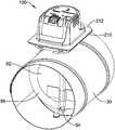
- FIG. 1is a schematic perspective view of a portion of a duct 30 with a damper assembly driven by an illustrative HVAC actuator 100 .
- the damper components other than the HVAC actuator 100may be referred to collectively as an HVAC component, to which the HVAC actuator may be coupled.
- the damper assemblymay include a damper blade 52 rotatably mounted on a damper shaft 54 between a closed state or position (illustrated) and an open state or position. In the fully closed state, damper blade 52 may be disposed in close contact with one or more damper stops 56 attached to the duct 30 , with the damper blade and damper stops substantially closing the duct to the flow of air.
- FIG. 1is a schematic perspective view of a portion of a duct 30 with a damper assembly driven by an illustrative HVAC actuator 100 .
- the damper components other than the HVAC actuator 100may be referred to collectively as an HVAC component, to which the HVAC actuator may be coupled.
- the damper assemblymay include a damper
- the plane of the damper blade 52is substantially perpendicular to the longitudinal axis of duct 30 when the damper is fully closed, however, this is not necessary, and a damper assembly may be configured with a damper blade and damper stops structured to substantially close the duct with the damper blade at a different angle relative to the duct.
- a damper assemblymay be configured with a damper blade and damper stops structured to substantially close the duct with the damper blade at a different angle relative to the duct.
- the plane of the damper blade 52In the fully open state, generally the plane of the damper blade 52 will be parallel with the airflow in the duct 30 , which generally would be the case with the plane of the damper blade being parallel to the longitudinal axis of the duct.
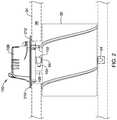
- FIG. 2is a schematic side view of duct 30 , damper assembly and illustrative HVAC actuator 100 of FIG. 1 .
- Damper shaft 54which may also be referred to as an input shaft, may extend out of the duct wall through an aperture in the duct wall.
- the illustrative HVAC actuator 100includes a rotatable output shaft 102 that may be operatively coupled to the end of damper shaft 54 as illustrated in FIG. 2 , such that rotational torque effective to rotate the damper shaft 54 and damper blade 52 may be imparted by the output shaft 102 .
- HVAC actuator 100may include a drive mechanism (not visible in FIG. 1 or 2 ) configured to selectively drive the output shaft 102 .
- the drive mechanism of HVAC actuator 100may be housed entirely or in part within a housing 106 .
- Housing 106may have a front side (e.g., the side toward the top of FIG.
- the back wall of the housing 106may be held away from the outer wall of the duct wall by a gap by virtue of the output shaft 102 extending out from the back side of the housing 106 and being mounted to the end of the damper shaft 54 as shown.
- output shaft 102 of HVAC actuator 100When output shaft 102 of HVAC actuator 100 rotates relative to housing 106 , it may rotate damper shaft 54 and in turn damper blade 52 relative to duct 30 , provided that the housing 106 does not move relative to the duct.
- an anti-rotation rod 108may be attached to housing 106 , and the rod 108 may be inserted into a hole in the duct wall of duct 30 . This is one implementation, and it is contemplated that any suitable anti-rotation mechanisms may be used, as desired.
- Anti-rotation rod 108may be referred to as a stop.
- the back wall of the housing 106may be configured to be spaced from the outer surface of the duct 30 , and the anti-rotation rod or stop 108 may be configured to extend out away from the back wall of the housing 106 towards the duct to engage the duct wall when the HVAC actuator 100 is coupled to the damper components.
- HVAC actuators of the present disclosuremay include further features to ease their installation and maintenance.
- HVAC ductsare often insulated to retard heat loss and/or gain to/from the environment. Insulation may take the form of an insulating layer around the outer surface 32 of the duct. Referring back to FIG. 2 , an outer surface 34 of an insulating layer 36 around duct 30 is represented in phantom outline.
- HVAC actuator 100is disposed when coupled to the duct 30 and damper components, there may be a discontinuity in the insulating layer 36 .
- techniciansmay apply tape between the insulating layer 36 and the HVAC actuator 100 .
- HVAC actuator 100may include a taping flange 210 .
- Taping flange 210may be configured to extend transversely away from the housing 106 and provide a taping surface 212 facing away from the duct 30 .
- the taping flange 210may further be configured to be spaced from the outer surface 32 of the duct 30 and adjacent to the outer surface 34 of the insulating layer 36 of the duct when the HVAC actuator 100 is coupled to the damper components.
- an HVAC actuatoris coupled to a valve, which may be disposed in a pipe or other fluid handling enclosure to which insulation may applied similarly as with duct 30 of FIG. 2 .
- Taping flange 210may be configured to facilitate taping of the HVAC actuator 100 to the outer surface 34 of the insulating layer 36 .
- the taping flange 210may be shaped to provide a front-facing surface 212 that is suitable for receiving tape to provide a seal between the taping flange 210 and the outer surface 34 of the insulating layer 36 .
- the taping flange 210may extend outward from the housing 106 around the entire perimeter of the housing, as illustrated. It may extend outward from the housing 106 by at least a minimum distance around the entire perimeter of the housing, for example, by at least 3 mm, 5 mm, 10 mm, or any other suitable distance.
- the taping flange 210may extend outward from the housing 106 approximately perpendicular to adjacent side walls of the housing, but this is not required.
- the taping flange 210may be disposed relative to the other parts of the HVAC actuator at any suitable location.
- the front-facing surface 212 of the flange 210may be disposed between the front side and back side of the housing 106 . In some cases, the flange 210 may be disposed substantially in registration with the back side of the housing 106 .
- the taping flange 210may be formed in any suitable way.
- the taping flange 210may be formed integrally with the housing 106 .
- the taping flange 210may be formed separately from the housing 106 and coupled to the housing.
- the present disclosurecontemplates a method for installing an HVAC actuator such as HVAC actuator 100 for driving an HVAC damper that is disposed in an insulated duct.
- the methodmay include the steps of operatively coupling an output shaft of the HVAC actuator to the input shaft of the HVAC damper and providing tape between a taping flange of the HVAC actuator and the outer surface of the insulating layer of the duct to form a seal.
- the methodmay further include the step of inserting a stop of the HVAC actuator through an aperture in the duct wall before operatively coupling the output shaft of the HVAC actuator to the input shaft of the HVAC damper.
- the methodmay also include tucking at least part of the insulating layer under the taping flange before providing tape between the taping flange of the HVAC actuator and the outer surface of the insulating layer of the duct to form a seal.
- HVAC actuators of the present disclosuremay be configured with a range adjustment mechanism to allow adjustment of their ranges of motion.
- the illustrative damper system of FIG. 1is illustrated with damper blade 52 and damper shaft 54 rotated to a fully closed position, with damper blade 52 in contact with damper stop 56 .
- damper blade 52 and damper shaft 54may be rotated about 90 degrees clockwise, as viewed from the side of HVAC actuator 100 , which we may refer to as the top side (relative to the drawing, but not necessarily describing a real-world spatial orientation of such a system).
- an HVAC actuatormay incorporate a range adjustment mechanism that prevent the actuator from rotating the damper blade 52 and damper shaft 54 (via output shaft 102 ) to the 90 degree fully closed position.
- FIGS. 3-5illustrate aspects of an illustrative range adjustment mechanism.
- a range adjustment mechanismmay be configured to prevent an actuator from rotating a damper blade and shaft to a 0 degree fully open position.
- FIG. 3is a schematic perspective view of a front side of the illustrative HVAC actuator 100 showing, among other features, a range adjustment knob 110 .
- the range adjustment knob 110is part of a range adjustment lever 111 more fully viewable in FIGS. 4, 5 , and other Figures of this disclosure.
- range adjustment knob 110is disposed on front side of housing 106 , where it may be manipulated easily by a user after the HVAC actuator 100 is mounted to a damper shaft 54 to allow the user to selectively limit rotation of the output shaft to a reduced range that is a subset of the full range of motion of the output shaft.
- An indicator 112 on housing 106may indicate, in conjunction with the position of range adjustment knob 110 , the adjustment of the range that has been selected, if any.
- indicator 112may include indicia labeled “0”, “1”, “2”, and “3”, although this is not limiting, and the indicator may include fewer or more indicia in some examples.
- the indicia “0”, “1”, “2”, and “3”may indicate discrete locations at which the range adjustment lever 111 and knob 110 may be set and adjusted between. Setting the range adjustment lever 111 and knob 110 to one of the discrete locations such as “0”, “1”, “2”, and “3” may allow a user to select a predetermined reduced range of motion that is a subset of the full range of motion of the output shaft 102 . Depending on the number of discrete locations provided, the range adjustment lever 111 may allow the user to select between no reduced range and a single predetermined reduced range, or a greater number of predetermined reduced ranges, such as two, three, or more. In the illustrative example of FIGS.
- Indicator 112may also be referred to as a range indicator, and/or indicia “0”, “1”, “2”, and “3” may be referred to as range indicators, in that they may indicate, in conjunction with the range adjustment knob 110 of the range adjustment lever 111 , which range or predetermined reduced range is selected.
- Indicium “0”may indicate a no stop position or setting of the range adjustment mechanism, in which the output shaft 102 is not restricted from rotating around its full range of motion completely from first end position (e.g., fully closed, 90 degrees) to second end position (e.g., fully open, 0 degrees).
- Indicia “1”, “2”, and “3”may indicate positions or settings of the range adjustment mechanism in which the output shaft 102 is restricted from rotating around its full range of motion in progressively smaller reduced ranges.
- the rangewhen set to position “1”, the range may be restricted between 80 degrees (10 degrees from fully closed) and 0 degrees (fully open), when set to position “2”, the range may be restricted between 65 degrees and 0 degrees, and when set to position “3”, the range may be restricted between 50 degrees and 0 degrees, although these values of 80, 65, and 50 degrees are merely exemplary and should not be considered limiting.
- the predetermined reduced ranges “1”, “2”, and “3”each includes the second end position (0 degrees) but has different first stop position (80, 65, and 50 degrees), the different first stop positions corresponding to partially-closed damper states.
- predetermined reduced rangesmay have a common first end position but different second stop positions.
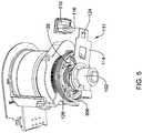
- FIG. 4is a schematic perspective view of illustrative HVAC actuator 100 showing features visible on the back side of the actuator, including the range adjustment lever 111 .
- the range adjustment lever 111may be rotatably mounted concentric with the output shaft 102 of the HVAC actuator 100 .
- the range adjustment lever 111may have a first portion 114 extending radially outward relative to the output shaft 102 and a second portion 116 that extend from the first portion toward the front side of the housing 106 .
- the range adjustment knob 110may be considered to be a part of the second portion 116 , or it may be considered to be attached to the second portion.
- the housing 106may include an opening 118 through which the second portion 116 extends from the back side to the front side of the housing 106 , although this is not necessary.
- a range adjustment levermay extend from back to front around the outside of the housing. In some illustrative examples, a range adjustment lever may not extend from the back to the front of an actuator entirely, or at all. In some such cases the range adjustment lever may be manipulatable from the front side of the housing, for example, by extending a tool or a finger through an opening in the housing to reach the range adjustment lever for adjustment.
- the illustrative HVAC actuator 100includes a plate 120 that is generally perpendicular to the output shaft 102 and proximal the first portion 114 of the range adjustment lever 111 .
- the plate 120may be rigidly affixed relative to the housing 106 .
- the plate 120may form at least part of a back surface of the housing 106 of the HVAC actuator 100 , but this is not required.
- the plate 120may be disposed at an intermediate depth within the interior of the HVAC actuator housing.
- plate 120may include two or more receptacles 122
- the range adjustment lever 111may include a projection 124 engageable by any one of the two or more receptacles.
- the projection 124may be included as part of the first portion 114 of the range adjustment lever 111 , but this is not necessary.
- a projectionmay be provided as part of a second portion of a range adjustment lever 111 , or be configured with respect to the range adjustment lever in any other suitable manner.
- the range adjustment lever 111may be manipulatable from the front side of the housing 106 to disengage the projection 124 from any one of the two or more receptacles 122 , to rotate the range adjustment lever, and to engage the projection with another one of the two or more receptacles, thereby allowing adjustment of the rotational position of the range adjustment lever between two or more discrete locations.
- the range adjustment lever 111may include or incorporate a spring lever, for example, the first portion 114 of the range adjustment lever may comprise a suitably elastic material, such an appropriate metal of suitable thickness.
- the “springy” or resilient range adjustment lever 111may be configured such that when a force is applied to the range adjustment lever toward the back of the housing 106 (e.g., via pressing range adjustment knob 110 toward the back), the projection 124 of the range adjustment lever may disengage from any one of the two or more receptacles 122 of the plate 120 , releasing the range adjustment lever for rotation to a new position.
- the relationship between a range adjustment lever and platemay be somewhat different, such that force is applied to the range adjustment lever toward the front of the housing to disengage a projection from a receptacle to release the range adjustment lever for rotation to a new position.
- the range adjustment lever 111may be configured to be pushed in a direction radially away from the output shaft 102 to disengage the projection from the two or more receptacles, after which the range adjustment lever 11 may be rotated to align the projection with a newly selected one of the two or more receptacles. The range adjustment lever 111 may then be pushed radially toward the output shaft 102 to engage the projection with the newly selected receptacle.
- the range adjustment lever 111may be configured to be pushed in a direction radially toward the output shaft 102 to disengage the projection from the two or more receptacles, after which the range adjustment lever 11 may be rotated to align the projection with a newly selected one of the two or more receptacles. The range adjustment lever 111 may then be pushed radially away from output shaft 102 to engage the projection with the newly selected receptacle.
- FIG. 5is a schematic perspective view of illustrative HVAC actuator 100 from the same viewpoint as FIG. 4 , but with the housing 106 and plate 120 removed, showing further details of the range adjustment lever 111 and the operation of the range adjustment mechanism.
- the illustrative HVAC actuator 100may include a tab 126 rigidly connected to the output shaft 102 , and the range adjustment lever 111 may move a mechanical stop 128 configured to limit the rotation of the output shaft when the tab 126 is rotated into contact with the mechanical stop 128 .
- the mechanical stop 128may be integral to the range adjustment lever 111 , but this is not required.
- the mechanical stop 128When the mechanical stop 128 is integral to the range adjustment lever 111 , then it may be substantially fixed or “locked” relative to the housing 106 of the HVAC actuator 100 when the projection 124 of the range adjustment lever 111 is engaged by a receptacle 122 of the plate 120 .
- the range adjustment lever 111may allow a user to select any provided stop position (for example, corresponding to discrete locations of the range adjustment lever that correspond to receptacles 122 , which may also correspond to indicated positions “1”, “2”, and “3”) or a no stop position (for example, corresponding to a receptacle of the plate 120 that corresponds to indicated position “0”) of the output shaft 102 , where the stop positions prevent the output shaft 102 from rotating completely to the first end position, and the no stop position allows the output shaft to rotate completely to the first end position.
- Indicator 112may visually indicate which stop position if any has been selected.
- a second range adjustment levermay also be provided, such that both first and second stops in either direction of motion for an HVAC actuator may be provided. That is, in some embodiments, there may be two adjustment levers provided; one for controlling one end (e.g. more closed end) of the desired range of motion and another for controlling the other end (e.g. more open end) of the desired range.
- the present disclosurecontemplates a method for adjusting a range of motion of an HVAC actuator such as HVAC actuator 100 .
- the methodmay include the steps of manipulating an adjustment lever from the front side of the housing to unlock the adjustment lever from a first lock position, moving the adjustment lever along a path to a second lock position, and releasing the adjustment lever to lock the adjustment lever in the second lock position.
- At least one of the first lock position and the second lock positionmay establish a stop position that limits rotation of the output shaft from reaching an end position of a full range of rotation motion between a first end position and a second end position.
- manipulating the adjustment levermay include pressing the lever in a direction that is toward the back side of the HVAC actuator, but other mechanisms are also contemplated.
- HVAC actuator 10may include other features that allow easy visual assessment of the state of the actuator.
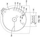
- FIG. 6is a schematic perspective view of illustrative HVAC actuator 100 showing, among other features, a faceplate 130 on the front side of the actuator that may display useful information. Faceplate 130 may include a first window 132 and a second window 134 positioned to provide visibility to an observer external the housing of light from corresponding light sources disposed within the housing.
- the first window 132may be a component of a “closed” indicator and the second window 134 may be a component of an “open” indicator, but this is not limiting and other configurations may be used in other examples.
- Windows 132 , 134may include lenses, diffractive or diffusive patterning, or any other suitable light redirection features that may help disperse or otherwise increase the viewing angle of the windows to an observer external the housing, when viewing light from light sources within the housing.
- Faceplate 130may be considered to be a component of the housing 106 .
- first lightmay have a first color (which may be red, for example, although this is arbitrary and any desired color may be chosen), and may be visible in first window 132 when the actuator is being actuated toward the first end position.
- First lightmay appear to blink (e.g., varying significantly in intensity versus time) in first window 132 when the output shaft 102 is rotating toward the first end position, and in some cases, may remain continuously visible with substantially constant intensity when the output shaft is disposed at the first end position or a first stop position, which may correspond to a damper closed state or damper partial closed state.
- the second light having a second colormay be visible in second window 134 .
- Second lightmay appear to blink in second window 134 when the output shaft 102 is rotating toward the second end position, and in some instances, may remain continuously visible with essentially constant intensity when the output shaft 102 is disposed at the second end position or a second stop position, which may correspond to a damper open state or damper partial open state.
- HVAC actuatormay be configured such that at most one of first window 132 and second window 134 transmits first or second light, respectively, at any given time.
- Costs associated with implementing the light indication patterns described hereinmay be reduced by adopting what may be described as a mechanical shutter or mechanical aperture approach to modulating the light visible through the first window 132 and/or the second window 134 , when compared to other approaches potentially involving switches, wiring, electronic logic, and the like.
- FIGS. 6-13illustrate such an approach.
- FIG. 7is a schematic perspective view of illustrative HVAC actuator 100 of FIG. 6 , but with the faceplate 130 removed.
- FIG. 8is a schematic perspective view of illustrative HVAC actuator 100 of FIG. 7 with the housing 106 also removed.
- An aperture member or wheel 136is shown in FIGS. 7 and 8 , but is removed in the schematic perspective view of FIG. 9 .
- a first light source 138 and a second light source 140are shown disposed on circuit board 142 .
- First light source 138 and second light source 140may be configured to provide first light having a first color and second light having a second color, respectively.
- Light sources 138 , 140may be light emitting diodes (LEDs), but this is not required and may be any suitable light source as desired.
- LEDslight emitting diodes
- first window 132may be aligned and positioned to provide visibility of the first light from the first light source 138 to an observer external the housing 106
- second window 134may be aligned and positioned to provide visibility of the second light from the second light source 140 to the observer.
- First light and second lightmay be visible via first and second windows 132 , 134 if there is no obstruction between first and second light sources 138 , 140 and their respective first and second windows 132 , 134 .
- Aperture member/wheel 136may be situated between the light sources 138 , 140 and the windows 132 , 134 and may, depending on its spatial disposition, obstruct or not obstruct the light from reaching the windows 132 , 134 .
- Aperture member/wheel 136may have a plurality of spaced openings 151 , 152 , 153 , 154 , 155 , and 156 through which light may pass unobstructed. Between the spaced openings 151 - 156 , the aperture member/wheel 136 may be substantially opaque and obstruct the passage of light, although it is not necessary for the passage of light to be obstructed completely.
- solid portions of the aperture wheelmay partially obstruct and partially transmit light. In other illustrative examples, solid portions of the aperture wheel may completely obstruct light.
- aperture member/wheel 136may be operatively coupled to the output shaft 102 of HVAC actuator 100 in any suitable way, directly or indirectly. Being so coupled, aperture member/wheel 136 may rotate as the output shaft is rotated. In some illustrative examples, aperture member/wheel 136 may be coupled indirectly to the output shaft 102 through one or more gears, and rotate in accordance with a gearing ratio with respect to the rotation of the output shaft. In the illustrative example of HVAC actuator 100 , aperture member/wheel 136 may be directly coupled relative to the output shaft 102 and may rotate at the same rotational rate as the output shaft 102 . Aperture member/wheel 136 may be coupled to or integrally formed with an arm 144 , as best seen in FIG. 8 .
- Arm 144may in turn be coupled to output shaft 102 . Such coupling may be via a coupling member 146 , which may be rigidly coupled to the output shaft 102 .
- the arrangement of output shaft 102 , coupling member 146 , and arm 144 illustrated in FIG. 8may provide a mechanism to transfer rotational motion directly from the output shaft 102 disposed generally at the back side of the HVAC actuator 100 to the aperture member/wheel 136 at the front side of the actuator.
- Aperture/member wheel 136may be round in shape, although this is not necessary. Aperture/member wheel 136 may rotate about a common rotation axis as the output shaft 102 , although this is not necessary.
- FIGS. 10A-Eare schematic perspective views from the front side of HVAC actuator 100 of faceplate 130 (rendered in phantom) with first window 132 and second window 134 , aperture member/wheel 136 , and circuit board 142 with first light source 138 and second light source 140 , with other components of the actuator omitted for clarity.
- FIGS. 10A-Eall show the same components of HVAC actuator 100 , but with aperture member/wheel 136 disposed at different rotational positions as it rotates with output shaft 102 .
- aperture member/wheel 136and more particularly, the openings 151 - 156 of the aperture wheel
- the light sources 138 , 140as well as windows 132 , 134 , as described in the following paragraphs.
- HVAC actuator 100may be disposed in a damper fully open state, with output shaft 102 rotated fully to the second end position. Opening 153 of the aperture member/wheel 136 is aligned and in registration with second light source 140 such that if the second light source is illuminated, its light is visible through second window 134 . Second light source 140 may be illuminated when HVAC actuator 100 is electrically commanded to open, as discussed further elsewhere herein. Note that first light source 138 is not visible through any of openings 151 - 156 , as none of the openings are in registration with the first light source. In other illustrative examples, there may be an opening in registration with the first light source 138 when the output shaft 102 is rotated fully to the second end position.
- FIG. 11Ais a schematic cross sectional view of faceplate 130 with first window 132 and second window 134 , aperture member/wheel 136 , and circuit board 142 with first light source 138 and second light source 140 , with other components of the actuator omitted for clarity.
- the relative alignment of windows 132 , 134 , aperture member/wheel 136 , and light sources 138 , 140is substantially the same as that illustrated in FIG. 10A .
- this viewone may appreciate the alignment and registration of opening 153 relative to second light source 140 such that if the second light source is illuminated, its light is visible through second window 134 . Also as in FIG.
- FIG. 10Bthe output shaft 102 and the aperture member/wheel 136 are rotated counter-clockwise relative to FIG. 10A . Opening 151 of the aperture member/wheel 136 is aligned and in registration with first light source 138 such that if the first light source is illuminated, its light is visible through first window 132 .
- FIG. 10Bcould illustrate an instant in time as HVAC actuator 100 is in the process of rotating the output shaft toward a closed or partially-closed state, having started, for example, in the open state illustrated in FIG. 10A .
- first light source 138may be illuminated continuously, as discussed further elsewhere herein.
- first light source 138may only be visible through first window 132 to an observer when an opening of the aperture member/wheel 136 is aligned with the light source 138 , as is opening 151 in FIG. 10B .
- an HVAC actuator 100 commanded to close from an open stateas in FIG. 10A
- first light source 138may be the first time light from illuminated first light source 138 may be visible to an observer, having appeared to have blinked on as opening 151 rotated into alignment with the first light source 138 , despite the fact that first light source 138 may have been illuminated continuously from the earliest moment that the actuator was commanded to close, when solid portions of aperture member/wheel 136 may have obstructed light from the first light source 138 from reaching the first window 132 .
- FIG. 10Cthe output shaft 102 and the aperture member/wheel 136 are rotated further counter-clockwise relative to FIG. 10B .
- First light source 138is not visible, with an obstructing portion of aperture member/wheel 136 between openings 151 and 152 being positioned over the light source. None of openings 151 - 6 are aligned and in registration with first light source 138 .
- an observermay have perceived light from illuminated first light source 138 to have blinked off as the obstructing portion between openings 151 and 152 rotated into the position of FIG. 10C from the previous position of FIG. 10B .
- the effective appearance from outside the housing 106 of the HVAC actuatormay be that the first light is turning on and off (blinking) as openings and obstructions of the aperture wheel 136 alternate in passing between the first light source 138 and the first window 132 .
- Some or all openings 151 - 156may be configured to cause the appearance of blinking of the first light from first light source 138 through the first window 132 as the output shaft 012 is rotated toward the first end position.
- FIG. 10Dthe output shaft 102 and the aperture member/wheel 136 are rotated further counter-clockwise relative to FIG. 10C .
- Opening 154is aligned and in registration with first light source 138 such that if the first light source 138 is illuminated, its light is visible through first window 132 .
- the position of aperture member/wheel 136may correspond to a damper partially-closed stop position selected via the range adjustment mechanism of HVAC actuator 100 , for example, range stop position “2”.
- first light from first light source 138may remain continuously visible through opening 154 and first window 132 if the first light source 138 remains illuminated, as may be the case when the HVAC actuator is being commanded to be closed.
- openings 153 and 155may correspond to range stop position “3” and “1” respectively such that they may be aligned and in registration with first light source 138 when the output shaft 102 is stopped at one of those positions.
- FIG. 10Ethe output shaft 102 and the aperture member/wheel 136 are rotated further counter-clockwise relative to FIG. 10D .
- Opening 156is aligned and in registration with first light source 138 such that if the first light source 138 is illuminated, its light is visible through first window 132 .
- the position of aperture member/wheel 136may correspond to an actuator state with the output shaft 102 rotated completely to the first end position, which may correspond to a damper fully closed state. If HVAC actuator 100 continues in a state of being electrically commanded to close, as discussed further elsewhere herein, first light source 138 may remain illuminated and its light may remain continuously visible through first window 132 for as long as it continues in that state.
- second light source 140may remain obscured by aperture member/wheel 136 , with none of the openings 151 - 156 aligned and in registration with the second light source 140 .
- FIGS. 10A-10Emay generally describe a progression starting at FIG. 10A with output shaft 102 rotated fully to the second end position which may correspond to a damper fully open state, and progressing to FIG. 10E , with the output shaft 102 rotated fully to the first end position which may correspond to a damper fully closed state.
- first light source 138may be continuously illuminated, with the alternating pattern of openings and obstructions of the aperture wheel 136 helping to create the appearance of blinking of first light as viewed via first window 132 .
- the aperture member/wheel 136may likewise modulate second light from second light source 140 , when the second light source is illuminated.
- the second light source 140may be illuminated when HVAC actuator 100 is electrically commanded to rotate the output shaft 102 toward the second end of its range, which may correspond to a damper open state. In such a condition, the second light source 140 may be illuminated continuously whether the output shaft 102 is rotating toward the second end of its range, or whether it stationary at the second end of its range. As may be appreciated from FIG.
- opening 153is aligned and in registration with second light source 140 , and openings 154 , 155 , and 156 are disposed clockwise relative to the second light source 140 , openings 153 - 156 may participate in providing varying patterns of second light.
- any appropriate patterns of openingsmay be provided on an aperture member to results in light patterns similar to those described herein.
- Other arrangementsare contemplated.
- light sourcesmay be disposed at different radii relative to the axis of rotation of the aperture member/wheel 136 , and separate patterns of openings at corresponding radii may exclusively modulate the light output of the different light sources.
- the openingsneed not be defined on all sides by the aperture member. For example, in some cases, the perimeter of the aperture member may undulate inwardly at certain locations to form corresponding openings.
- FIG. 12is a schematic illustration of a faceplate 160 of an HVAC actuator similar to HVAC actuator 100 .
- Faceplate 160has a single indicator window 162 .
- An HVAC actuator having faceplate 160 with single indicator window 162may be configured with a light source corresponding to the single indicator window and a moving aperture member that modulates visibility of light from the light source via the single indicator window in a manner like or similar to that of the system of FIGS. 6-11A .
- Such an HVAC actuatormay be configured such that the light source only illuminates when the actuator is powered to drive its output shaft in one direction (for example, in a damper open direction), but not when the actuator moves the output shaft in the other direction (for example, the closed direction).
- an HVAC actuatormay be powered only to drive its output shaft in the one direction, and may move the output shaft in the other direction when unpowered, for example, through the action of a return spring.
- an HVAC actuator having faceplate 160 of FIG. 12may be a damper actuator for a venting or bypass applications.
- FIG. 11Bis a schematic cross sectional view of an actuator faceplate 170 with an indicator window 172 , an aperture member 174 , and circuit board 176 with light source 178 .
- the arrangement of FIG. 11Bmay be similar to that of FIG. 11A , but with only a single window and light source rather than two.
- the arrangement of FIG. 11Bmay correspond to or be compatible with faceplate 160 of FIG. 12 .
- the arrangement of FIG. 11Bmay correspond to still yet another example, in which light source 178 may be capable of emitting multiple colors of light independently. This may be accomplished with multiple LED emitters, but it is contemplated that any suitable technology may be used.
- Such an arrangementcould be operated with a first color emitted when the actuator is actuated in a first direction, and a second color when actuated in a second direction.
- the same openings in aperture member 174may modulate the transmission of either color of light.
- FIG. 13is a schematic illustration of another illustrative example of an aperture member 220 that may be configured to modulate light for an HVAC actuator in a manner similar to aperture member/wheel 136 .
- Aperture member 220may translate as the output shaft of the HVAC actuator of which it is a component is rotated.
- Aperture member 220may be linked to output shaft motion via a rack-and-pinion mechanism 222 .
- Openings 224may provide a like function as openings 151 - 156 of aperture member/wheel 136 . While a rack-and-pinion mechanism is shown in FIG. 13 to produce a linear motion for the aperture member 220 , it is contemplated that any suitable translation mechanism may be used to move a number of apertures relative to one or more light sources.
- the present disclosurecontemplates a method for operating an HVAC actuator having the indicator features described in connection with FIGS. 6-12 .
- the methodmay include the steps of rotating an output shaft toward a first end position and stopping rotation of the output shaft when the output shaft reaches the first end position.
- the methodmay also include the step, as the output shaft 102 is rotated toward the first end position, of moving an aperture member 136 .
- the aperture member 136may have two or more spaced openings that transmit a first light from a first light source 138 to a first window 132 of a housing at each of two or more positions of the output shaft 102 , where the two or more openings of the aperture member 136 are configured to cause the appearance of blinking of the first light through the first window 132 as the output shaft 102 is rotated toward the first end position, and remaining lit when the output shaft 102 is at the first end position.
- the methodmay further include the steps of rotating the output shaft 102 toward a second end position and stopping rotation of the output shaft 102 when the output shaft reaches the second end position.
- the methodmay also include the step, as the output shaft 102 is rotated toward the second end position, of moving the aperture member 136 .
- the two or more spaced openings of the aperture member 136may be configured to transmit a second light from a second light source 140 to a second window 134 of the housing at each of two or more positions of the output shaft 102 , where the two or more openings of the aperture member 136 are configured to cause the appearance of blinking of the second light through the second window 134 as the output shaft 102 is rotated toward the second end position and remaining lit when the output shaft 102 is at the second end position
- HVAC actuator 100may provide further visual indicators of its current status. HVAC actuator 100 may include a position indicator viewable from the front side of housing 106 that moves as the output shaft 102 is rotated such that the position indicator indicates a current position of the output shaft. Aperture member/wheel 136 , which is operatively coupled to the output shaft 102 of HVAC actuator 100 and rotates with the output shaft, may serve as an indicator wheel for the position indicator.
- aperture member/wheel 136also serve as an indicator wheel of a position indicator
- an HVAC actuatormay include an indicator wheel operatively coupled to the output shaft 102 of the HVAC actuator that rotates with the output shaft 102 as a component of a position indicator that does not also serve as an aperture wheel.
- aperture wheel 136may include one or more markings that move with the indicator wheel and that are viewable from the front side of the housing 106 .
- markingsmay include a line 180 extending in a radial direction from the rotation axis of the aperture wheel 136 (see FIGS. 6-8 and 10A-10E ).
- Line 180 and any other provided markingsmay be viewable through a window of the housing 106 , such as window 182 of faceplate 130 (see FIG. 6 ).
- Window 182may be a transparent solid material, but this is not necessary, and in other illustrative examples, a window for viewing markings of an indicator wheel may simply be an opening in a housing.
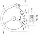
- faceplate 130 of housing 106may include one or more position indicia 184 that may, when used in conjunction with the one or more markings of the indicator wheel such as line 180 , indicate when the output shaft 102 is at one or more predetermined positions.
- indicium “0” of indicia 184may indicate when the output shaft is at a position corresponding to the second end of the range of motion, which may be when the damper is fully closed.
- the indicia “1”, “2”, and “3” of indicia 184 of the position indicatormay indicate when the output shaft is at the stop positions corresponding to the “1”, “2”, and “3” indicia of indicator 112 of the range adjustment mechanism.
- a technicianmay manipulate the range adjustment mechanism by moving range adjustment knob 110 of the range adjustment lever 111 to the position corresponding to indicium “1” of indicator 112 .
- the range of motion of the output shaft 102may then be limited to a range between fully open at 0 degrees and stop position “1”, which may be at, for example, 80 degrees.
- line 180may move with aperture wheel 136 such that at its furthest counter-clockwise rotation, it reaches indicium “1” of indicia 184 of the position indicator (as illustrated as an example in FIG. 6 ) but may not rotate further, as the motion of the output shaft is stopped by the range adjustment mechanism.
- Aperture wheel 136may be directly coupled to the output shaft 102 of the HVAC actuator 100 such that it rotates directly with the output shaft. When so provided, a given rotational displacement of the output shaft 102 may result in an identical rotation displacement of the aperture wheel 136 . For example, 47 degrees of rotation of the output shaft 102 may be coupled directly to the aperture wheel 136 to result in an identical 47 degrees of rotation of the indicator wheel.
- line 180may be aligned with the plane of the damper blade 52 such that after installation, a technician may be able to immediately visually ascertain the actual angular disposition of the damper blade (which, being within the duct 30 , may not be visible directly) simply from inspection of the position of line 180 of the position indicator, which may remain aligned with the plane of the damper blade.
- FIG. 13illustrates an aperture member 220 that translates rather than rotates.
- Aperture member 220may also serve as a position indicating member and include one or more markings 226 that may be viewable from the front side of a housing of an HVAC actuator, and which may be used in conjunction with position indicia on the housing to provide an indication of the current position of an output shaft.
- a translating position indicating membermay be provided that is not also an aperture member.
- the present disclosurecontemplates a method for operating n HVAC actuator such as HVAC actuator 100 having the position indicator features described herein.
- the methodmay include the steps of rotating an output shaft 102 extending from a back side of the HVAC actuator 100 moving a position indicator in proportion to the rotation of the output shaft 102 .
- the position indicatormay have markings and/or indicia that indicate a current position of the output shaft 102 .
- the methodmay also include the step of displaying the indicia of the position indicator through a window on a front side of the HVAC actuator.
- the position indicatormay comprise an indicator wheel, and the moving step may comprise rotating the indicator wheel about a common rotation axis as the output shaft, but this is not required.
- an HVAC actuator of the present disclosuremay be configured to selectively output rotational motion via an output shaft 102 in a first direction and a second direction.
- an HVAC actuator of the present disclosuremay be electrically controllable.
- electrical power for actuator operation and control signalsmay be provided separately.
- the supply of electrical voltage and current at electrical terminals of an HVAC actuatormay provide both the signal for a desired actuator operation and electrical power to implement that operation.
- Some HVAC actuators that provide output rotational motion via an output shaft 102 in a first direction and a second directionrequire electrical power for motion in each direction, and may be referred to as bi-directionally powered actuators.
- Some bi-directionally powered actuatorsmay be provided with three or more wiring terminals, including a common terminal, a first terminal for commanding rotation in the first direction, and a second terminal for commanding rotation in the second direction, whereupon when either of the first or second terminals is asserted by being supplied with appropriate voltage and/or current, an electric motor may drive the output shaft in the corresponding direction.
- a remote HVAC controller for such a bi-directionally powered HVAC actuatormay be required to provide appropriate control signals to the three or more wiring terminals to achieve proper actuator operation in both the first and the second directions. Such a controller may be referred to as a bi-directional controller.
- Some HVAC actuatorsmay only require electrical power for motion in one of two directions, and may be referred to as uni-directionally powered actuators.
- Some uni-directionally powered actuatorsmay be provided with only two wiring terminals, whereupon when the terminals are asserted by being supplied with appropriate voltage and/or current, an electric motor may drive the output shaft in one of the two directions. When electrical power is not asserted at the terminals, a return spring of the actuator may move the output shaft 102 in the other of the two directions.
- An advantage of a uni-directionally powered HVAC actuatoris that it may provide “failsafe” operation.
- the return springmay move the output shaft 102 to actuate the HVAC component (e.g., damper, valve, etc.) in a preferred power loss direction.
- the HVAC componente.g., damper, valve, etc.
- such uni-directionally powered actuatorsmay be available in “normally open” and “normally closed” versions, corresponding to the default state of the actuator in an unpowered or power loss condition.
- a remote HVAC controller for a such a uni-directionally powered actuator having only two wiring terminalsmay be configured to provide a control signal via two wires when motion in the electric motor driven direction is desired, and no signal when motion in the default return spring driven direction is desired.
- Such a controllermay be referred to as a uni-directional controller. Faceplate 160 of FIG.
- single indicator window 162may illuminate (whether blinking or continuously) only when power is applied to the actuator via the two wire terminals, and may remain un-illuminated when power is not applied via the two wire terminals.
- an HVAC controllerthat is configured to provide signals to a bi-directionally powered HVAC actuator via three wire terminals may be used to control a uni-directionally powered actuator that only includes two wire terminals.
- two of three wire connections provided by the HVAC controllermay be connected to the two wire terminals of the actuator: the common wire connection, and the appropriate one of the first or second direction wire connection, with the other direction wire connection being left unconnected.
- the actuatorwhen the actuator is not powered via the two wire terminals, the actuator may not provide any illuminated indications of actuator status.
- the present disclosurecontemplates uni-directionally powered HVAC actuators that include three wiring terminals, and which may be controlled either by a uni-directional HVAC controller with two wires, or by a bi-directional HVAC controller with three wires, and also include features to help prevent miss-wiring of the actuator.
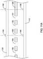
- FIG. 14is a schematic perspective view of the illustrative HVAC actuator 100 showing details of three wiring terminals 190 , 192 , and 194 .
- the three wiring terminalsmay be designated M1 ( 190 ), M4 ( 192 ), and M6 ( 194 ), as labeled on faceplate 130 , but this is merely exemplary and is not required.
- HVAC actuator 100may include a removable blocking tab 196 configured to block wire attachment to at least one of the wiring terminals. As illustrated, removable blocking tab 196 blocks wire attachment to wiring terminal 192 , which is the second and middle of the three wiring terminals 190 , 192 , 194 . However, any suitable wiring terminal or terminals may be blocked by one or more removable blocking tabs, depending on the configuration of the HVAC actuator.
- Removable blocking tab 196may be a break-away tab, and may be referred to as a break-away blocking tab. Removable blocking tab 196 may be integral to housing 106 . Removable blocking tab 196 may be configured such that once removed, it is not configured to be reattached. HVAC actuator 100 may be configured such that once a removable blocking tab, such as removable blocking tab 196 , is removed, wire attachment to the previously blocked wire terminal(s) is/are no longer blocked.
- the removable blocking tab 196may not be a break-away tab.
- the removable blocking tabmay be hinged, and may be rotated out of the way by an installer to expose previously blocked wiring terminal(s).
- the removable blocking tabmay be slide out of the way by the installer to expose previously blocked wiring terminal(s).
- FIG. 14shows in illustrative HVAC actuator 100 with removable blocking tab 196 in place.
- the HVAC actuatormay be suited for wired connection to a uni-directional HVAC controller that provides signals over two wires.
- the two unblocked wiring terminals M1 ( 190 ) and M6 ( 194 )may receive the two wires from the uni-directional HVAC controller.
- HVAC actuator 100may be configured with M1 ( 190 ) as electrical common, and M6 ( 194 ), when asserted, may cause the drive mechanism to drive the output shaft 102 toward the first end direction or position, which may be a more closed direction or position in comparison with the second end direction or position.
- the first end direction or positionmay be a more open direction or position in comparison with the second end direction or position.
- HVAC actuator 100may be configured to drive toward the first end direction with the two wires from the unidirectional controller attached to M1 ( 190 ) and M6 ( 194 ) with either polarity.
- HVAC actuator 100When HVAC actuator 100 is powered via M1 ( 190 ) and M6 ( 194 ) to drive output shaft 102 toward the first end direction or position, the first light source 138 may be continuously illuminated or activated and the second light source 140 may be deactivated.
- a return springmay drive the output shaft 102 toward the second end position, and first light source 138 may be non-illuminated. With terminal M4 ( 192 ) not asserted, as may be the case when it is blocked by removable blocking tab 196 , second light source 140 may also be non-illuminated.
- HVAC actuator 100may be configured with M1 ( 190 ) as electrical common, and M6 ( 194 ), when asserted, may cause the drive mechanism to drive the output shaft 102 toward the first end direction or position, which may be a more closed direction or position in comparison with the second end direction or position.
- M6194
- the first end direction or positionmay be a more open direction or position in comparison with the second end direction or position.
- M6194
- the first light source 138may be continuously illuminated or activated and the second light source 140 may be deactivated.
- the first light source 138When M6 ( 194 ) is not asserted, the first light source 138 may be deactivated and a return spring may drive the output shaft 102 toward the second end position.
- the second light source 140When M4 ( 192 ) is asserted, the second light source 140 may be continuously illuminated or activated, but there may be no electrical power applied to the drive mechanism of the HVAC actuator.
- the bi-directional controllerwill not also assert M6 ( 194 ), and the return spring may drive the output shaft 102 toward the second end position.
- both first and second light sources 138 , 140may be illuminated, and the drive mechanism may drive the output shaft 102 toward the first end direction or position.
- the pattern of openings 151 - 156 of aperture member/wheel 136may result in the appearance of first light in first window 132 and non-appearance of light in second window 134 to an observer viewing the front of the housing 106 .
- blinking of lightmay be observed in both first and second windows 132 , 134 , indicating a wiring or other error condition.
- removable blocking tab 196may help reduce the chance of miss-wiring the HVAC actuator.
- the HVAC actuator 100may be provided to a technician with removable blocking tab 196 intact. If using a uni-directional HVAC controller that provides two wires to control the actuator, then with removable blocking tab 196 in place, only two wiring terminals, for example M1 ( 190 ) and M6 ( 194 ), are readily accessible and the wires from the uni-directional HVAC controller may be coupled to these unblocked terminals without confusion.
- the removable blocking tab 196may help prevent miss-wiring to the blocked wiring terminal, for example, M4 ( 192 ). If, on the other hand, a bi-directional HVAC controller that provides three wires is used, the removable blocking tab 196 may be removed, and the three wires may be coupled to the appropriate wiring terminals 190 , 192 , 194 .
- HVAC actuator 100may include wire guides 200 , 202 , 204 associated with each of wire terminals 190 , 192 , 194 .
- Each wire guide 200 , 202 , 204may be regarded as an integral component of each wire terminal 190 , 192 , 194 , or it may be regarded as a separate accessory for its associated wire terminal.
- Each wire guide 200 , 202 , 204may define an aperture for receiving and guiding an end of a corresponding wire to a corresponding one of the wiring terminals 190 , 192 , 194 .
- First, second, and third wire guides 200 , 202 , 204may be formed from a common part.
- a removable blocking tabmay be situated in front of the aperture of a wire guide corresponding to a wire terminal 190 , 192 , 194 to help prevent inadvertent connection of a wire to that terminal.
- removable blocking tab 196may be situated in front of the aperture of wire guide 202 of second wire terminal M4 ( 192 ) to help prevent inadvertent connection of an improper wire to the second wire terminal, for example, in a case where a uni-directional HVAC controller that provides two wires is employed to control the HVAC actuator 100 .
- Each wire terminal 190 , 192 , 194may be configured to allow a wire to be inserted manually without the aid of tools, and, after insertion, to retain the wire firmly.
- Each wire terminal 190 , 192 , 194may include a corresponding release button 191 that, when pressed, actuates a release mechanism that allows insertion and removal of a wire from the terminal without tools.
- HVAC actuator 100may include integrated wire strain relief features.
- HVAC actuator 100may include wire wrap posts 197 , around which wires attached to the wire terminals 190 , 192 , 194 may be wrapped.
- Wrapping a wire attached to a wire terminal 190 , 192 , 194 around a post 197may isolate or buffer the end of the wire inserted into the terminal from mechanical forces applied to the wire on the other side of the wrap around the post, helping to prevent undesired detachment of the wire from the terminal.
- the present disclosurecontemplates a method for connecting two or more wires to an HVAC device, such as HVAC actuator 100 , including the step of identifying which of two or more wiring terminals of the HVAC device need to be connected to a wire.
- At least one of the two or more wiring terminals of the HVAC devicemay have a removable blocking tab that blocks access to the corresponding wiring terminal. If a wire needs to be connected to the at least one of the two or more wiring terminals that has a removable blocking tab that blocks access to the corresponding wiring terminal, the method may include the step of removing the removable blocking tab and then connecting a wire to the corresponding wiring terminal.
- the removable blocking tabmay be a break-away blocking tab, in which case removing the removable blocking tab may include breaking away the break-away blocking tab.
- a break-away blocking tabonce broken-away, may not be configured to be reattached. If a wire needs to be connected to one or more of the two or more wiring terminals that does not have a removable blocking tab that blocks access to the corresponding wiring terminal, the method may include the step of connecting a wire to the corresponding wiring terminal.
- HVAC actuator 100may include a controller for controlling the drive mechanism, the first light source 138 and the second light source 140 .
- the controllermay be disposed on a circuit board 142 .
- the controllermay be configured to activate the first light source 138 and deactivate the second light source 140 when the drive mechanism is driving the output shaft 102 toward the first end position.
- the controllermay further be configured to activate the second light source 140 and deactivate the first light source 138 when the output shaft 102 is moved toward the second end position.
- Output shaft 102may be moved toward the second end position as a result of force exerted by a return spring 306 .
- the drive mechanismmay be configured to selectively drive the output shaft 102 toward the second end position, and the controller may activate the second light source 140 and deactivate the first light source 138 when the drive mechanism is driving the output shaft toward the second end position.
- FIG. 15is a schematic partial exploded view of illustrative HVAC actuator 100 .
- Housing 106is omitted in FIG. 15 .
- the drive mechanism of HVAC actuator 100may include an electric motor 300 having an output gear (not visible in this view) coupled to a drive gear 304 , which may be rigidly fixed to output shaft 102 .
- the drive mechanismmay be configured to drive the output shaft 102 in only a single direction, for example, in a first direction which may be a damper or valve more closed direction.
- Return spring 306may be configured to exert a torque on the output shaft 102 that tends to move the output shaft in a second direction, which may be a damper or valve more open direction.
- the resultant torque of the drive mechanism on the output shaft 102may overcome the torque exerted by the return spring 306 such that the output shaft rotates in the first direction, or, if the output shaft has reached the first end or a first stop, it is maintained at that end or stop position against the torque exerted by the return spring.
- the torque exerted by the return spring 306may be sufficient to rotate the output shaft 102 in the second direction and/or maintain the output shaft at the second end or a second stop.
Landscapes
- Engineering & Computer Science (AREA)
- Chemical & Material Sciences (AREA)
- Combustion & Propulsion (AREA)
- Mechanical Engineering (AREA)
- General Engineering & Computer Science (AREA)
- Air-Conditioning For Vehicles (AREA)
- Physics & Mathematics (AREA)
- General Physics & Mathematics (AREA)
- Automation & Control Theory (AREA)
Abstract
Description
Claims (19)
Priority Applications (1)
| Application Number | Priority Date | Filing Date | Title |
|---|---|---|---|
| US14/133,482US10941960B2 (en) | 2013-12-18 | 2013-12-18 | HVAC actuator with position indicator |
Applications Claiming Priority (1)
| Application Number | Priority Date | Filing Date | Title |
|---|---|---|---|
| US14/133,482US10941960B2 (en) | 2013-12-18 | 2013-12-18 | HVAC actuator with position indicator |
Publications (2)
| Publication Number | Publication Date |
|---|---|
| US20150168985A1 US20150168985A1 (en) | 2015-06-18 |
| US10941960B2true US10941960B2 (en) | 2021-03-09 |
Family
ID=53368351
Family Applications (1)
| Application Number | Title | Priority Date | Filing Date |
|---|---|---|---|
| US14/133,482Active2037-10-01US10941960B2 (en) | 2013-12-18 | 2013-12-18 | HVAC actuator with position indicator |
Country Status (1)
| Country | Link |
|---|---|
| US (1) | US10941960B2 (en) |
Cited By (1)
| Publication number | Priority date | Publication date | Assignee | Title |
|---|---|---|---|---|
| DE102023207272B4 (en)* | 2023-07-28 | 2025-10-09 | Siemens Schweiz Ag | Air damper rotary actuator |
Families Citing this family (9)
| Publication number | Priority date | Publication date | Assignee | Title |
|---|---|---|---|---|
| US10119721B2 (en) | 2012-06-14 | 2018-11-06 | Honeywell International Inc. | Standoff for use with an insulated HVAC duct |
| US9664409B2 (en) | 2012-06-14 | 2017-05-30 | Honeywell International Inc. | HVAC damper system |
| US9623523B2 (en) | 2013-12-18 | 2017-04-18 | Honeywell International Inc. | HVAC actuator with taping flange |
| US10941960B2 (en) | 2013-12-18 | 2021-03-09 | Ademco Inc. | HVAC actuator with position indicator |
| US9732980B2 (en) | 2013-12-18 | 2017-08-15 | Honeywell International Inc. | HVAC actuator with range adjustment |
| US10203703B2 (en) | 2014-03-04 | 2019-02-12 | Mi Valve, Llc | Airflow balancing valve for HVAC systems |
| TWI631300B (en)* | 2018-01-18 | 2018-08-01 | 三久股份有限公司 | Damper drive |
| US11300314B2 (en) | 2018-04-13 | 2022-04-12 | Heat-Pipe Technology, Inc. | Heat exchanger |
| US10962303B2 (en)* | 2019-03-01 | 2021-03-30 | Mitek Holdings, Inc. | Heat exchanger |
Citations (265)
| Publication number | Priority date | Publication date | Assignee | Title |
|---|---|---|---|---|
| US154798A (en) | 1874-09-08 | Improvement in dampers | ||
| US371776A (en) | 1887-10-18 | Stove-pipe damper | ||
| US502203A (en) | 1893-07-25 | Stovepipe-damper | ||
| US633890A (en) | 1898-09-01 | 1899-09-26 | Horatio J Noyes | Damper. |
| US833554A (en) | 1906-02-08 | 1906-10-16 | Anna Schwoll | Stovepipe-damper. |
| US940182A (en) | 1909-03-25 | 1909-11-16 | John B Morgan | Radiator-valve. |
| US1013819A (en) | 1911-08-30 | 1912-01-02 | Heyman Rosenberg | Damper. |
| US1033866A (en) | 1910-07-05 | 1912-07-30 | Berlin Machine Works | Spiral indicator. |
| US1613322A (en) | 1921-03-21 | 1927-01-04 | Julius F Goetz | Muffler |
| US1710515A (en) | 1928-09-04 | 1929-04-23 | Roman Simon | Safety gas valve |
| US2037363A (en) | 1934-06-14 | 1936-04-14 | Surface Combustion Corp | Fuel valve and damper control for furnaces |
| US2259973A (en) | 1939-10-09 | 1941-10-21 | Welton E Firehammer | Furnace control |
| US2289579A (en) | 1940-02-15 | 1942-07-14 | Carl J Klermund | Adjustable automatic draft regulator |
| US2327980A (en) | 1941-12-22 | 1943-08-31 | Crane Co | Automatic declutching means |
| US2465162A (en) | 1945-12-12 | 1949-03-22 | Niles Bement Pond Co | Dehydrating system |
| US2475799A (en) | 1946-07-26 | 1949-07-12 | Sears Roebuck & Co | Barometric draft control |
| US2514446A (en) | 1947-02-28 | 1950-07-11 | Jr Edward A Field | Draft limiting damper |
| US2538190A (en) | 1945-08-29 | 1951-01-16 | Perfex Corp | Barometric damper |
| US2546714A (en) | 1946-02-18 | 1951-03-27 | William J Adams | Motor operated flue damper carrying a pressure operated auxiliary damper |
| US2616452A (en) | 1951-03-06 | 1952-11-04 | Skinner Chuck Company | Electromagnetic valve construction |
| US2735669A (en) | 1956-02-21 | seiler | ||
| US2745360A (en) | 1952-07-14 | 1956-05-15 | Magor Car Corp | Hopper outlet valve structure |
| US2761494A (en) | 1953-01-26 | 1956-09-04 | Edward A Field | Barometric draft regulator and burner control |
| US2837991A (en) | 1954-03-30 | 1958-06-10 | Hart & Cooley Mfg Co | Damper construction for air outlets |
| US2958065A (en) | 1959-03-17 | 1960-10-25 | Jr William H Flanagan | Electrical assembly |
| US2987330A (en) | 1956-10-16 | 1961-06-06 | Robertson Co H H | Sealed pipe to pipe to wall joint |
| US3070345A (en) | 1961-08-11 | 1962-12-25 | Maschf Augsburg Nuernberg Ag | Pipe line valve |
| US3117257A (en) | 1962-02-02 | 1964-01-07 | Anderson Controls Inc | Solenoid having a rotatable back stop for the plunger |
| US3143137A (en) | 1960-05-24 | 1964-08-04 | Muller Jacques | Quick-acting biased valved coupling for fluid pipe |
| US3147054A (en) | 1962-06-14 | 1964-09-01 | Rca Corp | Test point extender for circuit boards |
| US3172424A (en) | 1962-07-24 | 1965-03-09 | Crawford K Stillwagon | Disc type check valve |
| US3206119A (en) | 1963-10-31 | 1965-09-14 | William F Steinen | Draft regulator |
| US3230971A (en) | 1966-01-25 | Self-indicating relief valve | ||
| US3262027A (en) | 1964-04-06 | 1966-07-19 | Automatic Switch Co | Solenoid structure and mounting means therefor |
| US3276480A (en) | 1965-07-01 | 1966-10-04 | Barber Colman Co | Regulator for constant volume of gas flow |
| US3279744A (en) | 1964-03-09 | 1966-10-18 | Clary Corp | Valve actuator |
| US3295079A (en) | 1964-12-03 | 1966-12-27 | Honeywell Inc | Solenoid actuator assembly having a unitary spring clip for the plunger |
| US3311302A (en) | 1965-03-01 | 1967-03-28 | Danzer Metal Works Co | Two-way damper with adjustable sensitivity |
| US3329394A (en) | 1964-12-09 | 1967-07-04 | Hale Company | Lockable valve handle |
| US3384112A (en) | 1965-12-15 | 1968-05-21 | John W Woolley | Island check valve |
| US3402654A (en) | 1966-05-04 | 1968-09-24 | American Air Filter Co | Ventilation control |
| US3521659A (en) | 1967-05-18 | 1970-07-28 | Blaw Knox Co | High temperature valve for throttling or three-way application |
| US3727160A (en) | 1972-03-24 | 1973-04-10 | Automatic Switch Co | Retaining clip for a solenoid assembly |
| US3817452A (en) | 1973-01-26 | 1974-06-18 | Tempmaster Corp | Duct pressure actuated variable volume device |
| US3847210A (en) | 1972-09-14 | 1974-11-12 | J Wells | Damper sequencer |
| US4088150A (en) | 1975-08-05 | 1978-05-09 | Angelo Serratto | Valve for the automatic flow control of a fluid in a conditioning system |
| US4108369A (en) | 1977-03-28 | 1978-08-22 | Prikkel Iii John | Automatic flue damper |
| US4137945A (en) | 1976-06-01 | 1979-02-06 | W. A. Deutsher Pty. Ltd. | Gas tap |
| US4177716A (en) | 1978-02-21 | 1979-12-11 | Gerald J. Bowe | Automatic energy saver and fire damper for exhaust systems |
| US4196745A (en)* | 1977-04-25 | 1980-04-08 | Gustav F. Gerdts Kg | Flap valve |
| EP0021885A1 (en) | 1979-06-07 | 1981-01-07 | Jean Gachot | Handle for operating a valve |
| US4272036A (en) | 1978-08-03 | 1981-06-09 | Keson Industries, Inc. | Line reel |
| US4277019A (en) | 1980-05-12 | 1981-07-07 | Shreve James S | Electrically-controlled damper |
| US4301833A (en) | 1979-10-05 | 1981-11-24 | Donald Iii Robert A | Flow responsive safety valve |
| US4319714A (en) | 1978-02-17 | 1982-03-16 | Societe Anonyme Francaise Du Ferodo | Device for setting a valve |
| EP0057780A1 (en) | 1981-02-11 | 1982-08-18 | AMP INCORPORATED (a New Jersey corporation) | Electrical connector with a terminal having a slotted wire receiving portion and wire strain relief means |
| USD267335S (en) | 1980-03-06 | 1982-12-21 | Edwin Axel | Storm water outlet |
| US4379605A (en) | 1980-11-17 | 1983-04-12 | Harvey Hubbell Incorporated | Electrical receptacle of molded body construction |
| US4431134A (en) | 1982-11-08 | 1984-02-14 | Microcomm Corporation | Digital thermostat with protection against power interruption |
| US4487363A (en) | 1982-10-14 | 1984-12-11 | Parker Electronics, Inc. | Bypass control system to maintain a constant air supply pressure in a HVAC duct system |
| US4533114A (en) | 1983-02-08 | 1985-08-06 | Posi-Seal International, Inc. | Fail-safe actuator for rotary valves |
| US4534538A (en) | 1983-07-08 | 1985-08-13 | The United States Of America As Represented By The Secretary Of The Air Force | Modular air shut-off valve |
| US4549446A (en) | 1984-02-06 | 1985-10-29 | Johnson Service Company | Motorized valve actuator |
| USD286907S (en) | 1983-09-19 | 1986-11-25 | Georg Fischer Aktiengesellschaft | Hydraulic or pneumatic actuator unit for valves |
| US4671540A (en) | 1984-02-27 | 1987-06-09 | Swagelok Company | Coupling |
| US4683453A (en) | 1985-11-25 | 1987-07-28 | Automatic Switch Company | Solenoid actuator with fastener |
| US4691689A (en) | 1985-12-06 | 1987-09-08 | B. D. Wait Co. Limited | One piece adjustable damper |
| US4694851A (en) | 1983-05-20 | 1987-09-22 | Halton Oy | Flow regulator and its use |
| US4732318A (en) | 1986-01-17 | 1988-03-22 | Osheroff Gene W | Velocity controlled forced air temperature control system |
| USD295280S (en) | 1985-04-25 | 1988-04-19 | Georg Fischer Aktiengesellschaft | Valve actuator |
| US4751458A (en) | 1984-04-02 | 1988-06-14 | American Telephone And Telegraph Company, At&T Bell Laboratories | Test pads for integrated circuit chips |
| US4759726A (en) | 1985-08-13 | 1988-07-26 | Reed Devices, Inc. | Screwless type electrical terminal block |
| US4805870A (en) | 1983-02-03 | 1989-02-21 | Emerson Electric Co. | Coil retainer for solenoid |
| US4829447A (en) | 1987-06-22 | 1989-05-09 | Parker Electronics, Inc. | Bypass controller and bypass system |
| US4836497A (en) | 1988-03-08 | 1989-06-06 | Johnson Controls, Inc. | Adjustable valve linkage |
| US4841733A (en) | 1988-01-07 | 1989-06-27 | Dussault David R | Dri-Pc humidity and temperature controller |
| US4844115A (en) | 1988-10-31 | 1989-07-04 | Bowers Rudy M | Butterfly valve |
| US4926903A (en) | 1989-05-05 | 1990-05-22 | Tomoe Technical Research Company | Butterfly valve having a function for measuring a flow rate and method of measuring a flow rate with a butterfly valve |
| US5052537A (en) | 1989-12-14 | 1991-10-01 | Sundstrand Corporation | Rotary travel limit stop apparatus |
| US5058492A (en) | 1990-03-02 | 1991-10-22 | Doug Norton | Insulated diffuser for evaporative air cooling system |
| US5090445A (en) | 1991-02-19 | 1992-02-25 | Jackson Bert W | Air actuated damper |
| US5133265A (en) | 1991-04-08 | 1992-07-28 | Tab Products Company | Visual indicator with aligning ridges for indicating the status of a carriage lock for a mobile storage system having a rotatable lock actuator knob |
| US5169121A (en) | 1990-12-24 | 1992-12-08 | Mitsubishi Electronics America, Inc. | Damper control mechanism |
| US5233883A (en) | 1991-03-29 | 1993-08-10 | Honeywell Inc. | Mechanical actuator with scales indicating the position at which a limit control element will be operated |
| US5236006A (en) | 1992-04-22 | 1993-08-17 | Platusich Bruce M | Insulated HVAC valve assembly |
| US5249596A (en) | 1992-03-06 | 1993-10-05 | Carrier Corporation | Residential heating and air conditioning barometric bypass damper |
| US5317670A (en) | 1991-10-19 | 1994-05-31 | Paul Elia | Hot water storage system |
| US5334095A (en) | 1992-12-30 | 1994-08-02 | Colling George J | Rotary coupler with shaft misalignment and overtravel tolerance |
| US5338221A (en) | 1993-06-09 | 1994-08-16 | Molex Incorporated | Electrical connector for high density ribbon cable |
| EP0612950A1 (en) | 1993-02-26 | 1994-08-31 | TRW United-Carr GmbH | Clamping connection |
| US5393106A (en) | 1993-09-15 | 1995-02-28 | Casco Manufacturing | Sealed knock-down duct collar |
| USD359103S (en) | 1993-01-19 | 1995-06-06 | Mueller Co. | Valve |
| US5518462A (en) | 1994-08-12 | 1996-05-21 | Jordan Controls, Inc. | Spring return electric actuator |
| US5518277A (en) | 1991-09-03 | 1996-05-21 | Gcs Innovations, Inc. | Single piece duct connector for leakfree attachment to sidewall of highly flexible trunkline duct |
| US5540414A (en) | 1994-05-03 | 1996-07-30 | Taco, Inc. | Actuator and zone valve |
| US5551477A (en) | 1994-07-08 | 1996-09-03 | Kabushiki-Kaisha Motoyama Seisakusho | Diaphragm-type flow control valve and manual control valve apparatus |
| US5564461A (en) | 1995-11-09 | 1996-10-15 | Bray International, Inc. | Assembly for connecting an actuator to a rotary valve |
| US5581232A (en) | 1992-06-18 | 1996-12-03 | Mitsubishi Jidosha Kogyo Kabushiki Kaisha | Ultrasonic wave reception apparatus and obstacle detection apparatus |
| US5588682A (en) | 1995-06-26 | 1996-12-31 | Schwler Manufacturing Company Inc. | Electrically insulating gas line system |
| US5634486A (en) | 1993-09-13 | 1997-06-03 | Itt Richter Chemie-Technik Gmbh | Valve assembly with connection between an angularly displaceble member and actuator |
| US5635674A (en) | 1994-06-13 | 1997-06-03 | Owen; Donald W. | Sealed passage for electrical leads across a barrier |
| US5637835A (en) | 1995-05-26 | 1997-06-10 | The Foxboro Company | Automatic test detection of unsoldered thru-hole connector leads |
| EP0779476A2 (en) | 1995-12-15 | 1997-06-18 | Sammet Dampers Oy | A control damper, particularly for hot gases |
| US5669815A (en) | 1996-04-26 | 1997-09-23 | Martin Industries, Inc. | Barometric damper with magnetic latch |
| US5743709A (en)* | 1995-06-01 | 1998-04-28 | Honeywell Consumer Products, Inc. | Oscillating window fan |
| US5806555A (en) | 1997-01-31 | 1998-09-15 | Spears Manfacturing Co. | Locking device for valves |
| US5808514A (en) | 1996-09-19 | 1998-09-15 | Maxim Integrated Products, Inc. | Three state output method and apparatus for high speed amplifiers |
| US5808534A (en) | 1996-07-30 | 1998-09-15 | Laffey; James | Solenoid frame and method of manufacture |
| US5819791A (en) | 1997-11-04 | 1998-10-13 | Gulf Valve Company | Check valve including means to permit selective back flow |
| US5835981A (en) | 1997-01-07 | 1998-11-10 | Communications Technology Corporation | Terminal block mounting method and apparatus |
| US5921277A (en) | 1997-04-24 | 1999-07-13 | Bernal; Richard G. | Air duct damper |
| US5921527A (en) | 1995-12-22 | 1999-07-13 | Denso Corporation | Rotary-type door apparatus having two engagement portions for manual or automatic driving |
| US5934994A (en) | 1997-03-12 | 1999-08-10 | Beutler Heating & Air Conditioning | Damper apparatus including plenum and multiple damper blades |
| US5934644A (en) | 1993-12-18 | 1999-08-10 | Saia Ag Industrie-Elektronik Und Komponenten Behr Gmbh & Co | Setting device for a ventilation flap |
| US5944224A (en) | 1997-03-18 | 1999-08-31 | Outer Circle Products, Ltd. | Insulated vessel with handle and dispensing spout |
| US5947445A (en) | 1996-08-30 | 1999-09-07 | Bs&B Safety Systems, Inc. | Rotatable valve assembly |
| US5954088A (en) | 1998-07-17 | 1999-09-21 | Transworld Steel Enterprise Corp. | Ball valve adapted to couple with an output drive shaft of a valve control device |
| US5963045A (en) | 1995-12-29 | 1999-10-05 | Hewlett Packard Company | Method for testing circuit board assemblies |
| JPH11280948A (en) | 1998-03-27 | 1999-10-15 | Hitachi Chem Co Ltd | Operating lever of mixing valves for water combination faucet |
| WO2000002289A1 (en) | 1998-07-02 | 2000-01-13 | Ulrich Weitzel | Line distributor for telecommunications and security installations |
| US6015142A (en) | 1997-09-12 | 2000-01-18 | Johnson Controls, Inc. | Spring module for return-to-normal actuator |
| EP0976957A2 (en) | 1998-07-29 | 2000-02-02 | Karl Dungs GmbH & Co. | Servo pressure controller with stepped magnet armature |
| US6073907A (en)* | 1997-11-07 | 2000-06-13 | Erie Manufacturing Company | Removable and interchangeable valve actuator system |
| US6089034A (en) | 1998-11-12 | 2000-07-18 | Daimlerchrysler Corporation | Controller for reversible air conditioning and heat pump HVAC system for electric vehicles |
| US6179214B1 (en) | 1999-07-21 | 2001-01-30 | Carrier Corporation | Portable plug-in control module for use with the service modules of HVAC systems |
| US6198243B1 (en) | 1999-02-23 | 2001-03-06 | Johnson Controls Technology Co. | Method for automatically determining range of movement of an electromechanical actuator |
| US6196467B1 (en) | 1997-02-19 | 2001-03-06 | Dushane Steve | Wireless programming or programmable thermostat mobile unit for multiple separate controller or programmable fixed units and programming transmission method |
| US6422258B1 (en) | 2000-07-21 | 2002-07-23 | Emerson Electric Co. | Snap-and-crimp appliance water valve assembly and associated method for making the same |
| US6431203B1 (en) | 1999-02-01 | 2002-08-13 | Honeywell International Inc. | Actuator mounting assembly |
| EP1235128A2 (en) | 2001-02-27 | 2002-08-28 | Behr Thermot-tronik GmbH | Means for applying an actuator or a thermostat head on a valve |
| KR20030013488A (en) | 2003-01-08 | 2003-02-14 | 박실상 | Knob of ballvalve |
| US6561161B2 (en) | 2000-02-10 | 2003-05-13 | Siemens Aktiengesellschaft | Throttle valve configuration having an emergency air device |
| US6578686B2 (en) | 2000-11-15 | 2003-06-17 | Honeywell International Inc. | Actuator drive and display mechanism |
| US6581846B1 (en) | 2002-03-06 | 2003-06-24 | Howard B. Rosen | Thermostat including a vacation mode in which electrical devices within and proximate the conditioned space are operated by the thermostat to provide an occupied appearance |
| USD480450S1 (en) | 2002-05-16 | 2003-10-07 | Zurn Industries, Inc. | Flush valve actuator |
| US6676109B2 (en) | 2001-05-22 | 2004-01-13 | Kitz Corporation | Rotary valve |
| US6684264B1 (en) | 2000-06-16 | 2004-01-27 | Husky Injection Molding Systems, Ltd. | Method of simplifying machine operation |
| US6684901B1 (en) | 2001-08-23 | 2004-02-03 | Deltrol Controls | Modular liquid dispensing valve |
| US20040099833A1 (en) | 2001-01-26 | 2004-05-27 | Yamatake Corporation | Actuator for driving rotary valve actuator and valve device with the actuator |
| US6742765B2 (en) | 2001-01-10 | 2004-06-01 | Yamatake Corporation | Operating device and valve system |
| US6789781B2 (en) | 2001-03-16 | 2004-09-14 | Entegris, Inc. | Reinforced diaphragm valve |
| US6817378B2 (en) | 2001-04-04 | 2004-11-16 | Abco Consulting, Inc. | Fluid flow control damper assembly |
| USD498821S1 (en) | 2004-01-20 | 2004-11-23 | Sloan Valve Company | Actuator housing for a flush valve |
| DE10322832A1 (en) | 2003-05-19 | 2004-12-16 | Georg Fischer Rohrleitungssysteme Ag | Emergency hand-operation system for valve has handle with plug or screwdriver arrangement engaging in socket and has blade engaging in alternative screw head with slit |
| US6832938B2 (en) | 2002-12-13 | 2004-12-21 | Tyco Electronics Corporation | Electrical connector with integral wire release member |
| US6848672B2 (en) | 2001-10-04 | 2005-02-01 | Swagelok Company | Mounting bracket for valve actuator |
| US6874693B2 (en) | 2002-12-20 | 2005-04-05 | Honeywell International Inc. | Method and apparatus for controlling a multi-source heating system |
| US6895308B2 (en) | 2001-11-21 | 2005-05-17 | Siemens Building Technologies, Inc. | Controller for devices in a control network |
| US20050154496A1 (en) | 2004-01-08 | 2005-07-14 | Maple Chase Company | Appliance diagnostic display apparatus and network incorporating same |
| US6920896B2 (en) | 2001-10-31 | 2005-07-26 | Torrent Trading Ltd. | Visual position indicator for valves with linear moving valve stem |
| US6932319B2 (en) | 2001-06-13 | 2005-08-23 | Tritex Corporation | Linear valve actuator |
| US6956207B2 (en) | 2000-01-18 | 2005-10-18 | Advion Bioscience, Inc. | Separation media, multiple electrospray nozzle system and method |
| US7024527B1 (en) | 2003-07-18 | 2006-04-04 | Veritas Operating Corporation | Data restore mechanism |
| US7025328B2 (en) | 2004-06-24 | 2006-04-11 | Johnson Controls Technology Company | Damper actuator system |
| US7036791B2 (en) | 2001-07-11 | 2006-05-02 | Siemens Aktiengesellschaft, Wittelsbacherplatz 2 | Method for the contactless detection of the position of a butterfly valve shaft of a butterfly valve connecting piece and butterfly valve connecting piece |
| US7041902B1 (en) | 2003-01-09 | 2006-05-09 | Pass & Seymour, Inc. | Modular electrical device with circuit splitting member |
| US7048251B2 (en) | 2002-11-08 | 2006-05-23 | Caleffi S.P.A. | Valve with removable actuator |
| US7055795B2 (en) | 2003-07-17 | 2006-06-06 | Rotork Controls Limited | Drive mechanisms for valve actuators |
| EP1672261A1 (en) | 2004-12-17 | 2006-06-21 | Invensys Building Systems, Inc. | Removable interconnection of an actuator to a valve body |
| US7093618B2 (en) | 2004-04-30 | 2006-08-22 | Honeywell International, Inc. | Lounge valve mounting housing and assembly |
| EP1701108A2 (en) | 2005-03-11 | 2006-09-13 | Jürgen Eidmann | Control damper device |
| US20060219971A1 (en) | 2005-03-31 | 2006-10-05 | Robertshaw Controls Company | Bi-directional air flow damper having uni-directional synchronous motor |
| US7137408B2 (en) | 2003-01-28 | 2006-11-21 | Potter Electric Signal Company | Universal valve switch |
| US7188481B2 (en)* | 2002-10-30 | 2007-03-13 | Honeywell International Inc. | Adjustable damper actuator |
| JP2007108106A (en) | 2005-10-17 | 2007-04-26 | Kds Corp | Tape measure |
| US7212887B2 (en) | 2004-01-20 | 2007-05-01 | Carrier Corporation | Service and diagnostic tool for HVAC systems |
| USD543003S1 (en) | 2006-03-24 | 2007-05-15 | Gorbel, Inc. | Actuator for a lifting device |
| US7260899B2 (en) | 2005-11-15 | 2007-08-28 | Jones Johnny T | Tape measure having a handle and a removable chalk line marker and method therefor |
| USD552643S1 (en) | 2006-06-19 | 2007-10-09 | Valbia S.R.L. | Electric actuator |
| US20080051024A1 (en) | 2006-08-25 | 2008-02-28 | Siemens Building Technologies, Inc. | Damper actuator assembly with speed control |
| US7347716B2 (en) | 2006-05-11 | 2008-03-25 | Weidmüller Interface GmbH & Co. KG | Connector arrangement for multi-conductor cables |
| US7354319B2 (en) | 2005-12-15 | 2008-04-08 | Phoenix Contact Gmbh & Co. Kg | Electrical terminal |
| US20080116288A1 (en) | 2006-11-20 | 2008-05-22 | Honeywell International Inc. | Duct Damper for Retrofit of Existing Duct |
| USD571290S1 (en) | 2007-07-27 | 2008-06-17 | Globe Motors, Inc. | Rotary actuator housing |
| US7395718B2 (en) | 2004-05-17 | 2008-07-08 | Custom Sensors & Technologies, Inc. | Reliable piezo-resistive pressure sensor |
| EP1967777A1 (en) | 2007-03-05 | 2008-09-10 | Esbe Ab | Actuator for a multiway valve and connecting member for such an actuator |
| US7428626B2 (en) | 2005-03-08 | 2008-09-23 | Microsoft Corporation | Method and system for a second level address translation in a virtual machine environment |
| US7470143B2 (en) | 2006-04-20 | 2008-12-30 | Thomas & Betts International, Inc. | Electrical connector components |
| EP2017512A1 (en) | 2007-07-06 | 2009-01-21 | Esbe Ab | Setting of cam for valve |
| USD587211S1 (en) | 2008-01-28 | 2009-02-24 | Rotork Controls Limited | Actuator control unit |
| US20090093209A1 (en) | 2007-10-09 | 2009-04-09 | Bernal Richard G | Damper for an air duct |
| CN101424504A (en) | 2007-10-30 | 2009-05-06 | 宁波长城精工实业有限公司 | Hand-rotating clutch mechanism for tape |
| CN201246519Y (en) | 2008-08-25 | 2009-05-27 | 刘谦 | Opening control assembly of valve for transformer |
| US20090186572A1 (en) | 2008-01-22 | 2009-07-23 | Gerald Farrell | Air distributing apparatus for reducing energy consumption |
| EP2088529A2 (en) | 2008-02-04 | 2009-08-12 | Honeywell International Inc. | System and method for securing and executing a flash routine |
| USD600319S1 (en) | 2007-02-20 | 2009-09-15 | Illinois Tool Works Inc. | Valve |
| US7600327B2 (en) | 2007-06-11 | 2009-10-13 | Sharp Glenn M | Tape measure with manual and power tool assisted rewind handle |
| US7631155B1 (en) | 2007-06-30 | 2009-12-08 | Emc Corporation | Thin provisioning of a file system and an iSCSI LUN through a common mechanism |
| US7640677B2 (en) | 2006-01-19 | 2010-01-05 | Stabila Messgerate Gustav Ullrich Gmbh | Tape measure |
| USD609319S1 (en) | 2008-06-19 | 2010-02-02 | Ibiden Co., Ltd. | Particulate filter for diesel engine |
| USD610655S1 (en) | 2007-11-27 | 2010-02-23 | Festo Ag & Co. Kg | Pneumatic actuator |
| USD614150S1 (en) | 2009-07-01 | 2010-04-20 | Cts Corporation | Actuator |
| US7704008B2 (en) | 2005-09-20 | 2010-04-27 | Piolax, Inc. | Shaft fixing clip and shaft fixing structure using the clip |
| US7708254B2 (en) | 2007-08-07 | 2010-05-04 | Warren Controls, Inc. | Actuator apparatus for operating and locking a control valve and a method for its use |
| USD616067S1 (en) | 2006-07-17 | 2010-05-18 | Cavagna Group S.P.A. | Apparatus for gas delivery |
| US7769861B2 (en) | 2003-11-24 | 2010-08-03 | International Business Machines Corporation | Apparatus, system, and method for modeling for storage provisioning |
| USD621909S1 (en) | 2004-02-20 | 2010-08-17 | Sloan Valve Company | Enclosure for automatic bathroom flusher |
| GB2468292A (en) | 2009-03-02 | 2010-09-08 | Tri Air Innovations Ltd | Damper with spring clutch to permit or prevent movement of the damper blade by relative position of spring legs on the spring clutch. |
| US7805564B2 (en) | 1998-12-22 | 2010-09-28 | Hitachi, Ltd. | Display apparatus and its method for displaying connections among a host, a logical unit and a storage system in a virtual storage system |
| USD629069S1 (en) | 2004-02-20 | 2010-12-14 | Sloan Valve Company | Enclosure for automatic bathroom flusher |
| USD629871S1 (en) | 2009-02-16 | 2010-12-28 | Air Torque S.P.A. | Fluid dynamic actuator |
| USD631944S1 (en) | 2009-02-01 | 2011-02-01 | Green Badge, LLC | Interrupter for irrigation controller |
| US7904608B2 (en) | 2004-05-04 | 2011-03-08 | Price Robert M | System and method for updating software in electronic devices |
| USD634813S1 (en) | 2010-09-08 | 2011-03-22 | Dasher Medical Supply, Llc | Valve |
| US7914872B2 (en) | 2009-07-23 | 2011-03-29 | Auburn Manufacturing, Inc. | Segmented insulative device and related kit |
| WO2011043663A1 (en) | 2009-10-07 | 2011-04-14 | Lampe Holding B.V. | Portable ladder with a stand off device |
| US20110100050A1 (en) | 2009-10-29 | 2011-05-05 | Corporacion Empresarial Altra, S.L. | Flow regulator for air conditioning installations |
| WO2011066328A1 (en) | 2009-11-24 | 2011-06-03 | Duro Dyne Corporation | Unitary shaft extender apparatus |
| US20110220009A1 (en) | 2010-03-12 | 2011-09-15 | Visteon Global Technologies, Inc. | Indicator motion architecture for vehicle system status indication |
| US20110240893A1 (en) | 2010-04-02 | 2011-10-06 | Schneider Electric Buildings, Llc | Valve Actuator Having Synchronous Motor Having Plastic Bushings |
| US8038075B1 (en) | 2004-06-08 | 2011-10-18 | Walsh Emmet M | Air damper balancing system and method |
| US8050417B2 (en) | 2007-01-31 | 2011-11-01 | Orkli S. Coop | Auxiliary electromagnetic valve for a gas servo valve |
| USD650337S1 (en) | 2010-05-06 | 2011-12-13 | Valbia S.R.L. | Actuator |
| US8083205B2 (en) | 2003-10-17 | 2011-12-27 | Sundew Technologies, Llc | Fail safe pneumatically actuated valve with fast time response and adjustable conductance |
| US20120018014A1 (en) | 2010-07-21 | 2012-01-26 | Leslie Fernandes | Joint Cover with Manifold for Duct Leak Detection System |
| USD654523S1 (en) | 2009-10-09 | 2012-02-21 | Siemens Aktiengesellschaft | Large stroke actuator |
| US8122911B2 (en)* | 2010-05-05 | 2012-02-28 | Wark Rickey E | Adjustable orifice for coal supply conduit |
| US8136793B2 (en) | 2008-12-12 | 2012-03-20 | Inficon Gmbh | Valve arrangement |
| US20120100797A1 (en) | 2010-10-25 | 2012-04-26 | Vogel Timothy A | Remote zone balancing damper and air flow sensor system |
| US20120199776A1 (en) | 2011-02-09 | 2012-08-09 | Kmc Controls, Inc. | Quick Disconnect Actuator Mounting |
| US8251088B2 (en)* | 2007-02-09 | 2012-08-28 | Wark Rickey E | Variable orifice for particulate coal conduit |
| US20120260488A1 (en) | 2011-04-18 | 2012-10-18 | Michael Graham | Flange connector and gasket assembly |
| US20120282853A1 (en) | 2011-05-03 | 2012-11-08 | Sinur Richard R | Make-up air system and method |
| US20120290136A1 (en) | 2011-05-13 | 2012-11-15 | Johnson Controls Technology Company | Speed adjustment of an actuator for an hvac system |
| US8341350B2 (en) | 2010-09-21 | 2012-12-25 | Lsi Corporation | Analyzing sub-LUN granularity for dynamic storage tiering |
| US20120325338A1 (en) | 2009-10-13 | 2012-12-27 | Fratelli Pettinaroli S.P.A. | Automatic balancing valve |
| US8353716B2 (en) | 2010-12-14 | 2013-01-15 | Ideal Industries, Inc. | Terminal structures for wiring devices |
| US8356761B2 (en) | 2008-07-31 | 2013-01-22 | Siemens Industry, Inc. | Communication powered building automation system actuator |
| USD675714S1 (en) | 2009-04-07 | 2013-02-05 | Robertshaw Controls Company | Unregulated integrated function gas valve |
| US8386708B2 (en) | 2010-09-21 | 2013-02-26 | Lsi Corporation | Method for coupling sub-LUN load measuring metadata size to storage tier utilization in dynamic storage tiering |
| US20130049644A1 (en) | 2011-08-22 | 2013-02-28 | Hansen Corporation | Actuator for an airflow damper |
| US20130054932A1 (en) | 2011-08-26 | 2013-02-28 | Vmware, Inc. | Object storage system |
| USD680141S1 (en) | 2012-04-27 | 2013-04-16 | Tgk Co., Ltd. | Motor actuator |
| US20130146272A1 (en) | 2011-12-13 | 2013-06-13 | Ronald E. Jackson | Barometric relief air zone damper |
| US8480054B2 (en) | 2008-05-30 | 2013-07-09 | Woodward, Inc. | Tortionally stiff, thermally isolating shaft coupling with multiple degrees of freedom to accommodate misalignment |
| CN203051926U (en) | 2012-12-01 | 2013-07-10 | 卓旦春 | Folding handle of valve |
| USD686297S1 (en) | 2011-06-21 | 2013-07-16 | Metso Automation Usa Inc. | Valve position communications and control module |
| US20130187073A1 (en) | 2012-01-25 | 2013-07-25 | Honeywell International Inc. | Valve actuator with position indicator extension |
| USD687070S1 (en) | 2009-02-06 | 2013-07-30 | Ying-Chieh Liao | Coolant filling apparatus for a motor vehicle |
| USD691240S1 (en) | 2011-05-26 | 2013-10-08 | Siemens Aktiengesellschaft | Valve actuating device |
| USD691701S1 (en) | 2011-05-26 | 2013-10-15 | Siemens Aktiengesellschaft | Valve actuating device |
| USD691703S1 (en) | 2011-05-26 | 2013-10-15 | Siemens Aktiengesellschaft | Valve actuating device |
| US20130333784A1 (en) | 2012-06-14 | 2013-12-19 | Honeywell International Inc. | Spring loaded hvac damper |
| US20130333502A1 (en) | 2012-06-14 | 2013-12-19 | Honeywell International Inc. | Handle mechanism for an hvac damper actuator |
| US20130337736A1 (en) | 2012-06-14 | 2013-12-19 | Honeywell International Inc. | Hvac damper system |
| US20130334325A1 (en)* | 2012-06-14 | 2013-12-19 | Honeywell International Inc. | Standoff for use with an insulated hvac duct |
| USD697585S1 (en) | 2011-02-23 | 2014-01-14 | Honeywell International Inc. | Actuator housing |
| US8632054B2 (en) | 2011-02-23 | 2014-01-21 | Honeywell International Inc. | Valve actuator assembly with tool-less interconnect |
| US8645662B2 (en) | 2011-12-23 | 2014-02-04 | Oracle International Corporation | Sub-lun auto-tiering |
| US8641010B2 (en) | 2009-01-13 | 2014-02-04 | Danfoss A/S | Valve with a solenoid fixed to a plunger tube by a yoke |
| US8671990B2 (en) | 2010-02-12 | 2014-03-18 | Moog Inc. | Vacuum valve apparatus and method |
| US8684330B2 (en) | 2009-02-03 | 2014-04-01 | L'Air Liquide, Société Anonyme pour l'Étude et l'Éxploitation des Procédés Georges Claude | Device for selectively blocking a fluid passage |
| US20140312254A1 (en) | 2011-11-16 | 2014-10-23 | Elbi International S.P.A. | Electrically controlled valve device for household equipments |
| US8888571B2 (en)* | 2006-01-18 | 2014-11-18 | Valeo Systems Thermiques S.A.S. | Fastening device for an actuator and a housing, in particular for a motor vehicle |
| USD728071S1 (en) | 2013-12-27 | 2015-04-28 | Honeywell International Inc. | HVAC actuator |
| US20150147955A1 (en) | 2012-05-21 | 2015-05-28 | Capital Hardware Supply Inc. | Adjustable regulator and lock device for ductwork damper |
| US20150168005A1 (en) | 2013-12-18 | 2015-06-18 | Honeywell International Inc. | Hvac actuator with taping flange |
| US20150168006A1 (en) | 2013-12-18 | 2015-06-18 | Honeywell International Inc. | Hvac actuator with removable wire blocking tab |
| US20150168007A1 (en) | 2013-12-18 | 2015-06-18 | Honeywell International Inc. | Hvac actuator with range adjustment |
| US20150168985A1 (en) | 2013-12-18 | 2015-06-18 | Honeywell International Inc. | Hvac actuator with position indicator |
| US20150168004A1 (en) | 2013-12-18 | 2015-06-18 | Honeywell International Inc. | Hvac actuator with light indicator |
| US9366351B2 (en) | 2009-06-30 | 2016-06-14 | Robertshaw Controls Company | Water tight valve having sealed flying leads |
| US9641122B2 (en) | 2012-06-26 | 2017-05-02 | Johnson Controls Technology Company | HVAC actuator with automatic end stop recalibration |
| US20170134214A1 (en) | 2015-11-06 | 2017-05-11 | Honeywell International Inc. | Site management system with dynamic site threat level based on geo-location data |
| JP3219185U (en) | 2018-09-11 | 2018-12-06 | 株式会社タダノ | Mobile crane |
- 2013
- 2013-12-18USUS14/133,482patent/US10941960B2/enactiveActive
Patent Citations (279)
| Publication number | Priority date | Publication date | Assignee | Title |
|---|---|---|---|---|
| US154798A (en) | 1874-09-08 | Improvement in dampers | ||
| US371776A (en) | 1887-10-18 | Stove-pipe damper | ||
| US502203A (en) | 1893-07-25 | Stovepipe-damper | ||
| US2735669A (en) | 1956-02-21 | seiler | ||
| US3230971A (en) | 1966-01-25 | Self-indicating relief valve | ||
| US633890A (en) | 1898-09-01 | 1899-09-26 | Horatio J Noyes | Damper. |
| US833554A (en) | 1906-02-08 | 1906-10-16 | Anna Schwoll | Stovepipe-damper. |
| US940182A (en) | 1909-03-25 | 1909-11-16 | John B Morgan | Radiator-valve. |
| US1033866A (en) | 1910-07-05 | 1912-07-30 | Berlin Machine Works | Spiral indicator. |
| US1013819A (en) | 1911-08-30 | 1912-01-02 | Heyman Rosenberg | Damper. |
| US1613322A (en) | 1921-03-21 | 1927-01-04 | Julius F Goetz | Muffler |
| US1710515A (en) | 1928-09-04 | 1929-04-23 | Roman Simon | Safety gas valve |
| US2037363A (en) | 1934-06-14 | 1936-04-14 | Surface Combustion Corp | Fuel valve and damper control for furnaces |
| US2259973A (en) | 1939-10-09 | 1941-10-21 | Welton E Firehammer | Furnace control |
| US2289579A (en) | 1940-02-15 | 1942-07-14 | Carl J Klermund | Adjustable automatic draft regulator |
| US2327980A (en) | 1941-12-22 | 1943-08-31 | Crane Co | Automatic declutching means |
| US2538190A (en) | 1945-08-29 | 1951-01-16 | Perfex Corp | Barometric damper |
| US2465162A (en) | 1945-12-12 | 1949-03-22 | Niles Bement Pond Co | Dehydrating system |
| US2546714A (en) | 1946-02-18 | 1951-03-27 | William J Adams | Motor operated flue damper carrying a pressure operated auxiliary damper |
| US2475799A (en) | 1946-07-26 | 1949-07-12 | Sears Roebuck & Co | Barometric draft control |
| US2514446A (en) | 1947-02-28 | 1950-07-11 | Jr Edward A Field | Draft limiting damper |
| US2616452A (en) | 1951-03-06 | 1952-11-04 | Skinner Chuck Company | Electromagnetic valve construction |
| US2745360A (en) | 1952-07-14 | 1956-05-15 | Magor Car Corp | Hopper outlet valve structure |
| US2761494A (en) | 1953-01-26 | 1956-09-04 | Edward A Field | Barometric draft regulator and burner control |
| US2837991A (en) | 1954-03-30 | 1958-06-10 | Hart & Cooley Mfg Co | Damper construction for air outlets |
| US2987330A (en) | 1956-10-16 | 1961-06-06 | Robertson Co H H | Sealed pipe to pipe to wall joint |
| US2958065A (en) | 1959-03-17 | 1960-10-25 | Jr William H Flanagan | Electrical assembly |
| US3143137A (en) | 1960-05-24 | 1964-08-04 | Muller Jacques | Quick-acting biased valved coupling for fluid pipe |
| US3070345A (en) | 1961-08-11 | 1962-12-25 | Maschf Augsburg Nuernberg Ag | Pipe line valve |
| US3117257A (en) | 1962-02-02 | 1964-01-07 | Anderson Controls Inc | Solenoid having a rotatable back stop for the plunger |
| US3147054A (en) | 1962-06-14 | 1964-09-01 | Rca Corp | Test point extender for circuit boards |
| US3172424A (en) | 1962-07-24 | 1965-03-09 | Crawford K Stillwagon | Disc type check valve |
| US3206119A (en) | 1963-10-31 | 1965-09-14 | William F Steinen | Draft regulator |
| US3279744A (en) | 1964-03-09 | 1966-10-18 | Clary Corp | Valve actuator |
| US3262027A (en) | 1964-04-06 | 1966-07-19 | Automatic Switch Co | Solenoid structure and mounting means therefor |
| US3295079A (en) | 1964-12-03 | 1966-12-27 | Honeywell Inc | Solenoid actuator assembly having a unitary spring clip for the plunger |
| US3329394A (en) | 1964-12-09 | 1967-07-04 | Hale Company | Lockable valve handle |
| US3311302A (en) | 1965-03-01 | 1967-03-28 | Danzer Metal Works Co | Two-way damper with adjustable sensitivity |
| US3276480A (en) | 1965-07-01 | 1966-10-04 | Barber Colman Co | Regulator for constant volume of gas flow |
| US3384112A (en) | 1965-12-15 | 1968-05-21 | John W Woolley | Island check valve |
| US3402654A (en) | 1966-05-04 | 1968-09-24 | American Air Filter Co | Ventilation control |
| US3521659A (en) | 1967-05-18 | 1970-07-28 | Blaw Knox Co | High temperature valve for throttling or three-way application |
| US3727160A (en) | 1972-03-24 | 1973-04-10 | Automatic Switch Co | Retaining clip for a solenoid assembly |
| US3847210A (en) | 1972-09-14 | 1974-11-12 | J Wells | Damper sequencer |
| US3817452A (en) | 1973-01-26 | 1974-06-18 | Tempmaster Corp | Duct pressure actuated variable volume device |
| US4088150A (en) | 1975-08-05 | 1978-05-09 | Angelo Serratto | Valve for the automatic flow control of a fluid in a conditioning system |
| US4137945A (en) | 1976-06-01 | 1979-02-06 | W. A. Deutsher Pty. Ltd. | Gas tap |
| US4108369A (en) | 1977-03-28 | 1978-08-22 | Prikkel Iii John | Automatic flue damper |
| US4196745A (en)* | 1977-04-25 | 1980-04-08 | Gustav F. Gerdts Kg | Flap valve |
| US4319714A (en) | 1978-02-17 | 1982-03-16 | Societe Anonyme Francaise Du Ferodo | Device for setting a valve |
| US4177716A (en) | 1978-02-21 | 1979-12-11 | Gerald J. Bowe | Automatic energy saver and fire damper for exhaust systems |
| US4272036A (en) | 1978-08-03 | 1981-06-09 | Keson Industries, Inc. | Line reel |
| EP0021885A1 (en) | 1979-06-07 | 1981-01-07 | Jean Gachot | Handle for operating a valve |
| US4301833A (en) | 1979-10-05 | 1981-11-24 | Donald Iii Robert A | Flow responsive safety valve |
| USD267335S (en) | 1980-03-06 | 1982-12-21 | Edwin Axel | Storm water outlet |
| US4277019A (en) | 1980-05-12 | 1981-07-07 | Shreve James S | Electrically-controlled damper |
| US4379605A (en) | 1980-11-17 | 1983-04-12 | Harvey Hubbell Incorporated | Electrical receptacle of molded body construction |
| EP0057780A1 (en) | 1981-02-11 | 1982-08-18 | AMP INCORPORATED (a New Jersey corporation) | Electrical connector with a terminal having a slotted wire receiving portion and wire strain relief means |
| US4487363A (en) | 1982-10-14 | 1984-12-11 | Parker Electronics, Inc. | Bypass control system to maintain a constant air supply pressure in a HVAC duct system |
| US4431134A (en) | 1982-11-08 | 1984-02-14 | Microcomm Corporation | Digital thermostat with protection against power interruption |
| US4805870A (en) | 1983-02-03 | 1989-02-21 | Emerson Electric Co. | Coil retainer for solenoid |
| US4533114A (en) | 1983-02-08 | 1985-08-06 | Posi-Seal International, Inc. | Fail-safe actuator for rotary valves |
| US4694851A (en) | 1983-05-20 | 1987-09-22 | Halton Oy | Flow regulator and its use |
| US4534538A (en) | 1983-07-08 | 1985-08-13 | The United States Of America As Represented By The Secretary Of The Air Force | Modular air shut-off valve |
| USD286907S (en) | 1983-09-19 | 1986-11-25 | Georg Fischer Aktiengesellschaft | Hydraulic or pneumatic actuator unit for valves |
| US4549446A (en) | 1984-02-06 | 1985-10-29 | Johnson Service Company | Motorized valve actuator |
| US4671540A (en) | 1984-02-27 | 1987-06-09 | Swagelok Company | Coupling |
| US4751458A (en) | 1984-04-02 | 1988-06-14 | American Telephone And Telegraph Company, At&T Bell Laboratories | Test pads for integrated circuit chips |
| USD295280S (en) | 1985-04-25 | 1988-04-19 | Georg Fischer Aktiengesellschaft | Valve actuator |
| US4759726A (en) | 1985-08-13 | 1988-07-26 | Reed Devices, Inc. | Screwless type electrical terminal block |
| US4683453A (en) | 1985-11-25 | 1987-07-28 | Automatic Switch Company | Solenoid actuator with fastener |
| US4691689A (en) | 1985-12-06 | 1987-09-08 | B. D. Wait Co. Limited | One piece adjustable damper |
| US4732318A (en) | 1986-01-17 | 1988-03-22 | Osheroff Gene W | Velocity controlled forced air temperature control system |
| US4829447A (en) | 1987-06-22 | 1989-05-09 | Parker Electronics, Inc. | Bypass controller and bypass system |
| US4841733A (en) | 1988-01-07 | 1989-06-27 | Dussault David R | Dri-Pc humidity and temperature controller |
| US4836497A (en) | 1988-03-08 | 1989-06-06 | Johnson Controls, Inc. | Adjustable valve linkage |
| US4844115A (en) | 1988-10-31 | 1989-07-04 | Bowers Rudy M | Butterfly valve |
| US4926903A (en) | 1989-05-05 | 1990-05-22 | Tomoe Technical Research Company | Butterfly valve having a function for measuring a flow rate and method of measuring a flow rate with a butterfly valve |
| US5052537A (en) | 1989-12-14 | 1991-10-01 | Sundstrand Corporation | Rotary travel limit stop apparatus |
| US5058492A (en) | 1990-03-02 | 1991-10-22 | Doug Norton | Insulated diffuser for evaporative air cooling system |
| US5169121A (en) | 1990-12-24 | 1992-12-08 | Mitsubishi Electronics America, Inc. | Damper control mechanism |
| US5090445A (en) | 1991-02-19 | 1992-02-25 | Jackson Bert W | Air actuated damper |
| US5233883A (en) | 1991-03-29 | 1993-08-10 | Honeywell Inc. | Mechanical actuator with scales indicating the position at which a limit control element will be operated |
| US5133265A (en) | 1991-04-08 | 1992-07-28 | Tab Products Company | Visual indicator with aligning ridges for indicating the status of a carriage lock for a mobile storage system having a rotatable lock actuator knob |
| US5518277A (en) | 1991-09-03 | 1996-05-21 | Gcs Innovations, Inc. | Single piece duct connector for leakfree attachment to sidewall of highly flexible trunkline duct |
| US5317670A (en) | 1991-10-19 | 1994-05-31 | Paul Elia | Hot water storage system |
| US5249596A (en) | 1992-03-06 | 1993-10-05 | Carrier Corporation | Residential heating and air conditioning barometric bypass damper |
| US5236006A (en) | 1992-04-22 | 1993-08-17 | Platusich Bruce M | Insulated HVAC valve assembly |
| US5581232A (en) | 1992-06-18 | 1996-12-03 | Mitsubishi Jidosha Kogyo Kabushiki Kaisha | Ultrasonic wave reception apparatus and obstacle detection apparatus |
| US5334095A (en) | 1992-12-30 | 1994-08-02 | Colling George J | Rotary coupler with shaft misalignment and overtravel tolerance |
| USD359103S (en) | 1993-01-19 | 1995-06-06 | Mueller Co. | Valve |
| EP0612950A1 (en) | 1993-02-26 | 1994-08-31 | TRW United-Carr GmbH | Clamping connection |
| US5338221A (en) | 1993-06-09 | 1994-08-16 | Molex Incorporated | Electrical connector for high density ribbon cable |
| US5634486A (en) | 1993-09-13 | 1997-06-03 | Itt Richter Chemie-Technik Gmbh | Valve assembly with connection between an angularly displaceble member and actuator |
| US5393106A (en) | 1993-09-15 | 1995-02-28 | Casco Manufacturing | Sealed knock-down duct collar |
| US5934644A (en) | 1993-12-18 | 1999-08-10 | Saia Ag Industrie-Elektronik Und Komponenten Behr Gmbh & Co | Setting device for a ventilation flap |
| US5540414A (en) | 1994-05-03 | 1996-07-30 | Taco, Inc. | Actuator and zone valve |
| US5635674A (en) | 1994-06-13 | 1997-06-03 | Owen; Donald W. | Sealed passage for electrical leads across a barrier |
| US5551477A (en) | 1994-07-08 | 1996-09-03 | Kabushiki-Kaisha Motoyama Seisakusho | Diaphragm-type flow control valve and manual control valve apparatus |
| US5518462A (en) | 1994-08-12 | 1996-05-21 | Jordan Controls, Inc. | Spring return electric actuator |
| US5637835A (en) | 1995-05-26 | 1997-06-10 | The Foxboro Company | Automatic test detection of unsoldered thru-hole connector leads |
| US5743709A (en)* | 1995-06-01 | 1998-04-28 | Honeywell Consumer Products, Inc. | Oscillating window fan |
| US5588682A (en) | 1995-06-26 | 1996-12-31 | Schwler Manufacturing Company Inc. | Electrically insulating gas line system |
| US5564461A (en) | 1995-11-09 | 1996-10-15 | Bray International, Inc. | Assembly for connecting an actuator to a rotary valve |
| EP0779476A2 (en) | 1995-12-15 | 1997-06-18 | Sammet Dampers Oy | A control damper, particularly for hot gases |
| US5921527A (en) | 1995-12-22 | 1999-07-13 | Denso Corporation | Rotary-type door apparatus having two engagement portions for manual or automatic driving |
| US5963045A (en) | 1995-12-29 | 1999-10-05 | Hewlett Packard Company | Method for testing circuit board assemblies |
| US5669815A (en) | 1996-04-26 | 1997-09-23 | Martin Industries, Inc. | Barometric damper with magnetic latch |
| US5808534A (en) | 1996-07-30 | 1998-09-15 | Laffey; James | Solenoid frame and method of manufacture |
| US5947445A (en) | 1996-08-30 | 1999-09-07 | Bs&B Safety Systems, Inc. | Rotatable valve assembly |
| US5808514A (en) | 1996-09-19 | 1998-09-15 | Maxim Integrated Products, Inc. | Three state output method and apparatus for high speed amplifiers |
| US5835981A (en) | 1997-01-07 | 1998-11-10 | Communications Technology Corporation | Terminal block mounting method and apparatus |
| US5806555A (en) | 1997-01-31 | 1998-09-15 | Spears Manfacturing Co. | Locking device for valves |
| US6196467B1 (en) | 1997-02-19 | 2001-03-06 | Dushane Steve | Wireless programming or programmable thermostat mobile unit for multiple separate controller or programmable fixed units and programming transmission method |
| US5934994A (en) | 1997-03-12 | 1999-08-10 | Beutler Heating & Air Conditioning | Damper apparatus including plenum and multiple damper blades |
| US5944224A (en) | 1997-03-18 | 1999-08-31 | Outer Circle Products, Ltd. | Insulated vessel with handle and dispensing spout |
| US5921277A (en) | 1997-04-24 | 1999-07-13 | Bernal; Richard G. | Air duct damper |
| US6015142A (en) | 1997-09-12 | 2000-01-18 | Johnson Controls, Inc. | Spring module for return-to-normal actuator |
| US5819791A (en) | 1997-11-04 | 1998-10-13 | Gulf Valve Company | Check valve including means to permit selective back flow |
| US6073907A (en)* | 1997-11-07 | 2000-06-13 | Erie Manufacturing Company | Removable and interchangeable valve actuator system |
| JPH11280948A (en) | 1998-03-27 | 1999-10-15 | Hitachi Chem Co Ltd | Operating lever of mixing valves for water combination faucet |
| WO2000002289A1 (en) | 1998-07-02 | 2000-01-13 | Ulrich Weitzel | Line distributor for telecommunications and security installations |
| US5954088A (en) | 1998-07-17 | 1999-09-21 | Transworld Steel Enterprise Corp. | Ball valve adapted to couple with an output drive shaft of a valve control device |
| EP0976957A2 (en) | 1998-07-29 | 2000-02-02 | Karl Dungs GmbH & Co. | Servo pressure controller with stepped magnet armature |
| US6089034A (en) | 1998-11-12 | 2000-07-18 | Daimlerchrysler Corporation | Controller for reversible air conditioning and heat pump HVAC system for electric vehicles |
| US7805564B2 (en) | 1998-12-22 | 2010-09-28 | Hitachi, Ltd. | Display apparatus and its method for displaying connections among a host, a logical unit and a storage system in a virtual storage system |
| US8051244B2 (en) | 1998-12-22 | 2011-11-01 | Hitachi, Ltd. | Storage system for sending an access request from a host to a storage subsystem |
| US7937527B2 (en) | 1998-12-22 | 2011-05-03 | Hitachi, Ltd. | Storage system for sending an access request from a host to a storage subsystem |
| US6431203B1 (en) | 1999-02-01 | 2002-08-13 | Honeywell International Inc. | Actuator mounting assembly |
| US6198243B1 (en) | 1999-02-23 | 2001-03-06 | Johnson Controls Technology Co. | Method for automatically determining range of movement of an electromechanical actuator |
| US6179214B1 (en) | 1999-07-21 | 2001-01-30 | Carrier Corporation | Portable plug-in control module for use with the service modules of HVAC systems |
| US6956207B2 (en) | 2000-01-18 | 2005-10-18 | Advion Bioscience, Inc. | Separation media, multiple electrospray nozzle system and method |
| US6561161B2 (en) | 2000-02-10 | 2003-05-13 | Siemens Aktiengesellschaft | Throttle valve configuration having an emergency air device |
| US6684264B1 (en) | 2000-06-16 | 2004-01-27 | Husky Injection Molding Systems, Ltd. | Method of simplifying machine operation |
| US6422258B1 (en) | 2000-07-21 | 2002-07-23 | Emerson Electric Co. | Snap-and-crimp appliance water valve assembly and associated method for making the same |
| US6578686B2 (en) | 2000-11-15 | 2003-06-17 | Honeywell International Inc. | Actuator drive and display mechanism |
| US6742765B2 (en) | 2001-01-10 | 2004-06-01 | Yamatake Corporation | Operating device and valve system |
| US20040099833A1 (en) | 2001-01-26 | 2004-05-27 | Yamatake Corporation | Actuator for driving rotary valve actuator and valve device with the actuator |
| US6880806B2 (en) | 2001-01-26 | 2005-04-19 | Yamatake Corporation | Actuator for driving rotary valve actuator and valve device with the actuator |
| EP1235128A2 (en) | 2001-02-27 | 2002-08-28 | Behr Thermot-tronik GmbH | Means for applying an actuator or a thermostat head on a valve |
| US6789781B2 (en) | 2001-03-16 | 2004-09-14 | Entegris, Inc. | Reinforced diaphragm valve |
| US6994320B2 (en) | 2001-03-16 | 2006-02-07 | Entegris, Inc. | Reinforced diaphragm valve |
| US6817378B2 (en) | 2001-04-04 | 2004-11-16 | Abco Consulting, Inc. | Fluid flow control damper assembly |
| US6676109B2 (en) | 2001-05-22 | 2004-01-13 | Kitz Corporation | Rotary valve |
| US6932319B2 (en) | 2001-06-13 | 2005-08-23 | Tritex Corporation | Linear valve actuator |
| US7036791B2 (en) | 2001-07-11 | 2006-05-02 | Siemens Aktiengesellschaft, Wittelsbacherplatz 2 | Method for the contactless detection of the position of a butterfly valve shaft of a butterfly valve connecting piece and butterfly valve connecting piece |
| US6684901B1 (en) | 2001-08-23 | 2004-02-03 | Deltrol Controls | Modular liquid dispensing valve |
| US6848672B2 (en) | 2001-10-04 | 2005-02-01 | Swagelok Company | Mounting bracket for valve actuator |
| US6920896B2 (en) | 2001-10-31 | 2005-07-26 | Torrent Trading Ltd. | Visual position indicator for valves with linear moving valve stem |
| US6895308B2 (en) | 2001-11-21 | 2005-05-17 | Siemens Building Technologies, Inc. | Controller for devices in a control network |
| US6581846B1 (en) | 2002-03-06 | 2003-06-24 | Howard B. Rosen | Thermostat including a vacation mode in which electrical devices within and proximate the conditioned space are operated by the thermostat to provide an occupied appearance |
| USD480450S1 (en) | 2002-05-16 | 2003-10-07 | Zurn Industries, Inc. | Flush valve actuator |
| US7188481B2 (en)* | 2002-10-30 | 2007-03-13 | Honeywell International Inc. | Adjustable damper actuator |
| US7048251B2 (en) | 2002-11-08 | 2006-05-23 | Caleffi S.P.A. | Valve with removable actuator |
| US6832938B2 (en) | 2002-12-13 | 2004-12-21 | Tyco Electronics Corporation | Electrical connector with integral wire release member |
| US6874693B2 (en) | 2002-12-20 | 2005-04-05 | Honeywell International Inc. | Method and apparatus for controlling a multi-source heating system |
| KR20030013488A (en) | 2003-01-08 | 2003-02-14 | 박실상 | Knob of ballvalve |
| US7041902B1 (en) | 2003-01-09 | 2006-05-09 | Pass & Seymour, Inc. | Modular electrical device with circuit splitting member |
| US7137408B2 (en) | 2003-01-28 | 2006-11-21 | Potter Electric Signal Company | Universal valve switch |
| DE10322832A1 (en) | 2003-05-19 | 2004-12-16 | Georg Fischer Rohrleitungssysteme Ag | Emergency hand-operation system for valve has handle with plug or screwdriver arrangement engaging in socket and has blade engaging in alternative screw head with slit |
| US7055795B2 (en) | 2003-07-17 | 2006-06-06 | Rotork Controls Limited | Drive mechanisms for valve actuators |
| US7024527B1 (en) | 2003-07-18 | 2006-04-04 | Veritas Operating Corporation | Data restore mechanism |
| US8083205B2 (en) | 2003-10-17 | 2011-12-27 | Sundew Technologies, Llc | Fail safe pneumatically actuated valve with fast time response and adjustable conductance |
| US7769861B2 (en) | 2003-11-24 | 2010-08-03 | International Business Machines Corporation | Apparatus, system, and method for modeling for storage provisioning |
| US20050154496A1 (en) | 2004-01-08 | 2005-07-14 | Maple Chase Company | Appliance diagnostic display apparatus and network incorporating same |
| USD498821S1 (en) | 2004-01-20 | 2004-11-23 | Sloan Valve Company | Actuator housing for a flush valve |
| US7212887B2 (en) | 2004-01-20 | 2007-05-01 | Carrier Corporation | Service and diagnostic tool for HVAC systems |
| USD629069S1 (en) | 2004-02-20 | 2010-12-14 | Sloan Valve Company | Enclosure for automatic bathroom flusher |
| USD621909S1 (en) | 2004-02-20 | 2010-08-17 | Sloan Valve Company | Enclosure for automatic bathroom flusher |
| US7093618B2 (en) | 2004-04-30 | 2006-08-22 | Honeywell International, Inc. | Lounge valve mounting housing and assembly |
| US7904608B2 (en) | 2004-05-04 | 2011-03-08 | Price Robert M | System and method for updating software in electronic devices |
| US7395718B2 (en) | 2004-05-17 | 2008-07-08 | Custom Sensors & Technologies, Inc. | Reliable piezo-resistive pressure sensor |
| US8038075B1 (en) | 2004-06-08 | 2011-10-18 | Walsh Emmet M | Air damper balancing system and method |
| US7025328B2 (en) | 2004-06-24 | 2006-04-11 | Johnson Controls Technology Company | Damper actuator system |
| US7131635B2 (en) | 2004-12-17 | 2006-11-07 | Invensys Building Systems, Inc. | Removable interconnection of an actuator to a valve body |
| EP1672261A1 (en) | 2004-12-17 | 2006-06-21 | Invensys Building Systems, Inc. | Removable interconnection of an actuator to a valve body |
| US7428626B2 (en) | 2005-03-08 | 2008-09-23 | Microsoft Corporation | Method and system for a second level address translation in a virtual machine environment |
| EP1701108A2 (en) | 2005-03-11 | 2006-09-13 | Jürgen Eidmann | Control damper device |
| US20060219971A1 (en) | 2005-03-31 | 2006-10-05 | Robertshaw Controls Company | Bi-directional air flow damper having uni-directional synchronous motor |
| US7704008B2 (en) | 2005-09-20 | 2010-04-27 | Piolax, Inc. | Shaft fixing clip and shaft fixing structure using the clip |
| JP2007108106A (en) | 2005-10-17 | 2007-04-26 | Kds Corp | Tape measure |
| US7260899B2 (en) | 2005-11-15 | 2007-08-28 | Jones Johnny T | Tape measure having a handle and a removable chalk line marker and method therefor |
| US7354319B2 (en) | 2005-12-15 | 2008-04-08 | Phoenix Contact Gmbh & Co. Kg | Electrical terminal |
| US8888571B2 (en)* | 2006-01-18 | 2014-11-18 | Valeo Systems Thermiques S.A.S. | Fastening device for an actuator and a housing, in particular for a motor vehicle |
| US7640677B2 (en) | 2006-01-19 | 2010-01-05 | Stabila Messgerate Gustav Ullrich Gmbh | Tape measure |
| USD543003S1 (en) | 2006-03-24 | 2007-05-15 | Gorbel, Inc. | Actuator for a lifting device |
| US7470143B2 (en) | 2006-04-20 | 2008-12-30 | Thomas & Betts International, Inc. | Electrical connector components |
| US7347716B2 (en) | 2006-05-11 | 2008-03-25 | Weidmüller Interface GmbH & Co. KG | Connector arrangement for multi-conductor cables |
| USD552643S1 (en) | 2006-06-19 | 2007-10-09 | Valbia S.R.L. | Electric actuator |
| USD616067S1 (en) | 2006-07-17 | 2010-05-18 | Cavagna Group S.P.A. | Apparatus for gas delivery |
| US20080051024A1 (en) | 2006-08-25 | 2008-02-28 | Siemens Building Technologies, Inc. | Damper actuator assembly with speed control |
| US20080116288A1 (en) | 2006-11-20 | 2008-05-22 | Honeywell International Inc. | Duct Damper for Retrofit of Existing Duct |
| US8050417B2 (en) | 2007-01-31 | 2011-11-01 | Orkli S. Coop | Auxiliary electromagnetic valve for a gas servo valve |
| US8251088B2 (en)* | 2007-02-09 | 2012-08-28 | Wark Rickey E | Variable orifice for particulate coal conduit |
| USD600319S1 (en) | 2007-02-20 | 2009-09-15 | Illinois Tool Works Inc. | Valve |
| EP1967777A1 (en) | 2007-03-05 | 2008-09-10 | Esbe Ab | Actuator for a multiway valve and connecting member for such an actuator |
| US7600327B2 (en) | 2007-06-11 | 2009-10-13 | Sharp Glenn M | Tape measure with manual and power tool assisted rewind handle |
| US7631155B1 (en) | 2007-06-30 | 2009-12-08 | Emc Corporation | Thin provisioning of a file system and an iSCSI LUN through a common mechanism |
| EP2017512A1 (en) | 2007-07-06 | 2009-01-21 | Esbe Ab | Setting of cam for valve |
| USD571290S1 (en) | 2007-07-27 | 2008-06-17 | Globe Motors, Inc. | Rotary actuator housing |
| US7708254B2 (en) | 2007-08-07 | 2010-05-04 | Warren Controls, Inc. | Actuator apparatus for operating and locking a control valve and a method for its use |
| US20090093209A1 (en) | 2007-10-09 | 2009-04-09 | Bernal Richard G | Damper for an air duct |
| CN101424504A (en) | 2007-10-30 | 2009-05-06 | 宁波长城精工实业有限公司 | Hand-rotating clutch mechanism for tape |
| USD610655S1 (en) | 2007-11-27 | 2010-02-23 | Festo Ag & Co. Kg | Pneumatic actuator |
| US20090186572A1 (en) | 2008-01-22 | 2009-07-23 | Gerald Farrell | Air distributing apparatus for reducing energy consumption |
| USD587211S1 (en) | 2008-01-28 | 2009-02-24 | Rotork Controls Limited | Actuator control unit |
| EP2088529A2 (en) | 2008-02-04 | 2009-08-12 | Honeywell International Inc. | System and method for securing and executing a flash routine |
| US8480054B2 (en) | 2008-05-30 | 2013-07-09 | Woodward, Inc. | Tortionally stiff, thermally isolating shaft coupling with multiple degrees of freedom to accommodate misalignment |
| USD609319S1 (en) | 2008-06-19 | 2010-02-02 | Ibiden Co., Ltd. | Particulate filter for diesel engine |
| US8356761B2 (en) | 2008-07-31 | 2013-01-22 | Siemens Industry, Inc. | Communication powered building automation system actuator |
| CN201246519Y (en) | 2008-08-25 | 2009-05-27 | 刘谦 | Opening control assembly of valve for transformer |
| US8136793B2 (en) | 2008-12-12 | 2012-03-20 | Inficon Gmbh | Valve arrangement |
| US8641010B2 (en) | 2009-01-13 | 2014-02-04 | Danfoss A/S | Valve with a solenoid fixed to a plunger tube by a yoke |
| USD631944S1 (en) | 2009-02-01 | 2011-02-01 | Green Badge, LLC | Interrupter for irrigation controller |
| US8684330B2 (en) | 2009-02-03 | 2014-04-01 | L'Air Liquide, Société Anonyme pour l'Étude et l'Éxploitation des Procédés Georges Claude | Device for selectively blocking a fluid passage |
| USD687070S1 (en) | 2009-02-06 | 2013-07-30 | Ying-Chieh Liao | Coolant filling apparatus for a motor vehicle |
| USD629871S1 (en) | 2009-02-16 | 2010-12-28 | Air Torque S.P.A. | Fluid dynamic actuator |
| WO2010100403A1 (en) | 2009-03-02 | 2010-09-10 | Tri-Air Innovations Limited | A damper |
| GB2468292A (en) | 2009-03-02 | 2010-09-08 | Tri Air Innovations Ltd | Damper with spring clutch to permit or prevent movement of the damper blade by relative position of spring legs on the spring clutch. |
| USD675714S1 (en) | 2009-04-07 | 2013-02-05 | Robertshaw Controls Company | Unregulated integrated function gas valve |
| US9366351B2 (en) | 2009-06-30 | 2016-06-14 | Robertshaw Controls Company | Water tight valve having sealed flying leads |
| USD614150S1 (en) | 2009-07-01 | 2010-04-20 | Cts Corporation | Actuator |
| US7914872B2 (en) | 2009-07-23 | 2011-03-29 | Auburn Manufacturing, Inc. | Segmented insulative device and related kit |
| WO2011043663A1 (en) | 2009-10-07 | 2011-04-14 | Lampe Holding B.V. | Portable ladder with a stand off device |
| USD654523S1 (en) | 2009-10-09 | 2012-02-21 | Siemens Aktiengesellschaft | Large stroke actuator |
| US20120325338A1 (en) | 2009-10-13 | 2012-12-27 | Fratelli Pettinaroli S.P.A. | Automatic balancing valve |
| US8985140B2 (en) | 2009-10-13 | 2015-03-24 | Fratelli Pettinaroli S.P.A | Automatic balancing valve |
| US20110100050A1 (en) | 2009-10-29 | 2011-05-05 | Corporacion Empresarial Altra, S.L. | Flow regulator for air conditioning installations |
| WO2011066328A1 (en) | 2009-11-24 | 2011-06-03 | Duro Dyne Corporation | Unitary shaft extender apparatus |
| US8671990B2 (en) | 2010-02-12 | 2014-03-18 | Moog Inc. | Vacuum valve apparatus and method |
| US20110220009A1 (en) | 2010-03-12 | 2011-09-15 | Visteon Global Technologies, Inc. | Indicator motion architecture for vehicle system status indication |
| US20110240893A1 (en) | 2010-04-02 | 2011-10-06 | Schneider Electric Buildings, Llc | Valve Actuator Having Synchronous Motor Having Plastic Bushings |
| US8122911B2 (en)* | 2010-05-05 | 2012-02-28 | Wark Rickey E | Adjustable orifice for coal supply conduit |
| USD650337S1 (en) | 2010-05-06 | 2011-12-13 | Valbia S.R.L. | Actuator |
| US20120018014A1 (en) | 2010-07-21 | 2012-01-26 | Leslie Fernandes | Joint Cover with Manifold for Duct Leak Detection System |
| USD634813S1 (en) | 2010-09-08 | 2011-03-22 | Dasher Medical Supply, Llc | Valve |
| US8341350B2 (en) | 2010-09-21 | 2012-12-25 | Lsi Corporation | Analyzing sub-LUN granularity for dynamic storage tiering |
| US8386708B2 (en) | 2010-09-21 | 2013-02-26 | Lsi Corporation | Method for coupling sub-LUN load measuring metadata size to storage tier utilization in dynamic storage tiering |
| US20120100797A1 (en) | 2010-10-25 | 2012-04-26 | Vogel Timothy A | Remote zone balancing damper and air flow sensor system |
| US8353716B2 (en) | 2010-12-14 | 2013-01-15 | Ideal Industries, Inc. | Terminal structures for wiring devices |
| US20120199776A1 (en) | 2011-02-09 | 2012-08-09 | Kmc Controls, Inc. | Quick Disconnect Actuator Mounting |
| US8632054B2 (en) | 2011-02-23 | 2014-01-21 | Honeywell International Inc. | Valve actuator assembly with tool-less interconnect |
| USD697585S1 (en) | 2011-02-23 | 2014-01-14 | Honeywell International Inc. | Actuator housing |
| US20120260488A1 (en) | 2011-04-18 | 2012-10-18 | Michael Graham | Flange connector and gasket assembly |
| US20120282853A1 (en) | 2011-05-03 | 2012-11-08 | Sinur Richard R | Make-up air system and method |
| US20120290136A1 (en) | 2011-05-13 | 2012-11-15 | Johnson Controls Technology Company | Speed adjustment of an actuator for an hvac system |
| USD691240S1 (en) | 2011-05-26 | 2013-10-08 | Siemens Aktiengesellschaft | Valve actuating device |
| USD691701S1 (en) | 2011-05-26 | 2013-10-15 | Siemens Aktiengesellschaft | Valve actuating device |
| USD691703S1 (en) | 2011-05-26 | 2013-10-15 | Siemens Aktiengesellschaft | Valve actuating device |
| USD686297S1 (en) | 2011-06-21 | 2013-07-16 | Metso Automation Usa Inc. | Valve position communications and control module |
| US20130049644A1 (en) | 2011-08-22 | 2013-02-28 | Hansen Corporation | Actuator for an airflow damper |
| US20130054932A1 (en) | 2011-08-26 | 2013-02-28 | Vmware, Inc. | Object storage system |
| US8775773B2 (en) | 2011-08-26 | 2014-07-08 | Vmware, Inc. | Object storage system |
| US20140312254A1 (en) | 2011-11-16 | 2014-10-23 | Elbi International S.P.A. | Electrically controlled valve device for household equipments |
| US20130146272A1 (en) | 2011-12-13 | 2013-06-13 | Ronald E. Jackson | Barometric relief air zone damper |
| US8645662B2 (en) | 2011-12-23 | 2014-02-04 | Oracle International Corporation | Sub-lun auto-tiering |
| US8887655B2 (en) | 2012-01-25 | 2014-11-18 | Honeywell International Inc. | Valve actuator with position indicator extension |
| US20130187073A1 (en) | 2012-01-25 | 2013-07-25 | Honeywell International Inc. | Valve actuator with position indicator extension |
| USD680141S1 (en) | 2012-04-27 | 2013-04-16 | Tgk Co., Ltd. | Motor actuator |
| US20150147955A1 (en) | 2012-05-21 | 2015-05-28 | Capital Hardware Supply Inc. | Adjustable regulator and lock device for ductwork damper |
| US20130337736A1 (en) | 2012-06-14 | 2013-12-19 | Honeywell International Inc. | Hvac damper system |
| US20130334325A1 (en)* | 2012-06-14 | 2013-12-19 | Honeywell International Inc. | Standoff for use with an insulated hvac duct |
| US20130333502A1 (en) | 2012-06-14 | 2013-12-19 | Honeywell International Inc. | Handle mechanism for an hvac damper actuator |
| US9664409B2 (en) | 2012-06-14 | 2017-05-30 | Honeywell International Inc. | HVAC damper system |
| US9032993B2 (en) | 2012-06-14 | 2015-05-19 | Honeywell International Inc. | Handle mechanism for an HVAC damper actuator |
| US20130333784A1 (en) | 2012-06-14 | 2013-12-19 | Honeywell International Inc. | Spring loaded hvac damper |
| US9641122B2 (en) | 2012-06-26 | 2017-05-02 | Johnson Controls Technology Company | HVAC actuator with automatic end stop recalibration |
| CN203051926U (en) | 2012-12-01 | 2013-07-10 | 卓旦春 | Folding handle of valve |
| US20150168006A1 (en) | 2013-12-18 | 2015-06-18 | Honeywell International Inc. | Hvac actuator with removable wire blocking tab |
| US20150168007A1 (en) | 2013-12-18 | 2015-06-18 | Honeywell International Inc. | Hvac actuator with range adjustment |
| US20150168985A1 (en) | 2013-12-18 | 2015-06-18 | Honeywell International Inc. | Hvac actuator with position indicator |
| US20150168004A1 (en) | 2013-12-18 | 2015-06-18 | Honeywell International Inc. | Hvac actuator with light indicator |
| US9423143B2 (en) | 2013-12-18 | 2016-08-23 | Honeywell International Inc. | HVAC actuator with light indicator |
| US20150168005A1 (en) | 2013-12-18 | 2015-06-18 | Honeywell International Inc. | Hvac actuator with taping flange |
| US9732980B2 (en) | 2013-12-18 | 2017-08-15 | Honeywell International Inc. | HVAC actuator with range adjustment |
| US10295215B2 (en) | 2013-12-18 | 2019-05-21 | Ademco Inc. | HVAC actuator with range adjustment |
| USD728071S1 (en) | 2013-12-27 | 2015-04-28 | Honeywell International Inc. | HVAC actuator |
| US20170134214A1 (en) | 2015-11-06 | 2017-05-11 | Honeywell International Inc. | Site management system with dynamic site threat level based on geo-location data |
| JP3219185U (en) | 2018-09-11 | 2018-12-06 | 株式会社タダノ | Mobile crane |
Non-Patent Citations (98)
| Title |
|---|
| Air Torque, "3-Position 4th Generation Actuators (90° Rotation)," 2 pages, prior to Aug. 2, 2013. |
| Air Torque, "4th Generation Pneumatic Actuator," 20 pages, prior to Aug. 2, 2013. |
| Amendment After Final in Related U.S. Appl. No. 14/133,467, dated May 21, 2017. |
| Amendment in Related U.S. Appl. No. 14/133,467, dated Aug. 4, 2016. |
| Amendment in Related U.S. Appl. No. 14/133,467, dated Jan. 11, 2017. |
| Aprilaire Zone Comfort Control System, Safety & Installation Instructions, Model 6404, Research Products Corporation, 20 pages, 2005. |
| Aprilaire Zone Control System, Existing Home Damper Installation Instructions, Research Products Corporation, 2011. |
| Aprilaire Zone Control System, Round Damper Installation InstA7:G70ructions, Research Products Corporation, 2 pages, 2001. |
| Aprilaire, "Zone Control System, Existing Home Damper Installation Instructions," 1 page, Sep. 2011. |
| Aprilaire, "Zone Control System, Rectangular Damper Installation Instructions," Research Products Corporation, 2 pages, Mar. 1, 2000. |
| Aprilaire, "Zone Control System, Round Damper Installation Instructions," 2 pages, Apr. 2011. |
| Aprilaire, "Zone Dampers, Robust Design, Simplified Installs, All Applications," 4 pages, 2015. |
| Aprilaire, "Zoned Comfort Control, Residential Zoning Product Guide," 12 pages, 2016. |
| Azel Technologies Inc., i-Link, Intelligent Linking Concept for Zoning Controls in Hydronic Heating Systems, 4 pages, on or before Oct. 15, 2006. |
| Azel Technologies, DST-777S, DST-777D, Setpoint Temperature Controls, Installation and Operating Instructions, 4 pgs. on or before Oct. 15, 2006. |
| Barometric Bypass Damper, Installation Instructions, DAMPBAR08X14/DAMPBAR08X24, 1998. |
| Barometric Bypass Dampers, Aprilaire, Form 5062, Oct. 2016, 2 pp. |
| Belimo, CMB120-3, On/Off, Floating Point, Non-Spring Return, 100 to 240 VAC, pp. 313-314, May 2010. |
| Belimo, Installation and Operation, Non-Spring Return, pp. 362-370, May 2010. |
| Bryant, "Healthcare Solutions," 12 pages, prior to Aug. 5, 2013. |
| Bryant, Evolution Control, Homeowners Guide, 35 pages, 2004. |
| Bryant, Evolution Control, Installation and Startup Instructions, 12 pages, 2004. |
| Bryant, Evolution Control, Installation Instructions, 20 pages, 2005. |
| Bryant, Evolution Control, Zone Control Homeowner's Guide, 42 pages, 2004. |
| Carrier, Comfort Zone II, Owner's Guide, 24 pages, 1998. |
| Carrier, ZoneCC, Installation and Start-Up Instructions; 28 pages, 1999. |
| CHROMalytic Technology, "Actuators and Accessories; Air Actuators," Australian Distributors; Importers & Manufacturers, pp. 194-211, Downloaded Feb. 2012. |
| Daikin, "Daikin Zoning Kit, Installation Manual," 60 pages, downloaded Sep. 14, 2016. |
| Dampact, Direct-Drive Replacement Damper Actuator for Residential Zone Dampers, Installation Instructions, 4 pages, 1995. |
| Dampact, Replacement Direct Drive Replacement Actuator, Installation Instructions, 2 pages, 2003. |
| Damper Actuator Google Image Search Results: "https://www.google.com/search?q=damper+actuator&tbm=ish&source= . . ." 12 pages, Dec. 18, 2013 |
| Electric Actuator MOD.VB015 "Maintenance and Instillation Instructions of Valbia Electric Actuators" Sections 1.0-8.0″ 6 pages, downloaded Dec. 18, 2013. |
| Final Office Action in Related U.S. Appl. No. 14/133,467, dated Mar. 22, 2017. |
| Honeywell International Inc. v. Research Products Corporation, Case No. 3:17-cv-00723-wmc (W.D. Wis.); Section 102/103 Invalidity Contentions for U.S. Pat. No. 7,957,839; 189 pages, 2018. |
| Honeywell International Inc. v. Research Products Corporation, Case No. 3:17-cv-00723-wmc (W.D. Wis.); Section 103 Invalidity Contentions for U.S. Pat. No. 7,645,158, pp. 157 pages, 2018. |
| Honeywell International Inc. v. Research Products Corporation, Case No. 3:17-cv-00723-wmc (W.D. Wis.); Section 103 Invalidity Contentions for U.S. Pat. No. 7,913,180, 90 pages, 2018. |
| Honeywell International Inc. v. Research Products Corporation, Case No. 3:17-cv-00723-wmc (W.D. Wis.); Section 103 Invalidity Contentions for U.S. Pat. No. 9,310,091, 176 pages, 2018. |
| Honeywell International Inc. v. Research Products Corporation, Case No. 3:17-cv-00723-wmc (W.D. Wis.); Section 103 Invalidity Contentions for U.S. Pat. No. 9,664,409, 117 pages, 2018. |
| Honeywell International Inc. v. Research Products Corporation, Case No. 3:17-cv-00723-wmc (W.D. Wis.); Section 103 Invalidity Contentions for U.S. Pat. No. 9,732,980, 89 pages, 2018. |
| Honeywell, "Dampers Actuators and Valves," Application and Selection Guide, 295 pages, Jan. 2011. |
| Honeywell, "Excel 10 W7751H3007 VAV Actuators," Installation Instructions, 10 pages, 2007. |
| Honeywell, "M5410 C1001/L1001 Small On/Off Linear Valve Actuators," Product Data, 4 pages, 2010. |
| Honeywell, "M6061 Rotary Valve Actuators," Product Data, 6 pages, 2011. |
| Honeywell, "ML6420A30xx/ML7420A60xx," Electric Linear Valve Actuators, Installation Instructions, 2 pages, 2010. |
| Honeywell, "ML6435B/ML7435E Electric Linear Actuators for Floating/Modulating Control," Installation Instructions, 2 pages, 2008. |
| Honeywell, "MT4-024/MT4-230 MT8-024/MT8-230, Small Linear Thermoelectric Actuators," Product Data, 5 pages, 2009. |
| Honeywell, "MT-Clip-ATP—Mounting Clips for MT4/MT8," 2 pages, 2006. |
| Honeywell, "MT-Clip—Mounting Clips for MT4/MT8," Mounting Instructions, 1 page, prior to Feb. 23, 2011. |
| Honeywell, "N20xx/N34xx Non-spring Return Direct-Coupled Damper Actuators," Wiring, 4 pages, 2012. |
| Honeywell, "Small Linear Thermoelectric Actuator, MT4-024/MT4-230/MT8-024/MT8-230," Mounting Instructions, 2 pages, 2006. |
| Honeywell, "Small Linear Thermoelectric Actuator, MT4-024/MT4-230/MT8-024/MT8-230," Mounting Instructions, 2 pages, 2007. |
| Honeywell, "VC2, VC4, VC60, VC8 On-Off Actuator for VC Series Balanced Hydronic Valves," Installation Instructions, 8 pages, 2011. |
| Honeywell, "VC6800, VC6900 Series Floating Control Valves," Product Data, 6 pages, Nov. 1996. |
| Honeywell, M5003A, 2 pages, Sep. 2010. |
| Honeywell, M6410C/L M7410C, 2 pages, prior to Feb. 23, 2011. |
| Honeywell, M7061 Installation Instructions, 2 pages, 2003. |
| HVAC Actuator Google Image Search Results: "https://www.google.com/search?q=damper+actuator&tbm=ish&source= . . ." 12 pages, Dec. 18, 2013. |
| Jackson Systems, "BZD-XX Round Single Blade Barometric Zone Damper Installation Instructions," 4 pages, downloaded Sep. 14, 2016. |
| Johnson Controls, "Dampers and Actuators Catalog," 150 pages, 2013. |
| Johnson Controls, "VA-8122 Proportional Valve Actuator," Product/Technical Bulletin, VA-8122, May 2013. |
| Kostora, "Zoning Gets Smarter, More Accessible at 2016 AHR Expo," The NEWS, 4 pages, 2016. |
| Kromschroder, "Actuators IC 20, IC 40," 3.1.6.4 Edition 05.05 GB, 6 pages, prior to Aug. 8, 2013. |
| Meto-Fer Automation, "Rotary Actuators," 18 pages, Sep. 2012. |
| Office Action in Related U.S. Appl. No. 14/133,467, dated May 4, 2016. |
| Office Action in Related U.S. Appl. No. 14/133,467, dated Oct. 12, 2016. |
| Prosecution History from U.S. Appl. No. 14/133,467, dated May 4, 2016 through Aug. 1, 2017, 136 pp. |
| Prosecution History from U.S. Appl. No. 15/656,207, dated Sep. 18, 2017 through Feb. 15, 2019, 51 pp. |
| Reliable Controls, Mach2 System Controller, 2 pages, 2006. |
| Reliable Controls, Mach-Zone Unitary Controller, 2 pages, 2005. |
| RobertShaw, The Zone Control Book, Uni-Line North America, 44 pages, 1999. |
| Rule 3.12 Amendment After Allowance in Related U.S. Appl. No. 14/133,467, dated Jul. 11, 2017. |
| Search Report for Corresponding Application No. 12156608.7-2422 dated Jun. 1, 2012. |
| Seimens, RWD62U, Technical Instructions, 11 pages, Jan. 14, 2005. |
| Siemens, "OpenAir Electronic Damper Actuator GDE/GLB Rotary Non-Spring Return, Installation Instructions" Document No. 129-367, Rev. DA, 7 pages, Oct. 1, 2013. |
| Siemens, "OpenAir GEB Series, Rotary Non-Spring Return Actuator, Installation Instructions," Document No. 129-308, Rev. CA, 8 pages, Jan. 21, 2013. |
| Siemens, "Room Controller RXC32.1/RXC32.5 for VAV Systems with LonMark-Compatible Bus Communication," 14 pages, Jan. 16, 2012. |
| Siemens, "SQS82 Electronic Valve Actuator," Installation Instructions, Document No. 129-157, Rev. 5, Oct. 2000. |
| Siemens, OpenAir, Installation Instructions, 6 pages, Sep. 1, 2003. |
| Siemens, OpenAir, Technical Instructions, 14 pages, Jun. 10, 2004. |
| Smart-T and MT-Adapt-HW Mounting Adapter, 1 page, prior to Feb. 23, 2011. |
| Solidyne, "SMRT Actuator," 00-SMRT-1 Rev-0, 7 pages, 2009. |
| Taco Power Controls, PC700-2 Boiler Reset Control, Instruction Sheet, 8 pages, 2004. |
| Taco, Power Controls, Electronic Controls, 2 pages, 1997. |
| Tekmar, Data Brochure, Control Enclosures, 2 pages, 1995. |
| Tekmar, Data Brochure, Zone Control 369, 32 pages, 2000. |
| Tekmar, User Brochure, Zone Control 369, 8 pages, 2000. |
| Trane, "VariTrac Dampers, VAV-SVN04B-EN," 14 pages, Sep. 10, 2010. |
| U.S. Appl. No. 14/133,429, filed Dec. 18, 2013. |
| U.S. Appl. No. 14/133,441, filed Dec. 18, 2013. |
| U.S. Appl. No. 14/133,456, filed Dec. 18, 2013. |
| U.S. Appl. No. 14/133,467, filed Dec. 18, 2013. |
| U.S. Appl. No. 29/408,681, filed Dec. 15, 2011. |
| U.S. Appl. No. 29/477,001, filed Dec. 27, 2013. |
| Valbia Electric Actuators, Bonomi USA, Inc. "General Specifications," N.105, 4 pages, downloaded Dec. 18, 2013. |
| VICI Valco Instruments Co. Inc., "Multiposition Microelective Valve Actuators Models EMH, EMT, ECMH, and ECMT," VICI AG International, 9 pages, Downloaded Feb. 2012. TN-415 Dec. 2007. |
| Wattmaster Controls, WattMaster VAV System, Operator Interfaces Technical Guide, 36 pages, 2004. |
| Wilcoxon, "iT Accessories," Rev. A, 2 pages, Nov. 2004. |
| Zonefirst, Mini-Masterzone Zoning System—3 Zones, Installation and Operating Instructions, 4 pages, 2003. |
Cited By (1)
| Publication number | Priority date | Publication date | Assignee | Title |
|---|---|---|---|---|
| DE102023207272B4 (en)* | 2023-07-28 | 2025-10-09 | Siemens Schweiz Ag | Air damper rotary actuator |
Also Published As
| Publication number | Publication date |
|---|---|
| US20150168985A1 (en) | 2015-06-18 |
Similar Documents
| Publication | Publication Date | Title |
|---|---|---|
| US10295215B2 (en) | HVAC actuator with range adjustment | |
| US9423143B2 (en) | HVAC actuator with light indicator | |
| US10184681B2 (en) | HVAC actuator | |
| US9568207B2 (en) | HVAC actuator with removable wire blocking tab | |
| US10941960B2 (en) | HVAC actuator with position indicator | |
| US10744848B2 (en) | Actuator having a test mode | |
| US8588983B2 (en) | Actuator with diagnostics | |
| US10113762B2 (en) | Actuator having an adjustable running time | |
| US8749182B2 (en) | Actuator having an adjustable auxiliary output | |
| KR100940184B1 (en) | Motorized diffuser | |
| KR100313975B1 (en) | Actuator device for valve driving | |
| KR101621731B1 (en) | Valve driver and method for driving the same | |
| US9041319B2 (en) | Actuator having an address selector | |
| JP6682306B2 (en) | Device that operates the valve | |
| WO2010107498A1 (en) | Motorized gear and coupling system | |
| CN102155578A (en) | Valve actuator with customizable overload clutch | |
| US8922140B2 (en) | Dual potentiometer address and direction selection for an actuator | |
| KR200276162Y1 (en) | Indicator mounting structure of an electro-pneumatic positioner | |
| WO2017149555A1 (en) | Valve group for hydraulic circuits | |
| KR102715673B1 (en) | Actuator | |
| KR200407195Y1 (en) | Electric actuator operating light emitting display | |
| KR101340508B1 (en) | Proportional opening control device for ventilating damper having digital display | |
| SI26525A (en) | ELECTRIC VALVE ACTUATORS WITH BUILT-IN EXPLOSION-PROOF ELECTRONICS AND WITH BUILT-IN DIFFERENT ACTUATORS DEPENDING ON TORQUE WITH DIFFERENTLY SIZED HOUSINGS AND WITH ASSOCIATED INSTALLATION-COMPATIBLE VALVES | |
| CN106090390B (en) | A kind of auto-manual operation valve positioner | |
| BR102024019798A2 (en) | MECHANICAL POSITION INDICATOR AND AUTOMATION TECHNOLOGY ACTUATOR |
Legal Events
| Date | Code | Title | Description |
|---|---|---|---|
| AS | Assignment | Owner name:HONEYWELL INTERNATIONAL INC., NEW JERSEY Free format text:ASSIGNMENT OF ASSIGNORS INTEREST;ASSIGNORS:DU, JACK;EMMONS, DAVID J.;WOLFF, STEVEN;AND OTHERS;REEL/FRAME:032060/0573 Effective date:20131217 | |
| STCB | Information on status: application discontinuation | Free format text:ABANDONED -- FAILURE TO RESPOND TO AN OFFICE ACTION | |
| AS | Assignment | Owner name:JPMORGAN CHASE BANK, N.A., AS ADMINISTRATIVE AGENT, NEW YORK Free format text:SECURITY INTEREST;ASSIGNOR:ADEMCO INC.;REEL/FRAME:047337/0577 Effective date:20181025 Owner name:JPMORGAN CHASE BANK, N.A., AS ADMINISTRATIVE AGENT Free format text:SECURITY INTEREST;ASSIGNOR:ADEMCO INC.;REEL/FRAME:047337/0577 Effective date:20181025 | |
| AS | Assignment | Owner name:ADEMCO INC., MINNESOTA Free format text:ASSIGNMENT OF ASSIGNORS INTEREST;ASSIGNOR:HONEYWELL INTERNATIONAL INC.;REEL/FRAME:047785/0166 Effective date:20180729 | |
| STPP | Information on status: patent application and granting procedure in general | Free format text:RESPONSE TO NON-FINAL OFFICE ACTION ENTERED AND FORWARDED TO EXAMINER | |
| STPP | Information on status: patent application and granting procedure in general | Free format text:FINAL REJECTION MAILED | |
| STPP | Information on status: patent application and granting procedure in general | Free format text:ADVISORY ACTION MAILED | |
| STPP | Information on status: patent application and granting procedure in general | Free format text:NOTICE OF ALLOWANCE MAILED -- APPLICATION RECEIVED IN OFFICE OF PUBLICATIONS | |
| STCF | Information on status: patent grant | Free format text:PATENTED CASE | |
| MAFP | Maintenance fee payment | Free format text:PAYMENT OF MAINTENANCE FEE, 4TH YEAR, LARGE ENTITY (ORIGINAL EVENT CODE: M1551); ENTITY STATUS OF PATENT OWNER: LARGE ENTITY Year of fee payment:4 | |
| AS | Assignment | Owner name:RESIDEO LLC, DELAWARE Free format text:CHANGE OF NAME;ASSIGNOR:ADEMCO INC.;REEL/FRAME:071546/0001 Effective date:20241227 |