US10940324B2 - Wearable cardioverter defibrillator (WCD) system computing heart rate from noisy ECG signal - Google Patents
Wearable cardioverter defibrillator (WCD) system computing heart rate from noisy ECG signalDownload PDFInfo
- Publication number
- US10940324B2 US10940324B2US15/948,884US201815948884AUS10940324B2US 10940324 B2US10940324 B2US 10940324B2US 201815948884 AUS201815948884 AUS 201815948884AUS 10940324 B2US10940324 B2US 10940324B2
- Authority
- US
- United States
- Prior art keywords
- patient
- ecg signal
- peaks
- duration
- heart rate
- Prior art date
- Legal status (The legal status is an assumption and is not a legal conclusion. Google has not performed a legal analysis and makes no representation as to the accuracy of the status listed.)
- Active, expires
Links
Images


Classifications
- A—HUMAN NECESSITIES
- A61—MEDICAL OR VETERINARY SCIENCE; HYGIENE
- A61N—ELECTROTHERAPY; MAGNETOTHERAPY; RADIATION THERAPY; ULTRASOUND THERAPY
- A61N1/00—Electrotherapy; Circuits therefor
- A61N1/18—Applying electric currents by contact electrodes
- A61N1/32—Applying electric currents by contact electrodes alternating or intermittent currents
- A61N1/38—Applying electric currents by contact electrodes alternating or intermittent currents for producing shock effects
- A61N1/39—Heart defibrillators
- A61N1/3987—Heart defibrillators characterised by the timing or triggering of the shock
- A—HUMAN NECESSITIES
- A61—MEDICAL OR VETERINARY SCIENCE; HYGIENE
- A61B—DIAGNOSIS; SURGERY; IDENTIFICATION
- A61B5/00—Measuring for diagnostic purposes; Identification of persons
- A61B5/0002—Remote monitoring of patients using telemetry, e.g. transmission of vital signals via a communication network
- A—HUMAN NECESSITIES
- A61—MEDICAL OR VETERINARY SCIENCE; HYGIENE
- A61B—DIAGNOSIS; SURGERY; IDENTIFICATION
- A61B5/00—Measuring for diagnostic purposes; Identification of persons
- A61B5/02—Detecting, measuring or recording for evaluating the cardiovascular system, e.g. pulse, heart rate, blood pressure or blood flow
- A61B5/024—Measuring pulse rate or heart rate
- A61B5/02438—Measuring pulse rate or heart rate with portable devices, e.g. worn by the patient
- A—HUMAN NECESSITIES
- A61—MEDICAL OR VETERINARY SCIENCE; HYGIENE
- A61B—DIAGNOSIS; SURGERY; IDENTIFICATION
- A61B5/00—Measuring for diagnostic purposes; Identification of persons
- A61B5/02—Detecting, measuring or recording for evaluating the cardiovascular system, e.g. pulse, heart rate, blood pressure or blood flow
- A61B5/024—Measuring pulse rate or heart rate
- A61B5/0245—Measuring pulse rate or heart rate by using sensing means generating electric signals, i.e. ECG signals
- A61B5/0408—
- A61B5/044—
- A61B5/0456—
- A61B5/046—
- A—HUMAN NECESSITIES
- A61—MEDICAL OR VETERINARY SCIENCE; HYGIENE
- A61B—DIAGNOSIS; SURGERY; IDENTIFICATION
- A61B5/00—Measuring for diagnostic purposes; Identification of persons
- A61B5/24—Detecting, measuring or recording bioelectric or biomagnetic signals of the body or parts thereof
- A61B5/25—Bioelectric electrodes therefor
- A—HUMAN NECESSITIES
- A61—MEDICAL OR VETERINARY SCIENCE; HYGIENE
- A61B—DIAGNOSIS; SURGERY; IDENTIFICATION
- A61B5/00—Measuring for diagnostic purposes; Identification of persons
- A61B5/24—Detecting, measuring or recording bioelectric or biomagnetic signals of the body or parts thereof
- A61B5/316—Modalities, i.e. specific diagnostic methods
- A61B5/318—Heart-related electrical modalities, e.g. electrocardiography [ECG]
- A61B5/339—Displays specially adapted therefor
- A—HUMAN NECESSITIES
- A61—MEDICAL OR VETERINARY SCIENCE; HYGIENE
- A61B—DIAGNOSIS; SURGERY; IDENTIFICATION
- A61B5/00—Measuring for diagnostic purposes; Identification of persons
- A61B5/24—Detecting, measuring or recording bioelectric or biomagnetic signals of the body or parts thereof
- A61B5/316—Modalities, i.e. specific diagnostic methods
- A61B5/318—Heart-related electrical modalities, e.g. electrocardiography [ECG]
- A61B5/346—Analysis of electrocardiograms
- A61B5/349—Detecting specific parameters of the electrocardiograph cycle
- A61B5/352—Detecting R peaks, e.g. for synchronising diagnostic apparatus; Estimating R-R interval
- A—HUMAN NECESSITIES
- A61—MEDICAL OR VETERINARY SCIENCE; HYGIENE
- A61B—DIAGNOSIS; SURGERY; IDENTIFICATION
- A61B5/00—Measuring for diagnostic purposes; Identification of persons
- A61B5/24—Detecting, measuring or recording bioelectric or biomagnetic signals of the body or parts thereof
- A61B5/316—Modalities, i.e. specific diagnostic methods
- A61B5/318—Heart-related electrical modalities, e.g. electrocardiography [ECG]
- A61B5/346—Analysis of electrocardiograms
- A61B5/349—Detecting specific parameters of the electrocardiograph cycle
- A61B5/361—Detecting fibrillation
- A—HUMAN NECESSITIES
- A61—MEDICAL OR VETERINARY SCIENCE; HYGIENE
- A61B—DIAGNOSIS; SURGERY; IDENTIFICATION
- A61B5/00—Measuring for diagnostic purposes; Identification of persons
- A61B5/68—Arrangements of detecting, measuring or recording means, e.g. sensors, in relation to patient
- A61B5/6801—Arrangements of detecting, measuring or recording means, e.g. sensors, in relation to patient specially adapted to be attached to or worn on the body surface
- A61B5/6813—Specially adapted to be attached to a specific body part
- A61B5/6823—Trunk, e.g., chest, back, abdomen, hip
- A—HUMAN NECESSITIES
- A61—MEDICAL OR VETERINARY SCIENCE; HYGIENE
- A61B—DIAGNOSIS; SURGERY; IDENTIFICATION
- A61B5/00—Measuring for diagnostic purposes; Identification of persons
- A61B5/72—Signal processing specially adapted for physiological signals or for diagnostic purposes
- A61B5/7203—Signal processing specially adapted for physiological signals or for diagnostic purposes for noise prevention, reduction or removal
- A—HUMAN NECESSITIES
- A61—MEDICAL OR VETERINARY SCIENCE; HYGIENE
- A61N—ELECTROTHERAPY; MAGNETOTHERAPY; RADIATION THERAPY; ULTRASOUND THERAPY
- A61N1/00—Electrotherapy; Circuits therefor
- A61N1/02—Details
- A61N1/025—Digital circuitry features of electrotherapy devices, e.g. memory, clocks, processors
- A—HUMAN NECESSITIES
- A61—MEDICAL OR VETERINARY SCIENCE; HYGIENE
- A61N—ELECTROTHERAPY; MAGNETOTHERAPY; RADIATION THERAPY; ULTRASOUND THERAPY
- A61N1/00—Electrotherapy; Circuits therefor
- A61N1/18—Applying electric currents by contact electrodes
- A61N1/32—Applying electric currents by contact electrodes alternating or intermittent currents
- A61N1/38—Applying electric currents by contact electrodes alternating or intermittent currents for producing shock effects
- A61N1/39—Heart defibrillators
- A61N1/3904—External heart defibrillators [EHD]
- A—HUMAN NECESSITIES
- A61—MEDICAL OR VETERINARY SCIENCE; HYGIENE
- A61B—DIAGNOSIS; SURGERY; IDENTIFICATION
- A61B5/00—Measuring for diagnostic purposes; Identification of persons
- A61B5/0002—Remote monitoring of patients using telemetry, e.g. transmission of vital signals via a communication network
- A61B5/0004—Remote monitoring of patients using telemetry, e.g. transmission of vital signals via a communication network characterised by the type of physiological signal transmitted
- A61B5/0006—ECG or EEG signals
- A—HUMAN NECESSITIES
- A61—MEDICAL OR VETERINARY SCIENCE; HYGIENE
- A61B—DIAGNOSIS; SURGERY; IDENTIFICATION
- A61B5/00—Measuring for diagnostic purposes; Identification of persons
- A61B5/02—Detecting, measuring or recording for evaluating the cardiovascular system, e.g. pulse, heart rate, blood pressure or blood flow
- A61B5/02028—Determining haemodynamic parameters not otherwise provided for, e.g. cardiac contractility or left ventricular ejection fraction
- A—HUMAN NECESSITIES
- A61—MEDICAL OR VETERINARY SCIENCE; HYGIENE
- A61B—DIAGNOSIS; SURGERY; IDENTIFICATION
- A61B5/00—Measuring for diagnostic purposes; Identification of persons
- A61B5/02—Detecting, measuring or recording for evaluating the cardiovascular system, e.g. pulse, heart rate, blood pressure or blood flow
- A61B5/021—Measuring pressure in heart or blood vessels
- A—HUMAN NECESSITIES
- A61—MEDICAL OR VETERINARY SCIENCE; HYGIENE
- A61B—DIAGNOSIS; SURGERY; IDENTIFICATION
- A61B5/00—Measuring for diagnostic purposes; Identification of persons
- A61B5/02—Detecting, measuring or recording for evaluating the cardiovascular system, e.g. pulse, heart rate, blood pressure or blood flow
- A61B5/024—Measuring pulse rate or heart rate
- A61B5/02405—Determining heart rate variability
- A—HUMAN NECESSITIES
- A61—MEDICAL OR VETERINARY SCIENCE; HYGIENE
- A61B—DIAGNOSIS; SURGERY; IDENTIFICATION
- A61B5/00—Measuring for diagnostic purposes; Identification of persons
- A61B5/02—Detecting, measuring or recording for evaluating the cardiovascular system, e.g. pulse, heart rate, blood pressure or blood flow
- A61B5/026—Measuring blood flow
- A61B5/0261—Measuring blood flow using optical means, e.g. infrared light
- A61B5/04011—
- A61B5/0468—
- A—HUMAN NECESSITIES
- A61—MEDICAL OR VETERINARY SCIENCE; HYGIENE
- A61B—DIAGNOSIS; SURGERY; IDENTIFICATION
- A61B5/00—Measuring for diagnostic purposes; Identification of persons
- A61B5/08—Measuring devices for evaluating the respiratory organs
- A61B5/0816—Measuring devices for examining respiratory frequency
- A—HUMAN NECESSITIES
- A61—MEDICAL OR VETERINARY SCIENCE; HYGIENE
- A61B—DIAGNOSIS; SURGERY; IDENTIFICATION
- A61B5/00—Measuring for diagnostic purposes; Identification of persons
- A61B5/103—Measuring devices for testing the shape, pattern, colour, size or movement of the body or parts thereof, for diagnostic purposes
- A61B5/11—Measuring movement of the entire body or parts thereof, e.g. head or hand tremor or mobility of a limb
- A61B5/1112—Global tracking of patients, e.g. by using GPS
- A—HUMAN NECESSITIES
- A61—MEDICAL OR VETERINARY SCIENCE; HYGIENE
- A61B—DIAGNOSIS; SURGERY; IDENTIFICATION
- A61B5/00—Measuring for diagnostic purposes; Identification of persons
- A61B5/145—Measuring characteristics of blood in vivo, e.g. gas concentration or pH-value ; Measuring characteristics of body fluids or tissues, e.g. interstitial fluid or cerebral tissue
- A61B5/14542—Measuring characteristics of blood in vivo, e.g. gas concentration or pH-value ; Measuring characteristics of body fluids or tissues, e.g. interstitial fluid or cerebral tissue for measuring blood gases
- A—HUMAN NECESSITIES
- A61—MEDICAL OR VETERINARY SCIENCE; HYGIENE
- A61B—DIAGNOSIS; SURGERY; IDENTIFICATION
- A61B5/00—Measuring for diagnostic purposes; Identification of persons
- A61B5/145—Measuring characteristics of blood in vivo, e.g. gas concentration or pH-value ; Measuring characteristics of body fluids or tissues, e.g. interstitial fluid or cerebral tissue
- A61B5/1455—Measuring characteristics of blood in vivo, e.g. gas concentration or pH-value ; Measuring characteristics of body fluids or tissues, e.g. interstitial fluid or cerebral tissue using optical sensors, e.g. spectral photometrical oximeters
- A61B5/14551—Measuring characteristics of blood in vivo, e.g. gas concentration or pH-value ; Measuring characteristics of body fluids or tissues, e.g. interstitial fluid or cerebral tissue using optical sensors, e.g. spectral photometrical oximeters for measuring blood gases
- A—HUMAN NECESSITIES
- A61—MEDICAL OR VETERINARY SCIENCE; HYGIENE
- A61B—DIAGNOSIS; SURGERY; IDENTIFICATION
- A61B5/00—Measuring for diagnostic purposes; Identification of persons
- A61B5/24—Detecting, measuring or recording bioelectric or biomagnetic signals of the body or parts thereof
- A61B5/316—Modalities, i.e. specific diagnostic methods
- A61B5/318—Heart-related electrical modalities, e.g. electrocardiography [ECG]
- A61B5/339—Displays specially adapted therefor
- A61B5/341—Vectorcardiography [VCG]
- A—HUMAN NECESSITIES
- A61—MEDICAL OR VETERINARY SCIENCE; HYGIENE
- A61B—DIAGNOSIS; SURGERY; IDENTIFICATION
- A61B5/00—Measuring for diagnostic purposes; Identification of persons
- A61B5/24—Detecting, measuring or recording bioelectric or biomagnetic signals of the body or parts thereof
- A61B5/316—Modalities, i.e. specific diagnostic methods
- A61B5/318—Heart-related electrical modalities, e.g. electrocardiography [ECG]
- A61B5/346—Analysis of electrocardiograms
- A61B5/349—Detecting specific parameters of the electrocardiograph cycle
- A61B5/364—Detecting abnormal ECG interval, e.g. extrasystoles, ectopic heartbeats
- A—HUMAN NECESSITIES
- A61—MEDICAL OR VETERINARY SCIENCE; HYGIENE
- A61B—DIAGNOSIS; SURGERY; IDENTIFICATION
- A61B5/00—Measuring for diagnostic purposes; Identification of persons
- A61B5/72—Signal processing specially adapted for physiological signals or for diagnostic purposes
- A61B5/7271—Specific aspects of physiological measurement analysis
- A61B5/7275—Determining trends in physiological measurement data; Predicting development of a medical condition based on physiological measurements, e.g. determining a risk factor
- A—HUMAN NECESSITIES
- A61—MEDICAL OR VETERINARY SCIENCE; HYGIENE
- A61N—ELECTROTHERAPY; MAGNETOTHERAPY; RADIATION THERAPY; ULTRASOUND THERAPY
- A61N1/00—Electrotherapy; Circuits therefor
- A61N1/02—Details
- A61N1/04—Electrodes
- A61N1/0404—Electrodes for external use
- A61N1/0472—Structure-related aspects
- A61N1/0484—Garment electrodes worn by the patient
- A—HUMAN NECESSITIES
- A61—MEDICAL OR VETERINARY SCIENCE; HYGIENE
- A61N—ELECTROTHERAPY; MAGNETOTHERAPY; RADIATION THERAPY; ULTRASOUND THERAPY
- A61N1/00—Electrotherapy; Circuits therefor
- A61N1/18—Applying electric currents by contact electrodes
- A61N1/32—Applying electric currents by contact electrodes alternating or intermittent currents
- A61N1/38—Applying electric currents by contact electrodes alternating or intermittent currents for producing shock effects
- A61N1/39—Heart defibrillators
- A61N1/3968—Constructional arrangements, e.g. casings
- A—HUMAN NECESSITIES
- A61—MEDICAL OR VETERINARY SCIENCE; HYGIENE
- A61N—ELECTROTHERAPY; MAGNETOTHERAPY; RADIATION THERAPY; ULTRASOUND THERAPY
- A61N1/00—Electrotherapy; Circuits therefor
- A61N1/02—Details
- A61N1/08—Arrangements or circuits for monitoring, protecting, controlling or indicating
- A61N2001/083—Monitoring integrity of contacts, e.g. by impedance measurement
Definitions
- SCASudden Cardiac Arrest
- ICDImplantable Cardioverter Defibrillator
- a WCD systemtypically includes a harness, vest, or other garment that the patient is to wear.
- the WCD systemfurther includes electronic components, such as a defibrillator and electrodes, coupled to the harness, vest, or other garment.
- the external electrodesmay then make good electrical contact with the patient's skin, and therefore can help sense the patient's ECG. If a shockable heart arrhythmia is detected, then the defibrillator delivers the appropriate electric shock through the patient's body, and thus through the heart.
- a challenge in the prior artis that the patient's ECG signal may be corrupted by electrical noise. As such, it can be hard to interpret the ECG signal.
- WCDwearable cardioverter defibrillator
- a WCD systemincludes electrodes with which it senses an ECG signal of the patient.
- a processormay detect sequential peaks within the ECG signal, measure durations of time intervals between the peaks, including between non-sequential peaks, and identify a representative duration that best meets a plausibility criterion.
- the plausibility criterionmay be that the representative duration is the one that occurs the most often, i.e. is the mode.
- a heart ratecan be computed from a duration indicated by the representative duration and, if the heart rate meets a shock condition, the WCD system may deliver a shock to the patient.
- An advantagecan be that the representative duration can be close to a good R-R interval measurement of a patient, notwithstanding noise in the ECG signal that is in the shape of peaks.
- FIG. 1is a diagram of components of a sample wearable cardioverter defibrillator (WCD) system, made according to embodiments.
- WCDwearable cardioverter defibrillator
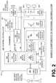
- FIG. 2is a diagram showing sample components of an external defibrillator, such as the one belonging in the system of FIG. 1 , and which is made according to embodiments.
- FIG. 3Ais a conceptual diagram for illustrating how different electrodes may sense ECG signals of the patient along different vectors according to embodiments.
- FIG. 3Bis a conceptual diagram for illustrating how a first ECG signal may be used for in a heart rate computation while a second sensed ECG signal of the patient may be used for a shock decision according to embodiments.
- FIG. 4shows time diagrams for illustrating how a patient's heart rate may be detected from a noise-free ECG signal in the prior art.
- FIG. 5is a time diagram for showing how noise in an ECG signal can corrupt the measurements used for the heart rate detection of FIG. 4 .
- FIG. 6is a time diagram for showing how a patient's heart rate may be detected from a noisy ECG signal according to embodiments.
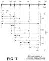
- FIG. 7is a time diagram for showing how a patient's heart rate may be detected from a noisy ECG signal, according to embodiments where all possible peak pairs are established.
- FIG. 8is a bar chart for identifying which one of time durations measured in FIG. 7 best meets a plausibility criterion, according to embodiments.
- FIG. 9is a bar chart of time durations measured in numbers of samples according to embodiments.
- FIG. 10is the bar chart of FIG. 9 , where clusters of time durations have been further discerned, according to embodiments.
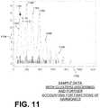
- FIG. 11is a bar chart of time durations where clusters have been discerned, and further where fractional harmonics have been accounted for, according to embodiments.
- FIG. 12is a flowchart for illustrating methods according to embodiments.
- WCDwearable cardioverter defibrillator
- a wearable cardioverter defibrillator (WCD) systemmade according to embodiments has a number of components. These components can be provided separately as modules that can be interconnected, or can be combined with other components, etc.
- FIG. 1depicts a patient 82 .
- Patient 82may also be referred to as a person and/or wearer, since the patient is wearing components of the WCD system.
- Patient 82is ambulatory, which means patient 82 can walk around, and is not necessarily bed-ridden.
- FIG. 1also depicts components of a WCD system made according to embodiments.
- One such componentis a support structure 170 that is wearable by patient 82 .
- support structure 170is shown only generically in FIG. 1 , and in fact partly conceptually.
- FIG. 1is provided merely to illustrate concepts about support structure 170 , and is not to be construed as limiting how support structure 170 is implemented, or how it is worn.
- Support structure 170can be implemented in many different ways. For example, it can be implemented in a single component or a combination of multiple components.
- support structure 170could include a vest, a half-vest, a garment, etc. In such embodiments such items can be worn similarly to parallel articles of clothing.
- support structure 170could include a harness, one or more belts or straps, etc. In such embodiments, such items can be worn by the patient around the torso, hips, over the shoulder, etc.
- support structure 170can include a container or housing, which can even be waterproof. In such embodiments, the support structure can be worn by being attached to the patient by adhesive material, for example as shown in U.S. Pat. No. 8,024,037.
- Support structure 170can even be implemented as described for the support structure of US Pat. App. No. US2017/0056682, which is incorporated herein by reference.
- additional components of the WCD systemcan be in the housing of a support structure instead of being attached externally to the support structure, for example as described in the US2017/0056682 document. There can be other examples.
- a WCD systemis configured to defibrillate a patient who is wearing it, by delivering an electrical charge to the patient's body in the form of an electric shock delivered in one or more pulses.
- FIG. 1shows a sample external defibrillator 100 , and sample defibrillation electrodes 104 , 108 , which are coupled to external defibrillator 100 via electrode leads 105 .
- Defibrillator 100 and defibrillation electrodes 104 , 108can be coupled to support structure 170 . As such, many of the components of defibrillator 100 could be therefore coupled to support structure 170 .
- defibrillator 100can administer, via electrodes 104 , 108 , a brief, strong electric pulse 111 through the body.
- Pulse 111is also known as shock, defibrillation shock, therapy and therapy shock. Pulse 111 is intended to go through and restart heart 85 , in an effort to save the life of patient 82 . Pulse 111 can further include one or more pacing pulses, and so on.
- a prior art defibrillatortypically decides whether to defibrillate or not based on an ECG signal of the patient.
- external defibrillator 100may initiate defibrillation (or hold-off defibrillation) based on a variety of inputs, with ECG merely being one of them.
- signalssuch as physiological signals containing physiological data can be obtained from patient 82 .
- patientmay be considered also a “user” of the WCD system, this is not a requirement. That is, for example, a user of the wearable cardioverter defibrillator (WCD) may include a clinician such as a doctor, nurse, emergency medical technician (EMT) or other similarly situated individual (or group of individuals).
- EMTemergency medical technician
- the WCD systemmay optionally include an outside monitoring device 180 .
- Device 180is called an “outside” device because it could be provided as a standalone device, for example not within the housing of defibrillator 100 .
- Device 180can be configured to sense or monitor at least one local parameter.
- a local parametercan be a parameter of patient 82 , or a parameter of the WCD system, or a parameter of the environment, as will be described later in this document.
- Device 180may include one or more transducers or sensors that are configured to render one or more physiological inputs or signals from one or more patient parameters that they sense.
- device 180is physically coupled to support structure 170 .
- device 180can be communicatively coupled with other components, which are coupled to support structure 170 .
- Such communicationcan be implemented by a communication module, as will be deemed applicable by a person skilled in the art in view of this description.
- FIG. 2is a diagram showing components of an external defibrillator 200 , made according to embodiments. These components can be, for example, included in external defibrillator 100 of FIG. 1 .
- the components shown in FIG. 2can be provided in a housing 201 , which may also be referred to as casing 201 .
- External defibrillator 200is intended for a patient who would be wearing it, such as patient 82 of FIG. 1 .
- Defibrillator 200may further include a user interface 280 for a user 282 .
- User 282can be patient 82 , also known as wearer 82 .
- user 282can be a local rescuer at the scene, such as a bystander who might offer assistance, or a trained person.
- user 282might be a remotely located trained caregiver in communication with the WCD system.
- User interface 280can be made in a number of ways.
- User interface 280may include output devices, which can be visual, audible or tactile, for communicating to a user by outputting images, sounds or vibrations. Images, sounds, vibrations, and anything that can be perceived by user 282 can also be called human-perceptible indications.
- output devicesThere are many examples of output devices.
- an output devicecan be a light, or a screen to display what is sensed, detected and/or measured, and provide visual feedback to rescuer 282 for their resuscitation attempts, and so on.
- Another output devicecan be a speaker, which can be configured to issue voice prompts, beeps, loud alarm sounds and/or words to warn bystanders, etc.
- User interface 280may further include input devices for receiving inputs from users. Such input devices may additionally include various controls, such as pushbuttons, keyboards, touchscreens, one or more microphones, and so on.
- An input devicecan be a cancel switch, which is sometimes called an “I am alive” switch or “live man” switch. In some embodiments, actuating the cancel switch can prevent the impending delivery of a shock.
- Defibrillator 200may include an internal monitoring device 281 .
- Device 281is called an “internal” device because it is incorporated within housing 201 .
- Monitoring device 281can sense or monitor patient parameters such as patient physiological parameters, system parameters and/or environmental parameters, all of which can be called patient data.
- internal monitoring device 281can be complementary or an alternative to outside monitoring device 180 of FIG. 1 . Allocating which of the parameters are to be monitored by which of monitoring devices 180 , 281 can be done according to design considerations.
- Device 281may include one or more transducers or sensors that are configured to render one or more physiological inputs from one or more patient parameters that it senses.
- Patient parametersmay include patient physiological parameters.
- Patient physiological parametersmay include, for example and without limitation, those physiological parameters that can be of any help in detecting by the wearable defibrillation system whether the patient is in need of a shock, plus optionally their medical history and/or event history. Examples of such parameters include the patient's ECG, blood oxygen level, blood flow, blood pressure, blood perfusion, pulsatile change in light transmission or reflection properties of perfused tissue, heart sounds, heart wall motion, breathing sounds and pulse.
- monitoring devices 180 , 281may include one or more sensors configured to acquire patient physiological signals. Examples of such sensors or transducers include electrodes to detect ECG data, a perfusion sensor, a pulse oximeter, a device for detecting blood flow (e.g.
- a Doppler devicea sensor for detecting blood pressure (e.g. a cuff), an optical sensor, illumination detectors and sensors perhaps working together with light sources for detecting color change in tissue, a motion sensor, a device that can detect heart wall movement, a sound sensor, a device with a microphone, an SpO 2 sensor, and so on.
- sensorscan help detect the patient's pulse, and can therefore also be called pulse detection sensors, pulse sensors, and pulse rate sensors.
- Pulse detectionis also taught at least in Physio-Control's U.S. Pat. No. 8,135,462, which is hereby incorporated by reference in its entirety.
- the transducerincludes an appropriate sensor, and the physiological input is a measurement by the sensor of that patient parameter.
- the appropriate sensor for a heart soundmay include a microphone, etc.
- the local parameteris a trend that can be detected in a monitored physiological parameter of patient 282 .
- a trendcan be detected by comparing values of parameters at different times.
- Parameters whose detected trends can particularly help a cardiac rehabilitation programinclude: a) cardiac function (e.g. ejection fraction, stroke volume, cardiac output, etc.); b) heart rate variability at rest or during exercise; c) heart rate profile during exercise and measurement of activity vigor, such as from the profile of an accelerometer signal and informed from adaptive rate pacemaker technology; d) heart rate trending; e) perfusion, such as from SpO 2 or CO 2 ; f) respiratory function, respiratory rate, etc.; g) motion, level of activity; and so on.
- cardiac functione.g. ejection fraction, stroke volume, cardiac output, etc.
- c) heart rate profile during exercise and measurement of activity vigorsuch as from the profile of an accelerometer signal and informed from adaptive rate pacemaker technology
- dheart
- Patient state parametersinclude recorded aspects of patient 282 , such as motion, posture, whether they have spoken recently plus maybe also what they said, and so on, plus optionally the history of these parameters.
- one of these monitoring devicescould include a location sensor such as a Global Positioning System (GPS) location sensor. Such a sensor can detect the location, plus a speed can be detected as a rate of change of location over time.
- GPSGlobal Positioning System
- Many motion detectorsoutput a motion signal that is indicative of the motion of the detector, and thus of the patient's body.
- Patient state parameterscan be very helpful in narrowing down the determination of whether SCA is indeed taking place.
- a WCD system made according to embodimentsmay include a motion detector.
- a motion detectorcan be implemented within monitoring device 180 or monitoring device 281 .
- Such a motion detectorcan be made in many ways as is known in the art, for example by using an accelerometer.
- a motion detector 287is implemented within monitoring device 281 .
- a motion detector of a WCD systemcan be configured to detect a motion event.
- the motion detectormay render or generate, from the detected motion event or motion, a motion detection input that can be received by a subsequent device or functionality.
- a motion eventcan be defined as is convenient, for example a change in motion from a baseline motion or rest, etc. In such cases, a sensed patient parameter is motion.
- System parameters of a WCD systemcan include system identification, battery status, system date and time, reports of self-testing, records of data entered, records of episodes and intervention, and so on.
- Environmental parameterscan include ambient temperature and pressure. Moreover, a humidity sensor may provide information as to whether it is likely raining. Presumed patient location could also be considered an environmental parameter. The patient location could be presumed, if monitoring device 180 or 281 includes a GPS location sensor as per the above, and if it is presumed that the patient is wearing the WCD system.
- Defibrillator 200typically includes a defibrillation port 210 , such as a socket in housing 201 .
- Defibrillation port 210includes electrical nodes 214 , 218 .
- Leads of defibrillation electrodes 204 , 208can be plugged into defibrillation port 210 , so as to make electrical contact with nodes 214 , 218 , respectively. It is also possible that defibrillation electrodes 204 , 208 are connected continuously to defibrillation port 210 , instead.
- defibrillation port 210can be used for guiding, via electrodes, to the wearer the electrical charge that has been stored in an energy storage module 250 that is described more fully later in this document.
- the electric chargewill be the shock for defibrillation, pacing, and so on.
- Defibrillator 200may optionally also have a sensor port 219 in housing 201 , which is also sometimes known as an ECG port.
- Sensor port 219can be adapted for plugging in sensing electrodes 209 , which are also known as ECG electrodes and ECG leads. It is also possible that sensing electrodes 209 can be connected continuously to sensor port 219 , instead.
- Sensing electrodes 209are types of transducers that can help sense an ECG signal, e.g. a 12-lead signal, or a signal from a different number of leads, especially if they make good electrical contact with the body of the patient and in particular with the skin of the patient.
- Sensing electrodes 209can be attached to the inside of support structure 170 for making good electrical contact with the patient, similarly with defibrillation electrodes 204 , 208 .
- a WCD systemalso includes a fluid that it can deploy automatically between the electrodes and the patient's skin.
- the fluidcan be conductive, such as by including an electrolyte, for establishing a better electrical contact between the electrode and the skin. Electrically speaking, when the fluid is deployed, the electrical impedance between the electrode and the skin is reduced. Mechanically speaking, the fluid may be in the form of a low-viscosity gel, so that it does not flow away from the electrode, after it has been deployed.
- the fluidcan be used for both defibrillation electrodes 204 , 208 , and for sensing electrodes 209 .
- a WCD systemaccording to embodiments further includes a fluid deploying mechanism 274 .
- Fluid deploying mechanism 274can be configured to cause at least some of the fluid to be released from the reservoir, and be deployed near one or both of the patient locations, to which the electrodes are configured to be attached to the patient.
- fluid deploying mechanism 274is activated prior to the electrical discharge responsive to receiving activation signal AS from a processor 230 , which is described more fully later in this document.
- FIG. 3Ais a conceptual diagram for illustrating how electrodes of a WCD system may sense or capture ECG signals along different vectors according to embodiments.
- a section of a patient 382 having a heart 385is shown.
- the four electrodes 304 , 306 , 307 , 308therefore can define six vectors, across which six respective ECG signals 311 , 312 , 313 , 314 , 315 , 316 can be sensed.
- FIG. 3Athus illustrates a multi-vector situation.
- electrodes 304 , 306 , 307 , 308are drawn on the same plane for simplicity, while that is not necessarily the case. Accordingly, the vectors of ECG signals 311 - 316 are not necessarily on the same plane, either.
- ECG signals 311 - 316might provide sufficient data for making a shock/no shock determination.
- the effortis to shock when needed, and not shock when not needed.
- the problemis that, at any given point in time, some of these ECG signals may include noise, while others not. The noise may be due to patient movement or how well the electrodes contact the skin.
- the noise problem for a WCDmay be further exacerbated by the desire to use dry, non-adhesive monitoring electrodes. Dry, non-adhesive electrodes are thought to be more comfortable for the patient to wear in the long term, but may produce more noise than a conventional ECG monitoring electrode that includes adhesive to hold the electrode in place and an electrolyte gel to reduce the impedance of the electrode-skin interface.
- FIG. 3Aalso shows a measurement circuit 320 and a processor 330 , which can be made as described for measurement circuit 220 and processor 230 later in this document.
- Processor 330may further compute a heart rate 333 according to embodiments, as described in more detail further in this document.
- defibrillator 200also includes a measurement circuit 220 , as one or more of its sensors or transducers.
- Measurement circuit 220senses one or more electrical physiological signals of the patient from sensor port 219 , if provided. Even if defibrillator 200 lacks sensor port 219 , measurement circuit 220 may optionally obtain physiological signals through nodes 214 , 218 instead, when defibrillation electrodes 204 , 208 are attached to the patient. In these cases, the physiological input reflects an ECG measurement.
- the patient parametercan be an ECG, which can be sensed as a voltage difference between electrodes 204 , 208 .
- the patient parametercan be an impedance, which can be sensed between electrodes 204 , 208 and/or the connections of sensor port 219 . Sensing the impedance can be useful for detecting, among other things, whether these electrodes 204 , 208 and/or sensing electrodes 209 are not making good electrical contact with the patient's body. These patient physiological signals can be sensed, when available. Measurement circuit 220 can then render or generate information about them as physiological inputs, data, other signals, etc. More strictly speaking, the information rendered by measurement circuit 220 is output from it, but this information can be called an input because it is received by a subsequent device or functionality as an input.
- Defibrillator 200also includes a processor 230 .
- Processor 230may be implemented in a number of ways. Such ways include, by way of example and not of limitation, digital and/or analog processors such as microprocessors and Digital Signal Processors (DSPs); controllers such as microcontrollers; software running in a machine; programmable circuits such as Field Programmable Gate Arrays (FPGAs), Field-Programmable Analog Arrays (FPAAs), Programmable Logic Devices (PLDs), Application Specific Integrated Circuits (ASICs), any combination of one or more of these, and so on.
- DSPsDigital Signal Processors
- FPGAsField Programmable Gate Arrays
- FPAAsField-Programmable Analog Arrays
- PLDsProgrammable Logic Devices
- ASICsApplication Specific Integrated Circuits
- Processor 230may include, or have access to, a non-transitory storage medium, such as memory 238 that is described more fully later in this document.
- a memorycan have a non-volatile component for storage of machine-readable and machine-executable instructions.
- a set of such instructionscan also be called a program.
- the instructionswhich may also referred to as “software,” generally provide functionality by performing methods as may be disclosed herein or understood by one skilled in the art in view of the disclosed embodiments.
- instances of the softwaremay be referred to as a “module” and by other similar terms.
- a moduleincludes a set of the instructions so as to offer or fulfill a particular functionality. Embodiments of modules and the functionality delivered are not limited by the embodiments described in this document.
- Detection module 232can include a Ventricular Fibrillation (VF) detector.
- VFVentricular Fibrillation
- the patient's sensed ECG from measurement circuit 220which can be available as physiological inputs, data, or other signals, may be used by the VF detector to determine whether the patient is experiencing VF. Detecting VF is useful, because VF typically results in SCA.
- Detection module 232can also include a Ventricular Tachycardia (VT) detector, and so on.
- VTVentricular Tachycardia
- Another such module in processor 230can be an advice module 234 , which generates advice for what to do.
- the advicecan be based on outputs of detection module 232 .
- the adviceis a shock/no shock determination that processor 230 can make, for example via advice module 234 .
- the shock/no shock determinationcan be made by executing a stored Shock Advisory Algorithm.
- a Shock Advisory Algorithmcan make a shock/no shock determination from one or more ECG signals that are sensed or captured according to embodiments, and determining whether a shock criterion is met. The determination can be made from a rhythm analysis of the sensed or captured ECG signal or otherwise.
- an electrical chargeis delivered to the patient. Delivering the electrical charge is also known as discharging. Shocking can be for defibrillation, pacing, and so on.
- Processor 230can include additional modules, such as other module 236 , for other functions.
- additional modulessuch as other module 236 , for other functions.
- internal monitoring device 281it may be operated in part by processor 230 , etc.
- Defibrillator 200optionally further includes a memory 238 , which can work together with processor 230 .
- Memory 238may be implemented in a number of ways. Such ways include, by way of example and not of limitation, volatile memories, Nonvolatile Memories (NVM), Read-Only Memories (ROM), Random Access Memories (RAM), magnetic disk storage media, optical storage media, smart cards, flash memory devices, any combination of these, and so on.
- Memory 238is thus a non-transitory storage medium.
- Memory 238if provided, can include programs for processor 230 , which processor 230 may be able to read and execute. More particularly, the programs can include sets of instructions in the form of code, which processor 230 may be able to execute upon reading.
- Executingis performed by physical manipulations of physical quantities, and may result in functions, operations, processes, actions and/or methods to be performed, and/or the processor to cause other devices or components or blocks to perform such functions, operations, processes, actions and/or methods.
- the programscan be operational for the inherent needs of processor 230 , and can also include protocols and ways that decisions can be made by advice module 234 .
- memory 238can store prompts for user 282 , if this user is a local rescuer.
- memory 238can store data. This data can include patient data, system data and environmental data, for example as learned by internal monitoring device 281 and outside monitoring device 180 . The data can be stored in memory 238 before it is transmitted out of defibrillator 200 , or stored there after it is received by defibrillator 200 .
- Defibrillator 200may also include a power source 240 .
- power source 240typically includes a battery. Such a battery is typically implemented as a battery pack, which can be rechargeable or not. Sometimes a combination is used of rechargeable and non-rechargeable battery packs.
- Other embodiments of power source 240can include an AC power override, for where AC power will be available, an energy-storing capacitor, and so on.
- power source 240is controlled by processor 230 . Appropriate components may be included to provide for charging or replacing power source 240 .
- Defibrillator 200may additionally include an energy storage module 250 .
- Energy storage module 250can be coupled to the support structure of the WCD system, for example either directly or via the electrodes and their leads. Module 250 is where some electrical energy can be stored temporarily in the form of an electrical charge, when preparing it for discharge to administer a shock. In embodiments, module 250 can be charged from power source 240 to the desired amount of energy, as controlled by processor 230 .
- module 250includes a capacitor 252 , which can be a single capacitor or a system of capacitors, and so on.
- energy storage module 250includes a device that exhibits high power density, such as an ultracapacitor. As described above, capacitor 252 can store the energy in the form of an electrical charge, for delivering to the patient.
- Defibrillator 200moreover includes a discharge circuit 255 .
- processor 230can be configured to control discharge circuit 255 to discharge through the patient the electrical charge stored in energy storage module 250 .
- circuit 255can permit the energy stored in module 250 to be discharged to nodes 214 , 218 , and from there also to defibrillation electrodes 204 , 208 , so as to cause a shock to be delivered to the patient.
- Circuit 255can include one or more switches 257 . Switches 257 can be made in a number of ways, such as by an H-bridge, and so on. Circuit 255 can also be controlled via user interface 280 .
- Defibrillator 200can optionally include a communication module 290 , for establishing one or more wired or wireless communication links with other devices of other entities, such as a remote assistance center, Emergency Medical Services (EMS), and so on.
- the datacan include patient data, event information, therapy attempted, CPR performance, system data, environmental data, and so on.
- communication module 290may transmit wirelessly, e.g. on a daily basis, heart rate, respiratory rate, and other vital signs data to a server accessible over the internet, for instance as described in US 20140043149. This data can be analyzed directly by the patient's physician and can also be analyzed automatically by algorithms designed to detect a developing illness and then notify medical personnel via text, email, phone, etc.
- Module 290may also include such interconnected sub-components as may be deemed necessary by a person skilled in the art, for example an antenna, portions of a processor, supporting electronics, outlet for a telephone or a network cable, etc. This way, data, commands, etc. can be communicated.
- Defibrillator 200can optionally include other components.
- one or more of the components of the shown WCD systemhave been customized for patient 82 .
- This customizationmay include a number of aspects.
- support structure 170can be fitted to the body of patient 82 .
- baseline physiological parameters of patient 82can be measured, such as the heart rate of patient 82 while resting, while walking, motion detector outputs while walking, etc.
- Such baseline physiological parameterscan be used to customize the WCD system, in order to make its diagnoses more accurate, since the patients' bodies differ from one another.
- such parameterscan be stored in a memory of the WCD system, and so on.
- a programming interfacecan be made according to embodiments, which receives such measured baseline physiological parameters.
- Such a programming interfacemay input automatically in the WCD system the baseline physiological parameters, along with other data.
- FIG. 3Bis a conceptual diagram that includes a time axis 348 .
- a first sample ECG signal 317 and a second sample ECG signal 318 of the patientare shown with reference to time axis 348 .
- Second ECG signal 318has been sensed after sensing first ECG signal 317 . It will be recognized that sample ECG signals 317 , 318 indicate VT, but that is only for example. Either one of ECG signals 317 , 318 may be sensed from any of the ECG channels or vectors of FIG. 3A , regardless of the fact that they are shown against the same time axis 348 .
- First ECG signal 317may result in computing heart rate 333 according to embodiments.
- the computed heart rate 333may be stored in memory 238 , which is repeated in FIG. 3B .
- Heart rate 333 stored in memory 238may then be downloaded later, transmitted wirelessly via communication module 290 , displayed by a screen of user interface 280 , and so on.
- Second ECG signal 318may be used to determine whether or not a shock criterion is met, for example by advice module 234 . Second ECG signal 318 may or may not have been used to compute the heart rate according to embodiments.
- processor 230may control, responsive to the shock criterion being met, discharge circuit 255 to discharge through patient 82 an electrical charge that is stored in energy storage module 250 , while support structure 170 is worn by patient 82 so as to deliver a shock 111 to patient 82 .
- FIG. 4shows an ECG signal in a time diagram 409 .
- Diagram 409has an ECG amplitude axis 407 and a time axis 408 .
- Diagram 409depicts a somewhat-idealized, noise-free ECG signal of patient 82 , as it might be sensed from a single channel 311 .
- the ECG signal of diagram 409hovers around a horizontal baseline value BL.
- Baseline value BLcan be considered to be zero, or it might be changing value due to noise, as described later in this document.
- the ECG signal of diagram 409includes three full heartbeats. In particular, three peaks 421 , 422 , 423 are shown, which occur sequentially. It will be recognized that peaks 421 , 422 , 423 are due to QRS complexes, each of which is followed by a T-wave of lesser amplitude. In this somewhat-idealized signal, a P-wave before the QRS complex and a U-wave after the QRS complex are not shown at all.
- the ECG signal of diagram 409is further idealized in that the QRS complexes are shown as peaks, or spikes; in fact some heart rhythms have QRS complexes that don't look like spikes.
- Peaks 421 , 422 , 423are typically used for detecting the heart rate, because their large amplitude relative to the remainder of the ECG signal makes them more easy to identify and/or detect.
- FIG. 4also shows another time axis 448 .
- Time axis 448indicates only the time occurrences 441 , 442 , 443 of peaks 421 , 422 , 423 , respectively.
- the successive peaksare considered in pairs to define time intervals.
- the pair of peaks 421 and 422defines a time interval 451 from time occurrences 441 , 442
- the pair of peaks 422 and 423defines a time interval 452 from time occurrences 442 , 443 .
- Time intervals 451 , 452are sometimes called R-R intervals of the ECG signal. The durations of time intervals 451 , 452 are measured, and heart rate 333 of the patient is thus computed from them.
- peaks 421 , 422 , 423correspond with peaks in the patient's blood pressure, which can be sensed by someone placing their hand against the neck or a wrist of a patient.
- FIG. 5shows an ECG signal in a time diagram 529 .
- Diagram 529has an ECG peaks axis 527 and a time axis 528 .
- Diagram 529depicts only peaks 521 , 522 , 523 , 524 , 525 of an ECG signal, with all other values of the ECG signal being shown as zero for simplification. This simplification is acceptable in this instance, as FIG. 5 is used for discussing only the detection of the heart rate, and only by the peaks of the ECG signal.
- FIG. 5also shows a time diagram 539 to depict sample noise that could be added to the ECG of diagram 529 .
- Diagram 539has a Noise peaks axis 537 and a time axis 538 .
- Diagram 539depicts only peaks 531 , 532 of noise, with all other values of the sample noise being shown as zero for simplification.
- noise peaks 531 , 532may have unequal amplitudes.
- FIG. 5further shows another time axis 548 .
- Time axis 548indicates only the time occurrences 541 , 542 , 543 , 544 , 545 , 546 , 547 of peaks 521 - 525 and also of peaks 531 , 532 .
- Time intervals 551 , 552 , 553 , 554 , 555 , 556can be used to compute a heart rate 533 . It is clear, however, that these time intervals 551 - 556 are no longer true R-R intervals, as they were in the idealized noise-free case of FIG. 4 , because of the noise in the ECG signal. As such, computed heart rate 533 may not be the true heart rate 333 . Rather, in the situation of FIG. 5 , the patient may be misdiagnosed with tachycardia due to noise peaks 531 , 532 .
- the true heart rate 333is measured, even in the presence of noise. Examples are now described.
- a time diagram 609has an ECG amplitude axis 607 and a time axis 608 .
- Diagram 609depicts an actual ECG signal of a patient. This ECG signal hovers around a horizontal baseline value BL.
- the units of time axisshows the ordinal number of a sample, i.e. 200 th , 400 th , etc.
- peaksare detected, which occur sequentially within a sensed ECG signal.
- peaks 621 , 622 , 623 , 624 , 625 , 626 , 627 , 628 , 629are detected, which occur sequentially. These peaks are detected in an effort to identify QRS complexes such as those of FIG. 4 , with the apprehension that some of these peaks may be due to noise as seen in FIG. 5 .
- a number of criteriacan be advantageously applied. For example, all peaks could have the same polarity, as QRS complexes do. Peaks of the opposite polarity can be ignored. In this example the polarity is positive, but it could equivalently be negative. Moreover, a peak can be deemed detected if it meets certain criteria, such as amplitude (e.g. relatively large rise over previous values, and relatively large fall back to about the same values), sharpness (e.g. relatively steep rise and relatively steep fall), and width (e.g. not wider beyond a threshold at mid-amplitude).
- amplitudee.g. relatively large rise over previous values, and relatively large fall back to about the same values
- sharpnesse.g. relatively steep rise and relatively steep fall
- widthe.g. not wider beyond a threshold at mid-amplitude
- FIG. 6also shows another time axis 648 .
- Time axis 648indicates only the time occurrences 641 , 642 , 643 , 644 , 645 , 646 , 647 of detected peaks 621 , 622 , 623 , 624 , 625 , 626 , 627 respectively.
- pairs of the detected peakscan be established, where at least one of the pairs is established by peaks that do not occur sequentially. Such pairs may thus define time intervals. Then durations of the time intervals can be measured.
- a pair of peaks 621 & 622defines a time interval 651 between time occurrences 641 & 642 . The same is true for time intervals 652 and 654 , and so on.
- peaks 621 & 623define a time interval 653 between time occurrences 641 & 643 .
- peaks 621 & 623do not occur sequentially; rather, peak 622 occurs after peak 621 and before peak 623 .
- time interval 653will be a lot larger than either time interval 651 or 652 .
- the duration of time interval 653would be the sum of the durations of time intervals 651 and 652 .
- peaks 621 & 624which do not occur sequentially, define a time interval 655 between time occurrences 641 & 644 , and so on. More durations could be shown in FIG. 6 .
- these durations 651 , 652 , 653 , 654 , 655can be used to compute heart rate 333 as further described later in this document.
- pairsare established among only some of the detected peaks. This can be implemented from the beginning, for example by not establishing all the possible pairs in FIG. 6 . This can be implemented after some of the processing described later where all the possible pairs are established. At that time which a recognition value may be computed. Then a peak may be rejected, at least tentatively, for example according to a recognition criterion. It may turn out that rejecting the peak improves the recognition value, and detection of heart rate 333 becomes more robust.
- all possible pairs of the detected peaksare established. An example is now described.
- FIG. 7shows a time axis 748 .
- Time axis 748indicates only the time occurrences 741 , 742 , 743 , 744 , 745 , 746 of peaks detected as described elsewhere in this document.
- pairs of peaksmay be referred to by the time durations they define.
- peaks at 741 & 742define a time duration 751 .
- time duration 751has a duration indicated by arrow 761 .
- time duration 751has a measured duration of 5. Of course, this value of 5 can be in relative terms for this example.
- the peak at 741defines a group 771 of time occurrences with each of the remaining considered peaks.
- the peak at 742defines a group 772 of time occurrences with each of the remaining considered peaks, and so on with groups 773 , 774 , and single time occurrence 755 .
- group 777is a group of all possible pairs of peaks 741 , 742 , 743 , 744 , 745 , 746 . Each pair is shown by an arrow, with its measured duration as a number within the arrow.
- the heart rate of the patientcan be computed from the identified duration.
- FIG. 8is a bar chart 806 . Its horizontal axis 802 shows possible values for the measured durations of time intervals. Its vertical axis 804 shows numbers for how often a measured interval had the duration of horizontal axis 802 . As such, bar chart 806 is not a time diagram.
- Time durations 777have been plotted in bar chart 806 . As such, the time intervals defined by the peak pairs have been classified by their durations.
- bar 881A salient feature of bar chart 806 is bar 881 , which is the tallest. As such, it can be identified that the measured duration that occurs the most often has a duration of 5.
- Other featuresare bars 882 , 883 , 884 , which occur at durations of 10, 15 and 20, and are the 2 nd , 3 rd , and 4 th harmonics of bar 881 .
- Bars 889show some entries, which are presumed to be due to noise.
- some durations like 4 and 6indicated by arrow 880 , have no occurrences. This may be a result of the time durations having discrete enough values for this example or, equivalently, the bins of the bar chart time durations being wide enough.
- the ECG signalis sensed in samples, and the time durations are measured in numbers of samples.
- the bins of the bar chartare wide enough, they can produce a bar chart like bar chart 806 , which is easy to work with even by having empty bins.
- a representative durationcan be identified that best meets a plausibility criterion.
- a plausibility criterioncan be implemented in a number of ways.
- the plausibility criterionmay include that the representative duration is the one that occurs the most often among the measured durations. Additional ways are described later in this document.
- a heart rate of the patientcan be computed from a duration indicated by the representative duration. Then it can be determined from the computed heart rate whether or not a shock criterion is met.
- Discharge circuit 255can be controlled, responsive to the shock criterion being met, to discharge the stored electrical charge through patient 82 while support structure 170 is worn by patient 82 , so as to deliver a shock to patient 82 .
- the electrodesare further configured to sense an other ECG signal
- the processoris further configured to: detect other peaks occurring sequentially within the sensed other ECG signal, establish other pairs of the detected other peaks, at least one of the other pairs being established by other peaks not occurring sequentially within the sensed other ECG signal, and measure other durations of time intervals defined by the established other pairs.
- the representative durationcan be identified from both the measured durations and the measured other durations, thus providing more data points. Examples are now described.
- FIG. 9is a bar chart 906 .
- Its horizontal axis 902shows possible values for the measured durations of time intervals. These values are in numbers of samples, for example as seen in axis 608 above.
- the vertical axis 904 of bar chart 906shows numbers for how often a measured interval had the duration of horizontal axis 902 . Intervals in this dataset range from 75-1000 samples, which could give a heart rate anywhere from 30-400 bpm (beats per minute). It will be observed that the most frequent occurrence is 3 for bar 981 , which occurs at a value between 300 and 350, perhaps at 335 samples.
- the heart ratecan be computed from the representative duration. For example, if at FIG. 9 the representative duration is taken to be at 335 samples, the heart rate can be computed from that value, factoring in also the frequency with which the ECG signal is sampled.
- processor 230is further configured to discern clusters of the measured durations.
- the representative durationis identified from the cluster that best meets a plausibility criterion. An example is now described.
- FIG. 10repeats bar chart 906 of FIG. 9 .
- FIG. 10adds a computed line 1007 that identifies clusters of the bar charts, according to grouping of the values of the horizontal axis 902 .
- Line 1007shows a cluster with a maximum at point 1081 , which corresponds to 331 samples.
- Line 1007also shows clusters at a second harmonic 1082 (662 samples), and at a third harmonic 1083 (993 samples).
- the cluster that best meets a plausibility criterionis at point 1081 .
- the representative durationis identified at 331 samples, and as occurring about 7 times after the grouping. This representative duration corresponds to a heart rate of 90.6 bpm, which seems plausible.
- While the chosen heart rateis 331 samples, it is possible that there was no duration measured with that exact value. It is further possible that the chosen heart rate does not correspond with the heart rate calculated for any given channel, which may raise questions.
- a WCD system incorporating this methodmay also have logic for deciding when to use the heart rate mode and when to use a simpler method. The mode tends to be beneficial when there is a substantial disagreement in the heart rate between channels and there is not an obvious reason for disqualifying one or more channels (like a dislodged ECG lead).
- the clustersare identified by filtering the measured durations.
- computed line 1007can be generated by running a grouping kernel to identify the true R-R interval. Discreet time, digital implementations are preferred.
- the grouping kernelcan be implemented as a boxcar Finite Impulse Response (FIR) filter with numerator coefficients of 1. This, effectively, counts up the intervals that are within the filter length.
- FIRFinite Impulse Response
- a standard FIR filtercan be run, possibly in both directions, to smooth the result. This method is particularly attractive in a multichannel system because it is helpful to have numerically enough R-R intervals to work with. In a single channel system the mode may still stand out, but it may not stand out as much because there are fewer intervals altogether. Other methods of identifying clusters (or groups) may produce similar results.
- the plausibility criterionincludes that a fraction of the identified representative duration occurs less often than an occurrence threshold. That fraction could be a half-, a third-, a quarter-harmonic and so on.
- the plausibility criterionmay include that a duration having a value of DIN occurs less often than M/N times, where N takes one of the values of 2, 3, 4 and 5. This helps mitigate against the possibility that an interval that is 2 ⁇ the true interval may show up with the highest count, which can cause the heart rate to read half the actual value. If the patient's rhythm is non-shockable, then there is not much harm in this, but if the patient has a shockable rhythm, then such undercounting might cause a false no-shock decision. An example is now described.
- FIG. 11is a bar chart 1106 . Its horizontal axis 1102 shows possible values for the measured durations of time intervals, in numbers of samples. Its vertical axis 1104 shows numbers for how often a measured interval had the duration of horizontal axis 1102 .
- FIG. 11adds a computed line 1107 that identifies clusters of the bar charts, according to grouping.
- Line 1107shows a cluster with a maximum at point 1181 , which corresponds to 98 samples, and occurs 13.57 times.
- Line 1107also shows clusters at a second harmonic 1182 , at a third harmonic 1183 , at a fourth harmonic 1184 , and at a fifth harmonic 1185 .
- peak 1182the highest occurrence is at peak 1182 .
- peak 1181the half-harmonic of peak 1182 would be peak 1181 , which does not occur less often than an occurrence threshold.
- peak 1181occurs 13.57 times at 98 samples, which is more than 8, and therefore peak 1182 is rejected as the representative duration.
- another representative durationis considered, which could be 1 ⁇ 2 or 1 ⁇ 3 the peak R-R interval.
- peak 1181is chosen, which passes the advanced plausibility criterion, even though it is shorter.
- the devices and/or systems mentioned in this documentperform functions, processes and/or methods. These functions, processes and/or methods may be implemented by one or more devices that include logic circuitry. Such a device can be alternately called a computer, and so on. It may be a standalone device or computer, such as a general purpose computer, or part of a device that has one or more additional functions.
- the logic circuitrymay include a processor and non-transitory computer-readable storage media, such as memories, of the type described elsewhere in this document. Often, for the sake of convenience only, it is preferred to implement and describe a program as various interconnected distinct software modules or features. These, along with data are individually and also collectively known as software. In some instances, software is combined with hardware, in a mix called firmware.
- FIG. 12shows a flowchart 1200 for describing methods according to embodiments.
- a first ECG signal of the patientmay be sensed, such as ECG signal 317 .
- Sensingcan be by the electrodes.
- peaks occurring sequentially within the first ECG signalmay be detected.
- pairs of the detected peaksmay be established. At least one of the pairs may be established by peaks not occurring sequentially.
- durations of time intervals defined by the established pairsmay be measured.
- a representative durationmay be identified, which best meets a plausibility criterion.
- the representative durationmay be identified from the measured durations.
- a heart rate of the patientmay be computed. Computing may be from a duration indicated by the representative duration.
- the computed heart rate of the patientmay be stored in a memory. Computing may be from a duration indicated by the representative duration.
- the computed heart ratemay be transmitted wirelessly, for example by a communication module.
- the computed heart ratemay be displayed on a screen.
- a second ECG signal of the patientmay be sensed, such as ECG signal 318 .
- itmay be determined whether or not a shock criterion is met. The determination may be from the second ECG signal of operation 1268 . If at operation 1270 the answer is “no”, indicated by a cross-out, then execution may return to a previous operation, such as operation 1210 .
- the discharge circuitmay be controlled to discharge the stored electrical charge through the patient. Discharging may be while the support structure is worn by the ambulatory patient, so as to deliver a shock to the patient.
- each operationcan be performed as an affirmative step of doing, or causing to happen, what is written that can take place. Such doing or causing to happen can be by the whole system or device, or just one or more components of it.
- the methods and the operationsmay be implemented in a number of ways, including using systems, devices and implementations described above.
- the order of operationsis not constrained to what is shown, and different orders may be possible according to different embodiments. Examples of such alternate orderings may include overlapping, interleaved, interrupted, reordered, incremental, preparatory, supplemental, simultaneous, reverse, or other variant orderings, unless context dictates otherwise.
- new operationsmay be added, or individual operations may be modified or deleted. The added operations can be, for example, from what is mentioned while primarily describing a different system, apparatus, device or method.
- the phrases “constructed to” and/or “configured to”denote one or more actual states of construction and/or configuration that is fundamentally tied to physical characteristics of the element or feature preceding these phrases and, as such, reach well beyond merely describing an intended use. Any such elements or features can be implemented in a number of ways, as will be apparent to a person skilled in the art after reviewing the present disclosure, beyond any examples shown in this document.
- a single reference numeralmay be used consistently to denote a single item, aspect, component, or process.
- a further effortmay have been made in the drafting of this description to use similar though not identical reference numerals to denote other versions or embodiments of an item, aspect, component or process that are identical or at least similar or related. Where made, such a further effort was not required, but was nevertheless made gratuitously so as to accelerate comprehension by the reader. Even where made in this document, such a further effort might not have been made completely consistently for all of the versions or embodiments that are made possible by this description. Accordingly, the description controls in defining an item, aspect, component or process, rather than its reference numeral. Any similarity in reference numerals may be used to infer a similarity in the text, but not to confuse aspects where the text or other context indicates otherwise.
Landscapes
- Health & Medical Sciences (AREA)
- Life Sciences & Earth Sciences (AREA)
- Engineering & Computer Science (AREA)
- Cardiology (AREA)
- General Health & Medical Sciences (AREA)
- Animal Behavior & Ethology (AREA)
- Biomedical Technology (AREA)
- Veterinary Medicine (AREA)
- Public Health (AREA)
- Heart & Thoracic Surgery (AREA)
- Biophysics (AREA)
- Surgery (AREA)
- Physics & Mathematics (AREA)
- Molecular Biology (AREA)
- Medical Informatics (AREA)
- Pathology (AREA)
- Signal Processing (AREA)
- Physiology (AREA)
- Nuclear Medicine, Radiotherapy & Molecular Imaging (AREA)
- Radiology & Medical Imaging (AREA)
- Computer Networks & Wireless Communication (AREA)
- Artificial Intelligence (AREA)
- Computer Vision & Pattern Recognition (AREA)
- Psychiatry (AREA)
- Electrotherapy Devices (AREA)
- Measurement And Recording Of Electrical Phenomena And Electrical Characteristics Of The Living Body (AREA)
Abstract
Description
Claims (14)
Priority Applications (4)
| Application Number | Priority Date | Filing Date | Title |
|---|---|---|---|
| US15/948,884US10940324B2 (en) | 2017-05-03 | 2018-04-09 | Wearable cardioverter defibrillator (WCD) system computing heart rate from noisy ECG signal |
| EP18170581.5AEP3398651B1 (en) | 2017-05-03 | 2018-05-03 | Wearable cardioverter defibrillator (wcd) system computing heart rate from noisy ecg signal |
| US17/172,859US11724118B2 (en) | 2017-05-03 | 2021-02-10 | Wearable cardioverter defibrillator (WCD) system computing heart rate from noisy ECG signal |
| US18/223,727US12434067B2 (en) | 2017-05-03 | 2023-07-19 | Wearable cardioverter defibrillator (WCD) system computing heart rate from noisy ECG signal |
Applications Claiming Priority (3)
| Application Number | Priority Date | Filing Date | Title |
|---|---|---|---|
| US201762501009P | 2017-05-03 | 2017-05-03 | |
| US201815880853A | 2018-01-26 | 2018-01-26 | |
| US15/948,884US10940324B2 (en) | 2017-05-03 | 2018-04-09 | Wearable cardioverter defibrillator (WCD) system computing heart rate from noisy ECG signal |
Related Parent Applications (1)
| Application Number | Title | Priority Date | Filing Date |
|---|---|---|---|
| US201815880853AContinuation-In-Part | 2017-05-03 | 2018-01-26 |
Related Child Applications (1)
| Application Number | Title | Priority Date | Filing Date |
|---|---|---|---|
| US17/172,859ContinuationUS11724118B2 (en) | 2017-05-03 | 2021-02-10 | Wearable cardioverter defibrillator (WCD) system computing heart rate from noisy ECG signal |
Publications (2)
| Publication Number | Publication Date |
|---|---|
| US20180318593A1 US20180318593A1 (en) | 2018-11-08 |
| US10940324B2true US10940324B2 (en) | 2021-03-09 |
Family
ID=62111002
Family Applications (3)
| Application Number | Title | Priority Date | Filing Date |
|---|---|---|---|
| US15/948,884Active2038-06-03US10940324B2 (en) | 2017-05-03 | 2018-04-09 | Wearable cardioverter defibrillator (WCD) system computing heart rate from noisy ECG signal |
| US17/172,859Active2038-08-14US11724118B2 (en) | 2017-05-03 | 2021-02-10 | Wearable cardioverter defibrillator (WCD) system computing heart rate from noisy ECG signal |
| US18/223,727ActiveUS12434067B2 (en) | 2017-05-03 | 2023-07-19 | Wearable cardioverter defibrillator (WCD) system computing heart rate from noisy ECG signal |
Family Applications After (2)
| Application Number | Title | Priority Date | Filing Date |
|---|---|---|---|
| US17/172,859Active2038-08-14US11724118B2 (en) | 2017-05-03 | 2021-02-10 | Wearable cardioverter defibrillator (WCD) system computing heart rate from noisy ECG signal |
| US18/223,727ActiveUS12434067B2 (en) | 2017-05-03 | 2023-07-19 | Wearable cardioverter defibrillator (WCD) system computing heart rate from noisy ECG signal |
Country Status (2)
| Country | Link |
|---|---|
| US (3) | US10940324B2 (en) |
| EP (1) | EP3398651B1 (en) |
Families Citing this family (9)
| Publication number | Priority date | Publication date | Assignee | Title |
|---|---|---|---|---|
| US11077310B1 (en) | 2016-10-04 | 2021-08-03 | West Affum Holdings Corp. | Wearable cardioverter defibrillator (WCD) system detecting QRS complexes in ECG signal by matched difference filter |
| USD858551S1 (en)* | 2017-12-14 | 2019-09-03 | Atlas Biomed Group Limited | Display screen with graphical user interface |
| US11160990B1 (en) | 2018-02-14 | 2021-11-02 | West Affum Holdings Corp. | Wearable cardioverter defibrillator (WCD) alarms |
| US11471693B1 (en) | 2018-02-14 | 2022-10-18 | West Affum Holdings Dac | Wearable cardioverter defibrillator (WCD) system choosing to consider ECG signals from different channels per QRS complex widths of the ECG signals |
| US12179032B2 (en) | 2018-02-14 | 2024-12-31 | West Affum Holdings Dac | Wearable cardioverter defibrillator (WCD) segment based episode opening and confirmation periods |
| US11865354B1 (en) | 2018-02-14 | 2024-01-09 | West Affum Holdings Dac | Methods and systems for distinguishing VT from VF |
| US11000691B2 (en) | 2018-04-24 | 2021-05-11 | West Affum Holdings Corp. | Substantially-median-based determination of long-term heart rates from ECG data of wearable cardioverter defibrillator (WCD) system |
| TWI731339B (en)* | 2018-06-11 | 2021-06-21 | 當代漢雲企業有限公司 | Device and method for pulse diagnosis measurement |
| EP3888546A1 (en)* | 2020-04-01 | 2021-10-06 | Koninklijke Philips N.V. | A system and method for determining respiratory effort |
Citations (76)
| Publication number | Priority date | Publication date | Assignee | Title |
|---|---|---|---|---|
| US3724355A (en) | 1970-06-12 | 1973-04-03 | K Schranz | Apparatus for processing exposed photographic film or the like |
| US4583524A (en) | 1984-11-21 | 1986-04-22 | Hutchins Donald C | Cardiopulmonary resuscitation prompting |
| US4619265A (en) | 1984-03-08 | 1986-10-28 | Physio-Control Corporation | Interactive portable defibrillator including ECG detection circuit |
| US4928690A (en) | 1988-04-25 | 1990-05-29 | Lifecor, Inc. | Portable device for sensing cardiac function and automatically delivering electrical therapy |
| US4955381A (en) | 1988-08-26 | 1990-09-11 | Cardiotronics, Inc. | Multi-pad, multi-function electrode |
| US5078134A (en) | 1988-04-25 | 1992-01-07 | Lifecor, Inc. | Portable device for sensing cardiac function and automatically delivering electrical therapy |
| US5228449A (en) | 1991-01-22 | 1993-07-20 | Athanasios G. Christ | System and method for detecting out-of-hospital cardiac emergencies and summoning emergency assistance |
| US5348008A (en) | 1991-11-25 | 1994-09-20 | Somnus Corporation | Cardiorespiratory alert system |
| US5394892A (en) | 1990-04-02 | 1995-03-07 | K J Mellet Nominees Pty Ltd | CPR prompting apparatus |
| US5405362A (en) | 1991-04-29 | 1995-04-11 | The Board Of Regents For The University Of Texas System | Interactive external defibrillation and drug injection system |
| US5474574A (en) | 1992-06-24 | 1995-12-12 | Cardiac Science, Inc. | Automatic external cardioverter/defibrillator |
| US5662690A (en) | 1994-12-08 | 1997-09-02 | Heartstream, Inc. | Defibrillator with training features and pause actuator |
| US5782878A (en) | 1994-12-07 | 1998-07-21 | Heartstream, Inc. | External defibrillator with communications network link |
| US5792204A (en) | 1996-05-08 | 1998-08-11 | Pacesetter, Inc. | Methods and apparatus for controlling an implantable device programmer using voice commands |
| WO1998039061A2 (en) | 1997-03-07 | 1998-09-11 | Cadent Medical Corporation | Wearable defibrillation system |
| US5902249A (en) | 1995-03-03 | 1999-05-11 | Heartstream, Inc. | Method and apparatus for detecting artifacts using common-mode signals in differential signal detectors |
| US5913685A (en) | 1996-06-24 | 1999-06-22 | Hutchins; Donald C. | CPR computer aiding |
| US5944669A (en) | 1997-11-20 | 1999-08-31 | Lifecor, Inc. | Apparatus and method for sensing cardiac function |
| US6047203A (en) | 1997-03-17 | 2000-04-04 | Nims, Inc. | Physiologic signs feedback system |
| US6065154A (en) | 1998-04-07 | 2000-05-23 | Lifecor, Inc. | Support garments for patient-worn energy delivery apparatus |
| US6108197A (en) | 1992-05-15 | 2000-08-22 | Via, Inc. | Flexible wearable computer |
| US6201992B1 (en) | 1999-04-01 | 2001-03-13 | Agilent Technologies, Inc. | Defibrillator interface capable of generating video images |
| US6263238B1 (en) | 1998-04-16 | 2001-07-17 | Survivalink Corporation | Automatic external defibrillator having a ventricular fibrillation detector |
| US6287328B1 (en) | 1999-04-08 | 2001-09-11 | Agilent Technologies, Inc. | Multivariable artifact assessment |
| US6319011B1 (en) | 1995-04-06 | 2001-11-20 | Michael J. Motti | Automatic training defibrillator simulator and method |
| US6334070B1 (en) | 1998-11-20 | 2001-12-25 | Medtronic Physio-Control Manufacturing Corp. | Visual and aural user interface for an automated external defibrillator |
| US6356785B1 (en) | 1997-11-06 | 2002-03-12 | Cecily Anne Snyder | External defibrillator with CPR prompts and ACLS prompts and methods of use |
| US6437083B1 (en) | 2001-12-06 | 2002-08-20 | General Electric Company | Process for preparing branched aromatic polycarbonates |
| US6529875B1 (en) | 1996-07-11 | 2003-03-04 | Sega Enterprises Ltd. | Voice recognizer, voice recognizing method and game machine using them |
| US20030158593A1 (en) | 2002-02-19 | 2003-08-21 | Heilman Marlin S. | Cardiac garment |
| US6681003B2 (en) | 1999-10-05 | 2004-01-20 | Lifecor, Inc. | Data collection and system management for patient-worn medical devices |
| US6762917B1 (en) | 2001-06-12 | 2004-07-13 | Novx Corporation | Method of monitoring ESC levels and protective devices utilizing the method |
| US20050107834A1 (en) | 2003-11-13 | 2005-05-19 | Freeman Gary A. | Multi-path transthoracic defibrillation and cardioversion |
| US7065401B2 (en) | 2002-05-08 | 2006-06-20 | Michael Worden | Method of applying electrical signals to a patient and automatic wearable external defibrillator |
| US20080312709A1 (en) | 2007-06-13 | 2008-12-18 | Volpe Shane S | Wearable medical treatment device with motion/position detection |
| US20090005827A1 (en) | 2007-06-26 | 2009-01-01 | David Weintraub | Wearable defibrillator |
| US7559902B2 (en) | 2003-08-22 | 2009-07-14 | Foster-Miller, Inc. | Physiological monitoring garment |
| US20100007413A1 (en) | 2006-11-10 | 2010-01-14 | Koninklijke Philips Electronics N.V. | Ecg electrode contact quality measurement system |
| US20100298899A1 (en) | 2007-06-13 | 2010-11-25 | Donnelly Edward J | Wearable medical treatment device |
| US7865238B2 (en) | 2004-09-29 | 2011-01-04 | Koninklijke Philips Electronics N.V. | High-voltage module for an external defibrillator |
| US7870761B2 (en) | 2002-05-14 | 2011-01-18 | Koninklijke Philips Electronics N.V. | Garment and method for producing the same |
| US20110288605A1 (en) | 2010-05-18 | 2011-11-24 | Zoll Medical Corporation | Wearable ambulatory medical device with multiple sensing electrodes |
| US20110288604A1 (en) | 2010-05-18 | 2011-11-24 | Kaib Thomas E | Wearable therapeutic device |
| US8135462B2 (en) | 2002-08-26 | 2012-03-13 | Physio-Control, Inc. | Pulse detection using patient physiological signals |
| US20120112903A1 (en) | 2010-11-08 | 2012-05-10 | Zoll Medical Corporation | Remote medical device alarm |
| US20120144551A1 (en) | 2010-12-09 | 2012-06-14 | Eric Guldalian | Conductive Garment |
| US20120150008A1 (en) | 2010-12-09 | 2012-06-14 | Kaib Thomas E | Electrode with redundant impedance reduction |
| US20120158075A1 (en) | 2010-12-16 | 2012-06-21 | Kaib Thomas E | Water resistant wearable medical device |
| US20120265265A1 (en) | 2011-04-13 | 2012-10-18 | Mehdi Razavi | Automated External Defibrillator Pad System |
| US20120283794A1 (en) | 2011-05-02 | 2012-11-08 | Kaib Thomas E | Patient-worn energy delivery apparatus and techniques for sizing same |
| US20120293323A1 (en) | 2011-03-25 | 2012-11-22 | Zoll Medical Corporation | System and method for adapting alarms in a wearable medical device |
| US20120302860A1 (en) | 2011-03-25 | 2012-11-29 | Zoll Medical Corporation | Selection of optimal channel for rate determination |
| US20120310315A1 (en) | 2009-03-17 | 2012-12-06 | Savage Walter T | Device and method for reducing patient transthoracic impedance for the purpose of delivering a therapeutic current |
| US8369944B2 (en) | 2007-06-06 | 2013-02-05 | Zoll Medical Corporation | Wearable defibrillator with audio input/output |
| US20130085538A1 (en) | 2011-09-01 | 2013-04-04 | Zoll Medical Corporation | Wearable monitoring and treatment device |
| US20130231711A1 (en) | 2012-03-02 | 2013-09-05 | Thomas E. Kaib | Systems and methods for configuring a wearable medical monitoring and/or treatment device |
| US20130245388A1 (en) | 2011-09-01 | 2013-09-19 | Mc10, Inc. | Electronics for detection of a condition of tissue |
| US8548557B2 (en) | 2010-08-12 | 2013-10-01 | Covidien Lp | Medical electrodes |
| US20130274565A1 (en) | 2012-04-13 | 2013-10-17 | Alois Antonin Langer | Outpatient health emergency warning system |
| US20130317852A1 (en) | 2012-05-22 | 2013-11-28 | Geneva Healthcare, LLC | Medical device information portal |
| US20130325078A1 (en) | 2012-05-31 | 2013-12-05 | Zoll Medical Corporation | Medical monitoring and treatment device with external pacing |
| US8615295B2 (en) | 2009-03-17 | 2013-12-24 | Cardiothrive, Inc. | External defibrillator |
| US20140025131A1 (en) | 2012-07-20 | 2014-01-23 | Physio-Control, Inc. | Wearable defibrillator with voice prompts and voice recognition |
| US20140070957A1 (en) | 2012-09-11 | 2014-03-13 | Gianluigi LONGINOTTI-BUITONI | Wearable communication platform |
| US20140107541A1 (en)* | 2012-03-27 | 2014-04-17 | Joseph L. Sullivan | System and method for electrocardiogram analysis and optimization of cardiopulmonary resuscitation and therapy delivery |
| US20140163663A1 (en) | 2012-12-11 | 2014-06-12 | Piyush Poddar | Method and system for switching shock vectors and decreasing transthoracic impedance for cardioversion and defibrillation |
| US8904214B2 (en) | 2010-07-09 | 2014-12-02 | Zoll Medical Corporation | System and method for conserving power in a medical device |
| US20140378812A1 (en) | 2011-12-20 | 2014-12-25 | Sensible Medical Innovatons | Thoracic garment of positioning electromagnetic (em) transducers and methods of using such thoracic garment |
| US20150039053A1 (en) | 2013-06-28 | 2015-02-05 | Zoll Medical Corporation | Systems and methods of delivering therapy using an ambulatory medical device |
| US9089685B2 (en) | 2013-02-25 | 2015-07-28 | West Affum Holdings Corp. | Wearable defibrillator with a multivector shock waveform |
| US9132267B2 (en) | 2013-03-04 | 2015-09-15 | Zoll Medical Corporation | Flexible therapy electrode system |
| US20150328472A1 (en) | 2014-05-13 | 2015-11-19 | Physio-Control, Inc. | Wearable cardioverter defibrillator components discarding ecg signals prior to making shock/no shock determination |
| US20160004831A1 (en) | 2014-07-07 | 2016-01-07 | Zoll Medical Corporation | Medical device with natural language processor |
| US20160082277A1 (en) | 2013-02-25 | 2016-03-24 | West Affum Holdings Corp. | Wearable cardioverter defibrillator (wcd) system informing patient that it is validating just-detected cardiac arrhythmia |
| WO2016077786A1 (en) | 2014-11-14 | 2016-05-19 | Zoll Medical Corporation | Medical premonitory event estimation |
| US9592403B2 (en) | 2013-02-25 | 2017-03-14 | West Affum Holdings Corp. | Wearable cardioverter defibrillator (WCD) system making shock/no shock determinations from multiple patient parameters |
Family Cites Families (59)
| Publication number | Priority date | Publication date | Assignee | Title |
|---|---|---|---|---|
| US3724455A (en) | 1970-06-02 | 1973-04-03 | P Unger | Cardiac warning device |
| US4666432A (en) | 1985-09-13 | 1987-05-19 | Mcneish Kenneth | Catheter retaining means and method |
| US4698848A (en) | 1986-09-26 | 1987-10-13 | Buckley Mary C | Blouse for cardiac patients |
| US5618208A (en) | 1994-06-03 | 1997-04-08 | Siemens Medical Systems, Inc. | Fully insulated, fully shielded electrical connector arrangement |
| US5708978A (en) | 1994-08-17 | 1998-01-20 | Johnsrud; Anna C. | Medical vest |
| US5741306A (en) | 1996-05-23 | 1998-04-21 | Lifecor, Inc. | Patient-worn energy delivery apparatus |
| US6280461B1 (en) | 1996-05-23 | 2001-08-28 | Lifecor, Inc. | Patient-worn energy delivery apparatus |
| US6450942B1 (en) | 1999-08-20 | 2002-09-17 | Cardiorest International Ltd. | Method for reducing heart loads in mammals |
| US7120495B2 (en) | 2000-09-18 | 2006-10-10 | Cameron Health, Inc. | Flexible subcutaneous implantable cardioverter-defibrillator |
| US8731658B2 (en) | 2005-01-31 | 2014-05-20 | Physio-Control, Inc | System and method for using diagnostic pulses in connection with defibrillation therapy |
| US8972017B2 (en) | 2005-11-16 | 2015-03-03 | Bioness Neuromodulation Ltd. | Gait modulation system and method |
| US7653431B2 (en) | 2005-12-20 | 2010-01-26 | Cardiac Pacemakers, Inc. | Arrhythmia discrimination based on determination of rate dependency |
| DE102005060985A1 (en) | 2005-12-20 | 2007-06-28 | Oestreich, Wolfgang, Dr.med. | System for mobile monitoring of heart functions has electrodes which are connected to central administrative unit through electrical conductors and these conductors are arranged in clothing |
| US7738965B2 (en) | 2006-04-28 | 2010-06-15 | Medtronic, Inc. | Holster for charging pectorally implanted medical devices |
| US8024037B2 (en) | 2006-08-01 | 2011-09-20 | Kumar Uday N | External defibrillator |
| US8527028B2 (en) | 2007-05-16 | 2013-09-03 | Medicomp, Inc. | Harness with sensors |
| US8560044B2 (en) | 2007-05-16 | 2013-10-15 | Medicomp, Inc. | Garment accessory with electrocardiogram sensors |
| US8116841B2 (en) | 2007-09-14 | 2012-02-14 | Corventis, Inc. | Adherent device with multiple physiological sensors |
| EP2194858B1 (en) | 2007-09-14 | 2017-11-22 | Corventis, Inc. | Medical device automatic start-up upon contact to patient tissue |
| WO2009036316A1 (en) | 2007-09-14 | 2009-03-19 | Corventis, Inc. | Energy management, tracking and security for adherent patient monitor |
| EP3922171A1 (en) | 2007-09-14 | 2021-12-15 | Medtronic Monitoring, Inc. | Adherent cardiac monitor with advanced sensing capabilities |
| US8626297B2 (en) | 2007-09-20 | 2014-01-07 | Boston Scientific Neuromodulation Corporation | Apparatus and methods for charging an implanted medical device power source |
| EP2446926B1 (en) | 2008-05-07 | 2013-06-26 | Cameron Health, Inc. | Devices for accurately classifying cardiac activity |
| JP5559810B2 (en) | 2008-12-15 | 2014-07-23 | コーヴェンティス,インク. | Patient monitoring system and method |
| JP5988991B2 (en) | 2010-12-10 | 2016-09-07 | ゾール メディカル コーポレイションZOLL Medical Corporation | Wearable treatment device |
| US20120191476A1 (en) | 2011-01-20 | 2012-07-26 | Reid C Shane | Systems and methods for collection, organization and display of ems information |
| EP2702621B1 (en) | 2011-04-28 | 2016-06-22 | Zoll Circulation, Inc. | Latch mechanism for battery retention |
| BR112013032419A2 (en) | 2011-06-20 | 2017-01-17 | Healthwatch Ltd | Independent, non-interfering usable health monitoring and alert system |
| US8742349B2 (en) | 2011-09-21 | 2014-06-03 | Carestream Health, Inc. | Portable radiographic detector exterior battery latch and methods for using the same |
| US9545211B2 (en)* | 2012-03-27 | 2017-01-17 | Physio-Control, Inc. | System and method for electrocardiogram analysis and optimization of cardiopulmonary resuscitation and therapy delivery |
| EP2869757A4 (en) | 2012-07-09 | 2016-03-09 | William E Crone | Perfusion detection system |
| US20140043149A1 (en) | 2012-08-10 | 2014-02-13 | Physio-Control, Inc | Mobile communication device & app for wearable defibrillator system |
| JP6407881B2 (en) | 2012-11-24 | 2018-10-17 | ヘルスウォッチ・リミテッドHealthwatch Ltd. | Float loop type fabric electrode and knitting method thereof |
| US9345898B2 (en) | 2013-01-23 | 2016-05-24 | West Affum Holdings Corp. | Wearable cardiac defibrillator system controlling conductive fluid deployment |
| CN105007769B (en) | 2013-02-13 | 2017-03-08 | 健康监测有限公司 | Method for limiting the elasticity of selection area in knitted fabric |
| US10500403B2 (en) | 2013-02-25 | 2019-12-10 | West Affum Holdings Corp. | WCD system validating detected cardiac arrhythmias thoroughly so as to not sound loudly due to some quickly self-terminating cardiac arrhythmias |
| US10016613B2 (en) | 2013-04-02 | 2018-07-10 | West Affum Holdings Corp. | Wearable cardiac defibrillator system long-term monitoring alternating patient parameters other than ECG |
| US20160113581A1 (en) | 2013-06-07 | 2016-04-28 | Healthwatch Ltd. | Docking station for smart garments |
| US10279189B2 (en) | 2013-06-14 | 2019-05-07 | Cardiothrive, Inc. | Wearable multiphasic cardioverter defibrillator system and method |
| US9955938B2 (en) | 2013-06-26 | 2018-05-01 | Zoll Medical Corporation | Therapeutic device including acoustic sensor |
| IN2015DN02541A (en) | 2013-10-18 | 2015-09-11 | Healthwatch Ltd | |
| US10188159B2 (en) | 2013-10-25 | 2019-01-29 | Armour Technologies, Inc. | Apparatus, system, and method for reducing head or neck trauma |
| CN106456984B (en) | 2014-02-24 | 2019-07-09 | 元素科学公司 | External defibrillator |
| SG11201607189VA (en) | 2014-03-09 | 2016-09-29 | Healthwatch Ltd | Elastic conductive stripe and methods of utilizing thereof |
| RU2016144983A (en) | 2014-04-17 | 2018-05-16 | Хелсуотч Лтд. | DEVICES AND METHODS FOR OBTAINING WORKING ECG SIGNALS BY USING DRY KNITTED ELECTRODES |
| KR101968941B1 (en) | 2014-04-18 | 2019-04-15 | 헬스와치 리미티드 | Connector and cable assembly for smart garments |
| US20180116537A1 (en) | 2014-07-07 | 2018-05-03 | Zoll Medical Corporation | System and Method for Distinguishing a Cardiac Event From Noise in an Electrocardiogram (ECG) Signal |
| US9724008B2 (en) | 2014-07-07 | 2017-08-08 | Zoll Medical Corporation | System and method for distinguishing a cardiac event from noise in an electrocardiogram (ECG) signal |
| US9451893B2 (en)* | 2014-08-18 | 2016-09-27 | Cameron Health, Inc. | Calculation of self-correlation in an implantable cardiac device |
| CN107106857B (en) | 2014-12-18 | 2021-06-08 | 皇家飞利浦有限公司 | Wearable Cardioverter Defibrillator (WCD) apparatus and method for improved comfort and longer wearing |
| US9886680B2 (en) | 2015-03-24 | 2018-02-06 | Zoll Medical Corporation | Low-power signaling for medical devices and medical device personnel |
| US9901741B2 (en)* | 2015-05-11 | 2018-02-27 | Physio-Control, Inc. | Wearable cardioverter defibrillator (WCD) system using sensor modules with reassurance code for confirmation before shock |
| US10535278B2 (en) | 2015-08-05 | 2020-01-14 | Myant, Inc. | Garment with stretch sensors |
| US11052241B2 (en) | 2016-11-03 | 2021-07-06 | West Affum Holdings Corp. | Wearable cardioverter defibrillator (WCD) system measuring patient's respiration |
| US11083906B2 (en) | 2017-01-05 | 2021-08-10 | West Affum Holdings Corp. | Wearable cardioverter defibrillator having adjustable alarm time |
| US11154230B2 (en) | 2017-01-05 | 2021-10-26 | West Affum Holdings Corp. | Wearable cardioverter defibrillator having reduced noise prompts |
| US11213691B2 (en) | 2017-02-27 | 2022-01-04 | Zoll Medical Corporation | Ambulatory medical device interaction |
| US10918879B2 (en) | 2017-07-28 | 2021-02-16 | West Affum Holdings Corp. | Wearable cardioverter defibrillator (WCD) system reacting to high-amplitude ECG noise |
| US11207538B2 (en) | 2017-09-12 | 2021-12-28 | West Affum Holdings Corp. | Wearable cardioverter defibrillator (WCD) system warning ambulatory patient by weak alerting shock |
- 2018
- 2018-04-09USUS15/948,884patent/US10940324B2/enactiveActive
- 2018-05-03EPEP18170581.5Apatent/EP3398651B1/enactiveActive
- 2021
- 2021-02-10USUS17/172,859patent/US11724118B2/enactiveActive
- 2023
- 2023-07-19USUS18/223,727patent/US12434067B2/enactiveActive
Patent Citations (98)
| Publication number | Priority date | Publication date | Assignee | Title |
|---|---|---|---|---|
| US3724355A (en) | 1970-06-12 | 1973-04-03 | K Schranz | Apparatus for processing exposed photographic film or the like |
| US4619265A (en) | 1984-03-08 | 1986-10-28 | Physio-Control Corporation | Interactive portable defibrillator including ECG detection circuit |
| USRE34800E (en) | 1984-11-21 | 1994-11-29 | Hutchins; Donald C. | Cardiopulmonary resuscitation prompting |
| US4583524A (en) | 1984-11-21 | 1986-04-22 | Hutchins Donald C | Cardiopulmonary resuscitation prompting |
| US4928690A (en) | 1988-04-25 | 1990-05-29 | Lifecor, Inc. | Portable device for sensing cardiac function and automatically delivering electrical therapy |
| US5078134A (en) | 1988-04-25 | 1992-01-07 | Lifecor, Inc. | Portable device for sensing cardiac function and automatically delivering electrical therapy |
| US4955381A (en) | 1988-08-26 | 1990-09-11 | Cardiotronics, Inc. | Multi-pad, multi-function electrode |
| US5394892A (en) | 1990-04-02 | 1995-03-07 | K J Mellet Nominees Pty Ltd | CPR prompting apparatus |
| US5228449A (en) | 1991-01-22 | 1993-07-20 | Athanasios G. Christ | System and method for detecting out-of-hospital cardiac emergencies and summoning emergency assistance |
| US5405362A (en) | 1991-04-29 | 1995-04-11 | The Board Of Regents For The University Of Texas System | Interactive external defibrillation and drug injection system |
| US5348008A (en) | 1991-11-25 | 1994-09-20 | Somnus Corporation | Cardiorespiratory alert system |
| US5353793A (en) | 1991-11-25 | 1994-10-11 | Oishi-Kogyo Company | Sensor apparatus |
| US6108197A (en) | 1992-05-15 | 2000-08-22 | Via, Inc. | Flexible wearable computer |
| US5474574A (en) | 1992-06-24 | 1995-12-12 | Cardiac Science, Inc. | Automatic external cardioverter/defibrillator |
| US5782878A (en) | 1994-12-07 | 1998-07-21 | Heartstream, Inc. | External defibrillator with communications network link |
| US5662690A (en) | 1994-12-08 | 1997-09-02 | Heartstream, Inc. | Defibrillator with training features and pause actuator |
| US5902249A (en) | 1995-03-03 | 1999-05-11 | Heartstream, Inc. | Method and apparatus for detecting artifacts using common-mode signals in differential signal detectors |
| US6319011B1 (en) | 1995-04-06 | 2001-11-20 | Michael J. Motti | Automatic training defibrillator simulator and method |
| US5792204A (en) | 1996-05-08 | 1998-08-11 | Pacesetter, Inc. | Methods and apparatus for controlling an implantable device programmer using voice commands |
| US5913685A (en) | 1996-06-24 | 1999-06-22 | Hutchins; Donald C. | CPR computer aiding |
| US6529875B1 (en) | 1996-07-11 | 2003-03-04 | Sega Enterprises Ltd. | Voice recognizer, voice recognizing method and game machine using them |
| US6671545B2 (en) | 1997-03-07 | 2003-12-30 | Cardiac Science, Inc. | Defibrillator with controller operating in a low power mode |
| US20110022105A9 (en) | 1997-03-07 | 2011-01-27 | Owen James M | Defibrillation system |
| US6148233A (en) | 1997-03-07 | 2000-11-14 | Cardiac Science, Inc. | Defibrillation system having segmented electrodes |
| US6546285B1 (en) | 1997-03-07 | 2003-04-08 | Cardiac Science, Inc. | Long term wear electrode for defibrillation system |
| WO1998039061A2 (en) | 1997-03-07 | 1998-09-11 | Cadent Medical Corporation | Wearable defibrillation system |
| US6427083B1 (en) | 1997-03-07 | 2002-07-30 | Cardiac Science, Inc. | Defibrillation system |
| US6304780B1 (en) | 1997-03-07 | 2001-10-16 | Cardiac Science Inc. | External defibrillator system with diagnostic module |
| US6047203A (en) | 1997-03-17 | 2000-04-04 | Nims, Inc. | Physiologic signs feedback system |
| US6356785B1 (en) | 1997-11-06 | 2002-03-12 | Cecily Anne Snyder | External defibrillator with CPR prompts and ACLS prompts and methods of use |
| US5944669A (en) | 1997-11-20 | 1999-08-31 | Lifecor, Inc. | Apparatus and method for sensing cardiac function |
| US6065154A (en) | 1998-04-07 | 2000-05-23 | Lifecor, Inc. | Support garments for patient-worn energy delivery apparatus |
| US6263238B1 (en) | 1998-04-16 | 2001-07-17 | Survivalink Corporation | Automatic external defibrillator having a ventricular fibrillation detector |
| US6334070B1 (en) | 1998-11-20 | 2001-12-25 | Medtronic Physio-Control Manufacturing Corp. | Visual and aural user interface for an automated external defibrillator |
| US6201992B1 (en) | 1999-04-01 | 2001-03-13 | Agilent Technologies, Inc. | Defibrillator interface capable of generating video images |
| US6287328B1 (en) | 1999-04-08 | 2001-09-11 | Agilent Technologies, Inc. | Multivariable artifact assessment |
| US6681003B2 (en) | 1999-10-05 | 2004-01-20 | Lifecor, Inc. | Data collection and system management for patient-worn medical devices |
| US6762917B1 (en) | 2001-06-12 | 2004-07-13 | Novx Corporation | Method of monitoring ESC levels and protective devices utilizing the method |
| US6437083B1 (en) | 2001-12-06 | 2002-08-20 | General Electric Company | Process for preparing branched aromatic polycarbonates |
| US20030158593A1 (en) | 2002-02-19 | 2003-08-21 | Heilman Marlin S. | Cardiac garment |
| US7065401B2 (en) | 2002-05-08 | 2006-06-20 | Michael Worden | Method of applying electrical signals to a patient and automatic wearable external defibrillator |
| US7870761B2 (en) | 2002-05-14 | 2011-01-18 | Koninklijke Philips Electronics N.V. | Garment and method for producing the same |
| US8135462B2 (en) | 2002-08-26 | 2012-03-13 | Physio-Control, Inc. | Pulse detection using patient physiological signals |
| US7559902B2 (en) | 2003-08-22 | 2009-07-14 | Foster-Miller, Inc. | Physiological monitoring garment |
| US20050107833A1 (en) | 2003-11-13 | 2005-05-19 | Freeman Gary A. | Multi-path transthoracic defibrillation and cardioversion |
| US20050107834A1 (en) | 2003-11-13 | 2005-05-19 | Freeman Gary A. | Multi-path transthoracic defibrillation and cardioversion |
| US7865238B2 (en) | 2004-09-29 | 2011-01-04 | Koninklijke Philips Electronics N.V. | High-voltage module for an external defibrillator |
| US20100007413A1 (en) | 2006-11-10 | 2010-01-14 | Koninklijke Philips Electronics N.V. | Ecg electrode contact quality measurement system |
| US8369944B2 (en) | 2007-06-06 | 2013-02-05 | Zoll Medical Corporation | Wearable defibrillator with audio input/output |
| US20140324112A1 (en) | 2007-06-06 | 2014-10-30 | Zoll Medical Corporation | Wearable defibrillator with audio input/output |
| US8965500B2 (en) | 2007-06-06 | 2015-02-24 | Zoll Medical Corporation | Wearable defibrillator with audio input/output |
| US7974689B2 (en) | 2007-06-13 | 2011-07-05 | Zoll Medical Corporation | Wearable medical treatment device with motion/position detection |
| US20100298899A1 (en) | 2007-06-13 | 2010-11-25 | Donnelly Edward J | Wearable medical treatment device |
| US8140154B2 (en) | 2007-06-13 | 2012-03-20 | Zoll Medical Corporation | Wearable medical treatment device |
| US20080312709A1 (en) | 2007-06-13 | 2008-12-18 | Volpe Shane S | Wearable medical treatment device with motion/position detection |
| US20090005827A1 (en) | 2007-06-26 | 2009-01-01 | David Weintraub | Wearable defibrillator |
| US20120310315A1 (en) | 2009-03-17 | 2012-12-06 | Savage Walter T | Device and method for reducing patient transthoracic impedance for the purpose of delivering a therapeutic current |
| US8615295B2 (en) | 2009-03-17 | 2013-12-24 | Cardiothrive, Inc. | External defibrillator |
| US20110288604A1 (en) | 2010-05-18 | 2011-11-24 | Kaib Thomas E | Wearable therapeutic device |
| US9008801B2 (en) | 2010-05-18 | 2015-04-14 | Zoll Medical Corporation | Wearable therapeutic device |
| US20110288605A1 (en) | 2010-05-18 | 2011-11-24 | Zoll Medical Corporation | Wearable ambulatory medical device with multiple sensing electrodes |
| US8904214B2 (en) | 2010-07-09 | 2014-12-02 | Zoll Medical Corporation | System and method for conserving power in a medical device |
| US9454219B2 (en) | 2010-07-09 | 2016-09-27 | Zoll Medical Corporation | System and method for conserving power in a medical device |
| US8548557B2 (en) | 2010-08-12 | 2013-10-01 | Covidien Lp | Medical electrodes |
| US20120112903A1 (en) | 2010-11-08 | 2012-05-10 | Zoll Medical Corporation | Remote medical device alarm |
| US20120144551A1 (en) | 2010-12-09 | 2012-06-14 | Eric Guldalian | Conductive Garment |
| US20120150008A1 (en) | 2010-12-09 | 2012-06-14 | Kaib Thomas E | Electrode with redundant impedance reduction |
| US20120158075A1 (en) | 2010-12-16 | 2012-06-21 | Kaib Thomas E | Water resistant wearable medical device |
| US20120302860A1 (en) | 2011-03-25 | 2012-11-29 | Zoll Medical Corporation | Selection of optimal channel for rate determination |
| US9408548B2 (en) | 2011-03-25 | 2016-08-09 | Zoll Medical Corporation | Selection of optimal channel for rate determination |
| US20120293323A1 (en) | 2011-03-25 | 2012-11-22 | Zoll Medical Corporation | System and method for adapting alarms in a wearable medical device |
| US8897860B2 (en) | 2011-03-25 | 2014-11-25 | Zoll Medical Corporation | Selection of optimal channel for rate determination |
| US20120265265A1 (en) | 2011-04-13 | 2012-10-18 | Mehdi Razavi | Automated External Defibrillator Pad System |
| US20120283794A1 (en) | 2011-05-02 | 2012-11-08 | Kaib Thomas E | Patient-worn energy delivery apparatus and techniques for sizing same |
| US9131901B2 (en) | 2011-09-01 | 2015-09-15 | Zoll Medical Corporation | Wearable monitoring and treatment device |
| US20130085538A1 (en) | 2011-09-01 | 2013-04-04 | Zoll Medical Corporation | Wearable monitoring and treatment device |
| US8644925B2 (en) | 2011-09-01 | 2014-02-04 | Zoll Medical Corporation | Wearable monitoring and treatment device |
| US20130245388A1 (en) | 2011-09-01 | 2013-09-19 | Mc10, Inc. | Electronics for detection of a condition of tissue |
| US20140378812A1 (en) | 2011-12-20 | 2014-12-25 | Sensible Medical Innovatons | Thoracic garment of positioning electromagnetic (em) transducers and methods of using such thoracic garment |
| US20130231711A1 (en) | 2012-03-02 | 2013-09-05 | Thomas E. Kaib | Systems and methods for configuring a wearable medical monitoring and/or treatment device |
| US20140107541A1 (en)* | 2012-03-27 | 2014-04-17 | Joseph L. Sullivan | System and method for electrocardiogram analysis and optimization of cardiopulmonary resuscitation and therapy delivery |
| US20130274565A1 (en) | 2012-04-13 | 2013-10-17 | Alois Antonin Langer | Outpatient health emergency warning system |
| US20130317852A1 (en) | 2012-05-22 | 2013-11-28 | Geneva Healthcare, LLC | Medical device information portal |
| US20130325078A1 (en) | 2012-05-31 | 2013-12-05 | Zoll Medical Corporation | Medical monitoring and treatment device with external pacing |
| US20140025131A1 (en) | 2012-07-20 | 2014-01-23 | Physio-Control, Inc. | Wearable defibrillator with voice prompts and voice recognition |
| US20140070957A1 (en) | 2012-09-11 | 2014-03-13 | Gianluigi LONGINOTTI-BUITONI | Wearable communication platform |
| US20140163663A1 (en) | 2012-12-11 | 2014-06-12 | Piyush Poddar | Method and system for switching shock vectors and decreasing transthoracic impedance for cardioversion and defibrillation |
| US20160082277A1 (en) | 2013-02-25 | 2016-03-24 | West Affum Holdings Corp. | Wearable cardioverter defibrillator (wcd) system informing patient that it is validating just-detected cardiac arrhythmia |
| US9089685B2 (en) | 2013-02-25 | 2015-07-28 | West Affum Holdings Corp. | Wearable defibrillator with a multivector shock waveform |
| US9592403B2 (en) | 2013-02-25 | 2017-03-14 | West Affum Holdings Corp. | Wearable cardioverter defibrillator (WCD) system making shock/no shock determinations from multiple patient parameters |
| US20170136251A1 (en) | 2013-02-25 | 2017-05-18 | West Affum Holdings Corp. | Wearable cardioverter defibrillator (wcd) system making shock/no shock determinations by aggregating aspects of multiple patient parameters |
| US9132267B2 (en) | 2013-03-04 | 2015-09-15 | Zoll Medical Corporation | Flexible therapy electrode system |
| US20150039053A1 (en) | 2013-06-28 | 2015-02-05 | Zoll Medical Corporation | Systems and methods of delivering therapy using an ambulatory medical device |
| US20150328472A1 (en) | 2014-05-13 | 2015-11-19 | Physio-Control, Inc. | Wearable cardioverter defibrillator components discarding ecg signals prior to making shock/no shock determination |
| US20160220832A1 (en) | 2014-05-13 | 2016-08-04 | West Affum Holdings Corp. | Wearable cardioverter defibrillator components discarding ecg signals prior to making shock/no shock determination |
| US20160243374A1 (en) | 2014-05-13 | 2016-08-25 | West Affum Holdings Corp. | Wearable cardioverter defibrillator components making aggregate shock/no shock determination from two or more ecg signals |
| US20160004831A1 (en) | 2014-07-07 | 2016-01-07 | Zoll Medical Corporation | Medical device with natural language processor |
| WO2016077786A1 (en) | 2014-11-14 | 2016-05-19 | Zoll Medical Corporation | Medical premonitory event estimation |
Non-Patent Citations (8)
| Title |
|---|
| EP Search report for EPO Application No. 18 170 581.5, filed May 3, 2018. |
| Heartstart MRx and XL AED Algorithm—Application Note, Jul. 2001, Edition 2 Philips Healthcare, USA. |
| Klein, H. U., Goldenberg I., & Moss, A. J., Risk Stratification for Implantable Cardioverter Defibrillator Therapy: The Role of the Wearable Cardioverter-Defibrillator, Clinical update, European Heart Journal, May 31, 2013, pp. 1-14, doi:10.1093/eurheartj/eht167, European Society of Cardiology. |
| Lifecor LifeVest System Model WCD 3100 Operator's Manual, 2006, PN 20B0040 Rev FI, Zoll Lifecor Corporation, Pittsburgh, PA. |
| LifeVest Model 4000 Patient Manual, Zoll, 2009, PN 20B0047 Rev B. |
| Pagan-Carlo, et al., "Encircling Overlapping Multipulse Shock Waveforms for Transthoracic Defibrillation," JACC Journals, Dec. 1998, vol. 32 Issue 7, p. 2065-2071. |
| Sooyeon Suh, Stress, Anxiety, and Heart Rate Variability in Chronic Obstructive Pulmonary Disease, Dissertation, 2010, The Ohio State University, Ohio USA. |
| The LifeVest Network/Patient Data Management System, Zoll, 2015, 2000503 Rev A. |
Also Published As
| Publication number | Publication date |
|---|---|
| EP3398651B1 (en) | 2023-04-05 |
| US20240001131A1 (en) | 2024-01-04 |
| US12434067B2 (en) | 2025-10-07 |
| US20210162227A1 (en) | 2021-06-03 |
| EP3398651A1 (en) | 2018-11-07 |
| US20180318593A1 (en) | 2018-11-08 |
| US11724118B2 (en) | 2023-08-15 |
Similar Documents
| Publication | Publication Date | Title |
|---|---|---|
| US11707632B2 (en) | Wearable cardioverter defibrillator (WCD) system reacting to high-amplitude ECG noise | |
| US12023510B2 (en) | Wearable cardioverter defibrillator (WCD) system reacting to high-frequency ECG noise | |
| US20240245906A1 (en) | Wearable cardioverter defibrillator (wcd) system measuring patient's respiration | |
| US12434067B2 (en) | Wearable cardioverter defibrillator (WCD) system computing heart rate from noisy ECG signal | |
| US11351390B2 (en) | Wearable monitor system computing patient heart rate by multiplying ECG signals from different channels | |
| US11351391B2 (en) | Wearable cardioverter defibrillator (WCD) system making shock/no shock determinations from multiple patient parameters | |
| US11865351B2 (en) | Medical device with enhanced electrocardiogram channel selection | |
| US20240058596A1 (en) | Multichannel posture dependent template based rhythm discrimination in a wearable cardioverter defibrillator | |
| US11077310B1 (en) | Wearable cardioverter defibrillator (WCD) system detecting QRS complexes in ECG signal by matched difference filter | |
| US12179031B2 (en) | Heart rate calculator with reduced overcounting | |
| US12097379B2 (en) | Wearable cardioverter defibrillator (WCD) system making shock/no shock determinations from multiple patient parameters | |
| US11865354B1 (en) | Methods and systems for distinguishing VT from VF |
Legal Events
| Date | Code | Title | Description |
|---|---|---|---|
| FEPP | Fee payment procedure | Free format text:ENTITY STATUS SET TO UNDISCOUNTED (ORIGINAL EVENT CODE: BIG.); ENTITY STATUS OF PATENT OWNER: LARGE ENTITY | |
| AS | Assignment | Owner name:PHYSIO-CONTROL DEVELOPMENT CO., LLC, WASHINGTON Free format text:ASSIGNMENT OF ASSIGNORS INTEREST;ASSIGNOR:SULLIVAN, JOSEPH L.;REEL/FRAME:045494/0410 Effective date:20180410 | |
| STPP | Information on status: patent application and granting procedure in general | Free format text:DOCKETED NEW CASE - READY FOR EXAMINATION | |
| STPP | Information on status: patent application and granting procedure in general | Free format text:NON FINAL ACTION MAILED | |
| STPP | Information on status: patent application and granting procedure in general | Free format text:NON FINAL ACTION MAILED | |
| AS | Assignment | Owner name:WEST AFFUM HOLDINGS CORP., CAYMAN ISLANDS Free format text:ASSIGNMENT OF ASSIGNORS INTEREST;ASSIGNOR:PHYSIO-CONTROL, INC.;REEL/FRAME:053372/0966 Effective date:20200728 | |
| STCF | Information on status: patent grant | Free format text:PATENTED CASE | |
| AS | Assignment | Owner name:WEST AFFUM HOLDINGS DAC, IRELAND Free format text:ASSIGNMENT OF ASSIGNORS INTEREST;ASSIGNOR:WEST AFFUM HOLDINGS CORP.;REEL/FRAME:060389/0694 Effective date:20220427 | |
| AS | Assignment | Owner name:PERCEPTIVE CREDIT HOLDINGS IV, LP, NEW YORK Free format text:SECURITY AGREEMENT;ASSIGNOR:WEST AFFUM HOLDINGS DESIGNATED ACTIVITY COMPANY;REEL/FRAME:065116/0049 Effective date:20230929 | |
| MAFP | Maintenance fee payment | Free format text:PAYMENT OF MAINTENANCE FEE, 4TH YEAR, LARGE ENTITY (ORIGINAL EVENT CODE: M1551); ENTITY STATUS OF PATENT OWNER: LARGE ENTITY Year of fee payment:4 | |
| AS | Assignment | Owner name:WEST AFFUM HOLDINGS CORP., CAYMAN ISLANDS Free format text:ASSIGNMENT OF ASSIGNORS INTEREST;ASSIGNOR:PHYSIO-CONTROL DEVELOPMENT CO., LLC;REEL/FRAME:070384/0498 Effective date:20171108 |