US10940086B2 - Bottle support and protective collar - Google Patents
Bottle support and protective collarDownload PDFInfo
- Publication number
- US10940086B2 US10940086B2US14/939,150US201514939150AUS10940086B2US 10940086 B2US10940086 B2US 10940086B2US 201514939150 AUS201514939150 AUS 201514939150AUS 10940086 B2US10940086 B2US 10940086B2
- Authority
- US
- United States
- Prior art keywords
- pliable
- annular core
- outer side
- ribs
- bottle
- Prior art date
- Legal status (The legal status is an assumption and is not a legal conclusion. Google has not performed a legal analysis and makes no representation as to the accuracy of the status listed.)
- Active, expires
Links
Images


Classifications
- A—HUMAN NECESSITIES
- A61—MEDICAL OR VETERINARY SCIENCE; HYGIENE
- A61J—CONTAINERS SPECIALLY ADAPTED FOR MEDICAL OR PHARMACEUTICAL PURPOSES; DEVICES OR METHODS SPECIALLY ADAPTED FOR BRINGING PHARMACEUTICAL PRODUCTS INTO PARTICULAR PHYSICAL OR ADMINISTERING FORMS; DEVICES FOR ADMINISTERING FOOD OR MEDICINES ORALLY; BABY COMFORTERS; DEVICES FOR RECEIVING SPITTLE
- A61J1/00—Containers specially adapted for medical or pharmaceutical purposes
- A61J1/14—Details; Accessories therefor
- A61J1/16—Holders for containers
- A—HUMAN NECESSITIES
- A61—MEDICAL OR VETERINARY SCIENCE; HYGIENE
- A61J—CONTAINERS SPECIALLY ADAPTED FOR MEDICAL OR PHARMACEUTICAL PURPOSES; DEVICES OR METHODS SPECIALLY ADAPTED FOR BRINGING PHARMACEUTICAL PRODUCTS INTO PARTICULAR PHYSICAL OR ADMINISTERING FORMS; DEVICES FOR ADMINISTERING FOOD OR MEDICINES ORALLY; BABY COMFORTERS; DEVICES FOR RECEIVING SPITTLE
- A61J1/00—Containers specially adapted for medical or pharmaceutical purposes
- A61J1/14—Details; Accessories therefor
- A61J1/20—Arrangements for transferring or mixing fluids, e.g. from vial to syringe
- A61J1/2003—Accessories used in combination with means for transfer or mixing of fluids, e.g. for activating fluid flow, separating fluids, filtering fluid or venting
- A61J1/2048—Connecting means
- A61J1/2055—Connecting means having gripping means
- A—HUMAN NECESSITIES
- A61—MEDICAL OR VETERINARY SCIENCE; HYGIENE
- A61J—CONTAINERS SPECIALLY ADAPTED FOR MEDICAL OR PHARMACEUTICAL PURPOSES; DEVICES OR METHODS SPECIALLY ADAPTED FOR BRINGING PHARMACEUTICAL PRODUCTS INTO PARTICULAR PHYSICAL OR ADMINISTERING FORMS; DEVICES FOR ADMINISTERING FOOD OR MEDICINES ORALLY; BABY COMFORTERS; DEVICES FOR RECEIVING SPITTLE
- A61J1/00—Containers specially adapted for medical or pharmaceutical purposes
- A61J1/14—Details; Accessories therefor
- A61J1/20—Arrangements for transferring or mixing fluids, e.g. from vial to syringe
- A61J1/2096—Combination of a vial and a syringe for transferring or mixing their contents
- A—HUMAN NECESSITIES
- A61—MEDICAL OR VETERINARY SCIENCE; HYGIENE
- A61M—DEVICES FOR INTRODUCING MEDIA INTO, OR ONTO, THE BODY; DEVICES FOR TRANSDUCING BODY MEDIA OR FOR TAKING MEDIA FROM THE BODY; DEVICES FOR PRODUCING OR ENDING SLEEP OR STUPOR
- A61M5/00—Devices for bringing media into the body in a subcutaneous, intra-vascular or intramuscular way; Accessories therefor, e.g. filling or cleaning devices, arm-rests
- A61M5/178—Syringes
- A61M5/31—Details
- A61M5/3129—Syringe barrels
- A61M5/3137—Specially designed finger grip means, e.g. for easy manipulation of the syringe rod
- A—HUMAN NECESSITIES
- A47—FURNITURE; DOMESTIC ARTICLES OR APPLIANCES; COFFEE MILLS; SPICE MILLS; SUCTION CLEANERS IN GENERAL
- A47G—HOUSEHOLD OR TABLE EQUIPMENT
- A47G23/00—Other table equipment
- A47G23/02—Glass or bottle holders
- A47G23/0208—Glass or bottle holders for drinking-glasses, plastic cups, or the like
- A47G23/0216—Glass or bottle holders for drinking-glasses, plastic cups, or the like for one glass or cup
- A—HUMAN NECESSITIES
- A61—MEDICAL OR VETERINARY SCIENCE; HYGIENE
- A61J—CONTAINERS SPECIALLY ADAPTED FOR MEDICAL OR PHARMACEUTICAL PURPOSES; DEVICES OR METHODS SPECIALLY ADAPTED FOR BRINGING PHARMACEUTICAL PRODUCTS INTO PARTICULAR PHYSICAL OR ADMINISTERING FORMS; DEVICES FOR ADMINISTERING FOOD OR MEDICINES ORALLY; BABY COMFORTERS; DEVICES FOR RECEIVING SPITTLE
- A61J1/00—Containers specially adapted for medical or pharmaceutical purposes
- A61J1/05—Containers specially adapted for medical or pharmaceutical purposes for collecting, storing or administering blood, plasma or medical fluids ; Infusion or perfusion containers
- A61J1/06—Ampoules or carpules
- A—HUMAN NECESSITIES
- A61—MEDICAL OR VETERINARY SCIENCE; HYGIENE
- A61M—DEVICES FOR INTRODUCING MEDIA INTO, OR ONTO, THE BODY; DEVICES FOR TRANSDUCING BODY MEDIA OR FOR TAKING MEDIA FROM THE BODY; DEVICES FOR PRODUCING OR ENDING SLEEP OR STUPOR
- A61M5/00—Devices for bringing media into the body in a subcutaneous, intra-vascular or intramuscular way; Accessories therefor, e.g. filling or cleaning devices, arm-rests
- A61M5/178—Syringes
- A61M5/31—Details
- A61M5/3129—Syringe barrels
- A61M5/3137—Specially designed finger grip means, e.g. for easy manipulation of the syringe rod
- A61M2005/3139—Finger grips not integrally formed with the syringe barrel, e.g. using adapter with finger grips
- A—HUMAN NECESSITIES
- A61—MEDICAL OR VETERINARY SCIENCE; HYGIENE
- A61M—DEVICES FOR INTRODUCING MEDIA INTO, OR ONTO, THE BODY; DEVICES FOR TRANSDUCING BODY MEDIA OR FOR TAKING MEDIA FROM THE BODY; DEVICES FOR PRODUCING OR ENDING SLEEP OR STUPOR
- A61M2209/00—Ancillary equipment
- A61M2209/08—Supports for equipment
- A—HUMAN NECESSITIES
- A61—MEDICAL OR VETERINARY SCIENCE; HYGIENE
- A61M—DEVICES FOR INTRODUCING MEDIA INTO, OR ONTO, THE BODY; DEVICES FOR TRANSDUCING BODY MEDIA OR FOR TAKING MEDIA FROM THE BODY; DEVICES FOR PRODUCING OR ENDING SLEEP OR STUPOR
- A61M5/00—Devices for bringing media into the body in a subcutaneous, intra-vascular or intramuscular way; Accessories therefor, e.g. filling or cleaning devices, arm-rests
- A61M5/178—Syringes
- A61M5/1782—Devices aiding filling of syringes in situ
Definitions
- This inventionrelates to a support element for bottles.
- Bottlesare inherently unstable owing to their cylindrical geometry, which renders them prone to slip and roll. Likewise, if inadvertently tilted, they are apt to tip and spill their contents if open or insufficiently sealed. This is at best a nuisance but can be hazardous if the contents are chemicals or medicines. There are many different types of bottle supports, some of which are intended to address these issues.
- US 2012/0241332discloses a multipack carrier for bottles, cans, or jars having a plurality of plastic braces each comprising a circular cutout for accommodating the neck of the bottle and a plurality of internal webs in the plane of the cutout that are flexed and resiliently grasped by the bottle neck.
- the deviceis used to carry multiple bottles but does not support them from falling or tipping over when disposed on a flat surface.
- US 2010/0140431discloses a bottle support comprising a cylindrical ring and a plurality of internal webs mounted parallel to an axis of the ring and each fixed to an inside surface thereof. The webs are flexed radially and resiliently grasped by the bottle neck for supporting an inverted container on a flat surface. Although this device will support a bottle disposed on a flat surface, it requires that all the webs are flexed equally and this militates against supporting a bottle at an angle.
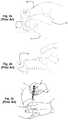
- FIGS. 1 a , 1 b , 1 c and 1 dshow pictorially the tendency for round and cylindrical objects 10 to slip when grasped between thumb 11 and forefinger 12 .
- a gripping forceis applied as shown in FIG. 1 c between points on the side surfaces of a cylindrical object 10 that are not diametrically opposite each other, a component of the gripping force acts to push the object out of the user's grip.
- This tendencyis increased if friction between the user's fingers and the outer surface of the object is reduced, such as when a bottle is gripped with wet or soapy hands.
- This tendency to slip from the user's gripis equally true for bottle supports of the type described in above-mentioned US 2010/0140431 owing to the smooth side surface of the cylindrical ring.
- FIGS. 2 a and 2 bshow pictorially a bottle 10 gripped non-diametrically between the thumb 11 and forefinger 12 of a user's hand. If the segment that is closer to the center 13 of the oblique arch between thumb and forefinger and bound by the points at which the bottle is gripped has an area less than half that of the bottle's cross-section, the gripping force will have a tangential component that urges the bottle away from the center 13 of the oblique arch. The bottle 10 will then slip out of the user's hand.
- the gripping forcewill have a tangential component that urges the bottle toward the center 13 of the oblique arch into the user's hand. In either case, the transverse grip on the bottle will be lost and the bottle will slip.
- liquid medicine bottlesare often provided with a resealable cap through which a hypodermic needle is inserted in order to withdraw a quantity of liquid.
- liquid in a hypodermic syringemay need to be injected into a vial or other container. Both of these operations require that the via or bottle be retained securely on a support surface, possibly inclined to the horizontal, in order to provide direct access to the cap and ensure visual alignment thereof to the tip of the hypodermic needle.
- liquidsmay be extracted from bottles such as medicine vials or injected therein in one of two ways, which we will describe with reference to a typical medical scenario.
- the bottleis placed on a work surface and the needle of a hypodermic syringe is inserted into the neck of the bottle.
- the only force appliedis vertical, this should avoid any tendency to skid. But in practice, this is difficult to achieve.
- Medical orderlieswork under pressure and work surfaces are often wet, so that any slight displacement of the needle from the vertical induces a horizontal force component that causes the bottle to slip.
- the bottleis gripped in one hand by or toward the neck and the hypodermic syringe is operated with the other hand.
- CN 2010/23742discloses a bottle sheath disposed between the neck and the middle portion of a bottle and fixed to the bottle body.
- WO 2010/037250discloses a non-slip sleeve that is removably fitted around the neck of a bottle.
- US 2008/0179353discloses a sleeve that is secured around the neck of a wine bottle for preventing dripping when pouring.
- Non-slip sheaththat may be removably attached to the neck of a bottle and is configured to coupling to a hypodermic syringe.
- the inventionalso addresses a number of problems associated with hypodermic syringes.
- the sharp needleis a common source of injury to both patient and medical staff. Initially the needle is protected by a guard, which must be removed prior to use often under conditions that may be stressful for the patient. A patient who wriggles increases the risk that the medical orderly will inject the needle poorly, thus causing hardship to the patient; and will more easily render the medical orderly prone to self-injury.
- Hypodermic needlesare typically injected into a blood vessel at an acute angle to the surface of the skin of about 15° or vertically at 90°, although they may be injected at other angles. The manner of use typically requires use of both hands as shown in FIG. 2 c .
- one handmay be used to hold the syringe and manipulate the plunger while a finger of the other hand is placed under the body of the syringe and serves as a fulcrum or pivot point that allows the medical orderly to guide the syringe at the appropriate angle with more control than could be achieved using only one hand.
- the close proximity of the other hand to the syringerenders it subject to self-injury, particularly if the patient moves unexpectedly.
- the length of the needledetermines the maximal depth of penetration, which itself is a function of the medical procedure. In other words, some procedures may require only superficial penetration while others may require that the needle be injected to a depth of over one-inch i.e. more than 2.5 cm.
- the longer the needlethe higher is the risk of injury and the more frightening it is to the patient. This is why patient management often dictates that the needle guard be removed out of sight of the patient and that the needle not be brandished in the sight of the patient. But regardless of when the needle guard is removed, the needle must be exposed prior to use and it is during this exposure that the medical orderly is most at risk of self-injury.
- hypodermic syringeAnother common source of injury occurs when lifting a hypodermic syringe from a supine position.
- a nursetypically hands the surgeon a tray on which there are disposed multiple instruments for carrying out the procedure and from which the surgeon selects the appropriate instrument.
- the hands of the surgeonmay be wet and a hypodermic syringe being cylindrical can easily slip from the surgeon's grip.
- optimal grippingis always achieved by the arch between thumb and forefinger, as explained above with reference to FIG. 2 a . This is how screwdrivers, for example, are gripped in a manner that allows adequate torque to be applied.
- hypodermic syringesare not amenable to be grasped in this manner and in practice a medical orderly is constrained to lift them using only his or her finger tips, thus vastly increasing the likelihood of slippage and self-injury.
- One object of the present inventionis to provide an improved bottle support that allows bottles to be supported by either their base or their neck and to be retained in the bottle support at an angle without detracting from the stability of the support.
- Another objectis to address and alleviate some of the aforementioned problems relating to safe transfer of liquid from a bottle to another container, particularly albeit not only to hypodermic syringes.
- Yet a further objectis to address and alleviate some of the aforementioned problems relating to use of hypodermic syringes.
- annular corehaving an inner side surface defining a hollow opening, an outer side surface, a top surface and a base surface, and
- a plurality of pliable ribseach at least partially encircling the annular core so as to overlap the base surface, the top surface and the outer side surface such that at least an upper end of each rib where it overlaps the top surface extends into the hollow opening.
- the ribsare mounted parallel to a longitudinal axis of the core but unlike the arrangement in US 2010/0140431 they cover at least partially the outer surface and project over the top surface. Furthermore, they extend into the hollow opening so as to be resiliently deformed by a bottle inserted therein and thereby grasp the bottle.
- the lower ends of the ribsextend into the hollow opening so as to provide a platform for supporting the base of the bottle and ensuring that it does not make direct contact with a surface on which the bottle support is disposed. This prevents contamination reaching a sterile bottle.
- FIGS. 1 a to 1 dshow schematically the tendency of a cylindrical bottle to slip when gripped non-diametrically
- FIGS. 2 a and 2 bshow pictorially the tendency of a cylindrical bottle to slip when gripped non-diametrically
- FIG. 2 cshows pictorially conventional two-handed use of a hypodermic syringe
- FIGS. 3 a , 3 b and 3 cshow pictorially details of a bottle support according to an embodiment of the invention
- FIGS. 4 a and 4 bshow pictorially a cylindrical bottle supported within the bottle support of FIG. 3 a;
- FIGS. 5 a , 5 b and 5 cshow pictorially the bottle support securely held between thumb and forefinger;
- FIGS. 6 a , 6 b and 6 cshow pictorially the bottle support preventing rolling or tipping of an inclined bottle
- FIG. 6 dshows how a cylindrical bottle may be prevented from rolling without use of the bottle support according to the invention
- FIG. 7shows pictorially use of the bottle support to avoid rolling of a hypodermic syringe
- FIG. 8shows pictorially use of the bottle support to isolate a hypodermic syringe from a working surface
- FIGS. 9 a and 9 bshow pictorially an assembly according to a second embodiment of the invention comprising a bottle support and a collar;
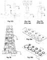
- FIGS. 10 a and 10 bshow a detail of the collar according to a first embodiment
- FIG. 11shows a detail of the collar according to a second embodiment
- FIG. 12shows pictorially use of the collar when transferring liquid between the bottle and a hypodermic syringe
- FIGS. 13 and 14show different uses of the bottle support to reduce the risk of self-injection or damage when transferring liquid between the bottle and a hypodermic syringe;
- FIGS. 15 and 16show use of the collar to avoid the risk of self-injection or damage when transferring liquid between the bottle and a hypodermic syringe;
- FIG. 17shows use of the bottle support to effect limited coupling between the bottle and another utensil
- FIG. 18shows in cross-section a collar having a slanted surface for guiding a hypodermic syringe
- FIG. 19shows in cross-section a collar fitted over the operative end of a hypodermic syringe for shielding the needle
- FIG. 20shows bending of a hypodermic needle that may occur with conventional syringes
- FIG. 21shows pictorially a resilient collar that reduces the malfunction shown in FIG. 20 ;
- FIG. 22shows pictorially how the collar of FIG. 21 cushions the needle and prevents it from bending inside the patient's skin;
- FIGS. 23 a and 23 bshow respectively details of a hypodermic syringe before and after the collar of FIG. 21 is fitted over the needle;
- FIG. 24 ashows a detail of a prior art needle assembly
- FIG. 24 bshows pictorially how the collar of FIG. 21 is fitted on to such a needle assembly
- FIG. 25shows the effect of using the collar to spread the pressure over a wider area
- FIGS. 26 a , 26 b and 26 cshow typical dimensions associated with the needle assembly with and without the collar in situ;
- FIGS. 27 a , 27 b and 27 cshow pictorially comparisons of prior art syringes with a syringe fitted with the collar of FIG. 21 ;
- FIG. 28shows pictorially multiple bottle supports stacked for easy display and packing
- FIG. 29 ashows pictorially a tray for mounting multiple bottle supports
- FIG. 29 bshows pictorially use of such a tray to mount multiple bottle supports.
- FIGS. 3 a , 3 b and 3 cshow pictorially a bottle support or mount 20 for supporting a cylindrical utensil, most typically having axial symmetry such as a cylindrical bottle.
- the bottledoes not need to have a circular cross-section and the term cylindrical is used herein in its strict mathematical sense, namely a surface generated by a straight line intersecting and moving along a closed plane curve, the directrix, while remaining parallel to a fixed straight line that is not on or parallel to the plane of the directrix.
- the bottle support 20includes an annular core 21 having an inner side surface 22 defining a hollow opening 23 , an outer side surface 24 , a top surface 25 and a base surface 26 .
- a plurality of pliable ribs 27at least partially encircle the annular core 21 so as to overlap the outer side surface 24 , the top surface 25 and the base surface 26 such that at least an upper end 28 of each rib where it overlaps the top surface extends into the hollow opening 23 .
- the lower ends 29 of at least some of the ribs where they overlap the base surface 26also extend into the hollow opening 23 .
- the annular core 21may be formed of rigid material or it may be pliable.
- the shape of a bottle than can be conveniently insertedis largely dictated by the extent to which the ribs can deform. Typically, this will restrict use of the device to bottles of regular cross-section, most typically circular. But if the core is also formed of pliable material, then there is virtually no limit to the shape of the bottle, or any other artefact, that can be securely retained therein.
- the annular core 21 and the ribs 27may be formed of a composite molding of pliable material.
- the ribsmay be a composite C-shaped molding of pliable material and may be attached to the annular core 21 using adhesive or plastic welding. In this case, there is no requirement for the annular core 21 and the ribs 27 to be formed of the same material.
- the ribsoverlap the base surface 26 , they serve to raise the base surface and insulate it from an external surface on which it is placed. Furthermore, where the lower ends of the ribs extend into the hollow opening 23 , they support the base of an object supported therein and insulate it from the external surface. This helps to prevent the object, which may be a medicine bottle or vial, from becoming contaminated. Finally, because the ribs 27 extend outwardly from the generally smooth surface of the core they provide additional support surfaces that serve as ledges that are more easily grasped or pinched between thumb and forefinger or other fingers. This makes it much easier to grasp the mount securely even with wet or slippery hands and significantly reduces the tendency of the mount to roll away as shown in FIG. 2 b . This functionality will now be described with reference to the drawings.
- FIGS. 4 a and 4 bshow a cylindrical bottle 10 supported by the bottle support 20 .
- the side surfaces of the bottleare grasped between forefinger and thumb particularly with the intention of lifting the bottle 10 from an external support surface 30 , there is still a tendency for the bottle to slip away from the user's grasp. But this tendency is reduced owing to the friction between the lower surfaces of the ribs and the support surface 30 .
- FIGS. 5 a and 5 bshow the bottle support securely held between the tips of two fingers or between thumb and forefinger by pinching protruding outer side surfaces 31 of the ribs that serve as ledges that are more easily grasped or pinched between the fingertips.
- FIG. 5 crather than lifting the bottle by holding the bottle support 20 , the bottle 20 is grasped but with the tips of the forefinger and thumb pressing against the tops of the ribs, which likewise serve as ledges that facilitate grasped or pinched between the fingertips.
- the lower surface of the bottledoes not protrude out of the lower surface of the base of the bottle holder, thus forming a recess 32 into which a user may insert his thumb or finger when grasping the bottle support from below.
- FIG. 6 ashows the bottle support 20 preventing rolling of a bottle 10 placed on an inclined support surface 30 .
- FIG. 6 bshows that the bottle support 20 is less prone to tipping even when partially tilted owing to its being placed, possibly inadvertently, on a tool 34 lying on a level surface 30 as is easily done in stressful working conditions such as operating theaters and the like.
- FIG. 6 cshows a bottle 10 supported within the bottle support 20 while stably retained at a significant incline on a tomato 35 .
- FIG. 6 dshows how medical staff may otherwise try to prevent a bottle 10 on an inclined surface 30 from rolling when no bottle support is available by retaining the bottle with the needle of a hypodermic syringe.
- FIG. 7shows pictorially use of the bottle support 20 to avoid rolling of a hypodermic syringe 36 by securing the bottle support 20 around the body of the syringe.
- Such userequires that the lower ends of the ribs of the bottle support 20 do not extend into the hollow, thus allowing the bottle support to be slid up and down the body of the syringe.
- FIG. 8shows use of the bottle support 20 to isolate a hypodermic syringe 36 from a working surface 30 thus prevent cross-contamination and at the same time preventing rolling of the syringe 36 .
- the same principlescan be applied to other utensils.
- FIGS. 9 a and 9 bthere is shown a bottle 10 having attached to its neck a collar 40 for facilitating non-slip gripping of the bottle.
- FIGS. 10 a and 10 bshow a first embodiment of the collar 40 comprising a body portion 41 having an axial bore 42 for surrounding the neck of the bottle and defining along at least a portion of an axis 43 thereof a substantially quadrilateral cross-section having in each corner thereof a respective arcuate recess 44 , each for accommodating a user's thumb or finger.
- the axial bore 42may be configured to accommodate an end of a hypodermic syringe and, to this end, may include at least two mutually contiguous sections 42 ′ and 42 ′′ of different cross-sectional areas so that the internal shape of the bore 42 is complementary to the external surface of the hypodermic syringe 36 .
- the collar 40may be formed of deformable material and dimensioned for axial compression or displacement of a predetermined distance that is adjusted to define a known protrusion of a hypodermic needle. This allows the collar 40 to be located at the end of the hypodermic needle, while concealing the tip of the needle, such that pushing the body of the syringe into the patient's skin causes the collar to compress and the needle to enter the skin.
- the body portion 41is of rectangular cross-section and defines opposing pairs of first and second side surfaces of different widths.
- the body portionmay be of square cross-section all of whose surfaces are of equal width. At least one of the side surfaces may have an indent or depression 45 for accommodating the user's finger.
- the indentmay be elongated with a major axis normal to an axis of the body portion.
- the top corners of the collarmay be slanted as shown schematically by chain-dotted lines in FIG. 10 b so that when the collar 40 is fitted to the operative end of a hypodermic syringe as described in more detail below, the resulting slanted edges may sever to guide the insertion of the needle at an angle determined by the degree of slant.
- FIG. 11shows a second embodiment of a collar 40 , having a body portion 41 an outer surface of which has a tapered portion 42 that projects axially upward opposite a base portion of the collar.
- the body portionincludes a lower portion of substantially quadrilateral cross-section, typically square.
- the tapered portion 42may be of smaller cross-sectional area than the base portion as shown in the figures so it that it tapers upward. Alternatively, it may be of larger cross-sectional area than the base portion so that it tapers downward.
- a respective arcuate recess 44for accommodating a user's thumb or finger. In some uses, it may be advantageous for the collar to be closed at one end to form a cap.
- FIG. 12shows use of the collar 40 when transferring liquid between the bottle 10 and a hypodermic syringe 36 .
- the neck of the collar 40defines a ribbed surface that is gripped between two fingers of one hand while the thumb of the same hand is held within the recess 32 of the base described above and shown in FIG. 5 c .
- the collarmay have a beveled indent 47 for better accommodating the fingers as best shown in FIG. 13 .
- the user's other handholds the hypodermic syringe 36 and aligns the needle 46 into the opening of the bottle.
- the ribbed surface of the collar 40provides some measure of shielding that reduces the risk of self-injection.
- FIG. 13shows one use of the bottle support 20 to reduce the risk of self-injury by supporting the bottle or vial 10 in the bottle support 20 on a support surface 30 so as to obviate the need for the user to touch or hold the via while aligning the hypodermic syringe therewith.
- FIG. 14shows another use of the bottle support 20 to reduce the risk of self-injury by displacing the support 20 from the base of the bottle 10 toward the neck and grasping the bottle behind the ribs 27 , which completely shield the fingers from the needle 46 .
- FIG. 15shows another embodiment where this risk is avoided altogether by elongating the collar 40 and providing at its end an internal axial bore 55 configured to accommodate an end of the hypodermic syringe 36 , thus allowing the neck of the bottle 10 to be coupled to the hypodermic syringe 36 as shown in FIG. 12 .
- the collar 40serves both as a grip and a sleeve or coupler for coupling to the mouth of another utensil as shown in FIG. 16 .
- FIG. 17shows use of the bottle support 20 to effect limited coupling between the bottle 10 and another utensil 10 ′.
- the depth of the ribs 19 at their lower endscreates a recess 32 shown in FIG. 5 c .
- the depth of the recessdepends on the dimensions and geometry of the ribs, specifically how far they extend beneath the base of the bottle support. But it also may be a function of their overall length and thickness and even their resilience since these factors will determine how far the bottle 10 needs to be pushed down into the bottle support to be firmly supported thereby. If the ribs are sufficiently stiff to support the bottle without the need to push the bottle down fully, this allows the effective depth of the recess 32 to be increased.
- FIG. 18shows in cross-section a collar 40 having a bore 42 shaped for accommodating the end of a hypodermic syringe (not shown) as described above with reference to FIG. 10 b .
- One side face 58 of the collaris at least partially beveled or slanted at an angle of 15° so that in use when this surface is guided along the surface of a patient's skin, the needle (not shown) will be maintained at an appropriate angle for venous injection without the need for manual support by the operator's finger.
- the drawingis schematic and in practice the slanted edge will be toward the front of the collar as shown by the chain-dotted lines in FIG. 10 b.
- FIG. 19shows in cross-section a collar 40 whose body 41 has an axial bore shaped to accommodate the operative end of a hypodermic syringe 36 and having a front end 60 for shielding the needle 46 .
- the front end 60is flared to provide a peripheral flexible skirt 61 that is formed of thin elastic material that is dimensioned such that in the initial state prior to use it completely covers and conceals the needle, but axially deforms when pushed against the surface of a patient's skin so as to retreat as the needle is injected.
- breathing apertures 62are provided around the periphery of the skirt that admit air and hinder suction.
- the flexible skirt 61may be dimensioned so that that in the initial state prior to use the needle protrudes a predetermined length.
- hypodermic needlesare very thin and easily deformed. If they are injected at the wrong angle and/or the patient moves, the needle can bend as shown in FIG. 20 and puncture the patient's skin in two locations. This is both painful and ineffective because the contents of the syringe are wasted and thus requires a further injection.
- FIG. 21shows how this malfunction can at least be mitigated by use of a collar 65 formed of deformable material such as foam and dimensioned for axial compression or displacement of a predetermined distance that is adjusted to define a known protrusion of a hypodermic needle.
- the collarhas a solid base portion that serves as a cap.
- FIG. 22shows use of the collar 65 , which abuts the skin as the needle 46 is injected. Should the needle bend owing to slight misalignment, it is cushioned by the collar and will bend back on itself without penetrating the patient's skin.
- FIGS. 23 a and 23 bshow respectively details of the hypodermic syringe before and after the collar 65 is fitted over the needle.
- FIG. 24 ashows a detail of a needle assembly 66 having a base 67 supporting the needle 46 .
- FIG. 24 bshows the collar 65 as it is fitted on to the needle assembly 66 so as to be supported by a peripheral flange of the base with the needle protruding through the opposite end of the collar.
- FIG. 25shows the effect of using the collar 65 , which pushes against the surface of the patient's skin over an extended area 68 thereof, which spreads the pressure over a wider area thereby reducing pain and assists in distributing the contents of the syringe more quickly through the surrounding tissue.
- FIGS. 26 a , 26 b and 26 cshow respectively typical dimensions of the needle assembly 66 (16.5 mm), and the length of the protruding end of the needle 46 without (9 mm) and with (6 mm) the collar in situ.
- the collarmay be integral with the object or utensil to which it is coupled. So, for example, it may be integral with the bottle allowing easy coupling to the hypodermic syringe, or vice versa.
- FIGS. 27 a , 27 b and 27 cshow pictorially comparisons of prior art syringes with a syringe fitted with the collar of FIG. 21 .
- the operative end of the hypodermic syringehas two intersecting ridges that press into the skin if pushed too deeply, causing significant pain to the patient.
- the resilient collar 65cushions the impact and helps to distribute pressure and thereby reduces pain.
- FIG. 28shows pictorially multiple bottle supports 20 of different diameters stacked for easy display and packing.
- the annular core 21 of each bottle supportis dimensioned so that when stacked on top of an immediately adjacent bottle support of larger diameter, the annular core 21 of the upper bottle support is supported by the ribs 19 of the lower bottle support, while the ribs of the upper bottle support are supported by the annular core of the lower bottle support.
- the annular cores 21are dimensioned so that any two alternate bottle supports can be stacked flat.
- the outer edges of the ribs 19 of the smaller bottle supportfit snugly within the inner edges of the ribs 19 of the lower bottle support.
- multiple bottle supportscan either be stacked into a tower as shown in FIG. 28 or they be dismantled and reassembled to form two sets of concentric rings.
- FIG. 29 ashows pictorially a tray 70 for mounting multiple bottle supports 20 .
- the tray 70has a plurality of upraised protuberances each dimensioned for accommodating a bottle support of appropriate diameter as shown in FIG. 29 b.
- the bottle supportmay more generally be a mount for supporting any cylindrical object and the collar may likewise be used in conjunction with any cylindrical object. In both cases as noted previously the object does not need to have a circular or even uniform cross-section.
Landscapes
- Health & Medical Sciences (AREA)
- Life Sciences & Earth Sciences (AREA)
- Veterinary Medicine (AREA)
- Public Health (AREA)
- General Health & Medical Sciences (AREA)
- Animal Behavior & Ethology (AREA)
- Pharmacology & Pharmacy (AREA)
- Engineering & Computer Science (AREA)
- Hematology (AREA)
- Heart & Thoracic Surgery (AREA)
- Biomedical Technology (AREA)
- Anesthesiology (AREA)
- Vascular Medicine (AREA)
- Physics & Mathematics (AREA)
- Fluid Mechanics (AREA)
- General Engineering & Computer Science (AREA)
- Infusion, Injection, And Reservoir Apparatuses (AREA)
- Mechanical Engineering (AREA)
Abstract
Description
Claims (21)
Priority Applications (2)
| Application Number | Priority Date | Filing Date | Title |
|---|---|---|---|
| US14/939,150US10940086B2 (en) | 2015-11-12 | 2015-11-12 | Bottle support and protective collar |
| US16/396,997US11337892B2 (en) | 2015-11-12 | 2019-04-29 | Grasping facilitators and uses thereof and kits involving the same |
Applications Claiming Priority (1)
| Application Number | Priority Date | Filing Date | Title |
|---|---|---|---|
| US14/939,150US10940086B2 (en) | 2015-11-12 | 2015-11-12 | Bottle support and protective collar |
Related Child Applications (2)
| Application Number | Title | Priority Date | Filing Date |
|---|---|---|---|
| US15/977,431Continuation-In-PartUS11458071B2 (en) | 2015-11-12 | 2018-05-11 | Torque enhancer device for grasping and tooling, and assemblies and uses thereof |
| US15/977,358Continuation-In-PartUS11234899B2 (en) | 2015-11-12 | 2018-05-11 | Grasping facilitators and uses thereof and kits involving the same |
Publications (2)
| Publication Number | Publication Date |
|---|---|
| US20170135901A1 US20170135901A1 (en) | 2017-05-18 |
| US10940086B2true US10940086B2 (en) | 2021-03-09 |
Family
ID=58690361
Family Applications (1)
| Application Number | Title | Priority Date | Filing Date |
|---|---|---|---|
| US14/939,150Active2039-04-03US10940086B2 (en) | 2015-11-12 | 2015-11-12 | Bottle support and protective collar |
Country Status (1)
| Country | Link |
|---|---|
| US (1) | US10940086B2 (en) |
Cited By (5)
| Publication number | Priority date | Publication date | Assignee | Title |
|---|---|---|---|---|
| US11097235B2 (en)* | 2019-07-23 | 2021-08-24 | Sartorius Stedim North America Inc. | Shaker flask stand with composite legs |
| US20220110469A1 (en)* | 2020-10-14 | 2022-04-14 | Denzel Barksdale | Serving Tray |
| USD950357S1 (en)* | 2019-07-23 | 2022-05-03 | Sartorius Stedim North America, Inc. | Support device |
| US11337892B2 (en) | 2015-11-12 | 2022-05-24 | Scalpal Llc | Grasping facilitators and uses thereof and kits involving the same |
| US20220184312A1 (en)* | 2019-01-24 | 2022-06-16 | Eveon | Assisted manual injection device for injecting a composition contained in a container |
Citations (168)
| Publication number | Priority date | Publication date | Assignee | Title |
|---|---|---|---|---|
| US1528713A (en)* | 1923-07-25 | 1925-03-03 | Ella E Weirick | Adjustable casserole frame |
| US1653083A (en)* | 1926-08-16 | 1927-12-20 | Sadie H Blaw | Flag holder |
| US2086674A (en)* | 1936-10-17 | 1937-07-13 | George A Lodin | Jar holder |
| US2122722A (en)* | 1936-07-17 | 1938-07-05 | John A O'neill | Insulin bottle holder |
| US2189587A (en)* | 1936-10-15 | 1940-02-06 | Lawrence A Lallement | Bottle carrier |
| US2215283A (en)* | 1938-07-06 | 1940-09-17 | Adel Prec Products Corp | Line supporting clip |
| US2563698A (en)* | 1949-01-13 | 1951-08-07 | Kolite Inc | Receptacle retaining device |
| US2634940A (en)* | 1947-02-24 | 1953-04-14 | Universal Match Corp | Ring clamp |
| US2727407A (en)* | 1950-09-12 | 1955-12-20 | Syntron Co | Flexible elastomer |
| US2782614A (en)* | 1954-07-13 | 1957-02-26 | William F Currie | Drinking attachment for cans |
| US2814267A (en)* | 1956-03-05 | 1957-11-26 | Goldstein Edwin | Drink indicating device |
| US2853261A (en)* | 1954-05-25 | 1958-09-23 | Loeb Leo | Stabilizer for containers |
| US3096960A (en)* | 1961-07-03 | 1963-07-09 | Thurlow R Kinney | Implement holder |
| US3284037A (en)* | 1964-11-18 | 1966-11-08 | Muller Franz | Pipe suspension means |
| US3302915A (en)* | 1966-06-02 | 1967-02-07 | Gen Cable Corp | Removable metal cushion for hose or pipe clamp |
| US3327893A (en)* | 1965-04-01 | 1967-06-27 | Budd Co | Protective slide for roving cans |
| US3345245A (en)* | 1960-09-26 | 1967-10-03 | Stauffer Chemical Co | Composite structure having shock absorbing properties |
| US3434682A (en)* | 1966-12-29 | 1969-03-25 | Ball Brothers Res Corp | Wire positioning and protective device |
| US3606218A (en)* | 1969-03-21 | 1971-09-20 | Gen Dynamics Corp | Sound and vibration isolation support |
| US3762673A (en)* | 1971-11-23 | 1973-10-02 | H Koslovsky | Medicant withdrawal unit |
| US3875979A (en)* | 1973-02-14 | 1975-04-08 | Wayne P Hults | Medication metering device |
| US3963226A (en)* | 1974-11-11 | 1976-06-15 | Jankowski Jr John J | Refuse container edge protector |
| US3999261A (en)* | 1975-12-08 | 1976-12-28 | Bingaman Harold J | Pad-type jar gripper |
| USD252441S (en)* | 1978-02-14 | 1979-07-24 | Allen Johnny G | Pedestal type garbage can holder |
| US4189807A (en)* | 1976-11-15 | 1980-02-26 | Viking Industries, Inc. | Clamp |
| US4222539A (en)* | 1978-10-30 | 1980-09-16 | Kramer Jack M | Clamp for clamping tubing, wire bundles, or the like |
| US4367572A (en)* | 1980-06-19 | 1983-01-11 | Zielenski Anthony L | Elastic clamping apparatus |
| US4441677A (en)* | 1982-04-02 | 1984-04-10 | Ta Mfg., Inc. | Clamp device |
| US4595515A (en)* | 1983-08-30 | 1986-06-17 | Murata Manufacturing Co., Ltd. | Vibration-isolating article |
| US4675020A (en)* | 1985-10-09 | 1987-06-23 | Kendall Mcgaw Laboratories, Inc. | Connector |
| US4713900A (en)* | 1984-12-10 | 1987-12-22 | Calloway Jr Luther | Bowl emblems |
| US4746017A (en)* | 1987-08-18 | 1988-05-24 | Bristol-Myers Company | Safety container for glass vials |
| US4880130A (en)* | 1988-07-21 | 1989-11-14 | Blake Peter J | Flexible, extruded, protective rim |
| US4969618A (en)* | 1988-08-25 | 1990-11-13 | Steve Thompson | Container holder |
| US5000331A (en)* | 1987-03-06 | 1991-03-19 | Instruments For Research and Industry I2 R. Inc. | Stabilized bottle |
| US5098051A (en)* | 1984-04-18 | 1992-03-24 | Aluma-Form, Inc. | Flexible banding and instrument support system |
| US5123558A (en)* | 1990-05-05 | 1992-06-23 | Moloney John G | Can cap and coaster |
| US5180132A (en)* | 1991-11-22 | 1993-01-19 | Pearson Scott A | Self-setting suction holder device |
| US5222701A (en)* | 1988-04-01 | 1993-06-29 | Rowland David E | Wall mounted support for holding articles |
| US5279576A (en)* | 1992-05-26 | 1994-01-18 | George Loo | Medication vial adapter |
| US5356406A (en)* | 1993-01-08 | 1994-10-18 | Steven Schraga | Adaptor to facilitate interconnection of medicine bottle and syringe |
| US5385555A (en)* | 1993-01-08 | 1995-01-31 | Becton, Dickinson And Company | Lockable safety shield for hypodermic syringe |
| US5390795A (en)* | 1994-07-22 | 1995-02-21 | Wolfgang Jobmann Florida, Inc. | Conical drum storage container |
| US5433324A (en)* | 1993-06-22 | 1995-07-18 | Leonard; Joe H. | Medicine reminder device |
| US5447764A (en)* | 1991-02-26 | 1995-09-05 | Langford; Mark H. | Insulated retainer for a beverage container |
| US5590782A (en)* | 1995-04-17 | 1997-01-07 | Habley Medical Technology Corporation | Vial holder assembly |
| US5592975A (en)* | 1993-12-21 | 1997-01-14 | Saar-Gummiwerk Gmbh | Glide tube ring for tube-in-tube systems |
| US5647845A (en)* | 1995-02-01 | 1997-07-15 | Habley Medical Technology Corporation | Generic intravenous infusion system |
| US5660138A (en)* | 1994-07-20 | 1997-08-26 | Hirsch; Victor E. | Indicator for compliance with recurring event |
| US5664753A (en)* | 1995-07-14 | 1997-09-09 | Takei; Koji | Bottle or container holder for holding the bottle or container in an inverted position |
| US5692640A (en)* | 1995-12-05 | 1997-12-02 | Caulfield; Patricia E. | Syringe content identification system |
| US5732915A (en)* | 1993-10-21 | 1998-03-31 | Signfix Limited | Unitary saddle-type base mount for attaching channel section to cylindrical article |
| US5738334A (en)* | 1993-10-21 | 1998-04-14 | Safegrip Inc. | Diaphragm flow control assembly |
| US5776124A (en)* | 1996-07-15 | 1998-07-07 | Wald; Arnold | Reusable adapter for uniting a syringe and vial |
| US5797897A (en)* | 1988-01-25 | 1998-08-25 | Baxter International Inc. | Pre-slit injection site and tapered cannula |
| US5803285A (en)* | 1996-05-28 | 1998-09-08 | Hirota; Koji | Cork cap for use with a cork to plug the mouth of a bottle |
| US5813638A (en)* | 1995-03-20 | 1998-09-29 | David F. Morris | Mixing bowl supporting assembly |
| US5857579A (en)* | 1990-07-13 | 1999-01-12 | J. G. Finneran Associates | Crimp top seal for vials |
| US5897090A (en)* | 1997-11-13 | 1999-04-27 | Bayer Corporation | Puck for a sample tube |
| US5944700A (en)* | 1997-09-26 | 1999-08-31 | Becton, Dickinson And Company | Adjustable injection length pen needle |
| US5961086A (en)* | 1998-04-27 | 1999-10-05 | Beckman Coulter, Inc. | Hands-free gripping device for containers |
| US5985219A (en)* | 1995-03-03 | 1999-11-16 | Pharmacia & Upjohn Diagnostics Ab | Test tube holder insert |
| US6109577A (en)* | 1998-03-02 | 2000-08-29 | Aluma-Form, Inc. | Flexible banding and instrument support system |
| US6152185A (en)* | 1997-06-02 | 2000-11-28 | National Valve & Engineering Company Pty. Ltd. | Hose protector system |
| US6205888B1 (en)* | 1997-07-18 | 2001-03-27 | David Steven Laudani | One-handed childproof medicine bottle opener |
| US6240668B1 (en)* | 1997-12-22 | 2001-06-05 | Pharcon Corporation | Apparatus to distinguish containers |
| US6247686B1 (en)* | 1998-05-20 | 2001-06-19 | Gate S.P.A. | Vibration damper block |
| US6253804B1 (en)* | 1999-11-05 | 2001-07-03 | Minimed Inc. | Needle safe transfer guard |
| US6286798B1 (en)* | 1998-11-19 | 2001-09-11 | Carol Ann Chun | Versatile beverage container holder |
| US20020117587A1 (en)* | 2001-02-20 | 2002-08-29 | Katsutoshi Tenma | Supporting device for non-averaged force |
| US6443403B1 (en)* | 2000-09-11 | 2002-09-03 | Panduit Corp. | Cable routing clamp and method of application |
| US6565054B2 (en)* | 2000-02-22 | 2003-05-20 | The United States Of America As Represented By The Secretary Of The Army | Syringe holder attachment for medication |
| US6578809B1 (en)* | 2000-09-22 | 2003-06-17 | Vincent A. Dimella | Flex grip mimpi apparatus |
| US6594928B1 (en)* | 1999-06-16 | 2003-07-22 | Burrell E. Clawson | Apparatus to identify information on containers |
| US6612526B2 (en)* | 2001-01-22 | 2003-09-02 | Offshore Clamp & Protector Technologies, Inc. | High strength buoyant clamp assembly and method of using same |
| US20040129596A1 (en)* | 2000-12-06 | 2004-07-08 | Geert Peter Van | Container and a container accessory |
| US20040205938A1 (en)* | 2003-04-17 | 2004-10-21 | Shedrain Corporation | Pliable handle |
| US20050205752A1 (en)* | 2004-03-16 | 2005-09-22 | Mick Pauli | Medication vial anti-tipping |
| US6971506B2 (en)* | 2001-04-03 | 2005-12-06 | Thermo Electron Oy | Test tube carrier |
| US6988824B2 (en)* | 2002-07-23 | 2006-01-24 | Ultrablend Color, Llc | Fluid mixing apparatus adapter bucket |
| US20060060592A1 (en)* | 2002-07-16 | 2006-03-23 | Misawa Homes Co., Ltd. | Woody molding, it's production system and production method |
| US7055224B2 (en)* | 2002-04-09 | 2006-06-06 | Wendan Enterprises, Inc. | Trash bag retainer |
| US20060118507A1 (en)* | 2005-03-07 | 2006-06-08 | Feldman Brenda L | Device and method for identifying containers personal to sighted and visually handicapped individuals |
| US7059368B2 (en)* | 2004-02-20 | 2006-06-13 | Point Guard Medical, Incorporated | Needle guide |
| US7077176B2 (en)* | 2003-04-28 | 2006-07-18 | Medical Instill Technologies, Inc. | Container with valve assembly for filling and dispensing substances, and apparatus and method for filling |
| US7122158B2 (en)* | 2002-02-28 | 2006-10-17 | Teruaki Itoh | Test tube holder |
| US20070080593A1 (en)* | 2005-10-07 | 2007-04-12 | O'donnell Steven B | Bearing sleeve |
| US20070079894A1 (en)* | 2003-10-30 | 2007-04-12 | Menachem Kraus | Safety drug handling device |
| US7216837B2 (en)* | 2005-05-11 | 2007-05-15 | Andres Pineda | Device for holding a container |
| US20070108205A1 (en)* | 2005-11-03 | 2007-05-17 | Bristol-Myers Squibb Company | Protective outer enclosure for pharmaceutical vial |
| US7243894B2 (en)* | 2002-02-15 | 2007-07-17 | 3M Innovative Properties Company | Mount for vibratory elements |
| US7264121B2 (en)* | 2002-05-01 | 2007-09-04 | Kao Corporation | Article holder |
| US20070214692A1 (en)* | 2006-03-16 | 2007-09-20 | Ferrara Kenneth D | System for facilitating preparation of medication doses |
| US20080011925A1 (en)* | 2005-08-12 | 2008-01-17 | Ruff Elaine S | Beverage Holder |
| US7328876B2 (en)* | 2003-09-05 | 2008-02-12 | Timothy Jones | Cup holder insert for a console |
| US7331707B2 (en)* | 2004-12-02 | 2008-02-19 | Delvalle Catherine J | Event monitoring bracelet |
| CN201023742Y (en) | 2006-10-08 | 2008-02-20 | 曹世龙 | Wine bottle with bottle cover |
| US20080065024A1 (en)* | 2006-08-14 | 2008-03-13 | John Witte | One hand syringe filling device |
| US20080105584A1 (en)* | 2006-11-02 | 2008-05-08 | Garnett Jay Cecil | System, method and article of manufacture for separating stacked storage containers |
| US7387049B1 (en)* | 2003-10-09 | 2008-06-17 | Ver Hage Richard P | Animal water feeding bottle cap handling system |
| US20080179353A1 (en) | 2007-01-31 | 2008-07-31 | Lior Maymon | Drip-catching apparatus for a bottle |
| US7422181B2 (en)* | 2004-05-26 | 2008-09-09 | Bollhoff Verbindungstechnik Gmbh | Joining assembly for fixing a tube at a holder |
| US20080312634A1 (en)* | 2007-06-13 | 2008-12-18 | Elisabet Helmerson | Device for providing fluid to a receptacle |
| US20090095865A1 (en)* | 2006-05-01 | 2009-04-16 | Cornerstone Research Group, Inc. | Device for Securely Holding Objects in Place |
| US7537136B2 (en)* | 2003-06-11 | 2009-05-26 | Laurent Hechmati | Foldable air insulating sleeve |
| US20100038273A1 (en)* | 2008-08-13 | 2010-02-18 | Johnson David T | Sleeve, system and/or method for concealing a surface of a container |
| WO2010037250A1 (en) | 2008-09-23 | 2010-04-08 | 广汉中艺工艺包装有限公司 | Antiskid beverage packaging bottle and antiskid decorative sleeve thereof |
| US7726621B1 (en)* | 2003-07-23 | 2010-06-01 | Dellinger Terry L | Container restraining device |
| US7731144B2 (en)* | 2004-03-29 | 2010-06-08 | Kazyaka Stephen R | Beverage container holder and basket |
| US20100140431A1 (en) | 2008-12-04 | 2010-06-10 | Van Horne Cynthia L | Apparatus for supporting an inverted container |
| US7748293B2 (en)* | 2008-05-08 | 2010-07-06 | Michael Peter Elwell | Pill container opener |
| US20100213206A1 (en)* | 2006-09-08 | 2010-08-26 | Greene Brian M | Detachable handle for a drinking device |
| US7845505B2 (en)* | 2003-06-03 | 2010-12-07 | Taisei Kako Co., Ltd. | Container cap |
| US20110061424A1 (en)* | 2009-08-03 | 2011-03-17 | Sarah Louise Gupta | Fitness bracelet with Timer |
| US7926780B2 (en)* | 2007-08-30 | 2011-04-19 | Hong Fu Jin Precision Industry (Shenzhen) Co., Ltd. | Vibration dampening structure for electronic device |
| US20110108513A1 (en)* | 2004-11-24 | 2011-05-12 | Peter Farrar A | Packaging article |
| US20110140412A1 (en)* | 2008-05-08 | 2011-06-16 | Amtrol Licensing Inc. | Support stand for pressure vessel |
| US8028850B2 (en)* | 2007-09-22 | 2011-10-04 | Israel Harry Zimmerman | Self-anchoring beverage container with directional release and attachment capability |
| US8087528B1 (en)* | 2008-01-28 | 2012-01-03 | Elizabeth Scarlett | Stabilizer cup holder |
| US20120000570A1 (en)* | 2010-07-02 | 2012-01-05 | Valentino Foscarota | Holding devices and methods for using the same |
| US20120065611A1 (en)* | 2010-09-10 | 2012-03-15 | National Jewish Health | Disposable vial holder and method to prevent needle stick injuries |
| US20120091296A1 (en)* | 2010-10-13 | 2012-04-19 | Tsung-Ying Lee | Adjustable Supporting Apparatus of Object Holder |
| US8215593B2 (en)* | 2006-06-27 | 2012-07-10 | J. Van Walraven Holding B.V. | Pipe clip with vibration-isolating insert |
| US8220629B2 (en)* | 2010-03-12 | 2012-07-17 | Cindy Marie Crosby | Expiration date device for cosmetic containers |
| US8225949B2 (en)* | 2005-11-30 | 2012-07-24 | Biocorp Recherche Et Developpement | Plug device for a container and container provided with one such device |
| US20120211503A1 (en)* | 2007-01-30 | 2012-08-23 | Daniel Victor Lafaver | Medicinial Vial Protector and Identifier System |
| US20120241332A1 (en) | 2011-03-25 | 2012-09-27 | Crossman Stephen Arthur | Multipack carrier for packaging containers |
| US8381361B2 (en)* | 2007-12-20 | 2013-02-26 | Airbus Deutschland Gmbh | Holding system for a line assembly |
| US20130098930A1 (en)* | 2011-10-22 | 2013-04-25 | Rosalind Ong | Protective Guard |
| US8475404B2 (en)* | 2007-08-21 | 2013-07-02 | Yukon Medical, Llc | Vial access and injection system |
| US20130206783A1 (en)* | 2012-02-15 | 2013-08-15 | Glp Systems Gmbh | Holder for cylindrical or conical containers |
| US8512295B2 (en)* | 2010-08-19 | 2013-08-20 | West Pharmaceutical Services, Inc. | Rigid needle shield |
| US20130240476A1 (en)* | 2010-11-24 | 2013-09-19 | West Pharmaceutical Services Deautschland GmbH & Co. KG | Device for stopping a container, container provided with such a device, and method for closing a batch of such containers |
| US20130303994A1 (en)* | 2010-11-22 | 2013-11-14 | Novartis Ag | Adapter |
| WO2013171521A2 (en)* | 2012-05-18 | 2013-11-21 | Trelleborg Offshore U.K. Ltd | Clamp |
| US20140008319A1 (en)* | 2012-07-09 | 2014-01-09 | Patricia Buxton-Dakides | Dial cap for medicine bottle |
| US8662580B2 (en)* | 2009-07-30 | 2014-03-04 | F.S. Fehrer Automotive Gmbh | Arm rest with drinking vessel holder |
| US8672176B2 (en)* | 2007-02-09 | 2014-03-18 | Souksomboun Sayasithsena | Beverage holding device |
| US8684624B2 (en)* | 2008-07-01 | 2014-04-01 | Saint-Gobain Performance Plastics Rencol Limited | Tolerance ring |
| US20140097323A1 (en)* | 2012-10-05 | 2014-04-10 | Dyson Technology Limited | Vibration isolation mount for an electric motor |
| US8733724B2 (en)* | 2009-09-18 | 2014-05-27 | Ford Global Technologies, Llc | One-piece plastic clamping device for holder for beverage containers |
| US20140166838A1 (en)* | 2012-12-17 | 2014-06-19 | Brandon Jason Murray | Bucket Lock |
| US20140173856A1 (en)* | 2011-05-26 | 2014-06-26 | Matrix Composites & Engineering Ltd | Clamp assembly and a clamp element for clamping bouyancy elements to pipeline risers |
| US20140231439A1 (en)* | 2010-10-04 | 2014-08-21 | Amtrol Licensing, Inc. | Plastic stand and method of attachment to a pressure vessel |
| US8833707B2 (en)* | 2010-07-15 | 2014-09-16 | Allen Medical Systems, Inc. | Disposable urology drainage bag |
| US20140290792A1 (en)* | 2010-08-13 | 2014-10-02 | Sanofi-Aventis Deutschland Gmbh | Connector for a Drug Delivery Device Reservoir |
| US8870132B2 (en)* | 2009-03-25 | 2014-10-28 | Franklin Fastener Company | Wrap bracket clamp assembly |
| US8876367B1 (en)* | 2009-10-05 | 2014-11-04 | Harold W. Howe | Container holder for mixers |
| US20140339387A1 (en)* | 2013-05-15 | 2014-11-20 | Infinite Innovations Inc. | Non-penetrating securing device system and use and method of making |
| US20140353337A1 (en)* | 2013-05-29 | 2014-12-04 | Gc Corporation | Container cover and dripping container |
| US20150101706A1 (en)* | 2012-04-02 | 2015-04-16 | Kobayashi & Co., Ltd. | Drug delivery device |
| US9133006B2 (en)* | 2010-10-31 | 2015-09-15 | Graham Packaging Company, L.P. | Systems, methods, and apparatuses for cooling hot-filled containers |
| US20150290079A1 (en)* | 2012-11-01 | 2015-10-15 | Otsuka Techno Corporation | Drug container storage device, drug container storage system, and method for sucking drug |
| US20150297451A1 (en)* | 2014-04-21 | 2015-10-22 | Becton Dickinson and Company Limited | Vial Stabilizer Base with Vial Adapter |
| US9211543B2 (en)* | 2011-12-28 | 2015-12-15 | Hitachi High-Technologies Corporation | Holder for transferring test tube |
| US9290302B2 (en)* | 2013-01-29 | 2016-03-22 | Kimberlee Ann Horn | Medicine dispensing record system |
| US20160207678A1 (en)* | 2015-01-19 | 2016-07-21 | Ronald Tuan | Cushion case for a container |
| US20160278557A1 (en)* | 2015-03-24 | 2016-09-29 | Karen Esposito | Cup holder |
| US20160318659A1 (en)* | 2015-01-03 | 2016-11-03 | Andrew Isaac Luna | Transparent Silicone Cover for the Safeguarding of Glass Pharmaceutical Vials |
| US20160367439A1 (en)* | 2015-06-18 | 2016-12-22 | Neomed, Inc | Syringe-to-syringe coupler |
| US20170027358A1 (en)* | 2015-07-31 | 2017-02-02 | Barnacle Coasters, LLC | Mobile no spill coaster |
| US20170204992A1 (en)* | 2014-08-19 | 2017-07-20 | Matrix Composites & Engineering Ltd. | Clamp for a flexible pipe |
| US20170225849A1 (en)* | 2014-11-11 | 2017-08-10 | Planetbox, Llc | Bottle and method of using |
| US20170231869A1 (en)* | 2016-02-15 | 2017-08-17 | Matthew Zerebny | Bottle support shoe with suction base |
| US20170273485A1 (en)* | 2016-03-24 | 2017-09-28 | Rao Innovations Llc | Modified folding disposable coffee cup sleeve |
| US9844846B2 (en)* | 2012-02-08 | 2017-12-19 | Tension International, Inc. | Container carrier |
| US9855193B2 (en)* | 2016-03-01 | 2018-01-02 | Porter John O'Doherty | Reminder identification article |
| USD827153S1 (en)* | 2016-11-15 | 2018-08-28 | Amgen Inc. | Vial sleeve |
- 2015
- 2015-11-12USUS14/939,150patent/US10940086B2/enactiveActive
Patent Citations (169)
| Publication number | Priority date | Publication date | Assignee | Title |
|---|---|---|---|---|
| US1528713A (en)* | 1923-07-25 | 1925-03-03 | Ella E Weirick | Adjustable casserole frame |
| US1653083A (en)* | 1926-08-16 | 1927-12-20 | Sadie H Blaw | Flag holder |
| US2122722A (en)* | 1936-07-17 | 1938-07-05 | John A O'neill | Insulin bottle holder |
| US2189587A (en)* | 1936-10-15 | 1940-02-06 | Lawrence A Lallement | Bottle carrier |
| US2086674A (en)* | 1936-10-17 | 1937-07-13 | George A Lodin | Jar holder |
| US2215283A (en)* | 1938-07-06 | 1940-09-17 | Adel Prec Products Corp | Line supporting clip |
| US2634940A (en)* | 1947-02-24 | 1953-04-14 | Universal Match Corp | Ring clamp |
| US2563698A (en)* | 1949-01-13 | 1951-08-07 | Kolite Inc | Receptacle retaining device |
| US2727407A (en)* | 1950-09-12 | 1955-12-20 | Syntron Co | Flexible elastomer |
| US2853261A (en)* | 1954-05-25 | 1958-09-23 | Loeb Leo | Stabilizer for containers |
| US2782614A (en)* | 1954-07-13 | 1957-02-26 | William F Currie | Drinking attachment for cans |
| US2814267A (en)* | 1956-03-05 | 1957-11-26 | Goldstein Edwin | Drink indicating device |
| US3345245A (en)* | 1960-09-26 | 1967-10-03 | Stauffer Chemical Co | Composite structure having shock absorbing properties |
| US3096960A (en)* | 1961-07-03 | 1963-07-09 | Thurlow R Kinney | Implement holder |
| US3284037A (en)* | 1964-11-18 | 1966-11-08 | Muller Franz | Pipe suspension means |
| US3327893A (en)* | 1965-04-01 | 1967-06-27 | Budd Co | Protective slide for roving cans |
| US3302915A (en)* | 1966-06-02 | 1967-02-07 | Gen Cable Corp | Removable metal cushion for hose or pipe clamp |
| US3434682A (en)* | 1966-12-29 | 1969-03-25 | Ball Brothers Res Corp | Wire positioning and protective device |
| US3606218A (en)* | 1969-03-21 | 1971-09-20 | Gen Dynamics Corp | Sound and vibration isolation support |
| US3762673A (en)* | 1971-11-23 | 1973-10-02 | H Koslovsky | Medicant withdrawal unit |
| US3875979A (en)* | 1973-02-14 | 1975-04-08 | Wayne P Hults | Medication metering device |
| US3963226A (en)* | 1974-11-11 | 1976-06-15 | Jankowski Jr John J | Refuse container edge protector |
| US3999261A (en)* | 1975-12-08 | 1976-12-28 | Bingaman Harold J | Pad-type jar gripper |
| US4189807A (en)* | 1976-11-15 | 1980-02-26 | Viking Industries, Inc. | Clamp |
| USD252441S (en)* | 1978-02-14 | 1979-07-24 | Allen Johnny G | Pedestal type garbage can holder |
| US4222539A (en)* | 1978-10-30 | 1980-09-16 | Kramer Jack M | Clamp for clamping tubing, wire bundles, or the like |
| US4367572A (en)* | 1980-06-19 | 1983-01-11 | Zielenski Anthony L | Elastic clamping apparatus |
| US4441677A (en)* | 1982-04-02 | 1984-04-10 | Ta Mfg., Inc. | Clamp device |
| US4595515A (en)* | 1983-08-30 | 1986-06-17 | Murata Manufacturing Co., Ltd. | Vibration-isolating article |
| US5098051A (en)* | 1984-04-18 | 1992-03-24 | Aluma-Form, Inc. | Flexible banding and instrument support system |
| US4713900A (en)* | 1984-12-10 | 1987-12-22 | Calloway Jr Luther | Bowl emblems |
| US4675020A (en)* | 1985-10-09 | 1987-06-23 | Kendall Mcgaw Laboratories, Inc. | Connector |
| US5000331A (en)* | 1987-03-06 | 1991-03-19 | Instruments For Research and Industry I2 R. Inc. | Stabilized bottle |
| US4746017A (en)* | 1987-08-18 | 1988-05-24 | Bristol-Myers Company | Safety container for glass vials |
| US5797897A (en)* | 1988-01-25 | 1998-08-25 | Baxter International Inc. | Pre-slit injection site and tapered cannula |
| US5222701A (en)* | 1988-04-01 | 1993-06-29 | Rowland David E | Wall mounted support for holding articles |
| US4880130A (en)* | 1988-07-21 | 1989-11-14 | Blake Peter J | Flexible, extruded, protective rim |
| US4969618A (en)* | 1988-08-25 | 1990-11-13 | Steve Thompson | Container holder |
| US5123558A (en)* | 1990-05-05 | 1992-06-23 | Moloney John G | Can cap and coaster |
| US5857579A (en)* | 1990-07-13 | 1999-01-12 | J. G. Finneran Associates | Crimp top seal for vials |
| US5447764A (en)* | 1991-02-26 | 1995-09-05 | Langford; Mark H. | Insulated retainer for a beverage container |
| US5180132A (en)* | 1991-11-22 | 1993-01-19 | Pearson Scott A | Self-setting suction holder device |
| US5279576A (en)* | 1992-05-26 | 1994-01-18 | George Loo | Medication vial adapter |
| US5356406A (en)* | 1993-01-08 | 1994-10-18 | Steven Schraga | Adaptor to facilitate interconnection of medicine bottle and syringe |
| US5385555A (en)* | 1993-01-08 | 1995-01-31 | Becton, Dickinson And Company | Lockable safety shield for hypodermic syringe |
| US5433324A (en)* | 1993-06-22 | 1995-07-18 | Leonard; Joe H. | Medicine reminder device |
| US5732915A (en)* | 1993-10-21 | 1998-03-31 | Signfix Limited | Unitary saddle-type base mount for attaching channel section to cylindrical article |
| US5738334A (en)* | 1993-10-21 | 1998-04-14 | Safegrip Inc. | Diaphragm flow control assembly |
| US5592975A (en)* | 1993-12-21 | 1997-01-14 | Saar-Gummiwerk Gmbh | Glide tube ring for tube-in-tube systems |
| US5660138A (en)* | 1994-07-20 | 1997-08-26 | Hirsch; Victor E. | Indicator for compliance with recurring event |
| US5390795A (en)* | 1994-07-22 | 1995-02-21 | Wolfgang Jobmann Florida, Inc. | Conical drum storage container |
| US5647845A (en)* | 1995-02-01 | 1997-07-15 | Habley Medical Technology Corporation | Generic intravenous infusion system |
| US5985219A (en)* | 1995-03-03 | 1999-11-16 | Pharmacia & Upjohn Diagnostics Ab | Test tube holder insert |
| US5813638A (en)* | 1995-03-20 | 1998-09-29 | David F. Morris | Mixing bowl supporting assembly |
| US5590782A (en)* | 1995-04-17 | 1997-01-07 | Habley Medical Technology Corporation | Vial holder assembly |
| US5664753A (en)* | 1995-07-14 | 1997-09-09 | Takei; Koji | Bottle or container holder for holding the bottle or container in an inverted position |
| US5692640A (en)* | 1995-12-05 | 1997-12-02 | Caulfield; Patricia E. | Syringe content identification system |
| US5803285A (en)* | 1996-05-28 | 1998-09-08 | Hirota; Koji | Cork cap for use with a cork to plug the mouth of a bottle |
| US5776124A (en)* | 1996-07-15 | 1998-07-07 | Wald; Arnold | Reusable adapter for uniting a syringe and vial |
| US6152185A (en)* | 1997-06-02 | 2000-11-28 | National Valve & Engineering Company Pty. Ltd. | Hose protector system |
| US6205888B1 (en)* | 1997-07-18 | 2001-03-27 | David Steven Laudani | One-handed childproof medicine bottle opener |
| US5944700A (en)* | 1997-09-26 | 1999-08-31 | Becton, Dickinson And Company | Adjustable injection length pen needle |
| US5897090A (en)* | 1997-11-13 | 1999-04-27 | Bayer Corporation | Puck for a sample tube |
| US6240668B1 (en)* | 1997-12-22 | 2001-06-05 | Pharcon Corporation | Apparatus to distinguish containers |
| US6109577A (en)* | 1998-03-02 | 2000-08-29 | Aluma-Form, Inc. | Flexible banding and instrument support system |
| US5961086A (en)* | 1998-04-27 | 1999-10-05 | Beckman Coulter, Inc. | Hands-free gripping device for containers |
| US6247686B1 (en)* | 1998-05-20 | 2001-06-19 | Gate S.P.A. | Vibration damper block |
| US6286798B1 (en)* | 1998-11-19 | 2001-09-11 | Carol Ann Chun | Versatile beverage container holder |
| US6594928B1 (en)* | 1999-06-16 | 2003-07-22 | Burrell E. Clawson | Apparatus to identify information on containers |
| US6253804B1 (en)* | 1999-11-05 | 2001-07-03 | Minimed Inc. | Needle safe transfer guard |
| US6565054B2 (en)* | 2000-02-22 | 2003-05-20 | The United States Of America As Represented By The Secretary Of The Army | Syringe holder attachment for medication |
| US6443403B1 (en)* | 2000-09-11 | 2002-09-03 | Panduit Corp. | Cable routing clamp and method of application |
| US6578809B1 (en)* | 2000-09-22 | 2003-06-17 | Vincent A. Dimella | Flex grip mimpi apparatus |
| US20040129596A1 (en)* | 2000-12-06 | 2004-07-08 | Geert Peter Van | Container and a container accessory |
| US6612526B2 (en)* | 2001-01-22 | 2003-09-02 | Offshore Clamp & Protector Technologies, Inc. | High strength buoyant clamp assembly and method of using same |
| US20020117587A1 (en)* | 2001-02-20 | 2002-08-29 | Katsutoshi Tenma | Supporting device for non-averaged force |
| US6971506B2 (en)* | 2001-04-03 | 2005-12-06 | Thermo Electron Oy | Test tube carrier |
| US7243894B2 (en)* | 2002-02-15 | 2007-07-17 | 3M Innovative Properties Company | Mount for vibratory elements |
| US7122158B2 (en)* | 2002-02-28 | 2006-10-17 | Teruaki Itoh | Test tube holder |
| US7055224B2 (en)* | 2002-04-09 | 2006-06-06 | Wendan Enterprises, Inc. | Trash bag retainer |
| US7264121B2 (en)* | 2002-05-01 | 2007-09-04 | Kao Corporation | Article holder |
| US20060060592A1 (en)* | 2002-07-16 | 2006-03-23 | Misawa Homes Co., Ltd. | Woody molding, it's production system and production method |
| US6988824B2 (en)* | 2002-07-23 | 2006-01-24 | Ultrablend Color, Llc | Fluid mixing apparatus adapter bucket |
| US20040205938A1 (en)* | 2003-04-17 | 2004-10-21 | Shedrain Corporation | Pliable handle |
| US7077176B2 (en)* | 2003-04-28 | 2006-07-18 | Medical Instill Technologies, Inc. | Container with valve assembly for filling and dispensing substances, and apparatus and method for filling |
| US7845505B2 (en)* | 2003-06-03 | 2010-12-07 | Taisei Kako Co., Ltd. | Container cap |
| US7537136B2 (en)* | 2003-06-11 | 2009-05-26 | Laurent Hechmati | Foldable air insulating sleeve |
| US7726621B1 (en)* | 2003-07-23 | 2010-06-01 | Dellinger Terry L | Container restraining device |
| US7328876B2 (en)* | 2003-09-05 | 2008-02-12 | Timothy Jones | Cup holder insert for a console |
| US7387049B1 (en)* | 2003-10-09 | 2008-06-17 | Ver Hage Richard P | Animal water feeding bottle cap handling system |
| US20070079894A1 (en)* | 2003-10-30 | 2007-04-12 | Menachem Kraus | Safety drug handling device |
| US7059368B2 (en)* | 2004-02-20 | 2006-06-13 | Point Guard Medical, Incorporated | Needle guide |
| US20050205752A1 (en)* | 2004-03-16 | 2005-09-22 | Mick Pauli | Medication vial anti-tipping |
| US7731144B2 (en)* | 2004-03-29 | 2010-06-08 | Kazyaka Stephen R | Beverage container holder and basket |
| US7422181B2 (en)* | 2004-05-26 | 2008-09-09 | Bollhoff Verbindungstechnik Gmbh | Joining assembly for fixing a tube at a holder |
| US20110108513A1 (en)* | 2004-11-24 | 2011-05-12 | Peter Farrar A | Packaging article |
| US7331707B2 (en)* | 2004-12-02 | 2008-02-19 | Delvalle Catherine J | Event monitoring bracelet |
| US20060118507A1 (en)* | 2005-03-07 | 2006-06-08 | Feldman Brenda L | Device and method for identifying containers personal to sighted and visually handicapped individuals |
| US7216837B2 (en)* | 2005-05-11 | 2007-05-15 | Andres Pineda | Device for holding a container |
| US20080011925A1 (en)* | 2005-08-12 | 2008-01-17 | Ruff Elaine S | Beverage Holder |
| US20070080593A1 (en)* | 2005-10-07 | 2007-04-12 | O'donnell Steven B | Bearing sleeve |
| US20070108205A1 (en)* | 2005-11-03 | 2007-05-17 | Bristol-Myers Squibb Company | Protective outer enclosure for pharmaceutical vial |
| US8225949B2 (en)* | 2005-11-30 | 2012-07-24 | Biocorp Recherche Et Developpement | Plug device for a container and container provided with one such device |
| US20070214692A1 (en)* | 2006-03-16 | 2007-09-20 | Ferrara Kenneth D | System for facilitating preparation of medication doses |
| US20090095865A1 (en)* | 2006-05-01 | 2009-04-16 | Cornerstone Research Group, Inc. | Device for Securely Holding Objects in Place |
| US8215593B2 (en)* | 2006-06-27 | 2012-07-10 | J. Van Walraven Holding B.V. | Pipe clip with vibration-isolating insert |
| US20080065024A1 (en)* | 2006-08-14 | 2008-03-13 | John Witte | One hand syringe filling device |
| US20100213206A1 (en)* | 2006-09-08 | 2010-08-26 | Greene Brian M | Detachable handle for a drinking device |
| CN201023742Y (en) | 2006-10-08 | 2008-02-20 | 曹世龙 | Wine bottle with bottle cover |
| US20080105584A1 (en)* | 2006-11-02 | 2008-05-08 | Garnett Jay Cecil | System, method and article of manufacture for separating stacked storage containers |
| US20120211503A1 (en)* | 2007-01-30 | 2012-08-23 | Daniel Victor Lafaver | Medicinial Vial Protector and Identifier System |
| US20080179353A1 (en) | 2007-01-31 | 2008-07-31 | Lior Maymon | Drip-catching apparatus for a bottle |
| US8672176B2 (en)* | 2007-02-09 | 2014-03-18 | Souksomboun Sayasithsena | Beverage holding device |
| US20080312634A1 (en)* | 2007-06-13 | 2008-12-18 | Elisabet Helmerson | Device for providing fluid to a receptacle |
| US8475404B2 (en)* | 2007-08-21 | 2013-07-02 | Yukon Medical, Llc | Vial access and injection system |
| US7926780B2 (en)* | 2007-08-30 | 2011-04-19 | Hong Fu Jin Precision Industry (Shenzhen) Co., Ltd. | Vibration dampening structure for electronic device |
| US8028850B2 (en)* | 2007-09-22 | 2011-10-04 | Israel Harry Zimmerman | Self-anchoring beverage container with directional release and attachment capability |
| US8381361B2 (en)* | 2007-12-20 | 2013-02-26 | Airbus Deutschland Gmbh | Holding system for a line assembly |
| US8087528B1 (en)* | 2008-01-28 | 2012-01-03 | Elizabeth Scarlett | Stabilizer cup holder |
| US20110140412A1 (en)* | 2008-05-08 | 2011-06-16 | Amtrol Licensing Inc. | Support stand for pressure vessel |
| US7748293B2 (en)* | 2008-05-08 | 2010-07-06 | Michael Peter Elwell | Pill container opener |
| US8684624B2 (en)* | 2008-07-01 | 2014-04-01 | Saint-Gobain Performance Plastics Rencol Limited | Tolerance ring |
| US20100038273A1 (en)* | 2008-08-13 | 2010-02-18 | Johnson David T | Sleeve, system and/or method for concealing a surface of a container |
| WO2010037250A1 (en) | 2008-09-23 | 2010-04-08 | 广汉中艺工艺包装有限公司 | Antiskid beverage packaging bottle and antiskid decorative sleeve thereof |
| US20100140431A1 (en) | 2008-12-04 | 2010-06-10 | Van Horne Cynthia L | Apparatus for supporting an inverted container |
| US8870132B2 (en)* | 2009-03-25 | 2014-10-28 | Franklin Fastener Company | Wrap bracket clamp assembly |
| US8662580B2 (en)* | 2009-07-30 | 2014-03-04 | F.S. Fehrer Automotive Gmbh | Arm rest with drinking vessel holder |
| US20110061424A1 (en)* | 2009-08-03 | 2011-03-17 | Sarah Louise Gupta | Fitness bracelet with Timer |
| US8733724B2 (en)* | 2009-09-18 | 2014-05-27 | Ford Global Technologies, Llc | One-piece plastic clamping device for holder for beverage containers |
| US8876367B1 (en)* | 2009-10-05 | 2014-11-04 | Harold W. Howe | Container holder for mixers |
| US8220629B2 (en)* | 2010-03-12 | 2012-07-17 | Cindy Marie Crosby | Expiration date device for cosmetic containers |
| US20120000570A1 (en)* | 2010-07-02 | 2012-01-05 | Valentino Foscarota | Holding devices and methods for using the same |
| US8833707B2 (en)* | 2010-07-15 | 2014-09-16 | Allen Medical Systems, Inc. | Disposable urology drainage bag |
| US20140290792A1 (en)* | 2010-08-13 | 2014-10-02 | Sanofi-Aventis Deutschland Gmbh | Connector for a Drug Delivery Device Reservoir |
| US8512295B2 (en)* | 2010-08-19 | 2013-08-20 | West Pharmaceutical Services, Inc. | Rigid needle shield |
| US20120065611A1 (en)* | 2010-09-10 | 2012-03-15 | National Jewish Health | Disposable vial holder and method to prevent needle stick injuries |
| US20140231439A1 (en)* | 2010-10-04 | 2014-08-21 | Amtrol Licensing, Inc. | Plastic stand and method of attachment to a pressure vessel |
| US20120091296A1 (en)* | 2010-10-13 | 2012-04-19 | Tsung-Ying Lee | Adjustable Supporting Apparatus of Object Holder |
| US9133006B2 (en)* | 2010-10-31 | 2015-09-15 | Graham Packaging Company, L.P. | Systems, methods, and apparatuses for cooling hot-filled containers |
| US20130303994A1 (en)* | 2010-11-22 | 2013-11-14 | Novartis Ag | Adapter |
| US20130240476A1 (en)* | 2010-11-24 | 2013-09-19 | West Pharmaceutical Services Deautschland GmbH & Co. KG | Device for stopping a container, container provided with such a device, and method for closing a batch of such containers |
| US20120241332A1 (en) | 2011-03-25 | 2012-09-27 | Crossman Stephen Arthur | Multipack carrier for packaging containers |
| US20140173856A1 (en)* | 2011-05-26 | 2014-06-26 | Matrix Composites & Engineering Ltd | Clamp assembly and a clamp element for clamping bouyancy elements to pipeline risers |
| US20130098930A1 (en)* | 2011-10-22 | 2013-04-25 | Rosalind Ong | Protective Guard |
| US9211543B2 (en)* | 2011-12-28 | 2015-12-15 | Hitachi High-Technologies Corporation | Holder for transferring test tube |
| US9844846B2 (en)* | 2012-02-08 | 2017-12-19 | Tension International, Inc. | Container carrier |
| US20130206783A1 (en)* | 2012-02-15 | 2013-08-15 | Glp Systems Gmbh | Holder for cylindrical or conical containers |
| US20150101706A1 (en)* | 2012-04-02 | 2015-04-16 | Kobayashi & Co., Ltd. | Drug delivery device |
| WO2013171521A2 (en)* | 2012-05-18 | 2013-11-21 | Trelleborg Offshore U.K. Ltd | Clamp |
| US9428969B2 (en)* | 2012-05-18 | 2016-08-30 | TRELLEBORG OFFSHORE U.K. Ltd. | Clamp |
| US20140008319A1 (en)* | 2012-07-09 | 2014-01-09 | Patricia Buxton-Dakides | Dial cap for medicine bottle |
| US20140097323A1 (en)* | 2012-10-05 | 2014-04-10 | Dyson Technology Limited | Vibration isolation mount for an electric motor |
| US20150290079A1 (en)* | 2012-11-01 | 2015-10-15 | Otsuka Techno Corporation | Drug container storage device, drug container storage system, and method for sucking drug |
| US20140166838A1 (en)* | 2012-12-17 | 2014-06-19 | Brandon Jason Murray | Bucket Lock |
| US9290302B2 (en)* | 2013-01-29 | 2016-03-22 | Kimberlee Ann Horn | Medicine dispensing record system |
| US20140339387A1 (en)* | 2013-05-15 | 2014-11-20 | Infinite Innovations Inc. | Non-penetrating securing device system and use and method of making |
| US20140353337A1 (en)* | 2013-05-29 | 2014-12-04 | Gc Corporation | Container cover and dripping container |
| US20150297451A1 (en)* | 2014-04-21 | 2015-10-22 | Becton Dickinson and Company Limited | Vial Stabilizer Base with Vial Adapter |
| US20170204992A1 (en)* | 2014-08-19 | 2017-07-20 | Matrix Composites & Engineering Ltd. | Clamp for a flexible pipe |
| US20170225849A1 (en)* | 2014-11-11 | 2017-08-10 | Planetbox, Llc | Bottle and method of using |
| US20160318659A1 (en)* | 2015-01-03 | 2016-11-03 | Andrew Isaac Luna | Transparent Silicone Cover for the Safeguarding of Glass Pharmaceutical Vials |
| US20160207678A1 (en)* | 2015-01-19 | 2016-07-21 | Ronald Tuan | Cushion case for a container |
| US20160278557A1 (en)* | 2015-03-24 | 2016-09-29 | Karen Esposito | Cup holder |
| US20160367439A1 (en)* | 2015-06-18 | 2016-12-22 | Neomed, Inc | Syringe-to-syringe coupler |
| US20170027358A1 (en)* | 2015-07-31 | 2017-02-02 | Barnacle Coasters, LLC | Mobile no spill coaster |
| US20170231869A1 (en)* | 2016-02-15 | 2017-08-17 | Matthew Zerebny | Bottle support shoe with suction base |
| US9855193B2 (en)* | 2016-03-01 | 2018-01-02 | Porter John O'Doherty | Reminder identification article |
| US20170273485A1 (en)* | 2016-03-24 | 2017-09-28 | Rao Innovations Llc | Modified folding disposable coffee cup sleeve |
| USD827153S1 (en)* | 2016-11-15 | 2018-08-28 | Amgen Inc. | Vial sleeve |
Cited By (5)
| Publication number | Priority date | Publication date | Assignee | Title |
|---|---|---|---|---|
| US11337892B2 (en) | 2015-11-12 | 2022-05-24 | Scalpal Llc | Grasping facilitators and uses thereof and kits involving the same |
| US20220184312A1 (en)* | 2019-01-24 | 2022-06-16 | Eveon | Assisted manual injection device for injecting a composition contained in a container |
| US11097235B2 (en)* | 2019-07-23 | 2021-08-24 | Sartorius Stedim North America Inc. | Shaker flask stand with composite legs |
| USD950357S1 (en)* | 2019-07-23 | 2022-05-03 | Sartorius Stedim North America, Inc. | Support device |
| US20220110469A1 (en)* | 2020-10-14 | 2022-04-14 | Denzel Barksdale | Serving Tray |
Also Published As
| Publication number | Publication date |
|---|---|
| US20170135901A1 (en) | 2017-05-18 |
Similar Documents
| Publication | Publication Date | Title |
|---|---|---|
| US10940086B2 (en) | Bottle support and protective collar | |
| US11944587B2 (en) | Grasping facilitators and uses thereof and kits involving the same | |
| US10039694B2 (en) | Disposable vial holder and method to prevent needle stick injuries | |
| US11701476B2 (en) | Cap for medical injector | |
| EP3291856B1 (en) | Sealed packages containing a medical device | |
| US11337892B2 (en) | Grasping facilitators and uses thereof and kits involving the same | |
| US11077253B2 (en) | Syringe | |
| NO333451B1 (en) | Device for distribution of substances | |
| JP2007534424A (en) | Liquid drug medical equipment | |
| CN108290008B (en) | Cap with hemispherical portion for medical injector | |
| US20160166770A1 (en) | Ergonomic Syringe Gripper Apparatus | |
| KR102181488B1 (en) | T-shaped cap for medical injector | |
| US9480622B1 (en) | Medical device safety holder | |
| GB2573578A (en) | Support devices |
Legal Events
| Date | Code | Title | Description |
|---|---|---|---|
| AS | Assignment | Owner name:SCALPAS LLC, MARYLAND Free format text:ASSIGNMENT OF ASSIGNORS INTEREST;ASSIGNORS:GITMAN, ELIOT ROBERT;GITMAN, TUVIA;REEL/FRAME:037024/0172 Effective date:20151112 | |
| AS | Assignment | Owner name:SCALPAL LLC, DELAWARE Free format text:ASSIGNMENT OF ASSIGNORS INTEREST;ASSIGNOR:SCALPAS LLC;REEL/FRAME:038154/0173 Effective date:20160314 | |
| STPP | Information on status: patent application and granting procedure in general | Free format text:NON FINAL ACTION MAILED | |
| STPP | Information on status: patent application and granting procedure in general | Free format text:RESPONSE TO NON-FINAL OFFICE ACTION ENTERED AND FORWARDED TO EXAMINER | |
| STCF | Information on status: patent grant | Free format text:PATENTED CASE | |
| MAFP | Maintenance fee payment | Free format text:PAYMENT OF MAINTENANCE FEE, 4TH YR, SMALL ENTITY (ORIGINAL EVENT CODE: M2551); ENTITY STATUS OF PATENT OWNER: SMALL ENTITY Year of fee payment:4 |