US10940048B2 - Assembly features and methods for a peel-and-place dressing for use with negative-pressure treatment - Google Patents
Assembly features and methods for a peel-and-place dressing for use with negative-pressure treatmentDownload PDFInfo
- Publication number
- US10940048B2 US10940048B2US15/997,763US201815997763AUS10940048B2US 10940048 B2US10940048 B2US 10940048B2US 201815997763 AUS201815997763 AUS 201815997763AUS 10940048 B2US10940048 B2US 10940048B2
- Authority
- US
- United States
- Prior art keywords
- layer
- apertures
- alignment
- retaining pins
- dressing
- Prior art date
- Legal status (The legal status is an assumption and is not a legal conclusion. Google has not performed a legal analysis and makes no representation as to the accuracy of the status listed.)
- Active, expires
Links
Images


Classifications
- A—HUMAN NECESSITIES
- A61—MEDICAL OR VETERINARY SCIENCE; HYGIENE
- A61F—FILTERS IMPLANTABLE INTO BLOOD VESSELS; PROSTHESES; DEVICES PROVIDING PATENCY TO, OR PREVENTING COLLAPSING OF, TUBULAR STRUCTURES OF THE BODY, e.g. STENTS; ORTHOPAEDIC, NURSING OR CONTRACEPTIVE DEVICES; FOMENTATION; TREATMENT OR PROTECTION OF EYES OR EARS; BANDAGES, DRESSINGS OR ABSORBENT PADS; FIRST-AID KITS
- A61F13/00—Bandages or dressings; Absorbent pads
- A61F13/05—Bandages or dressings; Absorbent pads specially adapted for use with sub-pressure or over-pressure therapy, wound drainage or wound irrigation, e.g. for use with negative-pressure wound therapy [NPWT]
- A61F13/00068—
- A—HUMAN NECESSITIES
- A61—MEDICAL OR VETERINARY SCIENCE; HYGIENE
- A61B—DIAGNOSIS; SURGERY; IDENTIFICATION
- A61B46/00—Surgical drapes
- A61B46/20—Surgical drapes specially adapted for patients
- A—HUMAN NECESSITIES
- A61—MEDICAL OR VETERINARY SCIENCE; HYGIENE
- A61F—FILTERS IMPLANTABLE INTO BLOOD VESSELS; PROSTHESES; DEVICES PROVIDING PATENCY TO, OR PREVENTING COLLAPSING OF, TUBULAR STRUCTURES OF THE BODY, e.g. STENTS; ORTHOPAEDIC, NURSING OR CONTRACEPTIVE DEVICES; FOMENTATION; TREATMENT OR PROTECTION OF EYES OR EARS; BANDAGES, DRESSINGS OR ABSORBENT PADS; FIRST-AID KITS
- A61F13/00—Bandages or dressings; Absorbent pads
- A61F13/00051—Accessories for dressings
- A61F13/00059—Accessories for dressings provided with visual effects, e.g. printed or colored
- A—HUMAN NECESSITIES
- A61—MEDICAL OR VETERINARY SCIENCE; HYGIENE
- A61F—FILTERS IMPLANTABLE INTO BLOOD VESSELS; PROSTHESES; DEVICES PROVIDING PATENCY TO, OR PREVENTING COLLAPSING OF, TUBULAR STRUCTURES OF THE BODY, e.g. STENTS; ORTHOPAEDIC, NURSING OR CONTRACEPTIVE DEVICES; FOMENTATION; TREATMENT OR PROTECTION OF EYES OR EARS; BANDAGES, DRESSINGS OR ABSORBENT PADS; FIRST-AID KITS
- A61F13/00—Bandages or dressings; Absorbent pads
- A61F13/00051—Accessories for dressings
- A61F13/00063—Accessories for dressings comprising medicaments or additives, e.g. odor control, PH control, debriding, antimicrobic
- A—HUMAN NECESSITIES
- A61—MEDICAL OR VETERINARY SCIENCE; HYGIENE
- A61F—FILTERS IMPLANTABLE INTO BLOOD VESSELS; PROSTHESES; DEVICES PROVIDING PATENCY TO, OR PREVENTING COLLAPSING OF, TUBULAR STRUCTURES OF THE BODY, e.g. STENTS; ORTHOPAEDIC, NURSING OR CONTRACEPTIVE DEVICES; FOMENTATION; TREATMENT OR PROTECTION OF EYES OR EARS; BANDAGES, DRESSINGS OR ABSORBENT PADS; FIRST-AID KITS
- A61F13/00—Bandages or dressings; Absorbent pads
- A61F13/02—Adhesive bandages or dressings
- A61F13/0203—Adhesive bandages or dressings with fluid retention members
- A61F13/0206—Adhesive bandages or dressings with fluid retention members with absorbent fibrous layers, e.g. woven or non-woven absorbent pads or island dressings
- A—HUMAN NECESSITIES
- A61—MEDICAL OR VETERINARY SCIENCE; HYGIENE
- A61F—FILTERS IMPLANTABLE INTO BLOOD VESSELS; PROSTHESES; DEVICES PROVIDING PATENCY TO, OR PREVENTING COLLAPSING OF, TUBULAR STRUCTURES OF THE BODY, e.g. STENTS; ORTHOPAEDIC, NURSING OR CONTRACEPTIVE DEVICES; FOMENTATION; TREATMENT OR PROTECTION OF EYES OR EARS; BANDAGES, DRESSINGS OR ABSORBENT PADS; FIRST-AID KITS
- A61F13/00—Bandages or dressings; Absorbent pads
- A61F13/02—Adhesive bandages or dressings
- A61F13/0203—Adhesive bandages or dressings with fluid retention members
- A61F13/0213—Adhesive bandages or dressings with fluid retention members the fluid retention member being a layer of hydrocolloid, gel forming material
- A61F13/0216—
- A—HUMAN NECESSITIES
- A61—MEDICAL OR VETERINARY SCIENCE; HYGIENE
- A61F—FILTERS IMPLANTABLE INTO BLOOD VESSELS; PROSTHESES; DEVICES PROVIDING PATENCY TO, OR PREVENTING COLLAPSING OF, TUBULAR STRUCTURES OF THE BODY, e.g. STENTS; ORTHOPAEDIC, NURSING OR CONTRACEPTIVE DEVICES; FOMENTATION; TREATMENT OR PROTECTION OF EYES OR EARS; BANDAGES, DRESSINGS OR ABSORBENT PADS; FIRST-AID KITS
- A61F13/00—Bandages or dressings; Absorbent pads
- A61F13/02—Adhesive bandages or dressings
- A61F13/0203—Adhesive bandages or dressings with fluid retention members
- A61F13/0223—Adhesive bandages or dressings with fluid retention members characterized by parametric properties of the fluid retention layer, e.g. absorbency, wicking capacity, liquid distribution
- A—HUMAN NECESSITIES
- A61—MEDICAL OR VETERINARY SCIENCE; HYGIENE
- A61F—FILTERS IMPLANTABLE INTO BLOOD VESSELS; PROSTHESES; DEVICES PROVIDING PATENCY TO, OR PREVENTING COLLAPSING OF, TUBULAR STRUCTURES OF THE BODY, e.g. STENTS; ORTHOPAEDIC, NURSING OR CONTRACEPTIVE DEVICES; FOMENTATION; TREATMENT OR PROTECTION OF EYES OR EARS; BANDAGES, DRESSINGS OR ABSORBENT PADS; FIRST-AID KITS
- A61F13/00—Bandages or dressings; Absorbent pads
- A61F13/02—Adhesive bandages or dressings
- A61F13/0246—Adhesive bandages or dressings characterised by the skin-adhering layer
- A61F13/0256—Adhesive bandages or dressings characterised by the skin-adhering layer characterized by the parametric properties of the adhesive
- A—HUMAN NECESSITIES
- A61—MEDICAL OR VETERINARY SCIENCE; HYGIENE
- A61F—FILTERS IMPLANTABLE INTO BLOOD VESSELS; PROSTHESES; DEVICES PROVIDING PATENCY TO, OR PREVENTING COLLAPSING OF, TUBULAR STRUCTURES OF THE BODY, e.g. STENTS; ORTHOPAEDIC, NURSING OR CONTRACEPTIVE DEVICES; FOMENTATION; TREATMENT OR PROTECTION OF EYES OR EARS; BANDAGES, DRESSINGS OR ABSORBENT PADS; FIRST-AID KITS
- A61F13/00—Bandages or dressings; Absorbent pads
- A61F13/02—Adhesive bandages or dressings
- A61F13/0259—Adhesive bandages or dressings characterised by the release liner covering the skin adhering layer
- A61F13/0263—Adhesive bandages or dressings characterised by the release liner covering the skin adhering layer especially adapted for island dressings
- A—HUMAN NECESSITIES
- A61—MEDICAL OR VETERINARY SCIENCE; HYGIENE
- A61F—FILTERS IMPLANTABLE INTO BLOOD VESSELS; PROSTHESES; DEVICES PROVIDING PATENCY TO, OR PREVENTING COLLAPSING OF, TUBULAR STRUCTURES OF THE BODY, e.g. STENTS; ORTHOPAEDIC, NURSING OR CONTRACEPTIVE DEVICES; FOMENTATION; TREATMENT OR PROTECTION OF EYES OR EARS; BANDAGES, DRESSINGS OR ABSORBENT PADS; FIRST-AID KITS
- A61F13/00—Bandages or dressings; Absorbent pads
- A61F13/02—Adhesive bandages or dressings
- A61F13/0276—Apparatus or processes for manufacturing adhesive dressings or bandages
- A61F13/0289—Apparatus or processes for manufacturing adhesive dressings or bandages manufacturing of adhesive dressings
- A—HUMAN NECESSITIES
- A61—MEDICAL OR VETERINARY SCIENCE; HYGIENE
- A61L—METHODS OR APPARATUS FOR STERILISING MATERIALS OR OBJECTS IN GENERAL; DISINFECTION, STERILISATION OR DEODORISATION OF AIR; CHEMICAL ASPECTS OF BANDAGES, DRESSINGS, ABSORBENT PADS OR SURGICAL ARTICLES; MATERIALS FOR BANDAGES, DRESSINGS, ABSORBENT PADS OR SURGICAL ARTICLES
- A61L15/00—Chemical aspects of, or use of materials for, bandages, dressings or absorbent pads
- A61L15/16—Bandages, dressings or absorbent pads for physiological fluids such as urine or blood, e.g. sanitary towels, tampons
- A61L15/22—Bandages, dressings or absorbent pads for physiological fluids such as urine or blood, e.g. sanitary towels, tampons containing macromolecular materials
- A61L15/24—Macromolecular compounds obtained by reactions only involving carbon-to-carbon unsaturated bonds; Derivatives thereof
- A—HUMAN NECESSITIES
- A61—MEDICAL OR VETERINARY SCIENCE; HYGIENE
- A61L—METHODS OR APPARATUS FOR STERILISING MATERIALS OR OBJECTS IN GENERAL; DISINFECTION, STERILISATION OR DEODORISATION OF AIR; CHEMICAL ASPECTS OF BANDAGES, DRESSINGS, ABSORBENT PADS OR SURGICAL ARTICLES; MATERIALS FOR BANDAGES, DRESSINGS, ABSORBENT PADS OR SURGICAL ARTICLES
- A61L15/00—Chemical aspects of, or use of materials for, bandages, dressings or absorbent pads
- A61L15/16—Bandages, dressings or absorbent pads for physiological fluids such as urine or blood, e.g. sanitary towels, tampons
- A61L15/22—Bandages, dressings or absorbent pads for physiological fluids such as urine or blood, e.g. sanitary towels, tampons containing macromolecular materials
- A61L15/26—Macromolecular compounds obtained otherwise than by reactions only involving carbon-to-carbon unsaturated bonds; Derivatives thereof
- A—HUMAN NECESSITIES
- A61—MEDICAL OR VETERINARY SCIENCE; HYGIENE
- A61L—METHODS OR APPARATUS FOR STERILISING MATERIALS OR OBJECTS IN GENERAL; DISINFECTION, STERILISATION OR DEODORISATION OF AIR; CHEMICAL ASPECTS OF BANDAGES, DRESSINGS, ABSORBENT PADS OR SURGICAL ARTICLES; MATERIALS FOR BANDAGES, DRESSINGS, ABSORBENT PADS OR SURGICAL ARTICLES
- A61L15/00—Chemical aspects of, or use of materials for, bandages, dressings or absorbent pads
- A61L15/16—Bandages, dressings or absorbent pads for physiological fluids such as urine or blood, e.g. sanitary towels, tampons
- A61L15/42—Use of materials characterised by their function or physical properties
- A61L15/52—Water-repellants
- A61M1/0086—
- A61M1/0088—
- A—HUMAN NECESSITIES
- A61—MEDICAL OR VETERINARY SCIENCE; HYGIENE
- A61M—DEVICES FOR INTRODUCING MEDIA INTO, OR ONTO, THE BODY; DEVICES FOR TRANSDUCING BODY MEDIA OR FOR TAKING MEDIA FROM THE BODY; DEVICES FOR PRODUCING OR ENDING SLEEP OR STUPOR
- A61M1/00—Suction or pumping devices for medical purposes; Devices for carrying-off, for treatment of, or for carrying-over, body-liquids; Drainage systems
- A61M1/84—Drainage tubes; Aspiration tips
- A61M1/86—Connectors between drainage tube and handpiece, e.g. drainage tubes detachable from handpiece
- A—HUMAN NECESSITIES
- A61—MEDICAL OR VETERINARY SCIENCE; HYGIENE
- A61M—DEVICES FOR INTRODUCING MEDIA INTO, OR ONTO, THE BODY; DEVICES FOR TRANSDUCING BODY MEDIA OR FOR TAKING MEDIA FROM THE BODY; DEVICES FOR PRODUCING OR ENDING SLEEP OR STUPOR
- A61M1/00—Suction or pumping devices for medical purposes; Devices for carrying-off, for treatment of, or for carrying-over, body-liquids; Drainage systems
- A61M1/90—Negative pressure wound therapy devices, i.e. devices for applying suction to a wound to promote healing, e.g. including a vacuum dressing
- A61M1/91—Suction aspects of the dressing
- A61M1/915—Constructional details of the pressure distribution manifold
- B—PERFORMING OPERATIONS; TRANSPORTING
- B29—WORKING OF PLASTICS; WORKING OF SUBSTANCES IN A PLASTIC STATE IN GENERAL
- B29C—SHAPING OR JOINING OF PLASTICS; SHAPING OF MATERIAL IN A PLASTIC STATE, NOT OTHERWISE PROVIDED FOR; AFTER-TREATMENT OF THE SHAPED PRODUCTS, e.g. REPAIRING
- B29C65/00—Joining or sealing of preformed parts, e.g. welding of plastics materials; Apparatus therefor
- B29C65/02—Joining or sealing of preformed parts, e.g. welding of plastics materials; Apparatus therefor by heating, with or without pressure
- B29C65/04—Dielectric heating, e.g. high-frequency welding, i.e. radio frequency welding of plastic materials having dielectric properties, e.g. PVC
- B—PERFORMING OPERATIONS; TRANSPORTING
- B29—WORKING OF PLASTICS; WORKING OF SUBSTANCES IN A PLASTIC STATE IN GENERAL
- B29C—SHAPING OR JOINING OF PLASTICS; SHAPING OF MATERIAL IN A PLASTIC STATE, NOT OTHERWISE PROVIDED FOR; AFTER-TREATMENT OF THE SHAPED PRODUCTS, e.g. REPAIRING
- B29C65/00—Joining or sealing of preformed parts, e.g. welding of plastics materials; Apparatus therefor
- B29C65/78—Means for handling the parts to be joined, e.g. for making containers or hollow articles, e.g. means for handling sheets, plates, web-like materials, tubular articles, hollow articles or elements to be joined therewith; Means for discharging the joined articles from the joining apparatus
- B29C65/7802—Positioning the parts to be joined, e.g. aligning, indexing or centring
- B29C65/7805—Positioning the parts to be joined, e.g. aligning, indexing or centring the parts to be joined comprising positioning features
- B29C65/7808—Positioning the parts to be joined, e.g. aligning, indexing or centring the parts to be joined comprising positioning features in the form of holes or slots
- B—PERFORMING OPERATIONS; TRANSPORTING
- B32—LAYERED PRODUCTS
- B32B—LAYERED PRODUCTS, i.e. PRODUCTS BUILT-UP OF STRATA OF FLAT OR NON-FLAT, e.g. CELLULAR OR HONEYCOMB, FORM
- B32B27/00—Layered products comprising a layer of synthetic resin
- B32B27/06—Layered products comprising a layer of synthetic resin as the main or only constituent of a layer, which is next to another layer of the same or of a different material
- B32B27/065—Layered products comprising a layer of synthetic resin as the main or only constituent of a layer, which is next to another layer of the same or of a different material of foam
- B—PERFORMING OPERATIONS; TRANSPORTING
- B32—LAYERED PRODUCTS
- B32B—LAYERED PRODUCTS, i.e. PRODUCTS BUILT-UP OF STRATA OF FLAT OR NON-FLAT, e.g. CELLULAR OR HONEYCOMB, FORM
- B32B27/00—Layered products comprising a layer of synthetic resin
- B32B27/32—Layered products comprising a layer of synthetic resin comprising polyolefins
- B—PERFORMING OPERATIONS; TRANSPORTING
- B32—LAYERED PRODUCTS
- B32B—LAYERED PRODUCTS, i.e. PRODUCTS BUILT-UP OF STRATA OF FLAT OR NON-FLAT, e.g. CELLULAR OR HONEYCOMB, FORM
- B32B27/00—Layered products comprising a layer of synthetic resin
- B32B27/40—Layered products comprising a layer of synthetic resin comprising polyurethanes
- B—PERFORMING OPERATIONS; TRANSPORTING
- B32—LAYERED PRODUCTS
- B32B—LAYERED PRODUCTS, i.e. PRODUCTS BUILT-UP OF STRATA OF FLAT OR NON-FLAT, e.g. CELLULAR OR HONEYCOMB, FORM
- B32B3/00—Layered products comprising a layer with external or internal discontinuities or unevennesses, or a layer of non-planar shape; Layered products comprising a layer having particular features of form
- B32B3/26—Layered products comprising a layer with external or internal discontinuities or unevennesses, or a layer of non-planar shape; Layered products comprising a layer having particular features of form characterised by a particular shape of the outline of the cross-section of a continuous layer; characterised by a layer with cavities or internal voids ; characterised by an apertured layer
- B32B3/266—Layered products comprising a layer with external or internal discontinuities or unevennesses, or a layer of non-planar shape; Layered products comprising a layer having particular features of form characterised by a particular shape of the outline of the cross-section of a continuous layer; characterised by a layer with cavities or internal voids ; characterised by an apertured layer characterised by an apertured layer, the apertures going through the whole thickness of the layer, e.g. expanded metal, perforated layer, slit layer regular cells B32B3/12
- B—PERFORMING OPERATIONS; TRANSPORTING
- B32—LAYERED PRODUCTS
- B32B—LAYERED PRODUCTS, i.e. PRODUCTS BUILT-UP OF STRATA OF FLAT OR NON-FLAT, e.g. CELLULAR OR HONEYCOMB, FORM
- B32B5/00—Layered products characterised by the non- homogeneity or physical structure, i.e. comprising a fibrous, filamentary, particulate or foam layer; Layered products characterised by having a layer differing constitutionally or physically in different parts
- B32B5/18—Layered products characterised by the non- homogeneity or physical structure, i.e. comprising a fibrous, filamentary, particulate or foam layer; Layered products characterised by having a layer differing constitutionally or physically in different parts characterised by features of a layer of foamed material
- A—HUMAN NECESSITIES
- A61—MEDICAL OR VETERINARY SCIENCE; HYGIENE
- A61F—FILTERS IMPLANTABLE INTO BLOOD VESSELS; PROSTHESES; DEVICES PROVIDING PATENCY TO, OR PREVENTING COLLAPSING OF, TUBULAR STRUCTURES OF THE BODY, e.g. STENTS; ORTHOPAEDIC, NURSING OR CONTRACEPTIVE DEVICES; FOMENTATION; TREATMENT OR PROTECTION OF EYES OR EARS; BANDAGES, DRESSINGS OR ABSORBENT PADS; FIRST-AID KITS
- A61F13/00—Bandages or dressings; Absorbent pads
- A61F2013/00089—Wound bandages
- A61F2013/00246—Wound bandages in a special way pervious to air or vapours
- A61F2013/00251—Wound bandages in a special way pervious to air or vapours with macroscopic openings
- A—HUMAN NECESSITIES
- A61—MEDICAL OR VETERINARY SCIENCE; HYGIENE
- A61F—FILTERS IMPLANTABLE INTO BLOOD VESSELS; PROSTHESES; DEVICES PROVIDING PATENCY TO, OR PREVENTING COLLAPSING OF, TUBULAR STRUCTURES OF THE BODY, e.g. STENTS; ORTHOPAEDIC, NURSING OR CONTRACEPTIVE DEVICES; FOMENTATION; TREATMENT OR PROTECTION OF EYES OR EARS; BANDAGES, DRESSINGS OR ABSORBENT PADS; FIRST-AID KITS
- A61F13/00—Bandages or dressings; Absorbent pads
- A61F2013/00089—Wound bandages
- A61F2013/00314—Wound bandages with surface treatments
- A61F2013/00319—Wound bandages with surface treatments to make surface hydrophobic
- A—HUMAN NECESSITIES
- A61—MEDICAL OR VETERINARY SCIENCE; HYGIENE
- A61F—FILTERS IMPLANTABLE INTO BLOOD VESSELS; PROSTHESES; DEVICES PROVIDING PATENCY TO, OR PREVENTING COLLAPSING OF, TUBULAR STRUCTURES OF THE BODY, e.g. STENTS; ORTHOPAEDIC, NURSING OR CONTRACEPTIVE DEVICES; FOMENTATION; TREATMENT OR PROTECTION OF EYES OR EARS; BANDAGES, DRESSINGS OR ABSORBENT PADS; FIRST-AID KITS
- A61F13/00—Bandages or dressings; Absorbent pads
- A61F2013/00361—Plasters
- A61F2013/00544—Plasters form or structure
- A61F2013/00604—Multilayer
- A—HUMAN NECESSITIES
- A61—MEDICAL OR VETERINARY SCIENCE; HYGIENE
- A61F—FILTERS IMPLANTABLE INTO BLOOD VESSELS; PROSTHESES; DEVICES PROVIDING PATENCY TO, OR PREVENTING COLLAPSING OF, TUBULAR STRUCTURES OF THE BODY, e.g. STENTS; ORTHOPAEDIC, NURSING OR CONTRACEPTIVE DEVICES; FOMENTATION; TREATMENT OR PROTECTION OF EYES OR EARS; BANDAGES, DRESSINGS OR ABSORBENT PADS; FIRST-AID KITS
- A61F13/00—Bandages or dressings; Absorbent pads
- A61F2013/00361—Plasters
- A61F2013/00655—Plasters adhesive
- A61F2013/00659—Plasters adhesive polymeric base
- A—HUMAN NECESSITIES
- A61—MEDICAL OR VETERINARY SCIENCE; HYGIENE
- A61F—FILTERS IMPLANTABLE INTO BLOOD VESSELS; PROSTHESES; DEVICES PROVIDING PATENCY TO, OR PREVENTING COLLAPSING OF, TUBULAR STRUCTURES OF THE BODY, e.g. STENTS; ORTHOPAEDIC, NURSING OR CONTRACEPTIVE DEVICES; FOMENTATION; TREATMENT OR PROTECTION OF EYES OR EARS; BANDAGES, DRESSINGS OR ABSORBENT PADS; FIRST-AID KITS
- A61F13/00—Bandages or dressings; Absorbent pads
- A61F13/15—Absorbent pads, e.g. sanitary towels, swabs or tampons for external or internal application to the body; Supporting or fastening means therefor; Tampon applicators
- A61F13/15203—Properties of the article, e.g. stiffness or absorbency
- A61F2013/15284—Properties of the article, e.g. stiffness or absorbency characterized by quantifiable properties
- A61F2013/15406—Basis weight
- A—HUMAN NECESSITIES
- A61—MEDICAL OR VETERINARY SCIENCE; HYGIENE
- A61F—FILTERS IMPLANTABLE INTO BLOOD VESSELS; PROSTHESES; DEVICES PROVIDING PATENCY TO, OR PREVENTING COLLAPSING OF, TUBULAR STRUCTURES OF THE BODY, e.g. STENTS; ORTHOPAEDIC, NURSING OR CONTRACEPTIVE DEVICES; FOMENTATION; TREATMENT OR PROTECTION OF EYES OR EARS; BANDAGES, DRESSINGS OR ABSORBENT PADS; FIRST-AID KITS
- A61F13/00—Bandages or dressings; Absorbent pads
- A61F13/15—Absorbent pads, e.g. sanitary towels, swabs or tampons for external or internal application to the body; Supporting or fastening means therefor; Tampon applicators
- A61F13/51—Absorbent pads, e.g. sanitary towels, swabs or tampons for external or internal application to the body; Supporting or fastening means therefor; Tampon applicators characterised by the outer layers of the pads
- A61F13/511—Topsheet, i.e. the permeable cover or layer facing the skin
- A61F13/51121—Topsheet, i.e. the permeable cover or layer facing the skin characterised by the material
- A61F2013/51139—Topsheet, i.e. the permeable cover or layer facing the skin characterised by the material being woven or knitted fabrics
- A—HUMAN NECESSITIES
- A61—MEDICAL OR VETERINARY SCIENCE; HYGIENE
- A61F—FILTERS IMPLANTABLE INTO BLOOD VESSELS; PROSTHESES; DEVICES PROVIDING PATENCY TO, OR PREVENTING COLLAPSING OF, TUBULAR STRUCTURES OF THE BODY, e.g. STENTS; ORTHOPAEDIC, NURSING OR CONTRACEPTIVE DEVICES; FOMENTATION; TREATMENT OR PROTECTION OF EYES OR EARS; BANDAGES, DRESSINGS OR ABSORBENT PADS; FIRST-AID KITS
- A61F13/00—Bandages or dressings; Absorbent pads
- A61F13/15—Absorbent pads, e.g. sanitary towels, swabs or tampons for external or internal application to the body; Supporting or fastening means therefor; Tampon applicators
- A61F13/51—Absorbent pads, e.g. sanitary towels, swabs or tampons for external or internal application to the body; Supporting or fastening means therefor; Tampon applicators characterised by the outer layers of the pads
- A61F13/511—Topsheet, i.e. the permeable cover or layer facing the skin
- A61F13/51121—Topsheet, i.e. the permeable cover or layer facing the skin characterised by the material
- A61F2013/51147—Topsheet, i.e. the permeable cover or layer facing the skin characterised by the material being polymeric films
- A—HUMAN NECESSITIES
- A61—MEDICAL OR VETERINARY SCIENCE; HYGIENE
- A61F—FILTERS IMPLANTABLE INTO BLOOD VESSELS; PROSTHESES; DEVICES PROVIDING PATENCY TO, OR PREVENTING COLLAPSING OF, TUBULAR STRUCTURES OF THE BODY, e.g. STENTS; ORTHOPAEDIC, NURSING OR CONTRACEPTIVE DEVICES; FOMENTATION; TREATMENT OR PROTECTION OF EYES OR EARS; BANDAGES, DRESSINGS OR ABSORBENT PADS; FIRST-AID KITS
- A61F13/00—Bandages or dressings; Absorbent pads
- A61F13/15—Absorbent pads, e.g. sanitary towels, swabs or tampons for external or internal application to the body; Supporting or fastening means therefor; Tampon applicators
- A61F13/51—Absorbent pads, e.g. sanitary towels, swabs or tampons for external or internal application to the body; Supporting or fastening means therefor; Tampon applicators characterised by the outer layers of the pads
- A61F13/511—Topsheet, i.e. the permeable cover or layer facing the skin
- A61F13/512—Topsheet, i.e. the permeable cover or layer facing the skin characterised by its apertures, e.g. perforations
- A61F2013/5127—Topsheet, i.e. the permeable cover or layer facing the skin characterised by its apertures, e.g. perforations characterized by the dimension of apertures
- A—HUMAN NECESSITIES
- A61—MEDICAL OR VETERINARY SCIENCE; HYGIENE
- A61F—FILTERS IMPLANTABLE INTO BLOOD VESSELS; PROSTHESES; DEVICES PROVIDING PATENCY TO, OR PREVENTING COLLAPSING OF, TUBULAR STRUCTURES OF THE BODY, e.g. STENTS; ORTHOPAEDIC, NURSING OR CONTRACEPTIVE DEVICES; FOMENTATION; TREATMENT OR PROTECTION OF EYES OR EARS; BANDAGES, DRESSINGS OR ABSORBENT PADS; FIRST-AID KITS
- A61F13/00—Bandages or dressings; Absorbent pads
- A61F13/15—Absorbent pads, e.g. sanitary towels, swabs or tampons for external or internal application to the body; Supporting or fastening means therefor; Tampon applicators
- A61F13/51—Absorbent pads, e.g. sanitary towels, swabs or tampons for external or internal application to the body; Supporting or fastening means therefor; Tampon applicators characterised by the outer layers of the pads
- A61F13/511—Topsheet, i.e. the permeable cover or layer facing the skin
- A61F13/513—Topsheet, i.e. the permeable cover or layer facing the skin characterised by its function or properties, e.g. stretchability, breathability, rewet, visual effect; having areas of different permeability
- A61F2013/51322—Topsheet, i.e. the permeable cover or layer facing the skin characterised by its function or properties, e.g. stretchability, breathability, rewet, visual effect; having areas of different permeability being elastomeric or stretchable
- A—HUMAN NECESSITIES
- A61—MEDICAL OR VETERINARY SCIENCE; HYGIENE
- A61F—FILTERS IMPLANTABLE INTO BLOOD VESSELS; PROSTHESES; DEVICES PROVIDING PATENCY TO, OR PREVENTING COLLAPSING OF, TUBULAR STRUCTURES OF THE BODY, e.g. STENTS; ORTHOPAEDIC, NURSING OR CONTRACEPTIVE DEVICES; FOMENTATION; TREATMENT OR PROTECTION OF EYES OR EARS; BANDAGES, DRESSINGS OR ABSORBENT PADS; FIRST-AID KITS
- A61F13/00—Bandages or dressings; Absorbent pads
- A61F13/15—Absorbent pads, e.g. sanitary towels, swabs or tampons for external or internal application to the body; Supporting or fastening means therefor; Tampon applicators
- A61F13/51—Absorbent pads, e.g. sanitary towels, swabs or tampons for external or internal application to the body; Supporting or fastening means therefor; Tampon applicators characterised by the outer layers of the pads
- A61F13/511—Topsheet, i.e. the permeable cover or layer facing the skin
- A61F13/513—Topsheet, i.e. the permeable cover or layer facing the skin characterised by its function or properties, e.g. stretchability, breathability, rewet, visual effect; having areas of different permeability
- A61F2013/51355—Topsheet, i.e. the permeable cover or layer facing the skin characterised by its function or properties, e.g. stretchability, breathability, rewet, visual effect; having areas of different permeability for improving fluid flow
- A61F2013/51372—Topsheet, i.e. the permeable cover or layer facing the skin characterised by its function or properties, e.g. stretchability, breathability, rewet, visual effect; having areas of different permeability for improving fluid flow with valve or valve-like upper layer; Tapered capillary structures
- A—HUMAN NECESSITIES
- A61—MEDICAL OR VETERINARY SCIENCE; HYGIENE
- A61L—METHODS OR APPARATUS FOR STERILISING MATERIALS OR OBJECTS IN GENERAL; DISINFECTION, STERILISATION OR DEODORISATION OF AIR; CHEMICAL ASPECTS OF BANDAGES, DRESSINGS, ABSORBENT PADS OR SURGICAL ARTICLES; MATERIALS FOR BANDAGES, DRESSINGS, ABSORBENT PADS OR SURGICAL ARTICLES
- A61L2420/00—Materials or methods for coatings medical devices
- A—HUMAN NECESSITIES
- A61—MEDICAL OR VETERINARY SCIENCE; HYGIENE
- A61M—DEVICES FOR INTRODUCING MEDIA INTO, OR ONTO, THE BODY; DEVICES FOR TRANSDUCING BODY MEDIA OR FOR TAKING MEDIA FROM THE BODY; DEVICES FOR PRODUCING OR ENDING SLEEP OR STUPOR
- A61M1/00—Suction or pumping devices for medical purposes; Devices for carrying-off, for treatment of, or for carrying-over, body-liquids; Drainage systems
- A61M1/90—Negative pressure wound therapy devices, i.e. devices for applying suction to a wound to promote healing, e.g. including a vacuum dressing
- A61M1/92—Negative pressure wound therapy devices, i.e. devices for applying suction to a wound to promote healing, e.g. including a vacuum dressing with liquid supply means
- A—HUMAN NECESSITIES
- A61—MEDICAL OR VETERINARY SCIENCE; HYGIENE
- A61M—DEVICES FOR INTRODUCING MEDIA INTO, OR ONTO, THE BODY; DEVICES FOR TRANSDUCING BODY MEDIA OR FOR TAKING MEDIA FROM THE BODY; DEVICES FOR PRODUCING OR ENDING SLEEP OR STUPOR
- A61M2205/00—General characteristics of the apparatus
- A61M2205/33—Controlling, regulating or measuring
- A61M2205/3331—Pressure; Flow
- A61M2205/3344—Measuring or controlling pressure at the body treatment site
- A—HUMAN NECESSITIES
- A61—MEDICAL OR VETERINARY SCIENCE; HYGIENE
- A61M—DEVICES FOR INTRODUCING MEDIA INTO, OR ONTO, THE BODY; DEVICES FOR TRANSDUCING BODY MEDIA OR FOR TAKING MEDIA FROM THE BODY; DEVICES FOR PRODUCING OR ENDING SLEEP OR STUPOR
- A61M2205/00—General characteristics of the apparatus
- A61M2205/58—Means for facilitating use, e.g. by people with impaired vision
- A61M2205/583—Means for facilitating use, e.g. by people with impaired vision by visual feedback
- A61M2205/584—Means for facilitating use, e.g. by people with impaired vision by visual feedback having a color code
- A—HUMAN NECESSITIES
- A61—MEDICAL OR VETERINARY SCIENCE; HYGIENE
- A61M—DEVICES FOR INTRODUCING MEDIA INTO, OR ONTO, THE BODY; DEVICES FOR TRANSDUCING BODY MEDIA OR FOR TAKING MEDIA FROM THE BODY; DEVICES FOR PRODUCING OR ENDING SLEEP OR STUPOR
- A61M2207/00—Methods of manufacture, assembly or production
- B—PERFORMING OPERATIONS; TRANSPORTING
- B29—WORKING OF PLASTICS; WORKING OF SUBSTANCES IN A PLASTIC STATE IN GENERAL
- B29L—INDEXING SCHEME ASSOCIATED WITH SUBCLASS B29C, RELATING TO PARTICULAR ARTICLES
- B29L2031/00—Other particular articles
- B29L2031/753—Medical equipment; Accessories therefor
- B—PERFORMING OPERATIONS; TRANSPORTING
- B32—LAYERED PRODUCTS
- B32B—LAYERED PRODUCTS, i.e. PRODUCTS BUILT-UP OF STRATA OF FLAT OR NON-FLAT, e.g. CELLULAR OR HONEYCOMB, FORM
- B32B2307/00—Properties of the layers or laminate
- B32B2307/70—Other properties
- B32B2307/73—Hydrophobic
- B—PERFORMING OPERATIONS; TRANSPORTING
- B32—LAYERED PRODUCTS
- B32B—LAYERED PRODUCTS, i.e. PRODUCTS BUILT-UP OF STRATA OF FLAT OR NON-FLAT, e.g. CELLULAR OR HONEYCOMB, FORM
- B32B2535/00—Medical equipment, e.g. bandage, prostheses or catheter
Definitions
- the invention set forth in the appended claimsrelates generally to tissue treatment systems and more particularly, but without limitation, to dressings for tissue treatment with negative pressure and methods of assembling and using the dressings for tissue treatment with negative pressure.
- Negative-pressure therapymay provide a number of benefits, including migration of epithelial and subcutaneous tissues, improved blood flow, and micro-deformation of tissue at a wound site. Together, these benefits can increase development of granulation tissue and reduce healing times.
- a method of assembling a composite dressingmay include providing an assembly station having a plurality of retaining pins and placing a first layer having a plurality of apertures on the assembly station.
- the methodmay include engaging the retaining pins with at least some of the apertures to retain the first layer in at least one plane.
- the methodmay further include placing a second layer having a plurality of fluid restrictions and at least one alignment area on the assembly station. The alignment areas may be engaged with the retaining pins so that at least some of the fluid restrictions are centrally aligned with at least some of the apertures.
- the methodmay include bonding the second layer to the first layer.
- a method of assembling a composite dressingmay include providing an assembly station having a plurality of protruding forms and placing a gel layer having a plurality of apertures on the assembly station.
- the protruding formsmay be inserted through at least some of the apertures to retain the gel layer in at least one plane.
- the methodmay further include placing a polymer film having at least two wings and a plurality of fluid restrictions over the gel layer on the assembly station, and the polymer film may be positioned so that the wings are in contact with all of the protruding forms. Additionally, the method may include bonding the polymer film to the gel layer.
- a method of assembling a composite dressingmay include providing an assembly station having a plurality of protruding forms and placing a gel layer having a plurality of apertures on the assembly station.
- the protruding formsmay be inserted through at least some of the apertures to retain the gel layer in at least one plane.
- the methodmay further include placing a polymer film having a plurality of fluid restrictions and at least two alignment apertures over the gel layer on the assembly station, and the protruding forms may be inserted through the alignment apertures.
- the methodmay further include bonding the polymer film to the gel layer.
- a method of assembling a composite dressingmay include placing a first layer on a means for retaining the first layer in at least one plane, placing a second layer adjacent to the first layer, and bonding the second layer to the first layer.
- the first layermay have a plurality of apertures
- the second layermay have a plurality of fluid restrictions and a means for aligning the fluid restrictions with the plurality of apertures.
- a dressing for treating a tissue sitemay include a first layer having a plurality of apertures, a second layer having a plurality of fluid restrictions, and a third layer comprising a foam.
- the second layermay be adapted to be positioned between the first layer and the third layer.
- the first layermay further include at least one alignment region having at least one alignment hole, and the second layer may include at least one alignment area. At least a portion of the at least one alignment area of the second layer may be configured to be positioned adjacent to at least a portion of the at least one alignment region of the first layer.
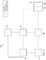
- FIG. 1is a functional block diagram of an example embodiment of a therapy system that can provide negative-pressure treatment in accordance with this specification;
- FIG. 2is an assembly view of an example of a dressing, illustrating additional details that may be associated with some example embodiments of the therapy system of FIG. 1 ;
- FIG. 3is a schematic view of an example configuration of apertures in a layer of the dressing of FIG. 2 , illustrating additional details that may be associated with some embodiments;
- FIG. 4is a schematic view of an example configuration of fluid restrictions in another layer that may be associated with some embodiments of the dressing of FIG. 2 ;
- FIG. 5is a schematic view of the example layer of FIG. 4 overlaid on the example layer of FIG. 3 ;
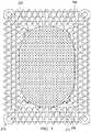
- FIG. 6is an assembly view of a tissue interface that may be associated with some additional embodiments of a dressing for use with the therapy system of FIG. 1 ;
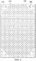
- FIG. 7is a schematic view of an example layer of the tissue interface of FIG. 6 , illustrating additional details that may be associated with some embodiments;
- FIG. 8is a schematic view of an example of another layer of the tissue interface of FIG. 6 , illustrating additional details that may be associated with some embodiments.
- FIG. 9is a schematic view of the example layer of FIG. 8 overlaid on the example layer of FIG. 7 .
- FIG. 1is a simplified functional block diagram of an example embodiment of a therapy system 100 that can provide negative-pressure therapy to a tissue site in accordance with this specification.
- tissue sitein this context broadly refers to a wound, defect, or other treatment target located on or within tissue, including, but not limited to, bone tissue, adipose tissue, muscle tissue, neural tissue, dermal tissue, vascular tissue, connective tissue, cartilage, tendons, or ligaments.
- a woundmay include chronic, acute, traumatic, subacute, and dehisced wounds, partial-thickness burns, ulcers (such as diabetic, pressure, or venous insufficiency ulcers), flaps, and grafts, for example.
- tissue sitemay also refer to areas of any tissue that are not necessarily wounded or defective, but are instead areas in which it may be desirable to add or promote the growth of additional tissue. For example, negative pressure may be applied to a tissue site to grow additional tissue that may be harvested and transplanted.
- the therapy system 100may include a source or supply of negative pressure, such as a negative-pressure source 102 , and one or more distribution components.
- a distribution componentis preferably detachable and may be disposable, reusable, or recyclable.
- a dressing, such as a dressing 104 , and a fluid container, such as a container 106are examples of distribution components that may be associated with some examples of the therapy system 100 .
- the dressing 104may comprise or consist essentially of a tissue interface 114 , a cover 116 , or both in some embodiments.
- a fluid conductoris another illustrative example of a distribution component.
- a tubeis an elongated, cylindrical structure with some flexibility, but the geometry and rigidity may vary.
- some fluid conductorsmay be molded into or otherwise integrally combined with other components.
- Distribution componentsmay also include or comprise interfaces or fluid ports to facilitate coupling and de-coupling other components.
- a dressing interfacemay facilitate coupling a fluid conductor to the dressing 104 .
- such a dressing interfacemay be a SENSAT.R.A.C.TM Pad available from Kinetic Concepts, Inc. of San Antonio, Tex.
- the therapy system 100may also include a regulator or controller, such as a controller 108 . Additionally, the therapy system 100 may include sensors to measure operating parameters and provide feedback signals to the controller 108 indicative of the operating parameters. As illustrated in FIG. 1 , for example, the therapy system 100 may include a first sensor 110 and a second sensor 112 coupled to the controller 108 .
- Some components of the therapy system 100may be housed within or used in conjunction with other components, such as sensors, processing units, alarm indicators, memory, databases, software, display devices, or user interfaces that further facilitate therapy.
- the negative-pressure source 102may be combined with the controller 108 and other components into a therapy unit.
- components of the therapy system 100may be coupled directly or indirectly.
- the negative-pressure source 102may be directly coupled to the container 106 and may be indirectly coupled to the dressing 104 through the container 106 .
- Couplingmay include fluid, mechanical, thermal, electrical, or chemical coupling (such as a chemical bond), or some combination of coupling in some contexts.
- the negative-pressure source 102may be electrically coupled to the controller 108 and may be fluidly coupled to one or more distribution components to provide a fluid path to a tissue site.
- componentsmay also be coupled by virtue of physical proximity, being integral to a single structure, or being formed from the same piece of material.
- a negative-pressure supplysuch as the negative-pressure source 102
- Negative pressuregenerally refers to a pressure less than a local ambient pressure, such as the ambient pressure in a local environment external to a sealed therapeutic environment. In many cases, the local ambient pressure may also be the atmospheric pressure at which a tissue site is located. Alternatively, the pressure may be less than a hydrostatic pressure associated with tissue at the tissue site. Unless otherwise indicated, values of pressure stated herein are gauge pressures.
- references to increases in negative pressuretypically refer to a decrease in absolute pressure, while decreases in negative pressure typically refer to an increase in absolute pressure. While the amount and nature of negative pressure provided by the negative-pressure source 102 may vary according to therapeutic requirements, the pressure is generally a low vacuum, also commonly referred to as a rough vacuum, between ⁇ 5 mm Hg ( ⁇ 667 Pa) and ⁇ 500 mm Hg ( ⁇ 66.7 kPa). Common therapeutic ranges are between ⁇ 50 mm Hg ( ⁇ 6.7 kPa) and ⁇ 300 mm Hg ( ⁇ 39.9 kPa).
- the container 106is representative of a container, canister, pouch, or other storage component, which can be used to manage exudates and other fluids withdrawn from a tissue site.
- a rigid containermay be preferred or required for collecting, storing, and disposing of fluids.
- fluidsmay be properly disposed of without rigid container storage, and a re-usable container could reduce waste and costs associated with negative-pressure therapy.
- a controllersuch as the controller 108
- the controller 108may be a microcontroller, which generally comprises an integrated circuit containing a processor core and a memory programmed to directly or indirectly control one or more operating parameters of the therapy system 100 . Operating parameters may include the power applied to the negative-pressure source 102 , the pressure generated by the negative-pressure source 102 , or the pressure distributed to the tissue interface 114 , for example.
- the controller 108is also preferably configured to receive one or more input signals, such as a feedback signal, and programmed to modify one or more operating parameters based on the input signals.
- Sensorssuch as the first sensor 110 and the second sensor 112 , are generally known in the art as any apparatus operable to detect or measure a physical phenomenon or property, and generally provide a signal indicative of the phenomenon or property that is detected or measured.
- the first sensor 110 and the second sensor 112may be configured to measure one or more operating parameters of the therapy system 100 .
- the first sensor 110may be a transducer configured to measure pressure in a pneumatic pathway and convert the measurement to a signal indicative of the pressure measured.
- the first sensor 110may be a piezo-resistive strain gauge.
- the second sensor 112may optionally measure operating parameters of the negative-pressure source 102 , such as a voltage or current, in some embodiments.
- the signals from the first sensor 110 and the second sensor 112are suitable as an input signal to the controller 108 , but some signal conditioning may be appropriate in some embodiments.
- the signalmay need to be filtered or amplified before it can be processed by the controller 108 .
- the signalis an electrical signal, but may be represented in other forms, such as an optical signal.
- the tissue interface 114can be generally adapted to partially or fully contact a tissue site.
- the tissue interface 114may take many forms, and have more than one layer in some embodiments.
- the tissue interface 114may also have many sizes, shapes, or thicknesses, depending on a variety of factors, such as the type of treatment being implemented or the nature and size of a tissue site.
- the size and shape of the tissue interface 114may be adapted to the contours of deep and irregular shaped tissue sites. Any or all of the surfaces of the tissue interface 114 may have an uneven, coarse, or jagged profile.
- the cover 116may provide a bacterial barrier and protection from physical trauma.
- the cover 116may also be constructed from a material that can reduce evaporative losses and provide a fluid seal between two components or two environments, such as between a therapeutic environment and a local external environment.
- the cover 116may comprise or consist of, for example, an elastomeric film or membrane that can provide a seal adequate to maintain a negative pressure at a tissue site for a given negative-pressure source.
- the cover 116may have a high moisture-vapor transmission rate (MVTR) in some applications.
- the MVTRmay be at least 250 grams per square meter per twenty-four hours in some embodiments, measured using an upright cup technique according to ASTM E96/E96M Upright Cup Method at 38° C. and 10% relative humidity (RH).
- RHrelative humidity
- an MVTR up to 5,000 grams per square meter per twenty-four hoursmay provide effective breathability and mechanical properties.
- the cover 116may be a polymer drape, such as a polyurethane film, that is permeable to water vapor but impermeable to liquid.
- a polymer drapesuch as a polyurethane film
- Such drapestypically have a thickness in the range of 25-50 microns.
- the permeabilitygenerally should be low enough that a desired negative pressure may be maintained.
- the cover 116may comprise, for example, one or more of the following materials: polyurethane (PU), such as hydrophilic polyurethane; cellulosics; hydrophilic polyamides; polyvinyl alcohol; polyvinyl pyrrolidone; hydrophilic acrylics; silicones, such as hydrophilic silicone elastomers; natural rubbers; polyisoprene; styrene butadiene rubber; chloroprene rubber; polybutadiene; nitrile rubber; butyl rubber; ethylene propylene rubber; ethylene propylene diene monomer; chlorosulfonated polyethylene; polysulfide rubber; ethylene vinyl acetate (EVA); co-polyester; and polyether block polymide copolymers.
- PUpolyurethane
- PUpolyurethane
- hydrophilic polyurethanesuch as hydrophilic polyurethane
- cellulosicssuch as cellulosics; hydrophilic polyamides
- the cover 116may comprise INSPIRE 2301 having an MVTR (upright cup technique) of 2600 g/m 2 /24 hours and a thickness of about 30 microns.
- An attachment devicemay be used to attach the cover 116 to an attachment surface, such as undamaged epidermis, a gasket, or another cover.
- the attachment devicemay take many forms.
- an attachment devicemay be a medically-acceptable, pressure-sensitive adhesive configured to bond the cover 116 to epidermis around a tissue site.
- some or all of the cover 116may be coated with an adhesive, such as an acrylic adhesive, which may have a coating weight of about 25-65 grams per square meter (g.s.m.). Thicker adhesives, or combinations of adhesives, may be applied in some embodiments to improve the seal and reduce leaks.
- Other example embodiments of an attachment devicemay include a double-sided tape, paste, hydrocolloid, hydrogel, silicone gel, or organogel.
- the tissue interface 114may be placed within, over, on, or otherwise proximate to a tissue site. If the tissue site is a wound, for example, the tissue interface 114 may partially or completely fill the wound, or it may be placed over the wound.
- the cover 116may be placed over the tissue interface 114 and sealed to an attachment surface near a tissue site. For example, the cover 116 may be sealed to undamaged epidermis peripheral to a tissue site.
- the dressing 104can provide a sealed therapeutic environment proximate to a tissue site, substantially isolated from the external environment, and the negative-pressure source 102 can reduce pressure in the sealed therapeutic environment.
- the fluid mechanics of using a negative-pressure source to reduce pressure in another component or location, such as within a sealed therapeutic environment,can be mathematically complex.
- the basic principles of fluid mechanics applicable to negative-pressure therapyare generally well-known to those skilled in the art, and the process of reducing pressure may be described illustratively herein as “delivering,” “distributing,” or “generating” negative pressure, for example.
- downstreamtypically implies something in a fluid path relatively closer to a source of negative pressure or further away from a source of positive pressure.
- upstreamimplies something relatively further away from a source of negative pressure or closer to a source of positive pressure.
- fluid inletor “outlet” in such a frame of reference. This orientation is generally presumed for purposes of describing various features and components herein.
- the fluid pathmay also be reversed in some applications, such as by substituting a positive-pressure source for a negative-pressure source, and this descriptive convention should not be construed as a limiting convention.
- Negative pressure applied across the tissue site through the tissue interface 114 in the sealed therapeutic environmentcan induce macro-strain and micro-strain in the tissue site. Negative pressure can also remove exudate and other fluid from a tissue site, which can be collected in container 106 .
- the controller 108may receive and process data from one or more sensors, such as the first sensor 110 .
- the controller 108may also control the operation of one or more components of the therapy system 100 to manage the pressure delivered to the tissue interface 114 .
- controller 108may include an input for receiving a desired target pressure and may be programmed for processing data relating to the setting and inputting of the target pressure to be applied to the tissue interface 114 .
- the target pressuremay be a fixed pressure value set by an operator as the target negative pressure desired for therapy at a tissue site and then provided as input to the controller 108 .
- the target pressuremay vary from tissue site to tissue site based on the type of tissue forming a tissue site, the type of injury or wound (if any), the medical condition of the patient, and the preference of the attending physician.
- the controller 108can operate the negative-pressure source 102 in one or more control modes based on the target pressure and may receive feedback from one or more sensors to maintain the target pressure at the tissue interface 114 .
- FIG. 2is an assembly view of an example of the dressing 104 of FIG. 1 , illustrating additional details that may be associated with some embodiments in which the tissue interface 114 comprises more than one layer.
- the tissue interface 114comprises a first layer 205 , a second layer 210 , and a third layer 215 .
- the first layer 205may be disposed adjacent to a second layer 210
- the third layer 215may be disposed adjacent to the second layer 210 opposite the first layer 205 .
- first layer 205 , the second layer 210 , and the third layer 215may be stacked so that the first layer 205 is in contact with the second layer 210 , and the second layer 210 is in contact with the first layer 205 and the third layer 215 .
- One or more of the first layer 205 , the second layer 210 , and the third layer 215may also be bonded to an adjacent layer in some embodiments.
- the first layer 205may comprise or consist essentially of a manifold or manifold layer, which provides a means for collecting or distributing fluid across the tissue interface 114 under pressure.
- the first layer 205may be adapted to receive negative pressure from a source and distribute negative pressure through multiple apertures across the tissue interface 114 , which may have the effect of collecting fluid from across a tissue site and drawing the fluid toward the source.
- the fluid pathmay be reversed or a secondary fluid path may be provided to facilitate delivering fluid, such as from a source of instillation solution, across the tissue interface 114 .
- the first layer 205may comprise a plurality of pathways, which can be interconnected to improve distribution or collection of fluids.
- the first layer 205may comprise or consist essentially of a porous material having interconnected fluid pathways.
- open-cell foam, reticulated foam, porous tissue collections, and other porous materialsuch as gauze or felted mat generally include pores, edges, and/or walls adapted to form interconnected fluid channels.
- Liquids, gels, and other foamsmay also include or be cured to include apertures and fluid pathways.
- the first layer 205may additionally or alternatively comprise projections that form interconnected fluid pathways.
- the first layer 205may be molded to provide surface projections that define interconnected fluid pathways. Any or all of the surfaces of the first layer 205 may have an uneven, coarse, or jagged profile
- the first layer 205may comprise or consist essentially of a reticulated foam having pore sizes and free volume that may vary according to needs of a prescribed therapy.
- a reticulated foam having a free volume of at least 90%may be suitable for many therapy applications, and a foam having an average pore size in a range of 400-600 microns (40-50 pores per inch) may be particularly suitable for some types of therapy.
- the tensile strength of the first layer 205may also vary according to needs of a prescribed therapy. For example, the tensile strength of a foam may be increased for instillation of topical treatment solutions.
- the 25% compression load deflection of the first layer 205may be at least 0.35 pounds per square inch, and the 65% compression load deflection may be at least 0.43 pounds per square inch.
- the tensile strength of the first layer 205may be at least 10 pounds per square inch.
- the first layer 205may have a tear strength of at least 2.5 pounds per inch.
- the first layer 205may be a foam comprised of polyols such as polyester or polyether, isocyanate such as toluene diisocyanate, and polymerization modifiers such as amines and tin compounds.
- the first layer 205may be a reticulated polyurethane ether foam such as used in GRANUFOAMTM dressing or V.A.C. VERAFLOTM dressing, both available from KCI of San Antonio, Tex.
- the first layer 205generally has a first planar surface and a second planar surface opposite the first planar surface.
- the thickness of the first layer 205 between the first planar surface and the second planar surfacemay also vary according to needs of a prescribed therapy. For example, the thickness of the first layer 205 may be decreased to relieve stress on other layers and to reduce tension on peripheral tissue.
- the thickness of the first layer 205can also affect the conformability of the first layer 205 . In some embodiments, a thickness in a range of about 5 millimeters to 10 millimeters may be suitable.
- the second layer 210may comprise or consist essentially of a means for controlling or managing fluid flow.
- the second layermay comprise or consist essentially of a liquid-impermeable, elastomeric material.
- the second layer 210may comprise or consist essentially of a polymer film.
- the second layer 210may also have a smooth or matte surface texture in some embodiments. A glossy or shiny finish better or equal to a grade B3 according to the SPI (Society of the Plastics Industry) standards may be particularly advantageous for some applications.
- variations in surface heightmay be limited to acceptable tolerances.
- the surface of the second layermay have a substantially flat surface, with height variations limited to 0.2 millimeters over a centimeter.
- the second layer 210may be hydrophobic.
- the hydrophobicity of the second layer 210may vary, but may have a contact angle with water of at least ninety degrees in some embodiments.
- the second layer 210may have a contact angle with water of no more than 150 degrees.
- the contact angle of the second layer 210may be in a range of at least 90 degrees to about 120 degrees, or in a range of at least 120 degrees to 150 degrees. Water contact angles can be measured using any standard apparatus.
- contact angle measuring instrumentscan often include an integrated system involving a level stage, liquid dropper such as a syringe, camera, and software designed to calculate contact angles more accurately and precisely, among other things.
- integrated systemsmay include the FT ⁇ 125, FT ⁇ 200, FT ⁇ 2000, and FT ⁇ 4000 systems, all commercially available from First Ten Angstroms, Inc., of Portsmouth, Va., and the DTA25, DTA30, and DTA100 systems, all commercially available from Kruss GmbH of Hamburg, Germany.
- water contact angles hereinare measured using deionized and distilled water on a level sample surface for a sessile drop added from a height of no more than 5 cm in air at 20-25° C. and 20-50% relative humidity. Contact angles reported herein represent averages of 5-9 measured values, discarding both the highest and lowest measured values.
- the hydrophobicity of the second layer 210may be further enhanced with a hydrophobic coating of other materials, such as silicones and fluorocarbons, either as coated from a liquid, or plasma coated.
- the second layer 210may also be suitable for welding to other layers, including the first layer 205 .
- the second layer 210may be adapted for welding to polyurethane foams using heat, radio frequency (RF) welding, or other methods to generate heat such as ultrasonic welding.
- RF weldingmay be particularly suitable for more polar materials, such as polyurethane, polyamides, polyesters and acrylates. Sacrificial polar interfaces may be used to facilitate RF welding of less polar film materials, such as polyethylene.
- the area density of the second layer 210may vary according to a prescribed therapy or application. In some embodiments, an area density of less than 40 grams per square meter may be suitable, and an area density of about 20-30 grams per square meter may be particularly advantageous for some applications.
- the second layer 210may comprise or consist essentially of a hydrophobic polymer, such as a polyethylene film.
- a hydrophobic polymersuch as a polyethylene film.
- the simple and inert structure of polyethylenecan provide a surface that interacts little, if any, with biological tissues and fluids, providing a surface that may encourage the free flow of liquids and low adherence, which can be particularly advantageous for many applications.
- polystyrene resinexamples include polyurethanes, acrylics, polyolefin (such as cyclic olefin copolymers), polyacetates, polyamides, polyesters, copolyesters, PEBAX block copolymers, thermoplastic elastomers, thermoplastic vulcanizates, polyethers, polyvinyl alcohols, polypropylene, polymethylpentene, polycarbonate, styrenics, silicones, fluoropolymers, and acetates.
- a thickness between 20 microns and 100 micronsmay be suitable for many applications. Films may be clear, colored, or printed.
- More polar films suitable for laminating to a polyethylene filminclude polyamide, co-polyesters, ionomers, and acrylics.
- tie layersmay be used, such as ethylene vinyl acetate, or modified polyurethanes.
- An ethyl methyl acrylate (EMA) filmmay also have suitable hydrophobic and welding properties for some configurations.
- the second layer 210may have one or more fluid restrictions 220 , which can be distributed uniformly or randomly across the second layer 210 .
- the fluid restrictions 220may be bi-directional and pressure-responsive.
- the fluid restrictions 220can generally comprise or consist essentially of an elastic passage that is normally unstrained to substantially reduce liquid flow, and can expand in response to a pressure gradient.
- the fluid restrictions 220may comprise or consist essentially of perforations in the second layer 210 . Perforations may be formed by removing material from the second layer 210 . For example, perforations may be formed by cutting through the second layer 210 , which may also deform the edges of the perforations in some embodiments.
- the passagesmay be sufficiently small to form a seal or flow restriction, which can substantially reduce or prevent liquid flow.
- one or more of the fluid restrictions 220may be an elastomeric valve that is normally closed when unstrained to substantially prevent liquid flow, and can open in response to a pressure gradient.
- a fenestration in the second layer 210may be a suitable valve for some applications. Fenestrations may also be formed by removing material from the second layer 210 , but the amount of material removed and the resulting dimensions of the fenestrations may be an order of magnitude less than perforations, and may not deform the edges.
- the fluid restrictions 220may comprise or consist essentially of one or more slots or combinations of slots in the second layer 210 .
- the fluid restrictions 220may comprise or consist of linear slots having a length less than 4 millimeters and a width less than 1 millimeter. The length may be at least 2 millimeters, and the width may be at least 0.4 millimeters in some embodiments. A length of about 3 millimeters and a width of about 0.8 millimeter may be particularly suitable for many applications. A tolerance of about 0.1 millimeter may also be acceptable. Such dimensions and tolerances may be achieved with a laser cutter, for example. Slots of such configurations may function as imperfect valves that substantially reduce liquid flow in a normally closed or resting state. For example, such slots may form a flow restriction without being completely closed or sealed. The slots can expand or open wider in response to a pressure gradient to allow increased liquid flow.
- the second layer 210may also include one or more alignment areas 222 , which may be designed to assist with aligning the second layer 210 with a portion of the third layer 215 .
- the alignment areas 222may be in the form of appendages, such as wings or tabs that may protrude from or extend from the perimeter of the second layer 210 .
- Some embodiments of the second layer 210may include alignment areas 222 that do not protrude from the perimeter of the second layer 210 , but rather are segments or specific area(s) of the second layer 210 .
- the third layer 215may be a sealing layer comprising or consisting essentially of a soft, pliable material suitable for providing a fluid seal with a tissue site, and may have a substantially flat surface.
- the third layer 215may comprise, without limitation, a silicone gel, a soft silicone, hydrocolloid, hydrogel, polyurethane gel, polyolefin gel, hydrogenated styrenic copolymer gel, a foamed gel, a soft closed cell foam such as polyurethanes and polyolefins coated with an adhesive, polyurethane, polyolefin, or hydrogenated styrenic copolymers.
- the third layer 215may have a thickness between about 200 microns ( ⁇ m) and about 1000 microns ( ⁇ m). In some embodiments, the third layer 215 may have a hardness between about 5 Shore 00 and about 80 Shore OO. Further, the third layer 215 may be comprised of hydrophobic or hydrophilic materials.
- the third layer 215may be a hydrophobic-coated material.
- the third layer 215may be formed by coating a spaced material, such as, for example, woven, nonwoven, molded, or extruded mesh with a hydrophobic material.
- the hydrophobic material for the coatingmay be a soft silicone, for example.
- the third layer 215may have a peripheral area, such as a periphery 225 , surrounding or around a central area, such as an interior portion 230 , and apertures 235 disposed through the periphery 225 and the interior portion 230 .
- the interior portion 230may correspond to a surface area of the first layer 205 in some examples.
- the third layer 215may also have corners 240 and edges 245 .
- the corners 240 and the edges 245may be part of the periphery 225 .
- the third layer 215may have an interior border 250 around the interior portion 230 , disposed between the interior portion 230 and the periphery 225 .
- the interior border 250may be substantially free of the apertures 235 , as illustrated in the example of FIG. 2 .
- the interior portion 230may be symmetrical and centrally disposed in the third layer 215 .
- the apertures 235may be formed by cutting or by application of local RF or ultrasonic energy, for example, or by other suitable techniques for forming an opening.
- the apertures 235may have a uniform distribution pattern, or may be randomly distributed on the third layer 215 .
- the apertures 235 in the third layer 215may have many shapes, including circles, squares, stars, ovals, polygons, slits, complex curves, rectilinear shapes, triangles, for example, or may have some combination of such shapes.
- each of the apertures 235may have uniform or similar geometric properties.
- each of the apertures 235may be circular apertures, having substantially the same diameter.
- the diameter of each of the apertures 235may be between about 1 millimeter to about 50 millimeters. In other embodiments, the diameter of each of the apertures 235 may be between about 1 millimeter to about 20 millimeters.
- geometric properties of the apertures 235may vary.
- the diameter of the apertures 235may vary depending on the position of the apertures 235 in the third layer 215 , as illustrated in FIG. 2 .
- the diameter of the apertures 235 in the periphery 225 of the third layer 215may be larger than the diameter of the apertures 235 in the interior portion 230 of the third layer 215 .
- the apertures 235 disposed in the periphery 225may have a diameter between about 9.8 millimeters to about 10.2 millimeters.
- the apertures 235 disposed in the corners 240may have a diameter between about 7.75 millimeters to about 8.75 millimeters.
- the apertures 235 disposed in the interior portion 230may have a diameter between about 1.8 millimeters to about 2.2 millimeters.
- At least one of the apertures 235 in the periphery 225 of the third layer 215may be positioned at the edges 245 of the periphery 225 , and may have an interior cut open or exposed at the edges 245 that is in fluid communication in a lateral direction with the edges 245 .
- the lateral directionmay refer to a direction toward the edges 245 and in the same plane as the third layer 215 .
- the apertures 235 in the periphery 225may be positioned proximate to or at the edges 245 and in fluid communication in a lateral direction with the edges 245 .
- the apertures 235 positioned proximate to or at the edges 245may be spaced substantially equidistant around the periphery 225 as shown in the example of FIG. 2 .
- the spacing of the apertures 235 proximate to or at the edges 245may be irregular.
- the third layer 215may further include one or more registration apertures, such as alignment holes 254 , which may be useful for facilitating alignment of the second layer 210 and the third layer 215 during manufacturing and/or assembly of the tissue interface 114 .
- the alignment holes 254may be positioned in corner regions of the interior border 250 of the third layer 215 , such as alignment regions 258 that may otherwise be substantially free of apertures or holes.
- the exact number and positioning of the alignment holes 254may vary; however, in some instances the alignment holes 254 may include two holes or apertures in each of the four corner regions of the interior border 250 , as shown in FIG. 2 , for a total of eight holes.
- the alignment holes 254may be positioned adjacent to a set of three apertures 235 of the periphery 225 , which may span along the curvatures of the four corners of the interior border 250 .
- the dressing 104may further include an attachment device, such as an adhesive 255 .
- the adhesive 255may be, for example, a medically-acceptable, pressure-sensitive adhesive that extends about a periphery, a portion, or the entire cover 116 .
- the adhesive 255may be an acrylic adhesive having a coating weight between 25-65 grams per square meter (g.s.m.). Thicker adhesives, or combinations of adhesives, may be applied in some embodiments to improve the seal and reduce leaks.
- the adhesive 255may be a layer having substantially the same shape as the periphery 225 . In some embodiments, such a layer of the adhesive 255 may be continuous or discontinuous.
- Discontinuities in the adhesive 255may be provided by apertures or holes (not shown) in the adhesive 255 .
- the apertures or holes in the adhesive 255may be formed after application of the adhesive 255 or by coating the adhesive 255 in patterns on a carrier layer, such as, for example, a side of the cover 116 .
- Apertures or holes in the adhesive 255may also be sized to enhance the MVTR of the dressing 104 in some example embodiments.
- a release liner 260may be attached to or positioned adjacent to the third layer 215 to protect the adhesive 255 prior to use.
- the release liner 260may also provide stiffness to assist with, for example, deployment of the dressing 104 .
- the release liner 260may be, for example, a casting paper, a film, or polyethylene.
- the release liner 260may be a polyester material such as polyethylene terephthalate (PET), or similar polar semi-crystalline polymer.
- PETpolyethylene terephthalate
- the use of a polar semi-crystalline polymer for the release liner 260may substantially preclude wrinkling or other deformation of the dressing 104 .
- the polar semi-crystalline polymermay be highly orientated and resistant to softening, swelling, or other deformation that may occur when brought into contact with components of the dressing 104 , or when subjected to temperature or environmental variations, or sterilization.
- the release liner 260may have a surface texture that may be imprinted on an adjacent layer, such as the third layer 215 .
- a release agentmay be disposed on a side of the release liner 260 that is configured to contact the third layer 215 .
- the release agentmay be a silicone coating and may have a release factor suitable to facilitate removal of the release liner 260 by hand and without damaging or deforming the dressing 104 .
- the release agentmay be a fluorocarbon or a fluorosilicone, for example.
- the release liner 260may be uncoated or otherwise used without a release agent.
- FIG. 2also illustrates one example of a fluid conductor 265 and a dressing interface 270 .
- the fluid conductor 265may be a flexible tube, which can be fluidly coupled on one end to the dressing interface 270 .
- the dressing interface 270may be an elbow connector, as shown in the example of FIG. 2 , which can be placed over an aperture 275 in the cover 116 to provide a fluid path between the fluid conductor 265 and the tissue interface 114 .
- FIG. 3is a schematic view of an example configuration of the apertures 235 , illustrating additional details that may be associated with some embodiments of the third layer 215 .
- the apertures 235 illustrated in FIG. 3may be associated only with the interior portion 230 .
- the apertures 235are generally circular and have a diameter of about 2 millimeters.
- FIG. 3also illustrates an example of a uniform distribution pattern of the apertures 235 in the interior portion 230 .
- the apertures 235are distributed across the interior portion 230 in a grid of parallel rows and columns. Within each row and column, the apertures 235 may be equidistant from each other, as illustrated in the example of FIG. 3 .
- FIG. 3illustrates one example configuration that may be particularly suitable for many applications, in which the apertures 235 are spaced about 6 millimeters apart along each row and column, with a 3 millimeter offset.
- FIG. 4is a schematic view of an example of the second layer 210 , illustrating additional details that may be associated with some embodiments.
- the fluid restrictions 220may each consist essentially of one or more linear slots having a length of about 3 millimeters.
- FIG. 4additionally illustrates an example of a uniform distribution pattern of the fluid restrictions 220 .
- the fluid restrictions 220are substantially coextensive with the second layer 210 , and are distributed across the second layer 210 in a grid of parallel rows and columns, in which the slots are also mutually parallel to each other.
- the rowsmay be spaced about 3 millimeters on center, and the fluid restrictions 220 within each of the rows may be spaced about 3 millimeters on center as illustrated in the example of FIG. 4 .
- the fluid restrictions 220 in adjacent rowsmay be aligned or offset.
- adjacent rowsmay be offset, as illustrated in FIG. 4 , so that the fluid restrictions 220 are aligned in alternating rows and separated by about 6 millimeters.
- the spacing of the fluid restrictions 220may vary in some embodiments to increase the density of the fluid restrictions 220 according to therapeutic requirements.
- the alignment areas 222 of FIG. 4are shown as wings that protrude from or extend beyond the perimeter of the second layer 210 .
- the alignment areas 222may facilitate alignment with features of both the third layer 215 as well as tools used in the manufacture and/or assembly of the tissue interface 114 .
- the wingsmay have a width of between 5 mm and 20 mm, and may protrude from the edge of the second layer 210 by a length of between 2 mm and 12 mm.
- the alignment areas 222may comprise wings having a width of 11 mm and a length of 5 mm. As depicted in FIG.
- the alignment areas 222 of the second layer 210may include one or more of the fluid restrictions 220 ; however, the fluid restrictions 220 may not be disposed on all or any of the alignment areas 222 .
- FIG. 4illustrates an embodiment of a second layer 210 comprising four alignment areas 222 in the form of wings; however, other examples may include a greater or lesser number of alignment areas 222 . The positioning of the alignment areas 222 may also be varied. Regardless of the number or size of alignment areas 222 , the fluid restrictions 220 should be registered to or correspond to the position and area of the alignment areas 222 so that when the alignment areas 222 are used to correctly position the second layer 210 , the fluid restrictions 220 will align with apertures 235 of the third layer 215 .
- the alignment areas 222 comprising wingsmay include an additional hole or perforation that may be larger than the fluid restrictions 220 .
- the additional holemay have a diameter of between about 1 mm and 2 mm, and may be large enough for the vision or scanning components of an automated assembly tool to detect.
- the additional holemay be formed in the center of the wing of the alignment area 222 .
- FIG. 5is a schematic view of the second layer 210 of FIG. 4 overlaid on the third layer 215 of FIG. 2 , illustrating additional details that may be associated with some example embodiments of the tissue interface 114 .
- the fluid restrictions 220may be aligned, overlapping, in registration with, or otherwise fluidly coupled to the apertures 235 in some embodiments.
- one or more of the fluid restrictions 220may be registered with the apertures 235 only in the interior portion 230 of the third layer 215 .
- the fluid restrictions 220 in the example of FIG. 5are generally configured so that each of the fluid restrictions 220 is registered with only one of the apertures 235 .
- one or more of the fluid restrictions 220may be registered with more than one of the apertures 235 .
- any one or more of the fluid restrictions 220may be a perforation or a fenestration that extends across two or more of the apertures 235 .
- one or more of the fluid restrictions 220may not be registered with any of the apertures 235 .
- the apertures 235may be sized to expose a portion of the second layer 210 , the fluid restrictions 220 , or both through the third layer 215 .
- each of the apertures 235may be sized to expose no more than two of the fluid restrictions 220 .
- the length of each of the fluid restrictions 220may be substantially equal to or less than the diameter of each of the apertures 235 .
- the average dimensions of the fluid restrictions 220are substantially similar to the average dimensions of the apertures 235 .
- the apertures 235may be elliptical in some embodiments, and the length of each of the fluid restrictions 220 may be substantially equal to the major axis or the minor axis. In some embodiments, though, the dimensions of the fluid restrictions 220 may exceed the dimensions of the apertures 235 , and the size of the apertures 235 may limit the effective size of the fluid restrictions 220 exposed to the lower surface of the dressing 104 .
- the alignment areas 222may align with a solid area, or non-perforated or non-apertured region of the third layer 215 that is located between apertures on the third layer 215 .
- the alignment areas 222such as wings, of the second layer 210 may be positioned between alignment holes 254 associated with alignment regions 258 of the third layer 215 , which may be in one or more of the corner regions of the interior border 250 of the third layer 215 . As shown in FIG.
- each of the four alignment areas 222 of the second layer 210may be positioned against an alignment region 258 of the third layer 215 and between two of the alignment holes 254 .
- the alignment regions 258may typically be portions of the third layer 215 that are not perforated and may be a solid material, such as a silicone material.
- the alignment regions 258may include a region between two alignment holes 254 , with each of the alignment holes 254 having a diameter of between 4 mm and 10 mm. In some embodiments, the alignment holes 254 may each have a diameter of approximately 6 mm.
- Each of the second layer 210 and third layer 215may be sized and scaled so that when each of the alignment areas 222 are properly positioned over the alignment regions 258 and between the alignment holes 254 , the second layer 210 and third layer 215 may align so that fluid restrictions 220 of the second layer 210 are aligned with apertures 235 of the interior portion 230 of the third layer 215 .
- the correct alignment of the layersmay ensure proper registration of the fluid restrictions 220 with the apertures 235 .
- the alignment areas 222may facilitate alignment of the fluid restrictions 220 and the apertures 235 by engaging with a structure of an assembly tool used for assembly of the tissue interface 114 .
- the third layer 215may be placed on an assembly tool such that rods or retaining pins of the assembly tool may extend through each of the eight alignment holes 254 of the third layer 215 .
- each of the alignment areas 222such as the wings of FIG. 5
- each of the wingsmay touch the two rods or retaining pins extending through the adjacent alignment holes 254 .
- the rods or pinsmay provide guides or boundaries between which the alignment areas 222 may be positioned.
- the alignment areas 222such as the wings, may each fit between two of the assembly rods or pins, without being creased or buckled.
- the second layer 210 and the third layer 215may be scaled to each other so that when the alignment areas 222 are properly positioned between the rods or pins, the fluid restrictions 220 may be aligned and registered with the apertures 235 of the third layer 215 in both X- and Y-axes. Once placed in contact with an alignment region 258 of the third layer 215 , the alignment areas 222 , as well as the other portions of the second layer 210 , may be held in the proper overlaid position on the third layer 215 , with the fluid restrictions 220 and apertures 235 in proper alignment, due to a silicone bond provided by the third layer 215 .
- the second layer 210may be aligned with the third layer 215 by aligning an additional guide hole included as part of the second layer 210 with an alignment hole 254 of the third layer 215 .
- the second layer 210 and the third layer 215may be configured such that when the two layers are overlaid in a proper position, the additional guide hole of the second layer 210 may be aligned or positioned adjacent to or over an alignment hole 254 of the third layer 215 .
- the guide hole of the second layer 210may be sized so that when the second layer 210 is aligned over the third layer 215 , the guide hole of the second layer 210 is coextensive with an alignment hole 254 of the third layer 215 .
- the additional guide hole of the second layer 210may be a different shape than the fluid restrictions 220 of the second layer 210 for easier identification.
- the shape itself of the guide hole of the second layer 210may also facilitate alignment.
- the shape of the alignment hole 254 of the third layer 215may also be different than that of the apertures 235 of the third layer 215 for easier identification.
- the alignment hole 254 of the third layer 215may be larger than the corresponding guide hole of the second layer 210 , which may enable an automated assembly system to adjust the positioning of the second layer 210 and third layer 215 as the two layers are brought into alignment.
- the first layer 205which may comprise an open-cell foam, may be placed on top of the second layer 210 subsequent to alignment of the second layer 210 and third layer 215 .
- the first layer 205may be sized and positioned adjacent a top surface of the second layer 210 to be substantially coextensive with the second layer 210 , exclusive of alignment areas 222 comprising the wings, as well as the interior portion 230 of the third layer 215 .
- the cover 116may then be placed on top of the first layer 205 , with the borders of the cover 116 placed around the first layer 205 and second layer 210 and compressed into silicone material of the third layer 215 to form a bond.
- the adhesive 255 of the cover 116may pass through any exposed apertures 235 of the third layer 215 , as well as any exposed fluid restrictions 220 of the second layer 210 .
- the first layer 205may be a foam, mesh, or non-woven coated with an antimicrobial agent.
- the first layermay comprise antimicrobial elements, such as fibers coated with an antimicrobial agent.
- some embodiments of the second layer 210may be a polymer coated or mixed with an antimicrobial agent.
- the fluid conductor 265may additionally or alternatively be treated with one or more antimicrobial agents.
- Suitable antimicrobial agentsmay include, for example, metallic silver, PHMB, iodine or its complexes and mixes such as povidone iodine, copper metal compounds, chlorhexidine, or some combination of these materials.
- one or more of the componentsmay be coated with a mixture that may include citric acid and collagen, which can reduce bio-films and infections.
- the first layer 205may be a foam coated with such a mixture.
- Individual components of the dressing 104may be bonded or otherwise secured to one another with a solvent or non-solvent adhesive, or with thermal welding, for example, without adversely affecting fluid management.
- the second layer 210 or the first layer 205may be coupled to the interior border 250 of the third layer 215 in any suitable manner, such as with a weld or an adhesive, for example.
- the cover 116 , the first layer 205 , the second layer 210 , the third layer 215 , or various combinationsmay be assembled before application or in situ.
- the cover 116may be laminated to the first layer 205
- the second layer 210may be laminated to the first layer 205 opposite the cover 116 in some embodiments.
- the third layer 215may also be coupled to the second layer 210 opposite the first layer 205 in some embodiments.
- one or more layers of the tissue interface 114may coextensive.
- the second layer 210 , the third layer 215 , or bothmay overlap the edge of the first layer 205 .
- the second layer 210 , the third layer 215 , or bothmay be cut flush with the edge of the first layer 205 , exposing the edge of the first layer 205 .
- the first layer 205may be coextensive with the second layer 210 , as illustrated in the embodiment of FIG. 2 .
- the dressing 104may be provided as a single, composite dressing.
- the third layer 215may be coupled to the cover 116 to enclose the first layer 205 and the second layer 210 , wherein the third layer 215 is configured to face a tissue site.
- the second layer 210 , the third layer 215 , or some combination of the second layer 210 and the third layer 215may be disposed on both sides of the first layer 205 .
- the release liner 260may be removed to expose the third layer 215 , which may be placed within, over, on, or otherwise proximate to a tissue site, particularly a surface tissue site and adjacent epidermis.
- the third layer 215 and the second layer 210may be interposed between the first layer 205 and the tissue site, which can substantially reduce or eliminate adverse interaction with the first layer 205 .
- the third layer 215may be placed over a surface wound (including edges of the wound) and undamaged epidermis to prevent direct contact with the first layer 205 .
- Treatment of a surface wound or placement of the dressing 104 on a surface woundincludes placing the dressing 104 immediately adjacent to the surface of the body or extending over at least a portion of the surface of the body. Treatment of a surface wound does not include placing the dressing 104 wholly within the body or wholly under the surface of the body, such as placing a dressing within an abdominal cavity.
- the interior portion 230 of the third layer 215may be positioned adjacent to, proximate to, or covering a tissue site.
- at least some portion of the second layer 210 , the fluid restrictions 220 , or bothmay be exposed to a tissue site through the third layer 215 .
- the periphery 225 of the third layer 215may be positioned adjacent to or proximate to tissue around or surrounding the tissue site.
- the third layer 215may be sufficiently tacky to hold the dressing 104 in position, while also allowing the dressing 104 to be removed or re-positioned without trauma to the tissue site.
- Removing the release liner 260can also expose the adhesive 255 , and the cover 116 may be attached to an attachment surface.
- the cover 116may be attached to epidermis peripheral to a tissue site, around the first layer 205 and the second layer 210 .
- the adhesive 255may be in fluid communication with an attachment surface through the apertures 235 in at least the periphery 225 of the third layer 215 in some embodiments.
- the adhesive 255may also be in fluid communication with the edges 245 through the apertures 235 exposed at the edges 245 .
- the adhesive 255may be pressed through the apertures 235 to bond the dressing 104 to the attachment surface.
- the apertures 235 at the edges 245may permit the adhesive 255 to flow around the edges 245 for enhancing the adhesion of the edges 245 to an attachment surface.
- apertures or holes in the third layer 215may be sized to control the amount of the adhesive 255 in fluid communication with the apertures 235 .
- the relative sizes of the apertures 235may be configured to maximize the surface area of the adhesive 255 exposed and in fluid communication through the apertures 235 at the corners 240 .
- the edges 245may intersect at substantially a right angle, or about 90 degrees, to define the corners 240 .
- the corners 240may have a radius of about 10 millimeters.
- three of the apertures 235 having a diameter between about 7.75 millimeters to about 8.75 millimetersmay be positioned in a triangular configuration at the corners 240 to maximize the exposed surface area for the adhesive 255 .
- the size and number of the apertures 235 in the corners 240may be adjusted as necessary, depending on the chosen geometry of the corners 240 , to maximize the exposed surface area of the adhesive 255 .
- the apertures 235 at the corners 240may be fully housed within the third layer 215 , substantially precluding fluid communication in a lateral direction exterior to the corners 240 .
- the apertures 235 at the corners 240 being fully housed within the third layer 215may substantially preclude fluid communication of the adhesive 255 exterior to the corners 240 , and may provide improved handling of the dressing 104 during deployment at a tissue site. Further, the exterior of the corners 240 being substantially free of the adhesive 255 may increase the flexibility of the corners 240 to enhance comfort.
- the bond strength of the adhesive 255may vary in different locations of the dressing 104 .
- the adhesive 255may have a lower bond strength in locations adjacent to the third layer 215 where the apertures 235 are relatively larger, and may have a higher bond strength where the apertures 235 are smaller.
- Adhesive 255 with lower bond strength in combination with larger apertures 235may provide a bond comparable to adhesive 255 with higher bond strength in locations having smaller apertures 235 .
- the geometry and dimensions of the tissue interface 114 , the cover 116 , or bothmay vary to suit a particular application or anatomy.
- the geometry or dimensions of the tissue interface 114 and the cover 116may be adapted to provide an effective and reliable seal against challenging anatomical surfaces, such as an elbow or heel, at and around a tissue site.
- the dimensionsmay be modified to increase the surface area for the third layer 215 to enhance the movement and proliferation of epithelial cells at a tissue site and reduce the likelihood of granulation tissue in-growth.
- the dressing 104may permit re-application or re-positioning to reduce or eliminate leaks, which can be caused by creases and other discontinuities in the dressing 104 and a tissue site.
- the ability to rectify leaksmay increase the reliability of the therapy and reduce power consumption in some embodiments.
- the dressing 104 in the example of FIG. 2can provide a sealed therapeutic environment proximate to a tissue site, substantially isolated from the external environment, and the negative-pressure source 102 can reduce the pressure in the sealed therapeutic environment.
- the dressing interface 270may disposed over the aperture 275 and attached to the cover 116 .
- the fluid conductor 265may be fluidly coupled to the dressing interface 270 and to the negative-pressure source 102 .
- Negative pressure applied through the tissue interface 114can create a negative pressure differential across the fluid restrictions 220 in the second layer 210 , which can open or expand the fluid restrictions 220 from their resting state.
- a pressure gradient across the fenestrationscan strain the adjacent material of the second layer 210 and increase the dimensions of the fenestrations to allow liquid movement through them, similar to the operation of a duckbill valve. Opening the fluid restrictions 220 can allow exudate and other liquid movement through the fluid restrictions 220 into the first layer 205 and the container 106 .
- Changes in pressurecan also cause the first layer 205 to expand and contract, and the interior border 250 of the third layer 215 may protect the epidermis from irritation.
- the second layer 210 and the third layer 215can also substantially reduce or prevent exposure of tissue to the first layer 205 in order to inhibit growth of tissue into the first layer 205 .
- the first layer 205may be hydrophobic to minimize retention or storage of liquid in the dressing 104 .
- the first layer 205may be hydrophilic.
- the first layer 205may also wick fluid away from a tissue site, while continuing to distribute negative pressure to the tissue site. The wicking properties of the first layer 205 may draw fluid away from a tissue site by capillary flow or other wicking mechanisms, for example.
- An example of a hydrophilic first layer 205is a polyvinyl alcohol, open-cell foam such as V.A.C. WHITEFOAMTM dressing available from KCI of San Antonio, Tex.
- Other hydrophilic foamsmay include those made from polyether.
- Other foams that may exhibit hydrophilic characteristicsinclude hydrophobic foams that have been treated or coated to provide hydrophilicity.
- the pressure differential across the fluid restrictions 220can dissipate, allowing the fluid restrictions 220 to move to their resting state and reduce the rate at which or prevent exudate or other liquid from returning to the tissue site through the second layer 210 .
- a fillermay also be disposed between a tissue site and the third layer 215 .
- a tissue siteis a surface wound
- a wound fillermay be applied interior to the periwound
- the third layer 215may be disposed over the periwound and the wound filler.
- the fillermay be a manifold, such as an open-cell foam.
- the fillermay comprise or consist essentially of the same material as the first layer 205 in some embodiments.
- instillation solution or other fluidmay be distributed to the dressing 104 , which can increase the pressure in the tissue interface 114 .
- the increased pressure in the tissue interface 114can create a positive pressure differential across the fluid restrictions 220 in the second layer 210 , which can open or expand the fluid restrictions 220 from their resting state to allow the instillation solution or other fluid to be distributed to the tissue site.
- FIG. 6is an assembly view of another example of the tissue interface 114 of FIG. 1 , illustrating additional details that may be associated with some embodiments.
- the alignment areas 222may be internal to the second layer 210 and do not protrude from an edge of the second layer 210 .
- the second layer 210may be rectangular in shape and may include alignment areas 222 in each of its four corners.
- the alignment areas 222 of the second layer 210 of FIG. 6may each include one or more registration apertures, such as alignment apertures 602 .
- the alignment apertures 602may be configured so that when the second layer 210 is placed against the third layer 215 , the alignment apertures 602 may be aligned with, or in some case be coextensive with one or more registration apertures, such as alignment holes 254 , of the third layer 215 .
- the third layer 215 of FIG. 7may include alignment holes 254 , which may be configured to be aligned with the alignment apertures 602 of the second layer 210 of FIG. 6 during manufacture or assembly of the tissue interface 114 of FIG. 6 .
- the alignment holes 254 of FIG. 7may be positioned in one or more alignment regions 258 of the interior border 250 of the third layer 215 , which may otherwise be substantially free of apertures, such as the apertures 235 . As shown in FIG.
- each of the four alignment regions 258 of the interior border 250may include one or more alignment holes 254 .
- each of the four alignment regions 258 of the interior border 250may include alignment holes 254 in the form of a group of three holes.
- each of the alignment regions 258may include alignment holes 254 comprising two or three holes measuring between 3 mm and 9 mm in diameter, for example, 6 mm in diameter.
- the alignment holes 254may be arranged so that each hole of the group of three holes may be evenly spaced to span around the corner of the alignment region 258 of the interior border 250 .
- each of the alignment holes 254may be spaced apart from the adjacent alignment hole 254 by a distance of between approximately 4 mm and 7 mm.
- a larger aperture 235 positioned in or adjacent to one or more of the alignment regions 258such as an aperture 235 having a diameter between 8 mm and 12 mm, or in some instances 10 mm, may be used instead of the alignment holes 254 for alignment with the second layer 210 .
- FIG. 8is a schematic view of the second layer 210 of FIG. 6 , illustrating additional details that may be associated with some illustrative embodiments.
- the alignment areas 222 of FIG. 8may be located or positioned in each of the four corners of the second layer 210 .
- the alignment areas 222 of the second layer 210may include alignment apertures 602 and may facilitate alignment with aspects of the third layer 215 of FIG. 7 .
- each of the three alignment apertures 602 in each of the alignment areas 222may be approximately 6 mm in diameter and may be separated from each other by approximately 6 mm.
- the alignment apertures 602may be circular and measure between approximately 3 mm and 12 mm in diameter. In some embodiments, a spacing distance of between 4 mm and 8 mm between adjacent alignment apertures 602 may be used.
- FIG. 9is a schematic view of the second layer 210 of FIG. 8 overlaid on the third layer 215 of FIG. 7 , illustrating additional details that may be associated with some example embodiments of the tissue interface 114 .
- the fluid restrictions 220may be aligned, overlapping, in registration with, or otherwise fluidly coupled to apertures 235 of the third layer 215 .
- one or more of the fluid restrictions 220may be registered with the apertures 235 only in the interior portion 230 of the third layer 215 , or only partially registered with the apertures 235 .
- the fluid restrictions 220 in the example of FIG. 9are generally configured so that each of the fluid restrictions 220 is registered with only one of the apertures 235 .
- the alignment areas 222 of the second layer 210may be positioned over the alignment regions 258 of the third layer 215 , which include the alignment holes 254 .
- each of the three alignment apertures 602may be aligned with one of the three alignment holes 254 , and the alignment holes 254 of the third layer 215 may not be covered by the material of the second layer 210 , but are covered by portions of the cover 116 once it is applied to the tissue interface 114 .
- the alignment areas 222may be sized and positioned on the second layer 210 , and the second layer 210 may be sized and shaped overall, such that the alignment areas 222 may align with the alignment regions 258 of the third layer 215 when the second layer 210 is positioned adjacent the interior portion 230 of the third layer 215 .
- the alignment apertures 602 of the alignment areas 222 of the second layer 210may align with the alignment holes 254 of the alignment regions 258 of the third layer 215 .
- the sizing and spacing of the alignment apertures 602 of the second layer 210 of FIG. 8may substantially match, or otherwise be compatible with, the alignment holes 254 of the third layer 215 of FIG. 7 .
- each of the alignment areas 222 of the second layer 210may include a greater or lesser number of alignment apertures 602 , and likewise, each of the alignment regions 258 of the third layer 215 may also include a greater or lesser number of alignment holes 254 .
- at least one of the alignment areas 222 of the second layer 210has at least one alignment aperture 602 that aligns with at least one alignment hole 254 of at least one of the alignment regions 258 of the third layer 215 when the second layer 210 is overlaid in the proper position on the third layer 215 .
- the second layer 210 and third layer 215may be configured so that when the alignment areas 222 of the second layer 210 are aligned with the alignment regions 258 of the third layer 215 , the majority of the fluid restrictions 220 are each in registration with or otherwise fluidly coupled to at least one of the apertures 235 of the third layer 215 .
- the alignment holes 254 of the third layer 215 and the alignment apertures 602 of the second layermay both be used in conjunction with an assembly tool for properly positioning and aligning the second layer 210 and the third layer 215 during construction of the tissue interface 114 .
- the third layer 215may be placed on or over a portion of an assembly tool that may include a number of rods or pins configured to extend upwards through the alignment holes 254 of the third layer 215 .
- the second layer 210may then be overlaid on the third layer 215 so that the rods or pins of the assembly tool may also extend upwards through the alignment apertures 602 of the second layer 210 .
- the rods or pins of the assembly toolmay be threaded through both the alignment holes 254 and the alignment apertures 602 of the third layer 215 and second layer 210 , respectively.
- Methods of manufacturingmay accommodate the multiple designs and embodiments of the alignment features of the second layer 210 and third layer 215 , and allow for reel-to-reel volume manufacturing of the tissue interface 114 and dressing 104 , as may be customary in the art.
- each of the second layer 210 and the third layer 215may be produced such that the fluid restrictions 220 and apertures 235 are registered to inter-layer registration points, such as the alignment features of the second layer 210 and third layer 215 .
- the fluid restrictions 220 and apertures 235may be registered to the alignment areas 222 and/or alignment apertures 602 of the second layer 210 and/or the alignment holes 254 of the third layer 215 .
- the fluid restrictions 220 and apertures 235should be registered to the alignment features of their respective layers, such as the second layer 210 and the third layer 215 , such that when the alignment features of the second layer 210 and the third layer 215 are aligned, the fluid restrictions 220 and apertures 235 are also correctly aligned.
- the fluid restrictions 220 and apertures 235should be registered to the registration points within a reasonable tolerance, for example with a range of about 0.2 mm to 6 mm.
- the third layer 215which may be positioned on a manufacturing web, may then be moved to an assembly station, where rods or pins of an assembly tool may be raised through the alignment holes 254 of the third layer 215 .
- the second layer 210may then be selected by a carrier mechanism, such as a shaped, high-flow vacuum cup that is articulated by a robot or other means.
- the second layer 210may then be moved by the carrier mechanism and positioned over the protruding rods or pins of the assembly tool.
- a camera-based systemmay be used to automatically adjust the location of the second layer 210 so that the appropriate features of the second layer 210 , depending on the particular embodiment, align with the protruding rods or pins of the assembly tool.
- the carrier mechanismmay lower the second layer 210 into place.
- the wingsmay each be lowered down between two of the rods or pins.
- the second layer 210may be lowered down so that the rods or pins of the assembly tool pass through the alignment apertures 602 .
- the second layer 210may then be affixed to the third layer 215 by the carrier mechanism of the robot, which may then be retracted to its starting position.
- the protruding rods or pinsmay also be withdrawn or lowered, and the assembly tool may move to a next assembly station on a manufacturing web, which may correspond to another sample of the third layer 215 .
- the rods or pins of the assembly toolmay include laser guides.
- low-power lasersmay be integrated into the rods or pins, or other portions of the assembly tool in order to detect a point of registration on one or more of the layers of the dressing 104 , such as the second layer 210 or third layer 215 of the tissue interface 114 .
- a low-power lasermay be integrated into a rod or pin of the assembly tool and may project a laser beam upwards from the rod or pin to detect an edge of either or both of the second layer 210 and the third layer 215 or one or more holes, such as the alignment apertures 602 of the second layer 210 and/or the alignment holes 254 of the third layer 215 .
- the assembly toolmay be better directed to automatically position and align the one or more layers of the dressing 104 .
- Such laser guidance featuresare typically very precise as well as accurate.
- the first layer 205which may comprise foam, may be positioned atop the second layer 210 using an automated camera system to position the first layer 205 within the boundary of the large apertures 235 of the underlying third layer 215 .
- a laser or other automated vision systemmay be utilized.
- a cover 116may then be placed over the other layers forming the tissue interface 114 .
- the cover 116may be located on another manufacturing web that is brought into union with the assembled layers of the tissue interface 114 and positioned over the first layer 205 and second layer 210 and sealing with the border of the third layer 215 .
- the dressing 104may then be removed from the master manufacturing web, and additional components, such as the release liner 260 , dressing interface 270 , and/or fluid conductor 265 may be fitted to the dressing 104 .
- the second layer 210may comprise a colored or semi-colored film for aiding with optical alignment with the third layer 215 . Although colored, the second layer 210 may remain substantially transparent. Additionally or alternatively, the second layer 210 may include visual alignment aids, such as cross-hairs, printed on the film of the second layer 210 for aiding with alignment of the second layer 210 with the third layer 215 or other components of the dressing 104 .
- automated alignment systemsmay use the one or more types of visual indicia mentioned above to align the second layer 210 and the third layer 215 , as well as other layers of the tissue interface 114 .
- a vision systemmay scan for and identify one or more of the visual indicia and then adjust motors or servos of an automated assembly tool to ensure that the visual indicia of the two or more layers of the tissue interface 114 are aligned.
- Such visualization systemsthat are known to one skilled in the art may be employed.
- the second layer 210may include a border surrounding the area of the second layer 210 comprising the fluid restrictions 220 .
- the second layer 210may include a plurality of larger apertures, so that when the second layer 210 is overlaid on the third layer 215 , the larger apertures of the additional border area of the second layer 210 may align with the apertures 235 of the periphery 225 of the third layer 215 . Accordingly, any of these additional apertures of the second layer 210 , in conjunction with a corresponding aperture 235 of the third layer 215 , may be used to align the second layer 210 with the third layer 215 .
- the second layer 210may additionally or alternatively include holes or apertures to align with any of the apertures 235 or other features of the third layer 215 .
- the cover 116 and adhesive 255may be bonded to the additional border area of the second layer 210 , which may in turn be bonded to the periphery 225 of the third layer 215 .
- a cover 116 comprising a polyurethane drape and an adhesive 255 comprising an acrylic adhesivemay be bonded to the polyethylene border of the second layer 210 , which may be bonded to the silicone material of the periphery 225 of the third layer 215 .
- the overall size of the second layer 210may be matched to the third layer 215 , which may further simplify the assembly process of the tissue interface 114 since each of the second layer 210 and third layer 215 may be supplied on a roll and the layers may be assembled using a reel-to-reel approach.
- the adhesive properties of the various layers of the dressing 104may be modified or adjusted as necessary to ensure a sustained laminate structure of the different layers.
- the periphery 225 of the third layer 215may be coated with an adhesive that may facilitate removal of the dressing 104 from a tissue site.
- one or more portions of the periphery 225may be coated with a light-switchable adhesive that may be triggered by a range of photo-initiators to cross-link and thus become brittle. Accordingly, when exposed to a photo-initiator, the adhesive bond strength of the adhesive may drop, which may enable the dressing 104 to be removed from a tissue site with less force.
- the light-switchable adhesivemay be tailored such that a range of wavelengths may trigger the drop in bond strength, for example light ranging from UVA to sunlight, as well as white light.
- the third layer 215may be modified such that rather than including the periphery 225 formed from a silicone material and comprising apertures 235 , the periphery 225 may instead be formed from a standard drape material, such as a polyurethane drape, and may not include apertures.
- the periphery 225 of the third layer 215may be omitted altogether. For example, the area of the third layer 215 outside of the interior border 250 may be omitted.
- Methods of treating a surface wound to promote healing and tissue granulationmay include applying the dressing 104 to a surface wound and sealing the dressing 104 to epidermis adjacent to the surface wound.
- the third layer 215may be placed over the surface wound, covering at least a portion of the edge of the surface wound and a periwound adjacent to the surface wound.
- the covermay also be attached to epidermis around the third layer 215 .
- the dressing 104may be fluidly coupled to a negative-pressure source, such as the negative-pressure source 102 . Negative pressure from the negative-pressure source may be applied to the dressing 104 , opening the fluid restrictions 220 .
- the fluid restrictions 220can be closed by blocking, stopping, or reducing the negative pressure.
- the second layer 210 and the third layer 215can substantially prevent exposure of tissue in the surface wound to the first layer 205 , inhibiting growth of tissue into the first layer 205 .
- the dressing 104can also substantially prevent maceration of the periwound.
- the systems, apparatuses, and methods described hereinmay provide significant advantages over prior dressings.
- some embodiments of the dressing 104provide a negative-pressure dressing that is simple to assemble and apply to a tissue site, reducing the time to apply and remove.
- the layers of the dressing 104such as the second layer 210 and third layer 215 may be configured with built-in guides for correctly aligning the second layer 210 and third layer 215 with each other within the dressing 104 .
- the guide portions of the second layer 210 and third layer 215may therefore provide the user with a more accurate way for ensuring correct alignment of the second layer 210 and third layer 215 that may be easier to consistently perform without the user having to rely primarily on eyesight for achieving the proper placement of the layers.
- the guide portions of the second layer 210 and third layer 215may provide means for more quickly and accurately assembling and/or positioning on a surface wound the layers of the dressing 104 .
- manual as well as automated methods of assembling the layers of the dressing 104 during manufacturingmay also be reliably accelerated.
- the guide features of the second layer 210 and third layer 215may be scaled up or down in size to correspond to larger or smaller sizes of the layers of the tissue interface 114 .
- the dressing 104may provide many benefits to a tissue site, such as good manifolding, beneficial granulation, protection of the peripheral tissue from maceration, and a low-trauma and high-seal bond. These characteristics may be particularly advantageous for surface wounds having moderate depth and medium-to-high levels of exudate. Some embodiments of the dressing 104 may remain on the tissue site for at least 5 days, and some embodiments may remain for at least 7 days. Antimicrobial agents in the dressing 104 may extend the usable life of the dressing 104 by reducing or eliminating infection risks that may be associated with extended use, particularly use with infected or highly exuding wounds.
Landscapes
- Health & Medical Sciences (AREA)
- Engineering & Computer Science (AREA)
- Life Sciences & Earth Sciences (AREA)
- Veterinary Medicine (AREA)
- Animal Behavior & Ethology (AREA)
- General Health & Medical Sciences (AREA)
- Public Health (AREA)
- Heart & Thoracic Surgery (AREA)
- Biomedical Technology (AREA)
- Vascular Medicine (AREA)
- Chemical & Material Sciences (AREA)
- Hematology (AREA)
- Materials Engineering (AREA)
- Epidemiology (AREA)
- Surgery (AREA)
- Anesthesiology (AREA)
- Chemical Kinetics & Catalysis (AREA)
- Dermatology (AREA)
- Manufacturing & Machinery (AREA)
- Mechanical Engineering (AREA)
- Medical Informatics (AREA)
- Molecular Biology (AREA)
- Dispersion Chemistry (AREA)
- Medicinal Chemistry (AREA)
- Media Introduction/Drainage Providing Device (AREA)
- Materials For Medical Uses (AREA)
- Treatments For Attaching Organic Compounds To Fibrous Goods (AREA)
Abstract
Description
Claims (14)
Priority Applications (1)
| Application Number | Priority Date | Filing Date | Title |
|---|---|---|---|
| US15/997,763US10940048B2 (en) | 2017-06-07 | 2018-06-05 | Assembly features and methods for a peel-and-place dressing for use with negative-pressure treatment |
Applications Claiming Priority (14)
| Application Number | Priority Date | Filing Date | Title |
|---|---|---|---|
| US201762516566P | 2017-06-07 | 2017-06-07 | |
| US201762516550P | 2017-06-07 | 2017-06-07 | |
| US201762516540P | 2017-06-07 | 2017-06-07 | |
| US201762565754P | 2017-09-29 | 2017-09-29 | |
| US201762576498P | 2017-10-24 | 2017-10-24 | |
| US201762592950P | 2017-11-30 | 2017-11-30 | |
| US201862613494P | 2018-01-04 | 2018-01-04 | |
| US201862615821P | 2018-01-10 | 2018-01-10 | |
| US201862616244P | 2018-01-11 | 2018-01-11 | |
| US201862623325P | 2018-01-29 | 2018-01-29 | |
| US201862625704P | 2018-02-02 | 2018-02-02 | |
| US201862633438P | 2018-02-21 | 2018-02-21 | |
| US201862650572P | 2018-03-30 | 2018-03-30 | |
| US15/997,763US10940048B2 (en) | 2017-06-07 | 2018-06-05 | Assembly features and methods for a peel-and-place dressing for use with negative-pressure treatment |
Publications (2)
| Publication Number | Publication Date |
|---|---|
| US20180353337A1 US20180353337A1 (en) | 2018-12-13 |
| US10940048B2true US10940048B2 (en) | 2021-03-09 |
Family
ID=62705768
Family Applications (4)
| Application Number | Title | Priority Date | Filing Date |
|---|---|---|---|
| US16/000,383AbandonedUS20190231601A1 (en) | 2017-06-07 | 2018-06-05 | Peel and place dressing for negative-pressure treatment |
| US15/997,763Active2038-11-27US10940048B2 (en) | 2017-06-07 | 2018-06-05 | Assembly features and methods for a peel-and-place dressing for use with negative-pressure treatment |
| US16/000,737Active2038-12-17US11607342B2 (en) | 2017-06-07 | 2018-06-05 | Peel and place dressing for negative-pressure therapy |
| US18/110,242PendingUS20230190533A1 (en) | 2017-06-07 | 2023-02-15 | Peel and place dressing for negative-pressure therapy |
Family Applications Before (1)
| Application Number | Title | Priority Date | Filing Date |
|---|---|---|---|
| US16/000,383AbandonedUS20190231601A1 (en) | 2017-06-07 | 2018-06-05 | Peel and place dressing for negative-pressure treatment |
Family Applications After (2)
| Application Number | Title | Priority Date | Filing Date |
|---|---|---|---|
| US16/000,737Active2038-12-17US11607342B2 (en) | 2017-06-07 | 2018-06-05 | Peel and place dressing for negative-pressure therapy |
| US18/110,242PendingUS20230190533A1 (en) | 2017-06-07 | 2023-02-15 | Peel and place dressing for negative-pressure therapy |
Country Status (10)
| Country | Link |
|---|---|
| US (4) | US20190231601A1 (en) |
| EP (4) | EP3634339B2 (en) |
| JP (4) | JP2020523073A (en) |
| KR (1) | KR20200016932A (en) |
| CN (3) | CN110799157B (en) |
| AU (2) | AU2018281120A1 (en) |
| BR (1) | BR112019025029A2 (en) |
| CA (2) | CA3061327A1 (en) |
| RU (1) | RU2019142320A (en) |
| WO (3) | WO2018226744A1 (en) |
Families Citing this family (56)
| Publication number | Priority date | Publication date | Assignee | Title |
|---|---|---|---|---|
| GB0808376D0 (en) | 2008-05-08 | 2008-06-18 | Bristol Myers Squibb Co | Wound dressing |
| GB0817796D0 (en) | 2008-09-29 | 2008-11-05 | Convatec Inc | wound dressing |
| GB201020236D0 (en) | 2010-11-30 | 2011-01-12 | Convatec Technologies Inc | A composition for detecting biofilms on viable tissues |
| US10207031B2 (en) | 2010-12-08 | 2019-02-19 | Convatec Technologies Inc. | Integrated system for assessing wound exudates |
| WO2012078724A1 (en) | 2010-12-08 | 2012-06-14 | Convatec Technologies Inc. | Apparatus and method for applying pressure to a wound site |
| ES2748519T3 (en) | 2010-12-08 | 2020-03-17 | Convatec Technologies Inc | Wound exudate system accessory |
| WO2013066426A2 (en) | 2011-06-24 | 2013-05-10 | Kci Licensing, Inc. | Reduced-pressure dressings employing tissue-fixation elements |
| GB201115182D0 (en) | 2011-09-02 | 2011-10-19 | Trio Healthcare Ltd | Skin contact material |
| GB2497406A (en) | 2011-11-29 | 2013-06-12 | Webtec Converting Llc | Dressing with a perforated binder layer |
| JP2016507663A (en) | 2012-12-20 | 2016-03-10 | コンバテック・テクノロジーズ・インコーポレイテッドConvatec Technologies Inc | Processing of chemically modified cellulosic fibers |
| WO2015172111A1 (en) | 2014-05-09 | 2015-11-12 | Kci Licensing, Inc. | Disruptive dressing for use with negative pressure and fluid instillation |
| US10898217B2 (en) | 2014-05-09 | 2021-01-26 | Kci Licensing, Inc. | Dressing providing apertures with multiple orifice sizes for negative-pressure therapy |
| WO2015172108A1 (en) | 2014-05-09 | 2015-11-12 | Kci Licensing, Inc. | Dressing with contracting layer for linear tissue sites |
| GB2543544A (en) | 2015-10-21 | 2017-04-26 | Brightwake Ltd | Wound dressing |
| AU2017243601A1 (en) | 2016-03-30 | 2018-11-22 | Acib Gmbh | Detecting microbial infection in wounds |
| PL3435941T3 (en) | 2016-03-30 | 2022-05-09 | Convatec Technologies Inc. | Detecting microbial infections in wounds |
| DK3481349T3 (en) | 2016-07-08 | 2021-07-12 | Convatec Technologies Inc | Flexible vacuum system |
| EP3481348A4 (en) | 2016-07-08 | 2020-02-26 | ConvaTec Technologies Inc. | Fluid collection apparatus |
| MX2019000232A (en) | 2016-07-08 | 2019-11-12 | Convatec Technologies Inc | Fluid flow sensing. |
| AU2018282188A1 (en)* | 2017-06-07 | 2019-12-19 | 3M Innovative Properties Company | Tissue contact interface |
| BR112019025025A2 (en)* | 2017-06-07 | 2020-06-16 | Kci Licensing, Inc | I THINK TO TREAT A TISSUE SITE WITH NEGATIVE PRESSURE, SYSTEM TO TREAT TISSUE WITH NEGATIVE PRESSURE, METHOD FOR TREATING A WOUND WITH NEGATIVE PRESSURE, USE OF THE SAME, AND SYSTEMS, APPLIANCES AND METHODS |
| WO2018226744A1 (en)* | 2017-06-07 | 2018-12-13 | Kci Licensing, Inc. | Peel and place dressing for negative -pressure treatment |
| CN111836655A (en) | 2017-11-16 | 2020-10-27 | 康沃特克有限公司 | fluid collection equipment |
| EP3829515A1 (en)* | 2018-08-01 | 2021-06-09 | KCI Licensing, Inc. | Soft-tissue treatment with negative pressure |
| US11666680B2 (en) | 2018-08-28 | 2023-06-06 | Aatru Medical, LLC | Dressing |
| US11007083B2 (en)* | 2018-08-28 | 2021-05-18 | Aatru Medical, LLC | Dressing |
| GB201816838D0 (en) | 2018-10-16 | 2018-11-28 | Smith & Nephew | Systems and method for applying biocompatible encapsulation to sensor enabled wound monitoring and therapy dressings |
| EP3946502A1 (en) | 2019-03-29 | 2022-02-09 | KCI Licensing, Inc. | Dressing with integrated pump and releasably coupled pump actuator |
| CN113710210A (en)* | 2019-04-22 | 2021-11-26 | 凯希特许有限公司 | Transparent peeling and placing dressing for negative pressure treatment |
| US12186159B2 (en) | 2019-04-24 | 2025-01-07 | Solventum Intellectual Properties Company | Hybrid adhesive tissue cover with application stretch |
| EP4295869A3 (en) | 2019-06-03 | 2024-03-20 | Convatec Limited | Methods and devices to disrupt and contain pathogens |
| US20220133546A1 (en)* | 2019-06-20 | 2022-05-05 | Kci Licensing, Inc. | Peel And Place Dressing For Negative-Pressure Therapy |
| CN114144209A (en)* | 2019-06-20 | 2022-03-04 | 凯希特许有限公司 | Systems, devices, and methods for negative pressure therapy with reduced tissue ingrowth and extended wear time |
| CN114126557A (en)* | 2019-06-26 | 2022-03-01 | 凯希特许有限公司 | Dressings with features to prevent maceration |
| US20220241116A1 (en)* | 2019-07-03 | 2022-08-04 | Kci Licensing, Inc. | Customizable Dressings For Negative-Pressure Treatment Of Large Areas |
| EP4007550B1 (en)* | 2019-07-26 | 2024-11-27 | Solventum Intellectual Properties Company | Antimicrobial/antibacterial disruptive dressing for use with negative pressure and fluid instillation |
| US20220257850A1 (en)* | 2019-07-30 | 2022-08-18 | Kci Licensing, Inc. | Negative-Pressure Dressing For Foot Treatment |
| WO2021024165A1 (en)* | 2019-08-08 | 2021-02-11 | Kci Licensing, Inc. | Tissue interface with fold-retaining fastener |
| WO2021102529A1 (en)* | 2019-11-26 | 2021-06-03 | Moreira Costa De Souza Gustavo | Dressing for negative pressure wound therapy |
| US20230000688A1 (en)* | 2019-12-04 | 2023-01-05 | Kci Licensing, Inc. | Tissue interface for negative pressure and instillation therapy |
| US12409072B2 (en) | 2019-12-05 | 2025-09-09 | Kci Manufacturing Unlimited Company | Multi-layer negative pressure incisional wound therapy dressing |
| US20220409801A1 (en)* | 2019-12-13 | 2022-12-29 | Kci Licensing, Inc. | Conformable dressing for negative-pressure treatment of large areas |
| US11771819B2 (en) | 2019-12-27 | 2023-10-03 | Convatec Limited | Low profile filter devices suitable for use in negative pressure wound therapy systems |
| US11331221B2 (en) | 2019-12-27 | 2022-05-17 | Convatec Limited | Negative pressure wound dressing |
| WO2021140468A1 (en)* | 2020-01-09 | 2021-07-15 | Kci Licensing, Inc. | Systems and apparatuses for wound cleansing and tissue deformation |
| WO2021148925A1 (en)* | 2020-01-21 | 2021-07-29 | Kci Licensing, Inc. | Customizable negative-pressure tissue interface with edge protection |
| GB202006305D0 (en) | 2020-04-29 | 2020-06-10 | Smith & Nephew | Apparatures and methods for negative pressure wound therapy |
| CN111773449A (en)* | 2020-07-23 | 2020-10-16 | 福建骏格科技有限公司 | Ring-type closed drainage device |
| WO2022034409A1 (en)* | 2020-08-11 | 2022-02-17 | Kci Manufacturing Unlimited Company | Dressings having selectable adhesive for use with instillation therapy and negative-pressure therapy |
| CN116547017A (en)* | 2020-08-21 | 2023-08-04 | 凯希制造无限公司 | Wound interface system with integral contact surface |
| CN116669670A (en)* | 2020-11-11 | 2023-08-29 | 凯希制造无限公司 | Extended Wear Dressing with Slough Cleaning Hole |
| WO2022123361A1 (en)* | 2020-12-07 | 2022-06-16 | Kci Manufacturing Unlimited Company | Extendable depth dressings with transparent capabililty |
| US20240350321A1 (en)* | 2021-08-18 | 2024-10-24 | Biodaptive Advanced Materials, Llc | Bandage with adhesive layer having varying perforation shapes and sizes |
| EP4489705A1 (en)* | 2022-03-09 | 2025-01-15 | Solventum Intellectual Properties Company | Improved dressings and systems for negative-pressure wound therapy and instillation therapy having low-volume manifolds and bypass instillation passages |
| JP2025521204A (en)* | 2022-06-06 | 2025-07-08 | ソルベンタム インテレクチュアル プロパティズ カンパニー | Negative Pressure Wound Therapy Device and System |
| CN115006116A (en)* | 2022-06-30 | 2022-09-06 | 长沙海润生物技术有限公司 | Gauze dressing cuts end-capping device |
Citations (219)
| Publication number | Priority date | Publication date | Assignee | Title |
|---|---|---|---|---|
| US1355846A (en) | 1920-02-06 | 1920-10-19 | David A Rannells | Medical appliance |
| US2547758A (en) | 1949-01-05 | 1951-04-03 | Wilmer B Keeling | Instrument for treating the male urethra |
| US2632443A (en) | 1949-04-18 | 1953-03-24 | Eleanor P Lesher | Surgical dressing |
| GB692578A (en) | 1949-09-13 | 1953-06-10 | Minnesota Mining & Mfg | Improvements in or relating to drape sheets for surgical use |
| US2682873A (en) | 1952-07-30 | 1954-07-06 | Johnson & Johnson | General purpose protective dressing |
| US2910763A (en) | 1955-08-17 | 1959-11-03 | Du Pont | Felt-like products |
| US2969057A (en) | 1957-11-04 | 1961-01-24 | Brady Co W H | Nematodic swab |
| US3066672A (en) | 1960-09-27 | 1962-12-04 | Jr William H Crosby | Method and apparatus for serial sampling of intestinal juice |
| US3367332A (en) | 1965-08-27 | 1968-02-06 | Gen Electric | Product and process for establishing a sterile area of skin |
| US3520300A (en) | 1967-03-15 | 1970-07-14 | Amp Inc | Surgical sponge and suction device |
| US3568675A (en) | 1968-08-30 | 1971-03-09 | Clyde B Harvey | Fistula and penetrating wound dressing |
| US3648692A (en) | 1970-12-07 | 1972-03-14 | Parke Davis & Co | Medical-surgical dressing for burns and the like |
| US3682180A (en) | 1970-06-08 | 1972-08-08 | Coilform Co Inc | Drain clip for surgical drain |
| US3826254A (en) | 1973-02-26 | 1974-07-30 | Verco Ind | Needle or catheter retaining appliance |
| DE2640413A1 (en) | 1976-09-08 | 1978-03-09 | Wolf Gmbh Richard | CATHETER MONITORING DEVICE |
| US4080970A (en) | 1976-11-17 | 1978-03-28 | Miller Thomas J | Post-operative combination dressing and internal drain tube with external shield and tube connector |
| US4096853A (en) | 1975-06-21 | 1978-06-27 | Hoechst Aktiengesellschaft | Device for the introduction of contrast medium into an anus praeter |
| US4139004A (en) | 1977-02-17 | 1979-02-13 | Gonzalez Jr Harry | Bandage apparatus for treating burns |
| US4165748A (en) | 1977-11-07 | 1979-08-28 | Johnson Melissa C | Catheter tube holder |
| US4173046A (en) | 1977-08-10 | 1979-11-06 | Gallagher John P | Absorptive patient underpad |
| US4184510A (en) | 1977-03-15 | 1980-01-22 | Fibra-Sonics, Inc. | Valued device for controlling vacuum in surgery |
| WO1980002182A1 (en) | 1979-04-06 | 1980-10-16 | J Moss | Portable suction device for collecting fluids from a closed wound |
| US4233969A (en) | 1976-11-11 | 1980-11-18 | Lock Peter M | Wound dressing materials |
| US4245630A (en) | 1976-10-08 | 1981-01-20 | T. J. Smith & Nephew, Ltd. | Tearable composite strip of materials |
| US4256109A (en) | 1978-07-10 | 1981-03-17 | Nichols Robert L | Shut off valve for medical suction apparatus |
| US4261363A (en) | 1979-11-09 | 1981-04-14 | C. R. Bard, Inc. | Retention clips for body fluid drains |
| US4275721A (en) | 1978-11-28 | 1981-06-30 | Landstingens Inkopscentral Lic, Ekonomisk Forening | Vein catheter bandage |
| US4284079A (en) | 1979-06-28 | 1981-08-18 | Adair Edwin Lloyd | Method for applying a male incontinence device |
| US4297995A (en) | 1980-06-03 | 1981-11-03 | Key Pharmaceuticals, Inc. | Bandage containing attachment post |
| US4333468A (en) | 1980-08-18 | 1982-06-08 | Geist Robert W | Mesentery tube holder apparatus |
| US4373519A (en) | 1981-06-26 | 1983-02-15 | Minnesota Mining And Manufacturing Company | Composite wound dressing |
| US4382441A (en) | 1978-12-06 | 1983-05-10 | Svedman Paul | Device for treating tissues, for example skin |
| US4392853A (en) | 1981-03-16 | 1983-07-12 | Rudolph Muto | Sterile assembly for protecting and fastening an indwelling device |
| US4392858A (en) | 1981-07-16 | 1983-07-12 | Sherwood Medical Company | Wound drainage device |
| US4419097A (en) | 1981-07-31 | 1983-12-06 | Rexar Industries, Inc. | Attachment for catheter tube |
| EP0100148A1 (en) | 1982-07-06 | 1984-02-08 | Dow Corning Limited | Medical-surgical dressing and a process for the production thereof |
| US4465485A (en) | 1981-03-06 | 1984-08-14 | Becton, Dickinson And Company | Suction canister with unitary shut-off valve and filter features |
| EP0117632A2 (en) | 1983-01-27 | 1984-09-05 | Johnson & Johnson Products Inc. | Adhesive film dressing |
| US4475909A (en) | 1982-05-06 | 1984-10-09 | Eisenberg Melvin I | Male urinary device and method for applying the device |
| US4480638A (en) | 1980-03-11 | 1984-11-06 | Eduard Schmid | Cushion for holding an element of grafted skin |
| US4525166A (en) | 1981-11-21 | 1985-06-25 | Intermedicat Gmbh | Rolled flexible medical suction drainage device |
| US4525374A (en) | 1984-02-27 | 1985-06-25 | Manresa, Inc. | Treating hydrophobic filters to render them hydrophilic |
| US4540412A (en) | 1983-07-14 | 1985-09-10 | The Kendall Company | Device for moist heat therapy |
| US4543100A (en) | 1983-11-01 | 1985-09-24 | Brodsky Stuart A | Catheter and drain tube retainer |
| US4548202A (en) | 1983-06-20 | 1985-10-22 | Ethicon, Inc. | Mesh tissue fasteners |
| US4551139A (en) | 1982-02-08 | 1985-11-05 | Marion Laboratories, Inc. | Method and apparatus for burn wound treatment |
| EP0161865A2 (en) | 1984-05-03 | 1985-11-21 | Smith and Nephew Associated Companies p.l.c. | Adhesive wound dressing |
| US4569348A (en) | 1980-02-22 | 1986-02-11 | Velcro Usa Inc. | Catheter tube holder strap |
| EP0174803A2 (en) | 1984-09-06 | 1986-03-19 | SMITH & NEPHEW plc | Adhesive dressings |
| AU550575B2 (en) | 1981-08-07 | 1986-03-27 | Richard Christian Wright | Wound drainage device |
| US4605399A (en) | 1984-12-04 | 1986-08-12 | Complex, Inc. | Transdermal infusion device |
| US4608041A (en) | 1981-10-14 | 1986-08-26 | Frese Nielsen | Device for treatment of wounds in body tissue of patients by exposure to jets of gas |
| US4640688A (en) | 1985-08-23 | 1987-02-03 | Mentor Corporation | Urine collection catheter |
| US4655754A (en) | 1984-11-09 | 1987-04-07 | Stryker Corporation | Vacuum wound drainage system and lipids baffle therefor |
| US4664662A (en) | 1984-08-02 | 1987-05-12 | Smith And Nephew Associated Companies Plc | Wound dressing |
| WO1987004626A1 (en) | 1986-01-31 | 1987-08-13 | Osmond, Roger, L., W. | Suction system for wound and gastro-intestinal drainage |
| US4710165A (en) | 1985-09-16 | 1987-12-01 | Mcneil Charles B | Wearable, variable rate suction/collection device |
| US4733659A (en) | 1986-01-17 | 1988-03-29 | Seton Company | Foam bandage |
| GB2195255A (en) | 1986-09-30 | 1988-04-07 | Vacutec Uk Limited | Method and apparatus for vacuum treatment of an epidermal surface |
| US4743232A (en) | 1986-10-06 | 1988-05-10 | The Clinipad Corporation | Package assembly for plastic film bandage |
| GB2197789A (en) | 1986-11-28 | 1988-06-02 | Smiths Industries Plc | Anti-foaming disinfectants used in surgical suction apparatus |
| US4758220A (en) | 1985-09-26 | 1988-07-19 | Alcon Laboratories, Inc. | Surgical cassette proximity sensing and latching apparatus |
| US4787888A (en) | 1987-06-01 | 1988-11-29 | University Of Connecticut | Disposable piezoelectric polymer bandage for percutaneous delivery of drugs and method for such percutaneous delivery (a) |
| US4826494A (en) | 1984-11-09 | 1989-05-02 | Stryker Corporation | Vacuum wound drainage system |
| US4838883A (en) | 1986-03-07 | 1989-06-13 | Nissho Corporation | Urine-collecting device |
| US4840187A (en) | 1986-09-11 | 1989-06-20 | Bard Limited | Sheath applicator |
| US4863449A (en) | 1987-07-06 | 1989-09-05 | Hollister Incorporated | Adhesive-lined elastic condom cathether |
| US4872450A (en) | 1984-08-17 | 1989-10-10 | Austad Eric D | Wound dressing and method of forming same |
| US4878901A (en) | 1986-10-10 | 1989-11-07 | Sachse Hans Ernst | Condom catheter, a urethral catheter for the prevention of ascending infections |
| GB2220357A (en) | 1988-05-28 | 1990-01-10 | Smiths Industries Plc | Medico-surgical containers |
| US4897081A (en) | 1984-05-25 | 1990-01-30 | Thermedics Inc. | Percutaneous access device |
| US4906240A (en) | 1988-02-01 | 1990-03-06 | Matrix Medica, Inc. | Adhesive-faced porous absorbent sheet and method of making same |
| US4906233A (en) | 1986-05-29 | 1990-03-06 | Terumo Kabushiki Kaisha | Method of securing a catheter body to a human skin surface |
| US4919654A (en) | 1988-08-03 | 1990-04-24 | Kalt Medical Corporation | IV clamp with membrane |
| CA2005436A1 (en) | 1988-12-13 | 1990-06-13 | Glenda G. Kalt | Transparent tracheostomy tube dressing |
| US4941882A (en) | 1987-03-14 | 1990-07-17 | Smith And Nephew Associated Companies, P.L.C. | Adhesive dressing for retaining a cannula on the skin |
| US4953565A (en) | 1986-11-26 | 1990-09-04 | Shunro Tachibana | Endermic application kits for external medicines |
| EP0385302A1 (en) | 1989-02-27 | 1990-09-05 | Hoechst Celanese Corporation | Coatings of intermediate molecular weight polyimides |
| WO1990010424A1 (en) | 1989-03-16 | 1990-09-20 | Smith & Nephew Plc | Absorbent devices and precursors therefor |
| US4969880A (en) | 1989-04-03 | 1990-11-13 | Zamierowski David S | Wound dressing and treatment method |
| US4985019A (en) | 1988-03-11 | 1991-01-15 | Michelson Gary K | X-ray marker |
| GB2235877A (en) | 1989-09-18 | 1991-03-20 | Antonio Talluri | Closed wound suction apparatus |
| US5037397A (en) | 1985-05-03 | 1991-08-06 | Medical Distributors, Inc. | Universal clamp |
| US5086170A (en) | 1989-01-16 | 1992-02-04 | Roussel Uclaf | Process for the preparation of azabicyclo compounds |
| US5092858A (en) | 1990-03-20 | 1992-03-03 | Becton, Dickinson And Company | Liquid gelling agent distributor device |
| US5100396A (en) | 1989-04-03 | 1992-03-31 | Zamierowski David S | Fluidic connection system and method |
| US5134994A (en) | 1990-02-12 | 1992-08-04 | Say Sam L | Field aspirator in a soft pack with externally mounted container |
| US5149331A (en) | 1991-05-03 | 1992-09-22 | Ariel Ferdman | Method and device for wound closure |
| US5167613A (en) | 1992-03-23 | 1992-12-01 | The Kendall Company | Composite vented wound dressing |
| US5176663A (en) | 1987-12-02 | 1993-01-05 | Pal Svedman | Dressing having pad with compressibility limiting elements |
| WO1993009727A1 (en) | 1991-11-14 | 1993-05-27 | Wake Forest University | Method and apparatus for treating tissue damage |
| US5215522A (en) | 1984-07-23 | 1993-06-01 | Ballard Medical Products | Single use medical aspirating device and method |
| US5232453A (en) | 1989-07-14 | 1993-08-03 | E. R. Squibb & Sons, Inc. | Catheter holder |
| WO1993019709A1 (en) | 1992-03-30 | 1993-10-14 | Mölnlycke AB | A method and an arrangement for manufacturing wound dressings, and a wound dressing manufactured in accordance with the method |
| US5261893A (en) | 1989-04-03 | 1993-11-16 | Zamierowski David S | Fastening system and method |
| US5278100A (en) | 1991-11-08 | 1994-01-11 | Micron Technology, Inc. | Chemical vapor deposition technique for depositing titanium silicide on semiconductor wafers |
| US5279550A (en) | 1991-12-19 | 1994-01-18 | Gish Biomedical, Inc. | Orthopedic autotransfusion system |
| US5298015A (en) | 1989-07-11 | 1994-03-29 | Nippon Zeon Co., Ltd. | Wound dressing having a porous structure |
| US5342376A (en) | 1993-05-03 | 1994-08-30 | Dermagraphics, Inc. | Inserting device for a barbed tissue connector |
| US5344415A (en) | 1993-06-15 | 1994-09-06 | Deroyal Industries, Inc. | Sterile system for dressing vascular access site |
| DE4306478A1 (en) | 1993-03-02 | 1994-09-08 | Wolfgang Dr Wagner | Drainage device, in particular pleural drainage device, and drainage method |
| WO1994020041A1 (en) | 1993-03-09 | 1994-09-15 | Wake Forest University | Wound treatment employing reduced pressure |
| US5358494A (en) | 1989-07-11 | 1994-10-25 | Svedman Paul | Irrigation dressing |
| US5437651A (en) | 1993-09-01 | 1995-08-01 | Research Medical, Inc. | Medical suction apparatus |
| US5437622A (en) | 1992-04-29 | 1995-08-01 | Laboratoire Hydrex (Sa) | Transparent adhesive dressing with reinforced starter cuts |
| DE29504378U1 (en) | 1995-03-15 | 1995-09-14 | MTG Medizinisch, technische Gerätebau GmbH, 66299 Friedrichsthal | Electronically controlled low-vacuum pump for chest and wound drainage |
| US5466231A (en) | 1993-11-04 | 1995-11-14 | Merocel Corporation | Laminated sponge device |
| WO1996005873A1 (en) | 1994-08-22 | 1996-02-29 | Kinetic Concepts Inc. | Wound drainage equipment |
| US5527293A (en) | 1989-04-03 | 1996-06-18 | Kinetic Concepts, Inc. | Fastening system and method |
| US5549584A (en) | 1994-02-14 | 1996-08-27 | The Kendall Company | Apparatus for removing fluid from a wound |
| US5556375A (en) | 1994-06-16 | 1996-09-17 | Hercules Incorporated | Wound dressing having a fenestrated base layer |
| US5607388A (en) | 1994-06-16 | 1997-03-04 | Hercules Incorporated | Multi-purpose wound dressing |
| WO1997018007A1 (en) | 1995-11-14 | 1997-05-22 | Kci Medical Limited | Portable wound treatment apparatus |
| US5876549A (en)* | 1995-05-24 | 1999-03-02 | International Business Machines Corporation | Method and apparatus for stacking sheets supported by carriers |
| GB2329127A (en) | 1997-09-12 | 1999-03-17 | Kci Medical Ltd | Suction head and drape wound treatment assembly |
| US5981822A (en) | 1997-05-02 | 1999-11-09 | Johnson & Johnson Medical, Inc. | Absorbent wound dressings |
| US6071267A (en) | 1998-02-06 | 2000-06-06 | Kinetic Concepts, Inc. | Medical patient fluid management interface system and method |
| US6135116A (en) | 1997-07-28 | 2000-10-24 | Kci Licensing, Inc. | Therapeutic method for treating ulcers |
| US6241747B1 (en) | 1993-05-03 | 2001-06-05 | Quill Medical, Inc. | Barbed Bodily tissue connector |
| US6287316B1 (en) | 1999-03-26 | 2001-09-11 | Ethicon, Inc. | Knitted surgical mesh |
| WO2001085248A1 (en) | 2000-05-09 | 2001-11-15 | Kci Licensing, Inc. | Abdominal wound dressing |
| US20020077661A1 (en) | 2000-12-20 | 2002-06-20 | Vahid Saadat | Multi-barbed device for retaining tissue in apposition and methods of use |
| US20020082567A1 (en) | 2000-11-29 | 2002-06-27 | Lockwood Jeffrey S. | Vacuum therapy and cleansing dressing for wounds |
| US20020115951A1 (en) | 2001-02-22 | 2002-08-22 | Core Products International, Inc. | Ankle brace providing upper and lower ankle adjustment |
| US20020120185A1 (en) | 2000-05-26 | 2002-08-29 | Kci Licensing, Inc. | System for combined transcutaneous blood gas monitoring and vacuum assisted wound closure |
| US20020143286A1 (en) | 2001-03-05 | 2002-10-03 | Kci Licensing, Inc. | Vacuum assisted wound treatment apparatus and infection identification system and method |
| US6488643B1 (en) | 1998-10-08 | 2002-12-03 | Kci Licensing, Inc. | Wound healing foot wrap |
| US6493568B1 (en) | 1994-07-19 | 2002-12-10 | Kci Licensing, Inc. | Patient interface system |
| AU755496B2 (en) | 1997-09-12 | 2002-12-12 | Kci Licensing, Inc. | Surgical drape and suction head for wound treatment |
| US6653523B1 (en) | 1994-12-20 | 2003-11-25 | Kimberly-Clark Worldwide, Inc. | Low gauge films and film/nonwoven laminates |
| US20040138604A1 (en) | 2002-12-31 | 2004-07-15 | Sigurjonsson Gudmundur Fertram | Wound dressing |
| US20040148756A1 (en)* | 2002-09-09 | 2004-08-05 | Pommer Richard J. | Alignment plate with matched thermal coefficient of expansion |
| US6855135B2 (en) | 2000-11-29 | 2005-02-15 | Hill-Rom Services, Inc. | Vacuum therapy and cleansing dressing for wounds |
| US20060241542A1 (en) | 2005-01-28 | 2006-10-26 | Gudnason Palmar I | Wound dressing and method for manufacturing the same |
| US20070038172A1 (en) | 2001-04-30 | 2007-02-15 | Kci Licensing, Inc. | Gradient wound treatment system and method |
| US7195624B2 (en) | 2001-12-26 | 2007-03-27 | Hill-Rom Services, Inc. | Vented vacuum bandage with irrigation for wound healing and method |
| US20070185426A1 (en) | 2001-02-16 | 2007-08-09 | Kci Licensing, Inc. | Biocompatible wound dressing |
| WO2007113597A2 (en) | 2006-04-03 | 2007-10-11 | Brightwake Limited | Adhesive laminates and applications thereof |
| US7338482B2 (en) | 2002-02-28 | 2008-03-04 | Hill-Rom Services, Inc. | External catheter access to vacuum bandage |
| JP4129536B2 (en) | 2000-02-24 | 2008-08-06 | ヴェネテック インターナショナル,インコーポレイテッド | Highly compatible catheter anchoring system |
| US20090047495A1 (en) | 2005-05-20 | 2009-02-19 | Charlie Hubbs | Silicone-impregnated foam product and method for producing same |
| US7534927B2 (en) | 2001-12-26 | 2009-05-19 | Hill-Rom Services, Inc. | Vacuum bandage packing |
| US20090234307A1 (en) | 2008-03-13 | 2009-09-17 | Tyco Healthcare Group Lp | Vacuum Port for Vacuum Wound Therapy |
| US20090293887A1 (en) | 2008-05-30 | 2009-12-03 | Robert Peyton Wilkes | Reduced-pressure, compression systems and apparatuses for use on breast tissue |
| US20100030178A1 (en) | 2008-08-01 | 2010-02-04 | Macmeccan Robert M | Composite article suitable for use as a wound dressing |
| US20100036334A1 (en) | 2008-08-08 | 2010-02-11 | Tyco Healthcare Group Lp | Wound Dressing of Continuous Fibers |
| US20100063484A1 (en) | 2008-09-05 | 2010-03-11 | Tyco Healthcare Group Lp | Three-Dimensional Porous Film Contact Layer With Improved Wound Healing |
| US20100069863A1 (en) | 2008-09-18 | 2010-03-18 | Jonathan Scott Olson | Multi-layer dressings, systems, and methods for applying reduced pressure at a tissue site |
| WO2010061228A1 (en) | 2008-11-28 | 2010-06-03 | Brightwake Limited | Perforation of laminated materials, laminate comprising a perforated layer of hydrophobic gel and an imperforate substrate, wound dressing |
| GB2468905A (en) | 2009-03-27 | 2010-09-29 | Brightwake Ltd | Wound packing element |
| US20100291184A1 (en) | 2007-09-11 | 2010-11-18 | Systagenix Wound Management | Wound dressing with apertured cover sheet |
| US20100305490A1 (en) | 2008-03-05 | 2010-12-02 | Richard Daniel John Coulthard | Dressing and method for applying reduced pressure to and collecting and storing fluid from a tissue site |
| US7846141B2 (en) | 2002-09-03 | 2010-12-07 | Bluesky Medical Group Incorporated | Reduced pressure treatment system |
| WO2011008497A2 (en) | 2009-07-15 | 2011-01-20 | Kci Licensing, Inc. | Reduced-pressure dressings, systems, and methods employing desolidifying barrier layers |
| US7880050B2 (en) | 2007-02-09 | 2011-02-01 | Kci Licensing, Inc. | Breathable interface system for topical reduced pressure |
| US20110054422A1 (en) | 2009-08-27 | 2011-03-03 | Christopher Brian Locke | Re-epithelialization wound dressings and systems |
| US20110160686A1 (en) | 2009-04-24 | 2011-06-30 | Alcare Co., Ltd. | Wound dressing and method for producing it |
| US20110213287A1 (en) | 2010-02-26 | 2011-09-01 | Smith & Nephew, Inc. | Systems and methods for using negative pressure wound therapy to manage open abdominal wounds |
| US20110224631A1 (en) | 2010-03-11 | 2011-09-15 | Tyler Simmons | Dressings, systems, and methods for treating a tissue site |
| WO2011135286A1 (en) | 2010-04-27 | 2011-11-03 | Smith & Nephew Plc | Wound dressing |
| US20110282309A1 (en) | 2010-04-27 | 2011-11-17 | Smith & Nephew Plc | Wound dressing and method of use |
| US20120046603A1 (en) | 2008-08-18 | 2012-02-23 | Hitachi, Ltd. | Hyperbaric dressing and method |
| US8168848B2 (en) | 2002-04-10 | 2012-05-01 | KCI Medical Resources, Inc. | Access openings in vacuum bandage |
| US20120157945A1 (en) | 2010-12-15 | 2012-06-21 | Timothy Mark Robinson | Foam Dressing with Integral Porous Film |
| US8216198B2 (en) | 2009-01-09 | 2012-07-10 | Tyco Healthcare Group Lp | Canister for receiving wound exudate in a negative pressure therapy system |
| US20120209226A1 (en) | 2011-02-14 | 2012-08-16 | Kci Licensing, Inc. | Reduced-pressure dressings, systems, and methods for use with linear wounds |
| US8251979B2 (en) | 2009-05-11 | 2012-08-28 | Tyco Healthcare Group Lp | Orientation independent canister for a negative pressure wound therapy device |
| US8257327B2 (en) | 2003-10-28 | 2012-09-04 | Smith & Nephew Plc | Wound cleansing apparatus with actives |
| US20120238932A1 (en) | 2009-12-03 | 2012-09-20 | Pharmaplast Sae | Wound dressing, and method and production line of producing the wound dressing |
| US20130030546A1 (en)* | 2010-03-17 | 2013-01-31 | Kabushiki Kaisha B. I. Tec | Stem Structure For Composite Prosthetic Hip And Method For Manufacturing The Same |
| US20130053748A1 (en) | 2011-08-25 | 2013-02-28 | Brightwake Limited | Non-adherent wound dressing |
| US8398614B2 (en) | 2002-10-28 | 2013-03-19 | Smith & Nephew Plc | Apparatus for aspirating, irrigating and cleansing wounds |
| US20130087266A1 (en)* | 2011-10-07 | 2013-04-11 | Hughes Network System Llc | Method and apparatus for assembly of a satellite antenna |
| US8449509B2 (en) | 2004-04-05 | 2013-05-28 | Bluesky Medical Group Incorporated | Flexible reduced pressure treatment appliance |
| US8454580B2 (en) | 2010-03-12 | 2013-06-04 | Kci Licensing, Inc. | Adjustable reduced-pressure wound coverings |
| US8529548B2 (en) | 2004-04-27 | 2013-09-10 | Smith & Nephew Plc | Wound treatment apparatus and method |
| US20130261534A1 (en) | 2006-09-28 | 2013-10-03 | Puricore, Inc. | Apparatus and method for wound, cavity, and bone treatment |
| US8551060B2 (en) | 2008-07-17 | 2013-10-08 | Smith & Nephew, Inc. | Subatmospheric pressure mechanism for wound therapy system and related methods therefor |
| US20140031771A1 (en) | 2012-07-30 | 2014-01-30 | Christopher Brian Locke | Incisional absorbent dressing |
| US20140107562A1 (en) | 2012-10-11 | 2014-04-17 | Anubis LLC | Oxygen diffusive wound dressings and methods of manufacturing and use |
| US20140163447A1 (en) | 2011-07-12 | 2014-06-12 | Medskin Solutions Dr. Suwelack Ag | Perforated, Layered Wound Treatment Material |
| US20140188059A1 (en) | 2013-01-02 | 2014-07-03 | Kci Licensing, Inc. | Medical drape having an ultra-thin drape film and a thick adhesive coating |
| US20140200532A1 (en) | 2013-01-16 | 2014-07-17 | Kci Licensing, Inc. | Ion exchange enhanced absorbent systems |
| US20140228787A1 (en) | 2013-02-13 | 2014-08-14 | Paul Hartmann Ag | Abdominal wound dressing comprising joining means |
| US20140236112A1 (en) | 2011-09-26 | 2014-08-21 | Bsn Medical Gmbh | Wound dressing |
| WO2014140608A1 (en) | 2013-03-15 | 2014-09-18 | Smith & Nephew Plc | Wound dressing sealant and use thereof |
| US20140350494A1 (en) | 2011-05-17 | 2014-11-27 | Smith & Nephew Plc | Tissue healing |
| US20140364819A1 (en) | 2013-06-10 | 2014-12-11 | Ultramend, Inc. | Nano-enhanced wound dressing |
| US8926592B2 (en) | 2003-10-28 | 2015-01-06 | Smith & Nephew Plc | Wound cleansing apparatus with heat |
| US20150057624A1 (en) | 2013-08-26 | 2015-02-26 | Kci Licensing, Inc. | Dressing interface with moisture controlling feature and sealing function |
| US9017302B2 (en) | 2008-07-21 | 2015-04-28 | Smith & Nephew, Inc. | Thin film wound dressing |
| US20150119831A1 (en) | 2013-10-30 | 2015-04-30 | Kci Licensing, Inc. | Condensate absorbing and dissipating system |
| US20150119830A1 (en) | 2013-10-30 | 2015-04-30 | Kci Licensing, Inc. | Absorbent conduit and system |
| US20150141941A1 (en) | 2012-05-23 | 2015-05-21 | Smith & Nephew Plc | Apparatuses and methods for negative pressure wound therapy |
| US20150174291A1 (en) | 2010-04-09 | 2015-06-25 | Kci Licensing, Inc. | Apparatuses, methods, and compositions for the treatment and prophylaxis of chronic wounds |
| US20150174304A1 (en) | 2012-03-12 | 2015-06-25 | Smith & Nephew, Plc | Reduced pressure apparatus and methods |
| US9168179B2 (en) | 2011-06-24 | 2015-10-27 | Kci Licensing, Inc. | Reduced-pressure dressings employing tissue-fixation elements |
| WO2015168681A1 (en) | 2014-05-02 | 2015-11-05 | Kci Licensing, Inc. | Fluid storage devices, systems, and methods |
| US20150320602A1 (en) | 2014-05-09 | 2015-11-12 | Kci Licensing, Inc. | Dressing with contracting layer for linear tissue sites |
| WO2015173547A1 (en) | 2014-05-14 | 2015-11-19 | Brightwake Limited | Wound dressing |
| WO2015193257A1 (en) | 2014-06-18 | 2015-12-23 | Smith & Nephew Plc | Wound dressing |
| US20160000610A1 (en) | 2013-01-09 | 2016-01-07 | Bsn Medical Gmbh | Liquid-permeable primary dressing with a silicone coating |
| US20160022885A1 (en) | 2013-03-13 | 2016-01-28 | Smith & Nephew Inc. | Negative pressure wound closure device and systems and methods of use in treating wounds with negative pressure |
| WO2016015001A2 (en) | 2014-07-24 | 2016-01-28 | Kci Licensing, Inc. | Combination fluid instillation and negative pressure dressing |
| WO2016014645A1 (en) | 2014-07-23 | 2016-01-28 | Innovative Therapies, Inc. | Foam laminate dressing |
| US20160144084A1 (en) | 2013-03-15 | 2016-05-26 | Smith & Nephew Plc | Wound dressing and method of treatment |
| US20160144085A1 (en) | 2013-06-18 | 2016-05-26 | Mölnlycke Health Care Ab | Fluid transport dressing |
| US9352075B2 (en) | 2010-12-07 | 2016-05-31 | Kci Licensing, Inc. | Wound healing apparatus for promoting granulation and epithelialization at a tissue site |
| US20160166744A1 (en) | 2012-02-03 | 2016-06-16 | Smith & Nephew Plc | Apparatuses and methods for wound therapy |
| US20160199550A1 (en) | 2015-01-14 | 2016-07-14 | Kci Licensing, Inc. | Closed abdominal manifold dressing |
| US20160263776A1 (en)* | 2014-11-13 | 2016-09-15 | The Boeing Company | Systems and methods for making indexed prepreg composite sheets and laminated composite articles |
| US20160262672A1 (en) | 2013-10-08 | 2016-09-15 | Smith & Nephew Plc | Ph indicator dressing |
| WO2017040045A1 (en) | 2015-09-01 | 2017-03-09 | Kci Licensing, Inc. | Dressing with increased apposition force |
| US20170079846A1 (en) | 2015-09-17 | 2017-03-23 | Kci Licensing, Inc. | Hybrid silicone and acrylic adhesive cover for use with wound treatment |
| US20170095374A1 (en) | 2015-10-05 | 2017-04-06 | Daniel Stuart Lauer | Hemostatic bandage for mucosal membranes, kit containing the same, and method of using the same |
| WO2017119996A1 (en) | 2016-01-06 | 2017-07-13 | Kci Liecensing, Inc. | System and methods for the treatment of wounds with dressing having closed cells |
| US20170312406A1 (en) | 2014-11-20 | 2017-11-02 | Mölnlycke Health Care Ab | Wound Dressings |
| US10016544B2 (en) | 2013-10-30 | 2018-07-10 | Kci Licensing, Inc. | Dressing with differentially sized perforations |
| US20190184075A1 (en) | 2016-08-23 | 2019-06-20 | Halao Ab | Wound dressing with inflatable structures |
Family Cites Families (71)
| Publication number | Priority date | Publication date | Assignee | Title |
|---|---|---|---|---|
| US3654060A (en) | 1969-12-29 | 1972-04-04 | Fibre Products Lab Inc | Absorbent slitted multi-ply films |
| US3930096A (en) | 1974-04-15 | 1975-12-30 | Deering Milliken Res Corp | Composite porous fabric-impervious film article |
| US4983173A (en) | 1983-03-07 | 1991-01-08 | The Kendall Company | Surgical sponge |
| DE3464326D1 (en) | 1983-04-06 | 1987-07-30 | Smith & Nephew Ass | Dressing |
| CA2071391C (en) | 1991-07-29 | 1998-05-05 | Thomas H. Gilman | Vented wound dressing |
| JP3061507B2 (en) | 1993-03-24 | 2000-07-10 | 三井化学株式会社 | Surface sheet for body fluid absorbent article, method for producing the same, and apparatus for producing the same |
| EP0726750A1 (en) | 1993-11-03 | 1996-08-21 | Smith & Nephew P.L.C. | Padding |
| US6019511A (en) | 1993-11-22 | 2000-02-01 | Tredegar Industries, Inc. | Protective assemblies |
| US5951505A (en) | 1996-02-05 | 1999-09-14 | Hollister Incorporated | Wound dressing and delivery system therefor |
| US5842503A (en) | 1996-08-16 | 1998-12-01 | The Excello Specialty Company | Integrally formed air flow valve |
| DE29621366U1 (en) | 1996-12-11 | 1997-03-06 | Lohmann Gmbh & Co Kg | Application aid for film dressings |
| EP0984085A4 (en) | 1997-05-20 | 2001-03-28 | Toray Industries | Polyester fiber and process for preparing the same |
| US20070021697A1 (en)* | 2004-07-26 | 2007-01-25 | Kci Licensing, Inc. | System and method for use of agent in combination with subatmospheric tissue treatment |
| JP3467432B2 (en) | 1999-06-24 | 2003-11-17 | ユニ・チャーム株式会社 | Flexible sheet for disposable wearing articles |
| US20010043943A1 (en) | 2000-05-22 | 2001-11-22 | Coffey Arthur C. | Combination SIS and vacuum bandage and method |
| US6903243B1 (en) | 2000-09-08 | 2005-06-07 | 3M Innovative Properties Company | Multi-layer absorbent wound dressing |
| US7005143B2 (en) | 2002-04-12 | 2006-02-28 | 3M Innovative Properties Company | Gel materials, medical articles, and methods |
| US7065820B2 (en) | 2003-06-30 | 2006-06-27 | Nike, Inc. | Article and method for laser-etching stratified materials |
| US8415523B2 (en) | 2005-04-16 | 2013-04-09 | Aalnex, Inc. | Secondary wound dressings for securing primary dressings and managing fluid from wounds, and methods of using same |
| US8551075B2 (en) | 2006-06-02 | 2013-10-08 | Kci Medical Resources | Assemblies, systems, and methods for vacuum assisted internal drainage during wound healing |
| JP4859606B2 (en) | 2006-09-21 | 2012-01-25 | 大王製紙株式会社 | Absorbent articles |
| US9820888B2 (en) | 2006-09-26 | 2017-11-21 | Smith & Nephew, Inc. | Wound dressing |
| CN101678156B (en) | 2007-05-10 | 2013-05-22 | 凯希特许有限公司 | Reduced pressure wound dressing having a wound contact surface with columnar protrusions |
| SE531259C2 (en)* | 2007-06-27 | 2009-02-03 | Moelnlycke Health Care Ab | Device for treating reduced pressure ulcers |
| US8153231B2 (en) | 2007-09-24 | 2012-04-10 | Tredegar Film Products Corporation | Thin web |
| TW200936108A (en) | 2008-02-29 | 2009-09-01 | Chen-Cheng Huang | Thin-layer with liquid diversion function |
| US8257326B2 (en)* | 2008-06-30 | 2012-09-04 | Tyco Healthcare Group Lp | Apparatus for enhancing wound healing |
| DE102008031182A1 (en) | 2008-07-03 | 2010-01-07 | Paul Hartmann Ag | Wound dressing with hydrogel matrix |
| US20100030170A1 (en) | 2008-08-01 | 2010-02-04 | Keith Alan Keller | Absorptive Pad |
| MX2011002861A (en) | 2008-09-18 | 2011-04-26 | Kci Licensing Inc | Therapy delivery systems and methods. |
| WO2010051071A1 (en) | 2008-10-29 | 2010-05-06 | Kci Licensing, Inc. | Reduced-pressure, wound-closure and treatment systems and methods |
| WO2010129299A2 (en) | 2009-04-27 | 2010-11-11 | Avery Dennison Corporation | Systems, methods and materials for delivery and debonding on demand |
| SE533841C2 (en)* | 2009-06-15 | 2011-02-01 | Moelnlycke Health Care Ab | Wound dressing with high fluid handling capacity |
| CN102712112B (en) | 2010-01-20 | 2015-11-25 | 凯希特许有限公司 | There is the foam wound insert of higher and lower density regions, wound dressing and method |
| DE102010014010A1 (en) | 2010-04-03 | 2011-10-06 | Birgit Riesinger | Wound care article adapted to different flow rates of the wound exudate |
| US8632512B2 (en)* | 2010-04-09 | 2014-01-21 | Kci Licensing, Inc. | Apparatuses, methods, and compositions for the treatment and prophylaxis of chronic wounds |
| GB201008347D0 (en)* | 2010-05-19 | 2010-07-07 | Smith & Nephew | Wound protection |
| WO2012063725A1 (en) | 2010-11-09 | 2012-05-18 | 株式会社瑞光 | Screen and film dressing for negative-pressure wound therapy and kit for negative-pressure wound therapy |
| GB2488749A (en) | 2011-01-31 | 2012-09-12 | Systagenix Wound Man Ip Co Bv | Laminated silicone coated wound dressing |
| WO2012126929A1 (en) | 2011-03-21 | 2012-09-27 | Ket Kunststoff- Und Elasttechnik Gmbh Liegau-Augustusbad | Primary dressing for moist wound healing, and method for producing said primary dressing |
| US9302034B2 (en)* | 2011-04-04 | 2016-04-05 | Smith & Nephew, Inc. | Negative pressure wound therapy dressing |
| EP2532325B1 (en)* | 2011-06-09 | 2014-03-05 | Paul Hartmann AG | Wound dressing comprising foam and cream base and swelling material for negative pressure therapy |
| CN104024498B (en)* | 2011-11-01 | 2017-08-22 | 布莱特维克公司 | Wound dressing and available for the line in wound dressing |
| CN103987348B (en) | 2011-12-16 | 2016-05-11 | 凯希特许有限公司 | Releasable Medical Drapes |
| CN103974679B (en) | 2011-12-16 | 2017-05-03 | 凯希特许有限公司 | Sealing system and method employing a switchable drape |
| GB201208282D0 (en)* | 2012-05-11 | 2012-06-20 | Surfaceskins Ltd | Delivery device |
| AU2013264937B2 (en) | 2012-05-24 | 2018-04-19 | Smith & Nephew Inc. | Devices and methods for treating and closing wounds with negative pressure |
| US9554944B2 (en) | 2012-08-20 | 2017-01-31 | Alessandro Barberio | Medical protruded pads or dressings for wound care including use with orthopedic and prosthetic devices |
| US9572968B2 (en)* | 2012-10-11 | 2017-02-21 | Hanuman Pelican, Inc. | Compressive oxygen diffusive wound dressings |
| JP2015533604A (en) | 2012-11-06 | 2015-11-26 | アドバンスト ファースト エイド リサーチ ピーティーイー.リミテッドAdvanced First Aid Research Pte.Ltd. | Thermally conductive metal-based bandage with hydrogel substrate |
| MY173787A (en) | 2012-11-30 | 2020-02-21 | Zuiko Corp | Composite sheet material, disposable wearing article using the same, and production method and production apparatus for composite sheet material |
| BR112015021123A2 (en) | 2013-03-14 | 2017-07-18 | Smith & Nephew | compressible wound fillers and systems and methods for use in treating negative pressure injuries |
| EP2968012B1 (en)* | 2013-03-14 | 2017-04-26 | KCI Licensing, Inc. | Absorbent dressing with hybrid drape |
| US9918879B2 (en) | 2013-05-19 | 2018-03-20 | E. Aubrey Woodroof | Chronic wound dressing with variable pore sizes |
| US10258516B2 (en) | 2013-07-31 | 2019-04-16 | Kimberly-Clark Worldwide, Inc. | Treated three-dimensional apertured liners |
| JP5960775B2 (en) | 2013-12-27 | 2016-08-02 | 花王株式会社 | Solid sheet and method for producing solid sheet |
| EP3126433A1 (en) | 2014-04-03 | 2017-02-08 | 3M Innovative Properties Company | Segmented film and method of making the same |
| JP6728062B2 (en) | 2014-05-09 | 2020-07-22 | ケーシーアイ ライセンシング インコーポレイテッド | Debriding dressings for use with negative pressure and fluid drip |
| WO2015172111A1 (en) | 2014-05-09 | 2015-11-12 | Kci Licensing, Inc. | Disruptive dressing for use with negative pressure and fluid instillation |
| WO2016030047A1 (en) | 2014-08-28 | 2016-03-03 | Mölnlycke Health Care Ab | A self-adhesive member |
| US10485891B2 (en) | 2014-10-06 | 2019-11-26 | Kci Licensing, Inc. | Multi-function dressing structure for negative-pressure therapy |
| WO2016100098A1 (en) | 2014-12-17 | 2016-06-23 | Kci Licensing, Inc. | Dressing with offloading capability |
| US11116674B2 (en) | 2014-12-31 | 2021-09-14 | Kimberly-Clark Worldwide, Inc. | Absorbent article having stretchable panels and method of making same |
| TWM506601U (en) | 2015-01-08 | 2015-08-11 | Benq Materials Corp | Negative pressure wound dressing |
| DE202015006570U1 (en)* | 2015-09-17 | 2015-10-15 | Lohmann & Rauscher Gmbh | Wound care arrangement |
| US20180296394A1 (en) | 2015-10-05 | 2018-10-18 | Alessandro Barberio | Wound dressing with elastic properties for contouring to the shape of a limb |
| WO2017087163A1 (en)* | 2015-11-20 | 2017-05-26 | Kci Licensing, Inc. | Medical system with flexible fluid storage bridge |
| US20170209312A1 (en) | 2016-01-22 | 2017-07-27 | Covidien Lp | Absorbent articles including silicone |
| GB201608099D0 (en) | 2016-05-09 | 2016-06-22 | Convatec Technologies Inc | Negative pressure wound dressing |
| CN112494211A (en) | 2016-08-29 | 2021-03-16 | 唐山市博世德医疗器械有限公司 | Silica gel dressing, multifunctional silica gel negative pressure drainage device and preparation method thereof |
| WO2018226744A1 (en)* | 2017-06-07 | 2018-12-13 | Kci Licensing, Inc. | Peel and place dressing for negative -pressure treatment |
- 2018
- 2018-06-05WOPCT/US2018/036129patent/WO2018226744A1/ennot_activeCeased
- 2018-06-05CACA3061327Apatent/CA3061327A1/enactivePending
- 2018-06-05WOPCT/US2018/035967patent/WO2018226630A1/ennot_activeCeased
- 2018-06-05BRBR112019025029-8Apatent/BR112019025029A2/ennot_activeApplication Discontinuation
- 2018-06-05USUS16/000,383patent/US20190231601A1/ennot_activeAbandoned
- 2018-06-05USUS15/997,763patent/US10940048B2/enactiveActive
- 2018-06-05JPJP2019566886Apatent/JP2020523073A/ennot_activeCeased
- 2018-06-05CACA3066065Apatent/CA3066065A1/enactivePending
- 2018-06-05KRKR1020207000155Apatent/KR20200016932A/ennot_activeWithdrawn
- 2018-06-05EPEP18735036.8Apatent/EP3634339B2/enactiveActive
- 2018-06-05RURU2019142320Apatent/RU2019142320A/enunknown
- 2018-06-05CNCN201880043643.0Apatent/CN110799157B/enactiveActive
- 2018-06-05EPEP22187062.9Apatent/EP4124325A1/enactivePending
- 2018-06-05CNCN201880036541.6Apatent/CN110691573A/enactivePending
- 2018-06-05CNCN201880049928.5Apatent/CN111295209A/enactivePending
- 2018-06-05AUAU2018281120Apatent/AU2018281120A1/ennot_activeAbandoned
- 2018-06-05WOPCT/US2018/036132patent/WO2018226746A1/ennot_activeCeased
- 2018-06-05USUS16/000,737patent/US11607342B2/enactiveActive
- 2018-06-05AUAU2018281333Apatent/AU2018281333A1/ennot_activeAbandoned
- 2018-06-05EPEP18734699.4Apatent/EP3634520A1/ennot_activeWithdrawn
- 2018-06-05EPEP18733491.7Apatent/EP3634332B1/enactiveActive
- 2018-06-05JPJP2019567267Apatent/JP7225124B2/enactiveActive
- 2023
- 2023-02-08JPJP2023017275Apatent/JP7664301B2/enactiveActive
- 2023-02-15USUS18/110,242patent/US20230190533A1/enactivePending
- 2025
- 2025-01-06JPJP2025001967Apatent/JP2025066736A/enactivePending
Patent Citations (269)
| Publication number | Priority date | Publication date | Assignee | Title |
|---|---|---|---|---|
| US1355846A (en) | 1920-02-06 | 1920-10-19 | David A Rannells | Medical appliance |
| US2547758A (en) | 1949-01-05 | 1951-04-03 | Wilmer B Keeling | Instrument for treating the male urethra |
| US2632443A (en) | 1949-04-18 | 1953-03-24 | Eleanor P Lesher | Surgical dressing |
| GB692578A (en) | 1949-09-13 | 1953-06-10 | Minnesota Mining & Mfg | Improvements in or relating to drape sheets for surgical use |
| US2682873A (en) | 1952-07-30 | 1954-07-06 | Johnson & Johnson | General purpose protective dressing |
| US2910763A (en) | 1955-08-17 | 1959-11-03 | Du Pont | Felt-like products |
| US2969057A (en) | 1957-11-04 | 1961-01-24 | Brady Co W H | Nematodic swab |
| US3066672A (en) | 1960-09-27 | 1962-12-04 | Jr William H Crosby | Method and apparatus for serial sampling of intestinal juice |
| US3367332A (en) | 1965-08-27 | 1968-02-06 | Gen Electric | Product and process for establishing a sterile area of skin |
| US3520300A (en) | 1967-03-15 | 1970-07-14 | Amp Inc | Surgical sponge and suction device |
| US3568675A (en) | 1968-08-30 | 1971-03-09 | Clyde B Harvey | Fistula and penetrating wound dressing |
| US3682180A (en) | 1970-06-08 | 1972-08-08 | Coilform Co Inc | Drain clip for surgical drain |
| US3648692A (en) | 1970-12-07 | 1972-03-14 | Parke Davis & Co | Medical-surgical dressing for burns and the like |
| US3826254A (en) | 1973-02-26 | 1974-07-30 | Verco Ind | Needle or catheter retaining appliance |
| US4096853A (en) | 1975-06-21 | 1978-06-27 | Hoechst Aktiengesellschaft | Device for the introduction of contrast medium into an anus praeter |
| DE2640413A1 (en) | 1976-09-08 | 1978-03-09 | Wolf Gmbh Richard | CATHETER MONITORING DEVICE |
| US4245630A (en) | 1976-10-08 | 1981-01-20 | T. J. Smith & Nephew, Ltd. | Tearable composite strip of materials |
| US4233969A (en) | 1976-11-11 | 1980-11-18 | Lock Peter M | Wound dressing materials |
| US4080970A (en) | 1976-11-17 | 1978-03-28 | Miller Thomas J | Post-operative combination dressing and internal drain tube with external shield and tube connector |
| US4139004A (en) | 1977-02-17 | 1979-02-13 | Gonzalez Jr Harry | Bandage apparatus for treating burns |
| US4184510A (en) | 1977-03-15 | 1980-01-22 | Fibra-Sonics, Inc. | Valued device for controlling vacuum in surgery |
| US4173046A (en) | 1977-08-10 | 1979-11-06 | Gallagher John P | Absorptive patient underpad |
| US4165748A (en) | 1977-11-07 | 1979-08-28 | Johnson Melissa C | Catheter tube holder |
| US4256109A (en) | 1978-07-10 | 1981-03-17 | Nichols Robert L | Shut off valve for medical suction apparatus |
| US4275721A (en) | 1978-11-28 | 1981-06-30 | Landstingens Inkopscentral Lic, Ekonomisk Forening | Vein catheter bandage |
| US4382441A (en) | 1978-12-06 | 1983-05-10 | Svedman Paul | Device for treating tissues, for example skin |
| WO1980002182A1 (en) | 1979-04-06 | 1980-10-16 | J Moss | Portable suction device for collecting fluids from a closed wound |
| US4284079A (en) | 1979-06-28 | 1981-08-18 | Adair Edwin Lloyd | Method for applying a male incontinence device |
| US4261363A (en) | 1979-11-09 | 1981-04-14 | C. R. Bard, Inc. | Retention clips for body fluid drains |
| US4569348A (en) | 1980-02-22 | 1986-02-11 | Velcro Usa Inc. | Catheter tube holder strap |
| US4480638A (en) | 1980-03-11 | 1984-11-06 | Eduard Schmid | Cushion for holding an element of grafted skin |
| US4297995A (en) | 1980-06-03 | 1981-11-03 | Key Pharmaceuticals, Inc. | Bandage containing attachment post |
| US4333468A (en) | 1980-08-18 | 1982-06-08 | Geist Robert W | Mesentery tube holder apparatus |
| US4465485A (en) | 1981-03-06 | 1984-08-14 | Becton, Dickinson And Company | Suction canister with unitary shut-off valve and filter features |
| US4392853A (en) | 1981-03-16 | 1983-07-12 | Rudolph Muto | Sterile assembly for protecting and fastening an indwelling device |
| US4373519A (en) | 1981-06-26 | 1983-02-15 | Minnesota Mining And Manufacturing Company | Composite wound dressing |
| US4392858A (en) | 1981-07-16 | 1983-07-12 | Sherwood Medical Company | Wound drainage device |
| US4419097A (en) | 1981-07-31 | 1983-12-06 | Rexar Industries, Inc. | Attachment for catheter tube |
| AU550575B2 (en) | 1981-08-07 | 1986-03-27 | Richard Christian Wright | Wound drainage device |
| US4608041A (en) | 1981-10-14 | 1986-08-26 | Frese Nielsen | Device for treatment of wounds in body tissue of patients by exposure to jets of gas |
| US4525166A (en) | 1981-11-21 | 1985-06-25 | Intermedicat Gmbh | Rolled flexible medical suction drainage device |
| US4551139A (en) | 1982-02-08 | 1985-11-05 | Marion Laboratories, Inc. | Method and apparatus for burn wound treatment |
| US4475909A (en) | 1982-05-06 | 1984-10-09 | Eisenberg Melvin I | Male urinary device and method for applying the device |
| EP0100148A1 (en) | 1982-07-06 | 1984-02-08 | Dow Corning Limited | Medical-surgical dressing and a process for the production thereof |
| EP0117632A2 (en) | 1983-01-27 | 1984-09-05 | Johnson & Johnson Products Inc. | Adhesive film dressing |
| US4548202A (en) | 1983-06-20 | 1985-10-22 | Ethicon, Inc. | Mesh tissue fasteners |
| US4540412A (en) | 1983-07-14 | 1985-09-10 | The Kendall Company | Device for moist heat therapy |
| US4543100A (en) | 1983-11-01 | 1985-09-24 | Brodsky Stuart A | Catheter and drain tube retainer |
| US4525374A (en) | 1984-02-27 | 1985-06-25 | Manresa, Inc. | Treating hydrophobic filters to render them hydrophilic |
| EP0161865A2 (en) | 1984-05-03 | 1985-11-21 | Smith and Nephew Associated Companies p.l.c. | Adhesive wound dressing |
| US4897081A (en) | 1984-05-25 | 1990-01-30 | Thermedics Inc. | Percutaneous access device |
| US5215522A (en) | 1984-07-23 | 1993-06-01 | Ballard Medical Products | Single use medical aspirating device and method |
| US4664662A (en) | 1984-08-02 | 1987-05-12 | Smith And Nephew Associated Companies Plc | Wound dressing |
| US4872450A (en) | 1984-08-17 | 1989-10-10 | Austad Eric D | Wound dressing and method of forming same |
| EP0174803A2 (en) | 1984-09-06 | 1986-03-19 | SMITH & NEPHEW plc | Adhesive dressings |
| US4655754A (en) | 1984-11-09 | 1987-04-07 | Stryker Corporation | Vacuum wound drainage system and lipids baffle therefor |
| US4826494A (en) | 1984-11-09 | 1989-05-02 | Stryker Corporation | Vacuum wound drainage system |
| US4605399A (en) | 1984-12-04 | 1986-08-12 | Complex, Inc. | Transdermal infusion device |
| US5037397A (en) | 1985-05-03 | 1991-08-06 | Medical Distributors, Inc. | Universal clamp |
| US4640688A (en) | 1985-08-23 | 1987-02-03 | Mentor Corporation | Urine collection catheter |
| US4710165A (en) | 1985-09-16 | 1987-12-01 | Mcneil Charles B | Wearable, variable rate suction/collection device |
| US4758220A (en) | 1985-09-26 | 1988-07-19 | Alcon Laboratories, Inc. | Surgical cassette proximity sensing and latching apparatus |
| US4733659A (en) | 1986-01-17 | 1988-03-29 | Seton Company | Foam bandage |
| WO1987004626A1 (en) | 1986-01-31 | 1987-08-13 | Osmond, Roger, L., W. | Suction system for wound and gastro-intestinal drainage |
| US4838883A (en) | 1986-03-07 | 1989-06-13 | Nissho Corporation | Urine-collecting device |
| US4906233A (en) | 1986-05-29 | 1990-03-06 | Terumo Kabushiki Kaisha | Method of securing a catheter body to a human skin surface |
| US4840187A (en) | 1986-09-11 | 1989-06-20 | Bard Limited | Sheath applicator |
| GB2195255A (en) | 1986-09-30 | 1988-04-07 | Vacutec Uk Limited | Method and apparatus for vacuum treatment of an epidermal surface |
| US4743232A (en) | 1986-10-06 | 1988-05-10 | The Clinipad Corporation | Package assembly for plastic film bandage |
| US4878901A (en) | 1986-10-10 | 1989-11-07 | Sachse Hans Ernst | Condom catheter, a urethral catheter for the prevention of ascending infections |
| US4953565A (en) | 1986-11-26 | 1990-09-04 | Shunro Tachibana | Endermic application kits for external medicines |
| GB2197789A (en) | 1986-11-28 | 1988-06-02 | Smiths Industries Plc | Anti-foaming disinfectants used in surgical suction apparatus |
| US4941882A (en) | 1987-03-14 | 1990-07-17 | Smith And Nephew Associated Companies, P.L.C. | Adhesive dressing for retaining a cannula on the skin |
| US4787888A (en) | 1987-06-01 | 1988-11-29 | University Of Connecticut | Disposable piezoelectric polymer bandage for percutaneous delivery of drugs and method for such percutaneous delivery (a) |
| US4863449A (en) | 1987-07-06 | 1989-09-05 | Hollister Incorporated | Adhesive-lined elastic condom cathether |
| US5176663A (en) | 1987-12-02 | 1993-01-05 | Pal Svedman | Dressing having pad with compressibility limiting elements |
| US4906240A (en) | 1988-02-01 | 1990-03-06 | Matrix Medica, Inc. | Adhesive-faced porous absorbent sheet and method of making same |
| US4985019A (en) | 1988-03-11 | 1991-01-15 | Michelson Gary K | X-ray marker |
| GB2220357A (en) | 1988-05-28 | 1990-01-10 | Smiths Industries Plc | Medico-surgical containers |
| US4919654A (en) | 1988-08-03 | 1990-04-24 | Kalt Medical Corporation | IV clamp with membrane |
| CA2005436A1 (en) | 1988-12-13 | 1990-06-13 | Glenda G. Kalt | Transparent tracheostomy tube dressing |
| US5086170A (en) | 1989-01-16 | 1992-02-04 | Roussel Uclaf | Process for the preparation of azabicyclo compounds |
| EP0385302A1 (en) | 1989-02-27 | 1990-09-05 | Hoechst Celanese Corporation | Coatings of intermediate molecular weight polyimides |
| WO1990010424A1 (en) | 1989-03-16 | 1990-09-20 | Smith & Nephew Plc | Absorbent devices and precursors therefor |
| US4969880A (en) | 1989-04-03 | 1990-11-13 | Zamierowski David S | Wound dressing and treatment method |
| US5100396A (en) | 1989-04-03 | 1992-03-31 | Zamierowski David S | Fluidic connection system and method |
| US5261893A (en) | 1989-04-03 | 1993-11-16 | Zamierowski David S | Fastening system and method |
| US5527293A (en) | 1989-04-03 | 1996-06-18 | Kinetic Concepts, Inc. | Fastening system and method |
| US5358494A (en) | 1989-07-11 | 1994-10-25 | Svedman Paul | Irrigation dressing |
| US5298015A (en) | 1989-07-11 | 1994-03-29 | Nippon Zeon Co., Ltd. | Wound dressing having a porous structure |
| US5232453A (en) | 1989-07-14 | 1993-08-03 | E. R. Squibb & Sons, Inc. | Catheter holder |
| GB2235877A (en) | 1989-09-18 | 1991-03-20 | Antonio Talluri | Closed wound suction apparatus |
| US5134994A (en) | 1990-02-12 | 1992-08-04 | Say Sam L | Field aspirator in a soft pack with externally mounted container |
| US5092858A (en) | 1990-03-20 | 1992-03-03 | Becton, Dickinson And Company | Liquid gelling agent distributor device |
| US5149331A (en) | 1991-05-03 | 1992-09-22 | Ariel Ferdman | Method and device for wound closure |
| US5278100A (en) | 1991-11-08 | 1994-01-11 | Micron Technology, Inc. | Chemical vapor deposition technique for depositing titanium silicide on semiconductor wafers |
| US5645081A (en) | 1991-11-14 | 1997-07-08 | Wake Forest University | Method of treating tissue damage and apparatus for same |
| WO1993009727A1 (en) | 1991-11-14 | 1993-05-27 | Wake Forest University | Method and apparatus for treating tissue damage |
| US5636643A (en) | 1991-11-14 | 1997-06-10 | Wake Forest University | Wound treatment employing reduced pressure |
| US5279550A (en) | 1991-12-19 | 1994-01-18 | Gish Biomedical, Inc. | Orthopedic autotransfusion system |
| US5167613A (en) | 1992-03-23 | 1992-12-01 | The Kendall Company | Composite vented wound dressing |
| US5635201A (en) | 1992-03-30 | 1997-06-03 | Molnlycke Ab | Method and an arrangement for manufacturing wound dressings, and a wound dressing manufactured in accordance with the method |
| WO1993019709A1 (en) | 1992-03-30 | 1993-10-14 | Mölnlycke AB | A method and an arrangement for manufacturing wound dressings, and a wound dressing manufactured in accordance with the method |
| US5437622A (en) | 1992-04-29 | 1995-08-01 | Laboratoire Hydrex (Sa) | Transparent adhesive dressing with reinforced starter cuts |
| DE4306478A1 (en) | 1993-03-02 | 1994-09-08 | Wolfgang Dr Wagner | Drainage device, in particular pleural drainage device, and drainage method |
| WO1994020041A1 (en) | 1993-03-09 | 1994-09-15 | Wake Forest University | Wound treatment employing reduced pressure |
| US6241747B1 (en) | 1993-05-03 | 2001-06-05 | Quill Medical, Inc. | Barbed Bodily tissue connector |
| US5342376A (en) | 1993-05-03 | 1994-08-30 | Dermagraphics, Inc. | Inserting device for a barbed tissue connector |
| US5344415A (en) | 1993-06-15 | 1994-09-06 | Deroyal Industries, Inc. | Sterile system for dressing vascular access site |
| US5437651A (en) | 1993-09-01 | 1995-08-01 | Research Medical, Inc. | Medical suction apparatus |
| US5466231A (en) | 1993-11-04 | 1995-11-14 | Merocel Corporation | Laminated sponge device |
| US5549584A (en) | 1994-02-14 | 1996-08-27 | The Kendall Company | Apparatus for removing fluid from a wound |
| US5556375A (en) | 1994-06-16 | 1996-09-17 | Hercules Incorporated | Wound dressing having a fenestrated base layer |
| US5607388A (en) | 1994-06-16 | 1997-03-04 | Hercules Incorporated | Multi-purpose wound dressing |
| US6493568B1 (en) | 1994-07-19 | 2002-12-10 | Kci Licensing, Inc. | Patient interface system |
| WO1996005873A1 (en) | 1994-08-22 | 1996-02-29 | Kinetic Concepts Inc. | Wound drainage equipment |
| US6653523B1 (en) | 1994-12-20 | 2003-11-25 | Kimberly-Clark Worldwide, Inc. | Low gauge films and film/nonwoven laminates |
| DE29504378U1 (en) | 1995-03-15 | 1995-09-14 | MTG Medizinisch, technische Gerätebau GmbH, 66299 Friedrichsthal | Electronically controlled low-vacuum pump for chest and wound drainage |
| US5876549A (en)* | 1995-05-24 | 1999-03-02 | International Business Machines Corporation | Method and apparatus for stacking sheets supported by carriers |
| WO1997018007A1 (en) | 1995-11-14 | 1997-05-22 | Kci Medical Limited | Portable wound treatment apparatus |
| US5981822A (en) | 1997-05-02 | 1999-11-09 | Johnson & Johnson Medical, Inc. | Absorbent wound dressings |
| US6135116A (en) | 1997-07-28 | 2000-10-24 | Kci Licensing, Inc. | Therapeutic method for treating ulcers |
| US6345623B1 (en) | 1997-09-12 | 2002-02-12 | Keith Patrick Heaton | Surgical drape and suction head for wound treatment |
| EP1018967A1 (en) | 1997-09-12 | 2000-07-19 | KCI Medical Ltd. | Surgical drape and suction head for wound treatment |
| GB2329127A (en) | 1997-09-12 | 1999-03-17 | Kci Medical Ltd | Suction head and drape wound treatment assembly |
| US6814079B2 (en) | 1997-09-12 | 2004-11-09 | Kci Licensing, Inc. | Surgical drape and suction head for wound treatment |
| WO1999013793A1 (en) | 1997-09-12 | 1999-03-25 | Kci Medical Limited | Surgical drape and suction head for wound treatment |
| AU745271B2 (en) | 1997-09-12 | 2002-03-14 | Kci Licensing, Inc. | Surgical drape and suction head for wound treatment |
| US6553998B2 (en) | 1997-09-12 | 2003-04-29 | Kci Licensing, Inc. | Surgical drape and suction head for wound treatment |
| AU755496B2 (en) | 1997-09-12 | 2002-12-12 | Kci Licensing, Inc. | Surgical drape and suction head for wound treatment |
| GB2333965A (en) | 1997-09-12 | 1999-08-11 | Kci Medical Ltd | Surgical drape |
| US6071267A (en) | 1998-02-06 | 2000-06-06 | Kinetic Concepts, Inc. | Medical patient fluid management interface system and method |
| US6488643B1 (en) | 1998-10-08 | 2002-12-03 | Kci Licensing, Inc. | Wound healing foot wrap |
| US6287316B1 (en) | 1999-03-26 | 2001-09-11 | Ethicon, Inc. | Knitted surgical mesh |
| JP4129536B2 (en) | 2000-02-24 | 2008-08-06 | ヴェネテック インターナショナル,インコーポレイテッド | Highly compatible catheter anchoring system |
| US8187210B2 (en) | 2000-05-09 | 2012-05-29 | Kci Licensing, Inc | Abdominal wound dressing |
| US7951100B2 (en) | 2000-05-09 | 2011-05-31 | Kci Licensing Inc. | Abdominal wound dressing |
| US9445947B2 (en) | 2000-05-09 | 2016-09-20 | Kci Licensing, Inc. | Abdominal wound dressing |
| WO2001085248A1 (en) | 2000-05-09 | 2001-11-15 | Kci Licensing, Inc. | Abdominal wound dressing |
| US8672903B2 (en) | 2000-05-09 | 2014-03-18 | Kci Licensing, Inc. | Abdominal wound dressing |
| US20040030304A1 (en) | 2000-05-09 | 2004-02-12 | Kenneth Hunt | Abdominal wound dressing |
| US7381859B2 (en) | 2000-05-09 | 2008-06-03 | Kci Licensing, Inc. | Removable wound closure |
| US20160354253A1 (en) | 2000-05-09 | 2016-12-08 | Kci Licensing, Inc. | Abdominal Wound Dressing |
| US20020120185A1 (en) | 2000-05-26 | 2002-08-29 | Kci Licensing, Inc. | System for combined transcutaneous blood gas monitoring and vacuum assisted wound closure |
| US10045886B2 (en) | 2000-11-29 | 2018-08-14 | Kci Medical Resources Unlimited Company | Vacuum therapy and cleansing dressing for wounds |
| US6855135B2 (en) | 2000-11-29 | 2005-02-15 | Hill-Rom Services, Inc. | Vacuum therapy and cleansing dressing for wounds |
| US20020082567A1 (en) | 2000-11-29 | 2002-06-27 | Lockwood Jeffrey S. | Vacuum therapy and cleansing dressing for wounds |
| US8246592B2 (en) | 2000-11-29 | 2012-08-21 | Kci Medical Resources | Vacuum therapy and cleansing dressing for wounds |
| US7988680B2 (en) | 2000-11-29 | 2011-08-02 | Kci Medical Resources | Vacuum therapy and cleansing dressing for wounds |
| US7867206B2 (en) | 2000-11-29 | 2011-01-11 | Kci Licensing, Inc. | Vacuum therapy and cleansing dressing for wounds |
| US20110313374A1 (en) | 2000-11-29 | 2011-12-22 | Lockwood Jeffrey S | Vacuum Therapy and Cleansing Dressing for Wounds |
| US6752794B2 (en) | 2000-11-29 | 2004-06-22 | Hill-Rom Services, Inc. | Vacuum therapy and cleansing dressing for wounds |
| US6685681B2 (en) | 2000-11-29 | 2004-02-03 | Hill-Rom Services, Inc. | Vacuum therapy and cleansing dressing for wounds |
| US20020077661A1 (en) | 2000-12-20 | 2002-06-20 | Vahid Saadat | Multi-barbed device for retaining tissue in apposition and methods of use |
| US20070185426A1 (en) | 2001-02-16 | 2007-08-09 | Kci Licensing, Inc. | Biocompatible wound dressing |
| US20020115951A1 (en) | 2001-02-22 | 2002-08-22 | Core Products International, Inc. | Ankle brace providing upper and lower ankle adjustment |
| US20020143286A1 (en) | 2001-03-05 | 2002-10-03 | Kci Licensing, Inc. | Vacuum assisted wound treatment apparatus and infection identification system and method |
| US20070038172A1 (en) | 2001-04-30 | 2007-02-15 | Kci Licensing, Inc. | Gradient wound treatment system and method |
| US8350116B2 (en) | 2001-12-26 | 2013-01-08 | Kci Medical Resources | Vacuum bandage packing |
| US7896864B2 (en) | 2001-12-26 | 2011-03-01 | Lockwood Jeffrey S | Vented vacuum bandage with irrigation for wound healing and method |
| US8884094B2 (en) | 2001-12-26 | 2014-11-11 | Kci Licensing, Inc. | Vacuum bandage packing |
| US7195624B2 (en) | 2001-12-26 | 2007-03-27 | Hill-Rom Services, Inc. | Vented vacuum bandage with irrigation for wound healing and method |
| US9844471B2 (en) | 2001-12-26 | 2017-12-19 | Kci Medical Resources Unlimited Company | Vacuum bandage packing |
| US20180071148A1 (en) | 2001-12-26 | 2018-03-15 | Kci Medical Resources Unlimited Company | Vacuum bandage packing |
| US7534927B2 (en) | 2001-12-26 | 2009-05-19 | Hill-Rom Services, Inc. | Vacuum bandage packing |
| US7338482B2 (en) | 2002-02-28 | 2008-03-04 | Hill-Rom Services, Inc. | External catheter access to vacuum bandage |
| US8168848B2 (en) | 2002-04-10 | 2012-05-01 | KCI Medical Resources, Inc. | Access openings in vacuum bandage |
| US8062273B2 (en) | 2002-09-03 | 2011-11-22 | Bluesky Medical Group Incorporated | Reduced pressure treatment system |
| US9211365B2 (en) | 2002-09-03 | 2015-12-15 | Bluesky Medical Group, Inc. | Reduced pressure treatment system |
| US7846141B2 (en) | 2002-09-03 | 2010-12-07 | Bluesky Medical Group Incorporated | Reduced pressure treatment system |
| US20040148756A1 (en)* | 2002-09-09 | 2004-08-05 | Pommer Richard J. | Alignment plate with matched thermal coefficient of expansion |
| US8834451B2 (en) | 2002-10-28 | 2014-09-16 | Smith & Nephew Plc | In-situ wound cleansing apparatus |
| US8398614B2 (en) | 2002-10-28 | 2013-03-19 | Smith & Nephew Plc | Apparatus for aspirating, irrigating and cleansing wounds |
| US8535296B2 (en) | 2002-10-28 | 2013-09-17 | Smith & Nephew Plc | Apparatus for aspirating, irrigating and cleansing wounds |
| US20040138604A1 (en) | 2002-12-31 | 2004-07-15 | Sigurjonsson Gudmundur Fertram | Wound dressing |
| US8257327B2 (en) | 2003-10-28 | 2012-09-04 | Smith & Nephew Plc | Wound cleansing apparatus with actives |
| US9289542B2 (en) | 2003-10-28 | 2016-03-22 | Smith & Nephew Plc | Wound cleansing apparatus |
| US8926592B2 (en) | 2003-10-28 | 2015-01-06 | Smith & Nephew Plc | Wound cleansing apparatus with heat |
| US8449509B2 (en) | 2004-04-05 | 2013-05-28 | Bluesky Medical Group Incorporated | Flexible reduced pressure treatment appliance |
| US9198801B2 (en) | 2004-04-05 | 2015-12-01 | Bluesky Medical Group, Inc. | Flexible reduced pressure treatment appliance |
| US8529548B2 (en) | 2004-04-27 | 2013-09-10 | Smith & Nephew Plc | Wound treatment apparatus and method |
| US20150080788A1 (en) | 2004-04-27 | 2015-03-19 | Smith & Nephew Plc | Wound treatment apparatus and method |
| US20060241542A1 (en) | 2005-01-28 | 2006-10-26 | Gudnason Palmar I | Wound dressing and method for manufacturing the same |
| US20090047495A1 (en) | 2005-05-20 | 2009-02-19 | Charlie Hubbs | Silicone-impregnated foam product and method for producing same |
| WO2007113597A2 (en) | 2006-04-03 | 2007-10-11 | Brightwake Limited | Adhesive laminates and applications thereof |
| US20100159192A1 (en) | 2006-04-03 | 2010-06-24 | Brightwake Limited | Adhesive laminates and applications thereof |
| US20130261534A1 (en) | 2006-09-28 | 2013-10-03 | Puricore, Inc. | Apparatus and method for wound, cavity, and bone treatment |
| US9526660B2 (en) | 2007-02-09 | 2016-12-27 | Kci Licensing, Inc. | Breathable interface system for topical reduced pressure |
| US9198802B2 (en) | 2007-02-09 | 2015-12-01 | Kci Licensing, Inc. | Breathable interface system for topical reduced pressure |
| US7880050B2 (en) | 2007-02-09 | 2011-02-01 | Kci Licensing, Inc. | Breathable interface system for topical reduced pressure |
| US20170172807A1 (en) | 2007-02-09 | 2017-06-22 | Kci Licensing, Inc. | Breathable interface system for topical reduced pressure |
| US8680359B2 (en) | 2007-02-09 | 2014-03-25 | Kci Licensing, Inc. | Breathable interface system for topical reduced pressure |
| US8148595B2 (en) | 2007-02-09 | 2012-04-03 | Kci Licensing, Inc. | Breathable interface system for topical reduced pressure |
| US20100291184A1 (en) | 2007-09-11 | 2010-11-18 | Systagenix Wound Management | Wound dressing with apertured cover sheet |
| US20100305490A1 (en) | 2008-03-05 | 2010-12-02 | Richard Daniel John Coulthard | Dressing and method for applying reduced pressure to and collecting and storing fluid from a tissue site |
| US20090234307A1 (en) | 2008-03-13 | 2009-09-17 | Tyco Healthcare Group Lp | Vacuum Port for Vacuum Wound Therapy |
| US20090293887A1 (en) | 2008-05-30 | 2009-12-03 | Robert Peyton Wilkes | Reduced-pressure, compression systems and apparatuses for use on breast tissue |
| US8551060B2 (en) | 2008-07-17 | 2013-10-08 | Smith & Nephew, Inc. | Subatmospheric pressure mechanism for wound therapy system and related methods therefor |
| US20140163491A1 (en) | 2008-07-17 | 2014-06-12 | Smith & Nephew, Inc. | Subatmospheric pressure mechanism for wound therapy system and related methods therefor |
| US9017302B2 (en) | 2008-07-21 | 2015-04-28 | Smith & Nephew, Inc. | Thin film wound dressing |
| US20100030178A1 (en) | 2008-08-01 | 2010-02-04 | Macmeccan Robert M | Composite article suitable for use as a wound dressing |
| US20100036334A1 (en) | 2008-08-08 | 2010-02-11 | Tyco Healthcare Group Lp | Wound Dressing of Continuous Fibers |
| US20120046603A1 (en) | 2008-08-18 | 2012-02-23 | Hitachi, Ltd. | Hyperbaric dressing and method |
| US20100063484A1 (en) | 2008-09-05 | 2010-03-11 | Tyco Healthcare Group Lp | Three-Dimensional Porous Film Contact Layer With Improved Wound Healing |
| US20100069863A1 (en) | 2008-09-18 | 2010-03-18 | Jonathan Scott Olson | Multi-layer dressings, systems, and methods for applying reduced pressure at a tissue site |
| WO2010061228A1 (en) | 2008-11-28 | 2010-06-03 | Brightwake Limited | Perforation of laminated materials, laminate comprising a perforated layer of hydrophobic gel and an imperforate substrate, wound dressing |
| US8679081B2 (en) | 2009-01-09 | 2014-03-25 | Smith & Nephew, Inc. | Canister for receiving wound exudate in a negative pressure therapy system |
| US8216198B2 (en) | 2009-01-09 | 2012-07-10 | Tyco Healthcare Group Lp | Canister for receiving wound exudate in a negative pressure therapy system |
| GB2468905A (en) | 2009-03-27 | 2010-09-29 | Brightwake Ltd | Wound packing element |
| US20110160686A1 (en) | 2009-04-24 | 2011-06-30 | Alcare Co., Ltd. | Wound dressing and method for producing it |
| US8568386B2 (en) | 2009-05-11 | 2013-10-29 | Smith & Nephew, Inc. | Orientation independent canister for a negative pressure wound therapy device |
| US8251979B2 (en) | 2009-05-11 | 2012-08-28 | Tyco Healthcare Group Lp | Orientation independent canister for a negative pressure wound therapy device |
| WO2011008497A2 (en) | 2009-07-15 | 2011-01-20 | Kci Licensing, Inc. | Reduced-pressure dressings, systems, and methods employing desolidifying barrier layers |
| US8690844B2 (en) | 2009-08-27 | 2014-04-08 | Kci Licensing, Inc. | Re-epithelialization wound dressings and systems |
| US20110054422A1 (en) | 2009-08-27 | 2011-03-03 | Christopher Brian Locke | Re-epithelialization wound dressings and systems |
| US20120238932A1 (en) | 2009-12-03 | 2012-09-20 | Pharmaplast Sae | Wound dressing, and method and production line of producing the wound dressing |
| US20110213287A1 (en) | 2010-02-26 | 2011-09-01 | Smith & Nephew, Inc. | Systems and methods for using negative pressure wound therapy to manage open abdominal wounds |
| US20110224631A1 (en) | 2010-03-11 | 2011-09-15 | Tyler Simmons | Dressings, systems, and methods for treating a tissue site |
| US8454580B2 (en) | 2010-03-12 | 2013-06-04 | Kci Licensing, Inc. | Adjustable reduced-pressure wound coverings |
| US20130030546A1 (en)* | 2010-03-17 | 2013-01-31 | Kabushiki Kaisha B. I. Tec | Stem Structure For Composite Prosthetic Hip And Method For Manufacturing The Same |
| US20150174291A1 (en) | 2010-04-09 | 2015-06-25 | Kci Licensing, Inc. | Apparatuses, methods, and compositions for the treatment and prophylaxis of chronic wounds |
| US20110282309A1 (en) | 2010-04-27 | 2011-11-17 | Smith & Nephew Plc | Wound dressing and method of use |
| WO2011135286A1 (en) | 2010-04-27 | 2011-11-03 | Smith & Nephew Plc | Wound dressing |
| US20160220742A1 (en) | 2010-12-07 | 2016-08-04 | Kci Licensing, Inc. | Wound Healing Apparatus For Promoting Granulation And Epithelialisation At A Tissue Site |
| US9352075B2 (en) | 2010-12-07 | 2016-05-31 | Kci Licensing, Inc. | Wound healing apparatus for promoting granulation and epithelialization at a tissue site |
| US20120157945A1 (en) | 2010-12-15 | 2012-06-21 | Timothy Mark Robinson | Foam Dressing with Integral Porous Film |
| US20120209226A1 (en) | 2011-02-14 | 2012-08-16 | Kci Licensing, Inc. | Reduced-pressure dressings, systems, and methods for use with linear wounds |
| US20140350494A1 (en) | 2011-05-17 | 2014-11-27 | Smith & Nephew Plc | Tissue healing |
| US9168179B2 (en) | 2011-06-24 | 2015-10-27 | Kci Licensing, Inc. | Reduced-pressure dressings employing tissue-fixation elements |
| US20160015571A1 (en) | 2011-06-24 | 2016-01-21 | Kci Licensing, Inc. | Reduced-pressure dressings employing tissue-fixation elements |
| US20170348154A1 (en) | 2011-06-24 | 2017-12-07 | Kci Licensing, Inc. | Reduced-pressure dressings employing tissue-fixation elements |
| US20140163447A1 (en) | 2011-07-12 | 2014-06-12 | Medskin Solutions Dr. Suwelack Ag | Perforated, Layered Wound Treatment Material |
| US20130053748A1 (en) | 2011-08-25 | 2013-02-28 | Brightwake Limited | Non-adherent wound dressing |
| US20140236112A1 (en) | 2011-09-26 | 2014-08-21 | Bsn Medical Gmbh | Wound dressing |
| US20130087266A1 (en)* | 2011-10-07 | 2013-04-11 | Hughes Network System Llc | Method and apparatus for assembly of a satellite antenna |
| US20160166744A1 (en) | 2012-02-03 | 2016-06-16 | Smith & Nephew Plc | Apparatuses and methods for wound therapy |
| US20150174304A1 (en) | 2012-03-12 | 2015-06-25 | Smith & Nephew, Plc | Reduced pressure apparatus and methods |
| US20150141941A1 (en) | 2012-05-23 | 2015-05-21 | Smith & Nephew Plc | Apparatuses and methods for negative pressure wound therapy |
| US20140031771A1 (en) | 2012-07-30 | 2014-01-30 | Christopher Brian Locke | Incisional absorbent dressing |
| US20140107562A1 (en) | 2012-10-11 | 2014-04-17 | Anubis LLC | Oxygen diffusive wound dressings and methods of manufacturing and use |
| US20140188059A1 (en) | 2013-01-02 | 2014-07-03 | Kci Licensing, Inc. | Medical drape having an ultra-thin drape film and a thick adhesive coating |
| US20160000610A1 (en) | 2013-01-09 | 2016-01-07 | Bsn Medical Gmbh | Liquid-permeable primary dressing with a silicone coating |
| US20140200532A1 (en) | 2013-01-16 | 2014-07-17 | Kci Licensing, Inc. | Ion exchange enhanced absorbent systems |
| US20140228787A1 (en) | 2013-02-13 | 2014-08-14 | Paul Hartmann Ag | Abdominal wound dressing comprising joining means |
| US20160022885A1 (en) | 2013-03-13 | 2016-01-28 | Smith & Nephew Inc. | Negative pressure wound closure device and systems and methods of use in treating wounds with negative pressure |
| US20160144084A1 (en) | 2013-03-15 | 2016-05-26 | Smith & Nephew Plc | Wound dressing and method of treatment |
| WO2014140608A1 (en) | 2013-03-15 | 2014-09-18 | Smith & Nephew Plc | Wound dressing sealant and use thereof |
| US20140364819A1 (en) | 2013-06-10 | 2014-12-11 | Ultramend, Inc. | Nano-enhanced wound dressing |
| US20160144085A1 (en) | 2013-06-18 | 2016-05-26 | Mölnlycke Health Care Ab | Fluid transport dressing |
| US20150057624A1 (en) | 2013-08-26 | 2015-02-26 | Kci Licensing, Inc. | Dressing interface with moisture controlling feature and sealing function |
| US20160262672A1 (en) | 2013-10-08 | 2016-09-15 | Smith & Nephew Plc | Ph indicator dressing |
| US20180289872A1 (en) | 2013-10-30 | 2018-10-11 | Kci Licensing, Inc. | Dressing With Differentially Sized Perforations |
| US20150119831A1 (en) | 2013-10-30 | 2015-04-30 | Kci Licensing, Inc. | Condensate absorbing and dissipating system |
| US10016544B2 (en) | 2013-10-30 | 2018-07-10 | Kci Licensing, Inc. | Dressing with differentially sized perforations |
| US20150119830A1 (en) | 2013-10-30 | 2015-04-30 | Kci Licensing, Inc. | Absorbent conduit and system |
| WO2015168681A1 (en) | 2014-05-02 | 2015-11-05 | Kci Licensing, Inc. | Fluid storage devices, systems, and methods |
| US20150320602A1 (en) | 2014-05-09 | 2015-11-12 | Kci Licensing, Inc. | Dressing with contracting layer for linear tissue sites |
| WO2015173547A1 (en) | 2014-05-14 | 2015-11-19 | Brightwake Limited | Wound dressing |
| WO2015193257A1 (en) | 2014-06-18 | 2015-12-23 | Smith & Nephew Plc | Wound dressing |
| WO2016014645A1 (en) | 2014-07-23 | 2016-01-28 | Innovative Therapies, Inc. | Foam laminate dressing |
| WO2016015001A2 (en) | 2014-07-24 | 2016-01-28 | Kci Licensing, Inc. | Combination fluid instillation and negative pressure dressing |
| US20160263776A1 (en)* | 2014-11-13 | 2016-09-15 | The Boeing Company | Systems and methods for making indexed prepreg composite sheets and laminated composite articles |
| US20170312406A1 (en) | 2014-11-20 | 2017-11-02 | Mölnlycke Health Care Ab | Wound Dressings |
| US20160199550A1 (en) | 2015-01-14 | 2016-07-14 | Kci Licensing, Inc. | Closed abdominal manifold dressing |
| WO2017040045A1 (en) | 2015-09-01 | 2017-03-09 | Kci Licensing, Inc. | Dressing with increased apposition force |
| US20170079846A1 (en) | 2015-09-17 | 2017-03-23 | Kci Licensing, Inc. | Hybrid silicone and acrylic adhesive cover for use with wound treatment |
| US20170095374A1 (en) | 2015-10-05 | 2017-04-06 | Daniel Stuart Lauer | Hemostatic bandage for mucosal membranes, kit containing the same, and method of using the same |
| WO2017119996A1 (en) | 2016-01-06 | 2017-07-13 | Kci Liecensing, Inc. | System and methods for the treatment of wounds with dressing having closed cells |
| US20190184075A1 (en) | 2016-08-23 | 2019-06-20 | Halao Ab | Wound dressing with inflatable structures |
Non-Patent Citations (75)
| Title |
|---|
| 3M™ Medical Tape 9830, Single Sided Transparent Polyethylene, 63# Liner, Configurable. Retrieved on May 21, 2019. Retrieved from the Internet: <www.3m.com/3M/en_US/company-us/all-3m-products/˜/3M-9830-Transparent-Polyethylene-Single-Sided-Medical-Tape-63-Liner/?N=5002385+8729793+3294739632&rt=rud; accessed May 21, 2019>. |
| 3M™ Medical Tape 9948, Single Sided Thermoplastic Elastomer Medical Tape, 63# liner, Configurable. Retrieved May 21, 2019. Retrieved from the Internet: <www.3m.com/3M/en_US/company-us/all-3m-products/˜/3M-9948-Single-Sided-Thermoplastic-Elastomer-TPE-Medical-Incise-Tape/?N:5002385+4294834151&rt=d; accessed May 21, 2019>. |
| A.A. Safronov, Dissertation Abstract, Vacuum Therapy of Trophic Ulcers of the Lower Leg with Simultaneous Autoplasty of the Skin (Central Scientific Research Institute of Traumatology and Orthopedics, Moscow, U.S.S.R. 1967) (copy and certified translation). |
| Arnljots, Björn et al: "Irrigation Treatment in Split-Thickness Skin Grafting of Intractable Leg Ulcers", Scand J. Plast Reconstr. Surg., No. 19, 1985, pp. 211-213. |
| Bastarrachea et al. Engineering Properties of Polymeric-Based Antimicrobial Films for Food Packaging: A Review. Food Engineering Reviews. 3. 2011. pp. 79-93. |
| Burkitt et al., "New Technologies in Silicone Adhesives: Silicone-based film adhesives, PSAs and tacky gels each offer unique advantages"; ASI (Adhesives & Sealants Industry), Aug. 1, 2012; https://www.adhesivesmag.com/articles/91217-new-technologies-in-silicone-adhesives. |
| C.E. Tennants, "The Use of Hypermia in the Postoperative Treatment of Lesions of the Extremities and Thorax," Journal of the American Medical Association 64 (1915), pp. 1548-1549. |
| Chariker, Mark E., M.D., et al; "Effective Management of incisional and cutaneous fistulae with closed suction wound drainage"; Contemporary Surgery, vol. 34, Jun. 1989, pp. 59-63. |
| Chinn, Steven D. et al: "Closed Wound Suction Drainage", The Journal of Foot Surgery, vol. 24, No. 1, 1985, pp. 76-81. |
| D.E. Tribble, An Improved Sump Drain-Irrigation Device of Simple Construction, Archives of Surgery 105 (1972) pp. 511-513. |
| Dattilo, Philip P., Jr., et al; "Medical Textiles: Application of an Absorbable Barbed Bi-directional Surgical Suture"; Journal of Textile and Apparel, Technology and Management, vol. 2, Issue 2, Spring 2002, pp. 1-5. |
| Davydov, Yu. A., et al; "Vacuum Therapy in the Treatment of Purulent Lactation Mastitis"; Vestnik Khirurgi, May 14, 1986, pp. 66-70, and 9 page English translation thereof. |
| Davydov, Yu.A., et al; "Bacteriological and Cytological Assessment of Vacuum Therapy for Purulent Wounds"; Vestnik Khirugi, Oct 1988, pp. 48-52, and 8 page English translation thereof. |
| Davydov, Yu.A., et al; "Concepts for the Clinical-Biological Management of the Wound Process in the Treatment of Purulent Wounds by Means of Vacuum Therapy"; Vestnik Khirurgi, Jul. 7, 1980, pp. 132-136, and 8 page English translation thereof. |
| Definition of "bonded," Merriam-Webster, www.https://www.merriam-webster.com/dictionary/bonded, retrieved Dec. 11, 2020. |
| Egnell Minor, Instruction Book, First Edition, 300 7502, Feb. 1975, pp. 24. |
| Egnell Minor: Addition to the Users Manual Concerning Overflow Protection—Concerns all Egnell Pumps, Feb. 3, 1983, pp. 2. |
| F.E. Johnson, "An Improved Technique for Skin Graft Placement Using a Suction Drain," Surgery, Gynecology, and Obstetrics 159 (1984), pp. 584-585. |
| G. {hacek over (Z)}ivadinovi?, V. ?uki?, {hacek over (Z)}. Maksimovi?, ?. Radak, and P. Pe{hacek over (s)}ka, "Vacuum Therapy in the Treatment of Peripheral Blood Vessels," Timok Medical Journal 11 (1986), pp. 161-164 (copy and certified translation). |
| George V. Letsou, MD., et al; "Stimulation of Adenylate Cyclase Activity in Cultured Endothelial Cells Subjected to Cyclic Stretch"; Journal of Cardiovascular Surgery, 31, 1990, pp. 634-639. |
| Heit, et al., "Foam Pore Size Is a Critical Interface Parameter of Suction-Based Wound Healing Devices," copyright 2012 by the American Society of Plastic Surgeons (www. PRSJournal.com) (Year: 2011). |
| International Search Report and Written Opinion for related application PCT/US2018/035945, dated Aug. 24, 2018. |
| International Search Report and Written Opinion for related application PCT/US2018/035957, dated Sep. 28, 2018. |
| International Search Report and Written Opinion for related application PCT/US2018/035995, dated Oct. 1, 2018. |
| International Search Report and Written Opinion for related application PCT/US2018/036013, dated Aug. 7, 2018. |
| International Search Report and Written Opinion for related application PCT/US2018/036019, dated Oct. 18, 2018. |
| International Search Report and Written Opinion for related application PCT/US2018/036021, dated Aug. 24, 2018. |
| International Search Report and Written Opinion for related application PCT/US2018/036049, dated Aug. 29, 2018. |
| International Search Report and Written Opinion for related application PCT/US2018/036054, dated Aug. 24, 2018. |
| International Search Report and Written Opinion for related application PCT/US2018/036074, dated Aug. 24, 2018. |
| International Search Report and Written Opinion for related application PCT/US2018/036077, dated Aug. 24, 2018. |
| International Search Report and Written Opinion for related application PCT/US2018/036129, dated Oct. 8, 2018. |
| International Search Report for PCT International Application PCT/GB95/01983; dated Nov. 23, 1995. |
| James H. Blackburn II, MD et al.: Negative-Pressure Dressings as a Bolster for Skin Grafts; Annals of Plastic Surgery, vol. 40, No. 5, May 1998, pp. 453-457; Lippincott Williams & Wilkins, Inc., Philidelphia, PA, USA. |
| John Masters; "Reliable, Inexpensive and Simple Suction Dressings"; Letter to the Editor, British Journal of Plastic Surgery, 1998, vol. 51 (3), p. 267; Elsevier Science/The British Association of Plastic Surgeons, UK. |
| K.F. Jeter, T.E. Tintle, and M. Chariker, "Managing Draining Wounds and Fistulae: New and Established Methods," Chronic Wound Care, edited by D. Krasner (Health Management Publications, Inc., King of Prussia, PA 1990), pp. 240-246. |
| Kostyuchenok, B.M., et al; "Vacuum Treatment in the Surgical Management of Purulent Wounds"; Vestnik Khirurgi, Sep. 1986, pp. 18-21 and 6 page English translation thereof. |
| Law, Definitions for Hydrophilicity, Hydrophobicity, and Superhydrophobicity: Getting the Basics Right, The Journal of Physical Chemistry Letters, Feb. 20, 2014, 686-688. |
| Louis C. Argenta, MD and Michael J. Morykwas, PHD; Vacuum-Assisted Closure: A New Method for Wound Control and Treatment: Clinical Experience; Annals of Plastic Surgery; vol. 38, No. 6, Jun. 1997; pp. 563-576. |
| M. Schein, R. Saadia, J.R. Jamieson, and G.A.G. Decker, "The ‘Sandwich Technique’ in the Management of the Open Abdomen," British Journal of Surgery 73 (1986), pp. 369-370. |
| M.J. Morykwas, L.C. Argenta, E.I. Shelton-Brown, and W. McGuirt, "Vacuum-Assisted Closure: A New Method for Wound Control and Treatment: Animal Studies and Basic Foundation," Annals of Plastic Surgery 38 (1997), pp. 553-562 (Morykwas I). |
| N.A. Bagautdinov, "Variant of External Vacuum Aspiration in the Treatment of Purulent Diseases of Soft Tissues," Current Problems in Modern Clinical Surgery: Interdepartmental Collection, edited by V. Ye Volkov et al. (Chuvashia State University, Cheboksary, U.S.S.R. 1986); pp. 94-96 (copy and certified translation). |
| Office Action for related application 16/000,284, dated Nov. 25, 2020. |
| Office Action for related U.S. Appl. No. 15/997,761, dated Sep. 14, 2020. |
| Office Action for related U.S. Appl. No. 15/997,809, dated Aug. 5, 2020. |
| Office Action for related U.S. Appl. No. 15/997,818, dated Sep. 3, 2020. |
| Office Action for related U.S. Appl. No. 15/997,833, dated Jun. 19, 2020. |
| Office Action for related U.S. Appl. No. 15/997,841, dated Aug. 5, 2020. |
| Office Action for related U.S. Appl. No. 15/997,923, dated Sep. 17, 2020. |
| Office Action for related U.S. Appl. No. 16/000,002, dated Oct. 28, 2020. |
| Office Action for related U.S. Appl. No. 16/000,284, dated Jun. 8, 2020. |
| Office Action for related U.S. Appl. No. 16/000,284, dated Sep. 23, 2019. |
| Office Action for related U.S. Appl. No. 16/000,368, dated Dec. 14, 2020. |
| Office Action for related U.S. Appl. No. 16/000,383, dated Jul. 8, 2020. |
| Office Action for related U.S. Appl. No. 16/000,411, dated Dec. 7, 2020. |
| Office Action for related U.S. Appl. No. 16/000,737, dated Sep. 29, 2020. |
| Orringer, Jay, et al; "Management of Wounds in Patients with Complex Enterocutaneous Fistulas"; Surgery, Gynecology & Obstetrics, Jul. 1987, vol. 165, pp. 79-80. |
| PCT International Examination and Search Report, PCT International Application PCT/GB96/02802; dated Jan. 15, 1998 & Apr. 29, 1997. |
| PCT International Search Report for PCT International Application PCT/GB98/02713; dated Jan. 8, 1999. |
| PCT Written Opinion, PCT International Application PCT/GB96/02802; dated Sep. 3, 1997. |
| PCT Written Opinion; PCT International Application PCT/GB98/02713; dated Jun. 8, 1999. |
| S.E. Greer, et al. "The Use of Subatmospheric Pressure Dressing Therapy to Close Lymphocutaneous Fistulas of the Groin" British Journal of Plastic Surgery (2000), 53, pp. 484-487. |
| Selections from W. Meyer and V. Schmieden, Bier's Hyperemic Treatment in Surgery, Medicine, and the Specialties: A Manual of Its Practical Application, (W.B. Saunders Co., Philadelphia, PA 1909), pp. 17-25, 44-64, 90-96, 167-170, and 210-211. |
| Selke et al. Packaging: Polymers for Containers, Encyclopedia of Materials: Science and Technology, Elsevier, 2001 pp. 6646-6652. |
| Singaporean Office Action for related application 11201909371P, dated Oct. 13, 2020. |
| Singaporean Office Action for related application 11201909383P, dated Oct. 5, 2020. |
| Susan Mendez-Eatmen, RN; "When wounds Won't Heal" RN Jan. 1998, vol. 61 (1); Medical Economics Company, Inc., Montvale, NJ, USA; pp. 20-24. |
| Svedman, P. et al: "A Dressing System Providing Fluid Supply and Suction Drainage Used for Continuous of Intermittent Irrigation", Annals of Plastic Surgery, vol. 17, No. 2, Aug. 1986, pp. 125-133. |
| Svedman, P.: "A Dressing Allowing Continuous Treatment of a Biosurface", IRCS Medical Science: Biomedical Technology, Clinical Medicine, Surgery and Transplantation, vol. 7, 1979, p. 221. |
| Svedman, P.: "Irrigation Treatment of Leg Ulcers", The Lancet, Sep. 3, 1983, pp. 532-534. |
| V.A. Kuznetsov & N.a. Bagautdinov, "Vacuum and Vacuum-Sorption Treatment of Open Septic Wounds," in II All-Union Conference on Wounds and Wound Infections: Presentation Abstracts, edited by B.M. Kostyuchenok et al. Moscow, U.S.S.R. Oct. 28-29, 1986) pp. 91-92 ("Bagautdinov II"). |
| V.A. Solovev et al., Guidelines, The Method of Treatment of Immature External Fistulas in the Upper Gastrointestinal Tract, editor-in-chief Prov. V.I. Parahonyak (S.M. Kirov Gorky State Medical Institute, Gorky, U.S.S.R. 1987) ("Solovev Guidelines"). |
| V.A. Solovev, Dissertation Abstract, Treatment and Prevention of Suture Failures after Gastric Resection (S.M. Kirov Gorky State Medical Institute, Gorky, U.S.S.R. 1988) ("Solovev Abstract"). |
| V.A.C.® Therapy Clinical Guidelines: A Reference Source for Clinicians; Jul. 2007. |
| Yusupov. Yu.N., et al; "Active Wound Drainage", Vestnki Khirurgi, vol. 138, Issue 4, 1987, and 7 page English translation thereof. |
Also Published As
| Publication number | Publication date |
|---|---|
| AU2018281120A1 (en) | 2020-01-02 |
| CA3061327A1 (en) | 2018-12-13 |
| JP7664301B2 (en) | 2025-04-17 |
| EP3634520A1 (en) | 2020-04-15 |
| CN110799157A (en) | 2020-02-14 |
| JP7225124B2 (en) | 2023-02-20 |
| US20190231601A1 (en) | 2019-08-01 |
| CA3066065A1 (en) | 2018-12-13 |
| JP2023065407A (en) | 2023-05-12 |
| KR20200016932A (en) | 2020-02-17 |
| EP3634339B2 (en) | 2025-02-19 |
| JP2020523073A (en) | 2020-08-06 |
| CN110799157B (en) | 2022-07-01 |
| US20230190533A1 (en) | 2023-06-22 |
| WO2018226744A1 (en) | 2018-12-13 |
| EP3634339B1 (en) | 2022-07-27 |
| US20180353337A1 (en) | 2018-12-13 |
| EP3634332A1 (en) | 2020-04-15 |
| RU2019142320A (en) | 2021-07-09 |
| EP3634332B1 (en) | 2022-07-27 |
| JP2020523083A (en) | 2020-08-06 |
| BR112019025029A2 (en) | 2020-06-23 |
| US20180353342A1 (en) | 2018-12-13 |
| US11607342B2 (en) | 2023-03-21 |
| EP4124325A1 (en) | 2023-02-01 |
| AU2018281333A1 (en) | 2019-10-31 |
| CN111295209A (en) | 2020-06-16 |
| CN110691573A (en) | 2020-01-14 |
| WO2018226746A1 (en) | 2018-12-13 |
| EP3634339A1 (en) | 2020-04-15 |
| WO2018226744A8 (en) | 2019-03-14 |
| JP2025066736A (en) | 2025-04-23 |
| WO2018226630A1 (en) | 2018-12-13 |
Similar Documents
| Publication | Publication Date | Title |
|---|---|---|
| US10940048B2 (en) | Assembly features and methods for a peel-and-place dressing for use with negative-pressure treatment | |
| US11179275B2 (en) | Methods for manufacturing and assembling dual material tissue interface for negative-pressure therapy | |
| US20240016665A1 (en) | Composite dressings for improved granulation and reduced maceration with negative-pressure treatment | |
| EP3634333B1 (en) | Peel and place dressing for thick exudate and instillation | |
| US11471584B2 (en) | Composite dressings for improved granulation and reduced maceration with negative-pressure treatment | |
| US20200121509A1 (en) | Peel and place dressing having a closed-cell contact layer | |
| US12329614B2 (en) | Tearable dressing structure | |
| AU2018282191A1 (en) | Customizable composite dressings for improved granulation and reduced maceration negative-pressure treatment | |
| US20180353338A1 (en) | Customizable Composite Dressings For Improved Granulation And Reduced Maceration With Negative-Pressure Treatment | |
| US20220241116A1 (en) | Customizable Dressings For Negative-Pressure Treatment Of Large Areas | |
| US20220249762A1 (en) | Composite Dressing For Tissue Closure With Negative Pressure |
Legal Events
| Date | Code | Title | Description |
|---|---|---|---|
| FEPP | Fee payment procedure | Free format text:ENTITY STATUS SET TO UNDISCOUNTED (ORIGINAL EVENT CODE: BIG.); ENTITY STATUS OF PATENT OWNER: LARGE ENTITY | |
| STPP | Information on status: patent application and granting procedure in general | Free format text:DOCKETED NEW CASE - READY FOR EXAMINATION | |
| AS | Assignment | Owner name:KCI LICENSING, INC., TEXAS Free format text:ASSIGNMENT OF ASSIGNORS INTEREST;ASSIGNOR:LOCKE, CHRISTOPHER BRIAN;REEL/FRAME:048685/0054 Effective date:20190108 | |
| STPP | Information on status: patent application and granting procedure in general | Free format text:NON FINAL ACTION MAILED | |
| STPP | Information on status: patent application and granting procedure in general | Free format text:RESPONSE TO NON-FINAL OFFICE ACTION ENTERED AND FORWARDED TO EXAMINER | |
| STPP | Information on status: patent application and granting procedure in general | Free format text:DOCKETED NEW CASE - READY FOR EXAMINATION | |
| STCF | Information on status: patent grant | Free format text:PATENTED CASE | |
| AS | Assignment | Owner name:3M INNOVATIVE PROPERTIES COMPANY, MINNESOTA Free format text:ASSIGNMENT OF ASSIGNORS INTEREST;ASSIGNOR:KCI LICENSING, INC.;REEL/FRAME:064788/0823 Effective date:20230830 | |
| AS | Assignment | Owner name:3M INNOVATIVE PROPERTIES COMPANY, MINNESOTA Free format text:CORRECTIVE ASSIGNMENT TO CORRECT THE APPLICATION LISTED ON SCHEDULE OF IP RIGHTS ATTACHED TO ASSIGNMENT AT LINES 55: 71; 89; 116-129; AND 131 NEED TO BE DELETED PREVIOUSLY RECORDED AT REEL: 064788 FRAME: 0823. ASSIGNOR(S) HEREBY CONFIRMS THE ASSIGNMENT;ASSIGNOR:KCI LICENSING, INC.;REEL/FRAME:064886/0479 Effective date:20230830 | |
| AS | Assignment | Owner name:SOLVENTUM INTELLECTUAL PROPERTIES COMPANY, MINNESOTA Free format text:ASSIGNMENT OF ASSIGNORS INTEREST;ASSIGNOR:3M INNOVATIVE PROPERTIES COMPANY;REEL/FRAME:066430/0333 Effective date:20240201 | |
| MAFP | Maintenance fee payment | Free format text:PAYMENT OF MAINTENANCE FEE, 4TH YEAR, LARGE ENTITY (ORIGINAL EVENT CODE: M1551); ENTITY STATUS OF PATENT OWNER: LARGE ENTITY Year of fee payment:4 |