US10939947B2 - Dermal and transdermal cryogenic microprobe systems - Google Patents
Dermal and transdermal cryogenic microprobe systemsDownload PDFInfo
- Publication number
- US10939947B2 US10939947B2US14/982,728US201514982728AUS10939947B2US 10939947 B2US10939947 B2US 10939947B2US 201514982728 AUS201514982728 AUS 201514982728AUS 10939947 B2US10939947 B2US 10939947B2
- Authority
- US
- United States
- Prior art keywords
- cooling fluid
- needle
- target tissue
- needles
- degrees
- Prior art date
- Legal status (The legal status is an assumption and is not a legal conclusion. Google has not performed a legal analysis and makes no representation as to the accuracy of the status listed.)
- Active, expires
Links
- 230000002500effect on skinEffects0.000title1
- 239000012809cooling fluidSubstances0.000claimsabstractdescription94
- 238000001816coolingMethods0.000claimsabstractdescription72
- 238000000034methodMethods0.000claimsabstractdescription32
- VYPSYNLAJGMNEJ-UHFFFAOYSA-NSilicium dioxideChemical compoundO=[Si]=OVYPSYNLAJGMNEJ-UHFFFAOYSA-N0.000claimsabstractdescription31
- 239000005350fused silica glassSubstances0.000claimsabstractdescription28
- 239000012530fluidSubstances0.000claimsabstractdescription17
- 239000007788liquidSubstances0.000claimsdescription27
- 210000005036nerveAnatomy0.000claimsdescription20
- 230000008016vaporizationEffects0.000claimsdescription15
- 229920000642polymerPolymers0.000claimsdescription10
- 238000000576coating methodMethods0.000claimsdescription8
- 238000009834vaporizationMethods0.000claimsdescription7
- 239000004642PolyimideSubstances0.000claimsdescription6
- 229920001721polyimidePolymers0.000claimsdescription6
- 230000002401inhibitory effectEffects0.000claimsdescription5
- 230000008093supporting effectEffects0.000claimsdescription5
- 230000000149penetrating effectEffects0.000claimsdescription4
- 238000013022ventingMethods0.000claimsdescription4
- 239000011248coating agentSubstances0.000claimsdescription3
- 238000011282treatmentMethods0.000abstractdescription64
- 239000000523sampleSubstances0.000abstractdescription39
- 239000002537cosmeticSubstances0.000abstractdescription21
- 230000007547defectEffects0.000abstractdescription7
- 231100000241scarToxicity0.000abstractdescription2
- 210000001519tissueAnatomy0.000description69
- GQPLMRYTRLFLPF-UHFFFAOYSA-NNitrous OxideChemical compound[O-][N+]#NGQPLMRYTRLFLPF-UHFFFAOYSA-N0.000description19
- 230000017074necrotic cell deathEffects0.000description14
- 230000006907apoptotic processEffects0.000description13
- 238000003780insertionMethods0.000description13
- 230000037431insertionEffects0.000description13
- 210000003205muscleAnatomy0.000description12
- 206010040954Skin wrinklingDiseases0.000description10
- 230000000694effectsEffects0.000description10
- 238000007634remodelingMethods0.000description10
- 230000037303wrinklesEffects0.000description10
- 208000002193PainDiseases0.000description8
- 206010061218InflammationDiseases0.000description7
- 230000004054inflammatory processEffects0.000description7
- 230000003902lesionEffects0.000description7
- 239000001272nitrous oxideSubstances0.000description7
- 230000015572biosynthetic processEffects0.000description6
- 210000000577adipose tissueAnatomy0.000description5
- 230000008901benefitEffects0.000description5
- 210000004027cellAnatomy0.000description5
- 230000008859changeEffects0.000description5
- 239000000203mixtureSubstances0.000description5
- 208000035484CelluliteDiseases0.000description4
- 206010049752Peau d'orangeDiseases0.000description4
- 230000036232celluliteEffects0.000description4
- 230000001976improved effectEffects0.000description4
- 230000003834intracellular effectEffects0.000description4
- 230000007774longtermEffects0.000description4
- 230000037361pathwayEffects0.000description4
- 230000009467reductionEffects0.000description4
- 230000008439repair processEffects0.000description4
- 230000004044responseEffects0.000description4
- 238000002560therapeutic procedureMethods0.000description4
- 230000007704transitionEffects0.000description4
- 208000002874Acne VulgarisDiseases0.000description3
- 206010000496acneDiseases0.000description3
- 230000009286beneficial effectEffects0.000description3
- 238000004891communicationMethods0.000description3
- 238000005520cutting processMethods0.000description3
- 230000009977dual effectEffects0.000description3
- 239000006260foamSubstances0.000description3
- 238000007710freezingMethods0.000description3
- 230000008014freezingEffects0.000description3
- 230000001939inductive effectEffects0.000description3
- 238000002347injectionMethods0.000description3
- 239000007924injectionSubstances0.000description3
- 230000003211malignant effectEffects0.000description3
- 230000003204osmotic effectEffects0.000description3
- 125000006850spacer groupChemical group0.000description3
- 229910001220stainless steelInorganic materials0.000description3
- 239000010935stainless steelSubstances0.000description3
- 101710117542Botulinum neurotoxin type AProteins0.000description2
- 229910001369BrassInorganic materials0.000description2
- CURLTUGMZLYLDI-UHFFFAOYSA-NCarbon dioxideChemical compoundO=C=OCURLTUGMZLYLDI-UHFFFAOYSA-N0.000description2
- 102000008186CollagenHuman genes0.000description2
- 108010035532CollagenProteins0.000description2
- 208000012266Needlestick injuryDiseases0.000description2
- 206010033799ParalysisDiseases0.000description2
- 239000000853adhesiveSubstances0.000description2
- 230000001070adhesive effectEffects0.000description2
- 238000013459approachMethods0.000description2
- 230000000712assemblyEffects0.000description2
- 238000000429assemblyMethods0.000description2
- 230000006399behaviorEffects0.000description2
- 229940089093botoxDrugs0.000description2
- 239000010951brassSubstances0.000description2
- 229920001436collagenPolymers0.000description2
- 210000002808connective tissueAnatomy0.000description2
- 239000000110cooling liquidSubstances0.000description2
- 230000006378damageEffects0.000description2
- 238000013480data collectionMethods0.000description2
- 229940079593drugDrugs0.000description2
- 239000003814drugSubstances0.000description2
- 230000035876healingEffects0.000description2
- 230000001965increasing effectEffects0.000description2
- 230000000977initiatory effectEffects0.000description2
- 230000005923long-lasting effectEffects0.000description2
- 230000007246mechanismEffects0.000description2
- 238000000694mesotherapyMethods0.000description2
- 230000004118muscle contractionEffects0.000description2
- 230000008058pain sensationEffects0.000description2
- 230000035515penetrationEffects0.000description2
- 238000005057refrigerationMethods0.000description2
- 230000035807sensationEffects0.000description2
- 238000010583slow coolingMethods0.000description2
- 230000007838tissue remodelingEffects0.000description2
- 239000003053toxinSubstances0.000description2
- 231100000765toxinToxicity0.000description2
- 108700012359toxinsProteins0.000description2
- 238000012546transferMethods0.000description2
- 206010003658Atrial FibrillationDiseases0.000description1
- 241000894006BacteriaSpecies0.000description1
- 208000034656ContusionsDiseases0.000description1
- 102000016942ElastinHuman genes0.000description1
- 108010014258ElastinProteins0.000description1
- 239000004593EpoxySubstances0.000description1
- 208000007101Muscle CrampDiseases0.000description1
- 208000008238Muscle SpasticityDiseases0.000description1
- 208000029549Muscle injuryDiseases0.000description1
- 229920000459Nitrile rubberPolymers0.000description1
- 208000001294Nociceptive PainDiseases0.000description1
- 206010030113OedemaDiseases0.000description1
- 239000004698PolyethyleneSubstances0.000description1
- 208000005392SpasmDiseases0.000description1
- 108010057266Type A Botulinum ToxinsProteins0.000description1
- 208000027418Wounds and injuryDiseases0.000description1
- 230000006978adaptationEffects0.000description1
- 210000001789adipocyteAnatomy0.000description1
- 230000003444anaesthetic effectEffects0.000description1
- 230000001640apoptogenic effectEffects0.000description1
- 230000004323axial lengthEffects0.000description1
- 238000001266bandagingMethods0.000description1
- 230000000975bioactive effectEffects0.000description1
- 210000004204blood vesselAnatomy0.000description1
- 238000009835boilingMethods0.000description1
- 210000000988bone and boneAnatomy0.000description1
- 229940094657botulinum toxin type aDrugs0.000description1
- 238000004364calculation methodMethods0.000description1
- 229910002092carbon dioxideInorganic materials0.000description1
- 239000001569carbon dioxideSubstances0.000description1
- 230000030833cell deathEffects0.000description1
- 230000037319collagen productionEffects0.000description1
- 238000004590computer programMethods0.000description1
- 238000002316cosmetic surgeryMethods0.000description1
- 230000001351cycling effectEffects0.000description1
- 208000031513cystDiseases0.000description1
- 238000013461designMethods0.000description1
- 238000011161developmentMethods0.000description1
- 230000018109developmental processEffects0.000description1
- 238000010586diagramMethods0.000description1
- 201000010099diseaseDiseases0.000description1
- 208000037265diseases, disorders, signs and symptomsDiseases0.000description1
- 229920002549elastinPolymers0.000description1
- 238000005516engineering processMethods0.000description1
- 238000001704evaporationMethods0.000description1
- 230000008020evaporationEffects0.000description1
- 210000001097facial muscleAnatomy0.000description1
- 239000000945fillerSubstances0.000description1
- NBVXSUQYWXRMNV-UHFFFAOYSA-NfluoromethaneChemical compoundFCNBVXSUQYWXRMNV-UHFFFAOYSA-N0.000description1
- 230000001632homeopathic effectEffects0.000description1
- 230000006872improvementEffects0.000description1
- 238000001727in vivoMethods0.000description1
- 210000004969inflammatory cellAnatomy0.000description1
- 230000005764inhibitory processEffects0.000description1
- 208000014674injuryDiseases0.000description1
- 230000030214innervationEffects0.000description1
- 230000002045lasting effectEffects0.000description1
- 239000000463materialSubstances0.000description1
- 230000005541medical transmissionEffects0.000description1
- 239000002184metalSubstances0.000description1
- 229910052751metalInorganic materials0.000description1
- 150000002739metalsChemical class0.000description1
- 238000012986modificationMethods0.000description1
- 230000004048modificationEffects0.000description1
- 210000000663muscle cellAnatomy0.000description1
- 230000003387muscularEffects0.000description1
- 230000001338necrotic effectEffects0.000description1
- 230000003287optical effectEffects0.000description1
- 230000000144pharmacologic effectEffects0.000description1
- -1polyethylenePolymers0.000description1
- 229920000573polyethylenePolymers0.000description1
- 239000002861polymer materialSubstances0.000description1
- 239000011148porous materialSubstances0.000description1
- 238000012545processingMethods0.000description1
- 238000011084recoveryMethods0.000description1
- 230000011514reflexEffects0.000description1
- 239000003507refrigerantSubstances0.000description1
- 238000012827research and developmentMethods0.000description1
- 238000007789sealingMethods0.000description1
- 210000001732sebaceous glandAnatomy0.000description1
- 210000002027skeletal muscleAnatomy0.000description1
- 210000000419skeletal muscle satellite cellAnatomy0.000description1
- 206010040882skin lesionDiseases0.000description1
- 231100000444skin lesionToxicity0.000description1
- 210000001057smooth muscle myoblastAnatomy0.000description1
- 239000007787solidSubstances0.000description1
- 238000007711solidificationMethods0.000description1
- 230000008023solidificationEffects0.000description1
- 208000018198spasticityDiseases0.000description1
- 238000011272standard treatmentMethods0.000description1
- 230000004936stimulating effectEffects0.000description1
- 238000010257thawingMethods0.000description1
- 230000001225therapeutic effectEffects0.000description1
- 230000000451tissue damageEffects0.000description1
- 231100000827tissue damageToxicity0.000description1
- 208000037816tissue injuryDiseases0.000description1
- 231100000167toxic agentToxicity0.000description1
- 239000003440toxic substanceSubstances0.000description1
- 230000001052transient effectEffects0.000description1
- 230000024883vasodilationEffects0.000description1
- 230000000007visual effectEffects0.000description1
- 229940088594vitaminDrugs0.000description1
- 239000011782vitaminSubstances0.000description1
- 229930003231vitaminNatural products0.000description1
- 235000013343vitaminNutrition0.000description1
Images


Classifications
- A—HUMAN NECESSITIES
- A61—MEDICAL OR VETERINARY SCIENCE; HYGIENE
- A61B—DIAGNOSIS; SURGERY; IDENTIFICATION
- A61B18/00—Surgical instruments, devices or methods for transferring non-mechanical forms of energy to or from the body
- A61B18/02—Surgical instruments, devices or methods for transferring non-mechanical forms of energy to or from the body by cooling, e.g. cryogenic techniques
- A—HUMAN NECESSITIES
- A61—MEDICAL OR VETERINARY SCIENCE; HYGIENE
- A61B—DIAGNOSIS; SURGERY; IDENTIFICATION
- A61B17/00—Surgical instruments, devices or methods
- A61B2017/00743—Type of operation; Specification of treatment sites
- A61B2017/00747—Dermatology
- A—HUMAN NECESSITIES
- A61—MEDICAL OR VETERINARY SCIENCE; HYGIENE
- A61B—DIAGNOSIS; SURGERY; IDENTIFICATION
- A61B18/00—Surgical instruments, devices or methods for transferring non-mechanical forms of energy to or from the body
- A61B2018/00315—Surgical instruments, devices or methods for transferring non-mechanical forms of energy to or from the body for treatment of particular body parts
- A61B2018/00452—Skin
- A—HUMAN NECESSITIES
- A61—MEDICAL OR VETERINARY SCIENCE; HYGIENE
- A61B—DIAGNOSIS; SURGERY; IDENTIFICATION
- A61B18/00—Surgical instruments, devices or methods for transferring non-mechanical forms of energy to or from the body
- A61B18/02—Surgical instruments, devices or methods for transferring non-mechanical forms of energy to or from the body by cooling, e.g. cryogenic techniques
- A61B2018/0231—Characteristics of handpieces or probes
- A61B2018/0262—Characteristics of handpieces or probes using a circulating cryogenic fluid
- A—HUMAN NECESSITIES
- A61—MEDICAL OR VETERINARY SCIENCE; HYGIENE
- A61B—DIAGNOSIS; SURGERY; IDENTIFICATION
- A61B18/00—Surgical instruments, devices or methods for transferring non-mechanical forms of energy to or from the body
- A61B18/02—Surgical instruments, devices or methods for transferring non-mechanical forms of energy to or from the body by cooling, e.g. cryogenic techniques
- A61B2018/0293—Surgical instruments, devices or methods for transferring non-mechanical forms of energy to or from the body by cooling, e.g. cryogenic techniques using an instrument interstitially inserted into the body, e.g. needle
Definitions
- the present inventionis generally directed to medical devices, systems, and methods, particularly for cooling-induced remodeling of tissues.
- Embodiments of the inventioninclude devices, systems, and methods for applying cryogenic cooling to dermatological tissues so as to selectively remodel one or more target tissues along and/or below an exposed surface of the skin.
- Embodimentsmay be employed for a variety of cosmetic conditions, optionally by inhibiting undesirable and/or unsightly effects on the skin (such as lines, wrinkles, or cellulite dimples) or on other surrounding tissue.
- the remodeling of the target tissuemay achieve a desired change in its behavior or composition.
- Botulinum toxin type Ais an example of a pharmacologically based therapy used for cosmetic applications. It is typically injected into the facial muscles to block muscle contraction, resulting in temporary innervation or paralysis of the muscle. Once the muscle is disabled, the movement contributing to the formation of the undesirable wrinkle is temporarily eliminated.
- Another example of pharmaceutical cosmetic treatmentis mesotherapy, where a cocktail of homeopathic medication, vitamins, and/or drugs approved for other indications is injected into the skin to deliver healing or corrective treatment to a specific area of the body.
- Various cocktailsare intended to effect body sculpting and cellulite reduction by dissolving adipose tissue, or skin resurfacing via collagen enhancement.
- Development of non-pharmacologically based cosmetic treatmentsalso continues.
- endermologyis a mechanical based therapy that utilizes vacuum suction to stretch or loosen fibrous connective tissues which are implicated in the dimpled appearance of cellulite.
- BOTOX® and/or mesotherapiesmay temporarily reduce lines and wrinkles, reduce fat, or provide other cosmetic benefits they are not without their drawbacks, particularly the dangers associated with injection of a known toxic substance into a patient, the potential dangers of injecting unknown and/or untested cocktails, and the like. Additionally, while the effects of endermology are not known to be potentially dangerous, they are brief and only mildly effective.
- the present inventiongenerally provides improved medical devices, systems, and methods. Embodiments may be particularly well suited for the treatment of dermatological and/or cosmetic defects, and alternative embodiments may be configured for treatment of a wide range of target tissues. Some embodiments of the present invention apply cooling with at least one small, tissue-penetrating probe, the probe often comprising a needle having a size suitable for inserting through an exposed surface of the skin of a patient without leaving a visible scar. The cooling may remodel one or more target tissue so as to effect a desired change in a composition of the target tissue and/or a change in its behavior.
- Treatmentmay be applied along most or all of the insertable length of an elongate needle, optionally by introducing cryogenic cooling fluid into the needle lumen through a small, tightly-toleranced lumen of a fused silica fluid supply tube, with the supply tube lumen often metering the cooling fluid.
- Treatment temperature and/or time controlmay be enhanced using a simple pressure relief valve coupled to the needle lumen with a limited total exhaust volume space.
- the pressure relief valvecomprises a biasing spring mechanically urging a valve member against a valve seat so as to maintain pressure of the needle lumen within a desired pressure range.
- An exhaust volumemay be defined along the cooling fluid path between the supply lumen and the valve seat, with the biasing spring typically being disposed outside the exhaust volume to minimize the size of the exhaust volume and.
- the exhaust volumeis preferably less than about 0.05 in 3 , typically being less than 0.01 in 3 , ideally being less than 0.005 in 3 .
- a supply valvewill be disposed between the supply lumen and the fluid source.
- the cooling fluid supply volume along the cooling fluid path between the needle lumen and the supply valvemay be vented by the supply valve.
- the valvemay have a first configuration and a second configuration, the valve in the first configuration providing fluid communication between the fluid source and the supply volume, the valve in the second configuration inhibiting the cooling flow and venting the supply volume so as to limit cooling fluid vaporization within the needle lumen after the valve moves from the first configuration to the second configuration.
- At least one distally oriented skin engaging surfacewill often be provided.
- a handpiece bodymay support the needle, and the at least one skin engaging surface may be supported by the handpiece body so as to engage the skin surface before and/or during cooling of the target tissue.
- an insertable length of the needle between the distal end of the needle and the at least one skin engaging surfacemay be selectably alterable, for example, by providing a plurality of spacer bodies, the spacer bodies having differing thicknesses. The user can select an effective needle length by mounting an appropriate spacer to the handpiece and/or needle.
- the skin engaging surfacemay be extendable distally beyond the needle to avoid unintentional needle sticks, apply cooling to the skin adjacent the needle insertion location, or pressure to dull any needle insertion pain, or the like.
- an articulatable supportmay couple the skin engaging surface to the needle so the skin engaging surface applies a pain dulling pressure to the skin before and/or during skin penetration by the needle.
- itmay be thermally coupled to a skin cooling chamber, wherein a skin cooling port directs cooling fluid from the fluid source into the skin cooling chamber.
- the skin cooling chambercan have a higher operating pressure than the needle lumen.
- the skin engaging surfacemay be configured to cool the skin to a more moderate, safe temperature (often being above ⁇ 15° C., optionally being above ⁇ 10° C., in some cases being above 0° C.) to inhibit inflammation, while the needle is configured to more significantly cool the target tissue (typically to significantly below 0° C., and in many cases being below ⁇ 15° C.) to induce necrosis.
- a more moderate, safe temperatureoften being above ⁇ 15° C., optionally being above ⁇ 10° C., in some cases being above 0° C.
- the needleis configured to more significantly cool the target tissue (typically to significantly below 0° C., and in many cases being below ⁇ 15° C.) to induce necrosis.
- Cooling ratesmay be tailored within a wide range to promote desired therapeutic results. For example, when the flow is initiated, an outer surface of the needle engaging the target tissue may cool at a rate of more than about 25° C./sec (optionally being more than about 40° C./sec) so as to promote intracellular ice formation and necrosis of the target tissue.
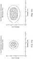
- an array of needlescan be coupled to the fluid source can have similar cooling rates to promote intracellular ice formation and necrosis of the target tissue between the needles.
- lower engaged tissue cooling ratesmay be used to help promote osmotic effects that inhibit intracellular ice formation and associated necrosis.
- a variety of more sophisticated embodimentsmay make use of multiple cooling states, such as by providing a controller coupled with the needle lumen via a valve.
- the controllermight, for example, have a first configuration for providing an initial cooling state and a second configuration for providing a treatment temperature in a target range.
- the treatment temperaturemight be established by generating a target treatment pressure in the lumen, while the initial cooling state could be configured (for example) to induce gradual cooling of the needle using an intermediate treatment pressure in the needle lumen that is higher than the target treatment pressure.
- the inventionprovides a method for treating a target tissue of a patient.
- the methodcomprises advancing a needle distally to penetrate into the target tissue, the needle having a lumen and a less than 16 gauge needle size.
- a cooling fluid flowis directed distally within the target tissue through a supply lumen within the needle.
- the target tissueis cooled by vaporizing a liquid from the cooling flow within the needle lumen.
- FIG. 1Bis a partially transparent perspective view of the self-contained probe of FIG. 1A , showing internal components of the cryogenic remodeling system and schematically illustrating replacement treatment needles 15 for use with the disposable probe.
- FIG. 3is a schematic cross-sectional view of an embodiment of a distal portion of the probe and system of FIG. 1B , showing a replaceable needle and an pressure relief valve with a limited exhaust volume.
- FIG. 3Aillustrates an exemplary fused silica cooling fluid supply tube for use in the replaceable needle of FIG. 3 .
- FIG. 4is a more detailed view of a replaceable needle assembly for use in the system of FIGS. 1A and 1B .
- FIGS. 5A-5Cillustrate an exemplary supply valve for use in the probe and system of FIGS. 1A and 1B .
- FIGS. 9, 9A, and 9Bschematically illustrate a needle having an elongate cross-section to enhance the volume of treated tissue.
- FIG. 10schematically illustrates a thermal model of a cryogenic microprobe needle.
- FIGS. 10A-10Cgraphically illustrate aspects of cryogenic cooling using nitrous oxide in the microprobe needles described herein.
- FIGS. 11A and 11Bschematically illustrate cross-sectional views cooling with a one needle system and a multiple needle system.
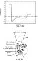
- FIG. 12graphically illustrates non-uniform cooling that can result from inadequate evaporation space within a small cryogenic needle probe.
- FIGS. 13A-13Dgraphically illustrate effects of changes in exhaust volume on the cooling response by a small cryogenic needle probe.
- FIG. 14schematically illustrates a cryogenic microprobe needle system being used for a dermatological treatment.
- FIG. 15is a flow chart schematically illustrating a method for treatment using the disposable cryogenic probe and system of FIG. 1B .
- Embodiments of the inventionwill facilitate remodeling of tissues disposed at and below the skin, optionally to treat a cosmetic defect, a lesion, a disease state, and/or so as to alter a shape of the overlying skin surface.
- Among the most immediate applications of the present inventionmay be the amelioration of lines and wrinkles, particularly by inhibiting muscular contractions which are associated with these cosmetic defects so as so improve an appearance of the patient.
- many embodiments of the inventionwill at least in part employ cold to immobilize muscles.
- nerves, muscles, and associated tissuesmay be temporarily immobilized using moderately cold temperatures of 10° C. to ⁇ 5° C. without permanently disabling the tissue structures.
- a needle probe or other treatment devicecan be used to identify a target tissue structure in a diagnostic mode with these moderate temperatures, and the same probe (or a different probe) can also be used to provide a longer term or permanent treatment, optionally by ablating the target tissue zone and/or inducing apoptosis at temperatures from about ⁇ 5° C. to about ⁇ 50° C.
- apoptosismay be induced using treatment temperatures from about ⁇ 1° C. to about ⁇ 15° C., optionally so as to provide a permanent treatment that limits or avoids inflammation and mobilization of skeletal muscle satellite repair cells.
- the duration of the treatment efficacy of such subdermal cryogenic treatmentsmay be selected and controlled, with colder temperatures, longer treatment times, and/or larger volumes or selected patterns of target tissue determining the longevity of the treatment. Additional description of cryogenic cooling for treatment of cosmetic and other defects may be found in U.S. patent application Ser. No. 11/295,204 filed on Dec. 5, 2005 (now U.S. Pat. No. 7,713,266) and entitled “Subdermal Cryogenic Remodeling of Muscles, Nerves, Connective Tissue, and/or Adipose Tissue (Fat),” the full disclosure of which is incorporated herein by reference.
- embodiments of the inventionmay also find applications for treatments of subdermal adipose tissues, benign, pre-malignant lesions, malignant lesions, acne and a wide range of other dermatological conditions (including dermatological conditions for which cryogenic treatments have been proposed and additional dermatological conditions), and the like.
- Embodiments of the inventionmay also find applications for alleviation of pain, including those associated with muscle spasms. Hence, a variety of embodiments may be provided.
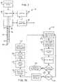
- a system for cryogenic remodelinghere comprises a self-contained probe handpiece generally having a proximal end 12 and a distal end 14 .
- a handpiece body or housing 16has a size and shape suitable for supporting in a hand of a surgeon or other system operator.
- a cryogenic cooling fluid supply 18 and electrical power source 20are found within housing 16 , along with a circuit 22 having a processor for controlling cooling applied by self-contained system 10 in response to actuation of an input 24 .
- Some embodimentsmay, at least in part, be manually activated, such as through the use of a manual supply valve and/or the like, so that processors, electrical power supplies, and the like may be absent.
- Probe 26Extending distally from distal end 14 of housing 16 is a tissue-penetrating cryogenic cooling probe 26 .
- Probe 26is thermally coupled to a cooling fluid path extending from cooling fluid source 18 , with the exemplary probe comprising a tubular body receiving at least a portion of the cooling fluid from the cooling fluid source therein.
- the exemplary probe 26comprises a 30 g needle having a sharpened distal end that is axially sealed.
- Probe 26may have an axial length between distal end 14 of housing 16 and the distal end of the needle of between about 1 ⁇ 2 mm and 5 cm, preferably having a length from about 1 cm to about 3 cm.
- needlesmay comprise a stainless steel tube with an inner diameter of about 0.006 inches and an outer diameter of about 0.012 inches, while alternative probes may comprise structures having outer diameters (or other lateral cross-sectional dimensions) from about 0.006 inches to about 0.100 inches.
- needle probe 26will comprise a 16 g or smaller size needle, typically comprising a 25 g or smaller needle.
- the exemplary cooling fluid supply 18comprises a cartridge containing a liquid under pressure, with the liquid preferably having a boiling temperature of the less than 37° C.
- the fluidis thermally coupled to the tissue-penetrating probe 26 , and the probe is positioned within the patient so that an outer surface of the probe is adjacent to a target tissue, the heat from the target tissue evaporates at least a portion of the liquid and the enthalpy of vaporization cools the target tissue.
- a valve(not shown) may be disposed along the cooling fluid flow path between cartridge 18 and probe 26 , or along the cooling fluid path after the probe so as to limit the temperature, time, rate of temperature change, or other cooling characteristics.
- the valvewill often be powered electrically via power source 20 , per the direction of processor 22 , but may at least in part be manually powered.
- the exemplary power source 20comprises a rechargeable or single-use battery.
- the exemplary cooling fluid supply 18comprises a single-use cartridge.
- the cartridge and cooling fluid thereinmay be stored and/or used at (or even above) room temperature.
- the cartridgesmay have a frangible seal or may be refillable, with the exemplary cartridge containing liquid N 2 O.
- a variety of alternative cooling fluidsmight also be used, with exemplary cooling fluids including fluorocarbon refrigerants and/or carbon dioxide.
- the quantity of cooling fluid contained by cartridge 18will typically be sufficient to treat at least a significant region of a patient, but will often be less than sufficient to treat two or more patients.
- An exemplary liquid N 2 O cartridgemight contain, for example, a quantity in a range from about 7 g to about 30 g of liquid.
- Processor 22will typically comprise a programmable electronic microprocessor embodying machine readable computer code or programming instructions for implementing one or more of the treatment methods described herein.
- the microprocessorwill typically include or be coupled to a memory (such as a non-volatile memory, a flash memory, a read-only memory (“ROM”), a random access memory (“RAM”), or the like) storing the computer code and data to be used thereby, and/or a recording media (including a magnetic recording media such as a hard disk, a floppy disk, or the like; or an optical recording media such as a CD or DVD) may be provided.
- a memorysuch as a non-volatile memory, a flash memory, a read-only memory (“ROM”), a random access memory (“RAM”), or the like
- a recording mediaincluding a magnetic recording media such as a hard disk, a floppy disk, or the like; or an optical recording media such as a CD or DVD
- Suitable interface devicessuch as digital-to-analog or analog-to-digital converters, or the like
- input/output devicessuch as USB or serial I/O ports, wireless communication cards, graphical display cards, and the like
- processor 22may be integrated on a single processor board and may run a single program or may make use of a plurality of boards running a number of different program modules in a wide variety of alternative distributed data processing or code architectures.
- Supply valvemay comprise an electrically actuated solenoid valve or the like operating in response to control signals from controller 22 , and/or may comprise a manual valve.
- Exemplary supply valvesmay comprise structures suitable for on/off valve operation, and may provide venting of the cooling fluid path downstream of the valve when cooling flow is halted so as to limit residual cryogenic fluid vaporization and cooling. More complex flow modulating valve structures might also be used in other embodiments.
- the cooling fluid from valve 32flows through a lumen 34 of a cooling fluid supply tube 36 .
- Supply tube 36is, at least in part, disposed within a lumen 38 of needle 26 , with the supply tube extending distally from a proximal end 40 of the needle toward a distal end 42 .
- the exemplary supply tube 36comprises a fused silica tubular structure 36 a having a polymer coating 36 b (see FIG. 3A ) and extends in cantilever into the needle lumen 38 .
- Supply tube 36may have an inner lumen with an effective inner diameter 36 c of less than about 200 ⁇ m, the inner diameter often being less than about 100 ⁇ m, and typically being less than about 40 ⁇ m.
- Exemplary embodiments of supply tube 36have inner lumens of between about 15 and 50 ⁇ m, such as about 30 ⁇ m.
- An outer diameter or size 36 d of supply tube 36will typically be less than about 1000 ⁇ m, often being less than about 800 ⁇ m, with exemplary embodiments being between about 60 and 150 ⁇ m, such as about 90 ⁇ m or 105 ⁇ m.
- the tolerance of the inner lumen diameter of supply tubing 36will preferably be relatively tight, typically being about +/ ⁇ 10 ⁇ m or tighter, often being +/ ⁇ 5 ⁇ m or tighter, and ideally being +/ ⁇ 3 ⁇ m or tighter, as the small diameter supply tube may provide the majority of (or even substantially all of) the metering of the cooling fluid flow into needle 26 .
- supply tubes 36 having outer jackets of polyimide (or other suitable polymer materials)may bend within the surrounding needle lumen 38 , the supply tube should have sufficient strength to avoid collapsing or excessive blow back during injection of cooling fluid into the needle.
- Polyimide coatingsmay also provide durability during assembly and use, and the fused silica/polymer structures can handle pressures of up to 100 kpsi.
- the relatively thin tubing wall and small outer size of the preferred supply tubesallows adequate space for vaporization of the nitrous oxide or other cooling fluid within the annular space between the supply tube 36 and surrounding needle lumen 38 . Inadequate space for vaporization might otherwise cause a buildup of liquid in that annular space and inconsistent temperatures, as illustrated in FIG. 12 .
- Exemplary structures for use as supply tube 36may include the flexible fused silica capillary tubing sold commercially by Polymicro Technologies, LLC of Phoenix, Ariz. under model names TSP, TSG, and TSU, optionally including model numbers TSP 020090, TSP040105, and/or others.
- the cooling fluid injected into lumen 38 of needle 26will typically comprises liquid, though some gas may also be injected. At least some of the liquid vaporizes within needle 26 , and the enthalpy of vaporization cools the tissue engaged by the needle. Controlling a pressure of the gas/liquid mixture within needle 26 substantially controls the temperature within lumen 38 , and hence the treatment temperature range of the tissue.
- a relatively simple mechanical pressure relief valve 46may be used to control the pressure within the lumen of the needle, with the exemplary valve comprising a valve body 48 (here in the form of a ball bearing) urged against a valve seat 50 by a biasing spring 52 .
- a large volume along the cooling fluid pathway between the exit from the supply tube and exit from the pressure relief valve 46may cause excessive transients.
- a large volume in this areamay result in initial temperatures that are significantly colder than a target and/or steady state temperature, as can be seen in FIG. 13D .
- Thiscan be problematic, particularly when (for example) the target temperature is only slightly warmer than an undesirable effect inducing temperature, such as when remodeling through apoptosis or the like while seeking to inhibit necrosis.
- the pressure relief valve 46may be integrated into a housing 54 supporting needle 26 , with the valve spring 52 being located outside the valve seat (and hence the pressure-control exit from pressure relief valve 46 ).
- pressure relief valve 46is also located adjacent the interface between the needle assembly and probe handpiece housing 54 .
- a detent 56may be engaged by a spring supported catch to hold the needle assembly releasably in position, and the components of the needle assembly 26 A (such as a brass or other metallic housing, a polyimide tubing 58 , needle 26 , and the like) may be affixed together using adhesive.
- the needle assembly and handpiece housingmay have corresponding threads for mounting and replacement of the needle assembly.
- 0-rings 60can seal the cooling fluid pathway.
- FIGS. 13A-13Cpresent additional details on the effects of exhaust volume on cooling transients.
- a graph of temperature over timeis shown for the outside temperature of an in vivo 30 g cooling needle with a target temperature of about ⁇ 12° C.
- the deviceswere constructed with different exhaust volumes, with the volume being greater than about 0.009 in 3 in the embodiment of FIG. 13A .
- the embodiment of FIGS. 13B and 13Chad exhaust volumes of about 0.009 in 3 and about 0.0025 in 3 , respectively.
- the data collection ratewas about 0.7 sec for the embodiment of FIG. 13A , while the embodiments of FIGS. 13B and 13C both had data collection rates of about 0.1 sec, so that the actual nadir for the embodiment of FIG. 13A may have actually been significantly lower than that shown.
- the exhaust volumeis preferably less than about 0.05 in 3 , typically being less than 0.01 in 3 and/or 0.009 in 3 , and ideally being less than 0.005 in 3 .
- the supply valvemight be cycled on and off, typically by controller 22 , with a timing sequence that would limit the cooling fluid flowing so that only vaporized gas reached the needle lumen (or a sufficiently limited amount of liquid to avoid excessive dropping of the needle lumen temperature). This cycling might be ended once the exhaust volume pressure was sufficient so that the refrigeration temperature would be within desired limits during steady state flow.
- FIGS. 2, 3, and 5A-5CAdditional aspects of the exemplary supply valves 32 can be understood with reference to FIGS. 2, 3, and 5A-5C .
- FIG. 3the valve is shown in the “on” configuration, with 0-rings 60 sealing either side of the cooling fluid flow path and the cooling fluid flowing around the movable valve member.
- FIGS. 5A-5Cthe cooling fluid flows through a passage 64 that extends axially along an alternative valve body of valve body 32 ′ when the valve is in the on configuration (seen in FIG. 5B ), with the O-rings being disposed between recesses in the movable valve body so as to allow the valve to operate when the valve body is in any rotational orientation about its axis.
- the cooling fluid flow path downstream of the valveis vented when the valve is in the “off” configuration (in the embodiment of FIG. 3 , by channel 66 , and in the embodiment of FIGS. 5A-5C by the vaporizing cooling fluid flowing through the annular space between the valve body and the adjacent housing 54 so as to preserve the cooling fluid within the movable valve body).
- Venting of the cooling fluid from the cooling fluid supply tube 36 when the cooling fluid flow is halted by supply valve 32 , 32 ′is advantageous to provide a rapid halt to the cooling of needle 26 .
- a 2.5 cm long 30 g needle cooled to an outside temperature of ⁇ 15° C.might use only about 0.003 g/sec of nitrous oxide after the system approaches or reaches steady state (for example, 10 seconds after initiation of cooling).
- FIG. 10Analytical models that may be used to derive these cooling flows include that illustrated in FIG. 10 , which may be combined with the properties of the cooling fluid (such as the pressure/enthalpy diagram of nitrous oxide seen in FIG. 10A ) and the thermal properties of tissue shown in Table I to determine theoretical minimum cooling fluid flow rates (see FIG. 10B ), theoretical minimum cooling fluid quantities (see FIG. 10C ), and the like.
- Fluid supply 18may be initially opened for use by penetrating a frangible seal of the cartridge with a pierce point 70 (such as by tightening a threaded cartridge support coupled to housing 54 ), with the nitrous being filtered by a filter 72 before being transmitted further along the cooling fluid path.
- Suitable filtersmay have pore sizes of from about 6 to about 25 ⁇ m, and may be available commercially from Porex of Georgia (or a variety of alternative suppliers), or may comprise a fine stainless steel screen (such as those having a mesh size of 635 with 0.0009′′ wire and spacing between the wire edges of approximately 0.0006′′), or the like.
- a wide variety of epoxy or other adhesives 74may be used, and the replaceable needle housing 24 A and other structural components may comprise a wide variety of metals or polymers, including brass or the like. Fins 76 may be included to help vaporize excess cooling liquid traveling proximally of the insertable length of needle 26 .
- Very fine needleswill typically be used to deliver to cooling at and/or below the surface of the skin. These needles can be damaged relatively easily if they strike a bone, or may otherwise be damaged or deformed before or during use. Fine needles well help inhibit damage to the skin during insertion, but may not be suitable for repeated insertion for treatment of numerous treatment sites or lesions of a particular patient, or for sequential treatment of a large area of the patient. Hence, the structures shown in FIGS. 1B, 3, and 4 allow the use probe bodies 16 , 54 with a plurality of sequentially replaceable needles.
- needle assemblies having differing numbers of needles in a needle arraymay also be selected and mounted to the probe body.
- Other embodimentsmay employ a single needle array fixedly mounted to the probe body, or a plurality of replaceable needle assemblies which all include the same number of needles.
- cooling fluid flow to a plurality of needlesmay be provided, for example, by inserting and bonding a plurality of fused silica supply tubes into a 0.010 polyimide tubing 58 or header within the needle assembly, and by advancing the distal end of each supply tube into a lumen of an associated needle 26 .
- the application of pressure before, during, and/or after coolingmay help dull or otherwise inhibit sharp pain. Such pain may otherwise result from the skin penetration, cooling, or thawing of the target and/or collateral tissues. It may also be beneficial to obscure the patient's view of the cooling needles, and/or to cover the needles when not in use so as to inhibit needle-stick injuries and potential disease transmission.
- skin-engaging surface 82may be supported by an articulatable support structure having a first configuration (shown in solid in FIG. 7 ) and a second configuration (shown dashed in FIG. 7 ).
- a simple spring mechanismmay be used to apply a desired contact force between the skin-engaging surface 82 and the patient before insertion and during cooling. More sophisticated arrangements can also be employed in which the needle is driven distally and then proximally relative to the skin engaging surface appropriate times after sufficient pressure is applied to the patient, and the like.
- FIG. 8still further alternative embodiments may be provided, in this case to apply different cooling temperatures to the patient, and/or to apply cooling to the skin surface and to a target tissue adjacent needle 26 .
- different cooling temperaturessuch as to about ⁇ 10° C.
- FIG. 14cooling of a target tissue TT cylinder around needle 26 sufficient to kill bacteria in the sebaceous gland and enlarged follicle opening (such as to about ⁇ 20° C.).
- This dual temperature treatmentmay be particularly beneficial for severe forms of acne involving cysts or nodules.
- tissue engaging surface 82that surface may be thermally coupled to a chamber 88 .
- Cooling fluidmay be transmitted into chamber 88 by a port of a cooling fluid supply tube 36 , and the pressure of chamber 88 (and hence the temperature within the chamber) can optionally be controlled by a dedicated additional pressure relief valve 46 a . As the pressure within chamber 88 may differ from that within the needle, different treatment temperatures may be provided.
- the structures described hereincan also be combined, for example, with the dual skin surface/needle temperature treatment structure of FIG. 8 being compatible with the replaceable needle systems of FIGS. 1B, 3 , and/or 4 .
- the dual skin surface/needle treatment systems and methodsmay also be compatible, for example, with the articulatable skin surface supports of FIG. 7 so as to apply cooled pressure to the skin prior to and/or during needle insertion using a flexible fluid supply tube or the like.
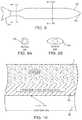
- needles having circular cross-sectional shapescan often be used, but may not always provide the desired surface area for the cross-sectional area of the needle. Increased surface area may decrease the amount of time the needle is inserted to cool a volume of tissue to a temperature in a target range. Hence, a needle with an elongate outer cross-section such as elliptical needle 90 may be desirable.
- a distal cutting edge 92 at the distal tipmay facilitate insertion and a circular cross-section 94 near the proximal end may limit cooling adjacent the skin, while cooling of the target tissue therebetween is enhanced by elliptical cross-section 96 .
- Method 100facilitates treating a patient using a cryogenic cooling system having a self-contained disposable handpiece and replaceable needles such as those of FIG. 1B .
- Method 100generally begins with a determination 110 of the desired tissue remodeling and results, such as the alleviation of specific cosmetic wrinkles of the face, the inhibition of pain from a particular site, the alleviation of unsightly skin lesions or cosmetic defects from a region of the face, or the like.
- Appropriate target tissues for treatmentare identified 112 (such as the subdermal muscles that induce the wrinkles, a tissue that transmits the pain signal, or the lesion-inducing infected tissues), allowing a target treatment depth, target treatment temperature profile, or the like to be determined 114 .
- any needles that are dulled (or otherwise determined to be sufficiently used to warrant replacement, regardless of whether it is after a single insertion, 5 insertions, or the like) during the treatmentmay be replaced with a new needle 116 before the next application of pressure/cooling 118 , needle insertion 120 , and/or the like.
- the used handpiece and needlescan be disposed of 130.
- Apoptosismay exhibit a non-inflammatory cell death. Without inflammation, normal muscular healing processes may be inhibited. Following many muscular injuries (including many injuries involving necrosis), skeletal muscle satellite cells may be mobilized by inflammation. Without inflammation, such mobilization may be limited or avoided. Apoptotic cell death may reduce muscle mass and/or may interrupt the collagen and elastin connective chain.
- one or more temperature feedback loopsmay be used to control the treatments, with the tissue temperature optionally being taken using a temperature sensing needle having a temperature sensor disposed adjacent an outer cooled skin engaging surface of the needle.
- the scope of the present inventionis limited solely by the independent claims.
Landscapes
- Health & Medical Sciences (AREA)
- Surgery (AREA)
- Life Sciences & Earth Sciences (AREA)
- Nuclear Medicine, Radiotherapy & Molecular Imaging (AREA)
- Medical Informatics (AREA)
- Engineering & Computer Science (AREA)
- Biomedical Technology (AREA)
- Heart & Thoracic Surgery (AREA)
- Otolaryngology (AREA)
- Molecular Biology (AREA)
- Animal Behavior & Ethology (AREA)
- General Health & Medical Sciences (AREA)
- Public Health (AREA)
- Veterinary Medicine (AREA)
- Surgical Instruments (AREA)
- Thermotherapy And Cooling Therapy Devices (AREA)
Abstract
Description
0.1 cc*(0.7 g/cc)=0.07 g of liquid nitrous oxide,
0.07 g/(0.003 g/sec)=23 sec.
These calculation assume a fused silica supply tube sized to allow the minimum flow of nitrous oxide when fluid supply has a pressure of about 900 psi. When the supply valve is shut off, the pressure on the needle side of the supply valve would decay, causing the actual residual run time to be longer, with only a partial cooling near the distal tip of
| TABLE I | ||
| Property | Units | Value |
| Upper temperature bond of freezing (T2) | ° C. | −1 |
| Peak of phase transition temperature (T3) | ° C. | −3 |
| Lower Temperature bond of freezing (T1) | ° C. | −8 |
| Thermal conductivity in unfrozen region (ku) | W/(mm −° C.) | 0.00063 |
| Thermal conductivity in frozen region (kf) | W/(mm −° C.) | 0.00151 |
| Volumetric specific heat in unfrozen region | J/(mm3−° C.) | 0.00316 |
| ({ρtct}f) | ||
| Volumetric specific heat in frozen region | J/(mm3−° C.) | 0.00193 |
| ({ρtct}f) | ||
| Latent heat of solidification (HF) | J/mm3 | 0.300 |
| TABLE II | |||
| Temperature | Skin | Muscle/Fat | |
| 37° C. | baseline | baseline | |
| 25° | cold sensation | ||
| 18° C. | reflex vasodilation of | ||
| 15° C. | |||
| 12° C. | reduction of | ||
| 10° C. | very cold sensation | ||
| reduction of chronic | |||
| Hunting response | |||
| 5° | pain sensation | ||
| 0° C. | freezing point | ||
| −1° C. | Phase transition begins | ||
| −2° C. | minimal apoptosis | ||
| −3° C. | Peak phase transition | ||
| −5° C. | tissue damage | moderatre apoptosis | |
| −8° C. | Completion of phase transition | ||
| −10° C. | considerable apoptosis | ||
| −15° C. | extensive apoptosis | ||
| mild-moderate necrosis | |||
| −40° C. | extensive necrosis | ||
| TABLE III | ||
| Cooled | ||
| Temperature | ||
| Range | Time Effectiveness | Purpose |
| ≥0° C. | Treatment lasts | Can be used to identify target |
| only while the | tissues. | |
| needle is inserted | ||
| into the target | ||
| tissue. | ||
| From 0° C. | Often lasts days or | Temporary treatment. Can be |
| to −5° C. | weeks, and target | used to evaluate effectiveness |
| tissue can repair | of remodeling treatment on | |
| itself. Embodiments | skin surface shape or the like. | |
| may last hours or | ||
| days. | ||
| From −5° C. | Often lasts months | Long term, potentially |
| to −15° C. | to years; and may | permanent cosmetic benefits. |
| be permanent. | Can be deployed in limited | |
| Limited muscle | doses over to time to achieve | |
| repair. | staged impact, controlling | |
| Embodiments may | outcome and avoiding negative | |
| last weeks to | outcome. May be employed as | |
| months. | the standard treatment. | |
| From −15° C. | Often lasts weeks | May result in Mid-term |
| to −25° C. | or months. Muscle | cosmetic benefits, and can be |
| may repair itself via | used where permanent effects | |
| satellite cell | are not desired or to evaluate | |
| mobilization. | outcomes of potentially | |
| Embodiment may | permanent dosing. | |
| last years. | Embodiments may provide | |
| permanent treatment. | ||
Claims (39)
Priority Applications (2)
| Application Number | Priority Date | Filing Date | Title |
|---|---|---|---|
| US14/982,728US10939947B2 (en) | 2006-12-21 | 2015-12-29 | Dermal and transdermal cryogenic microprobe systems |
| US17/193,406US20210186585A1 (en) | 2006-12-21 | 2021-03-05 | Dermal and Transdermal Cryogenic Microprobe Systems |
Applications Claiming Priority (2)
| Application Number | Priority Date | Filing Date | Title |
|---|---|---|---|
| US11/614,887US9254162B2 (en) | 2006-12-21 | 2006-12-21 | Dermal and transdermal cryogenic microprobe systems |
| US14/982,728US10939947B2 (en) | 2006-12-21 | 2015-12-29 | Dermal and transdermal cryogenic microprobe systems |
Related Parent Applications (1)
| Application Number | Title | Priority Date | Filing Date |
|---|---|---|---|
| US11/614,887ContinuationUS9254162B2 (en) | 2006-12-21 | 2006-12-21 | Dermal and transdermal cryogenic microprobe systems |
Related Child Applications (1)
| Application Number | Title | Priority Date | Filing Date |
|---|---|---|---|
| US17/193,406ContinuationUS20210186585A1 (en) | 2006-12-21 | 2021-03-05 | Dermal and Transdermal Cryogenic Microprobe Systems |
Publications (2)
| Publication Number | Publication Date |
|---|---|
| US20160183996A1 US20160183996A1 (en) | 2016-06-30 |
| US10939947B2true US10939947B2 (en) | 2021-03-09 |
Family
ID=39543972
Family Applications (3)
| Application Number | Title | Priority Date | Filing Date |
|---|---|---|---|
| US11/614,887Active2034-02-10US9254162B2 (en) | 2006-12-21 | 2006-12-21 | Dermal and transdermal cryogenic microprobe systems |
| US14/982,728Active2028-05-03US10939947B2 (en) | 2006-12-21 | 2015-12-29 | Dermal and transdermal cryogenic microprobe systems |
| US17/193,406PendingUS20210186585A1 (en) | 2006-12-21 | 2021-03-05 | Dermal and Transdermal Cryogenic Microprobe Systems |
Family Applications Before (1)
| Application Number | Title | Priority Date | Filing Date |
|---|---|---|---|
| US11/614,887Active2034-02-10US9254162B2 (en) | 2006-12-21 | 2006-12-21 | Dermal and transdermal cryogenic microprobe systems |
Family Applications After (1)
| Application Number | Title | Priority Date | Filing Date |
|---|---|---|---|
| US17/193,406PendingUS20210186585A1 (en) | 2006-12-21 | 2021-03-05 | Dermal and Transdermal Cryogenic Microprobe Systems |
Country Status (7)
| Country | Link |
|---|---|
| US (3) | US9254162B2 (en) |
| EP (2) | EP2094328B1 (en) |
| JP (1) | JP5285620B2 (en) |
| CA (1) | CA2673550A1 (en) |
| DK (1) | DK2094328T3 (en) |
| ES (1) | ES2508965T3 (en) |
| WO (1) | WO2008079812A2 (en) |
Cited By (4)
| Publication number | Priority date | Publication date | Assignee | Title |
|---|---|---|---|---|
| US20210186585A1 (en)* | 2006-12-21 | 2021-06-24 | Pacira Cryotech, Inc. | Dermal and Transdermal Cryogenic Microprobe Systems |
| US11938188B2 (en) | 2014-08-28 | 2024-03-26 | The General Hospital Corporation | Injectable slurries and methods of manufacturing and using the same |
| US12097282B2 (en) | 2014-08-28 | 2024-09-24 | The General Hospital Corporation | Injectable slurries and methods of manufacturing the same |
| US12369965B2 (en) | 2021-12-30 | 2025-07-29 | Cryosa, Inc. | Systems and methods for treatment of obstructive sleep apnea |
Families Citing this family (64)
| Publication number | Priority date | Publication date | Assignee | Title |
|---|---|---|---|---|
| EP2301471A1 (en) | 2004-04-01 | 2011-03-30 | The General Hospital Corporation | Method and apparatus for dermatological treatment and tissue reshaping |
| US7850683B2 (en)* | 2005-05-20 | 2010-12-14 | Myoscience, Inc. | Subdermal cryogenic remodeling of muscles, nerves, connective tissue, and/or adipose tissue (fat) |
| US7713266B2 (en)* | 2005-05-20 | 2010-05-11 | Myoscience, Inc. | Subdermal cryogenic remodeling of muscles, nerves, connective tissue, and/or adipose tissue (fat) |
| WO2007092610A2 (en) | 2006-02-07 | 2007-08-16 | Tivamed, Inc. | Vaginal remodeling device and methods |
| US8409185B2 (en)* | 2007-02-16 | 2013-04-02 | Myoscience, Inc. | Replaceable and/or easily removable needle systems for dermal and transdermal cryogenic remodeling |
| WO2009065061A1 (en) | 2007-11-14 | 2009-05-22 | Myoscience, Inc. | Pain management using cryogenic remodeling |
| DE602009001050D1 (en)* | 2008-06-04 | 2011-05-26 | Olympus Medical Systems Corp | Capsular medical device |
| JP5233031B2 (en)* | 2008-07-15 | 2013-07-10 | 株式会社デージーエス・コンピュータ | Cryotherapy planning device and cryotherapy device |
| US9204925B2 (en)* | 2008-08-14 | 2015-12-08 | The Cleveland Clinic Foundation | Apparatus and method for treating a neuromuscular defect |
| SI3187219T1 (en) | 2008-12-02 | 2020-09-30 | Allergan, Inc. | Injection device |
| JP5642087B2 (en) | 2008-12-22 | 2014-12-17 | ミオサイエンス インコーポレーティッド | Integrated cryosurgery system with refrigerant and power supply |
| WO2011013118A2 (en)* | 2009-07-27 | 2011-02-03 | Slatkine Michael | Methods and devices for tissue ablation |
| BR112012006059B8 (en) | 2009-09-18 | 2021-06-22 | Viveve Inc | apparatus and system for remodeling a therapeutic zone in the tissue underlying a mucosal epithelium of female genital tissue |
| CN103561673A (en) | 2010-12-13 | 2014-02-05 | 肌肉科技股份有限公司 | Method for reducing hyperdynamic facial wrinkles |
| WO2013106860A1 (en)* | 2012-01-13 | 2013-07-18 | Myoscience, Inc. | Cryogenic probe filtration system |
| CN104159534B (en) | 2012-01-13 | 2017-02-22 | 肌肉科技股份有限公司 | Skin protection for subdermal cryogenic remodeling for cosmetic and other treatments |
| WO2013106857A1 (en) | 2012-01-13 | 2013-07-18 | Myoscience, Inc. | Skin protection for subdermal cryogenic remodeling for cosmetic and other treatments |
| EP2802279B1 (en) | 2012-01-13 | 2017-08-16 | Myoscience, Inc. | Cryogenic needle with freeze zone regulation |
| US9017318B2 (en) | 2012-01-20 | 2015-04-28 | Myoscience, Inc. | Cryogenic probe system and method |
| US9610112B2 (en) | 2013-03-15 | 2017-04-04 | Myoscience, Inc. | Cryogenic enhancement of joint function, alleviation of joint stiffness and/or alleviation of pain associated with osteoarthritis |
| WO2014146127A1 (en) | 2013-03-15 | 2014-09-18 | Myoscience, Inc. | Methods and systems for treatment of spasticity |
| WO2014146126A1 (en) | 2013-03-15 | 2014-09-18 | Myoscience, Inc. | Cryogenic blunt dissection methods and devices |
| US9295512B2 (en)* | 2013-03-15 | 2016-03-29 | Myoscience, Inc. | Methods and devices for pain management |
| US20140350518A1 (en) | 2013-05-23 | 2014-11-27 | Allergan, Inc. | Syringe extrusion accessory |
| US20140350516A1 (en) | 2013-05-23 | 2014-11-27 | Allergan, Inc. | Mechanical syringe accessory |
| US10130409B2 (en) | 2013-11-05 | 2018-11-20 | Myoscience, Inc. | Secure cryosurgical treatment system |
| PL3082634T3 (en) | 2013-12-18 | 2021-10-18 | Novoxel Ltd. | Devices for tissue vaporization |
| US20170165105A1 (en)* | 2014-01-31 | 2017-06-15 | The General Hospital Corporation | Methods, kits, and cooling devices for disrupting function of one or more sebaceous glands |
| US20150216719A1 (en) | 2014-01-31 | 2015-08-06 | Zeltiq Aesthetics, Inc | Treatment systems and methods for treating cellulite and for providing other treatments |
| US10029048B2 (en) | 2014-05-13 | 2018-07-24 | Allergan, Inc. | High force injection devices |
| JP2017528239A (en) | 2014-09-15 | 2017-09-28 | ノヴォクセル リミテッド | Method and apparatus for thermal transpiration and thermal compression of tissue |
| US10226585B2 (en) | 2014-10-01 | 2019-03-12 | Allergan, Inc. | Devices for injection and dosing |
| EP3268063A4 (en) | 2015-03-10 | 2018-10-31 | Allergan Pharmaceuticals Holdings (Ireland) Unlimited Company | Multiple needle injector |
| WO2016145452A1 (en) | 2015-03-12 | 2016-09-15 | Myoscience, Inc. | Methods and systems for preventing neuroma formations |
| CN109310827B (en) | 2016-04-08 | 2021-09-07 | 阿勒根公司 | Suction and Injection Devices |
| EP4349396A3 (en) | 2016-05-13 | 2024-05-01 | Pacira CryoTech, Inc. | Systems for locating and treating with cold therapy |
| KR101905830B1 (en) | 2016-11-15 | 2018-10-08 | 울산과학기술원 | Cryoanesthesia device, method for controlling cryoanesthesia device and temperature controller of coolant in cryoanesthesia device |
| USD867582S1 (en) | 2017-03-24 | 2019-11-19 | Allergan, Inc. | Syringe device |
| KR20180131357A (en) | 2017-05-30 | 2018-12-10 | 주식회사 리센스메디컬 | Medical cooling apparatus |
| WO2018221848A1 (en) | 2017-05-30 | 2018-12-06 | 주식회사 리센스메디컬 | Medical cooling device |
| EP3709918B1 (en) | 2017-11-15 | 2025-06-18 | Pacira CryoTech, Inc. | Integrated cold therapy and electrical stimulation systems for locating and treating nerves |
| KR102517065B1 (en) | 2017-12-29 | 2023-04-03 | 주식회사 리센스메디컬 | Cooling generator |
| USD999392S1 (en)* | 2018-01-01 | 2023-09-19 | Rooijakkers Huisman L S | Vibrator |
| EP4154832B1 (en) | 2018-04-27 | 2024-05-22 | Recensmedical, Inc. | Cooling apparatus and cooling method |
| AU2019204574A1 (en) | 2018-06-27 | 2020-01-23 | Viveve, Inc. | Methods for treating urinary stress incontinence |
| FR3083443B1 (en)* | 2018-07-03 | 2025-02-21 | Axemox | DEVICE COMPRISING AN OBJECT WITH A HEATING AND BIOCOMPATIBLE TIP |
| CN112955099B (en) | 2018-07-27 | 2024-04-26 | 雷森斯医疗有限公司 | Medical cooling device and cooling method using same |
| WO2020028472A1 (en) | 2018-07-31 | 2020-02-06 | Zeltiq Aesthetics, Inc. | Methods, devices, and systems for improving skin characteristics |
| US11666479B2 (en) | 2018-08-19 | 2023-06-06 | Recensmedical, Inc. | Device for cooling anesthesia by chilled fluidic cooling medium |
| CN109745117A (en)* | 2019-01-10 | 2019-05-14 | 四川捷祥医疗器械有限公司 | A kind of Temperature-controlled appliance and method |
| USD921211S1 (en) | 2019-06-21 | 2021-06-01 | Recensmedical, Inc. | Medical cooling device |
| USD921911S1 (en) | 2019-06-21 | 2021-06-08 | Recensmedical, Inc. | Medical cooling device |
| US12121281B2 (en) | 2019-08-07 | 2024-10-22 | Christopher M. Shaari | Systems and methods for cryogenic treatment of headache |
| WO2021086847A1 (en)* | 2019-10-29 | 2021-05-06 | Pacira Cryotech, Inc. | Cryogenic device with quick-connect needle probes |
| USD914903S1 (en)* | 2019-11-04 | 2021-03-30 | Shenzhen Boyuan Intelligent Electronic Technology Co., Ltd | Beauty instrument |
| WO2021108141A1 (en) | 2019-11-27 | 2021-06-03 | Pacira Cryotech, Inc. | Display device and interfaces for cryogenic devices |
| JP7658967B2 (en) | 2019-12-03 | 2025-04-08 | パシラ クライオテック インコーポレイテッド | Cryogenic pressure stabilization |
| CN111437029B (en)* | 2020-04-27 | 2022-03-08 | 深圳半岛医疗有限公司 | Cold-freezing therapeutic device in scar and control method thereof |
| US11278341B2 (en) | 2020-07-14 | 2022-03-22 | Recensmedical, Inc. | Method of safely using controlled cooling systems and devices |
| USD968626S1 (en) | 2020-08-07 | 2022-11-01 | Recensmedical, Inc. | Medical cooling device |
| USD977633S1 (en) | 2020-08-07 | 2023-02-07 | Recensmedical, Inc. | Cradle for a medical cooling device |
| USD968627S1 (en) | 2020-08-07 | 2022-11-01 | Recensmedical, Inc. | Medical cooling device |
| US12364531B2 (en) | 2021-02-16 | 2025-07-22 | RecensMedical, Inc.; | Methods for treating skin disorders using precision cooling technology |
| WO2023067738A1 (en)* | 2021-10-20 | 2023-04-27 | オリンパスメディカルシステムズ株式会社 | Endoscope optical connector and endoscope |
Citations (152)
| Publication number | Priority date | Publication date | Assignee | Title |
|---|---|---|---|---|
| US2319542A (en) | 1940-06-24 | 1943-05-18 | Franklin E Hall | Therapeutic machine |
| US2672032A (en) | 1951-10-19 | 1954-03-16 | Towse Robert Albert Edward | Carcass freezing device |
| US3226492A (en) | 1961-06-30 | 1965-12-28 | Ericsson Telefon Ab L M | Circuit arrangement for telephone instruments |
| US3289424A (en) | 1963-07-01 | 1966-12-06 | Union Carbide Corp | Cryosurgical fluid control system |
| US3343544A (en) | 1965-12-21 | 1967-09-26 | Alcon Lab Inc | Cryogenic surgical instrument |
| US3351063A (en) | 1964-12-08 | 1967-11-07 | Stephen F Malaker | Cryosurgical probe |
| US3507283A (en) | 1967-10-11 | 1970-04-21 | Univ Northwestern | Cryosurgical instrument |
| US3532094A (en) | 1967-07-20 | 1970-10-06 | Norman O Stahl | Cryogenic-instrument with detachable probe |
| US3664344A (en) | 1970-09-15 | 1972-05-23 | Brymill Corp | Tyned cryosurgical probe |
| US3702114A (en) | 1970-08-26 | 1972-11-07 | Frigitronics Of Conn Inc | Liquid refrigerant spray device |
| US3795245A (en) | 1971-04-29 | 1974-03-05 | Al Co Du | Splash-proof leak-proof syringe-type cryosurgical instrument |
| US3814095A (en) | 1972-03-24 | 1974-06-04 | H Lubens | Occlusively applied anesthetic patch |
| US3830239A (en) | 1972-09-12 | 1974-08-20 | Frigitronics Of Conn Inc | Cryosurgical device |
| US3886945A (en) | 1972-06-14 | 1975-06-03 | Frigitronics Of Conn Inc | Cryosurgical apparatus |
| US3889681A (en) | 1974-10-30 | 1975-06-17 | Jack Douglas Waller | Cryosurgical spraying apparatus |
| US3951152A (en) | 1974-06-03 | 1976-04-20 | Dynatech Corporation | Cryosurgical probe |
| US3993075A (en) | 1975-12-24 | 1976-11-23 | Dynatech Corporation | Disposable, defrostable cryosurgical probe |
| US4140109A (en) | 1977-10-17 | 1979-02-20 | Savic Michael I | Impedance-based method and apparatus for monitoring cryodestruction in controlled cryosurgery |
| US4207897A (en) | 1976-07-21 | 1980-06-17 | Spembly Limited | Cryosurgical probe |
| US4236518A (en) | 1978-04-14 | 1980-12-02 | Gyne-Tech Instrument Corporation | Cryogenic device selectively operable in a continuous freezing mode, a continuous thawing mode or a combination thereof |
| US4306568A (en) | 1979-12-04 | 1981-12-22 | Torre Douglas P | Method and apparatus for congelation cryometry in cryosurgery |
| US4376376A (en) | 1980-05-12 | 1983-03-15 | Virginia M. Gregory | Cryogenic device operable in single or dual phase with a range of nozzle sizes and method of using the same |
| US4404862A (en) | 1981-11-02 | 1983-09-20 | Dynatech Precision Sampling Corporation | Microdispensing springs with a needle in a tubular extension |
| US4524771A (en) | 1982-10-28 | 1985-06-25 | Ethicon Inc. | Multiple curved surgical needle |
| US4758217A (en) | 1986-05-05 | 1988-07-19 | L'oreal | Method for obtaining a cryogenic treatment effect for the cutaneous covering and a unit for the implementation of this method |
| US4802475A (en) | 1987-06-22 | 1989-02-07 | Weshahy Ahmed H A G | Methods and apparatus of applying intra-lesional cryotherapy |
| US4946460A (en) | 1989-04-26 | 1990-08-07 | Cryo Instruments, Inc. | Apparatus for cryosurgery |
| US5059197A (en) | 1989-04-15 | 1991-10-22 | Urie Robert G | Lesion location device |
| US5200170A (en) | 1989-07-18 | 1993-04-06 | Mcdow Ronald A | Medical process--use of dichlorodifluoromethane (CCl2 F2) and chlorodifluoromethane (CHClF2) as cryogens for treating skin lesions |
| US5334181A (en) | 1990-09-26 | 1994-08-02 | Cryomedical Sciences, Inc. | Cryosurgical system for destroying tumors by freezing |
| US5520681A (en) | 1992-04-24 | 1996-05-28 | Surgical Laser Technologies, Inc. | Light energy emitting probe with inclusions distributed within and throughout probe's tip portion |
| US5571147A (en) | 1993-11-02 | 1996-11-05 | Sluijter; Menno E. | Thermal denervation of an intervertebral disc for relief of back pain |
| US5647868A (en) | 1994-02-02 | 1997-07-15 | Chinn; Douglas Owen | Cryosurgical integrated control and monitoring system and method |
| US5755753A (en) | 1995-05-05 | 1998-05-26 | Thermage, Inc. | Method for controlled contraction of collagen tissue |
| US5814040A (en) | 1994-04-05 | 1998-09-29 | The Regents Of The University Of California | Apparatus and method for dynamic cooling of biological tissues for thermal mediated surgery |
| US5879378A (en) | 1995-02-06 | 1999-03-09 | Kabushiki Kaisha Genchi Kenkyusho | Exothermic device and an application pad using the same |
| US5899897A (en) | 1996-09-26 | 1999-05-04 | Allegheny-Singer Research Institute | Method and apparatus for heating during cryosurgery |
| US5916212A (en) | 1998-01-23 | 1999-06-29 | Cryomedical Sciences, Inc. | Hand held cyrosurgical probe system |
| US5976505A (en) | 1997-07-02 | 1999-11-02 | Hcs Trust | Method for cryogenically treating psoriasis with liquid nitrogen or liquid nitrous oxide |
| US6003539A (en) | 1998-01-20 | 1999-12-21 | Nok Corporation | Differential pressure regulating valve and liquid shut-off valve device |
| US6032675A (en) | 1997-03-17 | 2000-03-07 | Rubinsky; Boris | Freezing method for controlled removal of fatty tissue by liposuction |
| US6039730A (en) | 1996-06-24 | 2000-03-21 | Allegheny-Singer Research Institute | Method and apparatus for cryosurgery |
| US6041787A (en) | 1997-03-17 | 2000-03-28 | Rubinsky; Boris | Use of cryoprotective agent compounds during cryosurgery |
| US6139545A (en) | 1998-09-09 | 2000-10-31 | Vidaderm | Systems and methods for ablating discrete motor nerve regions |
| US6141985A (en) | 1998-03-06 | 2000-11-07 | Societe Cryonic Medical | Self-contained and portable cryogenic apparatus using carbon dioxide in liquid/solid phases |
| US6182666B1 (en) | 1996-12-26 | 2001-02-06 | Cryogen, Inc. | Cryosurgical probe and method for uterine ablation |
| US6196839B1 (en) | 1999-01-29 | 2001-03-06 | Robert Gregg Ross | Continuous use orthodontic cooling appliance |
| US6277116B1 (en) | 1994-05-06 | 2001-08-21 | Vidaderm | Systems and methods for shrinking collagen in the dermis |
| US6277099B1 (en) | 1999-08-06 | 2001-08-21 | Becton, Dickinson And Company | Medication delivery pen |
| US20020010460A1 (en) | 1999-03-15 | 2002-01-24 | James Joye | Cryosurgical fluid supply |
| US20020013602A1 (en) | 2000-07-31 | 2002-01-31 | Huttner James J. | Method for controlling the pain from injections or minor surgical procedures and apparatus for use therewith |
| US6371943B1 (en) | 1997-09-08 | 2002-04-16 | Epimed International, Inc. | Spring tip needle combination |
| US20020045434A1 (en) | 2000-08-31 | 2002-04-18 | Lee Masoian | System and method for transmitting information modulated radio frequency signals using infrared transmission |
| US20020068929A1 (en) | 2000-10-24 | 2002-06-06 | Roni Zvuloni | Apparatus and method for compressing a gas, and cryosurgery system and method utilizing same |
| US20020128638A1 (en) | 2001-02-16 | 2002-09-12 | Patrick Chauvet | Method of using cryotreatment to treat brain tissue |
| US6468297B1 (en)* | 1999-02-24 | 2002-10-22 | Cryovascular Systems, Inc. | Cryogenically enhanced intravascular interventions |
| US20020156469A1 (en) | 1998-03-31 | 2002-10-24 | Yon Steven A. | Method and device for performing colling- or cryo-therapies for, e.g., angioplasty with reduced restenosis or pulmonary vein cell necrosis to inhibit atrial fibrillation employing tissue protection |
| US6494844B1 (en) | 2000-06-21 | 2002-12-17 | Sanarus Medical, Inc. | Device for biopsy and treatment of breast tumors |
| US20020193778A1 (en) | 1999-10-14 | 2002-12-19 | Alchas Paul G. | Method of intradermally injecting substances |
| US6503246B1 (en) | 2000-07-05 | 2003-01-07 | Mor Research Applications Ltd. | Cryoprobe and method of treating scars |
| US6506796B1 (en) | 1995-10-09 | 2003-01-14 | Centre International De Recherches Dermatologiques Galderma | Use of a RAR-γ-specific agonist ligand for increasing the rate of apoptosis |
| US20030036752A1 (en) | 2001-08-13 | 2003-02-20 | Cryovascular Systems, Inc. | Cryotherapy methods for treating vessel dissections and side branch occlusion |
| US6546935B2 (en) | 2000-04-27 | 2003-04-15 | Atricure, Inc. | Method for transmural ablation |
| US6551309B1 (en) | 2000-09-14 | 2003-04-22 | Cryoflex, Inc. | Dual action cryoprobe and methods of using the same |
| US6562030B1 (en) | 1999-04-06 | 2003-05-13 | Cryocath Technologies Inc. | Heater control of cryocatheter tip temperature |
| US20030181896A1 (en) | 2001-09-27 | 2003-09-25 | Roni Zvuloni | Apparatus and method for cryosurgical treatment of tumors of the breast |
| US6629951B2 (en) | 1999-08-05 | 2003-10-07 | Broncus Technologies, Inc. | Devices for creating collateral in the lungs |
| US20030195436A1 (en) | 2000-10-16 | 2003-10-16 | Sanarus Medical Incorporated | Device for biopsy of tumors |
| US20030220635A1 (en) | 1996-01-05 | 2003-11-27 | Knowlton Edward W. | Method for treating skin and underlying tissue |
| US6669688B2 (en) | 2000-01-25 | 2003-12-30 | The Regents Of The University Of California | Method and apparatus for measuring the heat transfer coefficient during cryogen spray cooling of tissue |
| US6672095B1 (en) | 2002-06-28 | 2004-01-06 | Chin-Kuang Luo | Therapeutic freezing device and method |
| US6682501B1 (en) | 1996-02-23 | 2004-01-27 | Gyrus Ent, L.L.C. | Submucosal tonsillectomy apparatus and method |
| US20040049177A1 (en)* | 2000-10-24 | 2004-03-11 | Roni Zvuloni | Multiple cryoprobe apparatus and method |
| US6723092B2 (en) | 2000-12-15 | 2004-04-20 | Tony R. Brown | Atrial fibrillation RF treatment device and method |
| US20040100798A1 (en)* | 2001-04-05 | 2004-05-27 | Stefano Modi | Application handpiece with lamp of novel shape |
| US6749624B2 (en) | 1996-01-05 | 2004-06-15 | Edward W. Knowlton | Fluid delivery apparatus |
| US20040122482A1 (en) | 2002-12-20 | 2004-06-24 | James Tung | Nerve proximity method and device |
| US6761715B2 (en) | 2001-04-26 | 2004-07-13 | Ronald J. Carroll | Method and device for neurocryo analgesia and anesthesia |
| US6764493B1 (en) | 1999-01-20 | 2004-07-20 | Pearl Technology Holdings, Llc | Tissue removal using biocompatible materials |
| US20040143252A1 (en) | 2003-01-16 | 2004-07-22 | Charlotte-Mecklenburg Hospital Authority D/B/A Carolinas Medical Center | Echogenic needle for transvaginal ultrasound directed reduction of uterine fibroids and an associated method |
| US20040162551A1 (en) | 2000-12-15 | 2004-08-19 | Brown Tony R. | Method and device for creating transmural lesions |
| US6789545B2 (en) | 2002-10-04 | 2004-09-14 | Sanarus Medical, Inc. | Method and system for cryoablating fibroadenomas |
| US20040191229A1 (en) | 2002-10-09 | 2004-09-30 | Link Charles J. | Antitumor vaccination using allogeneic tumor cells expressing alpha (1,3)-galactosyltransferase |
| US20040204705A1 (en) | 2003-04-10 | 2004-10-14 | Scimed Life Systems, Inc. | Cryotreatment devices and methods of forming conduction blocks |
| US20040210212A1 (en) | 2002-08-06 | 2004-10-21 | Maurice George T | Cryo-surgical apparatus and method of use |
| US20040215294A1 (en) | 2003-01-15 | 2004-10-28 | Mediphysics Llp | Cryotherapy probe |
| US20040215295A1 (en) | 2003-01-15 | 2004-10-28 | Mediphysics Llp | Cryotherapy system |
| US20040220497A1 (en) | 2000-03-02 | 2004-11-04 | Findlay Judith M. | Patch for locating a target zone for penetration |
| US20040225276A1 (en) | 2003-03-13 | 2004-11-11 | Burgess Cheryl M. | Methods of administering a material into a patient for dermal enhancement |
| US20040267257A1 (en) | 2003-06-30 | 2004-12-30 | George Bourne | Apparatus and methods for delivering energy to a target site within bone |
| US20050004563A1 (en) | 2003-07-01 | 2005-01-06 | Racz N. Sandor | Apparatus and methods for sensing and cooling during application of thermal energy for treating degenerative spinal discs |
| US6840935B2 (en) | 2000-08-09 | 2005-01-11 | Bekl Corporation | Gynecological ablation procedure and system using an ablation needle |
| US6905492B2 (en) | 2000-07-31 | 2005-06-14 | Galil Medical Ltd. | Planning and facilitation systems and methods for cryosurgery |
| US20050177148A1 (en) | 2003-12-22 | 2005-08-11 | Van Der Walt Nicholas R. | Cryosurgical devices for endometrial ablation |
| US20050182394A1 (en) | 2004-02-12 | 2005-08-18 | Spero Richard K. | Rotational core biopsy device with liquid cryogen adhesion probe |
| US20050203593A1 (en) | 2003-10-24 | 2005-09-15 | Shanks Steven C. | Method for dermatology therapies in combination with low level laser treatments |
| US20050203505A1 (en) | 2004-03-15 | 2005-09-15 | Scimed Life Systems, Inc. | Ablation probe with peltier effect thermal control |
| US20050209587A1 (en) | 1997-12-02 | 2005-09-22 | Cryovascular Systems,Inc. | Apparatus and method for cryogenic inhibition of hyperplasia |
| US20050209565A1 (en) | 1999-06-09 | 2005-09-22 | The Procter & Gamble Company | Intracutaneous microneedle array apparatus |
| US20050251103A1 (en) | 2002-10-30 | 2005-11-10 | Beat Steffen | Method and device for displaying and metering doses as a product is administered |
| US20050261753A1 (en) | 2003-01-15 | 2005-11-24 | Mediphysics Llp | Methods and systems for cryogenic cooling |
| US20050276759A1 (en) | 1994-12-02 | 2005-12-15 | Roser Bruce J | Solid dose delivery vehicle and methods of making same |
| US20050283148A1 (en) | 2004-06-17 | 2005-12-22 | Janssen William M | Ablation apparatus and system to limit nerve conduction |
| US20060015092A1 (en) | 2000-08-18 | 2006-01-19 | Cryovascular Systems, Inc. | Cryotherapy method for detecting and treating vulnerable plaque |
| US7001400B1 (en) | 1999-03-04 | 2006-02-21 | Abbott Laboratories | Articulating suturing device and method |
| US20060069385A1 (en) | 2004-09-28 | 2006-03-30 | Scimed Life Systems, Inc. | Methods and apparatus for tissue cryotherapy |
| US20060079914A1 (en) | 1999-03-04 | 2006-04-13 | Modesitt D B | Articulating suturing device and method |
| US20060084962A1 (en) | 2004-06-02 | 2006-04-20 | Cryovascular Systems, Inc. | Controllable pressure cryogenic balloon treatment system and method |
| US20060111732A1 (en) | 2002-10-03 | 2006-05-25 | George Gibbens | Cycling suturing and knot-tying device |
| US20060129142A1 (en) | 2004-12-15 | 2006-06-15 | Cryovascular Systems, Inc. | Efficient controlled cryogenic fluid delivery into a balloon catheter and other treatment devices |
| US20060142785A1 (en) | 1999-03-04 | 2006-06-29 | Modesitt D B | Articulating suturing device and method |
| US7081111B2 (en) | 2001-05-16 | 2006-07-25 | Optomed. As | Cryosurgical apparatus and methods |
| US20060173469A1 (en) | 2001-01-24 | 2006-08-03 | Klein Enrique J | Device and method for suturing of internal puncture sites |
| US20060189968A1 (en) | 2003-08-19 | 2006-08-24 | Howlett Harold A | Cryosurgery device |
| US20060190035A1 (en) | 2004-10-08 | 2006-08-24 | Sherwood Services Ag | Latching mechanism for forceps |
| US20060200117A1 (en) | 2002-11-18 | 2006-09-07 | Erik Hermans | Instrument for cryogenic treatments in the medical, paramedical and cosmetic field |
| US20060212048A1 (en) | 2005-03-21 | 2006-09-21 | Design Standards Corporation | Suturing device |
| US20060224149A1 (en) | 2003-04-21 | 2006-10-05 | Galil Medical Ltd. | Apparatus and method positioning a therapeutic probe with respect to a therapeutic target |
| US20060223052A1 (en) | 2005-03-30 | 2006-10-05 | Kimberly-Clark Worldwide, Inc. | Technique for detecting microorganisms |
| US7137978B2 (en)* | 2002-08-26 | 2006-11-21 | Arbel Medical Ltd | Cryosurgical instrument and its accessory system |
| WO2006127467A2 (en)* | 2005-05-20 | 2006-11-30 | Myoscience, Inc. | Subdermal cryogenic remodeling |
| US7195616B2 (en) | 2001-05-16 | 2007-03-27 | Eli Lilly And Company | Medication injector apparatus with drive assembly that facilitates reset |
| US20070073285A1 (en)* | 2005-09-27 | 2007-03-29 | Darion Peterson | Cooled RF ablation needle |
| US20070088217A1 (en) | 2005-10-13 | 2007-04-19 | Babaev Eilaz P | Apparatus and methods for the selective removal of tissue using combinations of ultrasonic energy and cryogenic energy |
| US7217939B2 (en) | 2002-07-23 | 2007-05-15 | Jettec Ab | Capillary tubing |
| US20070156125A1 (en) | 2005-12-30 | 2007-07-05 | Russell Delonzor | Encodable cryogenic device |
| US20070161975A1 (en) | 2006-01-06 | 2007-07-12 | Olga Goulko | Cryogenic applicator for rejuvenating human skin and related method |
| US20070167959A1 (en) | 1999-03-04 | 2007-07-19 | Abbott Laboratories | Articulating suturing device and method |
| US7250046B1 (en) | 2002-02-27 | 2007-07-31 | Fallat Lawrence M | Treatment of lower extremity pain |
| US20070179509A1 (en) | 2005-12-26 | 2007-08-02 | Nippon Sherwood Medical Industries Ltd. | Medical Suturing Device |
| US20070198071A1 (en) | 2006-02-22 | 2007-08-23 | Juniper Medical Systems | Cooling device for removing heat from subcutaneous lipid-rich cells |
| US7278991B2 (en)* | 2001-02-28 | 2007-10-09 | Angiodynamics, Inc. | Tissue surface treatment apparatus and method |
| US20070255362A1 (en) | 2006-04-28 | 2007-11-01 | Juniper Medical, Inc. | Cryoprotectant for use with a cooling device for improved cooling of subcutaneous lipid-rich cells |
| US20070270925A1 (en) | 2006-05-17 | 2007-11-22 | Juniper Medical, Inc. | Method and apparatus for non-invasively removing heat from subcutaneous lipid-rich cells including a coolant having a phase transition temperature |
| US20080033414A1 (en)* | 2006-08-03 | 2008-02-07 | Arbel Medical Ltd. | Cryogenic Probe for Treating Enlarged Volume of Tissue |
| US20080051776A1 (en) | 2001-05-21 | 2008-02-28 | Galil Medical Ltd. | Thin uninsulated cryoprobe and insulating probe introducer |
| US20080077201A1 (en) | 2006-09-26 | 2008-03-27 | Juniper Medical, Inc. | Cooling devices with flexible sensors |
| US20080077202A1 (en) | 2006-09-26 | 2008-03-27 | Juniper Medical, Inc. | Tissue Treatment Methods |
| US20080077211A1 (en) | 2006-09-26 | 2008-03-27 | Juniper Medical, Inc. | Cooling device having a plurality of controllable cooling elements to provide a predetermined cooling profile |
| US7367341B2 (en) | 2002-03-15 | 2008-05-06 | The General Hospital Corporation | Methods and devices for selective disruption of fatty tissue by controlled cooling |
| US20080183164A1 (en) | 2005-05-20 | 2008-07-31 | Myoscience, Inc. | Subdermal cryogenic remodeling of muscles, nerves, connective tissue, and/or adipose tissue (fat) |
| US20080200910A1 (en) | 2007-02-16 | 2008-08-21 | Myoscience, Inc. | Replaceable and/or Easily Removable Needle Systems for Dermal and Transdermal Cryogenic Remodeling |
| US20080287839A1 (en) | 2007-05-18 | 2008-11-20 | Juniper Medical, Inc. | Method of enhanced removal of heat from subcutaneous lipid-rich cells and treatment apparatus having an actuator |
| US20090018625A1 (en) | 2007-07-13 | 2009-01-15 | Juniper Medical, Inc. | Managing system temperature to remove heat from lipid-rich regions |
| US20090018627A1 (en) | 2007-07-13 | 2009-01-15 | Juniper Medical, Inc. | Secure systems for removing heat from lipid-rich regions |
| US20090018626A1 (en) | 2007-07-13 | 2009-01-15 | Juniper Medical, Inc. | User interfaces for a system that removes heat from lipid-rich regions |
| US20090018623A1 (en) | 2007-07-13 | 2009-01-15 | Juniper Medical, Inc. | System for treating lipid-rich regions |
| US20090018624A1 (en) | 2007-07-13 | 2009-01-15 | Juniper Medical, Inc. | Limiting use of disposable system patient protection devices |
| US20090118722A1 (en) | 2006-10-31 | 2009-05-07 | Ebbers Edward A | Method and apparatus for cooling subcutaneous lipid-rich cells or tissue |
| US7578819B2 (en) | 2005-05-16 | 2009-08-25 | Baxano, Inc. | Spinal access and neural localization |
| US20090248001A1 (en) | 2007-11-14 | 2009-10-01 | Myoscience, Inc. | Pain management using cryogenic remodeling |
| US20120089211A1 (en) | 2010-04-08 | 2012-04-12 | Myoscience, Inc. | Methods and apparatus for cryogenically treating multiple tissue sites with a single puncture |
Family Cites Families (37)
| Publication number | Priority date | Publication date | Assignee | Title |
|---|---|---|---|---|
| GB1360353A (en) | 1972-01-19 | 1974-07-17 | Atomic Energy Authority Uk | Method of making thermocouples |
| GB1402632A (en) | 1972-02-02 | 1975-08-13 | Wilkinson Sword Ltd | Medical equipment |
| US3910278A (en)* | 1974-06-03 | 1975-10-07 | Dynatech Corp | Cryosurgical probe |
| IT1159748B (en)* | 1978-06-23 | 1987-03-04 | Bracco Dario | CRIOTHERAPY APPARATUS |
| DE3022216A1 (en) | 1980-06-13 | 1982-01-28 | Heinz 3012 Langenhagen Hennecke | DEEP TEMPERATURE TRANSMISSION DEVICE FOR MEDICAL PURPOSES |
| JPS6013111U (en) | 1983-07-04 | 1985-01-29 | 株式会社 東理社 | surgical pump |
| JPH0538347Y2 (en) | 1987-10-28 | 1993-09-28 | ||
| JPH0538347A (en)* | 1991-08-06 | 1993-02-19 | Mayekawa Mfg Co Ltd | Freezing device for organism tissue |
| US7549424B2 (en)* | 1991-10-18 | 2009-06-23 | Pro Surg, Inc. | Method and apparatus for tissue treatment with laser and electromagnetic radiation |
| US5423807A (en)* | 1992-04-16 | 1995-06-13 | Implemed, Inc. | Cryogenic mapping and ablation catheter |
| DE4322955B4 (en)* | 1992-07-20 | 2007-12-20 | Aesculap Ag & Co. Kg | Invasive surgical instrument |
| US5536249A (en) | 1994-03-09 | 1996-07-16 | Visionary Medical Products, Inc. | Pen-type injector with a microprocessor and blood characteristic monitor |
| GB2289510A (en)* | 1994-05-10 | 1995-11-22 | Spembly Medical Ltd | Connector |
| US7620290B2 (en)* | 1995-08-31 | 2009-11-17 | Biolase Technology, Inc. | Modified-output fiber optic tips |
| US20040000316A1 (en) | 1996-01-05 | 2004-01-01 | Knowlton Edward W. | Methods for creating tissue effect utilizing electromagnetic energy and a reverse thermal gradient |
| JPH1014656A (en) | 1996-07-01 | 1998-01-20 | Shigemi Kobayashi | Facial wrinkle-removing utencil |
| GB2355728A (en) | 1999-10-27 | 2001-05-02 | Anson Medical Ltd | Tubular medical implants and methods of manufacture |
| JP2001178737A (en) | 1999-12-07 | 2001-07-03 | Dieter Steinfatt | Freezer device |
| PT1377327E (en) | 2001-04-13 | 2007-11-09 | Becton Dickinson Co | Prefillable intradermal delivery device |
| US7160291B2 (en) | 2003-06-25 | 2007-01-09 | Endocare, Inc. | Detachable cryosurgical probe |
| JP2005080988A (en) | 2003-09-10 | 2005-03-31 | Ruo Mei Ryan | Crymotherapy apparatus and heat conducting needle means |
| EP2301471A1 (en) | 2004-04-01 | 2011-03-30 | The General Hospital Corporation | Method and apparatus for dermatological treatment and tissue reshaping |
| KR20070039065A (en) | 2004-06-24 | 2007-04-11 | 필립 엘. 길덴버그 | Anti-robot sealing device |
| US7357797B2 (en)* | 2004-06-30 | 2008-04-15 | Cryocor, Inc. | System and method for varying return pressure to control tip temperature of a cryoablation catheter |
| DE602005010442D1 (en) | 2004-08-16 | 2008-11-27 | Zimmer Spine Inc | SPIRAL SEWING DEVICE |
| JP4324673B2 (en) | 2004-11-05 | 2009-09-02 | 国立大学法人東北大学 | Cryotherapy device with Peltier module |
| US7297136B2 (en) | 2004-12-06 | 2007-11-20 | Wyrick Ronald E | Medicine injection devices and methods |
| US20080200932A1 (en) | 2005-05-27 | 2008-08-21 | Ignacio Diaz De Tuesta Revilla | Surgical Needle Holder for Stitch Suturing |
| US20070055173A1 (en)* | 2005-08-23 | 2007-03-08 | Sanarus Medical, Inc. | Rotational core biopsy device with liquid cryogen adhesion probe |
| US7875041B2 (en) | 2005-09-28 | 2011-01-25 | Olympus Medical Systems Corp. | Suturing method for penetrating hole |
| CA2854625C (en) | 2006-01-27 | 2017-01-24 | Suturtek Incorporated | Apparatus and method for tissue closure |
| WO2007129121A1 (en) | 2006-05-08 | 2007-11-15 | Tayside Health Board | Device and method for improved surgical suturing |
| WO2007135629A1 (en) | 2006-05-16 | 2007-11-29 | Orhan Seyfi Aksakal | A needle pusher |
| ATE518484T1 (en) | 2006-05-31 | 2011-08-15 | Covidien Ag | MEDICAL SUTURE INSTRUMENT WITH GRIPPER DEVICE |
| FI20060749A7 (en)* | 2006-08-23 | 2008-04-28 | Hannu Paasonen | Drilling tool for drilling or reaming a hole |
| US9254162B2 (en)* | 2006-12-21 | 2016-02-09 | Myoscience, Inc. | Dermal and transdermal cryogenic microprobe systems |
| WO2009026471A1 (en) | 2007-08-21 | 2009-02-26 | Zeltiq Aesthetics, Inc. | Monitoring the cooling of subcutaneous lipid-rich cells, such as the cooling of adipose tissue |
- 2006
- 2006-12-21USUS11/614,887patent/US9254162B2/enactiveActive
- 2007
- 2007-12-18CACA002673550Apatent/CA2673550A1/ennot_activeAbandoned
- 2007-12-18EPEP07865802.8Apatent/EP2094328B1/enactiveActive
- 2007-12-18ESES07865802.8Tpatent/ES2508965T3/enactiveActive
- 2007-12-18EPEP14178999.0Apatent/EP2826498A1/ennot_activeWithdrawn
- 2007-12-18WOPCT/US2007/087893patent/WO2008079812A2/enactiveApplication Filing
- 2007-12-18DKDK07865802.8Tpatent/DK2094328T3/enactive
- 2007-12-18JPJP2009543133Apatent/JP5285620B2/enactiveActive
- 2015
- 2015-12-29USUS14/982,728patent/US10939947B2/enactiveActive
- 2021
- 2021-03-05USUS17/193,406patent/US20210186585A1/enactivePending
Patent Citations (180)
| Publication number | Priority date | Publication date | Assignee | Title |
|---|---|---|---|---|
| US2319542A (en) | 1940-06-24 | 1943-05-18 | Franklin E Hall | Therapeutic machine |
| US2672032A (en) | 1951-10-19 | 1954-03-16 | Towse Robert Albert Edward | Carcass freezing device |
| US3226492A (en) | 1961-06-30 | 1965-12-28 | Ericsson Telefon Ab L M | Circuit arrangement for telephone instruments |
| US3289424A (en) | 1963-07-01 | 1966-12-06 | Union Carbide Corp | Cryosurgical fluid control system |
| US3351063A (en) | 1964-12-08 | 1967-11-07 | Stephen F Malaker | Cryosurgical probe |
| US3343544A (en) | 1965-12-21 | 1967-09-26 | Alcon Lab Inc | Cryogenic surgical instrument |
| US3532094A (en) | 1967-07-20 | 1970-10-06 | Norman O Stahl | Cryogenic-instrument with detachable probe |
| US3507283A (en) | 1967-10-11 | 1970-04-21 | Univ Northwestern | Cryosurgical instrument |
| US3702114A (en) | 1970-08-26 | 1972-11-07 | Frigitronics Of Conn Inc | Liquid refrigerant spray device |
| US3664344A (en) | 1970-09-15 | 1972-05-23 | Brymill Corp | Tyned cryosurgical probe |
| US3795245A (en) | 1971-04-29 | 1974-03-05 | Al Co Du | Splash-proof leak-proof syringe-type cryosurgical instrument |
| US3814095A (en) | 1972-03-24 | 1974-06-04 | H Lubens | Occlusively applied anesthetic patch |
| US3886945A (en) | 1972-06-14 | 1975-06-03 | Frigitronics Of Conn Inc | Cryosurgical apparatus |
| US3830239A (en) | 1972-09-12 | 1974-08-20 | Frigitronics Of Conn Inc | Cryosurgical device |
| US3951152A (en) | 1974-06-03 | 1976-04-20 | Dynatech Corporation | Cryosurgical probe |
| US3889681A (en) | 1974-10-30 | 1975-06-17 | Jack Douglas Waller | Cryosurgical spraying apparatus |
| US3993075A (en) | 1975-12-24 | 1976-11-23 | Dynatech Corporation | Disposable, defrostable cryosurgical probe |
| US4207897A (en) | 1976-07-21 | 1980-06-17 | Spembly Limited | Cryosurgical probe |
| US4140109A (en) | 1977-10-17 | 1979-02-20 | Savic Michael I | Impedance-based method and apparatus for monitoring cryodestruction in controlled cryosurgery |
| US4236518A (en) | 1978-04-14 | 1980-12-02 | Gyne-Tech Instrument Corporation | Cryogenic device selectively operable in a continuous freezing mode, a continuous thawing mode or a combination thereof |
| US4306568A (en) | 1979-12-04 | 1981-12-22 | Torre Douglas P | Method and apparatus for congelation cryometry in cryosurgery |
| US4376376A (en) | 1980-05-12 | 1983-03-15 | Virginia M. Gregory | Cryogenic device operable in single or dual phase with a range of nozzle sizes and method of using the same |
| US4404862A (en) | 1981-11-02 | 1983-09-20 | Dynatech Precision Sampling Corporation | Microdispensing springs with a needle in a tubular extension |
| US4524771A (en) | 1982-10-28 | 1985-06-25 | Ethicon Inc. | Multiple curved surgical needle |
| US4758217A (en) | 1986-05-05 | 1988-07-19 | L'oreal | Method for obtaining a cryogenic treatment effect for the cutaneous covering and a unit for the implementation of this method |
| US4802475A (en) | 1987-06-22 | 1989-02-07 | Weshahy Ahmed H A G | Methods and apparatus of applying intra-lesional cryotherapy |
| US5059197A (en) | 1989-04-15 | 1991-10-22 | Urie Robert G | Lesion location device |
| US4946460A (en) | 1989-04-26 | 1990-08-07 | Cryo Instruments, Inc. | Apparatus for cryosurgery |
| US5200170A (en) | 1989-07-18 | 1993-04-06 | Mcdow Ronald A | Medical process--use of dichlorodifluoromethane (CCl2 F2) and chlorodifluoromethane (CHClF2) as cryogens for treating skin lesions |
| US5334181A (en) | 1990-09-26 | 1994-08-02 | Cryomedical Sciences, Inc. | Cryosurgical system for destroying tumors by freezing |
| US5520681A (en) | 1992-04-24 | 1996-05-28 | Surgical Laser Technologies, Inc. | Light energy emitting probe with inclusions distributed within and throughout probe's tip portion |
| US5571147A (en) | 1993-11-02 | 1996-11-05 | Sluijter; Menno E. | Thermal denervation of an intervertebral disc for relief of back pain |
| US5647868A (en) | 1994-02-02 | 1997-07-15 | Chinn; Douglas Owen | Cryosurgical integrated control and monitoring system and method |
| US5814040A (en) | 1994-04-05 | 1998-09-29 | The Regents Of The University Of California | Apparatus and method for dynamic cooling of biological tissues for thermal mediated surgery |
| US6277116B1 (en) | 1994-05-06 | 2001-08-21 | Vidaderm | Systems and methods for shrinking collagen in the dermis |
| US20050276759A1 (en) | 1994-12-02 | 2005-12-15 | Roser Bruce J | Solid dose delivery vehicle and methods of making same |
| US5879378A (en) | 1995-02-06 | 1999-03-09 | Kabushiki Kaisha Genchi Kenkyusho | Exothermic device and an application pad using the same |
| US5755753A (en) | 1995-05-05 | 1998-05-26 | Thermage, Inc. | Method for controlled contraction of collagen tissue |
| US6506796B1 (en) | 1995-10-09 | 2003-01-14 | Centre International De Recherches Dermatologiques Galderma | Use of a RAR-γ-specific agonist ligand for increasing the rate of apoptosis |
| US20030220635A1 (en) | 1996-01-05 | 2003-11-27 | Knowlton Edward W. | Method for treating skin and underlying tissue |
| US6749624B2 (en) | 1996-01-05 | 2004-06-15 | Edward W. Knowlton | Fluid delivery apparatus |
| US6682501B1 (en) | 1996-02-23 | 2004-01-27 | Gyrus Ent, L.L.C. | Submucosal tonsillectomy apparatus and method |
| US6039730A (en) | 1996-06-24 | 2000-03-21 | Allegheny-Singer Research Institute | Method and apparatus for cryosurgery |
| US6786902B1 (en) | 1996-06-24 | 2004-09-07 | Allegheny-Singer Research Institute | Method and apparatus for cryosurgery |
| US5899897A (en) | 1996-09-26 | 1999-05-04 | Allegheny-Singer Research Institute | Method and apparatus for heating during cryosurgery |
| US6182666B1 (en) | 1996-12-26 | 2001-02-06 | Cryogen, Inc. | Cryosurgical probe and method for uterine ablation |
| US6032675A (en) | 1997-03-17 | 2000-03-07 | Rubinsky; Boris | Freezing method for controlled removal of fatty tissue by liposuction |
| US6041787A (en) | 1997-03-17 | 2000-03-28 | Rubinsky; Boris | Use of cryoprotective agent compounds during cryosurgery |
| US5976505A (en) | 1997-07-02 | 1999-11-02 | Hcs Trust | Method for cryogenically treating psoriasis with liquid nitrogen or liquid nitrous oxide |
| US6371943B1 (en) | 1997-09-08 | 2002-04-16 | Epimed International, Inc. | Spring tip needle combination |
| US20050209587A1 (en) | 1997-12-02 | 2005-09-22 | Cryovascular Systems,Inc. | Apparatus and method for cryogenic inhibition of hyperplasia |
| US6003539A (en) | 1998-01-20 | 1999-12-21 | Nok Corporation | Differential pressure regulating valve and liquid shut-off valve device |
| US5916212A (en) | 1998-01-23 | 1999-06-29 | Cryomedical Sciences, Inc. | Hand held cyrosurgical probe system |
| US6141985A (en) | 1998-03-06 | 2000-11-07 | Societe Cryonic Medical | Self-contained and portable cryogenic apparatus using carbon dioxide in liquid/solid phases |
| US20020156469A1 (en) | 1998-03-31 | 2002-10-24 | Yon Steven A. | Method and device for performing colling- or cryo-therapies for, e.g., angioplasty with reduced restenosis or pulmonary vein cell necrosis to inhibit atrial fibrillation employing tissue protection |
| US6139545A (en) | 1998-09-09 | 2000-10-31 | Vidaderm | Systems and methods for ablating discrete motor nerve regions |
| US6764493B1 (en) | 1999-01-20 | 2004-07-20 | Pearl Technology Holdings, Llc | Tissue removal using biocompatible materials |
| US6196839B1 (en) | 1999-01-29 | 2001-03-06 | Robert Gregg Ross | Continuous use orthodontic cooling appliance |
| US20030109912A1 (en) | 1999-02-24 | 2003-06-12 | Cryovascular Systems, Inc. | Cryogenically enhanced intravascular interventions |
| US6468297B1 (en)* | 1999-02-24 | 2002-10-22 | Cryovascular Systems, Inc. | Cryogenically enhanced intravascular interventions |
| US7081112B2 (en) | 1999-02-24 | 2006-07-25 | Cryovascular Systems, Inc. | Cryogenically enhanced intravascular interventions |
| US20070167959A1 (en) | 1999-03-04 | 2007-07-19 | Abbott Laboratories | Articulating suturing device and method |
| US20060142785A1 (en) | 1999-03-04 | 2006-06-29 | Modesitt D B | Articulating suturing device and method |
| US20060079914A1 (en) | 1999-03-04 | 2006-04-13 | Modesitt D B | Articulating suturing device and method |
| US7001400B1 (en) | 1999-03-04 | 2006-02-21 | Abbott Laboratories | Articulating suturing device and method |
| US20020183731A1 (en) | 1999-03-15 | 2002-12-05 | Cryovascular Systems, Inc., A Delaware Corporation | Safety cryotherapy catheter |
| US6432102B2 (en) | 1999-03-15 | 2002-08-13 | Cryovascular Systems, Inc. | Cryosurgical fluid supply |
| US20060212028A1 (en) | 1999-03-15 | 2006-09-21 | Cryovascular Systems, Inc. | Cryosurgical fluid supply |
| US20040167505A1 (en) | 1999-03-15 | 2004-08-26 | Cryovascular Systems, Inc. | Cryosurgical fluid supply |
| US20020010460A1 (en) | 1999-03-15 | 2002-01-24 | James Joye | Cryosurgical fluid supply |
| US6562030B1 (en) | 1999-04-06 | 2003-05-13 | Cryocath Technologies Inc. | Heater control of cryocatheter tip temperature |
| US20050209565A1 (en) | 1999-06-09 | 2005-09-22 | The Procter & Gamble Company | Intracutaneous microneedle array apparatus |
| US6629951B2 (en) | 1999-08-05 | 2003-10-07 | Broncus Technologies, Inc. | Devices for creating collateral in the lungs |
| US6277099B1 (en) | 1999-08-06 | 2001-08-21 | Becton, Dickinson And Company | Medication delivery pen |
| US20020193778A1 (en) | 1999-10-14 | 2002-12-19 | Alchas Paul G. | Method of intradermally injecting substances |
| US6669688B2 (en) | 2000-01-25 | 2003-12-30 | The Regents Of The University Of California | Method and apparatus for measuring the heat transfer coefficient during cryogen spray cooling of tissue |
| US20040220497A1 (en) | 2000-03-02 | 2004-11-04 | Findlay Judith M. | Patch for locating a target zone for penetration |
| US6546935B2 (en) | 2000-04-27 | 2003-04-15 | Atricure, Inc. | Method for transmural ablation |
| US6494844B1 (en) | 2000-06-21 | 2002-12-17 | Sanarus Medical, Inc. | Device for biopsy and treatment of breast tumors |
| US20060009712A1 (en) | 2000-06-21 | 2006-01-12 | Sanarus, Inc. | Dual lumen device for biopsy and treatment of breast tumors and method for use |
| US6503246B1 (en) | 2000-07-05 | 2003-01-07 | Mor Research Applications Ltd. | Cryoprobe and method of treating scars |
| US6902554B2 (en) | 2000-07-31 | 2005-06-07 | Bionix Development Corporation | Method for controlling the pain from injections or minor surgical procedures and apparatus for use therewith |
| US6905492B2 (en) | 2000-07-31 | 2005-06-14 | Galil Medical Ltd. | Planning and facilitation systems and methods for cryosurgery |
| US20020013602A1 (en) | 2000-07-31 | 2002-01-31 | Huttner James J. | Method for controlling the pain from injections or minor surgical procedures and apparatus for use therewith |
| US6840935B2 (en) | 2000-08-09 | 2005-01-11 | Bekl Corporation | Gynecological ablation procedure and system using an ablation needle |
| US20060015092A1 (en) | 2000-08-18 | 2006-01-19 | Cryovascular Systems, Inc. | Cryotherapy method for detecting and treating vulnerable plaque |
| US20020045434A1 (en) | 2000-08-31 | 2002-04-18 | Lee Masoian | System and method for transmitting information modulated radio frequency signals using infrared transmission |
| US6551309B1 (en) | 2000-09-14 | 2003-04-22 | Cryoflex, Inc. | Dual action cryoprobe and methods of using the same |
| US20030195436A1 (en) | 2000-10-16 | 2003-10-16 | Sanarus Medical Incorporated | Device for biopsy of tumors |
| US7311672B2 (en) | 2000-10-16 | 2007-12-25 | Sanarus Medical, Inc. | Device for biopsy of tumors |
| US20040049177A1 (en)* | 2000-10-24 | 2004-03-11 | Roni Zvuloni | Multiple cryoprobe apparatus and method |
| US6706037B2 (en) | 2000-10-24 | 2004-03-16 | Galil Medical Ltd. | Multiple cryoprobe apparatus and method |
| US20020068929A1 (en) | 2000-10-24 | 2002-06-06 | Roni Zvuloni | Apparatus and method for compressing a gas, and cryosurgery system and method utilizing same |
| US6723092B2 (en) | 2000-12-15 | 2004-04-20 | Tony R. Brown | Atrial fibrillation RF treatment device and method |
| US20040162551A1 (en) | 2000-12-15 | 2004-08-19 | Brown Tony R. | Method and device for creating transmural lesions |
| US20060173469A1 (en) | 2001-01-24 | 2006-08-03 | Klein Enrique J | Device and method for suturing of internal puncture sites |
| US20020128638A1 (en) | 2001-02-16 | 2002-09-12 | Patrick Chauvet | Method of using cryotreatment to treat brain tissue |
| US6648880B2 (en) | 2001-02-16 | 2003-11-18 | Cryocath Technologies Inc. | Method of using cryotreatment to treat brain tissue |
| US7278991B2 (en)* | 2001-02-28 | 2007-10-09 | Angiodynamics, Inc. | Tissue surface treatment apparatus and method |
| US7422586B2 (en) | 2001-02-28 | 2008-09-09 | Angiodynamics, Inc. | Tissue surface treatment apparatus and method |
| US20040100798A1 (en)* | 2001-04-05 | 2004-05-27 | Stefano Modi | Application handpiece with lamp of novel shape |
| US20040220648A1 (en) | 2001-04-26 | 2004-11-04 | Carroll Ronald J. | Device for neurocryo analgesia and anesthesia |
| US6761715B2 (en) | 2001-04-26 | 2004-07-13 | Ronald J. Carroll | Method and device for neurocryo analgesia and anesthesia |
| US7195616B2 (en) | 2001-05-16 | 2007-03-27 | Eli Lilly And Company | Medication injector apparatus with drive assembly that facilitates reset |
| US7081111B2 (en) | 2001-05-16 | 2006-07-25 | Optomed. As | Cryosurgical apparatus and methods |
| US20080051776A1 (en) | 2001-05-21 | 2008-02-28 | Galil Medical Ltd. | Thin uninsulated cryoprobe and insulating probe introducer |
| US20040243116A1 (en) | 2001-08-13 | 2004-12-02 | Cryovascular Systems, Inc., A Delaware Corporation | Cryotherapy methods for treating vessel dissections and side branch occlusion |
| US20030036752A1 (en) | 2001-08-13 | 2003-02-20 | Cryovascular Systems, Inc. | Cryotherapy methods for treating vessel dissections and side branch occlusion |
| US20030181896A1 (en) | 2001-09-27 | 2003-09-25 | Roni Zvuloni | Apparatus and method for cryosurgical treatment of tumors of the breast |
| US7250046B1 (en) | 2002-02-27 | 2007-07-31 | Fallat Lawrence M | Treatment of lower extremity pain |
| US7367341B2 (en) | 2002-03-15 | 2008-05-06 | The General Hospital Corporation | Methods and devices for selective disruption of fatty tissue by controlled cooling |
| US6672095B1 (en) | 2002-06-28 | 2004-01-06 | Chin-Kuang Luo | Therapeutic freezing device and method |
| US7217939B2 (en) | 2002-07-23 | 2007-05-15 | Jettec Ab | Capillary tubing |
| US20040210212A1 (en) | 2002-08-06 | 2004-10-21 | Maurice George T | Cryo-surgical apparatus and method of use |
| US6858025B2 (en) | 2002-08-06 | 2005-02-22 | Medically Advanced Designs, Llc | Cryo-surgical apparatus and method of use |
| US20040215178A1 (en) | 2002-08-06 | 2004-10-28 | Maurice George T | Cryo-surgical apparatus and method of use |
| US7137978B2 (en)* | 2002-08-26 | 2006-11-21 | Arbel Medical Ltd | Cryosurgical instrument and its accessory system |
| US20060111732A1 (en) | 2002-10-03 | 2006-05-25 | George Gibbens | Cycling suturing and knot-tying device |
| US6789545B2 (en) | 2002-10-04 | 2004-09-14 | Sanarus Medical, Inc. | Method and system for cryoablating fibroadenomas |
| US20040191229A1 (en) | 2002-10-09 | 2004-09-30 | Link Charles J. | Antitumor vaccination using allogeneic tumor cells expressing alpha (1,3)-galactosyltransferase |
| US20050251103A1 (en) | 2002-10-30 | 2005-11-10 | Beat Steffen | Method and device for displaying and metering doses as a product is administered |
| US20060200117A1 (en) | 2002-11-18 | 2006-09-07 | Erik Hermans | Instrument for cryogenic treatments in the medical, paramedical and cosmetic field |
| US20040122482A1 (en) | 2002-12-20 | 2004-06-24 | James Tung | Nerve proximity method and device |
| US20040215294A1 (en) | 2003-01-15 | 2004-10-28 | Mediphysics Llp | Cryotherapy probe |
| US7083612B2 (en) | 2003-01-15 | 2006-08-01 | Cryodynamics, Llc | Cryotherapy system |
| US20050261753A1 (en) | 2003-01-15 | 2005-11-24 | Mediphysics Llp | Methods and systems for cryogenic cooling |
| US20040215295A1 (en) | 2003-01-15 | 2004-10-28 | Mediphysics Llp | Cryotherapy system |
| US20050228288A1 (en) | 2003-01-16 | 2005-10-13 | Charlotte-Mecklenburg Hospital Authority D/B/A Carolinas Medical Center | Echogenic needle for transvaginal ultrasound directed reduction of uterine fibroids and an associated method |
| US20040143252A1 (en) | 2003-01-16 | 2004-07-22 | Charlotte-Mecklenburg Hospital Authority D/B/A Carolinas Medical Center | Echogenic needle for transvaginal ultrasound directed reduction of uterine fibroids and an associated method |
| US20040225276A1 (en) | 2003-03-13 | 2004-11-11 | Burgess Cheryl M. | Methods of administering a material into a patient for dermal enhancement |
| US20040204705A1 (en) | 2003-04-10 | 2004-10-14 | Scimed Life Systems, Inc. | Cryotreatment devices and methods of forming conduction blocks |
| US20060224149A1 (en) | 2003-04-21 | 2006-10-05 | Galil Medical Ltd. | Apparatus and method positioning a therapeutic probe with respect to a therapeutic target |
| US6960208B2 (en) | 2003-06-30 | 2005-11-01 | Boston Scientific Scimed, Inc. | Apparatus and methods for delivering energy to a target site within bone |
| US20040267257A1 (en) | 2003-06-30 | 2004-12-30 | George Bourne | Apparatus and methods for delivering energy to a target site within bone |
| US20050004563A1 (en) | 2003-07-01 | 2005-01-06 | Racz N. Sandor | Apparatus and methods for sensing and cooling during application of thermal energy for treating degenerative spinal discs |
| US20060189968A1 (en) | 2003-08-19 | 2006-08-24 | Howlett Harold A | Cryosurgery device |
| US20050203593A1 (en) | 2003-10-24 | 2005-09-15 | Shanks Steven C. | Method for dermatology therapies in combination with low level laser treatments |
| US20050177148A1 (en) | 2003-12-22 | 2005-08-11 | Van Der Walt Nicholas R. | Cryosurgical devices for endometrial ablation |
| US20050177147A1 (en) | 2003-12-22 | 2005-08-11 | Vancelette David W. | Cryosurgical devices and methods for endometrial ablation |
| US20050182394A1 (en) | 2004-02-12 | 2005-08-18 | Spero Richard K. | Rotational core biopsy device with liquid cryogen adhesion probe |
| US7402140B2 (en) | 2004-02-12 | 2008-07-22 | Sanarus Medical, Inc. | Rotational core biopsy device with liquid cryogen adhesion probe |
| US20050203505A1 (en) | 2004-03-15 | 2005-09-15 | Scimed Life Systems, Inc. | Ablation probe with peltier effect thermal control |
| US20060084962A1 (en) | 2004-06-02 | 2006-04-20 | Cryovascular Systems, Inc. | Controllable pressure cryogenic balloon treatment system and method |
| US20050283148A1 (en) | 2004-06-17 | 2005-12-22 | Janssen William M | Ablation apparatus and system to limit nerve conduction |
| US20070060921A1 (en) | 2004-06-17 | 2007-03-15 | Jnj Technology Holdings Llc | Ablation apparatus and system to limit nerve conduction |
| US20070167943A1 (en) | 2004-06-17 | 2007-07-19 | Jnj Technology Holdings Llc | Ablation apparatus and system to limit nerve conduction |
| US20060069385A1 (en) | 2004-09-28 | 2006-03-30 | Scimed Life Systems, Inc. | Methods and apparatus for tissue cryotherapy |
| US20060190035A1 (en) | 2004-10-08 | 2006-08-24 | Sherwood Services Ag | Latching mechanism for forceps |
| US20060129142A1 (en) | 2004-12-15 | 2006-06-15 | Cryovascular Systems, Inc. | Efficient controlled cryogenic fluid delivery into a balloon catheter and other treatment devices |
| US20060212048A1 (en) | 2005-03-21 | 2006-09-21 | Design Standards Corporation | Suturing device |
| US20060223052A1 (en) | 2005-03-30 | 2006-10-05 | Kimberly-Clark Worldwide, Inc. | Technique for detecting microorganisms |
| US7578819B2 (en) | 2005-05-16 | 2009-08-25 | Baxano, Inc. | Spinal access and neural localization |
| US20090171334A1 (en) | 2005-05-20 | 2009-07-02 | Myoscience, Inc. | Subdermal cryogenic remodeling of muscles, nerves, connective tissue, and/or adipose tissue (fat) |
| US20080183164A1 (en) | 2005-05-20 | 2008-07-31 | Myoscience, Inc. | Subdermal cryogenic remodeling of muscles, nerves, connective tissue, and/or adipose tissue (fat) |
| US20070129714A1 (en) | 2005-05-20 | 2007-06-07 | Echo Healthcare Llc | Subdermal cryogenic remodeling of muscles, nerves, connective tissue, and/or adipose tissue (FAT) |
| WO2006127467A2 (en)* | 2005-05-20 | 2006-11-30 | Myoscience, Inc. | Subdermal cryogenic remodeling |
| US7850683B2 (en) | 2005-05-20 | 2010-12-14 | Myoscience, Inc. | Subdermal cryogenic remodeling of muscles, nerves, connective tissue, and/or adipose tissue (fat) |
| US20070073285A1 (en)* | 2005-09-27 | 2007-03-29 | Darion Peterson | Cooled RF ablation needle |
| US20070088217A1 (en) | 2005-10-13 | 2007-04-19 | Babaev Eilaz P | Apparatus and methods for the selective removal of tissue using combinations of ultrasonic energy and cryogenic energy |
| US20070179509A1 (en) | 2005-12-26 | 2007-08-02 | Nippon Sherwood Medical Industries Ltd. | Medical Suturing Device |
| US20070156125A1 (en) | 2005-12-30 | 2007-07-05 | Russell Delonzor | Encodable cryogenic device |
| US20070161975A1 (en) | 2006-01-06 | 2007-07-12 | Olga Goulko | Cryogenic applicator for rejuvenating human skin and related method |
| US20070198071A1 (en) | 2006-02-22 | 2007-08-23 | Juniper Medical Systems | Cooling device for removing heat from subcutaneous lipid-rich cells |
| US20070255362A1 (en) | 2006-04-28 | 2007-11-01 | Juniper Medical, Inc. | Cryoprotectant for use with a cooling device for improved cooling of subcutaneous lipid-rich cells |
| US20070270925A1 (en) | 2006-05-17 | 2007-11-22 | Juniper Medical, Inc. | Method and apparatus for non-invasively removing heat from subcutaneous lipid-rich cells including a coolant having a phase transition temperature |
| US20080033414A1 (en)* | 2006-08-03 | 2008-02-07 | Arbel Medical Ltd. | Cryogenic Probe for Treating Enlarged Volume of Tissue |
| US20080077202A1 (en) | 2006-09-26 | 2008-03-27 | Juniper Medical, Inc. | Tissue Treatment Methods |
| US20080077201A1 (en) | 2006-09-26 | 2008-03-27 | Juniper Medical, Inc. | Cooling devices with flexible sensors |
| US20080077211A1 (en) | 2006-09-26 | 2008-03-27 | Juniper Medical, Inc. | Cooling device having a plurality of controllable cooling elements to provide a predetermined cooling profile |
| US20090118722A1 (en) | 2006-10-31 | 2009-05-07 | Ebbers Edward A | Method and apparatus for cooling subcutaneous lipid-rich cells or tissue |
| US8409185B2 (en) | 2007-02-16 | 2013-04-02 | Myoscience, Inc. | Replaceable and/or easily removable needle systems for dermal and transdermal cryogenic remodeling |
| US20080200910A1 (en) | 2007-02-16 | 2008-08-21 | Myoscience, Inc. | Replaceable and/or Easily Removable Needle Systems for Dermal and Transdermal Cryogenic Remodeling |
| US20080287839A1 (en) | 2007-05-18 | 2008-11-20 | Juniper Medical, Inc. | Method of enhanced removal of heat from subcutaneous lipid-rich cells and treatment apparatus having an actuator |
| US20090018626A1 (en) | 2007-07-13 | 2009-01-15 | Juniper Medical, Inc. | User interfaces for a system that removes heat from lipid-rich regions |
| US20090018624A1 (en) | 2007-07-13 | 2009-01-15 | Juniper Medical, Inc. | Limiting use of disposable system patient protection devices |
| US20090018623A1 (en) | 2007-07-13 | 2009-01-15 | Juniper Medical, Inc. | System for treating lipid-rich regions |
| US20090018627A1 (en) | 2007-07-13 | 2009-01-15 | Juniper Medical, Inc. | Secure systems for removing heat from lipid-rich regions |
| US20090018625A1 (en) | 2007-07-13 | 2009-01-15 | Juniper Medical, Inc. | Managing system temperature to remove heat from lipid-rich regions |
| US20090248001A1 (en) | 2007-11-14 | 2009-10-01 | Myoscience, Inc. | Pain management using cryogenic remodeling |
| US20120089211A1 (en) | 2010-04-08 | 2012-04-12 | Myoscience, Inc. | Methods and apparatus for cryogenically treating multiple tissue sites with a single puncture |
Cited By (5)
| Publication number | Priority date | Publication date | Assignee | Title |
|---|---|---|---|---|
| US20210186585A1 (en)* | 2006-12-21 | 2021-06-24 | Pacira Cryotech, Inc. | Dermal and Transdermal Cryogenic Microprobe Systems |
| US11938188B2 (en) | 2014-08-28 | 2024-03-26 | The General Hospital Corporation | Injectable slurries and methods of manufacturing and using the same |
| US11964017B2 (en) | 2014-08-28 | 2024-04-23 | The General Hospital Corporation | Compositions and methods for treatment of neurological disorders |
| US12097282B2 (en) | 2014-08-28 | 2024-09-24 | The General Hospital Corporation | Injectable slurries and methods of manufacturing the same |
| US12369965B2 (en) | 2021-12-30 | 2025-07-29 | Cryosa, Inc. | Systems and methods for treatment of obstructive sleep apnea |
Also Published As
| Publication number | Publication date |
|---|---|
| US20210186585A1 (en) | 2021-06-24 |
| EP2094328A2 (en) | 2009-09-02 |
| US9254162B2 (en) | 2016-02-09 |
| ES2508965T3 (en) | 2014-10-16 |
| JP5285620B2 (en) | 2013-09-11 |
| EP2094328A4 (en) | 2012-07-04 |
| JP2010514466A (en) | 2010-05-06 |
| DK2094328T3 (en) | 2014-10-13 |
| US20160183996A1 (en) | 2016-06-30 |
| US20080154254A1 (en) | 2008-06-26 |
| EP2094328B1 (en) | 2014-08-20 |
| CA2673550A1 (en) | 2008-07-03 |
| EP2826498A1 (en) | 2015-01-21 |
| WO2008079812A3 (en) | 2008-08-21 |
| WO2008079812A2 (en) | 2008-07-03 |
Similar Documents
| Publication | Publication Date | Title |
|---|---|---|
| US20210186585A1 (en) | Dermal and Transdermal Cryogenic Microprobe Systems | |
| US9113855B2 (en) | Replaceable and/or easily removable needle systems for dermal and transdermal cryogenic remodeling | |
| US11672694B2 (en) | Pain management using cryogenic remodeling | |
| US9039688B2 (en) | Method for reducing hyperdynamic facial wrinkles | |
| US7862558B2 (en) | Subdermal cryogenic remodeling of muscles, nerves, connective tissue, and/or adipose tissue (fat) | |
| EP2499984B1 (en) | Apparatus for subdermal cryogenic remodeling of muscles, nerves, connective tissue and/or adipose tissue | |
| US20120089211A1 (en) | Methods and apparatus for cryogenically treating multiple tissue sites with a single puncture | |
| US20120259322A1 (en) | Skin protection for subdermal cryogenic remodeling for cosmetic and other treatments |
Legal Events
| Date | Code | Title | Description |
|---|---|---|---|
| AS | Assignment | Owner name:MYOSCIENCE, INC., CALIFORNIA Free format text:ASSIGNMENT OF ASSIGNORS INTEREST;ASSIGNORS:BURGER, KEITH;WILLIAMS, RONALD;ELKINS, LISA;REEL/FRAME:044160/0373 Effective date:20070219 | |
| STPP | Information on status: patent application and granting procedure in general | Free format text:RESPONSE TO NON-FINAL OFFICE ACTION ENTERED AND FORWARDED TO EXAMINER | |
| AS | Assignment | Owner name:MYOSCIENCE, INC., CALIFORNIA Free format text:ASSIGNMENT OF ASSIGNORS INTEREST;ASSIGNORS:BURGER, KEITH;WILLIAMS, RONALD;ELKINS, LISA;SIGNING DATES FROM 20180220 TO 20190228;REEL/FRAME:048627/0437 Owner name:MYOSCIENCE, INC., CALIFORNIA Free format text:ASSIGNMENT OF ASSIGNORS INTEREST;ASSIGNORS:BURGER, KEITH;WILLIAMS, RONALD;ELKINS, LISA;SIGNING DATESFROM 20180220 TO 20190228;REEL/FRAME:048627/0437 | |
| STPP | Information on status: patent application and granting procedure in general | Free format text:FINAL REJECTION MAILED | |
| FEPP | Fee payment procedure | Free format text:ENTITY STATUS SET TO UNDISCOUNTED (ORIGINAL EVENT CODE: BIG.); ENTITY STATUS OF PATENT OWNER: LARGE ENTITY | |
| AS | Assignment | Owner name:PACIRA CRYOTECH, INC., NEW JERSEY Free format text:CONFIRMATORY ASSIGNMENT;ASSIGNOR:MYOSCIENCE, INC.;REEL/FRAME:049758/0028 Effective date:20190701 | |
| STPP | Information on status: patent application and granting procedure in general | Free format text:DOCKETED NEW CASE - READY FOR EXAMINATION | |
| STPP | Information on status: patent application and granting procedure in general | Free format text:NON FINAL ACTION MAILED | |
| STPP | Information on status: patent application and granting procedure in general | Free format text:RESPONSE TO NON-FINAL OFFICE ACTION ENTERED AND FORWARDED TO EXAMINER | |
| STPP | Information on status: patent application and granting procedure in general | Free format text:RESPONSE AFTER FINAL ACTION FORWARDED TO EXAMINER | |
| STCF | Information on status: patent grant | Free format text:PATENTED CASE | |
| AS | Assignment | Owner name:JPMORGAN CHASE BANK, N.A., ILLINOIS Free format text:SUPPLEMENTAL CONFIRMATORY GRANT OF SECURITY INTEREST IN UNITED STATES PATENTS;ASSIGNORS:PACIRA CRYOTECH, INC.;PACIRA PHARMACEUTICALS, INC.;FLEXION THERAPEUTICS, INC.;REEL/FRAME:058516/0636 Effective date:20211207 | |
| AS | Assignment | Owner name:PACIRA THERAPEUTICS, INC. (F/K/A FLEXION THERAPEUTICS, INC.), FLORIDA Free format text:TERMINATION AND RELEASE OF SECURITY INTEREST IN PATENTS;ASSIGNOR:JPMORGAN CHASE BANK, N.A.;REEL/FRAME:063213/0864 Effective date:20230331 Owner name:PACIRA PHARMACEUTICALS, INC., FLORIDA Free format text:TERMINATION AND RELEASE OF SECURITY INTEREST IN PATENTS;ASSIGNOR:JPMORGAN CHASE BANK, N.A.;REEL/FRAME:063213/0864 Effective date:20230331 Owner name:PACIRA CRYOTECH, INC., FLORIDA Free format text:TERMINATION AND RELEASE OF SECURITY INTEREST IN PATENTS;ASSIGNOR:JPMORGAN CHASE BANK, N.A.;REEL/FRAME:063213/0864 Effective date:20230331 Owner name:JPMORGAN CHASE BANK, N.A., ILLINOIS Free format text:CONFIRMATORY GRANT OF SECURITY INTEREST IN UNITED STATES PATENTS;ASSIGNORS:PACIRA CRYOTECH, INC.;PACIRA PHARMACEUTICALS, INC.;PACIRA THERAPEUTICS, INC. (F/K/A FLEXION THERAPEUTICS, INC.);REEL/FRAME:063214/0108 Effective date:20230331 | |
| MAFP | Maintenance fee payment | Free format text:PAYMENT OF MAINTENANCE FEE, 4TH YEAR, LARGE ENTITY (ORIGINAL EVENT CODE: M1551); ENTITY STATUS OF PATENT OWNER: LARGE ENTITY Year of fee payment:4 |